Embed Size (px)
Citation preview
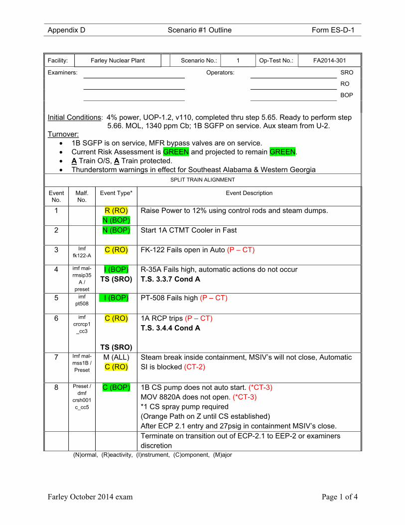
Appendix D Scenario #1 Outline Form ES-D-1
Farley October 2014 exam Page 1 of 4
Facility: Farley Nuclear Plant Scenario No.: 1 Op-Test No.: FA2014-301
Examiners: Operators: SRO
RO
BOP
Initial Conditions: 4% power, UOP-1.2, v110, completed thru step 5.65. Ready to perform step 5.66. MOL, 1340 ppm Cb; 1B SGFP on service. Aux steam from U-2.
Turnover: 1B SGFP is on service, MFR bypass valves are on service. Current Risk Assessment is GREEN and projected to remain GREEN. A Train O/S, A Train protected. Thunderstorm warnings in effect for Southeast Alabama & Western Georgia
SPLIT TRAIN ALIGNMENT
Event No.
Malf. No.
Event Type* Event Description
1 R (RO) N (BOP)
Raise Power to 12% using control rods and steam dumps.
2 N (BOP) Start 1A CTMT Cooler in Fast
3 Imf fk122-A
C (RO)
FK-122 Fails open in Auto (P – CT)
4 imf mal-rmsip35
A / preset
I (BOP) TS (SRO)
R-35A Fails high, automatic actions do not occur T.S. 3.3.7 Cond A
5 imf pt508
I (BOP) PT-508 Fails high (P – CT)
6 imf
crcrcp1_cc3
C (RO)
TS (SRO)
1A RCP trips (P – CT) T.S. 3.4.4 Cond A
7 Imf mal-mss1B / Preset
M (ALL) C (RO)
Steam break inside containment, MSIV’s will not close, Automatic SI is blocked (CT-2)
8 Preset /
dmf crsh001c_cc5
C (BOP)
1B CS pump does not auto start. (*CT-3) MOV 8820A does not open. (*CT-3) *1 CS spray pump required (Orange Path on Z until CS established) After ECP 2.1 entry and 27psig in containment MSIV’s close.
Terminate on transition out of ECP-2.1 to EEP-2 or examiners discretion
(N)ormal, (R)eactivity, (I)nstrument, (C)omponent, (M)ajor
Appendix D Scenario 1 Presets Form ES-D-1
Farley October 2014 exam Page 2 of 4
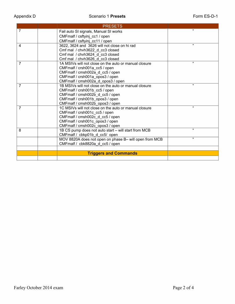
PRESETS 7 Fail auto SI signals, Manual SI works
CMFmalf / csftyinj_cc1 / open CMFmalf / csftyinj_cc11 / open
*
4 3622, 3624 and 3626 will not close on hi rad Cmf mal / chvh3622_d_cc3 closed Cmf mal / chvh3624_d_cc3 closed Cmf mal / chvh3626_d_cc3 closed
*
7 1A MSIVs will not close on the auto or manual closure CMFmalf / crsh001a_cc5 / open CMFmalf / cmsh002a_d_cc5 / open CMFmalf / crsh001a_opos3 / open CMFmalf / cmsh002a_d_opos3 / open
*
7 1B MSIVs will not close on the auto or manual closure CMFmalf / crsh001b_cc5 / open CMFmalf / cmsh002b_d_cc5 / open CMFmalf / crsh001b_opos3 / open CMFmalf / cmsh002b_opos3 / open
*
7 1C MSIVs will not close on the auto or manual closure CMFmalf / crsh001c_cc5 / open CMFmalf / cmsh002c_d_cc5 / open CMFmalf / crsh001c_opos3 / open CMFmalf / cmsh002c_opos3 / open
*
8 1B CS pump does not auto start – will start from MCB CMFmalf / cbkp01b_d_cc5/ open
*
MOV 8820A does not open on phase B– will open from MCB CMFmalf / cbk8820a_d_cc5 / open
*
Triggers and Commands
Appendix D Scenario 1 detailed summary
sheet Form ES-D-1
Farley October 2014 exam Page 3 of 4
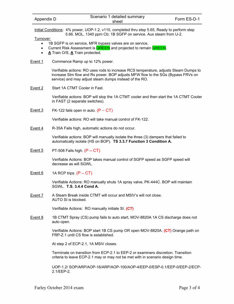
Initial Conditions: 4% power, UOP-1.2, v110, completed thru step 5.65, Ready to perform step 5.66. MOL, 1340 ppm Cb; 1B SGFP on service. Aux steam from U-2.
Turnover: 1B SGFP is on service, MFR bypass valves are on service. Current Risk Assessment is GREEN and projected to remain GREEN. A Train O/S, A Train protected.
Event 1 Commence Ramp up to 12% power. Verifiable actions: RO uses rods to increase RCS temperature, adjusts Steam Dumps to increase Stm flow and Rx power. BOP adjusts MFW flow to the SGs (Bypass FRVs on service) and may adjust steam dumps instead of the RO.
Event 2 Start 1A CTMT Cooler in Fast. Verifiable actions: BOP will stop the 1A CTMT cooler and then start the 1A CTMT Cooler in FAST (2 separate switches).
Event 3 FK-122 fails open in auto. (P – CT) Verifiable actions: RO will take manual control of FK-122.
Event 4 R-35A Fails high, automatic actions do not occur. Verifiable actions: BOP will manually isolate the three (3) dampers that failed to automatically isolate (HS on BOP). TS 3.3.7 Function 3 Condition A.
Event 5 PT-508 Fails high. (P – CT) Verifiable Actions: BOP takes manual control of SGFP speed as SGFP speed will decrease as will SGWL.
Event 6 1A RCP trips. (P – CT) Verifiable Actions: RO manually shuts 1A spray valve, PK-444C. BOP will maintain SGWL. T.S. 3.4.4 Cond A.
Event 7 A Steam Break inside CTMT will occur and MSIV’s will not close. AUTO SI is blocked. Verifiable Actions: RO manually initiate SI. (CT)
Event 8 1B CTMT Spray (CS) pump fails to auto start, MOV-8820A 1A CS discharge does not auto open. Verifiable Actions: BOP start 1B CS pump OR open MOV-8820A. (CT) Orange path on FRP-Z.1 until CS flow is established. At step 2 of ECP-2.1, 1A MSIV closes.
Terminate on transition from ECP-2.1 to EEP-2 or examiners discretion. Transition criteria to leave ECP-2.1 may or may not be met with in scenario design time.
UOP-1.2/ SOP/ARP/AOP-16/ARP/AOP-100/AOP-4/EEP-0/ESP-0.1/EEP-0/EEP-2/ECP-
2.1/EEP-2.
Appendix D Scenario 1 Critical Task sheet
Sheet Form ES-D-1
Farley October 2014 exam Page 4 of 4
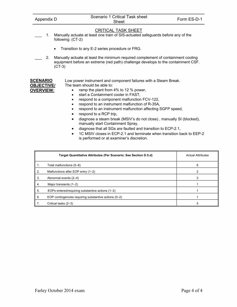
CRITICAL TASK SHEET 1. Manually actuate at least one train of SIS-actuated safeguards before any of the
following: (CT-2) Transition to any E-2 series procedure or FRG.
2. Manually actuate at least the minimum required complement of containment cooling
equipment before an extreme (red path) challenge develops to the containment CSF. (CT-3)
SCENARIO OBJECTIVE/ OVERVIEW:
Low power instrument and component failures with a Steam Break. The team should be able to:
ramp the plant from 4% to 12 % power, start a Containment cooler in FAST, respond to a component malfunction FCV-122, respond to an instrument malfunction of R-35A, respond to an instrument malfunction affecting SGFP speed, respond to a RCP trip, diagnose a steam break (MSIV’s do not close) , manually SI (blocked),
manually start Containment Spray, diagnose that all SGs are faulted and transition to ECP-2.1, 1C MSIV closes in ECP-2.1 and terminate when transition back to EEP-2
is performed or at examiner’s discretion.
Target Quantitative Attributes (Per Scenario; See Section D.5.d) Actual Attributes
1. Total malfunctions (5–8) 6
2. Malfunctions after EOP entry (1–2) 2
3. Abnormal events (2–4) 3
4. Major transients (1–2) 1
5. EOPs entered/requiring substantive actions (1–2) 1
6. EOP contingencies requiring substantive actions (0–2) 1
7. Critical tasks (2–3) 5
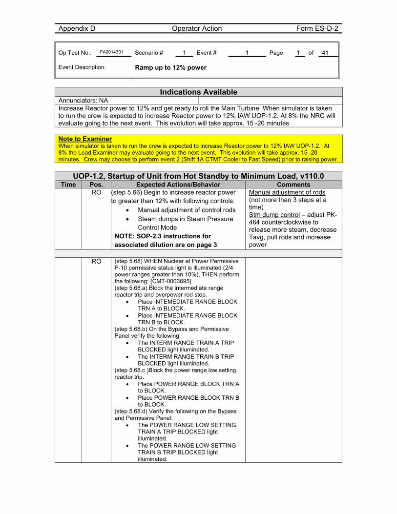
Appendix D Operator Action Form ES-D-2 Op Test No.: FA2014301 Scenario # 1 Event # 1 Page 1 of 41 Event Description: Ramp up to 12% power
Indications Available
Annunciators: NA Increase Reactor power to 12% and get ready to roll the Main Turbine. When simulator is taken to run the crew is expected to increase Reactor power to 12% IAW UOP-1.2. At 8% the NRC will evaluate going to the next event. This evolution will take approx. 15 -20 minutes Note to Examiner When simulator is taken to run the crew is expected to increase Reactor power to 12% IAW UOP-1.2. At 8% the Lead Examiner may evaluate going to the next event. This evolution will take approx. 15 -20 minutes. Crew may choose to perform event 2 (Shift 1A CTMT Cooler to Fast Speed) prior to raising power.
UOP-1.2, Startup of Unit from Hot Standby to Minimum Load, v110.0
Time Pos. Expected Actions/Behavior Comments RO (step 5.66) Begin to increase reactor power
to greater than 12% with following controls. Manual adjustment of control rods Steam dumps in Steam Pressure
Control Mode NOTE: SOP-2.3 instructions for associated dilution are on page 3
Manual adjustment of rods (not more than 3 steps at a time) Stm dump control – adjust PK-464 counterclockwise to release more steam, decrease Tavg, pull rods and increase power
RO (step 5.68) WHEN Nuclear at Power Permissive
P-10 permissive status light is illuminated (2/4 power ranges greater than 10%), THEN perform the following: {CMT-0003695} (step 5.68.a) Block the intermediate range reactor trip and overpower rod stop.
Place INTEMEDIATE RANGE BLOCK TRN A to BLOCK.
Place INTEMEDIATE RANGE BLOCK TRN B to BLOCK.
(step 5.68.b) On the Bypass and Permissive Panel verify the following:
The INTERM RANGE TRAIN A TRIP BLOCKED light illuminated.
The INTERM RANGE TRAIN B TRIP BLOCKED light illuminated.
(step 5.68.c )Block the power range low setting reactor trip.
Place POWER RANGE BLOCK TRN A to BLOCK.
Place POWER RANGE BLOCK TRN B to BLOCK.
(step 5.68.d) Verify the following on the Bypass and Permissive Panel:
The POWER RANGE LOW SETTING TRAIN A TRIP BLOCKED light illuminated.
The POWER RANGE LOW SETTING TRAIN B TRIP BLOCKED light illuminated.
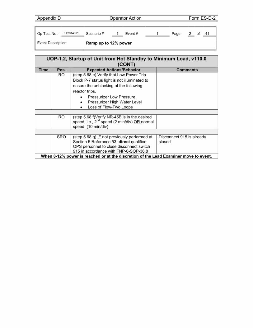
Appendix D Operator Action Form ES-D-2 Op Test No.: FA2014301 Scenario # 1 Event # 1 Page 2 of 41 Event Description: Ramp up to 12% power
UOP-1.2, Startup of Unit from Hot Standby to Minimum Load, v110.0
(CONT) Time Pos. Expected Actions/Behavior Comments
RO (step 5.68.e) Verify that Low Power Trip Block P-7 status light is not illuminated to ensure the unblocking of the following reactor trips.
Pressurizer Low Pressure Pressurizer High Water Level Loss of Flow-Two Loops
RO (step 5.68.f)Verify NR-45B is in the desired
speed, i.e., 2nd speed (2 min/div) OR normal speed. (10 min/div)
SRO (step 5.68.g) IF not previously performed at
Section 5 Reference 53, direct qualified OPS personnel to close disconnect switch 915 in accordance with FNP-0-SOP-36.8
Disconnect 915 is already closed.
When 8-12% power is reached or at the discretion of the Lead Examiner move to event.
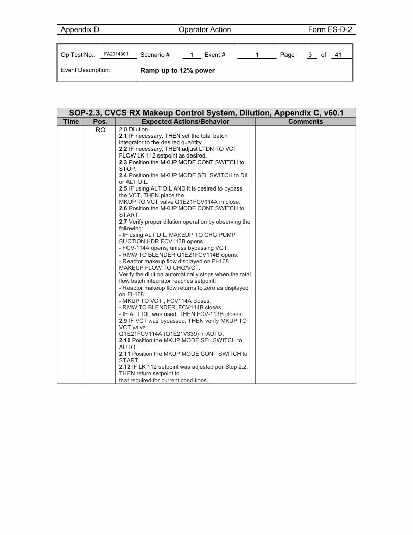
Appendix D Operator Action Form ES-D-2 Op Test No.: FA2014301 Scenario # 1 Event # 1 Page 3 of 41 Event Description: Ramp up to 12% power
SOP-2.3, CVCS RX Makeup Control System, Dilution, Appendix C, v60.1 Time Pos. Expected Actions/Behavior Comments
RO 2.0 Dilution 2.1 IF necessary, THEN set the total batch integrator to the desired quantity. 2.2 IF necessary, THEN adjust LTDN TO VCT FLOW LK 112 setpoint as desired. 2.3 Position the MKUP MODE CONT SWITCH to STOP. 2.4 Position the MKUP MODE SEL SWITCH to DIL or ALT DIL. 2.5 IF using ALT DIL AND it is desired to bypass the VCT, THEN place the MKUP TO VCT valve Q1E21FCV114A in close. 2.6 Position the MKUP MODE CONT SWITCH to START. 2.7 Verify proper dilution operation by observing the following: - IF using ALT DIL, MAKEUP TO CHG PUMP SUCTION HDR FCV113B opens. - FCV-114A opens, unless bypassing VCT. - RMW TO BLENDER Q1E21FCV114B opens. - Reactor makeup flow displayed on FI-168 MAKEUP FLOW TO CHG/VCT. Verify the dilution automatically stops when the total flow batch integrator reaches setpoint: - Reactor makeup flow returns to zero as displayed on FI-168 - MKUP TO VCT , FCV114A closes. - RMW TO BLENDER, FCV114B closes. - IF ALT DIL was used, THEN FCV-113B closes. 2.9 IF VCT was bypassed, THEN verify MKUP TO VCT valve Q1E21FCV114A (Q1E21V339) in AUTO. 2.10 Position the MKUP MODE SEL SWITCH to AUTO. 2.11 Position the MKUP MODE CONT SWITCH to START. 2.12 IF LK 112 setpoint was adjusted per Step 2.2, THEN return setpoint to that required for current conditions.
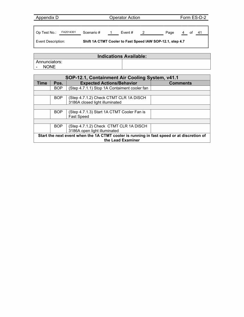
Appendix D Operator Action Form ES-D-2 Op Test No.: FA2014301 Scenario # 1 Event # 2 Page 4 of 41 Event Description: Shift 1A CTMT Cooler to Fast Speed IAW SOP-12.1, step 4.7
Indications Available:
Annunciators: - NONE
SOP-12.1, Containment Air Cooling System, v41.1
Time Pos. Expected Actions/Behavior Comments BOP (Step 4.7.1.1) Stop 1A Contaiment cooler fan BOP (Step 4.7.1.2) Check CTMT CLR 1A DISCH
3186A closed light illuminated
BOP (Step 4.7.1.3) Start 1A CTMT Cooler Fan is
Fast Speed
BOP (Step 4.7.1.2) Check CTMT CLR 1A DISCH
3186A open light illuminated
Start the next event when the 1A CTMT cooler is running in fast speed or at discretion of the Lead Examiner
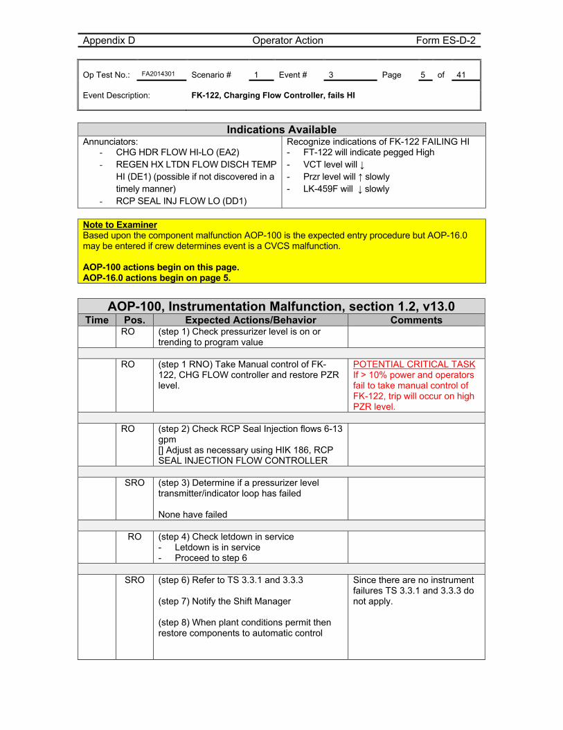
Appendix D Operator Action Form ES-D-2 Op Test No.: FA2014301 Scenario # 1 Event # 3 Page 5 of 41 Event Description: FK-122, Charging Flow Controller, fails HI
Indications Available
Annunciators: - CHG HDR FLOW HI-LO (EA2) - REGEN HX LTDN FLOW DISCH TEMP
HI (DE1) (possible if not discovered in a timely manner)
- RCP SEAL INJ FLOW LO (DD1)
Recognize indications of FK-122 FAILING HI - FT-122 will indicate pegged High - VCT level will ↓ - Przr level will ↑ slowly - LK-459F will ↓ slowly
Note to Examiner Based upon the component malfunction AOP-100 is the expected entry procedure but AOP-16.0 may be entered if crew determines event is a CVCS malfunction. AOP-100 actions begin on this page. AOP-16.0 actions begin on page 5.
AOP-100, Instrumentation Malfunction, section 1.2, v13.0
Time Pos. Expected Actions/Behavior Comments RO (step 1) Check pressurizer level is on or
trending to program value
RO (step 1 RNO) Take Manual control of FK-
122, CHG FLOW controller and restore PZR level.
POTENTIAL CRITICAL TASK If > 10% power and operators fail to take manual control of FK-122, trip will occur on high PZR level.
RO (step 2) Check RCP Seal Injection flows 6-13
gpm [] Adjust as necessary using HIK 186, RCP SEAL INJECTION FLOW CONTROLLER
SRO (step 3) Determine if a pressurizer level
transmitter/indicator loop has failed None have failed
RO (step 4) Check letdown in service
- Letdown is in service - Proceed to step 6
SRO (step 6) Refer to TS 3.3.1 and 3.3.3
(step 7) Notify the Shift Manager (step 8) When plant conditions permit then restore components to automatic control
Since there are no instrument failures TS 3.3.1 and 3.3.3 do not apply.
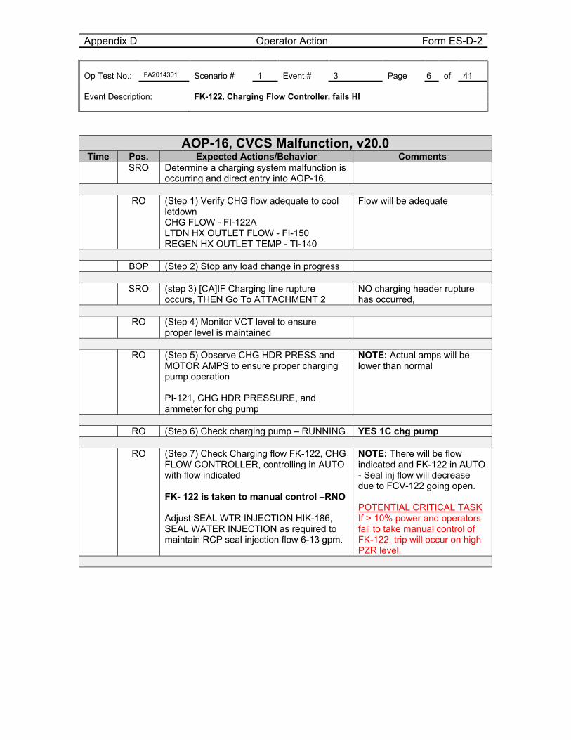
Appendix D Operator Action Form ES-D-2 Op Test No.: FA2014301 Scenario # 1 Event # 3 Page 6 of 41 Event Description: FK-122, Charging Flow Controller, fails HI
AOP-16, CVCS Malfunction, v20.0 Time Pos. Expected Actions/Behavior Comments
SRO Determine a charging system malfunction is occurring and direct entry into AOP-16.
RO (Step 1) Verify CHG flow adequate to cool
letdown CHG FLOW - FI-122A LTDN HX OUTLET FLOW - FI-150 REGEN HX OUTLET TEMP - TI-140
Flow will be adequate
BOP (Step 2) Stop any load change in progress SRO (step 3) [CA]IF Charging line rupture
occurs, THEN Go To ATTACHMENT 2 NO charging header rupture has occurred,
RO (Step 4) Monitor VCT level to ensure
proper level is maintained
RO (Step 5) Observe CHG HDR PRESS and
MOTOR AMPS to ensure proper charging pump operation PI-121, CHG HDR PRESSURE, and ammeter for chg pump
NOTE: Actual amps will be lower than normal
RO (Step 6) Check charging pump – RUNNING YES 1C chg pump RO (Step 7) Check Charging flow FK-122, CHG
FLOW CONTROLLER, controlling in AUTO with flow indicated FK- 122 is taken to manual control –RNO Adjust SEAL WTR INJECTION HIK-186, SEAL WATER INJECTION as required to maintain RCP seal injection flow 6-13 gpm.
NOTE: There will be flow indicated and FK-122 in AUTO - Seal inj flow will decrease due to FCV-122 going open. POTENTIAL CRITICAL TASK If > 10% power and operators fail to take manual control of FK-122, trip will occur on high PZR level.
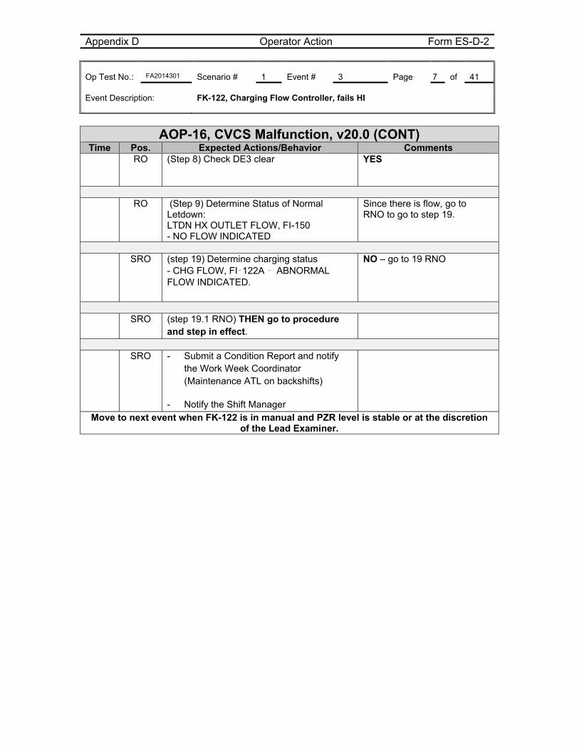
Appendix D Operator Action Form ES-D-2 Op Test No.: FA2014301 Scenario # 1 Event # 3 Page 7 of 41 Event Description: FK-122, Charging Flow Controller, fails HI
AOP-16, CVCS Malfunction, v20.0 (CONT) Time Pos. Expected Actions/Behavior Comments
RO (Step 8) Check DE3 clear
YES
RO (Step 9) Determine Status of Normal
Letdown: LTDN HX OUTLET FLOW, FI-150 - NO FLOW INDICATED
Since there is flow, go to RNO to go to step 19.
SRO (step 19) Determine charging status
- CHG FLOW, FI‑122A ‑ ABNORMAL FLOW INDICATED.
NO – go to 19 RNO
SRO (step 19.1 RNO) THEN go to procedure
and step in effect.
SRO - Submit a Condition Report and notify
the Work Week Coordinator (Maintenance ATL on backshifts)
- Notify the Shift Manager
Move to next event when FK-122 is in manual and PZR level is stable or at the discretion of the Lead Examiner.
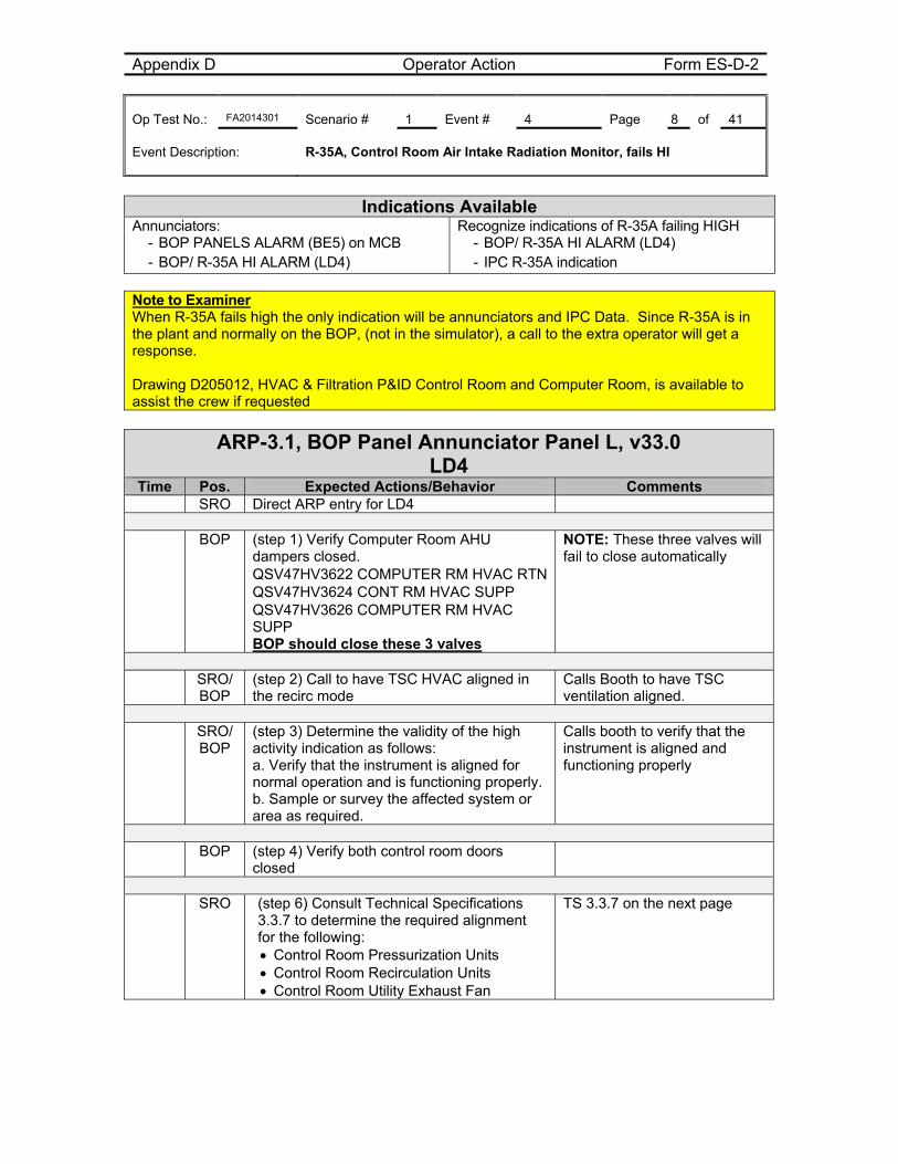
Appendix D Operator Action Form ES-D-2 Op Test No.: FA2014301 Scenario # 1 Event # 4 Page 8 of 41 Event Description: R-35A, Control Room Air Intake Radiation Monitor, fails HI
Indications Available
Annunciators: - BOP PANELS ALARM (BE5) on MCB - BOP/ R-35A HI ALARM (LD4)
Recognize indications of R-35A failing HIGH - BOP/ R-35A HI ALARM (LD4) - IPC R-35A indication
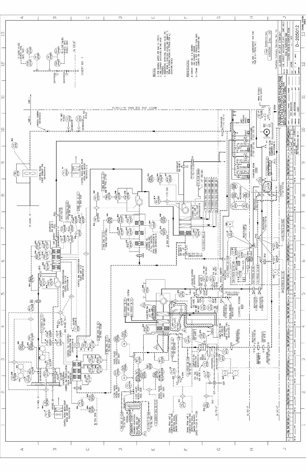
Note to Examiner When R-35A fails high the only indication will be annunciators and IPC Data. Since R-35A is in the plant and normally on the BOP, (not in the simulator), a call to the extra operator will get a response. Drawing D205012, HVAC & Filtration P&ID Control Room and Computer Room, is available to assist the crew if requested
ARP-3.1, BOP Panel Annunciator Panel L, v33.0 LD4
Time Pos. Expected Actions/Behavior Comments SRO Direct ARP entry for LD4
BOP (step 1) Verify Computer Room AHU
dampers closed. QSV47HV3622 COMPUTER RM HVAC RTN QSV47HV3624 CONT RM HVAC SUPP QSV47HV3626 COMPUTER RM HVAC SUPP BOP should close these 3 valves
NOTE: These three valves will fail to close automatically
SRO/
BOP (step 2) Call to have TSC HVAC aligned in the recirc mode
Calls Booth to have TSC ventilation aligned.
SRO/
BOP (step 3) Determine the validity of the high activity indication as follows: a. Verify that the instrument is aligned for normal operation and is functioning properly. b. Sample or survey the affected system or area as required.
Calls booth to verify that the instrument is aligned and functioning properly
BOP (step 4) Verify both control room doors
closed
SRO (step 6) Consult Technical Specifications
3.3.7 to determine the required alignment for the following: Control Room Pressurization Units Control Room Recirculation Units Control Room Utility Exhaust Fan
TS 3.3.7 on the next page
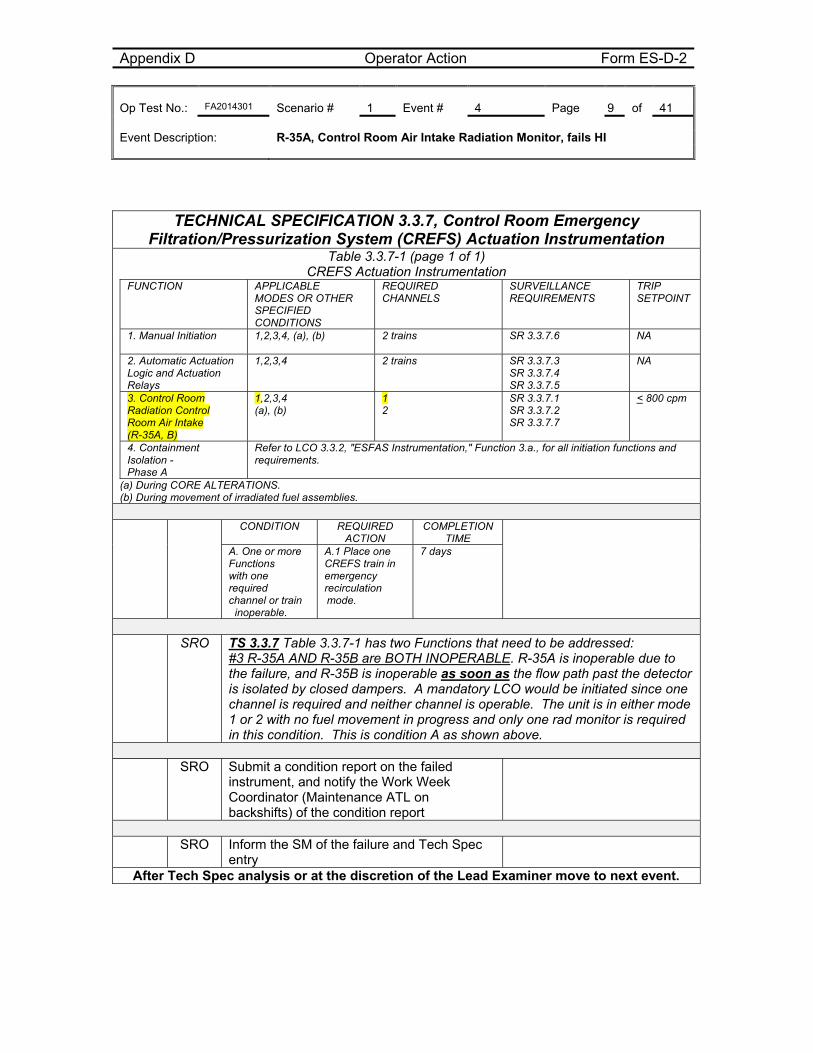
Appendix D Operator Action Form ES-D-2 Op Test No.: FA2014301 Scenario # 1 Event # 4 Page 9 of 41 Event Description: R-35A, Control Room Air Intake Radiation Monitor, fails HI
TECHNICAL SPECIFICATION 3.3.7, Control Room Emergency Filtration/Pressurization System (CREFS) Actuation Instrumentation
Table 3.3.7-1 (page 1 of 1) CREFS Actuation Instrumentation
FUNCTION
APPLICABLE MODES OR OTHER SPECIFIED CONDITIONS
REQUIRED CHANNELS
SURVEILLANCE REQUIREMENTS
TRIP SETPOINT
1. Manual Initiation
1,2,3,4, (a), (b) 2 trains SR 3.3.7.6 NA
2. Automatic Actuation Logic and Actuation Relays
1,2,3,4 2 trains SR 3.3.7.3 SR 3.3.7.4 SR 3.3.7.5
NA
3. Control Room Radiation Control Room Air Intake (R-35A, B)
1,2,3,4 (a), (b)
1 2
SR 3.3.7.1 SR 3.3.7.2 SR 3.3.7.7
< 800 cpm
4. Containment Isolation - Phase A
Refer to LCO 3.3.2, "ESFAS Instrumentation," Function 3.a., for all initiation functions and requirements.
(a) During CORE ALTERATIONS. (b) During movement of irradiated fuel assemblies.
CONDITION REQUIRED
ACTION COMPLETION
TIME
A. One or more Functions with one required channel or train
inoperable.
A.1 Place one CREFS train in emergency recirculation mode.
7 days
SRO TS 3.3.7 Table 3.3.7-1 has two Functions that need to be addressed:
#3 R-35A AND R-35B are BOTH INOPERABLE. R-35A is inoperable due to the failure, and R-35B is inoperable as soon as the flow path past the detector is isolated by closed dampers. A mandatory LCO would be initiated since one channel is required and neither channel is operable. The unit is in either mode 1 or 2 with no fuel movement in progress and only one rad monitor is required in this condition. This is condition A as shown above.
SRO Submit a condition report on the failed
instrument, and notify the Work Week Coordinator (Maintenance ATL on backshifts) of the condition report
SRO Inform the SM of the failure and Tech Spec
entry
After Tech Spec analysis or at the discretion of the Lead Examiner move to next event.
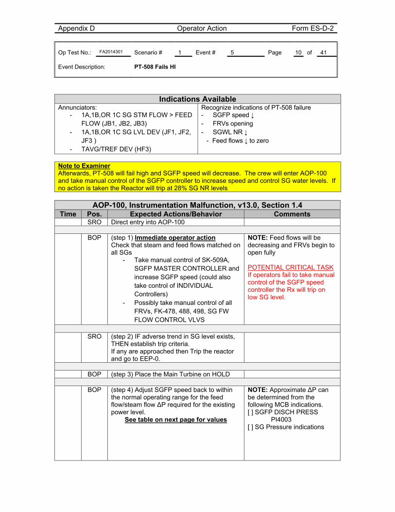
Appendix D Operator Action Form ES-D-2 Op Test No.: FA2014301 Scenario # 1 Event # 5 Page 10 of 41 Event Description: PT-508 Fails HI
Indications Available Annunciators:
- 1A,1B,OR 1C SG STM FLOW > FEED FLOW (JB1, JB2, JB3)
- 1A,1B,OR 1C SG LVL DEV (JF1, JF2, JF3 )
- TAVG/TREF DEV (HF3)
Recognize indications of PT-508 failure - SGFP speed ↓ - FRVs opening - SGWL NR ↓
- Feed flows ↓ to zero
Note to Examiner Afterwards, PT-508 will fail high and SGFP speed will decrease. The crew will enter AOP-100 and take manual control of the SGFP controller to increase speed and control SG water levels. If no action is taken the Reactor will trip at 28% SG NR levels
AOP-100, Instrumentation Malfunction, v13.0, Section 1.4 Time Pos. Expected Actions/Behavior Comments
SRO Direct entry into AOP-100
BOP (step 1) Immediate operator action Check that steam and feed flows matched on all SGs
- Take manual control of SK-509A, SGFP MASTER CONTROLLER and increase SGFP speed (could also take control of INDIVIDUAL Controllers)
- Possibly take manual control of all FRVs, FK-478, 488, 498, SG FW FLOW CONTROL VLVS
NOTE: Feed flows will be decreasing and FRVs begin to open fully POTENTIAL CRITICAL TASK If operators fail to take manual control of the SGFP speed controller the Rx will trip on low SG level.
SRO (step 2) IF adverse trend in SG level exists,
THEN establish trip criteria. If any are approached then Trip the reactor and go to EEP-0.
BOP (step 3) Place the Main Turbine on HOLD
BOP (step 4) Adjust SGFP speed back to within
the normal operating range for the feed flow/steam flow ∆P required for the existing power level.
See table on next page for values
NOTE: Approximate ∆P can be determined from the following MCB indications. [ ] SGFP DISCH PRESS PI4003 [ ] SG Pressure indications
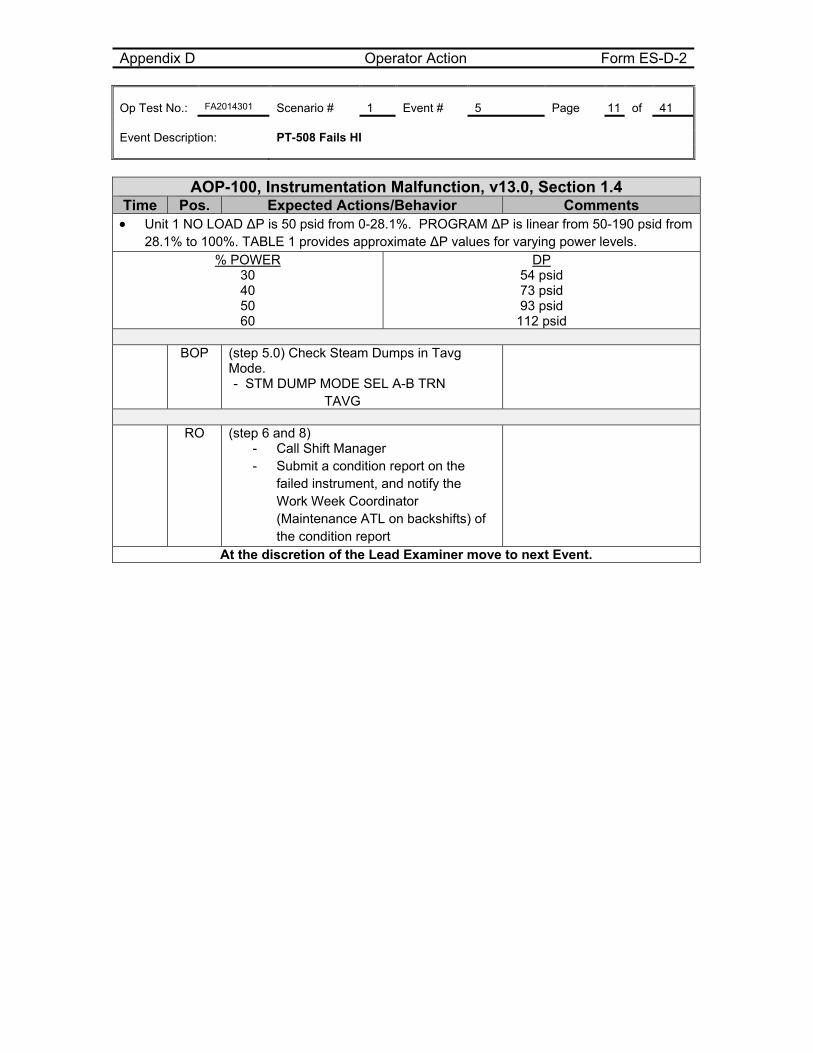
Appendix D Operator Action Form ES-D-2 Op Test No.: FA2014301 Scenario # 1 Event # 5 Page 11 of 41 Event Description: PT-508 Fails HI
AOP-100, Instrumentation Malfunction, v13.0, Section 1.4
Time Pos. Expected Actions/Behavior Comments Unit 1 NO LOAD ∆P is 50 psid from 0-28.1%. PROGRAM ∆P is linear from 50-190 psid from
28.1% to 100%. TABLE 1 provides approximate ∆P values for varying power levels. % POWER
30 40 50 60
DP 54 psid 73 psid 93 psid
112 psid
BOP (step 5.0) Check Steam Dumps in Tavg Mode. - STM DUMP MODE SEL A-B TRN
TAVG
RO (step 6 and 8)
- Call Shift Manager - Submit a condition report on the
failed instrument, and notify the Work Week Coordinator (Maintenance ATL on backshifts) of the condition report
At the discretion of the Lead Examiner move to next Event.
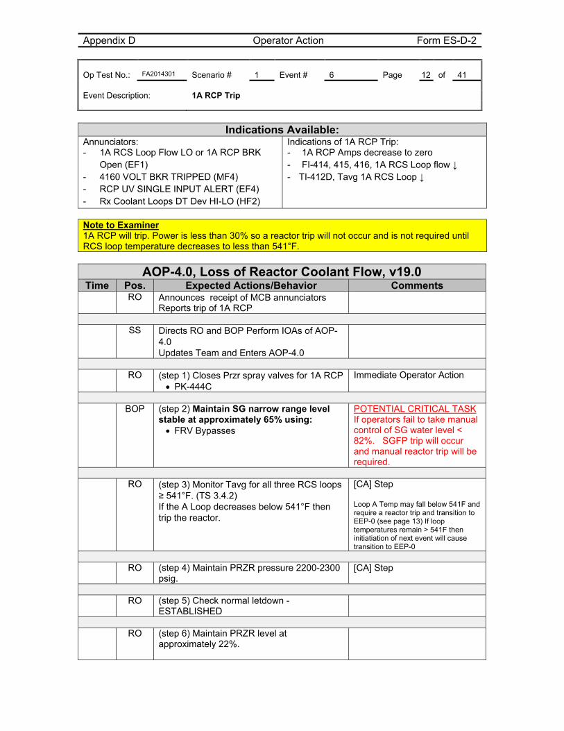
Appendix D Operator Action Form ES-D-2 Op Test No.: FA2014301 Scenario # 1 Event # 6 Page 12 of 41 Event Description: 1A RCP Trip
Indications Available:
Annunciators: - 1A RCS Loop Flow LO or 1A RCP BRK
Open (EF1) - 4160 VOLT BKR TRIPPED (MF4) - RCP UV SINGLE INPUT ALERT (EF4) - Rx Coolant Loops DT Dev HI-LO (HF2)
Indications of 1A RCP Trip: - 1A RCP Amps decrease to zero - FI-414, 415, 416, 1A RCS Loop flow ↓ - TI-412D, Tavg 1A RCS Loop ↓
Note to Examiner 1A RCP will trip. Power is less than 30% so a reactor trip will not occur and is not required until RCS loop temperature decreases to less than 541°F.
AOP-4.0, Loss of Reactor Coolant Flow, v19.0 Time Pos. Expected Actions/Behavior Comments
RO Announces receipt of MCB annunciators Reports trip of 1A RCP
SS Directs RO and BOP Perform IOAs of AOP-
4.0 Updates Team and Enters AOP-4.0
RO (step 1) Closes Przr spray valves for 1A RCP
PK-444C Immediate Operator Action
BOP (step 2) Maintain SG narrow range level
stable at approximately 65% using: FRV Bypasses
POTENTIAL CRITICAL TASK If operators fail to take manual control of SG water level < 82%. SGFP trip will occur and manual reactor trip will be required.
RO (step 3) Monitor Tavg for all three RCS loops
≥ 541°F. (TS 3.4.2) If the A Loop decreases below 541°F then trip the reactor.
[CA] Step Loop A Temp may fall below 541F and require a reactor trip and transition to EEP-0 (see page 13) If loop temperatures remain > 541F then initiatiation of next event will cause transition to EEP-0
RO (step 4) Maintain PRZR pressure 2200-2300
psig. [CA] Step
RO (step 5) Check normal letdown -
ESTABLISHED
RO (step 6) Maintain PRZR level at
approximately 22%.
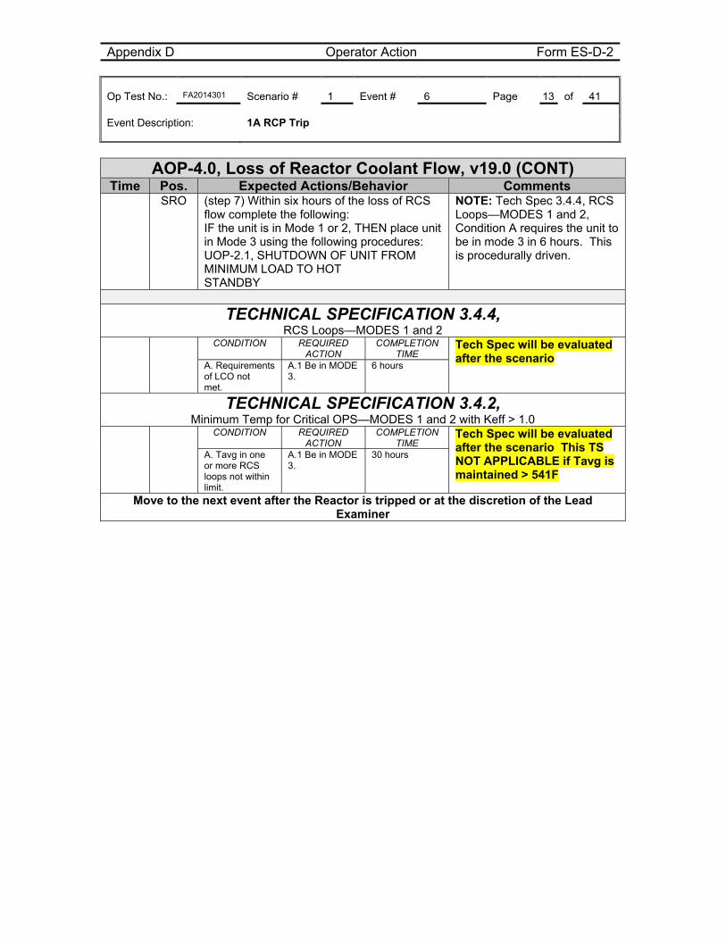
Appendix D Operator Action Form ES-D-2 Op Test No.: FA2014301 Scenario # 1 Event # 6 Page 13 of 41 Event Description: 1A RCP Trip
AOP-4.0, Loss of Reactor Coolant Flow, v19.0 (CONT) Time Pos. Expected Actions/Behavior Comments
SRO (step 7) Within six hours of the loss of RCS flow complete the following: IF the unit is in Mode 1 or 2, THEN place unit in Mode 3 using the following procedures: UOP-2.1, SHUTDOWN OF UNIT FROM MINIMUM LOAD TO HOT STANDBY
NOTE: Tech Spec 3.4.4, RCS Loops—MODES 1 and 2, Condition A requires the unit to be in mode 3 in 6 hours. This is procedurally driven.
TECHNICAL SPECIFICATION 3.4.4, RCS Loops—MODES 1 and 2
CONDITION REQUIRED ACTION
COMPLETION TIME
Tech Spec will be evaluated after the scenario
A. Requirements of LCO not met.
A.1 Be in MODE 3.
6 hours
TECHNICAL SPECIFICATION 3.4.2, Minimum Temp for Critical OPS—MODES 1 and 2 with Keff > 1.0
CONDITION REQUIRED ACTION
COMPLETION TIME
Tech Spec will be evaluated after the scenario This TS NOT APPLICABLE if Tavg is maintained > 541F
A. Tavg in one or more RCS loops not within limit.
A.1 Be in MODE 3.
30 hours
Move to the next event after the Reactor is tripped or at the discretion of the Lead Examiner
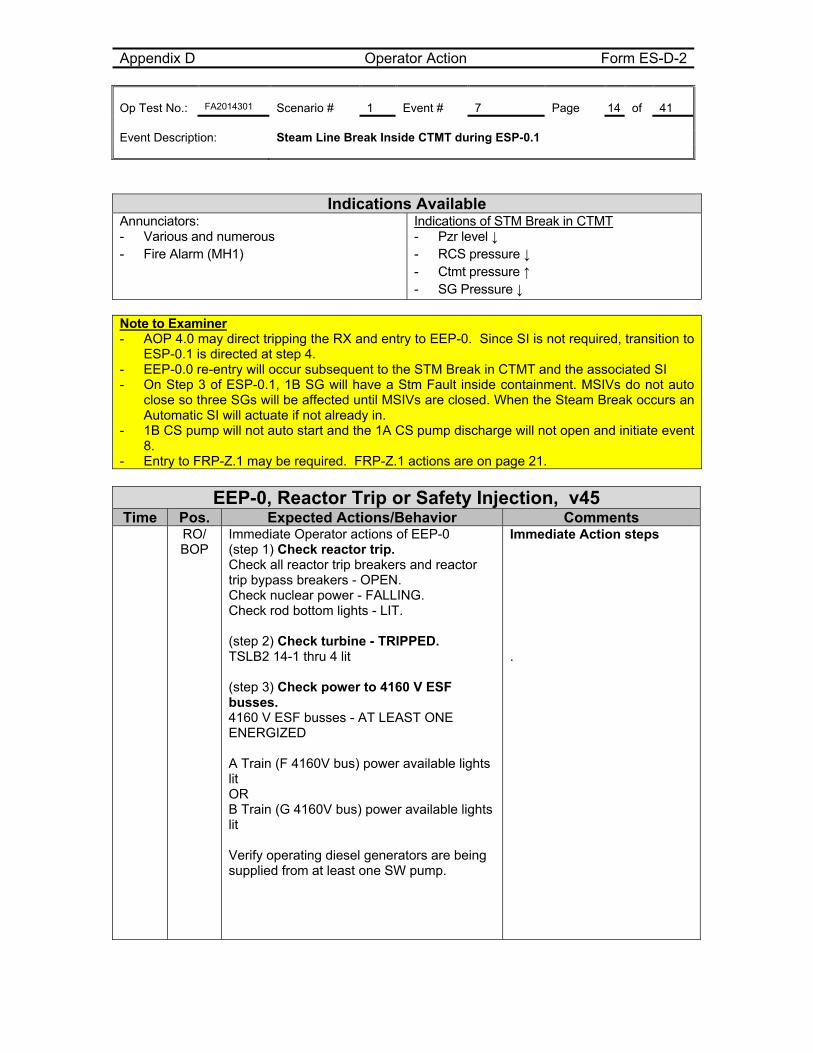
Appendix D Operator Action Form ES-D-2 Op Test No.: FA2014301 Scenario # 1 Event # 7 Page 14 of 41 Event Description: Steam Line Break Inside CTMT during ESP-0.1
Indications Available
Annunciators: - Various and numerous - Fire Alarm (MH1)
Indications of STM Break in CTMT - Pzr level ↓ - RCS pressure ↓ - Ctmt pressure ↑ - SG Pressure ↓
Note to Examiner - AOP 4.0 may direct tripping the RX and entry to EEP-0. Since SI is not required, transition to
ESP-0.1 is directed at step 4. - EEP-0.0 re-entry will occur subsequent to the STM Break in CTMT and the associated SI - On Step 3 of ESP-0.1, 1B SG will have a Stm Fault inside containment. MSIVs do not auto
close so three SGs will be affected until MSIVs are closed. When the Steam Break occurs an Automatic SI will actuate if not already in.
- 1B CS pump will not auto start and the 1A CS pump discharge will not open and initiate event 8.
- Entry to FRP-Z.1 may be required. FRP-Z.1 actions are on page 21.
EEP-0, Reactor Trip or Safety Injection, v45 Time Pos. Expected Actions/Behavior Comments
RO/ BOP
Immediate Operator actions of EEP-0 (step 1) Check reactor trip. Check all reactor trip breakers and reactor trip bypass breakers - OPEN. Check nuclear power - FALLING. Check rod bottom lights - LIT. (step 2) Check turbine - TRIPPED. TSLB2 14-1 thru 4 lit (step 3) Check power to 4160 V ESF busses. 4160 V ESF busses - AT LEAST ONE ENERGIZED A Train (F 4160V bus) power available lights lit OR B Train (G 4160V bus) power available lights lit Verify operating diesel generators are being supplied from at least one SW pump.
Immediate Action steps .
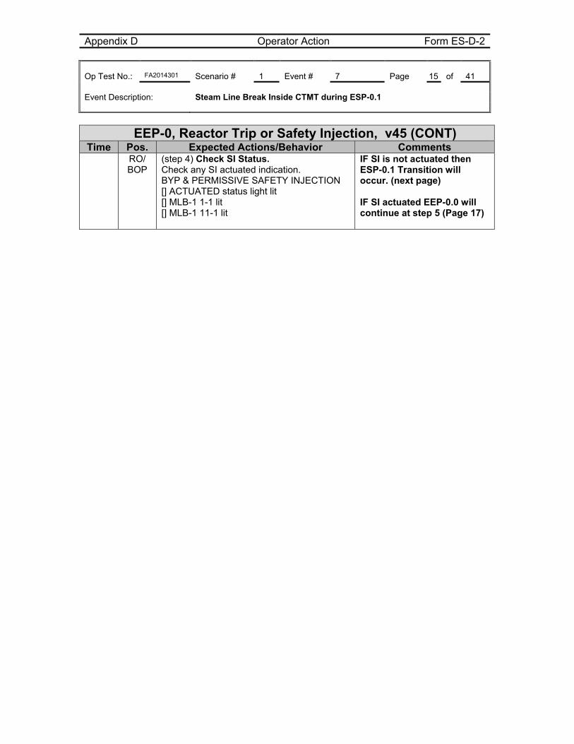
Appendix D Operator Action Form ES-D-2 Op Test No.: FA2014301 Scenario # 1 Event # 7 Page 15 of 41 Event Description: Steam Line Break Inside CTMT during ESP-0.1
EEP-0, Reactor Trip or Safety Injection, v45 (CONT) Time Pos. Expected Actions/Behavior Comments
RO/ BOP
(step 4) Check SI Status. Check any SI actuated indication. BYP & PERMISSIVE SAFETY INJECTION [] ACTUATED status light lit [] MLB-1 1-1 lit [] MLB-1 11-1 lit
IF SI is not actuated then ESP-0.1 Transition will occur. (next page) IF SI actuated EEP-0.0 will continue at step 5 (Page 17)
Appendix D Operator Action Form ES-D-2 Op Test No.: FA2014301 Scenario # 1 Event # 7/8 Page 16 of 41 Event Description: Steam Line Break Inside CTMT During ESP-0.1
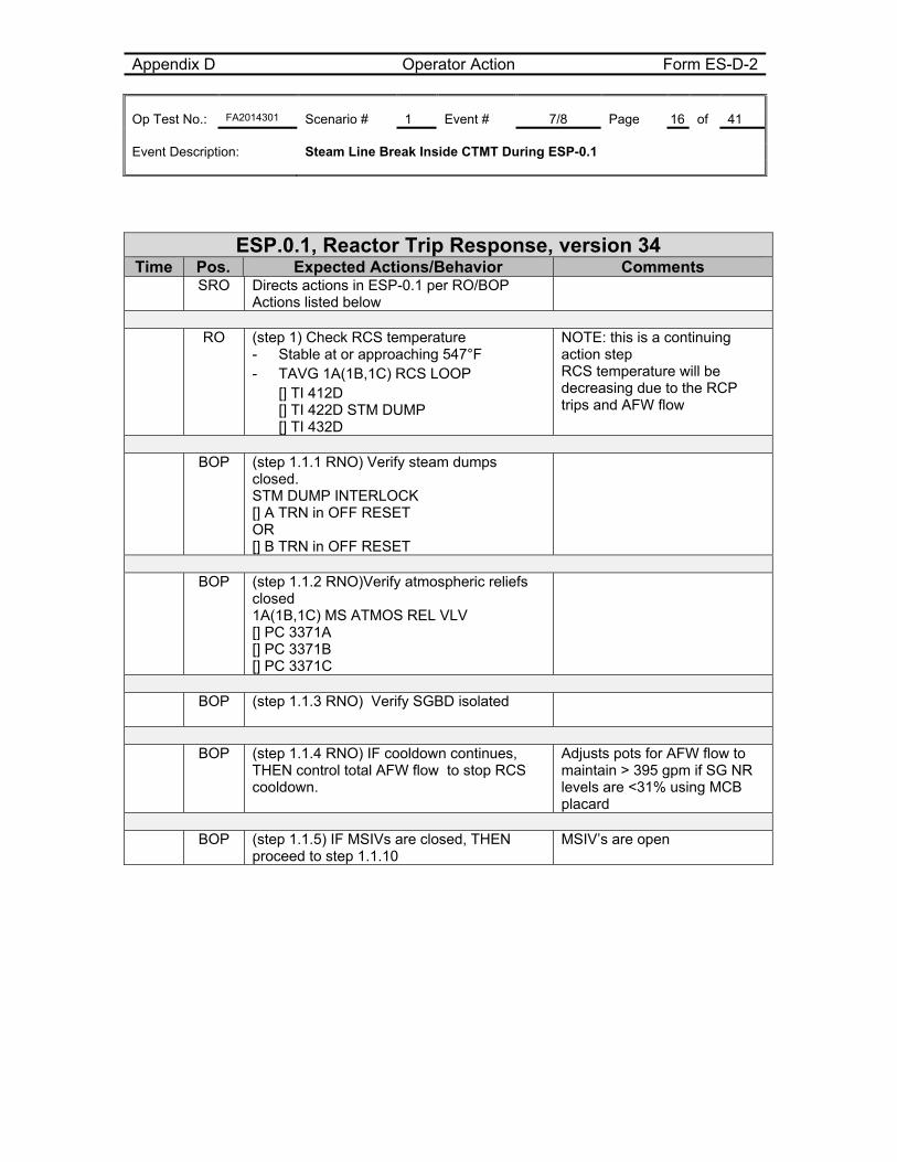
ESP.0.1, Reactor Trip Response, version 34 Time Pos. Expected Actions/Behavior Comments
SRO Directs actions in ESP-0.1 per RO/BOP Actions listed below
RO (step 1) Check RCS temperature
- Stable at or approaching 547°F - TAVG 1A(1B,1C) RCS LOOP
[] TI 412D [] TI 422D STM DUMP [] TI 432D
NOTE: this is a continuing action step RCS temperature will be decreasing due to the RCP trips and AFW flow
BOP (step 1.1.1 RNO) Verify steam dumps
closed. STM DUMP INTERLOCK [] A TRN in OFF RESET OR [] B TRN in OFF RESET
BOP (step 1.1.2 RNO)Verify atmospheric reliefs
closed 1A(1B,1C) MS ATMOS REL VLV [] PC 3371A [] PC 3371B [] PC 3371C
BOP (step 1.1.3 RNO) Verify SGBD isolated
BOP (step 1.1.4 RNO) IF cooldown continues,
THEN control total AFW flow to stop RCS cooldown.
Adjusts pots for AFW flow to maintain > 395 gpm if SG NR levels are <31% using MCB placard
BOP (step 1.1.5) IF MSIVs are closed, THEN
proceed to step 1.1.10 MSIV’s are open
Appendix D Operator Action Form ES-D-2 Op Test No.: FA2014301 Scenario # 1 Event # 7/8 Page 17 of 41 Event Description: Steam Line Break Inside CTMT During ESP-0.1
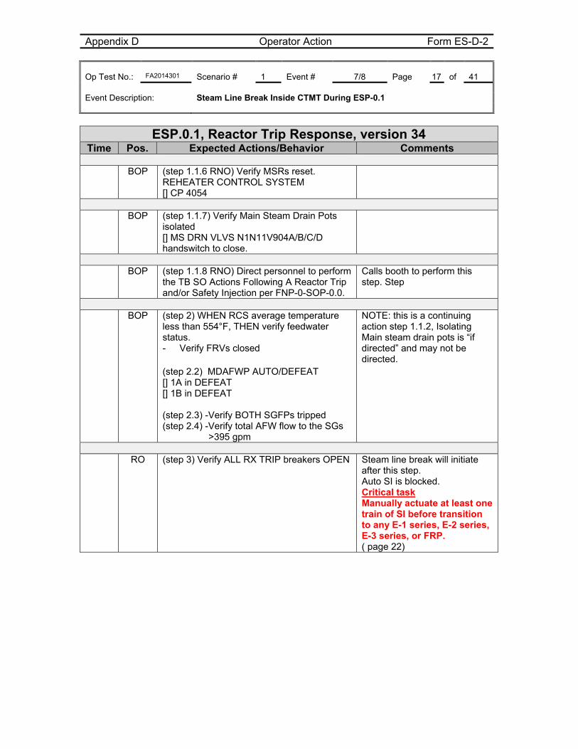
ESP.0.1, Reactor Trip Response, version 34 Time Pos. Expected Actions/Behavior Comments
BOP (step 1.1.6 RNO) Verify MSRs reset. REHEATER CONTROL SYSTEM [] CP 4054
BOP (step 1.1.7) Verify Main Steam Drain Pots
isolated [] MS DRN VLVS N1N11V904A/B/C/D handswitch to close.
BOP (step 1.1.8 RNO) Direct personnel to perform
the TB SO Actions Following A Reactor Trip and/or Safety Injection per FNP-0-SOP-0.0.
Calls booth to perform this step. Step
BOP (step 2) WHEN RCS average temperature
less than 554°F, THEN verify feedwater status. - Verify FRVs closed
(step 2.2) MDAFWP AUTO/DEFEAT [] 1A in DEFEAT [] 1B in DEFEAT (step 2.3) -Verify BOTH SGFPs tripped (step 2.4) -Verify total AFW flow to the SGs
>395 gpm
NOTE: this is a continuing action step 1.1.2, Isolating Main steam drain pots is “if directed” and may not be directed.
RO (step 3) Verify ALL RX TRIP breakers OPEN Steam line break will initiate
after this step. Auto SI is blocked. Critical task Manually actuate at least one train of SI before transition to any E-1 series, E-2 series, E-3 series, or FRP. ( page 22)
Appendix D Operator Action Form ES-D-2 Op Test No.: FA2014301 Scenario # 1 Event # 7/8 Page 18 of 41 Event Description: Steam Line Break Inside CTMT During ESP-0.1
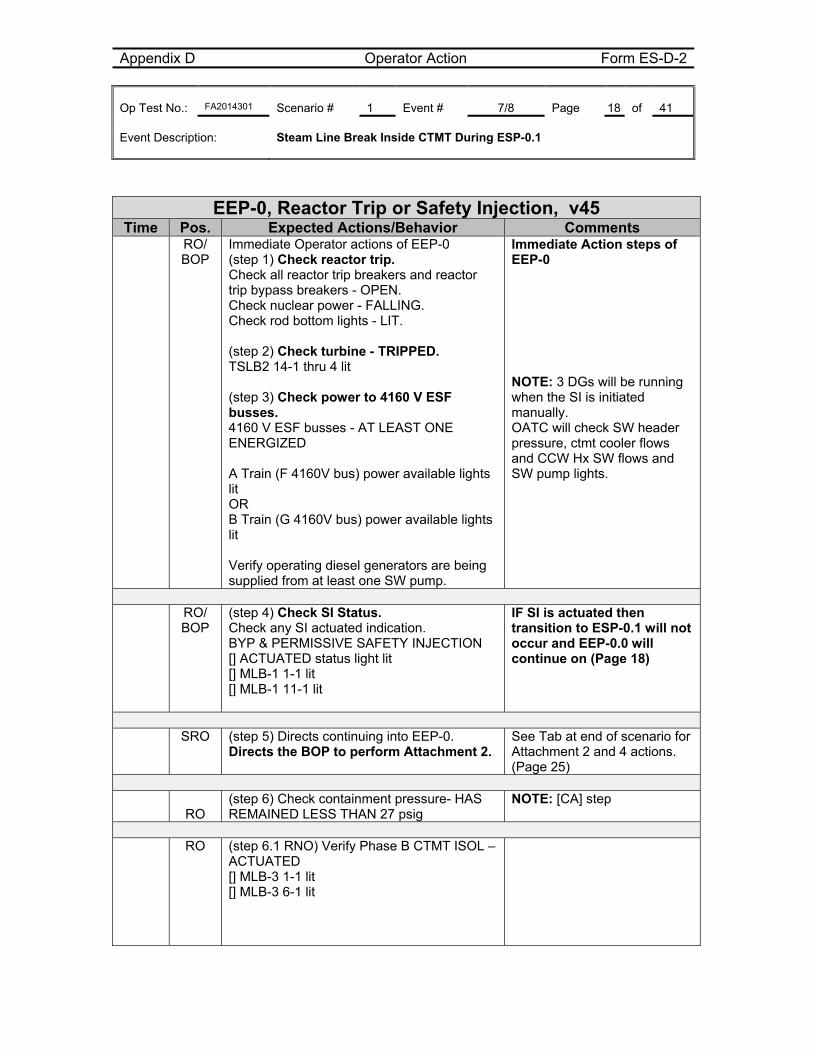
EEP-0, Reactor Trip or Safety Injection, v45 Time Pos. Expected Actions/Behavior Comments
RO/ BOP
Immediate Operator actions of EEP-0 (step 1) Check reactor trip. Check all reactor trip breakers and reactor trip bypass breakers - OPEN. Check nuclear power - FALLING. Check rod bottom lights - LIT. (step 2) Check turbine - TRIPPED. TSLB2 14-1 thru 4 lit (step 3) Check power to 4160 V ESF busses. 4160 V ESF busses - AT LEAST ONE ENERGIZED A Train (F 4160V bus) power available lights lit OR B Train (G 4160V bus) power available lights lit Verify operating diesel generators are being supplied from at least one SW pump.
Immediate Action steps of EEP-0 NOTE: 3 DGs will be running when the SI is initiated manually. OATC will check SW header pressure, ctmt cooler flows and CCW Hx SW flows and SW pump lights.
RO/
BOP (step 4) Check SI Status. Check any SI actuated indication. BYP & PERMISSIVE SAFETY INJECTION [] ACTUATED status light lit [] MLB-1 1-1 lit [] MLB-1 11-1 lit
IF SI is actuated then transition to ESP-0.1 will not occur and EEP-0.0 will continue on (Page 18)
SRO (step 5) Directs continuing into EEP-0.
Directs the BOP to perform Attachment 2. See Tab at end of scenario for Attachment 2 and 4 actions. (Page 25)
RO (step 6) Check containment pressure- HAS REMAINED LESS THAN 27 psig
NOTE: [CA] step
RO (step 6.1 RNO) Verify Phase B CTMT ISOL –
ACTUATED [] MLB-3 1-1 lit [] MLB-3 6-1 lit
Appendix D Operator Action Form ES-D-2 Op Test No.: FA2014301 Scenario # 1 Event # 7/8 Page 19 of 41 Event Description: Steam Line Break Inside CTMT During ESP-0.1
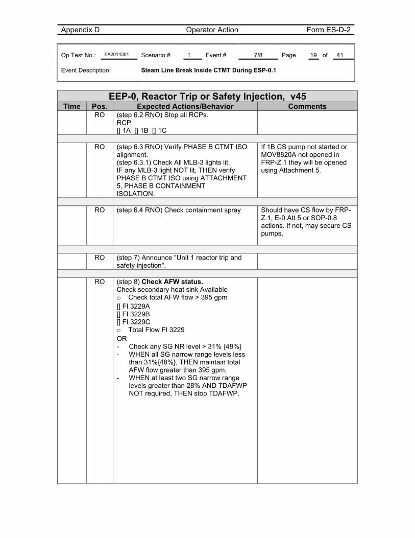
EEP-0, Reactor Trip or Safety Injection, v45 Time Pos. Expected Actions/Behavior Comments
RO (step 6.2 RNO) Stop all RCPs. RCP [] 1A [] 1B [] 1C
RO (step 6.3 RNO) Verify PHASE B CTMT ISO
alignment. (step 6.3.1) Check All MLB-3 lights lit. IF any MLB-3 light NOT lit, THEN verify PHASE B CTMT ISO using ATTACHMENT 5, PHASE B CONTAINMENT ISOLATION.
If 1B CS pump not started or MOV8820A not opened in FRP-Z.1 they will be opened using Attachment 5.
RO (step 6.4 RNO) Check containment spray Should have CS flow by FRP-
Z.1, E-0 Att 5 or SOP-0.8 actions. If not, may secure CS pumps.
RO (step 7) Announce "Unit 1 reactor trip and
safety injection".
RO (step 8) Check AFW status.
Check secondary heat sink Available o Check total AFW flow > 395 gpm [] FI 3229A [] FI 3229B [] FI 3229C o Total Flow FI 3229 OR - Check any SG NR level > 31% {48%} - WHEN all SG narrow range levels less
than 31%{48%}, THEN maintain total AFW flow greater than 395 gpm.
- WHEN at least two SG narrow range levels greater than 28% AND TDAFWP NOT required, THEN stop TDAFWP.
Appendix D Operator Action Form ES-D-2 Op Test No.: FA2014301 Scenario # 1 Event # 7/8 Page 20 of 41 Event Description: Steam Line Break Inside CTMT During ESP-0.1
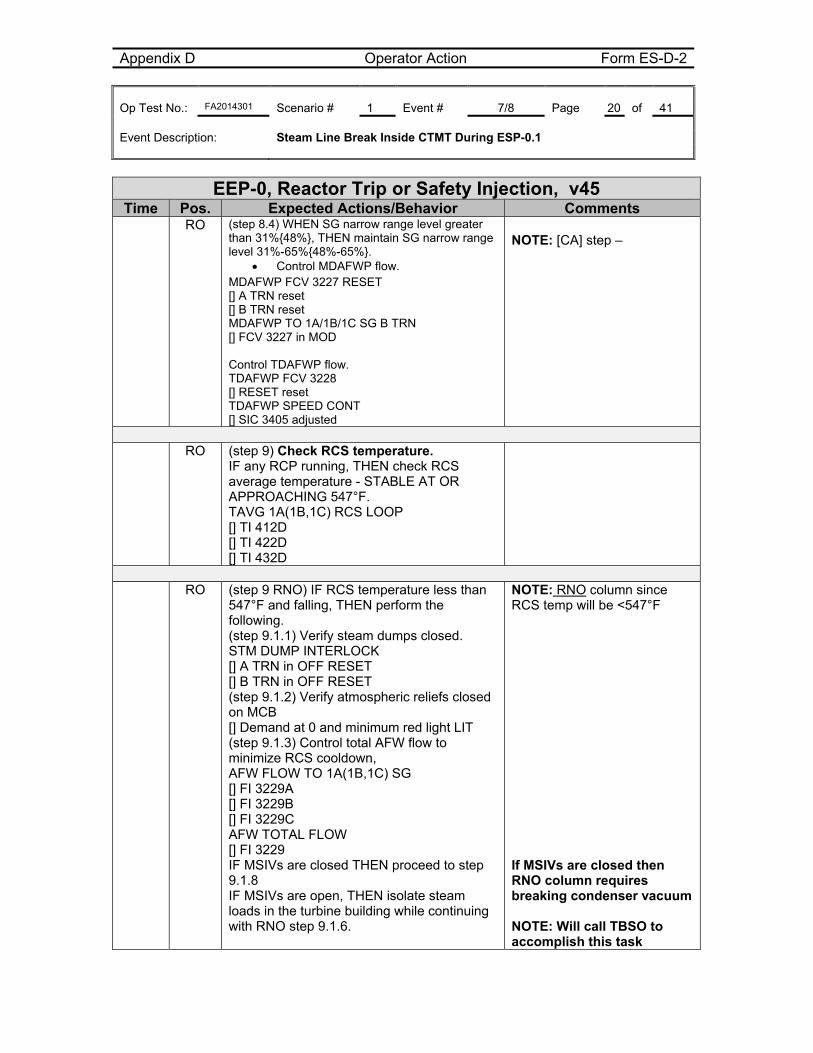
EEP-0, Reactor Trip or Safety Injection, v45 Time Pos. Expected Actions/Behavior Comments
RO (step 8.4) WHEN SG narrow range level greater than 31%{48%}, THEN maintain SG narrow range level 31%-65%{48%-65%}.
Control MDAFWP flow. MDAFWP FCV 3227 RESET [] A TRN reset [] B TRN reset MDAFWP TO 1A/1B/1C SG B TRN [] FCV 3227 in MOD Control TDAFWP flow. TDAFWP FCV 3228 [] RESET reset TDAFWP SPEED CONT [] SIC 3405 adjusted
NOTE: [CA] step –
RO (step 9) Check RCS temperature.
IF any RCP running, THEN check RCS average temperature - STABLE AT OR APPROACHING 547°F. TAVG 1A(1B,1C) RCS LOOP [] TI 412D [] TI 422D [] TI 432D
RO (step 9 RNO) IF RCS temperature less than
547°F and falling, THEN perform the following. (step 9.1.1) Verify steam dumps closed. STM DUMP INTERLOCK [] A TRN in OFF RESET [] B TRN in OFF RESET (step 9.1.2) Verify atmospheric reliefs closed on MCB [] Demand at 0 and minimum red light LIT (step 9.1.3) Control total AFW flow to minimize RCS cooldown, AFW FLOW TO 1A(1B,1C) SG [] FI 3229A [] FI 3229B [] FI 3229C AFW TOTAL FLOW [] FI 3229 IF MSIVs are closed THEN proceed to step 9.1.8 IF MSIVs are open, THEN isolate steam loads in the turbine building while continuing with RNO step 9.1.6.
NOTE: RNO column since RCS temp will be <547°F If MSIVs are closed then RNO column requires breaking condenser vacuum NOTE: Will call TBSO to accomplish this task
Appendix D Operator Action Form ES-D-2 Op Test No.: FA2014301 Scenario # 1 Event # 7/8 Page 21 of 41 Event Description: Steam Line Break Inside CTMT During ESP-0.1
EEP-0, Reactor Trip or Safety Injection, v45 Time Pos. Expected Actions/Behavior Comments
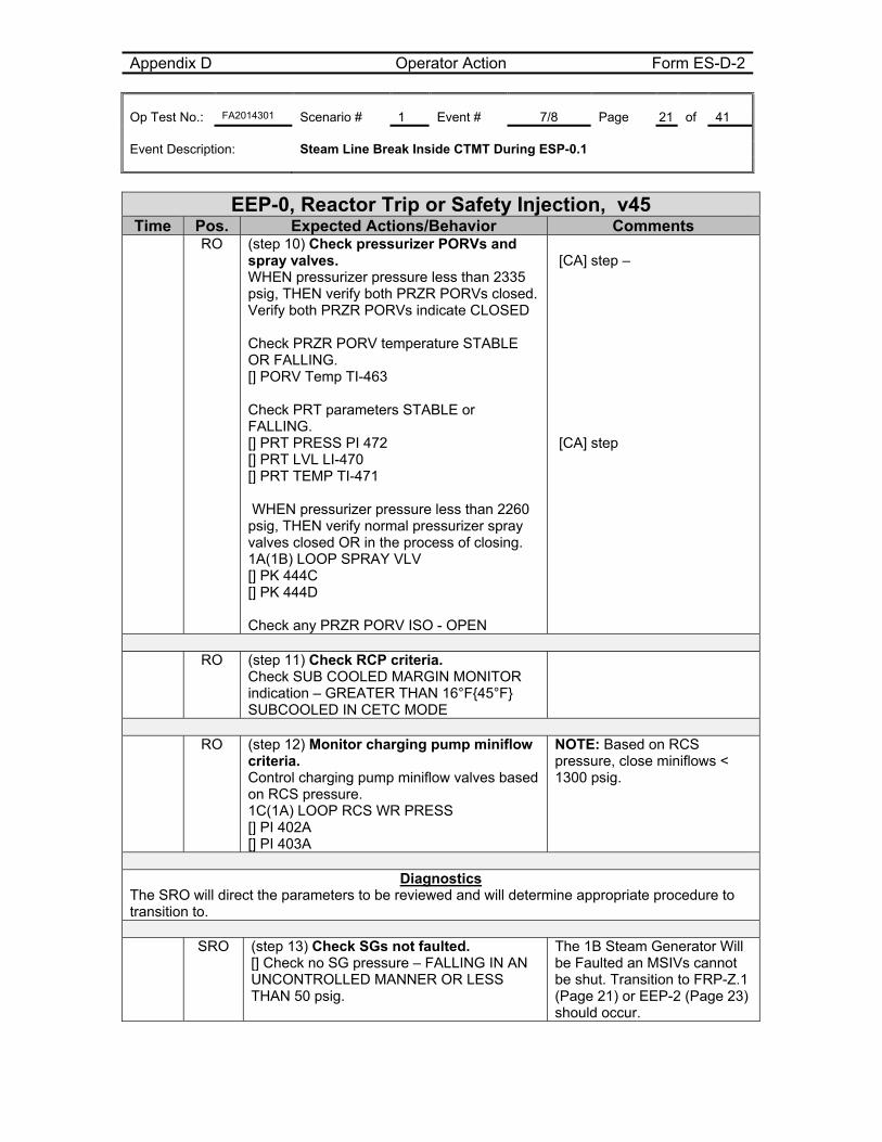
RO (step 10) Check pressurizer PORVs and spray valves. WHEN pressurizer pressure less than 2335 psig, THEN verify both PRZR PORVs closed. Verify both PRZR PORVs indicate CLOSED Check PRZR PORV temperature STABLE OR FALLING. [] PORV Temp TI-463 Check PRT parameters STABLE or FALLING. [] PRT PRESS PI 472 [] PRT LVL LI-470 [] PRT TEMP TI-471 WHEN pressurizer pressure less than 2260 psig, THEN verify normal pressurizer spray valves closed OR in the process of closing. 1A(1B) LOOP SPRAY VLV [] PK 444C [] PK 444D Check any PRZR PORV ISO - OPEN
[CA] step – [CA] step
RO (step 11) Check RCP criteria.
Check SUB COOLED MARGIN MONITOR indication – GREATER THAN 16°F{45°F} SUBCOOLED IN CETC MODE
RO (step 12) Monitor charging pump miniflow
criteria. Control charging pump miniflow valves based on RCS pressure. 1C(1A) LOOP RCS WR PRESS [] PI 402A [] PI 403A
NOTE: Based on RCS pressure, close miniflows < 1300 psig.
Diagnostics
The SRO will direct the parameters to be reviewed and will determine appropriate procedure to transition to.
SRO (step 13) Check SGs not faulted. [] Check no SG pressure – FALLING IN AN UNCONTROLLED MANNER OR LESS THAN 50 psig.
The 1B Steam Generator Will be Faulted an MSIVs cannot be shut. Transition to FRP-Z.1 (Page 21) or EEP-2 (Page 23) should occur.
Appendix D Operator Action Form ES-D-2 Op Test No.: FA2014301 Scenario # 1 Event # 7/8 Page 22 of 41 Event Description: Steam Line Break Inside CTMT During ESP-0.1
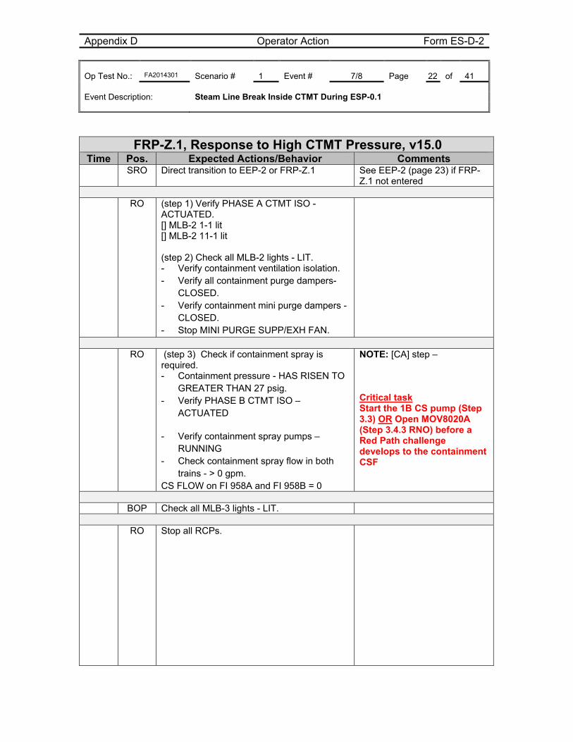
FRP-Z.1, Response to High CTMT Pressure, v15.0 Time Pos. Expected Actions/Behavior Comments SRO Direct transition to EEP-2 or FRP-Z.1 See EEP-2 (page 23) if FRP-
Z.1 not entered RO (step 1) Verify PHASE A CTMT ISO -
ACTUATED. [] MLB-2 1-1 lit [] MLB-2 11-1 lit (step 2) Check all MLB-2 lights - LIT. - Verify containment ventilation isolation. - Verify all containment purge dampers-
CLOSED. - Verify containment mini purge dampers -
CLOSED. - Stop MINI PURGE SUPP/EXH FAN.
RO (step 3) Check if containment spray is
required. - Containment pressure - HAS RISEN TO
GREATER THAN 27 psig. - Verify PHASE B CTMT ISO –
ACTUATED
- Verify containment spray pumps – RUNNING
- Check containment spray flow in both trains - > 0 gpm.
CS FLOW on FI 958A and FI 958B = 0
NOTE: [CA] step – Critical task Start the 1B CS pump (Step 3.3) OR Open MOV8020A (Step 3.4.3 RNO) before a Red Path challenge develops to the containment CSF
BOP Check all MLB-3 lights - LIT. RO Stop all RCPs.
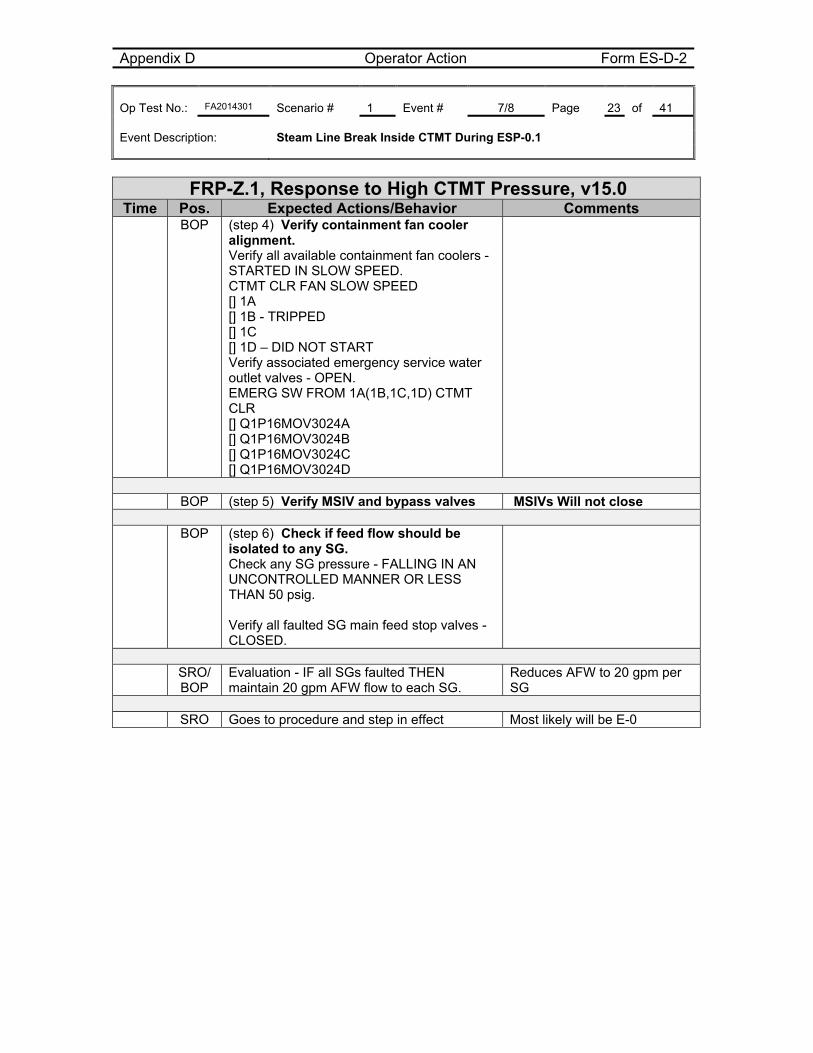
Appendix D Operator Action Form ES-D-2 Op Test No.: FA2014301 Scenario # 1 Event # 7/8 Page 23 of 41 Event Description: Steam Line Break Inside CTMT During ESP-0.1
FRP-Z.1, Response to High CTMT Pressure, v15.0 Time Pos. Expected Actions/Behavior Comments BOP (step 4) Verify containment fan cooler
alignment. Verify all available containment fan coolers - STARTED IN SLOW SPEED. CTMT CLR FAN SLOW SPEED [] 1A [] 1B - TRIPPED [] 1C [] 1D – DID NOT START Verify associated emergency service water outlet valves - OPEN. EMERG SW FROM 1A(1B,1C,1D) CTMT CLR [] Q1P16MOV3024A [] Q1P16MOV3024B [] Q1P16MOV3024C [] Q1P16MOV3024D
BOP (step 5) Verify MSIV and bypass valves MSIVs Will not close BOP (step 6) Check if feed flow should be
isolated to any SG. Check any SG pressure - FALLING IN AN UNCONTROLLED MANNER OR LESS THAN 50 psig. Verify all faulted SG main feed stop valves - CLOSED.
SRO/
BOP Evaluation - IF all SGs faulted THEN maintain 20 gpm AFW flow to each SG.
Reduces AFW to 20 gpm per SG
SRO Goes to procedure and step in effect Most likely will be E-0
Appendix D Operator Action Form ES-D-2 Op Test No.: FA2014301 Scenario # 1 Event # 7/8 Page 24 of 41 Event Description: Steam Line Break Inside CTMT During ESP-0.1
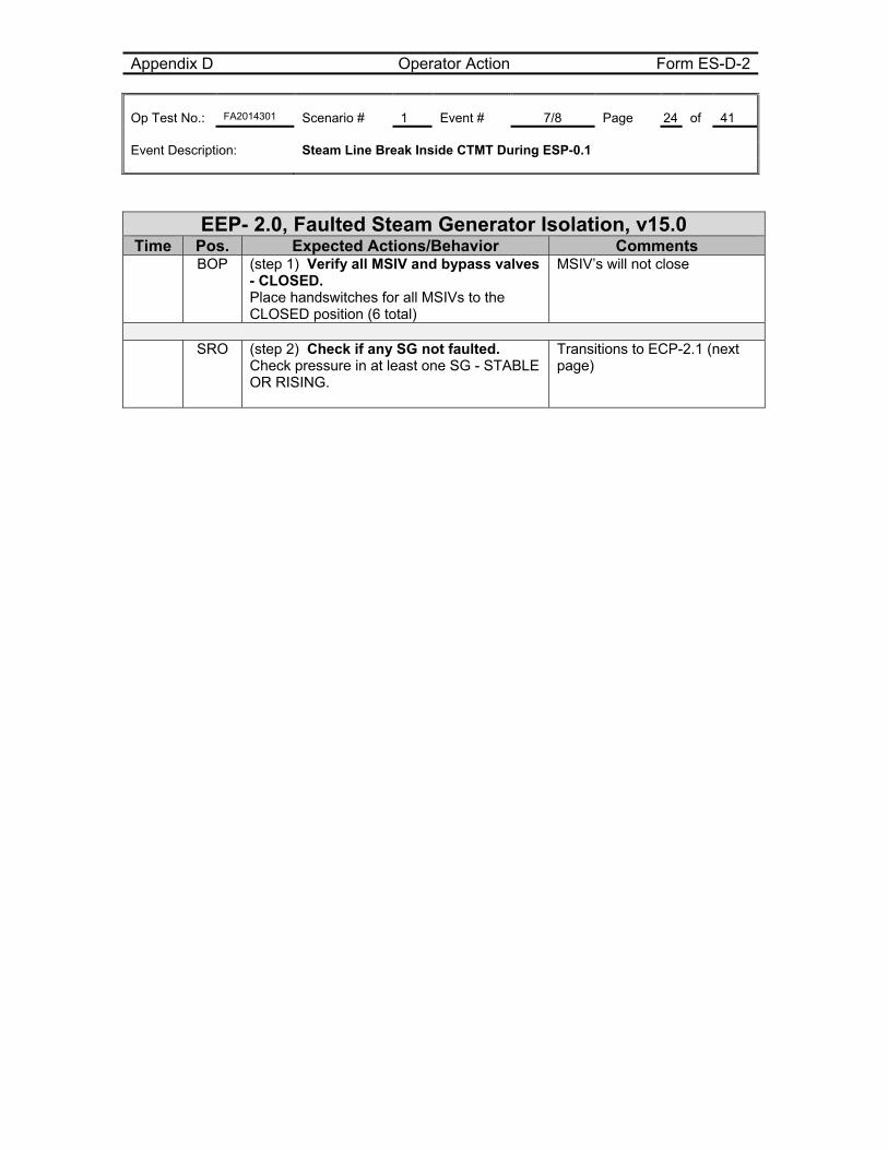
EEP- 2.0, Faulted Steam Generator Isolation, v15.0 Time Pos. Expected Actions/Behavior Comments BOP (step 1) Verify all MSIV and bypass valves
- CLOSED. Place handswitches for all MSIVs to the CLOSED position (6 total)
MSIV’s will not close
SRO (step 2) Check if any SG not faulted.
Check pressure in at least one SG - STABLE OR RISING.
Transitions to ECP-2.1 (next page)
Appendix D Operator Action Form ES-D-2 Op Test No.: FA2014301 Scenario # 1 Event # 7/8 Page 25 of 41 Event Description: Steam Line Break Inside CTMT During ESP-0.1
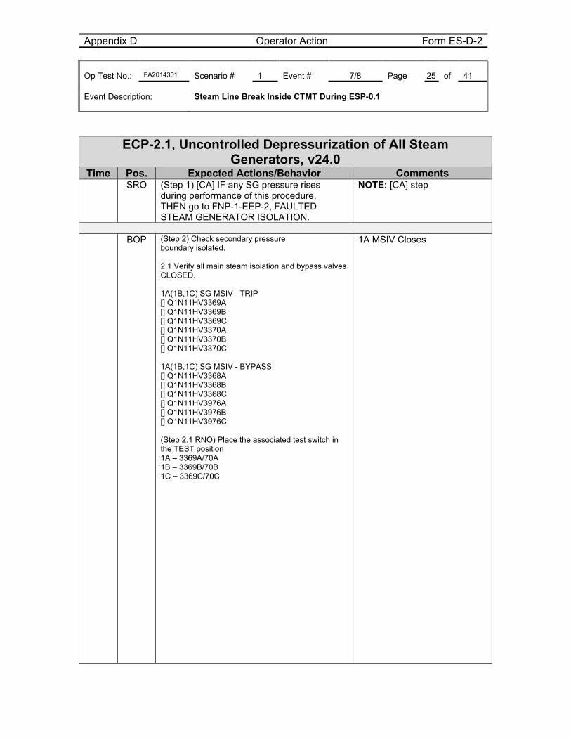
ECP-2.1, Uncontrolled Depressurization of All Steam Generators, v24.0
Time Pos. Expected Actions/Behavior Comments SRO (Step 1) [CA] IF any SG pressure rises
during performance of this procedure, THEN go to FNP-1-EEP-2, FAULTED STEAM GENERATOR ISOLATION.
NOTE: [CA] step
BOP (Step 2) Check secondary pressure
boundary isolated. 2.1 Verify all main steam isolation and bypass valves CLOSED. 1A(1B,1C) SG MSIV - TRIP [] Q1N11HV3369A [] Q1N11HV3369B [] Q1N11HV3369C [] Q1N11HV3370A [] Q1N11HV3370B [] Q1N11HV3370C 1A(1B,1C) SG MSIV - BYPASS [] Q1N11HV3368A [] Q1N11HV3368B [] Q1N11HV3368C [] Q1N11HV3976A [] Q1N11HV3976B [] Q1N11HV3976C (Step 2.1 RNO) Place the associated test switch in the TEST position 1A – 3369A/70A 1B – 3369B/70B 1C – 3369C/70C
1A MSIV Closes
Appendix D Operator Action Form ES-D-2 Op Test No.: FA2014301 Scenario # 1 Event # 7/8 Page 26 of 41 Event Description: Steam Line Break Inside CTMT During ESP-0.1
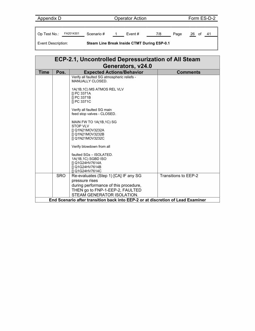
ECP-2.1, Uncontrolled Depressurization of All Steam Generators, v24.0
Time Pos. Expected Actions/Behavior Comments Verify all faulted SG atmospheric reliefs -
MANUALLY CLOSED. 1A(1B,1C) MS ATMOS REL VLV [] PC 3371A [] PC 3371B [] PC 3371C Verify all faulted SG main feed stop valves - CLOSED. MAIN FW TO 1A(1B,1C) SG STOP VLV [] Q1N21MOV3232A [] Q1N21MOV3232B [] Q1N21MOV3232C Verify blowdown from all faulted SGs – ISOLATED. 1A(1B,1C) SGBD ISO [] Q1G24HV7614A [] Q1G24HV7614B [] Q1G24HV7614C
SRO Re-evaluates (Step 1) [CA] IF any SG pressure rises during performance of this procedure, THEN go to FNP-1-EEP-2, FAULTED STEAM GENERATOR ISOLATION.
Transitions to EEP-2
End Scenario after transition back into EEP-2 or at discretion of Lead Examiner
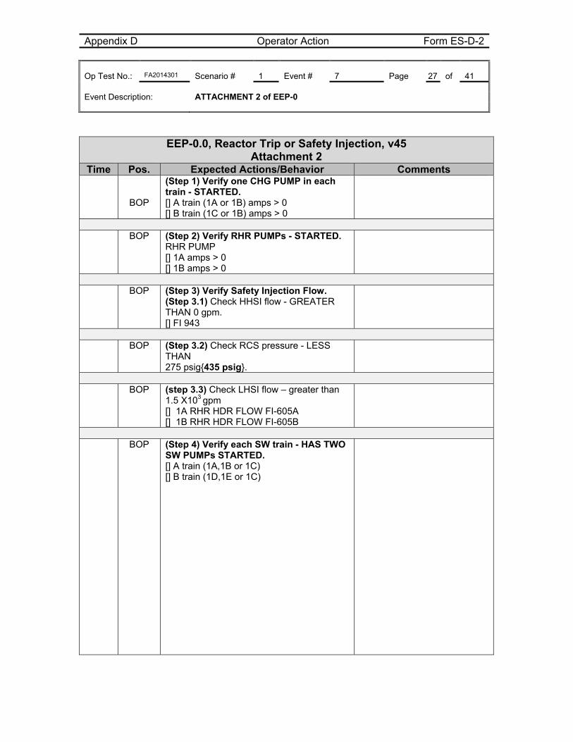
Appendix D Operator Action Form ES-D-2 Op Test No.: FA2014301 Scenario # 1 Event # 7 Page 27 of 41 Event Description: ATTACHMENT 2 of EEP-0
EEP-0.0, Reactor Trip or Safety Injection, v45
Attachment 2 Time Pos. Expected Actions/Behavior Comments
BOP
(Step 1) Verify one CHG PUMP in each train - STARTED. [] A train (1A or 1B) amps > 0 [] B train (1C or 1B) amps > 0
BOP (Step 2) Verify RHR PUMPs - STARTED.
RHR PUMP [] 1A amps > 0 [] 1B amps > 0
BOP (Step 3) Verify Safety Injection Flow.
(Step 3.1) Check HHSI flow - GREATER THAN 0 gpm. [] FI 943
BOP (Step 3.2) Check RCS pressure - LESS
THAN 275 psig{435 psig}.
BOP (step 3.3) Check LHSI flow – greater than
1.5 X10³ gpm [] 1A RHR HDR FLOW FI-605A [] 1B RHR HDR FLOW FI-605B
BOP (Step 4) Verify each SW train - HAS TWO
SW PUMPs STARTED. [] A train (1A,1B or 1C) [] B train (1D,1E or 1C)
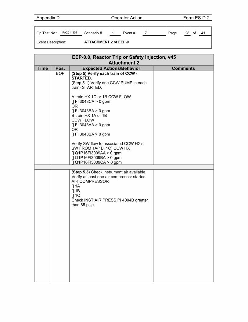
Appendix D Operator Action Form ES-D-2 Op Test No.: FA2014301 Scenario # 1 Event # 7 Page 28 of 41 Event Description: ATTACHMENT 2 of EEP-0
EEP-0.0, Reactor Trip or Safety Injection, v45 Attachment 2
Time Pos. Expected Actions/Behavior Comments BOP (Step 5) Verify each train of CCW -
STARTED. (Step 5.1) Verify one CCW PUMP in each train- STARTED. A train HX 1C or 1B CCW FLOW [] FI 3043CA > 0 gpm OR [] FI 3043BA > 0 gpm B train HX 1A or 1B CCW FLOW [] FI 3043AA > 0 gpm OR [] FI 3043BA > 0 gpm Verify SW flow to associated CCW HX's SW FROM 1A(1B, 1C) CCW HX [] Q1P16FI3009AA > 0 gpm [] Q1P16FI3009BA > 0 gpm [] Q1P16FI3009CA > 0 gpm
(Step 5.3) Check instrument air available.
Verify at least one air compressor started. AIR COMPRESSOR [] 1A [] 1B [] 1C Check INST AIR PRESS PI 4004B greater than 85 psig.
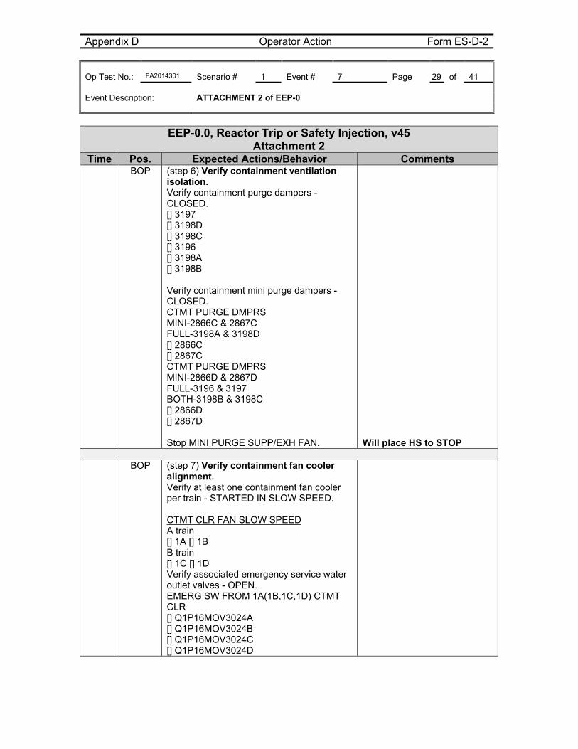
Appendix D Operator Action Form ES-D-2 Op Test No.: FA2014301 Scenario # 1 Event # 7 Page 29 of 41 Event Description: ATTACHMENT 2 of EEP-0
EEP-0.0, Reactor Trip or Safety Injection, v45 Attachment 2
Time Pos. Expected Actions/Behavior Comments BOP (step 6) Verify containment ventilation
isolation. Verify containment purge dampers - CLOSED. [] 3197 [] 3198D [] 3198C [] 3196 [] 3198A [] 3198B Verify containment mini purge dampers - CLOSED. CTMT PURGE DMPRS MINI-2866C & 2867C FULL-3198A & 3198D [] 2866C [] 2867C CTMT PURGE DMPRS MINI-2866D & 2867D FULL-3196 & 3197 BOTH-3198B & 3198C [] 2866D [] 2867D Stop MINI PURGE SUPP/EXH FAN.
Will place HS to STOP
BOP (step 7) Verify containment fan cooler
alignment. Verify at least one containment fan cooler per train - STARTED IN SLOW SPEED. CTMT CLR FAN SLOW SPEED A train [] 1A [] 1B B train [] 1C [] 1D Verify associated emergency service water outlet valves - OPEN. EMERG SW FROM 1A(1B,1C,1D) CTMT CLR [] Q1P16MOV3024A [] Q1P16MOV3024B [] Q1P16MOV3024C [] Q1P16MOV3024D
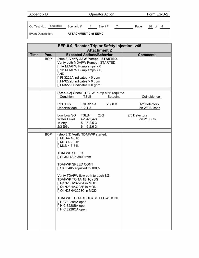
Appendix D Operator Action Form ES-D-2 Op Test No.: FA2014301 Scenario # 1 Event # 7 Page 30 of 41 Event Description: ATTACHMENT 2 of EEP-0
EEP-0.0, Reactor Trip or Safety Injection, v45 Attachment 2
Time Pos. Expected Actions/Behavior Comments BOP (step 8) Verify AFW Pumps - STARTED.
Verify both MDAFW Pumps - STARTED [] 1A MDAFW Pump amps > 0 [] 1B MDAFW Pump amps > 0 AND [] FI-3229A indicates > 0 gpm [] FI-3229B indicates > 0 gpm [] FI-3229C indicates > 0 gpm
(Step 8.2) Check TDAFW Pump start required.
�Condition �TSLB �Setpoint �Coincidence� RCP Bus TSLB2 1-1 �2680 V 1/2 Detectors Undervoltage 1-2 1-3 on 2/3 Busses Low Low SG TSLB4 28% 2/3 Detectors Water Level 4-1,4-2,4-3 on 2/3 SGs In Any 5-1,5-2,5-3 2/3 SGs 6-1,6-2,6-3
BOP (step 8.3) Verify TDAFWP started.
[] MLB-4 1-3 lit [] MLB-4 2-3 lit [] MLB-4 3-3 lit TDAFWP SPEED [] SI 3411A > 3900 rpm TDAFWP SPEED CONT [] SIC 3405 adjusted to 100% Verify TDAFW flow path to each SG. TDAFWP TO 1A(1B,1C) SG [] Q1N23HV3228A in MOD [] Q1N23HV3228B in MOD [] Q1N23HV3228C in MOD TDAFWP TO 1A(1B,1C) SG FLOW CONT [] HIC 3228AA open [] HIC 3228BA open [] HIC 3228CA open
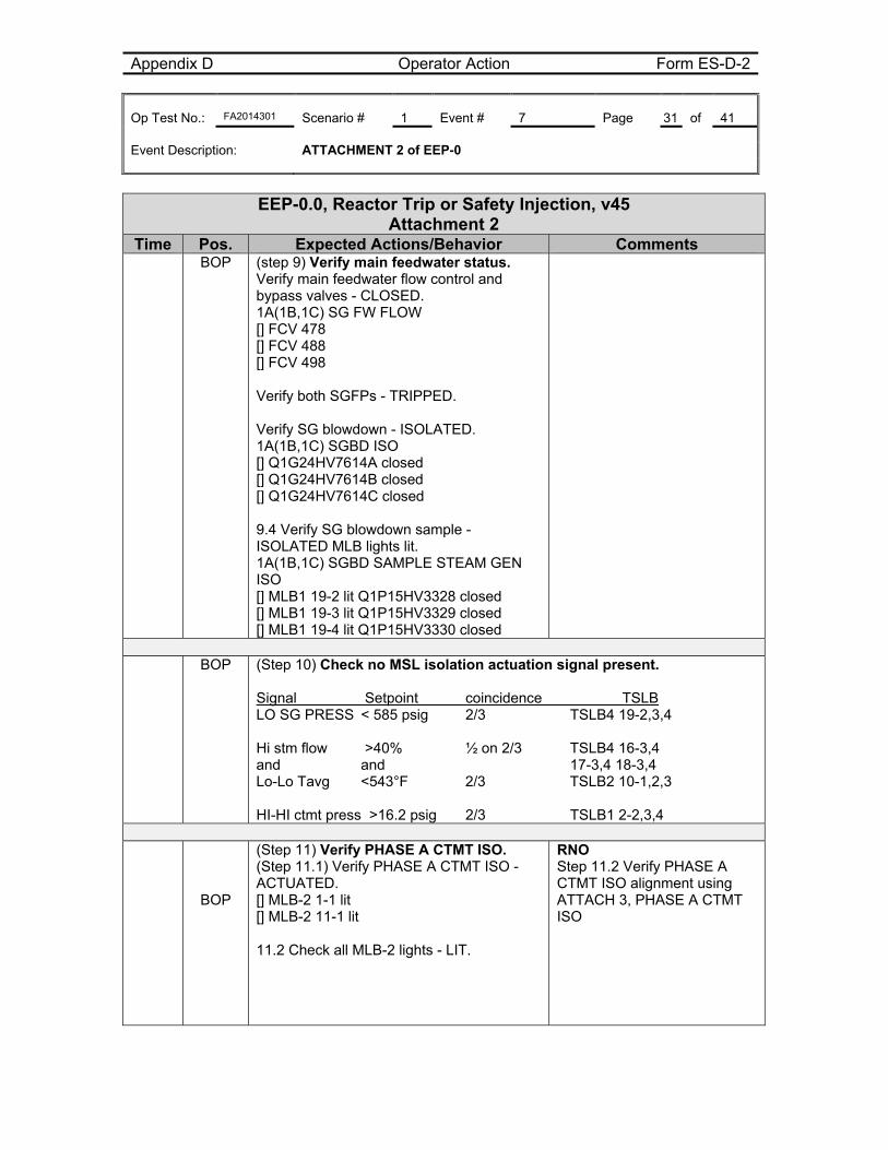
Appendix D Operator Action Form ES-D-2 Op Test No.: FA2014301 Scenario # 1 Event # 7 Page 31 of 41 Event Description: ATTACHMENT 2 of EEP-0
EEP-0.0, Reactor Trip or Safety Injection, v45 Attachment 2
Time Pos. Expected Actions/Behavior Comments BOP (step 9) Verify main feedwater status.
Verify main feedwater flow control and bypass valves - CLOSED. 1A(1B,1C) SG FW FLOW [] FCV 478 [] FCV 488 [] FCV 498 Verify both SGFPs - TRIPPED. Verify SG blowdown - ISOLATED. 1A(1B,1C) SGBD ISO [] Q1G24HV7614A closed [] Q1G24HV7614B closed [] Q1G24HV7614C closed 9.4 Verify SG blowdown sample - ISOLATED MLB lights lit. 1A(1B,1C) SGBD SAMPLE STEAM GEN ISO [] MLB1 19-2 lit Q1P15HV3328 closed [] MLB1 19-3 lit Q1P15HV3329 closed [] MLB1 19-4 lit Q1P15HV3330 closed
BOP (Step 10) Check no MSL isolation actuation signal present.
Signal Setpoint coincidence TSLB LO SG PRESS < 585 psig 2/3 TSLB4 19-2,3,4 Hi stm flow >40% ½ on 2/3 TSLB4 16-3,4 and and 17-3,4 18-3,4 Lo-Lo Tavg <543°F 2/3 TSLB2 10-1,2,3 HI-HI ctmt press >16.2 psig 2/3 TSLB1 2-2,3,4
BOP
(Step 11) Verify PHASE A CTMT ISO. (Step 11.1) Verify PHASE A CTMT ISO - ACTUATED. [] MLB-2 1-1 lit [] MLB-2 11-1 lit 11.2 Check all MLB-2 lights - LIT.
RNO Step 11.2 Verify PHASE A CTMT ISO alignment using ATTACH 3, PHASE A CTMT ISO
Appendix D Operator Action Form ES-D-2 Op Test No.: FA2014301 Scenario # 1 Event # 7 Page 32 of 41 Event Description: ATTACHMENT 2 of EEP-0
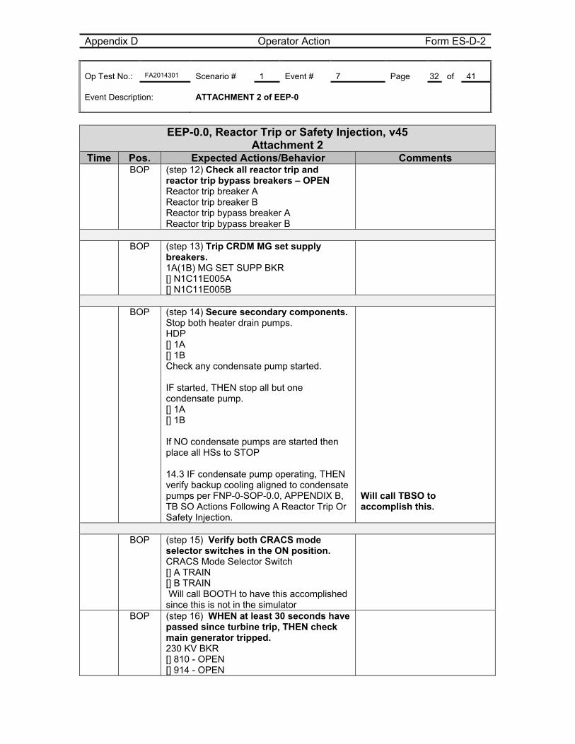
EEP-0.0, Reactor Trip or Safety Injection, v45 Attachment 2
Time Pos. Expected Actions/Behavior Comments BOP (step 12) Check all reactor trip and
reactor trip bypass breakers – OPEN Reactor trip breaker A Reactor trip breaker B Reactor trip bypass breaker A Reactor trip bypass breaker B
BOP (step 13) Trip CRDM MG set supply
breakers. 1A(1B) MG SET SUPP BKR [] N1C11E005A [] N1C11E005B
BOP (step 14) Secure secondary components.
Stop both heater drain pumps. HDP [] 1A [] 1B Check any condensate pump started. IF started, THEN stop all but one condensate pump. [] 1A [] 1B If NO condensate pumps are started then place all HSs to STOP 14.3 IF condensate pump operating, THEN verify backup cooling aligned to condensate pumps per FNP-0-SOP-0.0, APPENDIX B, TB SO Actions Following A Reactor Trip Or Safety Injection.
Will call TBSO to accomplish this.
BOP (step 15) Verify both CRACS mode
selector switches in the ON position. CRACS Mode Selector Switch [] A TRAIN [] B TRAIN Will call BOOTH to have this accomplished since this is not in the simulator
BOP (step 16) WHEN at least 30 seconds have passed since turbine trip, THEN check main generator tripped. 230 KV BKR [] 810 - OPEN [] 914 - OPEN
Appendix D Operator Action Form ES-D-2 Op Test No.: FA2014301 Scenario # 1 Event # 7 Page 33 of 41 Event Description: ATTACHMENT 2 of EEP-0
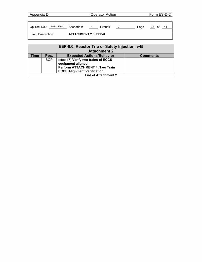
EEP-0.0, Reactor Trip or Safety Injection, v45 Attachment 2
Time Pos. Expected Actions/Behavior Comments BOP (step 17) Verify two trains of ECCS
equipment aligned. Perform ATTACHMENT 4, Two Train ECCS Alignment Verification.
End of Attachment 2
Appendix D Operator Action Form ES-D-2 Op Test No.: FA2014301 Scenario # 1 Event # 7 Page 34 of 41 Event Description: ATTACHMENT 2 of EEP-0
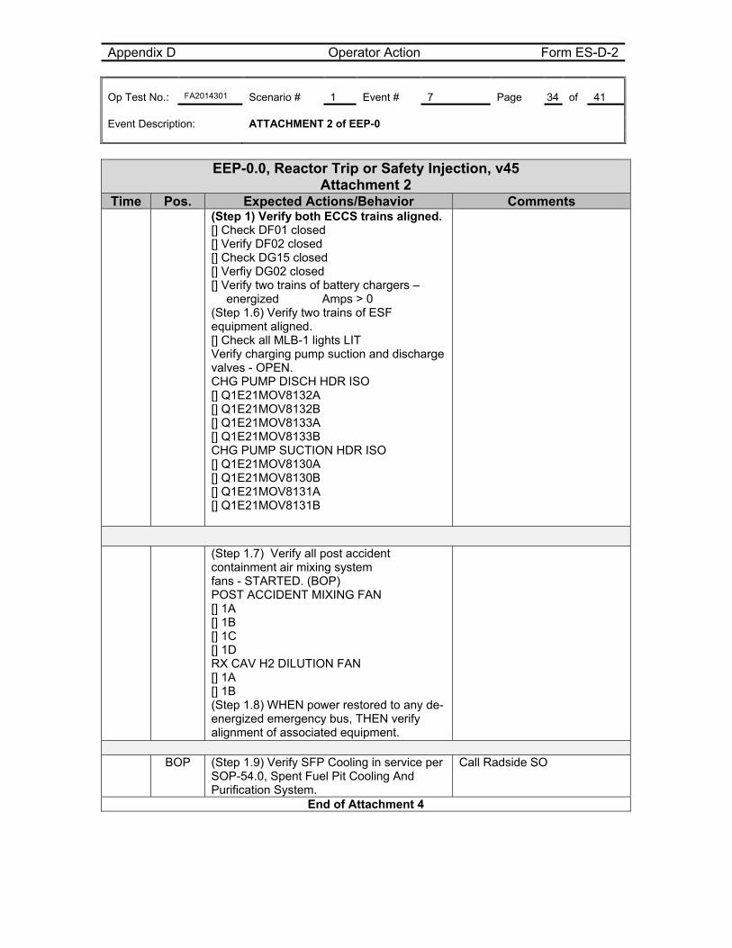
EEP-0.0, Reactor Trip or Safety Injection, v45 Attachment 2
Time Pos. Expected Actions/Behavior Comments (Step 1) Verify both ECCS trains aligned.
[] Check DF01 closed [] Verify DF02 closed [] Check DG15 closed [] Verfiy DG02 closed [] Verify two trains of battery chargers – energized Amps > 0 (Step 1.6) Verify two trains of ESF equipment aligned. [] Check all MLB-1 lights LIT Verify charging pump suction and discharge valves - OPEN. CHG PUMP DISCH HDR ISO [] Q1E21MOV8132A [] Q1E21MOV8132B [] Q1E21MOV8133A [] Q1E21MOV8133B CHG PUMP SUCTION HDR ISO [] Q1E21MOV8130A [] Q1E21MOV8130B [] Q1E21MOV8131A [] Q1E21MOV8131B
(Step 1.7) Verify all post accident containment air mixing system fans - STARTED. (BOP) POST ACCIDENT MIXING FAN [] 1A [] 1B [] 1C [] 1D RX CAV H2 DILUTION FAN [] 1A [] 1B (Step 1.8) WHEN power restored to any de-energized emergency bus, THEN verify alignment of associated equipment.
BOP (Step 1.9) Verify SFP Cooling in service per
SOP-54.0, Spent Fuel Pit Cooling And Purification System.
Call Radside SO
End of Attachment 4
Appendix D Operator Action Form ES-D-2 Op Test No.: FA2014301 Scenario # Event # Page 35 of 41 Event Description: Attachment 5 of EEP-0
EEP-0.0, Reactor Trip or Safety Injection, v45
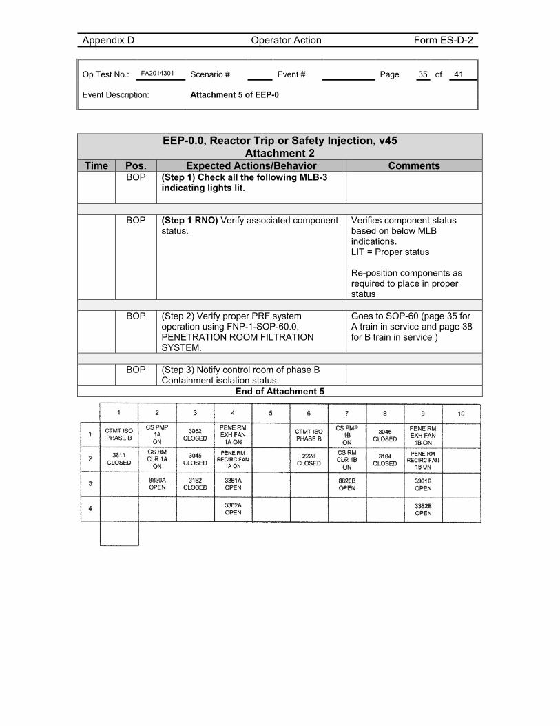
Attachment 2 Time Pos. Expected Actions/Behavior Comments BOP (Step 1) Check all the following MLB-3
indicating lights lit.
BOP (Step 1 RNO) Verify associated component
status.
Verifies component status based on below MLB indications. LIT = Proper status Re-position components as required to place in proper status
BOP (Step 2) Verify proper PRF system
operation using FNP-1-SOP-60.0, PENETRATION ROOM FILTRATION SYSTEM.
Goes to SOP-60 (page 35 for A train in service and page 38 for B train in service )
BOP (Step 3) Notify control room of phase B
Containment isolation status.
End of Attachment 5
Appendix D Operator Action Form ES-D-2 Op Test No.: FA2014301 Scenario # Event # Page 36 of 41 Event Description: Attachment 5 of EEP-0
SOP-60.0, Penetration Room Filtration, v35 A Train
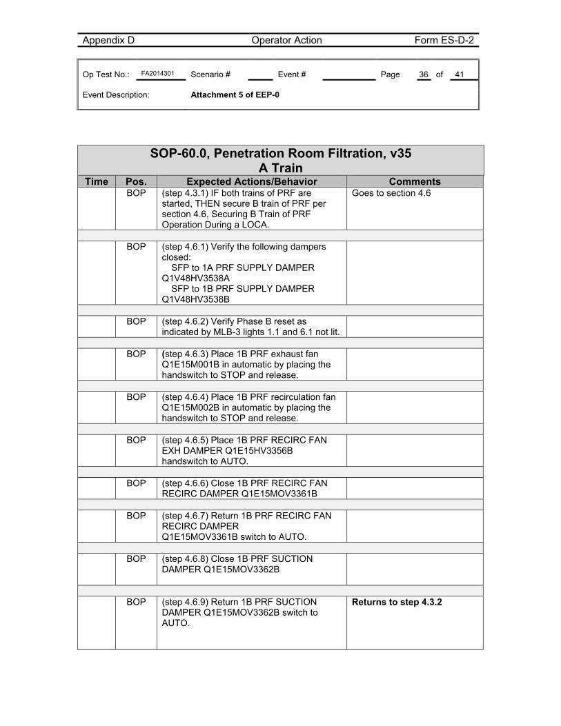
Time Pos. Expected Actions/Behavior Comments BOP (step 4.3.1) IF both trains of PRF are
started, THEN secure B train of PRF per section 4.6, Securing B Train of PRF Operation During a LOCA.
Goes to section 4.6
BOP (step 4.6.1) Verify the following dampers
closed: � SFP to 1A PRF SUPPLY DAMPER Q1V48HV3538A � SFP to 1B PRF SUPPLY DAMPER Q1V48HV3538B
BOP (step 4.6.2) Verify Phase B reset as
indicated by MLB-3 lights 1.1 and 6.1 not lit.
BOP (step 4.6.3) Place 1B PRF exhaust fan
Q1E15M001B in automatic by placing the handswitch to STOP and release.
BOP (step 4.6.4) Place 1B PRF recirculation fan
Q1E15M002B in automatic by placing the handswitch to STOP and release.
BOP (step 4.6.5) Place 1B PRF RECIRC FAN
EXH DAMPER Q1E15HV3356B handswitch to AUTO.
BOP (step 4.6.6) Close 1B PRF RECIRC FAN
RECIRC DAMPER Q1E15MOV3361B
BOP (step 4.6.7) Return 1B PRF RECIRC FAN
RECIRC DAMPER Q1E15MOV3361B switch to AUTO.
BOP (step 4.6.8) Close 1B PRF SUCTION
DAMPER Q1E15MOV3362B
BOP (step 4.6.9) Return 1B PRF SUCTION
DAMPER Q1E15MOV3362B switch to AUTO.
Returns to step 4.3.2
Appendix D Operator Action Form ES-D-2 Op Test No.: FA2014301 Scenario # Event # Page 37 of 41 Event Description: Attachment 5 of EEP-0
SOP-60.0, Penetration Room Filtration, v35 A Train
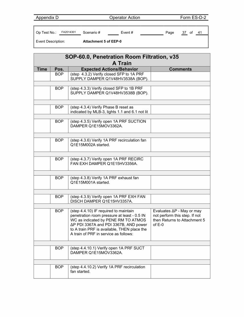
Time Pos. Expected Actions/Behavior Comments BOP (step 4.3.2) Verify closed SFP to 1A PRF
SUPPLY DAMPER Q1V48HV3538A (BOP).
BOP (step 4.3.3) Verify closed SFP to 1B PRF
SUPPLY DAMPER Q1V48HV3538B (BOP).
BOP (step 4.3.4) Verify Phase B reset as
indicated by MLB-3, lights 1.1 and 6.1 not lit
BOP (step 4.3.5) Verify open 1A PRF SUCTION
DAMPER Q1E15MOV3362A.
BOP (step 4.3.6) Verify 1A PRF recirculation fan
Q1E15M002A started.
BOP (step 4.3.7) Verify open 1A PRF RECIRC
FAN EXH DAMPER Q1E15HV3356A.
BOP (step 4.3.8) Verify 1A PRF exhaust fan
Q1E15M001A started.
BOP (step 4.3.9) Verify open 1A PRF EXH FAN
DISCH DAMPER Q1E15HV3357A.
BOP (step 4.4.10) IF required to maintain
penetration room pressure at least - 0.5 IN WC as indicated by PENE RM TO ATMOS ∆P PDI 3367A and PDI 3367B, AND power to A train PRF is available, THEN place the A train of PRF in service as follows:
Evaluates ∆P - May or may not perform this step. If not then Returns to Attachment 5 of E-0
BOP (step 4.4.10.1) Verify open 1A PRF SUCT
DAMPER Q1E15MOV3362A.
BOP (step 4.4.10.2) Verify 1A PRF recirculation
fan started.
Appendix D Operator Action Form ES-D-2 Op Test No.: FA2014301 Scenario # Event # Page 38 of 41 Event Description: Attachment 5 of EEP-0
SOP-60.0, Penetration Room Filtration, v35 A Train
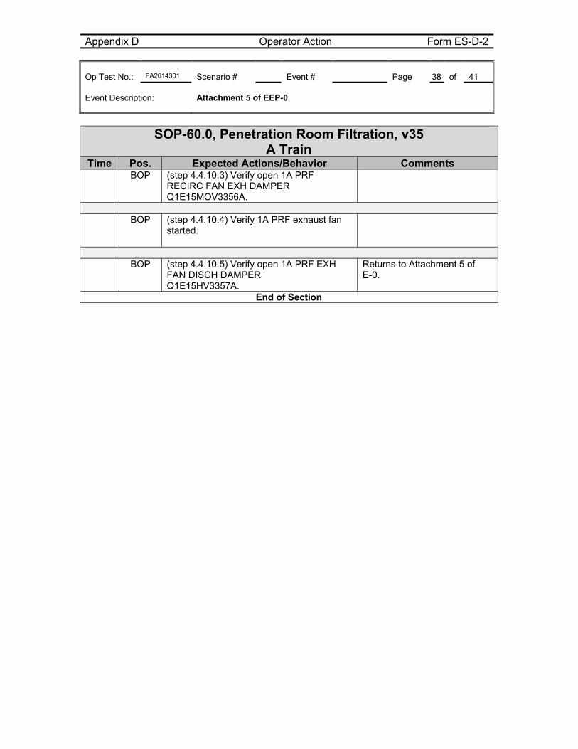
Time Pos. Expected Actions/Behavior Comments BOP (step 4.4.10.3) Verify open 1A PRF
RECIRC FAN EXH DAMPER Q1E15MOV3356A.
BOP (step 4.4.10.4) Verify 1A PRF exhaust fan
started.
BOP (step 4.4.10.5) Verify open 1A PRF EXH
FAN DISCH DAMPER Q1E15HV3357A.
Returns to Attachment 5 of E-0.
End of Section
Appendix D Operator Action Form ES-D-2 Op Test No.: FA2014301 Scenario # Event # Page 39 of 41 Event Description: Attachment 5 of EEP-0
SOP-60.0, Penetration Room Filtration, v35 B Train
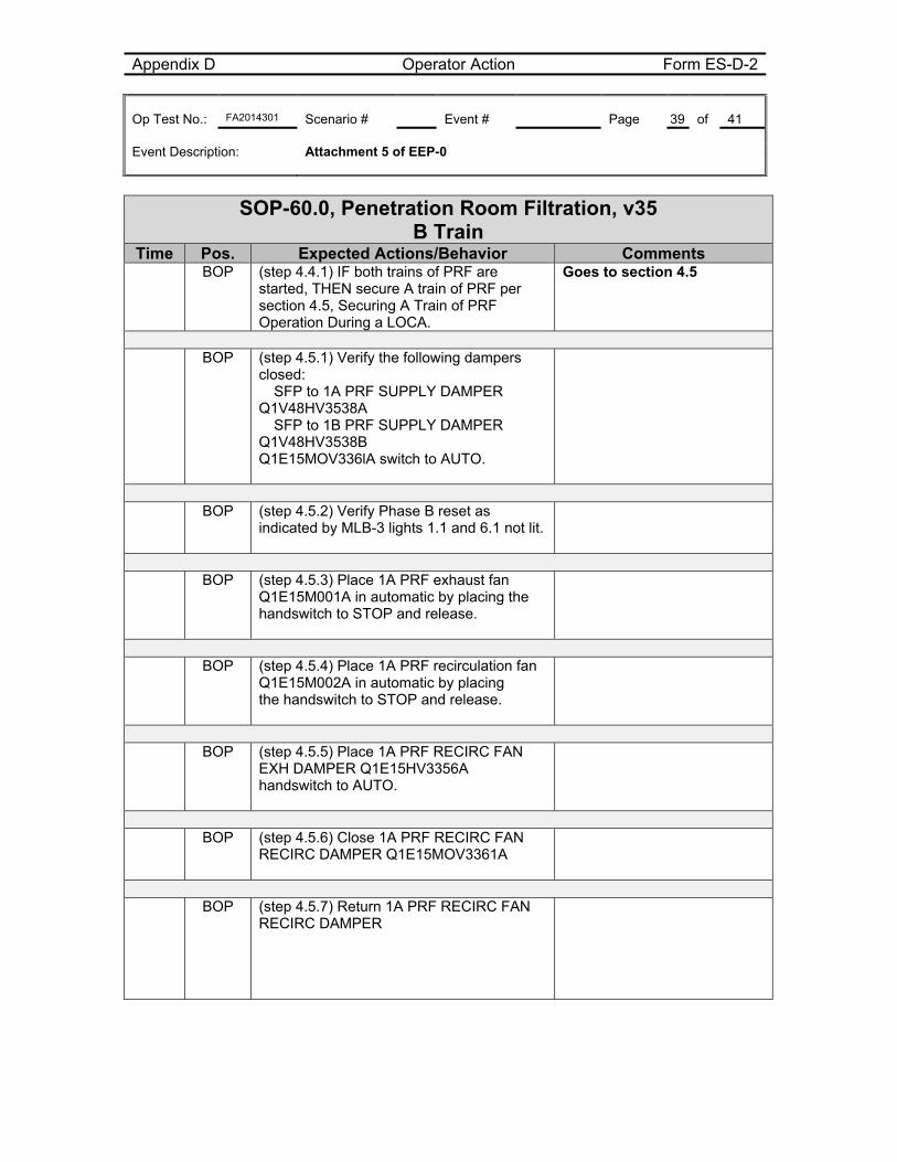
Time Pos. Expected Actions/Behavior Comments BOP (step 4.4.1) IF both trains of PRF are
started, THEN secure A train of PRF per section 4.5, Securing A Train of PRF Operation During a LOCA.
Goes to section 4.5
BOP (step 4.5.1) Verify the following dampers
closed: � SFP to 1A PRF SUPPLY DAMPER Q1V48HV3538A � SFP to 1B PRF SUPPLY DAMPER Q1V48HV3538B Q1E15MOV336lA switch to AUTO.
BOP (step 4.5.2) Verify Phase B reset as
indicated by MLB-3 lights 1.1 and 6.1 not lit.
BOP (step 4.5.3) Place 1A PRF exhaust fan
Q1E15M001A in automatic by placing the handswitch to STOP and release.
BOP (step 4.5.4) Place 1A PRF recirculation fan
Q1E15M002A in automatic by placing the handswitch to STOP and release.
BOP (step 4.5.5) Place 1A PRF RECIRC FAN
EXH DAMPER Q1E15HV3356A handswitch to AUTO.
BOP (step 4.5.6) Close 1A PRF RECIRC FAN
RECIRC DAMPER Q1E15MOV3361A
BOP (step 4.5.7) Return 1A PRF RECIRC FAN
RECIRC DAMPER
Appendix D Operator Action Form ES-D-2 Op Test No.: FA2014301 Scenario # Event # Page 40 of 41 Event Description: Attachment 5 of EEP-0
SOP-60.0, Penetration Room Filtration, v35 B Train
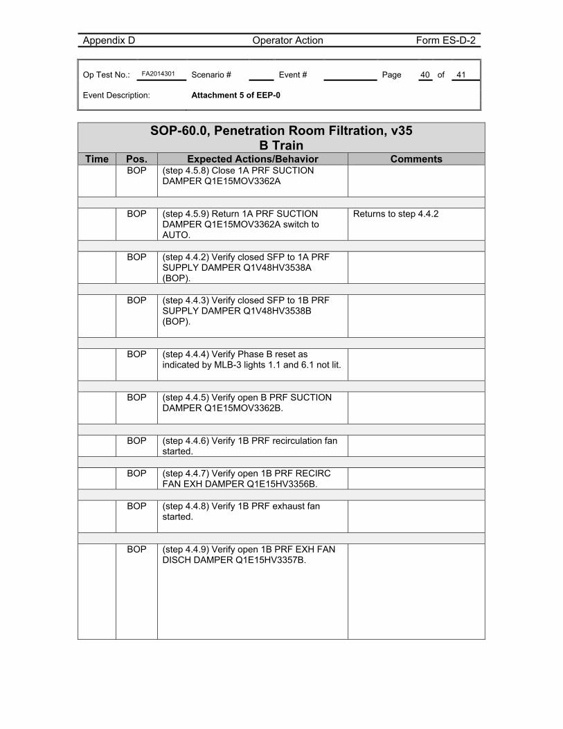
Time Pos. Expected Actions/Behavior Comments BOP (step 4.5.8) Close 1A PRF SUCTION
DAMPER Q1E15MOV3362A
BOP (step 4.5.9) Return 1A PRF SUCTION
DAMPER Q1E15MOV3362A switch to AUTO.
Returns to step 4.4.2
BOP (step 4.4.2) Verify closed SFP to 1A PRF
SUPPLY DAMPER Q1V48HV3538A (BOP).
BOP (step 4.4.3) Verify closed SFP to 1B PRF
SUPPLY DAMPER Q1V48HV3538B (BOP).
BOP (step 4.4.4) Verify Phase B reset as
indicated by MLB-3 lights 1.1 and 6.1 not lit.
BOP (step 4.4.5) Verify open B PRF SUCTION
DAMPER Q1E15MOV3362B.
BOP (step 4.4.6) Verify 1B PRF recirculation fan
started.
BOP (step 4.4.7) Verify open 1B PRF RECIRC
FAN EXH DAMPER Q1E15HV3356B.
BOP (step 4.4.8) Verify 1B PRF exhaust fan
started.
BOP (step 4.4.9) Verify open 1B PRF EXH FAN
DISCH DAMPER Q1E15HV3357B.
Appendix D Operator Action Form ES-D-2 Op Test No.: FA2014301 Scenario # Event # Page 41 of 41 Event Description: Attachment 5 of EEP-0
SOP-60.0, Penetration Room Filtration, v35 B Train
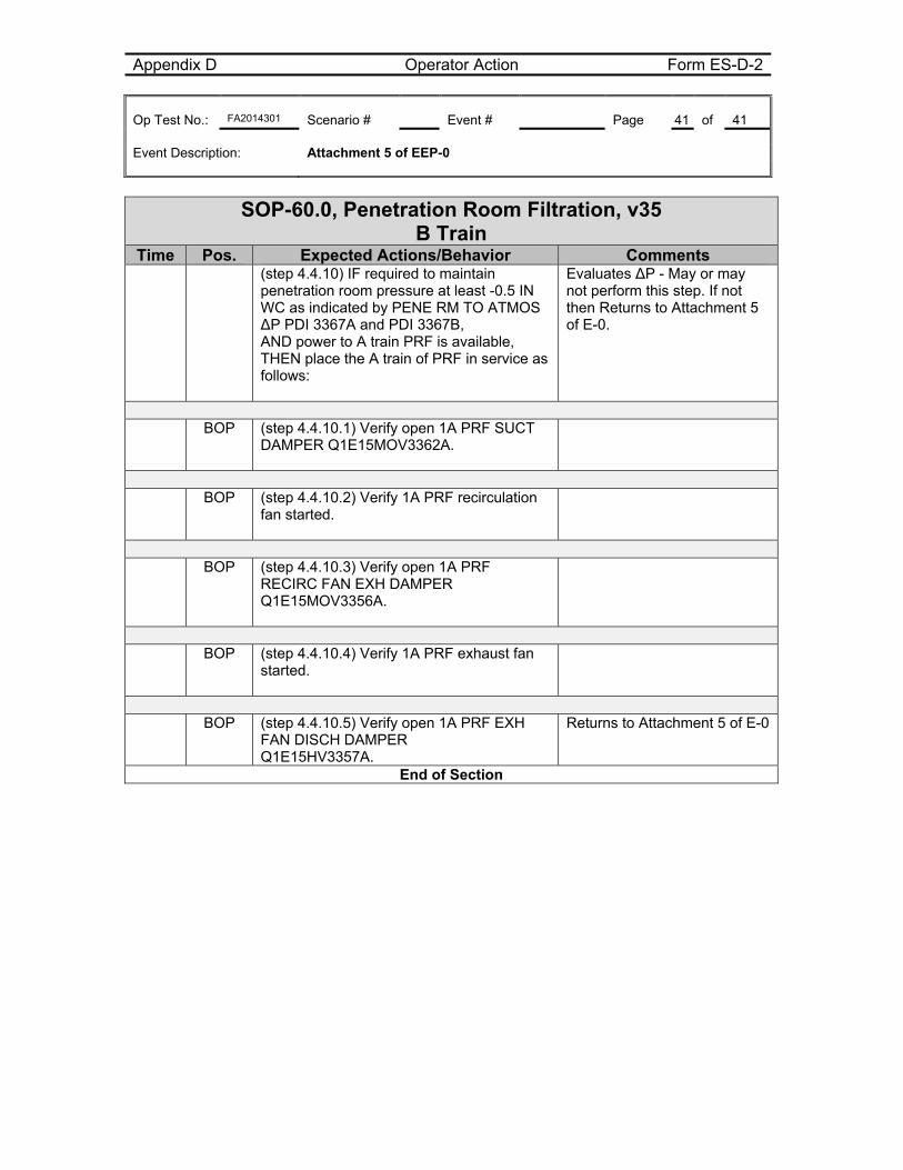
Time Pos. Expected Actions/Behavior Comments (step 4.4.10) IF required to maintain
penetration room pressure at least -0.5 IN WC as indicated by PENE RM TO ATMOS ∆P PDI 3367A and PDI 3367B, AND power to A train PRF is available, THEN place the A train of PRF in service as follows:
Evaluates ∆P - May or may not perform this step. If not then Returns to Attachment 5 of E-0.
BOP (step 4.4.10.1) Verify open 1A PRF SUCT
DAMPER Q1E15MOV3362A.
BOP (step 4.4.10.2) Verify 1A PRF recirculation
fan started.
BOP (step 4.4.10.3) Verify open 1A PRF
RECIRC FAN EXH DAMPER Q1E15MOV3356A.
BOP (step 4.4.10.4) Verify 1A PRF exhaust fan
started.
BOP (step 4.4.10.5) Verify open 1A PRF EXH
FAN DISCH DAMPER Q1E15HV3357A.
Returns to Attachment 5 of E-0
End of Section

Appendix D Crew Briefing sheet Form ES-D-3
Op-Test No.: FA2014301 Page 1 of 2
Brief
This simulator performance scenario is performed in the EVALUATION MODE. You should not
direct questions to the evaluators. Otherwise, you should perform as if you were in the MCR.
Your ability to maintain a log is not being graded, but maintaining a rough log is recommended to
help during briefs.
If you need to communicate with the Unit 2 operator, call Unit 2 at 2434 or page the Unit 2 Unit
Operator.
Respond to what you see. If there is a problem with the simulation, the session will be terminated or
adjusted as appropriate based on the specific problem.
Assign operating positions.
Ask for and answer questions.
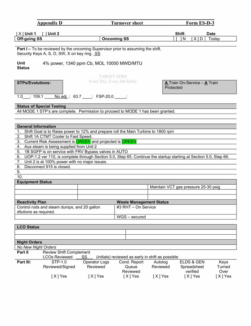
Appendix D Turnover sheet Form ES-D-3
[ X ] Unit 1 [ ] Unit 2 Shift: Date Off-going SS Oncoming SS [ ] N [ X ] D Today Part I – To be reviewed by the oncoming Supervisor prior to assuming the shift. Security Keys A, S, D, SW, X on key ring . SS Unit Status
4% power, 1340 ppm Cb, MOL 10000 MWD/MTU
STPs/Evolutions:
A Train On-Service – A Train Protected
1.0 ; 109.1 No adj. ; 63.7 ; FSP-20,0 ; Status of Special Testing All MODE 1 STP’s are complete. Permission to proceed to MODE 1 has been granted. General Information 1. Shift Goal is to Raise power to 12% and prepare roll the Main Turbine to 1800 rpm 2. Shift 1A CTMT Cooler to Fast Speed. 3. Current Risk Assessment is GREEN and projected is GREEN 4. Aux steam is being supplied from Unit 2 5. 1B SGFP is on service with FRV Bypass valves in AUTO 6. UOP-1.2 ver 110, is complete through Section 5.0, Step 65. Continue the startup starting at Section 5.0, Step 66. 7. Unit 2 is at 100% power with no major issues. 8. Disconnect 915 is closed. 9. 10. Equipment Status Maintain VCT gas pressure 25-30 psig Reactivity Plan Waste Management Status Control rods and steam dumps, and 20 gallon dilutions as required.
#3 RHT – On Service
WGS – secured LCO Status Night Orders No New Night Orders Part II Review Shift Complement LCOs Reviewed SS (initials) reviewed as early in shift as possible Part III: STP-1.0
Reviewed/Signed Operator Logs
Reviewed Cond. Report
Queue Reviewed
Autolog Reviewed
ELDS & GEN Spreadsheet
verified
Keys Turned Over
[ X ] Yes [ X ] Yes [ X ] Yes [ X ] Yes [ X ] Yes [ X ] Yes
TARGET ZERO Every Day, Every Job Safely

Unit One Reactivity Briefing Sheet
RCS Temp 549.0 °F Current RCS Borations / Dilutions:RX PWR 4.0 % Borate DiluteCurrent Xenon Concentration 2277 PCM 0 Gal. 20 Gal.
Burnup 10000 MWD/MTU Reactivity Additions: 0.00 4.08 PCMAs of (Date & Time) 10/2/2013 1:00 Total Reactivity Addition: 4.08 PCMCalculated Burnup 10596 MWD/MTU Net RCS Temperature Effect: 1.01 °F
As Of 9/23/14 1133 Net Rx Power Effect: 0.23 %Assumes constant power sinceLast Power history update Boron Worth
RCS Boron 1340 PPM Power DefectBAT Concentration 7350 PPM MTC
Current Bank Boric Acid Required for Power reductionDelta Rod Position: 164 Steps With no Control rod movement
Rod Worth DeltaPower
Power Defect (PCM) Delta PPM
Acid Required (Gallons)
Steps Out 1.00% 18 2.07 17One 6 PCM 2.00% 35 4.14 34Two 12 PCM 5.00% N/A N/A N/AFive 30 PCM 10.00% N/A N/A N/ATen 64 PCM 20.00% N/A N/A N/ATwenty 140 PCM 25.00% N/A N/A N/AFifty 410 PCM 50.00% N/A N/A N/A
75.00% N/A N/A N/ASteps In 100.00% N/A N/A N/AOne -6 PCMTwo -12 PCMFive -29 PCM a/o w/oTen -56 PCM RCS B-10 ratio 17.98 16.6Twenty -105 PCM BAT B-10 ratio 20.1 18.6Fifty -236 PCM NDR B-10 ratio 19.8 18.3
RCS Blended Flow Makeup RequirementsAcid to Borate 1 PPM (Gal.)
RMW to dilute 1 PPM( Gal.)
Required Acid flow Rate (GPM)
FK-113 Pot Setting
Values for Normal Auto M/U (Bat-100 ppm boron)
8.4 Gal. 37.1 Gal. 22.2 GPM
Values based on Actual Bat Concentration
8.3 Gal. 37.1 Gal. 21.9 GPM
Valid For Unit One cycle 24 26Core Physics Curves:Curve 5 Rev 29Curve 27 Rev 28Curve 34 Rev 46Curve 57 Rev 35Curve 57A Rev 25
5.44
-8.34 PCM/PPM70 PCM
-4.05 PCM/°F
5.53
Copy of U1 reactivity sheetPrinted by 9/23/2014 @ 11:34 AM
Version 5.2
Scenario #1 FA2014301
Southern Nuclear J.M. Farley Nuclear Plant
Operations Training Simulator Exam Scenario
BOOTH INSTRUCTOR GUIDE
ILT-37 NRC EXAM SCENARIO #1
Validation time: 100 minutes Validated by: Sorrell, Newell, Smith
TRN Supervisor Approval: Billy Thornton Date: 9/24/14
NRC Chief Examiner SEE NUREG 1021 FORM ES-301-3

Appendix D Scenario #1 Outline Form ES-D-1
Farley October 2014 exam Page 2 of 8
Facility: Farley Nuclear Plant Scenario No.: 1 Op-Test No.: FA2014-301
Examiners: Operators: SRO
RO
BOP
Initial Conditions: 4% power, UOP-1.2, v110, completed thru step 5.65. Ready to perform step 5.66. MOL, 1340ppm Cb; 1BSGFP on service. Aux steam from U-2.
Turnover: 1B SGFP is on service, MFR bypass valves are on service. Current Risk Assessment is GREEN and projected to remain GREEN. A Train O/S, A Train protected. Thunderstorm warnings in effect for Southeast Alabama & Western Georgia
SPLIT TRAIN ALIGNMENT
Event No.
Malf. No.
Event Type* Event Description
1 R (RO) N (BOP)
Raise Power to 12% using control rods and steam dumps.
2 N (BOP) Start 1A CTMT Cooler in Fast
3 Imf fk122-A
C (RO)
FK-122 Fails open in Auto(P – CT)
4 imf mal-rmsip35
A / preset
I (BOP) TS (SRO)
R-35A Fails high, automatic actions do not occur T.S. 3.3.7 Cond A
5 imf pt508
I (BOP) PT-508 Fails high(P – CT)
6 imf
crcrcp1_cc3
C (RO)
TS (SRO)
1A RCP trips(P – CT) T.S. 3.4.4 Cond A
7 Imf mal-mss1B / Preset
M (ALL) C (RO)
Steam break inside containment, MSIV’s will not close, Automatic SI is blocked (CT-2)
8 Preset /
dmf crsh001c_cc5
C (BOP)
1B CS pump does not auto start. (*CT-3) MOV 8820A does not open. (*CT-3) *1 CS spray pump required (Orange Path on Z until CS established) After ECP 2.1 entry and 27psig in containment MSIV’s close.
Terminate on transition out of ECP-2.1 to EEP-2 or examiners discretion
(N)ormal, (R)eactivity, (I)nstrument, (C)omponent, (M)ajor
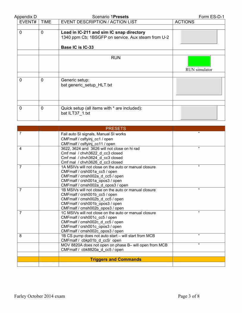
Appendix D Scenario 1Presets Form ES-D-1
Farley October 2014 exam Page 3 of 8
EVENT# TIME EVENT DESCRIPTION / ACTION LIST ACTIONS 0 0 Load in IC-211 and sim IC snap directory
1340 ppm Cb; 1BSGFP on service. Aux steam from U-2 Base IC is IC-33
RUN
RUN simulator
0 0 Generic setup:
bat generic_setup_HLT.txt
0 0 Quick setup (all items with * are included):
bat ILT37_1.txt
PRESETS 7 Fail auto SI signals, Manual SI works
CMFmalf / csftyinj_cc1 / open CMFmalf / csftyinj_cc11 / open
*
4 3622, 3624 and 3626 will not close on hi rad Cmf mal / chvh3622_d_cc3 closed Cmf mal / chvh3624_d_cc3 closed Cmf mal / chvh3626_d_cc3 closed
*
7 1A MSIVs will not close on the auto or manual closure CMFmalf / crsh001a_cc5 / open CMFmalf / cmsh002a_d_cc5 / open CMFmalf / crsh001a_opos3 / open CMFmalf / cmsh002a_d_opos3 / open
*
7 1B MSIVs will not close on the auto or manual closure CMFmalf / crsh001b_cc5 / open CMFmalf / cmsh002b_d_cc5 / open CMFmalf / crsh001b_opos3 / open CMFmalf / cmsh002b_opos3 / open
*
7 1C MSIVs will not close on the auto or manual closure CMFmalf / crsh001c_cc5 / open CMFmalf / cmsh002c_d_cc5 / open CMFmalf / crsh001c_opos3 / open CMFmalf / cmsh002c_opos3 / open
*
8 1B CS pump does not auto start – will start from MCB CMFmalf / cbkp01b_d_cc5/ open
*
MOV 8820A does not open on phase B– will open from MCB CMFmalf / cbk8820a_d_cc5 / open
*
Triggers and Commands
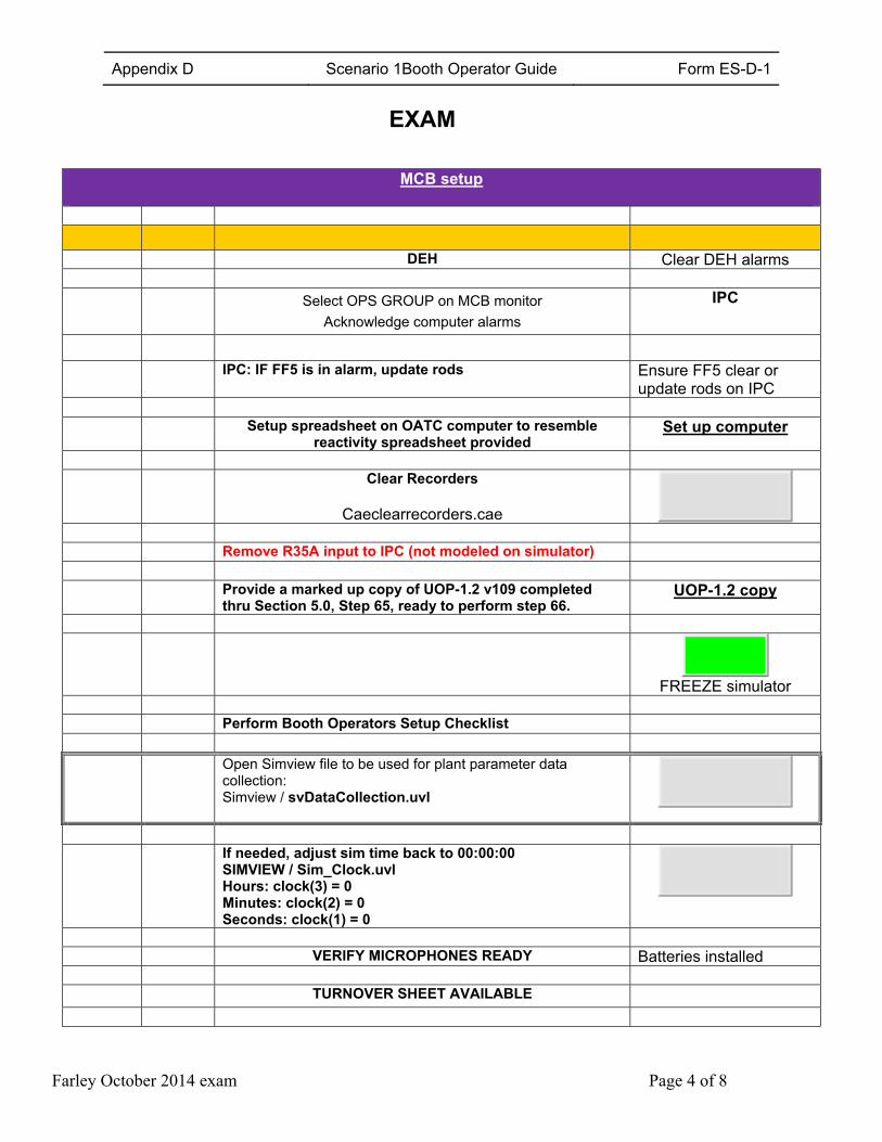
Appendix D Scenario 1Booth Operator Guide Form ES-D-1
Farley October 2014 exam Page 4 of 8
EXAM
MCB setup
DEH Clear DEH alarms Select OPS GROUP on MCB monitor
Acknowledge computer alarms
IPC
IPC: IF FF5 is in alarm, update rods Ensure FF5 clear or update rods on IPC
Setup spreadsheet on OATC computer to resemble
reactivity spreadsheet provided Set up computer
Clear Recorders
Caeclearrecorders.cae
Remove R35A input to IPC (not modeled on simulator) Provide a marked up copy of UOP-1.2 v109 completed
thru Section 5.0, Step 65, ready to perform step 66. UOP-1.2 copy
FREEZE simulator
Perform Booth Operators Setup Checklist Open Simview file to be used for plant parameter data
collection: Simview / svDataCollection.uvl
If needed, adjust sim time back to 00:00:00
SIMVIEW / Sim_Clock.uvl Hours: clock(3) = 0 Minutes: clock(2) = 0 Seconds: clock(1) = 0
VERIFY MICROPHONES READY Batteries installed TURNOVER SHEET AVAILABLE
Appendix D Scenario 1Booth Operator Guide Form ES-D-1
Farley October 2014 exam Page 5 of 8
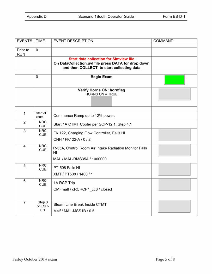
EVENT# TIME EVENT DESCRIPTION COMMAND Prior to RUN
0
Start data collection for Simview file On DataCollection.uvl file press DATA for drop down
and then COLLECT to start collecting data
0 Begin Exam
Verify Horns ON: hornflag HORNS ON = TRUE
1 Start of exam Commence Ramp up to 12% power.
2 NRC CUE Start 1A CTMT Cooler per SOP-12.1, Step 4.1
3 NRC CUE FK 122, Charging Flow Controller, Fails HI
CNH / FK122-A / 0 / 2
4 NRC CUE R-35A, Control Room Air Intake Radiation Monitor Fails
HI
MAL / MAL-RMS35A / 1000000
5 NRC CUE PT-508 Fails HI
XMT / PT508 / 1400 / 1
6 NRC CUE 1A RCP Trip
CMFmalf / cRCRCP1_cc3 / closed
7 Step 3 of ESP-
0.1
Steam Line Break Inside CTMT
Malf / MAL-MSS1B / 0.5
Appendix D Scenario 1Booth Operator Guide Form ES-D-1
Farley October 2014 exam Page 6 of 8
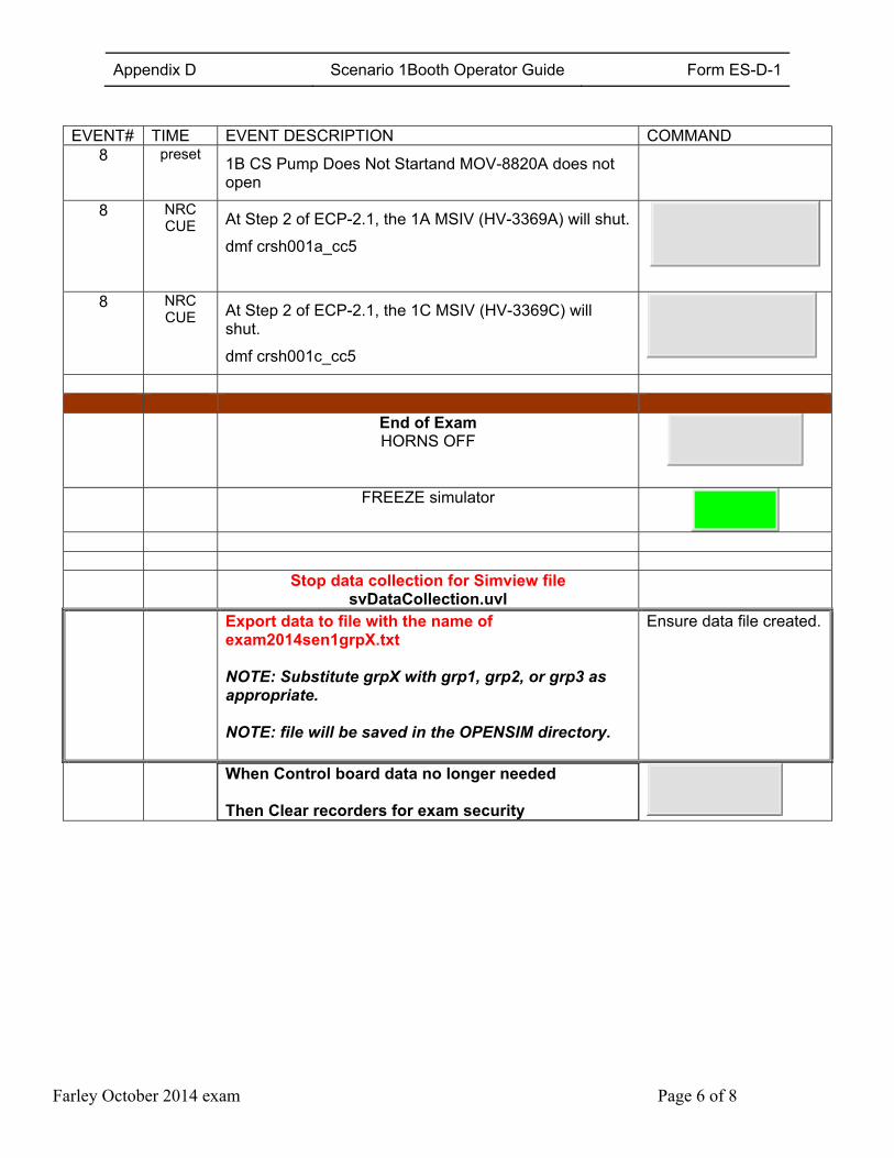
EVENT# TIME EVENT DESCRIPTION COMMAND
8 preset 1B CS Pump Does Not Startand MOV-8820A does not open
8 NRC CUE At Step 2 of ECP-2.1, the 1A MSIV (HV-3369A) will shut.
dmf crsh001a_cc5
8 NRC CUE At Step 2 of ECP-2.1, the 1C MSIV (HV-3369C) will
shut.
dmf crsh001c_cc5
End of Exam
HORNS OFF
FREEZE simulator
Stop data collection for Simview file
svDataCollection.uvl
Export data to file with the name of exam2014sen1grpX.txt
NOTE: Substitute grpX with grp1, grp2, or grp3 as appropriate.
NOTE: file will be saved in the OPENSIM directory.
Ensure data file created.
When Control board data no longer needed Then Clear recorders for exam security
Appendix D Scenario 1Booth Operator Guide Form ES-D-1
Farley October 2014 exam Page 7 of 8
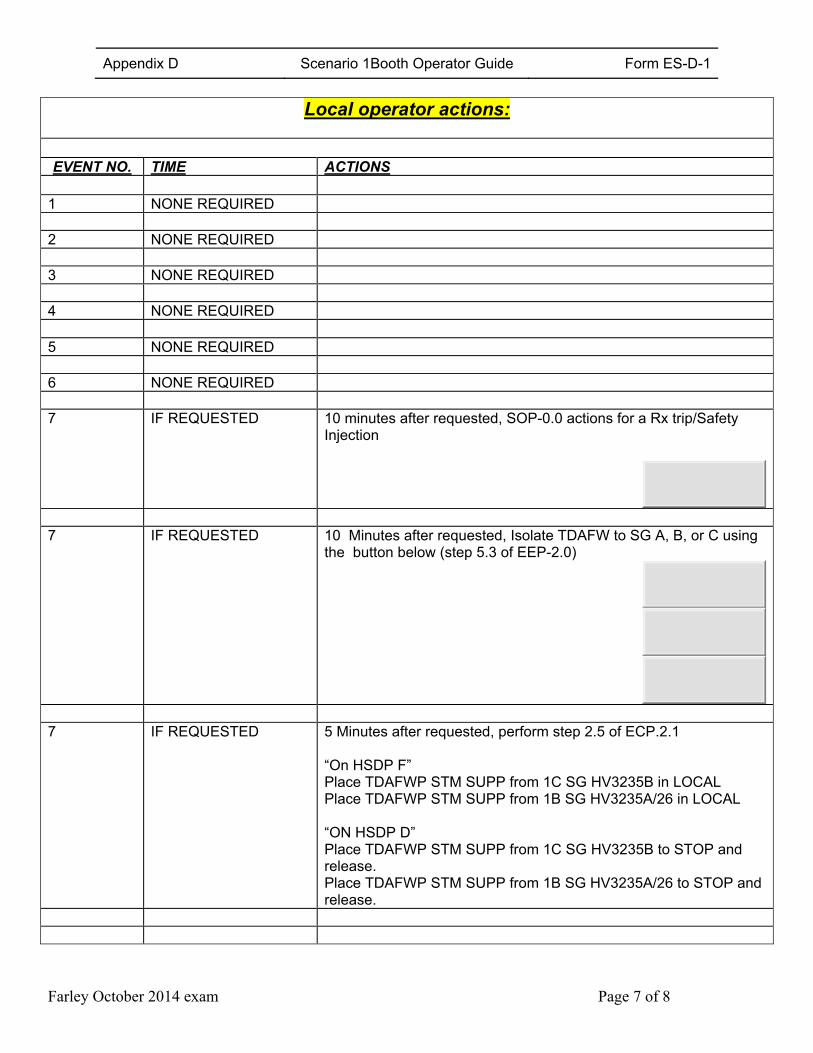
Local operator actions:
EVENT NO. TIME ACTIONS
1 NONE REQUIRED 2 NONE REQUIRED 3 NONE REQUIRED 4 NONE REQUIRED 5 NONE REQUIRED 6 NONE REQUIRED 7 IF REQUESTED 10 minutes after requested, SOP-0.0 actions for a Rx trip/Safety
Injection
7 IF REQUESTED 10 Minutes after requested, Isolate TDAFW to SG A, B, or C using
the button below (step 5.3 of EEP-2.0)
7 IF REQUESTED 5 Minutes after requested, perform step 2.5 of ECP.2.1
“On HSDP F” Place TDAFWP STM SUPP from 1C SG HV3235B in LOCAL Place TDAFWP STM SUPP from 1B SG HV3235A/26 in LOCAL “ON HSDP D” Place TDAFWP STM SUPP from 1C SG HV3235B to STOP and release. Place TDAFWP STM SUPP from 1B SG HV3235A/26 to STOP and release.
Appendix D Scenario 1Booth Operator Guide Form ES-D-1
Farley October 2014 exam Page 8 of 8
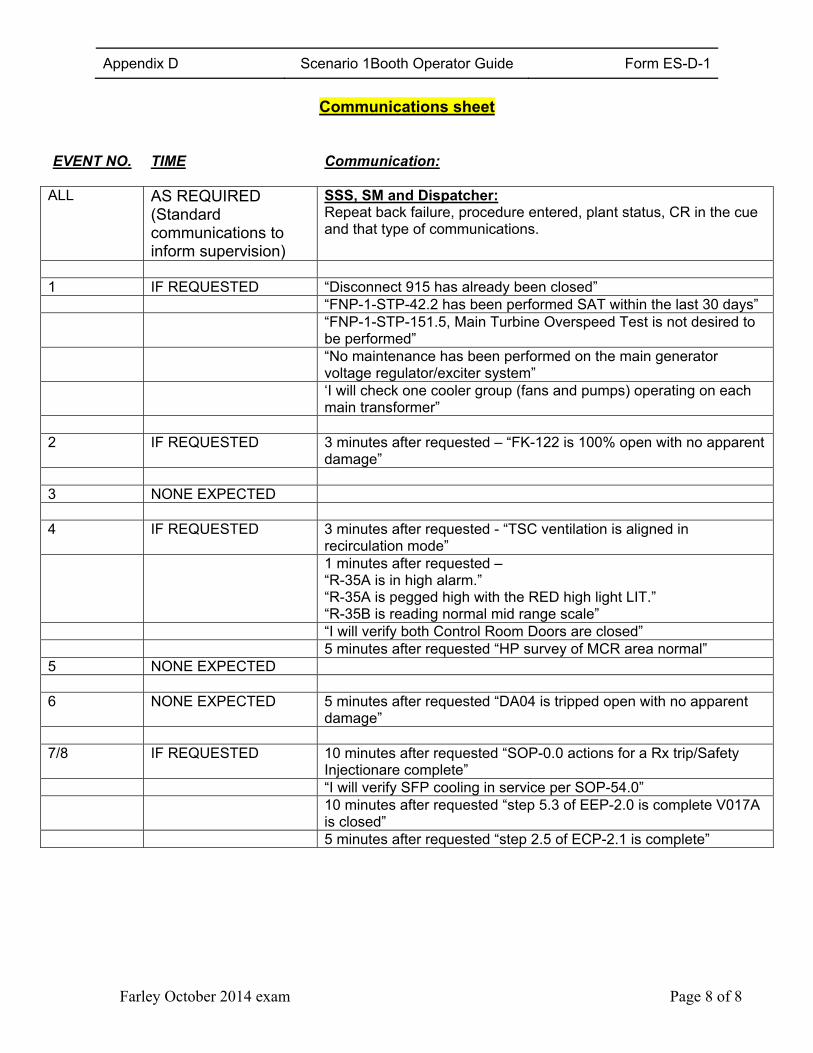
Communications sheet
EVENT NO. TIME Communication:
ALL AS REQUIRED
(Standard communications to inform supervision)
SSS, SM and Dispatcher: Repeat back failure, procedure entered, plant status, CR in the cue and that type of communications.
1 IF REQUESTED “Disconnect 915 has already been closed” “FNP-1-STP-42.2 has been performed SAT within the last 30 days” “FNP-1-STP-151.5, Main Turbine Overspeed Test is not desired to
be performed” “No maintenance has been performed on the main generator
voltage regulator/exciter system” ‘I will check one cooler group (fans and pumps) operating on each
main transformer” 2 IF REQUESTED 3 minutes after requested – “FK-122 is 100% open with no apparent
damage” 3 NONE EXPECTED 4 IF REQUESTED 3 minutes after requested - “TSC ventilation is aligned in
recirculation mode” 1 minutes after requested –
“R-35A is in high alarm.” “R-35A is pegged high with the RED high light LIT.” “R-35B is reading normal mid range scale”
“I will verify both Control Room Doors are closed” 5 minutes after requested “HP survey of MCR area normal” 5 NONE EXPECTED 6 NONE EXPECTED 5 minutes after requested “DA04 is tripped open with no apparent
damage” 7/8 IF REQUESTED 10 minutes after requested “SOP-0.0 actions for a Rx trip/Safety
Injectionare complete” “I will verify SFP cooling in service per SOP-54.0” 10 minutes after requested “step 5.3 of EEP-2.0 is complete V017A
is closed” 5 minutes after requested “step 2.5 of ECP-2.1 is complete”
Appendix D Scenario #2 Outline Form ES-D-1
Farley October 2014 exam Page 1 of 4
Facility: Farley Nuclear Plant Scenario No.: 2 Op-Test No.: FA2014-301
Examiners: Operators: SRO
RO
BOP
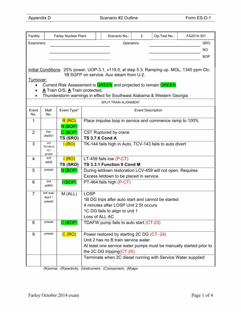
Initial Conditions: 25% power, UOP-3.1, v119.0, at step 5.3. Ramping up. MOL, 1340 ppm Cb; 1B SGFP on service. Aux steam from U-2.
Turnover: Current Risk Assessment is GREEN and projected to remain GREEN. A Train O/S, A Train protected. Thunderstorm warnings in effect for Southeast Alabama & Western Georgia
SPLIT TRAIN ALIGNMENT
Event No.
Malf. No.
Event Type* Event Description
1 R (RO) N (BOP)
Place impulse loop in service and commence ramp to 100%
2 loa-cfw001
C (BOP) TS (SRO)
CST Ruptured by crane TS 3.7.6 Cond A
3 imf TK144-A
10 / preset
I (RO)
TK-144 fails high in Auto, TCV-143 fails to auto divert
4 Imf lt459
I (RO) TS (SRO)
LT-459 fails low (P-CT) TS 3.3.1 Function 9 Cond M
5 preset N (BOP) During letdown restoration LCV-459 will not open. Requires Excess letdown to be placed in service.
6 Imf pt464
I (BOP)
PT-464 fails high (P-CT)
7 Imf mal-eps1 / preset
M (ALL) LOSP 1B DG trips after auto start and cannot be started 4 minutes after LOSP Unit 2 SI occurs 1C DG fails to align to unit 1 Loss of ALL AC
8 preset C (BOP)
TDAFW pump fails to auto start (CT-23)
9 preset C (RO)
Power restored by starting 2C DG (CT- 24) Unit 2 has no B train service water At least one service water pumps must be manually started prior to the 2C DG tripping(CT-25)
Terminate when 2C diesel running with Service Water supplied
(N)ormal, (R)eactivity, (I)nstrument, (C)omponent, (M)ajor
Appendix D Scenario 2 Presets Form ES-D-1
Farley October 2014 exam Page 2 of 4
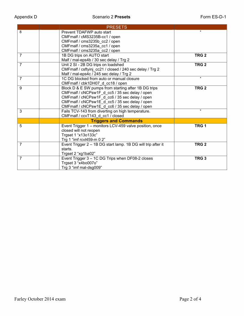
PRESETS 8 Prevent TDAFWP auto start
CMFmalf / cMS3235B-cc1 / open CMFmalf / cms3235b_cc2 / open CMFmalf / cms3235a_cc1 / open CMFmalf / cms3235a_cc2 / open
*
7 1B DG trips on AUTO start Malf / mal-eps4b / 30 sec delay / Trg 2
TRG 2
7 Unit 2 SI - 2B DG trips on loadshed CMFmalf / csftyinj_cc21 / closed / 240 sec delay / Trg 2 Malf / mal-eps4c / 245 sec delay / Trg 2
TRG 2
7 1C DG blocked from auto or manual closure CMFmalf / cbk1DH07_d_cc18 / open
*
9 Block D & E SW pumps from starting after 1B DG trips CMFmalf / cNCPsw1F_d_cc5 / 35 sec delay / open CMFmalf / cNCPsw1F_d_cc6 / 35 sec delay / open CMFmalf / cNCPsw1E_d_cc5 / 35 sec delay / open CMFmalf / cNCPsw1E_d_cc6 / 35 sec delay / open
TRG 2
3 Fails TCV-143 from diverting on high temperature. CMFmalf / ccvT143_d_cc1 / closed
*
Triggers and Commands 5 Event Trigger 1 – monitors LCV-459 valve position, once
closed will not reopen Trgset 1 “x13o133c” Trg 1 “imf rcvl459-m 0 2”
TRG 1
7 Event Trigger 2 – 1B DG start lamp. 1B DG will trip after it starts. Trgset 2 “xg1ba02”
TRG 2
7 Event Trigger 3 – 1C DG Trips when DF08-2 closes Trgset 3 “x4bo007o” Trg 3 “imf mal-dsg009”
TRG 3
Appendix D Scenario 2 detailed summary
sheet Form ES-D-1
Farley June 2014 exam Page 3 of 4
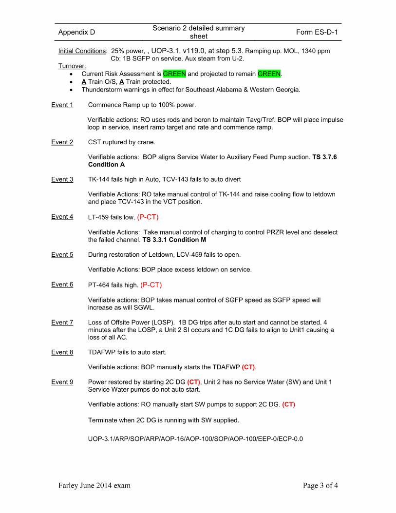
Initial Conditions: 25% power, , UOP-3.1, v119.0, at step 5.3. Ramping up. MOL, 1340 ppm Cb; 1B SGFP on service. Aux steam from U-2.
Turnover: Current Risk Assessment is GREEN and projected to remain GREEN. A Train O/S, A Train protected. Thunderstorm warnings in effect for Southeast Alabama & Western Georgia.
Event 1 Commence Ramp up to 100% power. Verifiable actions: RO uses rods and boron to maintain Tavg/Tref. BOP will place impulse loop in service, insert ramp target and rate and commence ramp.
Event 2 CST ruptured by crane. Verifiable actions: BOP aligns Service Water to Auxiliary Feed Pump suction. TS 3.7.6 Condition A
Event 3 TK-144 fails high in Auto, TCV-143 fails to auto divert Verifiable Actions: RO take manual control of TK-144 and raise cooling flow to letdown and place TCV-143 in the VCT position.
Event 4 LT-459 fails low. (P-CT) Verifiable Actions: Take manual control of charging to control PRZR level and deselect the failed channel. TS 3.3.1 Condition M
Event 5 During restoration of Letdown, LCV-459 fails to open. Verifiable Actions: BOP place excess letdown on service.
Event 6 PT-464 fails high. (P-CT) Verifiable actions: BOP takes manual control of SGFP speed as SGFP speed will increase as will SGWL.
Event 7 Loss of Offsite Power (LOSP). 1B DG trips after auto start and cannot be started. 4 minutes after the LOSP, a Unit 2 SI occurs and 1C DG fails to align to Unit1 causing a loss of all AC.
Event 8 TDAFWP fails to auto start. Verifiable actions: BOP manually starts the TDAFWP (CT).
Event 9 Power restored by starting 2C DG (CT), Unit 2 has no Service Water (SW) and Unit 1 Service Water pumps do not auto start. Verifiable actions: RO manually start SW pumps to support 2C DG. (CT)
Terminate when 2C DG is running with SW supplied. UOP-3.1/ARP/SOP/ARP/AOP-16/AOP-100/SOP/AOP-100/EEP-0/ECP-0.0
Appendix D Scenario 2 Critical Task sheet
Sheet Form ES-D-1
Farley June 2014 exam Page 4 of 4
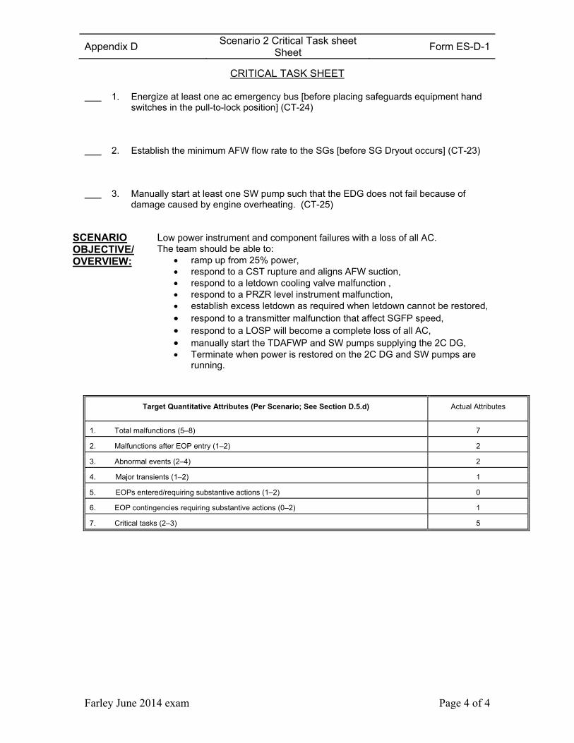
CRITICAL TASK SHEET
1. Energize at least one ac emergency bus [before placing safeguards equipment hand switches in the pull-to-lock position] (CT-24)
2. Establish the minimum AFW flow rate to the SGs [before SG Dryout occurs] (CT-23)
3. Manually start at least one SW pump such that the EDG does not fail because of damage caused by engine overheating. (CT-25)
SCENARIO OBJECTIVE/ OVERVIEW:
Low power instrument and component failures with a loss of all AC. The team should be able to:
ramp up from 25% power, respond to a CST rupture and aligns AFW suction, respond to a letdown cooling valve malfunction , respond to a PRZR level instrument malfunction, establish excess letdown as required when letdown cannot be restored, respond to a transmitter malfunction that affect SGFP speed, respond to a LOSP will become a complete loss of all AC, manually start the TDAFWP and SW pumps supplying the 2C DG, Terminate when power is restored on the 2C DG and SW pumps are
running.
Target Quantitative Attributes (Per Scenario; See Section D.5.d) Actual Attributes
1. Total malfunctions (5–8) 7
2. Malfunctions after EOP entry (1–2) 2
3. Abnormal events (2–4) 2
4. Major transients (1–2) 1
5. EOPs entered/requiring substantive actions (1–2) 0
6. EOP contingencies requiring substantive actions (0–2) 1
7. Critical tasks (2–3) 5
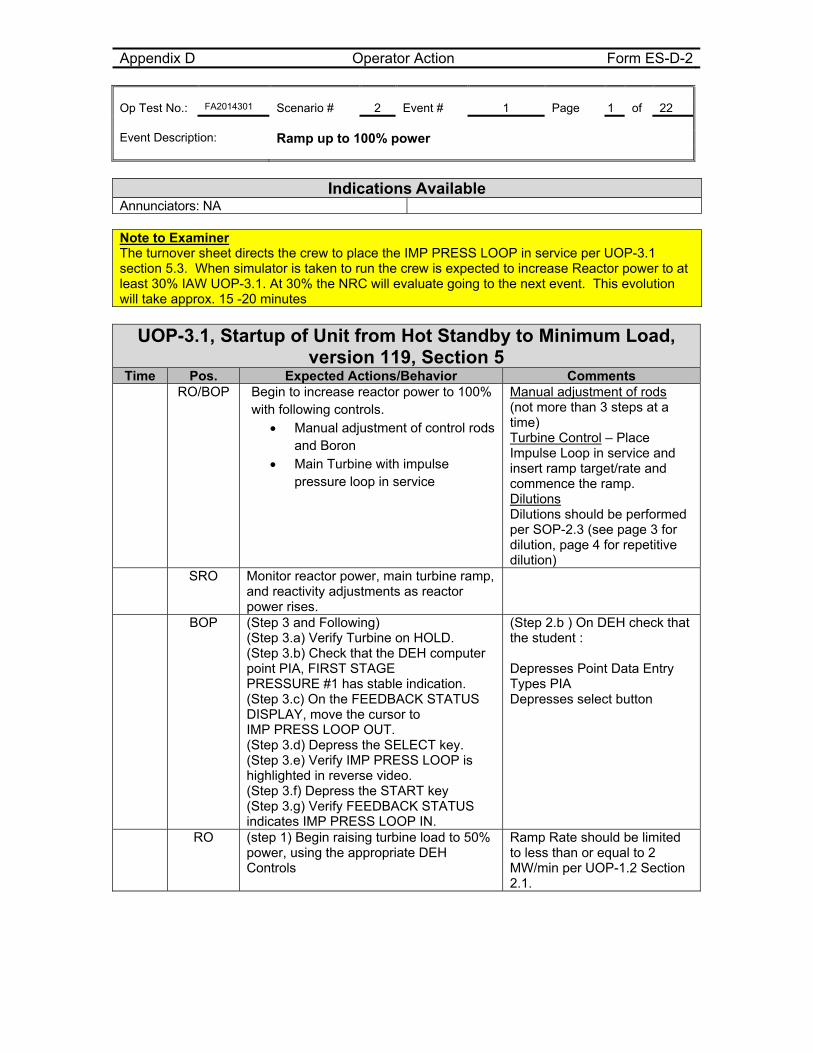
Appendix D Operator Action Form ES-D-2 Op Test No.: FA2014301 Scenario # 2 Event # 1 Page 1 of 22 Event Description: Ramp up to 100% power
Indications Available
Annunciators: NA Note to Examiner The turnover sheet directs the crew to place the IMP PRESS LOOP in service per UOP-3.1 section 5.3. When simulator is taken to run the crew is expected to increase Reactor power to at least 30% IAW UOP-3.1. At 30% the NRC will evaluate going to the next event. This evolution will take approx. 15 -20 minutes
UOP-3.1, Startup of Unit from Hot Standby to Minimum Load, version 119, Section 5
Time Pos. Expected Actions/Behavior Comments RO/BOP Begin to increase reactor power to 100%
with following controls. Manual adjustment of control rods
and Boron Main Turbine with impulse
pressure loop in service
Manual adjustment of rods (not more than 3 steps at a time) Turbine Control – Place Impulse Loop in service and insert ramp target/rate and commence the ramp. Dilutions Dilutions should be performed per SOP-2.3 (see page 3 for dilution, page 4 for repetitive dilution)
SRO Monitor reactor power, main turbine ramp, and reactivity adjustments as reactor power rises.
BOP (Step 3 and Following) (Step 3.a) Verify Turbine on HOLD. (Step 3.b) Check that the DEH computer point PIA, FIRST STAGE PRESSURE #1 has stable indication. (Step 3.c) On the FEEDBACK STATUS DISPLAY, move the cursor to IMP PRESS LOOP OUT. (Step 3.d) Depress the SELECT key. (Step 3.e) Verify IMP PRESS LOOP is highlighted in reverse video. (Step 3.f) Depress the START key (Step 3.g) Verify FEEDBACK STATUS indicates IMP PRESS LOOP IN.
(Step 2.b ) On DEH check that the student : Depresses Point Data Entry Types PIA Depresses select button
RO (step 1) Begin raising turbine load to 50% power, using the appropriate DEH Controls
Ramp Rate should be limited to less than or equal to 2 MW/min per UOP-1.2 Section 2.1.
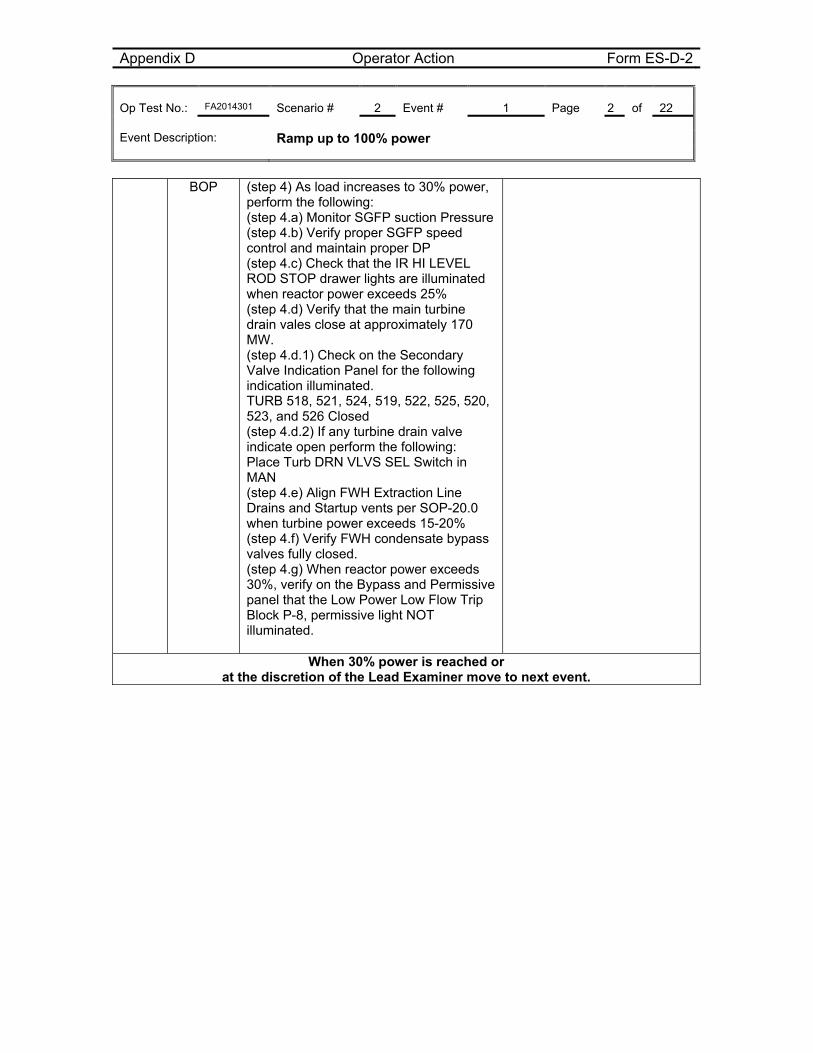
Appendix D Operator Action Form ES-D-2 Op Test No.: FA2014301 Scenario # 2 Event # 1 Page 2 of 22 Event Description: Ramp up to 100% power
BOP (step 4) As load increases to 30% power,
perform the following: (step 4.a) Monitor SGFP suction Pressure (step 4.b) Verify proper SGFP speed control and maintain proper DP (step 4.c) Check that the IR HI LEVEL ROD STOP drawer lights are illuminated when reactor power exceeds 25% (step 4.d) Verify that the main turbine drain vales close at approximately 170 MW. (step 4.d.1) Check on the Secondary Valve Indication Panel for the following indication illuminated. TURB 518, 521, 524, 519, 522, 525, 520, 523, and 526 Closed (step 4.d.2) If any turbine drain valve indicate open perform the following: Place Turb DRN VLVS SEL Switch in MAN (step 4.e) Align FWH Extraction Line Drains and Startup vents per SOP-20.0 when turbine power exceeds 15-20% (step 4.f) Verify FWH condensate bypass valves fully closed. (step 4.g) When reactor power exceeds 30%, verify on the Bypass and Permissive panel that the Low Power Low Flow Trip Block P-8, permissive light NOT illuminated.
When 30% power is reached or at the discretion of the Lead Examiner move to next event.
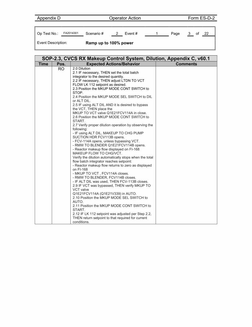
Appendix D Operator Action Form ES-D-2 Op Test No.: FA2014301 Scenario # 2 Event # 1 Page 3 of 22 Event Description: Ramp up to 100% power
SOP-2.3, CVCS RX Makeup Control System, Dilution, Appendix C, v60.1
Time Pos. Expected Actions/Behavior Comments RO 2.0 Dilution
2.1 IF necessary, THEN set the total batch integrator to the desired quantity. 2.2 IF necessary, THEN adjust LTDN TO VCT FLOW LK 112 setpoint as desired. 2.3 Position the MKUP MODE CONT SWITCH to STOP. 2.4 Position the MKUP MODE SEL SWITCH to DIL or ALT DIL. 2.5 IF using ALT DIL AND it is desired to bypass the VCT, THEN place the MKUP TO VCT valve Q1E21FCV114A in close. 2.6 Position the MKUP MODE CONT SWITCH to START. 2.7 Verify proper dilution operation by observing the following: - IF using ALT DIL, MAKEUP TO CHG PUMP SUCTION HDR FCV113B opens. - FCV-114A opens, unless bypassing VCT. - RMW TO BLENDER Q1E21FCV114B opens. - Reactor makeup flow displayed on FI-168 MAKEUP FLOW TO CHG/VCT. Verify the dilution automatically stops when the total flow batch integrator reaches setpoint: - Reactor makeup flow returns to zero as displayed on FI-168 - MKUP TO VCT , FCV114A closes. - RMW TO BLENDER, FCV114B closes. - IF ALT DIL was used, THEN FCV-113B closes. 2.9 IF VCT was bypassed, THEN verify MKUP TO VCT valve Q1E21FCV114A (Q1E21V339) in AUTO. 2.10 Position the MKUP MODE SEL SWITCH to AUTO. 2.11 Position the MKUP MODE CONT SWITCH to START. 2.12 IF LK 112 setpoint was adjusted per Step 2.2, THEN return setpoint to that required for current conditions.
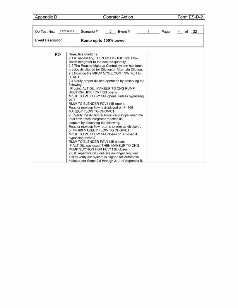
Appendix D Operator Action Form ES-D-2 Op Test No.: FA2014301 Scenario # 2 Event # 1 Page 4 of 22 Event Description: Ramp up to 100% power
RO Repetitive Dilutions
2.1 IF necessary, THEN set FIS-168 Total Flow Batch Integrator to the desired quantity. 2.2 The Reactor Makeup Control system has been previously aligned for Dilution or Alternate Dilution. 2.3 Position the MKUP MODE CONT SWITCH to START. 2.4 Verify proper dilution operation by observing the following: -IF using ALT DIL, MAKEUP TO CHG PUMP SUCTION HDR FCV113B opens. MKUP TO VCT FCV114A opens, unless bypassing VCT. RMW TO BLENDER FCV114B opens. Reactor makeup flow is displayed on FI-168 MAKEUP FLOW TO CHG/VCT. 2.5 Verify the dilution automatically stops when the total flow batch integrator reaches its setpoint by observing the following: Reactor makeup flow returns to zero as displayed on FI-168 MAKEUP FLOW TO CHG/VCT. MKUP TO VCT FCV114A closes or is closed if bypassing theVCT. RMW TO BLENDER FCV114B closes. IF ALT DIL was used, THEN MAKEUP TO CHG PUMP SUCTION HDR FCV113B closes. 2.6 IF repetitive dilutions are no longer required THEN verify the system is aligned for Automatic makeup per Steps 2.8 through 2.11 of Appendix B.
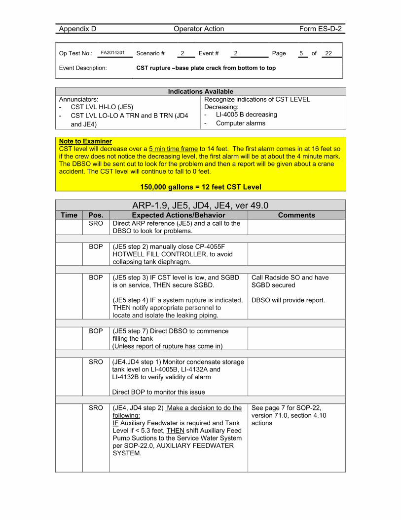
Appendix D Operator Action Form ES-D-2 Op Test No.: FA2014301 Scenario # 2 Event # 2 Page 5 of 22 Event Description: CST rupture –base plate crack from bottom to top
Indications Available
Annunciators: - CST LVL HI-LO (JE5) - CST LVL LO-LO A TRN and B TRN (JD4
and JE4)
Recognize indications of CST LEVEL Decreasing: - LI-4005 B decreasing - Computer alarms
Note to Examiner CST level will decrease over a 5 min time frame to 14 feet. The first alarm comes in at 16 feet so if the crew does not notice the decreasing level, the first alarm will be at about the 4 minute mark. The DBSO will be sent out to look for the problem and then a report will be given about a crane accident. The CST level will continue to fall to 0 feet.
150,000 gallons = 12 feet CST Level
ARP-1.9, JE5, JD4, JE4, ver 49.0 Time Pos. Expected Actions/Behavior Comments
SRO Direct ARP reference (JE5) and a call to the DBSO to look for problems.
BOP (JE5 step 2) manually close CP-4055F
HOTWELL FILL CONTROLLER, to avoid collapsing tank diaphragm.
BOP (JE5 step 3) IF CST level is low, and SGBD
is on service, THEN secure SGBD. (JE5 step 4) IF a system rupture is indicated, THEN notify appropriate personnel to locate and isolate the leaking piping.
Call Radside SO and have SGBD secured DBSO will provide report.
BOP (JE5 step 7) Direct DBSO to commence
filling the tank (Unless report of rupture has come in)
SRO (JE4.JD4 step 1) Monitor condensate storage
tank level on LI-4005B, LI-4132A and LI-4132B to verify validity of alarm Direct BOP to monitor this issue
SRO (JE4, JD4 step 2) Make a decision to do the
following: IF Auxiliary Feedwater is required and Tank Level if < 5.3 feet, THEN shift Auxiliary Feed Pump Suctions to the Service Water System per SOP-22.0, AUXILIARY FEEDWATER SYSTEM.
See page 7 for SOP-22, version 71.0, section 4.10 actions
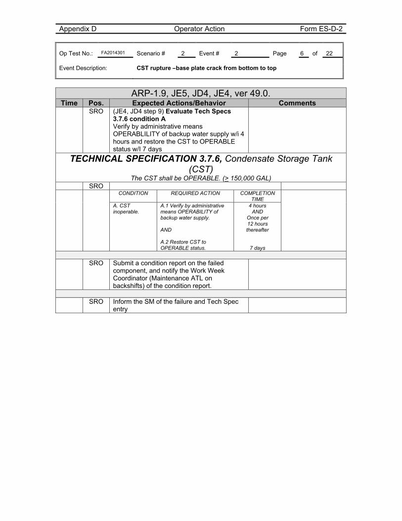
Appendix D Operator Action Form ES-D-2 Op Test No.: FA2014301 Scenario # 2 Event # 2 Page 6 of 22 Event Description: CST rupture –base plate crack from bottom to top
ARP-1.9, JE5, JD4, JE4, ver 49.0. Time Pos. Expected Actions/Behavior Comments
SRO (JE4, JD4 step 9) Evaluate Tech Specs 3.7.6 condition A Verify by administrative means OPERABLILITY of backup water supply w/i 4 hours and restore the CST to OPERABLE status w/I 7 days
TECHNICAL SPECIFICATION 3.7.6, Condensate Storage Tank (CST)
The CST shall be OPERABLE. (> 150,000 GAL) SRO CONDITION REQUIRED ACTION COMPLETION
TIME
A. CST inoperable.
A.1 Verify by administrative means OPERABILITY of backup water supply. AND A.2 Restore CST to OPERABLE status.
4 hours AND
Once per 12 hours thereafter
7 days
SRO Submit a condition report on the failed
component, and notify the Work Week Coordinator (Maintenance ATL on backshifts) of the condition report.
SRO Inform the SM of the failure and Tech Spec
entry
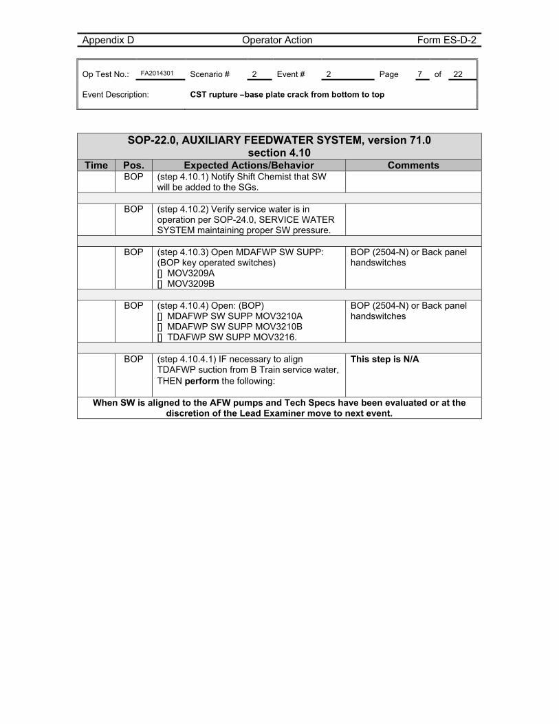
Appendix D Operator Action Form ES-D-2 Op Test No.: FA2014301 Scenario # 2 Event # 2 Page 7 of 22 Event Description: CST rupture –base plate crack from bottom to top
SOP-22.0, AUXILIARY FEEDWATER SYSTEM, version 71.0 section 4.10
Time Pos. Expected Actions/Behavior Comments BOP (step 4.10.1) Notify Shift Chemist that SW
will be added to the SGs.
BOP (step 4.10.2) Verify service water is in
operation per SOP-24.0, SERVICE WATER SYSTEM maintaining proper SW pressure.
BOP (step 4.10.3) Open MDAFWP SW SUPP:
(BOP key operated switches) [] MOV3209A [] MOV3209B
BOP (2504-N) or Back panel handswitches
BOP (step 4.10.4) Open: (BOP)
[] MDAFWP SW SUPP MOV3210A [] MDAFWP SW SUPP MOV3210B [] TDAFWP SW SUPP MOV3216.
BOP (2504-N) or Back panel handswitches
BOP (step 4.10.4.1) IF necessary to align
TDAFWP suction from B Train service water, THEN perform the following:
This step is N/A
When SW is aligned to the AFW pumps and Tech Specs have been evaluated or at the discretion of the Lead Examiner move to next event.
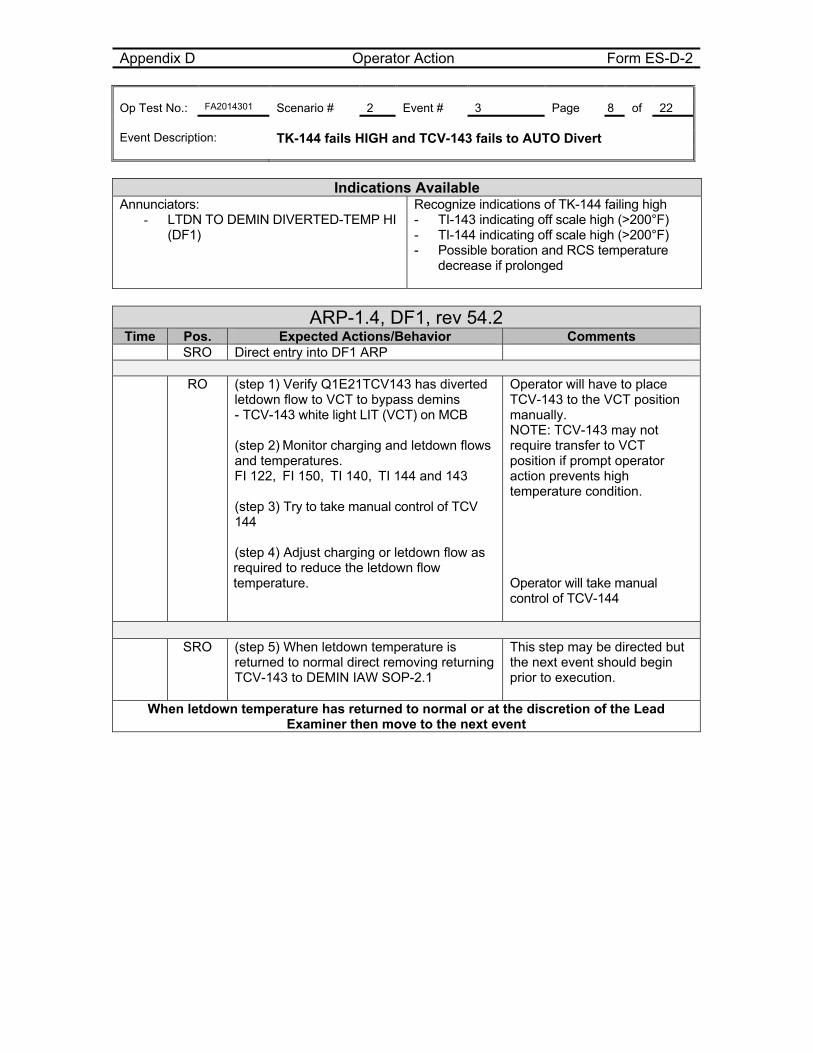
Appendix D Operator Action Form ES-D-2 Op Test No.: FA2014301 Scenario # 2 Event # 3 Page 8 of 22 Event Description: TK-144 fails HIGH and TCV-143 fails to AUTO Divert
Indications Available
Annunciators: - LTDN TO DEMIN DIVERTED-TEMP HI
(DF1)
Recognize indications of TK-144 failing high - TI-143 indicating off scale high (>200°F) - TI-144 indicating off scale high (>200°F) - Possible boration and RCS temperature
decrease if prolonged
ARP-1.4, DF1, rev 54.2 Time Pos. Expected Actions/Behavior Comments
SRO Direct entry into DF1 ARP RO (step 1) Verify Q1E21TCV143 has diverted
letdown flow to VCT to bypass demins - TCV-143 white light LIT (VCT) on MCB (step 2) Monitor charging and letdown flows and temperatures. FI 122, FI 150, TI 140, TI 144 and 143 (step 3) Try to take manual control of TCV 144 (step 4) Adjust charging or letdown flow as required to reduce the letdown flow temperature.
Operator will have to place TCV-143 to the VCT position manually. NOTE: TCV-143 may not require transfer to VCT position if prompt operator action prevents high temperature condition. Operator will take manual control of TCV-144
SRO (step 5) When letdown temperature is
returned to normal direct removing returning TCV-143 to DEMIN IAW SOP-2.1
This step may be directed but the next event should begin prior to execution.
When letdown temperature has returned to normal or at the discretion of the Lead Examiner then move to the next event
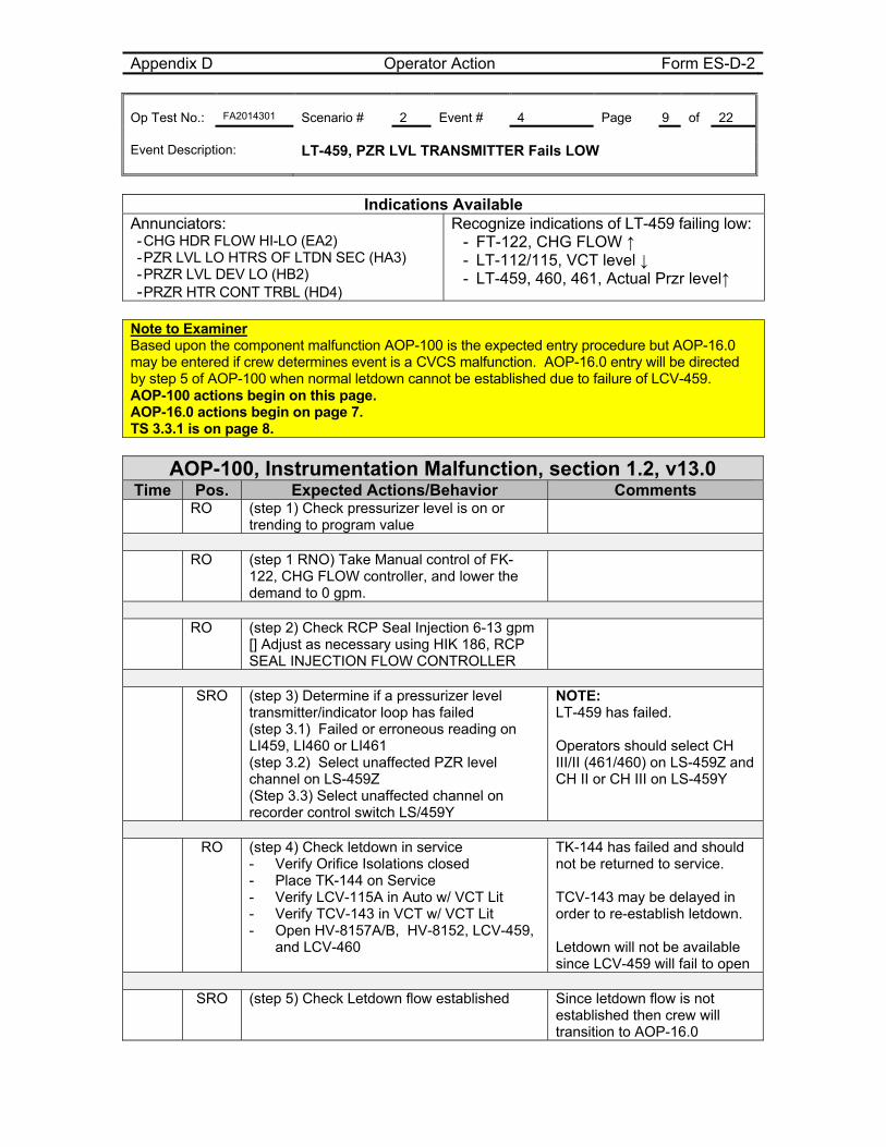
Appendix D Operator Action Form ES-D-2 Op Test No.: FA2014301 Scenario # 2 Event # 4 Page 9 of 22 Event Description: LT-459, PZR LVL TRANSMITTER Fails LOW
Indications Available
Annunciators: - CHG HDR FLOW HI-LO (EA2) - PZR LVL LO HTRS OF LTDN SEC (HA3) - PRZR LVL DEV LO (HB2) - PRZR HTR CONT TRBL (HD4)
Recognize indications of LT-459 failing low: - FT-122, CHG FLOW ↑ - LT-112/115, VCT level ↓ - LT-459, 460, 461, Actual Przr level↑
Note to Examiner Based upon the component malfunction AOP-100 is the expected entry procedure but AOP-16.0 may be entered if crew determines event is a CVCS malfunction. AOP-16.0 entry will be directed by step 5 of AOP-100 when normal letdown cannot be established due to failure of LCV-459. AOP-100 actions begin on this page. AOP-16.0 actions begin on page 7. TS 3.3.1 is on page 8.
AOP-100, Instrumentation Malfunction, section 1.2, v13.0 Time Pos. Expected Actions/Behavior Comments
RO (step 1) Check pressurizer level is on or trending to program value
RO (step 1 RNO) Take Manual control of FK-
122, CHG FLOW controller, and lower the demand to 0 gpm.
RO (step 2) Check RCP Seal Injection 6-13 gpm
[] Adjust as necessary using HIK 186, RCP SEAL INJECTION FLOW CONTROLLER
SRO (step 3) Determine if a pressurizer level
transmitter/indicator loop has failed (step 3.1) Failed or erroneous reading on LI459, LI460 or LI461 (step 3.2) Select unaffected PZR level channel on LS-459Z (Step 3.3) Select unaffected channel on recorder control switch LS/459Y
NOTE: LT-459 has failed. Operators should select CH III/II (461/460) on LS-459Z and CH II or CH III on LS-459Y
RO (step 4) Check letdown in service
- Verify Orifice Isolations closed - Place TK-144 on Service - Verify LCV-115A in Auto w/ VCT Lit - Verify TCV-143 in VCT w/ VCT Lit - Open HV-8157A/B, HV-8152, LCV-459,
and LCV-460
TK-144 has failed and should not be returned to service. TCV-143 may be delayed in order to re-establish letdown. Letdown will not be available since LCV-459 will fail to open
SRO (step 5) Check Letdown flow established Since letdown flow is not
established then crew will transition to AOP-16.0
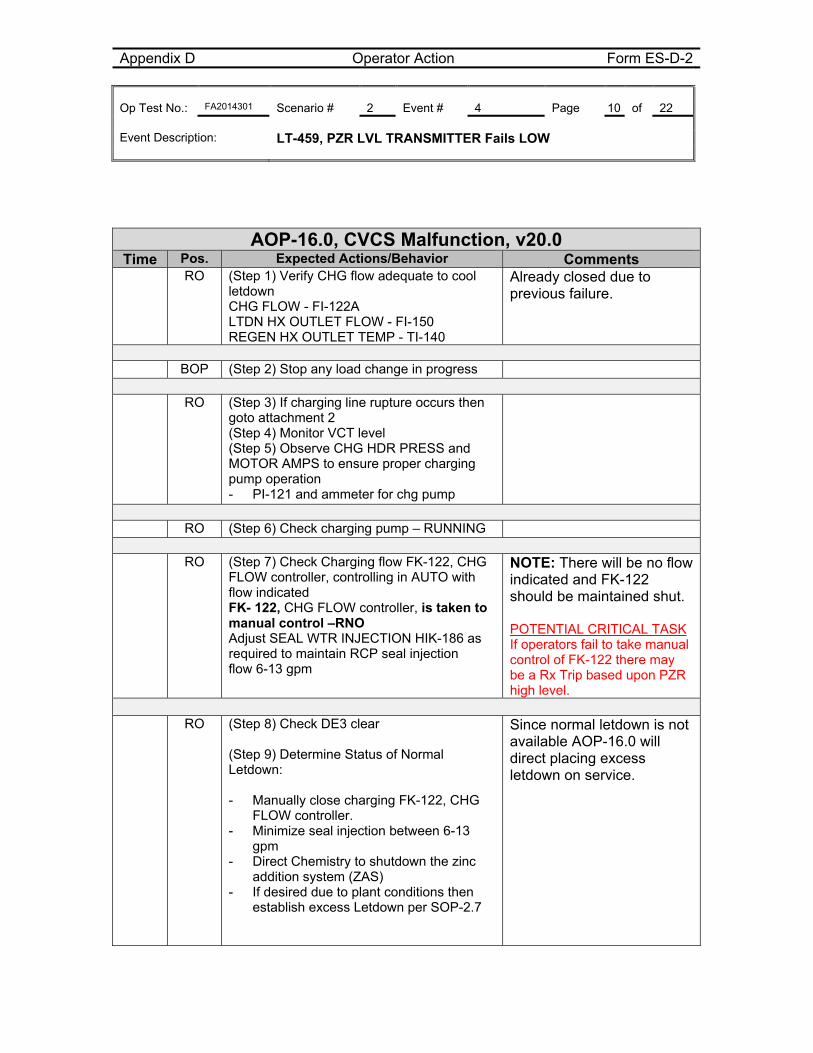
Appendix D Operator Action Form ES-D-2 Op Test No.: FA2014301 Scenario # 2 Event # 4 Page 10 of 22 Event Description: LT-459, PZR LVL TRANSMITTER Fails LOW
AOP-16.0, CVCS Malfunction, v20.0 Time Pos. Expected Actions/Behavior Comments RO (Step 1) Verify CHG flow adequate to cool
letdown CHG FLOW - FI-122A LTDN HX OUTLET FLOW - FI-150 REGEN HX OUTLET TEMP - TI-140
Already closed due to previous failure.
BOP (Step 2) Stop any load change in progress RO (Step 3) If charging line rupture occurs then
goto attachment 2 (Step 4) Monitor VCT level (Step 5) Observe CHG HDR PRESS and MOTOR AMPS to ensure proper charging pump operation - PI-121 and ammeter for chg pump
RO (Step 6) Check charging pump – RUNNING RO (Step 7) Check Charging flow FK-122, CHG
FLOW controller, controlling in AUTO with flow indicated FK- 122, CHG FLOW controller, is taken to manual control –RNO Adjust SEAL WTR INJECTION HIK-186 as required to maintain RCP seal injection flow 6-13 gpm
NOTE: There will be no flow indicated and FK-122 should be maintained shut. POTENTIAL CRITICAL TASK If operators fail to take manual control of FK-122 there may be a Rx Trip based upon PZR high level.
RO (Step 8) Check DE3 clear
(Step 9) Determine Status of Normal Letdown: - Manually close charging FK-122, CHG
FLOW controller. - Minimize seal injection between 6-13
gpm - Direct Chemistry to shutdown the zinc
addition system (ZAS) - If desired due to plant conditions then
establish excess Letdown per SOP-2.7
Since normal letdown is not available AOP-16.0 will direct placing excess letdown on service.
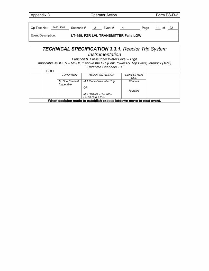
Appendix D Operator Action Form ES-D-2 Op Test No.: FA2014301 Scenario # 2 Event # 4 Page 11 of 22 Event Description: LT-459, PZR LVL TRANSMITTER Fails LOW
TECHNICAL SPECIFICATION 3.3.1, Reactor Trip System Instrumentation
Function 9. Pressurizer Water Level – High Applicable MODES – MODE 1 above the P-7 (Low Power Rx Trip Block) interlock (10%)
Required Channels - 3 SRO CONDITION REQUIRED ACTION COMPLETION
TIME
M. One Channel Inoperable
M.1 Place Channel in Trip OR M.2 Reduce THERMAL POWER to < P-7.
72 hours
78 hours
When decision made to establish excess letdown move to next event.
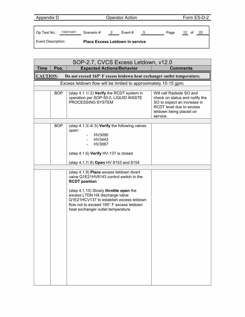
Appendix D Operator Action Form ES-D-2 Op Test No.: FA2014301 Scenario # 2 Event # 5 Page 12 of 22 Event Description: Place Excess Letdown in service
SOP-2.7, CVCS Excess Letdown, v12.0 Time Pos. Expected Actions/Behavior Comments
CAUTION: Do not exceed 165 F excess letdown heat exchanger outlet temperature.
Excess letdown flow will be limited to approximately 10-15 gpm.
BOP (step 4.1.1/.2) Verify the RCDT system in operation per SOP-50.0, LIQUID WASTE PROCESSING SYSTEM
Will call Radside SO and check on status and notify the SO to expect an increase in RCDT level due to excess letdown being placed on service.
BOP (step 4.1.3/.4/.5) Verify the following valves
open: - HV3095 - HV3443 - HV3067
(step 4.1.6) Verify HV-137 is closed (step 4.1.7/.8) Open HV 8153 and 8154
(step 4.1.9) Place excess letdown divert
valve Q1E21HV8143 control switch in the RCDT position (step 4.1.10) Slowly throttle open the excess LTDN HX discharge valve Q1E21HCV137 to establish excess letdown flow not to exceed 165 F excess letdown heat exchanger outlet temperature
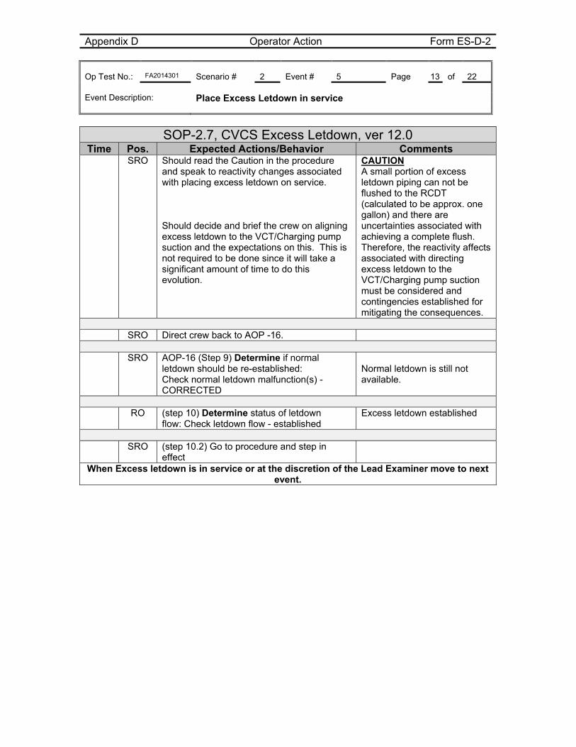
Appendix D Operator Action Form ES-D-2 Op Test No.: FA2014301 Scenario # 2 Event # 5 Page 13 of 22 Event Description: Place Excess Letdown in service
SOP-2.7, CVCS Excess Letdown, ver 12.0 Time Pos. Expected Actions/Behavior Comments
SRO Should read the Caution in the procedure and speak to reactivity changes associated with placing excess letdown on service. Should decide and brief the crew on aligning excess letdown to the VCT/Charging pump suction and the expectations on this. This is not required to be done since it will take a significant amount of time to do this evolution.
CAUTION A small portion of excess letdown piping can not be flushed to the RCDT (calculated to be approx. one gallon) and there are uncertainties associated with achieving a complete flush. Therefore, the reactivity affects associated with directing excess letdown to the VCT/Charging pump suction must be considered and contingencies established for mitigating the consequences.
SRO Direct crew back to AOP -16.
SRO AOP-16 (Step 9) Determine if normal
letdown should be re-established: Check normal letdown malfunction(s) - CORRECTED
Normal letdown is still not available.
RO (step 10) Determine status of letdown
flow: Check letdown flow - established Excess letdown established
SRO (step 10.2) Go to procedure and step in
effect
When Excess letdown is in service or at the discretion of the Lead Examiner move to next event.
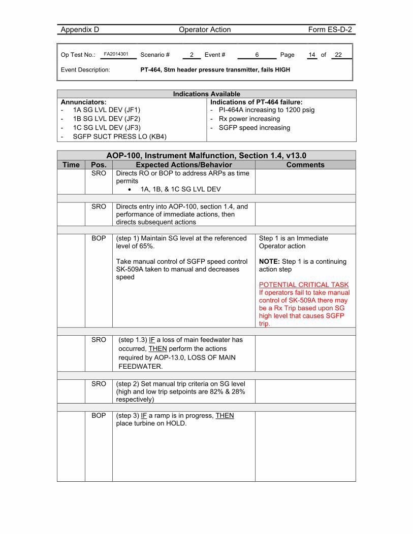
Appendix D Operator Action Form ES-D-2 Op Test No.: FA2014301 Scenario # 2 Event # 6 Page 14 of 22 Event Description: PT-464, Stm header pressure transmitter, fails HIGH
Indications Available Annunciators: - 1A SG LVL DEV (JF1) - 1B SG LVL DEV (JF2) - 1C SG LVL DEV (JF3) - SGFP SUCT PRESS LO (KB4)
Indications of PT-464 failure: - PI-464A increasing to 1200 psig - Rx power increasing - SGFP speed increasing
AOP-100, Instrument Malfunction, Section 1.4, v13.0
Time Pos. Expected Actions/Behavior Comments SRO Directs RO or BOP to address ARPs as time
permits 1A, 1B, & 1C SG LVL DEV
SRO Directs entry into AOP-100, section 1.4, and
performance of immediate actions, then directs subsequent actions
BOP (step 1) Maintain SG level at the referenced
level of 65%. Take manual control of SGFP speed control SK-509A taken to manual and decreases speed
Step 1 is an Immediate Operator action NOTE: Step 1 is a continuing action step POTENTIAL CRITICAL TASK If operators fail to take manual control of SK-509A there may be a Rx Trip based upon SG high level that causes SGFP trip.
SRO (step 1.3) IF a loss of main feedwater has
occurred, THEN perform the actions required by AOP-13.0, LOSS OF MAIN FEEDWATER.
SRO (step 2) Set manual trip criteria on SG level
(high and low trip setpoints are 82% & 28% respectively)
BOP (step 3) IF a ramp is in progress, THEN
place turbine on HOLD.
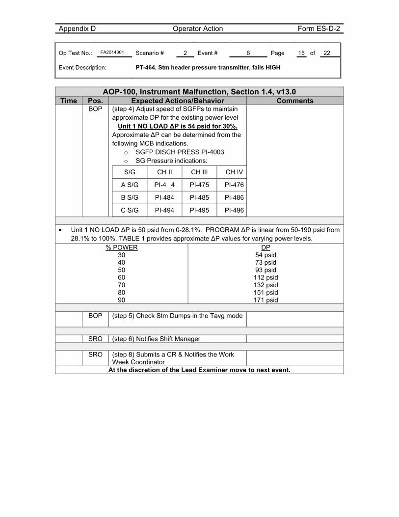
Appendix D Operator Action Form ES-D-2 Op Test No.: FA2014301 Scenario # 2 Event # 6 Page 15 of 22 Event Description: PT-464, Stm header pressure transmitter, fails HIGH
AOP-100, Instrument Malfunction, Section 1.4, v13.0 Time Pos. Expected Actions/Behavior Comments
BOP (step 4) Adjust speed of SGFPs to maintain approximate DP for the existing power level
Unit 1 NO LOAD ∆P is 54 psid for 30%. Approximate ∆P can be determined from the following MCB indications.
o SGFP DISCH PRESS PI-4003 o SG Pressure indications:
S/G CH II CH III CH IV
A S/G PI-4 4 PI-475 PI-476
B S/G PI-484 PI-485 PI-486
C S/G PI-494 PI-495 PI-496
Unit 1 NO LOAD ∆P is 50 psid from 0-28.1%. PROGRAM ∆P is linear from 50-190 psid from
28.1% to 100%. TABLE 1 provides approximate ∆P values for varying power levels. % POWER
30 40 50 60 70 80 90
DP 54 psid 73 psid 93 psid
112 psid 132 psid 151 psid 171 psid
BOP (step 5) Check Stm Dumps in the Tavg mode
SRO (step 6) Notifies Shift Manager
SRO (step 8) Submits a CR & Notifies the Work
Week Coordinator
At the discretion of the Lead Examiner move to next event.
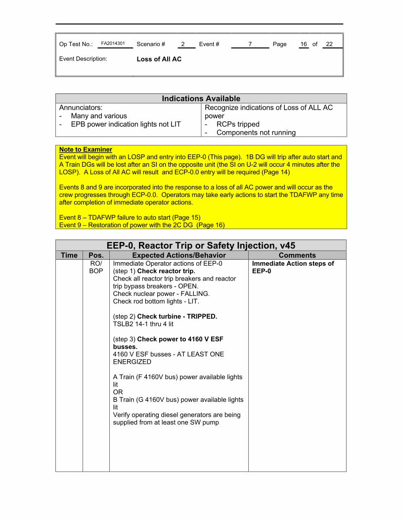
Op Test No.: FA2014301 Scenario # 2 Event # 7 Page 16 of 22 Event Description: Loss of All AC
Indications Available
Annunciators: - Many and various - EPB power indication lights not LIT
Recognize indications of Loss of ALL AC power - RCPs tripped - Components not running
Note to Examiner Event will begin with an LOSP and entry into EEP-0 (This page). 1B DG will trip after auto start and A Train DGs will be lost after an SI on the opposite unit (the SI on U-2 will occur 4 minutes after the LOSP). A Loss of All AC will result and ECP-0.0 entry will be required (Page 14) Events 8 and 9 are incorporated into the response to a loss of all AC power and will occur as the crew progresses through ECP-0.0. Operators may take early actions to start the TDAFWP any time after completion of immediate operator actions. Event 8 – TDAFWP failure to auto start (Page 15) Event 9 – Restoration of power with the 2C DG (Page 16)
EEP-0, Reactor Trip or Safety Injection, v45
Time Pos. Expected Actions/Behavior Comments RO/
BOP Immediate Operator actions of EEP-0 (step 1) Check reactor trip. Check all reactor trip breakers and reactor trip bypass breakers - OPEN. Check nuclear power - FALLING. Check rod bottom lights - LIT. (step 2) Check turbine - TRIPPED. TSLB2 14-1 thru 4 lit (step 3) Check power to 4160 V ESF busses. 4160 V ESF busses - AT LEAST ONE ENERGIZED A Train (F 4160V bus) power available lights lit OR B Train (G 4160V bus) power available lights lit Verify operating diesel generators are being supplied from at least one SW pump
Immediate Action steps of EEP-0
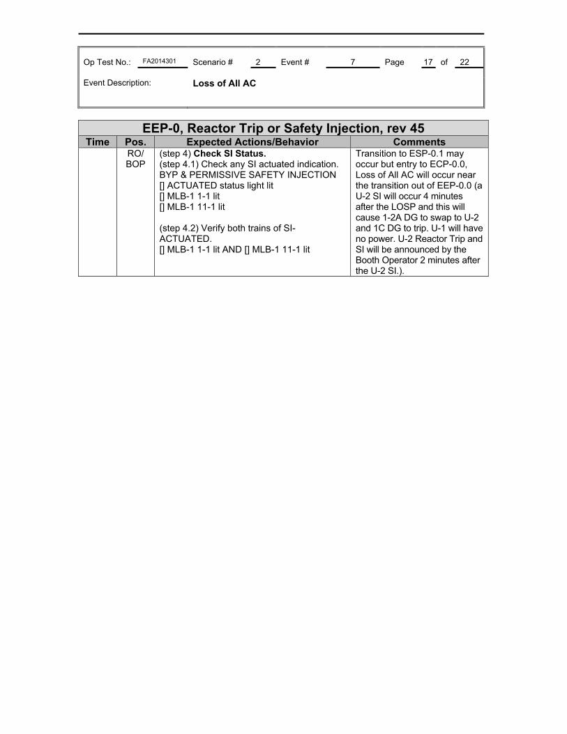
Op Test No.: FA2014301 Scenario # 2 Event # 7 Page 17 of 22 Event Description: Loss of All AC
EEP-0, Reactor Trip or Safety Injection, rev 45 Time Pos. Expected Actions/Behavior Comments
RO/ BOP
(step 4) Check SI Status. (step 4.1) Check any SI actuated indication. BYP & PERMISSIVE SAFETY INJECTION [] ACTUATED status light lit [] MLB-1 1-1 lit [] MLB-1 11-1 lit (step 4.2) Verify both trains of SI-ACTUATED. [] MLB-1 1-1 lit AND [] MLB-1 11-1 lit
Transition to ESP-0.1 may occur but entry to ECP-0.0, Loss of All AC will occur near the transition out of EEP-0.0 (a U-2 SI will occur 4 minutes after the LOSP and this will cause 1-2A DG to swap to U-2 and 1C DG to trip. U-1 will have no power. U-2 Reactor Trip and SI will be announced by the Booth Operator 2 minutes after the U-2 SI.).
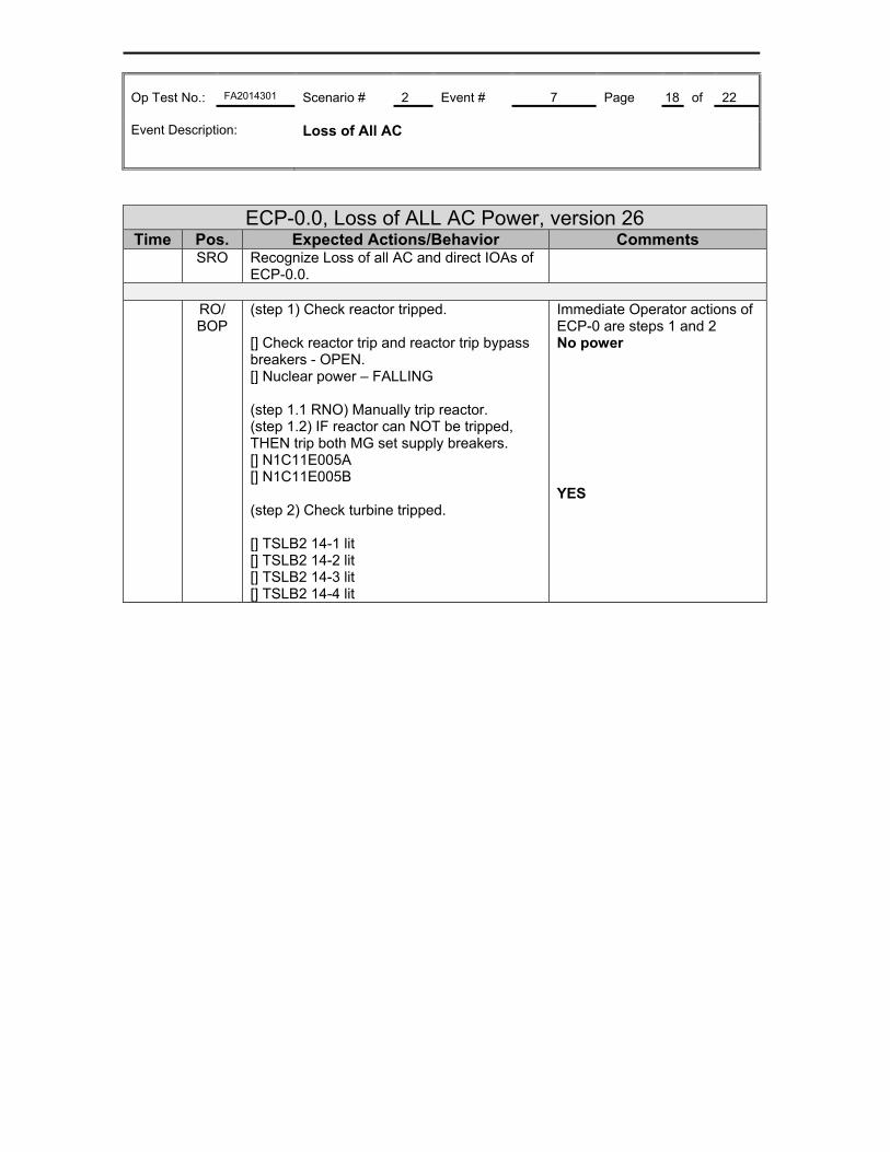
Op Test No.: FA2014301 Scenario # 2 Event # 7 Page 18 of 22 Event Description: Loss of All AC
ECP-0.0, Loss of ALL AC Power, version 26 Time Pos. Expected Actions/Behavior Comments
SRO Recognize Loss of all AC and direct IOAs of ECP-0.0.
RO/
BOP (step 1) Check reactor tripped. [] Check reactor trip and reactor trip bypass breakers - OPEN. [] Nuclear power – FALLING (step 1.1 RNO) Manually trip reactor. (step 1.2) IF reactor can NOT be tripped, THEN trip both MG set supply breakers. [] N1C11E005A [] N1C11E005B (step 2) Check turbine tripped. [] TSLB2 14-1 lit [] TSLB2 14-2 lit [] TSLB2 14-3 lit [] TSLB2 14-4 lit
Immediate Operator actions of ECP-0 are steps 1 and 2 No power YES
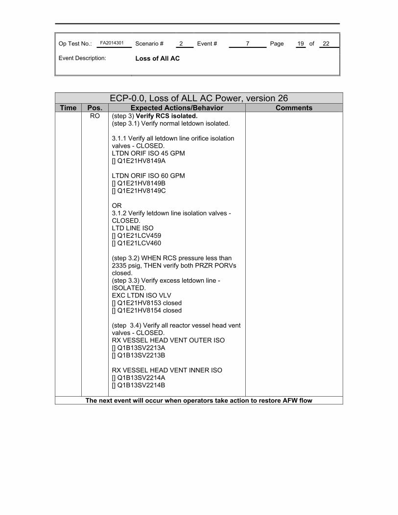
Op Test No.: FA2014301 Scenario # 2 Event # 7 Page 19 of 22 Event Description: Loss of All AC
ECP-0.0, Loss of ALL AC Power, version 26 Time Pos. Expected Actions/Behavior Comments
RO (step 3) Verify RCS isolated. (step 3.1) Verify normal letdown isolated. 3.1.1 Verify all letdown line orifice isolation valves - CLOSED. LTDN ORIF ISO 45 GPM [] Q1E21HV8149A LTDN ORIF ISO 60 GPM [] Q1E21HV8149B [] Q1E21HV8149C OR 3.1.2 Verify letdown line isolation valves - CLOSED. LTD LINE ISO [] Q1E21LCV459 [] Q1E21LCV460 (step 3.2) WHEN RCS pressure less than 2335 psig, THEN verify both PRZR PORVs closed. (step 3.3) Verify excess letdown line - ISOLATED. EXC LTDN ISO VLV [] Q1E21HV8153 closed [] Q1E21HV8154 closed (step 3.4) Verify all reactor vessel head vent valves - CLOSED. RX VESSEL HEAD VENT OUTER ISO [] Q1B13SV2213A [] Q1B13SV2213B RX VESSEL HEAD VENT INNER ISO [] Q1B13SV2214A [] Q1B13SV2214B
The next event will occur when operators take action to restore AFW flow
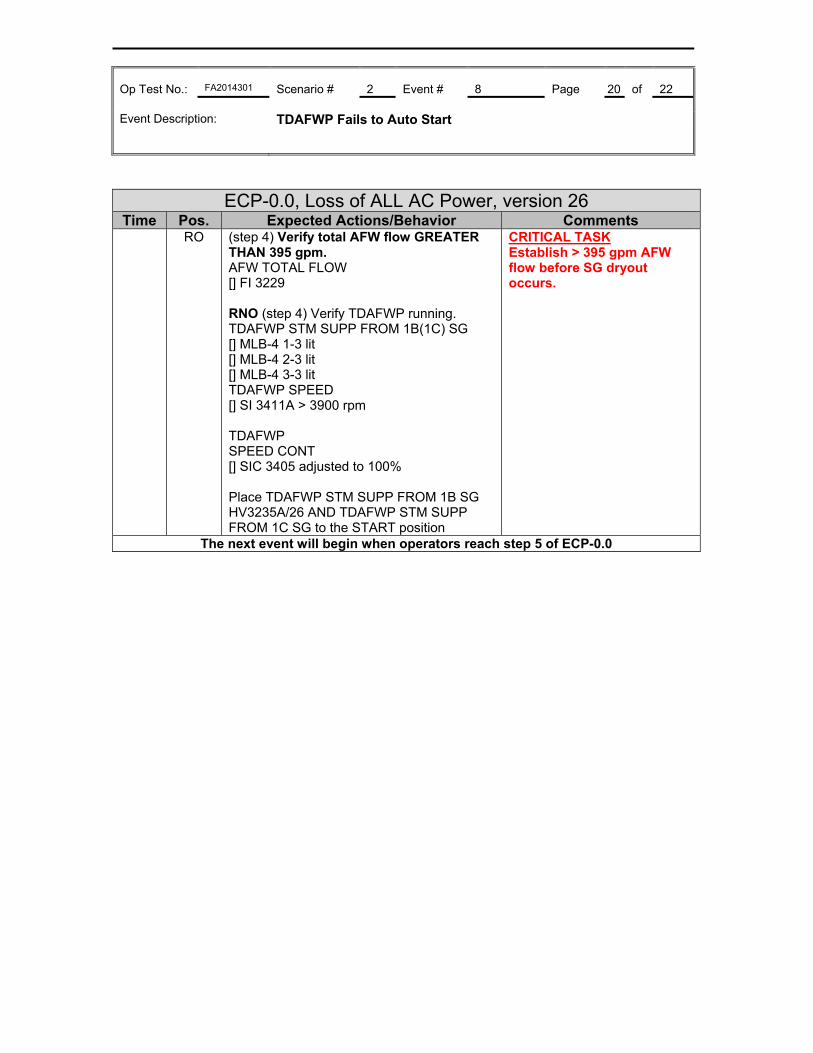
Op Test No.: FA2014301 Scenario # 2 Event # 8 Page 20 of 22 Event Description: TDAFWP Fails to Auto Start
ECP-0.0, Loss of ALL AC Power, version 26 Time Pos. Expected Actions/Behavior Comments
RO (step 4) Verify total AFW flow GREATER THAN 395 gpm. AFW TOTAL FLOW [] FI 3229 RNO (step 4) Verify TDAFWP running. TDAFWP STM SUPP FROM 1B(1C) SG [] MLB-4 1-3 lit [] MLB-4 2-3 lit [] MLB-4 3-3 lit TDAFWP SPEED [] SI 3411A > 3900 rpm TDAFWP SPEED CONT [] SIC 3405 adjusted to 100% Place TDAFWP STM SUPP FROM 1B SG HV3235A/26 AND TDAFWP STM SUPP FROM 1C SG to the START position
CRITICAL TASK Establish > 395 gpm AFW flow before SG dryout occurs.
The next event will begin when operators reach step 5 of ECP-0.0
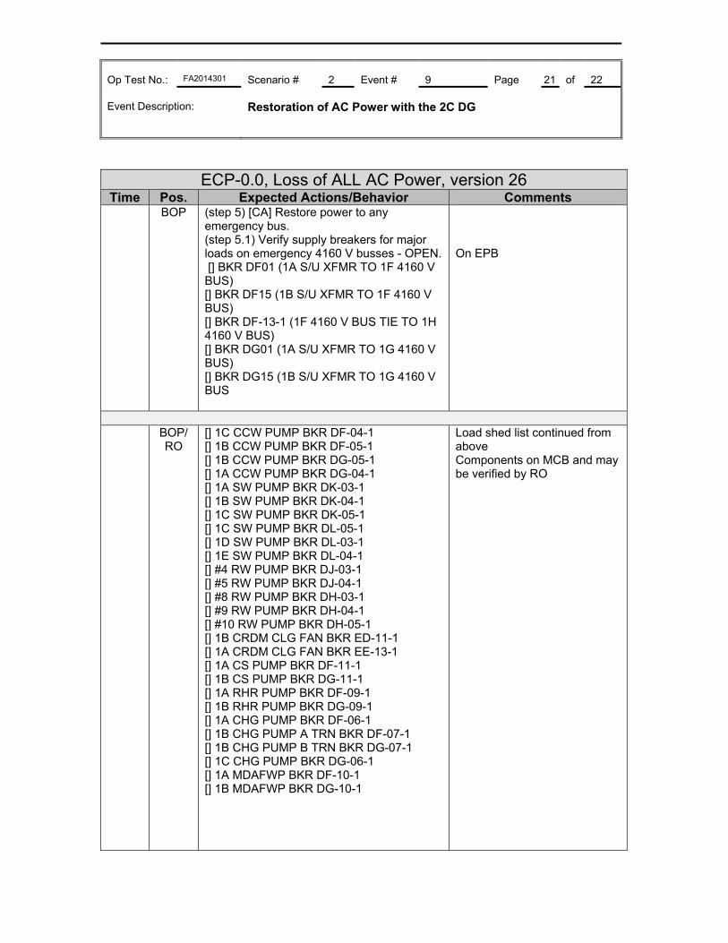
Op Test No.: FA2014301 Scenario # 2 Event # 9 Page 21 of 22 Event Description: Restoration of AC Power with the 2C DG
ECP-0.0, Loss of ALL AC Power, version 26 Time Pos. Expected Actions/Behavior Comments
BOP (step 5) [CA] Restore power to any emergency bus. (step 5.1) Verify supply breakers for major loads on emergency 4160 V busses - OPEN. [] BKR DF01 (1A S/U XFMR TO 1F 4160 V BUS) [] BKR DF15 (1B S/U XFMR TO 1F 4160 V BUS) [] BKR DF-13-1 (1F 4160 V BUS TIE TO 1H 4160 V BUS) [] BKR DG01 (1A S/U XFMR TO 1G 4160 V BUS) [] BKR DG15 (1B S/U XFMR TO 1G 4160 V BUS
On EPB
BOP/
RO [] 1C CCW PUMP BKR DF-04-1 [] 1B CCW PUMP BKR DF-05-1 [] 1B CCW PUMP BKR DG-05-1 [] 1A CCW PUMP BKR DG-04-1 [] 1A SW PUMP BKR DK-03-1 [] 1B SW PUMP BKR DK-04-1 [] 1C SW PUMP BKR DK-05-1 [] 1C SW PUMP BKR DL-05-1 [] 1D SW PUMP BKR DL-03-1 [] 1E SW PUMP BKR DL-04-1 [] #4 RW PUMP BKR DJ-03-1 [] #5 RW PUMP BKR DJ-04-1 [] #8 RW PUMP BKR DH-03-1 [] #9 RW PUMP BKR DH-04-1 [] #10 RW PUMP BKR DH-05-1 [] 1B CRDM CLG FAN BKR ED-11-1 [] 1A CRDM CLG FAN BKR EE-13-1 [] 1A CS PUMP BKR DF-11-1 [] 1B CS PUMP BKR DG-11-1 [] 1A RHR PUMP BKR DF-09-1 [] 1B RHR PUMP BKR DG-09-1 [] 1A CHG PUMP BKR DF-06-1 [] 1B CHG PUMP A TRN BKR DF-07-1 [] 1B CHG PUMP B TRN BKR DG-07-1 [] 1C CHG PUMP BKR DG-06-1 [] 1A MDAFWP BKR DF-10-1 [] 1B MDAFWP BKR DG-10-1
Load shed list continued from above Components on MCB and may be verified by RO
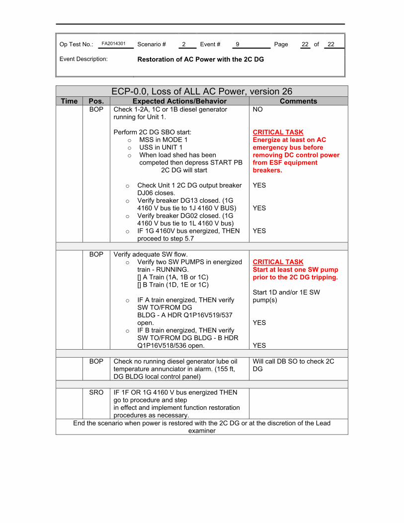
Op Test No.: FA2014301 Scenario # 2 Event # 9 Page 22 of 22 Event Description: Restoration of AC Power with the 2C DG
ECP-0.0, Loss of ALL AC Power, version 26 Time Pos. Expected Actions/Behavior Comments
BOP Check 1-2A, 1C or 1B diesel generator running for Unit 1. Perform 2C DG SBO start:
o MSS in MODE 1 o USS in UNIT 1 o When load shed has been
competed then depress START PB 2C DG will start
o Check Unit 1 2C DG output breaker
DJ06 closes. o Verify breaker DG13 closed. (1G
4160 V bus tie to 1J 4160 V BUS) o Verify breaker DG02 closed. (1G
4160 V bus tie to 1L 4160 V bus) o IF 1G 4160V bus energized, THEN
proceed to step 5.7
NO CRITICAL TASK Energize at least on AC emergency bus before removing DC control power from ESF equipment breakers. YES YES YES
BOP Verify adequate SW flow.
o Verify two SW PUMPS in energized train - RUNNING.
[] A Train (1A, 1B or 1C) [] B Train (1D, 1E or 1C)
o IF A train energized, THEN verify SW TO/FROM DG
BLDG - A HDR Q1P16V519/537 open.
o IF B train energized, THEN verify SW TO/FROM DG BLDG - B HDR Q1P16V518/536 open.
CRITICAL TASK Start at least one SW pump prior to the 2C DG tripping. Start 1D and/or 1E SW pump(s) YES YES
BOP Check no running diesel generator lube oil
temperature annunciator in alarm. (155 ft, DG BLDG local control panel)
Will call DB SO to check 2C DG
SRO IF 1F OR 1G 4160 V bus energized THEN
go to procedure and step in effect and implement function restoration procedures as necessary.
End the scenario when power is restored with the 2C DG or at the discretion of the Lead examiner
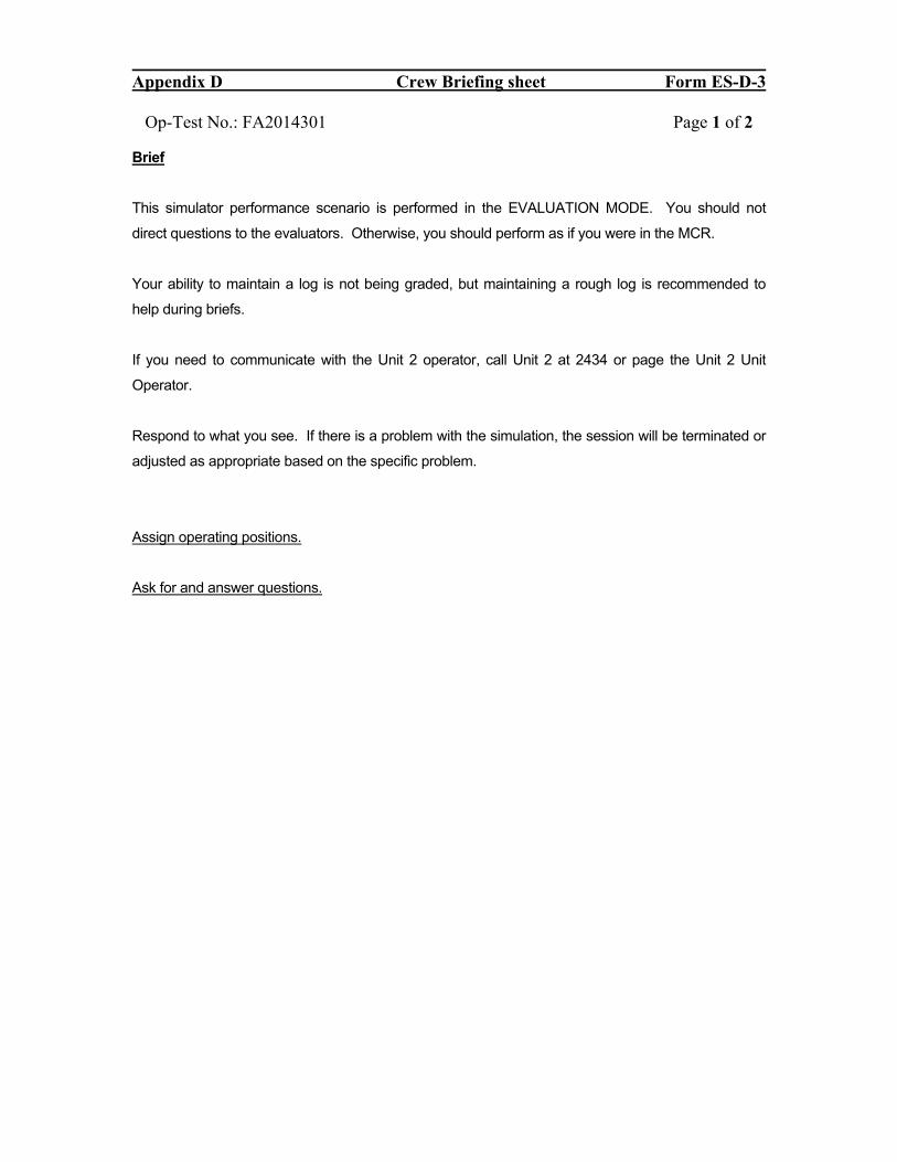
Appendix D Crew Briefing sheet Form ES-D-3
Op-Test No.: FA2014301 Page 1 of 2 Brief
This simulator performance scenario is performed in the EVALUATION MODE. You should not
direct questions to the evaluators. Otherwise, you should perform as if you were in the MCR.
Your ability to maintain a log is not being graded, but maintaining a rough log is recommended to
help during briefs.
If you need to communicate with the Unit 2 operator, call Unit 2 at 2434 or page the Unit 2 Unit
Operator.
Respond to what you see. If there is a problem with the simulation, the session will be terminated or
adjusted as appropriate based on the specific problem.
Assign operating positions.
Ask for and answer questions.
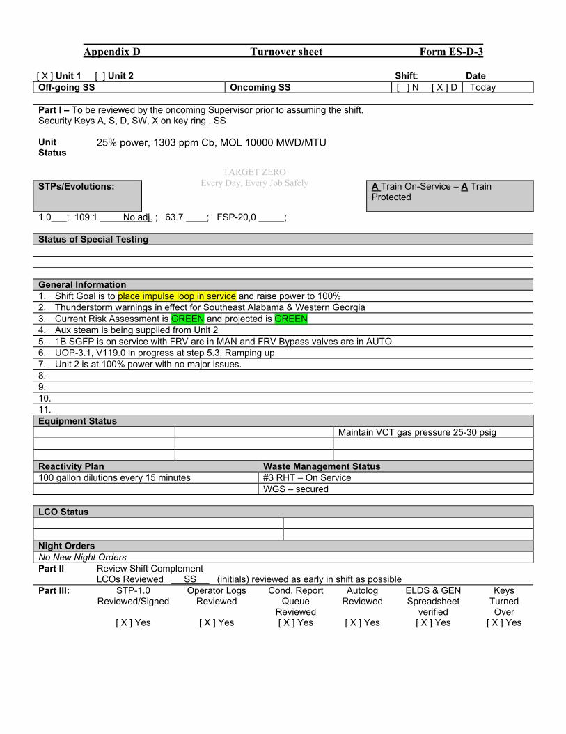
Appendix D Turnover sheet Form ES-D-3
[ X ] Unit 1 [ ] Unit 2 Shift: Date Off-going SS Oncoming SS [ ] N [ X ] D Today Part I – To be reviewed by the oncoming Supervisor prior to assuming the shift. Security Keys A, S, D, SW, X on key ring . SS Unit Status
25% power, 1303 ppm Cb, MOL 10000 MWD/MTU
STPs/Evolutions:
A Train On-Service – A Train Protected
1.0 ; 109.1 No adj. ; 63.7 ; FSP-20,0 ; Status of Special Testing General Information 1. Shift Goal is to place impulse loop in service and raise power to 100% 2. Thunderstorm warnings in effect for Southeast Alabama & Western Georgia 3. Current Risk Assessment is GREEN and projected is GREEN 4. Aux steam is being supplied from Unit 2 5. 1B SGFP is on service with FRV are in MAN and FRV Bypass valves are in AUTO 6. UOP-3.1, V119.0 in progress at step 5.3, Ramping up 7. Unit 2 is at 100% power with no major issues. 8. 9. 10. 11. Equipment Status Maintain VCT gas pressure 25-30 psig Reactivity Plan Waste Management Status 100 gallon dilutions every 15 minutes #3 RHT – On Service WGS – secured LCO Status Night Orders No New Night Orders Part II Review Shift Complement LCOs Reviewed SS (initials) reviewed as early in shift as possible Part III: STP-1.0
Reviewed/Signed Operator Logs
Reviewed Cond. Report
Queue Reviewed
Autolog Reviewed
ELDS & GEN Spreadsheet
verified
Keys Turned Over
[ X ] Yes [ X ] Yes [ X ] Yes [ X ] Yes [ X ] Yes [ X ] Yes
TARGET ZERO Every Day, Every Job Safely
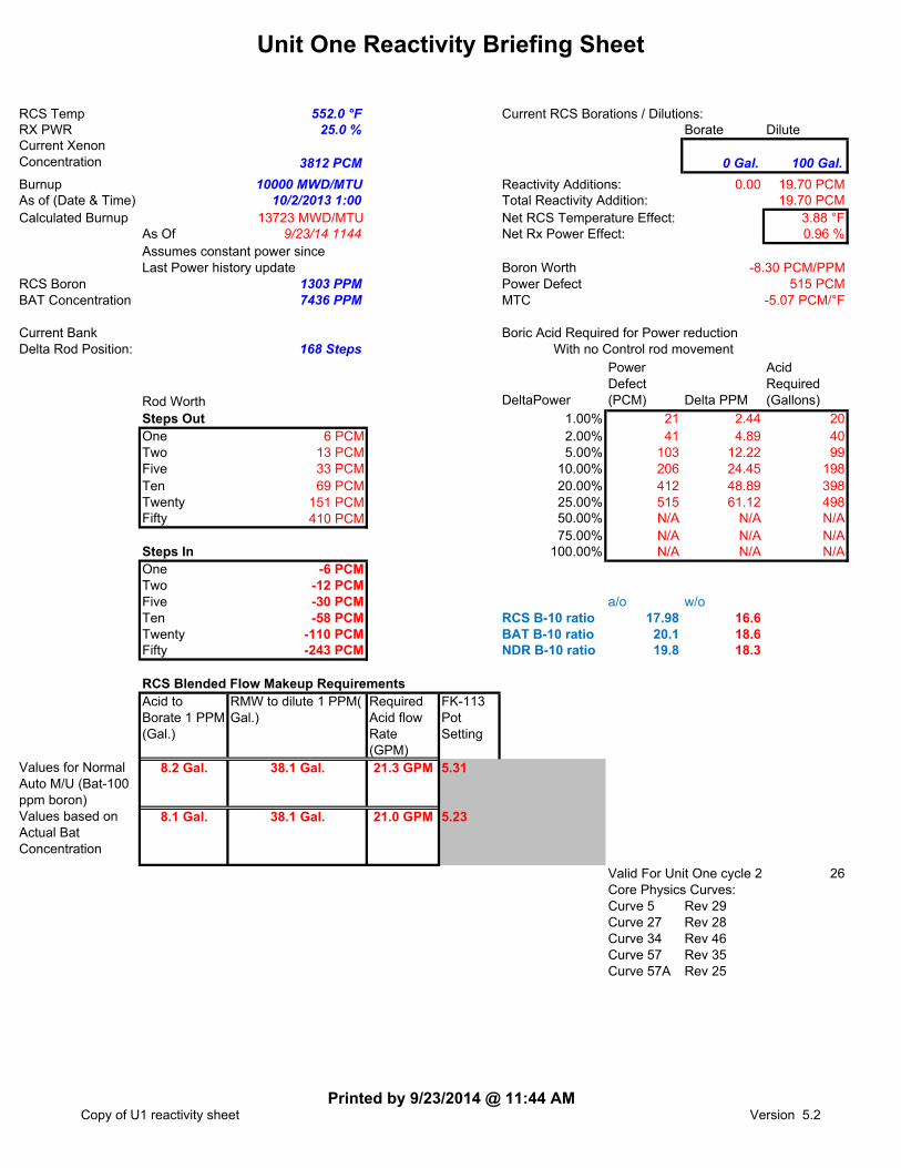
Unit One Reactivity Briefing Sheet
RCS Temp 552.0 °F Current RCS Borations / Dilutions:RX PWR 25.0 % Borate DiluteCurrent Xenon Concentration 3812 PCM 0 Gal. 100 Gal.
Burnup 10000 MWD/MTU Reactivity Additions: 0.00 19.70 PCMAs of (Date & Time) 10/2/2013 1:00 Total Reactivity Addition: 19.70 PCMCalculated Burnup 13723 MWD/MTU Net RCS Temperature Effect: 3.88 °F
As Of 9/23/14 1144 Net Rx Power Effect: 0.96 %Assumes constant power sinceLast Power history update Boron Worth
RCS Boron 1303 PPM Power DefectBAT Concentration 7436 PPM MTC
Current Bank Boric Acid Required for Power reductionDelta Rod Position: 168 Steps With no Control rod movement
Rod Worth DeltaPower
Power Defect (PCM) Delta PPM
Acid Required (Gallons)
Steps Out 1.00% 21 2.44 20One 6 PCM 2.00% 41 4.89 40Two 13 PCM 5.00% 103 12.22 99Five 33 PCM 10.00% 206 24.45 198Ten 69 PCM 20.00% 412 48.89 398Twenty 151 PCM 25.00% 515 61.12 498Fifty 410 PCM 50.00% N/A N/A N/A
75.00% N/A N/A N/ASteps In 100.00% N/A N/A N/AOne -6 PCMTwo -12 PCMFive -30 PCM a/o w/oTen -58 PCM RCS B-10 ratio 17.98 16.6Twenty -110 PCM BAT B-10 ratio 20.1 18.6Fifty -243 PCM NDR B-10 ratio 19.8 18.3
RCS Blended Flow Makeup RequirementsAcid to Borate 1 PPM (Gal.)
RMW to dilute 1 PPM( Gal.)
Required Acid flow Rate (GPM)
FK-113 Pot Setting
Values for Normal Auto M/U (Bat-100 ppm boron)
8.2 Gal. 38.1 Gal. 21.3 GPM
Values based on Actual Bat Concentration
8.1 Gal. 38.1 Gal. 21.0 GPM
Valid For Unit One cycle 24 26Core Physics Curves:Curve 5 Rev 29Curve 27 Rev 28Curve 34 Rev 46Curve 57 Rev 35Curve 57A Rev 25
5.23
-8.30 PCM/PPM515 PCM
-5.07 PCM/°F
5.31
Copy of U1 reactivity sheetPrinted by 9/23/2014 @ 11:44 AM
Version 5.2

Scenario #2 FA2014301
Southern Nuclear J.M. Farley Nuclear Plant
Operations Training Simulator Exam Scenario
BOOTH INSTRUCTOR GUIDE
ILT-37 NRC EXAM SCENARIO #2
Validation time: 100 Minutes Validated by: Sorrell, Newell, Smith
TRN Supervisor Approval: Billy Thornton Date: 9/24/14
NRC Chief Examiner SEE NUREG 1021 FORM ES-301-3
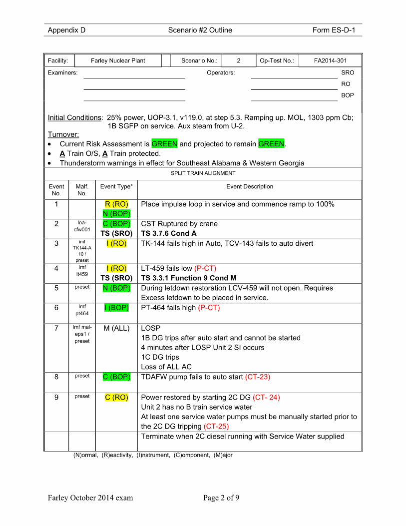
Appendix D Scenario #2 Outline Form ES-D-1
Farley October 2014 exam Page 2 of 9
Facility: Farley Nuclear Plant Scenario No.: 2 Op-Test No.: FA2014-301
Examiners: Operators: SRO
RO
BOP
Initial Conditions: 25% power, UOP-3.1, v119.0, at step 5.3. Ramping up. MOL, 1303 ppm Cb; 1B SGFP on service. Aux steam from U-2.
Turnover: Current Risk Assessment is GREEN and projected to remain GREEN. A Train O/S, A Train protected. Thunderstorm warnings in effect for Southeast Alabama & Western Georgia
SPLIT TRAIN ALIGNMENT
Event No.
Malf. No.
Event Type* Event Description
1 R (RO) N (BOP)
Place impulse loop in service and commence ramp to 100%
2 loa-cfw001
C (BOP) TS (SRO)
CST Ruptured by craneTS 3.7.6 Cond A
3 imf TK144-A
10 / preset
I (RO)
TK-144 fails high in Auto, TCV-143 fails to auto divert
4 Imf lt459
I (RO) TS (SRO)
LT-459 fails low (P-CT)TS 3.3.1 Function 9 Cond M
5 preset N (BOP) During letdown restoration LCV-459 will not open. Requires Excess letdown to be placed in service.
6 Imf pt464
I (BOP)
PT-464 fails high (P-CT)
7 Imf mal-eps1 / preset
M (ALL) LOSP 1B DG trips after auto start and cannot be started 4 minutes after LOSP Unit 2 SI occurs 1C DG trips Loss of ALL AC
8 preset C (BOP)
TDAFW pump fails to auto start (CT-23)
9 preset C (RO)
Power restored by starting 2C DG (CT- 24)Unit 2 has no B train service water At least one service water pumps must be manually started prior to the 2C DG tripping (CT-25)
Terminate when 2C diesel running with Service Water supplied
(N)ormal, (R)eactivity, (I)nstrument, (C)omponent, (M)ajor
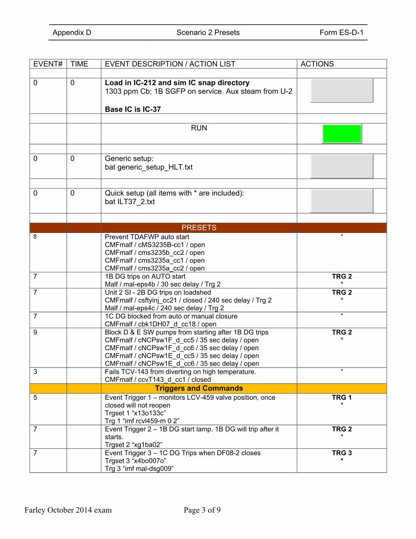
Appendix D Scenario 2 Presets Form ES-D-1
Farley October 2014 exam Page 3 of 9
EVENT# TIME EVENT DESCRIPTION / ACTION LIST ACTIONS 0 0 Load in IC-212 and sim IC snap directory
1303 ppm Cb; 1B SGFP on service. Aux steam from U-2 Base IC is IC-37
RUN
0 0 Generic setup:
bat generic_setup_HLT.txt
0 0 Quick setup (all items with * are included):
bat ILT37_2.txt
PRESETS 8 Prevent TDAFWP auto start
CMFmalf / cMS3235B-cc1 / open CMFmalf / cms3235b_cc2 / open CMFmalf / cms3235a_cc1 / open CMFmalf / cms3235a_cc2 / open
*
7 1B DG trips on AUTO start Malf / mal-eps4b / 30 sec delay / Trg 2
TRG 2 *
7 Unit 2 SI - 2B DG trips on loadshed CMFmalf / csftyinj_cc21 / closed / 240 sec delay / Trg 2 Malf / mal-eps4c / 240 sec delay / Trg 2
TRG 2 *
7 1C DG blocked from auto or manual closure CMFmalf / cbk1DH07_d_cc18 / open
*
9 Block D & E SW pumps from starting after 1B DG trips CMFmalf / cNCPsw1F_d_cc5 / 35 sec delay / open CMFmalf / cNCPsw1F_d_cc6 / 35 sec delay / open CMFmalf / cNCPsw1E_d_cc5 / 35 sec delay / open CMFmalf / cNCPsw1E_d_cc6 / 35 sec delay / open
TRG 2 *
3 Fails TCV-143 from diverting on high temperature. CMFmalf / ccvT143_d_cc1 / closed
*
Triggers and Commands 5 Event Trigger 1 – monitors LCV-459 valve position, once
closed will not reopen Trgset 1 “x13o133c” Trg 1 “imf rcvl459-m 0 2”
TRG 1 *
7 Event Trigger 2 – 1B DG start lamp. 1B DG will trip after it starts. Trgset 2 “xg1ba02”
TRG 2 *
7 Event Trigger 3 – 1C DG Trips when DF08-2 closes Trgset 3 “x4bo007o” Trg 3 “imf mal-dsg009”
TRG 3 *
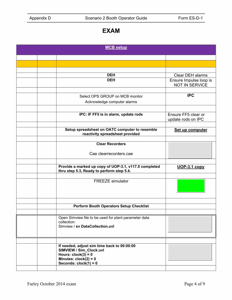
Appendix D Scenario 2 Booth Operator Guide Form ES-D-1
Farley October 2014 exam Page 4 of 9
EXAM
MCB setup
DEH Clear DEH alarms DEH Ensure Impulse loop is
NOT IN SERVICE Select OPS GROUP on MCB monitor
Acknowledge computer alarms
IPC
IPC: IF FF5 is in alarm, update rods Ensure FF5 clear or
update rods on IPC Setup spreadsheet on OATC computer to resemble
reactivity spreadsheet provided Set up computer
Clear Recorders
Cae clearrecorders.cae
Provide a marked up copy of UOP-3.1, v117.0 completed
thru step 5.3, Ready to perform step 5.4. UOP-3.1 copy
FREEZE simulator
Perform Booth Operators Setup Checklist Open Simview file to be used for plant parameter data
collection: Simview / sv DataCollection.uvl
If needed, adjust sim time back to 00:00:00
SIMVIEW / Sim_Clock.uvl Hours: clock(3) = 0 Minutes: clock(2) = 0 Seconds: clock(1) = 0
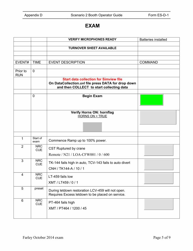
Appendix D Scenario 2 Booth Operator Guide Form ES-D-1
Farley October 2014 exam Page 5 of 9
EXAM
VERIFY MICROPHONES READY Batteries installed TURNOVER SHEET AVAILABLE EVENT# TIME EVENT DESCRIPTION COMMAND Prior to RUN
0
Start data collection for Simview fileOn DataCollection.uvl file press DATA for drop down
and then COLLECT to start collecting data
0 Begin Exam
Verify Horns ON: hornflagHORNS ON = TRUE
1 Start of exam Commence Ramp up to 100% power.
2 NRC CUE CST Ruptured by crane
Remote / N21 / LOA-CFW001 / 0 / 600
3 NRC CUE TK-144 fails high in auto, TCV-143 fails to auto divert
CNH / TK144-A / 10 / 1
4 NRC CUE LT-459 fails low
XMT / LT459 / 0 / 1
5 preset During letdown restoration LCV-459 will not open. Requires Excess letdown to be placed on service.
6 NRC CUE PT-464 fails high
XMT / PT464 / 1200 / 45
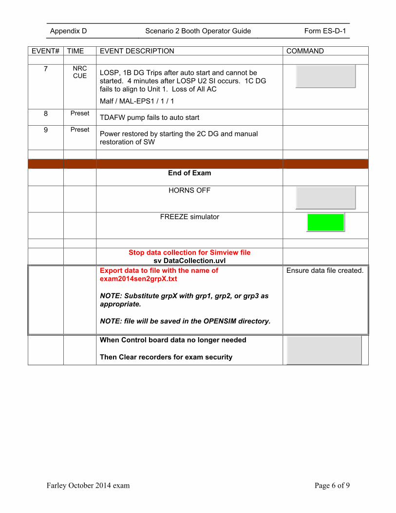
Appendix D Scenario 2 Booth Operator Guide Form ES-D-1
Farley October 2014 exam Page 6 of 9
EVENT# TIME EVENT DESCRIPTION COMMAND
7 NRC CUE
LOSP, 1B DG Trips after auto start and cannot be started. 4 minutes after LOSP U2 SI occurs. 1C DG fails to align to Unit 1. Loss of All AC
Malf / MAL-EPS1 / 1 / 1
8 Preset TDAFW pump fails to auto start
9 Preset Power restored by starting the 2C DG and manual restoration of SW
End of Exam
HORNS OFF
FREEZE simulator
Stop data collection for Simview file
sv DataCollection.uvl
Export data to file with the name of exam2014sen2grpX.txt
NOTE: Substitute grpX with grp1, grp2, or grp3 as appropriate.
NOTE: file will be saved in the OPENSIM directory.
Ensure data file created.
When Control board data no longer needed Then Clear recorders for exam security
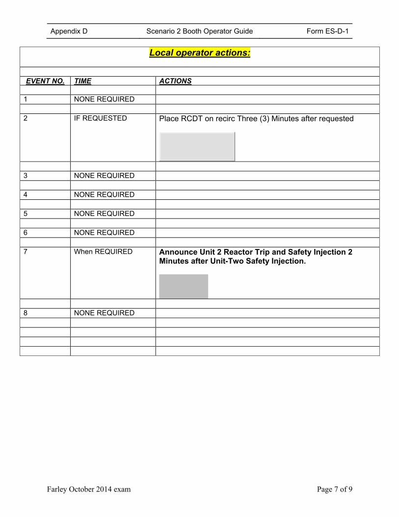
Appendix D Scenario 2 Booth Operator Guide Form ES-D-1
Farley October 2014 exam Page 7 of 9
Local operator actions:
EVENT NO. TIME ACTIONS
1 NONE REQUIRED 2 IF REQUESTED Place RCDT on recirc Three (3) Minutes after requested
3 NONE REQUIRED 4 NONE REQUIRED 5 NONE REQUIRED 6 NONE REQUIRED 7 When REQUIRED Announce Unit 2 Reactor Trip and Safety Injection 2
Minutes after Unit-Two Safety Injection.
8 NONE REQUIRED
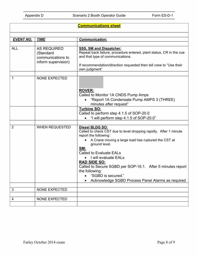
Appendix D Scenario 2 Booth Operator Guide Form ES-D-1
Farley October 2014 exam Page 8 of 9
Communications sheet
EVENT NO. TIME Communication:
ALL AS REQUIRED
(Standard communications to inform supervision)
SSS, SM and Dispatcher:Repeat back failure, procedure entered, plant status, CR in the cue and that type of communications. If recommendation/direction requested then tell crew to “Use their own judgment”
1 NONE EXPECTED
ROVER: Called to Monitor 1A CNDS Pump Amps
“Report 1A Condensate Pump AMPS 3 (THREE) minutes after request”
Turbine SO: Called to perform step 4.1.5 of SOP-20.0
“I will perform step 4.1.5 of SOP-20.0” 2 WHEN REQUESTED Diesel BLDG SO:
Called to check CST due to level dropping rapidly. After 1 minute report the following:
A Crane moving a large load has ruptured the CST at ground level.
SM: Called to Evaluate EALs
I will evaluate EALs RAD SIDE SO: Called to Secure SGBD per SOP-16.1. After 5 minutes report the following:
“SGBD is secured.” Acknowledge SGBD Process Panel Alarms as required
3 NONE EXPECTED 4 NONE EXPECTED
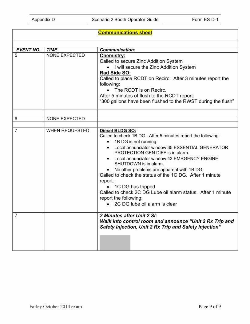
Appendix D Scenario 2 Booth Operator Guide Form ES-D-1
Farley October 2014 exam Page 9 of 9
Communications sheet
EVENT NO. TIME Communication:
5 NONE EXPECTED Chemistry: Called to secure Zinc Addition System
I will secure the Zinc Addition System Rad Side SO: Called to place RCDT on Recirc: After 3 minutes report the following:
The RCDT is on Recirc. After 5 minutes of flush to the RCDT report: “300 gallons have been flushed to the RWST during the flush”
6 NONE EXPECTED 7 WHEN REQUESTED Diesel BLDG SO:
Called to check 1B DG. After 5 minutes report the following: 1B DG is not running. Local annunciator window 35 ESSENTIAL GENERATOR
PROTECTION GEN DIFF is in alarm. Local annunciator window 43 EMRGENCY ENGINE
SHUTDOWN is in alarm. No other problems are apparent with 1B DG.
Called to check the status of the 1C DG. After 1 minute report:
1C DG has tripped Called to check 2C DG Lube oil alarm status. After 1 minute report the following:
2C DG lube oil alarm is clear
7
2 Minutes after Unit 2 SI: Walk into control room and announce “Unit 2 Rx Trip and Safety Injection, Unit 2 Rx Trip and Safety Injection”
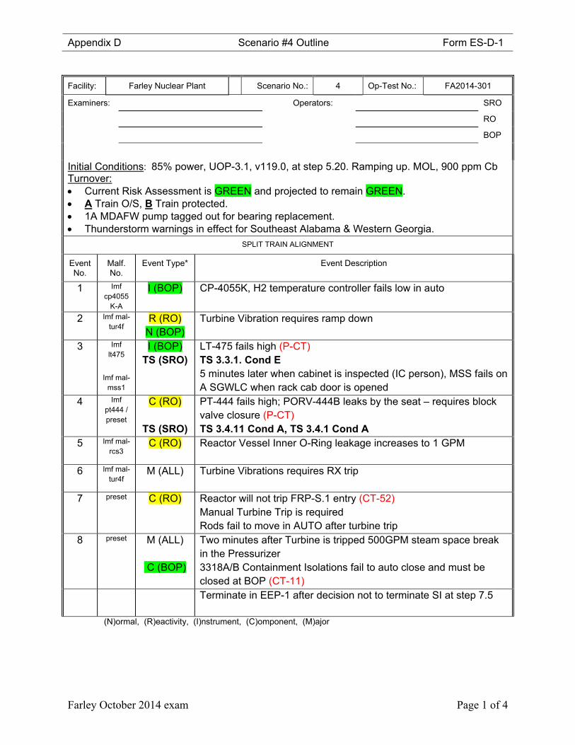
Appendix D Scenario #4 Outline Form ES-D-1
Farley October 2014 exam Page 1 of 4
Facility: Farley Nuclear Plant Scenario No.: 4 Op-Test No.: FA2014-301
Examiners: Operators: SRO
RO
BOP
Initial Conditions: 85% power, UOP-3.1, v119.0, at step 5.20. Ramping up. MOL, 900 ppm Cb
Turnover: Current Risk Assessment is GREEN and projected to remain GREEN. A Train O/S, B Train protected. 1A MDAFW pump tagged out for bearing replacement. Thunderstorm warnings in effect for Southeast Alabama & Western Georgia.
SPLIT TRAIN ALIGNMENT
Event No.
Malf. No.
Event Type* Event Description
1 Imf cp4055
K-A
I (BOP) CP-4055K, H2 temperature controller fails low in auto
2 Imf mal-tur4f
R (RO) N (BOP)
Turbine Vibration requires ramp down
3 Imf lt475
Imf mal-mss1
I (BOP) TS (SRO)
LT-475 fails high (P-CT) TS 3.3.1. Cond E 5 minutes later when cabinet is inspected (IC person), MSS fails on A SGWLC when rack cab door is opened
4 Imf pt444 / preset
C (RO)
TS (SRO)
PT-444 fails high; PORV-444B leaks by the seat – requires block valve closure (P-CT) TS 3.4.11 Cond A, TS 3.4.1 Cond A
5 Imf mal-rcs3
C (RO)
Reactor Vessel Inner O-Ring leakage increases to 1 GPM
6 Imf mal-tur4f
M (ALL) Turbine Vibrations requires RX trip
7 preset C (RO)
Reactor will not trip FRP-S.1 entry (CT-52) Manual Turbine Trip is required Rods fail to move in AUTO after turbine trip
8 preset M (ALL)
C (BOP)
Two minutes after Turbine is tripped 500GPM steam space break in the Pressurizer 3318A/B Containment Isolations fail to auto close and must be closed at BOP (CT-11)
Terminate in EEP-1 after decision not to terminate SI at step 7.5
(N)ormal, (R)eactivity, (I)nstrument, (C)omponent, (M)ajor
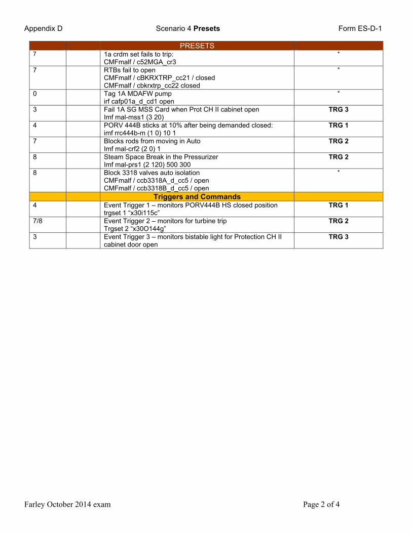
Appendix D Scenario 4 Presets Form ES-D-1
Farley October 2014 exam Page 2 of 4
PRESETS 7 1a crdm set fails to trip:
CMFmalf / c52MGA_cr3 *
7 RTBs fail to open CMFmalf / cBKRXTRP_cc21 / closed CMFmalf / cbkrxtrp_cc22 closed
*
0 Tag 1A MDAFW pump irf cafp01a_d_cd1 open
*
3 Fail 1A SG MSS Card when Prot CH II cabinet open Imf mal-mss1 (3 20)
TRG 3
4 PORV 444B sticks at 10% after being demanded closed: imf rrc444b-m (1 0) 10 1
TRG 1
7 Blocks rods from moving in Auto Imf mal-crf2 (2 0) 1
TRG 2
8 Steam Space Break in the Pressurizer Imf mal-prs1 (2 120) 500 300
TRG 2
8 Block 3318 valves auto isolation CMFmalf / ccb3318A_d_cc5 / open CMFmalf / ccb3318B_d_cc5 / open
*
Triggers and Commands 4 Event Trigger 1 – monitors PORV444B HS closed position
trgset 1 “x30i115c” TRG 1
7/8 Event Trigger 2 – monitors for turbine trip Trgset 2 “x30O144g”
TRG 2
3 Event Trigger 3 – monitors bistable light for Protection CH II cabinet door open
TRG 3
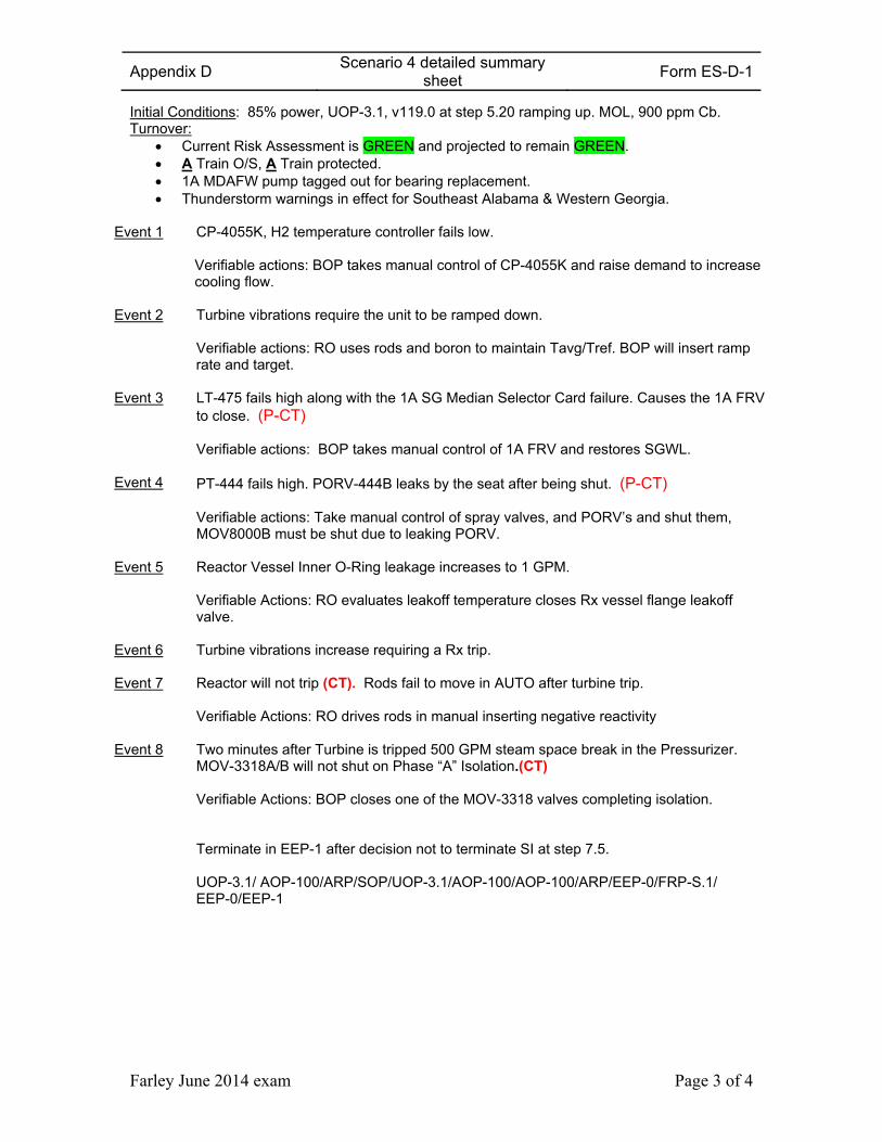
Appendix D Scenario 4 detailed summary
sheet Form ES-D-1
Farley June 2014 exam Page 3 of 4
Initial Conditions: 85% power, UOP-3.1, v119.0 at step 5.20 ramping up. MOL, 900 ppm Cb. Turnover:
Current Risk Assessment is GREEN and projected to remain GREEN. A Train O/S, A Train protected. 1A MDAFW pump tagged out for bearing replacement. Thunderstorm warnings in effect for Southeast Alabama & Western Georgia.
Event 1 CP-4055K, H2 temperature controller fails low. Verifiable actions: BOP takes manual control of CP-4055K and raise demand to increase cooling flow.
Event 2 Turbine vibrations require the unit to be ramped down. Verifiable actions: RO uses rods and boron to maintain Tavg/Tref. BOP will insert ramp rate and target.
Event 3 LT-475 fails high along with the 1A SG Median Selector Card failure. Causes the 1A FRV to close. (P-CT) Verifiable actions: BOP takes manual control of 1A FRV and restores SGWL.
Event 4 PT-444 fails high. PORV-444B leaks by the seat after being shut. (P-CT) Verifiable actions: Take manual control of spray valves, and PORV’s and shut them, MOV8000B must be shut due to leaking PORV.
Event 5 Reactor Vessel Inner O-Ring leakage increases to 1 GPM. Verifiable Actions: RO evaluates leakoff temperature closes Rx vessel flange leakoff valve.
Event 6 Turbine vibrations increase requiring a Rx trip.
Event 7 Reactor will not trip (CT). Rods fail to move in AUTO after turbine trip. Verifiable Actions: RO drives rods in manual inserting negative reactivity
Event 8 Two minutes after Turbine is tripped 500 GPM steam space break in the Pressurizer. MOV-3318A/B will not shut on Phase “A” Isolation.(CT) Verifiable Actions: BOP closes one of the MOV-3318 valves completing isolation. Terminate in EEP-1 after decision not to terminate SI at step 7.5.
UOP-3.1/ AOP-100/ARP/SOP/UOP-3.1/AOP-100/AOP-100/ARP/EEP-0/FRP-S.1/ EEP-0/EEP-1
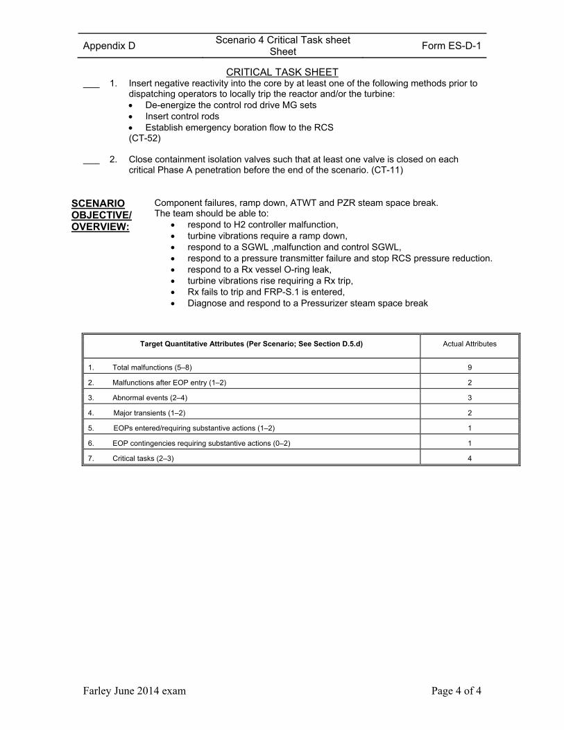
Appendix D Scenario 4 Critical Task sheet
Sheet Form ES-D-1
Farley June 2014 exam Page 4 of 4
CRITICAL TASK SHEET 1. Insert negative reactivity into the core by at least one of the following methods prior to
dispatching operators to locally trip the reactor and/or the turbine: De-energize the control rod drive MG sets Insert control rods Establish emergency boration flow to the RCS (CT-52)
2. Close containment isolation valves such that at least one valve is closed on each
critical Phase A penetration before the end of the scenario. (CT-11)
SCENARIO OBJECTIVE/ OVERVIEW:
Component failures, ramp down, ATWT and PZR steam space break. The team should be able to:
respond to H2 controller malfunction, turbine vibrations require a ramp down, respond to a SGWL ,malfunction and control SGWL, respond to a pressure transmitter failure and stop RCS pressure reduction. respond to a Rx vessel O-ring leak, turbine vibrations rise requiring a Rx trip, Rx fails to trip and FRP-S.1 is entered, Diagnose and respond to a Pressurizer steam space break
Target Quantitative Attributes (Per Scenario; See Section D.5.d) Actual Attributes
1. Total malfunctions (5–8) 9
2. Malfunctions after EOP entry (1–2) 2
3. Abnormal events (2–4) 3
4. Major transients (1–2) 2
5. EOPs entered/requiring substantive actions (1–2) 1
6. EOP contingencies requiring substantive actions (0–2) 1
7. Critical tasks (2–3) 4
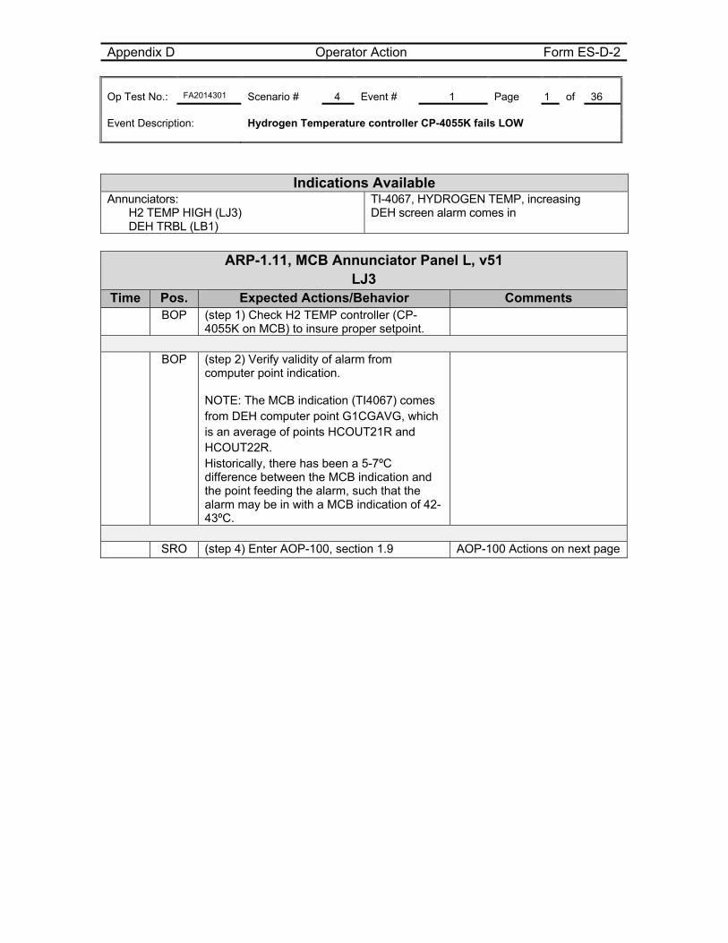
Appendix D Operator Action Form ES-D-2 Op Test No.: FA2014301 Scenario # 4 Event # 1 Page 1 of 36 Event Description: Hydrogen Temperature controller CP-4055K fails LOW
ARP-1.11, MCB Annunciator Panel L, v51 LJ3
Time Pos. Expected Actions/Behavior Comments BOP (step 1) Check H2 TEMP controller (CP-
4055K on MCB) to insure proper setpoint.
BOP (step 2) Verify validity of alarm from
computer point indication. NOTE: The MCB indication (TI4067) comes from DEH computer point G1CGAVG, which is an average of points HCOUT21R and HCOUT22R. Historically, there has been a 5-7ºC difference between the MCB indication and the point feeding the alarm, such that the alarm may be in with a MCB indication of 42-43ºC.
SRO (step 4) Enter AOP-100, section 1.9 AOP-100 Actions on next page
Indications Available Annunciators:
H2 TEMP HIGH (LJ3) DEH TRBL (LB1)
TI-4067, HYDROGEN TEMP, increasing DEH screen alarm comes in
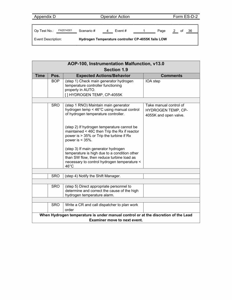
Appendix D Operator Action Form ES-D-2 Op Test No.: FA2014301 Scenario # 4 Event # 1 Page 2 of 36 Event Description: Hydrogen Temperature controller CP-4055K fails LOW
AOP-100, Instrumentation Malfunction, v13.0 Section 1.9
Time Pos. Expected Actions/Behavior Comments BOP (step 1) Check main generator hydrogen
temperature controller functioning properly in AUTO. [ ] HYDROGEN TEMP, CP-4055K
IOA step
SRO (step 1 RNO) Maintain main generator
hydrogen temp < 46°C using manual control of hydrogen temperature controller. (step 2) If hydrogen temperature cannot be maintained < 46C then Trip the Rx if reactor power is > 35% or Trip the turbine if Rx power is < 35%. (step 3) If main generator hydrogen temperature is high due to a condition other than SW flow, then reduce turbine load as necessary to control hydrogen temperature < 46°C
Take manual control of HYDROGEN TEMP, CP-4055K and open valve.
SRO (step 4) Notify the Shift Manager.
SRO (step 5) Direct appropriate personnel to
determine and correct the cause of the high hydrogen temperature alarm.
SRO Write a CR and call dispatcher to plan work
order
When Hydrogen temperature is under manual control or at the discretion of the Lead Examiner move to next event.
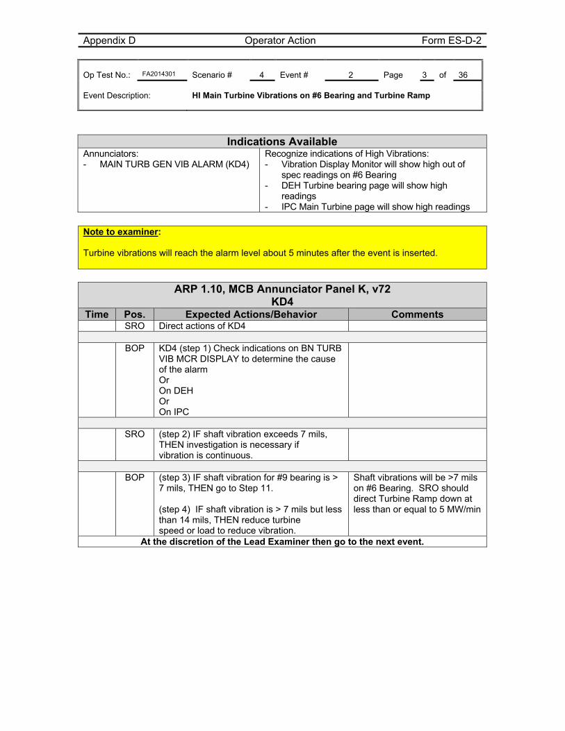
Appendix D Operator Action Form ES-D-2 Op Test No.: FA2014301 Scenario # 4 Event # 2 Page 3 of 36 Event Description: HI Main Turbine Vibrations on #6 Bearing and Turbine Ramp
Indications Available Annunciators: - MAIN TURB GEN VIB ALARM (KD4)
Recognize indications of High Vibrations: - Vibration Display Monitor will show high out of
spec readings on #6 Bearing - DEH Turbine bearing page will show high
readings - IPC Main Turbine page will show high readings
Note to examiner: Turbine vibrations will reach the alarm level about 5 minutes after the event is inserted.
ARP 1.10, MCB Annunciator Panel K, v72
KD4 Time Pos. Expected Actions/Behavior Comments
SRO Direct actions of KD4
BOP KD4 (step 1) Check indications on BN TURB VIB MCR DISPLAY to determine the cause of the alarm Or On DEH Or On IPC
SRO (step 2) IF shaft vibration exceeds 7 mils,
THEN investigation is necessary if vibration is continuous.
BOP (step 3) IF shaft vibration for #9 bearing is >
7 mils, THEN go to Step 11. (step 4) IF shaft vibration is > 7 mils but less than 14 mils, THEN reduce turbine speed or load to reduce vibration.
Shaft vibrations will be >7 mils on #6 Bearing. SRO should direct Turbine Ramp down at less than or equal to 5 MW/min
At the discretion of the Lead Examiner then go to the next event.
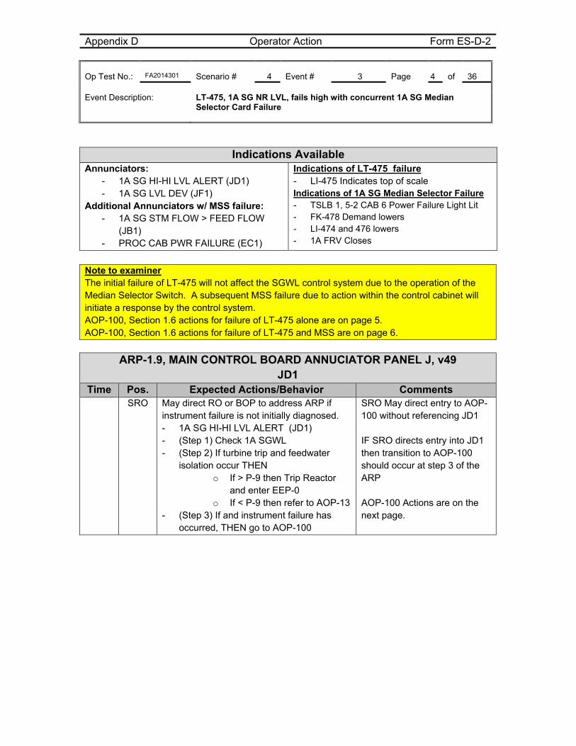
Appendix D Operator Action Form ES-D-2 Op Test No.: FA2014301 Scenario # 4 Event # 3 Page 4 of 36 Event Description: LT-475, 1A SG NR LVL, fails high with concurrent 1A SG Median
Selector Card Failure
Indications Available Annunciators:
- 1A SG HI-HI LVL ALERT (JD1) - 1A SG LVL DEV (JF1)
Additional Annunciators w/ MSS failure: - 1A SG STM FLOW > FEED FLOW
(JB1) - PROC CAB PWR FAILURE (EC1)
Indications of LT-475 failure - LI-475 Indicates top of scale Indications of 1A SG Median Selector Failure - TSLB 1, 5-2 CAB 6 Power Failure Light Lit - FK-478 Demand lowers - LI-474 and 476 lowers - 1A FRV Closes
Note to examiner The initial failure of LT-475 will not affect the SGWL control system due to the operation of the Median Selector Switch. A subsequent MSS failure due to action within the control cabinet will initiate a response by the control system. AOP-100, Section 1.6 actions for failure of LT-475 alone are on page 5. AOP-100, Section 1.6 actions for failure of LT-475 and MSS are on page 6.
ARP-1.9, MAIN CONTROL BOARD ANNUCIATOR PANEL J, v49 JD1
Time Pos. Expected Actions/Behavior Comments SRO May direct RO or BOP to address ARP if
instrument failure is not initially diagnosed. - 1A SG HI-HI LVL ALERT (JD1) - (Step 1) Check 1A SGWL - (Step 2) If turbine trip and feedwater
isolation occur THEN o If > P-9 then Trip Reactor
and enter EEP-0 o If < P-9 then refer to AOP-13
- (Step 3) If and instrument failure has occurred, THEN go to AOP-100
SRO May direct entry to AOP-100 without referencing JD1 IF SRO directs entry into JD1 then transition to AOP-100 should occur at step 3 of the ARP AOP-100 Actions are on the next page.
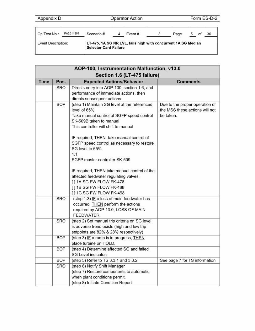
Appendix D Operator Action Form ES-D-2 Op Test No.: FA2014301 Scenario # 4 Event # 3 Page 5 of 36 Event Description: LT-475, 1A SG NR LVL, fails high with concurrent 1A SG Median
Selector Card Failure
AOP-100, Instrumentation Malfunction, v13.0 Section 1.6 (LT-475 failure)
Time Pos. Expected Actions/Behavior Comments SRO Directs entry into AOP-100, section 1.6, and
performance of immediate actions, then directs subsequent actions
BOP (step 1) Maintain SG level at the referenced level of 65%. Take manual control of SGFP speed control SK-509B taken to manual This controller will shift to manual IF required, THEN, take manual control of SGFP speed control as necessary to restore SG level to 65% 1.1 SGFP master controller SK-509 IF required, THEN take manual control of the affected feedwater regulating valves. [ ] 1A SG FW FLOW FK-478 [ ] 1B SG FW FLOW FK-488 [ ] 1C SG FW FLOW FK-498
Due to the proper operation of the MSS these actions will not be taken.
SRO (step 1.3) IF a loss of main feedwater has occurred, THEN perform the actions required by AOP-13.0, LOSS OF MAIN FEEDWATER.
SRO (step 2) Set manual trip criteria on SG level is adverse trend exists (high and low trip setpoints are 82% & 28% respectively)
BOP (step 3) IF a ramp is in progress, THEN place turbine on HOLD.
BOP (step 4) Determine affected SG and failed SG Level indicator.
BOP (step 5) Refer to TS 3.3.1 and 3.3.2 See page 7 for TS information SRO (step 6) Notify Shift Manager
(step 7) Restore components to automatic when plant conditions permit. (step 8) Initiate Condition Report
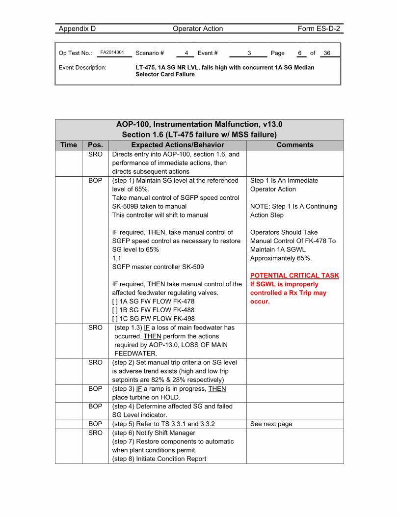
Appendix D Operator Action Form ES-D-2 Op Test No.: FA2014301 Scenario # 4 Event # 3 Page 6 of 36 Event Description: LT-475, 1A SG NR LVL, fails high with concurrent 1A SG Median
Selector Card Failure
AOP-100, Instrumentation Malfunction, v13.0 Section 1.6 (LT-475 failure w/ MSS failure)
Time Pos. Expected Actions/Behavior Comments SRO Directs entry into AOP-100, section 1.6, and
performance of immediate actions, then directs subsequent actions
BOP (step 1) Maintain SG level at the referenced level of 65%. Take manual control of SGFP speed control SK-509B taken to manual This controller will shift to manual IF required, THEN, take manual control of SGFP speed control as necessary to restore SG level to 65% 1.1 SGFP master controller SK-509 IF required, THEN take manual control of the affected feedwater regulating valves. [ ] 1A SG FW FLOW FK-478 [ ] 1B SG FW FLOW FK-488 [ ] 1C SG FW FLOW FK-498
Step 1 Is An Immediate Operator Action NOTE: Step 1 Is A Continuing Action Step Operators Should Take Manual Control Of FK-478 To Maintain 1A SGWL Approximantely 65%. POTENTIAL CRITICAL TASK If SGWL is improperly controlled a Rx Trip may occur.
SRO (step 1.3) IF a loss of main feedwater has occurred, THEN perform the actions required by AOP-13.0, LOSS OF MAIN FEEDWATER.
SRO (step 2) Set manual trip criteria on SG level is adverse trend exists (high and low trip setpoints are 82% & 28% respectively)
BOP (step 3) IF a ramp is in progress, THEN place turbine on HOLD.
BOP (step 4) Determine affected SG and failed SG Level indicator.
BOP (step 5) Refer to TS 3.3.1 and 3.3.2 See next page SRO (step 6) Notify Shift Manager
(step 7) Restore components to automatic when plant conditions permit. (step 8) Initiate Condition Report
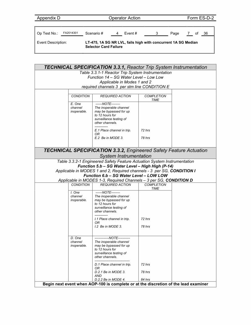
Appendix D Operator Action Form ES-D-2 Op Test No.: FA2014301 Scenario # 4 Event # 3 Page 7 of 36 Event Description: LT-475, 1A SG NR LVL, fails high with concurrent 1A SG Median
Selector Card Failure
TECHNICAL SPECIFICATION 3.3.1, Reactor Trip System Instrumentation Table 3.3.1-1 Reactor Trip System Instrumentation
Function 14 – SG Water Level – Low Low Applicable in Modes 1 and 2
required channels 3 per stm line CONDITION E
CONDITION REQUIRED ACTION COMPLETION TIME
E. One channel inoperable.
------NOTE-------- The inoperable channel may be bypassed for up to 12 hours for surveillance testing of other channels. ------------ E.1 Place channel in trip. OR E.2 Be in MODE 3.
72 hrs 78 hrs
TECHNICAL SPECIFICATION 3.3.2, Engineered Safety Feature Actuation System Instrumentation
Table 3.3.2-1 Engineered Safety Feature Actuation System Instrumentation Function 5.b – SG Water Level – High High (P-14)
Applicable in MODES 1 and 2, Required channels - 3 per SG, CONDITION I Function 6.b – SG Water Level – LOW LOW
Applicable in MODES 1-3, Required Channels – 3 per SG, CONDITION D CONDITION REQUIRED ACTION COMPLETION
TIME
I. One channel inoperable.
------NOTE-------- The inoperable channel may be bypassed for up to 12 hours for surveillance testing of other channels. ------------ I.1 Place channel in trip. OR I.2 Be in MODE 3.
72 hrs 78 hrs
D. One channel inoperable.
-------------NOTE----------- The inoperable channel may be bypassed for up to 12 hours for surveillance testing of other channels. -------------------------------- D.1 Place channel in trip. OR D.2.1 Be in MODE 3. AND D.2.2 Be in MODE 4.
72 hrs 78 hrs 84 hrs
Begin next event when AOP-100 is complete or at the discretion of the lead examiner
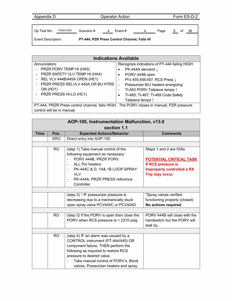
Appendix D Operator Action Form ES-D-2 Op Test No.: FA2014301 Scenario # 4 Event # 4 Page 8 of 36 Event Description: PT-444, PZR Press Control Channel, Fails HI
Indications Available Annunciators: - PRZR PORV TEMP HI (HA5) - PRZR SAFETY VLV TEMP HI (HA4) - REL VLV 444B\445A OPEN (HE1) - PRZR PRESS RELVLV 445A OR BU HTRS ON (HD1)
- PRZR PRESS HI-LO (HC1)
Recognize indications of PT-444 failing HIGH: PK-444A demand ↓ PORV 444B open - PI’s 455;456;457, RCS Press ↓ - Pressurizer B/U heaters energizing - TI-463 PORV Tailpiece temps ↑ TI-465; TI-467; TI-469 Code Safety
Tailpiece temps ↑ PT-444, PRZR Press control channel, fails HIGH. The PORV closes in manual, PZR pressure control will be in manual.
AOP-100, Instrumentation Malfunction, v13.0 section 1.1
Time Pos. Expected Actions/Behavior Comments SRO Direct entry into AOP-100 RO (step 1) Take manual control of the
following equipment as necessary: - PORV 444B, PRZR PORV. - ALL Pzr heaters - PK-444C & D, 1A& 1B LOOP SPRAY
VLV - PK-444A, PRZR PRESS reference
Controller
Steps 1 and 2 are IOAs POTENTIAL CRITICAL TASK If RCS pressure is improperly controlled a RX Trip may occur.
(step 2) * IF pressurizer pressure is
decreasing due to a mechanically stuck open spray valve PCV444C or PCV444D
*Spray valves verified functioning properly (closed) No actions required
RO (step 3) If the PORV is open then close the
PORV when RCS pressure is < 2310 psig. PORV 444B will close with the handswitch but the PORV will leak by.
RO (step 4) IF an alarm was caused by a
CONTROL instrument (PT-444/445) OR component failure, THEN perform the following as required to restore RCS pressure to desired value. - Take manual control of PORV’s, Block
valves, Pressurizer heaters and spray.
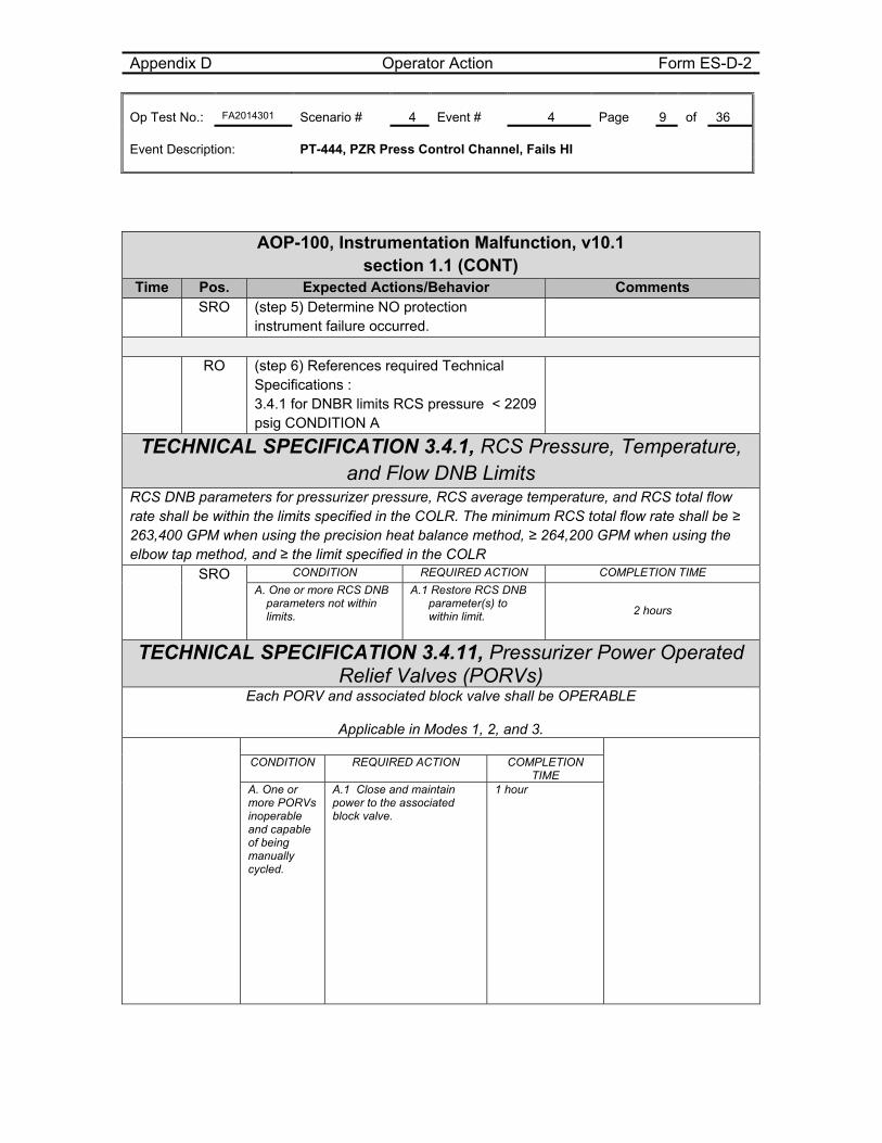
Appendix D Operator Action Form ES-D-2 Op Test No.: FA2014301 Scenario # 4 Event # 4 Page 9 of 36 Event Description: PT-444, PZR Press Control Channel, Fails HI
AOP-100, Instrumentation Malfunction, v10.1 section 1.1 (CONT)
Time Pos. Expected Actions/Behavior Comments SRO (step 5) Determine NO protection
instrument failure occurred.
RO (step 6) References required Technical
Specifications : 3.4.1 for DNBR limits RCS pressure < 2209 psig CONDITION A
TECHNICAL SPECIFICATION 3.4.1, RCS Pressure, Temperature, and Flow DNB Limits
RCS DNB parameters for pressurizer pressure, RCS average temperature, and RCS total flow rate shall be within the limits specified in the COLR. The minimum RCS total flow rate shall be ≥ 263,400 GPM when using the precision heat balance method, ≥ 264,200 GPM when using the elbow tap method, and ≥ the limit specified in the COLR
SRO CONDITION REQUIRED ACTION COMPLETION TIME
A. One or more RCS DNB parameters not within limits.
A.1 Restore RCS DNB parameter(s) to within limit. 2 hours
TECHNICAL SPECIFICATION 3.4.11, Pressurizer Power Operated Relief Valves (PORVs)
Each PORV and associated block valve shall be OPERABLE
Applicable in Modes 1, 2, and 3.
CONDITION REQUIRED ACTION COMPLETION TIME
A. One or more PORVs inoperable and capable of being manually cycled.
A.1 Close and maintain power to the associated block valve.
1 hour
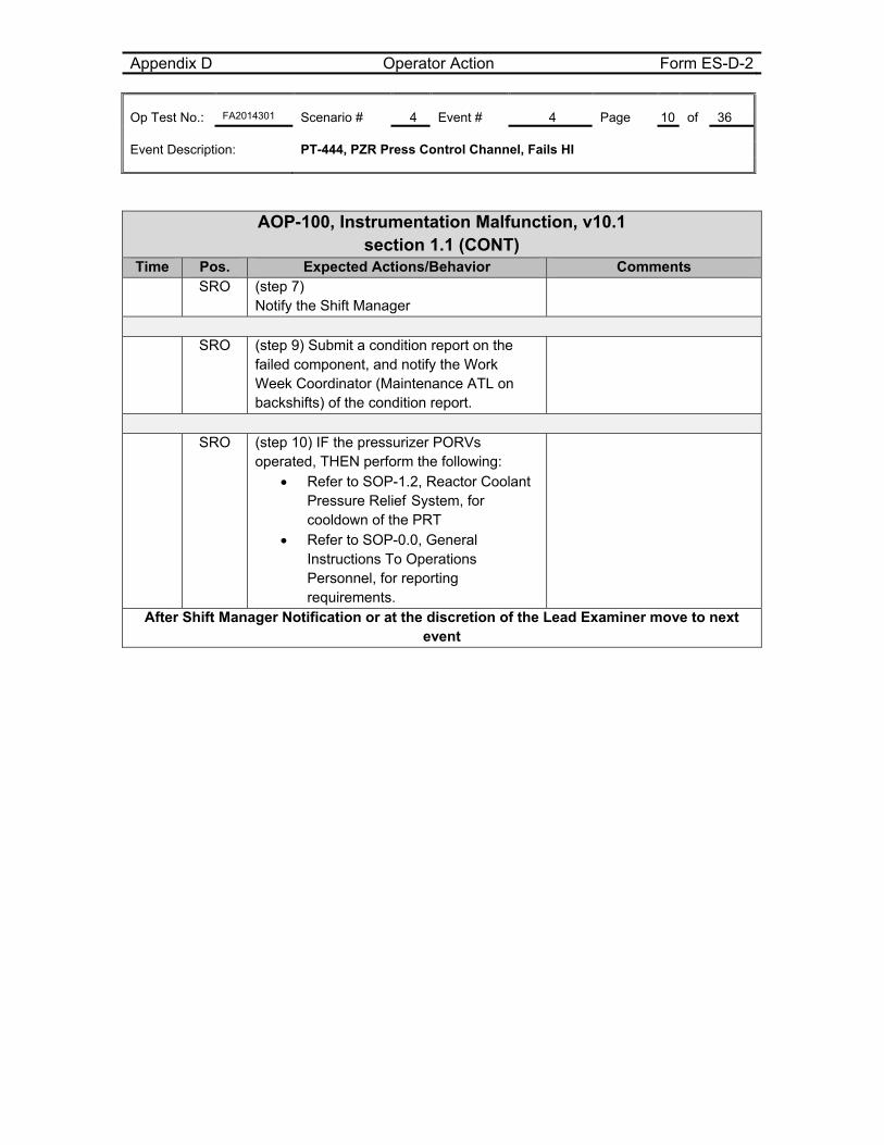
Appendix D Operator Action Form ES-D-2 Op Test No.: FA2014301 Scenario # 4 Event # 4 Page 10 of 36 Event Description: PT-444, PZR Press Control Channel, Fails HI
AOP-100, Instrumentation Malfunction, v10.1 section 1.1 (CONT)
Time Pos. Expected Actions/Behavior Comments SRO (step 7)
Notify the Shift Manager
SRO (step 9) Submit a condition report on the
failed component, and notify the Work Week Coordinator (Maintenance ATL on backshifts) of the condition report.
SRO (step 10) IF the pressurizer PORVs
operated, THEN perform the following: Refer to SOP-1.2, Reactor Coolant
Pressure Relief System, for cooldown of the PRT
Refer to SOP-0.0, General Instructions To Operations Personnel, for reporting requirements.
After Shift Manager Notification or at the discretion of the Lead Examiner move to next event
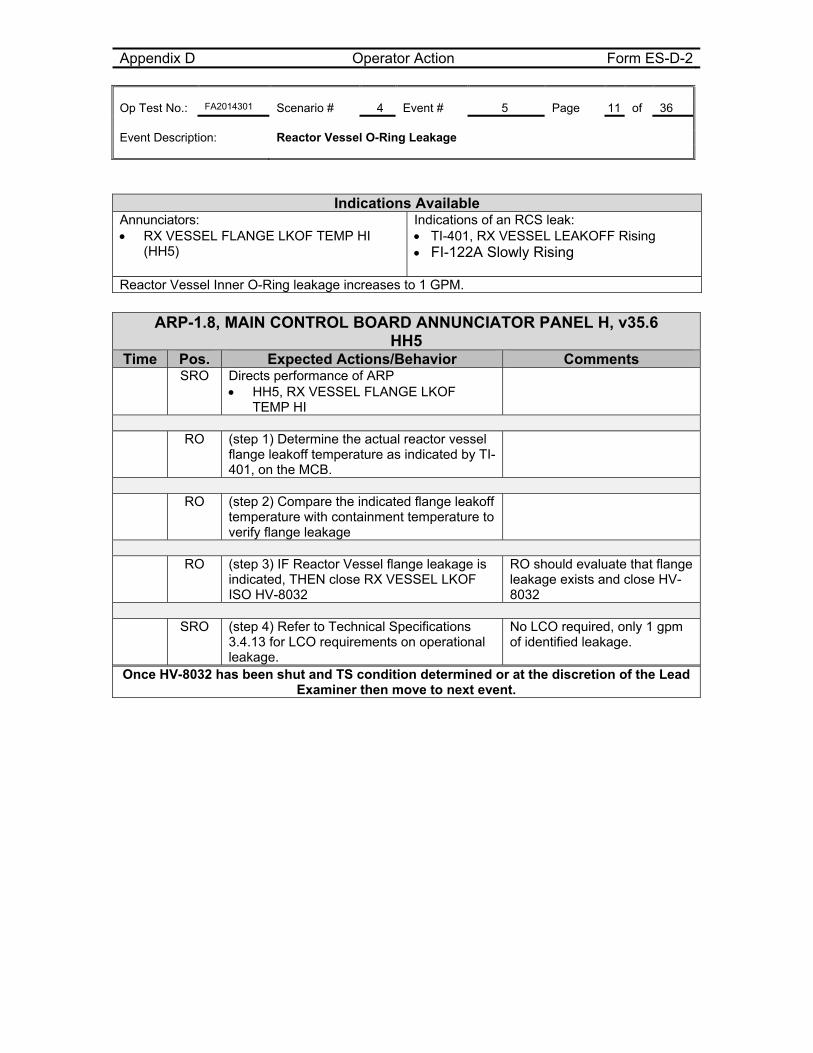
Appendix D Operator Action Form ES-D-2 Op Test No.: FA2014301 Scenario # 4 Event # 5 Page 11 of 36 Event Description: Reactor Vessel O-Ring Leakage
Indications Available Annunciators: RX VESSEL FLANGE LKOF TEMP HI
(HH5)
Indications of an RCS leak: TI-401, RX VESSEL LEAKOFF Rising FI-122A Slowly Rising
Reactor Vessel Inner O-Ring leakage increases to 1 GPM.
ARP-1.8, MAIN CONTROL BOARD ANNUNCIATOR PANEL H, v35.6 HH5
Time Pos. Expected Actions/Behavior Comments SRO Directs performance of ARP
HH5, RX VESSEL FLANGE LKOF TEMP HI
RO (step 1) Determine the actual reactor vessel
flange leakoff temperature as indicated by TI-401, on the MCB.
RO (step 2) Compare the indicated flange leakoff
temperature with containment temperature to verify flange leakage
RO (step 3) IF Reactor Vessel flange leakage is
indicated, THEN close RX VESSEL LKOF ISO HV-8032
RO should evaluate that flange leakage exists and close HV-8032
SRO (step 4) Refer to Technical Specifications
3.4.13 for LCO requirements on operational leakage.
No LCO required, only 1 gpm of identified leakage.
Once HV-8032 has been shut and TS condition determined or at the discretion of the Lead Examiner then move to next event.
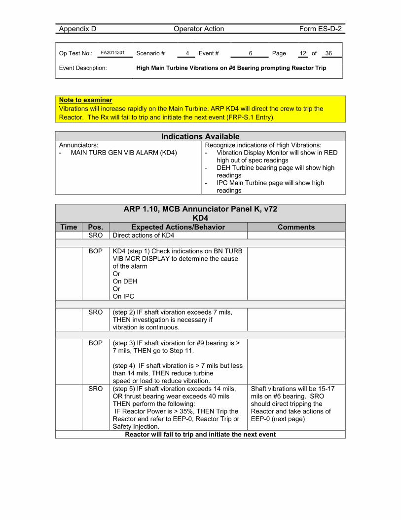
Appendix D Operator Action Form ES-D-2 Op Test No.: FA2014301 Scenario # 4 Event # 6 Page 12 of 36 Event Description: High Main Turbine Vibrations on #6 Bearing prompting Reactor Trip
Note to examiner Vibrations will increase rapidly on the Main Turbine. ARP KD4 will direct the crew to trip the Reactor. The Rx will fail to trip and initiate the next event (FRP-S.1 Entry).
Indications Available
Annunciators: - MAIN TURB GEN VIB ALARM (KD4)
Recognize indications of High Vibrations: - Vibration Display Monitor will show in RED
high out of spec readings - DEH Turbine bearing page will show high
readings - IPC Main Turbine page will show high
readings
ARP 1.10, MCB Annunciator Panel K, v72 KD4
Time Pos. Expected Actions/Behavior Comments SRO Direct actions of KD4
BOP KD4 (step 1) Check indications on BN TURB
VIB MCR DISPLAY to determine the cause of the alarm Or On DEH Or On IPC
SRO (step 2) IF shaft vibration exceeds 7 mils,
THEN investigation is necessary if vibration is continuous.
BOP (step 3) IF shaft vibration for #9 bearing is >
7 mils, THEN go to Step 11. (step 4) IF shaft vibration is > 7 mils but less than 14 mils, THEN reduce turbine speed or load to reduce vibration.
SRO (step 5) IF shaft vibration exceeds 14 mils, OR thrust bearing wear exceeds 40 mils THEN perform the following: IF Reactor Power is > 35%, THEN Trip the Reactor and refer to EEP-0, Reactor Trip or Safety Injection.
Shaft vibrations will be 15-17 mils on #6 bearing. SRO should direct tripping the Reactor and take actions of EEP-0 (next page)
Reactor will fail to trip and initiate the next event
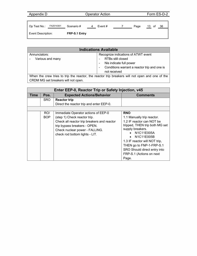
Appendix D Operator Action Form ES-D-2 Op Test No.: FA2014301 Scenario # 4 Event # 7 Page 13 of 36 Event Description: FRP-S.1 Entry
Indications Available Annunciators: - Various and many
Recognize indications of ATWT event - RTBs still closed - Nis indicate full power - Conditions warrant a reactor trip and one is
not received When the crew tries to trip the reactor, the reactor trip breakers will not open and one of the CRDM MG set breakers will not open.
Enter EEP-0, Reactor Trip or Safety Injection, v45 Time Pos. Expected Actions/Behavior Comments
SRO Reactor trip Direct the reactor trip and enter EEP-0.
RO/
BOP Immediate Operator actions of EEP-0 (step 1) Check reactor trip. Check all reactor trip breakers and reactor trip bypass breakers - OPEN. Check nuclear power - FALLING. check rod bottom lights - LIT.
RNO 1.1 Manually trip reactor. 1.2 IF reactor can NOT be tripped, THEN trip both MG set supply breakers.
N1C11E005A N1C11E005B
1.3 IF reactor will NOT trip, THEN go to FNP-1-FRP-S.1 SRO Should direct entry into FRP-S.1 (Actions on next Page.
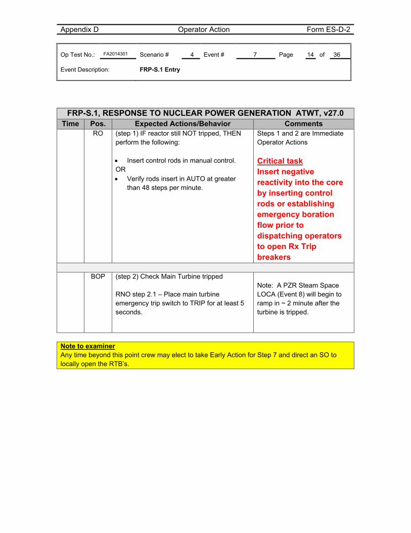
Appendix D Operator Action Form ES-D-2 Op Test No.: FA2014301 Scenario # 4 Event # 7 Page 14 of 36 Event Description: FRP-S.1 Entry
FRP-S.1, RESPONSE TO NUCLEAR POWER GENERATION ATWT, v27.0 Time Pos. Expected Actions/Behavior Comments
RO
(step 1) IF reactor still NOT tripped, THEN perform the following: Insert control rods in manual control. OR Verify rods insert in AUTO at greater
than 48 steps per minute.
Steps 1 and 2 are Immediate Operator Actions
Critical task Insert negative reactivity into the core by inserting control rods or establishing emergency boration flow prior to dispatching operators to open Rx Trip breakers
BOP (step 2) Check Main Turbine tripped
RNO step 2.1 – Place main turbine emergency trip switch to TRIP for at least 5 seconds.
Note: A PZR Steam Space LOCA (Event 8) will begin to ramp in ~ 2 minute after the turbine is tripped.
Note to examiner Any time beyond this point crew may elect to take Early Action for Step 7 and direct an SO to locally open the RTB’s.
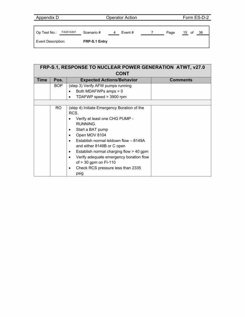
Appendix D Operator Action Form ES-D-2 Op Test No.: FA2014301 Scenario # 4 Event # 7 Page 15 of 36 Event Description: FRP-S.1 Entry
FRP-S.1, RESPONSE TO NUCLEAR POWER GENERATION ATWT, v27.0 CONT
Time Pos. Expected Actions/Behavior Comments BOP
(step 3) Verify AFW pumps running Both MDAFWPs amps > 0 TDAFWP speed > 3900 rpm
RO (step 4) Initiate Emergency Boration of the
RCS. Verify at least one CHG PUMP -
RUNNING. Start a BAT pump Open MOV 8104 Establish normal letdown flow – 8149A
and either 8149B or C open Establish normal charging flow > 40 gpm Verify adequate emergency boration flow
of > 30 gpm on FI-110 Check RCS pressure less than 2335
psig
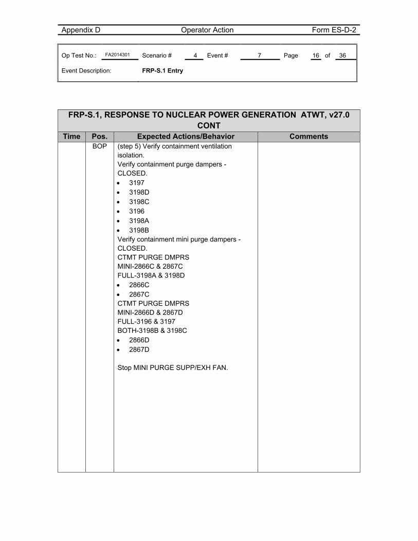
Appendix D Operator Action Form ES-D-2 Op Test No.: FA2014301 Scenario # 4 Event # 7 Page 16 of 36 Event Description: FRP-S.1 Entry
FRP-S.1, RESPONSE TO NUCLEAR POWER GENERATION ATWT, v27.0 CONT
Time Pos. Expected Actions/Behavior Comments BOP (step 5) Verify containment ventilation
isolation. Verify containment purge dampers - CLOSED. 3197 3198D 3198C 3196 3198A 3198B Verify containment mini purge dampers - CLOSED. CTMT PURGE DMPRS MINI-2866C & 2867C FULL-3198A & 3198D 2866C 2867C CTMT PURGE DMPRS MINI-2866D & 2867D FULL-3196 & 3197 BOTH-3198B & 3198C 2866D 2867D Stop MINI PURGE SUPP/EXH FAN.
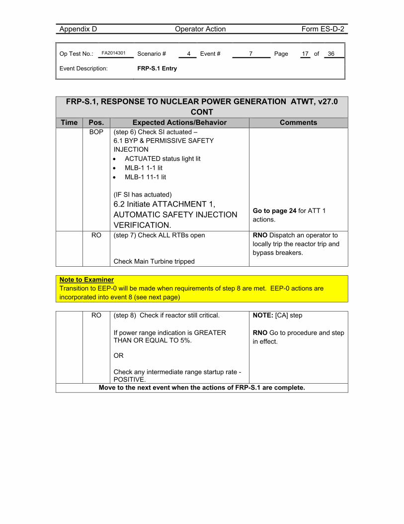
Appendix D Operator Action Form ES-D-2 Op Test No.: FA2014301 Scenario # 4 Event # 7 Page 17 of 36 Event Description: FRP-S.1 Entry
FRP-S.1, RESPONSE TO NUCLEAR POWER GENERATION ATWT, v27.0 CONT
Time Pos. Expected Actions/Behavior Comments BOP (step 6) Check SI actuated –
6.1 BYP & PERMISSIVE SAFETY INJECTION ACTUATED status light lit MLB-1 1-1 lit MLB-1 11-1 lit
(IF SI has actuated)
6.2 Initiate ATTACHMENT 1, AUTOMATIC SAFETY INJECTION VERIFICATION.
Go to page 24 for ATT 1 actions.
RO (step 7) Check ALL RTBs open Check Main Turbine tripped
RNO Dispatch an operator to locally trip the reactor trip and bypass breakers.
Note to Examiner Transition to EEP-0 will be made when requirements of step 8 are met. EEP-0 actions are incorporated into event 8 (see next page)
RO (step 8) Check if reactor still critical. If power range indication is GREATER THAN OR EQUAL TO 5%. OR Check any intermediate range startup rate - POSITIVE.
NOTE: [CA] step RNO Go to procedure and step in effect.
Move to the next event when the actions of FRP-S.1 are complete.
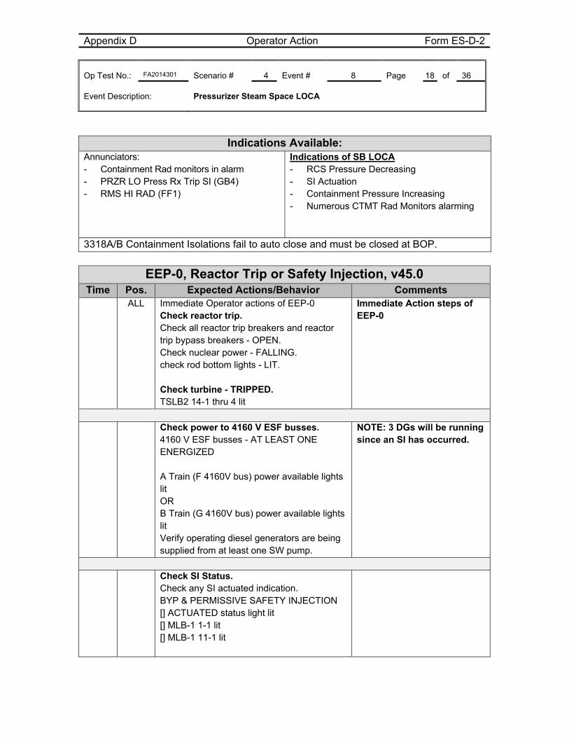
Appendix D Operator Action Form ES-D-2 Op Test No.: FA2014301 Scenario # 4 Event # 8 Page 18 of 36 Event Description: Pressurizer Steam Space LOCA
Indications Available: Annunciators: - Containment Rad monitors in alarm - PRZR LO Press Rx Trip SI (GB4) - RMS HI RAD (FF1)
Indications of SB LOCA - RCS Pressure Decreasing - SI Actuation - Containment Pressure Increasing - Numerous CTMT Rad Monitors alarming
3318A/B Containment Isolations fail to auto close and must be closed at BOP.
EEP-0, Reactor Trip or Safety Injection, v45.0
Time Pos. Expected Actions/Behavior Comments ALL Immediate Operator actions of EEP-0
Check reactor trip. Check all reactor trip breakers and reactor trip bypass breakers - OPEN. Check nuclear power - FALLING. check rod bottom lights - LIT. Check turbine - TRIPPED. TSLB2 14-1 thru 4 lit
Immediate Action steps of EEP-0
Check power to 4160 V ESF busses.
4160 V ESF busses - AT LEAST ONE ENERGIZED A Train (F 4160V bus) power available lights lit OR B Train (G 4160V bus) power available lights lit Verify operating diesel generators are being supplied from at least one SW pump.
NOTE: 3 DGs will be running since an SI has occurred.
Check SI Status.
Check any SI actuated indication. BYP & PERMISSIVE SAFETY INJECTION [] ACTUATED status light lit [] MLB-1 1-1 lit [] MLB-1 11-1 lit
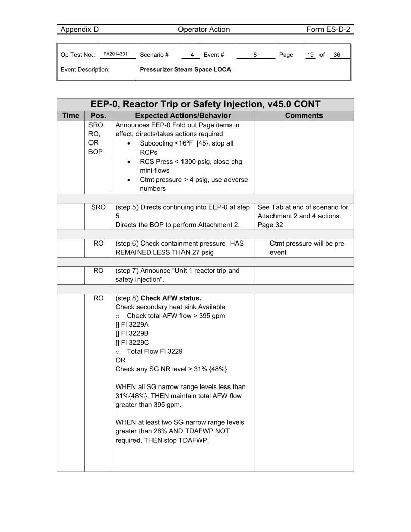
Appendix D Operator Action Form ES-D-2 Op Test No.: FA2014301 Scenario # 4 Event # 8 Page 19 of 36 Event Description: Pressurizer Steam Space LOCA
EEP-0, Reactor Trip or Safety Injection, v45.0 CONT
Time Pos. Expected Actions/Behavior Comments SRO,
RO, OR BOP
Announces EEP-0 Fold out Page items in effect, directs/takes actions required
Subcooling <16ºF [45}, stop all RCPs
RCS Press < 1300 psig, close chg mini-flows
Ctmt pressure > 4 psig, use adverse numbers
SRO (step 5) Directs continuing into EEP-0 at step
5. Directs the BOP to perform Attachment 2.
See Tab at end of scenario for Attachment 2 and 4 actions. Page 32
RO (step 6) Check containment pressure- HAS
REMAINED LESS THAN 27 psig Ctmt pressure will be pre-event
RO (step 7) Announce "Unit 1 reactor trip and
safety injection".
RO (step 8) Check AFW status.
Check secondary heat sink Available o Check total AFW flow > 395 gpm [] FI 3229A [] FI 3229B [] FI 3229C o Total Flow FI 3229 OR Check any SG NR level > 31% {48%} WHEN all SG narrow range levels less than 31%{48%}, THEN maintain total AFW flow greater than 395 gpm. WHEN at least two SG narrow range levels greater than 28% AND TDAFWP NOT required, THEN stop TDAFWP.
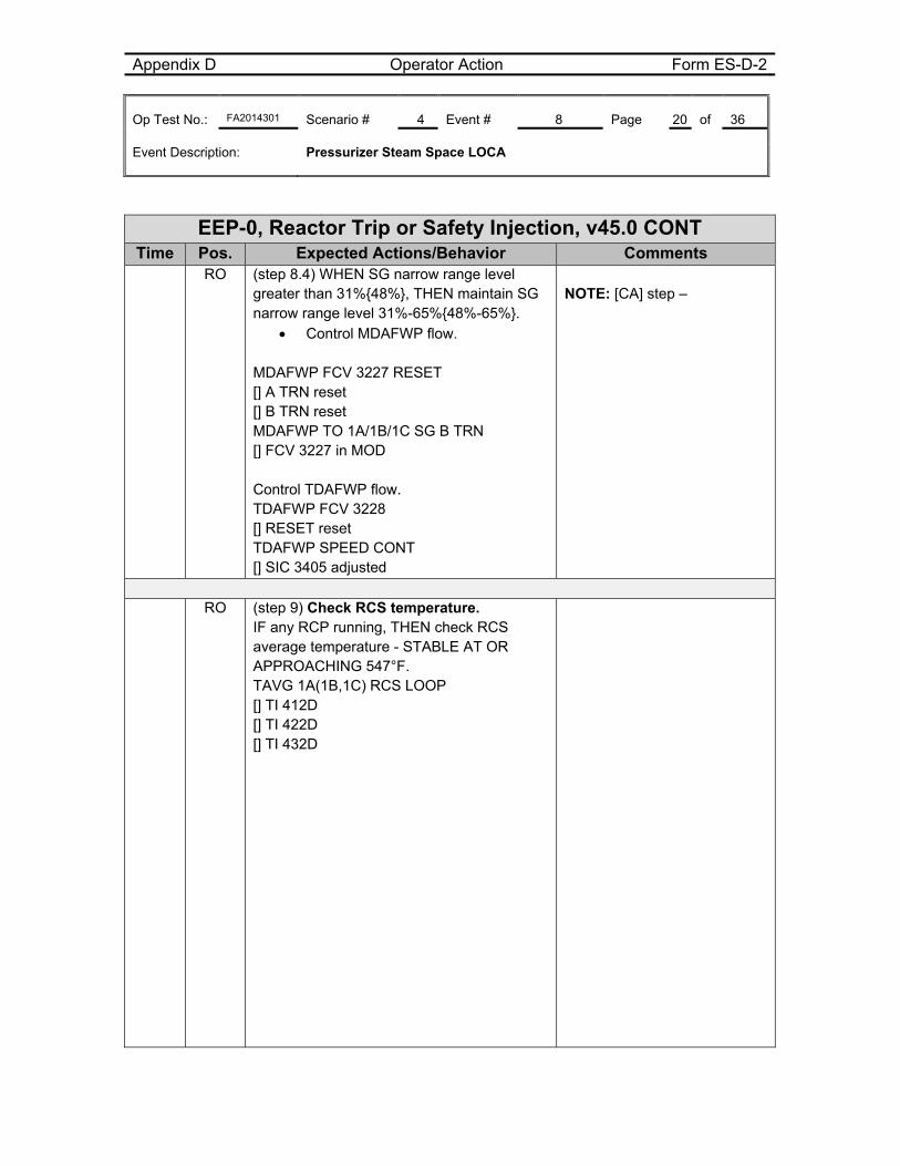
Appendix D Operator Action Form ES-D-2 Op Test No.: FA2014301 Scenario # 4 Event # 8 Page 20 of 36 Event Description: Pressurizer Steam Space LOCA
EEP-0, Reactor Trip or Safety Injection, v45.0 CONT
Time Pos. Expected Actions/Behavior Comments RO (step 8.4) WHEN SG narrow range level
greater than 31%{48%}, THEN maintain SG narrow range level 31%-65%{48%-65%}.
Control MDAFWP flow. MDAFWP FCV 3227 RESET [] A TRN reset [] B TRN reset MDAFWP TO 1A/1B/1C SG B TRN [] FCV 3227 in MOD Control TDAFWP flow. TDAFWP FCV 3228 [] RESET reset TDAFWP SPEED CONT [] SIC 3405 adjusted
NOTE: [CA] step –
RO (step 9) Check RCS temperature.
IF any RCP running, THEN check RCS average temperature - STABLE AT OR APPROACHING 547°F. TAVG 1A(1B,1C) RCS LOOP [] TI 412D [] TI 422D [] TI 432D
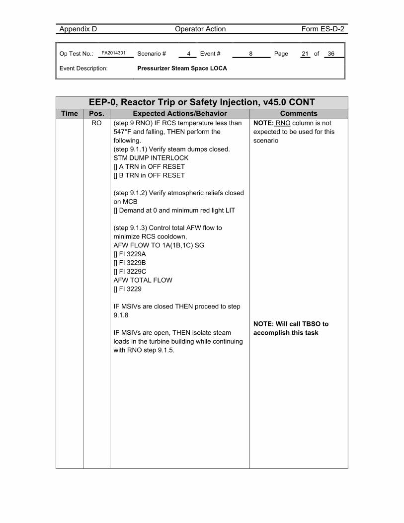
Appendix D Operator Action Form ES-D-2 Op Test No.: FA2014301 Scenario # 4 Event # 8 Page 21 of 36 Event Description: Pressurizer Steam Space LOCA
EEP-0, Reactor Trip or Safety Injection, v45.0 CONT
Time Pos. Expected Actions/Behavior Comments RO (step 9 RNO) IF RCS temperature less than
547°F and falling, THEN perform the following. (step 9.1.1) Verify steam dumps closed. STM DUMP INTERLOCK [] A TRN in OFF RESET [] B TRN in OFF RESET (step 9.1.2) Verify atmospheric reliefs closed on MCB [] Demand at 0 and minimum red light LIT (step 9.1.3) Control total AFW flow to minimize RCS cooldown, AFW FLOW TO 1A(1B,1C) SG [] FI 3229A [] FI 3229B [] FI 3229C AFW TOTAL FLOW [] FI 3229 IF MSIVs are closed THEN proceed to step 9.1.8 IF MSIVs are open, THEN isolate steam loads in the turbine building while continuing with RNO step 9.1.5.
NOTE: RNO column is not expected to be used for this scenario NOTE: Will call TBSO to accomplish this task
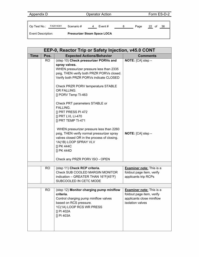
Appendix D Operator Action Form ES-D-2 Op Test No.: FA2014301 Scenario # 4 Event # 8 Page 22 of 36 Event Description: Pressurizer Steam Space LOCA
EEP-0, Reactor Trip or Safety Injection, v45.0 CONT
Time Pos. Expected Actions/Behavior Comments RO (step 10) Check pressurizer PORVs and
spray valves. WHEN pressurizer pressure less than 2335 psig, THEN verify both PRZR PORVs closed.Verify both PRZR PORVs indicate CLOSED Check PRZR PORV temperature STABLE OR FALLING. [] PORV Temp TI-463 Check PRT parameters STABLE or FALLING. [] PRT PRESS PI 472 [] PRT LVL LI-470 [] PRT TEMP TI-471 WHEN pressurizer pressure less than 2260 psig, THEN verify normal pressurizer spray valves closed OR in the process of closing. 1A(1B) LOOP SPRAY VLV [] PK 444C [] PK 444D Check any PRZR PORV ISO - OPEN
NOTE: [CA] step – NOTE: [CA] step –
RO (step 11) Check RCP criteria.
Check SUB COOLED MARGIN MONITOR indication – GREATER THAN 16°F{45°F} SUBCOOLED IN CETC MODE
Examiner note: This is a foldout page item, verify applicants trip RCPs
RO (step 12) Monitor charging pump miniflow
criteria. Control charging pump miniflow valves based on RCS pressure. 1C(1A) LOOP RCS WR PRESS [] PI 402A [] PI 403A
Examiner note: This is a foldout page item, verify applicants close miniflow isolation valves
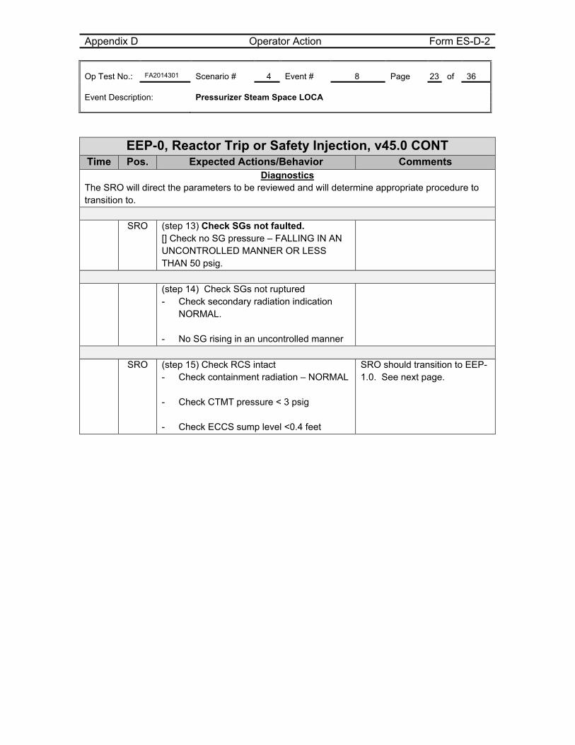
Appendix D Operator Action Form ES-D-2 Op Test No.: FA2014301 Scenario # 4 Event # 8 Page 23 of 36 Event Description: Pressurizer Steam Space LOCA
EEP-0, Reactor Trip or Safety Injection, v45.0 CONT
Time Pos. Expected Actions/Behavior Comments Diagnostics
The SRO will direct the parameters to be reviewed and will determine appropriate procedure to transition to.
SRO (step 13) Check SGs not faulted. [] Check no SG pressure – FALLING IN AN UNCONTROLLED MANNER OR LESS THAN 50 psig.
(step 14) Check SGs not ruptured
- Check secondary radiation indication NORMAL.
- No SG rising in an uncontrolled manner
SRO (step 15) Check RCS intact
- Check containment radiation – NORMAL - Check CTMT pressure < 3 psig
- Check ECCS sump level <0.4 feet
SRO should transition to EEP-1.0. See next page.
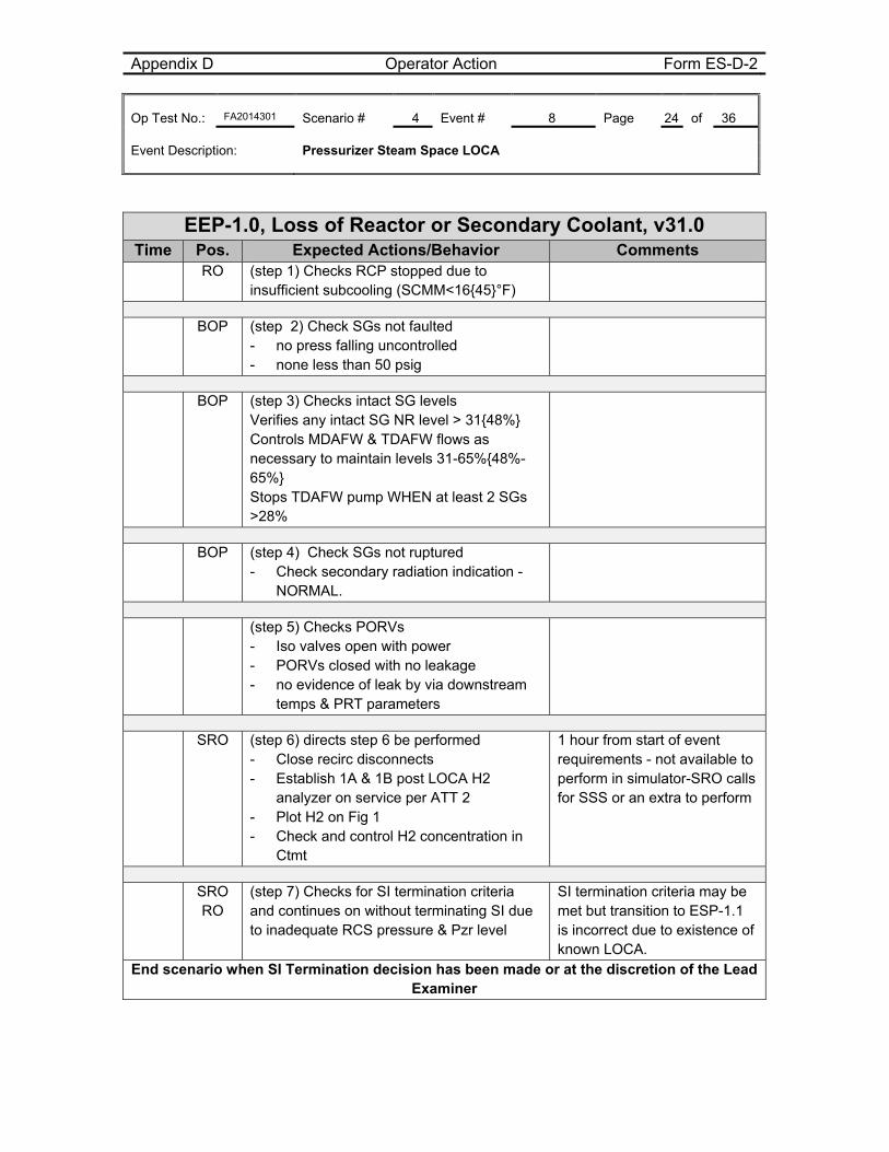
Appendix D Operator Action Form ES-D-2 Op Test No.: FA2014301 Scenario # 4 Event # 8 Page 24 of 36 Event Description: Pressurizer Steam Space LOCA
EEP-1.0, Loss of Reactor or Secondary Coolant, v31.0
Time Pos. Expected Actions/Behavior Comments RO (step 1) Checks RCP stopped due to
insufficient subcooling (SCMM<16{45}°F)
BOP (step 2) Check SGs not faulted - no press falling uncontrolled - none less than 50 psig
BOP (step 3) Checks intact SG levels Verifies any intact SG NR level > 31{48%} Controls MDAFW & TDAFW flows as necessary to maintain levels 31-65%{48%-65%} Stops TDAFW pump WHEN at least 2 SGs >28%
BOP (step 4) Check SGs not ruptured - Check secondary radiation indication -
NORMAL.
(step 5) Checks PORVs - Iso valves open with power - PORVs closed with no leakage - no evidence of leak by via downstream
temps & PRT parameters
SRO (step 6) directs step 6 be performed - Close recirc disconnects - Establish 1A & 1B post LOCA H2
analyzer on service per ATT 2 - Plot H2 on Fig 1 - Check and control H2 concentration in
Ctmt
1 hour from start of event requirements - not available to perform in simulator-SRO calls for SSS or an extra to perform
SRO RO
(step 7) Checks for SI termination criteria and continues on without terminating SI due to inadequate RCS pressure & Pzr level
SI termination criteria may be met but transition to ESP-1.1 is incorrect due to existence of known LOCA.
End scenario when SI Termination decision has been made or at the discretion of the Lead Examiner
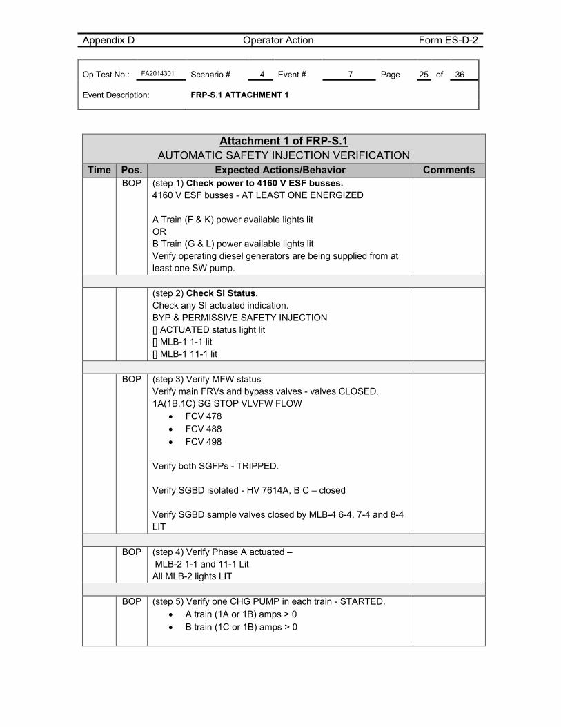
Appendix D Operator Action Form ES-D-2 Op Test No.: FA2014301 Scenario # 4 Event # 7 Page 25 of 36 Event Description: FRP-S.1 ATTACHMENT 1
Attachment 1 of FRP-S.1 AUTOMATIC SAFETY INJECTION VERIFICATION Time Pos. Expected Actions/Behavior Comments BOP (step 1) Check power to 4160 V ESF busses.
4160 V ESF busses - AT LEAST ONE ENERGIZED A Train (F & K) power available lights lit OR B Train (G & L) power available lights lit Verify operating diesel generators are being supplied from at least one SW pump.
(step 2) Check SI Status.
Check any SI actuated indication. BYP & PERMISSIVE SAFETY INJECTION [] ACTUATED status light lit [] MLB-1 1-1 lit [] MLB-1 11-1 lit
BOP (step 3) Verify MFW status
Verify main FRVs and bypass valves - valves CLOSED. 1A(1B,1C) SG STOP VLVFW FLOW
FCV 478 FCV 488 FCV 498
Verify both SGFPs - TRIPPED. Verify SGBD isolated - HV 7614A, B C – closed Verify SGBD sample valves closed by MLB-4 6-4, 7-4 and 8-4 LIT
BOP (step 4) Verify Phase A actuated –
MLB-2 1-1 and 11-1 Lit All MLB-2 lights LIT
BOP (step 5) Verify one CHG PUMP in each train - STARTED.
A train (1A or 1B) amps > 0 B train (1C or 1B) amps > 0
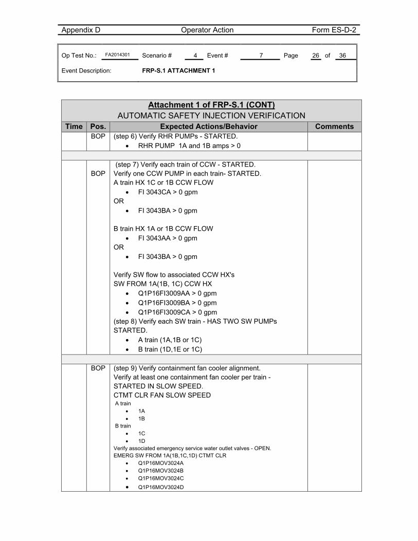
Appendix D Operator Action Form ES-D-2 Op Test No.: FA2014301 Scenario # 4 Event # 7 Page 26 of 36 Event Description: FRP-S.1 ATTACHMENT 1
Attachment 1 of FRP-S.1 (CONT) AUTOMATIC SAFETY INJECTION VERIFICATION Time Pos. Expected Actions/Behavior Comments BOP (step 6) Verify RHR PUMPs - STARTED.
RHR PUMP 1A and 1B amps > 0
BOP (step 7) Verify each train of CCW - STARTED. Verify one CCW PUMP in each train- STARTED. A train HX 1C or 1B CCW FLOW
FI 3043CA > 0 gpm OR
FI 3043BA > 0 gpm
B train HX 1A or 1B CCW FLOW FI 3043AA > 0 gpm
OR FI 3043BA > 0 gpm
Verify SW flow to associated CCW HX's SW FROM 1A(1B, 1C) CCW HX
Q1P16FI3009AA > 0 gpm Q1P16FI3009BA > 0 gpm Q1P16FI3009CA > 0 gpm
(step 8) Verify each SW train - HAS TWO SW PUMPs STARTED.
A train (1A,1B or 1C) B train (1D,1E or 1C)
BOP (step 9) Verify containment fan cooler alignment.
Verify at least one containment fan cooler per train - STARTED IN SLOW SPEED. CTMT CLR FAN SLOW SPEED A train
1A 1B
B train 1C 1D
Verify associated emergency service water outlet valves - OPEN. EMERG SW FROM 1A(1B,1C,1D) CTMT CLR
Q1P16MOV3024A Q1P16MOV3024B
Q1P16MOV3024C
Q1P16MOV3024D
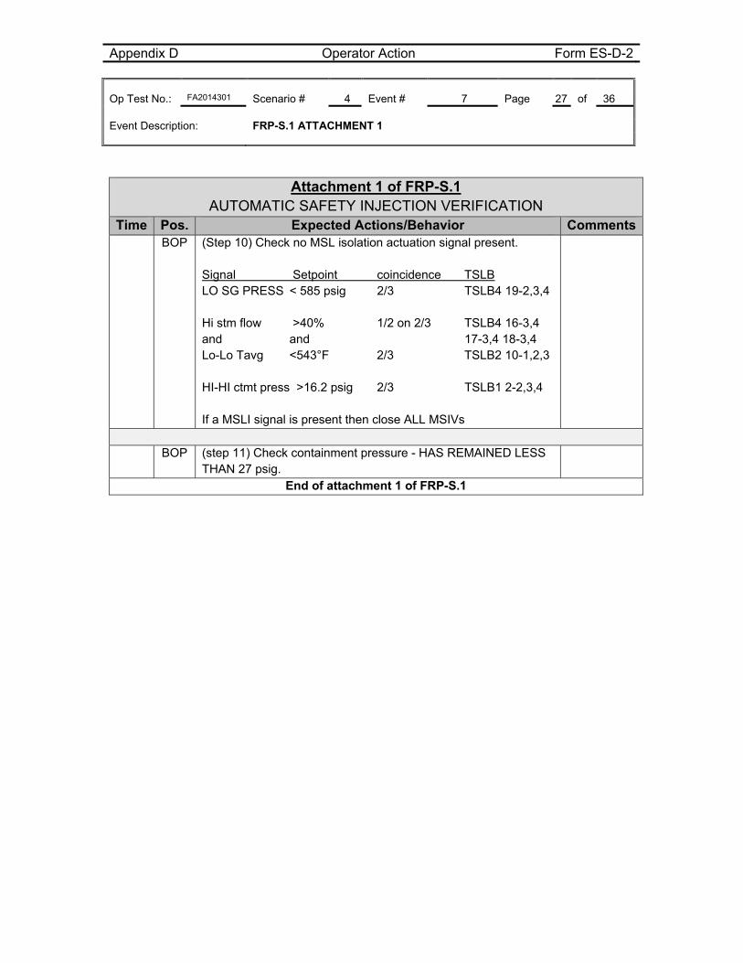
Appendix D Operator Action Form ES-D-2 Op Test No.: FA2014301 Scenario # 4 Event # 7 Page 27 of 36 Event Description: FRP-S.1 ATTACHMENT 1
Attachment 1 of FRP-S.1 AUTOMATIC SAFETY INJECTION VERIFICATION Time Pos. Expected Actions/Behavior Comments BOP (Step 10) Check no MSL isolation actuation signal present.
Signal Setpoint coincidence TSLB LO SG PRESS < 585 psig 2/3 TSLB4 19-2,3,4 Hi stm flow >40% 1/2 on 2/3 TSLB4 16-3,4 and and 17-3,4 18-3,4 Lo-Lo Tavg <543°F 2/3 TSLB2 10-1,2,3 HI-HI ctmt press >16.2 psig 2/3 TSLB1 2-2,3,4 If a MSLI signal is present then close ALL MSIVs
BOP (step 11) Check containment pressure - HAS REMAINED LESS
THAN 27 psig.
End of attachment 1 of FRP-S.1

Appendix D Operator Action Form ES-D-2 Op Test No.: FA2014301 Scenario # 4 Event # 7 Page 28 of 36 Event Description: Attachments 2 and 4 of EEP-0.0
EEP-0.0, Reactor Trip or Safety Injection, v45 Attachment 2
Time Pos. Expected Actions/Behavior Comments
BOP
(Step 1) Verify one CHG PUMP in each train - STARTED. [] A train (1A or 1B) amps > 0 [] B train (1C or 1B) amps > 0
BOP (Step 2) Verify RHR PUMPs - STARTED.
RHR PUMP [] 1A amps > 0 [] 1B amps > 0
BOP (Step 3) Verify Safety Injection Flow.
(Step 3.1) Check HHSI flow - GREATER THAN 0 gpm. [] FI 943
BOP (Step 3.2) Check RCS pressure - LESS
THAN 275 psig{435 psig}.
BOP (step 3.3) Check LHSI flow – greater than
1.5 X10³ gpm [] 1A RHR HDR FLOW FI-605A [] 1B RHR HDR FLOW FI-605B
BOP (Step 4) Verify each SW train - HAS TWO
SW PUMPs STARTED. [] A train (1A,1B or 1C) [] B train (1D,1E or 1C)
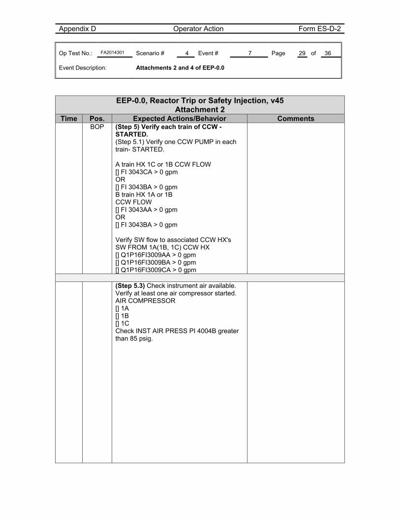
Appendix D Operator Action Form ES-D-2 Op Test No.: FA2014301 Scenario # 4 Event # 7 Page 29 of 36 Event Description: Attachments 2 and 4 of EEP-0.0
EEP-0.0, Reactor Trip or Safety Injection, v45 Attachment 2
Time Pos. Expected Actions/Behavior Comments BOP (Step 5) Verify each train of CCW -
STARTED. (Step 5.1) Verify one CCW PUMP in each train- STARTED. A train HX 1C or 1B CCW FLOW [] FI 3043CA > 0 gpm OR [] FI 3043BA > 0 gpm B train HX 1A or 1B CCW FLOW [] FI 3043AA > 0 gpm OR [] FI 3043BA > 0 gpm Verify SW flow to associated CCW HX's SW FROM 1A(1B, 1C) CCW HX [] Q1P16FI3009AA > 0 gpm [] Q1P16FI3009BA > 0 gpm [] Q1P16FI3009CA > 0 gpm
(Step 5.3) Check instrument air available.
Verify at least one air compressor started. AIR COMPRESSOR [] 1A [] 1B [] 1C Check INST AIR PRESS PI 4004B greater than 85 psig.
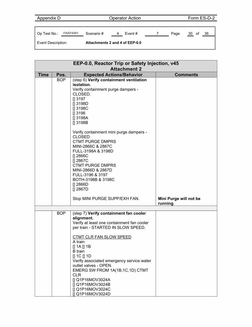
Appendix D Operator Action Form ES-D-2 Op Test No.: FA2014301 Scenario # 4 Event # 7 Page 30 of 36 Event Description: Attachments 2 and 4 of EEP-0.0
EEP-0.0, Reactor Trip or Safety Injection, v45 Attachment 2
Time Pos. Expected Actions/Behavior Comments BOP (step 6) Verify containment ventilation
isolation. Verify containment purge dampers - CLOSED. [] 3197 [] 3198D [] 3198C [] 3196 [] 3198A [] 3198B Verify containment mini purge dampers - CLOSED. CTMT PURGE DMPRS MINI-2866C & 2867C FULL-3198A & 3198D [] 2866C [] 2867C CTMT PURGE DMPRS MINI-2866D & 2867D FULL-3196 & 3197 BOTH-3198B & 3198C [] 2866D [] 2867D Stop MINI PURGE SUPP/EXH FAN.
Mini Purge will not be running
BOP (step 7) Verify containment fan cooler
alignment. Verify at least one containment fan cooler per train - STARTED IN SLOW SPEED. CTMT CLR FAN SLOW SPEED A train [] 1A [] 1B B train [] 1C [] 1D Verify associated emergency service water outlet valves - OPEN. EMERG SW FROM 1A(1B,1C,1D) CTMT CLR [] Q1P16MOV3024A [] Q1P16MOV3024B [] Q1P16MOV3024C [] Q1P16MOV3024D
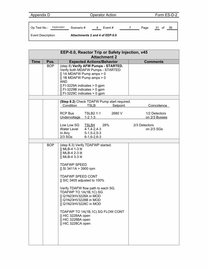
Appendix D Operator Action Form ES-D-2 Op Test No.: FA2014301 Scenario # 4 Event # 7 Page 31 of 36 Event Description: Attachments 2 and 4 of EEP-0.0
EEP-0.0, Reactor Trip or Safety Injection, v45 Attachment 2
Time Pos. Expected Actions/Behavior Comments BOP (step 8) Verify AFW Pumps - STARTED.
Verify both MDAFW Pumps - STARTED [] 1A MDAFW Pump amps > 0 [] 1B MDAFW Pump amps > 0 AND [] FI-3229A indicates > 0 gpm [] FI-3229B indicates > 0 gpm [] FI-3229C indicates > 0 gpm
(Step 8.2) Check TDAFW Pump start required.
�Condition �TSLB �Setpoint �Coincidence� RCP Bus TSLB2 1-1 �2680 V 1/2 Detectors Undervoltage 1-2 1-3 on 2/3 Busses Low Low SG TSLB4 28% 2/3 Detectors Water Level 4-1,4-2,4-3 on 2/3 SGs In Any 5-1,5-2,5-3 2/3 SGs 6-1,6-2,6-3
BOP (step 8.3) Verify TDAFWP started.
[] MLB-4 1-3 lit [] MLB-4 2-3 lit [] MLB-4 3-3 lit TDAFWP SPEED [] SI 3411A > 3900 rpm TDAFWP SPEED CONT [] SIC 3405 adjusted to 100% Verify TDAFW flow path to each SG. TDAFWP TO 1A(1B,1C) SG [] Q1N23HV3228A in MOD [] Q1N23HV3228B in MOD [] Q1N23HV3228C in MOD TDAFWP TO 1A(1B,1C) SG FLOW CONT [] HIC 3228AA open [] HIC 3228BA open [] HIC 3228CA open
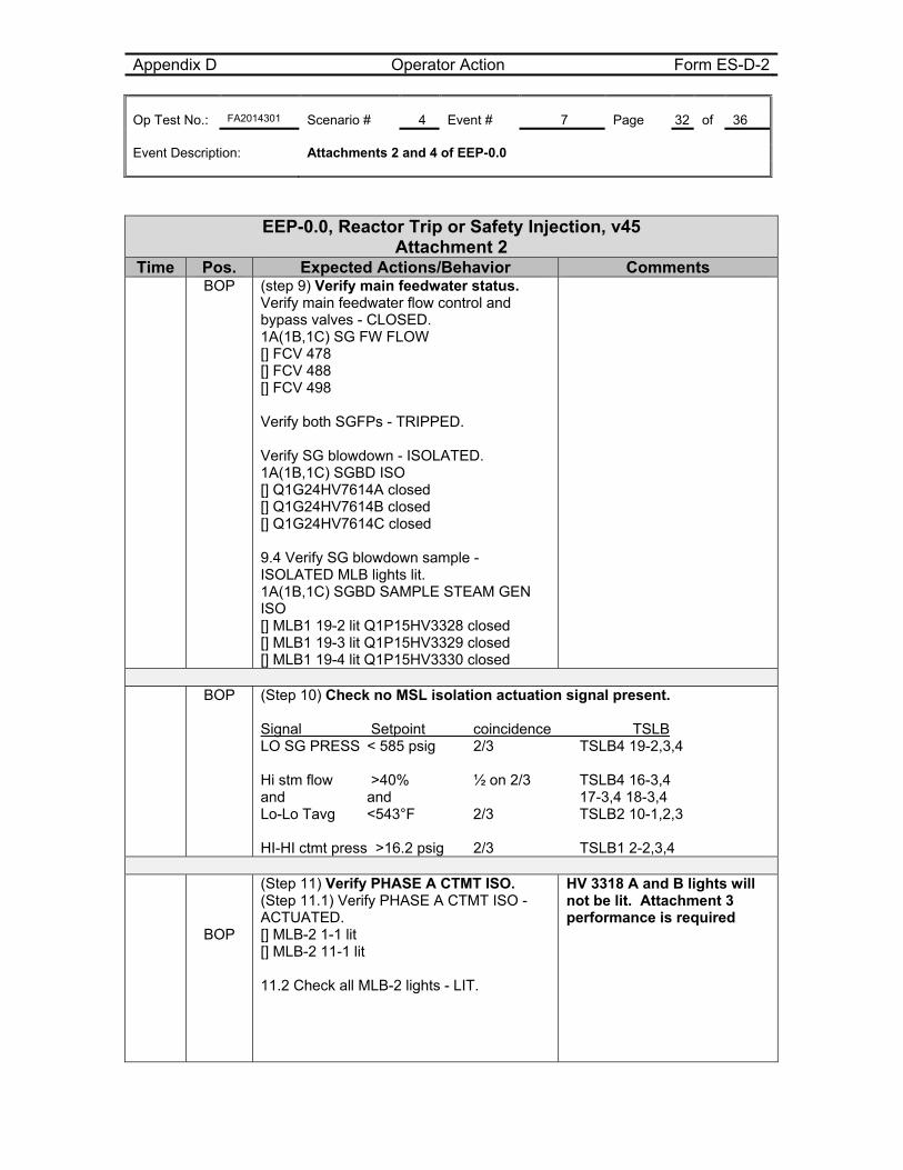
Appendix D Operator Action Form ES-D-2 Op Test No.: FA2014301 Scenario # 4 Event # 7 Page 32 of 36 Event Description: Attachments 2 and 4 of EEP-0.0
EEP-0.0, Reactor Trip or Safety Injection, v45 Attachment 2
Time Pos. Expected Actions/Behavior Comments BOP (step 9) Verify main feedwater status.
Verify main feedwater flow control and bypass valves - CLOSED. 1A(1B,1C) SG FW FLOW [] FCV 478 [] FCV 488 [] FCV 498 Verify both SGFPs - TRIPPED. Verify SG blowdown - ISOLATED. 1A(1B,1C) SGBD ISO [] Q1G24HV7614A closed [] Q1G24HV7614B closed [] Q1G24HV7614C closed 9.4 Verify SG blowdown sample - ISOLATED MLB lights lit. 1A(1B,1C) SGBD SAMPLE STEAM GEN ISO [] MLB1 19-2 lit Q1P15HV3328 closed [] MLB1 19-3 lit Q1P15HV3329 closed [] MLB1 19-4 lit Q1P15HV3330 closed
BOP (Step 10) Check no MSL isolation actuation signal present.
Signal Setpoint coincidence TSLB LO SG PRESS < 585 psig 2/3 TSLB4 19-2,3,4 Hi stm flow >40% ½ on 2/3 TSLB4 16-3,4 and and 17-3,4 18-3,4 Lo-Lo Tavg <543°F 2/3 TSLB2 10-1,2,3 HI-HI ctmt press >16.2 psig 2/3 TSLB1 2-2,3,4
BOP
(Step 11) Verify PHASE A CTMT ISO. (Step 11.1) Verify PHASE A CTMT ISO - ACTUATED. [] MLB-2 1-1 lit [] MLB-2 11-1 lit 11.2 Check all MLB-2 lights - LIT.
HV 3318 A and B lights will not be lit. Attachment 3 performance is required
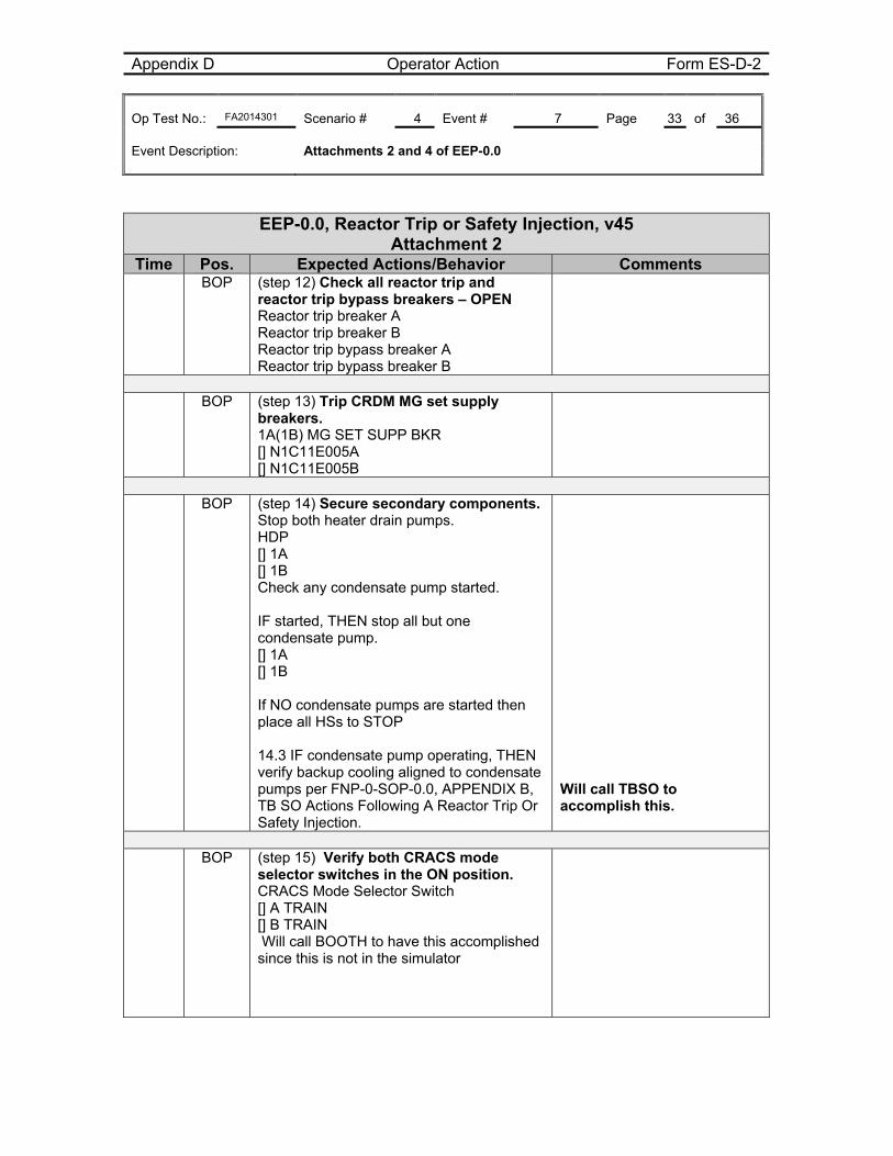
Appendix D Operator Action Form ES-D-2 Op Test No.: FA2014301 Scenario # 4 Event # 7 Page 33 of 36 Event Description: Attachments 2 and 4 of EEP-0.0
EEP-0.0, Reactor Trip or Safety Injection, v45 Attachment 2
Time Pos. Expected Actions/Behavior Comments BOP (step 12) Check all reactor trip and
reactor trip bypass breakers – OPEN Reactor trip breaker A Reactor trip breaker B Reactor trip bypass breaker A Reactor trip bypass breaker B
BOP (step 13) Trip CRDM MG set supply
breakers. 1A(1B) MG SET SUPP BKR [] N1C11E005A [] N1C11E005B
BOP (step 14) Secure secondary components.
Stop both heater drain pumps. HDP [] 1A [] 1B Check any condensate pump started. IF started, THEN stop all but one condensate pump. [] 1A [] 1B If NO condensate pumps are started then place all HSs to STOP 14.3 IF condensate pump operating, THEN verify backup cooling aligned to condensate pumps per FNP-0-SOP-0.0, APPENDIX B, TB SO Actions Following A Reactor Trip Or Safety Injection.
Will call TBSO to accomplish this.
BOP (step 15) Verify both CRACS mode
selector switches in the ON position. CRACS Mode Selector Switch [] A TRAIN [] B TRAIN Will call BOOTH to have this accomplished since this is not in the simulator
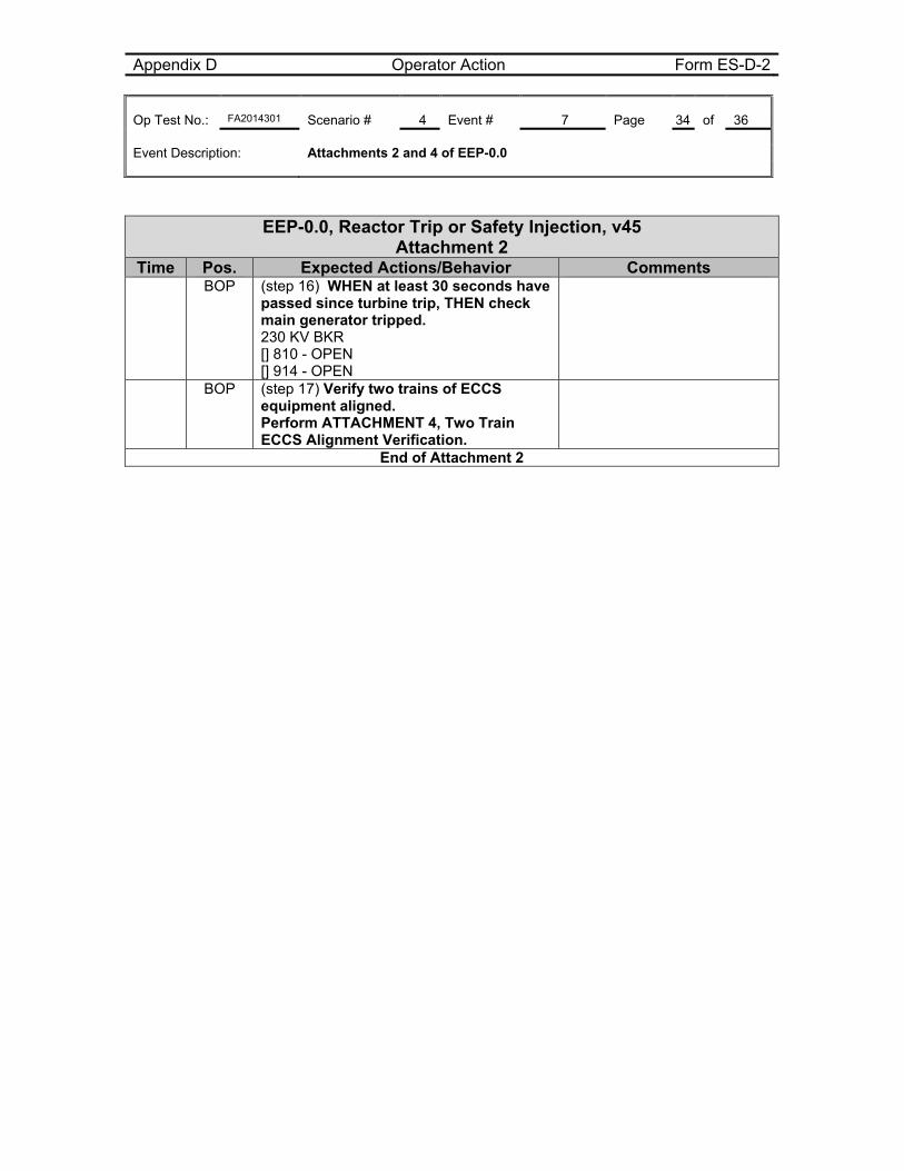
Appendix D Operator Action Form ES-D-2 Op Test No.: FA2014301 Scenario # 4 Event # 7 Page 34 of 36 Event Description: Attachments 2 and 4 of EEP-0.0
EEP-0.0, Reactor Trip or Safety Injection, v45 Attachment 2
Time Pos. Expected Actions/Behavior Comments BOP (step 16) WHEN at least 30 seconds have
passed since turbine trip, THEN check main generator tripped. 230 KV BKR [] 810 - OPEN [] 914 - OPEN
BOP (step 17) Verify two trains of ECCS equipment aligned. Perform ATTACHMENT 4, Two Train ECCS Alignment Verification.
End of Attachment 2
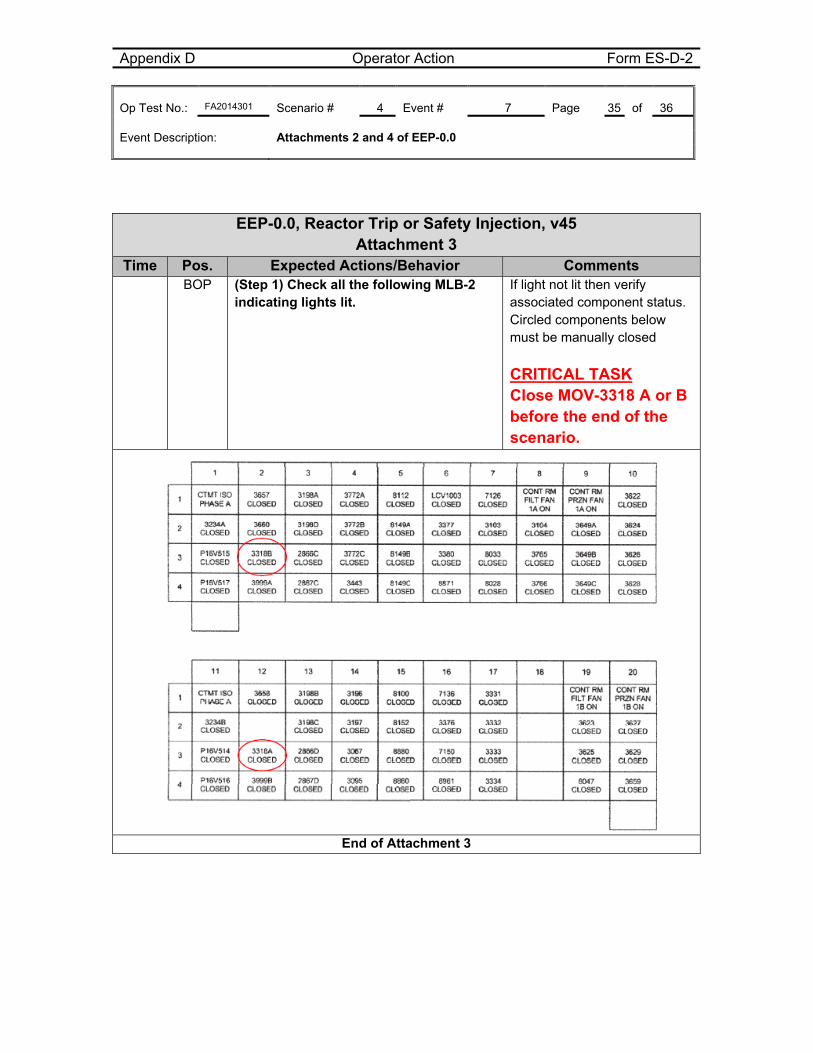
Appendix D Operator Action Form ES-D-2 Op Test No.: FA2014301 Scenario # 4 Event # 7 Page 35 of 36 Event Description: Attachments 2 and 4 of EEP-0.0
EEP-0.0, Reactor Trip or Safety Injection, v45 Attachment 3
Time Pos. Expected Actions/Behavior Comments BOP (Step 1) Check all the following MLB-2
indicating lights lit.
If light not lit then verify associated component status. Circled components below must be manually closed
CRITICAL TASK Close MOV-3318 A or B before the end of the scenario.
End of Attachment 3
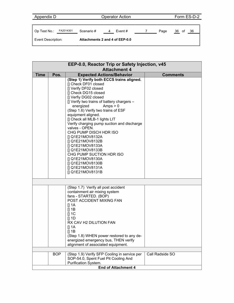
Appendix D Operator Action Form ES-D-2 Op Test No.: FA2014301 Scenario # 4 Event # 7 Page 36 of 36 Event Description: Attachments 2 and 4 of EEP-0.0
EEP-0.0, Reactor Trip or Safety Injection, v45 Attachment 4
Time Pos. Expected Actions/Behavior Comments (Step 1) Verify both ECCS trains aligned.
[] Check DF01 closed [] Verify DF02 closed [] Check DG15 closed [] Verfiy DG02 closed [] Verify two trains of battery chargers – energized Amps > 0 (Step 1.6) Verify two trains of ESF equipment aligned. [] Check all MLB-1 lights LIT Verify charging pump suction and discharge valves - OPEN. CHG PUMP DISCH HDR ISO [] Q1E21MOV8132A [] Q1E21MOV8132B [] Q1E21MOV8133A [] Q1E21MOV8133B CHG PUMP SUCTION HDR ISO [] Q1E21MOV8130A [] Q1E21MOV8130B [] Q1E21MOV8131A [] Q1E21MOV8131B
(Step 1.7) Verify all post accident containment air mixing system fans - STARTED. (BOP) POST ACCIDENT MIXING FAN [] 1A [] 1B [] 1C [] 1D RX CAV H2 DILUTION FAN [] 1A [] 1B (Step 1.8) WHEN power restored to any de-energized emergency bus, THEN verify alignment of associated equipment.
BOP (Step 1.9) Verify SFP Cooling in service per
SOP-54.0, Spent Fuel Pit Cooling And Purification System.
Call Radside SO
End of Attachment 4

Appendix D Crew Briefing sheet Form ES-D-3
Op-Test No.: FA2014301 Page 1 of 2 Brief
This simulator performance scenario is performed in the EVALUATION MODE. You should not
direct questions to the evaluators. Otherwise, you should perform as if you were in the MCR.
Your ability to maintain a log is not being graded, but maintaining a rough log is recommended to
help during briefs.
If you need to communicate with the Unit 2 operator, call Unit 2 at 2434 or page the Unit 2 Unit
Operator.
Respond to what you see. If there is a problem with the simulation, the session will be terminated or
adjusted as appropriate based on the specific problem.
Assign operating positions.
Ask for and answer questions.
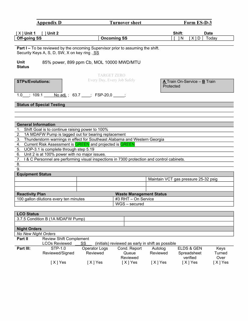
Appendix D Turnover sheet Form ES-D-3
[ X ] Unit 1 [ ] Unit 2 Shift: Date Off-going SS Oncoming SS [ ] N [ X ] D Today Part I – To be reviewed by the oncoming Supervisor prior to assuming the shift. Security Keys A, S, D, SW, X on key ring . SS Unit Status
85% power, 899 ppm Cb, MOL 10000 MWD/MTU
STPs/Evolutions:
A Train On-Service – B Train Protected
1.0 ; 109.1 No adj. ; 63.7 ; FSP-20,0 ; Status of Special Testing General Information 1. Shift Goal is to continue raising power to 100% 2. 1A MDAFW Pump is tagged out for bearing replacement 3. Thunderstorm warnings in effect for Southeast Alabama and Western Georgia 4. Current Risk Assessment is GREEN and projected is GREEN 5. UOP-3.1 is complete through step 5.19 6. Unit 2 is at 100% power with no major issues. 7. I & C Personnel are performing visual inspections in 7300 protection and control cabinets. 8. 9. Equipment Status Maintain VCT gas pressure 25-32 psig Reactivity Plan Waste Management Status 100 gallon dilutions every ten minutes #3 RHT – On Service WGS – secured LCO Status 3.7.5 Condition B (1A MDAFW Pump) Night Orders No New Night Orders Part II Review Shift Complement LCOs Reviewed SS (initials) reviewed as early in shift as possible Part III: STP-1.0
Reviewed/Signed Operator Logs
Reviewed Cond. Report
Queue Reviewed
Autolog Reviewed
ELDS & GEN Spreadsheet
verified
Keys Turned Over
[ X ] Yes [ X ] Yes [ X ] Yes [ X ] Yes [ X ] Yes [ X ] Yes
TARGET ZERO Every Day, Every Job Safely
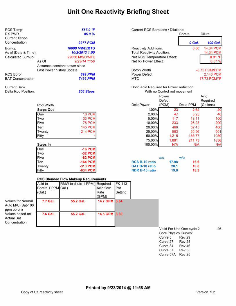
Unit One Reactivity Briefing Sheet
RCS Temp 567.0 °F Current RCS Borations / Dilutions:RX PWR 85.0 % Borate DiluteCurrent Xenon Concentration 2277 PCM 0 Gal. 100 Gal.
Burnup 10000 MWD/MTU Reactivity Additions: 0.00 14.34 PCMAs of (Date & Time) 10/2/2013 1:00 Total Reactivity Addition: 14.34 PCMCalculated Burnup 22658 MWD/MTU Net RCS Temperature Effect: 0.81 °F
As Of 9/23/14 1156 Net Rx Power Effect: 0.57 %Assumes constant power sinceLast Power history update Boron Worth
RCS Boron 899 PPM Power DefectBAT Concentration 7436 PPM MTC
Current Bank Boric Acid Required for Power reductionDelta Rod Position: 206 Steps With no Control rod movement
Rod Worth DeltaPower
Power Defect (PCM) Delta PPM
Acid Required (Gallons)
Steps Out 1.00% 23 2.62 20One 16 PCM 2.00% 47 5.25 40Two 33 PCM 5.00% 117 13.11 100Five 78 PCM 10.00% 233 26.23 200Ten 145 PCM 20.00% 466 52.45 400Twenty 214 PCM 25.00% 583 65.56 501Fifty * 50.00% 1,215 136.77 1050
75.00% 1,881 211.73 1636Steps In 100.00% N/A N/A N/AOne -16 PCMTwo -32 PCMFive -82 PCM a/o w/oTen -164 PCM RCS B-10 ratio 17.98 16.6Twenty -313 PCM BAT B-10 ratio 20.1 18.6Fifty -634 PCM NDR B-10 ratio 19.8 18.3
RCS Blended Flow Makeup RequirementsAcid to Borate 1 PPM (Gal.)
RMW to dilute 1 PPM( Gal.)
Required Acid flow Rate (GPM)
FK-113 Pot Setting
Values for Normal Auto M/U (Bat-100 ppm boron)
7.7 Gal. 55.2 Gal. 14.7 GPM
Values based on Actual Bat Concentration
7.6 Gal. 55.2 Gal. 14.5 GPM
Valid For Unit One cycle 24 26Core Physics Curves:Curve 5 Rev 29Curve 27 Rev 28Curve 34 Rev 46Curve 57 Rev 35Curve 57A Rev 25
3.60
-8.75 PCM/PPM2,148 PCM
-17.73 PCM/°F
3.64
Copy of U1 reactivity sheetPrinted by 9/23/2014 @ 11:58 AM
Version 5.2
Scenario #4 FA2014301
Southern Nuclear J.M. Farley Nuclear Plant
Operations Training Simulator Exam Scenario
BOOTH INSTRUCTOR GUIDE
ILT-37 NRC EXAM SCENARIO #4
Validation time: 85 minutes Validated by: Sorrell, Newell, Smith
TRN Supervisor Approval: Billy Thornton Date: 9/24/14
NRC Chief Examiner SEE NUREG 1021 FORM ES-301-3
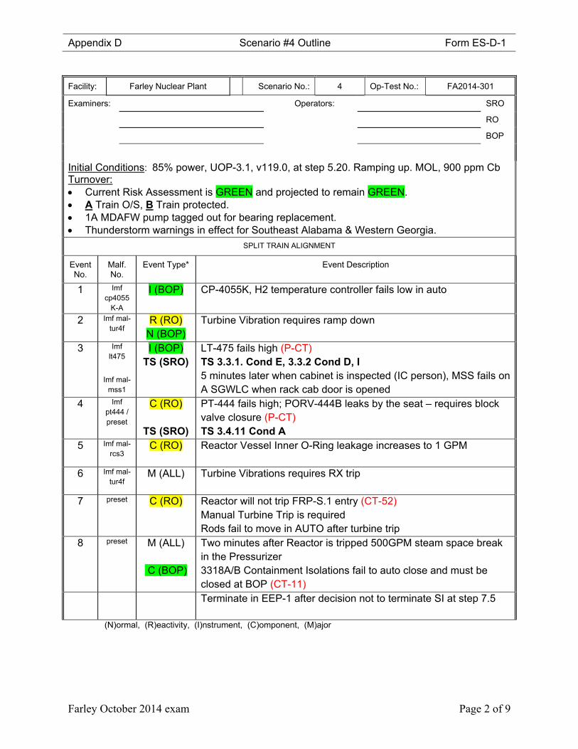
Appendix D Scenario #4 Outline Form ES-D-1
Farley October 2014 exam Page 2 of 9
Facility: Farley Nuclear Plant Scenario No.: 4 Op-Test No.: FA2014-301
Examiners: Operators: SRO
RO
BOP
Initial Conditions: 85% power, UOP-3.1, v119.0, at step 5.20. Ramping up. MOL, 900 ppm Cb
Turnover: Current Risk Assessment is GREEN and projected to remain GREEN. A Train O/S, B Train protected. 1A MDAFW pump tagged out for bearing replacement. Thunderstorm warnings in effect for Southeast Alabama & Western Georgia.
SPLIT TRAIN ALIGNMENT
Event No.
Malf. No.
Event Type* Event Description
1 Imf cp4055
K-A
I (BOP) CP-4055K, H2 temperature controller fails low in auto
2 Imf mal-tur4f
R (RO) N (BOP)
Turbine Vibration requires ramp down
3 Imf lt475
Imf mal-mss1
I (BOP) TS (SRO)
LT-475 fails high (P-CT) TS 3.3.1. Cond E, 3.3.2 Cond D, I 5 minutes later when cabinet is inspected (IC person), MSS fails on A SGWLC when rack cab door is opened
4 Imf pt444 / preset
C (RO)
TS (SRO)
PT-444 fails high; PORV-444B leaks by the seat – requires block valve closure (P-CT) TS 3.4.11 Cond A
5 Imf mal-rcs3
C (RO)
Reactor Vessel Inner O-Ring leakage increases to 1 GPM
6 Imf mal-tur4f
M (ALL) Turbine Vibrations requires RX trip
7 preset C (RO)
Reactor will not trip FRP-S.1 entry (CT-52) Manual Turbine Trip is required Rods fail to move in AUTO after turbine trip
8 preset M (ALL)
C (BOP)
Two minutes after Reactor is tripped 500GPM steam space break in the Pressurizer 3318A/B Containment Isolations fail to auto close and must be closed at BOP (CT-11)
Terminate in EEP-1 after decision not to terminate SI at step 7.5
(N)ormal, (R)eactivity, (I)nstrument, (C)omponent, (M)ajor
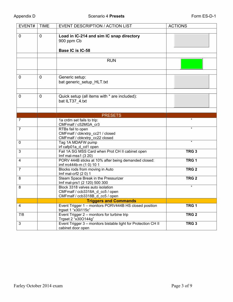
Appendix D Scenario 4 Presets Form ES-D-1
Farley October 2014 exam Page 3 of 9
EVENT# TIME EVENT DESCRIPTION / ACTION LIST ACTIONS 0 0 Load in IC-214 and sim IC snap directory
900 ppm Cb Base IC is IC-58
RUN
0 0 Generic setup:
bat generic_setup_HLT.txt
0 0 Quick setup (all items with * are included):
bat ILT37_4.txt
PRESETS 7 1a crdm set fails to trip:
CMFmalf / c52MGA_cr3 *
7 RTBs fail to open CMFmalf / cbkrxtrp_cc21 / closed CMFmalf / cbkrxtrp_cc22 closed
*
0 Tag 1A MDAFW pump irf cafp01a_d_cd1 open
*
3 Fail 1A SG MSS Card when Prot CH II cabinet open Imf mal-mss1 (3 20)
TRG 3
4 PORV 444B sticks at 10% after being demanded closed: imf rrc444b-m (1 0) 10 1
TRG 1
7 Blocks rods from moving in Auto Imf mal-crf2 (2 0) 1
TRG 2
8 Steam Space Break in the Pressurizer Imf mal-prs1 (2 120) 500 300
TRG 2
8 Block 3318 valves auto isolation CMFmalf / ccb3318A_d_cc5 / open CMFmalf / ccb3318B_d_cc5 / open
*
Triggers and Commands 4 Event Trigger 1 – monitors PORV444B HS closed position
trgset 1 “x30i115c” TRG 1
7/8 Event Trigger 2 – monitors for turbine trip Trgset 2 “x30O144g”
TRG 2
3 Event Trigger 3 – monitors bistable light for Protection CH II cabinet door open
TRG 3
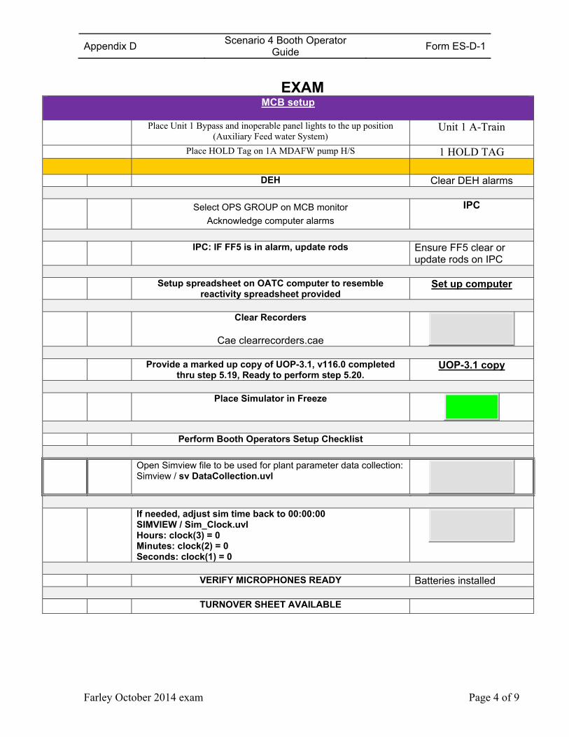
Appendix D Scenario 4 Booth Operator
Guide Form ES-D-1
Farley October 2014 exam Page 4 of 9
EXAM
MCB setup
Place Unit 1 Bypass and inoperable panel lights to the up position (Auxiliary Feed water System)
Unit 1 A-Train
Place HOLD Tag on 1A MDAFW pump H/S 1 HOLD TAG
DEH Clear DEH alarms
Select OPS GROUP on MCB monitor
Acknowledge computer alarms
IPC
IPC: IF FF5 is in alarm, update rods Ensure FF5 clear or
update rods on IPC Setup spreadsheet on OATC computer to resemble
reactivity spreadsheet provided Set up computer
Clear Recorders
Cae clearrecorders.cae
Provide a marked up copy of UOP-3.1, v116.0 completed
thru step 5.19, Ready to perform step 5.20. UOP-3.1 copy
Place Simulator in Freeze
Perform Booth Operators Setup Checklist Open Simview file to be used for plant parameter data collection:
Simview / sv DataCollection.uvl
If needed, adjust sim time back to 00:00:00
SIMVIEW / Sim_Clock.uvl Hours: clock(3) = 0 Minutes: clock(2) = 0 Seconds: clock(1) = 0
VERIFY MICROPHONES READY Batteries installed TURNOVER SHEET AVAILABLE
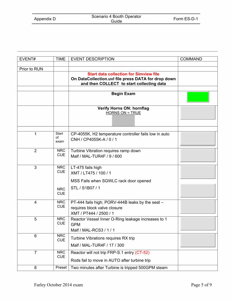
Appendix D Scenario 4 Booth Operator
Guide Form ES-D-1
Farley October 2014 exam Page 5 of 9
EVENT# TIME EVENT DESCRIPTION COMMAND Prior to RUN Start data collection for Simview file
On DataCollection.uvl file press DATA for drop down and then COLLECT to start collecting data
Begin Exam
Verify Horns ON: hornflag HORNS ON = TRUE
1 Start of exam
CP-4055K, H2 temperature controller fails low in auto CNH / CP4055K-A / 0 / 1
2 NRC CUE
Turbine Vibration requires ramp down Malf / MAL-TUR4F / 9 / 600
3 NRC CUE
NRC CUE
LT-475 fails high XMT / LT475 / 100 / 1
MSS Fails when SGWLC rack door opened
STL / S1B07 / 1
4 NRC CUE
PT-444 fails high; PORV-444B leaks by the seat – requires block valve closure XMT / PT444 / 2500 / 1
5 NRC CUE
Reactor Vessel Inner O-Ring leakage increases to 1 GPM Malf / MAL-RCS3 / 1 / 1
6 NRC CUE Turbine Vibrations requires RX trip
Malf / MAL-TUR4F / 17 / 300
7 NRC CUE
Reactor will not trip FRP-S.1 entry (CT-52)
Rods fail to move in AUTO after turbine trip
8 Preset Two minutes after Turbine is tripped 500GPM steam
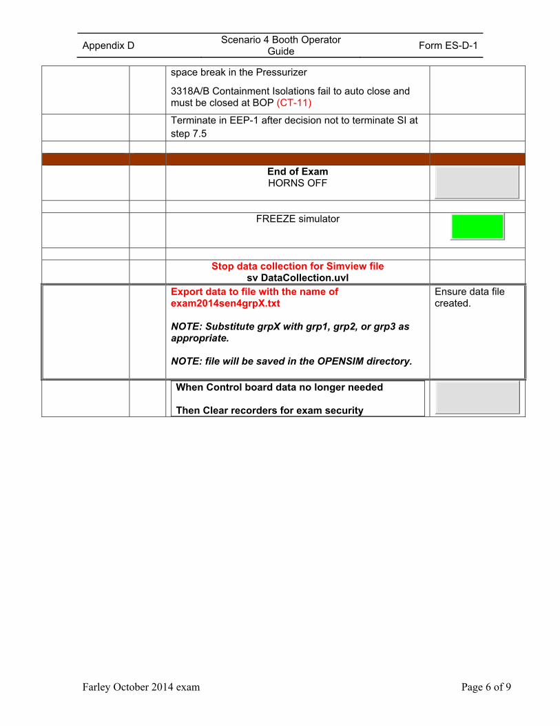
Appendix D Scenario 4 Booth Operator
Guide Form ES-D-1
Farley October 2014 exam Page 6 of 9
space break in the Pressurizer
3318A/B Containment Isolations fail to auto close and must be closed at BOP (CT-11)
Terminate in EEP-1 after decision not to terminate SI at step 7.5
End of Exam
HORNS OFF
FREEZE simulator
Stop data collection for Simview file
sv DataCollection.uvl
Export data to file with the name of exam2014sen4grpX.txt
NOTE: Substitute grpX with grp1, grp2, or grp3 as appropriate.
NOTE: file will be saved in the OPENSIM directory.
Ensure data file created.
When Control board data no longer needed Then Clear recorders for exam security
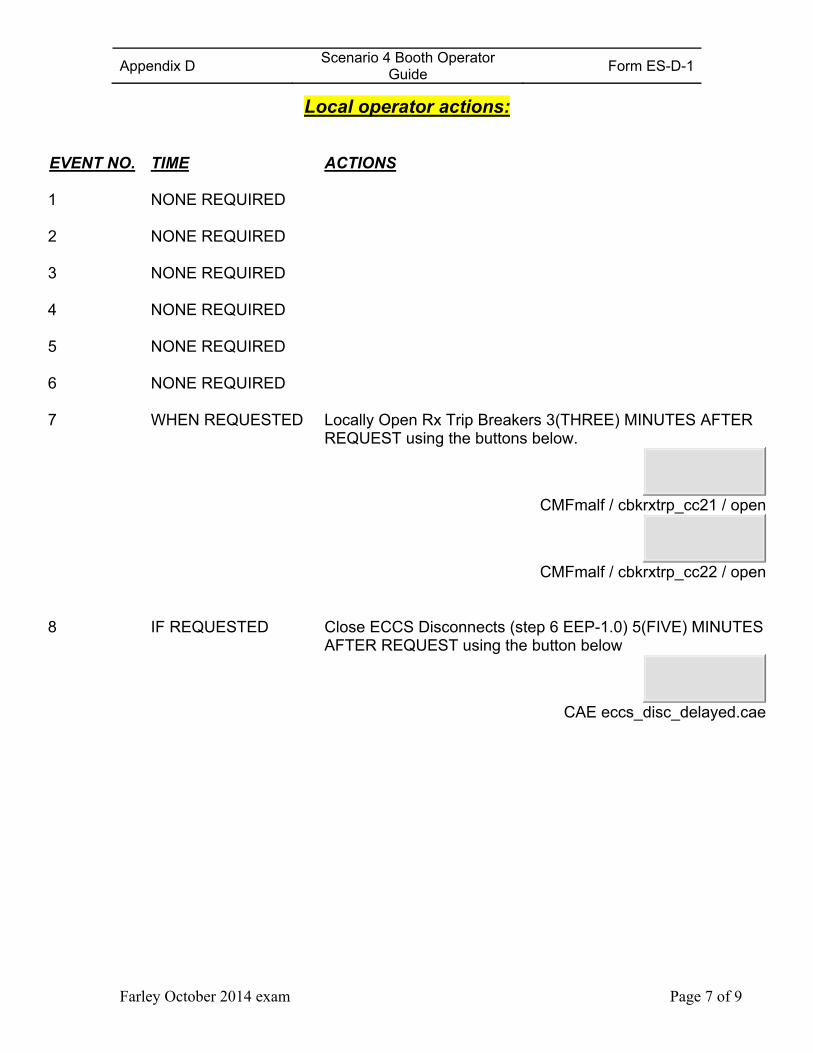
Appendix D Scenario 4 Booth Operator
Guide Form ES-D-1
Farley October 2014 exam Page 7 of 9
Local operator actions:
EVENT NO. TIME ACTIONS 1 NONE REQUIRED 2 NONE REQUIRED 3 NONE REQUIRED 4 NONE REQUIRED 5 NONE REQUIRED 6 NONE REQUIRED 7 WHEN REQUESTED Locally Open Rx Trip Breakers 3(THREE) MINUTES AFTER
REQUEST using the buttons below.
CMFmalf / cbkrxtrp_cc21 / open
CMFmalf / cbkrxtrp_cc22 / open
8 IF REQUESTED Close ECCS Disconnects (step 6 EEP-1.0) 5(FIVE) MINUTES
AFTER REQUEST using the button below
CAE eccs_disc_delayed.cae
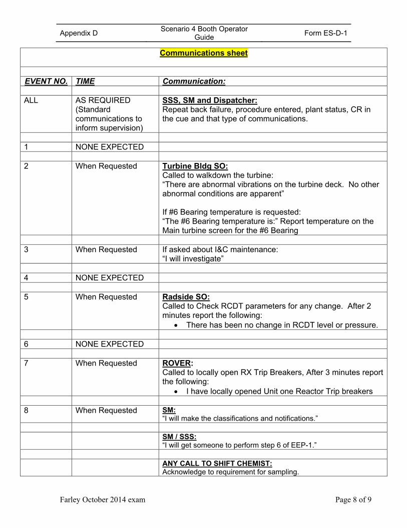
Appendix D Scenario 4 Booth Operator
Guide Form ES-D-1
Farley October 2014 exam Page 8 of 9
Communications sheet
EVENT NO. TIME Communication: ALL AS REQUIRED
(Standard communications to inform supervision)
SSS, SM and Dispatcher: Repeat back failure, procedure entered, plant status, CR in the cue and that type of communications.
1 NONE EXPECTED 2 When Requested Turbine Bldg SO:
Called to walkdown the turbine: “There are abnormal vibrations on the turbine deck. No other abnormal conditions are apparent” If #6 Bearing temperature is requested: “The #6 Bearing temperature is:” Report temperature on the Main turbine screen for the #6 Bearing
3 When Requested If asked about I&C maintenance:
“I will investigate” 4 NONE EXPECTED 5 When Requested Radside SO:
Called to Check RCDT parameters for any change. After 2 minutes report the following:
There has been no change in RCDT level or pressure. 6 NONE EXPECTED 7 When Requested ROVER:
Called to locally open RX Trip Breakers, After 3 minutes report the following:
I have locally opened Unit one Reactor Trip breakers 8 When Requested SM:
“I will make the classifications and notifications.” SM / SSS:
“I will get someone to perform step 6 of EEP-1.” ANY CALL TO SHIFT CHEMIST:
Acknowledge to requirement for sampling.
Appendix D Scenario 4 Booth Operator
Guide Form ES-D-1
Farley October 2014 exam Page 9 of 9
Communications sheet
EVENT NO. TIME Communication:

Appendix D Scenario #5 Outline Form ES-D-1
Farley October 2014 exam Page 1 of 4
Facility: Farley Nuclear Plant Scenario No.: 5 Op-Test No.: FA2014-301
Examiners: Operators: SRO
RO
BOP
Initial Conditions: 95% power, AOP-2 step 16.1. MOL, 894 ppm Cb; Turnover:
Current Risk Assessment is GREEN and projected to remain GREEN. A Train O/S, B Train protected. 1A MDAFW pump tagged out for bearing replacement. 7gpd tube leak. Thunderstorm warnings in effect for Southeast Alabama & Western Georgia. Maintain current power level for SG Tube Leakage evaluation
SPLIT TRAIN ALIGNMENT
Event No.
Malf. No.
Event Type* Event Description
1 N (BOP) Adjust R-70 setpoint
2 Imf pt476
I (BOP) TS (SRO)
PT-476 fails low (P-CT) TS 3.3.2 Cond D
3 Imf pk444a-a
C (RO)
PK-444A fails low. (P-CT)
4 Imf sgs5087a_cc3
C BOP Main Generator Seal oil pressure decreases due to air side seal oil pump trip and regulator malfunction – automatic actions are blocked
5 Irf loa-rds001
R (RO) TS (SRO)
Tube leak increases to 160GPD, ramp unit offline TS 3.4.13 Cond B
6 Preset C (RO)
Selected BAT pump will not Auto start during Auto makeup or borations
7 Imf pk444c-
m
M (ALL)
C (BOP)
“A” loop spray valve drifts open in manual control Reactor is tripped due to stuck open spray valve Main Turbine will not trip automatically or manually. GV closure is required (CT-13) 1B MDAFW will not auto start and cannot be started After start TDAFW pump speed slows to idle speed
8 Restore feed water in FRP H.1 (CT-43)
Terminate on exit of FRP H.1
(N)ormal, (R)eactivity, (I)nstrument, (C)omponent, (M)ajor
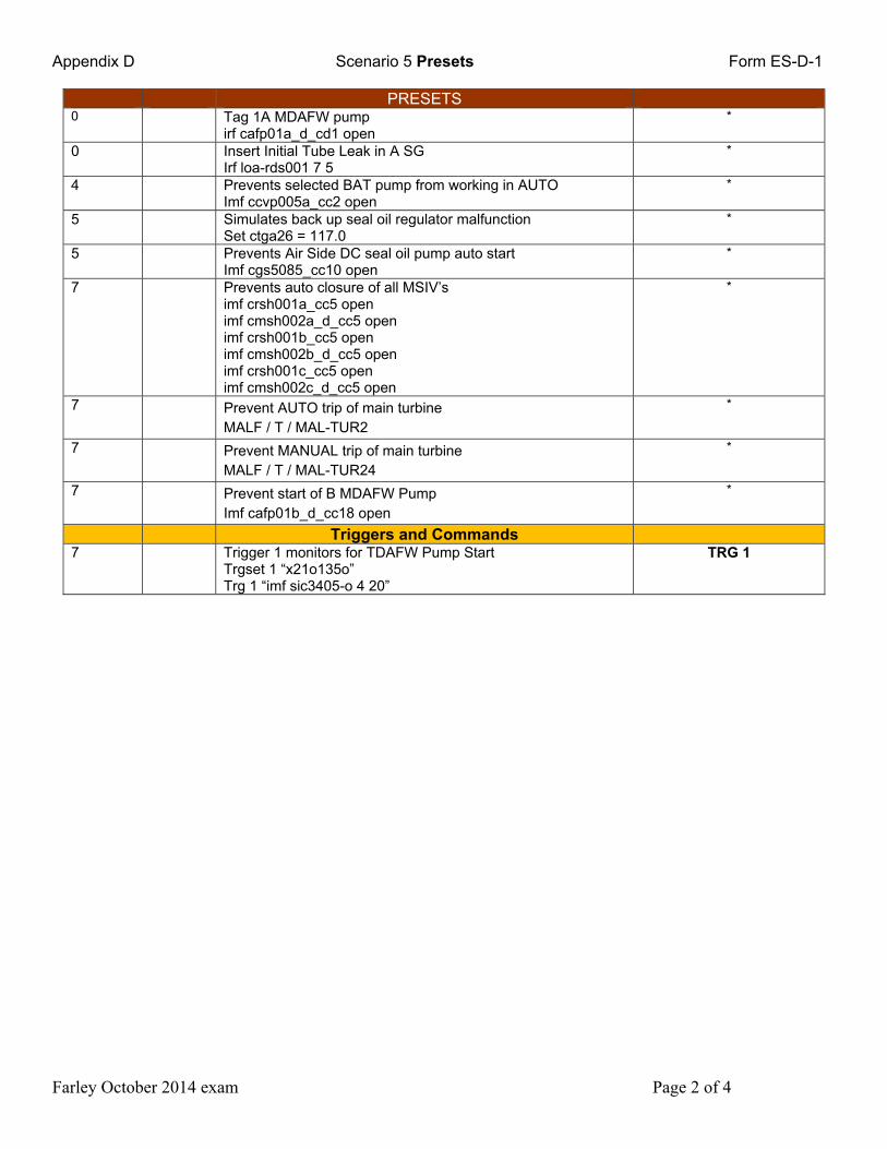
Appendix D Scenario 5 Presets Form ES-D-1
Farley October 2014 exam Page 2 of 4
PRESETS 0 Tag 1A MDAFW pump
irf cafp01a_d_cd1 open *
0 Insert Initial Tube Leak in A SG Irf loa-rds001 7 5
*
4 Prevents selected BAT pump from working in AUTO Imf ccvp005a_cc2 open
*
5 Simulates back up seal oil regulator malfunction Set ctga26 = 117.0
*
5 Prevents Air Side DC seal oil pump auto start Imf cgs5085_cc10 open
*
7 Prevents auto closure of all MSIV’s imf crsh001a_cc5 open imf cmsh002a_d_cc5 open imf crsh001b_cc5 open imf cmsh002b_d_cc5 open imf crsh001c_cc5 open imf cmsh002c_d_cc5 open
*
7 Prevent AUTO trip of main turbine MALF / T / MAL-TUR2
*
7 Prevent MANUAL trip of main turbine MALF / T / MAL-TUR24
*
7 Prevent start of B MDAFW Pump Imf cafp01b_d_cc18 open
*
Triggers and Commands 7 Trigger 1 monitors for TDAFW Pump Start
Trgset 1 “x21o135o” Trg 1 “imf sic3405-o 4 20”
TRG 1
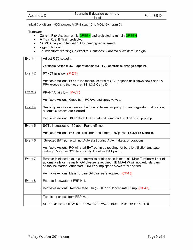
Appendix D Scenario 5 detailed summary
sheet Form ES-D-1
Farley October 2014 exam Page 3 of 4
Initial Conditions: 95% power, AOP-2 step 16.1. MOL, 894 ppm Cb Turnover:
Current Risk Assessment is GREEN and projected to remain GREEN. A Train O/S, B Train protected. 1A MDAFW pump tagged out for bearing replacement. 7 gpd tube leak Thunderstorm warnings in effect for Southeast Alabama & Western Georgia.
Event 1 Adjust R-70 setpoint. Verifiable Actions: BOP operates various R-70 controls to change setpoint.
Event 2 PT-476 fails low. (P-CT) Verifiable Actions: BOP takes manual control of SGFP speed as it slows down and 1A FRV closes and then opens. TS 3.3.2 Cond D.
Event 3 PK-444A fails low. (P-CT) Verifiable Actions: Close both PORVs and spray valves.
Event 4 Seal oil pressure decreases due to air side seal oil pump trip and regulator malfunction, automatic actions are blocked. Verifiable Actions: BOP starts DC air side oil pump and Seal oil backup pump.
Event 5 SGTL increases to 160 gpd. Ramp off line. Verifiable Actions: RO uses rods/boron to control Tavg/Tref. TS 3.4.13 Cond B.
Event 6 Selected BAT pump will not Auto start during Auto makeup or borations. Verifiable Actions: RO will start BAT pump as required for boration/dilution and auto makeup. May use SOP to switch to the other BAT pump.
Event 7 Reactor is tripped due to a spray valve drifting open in manual. Main Turbine will not trip automatically or manually. GV closure is required. 1B MDAFW will not auto start and cannot be started. After start TDAFW pump speed slows to idle speed. Verifiable Actions: Main Turbine GV closure is required. (CT-13)
Event 8 Restore feedwater in FRP-H.1. Verifiable Actions: Restore feed using SGFP or Condensate Pump. (CT-43)
Terminate on exit from FRP-H.1.
SOP/AOP-100/AOP-2/UOP-3.1/SOP/ARP/AOP-100/EEP-0/FRP-H.1/EEP-0
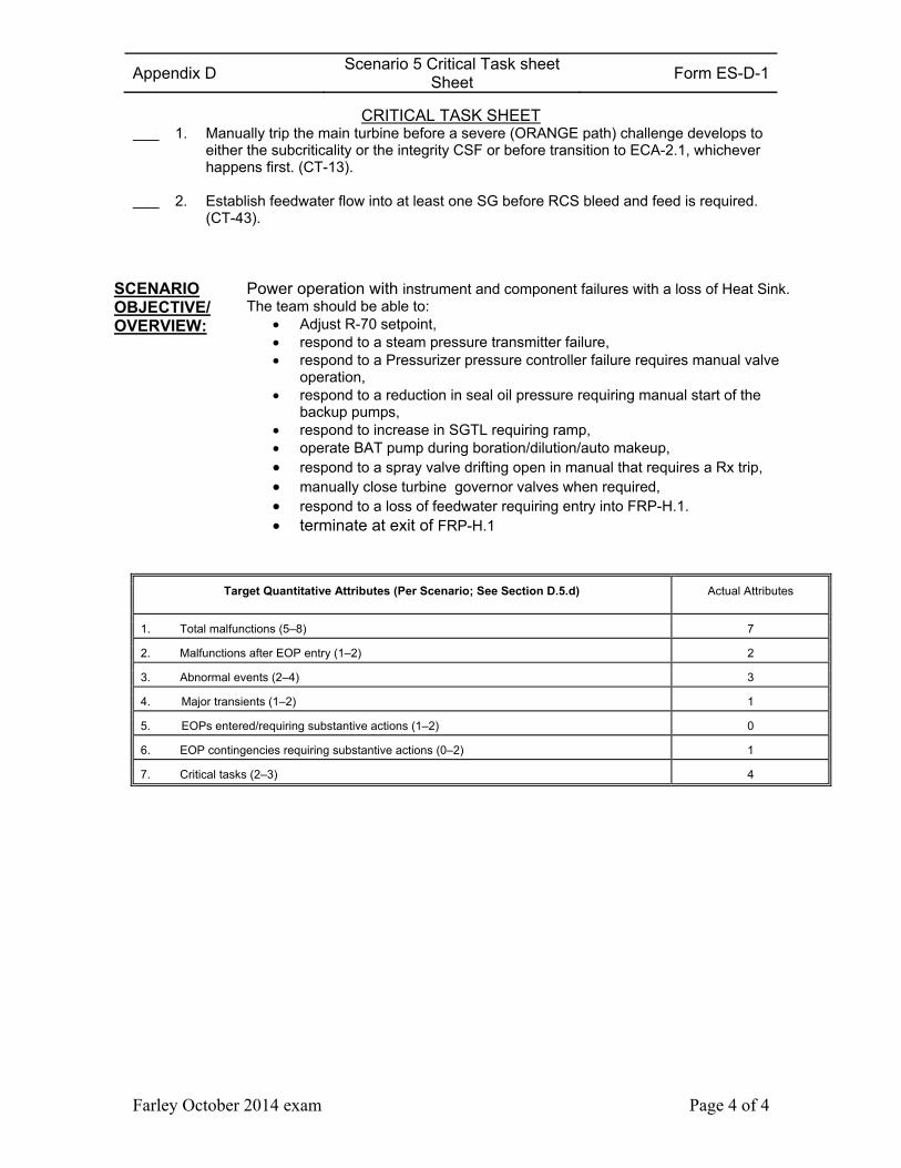
Appendix D Scenario 5 Critical Task sheet
Sheet Form ES-D-1
Farley October 2014 exam Page 4 of 4
CRITICAL TASK SHEET 1. Manually trip the main turbine before a severe (ORANGE path) challenge develops to
either the subcriticality or the integrity CSF or before transition to ECA-2.1, whichever happens first. (CT-13).
2. Establish feedwater flow into at least one SG before RCS bleed and feed is required. (CT-43).
SCENARIO OBJECTIVE/ OVERVIEW:
Power operation with instrument and component failures with a loss of Heat Sink.The team should be able to:
Adjust R-70 setpoint, respond to a steam pressure transmitter failure, respond to a Pressurizer pressure controller failure requires manual valve
operation, respond to a reduction in seal oil pressure requiring manual start of the
backup pumps, respond to increase in SGTL requiring ramp, operate BAT pump during boration/dilution/auto makeup, respond to a spray valve drifting open in manual that requires a Rx trip, manually close turbine governor valves when required, respond to a loss of feedwater requiring entry into FRP-H.1. terminate at exit of FRP-H.1
Target Quantitative Attributes (Per Scenario; See Section D.5.d) Actual Attributes
1. Total malfunctions (5–8) 7
2. Malfunctions after EOP entry (1–2) 2
3. Abnormal events (2–4) 3
4. Major transients (1–2) 1
5. EOPs entered/requiring substantive actions (1–2) 0
6. EOP contingencies requiring substantive actions (0–2) 1
7. Critical tasks (2–3) 4
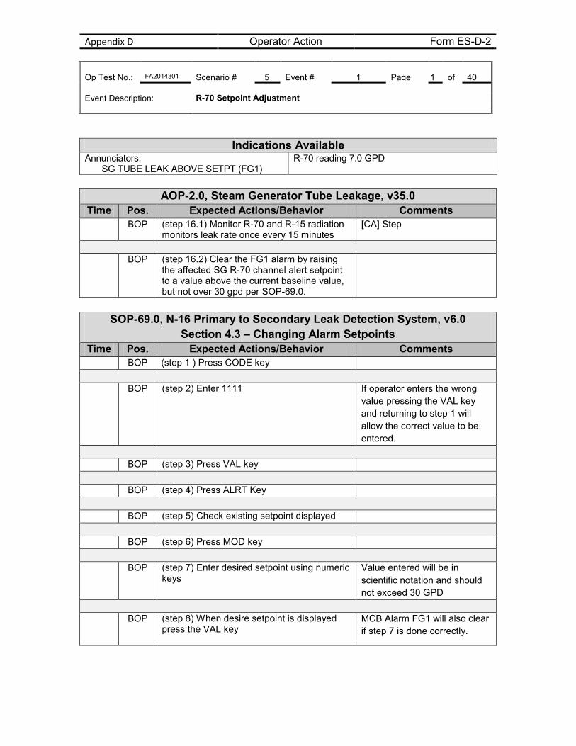
Appendix D Operator Action Form ES-D-2 Op Test No.: FA2014301 Scenario # 5 Event # 1 Page 1 of 40 Event Description: R-70 Setpoint Adjustment
AOP-2.0, Steam Generator Tube Leakage, v35.0
Time Pos. Expected Actions/Behavior Comments BOP (step 16.1) Monitor R-70 and R-15 radiation
monitors leak rate once every 15 minutes [CA] Step
BOP (step 16.2) Clear the FG1 alarm by raising
the affected SG R-70 channel alert setpoint to a value above the current baseline value, but not over 30 gpd per SOP-69.0.
SOP-69.0, N-16 Primary to Secondary Leak Detection System, v6.0
Section 4.3 – Changing Alarm Setpoints Time Pos. Expected Actions/Behavior Comments
BOP (step 1 ) Press CODE key
BOP (step 2) Enter 1111 If operator enters the wrong value pressing the VAL key and returning to step 1 will allow the correct value to be entered.
BOP (step 3) Press VAL key
BOP (step 4) Press ALRT Key
BOP (step 5) Check existing setpoint displayed
BOP (step 6) Press MOD key
BOP (step 7) Enter desired setpoint using numeric
keys Value entered will be in scientific notation and should not exceed 30 GPD
BOP (step 8) When desire setpoint is displayed
press the VAL key
MCB Alarm FG1 will also clear if step 7 is done correctly.
Indications Available Annunciators:
SG TUBE LEAK ABOVE SETPT (FG1) R-70 reading 7.0 GPD
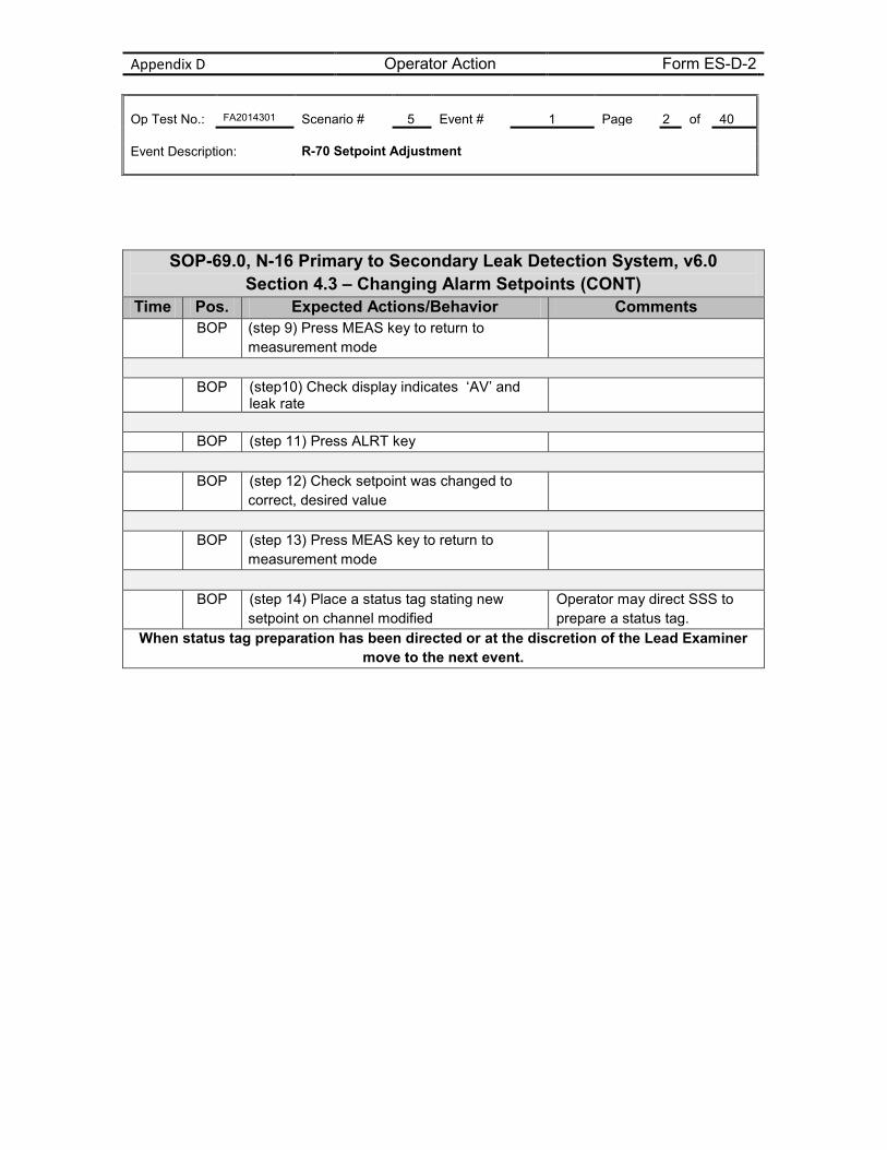
Appendix D Operator Action Form ES-D-2 Op Test No.: FA2014301 Scenario # 5 Event # 1 Page 2 of 40 Event Description: R-70 Setpoint Adjustment
SOP-69.0, N-16 Primary to Secondary Leak Detection System, v6.0 Section 4.3 – Changing Alarm Setpoints (CONT)
Time Pos. Expected Actions/Behavior Comments BOP (step 9) Press MEAS key to return to
measurement mode
BOP (step10) Check display indicates ‘AV’ and
leak rate
BOP (step 11) Press ALRT key
BOP (step 12) Check setpoint was changed to
correct, desired value
BOP (step 13) Press MEAS key to return to
measurement mode
BOP (step 14) Place a status tag stating new
setpoint on channel modified Operator may direct SSS to prepare a status tag.
When status tag preparation has been directed or at the discretion of the Lead Examiner move to the next event.
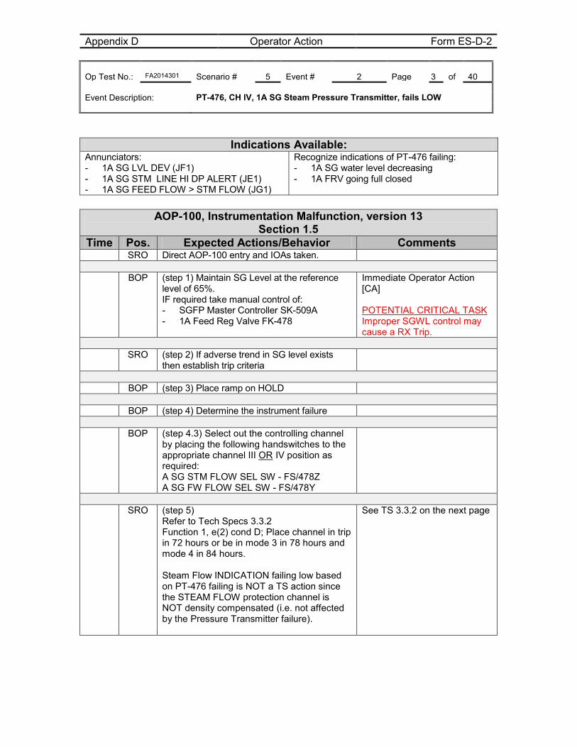
Appendix D Operator Action Form ES-D-2 Op Test No.: FA2014301 Scenario # 5 Event # 2 Page 3 of 40 Event Description: PT-476, CH IV, 1A SG Steam Pressure Transmitter, fails LOW
Indications Available: Annunciators: - 1A SG LVL DEV (JF1) - 1A SG STM LINE HI DP ALERT (JE1) - 1A SG FEED FLOW > STM FLOW (JG1)
Recognize indications of PT-476 failing: - 1A SG water level decreasing - 1A FRV going full closed
AOP-100, Instrumentation Malfunction, version 13
Section 1.5 Time Pos. Expected Actions/Behavior Comments
SRO Direct AOP-100 entry and IOAs taken.
BOP (step 1) Maintain SG Level at the reference level of 65%. IF required take manual control of: - SGFP Master Controller SK-509A - 1A Feed Reg Valve FK-478
Immediate Operator Action [CA] POTENTIAL CRITICAL TASK Improper SGWL control may cause a RX Trip.
SRO (step 2) If adverse trend in SG level exists
then establish trip criteria
BOP (step 3) Place ramp on HOLD
BOP (step 4) Determine the instrument failure
BOP (step 4.3) Select out the controlling channel
by placing the following handswitches to the appropriate channel III OR IV position as required: A SG STM FLOW SEL SW - FS/478Z A SG FW FLOW SEL SW - FS/478Y
SRO (step 5)
Refer to Tech Specs 3.3.2 Function 1, e(2) cond D; Place channel in trip in 72 hours or be in mode 3 in 78 hours and mode 4 in 84 hours. Steam Flow INDICATION failing low based on PT-476 failing is NOT a TS action since the STEAM FLOW protection channel is NOT density compensated (i.e. not affected by the Pressure Transmitter failure).
See TS 3.3.2 on the next page
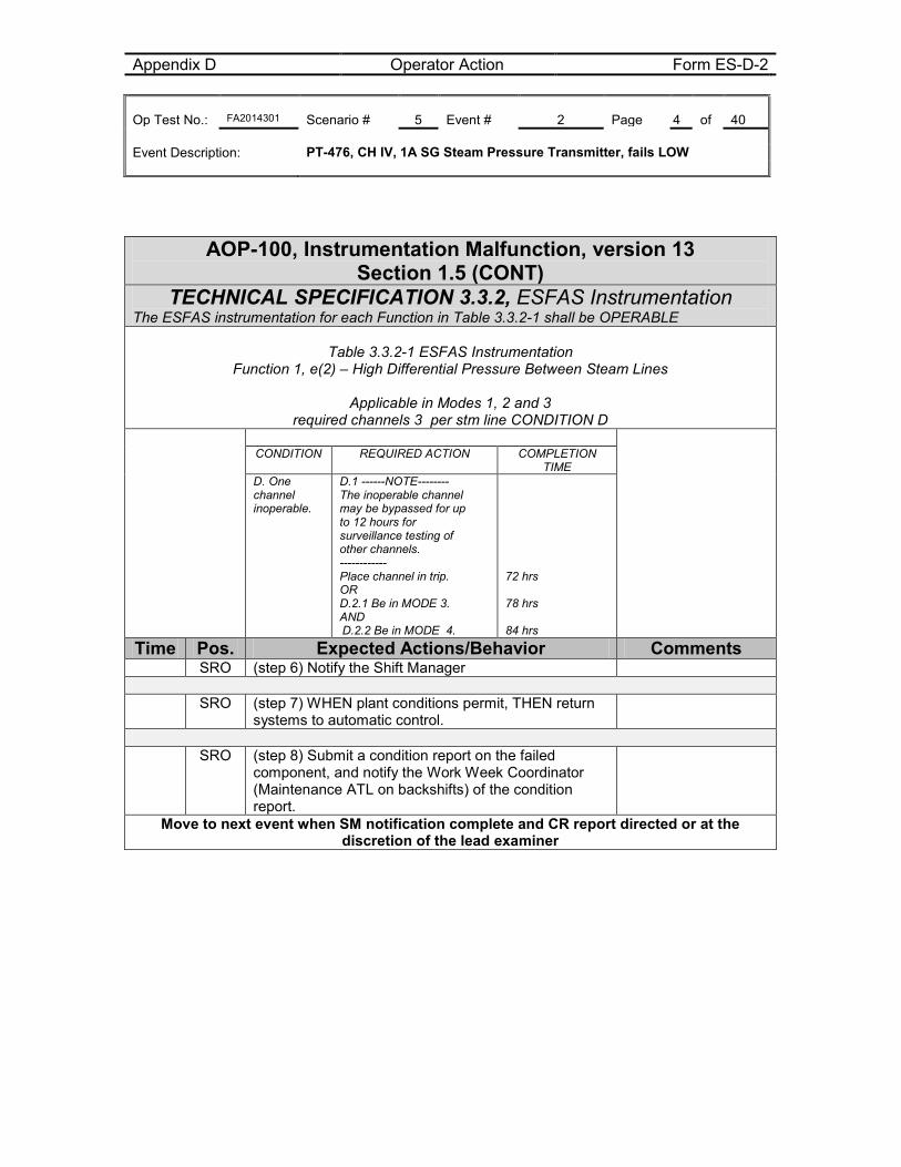
Appendix D Operator Action Form ES-D-2 Op Test No.: FA2014301 Scenario # 5 Event # 2 Page 4 of 40 Event Description: PT-476, CH IV, 1A SG Steam Pressure Transmitter, fails LOW
AOP-100, Instrumentation Malfunction, version 13
Section 1.5 (CONT) TECHNICAL SPECIFICATION 3.3.2, ESFAS Instrumentation
The ESFAS instrumentation for each Function in Table 3.3.2-1 shall be OPERABLE
Table 3.3.2-1 ESFAS Instrumentation Function 1, e(2) – High Differential Pressure Between Steam Lines
Applicable in Modes 1, 2 and 3
required channels 3 per stm line CONDITION D
CONDITION REQUIRED ACTION COMPLETION TIME
D. One channel inoperable.
D.1 ------NOTE-------- The inoperable channel may be bypassed for up to 12 hours for surveillance testing of other channels. ------------ Place channel in trip. OR D.2.1 Be in MODE 3. AND D.2.2 Be in MODE 4.
72 hrs 78 hrs 84 hrs
Time Pos. Expected Actions/Behavior Comments SRO (step 6) Notify the Shift Manager
SRO (step 7) WHEN plant conditions permit, THEN return
systems to automatic control.
SRO (step 8) Submit a condition report on the failed
component, and notify the Work Week Coordinator (Maintenance ATL on backshifts) of the condition report.
Move to next event when SM notification complete and CR report directed or at the discretion of the lead examiner
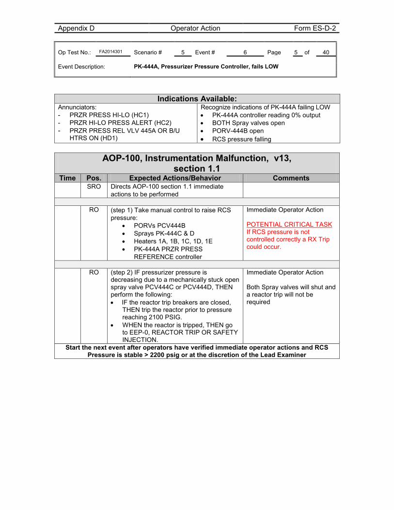
Appendix D Operator Action Form ES-D-2 Op Test No.: FA2014301 Scenario # 5 Event # 6 Page 5 of 40 Event Description: PK-444A, Pressurizer Pressure Controller, fails LOW
Indications Available: Annunciators: - PRZR PRESS HI-LO (HC1) - PRZR HI-LO PRESS ALERT (HC2) - PRZR PRESS REL VLV 445A OR B/U
HTRS ON (HD1)
Recognize indications of PK-444A failing LOW • PK-444A controller reading 0% output • BOTH Spray valves open • PORV-444B open • RCS pressure falling
AOP-100, Instrumentation Malfunction, v13,
section 1.1 Time Pos. Expected Actions/Behavior Comments
SRO Directs AOP-100 section 1.1 immediate actions to be performed
RO (step 1) Take manual control to raise RCS
pressure: • PORVs PCV444B • Sprays PK-444C & D • Heaters 1A, 1B, 1C, 1D, 1E • PK-444A PRZR PRESS
REFERENCE controller
Immediate Operator Action POTENTIAL CRITICAL TASK If RCS pressure is not controlled correctly a RX Trip could occur.
RO (step 2) IF pressurizer pressure is
decreasing due to a mechanically stuck open spray valve PCV444C or PCV444D, THEN perform the following: • IF the reactor trip breakers are closed,
THEN trip the reactor prior to pressure reaching 2100 PSIG.
• WHEN the reactor is tripped, THEN go to EEP-0, REACTOR TRIP OR SAFETY INJECTION.
Immediate Operator Action Both Spray valves will shut and a reactor trip will not be required
Start the next event after operators have verified immediate operator actions and RCS Pressure is stable > 2200 psig or at the discretion of the Lead Examiner
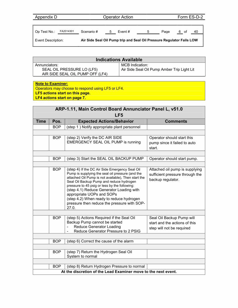
Appendix D Operator Action Form ES-D-2 Op Test No.: FA2014301 Scenario # 5 Event # 5 Page 6 of 40 Event Description: Air Side Seal Oil Pump trip and Seal Oil Pressure Regulator Fails LOW
Note to Examiner: Operators may choose to respond using LF5 or LF4. LF5 actions start on this page. LF4 actions start on page 7.
ARP-1.11, Main Control Board Annunciator Panel L, v51.0 LF5
Time Pos. Expected Actions/Behavior Comments BOP (step 1 ) Notify appropriate plant personnel
BOP (step 2) Verify the DC AIR SIDE
EMERGENCY SEAL OIL PUMP is running Operator should start this pump since it failed to auto start.
BOP (step 3) Start the SEAL OIL BACKUP PUMP Operator should start pump.
BOP (step 4) If the DC Air Side Emergency Seal Oil
Pump is supplying the seal oil pressure (and the attached Oil Pump is not available), Then start the Seal Oil Backup Pump and reduce hydrogen pressure to 45 psig or less by the following: (step 4.1) Reduce Generator Loading with appropriate UOPs and SOPs (step 4.2) When ready to reduce hydrogen pressure then reduce the pressure with SOP-27.0.
Attached oil pump is supplying sufficient pressure through the backup regulator.
BOP (step 5) Actions Required if the Seal Oil
Backup Pump cannot be started - Reduce Generator Loading - Reduce Generator Pressure to 2 PSIG
Seal Oil Backup Pump will start and the actions of this step will not be required
BOP (step 6) Correct the cause of the alarm
BOP (step 7) Return the Hydrogen Seal Oil
System to normal
BOP (step 8) Return Hydrogen Pressure to normal
At the discretion of the Lead Examiner move to the next event.
Indications Available Annunciators:
SEAL OIL PRESSURE LO (LF5) AIR SIDE SEAL OIL PUMP OFF (LF4)
MCB Indication: Air Side Seal Oil Pump Amber Trip Light Lit
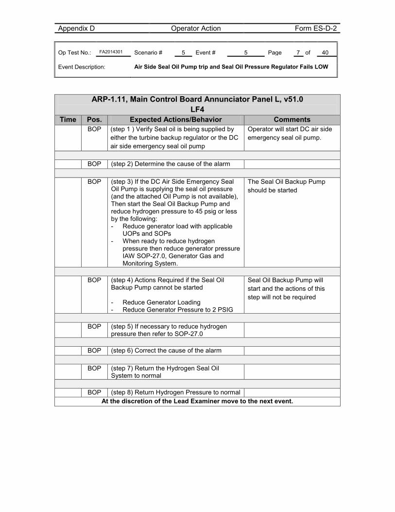
Appendix D Operator Action Form ES-D-2 Op Test No.: FA2014301 Scenario # 5 Event # 5 Page 7 of 40 Event Description: Air Side Seal Oil Pump trip and Seal Oil Pressure Regulator Fails LOW
ARP-1.11, Main Control Board Annunciator Panel L, v51.0 LF4
Time Pos. Expected Actions/Behavior Comments BOP (step 1 ) Verify Seal oil is being supplied by
either the turbine backup regulator or the DC air side emergency seal oil pump
Operator will start DC air side emergency seal oil pump.
BOP (step 2) Determine the cause of the alarm
BOP (step 3) If the DC Air Side Emergency Seal
Oil Pump is supplying the seal oil pressure (and the attached Oil Pump is not available), Then start the Seal Oil Backup Pump and reduce hydrogen pressure to 45 psig or less by the following: - Reduce generator load with applicable
UOPs and SOPs - When ready to reduce hydrogen
pressure then reduce generator pressure IAW SOP-27.0, Generator Gas and Monitoring System.
The Seal Oil Backup Pump should be started
BOP (step 4) Actions Required if the Seal Oil
Backup Pump cannot be started - Reduce Generator Loading - Reduce Generator Pressure to 2 PSIG
Seal Oil Backup Pump will start and the actions of this step will not be required
BOP (step 5) If necessary to reduce hydrogen
pressure then refer to SOP-27.0
BOP (step 6) Correct the cause of the alarm
BOP (step 7) Return the Hydrogen Seal Oil
System to normal
BOP (step 8) Return Hydrogen Pressure to normal
At the discretion of the Lead Examiner move to the next event.
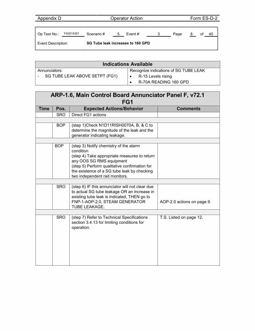
Appendix D Operator Action Form ES-D-2 Op Test No.: FA2014301 Scenario # 5 Event # 3 Page 8 of 40 Event Description: SG Tube leak increases to 160 GPD
Indications Available Annunciators: - SG TUBE LEAK ABOVE SETPT (FG1)
Recognize indications of SG TUBE LEAK • R-15 Levels rising • R-70A READING 160 GPD
ARP-1.6, Main Control Board Annunciator Panel F, v72.1
FG1 Time Pos. Expected Actions/Behavior Comments SRO Direct FG1 actions BOP (step 1)Check N1D11RISH0070A, B, & C to
determine the magnitude of the leak and the generator indicating leakage.
BOP (step 3) Notify chemistry of the alarm
condition (step 4) Take appropriate measures to return any OOS SG RMS equipment (step 5) Perform qualitative confirmation for the existence of a SG tube leak by checking two independent rad monitors.
SRO (step 6) IF this annunciator will not clear due
to actual SG tube leakage OR an increase in existing tube leak is indicated, THEN go to FNP-1-AOP-2.0, STEAM GENERATOR TUBE LEAKAGE.
AOP-2.0 actions on page 9.
SRO (step 7) Refer to Technical Specifications
section 3.4.13 for limiting conditions for operation.
T.S. Listed on page 12.
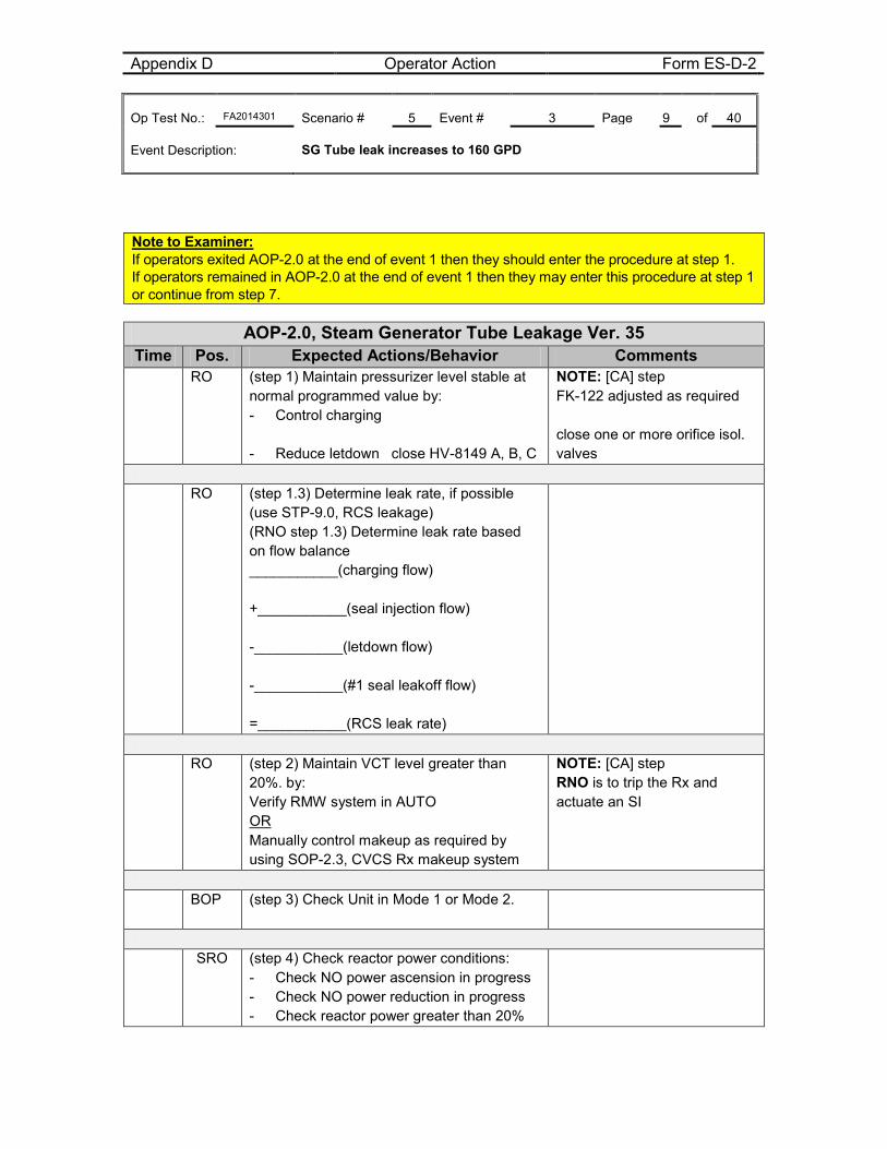
Appendix D Operator Action Form ES-D-2 Op Test No.: FA2014301 Scenario # 5 Event # 3 Page 9 of 40 Event Description: SG Tube leak increases to 160 GPD
Note to Examiner: If operators exited AOP-2.0 at the end of event 1 then they should enter the procedure at step 1. If operators remained in AOP-2.0 at the end of event 1 then they may enter this procedure at step 1 or continue from step 7.
AOP-2.0, Steam Generator Tube Leakage Ver. 35 Time Pos. Expected Actions/Behavior Comments
RO (step 1) Maintain pressurizer level stable at normal programmed value by: - Control charging
- Reduce letdown close HV-8149 A, B, C
NOTE: [CA] step FK-122 adjusted as required close one or more orifice isol. valves
RO (step 1.3) Determine leak rate, if possible
(use STP-9.0, RCS leakage) (RNO step 1.3) Determine leak rate based on flow balance ___________(charging flow) +___________(seal injection flow) -___________(letdown flow) -___________(#1 seal leakoff flow) =___________(RCS leak rate)
RO (step 2) Maintain VCT level greater than
20%. by: Verify RMW system in AUTO OR Manually control makeup as required by using SOP-2.3, CVCS Rx makeup system
NOTE: [CA] step RNO is to trip the Rx and actuate an SI
BOP (step 3) Check Unit in Mode 1 or Mode 2.
SRO (step 4) Check reactor power conditions:
- Check NO power ascension in progress - Check NO power reduction in progress - Check reactor power greater than 20%
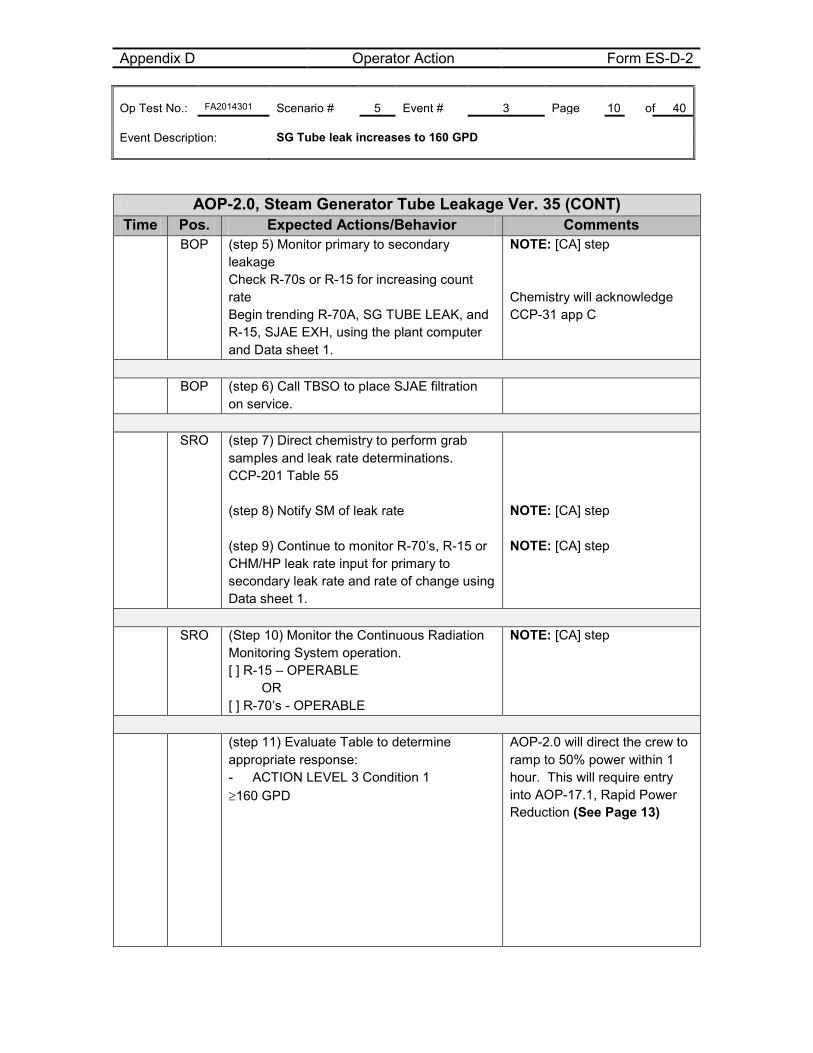
Appendix D Operator Action Form ES-D-2 Op Test No.: FA2014301 Scenario # 5 Event # 3 Page 10 of 40 Event Description: SG Tube leak increases to 160 GPD
AOP-2.0, Steam Generator Tube Leakage Ver. 35 (CONT) Time Pos. Expected Actions/Behavior Comments
BOP (step 5) Monitor primary to secondary leakage Check R-70s or R-15 for increasing count rate Begin trending R-70A, SG TUBE LEAK, and R-15, SJAE EXH, using the plant computer and Data sheet 1.
NOTE: [CA] step Chemistry will acknowledge CCP-31 app C
BOP (step 6) Call TBSO to place SJAE filtration
on service.
SRO (step 7) Direct chemistry to perform grab
samples and leak rate determinations. CCP-201 Table 55 (step 8) Notify SM of leak rate (step 9) Continue to monitor R-70’s, R-15 or CHM/HP leak rate input for primary to secondary leak rate and rate of change using Data sheet 1.
NOTE: [CA] step NOTE: [CA] step
SRO (Step 10) Monitor the Continuous Radiation
Monitoring System operation. [ ] R-15 – OPERABLE OR [ ] R-70’s - OPERABLE
NOTE: [CA] step
(step 11) Evaluate Table to determine
appropriate response: - ACTION LEVEL 3 Condition 1 ≥160 GPD
AOP-2.0 will direct the crew to ramp to 50% power within 1 hour. This will require entry into AOP-17.1, Rapid Power Reduction (See Page 13)
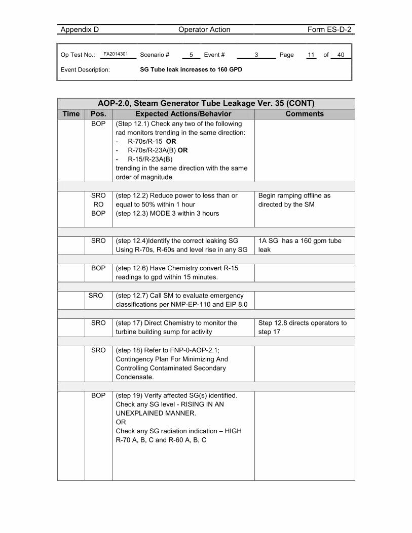
Appendix D Operator Action Form ES-D-2 Op Test No.: FA2014301 Scenario # 5 Event # 3 Page 11 of 40 Event Description: SG Tube leak increases to 160 GPD
AOP-2.0, Steam Generator Tube Leakage Ver. 35 (CONT) Time Pos. Expected Actions/Behavior Comments
BOP (Step 12.1) Check any two of the following rad monitors trending in the same direction: - R-70s/R-15 OR - R-70s/R-23A(B) OR - R-15/R-23A(B) trending in the same direction with the same order of magnitude
SRO
RO BOP
(step 12.2) Reduce power to less than or equal to 50% within 1 hour (step 12.3) MODE 3 within 3 hours
Begin ramping offline as directed by the SM
SRO (step 12.4)Identify the correct leaking SG
Using R-70s, R-60s and level rise in any SG 1A SG has a 160 gpm tube leak
BOP (step 12.6) Have Chemistry convert R-15
readings to gpd within 15 minutes.
SRO (step 12.7) Call SM to evaluate emergency
classifications per NMP-EP-110 and EIP 8.0
SRO (step 17) Direct Chemistry to monitor the
turbine building sump for activity Step 12.8 directs operators to step 17
SRO (step 18) Refer to FNP-0-AOP-2.1;
Contingency Plan For Minimizing And Controlling Contaminated Secondary Condensate.
BOP (step 19) Verify affected SG(s) identified.
Check any SG level - RISING IN AN UNEXPLAINED MANNER. OR Check any SG radiation indication – HIGH R-70 A, B, C and R-60 A, B, C
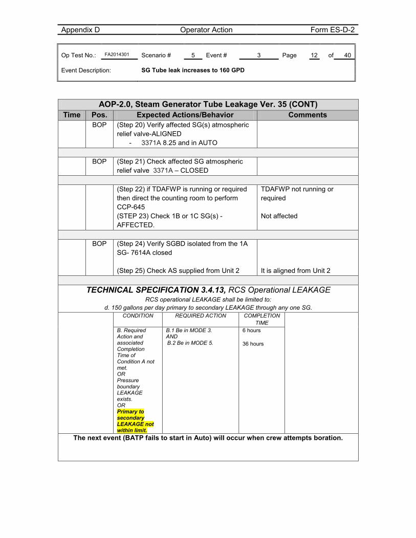
Appendix D Operator Action Form ES-D-2 Op Test No.: FA2014301 Scenario # 5 Event # 3 Page 12 of 40 Event Description: SG Tube leak increases to 160 GPD
AOP-2.0, Steam Generator Tube Leakage Ver. 35 (CONT) Time Pos. Expected Actions/Behavior Comments
BOP (Step 20) Verify affected SG(s) atmospheric relief valve-ALIGNED
- 3371A 8.25 and in AUTO
BOP (Step 21) Check affected SG atmospheric
relief valve 3371A – CLOSED
(Step 22) if TDAFWP is running or required
then direct the counting room to perform CCP-645 (STEP 23) Check 1B or 1C SG(s) - AFFECTED.
TDAFWP not running or required Not affected
BOP (Step 24) Verify SGBD isolated from the 1A
SG- 7614A closed (Step 25) Check AS supplied from Unit 2
It is aligned from Unit 2
TECHNICAL SPECIFICATION 3.4.13, RCS Operational LEAKAGE
RCS operational LEAKAGE shall be limited to: d. 150 gallons per day primary to secondary LEAKAGE through any one SG.
CONDITION REQUIRED ACTION COMPLETION TIME
B. Required Action and associated Completion Time of Condition A not met. OR Pressure boundary LEAKAGE exists. OR Primary to secondary LEAKAGE not within limit.
B.1 Be in MODE 3. AND B.2 Be in MODE 5.
6 hours 36 hours
The next event (BATP fails to start in Auto) will occur when crew attempts boration.
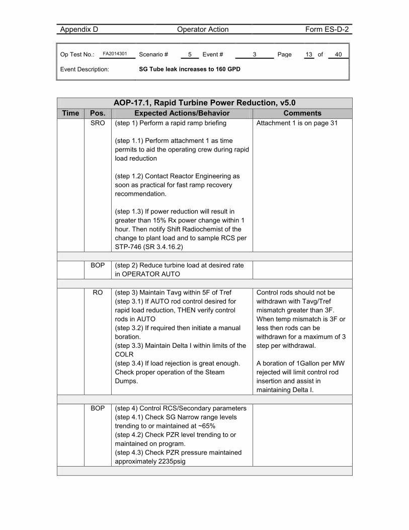
Appendix D Operator Action Form ES-D-2 Op Test No.: FA2014301 Scenario # 5 Event # 3 Page 13 of 40 Event Description: SG Tube leak increases to 160 GPD
AOP-17.1, Rapid Turbine Power Reduction, v5.0 Time Pos. Expected Actions/Behavior Comments
SRO (step 1) Perform a rapid ramp briefing (step 1.1) Perform attachment 1 as time permits to aid the operating crew during rapid load reduction (step 1.2) Contact Reactor Engineering as soon as practical for fast ramp recovery recommendation. (step 1.3) If power reduction will result in greater than 15% Rx power change within 1 hour. Then notify Shift Radiochemist of the change to plant load and to sample RCS per STP-746 (SR 3.4.16.2)
Attachment 1 is on page 31
BOP (step 2) Reduce turbine load at desired rate
in OPERATOR AUTO
RO (step 3) Maintain Tavg within 5F of Tref
(step 3.1) If AUTO rod control desired for rapid load reduction, THEN verify control rods in AUTO (step 3.2) If required then initiate a manual boration. (step 3.3) Maintain Delta I within limits of the COLR (step 3.4) If load rejection is great enough. Check proper operation of the Steam Dumps.
Control rods should not be withdrawn with Tavg/Tref mismatch greater than 3F. When temp mismatch is 3F or less then rods can be withdrawn for a maximum of 3 step per withdrawal. A boration of 1Gallon per MW rejected will limit control rod insertion and assist in maintaining Delta I.
BOP (step 4) Control RCS/Secondary parameters
(step 4.1) Check SG Narrow range levels trending to or maintained at ~65% (step 4.2) Check PZR level trending to or maintained on program. (step 4.3) Check PZR pressure maintained approximately 2235psig
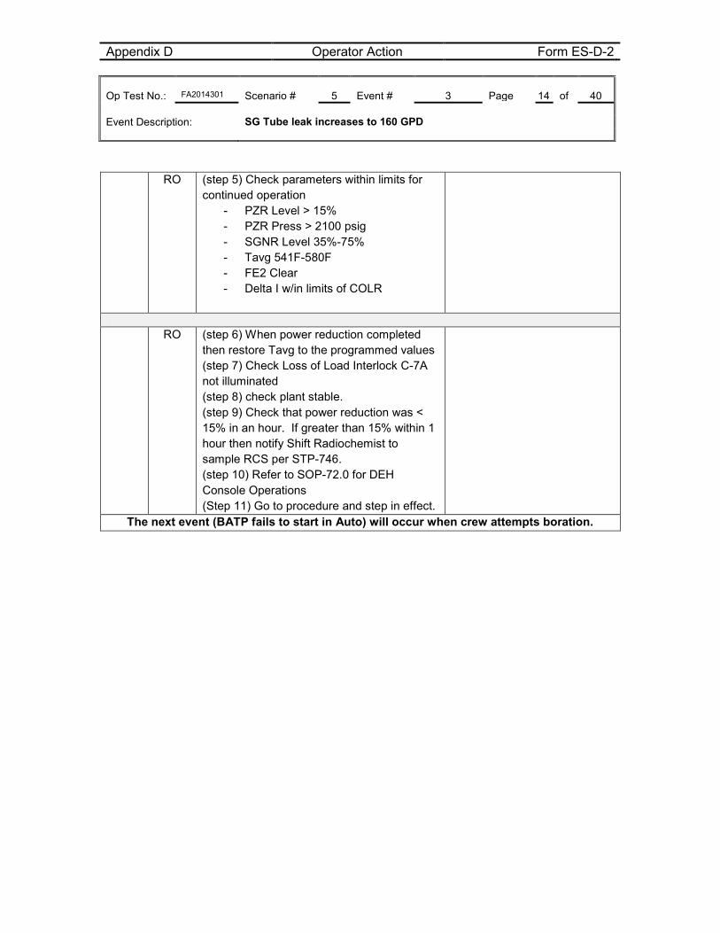
Appendix D Operator Action Form ES-D-2 Op Test No.: FA2014301 Scenario # 5 Event # 3 Page 14 of 40 Event Description: SG Tube leak increases to 160 GPD
RO (step 5) Check parameters within limits for continued operation
- PZR Level > 15% - PZR Press > 2100 psig - SGNR Level 35%-75% - Tavg 541F-580F - FE2 Clear - Delta I w/in limits of COLR
RO (step 6) When power reduction completed
then restore Tavg to the programmed values (step 7) Check Loss of Load Interlock C-7A not illuminated (step 8) check plant stable. (step 9) Check that power reduction was < 15% in an hour. If greater than 15% within 1 hour then notify Shift Radiochemist to sample RCS per STP-746. (step 10) Refer to SOP-72.0 for DEH Console Operations (Step 11) Go to procedure and step in effect.
The next event (BATP fails to start in Auto) will occur when crew attempts boration.
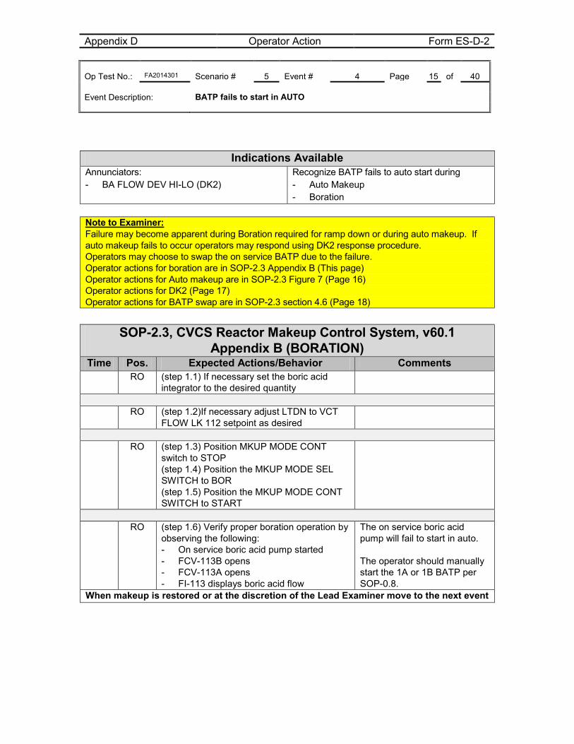
Appendix D Operator Action Form ES-D-2 Op Test No.: FA2014301 Scenario # 5 Event # 4 Page 15 of 40 Event Description: BATP fails to start in AUTO
Indications Available
Annunciators: - BA FLOW DEV HI-LO (DK2)
Recognize BATP fails to auto start during - Auto Makeup - Boration
Note to Examiner: Failure may become apparent during Boration required for ramp down or during auto makeup. If auto makeup fails to occur operators may respond using DK2 response procedure. Operators may choose to swap the on service BATP due to the failure. Operator actions for boration are in SOP-2.3 Appendix B (This page) Operator actions for Auto makeup are in SOP-2.3 Figure 7 (Page 16) Operator actions for DK2 (Page 17) Operator actions for BATP swap are in SOP-2.3 section 4.6 (Page 18)
SOP-2.3, CVCS Reactor Makeup Control System, v60.1
Appendix B (BORATION) Time Pos. Expected Actions/Behavior Comments RO (step 1.1) If necessary set the boric acid
integrator to the desired quantity
RO (step 1.2)If necessary adjust LTDN to VCT
FLOW LK 112 setpoint as desired
RO (step 1.3) Position MKUP MODE CONT
switch to STOP (step 1.4) Position the MKUP MODE SEL SWITCH to BOR (step 1.5) Position the MKUP MODE CONT SWITCH to START
RO (step 1.6) Verify proper boration operation by
observing the following: - On service boric acid pump started - FCV-113B opens - FCV-113A opens - FI-113 displays boric acid flow
The on service boric acid pump will fail to start in auto. The operator should manually start the 1A or 1B BATP per SOP-0.8.
When makeup is restored or at the discretion of the Lead Examiner move to the next event
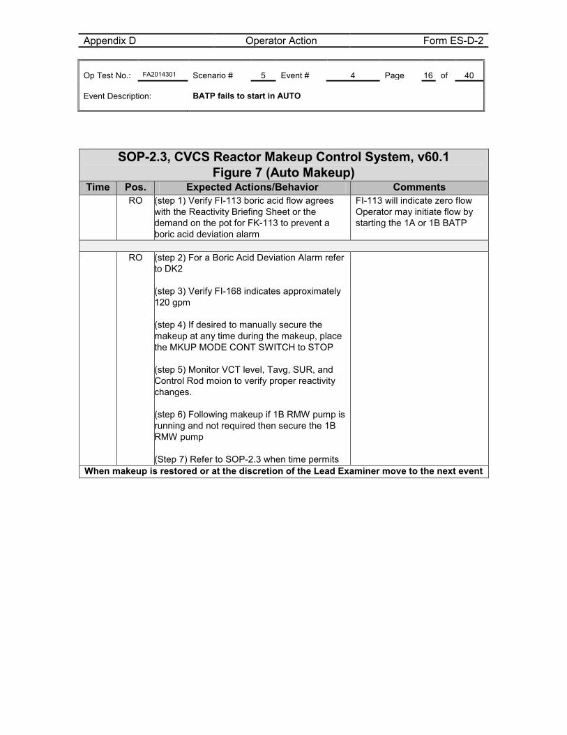
Appendix D Operator Action Form ES-D-2 Op Test No.: FA2014301 Scenario # 5 Event # 4 Page 16 of 40 Event Description: BATP fails to start in AUTO
SOP-2.3, CVCS Reactor Makeup Control System, v60.1
Figure 7 (Auto Makeup) Time Pos. Expected Actions/Behavior Comments RO (step 1) Verify FI-113 boric acid flow agrees
with the Reactivity Briefing Sheet or the demand on the pot for FK-113 to prevent a boric acid deviation alarm
FI-113 will indicate zero flow Operator may initiate flow by starting the 1A or 1B BATP
RO (step 2) For a Boric Acid Deviation Alarm refer
to DK2 (step 3) Verify FI-168 indicates approximately 120 gpm (step 4) If desired to manually secure the makeup at any time during the makeup, place the MKUP MODE CONT SWITCH to STOP (step 5) Monitor VCT level, Tavg, SUR, and Control Rod moion to verify proper reactivity changes. (step 6) Following makeup if 1B RMW pump is running and not required then secure the 1B RMW pump (Step 7) Refer to SOP-2.3 when time permits
When makeup is restored or at the discretion of the Lead Examiner move to the next event
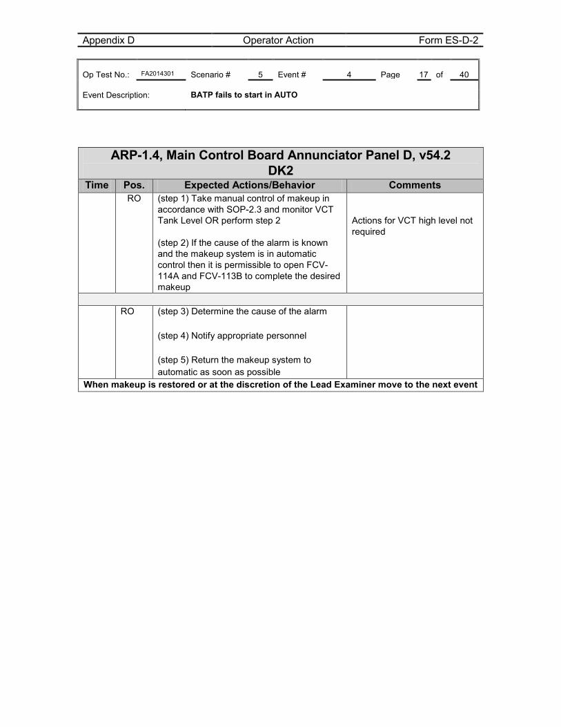
Appendix D Operator Action Form ES-D-2 Op Test No.: FA2014301 Scenario # 5 Event # 4 Page 17 of 40 Event Description: BATP fails to start in AUTO
ARP-1.4, Main Control Board Annunciator Panel D, v54.2
DK2 Time Pos. Expected Actions/Behavior Comments RO (step 1) Take manual control of makeup in
accordance with SOP-2.3 and monitor VCT Tank Level OR perform step 2 (step 2) If the cause of the alarm is known and the makeup system is in automatic control then it is permissible to open FCV-114A and FCV-113B to complete the desired makeup
Actions for VCT high level not required
RO (step 3) Determine the cause of the alarm
(step 4) Notify appropriate personnel (step 5) Return the makeup system to automatic as soon as possible
When makeup is restored or at the discretion of the Lead Examiner move to the next event
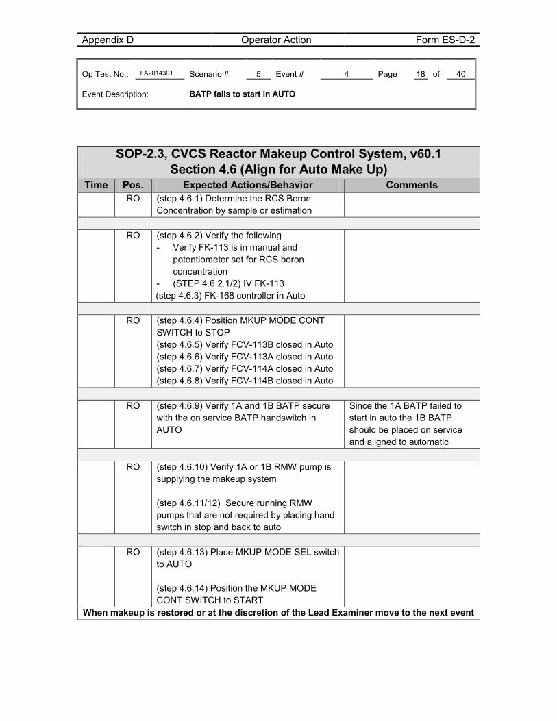
Appendix D Operator Action Form ES-D-2 Op Test No.: FA2014301 Scenario # 5 Event # 4 Page 18 of 40 Event Description: BATP fails to start in AUTO
SOP-2.3, CVCS Reactor Makeup Control System, v60.1
Section 4.6 (Align for Auto Make Up) Time Pos. Expected Actions/Behavior Comments
RO (step 4.6.1) Determine the RCS Boron Concentration by sample or estimation
RO (step 4.6.2) Verify the following
- Verify FK-113 is in manual and potentiometer set for RCS boron concentration
- (STEP 4.6.2.1/2) IV FK-113 (step 4.6.3) FK-168 controller in Auto
RO (step 4.6.4) Position MKUP MODE CONT
SWITCH to STOP (step 4.6.5) Verify FCV-113B closed in Auto (step 4.6.6) Verify FCV-113A closed in Auto (step 4.6.7) Verify FCV-114A closed in Auto (step 4.6.8) Verify FCV-114B closed in Auto
RO (step 4.6.9) Verify 1A and 1B BATP secure
with the on service BATP handswitch in AUTO
Since the 1A BATP failed to start in auto the 1B BATP should be placed on service and aligned to automatic
RO (step 4.6.10) Verify 1A or 1B RMW pump is
supplying the makeup system (step 4.6.11/12) Secure running RMW pumps that are not required by placing hand switch in stop and back to auto
RO (step 4.6.13) Place MKUP MODE SEL switch
to AUTO (step 4.6.14) Position the MKUP MODE CONT SWITCH to START
When makeup is restored or at the discretion of the Lead Examiner move to the next event
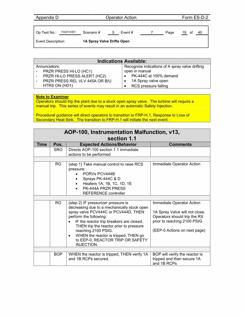
Appendix D Operator Action Form ES-D-2 Op Test No.: FA2014301 Scenario # 5 Event # 7 Page 19 of 40 Event Description: 1A Spray Valve Drifts Open
Indications Available: Annunciators: - PRZR PRESS HI-LO (HC1) - PRZR HI-LO PRESS ALERT (HC2) - PRZR PRESS REL VLV 445A OR B/U
HTRS ON (HD1)
Recognize indications of A spray valve drifting open in manual • PK-444C at 100% demand • 1A Spray valve open • RCS pressure falling
Note to Examiner Operators should trip the plant due to a stuck open spray valve. The turbine will require a manual trip. This series of events may result in an automatic Safety Injection. Procedural guidance will direct operators to transition to FRP-H.1, Response to Loss of Secondary Heat Sink. The transition to FRP-H.1 will initiate the next event.
AOP-100, Instrumentation Malfunction, v13,
section 1.1 Time Pos. Expected Actions/Behavior Comments
SRO Directs AOP-100 section 1.1 immediate actions to be performed
RO (step 1) Take manual control to raise RCS
pressure: • PORVs PCV444B • Sprays PK-444C & D • Heaters 1A, 1B, 1C, 1D, 1E • PK-444A PRZR PRESS
REFERENCE controller
Immediate Operator Action
RO (step 2) IF pressurizer pressure is
decreasing due to a mechanically stuck open spray valve PCV444C or PCV444D, THEN perform the following: • IF the reactor trip breakers are closed,
THEN trip the reactor prior to pressure reaching 2100 PSIG.
• WHEN the reactor is tripped, THEN go to EEP-0, REACTOR TRIP OR SAFETY INJECTION.
Immediate Operator Action 1A Spray Valve will not close. Operators should trip the RX prior to reaching 2100 PSIG (EEP-0 Actions on next page)
BOP WHEN the reactor is tripped, THEN verify 1A
and 1B RCPs secured. BOP will verify the reactor is tripped and then secure 1A and 1B RCPs
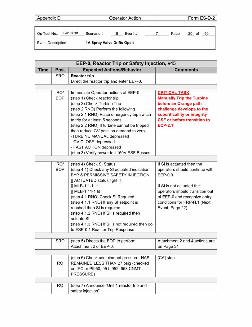
Appendix D Operator Action Form ES-D-2 Op Test No.: FA2014301 Scenario # 5 Event # 7 Page 20 of 40 Event Description: 1A Spray Valve Drifts Open
EEP-0, Reactor Trip or Safety Injection, v45 Time Pos. Expected Actions/Behavior Comments
SRO Reactor trip Direct the reactor trip and enter EEP-0.
RO/
BOP Immediate Operator actions of EEP-0 (step 1) Check reactor trip. (step 2) Check Turbine Trip (step 2 RNO) Perform the following (step 2.1 RNO) Place emergency trip switch to trip for at least 5 seconds (step 2.2 RNO) If turbine cannot be tripped then reduce GV position demand to zero -TURBINE MANUAL depressed - GV CLOSE depressed - FAST ACTION depressed (step 3) Verify power to 4160V ESF Busses
CRITICAL TASK Manually Trip the Turbine before an Orange path challenge develops to the subcriticallity or integrity CSF or before transition to ECP-2.1
RO/
BOP (step 4) Check SI Status. (step 4.1) Check any SI actuated indication. BYP & PERMISSIVE SAFETY INJECTION [] ACTUATED status light lit [] MLB-1 1-1 lit [] MLB-1 11-1 lit (step 4.1 RNO) Check SI Required (step 4.1.1 RNO) If any SI setpoint is reached then SI is required. (step 4.1.2 RNO) If SI is required then actuate SI (step 4.1.3 RNO) If SI is not required then go to ESP-0.1 Reactor Trip Response
If SI is actuated then the operators should continue with EEP-0.0. If SI is not actuated the operators should transition out of EEP-0 and recognize entry conditions for FRP-H.1 (Next Event, Page 22)
SRO (step 5) Directs the BOP to perform
Attachment 2 of EEP-0. Attachment 2 and 4 actions are on Page 31
RO (step 6) Check containment pressure- HAS REMAINED LESS THAN 27 psig (checked on IPC or PI950, 951, 952, 953,CNMT PRESSURE)
[CA] step
RO (step 7) Announce "Unit 1 reactor trip and
safety injection".
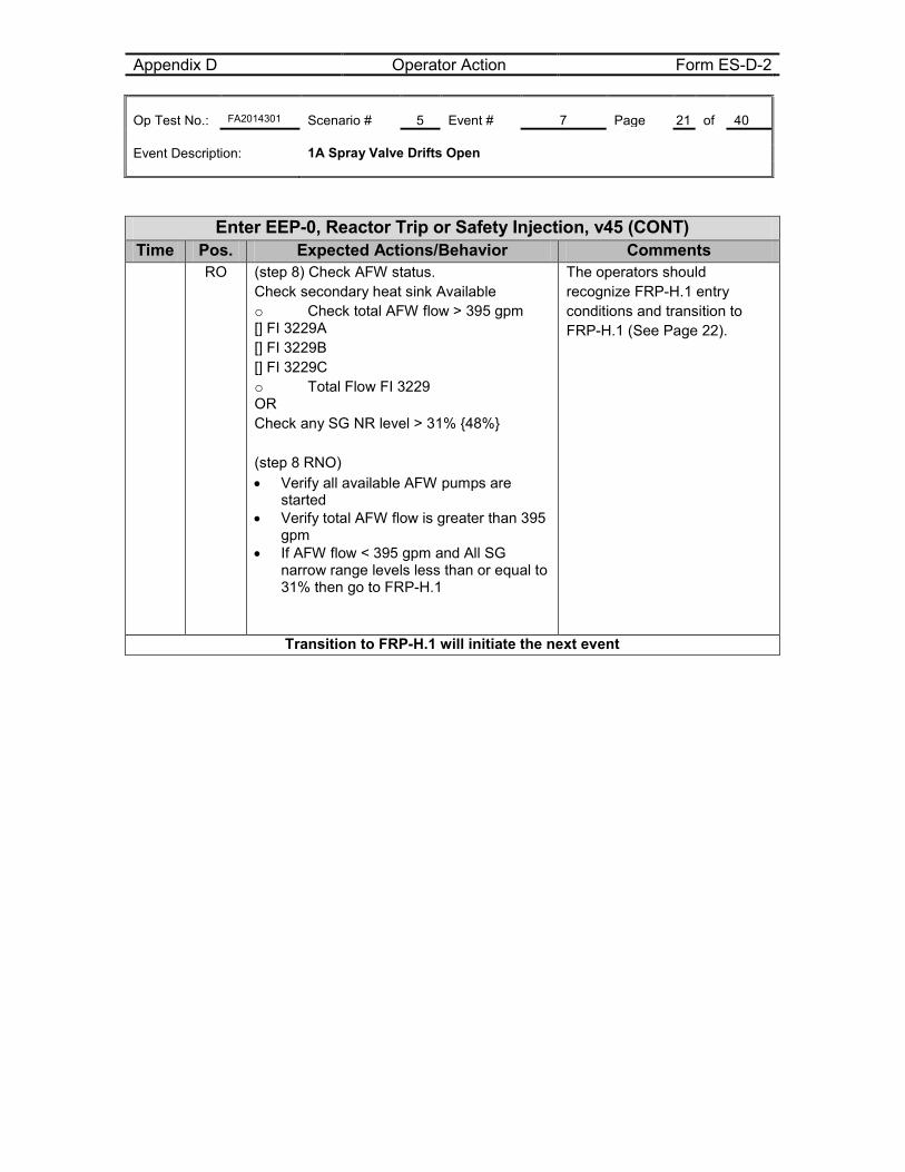
Appendix D Operator Action Form ES-D-2 Op Test No.: FA2014301 Scenario # 5 Event # 7 Page 21 of 40 Event Description: 1A Spray Valve Drifts Open
Enter EEP-0, Reactor Trip or Safety Injection, v45 (CONT) Time Pos. Expected Actions/Behavior Comments
RO (step 8) Check AFW status. Check secondary heat sink Available o Check total AFW flow > 395 gpm [] FI 3229A [] FI 3229B [] FI 3229C o Total Flow FI 3229 OR Check any SG NR level > 31% {48%} (step 8 RNO) • Verify all available AFW pumps are
started • Verify total AFW flow is greater than 395
gpm • If AFW flow < 395 gpm and All SG
narrow range levels less than or equal to 31% then go to FRP-H.1
The operators should recognize FRP-H.1 entry conditions and transition to FRP-H.1 (See Page 22).
Transition to FRP-H.1 will initiate the next event
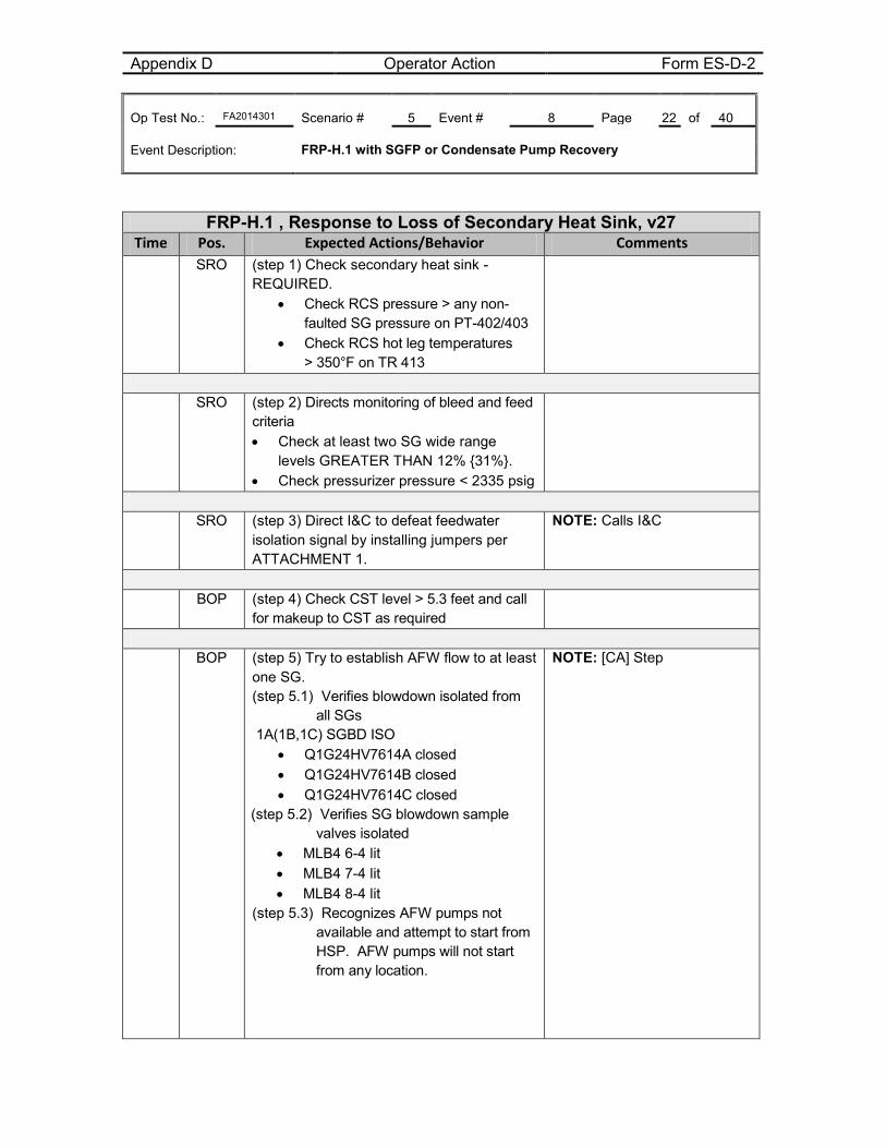
Appendix D Operator Action Form ES-D-2 Op Test No.: FA2014301 Scenario # 5 Event # 8 Page 22 of 40 Event Description: FRP-H.1 with SGFP or Condensate Pump Recovery
FRP-H.1 , Response to Loss of Secondary Heat Sink, v27 Time Pos. Expected Actions/Behavior Comments
SRO (step 1) Check secondary heat sink -REQUIRED.
• Check RCS pressure > any non-faulted SG pressure on PT-402/403
• Check RCS hot leg temperatures > 350°F on TR 413
SRO (step 2) Directs monitoring of bleed and feed
criteria • Check at least two SG wide range
levels GREATER THAN 12% {31%}. • Check pressurizer pressure < 2335 psig
SRO (step 3) Direct I&C to defeat feedwater
isolation signal by installing jumpers per ATTACHMENT 1.
NOTE: Calls I&C
BOP (step 4) Check CST level > 5.3 feet and call
for makeup to CST as required
BOP (step 5) Try to establish AFW flow to at least
one SG. (step 5.1) Verifies blowdown isolated from
all SGs 1A(1B,1C) SGBD ISO
• Q1G24HV7614A closed • Q1G24HV7614B closed • Q1G24HV7614C closed
(step 5.2) Verifies SG blowdown sample valves isolated
• MLB4 6-4 lit • MLB4 7-4 lit • MLB4 8-4 lit
(step 5.3) Recognizes AFW pumps not available and attempt to start from HSP. AFW pumps will not start from any location.
NOTE: [CA] Step
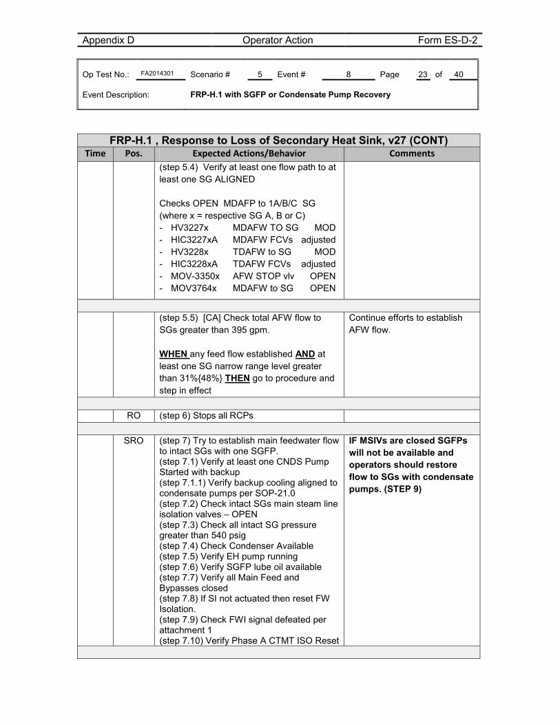
Appendix D Operator Action Form ES-D-2 Op Test No.: FA2014301 Scenario # 5 Event # 8 Page 23 of 40 Event Description: FRP-H.1 with SGFP or Condensate Pump Recovery
FRP-H.1 , Response to Loss of Secondary Heat Sink, v27 (CONT) Time Pos. Expected Actions/Behavior Comments
(step 5.4) Verify at least one flow path to at least one SG ALIGNED Checks OPEN MDAFP to 1A/B/C SG (where x = respective SG A, B or C) - HV3227x MDAFW TO SG MOD - HIC3227xA MDAFW FCVs adjusted - HV3228x TDAFW to SG MOD - HIC3228xA TDAFW FCVs adjusted - MOV-3350x AFW STOP vlv OPEN - MOV3764x MDAFW to SG OPEN
(step 5.5) [CA] Check total AFW flow to
SGs greater than 395 gpm. WHEN any feed flow established AND at least one SG narrow range level greater than 31%{48%} THEN go to procedure and step in effect
Continue efforts to establish AFW flow.
RO (step 6) Stops all RCPs
SRO (step 7) Try to establish main feedwater flow
to intact SGs with one SGFP. (step 7.1) Verify at least one CNDS Pump Started with backup (step 7.1.1) Verify backup cooling aligned to condensate pumps per SOP-21.0 (step 7.2) Check intact SGs main steam line isolation valves – OPEN (step 7.3) Check all intact SG pressure greater than 540 psig (step 7.4) Check Condenser Available (step 7.5) Verify EH pump running (step 7.6) Verify SGFP lube oil available (step 7.7) Verify all Main Feed and Bypasses closed (step 7.8) If SI not actuated then reset FW Isolation. (step 7.9) Check FWI signal defeated per attachment 1 (step 7.10) Verify Phase A CTMT ISO Reset
IF MSIVs are closed SGFPs will not be available and operators should restore flow to SGs with condensate pumps. (STEP 9)
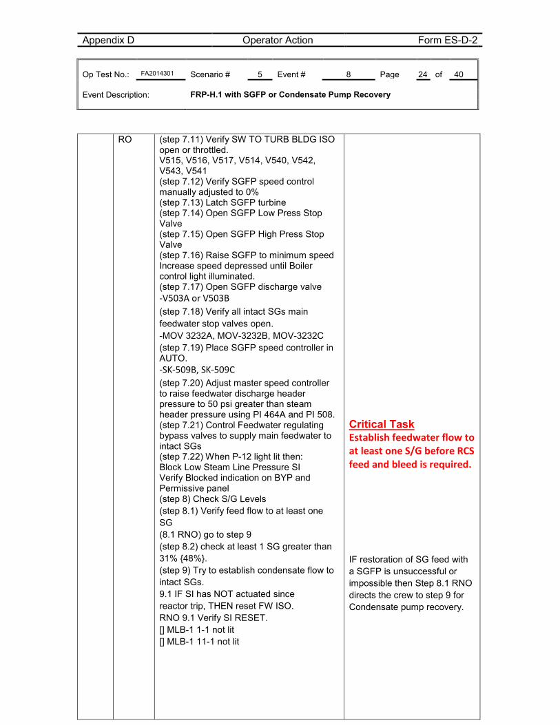
Appendix D Operator Action Form ES-D-2 Op Test No.: FA2014301 Scenario # 5 Event # 8 Page 24 of 40 Event Description: FRP-H.1 with SGFP or Condensate Pump Recovery
RO (step 7.11) Verify SW TO TURB BLDG ISO open or throttled. V515, V516, V517, V514, V540, V542, V543, V541 (step 7.12) Verify SGFP speed control manually adjusted to 0% (step 7.13) Latch SGFP turbine (step 7.14) Open SGFP Low Press Stop Valve (step 7.15) Open SGFP High Press Stop Valve (step 7.16) Raise SGFP to minimum speed Increase speed depressed until Boiler control light illuminated. (step 7.17) Open SGFP discharge valve -V503A or V503B (step 7.18) Verify all intact SGs main feedwater stop valves open. -MOV 3232A, MOV-3232B, MOV-3232C (step 7.19) Place SGFP speed controller in AUTO. -SK-509B, SK-509C (step 7.20) Adjust master speed controller to raise feedwater discharge header pressure to 50 psi greater than steam header pressure using PI 464A and PI 508. (step 7.21) Control Feedwater regulating bypass valves to supply main feedwater to intact SGs (step 7.22) When P-12 light lit then: Block Low Steam Line Pressure SI Verify Blocked indication on BYP and Permissive panel (step 8) Check S/G Levels (step 8.1) Verify feed flow to at least one SG (8.1 RNO) go to step 9 (step 8.2) check at least 1 SG greater than 31% {48%}. (step 9) Try to establish condensate flow to intact SGs. 9.1 IF SI has NOT actuated since reactor trip, THEN reset FW ISO. RNO 9.1 Verify SI RESET. [] MLB-1 1-1 not lit [] MLB-1 11-1 not lit
Critical Task Establish feedwater flow to at least one S/G before RCS feed and bleed is required. IF restoration of SG feed with a SGFP is unsuccessful or impossible then Step 8.1 RNO directs the crew to step 9 for Condensate pump recovery.
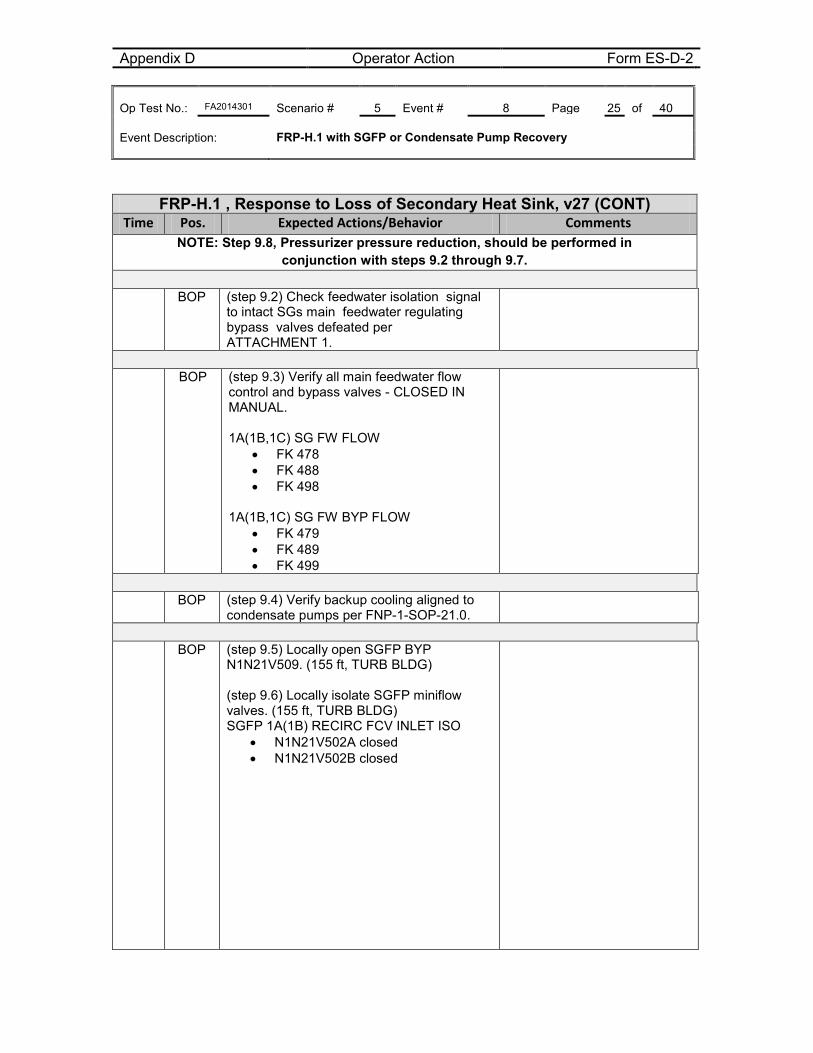
Appendix D Operator Action Form ES-D-2 Op Test No.: FA2014301 Scenario # 5 Event # 8 Page 25 of 40 Event Description: FRP-H.1 with SGFP or Condensate Pump Recovery
FRP-H.1 , Response to Loss of Secondary Heat Sink, v27 (CONT) Time Pos. Expected Actions/Behavior Comments
NOTE: Step 9.8, Pressurizer pressure reduction, should be performed in conjunction with steps 9.2 through 9.7.
BOP (step 9.2) Check feedwater isolation signal
to intact SGs main feedwater regulating bypass valves defeated per ATTACHMENT 1.
BOP (step 9.3) Verify all main feedwater flow
control and bypass valves - CLOSED IN MANUAL. 1A(1B,1C) SG FW FLOW
• FK 478 • FK 488 • FK 498
1A(1B,1C) SG FW BYP FLOW
• FK 479 • FK 489 • FK 499
BOP (step 9.4) Verify backup cooling aligned to
condensate pumps per FNP-1-SOP-21.0.
BOP (step 9.5) Locally open SGFP BYP
N1N21V509. (155 ft, TURB BLDG) (step 9.6) Locally isolate SGFP miniflow valves. (155 ft, TURB BLDG) SGFP 1A(1B) RECIRC FCV INLET ISO
• N1N21V502A closed • N1N21V502B closed
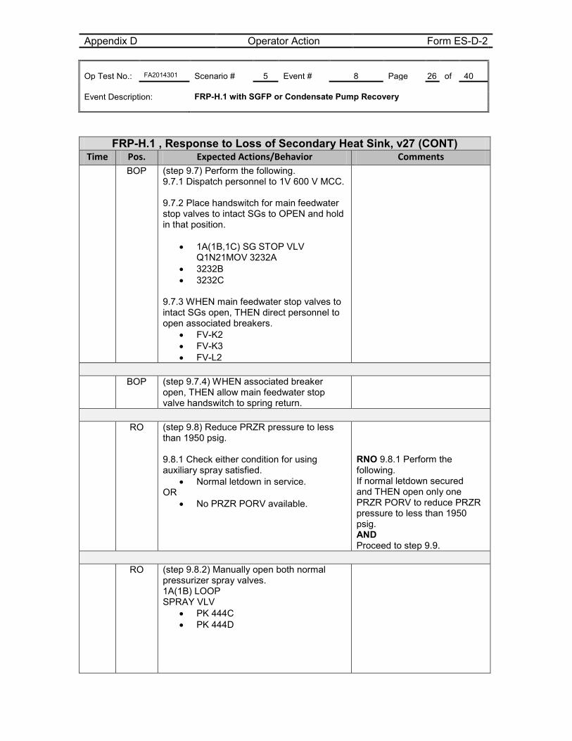
Appendix D Operator Action Form ES-D-2 Op Test No.: FA2014301 Scenario # 5 Event # 8 Page 26 of 40 Event Description: FRP-H.1 with SGFP or Condensate Pump Recovery
FRP-H.1 , Response to Loss of Secondary Heat Sink, v27 (CONT) Time Pos. Expected Actions/Behavior Comments
BOP (step 9.7) Perform the following. 9.7.1 Dispatch personnel to 1V 600 V MCC. 9.7.2 Place handswitch for main feedwater stop valves to intact SGs to OPEN and hold in that position.
• 1A(1B,1C) SG STOP VLV Q1N21MOV 3232A
• 3232B • 3232C
9.7.3 WHEN main feedwater stop valves to intact SGs open, THEN direct personnel to open associated breakers.
• FV-K2 • FV-K3 • FV-L2
BOP (step 9.7.4) WHEN associated breaker
open, THEN allow main feedwater stop valve handswitch to spring return.
RO (step 9.8) Reduce PRZR pressure to less
than 1950 psig. 9.8.1 Check either condition for using auxiliary spray satisfied.
• Normal letdown in service. OR
• No PRZR PORV available.
RNO 9.8.1 Perform the following. If normal letdown secured and THEN open only one PRZR PORV to reduce PRZR pressure to less than 1950 psig. AND Proceed to step 9.9.
RO (step 9.8.2) Manually open both normal
pressurizer spray valves. 1A(1B) LOOP SPRAY VLV
• PK 444C • PK 444D
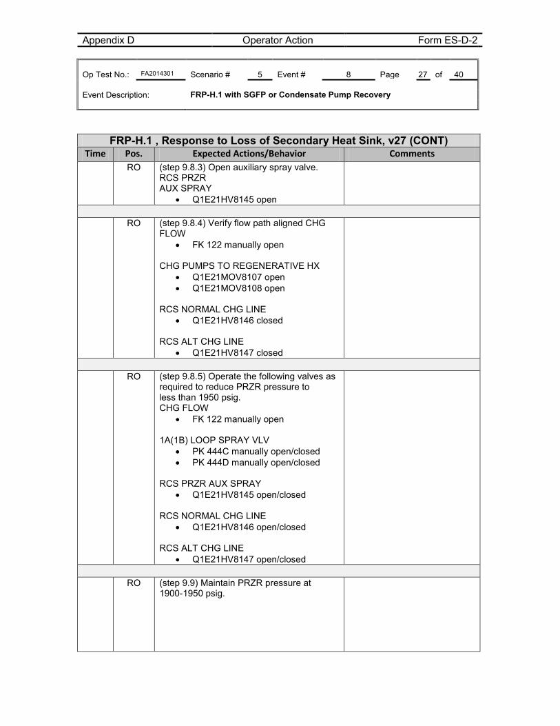
Appendix D Operator Action Form ES-D-2 Op Test No.: FA2014301 Scenario # 5 Event # 8 Page 27 of 40 Event Description: FRP-H.1 with SGFP or Condensate Pump Recovery
FRP-H.1 , Response to Loss of Secondary Heat Sink, v27 (CONT) Time Pos. Expected Actions/Behavior Comments
RO (step 9.8.3) Open auxiliary spray valve. RCS PRZR AUX SPRAY
• Q1E21HV8145 open
RO (step 9.8.4) Verify flow path aligned CHG
FLOW • FK 122 manually open
CHG PUMPS TO REGENERATIVE HX
• Q1E21MOV8107 open • Q1E21MOV8108 open
RCS NORMAL CHG LINE
• Q1E21HV8146 closed RCS ALT CHG LINE
• Q1E21HV8147 closed
RO (step 9.8.5) Operate the following valves as
required to reduce PRZR pressure to less than 1950 psig. CHG FLOW
• FK 122 manually open 1A(1B) LOOP SPRAY VLV
• PK 444C manually open/closed • PK 444D manually open/closed
RCS PRZR AUX SPRAY
• Q1E21HV8145 open/closed RCS NORMAL CHG LINE
• Q1E21HV8146 open/closed RCS ALT CHG LINE
• Q1E21HV8147 open/closed
RO (step 9.9) Maintain PRZR pressure at
1900-1950 psig.
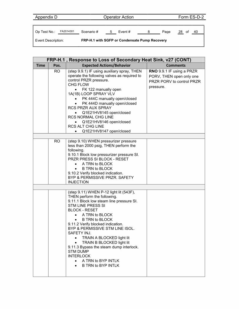
Appendix D Operator Action Form ES-D-2 Op Test No.: FA2014301 Scenario # 5 Event # 8 Page 28 of 40 Event Description: FRP-H.1 with SGFP or Condensate Pump Recovery
FRP-H.1 , Response to Loss of Secondary Heat Sink, v27 (CONT) Time Pos. Expected Actions/Behavior Comments
RO
(step 9.9.1) IF using auxiliary spray, THEN operate the following valves as required to control PRZR pressure. CHG FLOW
• FK 122 manually open 1A(1B) LOOP SPRAY VLV
• PK 444C manually open/closed • PK 444D manually open/closed
RCS PRZR AUX SPRAY • Q1E21HV8145 open/closed
RCS NORMAL CHG LINE • Q1E21HV8146 open/closed
RCS ALT CHG LINE • Q1E21HV8147 open/closed
RNO 9.9.1 IF using a PRZR PORV, THEN open only one PRZR PORV to control PRZR pressure.
RO (step 9.10) WHEN pressurizer pressure
less than 2000 psig, THEN perform the following. 9.10.1 Block low pressurizer pressure SI. PRZR PRESS SI BLOCK - RESET
• A TRN to BLOCK • B TRN to BLOCK
9.10.2 Verify blocked indication. BYP & PERMISSIVE PRZR. SAFETY INJECTION
(step 9.11) WHEN P-12 light lit (543F),
THEN perform the following. 9.11.1 Block low steam line pressure SI. STM LINE PRESS SI BLOCK - RESET
• A TRN to BLOCK • B TRN to BLOCK
9.11.2 Verify blocked indication. BYP & PERMISSIVE STM LINE ISOL. SAFETY INJ.
• TRAIN A BLOCKED light lit • TRAIN B BLOCKED light lit
9.11.3 Bypass the steam dump interlock. STM DUMP INTERLOCK
• A TRN to BYP INTLK • B TRN to BYP INTLK
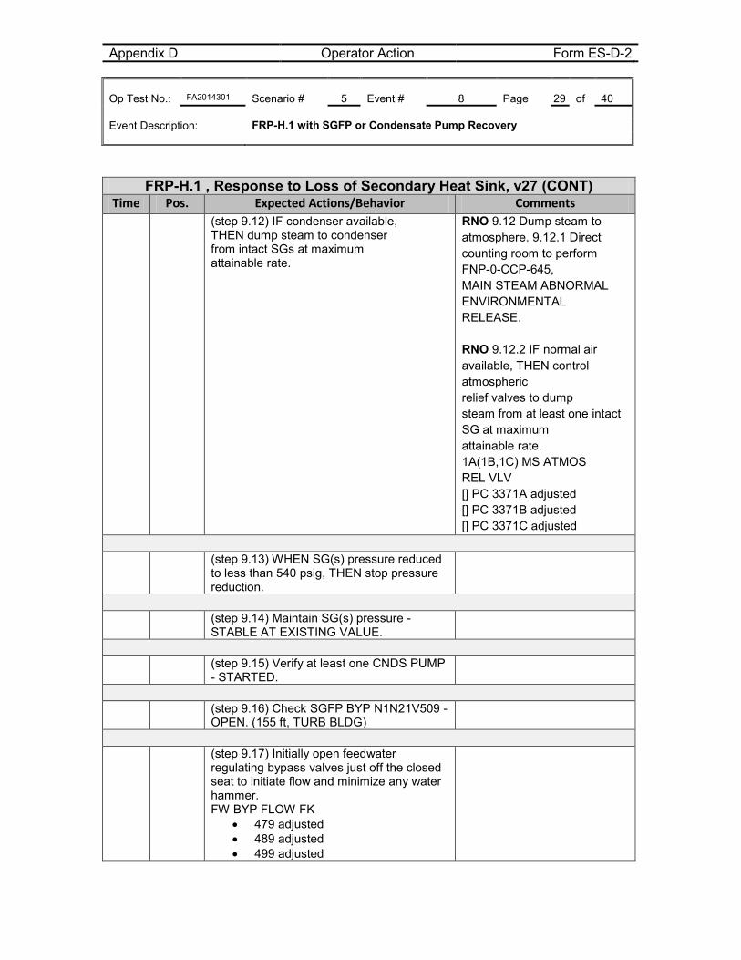
Appendix D Operator Action Form ES-D-2 Op Test No.: FA2014301 Scenario # 5 Event # 8 Page 29 of 40 Event Description: FRP-H.1 with SGFP or Condensate Pump Recovery
FRP-H.1 , Response to Loss of Secondary Heat Sink, v27 (CONT) Time Pos. Expected Actions/Behavior Comments
(step 9.12) IF condenser available, THEN dump steam to condenser from intact SGs at maximum attainable rate.
RNO 9.12 Dump steam to atmosphere. 9.12.1 Direct counting room to perform FNP-0-CCP-645, MAIN STEAM ABNORMAL ENVIRONMENTAL RELEASE. RNO 9.12.2 IF normal air available, THEN control atmospheric relief valves to dump steam from at least one intact SG at maximum attainable rate. 1A(1B,1C) MS ATMOS REL VLV [] PC 3371A adjusted [] PC 3371B adjusted [] PC 3371C adjusted
(step 9.13) WHEN SG(s) pressure reduced
to less than 540 psig, THEN stop pressure reduction.
(step 9.14) Maintain SG(s) pressure -
STABLE AT EXISTING VALUE.
(step 9.15) Verify at least one CNDS PUMP
- STARTED.
(step 9.16) Check SGFP BYP N1N21V509 -
OPEN. (155 ft, TURB BLDG)
(step 9.17) Initially open feedwater
regulating bypass valves just off the closed seat to initiate flow and minimize any water hammer. FW BYP FLOW FK
• 479 adjusted • 489 adjusted • 499 adjusted
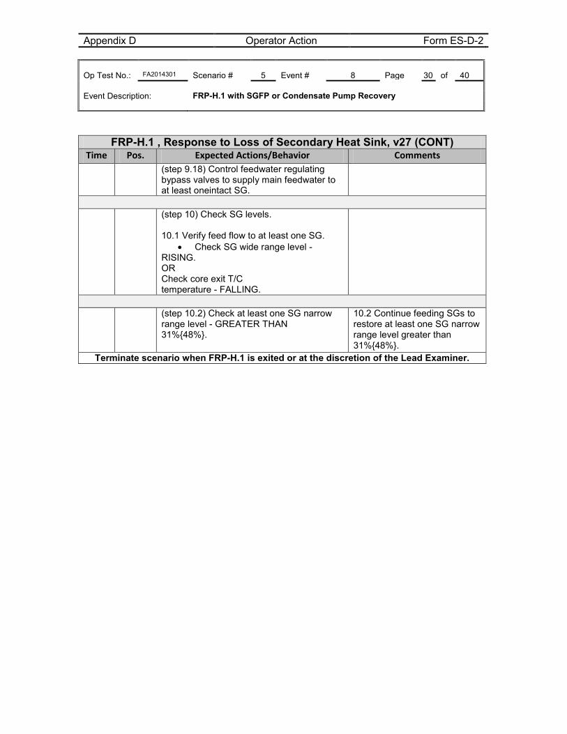
Appendix D Operator Action Form ES-D-2 Op Test No.: FA2014301 Scenario # 5 Event # 8 Page 30 of 40 Event Description: FRP-H.1 with SGFP or Condensate Pump Recovery
FRP-H.1 , Response to Loss of Secondary Heat Sink, v27 (CONT) Time Pos. Expected Actions/Behavior Comments
(step 9.18) Control feedwater regulating bypass valves to supply main feedwater to at least oneintact SG.
(step 10) Check SG levels.
10.1 Verify feed flow to at least one SG.
• Check SG wide range level - RISING. OR Check core exit T/C temperature - FALLING.
(step 10.2) Check at least one SG narrow
range level - GREATER THAN 31%{48%}.
10.2 Continue feeding SGs to restore at least one SG narrow range level greater than 31%{48%}.
Terminate scenario when FRP-H.1 is exited or at the discretion of the Lead Examiner.
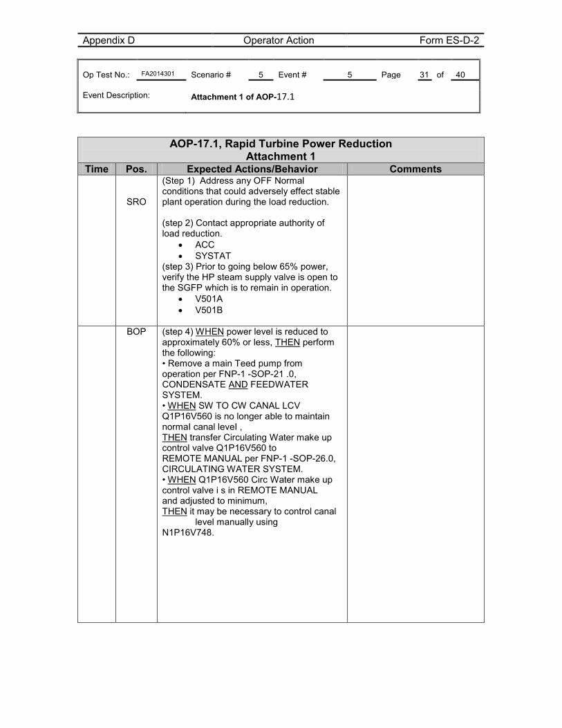
Appendix D Operator Action Form ES-D-2 Op Test No.: FA2014301 Scenario # 5 Event # 5 Page 31 of 40 Event Description: Attachment 1 of AOP-17.1
AOP-17.1, Rapid Turbine Power Reduction Attachment 1
Time Pos. Expected Actions/Behavior Comments
SRO
(Step 1) Address any OFF Normal conditions that could adversely effect stable plant operation during the load reduction. (step 2) Contact appropriate authority of load reduction.
• ACC • SYSTAT
(step 3) Prior to going below 65% power, verify the HP steam supply valve is open to the SGFP which is to remain in operation.
• V501A • V501B
BOP (step 4) WHEN power level is reduced to approximately 60% or less, THEN perform the following: • Remove a main Teed pump from operation per FNP-1 -SOP-21 .0, CONDENSATE AND FEEDWATER SYSTEM. • WHEN SW TO CW CANAL LCV Q1P16V560 is no longer able to maintain normaI canal leveI , THEN transfer Circulating Water make up control valve Q1P16V560 to REMOTE MANUAL per FNP-1 -SOP-26.0, CIRCULATING WATER SYSTEM. • WHEN Q1P16V560 Circ Water make up control valve i s in REMOTE MANUAL and adjusted to minimum, THEN it may be necessary to control canal level manually using N1P16V748.
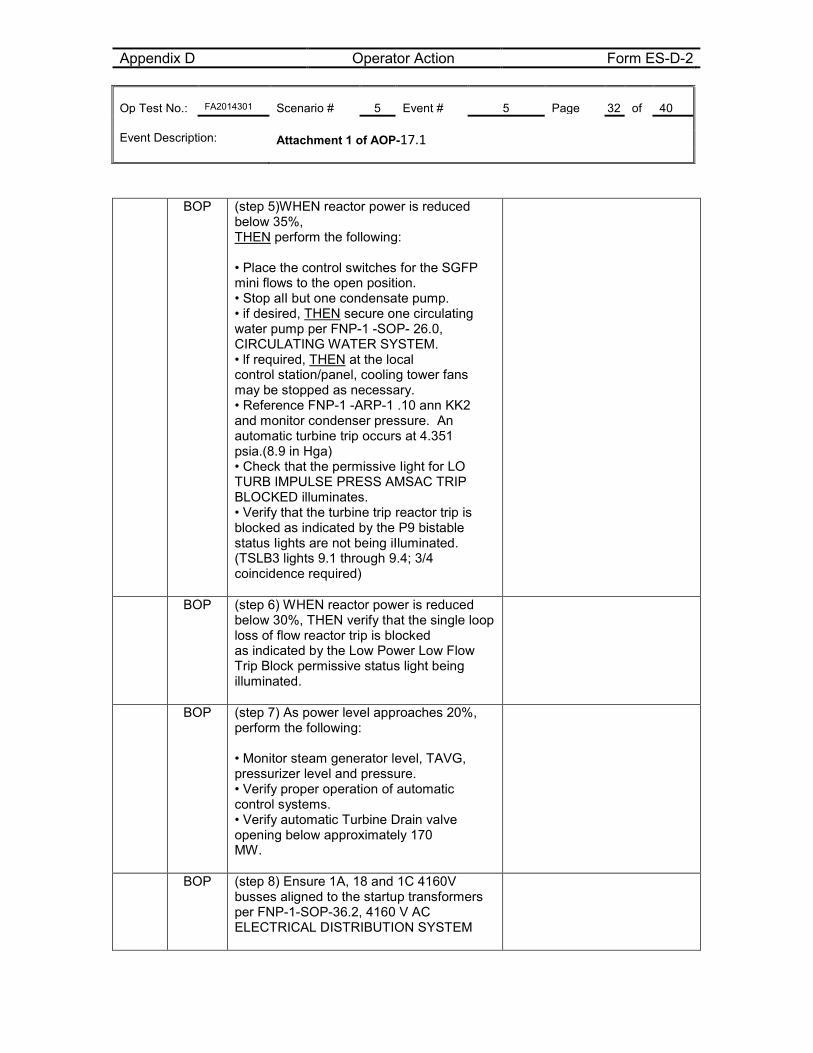
Appendix D Operator Action Form ES-D-2 Op Test No.: FA2014301 Scenario # 5 Event # 5 Page 32 of 40 Event Description: Attachment 1 of AOP-17.1
BOP (step 5)WHEN reactor power is reduced below 35%, THEN perform the following: • Place the control switches for the SGFP mini flows to the open position. • Stop alI but one condensate pump. • if desired, THEN secure one circulating water pump per FNP-1 -SOP- 26.0, CIRCULATING WATER SYSTEM. • lf required, THEN at the local control station/panel, cooling tower fans may be stopped as necessary. • Reference FNP-1 -ARP-1 .10 ann KK2 and monitor condenser pressure. An automatic turbine trip occurs at 4.351 psia.(8.9 in Hga) • Check that the permissive Iight for LO TURB IMPULSE PRESS AMSAC TRIP BLOCKED illuminates. • Verify that the turbine trip reactor trip is blocked as indicated by the P9 bistable status Iights are not being iIluminated. (TSLB3 lights 9.1 through 9.4; 3/4 coincidence required)
BOP (step 6) WHEN reactor power is reduced below 30%, THEN verify that the single loop loss of flow reactor trip is blocked as indicated by the Low Power Low Flow Trip Block permissive status light being illuminated.
BOP (step 7) As power level approaches 20%, perform the following: • Monitor steam generator level, TAVG, pressurizer level and pressure. • Verify proper operation of automatic control systems. • Verify automatic Turbine Drain valve opening below approximately 170 MW.
BOP (step 8) Ensure 1A, 18 and 1C 4160V busses aligned to the startup transformers per FNP-1-SOP-36.2, 4160 V AC ELECTRICAL DISTRIBUTION SYSTEM
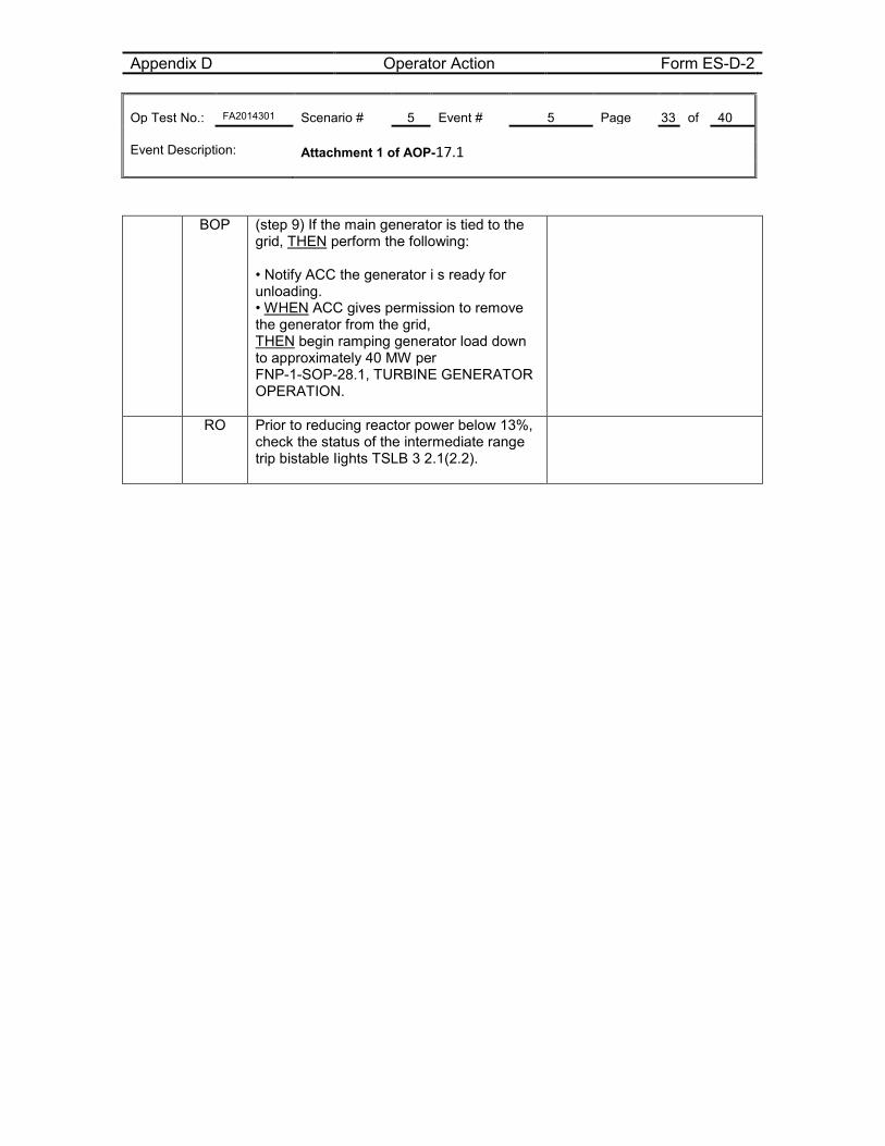
Appendix D Operator Action Form ES-D-2 Op Test No.: FA2014301 Scenario # 5 Event # 5 Page 33 of 40 Event Description: Attachment 1 of AOP-17.1
BOP (step 9) If the main generator is tied to the grid, THEN perform the following: • Notify ACC the generator i s ready for unloading. • WHEN ACC gives permission to remove the generator from the grid, THEN begin ramping generator load down to approximately 40 MW per FNP-1-SOP-28.1, TURBINE GENERATOR OPERATION.
RO Prior to reducing reactor power below 13%, check the status of the intermediate range trip bistable Iights TSLB 3 2.1(2.2).
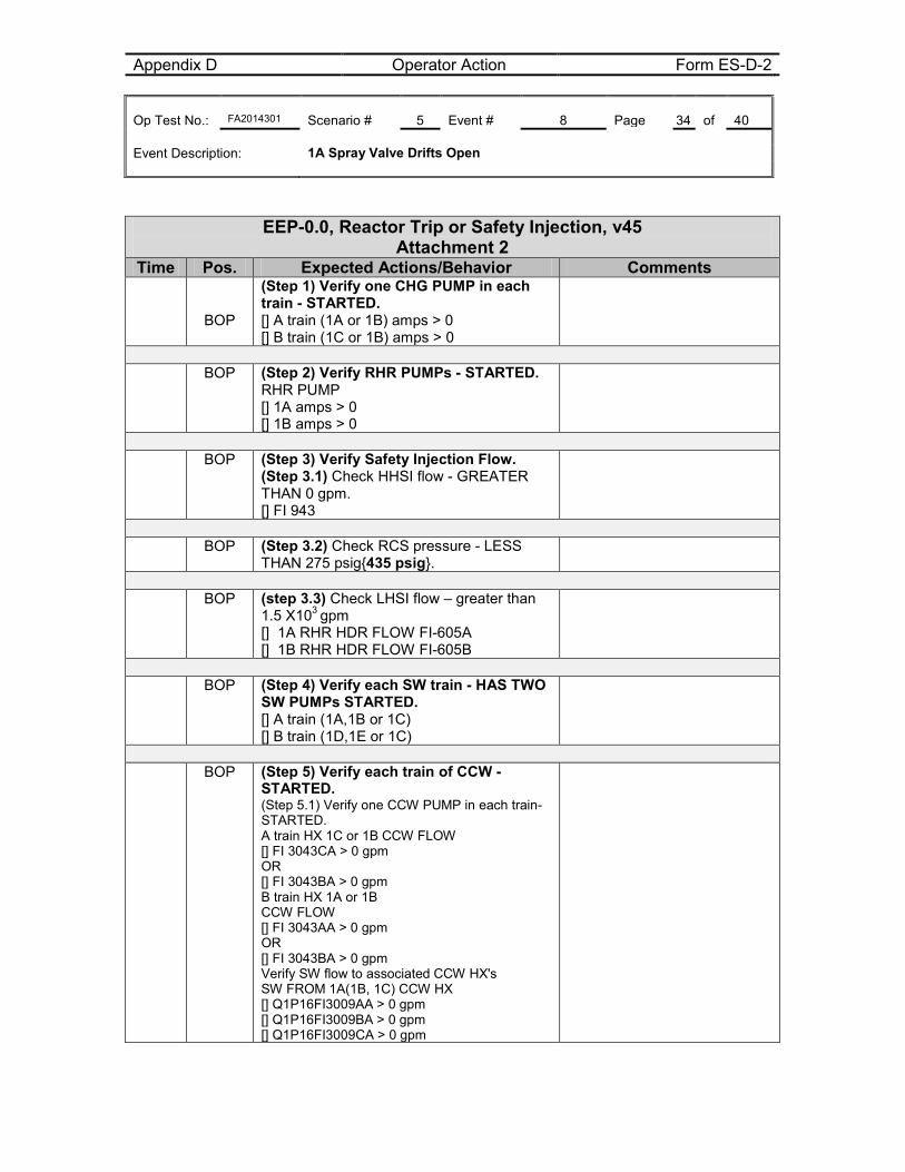
Appendix D Operator Action Form ES-D-2 Op Test No.: FA2014301 Scenario # 5 Event # 8 Page 34 of 40 Event Description: 1A Spray Valve Drifts Open
EEP-0.0, Reactor Trip or Safety Injection, v45 Attachment 2
Time Pos. Expected Actions/Behavior Comments
BOP
(Step 1) Verify one CHG PUMP in each train - STARTED. [] A train (1A or 1B) amps > 0 [] B train (1C or 1B) amps > 0
BOP (Step 2) Verify RHR PUMPs - STARTED.
RHR PUMP [] 1A amps > 0 [] 1B amps > 0
BOP (Step 3) Verify Safety Injection Flow.
(Step 3.1) Check HHSI flow - GREATER THAN 0 gpm. [] FI 943
BOP (Step 3.2) Check RCS pressure - LESS
THAN 275 psig{435 psig}.
BOP (step 3.3) Check LHSI flow – greater than
1.5 X10³ gpm [] 1A RHR HDR FLOW FI-605A [] 1B RHR HDR FLOW FI-605B
BOP (Step 4) Verify each SW train - HAS TWO
SW PUMPs STARTED. [] A train (1A,1B or 1C) [] B train (1D,1E or 1C)
BOP (Step 5) Verify each train of CCW -
STARTED. (Step 5.1) Verify one CCW PUMP in each train- STARTED. A train HX 1C or 1B CCW FLOW [] FI 3043CA > 0 gpm OR [] FI 3043BA > 0 gpm B train HX 1A or 1B CCW FLOW [] FI 3043AA > 0 gpm OR [] FI 3043BA > 0 gpm Verify SW flow to associated CCW HX's SW FROM 1A(1B, 1C) CCW HX [] Q1P16FI3009AA > 0 gpm [] Q1P16FI3009BA > 0 gpm [] Q1P16FI3009CA > 0 gpm
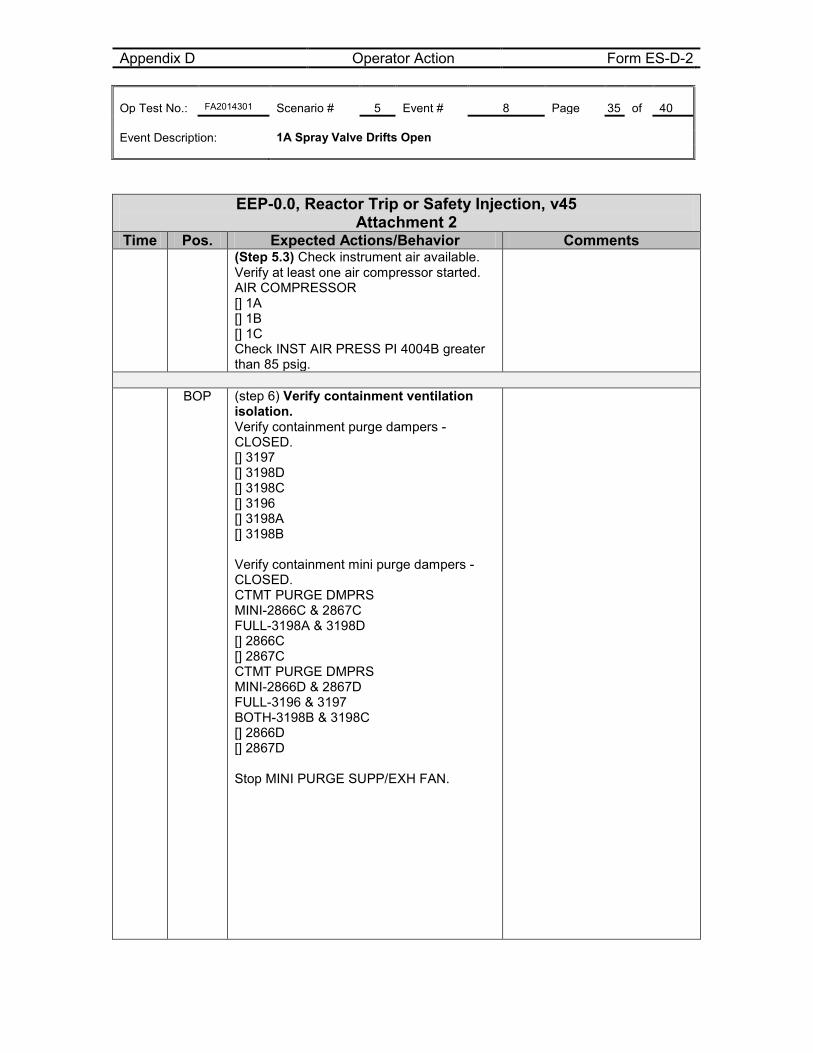
Appendix D Operator Action Form ES-D-2 Op Test No.: FA2014301 Scenario # 5 Event # 8 Page 35 of 40 Event Description: 1A Spray Valve Drifts Open
EEP-0.0, Reactor Trip or Safety Injection, v45 Attachment 2
Time Pos. Expected Actions/Behavior Comments (Step 5.3) Check instrument air available.
Verify at least one air compressor started. AIR COMPRESSOR [] 1A [] 1B [] 1C Check INST AIR PRESS PI 4004B greater than 85 psig.
BOP (step 6) Verify containment ventilation
isolation. Verify containment purge dampers - CLOSED. [] 3197 [] 3198D [] 3198C [] 3196 [] 3198A [] 3198B Verify containment mini purge dampers - CLOSED. CTMT PURGE DMPRS MINI-2866C & 2867C FULL-3198A & 3198D [] 2866C [] 2867C CTMT PURGE DMPRS MINI-2866D & 2867D FULL-3196 & 3197 BOTH-3198B & 3198C [] 2866D [] 2867D Stop MINI PURGE SUPP/EXH FAN.
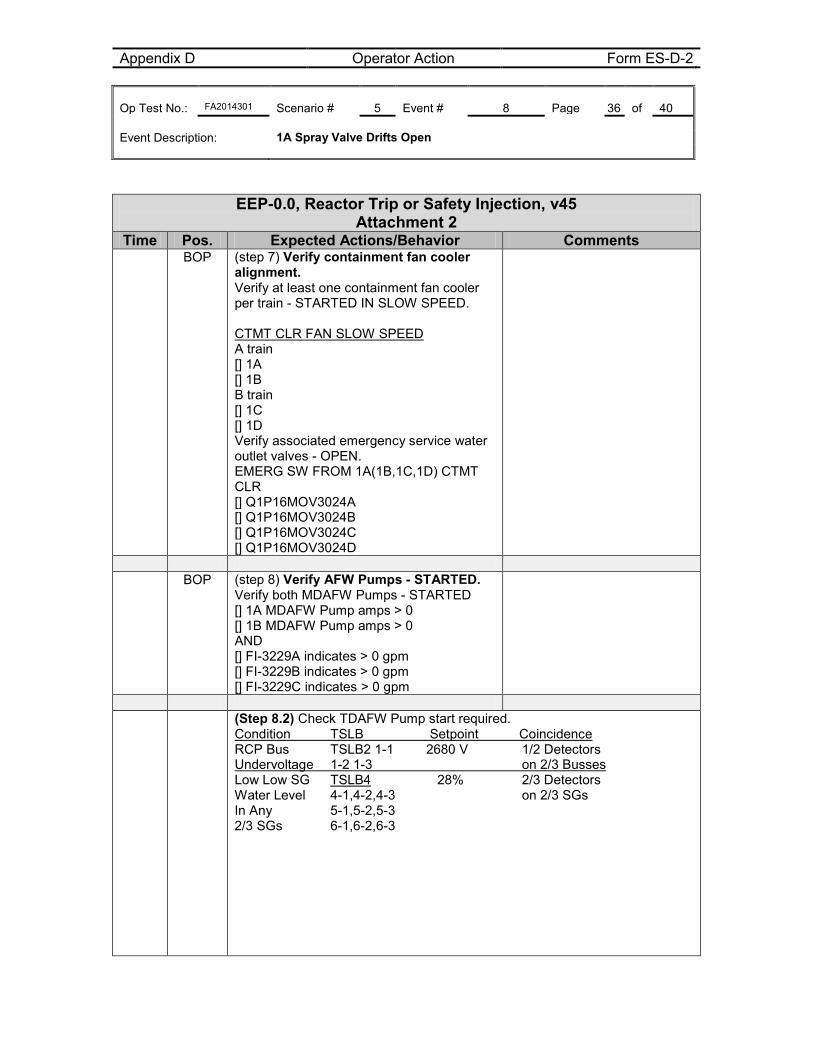
Appendix D Operator Action Form ES-D-2 Op Test No.: FA2014301 Scenario # 5 Event # 8 Page 36 of 40 Event Description: 1A Spray Valve Drifts Open
EEP-0.0, Reactor Trip or Safety Injection, v45 Attachment 2
Time Pos. Expected Actions/Behavior Comments BOP (step 7) Verify containment fan cooler
alignment. Verify at least one containment fan cooler per train - STARTED IN SLOW SPEED. CTMT CLR FAN SLOW SPEED A train [] 1A [] 1B B train [] 1C [] 1D Verify associated emergency service water outlet valves - OPEN. EMERG SW FROM 1A(1B,1C,1D) CTMT CLR [] Q1P16MOV3024A [] Q1P16MOV3024B [] Q1P16MOV3024C [] Q1P16MOV3024D
BOP (step 8) Verify AFW Pumps - STARTED.
Verify both MDAFW Pumps - STARTED [] 1A MDAFW Pump amps > 0 [] 1B MDAFW Pump amps > 0 AND [] FI-3229A indicates > 0 gpm [] FI-3229B indicates > 0 gpm [] FI-3229C indicates > 0 gpm
(Step 8.2) Check TDAFW Pump start required.
Condition TSLB Setpoint Coincidence RCP Bus TSLB2 1-1 2680 V 1/2 Detectors Undervoltage 1-2 1-3 on 2/3 Busses Low Low SG TSLB4 28% 2/3 Detectors Water Level 4-1,4-2,4-3 on 2/3 SGs In Any 5-1,5-2,5-3 2/3 SGs 6-1,6-2,6-3
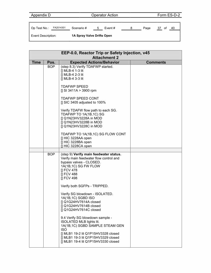
Appendix D Operator Action Form ES-D-2 Op Test No.: FA2014301 Scenario # 5 Event # 8 Page 37 of 40 Event Description: 1A Spray Valve Drifts Open
EEP-0.0, Reactor Trip or Safety Injection, v45 Attachment 2
Time Pos. Expected Actions/Behavior Comments BOP (step 8.3) Verify TDAFWP started.
[] MLB-4 1-3 lit [] MLB-4 2-3 lit [] MLB-4 3-3 lit TDAFWP SPEED [] SI 3411A > 3900 rpm TDAFWP SPEED CONT [] SIC 3405 adjusted to 100% Verify TDAFW flow path to each SG. TDAFWP TO 1A(1B,1C) SG [] Q1N23HV3228A in MOD [] Q1N23HV3228B in MOD [] Q1N23HV3228C in MOD TDAFWP TO 1A(1B,1C) SG FLOW CONT [] HIC 3228AA open [] HIC 3228BA open [] HIC 3228CA open
BOP (step 9) Verify main feedwater status.
Verify main feedwater flow control and bypass valves - CLOSED. 1A(1B,1C) SG FW FLOW [] FCV 478 [] FCV 488 [] FCV 498 Verify both SGFPs - TRIPPED. Verify SG blowdown - ISOLATED. 1A(1B,1C) SGBD ISO [] Q1G24HV7614A closed [] Q1G24HV7614B closed [] Q1G24HV7614C closed 9.4 Verify SG blowdown sample - ISOLATED MLB lights lit. 1A(1B,1C) SGBD SAMPLE STEAM GEN ISO [] MLB1 19-2 lit Q1P15HV3328 closed [] MLB1 19-3 lit Q1P15HV3329 closed [] MLB1 19-4 lit Q1P15HV3330 closed
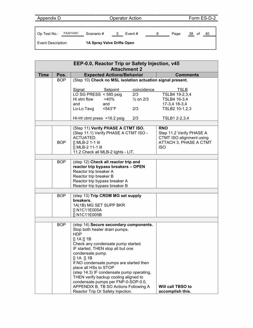
Appendix D Operator Action Form ES-D-2 Op Test No.: FA2014301 Scenario # 5 Event # 8 Page 38 of 40 Event Description: 1A Spray Valve Drifts Open
EEP-0.0, Reactor Trip or Safety Injection, v45 Attachment 2
Time Pos. Expected Actions/Behavior Comments BOP (Step 10) Check no MSL isolation actuation signal present.
Signal Setpoint coincidence TSLB LO SG PRESS < 585 psig 2/3 TSLB4 19-2,3,4 Hi stm flow >40% ½ on 2/3 TSLB4 16-3,4 and and 17-3,4 18-3,4 Lo-Lo Tavg <543°F 2/3 TSLB2 10-1,2,3 HI-HI ctmt press >16.2 psig 2/3 TSLB1 2-2,3,4
BOP
(Step 11) Verify PHASE A CTMT ISO. (Step 11.1) Verify PHASE A CTMT ISO - ACTUATED. [] MLB-2 1-1 lit [] MLB-2 11-1 lit 11.2 Check all MLB-2 lights - LIT.
RNO Step 11.2 Verify PHASE A CTMT ISO alignment using ATTACH 3, PHASE A CTMT ISO
BOP (step 12) Check all reactor trip and
reactor trip bypass breakers – OPEN Reactor trip breaker A Reactor trip breaker B Reactor trip bypass breaker A Reactor trip bypass breaker B
BOP (step 13) Trip CRDM MG set supply
breakers. 1A(1B) MG SET SUPP BKR [] N1C11E005A [] N1C11E005B
BOP (step 14) Secure secondary components.
Stop both heater drain pumps. HDP [] 1A [] 1B Check any condensate pump started. IF started, THEN stop all but one condensate pump. [] 1A [] 1B If NO condensate pumps are started then place all HSs to STOP (step 14.3) IF condensate pump operating, THEN verify backup cooling aligned to condensate pumps per FNP-0-SOP-0.0, APPENDIX B, TB SO Actions Following A Reactor Trip Or Safety Injection.
Will call TBSO to accomplish this.
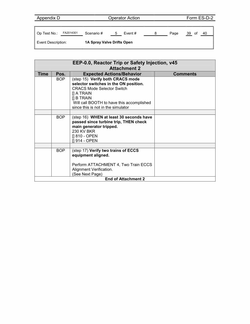
Appendix D Operator Action Form ES-D-2 Op Test No.: FA2014301 Scenario # 5 Event # 8 Page 39 of 40 Event Description: 1A Spray Valve Drifts Open
EEP-0.0, Reactor Trip or Safety Injection, v45 Attachment 2
Time Pos. Expected Actions/Behavior Comments BOP (step 15) Verify both CRACS mode
selector switches in the ON position. CRACS Mode Selector Switch [] A TRAIN [] B TRAIN Will call BOOTH to have this accomplished since this is not in the simulator
BOP (step 16) WHEN at least 30 seconds have
passed since turbine trip, THEN check main generator tripped. 230 KV BKR [] 810 - OPEN [] 914 - OPEN
BOP (step 17) Verify two trains of ECCS
equipment aligned. Perform ATTACHMENT 4, Two Train ECCS Alignment Verification. (See Next Page)
End of Attachment 2
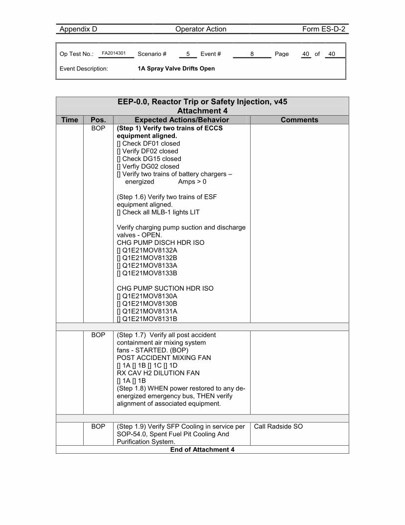
Appendix D Operator Action Form ES-D-2 Op Test No.: FA2014301 Scenario # 5 Event # 8 Page 40 of 40 Event Description: 1A Spray Valve Drifts Open
EEP-0.0, Reactor Trip or Safety Injection, v45 Attachment 4
Time Pos. Expected Actions/Behavior Comments BOP (Step 1) Verify two trains of ECCS
equipment aligned. [] Check DF01 closed [] Verify DF02 closed [] Check DG15 closed [] Verfiy DG02 closed [] Verify two trains of battery chargers – energized Amps > 0
(Step 1.6) Verify two trains of ESF equipment aligned. [] Check all MLB-1 lights LIT Verify charging pump suction and discharge valves - OPEN. CHG PUMP DISCH HDR ISO [] Q1E21MOV8132A [] Q1E21MOV8132B [] Q1E21MOV8133A [] Q1E21MOV8133B CHG PUMP SUCTION HDR ISO [] Q1E21MOV8130A [] Q1E21MOV8130B [] Q1E21MOV8131A [] Q1E21MOV8131B
BOP (Step 1.7) Verify all post accident
containment air mixing system fans - STARTED. (BOP) POST ACCIDENT MIXING FAN [] 1A [] 1B [] 1C [] 1D RX CAV H2 DILUTION FAN [] 1A [] 1B (Step 1.8) WHEN power restored to any de-energized emergency bus, THEN verify alignment of associated equipment.
BOP (Step 1.9) Verify SFP Cooling in service per
SOP-54.0, Spent Fuel Pit Cooling And Purification System.
Call Radside SO
End of Attachment 4

Appendix D Crew Briefing sheet Form ES-D-3
Op-Test No.: FA2014301 Page 1 of 2 Brief
This simulator performance scenario is performed in the EVALUATION MODE. You should not
direct questions to the evaluators. Otherwise, you should perform as if you were in the MCR.
Your ability to maintain a log is not being graded, but maintaining a rough log is recommended to
help during briefs.
If you need to communicate with the Unit 2 operator, call Unit 2 at 2434 or page the Unit 2 Unit
Operator.
Respond to what you see. If there is a problem with the simulation, the session will be terminated or
adjusted as appropriate based on the specific problem.
Assign operating positions.
Ask for and answer questions.
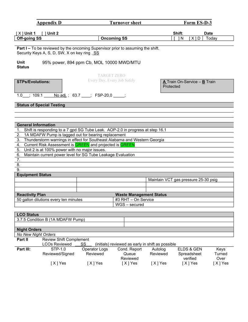
Appendix D Turnover sheet Form ES-D-3
[ X ] Unit 1 [ ] Unit 2 Shift: Date Off-going SS Oncoming SS [ ] N [ X ] D Today Part I – To be reviewed by the oncoming Supervisor prior to assuming the shift. Security Keys A, S, D, SW, X on key ring . SS Unit Status
95% power, 894 ppm Cb, MOL 10000 MWD/MTU
STPs/Evolutions:
A Train On-Service – B Train Protected
1.0 ; 109.1 No adj. ; 63.7 ; FSP-20,0 ; Status of Special Testing General Information 1. Shift is responding to a 7 gpd SG Tube Leak. AOP-2.0 in progress at step 16.1 2. 1A MDAFW Pump is tagged out for bearing replacement 3. Thunderstorm warnings in effect for Southeast Alabama and Western Georgia 4. Current Risk Assessment is GREEN and projected is GREEN 5. Unit 2 is at 100% power with no major issues. 6. Maintain current power level for SG Tube Leakage Evaluation 7. 8. 9. Equipment Status Maintain VCT gas pressure 25-30 psig Reactivity Plan Waste Management Status 50 gallon dilutions every ten minutes #3 RHT – On Service WGS – secured LCO Status 3.7.5 Condition B (1A MDAFW Pump) Night Orders No New Night Orders Part II Review Shift Complement LCOs Reviewed SS (initials) reviewed as early in shift as possible Part III: STP-1.0
Reviewed/Signed Operator Logs
Reviewed Cond. Report
Queue Reviewed
Autolog Reviewed
ELDS & GEN Spreadsheet
verified
Keys Turned Over
[ X ] Yes [ X ] Yes [ X ] Yes [ X ] Yes [ X ] Yes [ X ] Yes
TARGET ZERO Every Day, Every Job Safely
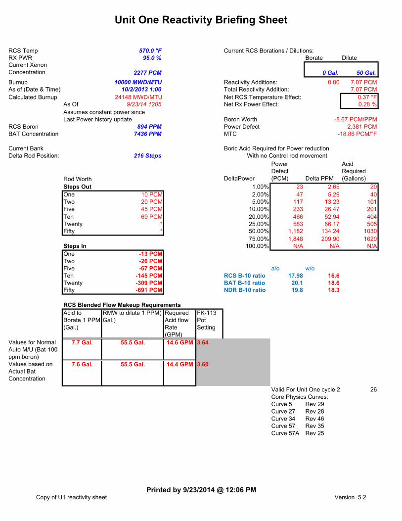
Unit One Reactivity Briefing Sheet
RCS Temp 570.0 °F Current RCS Borations / Dilutions:RX PWR 95.0 % Borate DiluteCurrent Xenon Concentration 2277 PCM 0 Gal. 50 Gal.
Burnup 10000 MWD/MTU Reactivity Additions: 0.00 7.07 PCMAs of (Date & Time) 10/2/2013 1:00 Total Reactivity Addition: 7.07 PCMCalculated Burnup 24148 MWD/MTU Net RCS Temperature Effect: 0.37 °F
As Of 9/23/14 1205 Net Rx Power Effect: 0.28 %Assumes constant power sinceLast Power history update Boron Worth
RCS Boron 894 PPM Power DefectBAT Concentration 7436 PPM MTC
Current Bank Boric Acid Required for Power reductionDelta Rod Position: 216 Steps With no Control rod movement
Rod Worth DeltaPower
Power Defect (PCM) Delta PPM
Acid Required (Gallons)
Steps Out 1.00% 23 2.65 20One 10 PCM 2.00% 47 5.29 40Two 20 PCM 5.00% 117 13.23 101Five 45 PCM 10.00% 233 26.47 201Ten 69 PCM 20.00% 466 52.94 404Twenty * 25.00% 583 66.17 505Fifty * 50.00% 1,182 134.24 1030
75.00% 1,848 209.90 1620Steps In 100.00% N/A N/A N/AOne -13 PCMTwo -26 PCMFive -67 PCM a/o w/oTen -145 PCM RCS B-10 ratio 17.98 16.6Twenty -309 PCM BAT B-10 ratio 20.1 18.6Fifty -691 PCM NDR B-10 ratio 19.8 18.3
RCS Blended Flow Makeup RequirementsAcid to Borate 1 PPM (Gal.)
RMW to dilute 1 PPM( Gal.)
Required Acid flow Rate (GPM)
FK-113 Pot Setting
Values for Normal Auto M/U (Bat-100 ppm boron)
7.7 Gal. 55.5 Gal. 14.6 GPM
Values based on Actual Bat Concentration
7.6 Gal. 55.5 Gal. 14.4 GPM
Valid For Unit One cycle 24 26Core Physics Curves:Curve 5 Rev 29Curve 27 Rev 28Curve 34 Rev 46Curve 57 Rev 35Curve 57A Rev 25
3.60
-8.67 PCM/PPM2,381 PCM
-18.86 PCM/°F
3.64
Copy of U1 reactivity sheetPrinted by 9/23/2014 @ 12:06 PM
Version 5.2
Scenario #5 FA2014301
Southern Nuclear J.M. Farley Nuclear Plant
Operations Training Simulator Exam Scenario
BOOTH INSTRUCTOR GUIDE
ILT-37 NRC EXAM SCENARIO #5
Validation time: 90 minutes Validated by: Sorrell, Smith, Jackson
TRN Supervisor Approval: Billy Thornton Date: 9/24/14
NRC Chief Examiner SEE NUREG 1021 FORM ES-301-3
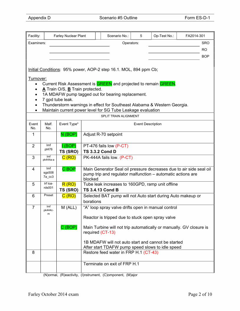
Appendix D Scenario #5 Outline Form ES-D-1
Farley October 2014 exam Page 2 of 10
Facility: Farley Nuclear Plant Scenario No.: 5 Op-Test No.: FA2014-301
Examiners: Operators: SRO
RO
BOP
Initial Conditions: 95% power, AOP-2 step 16.1. MOL, 894 ppm Cb; Turnover:
Current Risk Assessment is GREEN and projected to remain GREEN. A Train O/S, B Train protected. 1A MDAFW pump tagged out for bearing replacement. 7 gpd tube leak. Thunderstorm warnings in effect for Southeast Alabama & Western Georgia. Maintain current power level for SG Tube Leakage evaluation
SPLIT TRAIN ALIGNMENT
Event No.
Malf. No.
Event Type* Event Description
1 N (BOP) Adjust R-70 setpoint
2 Imf pt476
I (BOP) TS (SRO)
PT-476 fails low (P-CT) TS 3.3.2 Cond D
3 Imf pk444a-a
C (RO)
PK-444A fails low. (P-CT)
4 Imf sgs5087a_cc3
C BOP Main Generator Seal oil pressure decreases due to air side seal oil pump trip and regulator malfunction – automatic actions are blocked
5 Irf loa-rds001
R (RO) TS (SRO)
Tube leak increases to 160GPD, ramp unit offline TS 3.4.13 Cond B
6 Preset C (RO)
Selected BAT pump will not Auto start during Auto makeup or borations
7 Imf pk444c-
m
M (ALL)
C (BOP)
“A” loop spray valve drifts open in manual control Reactor is tripped due to stuck open spray valve Main Turbine will not trip automatically or manually. GV closure is required (CT-13) 1B MDAFW will not auto start and cannot be started After start TDAFW pump speed slows to idle speed
8 Restore feed water in FRP H.1 (CT-43)
Terminate on exit of FRP H.1
(N)ormal, (R)eactivity, (I)nstrument, (C)omponent, (M)ajor
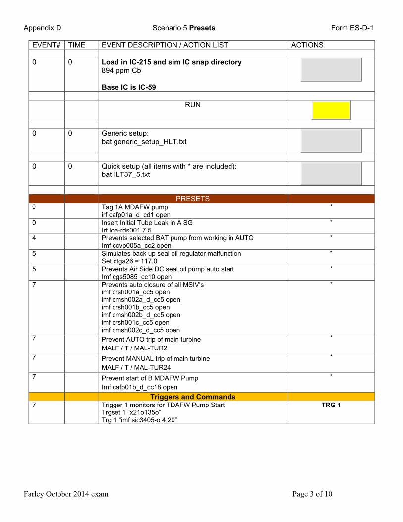
Appendix D Scenario 5 Presets Form ES-D-1
Farley October 2014 exam Page 3 of 10
EVENT# TIME EVENT DESCRIPTION / ACTION LIST ACTIONS 0 0 Load in IC-215 and sim IC snap directory
894 ppm Cb Base IC is IC-59
RUN
0 0 Generic setup:
bat generic_setup_HLT.txt
0 0 Quick setup (all items with * are included):
bat ILT37_5.txt
PRESETS 0 Tag 1A MDAFW pump
irf cafp01a_d_cd1 open *
0 Insert Initial Tube Leak in A SG Irf loa-rds001 7 5
*
4 Prevents selected BAT pump from working in AUTO Imf ccvp005a_cc2 open
*
5 Simulates back up seal oil regulator malfunction Set ctga26 = 117.0
*
5 Prevents Air Side DC seal oil pump auto start Imf cgs5085_cc10 open
*
7 Prevents auto closure of all MSIV’s imf crsh001a_cc5 open imf cmsh002a_d_cc5 open imf crsh001b_cc5 open imf cmsh002b_d_cc5 open imf crsh001c_cc5 open imf cmsh002c_d_cc5 open
*
7 Prevent AUTO trip of main turbine MALF / T / MAL-TUR2
*
7 Prevent MANUAL trip of main turbine MALF / T / MAL-TUR24
*
7 Prevent start of B MDAFW Pump Imf cafp01b_d_cc18 open
*
Triggers and Commands 7 Trigger 1 monitors for TDAFW Pump Start
Trgset 1 “x21o135o” Trg 1 “imf sic3405-o 4 20”
TRG 1
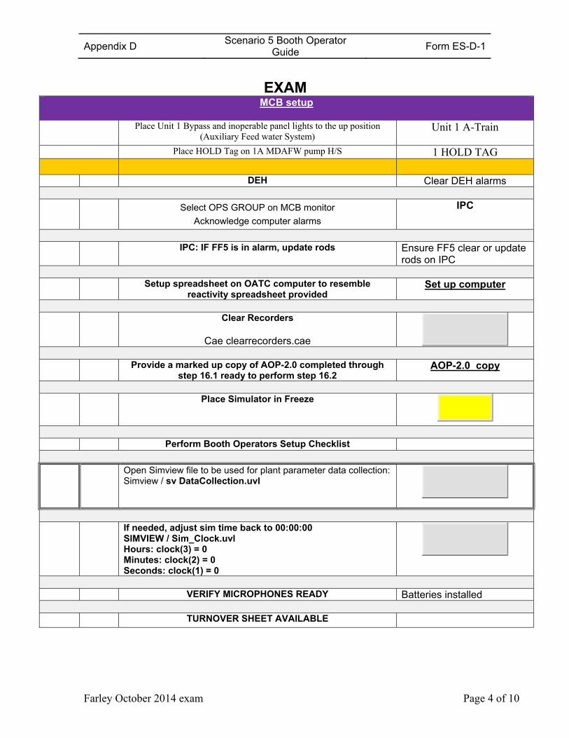
Appendix D Scenario 5 Booth Operator
Guide Form ES-D-1
Farley October 2014 exam Page 4 of 10
EXAM
MCB setup
Place Unit 1 Bypass and inoperable panel lights to the up position (Auxiliary Feed water System)
Unit 1 A-Train
Place HOLD Tag on 1A MDAFW pump H/S 1 HOLD TAG
DEH Clear DEH alarms
Select OPS GROUP on MCB monitor
Acknowledge computer alarms
IPC
IPC: IF FF5 is in alarm, update rods Ensure FF5 clear or update
rods on IPC Setup spreadsheet on OATC computer to resemble
reactivity spreadsheet provided Set up computer
Clear Recorders
Cae clearrecorders.cae
Provide a marked up copy of AOP-2.0 completed through
step 16.1 ready to perform step 16.2 AOP-2.0 copy
Place Simulator in Freeze
Perform Booth Operators Setup Checklist Open Simview file to be used for plant parameter data collection:
Simview / sv DataCollection.uvl
If needed, adjust sim time back to 00:00:00
SIMVIEW / Sim_Clock.uvl Hours: clock(3) = 0 Minutes: clock(2) = 0 Seconds: clock(1) = 0
VERIFY MICROPHONES READY Batteries installed TURNOVER SHEET AVAILABLE
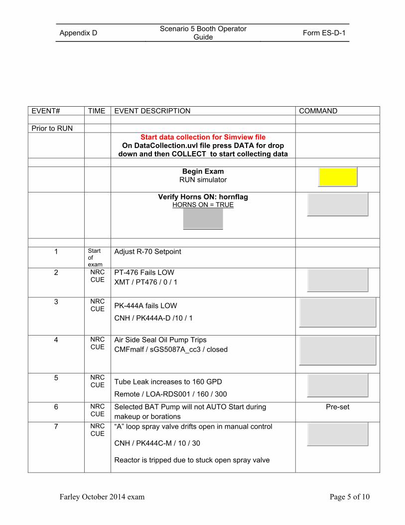
Appendix D Scenario 5 Booth Operator
Guide Form ES-D-1
Farley October 2014 exam Page 5 of 10
EVENT# TIME EVENT DESCRIPTION COMMAND Prior to RUN Start data collection for Simview file
On DataCollection.uvl file press DATA for drop down and then COLLECT to start collecting data
Begin Exam
RUN simulator
Verify Horns ON: hornflag HORNS ON = TRUE
1 Start of exam
Adjust R-70 Setpoint
2 NRC CUE
PT-476 Fails LOW XMT / PT476 / 0 / 1
3 NRC CUE PK-444A fails LOW
CNH / PK444A-D /10 / 1
4 NRC
CUE Air Side Seal Oil Pump Trips CMFmalf / sGS5087A_cc3 / closed
5 NRC CUE Tube Leak increases to 160 GPD
Remote / LOA-RDS001 / 160 / 300
6 NRC CUE
Selected BAT Pump will not AUTO Start during makeup or borations
Pre-set
7 NRC CUE
“A” loop spray valve drifts open in manual control CNH / PK444C-M / 10 / 30 Reactor is tripped due to stuck open spray valve
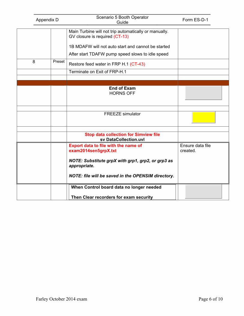
Appendix D Scenario 5 Booth Operator
Guide Form ES-D-1
Farley October 2014 exam Page 6 of 10
Main Turbine will not trip automatically or manually. GV closure is required (CT-13) 1B MDAFW will not auto start and cannot be started
After start TDAFW pump speed slows to idle speed
8 Preset Restore feed water in FRP H.1 (CT-43)
Terminate on Exit of FRP-H.1
End of Exam
HORNS OFF
FREEZE simulator
Stop data collection for Simview file
sv DataCollection.uvl
Export data to file with the name of exam2014sen5grpX.txt
NOTE: Substitute grpX with grp1, grp2, or grp3 as appropriate.
NOTE: file will be saved in the OPENSIM directory.
Ensure data file created.
When Control board data no longer needed Then Clear recorders for exam security
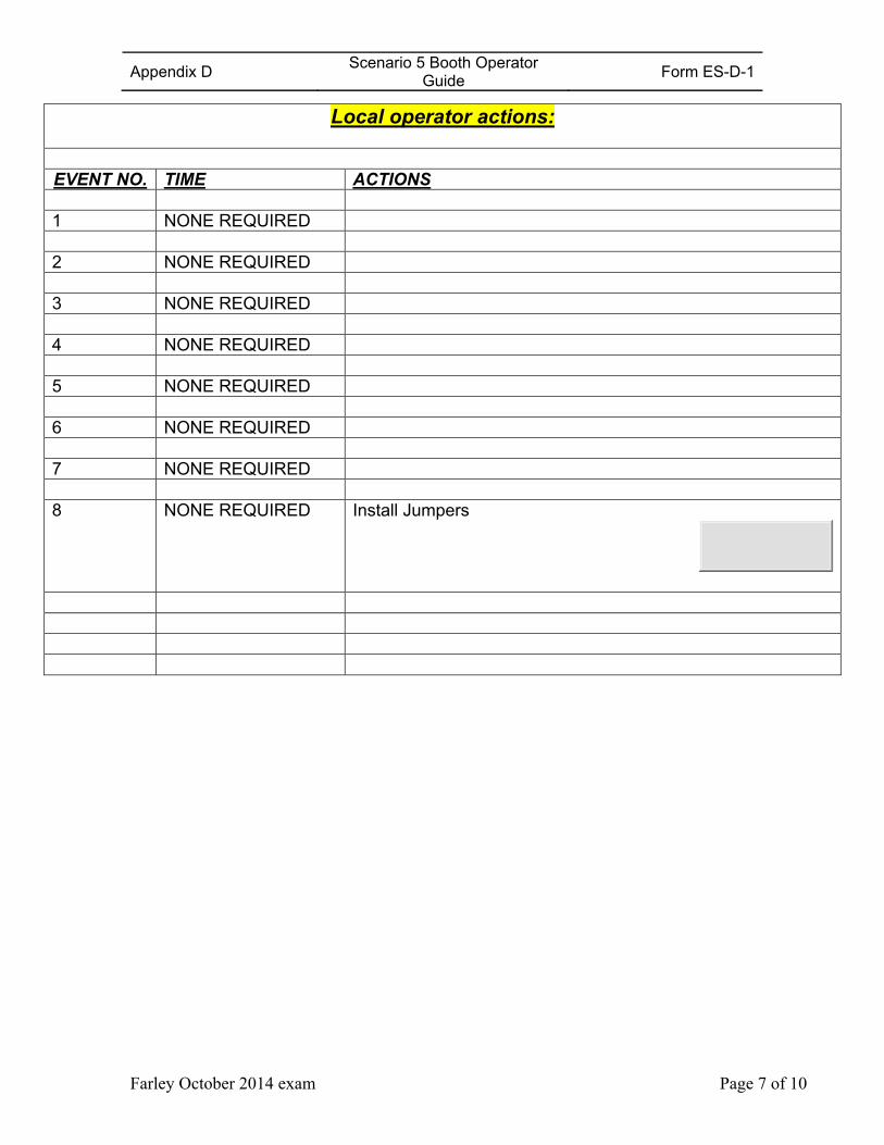
Appendix D Scenario 5 Booth Operator
Guide Form ES-D-1
Farley October 2014 exam Page 7 of 10
Local operator actions:
EVENT NO. TIME ACTIONS 1 NONE REQUIRED 2 NONE REQUIRED 3 NONE REQUIRED 4 NONE REQUIRED 5 NONE REQUIRED 6 NONE REQUIRED 7 NONE REQUIRED 8 NONE REQUIRED Install Jumpers
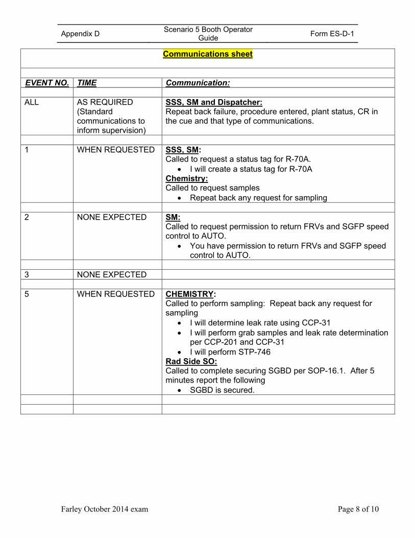
Appendix D Scenario 5 Booth Operator
Guide Form ES-D-1
Farley October 2014 exam Page 8 of 10
Communications sheet
EVENT NO. TIME Communication: ALL AS REQUIRED
(Standard communications to inform supervision)
SSS, SM and Dispatcher: Repeat back failure, procedure entered, plant status, CR in the cue and that type of communications.
1 WHEN REQUESTED SSS, SM:
Called to request a status tag for R-70A. I will create a status tag for R-70A
Chemistry: Called to request samples
Repeat back any request for sampling 2 NONE EXPECTED SM:
Called to request permission to return FRVs and SGFP speed control to AUTO.
You have permission to return FRVs and SGFP speed control to AUTO.
3 NONE EXPECTED 5 WHEN REQUESTED CHEMISTRY:
Called to perform sampling: Repeat back any request for sampling
I will determine leak rate using CCP-31 I will perform grab samples and leak rate determination
per CCP-201 and CCP-31 I will perform STP-746
Rad Side SO: Called to complete securing SGBD per SOP-16.1. After 5 minutes report the following
SGBD is secured.
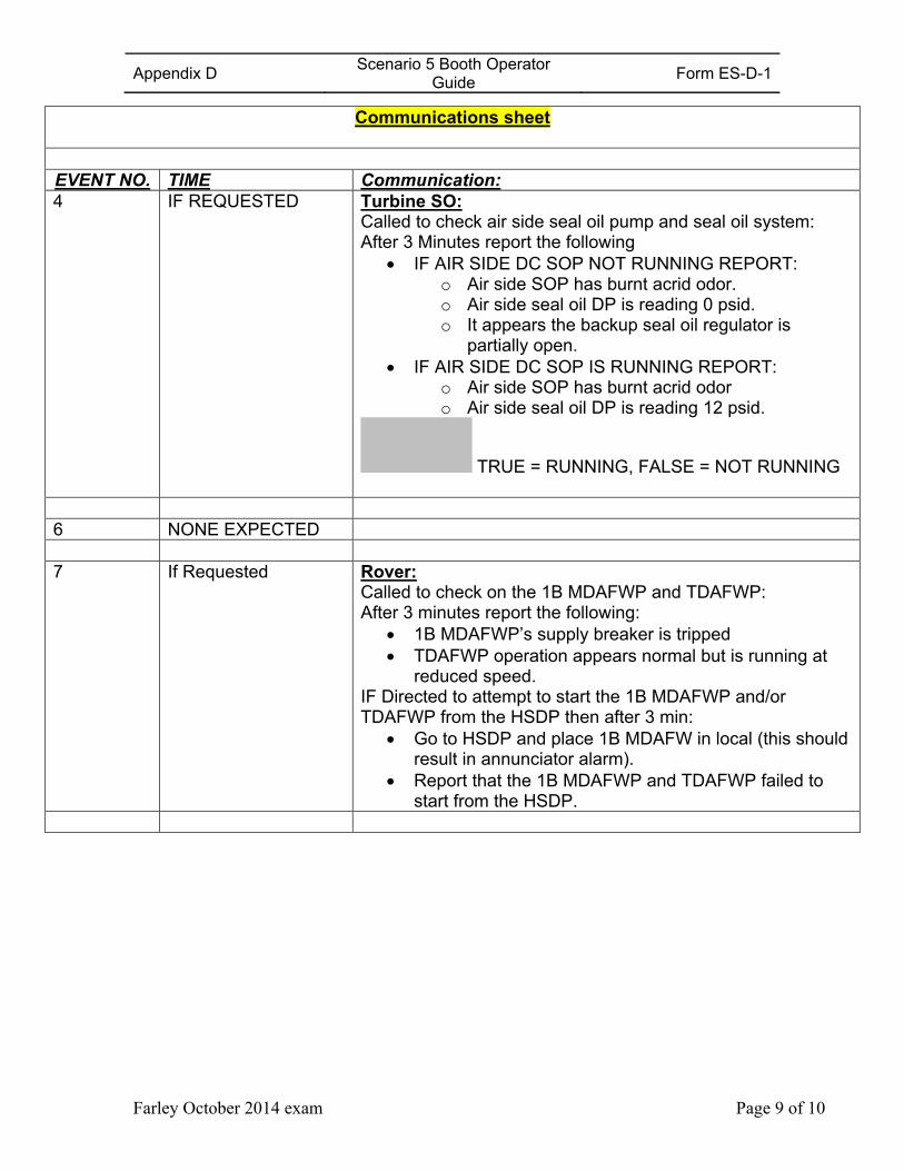
Appendix D Scenario 5 Booth Operator
Guide Form ES-D-1
Farley October 2014 exam Page 9 of 10
Communications sheet
EVENT NO. TIME Communication: 4 IF REQUESTED Turbine SO:
Called to check air side seal oil pump and seal oil system: After 3 Minutes report the following
IF AIR SIDE DC SOP NOT RUNNING REPORT: o Air side SOP has burnt acrid odor. o Air side seal oil DP is reading 0 psid. o It appears the backup seal oil regulator is
partially open. IF AIR SIDE DC SOP IS RUNNING REPORT:
o Air side SOP has burnt acrid odor o Air side seal oil DP is reading 12 psid.
TRUE = RUNNING, FALSE = NOT RUNNING
6 NONE EXPECTED 7 If Requested Rover:
Called to check on the 1B MDAFWP and TDAFWP: After 3 minutes report the following:
1B MDAFWP’s supply breaker is tripped TDAFWP operation appears normal but is running at
reduced speed. IF Directed to attempt to start the 1B MDAFWP and/or TDAFWP from the HSDP then after 3 min:
Go to HSDP and place 1B MDAFW in local (this should result in annunciator alarm).
Report that the 1B MDAFWP and TDAFWP failed to start from the HSDP.
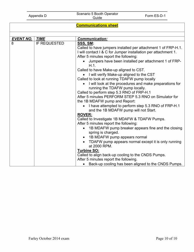
Appendix D Scenario 5 Booth Operator
Guide Form ES-D-1
Farley October 2014 exam Page 10 of 10
Communications sheet
EVENT NO. TIME Communication: 8 IF REQUESTED SSS, SM:
Called to have jumpers installed per attachment 1 of FRP-H.1. I will contact I & C for Jumper installation per attachment 1. After 5 minutes report the following:
Jumpers have been installed per attachment 1 of FRP-H.1.
Called to have Make-up aligned to CST. I will verify Make-up aligned to the CST
Called to look at running TDAFW pump locally I will look at the procedures and make preparations for
running the TDAFW pump locally. Called to perform step 5.3 RNO of FRP-H.1 After 5 minutes PERFORM STEP 5.3 RNO on Simulator for the 1B MDAFW pump and Report:
I have attempted to perform step 5.3 RNO of FRP-H.1 and the 1B MDAFW pump will not Start.
ROVER: Called to Investigate 1B MDAFW & TDAFW Pumps. After 5 minutes report the following:
1B MDAFW pump breaker appears fine and the closing spring is charged.
1B MDAFW pump appears normal TDAFW pump appears normal except it is only running
at 2000 RPM. Turbine SO: Called to align back-up cooling to the CNDS Pumps. After 5 minutes report the following.
Back-up cooling has been aligned to the CNDS Pumps.