Embed Size (px)
Citation preview

Fatigue Life Improvements of the AISI 304Stainless Steel Ground Surfaces by Wire Brushing
Nabil Ben Fredj, Mohamed Ben Nasr, Amir Ben Rhouma, Chedly Braham, and Habib Sidhom
(Submitted December 21, 2003)
The surface and subsurface integrity of metallic ground components is usually characterized by an inducedtensile residual stress, which has a detrimental effect on the fatigue life of these components. In particular,it tends to accelerate the initiation and growth of the fatigue cracks. In this investigation, to deliberatelygenerate compressive residual stresses into the ground surfaces of the AISI 304 stainless steel (SS), wirebrushing was applied. It was found that under the experimental conditions selected in this investigation,while the surface roughness was slightly improved by the brushing process, the surface residual stressshifted from a tensile stress (�� = +450 MPa) to a compressive stress (�� = −435 MPa). On the other hand,the work-hardened deformation layer was almost two times deeper after wire brushing. Concerning thefatigue life, an improvement of 26% in terms of endurance limit at 2 × 10⁶ cycles was realized. Scanningelectron microscope (SEM) observations of the fatigue fracture location and size were carried out toexplain the fatigue life improvement. It was found that the enhancement of the fatigue strength could becorrelated with the distribution and location of the fatigue fracture nucleation sites. Concerning the groundsurfaces, it was seen that the fatigue cracks initiated at the bottom of the grinding grooves and wereparticularly long (150-200 µm). However, the fatigue cracks at the brushed surfaces were shorter (20-40µm) and appeared to initiate sideways to the plowed material caused by the wire brushing. The results ofthe wire-brushed surface characterization have shown that significant advantages can be realized regard-ing surface integrity by the application of this low-cost process compared to shot peening.
Keywords fatigue life, grinding, residual stress, wire brushing
1. Introduction
The material removal mechanism for the grinding processcan be characterized by the formation of microchips generatedby the cutting edges of the abrasive grits. This specific mecha-nism for material removal in a machining process offers wideapplications to surfaces requiring high geometrical quality withtightened tolerances even for materials usually classified asdifficult to cut (i.e., ceramics).[1] However, as chip formationoccurs by intense shearing, in an extremely thin zone, undervery high deformation rates, and at very short times, the heatthat is generated by the plastic flow and friction can be con-ducted away from the grinding zone. This leads to surfaceswith low integrity having problems such as surface burning,material redeposition, surface and subsurface cracking, me-chanical and metallurgical transformations of the upper layersof the workpiece,[2,3] and surface tensile residual stresses.These characteristics and, in particular, the magnitude of thetensile surface residual stress were found to affect significantlythe fatigue lives of mechanical components[4-6] that have un-dergone grinding by accelerating the initiation and the propa-gation of the fatigue cracks. On the other hand, it was found
that the near-surface compressive residual stresses usually ex-tend the fatigue life.[7,8] To consider these findings with respectto in-service applications of ground components, compressiveresidual stresses have to be introduced to their surfaces. Thiscan be done by selecting fine grinding conditions with lowwork speeds and small cut depths, and, if necessary, the use ofcostly grinding wheels with special abrasive grits like SG,CBN, or diamond.[9] These solutions were found to affect sub-stantially the cost of the grinding operation, as they lower theprocess productivity and induce additional expenses for theacquisition and preparation of the grinding wheels.[10]
Another way of deliberately compressing the surface andnear-surface layers of the ground components consists of usingadditional surface treatments such as polishing, shot peen-ing,[11-15] deep rolling,[16] laser shock peening,[17,18] ball bur-nishing,[19] ultrasonic impact treatment,[20] surface coating,[21]
and/or surface nitriding.[22] Some results of published data,related to the improvement rates of the fatigue strength result-ing from these treatments, are reported in Table 1. This tableshows that the improvement in fatigue strength ranged from9-36%, depending on the treatment type, treatment conditions,treated materials, and machining process. Table 1 also showsthat laser shot peening and shot peening significantly affect thesurface roughness of the initial state generated by the previousmachining operation. This fact has to be taken into accountwhen such surface treatments are considered for surfaces re-quiring low roughness. The other main parameters that have tobe considered when selecting the surface treatment process arethe cost of the treatment and the geometry of the treated com-ponents. Indeed, while the industrial applications of ball bur-nishing and deep rolling are usually limited to rotationallysymmetric components (e.g., shafts), hammer and shot peening
Nabil Ben Fredj, Mohamed Ben Nasr, Amir Ben Rhouma, and HabibSidhom, Laboratoire de Mécanique, Matériaux et Procédés, LAB-STI-03, ESSTT, 5, Avenue Taha Hussein, 1008, Tunis, Tunisia; andChedly Braham, Laboratoire de Microstructure et Mécanique desMatériaux, ENSAM, CNRS ESA 8006, 75013 Paris, France. Contacte-mail: [email protected].
JMEPEG (2004) 13:564-574 ©ASM InternationalDOI: 10.1361/15477020420819 1059-9495/$19.00
564—Volume 13(5) October 2004 Journal of Materials Engineering and Performance

are frequently applied to the external surfaces of mechanicalcomponents. Concerning laser shot peening, ultrasonic impacttreatment, and surface coating, even though promising resultswere reported by recent investigations,[17,18,20] they remaincostly, and their applications are restricted to components withcomplicated geometry for which other techniques cannot be used.
Another method that can introduce compressive residualstresses into the upper layers of the surfaces of mechanicalcomponents by cold plastic deformation is wire brushing. Thislow-cost, fast, and easy technique is commonly used for onlinepolishing, deburring, and removing thin contaminated layers.Recently developed brushing methods use robotic systems forautomated deburring and applications for finishing of surfaceshaving complex geometries.[23,24] However, even though it isknown that the brush stiffness, rotational speed, and force ex-erted on the workpiece play crucial roles in establishing thematerial removal rate and surface finish quality, limited infor-mation is available in the literature pertaining to the brushedsurface integrity, particularly the improvements in the fatiguelife of brushed components. One class of material in whichwire brushing has been considered is stainless steel (SS). Infact, the investigation conducted by Ben Rhouma et al.[24]
showed substantial improvements in pitting, crevice, and cor-rosion resistance under stress in an aggressive medium for thebrushed surfaces of AISI 316L SS. These improvements wereexplained by the fact that the brushing process induces addi-
tional hardening by plastic deformation, leading to compres-sive residual stresses in the treated surfaces. Based on thesefindings, and to continue investigating the improvements ofmachined surface integrity resulting from the application of thewire-brushing process, experiments were conducted to evaluatethe fatigue life enhancements of the AISI 304 SS ground sur-faces. The brushing conditions were optimized on the basis ofcriteria related to induced residual stress, work hardening, sur-face roughness, and burr formation. In the second step, three-point bending fatigue tests were conducted on ground andbrushed specimens to evaluate the endurance limit improve-ments at 2 × 10⁶ cycles. The mechanisms of fatigue crackinitiation and propagation were investigated based on scanningelectron microscope (SEM) observations of the fatigue fracturesurface of the tested specimens. The role of work hardeningand residual stress on fatigue crack nucleation and growth wereestablished.
2. Experimental Procedures
2.1 Materials
The material used in this study was AISI 304 SS, for whichthe chemical composition and the mechanical properties aregiven in Tables 2 and 3, respectively. Figure 1 shows a micro-
Table 1 Improvements of machined surface integrity resulting from different posttreatment operations
MaterialMachiningconditions
Surface characterization Fatigue resistance
Hardening(a)Residual
stress, MPaRoughness(Ra), µm
�D,MPa
N(b),approx Specimen
Nucleationsites
AISI 4340 Gentle grinding … −350 … 827 2 × 10⁵ Notched Surface… … … … … … Not notched …
AISI 52100 Grinding … −40 … … … Notched Surface
AISI 5140 Grinding … −30 … … … Notched Surface
AISI 5120 Grinding … −50 … … … Notched Surface
AISI Al12SI-T6 Milling … … … 103 … Notched Surface
AISI A356-T6 Milling … … 0.7 110 … Notched Surface
AISI 7075-T6 Milling … … 0.6 190 … Notched Surface
MaterialPosttreatment
conditions
Surface characterization Fatigue resistance Fatigueimprovements,
% ReferenceHardening
(a)Residual
stress, MPaRoughness(Ra), µm
�D,MPa
N(b),approx Specimen
Nucleationsites
AISI 4340 Low plasticity burnishing … −1100 … 1033 7 × 10⁵ Notched Subsurface 25 14
AISI 4340 Shot peening
0.0027 A … −950 … 830 … Not notched Subsurface 9 15
0.0063 A … −1100 … 900 … Not notched Subsurface 12 15
0.0083 A … −1200 … 865 … Not notched Subsurface 10 15
0.0141 A … −1300 … 845 … Not notched Subsurface 10 15
AISI 52100 Shot peening … −880 … … … Notched Subsurface 10 16
AISI 5140 Shot peening … −750 … … … Notched Subsurface 15 16
AISI 5120 Shot peening … −570 … … … Notched Subsurface 18 16
AISI Al12SI-T6 Laser shot peening … −125 … 126 … Notched Subsurface 22 17
AISI A356-T6 Laser shot peening 10 −145 1.1 150 … Notched Subsurface 36 17
Shot peening 20 −210 5.8 … … … … … 17
AISI 7075-T6 Laser shot peening 10 −300 1.3 236 … Notched Subsurface 23 17
Shot peening 20 −340 5.7 215 … … Subsurface 12 17
(a) Hardening � �Hv /Hv × 100. Hv, initial hardness. (b) N, number of cycles in fatigue test
Journal of Materials Engineering and Performance Volume 13(5) October 2004—565

graph of the AISI 304 SS microstructure. It has an averagegrain size of 150 �m.
2.2 Surface Preparation
A notched fatigue-flexture specimen with a stress concen-tration factor of Kt � 1.6 was selected (Fig. 2). The mainadvantage obtained from using this geometry is that localizedcrack initiation starts at the notch root.
The notch was machined into the sample on an NC millingmachine using an endmill having a diameter of 8 mm. Speci-mens were subsequently subjected to a stress relief annealingtreatment (i.e., heating at 1050 °C over the course of 1 h fol-lowed by air cooling) before being ground and/or wire-brushed. Only the notch was ground using a V-shaped grindingwheel. The grinding conditions are summarized in Table 4.
The experimental setup used for the wire-brushing experi-ments is shown in schematic form in Fig. 3. An SS wire brushwas used for the experiments. This brush was set on a conven-tional milling machine. During the wire-brushing process, thewires were effectively compressed by 3% of their length (i.e.,the surface of the notch was set at 2.4 mm from the inner endof the wires). The experimental conditions under which thebrushing tests were conducted are listed in Table 5.
2.3 Testing Methods
The ground and brushed surfaces were characterized byroughness measurements using a stylus-type profilometer. Sur-face hardening was characterized by microhardness measure-ments using a microhardness tester set at a load of 50 gf. Thesurface residual stresses were evaluated using the x-ray methodunder the conditions listed in Table 6. Due to the coarse grainsize of the AISI 304 SS specimens, it was difficult to measurethe depth of residual stresses using this technique. Therefore,residual stress was also evaluated using the hole-drillingmethod.[24] Holes were drilled incrementally using a 2 mmdiameter drill rotating at a high cutting speed (2500 rpm) toavoid inducing additional residual stresses. High-cycle fatiguetests (up to 2 × 10⁶ cycles) were performed using a three-pointbend geometry. For all fatigue experiments, the stress ratio wasfixed to R = 0.1 and the test frequency to 15 Hz.
Table 2 Chemical composition
C Si Mn Cr Ni Mo Cu N Fe
0.05 0.41 1.14 18.04 9 0.193 0.0348 0.004 balance
Table 3 Mechanical properties
Yieldstress
Rm,MPa A, %
Microhardness(Hv)
Toughnessat 20 °C, J/cm2
315 690 58 172 270
Table 4 Grinding conditions
Conditions Set condition
Grinding mode Plunge surface grinding, down cutGrinding wheel 99 A 46 M 7 V 10 N with V shapeStock removal rate Z� � 30 mm3/mm/minWheel speed Vs � 30 m/sWork speed vw � 5 m/minDepth of cut a � 6 �mEnvironment Soluble oil (20%), 7.2 L/minWorkpiece material AISI 304 SSDresser Single-point diamond dresserDressing depth 0.01 mmCross feed 0.2 mm/revolutionEnvironment Dry
Fig. 1 Austenitic structure of the AISI 304 SS specimen
Fig. 2 Geometry of fatigue test specimen (stress concentration fac-tor, Kt � 1.6; all dimensions are in millimeters)
Fig. 3 Schematic view of the wire-brushing experimental setup andparameters
566—Volume 13(5) October 2004 Journal of Materials Engineering and Performance

To better understand the effects of mechanical and thermalloading on the surface quality corresponding to each surfacefinishing mode, force components and the surface temperaturegenerated by the grinding wheel and the wire brush were mea-sured. Forces were measured using a piezoelectric transducerdynamometer (model 9257B, Kistler, Kirkland, WA). The sur-face temperature was measured using a thermocouple with awire diameter of 25 �m.[10]
3. Results
3.1 Optimization of the Wire-Brushing Conditions
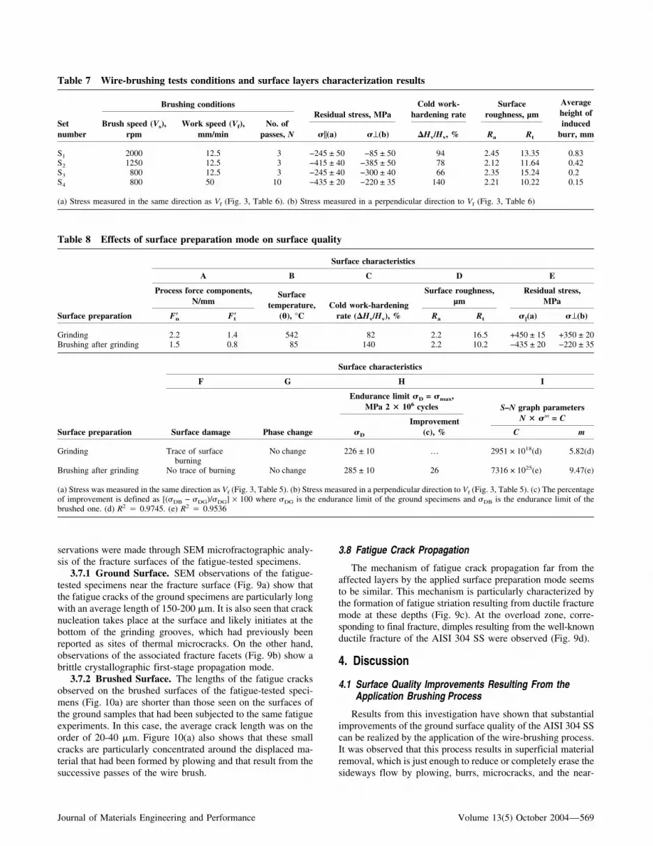
Previous investigations have shown that the main surfaceintegrity parameters controlling the fatigue behavior of the me-chanical components are the residual stress, the surface rough-ness, and the induced work hardening.[18-20,25,26] Therefore,wire brush optimization was made on the basis of criteria re-lated to high compressive residual stress, high work hardening,low surface roughness, and small size of burr formation by thebrushing process. Indeed, the main industrial application of thewire brushing remains deburring. On the other hand, eventhough the wire diameter and length are supposed to havesignificant effects on surface integrity, in this investigation, asthe same brush was used for all the experiments, the optimized
brushing conditions considered were the brush rotationalspeed, the work speed, and the number of passes.[24] The ef-fective wire compression was fixed at 3% of the wire length.Table 7 summarizes the experimental conditions considered foroptimization and the corresponding results. All brushed speci-mens were first ground under the conditions listed in Table 4.The surface roughness parameters generated by the grindingprocess were Ra � 2.2 �m and Rt � 16.5 �m. Ra is thearithmetic average surface roughness and Rt is the maximumsurface roughness.
Analyzing the results given in Table 6 leads to the conclu-sion that two brushing conditions have to be considered as theyoffer the highest compressive residual stresses. These condi-tions correspond to sets S2 and S4. In terms of productivity, S4
is more interesting as it takes only 12 s to finish brushing a 1mm length compared with S2, which takes 14 s to brush thesame length. On the other hand, even though no significantdifference in surface roughness is observed between these twoconditions, increased work hardening was realized using the S2
set of conditions. Moreover, it was observed that the height ofthe induced burr was much lower when brushing under S4
conditions. These observations suggest the use of S4 for wirebrushing the fatigue test specimens. Concerning the brushingconditions of set S1 (brush speed, or Vs � 2000 rpm; workspeed, Vf � 12.5 mm/min; N � three passes), a substantial
Fig. 4 (a) General aspect of the ground surface of the AISI 304 SS specimen. (b) Thermal microcracks at the bottom of the grinding groove (detailA in (a). (c) Roughness profile of the ground surface (Ra � 2.2 �m; Rt � 16.5 �m)
Journal of Materials Engineering and Performance Volume 13(5) October 2004—567

thermal effect on the brushed surface and on the brush wireswas noticed. The surface temperature of the sample increased,and the metallic wires of the brush were damaged. Indeed,under these conditions, a burr was formed by the welded mi-crofragments of the brush wires.
3.2 Ground and Brushed Surfaces Integrity
Table 8 gives the values of the parameters, which wereselected to characterize the surface integrity and the fatiguebehavior of the AISI 304 SS in the ground and brushed states.Table 8 also gives the force components and temperature val-ues generated during the process. These parameters were se-lected as they help in understanding the fatigue behavior of thetested specimens.
3.3 Surface Microgeometrical Quality
3.3.1 Ground Components. SEM observations of theground surfaces, which are shown in Fig. 4(a), highlight theback transfer of workpiece material. Sideways displacement ofthe workpiece material from grinding, through a plowingmechanism, is also observed. Moreover, microcracks with alength of 20 �m, which likely were generated by thermal ef-fects, are seen at the bottom of the grinding grooves (Fig. 4b).On the other hand, the ground surface roughness profile topog-raphy (Fig. 4c) exhibits irregularly spaced, nonuniform sharppeaks and valleys. This surface morphology is expected toaffect significantly the fatigue crack initiation of the AISI 304SS ground specimens.
3.3.2 Brushed Components. Brushed specimens (Fig. 5a)show similar morphology to the shot-peened surfaces. Plowingby plastic deformation results from the successive passes of the
wire brush. The grinding grooves are completely eliminated bythe brushing process, and no trace of these grooves can be seeneven at high magnification (Fig. 5b). The brushed surfaceroughness profile, which is shown in Fig. 5(c), shows a topog-raphy having fewer high irregularities with less sharpness thanthe roughness profiles of the ground surfaces. This explains thereduction of the Rt observed in column D of Table 8.
3.4 Work Hardening
Profiles of Vickers microhardness (Hv0.05) for the groundand wire-brushed surfaces are shown in Fig. 6. Figure 6 showsthat wire brushing leads to higher work hardening at the surfaceand is equivalent in depth to that obtained by grinding. Indeed,the work-hardening rate generated by the brushing process isalmost twice as high as that induced by the grinding process(Table 8, column C).
3.5 Residual Stress
3.5.1 Ground Components. The distribution of residualstresses induced by the grinding process is illustrated by theprofiles in Fig. 7(a). The main characteristics of these profilesare summarized in Table 8 (column E), which shows that theupper ground layers are particularly subject to tensile residualstresses in both directions. The higher levels of these stressesare achieved at a depth of 50-100 �m, with ��max � +600 MPaand �⊥max � +530 MPa. The lower levels of these stresseswere measured on the ground surfaces using the x-ray tech-nique (�� � +450 MPa; �⊥ � +350 MPa) and are probablydue to the relaxation effects of these stresses resulting from themicrocracks generated by the thermal loading of these surfaces(Fig. 4b).
3.5.2 Brushed Components. The residual stress profilesin Fig. 7(b) show the stress distribution measured for the wire-brushed surfaces. It should be noted that the residual stressesshift to compressive ones and that the highest levels of theresidual stresses are reached at a depth of 30-50 �m. However,less difference between the surface values (�� � −435 MPa; �⊥� −220 MPa) and the maximum values (�� � −514 MPa; �⊥� −233 MPa) of the residual stresses are observed in this case.
3.6 Fatigue Behavior of the Ground andBrushed Specimens
The stress, number of cycles (S-N) curves of Fig. 8 show thefatigue life of the ground and wire-brushed specimens sub-jected to constant amplitude loading. Fatigue tests werestopped beyond 2 × 10⁶ cycles if no fracture occurred. Clearly,the fatigue life of the brushed specimens was significantlyhigher than that of the ground specimens. For N > 106 cycles,the fatigue strength, as characterized by the endurance limit �D,increased by 26% for the ground and brushed specimens (Table8, column H). For an applied loading corresponding to �max �280 MPa, Fig. 8 shows that the fatigue life of ground speci-mens can be multiplied by a factor of 10 when wire brushingis applied to these surfaces.
3.7 Fatigue Crack Nucleation and First-Stage Propagation
Different fatigue crack nucleation mechanisms could be ob-served depending on the surface preparation mode. These ob-
Table 5 Brushing conditions
Conditions Set condition
Wire material SSBrush diameter D � 230 mmWire diameter � � 0.1 mmWire length l � 80 mmBrush rotational speed Vs � 800, 1250, and 2000 rpmWork speed Vf � 50 mm/minNumber of passes N � 3, 5, and 10 passesPercentage of effective
wire compression 3%
Table 6 X-ray diffraction parameters
Parameter Set parameter
Radiation � Mn K� x � � 0.2102 nmVoltage 20 kVCurrent 5 mAX-ray diffraction planes {3 1 1} 2� ≈ 152°Beam diameter 2 mm� angles 0° and 90 °� oscillation ±3°� angles −3727 −33.21 −28.88 −24.09 −18.43
−10.52 0.00 14.96 21.42 26.5731.09 35.26 39.23
568—Volume 13(5) October 2004 Journal of Materials Engineering and Performance
servations were made through SEM microfractographic analy-sis of the fracture surfaces of the fatigue-tested specimens.
3.7.1 Ground Surface. SEM observations of the fatigue-tested specimens near the fracture surface (Fig. 9a) show thatthe fatigue cracks of the ground specimens are particularly longwith an average length of 150-200 �m. It is also seen that cracknucleation takes place at the surface and likely initiates at thebottom of the grinding grooves, which had previously beenreported as sites of thermal microcracks. On the other hand,observations of the associated fracture facets (Fig. 9b) show abrittle crystallographic first-stage propagation mode.
3.7.2 Brushed Surface. The lengths of the fatigue cracksobserved on the brushed surfaces of the fatigue-tested speci-mens (Fig. 10a) are shorter than those seen on the surfaces ofthe ground samples that had been subjected to the same fatigueexperiments. In this case, the average crack length was on theorder of 20-40 �m. Figure 10(a) also shows that these smallcracks are particularly concentrated around the displaced ma-terial that had been formed by plowing and that result from thesuccessive passes of the wire brush.
3.8 Fatigue Crack Propagation
The mechanism of fatigue crack propagation far from theaffected layers by the applied surface preparation mode seemsto be similar. This mechanism is particularly characterized bythe formation of fatigue striation resulting from ductile fracturemode at these depths (Fig. 9c). At the overload zone, corre-sponding to final fracture, dimples resulting from the well-knownductile fracture of the AISI 304 SS were observed (Fig. 9d).
4. Discussion
4.1 Surface Quality Improvements Resulting From theApplication Brushing Process
Results from this investigation have shown that substantialimprovements of the ground surface quality of the AISI 304 SScan be realized by the application of the wire-brushing process.It was observed that this process results in superficial materialremoval, which is just enough to reduce or completely erase thesideways flow by plowing, burrs, microcracks, and the near-
Table 7 Wire-brushing tests conditions and surface layers characterization results
Setnumber
Brushing conditionsResidual stress, MPa
Cold work-hardening rate
Surfaceroughness, µm
Averageheight ofinduced
burr, mmBrush speed (Vs),
rpmWork speed (Vf),
mm/minNo. of
passes, N ��(a) �⊥(b) �Hv/Hv, % Ra Rt
S1 2000 12.5 3 −245 ± 50 −85 ± 50 94 2.45 13.35 0.83S2 1250 12.5 3 −415 ± 40 −385 ± 50 78 2.12 11.64 0.42S3 800 12.5 3 −245 ± 40 −300 ± 40 66 2.35 15.24 0.2S4 800 50 10 −435 ± 20 −220 ± 35 140 2.21 10.22 0.15
(a) Stress measured in the same direction as Vf (Fig. 3, Table 6). (b) Stress measured in a perpendicular direction to Vf (Fig. 3, Table 6)
Table 8 Effects of surface preparation mode on surface quality
Surface preparation
Surface characteristics
A B C D E
Process force components,N/mm
Surfacetemperature,
(�), °CCold work-hardening
rate (�Hv/Hv), %
Surface roughness,µm
Residual stress,MPa
F�n F�t Ra Rt ��(a) �⊥(b)
Grinding 2.2 1.4 542 82 2.2 16.5 +450 ± 15 +350 ± 20Brushing after grinding 1.5 0.8 85 140 2.2 10.2 −435 ± 20 −220 ± 35
Surface preparation
Surface characteristics
F G H I
Surface damage Phase change
Endurance limit �D = �max,MPa 2 � 106 cycles S–N graph parameters
N � �m = C
�D
Improvement(c), % C m
Grinding Trace of surface No change 226 ± 10 … 2951 × 1018(d) 5.82(d)burning
Brushing after grinding No trace of burning No change 285 ± 10 26 7316 × 1025(e) 9.47(e)
(a) Stress was measured in the same direction as Vf (Fig. 3, Table 5). (b) Stress measured in a perpendicular direction to Vf (Fig. 3, Table 5). (c) The percentageof improvement is defined as [(�DB − �DG)/�DG] × 100 where �DG is the endurance limit of the ground specimens and �DB is the endurance limit of thebrushed one. (d) R2 � 0.9745. (e) R2 � 0.9536
Journal of Materials Engineering and Performance Volume 13(5) October 2004—569

surface tensile residual stress distribution generated by thegrinding process. The ground surface quality improvementsrealized by the application of the brushing process can be sum-marized as follow:
• Improvement of the surface microgeometrical quality,which is characterized by a lower value of the parameter Rt
resulting from the plastic deformation of the ground sur-face generated by the successive passes of the wire brush.Within the experimental conditions used in this investiga-tion, Rt could be reduced to about 60% of the initial value.Moreover, no traces of surface burning or microcrackswere observed. On the other hand, roughness profiles haveshown that while the ground surface is characterized by asharp topography, a smoother one was observed for thebrushed surface. When these results were compared withthose obtained using a shot-peening process,[27] it could beconcluded that the wire-brushing process provides sur-faces with almost the same level of compressive residualstress and work hardening. However, wire-brushed sur-faces present higher microgeometrical quality comparedwith the shot-peened ones. Indeed, it was reported thatwhen surfaces of the AISI 304 SS were shot peened usingsteel shot with a diameter of 1.2 mm, and at a rate of 1.2
s/cm2, a compressive residual stress with maximum am-plitude of −650 MPa and maximum work hardening ofHv0.05 = 430 could be generated. However, under theseshot-peening conditions, the surface roughness parameterswere Rt � 41.1 �m and Ra � 4.7 �m. These values arehigh compared with those obtained using the brushing pro-cess (Rt � 10.2 �m; Ra � 2.1 �m). This difference isrelated to the fact that shot peening induces, dependingupon the shot intensity, overlaps, scaling, and microcracksresulting from excessive material deformation, and is re-sponsible for the low surface microgeometrical quality. Byconsidering the detrimental effects of the surface rough-ness on fatigue lifetime, it is expected that at equivalentlevels of compressive residual stress and work hardening,the wire-brushed specimens would give higher fatigue re-sistance than the shot-peened ones.
• Improvement of the quality of the surface, and the nearsurface layer by work hardening, results in higher surfacehardness and thicker hardened layer with no trace of sur-face microfracture. Improvement of the residual stressdistributions, which shifts from tensile for the groundsurfaces to compressive for the wire-brushed ones, isindependent of the measuring direction. Concerning theground surface, it was found that the maximum tensile
Fig. 5 (a) General aspect of the wire-brushed surface of the AISI 304 SS specimen. (b) Plowing by plastic deformation of the brushed surface(detail B in (a). (c) Roughness profile of the wire-brushed surface (Ra � 2.2 �m; Rt � 10.2 �m)
570—Volume 13(5) October 2004 Journal of Materials Engineering and Performance

residual stress was in the subsurface region. The lowervalue of residual stress, measured at the ground surface,may be explained by the relaxation effects of these stressesresulting from surface microcracks generated by the highthermal loading of these surfaces. Indeed, according toTable 8, column A, the specific grinding energy, which isthe energy per unit volume of material removal, can becalculated using the following formula[1]:
U =F t�Vs
vw a
where F�t is the specific tangential grinding force, Vs is thegrinding wheel peripheral speed, vw is the work speed, anda is the grinding depth of the cut. Using the experimentalvalues from Table 4, an energy density of 132 J/mm3 isneeded to remove 1 mm3 AISI 304 SS. This value is sig-nificantly higher than the value reported in Ref 28 whereit was indicated that even with U � 70 J/mm3, micro-cracks and microvoids characterize the ground surfacemorphology of the AISI 304 SS. In this research, grindingwas conducted under conditions of Vs � 30 m/s, vw � 15m/min, and a � 15 �m. On the other hand, the measuredgrinding temperature indicated in column B of Table 8 (�� 542 °C) is in a very good agreement with the valuegiven in Ref 26 and is high enough to generate localizedthermal damage at the ground surface.
Concerning the compressive residual stresses measured forwire-brushed surfaces, higher amplitudes can be expected bythe optimization of the brush specifications and the brushingconditions. However, it is expected that even at these optimizedbrushing conditions, as the wire brushing is a superficial sur-face treatment, the depths of the layers affected by this processremained limited compared with the depths that can be reachedby the shot-peening treatment.
4.2 Fatigue Life Improvements Resulting From theBrushing Process
The results of the fatigue tests conducted in this investiga-tion comparing the fatigue behavior of the ground and the
wire-brushed surfaces have shown longer lifetimes at 2 × 10⁶
cycles for the wire-brushed ones. These fatigue resistance im-provements can be explained by the enhancements of theground surface integrity resulting from the application of thewire-brushing process to these surfaces. Indeed, the fatiguelifetime, and, particularly, the mechanisms of fatigue cracknucleation and first-stage propagation of mechanical compo-nents subjected to surface loading are mainly controlled bytheir surface characteristics.[25,26,30-32]
4.2.1 Roughness Effects. Concerning the effects of the gen-erated surface roughness on the fatigue lifetime of mechanicalcomponents, it was reported that the fatigue resistance could beaffected significantly by this parameter.[25,26] Indeed, the fatigueresistance could be varied within an order of magnitude whensurface roughness was varied using different machining methods,such as forging, grinding, and polishing.[25] In this investigation,it was observed that the high and sharp valleys, which are char-acteristic of the ground surface topography, constitute potentialsites for fatigue crack initiation, as they are considered to be primelocations for microstress concentration.[26] Indeed, the fatigue
Fig. 6 Work hardening of the AISI 304 SS specimen induced by thegrinding and brushing processes
Fig. 7 (a) Residual stress profiles for the ground surface of the AISI304 SS (vw � 6 m/min; a � 5 �m). (b) Residual stress profiles for thewire-brushed surface of the AISI 304 SS (Vs � 800 rpm; Vf � 50mm/min; N � 10 passes)
Journal of Materials Engineering and Performance Volume 13(5) October 2004—571

Fig. 8 Fatigue lifetime improvements by wire brushing of the ground surfaces of the AISI 304 SS specimen
Fig. 9 (a) Surface fatigue crack distribution at a distance of 30 �m from the main fracture. (b) Fracture facet showing fatigue crack nucleationsites. Arrows indicate that the crack nucleation likely occurred at the bottom of the grinding grooves. (c) Fatigue striations at a depth of 800 �mbelow the ground surface, indicating a crack propagation speed of 0.3 �m per cycle. (d) Dimple fracture at a depth of 2 mm below the ground surface
572—Volume 13(5) October 2004 Journal of Materials Engineering and Performance

cracks were seen to initiate at the bottom of these valleys, whichcorrespond to the grinding grooves. Therefore, the generatedsurface roughness of mechanical components having under-gone grinding operation can be considered to be an importantparameter that significantly affects their fatigue lifetime.
The application of the wire-brushing process to these sur-faces results in a smoother surface topography. It, thus, has alower level of Rt and is less sensitive to the surface roughnessas a factor affecting fatigue crack nucleation.
4.2.2 Work Hardening Effects. The results of investiga-tions related to the effects of near-surface work hardening onfatigue behavior have shown that the amplitude of the harden-ing, and the corresponding depths of the affected layers, are themain parameters controlling, respectively, fatigue crack initia-tion and compressive residual stress relaxation under cyclicloading.[30,31] It was determined that a high surface-hardeningamplitude delays fatigue crack nucleation and that a largework-hardening layer results in less compressive residual stressrelaxation under the cyclic loading. Consequently, this leads toan increased fatigue lifetime for the mechanical compo-nents.[30] In this investigation, it was shown that the applicationof the brushing process to ground surfaces results in higher
surface work hardening and a deeper work-hardened layer.Thus, based on the explanations given in Ref 30, the effects ofwork hardening on the fatigue behavior of wire-brushed AISI304 SS specimens may be explained as follows: the fatiguestrength, which is characterized by the endurance limit �D, canbe improved by the high amplitude of the surface work-hardened layer, which delays fatigue crack initiation; and thefatigue lifetime, which is characterized by the number of cyclesto failure, can be increased by a work-hardened layer that re-duces compressive residual stress relaxation under cyclic load-ing.
4.2.3 Residual Stress Effects. The diagram of Goodman-Smith given in Fig. 11 shows that the presence of residualstresses can affect significantly the fatigue lifetime of mechani-cal components by altering the effective maximum appliedstress (�ap(max)) and the minimum applied stress (�ap(min)) dur-ing fatigue testing. In particular, it is seen that while compres-sive residual stress, which is generated by the wire-brushingprocess (�⊥ � −220 MPa), lowers the effective appliedstresses �ap(max) and �ap(min) (�ap(max) � 65 MPa and �ap(min)
� −191.5 MPa instead of �ap(max) � 285 MPa and �ap(min) �28.5 MPa for a theoretical load ratio R � �min/�max = 0.1,tensile residual stresses induced by the grinding process (�⊥ �+350 MPa) raises �ap(max) and �ap(min) (�ap(max) � 576 MPaand �ap(min) � 372.5 MPa instead of �ap(max) � 226 MPa and�ap(min) � 22.6 MPa for a theoretical load ratio R � 0.1). Thisdiagram explains the substantial contribution of residual stressregarding improvements in the endurance limit �D resultingfrom the application of the brushing process to ground sur-faces.
5. Conclusions
In this investigation, it was shown that mechanical surfacetreatment by wire brushing of ground AISI 304 SS componentscould substantially benefit the surface and near-surface integ-rity of the component. It was seen that this inexpensive andsimple process is capable of removing the thermally affectedlayer induced by grinding and, therefore, eliminates thermalmicrocracks, microvoids, and sharp grinding grooves. As aresult, surfaces with compressive residual stresses, havinghigher microgeometrical quality and higher hardness, could begenerated. When these results were compared with the surface
Fig. 10 (a) Fatigue cracks at the brushed surface at a distance of 30�m from the main fracture of the AISI 304 SS specimen. (b) Fracturefacet micrograph showing fatigue crack nucleation sites
Fig. 11 Diagram of Goodman-Smith showing the effects of the re-sidual stress on the applied cyclic stress �ap of the ground and brushedsurfaces
Journal of Materials Engineering and Performance Volume 13(5) October 2004—573

integrity resulting from the application of the shot-peening pro-cess to the AISI 304 SS specimen, it could be concluded thatwire-brushed surfaces lead to a higher microgeometrical qual-ity with comparable states of compressive residual stress andsurface work hardening. On the other hand, it was seen that thesurface integrity enhancements resulting from the applicationof the wire-brushing process to ground components led to sig-nificant improvements in fatigue behavior. Indeed, under theexperimental conditions used in this investigation, an improve-ment of 26% in the endurance limit at 2 × 10⁶ cycles could berealized by the application of the wire-brushing process to theground components. This value can be increased by furtheroptimization of the wire-brushing parameters, and the corre-sponding process conditions, particularly for materials withhigher mechanical strength characteristics.
References
1. S. Malkin, Grinding Technology Theory and Application of Machiningwith Abrasives, Ellis Horwood Limited, 1989, p 111-112
2. R. Snoeys, M. Maris, and J. Peters, Thermally Induced Damages inGrinding, Annals of the CIRP, Vol 27 (No. 2), 1978, p 571-576
3. K.C. Jain, A.N. Kumar, R.N. Mittal, and B.L. Juneja, Surface Integrityof a Hardened and Ground Low-Alloy Steel: Study Based on Surfaceand Subsurface Damage, Mater. Sci. Technol., Vol 2, 1986, p 856-863
4. D.Y. Jang, T.R. Watkins, K.J. Kozaczek, C.R. Hubbar, and O.B.Cavin, Surface Residual Stress in Machined Austenitic Stainless Steel,Wear, Vol 194, 1996, p 168-173
5. S.A. Bentley, A.L. Mantle, and D.K. Aspinwall, The Effect of Ma-chining on the Fatigue Strength of a Gamma Titanium AluminideIntermetallic Alloy, Intermetallics, Vol 7, 1999, p 967-996
6. J.D. Fordham, R. Pilkington, and C.C. Tang, The Effect of DifferentProfiling Techniques on the Fatigue Performance of Metallic Mem-branes of AISI 301 and Inconel 718, Int. J. Fatigue, Vol 9, 1997, p487-501
7. G.A. Webster and A.N. Ezeilo, Residual Stress Distribution and TheirInfluence of Fatigue Lifetimes, Int. J. Fatigue, Vol 23, 2001, p S375-S383
8. H. Jia-Wen, Z.H. Zhi, and Z. Ding-quan, Influence of Residual Stresson Fatigue Limit in Various Carbon Steel, International Conference onShot Peening ICSP-2, 14-17 May (Chicago), American Shot PeeningSociety, 1984, p 340-345
9. K.V. Kumar, R.R. Matarrese, and E. Ratterman, Control of ResidualStress in Production Grinding With CBN, SEA Technical Paper SeriesNo. 890979, 40th Annual Earthmoving Industry Conference, April11-13, 1989 (Peoria, IL)
10. N. Ben Fredj, Y. Ichida, K. Kishi, and X. Lei, Wear Mechanism ofCBN Wheels in Creep Feed Grinding, Proceedings of the First China-Japan International Conference on Progress of Cutting and Grinding,23-25 Nov (Beijing), International Academic Publisher, 1992, p 227-232
11. E.R. de lois, A. Walley, M.T. Milan, and G. Hammersley, FatigueCrack Initiation and Propagation on Shot-Peened Surfaces in A316Stainless Steel, Int. J. Fatigue, Vol 17, 1995, p 493-499
12. M. Widmark and A. Melander, Effect of Material, Heat Treatment,Grinding and Shot Peening on Contact Fatigue Life of CarburisedSteels, Int. J. Fatigue, Vol 21, 1999, p 309-327
13. Y. Ochi, K. Masaki, T. Matsumura, and T. Sekino, Effect of Shot-
Peening Treatment on High Cycle Fatigue Property of Ductile CastIron, Int. J. Fatigue, Vol 23, 2001, p 441-448
14. M.S.A. Torres and H.J.C. Voorwad, An Evaluation of Shot Peening,Residual Stress and Stress Relaxation on the Fatigue Life of AISI 4340Steel, Int. J. Fatigue, Vol 24, 2002, p 877-886
15. M.P. Nascimento, R.C. Souza, W.L. Pigatin, and H.J.C. Voorwald,Effects of Surface Treatments on the Fatigue Strength of AISI 4340Aeronautical Steel, Int. J. Fatigue, Vol 23, 2001, p 607-618
16. I. Altenberger, B. Scholtes, U. Martin, and H. Oettel, Cyclic Defor-mation and Near Surface Microstructures of Shot Peened or DeepRolled Austenitic Stainless Steel AISI 304, Mater. Sci. Eng., VolA264, 1999, p 1-16
17. P. Peyer, R. Fabbro, P. Merrien, and H.P. Lieudare, Laser Shot Pro-cessing of Aluminum Alloys. Application to High Cycle Fatigue Be-havior, Mater. Sci. Eng., Vol A210, 1996, p 102-113
18. L.W. Tsay, M.C. Young, M. C. Young, and C. Chen, Fatigue CrackGrowth Behavior of Laser-Processed 304 Stainless Steel in Air andGaseous Hydrogen, Corrosion Sci., Vol 45 (No. 9), 2003, p 1985-1997
19. P.S. Prevéy and J.T. Cammett, Low Cost Corrosion Damage Mitiga-tion and Improved Fatigue Performance of Low Plasticity Burnished7075-T6, J. Mater. Eng. Perf., Vol 10, 2001, p 548-555
20. Y.F. Kudryavtsev, P.P. Mikheev, and V.F. Korshun, Influence of Plas-tic Deformation and Residual Stresses, Created by Ultrasonic ImpactTreatment, on the Fatigue Strength of Welded Joints, Paton Weld. J.,Vol 12, 1995, p 3-7
21. G. Jaeger, I. Endler, K. Bartsch, M. Heilmaier, and A. Leonhardt,Fatigue Behavior of Duplex Treated TiCx N1-x - and Ti1-x Ax N-hardCoating Steel Compounds, Surf. Coat. Technol., Vol 150, 2002, p282-289
22. K. Genel, M. Demirkol, and M. Capa, Effect of Ion Nitriding onFatigue Behaviour of AISI 4140 Steel, Mater. Sci. Eng. A, Vol 279,2000, p 207-216
23. R.J. Stango, S.M. Heinrich, and C.Y. Shia, Analysis of ConstrainedFilament Deformation and Stiffness Properties of Brushes, ASME J.Eng. Indust., Vol 111, 1989, p 238-243
24. A. Ben Rhouma, C. Braham, M.E. Fitzpatrick, J. Lédion, and H.Sidhom, Effects of Surface Preparation on Pitting Resistance, ResidualStress, and Stress Corrosion Cracking in Austenitic Stainless Steel, J.Mater. Eng. Perf., Vol 10 (No. 5), 2001, p 507-514
25. S. Andrews and H. Sehigolo, A Computer Model for Fatigue CracksGrowth From Rough Surfaces, Int. J. Fatigue, Vol 22, 2000, p 619-630
26. P.S. Maiya and D.E. Bush, Effect of the Surface Roughness on Low-Cycle Fatigue Behavior of Type 304 Stainless Steel, Metall. Trans. A,Vol 6, 1975, p 1761-1774
27. M. Obata and A. Sudo, Effect of Shot Peening on Residual Stress andCorrosion Cracking for Cold Worked Austenitic Stainless Steel, In-ternational Conference on Shot Peening ICP-5, D. Kirk, ed., Sept13-17, 1993 (Oxford, UK), p 257-264
28. L. Jiang, J. Paro, and H. Hannu, Comparison of Grindability of HIPpedAustenitic 316L, Duplex 2205 and Super Duplex 2507 and As-Cast304 Stainless Steels Using Alumina Wheels, J. Mater. Proc. Technol.,Vol 62, 1996, p 1-9
29. S. Yossifon and C. Rubenstein, The Grinding of Workpieces Exhib-iting High Adhesion: Part 1. Mechanism, ASME J. Eng. Indust., Vol103, 1981, p 145-155
30. W.Z. Zhuang and G.R. Halford, Investigation of Residual Stress Re-laxation Under Cyclic Load, Int. J. Fatigue, Vol 23, 2001, p S31-S37
31. L. Lawson, E.Y. Chen, and M. Meshii, Near-Threshold Fatigue: AReview, Int. J. Fatigue, Vol 21, 1999, p S15-S34
32. I. Altenberger, B. Sckotes, U. Martin, and H. Oettel, Cyclic Deforma-tion and Near Surface Micostructures of Shot Peened or Rolled Aus-tenitic Stainless Steel AISI 304, Mater. Sci. Eng., Vol A264, 1999, p1-16
574—Volume 13(5) October 2004 Journal of Materials Engineering and Performance


