Embed Size (px)
Citation preview
B-HO-14E
Hose, Hose couplings & Adapters
TM
4-4-26 Sakuragawa Naniwa-ku, Osaka 556-0022 Japan Phone: +81-6-6563-1241 • Fax: +81-6-6563-1243
7605 Nitta Drive,Suwanee, GA 30024, U.S.A.Phone: +1-770-497-0212 • Fax: +1-770-623-1398https://www.nitta.com
NITTA CORPORATION OF AMERICA
Room 2705, Shenggao International Building,No.137 Xianxia Road, Shanghai 200051, P.R.ChinaPhone: +86-21-6229-6000 • Fax: +86-21-6229-9606
NITTA (SHANGHAI) MANAGEMENT CO.,LTD.
Chia Hsin Building, 10FL, Room No.100596 Chung Shan North Road Section 2Taipei, Taiwan, R.O.C.Phone: +886-2-2581-6296 • Fax: +886-2-2563-4900https://www.nitta.com.tw
TAIWAN NITTA FILTER CO.,LTD.
Hansaallee 20140549 Düsseldorf, GermanyPhone: +49-211-537535-0 • Fax: +49-211-537535-35https://www.nitta.de
NITTA INDUSTRIES EUROPE GmbH
7/472 Moo6, Tambol Mabyangporn,Amphur Pluadaeng, Rayong Province 21140, THAILANDPhone: +66-38-018-301 • Fax: +66-38-018-304https://www.nittathai.com
NITTA CORPORATION (THAI LAND) LIMITED
Gat No.191, 192, and 193, Plot No B, Village Vadhu Khurd, Taluka Haveli Dist Pune-412216,INDIAPhone: +91-20-6731-3400 • Fax: +91-20-6731-3401https://www.nitta.co.in
NITTA CORPORATION INDIA PVT LTD
https://www.nitta.co.jp
The specification is subject to change for improvement without notice.
19095000F
B+
1
Cleanand
Eco-friendly
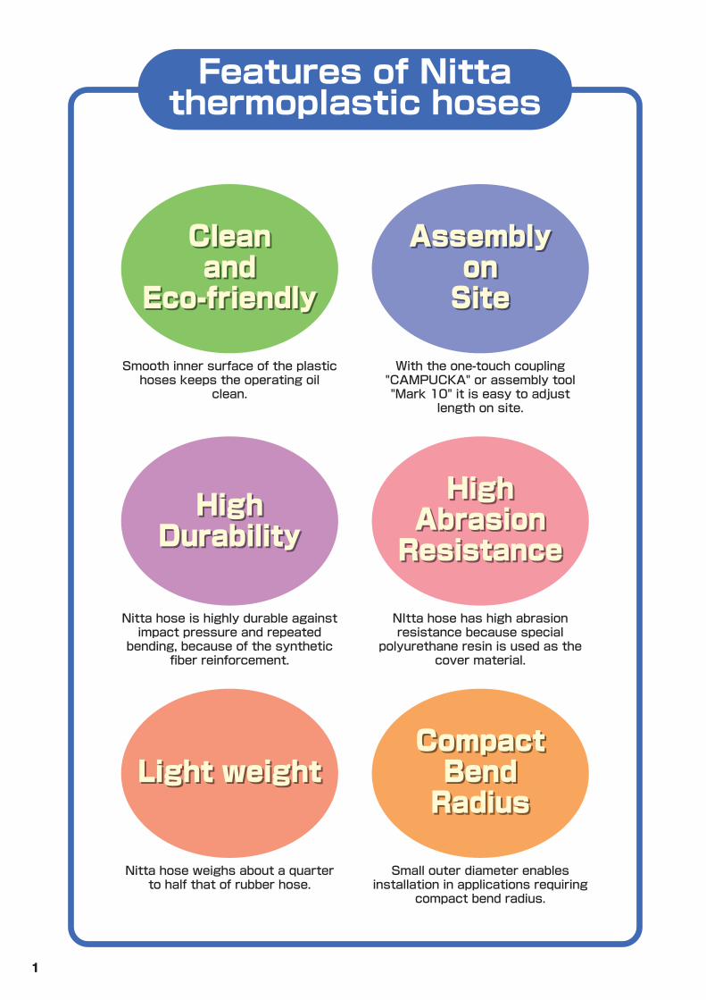
Smooth inner surface of the plastic hoses keeps the operating oil
clean.
Assemblyon
Site
With the one-touch coupling "CAMPUCKA" or assembly tool "Mark 10" it is easy to adjust
length on site.
HighDurability
Nitta hose is highly durable against impact pressure and repeated
bending, because of the synthetic fiber reinforcement.
HighAbrasion
Resistance
NItta hose has high abrasion resistance because special
polyurethane resin is used as the cover material.
Light weight
Nitta hose weighs about a quarter to half that of rubber hose.
CompactBend
Radius
Small outer diameter enables installation in applications requiring
compact bend radius.
Features of Nittathermoplastic hoses
Cleanand
Eco-friendly
Assemblyon
Site
HighDurability
HighAbrasion
Resistance
Light weightCompact
BendRadius
2
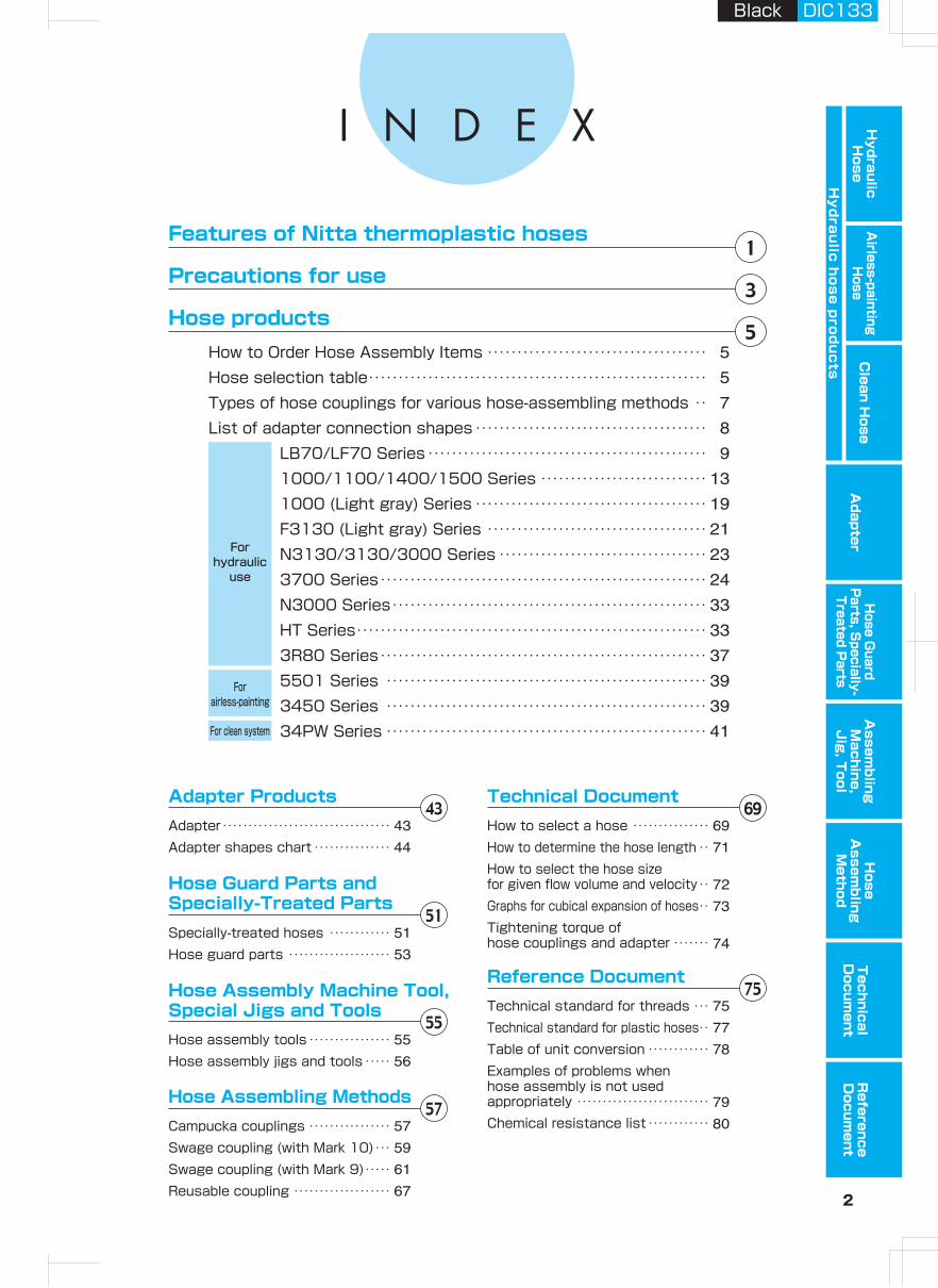
Features of Nitta thermoplastic hoses
Precautions for use
Hose products
Adapter ProductsAdapterAdapter shapes chart
Hose Guard Parts and Specially-Treated PartsSpecially-treated hosesHose guard parts
Hose Assembly Machine Tool, Special Jigs and ToolsHose assembly toolsHose assembly jigs and tools
Hose Assembling MethodsCampucka couplingsSwage coupling (with Mark 10)Swage coupling (with Mark 9)Reusable coupling
Technical DocumentHow to select a hoseHow to determine the hose lengthHow to select the hose size for given flow volume and velocityGraphs for cubical expansion of hosesTightening torque of hose couplings and adapter
Reference DocumentTechnical standard for threadsTechnical standard for plastic hosesTable of unit conversion Examples of problems when hose assembly is not used appropriatelyChemical resistance list
・・・・・・・・・・・・・・・・・・・・・・・・・・・・・・・・・・・・・・・・・・・・・・・・
・・・・・・・・・・・・・・・・・・・・・・・・・・・・・・・・
・・・・・・・・・・・・・・・・・・・・・
・・・・・・・・・・・・・・・・・・・・・・・・
・・・・・・・・・・・・・・・・・・・
・・・・・・・・・・・・・・・・・
・・・・
・・・・・・・
・・・・・
・・・・・・・・・・・・
・・・・・・・・・・・・・・・・・・・・・・・・・・・・・・・・・・・・・・
For clean system
Forairless-painting
Forhydraulic
use
How to Order Hose Assembly ItemsHose selection tableTypes of hose couplings for various hose-assembling methodsList of adapter connection shapes
LB70/LF70 Series1000/1100/1400/1500 Series1000 (Light gray) SeriesF3130 (Light gray) SeriesN3130/3130/3000 Series3700 SeriesN3000 SeriesHT Series3R80 Series5501 Series3450 Series34PW Series
・・・・・・・・・・・・・・・・・・・・・・・・・・・・・・・・・・・・・・・・・・・・・・・・・・・・・・・・・・・・・・・・・・・・・・・・・・・・・・・・・・・・・・・・・・・・・・
・・・・・・・・・・・・・・・・・・・・・・・・・・・・・・・・・・・・・・・・・
・・・・・・・・・・・・・・・・・・・・・・・・・・・・・・・・・・・・・・・・・・・・・・・・・・・・・・・・・・・・・・・・・・・・・・・・・・・
・・・・・・・・・・・・・・・・・・・・・・・・・・・・・・・・・・・・・・・・・・・・・・・・・・・・・・・・・・・・・・・・・・・・・・・・・・・・・・・・・・・・・・・・・・・・・・・・・・・・・・・・・・・・・・・
・・・・・・・・・・・・・・・・・・・・・・・・・・・・・・・・・・・・・・・・・・・・・・・・・・・・・・・・・・・・・・・・・・・・・・・・・・・・・・・・・・・・・・・・・・・・・・・・・・・・・・・・・・・・
・・・・・・・・・・・・・・・・・・・・・・・・・・・・・・・・・・・・・・・・・・・・・・・・・・・・・・・・・・・・・・・・・・・・・・・・・・・・・・・・・・・・・・・・・・・・・・・・・・・・・・・・・・・・・・・・・・・・・・・・・・・・・・・・・・・・・・・・・・・・・・・・・・・・・・・・・・・・・・・・・・・・・・・・・・・・・・・・・・・・・・・・・・・・・・・・・・・・・・・・・・・・・・・・・・・・・・・・・・・・・・・・・・・・・・・・・・・・・・・・・・・・・・・・・・・・・・・・・・・・・・・・・・・・・・・・・・・・
Hydraulic H
oseA
irless-paintingH
oseA
dapterH
ose Guard
Parts, S
pecially- Treated P
arts
Clean H
ose
Hy
dra
ulic
ho
se
pro
du
cts
Assem
bling
Machine,
Jig
, Tool
Hose
Assem
bling
Method
Technical
Docum
entR
eference D
ocument
Black DIC133
3 4
WhenSelecting
DANGER ①Cannot use for machines and equipment that maintain and control human life.②Cannot use for machines and equipment that require an extremely high level of safety.
①Please check if the use condition satisfies the "use conditions" in the catalog.②Do not use our products when a caustic or flammable gas is used as a fluid or is in the
environment.③If a gas is used as a fluid, keep the maximum working pressure below 1.0 MPa.④Do not use our products in places where excessive vibration or impact may occur.⑤Consult the "Table of chemical resistance" if chemicals are used as a fluid or in the environment.⑥There is a limited group of hose couplings for each type of hose product. Please select correct
combinations according to the specifications.⑦Our hose products and hose couplings are not compatible with other companies' hose products and hose
connectors.⑧Each type of hose product allows the use of a limited type of fluid. Do not use a fluid that is not allowed.⑨If use conditions are different between hose products and hose couplings, please use the operating
parameters of the lowest rated product as the guideline for all products in use.⑩The hose product must be of an appropriate size to maintain the necessary flow volume. If the size is not
appropriate, the increase in pressure drop and oil temperature could cause problems. The relation of fluid velocity, fluid volume, and hose inner diameter is given in "Nomograph".
⑪When electric insulation is necessary, for example in electrical works, please select "Nonconductive" hoses. Contact Nitta for details.
⑫When electric insulation is particularly required for use, including electrical works, please select "nonconductive" hoses. Contact Nitta for details.
①When water or glycol-type operating oil is used, hoses work without problem but some plated types of hose couplings cannot be used. Contact Nitta for details.
②Hose products might change their length by ±3% under pressure, so do not stretch hoses tightly.③Gas, liquid or solid components may leak from tubes or couplings. These quantities vary depending on the
material and use conditions. If there is a possibility of causing a problem in use, check the material and use conditions before use.
BeforeSelection
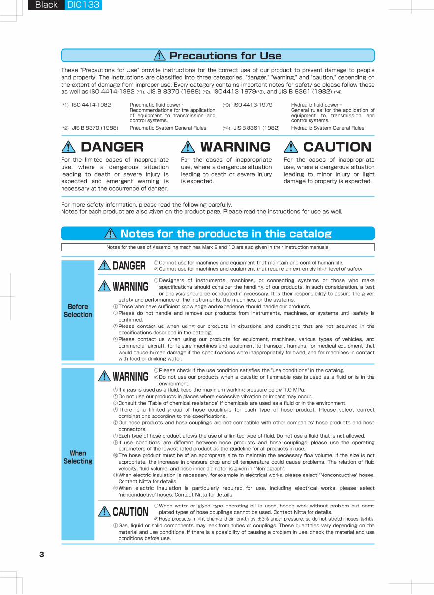
These "Precautions for Use" provide instructions for the correct use of our product to prevent damage to people and property. The instructions are classified into three categories, "danger," "warning," and "caution," depending on the extent of damage from improper use. Every category contains important notes for safety so please follow these as well as ISO 4414-1982 (*1), JIS B 8370 (1988) (*2), ISO4413-1979(*3), and JIS B 8361 (1982) (*4).
For more safety information, please read the following carefully. Notes for each product are also given on the product page. Please read the instructions for use as well.
DANGER WARNING CAUTIONFor the cases of inappropriate use, where a dangerous situation leading to minor injury or light damage to property is expected.
For the cases of inappropriate use, where a dangerous situation leading to death or severe injury is expected.
For the limited cases of inappropriate use, where a dangerous situation leading to death or severe injury is expected and emergent warning is necessary at the occurrence of danger.
Notes for the use of Assembling machines Mark 9 and 10 are also given in their instruction manuals.
(*1) ISO 4414-1982
(*2) JIS B 8370 (1988) Pneumatic System General Rules
(*3) ISO 4413-1979 Hydraulic fluid power…General rules for the application of equipment to transmission and control systems.
(*4) JIS B 8361 (1982) Hydraulic System General Rules
Pneumatic fluid power…Recommendations for the application of equipment to transmission and control systems.
WhenUsing
WhenStoring
①Instructions for connecting hoses are given in a separate document. Please read it and follow the instructions for installation.
②Do not use couplings with damaged threads and seat surface.③If you use reusable products such as reusable couplings, ensure that they are not damaged.④We will not guarantee any products which are additionally treated, disassembled or refabricated by others.⑤For installation of hoses, please assemble them in a place where unexpected disconnection of hose and
couplings cannot cause damage to people or property.
①Do not touch hose products during pressurlization. If you improperly approach or touch a hose during pressurlization could be quite dangerous if an unexpected breakage of the hose or the coupling were to scatter fluid inside.
②Do not touch hose products when the fluid is hot. It could cause a burn.③When water is used as a fluid, please keep it unfrozen.
①If you store unused products, keep them in a clean place to prevent dust. When fine particles such as dust enter the inside, they also enter the connecting equipment and may cause problems.
②Keep hose products in a dry place under 40℃ avoiding direct sunlight.③Store a hose in a straight position or in a coil with a larger diameter than the minimum
bend diameter.④Try to use hoses and couplings within about one year after production.
WhenMaintaining
①Please conduct periodic inspection. Confirm that there is no degradation such as outer damage, corrosion, and abrasion as well as any distorted parts and replace if necessary.
②Change the hose immediately if the outer damage or abrasion reaches, or is about to reach, the synthetic fiber braid.
WhenInstalling
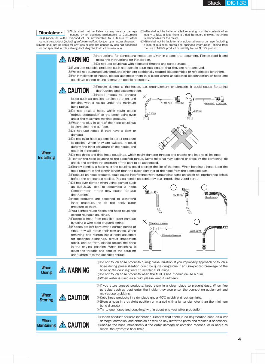
①Prevent damaging the hoses, e.g. entanglement or abrasion. It could cause flattening, destruction, and disconnection.
②Install hoses to prevent loads such as tension, torsion, rotation, and bending with a radius under the minimum bend radius.
③Do not break a hose, which might cause "fatigue destruction" at the break point even under the maximum working pressure.
④When the plug-in part of the hose couplings is dirty, clean the surface.
⑤Do not use hoses if they have a dent or damage.
⑥Do not twist hose assemblies after pressure is applied. When they are twisted, it could deform the inner structure of the hoses and result in destruction.
⑦Do not throw and drop hose couplings, which might damage threads and sheets and lead to oil leakage.⑧Tighten the hose coupling to the specified torque. Some material may expand or crack by the tightening, so
check and confirm the strength of the part to be assembled. ⑨Sharply bending a hose near the coupling could shorten the life of the hose. When bending a hose, keep the
hose straight of the length longer than the outer diameter of the hose from the asembled part.⑩Pressure on hose products could cause interference with surrounding parts on which no interference exists
before the pressure is applied. Please handle appropriately, e.g. introducing guard parts.⑪Do not over-tighten when using clamps such
as INSULOK ties to assemble a hose. Concentrated stress may cause "fatigue destruction".
⑫Hose products are designed to withstand inner pressure, so do not apply outer pressure to them.
⑬You cannot reuse hoses and hose couplings except reusable couplings.
⑭Protect a hose from possible outer damage by using a wire braid or guard spring.
⑮If hoses are left bent over a certain period of time, they will retain their new shape. When removing and reinstalling a hose assembly for machine exchange, circuit inspection, repair, and so forth, please attach the hose in the original position. When attaching it, clean the threads and seat of the coupling and tighten it to the specified torque.
①Nitta shall not be liable for any loss or damage caused by an accident attributable to Customer's
negligence or willful misconduct, or attributable to a failure of other company's product (including software malfunction), or by a natural disaster.
②Nitta shall not be liable for any loss or damage caused by use not described or not specified in this catalog (including the instruction manuals).
Disclaimer ③Nitta shall not be liable for a failure arising from the contents of an inquiry to Nitta unless there is a definite record showing that Nitta is responsible for the failure.
④Nitta shall not be liable for any incidental loss or damage (including a loss of business profits and business interruption) arising from the use of Nitta's product or inability to use Nitta's product.
Precautions for Use
Notes for the products in this catalog
①Designers of instruments, machines, or connecting systems or those who make specifications should consider the handling of our products. In such consideration, a test or analysis should be conducted if necessary. It is their responsibility to assure the given
safety and performance of the instruments, the machines, or the systems.②Those who have sufficient knowledge and experience should handle our products.③Please do not handle and remove our products from instruments, machines, or systems until safety is
confirmed.④Please contact us when using our products in situations and conditions that are not assumed in the
specifications described in the catalog.④Please contact us when using our products for equipment, machines, various types of vehicles, and
commercial aircraft, for leisure machines and equipment to transport humans, for medical equipment that would cause human damage if the specifications were inappropriately followed, and for machines in contact with food or drinking water.
WARNING
WARNING
CAUTION
WARNING
CAUTION
CAUTION
WARNING
CAUTION
Black DIC133Black DIC133
3 4
WhenSelecting
DANGER ①Cannot use for machines and equipment that maintain and control human life.②Cannot use for machines and equipment that require an extremely high level of safety.
①Please check if the use condition satisfies the "use conditions" in the catalog.②Do not use our products when a caustic or flammable gas is used as a fluid or is in the
environment.③If a gas is used as a fluid, keep the maximum working pressure below 1.0 MPa.④Do not use our products in places where excessive vibration or impact may occur.⑤Consult the "Table of chemical resistance" if chemicals are used as a fluid or in the environment.⑥There is a limited group of hose couplings for each type of hose product. Please select correct
combinations according to the specifications.⑦Our hose products and hose couplings are not compatible with other companies' hose products and hose
connectors.⑧Each type of hose product allows the use of a limited type of fluid. Do not use a fluid that is not allowed.⑨If use conditions are different between hose products and hose couplings, please use the operating
parameters of the lowest rated product as the guideline for all products in use.⑩The hose product must be of an appropriate size to maintain the necessary flow volume. If the size is not
appropriate, the increase in pressure drop and oil temperature could cause problems. The relation of fluid velocity, fluid volume, and hose inner diameter is given in "Nomograph".
⑪When electric insulation is necessary, for example in electrical works, please select "Nonconductive" hoses. Contact Nitta for details.
⑫When electric insulation is particularly required for use, including electrical works, please select "nonconductive" hoses. Contact Nitta for details.
①When water or glycol-type operating oil is used, hoses work without problem but some plated types of hose couplings cannot be used. Contact Nitta for details.
②Hose products might change their length by ±3% under pressure, so do not stretch hoses tightly.③Gas, liquid or solid components may leak from tubes or couplings. These quantities vary depending on the
material and use conditions. If there is a possibility of causing a problem in use, check the material and use conditions before use.
BeforeSelection
These "Precautions for Use" provide instructions for the correct use of our product to prevent damage to people and property. The instructions are classified into three categories, "danger," "warning," and "caution," depending on the extent of damage from improper use. Every category contains important notes for safety so please follow these as well as ISO 4414-1982 (*1), JIS B 8370 (1988) (*2), ISO4413-1979(*3), and JIS B 8361 (1982) (*4).
For more safety information, please read the following carefully. Notes for each product are also given on the product page. Please read the instructions for use as well.
DANGER WARNING CAUTIONFor the cases of inappropriate use, where a dangerous situation leading to minor injury or light damage to property is expected.
For the cases of inappropriate use, where a dangerous situation leading to death or severe injury is expected.
For the limited cases of inappropriate use, where a dangerous situation leading to death or severe injury is expected and emergent warning is necessary at the occurrence of danger.
Notes for the use of Assembling machines Mark 9 and 10 are also given in their instruction manuals.
(*1) ISO 4414-1982
(*2) JIS B 8370 (1988) Pneumatic System General Rules
(*3) ISO 4413-1979 Hydraulic fluid power…General rules for the application of equipment to transmission and control systems.
(*4) JIS B 8361 (1982) Hydraulic System General Rules
Pneumatic fluid power…Recommendations for the application of equipment to transmission and control systems.
WhenUsing
WhenStoring
①Instructions for connecting hoses are given in a separate document. Please read it and follow the instructions for installation.
②Do not use couplings with damaged threads and seat surface.③If you use reusable products such as reusable couplings, ensure that they are not damaged.④We will not guarantee any products which are additionally treated, disassembled or refabricated by others.⑤For installation of hoses, please assemble them in a place where unexpected disconnection of hose and
couplings cannot cause damage to people or property.
①Do not touch hose products during pressurlization. If you improperly approach or touch a hose during pressurlization could be quite dangerous if an unexpected breakage of the hose or the coupling were to scatter fluid inside.
②Do not touch hose products when the fluid is hot. It could cause a burn.③When water is used as a fluid, please keep it unfrozen.
①If you store unused products, keep them in a clean place to prevent dust. When fine particles such as dust enter the inside, they also enter the connecting equipment and may cause problems.
②Keep hose products in a dry place under 40℃ avoiding direct sunlight.③Store a hose in a straight position or in a coil with a larger diameter than the minimum
bend diameter.④Try to use hoses and couplings within about one year after production.
WhenMaintaining
①Please conduct periodic inspection. Confirm that there is no degradation such as outer damage, corrosion, and abrasion as well as any distorted parts and replace if necessary.
②Change the hose immediately if the outer damage or abrasion reaches, or is about to reach, the synthetic fiber braid.
WhenInstalling
①Prevent damaging the hoses, e.g. entanglement or abrasion. It could cause flattening, destruction, and disconnection.
②Install hoses to prevent loads such as tension, torsion, rotation, and bending with a radius under the minimum bend radius.
③Do not break a hose, which might cause "fatigue destruction" at the break point even under the maximum working pressure.
④When the plug-in part of the hose couplings is dirty, clean the surface.
⑤Do not use hoses if they have a dent or damage.
⑥Do not twist hose assemblies after pressure is applied. When they are twisted, it could deform the inner structure of the hoses and result in destruction.
⑦Do not throw and drop hose couplings, which might damage threads and sheets and lead to oil leakage.⑧Tighten the hose coupling to the specified torque. Some material may expand or crack by the tightening, so
check and confirm the strength of the part to be assembled. ⑨Sharply bending a hose near the coupling could shorten the life of the hose. When bending a hose, keep the
hose straight of the length longer than the outer diameter of the hose from the asembled part.⑩Pressure on hose products could cause interference with surrounding parts on which no interference exists
before the pressure is applied. Please handle appropriately, e.g. introducing guard parts.⑪Do not over-tighten when using clamps such
as INSULOK ties to assemble a hose. Concentrated stress may cause "fatigue destruction".
⑫Hose products are designed to withstand inner pressure, so do not apply outer pressure to them.
⑬You cannot reuse hoses and hose couplings except reusable couplings.
⑭Protect a hose from possible outer damage by using a wire braid or guard spring.
⑮If hoses are left bent over a certain period of time, they will retain their new shape. When removing and reinstalling a hose assembly for machine exchange, circuit inspection, repair, and so forth, please attach the hose in the original position. When attaching it, clean the threads and seat of the coupling and tighten it to the specified torque.
①Nitta shall not be liable for any loss or damage caused by an accident attributable to Customer's
negligence or willful misconduct, or attributable to a failure of other company's product (including software malfunction), or by a natural disaster.
②Nitta shall not be liable for any loss or damage caused by use not described or not specified in this catalog (including the instruction manuals).
Disclaimer ③Nitta shall not be liable for a failure arising from the contents of an inquiry to Nitta unless there is a definite record showing that Nitta is responsible for the failure.
④Nitta shall not be liable for any incidental loss or damage (including a loss of business profits and business interruption) arising from the use of Nitta's product or inability to use Nitta's product.
Precautions for Use
Notes for the products in this catalog
①Designers of instruments, machines, or connecting systems or those who make specifications should consider the handling of our products. In such consideration, a test or analysis should be conducted if necessary. It is their responsibility to assure the given
safety and performance of the instruments, the machines, or the systems.②Those who have sufficient knowledge and experience should handle our products.③Please do not handle and remove our products from instruments, machines, or systems until safety is
confirmed.④Please contact us when using our products in situations and conditions that are not assumed in the
specifications described in the catalog.④Please contact us when using our products for equipment, machines, various types of vehicles, and
commercial aircraft, for leisure machines and equipment to transport humans, for medical equipment that would cause human damage if the specifications were inappropriately followed, and for machines in contact with food or drinking water.
WARNING
WARNING
CAUTION
WARNING
CAUTION
CAUTION
WARNING
CAUTION
Black DIC133Black DIC133
5 6
Hydraulic H
oseA
irless-paintingH
oseA
dapterH
ose Guard
Parts, S
pecially- Treated P
arts
Clean H
ose
Hy
dra
ulic
ho
se
pro
du
cts
Assem
bling
Machine,
Jig
, Tool
Hose
Assem
bling
Method
Technical
Docum
entR
eference D
ocument
1
2
3/1603
1/404
5/1605
3/806
1/208
5/810
3/412
Application
116
Hose series
Page
Size I.D.(in.)
3.61/802
4.8
6.3
7.9
9.5
12.7
15.9
19.0
25.4
I.D.(mm)
Max
. wor
king
pres
sure
(M
Pa)
Features
Temp. range (℃)
3130 3000 3700 N3000 HT 3R80 5501 3450 34PWLF70 1000 1100 1400 1500 1000 F3130 N3130
H y d r a u l i c P i p i n g H y d r a u l i c P i p i n g ForAirless-painting
ForClean Use
20.0 - - - - - - - 20.0
20.0 34.0 21.0 - - 35.0 - 23.0 -
20.0 30.0 19.5 28.0 28.0 35.0 21.0 23.0 19.5
18.0 - - - - - - - -
18.0 24.0 16.0 21.0 21.0 28.0 21.0 21.0 16.0
16.0 20.0 14.0 21.0 21.0 25.0 - - 14.0
- - - 17.5 17.5 - - - -
10.0 13.0 - - - 16.0 - - 10.5
- 10.0 - - - 14.0 - - 10.5
- - - - - - 20.0 -
- - - - 15.0 - - 21.0
7.0 10.5 10.5 14.0 - 10.5 19.5 19.5
- - - - - - - 17.5
7.0 10.5 10.5 14.0 - 10.5 16.0 16.0
10.5 10.5 - - 10.5 14.0 14.0
- - - - - - - -
- - - - - - 9.0 9.0
- - - - - - 7.0 7.0
Super flexible, small bend radius
Outer wire braid Thin, light Thin, light
Thin, light, Campucka usable
Flexible, Campucka usable Flexible
●Construction machine
●Farming machine
●Machine tools, etc.
●Machine tools, etc.
●Industrial vehicles
●Farming machine, etc.
●Industrial vehicles
●Farming machine, etc.
●Oil pressure of machine tools
●Coolant piping
●Machine tools●Industrial
vehicles●General
operating machine
●Robot●Utility piping in
factory, etc.
●Construction machine
●Industrial vehicle
●Injection molding machine
●Hose reel, etc.
●Construction machine
●Industrial vehicle
●Injection molding machine
●Hose reel, etc.
●Construction machine
●Hydraulic press, etc.
●Airless painting machine, etc.
●Airless painting machine, etc.
●Facility in clean room
●Urethane coating
●Cesalination equipment, etc.
Reusable coupling usable
Reusable coupling usable Eco-friendly Flexible
Flexible, forhigh temp oil
High pressure
Painting(SUS braid)
Painting, light (conductive resin)
Pure water, chemicals
40 to +100 40 to +100 55 to +100 40 to +100 40 to +120 40 to +100 10 to +60 40 to +80 30 to +7040 to +10040 to +100
( for Campucka )20 to +10040 to +100
40 to +100
( for Campucka )20 to +10040 to +100 40 to +100
*2 *3*1 *3
(Light gray)(Light gray)
*1
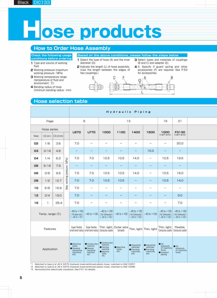
Hose selection table
How to Order Hose AssemblyCheck the following usage conditions before ordering
Based on the above conditions, please follow the steps below Length tolerance of hose assembly
Type and volume of working fluidWorking pressure (maximum working pressure : MPa)Working temperature range (temperature of fluid and environment : ℃)Bending radius of hose (minimum bending radius : mm)
1 2 3 4
Select the type of hose (A) and the inner diameter (D).Indicate the length (L) of hose assembly. (Use the length between the edges of two couplings.)
Select types and materials of couplings (B and C) and adapter (E).4. Specify if guard spring and other accessories (F) are required. See P.53 for accessories.
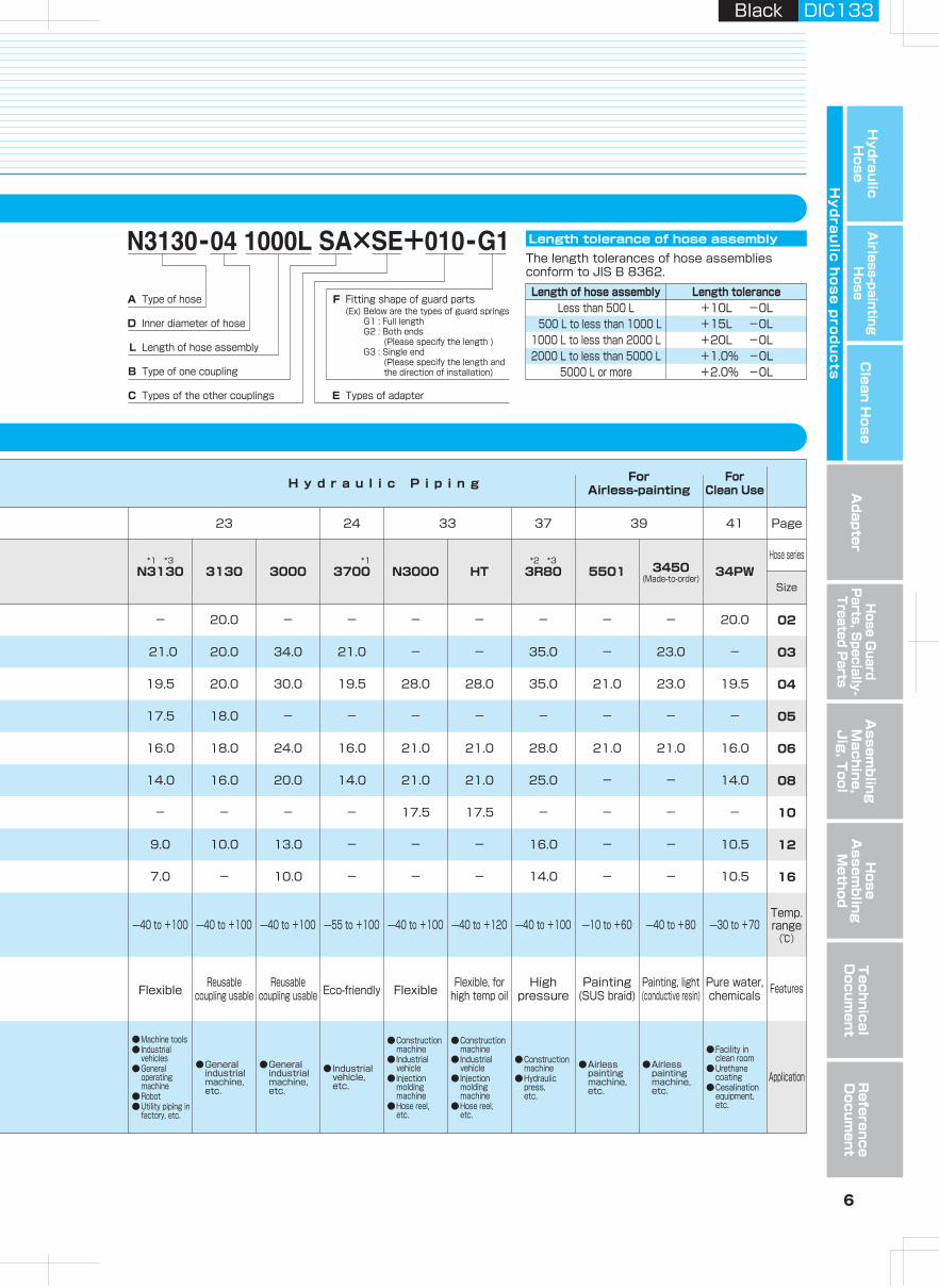
The length tolerances of hose assemblies conform to JIS B 8362.
3
4 Length of hose assembly Length toleranceLess than 500 L +10L -0L
500 L to less than 1000 L +15L -0L1000 L to less than 2000 L +20L -0L2000 L to less than 5000 L +1.0% -0L
5000 L or more +2.0% -0L
ose productsHFitting shape of guard parts(Ex) Below are the types of guard springs G1 : Full length G2 : Both ends (Please specify the length ) G3 : Single end (Please specify the length and the direction of installation)
Types of adapterTypes of the other couplings
Type of one coupling
Length of hose assembly
Inner diameter of hose
Type of hoseA
D
L
B
C E
F
Temp.range(℃)
Features
Application
03
04
05
06
08
10
12
16
02
9 13 19 21 23 24 33 37 39 41
●Industrial vehicle, etc.
●General industrial machine, etc.
●General industrial machine, etc.
(Made-to-order)
7.0
Page
Hose series
SizeLB70
7.0
-
7.0
-
7.0
7.0
7.0
7.0
Super flexible, small bend radius
●Machine tools
●General operating machine, etc.
40 to +100
( 16 sizes only )40 to +70
7.0
●Construction machine
●General operating machine, etc.
Thin, light, Campucka usable
●Oil pressure of machine tools
40 to +100
( for Campucka )20 to +100
40 to +100
( for Campucka )20 to +100
*1 Matched to type A of JIS K 6375 (hydraulic braid-reinforced plastic hose), matched to SAE100R7.*2 Matched to type B of JIS K 6375 (hydraulic braid-reinforced plastic hose), matched to SAE100R8.*3 Nonconductive (electrically insulative). See P.51 for details.
nD
L
BE C F A
Black DIC133Black DIC133
5 6
Hydraulic H
oseA
irless-paintingH
oseA
dapterH
ose Guard
Parts, S
pecially- Treated P
arts
Clean H
ose
Hy
dra
ulic
ho
se
pro
du
cts
Assem
bling
Machine,
Jig
, Tool
Hose
Assem
bling
Method
Technical
Docum
entR
eference D
ocument
1
2
3/1603
1/404
5/1605
3/806
1/208
5/810
3/412
Application
116
Hose series
Page
Size I.D.(in.)
3.61/802
4.8
6.3
7.9
9.5
12.7
15.9
19.0
25.4
I.D.(mm)
Max
. wor
king
pres
sure
(M
Pa)
Features
Temp. range (℃)
3130 3000 3700 N3000 HT 3R80 5501 3450 34PWLF70 1000 1100 1400 1500 1000 F3130 N3130
H y d r a u l i c P i p i n g H y d r a u l i c P i p i n g ForAirless-painting
ForClean Use
20.0 - - - - - - - 20.0
20.0 34.0 21.0 - - 35.0 - 23.0 -
20.0 30.0 19.5 28.0 28.0 35.0 21.0 23.0 19.5
18.0 - - - - - - - -
18.0 24.0 16.0 21.0 21.0 28.0 21.0 21.0 16.0
16.0 20.0 14.0 21.0 21.0 25.0 - - 14.0
- - - 17.5 17.5 - - - -
10.0 13.0 - - - 16.0 - - 10.5
- 10.0 - - - 14.0 - - 10.5
- - - - - - 20.0 -
- - - - 15.0 - - 21.0
7.0 10.5 10.5 14.0 - 10.5 19.5 19.5
- - - - - - - 17.5
7.0 10.5 10.5 14.0 - 10.5 16.0 16.0
10.5 10.5 - - 10.5 14.0 14.0
- - - - - - - -
- - - - - - 9.0 9.0
- - - - - - 7.0 7.0
Super flexible, small bend radius
Outer wire braid Thin, light Thin, light
Thin, light, Campucka usable
Flexible, Campucka usable Flexible
●Construction machine
●Farming machine
●Machine tools, etc.
●Machine tools, etc.
●Industrial vehicles
●Farming machine, etc.
●Industrial vehicles
●Farming machine, etc.
●Oil pressure of machine tools
●Coolant piping
●Machine tools●Industrial
vehicles●General
operating machine
●Robot●Utility piping in
factory, etc.
●Construction machine
●Industrial vehicle
●Injection molding machine
●Hose reel, etc.
●Construction machine
●Industrial vehicle
●Injection molding machine
●Hose reel, etc.
●Construction machine
●Hydraulic press, etc.
●Airless painting machine, etc.
●Airless painting machine, etc.
●Facility in clean room
●Urethane coating
●Cesalination equipment, etc.
Reusable coupling usable
Reusable coupling usable Eco-friendly Flexible
Flexible, forhigh temp oil
High pressure
Painting(SUS braid)
Painting, light (conductive resin)
Pure water, chemicals
40 to +100 40 to +100 55 to +100 40 to +100 40 to +120 40 to +100 10 to +60 40 to +80 30 to +7040 to +10040 to +100
( for Campucka )20 to +10040 to +100
40 to +100
( for Campucka )20 to +10040 to +100 40 to +100
*2 *3*1 *3
(Light gray)(Light gray)
*1
Hose selection table
How to Order Hose AssemblyCheck the following usage conditions before ordering
Based on the above conditions, please follow the steps below Length tolerance of hose assembly
Type and volume of working fluidWorking pressure (maximum working pressure : MPa)Working temperature range (temperature of fluid and environment : ℃)Bending radius of hose (minimum bending radius : mm)
1 2 3 4
Select the type of hose (A) and the inner diameter (D).Indicate the length (L) of hose assembly. (Use the length between the edges of two couplings.)
Select types and materials of couplings (B and C) and adapter (E).4. Specify if guard spring and other accessories (F) are required. See P.53 for accessories.
The length tolerances of hose assemblies conform to JIS B 8362.
3
4 Length of hose assembly Length toleranceLess than 500 L +10L -0L
500 L to less than 1000 L +15L -0L1000 L to less than 2000 L +20L -0L2000 L to less than 5000 L +1.0% -0L
5000 L or more +2.0% -0L
ose productsHFitting shape of guard parts(Ex) Below are the types of guard springs G1 : Full length G2 : Both ends (Please specify the length ) G3 : Single end (Please specify the length and the direction of installation)
Types of adapterTypes of the other couplings
Type of one coupling
Length of hose assembly
Inner diameter of hose
Type of hoseA
D
L
B
C E
F
Temp.range(℃)
Features
Application
03
04
05
06
08
10
12
16
02
9 13 19 21 23 24 33 37 39 41
●Industrial vehicle, etc.
●General industrial machine, etc.
●General industrial machine, etc.
(Made-to-order)
7.0
Page
Hose series
SizeLB70
7.0
-
7.0
-
7.0
7.0
7.0
7.0
Super flexible, small bend radius
●Machine tools
●General operating machine, etc.
40 to +100
( 16 sizes only )40 to +70
7.0
●Construction machine
●General operating machine, etc.
Thin, light, Campucka usable
●Oil pressure of machine tools
40 to +100
( for Campucka )20 to +100
40 to +100
( for Campucka )20 to +100
*1 Matched to type A of JIS K 6375 (hydraulic braid-reinforced plastic hose), matched to SAE100R7.*2 Matched to type B of JIS K 6375 (hydraulic braid-reinforced plastic hose), matched to SAE100R8.*3 Nonconductive (electrically insulative). See P.51 for details.
nD
L
BE C F A
Black DIC133Black DIC133
7 8
Hydraulic H
oseA
irless-paintingH
oseA
dapterH
ose Guard
Parts, S
pecially- Treated P
arts
Clean H
ose
Hy
dra
ulic
ho
se
pro
du
cts
Assem
bling
Machine,
Jig
, Tool
Hose
Assem
bling
Method
Technical
Docum
entR
eference D
ocument
Black DIC133Black DIC133
ose productsH
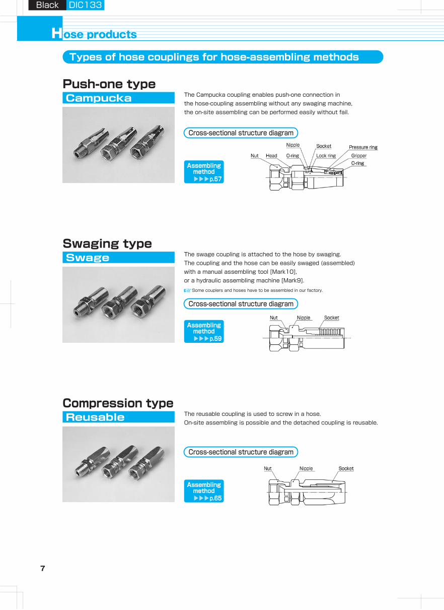
CampuckaPush-one type
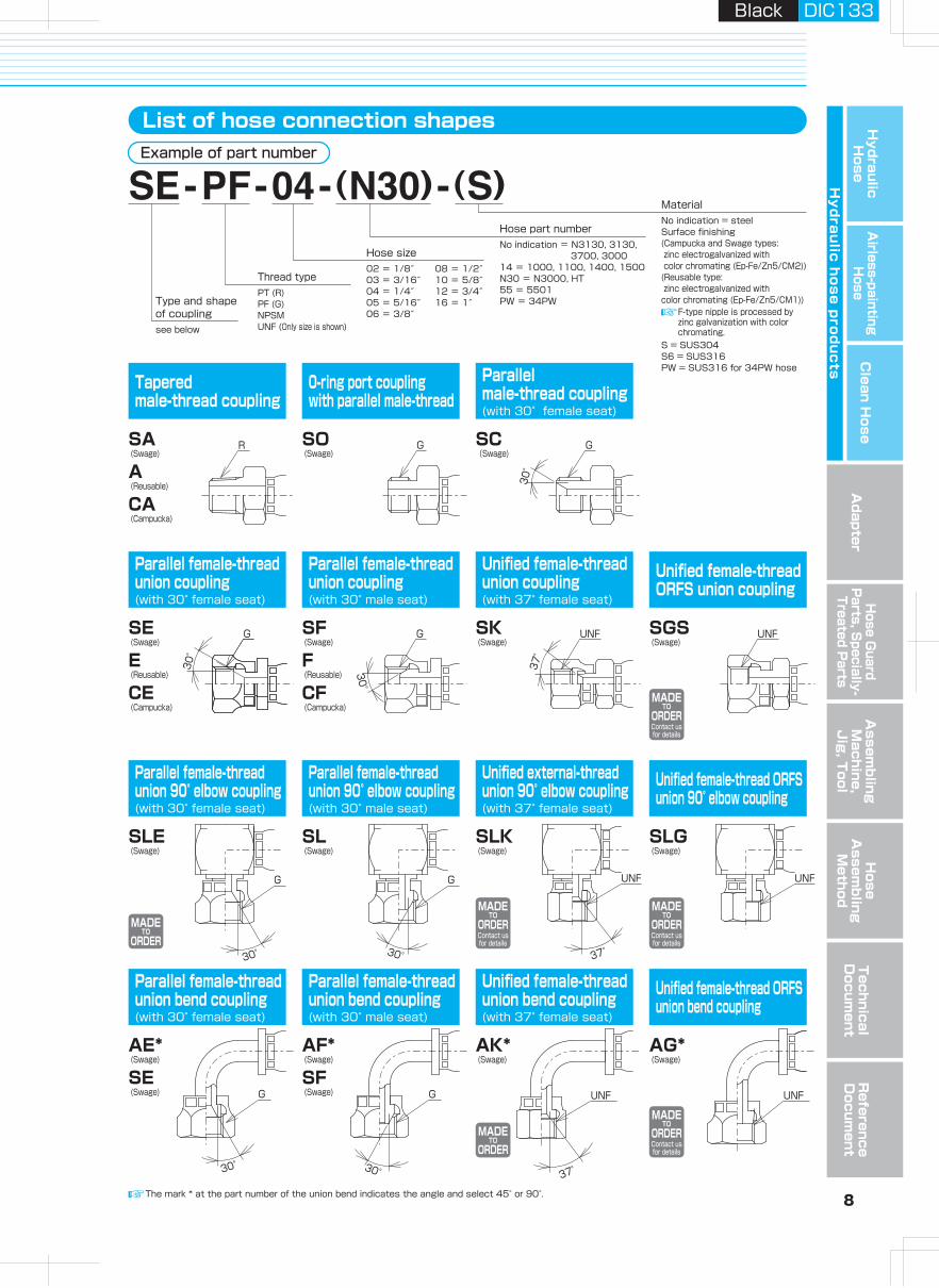
Types of hose couplings for hose-assembling methods List of hose connection shapes
The Campucka coupling enables push-one connection in the hose-coupling assembling without any swaging machine, the on-site assembling can be performed easily without fail.
SwageSwaging type
The swage coupling is attached to the hose by swaging.The coupling and the hose can be easily swaged (assembled) with a manual assembling tool [Mark10], or a hydraulic assembling machine [Mark9].
The reusable coupling is used to screw in a hose. On-site assembling is possible and the detached coupling is reusable.
Reusable
Parallel female-thread union bend coupling(with 30° female seat)
Parallel female-thread union 90° elbow coupling(with 30° female seat)
Parallel female-thread union coupling(with 30° female seat)
Tapered male-thread coupling
Parallel female-thread union bend coupling(with 30° male seat)
Parallel female-thread union 90° elbow coupling(with 30° male seat)
Parallel female-thread union coupling(with 30° male seat)
0-ring port coupling with parallel male-thread
Unified female-thread union bend coupling(with 37° female seat)
Unified external-thread union 90° elbow coupling(with 37° female seat)
Unified female-thread union coupling(with 37° female seat)
Parallel male-thread coupling(with 30°female seat)
Unified female-thread ORFS union bend coupling
Unified female-thread ORFS union 90° elbow coupling
Unified female-thread ORFS union coupling
AE* (Swage)
SE (Swage)
SLE (Swage)
SE (Swage)
E (Reusable)
CE (Campucka)
SA (Swage)
A (Reusable)
CA (Campucka)
AF* (Swage)
SF (Swage)
SL (Swage)
SF (Swage)
F (Reusable)
CF (Campucka)
SO (Swage)
AK* (Swage)
SLK (Swage)
SK (Swage)
SC(Swage)
AG* (Swage)
SLG (Swage)
SGS (Swage)
Compression type
Example of part number
MADETO
ORDERContact usfor details
MADETO
ORDERContact usfor details
MADETO
ORDERContact usfor details
MADETO
ORDERContact usfor details
MADETO
ORDER
MADETO
ORDER
No indication = steelSurface finishing (Campucka and Swage types: zinc electrogalvanized with color chromating (Ep-Fe/Zn5/CM2))(Reusable type: zinc electrogalvanized with color chromating (Ep-Fe/Zn5/CM1))
S = SUS304S6 = SUS316PW = SUS316 for 34PW hose
No indication = N3130, 3130, 3700, 300014 = 1000, 1100, 1400, 1500N30 = N3000, HT 55 = 5501PW = 34PW
02 = 1/8″03 = 3/16″04 = 1/4″05 = 5/16″06 = 3/8″
PT (R)PF (G)NPSMUNF (Only size is shown)see below
08 = 1/2″10 = 5/8″12 = 3/4″16 = 1″Type and shape
of coupling
Thread type
Hose size
Hose part number
Material
The mark * at the part number of the union bend indicates the angle and select 45° or 90°.
Cross-sectional structure diagram
Assemblingmethod
p.57
Cross-sectional structure diagram
Assemblingmethod
p.59
Cross-sectional structure diagram
Assemblingmethod
p.65
Some couplers and hoses have to be assembled in our factory.
F-type nipple is processed by zinc galvanization with color chromating.
R G
30°
G
30°
G
30°
G UNF
37°
UNF
30°
GG
30°
UNF
37°
UNF
30°
G
30°
G
37°
UNF UNF
7 8
Hydraulic H
oseA
irless-paintingH
oseA
dapterH
ose Guard
Parts, S
pecially- Treated P
arts
Clean H
ose
Hy
dra
ulic
ho
se
pro
du
cts
Assem
bling
Machine,
Jig
, Tool
Hose
Assem
bling
Method
Technical
Docum
entR
eference D
ocument
Black DIC133Black DIC133
ose productsH
CampuckaPush-one type
Types of hose couplings for hose-assembling methods List of hose connection shapes
The Campucka coupling enables push-one connection in the hose-coupling assembling without any swaging machine, the on-site assembling can be performed easily without fail.
SwageSwaging type
The swage coupling is attached to the hose by swaging.The coupling and the hose can be easily swaged (assembled) with a manual assembling tool [Mark10], or a hydraulic assembling machine [Mark9].
The reusable coupling is used to screw in a hose. On-site assembling is possible and the detached coupling is reusable.
Reusable
Parallel female-thread union bend coupling(with 30° female seat)
Parallel female-thread union 90° elbow coupling(with 30° female seat)
Parallel female-thread union coupling(with 30° female seat)
Tapered male-thread coupling
Parallel female-thread union bend coupling(with 30° male seat)
Parallel female-thread union 90° elbow coupling(with 30° male seat)
Parallel female-thread union coupling(with 30° male seat)
0-ring port coupling with parallel male-thread
Unified female-thread union bend coupling(with 37° female seat)
Unified external-thread union 90° elbow coupling(with 37° female seat)
Unified female-thread union coupling(with 37° female seat)
Parallel male-thread coupling(with 30°female seat)
Unified female-thread ORFS union bend coupling
Unified female-thread ORFS union 90° elbow coupling
Unified female-thread ORFS union coupling
AE* (Swage)
SE (Swage)
SLE (Swage)
SE (Swage)
E (Reusable)
CE (Campucka)
SA (Swage)
A (Reusable)
CA (Campucka)
AF* (Swage)
SF (Swage)
SL (Swage)
SF (Swage)
F (Reusable)
CF (Campucka)
SO (Swage)
AK* (Swage)
SLK (Swage)
SK (Swage)
SC(Swage)
AG* (Swage)
SLG (Swage)
SGS (Swage)
Compression type
Example of part number
MADETO
ORDERContact usfor details
MADETO
ORDERContact usfor details
MADETO
ORDERContact usfor details
MADETO
ORDERContact usfor details
MADETO
ORDER
MADETO
ORDER
No indication = steelSurface finishing (Campucka and Swage types: zinc electrogalvanized with color chromating (Ep-Fe/Zn5/CM2))(Reusable type: zinc electrogalvanized with color chromating (Ep-Fe/Zn5/CM1))
S = SUS304S6 = SUS316PW = SUS316 for 34PW hose
No indication = N3130, 3130, 3700, 300014 = 1000, 1100, 1400, 1500N30 = N3000, HT 55 = 5501PW = 34PW
02 = 1/8″03 = 3/16″04 = 1/4″05 = 5/16″06 = 3/8″
PT (R)PF (G)NPSMUNF (Only size is shown)see below
08 = 1/2″10 = 5/8″12 = 3/4″16 = 1″Type and shape
of coupling
Thread type
Hose size
Hose part number
Material
The mark * at the part number of the union bend indicates the angle and select 45° or 90°.
Cross-sectional structure diagram
Assemblingmethod
p.57
Cross-sectional structure diagram
Assemblingmethod
p.59
Cross-sectional structure diagram
Assemblingmethod
p.65
Some couplers and hoses have to be assembled in our factory.
F-type nipple is processed by zinc galvanization with color chromating.
R G
30°
G
30°
G
30°
G UNF
37°
UNF
30°
GG
30°
UNF
37°
UNF
30°
G
30°
G
37°
UNF UNF
9 10
Hydraulic H
oseA
irless-paintingH
oseA
dapterH
ose Guard
Parts, S
pecially- Treated P
arts
Clean H
ose
Hy
dra
ulic
ho
se
pro
du
cts
Assem
bling
Machine,
Jig
, Tool
Hose
Assem
bling
Method
Technical
Docum
entR
eference D
ocument
Black DIC133Black DIC133
Part No. Size No. R A B
Min.I.D.φD
L Y(HEX)
Weight(g) Pusher Die
Part No. Size No. G B C
Min.I.D.φD
H L X(HEX)
Y(HEX)
Weight(g) Pusher Die
Part No. Size No. G B C
Min.I.D.φD
H L X(HEX)
Y(HEX)
Weight(g) Pusher Die
Size
Part No. Size No.
I.D. O.D.(mm)(mm)(in.) (MPa)
Max. working pressure
(PSi) (MPa)
Min. burst pressure
Min. bending radius(mm)
Coupling
(PSi)
Weight(g/m)
Size
Part No. Size No.
I.D. O.D.(mm)(mm)(in.) (MPa)
Max. working pressure
(PSi) (MPa)
Min. burst pressure
Min. bending radius(mm)
Coupling
(PSi)
Weight(g/m)
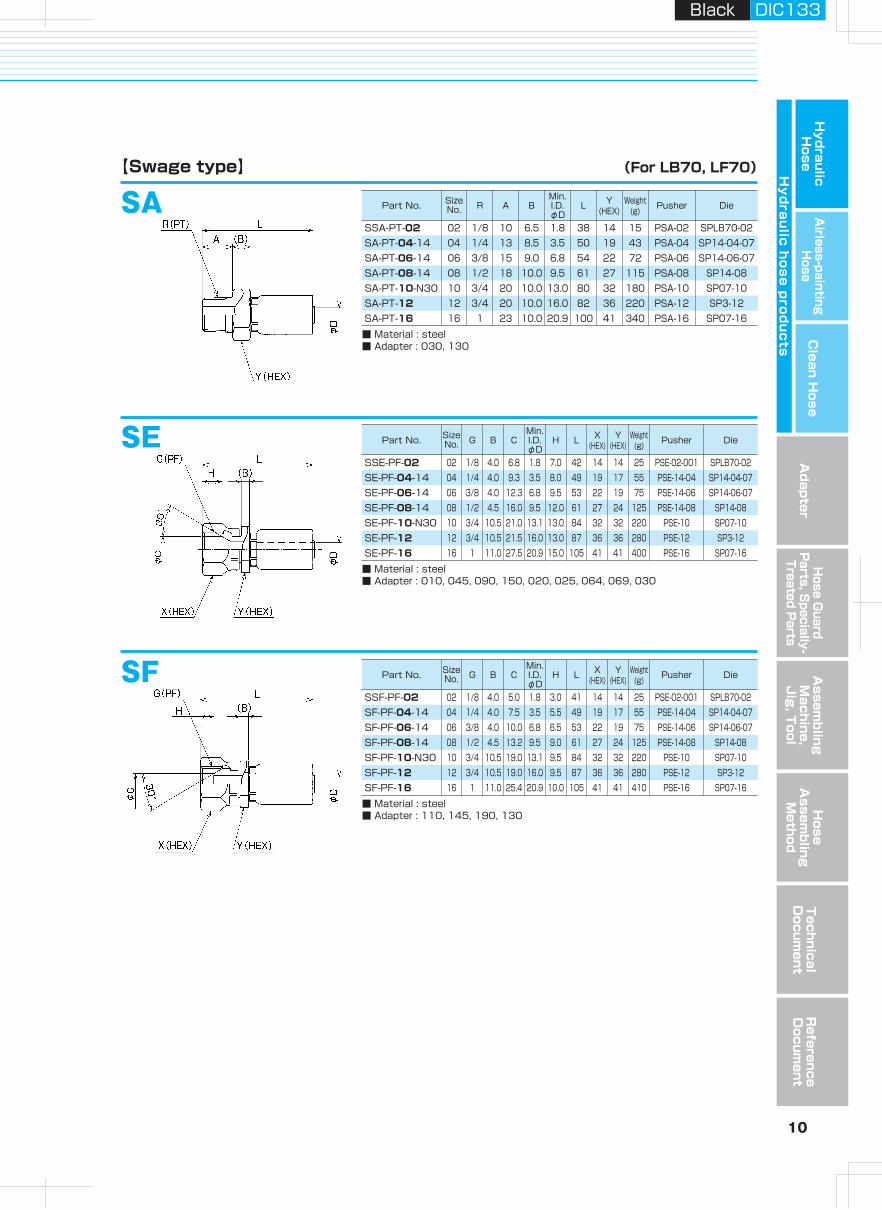
LB70 -LF70SeriesSA
SA-PT-04-14SA-PT-06-14
■ Material : steel■ Adapter : 030, 130
SE
【Swage type】
04 1/4 13 8.5 3.5 50 19 43 PSA-04 SP14-04-0706 3/8 15 9.0 6.8 54 22 72 PSA-06 SP14-06-07
SE-PF-04-14
■ Material : steel■ Adapter : 010, 045, 090, 150, 020, 025, 064, 069, 030
04 1/4 4.0 9.3 3.5 8.0 49 19 17 55 PSE-14-04 SP14-04-07SE-PF-06-14 06 3/8 4.0 12.3 6.8 9.5 53 22 19 75 PSE-14-06 SP14-06-07
SF-PF-04-14
■ Material : steel■ Adapter : 110, 145, 190, 130
04 1/4 4.0 7.5 3.5 5.5 49 19 17 55 PSE-14-04 SP14-04-07SF-PF-06-14 06 3/8 4.0 10.0 6.8 6.5 53 22 19 75 PSE-14-06 SP14-06-07
SF
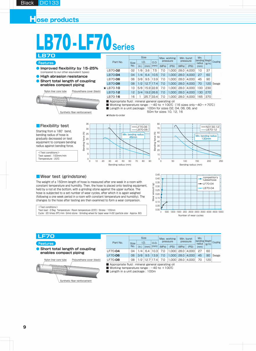
04 1/4 6.4 10.3 7.0 1,000 28.0 27 6006 3/8 9.5 13.9 7.0 1,000 28.0 45 90
LF70-04LF70-06
■ Appropriate fluid : mineral general operating oil■ Working temperature range : -40 to +100℃■ Length in a unit package : 100m
LF70
Swage
ose productsH
08 1/2 12.7 17.4 7.0 1,000 28.0
4,0004,0004,000 70 120LF70-08
SA-PT-08-14 08 1/2 18 10.0 9.5 61 27 115 PSA-08 SP14-08
SE-PF-08-14 08 1/2 4.5 16.0 9.5 12.0 61 27 24 125 PSE-14-08 SP14-08
SF-PF-08-14 08 1/2 4.5 13.2 9.5 9.0 61 27 24 125 PSE-14-08 SP14-08
(For LB70, LF70)
SSA-PT-02 02 1/8 10 6.5 1.8 38 14 15 PSA-02 SPLB70-02
SA-PT-10-N30 10 3/4 20 10.0 13.0 80 32 180 PSA-10 SP07-10SA-PT-12 12 3/4 20 10.0 16.0 82 36 220 PSA-12 SP3-12SA-PT-16 16 1 23 10.0 20.9 100 41 340 PSA-16 SP07-16
SE-PF-10-N30 10 3/4 10.5 21.0 13.1 13.0 84 32 32 220 PSE-10 SP07-10
SF-PF-10-N30 10 3/4 10.5 19.0 13.1 9.5 84 32 32 220 PSE-10 SP07-10
SE-PF-12 12 3/4 10.5 21.5 16.0 13.0 87 36 36 280 PSE-12 SP3-12
SF-PF-12 12 3/4 10.5 19.0 16.0 9.5 87 36 36 280 PSE-12 SP3-12
SE-PF-16 16 1 11.0 27.5 20.9 15.0 105 41 41 400 PSE-16 SP07-16
SF-PF-16 16 1 11.0 25.4 20.9 10.0 105 41 41 410 PSE-16 SP07-16
SSE-PF-02 02 1/8 4.0 6.8 1.8 7.0 42 14 14 25 PSE-02-001 SPLB70-02
SSF-PF-02 02 1/8 4.0 5.0 1.8 3.0 41 14 14 25 PSE-02-001 SPLB70-02
06 3/8 9.5 13.9 7.0 1,000 28.0LB70-0608 1/2 12.7 17.4 7.0 1,000 28.0LB70-0810 5/8 15.9 22.8 7.0 1,000 28.0LB70-1012 3/4 19.2 26.6 7.0 1,000 28.0LB70-1216 1 25.7 33.4 7.0 1,000 28.0LB70-16
02 1/8 3.6 7.5 7.0 1,000 28.004 1/4 6.4 10.5 7.0 1,000 28.0
LB70-02LB70-04
■ Appropriate fluid : mineral general operating oil■ Working temperature range : -40 to +100℃(16 sizes only-40~+70℃)■ Length in a unit package : 100m for sizes 02, 04, 06, 08, and
50m for sizes 10, 12, 16
Swage
LB70
★Made-to-order
★
Starting from a 180°bend, bending radius of hose is gradually decreased on test equipment to compare bending radius against bending force.
■Flexibility test
Bending radius (mm)
Ben
ding
for
ce (
N)
0 10 20 30 40 50 60 70 80 90
35
10
15
20
25
30
5
0
LF70-06LB70-06
Min. bending radius45mm
0 50 100 150 200 250
80
70
60
50
40
30
20
10
0
N3130-12LB70-12
Min. bending radius130mm
Number of wear cycles0 5000 10000 15000 2000 25000 30000 35000 40000 45000 50000
0.05
0.10
0.15
0.20
0.25
0.30
0.35
0.40
0.45
0.00
competitor'srubberhoseLF70-04
LB70-04
<Test conditions>Test load:2.5kg Temperature:Room temperature (23℃) Stroke:100mmCycle:20 times (RT)/min Grind stone:Grinding wheel for taper wear H-22 (particle size:Approx. 60)
The weight of a 150mm length of hose is measured after one week in a room with constant temperature and humidity. Then, the hose is placed onto testing equipment, held by a rod at the bottom, with a grinding stone against the upper surface. The hose is subjected to a set number of wear cycles, after which it is again weighed (following a one week period in a room with constant temperature and humidity). The changes to the hose after testing are then examined to form a wear comparison.
■Wear test (grindstone)
Polyurethane cover (black)Nylon liner core tube
Synthetic fiber reinforcement
Features● Improved flexibility by 15‒25% (compared to our other equivalent types)
● High abrasion resistance● Short total length of coupling
enables compact piping
Features
Polyurethane cover (black)Nylon liner core tube
Synthetic fiber reinforcement
● Short total length of coupling enables compact piping
Bending radius (mm)
Ben
ding
for
ce (
N)
Wea
r am
ount
(g)
<Test conditions>Test speed:100mm/minTemperature:23℃
4570
100130165
1027
4,0004,0004,0004,0004,000
4,0004,000
90120230270370
3760
9 10
Hydraulic H
oseA
irless-paintingH
oseA
dapterH
ose Guard
Parts, S
pecially- Treated P
arts
Clean H
ose
Hy
dra
ulic
ho
se
pro
du
cts
Assem
bling
Machine,
Jig
, Tool
Hose
Assem
bling
Method
Technical
Docum
entR
eference D
ocument
Black DIC133Black DIC133
Part No. Size No. R A B
Min.I.D.φD
L Y(HEX)
Weight(g) Pusher Die
Part No. Size No. G B C
Min.I.D.φD
H L X(HEX)
Y(HEX)
Weight(g) Pusher Die
Part No. Size No. G B C
Min.I.D.φD
H L X(HEX)
Y(HEX)
Weight(g) Pusher Die
Size
Part No. Size No.
I.D. O.D.(mm)(mm)(in.) (MPa)
Max. working pressure
(PSi) (MPa)
Min. burst pressure
Min. bending radius(mm)
Coupling
(PSi)
Weight(g/m)
Size
Part No. Size No.
I.D. O.D.(mm)(mm)(in.) (MPa)
Max. working pressure
(PSi) (MPa)
Min. burst pressure
Min. bending radius(mm)
Coupling
(PSi)
Weight(g/m)
LB70 -LF70SeriesSA
SA-PT-04-14SA-PT-06-14
■ Material : steel■ Adapter : 030, 130
SE
【Swage type】
04 1/4 13 8.5 3.5 50 19 43 PSA-04 SP14-04-0706 3/8 15 9.0 6.8 54 22 72 PSA-06 SP14-06-07
SE-PF-04-14
■ Material : steel■ Adapter : 010, 045, 090, 150, 020, 025, 064, 069, 030
04 1/4 4.0 9.3 3.5 8.0 49 19 17 55 PSE-14-04 SP14-04-07SE-PF-06-14 06 3/8 4.0 12.3 6.8 9.5 53 22 19 75 PSE-14-06 SP14-06-07
SF-PF-04-14
■ Material : steel■ Adapter : 110, 145, 190, 130
04 1/4 4.0 7.5 3.5 5.5 49 19 17 55 PSE-14-04 SP14-04-07SF-PF-06-14 06 3/8 4.0 10.0 6.8 6.5 53 22 19 75 PSE-14-06 SP14-06-07
SF
04 1/4 6.4 10.3 7.0 1,000 28.0 27 6006 3/8 9.5 13.9 7.0 1,000 28.0 45 90
LF70-04LF70-06
■ Appropriate fluid : mineral general operating oil■ Working temperature range : -40 to +100℃■ Length in a unit package : 100m
LF70
Swage
ose productsH
08 1/2 12.7 17.4 7.0 1,000 28.0
4,0004,0004,000 70 120LF70-08
SA-PT-08-14 08 1/2 18 10.0 9.5 61 27 115 PSA-08 SP14-08
SE-PF-08-14 08 1/2 4.5 16.0 9.5 12.0 61 27 24 125 PSE-14-08 SP14-08
SF-PF-08-14 08 1/2 4.5 13.2 9.5 9.0 61 27 24 125 PSE-14-08 SP14-08
(For LB70, LF70)
SSA-PT-02 02 1/8 10 6.5 1.8 38 14 15 PSA-02 SPLB70-02
SA-PT-10-N30 10 3/4 20 10.0 13.0 80 32 180 PSA-10 SP07-10SA-PT-12 12 3/4 20 10.0 16.0 82 36 220 PSA-12 SP3-12SA-PT-16 16 1 23 10.0 20.9 100 41 340 PSA-16 SP07-16
SE-PF-10-N30 10 3/4 10.5 21.0 13.1 13.0 84 32 32 220 PSE-10 SP07-10
SF-PF-10-N30 10 3/4 10.5 19.0 13.1 9.5 84 32 32 220 PSE-10 SP07-10
SE-PF-12 12 3/4 10.5 21.5 16.0 13.0 87 36 36 280 PSE-12 SP3-12
SF-PF-12 12 3/4 10.5 19.0 16.0 9.5 87 36 36 280 PSE-12 SP3-12
SE-PF-16 16 1 11.0 27.5 20.9 15.0 105 41 41 400 PSE-16 SP07-16
SF-PF-16 16 1 11.0 25.4 20.9 10.0 105 41 41 410 PSE-16 SP07-16
SSE-PF-02 02 1/8 4.0 6.8 1.8 7.0 42 14 14 25 PSE-02-001 SPLB70-02
SSF-PF-02 02 1/8 4.0 5.0 1.8 3.0 41 14 14 25 PSE-02-001 SPLB70-02
06 3/8 9.5 13.9 7.0 1,000 28.0LB70-0608 1/2 12.7 17.4 7.0 1,000 28.0LB70-0810 5/8 15.9 22.8 7.0 1,000 28.0LB70-1012 3/4 19.2 26.6 7.0 1,000 28.0LB70-1216 1 25.7 33.4 7.0 1,000 28.0LB70-16
02 1/8 3.6 7.5 7.0 1,000 28.004 1/4 6.4 10.5 7.0 1,000 28.0
LB70-02LB70-04
■ Appropriate fluid : mineral general operating oil■ Working temperature range : -40 to +100℃(16 sizes only-40~+70℃)■ Length in a unit package : 100m for sizes 02, 04, 06, 08, and
50m for sizes 10, 12, 16
Swage
LB70
★Made-to-order
★
Starting from a 180°bend, bending radius of hose is gradually decreased on test equipment to compare bending radius against bending force.
■Flexibility test
Bending radius (mm)
Ben
ding
for
ce (
N)
0 10 20 30 40 50 60 70 80 90
35
10
15
20
25
30
5
0
LF70-06LB70-06
Min. bending radius45mm
0 50 100 150 200 250
80
70
60
50
40
30
20
10
0
N3130-12LB70-12
Min. bending radius130mm
Number of wear cycles0 5000 10000 15000 2000 25000 30000 35000 40000 45000 50000
0.05
0.10
0.15
0.20
0.25
0.30
0.35
0.40
0.45
0.00
competitor'srubberhoseLF70-04
LB70-04
<Test conditions>Test load:2.5kg Temperature:Room temperature (23℃) Stroke:100mmCycle:20 times (RT)/min Grind stone:Grinding wheel for taper wear H-22 (particle size:Approx. 60)
The weight of a 150mm length of hose is measured after one week in a room with constant temperature and humidity. Then, the hose is placed onto testing equipment, held by a rod at the bottom, with a grinding stone against the upper surface. The hose is subjected to a set number of wear cycles, after which it is again weighed (following a one week period in a room with constant temperature and humidity). The changes to the hose after testing are then examined to form a wear comparison.
■Wear test (grindstone)
Polyurethane cover (black)Nylon liner core tube
Synthetic fiber reinforcement
Features● Improved flexibility by 15‒25% (compared to our other equivalent types)
● High abrasion resistance● Short total length of coupling
enables compact piping
Features
Polyurethane cover (black)Nylon liner core tube
Synthetic fiber reinforcement
● Short total length of coupling enables compact piping
Bending radius (mm)
Ben
ding
for
ce (
N)
Wea
r am
ount
(g)
<Test conditions>Test speed:100mm/minTemperature:23℃
4570
100130165
1027
4,0004,0004,0004,0004,000
4,0004,000
90120230270370
3760
11 12
Hydraulic H
oseA
irless-paintingH
oseA
dapterH
ose Guard
Parts, S
pecially- Treated P
arts
Clean H
ose
Hy
dra
ulic
ho
se
pro
du
cts
Assem
bling
Machine,
Jig
, Tool
Hose
Assem
bling
Method
Technical
Docum
entR
eference D
ocument
Black DIC133Black DIC133
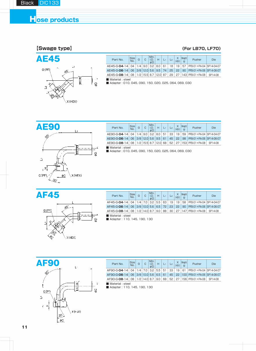
AE45
AE90
【Swage type】
AF45
AF90
ose productsH
AE45-G-04-14
■ Material : steel■ Adapter : 010, 045, 090, 150, 020, 025, 064, 069, 030
04 1/4 9.0 3.2 8.0 61 18 19 57 PFB-01+PA-04 SP14-04-07AE45-G-06-14 06 3/8 12.0 5.6 9.5 74 25 22 90 PFB-01+PA-06 SP14-06-07AE45-G-08-14 08 1/2 15.5 8.7 12.0 87 29 27 143 PFB-01+PA-08 SP14-08
AE90-G-04-14
■ Material : steel■ Adapter : 010, 045, 090, 150, 020, 025, 064, 069, 030
04 1/4 9.0 3.2 8.0 51 33 19 59 PFB-01+PA-04 SP14-04-07AE90-G-06-14 06 3/8 12.0 5.6 9.5 61 45 22 98 PFB-01+PA-06 SP14-06-07AE90-G-08-14 08 1/2 15.5 8.7 12.0 68 52 27 153 PFB-01+PA-08 SP14-08
AF45-G-04-14
■ Material : steel■ Adapter : 110, 145, 190, 130
04 1/4 7.0 3.2 5.5 63 19 19 58 PFB-01+PA-04 SP14-04-07AF45-G-06-14 06 3/8 10.0 5.6 6.5 72 23 22 90 PFB-01+PA-06 SP14-06-07AF45-G-08-14 08 1/2 14.0 8.7 9.0 88 30 27 147 PFB-01+PA-08 SP14-08
AF90-G-04-14
■ Material : steel■ Adapter : 110, 145, 190, 130
04 1/4 7.0 3.2 5.5 51 33 19 61 PFB-01+PA-04 SP14-04-07AF90-G-06-14 06 3/8 10.0 5.6 6.5 61 45 22 100 PFB-01+PA-06 SP14-06-07AF90-G-08-14 08 1/2 14.0 8.7 9.0 68 52 27 156 PFB-01+PA-08 SP14-08
(For LB70, LF70)
Part No. Size No. G C
Min.I.D.φD
H L1 L2X
(HEX)Weight
(g) Pusher Die
Part No. Size No. G C
Min.I.D.φD
H L1 L2X
(HEX)Weight
(g) Pusher Die
Part No. Size No. G C
Min.I.D.φD
H L1 L2X
(HEX)Weight
(g) Pusher Die
Part No. Size No. G C
Min.I.D.φD
H L1 L2X
(HEX)Weight
(g) Pusher Die

11 12
Hydraulic H
oseA
irless-paintingH
oseA
dapterH
ose Guard
Parts, S
pecially- Treated P
arts
Clean H
ose
Hy
dra
ulic
ho
se
pro
du
cts
Assem
bling
Machine,
Jig
, Tool
Hose
Assem
bling
Method
Technical
Docum
entR
eference D
ocument
Black DIC133Black DIC133
AE45
AE90
【Swage type】
AF45
AF90
ose productsH
AE45-G-04-14
■ Material : steel■ Adapter : 010, 045, 090, 150, 020, 025, 064, 069, 030
04 1/4 9.0 3.2 8.0 61 18 19 57 PFB-01+PA-04 SP14-04-07AE45-G-06-14 06 3/8 12.0 5.6 9.5 74 25 22 90 PFB-01+PA-06 SP14-06-07AE45-G-08-14 08 1/2 15.5 8.7 12.0 87 29 27 143 PFB-01+PA-08 SP14-08
AE90-G-04-14
■ Material : steel■ Adapter : 010, 045, 090, 150, 020, 025, 064, 069, 030
04 1/4 9.0 3.2 8.0 51 33 19 59 PFB-01+PA-04 SP14-04-07AE90-G-06-14 06 3/8 12.0 5.6 9.5 61 45 22 98 PFB-01+PA-06 SP14-06-07AE90-G-08-14 08 1/2 15.5 8.7 12.0 68 52 27 153 PFB-01+PA-08 SP14-08
AF45-G-04-14
■ Material : steel■ Adapter : 110, 145, 190, 130
04 1/4 7.0 3.2 5.5 63 19 19 58 PFB-01+PA-04 SP14-04-07AF45-G-06-14 06 3/8 10.0 5.6 6.5 72 23 22 90 PFB-01+PA-06 SP14-06-07AF45-G-08-14 08 1/2 14.0 8.7 9.0 88 30 27 147 PFB-01+PA-08 SP14-08
AF90-G-04-14
■ Material : steel■ Adapter : 110, 145, 190, 130
04 1/4 7.0 3.2 5.5 51 33 19 61 PFB-01+PA-04 SP14-04-07AF90-G-06-14 06 3/8 10.0 5.6 6.5 61 45 22 100 PFB-01+PA-06 SP14-06-07AF90-G-08-14 08 1/2 14.0 8.7 9.0 68 52 27 156 PFB-01+PA-08 SP14-08
(For LB70, LF70)
Part No. Size No. G C
Min.I.D.φD
H L1 L2X
(HEX)Weight
(g) Pusher Die
Part No. Size No. G C
Min.I.D.φD
H L1 L2X
(HEX)Weight
(g) Pusher Die
Part No. Size No. G C
Min.I.D.φD
H L1 L2X
(HEX)Weight
(g) Pusher Die
Part No. Size No. G C
Min.I.D.φD
H L1 L2X
(HEX)Weight
(g) Pusher Die
13 14
Hydraulic H
oseA
irless-paintingH
oseA
dapterH
ose Guard
Parts, S
pecially- Treated P
arts
Clean H
ose
Hy
dra
ulic
ho
se
pro
du
cts
Assem
bling
Machine,
Jig
, Tool
Hose
Assem
bling
Method
Technical
Docum
entR
eference D
ocument
Black DIC133Black DIC133
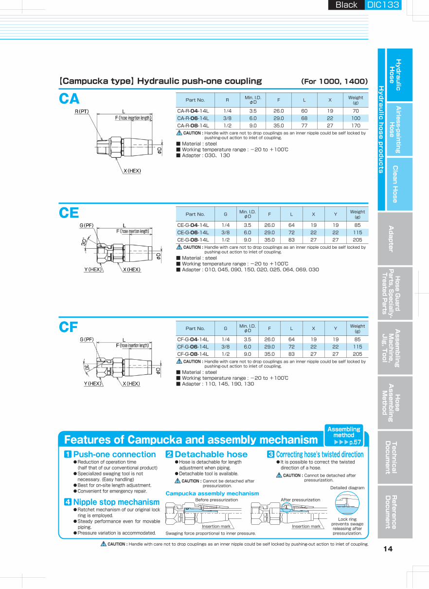
CAUTION : Handle with care not to drop couplings as an inner nipple could be self locked by pushing-out action to inlet of coupling.
Features of Campucka and assembly mechanism
● Reduction of operation time (half that of our conventional product)● Specialized swaging tool is not necessary. (Easy handling)● Best for on-site Iength adjustment.● Convenient for emergency repair.
Push-one connection1● Hose is detachable for length
adjustment when piping.● Detachable tool is available.
Detachable hose2● It is possible to correct the twisted
direction of a hose.
Correcting hose's twisted direction3
● Ratchet mechanism of our original lock ring is employed.
● Steady performance even for movable piping.
● Pressure variation is accommodated.
Nipple stop mechanism4Campucka assembly mechanism
Detailed diagram
Swaging force proportional to inner pressure.
Before pressurization
Insertion mark
After pressurization
Insertion mark
Lock ringprevents swage releasing after pressurization.
Assemblingmethod
p.57
CAUTION : Cannot be detached after pressurization.
CAUTION : Cannot be detached after pressurization.
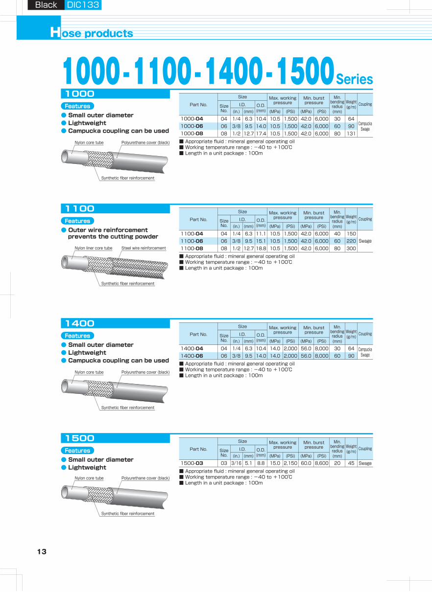
1000 -1100 -1400 -1500SeriesCA
CA-R-04-14L
CE
(For 1000, 1400)
1000-041000-061000-08
■ Appropriate fluid : mineral general operating oil■ Working temperature range : -40 to +100℃■ Length in a unit package : 100m
1000
1/4 3.5 26.0 60 19 70CA-R-06-14L 3/8 6.0 29.0 68 22 100CA-R-08-14L 1/2 9.0 35.0 77 27 170
CF
CampuckaSwage
Swage
CampuckaSwage
1100-041100-061100-08■ Appropriate fluid : mineral general operating oil■ Working temperature range : -40 to +100℃■ Length in a unit package : 100m
1100
1400-041400-06■ Appropriate fluid : mineral general operating oil■ Working temperature range : -40 to +100℃■ Length in a unit package : 100m
1400
1500-03
■ Appropriate fluid : mineral general operating oil■ Working temperature range : -40 to +100℃■ Length in a unit package : 100m
1500
Swage
CAUTION : Handle with care not to drop couplings as an inner nipple could be self locked by pushing-out action to inlet of coupling.
CAUTION : Handle with care not to drop couplings as an inner nipple could be self locked by pushing-out action to inlet of coupling.
CE-G-04-14L
■ Material : steel■ Working temperature range : -20 to +100℃■ Adapter : 010, 045, 090, 150, 020, 025, 064, 069, 030
1/4 3.5 26.0 64 19 19 853/8 6.0 29.0 72 22 22 1151/2 9.0 35.0 83 27 27 205
CE-G-06-14LCE-G-08-14L
CF-G-04-14L
■ Material : steel■ Working temperature range : -20 to +100℃■ Adapter : 110, 145, 190, 130
1/4 3.5 26.0 64 19 19 853/8 6.0 29.0 72 22 22 1151/2 9.0 35.0 83 27 27 205
CF-G-06-14LCF-G-08-14L
Polyurethane cover (black)Nylon core tube
Synthetic fiber reinforcement
Features● Small outer diameter● Lightweight● Campucka coupling can be used
Polyurethane cover (black)Nylon core tube
Synthetic fiber reinforcement
Features● Small outer diameter● Lightweight● Campucka coupling can be used
Polyurethane cover (black)Nylon core tube
Synthetic fiber reinforcement
Features● Small outer diameter● Lightweight
Features● Outer wire reinforcement
prevents the cutting powder
【Campucka type】 Hydraulic push-one coupling
ose productsH
Steel wire reinforcementNylon liner core tube
Synthetic fiber reinforcement
CAUTION : Handle with care not to drop couplings as an inner nipple could be self locked by pushing-out action to inlet of coupling.
■ Material : steel■ Working temperature range : -20 to +100℃■ Adapter : 030、130
04 1/4 6.3 10.4 10.5 1,500 42.0 6,000 30 6406 3/8 9.5 14.0 10.5 1,500 42.0 6,000 60 9008 1/2 12.7 17.4 10.5 1,500 42.0 6,000 80 131
04 1/4 6.3 11.1 10.5 1,500 42.0 6,000 40 15006 3/8 9.5 15.1 10.5 1,500 42.0 6,000 60 220
04 1/4 6.3 10.4 14.0 2,000 56.0 8,000 30 64
03 3/16 5.1 8.8 15.0 2,150 60.0 8,600 20 45
06 3/8 9.5 14.0 14.0 2,000 56.0 8,000 60 90
08 1/2 12.7 18.8 10.5 1,500 42.0 6,000 80 300
Part No. R Min. I.D.φD F L X Weight
(g)
Part No. G Min. I.D.φD F L X Y Weight
(g)
Part No. G Min. I.D.φD F L X Y Weight
(g)
Size
Part No. Size No.
I.D. O.D.(mm)(mm)(in.) (MPa)
Max. working pressure
(PSi) (MPa)
Min. burst pressure
Min. bending radius(mm)
Coupling
(PSi)
Weight(g/m)
Size
Part No. Size No.
I.D. O.D.(mm)(mm)(in.) (MPa)
Max. working pressure
(PSi) (MPa)
Min. burst pressure
Min. bending radius(mm)
Coupling
(PSi)
Weight(g/m)
Size
Part No. Size No.
I.D. O.D.(mm)(mm)(in.) (MPa)
Max. working pressure
(PSi) (MPa)
Min. burst pressure
Min. bending radius(mm)
Coupling
(PSi)
Weight(g/m)
Size
Part No. Size No.
I.D. O.D.(mm)(mm)(in.) (MPa)
Max. working pressure
(PSi) (MPa)
Min. burst pressure
Min. bending radius(mm)
Coupling
(PSi)
Weight(g/m)
13 14
Hydraulic H
oseA
irless-paintingH
oseA
dapterH
ose Guard
Parts, S
pecially- Treated P
arts
Clean H
ose
Hy
dra
ulic
ho
se
pro
du
cts
Assem
bling
Machine,
Jig
, Tool
Hose
Assem
bling
Method
Technical
Docum
entR
eference D
ocument
Black DIC133Black DIC133
CAUTION : Handle with care not to drop couplings as an inner nipple could be self locked by pushing-out action to inlet of coupling.
Features of Campucka and assembly mechanism
● Reduction of operation time (half that of our conventional product)● Specialized swaging tool is not necessary. (Easy handling)● Best for on-site Iength adjustment.● Convenient for emergency repair.
Push-one connection1● Hose is detachable for length
adjustment when piping.● Detachable tool is available.
Detachable hose2● It is possible to correct the twisted
direction of a hose.
Correcting hose's twisted direction3
● Ratchet mechanism of our original lock ring is employed.
● Steady performance even for movable piping.
● Pressure variation is accommodated.
Nipple stop mechanism4Campucka assembly mechanism
Detailed diagram
Swaging force proportional to inner pressure.
Before pressurization
Insertion mark
After pressurization
Insertion mark
Lock ringprevents swage releasing after pressurization.
Assemblingmethod
p.57
CAUTION : Cannot be detached after pressurization.
CAUTION : Cannot be detached after pressurization.
1000 -1100 -1400 -1500SeriesCA
CA-R-04-14L
CE
(For 1000, 1400)
1000-041000-061000-08
■ Appropriate fluid : mineral general operating oil■ Working temperature range : -40 to +100℃■ Length in a unit package : 100m
1000
1/4 3.5 26.0 60 19 70CA-R-06-14L 3/8 6.0 29.0 68 22 100CA-R-08-14L 1/2 9.0 35.0 77 27 170
CF
CampuckaSwage
Swage
CampuckaSwage
1100-041100-061100-08■ Appropriate fluid : mineral general operating oil■ Working temperature range : -40 to +100℃■ Length in a unit package : 100m
1100
1400-041400-06■ Appropriate fluid : mineral general operating oil■ Working temperature range : -40 to +100℃■ Length in a unit package : 100m
1400
1500-03
■ Appropriate fluid : mineral general operating oil■ Working temperature range : -40 to +100℃■ Length in a unit package : 100m
1500
Swage
CAUTION : Handle with care not to drop couplings as an inner nipple could be self locked by pushing-out action to inlet of coupling.
CAUTION : Handle with care not to drop couplings as an inner nipple could be self locked by pushing-out action to inlet of coupling.
CE-G-04-14L
■ Material : steel■ Working temperature range : -20 to +100℃■ Adapter : 010, 045, 090, 150, 020, 025, 064, 069, 030
1/4 3.5 26.0 64 19 19 853/8 6.0 29.0 72 22 22 1151/2 9.0 35.0 83 27 27 205
CE-G-06-14LCE-G-08-14L
CF-G-04-14L
■ Material : steel■ Working temperature range : -20 to +100℃■ Adapter : 110, 145, 190, 130
1/4 3.5 26.0 64 19 19 853/8 6.0 29.0 72 22 22 1151/2 9.0 35.0 83 27 27 205
CF-G-06-14LCF-G-08-14L
Polyurethane cover (black)Nylon core tube
Synthetic fiber reinforcement
Features● Small outer diameter● Lightweight● Campucka coupling can be used
Polyurethane cover (black)Nylon core tube
Synthetic fiber reinforcement
Features● Small outer diameter● Lightweight● Campucka coupling can be used
Polyurethane cover (black)Nylon core tube
Synthetic fiber reinforcement
Features● Small outer diameter● Lightweight
Features● Outer wire reinforcement
prevents the cutting powder
【Campucka type】 Hydraulic push-one coupling
ose productsH
Steel wire reinforcementNylon liner core tube
Synthetic fiber reinforcement
CAUTION : Handle with care not to drop couplings as an inner nipple could be self locked by pushing-out action to inlet of coupling.
■ Material : steel■ Working temperature range : -20 to +100℃■ Adapter : 030、130
04 1/4 6.3 10.4 10.5 1,500 42.0 6,000 30 6406 3/8 9.5 14.0 10.5 1,500 42.0 6,000 60 9008 1/2 12.7 17.4 10.5 1,500 42.0 6,000 80 131
04 1/4 6.3 11.1 10.5 1,500 42.0 6,000 40 15006 3/8 9.5 15.1 10.5 1,500 42.0 6,000 60 220
04 1/4 6.3 10.4 14.0 2,000 56.0 8,000 30 64
03 3/16 5.1 8.8 15.0 2,150 60.0 8,600 20 45
06 3/8 9.5 14.0 14.0 2,000 56.0 8,000 60 90
08 1/2 12.7 18.8 10.5 1,500 42.0 6,000 80 300
Part No. R Min. I.D.φD F L X Weight
(g)
Part No. G Min. I.D.φD F L X Y Weight
(g)
Part No. G Min. I.D.φD F L X Y Weight
(g)
Size
Part No. Size No.
I.D. O.D.(mm)(mm)(in.) (MPa)
Max. working pressure
(PSi) (MPa)
Min. burst pressure
Min. bending radius(mm)
Coupling
(PSi)
Weight(g/m)
Size
Part No. Size No.
I.D. O.D.(mm)(mm)(in.) (MPa)
Max. working pressure
(PSi) (MPa)
Min. burst pressure
Min. bending radius(mm)
Coupling
(PSi)
Weight(g/m)
Size
Part No. Size No.
I.D. O.D.(mm)(mm)(in.) (MPa)
Max. working pressure
(PSi) (MPa)
Min. burst pressure
Min. bending radius(mm)
Coupling
(PSi)
Weight(g/m)
Size
Part No. Size No.
I.D. O.D.(mm)(mm)(in.) (MPa)
Max. working pressure
(PSi) (MPa)
Min. burst pressure
Min. bending radius(mm)
Coupling
(PSi)
Weight(g/m)
15 16
Hydraulic H
oseA
irless-paintingH
oseA
dapterH
ose Guard
Parts, S
pecially- Treated P
arts
Clean H
ose
Hy
dra
ulic
ho
se
pro
du
cts
Assem
bling
Machine,
Jig
, Tool
Hose
Assem
bling
Method
Technical
Docum
entR
eference D
ocument
Black DIC133Black DIC133
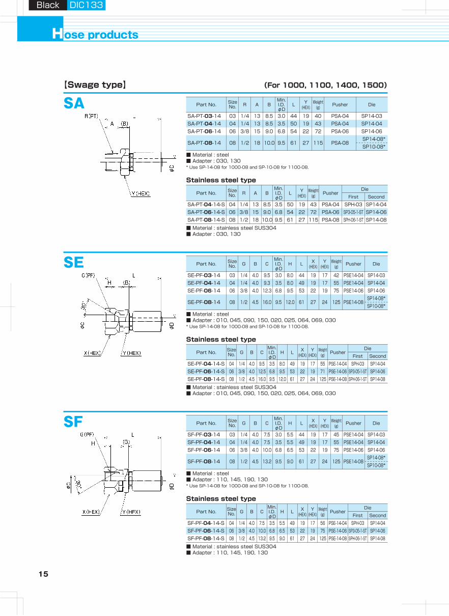
SASA-PT-03-14
■ Material : steel■ Adapter : 030, 130* Use SP-14-08 for 1000-08 and SP-10-08 for 1100-08.
【Swage type】
Stainless steel type
(For 1000, 1100, 1400, 1500)
03 1/4 13 8.5 3.0 44 19 40 PSA-04 SP14-03SA-PT-04-14 04 1/4 13 8.5 3.5 50 19 43 PSA-04 SP14-04SA-PT-06-14 06 3/8 15 9.0 6.8 54 22 72 PSA-06 SP14-06
SA-PT-08-14 08 1/2 18 10.0 9.5 61 27 115 PSA-08 SP14-08* SP10-08*
SA-PT-04-14-S
■ Material : stainless steel SUS304■ Adapter : 030, 130
04 1/4 13 8.5 3.5 50 19 43 PSA-04 SPH-03 SP14-04SA-PT-06-14-S 06 3/8 15 9.0 6.8 54 22 72 PSA-06 SP3-05-1-ST SP14-06SA-PT-08-14-S 08 1/2 18 10.0 9.5 61 27 115 PSA-08 SPH-06-1-ST SP14-08
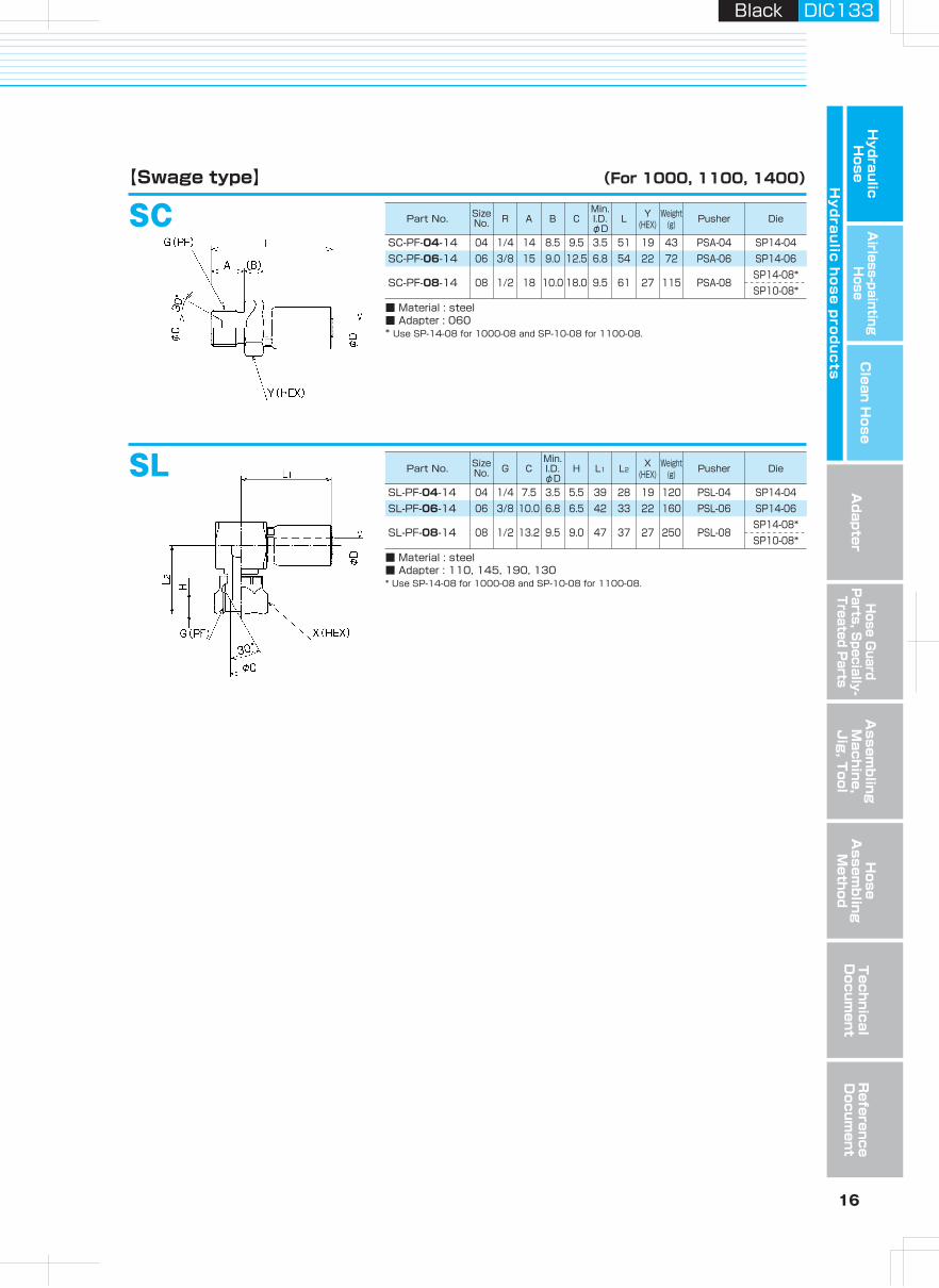
SCSC-PF-04-14
■ Material : steel■ Adapter : 060* Use SP-14-08 for 1000-08 and SP-10-08 for 1100-08.
【Swage type】 (For 1000, 1100, 1400)
04 1/4 14 8.5 9.5 3.5 51 19 43 PSA-04 SP14-04SC-PF-06-14 06 3/8 15 9.0 12.5 6.8 54 22 72 PSA-06 SP14-06
SC-PF-08-14 08 1/2 18 10.0 18.0 9.5 61 27 115 PSA-08SP14-08*SP10-08*
SLSL-PF-04-14
■ Material : steel■ Adapter : 110, 145, 190, 130* Use SP-14-08 for 1000-08 and SP-10-08 for 1100-08.
04 1/4 7.5 3.5 5.5 39 28 19 120 PSL-04 SP14-04SL-PF-06-14 06 3/8 10.0 6.8 6.5 42 33 22 160 PSL-06 SP14-06
SL-PF-08-14 08 1/2 13.2 9.5 9.0 47 37 27 250 PSL-08SP14-08*SP10-08*SE
SE-PF-03-14
■ Material : steel■ Adapter : 010, 045, 090, 150, 020, 025, 064, 069, 030* Use SP-14-08 for 1000-08 and SP-10-08 for 1100-08.
Stainless steel type
03 1/4 4.0 9.5 3.0 8.0 44 19 17 42 PSE14-04 SP14-03SE-PF-04-14 04 1/4 4.0 9.3 3.5 8.0 49 19 17 55 PSE14-04 SP14-04SE-PF-06-14 06 3/8 4.0 12.3 6.8 9.5 53 22 19 75 PSE14-06 SP14-06
SE-PF-08-14 08 1/2 4.5 16.0 9.5 12.0 61 27 24 125 PSE14-08SP14-08*SP10-08*
SE-PF-04-14-S
■ Material : stainless steel SUS304■ Adapter : 010, 045, 090, 150, 020, 025, 064, 069, 030
04 1/4 4.0 9.5 3.5 8.0 49 19 17 55 PSE-14-04 SPH-03 SP14-04SE-PF-06-14-S 06 3/8 4.0 12.5 6.8 9.5 53 22 19 71 PSE-14-06 SP3-05-1-ST SP14-06SE-PF-08-14-S 08 1/2 4.5 16.0 9.5 12.0 61 27 24 125 PSE-14-08 SPH-06-1-ST SP14-08
SFSF-PF-03-14
■ Material : steel■ Adapter : 110, 145, 190, 130* Use SP-14-08 for 1000-08 and SP-10-08 for 1100-08.
Stainless steel type
03 1/4 4.0 7.5 3.0 5.5 44 19 17 45 PSE14-04 SP14-03SF-PF-04-14 04 1/4 4.0 7.5 3.5 5.5 49 19 17 55 PSE14-04 SP14-04SF-PF-06-14 06 3/8 4.0 10.0 6.8 6.5 53 22 19 75 PSE14-06 SP14-06
SF-PF-08-14 08 1/2 4.5 13.2 9.5 9.0 61 27 24 125 PSE14-08SP14-08*SP10-08*
SF-PF-04-14-S
■ Material : stainless steel SUS304■ Adapter : 110, 145, 190, 130
04 1/4 4.0 7.5 3.5 5.5 49 19 17 56 PSE-14-04 SPH-03 SP14-04SF-PF-06-14-S 06 3/8 4.0 10.0 6.8 6.5 53 22 19 75 PSE-14-06 SP3-05-1-ST SP14-06SF-PF-08-14-S 08 1/2 4.5 13.2 9.5 9.0 61 27 24 125 PSE-14-08 SPH-06-1-ST SP14-08
ose productsH
Part No. Size No. R A B
Min.I.D.φD
L Y(HEX)
Weight(g) Pusher Die
Part No. Size No. R A B
Min.I.D.φD
L Y(HEX)
Weight(g) Pusher
First Second
Die
Part No. Size No. G B C
Min.I.D.φD
H L X(HEX)
Y(HEX)
Weight(g) Pusher Die
Part No. Size No. G B C
Min.I.D.φD
H L X(HEX)
Y(HEX)
Weight(g) Pusher
First Second
Die
Part No. Size No. G B C
Min.I.D.φD
H L X(HEX)
Y(HEX)
Weight(g) Pusher Die
Part No. Size No. G B C
Min.I.D.φD
H L X(HEX)
Y(HEX)
Weight(g) Pusher
First Second
Die
Part No. Size No. R A B C
Min.I.D.φD
L Y(HEX)
Weight(g) Pusher Die
Part No. Size No. G C
Min.I.D.φD
H L1 L2X
(HEX)Weight
(g) Pusher Die
15 16
Hydraulic H
oseA
irless-paintingH
oseA
dapterH
ose Guard
Parts, S
pecially- Treated P
arts
Clean H
ose
Hy
dra
ulic
ho
se
pro
du
cts
Assem
bling
Machine,
Jig
, Tool
Hose
Assem
bling
Method
Technical
Docum
entR
eference D
ocument
Black DIC133Black DIC133
SASA-PT-03-14
■ Material : steel■ Adapter : 030, 130* Use SP-14-08 for 1000-08 and SP-10-08 for 1100-08.
【Swage type】
Stainless steel type
(For 1000, 1100, 1400, 1500)
03 1/4 13 8.5 3.0 44 19 40 PSA-04 SP14-03SA-PT-04-14 04 1/4 13 8.5 3.5 50 19 43 PSA-04 SP14-04SA-PT-06-14 06 3/8 15 9.0 6.8 54 22 72 PSA-06 SP14-06
SA-PT-08-14 08 1/2 18 10.0 9.5 61 27 115 PSA-08 SP14-08* SP10-08*
SA-PT-04-14-S
■ Material : stainless steel SUS304■ Adapter : 030, 130
04 1/4 13 8.5 3.5 50 19 43 PSA-04 SPH-03 SP14-04SA-PT-06-14-S 06 3/8 15 9.0 6.8 54 22 72 PSA-06 SP3-05-1-ST SP14-06SA-PT-08-14-S 08 1/2 18 10.0 9.5 61 27 115 PSA-08 SPH-06-1-ST SP14-08
SCSC-PF-04-14
■ Material : steel■ Adapter : 060* Use SP-14-08 for 1000-08 and SP-10-08 for 1100-08.
【Swage type】 (For 1000, 1100, 1400)
04 1/4 14 8.5 9.5 3.5 51 19 43 PSA-04 SP14-04SC-PF-06-14 06 3/8 15 9.0 12.5 6.8 54 22 72 PSA-06 SP14-06
SC-PF-08-14 08 1/2 18 10.0 18.0 9.5 61 27 115 PSA-08SP14-08*SP10-08*
SLSL-PF-04-14
■ Material : steel■ Adapter : 110, 145, 190, 130* Use SP-14-08 for 1000-08 and SP-10-08 for 1100-08.
04 1/4 7.5 3.5 5.5 39 28 19 120 PSL-04 SP14-04SL-PF-06-14 06 3/8 10.0 6.8 6.5 42 33 22 160 PSL-06 SP14-06
SL-PF-08-14 08 1/2 13.2 9.5 9.0 47 37 27 250 PSL-08SP14-08*SP10-08*SE
SE-PF-03-14
■ Material : steel■ Adapter : 010, 045, 090, 150, 020, 025, 064, 069, 030* Use SP-14-08 for 1000-08 and SP-10-08 for 1100-08.
Stainless steel type
03 1/4 4.0 9.5 3.0 8.0 44 19 17 42 PSE14-04 SP14-03SE-PF-04-14 04 1/4 4.0 9.3 3.5 8.0 49 19 17 55 PSE14-04 SP14-04SE-PF-06-14 06 3/8 4.0 12.3 6.8 9.5 53 22 19 75 PSE14-06 SP14-06
SE-PF-08-14 08 1/2 4.5 16.0 9.5 12.0 61 27 24 125 PSE14-08SP14-08*SP10-08*
SE-PF-04-14-S
■ Material : stainless steel SUS304■ Adapter : 010, 045, 090, 150, 020, 025, 064, 069, 030
04 1/4 4.0 9.5 3.5 8.0 49 19 17 55 PSE-14-04 SPH-03 SP14-04SE-PF-06-14-S 06 3/8 4.0 12.5 6.8 9.5 53 22 19 71 PSE-14-06 SP3-05-1-ST SP14-06SE-PF-08-14-S 08 1/2 4.5 16.0 9.5 12.0 61 27 24 125 PSE-14-08 SPH-06-1-ST SP14-08
SFSF-PF-03-14
■ Material : steel■ Adapter : 110, 145, 190, 130* Use SP-14-08 for 1000-08 and SP-10-08 for 1100-08.
Stainless steel type
03 1/4 4.0 7.5 3.0 5.5 44 19 17 45 PSE14-04 SP14-03SF-PF-04-14 04 1/4 4.0 7.5 3.5 5.5 49 19 17 55 PSE14-04 SP14-04SF-PF-06-14 06 3/8 4.0 10.0 6.8 6.5 53 22 19 75 PSE14-06 SP14-06
SF-PF-08-14 08 1/2 4.5 13.2 9.5 9.0 61 27 24 125 PSE14-08SP14-08*SP10-08*
SF-PF-04-14-S
■ Material : stainless steel SUS304■ Adapter : 110, 145, 190, 130
04 1/4 4.0 7.5 3.5 5.5 49 19 17 56 PSE-14-04 SPH-03 SP14-04SF-PF-06-14-S 06 3/8 4.0 10.0 6.8 6.5 53 22 19 75 PSE-14-06 SP3-05-1-ST SP14-06SF-PF-08-14-S 08 1/2 4.5 13.2 9.5 9.0 61 27 24 125 PSE-14-08 SPH-06-1-ST SP14-08
ose productsH
Part No. Size No. R A B
Min.I.D.φD
L Y(HEX)
Weight(g) Pusher Die
Part No. Size No. R A B
Min.I.D.φD
L Y(HEX)
Weight(g) Pusher
First Second
Die
Part No. Size No. G B C
Min.I.D.φD
H L X(HEX)
Y(HEX)
Weight(g) Pusher Die
Part No. Size No. G B C
Min.I.D.φD
H L X(HEX)
Y(HEX)
Weight(g) Pusher
First Second
Die
Part No. Size No. G B C
Min.I.D.φD
H L X(HEX)
Y(HEX)
Weight(g) Pusher Die
Part No. Size No. G B C
Min.I.D.φD
H L X(HEX)
Y(HEX)
Weight(g) Pusher
First Second
Die
Part No. Size No. R A B C
Min.I.D.φD
L Y(HEX)
Weight(g) Pusher Die
Part No. Size No. G C
Min.I.D.φD
H L1 L2X
(HEX)Weight
(g) Pusher Die
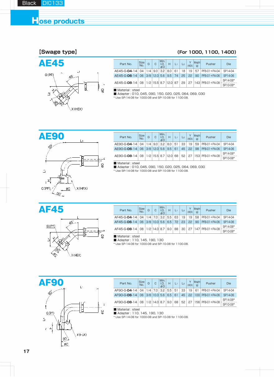
17 18
Hydraulic H
oseA
irless-paintingH
oseA
dapterH
ose Guard
Parts, S
pecially- Treated P
arts
Clean H
ose
Hy
dra
ulic
ho
se
pro
du
cts
Assem
bling
Machine,
Jig
, Tool
Hose
Assem
bling
Method
Technical
Docum
entR
eference D
ocument
ose productsH
Black DIC133Black DIC133
AE45【Swage type】 (For 1000, 1100, 1400)
SKSK-7/16-04-14
■ Material : steel* Use SP-14-08 for 1000-08 and SP-10-08 for 1100-08.★Made-to-order
【Swage type】 (For 1000, 1100, 1400)
04 7/16-20 6.5 7.5 3.5 9.0 51 19 17 58 PSK-04H SP14-04SK-9/16-06-14 06 9/16-18 7.5 11.0 6.8 10.0 57 22 19 82 PSK-06H SP14-06
SK-3/4-08-14
★★
★ 08 3/4-16 4.5 14.5 9.5 11.5 57 27 22 105 PSE-14-08SP14-08*SP10-08*
AE45-G-04-14
■ Material : steel■ Adapter : 010, 045, 090, 150, 020, 025, 064, 069, 030* Use SP-14-08 for 1000-08 and SP-10-08 for 1100-08.
04 1/4 9.0 3.2 8.0 61 18 19 57 PFB-01+PA-04 SP14-04AE45-G-06-14 06 3/8 12.0 5.6 9.5 74 25 22 90 PFB-01+PA-06 SP14-06
AE45-G-08-14 08 1/2 15.5 8.7 12.0 87 29 27 143 PFB-01+PA-08SP14-08*SP10-08*
AE90AE90-G-04-14
■ Material : steel■ Adapter : 010, 045, 090, 150, 020, 025, 064, 069, 030* Use SP-14-08 for 1000-08 and SP-10-08 for 1100-08.
04 1/4 9.0 3.2 8.0 51 33 19 59 PFB-01+PA-04 SP14-04AE90-G-06-14 06 3/8 12.0 5.6 9.5 61 45 22 98 PFB-01+PA-06 SP14-06
AE90-G-08-14 08 1/2 15.5 8.7 12.0 68 52 27 153 PFB-01+PA-08SP14-08*SP10-08*
AF45AF45-G-04-14
■ Material : steel■ Adapter : 110, 145, 190, 130* Use SP-14-08 for 1000-08 and SP-10-08 for 1100-08.
04 1/4 7.0 3.2 5.5 63 19 19 58 PFB-01+PA-04 SP14-04AF45-G-06-14 06 3/8 10.0 5.6 6.5 72 23 22 90 PFB-01+PA-06 SP14-06
AF45-G-08-14 08 1/2 14.0 8.7 9.0 88 30 27 147 PFB-01+PA-08SP14-08*SP10-08*
AF90AF90-G-04-14
■ Material : steel■ Adapter : 110, 145, 190, 130* Use SP-14-08 for 1000-08 and SP-10-08 for 1100-08.
04 1/4 7.0 3.2 5.5 51 33 19 61 PFB-01+PA-04 SP14-04AF90-G-06-14 06 3/8 10.0 5.6 6.5 61 45 22 100 PFB-01+PA-06 SP14-06
AF90-G-08-14 08 1/2 14.0 8.7 9.0 68 52 27 156 PFB-01+PA-08SP14-08*SP10-08*
AK45AK45-7/16-04-14-C
■ Material : steel* Use SP-14-08 for 1000-08 and SP-10-08 for 1100-08.★Made-to-order
04 7/16-20 7.5 3.2 9.0 70 27 19 57 PFB-01+PA-04 SP14-0406 9/16-18 11.0 5.6 10.0 91 39 22 90 PFB-01+PA-06 SP14-06
08 3/4-16 14.5 8.7 12.0 98 40 27 143 PFB-01+PA-08SP14-08*SP10-08*
AK45-9/16-06-14-C
AK45-3/4-08-14-C
★★
★
AK90-7/16-04-14-C
■ Material : steel* Use SP-14-08 for 1000-08 and SP-10-08 for 1100-08.★Made-to-order
04 7/16-20 7.5 3.2 9.0 51 36 19 59 PFB-01+PA-04 SP14-0406 9/16-18 11.0 5.6 10.0 61 40 22 98 PFB-01+PA-06 SP14-06
08 3/4-16 14.5 8.7 12.0 68 57 27 153 PFB-01+PA-08SP14-08*SP10-08*
AK90-9/16-06-14-C
AK90-3/4-08-14-C
★★
★
AK90
MADETO
ORDER
MADETO
ORDER
MADETO
ORDER
Part No. Size No. G C
Min.I.D.φD
H L1 L2Y
(HEX)Weight
(g) Pusher Die
Part No. Size No. G C
Min.I.D.φD
H L1 L2Y
(HEX)Weight
(g) Pusher Die
Part No. Size No. G C
Min.I.D.φD
H L1 L2Y
(HEX)Weight
(g) Pusher Die
Part No. Size No. G C
Min.I.D.φD
H L1 L2Y
(HEX)Weight
(g) Pusher Die
Part No. Size No. B C
Min.I.D.φD
H L X(HEX)
Y(HEX)
Weight(g) Pusher DieUNF
Part No. Size No. C
Min.I.D.φD
H L1 L2X
(HEX)Weight
(g) Pusher DieUNF
Part No. Size No. C
Min.I.D.φD
H L1 L2X
(HEX)Weight
(g) Pusher DieUNF
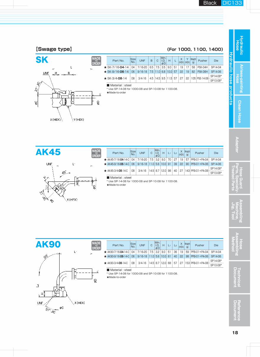
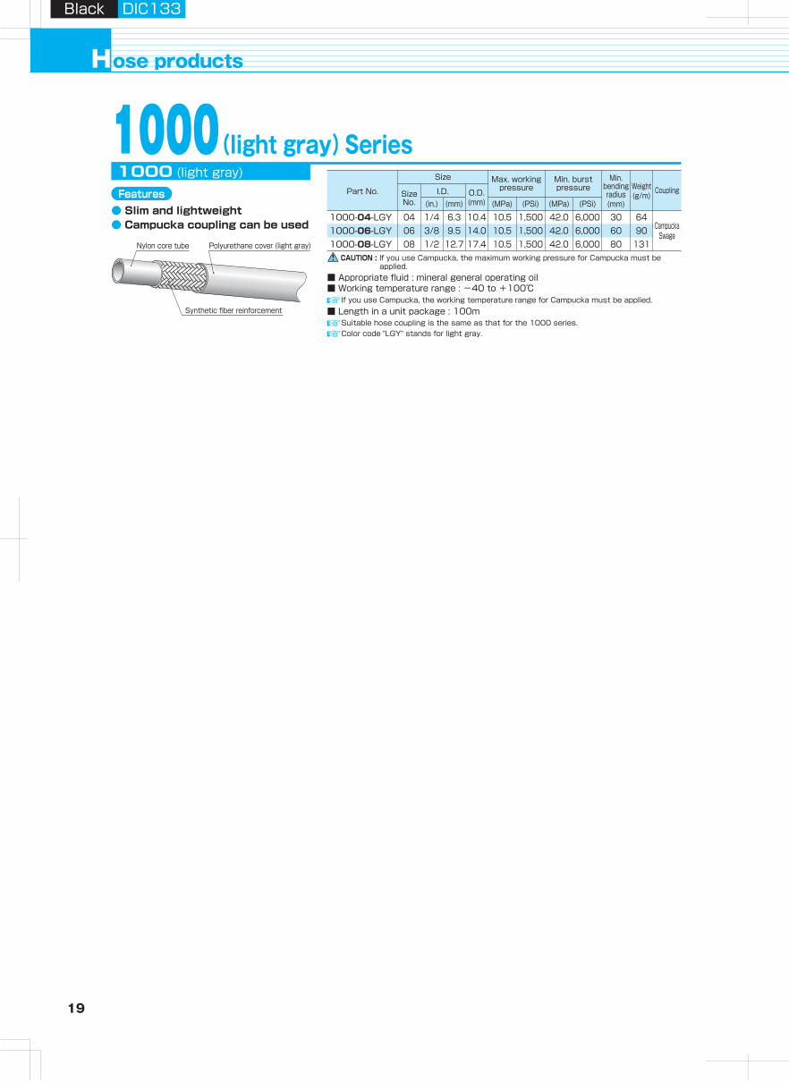
19 20
Hydraulic H
oseA
irless-paintingH
oseA
dapterH
ose Guard
Parts, S
pecially- Treated P
arts
Clean H
ose
Hy
dra
ulic
ho
se
pro
du
cts
Assem
bling
Machine,
Jig
, Tool
Hose
Assem
bling
Method
Technical
Docum
entR
eference D
ocument
ose productsH
Black DIC133Black DIC133
Features of Campucka and assembly mechanism
● Reduction of operation time (half that of our conventional product)● Specialized swaging tool is not necessary. (Easy handling)● Best for on-site Iength adjustment.● Convenient for emergency repair.
Push-one connection1● Hose is detachable for length
adjustment when piping.● Detachable tool is available.
Detachable hose2● It is possible to correct the twisted
direction of a hose.
Correcting hose's twisted direction3
● Ratchet mechanism of our original lock ring is employed.
● Steady performance even for movable piping.
● Pressure variation is accommodated.
Nipple stop mechanism4Campucka assembly mechanism
Detailed diagram
Swaging force proportional to inner pressure.
Before pressurization
Insertion mark
After pressurization
Insertion mark
Lock ringprevents swage releasing after pressurization.
Assemblingmethod
p.57
CAUTION : Cannot be detached after pressurization.
CAUTION : Cannot be detached after pressurization.
Part No. G Min. I.D.φD F L X Y Weight
(g)
Part No. Size No. G B C
Min.I.D.φD
H L X(HEX)
Y(HEX)
Weight(g) Pusher Die
Size
Part No. Size No.
I.D. O.D.(mm)(mm)(in.) (MPa)
Max. working pressure
(PSi) (MPa)
Min. burst pressure
Min. bending radius(mm)
Coupling
(PSi)
Weight(g/m)
Polyurethane cover (light gray)Nylon core tube
Synthetic fiber reinforcement
Features● Slim and lightweight● Campucka coupling can be used
1000(light gray)SeriesCE
CE-G-04-14L
【Campucka type】 Hydraulic push-one coupling
SE【Swage type】
(For 1000 (light gray))
1000-04-LGY1000-06-LGY1000-08-LGY
1000 (light gray)
1/4 3.5 26.0 64 19 19 853/8 6.0 29.0 72 22 22 1151/2 9.0 35.0 83 27 27 205
CE-G-06-14LCE-G-08-14L
■ Length in a unit package : 100mIf you use Campucka, the working temperature range for Campucka must be applied.
Suitable hose coupling is the same as that for the 1000 series.Color code "LGY" stands for light gray.
SE-PF-04-14
■ Material : steel■ Adapter : 010, 045, 090, 150, 020, 025, 064, 069, 030
04 1/4 4.0 9.3 3.5 8.0 49 19 17 55 PSE14-04 SP14-04SE-PF-06-14 06 3/8 4.0 12.3 6.8 9.5 53 22 19 75 PSE14-06 SP14-06SE-PF-08-14 08 1/2 4.5 16.0 9.5 12.0 61 27 24 125 PSE14-08 SP14-08
Applicable hose couplings are the same as those for 1000 series.
CAUTION : If you use Campucka, the maximum working pressure for Campucka must be applied.
■ Appropriate fluid : mineral general operating oil■ Working temperature range : -40 to +100℃ ■ Material : steel
■ Maximum working pressure : 10.5MPa■ Working temperature range : -20 to +100℃■ Adapter : 010, 045, 090, 150, 020, 025, 064, 069, 030
CAUTION : If you use Campucka, the maximum working pressure for Campucka must be applied.
CAUTION : Handle with care not to drop couplings as an inner nipple could be self locked by pushing-out action to inlet of coupling.
04 1/4 6.3 10.4 10.5 1,500 42.0 6,000 30 6406 3/8 9.5 14.0 10.5 1,500 42.0 6,000 60 9008 1/2 12.7 17.4 10.5 1,500 42.0 6,000 80 131
CampuckaSwage
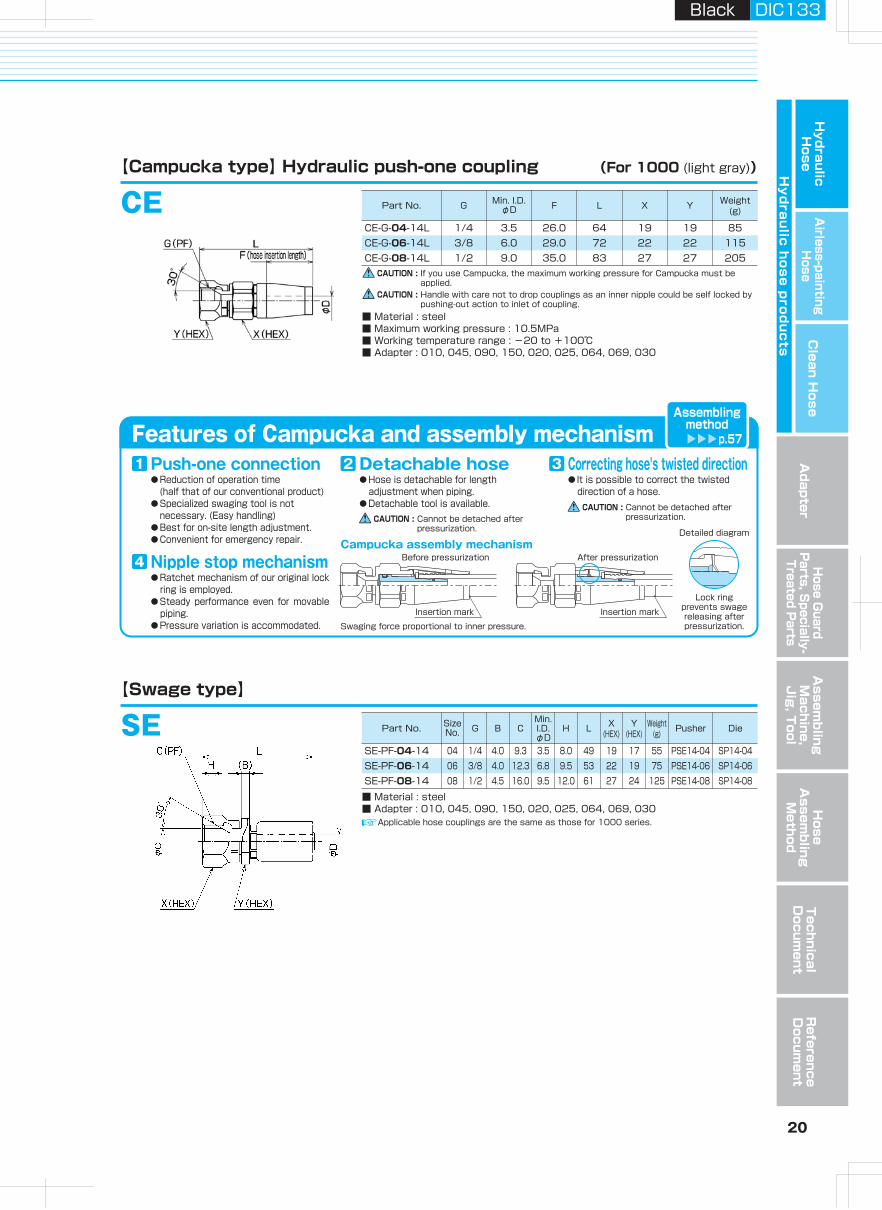
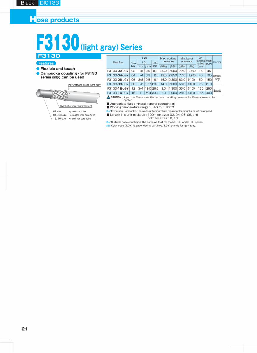
21 22
Hydraulic H
oseA
irless-paintingH
oseA
dapterH
ose Guard
Parts, S
pecially- Treated P
arts
Clean H
ose
Hy
dra
ulic
ho
se
pro
du
cts
Assem
bling
Machine,
Jig
, Tool
Hose
Assem
bling
Method
Technical
Docum
entR
eference D
ocument
ose productsH
Black DIC133Black DIC133
Polyurethane cover (light gray)
Synthetic fiber reinforcement
02 size04 - 08 size12, 16 size
Nylon core tubePolyester liner core tubeNylon liner core tube
Features● Flexible and tough● Campucka coupling (for F3130
series only) can be used
■ Length in a unit package : 100m for sizes 02, 04, 06, 08, and 50m for sizes 12, 16
If you use Campucka, the working temperature range for Campucka must be applied.
CAUTION : If you use Campucka, the maximum working pressure for Campucka must be applied.
■ Appropriate fluid : mineral general operating oil■ Working temperature range : -40 to +100℃
■ Material : steel■ Maximum working pressure : 10.5MPa (CE-G-02L : 20.0MPa)■ Working temperature range : -20 to +100℃■ Adapter : 010, 045, 090, 150, 020, 025, 064, 069, 030
CAUTION : Handle with care not to drop couplings as an inner nipple could be self locked by pushing-out action to inlet of coupling.
F3130(light gray)SeriesCE (For F3130 series only)
CE-G-02L
【Campucka type】 Hydraulic push-one coupling
SE【Swage type】
(For F3130 (light gray))
F3130-02-LGYF3130-04-LGYF3130-06-LGYF3130-08-LGYF3130-12-LGYF3130-16-LGY
F3130
02 1/8 1.5 22.5 62 14 14 44CE-G-04-F31-10L 04 1/4 3.5 28 74 19 19 105CE-G-06-F31-10L 06 3/8 6.3 34 84 22 22 150CE-G-08-F31-10L 08 1/2 9.4 37 92 27 27 225
SSE-PF-02
■ Material : steel■ Adapter : 010, 045, 090, 150, 020, 025, 064, 069, 030
02 1/8 4.0 6.8 1.8 7.0 42 14 14 25 PSE-02-001 SP3-02-001SE-PF-04 04 1/4 8.0 9.3 3.9 8.0 64 19 17 75 PSE-04 SP3-04SE-PF-06 06 3/8 9.5 12.3 6.8 9.5 71 22 19 100 PSE-06 SP3-06SE-PF-08 08 1/2 9.0 15.5 10.0 12.5 80 27 27 170 PSE-08 SP3-08SE-PF-12 12 3/4 10.5 21.5 16.0 13.0 87 36 36 280 PSE-12 SP3-12SE-PF-16 16 1 11.0 27.5 20.9 15.0 105 41 41 400 PSE-16 SP3-16
Suitable hose coupling is the same as that for the N3130 and 3130 series.Color code (-LGY) is appended to part Nos. "LGY" stands for light gray.
CampuckaSwage
02 1/8 3.6 8.3 20.0 2,900 72.0 10,500 15 4504 1/4 6.3 12.5 19.5 2,850 77.0 11,200 40 10506 3/8 9.5 16.4 16.0 2,300 63.0 9,100 50 15008 1/2 12.7 20.3 14.0 2,000 56.0 8,000 75 21012 3/4 19.0 26.6 9.0 1,300 35.0 5,100 130 29016 1 25.4 33.4 7.0 1,000 28.0 4,000 165 400
Swage
Features of Campucka and assembly mechanism
● Reduction of operation time (half that of our conventional product)● Specialized swaging tool is not necessary. (Easy handling)● Best for on-site Iength adjustment.● Convenient for emergency repair.
Push-one connection1● Hose is detachable for length
adjustment when piping.● Detachable tool is available.
Detachable hose2● It is possible to correct the twisted
direction of a hose.
Correcting hose's twisted direction3
● Ratchet mechanism of our original lock ring is employed.
● Steady performance even for movable piping.
● Pressure variation is accommodated.
Nipple stop mechanism4Campucka assembly mechanism
Detailed diagram
Swaging force proportional to inner pressure.
Before pressurization
Insertion mark
After pressurization
Insertion mark
Lock ringprevents swage releasing after pressurization.
Assemblingmethod
p.57
CAUTION : Cannot be detached after pressurization.
CAUTION : Cannot be detached after pressurization.
Part No. GSize No. Min. I.D.φD F L X Y Weight
(g)
品 番Size No. G B C
Min.I.D.φD
H L X(HEX)
Y(HEX)
Weight(g) Pusher Die
Size
Part No. Size No.
I.D. O.D.(mm)(mm)(in.) (MPa)
Max. working pressure
(PSi) (MPa)
Min. burst pressure
Min. bending radius(mm)
Coupling
(PSi)
Weight(g/m)
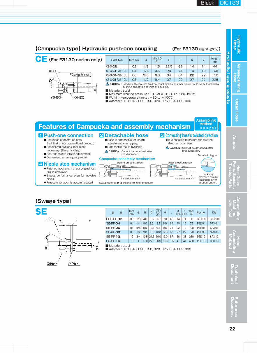
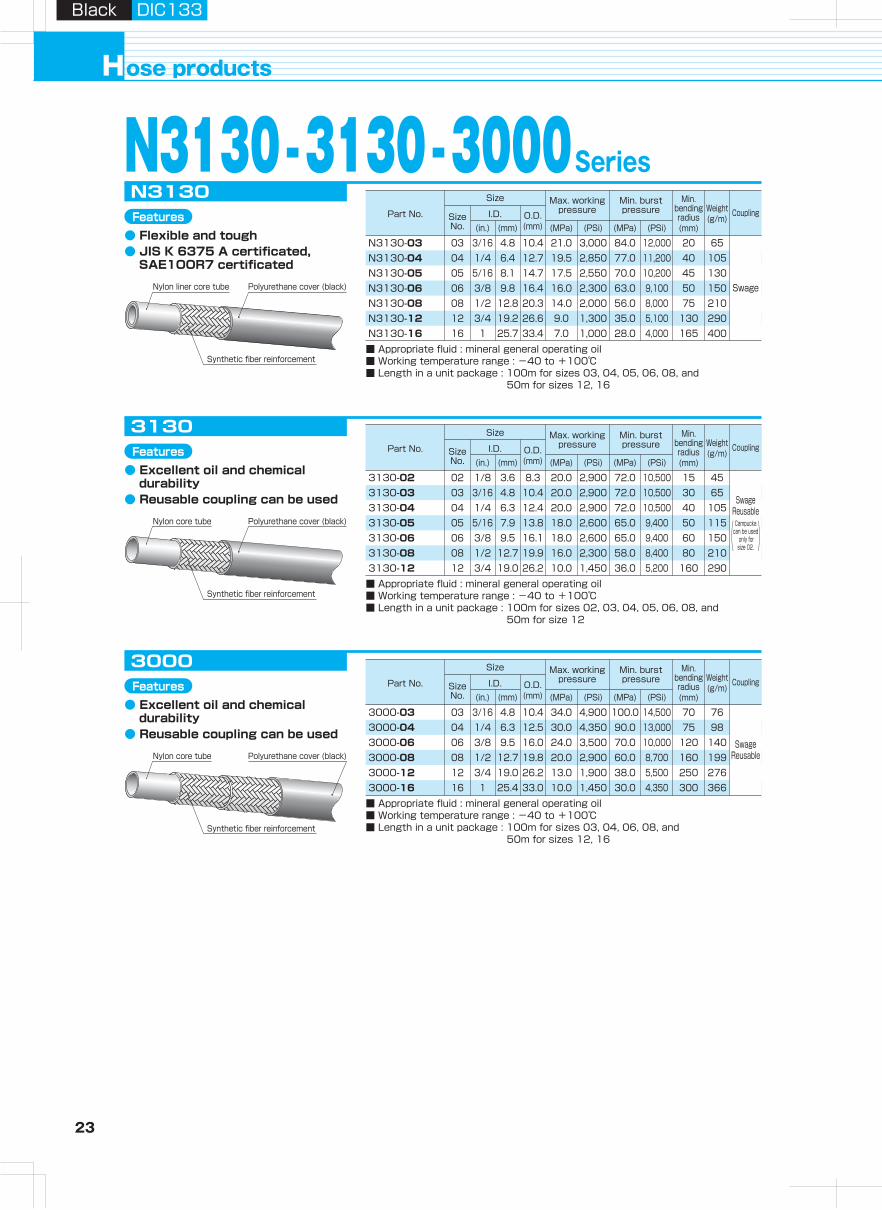
23 24
Hydraulic H
oseA
irless-paintingH
oseA
dapterH
ose Guard
Parts, S
pecially- Treated P
arts
Clean H
ose
Hy
dra
ulic
ho
se
pro
du
cts
Assem
bling
Machine,
Jig
, Tool
Hose
Assem
bling
Method
Technical
Docum
entR
eference D
ocument
ose productsH
Black DIC133Black DIC133
Size
Part No. Size No.
I.D. O.D.(mm)(mm)(in.) (MPa)
Max. working pressure
(PSi) (MPa)
Min. burst pressure
Min. bending radius(mm)
Coupling
(PSi)
Weight(g/m)
Size
Part No. Size No.
I.D. O.D.(mm)(mm)(in.) (MPa)
Max. working pressure
(PSi) (MPa)
Min. burst pressure
Min. bending radius(mm)
Coupling
(PSi)
Weight(g/m)
Size
Part No. Size No.
I.D. O.D.(mm)(mm)(in.) (MPa)
Max. working pressure
(PSi) (MPa)
Min. burst pressure
Min. bending radius(mm)
Coupling
(PSi)
Weight(g/m)
Size
Part No. Size No.
I.D. O.D.(mm)(mm)(in.) (MPa)
Max. working pressure
(PSi) (MPa)
Min. burst pressure
Min. bending radius(mm)
Coupling
(PSi)
Weight(g/m)
Features● Flexible and tough● JIS K 6375 A certificated,
SAE1OOR7 certificated
Features● High flexibility and steady
performance under low temperature environment〈-55℃〉
● JIS K 6375 A certificated, SAE1OOR7 certificated
Features● Excellent oil and chemical
durability● Reusable coupling can be used
Features● Excellent oil and chemical
durability● Reusable coupling can be used
N3130 -3130 -3000Series 3700Series (for low temperature environment)
N3130-03N3130-04N3130-05N3130-06N3130-08N3130-12N3130-16
N3130
■ Appropriate fluid : mineral general operating oil■ Working temperature range : -40 to +100℃■ Length in a unit package : 100m for sizes 03, 04, 05, 06, 08, and
50m for sizes 12, 16
3700-033700-043700-063700-08
3700
■ Appropriate fluid : mineral general operating oil■ Working temperature range : -55 to +100℃■ Length in a unit package : 100m
3130-023130-033130-043130-053130-063130-083130-12
3130
3000-033000-043000-063000-083000-123000-16
3000
■ Appropriate fluid : mineral general operating oil■ Working temperature range : -40 to +100℃■ Length in a unit package : 100m for sizes 03, 04, 06, 08, and
50m for sizes 12, 16
Synthetic fiber reinforcement
Polyurethane cover (black)Nylon core tube
Synthetic fiber reinforcement
Polyurethane cover (black)Nylon core tube
Polyurethane cover (black)Nylon liner core tube
Synthetic fiber reinforcement
■ Appropriate fluid : mineral general operating oil■ Working temperature range : -40 to +100℃■ Length in a unit package : 100m for sizes 02, 03, 04, 05, 06, 08, and
50m for size 12
Nylon liner core tube
Synthetic fiber reinforcement
Polyurethane cover (black) Swage
Swage
03 3/16 4.8 10.4 21.0 3,000 84.0 12,000 20 65 03 3/16 4.8 10.5 21.0 3,000 84.0 12,000 19 7604 1/4 6.4 12.7 19.5 2,850 77.0 11,200 40 10505 5/16 8.1 14.7 17.5 2,550 70.0 10,200 45 13006 3/8 9.8 16.4 16.0 2,300 63.0 9,100 50 150
04 1/4 6.3 12.8 19.5 2,850 77.0 11,200 32 10106 3/8 9.5 16.3 16.0 2,300 63.0 9,100 51 14108 1/2 12.7 20.2 14.0 2,000 56.0 8,000 76 196
08 1/2 12.8 20.3 14.0 2,000 56.0 8,000 75 21012 3/4 19.2 26.6 9.0 1,300 35.0 5,100 130 29016 1 25.7 33.4 7.0 1,000 28.0 4,000 165 400
02 1/8 3.6 8.3 20.0 2,900 72.0 10,500 15 4503 3/16 4.8 10.4 20.0 2,900 72.0 10,500 30 6504 1/4 6.3 12.4 20.0 2,900 72.0 10,500 40 10505 5/16 7.9 13.8 18.0 2,600 65.0 9,400 50 11506 3/8 9.5 16.1 18.0 2,600 65.0 9,400 60 15008 1/2 12.7 19.9 16.0 2,300 58.0 8,400 80 21012 3/4 19.0 26.2 10.0 1,450 36.0 5,200 160 290
Swage Reusable
03 3/16 4.8 10.4 34.0 4,900 100.0 14,500 70 7604 1/4 6.3 12.5 30.0 4,350 90.0 13,000 75 9806 3/8 9.5 16.0 24.0 3,500 70.0 10,000 120 14008 1/2 12.7 19.8 20.0 2,900 60.0 8,700 160 19912 3/4 19.0 26.2 13.0 1,900 38.0 5,500 250 27616 1 25.4 33.0 10.0 1,450 30.0 4,350 300 366
( )Swage
ReusableCampucka
can be used only forsize 02.
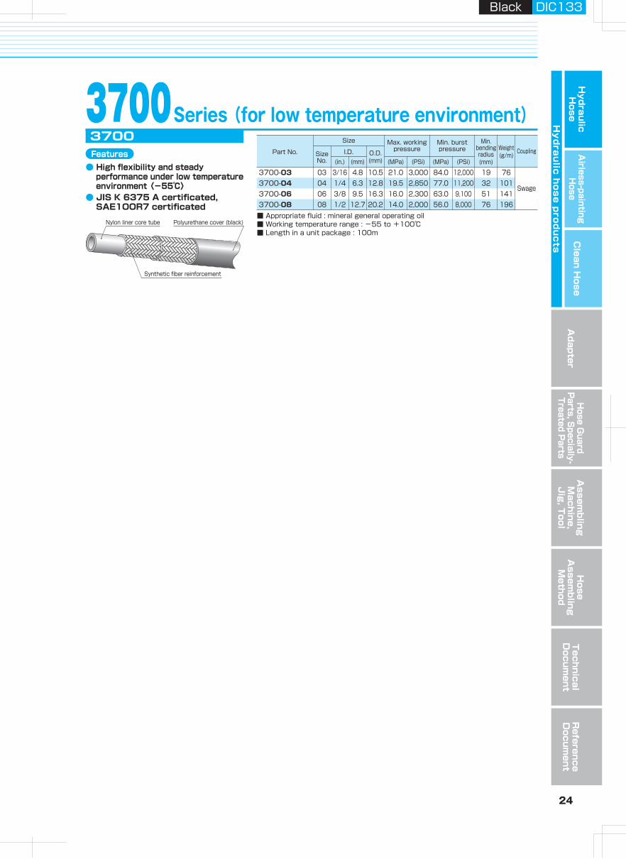
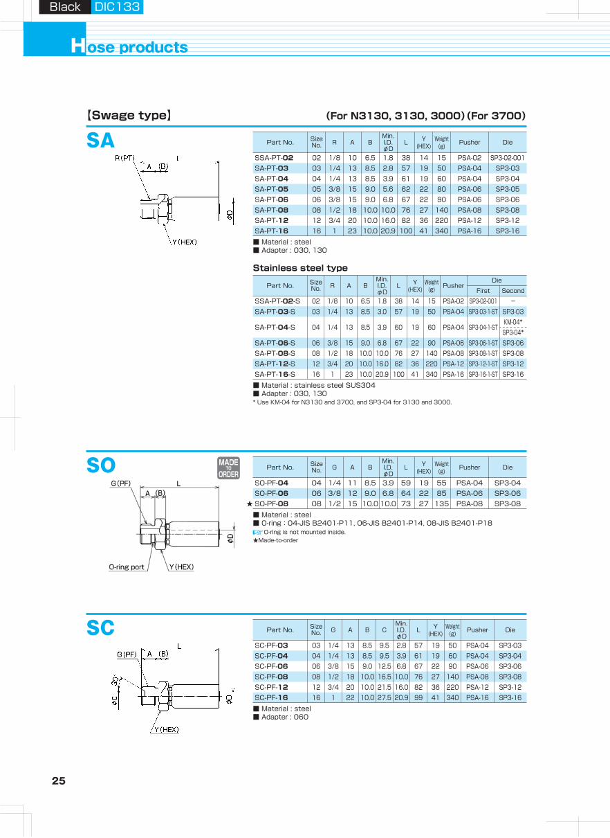
25 26
Hydraulic H
oseA
irless-paintingH
oseA
dapterH
ose Guard
Parts, S
pecially- Treated P
arts
Clean H
ose
Hy
dra
ulic
ho
se
pro
du
cts
Assem
bling
Machine,
Jig
, Tool
Hose
Assem
bling
Method
Technical
Docum
entR
eference D
ocument
ose productsH
Black DIC133Black DIC133
SASSA-PT-02
■ Material : steel■ Adapter : 030, 130
【Swage type】
Stainless steel type
(For N3130, 3130, 3000)(For 3700)
02 1/8 10 6.5 1.8 38 14 15 PSA-02 SP3-02-001SA-PT-03 03 1/4 13 8.5 2.8 57 19 50 PSA-04 SP3-03SA-PT-04 04 1/4 13 8.5 3.9 61 19 60 PSA-04 SP3-04SA-PT-05 05 3/8 15 9.0 5.6 62 22 80 PSA-06 SP3-05SA-PT-06 06 3/8 15 9.0 6.8 67 22 90 PSA-06 SP3-06SA-PT-08 08 1/2 18 10.0 10.0 76 27 140 PSA-08 SP3-08SA-PT-12 12 3/4 20 10.0 16.0 82 36 220 PSA-12 SP3-12SA-PT-16 16 1 23 10.0 20.9 100 41 340 PSA-16 SP3-16
SO-PF-04
■ Material : steel■ O-ring:04-JIS B2401-P11, 06-JIS B2401-P14, 08-JIS B2401-P18
04 1/4 11 8.5 3.9 59 19 55 PSA-04 SP3-04SO-PF-06 06 3/8 12 9.0 6.8 64 22 85 PSA-06 SP3-06SO-PF-08★ 08 1/2 15 10.0 10.0 73 27 135 PSA-08 SP3-08
SSA-PT-02-S
■ Material : stainless steel SUS304■ Adapter : 030, 130* Use KM-04 for N3130 and 3700, and SP3-04 for 3130 and 3000.
SA-PT-03-S
SA-PT-04-S
SA-PT-06-SSA-PT-08-SSA-PT-12-SSA-PT-16-S 16 1 23 10.0 20.9 100 41 340 PSA-16 SP3-16-1-ST SP3-16
12 3/4 20 10.0 16.0 82 36 220 PSA-12 SP3-12-1-ST SP3-1208 1/2 18 10.0 10.0 76 27 140 PSA-08 SP3-08-1-ST SP3-0806 3/8 15 9.0 6.8 67 22 90 PSA-06 SP3-06-1-ST SP3-06
04 1/4 13 8.5 3.9 60 19 60 PSA-04 SP3-04-1-STKM-04*SP3-04*
03 1/4 13 8.5 3.0 57 19 50 PSA-04 SP3-03-1-ST SP3-0302 1/8 10 6.5 1.8 38 14 15 PSA-02 SP3-02-001 -
Stainless steel type
SSE-PF-02-S
■ Material : stainless steel SUS304■ Adapter : 010, 045, 090, 150, 020, 025, 064, 069, 030* Use KM-04 for N3130 and 3700, and SP3-04 for 3130 and 3000.
SE-PF-03-S
SE-PF-04-S
SE-PF-06-SSE-PF-08-SSE-PF-12-SSE-PF-16-S
03 1/4 6.0 9.0 3.0 8.0 58 19 19 70 PSE-03 SP3-03-1-ST SP3-03
04 1/4 8.5 9.5 3.9 8.0 63 19 19 80 PSE-04 SP3-04-1-STKM-04*SP3-04*
06 3/8 9.5 12.5 6.8 10.0 71 22 22 110 PSE-06 SP3-06-1-ST SP3-0608 1/2 9.0 16.0 10.0 12.0 80 27 27 170 PSE-08 SP3-08-1-ST SP3-0812 3/4 10.5 21.5 16.0 13.0 87 36 36 280 PSE-12 SP3-12-1-ST SP3-1216 1 11.0 27.5 20.9 15.0 105 41 41 400 PSE-16 SP3-16-1-ST SP3-16
02 1/8 4.0 7.0 1.8 7.0 42 14 14 25 PSE-02-001 SP3-2-001 -
SE【Swage type】 (For N3130, 3130, 3000)(For 3700)
SC-PF-03
■ Material : steel■ Adapter : 060
03 1/4 13 8.5 9.5 2.8 57 19 50 PSA-04 SP3-0304 1/4 13 8.5 9.5 3.9 61 19 60 PSA-04 SP3-0406 3/8 15 9.0 12.5 6.8 67 22 90 PSA-06 SP3-0608 1/2 18 10.0 16.5 10.0 76 27 140 PSA-08 SP3-0812 3/4 20 10.0 21.5 16.0 82 36 220 PSA-12 SP3-1216 1 22 10.0 27.5 20.9 99 41 340 PSA-16 SP3-16
SC-PF-04SC-PF-06SC-PF-08SC-PF-12SC-PF-16
SO
SC
O-ring is not mounted inside.
SSE-PF-02
■ Material : steel■ Adapter : 010, 045, 090, 150, 020, 025, 064, 069, 030
02 1/8 4.0 6.8 1.8 7.0 42 14 14 25 PSE-02-001 SP3-02-001SE-PF-03 03 1/4 6.0 9.5 2.8 8.0 58 19 19 70 PSE-03 SP3-03SE-PF-04 04 1/4 8.0 9.3 3.9 8.0 64 19 17 75 PSE-04 SP3-04SE-PF-05 05 3/8 8.5 12.0 5.6 10.0 66 22 22 100 PSE-05 SP3-05SE-PF-06 06 3/8 9.5 12.3 6.8 10.0 71 22 19 100 PSE-06 SP3-06SE-PF-08 08 1/2 9.0 15.5 10.0 12.5 80 27 27 170 PSE-08 SP3-08SE-PF-12 12 3/4 10.5 21.5 16.0 13.0 87 36 36 280 PSE-12 SP3-12SE-PF-16 16 1 11.0 27.5 20.9 15.0 105 41 41 400 PSE-16 SP3-16
Stainless steel type
SSF-PF-02-S
■ Material : stainless steel SUS304■ Adapter : 110, 145, 190, 130* Use KM-04 for N3130 and 3700, and SP3-04 for 3130 and 3000.
SF-PF-04-S
SF-PF-06-SSF-PF-08-SSF-PF-12-SSF-PF-16-S
04 1/4 8.5 7.5 3.9 5.5 63 19 19 80 PSE-04 SP3-04-1-STKM-04*SP3-04*
06 3/8 9.5 10.0 6.8 6.5 71 22 22 110 PSE-06 SP3-06-1-ST SP3-0608 1/2 9.0 13.2 10.0 9.0 80 27 27 170 PSE-08 SP3-08-1-ST SP3-0812 3/4 10.5 19.0 16.0 9.5 87 36 36 280 PSE-12 SP3-12-1-ST SP3-1216 1 11.0 25.4 20.9 10.0 105 41 41 400 PSE-16 SP3-16-1-ST SP3-16
02 1/8 4.0 5.0 1.8 3.0 41 14 14 25 PSE-02-001 SP3-2-001 -
SFSSF-PF-02
■ Material : steel■ Adapter : 110, 145, 190, 130
02 1/8 4.0 5.0 1.8 3.0 41 14 14 25 PSE-02-001 SP3-02-001SF-PF-03 03 1/4 6.0 7.5 2.8 5.5 58 19 19 70 PSE-03 SP3-03SF-PF-04 04 1/4 8.5 7.5 3.9 5.5 63 19 17 75 PSE-04 SP3-04SF-PF-05 05 3/8 8.5 10.0 5.6 6.5 66 22 22 100 PSE-05 SP3-05SF-PF-06 06 3/8 9.5 10.0 6.8 6.5 71 22 19 100 PSE-06 SP3-06SF-PF-08 08 1/2 9.0 14.0 10.0 9.0 80 27 27 170 PSE-08 SP3-08SF-PF-12 12 3/4 10.5 19.0 16.0 9.5 87 36 36 280 PSE-12 SP3-12SF-PF-16 16 1 11.0 25.4 20.9 10.0 105 41 41 410 PSE-16 SP3-16
★Made-to-order
MADETO
ORDER
Part No. Size No. R A B
Min.I.D.φD
L Y(HEX)
Weight(g) Pusher Die
Part No. Size No. R A B
Min.I.D.φD
L Y(HEX)
Weight(g) Pusher Die
Part No. Size No. G A B
Min.I.D.φD
L Y(HEX)
Weight(g) Pusher Die
Part No. Size No. R A B
Min.I.D.φD
L Y(HEX)
Weight(g) Pusher
First Second
Die
Part No. Size No. G A B C
Min.I.D.φD
L Y(HEX)
Weight(g) Pusher Die
Part No. Size No. G B C
Min.I.D.φD
H L X(HEX)
Y(HEX)
Weight(g) Pusher
First Second
Die
Part No. Size No. G B C
Min.I.D.φD
H L X(HEX)
Y(HEX)
Weight(g) Pusher Die
Part No. Size No. G B C
Min.I.D.φD
H L X(HEX)
Y(HEX)
Weight(g) Pusher
First Second
Die
Part No. Size No. G B C
Min.I.D.φD
H L X(HEX)
Y(HEX)
Weight(g) Pusher Die
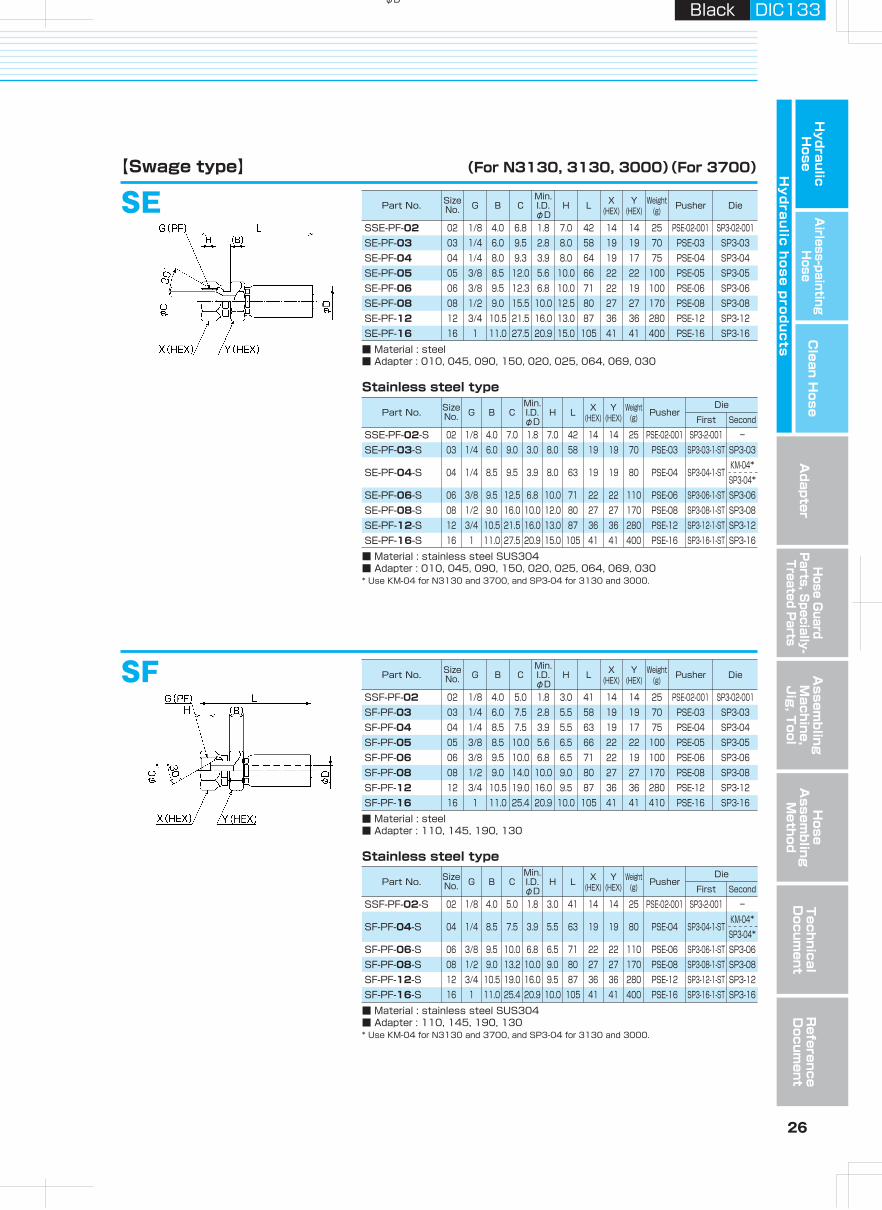
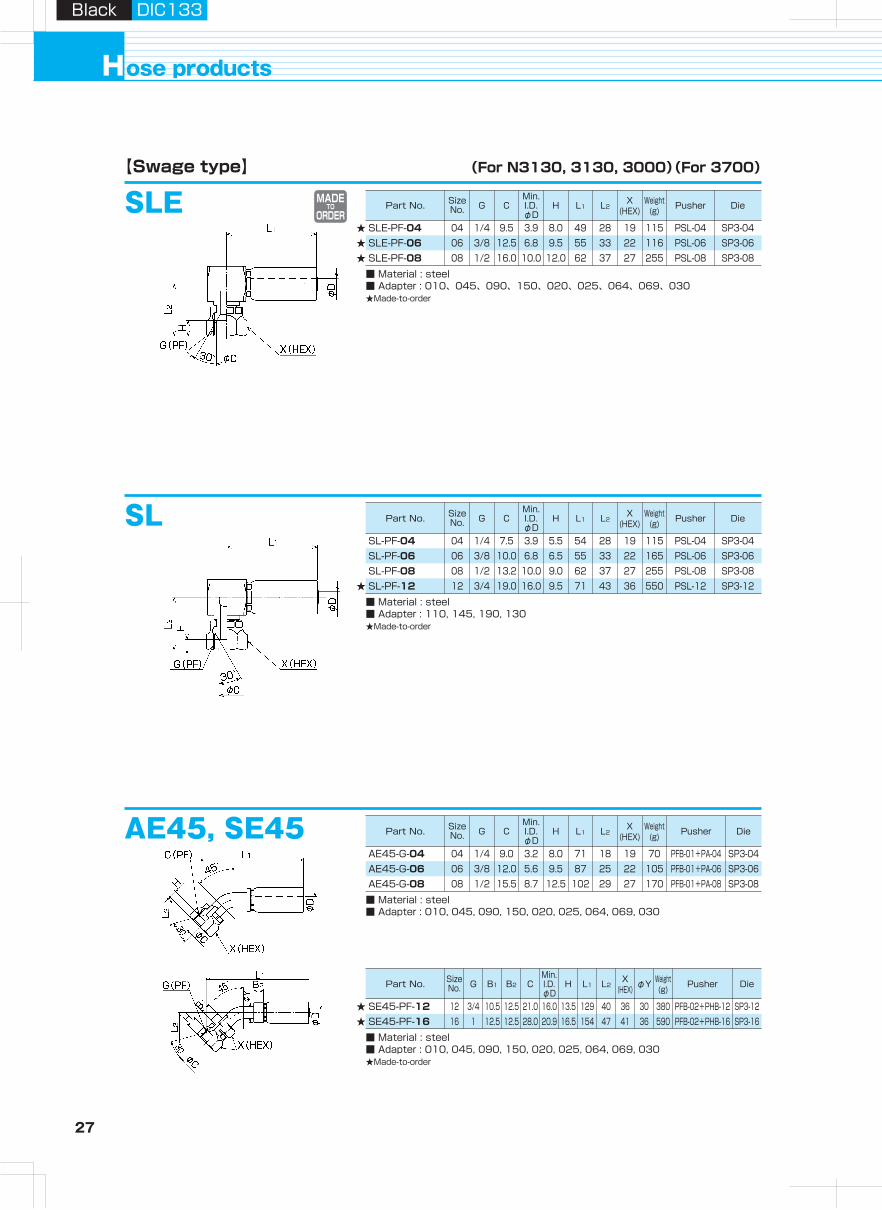
27 28
Hydraulic H
oseA
irless-paintingH
oseA
dapterH
ose Guard
Parts, S
pecially- Treated P
arts
Clean H
ose
Hy
dra
ulic
ho
se
pro
du
cts
Assem
bling
Machine,
Jig
, Tool
Hose
Assem
bling
Method
Technical
Docum
entR
eference D
ocument
ose productsH
Black DIC133Black DIC133
MADETO
ORDERSLE【Swage type】 (For N3130, 3130, 3000)(For 3700)
AE90, SE90【Swage type】 (For N3130, 3130, 3000)(For 3700)
SLE-PF-04
■ Material : steel■ Adapter : 010、045、090、150、020、025、064、069、030★Made-to-order
04 1/4 9.5 3.9 8.0 49 28 19 115 PSL-04 SP3-0406 3/8 12.5 6.8 9.5 55 33 22 116 PSL-06 SP3-0608 1/2 16.0 10.0 12.0 62 37 27 255 PSL-08 SP3-08
SLE-PF-06SLE-PF-08
★★★
SLSL-PF-04
■ Material : steel■ Adapter : 110, 145, 190, 130★Made-to-order
04 1/4 7.5 3.9 5.5 54 28 19 115 PSL-04 SP3-0406 3/8 10.0 6.8 6.5 55 33 22 165 PSL-06 SP3-0608 1/2 13.2 10.0 9.0 62 37 27 255 PSL-08 SP3-0812 3/4 19.0 16.0 9.5 71 43 36 550 PSL-12 SP3-12
SL-PF-06SL-PF-08SL-PF-12★
AE45, SE45AE45-G-04
■ Material : steel■ Adapter : 010, 045, 090, 150, 020, 025, 064, 069, 030
04 1/4 9.0 3.2 8.0 71 18 19 70 PFB-01+PA-04 SP3-0406 3/8 12.0 5.6 9.5 87 25 22 105 PFB-01+PA-06 SP3-0608 1/2 15.5 8.7 12.5 102 29 27 170 PFB-01+PA-08 SP3-08
AE45-G-06AE45-G-08
SE45-PF-12
■ Material : steel■ Adapter : 010, 045, 090, 150, 020, 025, 064, 069, 030★Made-to-order
12 3/4 10.5 12.5 21.0 16.0 13.5 129 40 36 30 380 PFB-02+PHB-12 SP3-1216 1 12.5 12.5 28.0 20.9 16.5 154 47 41 36 590 PFB-02+PHB-16 SP3-16SE45-PF-16
SE90-PF-12
■ Material : steel■ Adapter : 010, 045, 090, 150, 020, 025, 064, 069, 030
12 3/4 10.5 12.5 21.0 16.0 13.5 108 77 36 30 405 PFB-02+PHB-12 SP3-1216 1 12.5 12.5 28.0 20.9 16.5 127 87 41 36 645 PFB-02+PHB-16 SP3-16SE90-PF-16
AF45, SF45
SF45-PF-12
■ Material : steel■ Adapter : 110, 145, 190, 130★Made-to-order
12 3/4 10.5 12.5 19.0 16.0 9.5 129 40 36 30 381 PFB-02+PHB-12 SP3-1216 1 11.0 12.5 25.4 20.9 10.0 151 60 41 36 601 PFB-02+PHB-16 SP3-16SF45-PF-16
AF90, SF90
SF90-PF-12
■ Material : steel■ Adapter : 110, 145, 190, 130★Made-to-order
12 3/4 10.5 12.5 19.0 16.0 9.5 108 77 36 30 405 PFB-02+PHB-12 SP3-1216 1 11.0 12.5 25.4 20.9 10.0 127 86 41 36 645 PFB-02+PHB-16 SP3-16SF90-PF-16
★★
★★
★★
AE90-G-04
■ Material : steel■ Adapter : 010, 045, 090, 150, 020, 025, 064, 069, 030
04 1/4 9.0 3.2 8.0 59 33 19 75 PFB-01+PA-04 SP3-0406 3/8 12.0 5.6 9.5 74 45 22 115 PFB-01+PA-06 SP3-0608 1/2 15.5 8.7 12.5 83 54 27 180 PFB-01+PA-08 SP3-08
AE90-G-06AE90-G-08
AF45-G-04
■ Material : steel■ Adapter : 110, 145, 190, 130
04 1/4 7.0 3.2 5.5 73 19 19 70 PFB-01+PA-04 SP3-0406 3/8 10.0 5.6 6.5 85 23 22 110 PFB-01+PA-06 SP3-0608 1/2 14.0 8.7 9.0 103 29 27 155 PFB-01+PA-08 SP3-08
AF45-G-06AF45-G-08
AF90-G-04
■ Material : steel■ Adapter : 110, 145, 190, 130
04 1/4 7.0 3.2 5.5 61 33 19 75 PFB-01+PA-04 SP3-0406 3/8 10.0 5.6 6.5 74 45 22 115 PFB-01+PA-06 SP3-0608 1/2 14.0 8.7 9.0 83 52 27 165 PFB-01+PA-08 SP3-08
AF90-G-06AF90-G-08
Part No. Size No. G B1 B2 C
Min.I.D.φD
H L1 L2X
(HEX) φY Weight(g) Pusher Die
Part No. Size No. G B1 B2 C
Min.I.D.φD
H L1 L2X
(HEX) φY Weight(g) Pusher Die
Part No. Size No. G B1 B2 C
Min.I.D.φD
H L1 L2X
(HEX) φY Weight(g) Pusher Die
Part No. Size No. G C
Min.I.D.φD
H L1 L2X
(HEX)Weight
(g) Pusher Die
Part No. Size No. G C
Min.I.D.φD
H L1 L2X
(HEX)Weight
(g) Pusher Die
Part No. Size No. G C
Min.I.D.φD
H L1 L2X
(HEX)Weight
(g) Pusher Die
Part No. Size No. G C
Min.I.D.φD
H L1 L2X
(HEX)Weight
(g) Pusher Die
Part No. Size No. G C
Min.I.D.φD
H L1 L2X
(HEX)Weight
(g) Pusher Die
Part No. Size No. G C
Min.I.D.φD
H L1 L2X
(HEX)Weight
(g) Pusher Die
Part No. Size No. G B1 B2 C
Min.I.D.φD
H L1 L2X
(HEX) φY Weight(g) Pusher Die
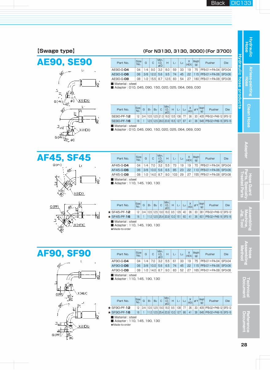
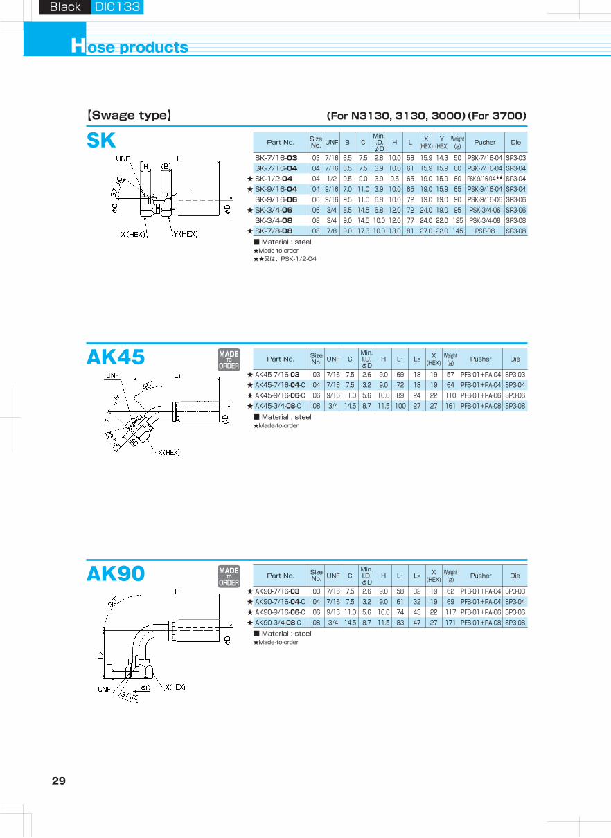
29 30
Hydraulic H
oseA
irless-paintingH
oseA
dapterH
ose Guard
Parts, S
pecially- Treated P
arts
Clean H
ose
Hy
dra
ulic
ho
se
pro
du
cts
Assem
bling
Machine,
Jig
, Tool
Hose
Assem
bling
Method
Technical
Docum
entR
eference D
ocument
ose productsH
Black DIC133Black DIC133
SK【Swage type】 (For N3130, 3130, 3000)(For 3700)
★
★
★★
【Campucka type】 Hydraulic push-one coupling (For 3130-02 only)
SK-7/16-03 03 7/16 6.5 7.5 2.8 10.0 58 15.9 14.3 50 PSK-7/16-04 SP3-03SK-7/16-04 04 7/16 6.5 7.5 3.9 10.0 61 15.9 15.9 60 PSK-7/16-04 SP3-04SK-1/2-04 04 1/2 9.5 9.0 3.9 9.5 65 19.0 15.9 60 SP3-04SK-9/16-04 04 9/16 7.0 11.0 3.9 10.0 65 19.0 15.9 65 PSK-9/16-04 SP3-04SK-9/16-06 06 9/16 9.5 11.0 6.8 10.0 72 19.0 19.0 90 PSK-9/16-06 SP3-06SK-3/4-06 06 3/4 8.5 14.5 6.8 12.0 72 24.0 19.0 95 PSK-3/4-06 SP3-06SK-3/4-08 08 3/4 9.0 14.5 10.0 12.0 77 24.0 22.0 125 PSK-3/4-08 SP3-08SK-7/8-08 08 7/8 9.0 17.3 10.0 13.0 81 27.0 22.0 145 PSE-08 SP3-08
AK45
★★★★ AK45-7/16-03
■ Material : steel★Made-to-order
03 7/16 7.5 2.6 9.0 69 18 19 57 PFB-01+PA-04 SP3-0304 7/16 7.5 3.2 9.0 72 18 19 64 PFB-01+PA-04 SP3-0406 9/16 11.0 5.6 10.0 89 24 22 110 PFB-01+PA-06 SP3-0608 3/4 14.5 8.7 11.5 100 27 27 161 PFB-01+PA-08 SP3-08
AK45-7/16-04-CAK45-9/16-06-CAK45-3/4-08-C
AK90
★★★★ AK90-7/16-03
■ Material : steel★Made-to-order
03 7/16 7.5 2.6 9.0 58 32 19 62 PFB-01+PA-04 SP3-0304 7/16 7.5 3.2 9.0 61 32 19 69 PFB-01+PA-04 SP3-0406 9/16 11.0 5.6 10.0 74 43 22 117 PFB-01+PA-06 SP3-0608 3/4 14.5 8.7 11.5 83 47 27 171 PFB-01+PA-08 SP3-08
AK90-7/16-04-CAK90-9/16-06-CAK90-3/4-08-C
CACA-R-02L
■ Material : steel■ Working temperature range : 20.0MPa■ Working temperature range : -20 to +100℃■ Adapter : 030, 130
02 1/8 1.5 22.5 56 14 36CAUTION : Handle with care not to drop couplings as an inner nipple could be self locked by
pushing-out action to inlet of coupling.
CAUTION : Handle with care not to drop couplings as an inner nipple could be self locked by pushing-out action to inlet of coupling.
CAUTION : Handle with care not to drop couplings as an inner nipple could be self locked by pushing-out action to inlet of coupling.
CECE-G-02L
■ Material : steel■ Working temperature range : 20.0MPa■ Working temperature range : -20 to +100℃■ Adapter : 010, 045, 090, 150, 030
02 1/8 1.5 22.5 62 14 14 44
CFCF-G-02L
■ Material : steel■ Working temperature range : 20.0MPa■ Working temperature range : -20 to +100℃■ Adapter : 110, 145, 190, 130
02 1/8 1.5 22.5 62 14 14 45
MADETO
ORDER
MADETO
ORDER
CAUTION : Handle with care not to drop couplings as an inner nipple could be self locked by pushing-out action to inlet of coupling.
Features of Campucka and assembly mechanism
● Reduction of operation time (half that of our conventional product)● Specialized swaging tool is not necessary. (Easy handling)● Best for on-site Iength adjustment.● Convenient for emergency repair.
Push-one connection1● Hose is detachable for length
adjustment when piping.● Detachable tool is available.
Detachable hose2● It is possible to correct the twisted
direction of a hose.
Correcting hose's twisted direction3
● Ratchet mechanism of our original lock ring is employed.
● Steady performance even for movable piping.
● Pressure variation is accommodated.
Nipple stop mechanism4Campucka assembly mechanism
Detailed diagram
Swaging force proportional to inner pressure.
Before pressurization
Insertion mark
After pressurization
Insertion mark
Lock ringprevents swage releasing after pressurization.
Assemblingmethod
p.57
CAUTION : Cannot be detached after pressurization.
CAUTION : Cannot be detached after pressurization.
PSK-9/16-04★★
■ Material : steel★Made-to-order★★又は、PSK-1/2-04
Part No. Size No. UNF B C
Min.I.D.φD
H L X(HEX)
Y(HEX)
Weight(g) Pusher Die
Part No. Size No. UNF C
Min.I.D.φD
H L1 L2X
(HEX)Weight
(g) Pusher Die
Part No. Size No. UNF C
Min.I.D.φD
H L1 L2X
(HEX)Weight
(g) Pusher Die
Part No. RSize No. Min. I.D.φD F L X Weight
(g)
Part No. GSize No. Min. I.D.φD F L X Y Weight
(g)
Part No. GSize No. Min. I.D.φD F L X Y Weight
(g)
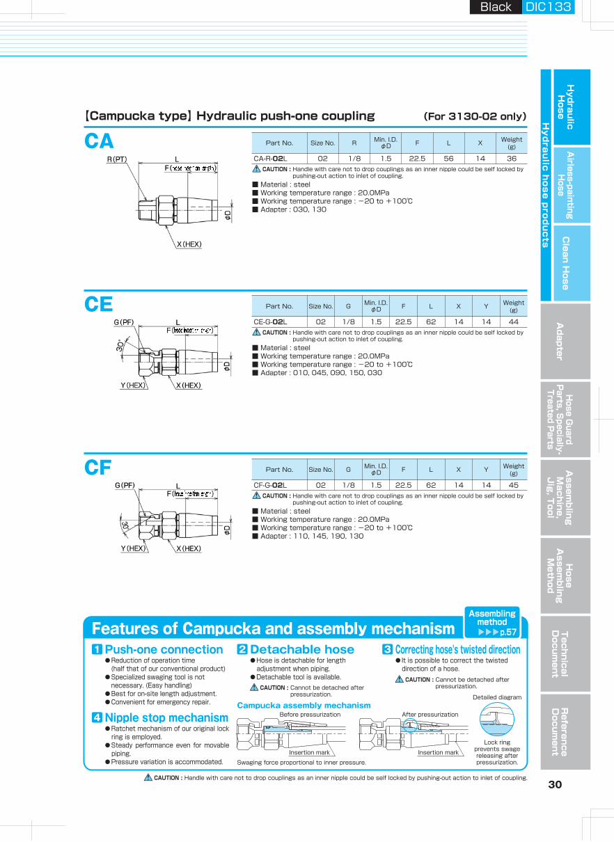
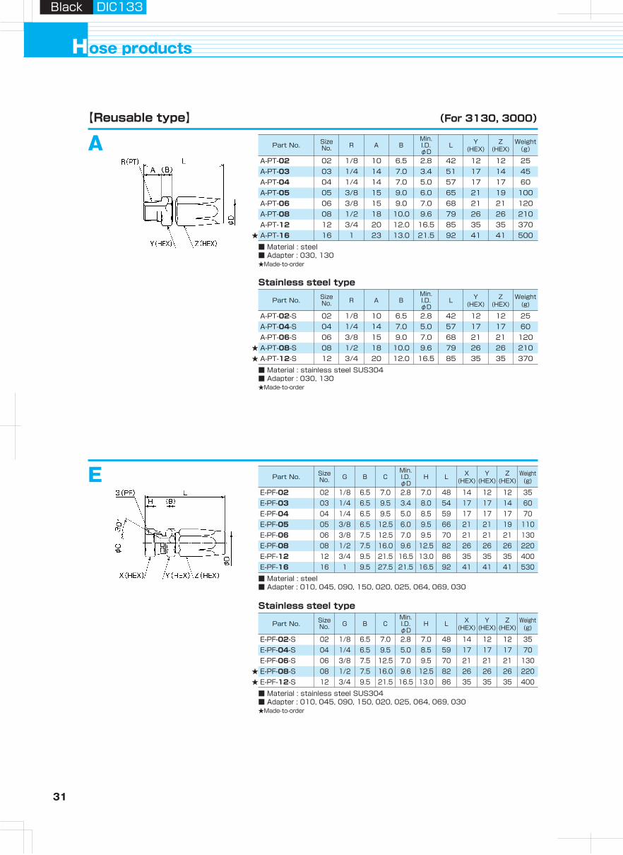
31 32
Hydraulic H
oseA
irless-paintingH
oseA
dapterH
ose Guard
Parts, S
pecially- Treated P
arts
Clean H
ose
Hy
dra
ulic
ho
se
pro
du
cts
Assem
bling
Machine,
Jig
, Tool
Hose
Assem
bling
Method
Technical
Docum
entR
eference D
ocument
ose productsH
Black DIC133Black DIC133
A【Reusable type】 (For 3130, 3000)
★
【Reusable type】 (For 3130, 3000)
A-PT-02
■ Material : steel■ Adapter : 030, 130★Made-to-order
02 1/8 10 6.5 2.8 42 12 12 25A-PT-03 03 1/4 14 7.0 3.4 51 17 14 45A-PT-04 04 1/4 14 7.0 5.0 57 17 17 60A-PT-05 05 3/8 15 9.0 6.0 65 21 19 100A-PT-06 06 3/8 15 9.0 7.0 68 21 21 120A-PT-08 08 1/2 18 10.0 9.6 79 26 26 210A-PT-12 12 3/4 20 12.0 16.5 85 35 35 370A-PT-16 16 1 23 13.0 21.5 92 41 41 500
EE-PF-02
■ Material : steel■ Adapter : 010, 045, 090, 150, 020, 025, 064, 069, 030
02 1/8 6.5 7.0 2.8 7.0 48 14 12 12 35E-PF-03 03 1/4 6.5 9.5 3.4 8.0 54 17 17 14 60E-PF-04 04 1/4 6.5 9.5 5.0 8.5 59 17 17 17 70E-PF-05 05 3/8 6.5 12.5 6.0 9.5 66 21 21 19 110E-PF-06 06 3/8 7.5 12.5 7.0 9.5 70 21 21 21 130E-PF-08 08 1/2 7.5 16.0 9.6 12.5 82 26 26 26 220E-PF-12 12 3/4 9.5 21.5 16.5 13.0 86 35 35 35 400E-PF-16 16 1 9.5 27.5 21.5 16.5 92 41 41 41 530
F-PF-02
■ Material : steel■ Adapter : 110, 145, 190, 130★Made-to-order
02 1/8 6.5 5.0 2.8 3.0 48 14 12 12 35F-PF-03 03 1/4 6.5 7.0 3.4 6.0 54 17 17 14 60F-PF-04 04 1/4 6.5 7.0 5.0 6.0 59 17 17 17 70F-PF-05 05 3/8 6.5 10.0 6.0 7.0 66 21 21 19 110F-PF-06 06 3/8 7.5 10.0 7.0 7.0 70 21 21 21 130F-PF-08 08 1/2 7.5 14.0 9.6 8.5 82 26 26 26 220F-PF-12 12 3/4 9.5 19.0 16.5 9.0 86 35 35 35 410F-PF-16 16 1 9.5 25.0 21.5 10.5 92 41 41 41 570
E-PF-02-S
■ Material : stainless steel SUS304■ Adapter : 010, 045, 090, 150, 020, 025, 064, 069, 030★Made-to-order
02 1/8 6.5 7.0 2.8 7.0 48 14 12 12 35E-PF-04-S 04 1/4 6.5 9.5 5.0 8.5 59 17 17 17 70E-PF-06-S 06 3/8 7.5 12.5 7.0 9.5 70 21 21 21 130E-PF-08-S 08 1/2 7.5 16.0 9.6 12.5 82 26 26 26 220E-PF-12-S 12 3/4 9.5 21.5 16.5 13.0 86 35 35 35 400
★★
A-PT-02-S
■ Material : stainless steel SUS304■ Adapter : 030, 130★Made-to-order
02 1/8 10 6.5 2.8 42 12 12 25A-PT-04-S 04 1/4 14 7.0 5.0 57 17 17 60A-PT-06-S 06 3/8 15 9.0 7.0 68 21 21 120A-PT-08-S 08 1/2 18 10.0 9.6 79 26 26 210A-PT-12-S 12 3/4 20 12.0 16.5 85 35 35 370
F
C
Stainless steel type
★★
Stainless steel type
★
C-PF-02
■ Material : steel■ Adapter : 060★Made-to-order
02 1/8 10 6.5 7.0 2.8 42 12 12 2503 1/4 14 7.0 9.5 3.4 51 17 14 4504 1/4 14 7.0 9.5 5.0 57 17 17 6006 3/8 15 9.0 12.5 7.0 68 21 21 12008 1/2 18 10.0 16.5 9.6 79 26 26 21012 3/4 20 12.0 22.0 16.5 85 35 35 500
C-PF-03C-PF-04C-PF-06C-PF-08C-PF-12★
★
Part No. SizeNo. R A B
Min.I.D.φD
L Y(HEX)
Z(HEX)
Weight(g)
Part No. SizeNo. G B C
Min.I.D.φD
H L X(HEX)
Y(HEX)
Z(HEX)
Weight(g)
Part No. SizeNo. G B C
Min.I.D.φD
H L X(HEX)
Y(HEX)
Z(HEX)
Weight(g)
Part No. SizeNo. G B C
Min.I.D.φD
H L X(HEX)
Y(HEX)
Z(HEX)
Weight(g)
Part No. SizeNo. R A B
Min.I.D.φD
L Y(HEX)
Z(HEX)
Weight(g)
Part No. SizeNo. G A B C
Min.I.D.φD
L Y(HEX)
Z(HEX)
Weight(g)
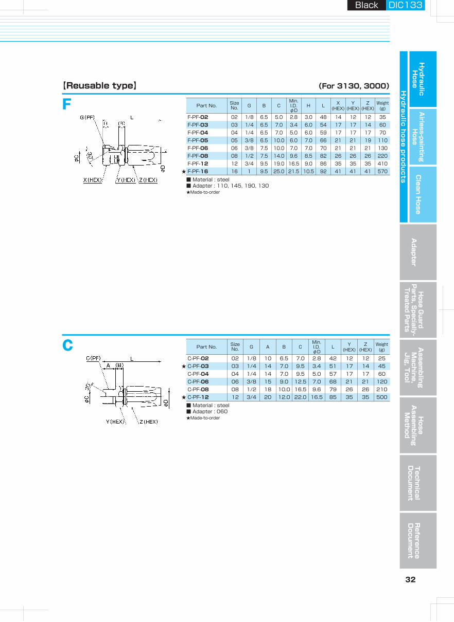
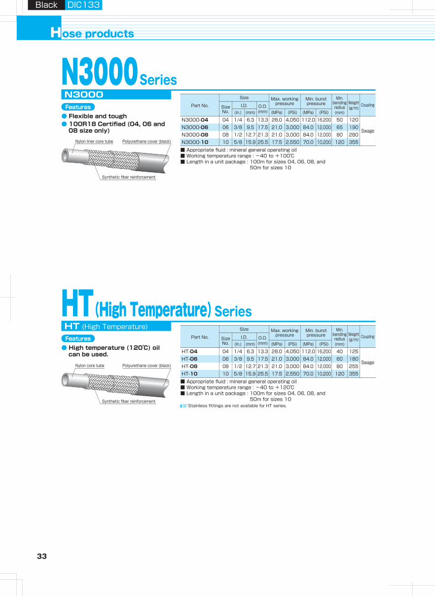
33 34
Hydraulic H
oseA
irless-paintingH
oseA
dapterH
ose Guard
Parts, S
pecially- Treated P
arts
Clean H
ose
Hy
dra
ulic
ho
se
pro
du
cts
Assem
bling
Machine,
Jig
, Tool
Hose
Assem
bling
Method
Technical
Docum
entR
eference D
ocument
ose productsH
Black DIC133Black DIC133
Part No. Size No. R A B
Min.I.D.φD
L Y(HEX)
Weight(g) Pusher
First Second
Die
Part No. Size No. R A B
Min.I.D.φD
L Y(HEX)
Weight(g) Pusher Die
Part No. Size No. G B C
Min.I.D.φD
H L X(HEX)
Y(HEX)
Weight(g) Pusher
First Second
Die
Part No. Size No. G B C
Min.I.D.φD
H L X(HEX)
Y(HEX)
Weight(g) Pusher Die
Part No. Size No. G B C
Min.I.D.φD
H L X(HEX)
Y(HEX)
Weight(g) Pusher Die
Size
Part No. Size No.
I.D. O.D.(mm)(mm)(in.) (MPa)
Max. working pressure
(PSi) (MPa)
Min. burst pressure
Min. bending radius(mm)
Coupling
(PSi)
Weight(g/m)
Size
Part No. Size No.
I.D. O.D.(mm)(mm)(in.) (MPa)
Max. working pressure
(PSi) (MPa)
Min. burst pressure
Min. bending radius(mm)
Coupling
(PSi)
Weight(g/m)
N3000Series
N3000-04N3000-06N3000-08N3000-10
N3000
■ Appropriate fluid : mineral general operating oil■ Working temperature range : -40 to +100℃■ Length in a unit package : 100m for sizes 04, 06, 08, and
50m for sizes 10
HT(High Temperature)Series
HT-04HT-06HT-08HT-10
HT (High Temperature)
■ Appropriate fluid : mineral general operating oil■ Working temperature range : -40 to +120℃■ Length in a unit package : 100m for sizes 04, 06, 08, and
50m for sizes 10
Stainless steel type
SA-PT-04-S
■ Material : stainless steel SUS304■ Adapter : 030, 130
SA-PT-06-N30-SSA-PT-08-N30-S
04 1/4 14 8.5 3.9 61 19 60 PSA-04 SPH-04-1-ST SPN-0406 3/8 15 9.0 6.8 67 22 90 PSA-06 SPH-06-1-ST SPN-0608 1/2 18 10.0 10.0 76 27 140 PSA-08 SPH-08-1-ST SPN-08
SA【Swage type】 (For N3000)(For HT)
SA-PT-04
■ Material : steel■ Adapter : 030, 130
04 1/4 13 8.5 3.9 61 19 60 PSA-04 SPN-0406 3/8 15 9.0 6.8 67 22 90 PSA-06 SPN-0608 1/2 18 10.0 10.0 76 27 140 PSA-08 SPN-0810 3/4 20 10.0 13.0 80 32 180 PSA-10 SPN-10
SA-PT-06-N30SA-PT-08-N30SA-PT-10-N30
Stainless steel type
SE-PF-04-S
■ Material : stainless steel SUS304■ Adapter : 010, 045, 090, 150, 020, 025, 064, 069, 030
SE-PF-06-N30-SSE-PF-08-N30-S
04 1/4 8.0 9.0 3.9 8.0 64 19 19 80 PSE-04 SPH-04-1-ST SPN-0406 3/8 9.5 12.5 6.8 9.5 71 22 22 110 PSE-06 SPH-06-1-ST SPN-0608 1/2 9.0 15.5 10.0 12.5 80 27 27 170 PSE-08 SPH-08-1-ST SPN-08
SESE-PF-04
■ Material : steel■ Adapter : 010, 045, 090, 150, 020, 025, 064, 069, 030
04 1/4 8.0 9.3 3.9 8.0 64 19 17 75 PSE-04 SPN-04SE-PF-06-N30 06 3/8 9.5 12.3 6.8 9.5 71 22 19 110 PSE-06 SPN-06SE-PF-08-N30 08 1/2 9.0 15.5 10.0 12.5 80 27 27 170 PSE-08 SPN-08SE-PF-10-N30 10 3/4 10.5 21.0 13.1 13.0 84 32 32 220 PSE-10 SPN-10
SFSF-PF-04
■ Material : steel■ Adapter : 110, 145, 190, 130
04 1/4 8.5 7.5 3.9 5.5 63 19 17 75 PSE-04 SPN-04SF-PF-06-N30 06 3/8 9.5 10.0 6.8 6.5 71 22 19 110 PSE-06 SPN-06SF-PF-08-N30 08 1/2 9.0 14.0 10.0 9.0 80 27 27 170 PSE-08 SPN-08SF-PF-10-N30 10 3/4 10.5 19.0 13.1 9.5 84 32 32 220 PSE-10 SPN-10
Stainless fittings are not available for HT series.
Features● Flexible and tough● 100R18 Certified (04, 06 and
08 size only)
Synthetic fiber reinforcement
Polyurethane cover (black)Nylon liner core tube
Features● High temperature (120℃) oil
can be used.
Synthetic fiber reinforcement
Polyurethane cover (black)Nylon core tube
Caution : The size 04 coupling for N3130 can also be used, but the swage die must be used for N3000 and HT.
Swage
Swage
04 1/4 6.3 13.3 28.0 4,050 112.0 16,200 50 12006 3/8 9.5 17.5 21.0 3,000 84.0 12,000 65 19008 1/2 12.7 21.3 21.0 3,000 84.0 12,000 80 28010 5/8 15.9 25.5 17.5 2,550 70.0 10,200 120 355
04 1/4 6.3 13.3 28.0 4,050 112.0 16,200 40 12506 3/8 9.5 17.5 21.0 3,000 84.0 12,000 60 18008 1/2 12.7 21.3 21.0 3,000 84.0 12,000 80 25510 5/8 15.9 25.5 17.5 2,550 70.0 10,200 120 355
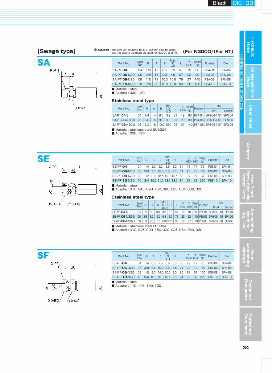
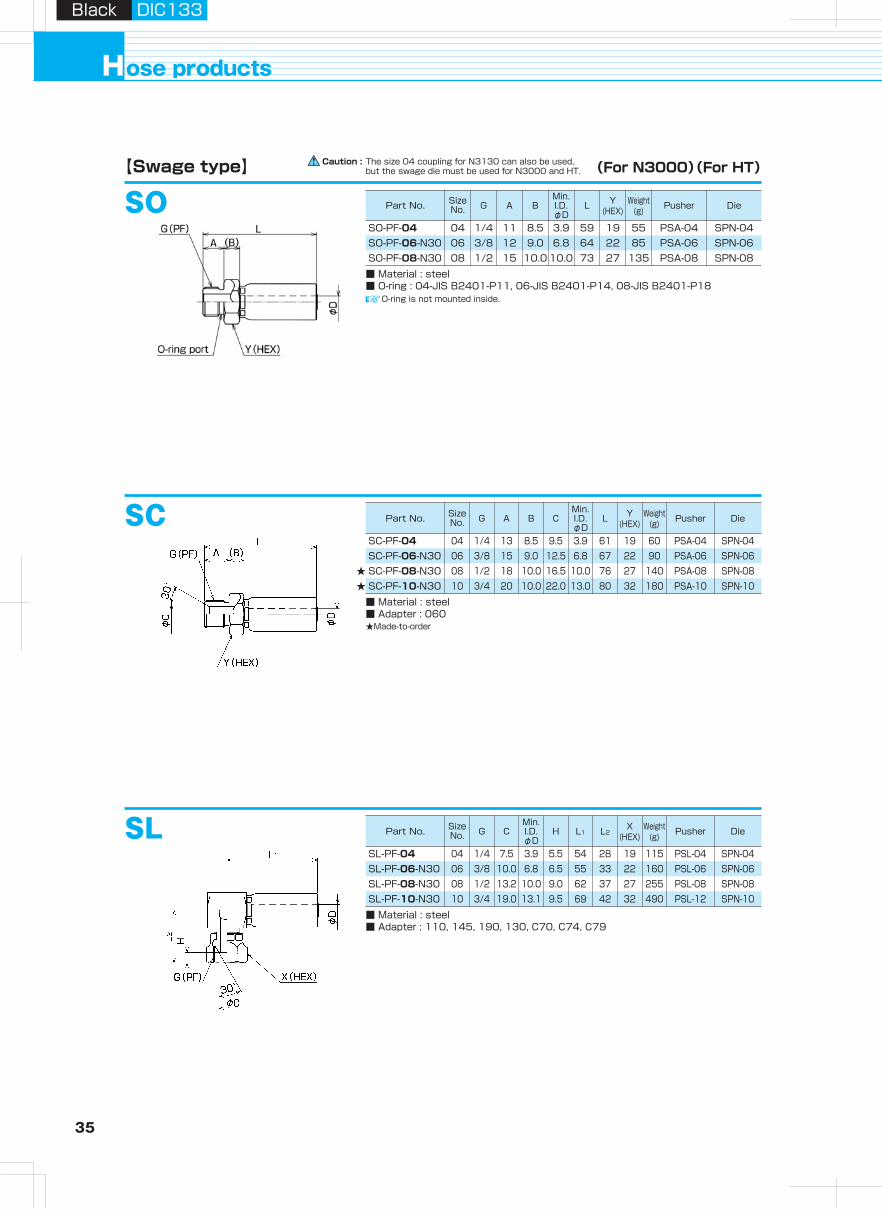
35 36
Hydraulic H
oseA
irless-paintingH
oseA
dapterH
ose Guard
Parts, S
pecially- Treated P
arts
Clean H
ose
Hy
dra
ulic
ho
se
pro
du
cts
Assem
bling
Machine,
Jig
, Tool
Hose
Assem
bling
Method
Technical
Docum
entR
eference D
ocument
ose productsH
Black DIC133Black DIC133
SO【Swage type】 (For N3000)(For HT) 【Swage type】 (For N3000)(For HT)
SC
SL
★★
SO-PF-04
■ Material : steel■ O-ring : 04-JIS B2401-P11, 06-JIS B2401-P14, 08-JIS B2401-P18
04 1/4 11 8.5 3.9 59 19 55 PSA-04 SPN-04SO-PF-06-N30 06 3/8 12 9.0 6.8 64 22 85 PSA-06 SPN-06SO-PF-08-N30 08 1/2 15 10.0 10.0 73 27 135 PSA-08 SPN-08
O-ring is not mounted inside.
SC-PF-04
■ Material : steel■ Adapter : 060★Made-to-order
04 1/4 13 8.5 9.5 3.9 61 19 60 PSA-04 SPN-0406 3/8 15 9.0 12.5 6.8 67 22 90 PSA-06 SPN-0608 1/2 18 10.0 16.5 10.0 76 27 140 PSA-08 SPN-0810 3/4 20 10.0 22.0 13.0 80 32 180 PSA-10 SPN-10
SC-PF-06-N30SC-PF-08-N30SC-PF-10-N30
SL-PF-04
■ Material : steel■ Adapter : 110, 145, 190, 130, C70, C74, C79
04 1/4 7.5 3.9 5.5 54 28 19 115 PSL-04 SPN-0406 3/8 10.0 6.8 6.5 55 33 22 160 PSL-06 SPN-0608 1/2 13.2 10.0 9.0 62 37 27 255 PSL-08 SPN-0810 3/4 19.0 13.1 9.5 69 42 32 490 PSL-12 SPN-10
SL-PF-06-N30SL-PF-08-N30SL-PF-10-N30
Caution : The size 04 coupling for N3130 can also be used, but the swage die must be used for N3000 and HT.
Caution : The size 04 coupling for N3130 can also be used, but the swage die must be used for N3000 and HT.
AE90, SE90AE90-G-04
■ Material : steel■ Adapter : 010, 045, 090, 150, 020, 025, 064, 069, 030
04 1/4 9.0 3.2 8.0 59 33 19 75 PFB-01+PA-04 SPN-0406 3/8 12.0 5.6 9.5 73 45 22 122 PFB-01+PA-06 SPN-0608 1/2 15.5 8.7 12.5 83 52 27 189 PFB-01+PA-08 SPN-08
AE90-G-06-N30AE90-G-08-N30
SE90-PF-10-N30■ Material : steel■ Adapter : 010, 045, 090, 150, 020, 025, 064, 069, 030★Made-to-order
10 3/4 21.0 13.1 13.0 105 76 32 354 PFB-02+PHB-12 SPN-10
AF45, SF45
AF90, SF90
★
AF45-G-04
■ Material : steel■ Adapter : 110, 145, 190, 130
04 1/4 7.0 3.2 5.5 73 19 19 70 PFB-01+PA-04 SPN-0406 3/8 10.0 5.6 6.5 85 23 22 115 PFB-01+PA-06 SPN-0608 1/2 14.0 8.7 9.0 103 29 27 185 PFB-01+PA-08 SPN-08
AF45-G-06-N30AF45-G-08-N30
SF45-PF-10-N30■ Material : steel■ Adapter : 110, 145, 190, 130★Made-to-order
10 3/4 19.0 13.1 9.5 126 40 32 335 PFB-02+PHB-12 SPN-10★
AF90-G-04
■ Material : steel■ Adapter : 110, 145, 190, 130
04 1/4 7.0 3.2 5.5 61 33 19 75 PFB-01+PA-04 SPN-0406 3/8 10.0 5.6 6.5 74 45 22 125 PFB-01+PA-06 SPN-0608 1/2 14.0 8.7 9.0 83 52 27 190 PFB-01+PA-08 SPN-08
AF90-G-06-N30AF90-G-08-N30
SF90-PF-10-N30■ Material : steel■ Adapter : 110, 145, 190, 130★Made-to-order
10 3/4 19.0 13.1 9.5 105 77 32 360 PFB-02+PHB-12 SPN-10★
Part No. Size No. G A B
Min.I.D.φD
L Y(HEX)
Weight(g) Pusher Die
Part No. Size No. G A B C
Min.I.D.φD
L Y(HEX)
Weight(g) Pusher Die
Part No. Size No. G C
Min.I.D.φD
H L1 L2X
(HEX)Weight
(g) Pusher Die
Part No. Size No. G C
Min.I.D.φD
H L1 L2X
(HEX)Weight
(g) Pusher Die
Part No. Size No. G C
Min.I.D.φD
H L1 L2X
(HEX)Weight
(g) Pusher Die
Part No. Size No. G C
Min.I.D.φD
H L1 L2X
(HEX)Weight
(g) Pusher Die
Part No. Size No. G C
Min.I.D.φD
H L1 L2X
(HEX)Weight
(g) Pusher Die
Part No. Size No. G C
Min.I.D.φD
H L1 L2X
(HEX)Weight
(g) Pusher Die
Part No. Size No. G C
Min.I.D.φD
H L1 L2X
(HEX)Weight
(g) Pusher Die
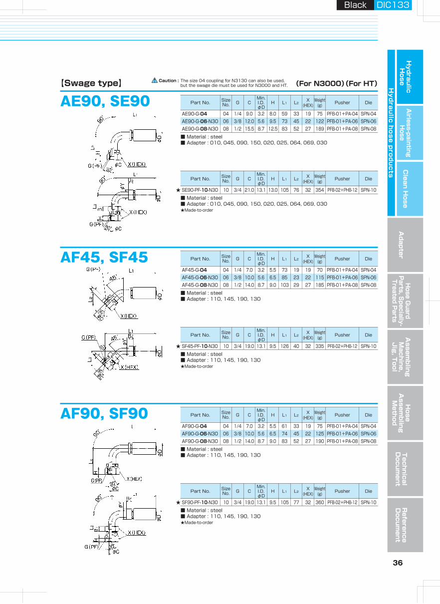
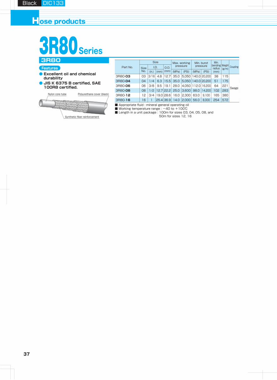
37 38
Hydraulic H
oseA
irless-paintingH
oseA
dapterH
ose Guard
Parts, S
pecially- Treated P
arts
Clean H
ose
Hy
dra
ulic
ho
se
pro
du
cts
Assem
bling
Machine,
Jig
, Tool
Hose
Assem
bling
Method
Technical
Docum
entR
eference D
ocument
ose productsH
Black DIC133Black DIC133
Part No. Size No. R A B
Min.I.D.φD
L Y(HEX)
Weight(g) Pusher
First Second
Die
Part No. Size No. R A B
Min.I.D.φD
L Y(HEX)
Weight(g) Pusher Die
Part No. Size No. G B C
Min.I.D.φD
H L X(HEX)
Y(HEX)
Weight(g) Pusher
First Second
Die
Part No. Size No. G B C
Min.I.D.φD
H L X(HEX)
Y(HEX)
Weight(g) Pusher Die
Part No. Size No. G B C
Min.I.D.φD
H L X(HEX)
Y(HEX)
Weight(g) Pusher Die
Part No. Size No. G A B C
Min.I.D.φD
L Y(HEX)
Weight(g) Pusher Die
Size
Part No. Size No.
I.D. O.D.(mm)(mm)(in.) (MPa)
Max. working pressure
(PSi) (MPa)
Min. burst pressure
Min. bending radius(mm)
Coupling
(PSi)
Weight(g/m)
Caution : The size 06 and 08 coupling for N3000 can also be used, but the swage die must be used for 3R80.3R80Series
3R80-033R80-043R80-063R80-083R80-123R80-16
3R80Features
● Excellent oil and chemical durability
● JIS K 6375 B certified, SAE 100R8 certified.
■ Appropriate fluid : mineral general operating oil■ Working temperature range : -40 to +100℃■ Length in a unit package : 100m for sizes 03, 04, 05, 08, and
50m for sizes 12, 16Stainless steel type
SA-PT-04-3R-S
■ Material : stainless steel SUS304■ Adapter : 030, 130
SA-PT-06-N30-SSA-PT-08-N30-S
04 1/4 14 8.5 3.9 61 19 72 PSA-04 SPH-04-1-ST SPH-0406 3/8 15 9.0 6.8 67 22 90 PSA-06 SPH-06-1-ST SPH-0608 1/2 18 10.0 10.0 76 27 140 PSA-08 SPH-08-1-ST SPH-08
SA【Swage type】 (For 3R80)
SA-PT-03-3R
■ Material : steel■ Adapter : 030, 130
03 1/4 13 8.5 2.8 53 19 50 PSA-04 SPH-03SA-PT-04-3R 04 1/4 13 8.5 3.9 61 19 60 PSA-04 SPH-04
06 3/8 15 9.0 6.8 67 22 90 PSA-06 SPH-0608 1/2 18 10.0 10.0 76 27 140 PSA-08 SPH-0812 3/4 20 10.0 16.0 83 36 220 PSA-12 SPH-1216 1 23 10.0 20.9 100 41 340 PSA-16 SPH-16
SA-PT-06-N30SA-PT-08-N30SA-PT-12-3RSA-PT-16-3R
Stainless steel type
SE-PF-04-3R-S
■ Material : stainless steel SUS304■ Adapter : 010, 045, 090, 150, 020, 025, 064, 069, 030
SE-PF-06-N30-SSE-PF-08-N30-SSE-PF-12-3R-SSE-PF-16-3R-S
04 1/4 8.5 9.5 3.9 8.0 63 19 19 80 PSE-04 SPH-04-1-ST SPH-0406 3/8 9.5 12.5 6.8 9.5 71 22 22 110 PSE-06 SPH-06-1-ST SPH-0608 1/2 9.0 15.5 10.0 12.5 80 27 27 170 PSE-08 SPH-08-1-ST SPH-0812 3/4 10.5 21.5 16.0 13.0 87 36 36 280 PSE-12 SPH-12-1-ST SPH-1216 1 11.0 27.5 20.9 15.0 105 41 41 400 PSE-16 SPH-16-1-ST SPH-16
SESE-PF-03-3RSE-PF-04-3R
■ Material : steel■ Adapter : 010, 045, 090, 150, 020, 025, 064, 069, 030
03 1/4 6.0 9.5 2.8 8.0 55 19 19 60 PSE-03 SPH-0304 1/4 8.5 9.5 3.9 8.0 63 19 19 80 PSE-04 SPH-04
SE-PF-06-N30 06 3/8 9.5 12.3 6.8 9.5 71 22 19 110 PSE-06 SPH-06SE-PF-08-N30 08 1/2 9.0 15.5 10.0 12.5 80 27 27 170 PSE-08 SPH-08SE-PF-12-3RSE-PF-16-3R
12 3/4 10.5 21.5 16.0 13.0 87 36 36 280 PSE-12 SPH-1216 1 11.0 27.5 20.9 15.0 105 41 41 400 PSE-16 SPH-16
SFSF-PF-03-3R
■ Material : steel■ Adapter : 110, 145, 190, 130
03 1/4 6.0 7.5 2.8 5.5 55 19 19 60 PSE-03 SPH-03SF-PF-04-3R 04 1/4 8.5 7.5 3.9 5.5 63 19 19 80 PSE-04 SPH-04SF-PF-06-N30 06 3/8 9.5 10.0 6.8 6.5 71 22 19 110 PSE-06 SPH-06SF-PF-08-N30 08 1/2 9.0 14.0 10.0 9.0 80 27 27 170 PSE-08 SPH-08
12 3/4 10.5 19.0 16.0 9.5 87 36 36 280 PSE-12 SPH-1216 1 11.0 25.4 20.9 10.0 105 41 41 410 PSE-16 SPH-16
SF-PF-12-3RSF-PF-16-3R
SCSC-PF-03-3R
■ Material : steel■ Adapter : 060★Made-to-order
03 1/4 13 8.5 9.5 2.8 53 19 50 PSA-04 SPH-0304 1/4 13 8.5 9.5 3.9 61 19 60 PSA-04 SPH-0406 3/8 15 9.0 12.5 6.8 67 22 90 PSA-06 SPH-0608 1/2 18 10.0 16.5 10.0 76 27 140 PSA-08 SPH-08
SC-PF-04-3RSC-PF-06-N30SC-PF-08-N30
★
★
Synthetic fiber reinforcement
Polyurethane cover (black)Nylon core tube
Swage
03 3/16 4.8 12.7 35.0 5,050 140.0 20,200 38 11504 1/4 6.3 15.5 35.0 5,050 140.0 20,200 51 17506 3/8 9.5 19.1 28.0 4,050 112.0 16,200 64 22108 1/2 12.7 22.2 25.0 3,600 98.0 14,200 102 28312 3/4 19.0 28.6 16.0 2,300 63.0 9,100 165 38016 1 25.4 36.9 14.0 2,000 56.0 8,000 254 572
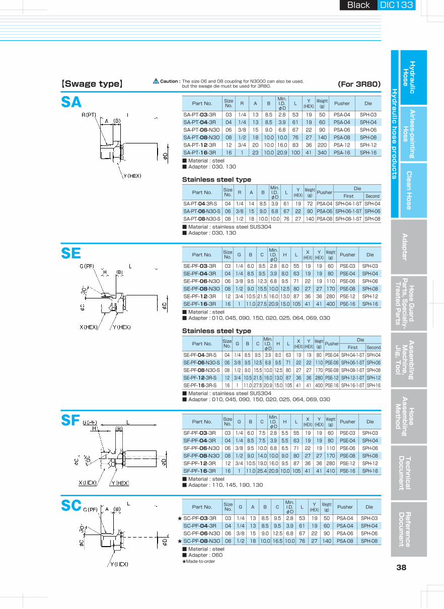
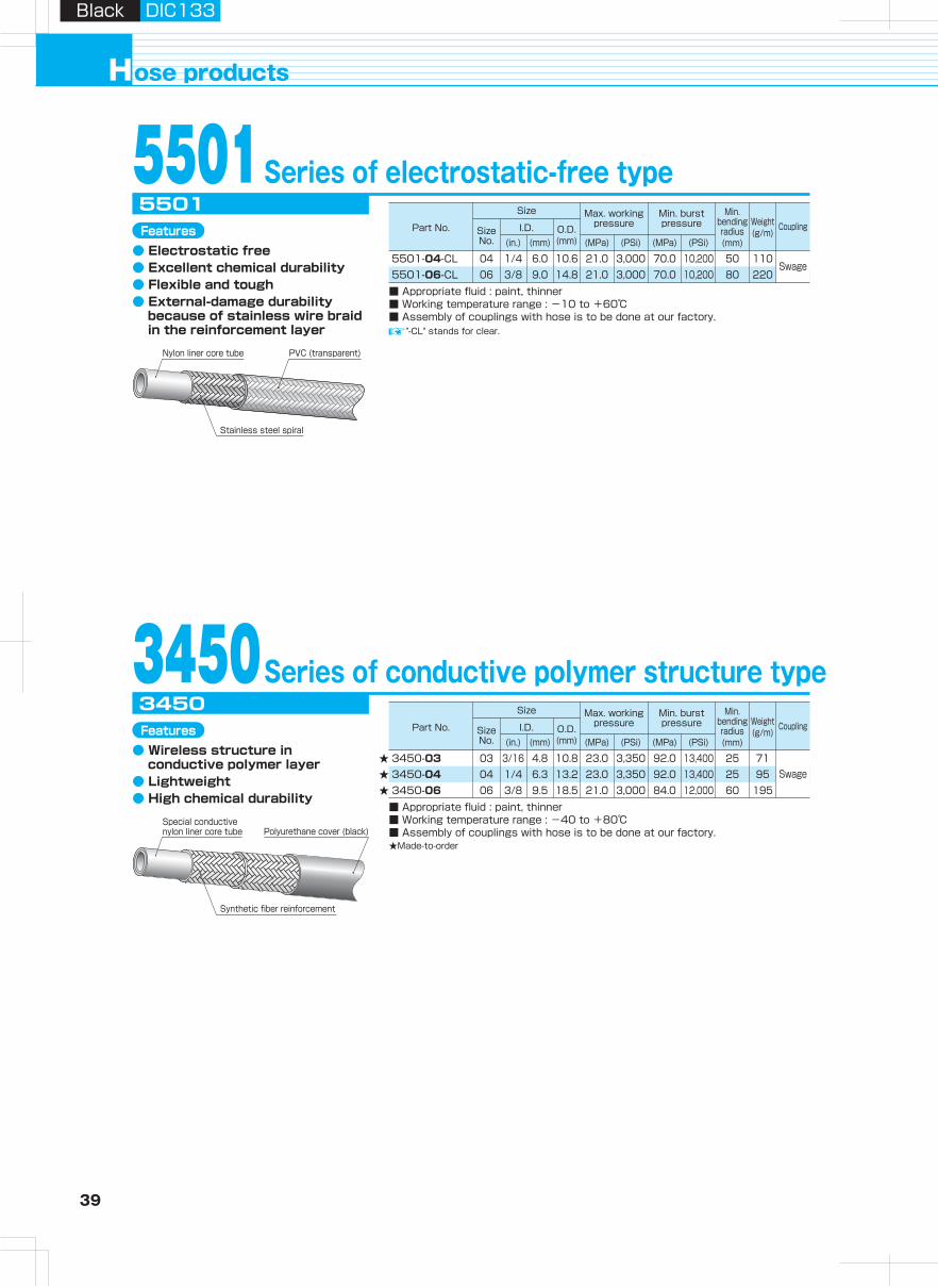
39 40
Hydraulic H
oseA
irless-paintingH
oseA
dapterH
ose Guard
Parts, S
pecially- Treated P
arts
Clean H
ose
Hy
dra
ulic
ho
se
pro
du
cts
Assem
bling
Machine,
Jig
, Tool
Hose
Assem
bling
Method
Technical
Docum
entR
eference D
ocument
ose productsH
Black DIC133Black DIC133
Size
Part No. Size No.
I.D. O.D.(mm)(mm)(in.) (MPa)
Max. working pressure
(PSi) (MPa)
Min. burst pressure
Min. bending radius(mm)
Coupling
(PSi)
Weight(g/m)
Size
Part No. Size No.
I.D. O.D.(mm)(mm)(in.) (MPa)
Max. working pressure
(PSi) (MPa)
Min. burst pressure
Min. bending radius(mm)
Coupling
(PSi)
Weight(g/m)
5501Series of electrostatic-free type
5501-04-CL5501-06-CL
5501
■ Appropriate fluid : paint, thinner■ Working temperature range : -10 to +60℃■ Assembly of couplings with hose is to be done at our factory.
3450Series of conductive polymer structure type3450
SF (for 5501)
【Swage type】 (For 5501)
(For 3450)
SF-PF-04-55
■ Material : steel■ Adapter : 110, 145, 190, 130 *Not suitable for NPSM.■ Assembly of couplings with hose is to be done at our factory.
Part No. Size No. G or NPSM B C
Min.I.D.φD
H L X(HEX)
Y(HEX)
Weight(g)
04 G1/4 8.5 7.5 3.3 5.5 60 19 17 8004 NPSM1/4 8.5 7.5 3.3 5.5 60 19 17 8006 G3/8 9.5 10.0 6.2 6.5 71 22 22 11006 NPSM3/8 9.5 10.0 6.2 6.5 71 22 22 110
SF-NPSM-04-55SF-PF-06-5501SF-NPSM-06-5501
SF-PF-03
■ Material : steel■ Adapter : 110, 145, 190, 130■ Assembly of couplings with hose is to be done at our factory.★Made-to-order
Part No. Size No. G or NPSM B C
Min.I.D.φD
H L X(HEX)
Y(HEX)
Weight(g)
03 G1/4 6.0 7.5 2.8 5.5 58 19 19 7003 NPSM1/4 6.0 7.5 3.0 4.0 56 19 19 7004 1/4 8.5 7.5 3.9 5.5 63 19 17 7504 NPSM1/4 8.5 7.5 4.0 5.5 63 19 19 8006 3/8 9.5 10.0 6.8 6.5 71 22 19 110
SF-NPSM-03-3450SF-PF-04SF-NPSM-04SF-PF-06-N30
SF (for 3450)
"-CL" stands for clear.
3450-033450-043450-06■ Appropriate fluid : paint, thinner■ Working temperature range : -40 to +80℃■ Assembly of couplings with hose is to be done at our factory.★Made-to-order
★★★
Features● Electrostatic free● Excellent chemical durability● Flexible and tough● External-damage durability
because of stainless wire braid in the reinforcement layer
★
★
PVC (transparent)Nylon liner core tube
Stainless steel spiral
Features● Wireless structure in
conductive polymer layer● Lightweight● High chemical durability
Synthetic fiber reinforcement
Polyurethane cover (black)Special conductive nylon liner core tube
Swage04 1/4 6.0 10.6 21.0 3,000 70.0 10,200 50 11006 3/8 9.0 14.8 21.0 3,000 70.0 10,200 80 220
Swage03 3/16 4.8 10.8 23.0 3,350 92.0 13,400 25 7104 1/4 6.3 13.2 23.0 3,350 92.0 13,400 25 9506 3/8 9.5 18.5 21.0 3,000 84.0 12,000 60 195
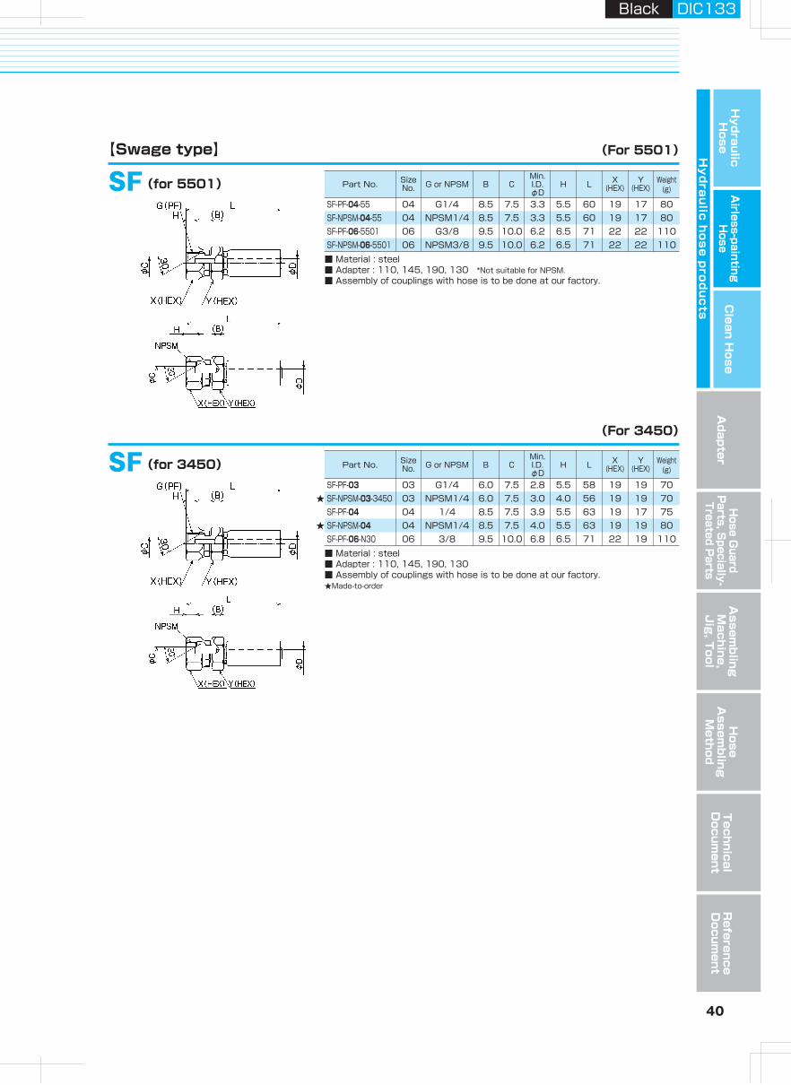
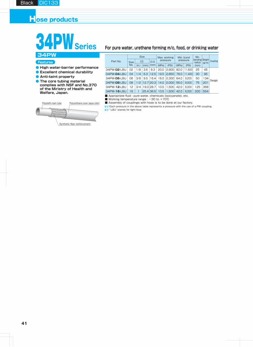
41 42
Hydraulic H
oseA
irless-paintingH
oseA
dapterH
ose Guard
Parts, S
pecially- Treated P
arts
Clean H
ose
Hy
dra
ulic
ho
se
pro
du
cts
Assem
bling
Machine,
Jig
, Tool
Hose
Assem
bling
Method
Technical
Docum
entR
eference D
ocument
ose productsH
Black DIC133Black DIC133
Part No. Size No. G B C
Min.I.D.φD
H L X(HEX)
Y(HEX)
Weight(g) Pusher
First Second
Die
Part No. Size No. G B C
Min.I.D.φD
H L X(HEX)
Y(HEX)
Weight(g) Pusher Die
Part No. Size No. G B C
Min.I.D.φD
H L X(HEX)
Y(HEX)
Weight(g) Pusher
First Second
Die
Part No. Size No. G R A1 A2 B C
Min.I.D.φD
L Y(HEX)
Weight(g)
Size
Part No. Size No.
I.D. O.D.(mm)(mm)(in.) (MPa)
Max. working pressure
(PSi) (MPa)
Min. burst pressure
Min. bending radius(mm)
Coupling
(PSi)
Weight(g/m)
34PWSeries
34PW-02-LBU34PW-04-LBU34PW-06-LBU34PW-08-LBU34PW-12-LBU34PW-16-LBU
34PW
■ Appropriate fluid : pure water, chemicals (isocyanate), etc.■ Working temperature range : -30 to +70℃■ Assembly of couplings with hose is to be done at our factory.
Each pressure in the above table represents a pressure with the use of a PW coupling."-LBU" stands for light blue.
Ultrasonic cleaning is available only for the couplings, if required. Contact us for details.As for the steel couplings; sizes 04, 06, and 08 for N3130 series, and sizes 12 and 16 for 3R80 can also be used.
SE (PW coupling)
【Swage type】 (For 34PW)For pure water, urethane forming m/c, food, or drinking water
Polyurethane cover (aqua color)Polyolefin resin tube
Synthetic fiber reinforcement
Features● High water-barrier performance● Excellent chemical durability● Anti-taint property● The core tubing material
complies with NSF and No.370 of the Miristry of Health and Welfare, Japan.
Stainless steel type (SUS316)
SE-G-04-PW
■ Material : stainless steel SUS316■ Assembly of couplings with hose is to be done at our factory.
SE-G-06-PWSE-G-08-PWSE-G-12-PWSE-G-16-PW
04 1/4 8.5 9.0 4.0 8.0 63 19 19 80 PSE-04 SP3-04-VC -06 3/8 9.5 12.0 6.9 9.0 71 22 22 110 PSE-06 SP3-06-VC -08 1/2 9.0 15.5 10.0 12.5 80 27 27 170 PSE-08 SP3-08-VC -12 3/4 10.0 21.0 16.0 13.5 86 36 36 270 PSE-12 SPH-12-1-ST SPH-12-VC16 1 11.0 28.0 20.9 16.5 105 41 41 410 PSE-16 SPH-16-1-ST SPH-16-37VC
Ultrasonic cleaning is available only for the couplings, if required. Contact us for details.As for the steel couplings; sizes 04, 06, and 08 for N3130 series, and sizes 12 and 16 for 3R80 can also be used.
SE (PWL coupling) for under 7.0 MPaStainless steel type (SUS316)
SE-G-04-PWL
■ Maximum working pressure (static pressure) : 7.0MPa■ Material : stainless steel SUS316■ Assembly of couplings with hose is to be done at our factory.
SE-G-06-PWLSE-G-08-PWLSE-G-12-PWLSE-G-16-PWL
04 1/4 6.0 9.0 5.0 8.0 42 19 19 60 PSE-04-PWL SPP-04-VC06 3/8 6.0 12.0 8.0 9.5 44 22 22 70 PSE-06-PWL SPP-06-VC08 1/2 8.0 15.5 11.0 12.5 54 27 27 130 PSE-08-PWL SPP-08-VC12 3/4 10.0 21.0 16.0 13.5 64 36 36 230 PSE12-PWL SPP-12-VC16 1 10.0 28.0 22.0 16.5 67 41 41 310 PSE-16-PWL SPP-16-VC
Ultrasonic cleaning is available only for the couplings, if required. Contact us for details.As for the steel coupling, size 02 for 3130 series, sizes 04, 06, and 08 for N3130 series, and sizes 12 and 16 for 3R80 can also be used.
SE Stainless steel type (SUS304)
SSE-PF-02-S
■ Material : stainless steel SUS304■ Assembly of couplings with hose is to be done at our factory.
SE-PF-04-SSE-PF-06-SSE-PF-08-SSE-PF-12-3R-SSE-PF-16-3R-S
02 1/8 4.0 7.0 1.8 7.0 42 14 14 25 PSE-02-001 SP3-02-001 -04 1/4 8.5 9.5 3.9 8.0 63 19 19 80 PSE-04 SP3-04-1-ST SP3-0406 3/8 9.5 12.5 6.8 9.5 71 22 22 110 PSE-06 SP3-06-1-ST SP3-0608 1/2 9.0 16.0 10.0 12.0 80 27 27 170 PSE-08 SP3-08-1-ST SP3-0812 3/4 10.5 21.5 16.0 13.0 87 36 36 280 PSE-12 SPH-12-1-ST SPH-1216 1 11.0 27.5 20.9 15.0 105 41 41 400 PSE-16 SPH-16-1-ST SPH-16
Ultrasonic cleaning is available only for the couplings, if required. Contact us for details.
Adapter for 34PW Stainless steel type (SUS316)
010-04-04-PW
■ Material : stainless steel SUS316
010-06-06-PW010-08-08-PW010-12-12-PW010-16-16-PW
04 1/4 1/4 13 14 8.0 7.0 5.5 35 19 4006 3/8 3/8 16 15 9.0 10.0 8.0 40 22 6008 1/2 1/2 19 18 10.0 13.0 11.0 47 27 10012 3/4 3/4 21 20 12.0 19.0 16.0 53 36 18016 1 1 23 23 13.0 25.0 22.0 59 41 250
02 1/8 3.6 8.3 20.0 2,900 80.0 11,600 25 4504 1/4 6.3 12.5 19.5 2,850 78.0 11,400 30 9506 3/8 9.5 16.4 16.0 2,300 64.0 9,200 50 13408 1/2 12.7 20.3 14.0 2,000 56.0 8,000 75 20112 3/4 19.0 28.7 10.5 1,500 42.0 6,000 125 36816 1 25.4 36.5 10.5 1,500 42.0 6,000 200 554
Swage
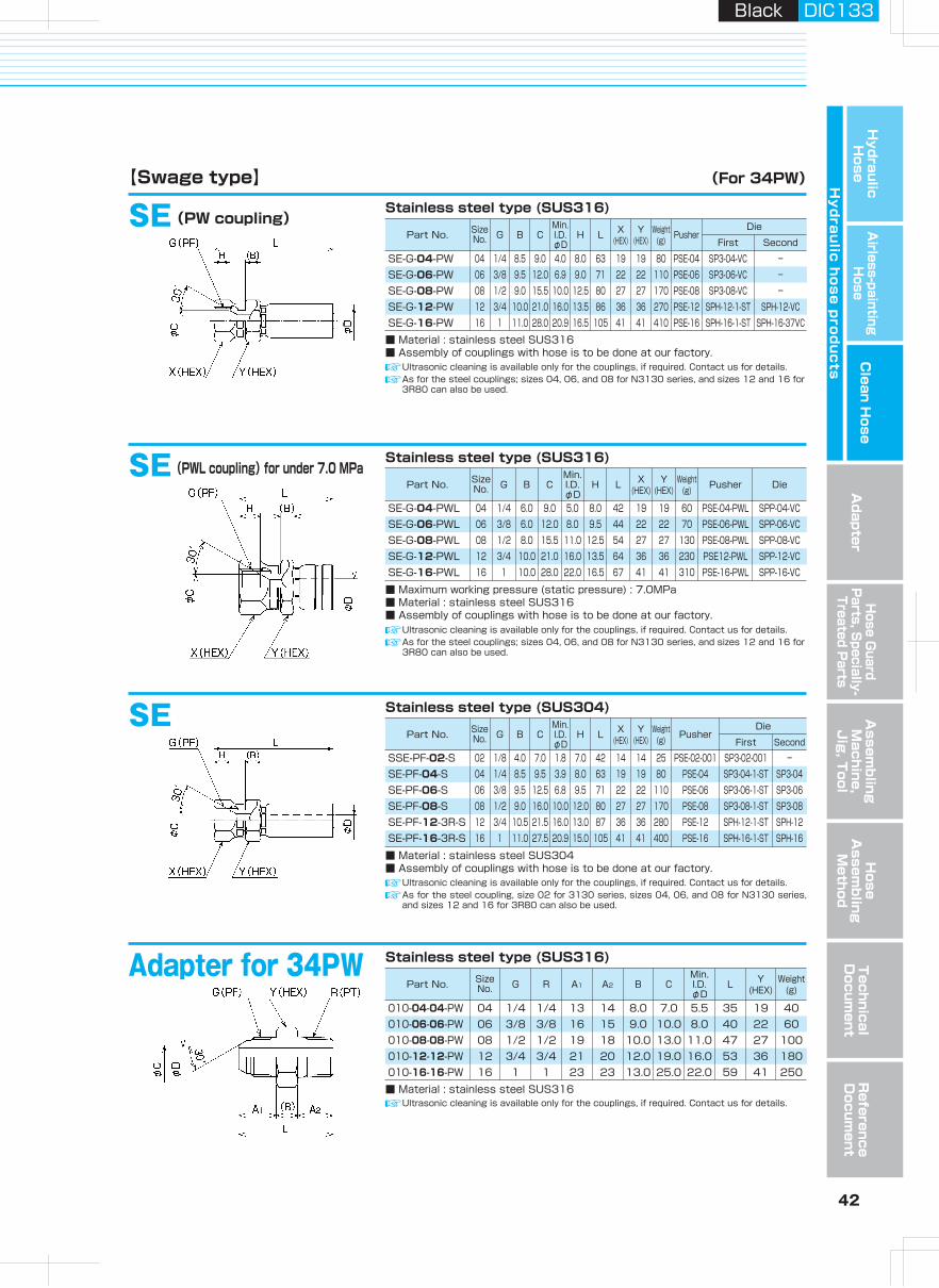
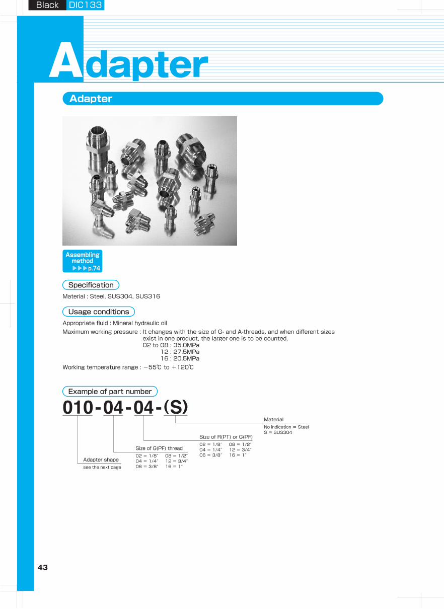
43 44
Hydraulic H
oseA
irless-paintingH
oseA
dapterH
ose Guard
Parts, S
pecially- Treated P
arts
Clean H
ose
Hy
dra
ulic
ho
se
pro
du
cts
Assem
bling
Machine,
Jig
, Tool
Hose
Assem
bling
Method
Technical
Docum
entR
eference D
ocument
Black DIC133Black DIC133
Adapter Adapter shapes chart
dapterA
Specification
No indication = SteelS = SUS304
02 = 1/8″04 = 1/4″06 = 3/8″see the next page
08 = 1/2″12 = 3/4″16 = 1″
02 = 1/8″04 = 1/4″06 = 3/8″
08 = 1/2″12 = 3/4″16 = 1″
Adapter shape
Size of G(PF) thread
Size of R(PT) or G(PF)
Material
Material : Steel, SUS304, SUS316
Usage conditions
Straight type 45° elbow type 90° elbow type Femalel-thread straight typeTaper thread type to equipment side (with 30° female seat)
Straight type 45° elbow type 90° elbow type Femalel-thread straight typeTaper thread type to equipment side (with 30° male seat)
Straight type 45° elbow type Thread screw boltTaper thread screw type to equipment side (with 30° malel seat)
Straight type Panel touch straight type Panel touch 90° straight type 45° bend type 90° bend typeInterconnection type (with 30° male seat)
110 145 190 130
010 045 090 030
010-001 090-001 007
Contact us for other shapes.
150 020 025 064 069
Assemblingmethod
p.74
Example of part number
Appropriate fluid : Mineral hydraulic oilMaximum working pressure : It changes with the size of G- and A-threads, and when different sizes
exist in one product, the larger one is to be counted.02 to 08 : 35.0MPa
12 : 27.5MPa16 : 20.5MPa
Working temperature range : -55℃ to +120℃
Parallel male-thread type
060
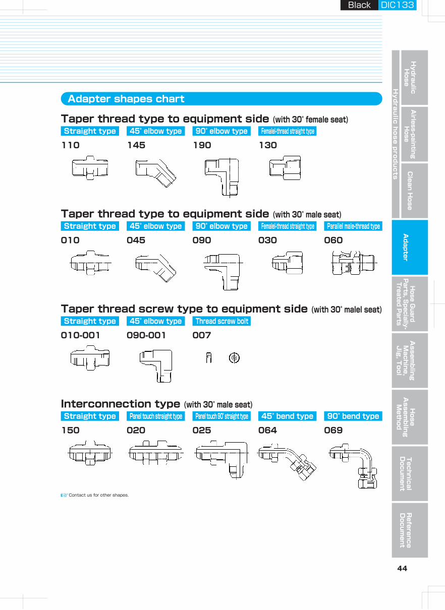
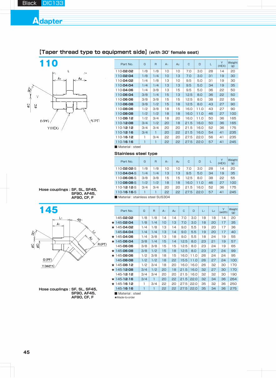
45 46
Hydraulic H
oseA
irless-paintingH
oseA
dapterH
ose Guard
Parts, S
pecially- Treated P
arts
Clean H
ose
Hy
dra
ulic
ho
se
pro
du
cts
Assem
bling
Machine,
Jig
, Tool
Hose
Assem
bling
Method
Technical
Docum
entR
eference D
ocument
dapterA
Black DIC133Black DIC133
Part No. G R A1 A2 C L Y(HEX)
Weight(g)
Part No. G R A1 A2 C L1 L2Y
(width)Weight
(g)
Part No. G R A1 A2 C L Y(HEX)
Weight(g)
Part No. G R A C L Y(HEX)
Weight(g)
Part No. G R A1 A2 C D1 D2 L1 L2Y
(width)Weight
(g)
Part No. G R A1 A2 C D1 D2 L1 L2Y
(HEX)Weight
(g)D
D D
D110【Taper thread type to equipment side】 (with 30° female seat)
110-02-02
■ Material : steel
1/8 1/8 10 10 7.0 3.0 28 14 20110-02-04 1/8 1/4 10 13 7.0 3.0 31 30110-04-02 1/4 1/8 13 10 31 19 30110-04-04 1/4 1/4 13 13 9.5 5.0 34 19 35110-04-06 1/4 3/8 13 15 36 22 50110-06-04 3/8 1/4 15 13 12.5 36 22 50110-06-06 3/8 3/8 15 15 12.5 8.0 38 22 55110-06-08 3/8 1/2 15 18 12.5 8.0 43 27 90110-08-06 1/2 3/8 18 15 11.0 43 27 90110-08-08 1/2 1/2 18 18 16.0 11.0 46 27 100110-08-12 1/2 3/4 18 20 50 36 165110-12-08 3/4 1/2 20 18 16.0 50 36 165110-12-12 3/4 3/4 20 20 21.5 16.0 52 36 175110-12-16 3/4 1 20 22 16.0 54 41 235110-16-12 1 3/4 22 20 27.5 22.0 56 41 235110-16-16 1 1 22 22 27.5 22.0 57 41 245
145145-02-02 1/8 1/8 14 14 7.0 3.0 18 18 14 20
1/8 1/4 10 13 7.0 3.0 18 20 17 351/4 1/8 13 14 9.0 5.5 19 20 17 361/4 1/4 13 14 9.0 5.5 19 20 17 401/4 3/8 13 9.0 18 24 19 553/8 1/4 15 14 12.5 8.0 23 21 19 573/8 3/8 15 15 12.5 8.0 23 24 19 653/8 1/2 15 18 12.5 23 27 24 991/2 3/8 18 15 16.0 11.0 26 24 24 951/2 1/2 18 22 15.5 11.0 26 27 24 1001/2 3/4 18 20 16.0 16.0 26 32 30 1703/4 1/2 20 18 21.5 16.0 32 27 30 1703/4 3/4 20 20 21.5 16.0 32 32 30 1903/4 1 20 22 21.5 22.0 32 34 36 2641 3/4 22 20 27.5 22.0 35 32 36 2501 1 22 22 22.0 35 34 36 275
145-02-04145-04-02145-04-04145-04-06145-06-04145-06-06145-06-08145-08-06145-08-08145-08-12145-12-08145-12-12145-12-16145-16-12145-16-16
110-02-02-S
■ Material : stainless steel SUS304
1/8 1/8 10 10 7.0 3.0 28 14 20110-04-04-S 1/4 1/4 13 13 9.5 5.0 34 19 35110-06-06-S 3/8 3/8 15 15 12.5 8.0 38 22 55110-08-08-S 1/2 1/2 18 18 16.0 11.0 46 27 100110-12-12-S 3/4 3/4 20 20 21.5 16.0 52 36 175110-16-16-S 1 1 22 22 27.5 22.0 57 41 245
130-02-02
■ Material : steel
1/8 1/8 10 7.0 3.0 25 14 181/4 1/4 13 5.5 30 19 363/8 3/8 15 12.5 8.0 34 22 521/2 1/2 18 11.0 40 27 883/4 3/4 20 16.0 45 36 1751 1 22 22.0 50 41 221
130-04-04130-06-06130-08-08130-12-12130-16-16
Stainless steel type
★★
★★
★★
★★
★★
■ Material : steel★Made-to-order
190【Taper thread type to equipment side】 (with 30° female seat)
190-02-02
■ Material : steel
■ Material : stainless steel SUS304
1/8 1/8 9 14 7.0 3.0 4.0 18 22 14 301/8 1/4 10 13 7.0 3.0 5.0 20 27 17 501/4 1/8 13 10 9.5 6.0 4.0 25 20 17 451/4 1/4 13 13 9.5 5.0 5.0 23 27 17 501/4 3/8 13 18 8.0 25 30 19 803/8 1/4 15 16 12.5 8.0 27 28 19 753/8 3/8 15 15 12.5 8.0 8.0 27 30 19 1453/8 1/2 15 22 12.5 8.0 11.0 28 38 24 1401/2 3/8 18 20 11.0 8.0 31 32 24 1401/2 1/2 18 18 16.0 11.0 11.0 31 38 24 1651/2 3/4 18 24 11.0 16.0 34 43 30 2503/4 1/2 20 22 16.0 11.0 36 41 30 2503/4 3/4 20 20 21.5 16.0 16.0 36 43 30 2653/4 1 20 22 21.5 16.0 22.0 46 36 4001 3/4 22 20 27.5 22.0 16.0 42 36 4001 1 22 27.5 22.0 22.0 42 46 36 460
190-02-04190-04-02190-04-04190-04-06190-06-04190-06-06190-06-08190-08-06190-08-08190-08-12190-12-08190-12-12190-12-16190-16-12190-16-16
190-02-02-S 1/8 1/8 7.0 3.0 18 22 14 301/4 1/4 13 13 9.5 5.0 5.0 23 27 17 503/8 3/8 15 15 12.5 8.0 8.0 27 30 19 1451/2 1/2 18 18 16.0 11.0 11.0 31 38 24 1653/4 3/4 20 20 21.5 16.0 16.0 36 43 30 265
190-04-04-S190-06-06-S190-08-08-S190-12-12-S
130
Stainless steel type
Hose couplings : SF, SL, SF45, SF90, AF45, AF90, CF, F
Hose couplings : SF, SL, SF45, SF90, AF45, AF90, CF, F
Hose couplings : SF, SL, SF45, SF90, AF45, AF90, CF, F
Hose couplings : SA, SF, SL, SF45, SF90, AF45, AF90, CA, CF, A, F
5.09.5
5.09.58.0
16.0
11.016.021.5
21.5
19
5.518
8.0
27.5
5.09.55.0
16.0
16.021.5
4044
22
3.01010
9.5
16.021.527.5
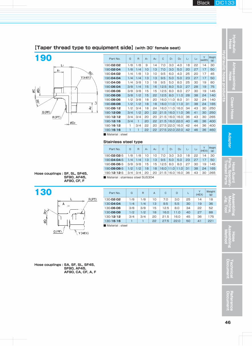
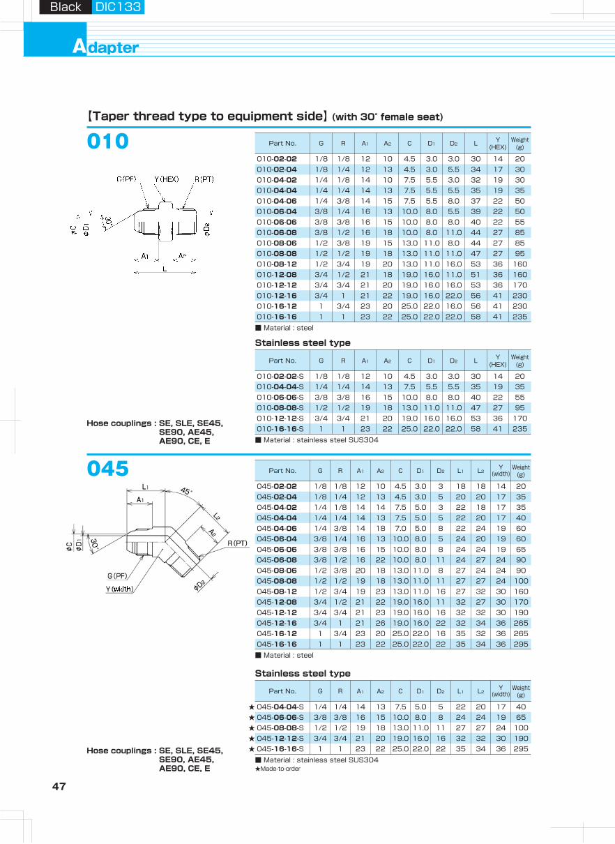
47 48
Hydraulic H
oseA
irless-paintingH
oseA
dapterH
ose Guard
Parts, S
pecially- Treated P
arts
Clean H
ose
Hy
dra
ulic
ho
se
pro
du
cts
Assem
bling
Machine,
Jig
, Tool
Hose
Assem
bling
Method
Technical
Docum
entR
eference D
ocument
dapterA
Black DIC133Black DIC133
Part No. G R A1 A2 C D1 D2 L Y(HEX)
Weight(g)
Part No. G R A1 A2 C D1 D2 L Y(HEX)
Weight(g)
Part No. G R A1 A2 C D1 D2 L1 L2Y
(width)Weight
(g)
Part No. G R A1 A2 C D1 D2 L1 L2Y
(width)Weight
(g)
Part No. G R A C L Y(HEX)
Weight(g)
Part No. G R A C L Y(HEX)
Weight(g)
Part No. G R A1 A2 CMin.I.D.φD
H L X(HEX)
Y(HEX)
Weight(g)
D
D
Part No. G R A1 A2 C D1 D2 L1 L2Y
(width)Weight
(g)
Part No. G R A1 A2 C D1 D2 L1 L2Y
(width)Weight
(g)
Hose couplings : SE, SLE, SE45, SE90, AE45, AE90, CE, E
Hose couplings : SE, SLE, SE45, SE90, AE45, AE90, CE, E
Hose couplings : SE, SLE, SE45, SE90, AE45, AE90, CE, E
Hose couplings : SA, SE, SLE, SE45, SE90, AE45, AE90, CA, CE, A, E
010【Taper thread type to equipment side】 (with 30° female seat)
■ Material : steel
045
010-02-02 1/8 1/8 12 10 4.5 3.0 3.0 30 14 201/8 1/4 12 13 4.5 3.0 5.5 34 17 301/4 1/8 14 10 7.5 5.5 3.0 32 19 301/4 1/4 14 13 7.5 5.5 5.5 35 19 351/4 3/8 14 15 7.5 5.5 8.0 37 22 503/8 1/4 16 13 10.0 8.0 5.5 39 22 503/8 3/8 16 15 10.0 8.0 8.0 40 22 553/8 1/2 16 18 10.0 8.0 11.0 44 27 851/2 3/8 19 15 13.0 11.0 8.0 44 27 851/2 1/2 19 18 13.0 11.0 11.0 47 27 951/2 3/4 19 20 13.0 11.0 16.0 53 36 1603/4 1/2 21 18 19.0 16.0 11.0 51 36 1603/4 3/4 21 20 19.0 16.0 16.0 53 36 1703/4 1 21 22 19.0 16.0 22.0 56 41 2301 3/4 23 20 25.0 22.0 16.0 56 41 2301 1 23 22 25.0 22.0 22.0 58 41 235
010-02-04010-04-02010-04-04010-04-06010-06-04010-06-06010-06-08010-08-06010-08-08010-08-12010-12-08010-12-12010-12-16010-16-12010-16-16
■ Material : stainless steel SUS304
010-02-02-S 1/8 1/8 12 10 4.5 3.0 3.0 30 14 201/4 1/4 14 13 7.5 5.5 5.5 35 19 353/8 3/8 16 15 10.0 8.0 8.0 40 22 551/2 1/2 19 18 13.0 11.0 11.0 47 27 953/4 3/4 21 20 19.0 16.0 16.0 53 36 1701 1 23 22 25.0 22.0 22.0 58 41 235
010-04-04-S010-06-06-S010-08-08-S010-12-12-S010-16-16-S
030-02-02
■ Material : steel
■ Material : stainless steel SUS304★Made-to-order
1/8 1/8 12 4.5 3.0 27 14 201/4 1/4 14 7.5 5.5 30 19 253/8 3/8 16 10.0 8.0 35 22 551/2 1/2 19 13.0 11.0 41 27 753/4 3/4 21 19.0 16.0 46 36 1601 1 23 25.0 22.0 51 41 220
030-04-04030-06-06030-08-08030-12-12030-16-16
030-02-02-S 1/8 1/8 12 4.5 3.0 27 14 201/4 1/4 14 7.5 5.5 30 19 253/8 3/8 16 10.0 8.0 35 22 551/2 1/2 19 13.0 11.0 41 27 753/4 3/4 21 19.0 16.0 46 36 1601 1 23 25.0 22.0 51 41 220
030-04-04-S030-06-06-S030-08-08-S030-12-12-S030-16-16-S
Stainless steel type
★★★★★
★★★★★★
090【Taper thread type to equipment side】 (with 30° male seat)
090-02-02
■ Material : steel
■ Material : stainless steel SUS304
1/8 1/8 12 4.5 3.0 4 22 22 14 301/8 1/4 12 13 4.5 3.0 5 23 27 17 451/4 1/8 14 10 7.5 5.0 3 24 23 17 451/4 1/4 14 13 7.5 5.0 5 24 27 17 501/4 3/8 18 7.5 5.5 8 29 30 19 803/8 1/4 16 13 10.0 8.0 5 29 27 19 753/8 3/8 16 15 10.0 8.0 8 29 30 19 803/8 1/2 16 18 10.0 8.0 11 29 38 24 1451/2 3/8 18 13.0 11.0 8 33 30 24 1401/2 1/2 20 22 13.0 11.0 11 33 38 24 1651/2 3/4 24 13.0 11.0 16 36 43 30 2503/4 1/2 21 22 19.0 16.0 11 36 38 30 2503/4 3/4 21 20 19.0 16.0 16 36 43 30 2653/4 1 23 25 19.0 16.0 22 42 46 36 4001 3/4 23 24 25.0 22.0 16 42 43 36 4001 1 23 22 25.0 22.0 22 42 46 36 400
090-02-04090-04-02090-04-04090-04-06090-06-04090-06-06090-06-08090-08-06090-08-08090-08-12090-12-08090-12-12090-12-16090-16-12090-16-16
090-02-02-S 1/8 1/8 4.5 3.0 4 22 22 14 301/4 1/4 14 13 7.5 5.0 5 24 27 17 503/8 3/8 16 15 10.0 8.0 8 29 30 19 801/2 1/2 19 18 13.0 11.0 11 33 38 24 1653/4 3/4 21 19.0 16.0 16 36 43 30 265
090-04-04-S090-06-06-S090-08-08-S090-12-12-S
030
Stainless steel type
Stainless steel type
045-02-02
■ Material : steel
■ Material : stainless steel SUS304★Made-to-order
1/8 1/8 12 10 4.5 3.0 3 18 18 14 201/8 1/4 12 13 4.5 3.0 5 20 20 17 351/4 1/8 14 3 22 18 17 351/4 1/4 14 13 7.5 5.0 5 22 20 17 401/4 3/8 18 7.0 8 22 24 19 603/8 1/4 16 13 10.0 8.0 5 24 20 19 603/8 3/8 16 15 10.0 8.0 8 24 24 19 653/8 1/2 22 10.0 8.0 11 24 27 24 901/2 3/8 20 18 13.0 11.0 8 27 24 24 901/2 1/2 19 18 13.0 11.0 11 27 27 24 1001/2 3/4 23 13.0 11.0 16 27 32 30 1603/4 1/2 21 22 19.0 16.0 11 32 27 30 1703/4 3/4 21 23 19.0 16.0 16 32 32 30 1903/4 1 21 26 19.0 16.0 22 32 34 36 2651 3/4 23 25.0 22.0 16 35 32 36 2651 1 23 22 25.0 22.0 22 35 34 36 295
045-02-04045-04-02045-04-04045-04-06045-06-04045-06-06045-06-08045-08-06045-08-08045-08-12045-12-08045-12-12045-12-16045-16-12045-16-16
1/4 1/4 14 13 7.5 5.0 5 22 20 17 403/8 3/8 16 15 10.0 8.0 8 24 24 19 651/2 1/2 19 18 13.0 11.0 11 27 27 24 1003/4 3/4 21 19.0 16.0 16 32 32 30 1901 1 23 22 25.0 22.0 22 35 34 36 295
045-04-04-S045-06-06-S045-08-08-S045-12-12-S045-16-16-S
Stainless steel type
1012
■ Material : steel
060-02-02 1/8 1/8 16.0 11 5.0 2.8 3.0 35 14 14 251/4 1/4 17.0 13 7.0 5.0 5.5 38 19 19 503/8 3/8 19.0 15 10.0 7.2 6.5 44 22 22 801/2 1/2 23.5 18 13.2 11.0 9.5 52 27 27 1153/4 3/4 23.5 21 19.0 16.0 9.5 57 36 36 2201 1 27.0 23 25.4 21.5 10.0 63 41 41 300
060-04-04060-06-06060-08-08060-12-12060-16-16
060
Hose couplings : SC
5.07.514
5.014
16
19
20
20
14
18
19
12
19
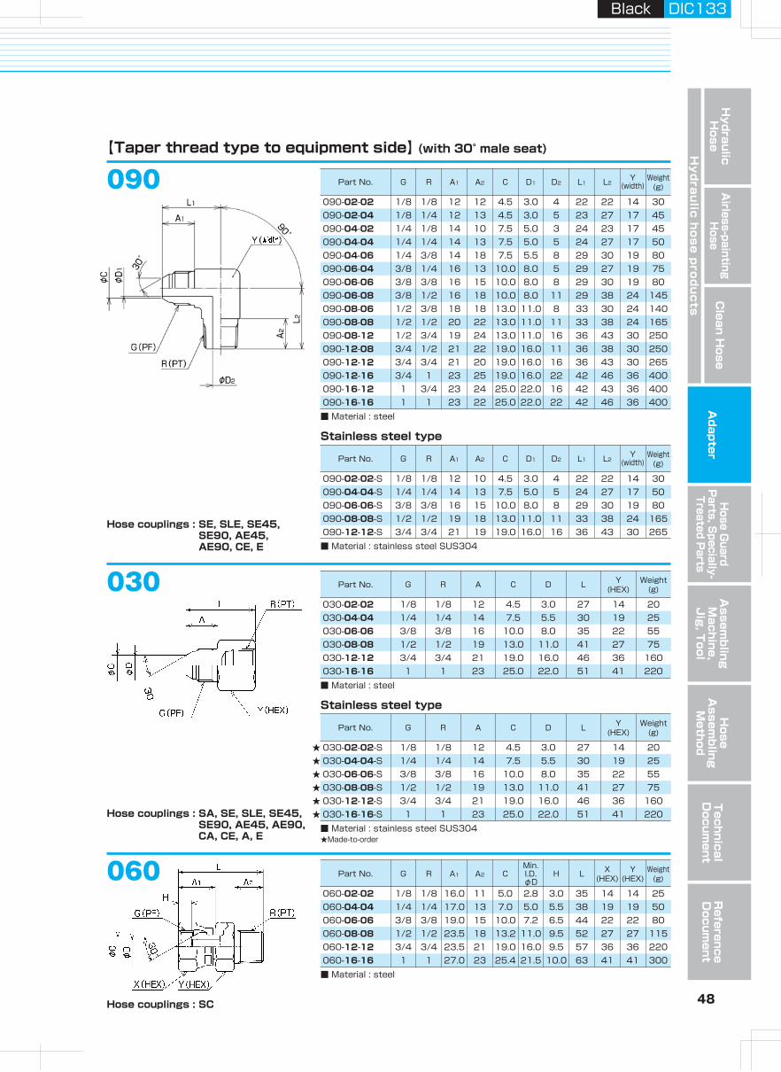
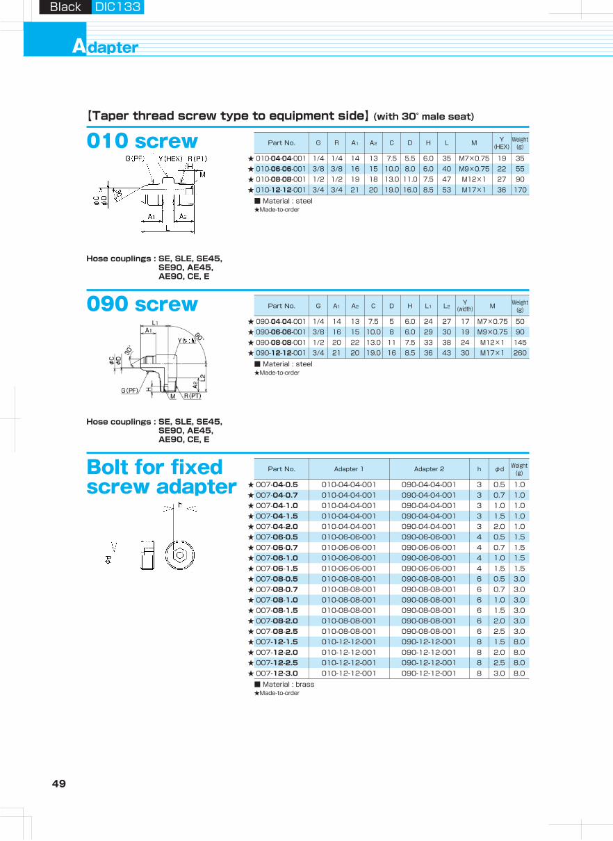
49 50
Hydraulic H
oseA
irless-paintingH
oseA
dapterH
ose Guard
Parts, S
pecially- Treated P
arts
Clean H
ose
Hy
dra
ulic
ho
se
pro
du
cts
Assem
bling
Machine,
Jig
, Tool
Hose
Assem
bling
Method
Technical
Docum
entR
eference D
ocument
dapterA
Black DIC133Black DIC133
Part No. G R A1 A2 C H L M Y(HEX)
Weight(g)D
Part No. G A1 A2 C H L1 L2Y
(width) M Weight(g)D
Part No. Adapter 1 Adapter 2 h φd Weight(g)
Part No. G1 G2 A B1 B2 C1 C2 D1 D2 H L1 L2X
(HEX)Y
(HEX)Pipesize
Weight(g)
Part No. G1 G2 A B1 B2 C1 C2 D1 D2 H L1 L2X
(HEX)Y
(HEX)Pipesize
Weight(g)
Part No. G A B C LT
(max. panel) thicknessX
(HEX)Y
(HEX)Mounting
nutWeight
(g)
Part No. G A C L Y(HEX)
Weight(g)
Part No. G A2 A2 B C L1 L2T
(max. panel) thicknessX
(HEX)Y
(width)Mounting
nutWeight
(g)
D
D
D
Hose couplings : SE, SLE, SE45, SE90, AE45, AE90, CE, E
Hose couplings : SE, SLE, SE45, SE90, AE45, AE90, CE, E
010 screw【Taper thread screw type to equipment side】 (with 30° male seat)
Bolt for fixed screw adapter
★★
★★★★★★★★★
★★
★★
★★
★★
150
020 panel touch
【Interconnection type】 (with 30° male seat)
1 23 12.0 25.0 22 87 10 46 46 NP016 5053/4 21 10.0 19.0 16 79 10 41 41 NP012 3651/2 19 10.0 13.0 11 71 10 30 30 NP08 1903/8 17 7.0 10.0 8 60 10 24 24 NP06 1051/4 14 7.0 7.5 5 54 10 22 22 NP04 75020-04-04-001
020-06-06-001020-08-08-001020-12-12-001020-16-16-001
007-04-0.5
■ Material : brass ★Made-to-order
010-04-04-001 090-04-04-001 3 0.5 1.0010-04-04-001 090-04-04-001 3 0.7 1.0010-04-04-001 090-04-04-001 3 1.0 1.0010-04-04-001 090-04-04-001 3 1.5 1.0010-04-04-001 090-04-04-001 3 2.0 1.0010-06-06-001 090-06-06-001 4 0.5 1.5010-06-06-001 090-06-06-001 4 0.7 1.5010-06-06-001 090-06-06-001 4 1.0 1.5010-06-06-001 090-06-06-001 4 1.5 1.5010-08-08-001 090-08-08-001 6 0.5 3.0010-08-08-001 090-08-08-001 6 0.7 3.0010-08-08-001 090-08-08-001 6 1.0 3.0010-08-08-001 090-08-08-001 6 1.5 3.0010-08-08-001 090-08-08-001 6 2.0 3.0010-08-08-001 090-08-08-001 6 2.5 3.0010-12-12-001 090-12-12-001 8 1.5 8.0010-12-12-001 090-12-12-001 8 2.0 8.0010-12-12-001 090-12-12-001 8 2.5 8.0010-12-12-001 090-12-12-001 8 3.0 8.0
007-04-0.7007-04-1.0007-04-1.5007-04-2.0007-06-0.5007-06-0.7007-06-1.0007-06-1.5007-08-0.5007-08-0.7007-08-1.0007-08-1.5007-08-2.0007-08-2.5007-12-1.5007-12-2.0007-12-2.5007-12-3.0
★★★★
■ Material : steel ★Made-to-order
010-04-04-001010-06-06-001010-08-08-001010-12-12-001
★★★★★
■ Material : steel
■ Material : steel ★Made-to-order
1/8 12 4.5 3.0 31 14 151/4 14 7.5 5.5 36 19 503/8 16 10.0 8.0 42 22 751/2 19 13.0 11.0 48 27 853/4 21 19.0 16.0 54 36 1601 23 25.0 22.0 59 41 230
150-02-02150-04-04150-06-06150-08-08150-12-12150-16-16
090 screw
★★★★
■ Material : steel ★Made-to-order
1/4 14 13 7.5 5 6.0 24 27 17 M7×0.75 503/8 16 15 10.0 8 6.0 29 30 19 M9×0.75 901/2 13.0 11 7.5 33 38 24 M12×1 1453/4 21 20 19.0 16 8.5 36 43 30 M17×1 260
090-04-04-001090-06-06-001090-08-08-001090-12-12-001
1/4 1/4 14 13 7.5 6.0 35 M7×0.75 19 353/8 3/8 16 15 10.0 8.0 6.0 40 M9×0.75 22 551/2 1/2 19 18 13.0 11.0 7.5 47 M12×1 27 903/4 3/4 21 19.0 16.0 8.5 53 M17×1 36 170
Hose couplings : SE, SLE, SE45, SE90, AE45, AE90, CE, E
025 panel touch1/4 32 15 7.0 7.0 5.5 45 26 10 22 22 NP04 1253/8 33 16 7.0 10.0 8.0 46 29 10 24 24 NP06 1601/2 40 19 10.0 13.0 11.0 59 35 10 30 30 NP08 320
025-04-04025-06-06025-08-08★
★★
★★★★★
★★★★★
■ Material : steel ★Made-to-order
Hose couplings : SE, SLE, SE45, SE90, AE45, AE90, CE, E
0641/4 1/4 15 8.5 8.5 9.0 9.0 5.0 5.0 8.0 63 26 19 19 φ10×t2 853/8 3/8 17 9.0 9.0 12.0 12.0 7.0 7.0 9.5 72 30 22 22 φ12×t2 1201/2 1/2 20 9.5 9.5 15.5 15.5 10.0 10.0 12.5 82 32 27 27 φ15×t2.5 2003/4 3/4 21 11.0 10.5 19.0 21.0 16.0 16.0 13.5 95 40 36 36 φ20×t2.5 3501 1 23 12.5 12.5 28.0 28.0 21.5 21.5 16.5 108 47 41 41 φ28×t3.5 515
064-04064-06064-08064-12064-16■ Material : steel ★Made-to-order
0691/4 1/4 15 8.5 8.5 7.0 9.0 5.0 5.0 8.0 46 45 19 19 φ10×t2 903/8 3/8 17 9.0 9.0 10.0 12.0 7.0 7.0 9.5 53 50 22 22 φ12×t2 1251/2 1/2 20 9.5 9.5 13.0 15.5 10.0 10.0 12.5 62 55 27 27 φ15×t2.5 2053/4 3/4 21 11.0 10.5 19.0 21.0 16.0 16.0 13.5 74 76 36 36 φ20×t2.5 3751 1 23 12.0 12.5 25.0 28.0 21.5 21.5 16.5 83 87 41 41 φ28×t3.5 565
069-04069-06069-08069-12069-16■ Material : steel ★Made-to-order
Hose couplings : SE, SLE, SE45, SE90, AE45, AE90, CE, E
Hose couplings : SE, SLE, SE45, SE90, AE45, AE90, CE, E
Hose couplings : SE, SLE, SE45, SE90, AE45, AE90, CE, E
5.5
20
2220
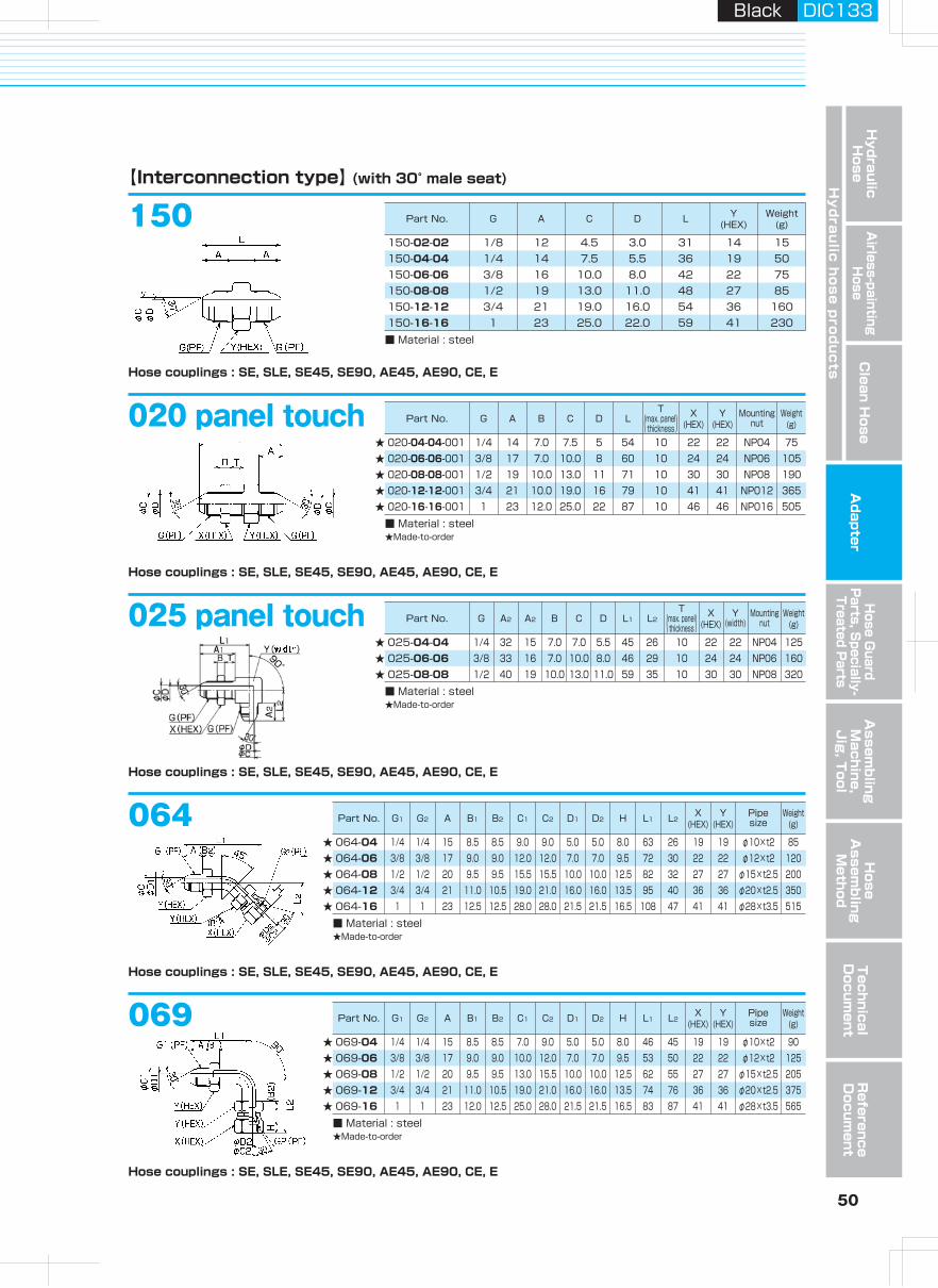
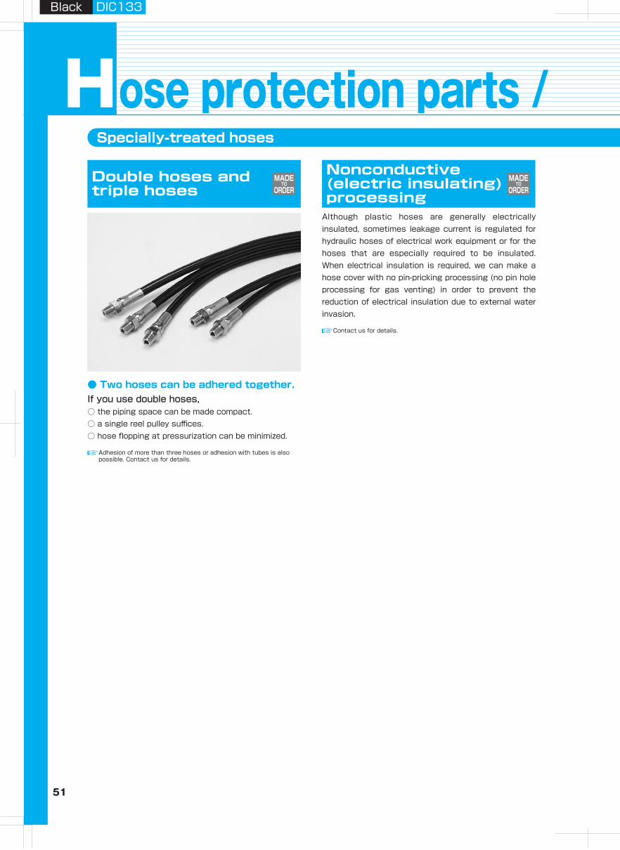
51 52
Hydraulic H
oseA
irless-paintingH
oseA
dapterH
ose Guard
Parts, S
pecially- Treated P
arts
Clean H
ose
Hy
dra
ulic
ho
se
pro
du
cts
Assem
bling
Machine,
Jig
, Tool
Hose
Assem
bling
Method
Technical
Docum
entR
eference D
ocument
Black DIC133Black DIC133
Specially-treated hoses
ose protection parts / special processed partsHDouble hoses and triple hoses
Adhesion of more than three hoses or adhesion with tubes is also possible. Contact us for details.
● Two hoses can be adhered together.If you use double hoses,○ the piping space can be made compact.○ a single reel pulley suffices.○ hose flopping at pressurization can be minimized.
Nonconductive (electric insulating) processing
Although plastic hoses are generally electrically insulated, sometimes leakage current is regulated for hydraulic hoses of electrical work equipment or for the hoses that are especially required to be insulated. When electrical insulation is required, we can make a hose cover with no pin-pricking processing (no pin hole processing for gas venting) in order to prevent the reduction of electrical insulation due to external water invasion.
Outer braid processing
● Processing of steel wire braid and stainless wire braid is possible.
○ Guarding hose against powderly metal.○ Maintaining electric conductivity○ Guarding hose against damage
Colored hose
● Hose cover can be colored.○ Coloring hoses (blue, red, gray, green, aqua color, etc)
MADETO
ORDERMADE
TOORDER
MADETO
ORDERMADE
TOORDER
Contact us for details.
Contact us for details.
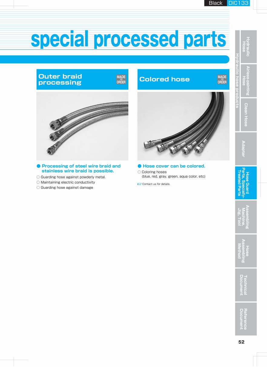
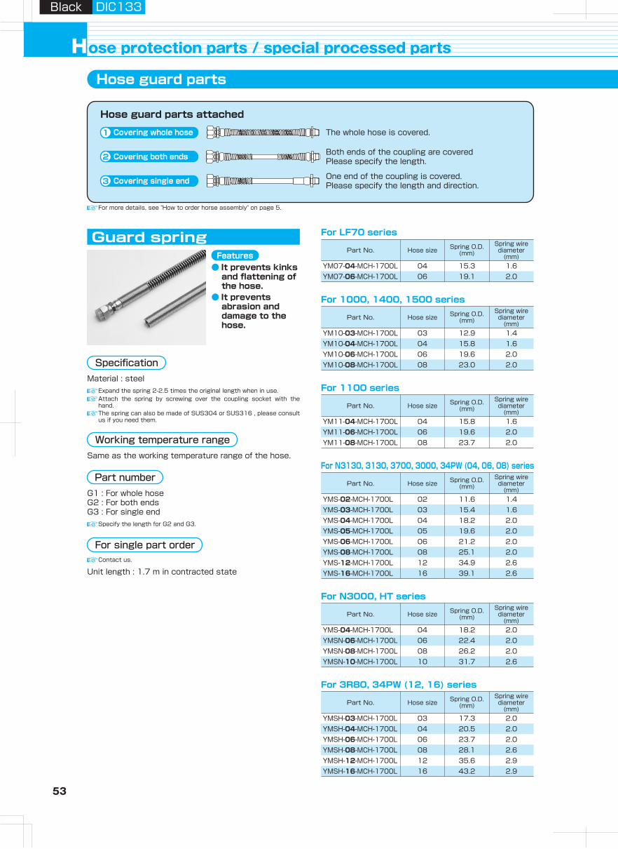
53 54
Hydraulic H
oseA
irless-paintingH
oseA
dapterH
ose Guard
Parts, S
pecially- Treated P
arts
Clean H
ose
Hy
dra
ulic
ho
se
pro
du
cts
Assem
bling
Machine,
Jig
, Tool
Hose
Assem
bling
Method
Technical
Docum
entR
eference D
ocument
ose protection parts / special processed parts H
Black DIC133Black DIC133
Part No. Hose size Spring O.D.(mm)
Spring wire diameter
(mm)
Part No. Hose size Spring O.D.(mm)
Spring wire diameter
(mm)
Part No. Hose size Spring O.D.(mm)
Spring wire diameter
(mm)
Part No. Hose size Spring O.D.(mm)
Spring wire diameter
(mm)
Part No. Hose size Spring O.D.(mm)
Spring wire diameter
(mm)
Part No. Hose size Spring O.D.(mm)
Spring wire diameter
(mm)
Part No.Outer × inner
diameters(mm)
Thickness(mm)
Pitch(mm)
Recommendedhose size
Part No.Inner diameter
before heat contraction
(mm)
Inner diameter after heat
contraction(mm)
Thickness after heat contraction
(mm)
Guard spring
Hose guard parts
Hose guard parts attached
Covering whole hose1
Covering both ends2
Covering single end3
The whole hose is covered.
Both ends of the coupling are covered Please specify the length.
One end of the coupling is covered. Please specify the length and direction.
Nylon spiral tube
Nylon : -40℃ to +105℃Polyethylene : -40℃ to +85℃
Heat contraction tube
Material : nylonColor : black
Polyethylene spiral tube is also available.Contact us for details.
Material : EPRColor : black
For more details, see "How to order horse assembly" on page 5.
Material : steelExpand the spring 2-2.5 times the original length when in use.
SPN-06-0-100MSPN-11-0-50MSPN-18-0-50M
5.5×4 0.75 10 02~0410.6×9 0.8 12 03~08
16.6×15 0.8 18 08~16
For LF70 series
04 15.3 1.606 19.1 2.0
For 1000, 1400, 1500 series
03 12.9 1.404 15.8 1.606 19.6 2.008 23.0 2.0
For N3000, HT series
04 18.2 2.006 22.4 2.008 26.2 2.010 31.7 2.6
For N3130, 3130, 3700, 3000, 34PW (04, 06, 08) series
02 11.6 1.403 15.4 1.604 18.2 2.005 19.6 2.006 21.2 2.008 25.1 2.0
16 39.1 2.6
For 3R80, 34PW (12, 16) series
03 17.3 2.004 20.5 2.006 23.7 2.008 28.1 2.612 35.6 2.916 43.2 2.9
H990-NT200-5M 20 10.0 1H990-NT250-5M 25 12.5 1H990-NT300-5M 30 15.0 1H990-NT400-5M 40 20.0 1
Specification
● It prevents abrasion and damage to the hose
● Light● It can be attached
after piping● For binding hoses● Excellent chemical
durability
Features● As an insulator
from outside● For binding
multiple hoses● For preventing
abrasion and damage to the hose
Features
Working temperature rangeSame as the working temperature range of the hose.
Specify the length for G2 and G3.
Part numberG1 : For whole hose G2 : For both ends G3 : For single end
Contact us.
For single part order
Unit length : 1.7 m in contracted state
Working temperature range-50℃ to +80℃
Working temperature range
Specify the length for S2 and S3.
Part numberS1 : For whole hose S2 : For both ends S3 : For single end Specify the length for E2 and E3.
Part numberE1 : For whole hose E2 : For both ends E3 : For single end
Contact us.
For single part order
Unit length : SPN-06-0 100MSPN-11-0, SPN-18-0 50M
Contact us.
For single part order
Unit length : 5M
Specification Specification
● It prevents kinks and flattening of the hose.
● It prevents abrasion and damage to the hose.
Features
12 2.6
YM07-04-MCH-1700LYM07-06-MCH-1700L
YM10-03-MCH-1700LYM10-04-MCH-1700LYM10-06-MCH-1700LYM10-08-MCH-1700L
YMS-04-MCH-1700LYMSN-06-MCH-1700LYMSN-08-MCH-1700LYMSN-10-MCH-1700L
YMS-02-MCH-1700LYMS-03-MCH-1700LYMS-04-MCH-1700LYMS-05-MCH-1700LYMS-06-MCH-1700LYMS-08-MCH-1700LYMS-12-MCH-1700LYMS-16-MCH-1700L
YMSH-03-MCH-1700LYMSH-04-MCH-1700LYMSH-06-MCH-1700LYMSH-08-MCH-1700LYMSH-12-MCH-1700LYMSH-16-MCH-1700L
YM11-04-MCH-1700LYM11-06-MCH-1700LYM11-08-MCH-1700L
04 15.8 1.606 19.6 2.008 23.7 2.0
For 1100 series
34.9
Attach the spring by screwing over the coupling socket with the hand.The spring can also be made of SUS304 or SUS316 , please consult us if you need them.
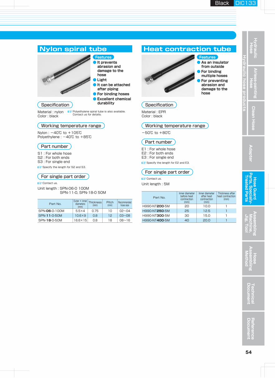
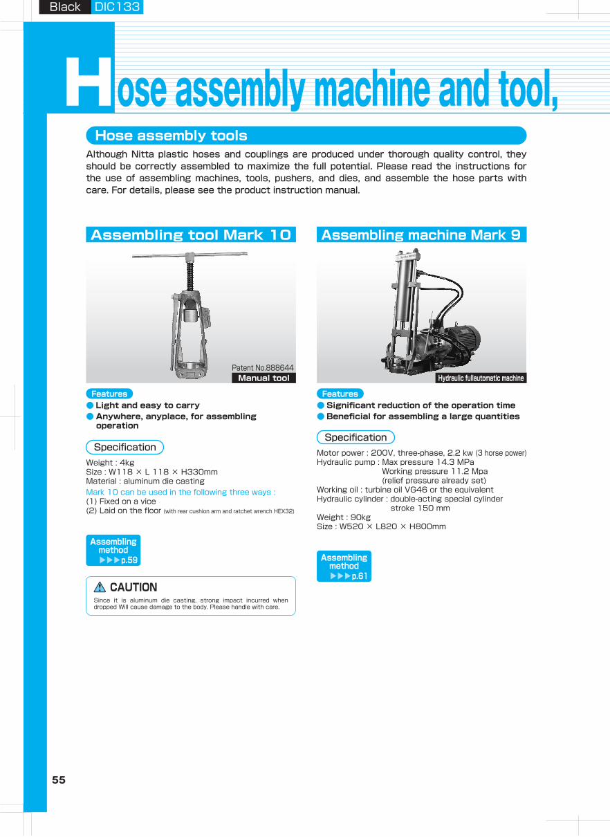
55 56
Hydraulic H
oseA
irless-paintingH
oseA
dapterH
ose Guard
Parts, S
pecially- Treated P
arts
Clean H
ose
Hy
dra
ulic
ho
se
pro
du
cts
Assem
bling
Machine,
Jig
, Tool
Hose
Assem
bling
Method
Technical
Docum
entR
eference D
ocument
Black DIC133Black DIC133
Hose assembly tools
ose assembly machine and tool, special jigs and toolsHAlthough Nitta plastic hoses and couplings are produced under thorough quality control, they should be correctly assembled to maximize the full potential. Please read the instructions for the use of assembling machines, tools, pushers, and dies, and assemble the hose parts with care. For details, please see the product instruction manual.
Hose assembly jigs and toolsThe followings are assembly jigs and tools for Mark 9 and 10.
Assembling tool Mark 10
Patent No.888644Manual tool
Assembling machine Mark 9
This is a jig to fix the sleeve of the hose coupling when assembling.
Pusher
This is a jig to swage the socket of the hose coupling when assembling.
Die
Part number: HC03This can cut hoses from sizes 02 to 08.
Part number : HC01This can cut all hose sizes. There are bolt holes in the base to fix the cutter to a work surface.
Part number :HD01 (for 03, 04, 05, 06, 08)HD02 (for 08, 12, 16)This is used to fix hoses in place.
Hand hose cutter
Hose cutter Holding die (vice block)
Contact us for details.Part number : TRL
Campucka coupling detachable jig Hose coupling cap seal
Assembly lubricant
Hydraulic fullautomatic machine
Fix the HC01 to a stable work surface.Remove the blade fixing spring to open the cutter.Set the hose into the U-shaped support.
Use a commercially available wire cutter to cut a wire braid hose.
1.2.3.
Push down the cutter handle to press-cut the hose.4.
Do not use with any resin hoses other than the ones manufactured by Nitta.
WARNING Do not touch the cutting edge of the cutter. Also, do not place your hand near the cutting edge of the cutter. Doing so is dangerous because it may cause injury.
CAUTION
Do not use with any resin hoses other than the ones manufactured by Nitta.
WARNING Do not touch the cutting edge of the cutter. Also, do not place your hand near the cutting edge of the cutter. Doing so is dangerous because it may cause injury.
CAUTION
WARNING Leaving the cutter with the blade exposed or not closed with the fixing spring is very dangerous.
When not using the cutter or when temporarily stopping work, fix the blade in closed position with the blade fixing spring so that the blade is not exposed.
5.
CAUTION Avoid cutting a wire braid hose such as an 1100 series hose. It may cause nicks in the blade.
CAUTION Cut the hose so that the cut surface is at right angles. If the hose is cut diagonally, there is a risk of causing malfunction due to insufficient hose insertion.
HC01 Handling Instructions
● Light and easy to carry● Anywhere, anyplace, for assembling
operation
Features
Assemblingmethod
p.59
● Significant reduction of the operation time● Beneficial for assembling a large quantities
Features
Assemblingmethod
p.61
List of suitablepart numbers
p.63
List of suitablepart numbers
p.63
CAUTIONSince it is aluminum die casting, strong impact incurred when dropped Will cause damage to the body. Please handle with care.
SpecificationMotor power : 200V, three-phase, 2.2 kw (3 horse power)Hydraulic pump : Max pressure 14.3 MPa
Working pressure 11.2 Mpa (relief pressure already set)
Working oil : turbine oil VG46 or the equivalentHydraulic cylinder : double-acting special cylinder
stroke 150 mmWeight : 90kgSize : W520 × L820 × H800mm
Use Size 02 at the position of 3/16 of HD01.
CAUTIONIf the recommended lubricant is not applied, coating damage and/or socket buckling may occur.
SpecificationWeight : 4kgSize : W118 × L 118 × H330mmMaterial : aluminum die castingMark 10 can be used in the following three ways :(1) Fixed on a vice(2) Laid on the floor (with rear cushion arm and ratchet wrench HEX32)
Part number :For assembling steel connectors : PG3740 (Nihon Kohsakuyu) (lubricant color : green)For assembling stainless connectors : CFH68 (Nisseki Mitsubishi) (lubricant color : yellow)Content: 500 ml
This is used when you insert a hose into a hose connector or swage connectors with assembling tools.
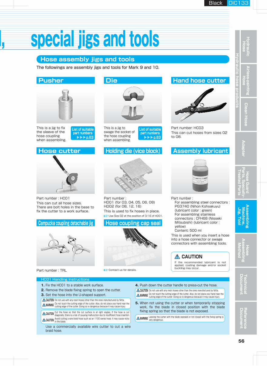
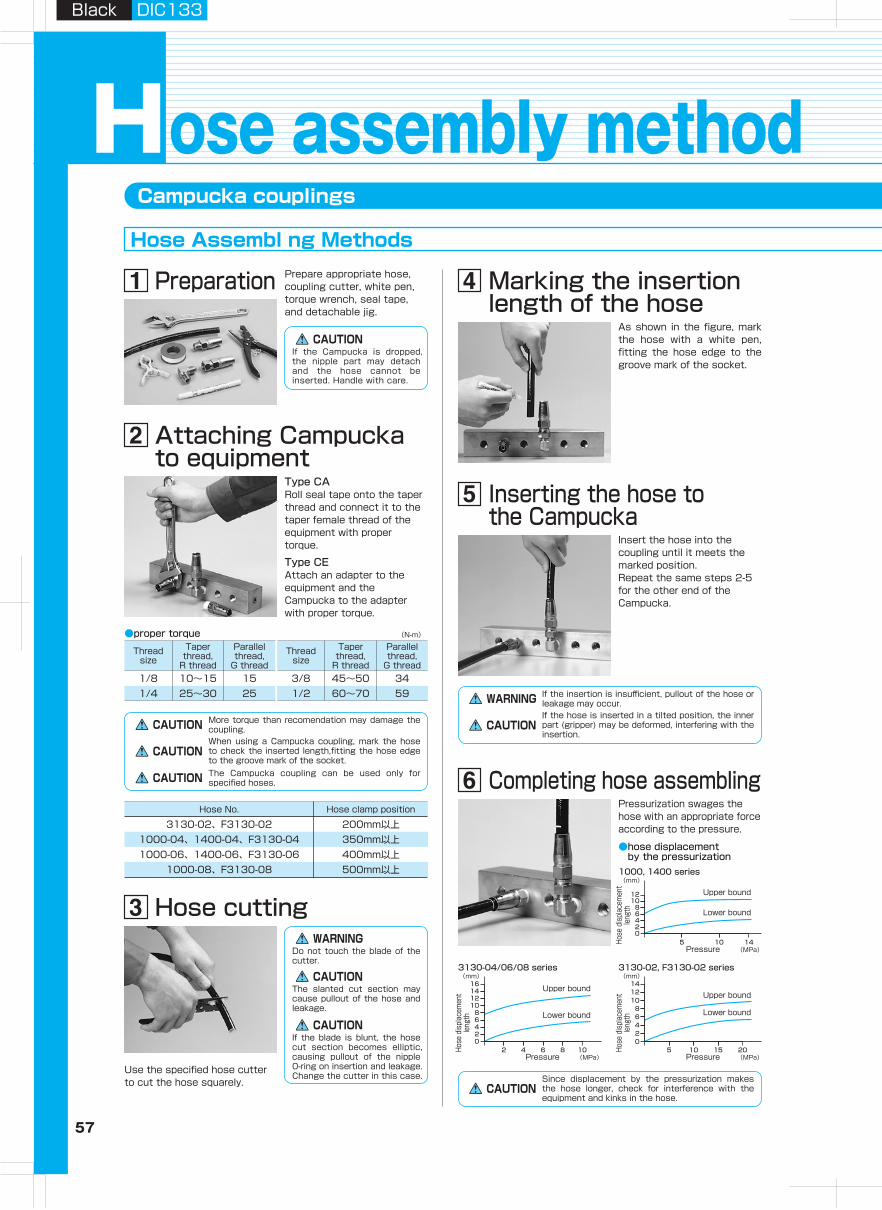
57 58
Hydraulic H
oseA
irless-paintingH
oseA
dapterH
ose Guard
Parts, S
pecially- Treated P
arts
Clean H
ose
Hy
dra
ulic
ho
se
pro
du
cts
Assem
bling
Machine,
Jig
, Tool
Hose
Assem
bling
Method
Technical
Docum
entR
eference D
ocument
Black DIC133Black DIC133
Campucka couplings
ose assembly methodHHose Assembl ng Methods
Thread size
Taper thread,
R thread
Parallel thread,
G thread3/8 45~50 341/2 60~70 59
Hose No. Hose clamp position
3130-02、F3130-02 200mm以上1000-04、1400-04、F3130-04 350mm以上1000-06、1400-06、F3130-06 400mm以上
1000-08、F3130-08 500mm以上
Inserting the hose to the Campucka
Insert the hose into the coupling until it meets the marked position.Repeat the same steps 2-5 for the other end of the Campucka.
Marking the insertion length of the hose
As shown in the figure, mark the hose with a white pen, fitting the hose edge to the groove mark of the socket.
Hose cutting
Use the specified hose cutter to cut the hose squarely.
Detaching hose (2)Push the hose toward the Campucka and then slowly pull it out.
Detaching hose (1)Detaching method(detachable only before pressurization)Insert the (two) edge pins of the detachable jig into the side holes of the socket.
Completing hose assemblingPressurization swages the hose with an appropriate force according to the pressure.
Preparation Prepare appropriate hose, coupling cutter, white pen, torque wrench, seal tape, and detachable jig.
Attaching Campucka to equipment
Type CARoll seal tape onto the taper thread and connect it to the taper female thread of the equipment with proper torque.
Type CEAttach an adapter to the equipment and the Campucka to the adapter with proper torque.
Thread size
Taper thread,
R thread
Parallel thread,
G thread1/8 10~15 151/4 25~30 25
(N-m)●proper torque
●hose displacement by the pressurization1000, 1400 series
Pressure
Upper bound
Upper bound
Lower bound
Lower bound
Hose
dis
plac
emen
tle
ngth
Hose
dis
plac
emen
tle
ngth
Hose
dis
plac
emen
tle
ngth
(MPa)
(mm)
1210
86420
5 10 14
3130-02, F3130-02 series
Pressure (MPa)
(mm)141210
86420
5 10 2015
Upper bound
Lower bound
3130-04/06/08 series
Pressure (MPa)
(mm)16141210
86420
2 4 8 106
* Do not pull the hose before pressurization.CAUTION More torque than recomendation may damage the coupling.When using a Campucka coupling, mark the hose to check the inserted length,fitting the hose edge to the groove mark of the socket.
CAUTION
The Campucka coupling can be used only for specified hoses.CAUTION
WARNING If the insertion is insufficient, pullout of the hose or leakage may occur.If the hose is inserted in a tilted position, the inner part (gripper) may be deformed, interfering with the insertion.
CAUTION
CAUTIONThe hose cannot be pulled out after pressurization. If it is forced, the inner part of the coupling could be damaged, causing pullout of the hose or leakage.The hose and the Campucka are not reusable once pressunzed.CAUTION
WARNINGDo not touch the blade of the cutter.
If the blade is blunt, the hose cut section becomes elliptic, causing pullout of the nipple 0-ring on insertion and leakage. Change the cutter in this case.
CAUTION
The slanted cut section may cause pullout of the hose and leakage.
CAUTION
CAUTIONSince displacement by the pressurization makes the hose longer, check for interference with the equipment and kinks in the hose.
CAUTIONIf the Campucka is dropped, the nipple part may detach and the hose cannot be inserted. Handle with care.
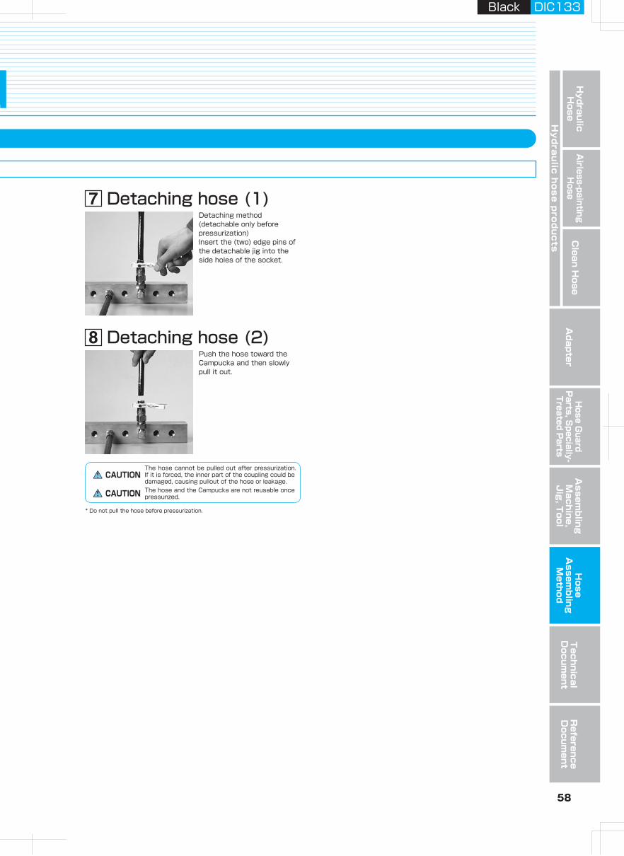
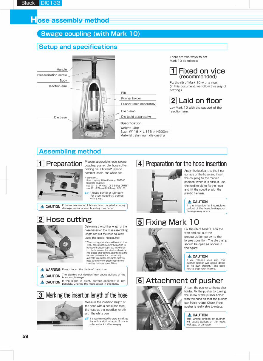
59 60
Hydraulic H
oseA
irless-paintingH
oseA
dapterH
ose Guard
Parts, S
pecially- Treated P
arts
Clean H
ose
Hy
dra
ulic
ho
se
pro
du
cts
Assem
bling
Machine,
Jig
, Tool
Hose
Assem
bling
Method
Technical
Docum
entR
eference D
ocument
Black DIC133Black DIC133
Do not over-tighten the screw.
(1)(2)
ose assembly methodHSwage coupling (with Mark 10)
Setup and specifications
Assembling method
Application of lubricantApply lubricant to the inner surface of the die.
Attachment of pusherAttach the pusher to the pusher holder. Fix the pusher by turning the screw of the pusher holder with the hand so that the pusher can freely rotate. Check if the pusher is really able to rotate.
Fixing Mark 10Fix the rib of Mark 10 on the vice and pull out the pressurization screw to the longest position. The die clamp should be open as shown in the figure.
Preparation for the hose insertionApply the lubricant to the inner surface of the hose and insert the coupling to the marked position. When it is difficult, use the holding die to fix the hose and hit the coupling with the plastic hammer.
There are two ways to set Mark 10 as follows:
Preparation Prepare appropriate hose, swage coupling, pusher, die, hose cutter, holding die, lubricant*, plastic hammer, scale, and white pen.
Hose cuttingDetermine the cutting length of the hose based on the hose assembling length and cut the hose squarely using the special hose cutter.
Measure the insertion length of the hose with a scale and mark the hose at the insertion length with the white pen.
Fixing a mate of the dieFix a mate of the die onto the tapered base.
Detaching hose assemblyUn-install the die clamp, rotate the pressurization screw anti-clockwise to send the pusher up, and remove the hose assembly from the die. If it is difficult to remove the assembly, gently tap the die with the plastic hammer.
Rotating handleAttach the handle to the pressurization screw and rotate the handle clockwise to send the pusher down. Continue until the pusher touches the die.
Insert the coupling, to which the hose is inserted, into the pusher.
Put the other mate of the die on the base. Turn the die clamp to lock the die and fix it firmly.
Hold the hose beneath the die base with your left hand. Pushing the coupling toward the pusher, turn the pressurization screw clockwise with your right hand to send the pusher down.As the pusher comes down, adjust the positions of the die hole and the coupling edge so they coincide.
Pusher holder
Pusher (sold separately)
Rib
Die clamp
Die (sold separately)
Reaction arm
Body
Pressurization screw
Handle
Die base
Weight : 4kgSize : W118 × L 118 × H330mmMaterial : aluminum die casting
Specification
Laid on floorLay Mark 10 with the support of the reaction arm.
Fixed on vice(recommended)
Fix the rib of Mark 10 with a vice.(In this document, we follow this way of setting.)
* lubricant...Steel coupling : Nihon Kosakuyu PG3740Stainless coupling : size 02‒12 : JX Nippon Oil & Energy CFH68size 16 : JX Nippon Oil & Energy DPX100
* lubricant...Steel coupling : Nihon Kosakuyu PG3740Stainless coupling : size 02‒12 : JX Nippon Oil & Energy CFH68size 16 : JX Nippon Oil & Energy DPX100
A 50cc bottle of lubricant (for steel coupling) comes with a set.
CAUTION If the recommended lubricant is not applied, coating damage and/or socket buckling may occur.
WARNING Do not touch the blade of the cutter.
The slanted cut section may cause pullout of the hose and leakage.CAUTIONIf the blade is blunt, correct assembly is not possible. Change the hose cutter in this case.CAUTION
It is recommended to draw a marking line with a width of about 2 mm in order to check it after swaging.
If the insertion is incomplete, pullout of the hose, leakage, or damage may occur.
CAUTION
CAUTIONIf the recommended lubricant is not applied, coating damage and/or socket buckling may occur.
CAUTIONThe wrong choice of pusher will cause pullout of the hose, leakage, or damage.
CAUTIONPay strict attention to prevent the die from falling.
CAUTIONBefore putting the die in storage, remove dust from the inner surface and thinly grease it to prevent rust.
CAUTIONDiscrepancy of the positions of the die hole and the coupling edge might cause damage to the coupling, such as socket defect.
CAUTIONDo not put your hand in the die.
CAUTIONIf you release your grip, the pusher holder will come down by its own weight. Take care not to trap your fingers.
CAUTIONThe wrong choice of pusher will cause pullout of the hose, leakage, or damage.
Marking the insertion length of the hose
Adjustment of positions of die and coupling
If you stop before the pusher touches the die, the swaging is insufficient and pullout of the hose or leakage may occur.CAUTION
Do not take your hands off the handle abruptly. The handle will return in a dangerous fashion.CAUTION
For safe operation, do not get your hands trapped.CAUTION
If you do not stop rotating the handle even after the pusher reaches the die, the tool may crash.CAUTION
For details such as maintenance, please read the instruction manual that comes with the product.
Check of hose assembly
* When cutting a wire braided hose such as 1100 series hose, secure the portion to be cut with plastic tape, etc. in advance in order to prevent the wire from breaking into pieces after cutting, and then cut the secured portion with a commercially available wire cutter, etc. Note that you need to remove the plastic tape before inserting the hose into a fitting.
(1) Check the swage diameter (see p.81).
(2) Check the mark position of the hose insertion length.
(3) Check the appearance of the coupling. (Check for any damage or misalignment of the track of the die.)
(4) Check the appearance of the hose. (Check for any kink or cut.)
Should problems occur, do not use the hose assembly.
Completion of hose assembling
Insertion to pusher
Fixing the other mate of the die
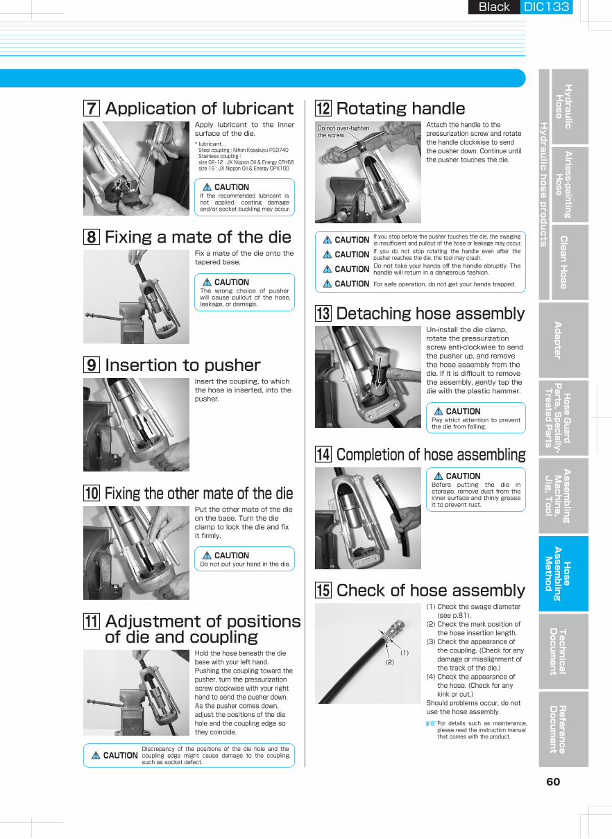
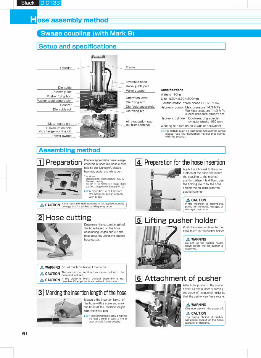
61 62
Hydraulic H
oseA
irless-paintingH
oseA
dapterH
ose Guard
Parts, S
pecially- Treated P
arts
Clean H
ose
Hy
dra
ulic
ho
se
pro
du
cts
Assem
bling
Machine,
Jig
, Tool
Hose
Assem
bling
Method
Technical
Docum
entR
eference D
ocument
Black DIC133Black DIC133
ose assembly methodH
Frame
Die (sold separately)Die fixing arm
Die fixing pin
Air evacuation cap(oil filler opening)
Operation lever
Valve guide poleValve stopper
Cylinder
Die guide
Die guide roll
Pusher fixing boltPusher (sold separately)
Counter
Pusher guide
Motor pump unitOil evacuation hole
(to change working oil)Power switch
Hydraulic hose
(1)(2)
Swage coupling (with Mark 9)
Setup and specifications
Assembling method
Fixing dieAttach the die onto the die fixing arm using the fixing pin.
Attachment of pusherAttach the pusher to the pusher holder. Fix the pusher by turning the screw of the pusher holder so that the pusher can freely rotate.
Lifting pusher holderPush the operation lever to the back to lift up the pusher holder.
Preparation
Hose cutting
Measure the insertion length of the hose with a scale and mark the hose at the insertion length with the white pen.
It is recommended to draw a marking line with a width of about 2 mm in order to check it after swaging.
Marking the insertion length of the hose
Application of lubricantApply lubricant to the inner surface of the die.
Hose assembling (3)Push the operation lever to the back with your right hand to send the pusher up.When the pusher goes up, the die opens by itself and the hose assembly can be removed.(The valve stopper adjusts the upper position of the cylinder.)
Check of hose assembly
Completion of hose assembling
Hose assembling (2)Pull the operation lever until the pusher touches the die.
Insertion to pusherInsert the coupling, to which the hose is inserted, into the pusher.
Hose assembling (1)Hold the hose beneath the die base with your left hand. Pushing the connector toward the pusher, pull the operation lever with your right hand to send the pusher down.As the pusher comes down, adjust the positions of the die hole and the connector edge so they coincide.
For details such as setting·up and electric wiring, please read the instruction manual that comes with the product.
SpecificationsWeight : 90kgSize : 520×820×800mmElectric motor : three phase 200V 2.2kwHydraulic pump : Max. pressure 14.3 MPa
Working pressure 11.2 MPa (Relief pressure already set)
Hydraulic cylinder : Double-acting special cylinder stroke 150 mm
Working oil : turbine oil VG46 or equivalent
Prepare appropriate hose, swage coupling, pusher, die, hose cutter, holding die, lubricant*, plastic hammer, scale, and white pen.* lubricant...
Steel coupling : Nihon Kosakuyu PG3740Stainless coupling : size 02‒12 : JX Nippon Oil & Energy CFH68size 16 : JX Nippon Oil & Energy DPX100
A 50cc bottle of lubricant (for steel coupling) comes with a set.
CAUTION If the recommended lubricant is not applied, coating damage and/or socket buckling may occur.
Determine the cutting length of the hose based on the hose assembling length and cut the hose squarely using the special hose cutter.
WARNING Do not touch the blade of the cutter.
The slanted cut section may cause pullout of the hose and leakage.CAUTIONIf the blade is blunt, correct assembly is not possible. Change the hose cutter in this case.CAUTION
Preparation for the hose insertionApply the lubricant to the inner surface of the hose and insert the coupling to the marked position. When it is difficult, use the holding die to fix the hose and hit the coupling with the plastic hammer.
If the insertion is incomplete, pullout of the hose, leakage, or damage may occur.
CAUTION
WARNINGDo not let the pusher holder down before the die pusher is attached.
Only operate with the power off.WARNING
CAUTIONThe wrong choice of pusher will cause pullout of the hose, leakage, or damage.
WARNINGOnly operate with the power off.
The wrong choice of pusher will cause pullout of the hose, leakage, or damage.
CAUTION
* lubricant...Steel coupling : Nihon Kosakuyu PG3740Stainless coupling : size 02‒12 : JX Nippon Oil & Energy CFH68size 16 : JX Nippon Oil & Energy DPX100
CAUTIONIf the recommended lubricant is not applied, coating damage and/or socket buckling may occur.
If you stop before the pusher touches the die, the swaging is insufficient and pullout of the hose or leakage may occur.
CAUTION
Use a hose of sufficient length to hold the hose.
WARNING
DANGER It is dangerous to hold the hose near the die base. The die could trap your hand.
Discrepancy of the positions of the die hole and the connector edge might cause damage to the coupling, such as socket defect.
CAUTION
When the die closes, check that the hose is not stuck in the die.CAUTION
Never touch the moving parts when operating the tool.DANGER
Pay strict attention to prevent the die from falling.
CAUTION
Before putting the die in storage, remove dust from the inner surface and thinly grease it to prevent rust.
CAUTION
For details such as maintenance, please read the instruction manual that comes with the product.
(1) Check the swage diameter (see p.81).
(2) Check the mark position of the hose insertion length.
(3) Check the appearance of the coupling. (Check for any damage or misalignment of the track of the die.)
(4) Check the appearance of the hose. (Check for any kink or cut.)
Should problems occur, do not use the hose assembly.
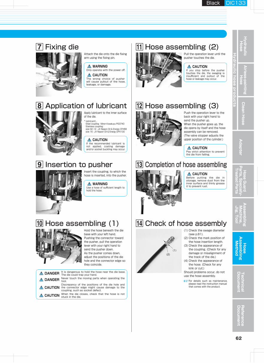
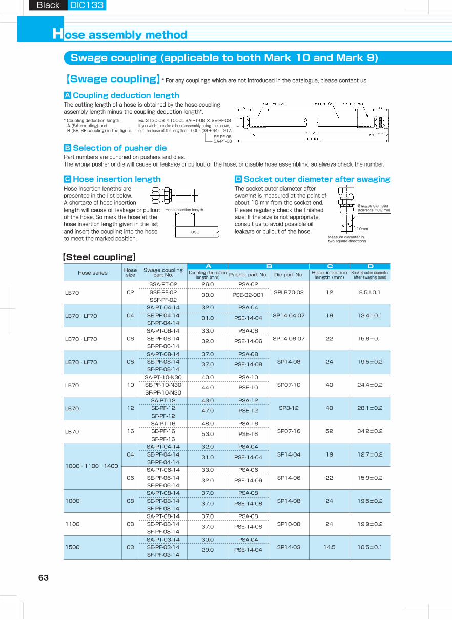
63 64
Hydraulic H
oseA
irless-paintingH
oseA
dapterH
ose Guard
Parts, S
pecially- Treated P
arts
Clean H
ose
Hy
dra
ulic
ho
se
pro
du
cts
Assem
bling
Machine,
Jig
, Tool
Hose
Assem
bling
Method
Technical
Docum
entR
eference D
ocument
Black DIC133Black DIC133
ose assembly methodHSwage coupling (applicable to both Mark 10 and Mark 9)
【Swage coupling】* For any couplings which are not introduced in the catalogue, please contact us.
A C DB【Steel coupling】
Hose insertion lengths are presented in the list below.A shortage of hose insertion length will cause oil leakage or pullout of the hose. So mark the hose at the hose insertion length given in the list and insert the coupling into the hose to meet the marked position.
Part numbers are punched on pushers and dies.The wrong pusher or die will cause oil leakage or pullout of the hose, or disable hose assembling, so always check the number.
The cutting length of a hose is obtained by the hose-coupling assembly length minus the coupling deduction length*.
The socket outer diameter after swaging is measured at the point of about 10 mm from the socket end.Please regularly check the finished size. If the size is not appropriate, consult us to avoid possible oil leakage or pullout of the hose.
* Coupling deduction length : A (SA coupling) and B (SE, SF coupling) in the figure.
Swaged diameter(tolerance ±0.2 mm)
10mm
Measure diameter in two square directions
Hose insertion length
HOSE
C Hose insertion length
B Selection of pusher die
A Coupling deduction length
D Socket outer diameter after swaging
Ex. 3130-08 ×1000L SA-PT-08 × SE-PF-08If you wish to make a hose assembly using the above, cut the hose at the length of 1000 - (39 + 44) = 917.
SE-PF-08SA-PT-08
1000・1100・1400
1000
1100
1500
LB70
LB70・LF70
SSA-PT-02 26.0 PSA-0202 SSE-PF-02 SPLB70-02 12 8.5±0.1
SSF-PF-0230.0 PSE-02-001
SA-PT-04-14 32.0 PSA-0404 SE-PF-04-14 SP14-04-07 19 12.4±0.1
SF-PF-04-1431.0 PSE-14-04
LB70・LF70
LB70・LF70
SA-PT-06-14 33.0 PSA-0606 SE-PF-06-14 SP14-06-07 22 15.6±0.1
SF-PF-06-1432.0 PSE-14-06
SA-PT-08-14 37.0 PSA-0808 SE-PF-08-14 SP14-08 24 19.5±0.2
SF-PF-08-1437.0 PSE-14-08
LB70
LB70
SA-PT-10-N30 40.0 PSA-1010 SE-PF-10-N30 SP07-10 40 24.4±0.2
SF-PF-10-N3044.0 PSE-10
SA-PT-12 43.0 PSA-1212 SE-PF-12 SP3-12 40 28.1±0.2
SF-PF-1247.0 PSE-12
LB70SA-PT-16 48.0 PSA-16
16 SE-PF-16 SP07-16 52 34.2±0.2SF-PF-16
53.0 PSE-16
SA-PT-04-14 32.0 PSA-0404 SE-PF-04-14 SP14-04 19 12.7±0.2
SF-PF-04-1431.0 PSE-14-04
SA-PT-06-14 33.0 PSA-0606 SE-PF-06-14 SP14-06 22 15.9±0.2
SF-PF-06-1432.0 PSE-14-06
SA-PT-08-14 37.0 PSA-0808 SE-PF-08-14 SP14-08 24 19.5±0.2
SF-PF-08-1437.0 PSE-14-08
SA-PT-08-14 37.0 PSA-0808 SE-PF-08-14 SP10-08 24 19.9±0.2
SF-PF-08-1437.0 PSE-14-08
SA-PT-03-14 30.0 PSA-0403 SE-PF-03-14 SP14-03 14.5 10.5±0.1
SF-PF-03-1429.0 PSE-14-04
3130・34PWSSA-PT-02 26.0 PSA-02
02 SSE-PF-02 SP3-02-001 12 9.2±0.2SSF-PF-02
30.0 PSE-02-001
SA-PT-03 32.0 PSA-0403 SE-PF-03 SP3-03 26 12.4±0.2
SF-PF-0333.0 PSE-03
SA-PT-04 33.0 PSA-0404 SE-PF-04 SP3-04 28 14.4±0.2
SF-PF-0436.0 PSE-04
N3130・37003130・3000・34PW
SA-PT-05 35.0 PSA-0605 SE-PF-05 SP3-05 28 16.0±0.2
SF-PF-0538.0 PSE-05
SA-PT-06 35.0 PSA-0606 SE-PF-06 SP3-06 33 17.6±0.2
SF-PF-0639.0 PSE-06
SA-PT-08 39.0 PSA-0808 SE-PF-08 SP3-08 37 21.5±0.2
SF-PF-0844.0 PSE-08
N3130・37003130・3000
SA-PT-12 43.0 PSA-1212 SE-PF-12 SP3-12 40 28.1±0.2
SF-PF-1247.0 PSE-12
SA-PT-16 48.0 PSA-1616 SE-PF-16 SP3-16 52 34.5±0.2
SF-PF-1653.0 PSE-16
SA-PT-04 33.0 PSA-0404 SE-PF-04 SPN-04 28 14.6±0.2
SF-PF-0436.0 PSE-04
N3000・HT
SA-PT-06-N30 35.0 PSA-0606 SE-PF-06-N30 SPN-06 33 18.9±0.2
SF-PF-06-N3039.0 PSE-06
SA-PT-08-N30 39.0 PSA-0808 SE-PF-08-N30 SPN-08 37 22.7±0.2
SF-PF-08-N3044.0 PSE-08
3R80
3R80・34PW
SA-PT-10-N30 40.0 PSA-1010 SE-PF-10-N30 SPN-10 40 26.2±0.2
SF-PF-10-N3044.0 PSE-10
A C DB
SA-PT-03-3R 35.0 PSA-0403 SE-PF-03-3R SPH-03 23 13.5±0.2
SF-PF-03-3R36.0 PSE-03
SA-PT-04-3R 33.0 PSA-0404 SE-PF-04-3R SPH-04 28 17.2±0.2
SF-PF-04-3R36.0 PSE-04
SA-PT-06-N30 35.0 PSA-0606 SE-PF-06-N30 SPH-06 33 20.1±0.2
SF-PF-06-N3039.0 PSE-06
SA-PT-08-N30 39.0 PSA-0808 SE-PF-08-N30 SPH-08 37 23.0±0.2
SF-PF-08-N3044.0 PSE-08
SA-PT-12-3R 43.0 PSA-1212 SE-PF-12-3R SPH-12 40 29.5±0.2
SF-PF-12-3R47.0 PSE-12
SA-PT-16-3R 48.0 PSA-1616 SE-PF-16-3R SPH-16 52 37.8±0.2
SF-PF-16-3R53.0 PSE-16
Socket outer diameter after swaging (mm)
Hose series Hose size
Swage coupling part No. Coupling deduction
length (mm) Pusher part No. Die part No. Hose insertion length (mm)
Socket outer diameter after swaging (mm)
Hose series Hose size
Swage coupling part No. Coupling deduction
length (mm) Pusher part No. Die part No. Hose insertion length (mm)
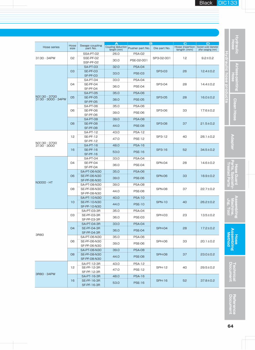
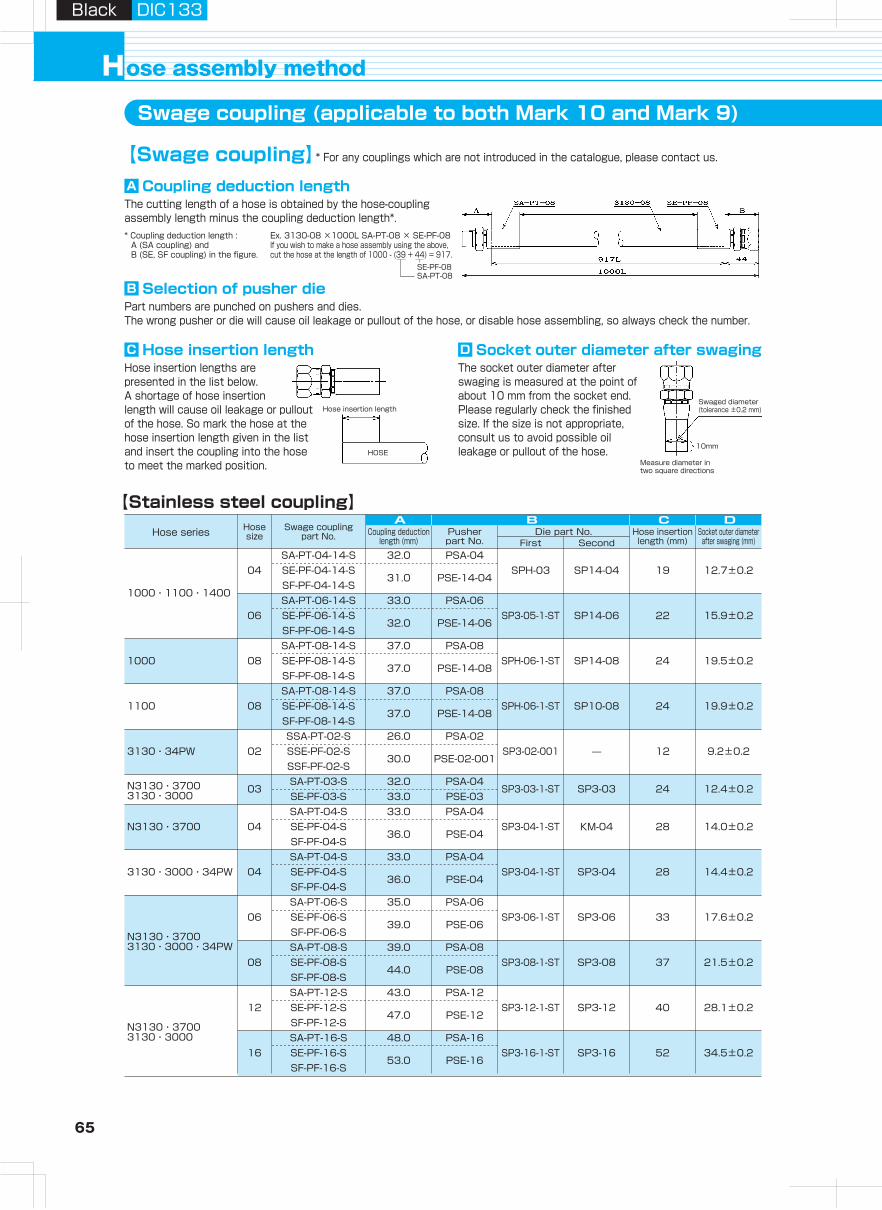
65 66
Hydraulic H
oseA
irless-paintingH
oseA
dapterH
ose Guard
Parts, S
pecially- Treated P
arts
Clean H
ose
Hy
dra
ulic
ho
se
pro
du
cts
Assem
bling
Machine,
Jig
, Tool
Hose
Assem
bling
Method
Technical
Docum
entR
eference D
ocument
Black DIC133Black DIC133
ose assembly methodHSwage coupling (applicable to both Mark 10 and Mark 9)
【Swage coupling】* For any couplings which are not introduced in the catalogue, please contact us.
Hose insertion lengths are presented in the list below.A shortage of hose insertion length will cause oil leakage or pullout of the hose. So mark the hose at the hose insertion length given in the list and insert the coupling into the hose to meet the marked position.
Part numbers are punched on pushers and dies.The wrong pusher or die will cause oil leakage or pullout of the hose, or disable hose assembling, so always check the number.
The cutting length of a hose is obtained by the hose-coupling assembly length minus the coupling deduction length*.
The socket outer diameter after swaging is measured at the point of about 10 mm from the socket end.Please regularly check the finished size. If the size is not appropriate, consult us to avoid possible oil leakage or pullout of the hose.
* Coupling deduction length : A (SA coupling) and B (SE, SF coupling) in the figure.
Swaged diameter(tolerance ±0.2 mm)
10mm
Measure diameter in two square directions
Hose insertion length
HOSE
C Hose insertion length
B Selection of pusher die
A Coupling deduction length
D Socket outer diameter after swaging
Ex. 3130-08 ×1000L SA-PT-08 × SE-PF-08If you wish to make a hose assembly using the above, cut the hose at the length of 1000 - (39 + 44) = 917.
SE-PF-08SA-PT-08
【Stainless steel coupling】
1000・1100・1400
1000
SA-PT-04-14-S 32.0 PSA-0404 SE-PF-04-14-S SPH-03 SP14-04 19 12.7±0.2
SF-PF-04-14-S
A C DB
31.0 PSE-14-04
SA-PT-06-14-S 33.0 PSA-0606 SE-PF-06-14-S SP3-05-1-ST SP14-06 22 15.9±0.2
SF-PF-06-14-S32.0 PSE-14-06
SA-PT-08-14-S 37.0 PSA-0808 SE-PF-08-14-S SPH-06-1-ST SP14-08 24 19.5±0.2
SF-PF-08-14-S37.0 PSE-14-08
1100SA-PT-08-14-S 37.0 PSA-08
08 SE-PF-08-14-S SPH-06-1-ST SP10-08 24 19.9±0.2SF-PF-08-14-S
37.0 PSE-14-08
3130・34PWSSA-PT-02-S 26.0 PSA-02
02 SSE-PF-02-S SP3-02-001 12 9.2±0.2SSF-PF-02-S
30.0 PSE-02-001
N3130・3700SA-PT-04-S 33.0 PSA-04
04 SE-PF-04-S SP3-04-1-ST KM-04 28 14.0±0.2SF-PF-04-S
36.0 PSE-04
3130・3000・34PWSA-PT-04-S 33.0 PSA-04
04 SE-PF-04-S SP3-04-1-ST SP3-04 28 14.4±0.2SF-PF-04-S
36.0 PSE-04
N3130・37003130・3000・34PW
N3130・37003130・3000
SA-PT-06-S 35.0 PSA-0606 SE-PF-06-S SP3-06-1-ST SP3-06 33 17.6±0.2
SF-PF-06-S39.0 PSE-06
SA-PT-08-S 39.0 PSA-0808 SE-PF-08-S SP3-08-1-ST SP3-08 37 21.5±0.2
SF-PF-08-S44.0 PSE-08
SA-PT-12-S 43.0 PSA-1212 SE-PF-12-S SP3-12-1-ST SP3-12 40 28.1±0.2
SF-PF-12-S47.0 PSE-12
SA-PT-16-S 48.0 PSA-1616 SE-PF-16-S SP3-16-1-ST SP3-16 52 34.5±0.2
SF-PF-16-S53.0 PSE-16
N3130・37003130・3000
SA-PT-03-S 32.0 PSA-0403
SE-PF-03-SSP3-03-1-ST SP3-03 24 12.4±0.2
33.0 PSE-03
A C DB
N3000・HT
3R80
3R80・34PW
34PW
SA-PT-04-S 33 PSA-0404
SE-PF-04-SSP3-04-1-ST SPN-04 28 14.6±0.2
35 PSE-04SA-PT-06-N30-S 34 PSA-0606SE-PF-06-N30-S
SPH-06-1-ST SPN-06 33 18.9±0.238 PSE-06
SA-PT-08-N30-S 39 PSA-0808
SE-PF-08-N30-SSPH-08-1-ST SPN-08 37 22.7±0.2
43 PSE-08SA-PT-04-3R-S 33 PSA-04
04SE-PF-04-3R-S
SPH-04-1-ST SPH-04 28 17.2±0.235 PSE-04
SA-PT-06-N30-S 34 PSA-0606
SE-PF-06-N30-SSPH-06-1-ST SPH-06 33 20.1±0.2
38 PSE-06SA-PT-08-N30-S 39 PSA-08
08SE-PF-08-N30-S
SPH-08-1-ST SPH-08 37 23.0±0.2
12 SE-PF-12-3R-S 47 PSE-12 SPH-12-1-ST SPH-12 40 29.5±0.216 SE-PF-16-3R-S 53 PSE-16 SPH-16-1-ST SPH-16 52 37.8±0.204 SE-G-04-PW 36 PSE-04 SP3-04-VC 28 14.4±0.206 SE-G-06-PW 39 PSE-06 SP3-06-VC 33 17.6±0.208 SE-G-08-PW 44 PSE-08 SP3-08-VC 37 21.5±0.212 SE-G-12-PW 47 PSE-12 SPH-12-1-ST SPH-12-VC 40 29.5±0.216 SE-G-16-PW 53 PSE-16 SPH-16-1-ST SPH-16-37VC 52 37.0±0.204 SE-G-04-PWL 31 PSE-04-PWL SPP-04-VC 11 14.7±0.206 SE-G-06-PWL 32 PSE-06-PWL SPP-06-VC 11 18.0±0.208 SE-G-08-PWL 39 PSE-08-PWL SPP-08-VC 14 21.8±0.212 SE-G-12-PWL 42 PSE-12-PWL SPP-12-VC 21 29.6±0.216 SE-G-16-PWL 45 PSE-16-PWL SPP-16-VC 29 37.2±0.2
43 PSE-08
Hose series Hose size
Swage couplingpart No. Coupling deduction
length (mm)Pusherpart No.
Die part No.SecondFirst
Hose insertion length (mm)
Socket outer diameter after swaging (mm)
Hose series Hose size
Swage couplingpart No. Coupling deduction
length (mm)Pusherpart No.
Die part No.SecondFirst
Hose insertion length (mm)
Socket outer diameter after swaging (mm)
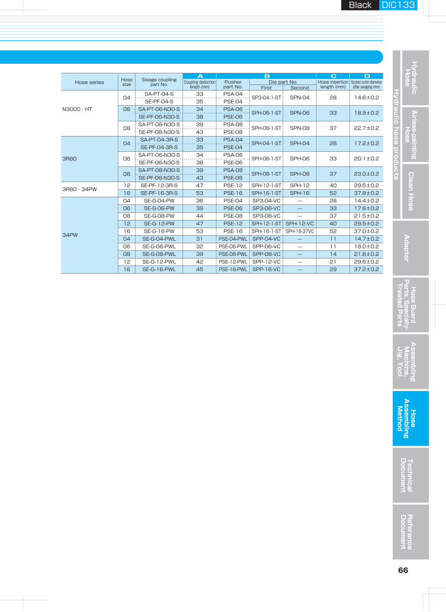
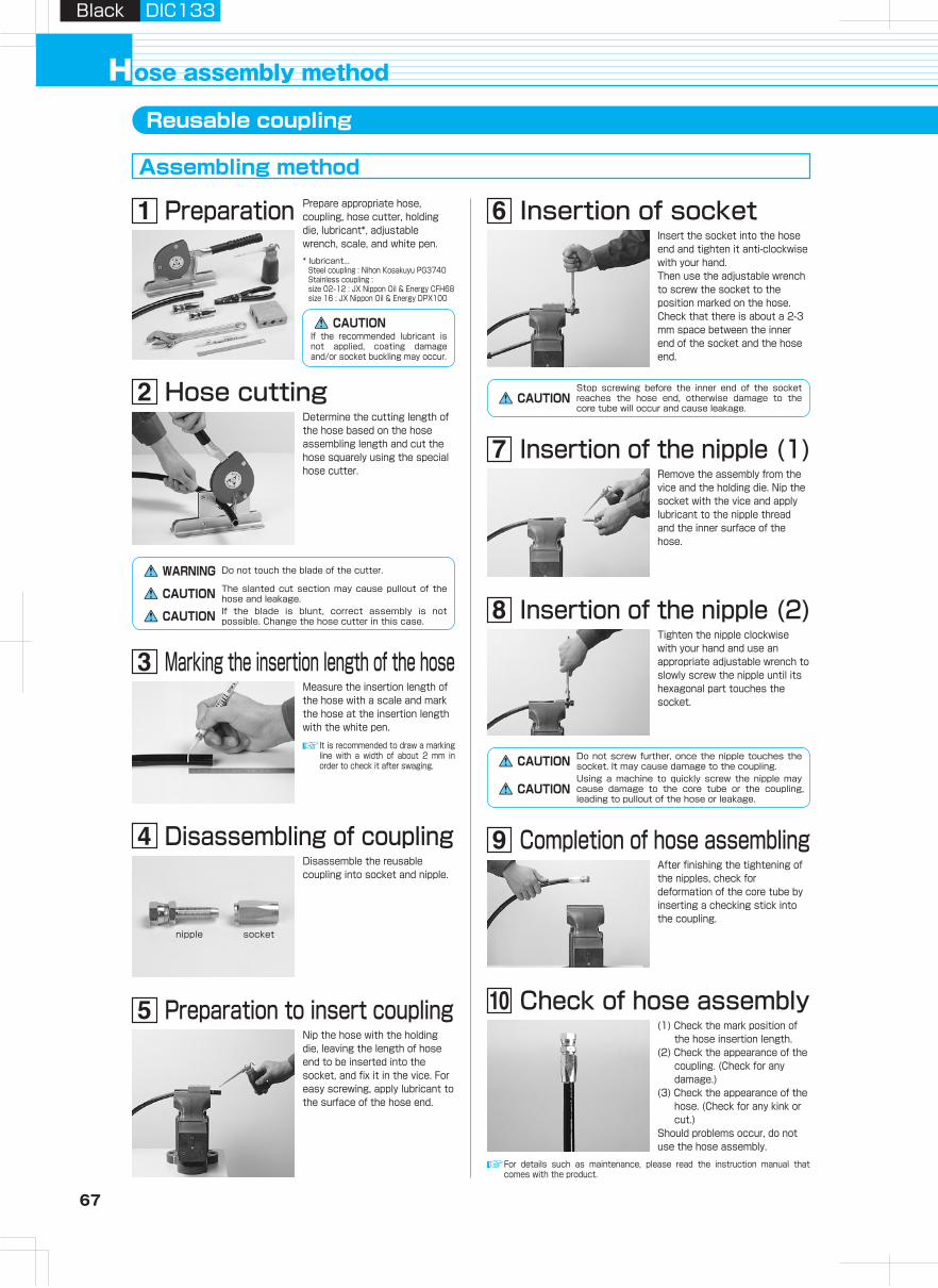
67 68
Hydraulic H
oseA
irless-paintingH
oseA
dapterH
ose Guard
Parts, S
pecially- Treated P
arts
Clean H
ose
Hy
dra
ulic
ho
se
pro
du
cts
Assem
bling
Machine,
Jig
, Tool
Hose
Assem
bling
Method
Technical
Docum
entR
eference D
ocument
Black DIC133Black DIC133
ose assembly methodHReusable coupling
Assembling method
Preparation Prepare appropriate hose, coupling, hose cutter, holding die, lubricant*, adjustable wrench, scale, and white pen.
Hose cutting
Disassemble the reusable coupling into socket and nipple.
Preparation to insert couplingNip the hose with the holding die, leaving the length of hose end to be inserted into the socket, and fix it in the vice. For easy screwing, apply lubricant to the surface of the hose end.
Insertion of socketInsert the socket into the hose end and tighten it anti-clockwise with your hand.Then use the adjustable wrench to screw the socket to the position marked on the hose. Check that there is about a 2-3 mm space between the inner end of the socket and the hose end.
Insertion of the nipple (1)Remove the assembly from the vice and the holding die. Nip the socket with the vice and apply lubricant to the nipple thread and the inner surface of the hose.
Tighten the nipple clockwise with your hand and use an appropriate adjustable wrench to slowly screw the nipple until its hexagonal part touches the socket.
After finishing the tightening of the nipples, check for deformation of the core tube by inserting a checking stick into the coupling.
nipple socket
(1) Check the mark position of the hose insertion length.
(2) Check the appearance of the coupling. (Check for any damage.)
(3) Check the appearance of the hose. (Check for any kink or cut.)
Should problems occur, do not use the hose assembly.
【Reusable coupling】* For any couplings which are not introduced in the catalogue, please contact us.
Hose insertion lengths are presented in the list below.A shortage of hose insertion length will cause oil leakage or pullout of the hose_ So mark the hose at the hose insertion length given in the list and insert the coupling into the hose to meet the marked position.
3130・3000
3130
3000
3130
3130・3000
A-PT-02 25.51602 E-PF-02
F-PF-02
A B
31.5
A-PT-03 30.02103 E-PF-03
F-PF-03 32.5
A-PT-04 31.52504 E-PF-04
F-PF-04 34.0
A-PT-05 35.52905 E-PF-05
F-PF-05 37.0
A-PT-06 37.53006 E-PF-06
F-PF-06 40.0
A-PT-08 43.03608 E-PF-08
F-PF-08 46.0
A-PT-12 46.53812 E-PF-12
F-PF-12 47.5
A-PT-16 49.54216 E-PF-16
F-PF-16 50.0
The cutting length of a hose is obtained by the hose-coupling assembly length minus the coupling deduction length*.* Coupling deduction length :
A (SA coupling) and B (SE, SF coupling) in the figure.
Table of hose screwing length
B Hose insertion length
A Coupling deduction length
* lubricant...Steel coupling : Nihon Kosakuyu PG3740Stainless coupling : size 02‒12 : JX Nippon Oil & Energy CFH68size 16 : JX Nippon Oil & Energy DPX100
CAUTIONStop screwing before the inner end of the socket reaches the hose end, otherwise damage to the core tube will occur and cause leakage.
CAUTIONIf the recommended lubricant is not applied, coating damage and/or socket buckling may occur.
Determine the cutting length of the hose based on the hose assembling length and cut the hose squarely using the special hose cutter.
WARNING Do not touch the blade of the cutter.
The slanted cut section may cause pullout of the hose and leakage.CAUTIONIf the blade is blunt, correct assembly is not possible. Change the hose cutter in this case.CAUTION
CAUTION Do not screw further, once the nipple touches the socket. It may cause damage to the coupling.Using a machine to quickly screw the nipple may cause damage to the core tube or the coupling, leading to pullout of the hose or leakage.
CAUTION
Measure the insertion length of the hose with a scale and mark the hose at the insertion length with the white pen.
It is recommended to draw a marking line with a width of about 2 mm in order to check it after swaging.
Marking the insertion length of the hose
For details such as maintenance, please read the instruction manual that comes with the product.
Ex. 3130-08 × 1000L SA-PT-08 × E-PF-08If you wish to make a hose assembly using the above, cut the hose at the length of 1000 - (43 + 46) = 911.
E-PF-08A-PT-08
Hose insertion length
Disassembling of coupling
Insertion of the nipple (2)
Completion of hose assembling
Check of hose assembly
Hose series Hose size
Reusable coupling part No. Coupling deduction
length (mm)Hose insertion length (mm)
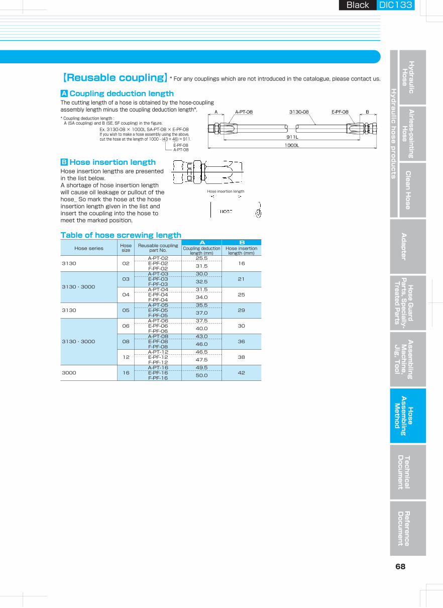
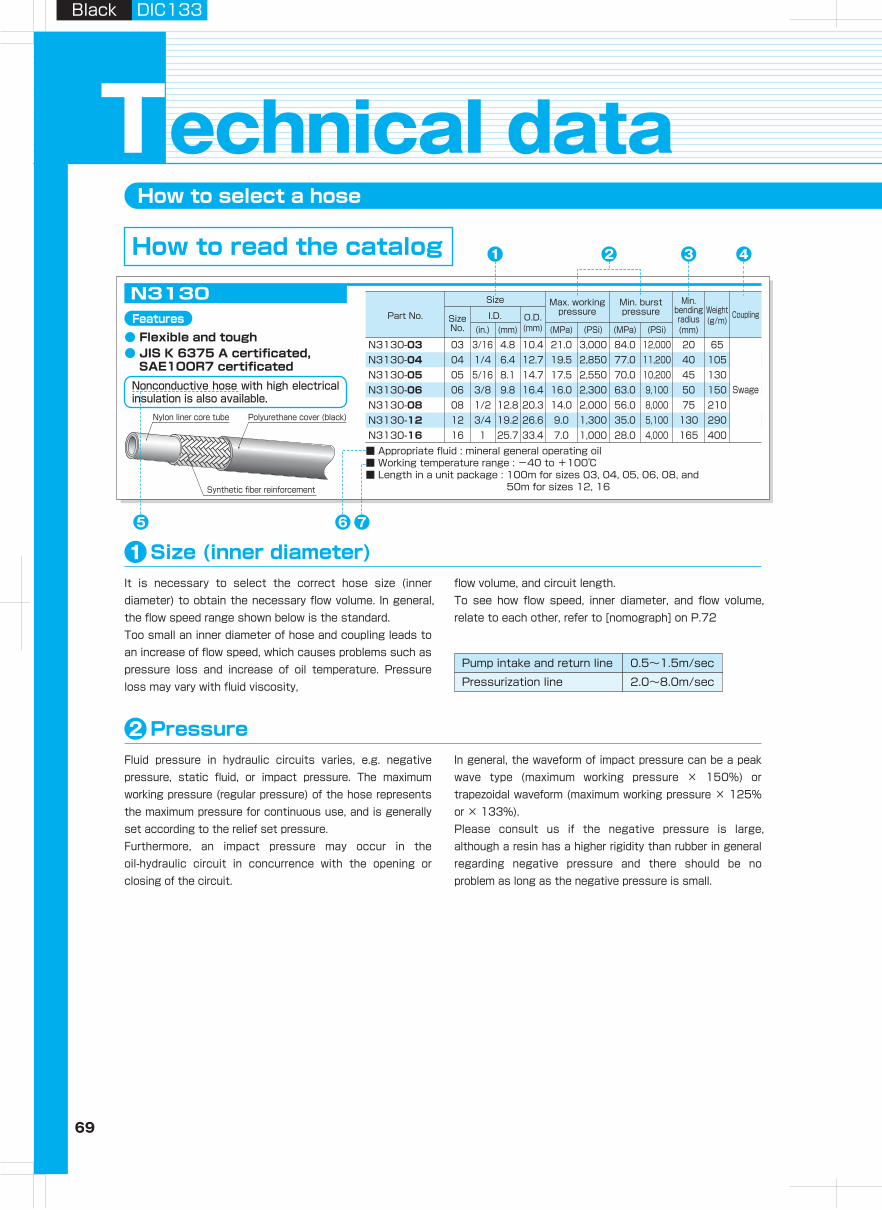
69 70
Hydraulic H
oseA
irless-paintingH
oseadapter
Hose G
uard P
arts, Specially-
Treated Parts
Clean H
ose
Hy
dra
ulic
ho
se
pro
du
cts
Assem
bling
Machine,
Jig
, Tool
Hose
Assem
bling
Method
Technical
Docum
entR
eference D
ocument
Black DIC133Black DIC133
Size
Part No. Size No.
I.D. O.D.(mm)(mm)(in.) (MPa)
Max. working pressure
(PSi) (MPa)
Min. burst pressure
Min. bending radius(mm)
Coupling
(PSi)
Weight(g/m)
How to select a hose
echnical dataT
It is necessary to select the correct hose size (inner diameter) to obtain the necessary flow volume. In general, the flow speed range shown below is the standard.Too small an inner diameter of hose and coupling leads to an increase of flow speed, which causes problems such as pressure loss and increase of oil temperature. Pressure loss may vary with fluid viscosity,
flow volume, and circuit length.To see how flow speed, inner diameter, and flow volume, relate to each other, refer to [nomograph] on P.72
Size (inner diameter)
Nonconductive hose with high electrical insulation is also available.
1
76
3 42
1
The hose can be bent, but there is always a limit. If the hose is bent at a radius smaller than the minimum bending radius, deformation or kink of the hose may occur and cause problems.Please bend the hose at a radius larger than the minimum bending radius.
Bending radius3
The coupling consists of a connection to equipment, a hexagonal part, and a connection to the hose. There are various types of couplings, including adapters. Sometimes connections to the imported equipment do not work well
because their thread and sheet shape differs from the JIS standard. Therefore, check the thread type, sealing method and sheet surface shape and angle of equipment to be connected before selecting couplings.
Coupling4
Plastic hoses in general have high electrical insulation. When electrical insulation is particularly necessary, e.g. for the hydraulic hose of electrical work equipment, leakage current is sometimes determined. Contact us in this case.
When electrical insulation is required, a nonconductive hose without pin pricking (no pin hole for gas venting) is also available to prevent the reduction of electrical insulation due to external water invasion.
Electrical insulation[nonconductive hose]5
Since the hose core tube is made of high oil resistant plastic , it will not be damaged by mineral or aqueous hydraulic oil. However, some types of synthetic hydraulic oil and nonflammable special oil could affect the hose.Typical couplings and adapters are made of zinc galvanized
steel. Contact us if using a special fluid that may damage the material or the surface processing.
Fluid type6
Using a hose at a temperature higher than the specification may cause thermal degradation and could shorten the hose life. Also using at a temperature lower than the specification could make the hose harder and
frangible. When effects of atmospheric temperature, e.g. radiational heat, are expected, use a heat insulator to protect the hose.
Working temperature (fluid temperature, atmospheric temperature)7Fluid pressure in hydraulic circuits varies, e.g. negative pressure, static fluid, or impact pressure. The maximum working pressure (regular pressure) of the hose represents the maximum pressure for continuous use, and is generally set according to the relief set pressure.Furthermore, an impact pressure may occur in the oil-hydraulic circuit in concurrence with the opening or closing of the circuit.
In general, the waveform of impact pressure can be a peak wave type (maximum working pressure × 150%) or trapezoidal waveform (maximum working pressure × 125% or × 133%).Please consult us if the negative pressure is large, although a resin has a higher rigidity than rubber in general regarding negative pressure and there should be no problem as long as the negative pressure is small.
Pressure2
Pump intake and return line
Pressurization line
0.5~1.5m/sec
2.0~8.0m/sec
Stainless couplings or black colored couplings (made-to-order) are also available if using water or glycol hydraulic oil.
How to read the catalog
r : Bending radius
Features● Flexible and tough● JIS K 6375 A certificated,
SAE1OOR7 certificated
N3130-03N3130-04N3130-05N3130-06N3130-08N3130-12N3130-16
N3130
■ Appropriate fluid : mineral general operating oil■ Working temperature range : -40 to +100℃■ Length in a unit package : 100m for sizes 03, 04, 05, 06, 08, and
50m for sizes 12, 16
Nylon liner core tube
Synthetic fiber reinforcement
Polyurethane cover (black)
Swage
03 3/16 4.8 10.4 21.0 3,000 84.0 12,000 20 6504 1/4 6.4 12.7 19.5 2,850 77.0 11,200 40 10505 5/16 8.1 14.7 17.5 2,550 70.0 10,200 45 13006 3/8 9.8 16.4 16.0 2,300 63.0 9,100 50 15008 1/2 12.8 20.3 14.0 2,000 56.0 8,000 75 21012 3/4 19.2 26.6 9.0 1,300 35.0 5,100 130 29016 1 25.7 33.4 7.0 1,000 28.0 4,000 165 400
5
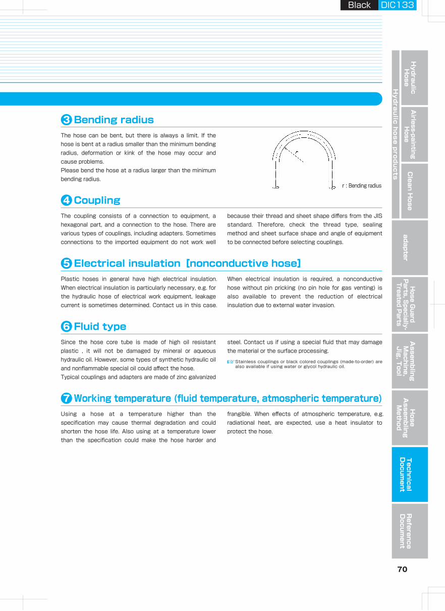
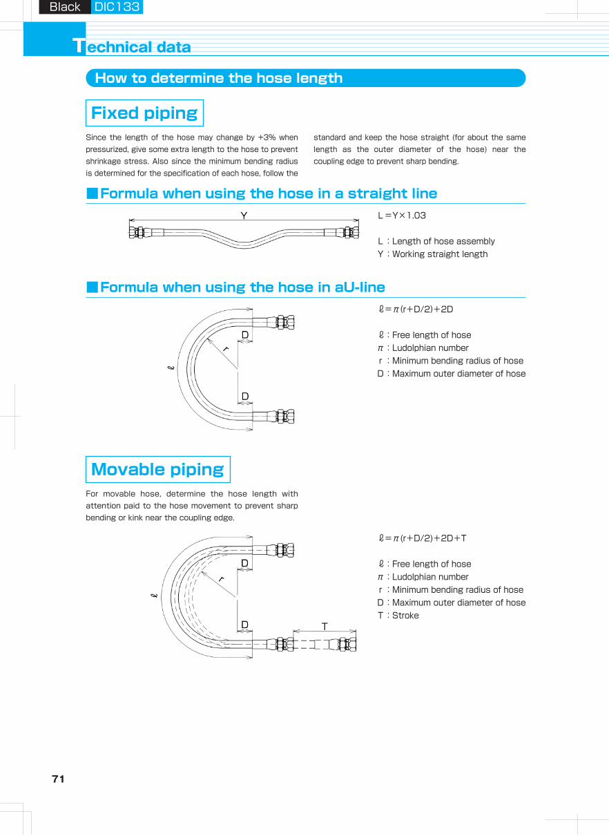
71 72
Hydraulic H
oseA
irless-paintingH
oseA
dapterH
ose Guard
Parts, S
pecially- Treated P
arts
Clean H
ose
Hy
dra
ulic
ho
se
pro
du
cts
Assem
bling
Machine,
Jig
, Tool
Hose
Assem
bling
Method
Technical
Docum
entR
eference D
ocument
Black DIC133Black DIC133
echnical dataTHow to determine the hose length How to select the hose size for given flow volume and velocity
L=Y×1.03
L:Length of hose assemblyY:Working straight length
Since the length of the hose may change by +3% when pressurized, give some extra length to the hose to prevent shrinkage stress. Also since the minimum bending radius is determined for the specification of each hose, follow the
standard and keep the hose straight (for about the same length as the outer diameter of the hose) near the coupling edge to prevent sharp bending.
■Formula when using the hose in a straight line
Fixed pipingThe figure below is to help in the selection of the most suitable choice of hose for equipment. Keep the flow velocity in the column. If the flow velocity exceeds the recommended value, problems such as increased pressure loss and overheating could occur. Generally, when fluid flows in a hose, the "flow volume", "flow velocity", and "hose cross section" are linked as shown in the formula below.
Therefore, if any two of the three are given, the rest is determined by this formula.
Explanation of nomograph
1) Select the discharge flow volume of the pressure line in the leftmost line graph.2) Select the flow velocity in the recommended range of the rightmost line graph.3) Draw a line connecting both points obtained above and find the correct hose inner diameter at the point where the line
crosses the central graph.
How to use the graph
For movable hose, determine the hose length with attention paid to the hose movement to prevent sharp bending or kink near the coupling edge.
Movable piping
■Formula when using the hose in aU-line
■Nomograph
2
3
4
5
10
15
20
30
40
50
100
150
200
300
400
2.5
12.010.09.08.07.06.0
5.0
4.0
3.0
2.0
1.00.90.80.70.60.5
0.4
0.3
0.2
0.1
1.5
Flow velocity(m/sec)
This figure is applicable to oil of maximum viscosity 66 est (40℃).
Velocity rangeof return line
Velocity rangeof pressure line
Hose cross section(cm2)
5.025.4
19.015.9
12.7
7.9
6.3
4.8
3.6
9.5
16
1210
08
05
04
03
02
06
4.03.0
2.0
1.0
0.50.40.3
0.2
0.1
Hose size
Hose inner diameter(mm)
=π(r+D/2)+2D+T
:Free length of hoseπ:Ludolphian numberr:Minimum bending radius of hoseD:Maximum outer diameter of hoseT:Stroke
=π(r+D/2)+2D
:Free length of hoseπ:Ludolphian numberr:Minimum bending radius of hoseD:Maximum outer diameter of hose
When the flow velocity of the pressure line is 5 m/sec and the necessary flow volume is 20 /min, the recommended hose size is 06.
(Ex.)
Flow volume( /min)
Hose cross section( )=
×10Flow volume( /min)Flow velocity(m/sec)×60
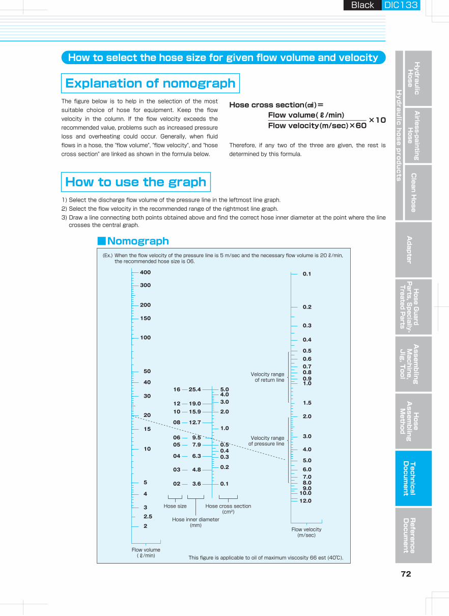
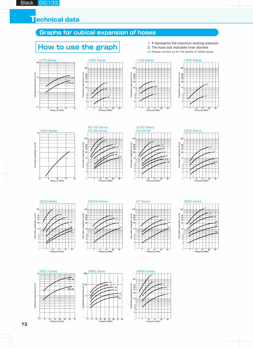
73 74
Hydraulic H
oseA
irless-paintingH
oseA
dapterH
ose Guard
Parts, S
pecially- Treated P
arts
Clean H
ose
Hy
dra
ulic
ho
se
pro
du
cts
Assem
bling
Machine,
Jig
, Tool
Hose
Assem
bling
Method
Technical
Docum
entR
eference D
ocument
Black DIC133Black DIC133
echnical dataTGraphs for cubical expansion of hoses Tightening torque of hose couplings and adapters
1. • represents the maximum working pressure2. The hose size indicates inner diameteHow to use the graph
Tighten with your hand until the two sheets perfectly contact each other.
Connection method of hose coupling (with sheet) and adapter
Please contact us for the details of 35NG series.
1 CouplingFix the adapter and nipple with a spanner so that the sheets cannot rotate together, and tighten the nut with a torque wrench (see the figure). When the rotation speed of the torque wrench is high, the surface pressure at the sheet surface is low, which might cause leakage. In this case, slowly tighten again until you feel a click.
2 Fixing
1/8
■ There must be no axial scratch or spiral tool mark on the O-shaped O-ring contact surface.
■ D1 scraped surface must be squarely or flat to the thread axis.
18 11.6 10 1.0 15 2.0 P81/4 24 15.6 12 1.5 18 2.5 P11
Thread size 1/8 1/4 3/8 1/2 3/4 1G (PF) Thread 15N・m 25N・m 34N・m 64N・m 132N・m 196N・m
3/8 28 18.6 12 2.0 18 2.5 P141/2 34 22.6 16 2.5 24 2.5 P183/4 45 29.8 17 2.5 25 3.5 P241 51 35.8 21 2.5 30 3.5 P29
【Parallel pipe thread】
Thread size 1/8 1/4 3/8 1/2 3/4 1R (PT) Thread 10 to 15N・m 25 to 30N・m 45 to 50N・m 60 to 70N・m 120 to 140N・m 140 to 160N・m
【Taper pipe thread】
Thread size 7/16-20 1/2-20 9/16-18 3/4-16 7/8-14UNF Thread 25N・m 30N・m 40N・m 50N・m 60N・m
【Unified fine thread】
Thread size 1/4 3/8NPSM Thread 25N・m 34N・m
【American Standard straight pipe threads for free-fitting mechanical joints for fixtures】
【Shape and size of JIS-standard O-ring port (JISB2351)】
LF70 Series 1000 Series 1100 Series 1400 Series
1500 SeriesN3130 Series, F3130 Series
3130 Series, F3130-02 3700 Series
3000 Series N3000 Series HT Series 3R80 Series
5501 Series 3450 Series 34PW Series
Adjust the axes of the coupling and adapter to
prevent non-uniform contact of sheets.After tightening with your hand, please check for any unwanted space between the coupling and adapter.
CAUTION
The tightening torque should follow the figures
in the "parallel pipe thread" table on the previous page.If the sheets are rotated while contacting each other, it will damage the sheet surface and cause leakage.
CAUTION
Thread nameG D1±0.3 D1
+0.1 0
L1(Min)
L2 (Max)
L3 (Min) L4
+0.40 0
SuitableO-ring number
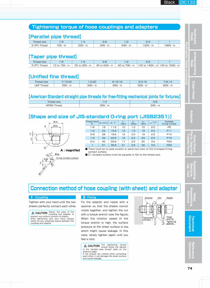
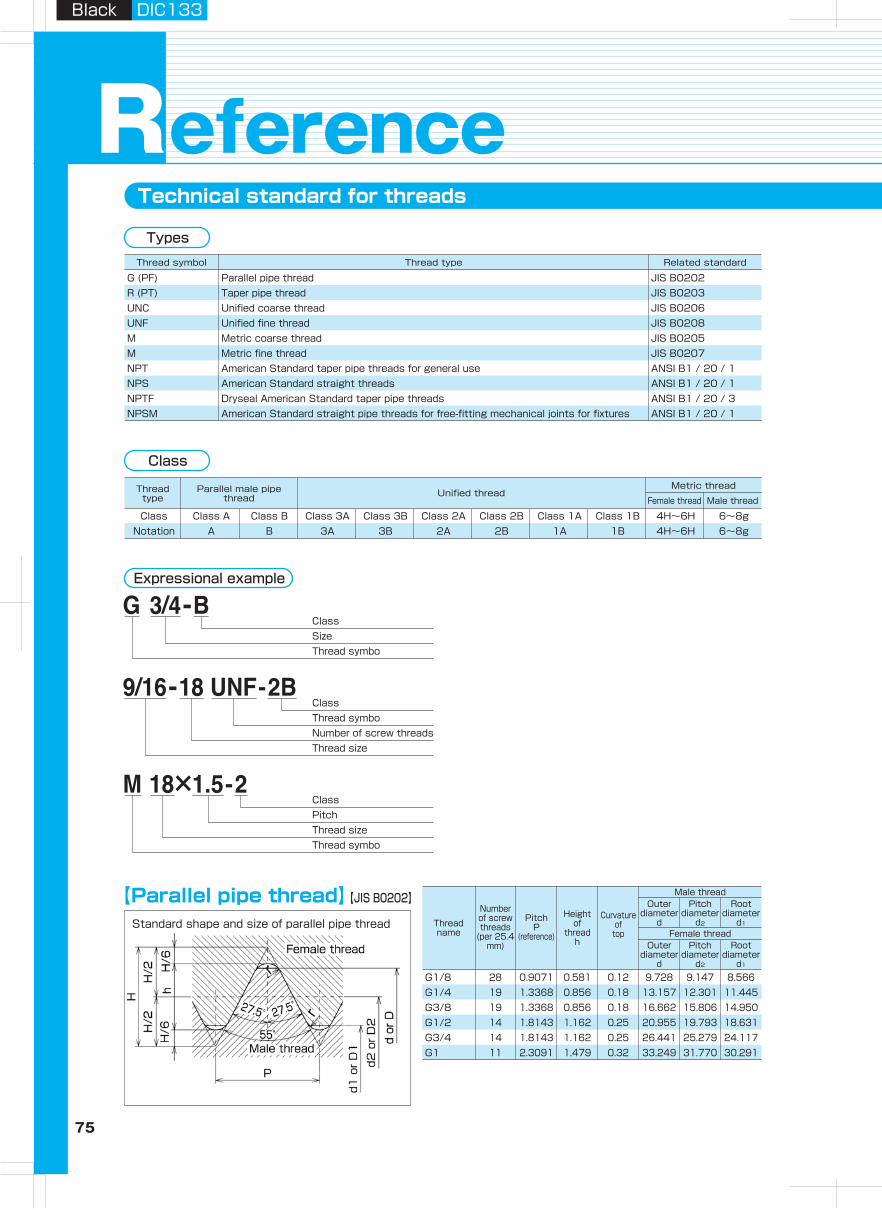
75 76
Hydraulic H
oseA
irless-paintingH
oseA
dapterH
ose Guard
Parts, S
pecially- Treated P
arts
Clean H
ose
Hy
dra
ulic
ho
se
pro
du
cts
Assem
bling
Machine,
Jig
, Tool
Hose
Assem
bling
Method
Technical
Docum
entR
eference D
ocument
Black DIC133Black DIC133
Technical standard for threads
eferenceR
28 0.9701 0.581 0.12 9.728 9.147 8.566 2.5 6.2 7.4 4.4 10.5 2.0R1/819 1.3368 0.856 0.18 13.157 12.301 11.445 3.7 9.4 11.0 6.7 13.8 2.3R1/419 1.3368 0.856 0.18 16.662 15.806 14.950 3.7 9.7 11.4 7.0 17.3 2.3R3/814 1.8143 1.162 0.25 20.955 19.793 18.631 5.0 12.7 15.0 9.1 21.7 2.8R1/214 1.8143 1.162 0.25 26.441 25.279 24.117 5.0 14.1 16.3 10.2 27.2 2.8R3/411 2.3091 1.479 0.32 33.249 31.770 30.291 6.4 16.2 19.1 11.6 34.0 3.2R1
【Unified fine thread】
Standard shape applied to tapered male and female threads
【Taper pipe threads】
Standfud shape of unified fine thread
1.5 0.812 12.000 11.026 10.376M12×1.51.5 0.812 14.000 13.026 12.376M14×1.51.5 0.812 16.000 15.026 14.376M16×1.51.5 0.812 18.000 17.026 16.376M18×1.51.5 0.812 20.000 19.026 18.376M20×1.51.5 0.812 22.000 21.026 20.376M22×1.51.5 0.812 24.000 23.026 22.376M24×1.51.5 0.812 30.000 29.026 28.376M30×1.5
28 0.9071 0.491 6.350 5.761 5.3671/ 4 -28 UNF24 1.0583 0.573 7.938 7.249 6.7925/16-24 UNF24 1.0583 0.573 9.525 8.837 8.3793/ 8 -24 UNF20 1.2700 0.687 11.112 10.287 9.7387/16-20 UNF20 1.2700 0.687 12.700 11.874 11.3261/ 2 -20 UNF18 1.4111 0.764 14.288 13.371 12.7619/16-18 UNF18 1.4111 0.764 15.875 14.958 14.3485/ 8 -18 UNF16 1.5875 0.859 19.050 18.019 17.3303/ 4 -16 UNF14 1.8143 0.982 22.225 21.046 20.2627/ 8 -14 UNF
【Metric fine threa】Standard shape of metric fine thread
28 0.9071 0.581 0.12 9.728 9.147 8.566G1/819 1.3368 0.856 0.18 13.157 12.301 11.445G1/419 1.3368 0.856 0.18 16.662 15.806 14.950G3/814 1.8143 1.162 0.25 20.955 19.793 18.631G1/214 1.8143 1.162 0.25 26.441 25.279 24.117G3/411 2.3091 1.479 0.32 33.249 31.770 30.291G1
Parallel pipe thread JIS B0202G (PF)Taper pipe thread JIS B0203R (PT)Unified coarse thread JIS B0206UNCUnified fine thread JIS B0208UNFMetric coarse thread JIS B0205MMetric fine thread JIS B0207MAmerican Standard taper pipe threads for general use ANSI B1 / 20 / 1NPTAmerican Standard straight threads ANSI B1 / 20 / 1NPSDryseal American Standard taper pipe threads ANSI B1 / 20 / 3NPTFAmerican Standard straight pipe threads for free-fitting mechanical joints for fixtures ANSI B1 / 20 / 1NPSM
Thread symbol Thread type Related standard
【Parallel pipe thread】Standard shape and size of parallel pipe thread
Types
Class A Class B Class 3A Class 3B Class 2A Class 2B Class 1A Class 1B 4H~6H 6~8gClassA B 3A 3B 2A 2B 1A 1B 4H~6H 6~8gNotation
Thread type
Parallel male pipe thread Unified thread
Female thread Male thread
Metric thread
Class
Expressional example
ClassSizeThread symbo
ClassThread symboNumber of screw threadsThread size
ClassPitchThread sizeThread symbo
【JIS B0202】
【JIS B0207】
【JIS B0208】
【JIS B0203】
±1.13±0.91±1.67±1.34±1.67±1.34±2.27±1.81±2.27±1.81±2.89±2.31
3.976.016.358.169.53
10.39
±0.071±0.104±0.104±0.142±0.142±0.181
Thread name
Numberof screw threads
(per 25.4 mm)
PitchP
(reference)
Heightof
threadh
Curvature of
top Female thread
Male thread
Pitchdiameter
d2
Rootdiameter
d1
Outerdiameter
d
Pitchdiameter
d2
Rootdiameter
d1
Outerdiameter
d
Threadname(PT) Female thread
Male thread
Male thread
Female threadFemale thread
Male thread
From position
of standard diameter to larger diameter
part
Frompipe edge
Atpipe edge
Standard diameter Length of useful threadThread
Stan-dard
length
Toler-ance along axis
Toler-ance along axis
Tolerance of
D1, D2 and D1
of female thread
Size of carbon-steel
pipe (reference)
With incompletethread part
Without incomplete thread part
Taper female thread, parallel female thread
Parallel male thread
Taper female thread
From standard diameter, pipe, pipe coupling
edge
Outer diame-
terThick-ness
From pipe orpipe coupling edge
(reference)
From positionof standard
diameter to smalle diameter part
Position ofstandard diameter
PitchP
(reference)
Height of
threadh
Curva-ture
radiusrorr2
Outer diameter
d
Pitch diameter
d2
Root diameter
d1
Root diameter
D
Pitch diameter
D2
Inner diameter
D1
Numberof
screw threads
(per 25.4mm)
n
Threadname
PitchP
(reference)
Height of engagement
H1Female thread
Male thread
Pitch diameterD2
Inner diameterD1
Root diameterD
Pitch diameterd2
Root diameterd1
Outer diameterd
Threadname
Numberof
screw threads
(per 25.4 mm)n
PitchP
(reference)
Height of engage-
mentH1
Female thread
Male thread
Pitch diameterD2
Inner diameterD1
Root diameterD
Pitch diameterd2
Root diameterd1
Outer diameterd
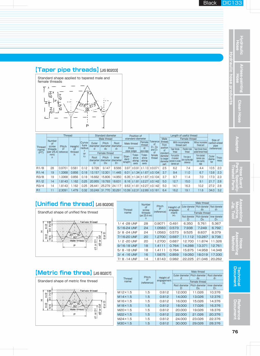
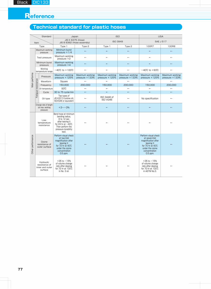
77 78
Hydraulic H
oseA
irless-paintingH
oseA
dapterH
ose Guard
Parts, S
pecially- Treated P
arts
Clean H
ose
Hy
dra
ulic
ho
se
pro
du
cts
Assem
bling
Machine,
Jig
, Tool
Hose
Assem
bling
Method
Technical
Docum
entR
eference D
ocument
Black DIC133Black DIC133
eferenceRTechnical standard for plastic hoses Table of unit conversion
← ← ← ← ←
Type 1 Type 2 Type 1 Type 2 100R7 100R8Type
Maximum working pressure
← ← ← ← ←Test pressure
← ← ← ← ←Minimum burst pressure
Maximum working pressure ×125%
Maximum working pressure ×133%
Maximum working pressure ×125%
Maximum working pressure ×133%
Maximum working pressure ×125%
Maximum working pressure ×133%Pressure
Two types of JIS K2213 (turbine oil), ISOVG46 or equivalent
← ISO 3448 ofISO VG46 ← No specification ←Oil type
Minimum burst pressure ×1/4
Maximum working pressure ×2
Maximum working pressure ×4
-40℃ to +100℃ ← ← ← -40℃ to +93℃ ←Working temperature range
Bend hose at minimum bending radius,
8 to 12 sec after leaving it
for 24 hr at -40℃.Then perform the pressure durability
test.
← ← ← ← ←
Perform visual check at two-fold
magnification after leaving it
for 72 hr at 40℃ under the ozone concentration
0.5 ppm.
Perform visual check at seven-fold
magnification after leaving it
for 70 hr at 40℃under the ozone concentration
0.5 ppm.
← ← ← ←
+35 to -15% of volume change rate after dipping for 72 hr at 100℃
in No. 3 oil.
+35 to -15% of volume change rate after dipping for 70 hr at 100℃
in ASTM No.3.
← ← ← ←
Low-temperature resistance
Ozone resistance of outer surface
Hydraulic resistance of
inner and outer surface
+3~-3% ← ← ← ← ←Change rate of length
(at max. working pressure)
Square ← ← ← ← ←Waveform
Fatig
ue re
sist
ance
Mai
n pe
rform
aO
ther
per
form
ance
93℃ ← ← ← ← ←Oil temperature
30 to 75 cycle/min ← ← ← ← ←Cycle
150,000 200,000 150,000 200,000 150,000 200,000Frequency
Standard
Item
USAISOJapan
SAE J 517ISO 3949JIS K 6375 (Hose)
JIS B 8362 (Hose assembly)
1 3.937×10 3.2808 1.0936 6.2×10⁻⁴
1 8.3333×10⁻² 2.778×10⁻² 1.6×10⁻⁵
3.048×10⁻¹ 1.2×10 1 3.3333×10⁻¹ 1.9×10⁻⁴
9.114×10⁻¹ 3.6×10 3 1 5.7×10⁻⁴
1.6093×10³ 6.3360×10⁴ 5.280×10³ 1.760×10³ 1
Length
1 9.842×10⁻⁴ 1.1023×10⁻³ 2.2046 3.5274×101.016×103 1 1.12 2.240×10³ 3.5838×10⁴
9.072×10³ 8.9286×10⁻¹ 1 2×10³ 3.2×10⁴
4.536×10³ 4.464×10⁻⁴ 5×10⁻⁴ 1 1.6×102.835×103 2.79×10⁻⁵ 3.13×10⁻⁵ 6.25×10⁻² 1
Weight
1 1×10⁻⁶ 1×10⁻⁵ 1.0197×10⁻⁵ 1.4504×10⁻⁴ 7.5006×10⁻³
1×10⁵ 1×10⁻¹ 1 1.0197 1.4504×10 7.5006×10²
9.8067×10⁴ 9.8067×10⁻² 9.8067×10⁻¹ 1 1.4223×10 7.3556×10²
6.8948×10³ 6.8948×10⁻³ 6.4898×10⁻² 7.0307×10⁻² 1 5.1715×101.3332×102 1.3332×10⁻⁴ 1.332×10⁻³ 1.3595×10⁻³ 1.9341×10⁻² 1
Pressure
1 1×10⁵ 1.0197×10⁻¹
1×10⁻⁵ 1 1.0197×10⁻⁶
9.8066 9.8066×10⁵ 1
Force
* is the Sl unit.
m in foot yard mile
kg ton (UK) ton (USA) lb Ounce
N dyn kgf
bar psi mmHgPa MPa kgf/cm2
2.54×10⁻²
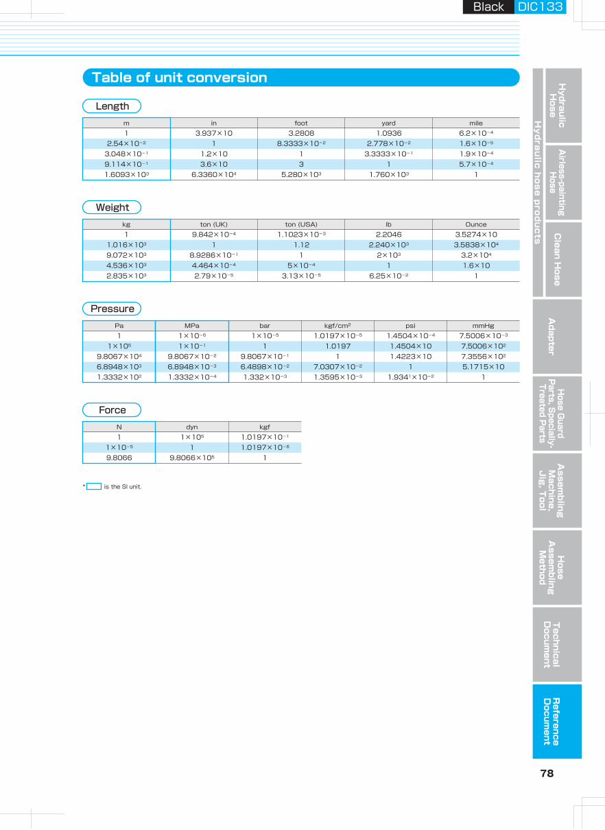
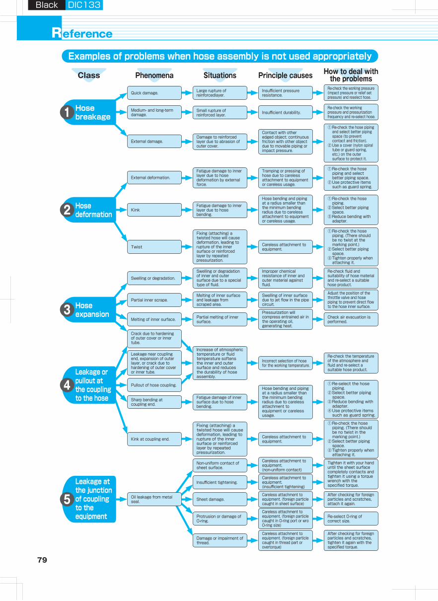
79 80
Hydraulic H
oseA
irless-paintingH
oseA
dapterH
ose Guard
Parts, S
pecially- Treated P
arts
Clean H
ose
Hy
dra
ulic
ho
se
pro
du
cts
Assem
bling
Machine,
Jig
, Tool
Hose
Assem
bling
Method
Technical
Docum
entR
eference D
ocument
Black DIC133Black DIC133
eferenceR
Tighten it with your hand until the sheet surface completely contacts and tighten it using a torque wrench with the specified torque.
①Re-check the hose piping.
②Select better piping space.
③Reduce bending with adapter.
Hose bending and piping at a radius smaller than the minimum bending radius due to careless attachment to equipment or careless usage.
①Re-check the hose piping and select better piping space.
②Use protective items such as guard spring.
Contact with other edged object; continuous friction with other object due to movable piping or impact pressure.
Increase of atmospheric temperature or fluid temperature softens the inner and outer surface and reduces the durability of hose assembly.
Leakage near coupling end, expansion of outer layer, or crack due to hardening of outer cover or inner tube.
Examples of problems when hose assembly is not used appropriately Chemical resistance list
Crack due to hardening of outer cover or inner tube.
Check air evacuation is performed.
Insufficient durability.
Incorrect selection of hose for the working temperature.
Small rupture of reinforced layer.
Large rupture of reinforcedlayer.
Pullout of hose coupling.
Non-uniform contact of sheet surface.
Sheet damage.Oil leakage from metal seal.
Protrusion or damage of O-ring.
Damage or impairment of thread.
Insufficient tightening.
Kink at coupling end.
Sharp bending at coupling end.
Melting of inner surface.
Partial inner scrape.
Partial melting of inner surface.
Swelling or degradation.
Twist
Kink
External deformation.
External damage.
Medium- and long-term damage.
Quick damage. Insufficient pressure resistance.
Re-select 0-ring of correct size.
How to deal withthe problemsPrinciple causesSituationsPhenomenaClass
Careless attachment to equipment.
Careless attachment to equipment.
Leakage at the junction of coupling to the equipment
5
Leakage or pullout at the coupling to the hose
4
Hose expansion3
Hose deformation2
Hose breakage1
○ ○ ○ - ○ ○ ○ ○Acetylene
- × - - - - - -Acetoamide
△ × × × ○ ○ ○ ○Acetaldehyde○ ○ △ - - - - -2-Aminophenyl Disulfide
△ △ × × △ ○ △ △Acetone
△ △ △ ○ ○ △ - -Amyl Alcohol
○ ○ - - - - ○ ○Ammonia Liquid
○ ○ - - - - ○ ○Ammonia Anhydrous× × × - △ ○ ○ ○Ammonia Gas Cold× × × - △ ○ △ △Ammonia Gas Hot
△ ○ △ - △ △ △ △Ammonia Water
A
Chemical resistance list (Guideline)
Please refer to the attached chemical resistance list for the safe use of the products.
Special attention should also be paid to the explanation written below.
1. The data shown here are based upon laboratory. Variations in temperature, pressure, fluids duration of exposure or other special conditions influence the results in the list and therefore no guarantee is expressed or implied.
2. Please be sure to evaluate the products in the condition at a real workplace before use.3. In case of aqueous solution in the list , the chemicals are all in a saturated condition at
a room temperature , unless otherwise stated.4. The list only shows chemical resistance at the liquid condition of chemicals but not
referring at all to the gas permeation quality . Do not use the products for the chemicals which is dangerous if the gas permeates through/from the products.
5. Please consult with us about the chemical resistance for the galvanized materials.
《Criteria of availability for each chemical》 ○ = No inlluence △ = Further confirmation required × = Not applicable - = No data available
Campucka couplings are for the general operating oil and can not be used for any other kinds of liquids.
When consulting with us in case of △, following data are necessary for us to judge.1 Pressure in operation, 2 Max. temperature in operation,
3 Concentration of chemicals, 4 Installation condition, 5 Applicatio.
Careless attachment to equipment. (non-uniform contact)
Swelling of inner surface due to jet flow in the pipe circuit.
Melting of inner surface and leakage from scraped area.
Fatigue damage to inner layer due to hose bending.
Damage to reinforced layer due to abrasion of outer cover.
Fatigue damage of inner surface due to hose bending.
Fixing (attaching) a twisted hose will cause deformation, leading to rupture of the inner surface or reinforced layer by repeated pressurization.
Hose bending and piping at a radius smaller than the minimum bending radius due to careless attachment to equipment or careless usage.
①Re-check the hose piping. (There should be no twist in the marking point.)
②Select better piping space.
③Tighten properly when attaching it.
①Re-check the hose piping and select better piping space (to prevent contact and friction).
②Use a cover (nylon spiral tube or guard spring, etc.) on the outer surface to protect it.
①Re-select the hose piping.
②Select better piping space.
③Reduce bending with adapter.
④Use protective items such as guard spring.
①Re-check the hose piping. (There should be no twist at the marking point.)
②Select better piping space.
③Tighten properly when attaching it.
Careless attachment to equipment. (insufficient tightening)
Careless attachment to equipment. (foreign particle caught in sheet surface)
Careless attachment to equipment. (foreign particle caught in O-ring port or wro O-ring size)
Careless attachment to equipment. (foreign particle caught in thread part or overtorque)
After checking for foreign particles and scratches, tighten it again with the specified torque.
Re-check the temperature of the atmosphere and fluid and re-select a suitable hose product.
Pressurization will compress entrained air in the operating oil, generating heat.
Improper chemical resistance of inner and outer material against fluid.
Swelling or degradation of inner and outer surface due to a special type of fluid.
Fatigue damage to inner layer due to hose deformation by external force.
Adjust the position of the throttle valve and hose piping to prevent direct flow to the hose inner surface.
Re-check fluid and suitability of hose material and re-select a suitable hose product.
Tramping or pressing of hose due to careless attachment to equipment or careless usage.
After checking for foreign particles and scratches, attach it again.
Re-check the working pressure (impact pressure or relief set pressure) and reselect hose.
Re-check the working pressure and pressurization frequency and re-select hose.
Fixing (attaching) a twisted hose will cause deformation, leading to rupture of the inner surface or reinforced layer by repeated pressurization.
When using the aqueous glycol operating oil, the materials for the couplings should be stainless or black oxidizing ones specially arranged upon request.
△ ○ × ○ △ × △ ○Acetic Acid (10%, 20℃)× △ × - - × △ △Acetic Acid (50%, 20℃)× × × - - × △ △Acetic Acid (50%, 70℃)× × × - - × △ △Acetic Acid (100%, 20℃)× △ × × × × △ △Acetic Anhydride
× × × - - - - -Acetyl Bromide× × × × × ○ - △Acetyl Chloride
× ○ - ○ - - - -Alum○ ○ - - - - - -Aluminium Acetate△ ○ - - - - - -Aluminium Bromide△ ○ - ○ - × × ×Aluminium Chloride△ ○ - - - △ × ×Aluminium Fluoride△ ○ △ - - - - △Aluminium Nitrate○ ○ - ○ - × ○ ○Aluminium Sulfate
○ ○ - - - - △ △Ammonium Carbonate○ ○ ○ ○ ○ × △ △Ammonium Chloride△ ○ △ × × △ △ △Ammonium Hydroxide○ ○ ○ ○ △ ○ △ △Ammonium Nitrate○ ○ - - - - - -Ammonium Persulphate○ ○ ○ ○ △ × △ △Ammonium Phosphate○ ○ ○ ○ △ × △ △Ammonium Sulfate○ × × × △ × - ○Amyl Acetate
- △ - - - - △ △Acrylonitrile
Chemicals (Weight concentration %,
Temperature ℃) Nylon
Hose materials
Polyolefi Urethane PVC Polyester Steel
Hose couplings / Adapters
SUS304 SUS316
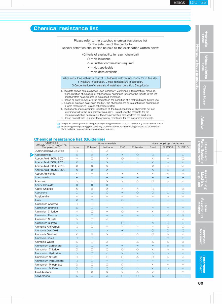
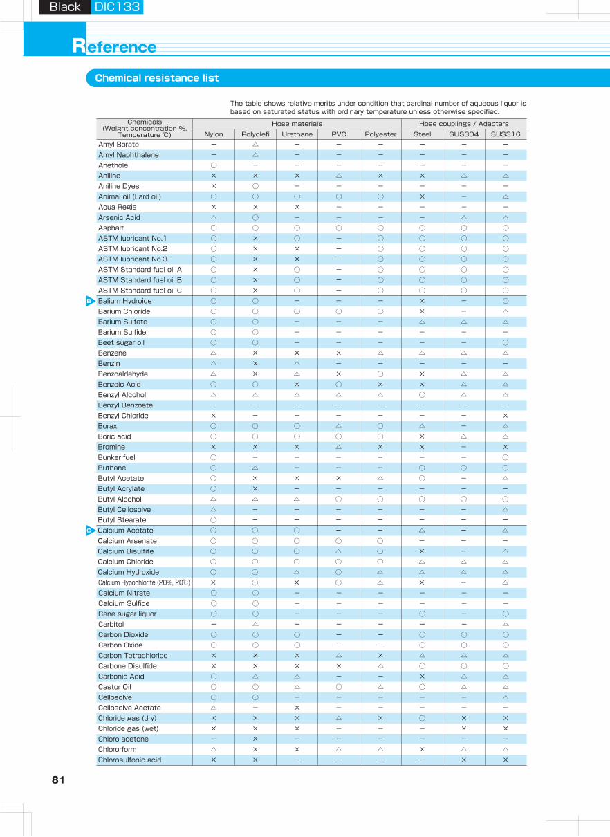
81 82
Hydraulic H
oseA
irless-paintingH
oseA
dapterH
ose Guard
Parts, S
pecially- Treated P
arts
Clean H
ose
Hy
dra
ulic
ho
se
pro
du
cts
Assem
bling
Machine,
Jig
, Tool
Hose
Assem
bling
Method
Technical
Docum
entR
eference D
ocument
Black DIC133Black DIC133
eferenceRChemical resistance list
× × × - - - - -Aqua Regia
B
C
× × - - - - - -Chlorotoluene
D
E
F
- △ - - - - - -Amyl Naphthalene- △ - - - - - -Amyl Borate
○ - - - - - - -Anethole× × × △ × × △ △Aniline× ○ - - - - - -Aniline Dyes○ ○ ○ ○ ○ × - △Animal oil (Lard oil)
○ ○ ○ ○ ○ ○ ○ ○Asphalt△ ○ - - - - △ △Arsenic Acid
○ × ○ - ○ ○ ○ ○ASTM lubricant No.1○ × × - ○ ○ ○ ○ASTM lubricant No.2○ × × - ○ ○ ○ ○ASTM lubricant No.3○ × ○ - ○ ○ ○ ○ASTM Standard fuel oil A○ × ○ - ○ ○ ○ ○ASTM Standard fuel oil B○ × ○ - ○ ○ ○ ○ASTM Standard fuel oil C○ ○ - - - × - ○Balium Hydroide○ ○ ○ ○ ○ × - △Barium Chloride○ ○ - - - △ △ △Barium Sulfate○ ○ - - - - - -Barium Sulfide
△ × △ - - - - -Benzin△ × × × △ △ △ △Benzene○ ○ - - - - - ○Beet sugar oil
△ × △ × ○ × △ △Benzoaldehyde○ ○ × ○ × × △ △Benzoic Acid△ △ △ △ △ ○ △ △Benzyl Alcohol- - - - - - - -Benzyl Benzoate× - - - - - - ×Benzyl Chloride○ ○ ○ △ ○ △ - △Borax○ ○ ○ ○ ○ × △Boric acid △× × × △ × × - ×Bromine○ - - - - - - ○Bunker fuel○ △ - - - ○ ○ ○Buthane○ × × × △ ○ - △Butyl Acetate○ × - - - - - -Butyl Acrylate△ △ △ ○ ○ ○ ○ ○Butyl Alcohol△ - - - - - - △Butyl Cellosolve○ - - - - - - -Butyl Stearate○ ○ ○ - - △ - △Calcium Acetate○ ○ ○ ○ ○ - - -Calcium Arsenate
○ ○ ○ ○ ○ △ △ △Calcium Chloride○ ○ ○ △ ○ × - △Calcium Bisulfite
○ ○ △ ○ △ △ △ △Calcium Hydroxide× ○ × ○ △ × - △Calcium Hypochlorite (20%, 20℃)○ ○ - - - - - -Calcium Nitrate○ ○ - - - - - -Calcium Sulfide
- △ - - - - - △Carbitol○ ○ - - - ○ - ○Cane sugar liquor
○ ○ ○ - - ○ ○ ○Carbon Oxide○ ○ ○ - - ○ ○ ○Carbon Dioxide
× × × △ × △ △ △Carbon Tetrachloride× × × × △ ○ ○ ○Carbone Disulfide○ △ △ - - × △ △Carbonic Acid○ ○ △ ○ △ ○ △ △Castor Oil○ ○ - - - - - △Cellosolve△ - × - - - - -Cellosolve Acetate× × × △ × ○ × ×Chloride gas (dry)× × × - - - × ×Chloride gas (wet)- × - - - - - -Chloro acetone△ × × △ △ × △ △Chlororform× × - - - - × ×Chlorosulfonic acid
× × × △ × × × △Chromic Acid (2%, 70℃)× × × - × × × △Chromic Acid (2%, 50℃)× × × - × × × △Chromic Acid (10%, 70℃)× × × - × × × △Chromic Acid (25%, 70℃)○ ○ △ ○ △ × △ △Citric acid○ △ ○ ○ ○ ○ ○ ○Coal-Tar△ ○ ○ ○ ○ × × ×Copper Chloride○ ○ - - - - - ○Copper Cyanide○ ○ ○ ○ ○ × △ ○Copper Sulfate○ △ ○ ○ ○ △ - ○Corn oil○ △ ○ ○ ○ ○ △ △Cotton seed oil× △ × △ × ○ △ △Creosote× × × △ × △ △ ○Cresol
○ △ - - - △ △ △Cyclohexanol○ × × - ○ △ - -Cyclohexanone
○ × △ △ ○ ○ - △Cyclohexane
○ △ - - - - - -Decalin△ ○ △ - - - - -Developer (Hypo)○ ○ △ × △ △ ○ ○Diacetone Alcohol△ × × - - - - ○Dibenzine Ether△ × △ - - - - -Dibutyl Ether○ △ △ - △ - - -Dibutyl Phthalate△ × × - - ○ - -Dichlorobenzene○ - △ - △ △ - ○Diezthanol Amine△ △ △ △ △ ○ - △Diethyl Ether△ × - - - - - -Diethyl Sebacate△ △ × - - - - -Diisopropyl Ketone× △ × - - - - -Dimethyl Formamide○ × × ○ ○ × △ ○Dinitrogen oxide (Nitrous Oxide)
○ × △ - - - - -Dioctyl Sebacate (DOS)○ × △ × △ - - -Dioctyl Phthalate (DOP)
△ × × - - - - -Dipentene (Limonene)△ × × - - - - -Diphenyl- - - - - - - -Diphenyl Oxide- - - - - - - -Dowtherm (100℃)- - - - - - - -Dowtherm (200℃)× - - - - - - -Epichlorohydrin○ - - - - - - -Ester Silicate× × - - - - - -Ethanol Amine○ △ × × △ ○ △ △Ethyl Acetate- - - - - - - -Ethyl Acetoacetate- - × - - - - -Ethyl Acrylate△ △ × △ △ ○ △ ○Ethyl Alcohol- × - - - - ○ ○Ethyl Benzene- ○ - - - - - △Ethyl Cellulose○ × × × × ○ ○ ○Ethyl Chloride○ × × - - - - -Ethyl Oxalate△ - - - - - - -Ethyl Silicate× × × × × - - -Ethylene Chlorohydrin× × - - - - - -Ethylene Diamine× △ × × × △ △ △Ethylene Dioxide○ ○ ○ ○ ○ △ △ △Ethylene Glycol○ × × - △ △ - △Ethylene Oxide○ × △ ○ ○ × △ ○Fatty Acids△ ○ - ○ - × × ×Ferric Chloride○ ○ - - - - - -Ferric Nitrate (II)- × × △ × × - △Fluorine- ○ ×× △ × △ - ○Fluoroboric acid× △ × ○ △ ○ △ △Formaldehyde (40%, 20℃)
Chemicals (Weight concentration %,
Temperature ℃) Nylon
Hose materials
Polyolefi Urethane PVC Polyester Steel
Hose couplings / Adapters
SUS304 SUS316
Chemicals (Weight concentration %,
Temperature ℃) Nylon
Hose materials
Polyolefi Urethane PVC Polyester Steel
Hose couplings / Adapters
SUS304 SUS316
The table shows relative merits under condition that cardinal number of aqueous liquor is based on saturated status with ordinary temperature unless otherwise specified.
The table shows relative merits under condition that cardinal number of aqueous liquor is based on saturated status with ordinary temperature unless otherwise specified.
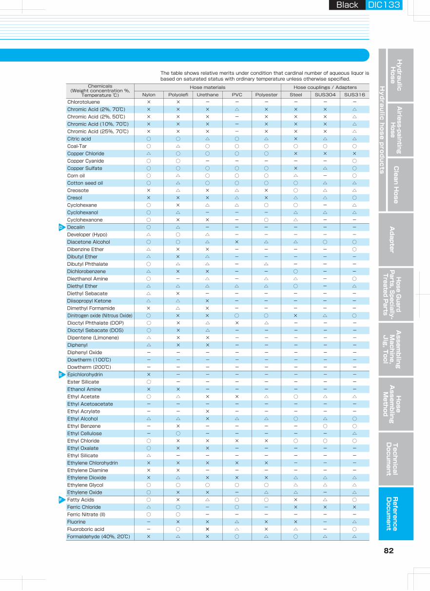
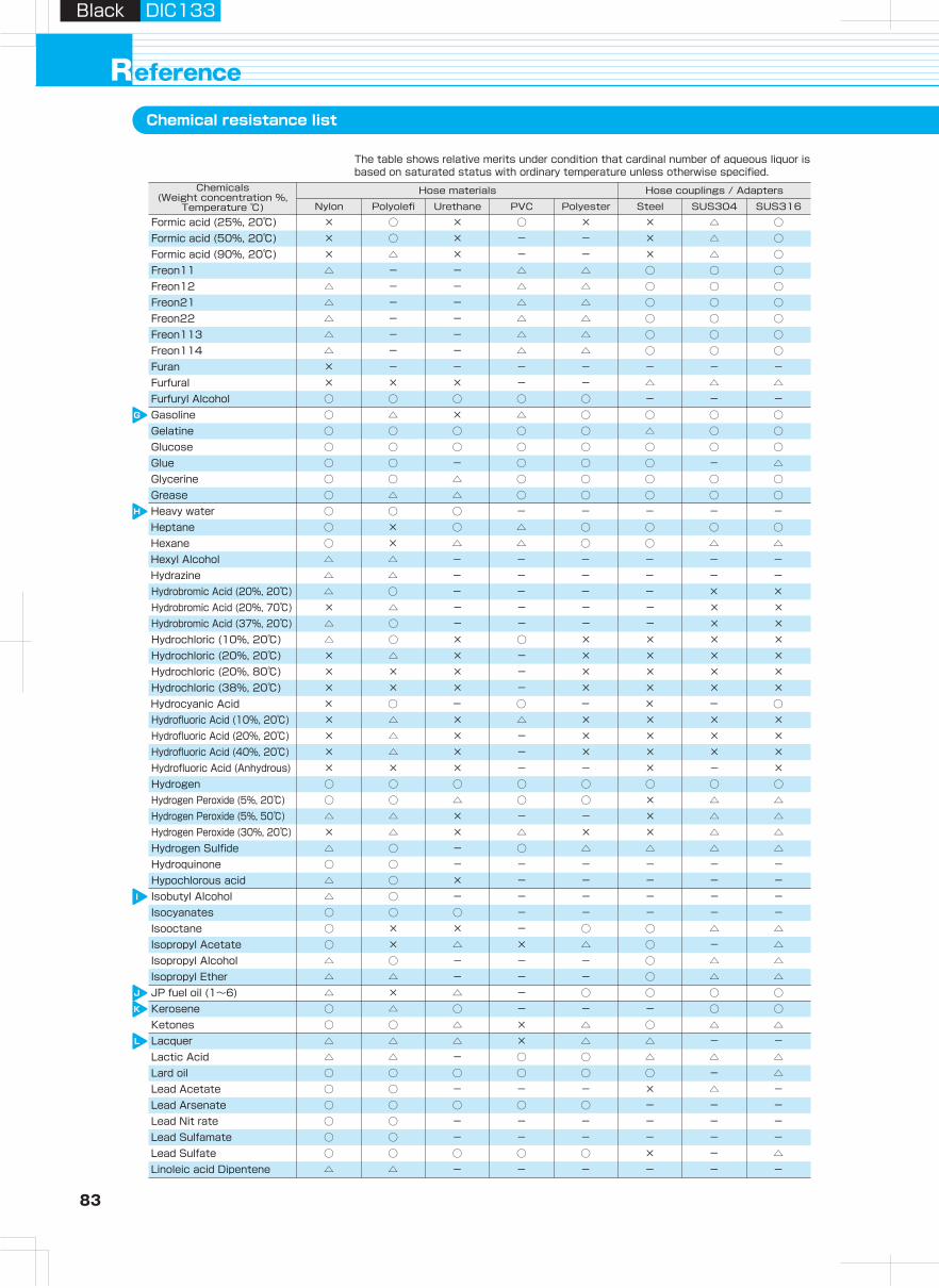
83 84
Hydraulic H
oseA
irless-paintingH
oseA
dapterH
ose Guard
Parts, S
pecially- Treated P
arts
Clean H
ose
Hy
dra
ulic
ho
se
pro
du
cts
Assem
bling
Machine,
Jig
, Tool
Hose
Assem
bling
Method
Technical
Docum
entR
eference D
ocument
Black DIC133Black DIC133
eferenceRChemical resistance list
G
H
I
J
K
L
M
N
O
P
○ × ○ ○ ○ ○ - -Petroleum× × × △ × ○ - △Perchloroethylene
× ○ × ○ × × △ ○Formic acid (25%, 20℃)× ○ × - - × △ ○Formic acid (50%, 20℃)× △ × - - × △ ○Formic acid (90%, 20℃)△ - - △ △ ○ ○ ○Freon11△ - - △ △ ○ ○ ○Freon12△ - - △ △ ○ ○ ○Freon21△ - - △ △ ○ ○ ○Freon22△ - - △ △ ○ ○ ○Freon113△ - - △ △ ○ ○ ○Freon114× - - - - - - -Furan× × × - - △ △ △Furfural○ ○ ○ ○ ○ - - -Furfuryl Alcohol○ △ × △ ○ ○ ○ ○Gasoline○ ○ ○ ○ ○ △ ○ ○Gelatine○ ○ ○ ○ ○ ○ ○ ○Glucose○ ○ - ○ ○ ○ - △Glue○ ○ △ ○ ○ ○ ○ ○Glycerine○ △ △ ○ ○ ○ ○ ○Grease○ ○ ○ - - - - -Heavy water○ × ○ △ ○ ○ ○ ○Heptane○ × △ △ ○ ○ △ △Hexane△ △ - - - - - -Hexyl Alcohol△ △ - - - - - -Hydrazine
× ○ - ○ - × - ○Hydrocyanic Acid
△ ○ - - - - × ×Hydrobromic Acid (20%, 20℃)× △ - - - - × ×Hydrobromic Acid (20%, 70℃)△ ○ - - - - × ×Hydrobromic Acid (37%, 20℃)△ ○ × ○ × × × ×Hydrochloric (10%, 20℃)× △ × - × × × ×Hydrochloric (20%, 20℃)× × × - × × × ×Hydrochloric (20%, 80℃)× × - × × × ×Hydrochloric (38%, 20℃) ×
× × × - - × - ×Hydrofluoric Acid (Anhydrous)
× △ × △ × × × ×Hydrofluoric Acid (10%, 20℃)× △ × - × × × ×Hydrofluoric Acid (20%, 20℃)× △ × - × × × ×Hydrofluoric Acid (40%, 20℃)
○ ○ ○ ○ ○ ○ ○ ○Hydrogen○ ○ △ ○ ○ × △ △Hydrogen Peroxide (5%, 20℃)△ △ × - - × △ △Hydrogen Peroxide (5%, 50℃)× △ × △ × × △ △Hydrogen Peroxide (30%, 20℃)△ ○ - ○ △ △ △ △Hydrogen Sulfide○ ○ - - - - - -Hydroquinone△ ○ × - - - - -Hypochlorous acid△ ○ - - - - - -Isobutyl Alcohol○ ○ ○ - - - - -Isocyanates○ × × - ○ ○ △ △Isooctane○ × △ × △ ○ - △Isopropyl Acetate△ ○ - - - ○ △ △Isopropyl Alcohol△ △ - - - ○ △ △Isopropyl Ether△ × △ - ○ ○ ○ ○JP fuel oil (1~6)○ △ ○ - - - ○ ○Kerosene○ ○ △ × △ ○ △ △Ketones△ △ △ × △ △ - -Lacquer△ △ - ○ ○ △ △ △Lactic Acid○ ○ ○ ○ ○ ○ - △Lard oil○ ○ - - - × △ -Lead Acetate○ ○ ○ ○ ○ - - -Lead Arsenate○ ○ - - - - - -Lead Nit rate○ ○ - - - - - -Lead Sulfamate○ ○ ○ ○ ○ × - △Lead Sulfate△ △ - - - - - -Linoleic acid Dipentene
○ × ○ - - - - -Linseed oil× × × - - - - -Liquid Chloride○ △ - - - - ○ ○Liquidified Petroleum Gas
○ × ○ ○ ○ ○ ○ ○Lubricant (mineral oil type)△ × × - △ ○ ○ ○Lubricant (Ether type)
○ ○ ○ ○ ○ △ × ×Magnesium Chloride○ ○ - - - - - -Lye solutions
○ ○ △ △ ○ ○ - △Magnesium Hydroxide○ ○ ○ ○ ○ △ ○ ○Magnesium Sulfate○ ○ △ ○ △ ○ △ △Maleic acid○ ○ - - - △ △ △Malic Acid- × - - - - - -Mercaptane○ ○ ○ △ ○ × × ×Mercuric Chloride○ ○ ○ × ○ △ - △Methane○ △ × × △ △ - ○Methyl Acetate△ △ × × △ △ △ △Methyl Alcohol△ × × × × - - ○Methyl Bromide× × × × × △ ○ ○Methyl Chloride△ △ × × △ △ - △Methyl Iso Butyl Ketone (MIBK)△ △ × × △ ○ △ △MethyiEethyl Ketone (MEK)
○ × - - - - - -Metyl Metacrylate× △ × - - - - -Methylene Dichloride
△ × × - ○ - - -Metyl Sulfate○ △ ○ ○ ○ ○ ○ ○Mineral oil
× × × - - - - -Monochloro Benzene× × × × × - - -Monochloro Acetic Acid
○ △ - - - - - -Monoethanol Amine○ × △ × △ ○ △ △Naphtha○ △ △ × △ ○ - △Naphthalene- ○ - - - - - -Naphthenic acid○ ○ - - - - ○ ○Natural gas- × - - - - - -n-Hexa Aldehyde○ ○ - - - - - △Nickel Acetate× ○ - × × × - ×Nickel Chloride○ ○ - - - × △ △Nickel Sulfate× ○ × ○ △ × △ ○Nitric acid (10%, 20℃)× △ × - - × △ ○Nitric acid (10%, 70℃)× △ × ○ × × △ ○Nitric acid (30%, 20℃)× × × - × × △ ○Nitric acid (30%, 70℃)× × × - × × △ ○Nitric acid (61%, 20℃)× × × - × × △ ○Nitric acid (fuming, 20℃)× × × × × ○ △ △Nitrobenzene- × - - - - - -Nitroethane○ ○ ○ ○ ○ ○ ○ ○Nitrogen- × - - - - - -Nitromethane- × - - - - - -Nitropropane× △ - - - - - △Octyl Alcohol○ △ △ △ ○ △ △ △Oleic Acid○ ○ ○ - - - ○ ○Olive Oil○ ○ △ ○ △ △ × ×Oxalic Acid△ △ △ - - - ○ ○Oxygene△ △ △ △ ○ △ △ ○Ozone○ △ - - - △ - △Palm oil○ ○ ○ ○ ○ △ △ △Palmitin Acid○ × ○ △ ○ ○ - △Pentane
× △ × △ × × △ △Phenol- - - - - - - -Phenyl Hydrazine- - - - - - - -Phorone
Chemicals (Weight concentration %,
Temperature ℃) Nylon
Hose materials
Polyolefi Urethane PVC Polyester Steel
Hose couplings / Adapters
SUS304 SUS316
Chemicals (Weight concentration %,
Temperature ℃) Nylon
Hose materials
Polyolefi Urethane PVC Polyester Steel
Hose couplings / Adapters
SUS304 SUS316
The table shows relative merits under condition that cardinal number of aqueous liquor is based on saturated status with ordinary temperature unless otherwise specified.
The table shows relative merits under condition that cardinal number of aqueous liquor is based on saturated status with ordinary temperature unless otherwise specified.
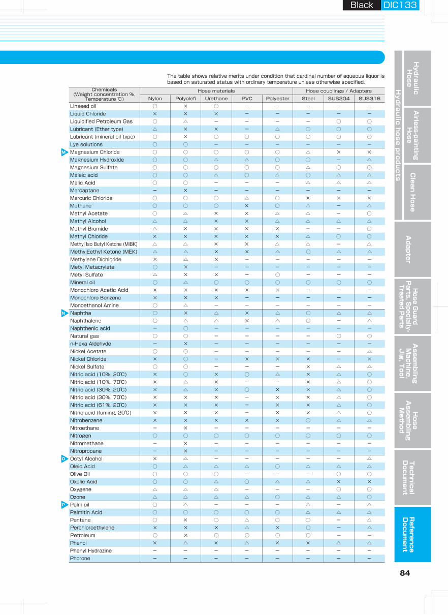
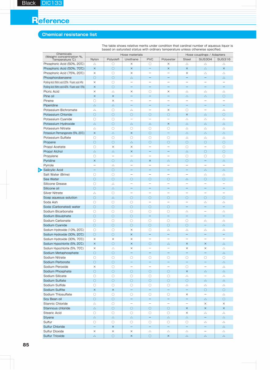
85 86
Hydraulic H
oseA
irless-paintingH
oseA
dapterH
ose Guard
Parts, S
pecially- Treated P
arts
Clean H
ose
Hy
dra
ulic
ho
se
pro
du
cts
Assem
bling
Machine,
Jig
, Tool
Hose
Assem
bling
Method
Technical
Docum
entR
eference D
ocument
Black DIC133Black DIC133
eferenceRChemical resistance list
S
T
U
V
X
Z
○ × - - - - - -Pinene
△ ○ × ○ × △ △ △Phosphoric Acid (50%, 20℃)× ○ × - × × △ ×Phosphoric Acid (50%, 70℃)× ○ × - - × △ △Phosphoric Acid (75%, 20℃)○ ○ △ - - - - △Phosphorobenzene× ○ - - - - - -Pickling Acid (Nitric acid 20% / Fluoric acid 4%)× ○ - - - - - -Pickling Acid (Nitric acid 40% / Fluoric acid 15%)× △ × ○ × △ △ △Picric Acid× × - - - △ △ ○Pine oil
△ △ - - - - - -Piperidine△ ○ △ - × ○ - △Potassium Bichromate○ ○ ○ ○ ○ × △ ○Potassium Chloride
△ ○ △ △ × △ △ △Potassium Hydroxide○ ○ - - - △ △ △Potassium Cyanide
△ ○ ○ ○ ○ △ △ △Potassium Nitrate× △ × ○ - △ △ △Potassium Permanganate (5%, 20℃)○ ○ ○ ○ ○ △ △ △Potassium Sulfate○ ○ △ ○ ○ ○ ○ ○Propane○ × × - - ○ - ○Propyl Acetate△ △ × - - △ ○ ○Propyl Alchol○ - - - - ○ ○ ○Propylene× ○ △ × △ ○ - △Pyridine- △ - - - - - -Pyrrole- ○ - - - - △ △Salicylic Acid○ - - - - △ △Salt Water (Brine) ○○ ○ ○ ○ ○ △ ○ ○Sea Water○ △ - - - - - -Silicone Grease○ △ - - - - - -Silicone oil△ ○ - - - - - -Silver Nitrate○ △ ○ ○ ○ ○ ○ ○Soap aqueous solution○ ○ ○ - - - △ △Soda Ash○ ○ ○ ○ ○ - - -Soda (Carbonated) water○ ○ ○ ○ ○ △ - △Sodium Bicarbonate○ ○ ○ - - - - -Sodium Bisulphate○ ○ ○ ○ ○ ○ △ △Sodium Carbonate○ ○ ○ ○ ○ ○ - △Sodium Cyanide
○ ○ × - - - - -Sodium Hydroxide (30%, 20℃)× × × - - - - -Sodium Hydroxide (30%, 70℃)
○ ○ × ○ △ △Sodium Hydroxide (10%, 20℃) △△
× ○ × ○ △ × × △Sodium Hypochlorite (5%, 20℃)× △ × - - × × △Sodium Hypochlorite (5%, 70℃)○ ○ - - - - - △Sodium Metaphosphate○ ○ ○ ○ ○ ○ ○ ○Sodium Nitrate○ ○ - - - - - △Sodium Perborate× ○ - - - ○ - △Sodium Peroxide○ ○ ○ ○ ○ × △ △Sodium Phosphate○ ○ ○ ○ ○ △ - △Sodium Silicate○ ○ ○ ○ ○ ○ △ △Sodium Sulfate○ ○ ○ ○ ○ △ △ △Sodium Sulfide× × - - - - ○ ○Sodium Sulfite○ ○ ○ ○ ○ × - △Sodium Thiosulfate○ ○ - - - - △ ○Soy Bean oil
△ ○ ○ ○ ○ × × ×Stannous chloride△ ○ - - - - × ×Stannic Chloride
○ ○ ○ ○ ○ × △ △Stearic Acid△ △ △ - △ △ - △Styene○ ○ ○ ○ ○ ○ △ △Sulfur- × - - - - - △Sulfur Chloride× × × △ △ △ - △Sulfur Dioxide△ ○ × ○ × △ △ △Sulfur Trioxide
△ △ × △ × × × ×Sulfuric Acid (10%, 20℃)× △ × - - × × ×Sulfuric Acid (10%, 70℃)× △ × △ × × × ×Sulfuric Acid (30%, 20℃)× × × - - × × ×Sulfuric Acid (30%, 70℃)× × × - - × × ×Sulfuric Acid (98%, 20℃)× × × - - × × ×Sulfuric Acid (fuming, 20℃)× × × △ △ △ △ △Sulfurous Acid○ ○ ○ ○ ○ △ △ △Table Salt (Common Salt)○ ○ △ ○ △ △ △ △Tannic Acid△ ○ ○ ○ ○ △ △ △Tartaric acid○ × - - - - - -Terpineol△ × - - - - - -TetrachloroEthane
△ × - - - - - -Tetrahydro Furan△ △ - - - - - △Tetraethyl Lead
△ × - - - - - -Tetraline○ - ○ - ○ - - -Tetrametyl Lead× × - - - - - -Thionyl Chloride△ × × × △ ○ ○ ○Toluene- - - - - - - -Triacetine○ - - - - - - -Tributoxyethyl Phosphate (TBEP)
× △ × △ × - △ △Trich loroacetate○ × △ × △ ○ - ○Tributyl Phosphate (TBP)
△ × × △ × ○ - ○Trichloroethylene○ × △ - - - - -Tricresyl Phosphate (TCP)○ × - - - ○ - ○Triethanolamine○ ○ - - - - ○ ○Tung oil○ × ○ ○ ○ △ - ○Turpentine oil○ ○ × ○ × - - -Uric acid○ ○ - - - - - -Vegetable oil△ × × × △ ○ ○ ○Xylene○ ○ - - - - - -Zeolite○ ○ - - - - - -Zinc Acetate△ ○ ○ ○ ○ △ △ ○Zinc Chloride△ ○ △ ○ △ × △ △Zinc Sulfide
Chemicals (Weight concentration %,
Temperature ℃) Nylon
Hose materials
Polyolefi Urethane PVC Polyester Steel
Hose couplings / Adapters
SUS304 SUS316
Chemicals (Weight concentration %,
Temperature ℃) Nylon
Hose materials
Polyolefi Urethane PVC Polyester Steel
Hose couplings / Adapters
SUS304 SUS316
The table shows relative merits under condition that cardinal number of aqueous liquor is based on saturated status with ordinary temperature unless otherwise specified.
The table shows relative merits under condition that cardinal number of aqueous liquor is based on saturated status with ordinary temperature unless otherwise specified.
使用しない
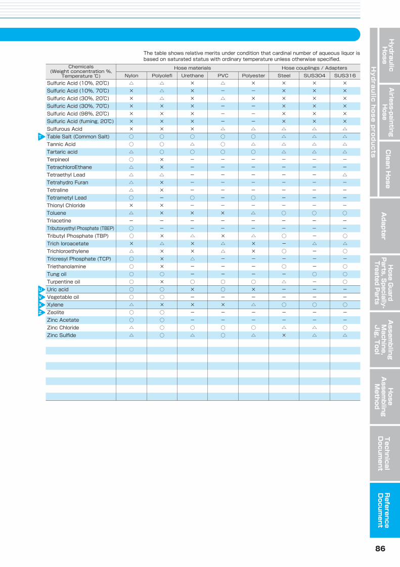
85 86
Hydraulic H
oseA
irless-paintingH
oseA
dapterH
ose Guard
Parts, S
pecially- Treated P
arts
Clean H
ose
Hy
dra
ulic
ho
se
pro
du
cts
Assem
bling
Machine,
Jig
, Tool
Hose
Assem
bling
Method
Technical
Docum
entR
eference D
ocument
Black DIC133=4cBlack DIC133
eferenceRChemical resistance list
S
T
U
V
X
Z
○ × - - - - - -Pinene
△ ○ × ○ × △ △ △Phosphoric Acid (50%, 20℃)× ○ × - × × △ ×Phosphoric Acid (50%, 70℃)× ○ × - - × △ △Phosphoric Acid (75%, 20℃)○ ○ △ - - - - △Phosphorobenzene× ○ - - - - - -Pickling Acid (Nitric acid 20% / Fluoric acid 4%)× ○ - - - - - -Pickling Acid (Nitric acid 40% / Fluoric acid 15%)× △ × ○ × △ △ △Picric Acid× × - - - △ △ ○Pine oil
△ △ - - - - - -Piperidine△ ○ △ - × ○ - △Potassium Bichromate○ ○ ○ ○ ○ × △ ○Potassium Chloride
△ ○ △ △ × △ △ △Potassium Hydroxide○ ○ - - - △ △ △Potassium Cyanide
△ ○ ○ ○ ○ △ △ △Potassium Nitrate× △ × ○ - △ △ △Potassium Permanganate (5%, 20℃)○ ○ ○ ○ ○ △ △ △Potassium Sulfate○ ○ △ ○ ○ ○ ○ ○Propane○ × × - - ○ - ○Propyl Acetate△ △ × - - △ ○ ○Propyl Alchol○ - - - - ○ ○ ○Propylene× ○ △ × △ ○ - △Pyridine- △ - - - - - -Pyrrole- ○ - - - - △ △Salicylic Acid○ - - - - △ △Salt Water (Brine) ○○ ○ ○ ○ ○ △ ○ ○Sea Water○ △ - - - - - -Silicone Grease○ △ - - - - - -Silicone oil△ ○ - - - - - -Silver Nitrate○ △ ○ ○ ○ ○ ○ ○Soap aqueous solution○ ○ ○ - - - △ △Soda Ash→炭酸ナトリウム参照○ ○ ○ ○ ○ - - -Soda (Carbonated) water○ ○ ○ ○ ○ △ - △Sodium Bicarbonate○ ○ ○ - - - - -Sodium Bisulphate○ ○ ○ ○ ○ ○ △ △Sodium Carbonate○ ○ ○ ○ ○ ○ - △Sodium Cyanide
○ ○ × - - - - -Sodium Hydroxide (30%, 20℃)× × × - - - - -Sodium Hydroxide (30%, 70℃)
○ ○ × ○ △ △Sodium Hydroxide (10%, 20℃) △△
× ○ × ○ △ × × △Sodium Hypochlorite (5%, 20℃)× △ × - - × × △Sodium Hypochlorite (5%, 70℃)○ ○ - - - - - △Sodium Metaphosphate○ ○ ○ ○ ○ ○ ○ ○Sodium Nitrate○ ○ - - - - - △Sodium Perborate× ○ - - - ○ - △Sodium Peroxide○ ○ ○ ○ ○ × △ △Sodium Phosphate○ ○ ○ ○ ○ △ - △Sodium Silicate○ ○ ○ ○ ○ ○ △ △Sodium Sulfate (ほう硝)○ ○ ○ ○ ○ △ △ △Sodium Sulfide× × - - - - ○ ○Sodium Sulfite○ ○ ○ ○ ○ × - △Sodium Thiosulfate○ ○ - - - - △ ○Soy Bean oil
△ ○ ○ ○ ○ × × ×Stannous chloride△ ○ - - - - × ×Stannic Chloride
○ ○ ○ ○ ○ × △ △Stearic Acid△ △ △ - △ △ - △Styene○ ○ ○ ○ ○ ○ △ △Sulfur- × - - - - - △Sulfur Chloride× × × △ △ △ - △Sulfur Dioxide△ ○ × ○ × △ △ △Sulfur Trioxide
△ △ × △ × × × ×Sulfuric Acid (10%, 20℃)× △ × - - × × ×Sulfuric Acid (10%, 70℃)× △ × △ × × × ×Sulfuric Acid (30%, 20℃)× × × - - × × ×Sulfuric Acid (30%, 70℃)× × × - - × × ×Sulfuric Acid (98%, 20℃)× × × - - × × ×Sulfuric Acid (fuming, 20℃)× × × △ △ △ △ △Sulfurous Acid○ ○ ○ ○ ○ △ △ △Table Salt (Common Salt)○ ○ △ ○ △ △ △ △Tannic Acid△ ○ ○ ○ ○ △ △ △Tartaric acid○ × - - - - - -Terpineol△ × - - - - - -TetrachloroEthane
△ × - - - - - -Tetrahydro Furan△ △ - - - - - △Tetraethyl Lead
△ × - - - - - -Tetraline○ - ○ - ○ - - -Tetrametyl Lead× × - - - - - -Thionyl Chloride△ × × × △ ○ ○ ○Toluene- - - - - - - -Triacetine○ - - - - - - -Tributoxyethyl Phosphate (TBEP)
× △ × △ × - △ △Trich loroacetate○ × △ × △ ○ - ○Tributyl Phosphate (TBP)
△ × × △ × ○ - ○Trichloroethylene○ × △ - - - - -Tricresyl Phosphate (TCP)○ × - - - ○ - ○Triethanolamine○ ○ - - - - ○ ○Tung oil○ × ○ ○ ○ △ - ○Turpentine oil○ ○ × ○ × - - -Uric acid○ ○ - - - - - -Vegetable oil△ × × × △ ○ ○ ○Xylene○ ○ - - - - - -Zeolite○ ○ - - - - - -Zinc Acetate△ ○ ○ ○ ○ △ △ ○Zinc Chloride△ ○ △ ○ △ × △ △Zinc Sulfide
Chemicals (Weight concentration %,
Temperature ℃) Nylon
Hose materials
Polyolefi Urethane PVC Polyester Steel
Hose couplings / Adapters
SUS304 SUS316
Chemicals (Weight concentration %,
Temperature ℃) Nylon
Hose materials
Polyolefi Urethane PVC Polyester Steel
Hose couplings / Adapters
SUS304 SUS316
The table shows relative merits under condition that cardinal number of aqueous liquor is based on saturated status with ordinary temperature unless otherwise specified.
The table shows relative merits under condition that cardinal number of aqueous liquor is based on saturated status with ordinary temperature unless otherwise specified.
使用しない

B-HO-��E
Hose, Hose couplings & Adapters
TM
4-4-26 Sakuragawa Naniwa-ku, Osaka 556-0022 Japan Phone: +81-6-6563-1241 • Fax: +81-6-6563-1243
7605 Nitta Drive,Suwanee, GA 30024, U.S.A.Phone: +1-770-497-0212 • Fax: +1-770-623-1398https://www.nitta.com
NITTA CORPORATION OF AMERICA
Room 2705, Shenggao International Building,No.137 Xianxia Road, Shanghai 200051, P.R.ChinaPhone: +86-21-6229-6000 • Fax: +86-21-6229-9606
NITTA (SHANGHAI) MANAGEMENT CO.,LTD.
Chia Hsin Building, 10FL, Room No.100596 Chung Shan North Road Section 2Taipei, Taiwan, R.O.C.Phone: +886-2-2581-6296 • Fax: +886-2-2563-4900https://www.nitta.com.tw
TAIWAN NITTA FILTER CO.,LTD.
Hansaallee 20140549 Düsseldorf, GermanyPhone: +49-211-537535-0 • Fax: +49-211-537535-35https://www.nitta.de
NITTA INDUSTRIES EUROPE GmbH
7/472 Moo6, Tambol Mabyangporn,Amphur Pluadaeng, Rayong Province 21140, THAILANDPhone: +66-38-018-301 • Fax: +66-38-018-304https://www.nittathai.com
NITTA CORPORATION (THAILAND) LIMITED
Gat No.191, 192, and 193, Plot No B, Village Vadhu Khurd, Taluka Haveli Dist Pune-412216,INDIAPhone: +91-20-6731-3400 • Fax: +91-20-6731-3401https://www.nitta.co.in
NITTA CORPORATION INDIA PVT LTD
https://www.nitta.co.jp
The specification is subject to change for improvement without notice.
19095000F
B+


