Embed Size (px)
Citation preview

Proceedings of the 8th U.S. National Conference on Earthquake Engineering April 18-22, 2006, San Francisco, California, USA
FIBER REINFORCED POLYMERS IN SEISMIC UPGRADING OF EXISTING REINFORCED CONCRETE STRUCTURES
S. P. Tastani1 and S. J. Pantazopoulou2
ABSTRACT
Externally-bonded Fiber Reinforced Polymers (FRPs) when used as jackets in reinforced concrete (r.c.) members are effective in increasing shear, lap-splice strength and deformation capacity. For this reason they are currently used extensively as a fast remedy in earthquake-damaged structures, or to strengthen under-designed structures in areas of high seismicity. FRP jackets impart little or no stiffness to the encased element, whereas experimental evidence indicates that the demand on bar anchorages increases after jacketing of the adjacent plastic hinges near supports. Under excessive rotation demand the jackets, being susceptible to stress concentrations, are at risk of rupture due to buckling of primary reinforcement, when the embedded stirrups are very sparse (substandard detailing). These performance issues are explored in the paper through a combined evaluation of published experimental evidence and simple mechanistic constructs that highlight the mechanical contribution of the jacket to the various failure modes of an r.c. element. Dependable deformation capacity at yield and ultimate and the various strength components are examined through collective evaluation of available tests and design lower bound expressions are derived. Criteria that should be considered as part of the upgrading strategy when FRP jacketing is used so as to control the deformation demand of the structure are also discussed.
Introduction
A common deficiency of many of the r.c. structures that get damaged during earthquakes is intrinsic lack of stiffness (e.g. in soft storey formations), combined with limited deformation capacity of the individual structural elements owing to non-ductile, old type detailing. Because excessive displacement brings out all the potential problems of an inadequate design or construction, it is necessary in repair/strengthening schemes to target for reduced displacement demand, by increasing the lateral stiffness of the structure. For this reason, global interventions need be accompanied by targeted local measures so as to increase the dependable deformation capacity of the individual members beyond the deformation demand.
FRP jacketing of damaged or under-designed r.c. members is considered a local
1 Ph.D. Candidate, Department of Civil Engineering, Demokritus University of Thrace, Xanthi 67100, Greece; tel/fax +30-25410-79639, [email protected] 2 Professor, Department of Civil Engrg., Demokritus University of Thrace, Xanthi 67100, Greece; tel/fax: +30-25410-79639, [email protected]
Paper No. 232

intervention as it has negligible influence of the lateral stiffness of the jacketed member and cannot effect changes on the response characteristics of the overall structure. As such jackets may successfully upgrade shear strength, lap splice strength, and the overall deformation capacity of individual members. Unless the transverse jackets serve to mitigate premature local failures that would otherwise limit the pre-yield response, secant to yield stiffness remains unaltered by the repair. Among their limitations is that they are susceptible to rupture at points of localized deformation demand. When used in critical zones of members undergoing excessive deformation demand (e.g., in flexible structures) they effectively reduce shear cracking in the plastic hinge regions, driving all deformation to occur within few flexural cracks near the support. Due to confinement of the compressive zone high strain demands develop in the tension reinforcement at the critical section. This imposes an increased demand for bar development capacity that cannot always be met by the anchorage in substandard construction (Tastani and Pantazopoulou 2003).
For these reasons FRP jacketing need be explicitly embedded in the context of the integrated global strategy of seismic rehabilitation of the structure, where, survivability of the upgraded structural system depends on the magnitude of the lateral drift. In the paper the confining pressure generated by the FRP, its effectiveness, and the design effective strain that may be used in calculations are considered. The derived expressions are used to obtain the various strength terms and the deformation capacity of FRP jacketed r.c. members. Finally considerations about drift control that need be combined with the FRP jacketing are discussed.
Mechanical effects of FRP jacketing on r.c. members
As a method of seismic upgrading FRP jacketing may achieve at best a marginal increase in the flexural strength of the members without influencing their initial stiffness, up to full exploitation of the deformation capacity of longitudinal reinforcement. The actual increase in flexural strength and deformation capacity effected through FRP jackets may be quantified by approaches similar to those used for conventionally r.c. members (ACI 440.2R-02, 2002). When functioning as transverse reinforcement, the jacket is mobilized passively in tension when the encased concrete dilates laterally, owing either to excessive compression, buckling of longitudinal reinforcement, web cracking due to shear, or cover splitting along anchorages or lap splices. In all cases the jacket acts as passive confinement by restraining dilation, thereby enhancing the deformation capacity of the encased member. Depending on the mechanical function of the jacket, either the transverse pressure in the direction normal to the plane of splitting, σlat,y, or the average transverse pressure in two orthogonal directions σlat
ave, may be needed to quantify the mechanical function of pressure on resistance. In any given direction of action y, the total transverse pressure, σlat,y, comprises contributions of the FRP jacket and the occasional embedded stirrups:
)bs/(fAkb/Entk2 yst,ysty,styefffffy,f
sty,lat
fy,laty,lat +=+= εσσσ (1)
Parameters kf,y and kst,y are the effectiveness coefficients for the two transverse confining systems, εf
eff is the effective tensile strain that develops in the jacket near failure (which may occur either by debonding or by rupture, whichever prevails), Ef, n, tf are the elastic modulus, number and thickness of the FRP plies, b is the cross-section width at the splitting plane (orthogonal to the applied jacket force), Ast is the total cross sectional area of stirrup legs crossing the splitting plane provided by a single stirrup layer, s the longitudinal spacing of stirrups and fy,st their yield stress.

b)
σlatf+σlat
st
Pst Pf
T2
FRP jacket
45o
flatσ
stlatσ
T1
C Lf
d Lf df
a)
R
d)
γ c)
ffb
Crack detail Pf
Pf
wcr
Pf
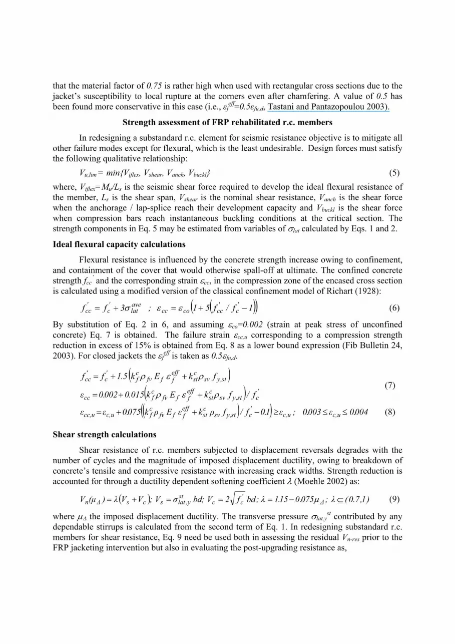
Figure 1. a) Free body diagram of FRP wrapped member at a shear crack plane, b) stress state of FRP strengthened rectangular cross section, failure of open jacket c) by delaminating from concrete and b) by diagonal tension of the cover.
Effectiveness coefficients for the various response mechanisms
The effectiveness coefficients kf,y and kst,y in Eq. 1 for the two transverse reinforcement systems depend upon the function of σlat,y in the response mechanism considered:
(1) For shear strengthening, kf,y depends on the development capacity of the jacket anchorage. Consider a shear crack extending at 45o along the web height df (Fig. 1a); transverse pressure develops in the y-direction (along the web height); b is the web width in Eq. 1. The design strain of the jacket will develop at the critical section, which is at the point of intersection with the crack. If the jacket is adequately closed, then kf,y=1 (Fig. 1b). If, owing to cross-sectional shape of the member it is not possible to wrap the jacket around the section, thus terminating it on the web near the compression zone, (e.g. in T-beams, Fig.1a), then, only those fibers that have sufficient anchorage length Lf beyond the crack may be considered effective as shear reinforcement. In this case, the effectiveness coefficient is kf,y = (df - Lf)/df <1. ACI 440.2R-02 (2002) proposes methods for calculating Lf (also discussed in the following sections). In direct analogy, for open shear links, kst,y=0.5 (FIB Bulletin 24, 2003) whereas kst,y=1 for well anchored closed stirrups.
(2) When strengthening for confinement, the confining pressure is the average value σlatave
obtained from Eq. 1 in the two principal directions of the cross section as σlat-x and σlat-y:
( ) ( )st,ysvcst
efffffv
cfx,laty,lat
avelat fkEk5.05.0 ρερσσσ +=+= (2)
where, ρfv and ρsv are the volumetric ratios of FRP and stirrup reinforcement. The familiar ex-pression for kf
c approximates the volume fraction of core concrete that is effectively restrained (similar to the approach used to evaluate confinement effectiveness of stirrups kst
c (Priestley et al. 1996). Therefore, kf
c=1-(b’2+d’2)/[3Ag(1-ρs)], where Ag is the gross cross section of the element, ρs is the ratio of longitudinal reinforcement, b’ and d’ the straight sides of the rectangular cross section encased by the jacket after chamfering the corners (ACI 440.2R-02, 2002, FIB Bulletin 14, 2001). For a cross section with a side aspect ratio of 3, the confinement effectiveness coeffi-cient becomes negligible (kf
c ≈ 0), whereas for square and circular sections kfc ≈ 0.5 and 1, respec-
tively. The underside is that the primary function of FRP wrapping in a cross section with a large

aspect ratio would be to increase its lateral load resistance rather than its axial load strength.
(3) In upgrading bar anchorages/lap splices by effecting transverse restraint through jacketing, the effectiveness coefficients are taken as follows: for the FRP jacket kf,y
anch = 1 whereas kst,yanch
=1/3 for stirrups to account for their spacing along the anchorage length. The splitting plane may occur either starting from an anchored bar and extending towards the nearest free surface, or may cross several bars. Depending on the direction of splitting, the restraining transverse pressure (and the associated terms in Eq. 1) may be in either of the two principal directions of the section.
Derivation of the effective strain, εf eff
The effective strain εfeff in Eqs. 1, 2 is the usable tensile strain capacity of the FRP jacket
and is only a fraction of the nominal deformation capacity of the material (εfu,d). The value of εfeff
depends on the mode of failure of the bonded layer that in turn is controlled by the bond strength of the substrate. In the following, εf
eff is defined depending on the jacket geometry (open or closed) and the likely mode of failure of the wrap. A jacket is considered open if it cannot be fully wrapped around the cross section of the member (as in the web of monolithic floor beams).
In open jackets the bonding substrate in the anchorage is the concrete cover. Failure may occur either by debonding of the FRP ply or by diagonal tension failure of the cover layer (Figs. 1c,d). Viability of the jacket depends on the low resistance of the cover concrete to direct tension. If debonding is suppressed by mechanical anchorage in the ends, the next likely mode of failure is diagonal cracking of the cover near pre-existing cracks. Note that the FRP sheet develops forces in tension when crossing cracks in concrete by shearing the substrate. Rather than slipping relative to its surroundings, the composite jacket drags the concrete cover in shear distortion so as to bridge the crack width, leading to premature diagonal tension failure of the concrete cover prior to realization of the jacket’s tensile strength. This mode of failure is controlled by the width wcr, of the cracks developing in the strengthened member under the wrap (Fig. 1d). Assuming a linear variation of jacket stresses and considering force equilibrium over the development length Lf, the critical strain εf
eff of the FRP layer at the crack and the required Lf may be defined as,
5.0d,fbffcrf
5.0ffd,fbcr
efff )f/tnEw2( L ; )]tnE2/(fw[ ==ε (3)
where ffb the bond stress distribution over Lf, and ffbd the average design value taken here equal to the tensile strength of the concrete, ft’. Cover shear distortion is γ= 0.5wcr / c, where c the cover thickness. This becomes prohibitively large for crack widths in excess of 0.3mm. Thus, the re-sults of Eq. 3 are capped by this limiting value for wcr; the larger the axial stiffness of the FRP sheet, the lower the strain that may be developed over the sheet anchorage, whereas the usable fraction of its strain capacity is limited by cracking of the substrate.
In closed jackets εfeff is calculated in a similar manner taking into account that the weak
link is the adhesive resin (fgl,d is the shear strength of the glue at the stage of plastification) stressed in shear along the overlap length, Lf of the exterior layer. The strength of the bonded system is controlled by the limiting slip sgl,u of the glue at shear failure as,
5.0d,glffgl,uf
5.0ffgl,ud,gl
efff )f/tEs(L ;)]tE/(sf[ ==ε (4)
ACI440.2R-02 (2002) proposes εfeff = 0.004 and 0.75εfu,d for open and closed jackets,
respectively. Results from compression tests with closed FRP jackets (Chaallal 2003) indicate
that the material factor of 0.75 is rather high when used with rectangular cross sections due to the jacket’s susceptibility to local rupture at the corners even after chamfering. A value of 0.5 has been found more conservative in this case (i.e., εf
eff=0.5εfu,d, Tastani and Pantazopoulou 2003).
Strength assessment of FRP rehabilitated r.c. members
In redesigning a substandard r.c. element for seismic resistance objective is to mitigate all other failure modes except for flexural, which is the least undesirable. Design forces must satisfy the following qualitative relationship:
Vu,lim = min{Viflex, Vshear, Vanch, Vbuckl} (5) where, Viflex=Mu/Ls is the seismic shear force required to develop the ideal flexural resistance of the member, Ls is the shear span, Vshear is the nominal shear resistance, Vanch is the shear force when the anchorage / lap-splice reach their development capacity and Vbuckl is the shear force when compression bars reach instantaneous buckling conditions at the critical section. The strength components in Eq. 5 may be estimated from variables of σlat calculated by Eqs. 1 and 2.
Ideal flexural capacity calculations
Flexural resistance is influenced by the concrete strength increase owing to confinement, and containment of the cover that would otherwise spall-off at ultimate. The confined concrete strength fcc
’ and the corresponding strain εcc, in the compression zone of the encased cross section is calculated using a modified version of the classical confinement model of Richart (1928):
( )( )1f/f51 ; 3ff 'c
'cccocc
avelat
'c
'cc −+=+= εεσ (6)
By substitution of Eq. 2 in 6, and assuming εco=0.002 (strain at peak stress of unconfined concrete) Eq. 7 is obtained. The failure strain εcc,u corresponding to a compression strength reduction in excess of 15% is obtained from Eq. 8 as a lower bound expression (Fib Bulletin 24, 2003). For closed jackets the εf
eff is taken as 0.5εfu,d.
( )( ) '
cst,ysvcst
efffffv
cfcc
st,ysvcst
efffffv
cf
'c
'cc
f/fkEk015.0002.0ε
fkEk5.1ff
ρερ
ρερ
++=
++= (7)
( )( ) 004.0ε003.0;ε1.0f/fρkεEρk075.0εε c,uc,u'cst,ysv
cst
efffffv
cfc,ucc,u ≤≤≥−++= (8)
Shear strength calculations
Shear resistance of r.c. members subjected to displacement reversals degrades with the number of cycles and the magnitude of imposed displacement ductility, owing to breakdown of concrete’s tensile and compressive resistance with increasing crack widths. Strength reduction is accounted for through a ductility dependent softening coefficient λ (Moehle 2002) as:
( ) )1,7.0( λ;075.015.1;bdf2bd; Vσ; VVVλ)(µV ∆'cc
sty,latscs∆n ⊆−===+= µλ (9)
where µ∆ the imposed displacement ductility. The transverse pressure σlat,yst contributed by any
dependable stirrups is calculated from the second term of Eq. 1. In redesigning substandard r.c. members for shear resistance, Eq. 9 need be used both in assessing the residual Vn-res prior to the FRP jacketing intervention but also in evaluating the post-upgrading resistance as,
( ){ } bhσV ; V)V(V)(q),q(λmin)(qV
VV)λ(q)(qVf
y,latf
wf
wcsnewoldnewn
csoldoldresn
=++=
+=−
λ (10)
where q is the behavior index (or R, FEMA 273 1997) and σlat,y f is the transverse pressure in con-
crete owing to the jacket in the direction of lateral sway (Eq. 1). The shear strength of the jack-eted member is the sum of the jacket contribution, Vw
f, and the contribution of the existing mechanisms, namely concrete Vc, and transverse steel Vs. In deriving Eq. 10, it has been assumed that the target µ∆ used in the redesign of the member is equal to the behavior index, qnew (or Rnew). Equation 10 recognizes that the existing mechanisms may have sustained damage during previ-ous loading. For this reason residual rather than the full contributions of core concrete and web reinforcement are considered, by taking the minimum value of λ for these terms, based on the ductility demand either suffered during previous events, or used as target value for redesign. Based on experiments the softening coefficient is not applied on the Vw
f as diagonal cracking is suppressed by the application of the jacket (Tastani and Pantazopoulou 2003).
Anchorage / lap-splice strength calculations
A direct consequence of member upgrading through FRP jacketing is to increase the deformation demand in the lap-splice / anchorage regions. Frequent bond related problems in existing construction include lap splicing of the main bars immediately above the floor level in the anticipated plastic hinge regions with sparse transverse reinforcement, use of smooth bars and small development lengths. To remedy anchorage problems, FRP jackets are wrapped orthogonal to the anticipated splitting cracks. The development capacity of a given anchorage length Lb is calculated from: F=µ⋅σlat⋅πDb⋅Lb, where µ is the coefficient of friction at the steel-concrete interface and σlat the pressure exerted upon the lateral surface of the bar by the cover, transverse stirrups and FRP jacket. The average bond stress fb is given by:
( ) )D/(N/Etnk2)sN/(fAkcff bbefffff
anchfbst,yst
anchst
'td,b πεµ ++= (11)
Nb is the number of bars (or pairs of spliced bars) laterally restrained by the transverse pressure. The value of εf
eff used in Eq. 11, is the surface strain value associated with attainment of bond strength along the bar, and it is in the order of 0.0015-0.002 (Priestley 1996). The lateral force in Eq. 5 required to develop the anchorage strength in the upgraded element is referred to as Vanch .
Resistance to longitudinal bar buckling in FRP-wrapped r.c. elements
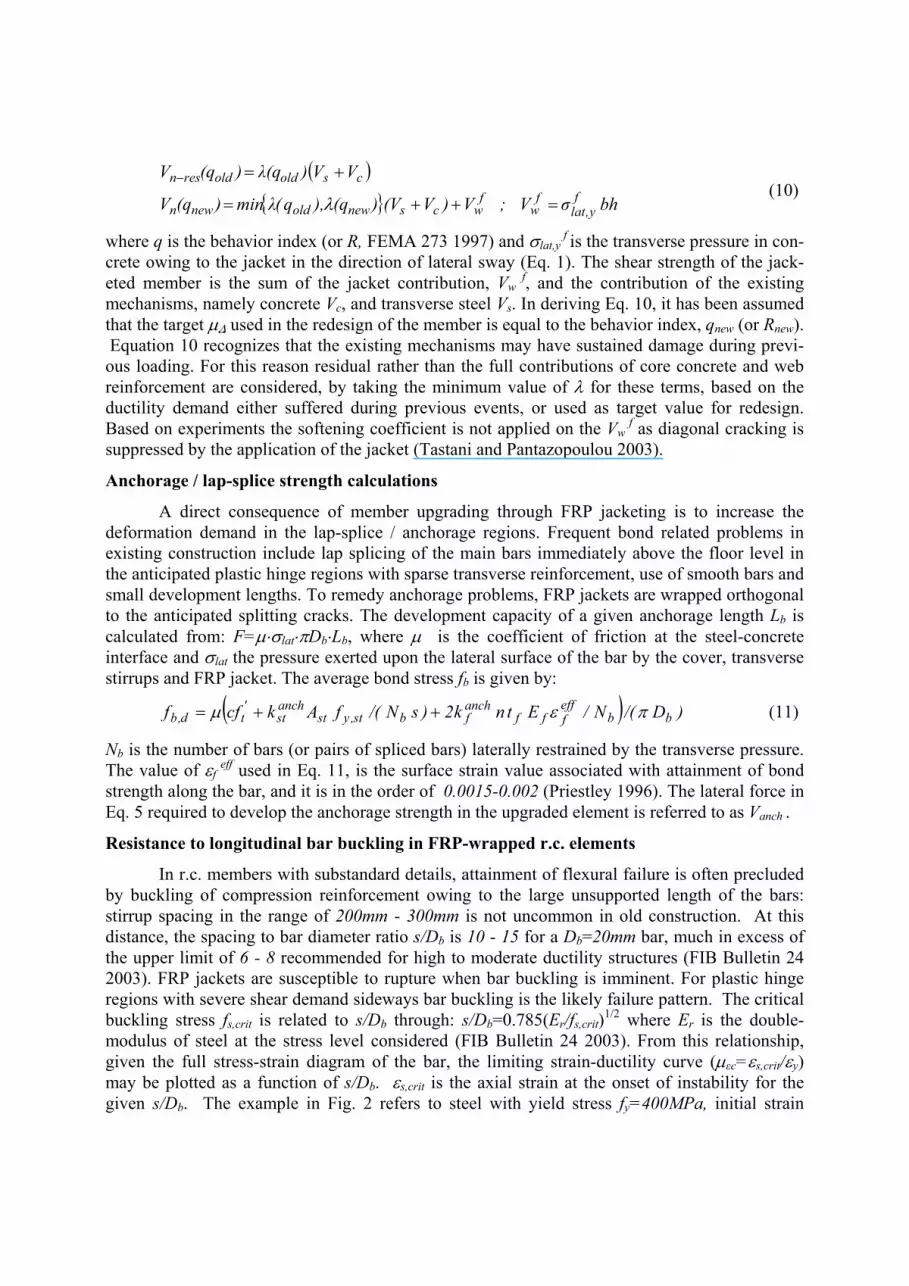
In r.c. members with substandard details, attainment of flexural failure is often precluded by buckling of compression reinforcement owing to the large unsupported length of the bars: stirrup spacing in the range of 200mm - 300mm is not uncommon in old construction. At this distance, the spacing to bar diameter ratio s/Db is 10 - 15 for a Db=20mm bar, much in excess of the upper limit of 6 - 8 recommended for high to moderate ductility structures (FIB Bulletin 24 2003). FRP jackets are susceptible to rupture when bar buckling is imminent. For plastic hinge regions with severe shear demand sideways bar buckling is the likely failure pattern. The critical buckling stress fs,crit is related to s/Db through: s/Db=0.785(Er/fs,crit)1/2 where Er is the double-modulus of steel at the stress level considered (FIB Bulletin 24 2003). From this relationship, given the full stress-strain diagram of the bar, the limiting strain-ductility curve (µεc=εs,crit/εy) may be plotted as a function of s/Db. εs,crit is the axial strain at the onset of instability for the given s/Db. The example in Fig. 2 refers to steel with yield stress fy=400MPa, initial strain

hardening slope of 30GPa and a yield plateau to a strain of 0.005.
Buckling of any individual bar segment is controlled by its strain-ductility curve, unless the dependable deformation capacity of encased concrete, εcc,u (from Eq. 8) exceeds the εs,crit value corresponding to the available s/Db. In that case redistribution between the compressed bars at incipient buckling and the encased concrete is possible, thereby postponing buckling to occur at a higher strain level. Therefore, by increasing the strain capacity of concrete through jacketing to levels higher than εs,crit, the effective s/Db is reduced, as depicted in Fig. 2. The dependable strain ductility of compression reinforcement is:
{ }ycu,sycrit,sc /,/max εεεεµε = (12)
The lateral force in Eq. 5 corresponding to the development of buckling strain εs,crit in the compression reinforcement is Vbuckl = Mbuckl/Ls where Mbuckl is obtained from equilibrium of moments in the critical section. In detailing the jacket it is important to ensure that the target displacement ductility of the member after upgrading, µ∆req=∆u
target/∆y, may be attained prior to buckling of primary reinforcement. To check this the
resulting curvature ductility demand µφ,req ( = φu,req/φy ) in the plastic hinge region of the member is obtained from µ∆,ρεθ:
( ) ( ) byspspspreq,req, Df022.0L08.0l;L/lL/l5.01131 +=−−+= φ∆ µµ (13)
Lacking a better approximation the length of plastic hinge lp in Eq. 13 is taken as per established expressions (Priestley 1996). This may require revision for FRP-jacketed members where the contribution of pullout is significant.
From µφ,req the compression strain ductility demand, µεc,req, of compression reinforcement may be estimated and compared to the dependable value resulting from Eq. 12. For example, for symmetric displacement reversals, µεc,req=1.1µφreq -1 (FIB Bulletin 24 2003). If the jacket layers required to satisfy this criterion are excessive, then it may be advisable to opt for increased storey stiffness so as to effect a reduction in the displacement ductility demand µ∆,req.
Deformation capacity assessment for FRP encased members
Results from over seventy published tests are used to assess the response of FRP jacketed r.c. prismatic members under reversed cyclic loading (Tastani and Pantazopoulou, 2003). For each specimen the experimental load – displacement envelope is used to define yield and ultimate displacement and lateral load strength, as illustrated in Fig. 2b: the characteristic points in the envelope correspond to 80% of the peak load, Vu. Figure 3a plots experimental estimates of yield displacement (defined as per Fig. 2b) after being normalized by the calculated result from two popular models: 1) according to classical mechanics (∆y=φyLs
2/3) and 2) including the
02468
10121416
0 2 4 6 8 10 12
µ εc = ε s
,cri
t /εy
µεc,u ∆µεc
s/Db
s
r
b fE.
Ds 7850=
a)
Shea
r for
ce
∆y ∆u ∆80% u Displacement
Vu FRP upgraded member
80%Vu
old-
deta
iled
mem
ber
b)
Figure 2. a) Relationship between µεcand s/Db ratio b) Definition of deformation indices.

flexural-slip component of the yield-displacement as proposed by Priestley (1996) (∆y=φy(Ls+0.022fyDb)2/3). Clearly, both analytical estimates fall well below the experimental value for yield displacement; the worse estimates resulting from the classical model. Underestimation of yield displacement indicates that the actual slip component is larger than calculated.
Figure 3b plots the reported (experimental) strength Vu of each upgraded member normalized by the Viflex on the y-axis, and by the calculated Vanch on the x-axis. Again, most of the experimental points fall below the equal value line underscoring the localization of deformation demand that occurs in the anchorage, which, after jacketing, becomes the weak link of the upgraded member. The tests confirm that it is possible to suppress all premature modes of failure so that flexural yielding may prevail, through FRP jacketing. This is manifested by the ductility in the load-displacement curve of the upgraded member. Here, tests results were correlated collectively with an empirical lower bound expression for the available displacement ductility, µ∆ as a function of transverse confining pressure σlat
ave (µ∆≥1.3 for poorly detailed members): (14)
Figure 3c compares the experimental values with the analytical estimates of Eq. 14 obtained using εf
eff=εfu,d. Experimental points lying below the lower bound curve
correspond to repair cases where the postrepair yield displacement used to quantify dependable ductility from the load displacement envelope was the apparent value, markedly greater than the true displacement at first steel yielding.
Conclusions: Global considerations when using FRP jackets for seismic upgrades
Most of the strength terms in Eq. 5 depend on the anticipated deformation demand in the member after repair. Once the strength of the weakest mechanism is exhausted, localization of deformation is expected to occur in that particular behavior mode, which becomes the fuse of member response upon increased deformation demand. Collective evaluation of the available experimental evidence demonstrated that jacketing of deficient r.c. members increases their nominal deformation capacity, but imposes a more severe demand upon the anchorage. A large component of the drift attained in jacketed column tests is due to lumped rotation owing to slippage of longitudinal bars from the support. Bar buckling is postponed in jacketed members as the compression strain capacity of the encased concrete core is increased, thereby enabling redistribution of bar stresses to concrete upon attainment of bar instability (Tastani 2005).
0
2
4
6
8
10
12
0.0 0.1 0.2 0.3 0.4 0.5
µ ∆
σlatave/fc
c)
Vu
/Vifl
ex
Vu / Vanch
0.0
0.5
1.0
1.5
2.0
0.0 0.5 1.0 1.5 2.0
b)
0
1
2
3
4
0 1 2 3 4
∆ y,e
xp /∆
y,Pr
iest
ley
∆y,exp /∆y,mech
a)
Figure 3. a) Comparison between ex-perimental and analytical yield dis-placements, b) Normalized experi-mental strengths, c) Correlation of Eq. 14 with test data.
1.02
4.123.1 ',
−
++=∆
c
stysvcst
efffffv
cf
ffkEk ρερ
µ

Recalling that FRP-jackets cannot increase member stiffness, it is useful to employ pertinent criteria in order to identify whether the upgrading measures need to involve storey stiffening along with local interventions through jacketing. Relevant response indices that may be used as diagnostic tools in assessing the global adequacy of the structural morphology are the magnitude of the fundamental structural period, drift at yield of the vertical element and the fundamental translational mode-shape of the structure that may reveal the existence of soft-storeys. In designing the upgrading scheme, the seismic demand need be determined in displacement terms. Prerequisite is idealization of the structure as an equivalent single degree of freedom system (ESDOF) through a selected empirical approximation of the predominant shape of lateral vibration and calculation of the corresponding stiffness (secant to yield).
For immediate results the ESDOF properties may be used with the YPS (Yield Point Spectra) of the design earthquake in order to evaluate the anticipated displacement demand and corresponding displacement ductility (Aschheim and Black 2000). Assuming the equal displacement rule the elastic spectral displacement is also the target displacement of the inelastic system: ∆u=Sd. For a preliminary assessment of the suitability of the upgrading scheme it is acceptable to adopt an upper limit of 2% for the lateral drift of the structure at the design earthquake; for larger displacement levels second order effects that are usually not efficiently mitigated by concrete encasement need be explicitly addressed in the upgrading strategy. The critical displacement limit, ∆u,crit=2%H (where H the building height) corresponds to a spectral limit of ∆crit
*. The vertical line in the ADRS drawn at displacement ∆crit
* defines a design boundary. Acceptable solutions are to the left of the vertical line and above the YPS associated with the limiting ductility of the system. By also implementing stiffening schemes in the structure, the radial line is effectively rotated counterclockwise in the ADRS, thereby reducing the design value of ∆u, with an attendant mild increase in the required Vy
*. Note that a larger increase in capacity may be required to also reduce the target µ value. The final step in the design is to apply the analytical expressions for each of the ultimate limit states discussed as per the qualitative Eq. 5, thereby linking the target indices of behavior to jacket dimensions.
Example: design of jacketing for a substandard r.c. column
The procedures described can be used to detail the jacket required to upgrade the seismic resistance of a substandard element to a desired level of displacement ductility. Consider an old-type reinforced concrete column in double bending, having a cross section of 400x700mm , clear height of 5m, symmetric tension and compression reinforcement ratios of 0.90%. Nominal material strengths are fc
’=25MPa, fy,s=400MPa (main bars) and fy,st=220MPa (stirrups). Rectangular stirrups (diameter of 6mm) spaced at s=300mm are provided (s/Db=50). Initial column shear resistance was calculated as Vn= 30%Vc+Vs=51.60kN, the ideal flexural capacity at column yielding and the corresponding displacement as Viflex=103.4kN, and ∆y= 36mm. Thus,
ATH3 long.
0
0.2
0.4
0.6
0.8
1
0 5 10 15 20 25 30 35 40 45Sd(mm)
S a /g
T1=0.22sec
T2=0.35sec
T3=0.5sec
µ=1
µ=2 µ=4
Vy*
Ve*
∆u,cr* ∆e
*
A
S
a /g
T4=0.7sec
1.0
0.8
0.6
0.4
0.2
00 5 10 15 20 25 30 35 40 45
∆y*
Figure 4. Isoductile YPS: definition of values (* identifies the ESDOF system).

shear failure would prevail at a displacement of ∆sh=18mm, well before flexural yielding.
Consider an upgrading scheme with CFRP jacketing so as to enhance member lateral drift capacity to 2%, corresponding to displacement ductility of µ∆=2.5 (wraps with tf =0.13mm, ff=3500MPa, εfu,d=0.015, and Ef=230GPa). The jacket is detailed using the procedures described in the preceding. Results are listed collectively in Table 1 for each design action (shear, anchorage, rebar buckling). Jackets are fully wrapped (closed), thus, the effective strain used in the calculations is εf
eff=50%εfu,d for shear and rebar buckling. In Table 1, each mode of failure considered leads to a different number of required layers. The more severe requirement in terms of jacket thickness is associated with the anchorage, oversupplying the demands of the other response mechanisms. Note that whereas shear was the likely mode of failure in the initial state of the member, theoretically a single jacket layer would suffice to upgrade column shear strength to levels exceeding the ideal flexural strength.
Table 1. Required jacket layers for each design action (nf to be rounded off to next integer).
Confinement for µ∆req =2.5 lp ≈ 350 mm (Priestley ’96) Bar Buckling (εcc,u=0.011, Eq. 8) Shear in-
crease Lap-Splice above
Base, Eq. 11 avail. Lb=20Db σlat
ave
/ f’c kf
c ρ fv% Eq.14 nf µεc,avail
Eq.12 µφ,req
Eq. 13 µεc,req=
1.1µφ,req - 1 Vw
f
(kN) nf
0.2 0.37 0.8 7.5 εcc,u/εy= 5.6 4.6 4.1<5.6 67.3 0.4
fbdavail =3 MPa
fbdreq=4.35 MPa
σlatf /Nb=110 (N/m),
nf=7.4 (εf
eff=0.13%)
References Tastani S. and Pantazopoulou S.J., 2003. Strength and deformation capacity of brittle r.c. members jack-
eted with frp wraps. CD-ROM Proceedings of the fib-Symposium on Concrete Structures in Seis-mic Regions, Technical Chamber of Greece (Ed.), Athens – Greece.
American Concrete Institute, 2002. Guide for the design and construction of externally bonded frp systems for strengthening concrete structures (ACI 440.2R-02). Farmington Hills, Michigan.
International Federation for Concrete, 2003. Seismic assessment and retrofit or r.c. buildings (FIB Bulle-tin 24). Report by Task Group 7.1, Chapter 4, , Lausanne Switzerland.
Priestley M., Seible F., Calvi M., 1996. Seismic design and retrofit of bridges. J. Wiley & Sons Inc., N.York.
International Federation for Concrete, 2001. Externally bonded FRP reinforcement for r.c. structures (FIB Bulletin 14). Report by Task Group 9.3, Lausanne Switzerland.
Brẽna S., Wood S. and Kreger M., 2003. Full-scale tests of bridge components strengthened using carbon FRP composites. ACI Structural Journal 100 (6), 775-784.
Chaallal O., Shahawy M. and Hassan M., 2003. Performance of axially loaded short rectangular columns strengthened with carbon FRP wrapping. ASCE J. Comp. for Construction 7 (3), 200-208.
Richart F., Brandtzaeg A. and Brown R., 1928. A study of the failure of concrete under combined com-pressive stresses. Engrg. Experiment Station Bull. #185, Univ. of Illinois, Urbana.
Moehle J., Elwood K. and Sezen H., 2002. Gravity load collapse of building frames during earthquakes. S.M. Uzumeri Symp.Behavior and Design of Conc. Str. for Seismic Performance, ACI-SP 197.
Federal Emergency Management Agency, 1997. NEHRP Guidelines for the seismic rehabilitation of buildings (FEMA Report 273), Washington D.C.
Tastani S., Pantazopoulou S., Zdoumba D., Plakantaras V., Akritidis E., 2005. Limitations of FRP-jacketing in confining old-type r.c. members in axial compression. in print, ASCE J. of Comp. for Construction.
Aschheim M. and Black E., 2000. Yield point spectra for seismic design and rehabilitation. EERI Earth-quake Spectra 16 (2), 317-336.


