Embed Size (px)
Citation preview

1
TRUBA COLLEGE OF ENGINEERING AND TECHNOLOGY
INDORE, (M.P.)
“FABRICATION OF RACK AND PINION STEERING USED IN ATV”
MAJOR PROJECT REPORT-2012
SUBMITTED BY:
ANIMESH SATLE (0830ME081009)
KHAGENDRA RAGHUWANANSHI (0830ME081026)
PIYUSH PARETA (0830ME081033)
SAURABH PANDEY (0830ME081052)
SHUBHAM KESHARI (0830ME081055)
SUBMITTED TO: GUIDED BY: PROF. MRS. SUMAN SHARMA MR. VISHAL ACHWAL
(HEAD OF MECHANICAL DEPARTMENT) (MECHANICAL DEPARTMENT)
DEPARTMENT OF MECHANICAL ENGINEERING

2
TRUBA COLLEGE OF ENGINEERING AND TECHNOLOGY
INDORE, (M.P.)
CERTIFICATE
This is to certify that the project work entitled “FABRICATION OF RACK AND PINION STEERING USED IN
ATV” has been carried out by ANIMESH SATLE, PIYUSH PARETA, KHAGENDRA SINGH RAGHUWANSHI,
SAURABH PANDEY, SHUBHAM KESHARI students of final year B.E. Mechanical Engineering under our
supervision and guidance. They have submitted this project report towards partial fulfillment for the
award of Bachelor of Engineering in Mechanical Engineering of Rajiv Gandhi Prodyogiki Vishvavidyalaya,
Bhopal during the academic year 2011-2012.
Mr. Vishal Achwal Prof. Suman Sharma Madam
Project Guide Head of Department
Mechanical Engg Dept. TCET Mechanical Engg Dept. TCET
Director
TCET, INDORE
DEPARTMENT OF MECHANICAL ENGINEERING

3
TRUBA COLLEGE OF ENGINEERING AND TECHNOLOGY
INDORE, (M.P.)
RECOMMENDATION
This is to certify that ANIMESH SATLE, KHAGENDRA SINGH RAGHUWANSHI, PIYUSH PARETA,
SAURABH PANDEY, SHUBHAM KESHARI students of Final year B.E (Mechanical Engineering) of
this institute have completed the project work entitled “FABRICATION OF RACK AND PINION
STEERING USED IN ATV” based on the syllabus and have submitted a satisfactory report on it in
the academic year 2011-2012.
INTERNAL EXAMINER EXTERNAL EXAMINER
Date- Date-
DEPARTMENT OF MECHANICAL ENGINEERING

4
ACKNOWLEDGEMENT
For the success of project DEDICATION, GUIDENCE, COORDINATION & KNOWLEDGE is the base. It’s my pleasure, that at the level of Final year in Engineering. I am able to understand “FABRICATION OF RACK AND PINION STEERING USED IN ATV” which is very useful in many applications.
I am very much thankful for the full corporation of Mrs. Suman Sharma Madam HOD of Mechanical Department.
I am very much thankful for the valuable guidance of Mr. Vishal Achwal Sir in making this project successful.
DEPARTMENT OF MECHANICAL ENGINEERING

5
Summary
Our Project has as aim the description and design the elements of the steering system for a formula S.A.E.
The steering system is one of the most important parts of the car because has the task to control the car and guide by the desirable trajectory. The action starts on the hands of the pilot and is transmitted through several elements that have different tasks until turn the wheels. A failure on this mechanism can be fatal to the health of the pilot.
Before start to design the elements of the steering system car, we will study different aspects that have influence on the design of the steering system.
First of all we report to the reader all about the Formula S.A.E. The aim, where take place the race the rules and the history of the competition. We will discover the main objective of the competition the development of young engineers because they have to manufacture the cars themselves.
Then we study the formula S.A.E. rules and we will put on our project the rules the more general rules and the rules directly related with the steering system in order to design our system bear in mind these restrictions that are established by the competition.
We will do a compilation of the general characteristics of a formula S.A.E. in order to know more about this kind of cars comparing with a formula one car that is known for the most of the people.
Subsequently we will study the theoretical knowledge and the technical fundamentals and general comments about the steering in general in order to understand better this system and applied on our formula S.A.E. In this chapter we will find out the characteristics that must has a steering system and the geometry (Ackerman and Jeantaud) of some elements of the system that produce the car has

6
a different performance on the road. Also we will study the different angles that we can give to the wheel and we will see the different qualities that the vehicle has depending on these angles.
Continually we will start with the design of our steering system. We will start this task separating the elements of the car that have influence on the design of the steering and the elements that really make up the system.
Continually we begin giving a description of the mechanism and continually we will describe the function and the characteristics of each element. We will focus on the steering column, the rack and pinion and the steering arms because we do the difference between the elements that we can manufacture and design and the elements that we will buy to the manufacturers. In order to design the elements that we will design ourselves we will use the Solid works program which we can to draw the elements and to calculate the stress that can support.
7
Contents
1. Introduction 9-13
1.1. Project aim 10-11
1.2. Importance of the steering system on a car. 12
1.3. The steering system on a common car 13
2. Review of literature 14-30
2.1. Steer System 15-16 2.2. General comments about the steering. 17-21 2.3. Technical fundamentals. 22-30
3. Working Model Description 31-40
4. Design process, results and discussions 41-53
4.1. Introduction. 42 4.2. Rack And Pinion Calculation. 42-44 4.3. Description of the steering system elements. 45-53
5. Drawing & Analysis 54-60

8
6. Applications 61-63
7. Advantages & Disadvantages 64-66
8. Project Scope 67-68
9. Conclusions 69-71
10. References 72-73
11. List of Figures 74-75
12. List of Tables 76
13. Appendices 77-92 13.1. Glossary 78-79 13.2. Appendix A 80-84 13.3. Appendix B 85-92

9
1. Introduction.
1.1 Project aim
1.2. Importance of the steering system on a car.
1.3. The steering system on a common car

10
1.1. Project aim. In this project we are going to carry out the study and the design of the steering system for a car used on competition races in circuits.
Along the project we will focus in the steering system but also we will watch the steering in a car that we can find travelling in one street in order to understand better the performance of the steering elements in order to after focus in a formula S.A.E. which is a car that requires a steering system more exigent due to is used on races.
By other hand we must know that we are manufacturing a steering system for a car so we will bear in mind different elements of the car which have influence at the time to manufacture the steering system. In this project we will do reference to the characteristics to these parts of the car and the measures, the weight or the design.
The project will be carry out bearing in mind a lot of very different aspects as the total cost of the project, the analysis stress and the materials to manufacture the steering components and the design of the car carefully since there are some technical rules which must be taken in consideration.
With regards to the budget, the Formula Student stipulates that there is no a maximum cost so I will make my project and finally I will calculate the total cost.
Once finished the single-seater will have as objective compete in the race of the Formula S.A.E competition.
A formula S.A.E. car is a car thought to compete in races. Everybody knows that in a race or in any competition the person who take part always try to win and for that try to put in effort as much as possible. In our project in which we are going to design the steering system of a formula S.A.E car, the efforts supported by all the elements of the vehicle are very hard and we keep in mind that the health of the pilot depends directly of a good car design. Particularly when we talk about the steering of a car the responsibility of to carry out a good design is maximum because join the breaking system, is the principal system to control the car and so is the principal element for the safety of the pilot.

11
By other hand as we can say we are going to design a car to compete in races. However our car is destined to compete in Formula Student. This kind of competition is thought to develop of young engineers because the students of different universities manufacture their own cars with their own resources. Obviously these resources are quite different than of a formula one team because the cars have not equal features. By this reason our project will be carried out bearing in mind the following aspects: a low budget, the formula S.A.E. rules and the time because the project must be finished on30th of March.

12
1.2. Importance of the steering system on a common car. The steering system is one of the most important parts of any car. Whether this element is vital to the safety driver of the vehicle in question concern.
While the steering, as we have said, is important in a common car which we can drive daily in our life, obviously is even more significant in a formula S.A.E. car since this kind of vehicles are designed to compete in races and the objective of the team and the pilot is always to bring the car to the limit to try to win. A failure of this mechanism during operation of the vehicle could lead to fatal circumstances to the driver who is at the expense of a car without control and with high velocity. As we have seen along the history, a lot of the most serious accidents have been caused due to a failure on the steering system with different fates for the drivers.
Although in this project we will start talking and explaining the elements of a common car to know more about the steering in general in any car, then we focus on the steering system for a competition car which is a little bit different that in a common car.
1.3. The steering system on a common car

13
The steering system is the mechanism which has the purpose to turn the guidelines wheels making that the pilot can guide his car along the desirable trajectory.
In order to carry out this task the pilot receive a lot of information by their eyes and the brain send a stimulus to their hands which are the elements in contact with the first part of the steering system, the steering wheel. Now the human work has finished it is the time to the mechanism work. The steering system work is to transmit the angle made by the pilot on the steering wheel across the different elements until the steering wheels.
Steering system elements:
- Steering wheel
- Quick disconnect mechanism
- Steering column
- Universal joint
- Steering box (rack-pinion)
- Tie rods
- Ball-and-socket
- Steering arms
- Upright
- Pivot
In our project we will study the theoretically knowledge that has influence on the steering system and basing on these fundaments we will design and describe the steering system elements.

14
2. Review of Literature.
2.1. Steer System
2.2. General comments about the steering.
2.3. Technical fundamentals.
2.1 Steer System

15
Steering system in automobiles are build from several component such as steering wheel, gears, linkages, and other components used to control the direction of a vehicle's motion. Because of friction between the front tires and the road, especially in parking, effort is required to turn the steering wheel. To lessen the effort required, the wheel is connected through a system of gears to components that position the front tires. The gears give the driver a mechanical advantage. Various types of gear assemblies, none with any decisive advantages over the others, are used, although some manufacturers prefer a rack-and-pinion system. In faster heavier cars, the amount of force required to turn the tires can be very great. Many of these cars use a power steering system. The system contains a hydraulic booster, which operates when the engine is running and supplies most of the necessary force when the driver turns the wheel.

16
Figure 2.1 Mechanical Steer Systems Rack-and-pinion SteeringRack-and-pinion steering is quickly becoming the most common type of steering on cars, small trucks and SUVs. It is actually a pretty simple mechanism. A rack-and pinion gear set is enclosed in a metal tube, with each end of the rack protruding from the tube. A rod, called a tie rod, connects to each end of the rack. The pinion gear is attached to the steering shaft. When you turn the steering wheel, the gear spins, moving the rack. The tie rod at each end of the rack connects to the steering arm on the spindle. The rack-and-pinion gear set does two things: It converts the rotational motion of the steering wheel into the linear motion needed to turn the wheels. It provides a gear reduction, making it easier to turn the wheels.

17
Figure 2.2 Mechanical Steer Rack inside View
2.2. General comments about the steering. As we can say before in this project the steering system is the mechanism which has the task to turn the wheels in order the driver can guide the vehicle along the desirable trajectory.
All steering system must satisfy the following characteristics:
Safety: the most important. Depend on the reliability of the mechanism and this one depends directly on the quality of used materials.
Gentleness: it achieves with a precise assembly and a perfect greasing. The hardness in the driving it make difficult and tiring drive the car along the desirable trajectory. It might be caused to badly position the tyres or because there is more friction due to the tyres are flat.
Accuracy: it takes doing a neither very hard nor gentle steering. The lack of the steering it might be caused by the next causes:
- Caused by here is too much play in the steering elements
- Caused by a differently debilitate of the right and left tyres
- Caused by the imbalance of the tyres that is the main responsible of the shimmy
- Caused by different pressures of the right and left tyres
Irreversibility: The steering must be semi-reversible. It consists of the steering wheel has to transmit the motion to the wheels, but these, in spite of the land irregularities, don´t must transmit the oscillations to the steering wheel. The semi-reversibility allows that the wheels recover their normal position with a small effort done by the driver after turn the steering wheel.
18
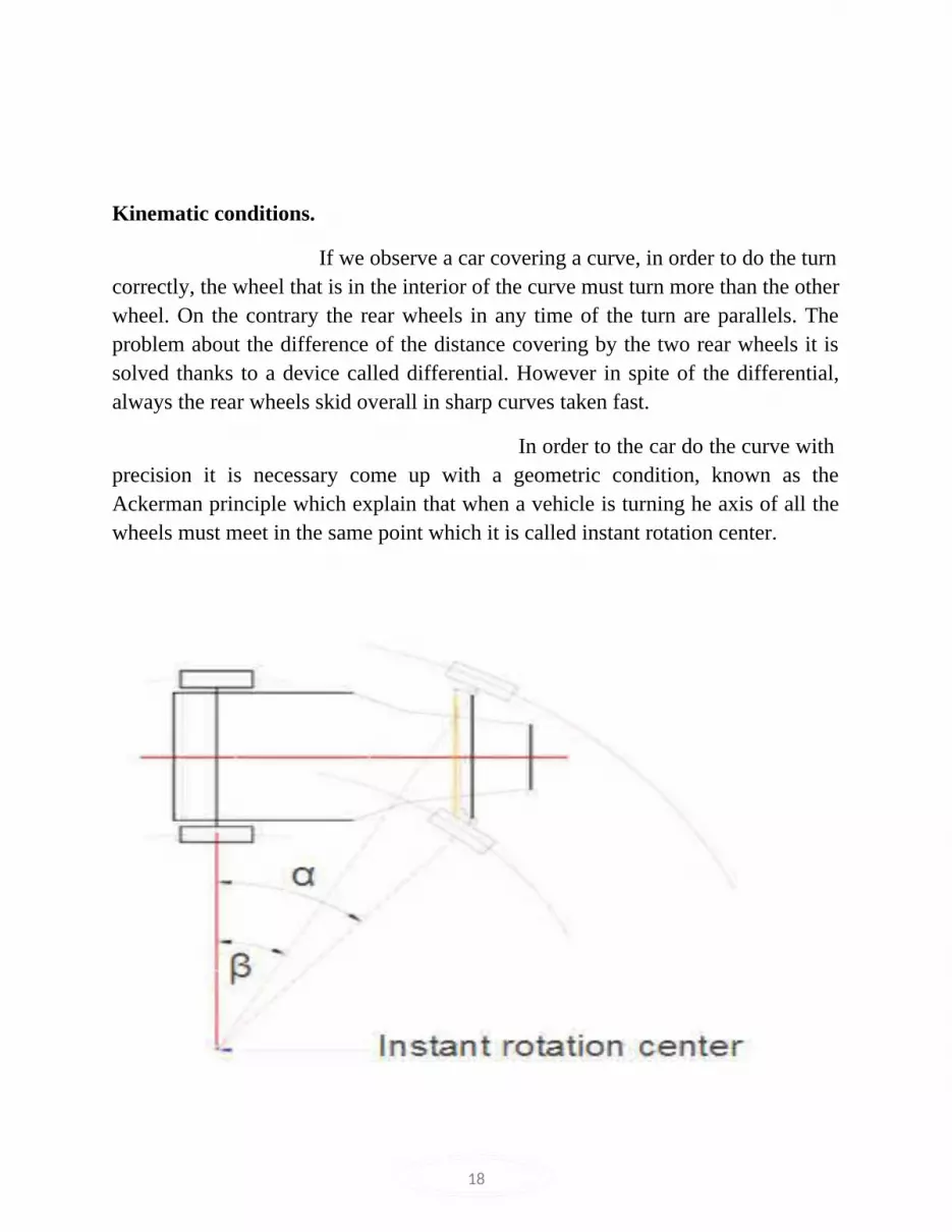
Kinematic conditions.
If we observe a car covering a curve, in order to do the turn correctly, the wheel that is in the interior of the curve must turn more than the other wheel. On the contrary the rear wheels in any time of the turn are parallels. The problem about the difference of the distance covering by the two rear wheels it is solved thanks to a device called differential. However in spite of the differential, always the rear wheels skid overall in sharp curves taken fast.
In order to the car do the curve with precision it is necessary come up with a geometric condition, known as the Ackerman principle which explain that when a vehicle is turning he axis of all the wheels must meet in the same point which it is called instant rotation center.

19
Figure 2.3. Ackerman principle
We can see in above picture not only the instant rotation centre, also the different angle of the right and left wheel. The wheel that is in the interior of curve describe an α angle bigger than the β angle described by the other wheel. It must be on this way because on the contrary if the front wheels will be parallels will finish broken.
To obtain these angles it is used an articulated trapezium called Jeantaud trapezium which we can show in the next picture.
Figure 2.4. Jeantaud trapezium

20
This trapezium has two parallel sides, one is the tie rod is shorter than the other which is the front axle which is fixed and two sides whit the same length but no parallels (the extension of the steering arms).
The studies executes by Jeantaud established that for the turn center of the all the wheels it will be the same, the extension of the steering arms must join with the center of the rear axle as we can show in the next picture.

21
Figure 2.5 Jeantaud trapezium
With all of this, we can determinate the relationship between the wheelbase, the track and the angles of the interior and exterior wheels in a curve. So if we have the next picture:
a α β
e
Figure 2.6. Turn radius of the wheels
Where:

22
a: track
e: wheelbase
I: instant rotation center
2.3. Technical fundamentals.

23
Figure 2.7. Wheels angles
Toe angle This is an angle, or linear measurement, formed by a line drawn through the horizontal center of each wheel relative to the center line of the vehicle. Toe can be read as individual, or the total of two wheels on the same axle. Proper toe will reduce scuff and improve tire life by reducing running toe to near zero.
If the pivot and the vertical axis of the wheels will be parallels, the effort to execute it would calculate with the next equation:
C = Fr*d
Where:
C: resistant torque Fr: resistance to go round d: distance of the torque
So we try to reduce this resistant torque decreasing the distance ``d´´.
Normally the distance ``d´´ although is short, exist and furthermore is necessary that exist a resistant torque in order to give a good stability to the steering because the wheels tend to become disorientated with the irregularities of the road the resistant torque made that the wheels turn to in a good position.
By other hand, the inclination angle causes some tendency to turn the steering in a straight line. This angle joins the advance, provoke that the vehicle raise on the front part of the vehicle on the interior wheel of the curve when the advance is positive or of the exterior wheel when the advance is negative.
Due to the weight, the vehicle tends to return to the balance position corresponding to a turn of zero degrees, contributing, the inclination, that

24
the guidelines wheels take again the position in straight line and keeping in this position.
Convergence Divergence
Figure 2.8. Toe rod
Convergence and divergence
Every longitudinal force tends to modifier the direction of the wheels. This effect is corrected with the convergence.
The convergence depends directly on the camber angle so the total convergence is the algebraic addition of the necessary convergence to bear in mind the effect of

25
the longitudinal forces and the camber angle. Then if the camber is positive, the convergence must be also positive, if the wheels work as guidelines wheels and motor wheels and the camber is negative, the convergence must be negative; lastly
if the wheels work as motor wheels and the camber is positive, the convergence may be positive or negative.
The convergence is obtained modifying the length of the steering arm. This fact made that the Jeantaud trapezium experiment a modification since when the car is stopped the uprights are not already perpendiculars to the longitudinal plane of the vehicle.
So we can conclude: is convenient that the convergence is the lowest possible but a low value of convergence is not bad because produce more stability to the car that made a driving more relaxed since the varieties on the road as a pothole tend to be annulated due to the convergence.
As regards the divergence, as with convergence the tyres are worn down because the wheels are not on a straight line. However when there is divergence the wheels ate turned on the out direction of the car making easier the turn of the vehicle. The same than the convergence if the car has not a low value of divergence it will be very difficult to drive the car since with a short turn of the wheel the car will turn a lot.
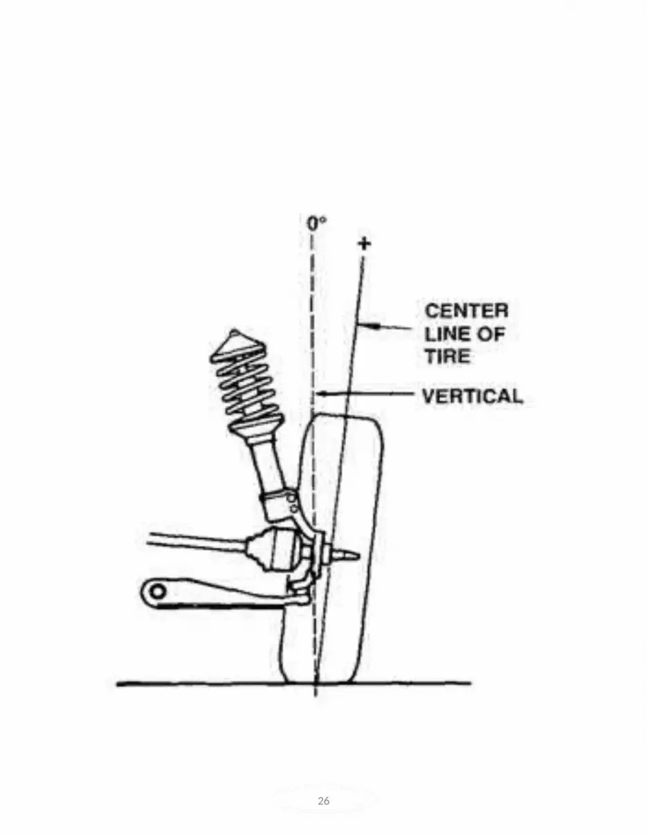
Camber angle.
Camber is the tilting of the top of the wheels inward or outward, toward or away from the automobile. If the wheels are tilted outward, they have positive camber. If they are tilted inward they have negative camber.
If the wheel has a inclination in the outside direction of the car the angle is positive and on the contrary the angle is negative.
Nowadays the majority of vehicles have a camber angle around 1º on their front wheels.
26

27
Figure 2.9. Camber angle
The upright supports flexure efforts equivalent to the momentum M = W*L.
Where: W: weight
L: distance
The fact to change the camber has influence on the toe angle because if the camber angle increases the toe angle decreases and vice versa.
Also this angle has a lot of influence on the tyres because an excessive value of the camber angle produces a high wear down of the tyres. If the camber angle is positive the wear is produced on the exterior of the tyre and with a negative angle the wear is produced on the interior of the tyre.

28
The camber angle equal to the caster angle provides the steering to keep the straight line by the cone effect.
Caster angle.
Caster is a line drawn through the steering axis, compared to vertical. If the axis is tilted back at the top, the angle is positive, tilted forward is negative. Caster improves stability, steering wheel return and cornering.
Figure 2.10. Caster angle
The caster angle can also obtain situating the pivot in front of the vertical of the wheel axis. On both process the wheel is dragged and then it produces stability on the front wheels. We will bear in mind in this system the effects of the direction radius and the toe angle.

29
The caster angle also depends of the camber angle. If the camber is of a considerable importance, even the caster may be negative in order to reduce the re-position effect. In fact a lot of modern vehicles when are stopped have a negative caster.
Drift effect
When a car is in a curve, the vehicle does not continue exactly by the trajectory that guide the guidelines wheels since due to the effect of the transversal forces which appear on the tyres the car is displaced guiding a trajectory that form an angle with the rim. This angle is denominated as drift angle. So the tyre drift is the change of the trajectory produced by the out of shape of the tyre. It cannot confuse the drift with Alost of grip or with a skid. The lost of grip can produce the skid but it has not influence on the drift. The drift depends on the velocity, the weight of the car, the pressure and the width of the tyre and the width of the rim.

30
Figure 2.11. Drift angle
Figure 2.12´. Drift angle vs. transversal force

31
3. Working Model Description

32
The rack and pinion
In general Before the appearance of the car the use of the rack and pinion was limited only to small vehicles because the steering proved too heavy and the improvements were not sufficiently suitable so it was necessary to make a lot of turns with the steering wheel in order to guide the wheels on the desirable trajectory. Nowadays this problem has been solved with the power-assisted steering. Actually the rack and pinion is very used by the fact that is cheap and the assembly is simply allowing the incorporation system that help on the driving as the power-assisted steering.

33
Figure 3.1. Rack and pinion
The system is connected directly with the tie rod and this one with the wheels having a high mechanical output. It is a great accuracy system, particularly in cars with the motor on the front part and with front-wheel-drive since decrease enormously the effort to do, is very smooth, and has a good recuperation and is safe.
The steering column ends with a pinion (generally helicoids) that engagesconstantly with a bar that is a rack. The rack moves inside a framework that is used as a guide and as protection of the outside agents. The rack is directly jointed with the tie rods with the ball-socket-joints transmitting the movement to the wheels. There are steering systems that have a power-assisted steering. This mechanism has the task of decrease the necessary effort at the time to drive the car. On the common cars the most used is the hydraulic system although is also used the pneumatic system or with an electrical system in the steering column.
In our case We have chosen the rack and pinion due is by far the most steering box used in a car and in particular because is light, simply and cheap. For this reason, is the election on the cars used to compete on circuits since the rack and pinion provide a lot of information to the pilot about the track due to have not auxiliary mechanisms that limit the feeling of the pilot.
Once transmitted the torque of the steering column through the pinion to the rack, the longitudinal movement of the rack is transmitted to the tie rods through of an axial ball-and-socket joint.
Inside the steering box the pinion will must be quite small and to transmit the high efforts to move the steering the modulus must be big so it must has a few number of teeth.
Both the pinion and the rack must be made of a high quality steel and are casehardened (material treatment) since have to support high efforts.

34
Figure 3.2. Rack and pinion lateral Figure 3.3.Rack and pinion front

35
Our design
In order to make the design of our rack-pinion for the steering box, we base our work on the choice of the rack and the pinion which will produce a greater lateral displacement of the wheels with the same turn of the steering wheel.
We start saying that our steering column has a radius of 18 mm an adequatevalue for this kind of cars.
The other start point is that the rack and the pinion must be the same modulus and the same material. A suitable material for these elements is SAE 1045 steel which is easy to mechanize.

36
Figure 3.4. Rack and pinion SAE 1045

37
In the followings pictures we can show the necessary parameters of the rack andpinion which we will operate to calculate the best possible design for our steering box.
Figure 3.5. Rack and pinion parameters
N: velocity of the pinion turn V: velocity of the rack
Z: number of pinion teeth
n: number of rack teeth in one cm
In order to calculate the velocity of the rack it is used the following equation:
v = N (z ÷ ȵ) cm/sg

38
And to calculate the distance that advance the rack in one complete turn of the pinion is:
d = (z ÷ ȵ)
Position: The position of the steering box will be determinate with the dimensions of the wheel. For Formula S.A.E. we will choose a wheel for the competition with theFollowings dimensions:
20.0 x 7.0 – 13 inches
If we translate to cm, we have an exterior diameter of 20 x 2.5 = 50 cm. Bearingin mind that the steering box is joined with the wheel through the tie rods and thesteering arms at the middle of the wheel. So we can obtain the distance of the steering box with the road and if we had the exacts measures of the cockpit we could calculate the distance of the steering box with the cockpit floor but the project of the chassis is studied in other project.
Finally the distance of the steering box to the road is:
50 / 2 = 25 cm
Tie rod
In our case in which we have chosen the rack and pinion for our steering box the tie rods are the bars which join the rack with the steering arms. The join is made through ball-and-socket joint. The connection between the ball-and-socket join and the steering arms is thread, making possible the variation of the distance from the end of the rack to the end of the steering arms. Then the joint secures through with nuts and locknuts. This is used to adjust the parallelism between the wheels. The tie rods must be made of alloyed steel since must be support the knocks to come from the wheels through the upright and the steering arms.

39
Figure 3.6. Tie rod
Ball-and-socket joint
The ball-and- socket joint allows the oscillations produced by the movement of the steering (the movement of the rack and he steering arms are in different plane) and the effect of the suspension (the wheels and the steering arms oscillate with the suspension whereas the rack is joined rigidly to the chassis). These elements consist of three parts: one ball, one bearing situated behind the ball in order to reduce the friction and the framework that contains them. The ball is connected with a thread rod in where is connected one of the elements to articulate. The other element is connected with another thread rod that comes from the framework.
Figure 3.7. Ball socket joint
40
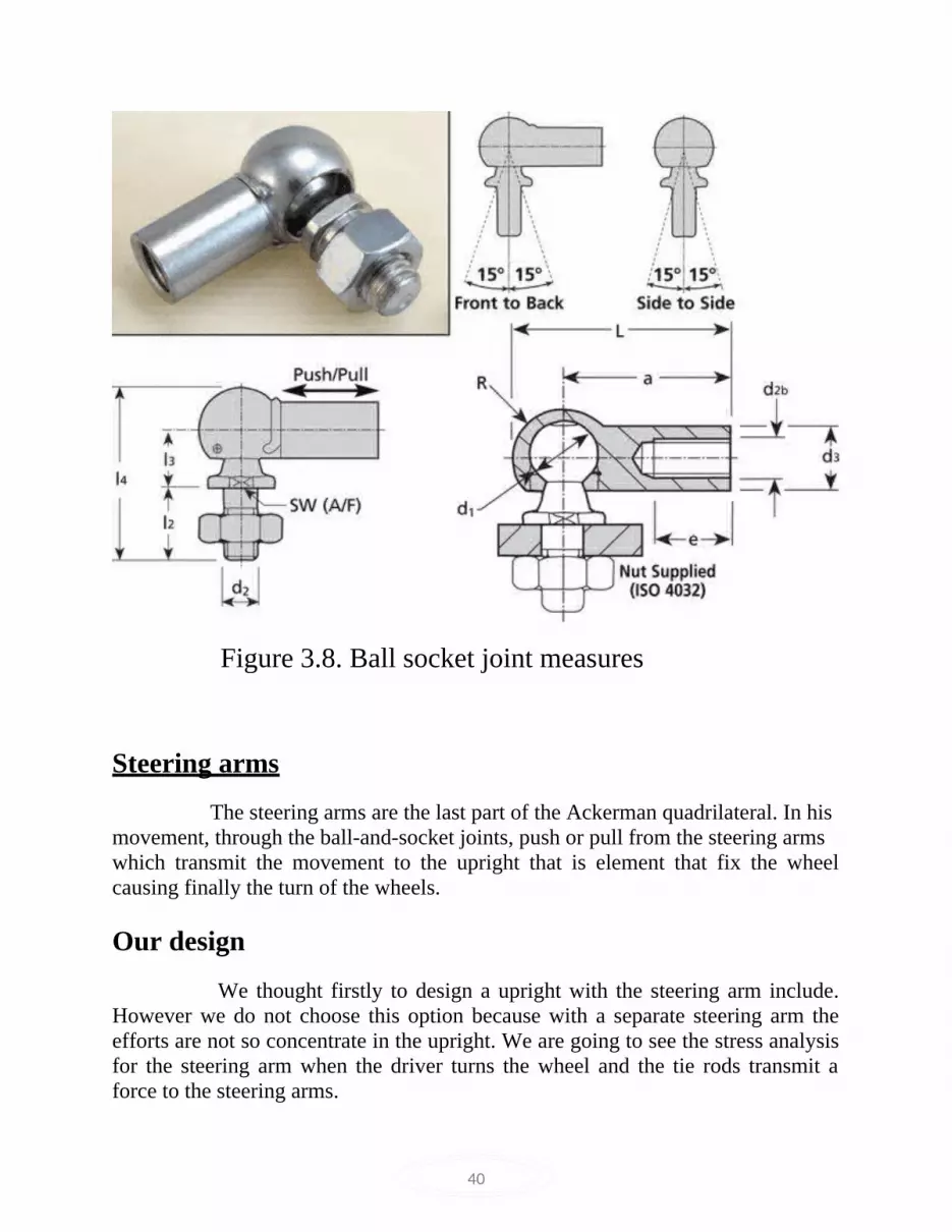
Figure 3.8. Ball socket joint measures
Steering arms
The steering arms are the last part of the Ackerman quadrilateral. In hismovement, through the ball-and-socket joints, push or pull from the steering armswhich transmit the movement to the upright that is element that fix the wheel causing finally the turn of the wheels.
Our design We thought firstly to design a upright with the steering arm include. However we do not choose this option because with a separate steering arm the efforts are not so concentrate in the upright. We are going to see the stress analysis for the steering arm when the driver turns the wheel and the tie rods transmit a force to the steering arms.

41
Figure 3.9. Steering arm in solid works

42
4. Design process results and discussions
43
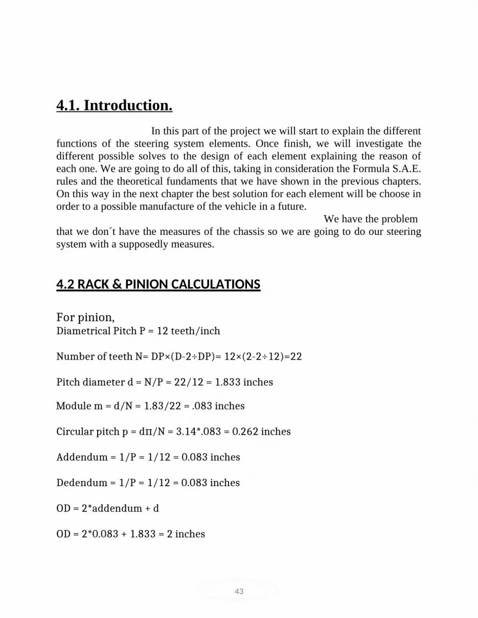
4.1. Introduction. In this part of the project we will start to explain the different functions of the steering system elements. Once finish, we will investigate the different possible solves to the design of each element explaining the reason of each one. We are going to do all of this, taking in consideration the Formula S.A.E. rules and the theoretical fundaments that we have shown in the previous chapters. On this way in the next chapter the best solution for each element will be choose in order to a possible manufacture of the vehicle in a future. We have the problem that we don´t have the measures of the chassis so we are going to do our steering system with a supposedly measures.
4.2 RACK & PINION CALCULATIONS
For pinion, Diametrical Pitch P = 12 teeth/inch
Number of teeth N= DP×(D-2÷DP)= 12×(2-2÷12)=22
Pitch diameter d = N/P = 22/12 = 1.833 inches Module m = d/N = 1.83/22 = .083 inches
Circular pitch p = d /N = 3.14*.083 = 0.262 inches π
Addendum = 1/P = 1/12 = 0.083 inches
Dedendum = 1/P = 1/12 = 0.083 inches
OD = 2*addendum + d
OD = 2*0.083 + 1.833 = 2 inches

44
For rack,
p’ = 0.262 inches
p’ = p*cosα
Here, α is pressure angle
p’ = 6.3/22 inches
So (6.3/22)*cos = 0.262 α
So, α = 24 degrees
ENGAGEMENT OF RACK AND PINION
Casing inner diameter = 25.4 mm Rack diameter = 22 mm
Radial clearance = (25.4 – 22)/2 = 1.7 mm
Sleeve thickness = 1mm
STEERING KNUCKLE
Length of knuckle = 8.5”
The plate used is 4” wide and .5” thick.
Kingpin Angle or Steering Inclination Angle (SIA) = 12 degrees (To ensure smaller scrub radius and hence more responsive steering)
45
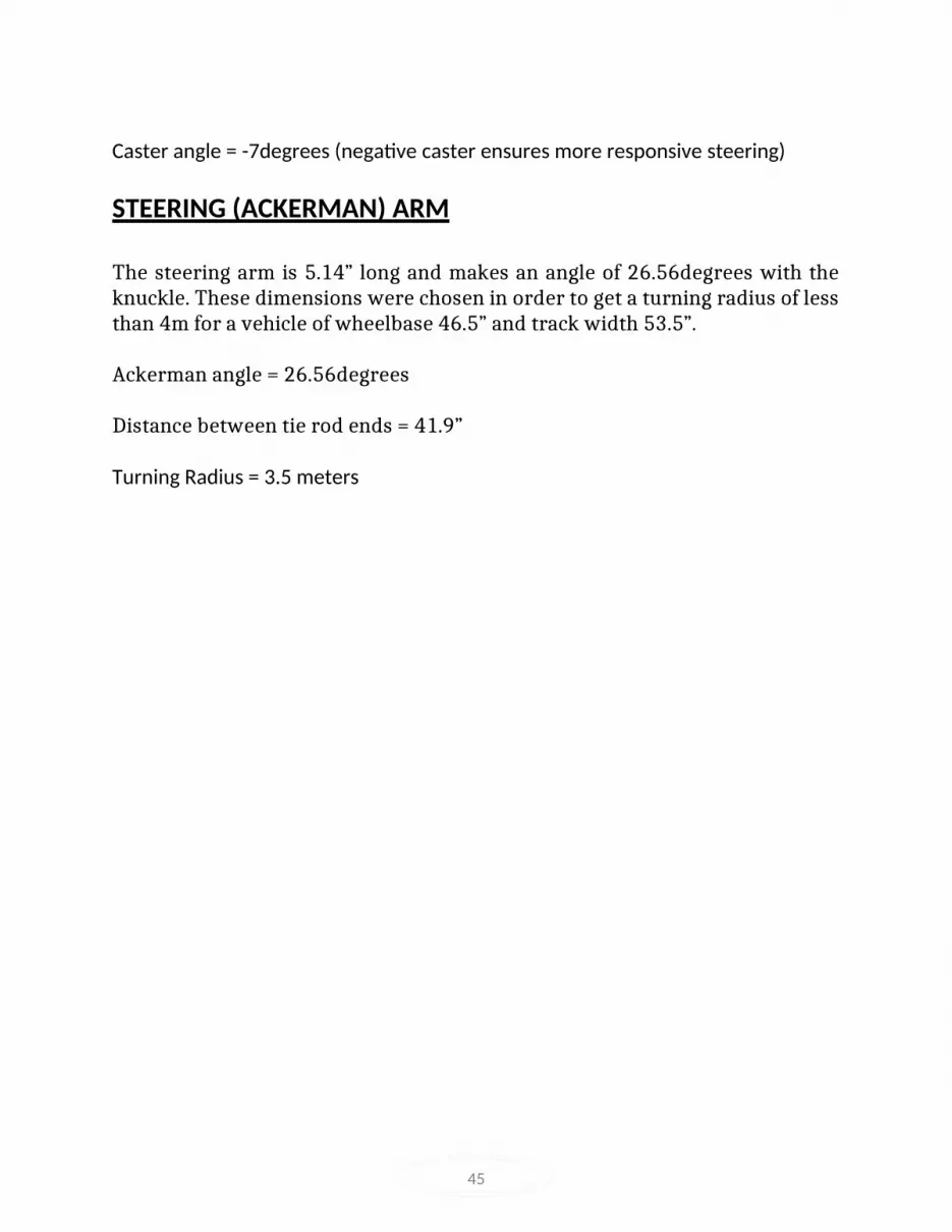
Caster angle = -7degrees (negative caster ensures more responsive steering)
STEERING (ACKERMAN) ARM
The steering arm is 5.14” long and makes an angle of 26.56degrees with the knuckle. These dimensions were chosen in order to get a turning radius of less than 4m for a vehicle of wheelbase 46.5” and track width 53.5”.
Ackerman angle = 26.56degrees
Distance between tie rod ends = 41.9”
Turning Radius = 3.5 meters

46
4.3. Description of the steering system elements In this chapter we be able to see the elements which to made up the steering system of one car and more in detail which are used in a competition vehicle. The weight of the car has importance on the performance of the car since depending of the weight the car has a different performance on the road. So we can distinguish in two parts different elements of the car: The elements which belong to the hang weight and the other that belong to the not hang weight. The not hang weights: is the part of the total weight of the car which is not support by the suspension. This weight support all the disruptions of the road so we try to reduce this weight the much as possible
- Rims
- Upright
- Brakes
- The bearings, springs and shocks absorbers (elements of the Suspension)
The hang weight: Is the weight that is supported by the suspension. This part is the heavier part of the car.
- Steering box
- Steering column
- Steering wheel
- Chassis, engine, driver, fuel, bodywork and one part of the suspension.
47
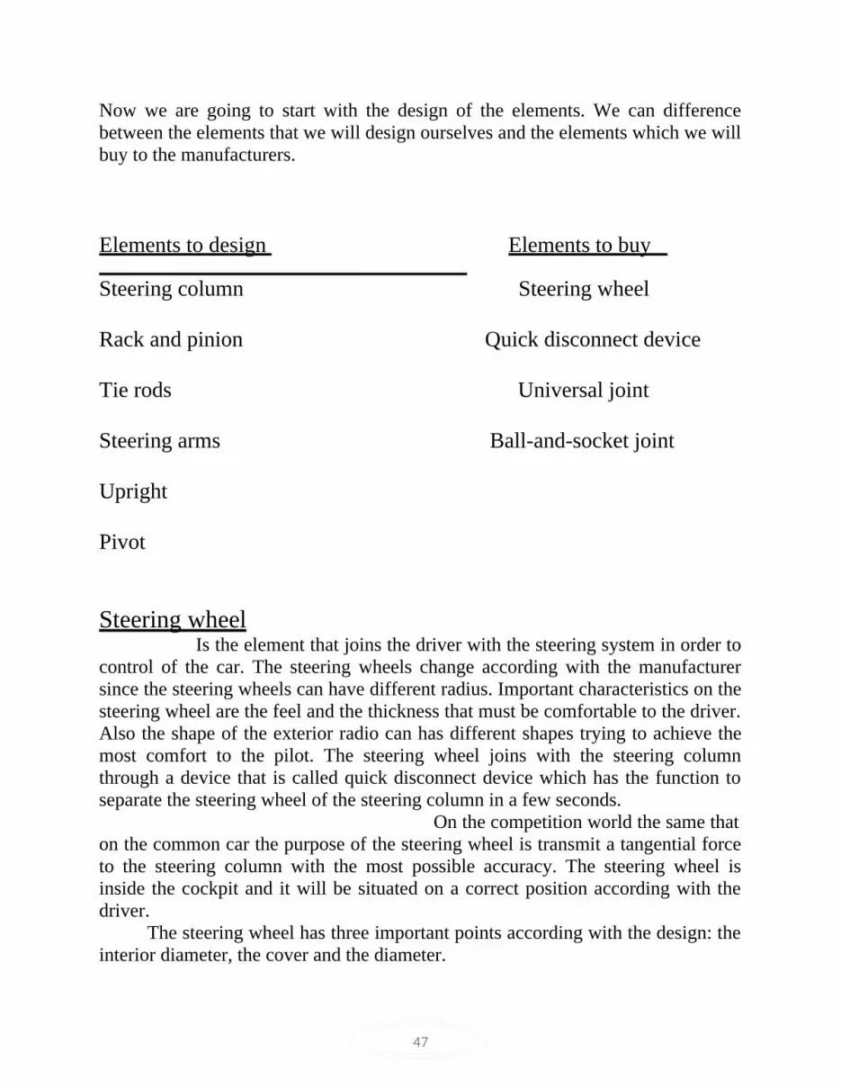
Now we are going to start with the design of the elements. We can difference between the elements that we will design ourselves and the elements which we will buy to the manufacturers.
Elements to design Elements to buy Steering column Steering wheel
Rack and pinion Quick disconnect device
Tie rods Universal joint
Steering arms Ball-and-socket joint
Upright
Pivot
Steering wheel Is the element that joins the driver with the steering system in order to control of the car. The steering wheels change according with the manufacturer since the steering wheels can have different radius. Important characteristics on the steering wheel are the feel and the thickness that must be comfortable to the driver. Also the shape of the exterior radio can has different shapes trying to achieve the most comfort to the pilot. The steering wheel joins with the steering column through a device that is called quick disconnect device which has the function to separate the steering wheel of the steering column in a few seconds. On the competition world the same that on the common car the purpose of the steering wheel is transmit a tangential force to the steering column with the most possible accuracy. The steering wheel is inside the cockpit and it will be situated on a correct position according with the driver. The steering wheel has three important points according with the design: the interior diameter, the cover and the diameter.

48
The steering wheel cover is also important because decrease the tiredness of thedriver if the friction with the gloves is high preventing the slide between the steering wheel with the gloves of the pilot when he is turning. A good election for the cover is suede because is hardwearing and have good friction properties when joins with the gloves of the pilot which usually also are made of suede. The diameter of the steering wheel determine the easily to drive the car. The tangential force applied over the steering wheel is between 20 and 200 N. This force depends on the position of the wheels according with the pilot. The pilot applied the force on the exterior diameter of the steering wheel so the momentum applied on the steering column will increase if we increase the radio of the steering wheel although the applied force have the same value. But by other a big exterior diameter will cause problems at the time to turn it inside a cockpit that has a limited size. In order to adapt the steering wheel to the cockpit on a correct position the most of the manufacturers create the steering wheels with the down part horizontal in order to achieve more distance between the legs of the pilot and the steering wheel.
We will chose this kind of design because is a perfect model for the positionof the pilot in a competition car where the pilot is with their legs full-length save. Once we have established the kind of design of the steering wheel, finally we are going to choose it. We have three possibilities to choose the steering wheel:
Possible solution 1: The first possibility is Sparco 015P260F:
Diameter: 260 mm Figure 4.1. Sparco steering wheel Grip: a good grip of suede

49
Possible solution 2: The second possibility is Sparco 015P310:
Dimensions: 310 * 260 mm
Grip: a good grip of suede
Figure 4.2. Sparco steering wheel
Possible solution 3:
The third possibility is OMP Indy:
Dimensions: 250 * 200 mm
Grip: black suede crown
Figure 4.3. Sparco steering wheel

50
Steering wheel selected: Once analyze the possibilities to choose the steering wheel, finally we have chosen the solution 3 OMP Indy because between the three possibilities it is cheapand overall the measures are the best to adapt to our cockpit. It has 200 mm in vertical direction and 250 mm in horizontal direction, furthermore the down part is horizontally o allow more space between the driver with the steering wheel. Now we are going to talk about the position of the steering wheel. According with the Formula S.A.E. rules, the exterior diameter must be down of the safety front hoop. The most convenient at the time to fix the position of the steering wheel is to maximize the distance with the legs of the pilot. Furthermore we bear in mind that the arms of the driver will not be totally on a straight line making an angle with the steering wheel bigger than 90º degrees.
Figure 4.4. Steering wheel angle
In our case this angle will be Ɵ = 90º + 15º = 105º

51
So now with the calculations we will be able to calculate the position of the steering wheel.
Figure 4.5. Measures Calculus
Showing this picture with the approximately measures of a driver, we can situatethe steering wheel in the cockpit.
Horizontally position: X4 + X5 + X6 = 32.84 + 30.42 + 10 = 73.26 cm
Vertically position:
Y1’’ = 43.94 cm
Checking the design:
If the diameter steering wheel in vertical position = 20 cm.
Y1’’ – Y2 – 20/2 = 15.14 cm

52
It is the distance of the space between the driver with the steering wheel agood measure for the comfort of the driver.
Steering column
This torsion bar joins the steering wheel with steering box through the quick disconnect mechanism. This bar only support the torsion effect produced by the turn of the steering wheel so it is not necessary a high quality steel. Also appears short compression efforts when the pilot leaning on the steering wheel, but are insignificant. In order to do the design of the steering column we will see the Formula S.A.E. rules and the effort analysis. According with the Formula S.A.E. rules the steering column cannot be one bar with only one direction due to different aspects. One of this is the safety of the driver since in case of accident, on a front crash, if the steering column only has on direction it will be easy that go out in direction to the pilot being very dangerous. The other aspects depend on the design for the comfort of the driver. Using a universal joint we can join two parts of the steering column making an angle allowing increase the distance between this element and the legs of the pilot and also increase the entry pinion angle into the steering box.
Our design Measures: we will design a steering column with a diameter of 18 mm a very normal measure in this kind of cars and which will be fit with our steering box perfectly. The thickness will be 2 mm since the steering column is a hollow bar.
Material: The steering column support torsion efforts so we do not need a highQuality steel. We will use SAE 1015.

53
Figure 4.6. AISI 1015 steel
Situation:

54
The steering column will start on the steering wheel until the universaljoint that is fixed with the chassis. Here it is produced the change of angle on thesteering column and starts the second part of the element that join the universal joint with the steering box.
Universal joint
This kind of joint is very utilized on the self-propulsion industry in order tomanufacture the steering columns, keeping the torque between bars with differentangles.
The most common kind of these devices for short angles between bars is the pinand block which works efficiently with angles bigger than 35º degrees.

55
Figure 4.7. Universal joint
The most of the universal joints for the competition require a bar of ¾ inches with a plane final in order to transmit the torque through the join.

56
5. DRAWING AND ANALYSIS

57
We can see in the picture, the deformation is produced in the joint with the tierod and with the force that we have applied the steering arm support the effort correctly because have a maximum deformation of 2.031e-002 mm.
Figure 5.1. Stress analysis in solid works of the steering arm

58
Upright
There are two kinds of uprights: the front and the rear uprights. Both are quite different since have different tasks on the car. The front uprights turn around the pivot and move the wheel due to the force that has transmitted the steering wheel. Furthermore the upright have two more functions: to fix the wheel and join the wheel with the suspension arms.
These elements must be very stiff in order to support the knocks that in frequently occasions will be very violent but at the same time they must be sufficiently tough in order to do not finish braked.
Our design We have designed, as we have said before, the upright separately of the steering arm in order to decrease the efforts on this element. By other hand we have designed the upright in order to be light. Finally the last parameter, we are going to design the upright inside a rim of 13 inches.

59
Figure 5.2. Upright in solid works
Now we are going to see the stress analysis hen we apply the force.
Front upright

60
Figure 5.3. Stress analysis of the upright
Back upright

61
Figure 5.4. Stress analysis of the upright

62
The displacement
Figure 5.5. Displacement

63
When we apply the force on the steering arm this one transmit the force to the upright and as we can show in the picture the maximum deflection is 8.154e-002 mm.
The assembly:

64
Figure 5.6. Assembly
6. APPLICATIONS

65
A rack and pinion is a type of linear actuator that is used for the conversion of rotary motion to linear, or vice versa. The circular “pinion” engages teeth on a linear gear bar or “rack.” An example of its use is in rack-and-pinion steering in automobiles. The pinion is attached to the bottom end of the steering column and turns with the steering wheel. The rack meshes with the pinion and is free to move left and right in response to the angular input at the steering wheel.
Rack and pinion steering, basically combines the steering box and center link into one unit. The steering wheel, through the steering column, is directly connected to the rack. Inside the steering rack is a pinion assembly that moves a toothed piston, which in turn moves the steering gear.
One end of the inner tie rod ends is connected to each end of this piston and the other end is connected directly to the outer tie rod end. The inner tie rod end is actually threaded into the outer tie rod end and can be rotated to make adjustments during a wheel alignment.
Rack and pinion steering is almost always used with a strut suspension system. The bottom of the steering knuckle still pivots on a lower ball joint, but the top of the knuckle is connected to the strut assembly. In this system, the outer tie rod end is connected to an arm on the strut housing itself.
The advantage of rack and pinion steering is that it's more precise than the mechanical system. By reducing the number of parts and pivot points, it can more accurately control wheel direction, making the steering more responsive. The disadvantage of a rack and pinion steering system is that it's prone to leakage, requiring replacement of the steering rack assembly.
The rack is supported at the other end in the rack housing, or tube, by a bush, normally of nylon. Nylon is used because it has a low coefficient of friction, and low wear rates.
The pinion is supported by 2 bearings in the rack housing. These bearings are pre-loaded to keep the pinion in the correct position, relative to the rack, and to eliminate free play.

66
A rack-and-pinion steering box is normally lubricated by grease.
Each end of the rack is protected from dirt and water by a flexible, synthetic, rubber bellows, attached to the rack housing and to the tie rod. The bellows extends and collapses, as the tie-rods move away from, and towards the housing, as the rack moves.
On some vehicles, both bellows are interconnected by a tube so that as the steering wheel is moved from side to side, air is transferred from the collapsing bellows side to the expanding bellows side.
Rack-and-pinion type steering gears are used because their construction makes them compact and light-weight.
Their steering response is very sharp, because the rack operates directly on the steering knuckle.
And there is very little sliding and rotation resistance, which gives lighter operation.

67
7. ADVANTAGES&
DISADVANTAGES

68
ADVANTAGES When comparing steering systems we really only need to think about two types--standard mechanical steering and rack and pinion steering. The standard mechanical steering system is either power assisted or non-power. Rack and pinion is almost always power assisted. There are advantages to both, but there are some significant advantages for rack and pinion that should be considered when comparing cars.
1. Fewer Parts
Rack and pinion steering tends to be more precise because there are fewer parts and pivot points. Because of this, the steering is more responsive and easier to control.
2. Lighter
Reducing the number of parts in a system also reduces the weight. A few pounds here or there may not seem like a big thing but with fuel economy or racing, every pound counts.
3. Road Feel
Driving on wet or icy roads can be tricky. A rack and pinion steering system gives us better "road feel," which makes this type of driving a little easier. It gives us quicker and better feedback than a standard system.
4. Repair
Repairing a rack and pinion steering system tends to be easier than a traditional system. There are two reasons for this. First, there are fewer moving parts so fewer to fail and need repairing. Second, it is the most common system, so most mechanics should be familiar with it; you do not need a specialist for repairs.

69
Disadvantages
Rack and pinion steering is used in many cars. Essentially, the steering wheel turns a round gear -- the pinion -- which in turn moves a straight bar with gear teeth -- the rack -- from side-to-side to turn the wheels. It is a simple arrangement, but it does have some disadvantages.
1. Leakage
Because of the simplicity of the system, rack and pinion steering requires fewer parts to function properly. However, this places a greater strain on the individual parts, and the wear can cause leakage, requiring replacement of the rack assembly.
2. Less Durability
When installed in a four-wheel-drive vehicle, rack and pinion steering can cause problems when driving off-road. While this simple system provides responsive handling on paved roads, the greater force required to turn the wheels on drastically uneven ground can cause it to wear out much more quickly
3. Vibration
Its simpler construction and reduced number of parts help rack and pinion systems provide more road feel than other steering mechanisms. However, this more intimate connection with the road can also transfer more noise and vibration to the driver and passengers.

70
8. Project Scope

71
Project Scope is the required step to gain knowledge and understanding on the main focus on the project.
The project scopes are:-
a) Investigation of the problem. In this process, the main idea is to find the problems that occur on the steering system. Identifying latent or hidden problems on the buggy’s steer system and then list down the possibility solution for solving the problem.
b) Set target specifications Base on steering types and benchmarks (Benchmarking is information on competing products gathered to support the positioning). Develop metrics for each types of steering to help identify the specification of the system. Set ideal and acceptable values for each steer system.
c) Conceptualization. Concentrate on designing the assembly line and create custom part for the steer system by making simple sketches known as thumbnail sketches of each concept. This is the brainstorming on the designing of costume made part that will fulfill the required specification needed for the part.
d) Further refinement and final concept selection. Draw in 2D or 3D for part studies and for testing to the proposed product features and functionality (solid work).The Drawing will be analyze by using COSMOS Xpress to get the required information such as maximum stress, minimum stress and the factor of safety of each part.
e) Control drawing In this stage, the main focus is to gain information on document functionally, features, size, surface finish and key dimension on each part. This information is helping in fabricate the final design models for the project.

72
9. Conclusions.

73
Finally we have finished our design. We have to design the steering system for aformula S.A.E. car describing all the elements and choosing the better options to make it and to can adapted in a total project to a car with the characteristics of Formula S.A.E.
We started the project investigating about this kind of vehicles and about the steering system in general in a car. The first step was to know the formula S.A.E. rules and the theoretical fundaments about the steering as Ackerman or the Jeanteaud Trapezium. These concepts have been in mind during the design of our elements.
The elements rack and pinion, tie rods, steering arms and the upright we have determinate the Jeantaud trapezium and we have obtained the connection between the turn angles of the front wheels with the wheelbase and the tracks. According to Jeantaud studies we have design the elements in order to the extensions of the lines that join the end of the tie rods with the point where the steering arm is joined with the upright finish on the center of the rear track in order to achieve a good performance of the vehicle.
As regards the elements, we have done the difference between the elements which will be designed by ourselves and the elements which we will buy to the manufacturers.
Talking about the elements which have been designed by ourselves we can say that we have done this task basing our designs in three parameters: comfort and safety for the pilot, improve the features of the car and the price, trying that the design is the cheapest as possible.
To situate the steering wheel and the steering column we have make a study between seven people in order to achieve the measures of a possible pilot. Once finish this task, we have calculate the position of the steering wheel achieving that the pilot drive in a good position avoiding an extreme tiredness and respecting the SAE rules that say the top of the steering wheel must be no higher than the top-most surface of the front hoop.
For the steering column we have calculated the torque produced in the element when the drive applies the maximum force to turn the wheels producing fatigue effort on the steel of 93.58 MPa and the steel chosen by our is the SAE 1015 that support until 386.1 MPa so the design for the steering column is correct.

74
To design the rack and pinion we had to check for a steering column with 18mm in diameter which was the most suitable design. We needed to achieve a largeradvance distance for the rack with the same turn in the pinion. We have done fourDesigns with two pinions and two racks. With the first design we achieve a distance of 76.92 cm, with the second 80 cm, with the third 73.3 cm and with the fourth 83.9 cm so we have chosen the fourth design since with the same turn of the steering wheel we achieve a larger advance distance of the rack in consequence a high value of the wheels turn. On this way we improve the steering system because in a curve the pilot has not to turn a lot the steering wheel so the tiredness in the driving will decrease.
We thought to do a foundation steering arm with the upright but finally we chose to separate in two pieces the steering arm and the upright in order to improve the features of the car. With the first design appear a lot of efforts in the upright so we chose separate in two pieces. As we shown in the previous chapter with our design the upright suffer a flexion efforts but with a very short displacement for the high value of the force, transmitted by the tie rods, which we have calculated with an excessive weight and friction coefficient to establish a safety coefficient. The weight is a parameter that always is important decrease as much as possible and with this design we achieve that the upright is lighter than the other.

75
10. References.

76
WEB PAGES:
www.students.sae.org/competitions/formulaseries
www.fsae.com
www.circulaseguro.com
http://www.tecnun.es/fstudent http://www.formulastudent.com
http://www.autocity.com
http://www.scribd.com/doc/2561082/Tema8Torsion
www.streetsideauto.com
www.efunda.com
www.scribd.com
BOOKS
Shigley et. al, Mechanical Engineering Design B. S. N. Parashar, R. K. Mittal, Elements of Manufacturing Processes Thomas D. Gillespie, Fundamentals of Vehicle Dynamics Milliken & Milliken, Race Car Vehicle Dynamics
Carroll Smith, Tune to win
Ghosh & Malik, Manufacturing Science

77
11. List of Figures
Figure 1. Mechanical Steer Systems 15
Figure 2. Mechanical Steer Rack inside View 16
Figure 3. Ackerman principle 18 Figure 4. Jeantaud trapezium 19
Figure 5. Jeantaud trapezium 20
Figure 6. Turn radius of the wheels 21
Figure 7. Wheels angles 22
Figure 8. Toe rod 24
Figure 9. Camber angle 26
Figure 10. Caster angle 28
Figure 11. Drift angle 29
Figure 12. Drift angle vs. transversal force 30
Figure 13. Rack and pinion 32
Figure 14. Rack and pinion lateral 34
Figure 15. Rack and pinion front 34
Figure 16. Rack and pinion parameters 36
Figure 17. Tie rod 38

78
Figure 18. Ball socket joint 38
Figure 19. Ball socket joint measures 39
Figure 20. Steering arm in solid works 40
Figure 21. Sparco steering wheel 47
Figure 22. Sparco steering wheel 48
Figure 23. Sparco steering wheel 48 Figure 24. Steering wheel angle 49
Figure 25. Measures Calculus 50
Figure 26. Universal joint 53
Figure 27. Stress analysis in solid works of the steering arm 55
Figure 28. Upright in solid works 56
Figure 29. Stress analysis of the upright 57
Figure 30. Stress analysis of the upright 58
Figure 31. Displacement 59
Figure 32. Assembly 60

79
12. List of Tables
Table 1. Rack and pinion SAE 1045 35
Table 2. AISI 1015 steel 52

80
13. Appendices
13.1. Glossary.
13.2. APPENDIX A
13.3. APPENDIX B

81
13.1. Glossary .
• Wheelbase: it is the distance between the front track and the rear track.
• Track: it is the distance between the pivots of the right and left wheels.
• Roll center: is the notional point at which the cornering forces in thesuspensions are reacted to the vehicle body.
• Torsion bar: is a bar that supports torsion efforts. These efforts areproduced by a tangential force in one point that is not the center on acircular bar.
• Single-seater: it is a car in which only can be one person. Normally in thiskind of cars the place where drive the pilot is called cockpit.
• Friction: force that appears contrary to the movement due to the contactbetween two surfaces.
• Gear assembly: It is a mechanism in which two elements transmitte amovement between them through, a part of the pieces that is called teeth.
• Power assisted steering: it is a mechanism used on the steering system tomake the turn on the steering wheel easy because the driver has to do lessforce. Principally there are two kinds: hydraulic and electrical.
• Front wheel drive: is a form of engine/transmission layout used in motorvehicles, where the engine drives the front wheels only. Most modernfront-wheel drive vehicles feature a transverse engine, rather than theconventional longitudinal engine arrangement generally found in rear wheeldrive and four-wheel drive vehicles.
• Front wheel assembly: is the joint of the elements of the front part of thecar.
• Rear wheel assembly: Is the joint of the elements of the rear part of theCar.

82
• Not hang weight: It is the part and elements of the car weigh that are notsupported by the suspension system.• Hang weight: it is the part and elements of the car weight that aresupported by the suspension system.
• Torque: is the tendency of a force to rotate an object about an axisfulcrum, or pivot. Just as a force is a push or a pull, a torque can be thoughtof as a twist.
• Rim: It is the part of the wheel generally made of aluminium or steel thatis inside of the tire supporting it.
• Instant rotation center: also called instantaneous centre, for a plane figuremoving in a two dimensional plane is a point in its plane around which allother points on the figure, for one instant, are rotating. This point itself isthe only point that is not moving at that instant.
• Kinematic: is the science that studies the movement of a particle on thespace.
• Dynamic: is the science that study the movement of a particle produced by a force.
• Aerodynamic: is a branch of dynamics concerned with studying themotion of air, particularly when it interacts with a moving object.Aerodynamics is a subfield of fluid dynamics and gas dynamics, with muchtheory shared between them.

83
13.2 APPENDIX A
The diagram below outlines the important geometry in determining the motions of the wheels in a vehicle that uses Ackerman steering geometry. Ackerman geometry is an interesting problem because it is dynamic. That is to say that we have two components moving together – the left and right steering knuckles, but the relationship between their motion changes as we move them.

84
Let’s look at the important distances and angles. The two most fundamental distances are the wheel base of the car and the kingpin center to center distance. If we draw two lines representing the wheelbase and the distance from the car’s center line to one of the king pins, we can make a triangle. By design, the line that goes through the centers of the steering arm forms the hypotenuse of this triangle. See below.
Note that the angle with its vertex at A is 90 degrees by design. Note that the line that forms the Ackerman angle with the hypotenuse is parallel with the thrust line. Because of this, we can say that angle B and the Ackerman angle are similar, so if we know one, we know the other. Clearly,
TAN Angle B = king pin center to center distance / 2 Wheelbase Wheelbase
C
Ackerman Angle
A B

85
Wheelbase
The problem is that we know the distances and are trying to find angle B. We need the inverse function ARCTAN. Rearranging, we get:
ARCTAN [king pin center to center distance / 2 ] = Angle B
Wheelbase
We can pick distances, turn the crank and find Angle B and by extension, the Ackerman Angle. According to our design, Wheel base = 46.5” King pin to king pin distance = 46.5”.
ARCTAN (46.5” / 2 ) = Angle B 46.5”
ARCTAN (.5) = 26.56º

86
To find the length of the tie rod, we can decompose the trapezoid ABCD into a rectangle and two triangles.
The distance between the tie rod ends (effective steering system length) is equal to the king pin to king pin center distance minus distance Y on each side. Ackerman

87
arm radius has been chosen to be 5.14”. Well, recall that the SIN of an angle is the ratio between the side opposite the angle and the hypotenuse i.e.
SIN 26.56º = Y/5.14”Y = 2.3” Now, LT = DKC – 2*RAA*SIN Ackerman Angle
Where:
LT is distance between the left and right tie rod ends
DKC is the distance between kingpins center to center
RAA is the radius of the Ackerman Arm
LT = 46.5” – 2*5.14”*SIN 26.56º
LT = 41.9”
Turning circle radius = (track/2) + (wheelbase/sin (steer angle))
= (53.5/2) + (46.5/sin24.72) inches
= 3.5m

88
13.3 APPENDIX B
STERRING KNUCKLE

89
STEERING (ACKERMAN) ARM

90

91
SHAFT

92

93
RACK
PINION

94
RACK AND PINION ASSEMBLY

95


