Embed Size (px)
Citation preview
Finite Element Modeling of Soft Fluidic Actuators:Overview and Recent Developments
Matheus S. Xavier,* Andrew J. Fleming, and Yuen K. Yong
1. Introduction
Soft robotics has experienced an exponential growth in publica-tions in the last two decades.[1] Unlike rigid conventional manip-ulators,[2,3] soft robots based on hydrogels,[4,5] electroactivepolymers,[6,7] and elastomers[7–9] are physically resilient and canadapt to delicate objects and environments due to their conformaldeformation.[10,11] They also show increased safety and dexteritycan be lightweight and used within constrained environments withrestricted access.[12,13] Many soft robots have a biologically inspireddesign coming from snakes,[14–17] worms,[18–20] fishes,[21–24]
manta rays,[25,26] and tentacles.[27–29] The scope of applicationsincludes minimally invasive surgery,[30,31] rehabilitation,[32,33]
elderly assistance,[34] safe human–robotinteraction,[35,36] and handling of fragilematerials.[37,38] Important features of softrobotics design, fabrication, modeling, andcontrol are covered in the soft roboticstoolkit.[39,40]
The building blocks of soft robots are thesoft actuators. The most popular categoryof soft actuator is the soft fluidic actuator(SFA), where actuation is achieved usinghydraulics or pneumatics.[8,41] These actua-tors are usually fabricated with silicone rub-bers following a 3D molding process,[42]
although directly 3D printing the soft actua-tors is also possible.[43,44] Silicone rubberis a highly flexible/extensible elastomerwith high-temperature resistance, low-temperature flexibility, and good biocom-patibility.[45] Elastomers can withstand verylarge strains over 500% with no permanentdeformation or fracture.[46] For relativelysmall strains, simple linear stress–strainrelationships can be used, and two of the
following parameters can be used to describe the elastic proper-ties: bulk compressibility, shear modulus, tensile modulus(Young’s modulus of elasticity), or Poisson’s ratio.[45] For largedeformations, nonlinear solid mechanic models using hyperelas-ticity should be considered.[8,32,47–50] Due to the strong nonli-nearities in SFAs and their complex geometries, analyticalmodeling is challenging.[51] A brief review of the analytical meth-ods for modeling of soft robotic structures is provided in thefollowing.
1.1. Analytical Modeling of Soft Actuators
The majority of soft/continuum robots with bending motion canbe approximated as a series of mutually tangent constant curva-ture sections, i.e., piecewise constant curvature.[52] This is aresult of the fact that the internal potential energy is uniformlydistributed along each section for pressure-driven robots.[53] Thisapproach has also been validated using Hamilton’s principle byGravagne et al.[54] As discussed by Webster and Jones,[52] thekinematics of continuum robots can be separated into robot-specific and robot-independent components in this approach.The robot specific mapping transforms the input pressures Por actuator space q to the configuration space κ,ϕ, l, and therobot-independent mapping goes from the configuration spaceto the task space x. The actuator space contains the length oftubes or bellows. The configuration space consists of the curva-ture κ, the angle of the plane containing the arc ϕ (also called
M. S. Xavier, Prof. A. J. Fleming, Dr. Y. K. YongPrecision Mechatronics LabSchool of Electrical Engineering and ComputingThe University of NewcastleCallaghan, NSW 2308, AustraliaE-mail: [email protected]
The ORCID identification number(s) for the author(s) of this articlecan be found under https://doi.org/10.1002/aisy.202000187.
© 2020 The Authors. Published by Wiley-VCH GmbH. This is an openaccess article under the terms of the Creative Commons AttributionLicense, which permits use, distribution and reproduction in anymedium, provided the original work is properly cited.
DOI: 10.1002/aisy.202000187
Many soft robots are composed of soft fluidic actuators that are fabricated fromsilicone rubbers and use hydraulic or pneumatic actuation. The strong non-linearities and complex geometries of soft actuators hinder the development ofanalytical models to describe their motion. Finite element modeling provides aneffective solution to this issue and allows the user to predict performance andoptimize soft actuator designs. Herein, the literature on a finite element analysisof soft actuators is reviewed. First, the required nonlinear elasticity concepts areintroduced with a focus on the relevant models for soft robotics. In particular, theprocedure for determining material constants for the hyperelastic models frommaterial testing and curve fitting is explored. Then, a comprehensive review ofconstitutive model parameters for the most widely used silicone rubbers in theliterature is provided. An overview of the procedure is provided for three com-mercially available software packages (Abaqus, Ansys, and COMSOL). Thecombination of modeling procedures, material properties, and design guidelinespresented in this article can be used as a starting point for soft robotic actuatordesign.
REVIEWwww.advintellsyst.com
Adv. Intell. Syst. 2020, 2000187 2000187 (1 of 18) © 2020 The Authors. Published by Wiley-VCH GmbH
azimuthal angle or angle of curvature) and arc length l(or s ∈ ½0, l�). Alternatively, κ or l can be replaced by the bendingangle θ or the radius of curvature r through the relations θ ¼ κsand κ ¼ 1=r.
The robot-independent mapping can be obtained with arcgeometry,[55,56] Denavit–Hartenberg parameters,[3,57,58] differen-tial geometry (Serret–Frenet frame),[55,59,60] integral representa-tion,[59,61,62] or exponential coordinates.[63] For the robot-specifictransformation, one must account for the transformationfrom input pressures to actuator lengths or input pressuresdirectly into configuration space. In the latter case, Suzumoriet al.[64,65] obtained the robot-specific transformation by linearanalysis based on the theory of infinitesimal elastic deformationand the constant curvature assumption. Under the constant cur-vature assumption, Drotman et al.[66] developed an analyticalexpression for the blocked force of a parallel bellows actuatorusing Castigliano’s method.
The piecewise constant curvature approach is practical wheninertia effects are negligible due to low speed and mass.[28] Toaccount for the mass of the actuator and external loading, modelsusing the Euler–Bernoulli equation[8,54,67] and the theory ofCosserat rods[68–70] have been considered.
The Euler–Bernoulli beam theory is used to model bendingactuators as ideal beams loaded with a pure moment at its edges,which originates from the axial component of the loadingpressure and is counteracted by the bending stiffness EI ofthe beam, where E is Young’s modulus, and I is the secondmoment of area.[8] The Euler–Bernoulli equation has beenapplied to the modeling of cylindrical actuators with eccentricvoid,[67,71] multimaterial asymmetry,[72] and omnidirectionalactuators.[65] However, this method is not applicable to largebending deformations or corrugated cross sections. In addition,Young’s modulus does not describe the complex stress–strainbehavior of most materials used in soft robotics.[8]
Many soft robots have a slender structure with one dimensionmuch larger than the other two; hence, they can be modeledusing the theory of Cosserat rods.[68–70] In the study given byTrivedi et al.,[73] a geometrically exact model is presented thataccounts for the large deformations and loading using conceptsfrom nonlinear elasticity and Cosserat rod theory for the manip-ulator dynamics. This modeling approach was shown to be tentimes more accurate than the constant curvature model for theOctArm manipulator when gravitational loading is considered.
An alternative is to use an empirical approach with energy-based inspiration, where the dynamic behavior of a bending actu-ator can be approximated by a lumped second-order dynamicequation.[14,74] The model parameters can be determined byleast-squares curve fitting[74,75] or system identification with aperiodic input signal.[76,77] Furthermore, a purely data-drivenapproach can be used to predict the bending angle of softactuators.[78]
1.2. Finite Element Method in Soft Robotics
Finite element modeling (FEM) provides an effective solution tohandling nonlinearities in soft robotics and avoids the need foran explicit analytical model. Furthermore, the FEM is not limitedto the slender structures required in the theory of Cosserat rods
or the modeling of bending motion using the piecewise constantcurvature assumption or Euler–Bernoulli beam theory. FEM hasfound many applications in soft robotics due to the following rea-sons:[51,79–81] 1) FEM can cope with the large deformations andmaterial nonlinearities during the pressurization of SFAs.2) FEM can be used to predict performance and evaluate thecapabilities and limitations of soft actuator designs under variousinputs. This rapid and efficient design framework reduces costand development time, because the fabrication of SFAs is verytime-consuming. 3) FEM can improve our understanding ofthe stress concentration and strain distribution in soft actuators.This feature leads to a better understanding of the influence oflocal strain on global actuator performance and can be used, forexample, to determine potential locations of fatigue. 4) FEM canhandle contact nonlinearities associated with surfaces that comeinto contact upon deformation.
1.3. Contributions and Outline of the Article
Recent review papers have covered different aspects of soft robot-ics design,[8,41] fabrication,[9,82] biological inspiration,[83,84] loco-motion,[85] actuation methods,[86,87] sensing,[88,89] kinematicmodeling,[52] control,[90,91] stiffening techniques,[92] and biomed-ical applications.[93,94] Despite the number of articles which useFEM, there is very little comparison of methods or guidelines forsuccessful modeling. This means that each new study oftenrequires significant trial and error to identify a compatiblemodeling and simulation procedure. Furthermore, these difficul-ties are compounded by the lack of a comprehensive database fornonlinear material properties of common silicone rubbers.
To address the first issue, different strategies and recommen-dations for analysis and design of SFAs with FEM are presentedusing Abaqus (Daussault Systèmes SE), Ansys (Ansys, Inc.), andCOMSOL Multiphysics (COMSOL Inc.). These recommenda-tions draw from procedures described in the literature andour group’s experience with FEM.
A step toward resolving the second issue is the July 2020 arti-cle of Marechal et al.,[95] where the authors present the mechani-cal characterization and the resulting material properties for awide set of commercially available silicone rubbers. Here, thematerial constants presented in the literature are compiledand serve as a starting point for soft roboticists in the modelingand design of soft robots.
This article first reviews the different categories of SFAs inSection 2. The continuummechanics background and hyperelas-tic models that underlie the modeling of soft actuators are intro-duced in Section 3. The strategies for characterizing theelastomeric materials used in the fabrication of soft actuatorsare discussed in Section 4. Section 5 provides an extensive reviewof the hyperelastic model constants in the literature for the mostpopular silicone rubbers within the soft robotics community.Using these model parameters, the FEM procedure can thenbe introduced. Section 6 presents an overview of the FEM pro-cedure using commercially available software. In Section 7,a comprehensive set of design guidelines for soft actuators is pre-sented based on results drawn from the literature and experi-ence. Finally, the challenges and opportunities of FEM forSFAs are discussed in Section 8.
www.advancedsciencenews.com www.advintellsyst.com
Adv. Intell. Syst. 2020, 2000187 2000187 (2 of 18) © 2020 The Authors. Published by Wiley-VCH GmbH
2. Soft Fluidic Actuators
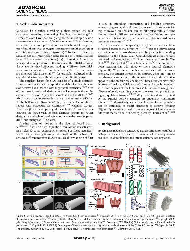
SFAs can be classified according to their motion into fourcategories: extending, contracting, bending, and twisting.[8,41]
These actuators have specifically engineered anisotropic flexiblestructures to achieve each of the four motions.[8,96] For bendingactuators, the anisotropic behavior can be achieved through theuse of multi-material, corrugated membrane (multi-chamber) oreccentric void asymmetries (Figure 1a).[8] In the first case, theactuator has different rubber compositions or a strain limitinglayer.[97] In the second case, folds (fins) on one side of the actua-tor expand under pressure. In the third case, the inflatable void ofthe actuator is placed off-center, leading to different layer thick-nesses in the actuator.[71] Combinations of the three scenariosare also possible; Sun et al.,[97] for example, evaluated multi-chambered actuators with fabric as a strain limiting layer.
The simplest design for SFAs consists of a single chamber.However, unless fibers are wrapped around the chamber, the actu-ator behaves like a balloon with high radial expansion.[48,98] Oneof the most investigated designs in the literature is the multi-chambered actuator. A popular example is the PneuNets,[32,47,99]
which consists of an extensible top layer and an inextensible butflexible bottom layer. Slow PneuNets (sPNs) use a block of siliconerubber with embedded air chambers,[97,99] whereas the fastPneuNets (fPNs) developed by Mosadegh et al.[47] contain gapsbetween the inside walls of each chamber (Figure 1c). Otherdesigns for multi-chambered actuators include the use of trapezoi-dal[48] and triangular[100] bellows.
Another common design is the fiber-reinforced actua-tor,[81,101,102] which draws inspiration fromMcKibben actuators,also referred to as pneumatic muscles. For these actuators,fibers can be arranged along the length of the actuator toachieve different motions (Figure 1d). Double wrapping of fiber
is used in extending, contracting, and bending actuators,whereas single wrapping of fiber can be used to introduce twist-ing. Moreover, an actuator can be fabricated with differentmotion types in different segments, thus combining multiplebehaviors. Fiber-reinforced actuators are also referred to asPneuFlex actuators.[38,103,104]
Soft actuators with multiple degrees of freedom have also beendeveloped. Bidirectional actuators[14–16,105] can be achieved usingsoft actuators with two chambers or by joining two bendingactuators via the bottom layer. Omnidirectional actuators wereproposed by Suzumori et al.[64,65] and further explored by Yanet al.,[106] Elsayed et al.,[80] and Khan and Li.[76] The omnidirec-tional actuator has with three or more internal chambers(Figure 1b). When three chambers are actuated with the samepressure, the actuator stretches. In contrast, when only one ortwo chambers are actuated, the actuator bends in the directionopposite to the pressurized chambers. These actuators have threedegrees of freedom, which are pitch, yaw, and stretch. Actuatorswith three degrees of freedom can also be fabricated using three(fiber-reinforced) extending actuators between two plates form-ing an equilateral triangle[107,108] (Figure 1g) in a design inspiredby the parallel bellows actuators in pneumatic continuumrobots.[27,35] Alternatively, cylindrical fiber-reinforced actuatorscan be combined in smart structures to achieve bending(Figure 1f ) as demonstrated in the one degree of freedom revo-lute joint mechanism in the study given by Skorina et al.[74,109]
3. Background
Hyperelastic models are considered that assume silicone rubber isisotropic and incompressible. Furthermore, all inelastic phenom-ena such as viscoelasticity and stress-softening are neglected.
Figure 1. SFAs designs. a) Bending actuators. Reproduced with permission.[8] Copyright 2017, John Wiley & Sons, Inc. b) Omnidirectional actuators.Reproduced with permission.[80] Copyright 2014, Mary Ann Liebert, Inc. c) Multi-chambered actuators. Reproduced with permission.[47] Copyright 2014,John Wiley & Sons, Inc. d) Fiber-reinforced actuators. Reproduced with permission.[102] Copyright 2017, PNAS. e) Bidirectional actuator. Reproduced withpermission.[75] Copyright 2017, IEEE. f ) One degree of freedom revolute joint. Reproduced under the terms of the CC-BY 4.0 License.[109] Copyright 2018.The authors, published by PLOS. g) Parallel bellows actuator. Reproduced with permission.[49] Copyright 2017, IEEE.
www.advancedsciencenews.com www.advintellsyst.com
Adv. Intell. Syst. 2020, 2000187 2000187 (3 of 18) © 2020 The Authors. Published by Wiley-VCH GmbH
3.1. Fundamentals of Continuum Mechanics
The deformation of a solid can be described by the relationshipbetween the spatial coordinate frame x (current configuration)and the material coordinate frame X (original configuration) as
x ¼ xðX, tÞ ¼ X þ u (1)
where u is the displacement vector.[110–112]
The deformation gradient is given by
F ¼ ∂x∂X
¼ Iþ ∂u∂X
¼
264
∂x∂X
∂x∂Y
∂x∂Z
∂y∂X
∂y∂Y
∂y∂Z
∂z∂X
∂z∂Y
∂z∂Z
375 (2)
F is the Jacobian matrix of the transformation from X to x;hence, J ¼ detðFÞ is the local volume scale factor. For an incom-pressible material, J ¼ 1.[110,111,113]
The polar decomposition theorem states that any second-ordertensor can be decomposed into a product of pure rotation (R) anda symmetric deformation tensor (U the right stretch tensor or Vthe left stretch tensor)
F ¼ RU ¼ VR, RTR ¼ RRT ¼ I (3)
Thus
FTF ¼ ðRUÞTRU ¼ UTU ¼ U2 ¼ C (4)
FFT ¼ VRðVRÞT ¼ VVT ¼ V2 ¼ B (5)
where C is the right Cauchy–Green deformation tensor, and B isthe left Cauchy–Green deformation tensor.[110–112] C and B admitthe same three principal invariants I1, I2, and I3 givenby[110,111,113]
I1 ¼ trðCÞ, I2 ¼12ðtrðCÞ2 � trðC2ÞÞ, I3 ¼ detðCÞ (6)
The stretch ratios λi represent the deformation of a differentialcubic volume element along the principal axes of a Cartesiancoordinate system.[112,114] They are given by the ratio of deformedlength (li) to undeformed length (Li), that is
λi ¼liLi, i ∈ 1, 2, 3 (7)
The three eigenvalues of U (or V), i.e., λ1, λ2, and λ3, are calledprincipal stretches. The corresponding eigenvectors of U givethree orthogonal directions in the material frame. Using theprincipal stretches, the principal invariants reduce to
I1 ¼ λ21 þ λ22 þ λ23, I2 ¼ λ21λ22 þ λ22λ
23 þ λ21λ
23, I3 ¼ λ21λ
22λ
23 (8)
A hyperelastic material model relies on the definition of astrain energy function W (or strain energy density), which isthe amount of energy stored elastically in a unit volume of mate-rial under the state of stretch specified by λ1, λ2, and λ3.
[110,111,113]
For an incompressible material, I3 ¼ 1 and W ¼ WðI1, I2Þ.Material models using these functions are discussed inSection 3.2.
For an isotropic incompressible hyperelastic material, stress–stretch relations are obtained from the strain energy function byvirtual work considerations
σ ¼ 2�λ21
∂W∂I1
� λ�21
∂W∂I2
�þ p (9)
where σ is the principal Cauchy stress, and p is the hydrostaticpressure (indeterminate Lagrange multiplier), which can bedetermined from the equilibrium equations and boundary con-ditions. Note that p does not represent the actual pressure on thechosen surfaces.[45,110,115] For a uniaxial tensile experiment,λ1 ¼ λ, λ2 ¼ λ3 ¼ 1=
ffiffiffiλ
p, and those boundary conditions are
σ2 ¼ σ3 ¼ 0. Then, the stress as a function of the stretchis[45,110,113,114]
σ ¼ 2�λ2 � 1
λ
��∂W∂I1
þ 1λ
∂W∂I2
�(10)
3.2. Hyperelastic Material Models
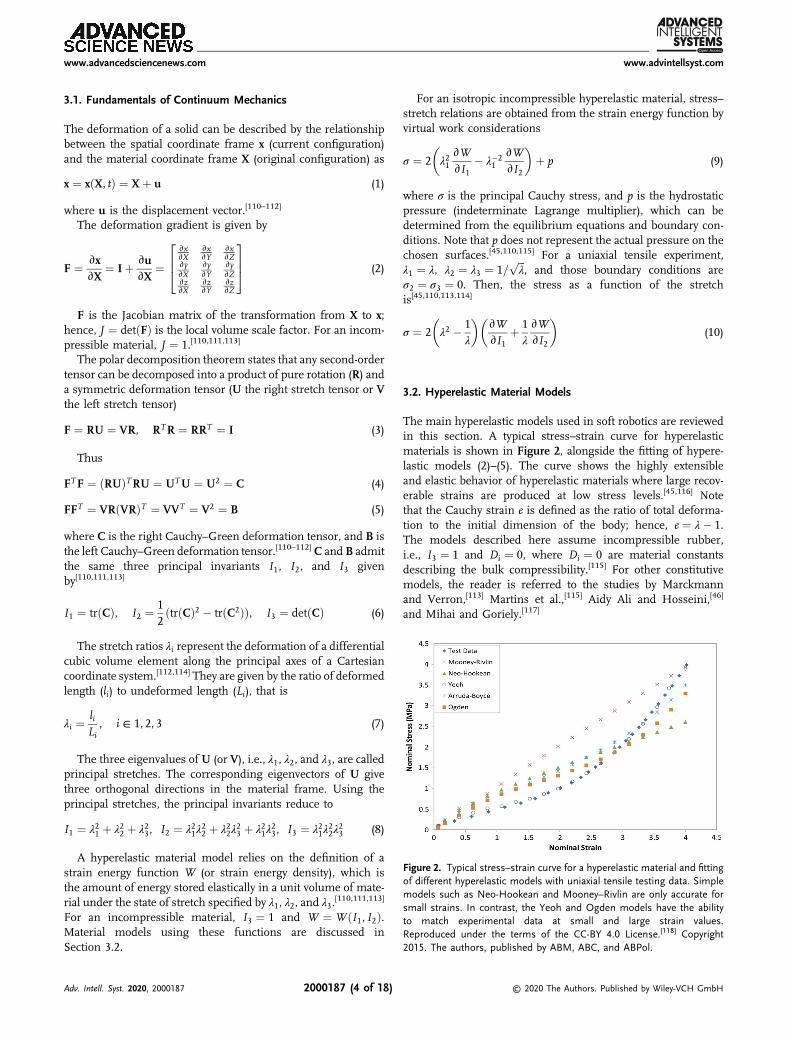
The main hyperelastic models used in soft robotics are reviewedin this section. A typical stress–strain curve for hyperelasticmaterials is shown in Figure 2, alongside the fitting of hypere-lastic models (2)–(5). The curve shows the highly extensibleand elastic behavior of hyperelastic materials where large recov-erable strains are produced at low stress levels.[45,116] Notethat the Cauchy strain e is defined as the ratio of total deforma-tion to the initial dimension of the body; hence, e ¼ λ� 1.The models described here assume incompressible rubber,i.e., I3 ¼ 1 and Di ¼ 0, where Di ¼ 0 are material constantsdescribing the bulk compressibility.[115] For other constitutivemodels, the reader is referred to the studies by Marckmannand Verron,[113] Martins et al.,[115] Aidy Ali and Hosseini,[46]
and Mihai and Goriely.[117]
Figure 2. Typical stress–strain curve for a hyperelastic material and fittingof different hyperelastic models with uniaxial tensile testing data. Simplemodels such as Neo-Hookean and Mooney–Rivlin are only accurate forsmall strains. In contrast, the Yeoh and Ogden models have the abilityto match experimental data at small and large strain values.Reproduced under the terms of the CC-BY 4.0 License.[118] Copyright2015. The authors, published by ABM, ABC, and ABPol.
www.advancedsciencenews.com www.advintellsyst.com
Adv. Intell. Syst. 2020, 2000187 2000187 (4 of 18) © 2020 The Authors. Published by Wiley-VCH GmbH
3.2.1. Polynomial Model (Generalized Rivlin Model)
W ¼Xn
i¼0, j¼0
CijðI1 � 3ÞiðI2 � 3Þj (11)
This model is often truncated in terms of the second and thirdorder.
3.2.2. Mooney–Rivlin Model
W ¼ C1ðI1 � 3Þ þ C2ðI2 � 3Þ (12)
This model is used for moderate deformation, i.e., lower than200%.
3.2.3. Ogden Model
W ¼XNn¼1
μnαn
ðλαn1 þ λαn2 þ λαn3 � 3Þ (13)
Six parameter model (N¼ 3) is the most used for large strainproblems, i.e., at or above 400%.
Experimental results show that ∂W∂I1
is approximately constant,and that ∂W
∂I2decreases with the amount of strain. Therefore, one
simplification is to ignore terms in I2.[45]
3.2.4. Yeoh Model
W ¼ C1ðI1 � 3Þ þ C2ðI1 � 3Þ2 þ C3ðI1 � 3Þ3 (14)
Also, one of the most used models for large strain problems, i.e.,at or above 400%.
3.2.5. Neo-Hookean Model
W ¼ C1ðI1 � 3Þ ¼ μ
2ðI1 � 3Þ (15)
where μ is the shear modulus. Good agreement for small strains,i.e., lower than 50%.
4. Material Testing and Curve Fitting
4.1. Material Testing
The coefficients in the hyperelastic models should be determinedusing uniaxial, biaxial, and shear test data.[46,113] However, moststudies have simply used uniaxial testing, because this is easy toperform with readily available material testing equipment.[118]
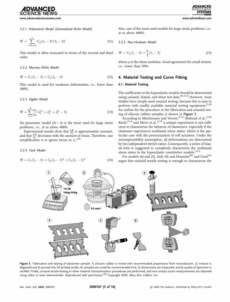
An outline for the procedure in the fabrication and uniaxial test-ing of silicone rubber samples is shown in Figure 3.
According to Marckmann and Verron,[113] Shahzad et al.,[118]
Rackl,[114] and Meier et al.,[119] a unique experiment is not suffi-cient to characterize the behavior of elastomers, especially if theelastomer experiences multiaxial stress states, which is the par-ticular case with the pressurization of soft actuators. Under theincompressibility assumption, all deformations are determinedby two independent stretch ratios. Consequently, a series of biax-ial tests is suggested to completely characterize the multiaxialstress states in the hyperelastic constitutive models.[113]
For models (4) and (5), Aidy Ali and Hosseini[46] and Gent[45]
argue that uniaxial tensile testing is enough to characterize the
Figure 3. Fabrication and testing of elastomer sample: 1) silicone rubber is mixed with recommended proportions from manufacturer, 2) mixture isdegassed and 3) poured into 3D printed molds, 4) samples are cured for recommended time, 5) dimensions are measured, and 6) quality of specimen isverified. Finally, uniaxial tensile testing or other material characterization procedures are performed, and non-contact strain measurements are obtainedusing video or laser extensometer. Reproduced with permission.[95] Copyright 2020, Mary Ann Liebert, Inc.
www.advancedsciencenews.com www.advintellsyst.com
Adv. Intell. Syst. 2020, 2000187 2000187 (5 of 18) © 2020 The Authors. Published by Wiley-VCH GmbH
material response. In particular, the Yeoh model describes theelastic behavior with reasonable success over quite large rangesof strain and is able to predict stress–stretch behavior in differentdeformation modes from data gained with simple uniaxialtesting. On the other hand, attention should be paid not touse the Ogden model with limited testing data, e.g., just uniaxialtension.[118]
Testing of elastomers has not yet been clearly defined by inter-national standards.[120] For uniaxial tensile testing of elastomers,Marechal et al.[95] have recommended the use of the ASTM D142standard.[121] In addition, the following guidelines are suggestedby Miller:[120] 1) In uniaxial tensile tests, the specimen must be atleast ten times longer than the width or thickness. 2) In pureshear tests, the specimen must be at least ten times wider thanthe length in the stretching direction. 3) Biaxial tensile tests arerecommended for a full description of the deformation modes ofthe elastomer. 4) Use non-contacting strain measuring devicessuch as video or laser extensometer and measure strains awayfrom the clamp. 5) Due to stress softening, consider 3–20 rep-etitions of the tests to obtain stable levels. 6) Tests should be per-formed at strain levels relevant for the application.
4.2. Curve Fitting
In the determination of the hyperelastic material constants, a par-ticular expression is obtained, substituting each of the modelsdiscussed in the previous section into Equation (10). The respec-tive stress–stretch equations are shown in Table 1.[95,114,115]
These relations are derived as a function of stress σ and stretchλ, while tensile testing data are force F and change in length δL,respectively. Therefore
σ ¼ FA, λ ¼ L0 þ δL
L0(16)
where A is the initial cross-sectional area of the reduced sectionof the sample, and L0 is the undeformed length.
To determine the coefficients Ci, αp, and μp, a nonlinear leastsquares optimization method is used to minimize the error withrespect to the parameters of the model. This can be achievedusing, for example, Scilab,[114] MATLAB, or Python[95] and alsowithin the standard FEM software discussed here. It is importantto note that the models can lead to error if they are used out of thedeformation range in which the parameters were identified.[113]
Furthermore, the calculation of the coefficients in the Ogdenmodel is more computationally intensive than in the other mod-els and can be more accurate in fitting experimental results whendata are available from multiple experimental tests. Therefore,models with few parameters are preferred for the purpose ofcomputational efficiency.[46]
The nonlinear least squares method involves minimizing thesum of squared errors between the theoretical and experimentalstresses as a function of stretch. In MATLAB, for example, this isachieved using the function fit with a nonlinear least squaresmethod in fitoptions and using one of the equations in Table 1in the definition of fittype. As another option, Marechal et al.[95]
have provided a set of Python functions for the implementationof the fitting algorithm.
5. Hyperelastic Models for Soft ActuatorMaterials
The most widely used silicone rubbers within the soft roboticscommunity are Ecoflex (Shore Hardness 00-10 to 00-50),[122]
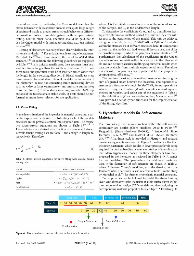
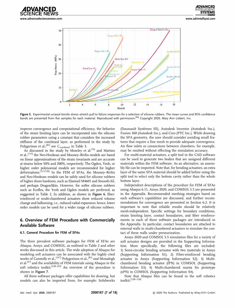
DragonSkin (Shore Hardness 10–30 A),[123] Smooth-Sil (ShoreHardness 36–60 A),[124] and Elastosil M4601 (Shore Hardness28A).[125] A hardness scale is provided in Figure 4, and uniaxialtensile testing results are shown in Figure 5. Ecoflex is softer thanthe other elastomers, which results in lower pressure levels beingrequired for desired bending or extension strokes of the soft actua-tors. Many hyperelastic models for these elastomers have beenproposed in the literature, as reviewed in Table 2 (N/A standsfor not available). The parameters for additional materialsused in the fabrication of soft actuators are shown in Table 3,where E denotes Young’s modulus, ρ is the density, and ν isPoisson’s ratio. The reader is also referred to Table 3 in the studyby Marechal et al.[95] for further hyperelastic material constants.
Two approaches can be followed to model the strain limitinglayer. One alternative is the inclusion of a thin surface layer withinthe computer-aided design (CAD) models and then assigning thecorresponding material properties to such layer. Alternatively, to
Table 1. Stress–stretch equations for curve fitting with uniaxial tensiletesting data.
Model Stress–stretch equation
Mooney–Rivlin σ ¼ 2ðλ2 � λ�1ÞðC1 þ C2λ�1Þ
Ogden σ ¼ Pnp¼1 μpðλαp�1 � λ�ðαp=2þ1ÞÞ
Yeoh σ ¼ 2ðλ2 � λ�1ÞPni¼1 iCiðλ2 þ 2λ�1 � 3Þi�1
Neo-Hookean σ ¼ 2ðλ2 � λ�1ÞC1
Extra soft Soft Medium soft Medium hard Hard
Shore 00
Shore A
0 10 20 30 40 50 60 70 80 90 100
0 10 20 30 40 50 60 70 80 90
Ecoflex series
Dragon Skin series Smooth-Sil series
Elastosil M4601
Figure 4. Shore hardness scale for silicone rubbers in soft robotics.
www.advancedsciencenews.com www.advintellsyst.com
Adv. Intell. Syst. 2020, 2000187 2000187 (6 of 18) © 2020 The Authors. Published by Wiley-VCH GmbH
improve convergence and computational efficiency, the behaviorof the strain limiting layer can be incorporated into the siliconerubber parameters using a constant that considers the increasedstiffness of the combined layer, as performed in the study byPolygerinos et al.;[81] see Ccombined in Table 3.
As discussed in the study by Moseley et al.[79] and Martinset al.,[115] the Neo-Hookean and Mooney–Rivlin models are basedon linear approximations of the strain invariants and are accurateat strains below 50% and 200%, respectively. The Ogden, Yeoh, orhigher order polynomial models are recommended for higherdeformations.[113,126] In the FEM of SFAs, the Mooney–Rivlinand Neo-Hookean models can be safely used for silicone rubbersof higher shore hardness, such as Elastosil M4601 and Smooth-Sil,and perhaps DragonSkin. However, for softer silicone rubberssuch as Ecoflex, the Yeoh and Ogden models are preferred, assuggested in Table 2. In addition, as shown in Figure 6, fiber-reinforced or multi-chambered actuators show reduced volumechange and ballooning, i.e., reduced radial expansion; hence, lowerorder models can be used for a wider range of silicone rubbers.
6. Overview of FEM Procedure with CommerciallyAvailable Software
6.1. General Procedure for FEM of SFAs
The three prevalent software packages for FEM of SFAs areAbaqus, Ansys, and COMSOL, as outlined in Table 2 and otherworks discussed in this article. The wide adoption of Abaqus formodeling soft actuators can be associated with the highly citedworks of Connolly et al.,[127] Polygerinos et al.,[81] and Mosadeghet al.[47] and the availability of FEM tutorials using Abaqus in thesoft robotics toolkit.[128,129] An overview of the procedure isshown in Figure 7.
All three software packages offer capabilities for drawing, butmodels can also be imported from, for example: Solidworks
(Daussault Systèmes SE), Autodesk Inventor (Autodesk Inc.),Fusion 360 (Autodesk Inc.), and Creo (PTC Inc.). While drawingthe SFA geometry, the user should consider avoiding small fea-tures that require a fine mesh to provide adequate convergence.Air flow inlets or connections between chambers, for example,may be omitted without effecting the simulation accuracy.
For multi-material actuators, a split tool in the CAD softwarecan be used to generate two bodies that are assigned differentmaterials within the FEM software. As an alternative, an assem-bly file can be imported. Note that, for bending actuators, an extralayer of the same SFA material should be added before using thesplit tool to select only the bottom cavity rather than the wholebottom layer.
Independent descriptions of the procedure for FEM of SFAsusing Abaqus 6.11, Ansys 2020, and COMSOL 5.5 are presentedin the Appendix. Recommended meshing strategies based oneach software’s capabilities are discussed, and further recom-mendations for convergence are presented in Section 6.2. It isimportant to note that reliable results should be relativelymesh-independent. Specific settings for boundary conditions,strain limiting layer, contact boundaries, and fiber reinforce-ments in each of three software packages are introduced inthe Appendix. In particular, contact boundaries are attached toexternal walls in multi-chambered actuators to simulate the con-tact of these walls under pressurization.
Ansys 2020 and COMSOL 5.5 simulation files for a variety ofsoft actuator designs are provided in the Supporting Informa-tion. More specifically, the following files are included:1) Semi-circular bending actuator with two materials in Ansys(Supporting Information S1). 2) Fiber-reinforced bendingactuator in Ansys (Supporting Information S2). 3) Multi-chambered bending actuator (fPN) in COMSOL (SupportingInformation S3). 4) Multi-chambered manta fin prototype(sPN) in COMSOL (Supporting Information S4).
Note that Abaqus files can be found in the soft roboticstoolkit.[128–130]
Figure 5. Experimental uniaxial tensile stress–stretch pull to failure responses for a selection of silicone rubbers. The mean curves and 95% confidencebands are presented from five samples for each material. Reproduced with permission.[95] Copyright 2020, Mary Ann Liebert, Inc.
www.advancedsciencenews.com www.advintellsyst.com
Adv. Intell. Syst. 2020, 2000187 2000187 (7 of 18) © 2020 The Authors. Published by Wiley-VCH GmbH
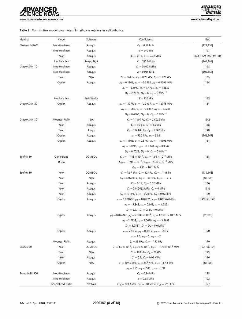
Table 2. Constitutive model parameters for silicone rubbers in soft robotics.
Material Model Software Coefficients Ref.
Elastosil M4601 Neo-Hookean Abaqus C1¼ 0.12 MPa [128,159]
Neo-Hookean Abaqus μ¼ 240 kPa [127]
Yeoh Abaqus C1¼ 0.11, C2¼ 0.02 MPa [47,81,129,146,149,160]
Hooke’s law Ansys, N/A E¼ 386.66 kPa [147,161]
DragonSkin 10 Neo-Hookean Abaqus C1¼ 0.0425MPa [128]
Neo-Hookean Abaqus μ¼ 0.085 MPa [102,162]
Yeoh N/A C1¼ 36 kPa, C2¼ 0.25 kPa, C3¼ 0.023 kPa [163]
Ogden Abaqus μ1¼ 0.1802, μ2¼�0.5538, μ3¼ 0.4099MPa [164]
α1¼�0.1997, α2¼ 1.4793, α3¼ 1.8837
D1¼ 2.2373, D2¼ 0, D3¼ 0MPa�1
Hooke’s law SolidWorks E¼ 120 kPa [165]
DragonSkin 20 Ogden Abaqus μ1¼ 1.3077, μ2¼�2.3497, μ3¼ 1.2075 MPa [164]
α1¼ 1.1087, α2¼�0.0317, α3¼�1.6291
D1¼ 0.4900, D2¼ 0, D3¼ 0MPa�1
DragonSkin 30 Mooney–Rivlin N/A C1¼ 1.190 kPa, C2¼ 23.028 kPa [80]
Yeoh Abaqus C1¼ 96 kPa, C2¼ 9.5 kPa [158]
Yeoh Ansys C1¼ 114.88 kPa, C2¼ 1.262 kPa [148]
Ogden Abaqus μ1¼ 75.5 kPa, α1¼ 5.84 [166,167]
Ogden Abaqus μ1¼ 1.1806, μ2¼ 0.8743, μ3¼�1.9396MPa [164]
α1¼ 1.0698, α2¼�1.2370, α3¼ 0.1347
D1¼ 0.7029, D2¼ 0, D3¼ 0MPa�1
Ecoflex 10 Generalized COMSOL C10¼�7.48� 10�3, C01¼ 1.96� 10�2 MPa [168]
Rivlin C20¼�1.98� 10�4, C02¼�5.39� 10�4 MPa
C11¼ 3.21� 10�3 MPa
Ecoflex 30 Yeoh COMSOL C1¼ 12.7 kPa, C2¼ 423 Pa, C3¼�1.46 Pa [139,168]
Yeoh N/A C1¼ 5.072 kPa, C2¼�331 Pa, C3¼�15 Pa [80,169]
Yeoh Abaqus C1¼ 0.11, C2¼ 0.02 MPa [106]
Yeoh Abaqus C1¼ 0.012662MPa, C2¼ 0MPa [81]
Yeoh Abaqus C1¼ 17 kPa, C2¼�0.2 kPa, C3¼ 0.023 kPa [170]
Ogden Abaqus μ1¼ 0.001887, μ2¼ 0.02225, μ3¼ 0.003574MPa [149,171,172]
α1¼�3.848, α2¼ 0.663, α3¼ 4.225
D1¼ 2.93; D2¼ 0; D3¼ 0MPa�1
Ogden Abaqus μ1¼ 0.024361, μ2¼ 6.6703� 10�5, μ3¼ 4.5381� 10�4 MPa [79,173]
α1¼ 1.7138, α2¼ 7.0679, α3¼�3.3659
D1¼ 3.2587, D2¼D3¼ 0.0 MPa�1
Ogden Abaqus μ1¼ 22 kPa, μ2¼ 0.4 kPa, μ3¼�2 kPa [170]
α1¼ 1.3, α2¼ 5, α3¼�2
Mooney–Rivlin Abaqus C1¼ 48 kPa, C2¼�152 kPa [170]
Ecoflex 50 Yeoh COMSOL C1¼ 1.9� 10�2, C2¼ 9� 10�4, C3¼�4.75� 10�6 MPa [162,168,174]
Yeoh N/A C1¼ 120 kPa, C2¼ 20 kPa [175]
Yeoh Abaqus C1¼ 0.1, C2¼ 0.02 MPa [176]
Ogden N/A μ1¼ 107.9 kPa, μ2¼ 21.47 Pa, μ3¼�87.1 kPa [80,169]
α1 ¼ 1.55, α2 ¼ 7.86, α3 ¼�1.91
Smooth-Sil 950 Neo-Hookean Abaqus C1 ¼ 0.34 MPa [128]
Neo-Hookean Abaqus μ¼ 0.68 MPa [102]
Generalized Rivlin Nastran C10 ¼ 279.3 kPa, C01 ¼ 10.5 kPa, C20 ¼ 59.1 kPa [177]
www.advancedsciencenews.com www.advintellsyst.com
Adv. Intell. Syst. 2020, 2000187 2000187 (8 of 18) © 2020 The Authors. Published by Wiley-VCH GmbH
6.2. Recommendations for Improved Convergence
1) According to Tawk and Alici,[51] as SFAs can undergo largedeformations, a very fine mesh is not recommended, and a rela-tively coarse mesh instead is desired for convergence. However, acoarse mesh might result in lower deformations for the samepressure value. In the authors’ experience, while coarse mesheshave facilitated convergence, they have failed to capture strongballooning effects during the pressurization of soft actuators.2) As a rule of thumb, reduced mesh sizes are only requiredin areas of large deformations and stresses. For soft actuatorsof typical sizes, i.e., 50–200mm length and 10–25mm width/diameter,[47,79–81,102,127] a mesh size of 1–3mm is a good startingpoint. 3) A 3D problem is always more complicated to analyzethan a 2D one, especially in nonlinear FEM. Whenever possible,
Table 3. Additional materials used in the modeling of soft actuators withFEM.
Material Model Coefficients Ref.
Kevlar fiber Elastic E¼ 31 067MPa, ρ¼ 1440 kg m�3 [81,102,127,143]
ν¼ 0.36, diam: 0.1778 mm
Fiber yarn Elastic E¼ 103 GPa, ν¼ 0.34 [144]
PBO fiber Elastic E¼ 5.8 GPa, ν¼ 0.3 [145]
Silicone O-ring Elastic E¼ 31 067MPa, ν ¼ 0.36 [106]
Paper Elastic E¼ 6.5 GPa, ρ¼ 750 kg m�3 [129,143]
ν¼ 0.2
Paper Elastic E¼ 1.2 GPa, ν¼ 0.2 [148]
Fiberglass Yeoh Ccombined ¼ 7.9 MPa [81]
100% 200% 300% 400%0% Strain
Hardness
Smooth-Sil
Elastosil M4601
DragonSkin
Ecoflex
Neo-Hookean
Mooney-Rivlin
Yeoh or Ogden
Group 1
Group 3 Group 3
Group 1
Group 2
Group 2
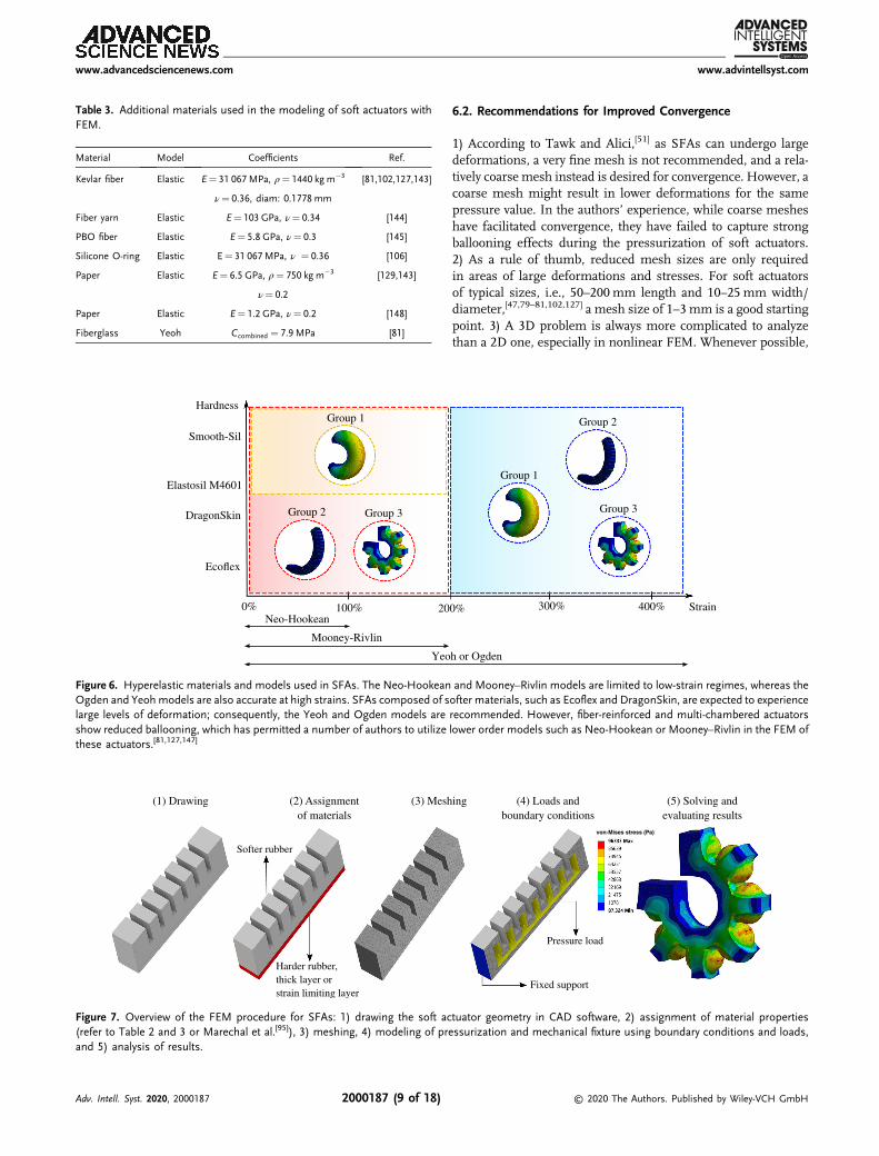
Figure 6. Hyperelastic materials and models used in SFAs. The Neo-Hookean and Mooney–Rivlin models are limited to low-strain regimes, whereas theOgden and Yeohmodels are also accurate at high strains. SFAs composed of softer materials, such as Ecoflex and DragonSkin, are expected to experiencelarge levels of deformation; consequently, the Yeoh and Ogden models are recommended. However, fiber-reinforced and multi-chambered actuatorsshow reduced ballooning, which has permitted a number of authors to utilize lower order models such as Neo-Hookean or Mooney–Rivlin in the FEM ofthese actuators.[81,127,147]
(1) Drawing (2) Assignmentof materials
(3) Meshing (4) Loads andboundary conditions
(5) Solving andevaluating results
von-Mises stress (Pa)
Harder rubber,thick layer orstrain limiting layer
Softer rubber
Pressure load
Fixed support
Figure 7. Overview of the FEM procedure for SFAs: 1) drawing the soft actuator geometry in CAD software, 2) assignment of material properties(refer to Table 2 and 3 or Marechal et al.[95]), 3) meshing, 4) modeling of pressurization and mechanical fixture using boundary conditions and loads,and 5) analysis of results.
www.advancedsciencenews.com www.advintellsyst.com
Adv. Intell. Syst. 2020, 2000187 2000187 (9 of 18) © 2020 The Authors. Published by Wiley-VCH GmbH
take advantage of symmetry in the model to reduce the totalnumber of elements in the model.[45] 4) If the mesh distorts badlyduring the simulation, the mesh density needs to be changedbetween load steps.[45] 5) During meshing, it is preferable touse a mesh with quadratic order elements and a hex dominantconfiguration, because hexahedron elements are less distortedwhen capturing curved geometries. 6) A reduction in the sizeof time steps can also improve convergence. As another option,a larger number of substeps can be used. This is an importantparameter to consider, because it prevents the load from beingapplied in one step, which usually results in convergenceissues.[51] 7) Increase the number of iterations for simulationsthat are close to converging. In Ansys, for example, this canbe achieved using the command NEQIT,50 to increase to 50 iter-ations (standard of 26).
6.3. Validation of FEM Results
Once the design is complete and relevant geometries and mate-rial properties have been optimized, the final geometry can befabricated for validation of the results. This can be achievedby directly 3D printing the geometry[51,131] or 3D printing moldsfor the desired shape.[9,82]
Experimental characterization of SFAs can be performedusing compressed air systems,[81,132,133] syringe pumps,[134–136]
fluidic drive cylinders,[137,138] or simply by manually actuatinga syringe.[139] Bending, extension, or twisting levels are post-processed from video recordings and/or obtained from motiontrackers. These measurements are then combined with the corre-sponding pressure values for comparison with FEM results.
7. FEM of SFAs: Design Guidelines
In this section, a collection of design guidelines for the differenttypes of SFAs is presented. Most of these results are drawn fromFEM studies; nonetheless, relevant concepts from experimentalcharacterization are also included. While these conclusions havebeen organized into four sections, note that the conclusions forsingle chamber actuators also apply for fiber-reinforced actua-tors. In addition, bidirectional and omnidirectional actuatorsfabricated using multiple fiber-reinforced actuators inherit thecharacteristics of single fiber-reinforced actuators.
In the design of SFAs, two universal parameters have a stronginfluence in the pressurization of soft actuators: wall thicknessand silicone rubber hardness. Reduced wall thickness andsilicone hardness lead to higher deformation at lower pressurevalues. For fiber-reinforced actuators, the wrapping densityand angle have high impact on the performance of the soft actu-ator. For omnidirectional actuators, increased void area gives riseto higher bending. For multi-chambered actuators, thinner inter-nal chamber walls, higher number of chambers, and the corru-gated design from fPNs result in improved strokes. Furtherdesign guidelines are presented in the following.
7.1. Single Chamber Actuators
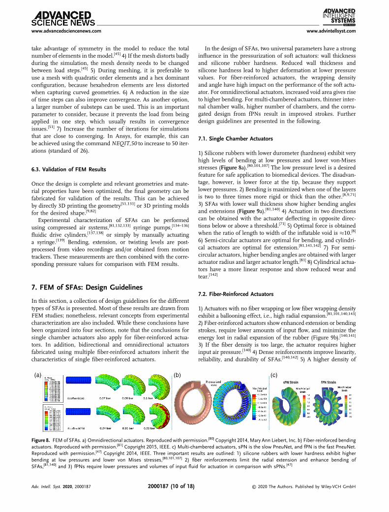
1) Silicone rubbers with lower durometer (hardness) exhibit veryhigh levels of bending at low pressures and lower von-Misesstresses (Figure 8a).[80,101,107] The low pressure level is a desiredfeature for safe application to biomedical devices. The disadvan-tage, however, is lower force at the tip, because they supportlower pressures. 2) Bending is maximized when one of the layersis two to three times more rigid or thick than the other.[8,9,71]
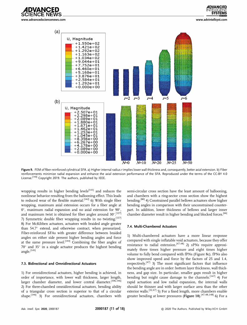
3) SFAs with lower wall thickness show higher bending anglesand extensions (Figure 9a).[81,140] 4) Actuation in two directionscan be obtained with the actuator deflecting in opposite direc-tions below or above a threshold.[71] 5) Optimal force is obtainedwhen the ratio of length to width of the inflatable void is �10.[8]
6) Semi-circular actuators are optimal for bending, and cylindri-cal actuators are optimal for extension.[81,141,142] 7) For semi-circular actuators, higher bending angles are obtained with largeractuator radius and larger actuator length.[81] 8) Cylindrical actua-tors have a more linear response and show reduced wear andtear.[142]
7.2. Fiber-Reinforced Actuators
1) Actuators with no fiber wrapping or low fiber wrapping densityexhibit a ballooning effect, i.e., high radial expansion.[81,101,140,143]
2) Fiber-reinforced actuators show enhanced extension or bendingstrokes, require lower amounts of input flow, and minimize theenergy lost in radial expansion of the rubber (Figure 9b).[140,141]
3) If the fiber density is too large, the actuator requires higherinput air pressure.[140] 4) Dense reinforcements improve linearity,reliability, and durability of SFAs.[140,142] 5) A higher density of
Figure 8. FEM of SFAs. a) Omnidirectional actuators. Reproduced with permission.[80] Copyright 2014, Mary Ann Liebert, Inc. b) Fiber-reinforced bendingactuators. Reproduced with permission.[81] Copyright 2015, IEEE. c) Multi-chambered actuators, sPN is the slow PneuNet, and fPN is the fast PneuNet.Reproduced with permission.[47] Copyright 2014, IEEE. Three important results are outlined: 1) silicone rubbers with lower hardness exhibit higherbending at low pressures and lower von Mises stresses,[80,101,107] 2) fiber reinforcements limit the radial extension and enhance bending ofSFAs,[81,140] and 3) fPNs require lower pressures and volumes of input fluid for actuation in comparison with sPNs.[47]
www.advancedsciencenews.com www.advintellsyst.com
Adv. Intell. Syst. 2020, 2000187 2000187 (10 of 18) © 2020 The Authors. Published by Wiley-VCH GmbH
wrapping results in higher bending levels[141] and reduces thenonlinear behavior resulting from the ballooning effect. This leadsto reduced wear of the flexible material.[142] 6) With single fiberwrapping, maximum axial extension occurs for a fiber angle at0�, maximum radial expansion and no axial extension for 90�,and maximum twist is obtained for fiber angles around 30�.[127]
7) Symmetric double fiber wrapping results in no twisting.[127]
8) For McKibben actuators, actuators with braided angle greaterthan 54.7� extend, and otherwise contract, when pressurized.Fiber-reinforced SFAs with greater difference between braidedangles on either side present higher bending angles and forceat the same pressure level.[144] Combining the fiber angles of70� and 35� in a single actuator produces the highest bendingangle.[145]
7.3. Bidirectional and Omnidirectional Actuators
1) For omnidirectional actuators, higher bending is achieved, inorder of importance, with lower wall thickness, larger length,larger chamber diameter, and lower central diameter.[106,146]
2) For three-chambed omnidirectional actuators, bending abilityof a triangular cross section is superior to that of a circularshape.[146] 3) For omnidirectional actuators, chambers with
semi-circular cross section have the least amount of ballooning,and chambers with a ring-sector cross section show the highestbending.[80] 4) Constrained parallel bellows actuators show higherbending angles in comparison with their unconstrained counter-part. In addition, lower thickness of bellows and larger innerchamber diameter result in higher bending and blocked forces.[66]
7.4. Multi-Chambered Actuators
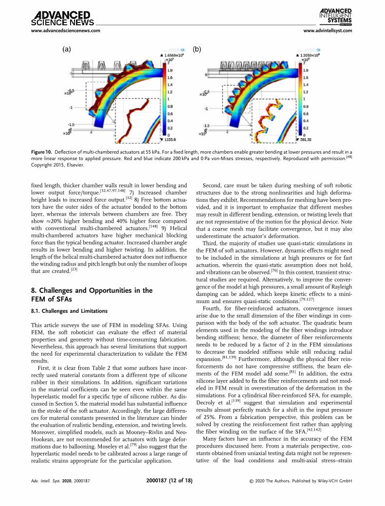
1) Multi-chambered actuators have a more linear responsecompared with single inflatable void actuators, because they offerresistance to radial extension.[47,48] 2) sPNs require approxi-mately three times higher pressure and eight times highervolume to fully bend compared with fPNs (Figure 8c). fPNs alsoshow improved speed and force by the factors of 25 and 1.4,respectively.[47] 3) The most significant factors that influencethe bending angle are in order: bottom layer thickness, wall thick-ness, and gap size. In particular, smaller gaps result in higherbending but might cause damage to the channels.[147] 4) Forrapid actuation and low radial expansion, the internal wallsshould be thinner and with larger surface area than the otherexterior walls.[32,47] 5) For a fixed length, more chambers enablegreater bending at lower pressures (Figure 10).[47,48,148] 6) For a
Figure 9. FEM of fiber-reinforced cylindrical SFA. a) Higher internal radius r implies lower wall thickness and, consequently, better axial extension. b) Fiberreinforcements minimize radial expansion and enhance the axial extension performance of the SFA. Reproduced under the terms of the CC-BY 4.0License.[140] Copyright 2019. The authors, published by IEEE.
www.advancedsciencenews.com www.advintellsyst.com
Adv. Intell. Syst. 2020, 2000187 2000187 (11 of 18) © 2020 The Authors. Published by Wiley-VCH GmbH
fixed length, thicker chamber walls result in lower bending andlower output force/torque.[32,47,97,148] 7) Increased chamberheight leads to increased force output.[32] 8) Free bottom actua-tors have the outer sides of the actuator bonded to the bottomlayer, whereas the intervals between chambers are free. Theyshow �20% higher bending and 40% higher force comparedwith conventional multi-chambered actuators.[148] 9) Helicalmulti-chambered actuators have higher mechanical blockingforce than the typical bending actuator. Increased chamber angleresults in lower bending and higher twisting. In addition, thelength of the helical multi-chambered actuator does not influencethe winding radius and pitch length but only the number of loopsthat are created.[23]
8. Challenges and Opportunities in theFEM of SFAs
8.1. Challenges and Limitations
This article surveys the use of FEM in modeling SFAs. UsingFEM, the soft roboticist can evaluate the effect of materialproperties and geometry without time-consuming fabrication.Nevertheless, this approach has several limitations that supportthe need for experimental characterization to validate the FEMresults.
First, it is clear from Table 2 that some authors have incor-rectly used material constants from a different type of siliconerubber in their simulations. In addition, significant variationsin the material coefficients can be seen even within the samehyperelastic model for a specific type of silicone rubber. As dis-cussed in Section 5, the material model has substantial influencein the stroke of the soft actuator. Accordingly, the large differen-ces for material constants presented in the literature can hinderthe evaluation of realistic bending, extension, and twisting levels.Moreover, simplified models, such as Mooney–Rivlin and Neo-Hookean, are not recommended for actuators with large defor-mations due to ballooning. Moseley et al.[79] also suggest that thehyperelastic model needs to be calibrated across a large range ofrealistic strains appropriate for the particular application.
Second, care must be taken during meshing of soft roboticstructures due to the strong nonlinearities and high deforma-tions they exhibit. Recommendations for meshing have been pro-vided, and it is important to emphasize that different meshesmay result in different bending, extension, or twisting levels thatare not representative of the motion for the physical device. Notethat a coarse mesh may facilitate convergence, but it may alsounderestimate the actuator’s deformation.
Third, the majority of studies use quasi-static simulations inthe FEM of soft actuators. However, dynamic effects might needto be included in the simulations at high pressures or for fastactuation, wherein the quasi-static assumption does not hold,and vibrations can be observed.[76] In this context, transient struc-tural studies are required. Alternatively, to improve the conver-gence of the model at high pressures, a small amount of Rayleighdamping can be added, which keeps kinetic effects to a mini-mum and ensures quasi-static conditions.[79,127]
Fourth, for fiber-reinforced actuators, convergence issuesarise due to the small dimension of the fiber windings in com-parison with the body of the soft actuator. The quadratic beamelements used in the modeling of the fiber windings introducebending stiffness; hence, the diameter of fiber reinforcementsneeds to be reduced by a factor of 2 in the FEM simulationsto decrease the modeled stiffness while still reducing radialexpansion.[81,139] Furthermore, although the physical fiber rein-forcements do not have compressive stiffness, the beam ele-ments of the FEM model add some.[81] In addition, the extrasilicone layer added to fix the fiber reinforcements and not mod-eled in FEM result in overestimation of the deformation in thesimulations. For a cylindrical fiber-reinforced SFA, for example,Decroly et al.[139] suggest that simulation and experimentalresults almost perfectly match for a shift in the input pressureof 25%. From a fabrication perspective, this problem can besolved by creating the reinforcement first rather than applyingthe fiber winding on the surface of the SFA.[42,142]
Many factors have an influence in the accuracy of the FEMprocedures discussed here. From a materials perspective, con-stants obtained from uniaxial testing data might not be represen-tative of the load conditions and multi-axial stress–strain
Figure 10. Deflection of multi-chambered actuators at 55 kPa. For a fixed length, more chambers enable greater bending at lower pressures and result in amore linear response to applied pressure. Red and blue indicate 200 kPa and 0 Pa von-Mises stresses, respectively. Reproduced with permission.[48]
Copyright 2015, Elsevier.
www.advancedsciencenews.com www.advintellsyst.com
Adv. Intell. Syst. 2020, 2000187 2000187 (12 of 18) © 2020 The Authors. Published by Wiley-VCH GmbH
relationships in the pressurization of SFAs. The properties ofhyperelastic materials are also affected by curing temperature,mixing ratio, and degassing. Moreover, compressibility, visco-elasticity, stress softening, and the Mullins effect are usuallyignored in FEM but also impact the performance of SFAs.
From a fabrication perspective, discrepancies are associatedwith 3D-printing artifacts or manual fabrication of soft actuators,especially for fiber-reinforced SFAs withmanual wrapping of fiber.From a measurement perspective, image post-processing techni-ques, camera resolution, and performance of trackers also affectthe accuracy of results. From an actuation perspective, the preci-sion of pressure measurement devices needs to be considered.
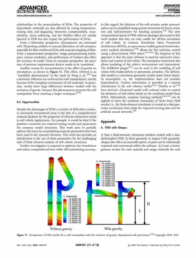
Another reason for inconsistencies is the effect of gravity onsimulations, as shown in Figure 11. This effect, referred to as“instability phenomenon” in the study by Peng et al.,[149] hasa dramatic influence on multi-section soft manipulators, mainlybecause of the compliant mechanism of soft materials. In partic-ular, results show large differences between models with theinclusion of gravity, because this phenomenon prevents the softmanipulator from reaching a larger workspace.[149]
8.2. Opportunities
Despite the advantages of FEM, a number of difficulties remain.A commonly encountered issue is the lack of a comprehensivematerial database for the properties of silicone elastomers suitedto soft robotic applications. For example, it would be ideal if thedatabase contained raw material testing results and parametersfor common model structures. This work aims to partiallyaddress this issue by consolidating material parameters that havebeen used in the research literature. This work also provides anintroduction to the use of these parameters for the challengingtask of finite element analysis of soft robotic structures.
Further investigation is required to optimize the simulationsand reduce computational time while still maintaining accuracy.
In this regard, the behavior of the soft actuator under pressuri-zation can be simplified using quarter-symmetry for linear actua-tors and half-symmetry for bending actuators.[79] The slowcomputational speed of FEM software packages discussed in thiswork implies that they are only usable for off-line simulationof soft robots. In contrast, Simulation Open FrameworkArchitecture (SOFA), an open-source toolkit geared toward inter-active medical simulation,[150] allows for fast real-time controlusing a direct/inverse FEM solver.[151,152] The keypoint of thisapproach is that the same software is used for interactive simu-lation and control of soft robots. The simulation framework alsoallows modeling of the robot’s environment and interactions.The SoftRobot plugin[153] can be used in the modeling of softrobots with tendon-driven or pneumatic actuation. The deform-able model is a non-linear geometric model under linear elastic-ity assumption; i.e., the implementation does not considerhyperelasticity. Further information is provided in a tutorialintroduction in the soft robotics toolkit.[154] Thieffry et al.[155]
have derived a linearized model with reduced order to controlthe dynamics of soft robots based on the nonlinear model fromSOFA. Alternatively, machine learning methods[156,157] can beapplied to learn the nonlinear kinematics of SFAs from FEMresults; i.e., the finite element simulation is treated as a data gen-erator mechanism that yields the required training data sets forartificial neural networks.[50]
Appendix
A. FEM with Abaqus
1) Start a fluid-structure interaction problem treated with a stan-dard/implicit FEM. 2) Draw geometry or import CAD geometry.Abaqus also offers an assembly option, so parts can be individuallyimported and constrained within the software. 3) Create a homo-geneous section for each material and assign materials for each
Figure 11. Comparison of FEM results for a soft manipulator with the inclusion of gravity. Reproduced with permission.[149] Copyright 2019, IEEE.
www.advancedsciencenews.com www.advintellsyst.com
Adv. Intell. Syst. 2020, 2000187 2000187 (13 of 18) © 2020 The Authors. Published by Wiley-VCH GmbH
geometry. 4) Create a new surface for the internal cavities. Usetools ! view cut manager to select hidden surfaces. 5) ActivateNlgeom to include nonlinear effects of large displacements.6) Insert boundary conditions and loads: Steps ! static general! pressure. Select surfaces with internal cavities and edit themagnitude with uniform distribution and ramp amplitude.According to the soft robotics toolkit, under the incrementationtab, set 1000 as the maximum number of increments, 0.01 asthe initial increment size, 1E-5 as the minimum increment size,and 0.01 as the maximum increment size. Boundary conditions!select desired fixed face! check the boxes U1, U2, andU3, and setvalues of 0 for fixed support. 7) Mesh the parts. Tetrahedral ele-ments with quadratic order and hybrid formulation are recom-mended. The approximate global size might need to be reducedto 1–2 for the soft actuator in particular. 8) Submit job andview results.
Strain limiting layer: bottom layer ! surfaces. Create a shellsection and then a skin for this surface. Contact boundaries:self-contact (standard).[158] Fiber reinforcement: mesh with qua-dratic beam elements. Tie constraints added after meshing.The soft robotics toolkit also provides scripts for FEM of fiber-reinforced actuators, which can be used for more advanced usersof Abaqus. In addition, for unstable quasi-static simulations athigher pressures, dynamic simulations can be performed witha small damping factor.[127]
B. FEM with Ansys
1) Create a static structural study. 2) Insert material propertiesinto engineering data. 3) Draw geometry in Design Modeleror SpaceClaim. Alternatively, a geometry generated using stan-dard CAD software can be imported into Design Modeler. In thiscase, generate geometry before proceeding. 4) Assign materialsfor different body parts. 5) Named selections: include a selectionwith all cavities in the soft actuator. This can be achieved usinga section plane and the hide faces option to select hiddencavities inside the actuator. 6) Perform meshing. Recommendedsettings: nonlinear mechanical physics, quadratic elements,and aggressive mechanical error limits. A mesh size of1–5mm can be used as a starting point. 7) Set up analysissettings. Auto time stepping on ! initial time step and mini-mum time step in the range 0.001–0.01, maximum in the range0.01–0.05. Large deflection on. 8) Insert boundary conditions andloads: Static structural ! pressure ! named selection !cavities. Normal to surface, ramped. Fixed support: applied toone of the faces of the soft actuator. 9) Select desired quantitiesto be evaluated such as total deformation and equivalentvon-Mises stress. 10) Solve and evaluate results. During the solu-tion, it might be worth evaluating force convergence using thesolution information tab. Furthermore, in the results tab, setthe results to true scale (1.0).
Strain limiting layer: Concept ! surface from faces ! assignuser defined thickness. Contact boundaries: frictional with sym-metric option to minimize penetration, which results in moreaccurate results and realistic behavior.[51] Fiber reinforcement:under model, select the fiber and assign a beam model type.Under connections, assign a bonded contact region betweenthe actuator and the fiber reinforcement.
C. FEM with COMSOL
1) Create a 3D (model wizard) study ! Physics: structuralmechanics, select solid mechanics ! stationary study.2) Draw or import geometry. COMSOL offers a range of 3Dprimitives that integrated with Boolean operations allow forintuitive 3D drawing of geometries. 3) Assign material proper-ties for each domain: solid mechanics ! material models !hyperelastic material. Select user defined model parametersand insert constants. 4) Under definitions, create an explicitselection and select the internal faces of the cavity using bound-ary as the geometric entity level. 5) Under global definitions,create a parameter (“ramp”), so that the pressure is increasedlinearly during simulation. 6) Insert boundary conditions andloads: Fixed constraint: applied to one end of the soft actuator.Boundary load: pressure load type is applied to every internalcavity. Define p to be the value of final pressure multipliedby the parameter in global definitions (“ramp”). 7) Performmeshing, see note 2 as follows. 8) Set up the stationary study.Under study extensions, enable auxiliary sweep and definethe parameter value list to be range(0.025,0.025,1). 9) Solveand evaluate results. Strain limiting layer: modeled by combin-ing the behavior of the strain limiting layer into the siliconerubber parameters for the bottom layer. Contact boundaries:contact pairs. Fiber reinforcement: prescribed displacementfixed in radial directions but free in the longitudinal direction,simulates the behavior of fiber wrapping in extendingactuators.
Note 1: FEM of SFAs with COMSOL Multiphysics requires alicense for the nonlinear structural materials module.
Note 2: In the authors’ experience with COMSOL, a physics-controlled mesh with a “finer” element size enables convergencefor a substantial range of pressures, whereas further refinementof the meshes or the use of mesh adaptation techniques showedlittle improvement.
Supporting InformationSupporting Information is available from the Wiley Online Library or fromthe author.
AcknowledgementsThe authors would like to thank Ben Routley for his assistance withsimulations in COMSOL Multiphysics and Octavio Reyes for his initialwork on FEM of fiber-reinforced soft actuators in Ansys.
Conflict of InterestThe authors declare no conflict of interest.
Keywordsfinite element modeling, fluidic actuators, hyperelastic models, softactuators, soft robotics
www.advancedsciencenews.com www.advintellsyst.com
Adv. Intell. Syst. 2020, 2000187 2000187 (14 of 18) © 2020 The Authors. Published by Wiley-VCH GmbH
Received: August 10, 2020Revised: September 3, 2020
Published online:
[1] G. Bao, H. Fang, L. Chen, Y. Wan, F. Xu, Q. Yang, L. Zhang, SoftRobot. 2018, 5, 229.
[2] J. Craig, Introduction to Robotics: Mechanics and Control, Pearson/Prentice Hall, New York 2005.
[3] M. Spong, S. Hutchinson, M. Vidyasagar, Robot Modeling and Control,Wiley, Hoboken, NJ 2005.
[4] H. Yuk, S. Lin, C. Ma, M. Takaffoli, N. X. Fang, X. Zhao, Nat.Commun. 2017, 8, 14230.
[5] R. Huang, S. Zheng, Z. Liu, T. Y. Ng, Int. J. Appl. Mech. 2020,12, 2050014.
[6] I. A. Anderson, T. A. Gisby, T. G. McKay, B. M. O’Brien, E. P. Calius,J. Appl. Phys. 2012, 112, 041101.
[7] Y. Yang, Y. Wu, C. Li, X. Yang, W. Chen, Adv. Intell. Syst. 2020,2, 1900077.
[8] B. Gorissen, D. Reynaerts, S. Konishi, K. Yoshida, J.-W. Kim,M. De Volder, Adv. Mater. 2017, 29, 43.
[9] A. Marchese, R. Katzschmann, D. Rus, Soft Robot. 2015, 2, 7.[10] S. I. Rich, R. J. Wood, C. Majidi, Nat. Electron. 2018, 1, 102.[11] M. Wehner, R. L. Truby, D. J. Fitzgerald, B. Mosadegh,
G. M. Whitesides, J. A. Lewis, R. J. Wood, Nature 2016, 536, 451.[12] C. Majidi, Adv. Mater. Technol. 2019, 4, 1800477.[13] G. Robinson, J. Davies, in Proc. IEEE Int. Conf. on Robotics and
Automation, vol. 4, IEEE, Piscataway, NJ 1999, pp. 2849–2854.[14] C. Onal, D. Rus, Bioinspir. Biomim. 2013, 8, 2.[15] M. Luo, W. Tao, F. Chen, T. Khuu, S. Ozel, C. Onal, in Proc. IEEE Conf.
on Technologies for Practical Robot Applications, IEEE, Piscataway, NJ2014.
[16] C. Branyan, C. Fleming, J. Remaley, A. Kothari, K. Tumer, R. Hatton,Y. Menguc, in Proc. IEEE Int. Conf. Robotics and Biomimetics, IEEE,Piscataway, NJ 2018, pp. 282–289.
[17] X. Qi, H. Shi, T. Pinto, X. Tan, IEEE Robot. Autom. Lett. 2020,5, 1610.
[18] A. A. Calderón, J. C. Ugalde, J. C. Zagal, N. O. Pérez-Arancibia, in Proc.IEEE Int. Conf. Robotics and Biomimetics, IEEE, Piscataway, NJ 2016,pp. 31–38.
[19] M. S. Xavier, A. J. Fleming, Y. K. Yong, in Proc. IEEE Int. Conf. Roboticsand Biomimetics, IEEE, Piscataway, NJ 2019, pp. 2269–2274.
[20] Z. Li, R. Huang, Z. Liu, Adv. Mater. Technol. 2019, 4, 1900653.[21] A. D. Marchese, C. D. Onal, D. Rus, Soft Robot. 2014, 1, 75.[22] T. Hou, X. Yang, H. Su, L. Chen, T. Wang, J. Liang, S. Zhang, in Proc.
IEEE Int. Conf. Robotics and Biomimetics, IEEE, Piscataway, NJ 2019,pp. 1020–1026.
[23] W. Hu, G. Alici, Soft Robot. 2020, 7, 267.[24] J. Zhang, J. Tang, J. Hong, T. Lu, H. Wang, in Int. Conf. on Intelligent
Robotics and Applications, Springer, Cham 2014, pp. 320–327.[25] K. Suzumori, S. Endo, T. Kanda, N. Kato, H. Suzuki, in Proc. IEEE Int.
Conf. on Robotics and Automation, IEEE, Piscataway, NJ 2007,pp. 4975–4980.
[26] Y. Cai, S. Bi, L. Zhang, J. Gao, in Proc. IEEE/RSJ IEEE Int. Conf.on Intelligent Robots and Systems, IEEE, Piscataway, NJ 2009,pp. 2138–2142.
[27] D. O’Brien, D. Lane, in Proc. IEEE Int. Conf. on Robotics andAutomation, vol. 3, IEEE, Piscataway, NJ 2001, pp. 2375–2380.
[28] S. Neppalli, B. Jones, in Proc. IEEE/RSJ IEEE Int. Conf. on IntelligentRobots and Systems, IEEE, Piscataway, NJ 2007, pp. 1503–1507.
[29] M. Cianchetti, T. Ranzani, G. Gerboni, T. Nanayakkara, K. Althoefer,P. Dasgupta, A. Menciassi, Soft Robot. 2014, 1, 122.
[30] M. Runciman, A. Darzi, G. Mylonas, Soft Robot. 2019, 6, 423.
[31] X. Hu, A. Chen, Y. Luo, C. Zhang, E. Zhang, Comput. Assist. Surg.2018, 23, 21.
[32] P. Polygerinos, S. Lyne, Z. Wang, L. Nicolini, B. Mosadegh,G. Whitesides, C. Walsh, in Proc. IEEE/RSJ IEEE Int. Conf. onIntelligent Robots and Systems, IEEE, Piscataway, NJ 2013,pp. 1512–1517.
[33] M. Wehner, B. Quinlivan, P. M. Aubin, E. Martinez-Villalpando,M. Baumann, L. Stirling, K. Holt, R. Wood, C. Walsh, in Proc. IEEEInt. Conf. on Robotics and Automation, IEEE, Piscataway, NJ 2013,pp. 3362–3369.
[34] Y. Ansari, M. Manti, E. Falotico, Y. Mollard, M. Cianchetti, C. Laschi,Int. J. Adv. Robot. Syst. 2017, 14, 1729881416687132.
[35] A. De Greef, P. Lambert, A. Delchambre, Precis. Eng. 2009, 33, 311.[36] T. Noritsugu, in Symp. on Fluid Power, vol. 2005, Citeseer, Princeton,
NJ 2005.[37] J. Shintake, V. Cacucciolo, D. Floreano, H. Shea, Adv. Mater. 2018, 30,
1707035.[38] R. Deimel, O. Brock, in Proc. IEEE Int. Conf. on Robotics and
Automation, IEEE, Piscataway, NJ 2013, pp. 2047–2053.[39] D. P. Holland, E. J. Park, P. Polygerinos, G. J. Bennett, C. J. Walsh, Soft
Robot. 2014, 1, 224.[40] D. P. Holland, C. Abah, M. Velasco-Enriquez, M. Herman, G. J. Bennett,
E. A. Vela, C. J. Walsh, IEEE Robot. Autom. Mag. 2017, 24, 57.[41] P. Polygerinos, N. Correll, S. A. Morin, B. Mosadegh, C. D. Onal,
K. Petersen, M. Cianchetti, M. T. Tolley, R. F. Shepherd, Adv. Eng.Mater. 2017, 19, 1700016.
[42] J. Fras, J. Glowka, K. Althoefer, in Proc. IEEE Int. Conf. on Soft Robotics,IEEE, Piscataway, NJ 2020, pp. 482–488.
[43] J. Gul, M. Sajid, M. Rehman, G. Siddiqui, I. Shah, K.-H. Kim, J.-W. Lee,K. Choi, Sci. Technol. Adv. Mat. 2018, 19, 243.
[44] T. Wallin, J. Pikul, R. Shepherd, Nat. Rev. Mater. 2018, 3, 84.[45] A. N. Gent, Engineering with Rubber, Hanser, Cincinnati 2012.[46] B. B. S. Aidy Ali, M. Hosseini, Am. J. Eng. Appl. Sci. 2010, 3, 232.[47] B. Mosadegh, P. Polygerinos, C. Keplinger, S. Wennstedt, R. Shepherd,
U. Gupta, J. Shim, K. Bertoldi, C. Walsh, G. Whitesides, Adv. Funct.Mater. 2014, 24, 2163.
[48] Y. Hwang, O. Paydar, R. Candler, Sens. Actuator A Phys. 2015,234, 65.
[49] T. Kalisky, Y. Wang, B. Shih, D. Drotman, S. Jadhav, E. Aronoff-Spencer, M. Tolley, in Proc. IEEE/RSJ IEEE Int. Conf. on IntelligentRobots and Systems, IEEE, Piscataway, NJ 2017, pp. 6207–6213.
[50] G. Runge, A. Raatz, CIRP Ann. 2017, 66, 9.[51] C. Tawk, G. Alici, Robotics 2020, 9, 52.[52] R. Webster III, B. Jones, Int. J. Rob. Res. 2010, 29, 1661.[53] I. D. Walker, ISRN Rob. 2013, 2013, 726506.[54] I. Gravagne, C. Rahn, I. Walker, IEEE/ASME Trans. Mechatron 2003,
8, 229.[55] M. Hannan, I. Walker, J. Robot. Syst. 2003, 20, 45.[56] Y. Bailly, Y. Amirat, in Proc. IEEE Int. Conf. on Robotics and Automation,
IEEE, Piscataway, NJ 2005, pp. 924–929.[57] B. Jones, I. Walker, IEEE Trans. Robot 2006, 22, 43.[58] Y. Ganji, F. Janabi-Sharifi, IEEE Trans. Biomed. Eng. 2009, 56, 621.[59] G. Chirikjian, J. Burdick, IEEE Trans. Robot Autom. 1995, 11, 781.[60] H. Mochiyama, T. Suzuki, in Proc. SICE Annual Conf., Vol. 3, IEEE,
Osaka, Japan 2002, pp. 1505–1510.[61] M. Ivanescu, in Proc. IEEE Int. Conf. on Robotics and Automation, vol.
2, IEEE, Piscataway, NJ 2002, pp. 1531–1538.[62] M. Ivanescu, N. Popescu, D. Popescu, in Proc. IEEE Int. Conf. on
Robotics and Automation, IEEE, Piscataway, NJ 2005, pp. 3274–3279.[63] R. Murray, Z. Li, S. Shankar Sastry, A Mathematical Introduction to
Robotic Manipulation, CRC Press, Boca Raton, FL 1994.[64] K. Suzumori, S. Iikura, H. Tanaka, in Proc. IEEE Micro Electro
Mechanical Systems, IEEE, Piscataway, NJ 1991, pp. 204–209.
www.advancedsciencenews.com www.advintellsyst.com
Adv. Intell. Syst. 2020, 2000187 2000187 (15 of 18) © 2020 The Authors. Published by Wiley-VCH GmbH
[65] K. Suzumori, S. Iikura, H. Tanaka, in Proc. IEEE Int. Conf. on Roboticsand Automation, vol. 2, IEEE, Piscataway, NJ 1991, pp. 1622–1627.
[66] D. Drotman, M. Ishida, S. Jadhav, M. Tolley, IEEE/ASME Trans.Mechatron. 2019, 24, 78.
[67] Y. Shapiro, A. Wolf, K. Gabor, Sens. Actuator, A 2011, 167, 484.[68] S. Antman, Nonlinear Problems of Elasticity, Springer, New York 2005.[69] M. Dehghani, S. Moosavian, in Proc. IEEE/ASME Int. Conf. on
Advanced Intelligent Mechatronics, IEEE, Piscataway, NJ 2011,pp. 966–971.
[70] B. Jones, R. Gray, K. Turlapati, in Proc. IEEE/RSJ IEEE Int. Conf.on Intelligent Robots and Systems, IEEE, Piscataway, NJ 2009,pp. 2659–2664.
[71] B. Gorissen, M. De Volder, A. De Greef, D. Reynaerts, Sens. Actuator,A 2011, 168, 58.
[72] L. Zentner, S. Petkun, R. Blickhan, Techn. Mechanik 2000, 20, 21.[73] D. Trivedi, A. Lotfi, C. Rahn, IEEE Trans. Robot 2008, 24, 773.[74] E. H. Skorina, M. Luo, S. Ozel, F. Chen, W. Tao, C. D. Onal, in Proc.
IEEE Int. Conf. on Robotics and Automation, IEEE, Piscataway, NJ2015, pp. 2544–2549.
[75] E. H. Skorina, M. Luo, W. Tao, F. Chen, J. Fu, C. D. Onal, IEEE Robot.Autom. Lett. 2017, 2, 964.
[76] A. H. Khan, S. Li, IEEE Access 2020, 8, 88793.[77] T. Wang, Y. Zhang, Z. Chen, S. Zhu, IEEE/ASME Trans. Mechatron.
2019, 24, 1346.[78] K. Elgeneidy, N. Lohse, M. Jackson, Mechatronics 2018, 50, 234.[79] P. Moseley, J. M. Florez, H. A. Sonar, G. Agarwal, W. Curtin, J. Paik,
Adv. Eng. Mater. 2016, 18, 978.[80] Y. Elsayed, A. Vincensi, C. Lekakou, T. Geng, C. Saaj, T. Ranzani,
M. Cianchetti, A. Menciassi, Soft Robot. 2014, 1, 255.[81] P. Polygerinos, Z. Wang, J. Overvelde, K. Galloway, R. Wood,
K. Bertoldi, C. Walsh, IEEE Trans. Robot 2015, 31, 778.[82] F. Schmitt, O. Piccin, L. Barbé, B. Bayle, Front. Robot. AI 2018, 5, 84.[83] S. Kim, C. Laschi, B. Trimmer, Trends Biotechnol. 2013, 31, 287.[84] D. Trivedi, C. Rahn, W. Kier, I. Walker, Appl. Bionics Biomech. 2008,
5, 99.[85] M. Calisti, G. Picardi, C. Laschi, J R Soc. Interface 2017, 14, 130.[86] P. Boyraz, G. Runge, A. Raatz 2018, 7, 48.[87] N. El-Atab, R. B. Mishra, F. Al-Modaf, L. Joharji, A. A. Alsharif,
H. Alamoudi, M. Diaz, N. Qaiser, M. M. Hussain, Adv. Intell.Syst. 2020, 2, 2000128.
[88] H. Wang, M. Totaro, L. Beccai, Adv. Sci. 2018, 5, 1800541.[89] N. Lu, D.-H. Kim, Soft Robot. 2014, 1, 53.[90] D. Rus, M. Tolley, Nature 2015, 521, 467.[91] T. George Thuruthel, Y. Ansari, E. Falotico, C. Laschi, Soft Robot.
2018, 5, 149.[92] M. Manti, V. Cacucciolo, M. Cianchetti, IEEE Robot. Autom. Mag.
2016, 23, 93.[93] M. Cianchetti, C. Laschi, A. Menciassi, P. Dario, Nat. Rev. Mater.
2018, 3, 143.[94] J.-H. Hsiao, J.-Y. Chang, C.-M. Cheng, Adv. Robotics 2019, 33, 1099.[95] L. Marechal, P. Balland, L. Lindenroth, F. Petrou, C. Kontovounisios,
F. Bello, Soft Robot. 2020, https://doi.org/10.1089/soro.2019.0115.[96] L. Hines, K. Petersen, G. Lum, M. Sitti, Adv. Mater. 2017, 29, 13.[97] Y. Sun, Y. Song, J. Paik, in Proc. IEEE/RSJ IEEE Int. Conf. on Intelligent
Robots and Systems, IEEE, Piscataway, NJ 2013, pp. 4446–4453.[98] S. Konishi, F. Kawai, P. Cusin, Sens. Actuator, A 2001, 89, 28.[99] R. Shepherd, F. Ilievski, W. Choi, S. Morin, A. Stokes, A. Mazzeo,
X. Chen, M. Wang, G. Whitesides, Proc. Natl. Acad. Sci. 2011,108, 20400.
[100] H.-W. Kang, I. Lee, D.-W. Cho, Microelectron. Eng. 2006, 83, 1201.[101] K. Galloway, P. Polygerinos, C. Walsh, R. Wood, in Proc. Int. Conf. on
Advanced Robotics, IEEE, Montevideo, Uruguay 2013.[102] F. Connolly, C. Walsh, K. Bertoldi, Proc. Natl. Acad. Sci. 2017, 114, 51.
[103] M. Memarian, R. Gorbet, D. Kulic, in Proc. IEEE/RSJ IEEE Int. Conf.on Intelligent Robots and Systems, IEEE, Piscataway, NJ 2015,pp. 1691–1697.
[104] R. Deimel, O. Brock, Int. J. Rob. Res. 2016, 35, 161.[105] M. Luo, E. H. Skorina, W. Tao, F. Chen, S. Ozel, Y. Sun, C. D. Onal,
Soft Robot. 2017, 4, 117.[106] J. Yan, H. Dong, X. Zhang, J. Zhao, in Proc. IEEE Int. Conf. on
Real-time Computing and Robotics, IEEE, Piscataway, NJ 2016,pp. 505–510.
[107] Y. Qin, Z. Wan, Y. Sun, E. Skorina, M. Luo, C. Onal, in Proc. IEEE Int.Conf. on Soft Robotics, IEEE, Piscataway, NJ 2018, pp. 77–82.
[108] N. Garbin, L. Wang, J. Chandler, K. Obstein, N. Simaan, P. Valdastri,in Proc. Int. Symp. on Medical Robotics, IEEE, Atlanta, GA 2018,pp. 1–6.
[109] E. H. Skorina, M. Luo, W. Y. Oo, W. Tao, F. Chen, S. Youssefian,N. Rahbar, C. D. Onal, PloS One 2018, 13, e0204637.
[110] A. G. Holzapfel, Nonlinear Solid Mechanics: A Continuum Approachfor Engineering, John Wiley & Sons, Inc., Chichester 2000.
[111] R. W. Ogden, Non-Linear Elastic Deformations, Courier Corporation,Mineola 1997.
[112] W. M. Lai, D. H. Rubin, E. Krempl, D. Rubin, Introduction toContinuum Mechanics, Butterworth-Heinemann, Cambridge 2009.
[113] G. Marckmann, E. Verron, Rubber Chem. Technol. 2006, 79, 835.[114] M. Rackl, in ScilabTEC, Conf. (Regensburg), Scilab, Paris, France 2015.[115] P. Martins, R. Natal Jorge, A. Ferreira, Strain 2006, 42, 135.[116] W. D. Callister, D. G. Rethwisch, Materials Science and Engineering,
vol. 5, John Wiley & Sons, New York, 2011.[117] L. Mihai, A. Goriely, Proc. R. Soc. A: Math. Phys. Eng. Sci. 2017,
473, 2207.[118] M. Shahzad, A. Kamran, M. Siddiqui, M. Farhan, Mater. Res. 2015,
18, 918.[119] P. Meier, S. Khader, R. Preuß, J. Dietrich, D. Voges, in Constitutive
Models for Rubber III, Balkema, Lisse 2003, pp. 99–106.[120] K. Miller, Axel Products, 2004.[121] ASTM, Standard Test Methods for Vulcanized Rubber and Thermoplastic
Elastomers – Tension, ASTM-D412-16, ASTM International, WestConshohocken, PA 2016.
[122] Smooth-On, Ecoflex Series – Datasheet, 2020, https://www.smooth-on.com/tb/files/ECOFLEX_SERIES_TB.pdf (accessed: February 2019).
[123] Smooth-On, Dragonskin Series – Datasheet, 2020, https://www.smooth-on.com/tb/files/DRAGON_SKIN_SERIES_TB.pdf(accessed: February 2019).
[124] Smooth-On, Smooth-sil series – datasheet, 2020, https://www.smooth-on.com/tb/files/SMOOTH-SIL_SERIES_TB.pdf (accessed:February 2019).
[125] Wacker, Elastosil m4601 – datasheet, 2020, https://www.wacker.com/h/en-us/medias/ELASTOSIL-M-4601-AB-en-2020.02.06-v2.pdf(accessed: February 2019).
[126] G. R. Bhashyam, Ansys, Inc, 2002.[127] F. Connolly, P. Polygerinos, C. Walsh, K. Bertoldi, Soft Robot. 2015,
2, 26.[128] P. Polygerinos, K. Galloway, Z. Wang, F. Connolly, J. T. B. Overvelde,
H. Young, Fiber reinforced actuators: Finite element modelling,2020, https://softroboticstoolkit.com/book/fr-modeling (accessed:February 2019).
[129] P. Polygerinos, B. Mosadegh, A. Campo, Pneunets bendingactuators: Modelling, 2020, https://softroboticstoolkit.com/book/pneunets-modeling (accessed: February 2019).
[130] G. Agarwal, P. Moseley, J. Florez, H. Sonar, W. Curtin, J. Paik,Modeling and design tool for soft pneumatic actuators, 2020,https://softroboticstoolkit.com/book/modeling-soft-pneumatic-actuators (accessed: March 2020).
[131] M. Manns, J. Morales, P. Frohn, Proc. CIRP 2018, 72, 328.
www.advancedsciencenews.com www.advintellsyst.com
Adv. Intell. Syst. 2020, 2000187 2000187 (16 of 18) © 2020 The Authors. Published by Wiley-VCH GmbH
[132] T. Jagadeesha, Pneumatics: Concepts, Design and Applications,Universities Press, 2015.
[133] M. Wehner, M. T. Tolley, Y. Mengüç, Y.-L. Park, A. Mozeika, Y. Ding,C. Onal, R. F. Shepherd, G. M. Whitesides, R. J. Wood, Soft Robot.2014, 1, 263.
[134] B. Wijnen, E. Hunt, G. Anzalone, J. Pearce, PLoS ONE 2014, 9, 9.[135] J. Lake, K. Heyde, W. Ruder, PLoS ONE 2017, 12, 4.[136] K. Ikuta, H. Ichikawa, K. Suzuki, D. Yajima, in Proc. IEEE Int.
Conf. on Robotics and Automation, IEEE, Piscataway, NJ 2006,pp. 4161–4166.
[137] A. Marchese, K. Komorowski, C. Onal, D. Rus, in Proc. IEEE Int.Conf. on Robotics and Automation, IEEE, Piscataway, NJ 2014,pp. 2189–2196.
[138] A. Marchese, D. Rus, Int. J. Rob. Res. 2016, 35, 840.[139] G. Decroly, B. Mertens, P. Lambert, A. Delchambre, Int. J. Comput.
Assist. Radiol. Surg. 2019, 15, 333.[140] Z. Zhang, X. Wang, S. Wang, D. Meng, B. Liang, IEEE Access 2019,
7, 134301.[141] M. S. Xavier, A. J. Fleming, Y. K. Yong, in Proc. IEEE Int. Conf. on
Control, Mechatronics and Automation, IEEE, Piscataway, NJ 2019,pp. 204–209.
[142] J. Fras, K. Althoefer, in 20th Annual Conf., TAROS 2019, Springer,Cham 2019, pp. 103–114.
[143] X. Xue, Z. Zhan, Y. Cai, L. Yao, Z. Lu, in Int. Conf. on IntelligentRobotics and Applications, Springer, 2019, pp. 641–651.
[144] B. Wang, K. C. Aw, M. Biglari-Abhari, A. McDaid, in Proc. IEEE/ASMEInt. Conf. on Advanced Intelligent Mechatronics, IEEE, Piscataway, NJ2016, pp. 83–88.
[145] I. N. A. M. Nordin, M. R. M. Razif, E. Natarajan, K. Iwata,K. Suzumori, in Proc. IEEE/ASME Int. Conf. on AdvancedIntelligent Mechatronics, IEEE, Piscataway, NJ 2013, pp. 128–133.
[146] R. Xie, M. Su, Y. Zhang, Y. Guan, in Proc. IEEE Int. Conf. Robotics andBiomimetics, IEEE, Piscataway, NJ 2018, pp. 618–623.
[147] W. Hu, R. Mutlu, W. Li, G. Alici, Robotics 2018, 7, 24.[148] F. Yang, Q. Ruan, Y. Man, Z. Xie, H. Yue, B. Li, R. Liu, IEEE Access
2020, 8, 122304.[149] X. Peng, N. Zhang, L. Ge, G. Gu, in Proc. IEEE Int. Conf. on Soft
Robotics, IEEE, Piscataway, NJ 2019, pp. 13–18.[150] F. Faure, C. Duriez, H. Delingette, J. Allard, B. Gilles,
S. Marchesseau, H. Talbot, H. Courtecuisse, G. Bousquet,I. Peterlik, S. Cotin, in Soft Tissue Biomechanical Modeling forComputer Assisted Surgery, Springer, Berlin 2012, pp. 283–321.
[151] C. Duriez, in Proc. IEEE Int. Conf. on Robotics and Automation, IEEE,Piscataway, NJ 2013, pp. 3982–3987.
[152] F. Largilliere, V. Verona, E. Coevoet, M. Sanz-Lopez, J. Dequidt,C. Duriez, in Proc. IEEE Int. Conf. on Robotics and Automation,IEEE, Piscataway, NJ 2015, pp. 2550–2555.
[153] E. Coevoet, T. Morales-Bieze, F. Largilliere, Z. Zhang, M. Thieffry,M. Sanz-Lopez, B. Carrez, D. Marchal, O. Goury, J. Dequidt,C. Duriez, Adv. Robotics 2017, 31, 1208.
[154] C. Duriez, Modeling, Simulation and Control of Soft Robots with Sofa,2020, https://softroboticstoolkit.com/sofa (access: March 2020).
[155] M. Thieffry, A. Kruszewski, C. Duriez, T. Guerra, IEEE Robot. Autom.Lett. 2019, 4, 25.
[156] S. Bhagat, H. Banerjee, Z. T. Ho Tse, H. Ren, Robotics 2019,8, 4.
[157] K. Chin, T. Hellebrekers, C. Majidi, Adv. Intell. Syst. 2020, 2, 1900171.[158] Z. Chen, X. Liang, T. Wu, T. Yin, Y. Xiang, S. Qu, Acta Mech. Solida
Sin. 2018, 31, 608.[159] Z. Zhang, H. Chen, Z. Zhang, Appl. Bionics Biomech. 2018, 2018.[160] J. Zhang, H. Wang, J. Tang, H. Guo, J. Hong, in Proc. IEEE Int.
Conf. on Information and Automation, IEEE, Piscataway, NJ 2015,pp. 2460–2465.
[161] G. Alici, T. Canty, R. Mutlu, W. Hu, V. Sencadas, Soft Robot. 2018,5, 24.
[162] D. Sarkar, S. Dasgupta, A. Arora, S. Sen, in Proc. of the Advances inRobotics 2019, ACM, Chennai, India 2019, pp. 1–7.
[163] B. Caasenbrood, A. Pogromsky, H. Nijmeijer, in Proc. IEEE Int. Conf.on Soft Robotics. IEEE, Piscataway, NJ 2020, pp. 633–638.
[164] S. G. Nuthi, Master’s thesis, Arizona State University, 2018.[165] R. A. Bilodeau, M. C. Yuen, J. C. Case, T. L. Buckner, R. Kramer-
Bottiglio, in Proc. IEEE/RSJ IEEE Int. Conf. on Intelligent Robotsand Systems, IEEE, Piscataway, NJ 2018, pp. 1–8.
[166] E. Milana, M. Bellotti, B. Gorissen, M. De Volder, D. Reynaerts, inProc. IEEE Int. Conf. on Soft Robotics, IEEE, Piscataway, NJ 2019,pp. 768–773.
[167] E. Milana, B. Van Raemdonck, K. Cornelis, E. Dehaerne,J. De Clerck, Y. De Groof, T. De Vil, B. Gorissen, D. Reynaerts, inProc. IEEE Int. Conf. on Soft Robotics, IEEE, Piscataway, NJ 2020,pp. 766–771.
[168] P. Kulkarni, Master’s thesis, Rutgers University-Graduate School-New Brunswick, 2015.
[169] Y. Elsayed, C. Lekakou, T. Geng, C. M. Saaj, in Proc. IEEE/ASME Int.Conf. on Advanced Intelligent Mechatronics, IEEE, Piscataway, NJ2014, pp. 44–49.
[170] D. Steck, J. Qu, S. Kordmahale, D. Tscharnuter, A. Muliana,J. Kameoka, J. Appl. Polym. Sci. 2019, 136, 5.
[171] G. Agarwal, N. Besuchet, B. Audergon, J. Paik, Sci. Rep. 2016,6, 1.
[172] W. Zhou, Y. Li, Soft Robot. 2019, 7, 168.[173] F.-Y. Xu, F.-Y. Jiang, Q.-S. Jiang, Y.-X. Lu, IEEE Access 2020, 8, 26356.[174] G. Runge, M. Wiese, L. Gunther, A. Raatz, in Proc. Int. Conf.
on Control, Automation and Robotics, IEEE, Nagoya, Japan 2017,pp. 7–14.
[175] L. Chen, C. Yang, H. Wang, D. Branson, J. Dai, R. Kang,Mech. Mach.Theory 2018, 130, 109.
[176] Z. Xue, Q. Wu, F. Gao, in Proc. Int. Conf. on Advanced Robotics andMechatronics, IEEE, Piscataway, NJ 2018, pp. 835–839.
[177] D. R. Ellis, M. P. Venter, G. Venter, in Proc. IEEE Int. Conf. on SoftRobotics. IEEE, Piscataway, NJ 2019, pp. 7–12.
Matheus S. Xavier received his B.S. degree in science and technology and his B.Eng. degree in controland automation engineering from the Federal University of ABC, Brazil, in 2016 and 2017, respectively.He is currently a Ph.D. student at the Precision Mechatronics Laboratory, The University of Newcastle,Australia. His research interests include soft robotics, mechatronics design, biomedical devices, andnonlinear control.
www.advancedsciencenews.com www.advintellsyst.com
Adv. Intell. Syst. 2020, 2000187 2000187 (17 of 18) © 2020 The Authors. Published by Wiley-VCH GmbH

Andrew J. Fleming is the Director of the Precision Mechatronics Laboratory and the Priority ResearchCenter for Complex Dynamic Systems and Control at The University of Newcastle, Australia. He receivedhis B.Eng. and Ph.D. degrees in electrical engineering from The University of Newcastle in 2000 and2004, respectively. His research includes micro-robotics, nanofabrication, metrological sensing, andnanopositioning.
Yuen K. Yong received her B.Eng. degree (1st Class Hons.) in mechatronic engineering and her Ph.D.degree in mechanical engineering from The University of Adelaide, Australia, in 2001 and 2007,respectively. Her research interests include miniature robots, finite element analysis of smart materialsand structures, the design and control of nanopositioning systems, and microelectromechanical systems.
www.advancedsciencenews.com www.advintellsyst.com
Adv. Intell. Syst. 2020, 2000187 2000187 (18 of 18) © 2020 The Authors. Published by Wiley-VCH GmbH


