Embed Size (px)
Citation preview
714Flue Gas Analyzer
The Value LeaderTM
www.tpi-thevalueleader.com
1. Introduction
Thank you for purchasing TPI brand products. The TPI 714 Flue GasAnalyzer is a state of the art, easy to use analyzer designed not only todisplay and calculate the required readings from a flue but also tocover most of the other measurements associated with combustion.The instrument is ruggedly constructed and comes with a 3 Year unitand 2 Year sensor Guarantee.
2. General Overview
The TPI 714 combustion analyzer uses state of the art electrochemicalsensors. This sensor technology provides the longest lasting, mostaccurate and reliable means for performing combustion tests. The sen-sors in your analyzer will need to be replaced periodically and calibra-tion is recommended once every year.
Electrochemical sensors by nature are always active. Therefore thetime the analyzer is off and not being used must be taken into accountwhen determining sensor life. The sensors in your analyzer are war-ranted for two years. This warranty does not cover sensors damagedthrough misuse of the analyzer.
You should keep the battery of your 714 charged so power is constant-ly being supplied to your sensors.
The following guidelines will help prevent damage to your sensors:
Always use the mini pump filter when testing flue gases.Always periodically check and replace the mini pump filter as needed.Always make sure the in-line filter / water trap is installed properly.Always periodically check and replace the in-line filter as needed.Always remove water or condensation from the inside of the in-line fil-ter / water trap assembly prior to performing tests.Always use the optional oil filter (p/n A773) when performing tests onoil burning equipment.
Contents
1. Introduction
2. General Overview
3. Instrument Overview3.1 Front View3.2 Back View3.3 Side Views3.4 Top View
4. Turning On & Off and Charging4.1 Turning On4.2 Turning Off4.3 Charging4.4 Activating The Backlight
5. Combustion Analysis5.1 Overview5.2 Procedure5.3 Combustion Displays5.4 Typical Test Locations5.5 Typical Test Results
6. Function Selection6.1 Function 1 - Thermometer6.2 Function 2 - Manometer6.3 Function 3 - Date / Time6.4 Function 4 - Combustion Analysis
7. Saving Data8. Recalling Data9. Printing Data10. Logging Data11. Communicating to a PC
Appendix A SpecificationsAppendix B Calibration & ServiceAppendix C GuaranteeAppendix D Installing the Optional A773 FilterAppendix E Error Codes and Trouble ShootingAppendix F CO Alarm SettingsAppendix G Manually Initializing Sensors
1. Introduction
Thank you for purchasing TPI brand products. The TPI 714 Flue GasAnalyzer is a state of the art, easy to use analyzer designed not only todisplay and calculate the required readings from a flue but also tocover most of the other measurements associated with combustion.The instrument is ruggedly constructed and comes with a 3 Year unitand 2 Year sensor Guarantee.
2. General Overview
The TPI 714 combustion analyzer uses state of the art electrochemicalsensors. This sensor technology provides the longest lasting, mostaccurate and reliable means for performing combustion tests. The sen-sors in your analyzer will need to be replaced periodically and calibra-tion is recommended once every year.
Electrochemical sensors by nature are always active. Therefore thetime the analyzer is off and not being used must be taken into accountwhen determining sensor life. The sensors in your analyzer are war-ranted for two years. This warranty does not cover sensors damagedthrough misuse of the analyzer.
You should keep the battery of your 714 charged so power is constant-ly being supplied to your sensors.
The following guidelines will help prevent damage to your sensors:
Always use the mini pump filter when testing flue gases.Always periodically check and replace the mini pump filter as needed.Always make sure the in-line filter / water trap is installed properly.Always periodically check and replace the in-line filter as needed.Always remove water or condensation from the inside of the in-line fil-ter / water trap assembly prior to performing tests.Always use the optional oil filter (p/n A773) when performing tests onoil burning equipment.
Contents
1. Introduction
2. General Overview
3. Instrument Overview3.1 Front View3.2 Back View3.3 Side Views3.4 Top View
4. Turning On & Off and Charging4.1 Turning On4.2 Turning Off4.3 Charging4.4 Activating The Backlight
5. Combustion Analysis5.1 Overview5.2 Procedure5.3 Combustion Displays5.4 Typical Test Locations5.5 Typical Test Results
6. Function Selection6.1 Function 1 - Thermometer6.2 Function 2 - Manometer6.3 Function 3 - Date / Time6.4 Function 4 - Combustion Analysis
7. Saving Data8. Recalling Data9. Printing Data10. Logging Data11. Communicating to a PC
Appendix A SpecificationsAppendix B Calibration & ServiceAppendix C GuaranteeAppendix D Installing the Optional A773 FilterAppendix E Error Codes and Trouble ShootingAppendix F CO Alarm SettingsAppendix G Manually Initializing Sensors
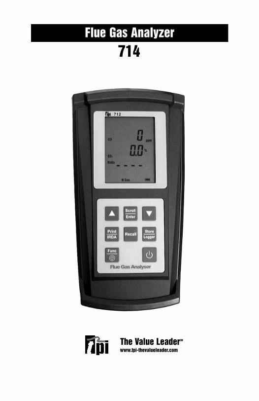
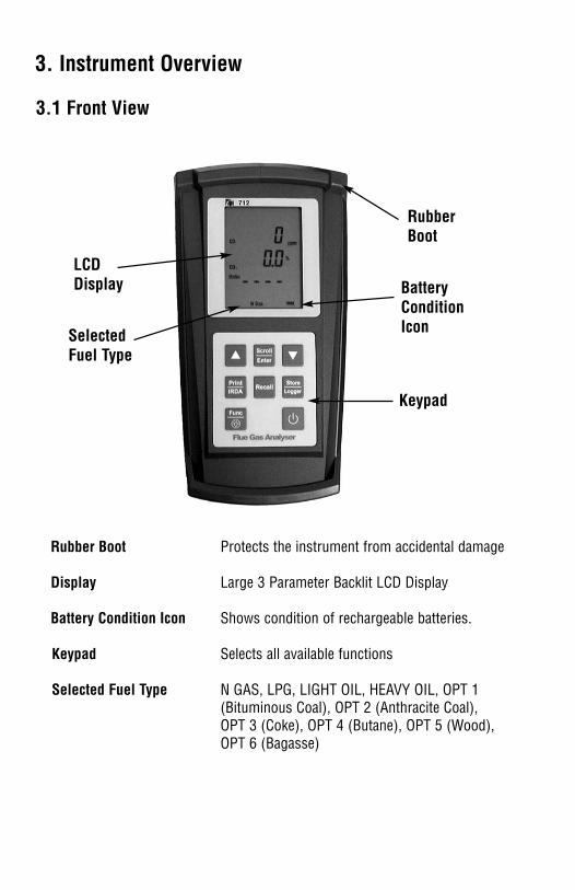
3. Instrument Overview
3.1 Front View
Rubber Boot Protects the instrument from accidental damage
Display Large 3 Parameter Backlit LCD Display
Battery Condition Icon Shows condition of rechargeable batteries.
Keypad Selects all available functions
Selected Fuel Type N GAS, LPG, LIGHT OIL, HEAVY OIL, OPT 1 (Bituminous Coal), OPT 2 (Anthracite Coal), OPT 3 (Coke), OPT 4 (Butane), OPT 5 (Wood), OPT 6 (Bagasse)
RubberBoot
LCDDisplay
Keypad
BatteryConditionIconSelected
Fuel Type
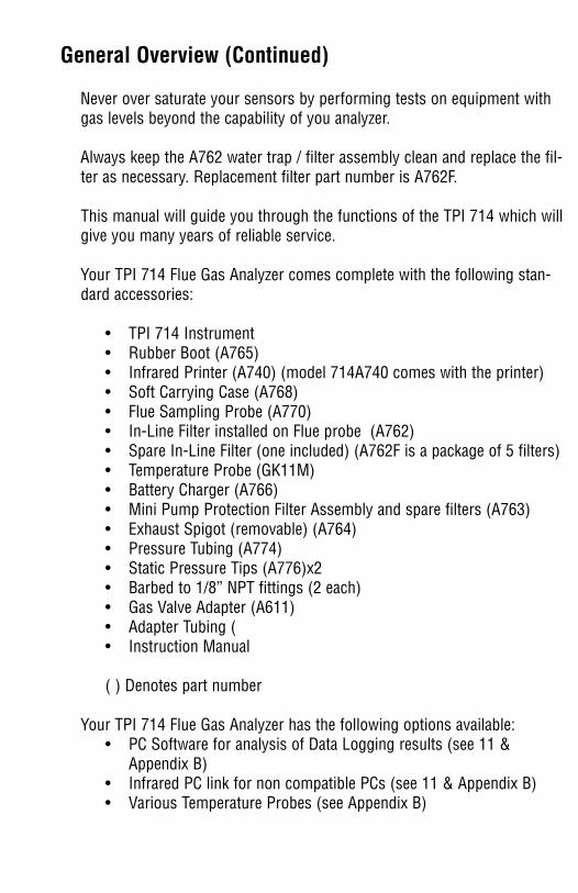
General Overview (Continued)
Never over saturate your sensors by performing tests on equipment withgas levels beyond the capability of you analyzer.
Always keep the A762 water trap / filter assembly clean and replace the fil-ter as necessary. Replacement filter part number is A762F.
This manual will guide you through the functions of the TPI 714 which willgive you many years of reliable service.
Your TPI 714 Flue Gas Analyzer comes complete with the following stan-dard accessories:
• TPI 714 Instrument• Rubber Boot (A765)• Infrared Printer (A740) (model 714A740 comes with the printer)• Soft Carrying Case (A768)• Flue Sampling Probe (A770)• In-Line Filter installed on Flue probe (A762)• Spare In-Line Filter (one included) (A762F is a package of 5 filters)• Temperature Probe (GK11M)• Battery Charger (A766)• Mini Pump Protection Filter Assembly and spare filters (A763)• Exhaust Spigot (removable) (A764)• Pressure Tubing (A774)• Static Pressure Tips (A776)x2• Barbed to 1/8” NPT fittings (2 each)• Gas Valve Adapter (A611)• Adapter Tubing ( • Instruction Manual
( ) Denotes part number
Your TPI 714 Flue Gas Analyzer has the following options available: • PC Software for analysis of Data Logging results (see 11 &
Appendix B)• Infrared PC link for non compatible PCs (see 11 & Appendix B)• Various Temperature Probes (see Appendix B)
3. Instrument Overview
3.1 Front View
Rubber Boot Protects the instrument from accidental damage
Display Large 3 Parameter Backlit LCD Display
Battery Condition Icon Shows condition of rechargeable batteries.
Keypad Selects all available functions
Selected Fuel Type N GAS, LPG, LIGHT OIL, HEAVY OIL, OPT 1 (Bituminous Coal), OPT 2 (Anthracite Coal), OPT 3 (Coke), OPT 4 (Butane), OPT 5 (Wood), OPT 6 (Bagasse)
RubberBoot
LCDDisplay
Keypad
BatteryConditionIconSelected
Fuel Type
General Overview (Continued)
Never over saturate your sensors by performing tests on equipment withgas levels beyond the capability of you analyzer.
Always keep the A762 water trap / filter assembly clean and replace the fil-ter as necessary. Replacement filter part number is A762F.
This manual will guide you through the functions of the TPI 714 which willgive you many years of reliable service.
Your TPI 714 Flue Gas Analyzer comes complete with the following stan-dard accessories:
• TPI 714 Instrument• Rubber Boot (A765)• Infrared Printer (A740) (model 714A740 comes with the printer)• Soft Carrying Case (A768)• Flue Sampling Probe (A770)• In-Line Filter installed on Flue probe (A762)• Spare In-Line Filter (one included) (A762F is a package of 5 filters)• Temperature Probe (GK11M)• Battery Charger (A766)• Mini Pump Protection Filter Assembly and spare filters (A763)• Exhaust Spigot (removable) (A764)• Pressure Tubing (A774)• Static Pressure Tips (A776)x2• Barbed to 1/8” NPT fittings (2 each)• Gas Valve Adapter (A611)• Adapter Tubing ( • Instruction Manual
( ) Denotes part number
Your TPI 714 Flue Gas Analyzer has the following options available: • PC Software for analysis of Data Logging results (see 11 &
Appendix B)• Infrared PC link for non compatible PCs (see 11 & Appendix B)• Various Temperature Probes (see Appendix B)
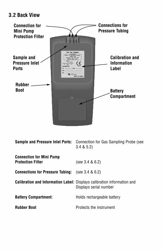
3.2 Back View
Sample and Pressure Inlet Ports: Connection for Gas Sampling Probe (see3.4 & 5.2)
Connection for Mini PumpProtection Filter (see 3.4 & 6.2)
Connections for Pressure Tubing: (see 3.4 & 6.2)
Calibration and Information Label: Displays calibration information andDisplays serial number
Battery Compartment: Holds rechargeable battery
Rubber Boot Protects the instrument
Calibration andInformationLabel
BatteryCompartment
RubberBoot
Connection forMini PumpProtection Filter
Connections forPressure Tubing
Sample andPressure InletPorts
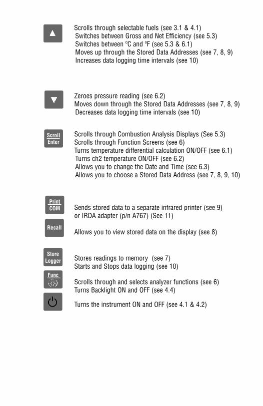
Scrolls through selectable fuels (see 3.1 & 4.1)Switches between Gross and Net Efficiency (see 5.3)Switches between ºC and ºF (see 5.3 & 6.1)Moves up through the Stored Data Addresses (see 7, 8, 9)Increases data logging time intervals (see 10)
Zeroes pressure reading (see 6.2)Moves down through the Stored Data Addresses (see 7, 8, 9)Decreases data logging time intervals (see 10)
Scrolls through Combustion Analysis Displays (See 5.3)Scrolls through Function Screens (see 6)Turns temperature differential calculation ON/OFF (see 6.1)Turns ch2 temperature ON/OFF (see 6.2)Allows you to change the Date and Time (see 6.3)Allows you to choose a Stored Data Address (see 7, 8, 9, 10)
Sends stored data to a separate infrared printer (see 9)or IRDA adapter (p/n A767) (See 11)
Allows you to view stored data on the display (see 8)
Stores readings to memory (see 7)Starts and Stops data logging (see 10)
Scrolls through and selects analyzer functions (see 6)Turns Backlight ON and OFF (see 4.4)
Turns the instrument ON and OFF (see 4.1 & 4.2)
PrintCOM
Recall
StoreLogger
Func
ScrollEnter
3.2 Back View
Sample and Pressure Inlet Ports: Connection for Gas Sampling Probe (see3.4 & 5.2)
Connection for Mini PumpProtection Filter (see 3.4 & 6.2)
Connections for Pressure Tubing: (see 3.4 & 6.2)
Calibration and Information Label: Displays calibration information andDisplays serial number
Battery Compartment: Holds rechargeable battery
Rubber Boot Protects the instrument
Calibration andInformationLabel
BatteryCompartment
RubberBoot
Connection forMini PumpProtection Filter
Connections forPressure Tubing
Sample andPressure InletPorts
Scrolls through selectable fuels (see 3.1 & 4.1)Switches between Gross and Net Efficiency (see 5.3)Switches between ºC and ºF (see 5.3 & 6.1)Moves up through the Stored Data Addresses (see 7, 8, 9)Increases data logging time intervals (see 10)
Zeroes pressure reading (see 6.2)Moves down through the Stored Data Addresses (see 7, 8, 9)Decreases data logging time intervals (see 10)
Scrolls through Combustion Analysis Displays (See 5.3)Scrolls through Function Screens (see 6)Turns temperature differential calculation ON/OFF (see 6.1)Turns ch2 temperature ON/OFF (see 6.2)Allows you to change the Date and Time (see 6.3)Allows you to choose a Stored Data Address (see 7, 8, 9, 10)
Sends stored data to a separate infrared printer (see 9)or IRDA adapter (p/n A767) (See 11)
Allows you to view stored data on the display (see 8)
Stores readings to memory (see 7)Starts and Stops data logging (see 10)
Scrolls through and selects analyzer functions (see 6)Turns Backlight ON and OFF (see 4.4)
Turns the instrument ON and OFF (see 4.1 & 4.2)
PrintCOM
Recall
StoreLogger
Func
ScrollEnter

3.3 Side ViewsExhaust Port Port for connection of Exhaust Adapter
Infrared Window Window for sending stored data to IR Printer or PC (see 9 & 11)
Rubber Boot Protects the instrument from accidental damage
ExhaustPort
InfraredWindow
RubberBoot
ChargerSocket
T1T2
P (+) P (-)
Gas Sampling Port
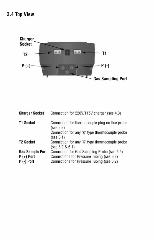
Charger Socket Connection for 220V/115V charger (see 4.3)
T1 Socket Connection for thermocouple plug on flue probe (see 5.2)Connection for any 'K' type thermocouple probe (see 6.1)
T2 Socket Connection for any 'K' type thermocouple probe (see 5.2 & 6.1)
Gas Sample Port Connection for Gas Sampling Probe (see 5.2)P (+) Port Connections for Pressure Tubing (see 6.2)P (-) Port Connections for Pressure Tubing (see 6.2)
3.4 Top View
3.3 Side ViewsExhaust Port Port for connection of Exhaust Adapter
Infrared Window Window for sending stored data to IR Printer or PC (see 9 & 11)
Rubber Boot Protects the instrument from accidental damage
ExhaustPort
InfraredWindow
RubberBoot
ChargerSocket
T1T2
P (+) P (-)
Gas Sampling Port
Charger Socket Connection for 220V/115V charger (see 4.3)
T1 Socket Connection for thermocouple plug on flue probe (see 5.2)Connection for any 'K' type thermocouple probe (see 6.1)
T2 Socket Connection for any 'K' type thermocouple probe (see 5.2 & 6.1)
Gas Sample Port Connection for Gas Sampling Probe (see 5.2)P (+) Port Connections for Pressure Tubing (see 6.2)P (-) Port Connections for Pressure Tubing (see 6.2)
3.4 Top View
4. Turning On & Off and Charging
4.1 Turning On
Always: - Before turning on please ensure that the Mini Pump Protection Filterassembly and the Temperature Sampling Probe complete with In-Line Filter or theTubing & In-Line Filter for Leak Detection are not connected to the Gas SamplePort (see 2.2 or 2.4)
Press and hold down the Power Key and the TPI 714 will start its 30 secondcountdown 'PURGE' will be displayed: - The instrument MUST be turned on in aclean air environment as the 30 second purge will set the Carbon Monoxide levelto Zero and the Oxygen to 20.9%. The 714 may re-start the coutdown severaltimes before normal operation. This means the sensors are still initializingand is normal.
Ensure that the filters are clean and dry as dirty or wet filters will result in a lossof flow rate and 'Lo Flo' will be displayed to inform you that filters should bechanged
During the last 20 seconds of the 30 second purge time the user can scrollthrough the following Fuels: - Natural Gas, LPG, Light Oil, Heavy Oil, OPT1 :Bituminous Coal, OPT 2 : Anthracite Coal, OPT 3: Coke, OPT 4: Butane, OPT 5:Wood (Dry), OPT 6: Bagasse by pressing the Up Arrow Key to select the Fuelthey are working with. When desired fuel is displayed release the key, displayedfuel is now selected.
After the 30 second countdown the instrument is ready to take Flue, Temperature,Pressure or Leak Detection readings and Combustion Display 1 will be the firstdisplay.
The 714 will auto power off if no keys have been pressed for 10 minutes and theCO level is below 15ppm.
The Scroll/Enter Key allows you to scroll through the combustion displays as out-lined in section 5.3. The Func Key is used to select the 714 function mode andallows you to set it to be a combustion analyzer, manometer, thermometer, orcombustible leak detector. In addition, the Func Key is used to access the dateand time display. See section 6 for more information on the Func Key.
4.2 Turning Off
Always: - Before turning off return the instrument to a clean air environment andallow the Carbon Monoxide level to return to below 15ppm and the Oxygen levelto return to 20.9% (± 0.3%) Press the Power Key to turn the instrument off:-NOTE Should you attempt to turn the instrument Off and the CO reading is above15ppm then the instrument will remain On and a short Beep will be heard. TheInstrument can only be switched off if the CO is below 15ppm
The instrument has an auto shut off after 10 minutes should no keys have beenpressed for this period and as mentioned above that the CO is below 15ppm.Should the CO be above 15ppm then the 10 minute auto shut off countdown willnot begin till the CO has gone below 15ppm
4.3 Charging
Plug the Charger supplied into the charger socket on the instrument (see 3.4). Ifthe instrument is turned on then a charging symbol will be displayed. Should theinstrument then be turned off, turn off automatically or be turned off when thecharger is plugged in then the charging symbol will not be displayed BUT theinstrument will still be charging.
The instrument should be charged overnight for a period of 10 to 12 hours andwill give over 6 hours Operating Time. If a beeping noise is heard during chargingdisconnect the charger. This is an indication of something wrong in the chargingcircuit. Please contact TPI technical assistance at 800-368-5719.
Alternatively, the instrument can be used when plugged into the charger.
4.4 Activating the Backlight
The display backlight can be activated at any time by pressing and holding downthe Func Key for approximately 2 seconds. The backlight will automatically shutoff after approximately 20 seconds to preserve battery life.
NOTE: When selecting oil as fuel be sure to use the optionaloil filter (A773) or readings could become erratic. SeeAppendix E for installation instructions.
COMBUSTION ANALYSIS (Continued)
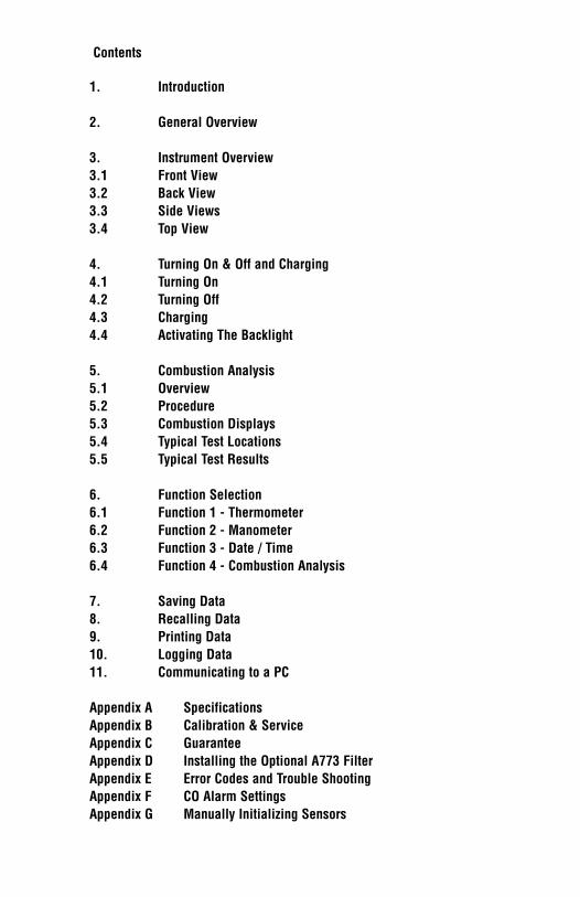
5.2 Procedure
1. Turn the 714 on as outlined in section 4.1. At any time you can activate theBacklight by holding down the Func/Backlight Key for 2 seconds. The back-light will automatically shut off after 20 seconds to preserve battery life.
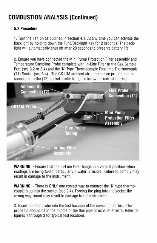
2. Ensure you have connected the Mini Pump Protection Filter assembly andTemperature Sampling Probe complete with In-Line Filter to the Gas SamplePort (see 3.2 or 3.4) and the 'K' Type Thermocouple Plug into Thermocouple(T1) Socket (see 3.4). The GK11M ambient air temperature probe must beconnected to the (T2) socket. (refer to figure below for correct hookup)
WARNING: - Ensure that the In-Line Filter hangs in a vertical position whenreadings are being taken, particularly if water is visible. Failure to comply mayresult in damage to the instrument.
WARNING: - There is ONLY one correct way to connect the 'K' type thermo-couple plug into the socket (see 2.4). Forcing the plug into the socket thewrong way round may result in damage to the instrument.
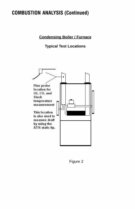
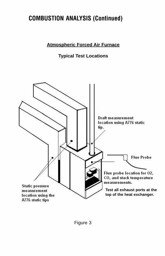
3. Insert the flue probe into the test location of the device under test. Theprobe tip should be in the middle of the flue pipe or exhaust stream. Refer tofigures 1 through 3 for typical test locations.
Mini PumpProtection FilterAssembly
Ambient AirConnection (T2)
GK11M Probe
Flue ProbeConnection (T1)
In-line FilterAssembly
Flue Probe Tubing
5. COMBUSTION ANALYSIS
5.1 Overview
Testing for carbon monoxide, oxygen, and stack temperature is very important tothe overall safety and efficiency of heating equipment. The following guidelinesand descriptions are generic and meant to provide you with a basic understand-ing of combustion testing. TPI always recommends you contact the manufacturerof the device under test, obtain information specific to the device, and follow theprocedures and safety guidelines for performing tests and affecting repairs.
In general, for most applications flue gas samples should be taken prior to thedraft diverter or any other opening that allows room air to enter the system. Thisprevents room air from mixing with gases in the flue and diluting the test sample.To ensure accurate and consistent combustion tests, it is important gas and tem-perature samples be taken at the same location. This is easy with the TPI flueprobe because the temperature sensor is an integral part of the probe.
Prior to taking a sample, the device under test should be on and operating.Putting the flue probe in the sample area prior to starting the device may causesaturation of the sensors due to the higher initial concentration of carbon monox-ide that may be encountered upon start up. If this happens, allow your analyzer topurge in fresh air until the carbon monoxide level returns to 0 ppm and the oxy-gen level returns to 20.9%. This may take more than an hour depending on howsaturated the sensors are.
The included figures show locations for performing tests on commonly encoun-tered equipment. Remember to consult with the manufacturer of the device undertest for specific test information.
NOTE: When selecting oil as fuel be sure to use the optionaloil filter (A773) or readings could become erratic. SeeAppendix E for installation instructions.
COMBUSTION ANALYSIS (Continued)
5.2 Procedure
1. Turn the 714 on as outlined in section 4.1. At any time you can activate theBacklight by holding down the Func/Backlight Key for 2 seconds. The back-light will automatically shut off after 20 seconds to preserve battery life.
2. Ensure you have connected the Mini Pump Protection Filter assembly andTemperature Sampling Probe complete with In-Line Filter to the Gas SamplePort (see 3.2 or 3.4) and the 'K' Type Thermocouple Plug into Thermocouple(T1) Socket (see 3.4). The GK11M ambient air temperature probe must beconnected to the (T2) socket. (refer to figure below for correct hookup)
WARNING: - Ensure that the In-Line Filter hangs in a vertical position whenreadings are being taken, particularly if water is visible. Failure to comply mayresult in damage to the instrument.
WARNING: - There is ONLY one correct way to connect the 'K' type thermo-couple plug into the socket (see 2.4). Forcing the plug into the socket thewrong way round may result in damage to the instrument.
3. Insert the flue probe into the test location of the device under test. Theprobe tip should be in the middle of the flue pipe or exhaust stream. Refer tofigures 1 through 3 for typical test locations.
Mini PumpProtection FilterAssembly
Ambient AirConnection (T2)
GK11M Probe
Flue ProbeConnection (T1)
In-line FilterAssembly
Flue Probe Tubing
5. COMBUSTION ANALYSIS
5.1 Overview
Testing for carbon monoxide, oxygen, and stack temperature is very important tothe overall safety and efficiency of heating equipment. The following guidelinesand descriptions are generic and meant to provide you with a basic understand-ing of combustion testing. TPI always recommends you contact the manufacturerof the device under test, obtain information specific to the device, and follow theprocedures and safety guidelines for performing tests and affecting repairs.
In general, for most applications flue gas samples should be taken prior to thedraft diverter or any other opening that allows room air to enter the system. Thisprevents room air from mixing with gases in the flue and diluting the test sample.To ensure accurate and consistent combustion tests, it is important gas and tem-perature samples be taken at the same location. This is easy with the TPI flueprobe because the temperature sensor is an integral part of the probe.
Prior to taking a sample, the device under test should be on and operating.Putting the flue probe in the sample area prior to starting the device may causesaturation of the sensors due to the higher initial concentration of carbon monox-ide that may be encountered upon start up. If this happens, allow your analyzer topurge in fresh air until the carbon monoxide level returns to 0 ppm and the oxy-gen level returns to 20.9%. This may take more than an hour depending on howsaturated the sensors are.
The included figures show locations for performing tests on commonly encoun-tered equipment. Remember to consult with the manufacturer of the device undertest for specific test information.
NOTE: When selecting oil as fuel be sure to use the optionaloil filter (A773) or readings could become erratic. SeeAppendix E for installation instructions.
COMBUSTION ANALYSIS (Continued)
5.3 Combustion Displays (continued)
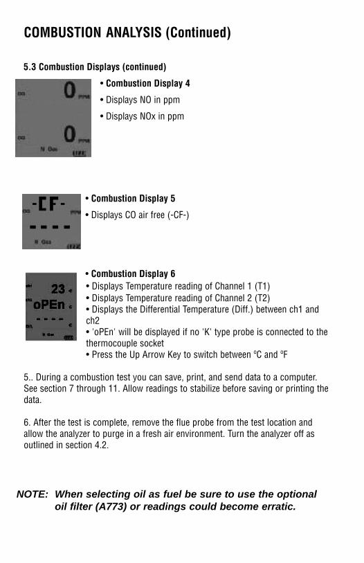
• Combustion Display 4
• Displays NO in ppm
• Displays NOx in ppm
• Combustion Display 5
• Displays CO air free (-CF-)
• Combustion Display 6• Displays Temperature reading of Channel 1 (T1) • Displays Temperature reading of Channel 2 (T2) • Displays the Differential Temperature (Diff.) between ch1 andch2 • 'oPEn' will be displayed if no 'K' type probe is connected to thethermocouple socket• Press the Up Arrow Key to switch between ºC and ºF
5.. During a combustion test you can save, print, and send data to a computer.See section 7 through 11. Allow readings to stabilize before saving or printing thedata.
6. After the test is complete, remove the flue probe from the test location andallow the analyzer to purge in a fresh air environment. Turn the analyzer off asoutlined in section 4.2.
COMBUSTION ANALYSIS (Continued)
4. As seen below, use the Scroll/Enter Key to move through the various com-bustion displays.
5.3 Combustion Displays
You can move through the following Combustion Analysis Screens by repeat-edly pressing Scroll/Enter:
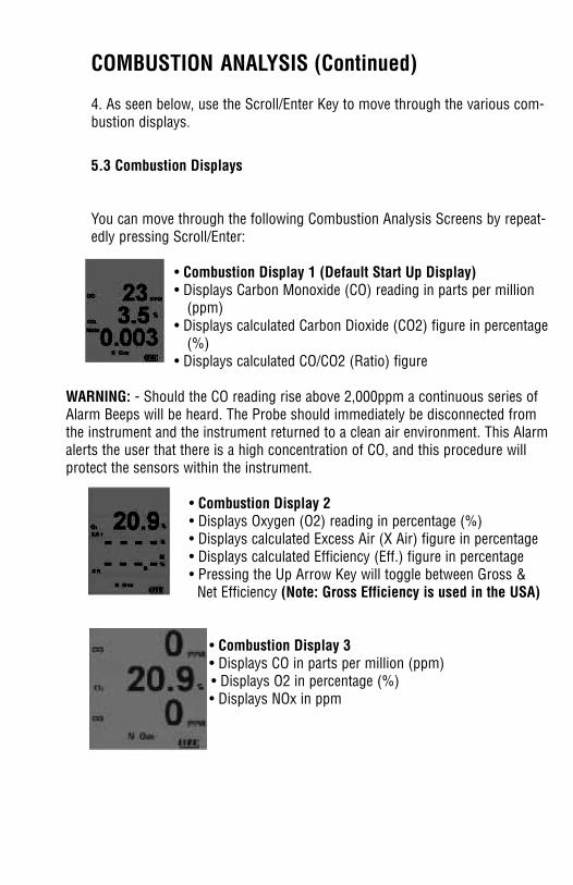
• Combustion Display 1 (Default Start Up Display)• Displays Carbon Monoxide (CO) reading in parts per million
(ppm)• Displays calculated Carbon Dioxide (CO2) figure in percentage
(%)• Displays calculated CO/CO2 (Ratio) figure
WARNING: - Should the CO reading rise above 2,000ppm a continuous series ofAlarm Beeps will be heard. The Probe should immediately be disconnected fromthe instrument and the instrument returned to a clean air environment. This Alarmalerts the user that there is a high concentration of CO, and this procedure willprotect the sensors within the instrument.
• Combustion Display 2• Displays Oxygen (O2) reading in percentage (%)• Displays calculated Excess Air (X Air) figure in percentage • Displays calculated Efficiency (Eff.) figure in percentage • Pressing the Up Arrow Key will toggle between Gross &
Net Efficiency (Note: Gross Efficiency is used in the USA)
• Combustion Display 3• Displays CO in parts per million (ppm)• Displays O2 in percentage (%)• Displays NOx in ppm
NOTE: When selecting oil as fuel be sure to use the optionaloil filter (A773) or readings could become erratic.
COMBUSTION ANALYSIS (Continued)
5.3 Combustion Displays (continued)
• Combustion Display 4
• Displays NO in ppm
• Displays NOx in ppm
• Combustion Display 5
• Displays CO air free (-CF-)
• Combustion Display 6• Displays Temperature reading of Channel 1 (T1) • Displays Temperature reading of Channel 2 (T2) • Displays the Differential Temperature (Diff.) between ch1 andch2 • 'oPEn' will be displayed if no 'K' type probe is connected to thethermocouple socket• Press the Up Arrow Key to switch between ºC and ºF
5.. During a combustion test you can save, print, and send data to a computer.See section 7 through 11. Allow readings to stabilize before saving or printing thedata.
6. After the test is complete, remove the flue probe from the test location andallow the analyzer to purge in a fresh air environment. Turn the analyzer off asoutlined in section 4.2.
COMBUSTION ANALYSIS (Continued)
4. As seen below, use the Scroll/Enter Key to move through the various com-bustion displays.
5.3 Combustion Displays
You can move through the following Combustion Analysis Screens by repeat-edly pressing Scroll/Enter:
• Combustion Display 1 (Default Start Up Display)• Displays Carbon Monoxide (CO) reading in parts per million
(ppm)• Displays calculated Carbon Dioxide (CO2) figure in percentage
(%)• Displays calculated CO/CO2 (Ratio) figure
WARNING: - Should the CO reading rise above 2,000ppm a continuous series ofAlarm Beeps will be heard. The Probe should immediately be disconnected fromthe instrument and the instrument returned to a clean air environment. This Alarmalerts the user that there is a high concentration of CO, and this procedure willprotect the sensors within the instrument.
• Combustion Display 2• Displays Oxygen (O2) reading in percentage (%)• Displays calculated Excess Air (X Air) figure in percentage • Displays calculated Efficiency (Eff.) figure in percentage • Pressing the Up Arrow Key will toggle between Gross &
Net Efficiency (Note: Gross Efficiency is used in the USA)
• Combustion Display 3• Displays CO in parts per million (ppm)• Displays O2 in percentage (%)• Displays NOx in ppm
NOTE: When selecting oil as fuel be sure to use the optionaloil filter (A773) or readings could become erratic.
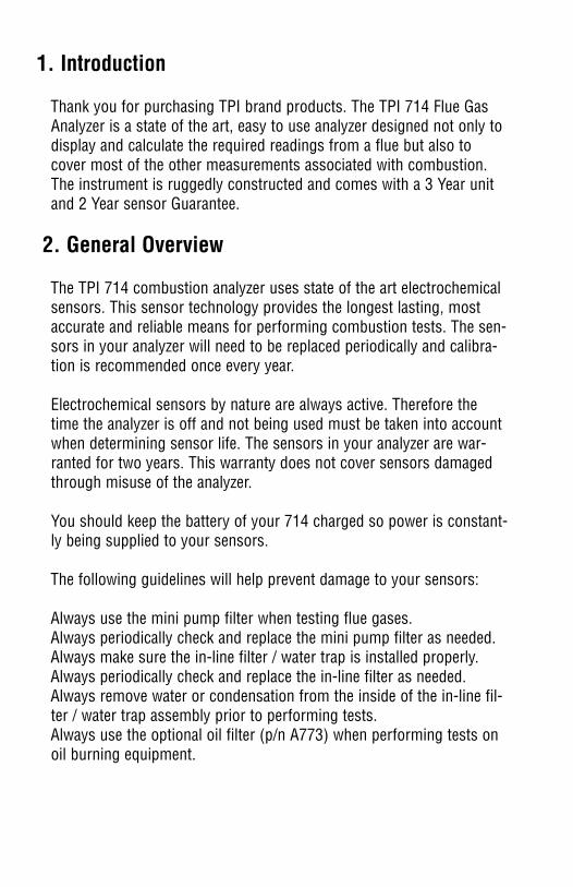
5.4 TYPICAL TEST LOCATIONS
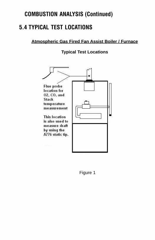
Atmospheric Gas Fired Fan Assist Boiler / Furnace
Typical Test Locations
COMBUSTION ANALYSIS (Continued) COMBUSTION ANALYSIS (Continued)
Condensing Boiler / Furnace
Typical Test Locations
Figure 1
Figure 2
5.4 TYPICAL TEST LOCATIONS
Atmospheric Gas Fired Fan Assist Boiler / Furnace
Typical Test Locations
COMBUSTION ANALYSIS (Continued) COMBUSTION ANALYSIS (Continued)
Condensing Boiler / Furnace
Typical Test Locations
Figure 1
Figure 2
COMBUSTION ANALYSIS (Continued)
Test all exhaust ports at thetop of the heat exchanger.
Atmospheric Forced Air Furnace
Typical Test Locations
COMBUSTION ANALYSIS (Continued)
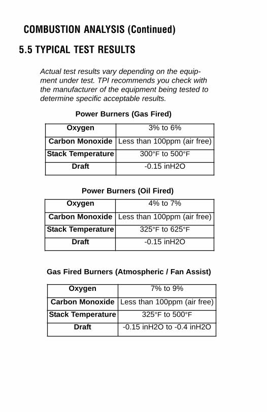
5.5 TYPICAL TEST RESULTS
Actual test results vary depending on the equip-ment under test. TPI recommends you check withthe manufacturer of the equipment being tested todetermine specific acceptable results.
Oxygen 3% to 6%
Carbon Monoxide Less than 100ppm (air free)
Stack Temperature 300°F to 500°F
Draft -0.15 inH2O
Oxygen 4% to 7%
Carbon Monoxide Less than 100ppm (air free)
Stack Temperature 325°F to 625°F
Draft -0.15 inH2O
Power Burners (Gas Fired)
Power Burners (Oil Fired)
Oxygen 7% to 9%
Carbon Monoxide Less than 100ppm (air free)
Stack Temperature 325°F to 500°F
Draft -0.15 inH2O to -0.4 inH2O
Gas Fired Burners (Atmospheric / Fan Assist)
Figure 3
COMBUSTION ANALYSIS (Continued)
Test all exhaust ports at thetop of the heat exchanger.
Atmospheric Forced Air Furnace
Typical Test Locations
COMBUSTION ANALYSIS (Continued)
5.5 TYPICAL TEST RESULTS
Actual test results vary depending on the equip-ment under test. TPI recommends you check withthe manufacturer of the equipment being tested todetermine specific acceptable results.
Oxygen 3% to 6%
Carbon Monoxide Less than 100ppm (air free)
Stack Temperature 300°F to 500°F
Draft -0.15 inH2O
Oxygen 4% to 7%
Carbon Monoxide Less than 100ppm (air free)
Stack Temperature 325°F to 625°F
Draft -0.15 inH2O
Power Burners (Gas Fired)
Power Burners (Oil Fired)
Oxygen 7% to 9%
Carbon Monoxide Less than 100ppm (air free)
Stack Temperature 325°F to 500°F
Draft -0.15 inH2O to -0.4 inH2O
Gas Fired Burners (Atmospheric / Fan Assist)
Figure 3
6.2 Function 2: - Manometer
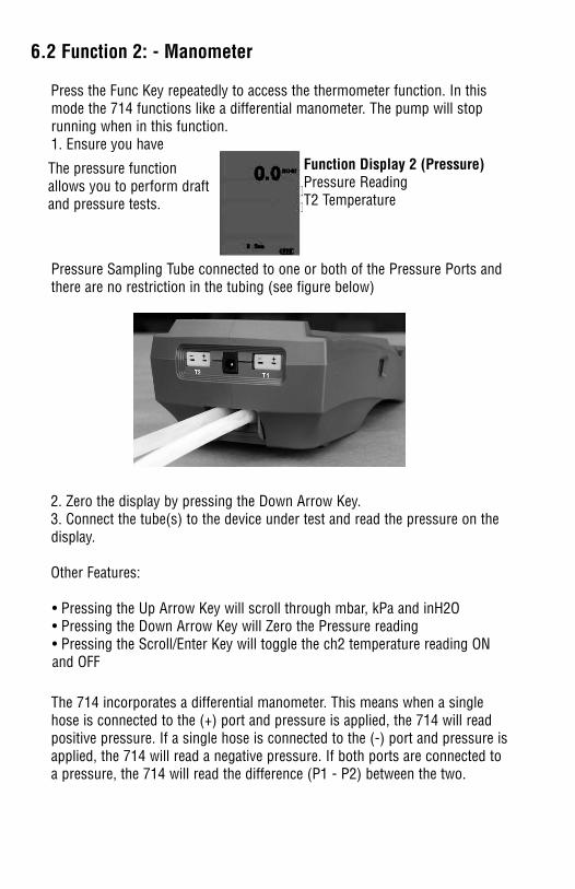
Press the Func Key repeatedly to access the thermometer function. In thismode the 714 functions like a differential manometer. The pump will stoprunning when in this function.1. Ensure you have
Pressure Sampling Tube connected to one or both of the Pressure Ports andthere are no restriction in the tubing (see figure below)
2. Zero the display by pressing the Down Arrow Key.3. Connect the tube(s) to the device under test and read the pressure on thedisplay.
Other Features:
• Pressing the Up Arrow Key will scroll through mbar, kPa and inH2O• Pressing the Down Arrow Key will Zero the Pressure reading• Pressing the Scroll/Enter Key will toggle the ch2 temperature reading ONand OFF
The 714 incorporates a differential manometer. This means when a singlehose is connected to the (+) port and pressure is applied, the 714 will readpositive pressure. If a single hose is connected to the (-) port and pressure isapplied, the 714 will read a negative pressure. If both ports are connected toa pressure, the 714 will read the difference (P1 - P2) between the two.
6. FUNCTION SELECTIONPressing the Func Key enables access to the different functions available onthe 714. Available functions are: Combustion Analyzer, Thermometer,Manometer, and Date / Time display.
6.1 Function 1: - Thermometer
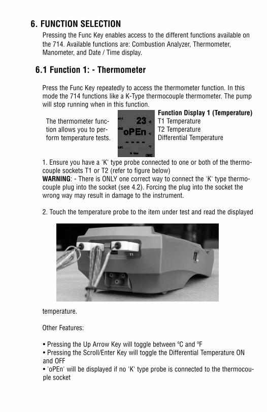
Press the Func Key repeatedly to access the thermometer function. In thismode the 714 functions like a K-Type thermocouple thermometer. The pumpwill stop running when in this function.
1. Ensure you have a 'K' type probe connected to one or both of the thermo-couple sockets T1 or T2 (refer to figure below)WARNING: - There is ONLY one correct way to connect the 'K' type thermo-couple plug into the socket (see 4.2). Forcing the plug into the socket thewrong way may result in damage to the instrument.
2. Touch the temperature probe to the item under test and read the displayed
temperature.
Other Features:
• Pressing the Up Arrow Key will toggle between ºC and ºF• Pressing the Scroll/Enter Key will toggle the Differential Temperature ON and OFF• 'oPEn' will be displayed if no 'K' type probe is connected to the thermocou-ple socket
The thermometer func-tion allows you to per-form temperature tests.
The pressure functionallows you to perform draftand pressure tests.
Function Display 1 (Temperature)T1 TemperatureT2 TemperatureDifferential Temperature
Function Display 2 (Pressure)Pressure ReadingT2 Temperature
6.2 Function 2: - Manometer
Press the Func Key repeatedly to access the thermometer function. In thismode the 714 functions like a differential manometer. The pump will stoprunning when in this function.1. Ensure you have
Pressure Sampling Tube connected to one or both of the Pressure Ports andthere are no restriction in the tubing (see figure below)
2. Zero the display by pressing the Down Arrow Key.3. Connect the tube(s) to the device under test and read the pressure on thedisplay.
Other Features:
• Pressing the Up Arrow Key will scroll through mbar, kPa and inH2O• Pressing the Down Arrow Key will Zero the Pressure reading• Pressing the Scroll/Enter Key will toggle the ch2 temperature reading ONand OFF
The 714 incorporates a differential manometer. This means when a singlehose is connected to the (+) port and pressure is applied, the 714 will readpositive pressure. If a single hose is connected to the (-) port and pressure isapplied, the 714 will read a negative pressure. If both ports are connected toa pressure, the 714 will read the difference (P1 - P2) between the two.
6. FUNCTION SELECTIONPressing the Func Key enables access to the different functions available onthe 714. Available functions are: Combustion Analyzer, Thermometer,Manometer, and Date / Time display.
6.1 Function 1: - Thermometer
Press the Func Key repeatedly to access the thermometer function. In thismode the 714 functions like a K-Type thermocouple thermometer. The pumpwill stop running when in this function.
1. Ensure you have a 'K' type probe connected to one or both of the thermo-couple sockets T1 or T2 (refer to figure below)WARNING: - There is ONLY one correct way to connect the 'K' type thermo-couple plug into the socket (see 4.2). Forcing the plug into the socket thewrong way may result in damage to the instrument.
2. Touch the temperature probe to the item under test and read the displayed
temperature.
Other Features:
• Pressing the Up Arrow Key will toggle between ºC and ºF• Pressing the Scroll/Enter Key will toggle the Differential Temperature ON and OFF• 'oPEn' will be displayed if no 'K' type probe is connected to the thermocou-ple socket
The thermometer func-tion allows you to per-form temperature tests.
The pressure functionallows you to perform draftand pressure tests.
Function Display 1 (Temperature)T1 TemperatureT2 TemperatureDifferential Temperature
Function Display 2 (Pressure)Pressure ReadingT2 Temperature
7. SAVING DATA
During testing, data can be stored for later retrieval by following these steps:
1. Press the Store/Logger Key once'Addr' will be displayed on the top line along with 'SA ' and a location numberfrom 0 to 9 will be flashing on the screen. Select the required address locationthat you wish to save the data to by pressing the Up and Down Arrow Keys
2. Press the Scroll/Enter Key onceThe location number which you have chosen will stop flashing and after about3 seconds the instrument will return to the screen/function you were previous-ly on.
You have just successfully stored a set of readings which can be eitherreviewed on screen (see 6) or sent to the IR printer (see 9)
When data is saved, all data previously in the address will be overwritten.Whensaving pressure/draft readings, select an address different from the one usedto save combustion readings.
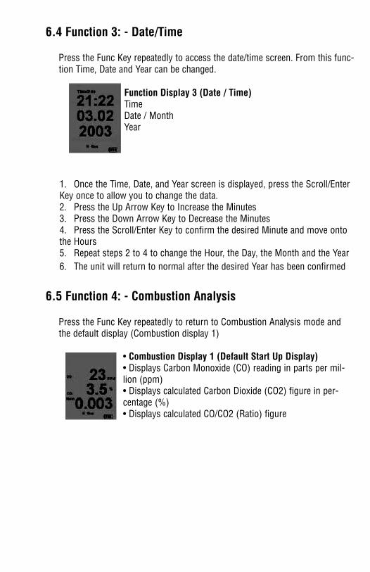
6.4 Function 3: - Date/Time
Press the Func Key repeatedly to access the date/time screen. From this func-tion Time, Date and Year can be changed.
1. Once the Time, Date, and Year screen is displayed, press the Scroll/EnterKey once to allow you to change the data.2. Press the Up Arrow Key to Increase the Minutes3. Press the Down Arrow Key to Decrease the Minutes4. Press the Scroll/Enter Key to confirm the desired Minute and move ontothe Hours5. Repeat steps 2 to 4 to change the Hour, the Day, the Month and the Year6. The unit will return to normal after the desired Year has been confirmed
6.5 Function 4: - Combustion Analysis
Press the Func Key repeatedly to return to Combustion Analysis mode andthe default display (Combustion display 1)
• Combustion Display 1 (Default Start Up Display)• Displays Carbon Monoxide (CO) reading in parts per mil-lion (ppm)• Displays calculated Carbon Dioxide (CO2) figure in per-centage (%)• Displays calculated CO/CO2 (Ratio) figure
Function Display 3 (Date / Time)TimeDate / MonthYear
7. SAVING DATA
During testing, data can be stored for later retrieval by following these steps:
1. Press the Store/Logger Key once'Addr' will be displayed on the top line along with 'SA ' and a location numberfrom 0 to 9 will be flashing on the screen. Select the required address locationthat you wish to save the data to by pressing the Up and Down Arrow Keys
2. Press the Scroll/Enter Key onceThe location number which you have chosen will stop flashing and after about3 seconds the instrument will return to the screen/function you were previous-ly on.
You have just successfully stored a set of readings which can be eitherreviewed on screen (see 6) or sent to the IR printer (see 9)
When data is saved, all data previously in the address will be overwritten.Whensaving pressure/draft readings, select an address different from the one usedto save combustion readings.
6.4 Function 3: - Date/Time
Press the Func Key repeatedly to access the date/time screen. From this func-tion Time, Date and Year can be changed.
1. Once the Time, Date, and Year screen is displayed, press the Scroll/EnterKey once to allow you to change the data.2. Press the Up Arrow Key to Increase the Minutes3. Press the Down Arrow Key to Decrease the Minutes4. Press the Scroll/Enter Key to confirm the desired Minute and move ontothe Hours5. Repeat steps 2 to 4 to change the Hour, the Day, the Month and the Year6. The unit will return to normal after the desired Year has been confirmed
6.5 Function 4: - Combustion Analysis
Press the Func Key repeatedly to return to Combustion Analysis mode andthe default display (Combustion display 1)
• Combustion Display 1 (Default Start Up Display)• Displays Carbon Monoxide (CO) reading in parts per mil-lion (ppm)• Displays calculated Carbon Dioxide (CO2) figure in per-centage (%)• Displays calculated CO/CO2 (Ratio) figure
Function Display 3 (Date / Time)TimeDate / MonthYear
9. PRINTING DATA
WARNING: - To operate correctly there must be a clear line of sight betweenthe Infrared Window on the instrument (see 3.3) and the Infrared Window onthe IR Printer (see Printer instructions). Place the printer so it is no closerthan approximately 6 inches from the analyzer.
1. Press the Print/COM Key once'rEAL' and “Stor’ will be displayed and ‘rEAL’ will be flashing. Selecting ‘rEAL’ will cause the 714 to print the test data currently on thedisplay (real time data). Selecting ‘Stor’ will cause the 714 to print datastored in memory. Use the Up and Down Arrow Keys to select the desiredprint mode and press the Scroll/Enter Key.
REAL Print Mode - If rEAL print mode is selected, the analyzer will dis-play ‘Wait’ ‘out’ and bars will change position on the LCD until printing iscomplete.
After printing is complete, ‘End’ will be displayed and ‘YES’ (or ‘no’) willblink. Selecting ‘YES’ will return the 714 to normal operation, selecting‘no’ will return the 714 to the print selection screen so you can printagain. Use the Up and Down Arrow Keys to make the selection and pressthe Scroll/Enter Key.
STOR Print Mode - If Stor mode is selected, 'Addr' will be displayed onthe top line along with 'SA ' and a location number from 0 to 9 will beflashing on the screen. Select the required address location that you wishto print data from by pressing the Up and Down Arrow Keys and pressthe ‘Scroll/Enter’ Key. The analyzer will display ‘Wait’, ‘out’ and bars willchange position on the LCD until printing is complete.
After printing is complete, ‘End’ will be displayed and ‘YES’ (or ‘no’) willblink. Selecting ‘YES’ will return the 714 to normal operation, selecting‘no’ will return the 714 to the print selection screen so you can printagain. Use the Up and Down Arrow Keys to make the selection and pressthe Scroll/Enter Key.
Combustion and pressure/draft printouts must be performed separately.Perform a combustion test and save the data. Perform a pressure/drafttest and save the data in a different address. Print each address sepa-rately.
8. RECALLING DATA1. Press the Recall Key once
'Addr' will be displayed on the top line along with 'SA ' and a locationnumber from 0 to 9 will be flashing on the screen. Select the requiredaddress location that you wish to save the data to by pressing the Up andDown Arrow Keys
2. Press the Scroll/Enter Key onceThe Time & Date of the Saved Data from the selected address location willbe displayed flashing on the screen.The rest of the Saved Data at this address location can be reviewed bypressing the Up and Down Arrow Keys
4. Press the Scroll/Enter Key once when you are finished reviewing the data.'End' will be displayed with 'YES' flashing
5. Press the Scroll/Enter Key once to EXIT or
6. Press the Up or Down Arrow Keys'End' will be displayed with 'no' flashing
7. Press the Scroll/Enter Key once to CHOOSE another address location toreview and repeat steps 2 to 5
11. COMMUNICATING TO A PCThis function requires the optional A767 IrDA Adapter. Please refer to the A767 manual for complete instructions on using the adapter. Optional software part number A772 is available for use with MICROSOFT ® WINDOWS or communication can be performed using MICROSOFT ® HYPER TERMINAL.
USING MICROSOFT ®® HYPER TERMINAL
1. Open MICROSOFT ® HYPER TERMINAL and set the COM port as fol-lows:
Baud: 9600Data Bits: 8Parity: NoneStop Bit: 1Flow Control: None
2. Press and hold the Print/Com Key until a beep is heard and ‘COMM’ isflashing in the upper right hand of the display.
3. Connect the A767 to the computer and turn it on. Place the A767 6 to8 inches from the 714 with a clear line of sight between the sensorwindows.
4. Press and hold the Recall key until a beep is heard. The 714 will dis-play ‘Real’, ‘Stor’, and ‘Logg’. Using the Up and Down Arrow Keys,select the desired transfer mode and press the Scroll/Enter Key.
Real : This mode will transfer current readings (real-time) to the com-puter. After communication the 714 will return to normal operation.
Stor: This mode will transfer the 10 save locations to the computer.While the 714 is communicating ‘Stor Out’ will be displayed. Aftercommunication is complete the 714 will return to normal operation.
Logg: This mode will transfer logged data locations 0 through 99 ofthe selected page (0 through 3). When the 714 is communicating‘Logg Out’ will be displayed. After communication is complete the 714will return to normal operation.
10. LOGGING DATA
1. Press and hold down the Store/Logger Key for approximately 2 seconds'S-t' will be displayed with '05 S' flashing indicating that the instrumentwill log a set of 100 readings every 5 seconds.You can choose from the following logging times '05 S' (100 readings total, 1 reading recorded every 5 seconds)'10 S' (100 readings total, 1 reading recorded every 10 seconds) '20 S' (100 readings total, 1 reading recorded every 20 seconds)'30 S' (100 readings total, 1 reading recorded every 30 seconds) '01 M' (100 readings total, 1 reading recorded every 1 minute)'03 M' (100 readings total, 1 reading recorded every 3 minutes) by pressing either the Up or Down Arrow Keys
2. Press the Scroll/Enter Key once'PAGE PA ' will be displayed and a page number from 0 to 3 will be flash-ing.Select the required page location that you wish to log the saved data to bypressing the Up and Down Arrow Keys
3. Press the Scroll/Enter Key onceThe instrument will return to the previous screen/function with 'Logger' flashing on the top line.The instrument will continue logging until all 100 readings have beensaved or you press and hold down the Store/Logger Key. WARNING: - The instrument will not Turn Off if data logging is commenc-ing. A beep will be heard to warn you of this fact if you try to turn theinstrument off.
Logged data can only be retrieved by sending the information to a com-puter. This requires the use of the optional A767 IRDA adapter andeither Microsoft Hyper Terminal or the optional PC software part num-ber A772.
Appendix A : SPECIFICATIONS (Continued)
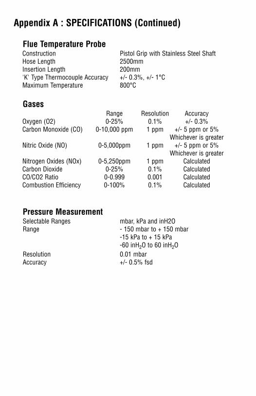
Flue Temperature ProbeConstruction Pistol Grip with Stainless Steel ShaftHose Length 2500mmInsertion Length 200mm'K' Type Thermocouple Accuracy +/- 0.3%, +/- 1°CMaximum Temperature 800°C
GasesRange Resolution Accuracy
Oxygen (O2) 0-25% 0.1% +/- 0.3%Carbon Monoxide (CO) 0-10,000 ppm 1 ppm +/- 5 ppm or 5%
Whichever is greaterNitric Oxide (NO) 0-5,000ppm 1 ppm +/- 5 ppm or 5%
Whichever is greaterNitrogen Oxides (NOx) 0-5,250ppm 1 ppm CalculatedCarbon Dioxide 0-25% 0.1% CalculatedCO/CO2 Ratio 0-0.999 0.001 CalculatedCombustion Efficiency 0-100% 0.1% Calculated
Pressure MeasurementSelectable Ranges mbar, kPa and inH2ORange - 150 mbar to + 150 mbar
-15 kPa to + 15 kPa-60 inH2O to 60 inH2O
Resolution 0.01 mbarAccuracy +/- 0.5% fsd
COMMUNICATING TO A PC (Continued)
5. To return to normal operation press and hold the Print/Comm Key until a beep is heard and ‘COMM’ is no longer displayed.
Requests for stored and real data can be made from the PC throughHyper Terminal to the 714.
Requesting Sored Data1. Follow steps 1 through 3 on page 21.2. From your computer type QTS (All Caps) and press ENTER.3. The 714 will send stored data and return to normal operation.
Requesting Real Data1. Follow steps 1 through 3 on page 21.2. From your computer type QTR (All Caps) and press ENTER.3. The 714 will send Real time data and return to normal operation.
If using the optional PC software part number A772, please refer to theinstructions that comes with the software.
Appendix A : SPECIFICATIONS
InstrumentOperating Temperature Range 14°F to +122°F (-10°C to +50°C)Battery Rechargeable Ni-MHBattery Life > 6 HoursCharger Input Voltage 115V or 230V : 50/60 Hz ACFuels Natural Gas, LPG, Light Oil, Heavy Oil Pressure Ranges mbar, kPa & inH2ODisplay Backlit LCDData Storage 10 sets of readingsData Logging 400 sets of readings on 'Timed Interval
Logging'Time & Date 24 Hour Real Time ClockDimensions 200mm x 90mm x 60mmWeight 500gCasing Rubber Boot as StandardSwitch Off FailsafeExhaust Safety SpigotConforms to BS7927 (and the draft BS7967)
Appendix A : SPECIFICATIONS (Continued)
Flue Temperature ProbeConstruction Pistol Grip with Stainless Steel ShaftHose Length 2500mmInsertion Length 200mm'K' Type Thermocouple Accuracy +/- 0.3%, +/- 1°CMaximum Temperature 800°C
GasesRange Resolution Accuracy
Oxygen (O2) 0-25% 0.1% +/- 0.3%Carbon Monoxide (CO) 0-10,000 ppm 1 ppm +/- 5 ppm or 5%
Whichever is greaterNitric Oxide (NO) 0-5,000ppm 1 ppm +/- 5 ppm or 5%
Whichever is greaterNitrogen Oxides (NOx) 0-5,250ppm 1 ppm CalculatedCarbon Dioxide 0-25% 0.1% CalculatedCO/CO2 Ratio 0-0.999 0.001 CalculatedCombustion Efficiency 0-100% 0.1% Calculated
Pressure MeasurementSelectable Ranges mbar, kPa and inH2ORange - 150 mbar to + 150 mbar
-15 kPa to + 15 kPa-60 inH2O to 60 inH2O
Resolution 0.01 mbarAccuracy +/- 0.5% fsd
COMMUNICATING TO A PC (Continued)
5. To return to normal operation press and hold the Print/Comm Key until a beep is heard and ‘COMM’ is no longer displayed.
Requests for stored and real data can be made from the PC throughHyper Terminal to the 714.
Requesting Sored Data1. Follow steps 1 through 3 on page 21.2. From your computer type QTS (All Caps) and press ENTER.3. The 714 will send stored data and return to normal operation.
Requesting Real Data1. Follow steps 1 through 3 on page 21.2. From your computer type QTR (All Caps) and press ENTER.3. The 714 will send Real time data and return to normal operation.
If using the optional PC software part number A772, please refer to theinstructions that comes with the software.
Appendix A : SPECIFICATIONS
InstrumentOperating Temperature Range 14°F to +122°F (-10°C to +50°C)Battery Rechargeable Ni-MHBattery Life > 6 HoursCharger Input Voltage 115V or 230V : 50/60 Hz ACFuels Natural Gas, LPG, Light Oil, Heavy Oil Pressure Ranges mbar, kPa & inH2ODisplay Backlit LCDData Storage 10 sets of readingsData Logging 400 sets of readings on 'Timed Interval
Logging'Time & Date 24 Hour Real Time ClockDimensions 200mm x 90mm x 60mmWeight 500gCasing Rubber Boot as StandardSwitch Off FailsafeExhaust Safety SpigotConforms to BS7927 (and the draft BS7967)
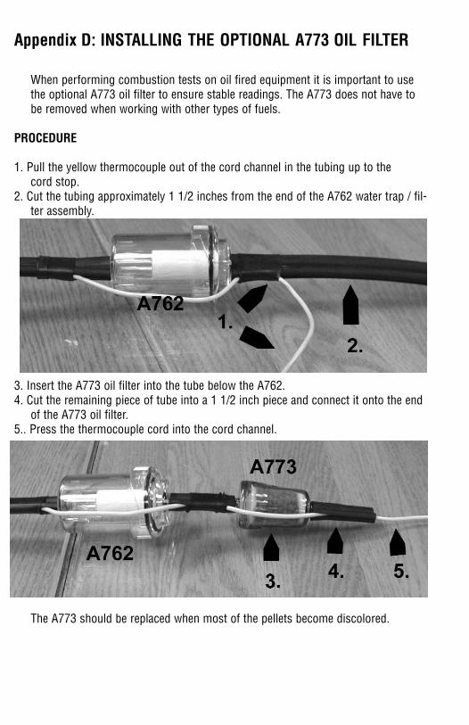
Appendix D: INSTALLING THE OPTIONAL A773 OIL FILTER
When performing combustion tests on oil fired equipment it is important to usethe optional A773 oil filter to ensure stable readings. The A773 does not have tobe removed when working with other types of fuels.
PROCEDURE
1. Pull the yellow thermocouple out of the cord channel in the tubing up to the cord stop.
2. Cut the tubing approximately 1 1/2 inches from the end of the A762 water trap / fil-ter assembly.
3. Insert the A773 oil filter into the tube below the A762.4. Cut the remaining piece of tube into a 1 1/2 inch piece and connect it onto the end
of the A773 oil filter.5.. Press the thermocouple cord into the cord channel.
The A773 should be replaced when most of the pellets become discolored.
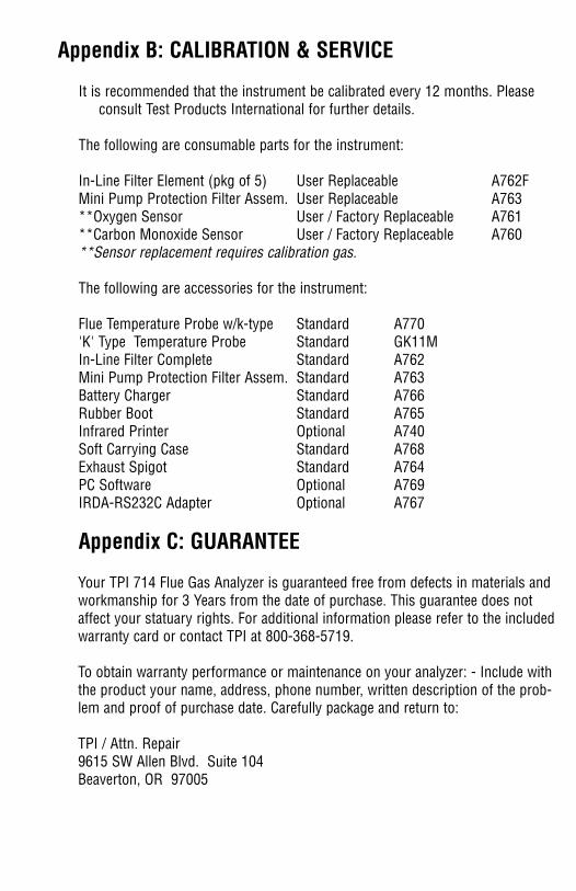
Appendix B: CALIBRATION & SERVICE
It is recommended that the instrument be calibrated every 12 months. Pleaseconsult Test Products International for further details.
The following are consumable parts for the instrument:
In-Line Filter Element (pkg of 5) User Replaceable A762FMini Pump Protection Filter Assem. User Replaceable A763 **Oxygen Sensor User / Factory Replaceable A761**Carbon Monoxide Sensor User / Factory Replaceable A760**Sensor replacement requires calibration gas.
The following are accessories for the instrument:
Flue Temperature Probe w/k-type Standard A770'K' Type Temperature Probe Standard GK11MIn-Line Filter Complete Standard A762Mini Pump Protection Filter Assem. Standard A763 Battery Charger Standard A766 Rubber Boot Standard A765 Infrared Printer Optional A740 Soft Carrying Case Standard A768 Exhaust Spigot Standard A764PC Software Optional A769IRDA-RS232C Adapter Optional A767
Appendix C: GUARANTEE
Your TPI 714 Flue Gas Analyzer is guaranteed free from defects in materials andworkmanship for 3 Years from the date of purchase. This guarantee does notaffect your statuary rights. For additional information please refer to the includedwarranty card or contact TPI at 800-368-5719.
To obtain warranty performance or maintenance on your analyzer: - Include withthe product your name, address, phone number, written description of the prob-lem and proof of purchase date. Carefully package and return to:
TPI / Attn. Repair9615 SW Allen Blvd. Suite 104Beaverton, OR 97005
Appendix D: INSTALLING THE OPTIONAL A773 OIL FILTER
When performing combustion tests on oil fired equipment it is important to usethe optional A773 oil filter to ensure stable readings. The A773 does not have tobe removed when working with other types of fuels.
PROCEDURE
1. Pull the yellow thermocouple out of the cord channel in the tubing up to the cord stop.
2. Cut the tubing approximately 1 1/2 inches from the end of the A762 water trap / fil-ter assembly.
3. Insert the A773 oil filter into the tube below the A762.4. Cut the remaining piece of tube into a 1 1/2 inch piece and connect it onto the end
of the A773 oil filter.5.. Press the thermocouple cord into the cord channel.
The A773 should be replaced when most of the pellets become discolored.
Appendix B: CALIBRATION & SERVICE
It is recommended that the instrument be calibrated every 12 months. Pleaseconsult Test Products International for further details.
The following are consumable parts for the instrument:
In-Line Filter Element (pkg of 5) User Replaceable A762FMini Pump Protection Filter Assem. User Replaceable A763 **Oxygen Sensor User / Factory Replaceable A761**Carbon Monoxide Sensor User / Factory Replaceable A760**Sensor replacement requires calibration gas.
The following are accessories for the instrument:
Flue Temperature Probe w/k-type Standard A770'K' Type Temperature Probe Standard GK11MIn-Line Filter Complete Standard A762Mini Pump Protection Filter Assem. Standard A763 Battery Charger Standard A766 Rubber Boot Standard A765 Infrared Printer Optional A740 Soft Carrying Case Standard A768 Exhaust Spigot Standard A764PC Software Optional A769IRDA-RS232C Adapter Optional A767
Appendix C: GUARANTEE
Your TPI 714 Flue Gas Analyzer is guaranteed free from defects in materials andworkmanship for 3 Years from the date of purchase. This guarantee does notaffect your statuary rights. For additional information please refer to the includedwarranty card or contact TPI at 800-368-5719.
To obtain warranty performance or maintenance on your analyzer: - Include withthe product your name, address, phone number, written description of the prob-lem and proof of purchase date. Carefully package and return to:
TPI / Attn. Repair9615 SW Allen Blvd. Suite 104Beaverton, OR 97005
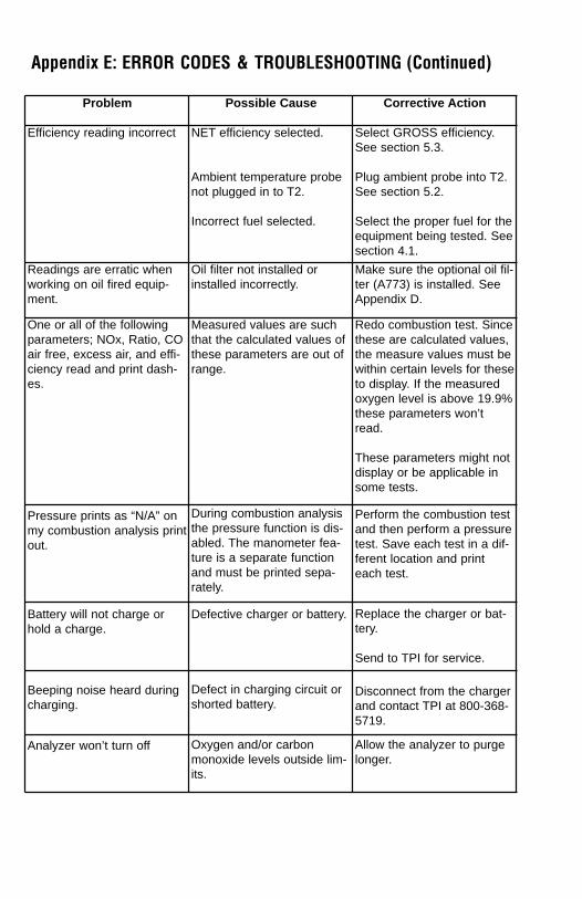
Problem Possible Cause Corrective Action
Efficiency reading incorrect NET efficiency selected.
Ambient temperature probenot plugged in to T2.
Incorrect fuel selected.
Select GROSS efficiency.See section 5.3.
Plug ambient probe into T2.See section 5.2.
Select the proper fuel for theequipment being tested. Seesection 4.1.
Readings are erratic whenworking on oil fired equip-ment.
Oil filter not installed orinstalled incorrectly.
Make sure the optional oil fil-ter (A773) is installed. SeeAppendix D.
One or all of the followingparameters; NOx, Ratio, COair free, excess air, and effi-ciency read and print dash-es.
Measured values are suchthat the calculated values ofthese parameters are out ofrange.
Redo combustion test. Sincethese are calculated values,the measure values must bewithin certain levels for theseto display. If the measuredoxygen level is above 19.9%these parameters won’tread.
These parameters might notdisplay or be applicable insome tests.
Pressure prints as “N/A” onmy combustion analysis printout.
During combustion analysisthe pressure function is dis-abled. The manometer fea-ture is a separate functionand must be printed sepa-rately.
Perform the combustion testand then perform a pressuretest. Save each test in a dif-ferent location and printeach test.
Battery will not charge orhold a charge.
Defective charger or battery. Replace the charger or bat-tery.
Send to TPI for service.
Beeping noise heard duringcharging.
Defect in charging circuit orshorted battery.
Disconnect from the chargerand contact TPI at 800-368-5719.
Analyzer won’t turn off Oxygen and/or carbonmonoxide levels outside lim-its.
Allow the analyzer to purgelonger.
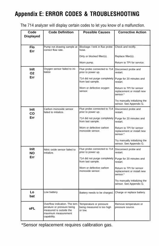
Appendix E: ERROR CODES & TROUBLESHOOTING (Continued)Appendix E: ERROR CODES & TROUBLESHOOTING
The 714 analyzer will display certain codes to let you know of a malfunction.
*Sensor replacement requires calibration gas.
CodeDisplayed
Code Definition Possible Causes Corrective Action
FloErr
Pump not drawing sample atcorrect flow rate.
Blockage / kink in flue probehose.
Dirty or blocked filter(s).
Worn pump.
Check and rectify.
Replace filter(s).
Return to TPI for service.
InItO2Err
Oxygen sensor failed to ini-tialize
Flue probe connected to 714prior to power up.
714 did not purge completelyfrom last sample.
Worn or defective oxygensensor.
Disconnect probe andrestart.
Purge for 20 minutes andrestart.
Return to TPI for sensorreplacement or install newsensor.*
Try manually initializing thesensor. See Appendix G.
InItCOErr
Carbon monoxide sensorfailed to initialize.
Flue probe connected to 714prior to power up.
714 did not purge completelyfrom last sample.
Worn or defective carbonmonoxide sensor.
Disconnect probe andrestart.
Purge for 20 minutes andrestart.
Return to TPI for sensorreplacement or install newsensor.*
Try manually initializing thesensor. See Appendix G.
InItNOErr
Nitric oxide sensor failed toinitialize.
Flue probe connected to 714prior to power up.
714 did not purge completelyfrom last sample.
Worn or defective carbonmonoxide sensor.
Disconnect probe andrestart.
Purge for 20 minutes andrestart.
Return to TPI for sensorreplacement or install newsensor.*
Try manually initializing thesensor. See Appendix G.
Lobat
Low battery. Battery needs to be charged. Charge or replace battery.
oFLOverflow indication. The tem-perature or pressure beingmeasured is outside themaximum measurementcapability.
Temperature or pressurebeing measured is too highor low.
Remove temperature orpressure source.
Problem Possible Cause Corrective Action
Efficiency reading incorrect NET efficiency selected.
Ambient temperature probenot plugged in to T2.
Incorrect fuel selected.
Select GROSS efficiency.See section 5.3.
Plug ambient probe into T2.See section 5.2.
Select the proper fuel for theequipment being tested. Seesection 4.1.
Readings are erratic whenworking on oil fired equip-ment.
Oil filter not installed orinstalled incorrectly.
Make sure the optional oil fil-ter (A773) is installed. SeeAppendix D.
One or all of the followingparameters; NOx, Ratio, COair free, excess air, and effi-ciency read and print dash-es.
Measured values are suchthat the calculated values ofthese parameters are out ofrange.
Redo combustion test. Sincethese are calculated values,the measure values must bewithin certain levels for theseto display. If the measuredoxygen level is above 19.9%these parameters won’tread.
These parameters might notdisplay or be applicable insome tests.
Pressure prints as “N/A” onmy combustion analysis printout.
During combustion analysisthe pressure function is dis-abled. The manometer fea-ture is a separate functionand must be printed sepa-rately.
Perform the combustion testand then perform a pressuretest. Save each test in a dif-ferent location and printeach test.
Battery will not charge orhold a charge.
Defective charger or battery. Replace the charger or bat-tery.
Send to TPI for service.
Beeping noise heard duringcharging.
Defect in charging circuit orshorted battery.
Disconnect from the chargerand contact TPI at 800-368-5719.
Analyzer won’t turn off Oxygen and/or carbonmonoxide levels outside lim-its.
Allow the analyzer to purgelonger.
Appendix E: ERROR CODES & TROUBLESHOOTING (Continued)Appendix E: ERROR CODES & TROUBLESHOOTING
The 714 analyzer will display certain codes to let you know of a malfunction.
*Sensor replacement requires calibration gas.
CodeDisplayed
Code Definition Possible Causes Corrective Action
FloErr
Pump not drawing sample atcorrect flow rate.
Blockage / kink in flue probehose.
Dirty or blocked filter(s).
Worn pump.
Check and rectify.
Replace filter(s).
Return to TPI for service.
InItO2Err
Oxygen sensor failed to ini-tialize
Flue probe connected to 714prior to power up.
714 did not purge completelyfrom last sample.
Worn or defective oxygensensor.
Disconnect probe andrestart.
Purge for 20 minutes andrestart.
Return to TPI for sensorreplacement or install newsensor.*
Try manually initializing thesensor. See Appendix G.
InItCOErr
Carbon monoxide sensorfailed to initialize.
Flue probe connected to 714prior to power up.
714 did not purge completelyfrom last sample.
Worn or defective carbonmonoxide sensor.
Disconnect probe andrestart.
Purge for 20 minutes andrestart.
Return to TPI for sensorreplacement or install newsensor.*
Try manually initializing thesensor. See Appendix G.
InItNOErr
Nitric oxide sensor failed toinitialize.
Flue probe connected to 714prior to power up.
714 did not purge completelyfrom last sample.
Worn or defective carbonmonoxide sensor.
Disconnect probe andrestart.
Purge for 20 minutes andrestart.
Return to TPI for sensorreplacement or install newsensor.*
Try manually initializing thesensor. See Appendix G.
Lobat
Low battery. Battery needs to be charged. Charge or replace battery.
oFLOverflow indication. The tem-perature or pressure beingmeasured is outside themaximum measurementcapability.
Temperature or pressurebeing measured is too highor low.
Remove temperature orpressure source.
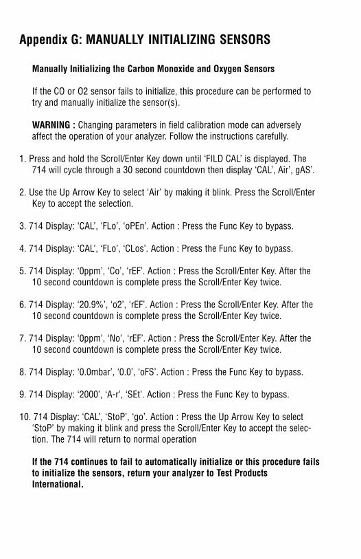
Appendix G: MANUALLY INITIALIZING SENSORS
Manually Initializing the Carbon Monoxide and Oxygen Sensors
If the CO or O2 sensor fails to initialize, this procedure can be performed totry and manually initialize the sensor(s).
WARNING : Changing parameters in field calibration mode can adverselyaffect the operation of your analyzer. Follow the instructions carefully.
1. Press and hold the Scroll/Enter Key down until ‘FILD CAL’ is displayed. The714 will cycle through a 30 second countdown then display ‘CAL’, Air’, gAS’.
2. Use the Up Arrow Key to select ‘Air’ by making it blink. Press the Scroll/EnterKey to accept the selection.
3. 714 Display: ‘CAL’, ‘FLo’, ‘oPEn’. Action : Press the Func Key to bypass.
4. 714 Display: ‘CAL’, ‘FLo’, ‘CLos’. Action : Press the Func Key to bypass.
5. 714 Display: ‘0ppm’, ‘Co’, ‘rEF’. Action : Press the Scroll/Enter Key. After the10 second countdown is complete press the Scroll/Enter Key twice.
6. 714 Display: ‘20.9%’, ‘o2’, ‘rEF’. Action : Press the Scroll/Enter Key. After the10 second countdown is complete press the Scroll/Enter Key twice.
7. 714 Display: ‘0ppm’, ‘No’, ‘rEF’. Action : Press the Scroll/Enter Key. After the10 second countdown is complete press the Scroll/Enter Key twice.
8. 714 Display: ‘0.0mbar’, ‘0.0’, ‘oFS’. Action : Press the Func Key to bypass.
9. 714 Display: ‘2000’, ‘A-r’, ‘SEt’. Action : Press the Func Key to bypass.
10. 714 Display: ‘CAL’, ‘StoP’, ‘go’. Action : Press the Up Arrow Key to select‘StoP’ by making it blink and press the Scroll/Enter Key to accept the selec-tion. The 714 will return to normal operation
If the 714 continues to fail to automatically initialize or this procedure failsto initialize the sensors, return your analyzer to Test ProductsInternational.
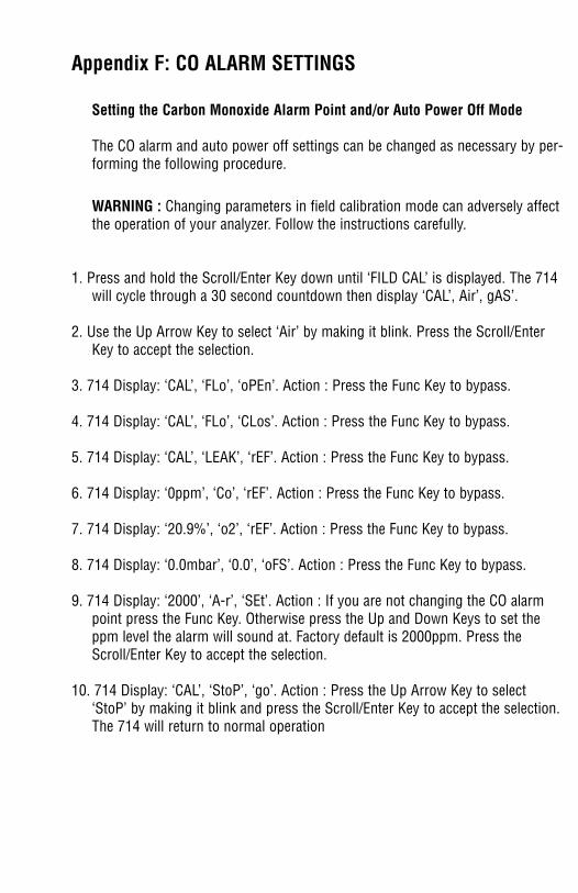
Appendix F: CO ALARM SETTINGS
Setting the Carbon Monoxide Alarm Point and/or Auto Power Off Mode
The CO alarm and auto power off settings can be changed as necessary by per-forming the following procedure.
WARNING : Changing parameters in field calibration mode can adversely affectthe operation of your analyzer. Follow the instructions carefully.
1. Press and hold the Scroll/Enter Key down until ‘FILD CAL’ is displayed. The 714will cycle through a 30 second countdown then display ‘CAL’, Air’, gAS’.
2. Use the Up Arrow Key to select ‘Air’ by making it blink. Press the Scroll/EnterKey to accept the selection.
3. 714 Display: ‘CAL’, ‘FLo’, ‘oPEn’. Action : Press the Func Key to bypass.
4. 714 Display: ‘CAL’, ‘FLo’, ‘CLos’. Action : Press the Func Key to bypass.
5. 714 Display: ‘CAL’, ‘LEAK’, ‘rEF’. Action : Press the Func Key to bypass.
6. 714 Display: ‘0ppm’, ‘Co’, ‘rEF’. Action : Press the Func Key to bypass.
7. 714 Display: ‘20.9%’, ‘o2’, ‘rEF’. Action : Press the Func Key to bypass.
8. 714 Display: ‘0.0mbar’, ‘0.0’, ‘oFS’. Action : Press the Func Key to bypass.
9. 714 Display: ‘2000’, ‘A-r’, ‘SEt’. Action : If you are not changing the CO alarmpoint press the Func Key. Otherwise press the Up and Down Keys to set theppm level the alarm will sound at. Factory default is 2000ppm. Press theScroll/Enter Key to accept the selection.
10. 714 Display: ‘CAL’, ‘StoP’, ‘go’. Action : Press the Up Arrow Key to select‘StoP’ by making it blink and press the Scroll/Enter Key to accept the selection.The 714 will return to normal operation
Appendix G: MANUALLY INITIALIZING SENSORS
Manually Initializing the Carbon Monoxide and Oxygen Sensors
If the CO or O2 sensor fails to initialize, this procedure can be performed totry and manually initialize the sensor(s).
WARNING : Changing parameters in field calibration mode can adverselyaffect the operation of your analyzer. Follow the instructions carefully.
1. Press and hold the Scroll/Enter Key down until ‘FILD CAL’ is displayed. The714 will cycle through a 30 second countdown then display ‘CAL’, Air’, gAS’.
2. Use the Up Arrow Key to select ‘Air’ by making it blink. Press the Scroll/EnterKey to accept the selection.
3. 714 Display: ‘CAL’, ‘FLo’, ‘oPEn’. Action : Press the Func Key to bypass.
4. 714 Display: ‘CAL’, ‘FLo’, ‘CLos’. Action : Press the Func Key to bypass.
5. 714 Display: ‘0ppm’, ‘Co’, ‘rEF’. Action : Press the Scroll/Enter Key. After the10 second countdown is complete press the Scroll/Enter Key twice.
6. 714 Display: ‘20.9%’, ‘o2’, ‘rEF’. Action : Press the Scroll/Enter Key. After the10 second countdown is complete press the Scroll/Enter Key twice.
7. 714 Display: ‘0ppm’, ‘No’, ‘rEF’. Action : Press the Scroll/Enter Key. After the10 second countdown is complete press the Scroll/Enter Key twice.
8. 714 Display: ‘0.0mbar’, ‘0.0’, ‘oFS’. Action : Press the Func Key to bypass.
9. 714 Display: ‘2000’, ‘A-r’, ‘SEt’. Action : Press the Func Key to bypass.
10. 714 Display: ‘CAL’, ‘StoP’, ‘go’. Action : Press the Up Arrow Key to select‘StoP’ by making it blink and press the Scroll/Enter Key to accept the selec-tion. The 714 will return to normal operation
If the 714 continues to fail to automatically initialize or this procedure failsto initialize the sensors, return your analyzer to Test ProductsInternational.
Appendix F: CO ALARM SETTINGS
Setting the Carbon Monoxide Alarm Point and/or Auto Power Off Mode
The CO alarm and auto power off settings can be changed as necessary by per-forming the following procedure.
WARNING : Changing parameters in field calibration mode can adversely affectthe operation of your analyzer. Follow the instructions carefully.
1. Press and hold the Scroll/Enter Key down until ‘FILD CAL’ is displayed. The 714will cycle through a 30 second countdown then display ‘CAL’, Air’, gAS’.
2. Use the Up Arrow Key to select ‘Air’ by making it blink. Press the Scroll/EnterKey to accept the selection.
3. 714 Display: ‘CAL’, ‘FLo’, ‘oPEn’. Action : Press the Func Key to bypass.
4. 714 Display: ‘CAL’, ‘FLo’, ‘CLos’. Action : Press the Func Key to bypass.
5. 714 Display: ‘CAL’, ‘LEAK’, ‘rEF’. Action : Press the Func Key to bypass.
6. 714 Display: ‘0ppm’, ‘Co’, ‘rEF’. Action : Press the Func Key to bypass.
7. 714 Display: ‘20.9%’, ‘o2’, ‘rEF’. Action : Press the Func Key to bypass.
8. 714 Display: ‘0.0mbar’, ‘0.0’, ‘oFS’. Action : Press the Func Key to bypass.
9. 714 Display: ‘2000’, ‘A-r’, ‘SEt’. Action : If you are not changing the CO alarmpoint press the Func Key. Otherwise press the Up and Down Keys to set theppm level the alarm will sound at. Factory default is 2000ppm. Press theScroll/Enter Key to accept the selection.
10. 714 Display: ‘CAL’, ‘StoP’, ‘go’. Action : Press the Up Arrow Key to select‘StoP’ by making it blink and press the Scroll/Enter Key to accept the selection.The 714 will return to normal operation

Notes:Notes:

Notes: Notes:

Notes:Notes:

Notes: Notes:

Test Products International, Inc.9615 SW Allen Blvd., Ste. 104
Beaverton, OR 97005Tel: 503-520-9197 Fax: 503-520-1225
www.tpi-thevalueleader.com
Test Products International, Ltd.342 Bronte Road South, Unit #9Milton Ontario Canada L9T5B7
Tel: 905-693-8558 Fax: 905-693-0888