Embed Size (px)
Citation preview
Gas Analyzer
Owner’s Guide

Gas Analyzer Owner’s Guideii
This document was, as far as possible, accurate at the time of release. However, changes may have been made to the software and hardware it describes since then. ADInstruments Pty Ltd reserves the right to alter specifications as required. Late-breaking information may be supplied separately.
Trademarks of ADInstruments
PowerLab®, LabChart®, LabTutor®, LabAuthor® and MacLab® are registered trademarks of ADInstruments Pty Ltd. The names of specific recording units, such as PowerLab 8/30, are trademarks of ADInstruments Pty Ltd. LabTutor Server, Chart and Scope (application programs) and LabTutor Online are trademarks of ADInstruments Pty Ltd.
Other Trademarks
Apple, Mac and Macintosh are registered trademarks of Apple Computer, Inc.
Windows, Windows 7, Windows Vista and Windows XP are either registered trademarks or trademarks of Microsoft Corporation.
All other trademarks are the property of their respective owners.
Product: ML206 Gas Analyzer
Document Number: U-ML206-OG-003DPart Number: 4389
Copyright © January 2010 ADInstruments Pty Ltd.Unit 13, 22 Lexington Drive, Bella Vista, NSW 2153, Australia
All rights reserved. No part of this document may be reproduced by any means without the prior written permission of ADInstruments Pty Ltd.
Web: www.adinstruments.comTechnical Support: [email protected]: [email protected]
ADInstruments Pty Ltd. ISO 9001:2000 Certified Quality Management System
Reg. No. 1053
Contents iii
Contents
Safety Notes 5
1 Overview 11How to Use This Guide . . . . . . . . . . . . . . . . . . . . . . . . . . . . . . . . . . . . 12
Checking the Gas Analyzer . . . . . . . . . . . . . . . . . . . . . . . . . . . . . . . 12The Gas Analyzer . . . . . . . . . . . . . . . . . . . . . . . . . . . . . . . . . . . . . . . 12
The Front Panel . . . . . . . . . . . . . . . . . . . . . . . . . . . . . . . . . . . . . . 12The Back Panel . . . . . . . . . . . . . . . . . . . . . . . . . . . . . . . . . . . . . . 13
2 Using the Gas Analyzer 15Connecting the Gas Analyzer. . . . . . . . . . . . . . . . . . . . . . . . . . . . . . . . . 16
Connecting to the PowerLab . . . . . . . . . . . . . . . . . . . . . . . . . . . . . . . 16Connecting to Other Recorders . . . . . . . . . . . . . . . . . . . . . . . . . . . . . 17
Using the Gas Analyzer . . . . . . . . . . . . . . . . . . . . . . . . . . . . . . . . . . . . 17Power-up Test of the Gas Analyzer . . . . . . . . . . . . . . . . . . . . . . . . . . . 17Sample Inlet . . . . . . . . . . . . . . . . . . . . . . . . . . . . . . . . . . . . . . . . 17Recording . . . . . . . . . . . . . . . . . . . . . . . . . . . . . . . . . . . . . . . . . 18Calibration . . . . . . . . . . . . . . . . . . . . . . . . . . . . . . . . . . . . . . . . . 20
3 Care and Maintenance 23Cleaning . . . . . . . . . . . . . . . . . . . . . . . . . . . . . . . . . . . . . . . . . . 24Maintenance . . . . . . . . . . . . . . . . . . . . . . . . . . . . . . . . . . . . . . . . 24
A Technical Details 25How it Works . . . . . . . . . . . . . . . . . . . . . . . . . . . . . . . . . . . . . . . . . . 26
O2 Transducer . . . . . . . . . . . . . . . . . . . . . . . . . . . . . . . . . . . . . . . 26CO2 Transducer . . . . . . . . . . . . . . . . . . . . . . . . . . . . . . . . . . . . . . 27Considerations When Using the Gas Analyzer . . . . . . . . . . . . . . . . . . . . 27
B Troubleshooting 29
C Specifications 31
Index 35

Gas Analyzer Owner’s Guide iv
Safety Notes 5
Statement of Intended Use
All products manufactured by ADInstruments are intended for use in teaching and research applications and environments only. ADInstruments products are NOT intended to be used as medical devices or in medical environments. That is, no product supplied by ADInstruments is intended to be used to diagnose, treat or monitor a subject. Furthermore no product is intended for the prevention, curing or alleviation of disease, injury or handicap.
Where a product meets IEC 60601-1 it is under the principle that:
• it is a more rigorous standard than other standards that could be chosen, and
• it provides a high safety level for subjects and operators.
The choice to meet IEC 60601-1 is in no way to be interpreted to mean that a product:
• is a medical device,• may be interpreted as a medical device, or• is safe to be used as a medical device.
Safety Symbols
Devices manufactured by ADInstruments that are designed for direct connection to humans are tested to IEC 601-1:1998 (including amendments 1 and 2) and 60601-1-2, and carry one or more of the safety symbols below.
Safety Notes
Gas Analyzer Owner’s Guide 6
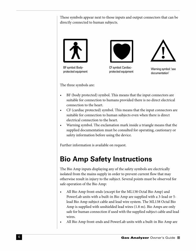
These symbols appear next to those inputs and output connectors that can be directly connected to human subjects.
The three symbols are:
• BF (body protected) symbol. This means that the input connectors are suitable for connection to humans provided there is no direct electrical connection to the heart.
• CF (cardiac protected) symbol. This means that the input connectors are suitable for connection to human subjects even when there is direct electrical connection to the heart.
• Warning symbol. The exclamation mark inside a triangle means that the supplied documentation must be consulted for operating, cautionary or safety information before using the device.
Further information is available on request.
Bio Amp Safety Instructions
The Bio Amp inputs displaying any of the safety symbols are electrically isolated from the mains supply in order to prevent current flow that may otherwise result in injury to the subject. Several points must be observed for safe operation of the Bio Amp:
• All Bio Amp front-ends (except for the ML138 Octal Bio Amp) and PowerLab units with a built-in Bio Amp are supplied with a 3-lead or 5-lead Bio Amp subject cable and lead wire system. The ML138 Octal Bio Amp is supplied with unshielded lead wires (1.8 m). Bio Amps are only safe for human connection if used with the supplied subject cable and lead wires.
• All Bio Amp front-ends and PowerLab units with a built-in Bio Amp are
BF symbol: Body-protected equipment
CF symbol: Cardiac-protected equipment
!Warning symbol: ‘see documentation’

Safety Notes 7
not defibrillator-protected. Using the Bio Amp to record signals during defibrillator discharges may damage the input stages of the amplifiers. This may result in a safety hazard.
• Never use damaged Bio Amp cables or leads. Damaged cables and leads must always be replaced before any connection to humans is made.
Isolated Stimulator Safety
Instructions
The Isolated Stimulator outputs of a front-end signal conditioner or PowerLab with a built-in isolated stimulator are electrically isolated. However, they can produce pulses of up to 100 V at up to 20 mA. Injury can still occur from careless use of these devices. Several points must be observed for safe operation of the Isolated Stimulator:
• The Isolated Stimulator output must only be used with the supplied bar stimulus electrode.
• The Isolated Stimulator output must not be used with individual (physically separate) stimulating electrodes.
• Stimulation must not be applied across the chest or head. • Do not hold one electrode in each hand.• Always use a suitable electrode cream or gel and proper skin preparation
to ensure a low-impedance electrode contact. Using electrodes without electrode cream can result in burns to the skin or discomfort for the subject.
• Subjects with implantable or external cardiac pacemakers, a cardiac condition, or a history of epileptic episodes must not be subject to electrical stimulation.
• Always commence stimulation at the lowest current setting and slowly increase the current.
• Stop stimulation if the subject experiences pain or discomfort.• Do not use faulty cables, or those that have exhibited intermittent faults.• Do not attempt to measure or record the Isolated Stimulator waveform
while connected to a subject using a PowerLab input or any other piece of equipment that does not carry the appropriate safety symbol (see Safety Symbols above).
Always check the status indicator on the front panel. It will always flash green each time the stimulator delivers a current pulse. A yellow flash indicates an ‘out-of-compliance’ (OOC) condition that may be due to the electrode contact drying up. Always ensure that there is good electrode contact at all times.
Gas Analyzer Owner’s Guide 8
Electrodes that are left on a subject for some time need to be checked for dry contacts. An electrode impedance meter can be used for this task.
• Always be alert for any adverse physiological effects in the subject. At the first sign of a problem, stimulation must be stopped, either from the software or by flicking down the safety switch on the front panel of any built-in Isolated Stimulator or the ML180 Stimulus Isolator.
• The ML180 Stimulus Isolator is supplied with a special transformer plug pack. The plug pack complies with medical safety requirements. Therefore, under no circumstances should any other transformer be used with the Stimulus Isolator. For a replacement transformer plug pack please contact your nearest ADInstruments representative.
General Safety Instructions
To achieve the optimal degree of subject and operator safety, consideration should be given to the following guidelines when setting up a PowerLab system either as stand-alone equipment or when using PowerLab equipment in conjunction with other equipment. Failure to do so may compromise the inherent safety measures designed into PowerLab equipment. The following guidelines are based on principles outlined in the international safety standard IEC60601-1-1: General requirements for safety - Collateral standard: Safety requirements for medical systems. Reference to this standard is required when setting up a system for human connection.
PowerLab systems (and many other devices) require the connection of a personal computer for operation. This personal computer should be certified as complying with IEC60950 and should be located outside a 1.8 m radius from the subject (so that the subject cannot touch it while connected to the system). Within this 1.8 m radius, only equipment complying with IEC60601-1 should be present. Connecting a system in this way obviates the provision of additional safety measures and the measurement of leakage currents.
Accompanying documents for each piece of equipment in the system should be thoroughly examined prior to connection of the system.
While it is not possible to cover all arrangements of equipment in a system, some general guidelines for safe use of the equipment are presented below:
• Any electrical equipment which is located within the SUBJECT AREA should be approved to IEC60601-1.
• Only connect those parts of equipment that are marked as an APPLIED PART to the subject. APPLIED PARTS may be recognized by the BF or CF symbols which appear in the Safety Symbols section of these Safety Notes.
Safety Notes 9
• Only CF-rated APPLIED PARTS must be used for direct cardiac connection.
• Never connect parts which are marked as an APPLIED PART to those which are not marked as APPLIED PARTS.
• Do not touch the subject to which the PowerLab (or its peripherals) is connected at the same time as making contact with parts of the PowerLab (or its peripherals) that are not intended for contact to the subject.
• Cleaning and sterilization of equipment should be performed in accordance with manufacturer’s instructions. The isolation barrier may be compromised if manufacturer’s cleaning instructions are not followed.
• The ambient environment (such as the temperature and relative humidity) of the system should be kept within the manufacturer’s specified range or the isolation barrier may be compromised.
• The entry of liquids into equipment may also compromise the isolation barrier. If spillage occurs, the manufacturer of the affected equipment should be contacted before using the equipment.
• Many electrical systems (particularly those in metal enclosures) depend upon the presence of a protective earth for electrical safety. This is generally provided from the power outlet through a power cord, but may also be supplied as a dedicated safety earth conductor. Power cords should never be modified so as to remove the earth connection. The integrity of the protective earth connection between each piece of equipment and the protective earth should be verified regularly by qualified personnel.
• Avoid using multiple portable socket-outlets (such as power boards) where possible as they provide an inherently less safe environment with respect to electrical hazards. Individual connection of each piece of equipment to fixed mains socket-outlets is the preferred means of connection.
If multiple portable socket outlets are used, they are subject to the following constraints:
• They shall not be placed on the floor.• Additional multiple portable socket outlets or extension cords shall not be
connected to the system.• They shall only be used for supplying power to equipment which is
intended to form part of the system.
Cleaning and Sterilization
ADInstruments products may be wiped down with a lint free cloth moistened with industrial methylated spirit. Refer to the manufacturer’s guidelines or the
Gas Analyzer Owner’s Guide 10
Data Card supplied with transducers and accessories for specific cleaning and sterilizing instructions.
Preventative Inspection and
Maintenance
PowerLab systems and ADInstruments front-ends are all maintenance-free and do not require periodic calibration or adjustment to ensure safe operation. Internal diagnostic software performs system checks during power up and will report errors if a significant problem is found. There is no need to open the instrument for inspection or maintenance, and doing so within the warranty period will void the warranty.
Your PowerLab system can be periodically checked for basic safety by using an appropriate safety testing device. Tests such as earth leakage, earth bond, insulation resistance, subject leakage and auxiliary currents and power cable integrity can all be performed on the PowerLab system without having to remove the covers. Follow the instructions for the testing device if performing such tests.
If the PowerLab system is found not to comply with such testing you should contact your PowerLab representative to arrange for the equipment to be checked and serviced. Do not attempt to service the device yourself.
Environment
Electronic components are susceptible to corrosive substances and atmospheres, and must be kept away from laboratory chemicals.
Storage Conditions• Temperature in the range 0–40 °C • Non-condensing humidity in the range 0–95%.
Operating Conditions• Temperature in the range 5–35 °C• Non-condensing humidity in the range 0–90%.
Disposal• Forward to recycling center or return to manufacturer.
Chapter 1 Overview 11
The ADInstruments ML206 Gas Analyzer is a set of transducers used for the
measurement of respiratory gases. It contains infrared carbon dioxide and
visible spectrum oxygen detectors, and connects to any PowerLab® data
acquisition system, or any device that records an analog signal. The Gas
Analyzer measures carbon dioxide and oxygen content in expired gas.
This owner’s guide covers the features of the Gas Analyzer, its operation with
a PowerLab data acquisition system, and how to use it to analyze gas samples.
1 Overview
Gas Analyzer Owner’s Guide 12
How to Use This Guide
This owner’s guide describes how to set up and begin using your Gas Analyzer. Topics discussed included how to connect the hardware, perform a simple power-up test and calibration of the Gas Analyzer. The appendices provide technical information about the Gas Analyzer and look at some potential problems and their solutions. There is an index at the end of this guide.
Checking the Gas Analyzer
Before connecting the Gas Analyzer to anything, check it carefully for signs of physical damage.
1. Check that there are no obvious signs of damage to the outside of the Gas Analyzer casing.
2. Check that there is no obvious sign of internal damage, such as rattling. Pick up the Gas Analyzer, tilt it gently from side to side, and listen for anything that appears to be loose.
If you have found a problem, contact your authorized ADInstruments representative immediately, and describe the problem so arrangements can be made to replace or repair the unit.
The Gas Analyzer
The remainder of this chapter contains general information about the features, connections and indicators of the Gas Analyzer. More detailed information can be found in Appendix A.
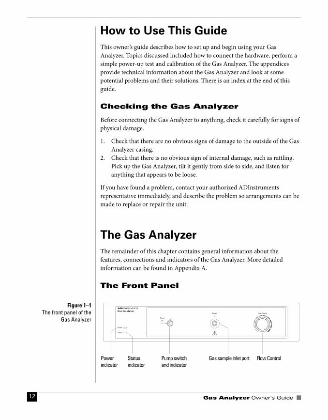
The Front Panel
Power indicator
Gas sample inlet portPump switch and indicator
Status indicator
Flow Control
Figure 1–1The front panel of the
Gas Analyzer
Chapter 1 Overview 13
Power Indicator
The Power indicator is located on the left hand side of the front panel and will glow blue when the power is connected properly. If the light does not illuminate when the Gas Analyzer is switched on then the power cable may not be connected properly or a fuse may have blown. If the internal fuses are suspected of having blown, the unit should be returned to your local ADInstruments representative.
Status Indicator
The Status indicator glows green when the Gas Analyzer is connected to a PowerLab and has been recognized by LabChart.
Pump On Indicator and Switch
The pump is activated using the switch. The indicator glows yellow, and the internal pump may be heard, when it is running.
Gas Sample Inlet
A sample inlet port is provided on the front panel. The inlet port is directly connected to the internal gas transducers of the Gas Analyzer. A sample flows through this port to be analyzed. Note that the hydrophobic filter, supplied with every unit, must be used at all times
Flow Control
A single-turn knob on the front panel controls the sampling flow rate to suit different applications.
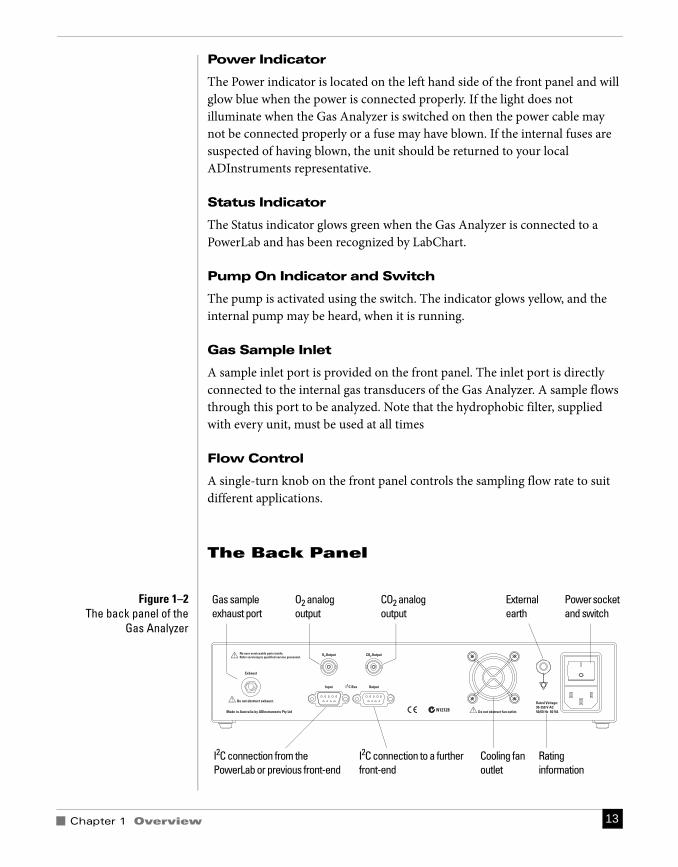
The Back Panel
Power socket and switch
Rating information
Gas sample exhaust port
CO2 analog output
O2 analog output
External earth
Cooling fan outlet
I2C connection from the PowerLab or previous front-end
I2C connection to a further front-end
Figure 1–2The back panel of the
Gas Analyzer
Gas Analyzer Owner’s Guide 14
Exhaust Port
A single exhaust port expels sample air to the atmosphere. Keep this port clear. Impeding the port prevents a clear flow of your sample past the transducers, which may reduce the accuracy of recordings.
Analog Outputs
Two analog signal outputs proportional to the carbon dioxide and oxygen concentrations are provided with BNC connectors. They are linear over the range of gas concentrations in expired air. That is, 0–1 V from the CO2 output (equivalent to 0–10% CO2) and 0.05–1 V from the O2 output (equivalent to 5–100% O2). See Appendix A for further details.
These outputs connect to the analog inputs of your data recorder to provide the signals for the CO2 and O2 content of the sample gas.
I2C Input and Output Ports
The I2C ports allow front-ends manufactured by ADInstruments to be chained together and supplied with power and communications from the PowerLab. Only 50 mA maximum current can be provided through this bus, so it should not be used for third-party devices drawing more current.
Power Connections
The power switch on the back of the Gas Analyzer turns the unit on and off. The unit is connected to the power outlet using the 3-pin IEC style power cable supplied with the unit. The Gas Analyzer should always be grounded for safe operation.
Fuse Replacement
The Gas Analyzer uses an autoranging power supply with internal fuses. If the internal fuses are suspected of having blown, the unit should be returned to your ADInstruments distributor for servicing.
Chapter 2 Using the Gas Analyzer 15
This chapter guides you through connecting your Gas Analyzer to your
PowerLab and performing an initial check to make sure that there are no
problems or omissions.
IMPORTANT: Always turn off both the PowerLab and Gas Analyzer before
connecting or disconnecting either unit. Failure to do this may result in
damage to the units.
2 Using theGas Analyzer
Gas Analyzer Owner’s Guide 16
Connecting the Gas Analyzer
The Gas Analyzer can operate either as a PowerLab front-end or as a stand-alone unit connected to any analog meter or recording device.
Connecting to the PowerLab
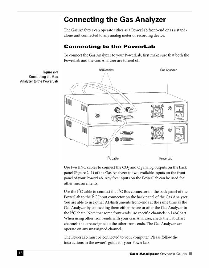
To connect the Gas Analyzer to your PowerLab, first make sure that both the PowerLab and the Gas Analyzer are turned off.
Use two BNC cables to connect the CO2 and O2 analog outputs on the back panel (Figure 2–1) of the Gas Analyzer to two available inputs on the front panel of your PowerLab. Any free inputs on the PowerLab can be used for other measurements.
Use the I2C cable to connect the I2C Bus connector on the back panel of the PowerLab to the I2C Input connector on the back panel of the Gas Analyzer. You are able to use other ADInstruments front-ends at the same time as the Gas Analyzer by connecting them either before or after the Gas Analyzer in the I2C chain. Note that some front-ends use specific channels in LabChart. When using other front-ends with your Gas Analyzer, check the LabChart channels that are assigned to the other front-ends. The Gas Analyzer can operate on any unassigned channel.
The PowerLab must be connected to your computer. Please follow the instructions in the owner’s guide for your PowerLab.
I2C cable PowerLab
Gas AnalyzerBNC cablesFigure 2–1
Connecting the GasAnalyzer to the PowerLab
Chapter 2 Using the Gas Analyzer 17
Connecting to Other Recorders
Analog signals from the Gas Analyzer are linear and proportional to CO2 and O2 partial pressures (CO2 output of 0–1 V is equivalent to 0–10% CO2 and O2 output of 0.05–1 V is equivalent to 5–100% O2). Although this guide assumes that you are using a PowerLab and LabChart, the principles of operation and calibration apply to any meter or recorder that you attach to the Gas Analyzer.
Using the Gas Analyzer
When first switched on, the Gas Analyzer performs an initial self-test, and it should then be allowed time to warm up. When used with a PowerLab and LabChart, the Gas Analyzer has default scaling and units, and so can be used without further setting up. If required, you can calibrate it yourself using LabChart (see "Calibration", p. 20).
Power-up Test of the Gas Analyzer
The Gas Analyzer performs an initial check when it is switched on.
1. Ensure dust caps are removed from both the Sample In and Exhaust ports of the Gas Analyzer, and that the Exhaust port is clear of obstruction.
2. Turn on the Gas Analyzer. Its Power indicator should glow blue. 3. Check the internal pump by flicking the Pump On switch. Its indicator
should glow yellow and the pump may be heard.
Allow at least 10 minutes of operation with the pump on before recording with the Gas Analyzer. Until it has warmed up, the output from the CO2 transducer may be unusable due to a large offset.
Sample Inlet
This system is designed for passive sampling only: there is no need to breathe or blow directly into tubing connected to the inlet port. Connection to a high pressure source may damage the internal components.
Do not obstruct sample airflow as this can damage the internal pump.
It is extremely important that a method of moisture removal is employed when using the Gas Analyzer because any moisture entering the sample inlet port can damage the instrument. As a minimum, use Nafion tubing and an in-line polypropylene 0.45 μm hydrophobic filter (both supplied) to connect between the subject and the gas sample inlet. This has the advantage of being
Gas Analyzer Owner’s Guide 18
low-maintenance and reduces the dead-space volume of the sample. Nafion is a reusable length of reinforced membrane that equilibrates the humidity across the tube wall. It is ideal for low humidity, non-equatorial climates, and air-conditioned environments that have low humidity.
In humid environments and for extra protection, completely dry the sample by using desiccant to remove any moisture. Drying should be employed when sampling from an exercising subject.
It is also recommended that a PFT bacterial filter (available as part of the Spirometer Kit from ADInstruments, for example) be fitted in the circuit after the face mask or mouthpiece so as to reduce bacterial build-up inside the Gas Analyzer.
Recording
After connecting the Gas Analyzer to a PowerLab, with the PowerLab connected to your computer, connect the sampling tubing to the gas sample inlet of the Gas Analyzer using the in-line hydrophobic filter and Nafion tubing (to remove moisture). The analog signals from the Gas Analyzer are linear and proportional to the concentrations of CO2 and O2 (0–1 V from the CO2 output is equivalent to 0–10% CO2 and 0.05–1 V from the O2 output is equivalent to 5–100% O2). These are approximate voltages and some variation from these values can occur.
1. Perform the power-up test for the Gas Analyzer as described in the previ-ous section. Allow the Gas Analyzer at least 10 minutes warm-up time before use.
2. Turn on your PowerLab. It should perform its normal diagnostic tests, as described in the owner’s guide.
3. Start LabChart. The Status indicator of the Gas Analyzer should glow green. A suggested initial sampling rate is 20 /s.
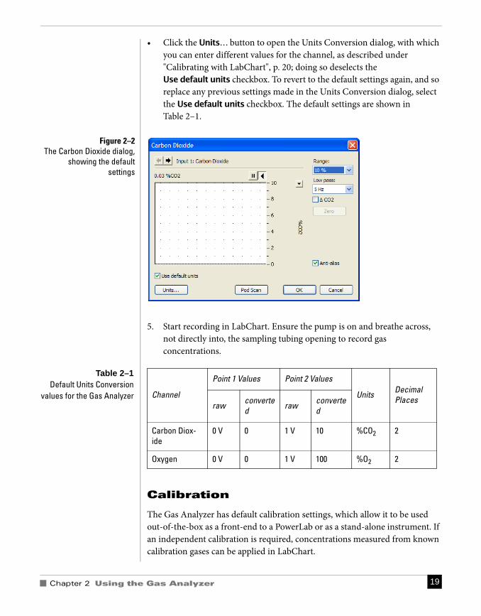
4. To preview the signal from the Gas Analyzer, or to adjust the range or low-pass filter settings, choose Carbon Dioxide… (or Oxygen…) from the relevant Channel Function pop-up menu. The Carbon Dioxide (or Oxygen) dialog appears (Figure 2–2).
• The default Range is 10% for the Carbon Dioxide input and 100% for the Oxygen input.
• The default Low-pass filter setting is 5 Hz. • You can record data in absolute or difference modes. The difference mode
can be used to record changes in gas concentration from an ambient level. Select the ý CO2 (or ý O2) checkbox to use the difference mode. When in difference mode, click the Zero button to remove any offset in the signal (Figure 2–2).
Warning
Do not breathe or blowdirectly into the sampling
tube – doing so maydamage the gas
transducers
Chapter 2 Using the Gas Analyzer 19
• Click the Units… button to open the Units Conversion dialog, with which you can enter different values for the channel, as described under "Calibrating with LabChart", p. 20; doing so deselects the Use default units checkbox. To revert to the default settings again, and so replace any previous settings made in the Units Conversion dialog, select the Use default units checkbox. The default settings are shown in Table 2–1.
5. Start recording in LabChart. Ensure the pump is on and breathe across, not directly into, the sampling tubing opening to record gas concentrations.
Calibration
The Gas Analyzer has default calibration settings, which allow it to be used out-of-the-box as a front-end to a PowerLab or as a stand-alone instrument. If an independent calibration is required, concentrations measured from known calibration gases can be applied in LabChart.
Channel
Point 1 Values Point 2 Values
Units Decimal Places
raw converted raw converte
d
Carbon Diox-ide
0 V 0 1 V 10 %CO2 2
Oxygen 0 V 0 1 V 100 %O2 2
Figure 2–2The Carbon Dioxide dialog,
showing the defaultsettings
Table 2–1Default Units Conversion
values for the Gas Analyzer

Gas Analyzer Owner’s Guide 20
Default Calibration Settings
Both transducers produce linear outputs that are directly proportional to the concentrations of the CO2 and O2 in the sample. The CO2 transducer has an output of 0–1 V for 0–10% CO2 and the O2 transducer has an output of 0.05–1 V for 5–100% O2. The linearity of the transducers allows the default units conversion values, displayed in Table 2–1, to be used.
Calibration Gases
The carbon dioxide transducer can be calibrated using two gas samples with known CO2 concentrations. The first can be room air, which has a CO2 content of 0.03% (atmospheric CO2 content by volume is 0.033 ±0.001%1). The second gas should have a CO2 content between 5% and 10%. The flow rate of the sample gas should be held constant during calibration as the CO2 reading is affected by the pressure and flow rate.
The oxygen transducer can be calibrated using two gases of known composition and with O2 concentrations appropriate to the range of measurements that are expected. Room air can be one of the gases. It has an O2 content of ~21% (atmospheric O2 content by volume is 20.946 ±0.003%1). A second concentration in the range 5 to 21% O2 can be used to represent an intermediate O2 concentration. Pure N2 cannot be used.
Calibrating with LabChart
To perform an independent calibration of each of the CO2 and O2 transducers
in LabChart, you use the Units Conversion feature to scale the transducer output appropriately.
1. When calibrating, make a recording of the transducer’s response to gases of known concentrations (for example, a calibration gas and room air).
2. Select the region of the LabChart recording that shows the response to both calibration gases and then choose Carbon Dioxide… (or Oxygen…) from the relevant Channel Function pop-up menu to open the Carbon Dioxide (or Oxygen) dialog.
3. If you are using LabChart, clear the Use default units checkbox in the Carbon Dioxide (or Oxygen) dialog. Click the Units… button to open the Units Conversion dialog. Details of how to enter calibration values into the Units Conversion dialog can be found in the LabChart Help. Note that the Use default units checkbox in the Carbon Dioxide (or Oxygen) dialog can be checked to restore the default conversion values for the Gas Analyzer.
1. Handbook of Chemistry and Physics 57th Edition, CRC Press.
Chapter 2 Using the Gas Analyzer 21
If you are using a version of Chart earlier than v5.1, which doesn’t have the Use default units checkbox, use the Multipoint Calibration extension (a free download from www.ADInstruments.com) to ensure the calibration values overwrite the default values. Details of how to use the extension can be found in the MP Calibration Guide that gets installed into the ADInstruments’ Documentation folder.
Once the calibration values are entered and applied, they can be saved as a LabChart Settings file for later reuse.

Gas Analyzer Owner’s Guide 22
Chapter 3 Care and Maintenance 23
The Gas Analyzer has been designed to eliminate much of the usual
maintenance associated with sensitive measuring devices. The only
maintenance that you may need to perform is the replacement of the
hydrophobic and bacterial filters.
3 Care andMaintenance
Gas Analyzer Owner’s Guide 24
Cleaning
The external surfaces of the Gas Analyzer can be cleaned using a mild soap solution and a soft cloth and then wiped clean with a damp cloth. Do not use abrasive cleaners as these may damage the external surfaces of the device.
Maintenance
The only maintenance you should perform on the Gas Analyzer is the replacement of the external filters in the gas pathway.
It is recommended that the unit be returned to your ADInstruments distributor annually for servicing. Note that removing the cover of the Gas Analyzer will void the warranty.
Hydrophobic Filter
A polypropylene hydrophobic filter fitted in the gas sample line should be replaced regularly.
Bacterial Filter
The PFT bacterial filter fitted in the circuit after the face mask or mouthpiece is disposable and should be replaced for each new subject.
Moisture Handling
In humid environments, or when sampling from exercising subjects, remove moisture from the sample using Nafion tubing in a dry environment and/or desiccant.
AA P P E N D I X
Appendix A Technical Details 25
This Appendix describes some technical aspects of the Gas Analyzer’s
operation. You do not need to know the material in this section in order to
operate the Gas Analyzer and it is not intended in any way as a service guide.
It should be noted that any modification or attempt to service your Gas
Analyzer voids your rights under the warranty.
A TechnicalDetails
Gas Analyzer Owner’s Guide 26
How it Works
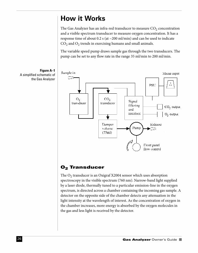
The Gas Analyzer has an infra-red transducer to measure CO2 concentration and a visible spectrum transducer to measure oxygen concentration. It has a response time of about 0.2 s (at ~200 ml/min) and can be used to indicate CO2 and O2 trends in exercising humans and small animals.
The variable speed pump draws sample gas through the two transducers. The pump can be set to any flow rate in the range 35 ml/min to 200 ml/min.
O2 Transducer
The O2 transducer is an Oxigraf X2004 sensor which uses absorption spectroscopy in the visible spectrum (760 nm). Narrow-band light supplied by a laser diode, thermally tuned to a particular emission-line in the oxygen spectrum, is directed across a chamber containing the incoming gas sample. A detector on the opposite side of the chamber detects any attenuation in the light intensity at the wavelength of interest. As the concentration of oxygen in the chamber increases, more energy is absorbed by the oxygen molecules in the gas and less light is received by the detector.
Figure A–1A simplified schematic of
the Gas Analyzer
Appendix A Technical Details 27
CO2 Transducer
The CO2 transducer is a Servomex model 1507 infrared transducer. It is calibrated so that output voltages in the range 0–1 V are proportional to CO2 concentrations in the range 0–10%. The optical path, generation and detection system is an amplitude modulated carrier system.
Considerations When Using the Gas Analyzer
• The sample inlet and exhaust ports on the Gas Analyzer should remain clear.
• Unnecessary dead-space in the gas path should be kept to a minimum. • Chemical contamination and rubber compounds should be avoided.• The sample gas dewpoint should be at least 10 °C below transducer
temperature. The sample gas should be free of oil contaminants, particles and liquids or condensing vapors.
• In humid environments, or when sampling from exercising subjects, dry the sample using desiccant. Removing moisture will lengthen the life of the transducers.

Gas Analyzer Owner’s Guide 28
Appendix B Troubleshooting 29
BA P P E N D I X
This appendix describes some problems that may arise when using the Gas
Analyzer. In most cases of when the Gas Analyzer does not appear to function
correctly, the problem can be fixed by checking connections and starting up
the LabChart application again.
If you cannot find a solution to your problem in this appendix, or in your
PowerLab owner’s guide or the LabChart Help Center, please contact your
ADInstruments representative.
B Troubleshooting
Gas Analyzer Owner’s Guide 30
Power indicator fails to light
The Gas Analyzer is off or the power is switched off at the wall, the power cable is not connected firmly, or a fuse is blown.
• Physically check switches and power connections.• Check that the power cable is firmly connected at the back of the Gas
Analyzer.
If the internal fuses are suspected of having blown, the unit should be returned to your ADInstruments distributor for servicing.
Drift in the Output Signal
Positive Drift: Contamination build up in the sample chambers of the transducers will cause a positive drift proportional to the build up. Return the unit for cleaning or transducer replacement.
Cyclic Drift: Cyclic drift is directly related to temperature variations.
No or Noisy Output
Erratic or noisy output: Excessive bench temperature fluctuations lead to noisy or erratic drift in the transducers. Place a shroud over the benchtop to reduce fluctuations. Check power supply for ripples.
No output response or no output at situation: The sample cell is filled with condensate or there is a malfunction of the detector. Return the unit for cleaning or transducer replacement.
Output extremely erratic: Operating temperature outside specification.
Impeded sample airflow
The bacterial filter may become clogged under high humidity conditions. Replace the bacterial filter.
The exhaust port may be blocked or airflow impeded. Ensure the port is not restricted and is clear of obstructions.
No response to changes in sample concentration
Check that the pump is turned on.
Appendix C Specifications 31
CA P P E N D I X
Specifications
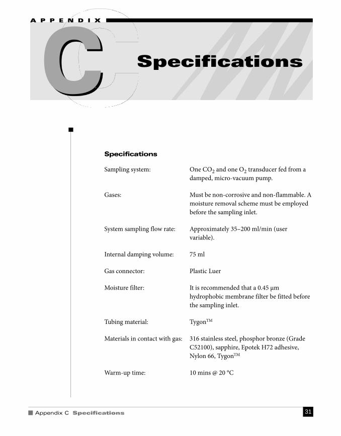
Sampling system: One CO2 and one O2 transducer fed from a damped, micro-vacuum pump.
Gases: Must be non-corrosive and non-flammable. A moisture removal scheme must be employed before the sampling inlet.
System sampling flow rate: Approximately 35–200 ml/min (user variable).
Internal damping volume: 75 ml
Gas connector: Plastic Luer
Moisture filter: It is recommended that a 0.45 μm hydrophobic membrane filter be fitted before the sampling inlet.
Tubing material: TygonTM
Materials in contact with gas: 316 stainless steel, phosphor bronze (Grade C52100), sapphire, Epotek H72 adhesive, Nylon 66, TygonTM
Warm-up time: 10 mins @ 20 °C
C Specifications
Gas Analyzer Owner’s Guide 32
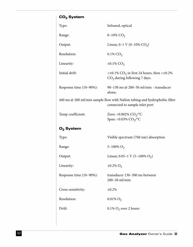
CO2 System
Type: Infrared, optical
Range: 0–10% CO2
Output: Linear, 0–1 V (0–10% CO2)
Resolution: 0.1% CO2
Linearity: ±0.1% CO2
Initial drift: <±0.1% CO2 in first 24 hours, then <±0.2% CO2 during following 7 days.
Response time (10–90%): 90–130 ms @ 200–50 ml/min - transducer alone;
440 ms @ 200 ml/min sample flow with Nafion tubing and hydrophobic filter connected to sample inlet port
Temp coefficient: Zero: <0.002% CO2/°CSpan: <0.03% CO2/°C
O2 System
Type: Visible spectrum (760 nm) absorption
Range: 5–100% O2
Output: Linear, 0.05–1 V (5–100% O2)
Linearity: ±0.2% O2
Response time (10–90%): transducer 130–300 ms between 200–50 ml/min
Cross-sensitivity: ±0.2%
Resolution: 0.01% O2
Drift: 0.1% O2 over 2 hours
Appendix C Specifications 33
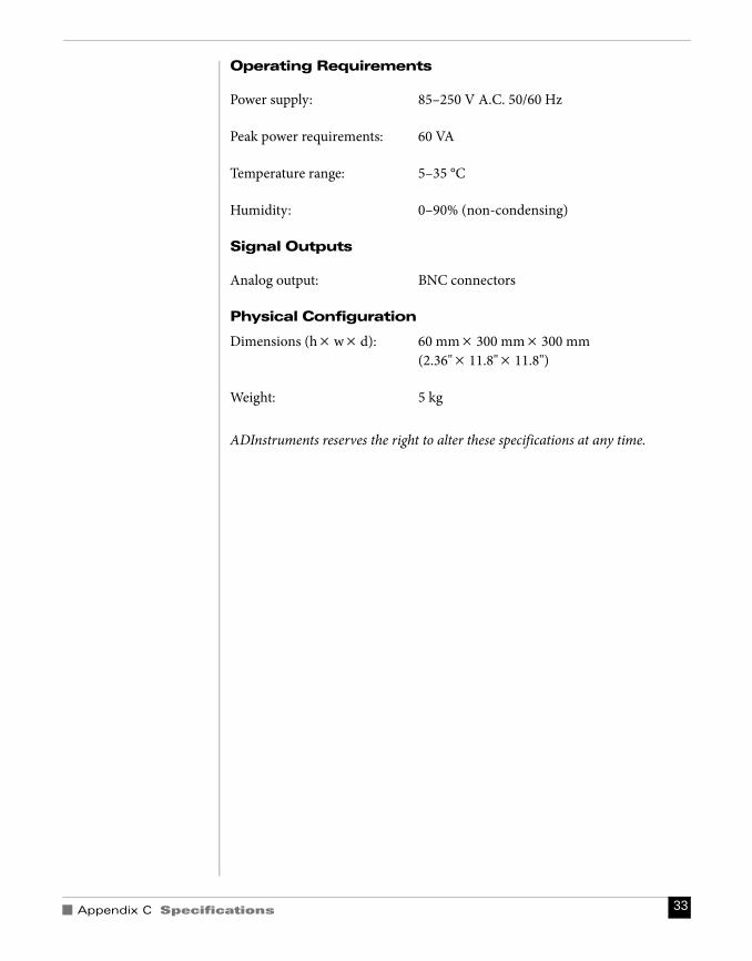
Operating Requirements
Power supply: 85–250 V A.C. 50/60 Hz
Peak power requirements: 60 VA
Temperature range: 5–35 °C
Humidity: 0–90% (non-condensing)
Signal Outputs
Analog output: BNC connectors
Physical Configuration
Dimensions (h × w × d): 60 mm × 300 mm × 300 mm (2.36" × 11.8" × 11.8")
Weight: 5 kg
ADInstruments reserves the right to alter these specifications at any time.

Gas Analyzer Owner’s Guide 34
Index 35
Aanalog outputs 14
Bback panel 13bacterial filter 18, 24
Ccalibrating 20–21Carbon Dioxide dialog 19carbon dioxide transducer 27cleaning 9, 24connecting to the PowerLab 16connections
to other recorders 17, 16
Eexhaust port 14
Fflow control 13front panel 12fuse replacement 14
Hhydrophobic filter 18, 24
Iinitial check 12
Mmaintenance 10, 24
NNafion 18
OOxygen dialog 19oxygen transducer 26
Ppower connection 14power indicator 13PowerLab connection 16problems 29pump
indicator 13switch 13
SSafety Notes 5–10sample port 13sampling breath 19specifications 31status indicator 13storage 10
Ttechnical specifications 31–33
UUse default units checkbox 19using the Gas Analyzer 27
initially 17
Index

Gas Analyzer Owner’s Guide 36


