Embed Size (px)
Citation preview

Forces and Moments Generated by Swept-Forward Grid
Fins and Planar Fins
Marco Debiasi1§
Centre for Defence Engineering, Cranfield University, Shrivenham, SN6 8LA, United Kingdom.
§Corresponding author: [email protected]; (+44) 1793 785375
Nomenclature
CF = force coefficient
CM = moment coefficient
c = grid-fin chord (lattice element chord), mm
D = diameter of the ogive-cylinder body, mm
h = grid-fin height, mm
L = length of the ogive-cylinder body, mm
M∞ = freestream Mach number
p = static pressure, Pa
R = radius of curvature of the ogive nose
ReD = Reynolds number based on the body diameter
s = fin span, mm
T = static temperature, K
t = planar fin thickness, mm
U∞ = freestream velocity, m/s
w = thickness of the walls of the lattice cells, mm
x = longitudinal coordinate of the vehicle
y = spanwise coordinate of the vehicle
z = normal coordinate of the vehicle
= angle of attack
1 Senior Research Scientist, Temasek Laboratories, National University of Singapore; currently Research Fellow,
Cranfield University, United Kingdom, Member AIAA.
= sweep angle of the grid fin lattice
I. Introduction
RID fins are unconventional control surfaces originally developed in Russia [1] whose geometrical
configurations and aerodynamic properties have been described in theoretical [2-6], experimental [7-24], and
numerical [25-45] studies. They have smaller chord than planar fins so they generate smaller hinge moments [7]
which require smaller actuators to rotate them in a high-speed flow. Their small chord also makes them less likely to
stall at high angles of attack which increases their control effectiveness [7]. Finally, they can be conformally folded
over an aerodynamic body to create a compact and convenient package to store.
Grid fins can have higher or lower drag than planar fins depending on the speed of the airflow [13, 14]. They
have a disadvantage in the transonic regime where the flow chokes in the cells of their lattice thus reducing the flow
rate through the fin which effectively acts as an obstacle to the flow [34, 35]. At low subsonic and at supersonic
speeds the lattice manages to swallow the flow thus reducing the drag and improving the control characteristics.
This study complements and expands one previously conducted on the forces and moments generated by
globally swept-back grid fins [24]. A globally swept-forward grid fin with sharp leading edges rather than a swept-
back geometry has been considered which should offer similar aerodynamic characteristics. Swept-forward grid fins
would be easier to deploy from their folded position over a vehicle’s body since, unlike swept-back fins which need
to raise up from stored to deployed position against the aerodynamic forces, swept-forward fins would deploy with
the help of the aerodynamic forces. Additionally, this study directly compares the aerodynamic characteristics of
swept-forward grid fins to those of planar fins. To this aim, aerodynamic data have been obtained for a
representative planar-fin geometry. Some data have been obtained anew for the reference grid-fin configuration [24]
to verify their consistency and comparability. Wind-tunnel measurements were conducted at freestream Mach
numbers ranging from 0.72 to 1.30 and at angles of attack up to 12° at selected Mach numbers.
II. Experimental Setup
The experimental setup is the same of Debiasi and Zeng [24] with stainless-steel models in a transonic wind
tunnel.
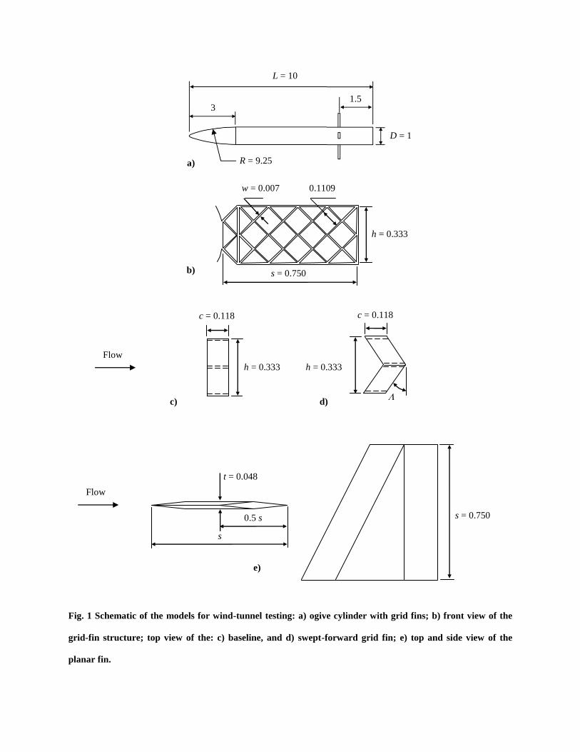
The geometry of the fins is presented in Fig. 1 where all the dimensions are relative to the diameter D = 114.3
mm of the ogive-cylinder body on which the fins were mounted. This is a 7D long cylindrical body capped by a 3D-
G
long tangent ogive nose. The grid fins have a rectangular outer frame with span s, height h and chord c of size
0.75D, 0.333D and 0.118D , respectively. The thickness w of the walls of the lattice is 0.007D. Figures 1 c) and d)
show the top view of the baseline (reference) and of the globally swept-forward grid fins, respectively. The baseline
grid fin has the same geometry discussed in numerous studies [5, 10, 11, 13, 14, 16, 21, 23-28, 34-37, 42]. The
geometry of the swept-forward fin is obtained by tilting forward the framework of grid cells by an angle = 30°
while maintaining the same projected structure and dimensions of the baseline fin shown in Fig. 1b). The leading
edges of the lattice walls of the swept-forward fin have a 20° sharp profile (SF-sharp) to improve the flow ingestion
at transonic and supersonic speeds [19, 21, 23, 24, 39]. The planar fin was not designed to match the aerodynamic
characteristics of either type of grid fin at some specific flow conditions. Rather, a representative clipped-delta
planar fin was designed that has the same span s of the grid fins, root chord equal to the span, tip chord of half this
value, and thickness t equal to 0.048D, Fig. 1e). Four fins mounted 1.5D forward of the body base were used in all
the measurements. Figure 2 shows a picture of the rear part of the body with concurrent installation (not tested) of
the baseline grid fin, the planar fin, and the SF-sharp grid fin, clockwise from left to right.
The ogive-cylinder body was installed on a sting in the center of the wind-tunnel test section. A balance with
resolution of 0.014 N and accuracy of 0.092% located close to the center of gravity of the body was used to measure
the forces and moments acting on it. Its coordinate system has x axis in the body longitudinal direction, y axis in the
spanwise direction, and z axis normal to these. The data were recorded simultaneously to the total and static values
of the pressure and temperature in the test section, and corrected for the effect of the pressure measured at the base
of the body.
Measurements were taken at freestream Mach numbers M∞ between 0.72 and 1.30. The test section of the blow-
down wind tunnel has slanted circular perforations with suction capability for reducing wall interference and shock
reflections. A flow control system maintains the Mach number and the pressure in the test section within 1% of the
desired values during the data acquisition. The corresponding static pressure p and the static temperature T are
indicated in Table 1.
III. Results
The force and moment coefficients are obtained from the measured values by using the body diameter and the
area of its base as dimensional references. No significant differences were found between repeated measurements.
The incremental forces produced by the fins are obtained as the difference of those of the body with and without fins
at the same flow conditions.
Axial force (drag) measurements were taken by varying M∞ between 0.72 and 1.20 (high-subsonic and transonic
flow conditions) with the body at an angle of attack equal to zero. Figure 3 presents the incremental axial-force
coefficient CFx,fin of a single fin. The typical drawback of grid fins, namely their high drag at transonic speed, is well
evidenced in the figure. The baseline grid fin has substantially higher drag than the planar fin with Mach number
variations resembling those observed for similar [11, 13, 14] or comparable [7, 15] fins. The SF-sharp fin reduces
the drag by 30 to 35 % relative to the baseline, a result analogous to that of a globally swept-back grid fin with sharp
leading edges (SB-sharp) [24]. Wang and Yu obtained larger drag reductions with numerical simulation of
individual grid cells of the same geometry [41]. The axial force coefficient of the planar fin increases with the
freestream velocity and peaks at M∞ = 1.00, as expected for a wing in transonic flow. The coefficients of the
baseline and of the SF-sharp grid fins also increase with the freestream velocity but peak at M∞ = 0.90 and M∞ =
0.95, respectively. This is associated to the flow choking in the lattice which is more severe for the baseline fin than
for the SF-sharp fin. The axial force coefficient of all the fins starts decreasing above M∞ = 1.10.
The effect of the angle of attack of the body was explored by varying it from 0° to 12° at M∞ = 0.90 and 1.10
which are considered to be significant transonic conditions as well as at the moderate supersonic value of M∞ =
1.30. Measurements, not shown here, were performed by varying from 0° to -12° to verify that the results mirror
those obtained at positive angles.
Figure 4 shows the axial-force coefficient of the body alone and with fins. In all cases the coefficient varies
little with the angle of attack. The body with baseline grid fins has a coefficient of about 0.6, close to the results
reported for this or comparable fins in other studies [13, 14, 29, 30]. The drag reduction of the four SF-sharp grid
fins relative to the baseline fins is consistent with that of two lateral (elevator) SB-sharp fins shown in Ref. 24.
Planar fins have lower drag than the SF-sharp fins in these flow conditions.
Figure 5 shows that the normal-force coefficient of the body without and with fins increases with the angle of
attack. The results are similar to those available in literature for the body without and with comparable fins [8, 30,
33]. The contribution of the vertical (rudder) planar fins is deemed negligible whereas the vertical grid fins
moderately add to the normal force produced by the lateral grid fins [13, 25, 28, 30]. At M∞ = 0.90 the normal force
of the body with baseline fins drops somewhat for > 8°, an effect also observed at ≈ 7° using two lateral
baseline fins [24]. Similar to their swept-back counterparts, the SF-sharp fins do not create such drop. At M∞ = 1.10
and 1.30 the normal-force coefficient with the baseline and the SF-sharp fins are practically equivalent, the latter
fins having a marginal benefit. At these Mach numbers and angles of attack the planar fins have larger normal-force
coefficient.
This is also reflected in the pitching-moment coefficient of the body, Fig. 6, which is linearly related to the
corresponding normal-force coefficient. Since the fins are located at the tail of the body, their positive normal force
produces a negative pitching moment relative to the balance which is located close to the center of gravity of the
body. Unlike their swept-back counterparts, the SF-sharp fins create only marginally larger (but at M∞ = 0.90
smoother) pitching moments than the baseline fins. In all cases the values are smaller than those of the planar fins
indicating that the latter have better control characteristics for maneuvering a vehicle at transonic and moderately
supersonic speed.
IV. Conclusion
Measurements have been conducted at transonic conditions and in a range of angles of attack of the
aerodynamic characteristics of grid fins without and with a globally swept-forward lattice structure having sharp
leading edges. These are compared to the measurements of representative planar fins in the same flow conditions.
All types of fins were mounted on an ogive-cylinder body installed in a blow-down wind tunnel. The results
obtained indicate that swept-forward grid fins with sharp leading edges have performance comparable to that of
similarly featured swept-back grid fins. While both types of globally swept grid fins have better aerodynamic
characteristics than a much referenced unswept type, their performance falls short of that of planar fins in the range
of speeds and angles of attack explored. These results, together with others available in literature for various grid-fin
geometries, suggest that globally sweeping the lattice provides moderate aerodynamic benefits in the transonic
regime and that increasing a grid-fin performance entails optimizing the profiles of its lattice walls. Additional
research is required to understand if concurrent optimization of the walls’ profiles in a globally swept grid-fin can
produce aerodynamic characteristics competitive with those of planar fins.
References
[1] Belotserkovsky, S. M., Odnovol, L. A., Safin, Y. Z., Tiulenev, A. N., Frolov, V. P., and Shitov, V. A., “Reshetchatye
Kryl’ya,” (in Russian), translated as “Wings with Internal Framework,” Machine Translation FTD-ID (RS) T-1289-89,
Foreign Technology Division, February 1987.
[2] Brooks, R. A., and Burkhalter, J. E., "Experimental and analytical analysis of grid fin configurations," AIAA Paper 1988-
0280, January 1988.
doi: 10.2514/6.1988-280
[3] Burkhalter, J. E., Hartfield, R. J., and Leleux, T. M., “Nonlinear Aerodynamic Analysis of Grid Fin Configuration,” Journal
of Aircraft, Vol. 32, No. 3, 1995, pp. 547-554.
doi: 10.2514/3.46754
[4] Ledlow, T. W. II, Burkhalter, J. E., and Hartfield, R. J., “Integration of Grid Fins for the Optimal Design of Missile
Systems,” AIAA Paper 2015-2017, January 2015.
doi: 10.2514/6.2015-1017
[5] Theerthamalai, P., and Nagarathinam, M., “Aerodynamic Analysis of Grid-Fin Configurations at Supersonic Speeds,”
Journal of Spacecraft and Rockets, Vol. 43, No. 4, 2006, pp. 750-756.
doi: 10.2514/1.16741
[6] Theerthamalai, P., “Aerodynamic Characterization of grid Fins at Subsonic Speeds,” Journal of Aircraft, Vol. 44, No. 2,
2007, pp. 694-697.
doi: 10.2514/1.27653
[7] Washington, W. D., and Miller, M. S., “Grid Fins – A New Concept for Missile Stability and Control,” AIAA Paper 93-0035,
January 1993.
doi: 10.2514/6.1993-35
[8] Washington, W. D., Booth, P. F., and Miller, M. S., “Curvature and Leading Edge Sweep Back Effects on Grid Fin
Aerodynamic Characteristics,” AIAA Paper 93-3480, August 1993.
doi: 10.2514/6.1993-3480
[9] Miller, M. S., and Washington, W. D., “An Experimental Investigation of Grid Fin Drag Reduction Techniques,” AIAA
Paper 94-1914, June 1994.
doi: 10.2514/6.1994-1914
[10] Simpson, G. M., and Sadler, A. J., “Lattice Controls: A Comparison with Conventional, Planar Fins,” Proceedings of the
Research and Technology Organization AVT Symposium on Missile Aerodynamic, Sorrento, Italy, May 1998, RTO-MP-5,
pp. (9-1)-(9-10).
[11] Abate, G. L., Duckerschein, R. P., and Hathaway, W., “Subsonic/Transonic Free-Flight Tests of a Generic Missile with grid
Fins,” AIAA Paper 2000-0937, January 2000.
doi: 10.2514/6.2000-937
[12] Berner, C., and Dupuis, A., “Wind Tunnel Tests of a Grid Finned Projectile Configuration,” AIAA Paper 2001-0105,
January 2001.
doi: 10.2514/6.2001-105
[13] Fournier, E. Y., “Wind Tunnel Investigation of Grid Fin and Conventional Planar Control Surfaces,” AIAA Paper 2001-
0256, January 2001.
doi: 10.2514/6.2001-256
[14] Abate, G., Winchenbach, G., and Hathaway, W., “Transonic aerodynamic and scaling issues for lattice fin projectiles tested
in a ballistic range,” Proceedings of the 19th International Symposium of Ballistic, Interlaken, Switzerland, May 2001, pp.
413-420.
[15] Dupuis, A., and Berner, C., “Aerodynamic Aspects of a Grid Finned Projectile at Subsonic and Supersonic Velocities,”
Proceedings of the 19th International Symposium of Ballistics, Interlaken, Switzerland, May 2001, pp. 495-502.
[16] Fournier, E. Y., “Wind tunnel investigation of a high L/D projectile with grid fin and conventional planar control surfaces,”
Proceedings of the 19th International Symposium of Ballistics, Interlaken, Switzerland, May 2001, pp. 511-520.
[17] Hiroshima F. and Tatsumi, K., “Grid Pattern Effects of Aerodynamic Characteristics of Grid Fins,” Proceedings of the 4th
International Congress of the Aeronautical Sciences, Yokohama, Japan, August - September 2004, pp. 1-8.
[18] Dupuis, A., Berner, C., and Bernier, A., “Aerodynamic characteristic of the A3 DRDC-ISL reference projectile: Missile with
lattice fins,” Defence R&D Canada Valcartier Technical Report 2005-216, August 2005.
[19] Guyot, D., and Schülein, E., “Novel Locally Swept Lattice Wings for Missile Control at High Speeds,” AIAA Paper 2007-
0063, January 2007.
doi: 10.2514/6.2007-63
[20] Misra, A., Singhal, A., Ghosh, A. K., and Ghosh, K., “Wind Tunnel Study of a Grid Fin Stabilized Guided Projectile,”
AIAA Paper 2008-6882, August 2008.
doi: 10.2514/6.2008-6882
[21] Debiasi, M., Zeng, Y., and Chng, T. L., “Swept-back Grid Fins for Transonic Drag Reduction,” AIAA Paper 2010-4244,
June - July 2010.
doi: 10.2514/6.2010-4244
[22] Pruzan, D. A., Mendenhall, M. R., Rose, W. C., and Schuster, D. M., “Grid Fin Stabilization of the Orion Launch Abort
Vehicle,” AIAA Paper 2011-3018, June 2011.
doi: 10.2514/6.2011-3018
[23] Debiasi, M., “Measurements of the Forces and Moments Generated by Swept-back Grid Fins,” AIAA Paper 2012-2909,
June 2012.
doi: 10.2514/6.2012-2909
[24] Debiasi, M. and Zeng, Y., “Forces and Moments Generated by Swept-Back Grid Fins with Sharp Leading Edges,” Journal
of Aircraft, Vol. 53, No. 6, 2016, pp. 1962-1966.
doi: 10.2514/1.C033504
[25] DeSpirito, J., Edge, H. L., Weinacht, P., and Sahu, J., “CFD Analysis of Grid Fins for Maneuvering Missiles,” AIAA Paper
2000-0391, January 2000.
doi: 10.2514/6.2000-391
[26] Chen, S., Khalid, M., Xu, H., and Lesage, F., “A Comprehensive CFD Investigation of Grid Fins as Efficient Control
Surface Devices,” AIAA Paper 2000-0987, January 2000.
doi: 10.2514/6.2000-987
[27] DeSpirito, J., and Sahu, J., “Viscous CFD Calculations of Grid Fin Missile Aerodynamics in the Supersonic Flow Regime,”
AIAA Paper 2001-0257, January 2001.
doi: 10.2514/6.2001-257
[28] DeSpirito, J., Edge, H. L., Weinacht, P., Sahu, J., and Dinavahi, S. P. G., “Computational Fluid Dynamics Analysis of a
Missile with Grid Fins,” Journal of Spacecraft and Rockets, Vol. 38, No. 5, 2001, pp. 711-718.
doi: 10.2514/2.3756
[29] DeSpirito, J., Vaughn, M. E., and Washington, D. W., “Numerical Investigation of Canard-Controlled Missile with Planar
and Grid Fins,” Journal of Spacecraft and Rockets, Vol. 40, No. 3, 2003, pp. 363-370.
doi: 10.2514/2.3971
[30] DeSpirito, J., Vaughn, M. E., and Washington, W. D., “Numerical Investigation of Aerodynamics of Canard-Controlled
Missile Using Planar and Grid Tail Fins, Part I: Supersonic Flow,” Army Research Laboratory Technical Report 2848,
September 2002.
[31] DeSpirito, J., Vaughn, M. E., and Washington, W. D., “Subsonic Flow CFD Investigation of Canard-Controlled Missile with
Planar and Grid Fins,” AIAA Paper 2003-0027, January 2003.
doi: 10.2514/6.2003-27
[32] Lin, H., Huang, J. C., and Chieng, C-C., “Navier–Stokes Computations for Body/Cruciform Grid Fin Configuration,”
Journal of Spacecraft and Rockets, Vol. 40, No. 1, 2003, pp. 30-38.
doi: 10.2514/2.391
[33] DeSpirito, J., Vaughn, M. E., and Washington, W. D., “Numerical Investigation of Aerodynamics of Canard-Controlled
Missile Using Planar and Grid Tail Fins, Part II: Subsonic and Transonic Flow,” Army Research Laboratory Technical
Report 3162, March 2004.
[34] Hughson, M. C., Blades, E. L., and Abate, G. L., “Transonic Aerodynamic Analysis of Lattice Grid Tail Fin Missiles,”
AIAA Paper 2006-3651, June 2006.
doi: 10.2514/6.2006-3651
[35] Hughson, M. C., Blades, E. L., Luke, E. A., and Abate, G. L., “Analysis of Lattice Grid Tailfin Missiles in High-Speed
Flow,” AIAA Paper 2007-3932, June 2007.
doi: 10.2514/6.2007-3932
[36] Zeng, Y., Cai J. S., Debiasi, M., and Chng, T. L., “Numerical Study on Drag Reduction for Grid-Fin Configurations,” AIAA
Paper 2009-1105, January 2009.
doi: 10.2514/6.2009-1105
[37] Cai J. S., “Numerical Study on Choked Flow over Grid-Fin Configurations,” Journal of Spacecraft and Rockets, Vol. 46,
No. 5, 2009, pp. 949-956.
doi: 10.2514/1.41442
[38] Kless, J. E., and Aftosmis, M. J., “Analysis of Grid Fins for Launch Abort Vehicle Using a Cartesian Euler Solver,” AIAA
Paper 2011-3666, June 2011.
doi: 10.2514/6.2011-3666
[39] Zeng, Y., “Drag Reduction for Sweptback Grid Fin with Blunt and Sharp Leading Edges,” Journal of Aircraft, Vol. 49, No.
5, 2012, pp. 1526-1531.
doi: 10.2514/1.C031653
[40] Ravindra, K., Nikhil Shende, V., and Balakrishnan, N., “CFD Simulation of the Grid Fin Flows,” AIAA Paper 2013-3023,
June 2013.
doi: 10.2514/6.2013-3023
[41] Wang, D., and Yu, Y., “Numerical study on drag reduction for sweptback, sweptfront, delta grid fin with blunt and sharp
leading edges,” AIAA Paper 2014-0638, January 2014.
doi: 10.2514/6.2014-0638
[42] Despeyroux, A., Hickey, J.-P., Desaulnier, R., Luciano, R., Piotrowski, M., and Hamel, N., “Numerical Analysis of Static
and Dynamic Performances of Grid Fin Controlled Missiles,” Journal of Spacecraft and Rockets, Vol. 52, No. 4, 2015, pp.
1236-1252.
doi: 10.2514/1.A33189
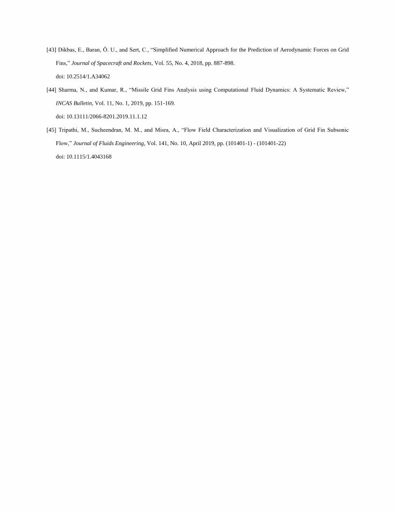
[43] Dikbas, E., Baran, Ö. U., and Sert, C., “Simplified Numerical Approach for the Prediction of Aerodynamic Forces on Grid
Fins,” Journal of Spacecraft and Rockets, Vol. 55, No. 4, 2018, pp. 887-898.
doi: 10.2514/1.A34062
[44] Sharma, N., and Kumar, R., “Missile Grid Fins Analysis using Computational Fluid Dynamics: A Systematic Review,”
INCAS Bulletin, Vol. 11, No. 1, 2019, pp. 151-169.
doi: 10.13111/2066-8201.2019.11.1.12
[45] Tripathi, M., Sucheendran, M. M., and Misra, A., “Flow Field Characterization and Visualization of Grid Fin Subsonic
Flow,” Journal of Fluids Engineering, Vol. 141, No. 10, April 2019, pp. (101401-1) - (101401-22)
doi: 10.1115/1.4043168
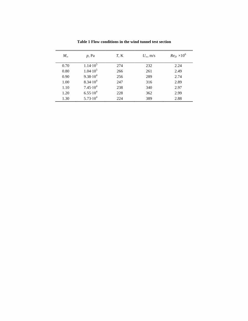
Table 1 Flow conditions in the wind tunnel test section
M∞ p, Pa T, K U∞, m/s ReD ×106
0.70 1.14∙105 274 232 2.24
0.80 1.04∙105 266 261 2.49
0.90 9.38∙104 256 289 2.74
1.00 8.34∙104 247 316 2.89
1.10 7.45∙104 238 340 2.97
1.20 6.55∙104 228 362 2.99
1.30 5.73∙104 224 389 2.88
c) d)
Fig. 1 Schematic of the models for wind-tunnel testing: a) ogive cylinder with grid fins; b) front view of the
grid-fin structure; top view of the: c) baseline, and d) swept-forward grid fin; e) top and side view of the
planar fin.
D = 1
L = 10
1.5 3
R = 9.25 a)
w = 0.007 0.1109
s = 0.750
h = 0.333
b)
c = 0.118
h = 0.333
c = 0.118
h = 0.333
Flow
e)
s = 0.750
Flow
s
t = 0.048
0.5 s
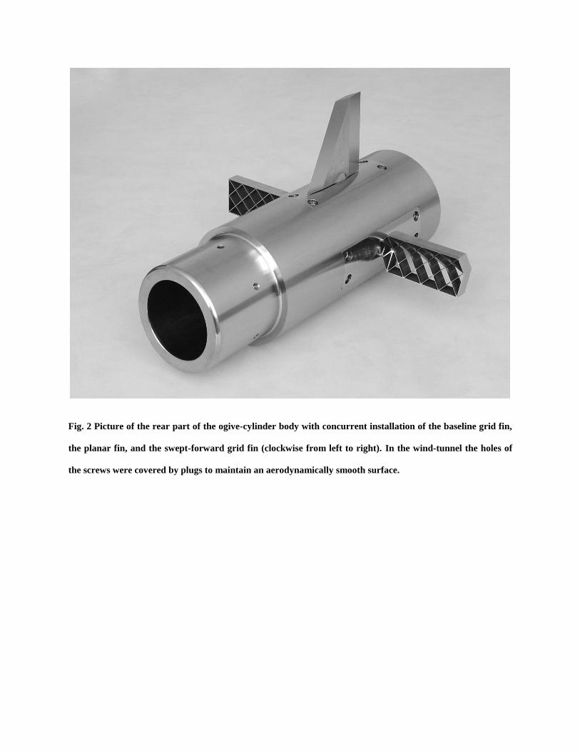
Fig. 2 Picture of the rear part of the ogive-cylinder body with concurrent installation of the baseline grid fin,
the planar fin, and the swept-forward grid fin (clockwise from left to right). In the wind-tunnel the holes of
the screws were covered by plugs to maintain an aerodynamically smooth surface.
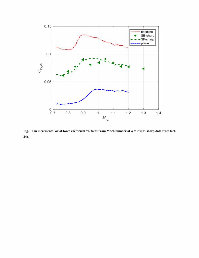
Fig.3 Fin incremental axial-force coefficient vs. freestream Mach number at = 0º (SB-sharp data from Ref.
24).
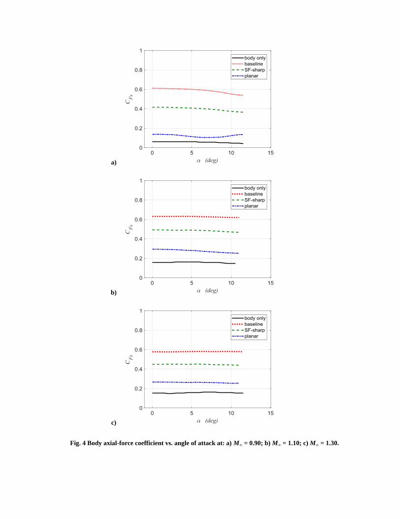
Fig. 4 Body axial-force coefficient vs. angle of attack at: a) M∞ = 0.90; b) M∞ = 1.10; c) M∞ = 1.30.
a)
b)
c)
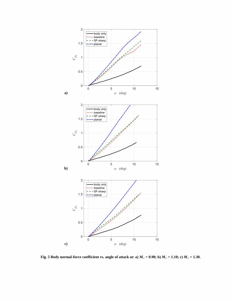
Fig. 5 Body normal-force coefficient vs. angle of attack at: a) M∞ = 0.90; b) M∞ = 1.10; c) M∞ = 1.30.
a)
b)
c)
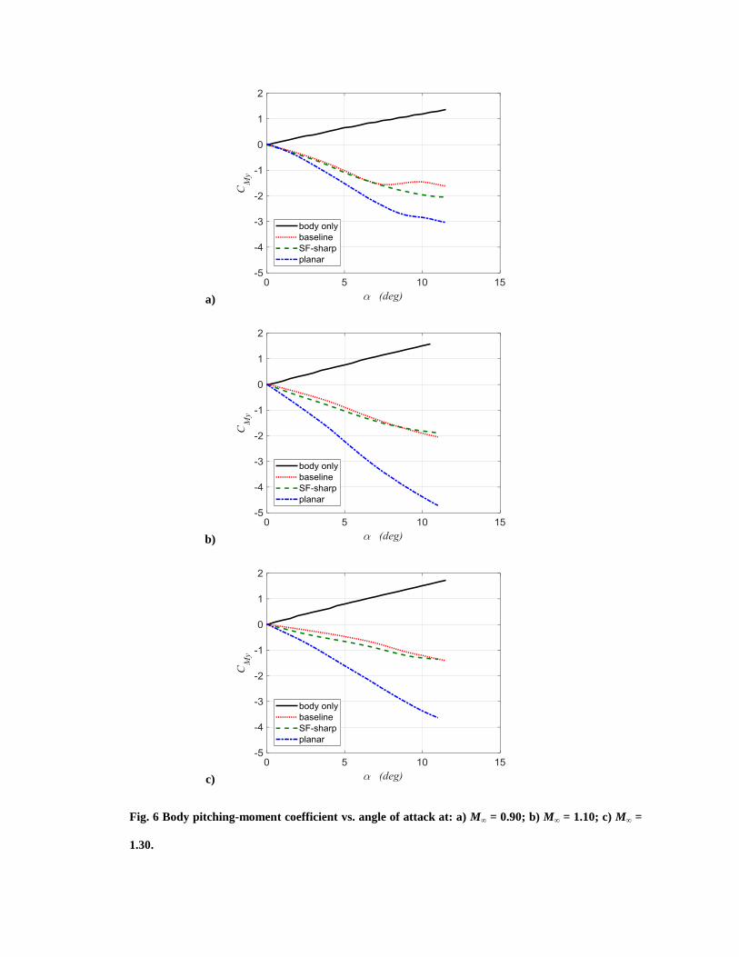
Fig. 6 Body pitching-moment coefficient vs. angle of attack at: a) M∞ = 0.90; b) M∞ = 1.10; c) M∞ =
1.30.
a)
b)
c)


