Embed Size (px)
Citation preview
Ford AX4S
Rebuild Procedures
Written by: Clifford McCormick
©2003 ATRA. All Rights Reserved. Printed in U. S. A.
iiiAX4S Rebuild ProceduresProgram Introduction…
The Ford AX4S has been with us now for well over a decade, and this unit has quickly become one of the most widely used late-model Ford full-sized vehicle transaxles. Although this transaxle is not a relatively new design, there may be parts of the rebuild process that you are not very familiar with, or you may be new to this particular type of transaxle. In either case, you need some point of reference- something that will show you how to proceed when you are not sure (or have no idea whatsoever), and that is exactly what this book is designed to do.
You will not find a photocopied section out of a factory manual between these covers. In fact, you will notice a substantial difference between the book you are holding and any other books written on the subject. This is because, as this book was being written, the author was rebuilding an AX4S step by step as he was writing this book. This helped assure that there would be no missing steps (and it was also real handy for taking pictures along the way…). This book was written for transmission rebuilders, by a transmission rebuilder, in plain English rather than complex ‘factoreze’ terminology.
So, whether you’ve already done a few of the AX4S units, or are about to tackle your first one, this book will show you how to get through the sticky parts of a rebuild, as well as the most thorough way to get through the job, start to finish.
©2003 ATRA. All Rights Reserved. Printed in U. S. A.
iv AX4S Rebuild Procedures
©2003 ATRA. All Rights Reserved. Printed in U. S. A.
vAX4S Rebuild ProceduresTable Of Contents
Unit Disassembly
Input Drum
Reverse Drum
Gear Train
Final Drive
Pump
Valve Body
Case and Chain Cover
Unit Assembly
Page 1
Page 15
Page 40
Page 45
Page 49
Page 61
Page 82
Page 95
Page 107
This program has been designed by the Automatic Transmission Rebuilders Association (ATRA) to be used by qualified automotive transmission technicians. Since the circumstance of its use is beyond ATRA’s control, ATRA assumes no liability for the use of such information or any damages incurred through its use and application. Nothing contained in this program is to be considered contractual or providing some form of warranty on the part of ATRA. No part of this program should be construed as recommending any procedure which is contrary to the vehicle manufacturer’s procedures. ATRA recommends that only certified automotive technicians with experience in transmission diagnosis and repair perform the procedures in this program.
This program contains copyrighted material belonging to ATRA. No part of this program may be reproduced or used in any form by any means- graphic, electronic or mechanical, including photocopying, recording, electronic, or information storage-and-retrieval systems- without the express written permission from ATRA.
ATRA® and the ATRA® logo are registered trademarks of the Automatic Transmission Rebuilders Association.
Public exhibition or use of this material for group training or as part of a school curriculum, without the express written permission of ATRA, is prohibited by law. For information on using this material for independent training programs, contact ATRA at (805) 604-2000.
©2003 ATRA. All rights reserved. Printed in U.S.A.
©2003 ATRA. All Rights Reserved. Printed in U. S. A.
1 AX4S Rebuild ProceduresTransaxle Disassembly
Step 1: Remove the converter, and let the transaxle drain.
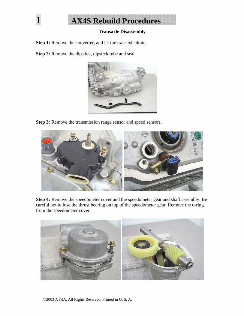
Step 2: Remove the dipstick, dipstick tube and seal.
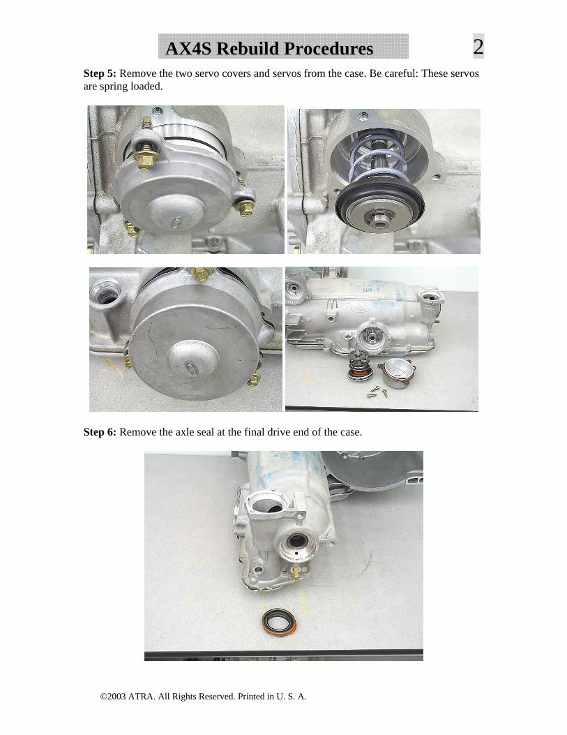
Step 3: Remove the transmission range sensor and speed sensors.
Step 4: Remove the speedometer cover and the speedometer gear and shaft assembly. Be careful not to lose the thrust bearing on top of the speedometer gear. Remove the o-ring from the speedometer cover.
©2003 ATRA. All Rights Reserved. Printed in U. S. A.
2AX4S Rebuild ProceduresStep 5: Remove the two servo covers and servos from the case. Be careful: These servos are spring loaded.
Step 6: Remove the axle seal at the final drive end of the case.
©2003 ATRA. All Rights Reserved. Printed in U. S. A.
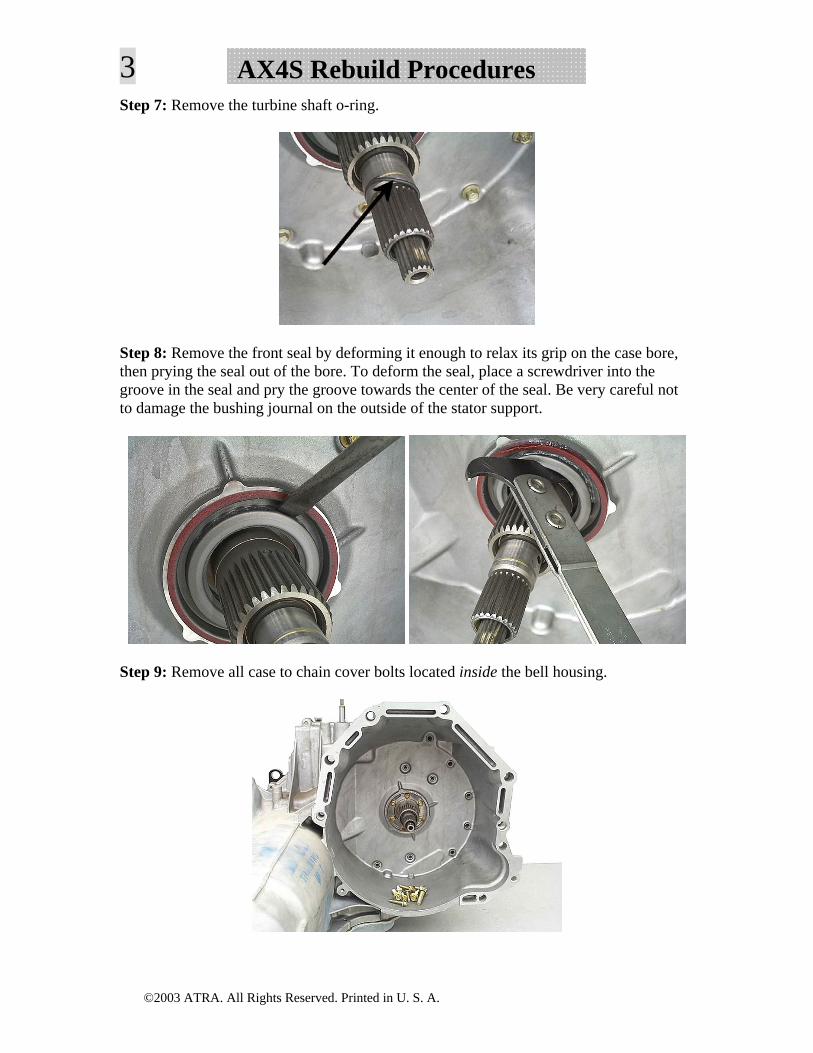
3 AX4S Rebuild ProceduresStep 7: Remove the turbine shaft o-ring.
Step 8: Remove the front seal by deforming it enough to relax its grip on the case bore, then prying the seal out of the bore. To deform the seal, place a screwdriver into the groove in the seal and pry the groove towards the center of the seal. Be very careful not to damage the bushing journal on the outside of the stator support.
Step 9: Remove all case to chain cover bolts located inside the bell housing.
©2003 ATRA. All Rights Reserved. Printed in U. S. A.
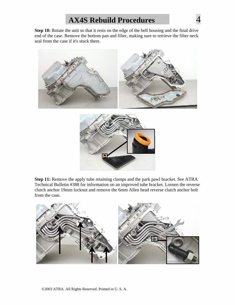
4AX4S Rebuild ProceduresStep 10: Rotate the unit so that it rests on the edge of the bell housing and the final drive end of the case. Remove the bottom pan and filter, making sure to retrieve the filter neck seal from the case if it's stuck there.
Step 11: Remove the apply tube retaining clamps and the park pawl bracket. See ATRA Technical Bulletin #388 for information on an improved tube bracket. Loosen the reverse clutch anchor 19mm locknut and remove the 6mm Allen head reverse clutch anchor bolt from the case.
©2003 ATRA. All Rights Reserved. Printed in U. S. A.
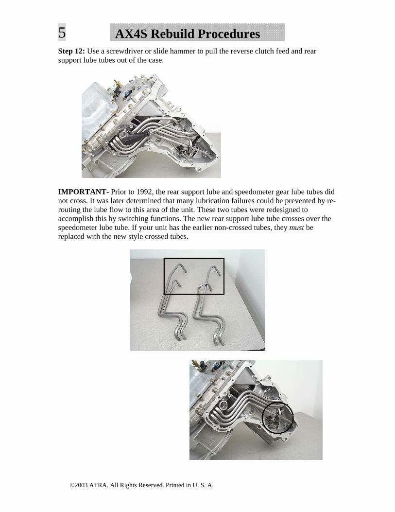
5 AX4S Rebuild ProceduresStep 12: Use a screwdriver or slide hammer to pull the reverse clutch feed and rear support lube tubes out of the case.
IMPORTANT- Prior to 1992, the rear support lube and speedometer gear lube tubes did not cross. It was later determined that many lubrication failures could be prevented by re-routing the lube flow to this area of the unit. These two tubes were redesigned to accomplish this by switching functions. The new rear support lube tube crosses over the speedometer lube tube. If your unit has the earlier non-crossed tubes, they must be replaced with the new style crossed tubes.
©2003 ATRA. All Rights Reserved. Printed in U. S. A.
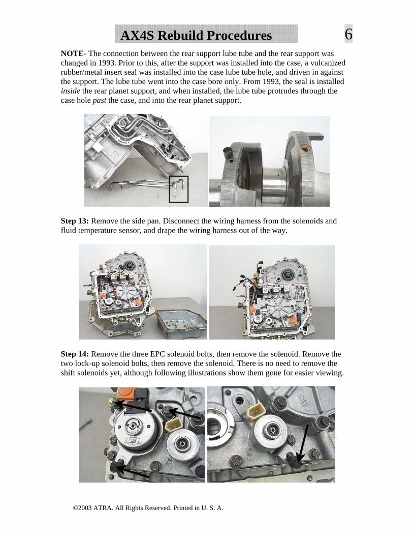
6AX4S Rebuild ProceduresNOTE- The connection between the rear support lube tube and the rear support was changed in 1993. Prior to this, after the support was installed into the case, a vulcanized rubber/metal insert seal was installed into the case lube tube hole, and driven in against the support. The lube tube went into the case bore only. From 1993, the seal is installed inside the rear planet support, and when installed, the lube tube protrudes through the case hole past the case, and into the rear planet support.
Step 13: Remove the side pan. Disconnect the wiring harness from the solenoids and fluid temperature sensor, and drape the wiring harness out of the way.
Step 14: Remove the three EPC solenoid bolts, then remove the solenoid. Remove the two lock-up solenoid bolts, then remove the solenoid. There is no need to remove the shift solenoids yet, although following illustrations show them gone for easier viewing.
©2003 ATRA. All Rights Reserved. Printed in U. S. A.
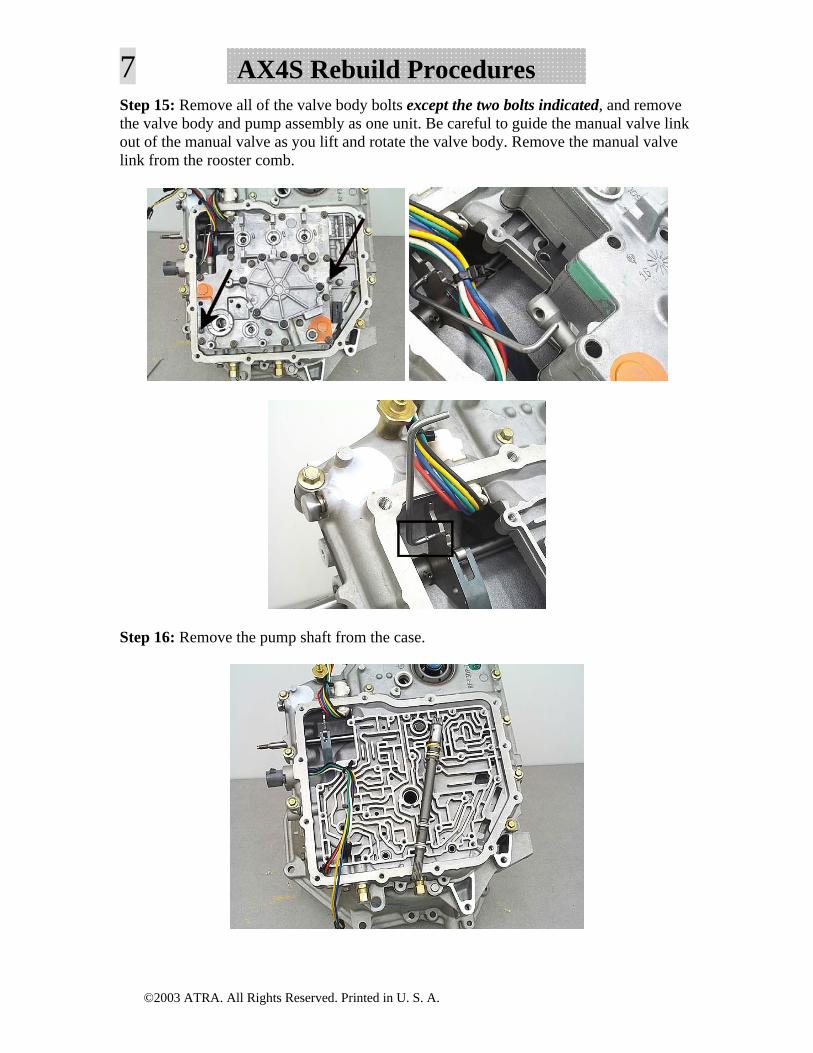
7 AX4S Rebuild ProceduresStep 15: Remove all of the valve body bolts except the two bolts indicated, and remove the valve body and pump assembly as one unit. Be careful to guide the manual valve link out of the manual valve as you lift and rotate the valve body. Remove the manual valve link from the rooster comb.
Step 16: Remove the pump shaft from the case.
©2003 ATRA. All Rights Reserved. Printed in U. S. A.
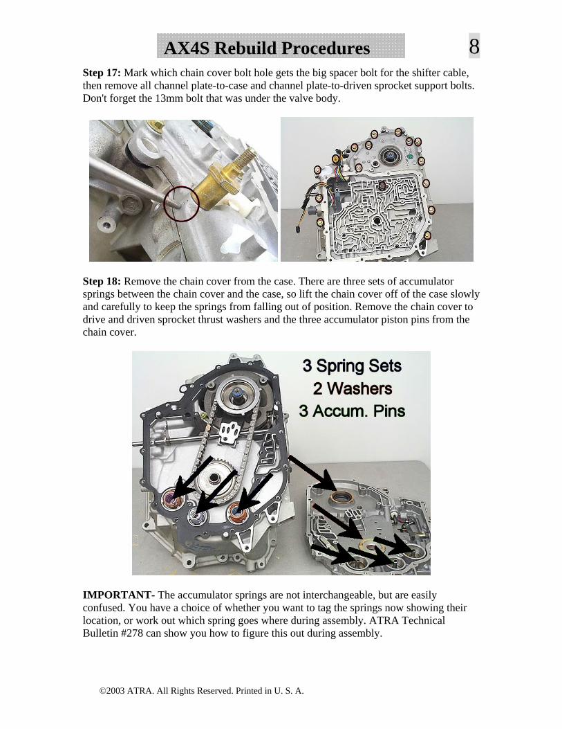
8AX4S Rebuild ProceduresStep 17: Mark which chain cover bolt hole gets the big spacer bolt for the shifter cable, then remove all channel plate-to-case and channel plate-to-driven sprocket support bolts. Don't forget the 13mm bolt that was under the valve body.
Step 18: Remove the chain cover from the case. There are three sets of accumulator springs between the chain cover and the case, so lift the chain cover off of the case slowly and carefully to keep the springs from falling out of position. Remove the chain cover to drive and driven sprocket thrust washers and the three accumulator piston pins from the chain cover.
IMPORTANT- The accumulator springs are not interchangeable, but are easily confused. You have a choice of whether you want to tag the springs now showing their location, or work out which spring goes where during assembly. ATRA Technical Bulletin #278 can show you how to figure this out during assembly.
©2003 ATRA. All Rights Reserved. Printed in U. S. A.
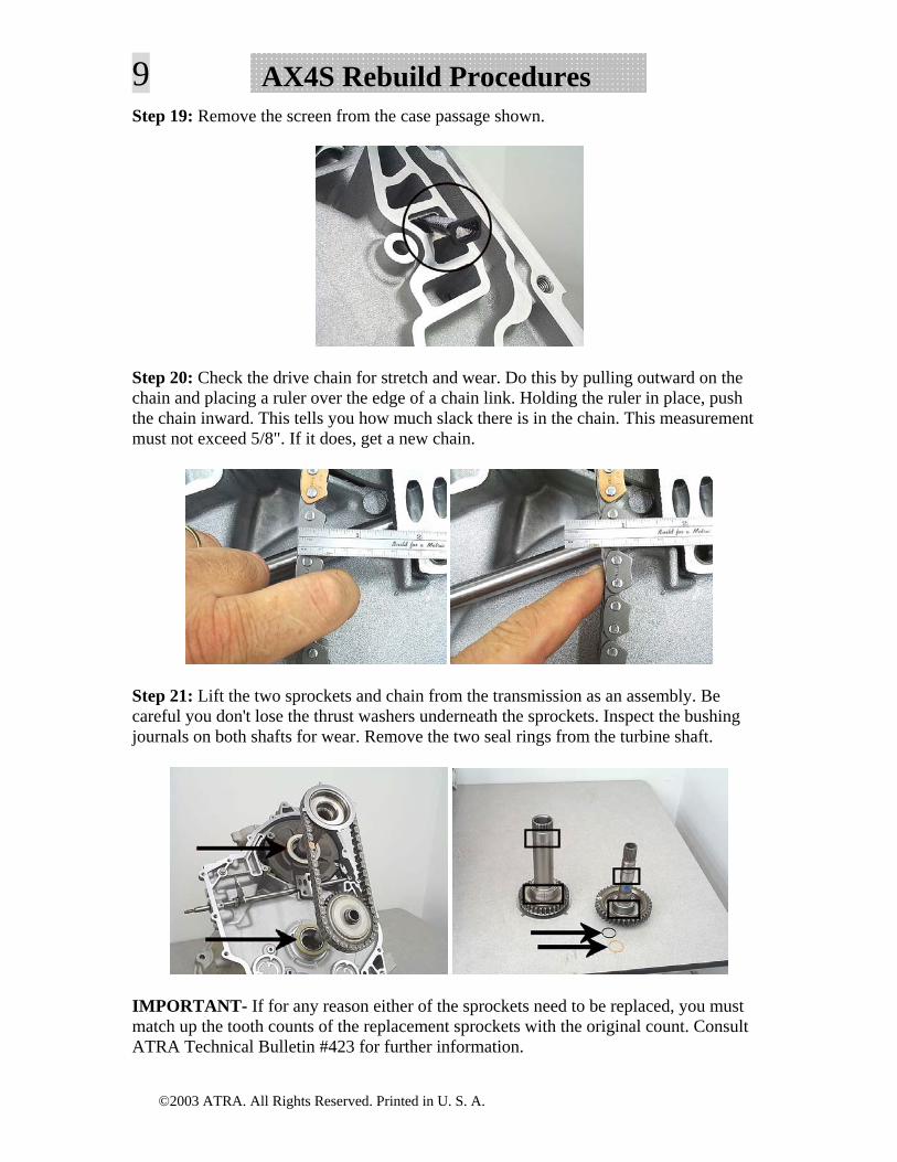
9 AX4S Rebuild ProceduresStep 19: Remove the screen from the case passage shown.
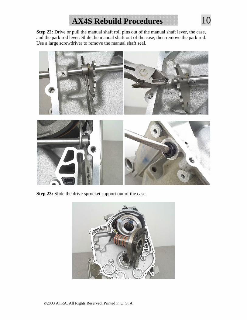
Step 20: Check the drive chain for stretch and wear. Do this by pulling outward on the chain and placing a ruler over the edge of a chain link. Holding the ruler in place, push the chain inward. This tells you how much slack there is in the chain. This measurement must not exceed 5/8". If it does, get a new chain.
Step 21: Lift the two sprockets and chain from the transmission as an assembly. Be careful you don't lose the thrust washers underneath the sprockets. Inspect the bushing journals on both shafts for wear. Remove the two seal rings from the turbine shaft.
IMPORTANT- If for any reason either of the sprockets need to be replaced, you must match up the tooth counts of the replacement sprockets with the original count. Consult ATRA Technical Bulletin #423 for further information.
©2003 ATRA. All Rights Reserved. Printed in U. S. A.
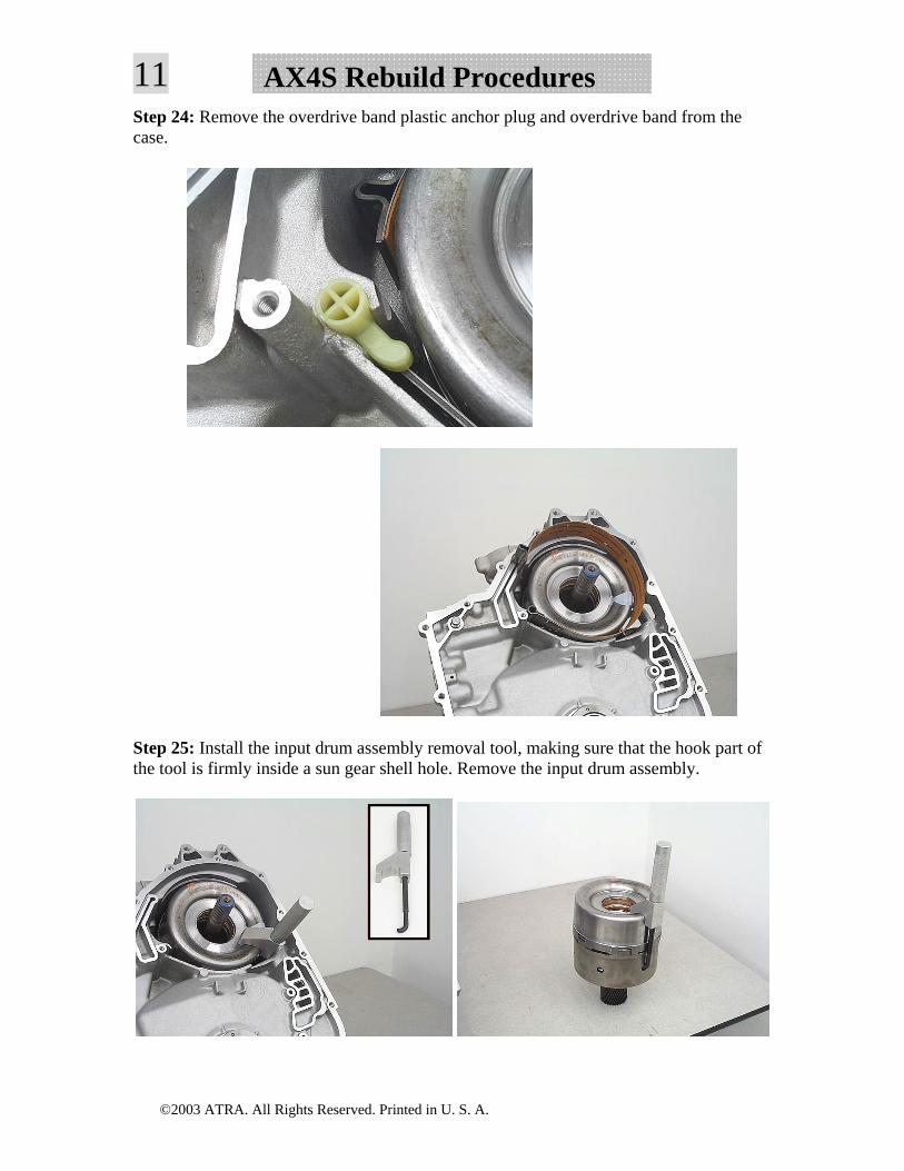
10AX4S Rebuild ProceduresStep 22: Drive or pull the manual shaft roll pins out of the manual shaft lever, the case, and the park rod lever. Slide the manual shaft out of the case, then remove the park rod. Use a large screwdriver to remove the manual shaft seal.
Step 23: Slide the drive sprocket support out of the case.
©2003 ATRA. All Rights Reserved. Printed in U. S. A.
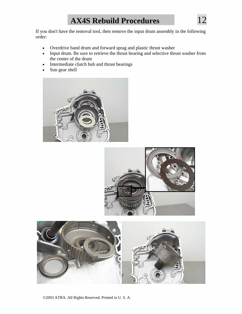
11 AX4S Rebuild ProceduresStep 24: Remove the overdrive band plastic anchor plug and overdrive band from the case.
Step 25: Install the input drum assembly removal tool, making sure that the hook part of the tool is firmly inside a sun gear shell hole. Remove the input drum assembly.
©2003 ATRA. All Rights Reserved. Printed in U. S. A.
12AX4S Rebuild ProceduresIf you don't have the removal tool, then remove the input drum assembly in the following order:
• Overdrive band drum and forward sprag and plastic thrust washer • Input drum. Be sure to retrieve the thrust bearing and selective thrust washer from
the center of the drum • Intermediate clutch hub and thrust bearings • Sun gear shell
©2003 ATRA. All Rights Reserved. Printed in U. S. A.
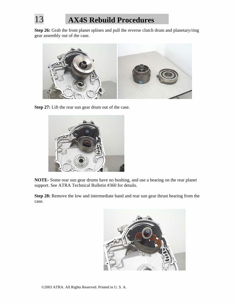
13 AX4S Rebuild ProceduresStep 26: Grab the front planet splines and pull the reverse clutch drum and planetary/ring gear assembly out of the case.
Step 27: Lift the rear sun gear drum out of the case.
NOTE- Some rear sun gear drums have no bushing, and use a bearing on the rear planet support. See ATRA Technical Bulletin #360 for details.
Step 28: Remove the low and intermediate band and rear sun gear thrust bearing from the case.
©2003 ATRA. All Rights Reserved. Printed in U. S. A.
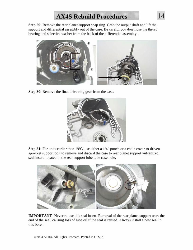
14AX4S Rebuild ProceduresStep 29: Remove the rear planet support snap ring. Grab the output shaft and lift the support and differential assembly out of the case. Be careful you don't lose the thrust bearing and selective washer from the back of the differential assembly.
Step 30: Remove the final drive ring gear from the case.
Step 31: For units earlier than 1993, use either a 1/4" punch or a chain cover-to-driven sprocket support bolt to remove and discard the case to rear planet support vulcanized seal insert, located in the rear support lube tube case hole.
IMPORTANT- Never re-use this seal insert. Removal of the rear planet support tears the end of the seal, causing loss of lube oil if the seal is reused. Always install a new seal in this bore.
©2003 ATRA. All Rights Reserved. Printed in U. S. A.
15 AX4S Rebuild ProceduresInput Drum Disassembly
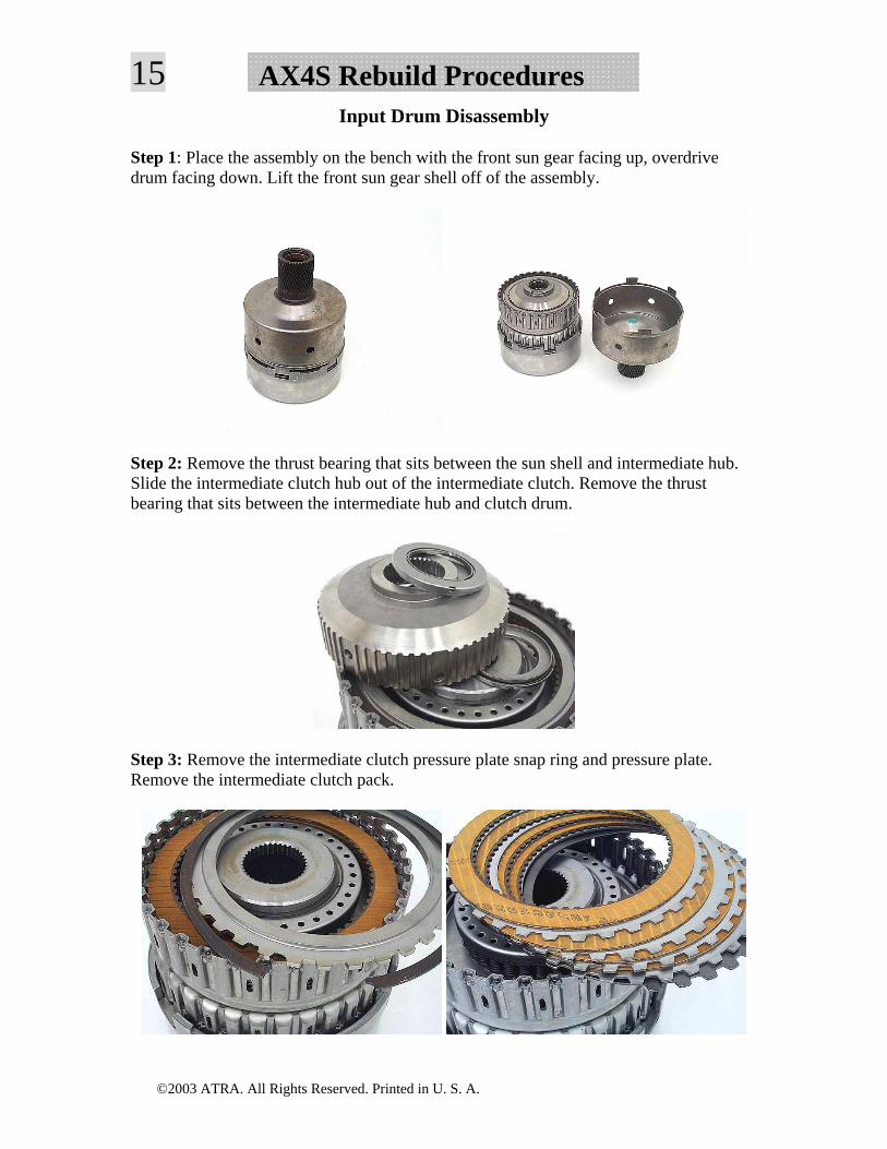
Step 1: Place the assembly on the bench with the front sun gear facing up, overdrive drum facing down. Lift the front sun gear shell off of the assembly.
Step 2: Remove the thrust bearing that sits between the sun shell and intermediate hub. Slide the intermediate clutch hub out of the intermediate clutch. Remove the thrust bearing that sits between the intermediate hub and clutch drum.
Step 3: Remove the intermediate clutch pressure plate snap ring and pressure plate. Remove the intermediate clutch pack.
©2003 ATRA. All Rights Reserved. Printed in U. S. A.
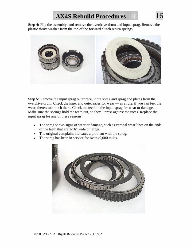
16AX4S Rebuild ProceduresStep 4: Flip the assembly, and remove the overdrive drum and input sprag. Remove the plastic thrust washer from the top of the forward clutch return springs.
Step 5: Remove the input sprag outer race, input sprag and sprag end plates from the overdrive drum. Check the inner and outer races for wear — as a rule, if you can feel the wear, there's too much there. Check the teeth in the input sprag for wear or damage. Make sure the springs hold the teeth out, so they'll press against the races. Replace the input sprag for any of these reasons:
• The sprag shows signs of wear or damage, such as vertical wear lines on the ends of the teeth that are 1/16" wide or larger.
• The original complaint indicates a problem with the sprag. • The sprag has been in service for over 40,000 miles.
©2003 ATRA. All Rights Reserved. Printed in U. S. A.
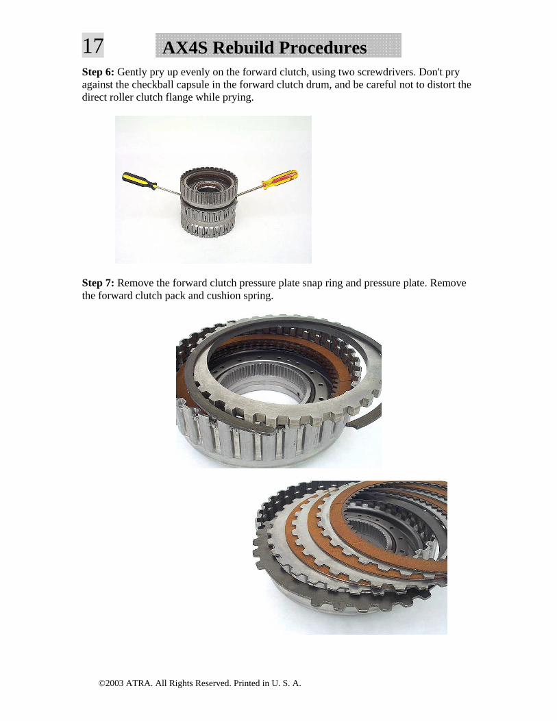
17 AX4S Rebuild ProceduresStep 6: Gently pry up evenly on the forward clutch, using two screwdrivers. Don't pry against the checkball capsule in the forward clutch drum, and be careful not to distort the direct roller clutch flange while prying.
Step 7: Remove the forward clutch pressure plate snap ring and pressure plate. Remove the forward clutch pack and cushion spring.
©2003 ATRA. All Rights Reserved. Printed in U. S. A.
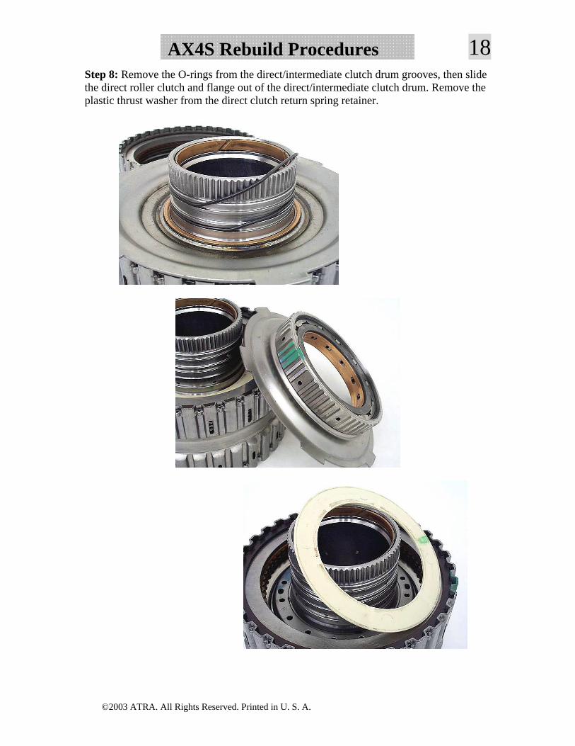
18AX4S Rebuild ProceduresStep 8: Remove the O-rings from the direct/intermediate clutch drum grooves, then slide the direct roller clutch and flange out of the direct/intermediate clutch drum. Remove the plastic thrust washer from the direct clutch return spring retainer.
©2003 ATRA. All Rights Reserved. Printed in U. S. A.
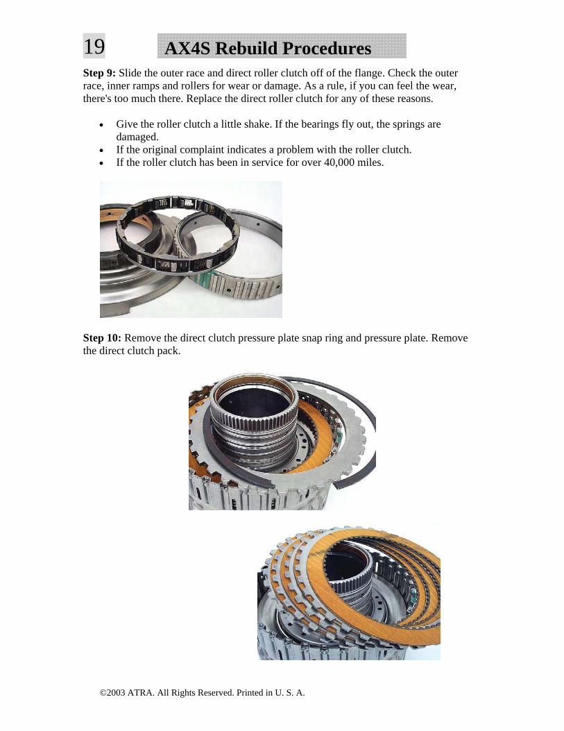
19 AX4S Rebuild ProceduresStep 9: Slide the outer race and direct roller clutch off of the flange. Check the outer race, inner ramps and rollers for wear or damage. As a rule, if you can feel the wear, there's too much there. Replace the direct roller clutch for any of these reasons.
• Give the roller clutch a little shake. If the bearings fly out, the springs are damaged.
• If the original complaint indicates a problem with the roller clutch. • If the roller clutch has been in service for over 40,000 miles.
Step 10: Remove the direct clutch pressure plate snap ring and pressure plate. Remove the direct clutch pack.
©2003 ATRA. All Rights Reserved. Printed in U. S. A.
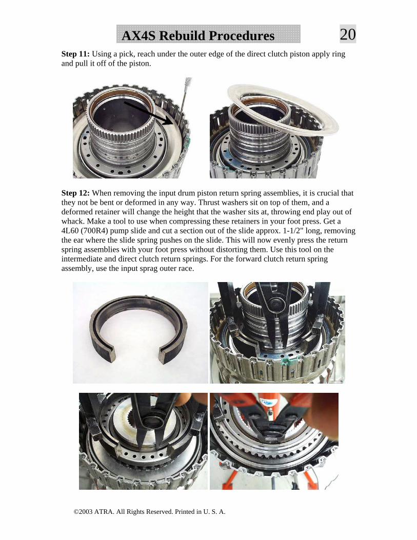
20AX4S Rebuild ProceduresStep 11: Using a pick, reach under the outer edge of the direct clutch piston apply ring and pull it off of the piston.
Step 12: When removing the input drum piston return spring assemblies, it is crucial that they not be bent or deformed in any way. Thrust washers sit on top of them, and a deformed retainer will change the height that the washer sits at, throwing end play out of whack. Make a tool to use when compressing these retainers in your foot press. Get a 4L60 (700R4) pump slide and cut a section out of the slide approx. 1-1/2" long, removing the ear where the slide spring pushes on the slide. This will now evenly press the return spring assemblies with your foot press without distorting them. Use this tool on the intermediate and direct clutch return springs. For the forward clutch return spring assembly, use the input sprag outer race.
©2003 ATRA. All Rights Reserved. Printed in U. S. A.
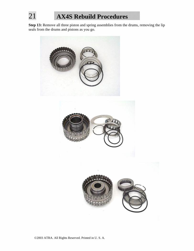
21 AX4S Rebuild ProceduresStep 13: Remove all three piston and spring assemblies from the drums, removing the lip seals from the drums and pistons as you go.
©2003 ATRA. All Rights Reserved. Printed in U. S. A.
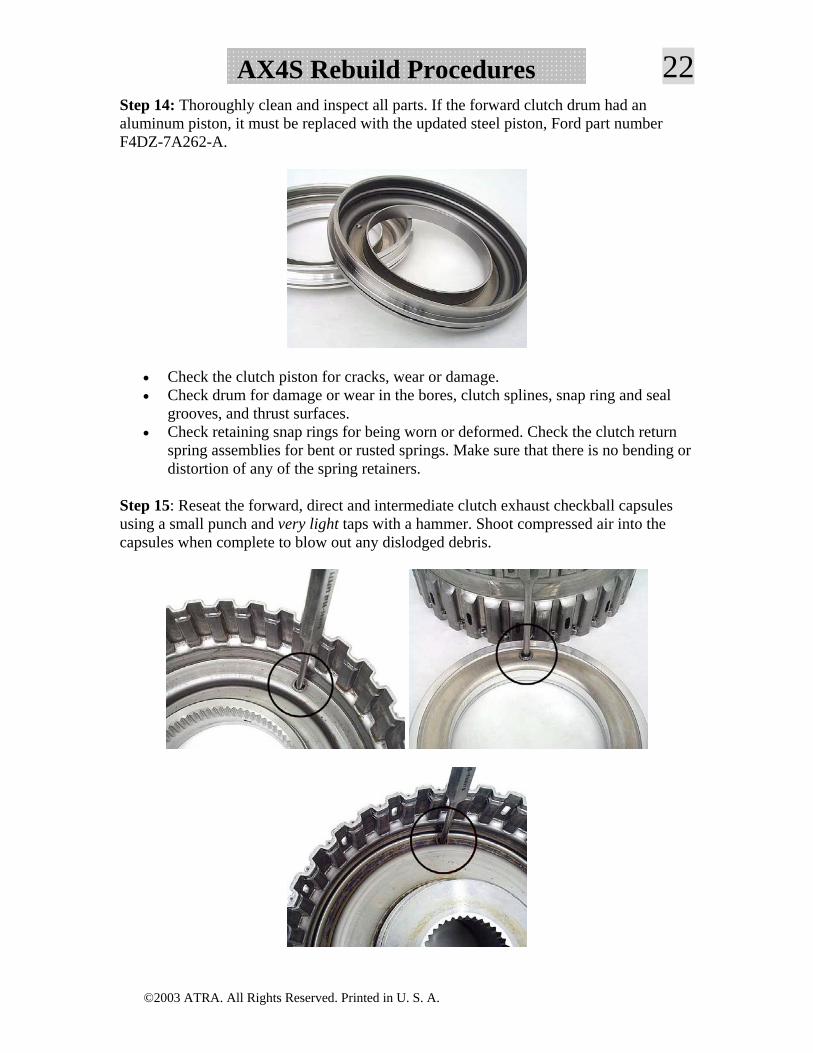
22AX4S Rebuild ProceduresStep 14: Thoroughly clean and inspect all parts. If the forward clutch drum had an aluminum piston, it must be replaced with the updated steel piston, Ford part number F4DZ-7A262-A.
• Check the clutch piston for cracks, wear or damage. • Check drum for damage or wear in the bores, clutch splines, snap ring and seal
grooves, and thrust surfaces. • Check retaining snap rings for being worn or deformed. Check the clutch return
spring assemblies for bent or rusted springs. Make sure that there is no bending or distortion of any of the spring retainers.
Step 15: Reseat the forward, direct and intermediate clutch exhaust checkball capsules using a small punch and very light taps with a hammer. Shoot compressed air into the capsules when complete to blow out any dislodged debris.
©2003 ATRA. All Rights Reserved. Printed in U. S. A.
23 AX4S Rebuild ProceduresInput Drum Assembly
Intermediate Clutch
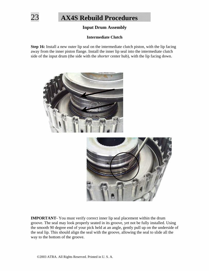
Step 16: Install a new outer lip seal on the intermediate clutch piston, with the lip facing away from the inner piston flange. Install the inner lip seal into the intermediate clutch side of the input drum (the side with the shorter center hub), with the lip facing down.
IMPORTANT- You must verify correct inner lip seal placement within the drum groove. The seal may look properly seated in its groove, yet not be fully installed. Using the smooth 90 degree end of your pick held at an angle, gently pull up on the underside of the seal lip. This should align the seal with the groove, allowing the seal to slide all the way to the bottom of the groove.
©2003 ATRA. All Rights Reserved. Printed in U. S. A.
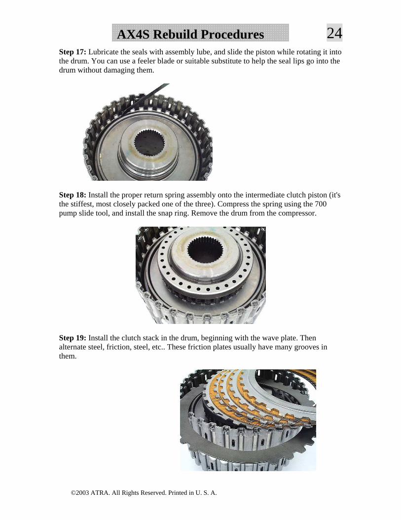
24AX4S Rebuild ProceduresStep 17: Lubricate the seals with assembly lube, and slide the piston while rotating it into the drum. You can use a feeler blade or suitable substitute to help the seal lips go into the drum without damaging them.
Step 18: Install the proper return spring assembly onto the intermediate clutch piston (it's the stiffest, most closely packed one of the three). Compress the spring using the 700 pump slide tool, and install the snap ring. Remove the drum from the compressor.
Step 19: Install the clutch stack in the drum, beginning with the wave plate. Then alternate steel, friction, steel, etc.. These friction plates usually have many grooves in them.
©2003 ATRA. All Rights Reserved. Printed in U. S. A.
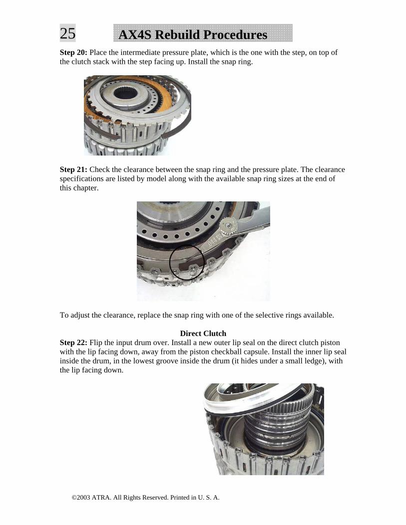
25 AX4S Rebuild ProceduresStep 20: Place the intermediate pressure plate, which is the one with the step, on top of the clutch stack with the step facing up. Install the snap ring.
Step 21: Check the clearance between the snap ring and the pressure plate. The clearance specifications are listed by model along with the available snap ring sizes at the end of this chapter.
To adjust the clearance, replace the snap ring with one of the selective rings available.
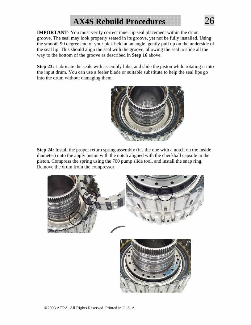
Direct Clutch Step 22: Flip the input drum over. Install a new outer lip seal on the direct clutch piston with the lip facing down, away from the piston checkball capsule. Install the inner lip seal inside the drum, in the lowest groove inside the drum (it hides under a small ledge), with the lip facing down.
©2003 ATRA. All Rights Reserved. Printed in U. S. A.
26AX4S Rebuild ProceduresIMPORTANT- You must verify correct inner lip seal placement within the drum groove. The seal may look properly seated in its groove, yet not be fully installed. Using the smooth 90 degree end of your pick held at an angle, gently pull up on the underside of the seal lip. This should align the seal with the groove, allowing the seal to slide all the way to the bottom of the groove as described in Step 16 above.
Step 23: Lubricate the seals with assembly lube, and slide the piston while rotating it into the input drum. You can use a feeler blade or suitable substitute to help the seal lips go into the drum without damaging them.
Step 24: Install the proper return spring assembly (it's the one with a notch on the inside diameter) onto the apply piston with the notch aligned with the checkball capsule in the piston. Compress the spring using the 700 pump slide tool, and install the snap ring. Remove the drum from the compressor.
©2003 ATRA. All Rights Reserved. Printed in U. S. A.
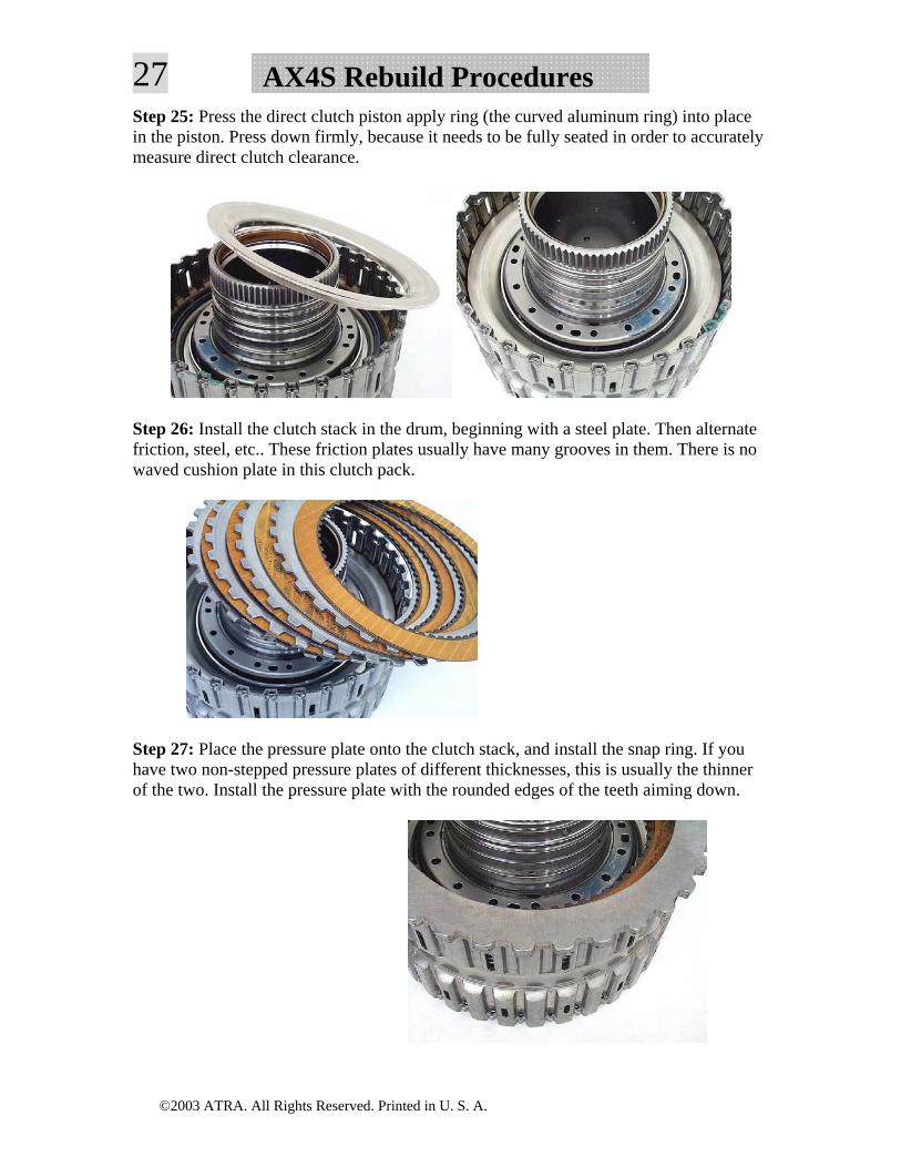
27 AX4S Rebuild ProceduresStep 25: Press the direct clutch piston apply ring (the curved aluminum ring) into place in the piston. Press down firmly, because it needs to be fully seated in order to accurately measure direct clutch clearance.
Step 26: Install the clutch stack in the drum, beginning with a steel plate. Then alternate friction, steel, etc.. These friction plates usually have many grooves in them. There is no waved cushion plate in this clutch pack.
Step 27: Place the pressure plate onto the clutch stack, and install the snap ring. If you have two non-stepped pressure plates of different thicknesses, this is usually the thinner of the two. Install the pressure plate with the rounded edges of the teeth aiming down.
©2003 ATRA. All Rights Reserved. Printed in U. S. A.
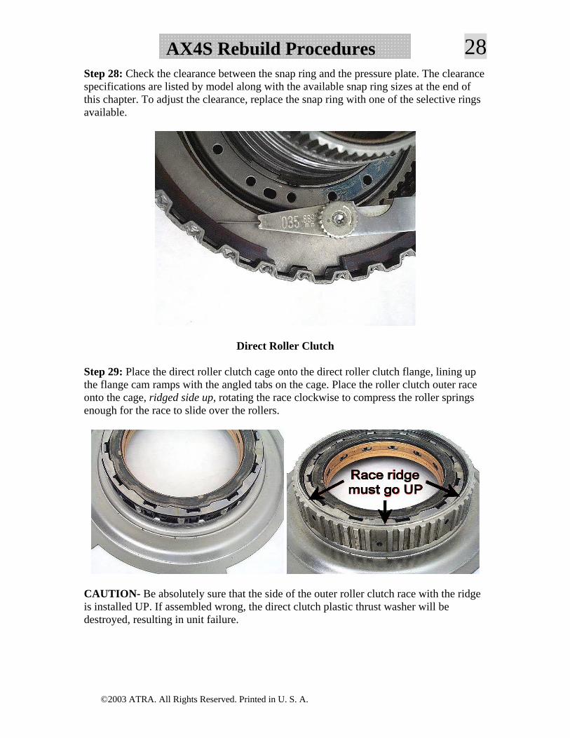
28AX4S Rebuild ProceduresStep 28: Check the clearance between the snap ring and the pressure plate. The clearance specifications are listed by model along with the available snap ring sizes at the end of this chapter. To adjust the clearance, replace the snap ring with one of the selective rings available.
Direct Roller Clutch
Step 29: Place the direct roller clutch cage onto the direct roller clutch flange, lining up the flange cam ramps with the angled tabs on the cage. Place the roller clutch outer race onto the cage, ridged side up, rotating the race clockwise to compress the roller springs enough for the race to slide over the rollers.
CAUTION- Be absolutely sure that the side of the outer roller clutch race with the ridge is installed UP. If assembled wrong, the direct clutch plastic thrust washer will be destroyed, resulting in unit failure.
©2003 ATRA. All Rights Reserved. Printed in U. S. A.
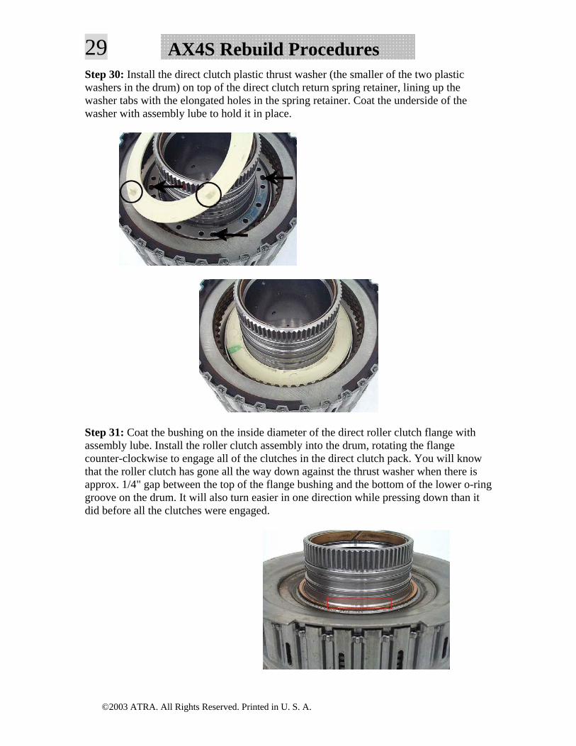
29 AX4S Rebuild ProceduresStep 30: Install the direct clutch plastic thrust washer (the smaller of the two plastic washers in the drum) on top of the direct clutch return spring retainer, lining up the washer tabs with the elongated holes in the spring retainer. Coat the underside of the washer with assembly lube to hold it in place.
Step 31: Coat the bushing on the inside diameter of the direct roller clutch flange with assembly lube. Install the roller clutch assembly into the drum, rotating the flange counter-clockwise to engage all of the clutches in the direct clutch pack. You will know that the roller clutch has gone all the way down against the thrust washer when there is approx. 1/4" gap between the top of the flange bushing and the bottom of the lower o-ring groove on the drum. It will also turn easier in one direction while pressing down than it did before all the clutches were engaged.
©2003 ATRA. All Rights Reserved. Printed in U. S. A.
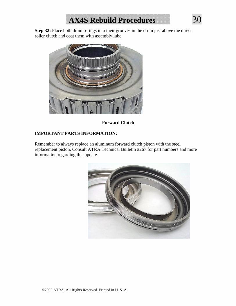
30AX4S Rebuild ProceduresStep 32: Place both drum o-rings into their grooves in the drum just above the direct roller clutch and coat them with assembly lube.
Forward Clutch
IMPORTANT PARTS INFORMATION:
Remember to always replace an aluminum forward clutch piston with the steel replacement piston. Consult ATRA Technical Bulletin #267 for part numbers and more information regarding this update.
©2003 ATRA. All Rights Reserved. Printed in U. S. A.
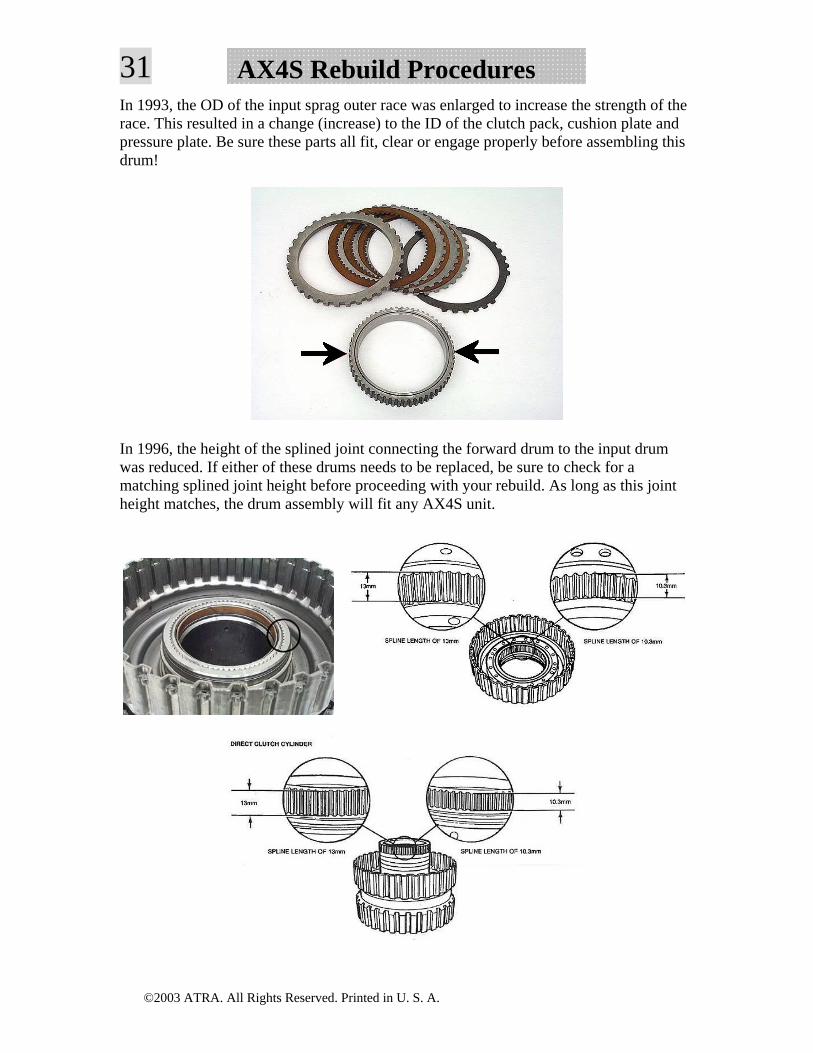
31 AX4S Rebuild ProceduresIn 1993, the OD of the input sprag outer race was enlarged to increase the strength of the race. This resulted in a change (increase) to the ID of the clutch pack, cushion plate and pressure plate. Be sure these parts all fit, clear or engage properly before assembling this drum!
In 1996, the height of the splined joint connecting the forward drum to the input drum was reduced. If either of these drums needs to be replaced, be sure to check for a matching splined joint height before proceeding with your rebuild. As long as this joint height matches, the drum assembly will fit any AX4S unit.
©2003 ATRA. All Rights Reserved. Printed in U. S. A.
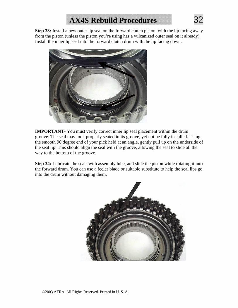
32AX4S Rebuild ProceduresStep 33: Install a new outer lip seal on the forward clutch piston, with the lip facing away from the piston (unless the piston you’re using has a vulcanized outer seal on it already). Install the inner lip seal into the forward clutch drum with the lip facing down.
IMPORTANT- You must verify correct inner lip seal placement within the drum groove. The seal may look properly seated in its groove, yet not be fully installed. Using the smooth 90 degree end of your pick held at an angle, gently pull up on the underside of the seal lip. This should align the seal with the groove, allowing the seal to slide all the way to the bottom of the groove.
Step 34: Lubricate the seals with assembly lube, and slide the piston while rotating it into the forward drum. You can use a feeler blade or suitable substitute to help the seal lips go into the drum without damaging them.
©2003 ATRA. All Rights Reserved. Printed in U. S. A.
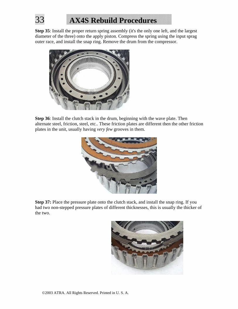
33 AX4S Rebuild ProceduresStep 35: Install the proper return spring assembly (it's the only one left, and the largest diameter of the three) onto the apply piston. Compress the spring using the input sprag outer race, and install the snap ring. Remove the drum from the compressor.
Step 36: Install the clutch stack in the drum, beginning with the wave plate. Then alternate steel, friction, steel, etc.. These friction plates are different then the other friction plates in the unit, usually having very few grooves in them.
Step 37: Place the pressure plate onto the clutch stack, and install the snap ring. If you had two non-stepped pressure plates of different thicknesses, this is usually the thicker of the two.
©2003 ATRA. All Rights Reserved. Printed in U. S. A.
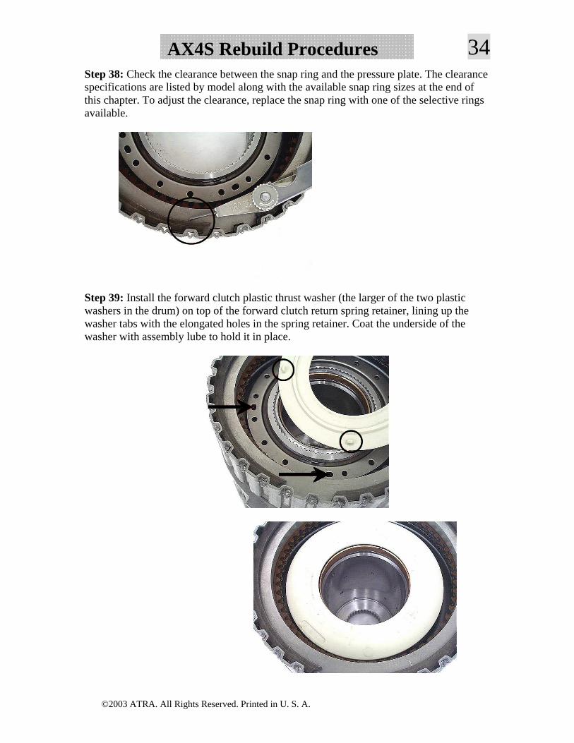
34AX4S Rebuild ProceduresStep 38: Check the clearance between the snap ring and the pressure plate. The clearance specifications are listed by model along with the available snap ring sizes at the end of this chapter. To adjust the clearance, replace the snap ring with one of the selective rings available.
Step 39: Install the forward clutch plastic thrust washer (the larger of the two plastic washers in the drum) on top of the forward clutch return spring retainer, lining up the washer tabs with the elongated holes in the spring retainer. Coat the underside of the washer with assembly lube to hold it in place.
©2003 ATRA. All Rights Reserved. Printed in U. S. A.
35 AX4S Rebuild ProceduresInput Sprag/Overdrive Drum
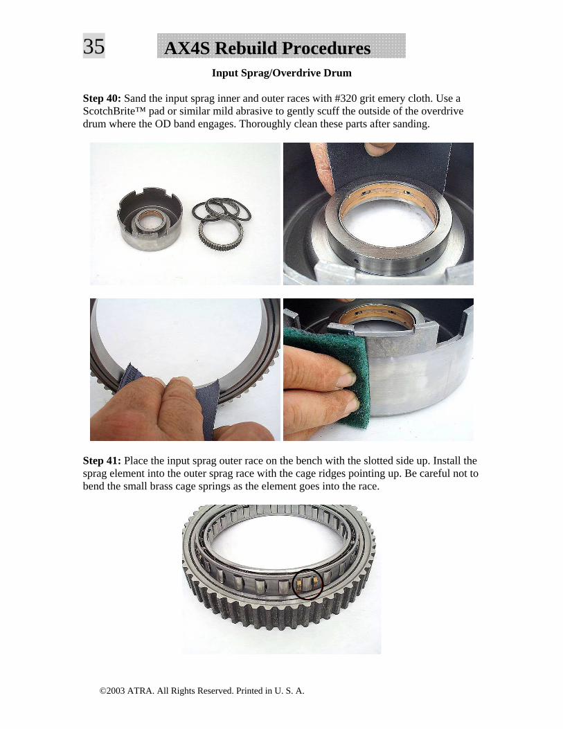
Step 40: Sand the input sprag inner and outer races with #320 grit emery cloth. Use a ScotchBrite™ pad or similar mild abrasive to gently scuff the outside of the overdrive drum where the OD band engages. Thoroughly clean these parts after sanding.
Step 41: Place the input sprag outer race on the bench with the slotted side up. Install the sprag element into the outer sprag race with the cage ridges pointing up. Be careful not to bend the small brass cage springs as the element goes into the race.
©2003 ATRA. All Rights Reserved. Printed in U. S. A.
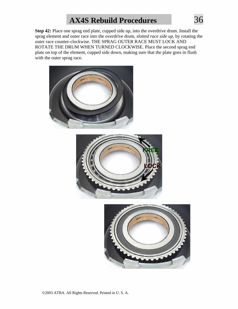
36AX4S Rebuild ProceduresStep 42: Place one sprag end plate, cupped side up, into the overdrive drum. Install the sprag element and outer race into the overdrive drum, slotted race side up, by rotating the outer race counter-clockwise. THE SPRAG OUTER RACE MUST LOCK AND ROTATE THE DRUM WHEN TURNED CLOCKWISE. Place the second sprag end plate on top of the element, cupped side down, making sure that the plate goes in flush with the outer sprag race.
©2003 ATRA. All Rights Reserved. Printed in U. S. A.
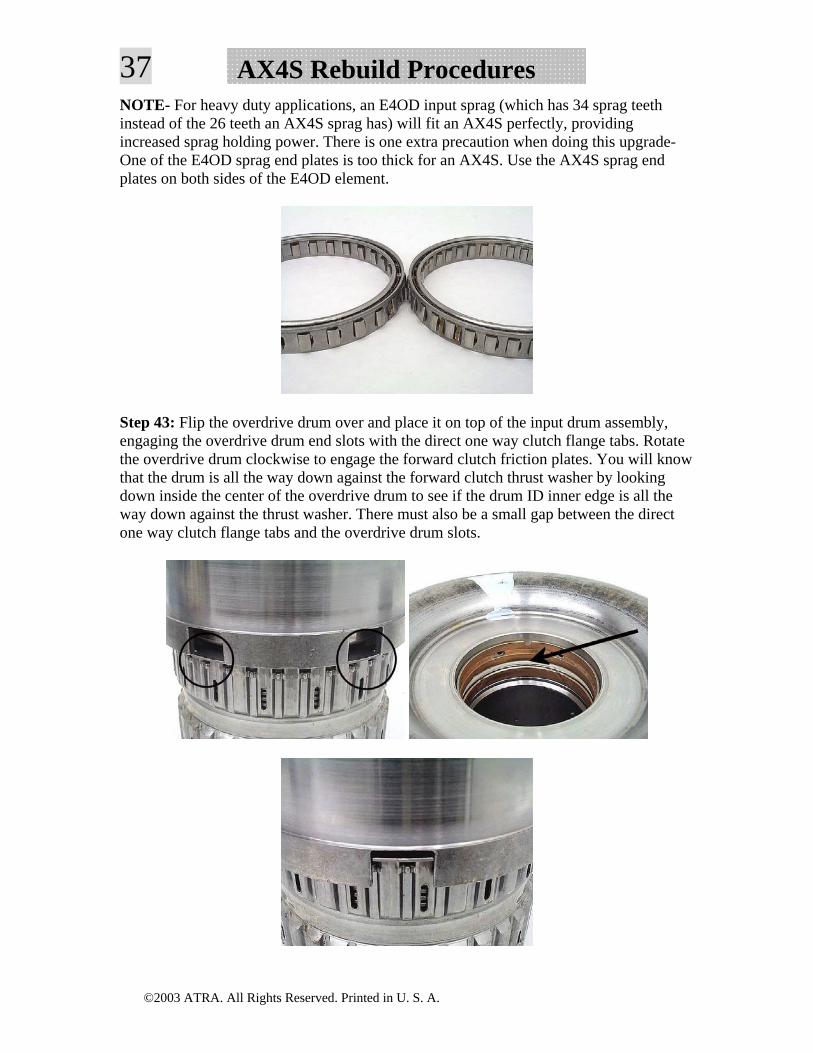
37 AX4S Rebuild ProceduresNOTE- For heavy duty applications, an E4OD input sprag (which has 34 sprag teeth instead of the 26 teeth an AX4S sprag has) will fit an AX4S perfectly, providing increased sprag holding power. There is one extra precaution when doing this upgrade- One of the E4OD sprag end plates is too thick for an AX4S. Use the AX4S sprag end plates on both sides of the E4OD element.
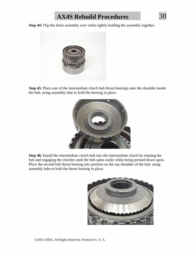
Step 43: Flip the overdrive drum over and place it on top of the input drum assembly, engaging the overdrive drum end slots with the direct one way clutch flange tabs. Rotate the overdrive drum clockwise to engage the forward clutch friction plates. You will know that the drum is all the way down against the forward clutch thrust washer by looking down inside the center of the overdrive drum to see if the drum ID inner edge is all the way down against the thrust washer. There must also be a small gap between the direct one way clutch flange tabs and the overdrive drum slots.
©2003 ATRA. All Rights Reserved. Printed in U. S. A.
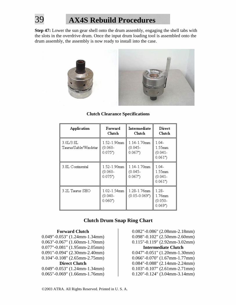
38AX4S Rebuild ProceduresStep 44: Flip the drum assembly over while tightly holding the assembly together.
Step 45: Place one of the intermediate clutch hub thrust bearings onto the shoulder inside the hub, using assembly lube to hold the bearing in place.
Step 46: Install the intermediate clutch hub into the intermediate clutch by rotating the hub and engaging the clutches until the hub spins easily while being pressed down upon. Place the second hub thrust bearing into position on the top shoulder of the hub, using assembly lube to hold the thrust bearing in place.
©2003 ATRA. All Rights Reserved. Printed in U. S. A.
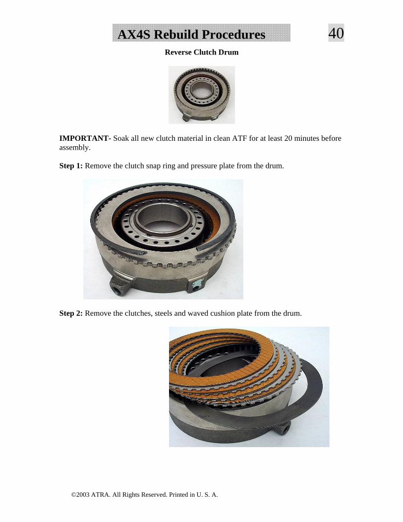
39 AX4S Rebuild ProceduresStep 47: Lower the sun gear shell onto the drum assembly, engaging the shell tabs with the slots in the overdrive drum. Once the input drum loading tool is assembled onto the drum assembly, the assembly is now ready to install into the case.
Clutch Clearance Specifications
Clutch Drum Snap Ring Chart
Forward Clutch 0.049"-0.053" (1.24mm-1.34mm) 0.063"-0.067" (1.60mm-1.70mm) 0.077"-0.081" (1.95mm-2.05mm) 0.091"-0.094" (2.30mm-2.40mm) 0.104"-0.108" (2.65mm-2.75mm)
Direct Clutch 0.049"-0.053" (1.24mm-1.34mm) 0.065"-0.069" (1.66mm-1.76mm)
0.082"-0.086" (2.08mm-2.18mm) 0.098"-0.102" (2.50mm-2.60mm) 0.115"-0.119" (2.92mm-3.02mm)
Intermediate Clutch 0.047"-0.051" (1.20mm-1.30mm) 0.066"-0.070" (1.67mm-1.77mm) 0.084"-0.088" (2.14mm-2.24mm) 0.103"-0.107" (2.61mm-2.71mm) 0.120"-0.124" (3.04mm-3.14mm)
©2003 ATRA. All Rights Reserved. Printed in U. S. A.
40AX4S Rebuild ProceduresReverse Clutch Drum
IMPORTANT- Soak all new clutch material in clean ATF for at least 20 minutes before assembly.
Step 1: Remove the clutch snap ring and pressure plate from the drum.
Step 2: Remove the clutches, steels and waved cushion plate from the drum.
©2003 ATRA. All Rights Reserved. Printed in U. S. A.
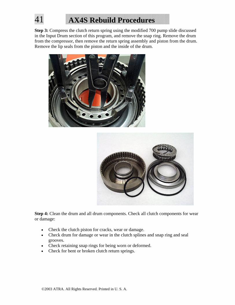
41 AX4S Rebuild ProceduresStep 3: Compress the clutch return spring using the modified 700 pump slide discussed in the Input Drum section of this program, and remove the snap ring. Remove the drum from the compressor, then remove the return spring assembly and piston from the drum. Remove the lip seals from the piston and the inside of the drum.
Step 4: Clean the drum and all drum components. Check all clutch components for wear or damage:
• Check the clutch piston for cracks, wear or damage. • Check drum for damage or wear in the clutch splines and snap ring and seal
grooves. • Check retaining snap rings for being worn or deformed. • Check for bent or broken clutch return springs.
©2003 ATRA. All Rights Reserved. Printed in U. S. A.
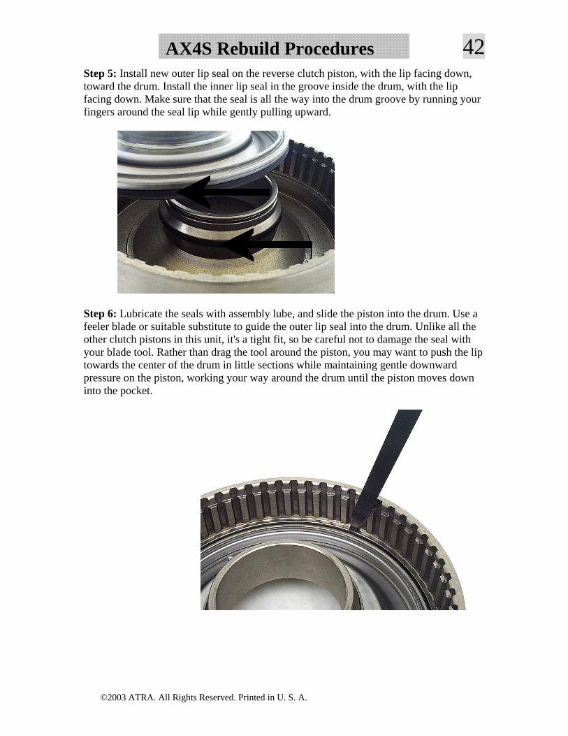
42AX4S Rebuild ProceduresStep 5: Install new outer lip seal on the reverse clutch piston, with the lip facing down, toward the drum. Install the inner lip seal in the groove inside the drum, with the lip facing down. Make sure that the seal is all the way into the drum groove by running your fingers around the seal lip while gently pulling upward.
Step 6: Lubricate the seals with assembly lube, and slide the piston into the drum. Use a feeler blade or suitable substitute to guide the outer lip seal into the drum. Unlike all the other clutch pistons in this unit, it's a tight fit, so be careful not to damage the seal with your blade tool. Rather than drag the tool around the piston, you may want to push the lip towards the center of the drum in little sections while maintaining gentle downward pressure on the piston, working your way around the drum until the piston moves down into the pocket.
©2003 ATRA. All Rights Reserved. Printed in U. S. A.
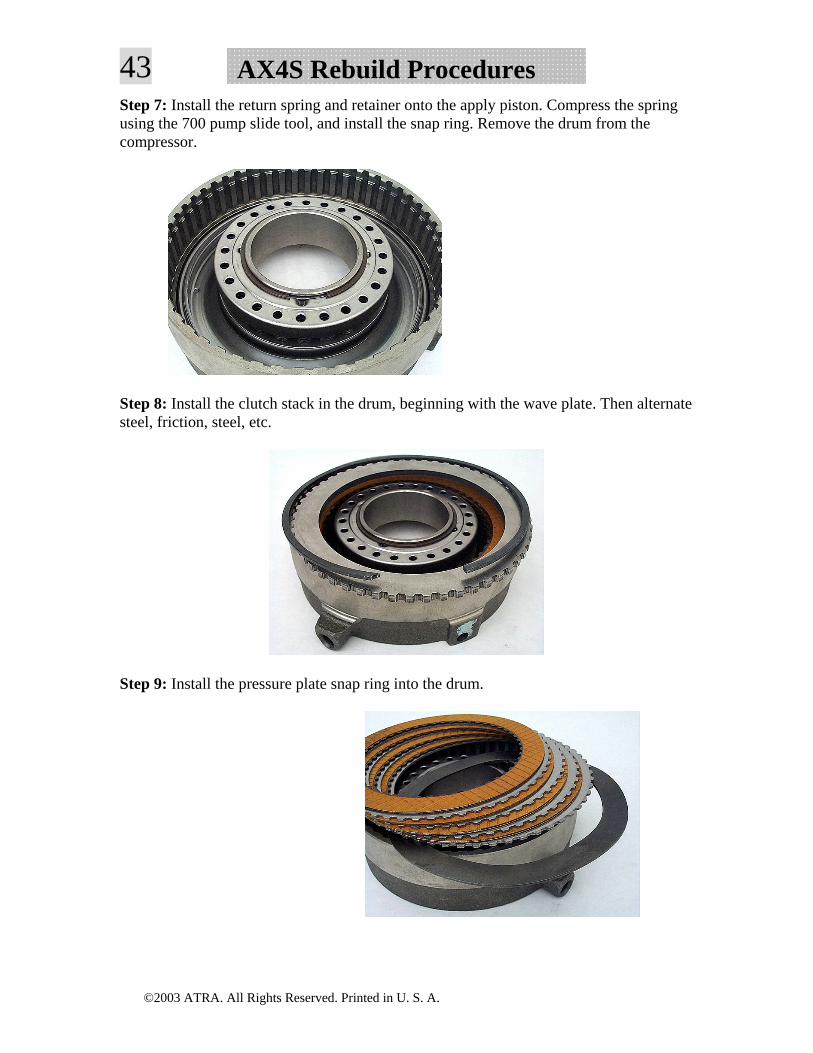
43 AX4S Rebuild ProceduresStep 7: Install the return spring and retainer onto the apply piston. Compress the spring using the 700 pump slide tool, and install the snap ring. Remove the drum from the compressor.
Step 8: Install the clutch stack in the drum, beginning with the wave plate. Then alternate steel, friction, steel, etc.
Step 9: Install the pressure plate snap ring into the drum.
©2003 ATRA. All Rights Reserved. Printed in U. S. A.
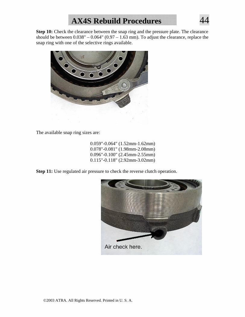
44AX4S Rebuild ProceduresStep 10: Check the clearance between the snap ring and the pressure plate. The clearance should be between 0.038" – 0.064" (0.97 – 1.63 mm). To adjust the clearance, replace the snap ring with one of the selective rings available.
The available snap ring sizes are:
0.059"-0.064" (1.52mm-1.62mm) 0.078"-0.081" (1.98mm-2.08mm) 0.096"-0.100" (2.45mm-2.55mm) 0.115"-0.118" (2.92mm-3.02mm)
Step 11: Use regulated air pressure to check the reverse clutch operation.
©2003 ATRA. All Rights Reserved. Printed in U. S. A.
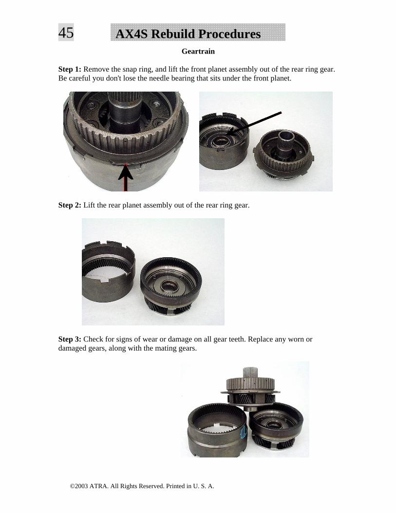
45 AX4S Rebuild ProceduresGeartrain
Step 1: Remove the snap ring, and lift the front planet assembly out of the rear ring gear. Be careful you don't lose the needle bearing that sits under the front planet.
Step 2: Lift the rear planet assembly out of the rear ring gear.
Step 3: Check for signs of wear or damage on all gear teeth. Replace any worn or damaged gears, along with the mating gears.
©2003 ATRA. All Rights Reserved. Printed in U. S. A.
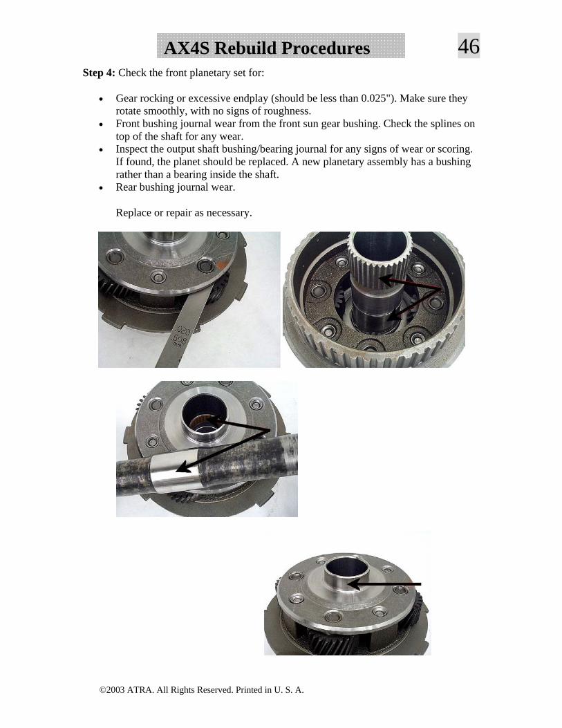
46AX4S Rebuild ProceduresStep 4: Check the front planetary set for:
• Gear rocking or excessive endplay (should be less than 0.025"). Make sure they rotate smoothly, with no signs of roughness.
• Front bushing journal wear from the front sun gear bushing. Check the splines on top of the shaft for any wear.
• Inspect the output shaft bushing/bearing journal for any signs of wear or scoring. If found, the planet should be replaced. A new planetary assembly has a bushing rather than a bearing inside the shaft.
• Rear bushing journal wear.
Replace or repair as necessary.
©2003 ATRA. All Rights Reserved. Printed in U. S. A.
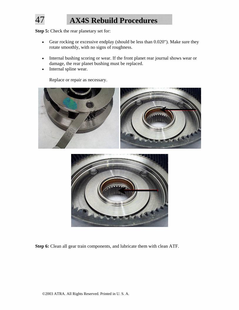
47 AX4S Rebuild ProceduresStep 5: Check the rear planetary set for:
• Gear rocking or excessive endplay (should be less than 0.020"). Make sure they rotate smoothly, with no signs of roughness.
• Internal bushing scoring or wear. If the front planet rear journal shows wear or damage, the rear planet bushing must be replaced.
• Internal spline wear.
Replace or repair as necessary.
Step 6: Clean all gear train components, and lubricate them with clean ATF.
©2003 ATRA. All Rights Reserved. Printed in U. S. A.
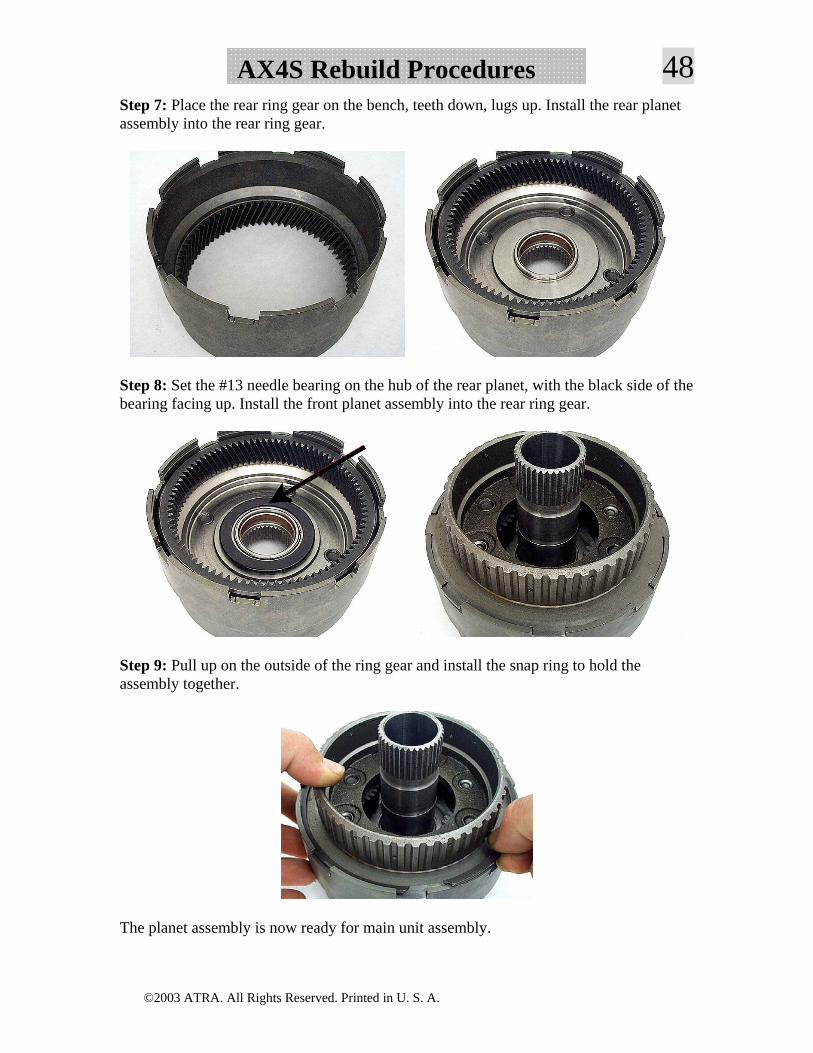
48AX4S Rebuild ProceduresStep 7: Place the rear ring gear on the bench, teeth down, lugs up. Install the rear planet assembly into the rear ring gear.
Step 8: Set the #13 needle bearing on the hub of the rear planet, with the black side of the bearing facing up. Install the front planet assembly into the rear ring gear.
Step 9: Pull up on the outside of the ring gear and install the snap ring to hold the assembly together.
The planet assembly is now ready for main unit assembly.
©2003 ATRA. All Rights Reserved. Printed in U. S. A.
49 AX4S Rebuild ProceduresFinal Drive
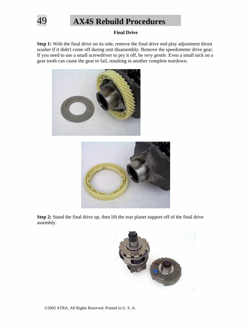
Step 1: With the final drive on its side, remove the final drive end play adjustment thrust washer if it didn't come off during unit disassembly. Remove the speedometer drive gear. If you need to use a small screwdriver to pry it off, be very gentle. Even a small nick on a gear tooth can cause the gear to fail, resulting in another complete teardown.
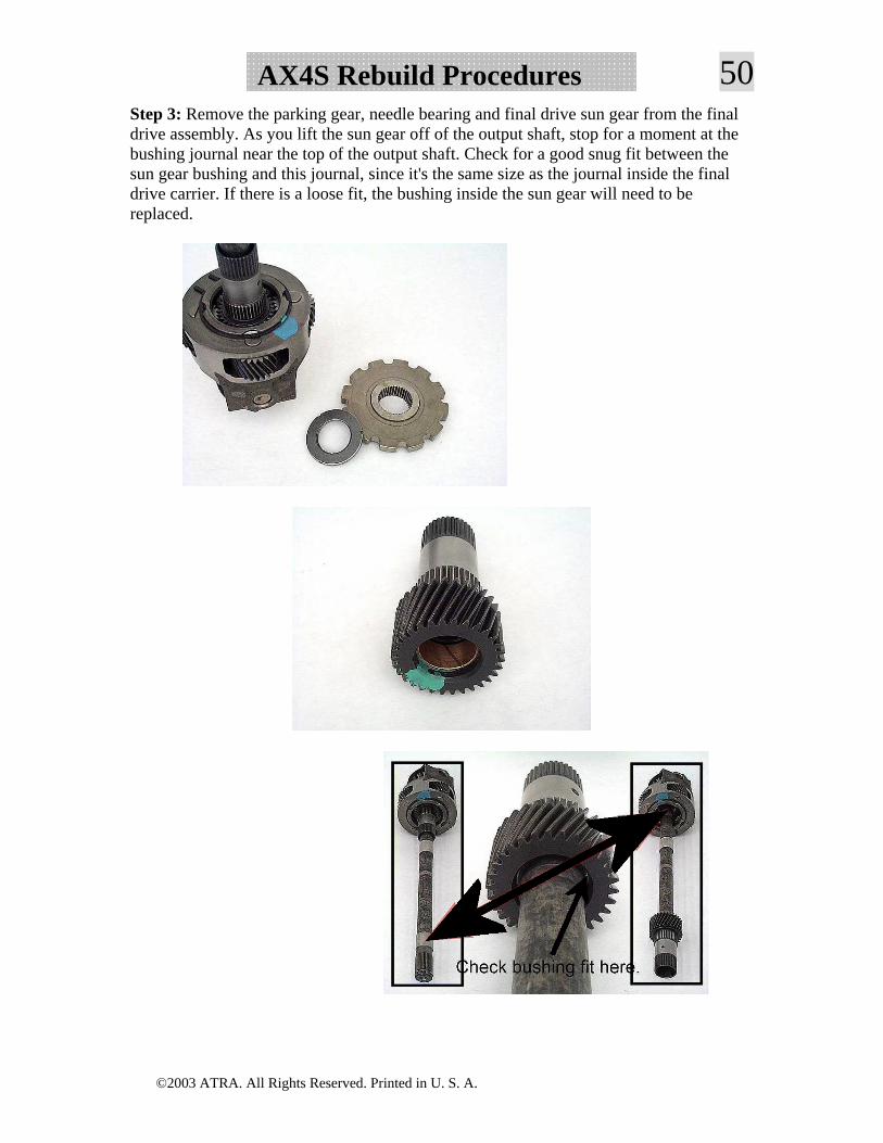
Step 2: Stand the final drive up, then lift the rear planet support off of the final drive assembly.
©2003 ATRA. All Rights Reserved. Printed in U. S. A.
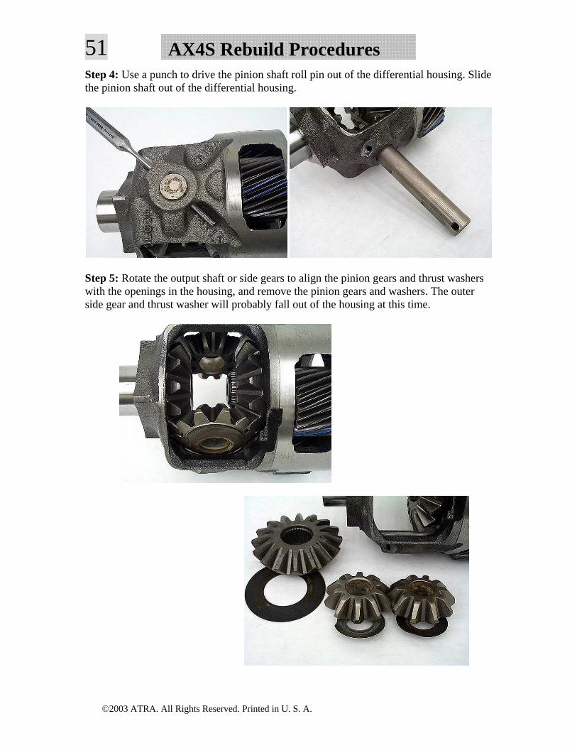
50AX4S Rebuild ProceduresStep 3: Remove the parking gear, needle bearing and final drive sun gear from the final drive assembly. As you lift the sun gear off of the output shaft, stop for a moment at the bushing journal near the top of the output shaft. Check for a good snug fit between the sun gear bushing and this journal, since it's the same size as the journal inside the final drive carrier. If there is a loose fit, the bushing inside the sun gear will need to be replaced.
©2003 ATRA. All Rights Reserved. Printed in U. S. A.
51 AX4S Rebuild ProceduresStep 4: Use a punch to drive the pinion shaft roll pin out of the differential housing. Slide the pinion shaft out of the differential housing.
Step 5: Rotate the output shaft or side gears to align the pinion gears and thrust washers with the openings in the housing, and remove the pinion gears and washers. The outer side gear and thrust washer will probably fall out of the housing at this time.
©2003 ATRA. All Rights Reserved. Printed in U. S. A.
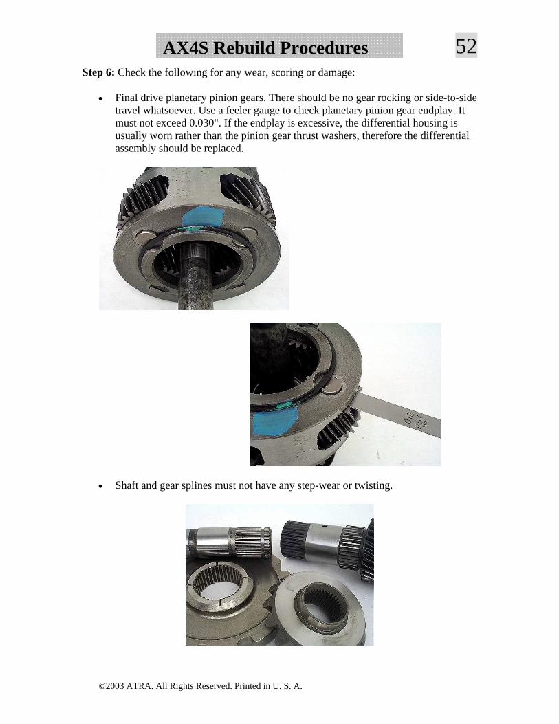
52AX4S Rebuild ProceduresStep 6: Check the following for any wear, scoring or damage:
• Final drive planetary pinion gears. There should be no gear rocking or side-to-side travel whatsoever. Use a feeler gauge to check planetary pinion gear endplay. It must not exceed 0.030". If the endplay is excessive, the differential housing is usually worn rather than the pinion gear thrust washers, therefore the differential assembly should be replaced.
• Shaft and gear splines must not have any step-wear or twisting.
©2003 ATRA. All Rights Reserved. Printed in U. S. A.
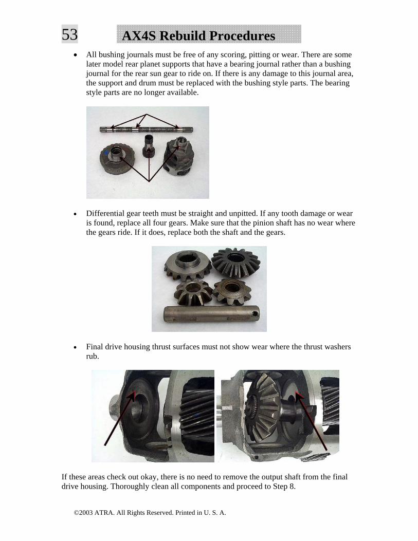
53 AX4S Rebuild Procedures• All bushing journals must be free of any scoring, pitting or wear. There are some
later model rear planet supports that have a bearing journal rather than a bushing journal for the rear sun gear to ride on. If there is any damage to this journal area, the support and drum must be replaced with the bushing style parts. The bearing style parts are no longer available.
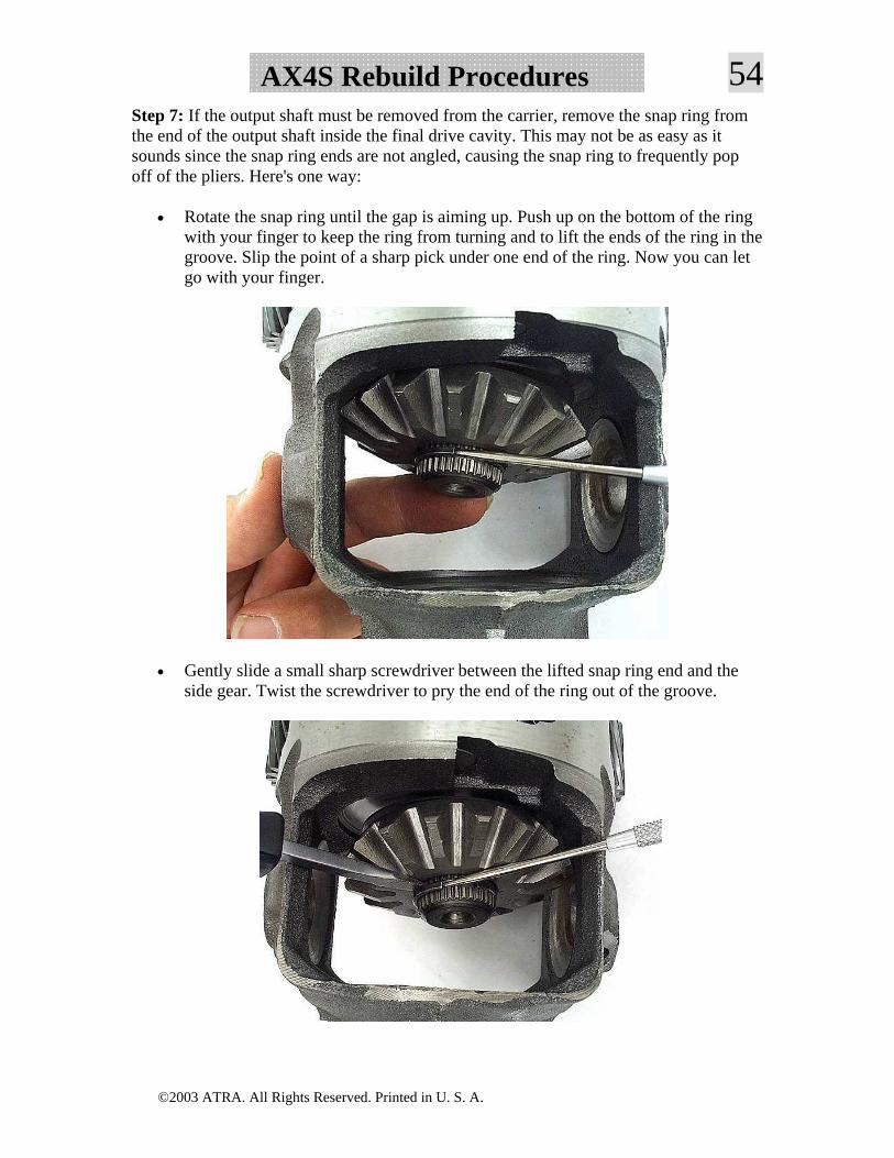
• Differential gear teeth must be straight and unpitted. If any tooth damage or wear is found, replace all four gears. Make sure that the pinion shaft has no wear where the gears ride. If it does, replace both the shaft and the gears.
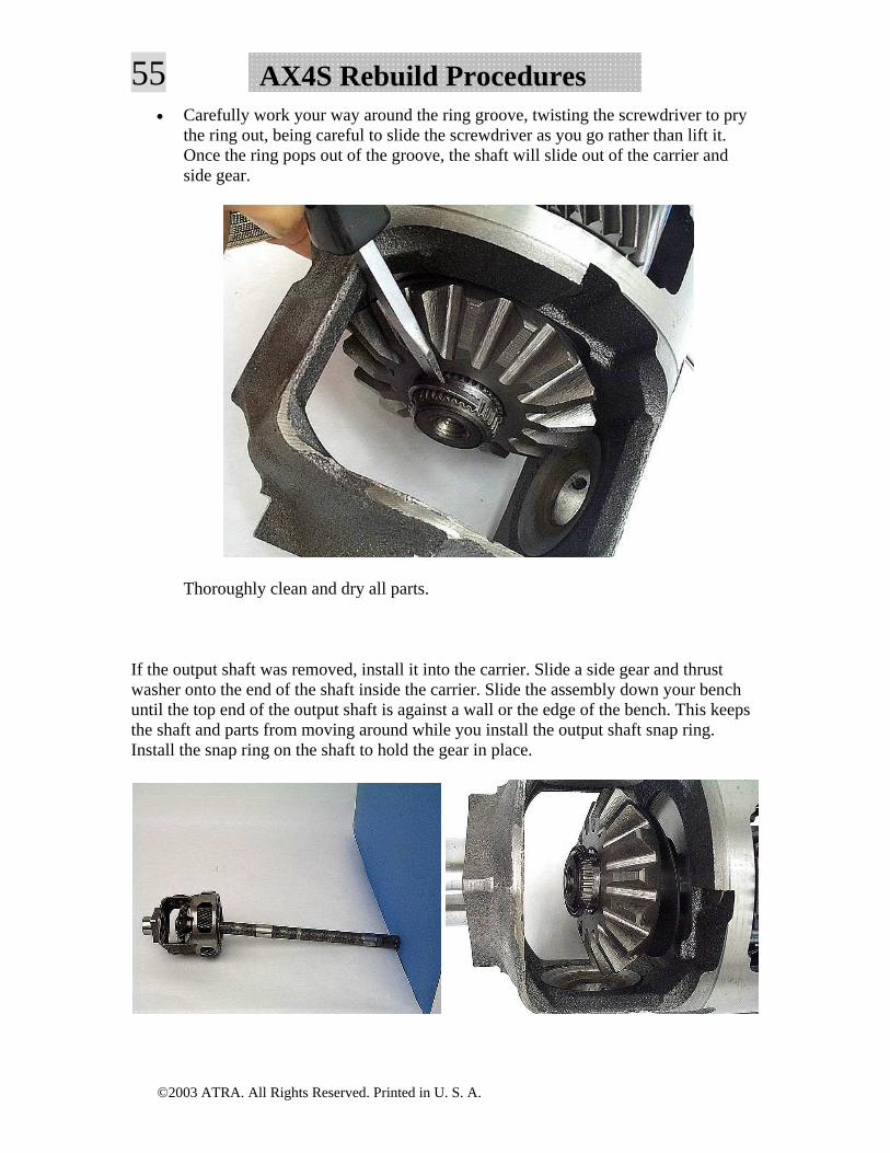
• Final drive housing thrust surfaces must not show wear where the thrust washers rub.
If these areas check out okay, there is no need to remove the output shaft from the final drive housing. Thoroughly clean all components and proceed to Step 8.
©2003 ATRA. All Rights Reserved. Printed in U. S. A.
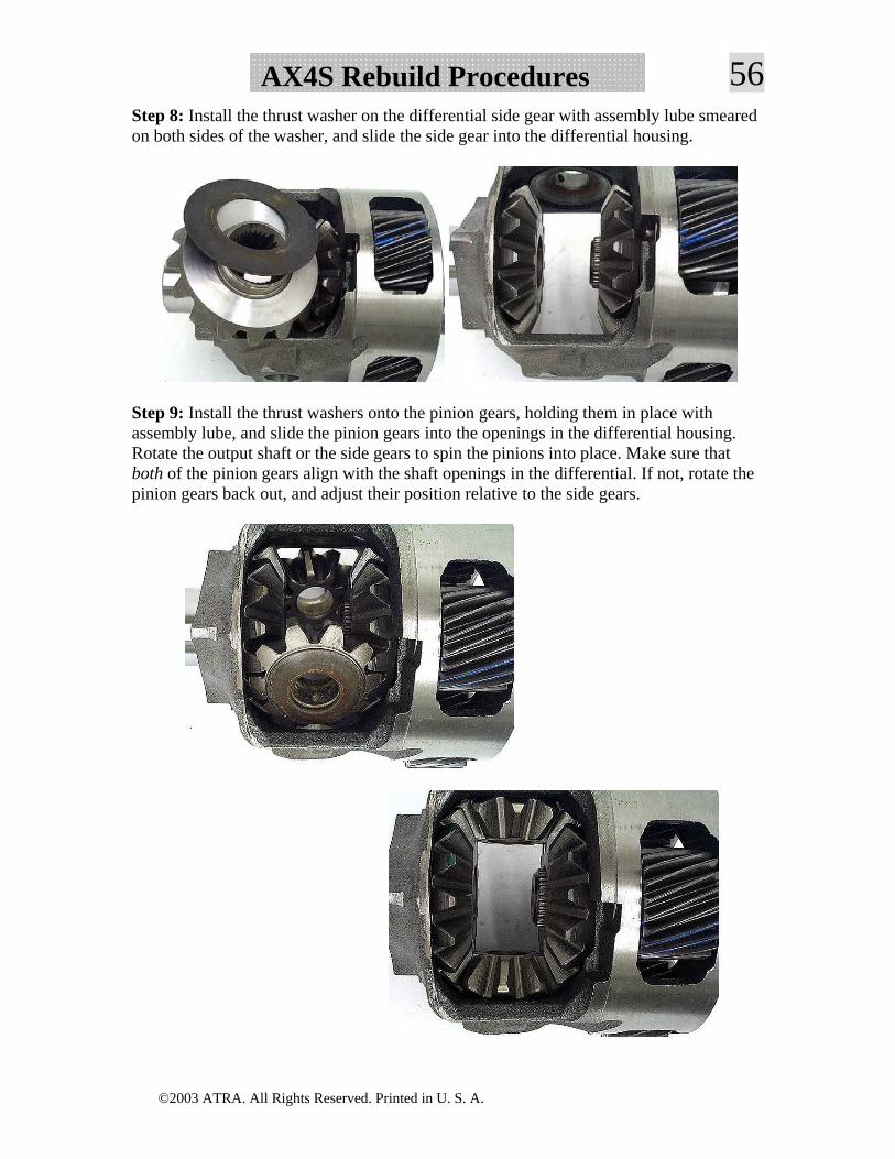
54AX4S Rebuild ProceduresStep 7: If the output shaft must be removed from the carrier, remove the snap ring from the end of the output shaft inside the final drive cavity. This may not be as easy as it sounds since the snap ring ends are not angled, causing the snap ring to frequently pop off of the pliers. Here's one way:
• Rotate the snap ring until the gap is aiming up. Push up on the bottom of the ring with your finger to keep the ring from turning and to lift the ends of the ring in the groove. Slip the point of a sharp pick under one end of the ring. Now you can let go with your finger.
• Gently slide a small sharp screwdriver between the lifted snap ring end and the side gear. Twist the screwdriver to pry the end of the ring out of the groove.
©2003 ATRA. All Rights Reserved. Printed in U. S. A.
55 AX4S Rebuild Procedures• Carefully work your way around the ring groove, twisting the screwdriver to pry
the ring out, being careful to slide the screwdriver as you go rather than lift it. Once the ring pops out of the groove, the shaft will slide out of the carrier and side gear.
Thoroughly clean and dry all parts.
If the output shaft was removed, install it into the carrier. Slide a side gear and thrust washer onto the end of the shaft inside the carrier. Slide the assembly down your bench until the top end of the output shaft is against a wall or the edge of the bench. This keeps the shaft and parts from moving around while you install the output shaft snap ring. Install the snap ring on the shaft to hold the gear in place.
©2003 ATRA. All Rights Reserved. Printed in U. S. A.
56AX4S Rebuild ProceduresStep 8: Install the thrust washer on the differential side gear with assembly lube smeared on both sides of the washer, and slide the side gear into the differential housing.
Step 9: Install the thrust washers onto the pinion gears, holding them in place with assembly lube, and slide the pinion gears into the openings in the differential housing. Rotate the output shaft or the side gears to spin the pinions into place. Make sure that both of the pinion gears align with the shaft openings in the differential. If not, rotate the pinion gears back out, and adjust their position relative to the side gears.
©2003 ATRA. All Rights Reserved. Printed in U. S. A.
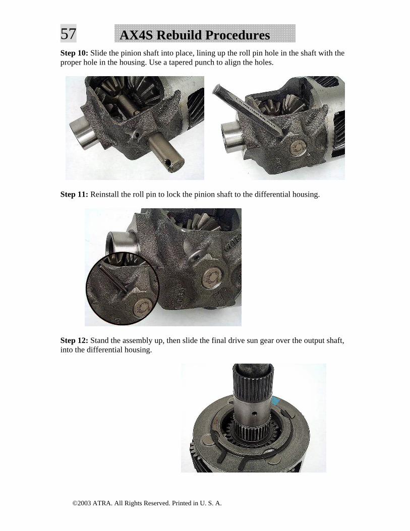
57 AX4S Rebuild ProceduresStep 10: Slide the pinion shaft into place, lining up the roll pin hole in the shaft with the proper hole in the housing. Use a tapered punch to align the holes.
Step 11: Reinstall the roll pin to lock the pinion shaft to the differential housing.
Step 12: Stand the assembly up, then slide the final drive sun gear over the output shaft, into the differential housing.
©2003 ATRA. All Rights Reserved. Printed in U. S. A.
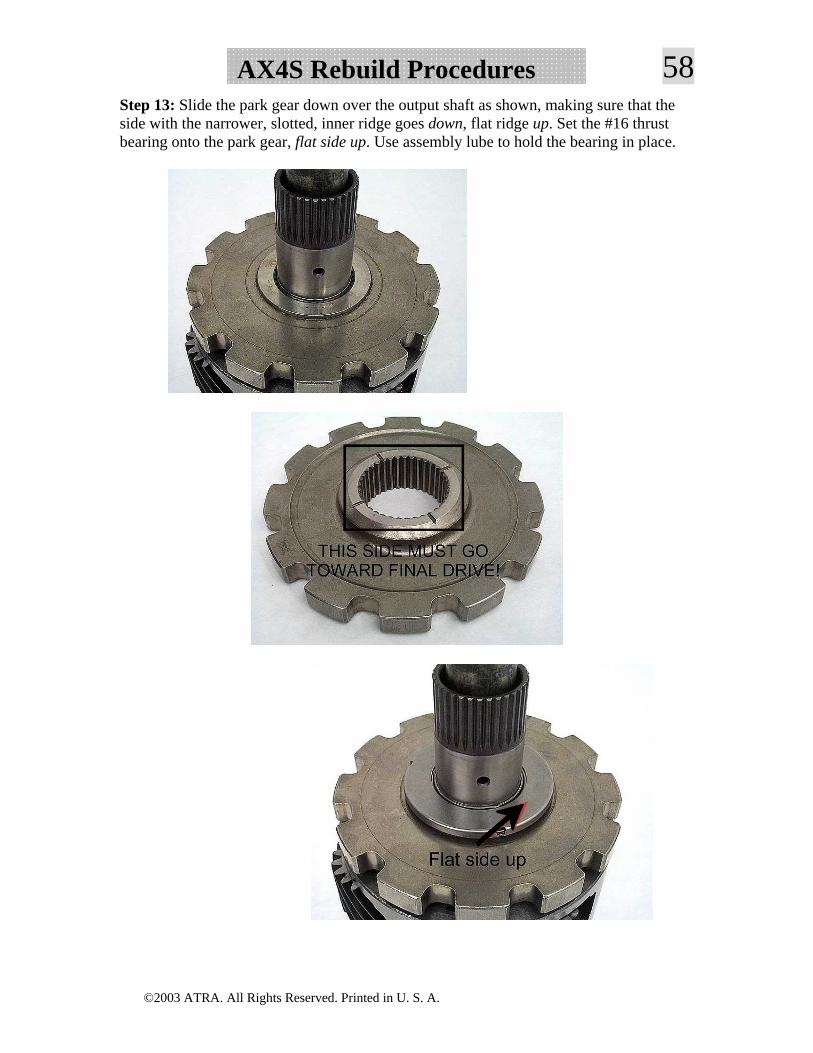
58AX4S Rebuild ProceduresStep 13: Slide the park gear down over the output shaft as shown, making sure that the side with the narrower, slotted, inner ridge goes down, flat ridge up. Set the #16 thrust bearing onto the park gear, flat side up. Use assembly lube to hold the bearing in place.
©2003 ATRA. All Rights Reserved. Printed in U. S. A.
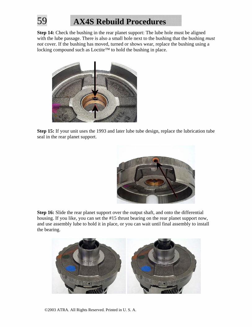
59 AX4S Rebuild ProceduresStep 14: Check the bushing in the rear planet support: The lube hole must be aligned with the lube passage. There is also a small hole next to the bushing that the bushing must not cover. If the bushing has moved, turned or shows wear, replace the bushing using a locking compound such as Loctite™ to hold the bushing in place.
Step 15: If your unit uses the 1993 and later lube tube design, replace the lubrication tube seal in the rear planet support.
Step 16: Slide the rear planet support over the output shaft, and onto the differential housing. If you like, you can set the #15 thrust bearing on the rear planet support now, and use assembly lube to hold it in place, or you can wait until final assembly to install the bearing.
©2003 ATRA. All Rights Reserved. Printed in U. S. A.
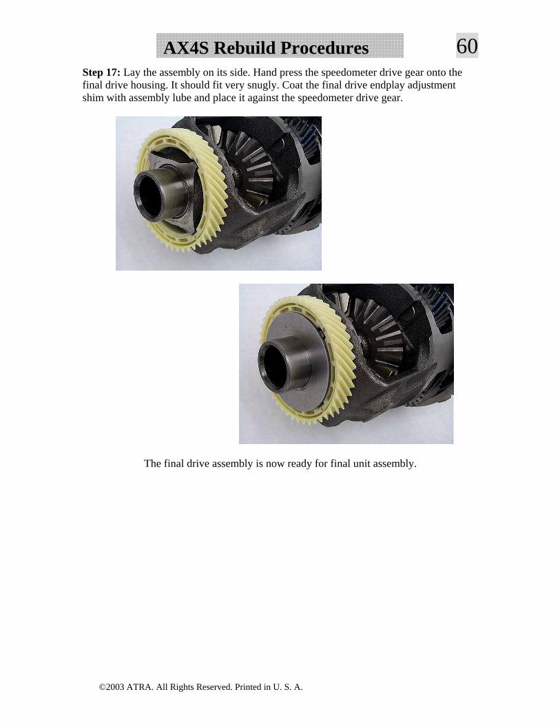
60AX4S Rebuild ProceduresStep 17: Lay the assembly on its side. Hand press the speedometer drive gear onto the final drive housing. It should fit very snugly. Coat the final drive endplay adjustment shim with assembly lube and place it against the speedometer drive gear.
The final drive assembly is now ready for final unit assembly.
©2003 ATRA. All Rights Reserved. Printed in U. S. A.
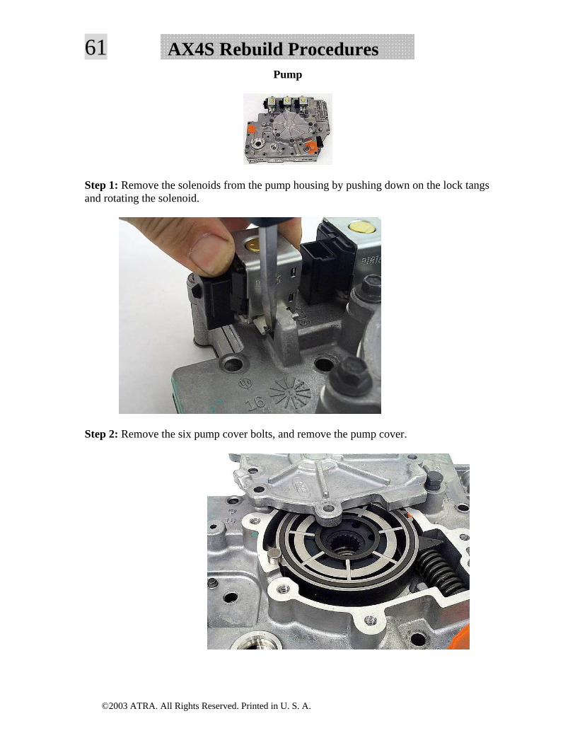
61 AX4S Rebuild ProceduresPump
Step 1: Remove the solenoids from the pump housing by pushing down on the lock tangs and rotating the solenoid.
Step 2: Remove the six pump cover bolts, and remove the pump cover.
©2003 ATRA. All Rights Reserved. Printed in U. S. A.
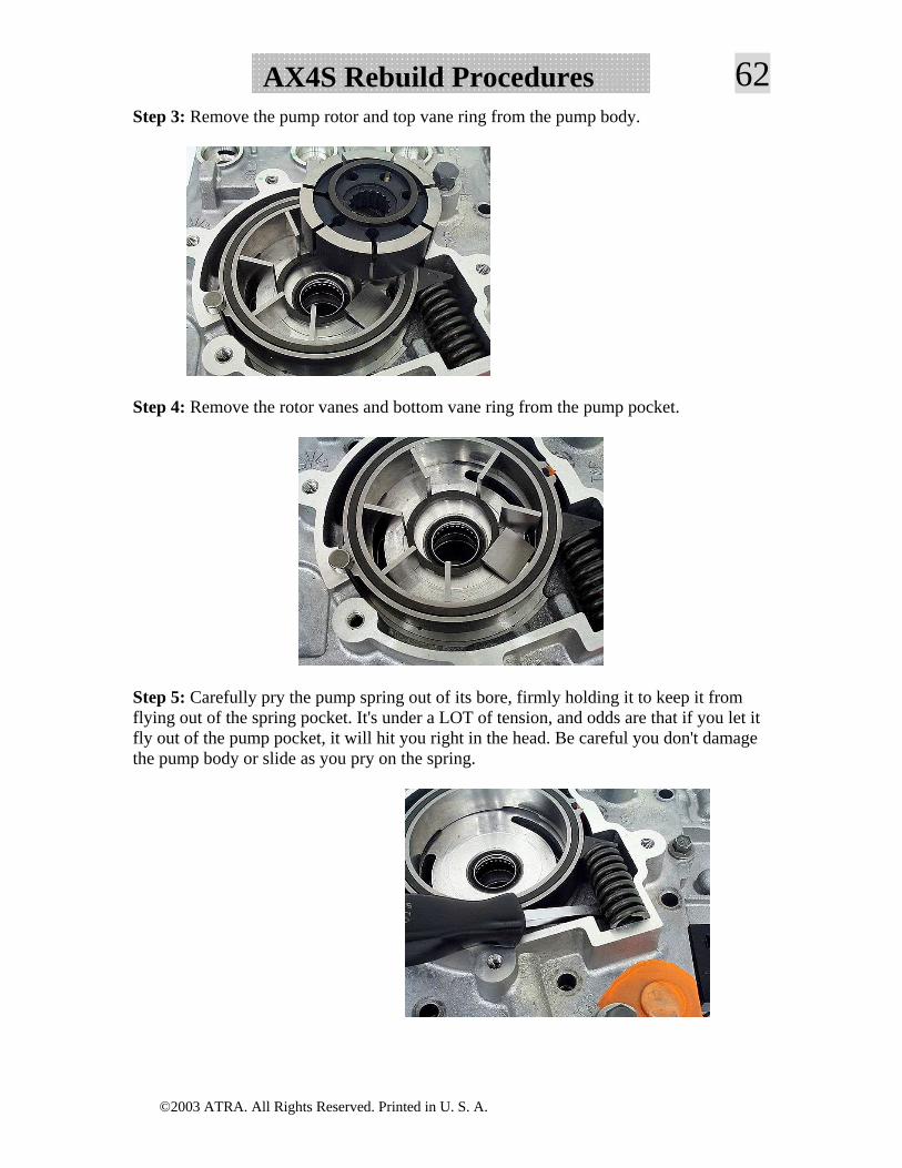
62AX4S Rebuild ProceduresStep 3: Remove the pump rotor and top vane ring from the pump body.
Step 4: Remove the rotor vanes and bottom vane ring from the pump pocket.
Step 5: Carefully pry the pump spring out of its bore, firmly holding it to keep it from flying out of the spring pocket. It's under a LOT of tension, and odds are that if you let it fly out of the pump pocket, it will hit you right in the head. Be careful you don't damage the pump body or slide as you pry on the spring.
©2003 ATRA. All Rights Reserved. Printed in U. S. A.
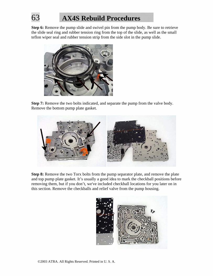
63 AX4S Rebuild ProceduresStep 6: Remove the pump slide and swivel pin from the pump body. Be sure to retrieve the slide seal ring and rubber tension ring from the top of the slide, as well as the small teflon wiper seal and rubber tension strip from the side slot in the pump slide.
Step 7: Remove the two bolts indicated, and separate the pump from the valve body. Remove the bottom pump plate gasket.
Step 8: Remove the two Torx bolts from the pump separator plate, and remove the plate and top pump plate gasket. It’s usually a good idea to mark the checkball positions before removing them, but if you don’t, we've included checkball locations for you later on in this section. Remove the checkballs and relief valve from the pump housing.
©2003 ATRA. All Rights Reserved. Printed in U. S. A.
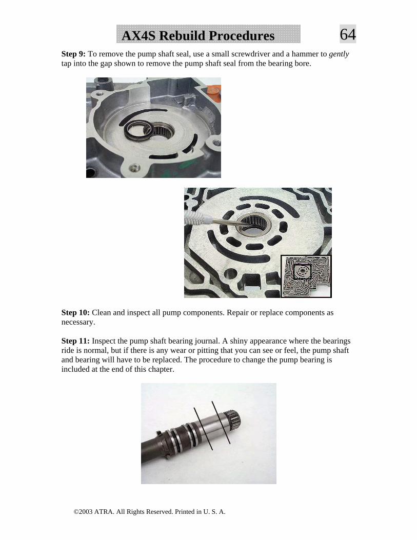
64AX4S Rebuild ProceduresStep 9: To remove the pump shaft seal, use a small screwdriver and a hammer to gently tap into the gap shown to remove the pump shaft seal from the bearing bore.
Step 10: Clean and inspect all pump components. Repair or replace components as necessary.
Step 11: Inspect the pump shaft bearing journal. A shiny appearance where the bearings ride is normal, but if there is any wear or pitting that you can see or feel, the pump shaft and bearing will have to be replaced. The procedure to change the pump bearing is included at the end of this chapter.
©2003 ATRA. All Rights Reserved. Printed in U. S. A.
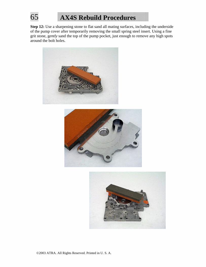
65 AX4S Rebuild ProceduresStep 12: Use a sharpening stone to flat sand all mating surfaces, including the underside of the pump cover after temporarily removing the small spring steel insert. Using a fine grit stone, gently sand the top of the pump pocket, just enough to remove any high spots around the bolt holes.
©2003 ATRA. All Rights Reserved. Printed in U. S. A.
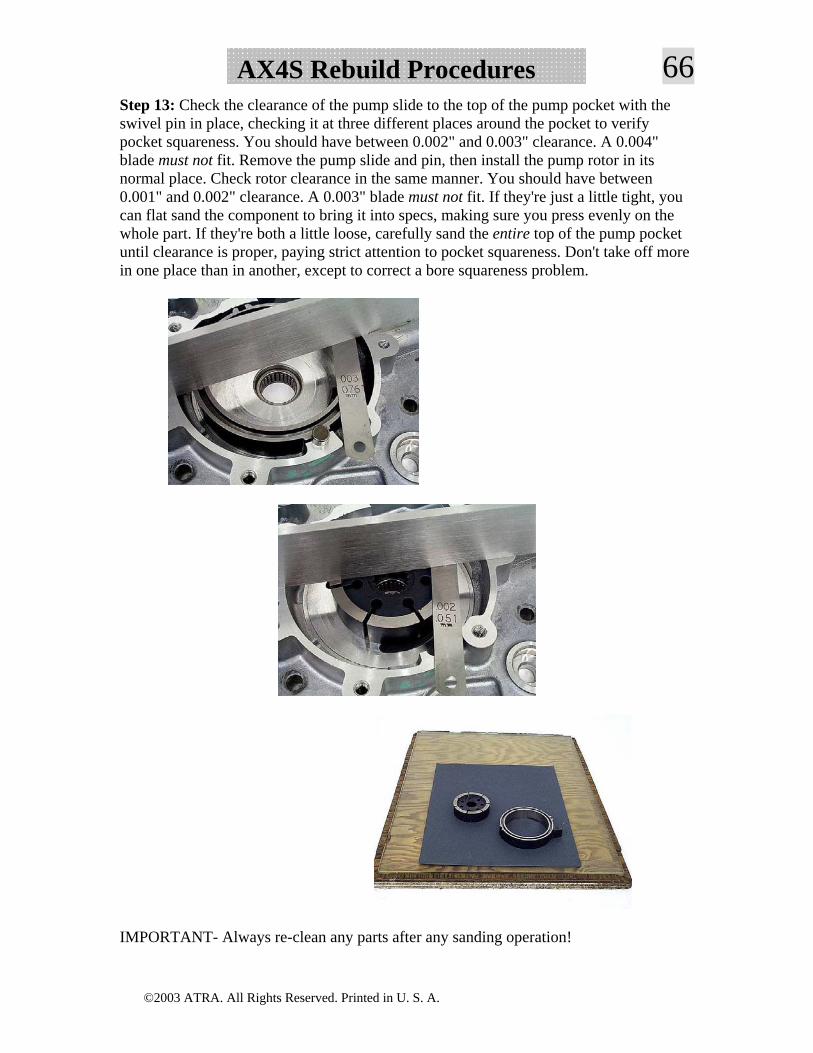
66AX4S Rebuild ProceduresStep 13: Check the clearance of the pump slide to the top of the pump pocket with the swivel pin in place, checking it at three different places around the pocket to verify pocket squareness. You should have between 0.002" and 0.003" clearance. A 0.004" blade must not fit. Remove the pump slide and pin, then install the pump rotor in its normal place. Check rotor clearance in the same manner. You should have between 0.001" and 0.002" clearance. A 0.003" blade must not fit. If they're just a little tight, you can flat sand the component to bring it into specs, making sure you press evenly on the whole part. If they're both a little loose, carefully sand the entire top of the pump pocket until clearance is proper, paying strict attention to pocket squareness. Don't take off more in one place than in another, except to correct a bore squareness problem.
IMPORTANT- Always re-clean any parts after any sanding operation!
©2003 ATRA. All Rights Reserved. Printed in U. S. A.
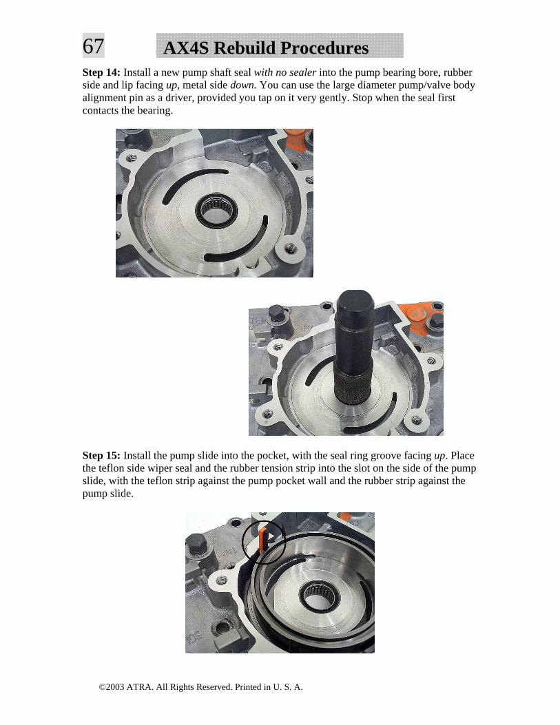
67 AX4S Rebuild ProceduresStep 14: Install a new pump shaft seal with no sealer into the pump bearing bore, rubber side and lip facing up, metal side down. You can use the large diameter pump/valve body alignment pin as a driver, provided you tap on it very gently. Stop when the seal first contacts the bearing.
Step 15: Install the pump slide into the pocket, with the seal ring groove facing up. Place the teflon side wiper seal and the rubber tension strip into the slot on the side of the pump slide, with the teflon strip against the pump pocket wall and the rubber strip against the pump slide.
©2003 ATRA. All Rights Reserved. Printed in U. S. A.
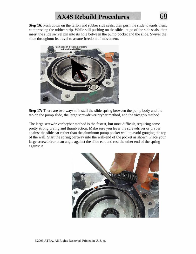
68AX4S Rebuild ProceduresStep 16: Push down on the teflon and rubber side seals, then push the slide towards them, compressing the rubber strip. While still pushing on the slide, let go of the side seals, then insert the slide swivel pin into its hole between the pump pocket and the slide. Swivel the slide throughout its travel to assure freedom of movement.
Step 17: There are two ways to install the slide spring between the pump body and the tab on the pump slide, the large screwdriver/prybar method, and the vicegrip method.
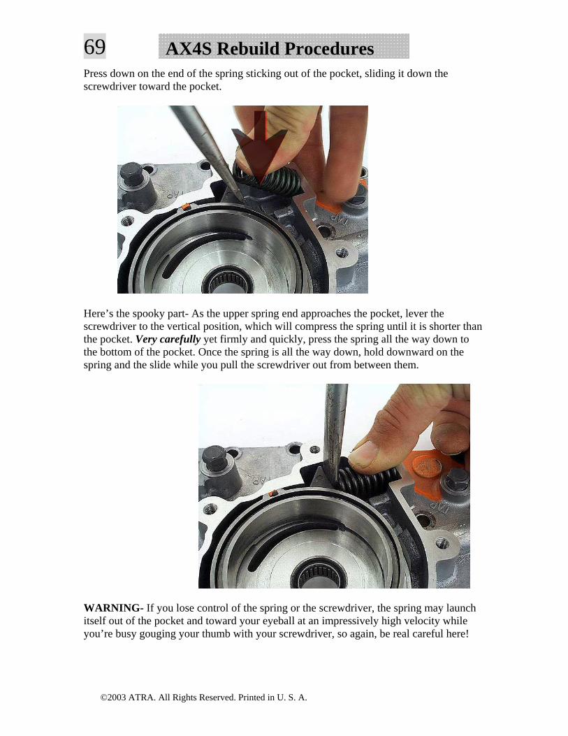
The large screwdriver/prybar method is the fastest, but most difficult, requiring some pretty strong prying and thumb action. Make sure you lever the screwdriver or prybar against the slide ear rather than the aluminum pump pocket wall to avoid gouging the top of the wall. Start the spring partway into the wall-end of the pocket as shown. Place your large screwdriver at an angle against the slide ear, and rest the other end of the spring against it.
©2003 ATRA. All Rights Reserved. Printed in U. S. A.
69 AX4S Rebuild ProceduresPress down on the end of the spring sticking out of the pocket, sliding it down the screwdriver toward the pocket.
Here’s the spooky part- As the upper spring end approaches the pocket, lever the screwdriver to the vertical position, which will compress the spring until it is shorter than the pocket. Very carefully yet firmly and quickly, press the spring all the way down to the bottom of the pocket. Once the spring is all the way down, hold downward on the spring and the slide while you pull the screwdriver out from between them.
WARNING- If you lose control of the spring or the screwdriver, the spring may launch itself out of the pocket and toward your eyeball at an impressively high velocity while you’re busy gouging your thumb with your screwdriver, so again, be real careful here!
©2003 ATRA. All Rights Reserved. Printed in U. S. A.
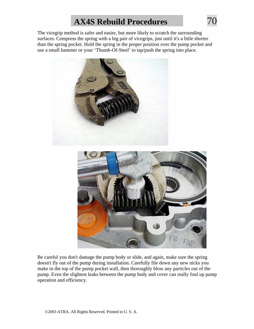
70AX4S Rebuild ProceduresThe vicegrip method is safer and easier, but more likely to scratch the surrounding surfaces. Compress the spring with a big pair of vicegrips, just until it's a little shorter than the spring pocket. Hold the spring in the proper position over the pump pocket and use a small hammer or your ‘Thumb-Of-Steel’ to tap/push the spring into place.
Be careful you don't damage the pump body or slide, and again, make sure the spring doesn't fly out of the pump during installation. Carefully file down any new nicks you make in the top of the pump pocket wall, then thoroughly blow any particles out of the pump. Even the slightest leaks between the pump body and cover can really foul up pump operation and efficiency.
©2003 ATRA. All Rights Reserved. Printed in U. S. A.
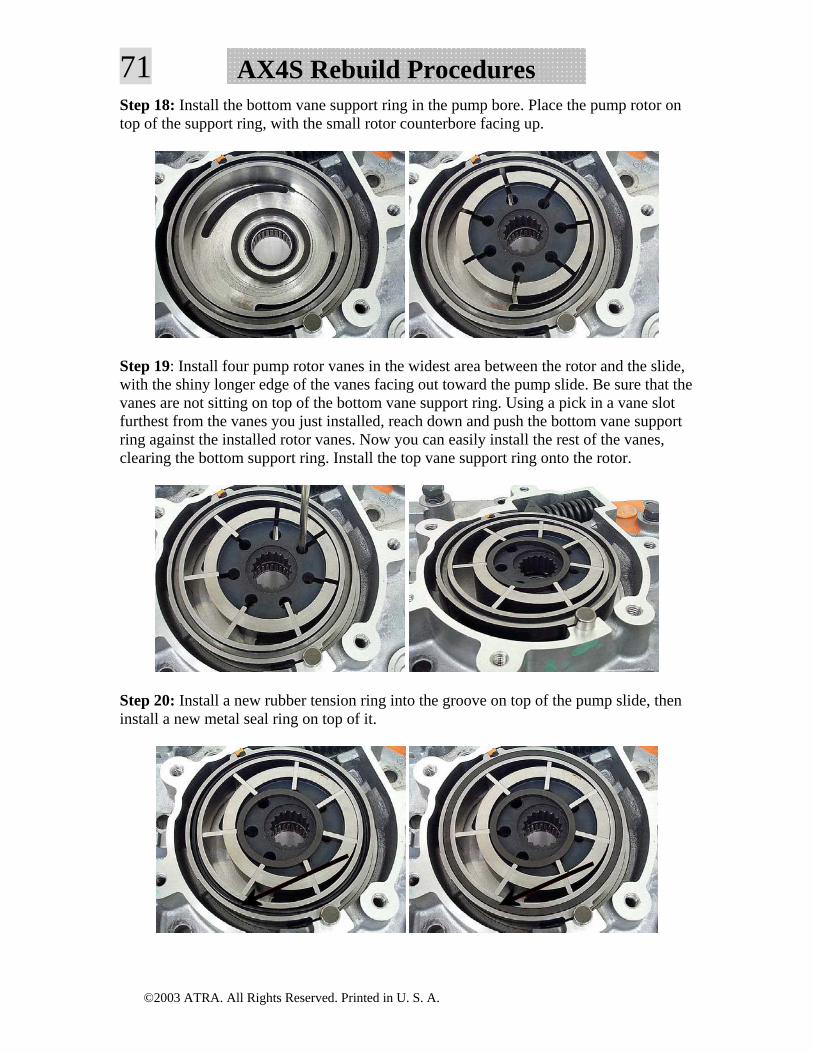
71 AX4S Rebuild ProceduresStep 18: Install the bottom vane support ring in the pump bore. Place the pump rotor on top of the support ring, with the small rotor counterbore facing up.
Step 19: Install four pump rotor vanes in the widest area between the rotor and the slide, with the shiny longer edge of the vanes facing out toward the pump slide. Be sure that the vanes are not sitting on top of the bottom vane support ring. Using a pick in a vane slot furthest from the vanes you just installed, reach down and push the bottom vane support ring against the installed rotor vanes. Now you can easily install the rest of the vanes, clearing the bottom support ring. Install the top vane support ring onto the rotor.
Step 20: Install a new rubber tension ring into the groove on top of the pump slide, then install a new metal seal ring on top of it.
©2003 ATRA. All Rights Reserved. Printed in U. S. A.
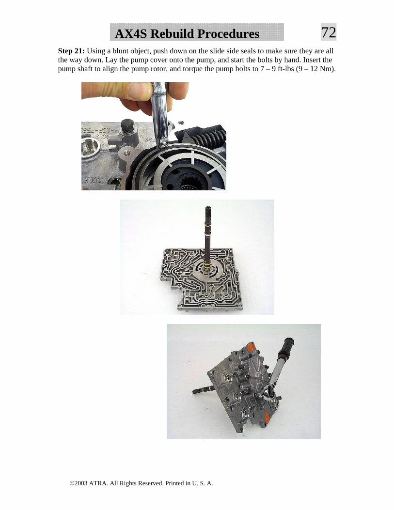
72AX4S Rebuild ProceduresStep 21: Using a blunt object, push down on the slide side seals to make sure they are all the way down. Lay the pump cover onto the pump, and start the bolts by hand. Insert the pump shaft to align the pump rotor, and torque the pump bolts to 7 – 9 ft-lbs (9 – 12 Nm).
©2003 ATRA. All Rights Reserved. Printed in U. S. A.
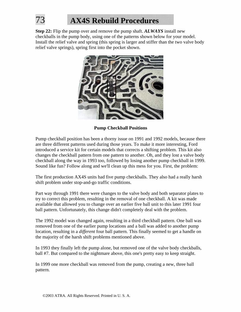
73 AX4S Rebuild ProceduresStep 22: Flip the pump over and remove the pump shaft. ALWAYS install new checkballs in the pump body, using one of the patterns shown below for your model. Install the relief valve and spring (this spring is larger and stiffer than the two valve body relief valve springs), spring first into the pocket shown.
Pump Checkball Positions
Pump checkball position has been a thorny issue on 1991 and 1992 models, because there are three different patterns used during those years. To make it more interesting, Ford introduced a service kit for certain models that corrects a shifting problem. This kit also changes the checkball pattern from one pattern to another. Oh, and they lost a valve body checkball along the way in 1993 too, followed by losing another pump checkball in 1999. Sound like fun? Follow along and we'll clean up this mess for you. First, the problem:
The first production AX4S units had five pump checkballs. They also had a really harsh shift problem under stop-and-go traffic conditions.
Part way through 1991 there were changes to the valve body and both separator plates to try to correct this problem, resulting in the removal of one checkball. A kit was made available that allowed you to change over an earlier five ball unit to this later 1991 four ball pattern. Unfortunately, this change didn't completely deal with the problem.
The 1992 model was changed again, resulting in a third checkball pattern. One ball was removed from one of the earlier pump locations and a ball was added to another pump location, resulting in a different four ball pattern. This finally seemed to get a handle on the majority of the harsh shift problems mentioned above.
In 1993 they finally left the pump alone, but removed one of the valve body checkballs, ball #7. But compared to the nightmare above, this one's pretty easy to keep straight.
In 1999 one more checkball was removed from the pump, creating a new, three ball pattern.
©2003 ATRA. All Rights Reserved. Printed in U. S. A.
74AX4S Rebuild ProceduresThe question: Where do you put the dang pump checkballs? Over the years this problem has cooked down a bit, so it's not quite as complex as it used to be. Here's what we recommend:
Situation 1: If you have an early 1991 unit with a five checkball pump, identified by two holes in the position shown rather than one hole, install the kit mentioned above and convert the pump to the 1992 four ball pattern shown below, provided your unit will accept the kit. The modifications to the valve body and plates do help get rid of the harsh shift problem.
? When installing this kit, you may notice that the instructions tell you to use the late 1991 four checkball pattern, yet we just told you to use the 1992 four checkball pattern. Don't worry. Our way works better.
IMPORTANT- Not all five ball units can use this kit! There is a measurement you must take to determine if the kit will fit your unit. ATRA Technical Bulletin #240 explains this measurement procedure and includes the kit part numbers. Here’s bulletin #240:
Technical Bulletin #240 1991 AXOD-E Slips, Flare shifts, No line rise
There is a kit available from Ford that allows you to upgrade the function of the second design backout valve, which was introduced in late 1991. It is important to know that not all 1991 AXOD-Es can be upgraded. If the original backout valve diameter measures greater than .349" (the diameter of the new valve), the kit will not work. If you install the kit into a valve body that has a backout valve bore diameter that is greater than .349", EPC and servo apply oil will be exhausted.
The kit will also include a replacement retainer used between the pull-in control valve and 3-2 timing valve springs.
If you are unable to use the kit, you can purchase the retainer separately. The Ford part number is F1DZ-7F194-A.
©2003 ATRA. All Rights Reserved. Printed in U. S. A.
75 AX4S Rebuild Procedures
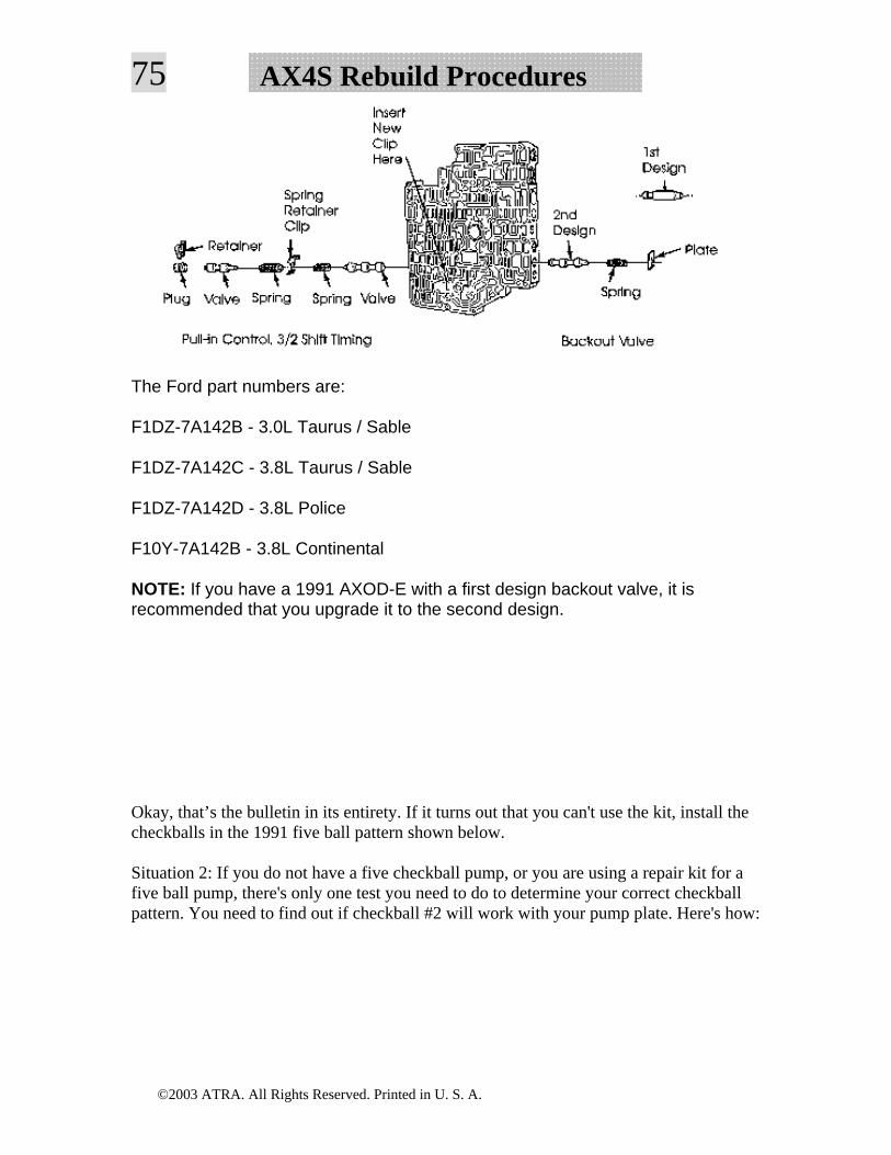
The Ford part numbers are:
F1DZ-7A142B - 3.0L Taurus / Sable
F1DZ-7A142C - 3.8L Taurus / Sable
F1DZ-7A142D - 3.8L Police
F10Y-7A142B - 3.8L Continental
NOTE: If you have a 1991 AXOD-E with a first design backout valve, it is recommended that you upgrade it to the second design.
Okay, that’s the bulletin in its entirety. If it turns out that you can't use the kit, install the checkballs in the 1991 five ball pattern shown below.
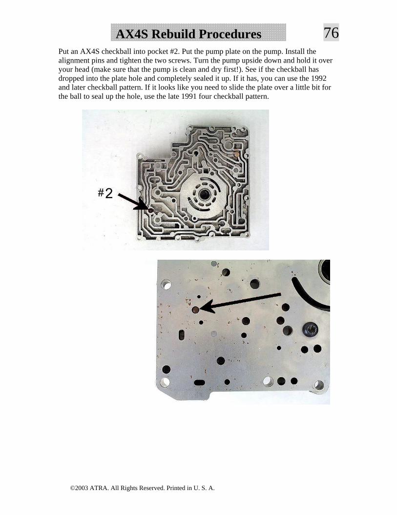
Situation 2: If you do not have a five checkball pump, or you are using a repair kit for a five ball pump, there's only one test you need to do to determine your correct checkball pattern. You need to find out if checkball #2 will work with your pump plate. Here's how:
©2003 ATRA. All Rights Reserved. Printed in U. S. A.
76AX4S Rebuild ProceduresPut an AX4S checkball into pocket #2. Put the pump plate on the pump. Install the alignment pins and tighten the two screws. Turn the pump upside down and hold it over your head (make sure that the pump is clean and dry first!). See if the checkball has dropped into the plate hole and completely sealed it up. If it has, you can use the 1992 and later checkball pattern. If it looks like you need to slide the plate over a little bit for the ball to seal up the hole, use the late 1991 four checkball pattern.
©2003 ATRA. All Rights Reserved. Printed in U. S. A.
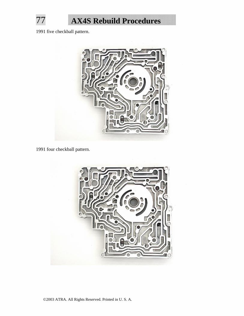
77 AX4S Rebuild Procedures1991 five checkball pattern.
1991 four checkball pattern.
©2003 ATRA. All Rights Reserved. Printed in U. S. A.
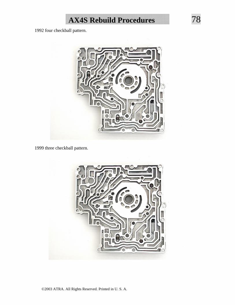
78AX4S Rebuild Procedures1992 four checkball pattern.
1999 three checkball pattern.
©2003 ATRA. All Rights Reserved. Printed in U. S. A.
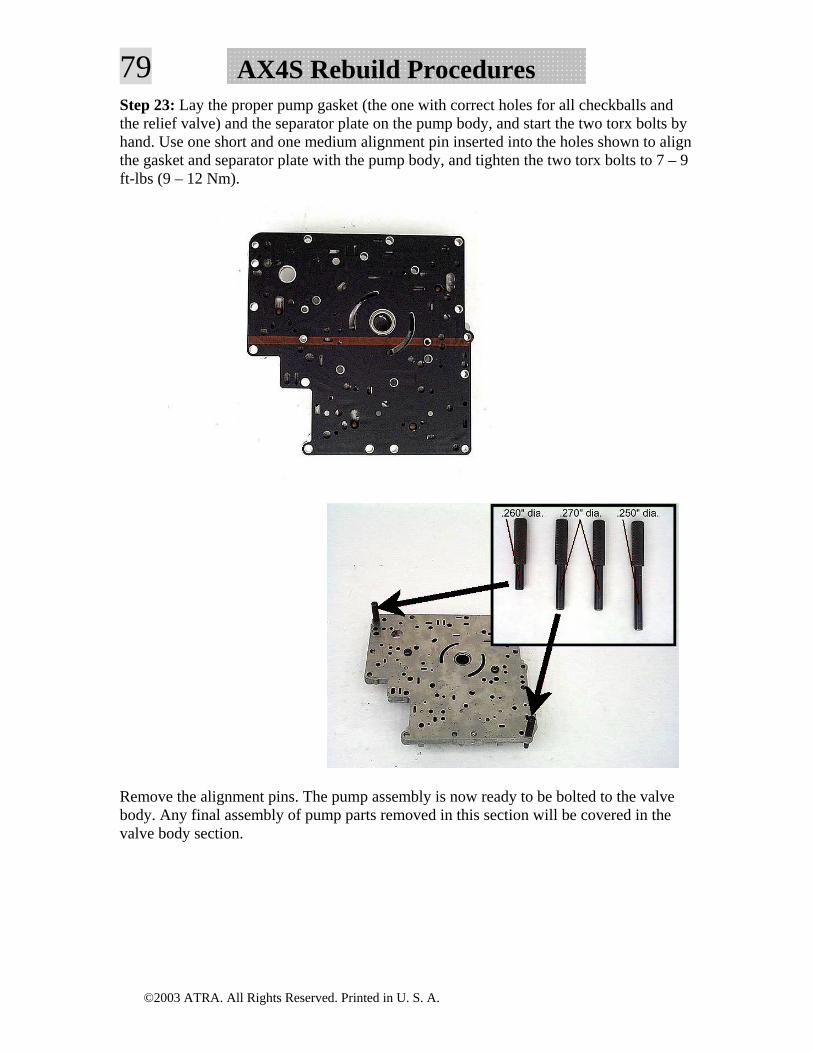
79 AX4S Rebuild ProceduresStep 23: Lay the proper pump gasket (the one with correct holes for all checkballs and the relief valve) and the separator plate on the pump body, and start the two torx bolts by hand. Use one short and one medium alignment pin inserted into the holes shown to align the gasket and separator plate with the pump body, and tighten the two torx bolts to 7 – 9 ft-lbs (9 – 12 Nm).
Remove the alignment pins. The pump assembly is now ready to be bolted to the valve body. Any final assembly of pump parts removed in this section will be covered in the valve body section.
©2003 ATRA. All Rights Reserved. Printed in U. S. A.
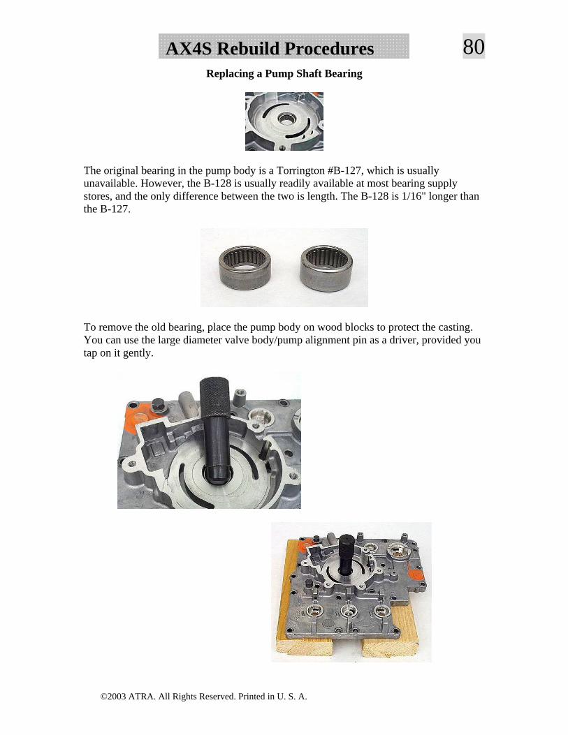
80AX4S Rebuild ProceduresReplacing a Pump Shaft Bearing
The original bearing in the pump body is a Torrington #B-127, which is usually unavailable. However, the B-128 is usually readily available at most bearing supply stores, and the only difference between the two is length. The B-128 is 1/16" longer than the B-127.
To remove the old bearing, place the pump body on wood blocks to protect the casting. You can use the large diameter valve body/pump alignment pin as a driver, provided you tap on it gently.
©2003 ATRA. All Rights Reserved. Printed in U. S. A.
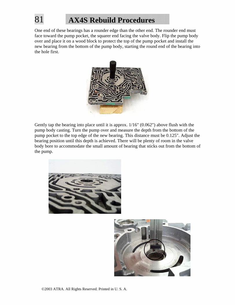
81 AX4S Rebuild ProceduresOne end of these bearings has a rounder edge than the other end. The rounder end must face toward the pump pocket, the squarer end facing the valve body. Flip the pump body over and place it on a wood block to protect the top of the pump pocket and install the new bearing from the bottom of the pump body, starting the round end of the bearing into the hole first.
Gently tap the bearing into place until it is approx. 1/16" (0.062") above flush with the pump body casting. Turn the pump over and measure the depth from the bottom of the pump pocket to the top edge of the new bearing. This distance must be 0.125". Adjust the bearing position until this depth is achieved. There will be plenty of room in the valve body bore to accommodate the small amount of bearing that sticks out from the bottom of the pump.
©2003 ATRA. All Rights Reserved. Printed in U. S. A.
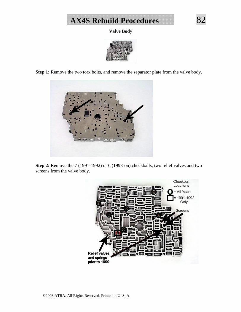
82AX4S Rebuild ProceduresValve Body
Step 1: Remove the two torx bolts, and remove the separator plate from the valve body.
Step 2: Remove the 7 (1991-1992) or 6 (1993-on) checkballs, two relief valves and two screens from the valve body.
©2003 ATRA. All Rights Reserved. Printed in U. S. A.
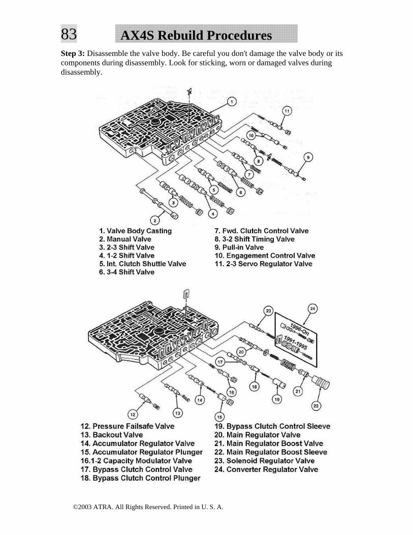
83 AX4S Rebuild ProceduresStep 3: Disassemble the valve body. Be careful you don't damage the valve body or its components during disassembly. Look for sticking, worn or damaged valves during disassembly.
©2003 ATRA. All Rights Reserved. Printed in U. S. A.
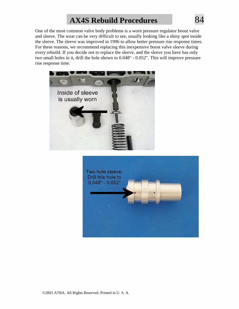
84AX4S Rebuild ProceduresOne of the most common valve body problems is a worn pressure regulator boost valve and sleeve. The wear can be very difficult to see, usually looking like a shiny spot inside the sleeve. The sleeve was improved in 1996 to allow better pressure rise response times. For these reasons, we recommend replacing this inexpensive boost valve sleeve during every rebuild. If you decide not to replace the sleeve, and the sleeve you have has only two small holes in it, drill the hole shown to 0.048" - 0.052". This will improve pressure rise response time.
©2003 ATRA. All Rights Reserved. Printed in U. S. A.
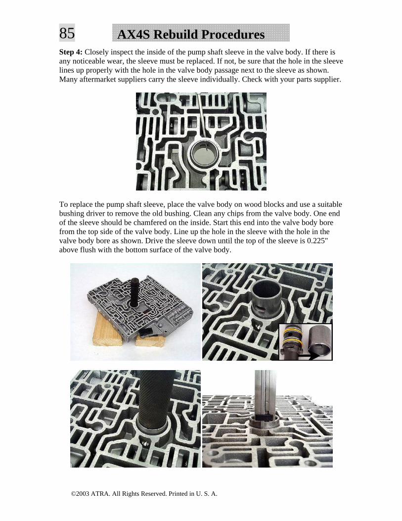
85 AX4S Rebuild ProceduresStep 4: Closely inspect the inside of the pump shaft sleeve in the valve body. If there is any noticeable wear, the sleeve must be replaced. If not, be sure that the hole in the sleeve lines up properly with the hole in the valve body passage next to the sleeve as shown. Many aftermarket suppliers carry the sleeve individually. Check with your parts supplier.
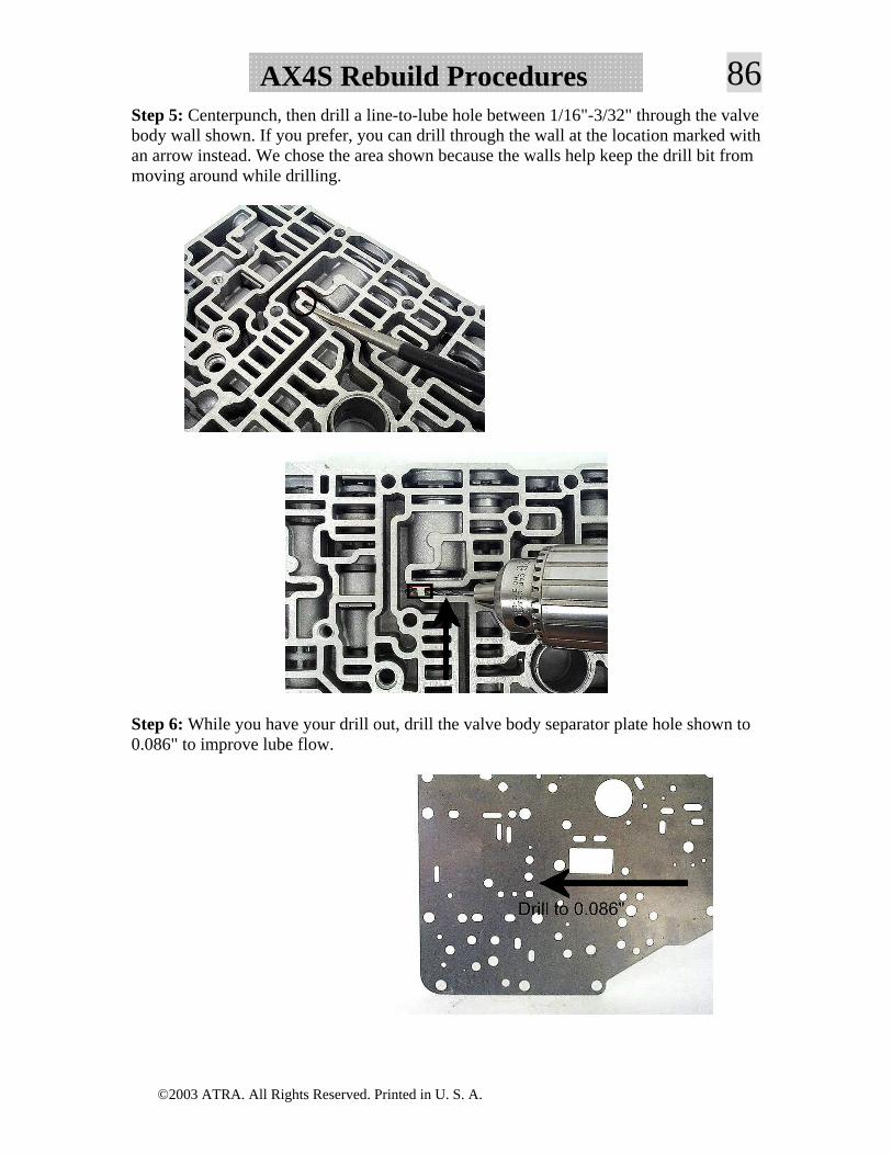
To replace the pump shaft sleeve, place the valve body on wood blocks and use a suitable bushing driver to remove the old bushing. Clean any chips from the valve body. One end of the sleeve should be chamfered on the inside. Start this end into the valve body bore from the top side of the valve body. Line up the hole in the sleeve with the hole in the valve body bore as shown. Drive the sleeve down until the top of the sleeve is 0.225" above flush with the bottom surface of the valve body.
©2003 ATRA. All Rights Reserved. Printed in U. S. A.
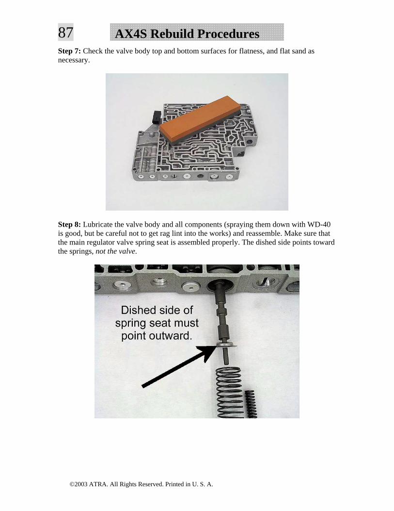
86AX4S Rebuild ProceduresStep 5: Centerpunch, then drill a line-to-lube hole between 1/16"-3/32" through the valve body wall shown. If you prefer, you can drill through the wall at the location marked with an arrow instead. We chose the area shown because the walls help keep the drill bit from moving around while drilling.
Step 6: While you have your drill out, drill the valve body separator plate hole shown to 0.086" to improve lube flow.
©2003 ATRA. All Rights Reserved. Printed in U. S. A.
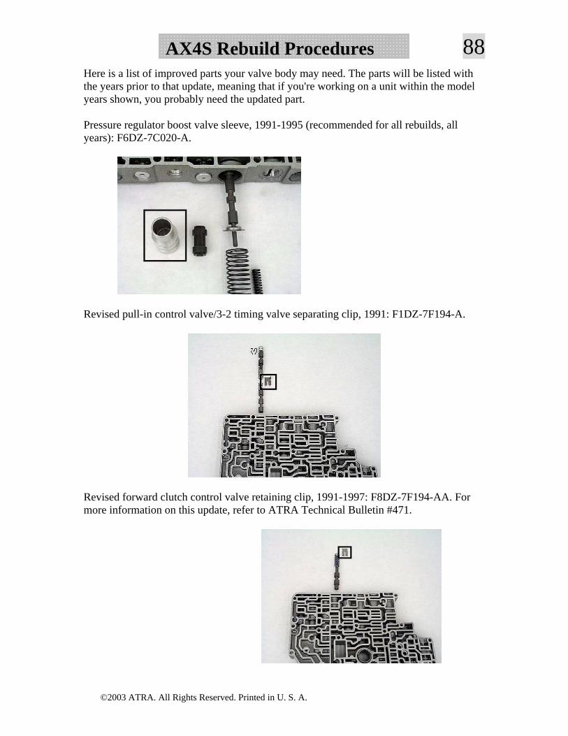
87 AX4S Rebuild ProceduresStep 7: Check the valve body top and bottom surfaces for flatness, and flat sand as necessary.
Step 8: Lubricate the valve body and all components (spraying them down with WD-40 is good, but be careful not to get rag lint into the works) and reassemble. Make sure that the main regulator valve spring seat is assembled properly. The dished side points toward the springs, not the valve.
©2003 ATRA. All Rights Reserved. Printed in U. S. A.
88AX4S Rebuild ProceduresHere is a list of improved parts your valve body may need. The parts will be listed with the years prior to that update, meaning that if you're working on a unit within the model years shown, you probably need the updated part.
Pressure regulator boost valve sleeve, 1991-1995 (recommended for all rebuilds, all years): F6DZ-7C020-A.
Revised pull-in control valve/3-2 timing valve separating clip, 1991: F1DZ-7F194-A.
Revised forward clutch control valve retaining clip, 1991-1997: F8DZ-7F194-AA. For more information on this update, refer to ATRA Technical Bulletin #471.
©2003 ATRA. All Rights Reserved. Printed in U. S. A.
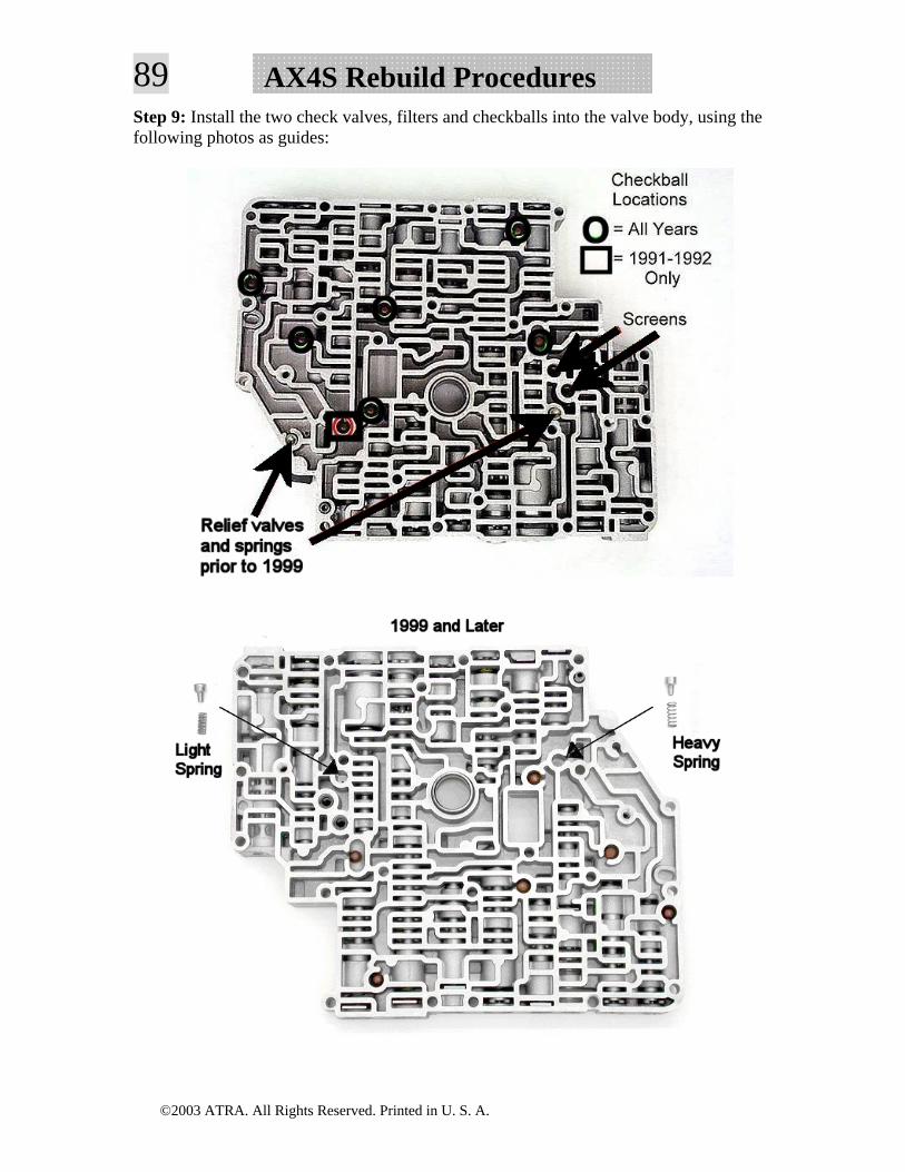
89 AX4S Rebuild ProceduresStep 9: Install the two check valves, filters and checkballs into the valve body, using the following photos as guides:
©2003 ATRA. All Rights Reserved. Printed in U. S. A.
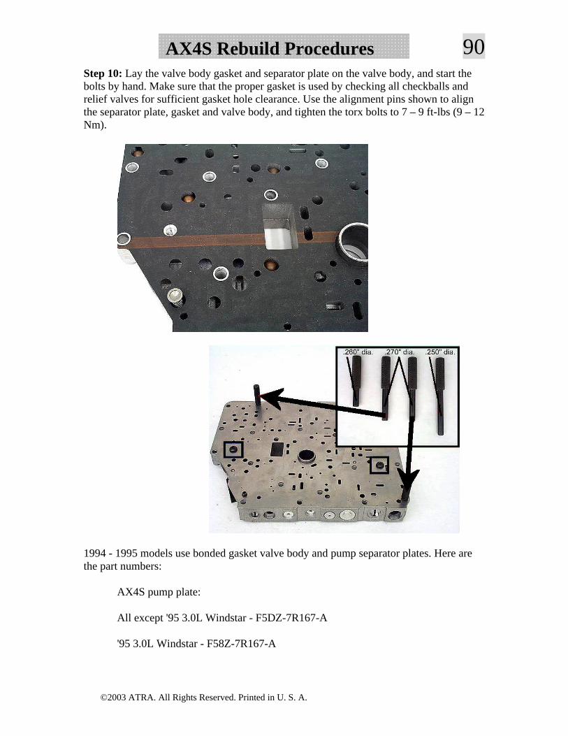
90AX4S Rebuild ProceduresStep 10: Lay the valve body gasket and separator plate on the valve body, and start the bolts by hand. Make sure that the proper gasket is used by checking all checkballs and relief valves for sufficient gasket hole clearance. Use the alignment pins shown to align the separator plate, gasket and valve body, and tighten the torx bolts to 7 – 9 ft-lbs (9 – 12 Nm).
1994 - 1995 models use bonded gasket valve body and pump separator plates. Here are the part numbers:
AX4S pump plate:
All except '95 3.0L Windstar - F5DZ-7R167-A
'95 3.0L Windstar - F58Z-7R167-A
©2003 ATRA. All Rights Reserved. Printed in U. S. A.
91 AX4S Rebuild ProceduresAX4S valve body plate:
'94-'95 3.0L Taurus/Sable - F5DZ-7Z490-C
'94-'95 3.8L Taurus/Sable/Continental - F5DZ-7Z490-D
'94-'95 3.2L Taurus SHO - F5DZ-7Z490-B
'95 3.0L Windstar F58Z-7Z490-B
'95 3.8L Windstar F58Z-7Z490-A
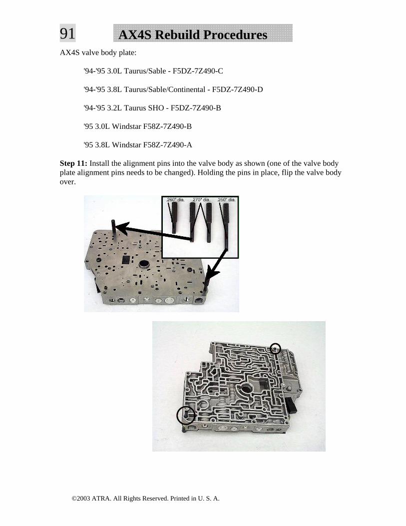
Step 11: Install the alignment pins into the valve body as shown (one of the valve body plate alignment pins needs to be changed). Holding the pins in place, flip the valve body over.
©2003 ATRA. All Rights Reserved. Printed in U. S. A.
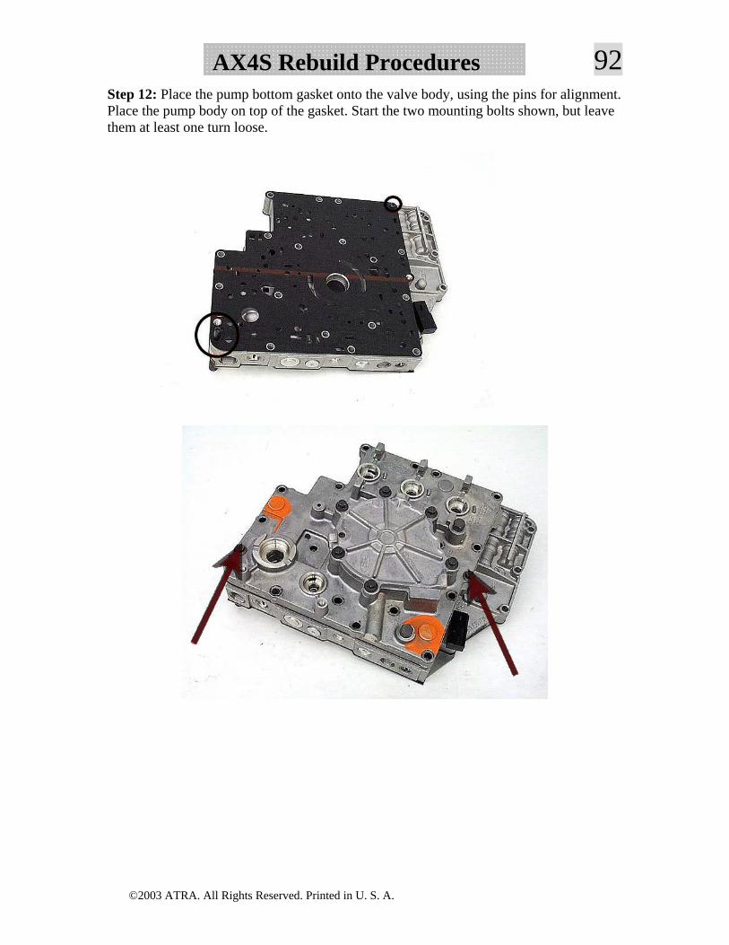
92AX4S Rebuild ProceduresStep 12: Place the pump bottom gasket onto the valve body, using the pins for alignment. Place the pump body on top of the gasket. Start the two mounting bolts shown, but leave them at least one turn loose.
©2003 ATRA. All Rights Reserved. Printed in U. S. A.
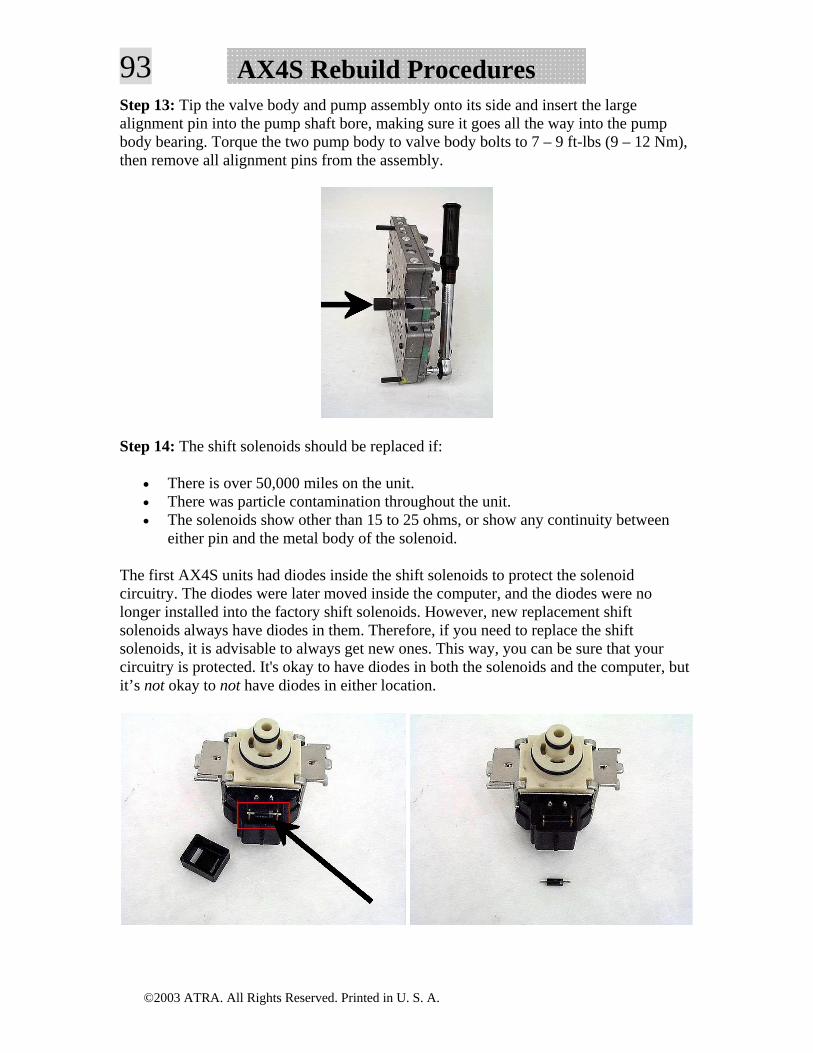
93 AX4S Rebuild ProceduresStep 13: Tip the valve body and pump assembly onto its side and insert the large alignment pin into the pump shaft bore, making sure it goes all the way into the pump body bearing. Torque the two pump body to valve body bolts to 7 – 9 ft-lbs (9 – 12 Nm), then remove all alignment pins from the assembly.
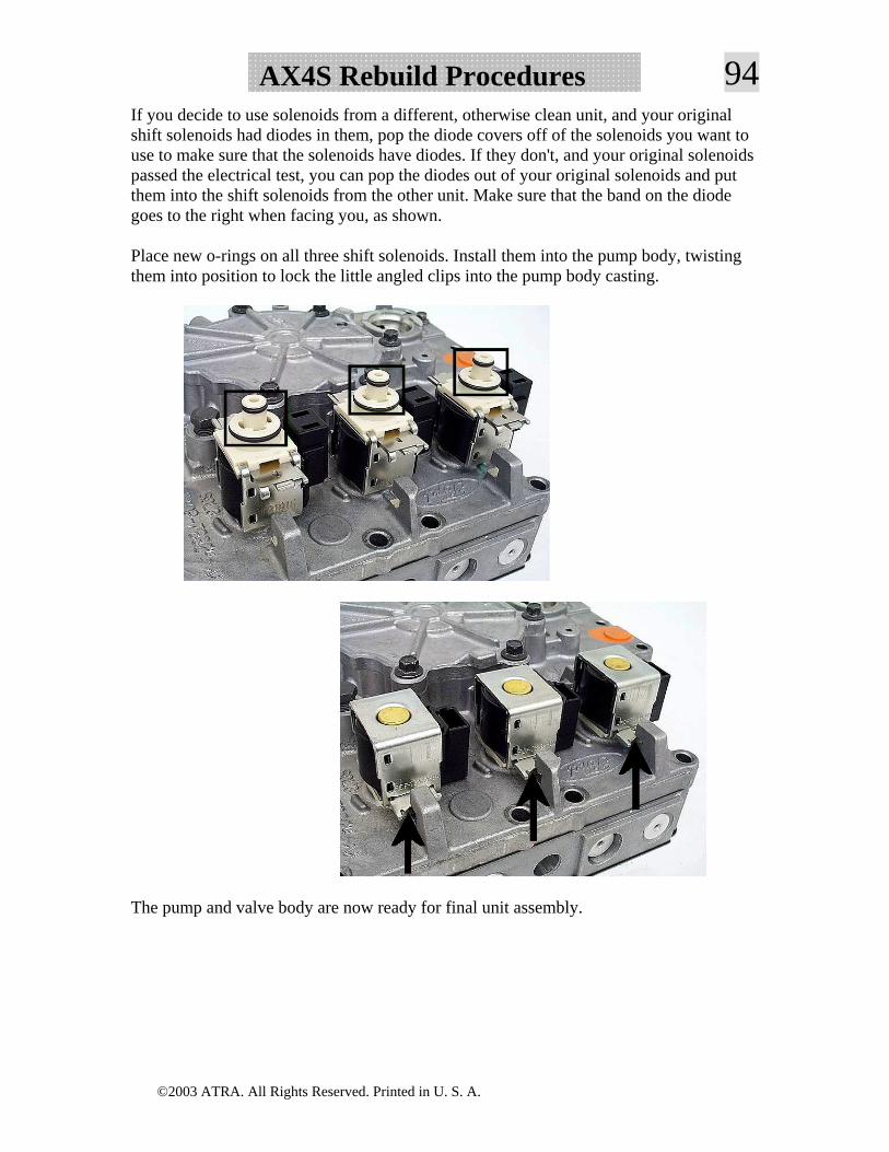
Step 14: The shift solenoids should be replaced if:
• There is over 50,000 miles on the unit. • There was particle contamination throughout the unit. • The solenoids show other than 15 to 25 ohms, or show any continuity between
either pin and the metal body of the solenoid.
The first AX4S units had diodes inside the shift solenoids to protect the solenoid circuitry. The diodes were later moved inside the computer, and the diodes were no longer installed into the factory shift solenoids. However, new replacement shift solenoids always have diodes in them. Therefore, if you need to replace the shift solenoids, it is advisable to always get new ones. This way, you can be sure that your circuitry is protected. It's okay to have diodes in both the solenoids and the computer, but it’s not okay to not have diodes in either location.
©2003 ATRA. All Rights Reserved. Printed in U. S. A.
94AX4S Rebuild ProceduresIf you decide to use solenoids from a different, otherwise clean unit, and your original shift solenoids had diodes in them, pop the diode covers off of the solenoids you want to use to make sure that the solenoids have diodes. If they don't, and your original solenoids passed the electrical test, you can pop the diodes out of your original solenoids and put them into the shift solenoids from the other unit. Make sure that the band on the diode goes to the right when facing you, as shown.
Place new o-rings on all three shift solenoids. Install them into the pump body, twisting them into position to lock the little angled clips into the pump body casting.
The pump and valve body are now ready for final unit assembly.
©2003 ATRA. All Rights Reserved. Printed in U. S. A.
95 AX4S Rebuild ProceduresCase and Chain Cover Preparation
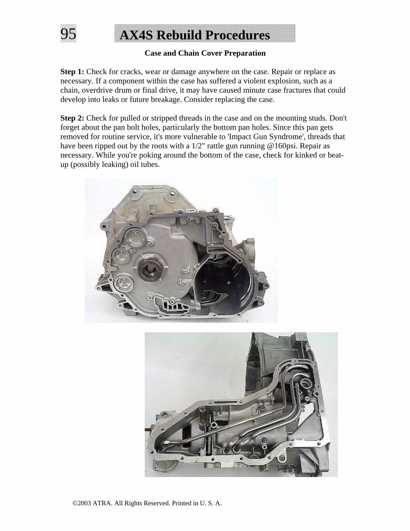
Step 1: Check for cracks, wear or damage anywhere on the case. Repair or replace as necessary. If a component within the case has suffered a violent explosion, such as a chain, overdrive drum or final drive, it may have caused minute case fractures that could develop into leaks or future breakage. Consider replacing the case.
Step 2: Check for pulled or stripped threads in the case and on the mounting studs. Don't forget about the pan bolt holes, particularly the bottom pan holes. Since this pan gets removed for routine service, it's more vulnerable to 'Impact Gun Syndrome', threads that have been ripped out by the roots with a 1/2" rattle gun running @160psi. Repair as necessary. While you're poking around the bottom of the case, check for kinked or beat-up (possibly leaking) oil tubes.
©2003 ATRA. All Rights Reserved. Printed in U. S. A.
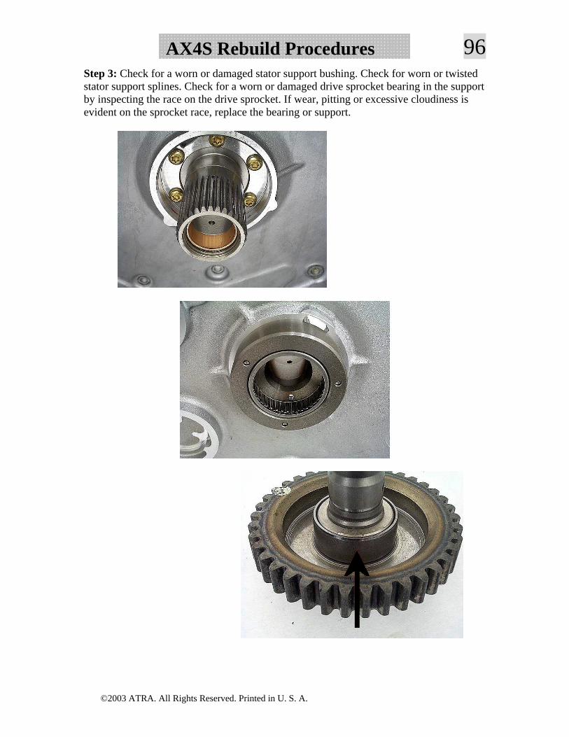
96AX4S Rebuild ProceduresStep 3: Check for a worn or damaged stator support bushing. Check for worn or twisted stator support splines. Check for a worn or damaged drive sprocket bearing in the support by inspecting the race on the drive sprocket. If wear, pitting or excessive cloudiness is evident on the sprocket race, replace the bearing or support.
©2003 ATRA. All Rights Reserved. Printed in U. S. A.
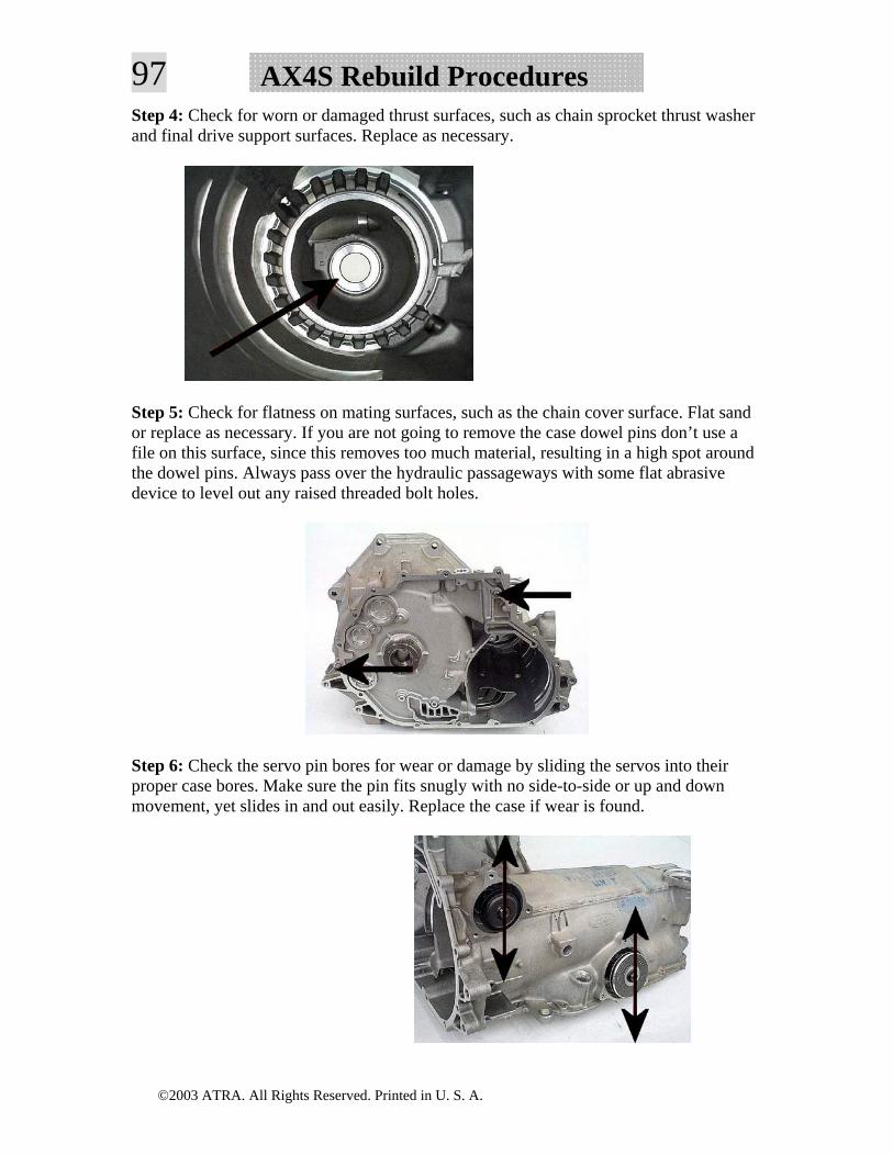
97 AX4S Rebuild ProceduresStep 4: Check for worn or damaged thrust surfaces, such as chain sprocket thrust washer and final drive support surfaces. Replace as necessary.
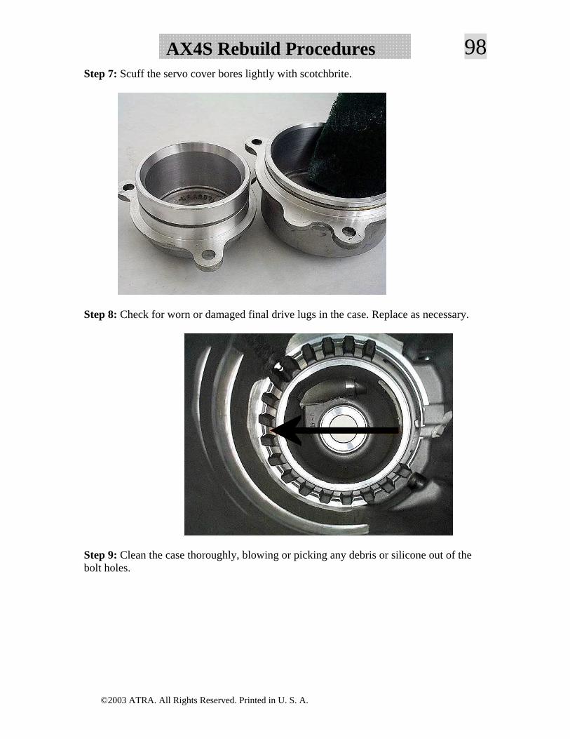
Step 5: Check for flatness on mating surfaces, such as the chain cover surface. Flat sand or replace as necessary. If you are not going to remove the case dowel pins don’t use a file on this surface, since this removes too much material, resulting in a high spot around the dowel pins. Always pass over the hydraulic passageways with some flat abrasive device to level out any raised threaded bolt holes.
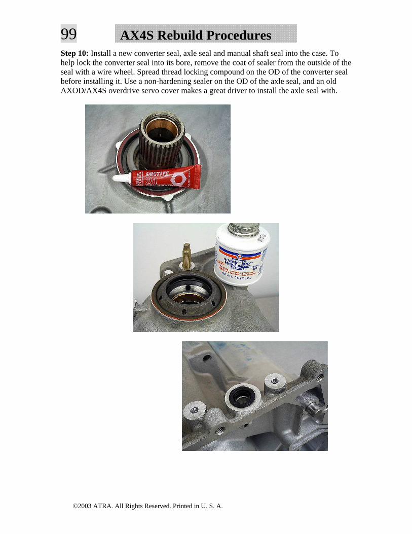
Step 6: Check the servo pin bores for wear or damage by sliding the servos into their proper case bores. Make sure the pin fits snugly with no side-to-side or up and down movement, yet slides in and out easily. Replace the case if wear is found.
©2003 ATRA. All Rights Reserved. Printed in U. S. A.
98AX4S Rebuild ProceduresStep 7: Scuff the servo cover bores lightly with scotchbrite.
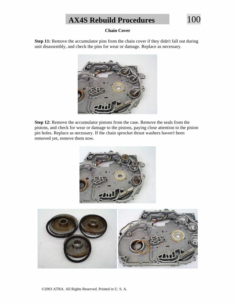
Step 8: Check for worn or damaged final drive lugs in the case. Replace as necessary.
Step 9: Clean the case thoroughly, blowing or picking any debris or silicone out of the bolt holes.
©2003 ATRA. All Rights Reserved. Printed in U. S. A.
99 AX4S Rebuild ProceduresStep 10: Install a new converter seal, axle seal and manual shaft seal into the case. To help lock the converter seal into its bore, remove the coat of sealer from the outside of the seal with a wire wheel. Spread thread locking compound on the OD of the converter seal before installing it. Use a non-hardening sealer on the OD of the axle seal, and an old AXOD/AX4S overdrive servo cover makes a great driver to install the axle seal with.
©2003 ATRA. All Rights Reserved. Printed in U. S. A.
100AX4S Rebuild ProceduresChain Cover
Step 11: Remove the accumulator pins from the chain cover if they didn't fall out during unit disassembly, and check the pins for wear or damage. Replace as necessary.
Step 12: Remove the accumulator pistons from the case. Remove the seals from the pistons, and check for wear or damage to the pistons, paying close attention to the piston pin holes. Replace as necessary. If the chain sprocket thrust washers haven't been removed yet, remove them now.
©2003 ATRA. All Rights Reserved. Printed in U. S. A.
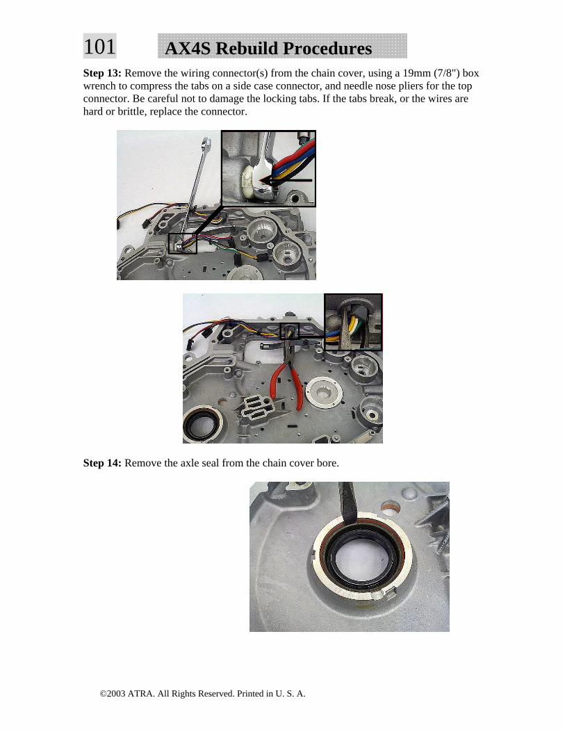
101 AX4S Rebuild ProceduresStep 13: Remove the wiring connector(s) from the chain cover, using a 19mm (7/8") box wrench to compress the tabs on a side case connector, and needle nose pliers for the top connector. Be careful not to damage the locking tabs. If the tabs break, or the wires are hard or brittle, replace the connector.
Step 14: Remove the axle seal from the chain cover bore.
©2003 ATRA. All Rights Reserved. Printed in U. S. A.
102AX4S Rebuild ProceduresStep 15: Check for cracks, wear or damage anywhere on the chain cover. Repair or replace as necessary. If the chain failed violently and beat up the aluminum, it may have caused stress fractures that will cause later leaks or failures. If this has occurred, consider replacing the cover.
Step 16: Check for pulled or stripped threaded bolt holes in the chain cover. Repair or replace as necessary.
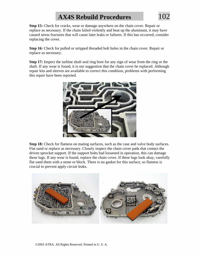
Step 17: Inspect the turbine shaft seal ring bore for any sign of wear from the ring or the shaft. If any wear is found, it is our suggestion that the chain cover be replaced. Although repair kits and sleeves are available to correct this condition, problems with performing this repair have been reported.
Step 18: Check for flatness on mating surfaces, such as the case and valve body surfaces. Flat sand or replace as necessary. Closely inspect the chain cover pads that contact the driven sprocket support. If the support bolts had loosened in operation, this can damage these lugs. If any wear is found, replace the chain cover. If these lugs look okay, carefully flat sand them with a stone or block. There is no gasket for this surface, so flatness is crucial to prevent apply circuit leaks.
©2003 ATRA. All Rights Reserved. Printed in U. S. A.
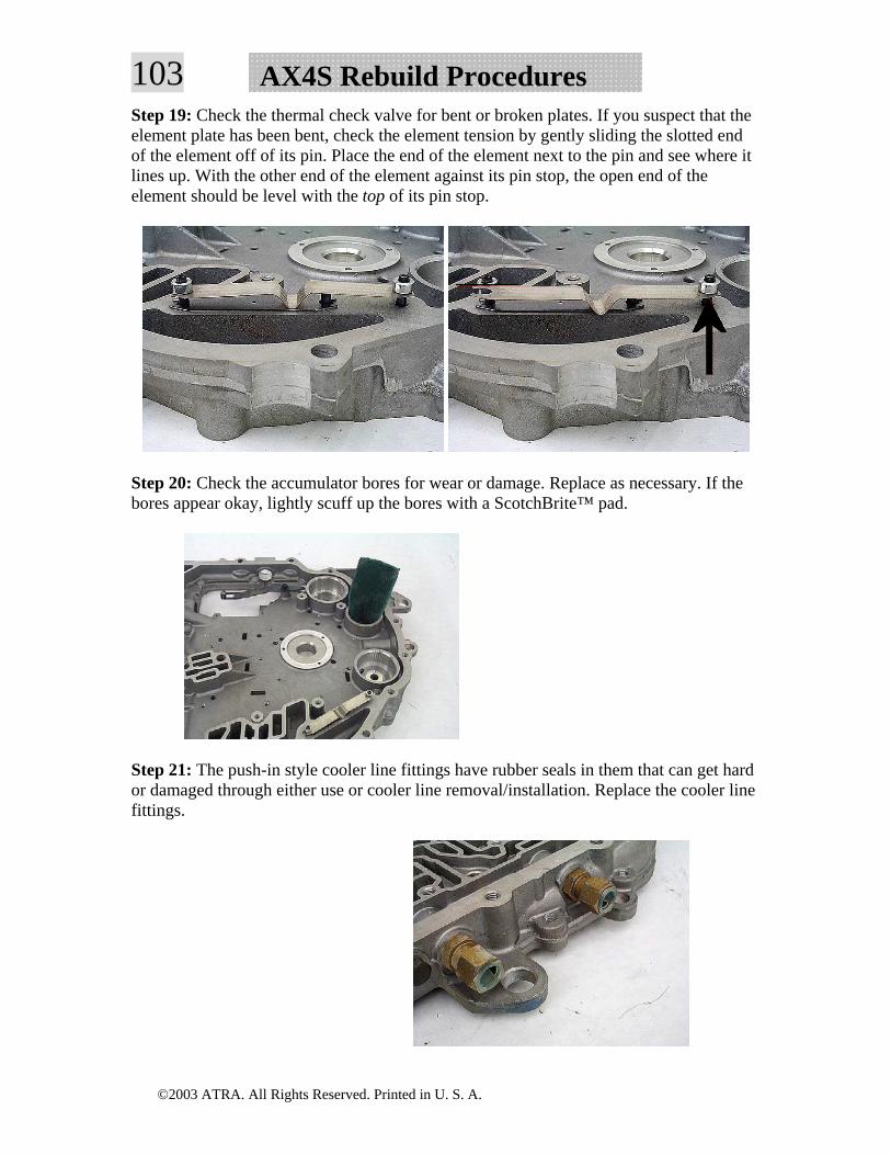
103 AX4S Rebuild ProceduresStep 19: Check the thermal check valve for bent or broken plates. If you suspect that the element plate has been bent, check the element tension by gently sliding the slotted end of the element off of its pin. Place the end of the element next to the pin and see where it lines up. With the other end of the element against its pin stop, the open end of the element should be level with the top of its pin stop.
Step 20: Check the accumulator bores for wear or damage. Replace as necessary. If the bores appear okay, lightly scuff up the bores with a ScotchBrite™ pad.
Step 21: The push-in style cooler line fittings have rubber seals in them that can get hard or damaged through either use or cooler line removal/installation. Replace the cooler line fittings.
©2003 ATRA. All Rights Reserved. Printed in U. S. A.
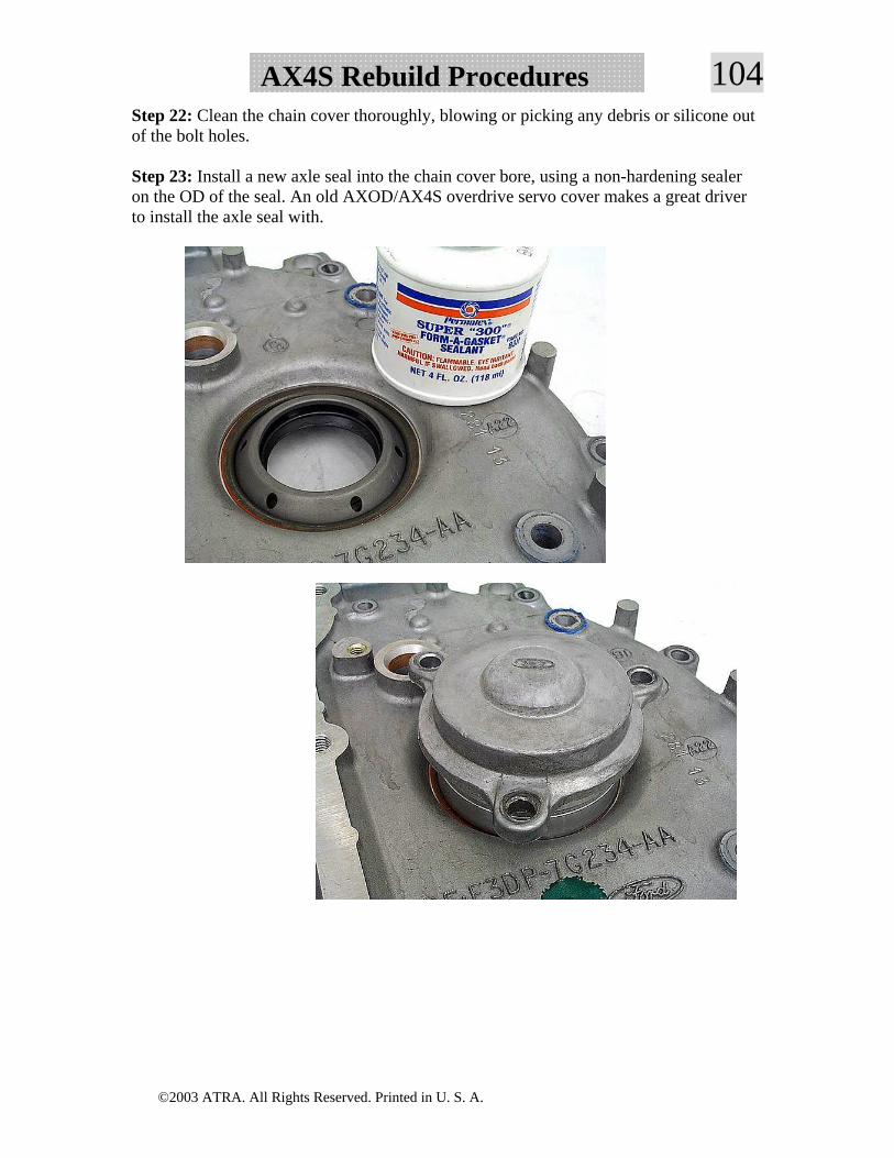
104AX4S Rebuild ProceduresStep 22: Clean the chain cover thoroughly, blowing or picking any debris or silicone out of the bolt holes.
Step 23: Install a new axle seal into the chain cover bore, using a non-hardening sealer on the OD of the seal. An old AXOD/AX4S overdrive servo cover makes a great driver to install the axle seal with.
©2003 ATRA. All Rights Reserved. Printed in U. S. A.
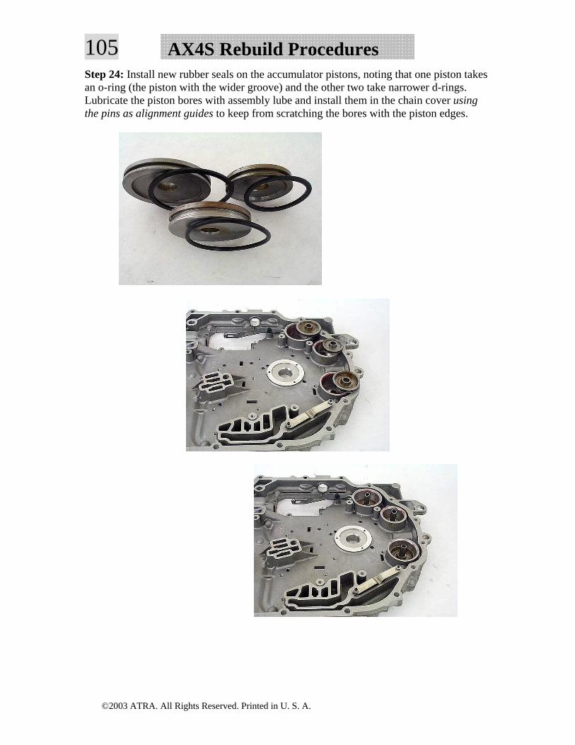
105 AX4S Rebuild ProceduresStep 24: Install new rubber seals on the accumulator pistons, noting that one piston takes an o-ring (the piston with the wider groove) and the other two take narrower d-rings. Lubricate the piston bores with assembly lube and install them in the chain cover using the pins as alignment guides to keep from scratching the bores with the piston edges.
©2003 ATRA. All Rights Reserved. Printed in U. S. A.
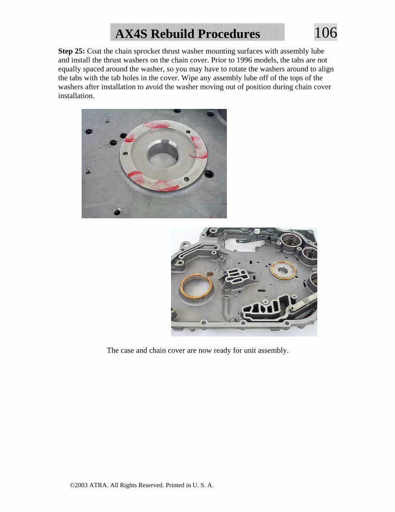
106AX4S Rebuild ProceduresStep 25: Coat the chain sprocket thrust washer mounting surfaces with assembly lube and install the thrust washers on the chain cover. Prior to 1996 models, the tabs are not equally spaced around the washer, so you may have to rotate the washers around to align the tabs with the tab holes in the cover. Wipe any assembly lube off of the tops of the washers after installation to avoid the washer moving out of position during chain cover installation.
The case and chain cover are now ready for unit assembly.
©2003 ATRA. All Rights Reserved. Printed in U. S. A.
107 AX4S Rebuild ProceduresTransaxle Assembly
Soak all new clutch material in clean ATF for at least 20 minutes before assembly.
IMPORTANT- On 1992 and earlier units, check to be sure that the vulcanized seal insert has been removed and discarded from the rear planet support lube tube hole in the case.
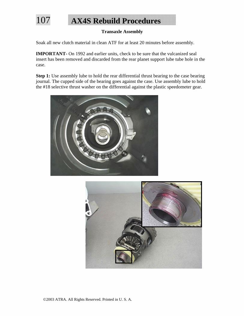
Step 1: Use assembly lube to hold the rear differential thrust bearing to the case bearing journal. The cupped side of the bearing goes against the case. Use assembly lube to hold the #18 selective thrust washer on the differential against the plastic speedometer gear.
©2003 ATRA. All Rights Reserved. Printed in U. S. A.
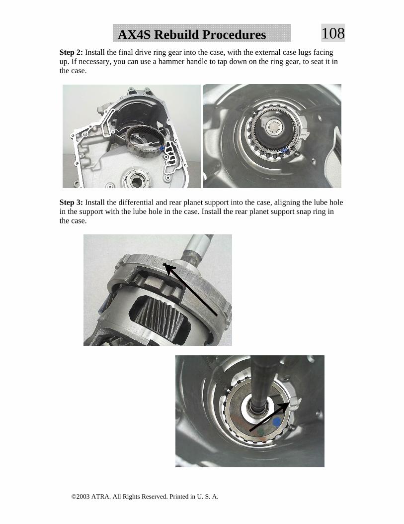
108AX4S Rebuild ProceduresStep 2: Install the final drive ring gear into the case, with the external case lugs facing up. If necessary, you can use a hammer handle to tap down on the ring gear, to seat it in the case.
Step 3: Install the differential and rear planet support into the case, aligning the lube hole in the support with the lube hole in the case. Install the rear planet support snap ring in the case.
©2003 ATRA. All Rights Reserved. Printed in U. S. A.
109 AX4S Rebuild Procedures
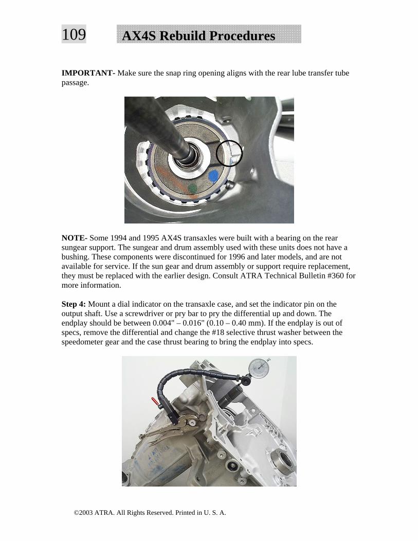
IMPORTANT- Make sure the snap ring opening aligns with the rear lube transfer tube passage.
NOTE- Some 1994 and 1995 AX4S transaxles were built with a bearing on the rear sungear support. The sungear and drum assembly used with these units does not have a bushing. These components were discontinued for 1996 and later models, and are not available for service. If the sun gear and drum assembly or support require replacement, they must be replaced with the earlier design. Consult ATRA Technical Bulletin #360 for more information.
Step 4: Mount a dial indicator on the transaxle case, and set the indicator pin on the output shaft. Use a screwdriver or pry bar to pry the differential up and down. The endplay should be between 0.004" – 0.016" (0.10 – 0.40 mm). If the endplay is out of specs, remove the differential and change the #18 selective thrust washer between the speedometer gear and the case thrust bearing to bring the endplay into specs.
©2003 ATRA. All Rights Reserved. Printed in U. S. A.
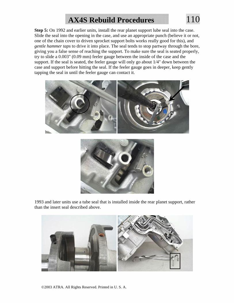
110AX4S Rebuild ProceduresStep 5: On 1992 and earlier units, install the rear planet support lube seal into the case. Slide the seal into the opening in the case, and use an appropriate punch (believe it or not, one of the chain cover to driven sprocket support bolts works really good for this), and gentle hammer taps to drive it into place. The seal tends to stop partway through the bore, giving you a false sense of reaching the support. To make sure the seal is seated properly, try to slide a 0.003" (0.09 mm) feeler gauge between the inside of the case and the support. If the seal is seated, the feeler gauge will only go about 1/4" down between the case and support before hitting the seal. If the feeler gauge goes in deeper, keep gently tapping the seal in until the feeler gauge can contact it.
1993 and later units use a tube seal that is installed inside the rear planet support, rather than the insert seal described above.
©2003 ATRA. All Rights Reserved. Printed in U. S. A.
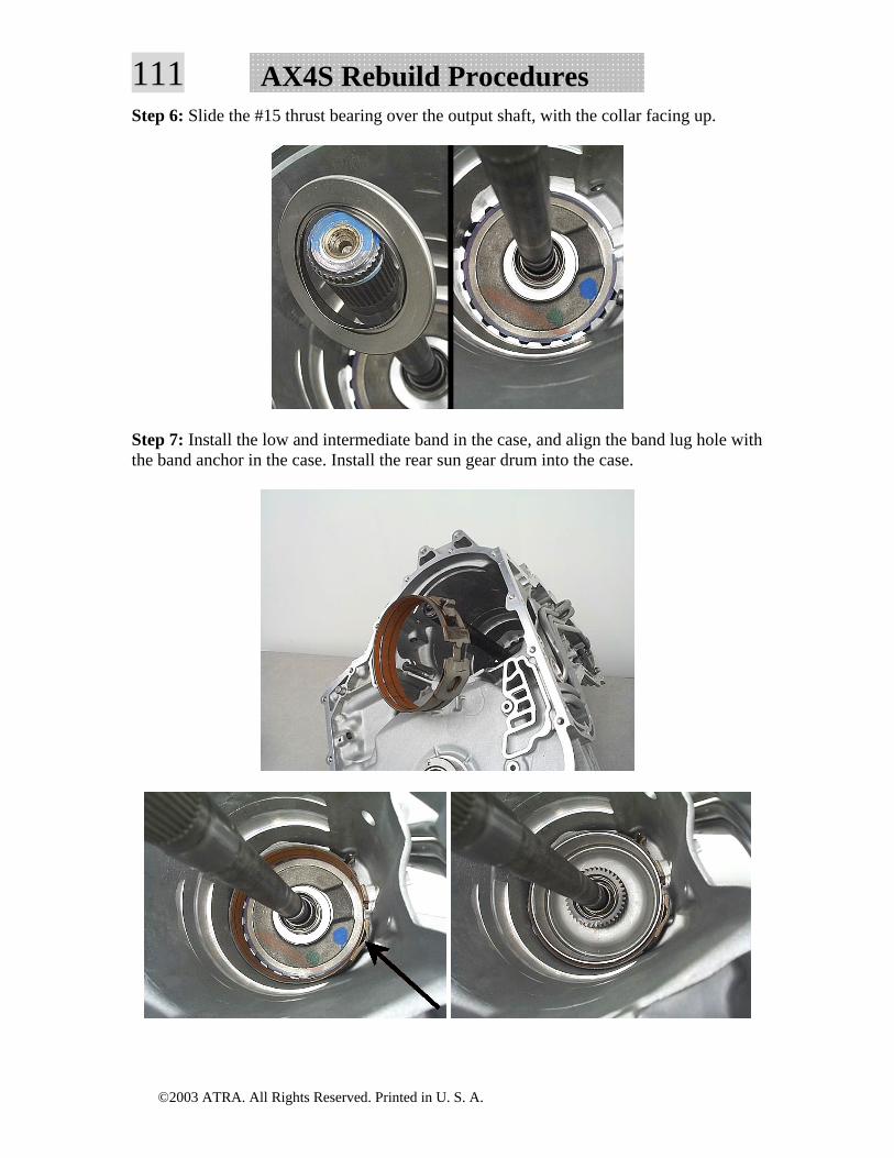
111 AX4S Rebuild ProceduresStep 6: Slide the #15 thrust bearing over the output shaft, with the collar facing up.
Step 7: Install the low and intermediate band in the case, and align the band lug hole with the band anchor in the case. Install the rear sun gear drum into the case.
©2003 ATRA. All Rights Reserved. Printed in U. S. A.
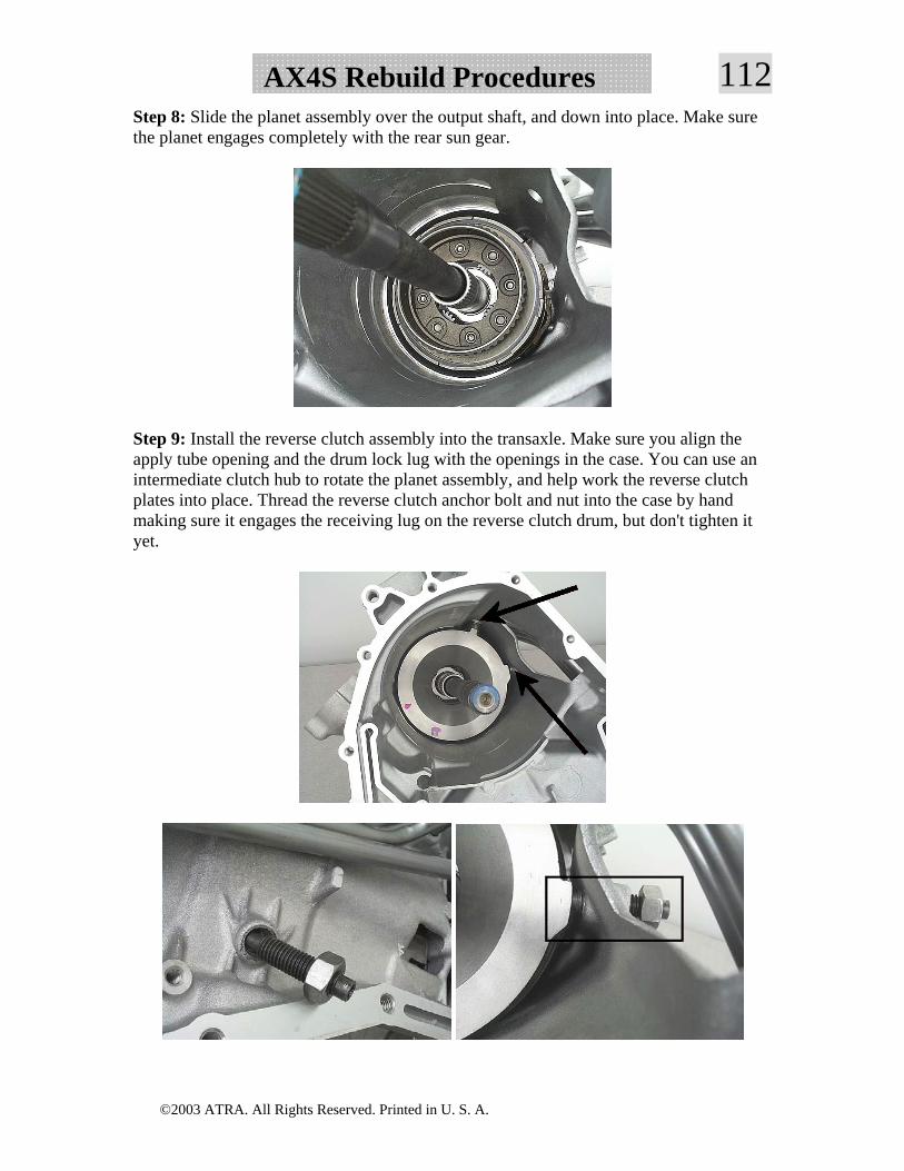
112AX4S Rebuild ProceduresStep 8: Slide the planet assembly over the output shaft, and down into place. Make sure the planet engages completely with the rear sun gear.
Step 9: Install the reverse clutch assembly into the transaxle. Make sure you align the apply tube opening and the drum lock lug with the openings in the case. You can use an intermediate clutch hub to rotate the planet assembly, and help work the reverse clutch plates into place. Thread the reverse clutch anchor bolt and nut into the case by hand making sure it engages the receiving lug on the reverse clutch drum, but don't tighten it yet.
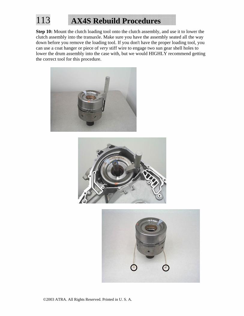
©2003 ATRA. All Rights Reserved. Printed in U. S. A.
113 AX4S Rebuild ProceduresStep 10: Mount the clutch loading tool onto the clutch assembly, and use it to lower the clutch assembly into the transaxle. Make sure you have the assembly seated all the way down before you remove the loading tool. If you don't have the proper loading tool, you can use a coat hanger or piece of very stiff wire to engage two sun gear shell holes to lower the drum assembly into the case with, but we would HIGHLY recommend getting the correct tool for this procedure.
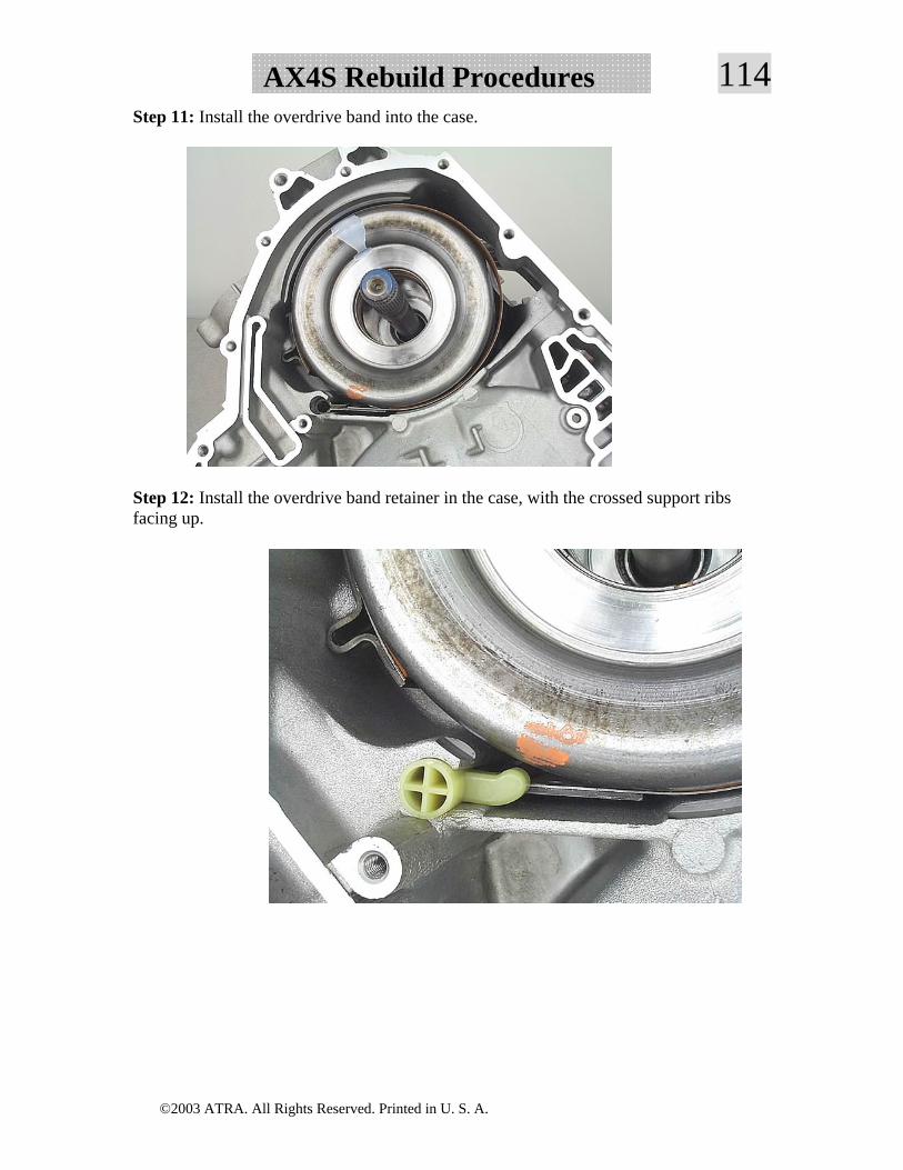
©2003 ATRA. All Rights Reserved. Printed in U. S. A.
114AX4S Rebuild ProceduresStep 11: Install the overdrive band into the case.
Step 12: Install the overdrive band retainer in the case, with the crossed support ribs facing up.
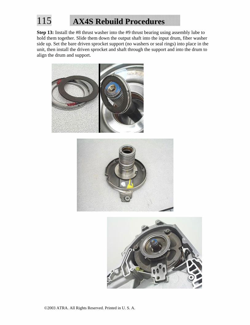
©2003 ATRA. All Rights Reserved. Printed in U. S. A.
115 AX4S Rebuild ProceduresStep 13: Install the #8 thrust washer into the #9 thrust bearing using assembly lube to hold them together. Slide them down the output shaft into the input drum, fiber washer side up. Set the bare driven sprocket support (no washers or seal rings) into place in the unit, then install the driven sprocket and shaft through the support and into the drum to align the drum and support.
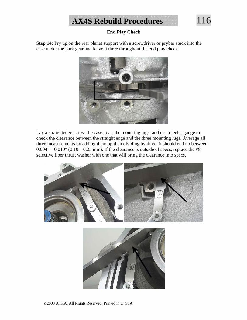
©2003 ATRA. All Rights Reserved. Printed in U. S. A.
116AX4S Rebuild ProceduresEnd Play Check
Step 14: Pry up on the rear planet support with a screwdriver or prybar stuck into the case under the park gear and leave it there throughout the end play check.
Lay a straightedge across the case, over the mounting lugs, and use a feeler gauge to check the clearance between the straight edge and the three mounting lugs. Average all three measurements by adding them up then dividing by three; it should end up between 0.004" – 0.010" (0.10 – 0.25 mm). If the clearance is outside of specs, replace the #8 selective fiber thrust washer with one that will bring the clearance into specs.
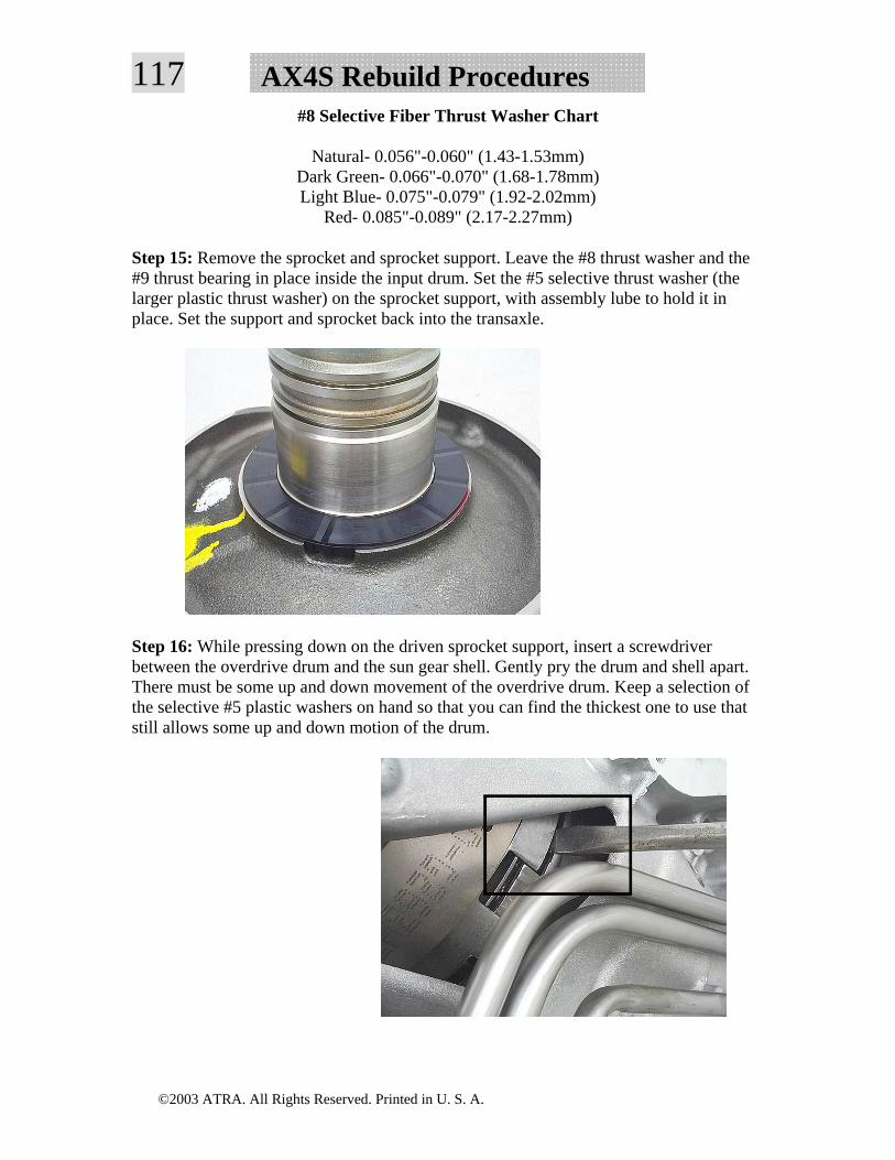
©2003 ATRA. All Rights Reserved. Printed in U. S. A.
117 AX4S Rebuild Procedures#8 Selective Fiber Thrust Washer Chart
Natural- 0.056"-0.060" (1.43-1.53mm) Dark Green- 0.066"-0.070" (1.68-1.78mm) Light Blue- 0.075"-0.079" (1.92-2.02mm)
Red- 0.085"-0.089" (2.17-2.27mm)
Step 15: Remove the sprocket and sprocket support. Leave the #8 thrust washer and the #9 thrust bearing in place inside the input drum. Set the #5 selective thrust washer (the larger plastic thrust washer) on the sprocket support, with assembly lube to hold it in place. Set the support and sprocket back into the transaxle.
Step 16: While pressing down on the driven sprocket support, insert a screwdriver between the overdrive drum and the sun gear shell. Gently pry the drum and shell apart. There must be some up and down movement of the overdrive drum. Keep a selection of the selective #5 plastic washers on hand so that you can find the thickest one to use that still allows some up and down motion of the drum.
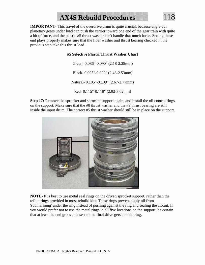
©2003 ATRA. All Rights Reserved. Printed in U. S. A.
118AX4S Rebuild ProceduresIMPORTANT- This travel of the overdrive drum is quite crucial, because angle-cut planetary gears under load can push the carrier toward one end of the gear train with quite a bit of force, and the plastic #5 thrust washer can't handle that much force. Setting these end plays properly makes sure that the fiber washer and thrust bearing checked in the previous step take this thrust load.
#5 Selective Plastic Thrust Washer Chart
Green- 0.086"-0.090" (2.18-2.28mm)
Black- 0.095"-0.099" (2.43-2.53mm)
Natural- 0.105"-0.109" (2.67-2.77mm)
Red- 0.115"-0.118" (2.92-3.02mm)
Step 17: Remove the sprocket and sprocket support again, and install the oil control rings on the support. Make sure that the #8 thrust washer and the #9 thrust bearing are still inside the input drum. The correct #5 thrust washer should still be in place on the support.
NOTE- It is best to use metal seal rings on the driven sprocket support, rather than the teflon rings provided in most rebuild kits. These rings prevent apply oil from 'submarining' under the ring instead of pushing against the ring and sealing the circuit. If you would prefer not to use the metal rings in all five locations on the support, be certain that at least the end groove closest to the final drive gets a metal ring.
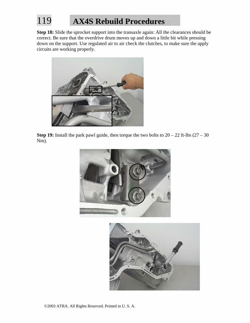
©2003 ATRA. All Rights Reserved. Printed in U. S. A.
119 AX4S Rebuild ProceduresStep 18: Slide the sprocket support into the transaxle again: All the clearances should be correct. Be sure that the overdrive drum moves up and down a little bit while pressing down on the support. Use regulated air to air check the clutches, to make sure the apply circuits are working properly.
Step 19: Install the park pawl guide, then torque the two bolts to 20 – 22 ft-lbs (27 – 30 Nm).
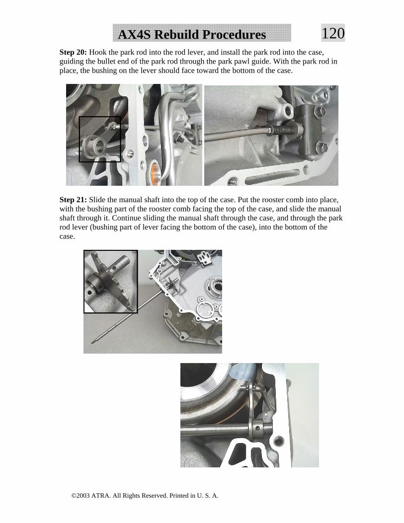
©2003 ATRA. All Rights Reserved. Printed in U. S. A.
120AX4S Rebuild ProceduresStep 20: Hook the park rod into the rod lever, and install the park rod into the case, guiding the bullet end of the park rod through the park pawl guide. With the park rod in place, the bushing on the lever should face toward the bottom of the case.
Step 21: Slide the manual shaft into the top of the case. Put the rooster comb into place, with the bushing part of the rooster comb facing the top of the case, and slide the manual shaft through it. Continue sliding the manual shaft through the case, and through the park rod lever (bushing part of lever facing the bottom of the case), into the bottom of the case.
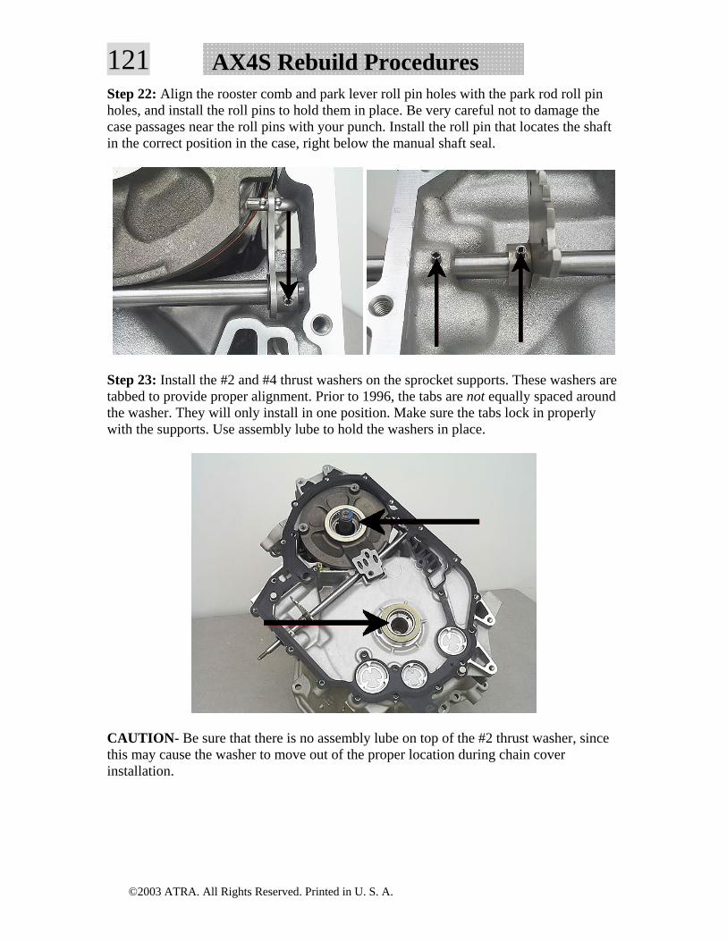
©2003 ATRA. All Rights Reserved. Printed in U. S. A.
121 AX4S Rebuild ProceduresStep 22: Align the rooster comb and park lever roll pin holes with the park rod roll pin holes, and install the roll pins to hold them in place. Be very careful not to damage the case passages near the roll pins with your punch. Install the roll pin that locates the shaft in the correct position in the case, right below the manual shaft seal.
Step 23: Install the #2 and #4 thrust washers on the sprocket supports. These washers are tabbed to provide proper alignment. Prior to 1996, the tabs are not equally spaced around the washer. They will only install in one position. Make sure the tabs lock in properly with the supports. Use assembly lube to hold the washers in place.
CAUTION- Be sure that there is no assembly lube on top of the #2 thrust washer, since this may cause the washer to move out of the proper location during chain cover installation.
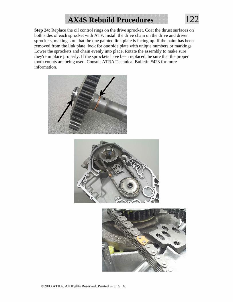
©2003 ATRA. All Rights Reserved. Printed in U. S. A.
122AX4S Rebuild ProceduresStep 24: Replace the oil control rings on the drive sprocket. Coat the thrust surfaces on both sides of each sprocket with ATF. Install the drive chain on the drive and driven sprockets, making sure that the one painted link plate is facing up. If the paint has been removed from the link plate, look for one side plate with unique numbers or markings. Lower the sprockets and chain evenly into place. Rotate the assembly to make sure they're in place properly. If the sprockets have been replaced, be sure that the proper tooth counts are being used. Consult ATRA Technical Bulletin #423 for more information.
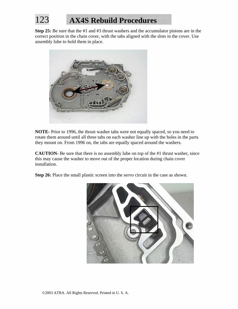
©2003 ATRA. All Rights Reserved. Printed in U. S. A.
123 AX4S Rebuild ProceduresStep 25: Be sure that the #1 and #3 thrust washers and the accumulator pistons are in the correct position in the chain cover, with the tabs aligned with the slots in the cover. Use assembly lube to hold them in place.
NOTE- Prior to 1996, the thrust washer tabs were not equally spaced, so you need to rotate them around until all three tabs on each washer line up with the holes in the parts they mount on. From 1996 on, the tabs are equally spaced around the washers.
CAUTION- Be sure that there is no assembly lube on top of the #1 thrust washer, since this may cause the washer to move out of the proper location during chain cover installation.
Step 26: Place the small plastic screen into the servo circuit in the case as shown.
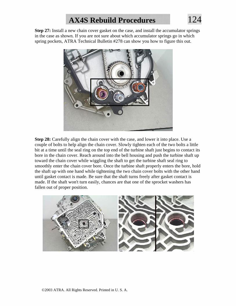
©2003 ATRA. All Rights Reserved. Printed in U. S. A.
124AX4S Rebuild ProceduresStep 27: Install a new chain cover gasket on the case, and install the accumulator springs in the case as shown. If you are not sure about which accumulator springs go in which spring pockets, ATRA Technical Bulletin #278 can show you how to figure this out.
Step 28: Carefully align the chain cover with the case, and lower it into place. Use a couple of bolts to help align the chain cover. Slowly tighten each of the two bolts a little bit at a time until the seal ring on the top end of the turbine shaft just begins to contact its bore in the chain cover. Reach around into the bell housing and push the turbine shaft up toward the chain cover while wiggling the shaft to get the turbine shaft seal ring to smoothly enter the chain cover bore. Once the turbine shaft properly enters the bore, hold the shaft up with one hand while tightening the two chain cover bolts with the other hand until gasket contact is made. Be sure that the shaft turns freely after gasket contact is made. If the shaft won't turn easily, chances are that one of the sprocket washers has fallen out of proper position.
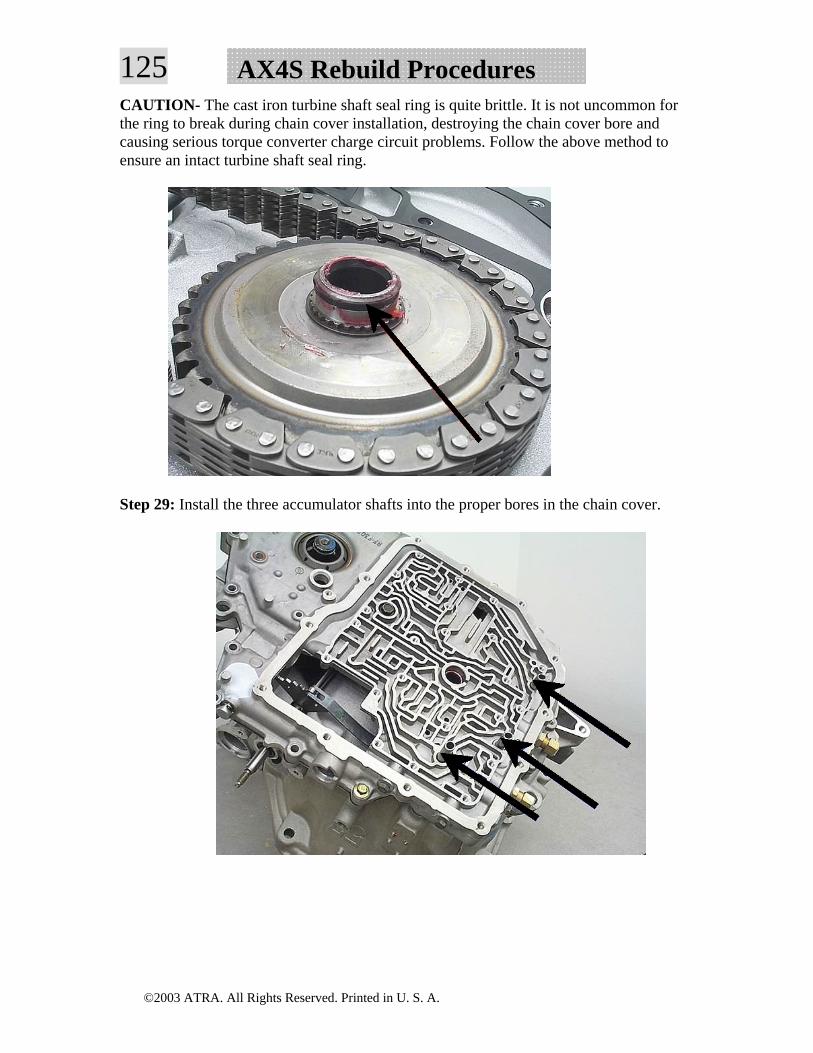
©2003 ATRA. All Rights Reserved. Printed in U. S. A.
125 AX4S Rebuild ProceduresCAUTION- The cast iron turbine shaft seal ring is quite brittle. It is not uncommon for the ring to break during chain cover installation, destroying the chain cover bore and causing serious torque converter charge circuit problems. Follow the above method to ensure an intact turbine shaft seal ring.
Step 29: Install the three accumulator shafts into the proper bores in the chain cover.
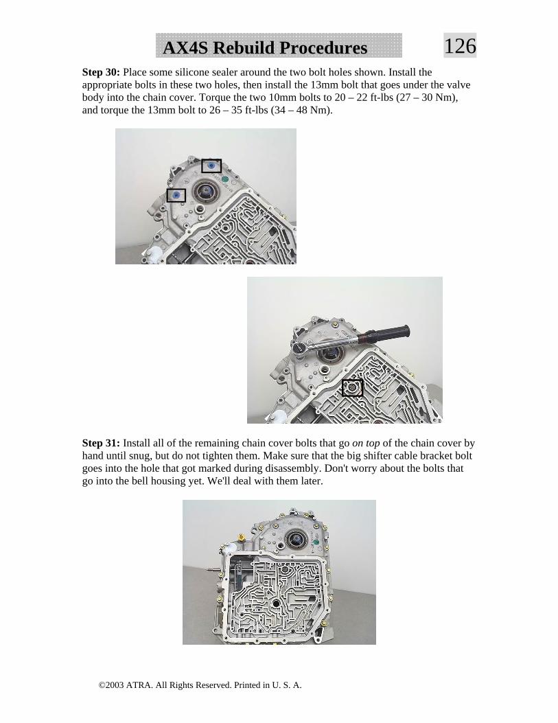
©2003 ATRA. All Rights Reserved. Printed in U. S. A.
126AX4S Rebuild ProceduresStep 30: Place some silicone sealer around the two bolt holes shown. Install the appropriate bolts in these two holes, then install the 13mm bolt that goes under the valve body into the chain cover. Torque the two 10mm bolts to 20 – 22 ft-lbs (27 – 30 Nm), and torque the 13mm bolt to 26 – 35 ft-lbs (34 – 48 Nm).
Step 31: Install all of the remaining chain cover bolts that go on top of the chain cover by hand until snug, but do not tighten them. Make sure that the big shifter cable bracket bolt goes into the hole that got marked during disassembly. Don't worry about the bolts that go into the bell housing yet. We'll deal with them later.
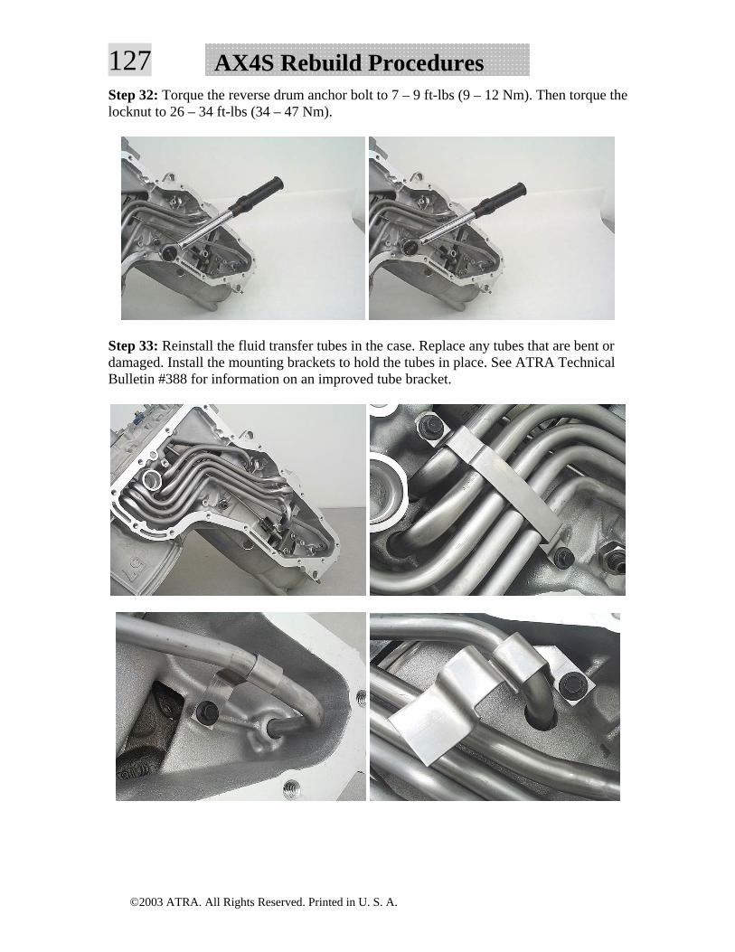
©2003 ATRA. All Rights Reserved. Printed in U. S. A.
127 AX4S Rebuild ProceduresStep 32: Torque the reverse drum anchor bolt to 7 – 9 ft-lbs (9 – 12 Nm). Then torque the locknut to 26 – 34 ft-lbs (34 – 47 Nm).
Step 33: Reinstall the fluid transfer tubes in the case. Replace any tubes that are bent or damaged. Install the mounting brackets to hold the tubes in place. See ATRA Technical Bulletin #388 for information on an improved tube bracket.
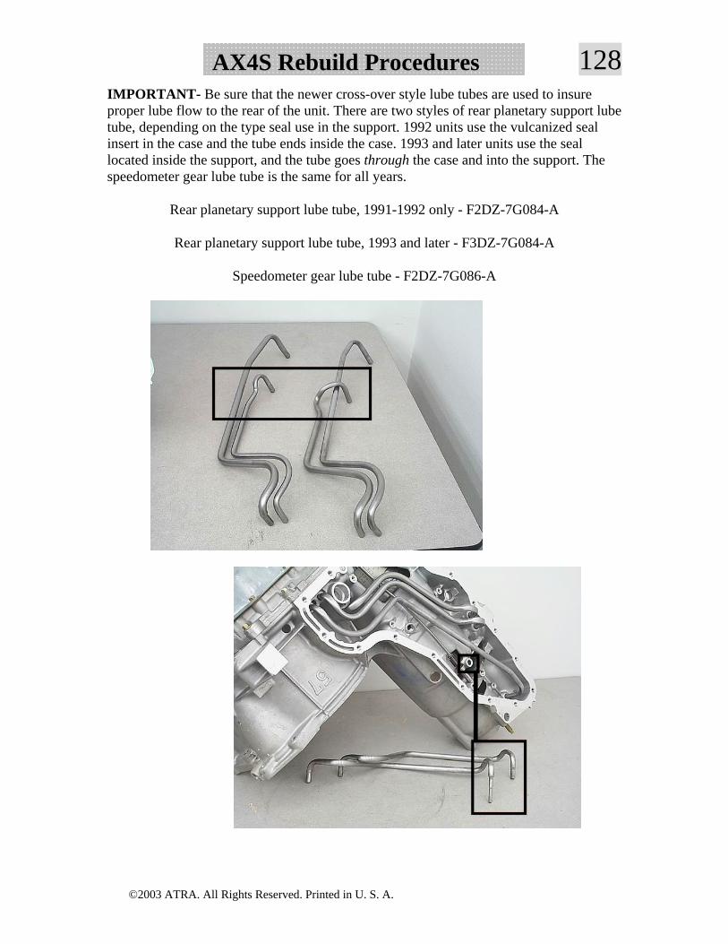
©2003 ATRA. All Rights Reserved. Printed in U. S. A.
128AX4S Rebuild ProceduresIMPORTANT- Be sure that the newer cross-over style lube tubes are used to insure proper lube flow to the rear of the unit. There are two styles of rear planetary support lube tube, depending on the type seal use in the support. 1992 units use the vulcanized seal insert in the case and the tube ends inside the case. 1993 and later units use the seal located inside the support, and the tube goes through the case and into the support. The speedometer gear lube tube is the same for all years.
Rear planetary support lube tube, 1991-1992 only - F2DZ-7G084-A
Rear planetary support lube tube, 1993 and later - F3DZ-7G084-A
Speedometer gear lube tube - F2DZ-7G086-A
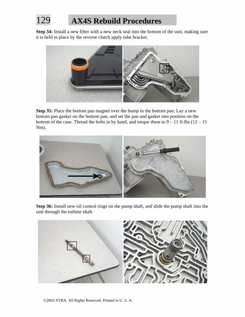
©2003 ATRA. All Rights Reserved. Printed in U. S. A.
129 AX4S Rebuild ProceduresStep 34: Install a new filter with a new neck seal into the bottom of the unit, making sure it is held in place by the reverse clutch apply tube bracket.
Step 35: Place the bottom pan magnet over the bump in the bottom pan. Lay a new bottom pan gasket on the bottom pan, and set the pan and gasket into position on the bottom of the case. Thread the bolts in by hand, and torque them to 9 – 11 ft-lbs (12 – 15 Nm).
Step 36: Install new oil control rings on the pump shaft, and slide the pump shaft into the unit through the turbine shaft.
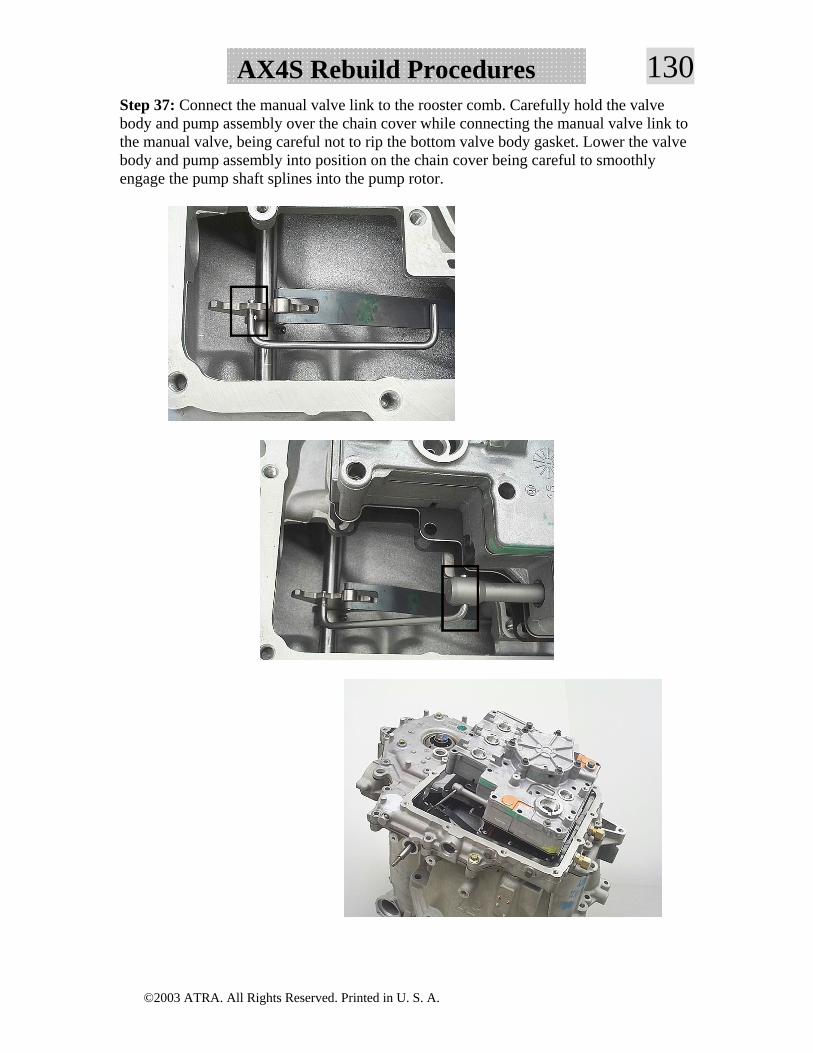
©2003 ATRA. All Rights Reserved. Printed in U. S. A.
130AX4S Rebuild ProceduresStep 37: Connect the manual valve link to the rooster comb. Carefully hold the valve body and pump assembly over the chain cover while connecting the manual valve link to the manual valve, being careful not to rip the bottom valve body gasket. Lower the valve body and pump assembly into position on the chain cover being careful to smoothly engage the pump shaft splines into the pump rotor.
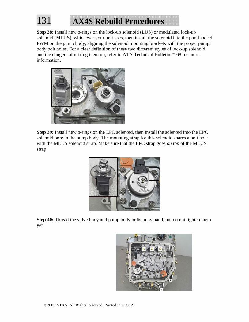
©2003 ATRA. All Rights Reserved. Printed in U. S. A.
131 AX4S Rebuild ProceduresStep 38: Install new o-rings on the lock-up solenoid (LUS) or modulated lock-up solenoid (MLUS), whichever your unit uses, then install the solenoid into the port labeled PWM on the pump body, aligning the solenoid mounting brackets with the proper pump body bolt holes. For a clear definition of these two different styles of lock-up solenoid and the dangers of mixing them up, refer to ATA Technical Bulletin #168 for more information.
Step 39: Install new o-rings on the EPC solenoid, then install the solenoid into the EPC solenoid bore in the pump body. The mounting strap for this solenoid shares a bolt hole with the MLUS solenoid strap. Make sure that the EPC strap goes on top of the MLUS strap.
Step 40: Thread the valve body and pump body bolts in by hand, but do not tighten them yet.
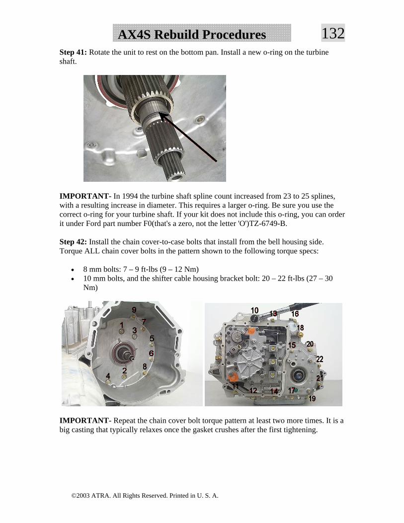
©2003 ATRA. All Rights Reserved. Printed in U. S. A.
132AX4S Rebuild ProceduresStep 41: Rotate the unit to rest on the bottom pan. Install a new o-ring on the turbine shaft.
IMPORTANT- In 1994 the turbine shaft spline count increased from 23 to 25 splines, with a resulting increase in diameter. This requires a larger o-ring. Be sure you use the correct o-ring for your turbine shaft. If your kit does not include this o-ring, you can order it under Ford part number F0(that's a zero, not the letter 'O')TZ-6749-B.
Step 42: Install the chain cover-to-case bolts that install from the bell housing side. Torque ALL chain cover bolts in the pattern shown to the following torque specs:
• 8 mm bolts: 7 – 9 ft-lbs (9 – 12 Nm) • 10 mm bolts, and the shifter cable housing bracket bolt: 20 – 22 ft-lbs (27 – 30
Nm)
IMPORTANT- Repeat the chain cover bolt torque pattern at least two more times. It is a big casting that typically relaxes once the gasket crushes after the first tightening.
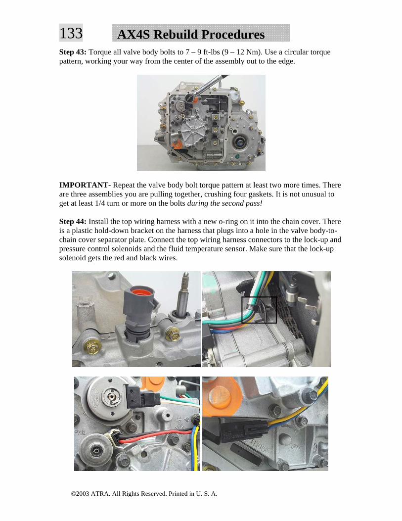
©2003 ATRA. All Rights Reserved. Printed in U. S. A.
133 AX4S Rebuild ProceduresStep 43: Torque all valve body bolts to 7 – 9 ft-lbs (9 – 12 Nm). Use a circular torque pattern, working your way from the center of the assembly out to the edge.
IMPORTANT- Repeat the valve body bolt torque pattern at least two more times. There are three assemblies you are pulling together, crushing four gaskets. It is not unusual to get at least 1/4 turn or more on the bolts during the second pass!
Step 44: Install the top wiring harness with a new o-ring on it into the chain cover. There is a plastic hold-down bracket on the harness that plugs into a hole in the valve body-to-chain cover separator plate. Connect the top wiring harness connectors to the lock-up and pressure control solenoids and the fluid temperature sensor. Make sure that the lock-up solenoid gets the red and black wires.
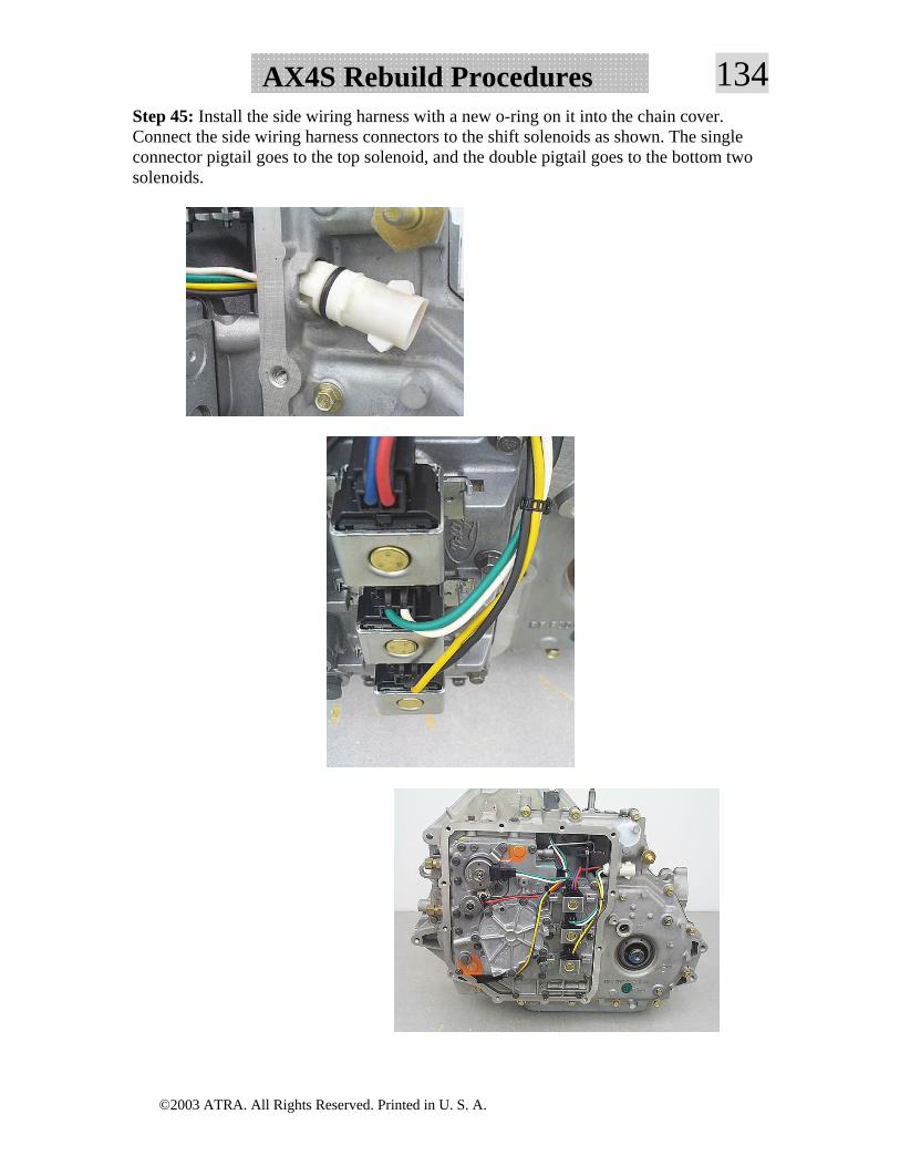
©2003 ATRA. All Rights Reserved. Printed in U. S. A.
134AX4S Rebuild ProceduresStep 45: Install the side wiring harness with a new o-ring on it into the chain cover. Connect the side wiring harness connectors to the shift solenoids as shown. The single connector pigtail goes to the top solenoid, and the double pigtail goes to the bottom two solenoids.
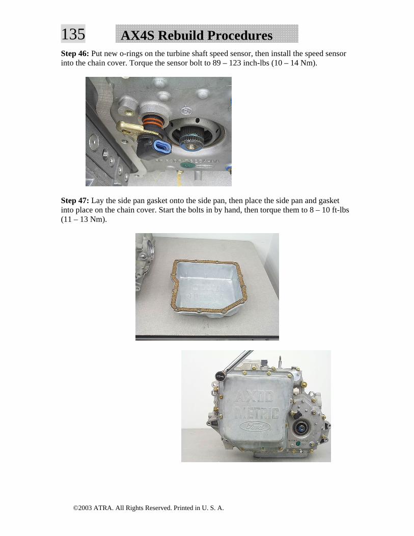
©2003 ATRA. All Rights Reserved. Printed in U. S. A.
135 AX4S Rebuild ProceduresStep 46: Put new o-rings on the turbine shaft speed sensor, then install the speed sensor into the chain cover. Torque the sensor bolt to 89 – 123 inch-lbs (10 – 14 Nm).
Step 47: Lay the side pan gasket onto the side pan, then place the side pan and gasket into place on the chain cover. Start the bolts in by hand, then torque them to 8 – 10 ft-lbs (11 – 13 Nm).
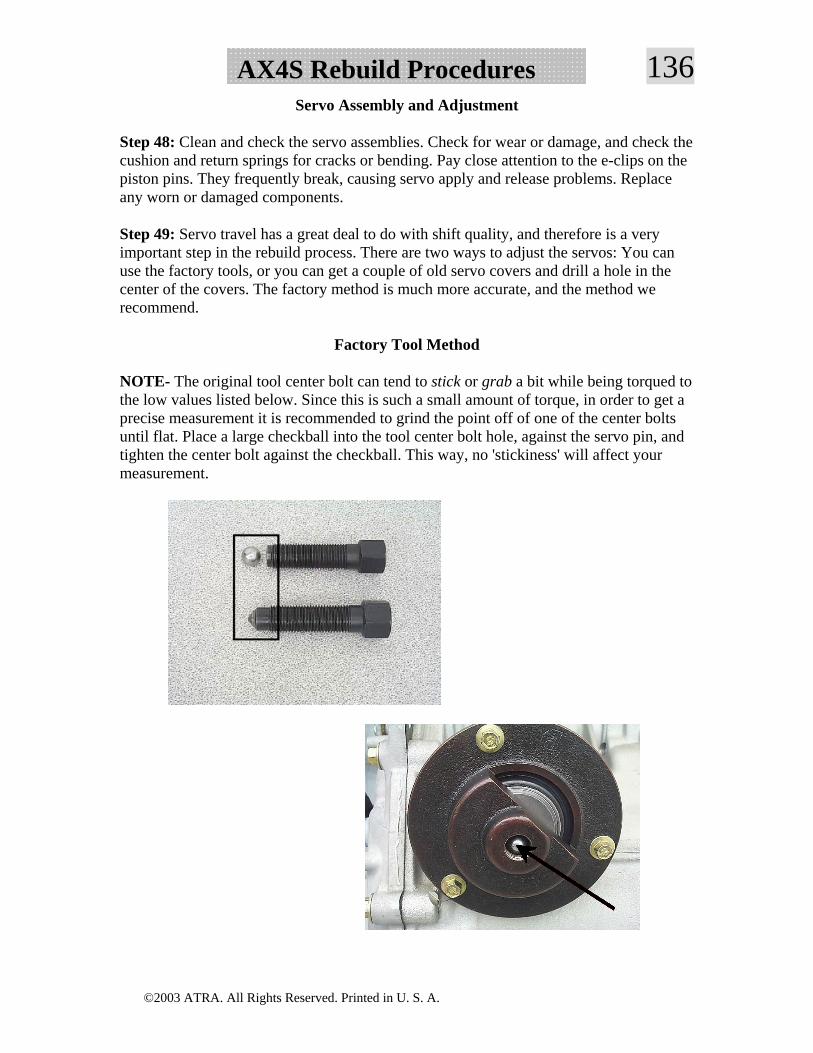
©2003 ATRA. All Rights Reserved. Printed in U. S. A.
136AX4S Rebuild ProceduresServo Assembly and Adjustment
Step 48: Clean and check the servo assemblies. Check for wear or damage, and check the cushion and return springs for cracks or bending. Pay close attention to the e-clips on the piston pins. They frequently break, causing servo apply and release problems. Replace any worn or damaged components.
Step 49: Servo travel has a great deal to do with shift quality, and therefore is a very important step in the rebuild process. There are two ways to adjust the servos: You can use the factory tools, or you can get a couple of old servo covers and drill a hole in the center of the covers. The factory method is much more accurate, and the method we recommend.
Factory Tool Method
NOTE- The original tool center bolt can tend to stick or grab a bit while being torqued to the low values listed below. Since this is such a small amount of torque, in order to get a precise measurement it is recommended to grind the point off of one of the center bolts until flat. Place a large checkball into the tool center bolt hole, against the servo pin, and tighten the center bolt against the checkball. This way, no 'stickiness' will affect your measurement.
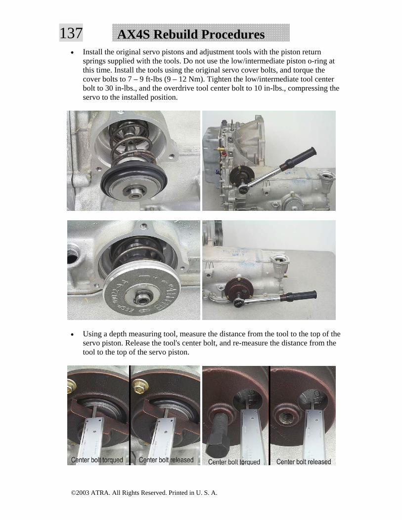
©2003 ATRA. All Rights Reserved. Printed in U. S. A.
137 AX4S Rebuild Procedures• Install the original servo pistons and adjustment tools with the piston return
springs supplied with the tools. Do not use the low/intermediate piston o-ring at this time. Install the tools using the original servo cover bolts, and torque the cover bolts to 7 – 9 ft-lbs (9 – 12 Nm). Tighten the low/intermediate tool center bolt to 30 in-lbs., and the overdrive tool center bolt to 10 in-lbs., compressing the servo to the installed position.
• Using a depth measuring tool, measure the distance from the tool to the top of the servo piston. Release the tool's center bolt, and re-measure the distance from the tool to the top of the servo piston.
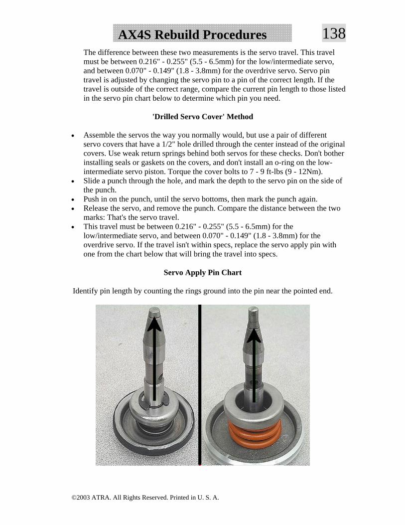
©2003 ATRA. All Rights Reserved. Printed in U. S. A.
138AX4S Rebuild ProceduresThe difference between these two measurements is the servo travel. This travel must be between 0.216" - 0.255" (5.5 - 6.5mm) for the low/intermediate servo, and between 0.070" - 0.149" (1.8 - 3.8mm) for the overdrive servo. Servo pin travel is adjusted by changing the servo pin to a pin of the correct length. If the travel is outside of the correct range, compare the current pin length to those listed in the servo pin chart below to determine which pin you need.
'Drilled Servo Cover' Method
• Assemble the servos the way you normally would, but use a pair of different servo covers that have a 1/2" hole drilled through the center instead of the original covers. Use weak return springs behind both servos for these checks. Don't bother installing seals or gaskets on the covers, and don't install an o-ring on the low-intermediate servo piston. Torque the cover bolts to 7 - 9 ft-lbs (9 - 12Nm).
• Slide a punch through the hole, and mark the depth to the servo pin on the side of the punch.
• Push in on the punch, until the servo bottoms, then mark the punch again. • Release the servo, and remove the punch. Compare the distance between the two
marks: That's the servo travel. • This travel must be between 0.216" - 0.255" (5.5 - 6.5mm) for the
low/intermediate servo, and between 0.070" - 0.149" (1.8 - 3.8mm) for the overdrive servo. If the travel isn't within specs, replace the servo apply pin with one from the chart below that will bring the travel into specs.
Servo Apply Pin Chart
Identify pin length by counting the rings ground into the pin near the pointed end.
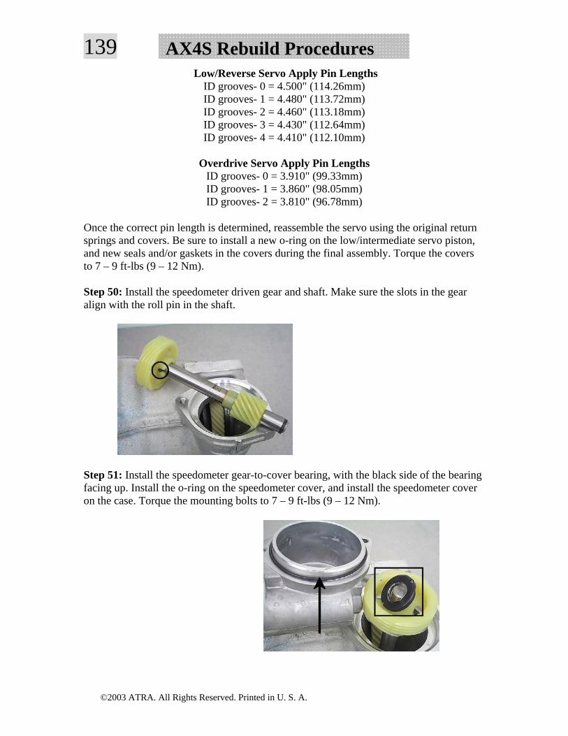
©2003 ATRA. All Rights Reserved. Printed in U. S. A.
139 AX4S Rebuild Procedures Low/Reverse Servo Apply Pin Lengths
ID grooves- 0 = 4.500" (114.26mm) ID grooves- 1 = 4.480" (113.72mm) ID grooves- 2 = 4.460" (113.18mm) ID grooves- 3 = 4.430" (112.64mm) ID grooves- 4 = 4.410" (112.10mm)
Overdrive Servo Apply Pin Lengths
ID grooves- 0 = 3.910" (99.33mm) ID grooves- 1 = 3.860" (98.05mm) ID grooves- 2 = 3.810" (96.78mm)
Once the correct pin length is determined, reassemble the servo using the original return springs and covers. Be sure to install a new o-ring on the low/intermediate servo piston, and new seals and/or gaskets in the covers during the final assembly. Torque the covers to 7 – 9 ft-lbs (9 – 12 Nm).
Step 50: Install the speedometer driven gear and shaft. Make sure the slots in the gear align with the roll pin in the shaft.
Step 51: Install the speedometer gear-to-cover bearing, with the black side of the bearing facing up. Install the o-ring on the speedometer cover, and install the speedometer cover on the case. Torque the mounting bolts to 7 – 9 ft-lbs (9 – 12 Nm).
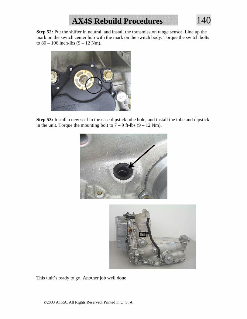
©2003 ATRA. All Rights Reserved. Printed in U. S. A.
140AX4S Rebuild ProceduresStep 52: Put the shifter in neutral, and install the transmission range sensor. Line up the mark on the switch center hub with the mark on the switch body. Torque the switch bolts to 80 – 106 inch-lbs (9 – 12 Nm).
Step 53: Install a new seal in the case dipstick tube hole, and install the tube and dipstick in the unit. Torque the mounting bolt to 7 – 9 ft-lbs (9 – 12 Nm).
This unit’s ready to go. Another job well done.