Embed Size (px)
Citation preview
FPGA videogame
6.111 final project report
Telmo Luis Correa Junior
2
Index Index ................................................................................................................................. 2 List of figures .................................................................................................................... 3 List of tables ...................................................................................................................... 4 Introduction ....................................................................................................................... 5 Project Design ................................................................................................................... 6
Design tools ................................................................................................................... 6 Design overview ............................................................................................................ 7
Output........................................................................................................................ 7 GPU communication.................................................................................................. 9 GPU submodules...................................................................................................... 10
Hardware protocols ...................................................................................................... 12 CPU to GPU ............................................................................................................ 12 Blob manager to blob ............................................................................................... 17
Feedback ......................................................................................................................... 18 References ....................................................................................................................... 19 Appendix A: Verilog files ................................................................................................ 20
final-project.v .............................................................................................................. 20 vga.v............................................................................................................................ 34 beta2.v ......................................................................................................................... 35 coordinate_generator.v................................................................................................. 41 debounce.v................................................................................................................... 42 blob.v........................................................................................................................... 42 blob_manager.v............................................................................................................ 48 sprite_manager.v.......................................................................................................... 52 pixel_tree.v .................................................................................................................. 59 pixel_combinator.v ...................................................................................................... 66 interrupt_generator.v.................................................................................................... 68 fifo.v............................................................................................................................ 71
Appendix B: Bsim macros ............................................................................................... 73 beta.uasm..................................................................................................................... 73 ram.uasm ..................................................................................................................... 84
Appendix C: Other scripts.............................................................................................. 100 ImageConverter.java .................................................................................................. 100 betamem.py ............................................................................................................... 101
Appendix D: ROM Sprites............................................................................................. 104
3
List of figures Fig. 1: System block diagram ............................................................................................ 8 Fig. 2: VGA horizontal sync ............................................................................................. 9 Fig. 3: VGA vertical sync ................................................................................................. 9 Fig. 4: GPU block diagram .............................................................................................. 11
4
List of tables Table 1: VGA timings........................................................................................................ 9 Table 2: Blob states ......................................................................................................... 12 Table 3: Blob pixel filters ................................................................................................ 16 Table 4: command_bus protocol ..................................................................................... 18
5
Introduction The aim of this project was to develop a gaming system on the FPGA easily reconfigurable; by switching small component parts on the system, it could be used to play another game. Two apparently opposing goals were set: to avoid hardwiring game logic into the hardware, and to use the massive parallel processing power available on the labkit to speed up the game, making this project have an interesting digital design aspect. The compromise was achieved by designing the game logic itself to be controlled by a microprocessor, but letting the graphics processing being controlled by hardware, in the form of a somewhat primitive graphics processing unit.
Diverse factors, such as availability, familiarity and available technical support, the microprocessor architeture chosen was the Beta, a processor used for an introductory computational structures class at MIT, 6.004. The GPU design is very ad hoc; nevertheless, it is inspired by and shares various similarities with early-eras of videogame systems, such as the use of sprites, of hardware modules dedicated to individual images, the hierarchic colllision detection on a pixel-by-pixel level, image layering, mirroring, and color filters. A more unusual characteristic of this GPU is to assume the responsability for image loading; the design guideline was that the processor should not waste cycles doing a graphics-related task, but instead give a (somewhat) higher lever instruction to the GPU.
6
Project Design
Design tools All hardware used for this project was supplied by the course staff: the labkit FPGA, logic analyzers, and LCD monitors for output. Various softwares were employed:the Xilinx development suit for the Verilog code, some Java for converting images into text format parsable by memory creators, the BSim beta simulator provided by 6.004, and a Python script to speed up the creation of small memory modules, provided by the professor. The verilog code for the processor module was provided by the course staff. The 2-stage pipelined Beta was used almost on unaltered form, except for the duplication and exposure of 5 registers, addition and externalization of a new control signal, and a corresponding opcode for hardware calls. This difference was enough, however, to make the BSim simulations slightly less useful, since a macro would have to be redefined either for producing a new RAM with the game logic either for software simulation, and forgetting this detail would cause a whole synthesis process to be wasted (around 30 minutes on late design stage). The hardware call macro, HW(), would have its definition altered for producing the .coe files for the labkit and for the software simulation. Software simulations for verilog and tests of individual moqdules would probably have been very useful; as of two days before the demo date, some of the GPU modules still had hard-to-track bugs, and the hardware synthesis of those particular modules is the largest time sink of the development, and their absence might be one of the factors of the project not being as polished as originally envisioned (together with an inappropriate schedule).
7
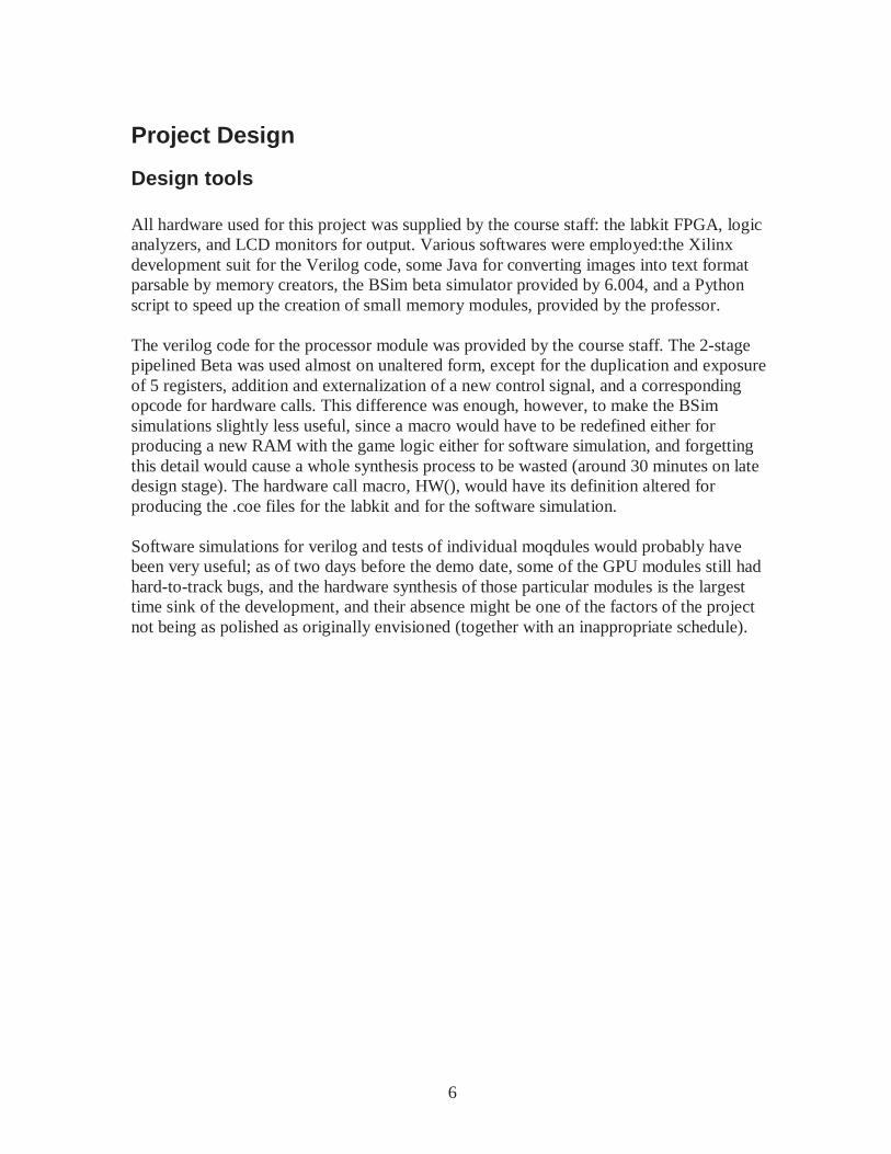
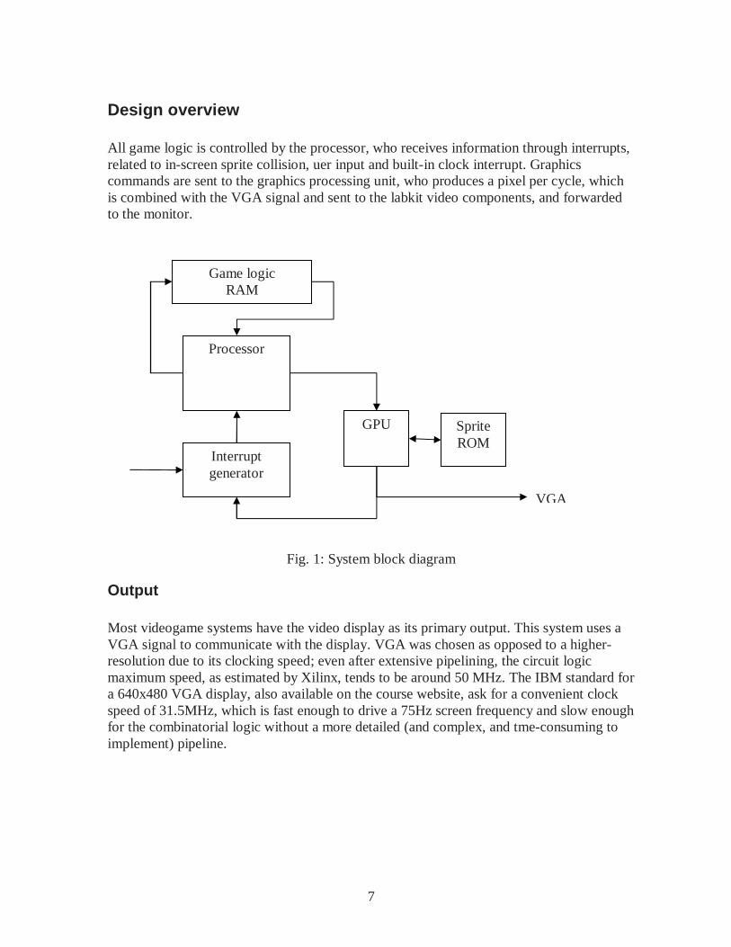
Design overview All game logic is controlled by the processor, who receives information through interrupts, related to in-screen sprite collision, uer input and built-in clock interrupt. Graphics commands are sent to the graphics processing unit, who produces a pixel per cycle, which is combined with the VGA signal and sent to the labkit video components, and forwarded to the monitor.
Fig. 1: System block diagram
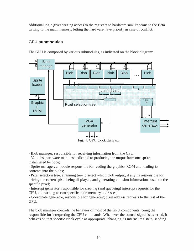
Output Most videogame systems have the video display as its primary output. This system uses a VGA signal to communicate with the display. VGA was chosen as opposed to a higher-resolution due to its clocking speed; even after extensive pipelining, the circuit logic maximum speed, as estimated by Xilinx, tends to be around 50 MHz. The IBM standard for a 640x480 VGA display, also available on the course website, ask for a convenient clock speed of 31.5MHz, which is fast enough to drive a 75Hz screen frequency and slow enough for the combinatorial logic without a more detailed (and complex, and tme-consuming to implement) pipeline.
Processor
GPU
Interrupt generator
Game logic RAM
Sprite ROM
VGA
8
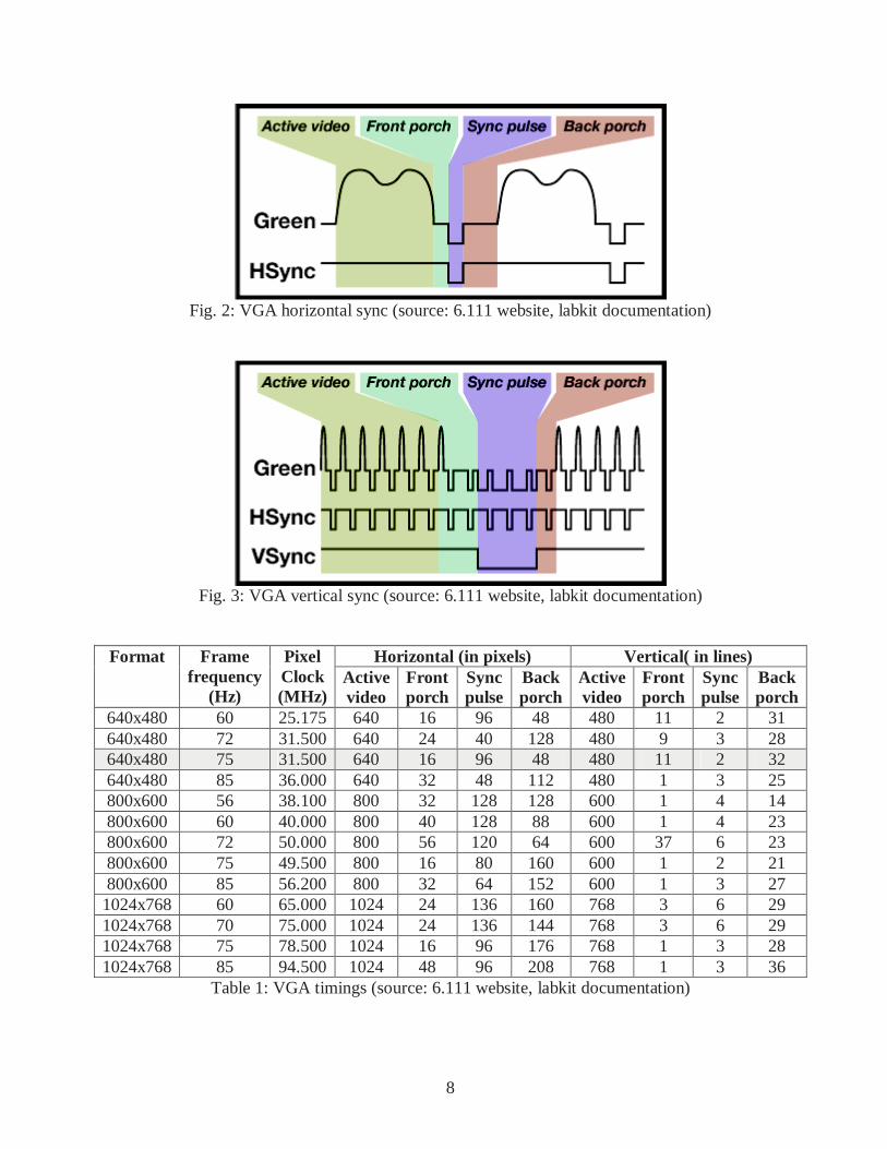
Fig. 2: VGA horizontal sync (source: 6.111 website, labkit documentation)
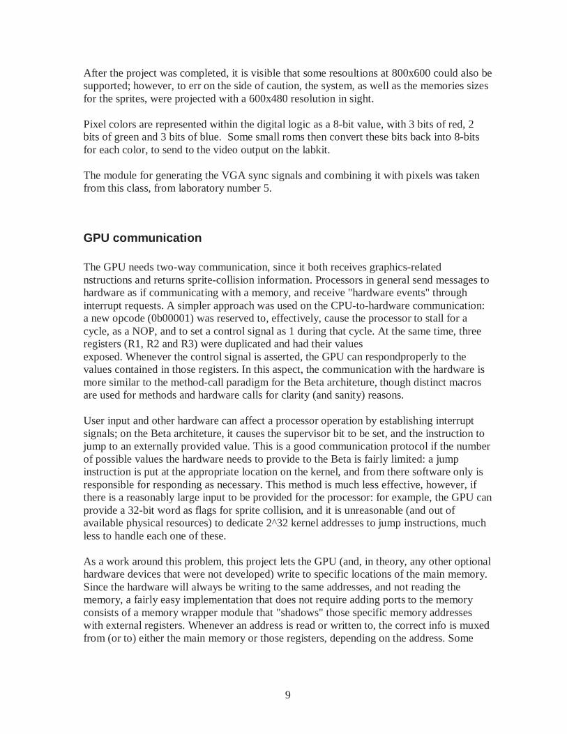
Fig. 3: VGA vertical sync (source: 6.111 website, labkit documentation)
Horizontal (in pixels) Vertical( in lines) Format
Frame frequency
(Hz)
Pixel Clock (MHz)
Active video
Front porch
Sync pulse
Back porch
Active video
Front porch
Sync pulse
Back porch
640x480 60 25.175 640 16 96 48 480 11 2 31 640x480 72 31.500 640 24 40 128 480 9 3 28 640x480 75 31.500 640 16 96 48 480 11 2 32 640x480 85 36.000 640 32 48 112 480 1 3 25 800x600 56 38.100 800 32 128 128 600 1 4 14 800x600 60 40.000 800 40 128 88 600 1 4 23 800x600 72 50.000 800 56 120 64 600 37 6 23 800x600 75 49.500 800 16 80 160 600 1 2 21 800x600 85 56.200 800 32 64 152 600 1 3 27 1024x768 60 65.000 1024 24 136 160 768 3 6 29 1024x768 70 75.000 1024 24 136 144 768 3 6 29 1024x768 75 78.500 1024 16 96 176 768 1 3 28 1024x768 85 94.500 1024 48 96 208 768 1 3 36
Table 1: VGA timings (source: 6.111 website, labkit documentation)
9
After the project was completed, it is visible that some resoultions at 800x600 could also be supported; however, to err on the side of caution, the system, as well as the memories sizes for the sprites, were projected with a 600x480 resolution in sight. Pixel colors are represented within the digital logic as a 8-bit value, with 3 bits of red, 2 bits of green and 3 bits of blue. Some small roms then convert these bits back into 8-bits for each color, to send to the video output on the labkit. The module for generating the VGA sync signals and combining it with pixels was taken from this class, from laboratory number 5.
GPU communication The GPU needs two-way communication, since it both receives graphics-related nstructions and returns sprite-collision information. Processors in general send messages to hardware as if communicating with a memory, and receive "hardware events" through interrupt requests. A simpler approach was used on the CPU-to-hardware communication: a new opcode (0b00001) was reserved to, effectively, cause the processor to stall for a cycle, as a NOP, and to set a control signal as 1 during that cycle. At the same time, three registers (R1, R2 and R3) were duplicated and had their values exposed. Whenever the control signal is asserted, the GPU can respondproperly to the values contained in those registers. In this aspect, the communication with the hardware is more similar to the method-call paradigm for the Beta architeture, though distinct macros are used for methods and hardware calls for clarity (and sanity) reasons. User input and other hardware can affect a processor operation by establishing interrupt signals; on the Beta architeture, it causes the supervisor bit to be set, and the instruction to jump to an externally provided value. This is a good communication protocol if the number of possible values the hardware needs to provide to the Beta is fairly limited: a jump instruction is put at the appropriate location on the kernel, and from there software only is responsible for responding as necessary. This method is much less effective, however, if there is a reasonably large input to be provided for the processor: for example, the GPU can provide a 32-bit word as flags for sprite collision, and it is unreasonable (and out of available physical resources) to dedicate 2^32 kernel addresses to jump instructions, much less to handle each one of these. As a work around this problem, this project lets the GPU (and, in theory, any other optional hardware devices that were not developed) write to specific locations of the main memory. Since the hardware will always be writing to the same addresses, and not reading the memory, a fairly easy implementation that does not require adding ports to the memory consists of a memory wrapper module that "shadows" those specific memory addresses with external registers. Whenever an address is read or written to, the correct info is muxed from (or to) either the main memory or those registers, depending on the address. Some
10
additional logic gives writing access to the registers to hardware simultaneous to the Beta writing to the main memory, letting the hardware have priority in case of conflict.
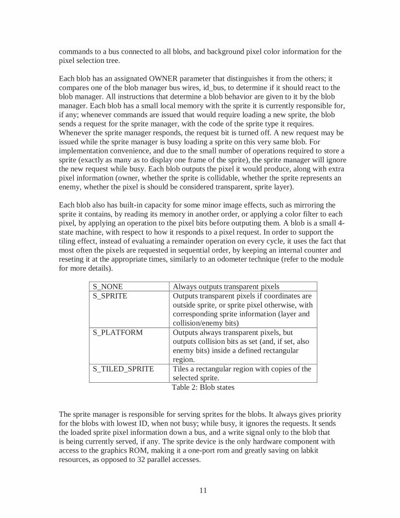
GPU submodules The GPU is composed by various submodules, as indicated on the block diagram:
Fig. 4: GPU block diagram
- Blob manager, responsible for receiving information from the CPU; - 32 blobs, hardware modules dedicated to producing the output from one sprite instantiated by code; - Sprite manager, a module responsible for reading the graphics ROM and loading its contents into the blobs; - Pixel selection tree, a fanning tree to select which blob output, if any, is responsible for driving the current pixel being displayed, and generating collision information based on the specific pixel; - Interrupt generator, responsible for creating (and queueing) interrupt requests for the CPU, and writing to two specific main memory addresses; - Coordinate generator, responsible for generating pixel address requests to the rest of the GPU. The blob manager controls the behavior of most of the GPU components, being the responsible for interpreting the CPU commands. Whenever the control signal is asserted, it behaves on that specific clock cycle as appropriate, changing its internal registers, sending
Collision OR
Blob manage
r Blob Blob Blob Blob Blob Blob …
Interrupt generator
…
VGA generator
Pixel selection tree
Sprite loader
Graphics
ROM
11
commands to a bus connected to all blobs, and background pixel color information for the pixel selection tree. Each blob has an assignated OWNER parameter that distinguishes it from the others; it compares one of the blob manager bus wires, id_bus, to determine if it should react to the blob manager. All instructions that determine a blob behavior are given to it by the blob manager. Each blob has a small local memory with the sprite it is currently responsible for, if any; whenever commands are issued that would require loading a new sprite, the blob sends a request for the sprite manager, with the code of the sprite type it requires. Whenever the sprite manager responds, the request bit is turned off. A new request may be issued while the sprite manager is busy loading a sprite on this very same blob. For implementation convenience, and due to the small number of operations required to store a sprite (exactly as many as to display one frame of the sprite), the sprite manager will ignore the new request while busy. Each blob outputs the pixel it would produce, along with extra pixel information (owner, whether the sprite is collidable, whether the sprite represents an enemy, whether the pixel is should be considered transparent, sprite layer). Each blob also has built-in capacity for some minor image effects, such as mirroring the sprite it contains, by reading its memory in another order, or applying a color filter to each pixel, by applying an operation to the pixel bits before outputing them. A blob is a small 4-state machine, with respect to how it responds to a pixel request. In order to support the tiling effect, instead of evaluating a remainder operation on every cycle, it uses the fact that most often the pixels are requested in sequential order, by keeping an internal counter and reseting it at the appropriate times, similarly to an odometer technique (refer to the module for more details).
S_NONE Always outputs transparent pixels S_SPRITE Outputs transparent pixels if coordinates are
outside sprite, or sprite pixel otherwise, with corresponding sprite information (layer and collision/enemy bits)
S_PLATFORM Outputs always transparent pixels, but outputs collision bits as set (and, if set, also enemy bits) inside a defined rectangular region.
S_TILED_SPRITE Tiles a rectangular region with copies of the selected sprite. Table 2: Blob states
The sprite manager is responsible for serving sprites for the blobs. It always gives priority for the blobs with lowest ID, when not busy; while busy, it ignores the requests. It sends the loaded sprite pixel information down a bus, and a write signal only to the blob that is being currently served, if any. The sprite device is the only hardware component with access to the graphics ROM, making it a one-port rom and greatly saving on labkit resources, as opposed to 32 parallel accesses.
12
The pixel selection tree is made mostly of smaller submodules, named pixel combinators. The pixel combinators take four inputs of the form produced by a blob, and output a series of signal of the same form (pixel color, pixel owner, layer, etc.), along with collision information for each one of its inputs (whether it is collidable and is colliding with something collidable on the current pixel, whether it is collidable and is colliding with something collidable and enemy on the current pixel). A tree of 7 pixel combinators, in 3 layers, along with extra logic to collect collision information, form the pixel selection tree. At the last layer, some additional logic determines whether to display the background pixel instead of the selected pixel. The pixel selection tree has the most logic on the GPU; as such, it is pipelined after each pixel combinator layer. The interrupt generator, while might or might not be considered as a proper part of the GPU, receives the collision information from the pixel selection tree, monitores it for changes over one screen sweep, and when it happens it sends an interrupt to the CPU, writing the new collision information on the proper place in the wrapper main memory. For implementation convenience, it also generate the interrupt requests for the other interrupt events (labkit button presses and releases, and a low-frequency clock. The coordinate generator sends x, y coordinates in advance to the blob manager, to be processed by the GPU logic described above (the blob manager adds the screen coordinates, sends it to the blobs, the blobs produce the pixel, which is filtered down the pixel selection tree, muxed with the background color, and sent to the display). It sends coordinates in advance to the current hcount, vcount vga information to count for the pipeline delay.
Hardware protocols
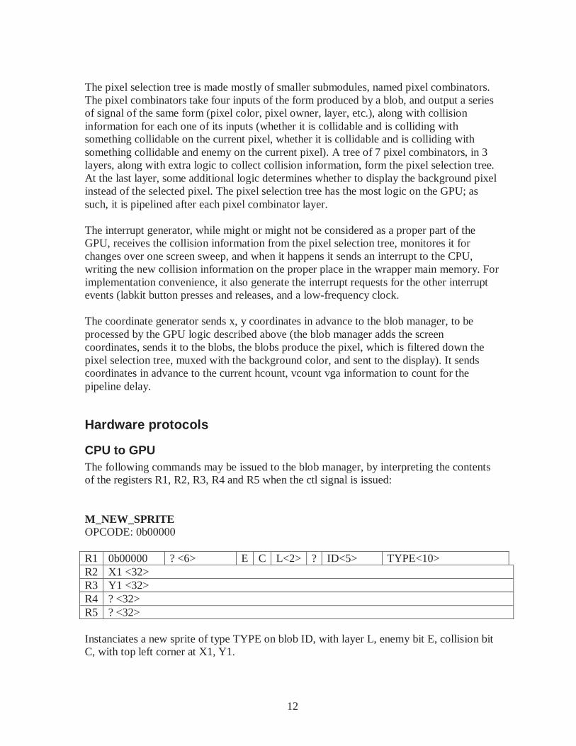
CPU to GPU The following commands may be issued to the blob manager, by interpreting the contents of the registers R1, R2, R3, R4 and R5 when the ctl signal is issued: M_NEW_SPRITE OPCODE: 0b00000 R1 0b00000 ? <6> E C L<2> ? ID<5> TYPE<10> R2 X1 <32> R3 Y1 <32> R4 ? <32> R5 ? <32> Instanciates a new sprite of type TYPE on blob ID, with layer L, enemy bit E, collision bit C, with top left corner at X1, Y1.
13
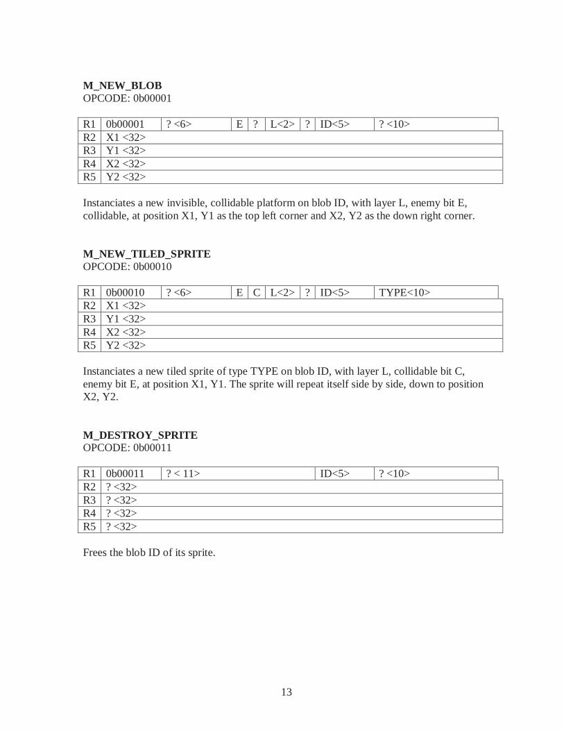
M_NEW_BLOB OPCODE: 0b00001 R1 0b00001 ? <6> E ? L<2> ? ID<5> ? <10> R2 X1 <32> R3 Y1 <32> R4 X2 <32> R5 Y2 <32> Instanciates a new invisible, collidable platform on blob ID, with layer L, enemy bit E, collidable, at position X1, Y1 as the top left corner and X2, Y2 as the down right corner. M_NEW_TILED_SPRITE OPCODE: 0b00010 R1 0b00010 ? <6> E C L<2> ? ID<5> TYPE<10> R2 X1 <32> R3 Y1 <32> R4 X2 <32> R5 Y2 <32> Instanciates a new tiled sprite of type TYPE on blob ID, with layer L, collidable bit C, enemy bit E, at position X1, Y1. The sprite will repeat itself side by side, down to position X2, Y2. M_DESTROY_SPRITE OPCODE: 0b00011 R1 0b00011 ? < 11> ID<5> ? <10> R2 ? <32> R3 ? <32> R4 ? <32> R5 ? <32> Frees the blob ID of its sprite.
14
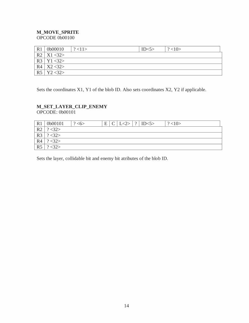
M_MOVE_SPRITE OPCODE 0b00100 R1 0b00010 ? <11> ID<5> ? <10> R2 X1 <32> R3 Y1 <32> R4 X2 <32> R5 Y2 <32> Sets the coordinates X1, Y1 of the blob ID. Also sets coordinates X2, Y2 if applicable. M_SET_LAYER_CLIP_ENEMY OPCODE: 0b00101 R1 0b00101 ? <6> E C L<2> ? ID<5> ? <10> R2 ? <32> R3 ? <32> R4 ? <32> R5 ? <32> Sets the layer, collidable bit and enemy bit atributes of the blob ID.
15
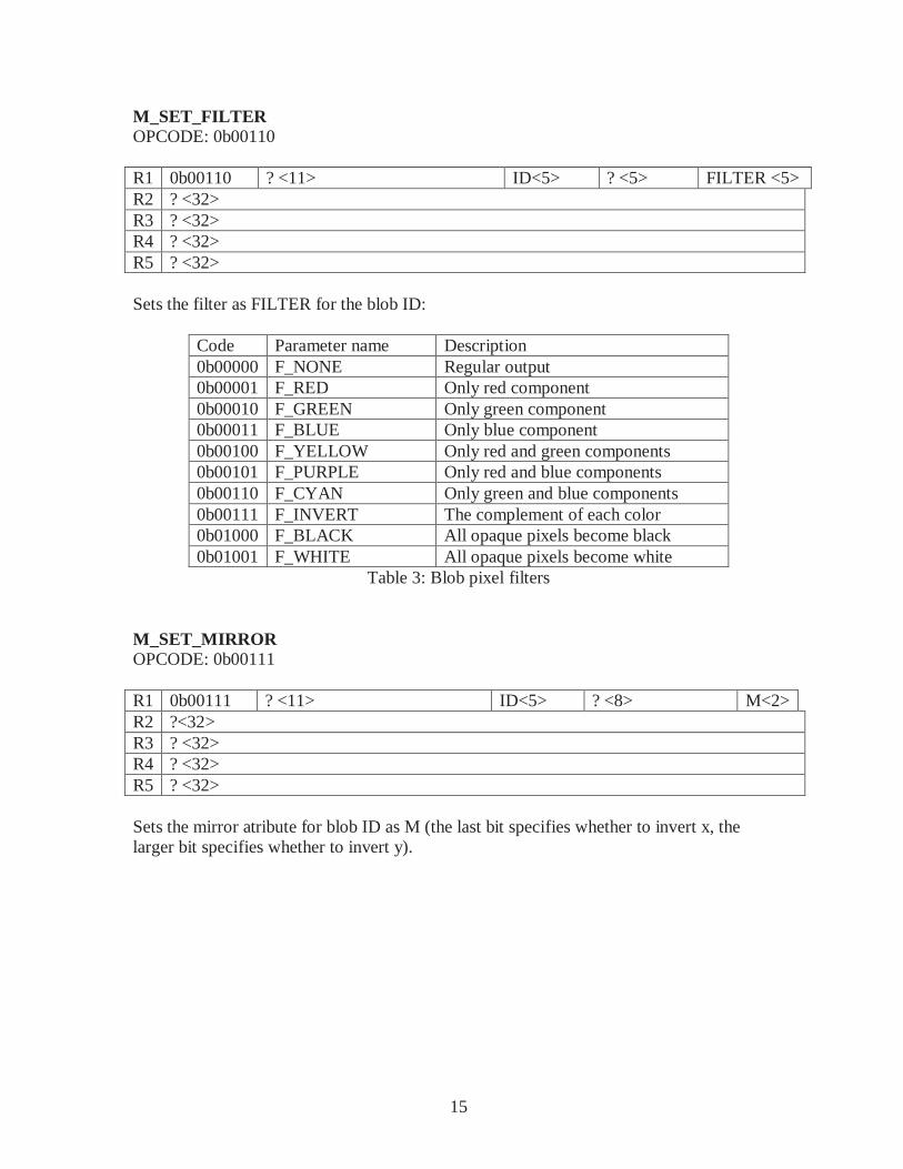
M_SET_FILTER OPCODE: 0b00110 R1 0b00110 ? <11> ID<5> ? <5> FILTER <5> R2 ? <32> R3 ? <32> R4 ? <32> R5 ? <32> Sets the filter as FILTER for the blob ID:
Code Parameter name Description 0b00000 F_NONE Regular output 0b00001 F_RED Only red component 0b00010 F_GREEN Only green component 0b00011 F_BLUE Only blue component 0b00100 F_YELLOW Only red and green components 0b00101 F_PURPLE Only red and blue components 0b00110 F_CYAN Only green and blue components 0b00111 F_INVERT The complement of each color 0b01000 F_BLACK All opaque pixels become black 0b01001 F_WHITE All opaque pixels become white
Table 3: Blob pixel filters M_SET_MIRROR OPCODE: 0b00111 R1 0b00111 ? <11> ID<5> ? <8> M<2> R2 ?<32> R3 ? <32> R4 ? <32> R5 ? <32> Sets the mirror atribute for blob ID as M (the last bit specifies whether to invert x, the larger bit specifies whether to invert y).
16
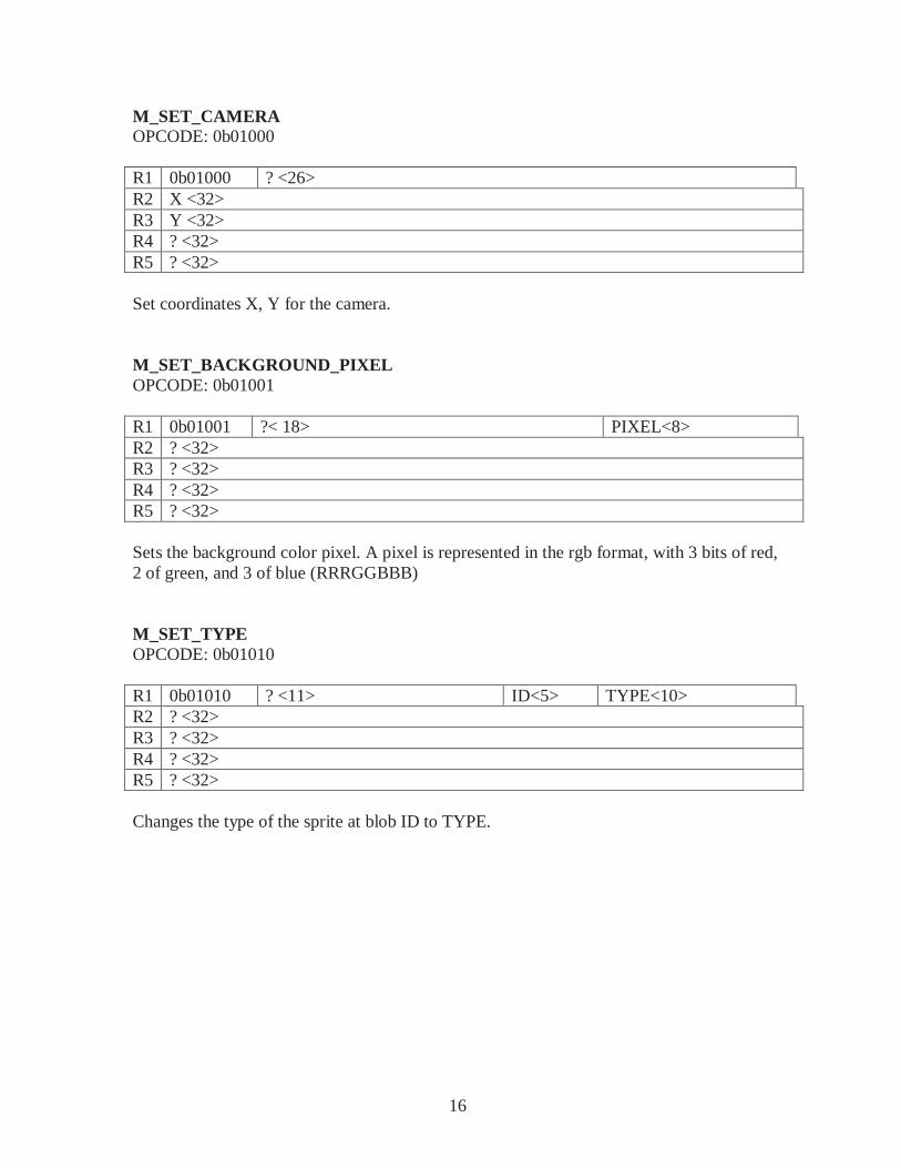
M_SET_CAMERA OPCODE: 0b01000 R1 0b01000 ? <26> R2 X <32> R3 Y <32> R4 ? <32> R5 ? <32> Set coordinates X, Y for the camera. M_SET_BACKGROUND_PIXEL OPCODE: 0b01001 R1 0b01001 ?< 18> PIXEL<8> R2 ? <32> R3 ? <32> R4 ? <32> R5 ? <32> Sets the background color pixel. A pixel is represented in the rgb format, with 3 bits of red, 2 of green, and 3 of blue (RRRGGBBB) M_SET_TYPE OPCODE: 0b01010 R1 0b01010 ? <11> ID<5> TYPE<10> R2 ? <32> R3 ? <32> R4 ? <32> R5 ? <32> Changes the type of the sprite at blob ID to TYPE.
17
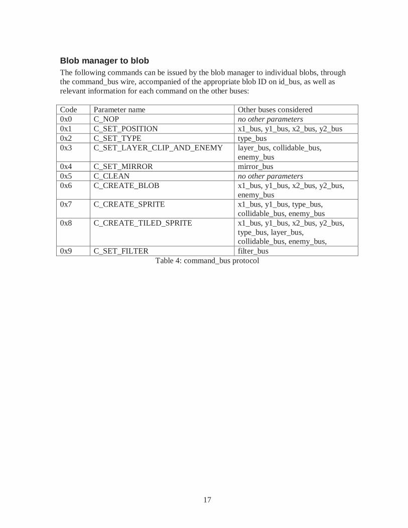
Blob manager to blob The following commands can be issued by the blob manager to individual blobs, through the command_bus wire, accompanied of the appropriate blob ID on id_bus, as well as relevant information for each command on the other buses: Code Parameter name Other buses considered 0x0 C_NOP no other parameters 0x1 C_SET_POSITION x1_bus, y1_bus, x2_bus, y2_bus 0x2 C_SET_TYPE type_bus 0x3 C_SET_LAYER_CLIP_AND_ENEMY layer_bus, collidable_bus,
enemy_bus 0x4 C_SET_MIRROR mirror_bus 0x5 C_CLEAN no other parameters 0x6 C_CREATE_BLOB x1_bus, y1_bus, x2_bus, y2_bus,
enemy_bus 0x7 C_CREATE_SPRITE x1_bus, y1_bus, type_bus,
collidable_bus, enemy_bus 0x8 C_CREATE_TILED_SPRITE x1_bus, y1_bus, x2_bus, y2_bus,
type_bus, layer_bus, collidable_bus, enemy_bus,
0x9 C_SET_FILTER filter_bus Table 4: command_bus protocol
18
Feedback Developing an entire programmable game system is a huege project, even more so for a one person group. Doing the bulk of the work during the last week and not being able to sleep at all on the last days approaching the deadline is definitively something to be avoided, even though in the future I will look back to this project with fondness. This project touched on computer-related engineering practices on diverse levels; producing a sprite controlled via assembly code and general-purpose hardware was very satisfying. TAs told me that not many projects use the Beta, due to its complexity. While it has a reasonably large set of instructions, it is most likely one a prospective student would already be familiar with, from 6.004, and a deep understanding of its control signals, as well as the 6.004 kernel, is required for an adequate debug of the project (for instance, to recognize that, on a previous attempt, the hardware control signal and the SVC calls had namespace conflicts.) A simulator for the Beta itself is very convenient, to reduce the amount of synthesis and save much time during debugging. A better though approach for interfacing with the beta would also have made things easier – some too-late research revealed me that the standard approach for interfacing a processor with hardware is to mux out the memory ports, so that the interfacing may be done entirely with load and store commands (besides interruptions). I strongly recommend doing that in any project using a Beta. Insufficient documentation of the sample kernel code in the 6.004 course locker proved to be a minor annoyance at a late development stage. Different versions of the kernel, with or without accompaning code, can be found distributed in course-related materials. An older version uses big-endian opcodes to make system calls to the kernel, while a more recent one would use little-endian opcodes. Originally incompatible namespaces for the software system calls and the hardware call would lead the system to unexpected behavior, hard to track without comparing a line-by-line simulation and the logic analyzer output. Early testing of components and/or simulations would have been greatly helpful. Few things are more frustrating than spending 30 minutes synthesizing all the hardware to determine that a wrong signal is being produced because of a missing case on a case statement, or a typo. Due to its own nature as a processor, it is hard to understand what is happening at any given moment without outputting various control signals to the logic analyzer. While this project did not get implemented as far as originally planned, nevertheless it worked at a very basic level – a proof of concept level, if you will – and with additional time, it wouldn’t be hard to actually create a game based on this, or add additional output hardware, such as audio, interfacing with the CPU on the same way that the GPU does.
19
References 6.111 website, Fall ’07. Lecture slides, labkit documentation, and VGA specification. http://web.mit.edu/6.111/www/f2007/index.html Retrieved in 12.12.2007 6.004 website, Fall ’07. BSim program and documentation, 2-stage pipelined Beta documentation. http://6004.lcs.mit.edu/currentsemester/courseware/ Retrieved in 12.12.2007
20
Appendix A: Verilog files
final-project.v
Contains the top-level module file for the project, a wrapper for the main RAM that allows it to behave as if hardware could write to specific addresses, and tables to convert from 2-bit and 3-bit to 8-bit color information. /////////////////////////////////////////////////// //////////////////////////// // // 6.111 FPGA Labkit -- Template Toplevel Module // // For Labkit Revision 004 // // // Created: October 31, 2004, from revision 003 fil e // Author: Nathan Ickes // /////////////////////////////////////////////////// //////////////////////////// // // CHANGES FOR BOARD REVISION 004 // // 1) Added signals for logic analyzer pods 2-4. // 2) Expanded "tv_in_ycrcb" to 20 bits. // 3) Renamed "tv_out_data" to "tv_out_i2c_data" an d "tv_out_sclk" to // "tv_out_i2c_clock". // 4) Reversed disp_data_in and disp_data_out signa ls, so that "out" is an // output of the FPGA, and "in" is an input. // // CHANGES FOR BOARD REVISION 003 // // 1) Combined flash chip enables into a single sig nal, flash_ce_b. // // CHANGES FOR BOARD REVISION 002 // // 1) Added SRAM clock feedback path input and outp ut // 2) Renamed "mousedata" to "mouse_data" // 3) Renamed some ZBT memory signals. Parity bits are now incorporated into // the data bus, and the byte write enables have been combined into the // 4-bit ram#_bwe_b bus. // 4) Removed the "systemace_clock" net, since the SystemACE clock is now // hardwired on the PCB to the oscillator. // /////////////////////////////////////////////////// //////////////////////////// // // Complete change history (including bug fixes) // // 2005-Sep-09: Added missing default assignments t o "ac97_sdata_out", // "disp_data_out", "analyzer[2-3]_clo ck" and // "analyzer[2-3]_data". // // 2005-Jan-23: Reduced flash address bus to 24 bit s, to match 128Mb devices // actually populated on the boards. ( The boards support up to // 256Mb devices, with 25 address line s.) // // 2004-Oct-31: Adapted to new revision 004 board. // // 2004-May-01: Changed "disp_data_in" to be an out put, and gave it a default // value. (Previous versions of this f ile declared this port to // be an input.)
21
// // 2004-Apr-29: Reduced SRAM address busses to 19 b its, to match 18Mb devices // actually populated on the boards. ( The boards support up to // 72Mb devices, with 21 address lines .) // // 2004-Apr-29: Change history started // /////////////////////////////////////////////////// //////////////////////////// module final_project (beep, audio_reset_b, ac97_sda ta_out, ac97_sdata_in, ac97_synch, ac97_bit_clock, vga_out_red, vga_out_green, vga_out_blue, v ga_out_sync_b, vga_out_blank_b, vga_out_pixel_clock, vga_o ut_hsync, vga_out_vsync, tv_out_ycrcb, tv_out_reset_b, tv_out_clock, tv_out_i2c_clock, tv_out_i2c_data, tv_out_pal_ntsc, tv_out_hs ync_b, tv_out_vsync_b, tv_out_blank_b, tv_out_subc ar_reset, tv_in_ycrcb, tv_in_data_valid, tv_in_line_c lock1, tv_in_line_clock2, tv_in_aef, tv_in_hff, tv _in_aff, tv_in_i2c_clock, tv_in_i2c_data, tv_in_fifo _read, tv_in_fifo_clock, tv_in_iso, tv_in_reset_b, tv_in_clock, ram0_data, ram0_address, ram0_adv_ld, ram0_ clk, ram0_cen_b, ram0_ce_b, ram0_oe_b, ram0_we_b, ram0_bwe_b , ram1_data, ram1_address, ram1_adv_ld, ram1_ clk, ram1_cen_b, ram1_ce_b, ram1_oe_b, ram1_we_b, ram1_bwe_b , clock_feedback_out, clock_feedback_in, flash_data, flash_address, flash_ce_b, flas h_oe_b, flash_we_b, flash_reset_b, flash_sts, flash_byte_b, rs232_txd, rs232_rxd, rs232_rts, rs232_cts, mouse_clock, mouse_data, keyboard_clock, ke yboard_data, clock_27mhz, clock1, clock2, disp_blank, disp_data_out, disp_clock, disp _rs, disp_ce_b, disp_reset_b, disp_data_in, button0, button1, button2, button3, button_ enter, button_right, button_left, button_down, button_up, switch, led, user1, user2, user3, user4, daughtercard, systemace_data, systemace_address, systemac e_ce_b, systemace_we_b, systemace_oe_b, systemace_i rq, systemace_mpbrdy, analyzer1_data, analyzer1_clock, analyzer2_data, analyzer2_clock, analyzer3_data, analyzer3_clock,
22
analyzer4_data, analyzer4_clock); output beep, audio_reset_b, ac97_synch, ac97_sda ta_out; input ac97_bit_clock, ac97_sdata_in; output [7:0] vga_out_red, vga_out_green, vga_out _blue; output vga_out_sync_b, vga_out_blank_b, vga_out_ pixel_clock, vga_out_hsync, vga_out_vsync; output [9:0] tv_out_ycrcb; output tv_out_reset_b, tv_out_clock, tv_out_i2c_ clock, tv_out_i2c_data, tv_out_pal_ntsc, tv_out_hsync_b, tv_out_vsync_b, tv_out_blank_b, tv_out_subcar_reset; input [19:0] tv_in_ycrcb; input tv_in_data_valid, tv_in_line_clock1, tv_i n_line_clock2, tv_in_aef, tv_in_hff, tv_in_aff; output tv_in_i2c_clock, tv_in_fifo_read, tv_in_f ifo_clock, tv_in_iso, tv_in_reset_b, tv_in_clock; inout tv_in_i2c_data; inout [35:0] ram0_data; output [18:0] ram0_address; output ram0_adv_ld, ram0_clk, ram0_cen_b, ram0_c e_b, ram0_oe_b, ram0_we_b; output [3:0] ram0_bwe_b; inout [35:0] ram1_data; output [18:0] ram1_address; output ram1_adv_ld, ram1_clk, ram1_cen_b, ram1_c e_b, ram1_oe_b, ram1_we_b; output [3:0] ram1_bwe_b; input clock_feedback_in; output clock_feedback_out; inout [15:0] flash_data; output [23:0] flash_address; output flash_ce_b, flash_oe_b, flash_we_b, flash _reset_b, flash_byte_b; input flash_sts; output rs232_txd, rs232_rts; input rs232_rxd, rs232_cts; input mouse_clock, mouse_data, keyboard_clock, keyboard_data; input clock_27mhz, clock1, clock2; output disp_blank, disp_clock, disp_rs, disp_ce_ b, disp_reset_b; input disp_data_in; output disp_data_out; input button0, button1, button2, button3, butto n_enter, button_right, button_left, button_down, button_up; input [7:0] switch; output [7:0] led; inout [31:0] user1, user2, user3, user4; inout [43:0] daughtercard; inout [15:0] systemace_data; output [6:0] systemace_address; output systemace_ce_b, systemace_we_b, systemace _oe_b; input systemace_irq, systemace_mpbrdy;
23
output [15:0] analyzer1_data, analyzer2_data, an alyzer3_data, analyzer4_data; output analyzer1_clock, analyzer2_clock, analyze r3_clock, analyzer4_clock; //////////////////////////////////////////////// //////////////////////////// // // I/O Assignments // //////////////////////////////////////////////// //////////////////////////// // Audio Input and Output assign beep= 1'b0; assign audio_reset_b = 1'b0; assign ac97_synch = 1'b0; assign ac97_sdata_out = 1'b0; // ac97_sdata_in is an input // Video Output assign tv_out_ycrcb = 10'h0; assign tv_out_reset_b = 1'b0; assign tv_out_clock = 1'b0; assign tv_out_i2c_clock = 1'b0; assign tv_out_i2c_data = 1'b0; assign tv_out_pal_ntsc = 1'b0; assign tv_out_hsync_b = 1'b1; assign tv_out_vsync_b = 1'b1; assign tv_out_blank_b = 1'b1; assign tv_out_subcar_reset = 1'b0; // Video Input assign tv_in_i2c_clock = 1'b0; assign tv_in_fifo_read = 1'b0; assign tv_in_fifo_clock = 1'b0; assign tv_in_iso = 1'b0; assign tv_in_reset_b = 1'b0; assign tv_in_clock = 1'b0; assign tv_in_i2c_data = 1'bZ; // tv_in_ycrcb, tv_in_data_valid, tv_in_line_clo ck1, tv_in_line_clock2, // tv_in_aef, tv_in_hff, and tv_in_aff are input s // SRAMs assign ram0_data = 36'hZ; assign ram0_address = 19'h0; assign ram0_adv_ld = 1'b0; assign ram0_clk = 1'b0; assign ram0_cen_b = 1'b1; assign ram0_ce_b = 1'b1; assign ram0_oe_b = 1'b1; assign ram0_we_b = 1'b1; assign ram0_bwe_b = 4'hF; assign ram1_data = 36'hZ; assign ram1_address = 19'h0; assign ram1_adv_ld = 1'b0; assign ram1_clk = 1'b0; assign ram1_cen_b = 1'b1; assign ram1_ce_b = 1'b1; assign ram1_oe_b = 1'b1; assign ram1_we_b = 1'b1; assign ram1_bwe_b = 4'hF; assign clock_feedback_out = 1'b0; // clock_feedback_in is an input
24
// Flash ROM assign flash_data = 16'hZ; assign flash_address = 24'h0; assign flash_ce_b = 1'b1; assign flash_oe_b = 1'b1; assign flash_we_b = 1'b1; assign flash_reset_b = 1'b0; assign flash_byte_b = 1'b1; // flash_sts is an input // RS-232 Interface assign rs232_txd = 1'b1; assign rs232_rts = 1'b1; // rs232_rxd and rs232_cts are inputs // PS/2 Ports // mouse_clock, mouse_data, keyboard_clock, and keyboard_data are inputs // LED Displays assign disp_blank = 1'b1; assign disp_clock = 1'b0; assign disp_rs = 1'b0; assign disp_ce_b = 1'b1; assign disp_reset_b = 1'b0; assign disp_data_out = 1'b0; // disp_data_in is an input // Buttons, Switches, and Individual LEDs // assign led = 8'hFF; // button0, button1, button2, button3, button_en ter, button_right, // button_left, button_down, button_up, and swit ches are inputs // User I/Os assign user1 = 32'hZ; assign user2 = 32'hZ; assign user3 = 32'hZ; assign user4 = 32'hZ; // Daughtercard Connectors assign daughtercard = 44'hZ; // SystemACE Microprocessor Port assign systemace_data = 16'hZ; assign systemace_address = 7'h0; assign systemace_ce_b = 1'b1; assign systemace_we_b = 1'b1; assign systemace_oe_b = 1'b1; // systemace_irq and systemace_mpbrdy are inputs //////////////////////////////////////////////// //////////////////////////// // // videogame code // //////////////////////////////////////////////// //////////////////////////// // use FPGA's digital clock manager to produce a // 31.5MHz clock // Those things, after the following two lines? TH EY ARE NOT COMMENTS. // They are parameters for the digital clock manag er. // I wish that had been documented somewhere. wire clk_unbuf, clk; DCM vclk1(.CLKIN(clock_27mhz),.CLKFX(clk_unbuf)) ;
25
// synthesis attribute CLKFX_DIVIDE of vclk1 is 6 // synthesis attribute CLKFX_MULTIPLY of vclk1 i s 7 // synthesis attribute CLK_FEEDBACK of vclk1 is NONE // synthesis attribute CLKIN_PERIOD of vclk1 is 37 BUFG vclk2(.O(clk),.I(clk_unbuf)); // power-on reset generation wire power_on_reset; // remain high for first 16 clocks SRL16 reset_sr (.D(1'b0), .CLK(clk), .Q(power_on _reset), .A0(1'b1), .A1(1'b1), .A2(1'b1), .A3(1'b1)); defparam reset_sr.INIT = 16'hFFFF; // Button 0 button is user reset wire reset,user_reset; debounce db1(power_on_reset, clk, ~button0, user _reset); assign reset = user_reset | power_on_reset; // UP, DOWN, LEFT, RIGHT, ENTER, 1, 2, 3 buttons for game control wire up,down,left,right,enter,one,two,three; debounce db2(reset, clk, ~button_up, up); debounce db3(reset, clk, ~button_down, down); debounce db4(reset, clk, ~button_left, left); debounce db5(reset, clk, ~button_right, right); debounce db6(reset, clk, ~button_enter, enter); debounce db7(reset, clk, ~button1, one); debounce db8(reset, clk, ~button2, two); debounce db9(reset, clk, ~button3, three); // generate basic VGA video signals wire [10:0] hcount; wire [9:0] vcount; wire hsync,vsync,blank; vga vga1(clk,hcount,vcount,hsync,vsync,blank); // pixel tree output, fed to vga signal wire [7:0] pixel; /* All paramaters are listed here for programming c onvenience. // GPU opcodes parameter M_NEW_SPRITE = 0; parameter M_NEW_BLOB = 1; parameter M_NEW_TILED_SPRITE = 2; parameter M_DESTROY_SPRITE = 3; parameter M_MOVE_SPRITE = 4; parameter M_SET_LAYER_CLIP_ENEMY = 5; parameter M_SET_FILTER = 6; parameter M_SET_MIRROR = 7; parameter M_SET_CAMERA = 8; parameter M_SET_BACKGROUND = 9; parameter M_SET_TYPE = 10; parameter C_NOP = 0; parameter C_SET_POSITION = 1; parameter C_SET_TYPE = 2; parameter C_SET_LAYER_AND_CLIP = 3; parameter C_SET_MIRROR = 4; parameter C_CLEAN = 5; parameter C_CREATE_BLOB = 6; parameter C_CREATE_SPRITE = 7; parameter C_CREATE_TILED_SPRITE = 8; parameter C_SET_FILTER = 9;
26
// IRQ xaddr parameter I_ECOLLISION = 3; parameter I_COLLISION = 4; parameter I_UP_PRESS = 5; parameter I_DOWN_PRESS = 6; parameter I_LEFT_PRESS = 7; parameter I_RIGHT_PRESS = 8; parameter I_B1_PRESS = 9; parameter I_B2_PRESS = 10; parameter I_B3_PRESS = 11; parameter I_UP_RELEASE = 12; parameter I_DOWN_RELEASE = 13; parameter I_LEFT_RELEASE = 14; parameter I_RIGHT_RELEASE = 15; parameter I_B1_RELEASE = 16; parameter I_B2_RELEASE = 17; parameter I_B3_RELEASE = 18; // blob filters parameter F_NONE = 0; parameter F_RED = 1; parameter F_GREEN = 2; parameter F_BLUE = 3; parameter F_YELLOW = 4; parameter F_PURPLE = 5; parameter F_CYAN = 6; parameter F_INVERT = 7; parameter F_BLACK = 8; parameter F_WHITE = 9; */ // blob manager related wires wire ctl; wire[3:0] command_bus; wire[5:0] id_bus; wire[1:0] layer_bus; wire collidable_bus, enemy_bus; wire[5:0] filter_bus; wire[1:0] mirror_bus; wire[6:0] type_bus; wire[31:0] x1_bus, x2_bus, y1_bus, y2_bus; wire[31:0] pixel_x, pixel_y; wire[9:0] x_request, y_request; // sprite manager related wires wire[11:0] adr_in; wire[7:0] din; wire[31:0] request, we; wire[223:0] sprite_type; wire[7:0] alpha_bus, h_bus, w_bus; // pixel-tree related wires wire[31:0] collision, ecollision; wire[7:0] bkg_pixel; wire[255:0] pixels; wire[223:0] owners; wire[31:0] zs; wire[63:0] layers; wire[63:0] ce; // CPU related wires wire irq, full, pc31, hwwe, mwe;
27
wire[4:0] xadr; wire[31:0] ma; wire[31:0] mdin, mdout; wire[31:0] reg1, reg2, reg3, reg4, reg5; // beta, memory and interrupts beta2 beta (.clk(clk),.reset(reset),.irq(irq),.xa dr({24'b0,xadr,2'b0}), .ma(ma),.mdin(mdin),.mdout(mdout),.mwe (mwe), .reg1(reg1), .reg2(reg2), .reg3(reg3), .reg4(reg4), .reg5(reg5), .ctrl(ctl), .pc31(pc31)); ram_beta beta_ram(.clock(clk), .we(mwe), .addr(ma [15:2]), .rdata(mdin), .wdata(mdout), .hwwe(hwwe), .xa dr(xadr), .collision(collision), .ecollis ion(ecollision)); interrupt_generator ig(clk, reset, collision, eco llision, up, down, left, right, enter, one, t wo, three, irq, xadr, hwwe, pc31); assign led = ~{up, down, left, right, enter, rese t, switch[1], switch[0]}; // GPU coordinate_generator cg (clk, reset, hcount, vcou nt, x_request, y_request); // debug wires wire[31:0] screen_x, screen_y, x1, y1; blob_manager bm (.clk(clk), .reset(reset), .ctl(c tl), .reg1(reg1), .reg2(reg2), .reg3(reg3), .reg4( reg4), .reg5(reg5), .x_request(x_request), .y_reques t(y_request), .pixel_x(pixel_x), .pixel_y(pixe l_y), .x1_bus(x1_bus), .y1_bus(y1_bus), .x2_bus(x2_bus) , .y2_bus(y2_bus), .type_bus(type_bus), .mirror_bus (mirror_bus), .filter_bus(filter_bus), .collid able_bus(collidable_bus), .enemy_bus(enemy_bus),.layer_bus (layer_bus),.id_bus(id_bus), .command_bus(command_bus), .bkg_ pixel(bkg_pixel), .screen_x(screen_x), .screen_y(s creen_y)); pixel_tree pt (clk, pixels, owners, zs, layers, c e, pixel, collision, ecollision, bkg_pixel); sprite_manager sm (.clk(clk), .reset(reset), .req uest(request), .sprite_type(sprite_type), .we (we), .addr(adr_in), .din(din), .alpha_bus(alpha_bu s), .h_bus(h_bus), .w_bus(w_bus)); // I didn't find verilog supportive enough for lo oping through distinct // instances, specifying indexes. The list of blo b instances was generated // using an external script, then pasted here. wire[7:0] x_rem1, y_rem1, x_rem2, y_rem2; // debu g wires // Debug signals to logic analyzer. // Possibly the most-often edited piece of code o f this project. assign analyzer1_data = ma[15:0]; assign analyzer1_clock = clk; assign analyzer2_data = {xadr[2:0], irq, we[3:0], xadr[4:3],
28
command_bus,ctl,reset}; assign analyzer2_clock = clk; assign analyzer3_data = switch[5] ? (switch[3] ? x_rem1 : y_rem1) : switch[3] ? din : adr_in; assign analyzer3_clock = clk; assign analyzer4_data = switch[7] ? (switch[6] ? x_rem2 : y_rem2) : switch[6] ? {h_bus,w_bus} : {pixel_x, pixel_y}; assign analyzer4_clock = clk; blob blob0(clk, reset, pixel_x, pixel_y, x1_bus, y1_bus, x2_bus, y2_bus, type_bus, mirror_bus, filter_bus, coll idable_bus, enemy_bus, layer_bus, alpha_bus, h_bus, w_bus, id _bus, command_bus, pixels[7:0], layers[1:0], owners[6:0], we[0], din, adr_in, sprite_type[6:0], request[0], zs[0], c e[1:0], x_rem1, y_rem1); blob blob1(clk, reset, pixel_x, pixel_y, x1_bus, y1_bus, x2_bus, y2_bus, type_bus, mirror_bus, filter_bus, coll idable_bus, enemy_bus, layer_bus, alpha_bus, h_bus, w_bus, id _bus, command_bus, pixels[15:8], layers[3:2], owners[13:7 ], we[1], din, adr_in, sprite_type[13:7], request[1], zs[1], ce[3:2], x_rem2, y_rem2); blob blob2(clk, reset, pixel_x, pixel_y, x1_bus, y1_bus, x2_bus, y2_bus, type_bus, mirror_bus, filter_bus, coll idable_bus, enemy_bus, layer_bus, alpha_bus, h_bus, w_bus, id _bus, command_bus, pixels[23:16], layers[5:4], owners[20: 14], we[2], din, adr_in, sprite_type[20:14], request[2], zs[2], ce[5:4]); blob blob3(clk, reset, pixel_x, pixel_y, x1_bus, y1_bus, x2_bus, y2_bus, type_bus, mirror_bus, filter_bus, coll idable_bus, enemy_bus, layer_bus, alpha_bus, h_bus, w_bus, id _bus, command_bus, pixels[31:24], layers[7:6], owners[27: 21], we[3], din, adr_in, sprite_type[27:21], request[3], zs[3], ce[7:6]); blob blob4(clk, reset, pixel_x, pixel_y, x1_bus, y1_bus, x2_bus, y2_bus, type_bus, mirror_bus, filter_bus, coll idable_bus, enemy_bus, layer_bus, alpha_bus, h_bus, w_bus, id _bus, command_bus, pixels[39:32], layers[9:8], owners[34: 28], we[4], din, adr_in, sprite_type[34:28], request[4], zs[4], ce[9:8]); blob blob5(clk, reset, pixel_x, pixel_y, x1_bus, y1_bus, x2_bus, y2_bus, type_bus, mirror_bus, filter_bus, coll idable_bus, enemy_bus, layer_bus, alpha_bus, h_bus, w_bus, id _bus, command_bus, pixels[47:40], layers[11:10], owners[4 1:35], we[5], din, adr_in, sprite_type[41:35], request[5], zs[5], ce[11:10]); blob blob6(clk, reset, pixel_x, pixel_y, x1_bus, y1_bus, x2_bus, y2_bus, type_bus, mirror_bus, filter_bus, coll idable_bus, enemy_bus, layer_bus, alpha_bus, h_bus, w_bus, id _bus, command_bus, pixels[55:48], layers[13:12], owners[4 8:42], we[6], din, adr_in, sprite_type[48:42], request[6], zs[6], ce[13:12]); blob blob7(clk, reset, pixel_x, pixel_y, x1_bus, y1_bus, x2_bus, y2_bus, type_bus, mirror_bus, filter_bus, coll idable_bus, enemy_bus, layer_bus, alpha_bus, h_bus, w_bus, id _bus, command_bus, pixels[63:56], layers[15:14], owners[5 5:49], we[7], din, adr_in, sprite_type[55:49], request[7], zs[7], ce[15:14]); blob blob8(clk, reset, pixel_x, pixel_y, x1_bus, y1_bus, x2_bus, y2_bus, type_bus, mirror_bus, filter_bus, coll idable_bus, enemy_bus, layer_bus, alpha_bus, h_bus, w_bus, id _bus, command_bus, pixels[71:64], layers[17:16], owners[6 2:56], we[8], din, adr_in, sprite_type[62:56], request[8], zs[8], ce[17:16]);
29
blob blob9(clk, reset, pixel_x, pixel_y, x1_bus, y1_bus, x2_bus, y2_bus, type_bus, mirror_bus, filter_bus, coll idable_bus, enemy_bus, layer_bus, alpha_bus, h_bus, w_bus, id _bus, command_bus, pixels[79:72], layers[19:18], owners[6 9:63], we[9], din, adr_in, sprite_type[69:63], request[9], zs[9], ce[19:18]); blob blob10(clk, reset, pixel_x, pixel_y, x1_bus, y1_bus, x2_bus, y2_bus, type_bus, mirror_bus, filter_bus, col lidable_bus, enemy_bus, layer_bus, alpha_bus, h_bus, w_bus, i d_bus, command_bus, pixels[87:80], layers[21:20], owners[ 76:70], we[10], din, adr_in, sprite_type[76:70], request[10], zs[1 0], ce[21:20]); blob blob11(clk, reset, pixel_x, pixel_y, x1_bus, y1_bus, x2_bus, y2_bus, type_bus, mirror_bus, filter_bus, col lidable_bus, enemy_bus, layer_bus, alpha_bus, h_bus, w_bus, i d_bus, command_bus, pixels[95:88], layers[23:22], owners[ 83:77], we[11], din, adr_in, sprite_type[83:77], request[11], zs[1 1], ce[23:22]); blob blob12(clk, reset, pixel_x, pixel_y, x1_bus, y1_bus, x2_bus, y2_bus, ty pe_bus, mirror_bus, filter_bus, colli dable_bus, enemy_bus, layer_bus, alpha_bus, h_bus, w_bus, i d_bus, command_bus, pixels[103:96], layers[25:24], owners [90:84], we[12], din, adr_in, sprite_type[90:84], request[1 2], zs[12], ce[25:24]); blob blob13(clk, reset, pixel_x, pixel_y, x1_bus, y1_bus, x2_bus, y2_bus, type_bus, mirror_bus, filter_bus, col lidable_bus, enemy_bus, layer_bus, alpha_bus, h_bus, w_bus, i d_bus, command_bus, pixels[111:104], layers[27:26], owner s[97:91], we[13], din, adr_in, sprite_type[97:91], request[1 3], zs[13], ce[27:26]); blob blob14(clk, reset, pixel_x, pixel_y, x1_bus, y1_bus, x2_bus, y2_bus, type_bus, mirror_bus, filter_bus, col lidable_bus, enemy_bus, layer_bus, alpha_bus, h_bus, w_bus, i d_bus, command_bus, pixels[119:112], layers[29:28], owner s[104:98], we[14], din, adr_in, sprite_type[104:98], request[ 14], zs[14], ce[29:28]); blob blob15(clk, reset, pixel_x, pixel_y, x1_bus, y1_bus, x2_bus, y2_bus, type_bus, mirror_bus, filter_bus, col lidable_bus, enemy_bus, layer_bus, alpha_bus, h_bus, w_bus, i d_bus, command_bus, pixels[127:120], layers[31:30], owner s[111:105], we[15], din, adr_in, sprite_type[111:105], request [15], zs[15], ce[31:30]); blob blob16(clk, reset, pixel_x, pixel_y, x1_bus, y1_bus, x2_bus, y2_bus, type_bus, mirror_bus, filter_bus, col lidable_bus, enemy_bus, layer_bus, alpha_bus, h_bus, w_bus, i d_bus, command_bus, pixels[135:128], layers[33:32], owner s[118:112], we[16], din, adr_in, sprite_type[118:112], request [16], zs[16], ce[33:32]); blob blob17(clk, reset, pixel_x, pixel_y, x1_bus, y1_bus, x2_bus, y2_bus, type_bus, mirror_bus, filter_bus, col lidable_bus, enemy_bus, layer_bus, alpha_bus, h_bus, w_bus, i d_bus, command_bus, pixels[143:136], layers[35:34], owner s[125:119], we[17], din, adr_in, sprite_type[125:119], request [17], zs[17], ce[35:34]); blob blob18(clk, reset, pixel_x, pixel_y, x1_bus, y1_bus, x2_bus, y2_bus, type_bus, mirror_bus, filter_bus, col lidable_bus, enemy_bus, layer_bus, alpha_bus, h_bus, w_bus, i d_bus, command_bus, pixels[151:144], layers[37:36], owner s[132:126], we[18], din, adr_in, sprite_type[132:126], request [18], zs[18], ce[37:36]); blob blob19(clk, reset, pixel_x, pixel_y, x1_bus, y1_bus, x2_bus, y2_bus, type_bus, mirror_bus, filter_bus, col lidable_bus, enemy_bus, layer_bus, alpha_bus, h_bus, w_bus, i d_bus, command_bus,
30
pixels[159:152], layers[39:38], owner s[139:133], we[19], din, adr_in, sprite_type[139:133], request [19], zs[19], ce[39:38]); blob blob20(clk, reset, pixel_x, pixel_y, x1_bus, y1_bus, x2_bus, y2_bus, type_bus, mirror_bus, filter_bus, col lidable_bus, enemy_bus, layer_bus, alpha_bus, h_bus, w_bus, id _bus, command_bus, pixels[167:160], layers[41:40], owners [146:140], we[20], din, adr_in, sprite_type[146:140], request[ 20], zs[20], ce[41:40]); blob blob21(clk, reset, pixel_x, pixel_y, x1_bus, y1_bus, x2_bus, y2_bus, type_bus, mirror_bus, filter_bus, col lidable_bus, enemy_bus, layer_bus, alpha_bus, h_bus, w_bus, i d_bus, command_bus, pixels[175:168], layers[43:42], owner s[153:147], we[21], din, adr_in, sprite_type[153:147], request [21], zs[21], ce[43:42]); blob blob22(clk, reset, pixel_x, pixel_y, x1_bus, y1_bus, x2_bus, y2_bus, type_bus, mirror_bus, filter_bus, col lidable_bus, enemy_bus, layer_bus, alpha_bus, h_bus, w_bus, i d_bus, command_bus, pixels[183:176], layers[45:44], owner s[160:154], we[22], din, adr_in, sprite_type[160:154], request [22], zs[22], ce[45:44]); blob blob23(clk, reset, pixel_x, pixel_y, x1_bus, y1_bus, x2_bus, y2_bus, type_bus, mirror_bus, filter_bus, col lidable_bus, enemy_bus, layer_bus, alpha_bus, h_bus, w_bus, i d_bus, command_bus, pixels[191:184], layers[47:46], owner s[167:161], we[23], din, adr_in, sprite_type[167:161], request [23], zs[23], ce[47:46]); blob blob24(clk, reset, pixel_x, pixel_y, x1_bus, y1_bus, x2_bus, y2_bus, type_bus, mirror_bus, filter_bus, col lidable_bus, enemy_bus, layer_bus, alpha_bus, h_bus, w_bus, i d_bus, command_bus, pixels[199:192], layers[49:48], owner s[174:168], we[24], din, adr_in, sprite_type[174:168], request [24], zs[24], ce[49:48]); blob blob25(clk, reset, pixel_x, pixel_y, x1_bus, y1_bus, x2_bus, y2_bus, type_bus, mirror_bus, filter_bus, col lidable_bus, enemy_bus, layer_bus, alpha_bus, h_bus, w_bus, i d_bus, command_bus, pixels[207:200], layers[51:50], owner s[181:175], we[25], din, adr_in, sprite_type[181:175], request [25], zs[25], ce[51:50]); blob blob26(clk, reset, pixel_x, pixel_y, x1_bus, y1_bus, x2_bus, y2_bus, type_bus, mirror_bus, filter_bus, col lidable_bus, enemy_bus, layer_bus, alpha_bus, h_bus, w_bus, i d_bus, command_bus, pixels[215:208], layers[53:52], owner s[188:182], we[26], din, adr_in, sprite_type[188:182], request [26], zs[26], ce[53:52]); blob blob27(clk, reset,pixel_x, pixel_y, x1_bus, y1_bus, x2_bus, y2_bus, type_bus, mirror_bus, filter_bus, col lidable_bus, enemy_bus, layer_bus, alpha_bus, h_bus, w_bus, i d_bus, command_bus, pixels[223:216], layers[55:54], owner s[195:189], we[27], din, adr_in, sprite_type[195:189], request [27], zs[27], ce[55:54]); blob blob28(clk, reset, pixel_x, pixel_y, x1_bus, y1_bus, x2_bus, y2_bus, type_bus, mirror_bus, filter_bus, col lidable_bus, enemy_bus, layer_bus, alpha_bus, h_bus, w_bus, i d_bus, command_bus, pixels[231:224], layers[57:56], owner s[202:196], we[28], din, adr_in, sprite_type[202:196], request [28], zs[28], ce[57:56]); blob blob29(clk, reset, pixel_x, pixel_y, x1_bus, y1_bus, x2_bus, y2_bus, type_bus, mirror_bus, filter_bus, col lidable_bus, enemy_bus, layer_bus, alpha_bus, h_bus, w_bus, i d_bus, command_bus, pixels[239:232], layers[59:58], owner s[209:203], we[29], din, adr_in, sprite_type[209:203], request [29], zs[29], ce[59:58]);
31
blob blob30(clk, reset, pixel_x, pixel_y, x1_bus, y1_bus, x2_bus, y2_bus, type_bus, mirror_bus, filter_bus, col lidable_bus, enemy_bus, layer_bus, alpha_bus, h_bus, w_bus, i d_bus, command_bus, pixels[247:240], layers[61:60], owner s[216:210], we[30], din, adr_in, sprite_type[216:210], request [30], zs[30], ce[61:60]); blob blob31(clk, reset, pixel_x, pixel_y, x1_bus, y1_bus, x2_bus, y2_bus, type_bus, mirror_bus, filter_bus, col lidable_bus, enemy_bus, layer_bus, alpha_bus, h_bus, w_bus, i d_bus, command_bus, pixels[255:248], layers[63:62], owner s[223:217], we[31], din, adr_in, sprite_type[223:217], request [31], zs[31], ce[63:62]); // blob parameters: needed for collecting collisi on info defparam blob0.OWNER = 0; defparam blob1.OWNER = 1; defparam blob2.OWNER = 2; defparam blob3.OWNER = 3; defparam blob4.OWNER = 4; defparam blob5.OWNER = 5; defparam blob6.OWNER = 6; defparam blob7.OWNER = 7; defparam blob8.OWNER = 8; defparam blob9.OWNER = 9; defparam blob10.OWNER = 10; defparam blob11.OWNER = 11; defparam blob12.OWNER = 12; defparam blob13.OWNER = 13; defparam blob14.OWNER = 14; defparam blob15.OWNER = 15; defparam blob16.OWNER = 16; defparam blob17.OWNER = 17; defparam blob18.OWNER = 18; defparam blob19.OWNER = 19; defparam blob20.OWNER = 20; defparam blob21.OWNER = 21; defparam blob22.OWNER = 22; defparam blob23.OWNER = 23; defparam blob24.OWNER = 24; defparam blob25.OWNER = 25; defparam blob26.OWNER = 26; defparam blob27.OWNER = 27; defparam blob28.OWNER = 28; defparam blob29.OWNER = 29; defparam blob30.OWNER = 30; defparam blob31.OWNER = 31; parameter PIXELS_PER_LINE = 640; parameter LINES = 480; // switch[1:0] selects which video generator to u se: // 00 (or 11): final project game // 01: 1 pixel outline of active video area (adj ust screen controls) // 10: color bars reg [7:0] rgb; reg b,hs,vs; always @(posedge clk) begin hs <= hsync; vs <= vsync;
32
b <= blank; // zero rgb if outside screen; somehow needed f or preventing badness if (hcount > PIXELS_PER_LINE || vcount > LINES) rgb <= 0; else if (switch[1:0] == 2'b01) begin // 1 pixel outline of visible area (white) rgb <= (hcount==0 | hcount==PIXELS_PER_LINE-1 | vcount==0 | vcount==LINES-1 ) ? 8'hFF : 0; end else if (switch[1:0] == 2'b10) begin // color bars; map a bit from vertical coordi nates to every // bit of a color rgb <= {hcount[8], hcount[8], hcount[8], hcou nt[7], hcount[7], hcount[6], hcount[6], hcount[6]}; end else if (switch[2]) rgb <= pixel; else rgb <= zs[0] ? bkg_pixel : pixels[7:0]; end // VGA Output. In order to meet the setup and ho ld times of the // ADV7125, we send it ~clk, just like the code t hat was here when // I copied this piece of code over from lab5 of 6.111 Fall '07. // No matter that the resolution and the clock ar e completely different. // We use small tables (converted to ROMs by synt hesis) to convert // colors from 2 or 3 bits back to 8 bits. three_vga red_converter(rgb[7:5], vga_out_red); two_vga green_converter(rgb[4:3], vga_out_green); three_vga blue_converter(rgb[2:0], vga_out_blue); assign vga_out_sync_b = 1'b1; // not used assign vga_out_blank_b = ~b; assign vga_out_pixel_clock = clk; assign vga_out_hsync = hs; assign vga_out_vsync = vs; endmodule // converts 2-bit color information to 8-bit module two_vga(two, eight); input[1:0] two; output[7:0] eight; reg[7:0] eight; always @(two) begin case (two) 2'b00: eight = 8'h00; 2'b01: eight = 8'h55; 2'b10: eight = 8'hAA; 2'b11: eight = 8'hFF; default: eight = 8'hXX; endcase end endmodule
33
// converts 3-bit color information to 8-bit module three_vga(three, eight); input[2:0] three; output[7:0] eight; reg[7:0] eight; always @(three) begin case (three) 3'b000: eight = 8'h00; 3'b001: eight = 8'h24; 3'b010: eight = 8'h49; 3'b011: eight = 8'h6D; 3'b100: eight = 8'h92; 3'b101: eight = 8'hB6; 3'b110: eight = 8'hDB; 3'b111: eight = 8'hFF; default: eight = 8'hXX; endcase end endmodule /////////////////////////////////////////////////// //////////////////////////// // // A wrapper for the RAM, giving write access to a couple registers to // hardware. // /////////////////////////////////////////////////// //////////////////////////// module ram_beta (clock, we, addr, rdata, wdata, hww e, xadr, collision, ecollision); input clock; input we; // write enable: 1=w rite, 0=read (from addr 1) input[13:0] addr; // address input[31:0] wdata; // write data port input hwwe; // hardware interrup t write enable input[4:0] xadr; // instruction type (I_ECOLLISION or // I_COLLISION) input[31:0] collision, ecollision; output[31:0] rdata; // read data port // RAM hardware interrupt reserved addresses parameter M_COLLISION_ADDR = 21; parameter M_ECOLLISION_ADDR = 22; parameter I_ECOLLISION = 3; parameter I_COLLISION = 4; wire[31:0] ram_rdata; wire[31:0] rdata; reg[31:0] extra_memory[1:0]; // the real RAM, with game code logic, goes here ram real_ram(.addr(addr), .clk(clock), .din(wdat a), .dout(ram_rdata), .we(we)); // mux where to read from, RAM or shadowing regi sters assign rdata = (addr == M_COLLISION_ADDR) ? ext ra_memory[0] : (addr == M_ECOLLISION_ADDR) ? extra_memory[1] : ram_rdata;
34
always @(posedge clock) begin // write enable if (we) begin if (addr == M_COLLISION_ADDR) extra_memory[0] <= wdata; else if (addr == M_ECOLLISION_ADDR) extra_memory[1] <= wdata; end // hardware write enable if (hwwe) begin if (xadr == I_COLLISION) extra_memory[0] <= collision; if (xadr == I_ECOLLISION) extra_memory[1] <= ecollision; end end endmodule
vga.v
Contains the VGA module, based on the XVGA module from lab 5, but with pixels per line, number of lines, porces and sync pulse parameters explicited, for easier understanding of the code and future generalizations. /////////////////////////////////////////////////// //////////////////////////// // // vga: Generate VGA display signals (640 x 480 @ 7 5Hz) // /////////////////////////////////////////////////// //////////////////////////// module vga(vclock, hcount, vcount, hsync, vsync, bl ank); input vclock; output[10:0] hcount; output[9:0] vcount; output vsync, hsync, blank; reg hsync, vsync, hblank, vblank, blank; reg [10:0] hcount; // pixel number on current line reg [9:0] vcount; // line number parameter PIXELS_PER_LINE = 640; parameter H_FRONT_PORCH = 16; parameter H_SYNC_PULSE = 96; parameter H_BACK_PORCH = 48; parameter LINES = 480; parameter V_FRONT_PORCH = 11; parameter V_SYNC_PULSE = 2; parameter V_BACK_PORCH = 32; // horizontal wire hsyncon, hsyncoff, hreset, hblankon; assign hblankon = (hcount == PIXELS_PER_LINE - 1 ); assign hsyncon = (hcount == PIXELS_PER_LINE + H _FRONT_PORCH - 1); assign hsyncoff = (hcount == PIXELS_PER_LINE + H _FRONT_PORCH + H_SYNC_PULSE - 1); assign hreset = (hcount == PIXELS_PER_LINE + H _FRONT_PORCH
35
+ H_SYNC_PULSE + H_BACK_PORCH - 1); // vertical wire vsyncon, vsyncoff, vreset, vblankon; assign vblankon = hreset & (vcount == LINES - 1) ; assign vsyncon = hreset & (vcount == LINES + V_ FRONT_PORCH - 1); assign vsyncoff = hreset & (vcount == LINES + V_ FRONT_PORCH + V_SYNC_PULSE - 1); assign vreset = hreset & (vcount == LINES + V_ FRONT_PORCH + V_SYNC_PULSE + V_BA CK_PORCH - 1); // sync and blanking wire next_hblank, next_vblank; assign next_hblank = hreset ? 0 : hblankon ? 1 : hblank; assign next_vblank = vreset ? 0 : vblankon ? 1 : vblank; always @(posedge vclock) begin hcount <= hreset ? 0 : hcount + 1; hblank <= next_hblank; hsync <= hsyncon ? 0 : hsyncoff ? 1 : hsync; vcount <= hreset ? (vreset? 0 : vcount + 1) : v count; vblank <= next_vblank; vsync <= vsyncon ? 0 : vsyncoff ? 1 : vsync; blank <= next_vblank | (next_vblank & ~hreset); end endmodule
beta2.v
Contains the 2-stage pipelined beta processor and its submodules. Based largely on the beta2.v file provided on the 6.111 course website, but modified to expose pc31 and the first 5 registers, as well as adding the new hardware call opcode. /////////////////////////////////////////////////// //////////////////////////// // // 2-stage pipelined Beta (one bidirectional memory port) [cjt] // modified to expose registers and control signal, and for interrupts // /////////////////////////////////////////////////// //////////////////////////// module beta2(clk, reset, irq, xadr, ma, mdin, mdout , mwe, reg1, reg2, reg3, reg4, reg5, ctrl, pc31); input clk, reset, irq; input[30:0] xadr; // irq address input[31:0] mdin; // data in output[31:0] ma; // memory addres s output[31:0] mdout; // data out output[31:0] reg1, reg2, reg3, reg4, reg5; // exposed regis ter values output mwe; // memory write enable output ctrl; // control signa l for hardware output pc31; // exposed super visor bit // beta2 registers reg [31:0] npc,pc_inc; reg [31:0] inst;
36
reg [4:0] rc_save; // needed for second cycle on LD,LDR // debug assign opcode = inst[31:26]; // internal buses wire [31:0] rd1,rd2,wd; wire [31:0] a,b,xb,c,addsub,cmp,shift,boole,mult; // control signals wire wasel,werf,z,asel,bsel,csel; wire addsub_op,cmp_lt,cmp_eq,shift_op,shift_sxt,b oole_and,boole_or; wire wd_addsub,wd_cmp,wd_shift,wd_boole,wd_mult; wire msel,msel_next,branch,trap,interrupt; assign pc31 = npc[31]; // pc wire [31:0] npc_inc,npc_next; assign npc_inc = npc + 4; assign npc_next = reset ? 32'h80000000 : msel ? npc : branch ? {npc[31] & addsub[31], addsub[30:2],2'b00} : trap ? 32'h80000004 : interrupt ? {1'b1,xadr} : {npc[31],npc_inc[30:0]}; always @ (posedge clk) begin npc <= npc_next; // logic for msel handled ab ove if (!msel) pc_inc <= {npc[31],npc_inc[30:0]}; end // instruction reg always @ (posedge clk) if (!msel) inst <= mdin; // control logic decode ctl(.clk(clk),.reset(reset),.irq(irq & !np c[31]),.z(z), .opcode(inst[31:26]), .asel(asel),.bsel(bsel),.csel(csel),.w asel(wasel), .werf(werf),.msel(msel),.msel_next(mse l_next),.mwe(mwe), .addsub_op(addsub_op),.cmp_lt(cmp_lt), .cmp_eq(cmp_eq), .shift_op(shift_op),.shift_sxt(shift_s xt), .boole_and(boole_and),.boole_or(boole_ or), .wd_addsub(wd_addsub),.wd_cmp(wd_cmp), .wd_shift(wd_shift),.wd_boole(wd_boole ),.wd_mult(wd_mult), .branch(branch),.trap(trap),.interrupt (interrupt),.ctrl(ctrl)); // register file wire [4:0] wa; always @ (posedge clk) if (!msel) rc_save <= inst [25:21]; assign wa = msel ? rc_save : wasel ? 5'd30 : inst [25:21]; regfile rf(inst[20:16],rd1,inst[15:11],rd2,inst[2 5:21],mdout, wa,wd,clk,werf,reg1,reg2,reg3,reg4 ,reg5); assign z = ~| rd1; // used in BEQ/BNE instructi ons // alu assign a = asel ? pc_inc : rd1; assign b = bsel ? c : rd2; assign c = csel ? {{14{inst[15]}},inst[15:0],2'b0 0} : {{16{inst[15]}},inst[15:0]}; wire addsub_n,addsub_v,addsub_z;
37
assign xb = {32{addsub_op}} ^ b; assign addsub = a + xb + addsub_op; assign addsub_n = addsub[31]; assign addsub_v = (addsub[31] & ~a[31] & ~xb[31]) | (~addsub[31] & a[31] & xb[31]); assign addsub_z = ~| addsub; assign cmp[31:1] = 0; assign cmp[0] = (cmp_lt & (addsub_n ^ addsub_v)) | (cmp_eq & addsub_z); //mul32 mpy(a,b,mult); wire [31:0] shift_right; // Verilog >>> operator not synthesized correctly , so do it by hand shift_right sr(shift_sxt,a,b[4:0],shift_right); assign shift = shift_op ? shift_right : a << b[4: 0]; assign boole = boole_and ? (a & b) : boole_or ? ( a | b) : a ^ b; // result mux, listed in order of speed (slowest first) assign wd = msel ? mdin : wd_cmp ? cmp : wd_addsub ? addsub : //wd_mult ? mult : wd_shift ? shift : wd_boole ? boole : pc_inc; // assume synchronous external memory assign ma = msel_next ? {npc[31],addsub[30:0]} : npc_next; endmodule /////////////////////////////////////////////////// //////////////////////////// // // 3-port register file // /////////////////////////////////////////////////// //////////////////////////// // Beta register file: 32 registers of 32 bits // R31 always reads as 0 // 3 read ports, 1 write port module regfile(ra1,rd1,ra2,rd2,ra3,rd3,wa,wd,clk,we rf,reg1,reg2,reg3,reg4,reg5); input [4:0] ra1,ra2,ra3,wa; output [31:0] rd1,rd2,rd3; output [31:0] reg1, reg2, reg3,reg4,reg5; input [31:0] wd; input clk,werf; (* ram_style = "distributed" *) reg [31:0] regfile[31:0]; reg [31:0] reg1,reg2,reg3,reg4,reg5; assign rd1 = regfile[ra1]; assign rd2 = regfile[ra2]; assign rd3 = regfile[ra3]; always @ (posedge clk) if (werf && wa != 31) begin regfile[wa] <= wd; if (wa == 5'd1) reg1 <= wd; if (wa == 5'd2) reg2 <= wd; if (wa == 5'd3) reg3 <= wd; if (wa == 5'd4) reg4 <= wd;
38
if (wa == 5'd5) reg5 <= wd; end endmodule /////////////////////////////////////////////////// //////////////////////////// // // Instruction decode (inst => datapath control sig nals) // /////////////////////////////////////////////////// //////////////////////////// module decode(clk,reset,irq,z,opcode, asel,bsel,csel,wasel,werf,msel,msel_n ext,mwe, addsub_op,cmp_lt,cmp_eq, shift_op,shift_sxt,boole_and,boole_or , wd_addsub,wd_cmp,wd_shift,wd_boole,wd _mult, branch,trap,interrupt,ctrl); input clk,reset,irq,z; input [5:0] opcode; output asel,bsel,csel,wasel,werf,msel,msel_next,m we; output addsub_op,shift_op,shift_sxt,cmp_lt,cmp_eq ,boole_and,boole_or; output wd_addsub,wd_cmp,wd_shift,wd_boole,wd_mult ; output branch,trap,interrupt,ctrl; reg asel,bsel,csel,wasel,mem_next; reg addsub_op,shift_op,shift_sxt,cmp_lt,cmp_eq,bo ole_and,boole_or; reg wd_addsub,wd_cmp,wd_shift,wd_boole,wd_mult; reg branch,trap,interrupt,ctrl; // a little bit of state... reg annul,msel,mwrite; always @ (opcode or z or annul or msel or irq or reset) begin // initial assignments for all control signals asel = 1'hx; bsel = 1'hx; csel = 1'hx; addsub_op = 1'hx; shift_op = 1'hx; shift_sxt = 1'hx; cmp_lt = 1'hx; cmp_eq = 1'hx; boole_and = 1'hx; boole_or = 1'hx; wasel = 0; mem_next = 0; wd_addsub = 0; wd_cmp = 0; wd_shift = 0; wd_boole = 0; wd_mult = 0; branch = 0; trap = 0; interrupt = 0; ctrl = 0; if (irq && !reset && !annul && !msel) begin interrupt = 1; wasel = 1;
39
end else casez (opcode) 6'b000001: begin // HW call ctrl = 1; end 6'b011000: begin // LD asel = 0; bsel = 1; csel = 0; addsub_op = 0; mem_next = 1; end 6'b011001: begin // ST asel = 0; bsel = 1; csel = 0; addsub_op = 0; mem_next = 1; end 6'b011011: begin // JMP asel = 0; bsel = 1; csel = 0; addsub_op = 0; branch = !annul && !msel; end 6'b011101: begin // BEQ asel = 1; bsel = 1; csel = 1; addsub_op = 0; branch = !annul && !msel && z; end 6'b011110: begin // BNE asel = 1; bsel = 1; csel = 1; addsub_op = 0; branch = !annul && !msel && ~z; end 6'b011111: begin // LDR asel = 1; bsel = 1; csel = 1; addsub_op = 0; mem_next = 1; end 6'b1?0000: begin // ADD, ADDC asel = 0; bsel = opcode[4]; csel = 0; addsub_op = 0; wd_addsub = 1; end 6'b1?0001: begin // SUB, SUBC asel = 0; bsel = opcode[4]; csel = 0; addsub_op = 1; wd_addsub = 1; end //6'b1?0010: begin // MUL, MULC // asel = 0; bsel = opcode[4]; cs el = 0; // wd_mult = 1; // end 6'b1?0100: begin // CMPEQ, CMPEQC asel = 0; bsel = opcode[4]; csel = 0; addsub_op = 1; cmp_eq = 1; cmp_lt = 0; wd_cmp = 1; end 6'b1?0101: begin // CMPLT, CMPLTC asel = 0; bsel = opcode[4]; csel = 0; addsub_op = 1; cmp_eq = 0; cmp_lt = 1; wd_cmp = 1; end 6'b1?0110: begin // CMPLE, CMPLEC asel = 0; bsel = opcode[4]; csel = 0; addsub_op = 1;
40
cmp_eq = 1; cmp_lt = 1; wd_cmp = 1; end 6'b1?1000: begin // AND, ANDC asel = 0; bsel = opcode[4]; csel = 0; boole_and = 1; boole_or = 0; wd_boole = 1; end 6'b1?1001: begin // OR, ORC asel = 0; bsel = opcode[4]; csel = 0; boole_and = 0; boole_or = 1; wd_boole = 1; end 6'b1?1010: begin // XOR, XORC asel = 0; bsel = opcode[4]; csel = 0; boole_and = 0; boole_or = 0; wd_boole = 1; end 6'b1?1100: begin // SHL, SHLC asel = 0; bsel = opcode[4]; csel = 0; shift_op = 0; wd_shift = 1; end 6'b1?1101: begin // SHR, SHRC asel = 0; bsel = opcode[4]; csel = 0; shift_op = 1; shift_sxt = 0; wd_shift = 1; end 6'b1?1110: begin // SRA, SRAC asel = 0; bsel = opcode[4]; csel = 0; shift_op = 1; shift_sxt = 1; wd_shift = 1; end default: begin // illegal opcode trap = !annul && !msel; wasel = 1; end endcase end // state wire msel_next = !reset && !annul && mem_next && !msel; wire mwrite_next = msel_next && opcode==6'b011001 ; always @ (posedge clk) begin annul <= !reset && (trap || branch || interrupt ); msel <= msel_next; mwrite <= mwrite_next; end assign mwe = mwrite_next; // assume synchronous memory assign werf = msel ? !mwrite : (!annul & !mem_nex t); endmodule /////////////////////////////////////////////////// //////////////////////////// // // 32-bit signed/unsiged right shift // /////////////////////////////////////////////////// //////////////////////////// module shift_right(sxt,a,b,shift_right); input sxt; input [31:0] a;
41
input [4:0] b; output [31:0] shift_right; wire [31:0] w,x,y,z; wire sin; assign sin = sxt & a[31]; assign w = b[0] ? {sin,a[31:1]} : a; assign x = b[1] ? {{2{sin}},w[31:2]} : w; assign y = b[2] ? {{4{sin}},x[31:4]} : x; assign z = b[3] ? {{8{sin}},y[31:8]} : y; assign shift_right = b[4] ? {{16{sin}},z[31:16]} : z; endmodule
coordinate_generator.v
Contains the coordinate generator module; parametrized to configure for how many positions in advance to ask for. /////////////////////////////////////////////////// //////////////////////////// // // coordinate_generator: Sends screen coordinates t o solicite for GPU in // advance // /////////////////////////////////////////////////// //////////////////////////// module coordinate_generator(vclock, reset, hcount, vcount, x, y); input vclock, reset; input[10:0] hcount; input[9:0] vcount; output[9:0] x, y; reg[9:0] x, y; parameter LINE_SIZE = 800; parameter TOTAL_LINES = 525; parameter STAGES = 5; always @(posedge vclock) begin if (reset) begin x <= 0; y <= 0; end if (hcount < LINE_SIZE - 1 - STAGES) begin x <= hcount + STAGES; y <= vcount; end else if (vcount == TOTAL_LINES - 1) begin x <= hcount + STAGES - 800; y <= 0; end else begin x <= hcount + STAGES - 800; y <= vcount + 1; end end endmodule
42
debounce.v
Contains the debouncer module provided by most 6.111 laboratories. /////////////////////////////////////////////////// //////////////////////////// // // Pushbutton Debounce Module (video version) // /////////////////////////////////////////////////// //////////////////////////// module debounce (reset, clock, noisy, clean); input reset, clock, noisy; output clean; reg [19:0] count; reg new, clean; always @(posedge clock) if (reset) begin new <= noisy; clean <= noisy; count <= 0; end else if (noisy != new) begin new <= noisy; cou nt <= 0; end else if (count == 650000) clean <= new; else count <= count+1; endmodule
blob.v
Contains the blob module. /////////////////////////////////////////////////// //////////////////////////// // // blob: Hardware blob responsible for displaying a nd managing one sprite. // // Receives instructions from blob manager, solicit es and receives sprites // from sprite manager, and sends pixel information to pixel tree. // // Includes support for tiling, mirroring and some hardwired color filters. // Contains a small BRAM for storing a sprite. // // Could be extended to support right-angle rotatio n, or less easily for // other operations as zoom and rotation, using pix el color interpolation, // without modifying other modules except the blob manager. // // The maximum blob size is determined both by BRAM size and the reminder // counter registers (see below for more informatio n). // /////////////////////////////////////////////////// //////////////////////////// module blob(clk, reset, pixel_x, pixel_y, x1_bus, y 1_bus, x2_bus, y2_bus, type_bus, mirror_bus, filter_bus, colli dable_bus, enemy_bus, layer_bus, alpha_bus, h_bus, w_bus, id_ bus, command, pixel_out, layer_out, owner_out, we, din, addr_in, sprite_type, request, z, ce, x_rem, y_rem); input clk, reset; // clock and reset input[31:0] pixel_x, pixel_y; // solicited pixel positions input[31:0] x1_bus,y1_bus,x2_bus,y2_bus; // buses for setting x1, x2, // y1, y2
43
input[6:0] type_bus; // bus for setting type input[1:0] mirror_bus; // bus for setting mirror input[5:0] filter_bus; // bus for setting filter input collidable_bus, enemy_bus; // bus for setting collidable // and enemy bits input[1:0] layer_bus; // bus for setting layers input[5:0] id_bus; // blob ID bus input[3:0] command; // bus with the command input[7:0] din; // pixel data received from // sprite manager input[11:0] addr_in; // address to write the // received data to, from // sprite manager input we; // write enable to blob BRAM input[7:0] alpha_bus, h_bus, w_bus; // buses for setting the // transparent pixel color, // height and width, from // sprite manager output[7:0] pixel_out; // produced pixel output[1:0] layer_out; // produced layer output[6:0] owner_out; // produced owner (constant and // equal to OWNER parameter) output[6:0] sprite_type; // solicited sprite type for // sprite manager output[1:0] ce; // output of collision/enemy // bits output request, z; // request: request bit for // sprite manager; // z: whether the produced // pixel is transparent parameter OWNER = 0; // OWNER parameter; identifies // a blob uniquely // debug signals output[7:0] x_rem, y_rem; // exposing for deb ug // local memory wire[7:0] dout; reg[7:0] w, h; reg[10:0] read_addr; blob_memory memory(.addra(addr_in), .addrb(read_ addr), .clka(clk), .clkb(clk), .dina(din), .dout b(dout), .wea(we)); reg[1:0] state; reg[31:0] x1, y1, x2, y2; reg[6:0] type; reg[3:0] step; reg collidable, enemy; reg[1:0] layer; reg[7:0] pixel_out; reg[1:0] layer_out; reg z; reg request; reg platform; reg[7:0] alpha; reg prev_we, prev_we2; reg[5:0] filter; reg[1:0] mirror; // blob states parameter S_NONE = 0;
44
parameter S_SPRITE = 1; parameter S_PLATFORM = 2; parameter S_TILED_SPRITE = 3; // blob commands parameter C_NOP = 0; parameter C_SET_POSITION = 1; parameter C_SET_TYPE = 2; parameter C_SET_LAYER_AND_CLIP = 3; parameter C_SET_MIRROR = 4; parameter C_CLEAN = 5; parameter C_CREATE_BLOB = 6; parameter C_CREATE_SPRITE = 7; parameter C_CREATE_TILED_SPRITE = 8; parameter C_SET_FILTER = 9; // filter parameters parameter F_NONE = 0; parameter F_RED = 1; parameter F_GREEN = 2; parameter F_BLUE = 3; parameter F_YELLOW = 4; parameter F_PURPLE = 5; parameter F_CYAN = 6; parameter F_INVERT = 7; parameter F_BLACK = 8; parameter F_WHITE = 9; assign owner_out = OWNER; assign sprite_type = type; reg[7:0] x_rem, y_rem; reg prev_y_unit; reg[7:0] prev_dout; reg[1:0] ce; always @ (posedge clk) begin if (reset) begin state <= S_NONE; layer_out <= 0; layer <= 0; request <= 0; read_addr <= 0; platform <= 0; filter <= F_NONE; mirror <= 0; x_rem <= 0; y_rem <= 0; prev_y_unit <= pixel_y[0]; alpha <= 0; w <= 0; h <= 0; ce <= 0; prev_we <= 0; prev_we2 <= 0; end else begin // signals controlled by sprite manager // do not capture info if it is still writing old information; // only get signals on change of we from 0 to 1 (2 cycles ago) if (we & !prev_we2) begin
45
request <= 0; alpha <= alpha_bus; w <= w_bus; h <= h_bus; end prev_we <= we; prev_we2 <= prev_we; layer_out <= layer; prev_dout <= dout; // x_rem and y_rem are bounded by w and y, respectively, so this // statement makes sense; // mirror bits are used to determine how t o read the image read_addr <= mirror[1] ? mirror[0] ? (h - y_rem) * w + (w - x_rem) : (h - y_rem) * w + x_rem : mirror[0] ? y_rem * w + (w - x_rem) : y_rem * w + x_rem; // Now, the remainder operation is way too e xpansive to do in one // cycle at 31.5MHz, and looking up tables i s too messy / roomy. // The hack around it is to use the fact tha t, most of the time, the // pixels will be scanned from right to left , then from top to down, and // keep bounded counters that are set back t o 0 whenever appropriate. // Yes, it might cause at most one frame of weirdness when the sprite or // the camera move, but one frame at 75Hz is not that bad. // 0 <= x_rem < w, except when aligning just before sprite start if ((pixel_x + 1) == x1) x_rem <= -1; else if (pixel_x == 0) x_rem <= 0; else if ((x_rem + 1) < w) x_rem <= x_rem + 1; else x_rem <= 0; // 0 <= y_rem < h, except when aligning just before sprite start if (prev_y_unit != pixel_y[0]) begin prev_y_unit <= pixel_y[0]; if ((pixel_y + 1) == y1) y_rem <= -1; else if (pixel_y == 0) y_rem <= 0; else if ((y_rem + 1) < h) y_rem <= y_rem + 1; else y_rem <= 0; end // interpret command if there is command av ailable if (id_bus == owner_out[5:0]) begin case (command) C_SET_POSITION: begin if (state == S_SPRITE) begin x1 <= x1_bus; y1 <= y1_bus;
46
end else if (state == S_PLATFORM || state == S_TILE D_SPRITE) begin x1 <= x1_bus; y1 <= y1_bus; x2 <= x2_bus; y2 <= y2_bus; end end C_SET_TYPE: begin type <= type_bus; request <= 1; end C_SET_LAYER_AND_CLIP: begin layer <= layer_bus; collidable <= collidable_bus; enemy <= enemy_bus; end C_SET_MIRROR: begin mirror <= mirror_bus; end C_CLEAN: begin state <= S_NONE; request <= 0; platform <= 0; end C_CREATE_BLOB: begin state <= S_PLATFORM; x1 <= x1_bus; y1 <= y1_bus; x2 <= x2_bus; y2 <= y2_bus; collidable <= 1; platform <= 1; request <= 0; layer <= 3; enemy <= enemy_bus; end C_CREATE_SPRITE: begin state <= S_SPRITE; x1 <= x1_bus; y1 <= y1_bus; type <= type_bus; layer <= layer_bus; collidable <= collidable_bus; enemy <= enemy_bus; platform <= 0; request <= 1; mirror <= 0; filter <= F_NONE; end
47
C_CREATE_TILED_SPRITE: begin state <= S_TILED_SPRITE; x1 <= x1_bus; y1 <= y1_bus; x2 <= x2_bus; y2 <= y2_bus; type <= type_bus; layer <= layer_bus; platform <= 0; collidable <= collidable_bus; enemy <= enemy_bus; request <= 1; mirror <= 0; filter <= F_NONE; end C_SET_FILTER: begin filter <= filter_bus; mirror <= mirror_bus; end // on default, do nothing endcase end // produce pixel_out: case (state) S_NONE: begin pixel_out <= 0; alpha <= 0; z <= 1; end S_SPRITE: begin if (pixel_x < x1 +4 || pixel_x >= x1 + w +4 || pixel_y < y1 +4 || pixel_y >= y1 + h+4) begin pixel_out <= 0; ce <= 0; z <= 1; end else begin case (filter) F_NONE: pixel_out <= dout; F_RED: pixel_out <= {dout[7:5],5'b0}; F_GREEN: pixel_out <= {3'b0,dout[4:3],3'b0} ; F_BLUE: pixel_out <= {5'b0,dout[2:0]}; F_YELLOW: pixel_out <= {dout[7:3],3'b0}; F_PURPLE: pixel_out <= {dout[7:5],2'b0,dout[ 2:0]}; F_CYAN: pixel_out <= {3'b0,dout[4:0]}; F_INVERT: pixel_out <= ~dout; F_BLACK: pixel_out <= 8'h00; F_WHITE: pixel_out <= 8'hFF; default: pixel_out <= dout; endcase ce[0] <= (dout != alpha); ce[1] <= (dout != alpha) && enemy; z <= (dout == alpha);
48
end end S_PLATFORM: begin z <= 1; pixel_out <= 0; if (pixel_x < x1 || pixel_x >= x2 || pixel_y < = y1 || pixel_y >= y2) begin ce <= 0; end else begin ce[0] <= 1; ce[1] <= enemy; end end S_TILED_SPRITE: begin if (pixel_x < x1 +4|| pixel_x >= x2 +4|| pixel _y < y1 +4 || pixel_y >= y2+4) begin pixel_out <= 0; z <= 1; ce <= 0; end else begin case (filter) F_NONE: pixel_out <= dout; F_RED: pixel_out <= {dout[7:5],5'b0}; F_GREEN: pixel_out <= {3'b0,dout[4:3],3'b0 }; F_BLUE: pixel_out <= {5'b0,dout[2:0]}; F_YELLOW: pixel_out <= {dout[7:3],3'b0}; F_PURPLE: pixel_out <= {dout[7:5],2'b0,dout [2:0]}; F_CYAN: pixel_out <= {3'b0,dout[4:0]}; F_INVERT: pixel_out <= ~dout; F_BLACK: pixel_out <= 8'h00; F_WHITE: pixel_out <= 8'hFF; default: pixel_out <= dout; endcase ce[0] <= (dout != alpha); ce[1] <= (dout != alpha) && enemy; z <= (dout == alpha); end end endcase end end endmodule
blob_manager.v
Contains the blob manager module. /////////////////////////////////////////////////// ///////////////////////////// // // blob_manager: Coordinates the GPU: listens to th e GPU, issues commands // to the blobs, stores screen coordinates and pass absolute (camera + screen) // pixel values to the blobs. // /////////////////////////////////////////////////// /////////////////////////////
49
module blob_manager(clk, reset, ctl, reg1, reg2, re g3, reg4, reg5, x_request, y_request, pixel_x, pixel_y, x1 _bus, y1_bus, x2_bus, y2_bus, type_bus, mirror_bus, filter_bu s, collidable_bus, enemy_bus, layer_bus, id_bus, c ommand_bus, bkg_pixel, screen_x, screen_y); input clk, reset, ctl; input[31:0] reg1, reg2, reg3, reg4, reg5; input[9:0] x_request, y_request; output[31:0] pixel_x, pixel_y; output[31:0] x1_bus, y1_bus, x2_bus, y2_bus; output[6:0] type_bus; output collidable_bus, enemy_bus; output[1:0] mirror_bus; output[5:0] filter_bus; output[1:0] layer_bus; output[5:0] id_bus; output[3:0] command_bus; output[7:0] bkg_pixel; // debug output[31:0] screen_x, screen_y; reg[31:0] pixel_x, pixel_y; reg[31:0] x1_bus,y1_bus,x2_bus,y2_bus; reg[6:0] type_bus; reg collidable_bus, enemy_bus; reg[1:0] layer_bus; reg[5:0] id_bus; reg[3:0] command_bus; reg[7:0] bkg_pixel; reg[5:0] filter_bus; reg[1:0] mirror_bus; reg[31:0] screen_x, screen_y; parameter M_NEW_SPRITE = 0; parameter M_NEW_BLOB = 1; parameter M_NEW_TILED_SPRITE = 2; parameter M_DESTROY_SPRITE = 3; parameter M_MOVE_SPRITE = 4; parameter M_SET_LAYER_CLIP_ENEMY = 5; parameter M_SET_FILTER = 6; parameter M_SET_MIRROR = 7; parameter M_SET_CAMERA = 8; parameter M_SET_BACKGROUND = 9; parameter M_SET_TYPE = 10; parameter C_NOP = 0; parameter C_SET_POSITION = 1; parameter C_SET_TYPE = 2; parameter C_SET_LAYER_AND_CLIP = 3; parameter C_SET_MIRROR = 4; parameter C_CLEAN = 5; parameter C_CREATE_BLOB = 6; parameter C_CREATE_SPRITE = 7; parameter C_CREATE_TILED_SPRITE = 8; parameter C_SET_FILTER = 9; always @ (posedge clk) begin if (reset) begin bkg_pixel <= 0;
50
screen_x <= 0; screen_y <= 0; filter_bus <= 0; command_bus <= C_NOP; end pixel_x <= screen_x + x_request; pixel_y <= screen_y + y_request; if (ctl) begin x1_bus <= 0; x2_bus <= 0; y1_bus <= 0; y2_bus <= 0; type_bus <= 0; collidable_bus <= 0; enemy_bus <= 0; layer_bus <= 0; id_bus <= 0; case (reg1[31:27]) M_NEW_SPRITE: begin type_bus <= reg1[9:0]; id_bus <= reg1[15:10]; layer_bus <= reg1[17:16]; collidable_bus <= reg1[18]; enemy_bus <= reg1[19]; x1_bus <= reg2; y1_bus <= reg3; command_bus <= C_CREATE_SPRITE; end M_NEW_BLOB: begin id_bus <= reg1[15:10]; layer_bus <= reg1[17:16]; collidable_bus <= 1; enemy_bus <= reg1[19]; x1_bus <= reg2; y1_bus <= reg3; x2_bus <= reg4; y2_bus <= reg5; command_bus <= C_CREATE_BLOB; end M_NEW_TILED_SPRITE: begin type_bus <= reg1[9:0]; id_bus <= reg1[15:10]; layer_bus <= reg1[17:16]; collidable_bus <= reg1[18]; enemy_bus <= reg1[19]; x1_bus <= reg2; y1_bus <= reg3; x2_bus <= reg4; y2_bus <= reg5; command_bus <= C_CREATE_TILED_SPRITE; end M_DESTROY_SPRITE: begin id_bus <= reg1[15:10];
51
command_bus <= C_CLEAN; end M_MOVE_SPRITE: begin id_bus <= reg1[15:10]; x1_bus <= reg2; y1_bus <= reg3; x2_bus <= reg4; y2_bus <= reg5; command_bus <= C_SET_POSITION; end M_SET_LAYER_CLIP_ENEMY: begin layer_bus <= reg1[17:16]; collidable_bus <= reg1[18]; enemy_bus <= reg1[19]; id_bus <= reg1[15:10]; command_bus <= C_SET_LAYER_AND_CLIP; end M_SET_FILTER: begin filter_bus <= reg1[5:0]; id_bus <= reg1[15:10]; command_bus <= C_SET_FILTER; end M_SET_MIRROR: begin mirror_bus <= reg1[1:0]; id_bus <= reg1[15:10]; command_bus <= C_SET_MIRROR; end M_SET_CAMERA: begin screen_x <= reg2; screen_y <= reg3; command_bus <= C_NOP; end M_SET_BACKGROUND: begin bkg_pixel <= reg1[7:0]; command_bus <= C_NOP; end M_SET_TYPE: begin type_bus <= reg1[9:0]; id_bus <= reg1[15:10]; command_bus <= C_SET_TYPE; end default: begin command_bus <= C_NOP; end endcase end else begin // If ctl is not assert ed, send NOPs
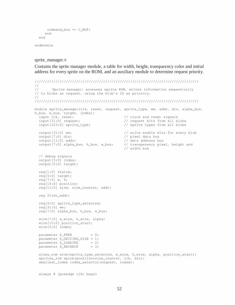
52
command_bus <= C_NOP; end end endmodule
sprite_manager.v
Contains the sprite manager module, a table for width, height, transparency color and initial address for every sprite on the ROM, and an auxiliary module to determine request priority. /////////////////////////////////////////////////// //////////////////////////// // // Sprite manager: accesses sprite ROM, writes info rmation sequentially // to blobs as request, using the blob's ID as prio rity. // /////////////////////////////////////////////////// //////////////////////////// module sprite_manager(clk, reset, request, sprite_t ype, we, addr, din, alpha_bus, h_bus, w_bus, target, index); input clk, reset; // clock and reset signals input[31:0] request; // reque st bits from all blobs input[223:0] sprite_type; // sprit e types from all blobs output[31:0] we; // write enable bits for every blob output[7:0] din; // pixel data bus output[11:0] addr; // data address bus output[7:0] alpha_bus, h_bus, w_bus; // trans parency pixel, height and // width bus // debug signals output[5:0] index; output[5:0] target; reg[1:0] status; reg[5:0] target; reg[7:0] w, h; reg[15:0] position; reg[11:0] size, size_counter, addr; reg first_addr; reg[6:0] sprite_type_selected; reg[31:0] we; reg[7:0] alpha_bus, h_bus, w_bus; wire[7:0] w_wire, h_wire, alpha; wire[15:0] position_start; wire[5:0] index; parameter S_FREE = 0; parameter S_GETTING_SIZE = 1; parameter S_LOADING = 2; parameter S_RECHECK = 3; sizes_rom srom(sprite_type_selected, w_wire, h_wi re, alpha, position_start); sprites_rom sprom(position+size_counter, clk, din ); smallest_index index_selector(request, index); always @ (posedge clk) begin
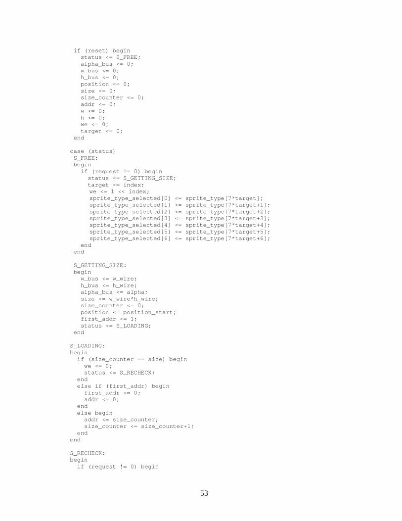
53
if (reset) begin status <= S_FREE; alpha_bus <= 0; w_bus <= 0; h_bus <= 0; position <= 0; size <= 0; size_counter <= 0; addr <= 0; w <= 0; h <= 0; we <= 0; target <= 0; end case (status) S_FREE: begin if (request != 0) begin status <= S_GETTING_SIZE; target <= index; we <= 1 << index; sprite_type_selected[0] <= sprite_type[7*target]; sprite_type_selected[1] <= sprite_type[7*target+1] ; sprite_type_selected[2] <= sprite_type[7*target+2] ; sprite_type_selected[3] <= sprite_type[7*target+3] ; sprite_type_selected[4] <= sprite_type[7*target+4] ; sprite_type_selected[5] <= sprite_type[7*target+5] ; sprite_type_selected[6] <= sprite_type[7*target+6] ; end end S_GETTING_SIZE: begin w_bus <= w_wire; h_bus <= h_wire; alpha_bus <= alpha; size <= w_wire*h_wire; size_counter <= 0; position <= position_start; first_addr <= 1; status <= S_LOADING; end S_LOADING: begin if (size_counter == size) begin we <= 0; status <= S_RECHECK; end else if (first_addr) begin first_addr <= 0; addr <= 0; end else begin addr <= size_counter; size_counter <= size_counter+1; end end S_RECHECK: begin if (request != 0) begin
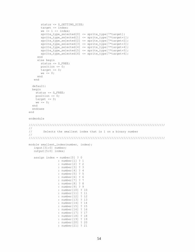
54
status <= S_GETTING_SIZE; target <= index; we <= 1 << index; sprite_type_selected[0] <= sprite_type[7*tar get]; sprite_type_selected[1] <= sprite_type[7*tar get+1]; sprite_type_selected[2] <= sprite_type[7*tar get+2]; sprite_type_selected[3] <= sprite_type[7*tar get+3]; sprite_type_selected[4] <= sprite_type[7*tar get+4]; sprite_type_selected[5] <= sprite_type[7*tar get+5]; sprite_type_selected[6] <= sprite_type[7*tar get+6]; end else begin status <= S_FREE; position <= 0; target <= 0; we <= 0; end end default: begin status <= S_FREE; position <= 0; target <= 0; we <= 0; end endcase end endmodule /////////////////////////////////////////////////// //////////////////////////// // // Selects the smallest index that is 1 on a binary number // /////////////////////////////////////////////////// //////////////////////////// module smallest_index(number, index); input[31:0] number; output[5:0] index; assign index = number[0] ? 0 : number[1] ? 1 : number[2] ? 2 : number[3] ? 3 : number[4] ? 4 : number[5] ? 5 : number[6] ? 6 : number[7] ? 7 : number[8] ? 8 : number[9] ? 9 : number[10] ? 10 : number[11] ? 11 : number[12] ? 12 : number[13] ? 13 : number[14] ? 14 : number[15] ? 15 : number[16] ? 16 : number[17] ? 17 : number[18] ? 18 : number[19] ? 19 : number[20] ? 20 : number[21] ? 21
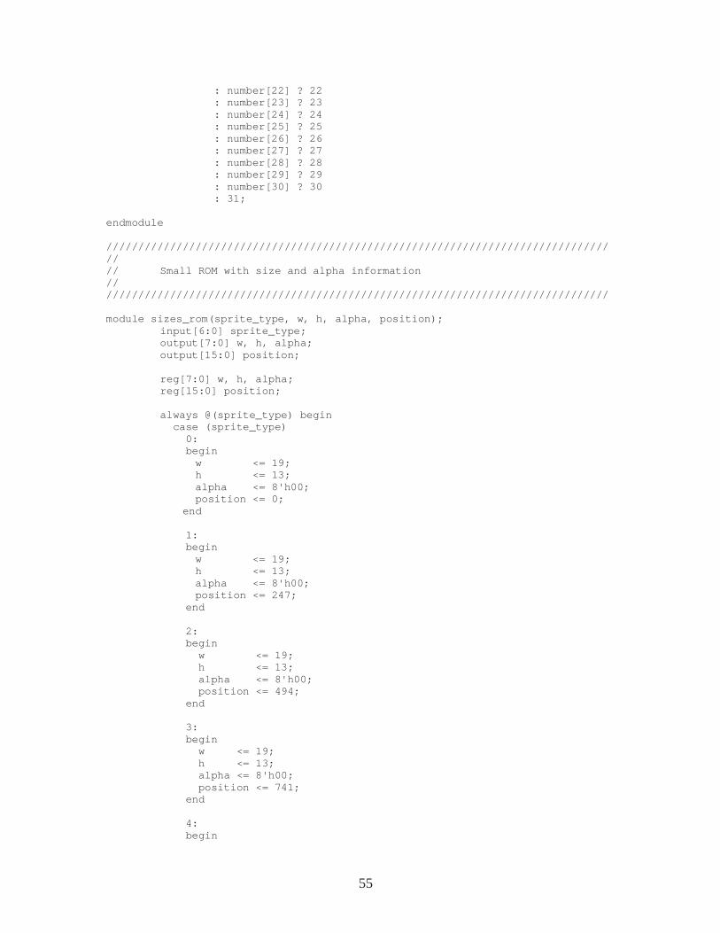
55
: number[22] ? 22 : number[23] ? 23 : number[24] ? 24 : number[25] ? 25 : number[26] ? 26 : number[27] ? 27 : number[28] ? 28 : number[29] ? 29 : number[30] ? 30 : 31; endmodule /////////////////////////////////////////////////// //////////////////////////// // // Small ROM with size and alpha information // /////////////////////////////////////////////////// //////////////////////////// module sizes_rom(sprite_type, w, h, alpha, position ); input[6:0] sprite_type; output[7:0] w, h, alpha; output[15:0] position; reg[7:0] w, h, alpha; reg[15:0] position; always @(sprite_type) begin case (sprite_type) 0: begin w <= 19; h <= 13; alpha <= 8'h00; position <= 0; end 1: begin w <= 19; h <= 13; alpha <= 8'h00; position <= 247; end 2: begin w <= 19; h <= 13; alpha <= 8'h00; position <= 494; end 3: begin w <= 19; h <= 13; alpha <= 8'h00; position <= 741; end 4: begin
56
w <= 19; h <= 13; alpha <= 8'h00; position <= 988; end 5: begin w <= 19; h <= 13; alpha <= 8'h00; position <= 1235; end 6: begin w <= 19; h <= 13; alpha <= 8'h00; position <= 1482; end 7: begin w <= 19; h <= 13; alpha <= 8'h00; position <= 1729; end 8: begin w <= 19; h <= 13; alpha <= 8'h00; position <= 1796; end 9: begin w <= 19; h <= 13; alpha <= 8'h00; position <= 2223; end 10: // : begin w <= 19; h <= 13; alpha <= 8'h00; position <= 2470; end 11: // heart 0 begin w <= 13; h <= 11; alpha <= 8'h00; position <= 2717; end 12: // heart 1
57
begin w <= 13; h <= 11; alpha <= 8'h00; position <= 2860; end 13: // heart 2 begin w <= 13; h <= 11; alpha <= 8'h00; position <= 3003; end 14: // heart 3 begin w <= 13; h <= 11; alpha <= 8'h00; position <= 3146; end 15: // heart 4 begin w <= 13; h <= 11; alpha <= 8'h00; position <= 3289; end 16: // bm1 begin w <= 19; h <= 26; alpha <= 8'h07; position <= 3432; end 17: // bm2 begin w <= 19; h <= 26; alpha <= 8'h07; position <= 3926; end 18: // bm_casting begin w <= 18; h <= 26; alpha <= 8'h07; position <= 4420; end 19: // bm_hurt begin w <= 19; h <= 26; alpha <= 8'h07; position <= 4888; end
58
20: // bm_dead begin w <= 26; h <= 26; alpha <= 8'h07; position <= 5382; end 21: // box begin w <= 16; h <= 16; alpha <= 8'hFF; position <= 6058; end 22: // brick begin w <= 16; h <= 16; alpha <= 8'hE0; position <= 6314; end 23: // red_rock begin w <= 16; h <= 15; alpha <= 8'h07; position <= 6570; end 24: // fire_1 begin w <= 13; h <= 15; alpha <= 8'h07; position <= 6810; end 25: // fire_2 begin w <= 13; h <= 15; alpha <= 8'h07; position <= 7005; end 26: // hadouken_start begin w <= 6; h <= 46; alpha <= 8'h07; position <= 7200; end 27: // hadouken_loop begin w <= 1; h <= 46; alpha <= 8'h07; position <= 7476; end
59
28: // arrow begin w <= 16; h <= 26; alpha <= 8'h07; position <= 7522; end 29: // archer begin w <= 25; h <= 26; alpha <= 8'h07; position <= 7938; end 30: // archer_firing begin w <= 25; h <= 26; alpha <= 8'h07; position <= 8588; end 31: // paladin begin w <= 20; h <= 26; alpha <= 8'h07; position <= 9238; end 32: // paladin_2 begin w <= 20; h <= 26; alpha <= 8'h07; position <= 9758; end // check: 10278 lines default: begin w <= 0; h <= 0; alpha <= 8'h00; end endcase end endmodule
pixel_tree.v
Contains the pixel tree module, with the collision OR logic. /////////////////////////////////////////////////// ///////////////////////////// // // pixel_tree: Produces the appropriate collision i nfo and sprite color
60
// from the 32 blob outputs. // // 4-stage pipelined. // // Uses a tree of pixel-combinators to select the a ppropriate pixel to display, // if any, and send the inferences it can make abou t collisions on the current // pixel position to the interrupt generator. // /////////////////////////////////////////////////// ///////////////////////////// module pixel_tree(clk, pixels, owners, z, layers, c e, pixel_out, collision, ecollision, bkg_pixel); input clk; input[255:0] pixels; input[223:0] owners; input[63:0] layers; input[63:0] ce; input[31:0] z; input[7:0] bkg_pixel; output[7:0] pixel_out; output[31:0] collision, ecollision; wire[63:0] pixel_a; wire[55:0] owner_a; wire[15:0] layer_a; wire[15:0] cea; wire[31:0] ca, eca; wire[7:0] za; wire[15:0] pixel_b; wire[13:0] owner_b; wire[3:0] layer_b; wire[3:0] ceb; wire[7:0] cb, ecb; wire[1:0] zb; wire[7:0] pixel_c; wire[6:0] owner_c; wire[1:0] layer_c; wire[1:0] cec; wire[3:0] cc, ecc; wire zc; wire[31:0] c, e; reg[63:0] pixel_areg; reg[55:0] owner_areg; reg[15:0] layer_areg; reg[15:0] ceareg; reg[31:0] careg, ecareg; reg[7:0] za_reg; reg[55:0] owner_a2reg; reg[31:0] ca2reg, eca2reg; reg[55:0] owner_a3reg; reg[31:0] ca3reg, eca3reg; reg[15:0] pixel_breg; reg[13:0] owner_breg;
61
reg[3:0] layer_breg; reg[3:0] cebreg; reg[7:0] cbreg, ecbreg; reg[1:0] zb_reg; reg[13:0] owner_b2reg; reg[7:0] cb2reg, ecb2reg; reg[6:0] owner_creg; reg[1:0] cecreg; reg[1:0] ccreg, eccreg; reg[31:0] collision_reg, ecollision_reg; reg[7:0] pixel_out_reg, pixel_out; assign collision = collision_reg; assign ecollision = ecollision_reg; // pixel combinator tree // layer 1 pixel_combinator a1(clk, pixels[7:0], pixels[15:8 ], pixels[23:16], pixels[31:24], z[0], z[1], z[ 2], z[3], owners[6:0], owners[13:7], ow ners[20:14], owners[27:21], layers[1:0], layers[3:2], lay ers[5:4], layers[7:6], ce[1:0], ce[3:2], ce[5:4], ce [7:6], pixel_a[7:0], layer_a[1:0], o wner_a[6:0], cea[1:0], za[0], ca[0], ca[1], ca[2], ca[3], eca[0], eca[1], eca[2], eca[3 ]); pixel_combinator a2(clk, pixels[39:32], pixels[47 :40], pixels[55:48], pixels[63:56], z[4], z[5], z[ 6], z[7], owners[34:28], owners[41:35], owners[48:42], owners[55:49], layers[9:8], layers[11:10], l ayers[13:12], layers[15:14], ce[9:8], ce[11:10], ce[13:12] , ce[15:14], pixel_a[15:8], layer_a[3:2], owner_a[13:7], cea[3:2], za[1], ca[4], ca[5], ca[6], c a[7], eca[4], eca[5], eca[6], eca[7 ]); pixel_combinator a3(clk, pixels[71:64], pixels[79 :72], pixels[87:80], pixels[95:88], z[8], z[9], z[ 10], z[11], owners[62:56], owners[69:63], owners[76:70], owners[83:77], layers[17:16], layers[19:18], layers[21:20], layers[23:22], ce[17:16], ce[19:18], ce[21:2 0], ce[23:22], pixel_a[23:16], layer_a[5:4], owner_a[20:14], cea[5:4], za[2], ca[8], ca[9], ca[10], ca[11], eca[8], eca[9], eca[10], eca[ 11]); pixel_combinator a4(clk, pixels[103:96], pixels[1 11:104], pixels[119:112], pixels[127:120], z[12], z[13] , z[14], z[15], owners[90:84], owners[97:91], owners[104:98], owners[111:105], layers[25:24], layers[27:26], layers[29:28],layers[31:30], ce[25:24], ce[27:26], ce[29:2 8], ce[31:30], pixel_a[31:24], layer_a[7:6], owner_a[27:21], cea[7:6], za[3], ca[12], ca[13], ca[14] , ca[15], eca[12], eca[13], eca[14], ec a[15]); pixel_combinator a5(clk, pixels[135:128], pixels[ 143:136], pixels[151:144], pixels[159:152], z[16], z[17] , z[18], z[19], owners[118:112], owners[125:1 19], owners[132:126], owners[139:133], layers[33:32], layers[35:34], layers[37:36], layers[39:38],
62
ce[33:32], ce[35:34], ce[37:3 6], ce[39:38], pixel_a[39:32], layer_a[9:8], owner_a[34:28], cea[9:8], za[4], ca[16], ca[17], ca[18] , ca[19], eca[16], eca[17], eca[18], ec a[19]); pixel_combinator a6(clk, pixels[167:160], pixels[ 175:168], pixels[183:176], pixels[191:184], z[20], z[21] , z[22], z[23], owners[146:140], owners[153:1 47], owners[160:154], owners[167:161], layers[41:40 ], layers[43:42], layers[45:44], layers[47:46], ce[41:40], ce[43:42], ce[45:4 4], ce[47:46], pixel_a[47:40], layer_a[11:10 ], owner_a[41:35], cea[11:10], za[5], ca[20], ca[21], ca[22] , ca[23], eca[20], eca[21], eca[22], ec a[23]); pixel_combinator a7(clk, pixels[199:192], pixels[ 207:200], pixels[215:208], pixels[223:216], z[24], z[25] , z[26], z[27], owners[174:168], owners[181:1 75], owners[188:182], owners[195:189], layers[49:48], layers[51:50], layers[53:52], layers[55:54], ce[49:48], ce[51:50], ce[53:5 2], ce[55:54], pixel_a[55:48], layer_a[13:12 ], owner_a[48:42], cea[13:12], za[6], ca[24], ca[25], ca[26] , ca[27], eca[24], eca[25], eca[26], ec a[27]); pixel_combinator a8(clk, pixels[231:224], pixels[ 239:232], pixels[247:240], pixels[255:248], z[28], z[29], z[30], z[31], owners[202:196], owners[209:2 03], owners[216:210], owners[223:217], layers[57:56], layers[59:58], layers[61:60], layers[63:62], ce[57:56], ce[59:58], ce[61:6 0], ce[63:62], pixel_a[63:56], layer_a[15:14 ], owner_a[55:49], cea[15:14], za[7], ca[28], ca[29], ca[30] , ca[31], eca[28], eca[29], eca[30], ec a[31]); // layer 2 pixel_combinator b1(clk, pixel_a[7:0], pixel_a[15 :8], pixel_a[23:16], pixel_a[31:24], za[0], za[1], za[2], za[3], owner_a[6:0], owner_a[13:7], owner_a[20:14], owner_a[27:21], layer_a[1:0], layer_a[3:2], l ayer_a[5:4], layer_a[7:6], cea[1:0], cea[3:2], cea[5:4], cea[7:6], pixel_b[7:0], layer_b[1:0], o wner_b[6:0], ceb[1:0], zb[0], cb[0], cb[1], cb[2], cb[3], ecb[0], ecb[1], ecb[2], ecb[3 ]); pixel_combinator b2(clk, pixel_a[39:32], pixel_a[ 47:40], pixel_a[55:48], pixel_a[63:56], za[4], za[5], za[6], za[7], owner_a[34:28], owner_a[41:35 ], owner_a[48:42], owner_a[55:49], layer_a[9:8], layer_a[11:10], layer_a[13:12], layer_a[15:14], cea[9:8], cea[11:10], cea[13: 12], cea[15:14], pixel_b[15:8], layer_b[3:2], owner_b[13:7], ceb[3:2], zb[1], cb[4], cb[5], cb[6], c b[7], ecb[4], ecb[5], ecb[6], ecb[7 ]); // layer 3 pixel_combinator c1(clk, pixel_b[7:0], pixel_b[15 :8], 8'b0, 8'b0, zb[0], zb[1], 1'b1, 1'b1, owner_b[6:0], owner_b[13:7], 7'b0, 7'b0,
63
layer_b[1:0], layer_b[3:2], 2 'b0, 2'b0, ceb[1:0], ceb[3:2], 2'b0, 2'b 0, pixel_c[7:0], layer_c[1:0], o wner_c[6:0], cec[1:0], zc, cc[0], cc[1], cc[2], cc[3], ecc[0], ecc[1], ecc[2], ecc[3 ]); // collision OR // collision: assign c[0] = ca3reg[0] | ((owner_a3reg[6:0] == 0) & cb2reg[0]) | ((owner_b2reg[6:0] == 0) & ccreg[0]); assign c[1] = ca3reg[1] | ((owner_a3reg[6:0] == 1) & cb2reg[0]) | ((owner_b2reg[6:0] == 1) & ccreg[0]); assign c[2] = ca3reg[2] | ((owner_a3reg[6:0] == 2) & cb2reg[0]) | ((owner_b2reg[6:0] == 2) & ccreg[0]); assign c[3] = ca3reg[3] | ((owner_a3reg[6:0] == 3) & cb2reg[0]) | ((owner_b2reg[6:0] == 3) & ccreg[0]); assign c[4] = ca3reg[4] | ((owner_a3reg[13:7] = = 4) & cb2reg[1]) | ((owner_b2reg[6:0] == 4) & ccreg[0]); assign c[5] = ca3reg[5] | ((owner_a3reg[13:7] = = 5) & cb2reg[1]) | ((owner_b2reg[6:0] == 5) & ccreg[0]); assign c[6] = ca3reg[6] | ((owner_a3reg[13:7] = = 6) & cb2reg[1]) | ((owner_b2reg[6:0] == 6) & ccreg[0]); assign c[7] = ca3reg[7] | ((owner_a3reg[13:7] = = 7) & cb2reg[1]) | ((owner_b2reg[6:0] == 7) & ccreg[0]); assign c[8] = ca3reg[8] | ((owner_a3reg[20:14] == 8) & cb2reg[2]) | ((owner_b2reg[6:0] == 0) & ccreg[0]); assign c[9] = ca3reg[9] | ((owner_a3reg[20:14] == 9) & cb2reg[2]) | ((owner_b2reg[6:0] == 1) & ccreg[0]); assign c[10] = ca3reg[10] | ((owner_a3reg[20:14] == 10) & cb2reg[2]) | ((owner_b2reg[6:0] == 2) & ccreg[0]); assign c[11] = ca3reg[11] | ((owner_a3reg[20:14] == 11) & cb2reg[2]) | ((owner_b2reg[6:0] == 3) & ccreg[0]); assign c[12] = ca3reg[12] | ((owner_a3reg[27:21] == 12) & cb2reg[3]) | ((owner_b2reg[6:0] == 4) & ccreg[0]); assign c[13] = ca3reg[13] | ((owner_a3reg[27:21] == 13) & cb2reg[3]) | ((owner_b2reg[6:0] == 5) & ccreg[0]); assign c[14] = ca3reg[14] | ((owner_a3reg[27:21] == 14) & cb2reg[3]) | ((owner_b2reg[6:0] == 6) & ccreg[0]); assign c[15] = ca3reg[15] | ((owner_a3reg[27:21] == 15) & cb2reg[3]) | ((owner_b2reg[6:0] == 7) & ccreg[0]); assign c[16] = ca3reg[16] | ((owner_a3reg[34:28] == 16) & cb2reg[4]) | ((owner_b2reg[13:7] == 16) & ccreg[1]); assign c[17] = ca3reg[17] | ((owner_a3reg[34:28] == 17) & cb2reg[4]) | ((owner_b2reg[13:7] == 17) & ccreg[1]); assign c[18] = ca3reg[18] | ((owner_a3reg[34:28] == 18) & cb2reg[4]) | ((owner_b2reg[13:7] == 18) & ccreg[1]); assign c[19] = ca3reg[19] | ((owner_a3reg[34:28] == 19) & cb2reg[4]) | ((owner_b2reg[13:7] == 19) & ccreg[1]); assign c[20] = ca3reg[20] | ((owner_a3reg[41:35] == 20) & cb2reg[5]) | ((owner_b2reg[13:7] == 20) & ccreg[1]); assign c[21] = ca3reg[21] | ((owner_a3reg[41:35] == 21) & cb2reg[5]) | ((owner_b2reg[13:7] == 21) & ccreg[1]); assign c[22] = ca3reg[22] | ((owner_a3reg[41:35] == 22) & cb2reg[5]) | ((owner_b2reg[13:7] == 22) & ccreg[1]); assign c[23] = ca3reg[23] | ((owner_a3reg[41:35] == 23) & cb2reg[5]) | ((owner_b2reg[13:7] == 23) & ccreg[1]);
64
assign c[24] = ca3reg[24] | ((owner_a3reg[48:42] == 24) & cb2reg[6]) | ((owner_b2reg[13:7] == 24) & ccreg[1]); assign c[25] = ca3reg[25] | ((owner_a3reg[48:42] == 25) & cb2reg[6]) | ((owner_b2reg[13:7] == 25) & ccreg[1]); assign c[26] = ca3reg[26] | ((owner_a3reg[48:42] == 26) & cb2reg[6]) | ((owner_b2reg[13:7] == 26) & ccreg[1]); assign c[27] = ca3reg[27] | ((owner_a3reg[48:42] == 27) & cb2reg[6]) | ((owner_b2reg[13:7] == 27) & ccreg[1]); assign c[28] = ca3reg[28] | ((owner_a3reg[55:49] == 28) & cb2reg[7]) | ((owner_b2reg[13:7] == 28) & ccreg[1]); assign c[29] = ca3reg[29] | ((owner_a3reg[55:49] == 29) & cb2reg[7]) | ((owner_b2reg[13:7] == 29) & ccreg[1]); assign c[30] = ca3reg[30] | ((owner_a3reg[55:49] == 30) & cb2reg[7]) | ((owner_b2reg[13:7] == 30) & ccreg[1]); assign c[31] = ca3reg[31] | ((owner_a3reg[55:49] == 31) & cb2reg[7]) | ((owner_b2reg[13:7] == 31) & ccreg[1]); // enemy: assign e[0] = eca3reg[0] | ((owner_a3reg[6:0] = = 0) & ecb2reg[0]) | ((owner_b2reg[6:0] == 0) & eccreg[0]); assign e[1] = eca3reg[1] | ((owner_a3reg[6:0] = = 1) & ecb2reg[0]) | ((owner_b2reg[6:0] == 1) & eccreg[0]); assign e[2] = eca3reg[2] | ((owner_a3reg[6:0] = = 2) & ecb2reg[0]) | ((owner_b2reg[6:0] == 2) & eccreg[0]); assign e[3] = eca3reg[3] | ((owner_a3reg[6:0] = = 3) & ecb2reg[0]) | ((owner_b2reg[6:0] == 3) & eccreg[0]); assign e[4] = eca3reg[4] | ((owner_a3reg[13:7] == 4) & ecb2reg[1]) | ((owner_b2reg[6:0] == 4) & eccreg[0]); assign e[5] = eca3reg[5] | ((owner_a3reg[13:7] == 5) & ecb2reg[1]) | ((owner_b2reg[6:0] == 5) & eccreg[0]); assign e[6] = eca3reg[6] | ((owner_a3reg[13:7] == 6) & ecb2reg[1]) | ((owner_b2reg[6:0] == 6) & eccreg[0]); assign e[7] = eca3reg[7] | ((owner_a3reg[13:7] == 7) & ecb2reg[1]) | ((owner_b2reg[6:0] == 7) & eccreg[0]); assign e[8] = eca3reg[8] | ((owner_a3reg[20:14] == 8) & ecb2reg[2]) | ((owner_b2reg[6:0] == 0) & eccreg[0]); assign e[9] = eca3reg[9] | ((owner_a3reg[20:14] == 9) & ecb2reg[2]) | ((owner_b2reg[6:0] == 1) & eccreg[0]); assign e[10] = eca3reg[10] | ((owner_a3reg[20:14] == 10) & ecb2reg[2]) | ((owner_b2reg[6:0] == 2) & eccreg[0]); assign e[11] = eca3reg[11] | ((owner_a3reg[20:14] == 11) & ecb2reg[2]) | ((owner_b2reg[6:0] == 3) & eccreg[0]); assign e[12] = eca3reg[12] | ((owner_a3reg[27:21] == 12) & ecb2reg[3]) | ((owner_b2reg[6:0] == 4) & eccreg[0]); assign e[13] = eca3reg[13] | ((owner_a3reg[27:21] == 13) & ecb2reg[3]) | ((owner_b2reg[6:0] == 5) & eccreg[0]); assign e[14] = eca3reg[14] | ((owner_a3reg[27:21] == 14) & ecb2reg[3]) | ((owner_b2reg[6:0] == 6) & eccreg[0]); assign e[15] = eca3reg[15] | ((owner_a3reg[27:21] == 15) & ecb2reg[3]) | ((owner_b2reg[6:0] == 7) & eccreg[0]); assign e[16] = eca3reg[16] | ((owner_a3reg[34:28] == 16) & ecb2reg[4]) | ((owner_b2reg[13:7] == 16) & eccreg[1]); assign e[17] = eca3reg[17] | ((owner_a3reg[34:28] == 17) & ecb2reg[4]) | ((owner_b2reg[13:7] == 17) & eccreg[1]); assign e[18] = eca3reg[18] | ((owner_a3reg[34:28] == 18) & ecb2reg[4]) | ((owner_b2reg[13:7] == 18) & eccreg[1]); assign e[19] = eca3reg[19] | ((owner_a3reg[34:28] == 19) & ecb2reg[4]) | ((owner_b2reg[13:7] == 19) & eccreg[1]);
65
assign e[20] = eca3reg[20] | ((owner_a3reg[41:35] == 20) & ecb2reg[5]) | ((owner_b2reg[13:7] == 20) & eccreg[1]); assign e[21] = eca3reg[21] | ((owner_a3reg[41:35] == 21) & ecb2reg[5]) | ((owner_b2reg[13:7] == 21) & eccreg[1]); assign e[22] = eca3reg[22] | ((owner_a3reg[41:35] == 22) & ecb2reg[5]) | ((owner_b2reg[13:7] == 22) & eccreg[1]); assign e[23] = eca3reg[23] | ((owner_a3reg[41:35] == 23) & ecb2reg[5]) | ((owner_b2reg[13:7] == 23) & eccreg[1]); assign e[24] = eca3reg[24] | ((owner_a3reg[48:42] == 24) & ecb2reg[6]) | ((owner_b2reg[13:7] == 24) & eccreg[1]); assign e[25] = eca3reg[25] | ((owner_a3reg[48:42] == 25) & ecb2reg[6]) | ((owner_b2reg[13:7] == 25) & eccreg[1]); assign e[26] = eca3reg[26] | ((owner_a3reg[48:42] == 26) & ecb2reg[6]) | ((owner_b2reg[13:7] == 26) & eccreg[1]); assign e[27] = eca3reg[27] | ((owner_a3reg[48:42] == 27) & ecb2reg[6]) | ((owner_b2reg[13:7] == 27) & eccreg[1]); assign e[28] = eca3reg[28] | ((owner_a3reg[55:49] == 28) & ecb2reg[7]) | ((owner_b2reg[13:7] == 28) & eccreg[1]); assign e[29] = eca3reg[29] | ((owner_a3reg[55:49] == 29) & ecb2reg[7]) | ((owner_b2reg[13:7] == 29) & eccreg[1]); assign e[30] = eca3reg[30] | ((owner_a3reg[55:49] == 30) & ecb2reg[7]) | ((owner_b2reg[13:7] == 30) & eccreg[1]); assign e[31] = eca3reg[31] | ((owner_a3reg[55:49] == 31) & ecb2reg[7]) | ((owner_b2reg[13:7] == 31) & eccreg[1]); // pipeline always @(posedge clk) begin pixel_areg <= pixel_a; owner_areg <= owner_a; layer_areg <= layer_a; ceareg <= cea; careg <= ca; ecareg <= eca; za_reg <= za; owner_a2reg <= owner_areg; ca2reg <= careg; eca2reg <= ecareg; owner_a3reg <= owner_a2reg; ca3reg <= ca2reg; eca3reg <= eca2reg; pixel_breg <= pixel_b; owner_breg <= owner_b; layer_breg <= layer_b; cebreg <= ceb; cbreg <= cb; ecbreg <= ecb; zb_reg <= zb; owner_b2reg <= owner_breg; cb2reg <= cbreg; ecb2reg <= ecbreg; owner_creg <= owner_c; cecreg <= cec; ccreg <= cc; eccreg <= ecc;
66
collision_reg <= c; ecollision_reg <= e; pixel_out <= zc ? bkg_pixel : pixel_c; end endmodule
pixel_combinator.v
Contains the pixel combinator module, and a module to select the smallest from 4 inputs and point its index. /////////////////////////////////////////////////// ///////////////////////////// // // pixel_combinator: Selects the appropriate pixel and sprite info from 4 inputs // // pixel1, pixel2, pixel3, pixel4: 4 8-bit pixel va lues // z1, z2, z3, z4: whether the pixels should be con sidered transparent // owner1, owner2, owner3, owner4: ID of blob respo nsible for the pixel // layer1, layer2, lauye3, layer4: pixel layer (2-b it) // ce1, ce2, ce3, ce4: {enemy, collision} bit infor mation // pixel_out: selected pixel output // layer_out: selected layer output // ce_out: combined ce output // z_out: whether the output is transparent // conflict1, conflict2, conflict3, conflict4: coll ision information output for // each pixel // econflict1, econflict2, econflict3, econflict4: enemy collision information // for each pixel // /////////////////////////////////////////////////// ///////////////////////////// module pixel_combinator(clk, pixel1, pixel2, pixel3 , pixel4, z1, z2, z3, z4, owner1, owner2, owner3, own er4, layer1, layer2, layer3, lay er4, ce1, ce2, ce3, ce4, pixel_out, layer_out, owner _out, ce_out, z_out, conflict1, conflict2, confl ict3, conflict4, econflict1, econflict2, eco nflict3, econflict4); input clk; input[7:0] pixel1, pixel2, pixel3, pixel4; input[6:0] owner1, owner2, owner3, owner4; input[1:0] layer1, layer2, layer3, layer4; input[1:0] ce1, ce2, ce3, ce4; input z1, z2, z3, z4; output[7:0] pixel_out; output[1:0] layer_out; output[1:0] ce_out; output[6:0] owner_out; output z_out; output conflict1, conflict2, conflict3, conflict 4; output econflict1, econflict2, econflict3, econf lict4; wire en1, en2, en3, en4, o1, o2, o3, o4, c1, c2, c3, c4, e1, e2, e3, e4; wire[1:0] win_id; wire[1:0] alayer1, alayer2, alayer3, alayer4; assign en1 = ~z1;
67
assign en2 = ~z2; assign en3 = ~z3; assign en4 = ~z4; assign alayer1 = en1 ? layer1 : 3; assign alayer2 = en2 ? layer2 : 3; assign alayer3 = en3 ? layer3 : 3; assign alayer4 = en4 ? layer4 : 3; min4 layer_selector(alayer1, alayer2, alayer3, a layer4, layer_out, win_id); assign o1 = (en2 | en3 | en4); assign o2 = (en1 | en3 | en4); assign o3 = (en1 | en2 | en4); assign o4 = (en1 | en2 | en3); assign c1 = ce2[0] | ce3[0] | ce4[0]; assign c2 = ce1[0] | ce3[0] | ce4[0]; assign c3 = ce1[0] | ce2[0] | ce4[0]; assign c4 = ce1[0] | ce2[0] | ce3[0]; assign e1 = ce2[1] | ce3[1] | ce4[1]; assign e2 = ce1[1] | ce3[1] | ce4[1]; assign e3 = ce1[1] | ce2[1] | ce4[1]; assign e4 = ce1[1] | ce2[1] | ce3[1]; reg pixel_out; reg owner_out; reg z_out, ce_out; reg conflict1, conflict2, conflict3, conflict4; reg econflict1, econflict2, econflict3, econflic t4; always @ (posedge clk) begin pixel_out <= win_id == 3 ? pixel4 : win_id == 2 ? pixel3 : win_id == 1 ? pixel2 : pixel1; owner_out <= win_id == 3 ? owner4 : win_id == 2 ? owner3 : win_id == 1 ? owner2 : owner1; z_out <= z1 & z2 & z3 & z4; ce_out <= ce1 | ce2 | ce3 | ce4; conflict1 <= o1 & ce1[0] ? c1 : 0; conflict2 <= o2 & ce2[0] ? c2 : 0; conflict3 <= o3 & ce3[0] ? c3 : 0; conflict4 <= o4 & ce4[0] ? c4 : 0; econflict1 <= o1 & ce1[0] ? e1 : 0; econflict2 <= o2 & ce2[0] ? e2 : 0; econflict3 <= o3 & ce3[0] ? e3 : 0; econflict4 <= o4 & ce4[0] ? e4 : 0; end endmodule /////////////////////////////////////////////////// ///////////////////////////// // // min4: Produces the minimum value and the minimum index from 4 2-bit values. // /////////////////////////////////////////////////// ///////////////////////////// module min4(c1, c2, c3, c4, win, win_id); input[1:0] c1, c2, c3, c4;
68
output[1:0] win, win_id; wire[1:0] w1, w2, wid1, wid2; assign w1 = (c4 < c3 ? c4 : c3); assign wid1 = (c4 < c3 ? 3 : 2); assign w2 = (c2 < c1 ? c2 : c1); assign wid2 = (c2 < c1 ? 1 : 0); assign win = (w2 < w1? w2 : w1); assign win_id = (w2 < w1? wid2 : wid1); endmodule
interrupt_generator.v
Contains the interrupt generator module. /////////////////////////////////////////////////// ///////////////////////////// // // interrupt_generator: module responsible for send ing interrupts to CPU // // The beta just ignores interrupts while on superv isor mode (pc31 = 1), so // we need to watch it and queue the requests as ne eded. This module contains // a 16-word FIFO to queue the requests; it sends I RQs to the beta on every // cycle it is not on supervisor mode, emptying the queue. As such, it is usually // improbable to have more than 3 or 4 requests at the queue at any time. // If the queue overflows, the extra requests are i gnored. // // Since collision between two sprites cannot be in ferred from one pixel alone, // this module collects the current collision infor mation on a register used as a // buffer, and ORs it with the new input at every c lock cycle. After iteration // through one screen, it then compares with a prev ious value to determine // whether the collision status changed for any spr ite; if so, it queues up the // appropriate interrupt. // // Note that this mechanism for collision detection implies that no off-screen // collisions are detected. For most games this is projected for, collisions are // not a matter out of the screen. // /////////////////////////////////////////////////// ///////////////////////////// module interrupt_generator(clk, reset, collision, e collision, up, down, left, right, enter, b1, b2, b3 , irq, xaddr, hwwe, pc31); input clk, reset, pc31; // clock, reset and // supervisor bit signals input[31:0] collision, ecollision; // collision inferences for // the current pixel input up, down, left, right, enter, b1, b2, b3; // signals determining // whether the buttons are // pressed output irq; // the interrupt request s ignal itself output[4:0] xaddr; // address to jump to, wit hout the 2 last bits (00) output hwwe; // whether to record the c ollision info to the memory reg[31:0] c_reg, ec_reg, c_buf, ec_buf; reg irq_internal, wr, hwwe, rd; reg[4:0] din, xaddr;
69
reg up_reg, down_reg, left_reg, right_reg, enter _reg, b1_reg, b2_reg, b3_reg; reg[18:0] counter; wire[4:0] dout; wire irq, empty; assign irq = irq_internal & !empty; fifo irq_fifo (clk, reset, din, wr, full, dout, rd, empty, overflow); defparam irq_fifo.LOGSIZE = 4; defparam irq_fifo.WIDTH = 5; parameter I_CLOCK = 2; parameter I_ECOLLISION = 3; parameter I_COLLISION = 4; parameter I_UP_PRESS = 5; parameter I_DOWN_PRESS = 6; parameter I_LEFT_PRESS = 7; parameter I_RIGHT_PRESS = 8; parameter I_ENTER_PRESS = 9; parameter I_B1_PRESS = 10; parameter I_B2_PRESS = 11; parameter I_B3_PRESS = 12; parameter I_UP_RELEASE = 13; parameter I_DOWN_RELEASE = 14; parameter I_LEFT_RELEASE = 15; parameter I_RIGHT_RELEASE = 16; parameter I_ENTER_RELEASE = 17; parameter I_B1_RELEASE = 18; parameter I_B2_RELEASE = 19; parameter I_B3_RELEASE = 20; parameter CYCLES = 480000 - 1; always @(posedge clk) begin if (reset) begin hwwe <= 0; wr <= 0; rd <= 0; din <= 0; c_reg <= 0; ec_reg <= 0; up_reg <= 0; down_reg <= 0; left_reg <= 0; right_reg <= 0; enter_reg <= 0; b1_reg <= 0; b2_reg <= 0; b3_reg <= 0; c_buf <= 0; ec_buf <= 0; irq_internal <= 0; counter <= 0; end if (counter == CYCLES) begin counter <= 0; din <= I_CLOCK; wr <= 1;
70
c_buf <= c_buf | collision; ec_buf <= ec_buf | ecollision; end else if (counter == CYCLES - 1) begin counter <= counter+1; c_buf <= c_buf | collision; if (ec_buf != ec_reg) begin din <= I_ECOLLISION; wr <= 1; ec_reg <= ec_buf; ec_buf <= 0; end end else if (counter == CYCLES - 2) begin counter <= counter+1; ec_buf <= ec_buf | ecollision; if (c_buf != c_reg) begin din <= I_COLLISION; wr <= 1; c_reg <= collision; c_buf <= 0; end end else begin counter <= counter+1; c_buf <= c_buf | collision; ec_buf <= ec_buf | ecollision; if (up != up_reg) begin din <= up ? I_UP_PRESS : I_UP_RELEASE; wr <= 1; up_reg <= up; end else if (down != down_reg) begin din <= down ? I_DOWN_PRESS : I_DOWN_RELEASE; wr <= 1; down_reg <= down; end else if (left != left_reg) begin din <= left ? I_LEFT_PRESS : I_LEFT_RELEASE; wr <= 1; left_reg <= left; end else if (right != right_reg) begin din <= right ? I_RIGHT_PRESS : I_RIGHT_RE LEASE; wr <= 1; right_reg <= right; end else if (enter != enter) begin din <= enter ? I_ENTER_PRESS : I_ENTER_RELEASE; wr <= 1; enter_reg <= enter; end else if (b1 != b1_reg) begin din <= b1 ? I_B1_PRESS : I_B1_RELEASE; wr <= 1; b1_reg <= b1; end
71
else if (b2 != b2_reg) begin din <= b2 ? I_B2_PRESS : I_B2_RELEASE; wr <= 1; b2_reg <= b2; end else if (b3 != b3_reg) begin din <= b3 ? I_B3_PRESS : I_B3_RELEASE; wr <= 1; b3_reg <= b3; end else begin wr <= 0; din <= 0; end end if (!pc31 && !empty) begin irq_internal <= 1; xaddr <= dout; rd <= 1; hwwe <= (dout == I_COLLISION) || (dout == I_ECOLLI SION); end else begin irq_internal <= 0; xaddr <= 0; rd <= 0; end end endmodule
fifo.v
Contains the first-in, first-out memory module provided in lecture. // a simple synchronous FIFO (first-in first-out) b uffer // Parameters: // LOGSIZE (parameter) FIFO has 1<<LOGSIZE elem ents // WIDTH (parameter) each element has WIDTH b its // Ports: // clk (input) all actions triggered on ris ing edge // reset (input) synchronously empties fifo // din (input, WIDTH bits) data to be store d // wr (input) when asserted, store new dat a // full (output) asserted when FIFO is full // dout (output, WIDTH bits) data read from FIFO // rd (input) when asserted, removes first element // empty (output) asserted when fifo is empty // overflow (output) asserted when WR but no roo m, cleared on next RD module fifo(clk,reset,din,wr,full,dout,rd,empty,ove rflow); parameter LOGSIZE = 2; // default size is 4 ele ments parameter WIDTH = 4; // default width is 4 bi ts parameter SIZE = 1 << LOGSIZE; // compute size input clk,reset,rd,wr; input [WIDTH-1:0] din;
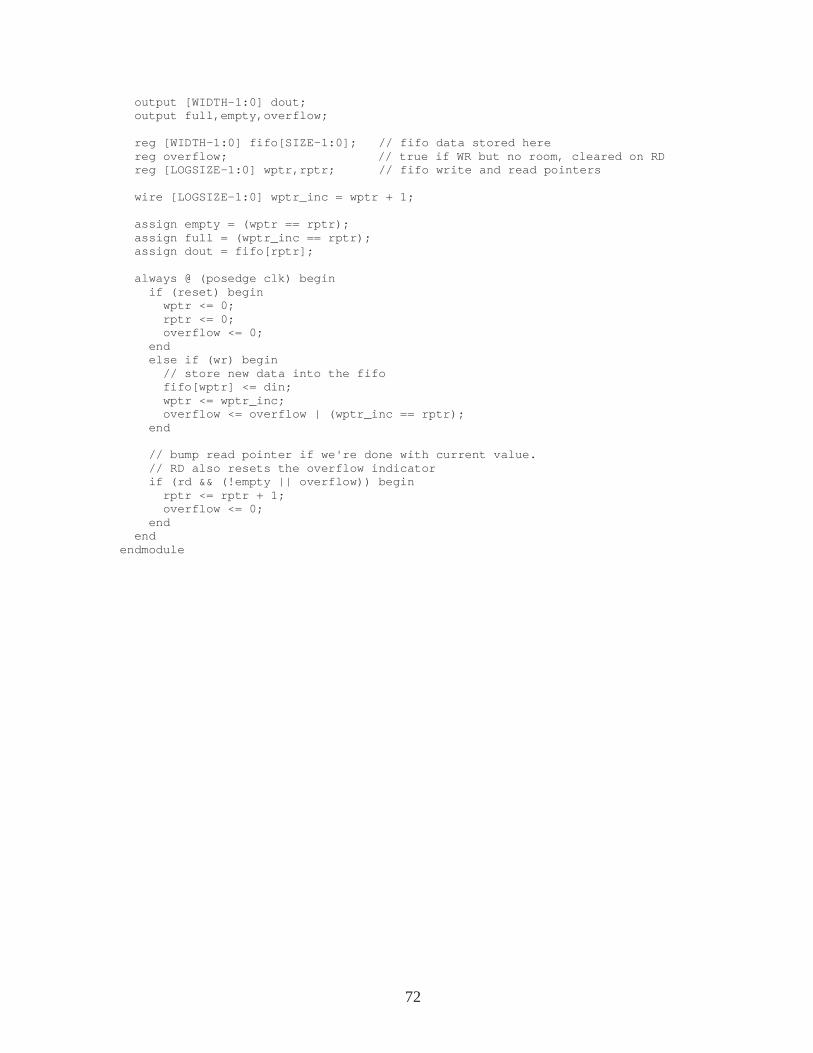
72
output [WIDTH-1:0] dout; output full,empty,overflow; reg [WIDTH-1:0] fifo[SIZE-1:0]; // fifo data st ored here reg overflow; // true if WR but no room, clea red on RD reg [LOGSIZE-1:0] wptr,rptr; // fifo write a nd read pointers wire [LOGSIZE-1:0] wptr_inc = wptr + 1; assign empty = (wptr == rptr); assign full = (wptr_inc == rptr); assign dout = fifo[rptr]; always @ (posedge clk) begin if (reset) begin wptr <= 0; rptr <= 0; overflow <= 0; end else if (wr) begin // store new data into the fifo fifo[wptr] <= din; wptr <= wptr_inc; overflow <= overflow | (wptr_inc == rptr); end // bump read pointer if we're done with current value. // RD also resets the overflow indicator if (rd && (!empty || overflow)) begin rptr <= rptr + 1; overflow <= 0; end end endmodule
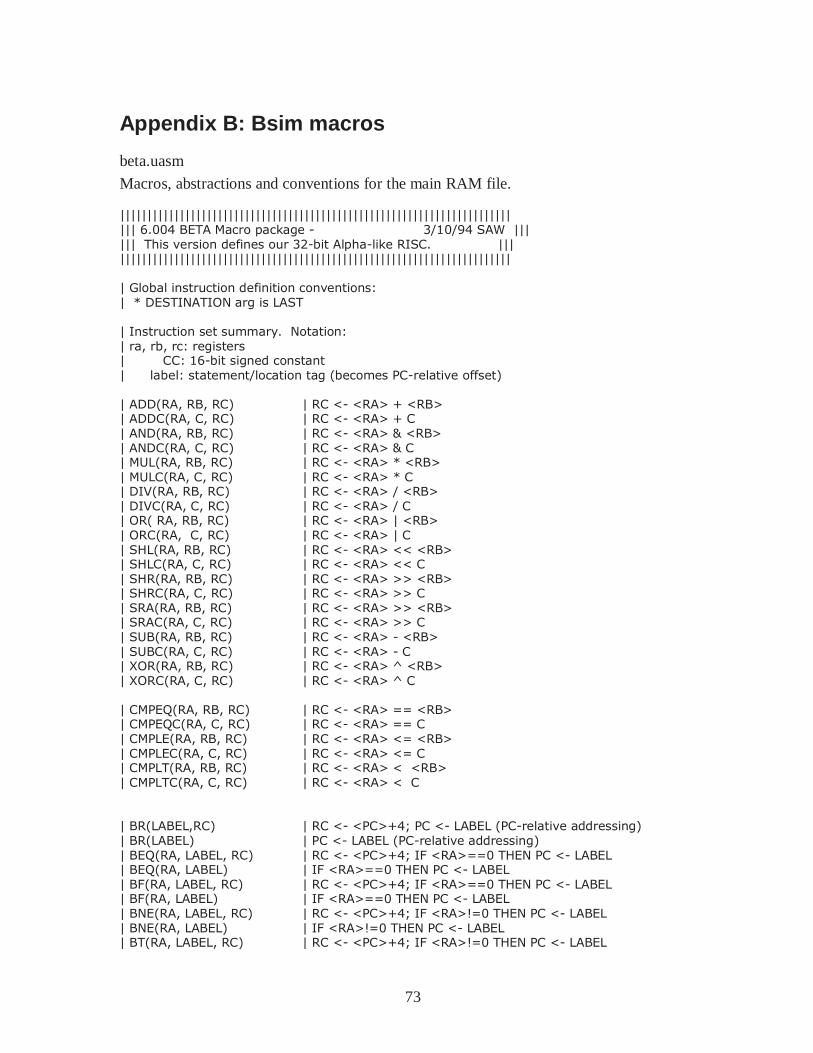
73
Appendix B: Bsim macros
beta.uasm
Macros, abstractions and conventions for the main RAM file. |||||||||||||||||||||||||||||||||||||||||||||||||||||||||||||||||||||||| ||| 6.004 BETA Macro package - 3/10/94 SAW ||| ||| This version defines our 32-bit Alpha-like RISC. ||| |||||||||||||||||||||||||||||||||||||||||||||||||||||||||||||||||||||||| | Global instruction definition conventions: | * DESTINATION arg is LAST | Instruction set summary. Notation: | ra, rb, rc: registers | CC: 16-bit signed constant | label: statement/location tag (becomes PC-relative offset) | ADD(RA, RB, RC) | RC <- <RA> + <RB> | ADDC(RA, C, RC) | RC <- <RA> + C | AND(RA, RB, RC) | RC <- <RA> & <RB> | ANDC(RA, C, RC) | RC <- <RA> & C | MUL(RA, RB, RC) | RC <- <RA> * <RB> | MULC(RA, C, RC) | RC <- <RA> * C | DIV(RA, RB, RC) | RC <- <RA> / <RB> | DIVC(RA, C, RC) | RC <- <RA> / C | OR( RA, RB, RC) | RC <- <RA> | <RB> | ORC(RA, C, RC) | RC <- <RA> | C | SHL(RA, RB, RC) | RC <- <RA> << <RB> | SHLC(RA, C, RC) | RC <- <RA> << C | SHR(RA, RB, RC) | RC <- <RA> >> <RB> | SHRC(RA, C, RC) | RC <- <RA> >> C | SRA(RA, RB, RC) | RC <- <RA> >> <RB> | SRAC(RA, C, RC) | RC <- <RA> >> C | SUB(RA, RB, RC) | RC <- <RA> - <RB> | SUBC(RA, C, RC) | RC <- <RA> - C | XOR(RA, RB, RC) | RC <- <RA> ^ <RB> | XORC(RA, C, RC) | RC <- <RA> ^ C | CMPEQ(RA, RB, RC) | RC <- <RA> == <RB> | CMPEQC(RA, C, RC) | RC <- <RA> == C | CMPLE(RA, RB, RC) | RC <- <RA> <= <RB> | CMPLEC(RA, C, RC) | RC <- <RA> <= C | CMPLT(RA, RB, RC) | RC <- <RA> < <RB> | CMPLTC(RA, C, RC) | RC <- <RA> < C | BR(LABEL,RC) | RC <- <PC>+4; PC <- LABEL (PC-relative addressing) | BR(LABEL) | PC <- LABEL (PC-relative addressing) | BEQ(RA, LABEL, RC) | RC <- <PC>+4; IF <RA>==0 THEN PC <- LABEL | BEQ(RA, LABEL) | IF <RA>==0 THEN PC <- LABEL | BF(RA, LABEL, RC) | RC <- <PC>+4; IF <RA>==0 THEN PC <- LABEL | BF(RA, LABEL) | IF <RA>==0 THEN PC <- LABEL | BNE(RA, LABEL, RC) | RC <- <PC>+4; IF <RA>!=0 THEN PC <- LABEL | BNE(RA, LABEL) | IF <RA>!=0 THEN PC <- LABEL | BT(RA, LABEL, RC) | RC <- <PC>+4; IF <RA>!=0 THEN PC <- LABEL
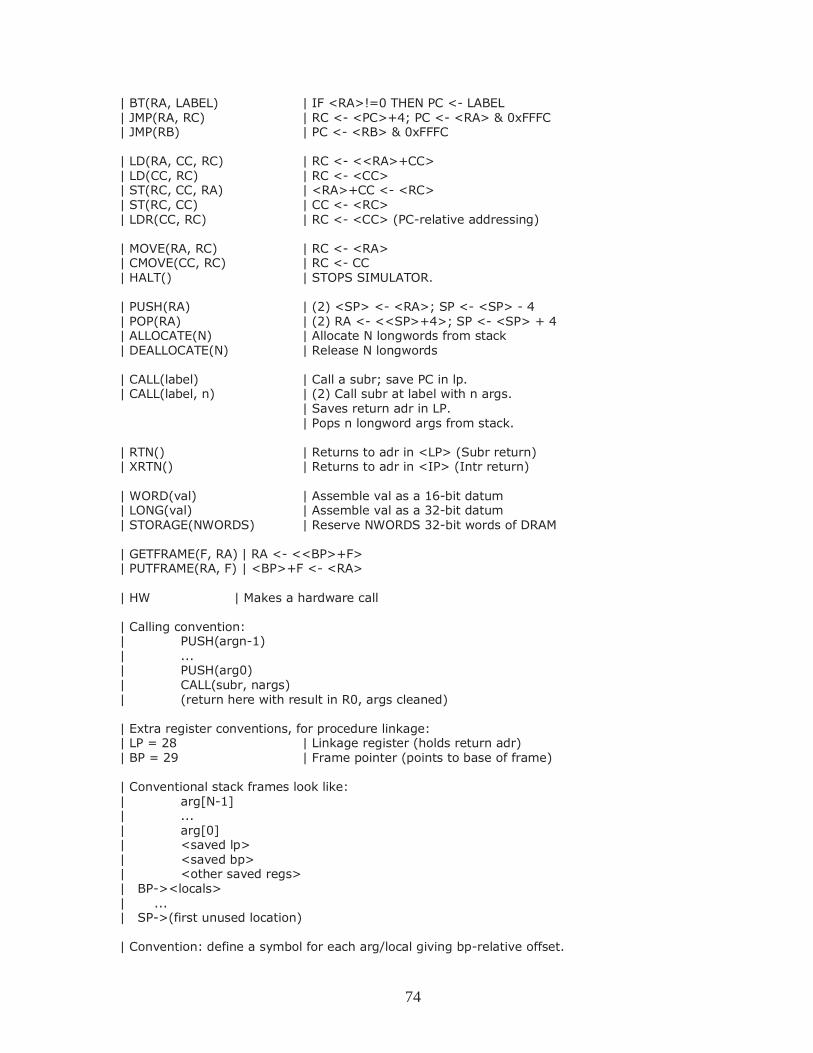
74
| BT(RA, LABEL) | IF <RA>!=0 THEN PC <- LABEL | JMP(RA, RC) | RC <- <PC>+4; PC <- <RA> & 0xFFFC | JMP(RB) | PC <- <RB> & 0xFFFC | LD(RA, CC, RC) | RC <- <<RA>+CC> | LD(CC, RC) | RC <- <CC> | ST(RC, CC, RA) | <RA>+CC <- <RC> | ST(RC, CC) | CC <- <RC> | LDR(CC, RC) | RC <- <CC> (PC-relative addressing) | MOVE(RA, RC) | RC <- <RA> | CMOVE(CC, RC) | RC <- CC | HALT() | STOPS SIMULATOR. | PUSH(RA) | (2) <SP> <- <RA>; SP <- <SP> - 4 | POP(RA) | (2) RA <- <<SP>+4>; SP <- <SP> + 4 | ALLOCATE(N) | Allocate N longwords from stack | DEALLOCATE(N) | Release N longwords | CALL(label) | Call a subr; save PC in lp. | CALL(label, n) | (2) Call subr at label with n args. | Saves return adr in LP. | Pops n longword args from stack. | RTN() | Returns to adr in <LP> (Subr return) | XRTN() | Returns to adr in <IP> (Intr return) | WORD(val) | Assemble val as a 16-bit datum | LONG(val) | Assemble val as a 32-bit datum | STORAGE(NWORDS) | Reserve NWORDS 32-bit words of DRAM | GETFRAME(F, RA) | RA <- <<BP>+F> | PUTFRAME(RA, F) | <BP>+F <- <RA> | HW | Makes a hardware call | Calling convention: | PUSH(argn-1) | ... | PUSH(arg0) | CALL(subr, nargs) | (return here with result in R0, args cleaned) | Extra register conventions, for procedure linkage: | LP = 28 | Linkage register (holds return adr) | BP = 29 | Frame pointer (points to base of frame) | Conventional stack frames look like: | arg[N-1] | ... | arg[0] | <saved lp> | <saved bp> | <other saved regs> | BP-><locals> | ... | SP->(first unused location) | Convention: define a symbol for each arg/local giving bp-relative offset.
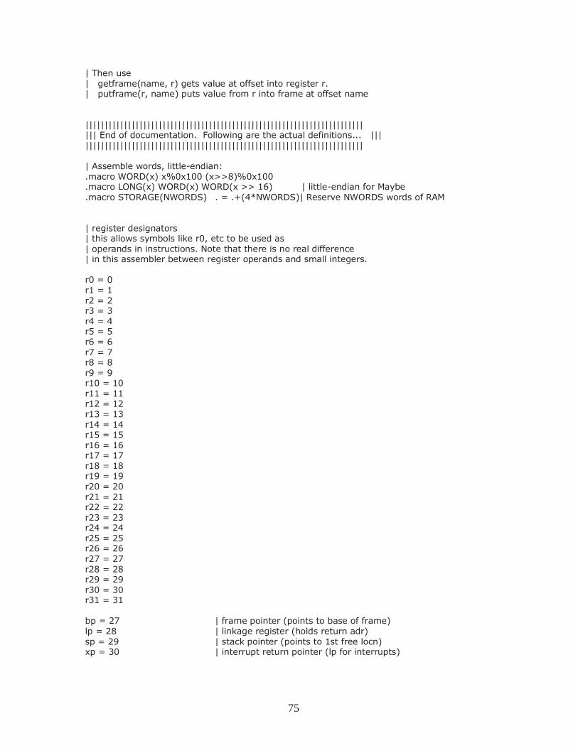
75
| Then use | getframe(name, r) gets value at offset into register r. | putframe(r, name) puts value from r into frame at offset name |||||||||||||||||||||||||||||||||||||||||||||||||||||||||||||||||||||||| ||| End of documentation. Following are the actual definitions... ||| |||||||||||||||||||||||||||||||||||||||||||||||||||||||||||||||||||||||| | Assemble words, little-endian: .macro WORD(x) x%0x100 (x>>8)%0x100 .macro LONG(x) WORD(x) WORD(x >> 16) | little-endian for Maybe .macro STORAGE(NWORDS) . = .+(4*NWORDS)| Reserve NWORDS words of RAM | register designators | this allows symbols like r0, etc to be used as | operands in instructions. Note that there is no real difference | in this assembler between register operands and small integers. r0 = 0 r1 = 1 r2 = 2 r3 = 3 r4 = 4 r5 = 5 r6 = 6 r7 = 7 r8 = 8 r9 = 9 r10 = 10 r11 = 11 r12 = 12 r13 = 13 r14 = 14 r15 = 15 r16 = 16 r17 = 17 r18 = 18 r19 = 19 r20 = 20 r21 = 21 r22 = 22 r23 = 23 r24 = 24 r25 = 25 r26 = 26 r27 = 27 r28 = 28 r29 = 29 r30 = 30 r31 = 31 bp = 27 | frame pointer (points to base of frame) lp = 28 | linkage register (holds return adr) sp = 29 | stack pointer (points to 1st free locn) xp = 30 | interrupt return pointer (lp for interrupts)
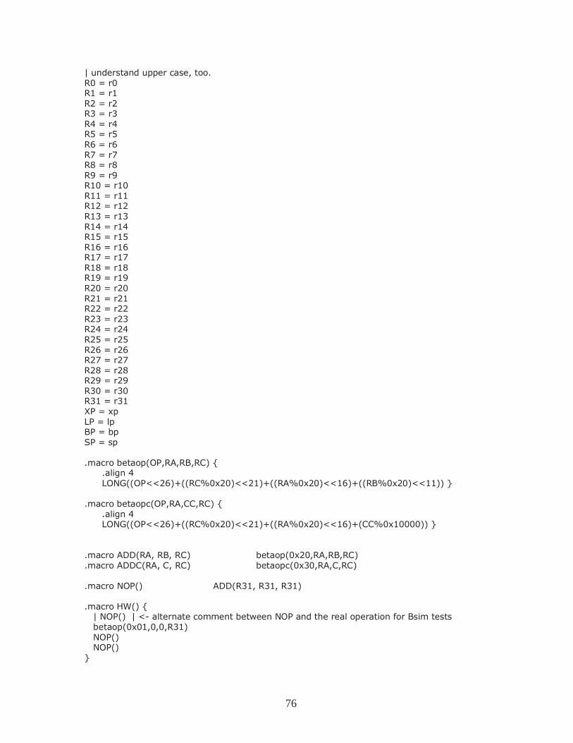
76
| understand upper case, too. R0 = r0 R1 = r1 R2 = r2 R3 = r3 R4 = r4 R5 = r5 R6 = r6 R7 = r7 R8 = r8 R9 = r9 R10 = r10 R11 = r11 R12 = r12 R13 = r13 R14 = r14 R15 = r15 R16 = r16 R17 = r17 R18 = r18 R19 = r19 R20 = r20 R21 = r21 R22 = r22 R23 = r23 R24 = r24 R25 = r25 R26 = r26 R27 = r27 R28 = r28 R29 = r29 R30 = r30 R31 = r31 XP = xp LP = lp BP = bp SP = sp .macro betaop(OP,RA,RB,RC) { .align 4 LONG((OP<<26)+((RC%0x20)<<21)+((RA%0x20)<<16)+((RB%0x20)<<11)) } .macro betaopc(OP,RA,CC,RC) { .align 4 LONG((OP<<26)+((RC%0x20)<<21)+((RA%0x20)<<16)+(CC%0x10000)) } .macro ADD(RA, RB, RC) betaop(0x20,RA,RB,RC) .macro ADDC(RA, C, RC) betaopc(0x30,RA,C,RC) .macro NOP() ADD(R31, R31, R31) .macro HW() { | NOP() | <- alternate comment between NOP and the real operation for Bsim tests betaop(0x01,0,0,R31) NOP() NOP() }
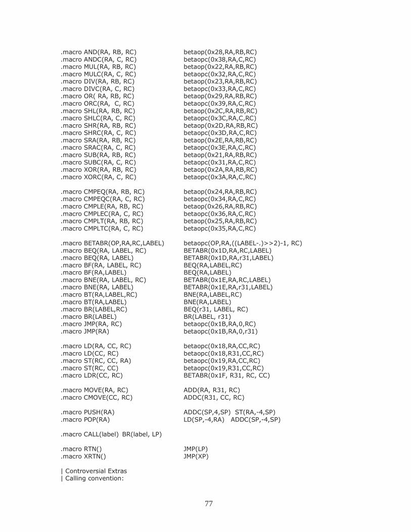
77
.macro AND(RA, RB, RC) betaop(0x28,RA,RB,RC)
.macro ANDC(RA, C, RC) betaopc(0x38,RA,C,RC)
.macro MUL(RA, RB, RC) betaop(0x22,RA,RB,RC)
.macro MULC(RA, C, RC) betaopc(0x32,RA,C,RC)
.macro DIV(RA, RB, RC) betaop(0x23,RA,RB,RC)
.macro DIVC(RA, C, RC) betaopc(0x33,RA,C,RC)
.macro OR( RA, RB, RC) betaop(0x29,RA,RB,RC)
.macro ORC(RA, C, RC) betaopc(0x39,RA,C,RC)
.macro SHL(RA, RB, RC) betaop(0x2C,RA,RB,RC)
.macro SHLC(RA, C, RC) betaopc(0x3C,RA,C,RC)
.macro SHR(RA, RB, RC) betaop(0x2D,RA,RB,RC)
.macro SHRC(RA, C, RC) betaopc(0x3D,RA,C,RC)
.macro SRA(RA, RB, RC) betaop(0x2E,RA,RB,RC)
.macro SRAC(RA, C, RC) betaopc(0x3E,RA,C,RC)
.macro SUB(RA, RB, RC) betaop(0x21,RA,RB,RC)
.macro SUBC(RA, C, RC) betaopc(0x31,RA,C,RC)
.macro XOR(RA, RB, RC) betaop(0x2A,RA,RB,RC)
.macro XORC(RA, C, RC) betaopc(0x3A,RA,C,RC) .macro CMPEQ(RA, RB, RC) betaop(0x24,RA,RB,RC) .macro CMPEQC(RA, C, RC) betaopc(0x34,RA,C,RC) .macro CMPLE(RA, RB, RC) betaop(0x26,RA,RB,RC) .macro CMPLEC(RA, C, RC) betaopc(0x36,RA,C,RC) .macro CMPLT(RA, RB, RC) betaop(0x25,RA,RB,RC) .macro CMPLTC(RA, C, RC) betaopc(0x35,RA,C,RC) .macro BETABR(OP,RA,RC,LABEL) betaopc(OP,RA,((LABEL-.)>>2)-1, RC) .macro BEQ(RA, LABEL, RC) BETABR(0x1D,RA,RC,LABEL) .macro BEQ(RA, LABEL) BETABR(0x1D,RA,r31,LABEL) .macro BF(RA, LABEL, RC) BEQ(RA,LABEL,RC) .macro BF(RA,LABEL) BEQ(RA,LABEL) .macro BNE(RA, LABEL, RC) BETABR(0x1E,RA,RC,LABEL) .macro BNE(RA, LABEL) BETABR(0x1E,RA,r31,LABEL) .macro BT(RA,LABEL,RC) BNE(RA,LABEL,RC) .macro BT(RA,LABEL) BNE(RA,LABEL) .macro BR(LABEL,RC) BEQ(r31, LABEL, RC) .macro BR(LABEL) BR(LABEL, r31) .macro JMP(RA, RC) betaopc(0x1B,RA,0,RC) .macro JMP(RA) betaopc(0x1B,RA,0,r31) .macro LD(RA, CC, RC) betaopc(0x18,RA,CC,RC) .macro LD(CC, RC) betaopc(0x18,R31,CC,RC) .macro ST(RC, CC, RA) betaopc(0x19,RA,CC,RC) .macro ST(RC, CC) betaopc(0x19,R31,CC,RC) .macro LDR(CC, RC) BETABR(0x1F, R31, RC, CC) .macro MOVE(RA, RC) ADD(RA, R31, RC) .macro CMOVE(CC, RC) ADDC(R31, CC, RC) .macro PUSH(RA) ADDC(SP,4,SP) ST(RA,-4,SP) .macro POP(RA) LD(SP,-4,RA) ADDC(SP,-4,SP) .macro CALL(label) BR(label, LP) .macro RTN() JMP(LP) .macro XRTN() JMP(XP) | Controversial Extras | Calling convention:
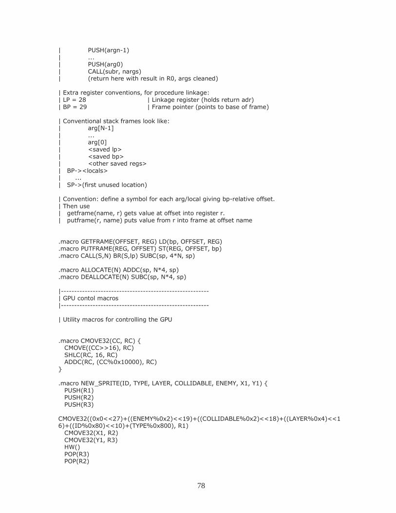
78
| PUSH(argn-1) | ... | PUSH(arg0) | CALL(subr, nargs) | (return here with result in R0, args cleaned) | Extra register conventions, for procedure linkage: | LP = 28 | Linkage register (holds return adr) | BP = 29 | Frame pointer (points to base of frame) | Conventional stack frames look like: | arg[N-1] | ... | arg[0] | <saved lp> | <saved bp> | <other saved regs> | BP-><locals> | ... | SP->(first unused location) | Convention: define a symbol for each arg/local giving bp-relative offset. | Then use | getframe(name, r) gets value at offset into register r. | putframe(r, name) puts value from r into frame at offset name .macro GETFRAME(OFFSET, REG) LD(bp, OFFSET, REG) .macro PUTFRAME(REG, OFFSET) ST(REG, OFFSET, bp) .macro CALL(S,N) BR(S,lp) SUBC(sp, 4*N, sp) .macro ALLOCATE(N) ADDC(sp, N*4, sp) .macro DEALLOCATE(N) SUBC(sp, N*4, sp) |-------------------------------------------------------- | GPU contol macros |-------------------------------------------------------- | Utility macros for controlling the GPU .macro CMOVE32(CC, RC) { CMOVE((CC>>16), RC) SHLC(RC, 16, RC) ADDC(RC, (CC%0x10000), RC) } .macro NEW_SPRITE(ID, TYPE, LAYER, COLLIDABLE, ENEMY, X1, Y1) { PUSH(R1) PUSH(R2) PUSH(R3) CMOVE32((0x0<<27)+((ENEMY%0x2)<<19)+((COLLIDABLE%0x2)<<18)+((LAYER%0x4)<<16)+((ID%0x80)<<10)+(TYPE%0x800), R1) CMOVE32(X1, R2) CMOVE32(Y1, R3) HW() POP(R3) POP(R2)
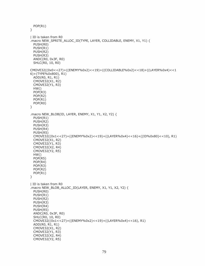
79
POP(R1) } | ID is taken from R0 .macro NEW_SPRITE_ALLOC_ID(TYPE, LAYER, COLLIDABLE, ENEMY, X1, Y1) { PUSH(R0) PUSH(R1) PUSH(R2) PUSH(R3) ANDC(R0, 0x3F, R0) SHLC(R0, 10, R0) CMOVE32((0x0<<27)+((ENEMY%0x2)<<19)+((COLLIDABLE%0x2)<<18)+((LAYER%0x4)<<16)+(TYPE%0x800), R1) ADD(R0, R1, R1) CMOVE32(X1, R2) CMOVE32(Y1, R3) HW() POP(R3) POP(R2) POP(R1) POP(R0) } .macro NEW_BLOB(ID, LAYER, ENEMY, X1, Y1, X2, Y2) { PUSH(R1) PUSH(R2) PUSH(R3) PUSH(R4) PUSH(R5) CMOVE32((0x1<<27)+((ENEMY%0x2)<<19)+((LAYER%0x4)<<16)+((ID%0x80)<<10), R1) CMOVE32(X1, R2) CMOVE32(Y1, R3) CMOVE32(X2, R4) CMOVE32(Y2, R5) HW() POP(R5) POP(R4) POP(R3) POP(R2) POP(R1) } | ID is taken from R0 .macro NEW_BLOB_ALLOC_ID(LAYER, ENEMY, X1, Y1, X2, Y2) { PUSH(R0) PUSH(R1) PUSH(R2) PUSH(R3) PUSH(R4) PUSH(R5) ANDC(R0, 0x3F, R0) SHLC(R0, 10, R0) CMOVE32((0x1<<27)+((ENEMY%0x2)<<19)+((LAYER%0x4)<<16), R1) ADD(R0, R1, R1) CMOVE32(X1, R2) CMOVE32(Y1, R3) CMOVE32(X2, R4) CMOVE32(Y2, R5)
80
HW() POP(R5) POP(R4) POP(R3) POP(R2) POP(R1) POP(R0) } .macro NEW_TILED_SPRITE(ID, TYPE, LAYER, COLLIDABLE, ENEMY, X1, Y1, X2, Y2) { PUSH(R1) PUSH(R2) PUSH(R3) PUSH(R4) PUSH(R5) CMOVE32((0x2<<27)+((ENEMY%0x2)<<19)+((COLLIDABLE%0x2)<<18)+((LAYER%0x4)<<16)+((ID%0x80)<<10)+(TYPE%0x800), R1) CMOVE32(X1, R2) CMOVE32(Y1, R3) CMOVE32(X2, R4) CMOVE32(Y2, R5) HW() POP(R5) POP(R4) POP(R3) POP(R2) POP(R1) } | ID is taken from R0 .macro NEW_TILED_SPRITE_ALLOC_ID(TYPE, LAYER, COLLIDABLE, ENEMY, X1, Y1, X2, Y2) { PUSH(R0) PUSH(R1) PUSH(R2) PUSH(R3) PUSH(R4) PUSH(R5) ANDC(R0, 0x3F, R0) SHLC(R0, 10, R0) CMOVE32((0x2<<27)+((ENEMY%0x2)<<19)+((COLLIDABLE%0x2)<<18)+((LAYER%0x4)<<16)+(TYPE%0x800), R1) ADD(R0, R1, R1) CMOVE32(X1, R2) CMOVE32(Y1, R3) CMOVE32(X2, R4) CMOVE32(Y2, R5) HW() POP(R5) POP(R4) POP(R3) POP(R2) POP(R1) POP(R0) } | X1, Y1, X2, Y2 in place .macro NEW_TILED_SPRITE_REG_POS(ID, TYPE, LAYER, COLLIDABLE, ENEMY) {
81
PUSH(R1) CMOVE32((0x2<<27)+((ENEMY%0x2)<<19)+((COLLIDABLE%0x2)<<18)+((LAYER%0x4)<<16)+((ID%0x80)<<10)+(TYPE%0x800), R1) HW() POP(R1) } .macro DESTROY_SPRITE(ID) { PUSH(R1) CMOVE32((0x3<<27)+((ID%0x80)<<10), R1) HW() POP(R1) } .macro SET_TYPE(ID, TYPE) { PUSH(R1) CMOVE32((0xA<<27)+((ID%0x80)<<10)+(TYPE%0x800), R1) HW() POP(R1) } | ID is taken from R0 .macro SET_TYPE_ALLOC_ID(TYPE) { PUSH(R0) PUSH(R1) ANDC(R0, 0x3F, R0) SHLC(R0, 10, R0) CMOVE32((0xA<<27)+((ID%0x80)<<10)+(TYPE%0x800), R1) ADD(R0, R1, R1) HW() POP(R1) POP(R0) } | R2, R3 must contain positions .macro MOVE_SPRITE(ID) { PUSH(R1) CMOVE32((0x4<<27) + ((ID%0x80)<<10), R1) HW() POP(R1) } | ID is taken from R0 | R2, R3 must contain positions .macro MOVE_SPRITE_ALLOC_ID() { PUSH(R0) PUSH(R1) ANDC(R0, 0x3F, R0) SHLC(R0, 10, R0) CMOVE32((0x4<<27), R1) ADD(R0, R1, R1) HW() POP(R1) POP(R0) } .macro SET_LCP(ID, LAYER, COLLIDABLE, ENEMY) { PUSH(R1)
82
CMOVE32((0x5<<27)+((ENEMY%0x2)<<19)+((COLLIDABLE%0x2)<<18)+((LAYER%0x4)<<16)+((ID%0x80)<<10), R1) HW() POP(R1) } | ID is taken from R0 | LAYER is taken from R2 | {COLLIDABLE,ENEMY} is taken from R3 .macro SET_LCP_ALLOC_ID() { PUSH(R0) PUSH(R1) PUSH(R2) PUSH(R3) ANDC(R0, 0x3F, R0) ANDC(R2, 0x3, R2) ANDC(R3, 0x3, R3) SHLC(R0, 10, R0) SHLC(R2, 16, R2) SHLC(R3, 18, R3) CMOVE32((0x5<<26), R1) ADD(R0, R1, R1) ADD(R2, R3, R3) ADD(R3, R1, R1) HW() POP(R3) POP(R2) POP(R1) POP(R0) } .macro SET_FILTER(ID, FILTER) { PUSH(R1) CMOVE32((0x6<<27)+((ID%0x80)<<10)+(FILTER%0x20), R1) HW() POP(R1) } | ID is taken from R0 .macro SET_FILTER_ALLOC_ID(FILTER) { PUSH(R0) PUSH(R1) ANDC(R0, 0x3F, R0) SHLC(R0, 10, R0) CMOVE32((0x6<<27)+(FILTER%0x20), R1) ADD(R0, R1, R1) HW() POP(R1) POP(R0) } .macro SET_MIRROR(ID, MIRROR) { PUSH(R1) CMOVE32((0x7<<27)+(MIRROR%0x4),R1) HW() POP(R1) }
83
| ID is taken from R0 .macro SET_MIRROR_ALLOC_ID(MIRROR) { PUSH(R0) PUSH(R1) ANDC(R0, 0x3F, R0) SHLC(R0, 10, R0) CMOVE32((0x7<<27)+(MIRROR%0x4),R1) ADD(R0, R1, R1) HW() POP(R1) POP(R0) } .macro SET_CAMERA(X, Y) { PUSH(R1) PUSH(R2) PUSH(R3) CMOVE32((0x8<<27), R1) CMOVE32(X, R2) CMOVE32(Y, R3) HW() POP(R3) POP(R2) POP(R1) } | X, Y already stored on R2, R3 .macro SET_CAMERA_ALLOC() { PUSH(R1) CMOVE32((0x8<<27), R1) HW() POP(R1) } .macro SET_BACKGROUND(PIXEL) { PUSH(R1) CMOVE32((0x9<<27)+(PIXEL%0x100), R1) HW() POP(R1) } | PIXEL is taken from R0 .macro SET_BACKGROUND_ALLOC_PIXEL() { PUSH(R0) PUSH(R1) ANDC(R0, 0xFF, R0) CMOVE32((0x9<<27)+(PIXEL%0x100), R1) ADD(R0, R1, R1) HW() POP(R1) POP(R0) } |-------------------------------------------------------- | Privileged mode instructions |-------------------------------------------------------- | SVC calls; used for OS extensions
84
| Note that, conventionally, this uses betaopc(0x01, 0, code, 0). | Unfortunately that conflicts with our conventions for the HW() call, | and as such Yield() would become nonsensical commands to the beta. | This bug was a royal pain to locate. .macro SVC(code) betaopc (0x03, 0, code, 0) | Trap and interrupt vectors VEC_RESET = 0 | Reset (powerup) VEC_II = 4 | Illegal instruction (also SVC call) VEC_CLK = 8 | Clock interrupt VEC_ECOLLISION = 12 | HW interrupt VEC_COLLISION = 16 | HW interrupt VEC_UP_PRESS = 20 | User input interrupts VEC_DOWN_PRESS = 24 VEC_LEFT_PRESS = 28 VEC_RIGHT_PRESS = 32 VEC_ENTER_PRESS = 36 VEC_B1_PRESS = 40 VEC_B2_PRESS = 44 VEC_B3_PRESS = 48 VEC_UP_RELEASE = 52 VEC_DOWN_RELEASE = 56 VEC_LEFT_RELEASE = 60 VEC_RIGHT_RELEASE = 64 VEC_ENTER_RELEASE = 68 VEC_B1_RELEASE = 72 VEC_B2_RELEASE = 76 VEC_B3_RELEASE = 80 | HW-access memory ENEMY_STATE = 84 COLLISION_STATE = 88 | constant for the supervisor bit in the PC PC_SUPERVISOR = 0x80000000 | the bit itself PC_MASK = 0x7fffffff | a mask for the rest of the PC
ram.uasm
Contains the kernel and user processes for the game logic itself. |||||||||||||||||||||||||||||||||||||||||||||||||||||||||||||||||||||||| ||| Videogame OS demo, based on Simple OS for 6.004 Beta processor by Steve Ward(4/19/94) |||||||||||||||||||||||||||||||||||||||||||||||||||||||||||||||||||||||| ||| ||| This file contains a primitive but complete timesharing kernel ||| sufficient to run three processes, plus handlers for a small ||| selection of supervisor calls (SVCs) to perform OS services. ||| The latter include simple console I/O and semaphores. ||| ||| All kernel code is executed with the Kernel-mode bit of the ||| program counter -- its high-order bit --- set. This causes ||| new interrupt requests to be deferred until the kernel returns
85
||| to user mode. .include beta.uasm ||| Interrupt vectors: . = VEC_RESET BR(I_Reset) | on Reset (start-up) . = VEC_II BR(I_IllOp) | on Illegal Instruction (eg SVC) . = VEC_CLK BR(I_Clk) | on clock interrupt . = VEC_ECOLLISION BR(I_Ecol) | on HW interrupt . = VEC_COLLISION BR(I_Col) . = VEC_UP_PRESS | on user interrupt BR(I_UP) . = VEC_DOWN_PRESS BR(I_DP) . = VEC_LEFT_PRESS BR(I_LP) . = VEC_RIGHT_PRESS BR(I_RP) . = VEC_ENTER_PRESS BR(I_EP) . = VEC_B1_PRESS BR(I_B1P) . = VEC_B2_PRESS BR(I_B2P) . = VEC_B3_PRESS BR(I_B3P) . = VEC_UP_RELEASE BR(I_UR) . = VEC_DOWN_RELEASE BR(I_DR) . = VEC_LEFT_RELEASE BR(I_LR) . = VEC_RIGHT_RELEASE BR(I_RR) . - VEC_ENTER_RELEASE BR(I_ER) . = VEC_B1_RELEASE BR(I_B1R) . = VEC_B2_RELEASE BR(I_B2R) . = VEC_B3_RELEASE BR(I_B3R) . = ENEMY_STATE | Memory areas accessed by hardware Enemy_State: LONG(0) . = COLLISION_STATE Collision_State: LONG(0) ||| The following macro is the first instruction to be entered for each ||| asynchronous I/O interrupt handler. It adjusts XP (the interrupted ||| PC) to account for the instruction skipped due to the pipeline bubble. .macro ENTER_INTERRUPT SUBC(XP,4,XP) ||||||||||||||||||||||||||||||||||||||||||||||||||||||||||||||||||||||||
86
||| Kernel Interrupt support code ||| We use a slightly simpler (and less efficient) scheme here from ||| that in the text. On kernel entry, the ENTIRE state -- 31 ||| registers -- of the interrupted program is saved in a designated ||| region of kernel memory ("UserMState", below). This entire state ||| is then restored on return to the interrupted program. |||||||||||||||||||||||||||||||||||||||||||||||||||||||||||||||||||||||| | Here's the SAVED STATE of the interrupted process, while we're | processing an interrupt. UserMState: STORAGE(32) | R0-R31... (PC is in XP!) | Here are macros to SAVE and RESTORE state -- 31 registers -- from | the above storage. | N.B. - The following macro assumes that R0 is a macro for | the integer 0, R1 is a macro for the integer 1, etc. .macro SS(R) ST(R, UserMState+(4*R)) | (Auxiliary macro) .macro SAVESTATE() { SS(0) SS(1) SS(2) SS(3) SS(4) SS(5) SS(6) SS(7) SS(8) SS(9) SS(10) SS(11) SS(12) SS(13) SS(14) SS(15) SS(16) SS(17) SS(18) SS(19) SS(20) SS(21) SS(22) SS(23) SS(24) SS(25) SS(26) SS(27) SS(28) SS(29) SS(30) } | See comment for SS(R), above .macro RS(R) LD(UserMState+(4*R), R) | (Auxiliary macro) .macro RESTORESTATE() { RS(0) RS(1) RS(2) RS(3) RS(4) RS(5) RS(6) RS(7) RS(8) RS(9) RS(10) RS(11) RS(12) RS(13) RS(14) RS(15) RS(16) RS(17) RS(18) RS(19) RS(20) RS(21) RS(22) RS(23) RS(24) RS(25) RS(26) RS(27) RS(28) RS(29) RS(30) } KStack: LONG(.+4) | Pointer to ... STORAGE(256) | ... the kernel stack. ||||||||||||||||||||||||||||||||||||||||||||||||||||||||||||||||||||||||||||||| ||| Handler for Illegal Instructions ||| (including SVCs) ||||||||||||||||||||||||||||||||||||||||||||||||||||||||||||||||||||||||||||||| I_IllOp: SAVESTATE() | Save the machine state. LD(KStack, SP) | Install kernel stack pointer. LD(XP, -4, r0) | Fetch the illegal instruction SHRC(r0, 26, r0) | Extract the 6-bit OPCODE SUBC(r0, 2, r0) | NEW: account for the fact that we modified the definition of SVC SHLC(r0, 2, r0) | Make it a WORD (4-byte) index LD(r0, UUOTbl, r0) | Fetch UUOTbl[OPCODE] JMP(r0) | and dispatch to the UUO handler. .macro UUO(ADR) LONG(ADR+PC_SUPERVISOR) | Auxiliary Macros .macro BAD() UUO(UUOError)
87
UUOTbl: BAD() UUO(SVC_UUO) BAD() BAD() BAD() BAD() BAD() BAD() BAD() BAD() BAD() BAD() BAD() BAD() BAD() BAD() BAD() BAD() BAD() BAD() BAD() BAD() BAD() BAD() BAD() BAD() BAD() BAD() BAD() BAD() BAD() BAD() ||| Here's the handler for truly unused opcodes (not SVCs): UUOError: BR(UUOError) | Crash system ||| Here's the common exit sequence from Kernel interrupt handlers: ||| Restore registers, and jump back to the interrupted user-mode ||| program. I_Rtn: RESTORESTATE() kexit: JMP(XP) | Good place for debugging breakpoint! ||| Alternate return from interrupt handler which BACKS UP PC, ||| and calls the scheduler prior to returning. This causes ||| the trapped SVC to be re-executed when the process is ||| eventually rescheduled... I_Wait: LD(UserMState+(4*30), r0) | Grab XP from saved MState, SUBC(r0, 4, r0) | back it up to point to ST(r0, UserMState+(4*30)) | SVC instruction CALL(Scheduler) | Switch current process, BR(I_Rtn) | and return to (some) user. ||| Sub-handler for SVCs, called from I_IllOp on SVC opcode: SVC_UUO: LD(XP, -4, r0) | The faulting instruction. ANDC(r0,0x7,r0) | Pick out low bits, SHLC(r0,2,r0) | make a word index, LD(r0,SVCTbl,r0) | and fetch the table entry. JMP(r0) SVCTbl: UUO(HaltH) | SVC(0): User-mode HALT instruction UUO(WaitH) | SVC(1): Wait(S) ,,, S in R3 UUO(SignalH) | SVC(2): Signal(S), S in R3 UUO(YieldH) | SVC(3): Yield() UUO(GetECollision) | SVC(4): Get enemy collision info, when it changes, into R0 UUO(GetCollision) | SVC(5): Get collision info, when it changes, into R0 BAD() | SVC(6): unused BAD() | SVC(7): unused |||||||||||||||||||||||||||||||||||||||||||||||||||||||||||||||||||||||| ||| Enemy collision and collision handling ||| ||| Interrupts set flags informing there is a new value, which was ||| stored by hardware. Functions block until flag is clean, then ||| clean the flag and return the new requested value. |||||||||||||||||||||||||||||||||||||||||||||||||||||||||||||||||||||||| | Enemy_State defined on fixed position
88
Enemy_Flag: LONG(0) Collision_Flag: LONG(0) GetECollision: | return new enemy collision info in r0 LD(Enemy_Flag, r0) BEQ(r0, I_Wait) | If there is no new value, wait | new enemy collision, return it LD(Enemy_State, r0) | Fetch value to return ST(r31, Enemy_Flag) | clear flag, value is not new anymore BR(I_Rtn) | and return to user GetCollision: | return new collision info in r0 when available LD(Collision_Flag, r0) BEQ(r0, I_Wait) | If there is no new value, wait | new collision info, return it LD(Collision_State, r0) | Fetch value to return ST(r31,Collision_Flag) | clear flag, value is not new anymore BR(I_Rtn) | and return to user I_Ecol: ENTER_INTERRUPT() | adjust PC ST(r0, UserMState) | save R0 CMOVE(1, r0) ST(r1, Enemy_Flag) | set flag LD(UserMState, r0) | restore R0 BR(I_Rtn) | and return to user I_Col: ENTER_INTERRUPT() | adjust PC ST(r0, UserMState) | save R0 CMOVE(1, r0) ST(r1, Collision_Flag) | set flag LD(UserMState, r0) | restore R0 BR(I_Rtn) | and return to user |||||||||||||||||||||||||||||||||||||||||||||||||||||||||||||||||||||||| ||| User input handling ||| ||| Whenever there is a key change, save it to Button_Flags. |||||||||||||||||||||||||||||||||||||||||||||||||||||||||||||||||||||||| | Flags positions: | UP: 0 | DOWN: 1 | LEFT: 2 | RIGHT: 3 | ENTER: 4 | B1: 5 | B2: 6 | B3: 7 Button_Flags: LONG(0) | Key press interrupts I_UP: ENTER_INTERRUPT() | Adjust PC SET_BACKGROUND(0b11100000) ST(r0, UserMState) | Save R0 LD(Button_Flags, r0) | load flags
89
ORC(r0, 0x1, r0) | set position 0 to 1 ST(r0, Button_Flags) | store flags LD(UserMState, r0) | restore r0 BR(I_Rtn) | return to user I_DP: ENTER_INTERRUPT() | Adjust PC SET_BACKGROUND(0b11100000) ST(r0, UserMState) | Save R0 LD(Button_Flags, r0) | load flags ORC(r0, 0x2, r0) | set position 1 to 1 ST(r0, Button_Flags) | store flags LD(UserMState, r0) | restore r0 BR(I_Rtn) | return to user I_LP: ENTER_INTERRUPT() | Adjust PC SET_BACKGROUND(0b11100000) ST(r0, UserMState) | Save R0 LD(Button_Flags, r0) | load flags ORC(r0, 0x4, r0) | set position 2 to 1 ST(r0, Button_Flags) | store flags LD(UserMState, r0) | restore r0 BR(I_Rtn) | return to user I_RP: ENTER_INTERRUPT() | Adjust PC SET_BACKGROUND(0b11100000) ST(r0, UserMState) | Save R0 LD(Button_Flags, r0) | load flags ORC(r0, 0x8, r0) | set position 3 to 1 ST(r0, Button_Flags) | store flags LD(UserMState, r0) | restore r0 BR(I_Rtn) | return to user I_EP: ENTER_INTERRUPT() | Adjust PC SET_BACKGROUND(0b11100000) ST(r0, UserMState) | Save R0 LD(Button_Flags, r0) | load flags ORC(r0, 0x10, r0) | set position 4 to 1 ST(r0, Button_Flags) | store flags LD(UserMState, r0) | restore r0 BR(I_Rtn) | return to user I_B1P: ENTER_INTERRUPT() | Adjust PC SET_BACKGROUND(0b11100000) ST(r0, UserMState) | Save R0 LD(Button_Flags, r0) | load flags ORC(r0, 0x20, r0) | set position 5 to 1 ST(r0, Button_Flags) | store flags LD(UserMState, r0) | restore r0 BR(I_Rtn) | return to user I_B2P: ENTER_INTERRUPT() | Adjust PC SET_BACKGROUND(0b11100000) ST(r0, UserMState) | Save R0 LD(Button_Flags, r0) | load flags ORC(r0, 0x40, r0) | set position 6 to 1 ST(r0, Button_Flags) | store flags LD(UserMState, r0) | restore r0 BR(I_Rtn) | return to user
90
I_B3P: ENTER_INTERRUPT() | Adjust PC SET_BACKGROUND(0b11100000) ST(r0, UserMState) | Save R0 LD(Button_Flags, r0) | load flags ORC(r0, 0x80, r0) | set position 7 to 1 ST(r0, Button_Flags) | store flags LD(UserMState, r0) | restore r0 BR(I_Rtn) | return to user | Key release interrupts I_UR: ENTER_INTERRUPT() | Adjust PC ST(r0, UserMState) | Save R0 SET_BACKGROUND(0b00011000) LD(Button_Flags, r0) | load flags ANDC(r0, 0xFFFE, r0) | set position 0 to 0 ST(r0, Button_Flags) | store flags LD(UserMState, r0) | restore r0 BR(I_Rtn) | return to user I_DR: ENTER_INTERRUPT() | Adjust PC SET_BACKGROUND(0b00011000) ST(r0, UserMState) | Save R0 LD(Button_Flags, r0) | load flags ANDC(r0, 0xFFFD, r0) | set position 1 to 0 ST(r0, Button_Flags) | store flags LD(UserMState, r0) | restore r0 BR(I_Rtn) | return to user I_LR: ENTER_INTERRUPT() | Adjust PC SET_BACKGROUND(0b00011000) ST(r0, UserMState) | Save R0 LD(Button_Flags, r0) | load flags ANDC(r0, 0xFFFB, r0) | set position 2 to 0 ST(r0, Button_Flags) | store flags LD(UserMState, r0) | restore r0 BR(I_Rtn) | return to user I_RR: ENTER_INTERRUPT() | Adjust PC SET_BACKGROUND(0b00011000) ST(r0, UserMState) | Save R0 LD(Button_Flags, r0) | load flags ANDC(r0, 0xFFF7, r0) | set position 3 to 0 ST(r0, Button_Flags) | store flags LD(UserMState, r0) | restore r0 BR(I_Rtn) | return to user I_ER: ENTER_INTERRUPT() | Adjust PC SET_BACKGROUND(0b00011000) ST(r0, UserMState) | Save R0 LD(Button_Flags, r0) | load flags ANDC(r0, 0xFFEF, r0) | set position 4 to 0 ST(r0, Button_Flags) | store flags LD(UserMState, r0) | restore r0 BR(I_Rtn) | return to user I_B1R: ENTER_INTERRUPT() | Adjust PC SET_BACKGROUND(0b00011000)
91
ST(r0, UserMState) | Save R0 LD(Button_Flags, r0) | load flags ANDC(r0, 0xFFDF, r0) | set position 5 to 0 ST(r0, Button_Flags) | store flags LD(UserMState, r0) | restore r0 BR(I_Rtn) | return to user I_B2R: ENTER_INTERRUPT() | Adjust PC SET_BACKGROUND(0b00011000) ST(r0, UserMState) | Save R0 LD(Button_Flags, r0) | load flags ANDC(r0, 0xFFBF, r0) | set position 6 to 0 ST(r0, Button_Flags) | store flags LD(UserMState, r0) | restore r0 BR(I_Rtn) | return to user I_B3R: ENTER_INTERRUPT() | Adjust PC SET_BACKGROUND(0b00011000) ST(r0, UserMState) | Save R0 LD(Button_Flags, r0) | load flags ANDC(r0, 0xFF7F, r0) | set position 7 to 0 ST(r0, Button_Flags) | store flags LD(UserMState, r0) | restore r0 BR(I_Rtn) | return to user ||||||||||||||||||||||||||||||||||||||||||||||||||||||||||||||||||||||||||||||| ||| Timesharing: N-process round-robin scheduler ||||||||||||||||||||||||||||||||||||||||||||||||||||||||||||||||||||||||||||||| ||| ProcTbl contains a 31-word data structure for each process, ||| including R0-R30. R31, which always contains 0, is omitted. ||| The XP (R30) value stored for each process is the PC, ||| and points to the next instruction to be executed. ||| The kernel variable CurProc always points to the ProcTbl entry ||| corresponding to the "swapped in" process. ProcTbl: STORAGE(29) | Process 0: R0-R28 LONG(P0Stack) | Process 0: SP LONG(P0Start) | Process 0: XP (= PC) STORAGE(29) | Process 1: R0-R28 LONG(P1Stack) | Process 1: SP LONG(P1Start) | Process 1: XP (= PC) CurProc: LONG(ProcTbl) ||| Schedule a new process. ||| Swaps current process out of UserMState, swaps in a new one. Scheduler: PUSH(LP) CMOVE(UserMState, r0) LD(CurProc, r1) CALL(CopyMState) | Copy UserMState -> CurProc LD(CurProc, r0)
92
ADDC(r0, 4*31, r0) | Increment to next process.. CMPLTC(r0,CurProc, r1) | End of ProcTbl? BT(r1, Sched1) | Nope, its OK. CMOVE(ProcTbl, r0) | yup, back to Process 0. Sched1: ST(r0, CurProc) | Here's the new process; ADDC(r31, UserMState, r1) | Swap new process in. CALL(CopyMState) LD(Tics, r0) | Reset TicsLeft counter ST(r0, TicsLeft) | to Tics. POP(LP) JMP(LP) | and return to caller. | Copy a 31-word MState structure from the address in <r0> to that in <r1> | Trashes r2, leaves r0-r1 unchanged. .macro CM(N) LD(r0, N*4, r2) ST(r2, N*4, r1) | Auxiliary macro CopyMState: CM(0) CM(1) CM(2) CM(3) CM(4) CM(5) CM(6) CM(7) CM(8) CM(9) CM(10) CM(11) CM(12) CM(13) CM(14) CM(15) CM(16) CM(17) CM(18) CM(19) CM(20) CM(21) CM(22) CM(23) CM(24) CM(25) CM(26) CM(27) CM(28) CM(29) CM(30) JMP(LP) ||||||||||||||||||||||||||||||||||||||||||||||||||||||||||||||||||||||||||||||| ||| Clock interrupt handler: Invoke the scheduler. ||||||||||||||||||||||||||||||||||||||||||||||||||||||||||||||||||||||||||||||| ||| Here's the deal: ||| Each compute-bound process gets a quantum consisting of TICS clock ||| interrupts, where TICS is the number stored in the variable Tics ||| below. To avoid overhead, we do a full state save only when the ||| clock interrupt will cause a process swap, using the TicsLeft ||| variable as a counter. ||| We do a LIMITED state save (r0 only) in order to free up a register, ||| then count down TicsLeft stored below. When it becomes negative, ||| we do a FULL state save and call the scheduler; otherwise we just ||| return, having burned only a few clock cycles on the interrupt. ||| RECALL that the call to Scheduler sets TicsLeft to Tics, giving ||| the newly-swapped-in process a full quantum. Tics: LONG(2) | Number of clock interrupts/quantum. TicsLeft: LONG(0) | Number of tics left in this quantum I_Clk: ENTER_INTERRUPT() | Adjust the PC! ST(r0, UserMState) | Save R0 ONLY, for now. LD(TicsLeft, r0) | Count down TicsLeft SUBC(r0,1,r0) ST(r0, TicsLeft) | Now there's one left. CMPLTC(r0, 0, r0) | If new value is negative, then BT(r0, DoSwap) | swap processes. LD(UserMState, r0) | Else restore r0, and JMP(XP) | return to same user. DoSwap: LD(UserMState, r0) | Restore r0, so we can do a SAVESTATE() | FULL State save. LD(KStack, SP) | Install kernel stack pointer. CALL(Scheduler) | Swap it out! BR(I_Rtn) | and return to next process.
93
|||||||||||||||||||||||||||||||||||||||||||||||||||||||||||||||||||||||| ||| yield() SVC: voluntarily give up rest of time quantum. |||||||||||||||||||||||||||||||||||||||||||||||||||||||||||||||||||||||| YieldH: CALL(Scheduler) | Schedule next process, and BR(I_Rtn) | and return to user. ||||||||||||||||||||||||||||||||||||||||||||||||||||||||||||||||||||||||||||||| ||| Here on start-up (reset): Begin executing process 0. ||||||||||||||||||||||||||||||||||||||||||||||||||||||||||||||||||||||||||||||| I_Reset: CMOVE(P0Stack, SP) CMOVE(P0Start, XP) ST(R31, Button_Flags) JMP(XP) ||||||||||||||||||||||||||||||||||||||||||||||||||||||||||||||||||||||||||||||| ||| SVC Sub-handler for user-mode HALTs ||||||||||||||||||||||||||||||||||||||||||||||||||||||||||||||||||||||||||||||| HaltH: BR(I_Wait) | SVC(0): User-mode HALT SVC ||||||||||||||||||||||||||||||||||||||||||||||||||||||||||||||||||||||||||||||| ||| Kernel support for User-mode Semaphores ||||||||||||||||||||||||||||||||||||||||||||||||||||||||||||||||||||||||||||||| ||| User-mode access: macrodefinitions. Semaphore adr passed in r3, ||| which is saved & restored appropriately by macros: ||| NB: Wait() and Signal() SVCs each pass the address of a semaphore ||| in R3. Since the Illegal Opcode handler code doesn't change any ||| registers except R0, the R3 semaphore address is still intact ||| when we enter these handlers: ||| Kernel handler: wait(s): ||| ADDRESS of semaphore s in r3. WaitH: LD(r3,0,r0) | Fetch semaphore value. BEQ(r0,I_Wait) | If zero, block.. SUBC(r0,1,r0) | else, decrement and return. ST(r0,0,r3) | Store back into semaphore BR(I_Rtn) | and return to user. ||| Kernel handler: signal(s): ||| ADDRESS of semaphore s in r3. SignalH:LD(r3,0,r0) | Fetch semaphore value. ADDC(r0,1,r0) | increment it, ST(r0,0,r3) | Store new semaphore value. BR(I_Rtn) | and return to user.
94
||||||||||||||||||||||||||||||||||||||||||||||||||||||||||||||||||||||||||||||| ||| User-mode processes ||||||||||||||||||||||||||||||||||||||||||||||||||||||||||||||||||||||||||||||| .macro Halt() SVC(0) | Stop a process .macro Yield() SVC(3) | Give up remaining quantum .macro Enemy() SVC(4) | Wait until enemy collision changes, get info on R0 .macro Collision() SVC(5) | Wait until collision changes, get info on R1 ||| Semaphore macros. ||| Wait(S) waits on semaphore S; Signal(S) signals on S. ||| Both preserve all registers, by pushing & popping R3. .macro Wait(S) { PUSH(r3) | Save old <r3>, LDR(S,r3) | put semaphore address into r3 SVC(2) | Wait on semaphore whose adr is in R3 POP(r3) } | and restore former <r3> .macro Signal(S) { PUSH(r3) | Save old <r3>, LDR(S,r3) | put semaphore address into r3 SVC(3) | Signal on semaphore whose adr is in R3 POP(r3) } | and restore former <r3> ||| Allocate a semaphore: used like ||| name: semaphore(size) .macro semaphore(N) { | Allocate a semaphore, and build a ptr LONG(.+4) | Pointer to semaphore LONG(N) } | Semaphore itself, init value N. | Sprite types: | 0-9: digits | 10: : | 11-15: hearts 0/4-4/4 | 16: bm 1 | 17: bm 2 | 18: bm casting | 19: bm hurt | 20: bm dead | 21: box | 22: brick | 23: red rock | 24: fire 1 | 25: fire 2 | 26: hadouken start | 27: hadouken loop | 28: arrow | 29: archer | 30: archer firing | 31: paladin 1 | 32: paladin 2 ||||||||||||||||||||||||||||||||||||||||||||||||||||||||||||||||||||||||||||||| ||| Process zero: setup and clock ||| ||| Create the level, initialize the variables, use timer
95
||||||||||||||||||||||||||||||||||||||||||||||||||||||||||||||||||||||||||||||| P0Start: SET_CAMERA(0, 5000) CMOVE(0, R0) ST(R0, CameraX) CMOVE(5000, R1) ST(R1, CameraY) SET_BACKGROUND(0b11111000) NEW_SPRITE(0, 16, 2, 1, 0, 100, 5214) SET_MIRROR(0, 1) CMOVE(100, R0) ST(R0, PlayerX) CMOVE(5214, R0) ST(R0, PlayerY) NEW_TILED_SPRITE(1, 23, 2, 1, 0, 0, 5240, 5000, 10000) NEW_TILED_SPRITE(2, 22, 2, 1, 0, 300, 5180, 364, 5196) CMOVE(0, R0) BR(P0Cycle) CycleSize: LONG(0xFFFF2C8) P0Cycle: Yield() ADDC(R0, 1, R0) LD(CycleSize, R1) CMPEQC(R0, R1, R1) BT(R1, P0Cycle) CALL(UpdatePlayer) CMOVE(0, R0) BR(P0Cycle) UpdatePlayer: LD(Button_Flags, R9) | Up/down ANDC(R9, 0x1, R1) ANDC(R9, 0x2, R2) BT(R1, B_Up) BT(R2, B_Down) BR(B_VZero) B_Up: LD(PlayerUp, R3) BT(R3, B_VZero) CMOVE(1, R3) ST(R3, PlayerUp) CMOVE(10, R4) ST(R4, PlayerV) BR(B_VDone) B_Down: LD(PlayerUp, R3) BT(R3, B_VZero) CALL(MakeHurt) BR(B_VDone) B_VZero: CALL(MakeNotHurt) BR(B_VDone)
96
MakeHurt: CMOVE(3, R0) ST(R0, PlayerStatus) SET_TYPE(0, 19) RTN() MakeNotHurt: LD(PlayerStatus, R1) CMPEQC(R1, 3, R0) BT(R0, MakeZero) RTN() MakeWalk: LD(PlayerStatus, R1) CMPEQC(R1, 0, R0) BT(R0, MakeOne) CMPEQC(R1, 1, R0) BT(R0, MakeZero) RTN() MakeOne: CMOVE(1, R1) ST(R1, PlayerStatus) SET_TYPE(0, 17) RTN() MakeZero: ST(R31, PlayerStatus) SET_TYPE(0, 16) RTN() MakeCasting: CMOVE(2, R1) ST(R1, PlayerStatus) SET_TYPE(0, 18) RTN() B_VDone: ANDC(R9, 0x4, R3) ANDC(R9, 0x8, R4) BT(R3, B_Left) BT(R4, B_Right) BR(B_HDone) B_Left: SET_MIRROR(0, 0) ST(R31, PlayerMirror) CALL(MakeWalk) LD(PlayerX, R0) LD(CameraX, R2) ADDC(R2, 5, R2) CMPLEC(R0, R2, R1) BT(R1, B_HDone) CALL(MoveLeft) BR(B_HDone) B_Right: SET_MIRROR(0, 1)
97
CMOVE(1, R0) ST(R0, PlayerMirror) CALL(MakeWalk) LD(PlayerX, R0) LD(CameraX, R2) ADDC(R2, 449, R2) CMPLEC(R0, R2, R1) BF(R1, B_HDone) CALL(MoveRight) BR(B_HDone) MoveLeft: LD(PlayerX, R0) SUBC(R0, 1, R0) ST(R0, PlayerX) LD(PlayerX, R2) LD(PlayerY, R3) | MOVE_SPRITE(0) RTN() MoveRight: LD(PlayerX, R0) ADDC(R0, 1, R0) ST(R0, PlayerX) LD(PlayerX, R2) LD(PlayerY, R3) | MOVE_SPRITE(0) RTN() B_HDone: ANDC(R9, 0x10, R5) BF(R5, B_CastingDone) B_Casting: CALL(MakeCasting) B_CastingDone: BR(P0Cycle) P0Stack: STORAGE(256) ||||||||||||||||||||||||||||||||||||||||||||||||||||||||||||||||||||||||||||||| ||| Variables ||||||||||||||||||||||||||||||||||||||||||||||||||||||||||||||||||||||||||||||| CameraX: LONG(0) CameraY: LONG(0) PlayerX: LONG(0) PlayerY: LONG(0) PlayerUp: LONG(0) | 0 = floor, 1 = up, 2 = down PlayerV: LONG(0) | vertical speed PlayerStatus: LONG(0) | 0 = step1, 1 = step2, 2 = casting, 3 = hurt/down, 4 = dead PlayerMirror: LONG(1) | 1 = right, 0 = left Gravity: LONG(0xFFFF2C8) | how many cicles for each iteration |||||||||||||||||||||||||||||||||||||||||||||||||||||||||||||||||||||||||||||||
98
||| Process one: gravity ||||||||||||||||||||||||||||||||||||||||||||||||||||||||||||||||||||||||||||||| P1Start: CMOVE(0, R0) P1Cycle: Yield() ADDC(R0, 1, R0) LD(Gravity, R1) CMPEQC(R0, R1, R1) BT(R1, GStart) GStart: ADDC(R0, 1, R0) LD(PlayerUp, R6) BF(R6, GFloor) CMPEQC(R6, 1, R0) BT(R0, GUp) BR(GDown) GFloor: LD(Collision_Flag, R0) ANDC(R0, 1, R0) BT(R0, GDone) CMOVE(2, R0) ST(R0, PlayerUp) ST(R31, PlayerV) BR(GDone) GUp: LD(PlayerV, R6) BF(R6, GTurn) SUBC(R6, 1, R6) ST(R6, PlayerV) LD(PlayerY, R2) SUB(R2, R6, R2) ST(R2, PlayerY) LD(PlayerX, R2) LD(PlayerY, R3) | MOVE_SPRITE(0) BR(GDone) GTurn: CMOVE(2, R0) ST(R0, PlayerUp) BR(GDone) GDown: LD(PlayerY, R0) CMPLEC(R0, 5240, R1) BF(R1, GCollided) CMPLEC(R0, 5180, R1) BT(R1, GNotCollided) LD(PlayerX, R1) CMPLEC(R1, 281, R2) BT(R2, GNotCollided) CMPLEC(R1, 364, R2) BF(R2, GNotCollided) BR(GCollided) GNotCollided: LD(PlayerV, R6) ADDC(R6, 1, R6) ST(R6, PlayerV) LD(PlayerY, R2)
99
ADD(R2, R6, R2) ST(R2, PlayerY) LD(PlayerX, R2) LD(PlayerY, R3) | MOVE_SPRITE(0) BR(GDone) GCollided: ST(R31, PlayerUp) GDone: BR(GStart) P1Stack: STORAGE(256)
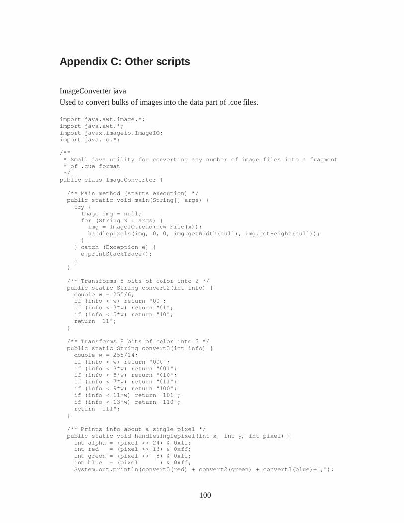
100
Appendix C: Other scripts
ImageConverter.java
Used to convert bulks of images into the data part of .coe files. import java.awt.image.*; import java.awt.*; import javax.imageio.ImageIO; import java.io.*; /** * Small java utility for converting any number of image files into a fragment * of .cue format */ public class ImageConverter { /** Main method (starts execution) */ public static void main(String[] args) { try { Image img = null; for (String x : args) { img = ImageIO.read(new File(x)); handlepixels(img, 0, 0, img.getWidth(null), img.getHeight(null)); } } catch (Exception e) { e.printStackTrace(); } } /** Transforms 8 bits of color into 2 */ public static String convert2(int info) { double w = 255/6; if (info < w) return "00"; if (info < 3*w) return "01"; if (info < 5*w) return "10"; return "11"; } /** Transforms 8 bits of color into 3 */ public static String convert3(int info) { double w = 255/14; if (info < w) return "000"; if (info < 3*w) return "001"; if (info < 5*w) return "010"; if (info < 7*w) return "011"; if (info < 9*w) return "100"; if (info < 11*w) return "101"; if (info < 13*w) return "110"; return "111"; } /** Prints info about a single pixel */ public static void handlesinglepixel(int x, int y , int pixel) { int alpha = (pixel >> 24) & 0xff; int red = (pixel >> 16) & 0xff; int green = (pixel >> 8) & 0xff; int blue = (pixel ) & 0xff; System.out.println(convert3(red) + convert2(gre en) + convert3(blue)+",");

101
} /** Prints info about all pixels, then pads it wi th zeros */ public static void handlepixels(Image img, int x, int y, int w, int h) { int[] pixels = new int[w * h]; PixelGrabber pg = new PixelGrabber(img, x, y, w , h, pixels, 0, w); try { pg.grabPixels(); } catch (InterruptedException e) { System.err.println("interrupted waiting for p ixels!"); return; } if ((pg.getStatus() & ImageObserver.ABORT) != 0 ) { System.err.println("image fetch aborted or er rored"); return; } for (int j = 0; j < h; j++) { for (int i = 0; i < w; i++) { handlesinglepixel(x+i, y+j, pixels[j * w + i]); } } } }
betamem.py
Used to quickly build small BRAMs .v files based on coe files (as opposed to built-in utility on Xilinx, which is fairly slow). Code provided by Chris Terman. #!/usr/bin/env python import sys,os,os.path,traceback # get name of code/module if (len(sys.argv) != 2): print "Usage: betamem <modulename>" sys.exit(0) mname = sys.argv[1] # read in memory contents coename = mname + ".coe" if not os.path.exists(coename): print "Oops: can't find %s" % coename sys.exit(0) try: f = open(coename) contents = f.read() # read in entire file f.close() except Exception,e: print "Oops:",e sys.exit(0) # make a list, one entry per location. Skip past # any coe header lines. contents = contents.replace(',','').split('\n') # convert each hex string to an integer locations = [] for line in contents:
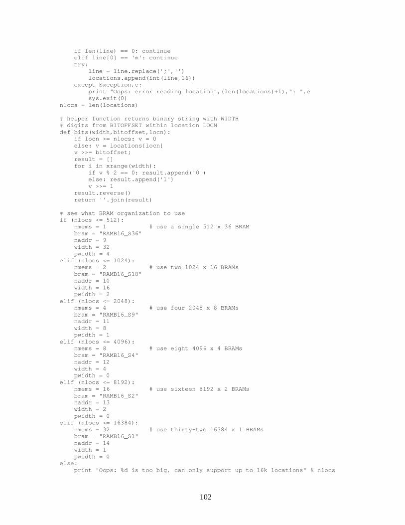
102
if len(line) == 0: continue elif line[0] == 'm': continue try: line = line.replace(';','') locations.append(int(line,16)) except Exception,e: print "Oops: error reading location",(len(l ocations)+1),": ",e sys.exit(0) nlocs = len(locations) # helper function returns binary string with WIDTH # digits from BITOFFSET within location LOCN def bits(width,bitoffset,locn): if locn >= nlocs: v = 0 else: v = locations[locn] v >>= bitoffset; result = [] for i in xrange(width): if v % 2 == 0: result.append('0') else: result.append('1') v >>= 1 result.reverse() return ''.join(result) # see what BRAM organization to use if (nlocs <= 512): nmems = 1 # use a single 512 x 36 BR AM bram = "RAMB16_S36" naddr = 9 width = 32 pwidth = 4 elif (nlocs <= 1024): nmems = 2 # use two 1024 x 16 BRAMs bram = "RAMB16_S18" naddr = 10 width = 16 pwidth = 2 elif (nlocs <= 2048): nmems = 4 # use four 2048 x 8 BRAMs bram = "RAMB16_S9" naddr = 11 width = 8 pwidth = 1 elif (nlocs <= 4096): nmems = 8 # use eight 4096 x 4 BRAMs bram = "RAMB16_S4" naddr = 12 width = 4 pwidth = 0 elif (nlocs <= 8192): nmems = 16 # use sixteen 8192 x 2 BRA Ms bram = "RAMB16_S2" naddr = 13 width = 2 pwidth = 0 elif (nlocs <= 16384): nmems = 32 # use thirty-two 16384 x 1 BRAMs bram = "RAMB16_S1" naddr = 14 width = 1 pwidth = 0 else: print "Oops: %d is too big, can only support up to 16k locations" % nlocs
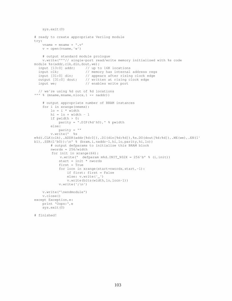
103
sys.exit(0) # ready to create appropriate Verilog module try: vname = mname + ".v" v = open(vname,'w') # output standard module prologue v.write("""// single-port read/write memory ini tialized with %s code module %s(addr,clk,din,dout,we); input [13:0] addr; // up to 16K locations input clk; // memory has internal add ress regs input [31:0] din; // appears after rising cl ock edge output [31:0] dout; // written at rising clock edge input we; // enables write port // we're using %d out of %d locations """ % (mname,mname,nlocs,1 << naddr)) # output appropriate number of BRAM instances for i in xrange(nmems): lo = i * width hi = lo + width - 1 if pwidth > 0: parity = ".DIP(%d'h0)," % pwidth else: parity = "" v.write(" %s m%d(.CLK(clk),.ADDR(addr[%d:0]),.DI(din[%d:%d]),%s. DO(dout[%d:%d]),.WE(we),.EN(1'b1),.SSR(1'b0));\n" % (bram,i,naddr-1,hi,lo,parity, hi,lo)) # output defparams to initialize this BRAM block nwords = 256/width for init in xrange(64): v.write(" defparam m%d.INIT_%02X = 256'b" % ( i,init)) start = init * nwords first = True for locn in xrange(start+nwords,start,- 1): if first: first = False else: v.write('_') v.write(bits(width,lo,locn-1)) v.write(';\n') v.write("\nendmodule") v.close() except Exception,e: print "Oops:",e sys.exit(0) # finished!
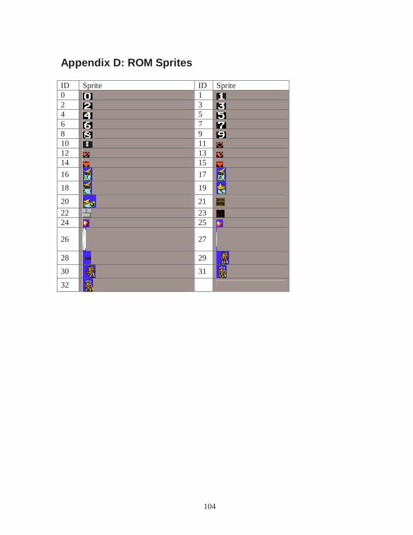
104
Appendix D: ROM Sprites ID Sprite ID Sprite 0 1 2 3 4 5 6 7 8 9 10 11 12 13 14 15 16 17 18 19 20 21 22 23 24 25
26
27
28 29 30 31 32