Embed Size (px)
Citation preview

/ Perfect Charging / Perfect Welding / Solar Energy
42,0426,0062,EA 022-07062016
Fronius IG Plus25 V / 30 V / 35 V / 50 V / 55 V / 60 V 70 V / 80 V / 100 V / 120 V / 150 V
Operating Instructions
Inverter for grid-connected photo-voltaic systemsE
N-U
S

2

EN-U
S
Dear reader,
Introduction Thank you for the trust you have placed in our company and congratulations on buying this high-quality Fronius product. These instructions will help you familiarize yourself with the product. Reading the instructions carefully will enable you to learn about the many different features it has to offer. This will allow you to make full use of its advantages.
Please also note the safety rules to ensure greater safety when using the product. Careful handling of the product will repay you with years of safe and reliable operation. These are essential prerequisites for excellent results.
3

4

EN-U
S
Contents
Safety Instructions ..................................................................................................................................... 9Explanation of Safety Instructions......................................................................................................... 9General ................................................................................................................................................. 9Utilization in Accordance with "Intended Purpose" ............................................................................... 10Environmental Conditions ..................................................................................................................... 10Qualified Service Engineers.................................................................................................................. 10Safety Measures at the Installation Location ........................................................................................ 10Data Regarding Noise Emission Values ............................................................................................... 11EMC Device Classifications .................................................................................................................. 11EMC Measures ..................................................................................................................................... 11Grid Connection .................................................................................................................................... 11Electrical Installations ........................................................................................................................... 11Protective Measures against ESD ........................................................................................................ 12Safety measures in normal operation ................................................................................................... 12Safety Symbols ..................................................................................................................................... 12Disposal ................................................................................................................................................ 12Backup .................................................................................................................................................. 12Copyright............................................................................................................................................... 12
Protection of Persons and Equipment ....................................................................................................... 13Safety.................................................................................................................................................... 13Protection of Persons and Equipment .................................................................................................. 13Galvanic isolation.................................................................................................................................. 13Monitoring the Grid ............................................................................................................................... 13Warning notices affixed to the device ................................................................................................... 13Warning notice on the wall bracket ....................................................................................................... 15
The Fronius IG Plus Unit in the PV System ............................................................................................... 16General ................................................................................................................................................. 16Tasks .................................................................................................................................................... 16Converting DC to AC Current ............................................................................................................... 16Fully automatic operation management................................................................................................ 16Display function and data communication ............................................................................................ 16System Upgrade ................................................................................................................................... 16Forced Ventilation ................................................................................................................................. 17100 kohm Grounding Kit Option............................................................................................................ 17Power derating...................................................................................................................................... 17
Fronius IG Plus Installation and Connection.............................................................................................. 18Inverter Construction............................................................................................................................. 18Overview............................................................................................................................................... 18
Choosing the Location ............................................................................................................................... 19Choosing the Location, General ........................................................................................................... 19Choosing a Location for Inside Installation ........................................................................................... 19Choosing a location for outdoor installation .......................................................................................... 20
Fronius IG Plus Connection Options.......................................................................................................... 21Fronius IG Plus connection options ...................................................................................................... 21
Knockouts on the Fronius IG Plus ............................................................................................................. 23General ................................................................................................................................................. 23Knockouts on the Fronius IG Plus for wire inputs ................................................................................. 23Removing Knockouts ............................................................................................................................ 23
Fronius IG Plus Installation ........................................................................................................................ 24Attaching the wall bracket ..................................................................................................................... 24Lifting the Fronius IG Plus..................................................................................................................... 24Fronius IG Plus installation ................................................................................................................... 25
Connecting the Fronius IG Plus to the Public Grid (AC) ............................................................................ 27Monitoring the Grid ............................................................................................................................... 27Installations with Several Inverters ....................................................................................................... 27AC-side terminals.................................................................................................................................. 27Mains Neutral Conductor ...................................................................................................................... 28Connecting Aluminum Cables............................................................................................................... 28Cross Section of AC Wires ................................................................................................................... 28Safety.................................................................................................................................................... 28
5

Connecting the Fronius IG Plus to the public grid (AC) ........................................................................ 28Maximum alternating current fuse protection........................................................................................ 29
Connecting Solar Module Strings to the Fronius IG Plus (DC) .................................................................. 30General Information about Solar Modules ............................................................................................ 30Safety.................................................................................................................................................... 30DC-Side Terminals................................................................................................................................ 31Connecting aluminum cables (DC) ....................................................................................................... 31Polarity Reversal of Solar Module Strings ............................................................................................ 32Overview............................................................................................................................................... 32
Ungrounded System: Connecting Solar Module Strings............................................................................ 33Wire Cross Section of Solar Module Strings......................................................................................... 33Ungrounded system: Connecting solar module strings ........................................................................ 33Selecting String Fuses .......................................................................................................................... 35Inserting String Fuses ........................................................................................................................... 35
Ungrounded System: Connecting Solar Module Strings with a Cable Cross Section > 16 mm² ............... 37General ................................................................................................................................................. 37Additional components required ........................................................................................................... 37Ungrounded system: Connecting solar module strings with a cable cross section > 16 mm² .............. 37
Solar Module Ground at Negative Pole: Connecting Solar Module Strings............................................... 41General ................................................................................................................................................. 41Wire Cross Section of Solar Module Strings......................................................................................... 41Solar module ground at negative pole: Connecting solar module strings............................................. 41Selecting String Fuses .......................................................................................................................... 43Inserting String Fuses ........................................................................................................................... 43
Solar Module Ground at Negative Pole: Connecting Solar Module Strings with a Cable Cross Section > 16 mm²....................................................................................................................................................... 45
General ................................................................................................................................................. 45Additional components required ........................................................................................................... 45Solar module ground at negative pole: Connecting solar module strings with a cable cross section > 16 mm².................................................................................................................................................. 45
Solar Module Ground at Negative Pole for Fronius IG Plus ...................................................................... 49General ................................................................................................................................................. 49Solar Module Ground at Negative Pole ................................................................................................ 49Solar Module Grounding at Negative Pole for Fronius IG Plus............................................................. 49Safety.................................................................................................................................................... 50Setting inverters for grounded solar modules ....................................................................................... 50Solar Module Ground: Inserting Fuse or "100 kohm Grounding Kit" Option......................................... 50Opening Fronius IG Plus for Service/Maintenance............................................................................... 51
Solar Module Ground at Positive Pole: Connecting Solar Module Strings ................................................ 52General ................................................................................................................................................. 52Wire Cross Section of Solar Module Strings......................................................................................... 52Solar module ground at positive pole: Connecting solar module strings .............................................. 52Selecting String Fuses .......................................................................................................................... 55Inserting String Fuses ........................................................................................................................... 55
Solar Module Ground at Positive Pole: Connecting Solar Module Strings with a Cable Cross Section > 16 mm²............................................................................................................................................................ 56
General ................................................................................................................................................. 56Additional components required ........................................................................................................... 56Solar module ground at positive pole: Connecting solar module strings with a cable cross section > 16 mm²....................................................................................................................................................... 56
Solar Module Ground at Positive Pole for Fronius IG Plus ........................................................................ 61General ................................................................................................................................................. 61Solar Module Ground at Positive Pole .................................................................................................. 61Solar Module Grounding at Positive Pole for Fronius IG Plus .............................................................. 61Safety.................................................................................................................................................... 62Setting inverters for grounded solar modules ....................................................................................... 62Solar Module Ground: Inserting Fuse or "100 kohm Grounding Kit" Option......................................... 62Opening Fronius IG Plus for Service/Maintenance............................................................................... 63
Criteria for the Proper Selection of String Fuses ....................................................................................... 64General ................................................................................................................................................. 64Criteria for the Proper Selection of String Fuses .................................................................................. 64Effects of Using Underrated Fuses ....................................................................................................... 64Fuse Recommendations ....................................................................................................................... 64Application Example ............................................................................................................................. 64
6

EN-U
S
Fuses .................................................................................................................................................... 64Closing Fronius IG Plus ............................................................................................................................. 66
Closing Fronius IG Plus ........................................................................................................................ 66Inserting Option Cards ............................................................................................................................... 67
Suitable Option Cards........................................................................................................................... 67Safety.................................................................................................................................................... 67Opening Fronius IG Plus....................................................................................................................... 67Inserting option cards into the Fronius IG Plus ..................................................................................... 68Closing Fronius IG Plus ........................................................................................................................ 68
Data Communication and Solar Net .......................................................................................................... 70Solar Net and Data Interface ................................................................................................................ 70Example ................................................................................................................................................ 70
Commissioning .......................................................................................................................................... 72Factory Configuration............................................................................................................................ 72Start-up operation ................................................................................................................................. 72Setting Inverters for Available Solar Module Ground............................................................................ 72
Product Description Fronius IG Plus.......................................................................................................... 76Controls and Indicators ......................................................................................................................... 76Display .................................................................................................................................................. 76Operating Status LED........................................................................................................................... 78
Startup Phase and Grid Feed-in Mode ...................................................................................................... 79Startup phase........................................................................................................................................ 79Test Procedure ..................................................................................................................................... 79Operation of Feeding Energy into the Grid ........................................................................................... 80
Navigation in the Menu Level..................................................................................................................... 81Activating display illumination ............................................................................................................... 81Automatic switch to the "Now" display mode or the startup phase ....................................................... 81Accessing the Menu Level .................................................................................................................... 81
The Display Modes .................................................................................................................................... 82The Display Modes ............................................................................................................................... 82Selecting a Display Mode ..................................................................................................................... 82Overview of Display Values .................................................................................................................. 83
Display Values in "Now" Display Mode...................................................................................................... 84Selecting the "Now" Display Mode........................................................................................................ 84Display values in the "Now" display mode ............................................................................................ 84Options.................................................................................................................................................. 86
Display Values in "Day / Year / Total" Display Modes ............................................................................... 87General ................................................................................................................................................. 87Selecting "Day / Year / Total" Display Mode......................................................................................... 87Display values in the 'Day / Year / Total' display modes....................................................................... 88Options.................................................................................................................................................. 89
The Setup Menu ........................................................................................................................................ 90Presetting.............................................................................................................................................. 90Accessing the Setup Menu ................................................................................................................... 90Scrolling through Menu Items ............................................................................................................... 91
Menu Items in the Setup Menu .................................................................................................................. 92STANDBY............................................................................................................................................. 92WLAN AP.............................................................................................................................................. 92CONTRAST .......................................................................................................................................... 93LIGHT MODE........................................................................................................................................ 94CASH.................................................................................................................................................... 94CO2....................................................................................................................................................... 94YIELD.................................................................................................................................................... 95IG no. .................................................................................................................................................... 95DAT COM ............................................................................................................................................. 95TIME ..................................................................................................................................................... 96LIMIT CFG ............................................................................................................................................ 96STATE PS............................................................................................................................................. 99VERSION.............................................................................................................................................. 100
Setting and Displaying Menu Items ........................................................................................................... 101Setting Menu Items - General ............................................................................................................... 101Examples of Setting and Displaying Menu Items.................................................................................. 101Setting the Currency and Charge Rate................................................................................................. 101Displaying and Setting Parameters in the "DATCOM" Menu Item........................................................ 103
7

Setting Time and Date ......................................................................................................................... 106Setup Lock function ................................................................................................................................... 109
General ................................................................................................................................................. 109Activating/deactivating the "Setup Lock" function ................................................................................. 109
Select Log Entry function ........................................................................................................................... 111General ................................................................................................................................................. 111'Select Log Entry' function - access saved grid errors .......................................................................... 111
Energy Management function .................................................................................................................... 113General ................................................................................................................................................. 113Activating the "Energy Management" function...................................................................................... 113Notes on configuring the switch-on and switch-off points ..................................................................... 115Example ................................................................................................................................................ 116
Status Diagnosis and Troubleshooting ...................................................................................................... 117Displaying Status Codes....................................................................................................................... 117Normal Operation Status Codes ........................................................................................................... 117Total Failure .......................................................................................................................................... 117Status Codes on inverters with Several Power Stage Sets .................................................................. 117Class 1 Status Codes ........................................................................................................................... 118Class 3 status codes............................................................................................................................. 120Class 4 status codes............................................................................................................................. 122Class 5 status codes............................................................................................................................. 128Customer Service ................................................................................................................................. 132
Maintenance .............................................................................................................................................. 133Safety.................................................................................................................................................... 133General ................................................................................................................................................. 133Operation in Dusty Environments ......................................................................................................... 133Opening Fronius IG Plus for Service/Maintenance............................................................................... 133
Replacing String Fuses.............................................................................................................................. 135Safety.................................................................................................................................................... 135Preparation ........................................................................................................................................... 135Replacing Fuses ................................................................................................................................... 136Finally.................................................................................................................................................... 136
Technical Data ........................................................................................................................................... 138Fronius IG Plus 25 V-1.......................................................................................................................... 138Fronius IG Plus 30 V-1.......................................................................................................................... 139Fronius IG Plus 35 V-1.......................................................................................................................... 140Fronius IG Plus 50 V-1.......................................................................................................................... 141Fronius IG Plus 55 V-1, Fronius IG Plus 55 V-2 ................................................................................... 142Fronius IG Plus 55 V-3.......................................................................................................................... 144Fronius IG Plus 60 V-1,Fronius IG Plus60 V-2 ..................................................................................... 145Fronius IG Plus 60 V-3.......................................................................................................................... 146Fronius IG Plus 70 V-1, Fronius IG Plus 70 V-2 ................................................................................... 147Fronius IG Plus 80 V-3.......................................................................................................................... 148Fronius IG Plus 100 V-1, Fronius IG Plus 100 V-2 ............................................................................... 149Fronius IG Plus 100 V-3........................................................................................................................ 151Fronius IG Plus 120 V-1........................................................................................................................ 152Fronius IG Plus 120 V-3........................................................................................................................ 153Fronius IG Plus 150 V-3........................................................................................................................ 154Explanation of footnotes ....................................................................................................................... 155
Relevant Standards and Directives............................................................................................................ 156CE Conformity Marking......................................................................................................................... 156Parallel Operation of In-Plant Power Generation Systems ................................................................... 156Circuit to Prevent Islanding ................................................................................................................... 156Grid Failure ........................................................................................................................................... 156
Terms and conditions of warranty and disposal......................................................................................... 157Fronius Manufacturer's Warranty.......................................................................................................... 157Disposal ................................................................................................................................................ 157
8

EN-U
S
Safety Instructions
Explanation of Safety Instruc-tions
If you see any of the symbols depicted in the "Safety Rules," special care is required.
General
DANGER! Indicates an immediate danger. Death or serious injury may result if appropriate precautions are not taken.
WARNING! Indicates a possibly dangerous situation. Death or serious injury may result if appropriate precautions are not taken.
CAUTION! Indicates a situation where damage or injury could occur. Minor injury or damage to property may result if appropriate precautions are not taken.
NOTE! Indicates the possibility of flawed results and damage to the equipment.
IMPORTANT! Indicates tips for correct operation and other particularly useful information. It does not indicate a potentially damaging or dangerous situation.
The device is manufactured using state-of-the-art technology and according to recognized safety standards. If used incorrectly or misused, however, it can cause- injury or death to the operator or a third party,- damage to the device and other material assets belonging to the operator,- inefficient operation of the deviceAll persons involved in commissioning, maintaining and servicing the device must- be suitably qualified,- have knowledge of and experience in dealing with electrical installations
and- read and follow these operating instructions carefully
The operating instructions must always be at hand wherever the device is be-ing used. In addition to the operating instructions, attention must also be paid to any generally applicable and local regulations regarding accident preven-tion and environmental protection.All safety and danger notices on the device - must be kept in a legible state - must not be damaged/marked - must not be removed- must not be covered, pasted or painted overFor the location of the safety and danger notices on the device, refer to the section headed "General" in the operating instructions for the device.Before switching on the device, remove any faults that could compromise safety.Your personal safety is at stake!
9

Utilization in Ac-cordance with "Intended Pur-pose"
Environmental Conditions
Qualified Service Engineers
Safety Measures at the Installation Location
When installing devices with openings for cooling air, ensure that the cooling air can enter and exit unhindered through the vents. Only operate the device in accordance with the de-gree of protection shown on the rating plate.
The device is to be used exclusively for its intended purpose. Utilization for any other purpose, or in any other manner, shall be deemed to be "not in accordance with the intended purpose." The manufacturer shall not be liable for any damage resulting from such improper use.
Utilization in accordance with the "intended purpose" also includes - carefully reading and obeying all the instructions and all the safety and
danger notices in the operating instructions- performing all stipulated inspection and servicing work- installation as specified in the operating instructionsThe following guidelines should also be applied where relevant:- Regulations of the utility regarding energy fed into the grid- Instructions from the solar module manufacturer
Operation or storage of the device outside the stipulated area will be deemed as "not in accordance with the intended purpose." The manufacturer is not re-sponsible for any damages resulting from unintended use.For exact information on permitted environmental conditions, please refer to the "Technical data" in the operating instructions.
The servicing information contained in these operating instructions is intended only for the use of qualified service engineers. An electric shock can be fatal. Do not perform any actions other than those described in the documentation. This also applies to those who may be qualified.All cables and leads must be secured, undamaged, insulated and adequately dimensioned. Loose connections, scorched, damaged or inadequately dimen-sioned cables and leads must be immediately repaired by authorized person-nel.Maintenance and repair work must only be carried out by authorized person-nel.It is impossible to guarantee that externally procured parts are designed and manufactured to meet the demands made on them, or that they satisfy safety requirements. Use only original replacement parts (also applies to standard parts).Do not carry out any modifications, alterations, etc. without the manufacturer's consent.Components that are not in perfect condition must be changed immediately.
10
EN-U
S
Data Regarding Noise Emission ValuesEMC Device Clas-sifications
EMC Measures
Grid Connection
Electrical Installa-tions
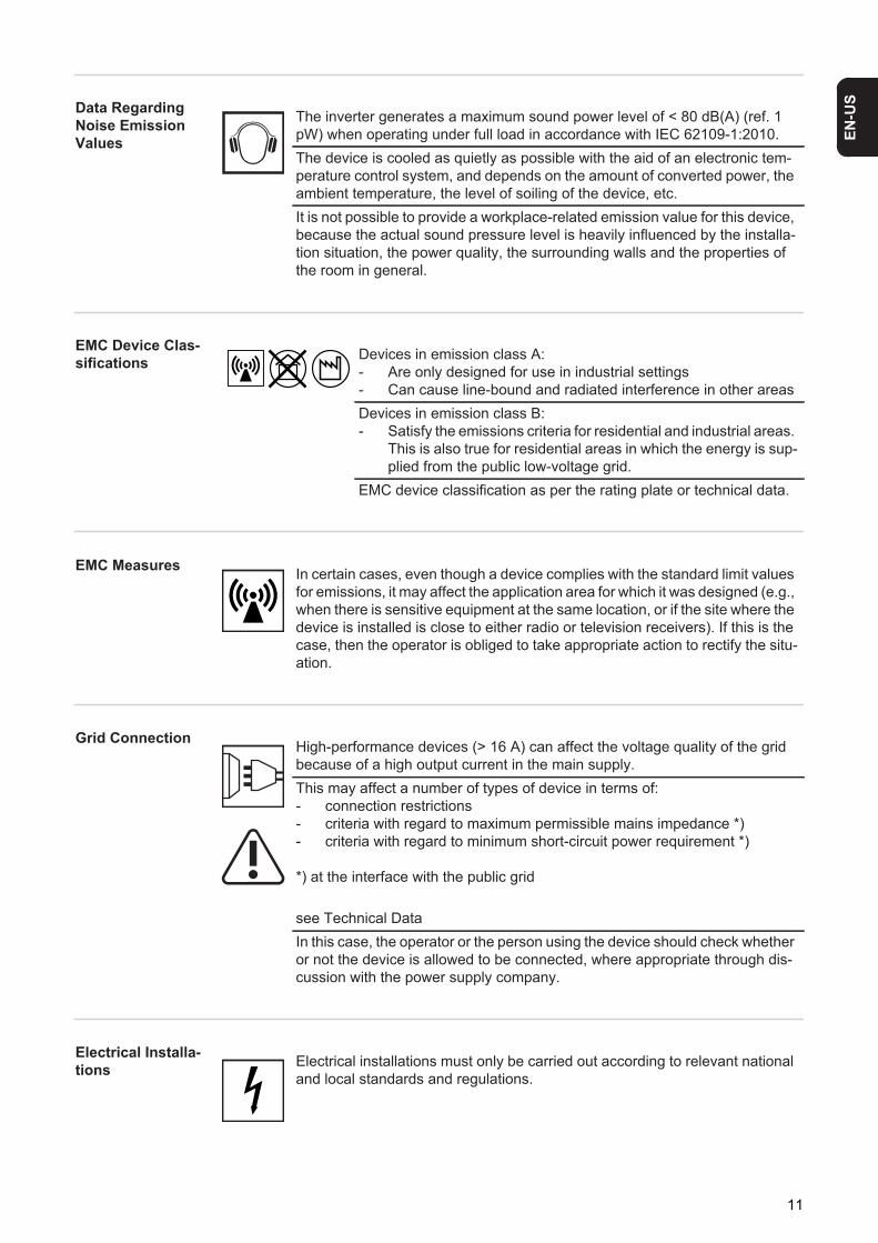
The inverter generates a maximum sound power level of < 80 dB(A) (ref. 1 pW) when operating under full load in accordance with IEC 62109-1:2010.The device is cooled as quietly as possible with the aid of an electronic tem-perature control system, and depends on the amount of converted power, the ambient temperature, the level of soiling of the device, etc.It is not possible to provide a workplace-related emission value for this device, because the actual sound pressure level is heavily influenced by the installa-tion situation, the power quality, the surrounding walls and the properties of the room in general.
Devices in emission class A:- Are only designed for use in industrial settings- Can cause line-bound and radiated interference in other areasDevices in emission class B:- Satisfy the emissions criteria for residential and industrial areas.
This is also true for residential areas in which the energy is sup-plied from the public low-voltage grid.
EMC device classification as per the rating plate or technical data.
In certain cases, even though a device complies with the standard limit values for emissions, it may affect the application area for which it was designed (e.g., when there is sensitive equipment at the same location, or if the site where the device is installed is close to either radio or television receivers). If this is the case, then the operator is obliged to take appropriate action to rectify the situ-ation.
High-performance devices (> 16 A) can affect the voltage quality of the grid because of a high output current in the main supply.This may affect a number of types of device in terms of:- connection restrictions- criteria with regard to maximum permissible mains impedance *)- criteria with regard to minimum short-circuit power requirement *)
*) at the interface with the public grid
see Technical DataIn this case, the operator or the person using the device should check whether or not the device is allowed to be connected, where appropriate through dis-cussion with the power supply company.
Electrical installations must only be carried out according to relevant national and local standards and regulations.
11

Protective Mea-sures against ESD
Safety measures in normal opera-tion
Safety Symbols
Disposal
Backup
Copyright
Danger of damage to electrical components from electrical discharge. Suitable measures should be taken to protect against ESD when replacing and install-ing components.
Only operate the device when all safety devices are fully functional. If the safe-ty devices are not fully functional, there is a risk of- injury or death to the operator or a third party- damage to the device and other material assets belonging to the operat-
ing company- inefficient operation of the deviceSafety equipment that is not fully functional must be repaired by an authorized specialist before the device is turned on.Never bypass or disable safety devices.
Devices with the CE marking satisfy the essential requirements of the low-volt-age and electromagnetic compatibility directives. Further details can be found in the appendix or the chapter entitled "Technical data" in your documentation.
Do not dispose of this device with normal domestic waste! To comply with the European Directive on Waste Electrical and Electronic Equipment and its im-plementation as national law, electrical equipment that has reached the end of its life must be collected separately and returned to an approved recycling fa-cility. Any device that you no longer require must be returned to your dealer, or you must locate the approved collection and recycling facilities in your area. Ignoring this European Directive may have potentially adverse affects on the environment and your health!
The user is responsible for backing up any changes made to the factory set-tings. The manufacturer accepts no liability for any deleted personal settings.
Copyright of these operating instructions remains with the manufacturer.Text and illustrations are technically correct at the time of going to print. The right to make modifications is reserved. The contents of the operating instruc-tions shall not provide the basis for any claims whatsoever on the part of the purchaser. If you have any suggestions for improvement, or can point out any mistakes that you have found in the operating instructions, we will be most grateful for your comments.
12

EN-U
S
Protection of Persons and Equipment
Safety
Protection of Per-sons and Equip-ment
The design and function of the inverter offer a maximum level of safety, both during instal-lation as well as operation.
The inverter provides operator and equipment protection through:a) galvanic isolationb) monitoring the grid
Galvanic isolation The inverter is equipped with a high frequency transformer that ensures galvanic isolation between the DC side and the grid, thus ensuring the highest possible safety.
Monitoring the Grid
Whenever conditions in the electric grid are inconsistent with standard conditions (for ex-ample, grid switch-off, interruption), the inverter will immediately stop operating and inter-rupt the supply of power into the grid.
Grid monitoring is carried out using:- Voltage monitoring- Frequency monitoring- Monitoring islanding conditions
Warning notices affixed to the de-vice
The inverter contains warning notices and safety symbols. These warning notices and safety symbols must NOT be removed or painted over. The notices and symbols warn against operating the equipment incorrectly, as this may result in serious injury and dam-age.
WARNING! If the equipment is used or tasks are carried out incorrectly, serious injury or damage may result. Only qualified personnel are authorized to install your inverter and only within the scope of the respective technical regulations. It is essential that you read the "Safety regulations" chapter before commissioning the equipment or carrying out maintenance work.
13

Safety symbols:
14

EN-U
S
Text of warning notices:
WARNING!The connection area should only be opened by a licensed electrician. The separate power stage set area should only be disconnected from the connection area after first being dis-connected from the grid power. The separate power stage set area should only be opened by trained service personnel.You must wait until the capacitors have discharged. Discharge takes 5 minutes. The neu-tral conductor of the grid must be grounded. Solar modules exposed to light create danger-ous voltage. Activate the DC disconnect and disengage the module ground, if available, before working on the solar modules.
Warning notice on the wall brack-et
The wall bracket contains a warning notice regarding the installation of several inverters next to each other. This warning notice warns against incorrect installation and must not be removed or painted over. Incorrect installation voids the warranty, property damage can result.
The spacing information listed in the warning notice from the wall/ceiling to the inverter and from inverter to inverter must be observed when installing several inverters next to each other.
Risk of serious injury and damage due to incorrect operation
Do not use the functions described until you have thoroughly read and under-stood the following documents:- these operating instructions- all operating instructions for system components of the photovoltaic sys-
tem, especially the safety rules
Dangerous electrical voltages
15

The Fronius IG Plus Unit in the PV System
General The solar inverter is the highly complex link between the solar modules and the public grid.
Tasks The main tasks of the inverter include:- Converting DC to AC current- Fully automatic operational management- Display function and data communication
Converting DC to AC Current
The inverter transforms the direct current generated by the solar modules into alternating current. This alternating current is fed into your home system or into the public grid and synchronized with the voltage that is used there.
Fully automatic operation man-agement
The inverter is fully automatic. Starting at sunrise, as soon as the solar modules generate enough energy, the automatic control unit starts monitoring grid voltage and frequency. As soon as there is a sufficient level of irradiance, your solar inverter starts feeding energy into the grid.
The control system of the inverter ensures that the maximum possible power output is drawn from the solar modules at all times. This function is called MPPT (Maximum Power Point Tracking).
As dusk starts and there is no longer sufficient energy available to feed power into the grid, the inverter shuts down the grid connection completely and stops operating. All settings and recorded data are saved.
Display function and data commu-nication
The display on the inverter is the interface between the inverter and the operator. The de-sign of the display is geared towards simple operation and making system data available as long as the inverter operates.
The inverter is equipped with a basic logging function to monitor minimum and maximum data on a daily and a cumulative basis. These values are shown on the display.
A wide range of data communication products allows for many possibilities of recording and viewing data.
System Upgrade The inverter is designed for various system upgrades, e.g.:- Upgrades that enable the inverter to communicate with external system upgrades as
well as with other inverters- Datalogger (when using a PC to record and manage data from your photovoltaic sys-
tem), includes Datalogger and a modem interface- Various large-format displays- Fronius Personal Display- Actuators (e.g.: relays, alarms)- Interface cards
IMPORTANT! The inverter has been designed exclusively for use in grid-connected pho-tovoltaic systems. It cannot generate electric power independently of the grid.
16

EN-U
S
System upgrades are available as plug-in cards.
Forced Ventila-tion
The inverter's temperature-controlled, variable-speed fan with ball-bearing support pro-vides:- optimal inverter cooling- efficiency increases- cooler components, thus improving service life- least possible energy consumption and lowest possible noise level- weight reduction due to a reduction of the cooling element surface
100 kohm Grounding Kit Option
Power derating Should there be insufficient heat dissipation in spite of the fan operating at maximum speed (for example, inadequate heat transfer away from the heat sinks), the power will be derated to protect the inverter when the ambient temperature reaches approx. 40 °C and above.
Derating the power reduces the output of the inverter for a short period sufficient to ensure that the temperature will not exceed the permissible limit.Your inverter will remain ready for operation as long as possible without any interruption.
Along with the solar module ground on the positive or negative pole, solar modules can also be grounded with high resistance on the positive or negative pole.
This requires the 100 kohm Grounding Kit option, which is insert-ed into the corresponding fuse holder similar to a regular fuse for the solar module ground. Grounding Kit 100 kOhm
17

Fronius IG Plus Installation and Connection
Inverter Con-struction
The power stage set and the connection area are separated from each other for de-livery.
(1) Power stage set(s)
(2) Connection area
Overview ‘Fronius IG Plus Installation and Connection’ contains the following sections:- Choosing the Location- Fronius IG Plus Connection Options- Knockouts on the Fronius IG Plus- Fronius IG Plus Installation- Connecting the Fronius IG Plus to the Public Grid (AC)- Connecting Solar Module Strings to the Fronius IG Plus (DC)- Closing Fronius IG Plus
(1)
(2)
18

EN-U
S
Choosing the Location
Choosing the Lo-cation, General
Please note the following criteria when choosing a location for the inverter:
Choosing a Loca-tion for Inside In-stallation
It should only be installed on a stable, vertical wallMax. ambient temperatures: -20 °C / +55 °CRelative humidity: 0 - 95 %For use at altitudes above sea level: up to 2000 m- There should be a 200 mm (7.8 in) clearance on both sides of the inverter for the cool
air vents.- Maintain a side distance of 300 mm (11.8 in) between individual inverters.
The air flow direction within the inverter is from right to left (cold air intake on right, hot air exit on left).When installing the inverter in a switch panel cabinet (or similar closed environment), it is necessary to make sure that the hot air that develops will be discharged by forced venti-lation.The inverter is designed for installation both indoors and outdoors.
50 mm
300 mm
200 mm
During certain operation phases the inverter may produce a slight noise. For this reason it should not be installed in an occupied living area.Do not install the inverter in:- areas with large amounts of dust- areas with large amounts of conducting dust particles (e.g., iron filings)- areas with corrosive gases, acids or salts- areas where there is an increased risk of accidents, e.g., from farm animals (horses,
cattle, sheep, pigs, etc.)- stables or adjoining areas- storage areas for hay, straw, chaff, animal feed, fertilizers, etc.- storage or processing areas for fruit, vegetables or winegrowing products- areas used in the preparation of grain, green fodder or animal feeds- greenhouses
19

Choosing a loca-tion for outdoor installation
Because of its degree of protection, the inverter is not susceptible to splash water from any direction.
However the manufacturer recommends, if possible, not to expose the inverter to direct weathering, in order to prevent water deposits caused by rain or snow.In order to protect the display, the inverter should not be exposed to direct sunlight. Ide-ally, the inverter should be installed in a protected location, e.g., near the solar modules or under a roof overhang.Do not install the inverter:- where it can be exposed to ammonia, corrosive gasses, acids or salts (e.g., fertilizer
storage areas, vent openings of livestock stables, chemical plants, tanneries)
20

EN-U
S
Fronius IG Plus Connection Options
Fronius IG Plus connection op-tions
Item Description(1) Fuse cover (6 x for string fuses, 1 x for the solar module ground fuse)(2) Jumper slot SMON(3) DC+ main switch wire(4) 6 DC+ fuse holders(5) Jumper slot SMOFF(6) DC- main switch wire(7) Plug-in card for country setup (IG Brain)(8) Open card slot for an option card(9) Open card slot for a second option card(10) Open card slot for a third option card(11) Fuse holder for solar module ground(12) Strain relief for plug-in card cable(13) AC-side terminals(14) Metric screw joint M32 or M40 (AC connection)(15) 6 DC- terminals(16) Strain relief for solar module strings
21
(17) 6 DC+ terminals(18) DC main switch
Item Description
22

EN-U
S
Knockouts on the Fronius IG Plus
General The inverter contains several knockouts of different sizes. When knocked out, the open-ings are used for the inputs of various wires.
Knockouts on the Fronius IG Plus for wire inputs
Item Description
(1) 2 cable inputs for M32 metric screw joint (for DC cables with a cross section > 16 mm²)
(2) 12 cables inputs for 6 solar module strings DC(for a cable diameter of 5 - 9.2 mm)
(3) Sealing insert (cable input for plug-in card wire)
Removing Knock-outs
The knockouts made from plastic as well as the larger ones made from metal should only be removed from the outside in.
The smaller knockouts made from metal should be removed from the inside out.
You should only remove the number of knockouts required for the available cables (e.g., 6 openings for 3 module strings).
The plastic knockouts are also equipped with centering holes so that they can be drilled out if required.
(1)
(2)
(3)
23

Fronius IG Plus Installation
Attaching the wall bracket
1 2
1 2
Lifting the Fro-nius IG Plus
Fronius recommends using commercially available vacuum lifting pads for flat surfaces to lift the connection area and power stage set.
IMPORTANT! - The vacuum lifting pads must be designed for the weight of the connection area and
power stage set.- Follow all safety instructions from the vacuum lifting pad manufacturer.- Vacuum lifting pads are not part of the scope of delivery for the inverter.
IMPORTANT! Depending on the surface, different dowels and screws may be required for installing the wall bracket. Therefore, these dowels and screws are not part of the scope of supply for the inverter. The system installer is responsible for selecting the proper dowels and screws.
NOTE! The Fronius IG Plus should only be installed upright on the wall.
"click""click"
1
1
1 min. 50 mmmin. 2 in.
2
1
1
7
3
5
4
6
(*)
2
IMPORTANT! Attach the wall bracket so that the display marking (*) on the wall bracket is at eye level.
22
3
4
1
6
5
3
2
6 x
4
6
7
1
5
23
4
24

EN-U
S
Weight information for the connection area and power stage set:
Fronius IG Plus installation
1 2
Inverter Connection area Power stage setFronius IG Plus 25 V-1 9.85 kg 13.95 kgFronius IG Plus 30 V-1 9.85 kg 13.95 kgFronius IG Plus 35 V-1 9.85 kg 13.95 kgFronius IG Plus 50 V-1 9.85 kg 13.95 kgFronius IG Plus 55 V-1 9.85 kg 26.10 kgFronius IG Plus 55 V-2 9.85 kg 26.10 kgFronius IG Plus 55 V-3 11.05 kg 38.15 kgFronius IG Plus 60 V-1 9.85 kg 26.10 kgFronius IG Plus 60 V-2 9.85 kg 26.10 kgFronius IG Plus 60 V-3 11.05 kg 38.15 kgFronius IG Plus 70 V-1 9.85 kg 26.10 kgFronius IG Plus 70 V-2 9.85 kg 26.10 kgFronius IG Plus 80 V-3 11.05 kg 38.15 kgFronius IG Plus 100 V-1 10.80 kg 26.10 kgFronius IG Plus 100 V-2 10.85 kg 26.10 kgFronius IG Plus 100 V-3 11.05 kg 38.15 kgFronius IG Plus 120 V-1 11.05 kg 38.15 kgFronius IG Plus 120 V-3 11.05 kg 38.15 kgFronius IG Plus 150 V-3 11.05 kg 38.15 kg
NOTE! For inverter assembly, please ensure that:- the wall bracket is fixed securely to the wall- the connector is hung and fixed to the wall bracket- the power stage set is hung on the wall bracket and fixed to the connector
2
1
A
B
1
1
2
2
25

3 4
5 6
7
Use the screws in the bag attached to the wall bracket to secure the power stage set to the connection area.
14
2
3
3
1
4
33
12
5
32
1
23
A B
6
1
12 3
1
7
26

EN-U
S
Connecting the Fronius IG Plus to the Public Grid (AC)
Monitoring the Grid
Installations with Several Inverters
For larger photovoltaic systems, it is possible to connect several inverters in parallel with-out any problems. To ensure symmetrical feeding, connect the inverters uniformly to all 3 phases.
AC-side terminals
IMPORTANT! The resistance in the leads to the AC-side connection terminals must be as low as possible for optimal functioning of grid monitoring.
Single-phase inverter Two-phase inverter
Three-phase inverter Legend:
L1 Phase conductorL2 Phase conductorL3 Phase conductorN Neutral conductorPE Ground conductor/groundingPE (a) Connection option for additional
grounding(b) "US Sense" terminal (for USA)
Max. cable cross-section:25 mm² - for flexible cables35 mm² - for rigid cables
PE (a) (b)PE (a)
PE (a) (b)
27

Mains Neutral Conductor
The neutral conductor must be connected in order to operate the inverter.
Connecting Alu-minum Cables
Cross Section of AC Wires
For M32 metric screw joint: Cable diameter 11 - 21 mm
For M40 metric screw joint: Cable diameter 19 - 28 mm
If required, use reducers for smaller cable diameters.
Safety
Connecting the Fronius IG Plus to the public grid (AC)
Only an authorized electrician is permitted to connect this inverter to the public grid.
NOTE! Make sure that the grid neutral conductor is grounded.
NOTE! If the neutral conductor is too small it can aversely affect the inverter's feed-in of power to the mains. The neutral conductor must therefore be the same size as the other live conductors: L1, L2 and L3.
NOTE! The AC side terminals are not designed for connecting aluminum cables.
WARNING! An electric shock can be fatal. Danger due to grid voltage and DC voltage from solar modules.- The connection area should only be opened by a licensed electrician.- The separate power stage set area should only be disconnected from the
connection area after first being disconnected from the grid power.- The separate power stage set area should only be opened by Fronius-trained
service personnel.
Never work with live wires! Prior to all connection work, make sure that the AC and DC wires are not charged.
CAUTION! Danger of damaging the inverter by overloading the grid neutral con-ductor.- Do not connect 2-phase and 3-phase devices together to one phase- Never operate multi-phase devices in one phase
CAUTION! Danger of damaging the inverter from improperly connected termi-nals. Improperly connected terminals can cause thermal damage to the inverter and may cause a fire. When connecting the AC and DC cables, make sure that all terminals are tightened securely using the proper torque.
NOTE! Finely stranded cables up to conductor class 5 can be connected to the AC-side terminals without wire end ferrules.
28

EN-U
S
1 2
Maximum alter-nating current fuse protection
1
off
on
20 mm10 mm
OFF
AC
2
1
2 3 4 65
1
7
2
Terminal tightening torque: 2 Nm
Inverter Phases Nominal output Fuse protectionFronius IG Plus 25 V-1 1 2.6 kW 1 x C 25 AFronius IG Plus 30 V-1 1 3 kW 1 x C 25 AFronius IG Plus 35 V-1 1 3.5 kW 1 x C 25 AFronius IG Plus 50 V-1 1 4 kW 1 x C 25 AFronius IG Plus 55 V-1 1 5 kW 1 x C 50 AFronius IG Plus 55 V-2 2 5 kW 2 x C 25 AFronius IG Plus 55 V-3 3 5 kW 3 x C 25 AFronius IG Plus 60 V-1 1 6 kW 1 x C 50 AFronius IG Plus 60 V-2 2 6 kW 2 x C 25 AFronius IG Plus 60 V-3 3 6 kW 3 x C 25 AFronius IG Plus 70 V-1 1 6.5 kW 1 x C 50 AFronius IG Plus 70 V-2 2 6.5 kW 2 x C 25 AFronius IG Plus 80 V-3 3 7 kW 3 x C 25 AFronius IG Plus 100 V-1 1 8 kW 1 x C 50 AFronius IG Plus 100 V-2 2 8 kW 2 x C 25 AFronius IG Plus 100 V-3 3 8 kW 3 x C 25 AFronius IG Plus 120 V-1 1 10 kW 1 x C 63 AFronius IG Plus 120 V-3 3 10 kW 3 x C 25 AFronius IG Plus 150 V-3 3 12 kW 3 x C 25 A
NOTE! A residual current circuit breaker for the AC connecting cable may be re-quired depending on local regulations, the power supply company as well as oth-er conditions. A type A residual current circuit breaker is generally sufficient in this case, however, false alarms can be triggered for the type A residual current circuit breaker in individual cases and depending on local conditions. For this reason, Fronius recommends that you use a residual current circuit breaker suitable for a frequency converter.
NOTE! Only for three-phase inverters: When using a residual current circuit breaker, the voltage difference between the PE ground conductor and the N neu-tral conductor must not be higher than 8 V.
29

Connecting Solar Module Strings to the Fronius IG Plus (DC)
General Informa-tion about Solar Modules
In order to select suitable solar modules and get the most efficient use out of the inverter, please note the following points:- If irradiance is constant and the temperature is falling, the open circuit voltage of the
solar modules will increase. Open circuit voltage may not exceed 600 V.Whenever the open circuit voltage of the solar modules exceeds 600 volts, the inverter may be damaged, and all warranty rights will become null and void.
- More exact values for dimensioning solar modules for the chosen installation location can be provided using suitable calculation programs like the Fronius Solar.configura-tor (available at http.//www.fronius.com).
Safety
NOTE! Before connecting solar modules:- make sure that the voltage specified by the manufacturer corresponds to the
actual measured voltage- determine whether or not a solar module ground is required
WARNING! An electric shock can be fatal. Danger due to grid voltage and DC voltage from solar modules.- The connection area should only be opened by a licensed electrician.- The separate power stage set area should only be disconnected from the
connection area after first being disconnected from the grid power.- The separate power stage set area should only be opened by Fronius-trained
service personnel.
Never work with live wires! Prior to all connection work, make sure that the AC and DC wires are not charged.
The DC main switch is only used to switch off power to the power stage set. When the DC main switch is turned off, the connection area is still energized.
CAUTION! Danger of damaging the inverter from improperly connected termi-nals. Improperly connected terminals can cause thermal damage to the inverter and may cause a fire. When connecting the AC and DC cables, make sure that all terminals are tightened securely using the proper torque.
30

EN-U
S
DC-Side Termi-nalsConnecting alu-minum cables (DC)
The DC-side terminals are designed for connecting single-wire, round aluminum cables. The following points must be taken into account when connecting aluminum cables due to the non-conducting oxide layer of aluminum:- The reduced rated currents for aluminum cables- The connection requirements listed below
Reduced rated currents for aluminum cables:
Connection requirements:
Carefully clean off the oxide layer of the stripped cable end, e.g., using a knife.
After removing the oxide layer of the cable end, rub in a neutral grease, e.g., acid- and alkali-free Vaseline.Then immediately connect to the terminal.
Repeat the steps above whenever the cable is disconnected and then reconnected.
DC+ DC-
Rated cross section Reduced rated current2.5 mm² 20 A4 mm² 27 A6 mm² 35 A10 mm² 48 A16 mm² 64 A
NOTE! Take into account local specifications when configuring cable cross sec-tions.
IMPORTANT! Do not use brushes, files or sandpaper. Aluminum particles may get stuck and can transfer to other cables.
1
2
3
31

Polarity Reversal of Solar Module Strings
Connecting all solar module strings with reverse polarity will not cause any damage to the inverter.
All solar module strings connected with reverse polari-ty - no damage to the inverter
One single solar module string connected with reverse polarity - risk of damage, risk of fire !
Overview ‘Connecting Solar Module Strings to the Fronius IG Plus (DC)’ includes the following sec-tions:- Ungrounded System: Connecting Solar Module Strings- Ungrounded System: Connecting Solar Module Strings with a Cable Cross Section >
16 mm²
- Solar Module Ground at Negative Pole: Connecting Solar Module Strings- Solar Module Ground at Negative Pole: Connecting Solar Module Strings with a Cable
Cross Section > 16 mm²- Solar Module Ground at Negative Pole for Fronius IG Plus
- Solar Module Ground at Positive Pole: Connecting Solar Module Strings- Solar Module Ground at Positive Pole: Connecting Solar Module Strings with a Cable
Cross Section > 16 mm²- Solar Module Ground at Positive Pole for Fronius IG Plus
- Criteria for the Proper Selection of String Fuses
CAUTION! Risk of damage and fire to inverter due to reverse polarity of single solar module strings.Reverse polarity of even one single solar module string can cause an unaccept-able thermal load, which can lead to an inverter fire.Confirm string polarity and voltage before connecting DC wires to the inverter!
DC+ DC-
+---
++
DC+ DC-
+--
-+
+
32

EN-U
S
Ungrounded System: Connecting Solar Module Strings
Wire Cross Sec-tion of Solar Mod-ule Strings
The cable cross section for solar module strings should be a maximum of 16 mm² per ca-ble.
Ungrounded sys-tem: Connecting solar module strings
1 2
3
NOTE! To ensure an effective strain relief device for solar module strings, only use cable cross sections of the same size.
1
1
6 x1
2
12
3
4
4
3
NOTE! Finely stranded cables up to conductor class 5 can be connected to the DC-side terminals without wire end ferrules.
33

1
2 3
1
10 mm
4
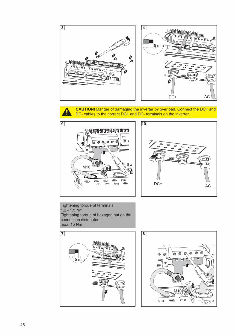
CAUTION! Danger of damaging the inverter by overload. - Only connect a maximum of 20 A to an individual DC terminal.- Connect the DC+ and DC- cables to the correct DC+ and DC- terminals on
the inverter.
6
SMON
SMOFF
21
3
7
Tightening torque of terminals:1.2 - 1.5 Nm
IMPORTANT! - Set the jumper from the 'SMON' position to the 'SMOFF' position for correct measure-
ment results- Check the polarity and voltage of the solar module strings: the voltage should be a
max. of 600 V, the difference between the individual solar module strings should be a max. of 10 V.
34

EN-U
S
4 5
6 7
For more information on string fuses, see the section "Criteria for the proper selection of string fuses."
Selecting String Fuses
If the solar module manufacturer requires the use of string fuses for operation:- Select string fuses according to the information from the solar module manufacturer
or according to "Criteria for the Proper Selection of String Fuses" (max. 20 A per solar module string, max. 6 solar module strings)
Inserting String Fuses
max. 600 V
10
2
1
3
SMON
SMOFF
11
IMPORTANT! - When connecting solar module strings, you should use metal bolts or string fuses with
fuse covers in the fuse holders depending on the solar module manufacturer's instruc-tions. The metal bolts are included in the inverter scope of delivery.
- Place metal bolts with fuse covers in the fuse holders for unoccupied DC+ terminals.
1
2
6 x
14
1
23
15
IMPORTANT! - Please follow solar module safety instructions- Follow all solar module manufacturer requirements
NOTE! If the solar module manufacturer requires the use of string fuses:- Insert fuses with a fuse cover in the respective fuse holder- Do not operate the inverter without fuse covers
35

1
1
1
4
2
3
1WARNING! An electric shock can be fatal. Danger from DC voltage from solar modules. Fuse covers are for installation purposes only. They offer no protection against contact.
36

EN-U
S
Ungrounded System: Connecting Solar Module Strings with a Cable Cross Section > 16 mm²
General As an option, you can also connect DC cables to the inverter with a cross section > 16 mm², e.g., when the DC cables from the solar modules are combined outside of the inverter into a large string.
Additional com-ponents required
The following additional components are required for connecting DC cables with a cross section > 16 mm²:
- 2 M32 metric screw joints (degree of protection min. IP45)
- 2 connection distributors
*)Metric screw joints and connection dis-tributors are available from Fronius as an option.
- 2 M10 cable lugs
Select cable lugs that match the availa-ble DC cables
- 2 M10 hexagon nuts
Ungrounded sys-tem: Connecting solar module strings with a ca-ble cross section > 16 mm²
1 2
*)
3
12
4
1
6 x1
2
37

3 4
5 6
1 2
12
3
4
4
3
5 mm
DC+ AC
1
3
4
CAUTION! Danger of damaging the inverter by overload. Connect the DC+ and DC- cables to the correct DC+ and DC- terminals on the inverter.
3
1
6 x
2M10 5
3
4
9
1
DC+ AC
10
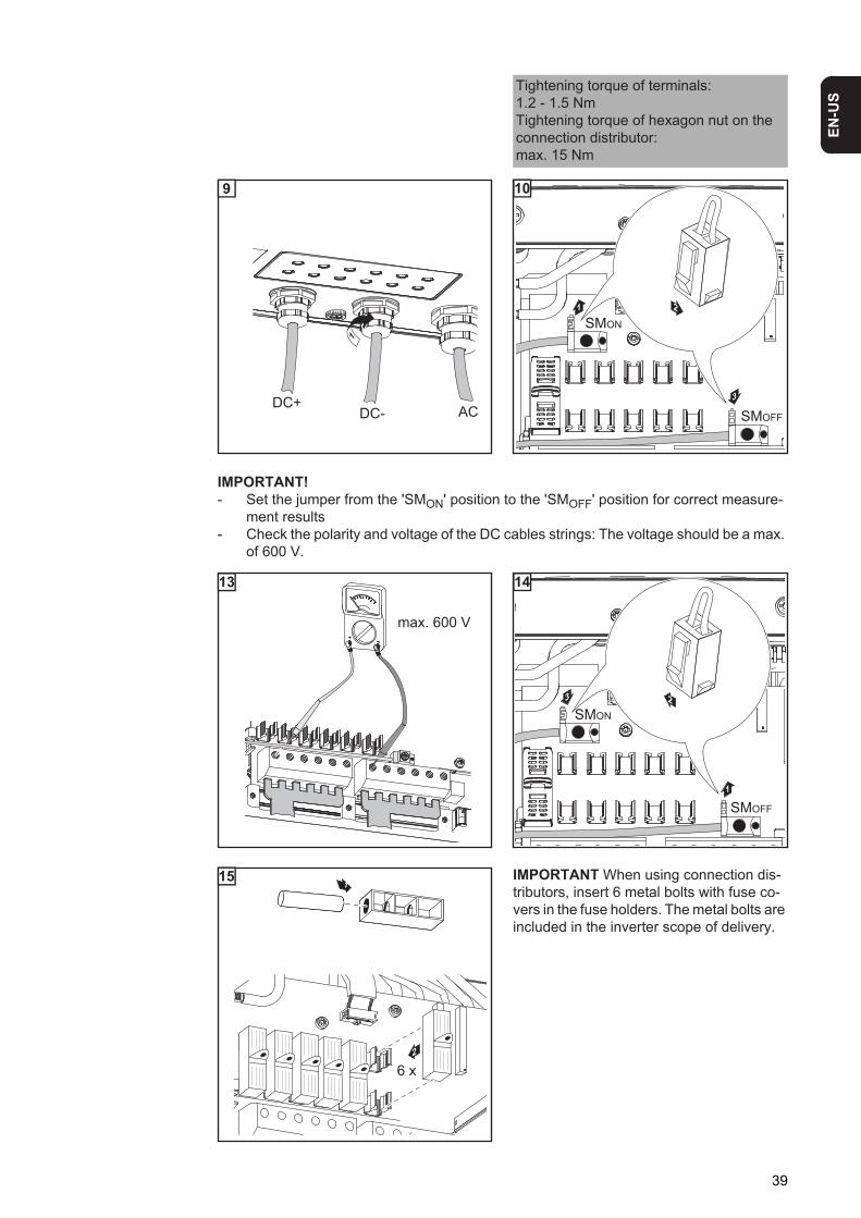
Tightening torque of terminals:1.2 - 1.5 NmTightening torque of hexagon nut on the connection distributor:max. 15 Nm
1
25 mm
7
2
1
6 x3
4
5
M10
8
38
EN-U
S
1 2
3 4
5
IMPORTANT When using connection dis-tributors, insert 6 metal bolts with fuse co-vers in the fuse holders. The metal bolts are included in the inverter scope of delivery.
Tightening torque of terminals:1.2 - 1.5 NmTightening torque of hexagon nut on the connection distributor:max. 15 Nm
1
DC+DC- AC
9
SMON
SMOFF
21
3
10
IMPORTANT! - Set the jumper from the 'SMON' position to the 'SMOFF' position for correct measure-
ment results- Check the polarity and voltage of the DC cables strings: The voltage should be a max.
of 600 V.
max. 600 V
13
2
1
3
SMON
SMOFF
14
1
2
6 x
15
39

40

EN-U
S
Solar Module Ground at Negative Pole: Connecting Solar Module Strings
General The following steps are only necessary when the solar module manufacturer requires a so-lar module ground at the negative pole.
Wire Cross Sec-tion of Solar Mod-ule Strings
The cable cross section for solar module strings should be a maximum of 16 mm² per ca-ble.
Solar module ground at nega-tive pole: Con-necting solar module strings
1 2
3
NOTE! To ensure an effective strain relief device for solar module strings, only use cable cross sections of the same size.
1
1
6 x1
2
12
3
4
4
3
NOTE! Finely stranded cables up to conductor class 5 can be connected to the DC-side terminals without wire end ferrules.
41

1
2 3
1
10 mm
4
CAUTION! Danger of damaging the inverter by overload. - Only connect a maximum of 20 A to an individual DC terminal.- Connect the DC+ and DC- cables to the correct DC+ and DC- terminals on
the inverter.
6
SMON
SMOFF
21
3
7
Tightening torque of terminals:1.2 - 1.5 Nm
IMPORTANT! - Set the jumper from the 'SMON' position to the 'SMOFF' position for correct measure-
ment results- Check the polarity and voltage of the solar module strings: the voltage should be a
max. of 600 V, the difference between the individual solar module strings should be a max. of 10 V.
42

EN-U
S
4 5
6 7
For more information on string fuses, see the section "Criteria for the proper selection of string fuses."
Selecting String Fuses
If the solar module manufacturer requires the use of string fuses for operation:- Select string fuses according to the information from the solar module manufacturer
or according to "Criteria for the Proper Selection of String Fuses" (max. 20 A per solar module string, max. 6 solar module strings)
Inserting String Fuses
max. 600 V
10
2
1
3
SMON
SMOFF
11
IMPORTANT! - When connecting solar module strings, you should use metal bolts or string fuses with
fuse covers in the fuse holders depending on the solar module manufacturer's instruc-tions. The metal bolts are included in the inverter scope of delivery.
- Place metal bolts with fuse covers in the fuse holders for unoccupied DC+ terminals.
1
2
6 x
14
1
23
15
IMPORTANT! - Please follow solar module safety instructions- Follow all solar module manufacturer requirements
NOTE! If the solar module manufacturer requires the use of string fuses:- Insert fuses with a fuse cover in the respective fuse holder- Do not operate the inverter without fuse covers
43
1
1
1
4
2
3
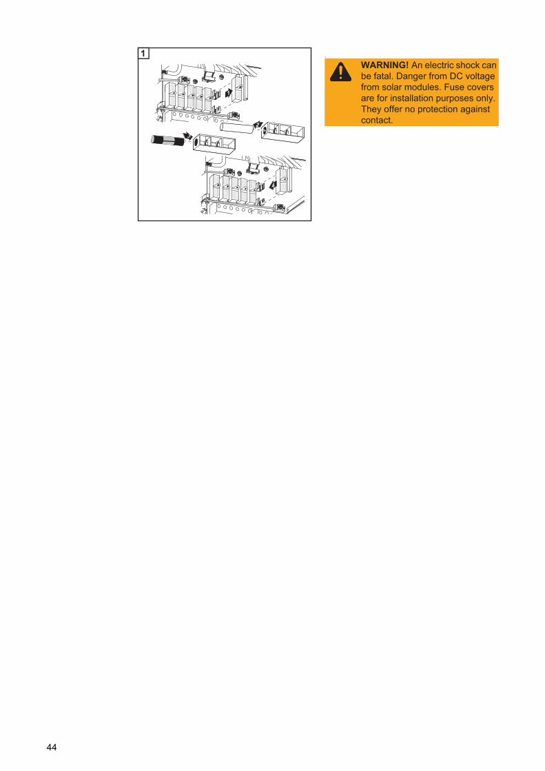
1WARNING! An electric shock can be fatal. Danger from DC voltage from solar modules. Fuse covers are for installation purposes only. They offer no protection against contact.
44

EN-U
S
Solar Module Ground at Negative Pole: Connecting Solar Module Strings with a Cable Cross Section > 16 mm²
General The following steps are only necessary when the solar module manufacturer requires a so-lar module ground at the negative pole.
As an option, you can also connect DC cables to the inverter with a cross section > 16 mm², e.g., when the DC cables from the solar modules are combined outside of the inverter into a large string.
Additional com-ponents required
The following additional components are required for connecting DC cables with a cross section > 16 mm²:
- 2 M32 metric screw joints (degree of protection min. IP45)
- 2 connection distributors
*)Metric screw joints and connection dis-tributors are available from Fronius as an option.
- 2 M10 cable lugs
Select cable lugs that match the availa-ble DC cables
- 2 M10 hexagon nuts
Solar module ground at nega-tive pole: Con-necting solar module strings with a cable cross section > 16 mm²
1 2
*)
3
12
4
1
6 x1
2
45
3 4
5 6
1 2
12
3
4
4
3
5 mm
DC+ AC
1
3
4
CAUTION! Danger of damaging the inverter by overload. Connect the DC+ and DC- cables to the correct DC+ and DC- terminals on the inverter.
3
1
6 x
2M10 5
3
4
9
1
DC+ AC
10
Tightening torque of terminals:1.2 - 1.5 NmTightening torque of hexagon nut on the connection distributor:max. 15 Nm
1
25 mm
7
2
1
6 x3
4
5
M10
8
46

EN-U
S
1 2
3 4
5
IMPORTANT When using connection dis-tributors, insert 6 metal bolts with fuse co-vers in the fuse holders. The metal bolts are included in the inverter scope of delivery.
Tightening torque of terminals:1.2 - 1.5 NmTightening torque of hexagon nut on the connection distributor:max. 15 Nm
1
DC+DC- AC
9
SMON
SMOFF
21
3
10
IMPORTANT! - Set the jumper from the 'SMON' position to the 'SMOFF' position for correct measure-
ment results- Check the polarity and voltage of the DC cables strings: The voltage should be a max.
of 600 V.
max. 600 V
13
2
1
3
SMON
SMOFF
14
1
2
6 x
15
47

48

EN-U
S
Solar Module Ground at Negative Pole for Fronius IG Plus
General Some manufacturers of solar modules stipulate that the module must be grounded.
IMPORTANT: Take into account the following points if a solar module ground is required: - Specifications of the solar module manufacturer regarding polarity and required type
of solar module ground- National provisions
Solar Module Ground at Nega-tive Pole
Example:Solar module ground at negative pole with fuse or high ohm resistor
(1) Solar module(2) Inverter(3) Fuse / High ohm resistor
Solar Module Grounding at Negative Pole for Fronius IG Plus
You can ground solar modules in the Fronius IG Plus using a fuse or a high ohm resistor.
Fuse Holder on the Fronius IG Plus for So-lar Module Grounding
Fronius recommends a 1A fuse, size 10 x 38 mm for solar module grounding.
For solar module grounding using a high ohm resistor, Fronius recommends the "100 kOhm Grounding Kit" option only.
DC+
DC-
N
PE
(1) (2)
=~
=~
L
(3)
WARNING! An electric shock can be fatal. Incorrect or insufficient solar module grounding may result in an electric shock.If the solar module manufacturer requires solar module grounding in the inverter, this may only be provided via the specified fuse or the high ohm resistor "Ground-ing Kit 100 kohm" in compliance with IEC 62109-2.
49

Safety
Setting inverters for grounded so-lar modules
When solar modules are grounded, the inverter's insulation monitoring must be deactivat-ed. For this reason, the inverter must be configured in the second level of the Setup menu so that an error message is displayed or the inverter turns off when the ground fuse is blown (depending on the country setup). The access code 22742 must be entered in order to access the second level of the Setup menu.
Solar Module Ground: Inserting Fuse or "100 kohm Grounding Kit" Option
WARNING! An electric shock can be fatal. Danger presented by DC voltage from solar modules that are exposed to light. When solar modules are grounded, the inverter's insulation monitoring is deactivated.- Ensure that grounded solar modules are designed so that they are double in-
sulated according to protection class II.- Place the relevant safety labels in a clearly visible place on the photovoltaic
system.- Set the inverter so that a warning message is displayed if the fuse trips.
Safety label for the solar module ground
IMPORTANT! The safety labels and fuse for the solar module ground are not part of the scope of delivery for the inverter and must be obtained separately.Warnung!
Ein elektrischer Schlag kann tödlich sein. Gefahr durch DC-Spannung von den Solarmodulen.Die Isolationsüberwachung des Wechsel-richters ist deaktiviert. Die Solarmodule sind geerdet.Vor Arbeiten an der Photovoltaik-Anlage AC- und DC-Seite spannungsfrei schalten.
Warnung!Ein elektrischer Schlag kann tödlich sein. Gefahr durch DC-Spannung von den Solarmodulen.Die Isolationsüberwachung des Wechsel-richters ist deaktiviert. Die Solarmodule sind geerdet.Vor Arbeiten an der Photovoltaik-Anlage AC- und DC-Seite spannungsfrei schalten.
Warnung!Ein elektrischer Schlag kann tödlichsein. Gefahr durch DC-Spannung von den Solarmodulen. Die Isolationsüberwachung des Wechselrichters ist deaktiviert. Die Solarmodule sind geerdet.Vor Arbeiten an der Photovoltaik-k-Anlage AC- und DC-Seite spannungs-frei schalten.
Warnung!Ein elektrischer Schlag kann tödlichsein. Gefahr durch DC-Spannung von den Solarmodulen. Die Isolationsüberwachung des Wechselrichters ist deaktiviert. Die Solarmodule sind geerdet.Vor Arbeiten an der Photovoltaik-k-Anlage AC- und DC-Seite spannungs-frei schalten.
Warnung!Ein elektrischer Schlag kann tödlichsein. Gefahr durch DC-Spannung von den Solarmodulen. Die Isolationsüberwachung des Wechselrichters ist deaktiviert. Die Solarmodule sind geerdet.Vor Arbeiten an der Photovoltaik-k-Anlage AC- und DC-Seite spannungs-frei schalten.
NOTE! If the solar module manufacturer requires a ground for solar modules at the negative pole:- Insert the "100 kohm Grounding Kit" option into the fuse holder completely
with the plastic jacket- Do not operate the inverter without the plastic jacket when using the "100
kohm Grounding Kit" option
or
- Insert the fuse with a fuse cover in the fuse holder- Do not operate the inverter without a fuse cover
WARNING! An electric shock can be fatal. Danger from DC voltage from solar modules. Fuse covers are for installation purposes only. They offer no protection against contact.
The DC main switch is only used to switch off power to the power stage set. When the DC main switch is turned off, the solar module ground at the negative pole re-mains unaffected. Never touch the DC+ and DC-.
50
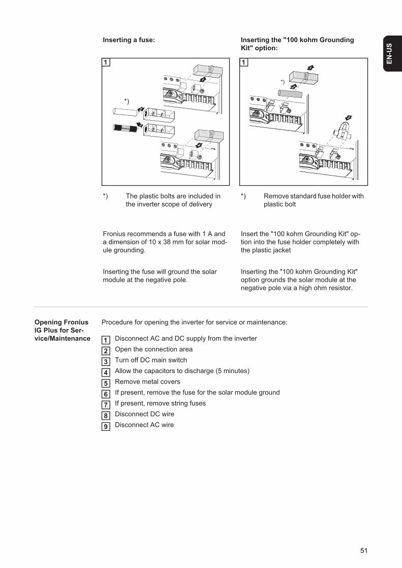
EN-U
S
Opening Fronius IG Plus for Ser-vice/Maintenance
Procedure for opening the inverter for service or maintenance:
Disconnect AC and DC supply from the inverterOpen the connection areaTurn off DC main switchAllow the capacitors to discharge (5 minutes)Remove metal coversIf present, remove the fuse for the solar module groundIf present, remove string fusesDisconnect DC wireDisconnect AC wire
Inserting a fuse: Inserting the "100 kohm Grounding Kit" option:
1
*) The plastic bolts are included in the inverter scope of delivery
1
*) Remove standard fuse holder with plastic bolt
Fronius recommends a fuse with 1 A and a dimension of 10 x 38 mm for solar mod-ule grounding.
Insert the "100 kohm Grounding Kit" op-tion into the fuse holder completely with the plastic jacket
Inserting the fuse will ground the solar module at the negative pole.
Inserting the "100 kohm Grounding Kit" option grounds the solar module at the negative pole via a high ohm resistor.
4
1
2
3
*)
1
3
1
2*)
1
123456789
51

Solar Module Ground at Positive Pole: Connecting Solar Module Strings
General The following steps are necessary when the solar module manufacturer requires a solar module ground at the positive pole.
Wire Cross Sec-tion of Solar Mod-ule Strings
The cable cross section for solar module strings should be a maximum of 16 mm² per ca-ble.
Solar module ground at posi-tive pole: Con-necting solar module strings
1 2
3 4
After disconnecting the DC main switch cable:- Connect the DC+ cable to the DC- connection as per step 5- Connect the DC- cable to the DC+ connection as per step 5- Identify the reversed polarity with (+) and (-) according to steps 6 and 7
NOTE! To ensure an effective strain relief device for solar module strings, only use cable cross sections of the same size.
1
1
6 x1
2
12
3
4
4
3
1
3
2
4
DC +
DC -
4
52

EN-U
S
1 2
3
1
3
5
DC +
1
12
4
DC -
5
DC +
DC -
1
2
6
DC -
DC +2
1
7
NOTE! Finely stranded cables up to conductor class 5 can be connected to the DC-side terminals without wire end ferrules.
1
10 mm
8
CAUTION! Danger of damaging the inverter by overload.- Only connect a maximum of 20 A to an individual DC terminal. - Connect the DC+ cable to the right connection block of the inverter's DC ter-
minals.- Connect the DC- cable to the left connection block of the inverter's DC termi-
nals.- Identify the reversed polarity with (+) and (-) according to step 10
53
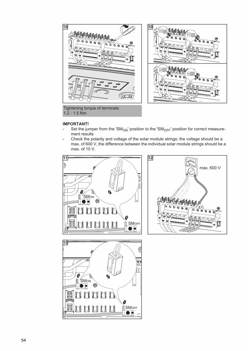
1 2
3
2 1
Tightening torque of terminals:1.2 - 1.5 Nm
IMPORTANT! - Set the jumper from the 'SMON' position to the 'SMOFF' position for correct measure-
ment results- Check the polarity and voltage of the solar module strings: the voltage should be a
max. of 600 V, the difference between the individual solar module strings should be a max. of 10 V.
DC- DC+
10
DC- DC+
DC +
DC -
DC- DC+
DC -
DC +
DC +1 DC -
2
DC -
DC +34
10
SMON
SMOFF
21
3
11
max. 600 V
12
2
1
3
SMON
SMOFF
15
54

EN-U
S
4 5
Selecting String Fuses
If the solar module manufacturer requires the use of string fuses for operation:- Select string fuses according to the information from the solar module manufacturer
or according to "Criteria for the Proper Selection of String Fuses" (max. 20 A per solar module string, max. 6 solar module strings)
Inserting String Fuses
1
1
IMPORTANT! - When connecting solar module strings, you should use metal bolts with fuse covers in
the fuse holders depending on the solar module manufacturer's instructions.The metal bolts are included in the inverter scope of delivery.
- Place metal bolts with fuse covers in the fuse holders for unoccupied DC+ terminals.
1
2
6 x
17
1
23
18
IMPORTANT! - Please follow solar module safety instructions- Follow all solar module manufacturer requirements
NOTE! If the solar module manufacturer requires the use of string fuses:- Insert fuses with a fuse cover in the respective fuse holder- Do not operate the inverter without fuse covers
1
4
2
3
1WARNING! An electric shock can be fatal. Danger from DC voltage from solar modules. Fuse covers are for installation purposes only. They offer no protection against contact.
55

Solar Module Ground at Positive Pole: Connecting Solar Module Strings with a Cable Cross Section > 16 mm²
General The following steps are only necessary when the solar module manufacturer requires a so-lar module ground at the negative pole.
As an option, you can also connect DC cables to the inverter with a cross section > 16 mm², e.g., when the DC cables from the solar modules are combined outside of the inverter into a large string.
Additional com-ponents required
The following additional components are required for connecting DC cables with a cross section > 16 mm²:
- 2 M32 metric screw joints (degree of protection min. IP45)
- 2 connection distributors
*)Metric screw joints and connection dis-tributors are available from Fronius as an option.
- 2 M10 cable lugs
Select cable lugs that match the availa-ble DC cables
- 2 M10 hexagon nuts
Solar module ground at posi-tive pole: Con-necting solar module strings with a cable cross section > 16 mm²
2 3
*)
3
12
4
2
6 x1
3
56

EN-U
S
4 5
After disconnecting the DC main switch cables:- Connect the DC+ cable to the DC- connection as per step 5- Connect the DC- cable to the DC+ connection as per step 5- Identify the reversed polarity with (+) and (-) according to steps 6 and 71 2
3 4
12
3
4
4
4
1
3
2
4
DC +
DC -
5
3
5
DC +
1
12
4
DC -
5
DC +
DC -
1
2
6
DC -
DC +2
1
7
5 mm
1
2
8
57

5 6
1 2
CAUTION! Danger of damaging the inverter by overload.- Connect the DC+ cable to the right connection block of the inverter's DC ter-
minals.- Connect the DC- cable to the left connection block of the inverter's DC termi-
nals.- Identify the reversed polarity with (+) and (-) according to step 14
3
1
6 x
2M10 5
3
4
DC-
13
1
DC- AC
14
Tightening torque of terminals:1.2 - 1.5 NmTightening torque of hexagon nut on the connection distributor:max. 15 Nm
1
25 mm
DC+ AC
11
2
1
6 x3
4
5
M10
DC+
12
Tightening torque of terminals:1.2 - 1.5 NmTightening torque of hexagon nut on the connection distributor:max. 15 Nm
58

EN-U
S
1 2
1 2
3
1
DC+DC- AC
13
DC +
DC -
DC -
DC +
DC +1 DC -
2
DC -
DC +34
14
IMPORTANT! - Set the jumper from the 'SMON' position to the 'SMOFF' position for correct measure-
ment results- Check the polarity and voltage of the DC cables strings: The voltage should be a max.
of 600 V.
SMON
SMOFF
21
3
15 16
2
1
3
SMON
SMOFF
17
IMPORTANT! When using connection distributors, insert 6 metal bolts with fuse covers in the fuse holders. The metal bolts are included in the Fronius IG Plus scope of delivery.
59

4
1
2
6 x
21
60

EN-U
S
Solar Module Ground at Positive Pole for Fronius IG Plus
General Some manufacturers of solar modules stipulate that the module must be grounded.
IMPORTANT: Take into account the following points if a solar module ground is required: - Specifications of the solar module manufacturer regarding polarity and required type
of solar module ground- National provisions
Solar Module Ground at Posi-tive Pole
Example:Solar module ground at positive pole with fuse or high ohm resistor
(1) Solar module(2) Inverter(3) Fuse / High ohm resistor
Solar Module Grounding at Positive Pole for Fronius IG Plus
You can ground solar modules in the Fronius IG Plus using a fuse or a high ohm resistor.
Fuse Holder on the Fronius IG Plus for So-lar Module Grounding
Fronius recommends a 1A fuse, size 10 x 38 mm for solar module grounding.
For solar module grounding using a high ohm resistor, Fronius recommends the "100 kOhm Grounding Kit" option only.
DC+
DC- PE
LN
(1) (2)
=~
=~(3)
WARNING! An electric shock can be fatal. Incorrect or insufficient solar module grounding may result in an electric shock.If the solar module manufacturer requires solar module grounding in the inverter, this may only be provided via the specified fuse or the high ohm resistor "Ground-ing Kit 100 kohm" in compliance with IEC 62109-2.
61

Safety
Setting inverters for grounded so-lar modules
When solar modules are grounded, the inverter's insulation monitoring must be deactivat-ed. For this reason, the inverter must be configured in the second level of the Setup menu so that an error message is displayed or the inverter turns off when the ground fuse is blown (depending on the country setup). The access code 22742 must be entered in order to access the second level of the Setup menu.
Solar Module Ground: Inserting Fuse or "100 kohm Grounding Kit" Option
WARNING! An electric shock can be fatal. Danger presented by DC voltage from solar modules that are exposed to light. When solar modules are grounded, the inverter's insulation monitoring is deactivated.- Ensure that grounded solar modules are designed so that they are double in-
sulated according to protection class II.- Place the relevant safety labels in a clearly visible place on the photovoltaic
system.- Set the inverter so that a warning message is displayed if the fuse trips.
Safety label for the solar module ground
IMPORTANT! The safety labels and fuse for the solar module ground are not part of the scope of delivery for the inverter and must be obtained separately.Warnung!
Ein elektrischer Schlag kann tödlich sein. Gefahr durch DC-Spannung von den Solarmodulen.Die Isolationsüberwachung des Wechsel-richters ist deaktiviert. Die Solarmodule sind geerdet.Vor Arbeiten an der Photovoltaik-Anlage AC- und DC-Seite spannungsfrei schalten.
Warnung!Ein elektrischer Schlag kann tödlich sein. Gefahr durch DC-Spannung von den Solarmodulen.Die Isolationsüberwachung des Wechsel-richters ist deaktiviert. Die Solarmodule sind geerdet.Vor Arbeiten an der Photovoltaik-Anlage AC- und DC-Seite spannungsfrei schalten.
Warnung!Ein elektrischer Schlag kann tödlichsein. Gefahr durch DC-Spannung von den Solarmodulen. Die Isolationsüberwachung des Wechselrichters ist deaktiviert. Die Solarmodule sind geerdet.Vor Arbeiten an der Photovoltaik-k-Anlage AC- und DC-Seite spannungs-frei schalten.
Warnung!Ein elektrischer Schlag kann tödlichsein. Gefahr durch DC-Spannung von den Solarmodulen. Die Isolationsüberwachung des Wechselrichters ist deaktiviert. Die Solarmodule sind geerdet.Vor Arbeiten an der Photovoltaik-k-Anlage AC- und DC-Seite spannungs-frei schalten.
Warnung!Ein elektrischer Schlag kann tödlichsein. Gefahr durch DC-Spannung von den Solarmodulen. Die Isolationsüberwachung des Wechselrichters ist deaktiviert. Die Solarmodule sind geerdet.Vor Arbeiten an der Photovoltaik-k-Anlage AC- und DC-Seite spannungs-frei schalten.
NOTE! If the solar module manufacturer requires a ground for solar modules at the positive pole:- Insert the "100 kohm Grounding Kit" option into the fuse holder completely
with the plastic jacket- Do not operate the inverter without the plastic jacket when using the "100
kohm Grounding Kit" option
or
- Insert the fuse with a fuse cover in the fuse holder- Do not operate the inverter without a fuse cover
WARNING! An electric shock can be fatal. Danger from DC voltage from solar modules. Fuse covers are for installation purposes only. They offer no protection against contact.
The DC main switch is only used to switch off power to the power stage set. When the DC main switch is turned off, the solar module ground at the negative pole re-mains unaffected. Never touch the DC+ and DC-.
62

EN-U
S
Opening Fronius IG Plus for Ser-vice/Maintenance
Procedure for opening the inverter for service or maintenance:
Disconnect AC and DC supply from the inverterOpen the connection areaTurn off DC main switchAllow the capacitors to discharge (5 minutes)Remove metal coversIf present, remove the fuse for the solar module groundIf present, remove string fusesDisconnect DC wireDisconnect AC wire
Inserting a fuse: Inserting the "100 kohm Grounding Kit" option:
1
*) The plastic bolts are included in the inverter scope of delivery
1
*) Remove standard fuse holder with plastic bolt
Fronius recommends a fuse with 1 A and a dimension of 10 x 38 mm for solar mod-ule grounding.
Insert the "100 kohm Grounding Kit" op-tion into the fuse holder completely with the plastic jacket
Inserting the fuse will ground the solar module at the positive pole.
Inserting the "100 kohm Grounding Kit" option grounds the solar module at the positive pole via a high ohm resistor.
4
1
2
3
*)
1
3
1
2*)
1
123456789
63
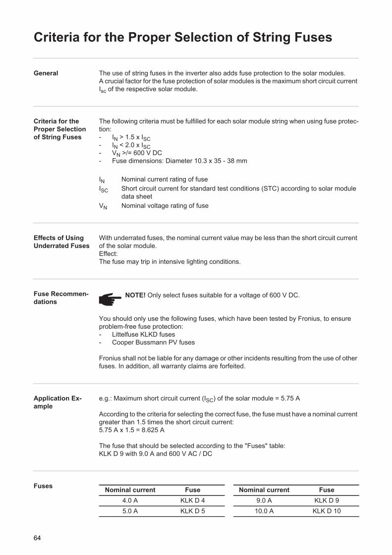
Criteria for the Proper Selection of String Fuses
General The use of string fuses in the inverter also adds fuse protection to the solar modules.A crucial factor for the fuse protection of solar modules is the maximum short circuit current Isc of the respective solar module.
Criteria for the Proper Selection of String Fuses
The following criteria must be fulfilled for each solar module string when using fuse protec-tion:- IN > 1.5 x ISC- IN < 2.0 x ISC- VN >/= 600 V DC- Fuse dimensions: Diameter 10.3 x 35 - 38 mm
IN Nominal current rating of fuseISC Short circuit current for standard test conditions (STC) according to solar module
data sheetVN Nominal voltage rating of fuse
Effects of Using Underrated Fuses
With underrated fuses, the nominal current value may be less than the short circuit current of the solar module.Effect:The fuse may trip in intensive lighting conditions.
Fuse Recommen-dations
You should only use the following fuses, which have been tested by Fronius, to ensure problem-free fuse protection:- Littelfuse KLKD fuses- Cooper Bussmann PV fuses
Fronius shall not be liable for any damage or other incidents resulting from the use of other fuses. In addition, all warranty claims are forfeited.
Application Ex-ample
e.g.: Maximum short circuit current (ISC) of the solar module = 5.75 A
According to the criteria for selecting the correct fuse, the fuse must have a nominal current greater than 1.5 times the short circuit current:5.75 A x 1.5 = 8.625 A
The fuse that should be selected according to the "Fuses" table: KLK D 9 with 9.0 A and 600 V AC / DC
Fuses
NOTE! Only select fuses suitable for a voltage of 600 V DC.
Nominal current Fuse Nominal current Fuse4.0 A KLK D 4 9.0 A KLK D 95.0 A KLK D 5 10.0 A KLK D 10
64

EN-U
S
'Fuses' table: Extract of suitable fuses, e.g. Littelfuse fuses
6.0 A KLK D 6 12.0 A KLK D 127.0 A KLK D 7 15.0 A KLK D 158.0 A KLK D 8 20.0 A KLK D 20
Nominal current Fuse Nominal current Fuse
65

Closing Fronius IG Plus
Closing Fronius IG Plus
1 2
3
1
1
32
1
1
2
3
2
4 1
3
66

EN-U
S
Inserting Option Cards
Suitable Option Cards
There are several options and system upgrades available for the inverter, e.g.:- Datalogger and modem interfaces (for using a PC to record and manage data from
your photovoltaic system)- Various large displays (public display)- Actuators / relays / alarms (signal card)
System upgrades come in the form of plug-in cards. The inverter can be equipped with three option cards.
Safety
Opening Fronius IG Plus
When adding option cards to the inverter, please follow all inverter safety instructions and information.
1 2
WARNING! An electric shock can be fatal. Danger due to grid voltage and DC voltage from solar modules.- The connection area should only be opened by a licensed electrician.- Never work with live wires! Prior to all connection work, make sure that the
AC and DC wires are not charged.
WARNING! An electric shock can be fatal. Danger from residual voltage from ca-pacitors.
You must wait until the capacitors have discharged. Discharge takes 5 minutes.
NOTE! Follow general ESD precautions when handling option cards.
14
2
3
1
1
2
67

Inserting option cards into the Fronius IG Plus
1 2
3 4
Closing Fronius IG Plus
1 2
1
1
4
7 8
1
3
2
5 6
2
1
3
4
2
3
11
3
24 4
55
*
4
IMPORTANT! When networking several DATCOM components, a termination plug must be placed on each free IN and/or OUT connection of a DATCOM component.
IMPORTANT! Close any unused openings at the sealing insert using corresponding blanking plugs.
1
1
32
1
1
2
68

EN-U
S
3
3
2
4 1
3
69
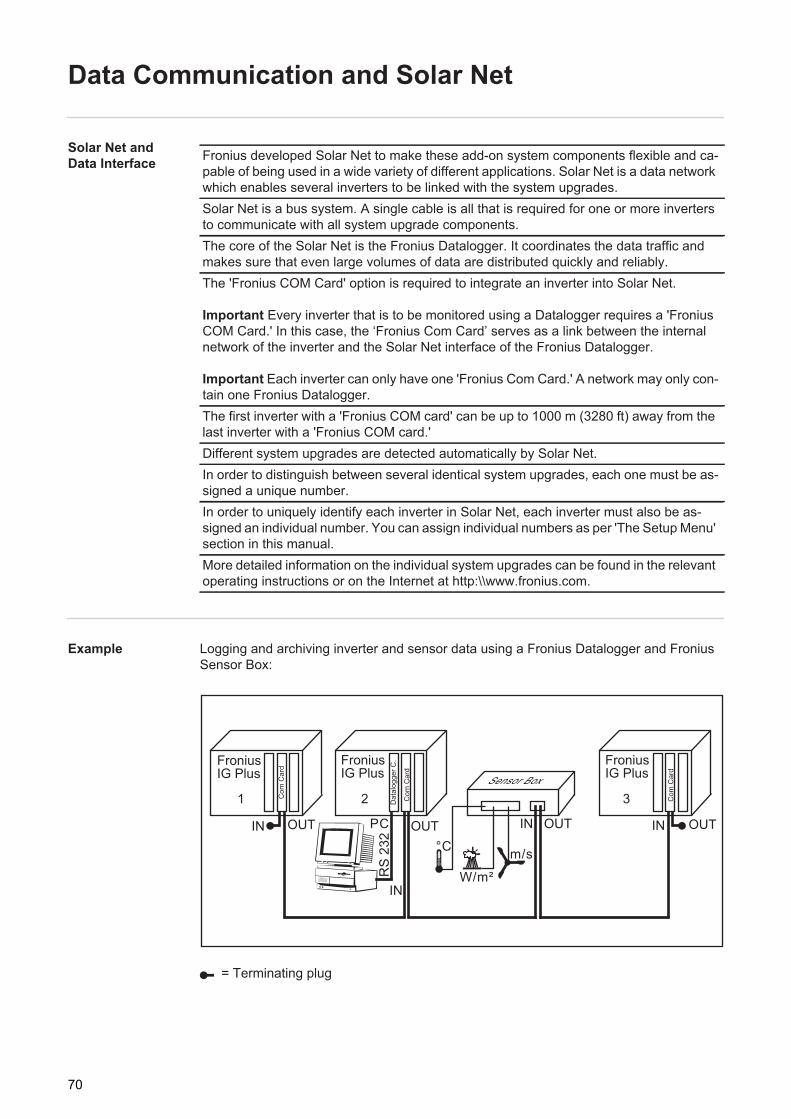
Data Communication and Solar Net
Solar Net and Data Interface
Example Logging and archiving inverter and sensor data using a Fronius Datalogger and Fronius Sensor Box:
Fronius developed Solar Net to make these add-on system components flexible and ca-pable of being used in a wide variety of different applications. Solar Net is a data network which enables several inverters to be linked with the system upgrades.Solar Net is a bus system. A single cable is all that is required for one or more inverters to communicate with all system upgrade components.The core of the Solar Net is the Fronius Datalogger. It coordinates the data traffic and makes sure that even large volumes of data are distributed quickly and reliably.The 'Fronius COM Card' option is required to integrate an inverter into Solar Net.
Important Every inverter that is to be monitored using a Datalogger requires a 'Fronius COM Card.' In this case, the ‘Fronius Com Card’ serves as a link between the internal network of the inverter and the Solar Net interface of the Fronius Datalogger.
Important Each inverter can only have one 'Fronius Com Card.' A network may only con-tain one Fronius Datalogger.The first inverter with a 'Fronius COM card' can be up to 1000 m (3280 ft) away from the last inverter with a 'Fronius COM card.'Different system upgrades are detected automatically by Solar Net.In order to distinguish between several identical system upgrades, each one must be as-signed a unique number.In order to uniquely identify each inverter in Solar Net, each inverter must also be as-signed an individual number. You can assign individual numbers as per 'The Setup Menu' section in this manual.More detailed information on the individual system upgrades can be found in the relevant operating instructions or on the Internet at http:\\www.fronius.com.
= Terminating plug
1 2 3
FroniusIG Plus
FroniusIG Plus
FroniusIG Plus
Com
Car
d
Dat
alog
ger C
.
IN OUT
Com
Car
d
Com
Car
d
IN
OUT
RS
232
IN OUT
Sensor Box
IN OUT
°C
W/m²
m/s
PC
70
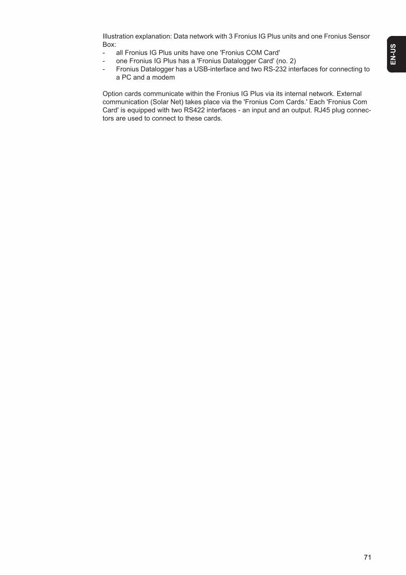
EN-U
S
Illustration explanation: Data network with 3 Fronius IG Plus units and one Fronius Sensor Box:- all Fronius IG Plus units have one 'Fronius COM Card' - one Fronius IG Plus has a 'Fronius Datalogger Card' (no. 2)- Fronius Datalogger has a USB-interface and two RS-232 interfaces for connecting to
a PC and a modem
Option cards communicate within the Fronius IG Plus via its internal network. External communication (Solar Net) takes place via the 'Fronius Com Cards.' Each 'Fronius Com Card' is equipped with two RS422 interfaces - an input and an output. RJ45 plug connec-tors are used to connect to these cards.
71

Commissioning
Factory Configu-ration
The inverter has been pre-configured in the factory and is ready for operation.
To change your inverter settings, please see "The Setup Menu" section in these instruc-tions.
Start-up opera-tion
Once the inverter has been connected to the solar modules (DC) and the public grid (AC), turn the main switch to position - 1 -.
1 2
- As soon as the photovoltaic modules produce sufficient power, the Operating Status LED lights up orange. The screen displays the startup phase. The orange LED indi-cates that the feed-in mode of the inverter will begin shortly.
- After the automatic inverter start, the Operating Status LED lights up green.- Provided that power continues to feed into the grid, the Operating Status LED will re-
main green to confirm that the inverter is functioning correctly.
Setting Inverters for Available So-lar Module Ground
If a solar module ground is being used, the status message 502 "Insulation value too low" will be displayed after the inverter is turned on and upon completion of the startup phase.
NOTE! Regardless of whether bolts or fuses are used, do not operate the inverter without fuse covers.
NOTE! To ensure the degree of protection at the inverter:- Insert blanking plugs into all openings at the sealing insert in which there are
no cables- If cables are run through the sealing insert, insert the remaining blanking
plugs in the recesses located on the outside
1
off
on1
2
ON
AC
2
NOTE! If a solar module ground is used, the corresponding grounding mode must be set in the 'Basic Service Menu' after the inverter is turned on.
A 5-character access code is required to access the 'Basic Service Menu.' This access code will be provided by Fronius upon request.
72

EN-U
S
Confirm the status message by pres-sing the "Enter" key
The current insulation value is displayed.
Press the "Menu" key
The "menu" is displayed.
Select the "Setup" mode using the "Left" or "Right" keys
Press the unassigned "Esc" key 5 x
"CODE" is displayed, the first digit flashes.
Use the "Up" and "Down" keys to select the value for the first digit of the access code
Press the "Enter" key
The second digit flashes.
Use the "Up" and "Down" keys to select a value for the second digit of the access code
Press the "Enter" key
The third digit flashes.
Use the "Up" and "Down" keys to select a value for the third digit of the access code
Press the "Enter" key
1
2
3
4
5
6
7
8
9
10
73

The fourth digit flashes.
Use the "Up" and "Down" keys to select a value for the fourth digit of the access code
Press the "Enter" key
The fifth digit flashes.
Use the "Up" and "Down" keys to select a value for the fifth digit of the access code
Press the "Enter" key
The access code flashes.*) ... Code example
Press the "Enter" key
The inverter is now in the Basic Service menu, the first parameter is displayed:- 'MIXMODE' for multiphase inverters- 'DCMODE' for one-phase inverters
Use the "Up" or "Down" keys to select the 'GNDMODE' parameter
Press the "Enter" key
The grounding mode is displayed.
Use the "Up" and "Down" keys to select the grounding mode:
OFF = no solar module ground (factory set-ting)
11
12
13
14
*)15
16
17
18
74

EN-U
S
NEG = solar module ground at negative pole
POS = solar module ground at positive pole
-100 kohm = solar module ground at nega-tive pole using high ohm resistor
+100 kohm = Solar module ground at posi-tive pole using high ohm resistor
Press the "Enter" key to apply the re-quired grounding modePress the "Esc" key to exit the Basic Service menu
19
20
75

Product Description Fronius IG Plus
Controls and Indi-cators
Item Function
(1) Displayfor displaying values, settings and menus
(2) Operating Status LEDfor displaying the operating status
(3) "Enter" keyfor confirming a selection
(4) "Menu / Esc" keyfor scrolling through menu optionsfor exiting the Setup menu
(5) "Down/Right" keydepending on the selection:for navigating downfor navigating right
(6) "Left/Up" keydepending on the selection:for navigating leftfor navigating up
Display The display unit's power is supplied via the safety-low voltage of the solar modules, which means that the display unit can be used only in the daytime.
(1)
(6) (5) (4) (3)
(2)
IMPORTANT! The inverter display is not a calibrated measuring instrument. A slight inac-curacy of a few percent is intrinsic to the system. A calibrated meter will be needed to make calculations for the power supply company.
76

EN-U
S
Item Function(1) Icons for the "Now" display mode(2) Icons for the "Day" display mode(3) Icons for the "Year" display mode(4) Icons for the "Total" display mode(5) Icons for the "Setup" display mode(6) Icons for operating conditions
The value shown represents the maximum value within the period of observation (depending on which display mode is selected).
The value shown represents the minimum value within the period of observation (depending on which display mode is selected).
Important The minimum and maximum values displayed do not rep-resent the absolute extreme values, because data are recorded only at two-second intervals.
... appears when values are displayed which are directly associated with the solar modules
... appears when values are displayed which are directly associated with the public grid
... appears with data readings that are directly related to the inverter
(7) Range for display unitfor displaying the applicable measuring unit
(8) Icon for the "Enter" key(9) Icons for the "Menu/Esc" key(10) Icons for the "Down/Right" key(11) Icons for the "Left/Up" key
(11) (10)
(3) (4) (5)
(6)
(7)
(13)
(12)
(9) (8)
(1) (2)
77

Operating Status LED
Position of Operating Status LED on the in-verter
Depending on the operating status, the Operating Status LED assumes different colors:
A list of most status codes, the corresponding status information, their status causes and repair measures can be found in the chapter "Troubleshooting and Maintenance," section "Status Diagnosis and Troubleshooting."
(12) Range for display valuefor displaying the value
(13) Output bar (not active during setup)indicates the output power fed into the grid at a given moment - regardless of the display mode chosen. The screen displays % of the maximum possible output power of your solar inverter
Item Function
Operating Status LED ExplanationSteady green The LED stays lit after the automatic startup phase of the invert-
er as long as power is being fed into the grid.It indicates problem-free operation of the photovoltaic system.
Flashing green The photovoltaic system is working correctly, a status code is on the display.
When a status code is shown, rectify the relevant condition by going to the "Maintenance and Service" chapter, "Status Diag-nosis and Troubleshooting" section. The status code can be ac-knowledged by pressing the "Enter" key.
Steady orange The inverter enters an automatic startup phase as soon as the solar modules are delivering sufficient power after sunrise.
Flashes orange A warning is shown on the display or the inverter has been set to standby operation in the Setup menu (= manual shutoff of operation).
The next day, operation will resume automatically.
During the time the LED flashes orange, operation can be re-sumed manually at any time (see section "The Setup Menu")
Steady red General status: the respective status code is shown on the screen
Remains dark There is no connection to the solar modules, no solar module power due to darkness.
78

EN-U
S
Startup Phase and Grid Feed-in Mode
Startup phase The inverter carries out a self test after being turned on automatically. Then a test of the public grid is carried out. This test can take from several seconds up to several minutes depending on local regulations. During the startup sequence the illumination of the Oper-ating Status LED is orange.
Test Procedure 1. Segment testAll display elements light up for about one second
2. Self test of important inverter components- The inverter goes through a master check list for several seconds - The display will show "TEST" as well as the component currently being tested
(e.g., "LED")
3. Synchronization with grid:- "WAIT PS" is displayed, the inverter icon flashes: The inverter waits for all power
stage sets on the grid to be operational. This procedure is dependent on the DC voltage.
- Next, the display shows "SYNC AC," the grid icon flashes
4. Startup test- Before the inverter begins feeding power into the grid, grid conditions are tested
according to local regulations.- The display shows "START UP"
The startup test can take anything from just a few seconds up to several minutes de-
79

pending on national regulations. The time elapsed is indicated by a bar shrinking from the top down.
Whenever two scale divisions stop flashing and disappear, 1/10 of the total duration of the test is over.
Operation of Feeding Energy into the Grid
- Once the tests have been completed, the inverter starts feeding power into the grid.- The display shows the present power feeding into the grid.- The Operating Status LED lights up green, and the inverter starts operating.
80

EN-U
S
Navigation in the Menu Level
Activating display illumination
Press any key
The display illumination is activated.
If no key is pressed for 30 seconds, the display backlight goes out (provided that the display illumination is set to automatic in the Setup menu).
The Setup menu also offers a choice between a permanently lit or permanently dark display.
Automatic switch to the "Now" dis-play mode or the startup phase
If no key is pressed for 2 minutes:- While power is being fed into the grid, the inverter automatically switches to the "Now"
display mode and the present output power is displayed.- If the inverter is not feeding power into the grid, the inverter automatically switches to
the startup phase for synchronization with the grid.
The inverter switches to the "Now" display mode or startup phase from anywhere with-in the display modes or the Setup menu.
Accessing the Menu Level
Press the "Menu" key (1)
"Menu" will appear on the display
The inverter is now in the menu level.
From the menu level you can- set the desired display mode- access the Setup menu
1
(1)
1
81

The Display Modes
The Display Modes
Selecting a Dis-play Mode
Accessing the menu level Use the "left" (7) or "right" (6) keys to select your preferred display mode (1) - (4)
Press "Enter" (5)
The selected display mode is shown, e.g., "Day" display mode.
"Now" display mode ...... Displays real-time values
"Day" display mode ...... Displays values for power fed into the grid during that day
"Year" display mode ...... Displays values for the present calendar year - only avail-able in combination with optional Fronius Datalogger
"Total" display mode ...... Displays values for power fed into the grid since the in-verter was started for the first time
(7)
(1) (2) (3) (4)
(6) (5)
12
3
IMPORTANT! The "Year" menu option is supported only when the optional Fronius Datalogger is connected. This system up-grade includes a real-time clock.
82

EN-U
S
Overview of Dis-play Valuesx OptionalIf the DatCom component for the required options is not available, the message "N.A." (not available) is shown.
Display mode
Symbol Unit Optional Display value
"Now" W - Output power
V - Grid voltage
A - Output current
Hz - Grid frequency
V - Solar module voltage
A - Solar module current
Mohm - Insulation resistance
HH:MM x Time"Day" kWh / MWh - Energy fed into the grid
"Year" Currency - Return
"Total" kg / T - CO2 reduction
W - Max. output power
V - Maximum grid voltage
V - Minimum grid voltage
V - Maximum array voltage
HH:MM - Service hours completed by the in-verter
83

Display Values in "Now" Display Mode
Selecting the "Now" Display Mode
Select the "Now" display mode
The first display value in the "Now" display mode appears
Use the "Down" (2) key to scroll to the next display value
Scroll back using the "Up" key (1)
Display values in the "Now" display mode
(1) (2)
1
2
Output powerPower (in watts) currently being fed into the grid
The "Enter" key is active for the output power display if at least one of the following func-tions is available on the inverter:- Reactive power mode- Remote-controlled effective power reduction- GVPR (Grid Voltage-dependent Power Reduction)
The availability of a function depends on the country setup, device-specific settings and the software version of electronic assemblies.
Reactive power mode:- The current apparent power for the device is displayed in VA by pressing the "Enter"
key.- The current operating mode can be displayed by pressing the "Up" and "Down" keys.
Remote-controlled effective power reduction (if there is a Fronius Power Control Box/Card in the Solar Net and a power reduction has been triggered by the utility company):- Pressing the "Enter" key will display the power reduction as a percentage.- You can display how long the power reduction has been in effect by pressing the
"Up" and "Down" keys.
GVPR:- Pressing the "Enter" key will display the activation time in SEC/GVPR (alternating).
You can use the "Up" and "Down" keys after pressing the "Enter" key to scroll through the existing parameters.
- You can return to the menu level by pressing the "Menu" key.
84

EN-U
S
The insulation resistance is the resistance between the positive or negative pole of the photovoltaic system and the earth potential. If an insulation resistance of > 600 kOhm is shown, this means that the photovoltaic system is adequately insulated.
For example, phase voltage for phase L1:
Grid voltageExternal conductor voltage (volts)
The "Enter" key is active for multi-phase inverters.- The phase voltage can be displayed
by pressing the "Enter" key. - The phase voltage of the other
phases can be displayed by pressing the "Up" and "Down" keys.
- You can return to the menu level by pressing the "Menu" key.
For example, phase current for phase L3:
Output currentCurrent (in amperes) supplied to the grid at any particular moment
The "Enter" key is active for multi-phase inverters.- The phase current can be displayed
by pressing the "Enter" key. - The phase current of the other
phases can be displayed by pressing the "Up" and "Down" keys.
- You can return to the menu level by pressing the "Menu" key.
Grid frequency(hertz)
Solar module voltageVoltage of the solar modules at the mo-ment of data display (volts)
Solar module currentCurrent supplied by solar modules at the moment of data display (amperes)
Insulation resistance of photovoltaic system(MOhm)For ungrounded solar modules
WARNING! An electric shock can be fatal. The positive and negative poles of the photovoltaic system should never be touched if the insulation resistance is less than 600 kOhm. An insulation resistance of < 600 kOhm may be due to an inad-equately insulated DC lead or defective solar modules. In the event that the insu-lation resistance is too low, you must contact your Fronius service partner.
85

An insulation resistance of less than 600 kOhm indicates an error.
When the insulation resistance is less than 10 MOhm, the display differentiates between:- negative potential of the ground (polarity sign '-')- positive potential of the ground (polarity sign '+')
Options If the DatCom component for the required options is not available, the message "N.A." (not available) is shown.
Display example of a negative potential (polarity sign '-')Short circuit between DC- lead and ground
Display example of a positive potential (polarity sign '+')Short circuit between DC+ lead and ground
GFDI statusfor grounded solar modules 'GFDI OK' is displayed if there is no ground fault in the system
GFDI = Ground Fault Detector InterruptorTime (datalogger option)When the time on the inverter or a system add-on is changed, this changes the time on all devices connected via Solar Net.
86

EN-U
S
Display Values in "Day / Year / Total" Display Modes
General For the inverter, the day begins when it switches on. If the DC supply line is disconnected, the following parameters within the "Day" display mode will be reset after repeating the startup:- Return (currency can be selected)- CO2 reduction (kg)- Maximum output power (watts)- Maximum grid voltage (volts)- Minimum grid voltage (volts)- Service hours completed by the inverter
If an optional Fronius Datalogger is available, the display values listed always apply to the whole day.
Selecting "Day / Year / Total" Dis-play Mode
First Display Value in the "Day" Display Mode:
First Display Value in the "Year" Display Mode:
First Display Value in the "Total" Display Mode:
Select the "Day" or"Year" or"Total" display mode
The first display value in the selected dis-play mode appears.
Use the "Down" (2) key to scroll to the next display value
Scroll back using the "Up" key (1)
(1) (2) (1) (2)
(1) (2)
1
2
87

Display values in the 'Day / Year / Total' display modes
Output energyEnergy fed into the grid over the period of time in question (kWh / MWh)
Due to the variety of different monitoring systems, there can be deviations between the readings of other metering instruments and the readings from the inverter. For determin-ing the energy supplied to the grid, only the readings of the calibrated meter supplied by the electric utility company are relevant.
YieldAmount of money earned during the peri-od of time in question (currency can be se-lected in the Setup menu)
As was the case for the output energy, readings may differ from those of other instru-ments.
'The Setup menu' section describes how to set the currency and rate for the output ener-gy. The factory setting depends on the respective country-specific setting.
CO2 reductionCO2 emissions saved during the monitored period(kg / T; T = tons) The area for unit display switches between ‘kg’ or ‘T’ and ‘CO2.’
The CO2 meter gives an indication of CO2 emissions that would be released during the generation of the same amount of electricity in a combustion power plant.The factory setting is 0.59 kg / kWh (source: DGS - the German Society for Solar Energy).
Maximum output powerHighest output power of the inverter during observation period (watts)
Maximum grid voltageHighest reading of grid voltage (V) during observation period
88

EN-U
S
Options If the DatCom component for the required options is not available, the message "N.A." (notavailable) is shown.
For example, maximum phase voltage for phase L1:
The 'Enter' key is active in the 'Total' dis-play mode depending on the country set-up or the device-specific settings.- The maximum phase voltage mea-
sured during the time in question can be displayed by pressing the 'Enter' key.
- The maximum phase voltage of the other phases measured during the time in question can be displayed by pressing the 'Up' and 'Down' keys.
- You can return to the menu level by pressing the 'Menu' key.
Minimum grid voltageLowest reading of grid voltage (V) during observation period
Maximum solar module voltageHighest reading of solar module voltage (V) during observation period
Operating hoursIndicates how long the inverter has been operating(HH:MM)
Duration of operation is shown in hours and minutes up to 999 h and 59 min (display: ‘999:59’). After that only full hours are displayed.
Although the inverter does not operate during the night, all sensor data are recorded around the clock.
89

The Setup Menu
Presetting Following commissioning, the inverter is preconfigured according to the country setup.
The SETUP menu item enables you to easily customize the inverter’s preset parameters to your needs.
Accessing the Setup Menu
Switch to the menu level (press the "Menu" key)Select the "Setup" (1) mode using the "Left" (4) or "Right" (3) keysPress "Enter" (2)
The Setup Menu’s first menu item "STAND-BY" is shown.
(4) (3) (2)
(1)1
2
3
90

EN-U
S
Scrolling through Menu ItemsAccess the Setup menuScroll through the available menu items using the "Up" (1) and "Down" (2) keys
Example: "STANDBY" menu item Example: "CONTRAST" menu item
(1) (2) (1) (2)
12
91

Menu Items in the Setup Menu
STANDBY Manual activation / deactivation of Standby operation using the "Enter" key
- The power electronics are switched off in standby mode. No power is fed into the grid.- The Operating Status LED flashes orange.- The orange flashing Operating Status LED stops at dusk. - After the subsequent sunrise, the power supply operation into the grid is resumed au-
tomatically (after completion of the startup phase the LED is illuminated green).- Grid supply operation can be resumed at any time whenever the LED is flashing or-
ange (deactivate "STANDBY").
If the Standby mode is activated by pressing the "Enter" key, the display alternates be-tween "STANDBY" and "Enter:"
To maintain Standby operation:- Press the "Esc" key
To end Standby operation:- Press the "Enter" key
WLAN AP To activate/deactivate the Fronius Datama-nager 2.0 WLAN access point (e.g., to set up system monitoring)
Unit -Setting range EnterFactory setting Automatic operation of feeding energy into the grid (Standby
deactivated)
Setting range MODE/SSID/KEY
MODE To activate/deactivate the WLAN access pointON The WLAN access point is activated.OFF The WLAN access point is deactivated.
SSID* To display the Fronius network ID: FRONIUS_240.xxxxx (5–8 digits)(scrolls through)
92

EN-U
S
Activating the WLAN access point
Requirement:- There must be a Fronius Datamanager 2.0 plug-in card in the inverter or Fronius Solar
Net,or
- There must be a Fronius Datamanager Box 2.0 in the Fronius Solar Net.
Select the "WLAN AP" menu itemPress the "Enter" key
"MODE" is displayed.
Press the "Enter" key
The current WLAN access point status is displayed:
ON The WLAN access point is activated.
If the IP switch of the Fronius Datamanager 2.0 plug-in card or Fronius Dataman-ager Box 2.0 is activated, then arrows and "Enter" are hidden:
Settings cannot be changed.
OFF The WLAN access point is deactivated.
To activate the WLAN access point, select "ON" using the "Up" or "Down" keysPress the "Enter" key
The WLAN access point is activated and stays open for one hour.
Press the "Esc" key to exit the menu
"MODE" is displayed.
To select the "SSID" and "KEY" points, use the "Up" or "Down" keys and press the "Enter" key to display them.
CONTRAST Contrast setting on LCD display
KEY* To display the network password (8 digits)
* "SSID" and "KEY" values are only displayed when "MODE" is set to "ON".If "MODE" is set to "OFF", "---" will be displayed.
12
3
45
6
93

Since contrast depends on temperature, it may be necessary to adjust the "CONTRAST" menu item when ambient conditions change.
LIGHT MODE Initial setting for display illumination.
CASH Sets the currency and charge rate for the output energy to the grid
CO2 Setting of CO2 reduction factor
Unit -Setting range 0 - 7Factory setting 7
Unit -Setting range AUTO / ON / OFFFactory setting AUTO
AUTO: The display illumination will stop 30 seconds after the last time a key has been pressed.
ON: The display will remain illuminated whenever power is supplied to the grid.
OFF: The display illumination will be permanently off.
IMPORTANT! The "LIGHT MODE" setting only relates to the display's background illumi-nation. The LCD display will still remain on during operation. Its energy consumption is less than one mW (1/1000 W).
Unit -Display area Currency / Charge rate / kWhFactory setting (depends on the country setting)
Unit kg/kWh, T/kWhSetting range 00,01 - 99,99Factory setting 0.59 kg/kWh
94

EN-U
S
YIELDOFF SETOffset is an amount of energy (in Wh, kWh, or MWh) that can be added to the lifetime total energy output of the inverter to give it a ‘head start.’
CALI.Preset correction value, so that the data shown on the inverter display corresponds to the calibrated data shown on the electric meter
IG no. Number setting (address) of the inverter in a setup comprising multiple solar inverters linked together
DAT COM Indicates status of data transmission, func-tion test or activates and resets various op-tion (e.g., Fronius Signal Card, Fronius Personal Display Card, Fronius Interface Card, Fronius TAC Card, etc.)
Setting- an OFFSET value for the total energy
display - a measurement correction value for
the Day, Year and Total energy dis-play
Setting range OFF SET / CALI.
Unit Wh / kWh / MWhSetting range 5-digit + k... / M...
1 kWh = 1000 Wh1 MWh = 1000000 Wh
Factory setting 0
Unit %Setting range -5.0 - +5.0 in increments of 0.1Factory setting 0
Unit -Setting range 01 - 99 (100th inverter = 00)Factory setting 1
IMPORTANT! Each inverter must be assigned its own address when connecting several inverters in a data communications system.
Setting range Displays OK COM or ERROR COM; SIGCD TEST / PDCD RST / IFCD RST / TAC TEST
95

OK COM / ERROR COMDisplays data communication available via Solar Net or an error that occurred in data com-munication
Examples of options:
SIGCD TESTFunction test for the Fronius Signal Card option
When the "Energy Management" function is activated, the function test for the Fronius Sig-nal Card cannot be carried out.
PDCD RSTResets the Fronius Personal Display Card option
IFCD RSTResets the Fronius Interface Card option
TAC TESTFunction test for the Fronius Power Relay Card (TAC) option
TIME Date and time setting
LIMIT CFG Used to display settings relevant to a power supply company. The displayed values de-pend on the respective country setup or de-vice-specific inverter settings.
Unit DDMMYYYY, HH:MMSetting range Date / TimeFactory setting -
IMPORTANT! The "TIME" menu item is only supported when the Fronius Datalogger op-tion is installed.
Display range U IL Max / U IL/TRIP* Max / U IL Min / U IL/TRIP* Min / U OL Max / U OL/TRIP* Max / U OL Min / U OL/TRIP* Min / U RC Max / U RC Min / U LLFREQ IL Max / FREQ IL/TRIP* Max / FREQ IL Min / FREQ IL/TRIP* Min / FREQ OL Max / FREQ OL/TRIP* Max / FREQ OL Min / FREQ OL/TRIP* Min / FREQ RE Max / FREQ RE MinSTART TIME/INIT* / START TIME/RCON*AGF / EMI COMP / POWER LIM / MIX MODE
* Alternating display, e.g.:
96

EN-U
S
IL "Inner Limit"OL "Outer Limit"
Different clearing times can be assigned to the inner limit IL and the outer limit OL depend-ing on the country setup or device-specific settings.E.g.:- Short clearing time for a deviation from the outer limit- Longer clearing time for a deviation from the inner limit
U IL MaxUpper inner grid voltage limit in V
U IL/TRIP MaxClearing time for exceeding the upper inner grid voltage limit in P**
U IL MinLower inner grid voltage limit in V
U IL/TRIP MinClearing time for falling below the lower inner grid voltage limit in P**
U OL MaxUpper outer grid voltage limit in V
U OL/TRIP MaxClearing time for exceeding the upper outer grid voltage limit in P**
U OL MinLower outer grid voltage limit in V
U OL/TRIP MinClearing time for falling below the lower outer grid voltage limit in P**
U RC Max"Reconnection"Upper voltage limit for reconnection to the public grid after disconnection due to an unac-ceptable parameter deviation
U RC Min"Reconnection"Lower voltage limit for reconnection to the public grid after disconnection due to an unac-ceptable parameter deviation
U LL"Longtime Limit"Voltage limit in V for the voltage average determined over a longer time period
FREQ IL MaxUpper inner grid frequency limit in Hz
FREQ IL/TRIP MaxClearing time for exceeding the upper inner grid frequency limit in P**
FREQ IL MinLower inner grid frequency limit in Hz
97
FREQ IL/TRIP MinClearing time for falling below the lower inner grid frequency limit in P**
FREQ OL MaxUpper outer grid frequency limit in Hz
FREQ OL/TRIP MaxClearing time for exceeding the upper outer grid frequency limit in P**
FREQ OL MinLower outer grid frequency limit in Hz
FREQ OL/TRIP MinClearing time for falling below the lower outer grid frequency limit in P**
** P = grid periods; 1 P corresponds to 20 ms at 50 Hz and 16.66 ms at 60 Hz
FREQ RC Max"Reconnection"Upper grid frequency limit for reconnection to the public grid after disconnection due to an unacceptable parameter deviation
FREQ RC Min"Reconnection"Lower grid frequency limit for reconnection to the public grid after disconnection due to an unacceptable parameter deviation
START TIME/INITStartup time of the inverter in s
START TIME/RCONReconnection time in s after a grid error
AGF"Advanced Grid Features"
Display range Q MODE / GPIS / GFPR / FULL/LVRT
98

EN-U
S
EMI COMPCompensation of the EMC filter during operation
ON / OFF / N.A.
POWER LIMConstant apparent power limiting
MIX MODEDC operating type
*** alternating displayN.A. not available
- Press the "Enter" key to display the respective value- Press "Esc" to exit the displayed value
STATE PS Status display of power stage sets; the last error that has occurred can be displayed
Q MODE Mode for reactive power specification- CONST / COSP***
Constant cos phi specification- CONST / Q REL***
Constant specification of the relative reactive power in %- CONST / Q ABS***
Constant specification of an absolute reactive power in var- COSP (P)
cos phi specification depending on the effective power- Q (U)
Relative reactive power specification regarding the current grid voltage
- Q (P)Relative reactive power specification depending on the ef-fective power
- OFFThe inverter is operating in the pure effective power range (cos phi = 1)
GPIS "Gradual Power Increment at Startup"SoftStart function regarding how fast the inverter should in-crease the power
ON / OFF / N.A.GFPR "Grid Frequency Depending Power Reduction"
Power reduction depending on the grid frequency
ON / OFF / N.A.FULL / LVRT*** "Low Voltage Ride Through"
Function for bridging a grid voltage gap that was caused by grid voltage parameters outside of the limits
ON / OFF / N.A.
99

VERSION Displays the version number and serial number of electronic components (e.g., IG Brain, power stage sets, display, country setup)
IMPORTANT! Due to the low level of irradiance early in the morning and in the evening, the status codes 306 (power low) and 307 (DC low) are displayed routinely at these times of day. These status messages do not indicate any kind of fault.
Unit -Display area MAIN CTRL / LCD / PS (PS00, PS01, PS02) / SETUPFactory setting -
MAINCTRL Version data of IG Brain unit (inverter control)LCD Display version dataPS Power stage set version data (PS00 - max. PS02)SETUP Display of current country setup
The current country setup is displayed (2-3 letters) by pressing the "Enter" key, e.g., "DE" for Germany country setup;Exit the Country Setup display by pressing the "Esc" key
100

EN-U
S
Setting and Displaying Menu Items
Setting Menu Items - General
Access the Setup menuUse the "Up" or "Down" keys to select the desired menu item
Press the "Enter" key
Examples of Set-ting and Display-ing Menu Items
The following examples describe how to set and display menu items:- Setting the Currency and Charge Rate- Displaying and Setting Parameters in the "DATCOM" Menu Item- Setting Time and Date
Setting the Cur-rency and Charge Rate
Select the "CASH" menu itemPress the "Enter" key
The first digit of a value to be set flash-es:
The available settings are displayed:
Use the "Up" and "Down" keys to se-lect a value for the first digit
Press the "Enter" key
The second digit of the value flashes.Repeat steps 4 and 5 until ...
the entire value flashes.Press the "Enter" keyRepeat steps 4 - 6 for units or other values to be set until the unit or value flashes.Press the "Enter" key to save and ap-ply the changes.
Press the "Esc" key to not save the changes.
Use the "Up" and "Down" keys to se-lect the desired setting
Press the "Enter" key to save and ap-ply the selection.
Press the "Esc" key to not save the selection.
The currently selected menu item is dis-played.
The currently selected menu item is dis-played.
12
3
4
5
6
78
9
4
5
12
101

The currency is displayed, factory setting = "EUR";The first character flashes.
Use the "Up" and "Down" keys to select a letter for the first character
Press the "Enter" key
The second character flashes.
Use the "Up" and "Down" keys to
select a letter for the second characterPress the "Enter" key
The third character flashes.
Use the "Up" and "Down" keys to select a letter for the third character
Press the "Enter" key
The set currency flashes.
Press the "Enter" key
The charge rate in kWh/currency is display-ed, factory setting = EUR 0.48 / kWhThe first digit flashes.
Use the "Up" and "Down" keys to select a value for the first digit (e.g., 0)
3
4
5
6
7
8
9
10
Press the "Enter" key11
102

EN-U
S
The second digit flashes.
Use the "Up" and "Down" keys to select a value for the second digit (e.g., 0)
Press the "Enter" key
The first digit after the decimal point flas-hes.
Use the "Up" and "Down" keys to select a value for the first digit after the decimal point (e.g., 4)
Press the "Enter" key
The second digit after the decimal point flashes.
Use the "Up" and "Down" keys to select a value for the second digit after the decimal point (e.g., 8)
The values that can be set range from 00.01 to 99.99.Press the "Enter" key
The set charge rate flashes.
Press the "Enter" key
The currency and the charge rate are ap-plied.
Press the "Esc" key to exit the "CASH" menu item
Displaying and Setting Parame-ters in the "DAT-COM" Menu Item
Select the "DATCOM" menu itemPress the "Enter" keyThe following displays depend on whether- a data connection has been esta-
blished - a data connection is faulty or an
option is not installed
Available data connection
12
13
14
15
16
17
18
19
12
103

If there is a data connection available, "OK-COM" is shown.
Use the "Down" key to access the "sig-nal card test"
"SIGCDTEST" is displayed
Press the "Enter" key
The "Signal Card Test" starts, "SIGCD ON" appears on the display.
If the "signal card" is active, it will emit an acoustic signal in confirmation.
Press the "Esc" key to exit the "Signal Card Test"
"SIGCD TEST" is displayed
Use the "Down" key to select additional options:
e.g., Reset Personal Display Card ("PDCD RST") ...
3
4
IMPORTANT! If no acoustic signal is heard, the signal lines should be checked.
5
6
104

EN-U
S
...or reset Interface Card ("IFCD RST")
Press the "Enter" key
"PDCD DONE"...
...or...
"IFCD DONE" is displayed
Press the "Esc" key to exit the current optionUse the "Down" key to select additional options:
"TAC ON" is displayed
To test the function of the Fronius Po-wer Relay Card option, press the "En-ter" key
"TAC TEST" is displayed, the AC relay swit-ches off and the AC connection to the inver-ter is interrupted (no grid feed).
Press the "Esc" key 2x to exit the "DATCOM" menu item
Data connection faulty or DATCOM is not installed
If there is a faulty data connection or op-tions are not installed, "ERROR COM" is displayed.
Select the respective option using the "Down" key
7
8
9
10
11
3
105

"SIGCD NI" (Signal Card not installed) or"PDCD NI" (Personal Display Card not in-stalled) or"IFCD NI" (Interface Card not installed) or"TAC NI" (TAC Card not installed)is displayed.
Press the "Esc" key to exit the "DATCOM" menu item
Setting Time and Date
Select the "TIME" menu itemPress the "Enter" key
The date is displayed (DD.MM.YYYY), the first digit for the day flashes.
Use the "Up" and "Down" keys to select a value for the first day digit
Press the "Enter" key
The second digit for the day flashes.
Use the "Up" and "Down" keys to select a value for the second day digit
Press the "Enter" key
The first digit for the month flashes.
Use the "Up" and "Down" keys to select a value for the first month digit
Press the "Enter" key
4
12
3
4
5
6
7
8
106

EN-U
S
The second digit for the month flashes.
Use the "Up" and "Down" keys to select a value for the second month di-git
Press the "Enter" key
The first digit for the year flashes.
Use the "Up" and "Down" keys to select a value for the first year digit
Press the "Enter" key
The second digit for the year flashes.
Use the "Up" and "Down" keys to select a value for the second year digit
Press the "Enter" key
The third digit for the year flashes.
Use the "Up" and "Down" keys to select a value for the third year digit
Press the "Enter" key
The fourth digit for the year flashes.
Use the "Up" and "Down" keys to select a value for the fourth year digit
Press the "Enter" key
The set date then flashes.
Press the "Enter" key
9
10
11
12
13
14
15
16
17
18
19
107

The time is displayed (HH:MM), the first di-git for the hour flashes.
Use the "Up" and "Down" keys to select a value for the first hour digit
Press the "Enter" key
The second digit for the hour flashes.
Use the "Up" and "Down" keys to select a value for the second hour digit
Press the "Enter" key
The first digit for the minutes flashes.
Use the "Up" and "Down" keys to select a value for the first minutes digit
Press the "Enter" key
The second digit for the minutes flashes.
Use the "Up" and "Down" keys to select a value for the second minutes digit
Press the "Enter" key
The set time flashes.
Press the "Enter" key to apply the time Press the "Esc" key to exit the "TIME" menu item
20
21
22
23
24
25
26
27
2829
108
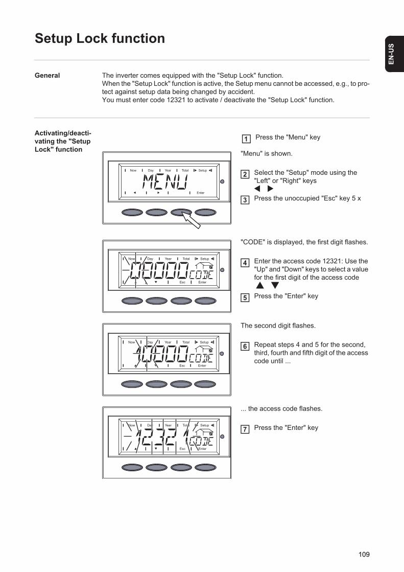
EN-U
S
Setup Lock function
General The inverter comes equipped with the "Setup Lock" function. When the "Setup Lock" function is active, the Setup menu cannot be accessed, e.g., to pro-tect against setup data being changed by accident.You must enter code 12321 to activate / deactivate the "Setup Lock" function.
Activating/deacti-vating the "Setup Lock" function "Menu" is shown.
Select the "Setup" mode using the "Left" or "Right" keys
Press the unoccupied "Esc" key 5 x
"CODE" is displayed, the first digit flashes.
Enter the access code 12321: Use the "Up" and "Down" keys to select a value for the first digit of the access code
Press the "Enter" key
The second digit flashes.
Repeat steps 4 and 5 for the second, third, fourth and fifth digit of the access code until ...
... the access code flashes.
Press the "Enter" key
Press the "Menu" key1
2
3
4
5
6
7
109

"SETUP LOCK" is displayed.
Press the "Enter" key
"ON LOCK" is displayed.
Use the "Up" and "Down" keys to select the desired function
ON LOCK = "Setup Lock" function is activa-ted (the Setup menu cannot be accessed)
OFF LOCK = "Setup Lock" function is deac-tivated (the Setup menu can be accessed)
Press the "Enter" key to apply the fun-ction
8
9
10
110

EN-U
S
Select Log Entry function
General The inverter is equipped with a simple logging function that can record up to 5 grid errors.The 5 most recent grid errors are saved together with the time the error occurred according to the total operating hours counter. When there are more than 5 errors, the oldest error is deleted.A grid error is saved when it is different than the most recent error.
Code 22564 must be entered to access saved grid errors.
'Select Log Entry' function - access saved grid errors "Menu" is shown.
Select the "Setup" mode using the "Left" or "Right" keys
Press the unassigned "Esc" key five times
"CODE" is displayed, the first digit flashes.
Enter the access code 22564: Use the "Up" and "Down" keys to select a value for the first digit of the access code
Press the "Enter" key
The second digit flashes.
Repeat steps 4 and 5 for the second, third, fourth and fifth digits of the ac-cess code until ...
... the access code flashes.
Press the "Enter" key
Press the "Menu" key1
2
3
4
5
6
7
111

"LOG" and ...
... "ENTRY" are displayed alternately.
Press the "Enter" key
The first saved grid error "LOG 1" is shown.
Use the "Up" and "Down" keys to select the desired grid error
LOG 1 ... contains the most recent grid er-ror
LOG 5 ... contains the oldest grid error
Press the "Enter" key to display the grid error
The corresponding status code is displayed (e.g. STATE 115 = AC frequency in phase 1 is too high)
Press the "Up" or "Down" key
The time when the grid error occurred (ac-cording to the total operating hours counter) is displayed.
Press "Esc" twice to exit the "Select Log Entry" function
8
9
10
11
12
NOTE! If the status code "STATE -----" and time "0:00 H" are displayed, then a save location was selected at which no AC error has yet been logged.
112

EN-U
S
Energy Management function
General The inverter is fitted with an "Energy Management" function.Via the "Energy Management" function, a potential-free switch contact can be triggered so that this functions as an actuator.A user connected to the switch contact can thus be controlled by assigning a power feed dependent switch-on or switch-off point.
The "Energy Management" function is only available if the "Fronius Signal Card" option is installed in the inverter.
When the "Energy Management" function is active,- the basic function of the Fronius Signal Card is deactivated automatically
and- the potential-free switch contact of the Fronius Signal Card is triggered accordingly.
For further information, refer to the Fronius Signal Card operating instructions.
The switch contact is switched off- when no current is being fed into the public mains supply by the inverter;- when the inverter is switched manually to standby mode;- if there is an effective power setting of <10% of the power rating (e.g. via the Fronius
Power Control Card/Box);- if there is insufficient solar irradiation (status codes "POWER LOW" and "DC LOW").
In the "Basic Service Menu" you can activate the "Energy Management" function and set a switch-on and switch-off point.For access to the "Basic Service Menu," the code 22742 must be entered.
Activating the "Energy Manage-ment" function "Menu" is displayed.
Select the "Setup" mode using the "Left" or "Right" keys
Press the unassigned "Esc" key five times
NOTE! The buzzer on the Fronius Signal Card can only be switched on or off by setting the "Buz." jumper on the Fronius Signal Card appropriately.If the "Buz." jumper is in the "on" position, the acoustic signal sounds for as long as the potential-free contact of the Fronius Signal Card is switched on as a result of the "Energy Management" function.
Press the "Menu" key1
2
3
113

"CODE" is displayed, the first digit flashes.
Enter the access code 22742: Use the "Up" and "Down" keys to select a value for the first digit of the access code
Press the "Enter" key
The second digit flashes.
Repeat steps 4 and 5 for the second, third, fourth and fifth digits of the ac-cess code until...
the access code flashes.
Press the "Enter" key
The inverter is now in the "Basic Service" menu, the first parameter is displayed:- "MIXMODE" for multiphase inverters- "DCMODE" for single-phase inverters
Use the "Up" or "Down" keys to select the "E-MNG" parameter
Press the "Enter" key
The current "Energy Management" status is displayed.
OFF The "Energy Management" function is deactivated (factory setting)
ON The "Energy Management" function is activated
To activate the Energy Management function, select "ON" using the "Up" or "Down" keys:
Press the "Enter" key
4
5
6
7
8
9
10
11
114

EN-U
S
Effective power limits are displayed:
LIM EN = Limit engage (switch-on point)
Effective power limit, beyond which the switch contact is switched on
Factory setting: 20% of the power rating
LIM DI = Limit disengage (switch-off point)
Effective power limit, beyond which the switch contact is switched off
Factory setting: 0Use the "Up" and "Down" keys to select the desired effective power limit:
Press the "Enter" key
The current switch-on or switch-off point is displayed in W
Altering the switch-on or switch-off point
To alter the switch-on or switch-off point:
a) Press the "Enter" key
The first digit of the value flashes.
b) Assign the appropriate value to a flashing digit using the "Up" or "Down" keysc) Press the "Enter" keyd) Repeat the process for each digit until the whole value of the switch-on or switch-off
point is flashing.e) Press the "Enter" key
The value currently set for the switch-on or switch-off point is displayed.
f) Press the "Esc" key
The corresponding effective power limit is displayed.
Press the "Esc" key 3 times to exit the "Basic Service" menu.
Notes on config-uring the switch-on and switch-off points
Pay attention to the following when configuring the switch-on and switch-off points:
Insufficient difference between the switch-on point and the switch-off point or power fluc-tuations can cause frequent switching cycles.To avoid excessive switching on and off, the difference between the switch-on and switch-off points should be at least 100 - 200 W.
12
13
14
115

When selecting the switch-off point, consider the power consumption of the connected us-er.
When selecting the switch-on point also bear in mind the weather conditions and the ex-pected solar radiation.
Example Switch-on point ‘LIM EN‘ = 2000 WSwitch off point ‘LIM DI‘ = 1800 W
If the inverter supplies 2000 W or more, the potential free signal contact on the Fronius Sig-nal Card is switched on.If the inverter output sinks below 1800 W, the signal contact is switched off.
Possible applications:Operation of a heat pump or an air-conditioning system, using as much self-produced pow-er as possible.
116

EN-U
S
Status Diagnosis and Troubleshooting
Displaying Sta-tus Codes
Your inverter is equipped with a self diagnostic system that automatically identifies a large number of possible operation issues by itself and displays them on the screen. This en-ables you to know immediately if there are any malfunctions in the inverter, the photovoltaic system or any installation or operating errors.
Whenever the self diagnostic system has identified a particular issue, the respective status code is shown on the screen.
Normal Operation Status Codes
Total Failure If the display remains dark for a long time after sunrise:- Check the open circuit voltage of the solar modules at the connections of the inverter:
Open circuit voltage < 260 V ... error in the photovoltaic system
Open circuit voltage > 260 V ... may indicate a basic fault in the inverter. In this case, notify a Fronius-trained service engineer.
Status Codes on inverters with Several Power Stage Sets
A special status diagnostic is run if an error occurs in an inverter with several power stage sets.
It is also possible to call up status codes even if there is no actual error in existence. This form of status polling may be found in the section "The Setup Menu."
IMPORTANT! Status codes may sometimes appear briefly as a result of the control re-sponse from the inverter. If it subsequently continues to operate normally, there has not been a system error.
The open circuit voltage of the solar mod-ules is too low.
As soon as the open circuit voltage exceeds 265 V, the inverter starts synchronizing with the grid (display shows "SYNC AC").
The total power output of the solar mod-ules is insufficient.
After a short time the inverter resumes grid synchronization (display shows "SYNC AC").
117

Display during normal operation
When there is an error in one of the power stage sets, the display flashes between "STATE" and the corresponding status code(e.g., "STATE 515")
and
"ENTER"
- Press the "Enter" key twice
- The status display of the power stage sets "STATE PS" appears
- Press the "Enter" key
Class 1 Status Codes
Class 1 status codes are typically tempo-rary. Their cause lies in the public grid.
The initial response of the inverter is to disconnect itself from the grid. The grid is subse-quently checked for the stipulated monitoring period. If after the end of this period no fur-ther defect is identified, your inverter resumes operating and feeding power into the grid.
IMPORTANT! The 2nd position x defines the exact network point for the following status codes:
0 = several / all 3 phases1 = L12 = L23 = L3
118

EN-U
S
1x2AC voltage too high
Behavior Grid conditions are thoroughly tested and as soon as they are again within the permissible range, the inverter will resume feeding power into the grid.
Remedy Check grid connections and fusesShould the status code persist, you should contact your system installer
1x3AC voltage too low
Behavior Grid conditions are thoroughly tested and as soon as they are again within the permissible range, the inverter will resume feeding power into the grid.
Remedy Check grid connections, breakers and disconnectShould the status code persist, you should contact your system installer
1x5AC frequency too high
Behavior Grid conditions are thoroughly tested and as soon as they are again within the permissible range, the inverter will resume feeding power into the grid.
Remedy Check grid connections and fusesShould the status code persist, you should contact your system installer
1x6AC frequency too low
Behavior Grid conditions are thoroughly tested and as soon as they are again within the permissible range, the inverter will resume feeding power into the grid.
Remedy Check grid connections and fusesShould the status code persist, you should contact your system installer
1x7No AC grid detected
Behavior Grid conditions are thoroughly tested and as soon as they are again within the permissible range, the inverter will resume feeding power into the grid.
Remedy Check grid connections and fusesShould the status code persist, you should contact your system installer
108Islanding detected
119

Class 3 status codes
Class 3 comprises status codes that may appear during feed-in operation and that do not cause a permanent interruption of the operation of feeding power into the grid.
After automatic disconnection from the grid and waiting for its conditions to return to those stipulated, your inverter will try to resume feed-in operation.
Behavior Grid conditions are thoroughly tested and as soon as they are again within the permissible range, the inverter will resume feeding power into the grid.
Remedy Should the status code persist, you should contact your system installer
109General grid errorThis error is always displayed first for grid errors. After reviewing all power stage sets, the grid error is specified in more detail: 1x1 / 1x4 or the display remains at "109" (e.g., when 2 phases report "104" and one phase "101")
Behavior Grid conditions are thoroughly tested and as soon as they are again within the permissible range, the inverter will resume feeding power into the grid.
Remedy Check grid connections and fusesShould the status code persist, you should contact your system installer
301Overcurrent (AC)
Description Short interruption of power feeding into the grid due to overcur-rent.The inverter returns to the startup phase.
Remedy Fault is rectified automaticallyIf this status code keeps recurring, contact your system installer
302Overcurrent (DC)
Description Short interruption of power feeding into the grid due to overcur-rent.The inverter returns to the startup phase.
Remedy Fault is rectified automaticallyIf this status code keeps recurring, contact your system installer
303Over-temperature buck converter
120

EN-U
S
Description Short interruption of power feeding into the grid due to over-temperature.The inverter returns to the startup phase.
Remedy Fault is rectified automaticallyIf this status code keeps recurring, contact your system installer
304Over-temperature cooling element
Description Short interruption of power feeding into the grid due to over-temperature.The inverter returns to the startup phase.
Remedy Fault is rectified automaticallyIf this status code keeps recurring, contact your system installer
305No power transfer to grid possible
Description Continual interruption of grid feed operation
Remedy Should the status code persist, you should contact your system installer
'POWER LOW' (306)Intermediate circuit voltage has dropped below permissible threshold value for feed in.This error is shown on the inverter in plain text.
Description Short interruption of power feeding into the grid.The inverter returns to the startup phase.
Remedy Fault is rectified automaticallyIf this status code keeps recurring, contact your system installer
'DC LOW' (307)DC input voltage is too low for feed in.This error is shown on the inverter in plain text.
Description Short interruption of power feeding into the grid.The inverter returns to the startup phase.
Remedy Fault is rectified automaticallyIf this status code keeps recurring, contact your system installer
308Intermediate circuit voltage too high.
Description Short interruption of power feeding into the grid.The inverter returns to the startup phase.
Remedy Fault is rectified automaticallyIf this status code keeps recurring, contact your system installer
121

Class 4 status codes
Class 4 status codes may require the inter-vention of a trained Fronius service techni-cian.
401No internal communication with power stage set
Description The inverter will automatically attempt to connect again and, if possible, resume feeding power into the grid
Remedy Check grid connections and fusesIf status code persists: Contact a Fronius-trained service tech-nician
402Communication with EEPROM not possible
Description The inverter will automatically attempt to connect again and, if possible, resume feeding power into the grid.
Remedy If status code persists: Contact a Fronius-trained service tech-nician
403EEPROM faulty
Description The inverter will automatically attempt to connect again and, if possible, resume feeding power into the grid.
Remedy If status code persists: Contact a Fronius-trained service tech-nician
406One or both temperature sensors are defective
Description The inverter disconnects from the grid for safety reasons.
Remedy If status code persists: Contact a Fronius-trained service tech-nician
407Temperature sensor at cooling element defective
Description The inverter disconnects from the grid for safety reasons.
Remedy If status code persists: Contact a Fronius-trained service tech-nician
408Direct current feed in
Description The inverter disconnects from the grid for safety reasons.
122

EN-U
S
Remedy If status code persists: Contact a Fronius-trained service tech-nician
412The "fixed voltage" setting has been selected instead of MPP voltage operation and the voltage is set to too low a value, or DC voltage exceeds allowable limits.
Description Fixed voltage lower than the current MPP voltage.
Remedy Remove excess solar modules so DC voltage fits within inverter limits If the status code persists: Contact a Fronius-trained service technician
413Control problems
Description The inverter briefly disconnects from the grid if AC voltage or frequency are out of range.
Remedy If status code persists: Contact a Fronius-trained service tech-nician
414EEPROM faulty
Description Memory deleted
Remedy If status code persists: Contact a Fronius-trained service tech-nician
416Communication with IG Brain not possible.
Description The Operating Status LED lights up orange, then the inverter at-tempts a restart.
Remedy If status code persists: Contact a Fronius-trained service tech-nician
417Two power stage sets have the same PC board number
Description The inverter stops feeding power into the grid, the display shows a critical error via a red Operating Status LED
Remedy If status code persists: Contact a Fronius-trained service tech-nician
419Two or more power stage sets with an identical software serial number detected.
Description The inverter stops feeding power into the grid, the display shows a critical error via a red Operating Status LED
Remedy If status code persists: Contact a Fronius-trained service tech-nician
123

421PC board number has been set incorrectly
Description The inverter stops feeding power into the grid, the display shows a critical error via a red Operating Status LED.
Remedy If status code persists: Contact a Fronius-trained service tech-nician
425Communication with the power stage set is not possible
Description The Operating Status LED lights up orange, then the inverter at-tempts a restart.
Remedy If status code persists: Contact a Fronius-trained service tech-nician
431All power stage sets are in boot mode
Description The inverter stops feeding power into the grid, the display shows a critical error via a red Operating Status LED.
Remedy Update firmware using Bootloader or Fronius Solar.update/IG Plus
Switches between SLAVE / DC LOW or SLAVE / POWER LOW (439)The MPP master power stage set is switched off because of an error in a slave power stage set (in the balance mode).
Description The inverter stops feeding power into the grid, the display shows a critical error via a red Operating Status LED.
Remedy If status code persists: Contact a Fronius-trained service tech-nician
Switches between SLAVE / DC LOW or SLAVE / POWER LOW (439)The MPP master power stage set is switched off because of a fauilty GFDI grounding fuse.
Description The inverter stops feeding power into the grid, the display shows a critical error via a red Operating Status LED.
Remedy Check the GFDI grounding fuse and replace it, if necessary. If status code persists: Contact a Fronius-trained service techni-cian
442No phase master for a phase
Description The inverter stops feeding power into the grid, the display shows a critical error via a red Operating Status LED.
Remedy If status code persists: Contact a Fronius-trained service tech-nician
124

EN-U
S
443Energy transfer not possible
Description The inverter stops feeding power into the grid, the display shows a critical error via a red Operating Status LED.
Remedy If status code persists: Contact a Fronius-trained service tech-nician
445Invalid power stage set configuration
Description The inverter stops feeding power into the grid, the display shows a critical error via a red Operating Status LED.
Remedy If status code persists: Contact a Fronius-trained service tech-nician
450The monitoring of the power stage set main processor ‘Guard’ is active
Description The inverter stops feeding power into the grid, the display shows a critical error via a red Operating Status LED.
Remedy If status code persists: Contact a Fronius-trained service tech-nician
451The EEPROM Guard Control is defective
Description The inverter stops feeding power into the grid, the display shows a critical error via a red Operating Status LED.
Remedy If status code persists: Contact a Fronius-trained service tech-nician
452Communication between ‘Guard’ and the digital signal processor (DSP) has been inter-rupted
Description The inverter stops feeding power into the grid, the display shows a critical error via a red Operating Status LED.
Remedy If status code persists: Contact a Fronius-trained service tech-nician
453Error in grid voltage recording
Description The inverter stops feeding power into the grid, the display shows a critical error via a red Operating Status LED.
Remedy If status code persists: Contact a Fronius-trained service tech-nician
454Error in grid frequency recording
125

Description The inverter stops feeding power into the grid, the display shows a critical error via a red Operating Status LED.
Remedy If status code persists: Contact a Fronius-trained service tech-nician
455Reference power source for AC measurement is operating outside of tolerances
Description The inverter stops feeding power into the grid, the display shows a critical error via a red Operating Status LED.
Remedy If status code persists: Contact a Fronius-trained service tech-nician
456Error during anti-islanding test
Description The inverter stops feeding power into the grid, the display shows a critical error via a red Operating Status LED.
Remedy If status code persists: Contact a Fronius-trained service tech-nician
457Grid relay stuck
Description The inverter stops feeding power into the grid, the display shows a critical error via a red Operating Status LED.
Remedy If status code persists: Contact a Fronius-trained service tech-nician
460Reference power source for the digital signal processor (DSP) is operating outside of tol-erances
Description The inverter stops feeding power into the grid, the display shows a critical error via a red Operating Status LED.
Remedy If status code persists: Contact a Fronius-trained service tech-nician
461Error in DSP data memory
Description The inverter stops feeding power into the grid, the display shows a critical error via a red Operating Status LED.
Remedy If status code persists: Contact a Fronius-trained service tech-nician
464Display errorThe software and/or hardware versions of the display and IG Brain are not compatible.
Description The inverter stops feeding power into the grid, the display shows a critical error via a red Operating Status LED.
126

EN-U
S
Remedy Update firmware using Bootloader or Fronius Solar.update/IG Plus
465Display errorThe UI command sent from the IG Brain is not recognized by the present display version.
Description The inverter stops feeding power into the grid, the display shows a critical error via a red Operating Status LED.
Remedy If status code persists: Contact a Fronius-trained service tech-nician
466Display errorThe display was not detected.
Description The inverter stops feeding power into the grid, the display shows a critical error via a red Operating Status LED.
Remedy Check the display for damage, connect display, check ribbon wire for damage, check IG Brain for damageIf status code persists: Contact a Fronius-trained service tech-nician
467The display has not received a start command from the IG Brain for longer than 6 s.
Description The inverter will automatically attempt to connect again and, if possible, resume feeding power into the grid.
Remedy If status code persists: Contact a Fronius-trained service tech-nician
469Output choke connected to wrong poles
Description The inverter stops feeding power into the grid, the display shows a critical error via a red Operating Status LED.
Remedy Properly connect output choke If status code persists: Contact a Fronius-trained service tech-nician
470The buck converter relay does not open at high DC voltage
Description The inverter stops feeding power into the grid, the display shows a critical error via a red Operating Status LED.
Remedy Check system configurationIf status code persists: Contact a Fronius-trained service tech-nician
471Defective fuse for solar module ground has not yet been replaced.This status code is displayed when the fuse for the solar module ground has not been replaced after a specific period of time after the status code 551 is displayed.
127

Class 5 status codes
Class 5 status codes generally do not im-pair the operation of feeding power into the grid. They will be displayed until the status code is acknowledged by pressing a key (the inverter, however, continues working normally in the background).- press any key- error message disappears
Description The inverter stops feeding power into the grid, the display shows a critical error via a red Operating Status LED.
Remedy Insert new fuse for the solar module ground so that the solar modules are grounded at the negative or positive pole.Fault is rectified automaticallyIf this status code keeps recurring, contact your system installer
474Short circuit between DC connection and ground (external insulation fault)High ohm resistor for solar module ground is defective
Description The inverter stops feeding power into the grid, the display shows a critical error via a red Operating Status LED.
Remedy Insert new high ohm resistor for solar module ground.Remedy external insulation faultFault is rectified automaticallyIf this status code keeps recurring, contact your system installer
475DC insulation faultThe insulation value of the DC terminals to the protective earth (PE) is ≤ 500 kilohms
Description The inverter interrupts feed-in operation
Remedy Correct insulation fault
502DC insulation fault
Description While automatically measuring the insulation, the inverter has detected an insulation fault to the ground.
Remedy Check the insulation of your photovoltaic systemThe status code reappears: contact your system installer
504No Solar Net communication possible
Description Inverter address issued twice.
Remedy Change inverter address (section: ‘The Setup menu’)
128

EN-U
S
Description The Solar Net components required are in the inverter: Howev-er, communication is still not currently possible.
Remedy Status code will disappear after changing the inverter address505EEPROM faulty
Description Data from the Setup menu are lost.
Remedy Remedied automatically506EEPROM faulty
Description Data from the ‘Total’ menu are lost.
Remedy Remedied automatically507EEPROM faulty
Description Data from the ‘Day’ / ‘Year’ menu are lost.
Remedy Remedied automatically508Inverter address incorrect
Description Address for data communication is no longer saved.
Remedy Set address again50924h no feed in
Description Example: solar modules covered with snow
Remedy Example: remove snow from solar modules510EEPROM faulty
Description SMS settings were restored to default.
Remedy If necessary, reconfigure SMS511EEPROM faulty
Description Sensor card settings were restored to default
Remedy If necessary, reconfigure measuring channels512Too many power stage sets in the system
129

Description Too many power stage sets have been detected in the system.
Remedy If status code persists: Contact a Fronius-trained service tech-nician
513Power stage set in boot mode
Description One or more power stage sets cannot be activated, because they are in boot mode.
Remedy Update power stage set firmware514No communication with one of the power stage sets
Description Warning message from one of the power stage sets, second power stage set working normally
Remedy If status code persists: Contact a Fronius-trained service tech-nician
515Faulty plug connections
Description Temperature sensor on cooling element faulty or not connected properly.
Remedy If status code persists: Contact a Fronius-trained service tech-nician
516Status codes present for one of the power stage sets.
Description It is not possible to activate all power stage sets
Remedy Carry out analysis. For more information, see the ‘The setup menu’ section. If status code persists: Contact a Fronius-trained service technician
517Change of master has taken place.
Description Transformer not connected / not plugged inBridge short-circuitDetection of intermediate circuit voltage damaged
Remedy Check possible errors referred to in ‘Description.’ If status code persists: Contact a Fronius-trained service technician
550String fuse defective.
Description One or more string fuses are defective.
Remedy Test string fuses and replace any that are defective
130

EN-U
S
550Jumper set incorrectly
Description The jumper on the C-Box PC board was not reset to the ‘SMon’ position after the solar module strings were checked
Remedy Set the jumper on the C-Box PC board to the ‘SMon’ position551Fuse for solar module ground is defective
Description The fuse for the solar module ground is defective, replace the fuse to protect the solar module.
Remedy Insert new fuse for the solar module ground so that the solar modules are grounded at the negative or positive pole.Fault is rectified automaticallyIf this status code keeps recurring, contact your system installer
553Phase master deactivated due to frequently occurring errors
Description A reintegration of the power stage set into the Mix network will be attempted at a later time.
Remedy If status code persists: Contact a Fronius-trained service tech-nician
558Feature deactivated (e.g., inverter control via the Fronius Power Control Box option)
Description A feature had to be deactivated (e.g., after component replace-ment).The status code is no longer displayed after the next DC discon-nect.
Remedy Confirm error, update firmware using Bootloader or Fronius So-lar.update/IG Plus, if required (The inverter will also operate problem-free without updating the firmware)
559"Low Voltage Ride Through" event
Description Grid voltage parameters outside of the limits have caused a grid voltage gap. The inverter attempts to bridge the grid voltage gap.
Remedy Fault is corrected automatically when grid parameters return to normalIf this status code keeps recurring, contact your system installer
560Power reduction due to over-frequency
Description The inverter reduces output power due to excessive grid fre-quency in order to stabilize the grid.
131

Customer Service
Remedy Fault is corrected automatically when the grid frequency returns to normalIf this status code keeps recurring, contact your system installer
561Power reduction due to excessive power stage set temperature
Description The inverter reduces output power due to excessive ambient temperature.
Remedy Error is corrected automatically after cooling down
IMPORTANT! Please contact your Fronius dealer or a Fronius-trained service technician if- an error appears frequently or for a long period of time- an error appears that is not listed in the tables
132

EN-U
S
Maintenance
Safety
General The inverter is designed so that it does not require additional maintenance. However, there are a few points to keep in mind during operation to ensure that the inverter functions op-timally.
Operation in Dusty Environ-ments
When operating the inverter in extremely dusty environments:Remove the fan cover and clean the integ-rated fly screen as required
Opening Fronius IG Plus for Ser-vice/Maintenance
Procedure for opening the inverter for service or maintenance:
Disconnect AC and DC supply from the inverterOpen the connection areaTurn off DC main switchAllow the capacitors to discharge (5 minutes)
WARNING! An electric shock can be fatal. Danger due to grid voltage and DC voltage from solar modules.- The connection area should only be opened by a licensed electrician.- The separate power stage set area should only be disconnected from the
connection area after first being disconnected from the grid power.- The separate power stage set area should only be opened by Fronius-trained
service personnel.
Never work with live wires! Prior to all connection work, make sure that the AC and DC wires are not charged.
The DC main switch is only used to switch off power to the power stage set. When the DC main switch is turned off, the connection area is still energized.
WARNING! An electric shock can be fatal. Danger from residual voltage from ca-pacitors.
You must wait until the capacitors have discharged. Discharge takes 5 minutes.
2
1
3
1234
133

Remove metal coversIf present, remove the fuse for the solar module groundIf present, remove string fusesDisconnect DC wireDisconnect AC wire
56789
134

EN-U
S
Replacing String Fuses
Safety
Preparation 1 2
3 4
WARNING! An electric shock can be fatal. Danger due to grid voltage and DC voltage from solar modules.- The connection area should only be opened by a licensed electrician.- The separate power stage set area should only be disconnected from the
connection area after first being disconnected from the grid power.- The separate power stage set area should only be opened by Fronius-trained
service personnel.
Never work with live wires! Prior to all connection work, make sure that the AC and DC wires are not charged.
The DC main switch is only used to switch off power to the power stage set. When the DC main switch is turned off, the connection area is still energized.
WARNING! An electric shock can be fatal. Danger from residual voltage from ca-pacitors.
You must wait until the capacitors have discharged. Discharge takes 5 minutes.
off
on
1
2
OFF
AC
1
14
2
3
2
1
3
33
12
4
135

Replacing Fuses Test the fuse holder at the terminal for continuity
1
After replacing the fuse:- Find out and correct the cause for the defective fuse
Finally... 1 2
NOTE! Only use fuses for solar modules that meet the criteria for the proper se-lection of string fuses.
Fuse dimensions: Diameter 10.3 x 35 - 38 mm
1
4
1
3
2
2
3
1
1
32
1
1
2
136

EN-U
S
3 4
3
2
4 1
3
off
on1
ON
AC
2
4
137

Technical Data
Fronius IG Plus 25 V-1
Input data
Output data
General data
Safety equipment
MPP voltage range 230 - 500 V DCMax. input voltage(at 1000 W/m² / -10 °C in an open circuit)
600 V DC
Max. input current 11.9 A DCMax. array short circuit current 17.9 A
Nominal output power (Pnom) 2.6 kWMax output power 2.6 kWNominal AC output voltage 1 ~ NPE 230 VGrid voltage tolerance +10 / -15 % 1)
Nominal output current (single phase) 11.3 A ACNominal frequency 50 - 60 Hz 1)
Harmonic distortion < 3,0 %Power factor (cos phi) 1
0.75 - 1 ind./cap.2)
Max. permitted grid impedance Zmax at PCC3) NoneMaximum continuous utility backfeed current4) 0 A5)
Synchronization in-rush current6) 0 A5)
Maximum output fault current / duration 346 A / 3.24 μs
Maximum efficiency 95.7 %Euro. efficiency 94.6 %Night consumption 0.23 WCooling Controlled forced-air ventilationDegree of protection IP 54
in Australia, IP 44Dimensions h x w x d 673 x 434 x 250 mmWeight 23.8 kgPermissible ambient temperature (with 95% rel. humidity)
- 20 °C - +55 °C
EMC emissions class BOver-voltage category (OVC) AC 3 / DC 2
DC insulation measurement Warning / Shutdown 7) at RISO < 600 kilohmsDC over-voltage protection integratedProtection against reverse polarity integratedManifestation of DC overload Operating point shift
138

EN-U
S
Fronius IG Plus 30 V-1Input data
Output data
General data
Safety equipment
MPP voltage range 230 - 500 V DCMax. input voltage(at 1000 W/m² / -10 °C in an open circuit)
600 V DC
Max. input current 13.8 A DCMax. array short circuit current 20.7 A
Nominal output power (Pnom) 3.0 kWMax output power 3.0 kWNominal AC output voltage 1 ~ NPE 230 VGrid voltage tolerance +10 / -15 % 1)
Nominal output current (single phase) 13.0 A ACNominal frequency 50 - 60 Hz 1)
Harmonic distortion < 3,0 %Power factor (cos phi) 1
0.75 - 1 ind./cap.2)
Max. permitted grid impedance Zmax at PCC3) NoneMaximum continuous utility backfeed current4) 0 A5)
Synchronization in-rush current6) 0 A5)
Maximum output fault current / duration 346 A / 3.24 μs
Maximum efficiency 95,7 %Euro. efficiency 94,8 %Night consumption 0.23 WCooling Controlled forced-air ventilationDegree of protection IP 54
in Australia, IP 44Dimensions h x w x d 673 x 434 x 250 mmWeight 23.8 kgPermissible ambient temperature (with 95% rel. humidity)
- 20 °C - +55 °C
EMC emissions class BOver-voltage category (OVC) AC 3 / DC 2
DC insulation measurement Warning / Shutdown 7) at RISO < 600 kilohmsDC over-voltage protection integratedProtection against reverse polarity integratedManifestation of DC overload Operating point shift
139
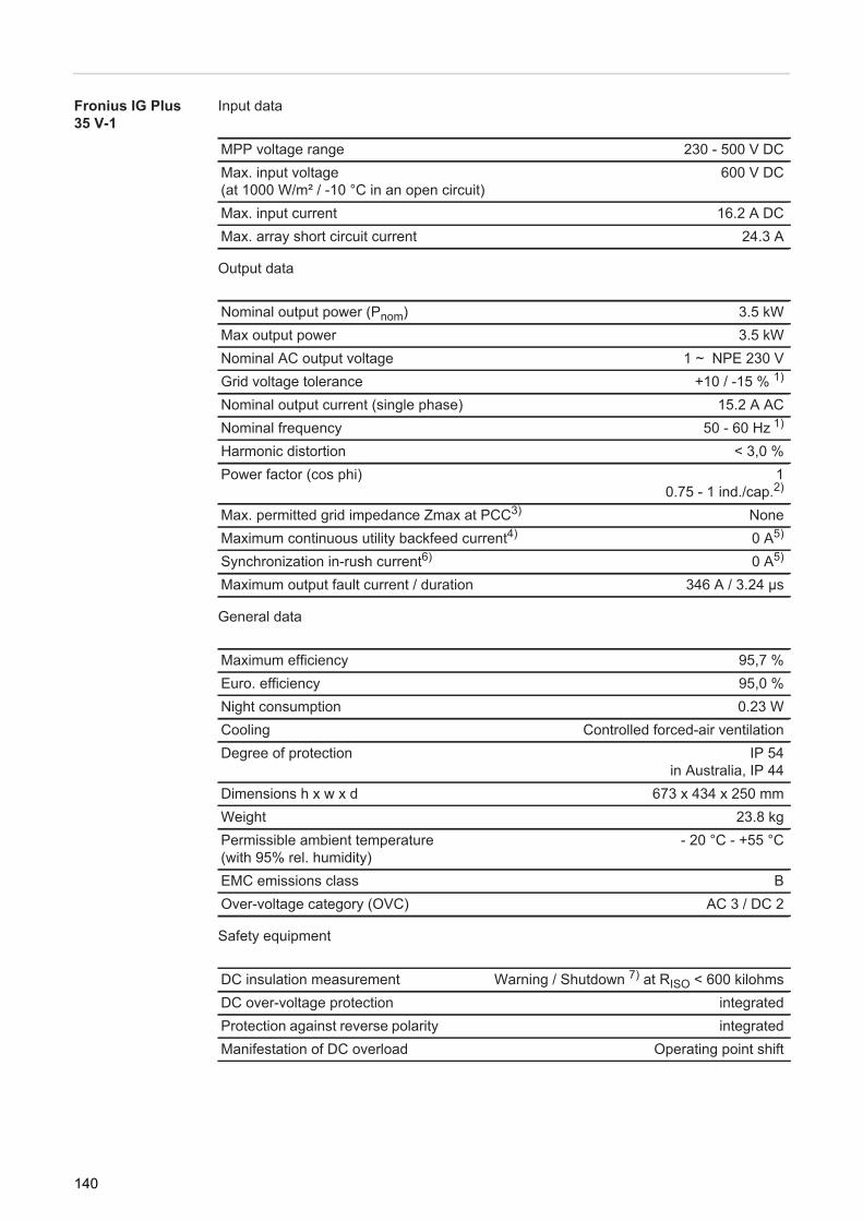
Fronius IG Plus 35 V-1
Input data
Output data
General data
Safety equipment
MPP voltage range 230 - 500 V DCMax. input voltage(at 1000 W/m² / -10 °C in an open circuit)
600 V DC
Max. input current 16.2 A DCMax. array short circuit current 24.3 A
Nominal output power (Pnom) 3.5 kWMax output power 3.5 kWNominal AC output voltage 1 ~ NPE 230 VGrid voltage tolerance +10 / -15 % 1)
Nominal output current (single phase) 15.2 A ACNominal frequency 50 - 60 Hz 1)
Harmonic distortion < 3,0 %Power factor (cos phi) 1
0.75 - 1 ind./cap.2)
Max. permitted grid impedance Zmax at PCC3) NoneMaximum continuous utility backfeed current4) 0 A5)
Synchronization in-rush current6) 0 A5)
Maximum output fault current / duration 346 A / 3.24 μs
Maximum efficiency 95,7 %Euro. efficiency 95,0 %Night consumption 0.23 WCooling Controlled forced-air ventilationDegree of protection IP 54
in Australia, IP 44Dimensions h x w x d 673 x 434 x 250 mmWeight 23.8 kgPermissible ambient temperature (with 95% rel. humidity)
- 20 °C - +55 °C
EMC emissions class BOver-voltage category (OVC) AC 3 / DC 2
DC insulation measurement Warning / Shutdown 7) at RISO < 600 kilohmsDC over-voltage protection integratedProtection against reverse polarity integratedManifestation of DC overload Operating point shift
140

EN-U
S
Fronius IG Plus 50 V-1Input data
Output data
General data
Safety equipment
MPP voltage range 230 - 500 V DCMax. input voltage(at 1000 W/m² / -10 °C in an open circuit)
600 V DC
Max. input current 18.6 A DCMax. array short circuit current 27.9 A
Nominal output power (Pnom) 4 kWMax output power 4 kWNominal AC output voltage 1 ~ NPE 230 VGrid voltage tolerance +10 / -15 % 1)
Nominal output current (single phase) 17.4 A ACNominal frequency 50 - 60 Hz 1)
Harmonic distortion < 3,0 %Power factor (cos phi) 1
0.75 - 1 ind./cap.2)
Max. permitted grid impedance Zmax at PCC3) 261 megaohmsMaximum continuous utility backfeed current4) 0 A5)
Synchronization in-rush current6) 0 A5)
Maximum output fault current / duration 346 A / 3.24 μs
Maximum efficiency 95,7 %Euro. efficiency 95 %Night consumption 0.23 WCooling Controlled forced-air ventilationDegree of protection IP 54
in Australia, IP 44Dimensions l x w x h 673 x 434 x 250 mmWeight 23.8 kgPermissible ambient temperature (with 95% rel. humidity)
- 20 °C - +55 °C
EMC emissions class BOver-voltage category (OVC) AC 3 / DC 2
DC insulation measurement Warning / Shutdown 7) at RISO < 600 kilohmsDC over-voltage protection integratedProtection against reverse polarity integratedManifestation of DC overload Operating point shift
141

Fronius IG Plus 55 V-1, Fronius IG Plus 55 V-2
Input data
Output data
General data
Safety equipment
MPP voltage range 230–500 V DCMax. input voltage(at 1000 W/m² / -10 °C in an open cir-cuit)
600 V DC
Max. input current 37.1 A DCMax. short circuit current of the solar modules 22.9 A
Nominal output power (Pnom) 5 kWMax. output power 5 kWNominal mains voltage 1 ~ NPE 230 V
2 ~ NPE 400 / 230 VMains voltage tolerance +10 / -15% 1)
Nominal output current single-phasetwo-phase
21.7 A AC10.9 A AC
Nominal frequency 50 - 60 Hz 1)
Distortion factor < 3 %Power factor (cos phi) 1
0.75 - 1 ind./cap.2)
Max. permitted mains impedance Zmax at PCC3)
single-phasetwo-phase
207 mOhmnone
Max. recovery current 4) 0 A5)
Switch-on current pulse 6) 0 A5)
Maximum output fault current / duration 426 A / 125 μs
Maximum efficiency 95.7%Europ. efficiency 94.9 %Night consumption single-phase
two-phase0.36 W0.50 W
Cooling Controlled forced-air ventila-tion
Degree of protection IP 54in Australia, IP 44
Dimensions h x w x d 968 x 434 x 250 mmWeight 36.9 kgPermissible ambient temperature (at 95% rel. humidity)
- 20 °C - +55 °C
EMC emission class BOvervoltage category (OVC) AC 3 / DC 2
DC insulation measurement Warning / Shutdown 7) at RISO < 600 kOhmDC overvoltage protection integrated
142

EN-U
S
Reverse polarity protection integratedManifestation of DC overload Operating point shift
143

Fronius IG Plus 55 V-3
Input data
Output data
General data
Safety equipment
MPP voltage range 230 - 500 V DCMax. input voltage(at 1000 W/m² / -10 °C in an open circuit)
600 V DC
Max. input current 22.8 A DCMax. array short circuit current 34.2 A
Nominal output power (Pnom) 5 kWMax output power 5 kWNominal AC output voltage 3 ~ NPE 400 / 230 VGrid voltage tolerance +10 / -15 % 1)
Nominal output current (three-phase) 7.3 A ACNominal frequency 50 - 60 Hz 1)
Harmonic distortion < 3.0 %Power factor (cos phi) 1
0.75 - 1 ind./cap.2)
Max. permitted grid impedance Zmax at PCC3) NoneMaximum continuous utility backfeed current4) 0 A5)
Synchronization in-rush current6) 0 A5)
Maximum output fault current / duration 504 A / 30.26 ms
Maximum efficiency 95.9 %Euro. efficiency 94.9 %Night consumption 1.72 WCooling Controlled forced-air ventilationDegree of protection IP 54
in Australia, IP 44Dimensions h x w x d 1263 x 434 x 250 mmWeight 49.2 kgPermissible ambient temperature (with 95% rel. humidity)
- 20 °C - +55 °C
EMC emissions class BOver-voltage category (OVC) AC 3 / DC 2
DC insulation measurement Warning / Shutdown 7) at RISO < 600 kilohmsDC over-voltage protection integratedProtection against reverse polarity integratedManifestation of DC overload Operating point shift
144

EN-U
S
Fronius IG Plus 60 V-1,Fronius IG Plus60 V-2Input data
Output data
General data
Safety equipment
MPP voltage range 230 - 500 V DCMax. input voltage(at 1000 W/m² / -10°C in an open circuit)
600 V DC
Max. input current 27.5 A DCMax. short circuit current of the solar modules 41.3 A
Nominal output power (Pnom) 6 kWMax output power 6 kWNominal mains voltage 1 ~ NPE 230 V
2 ~ NPE 400 / 230 VMains voltage tolerance +10 / -15% 1)
Nominal output current single-phase two-phase
26.1 A AC13.0 A AC
Nominal frequency 50 - 60 Hz 1)
Distortion factor < 3.0%Power factor (cos phi) 1
0.75 - 1 ind./cap.2)
Max. permitted mains impedance Zmax at PCC3) single-phase 173 mOhmtwo-phase none
Max. recovery current 4) 0 A5)
Switch-on current pulse 6) 0 A5)
Maximum output fault current / duration 426 A / 125 μs
Maximum efficiency 95.7%Europ. efficiency 95.0%Night consumption single-phase 0.36 W
two-phase 0.50 WCooling Controlled forced-air ventilationDegree of protection IP 54
in Australia, IP 44Dimensions h x w x d 968 x 434 x 250 mmWeight 36.9 kgPermissible ambient temperature (at 95% rel. humidity)
- 20 °C - +55 °C
EMC emission class BOvervoltage category (OVC) AC 3 / DC 2
DC insulation measurement Warning / Shutdown 7) at RISO < 600 kOHMDC overvoltage protection integratedReverse polarity protection integratedManifestation of DC overload Operating point shift
145

Fronius IG Plus 60 V-3
Input data
Output data
General data
Safety equipment
MPP voltage range 230 - 500 V DCMax. input voltage(at 1000 W/m² / -10 °C in an open circuit)
600 V DC
Max. input current 27.5 A DCMax. array short circuit current 41.3 A
Nominal output power (Pnom) 6 kWMax output power 6 kWNominal AC output voltage 3 ~ NPE 400 / 230 VGrid voltage tolerance +10 / -15 % 1)
Nominal output current (three-phase) 8.7 A ACNominal frequency 50 - 60 Hz 1)
Harmonic distortion < 3.0 %Power factor (cos phi) 1
0.75 - 1 ind./cap.2)
Max. permitted grid impedance Zmax at PCC3) NoneMaximum continuous utility backfeed current4) 0 A5)
Synchronization in-rush current6) 0 A5)
Maximum output fault current / duration 504 A / 30.26 μs
Maximum efficiency 95.9 %Euro. efficiency 95.0 %Night consumption 1.72 WCooling Controlled forced-air ventilationDegree of protection IP 54
in Australia, IP 44Dimensions h x w x d 1263 x 434 x 250 mmWeight 49.2 kgPermissible ambient temperature (with 95% rel. humidity)
- 20 °C - +55 °C
EMC emissions class BOver-voltage category (OVC) AC 3 / DC 2
DC insulation measurement Warning / Shutdown 7) at RISO < 600 kilohmsDC over-voltage protection integratedProtection against reverse polarity integratedManifestation of DC overload Operating point shift
146

EN-U
S
Fronius IG Plus 70 V-1, Fronius IG Plus 70 V-2Input data
Output data
General data
Safety equipment
MPP voltage range 230 - 500 V DCMax. input voltage(at 1000 W/m² / -10 °C in an open circuit)
600 V DC
Max. input current 30 A DCMax. array short circuit current 45.0 A
Nominal output power (Pnom) 6.5 kWMax output power 6.5 kWNominal AC output voltage 1 ~ NPE 230 V
2 ~ NPE 400 / 230 VGrid voltage tolerance +10 / -15 % 1)
Nominal output current single phase two-phase
28.3 A AC14.1 A AC
Nominal frequency 50 - 60 Hz 1)
Harmonic distortion < 3.0 %Power factor (cos phi) 1
0.75 - 1 ind./cap.2)
Max. permitted grid impedance Zmax at PCC3) single-phase 161 milliohmstwo-phase none
Maximum continuous utility backfeed current4) 0 A5)
Synchronization in-rush current6) 0 A5)
Maximum output fault current / duration 426 A / 125 μs
Maximum efficiency 95.7 %Euro. efficiency 95.1 %Night consumption 0.36 WCooling Controlled forced-air ventilationDegree of protection IP 54
in Australia, IP 44Dimensions h x w x d 968 x 434 x 250 mmWeight 36.9 kgPermissible ambient temperature (with 95% rel. humidity)
- 20 °C - +55 °C
EMC emissions class BOver-voltage category (OVC) AC 3 / DC 2
DC insulation measurement Warning / Shutdown 7) at RISO < 600 kilohmsDC over-voltage protection integratedProtection against reverse polarity integratedManifestation of DC overload Operating point shift
147

Fronius IG Plus 80 V-3
Input data
Output data
General data
Safety equipment
MPP voltage range 230 - 500 V DCMax. input voltage(at 1000 W/m² / -10 °C in an open circuit)
600 V DC
Max. input current 32.0 A DCMax. array short circuit current 48.0 A
Nominal output power (Pnom) 7 kWMax output power 7 kWNominal AC output voltage 3 ~ NPE 400 / 230 VGrid voltage tolerance +10 / -15 % 1)
Nominal output current (three-phase) 10.2 A ACNominal frequency 50 - 60 Hz 1)
Harmonic distortion < 3.0 %Power factor (cos phi) 1
0.75 - 1 ind./cap.2)
Max. permitted grid impedance Zmax at PCC3) NoneMaximum continuous utility backfeed current4) 0 A5)
Synchronization in-rush current6) 0 A5)
Maximum output fault current / duration 504 A / 30.26 μs
Maximum efficiency 95.9 %Euro. efficiency 95.1 %Night consumption 1.72 WCooling Controlled forced-air ventilationDegree of protection IP 54
in Australia, IP 44Dimensions h x w x d 1263 x 434 x 250 mmWeight 49.2 kgPermissible ambient temperature (with 95% rel. humidity)
- 20 °C - +55 °C
EMC emissions class BOver-voltage category (OVC) AC 3 / DC 2
DC insulation measurement Warning / Shutdown 7) at RISO < 600 kilohmsDC over-voltage protection integratedProtection against reverse polarity integratedManifestation of DC overload Operating point shift
148
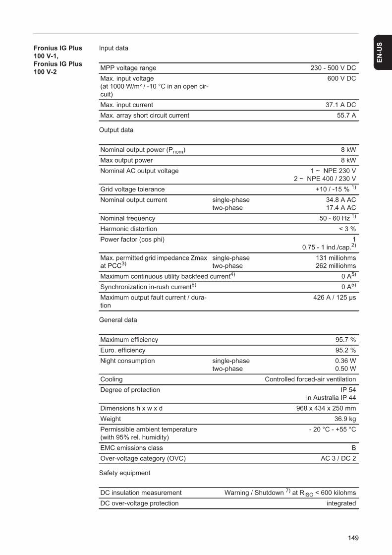
EN-U
S
Fronius IG Plus 100 V-1, Fronius IG Plus 100 V-2Input data
Output data
General data
Safety equipment
MPP voltage range 230 - 500 V DCMax. input voltage(at 1000 W/m² / -10 °C in an open cir-cuit)
600 V DC
Max. input current 37.1 A DCMax. array short circuit current 55.7 A
Nominal output power (Pnom) 8 kWMax output power 8 kWNominal AC output voltage 1 ~ NPE 230 V
2 ~ NPE 400 / 230 VGrid voltage tolerance +10 / -15 % 1)
Nominal output current single-phasetwo-phase
34.8 A AC17.4 A AC
Nominal frequency 50 - 60 Hz 1)
Harmonic distortion < 3 %Power factor (cos phi) 1
0.75 - 1 ind./cap.2)
Max. permitted grid impedance Zmax at PCC3)
single-phasetwo-phase
131 milliohms262 milliohms
Maximum continuous utility backfeed current4) 0 A5)
Synchronization in-rush current6) 0 A5)
Maximum output fault current / dura-tion
426 A / 125 μs
Maximum efficiency 95.7 %Euro. efficiency 95.2 %Night consumption single-phase
two-phase0.36 W0.50 W
Cooling Controlled forced-air ventilationDegree of protection IP 54
in Australia IP 44Dimensions h x w x d 968 x 434 x 250 mmWeight 36.9 kgPermissible ambient temperature (with 95% rel. humidity)
- 20 °C - +55 °C
EMC emissions class BOver-voltage category (OVC) AC 3 / DC 2
DC insulation measurement Warning / Shutdown 7) at RISO < 600 kilohmsDC over-voltage protection integrated
149
Protection against reverse polarity integratedManifestation of DC overload Operating point shift
150

EN-U
S
Fronius IG Plus 100 V-3Input data
Output data
General data
Safety equipment
MPP voltage range 230 - 500 V DCMax. input voltage(at 1000 W/m² / -10 °C in an open cir-cuit)
600 V DC
Max. input current three-phase 36.7 A DCMax. array short circuit current three-phase 55.1 A
Nominal output power (Pnom) 8 kWMax output power 8 kWNominal AC output voltage 3 ~ NPE 400 / 230 VGrid voltage tolerance +10 / -15 % 1)
Nominal output current three-phase 11.6 A ACNominal frequency 50 - 60 Hz 1)
Harmonic distortion < 3 %Power factor (cos phi) 1
0.75 - 1 ind./cap.2)
Max. permitted grid impedance Zmax at PCC3)
three-phase none
Maximum continuous utility backfeed current4) 0 A5)
Synchronization in-rush current6) 0 A5)
Maximum output fault current / dura-tion
three-phase 504 A / 30.26 ms
Maximum efficiency three-phase 95.9 %Euro. efficiency three-phase 95.3 %Night consumption three-phase 1.72 WCooling Controlled forced-air ventilationDegree of protection IP 54
in Australia IP 44Dimensions h x w x d three-phase 1263 x 434 x 250 mmWeight three-phase 49.2 kgPermissible ambient temperature (with 95% rel. humidity)
- 20 °C - +55 °C
EMC emissions class BOver-voltage category (OVC) AC 3 / DC 2
DC insulation measurement Warning / Shutdown 7) at RISO < 600 kilohmsDC over-voltage protection integratedProtection against reverse polarity integratedManifestation of DC overload Operating point shift
151

Fronius IG Plus 120 V-1
Input Data
Output Data
General Data
Protection Devices
MPP voltage range 230–500 V DCMax. input voltage(at 1000 W/m²/-10°C in an open circuit)
600 V DC
Max. input current 46.2 A DCMax. short circuit current of the solar modules 69.3 A
Nominal output power (Pnom) 10 kWMax. output power 10 kWNominal mains voltage 1 ~ NPE 230 VMains voltage tolerance +10/-15% 1)
Nominal output currentat 220 Vat 230 V
45.5 A AC43.5 A AC
Nominal frequency 16.7/50/60 Hz 1)
Total harmonic distortion < 3.0%Power factor (cos phi) 1
0.75 – 1 ind./cap. 2)
Max. permitted mains impedance Zmax at PCC 3) NoneMax. recovery current 4) 0 A 5)
Switch-on current pulse 6) 0 A 5)
Max. output residual current per duration 504 A/30.26 ms
Maximum efficiency 95.9%Europ. efficiency 95.4%Self-consumption at night 0.36 WCooling Controlled forced-air ventila-
tionProtection class IP 54
in Australia, IP 44Dimensions h x w x d 1263 x 434 x 250 mmWeight 49.2 kgPermissible ambient temperature (at 95% rel. humidity)
-25°C–+55°C
EMC device class BOvervoltage category (OVC) AC 3/DC 2
DC insulation measurement Warning/shutdown 7) at RISO < 600 kOhmDC fuse IntegratedReverse polarity protection IntegratedManifestation of DC overload Operating point shift
152

EN-U
S
Fronius IG Plus 120 V-3Input data
Output data
General data
Safety equipment
MPP voltage range 230 - 500 V DCMax. input voltage(at 1000 W/m² / -10 °C in an open circuit)
600 V DC
Max. input current 46.2 A DCMax. array short circuit current 69.3 A
Nominal output power (Pnom) 10 kWMax output power 10 kWNominal AC output voltage 3 ~ NPE 400 / 230 VGrid voltage tolerance +10 / -15 % 1)
Nominal output current (three-phase) 14.5 A ACNominal frequency 50 - 60 Hz 1)
Harmonic distortion < 3.0 %Power factor (cos phi) 1
0.75 - 1 ind./cap.2)
Max. permitted grid impedance Zmax at PCC3) NoneMaximum continuous utility backfeed current4) 0 A5)
Synchronization in-rush current6) 0 A5)
Maximum output fault current / duration 504 A / 30.26 ms
Maximum efficiency 95.9 %Euro. efficiency 95.4 %Night consumption 1.72 WCooling Controlled forced-air ventilationDegree of protection IP 54
in Australia, IP 44Dimensions h x w x d 1263 x 434 x 250 mmWeight 49.2 kgPermissible ambient temperature (with 95% rel. humidity)
- 20 °C - +55 °C
EMC emissions class BOver-voltage category (OVC) AC 3 / DC 2
DC insulation measurement Warning / Shutdown 7) at RISO < 600 kilohmsDC over-voltage protection integratedProtection against reverse polarity integratedManifestation of DC overload Operating point shift
153

Fronius IG Plus 150 V-3
Input data
Output data
General data
Safety equipment
MPP voltage range 230 - 500 V DCMax. input voltage(at 1000 W/m² / -10 °C in an open circuit)
600 V DC
Max. input current 55.6 A DCMax. array short circuit current 83.4 A
Nominal output power (Pnom) 12 kWMax output power 12 kWNominal AC output voltage 3 ~ NPE 400 / 230 VGrid voltage tolerance +10 / -15 % 1)
Nominal output current (three-phase) 17.4 A ACNominal frequency 50 - 60 Hz 1)
Harmonic distortion < 3.0 %Power factor (cos phi) 1
0.75 - 1 ind./cap.2)
Max. permitted grid impedance Zmax at PCC3) NoneMaximum continuous utility backfeed current4) 0 A5)
Synchronization in-rush current6) 0 A5)
Maximum output fault current / duration 504 A / 30.26 μs
Maximum efficiency 95.9 %Euro. efficiency 95.4 %Night consumption 1.72 WCooling Controlled forced-air ventilationDegree of protection IP 54
in Australia, IP 44Dimensions h x w x d 1263 x 434 x 250 mmWeight 49.2 kgPermissible ambient temperature (with 95% rel. humidity)
- 20 °C - +55 °C
EMC emissions class BOver-voltage category (OVC) AC 3 / DC 2
DC insulation measurement Warning / Shutdown 7) at RISO < 600 kilohmsDC over-voltage protection integratedProtection against reverse polarity integratedManifestation of DC overload Operating point shift
154

EN-U
S
Explanation of footnotes1) The values provided are standard values. If required, the inverter can be custom-ized for a specific country.
2) Depending on the country setup or device-specific settings(ind. = inductive; cap. = capacitive)
3) PCC = interface to the public grid4) Max. current from the inverter to the solar module when there is an error in the in-
verter, or when the insulation between the AC and DC wires is defective.5) Assured by electrical design of the inverter6) Peak current when turning on the inverter7) Depending on the country setup
155

Relevant Standards and Directives
CE Conformity Marking
The equipment complies with all the requisite and relevant standards and directives that form part of the relevant EU directive, and therefore is permitted to display the CE mark.
Parallel Operation of In-Plant Power Generation Sys-tems
The inverter complies with the- "Guidelines for connection and parallel operation of in-plant generation systems with
the low-voltage grid" published by the German Electricity Industry Association (VDEW)
- "Technical guidelines for parallel operation of in-plant generation systems with distri-bution networks" published by the Association of Austrian Electricity Companies.
Circuit to Prevent Islanding
The inverter has an approved circuit to prevent stand alone operation
Grid Failure The standard measurement and safety procedures integrated into the inverter ensure that the power feed is immediately interrupted in the event of a grid failure (shut-off by the utility or damage to lines).
156

EN-U
S
Terms and conditions of warranty and disposal
Fronius Manufac-turer's Warranty
Detailed warranty terms and conditions specific to your country can be found online: www.fronius.com/solar/warranty
To take advantage of the full warranty duration for your newly installed Fronius inverter or accumulator, register your product at: www.solarweb.com.
Disposal Should your inverter be replaced at some future date, Fronius will accept the obsolete equipment back and provide for its proper recycling.
157

158

EN-U
S
159

Document of Compliance 09017
Product: Automatic switching center
Type: IG Plus V
Intended Use: Automatic switching center inaccessible to the DSO asa safety interface between an in-plant generation system and the low-voltagegrid. Also a backup for a switching center always accessible to the DSO withan isolation function. The switching center is an integral part of the PVinverter type: Fronius IG Plus V.
Test specification:DIN V VDE V 0126-1-1: „Automatic switching center between a parallel net generation system and the
public low-voltage grid“
The safety concept of the above product tested with the report of 30.10.2009, ref. 2.03.02013.1.0(arsenal research) corresponds to the safety requirements for the intended purpose valid at the timethis certificate was issued.
This document of compliance is valid until:
31.12.2014
2006-02
160

EN-U
S
Certificat de conformité 09017
Produit : Commutateur automatique
Type : IG Plus V
Utilisation conforme à la destination : Commutateur automatique, inaccessible au gestionnaire de réseau de
distribution (VNB), en tant qu’interface de sécurité entre une installation deproduction autonome et le réseau basse tension. Pièce de rechange pourremplacer un commutateur avec fonction de séparation accessible par legestionnaire de réseau de distribution (VNB). Le commutateur est uncomposant intégral de l’onduleur PV de type : Fronius IG Plus V.
Documents de base pour la vérification :DIN V VDE 0126-1-1 : 2006-02 „Commutateur automatique entre une installation de production
autonome parallèle au réseau et le réseau public basse tension“
Lors de l’établissement de la présente attestation, le concept de sécurité du produit précité, objet durapport en date du 30.10.2009 N° dossier 2.03.02013.1.0 (arsenal research), est en conformité avecles exigences techniques de sécurité en vigueur pour l’application conforme à l’emploi indiqué.
La présente attestation de conformité perd sa validité au plus tard le
31.12.2014
161

Fronius Worldwide - www.fronius.com/addresses
Under http://www.fronius.com/addresses you will find all addresses of our sales branches and partner firms!
Fronius International GmbH4600 Wels, Froniusplatz 1, AustriaE-Mail: [email protected]://www.fronius.com
Fronius USA LLC Solar Electronics Division6797 Fronius Drive, Portage, IN 46368E-Mail: [email protected]://www.fronius-usa.com


