Embed Size (px)
Citation preview

1 Construction Manager at Risk RFQ
Construction Manager at Risk RFQ Addendum #1 Issue Date: March 23, 2022 Bids Due: April 26, 2022 Time: 12:00 PM Location: Mr. Ben Miller Tetra Tech, Inc. 1560 Broadway, Suite 1400 Denver, CO 80202 [email protected] The items contained in this Addendum are hereby issued to provide information about the projects identified in the updated Needs Assessment Study (NAS) for the Fruita Wastewater Reclamation Facility. This Addendum shall include the following enclosed items: Updated Needs Assessment Study (NAS) for the Fruita Wastewater Reclamation Facility This Addendum does not change the deadline to submit a bid.

Fruita WWRF – DRAFT Needs Assessment Study December 29, 2021
PRESENTED TO PRESENTED BY
The City of Fruita
900 Kiefer Avenue
Fruita, CO 81521
Tetra Tech
1560 Broadway
Suite 1400
Denver, CO 80202
P +1-303-825-5999
F +1-303-825-0642
tetratech.com
Prepared by:
Ben Miller, P.E.
Jim McQuarrie, P.E.
Mark Maxwell, P.E.
McKenna Pearson, E.I.
i
TABLE OF CONTENTS
1.0 INTRODUCTION ..................................................................................................................................................1
2.0 BACKGROUND ...................................................................................................................................................1
3.0 CAPITAL IMPROVEMENTS AND BUDGETING ................................................................................................2
3.1 Recommended and potential Projects ...........................................................................................................2
3.1.1 Sludge Granulation ...............................................................................................................................2
3.1.2 Concurrent Operation of the RDTs .......................................................................................................3
3.1.3 Centrifuge .............................................................................................................................................3
3.1.4 UV Disinfection System ........................................................................................................................3
3.1.5 Operations Building Expansion ............................................................................................................3
3.1.6 Phosphorous Treatment Improvements for Regulation 31 ..................................................................4
3.2 Capital improvement and Development Summary ........................................................................................5
3.3 Estimated Project Costs .................................................................................................................................6
3.3.1 Cost Estimating Assumptions ...............................................................................................................6
3.3.2 Total Project Cost Opinions ..................................................................................................................6
LIST OF TABLES
Table 2-1 Current Discharge Permit Requirements(1) ................................................................................................2
Table 3-1 Capital Improvement and Development Summary ....................................................................................5
Table 3-2 Summary of Proposed Improvements ........................................................................................................7
APPENDICES
APPENDIX A - DETAILED COST OPINIONS AND VENDOR QUOTES (WHERE APPLICABLE) FOR EACH
CAPITAL IMPROVEMENT PROJECT ......................................................................................................................8
APPENDIX B – 2016 NEEDS ASESSMENT STUDY ...............................................................................................9
ii
ACRONYMS/ABBREVIATIONS
Acronyms/Abbreviations Definition
ATAD Autothermal Thermophilic Aerobic Digestion
Bio-P Biological Phosphorous
Ca Calcium
CaP Calcium Phosphate
CBOD5 Carbonaceous Five-Day Biochemical Oxygen Demand
Mg Magnesium
mg/L Milligrams per liter
mgd Million gallons per day
mg-N/L Milligrams of nitrogen per liter (as N)
mg-P/L Milligrams of phosphorus per liter (as P)
mLs Milliliters
NAS Needs Assessment Study
PAO Phosphorous Accumulating Organism
pH Negative base 10 logarithm of the hydrogen ion concentration
RAS Return Activated Sludge
RDT Rotary Drum Thickener
SNDR Storage Nitrification Denitrification Reactor
SVI Sludge Volume Index
TIN Total Inorganic Nitrogen
TN Total Nitrogen (as N)
TP Total Phosphorus (as P)
TSS Total Suspended Solids
UV Ultraviolet
WAS Waste Activated Sludge
WWRF Wastewater Reclamation Facility

1
1.0 INTRODUCTION
The City requested that Tetra Tech provide an update to the 2016 Needs Assessment Study (NAS) previously
prepared by Tetra Tech for the Fruita Wastewater Reclamation Facility (WWRF). The planning horizon for the NAS
is 10-years (2021-2030). The scope focuses on (1) providing up-to-date cost estimates for items that have not been
addressed since the 2016 NAS and (2) providing cost estimates for the addition of sludge granulation equipment
and Regulation 31 driven phosphorous treatment improvements. For the purpose of the NAS, it is assumed that the
Fruita WWRF has adequate capacity to handle growth-related demands during the 10-year period. Therefore, no
new population growth, flow, and organic load projections will be developed for the NAS. Accordingly, the scope
and fee focused on the development of a prioritized capital improvement program that will enhance the reliability
and efficacy of plant operations and ensure that the City budgets for necessary improvements in advance of when
they need to come online.
2.0 BACKGROUND
The Fruita WWRF utilizes oxidation ditches and ultraviolet (UV) disinfection to provide advanced secondary
treatment of primarily domestic wastewater, plus a small amount of industrial wastes, from the City. Discharge of
the disinfected final effluent is to the Colorado River. A summary of the discharge permit limits are presented in
Table 2-1. The permit is slated to be renewed in 2025. The major unit processes that comprise the Fruita WWRF
can be found in the 2016 NAS which has been included in the Appendix. The Fruita WWRF has a rated maximum
month (30-day average) flow capacity of 2.33-million gallons per day (MGD).

2
Table 2-1 Current Discharge Permit Requirements(1)
Parameter Units Permit Limit
CBOD₅ mg/L 25
TSS mg/L 30
Ammonia-Jan mg/L 5.6
Ammonia-Feb mg/L 5.1
Ammonia-Mar mg/L 4.6
Ammonia-Apr mg/L 3.6
Ammonia-May mg/L 3.2
Ammonia-Jun mg/L 2.5
Ammonia-Jul mg/L 2.2
Ammonia-Aug mg/L 2.1
Ammonia-Sept mg/L 2.1
Ammonia-Oct mg/L 2.6
Ammonia-Nov mg/L 3.2
Ammonia-Dec mg/L 4.1
pH Units 6.5-9*
E. coli #/100 mLs 2,000
(1)Unless otherwise noted, effluent limits listed in this table are 30-day average values (30-day geometric mean for E. coli). There are higher, weekly average limits for CBOD5 and TSS and daily maximums for ammonia. However, compliance with weekly or daily maximum limits for these three parameters has not been an issue due to the robust design and stable operation of the oxidation ditches. *Instantaneous minimum-maximum during each day.
3.0 CAPITAL IMPROVEMENTS AND BUDGETING
This section summarizes the improvements that may be needed during the near-term planning period (2021-2030).
Budget estimates have been prepared for these improvements and then spread out over the 10-year planning
period based on recommendations by Tetra Tech and input from WWRF staff.
3.1 RECOMMENDED AND POTENTIAL PROJECTS
3.1.1 Sludge Granulation
Sludge granulation (or densification) is a relatively new approach in wastewater process design that provides
greater operational control of sludge settling behavior which can be monitored using the sludge volume index (SVI).
The Fruita WWRF often contends with high SVI conditions (130 mL/g during winter) which limits the overall capacity
of the existing clarifiers and constrains the feed total solids concentration to the rotary drum thickeners (RDTs).
Experience with granulation at other similar plants shows that SVI can be controlled year-round at SVI values in the
80 mL/g range. Similar performance at Fruita would result in potential re-rating of capacity by 20 percent for the
existing ditch/clarifier as well as better return activated sludge (RAS) control and improved inlet conditions to the

3
thickening RDTs. To demonstrate sludge granulation at Fruita, three potential layout options were developed. Each
of the options develop an internal “anerobic feasting” condition and include external selection pressure through
hydrocyclone wasting that preferentially wastes out the poorer settling sludge in favor of retaining the more granular
material. The three location options for a pair of 10 m3/hr In-Dense cyclones are (1) on top of the anaerobic selector
zones, (2) in the basement gallery of the headwork building close to the WAS/RAS pumps, or (3) on the upper floor
of the headworks building above the RAW/WAS pumps. Each of the options will be conceptually developed with
Fruita staff. Options 1 and 3 are lower cost than Option 2 since they allow gravity discharge from the cyclones.
3.1.2 Concurrent Operation of the RDTs
Improvements are needed to the control and polymer feed systems to enable both RDTs to operate at the same
time, instead of the current duty and standby mode. As part of the polymer feed system improvements needed for
parallel operation of the RDTs, Tetra Tech investigated the feasibility and cost of installing wetted polymer aging
tanks, which require new aged polymer feed pumps. Although there is debate in the industry about the value of
aging polymer prior to use, the purpose of polymer aging is to give the polymer sufficient time to hydrate (react with
water) and for full activation (elongation) of the polymer molecule. Polymer aging tanks were common 20 to 30
years ago but are less often used now in response to polymer feed supplier assertions that batching systems
provide for polymer activation without the need for aging and to cut capital costs. Velodyne has proposed mixing
tank and solution metering systems that will supply the polymer needed for both the centrifuge and RDTs.
3.1.3 Centrifuge
Tetra Tech developed a budget number for adding a second centrifuge, no smaller than the current one, that can
operate in parallel with the centrifuge currently in place. The existing centrifuge is relatively small and requires a
significant number of operating hours per week to dewater the digested sludge, taking staff time away from other
duties. In addition, there is no backup means of dewatering should the centrifuge be out of service for an extended
period of time. Should that occur, the City will be forced into an expensive liquid sludge hauling operation, most
likely by means of a contract hauler that has permitted sites upon which the City’s digested sludge can be applied.
3.1.4 UV Disinfection System
The calcium hypochlorite backup disinfection system could be better used for RAS chlorination and filament control
and should be relocated to the Headworks pump gallery for this purpose. If so, a second bank of UV lamps should
be installed immediately downstream of the existing bank (i.e. in series) to meet Colorado Department of Public
Health redundancy requirements. Capacity expansion for the third ditch would be provided by widening the channel
and adding more horizontal UV lamp arrays, the potential for which was designed into the existing UV bank. A
plastic channel liner can be installed to facilitate the widening process in the future. There appears to be sufficient
linear length of channel to accommodate a second bank of UV lamps. The finger weirs that control the water level
over the UV lamps will be demolished and replaced with a rotating gate after the second bank of UV lamps. Trojan
has recommended that the new bank of UV lamps consist of six horizontal arrays that are six lamps deep.
3.1.5 Operations Building Expansion
Tetra Tech developed budget number for the expansion of the operations building. Additional space is being request
by WWRF staff to provide room for training and to accommodate staff increases as the WWRF handles more flow/
load.

4
3.1.6 Phosphorous Treatment Improvements for Regulation 31
3.1.6.1 Regulation 31 Overview
Regulation 31 includes interim, median, and annual in-stream numeric nutrient quality values. The interim in-stream
total phosphorous (TP) and total nitrogen (TN) values for warm water streams such as Colorado River at Fruita are
2.01 mg-N/L of TN, which includes total inorganic nitrogen (TIN) plus organic nitrogen, and 0.17 mg-P/L for TP.
Site-specific standards can be developed based on limiting in-stream chlorophyll a to 150 mg/m2. The receiving
stream cannot exceed Regulation 31 standards more than 1 year out of 5 and dischargers must demonstrate the
ability to comply with Regulation 31. The revisions to Regulation 31 were approved assuming these numeric nutrient
values would not be established as definitive water quality criteria until 2027, except in very limited cases.
3.1.6.2 Phosphorous Sequestration
Exemplary biological phosphorus (Bio-P) removal requires that whole plant operations include some form of
sequestration or redirection of the phosphorus-laden filtrate or return stream from sludge processing. The
autothermal thermophilic aerobic digestion (ATAD) process at Fruita re-releases much of the polyphosphate
accumulated by the phosphorus accumulating organisms (PAOs) during mainstream treatment. At Fruita, the
centrate return stream brings back about 400 mg-P/L of return phosphorus. Breaking this recycle loop is one of the
critical strategies in achieving overall exemplary phosphorus removal with Bio-P and plain filtration with multiple
examples of plants achieving total phosphorus of ~0.17 mg-P/L. Iron has been used in the past for chemical
sequestration of return phosphorus loads. However, iron works well only under higher pH conditions and also
consumes a lot of alkalinity important to the nitrification process. More recently, magnesium (Mg) based chemicals
are being favored at higher pH ranges for phosphorus sequestration over iron as Mg performs better at sequestering
phosphorus and doesn’t consume as much alkalinity. At lower pH ranges, such with Fruita’s ATAD / storage
nitrification denitrification reactor (SNDR) process, calcium hydroxide is favored. The calcium (Ca) efficiently
sequesters phosphate forming calcium-phosphate (CaP). Like Mg, the addition of Ca has also been shown to
improve dewatering performance and reduce polymer consumption.
With optimized sequestration of the return phosphorus loads in the centrate, it is likely that the Fruita effluent will
be consistently at 0.1 mg-P/L or less ortho-phosphate. Subsequent particle filtration (e.g. cloth media disk filters) of
the effluent will provide low-level effluent total phosphorus (~0.17 mg-P/L) without chemical addition to the
mainstream. Aqua Aerobics has recommended that the cloth media disk filters consist of one 4-Disk AquaDisk Cloth
Media Filter in a painted steel basin. Tetra Tech assumes that a new building, approximately 30 ft x 50 ft will be
required to house the tertiary filter. A pilot study will be required to verify effluent requirements can be met with this
filter design. Additionally, it is recommended that a pilot demonstration and modeling analysis be conducted to
support a techno-economic analysis of calcium hydroxide as an alternative to iron addition.

5
3.2 CAPITAL IMPROVEMENT AND DEVELOPMENT SUMMARY
Table 3-1 Capital Improvement and Development Summary
WWRF Improvements Total Cost
2022 2023 2024 2025 2026 2027 2028
Sludge Granulation $250,000 $250,000
Concurrent Operation of RDTs $270,000 $270,000
Polymer Aging Improvements $64,000 $64,000
Reg 31 Improvements - Calcium Hydroxide Demo
$100,000 $100,000
Reg 31 Improvements - Cloth Media Disk Filter
$80,000 $80,000
Centrifuge
$690,000 $690,000 Centrifuge Appurtenances
Centrifuge Audit
Additional of Full Second UV Bank $260,000 $260,000
Operations Building Expansion $180,000 $180,000
Reg 31 Improvements - Cloth Media Filter
$2,890,000 $1,445,000 $1,445,000
Total Projected Costs for Each Year $250,000 $334,000 $870,000 $260,000 $180,000 $1,445,000 $1,445,000

6
3.3 ESTIMATED PROJECT COSTS
Planning level cost opinions have been prepared for each improvement project discussed above.
3.3.1 Cost Estimating Assumptions
Preliminary cost opinions were prepared for each recommended or potential near-term improvement. Cost opinions
were developed using the Engineering News Record Construction Cost Index. For a study or feasibility level report,
this is considered a Class 4 estimate, and the final costs could range between -30% on the low side to +50% on
the high side.
Construction costs consist of site work, mechanical equipment, concrete, pumps, chemical metering equipment,
piping valves, structural, electrical and instrumentation, etc. Bonds and insurance have been included at 2% and
contractor’s overhead and profit are assumed to be 15%. A 25% construction cost contingency is included for this
planning level stage. Total capital cost includes a 15% cost allowance for preparing engineering plans,
specifications, bidding and construction phase services, on-site inspection, incidental permits, survey, geotechnical,
legal, and City administrative costs. The percentage allowances for each improvement varies depending on the
level of difficulty as well as what was included, or not, in the vendor quote.
3.3.2 Total Project Cost Opinions
Table 3-2 is a capital cost summary of the proposed improvements for the Fruita WWRF. Details of project costs
are included in the Appendix. The total NAS improvements for the Fruita WWRF is estimated at approximately
$4,784,000 for all items listed.

7
Table 3-2 Summary of Proposed Improvements
Capital Improvement Projects Cost
2022 Sludge Granulation $250,000.00
2023 Solids Handling Facilities
Concurrent Operation of RDTs $270,000
Polymer Aging Improvements $64,000
2024 Centrifuge
$690,000 Centrifuge Appurtenances
Centrifuge Audit
Pilot Demonstration for Calcium Hydroxide Use $100,000
Pilot Demonstration for Cloth Media Disk Filter $80,000
2025 UV Disinfection
Addition of Full Second UV Bank $260,000
2026 Operations Building
Operations Building Expansion $180,000
2027 Reg 31 Phosphorous Treatment Improvements
Cloth Media Disk Filters $1,445,000
2028 Reg 31 Improvements Continued $1,445,000
Total Cost $4,784,000

8
APPENDIX A - DETAILED COST OPINIONS AND VENDOR QUOTES (WHERE APPLICABLE) FOR EACH CAPITAL IMPROVEMENT PROJECT

Project: Fruita WWRF-Needs Assessment Study
PN: 200-29161-22001
Date: 12/29/2021
Desc: 2022 Improvement Projects
Equipment Cost $112,000
Installation (20%) $22,400
Electrical I&C (20%) $22,400
Subtotal $156,800
Contracts/Bonds/Insurance (2%) $3,136
Mobilization/Demobilization (3%) $4,704
Contractor Overhead and Profit (15%) $23,520
Subtotal $188,160
Construction Contingency (15%) $28,224
Subtotal $216,384
Engineering Design $32,458
Total $250,000
Note:
1. Project total rounded to the nearest $10,000
Sludge Granulation
Sludge Granulation

Project: Fruita WWRF-Needs Assessment Study
PN: 200-29161-22001
Date: 12/29/2021
Desc: 2023 Improvement Projects
Equipment (Includes I&C Programming) $163,200
Replumbing $8,400
Subtotal $171,600
Installation (0%) $0
Electrical (10%) $17,160
Subtotal $188,760
Contracts/Bonds/Insurance (0%) $0
Mobilization/Demobilization (0%) $0
Contractor Overhead and Profit (15%) $28,314
Subtotal $217,074
Construction Contingency (15%) $32,561
Subtotal $249,635
Engineering Design $19,971
Total $270,000
Equipment Cost $32,500
Installation (25%) $8,125
Electrical I&C (10%) $3,250
Sitework (0%) $0
Subtotal $43,875
Contracts/Bonds/Insurance (0%) $0
Mobilization/Demobilization (0%) $0
Contractor Overhead and Profit (15%) $6,581
Subtotal $50,456
Construction Contingency (10%) $5,046
Subtotal $55,502
Engineering Design $8,325
Total $64,000.00
Note:
1. Project total rounded to the nearest $1,000
Concurrent Operation of RDTs
Polymer Aging
Improvements
Concurrent
Operation of
RDTs

Project: Fruita WWRF-Needs Assessment Study
PN: 200-29161-22001
Date: 12/29/2021
Desc: 2024 Improvement Projects
Equipment Cost $256,200
Appurtenances $24,000
Audit $4,000
Subtotal $284,200
Installation (25%) $71,050
Electrical I&C (20%) $56,840
Subtotal $412,090
Contracts/Bonds/Insurance (2%) $8,242
Mobilization/Demobilization (4%) $16,484
Contractor Overhead and Profit (15%) $61,814
Subtotal $498,629
Construction Contingency (25%) $124,657
Subtotal $623,286
Engineering Design $62,329
Total $690,000
Demonstration - Lump Sum $100,000
Installation (0%) $0
Electrical I&C (0%) $0
Sitework (0%) $0
Subtotal $100,000
Contracts/Bonds/Insurance (0%) $0
Mobilization/Demobilization (0%) $0
Contractor Overhead and Profit (0%) $0
Subtotal $100,000
Construction Contingency (0%) $0
Subtotal $100,000
Engineering Design $0
Total $100,000
Demonstration - Lump Sum $80,000
Installation (0%) $0
Electrical I&C (0%) $0
Sitework (0%) $0
Subtotal $80,000
Contracts/Bonds/Insurance (0%) $0
Mobilization/Demobilization (0%) $0
Construction Contingency (0%) $0
Subtotal $80,000
Contractor Overhead and Profit (0%) $0
Subtotal $80,000
Engineering Design $0
Total $80,000
Note:
1. Project total rounded to the nearest $10,000
Solids Handling Facilites
Reg 31 Phosphorous Treatment Improvements
Pilot Demonstration for
Cloth Media Disk Filters
Pilot Demonstration for
Calcium Hydroxide
Centrifuge, Centrifuge
Appurtenances and
Audit

CENTRIFUGECONTROL PANEL
CENTRIFUGE
SAMPLETROUGH
3D503
GD354
GD354
JD355
JD355
ID355
ID355
3D507
SPLASH CONE ASSY (TYP)SEE NOTE 1
RADAR GAUGE (TYP)SEE NOTE 2
6" BIO (TYP)
8" BIO (TYP)(FOAM CONTROL)
PLY7100
LCP7300
CEN7300
RDT6100
KD355
KD355
POLYMER CONNECTION TUBE (NOTE 3)
RDT6200
PLY6120
CV6801
AIR RELEASEVALVE (TYP OF 3)
4D507
PIPEPENETRATION
4'x6' HATCH
4'x4'POLYMER
TOTE (TYP)(NOTE 3)
RDT CONTROLPANEL
RDT CONTROLPANEL
1A555
4'x6' HATCH1
A555
4'x4' HATCH1
A555
5D505
1
A
B
C
D
E
F
G
H
J
I
2 3 4 5 6 7 8 9 10 11 12 13 14
Mon
day,
Oct
ober
26,
200
9 1:
55:5
8 PM
D
RA
WIN
G: H
:\133
-671
4-08
-01\
CAD
\She
etFi
les\
WW
TP\D
1_So
lids
ATA
D C
entri
fuge
Roo
m P
lan
.DW
G L
AYO
UT:
D15
6 U
SER
NA
ME:
KR
AMER
, KE
LLY
Copyright: Tetra Tech
MA
RK
DA
TED
ESC
RIP
TIO
NB
Y
ww
w.rt
wen
gine
erin
g.co
m
D156
CIT
Y O
F FR
UIT
A W
ASTE
WAT
ERR
EC
LAM
ATI
ON
FA
CIL
ITY
PR
OJE
CT
CE
NTR
IFU
GE
RO
OM
PR
OC
ES
S P
LAN
1576
She
rman
St.
Sui
te 1
00D
enve
r, C
olor
ado
8020
3P
HO
NE
: (30
3) 8
25-5
999
FA
X: (
303)
825
-064
2
IF THIS BAR DOES NOT MEASURE 1"DRAWING IS NOT TO LABELED SCALE
CO
NS
TRU
CTI
ON
SE
T09
/09
GENERAL NOTES:1. SPLASH CONE ASSY IS SUPPLIED BY ATAD EQUIPMENT SUPPLIER. CONTRACTOR IS
RESPONSIBLE FOR 14" SST PIPE PENETRATION WITH FLANGE 6" ABOVE TOP OF TANK.SEE DETAIL 6/D507.
2A. RADAR GAUGE IS SUPPLIED BY ATAD EQUIPMENT SUPPLIER. CONTRACTOR ISRESPONSIBLE FOR 10" SST PIPE PENETRATION WITH FLANGE 6" ABOVE TOP OF TANKAND 1/8" THICK NEOPRENE GASKET, SEE DETAIL 3/D507
2B. PLACE SNDR RADAR GAUGE 2' MIN FROM TANK INSIDE WALL
3. PROVIDE 1 POLYMER CONNECTION TUBE ASSY FOR EACH POLYMER FEED UNIT (3TOTAL). EACH POLYMER CONNECTION TUBE ASSY CONSISTS OF 12 FEET OF 3/4"I.D.REINFORCED PLASTIC TUBING, BALL VALVES, QUICK DISCONNECT AND END FITTING,SEE DETAIL 4/D503
4. RDT LAYOUT SHOWN FOR PARKSON (WEST) AND ALFA-LAVAL (EAST). ACTUAL LAYOUTAND PLATFORM DETAILS DEPEND ON CHOSEN MANUFACTURER. COORDINATE PIPINGCONNECTIONS BASED ON CHOSEN MANUFACTURER
5. SEE DRAWING J156 FOR ODOR CONTROL DUCTWORK AND VALVE BOXES ON ATAD ANDSNDR TOP SLAB
6. POLYMER PIPING IS TO BE ROUTED IN GENERAL ACCORDANCE WITH THE ROUTINGSHOWN ON THE DRAWINGS. THE PIPING SHALL BE FIELD ROUTED AS ACCEPTABLE TOTHE ENGINEER TO THE LOCATIONS INDICATED IN THE CONTRACT DOCUMENTS
N
SCALE: 1/8"=1'-0"PLAN
-
EQUIPMENT:
-
19
20
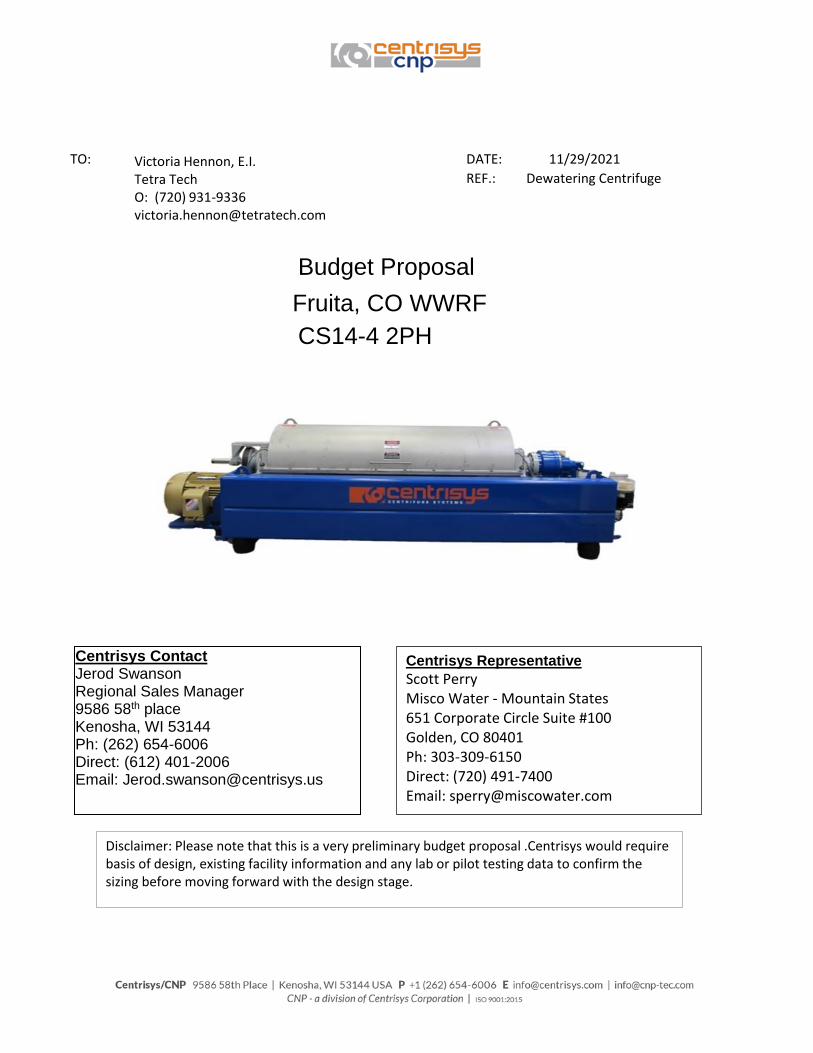
TO: DATE:
REF.: Dewatering Centrifuge
11/29/2021
Fruita, CO WWRFCS14-4 2PH
Budget Proposal
Centrisys Contact Jerod Swanson Regional Sales Manager 9586 58th place Kenosha, WI 53144 Ph: (262) 654-6006 Direct: (612) 401-2006 Email: [email protected]
Disclaimer: Please note that this is a very preliminary budget proposal .Centrisys would require basis of design, existing facility information and any lab or pilot testing data to confirm the sizing before moving forward with the design stage.
Centrisys Representative
Scott PerryMisco Water - Mountain States651 Corporate Circle Suite #100Golden, CO 80401Ph: 303-309-6150Direct: (720) 491-7400Email: [email protected]
Victoria Hennon, E.I. Tetra TechO: (720) [email protected]

Centrisys is pleased to provide this budget quotation for the following:
ITEM 1
1.A Centrifuge Specification
No. of units: 1Model: CS14-4 2PHInside bowl diameter (in): 14Bowl length (in): 55Bowl length to diameter ratio: 4.0:1Beach angle (deg): 15Maximum Bowl speed (RPM): 4000Type of lubrication: Automatic GreaseMain Motor HP: 30Back Drive Motor HP: 10*Max. Hydraulic Loading (gpm) 60*Max. Solids Loading (lb/hr) 810
*Maximum loading rates for standard municipal sludges. Does not apply to all applications. Optimal performance does
not occur at maximum loading levels.
ONE (1) DECANTER CENTRIFUGE UNIT COMPLETE WITH AUTOMATIC
HYDRAULIC BACKDRIVE
1.B. Scope of supply
1. Each unit will be provided based on the attached drawing (i) Duplex SS Solid bowl (ii) Scroll conveyor with Duplex SS Scroll shaft; 304SS flights (iii) 304 SS lower and upper casing (iv) Solid and liquid flexible connectors (v) Dewatered Sludge and Centrate Chutes/Hoppers (vi) Powder coated carbon steel base/frame (vii) Vibration isolators (viii) Spare parts/tools (ix) Control Panel (water cooled)
A. 304SS NEMA 4X Enclosure for each centrifuge B. Main circuit breaker C. VFD for main drive motor D. Allen Bradley PLC (compact logix), valve amplifier and motor
starter for automatic hydraulic back drive system E. Ethernet communication and historical trending of key
parameters F. 10” Allen-Bradley panel view touch screen
(x) Instrumentation A. One (1) vibration sensor per unit B. One (1) main bearing temperature sensor C. One (1) each Bowl/Scroll speed sensor/unit D. One (1) Hydraulic oil level/temp, hydraulic pressure sensor/unit
(xi) Automatic Grease Lubrication System A. One (1) low grease level sensor per unit
(xii) One (1) trip and 5 days of startup assistance

Budget Price:All the above for…..........................................................................
F.O.B. Job Site, freight included, Taxes Excluded
Optional Ancillary Equipment per unit:
Feed PumpPolymer System
Diverter Gate
Conveyor (16 ft.)
PAYMENT TERMS:
Lead Time: 20-22 weeks following receipt of the Approved drawings
Adder 32,000$
8,400$
6,860$
12,180$
7,560$
4,200$
256,200.00$
5,600$
30% with order; 60% upon shipment; 10% after startup not to exceed 90 days
after shipment.
4 ft. Stand, Walkway,ladder
Flowmeter4 ft. Stand
AdderAdder
AdderAdderAdder
Adder
BUYER/OWNER RESPONSIBILITY (UNLESS INCLUDED AS ADDER):
• Stand • Feed pump • Polymer system • Flow meter • Cake conveyor • Anchor bolts. • Building and building plans (Centrisys provides only the layout drawings without any
responsibility of updating any plans or building) • Building modifications • Structural and Civil engineering labor • Lubricants • All utilities that are required for operation • Unloading, uncrating, installation and installation supervision. Installation will, at minimum,
require a forklift and possibly a crane/hoist. • Readiness of the Equipment before requesting start-up service. Non-readiness may incur
additional charges. • Compatibility of Equipment materials of construction with process environment. • Piping connections, platforms, gratings and railings unless stated otherwise.
Any other auxiliary equipment or service not detailed above.
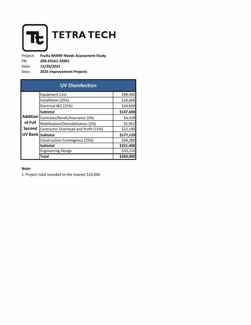
Project: Fruita WWRF-Needs Assessment Study
PN: 200-29161-22001
Date: 12/29/2021
Desc: 2025 Improvement Projects
Equipment Cost $98,400
Installation (25%) $24,600
Electrical I&C (25%) $24,600
Subtotal $147,600
Contracts/Bonds/Insurance (3%) $4,428
Mobilization/Demobilization (2%) $2,952
Contractor Overhead and Profit (15%) $22,140
Subtotal $177,120
Construction Contingency (25%) $44,280
Subtotal $221,400
Engineering Design $33,210
Total $260,000
Note:
1. Project total rounded to the nearest $10,000
UV Disinfection
Addition
of Full
Second
UV Bank

A-
A-
B-
B-
NPW WETWELL(BELOW)
P5120 P5110
FE5130
7D505
WALLPENETRATION
12" PARSHALL FLUME
16'-9" 12'-7" 6'-9"
1'-0
" (TY
P)
PF5020
FE5020
UV5000
4'-0
"
8'-11" 2'-6" 5'-0" 5'-0" 2'-8" 5'-6" 4'-0"
30" FEFF
21'-1" 1D511
CONCRETEBAFFLE
7'-0
"
PALETTE
NPW-R
NPW
1" CONDUITIN SLAB
BU
11
3 5 8
TRENCHDUCT
11D505
WEIRDRAIN
12" PARSHALL FLUMEPF5020
TOP OF WEIR EL 4465.50
BOT EL 4454.50
MONORAILAND HOIST
UV5000
SEE NOTE 1
4'-0" 5'-3" 2'-11" 11'-6" 7'-6" 6'-7" 9'-4"
WSE 4464.464" NPW-R
EL 4464.00
1" CONDUITEL 4466.00
11
1
9
1112
1
5
13
121'-0
"
1
7
4 16
15
EL 4472.50
1'-6" 2'-6"
3"
4
5
6
2
12
14
1
A
B
C
D
E
F
G
H
J
I
2 3 4 5 6 7 8 9 10 11 12 13 14
Mon
day,
Oct
ober
26,
200
9 1:
55:2
0 PM
D
RA
WIN
G: H
:\133
-671
4-08
-01\
CAD
\She
etFi
les\
WW
TP\D
1_U
V D
isin
fect
ion
Plan
.DW
G L
AYO
UT:
D15
1 U
SER
NA
ME:
KR
AMER
, KE
LLY
Copyright: Tetra Tech
MA
RK
DA
TED
ESC
RIP
TIO
NB
Y
ww
w.rt
wen
gine
erin
g.co
m
D151
CIT
Y O
F FR
UIT
A W
ASTE
WAT
ERR
EC
LAM
ATI
ON
FA
CIL
ITY
PR
OJE
CT
UV
DIS
INFE
CTI
ON
PR
OC
ES
S P
LAN
& S
EC
TIO
NS
1576
She
rman
St.
Sui
te 1
00D
enve
r, C
olor
ado
8020
3P
HO
NE
: (30
3) 8
25-5
999
FA
X: (
303)
825
-064
2
IF THIS BAR DOES NOT MEASURE 1"DRAWING IS NOT TO LABELED SCALE
CO
NS
TRU
CTI
ON
SE
T09
/09
GENERAL NOTES:1. COAT INTERIOR OF CHANNEL PER SPEC SECTION 0990
2. SEE SHEET E152 FOR UV CONTROL SYSTEM AND CABLE TRAY REQUIREMENTS
3. RE: STRUCTURAL FOR MONORAIL SUPPORT
4. RE: CIVIL SHEETS FOR SITE PIPING & PROFILES
5. RE: ELECTRICAL FOR TRENCH DUCT
6. POLYMER PIPING IS TO BE ROUTED IN GENERAL ACCORDANCE WITH THE ROUTINGSHOWN ON THE DRAWINGS. THE PIPING SHALL BE FIELD ROUTED AS ACCEPTABLETO THE ENGINEER TO THE LOCATIONS INDICATED IN THE CONTRACT DOCUMENTS
7. ALL PIPING BELOW CONCRETE SLABS ON GRADE SHALL BE CONCRETE ENCASEDPER DETAIL 3/C502
N
SCALE: 1/8"=1'-0"PLAN
A-
SECTION1/8"=1'-0"
B-
SECTION1/8"=1'-0"
6" 90° BEND
EQUIPMENT:
6" BFV
1
2
6" MAG METER3
6" TEE4
6" FCA5
6" CHECK VALVE6
7
1" BALL VALVE8
HYDROPNEUMATIC TANK9
10
4" EQUIP BASE11
6" BASE 90° BEND12
3/4" 304 SST THD ROD ANCHORS FORBAFFLE @ MID POINT OF BAFFLE
2" ARV (ROUTE DISCHARGE PIPETHRU FLOOR TO WET WELL)
SELF CLEANING STRAINER
6" FLEX COUPLING14
13
3" PRV
6" COMPANION FL16
15

Confidential - Company Proprietary
PROPOSAL FOR THE FRUITA EXPANSION, COQUOTE: 23233212/07/2021
The TrojanUV3000Plus™ is operating in over 2000 municipal wastewater plants around the world.
Disinfecting over 17 billion gallons a day, the TrojanUV3000Plus™ has become the reference standard in the industry.

Fruita Expansion 232332 12/07/2021- 2 -
Confidential - Company Proprietary
December 7, 2021
In response to your request, we are pleased to provide the following TrojanUV3000Plus™ proposal for the FRUITA EXPANSION project.
The TrojanUV3000PlusTM has been shown in over 2000 installations to provide dependable performance, simplified maintenance, and superior electrical efficiency. As explained in this proposal, the system incorporates innovative features to reduce O&M costs, including variable output electronic ballasts to provide dimming capability and Trojan’s revolutionary ActiClean-WWTM system – the industry’s only online chemical and mechanical quartz sleeve cleaning system. All Trojan installations are supported by a global network of certified Service Representatives providing local service and support.
Please do not hesitate to call us if you have any questions regarding this proposal. Thank you for the opportunity to quote the TrojanUV3000Plus™ and we look forward to working with you on this project.
With best regards,
Jordan FournierRegional ManagerTrojan [email protected]

Fruita Expansion 232332 12/07/2021- 3 -
Confidential - Company Proprietary
DESIGN CRITERIAFRUITA EXPANSION
Peak Design Flow: 4.60 MGD
UV Transmittance: 65 % (minimum)
Total Suspended Solids: 30 mg/l (30 Day Average, grab sample)
Disinfection Limit: 2 000 Fecal Coliform per 100 ml, based on a day 30 of consecutive daily grab samples
Design Dose: 24 mJ/cm2 (bioassay validated)
Validation Factors:0.98 end of lamp life factor (Low-Pressure Amalgam Lamps)0.95 fouling factor (ActiClean-WW™ Chemical / Mechanical Cleaning System)
DESIGN SUMMARYQUOTE: 232332Based on the above design criteria, the TrojanUV3000Plus™ proposed consists of:
CHANNEL (Please reference Trojan layout drawings for details.)
Number of Channels: 1 (existing channel to be utilized)
Approximate Channel Length Required: 14 ft 2 in
Channel Width Based on Number of UV Modules: 24 in
Channel Depth Recommended for UV Module Access: 54 inUV MODULESTotal Number of Banks: 1
Number of Modules per Bank: 6
Number of Lamps per Module: 6
Total Number of UV Lamps: 36
Maximum Power Draw: 9 kW UV PANELSPower Distribution Center Quantity: 1
System Control Center Quantity: Existing SCC to be utilizedMISCELLANEOUS EQUIPMENTLevel Controller Quantity: 1
Type of Level Controller: Weighted Gate (ALC)
Automatic Chemical / Mechanical Cleaning: Trojan ActiClean-WW™
Other Equipment:
ELECTRICAL REQUIREMENTS

Fruita Expansion 232332 12/07/2021- 4 -
Confidential - Company Proprietary
1. Each Power Distribution Center requires an electrical supply of one (1) 480/277V 60Hz, 3 Phase, 4 Wire + Ground, 12 Amps, 9.20 kVA
2. Electrical disconnects required per local code are not included in this proposal.
COMMERCIAL INFORMATION
Total Capital Cost: $98,400 (USD)This price excludes any taxes that may be applicable and is valid for 90 days from the date of this letter.
EQUIPMENT WARRANTEES
1. Trojan Technologies warrants all components of the system (excluding UV lamps) against faulty workmanship and materials for a period of 12 months from date of start-up or 18 months after shipment, whichever comes first.
2. UV lamps purchased are warranted for 12,000 hours of operation or 3 years from shipment, whichever comes first. The warranty is pro-rated after 9,000 hours of operation. This means that if a lamp fails prior to 9,000 hours of use, a new lamp is provided at no charge.
3. Electronic ballasts are warranted for 5 years, pro-rated after 1 year.

Project: Fruita WWRF-Needs Assessment Study
PN: 200-29161-22001
Date: 12/29/2021
Desc: 2026 Improvement Projects
Equipment Cost-Single Allowance $180,000
Installation (0%) $0
Electrical I&C (0%) $0
Sitework (0%) $0
Subtotal $180,000
Contracts/Bonds/Insurance (0%) $0
Mobilization/Demobilization (0%) $0
Contractor Overhead and Profit (0%) $0
Subtotal $180,000
Construction Contingency (0%) $0
Subtotal $180,000
Engineering Design $0
Total $180,000
Note:
1. Project total rounded to the nearest $10,000
Operations Building
Operations Building
Expansion

Project: Fruita WWRF-Needs Assessment Study
PN: 200-29161-22001
Date: 12/29/2021
Desc: 2027 Improvement Projects
Equipment Cost - Includes freight, startup $232,970
Tertiary Building (30X50) $525,000
Subtotal $757,970
Installation (25%) (Equip Only) $58,243
Electrical I&C (20%) $151,594
Sitework (5%) $37,899
Subtotal $1,763,675
Contracts/Bonds/Insurance (2%) $35,274
Mobilization/Demobilization (4%) $70,547
Contractor Overhead and Profit (15%) $264,551
Subtotal $2,134,047
Construction Contingency (25%) $533,512
Subtotal $2,667,558
Engineering Design $213,405
Total $2,890,000
Note:
Reg 31 Bio-P Improvements
Cloth Media Disk
Filters
1. Project total rounded to the nearest $10,000
2. Project recommended to be executed over 2 year span (2027 - 2028)

6306 N. Alpine Rd Loves Park, IL 61111
(815) 654-2501 www.aqua-aerobic.com
Design# 166551
AquaDisk®
Cloth Media Filter
Process Design Report
© 2021 Aqua-Aerobic Systems, Inc
FRUITA WWTP, CO
December 21, 2021
Option: Preliminary Filter Design
Designed By: Nicholas Fortsas

Design Notes
Process/Site
- The following parameters have been assumed, as displayed on the design (engineer to verify): Maximum flow, maximum
influent TSS, influent Total P.
- Chemical addition for coagulation/flocculation must be added upstream of the filter. In addition, rapid mixing and a flocculation
tank with at least 5 minutes retention time must be provided. The chemical dosage should be flow-paced and controlled to avoid
over-dosing.
- To achieve the effluent monthly average total phosphorus limit, the biological process, chemical feed systems, and Cloth Media
Filters need to be designed to facilitate optimum performance.
- A minimum of twelve (12) daily composite samples per month (both influent and effluent) shall be obtained for total phosphorus
analysis.
- Secondary effluent phosphorus shall be in a reactive phosphate form and/or a filterable particulate form.
- Chemical feed lines (i.e. metal salts) shall be furnished to each reactor, aerobic digester and dewatering supernatant streams
as necessary.
- Chemical addition (i.e. metal salts, and/or polymer) shall be furnished prior to the filter. Adequate rapid mixing must be
provided as part of the chemical feed system. The chemical dosage should be flow-paced and controlled to avoid overdosing.
Jar testing with various metal salts and polymers is recommended to determine the most effective metal salt and polymer as well
as the optimum dosages of each, and to estimate the degree of phosphorus removal that can be achieved. In addition, a pilot
study may be required to verify the actual performance capability.
- pH monitoring of 6.5-8.5 of the biological reactor is required when adding metal salts.
- The cloth media filter will only remove TP that is associated with the TSS removed by the filter. Since only insoluble,
particle-associated phosphorous is capable of being removed by filtration, phosphorous speciation shall be provided by the
owner to substantiate the concentrations of soluble and insoluble phosphorous in the filter influent. If the proportions of soluble
(unfilterable) and insoluble phosphorous are such that removal to achieve the desired effluent limit is not practical, the owner will
provide for proper conditioning of the wastewater, upstream of the filter system, to allow for the required removal.
- A treatability study is required to assure that the required effluent quality is achievable.
- The average and maximum design flow and loading conditions, shown within the report, are based on maximum month
average and maximum day conditions, respectively.
Filtration
- The cloth media filter recommendation and anticipated effluent quality are based upon influent water quality conditions as
shown under "Design Parameters" of this Process Design Report.
- The filter influent should be free of algae and other solids that are not filterable through a nominal 5 micron pore size media.
Provisions to treat algae and condition the solids to be filterable are the responsibility of others.
- Redundancy has not been considered in the cloth media filter design.
Equipment
- Scope of supply includes freight, installation supervision and start-up services.
- Equipment selection is based upon the use of Aqua-Aerobic Systems' standard materials of construction and electrical
components, suitable for non-classified electrical environments.
- Aqua-Aerobic Systems, Inc. is familiar with various “Buy American” Acts (i.e. AIS, ARRA, Federal FAR 52.225, EXIM Bank,
USAid, PA Steel Products Act, etc.). As the project develops Aqua-Aerobic Systems can work with you to ensure full
compliance of our goods with various Buy American provisions if they are applicable/required for the project. When applicable,
please provide us with the specifics of the project’s “Buy American” provisions.
- If the cloth media filter will be offline for extended periods of time, protection from sunlight is required.
12/21/2021 9:57:08AM Aqua-Aerobic Systems, Inc CONFIDENTIAL
Project ID: 117100 - FRUITA WWTP, CO / Design#: 166551
Page 2 of 5
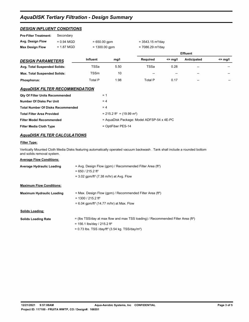
AquaDISK Tertiary Filtration - Design Summary
DESIGN INFLUENT CONDITIONS
Avg. Design Flow
Max Design Flow
= 0.94 MGD = 3543.15 m³/day
= 1.87 MGD = 7086.29 m³/day
Pre-Filter Treatment: Secondary
= 650.00 gpm
= 1300.00 gpm
DESIGN PARAMETERS Influent mg/l Required <= mg/l Anticipated <= mg/l
Effluent
Avg. Total Suspended Solids: 5.50TSSa 0.28 --TSSa --
Max. Total Suspended Solids: TSSm 10 -- -- -- --
Phosphorus: Total P 1.98 Total P 0.17 -- --
AquaDISK FILTER RECOMMENDATION
Qty Of Filter Units Recommended
Number Of Disks Per Unit
AquaDISK FILTER CALCULATIONS
Filter Type:
Total Number Of Disks Recommended
Total Filter Area Provided
Filter Model Recommended
= 1
= 4
= 4
= 215.2 ft² = (19.99 m²)
= AquaDisk Package: Model ADFSP-54 x 4E-PC
Filter Media Cloth Type = OptiFiber PES-14
Vertically Mounted Cloth Media Disks featuring automatically operated vacuum backwash . Tank shall include a rounded bottom
and solids removal system.
Average Flow Conditions:
Average Hydraulic Loading
Maximum Flow Conditions:
Maximum Hydraulic Loading
= Avg. Design Flow (gpm) / Recommended Filter Area (ft²)
= 650 / 215.2 ft²
= 3.02 gpm/ft² (7.38 m/hr) at Avg. Flow
= Max. Design Flow (gpm) / Recommended Filter Area (ft²)
= 1300 / 215.2 ft²
= 6.04 gpm/ft² (14.77 m/hr) at Max. Flow
Solids Loading:
Solids Loading Rate = (lbs TSS/day at max flow and max TSS loading) / Recommended Filter Area (ft²)
= 156.1 lbs/day / 215.2 ft²
= 0.73 lbs. TSS /day/ft² (3.54 kg. TSS/day/m²)
12/21/2021 9:57:08AM Aqua-Aerobic Systems, Inc CONFIDENTIAL
Project ID: 117100 - FRUITA WWTP, CO / Design#: 166551
Page 3 of 5

Equipment Summary
Cloth Media Filters
AquaDisk Tanks/Basins
1 AquaDisk Model # ADFSP-54x4E-PC Package Filter Painted Steel Tank(s) consisting of:
- 4 Disk painted steel tank(s).
- 3" ball valve(s).
AquaDisk Centertube Assemblies
1 Centertube(s) consisting of:
- 304 stainless steel centertube weldment(s).
- Centertube driven sprocket(s).
- Dual wheel assembly(ies).
- Rider wheel bracket assembly(ies).
- Effluent seal plate weldment.
- Centertube bearing kit(s).
- Effluent centertube lip seal(s).
- Pile cloth media and non-corrosive support frame assemblies.
- Disk segment 304 stainless steel support rods.
- Media sealing gaskets.
1 Cloth set(s) will have the following feature:
- Cloth will be OptiFiber PES-14.
AquaDisk Drive Assemblies
1 Drive System(s) consisting of:
- Gearbox with motor.
- Drive sprocket(s).
- Drive chain(s) with pins.
- Stationary drive bracket weldment(s).
- Adjustable drive bracket weldment(s).
- Chain guard weldment(s).
- Warning label(s).
AquaDisk Backwash/Sludge Assemblies
1 Backwash System(s) consisting of:
- Backwash shoe assemblies.
- Backwash shoe support weldment(s).
- 1 1/2" flexible hose.
- Stainless steel backwash shoe springs.
- Hose clamps.
1 Backwash/Solids Waste Pump(s) consisting of:
- Backwash/waste pump(s).
- Stainless steel anchors.
- 0 to 15 psi pressure gauge(s).
- 0 to 30 inches mercury vacuum gauge(s).
- Throttling gate valve(s).
- 2" bronze 3 way ball valve(s).
AquaDisk Instrumentation
1 Pressure Transmitter(s) consisting of:
- Level transmitter(s).
1 Float Switch(es) consisting of:
- Float switch(es).
12/21/2021 9:57:08AM Aqua-Aerobic Systems, Inc CONFIDENTIAL
Project ID: 117100 - FRUITA WWTP, CO / Design#: 166551
Page 4 of 5

1 Vacuum Transmitter(s) consisting of:
- Vacuum transmitter(s).
AquaDisk Valves
1 Set(s) of Backwash Valves consisting of:
- 2" full port, three piece, stainless steel body ball valve(s), grooved end connections with single phase electric
actuator(s). Valve / actuator combination shall be TCI / RCI (RCI, a division of Rotork).
- 2" flexible hose.
- Victaulic coupler(s).
1 Solids Waste Valve(s) consisting of:
- 2" full port, three piece, stainless steel body ball valve(s), grooved end connections with single phase electric
actuator(s). Valve / actuator combination shall be TCI / RCI (RCI, a division of Rotork).
- 2" flexible hose.
- Victaulic coupler(s).
AquaDisk Controls w/Starters
1 Conduit Installation(s) consisting of:
- PVC conduit and fittings.
1 Control Panel(s) consisting of:
- NEMA 4X fiberglass enclosure(s).
- Circuit breaker with handle.
- Transformer(s).
- Fuses and fuse blocks.
- Line filter(s).
- GFI convenience outlet(s).
- Control relay(s).
- Selector switch(es).
- Indicating pilot light(s).
- MicroLogix 1400 PLC(s).
- Ethernet switch(es).
- Operator interface(s).
- Power supply(ies).
- Motor starter(s).
- Terminal blocks.
- UL label(s).
12/21/2021 9:57:08AM Aqua-Aerobic Systems, Inc CONFIDENTIAL
Project ID: 117100 - FRUITA WWTP, CO / Design#: 166551
Page 5 of 5

Project: Fruita WWRF-Needs Assessment Study
PN: 200-29161-22001
Date: 12/29/2021
Desc: Capital Improvement Plan and Development Summary
2022 2023 2024 2025 2026 2027 2028Sludge Granulation $250,000 $250,000
Concurrent Operation of RDTs $270,000 $270,000
Polymer Aging Improvements $64,000 $64,000
Reg 31 Improvements - Calcium Hydroxide Demo $100,000 $100,000
Reg 31 Improvements - Cloth Media Disk Filter $80,000 $80,000
Centrifuge
Centrifuge Appurtenances
Centrifuge Audit
Additional of Full Second UV Bank $260,000 $260,000
Operations Building Expansion $180,000 $180,000
Reg 31 Improvements - Cloth Media Filter $2,890,000 $1,445,000 $1,445,000
$250,000 $334,000 $870,000 $260,000 $180,000 $1,445,000 $1,445,000Total Projected Costs for Each Year
WWRF Improvements Total Cost
$690,000 $690,000

Project: Fruita WWRF-Needs Assessment Study
PN: 200-29161-22001
Date: 12/29/2021
Desc: Project Summary
2022 Sludge Granulation $250,000
2023 Solids Handling Facilities
Concurrent Operation of RDTs $270,000
Polymer Aging Improvements $64,000
2024 Centrifuge
Centrifuge Appurtenances
Centrifuge Audit
Pilot Demonstration for Calcium Hydroxide Use $100,000
Pilot Demonstration for Cloth Media Disk Filter $80,000
2025 UV Disinfection
Addition of Full Second UV Bank $260,000
2026 Operations Building
Operations Building Expansion $180,000
2027 Reg 31 Phosphorous Treatment Improvements
Cloth Media Disk Filters $1,445,000
2028 Reg 31 Improvements Continued $1,445,000
$4,784,000Total Cost
$690,000
Capital Improvement Projects Cost

9
APPENDIX B – 2016 NEEDS ASESSMENT STUDY

Fruita WWRF-Needs Assessment StudyMay 13, 2016
PRESENTED TO PRESENTED BY
The City of Fruita900 Kiefer Avenue
Fruita, CO 81521
Tetra Tech1576 Sherman Street
Denver, CO 80203
P +1-303-825-5999
F +1-303-825-0642
tetratech.com
Prepared by:
Mark Maxwell, P.E.
Caroline Verlander
John Huckenpahler
i Footer Information
TABLE OF CONTENTS
1.0 INTRODUCTION ..................................................................................................................................................1
2.0 BACKGROUND ...................................................................................................................................................1
3.0 PROCESS ............................................................................................................................................................8
3.1 Headworks .....................................................................................................................................................8
3.1.1 Influent Channel and Pump Wetwell Corrosion....................................................................................8
3.1.2 Rotary Drum Screen Performance .......................................................................................................9
3.1.3 H₂S Concentrations and Air Ionization .................................................................................................9
3.1.4 RAS Pumps ....................................................................................................................................... 10
3.1.5 Hypochlorite Feed System ................................................................................................................ 11
3.2 Activated Sludge Complex.......................................................................................................................... 11
3.2.1 Anaerobic Selectors .......................................................................................................................... 11
3.2.2 Oxidation Ditches .............................................................................................................................. 12
3.2.3 Secondary Clarifiers .......................................................................................................................... 14
3.3 Aeration Blowers ......................................................................................................................................... 14
3.4 UV Disinfection Room................................................................................................................................. 15
3.5 Solids Handling Facilities ............................................................................................................................ 16
3.5.1 WAS Thickening ................................................................................................................................ 16
3.5.2 ATAD ................................................................................................................................................. 16
3.5.3 Dewatering Centrifuge....................................................................................................................... 17
3.5.4 Further Composting and Drying of Biosolids..................................................................................... 17
3.6 Biofilter ........................................................................................................................................................ 18
3.7 Control Systems.......................................................................................................................................... 18
3.7.1 SCADA and HMI Screens ................................................................................................................. 18
3.8 Operations Building..................................................................................................................................... 18
4.0 FORECASTING REGULATORY COMPLIANCE REQUIREMENTS FOR 2016-2025.................................... 19
4.1 CDPHE Nutrient Quality Rules ................................................................................................................... 19
4.1.1 Regulation 85 .................................................................................................................................... 19
4.1.2 Regulation 31 .................................................................................................................................... 20
4.2 Temperature Rule ....................................................................................................................................... 20
4.3 Ammonia Criteria ........................................................................................................................................ 21
4.4 Arsenic ........................................................................................................................................................ 21
5.0 ALTERNATIVE DEVELOPMENT AND BUDGETING ..................................................................................... 21

ii Footer Information
5.1 Recommended and potential Projects ........................................................................................................ 21
5.1.1 Headworks......................................................................................................................................... 21
5.1.2 Activated Sludge Complex ................................................................................................................ 23
5.1.3 Aeration Blowers ............................................................................................................................... 23
5.1.4 UV Disinfection System..................................................................................................................... 24
5.1.5 Solids Handling Facility ..................................................................................................................... 24
5.1.6 ATAD Biofilter .................................................................................................................................... 25
5.1.7 Control Systems ................................................................................................................................ 25
5.1.8 Big Data Analysis .............................................................................................................................. 26
5.2 Capital improvement and Development Summary ..................................................................................... 27
5.3 Estimated Project Costs.............................................................................................................................. 28
5.3.1 Cost Estimating Assumptions............................................................................................................ 28
5.3.2 Total Project Cost Opinions............................................................................................................... 28
LIST OF TABLES
Table 2-1 Current Discharge Permit Requirements(1) ................................................................................................1
Table 2-2 Existing Plant Design Summary................................................................................................................2
Table 4-1 Recommended EPA Nutrient Quality Criteria for Water Bodies in Ecoregion III(1) ................................. 19
Table 4-2 Regulation 85 Effluent Limits .................................................................................................................. 20
Table 5-4 Summary of Proposed Improvements..................................................................................................... 28
LIST OF FIGURES
No table of figures entries found.
APPENDICES
APPENDIX A - DETAILED COST OPINIONS AND VENDOR QUOTES (WHERE APPLICABLE) FOR EACH
NEAR-TERM IMPROVEMENT PROJECT ............................................................................................................. 30

iii Footer Information
ACRONYMS/ABBREVIATIONS
Acronyms/Abbreviations Definition
AACE American Association of Cost Engineering
ACGIH American Conference of Governmental Industrial Hygienists
ADWF Average Dry Weather Flow
ATAD Autothermal Thermophilic Aerobic Digestion
AVG Average
BNR Biological Nutrient Removal
BOD Biochemical Oxygen Demand
C Degrees Centigrade
CBOD₅ Carbonaceous Five-Day Biochemical Oxygen Demand
CDPHE Colorado Department of Public Health and Environment
cf Cubic feet
cfm Cubic feet per minute
CIP Capital Improvement Program
DO Dissolved Oxygen
Dry lb/hr Dry pounds per hour
DSL Digested Sludge
EPA Environmental Protection Agency
F/M Food to Microorganism ratio
ft/sec Foot or feet per second
ft² Square feet
ft³ Cubic feet
gpd Gallons per day
gpd/ft2 Gallons per day per square feet
gpm Gallons per minute
GR Grit
H Hourly
HDPE High Density Polyethylene
HMI Human-Machine Interface
HP Horsepower
HRT Hydraulic Retention Time
H₂S Hydrogen Sulfide Gas
HST High Speed Turbo
HVAC Heating, Ventilation, and Air Conditioning

iv Footer Information
Acronyms/Abbreviations Definition
IFM Influent Force Main
in Inch
kV Kilovolts
kW Kilowatts
kWh Kilowatt-hours
lb/day Pounds per day
lb/day/ft2 Pound per day per square foot
lb BOD₅/1000 ft³ Pound of Five-Day Biochemical Oxygen Demand per one thousand cubic feet
lb/hr Pounds per hour
lb/dt Pounds per dry ton
MCC Motor Control Center
MG Million Gallons
mg/L Milligrams per liter
mg-P/L Milligrams of phosphorus per liter (as P)
mg-N/L Milligrams of nitrogen per liter (as N)
MG Million Gallons
mgd Million gallons per day
MIN Minimum
ML Mixed Liquor
mLs Milliliters
MLSS Mixed Liquor Suspended Solids
mm Millimeters
MM Maximum Month
MT Metric Tons
mW-sec/cm2 Milliwatt seconds per centimeter squared
N Nitrogen
NaOCl Sodium Hypochlorite
NAS Needs Assessment Study
N/D Nitrification and Denitrification
NIOSH National Institute for Occupational Safety and Health
No. Number
O&M Operation and Maintenance
OSHA Occupational Safety and Health Administration
PAO Phosphorous Accumulating Organism
P Phosphorus (noun) or Phosphorous (adjective)
v Footer Information
Acronyms/Abbreviations Definition
PAR Pathogen Reduction (as per EPA Part 503 Regulations)
PE Primary Effluent
pH Negative base 10 logarithm of the hydrogen ion concentration
PH Peak Hourly
PI Primary Influent
PLC Programmable Logic Controller
Poly Polymer
ppd Pounds per day
ppm Parts per million
ppmv Parts per million by volume
psi Pounds per square inch
psig Pounds per square inch gauge
PSL Primary Sludge
PWWF Peak Wet Weather Flow
RAS Return Activated Sludge
rDON Refractory Dissolved Oxygen Nitrogen
RDT Rotary Drum Thickener
rpm Revolutions per minute
SCADA Supervisory Control and Data Acquisition
SCF Standard Cubic Feet
SCFH Standard Cubic Feet per Hour
SCFM Standard Cubic Feet per Minute
SLR Average Surface Loading Rate
SNDR Storage Nitrification Denitrification Reactor
SOR Standard Oxygen Requirement
SRT Solids Retention Time
STEL Short-Term Exposure Limit
TDH Total Dynamic Head
TDS Total Dissolved Solids or Thickened Digested Sludge
T&E Threatened and Endangered
TIN Total Inorganic Nitrogen
TLV Threshold Limit Value
TN Total Nitrogen (as N)
TP Total Phosphorus (as P)
TSS Total Suspended Solids

vi Footer Information
Acronyms/Abbreviations Definition
TWA Time Weighted Average
TWAS Thickened Waste Activated Sludge
UV Ultraviolet
USDA United Stated Department of Agriculture
VAR Vector Attraction Reduction (as per EPA Part 503 Regulations)
VFA Volatile Fatty Acid
VFD Variable Frequency Drive
VOC Volatile Organic Compound
VS Volatile Solids
WAS Waste Activated Sludge
WQCC Water Quality Control Commission
wt/d Wet tons per day
wt/y Wet tons per year
WWRF Wastewater Reclamation Facility
yd³ Cubic yards
% Percentage

1 Footer Information
1.0 INTRODUCTION
The City requested that Tetra Tech provide a near-term Needs Assessment Study (NAS) for the Fruita Wastewater
Reclamation Facility (WWRF). The planning horizon for the NAS is 10 years (2016-2025). The scope focuses on
(1) asset management improvements necessary for continuous successful operation of the WWRF and (2)
regulatory compliance needs, particularly the nutrient removal enhancements that may be necessitated by Colorado
Department of Public Health and Environment (CDPHE) Regulations 85/31. For the purpose of the NAS, it is
assumed that the Fruita WWRF has adequate capacity to handle growth-related demands during the 10-year
period. Therefore, no new population growth, flow, and organic load projections will be developed for the NAS.
Accordingly, the scope and fee focused on the development of a prioritized capital improvement program (CIP) that
will enhance the reliability and efficacy of plant operations and ensure that the City budgets for necessary
improvements in advance of when they need to come on line.
2.0 BACKGROUND
The Fruita WWRF utilizes oxidation ditches and ultraviolet (UV) disinfection to provide advanced secondary
treatment of primarily domestic wastewater, plus a small amount of industrial wastes, from the City. Discharge of
the disinfected final effluent is to the Colorado River. Discharge permit limits are the same as those that were in
effect when the WRRF first came on line in 2012, a summary of which are presented in Table 2-1. The permit is
slated to be renewed in 2017, which will be further discussed later in this NAS. The major unit processes that
comprise the Fruita WWRF, which has a rated maximum month (30-day average) flow capacity of 2.33 million
gallons per day (MGD) are summarized in Table 2-2.
Table 2-1 Current Discharge Permit Requirements(1)
Parameter Units Permit Limit
CBOD₅ mg/L 25
TSS mg/L 30
Ammonia-Jan mg/L 3.9
Ammonia-Feb mg/L 4.2
Ammonia-Mar mg/L 3.7
Ammonia-Apr mg/L 3.2
Ammonia-May mg/L 2.6
Ammonia-Jun mg/L 2.5
Ammonia-Jul mg/L 2.2
Ammonia-Aug mg/L 1.9
Ammonia-Sept mg/L 2.3
Ammonia-Oct mg/L 2.2
Ammonia-Nov mg/L 3.0
Ammonia-Dec mg/L 3.6
pH Units 6.5-9*

2 Footer Information
Parameter Units Permit Limit
E. coli #/100 mLs 2000
(1)Unless otherwise noted, effluent limits listed in this table are 30-day average values (30-day geometric mean for E. coli). There arehigher, weekly average limits for CBOD5 and TSS and daily maximums for ammonia. However, compliance with weekly or dailymaximum limits for these three parameters has not been an issue due to the robust design and stable operation of the oxidationditches.*Instantaneous minimum-maximum during each day.
Preliminary treatment includes mechanical fine screening, grit removal, and influent pumping. Advanced secondary
treatment incorporating anaerobic selector basins, long detention time oxidation ditches with alternating oxic and
anoxic zones for ammonia oxidation and nitrate reduction (nitrification and denitrification), secondary clarifiers, and
return activated sludge (RAS), waste activated sludge (WAS), and clarifier scum pumps. One bank of low pressure,
high output UV lamps mounted horizontally in a gravity flow channel provides for disinfection. Screenings and grit
are washed and dewatered and temporarily stored on site prior to landfill disposal.
WAS from the secondary clarifiers is pumped to the solids handling facilities for temporary storage, thickening,
volatile solids destruction, dewatering, and supplemental air drying of the Grade I, Class A biosolids product (i.e.
low metals and low pathogen content). Rotary drum thickeners (RDTs) are used to concentrate the WAS prior to
autothermal thermophilic aerobic digestion (ATAD) for a high-level of volatile solids destruction at 55 to 60 degrees
Centigrade (C), which is equivalent to composting with respect to meeting vector attraction reduction (VAR) and
pathogen reduction (PAR) criteria. The digested sludge is conveyed to a storage nitrification denitrification reactor
(SNDR) for cooling prior to dewatering. Some level of ammonia oxidation and nitrogen reduction is achieved in the
SNDR tank via on/off aeration. Biosolids dewatering is achieved via polymer addition and centrifugation, with
supplemental air drying of dewatered cake on outdoor asphalt pads using a paddle-bladed auger/aerator. During
the supplemental air drying process, the biosolids continue to digest aerobically, heating up the storage piles and
achieving a second stage of composting. The combination of ATAD plus supplemental air drying is estimate to
provide a 50% reduction in total WAS mass, and 99% reduction in volume compared to the amount of WAS pumped
to the storage tank.
Plant automation is by means of programmable logic controllers (PLCs) which have been set up to perform certain
tasks. The operators communicate with the PLCs through the Supervisory Control and Data Acquisition (SCADA)
software. The SCADA system software resides on a computer referred to as the Human-Machine Interface (HMI).
There are three locations the operator can access the HMI including the Administration Building, the Solids
Processing Building, and the Headworks Building.
Table 2-2 Existing Plant Design Summary
HEADWORKS
PARAMETER UNITS DESIGN BASIS
MECHANICAL FINE SCREEN (PERFORATED PLATE)
NUMBER 1
TYPE ROTARY DRUM
DIAMETER OF PERFORATIONS IN 1/8
FLOW CAPACITY MGD 6.9
MANUAL BYPASS BAR SCREEN (CONVENTIONAL BAR RACK)
NUMBER 1
TYPE MANUAL
BAR SPACING IN 1
FLOW CAPACITY MGD 6.9

3 Footer Information
HEADWORKS
PARAMETER UNITS DESIGN BASIS
GRIT BASIN
NUMBER 1
TYPE VORTEX
FLOW CAPACITY MGD 6.9
GRIT PUMPS
NUMBER 2
TYPE RECESSED IMPELLER
CAPACITY, EACH GPM 220
RATED HEAD, EACH FT 38
MOTOR HP, EACH HP 10
GRIT CLASSIFIER
NUMBER 1
TYPE CYCLONE
CAPACITY GPM 220
GRIT DEWATERING
NUMBER 1
TYPE INLINE SCREW
CAPACITY GPM 15
INFLUENT PUMPS
NUMBER 3
TYPE CENTRIFUGAL
CAPACITY MAX, EACH GPM 1,600
CAPACITY MIN, EACH GPM 300
RATED HEAD, EACH FT 45
MOTOR HP, EACH HP 40
WET WELL VOLUME GAL 9,950
HEADWORKS ODOR CONTROL
PARAMETER UNITS DESIGN BASIS
FOUL AIR FANS
NUMBER 2
CAPACITY SCFM 3,000
MOTOR HP HP 2
OXIDATION DITCHES
PARAMETER UNITS DESIGN BASIS
ANAEROBIC SELECTORS

4 Footer Information
OXIDATION DITCHES
PARAMETER UNITS DESIGN BASIS
NUMBER 2
COMBINED LENGTH FT 38
WIDTH FT 20
HRT Hr 1 TO 2
SELECTOR MIXERS
NUMBER 2
TYPE VERTICAL SHAFT
MOTOR HP, EACH HP 3
OXIDATION DITCHES
NUMBER 2
TOTAL LENGTH FT 187
CHANNEL WIDTH FT 30
WATER DEPTH FT 18
VOLUME, EACH MG 1.4
SRTTOTAL DAYS 19.1
SRTANOXIC DAYS 6.3
SRTAEROBIC DAYS 12.8
HRTTOTAL Hr 29.1
MLSS CONC. mg/L 3,000
SPACE LOADINGAVGLB BOD5/1,000 FT3 5.13
SPACE LOADINGMMLB BOD5/1,000 FT3 20
MIN. WATER TEMP °C 10
WATER VELOCITY FT/S 0.8 TO 2
OXIDATION DITCH AERATION DEMANDS
AOR, TOTAL LB/DAY 11,900
ALPHA FACTOR 0.5
SOR, TOTAL LB/DAY 38,200
MIXERS
TYPE VERTICAL DRUM
NUMBER (PERDITCH)
2
MOTOR HP, EACH HP 15
BLOWERS
PARAMETERS UNITSDESIGNBASIS
AIR REQUIREMENTS
OXIDATION DITCHES SCFM 4,920
ATAD SCFM 1,000
SMALL BLOWERS
NUMBER 1

5 Footer Information
BLOWERS
PARAMETERS UNITSDESIGNBASIS
TYPEHIGH SPEED
TURBO
CAPACITY MAX, EACH SCFM 1,500
CAPACITY MIN, EACH SCFM 825
DISCHARGE PRESSURE PSI 10
MOTOR HP, EACH HP 100
LARGE BLOWERS
NUMBER 3
TYPE HIGH SPEED TURBO
CAPACITY MAX, EACH SCFM 3,000
CAPACITY MIN, EACH SCFM 1,650
PRESSURE PSI 10
MOTOR HP, EACH HP 200
SECONDARY CLARIFIERS
PARAMETER UNITSDESIGNBASIS
CLARIFIERS
NUMBER 2
DIAMETER FT 53
SIDE WATER DEPTH FT 14
SURFACE AREA FT2 2,206
SORAVG GPD/FT2 378
SORMM GPD/FT2 529
SORH GPD/FT2 1,043
SLRAVG LB/DAY/FT2 16
SLRMM LB/DAY/FT2 36
QMAX SUCTION HEADER GPM 1215
QMIN SUCTION HEADER GPM 150
LARGE RAS PUMPS
NUMBER 3
TYPE CENTRIFUGAL
CAPACITY MAX, EACH GPM 1220
CAPACITY MIN, EACH GPM 300
MOTOR HP, EACH HP 40
SMALL RAS PUMP
NUMBER 1
TYPE CENTRIFUGAL
CAPACITY MAX, EACH GPM 400
CAPACITY MIN, EACH GPM 150
MOTOR HP, EACH HP 20
WAS PUMPS
NUMBER 3

6 Footer Information
SOLIDS PROCESSING
PARAMETERS UNITSDESIGNBASIS
WAS HOLDING
VOLUME, TOTAL GAL 136,000
HRT DAYS 2.5
RDT FEED PUMPS
NUMBER 2
TYPE PROGRESSING CAVITY
CAPACITY, EACH GPM 150
MOTOR HP, EACH HP 10
ROTARY DRUM THICKENER
NUMBER 2
CAPACITY, EACH GPM 150
SOLIDS CONC. % 6 TO 8
ATAD REACTORS
NUMBER 3
VOLUME, TOTAL MG 0.172
HRT DAYS 23
MOTIVE PUMP HP, EACH HP 60
SNDR REACTORS
NUMBER 1
VOLUME, TOTAL MG 0.12
TYPEPROGRESSING
CAVITY
CAPACITY MAX, EACH GPM 90
CAPACITY MIN, EACH GPM 15
MOTOR HP, EACH HP 5
DISINFECTION
PARAMETERSUNITS
DESIGNBASIS
UV DISINFECTION UNIT
NUMBER OF UV BANKS EA 1
LAMP ARRAYS/BANK EA 6
NUMBER OF LAMPS/ARRAY EA 6
TOTAL LAMPS PER BANK EA 36
DESIGN UV DOSE mW-sec/cm2 30,000

7 Footer Information
HRT DAYS 16
MOTIVE PUMP HP, EACH HP 40
CENTRIFUGE FEED PUMPS
TYPE PROGRESSING CAVITY
NUMBER 2
CAPACITY, EACH GPM 80
CENTRIFUGE
NUMBER 1
HYDRUALIC CAPACITY,EA.
GPM 30
SOLIDS LOADING, EACH Dry Lb/Hr 450
MOTOR HP, EACH HP 25
SOLIDS PROCESSING AREA ODOR CONTROL
PARAMETER UNITSDESIGNBASIS
WET SCRUBBER
NUMBER 1
DIAMETER FT 8
HEIGHT FT 12
BIOFILTER
NUMBER 1
LENGTH FT 74
WIDTH FT 27
HEIGHT FT 6
TOTAL AIR FLOW RATE SCFM 4,150
EMPTY BED CONTACTTIME
seconds 174
FOUL AIR FANS
NUMBER 2
CAPACITY SCFM 4,150
MOTOR HP HP 20

8 Footer Information
3.0 PROCESS
3.1 HEADWORKS
3.1.1 Influent Channel and Pump Wetwell Corrosion
Currently there is one, 3-mm perforated plate rotary drum screen and one manual bypass bar screen in the influent
channel. The hydrogen sulfide (H2S) laden raw wastewater enters the WWRF at the rotary drum screen. The
rotating screen aspirates the raw wastewater, causing some of the H2S gas to be released into the head space
above the screen. The removable covers over the screen and influent channel keep most, but not all of the H2S
below the operating floor. The foul air in the channel is separately vented through an outdoor-located activated
carbon filter for odor scrubbing before being released into the atmosphere.
The headspace above the water level in the channel and influent pump wetwell is damp and contains atmospheric
oxygen, which supports the growth of aerobic, sulfide-oxidizing bacteria. The biological oxidation of sulfide to sulfate
creates sulfuric acid that dissolves the cement paste that holds concrete together. In these situations, corrosion is
more severe higher up in the channel where more oxygen is available in the head space. There is typically no H2S-
related corrosion below the water level due to lack of dissolved oxygen (DO) and/or dilution of acidity by the raw
wastewater. As shown on Photos 1 and 2, the coating applied during construction has failed near the top of the
channel that houses the rotary screen and the coarse aggregate used to make concrete is now visible. This is a
severe level of corrosion and will cause structural failure of the influent channel and wetwell if left unchecked.
Further investigation revealed that severe concrete corrosion extends from the beginning of the influent channel to
the end, including the influent pump wetwell.
Photo 1: Failed Concrete Coating in Rotary Drum Screening Channel

9 Footer Information
Photo 2: Concrete Corrosion in Rotary Drum Screening Channel
3.1.2 Rotary Drum Screen Performance
The 3-mm perforated screen is very effective at removing lightweight inorganic materials that can foul downstream
equipment, such as pumps and the centrifuge, and degrade the aesthetic quality of the Class A biosolids product,
making it less acceptable to end users. Therefore, the best approach to making these repairs is to first install the
second drum screen that was deferred from the original project during the value engineering review and then pull
out the existing screen and repair the concrete channel and recoat it, perhaps with a different coating system this
time. If hydraulics will allow, when a second screen is installed, the staff would like to be able to run the screens in
series as well as parallel.
The rotary drum is only supposed to turn when differential headloss across the screen calls for it to do so. However,
grease tends to plug the 3-mm perforated openings, causing the drum to turn and washwater to run continuously.
In addition, if the screen runs continuously, the belt conveyor for the washed and dewatered screening must also
run continuously. All of these factors increase energy usage for this unit process.
3.1.3 H₂S Concentrations and Air Ionization
At Tetra Tech’s request, WRRF staff used a portable meter to determine airborne H₂S concentrations within the
Headworks Building. Adjacent to the influent channel, H₂S values respectively ranged from 5 ppm with the channel
cover closed and 10 ppm with it open. H₂S concentrations within the rotary drum screen chamber exceeded the
upper range of the H₂S meter, which is 20 ppm, with the screen cover closed. The higher concentrations within the
screening chamber are due to the fact that the raw wastewater is agitated/aerated by the rotating movement of the
screen. H2S gas and volatile organo-sulfur compounds (mercaptans) are released from the liquid phase as the
influent flow is partially aspirated (degassed) when it passes through the screens. Both H₂S and mercaptans have
strongly disagreeable odors, even when airborne concentrations are very low.
While the United States Occupational Safety and Health Administration (OSHA) is the most well-known and
referenced occupational health organization, there are others, such as:
• NIOSH – National Institute for Occupational Safety and Health (a division of the Centers for Disease
Control)

10 Footer Information
• ACGIH – American Conference of Governmental Industrial Hygienists (a professional organization of
industrial hygienists)
Based on published information from these organizations, the 10-minute short-term exposure limit (STEL) values
for workers exposed to H2S gas range from 5 to 20 ppm, as summarized below:
• Current OSHA standard – a short-term exposure limit (STEL) of 20 ppm for up to 10 minutes. OSHA allows
50 ppm for up to 10 minutes if the person is not exposed to any other measureable amounts of H2S that
day. The 50 ppm value is not really applicable in this situation since H2S is present in many locations within
the buildings and grounds that comprise the Fruita WWRF. It is unlikely for a person to not to be exposed
to any other H2S on the plant site.
• Proposed OSHA standard – a time weighted average (TWA) of 10 ppm for over an 8-hour period with a
STEL of 15 ppm for up to 10 minutes.
• NIOSH standard – a single limit of 10 ppm for up to 10 minutes.
• ACGIH recommendation – a threshold limit value (TLV) of 1 ppm as an 8-hour TWA and a STEL of 5 ppm.
While the current 10-minute STEL set by OSHA is 20 ppm, they attempted to change it to 15 ppm and were enjoined
by Federal court from doing so in 1989. Based on the literature, there is no unanimity among occupational health
professions regarding the safe level of worker exposure to H2S gas. Erring on the side of caution, the City should
consider the upper range of the 10-minute STEL for H2S to be OSHA’s proposed value of 15 ppm and lower STEL
values are encouraged based on the recommendations from other worker protection agencies. Continuous
monitoring data from the Headworks Building indicates the H2S levels in and around the influent channel are
elevated and are close to the threshold levels for creating negative health effects. While it is unusual for operators
to spend their entire shift in the Headworks Building, it is routine for operations staff to be in the building for 10
minutes or more.
Tetra Tech will recommended that the City implement improvements to reduce H2S levels within the Headworks
Building. These include making sure inlet and outlet ventilation ducts are clean and exhaust fans are working at
full capacity. Tetra Tech will also suggest that the City install an inlet air ionization system to reduce airborne H2S
levels in this structure, which will also reduce concrete corrosion in the influent channels and pump wetwell. An
additional recommendation is that the City set a 10-minute STEL for H2S at the WWRF, be it the current or proposed
OSHA standards, the suggested values set by the other occupational health organizations noted above, or
something in between.
In the interim, until air ionization is added to the ventilation system, WWRF staff members who will be in the
Headworks Building for more than 10 minutes should use the City’s portable H2S monitor to make sure STELs for
H2S, at whatever level is set by the City, are not exceeded.
3.1.4 RAS Pumps
The lower level of the Headworks houses the influent, return activated sludge (RAS), waste activated sludge (WAS),
and scum pumps. Near-term considerations in the pump gallery include how to provide a greater range in RAS
pumping capacity and whether there is sufficient room under the stairwell to relocate the calcium hypochlorite
chlorine feeder from the ultraviolet (UV) light disinfection room.
Currently, there are four RAS pumps, three rated at 40 horsepower (HP), and one at 20 HP. To improve operational
control and reduce energy consumption at low flows and when the activated sludge is settling well, staff would like
to replace one of the 40-HP motors with 20-HP unit, resulting in one larger (40-HP) and one smaller (20-HP) RAS
pump for each clarifier. Further analysis is needed to determine if the pump impeller connected to the downsized
motor also needs to be changed out. The downsizing of one pump will enable the operators to turn down RAS
output to just that needed to maintain minimal sludge blankets in each clarifier. In case one of the 40-HP pumps
go out of service, the City will still meet Colorado Department of Public Health and Environment (CDPHE) firm

11 Footer Information
capacity pumping requirements for two clarifiers. If the third ditch and secondary clarifier are installed in the future,
the City may need to replace the two, 20-HP motors so all four RAS pumps in the gallery are 40-HP units and in
compliance with CDPHE firm capacity criteria.
3.1.5 Hypochlorite Feed System
If relocated to the Headworks pump gallery, the hypochlorite feed system shown in Photo 3 could be used to
chlorinate the RAS when filamentous bacteria outbreaks occur, which reduce biomass settling rates and increase
total suspended solids (TSS) levels in the final effluent. If possible, the chlorine will be fed to the suction side of
the RAS pumps so complete mixing is assured via the energy input associated with pumping. The alternate
chlorine feed point will be to the RAS discharge manifold. There are enough bends in the RAS discharge line to
fully disperse chlorine solution into the mixed liquor between the pump gallery and the selector basins. While the
degree of mixing is not as vigorous as that provided by the pumps, it is sufficient as a secondary or backup location.
Additional carry water will be provided to generate more mixing energy for the chlorine, whether it is fed upstream
or downstream of the RAS pumps.
Photo 3: Existing Calcium Hypochlorite Tablet Chlorination System in the UV Room
3.2 ACTIVATED SLUDGE COMPLEX
3.2.1 Anaerobic Selectors
Immediately upstream of the two oxidation ditches are two anaerobic selector basins, both of which receive the
screened and degritted flow and RAS via pumping. The two selector basins typically operate in series, although
several other modes are possible because all the influent and RAS can be fed to the upstream selector or split
between the two. The conditioned RAS from the second selector is split between the oxidation ditches in service.
The anaerobic selector basins were sized to provide a high food to microorganism (F/M) ratio, which tends to
promote the growth of floc-forming bacteria and discourage the proliferation of filaments. To save capital costs, the
anaerobic selector basins were not upsized for biological phosphorous (Bio-P) release. At current flows, however,
the operators have been able to routinely achieve Bio-P release, with subsequent luxury uptake of phosphorus by
phosphorous accumulating organisms (PAOs) in the oxidation ditches. The selector basins are mixed, but not
aerated.
There are three types of high F/M ratio selector basins: anaerobic, anoxic, and oxic. Researchers have found that
these three environmental zones have varying levels of effectiveness at controlling the growth of different

12 Footer Information
filamentous organisms. A recent outbreak of M. Parvicella suggests that the anaerobic selectors were not effective
in keeping this type of filament from proliferating when environmental conditions are suitable for it to grow.
Therefore, Tetra Tech will determine the cost to make the first (upstream) selector basin into a ‘swing’ zone that
could be either anaerobic or oxic (aerated). In that way, the operators can run the two selector basins as oxic and
anaerobic zones in series, or both anaerobic, depending upon which mode was more effective at preventing the
excessive growth of filaments and poor settling activated sludge biomass.
While submerged turbine aerators were a popular means of activated sludge aeration in the 1970s and 80s, they
are no more efficient than coarse bubble aeration. In addition, the slow-speed, large impeller mixers used to stir
the contents of the selector basins may not be suitable for use as a submerged turbine aerator. While this possibility
will be discussed with the mixer manufacturer, it may be necessary to install fine bubble diffusers in the upstream
selector basin. In either case, low pressure air for oxygenating the selector tank would come from the existing
blowers.
Photo 4: Each Selector Basin is Equipped with One, Slow-Speed Turbine Mixer (above)
3.2.2 Oxidation Ditches
Currently, flows and loads are just below 50% of the two-ditch design criteria and normally just one ditch is in
service. However, it will not be long before both ditches will need to be in service to handle the flow and load
entering the WWRF. In the interim, the PVC piping used to create the fine bubble aeration system in the unused
ditch is exposed to the sun to some degree, depending upon how much water or final effluent is used to cover the
diffusers.
The principal near-term issue with the oxidation ditch basins themselves is the potential for corrosion of the Landia
end mixer blades. There are two tall vertical mixers in each ditch, one at each end of the straight run of the oval
basin (see Photo 5). The purpose of the mixers is to propel the activated sludge mixed liquor around the ditches

13 Footer Information
at a minimum velocity of 1.0 foot per second. The oxidation ditch style of activated sludge treatment cannot work
unless the mixed liquor is propelled around the ditch and, in this case, flows through alternate oxic (aerated) and
anoxic (no aeration) zones, which provide for organic and ammonia oxidation (aerated zones) and nitrate reduction
(anoxic zones).
Photo 5: PVC Aeration Grids and Vertical End Mixer in Oxidation Ditch
The mixed liquor enters the oxidation ditch near the end of the semi-circular anoxic zone. WWRF staff asked if it
might be better to have the influent enter at the beginning of the anoxic zone so soluble BOD is more available to
support denitrification. However, this is not necessary for nitrate reduction to work well in this process
configuration. The soluble BOD for this high SRT biological nutrient removal (BNR) process comes from
endogenous decay of older activated sludge organisms and where the influent enters the activated sludge system
is less important than say the modified Ludzack-Ettinger Process.
When the oxidation ditch is being aerated, the oxic zone tends to act as a hydraulic barrier to foam moving aroundthe ditch and to the secondary clarifiers for removal from the liquid stream treatment process. When filaments arepresent in the mixed liquor, many of these low density organisms populate the foam and can re-inoculate theactivated sludge if not removed from the surface. Since it only takes 3 to 5 minutes for the mixed liquor to goaround the oval oxidation ditch, the operators may want to routinely cycle the air off for this amount of time so thatover the course of the day, the foam flows into the secondary clarifier where it can be collected. When filamentsare too numerous within the foam, the operators now have the ability to chlorinate the scum discharge to help killoff these organisms, although biomass settling improvement comes slowly when dealing with filament control.

14 Footer Information
3.2.3 Secondary Clarifiers
The principal concern with the clarifiers is corrosion of the steel sludge collector system, including energy
dissipating inlet, floc well, and other metallic surfaces. Investigations by Tetra Tech and WRRF staff indicate that
rust spots are superficial and do not penetrate through the metal. Accordingly, sand blasting and recoating should
be sufficient to restore the integrity of in-basin metallic surfaces. For the perimeter V-notch weir, however, an
alternate approach may be to replace the existing metal pieces with corrosion-free fiberglass ones.
Photo 6: Secondary Clarifier Corrosion
3.3 AERATION BLOWERS
The blower room was designed for five high-speed turbo (HST) frictionless air foil blowers, four of which were
installed as part of the original construction project…three, 200-HP units and one, 100-HP blower. All units are
equipped with integral variable frequency drives (VFDs) and have higher ‘wire-to-air’ production efficiencies
compared to conventional multi-stage centrifugal blowers, especially when output is turned down via the VFDs.
Precise aeration control is needed to optimize dissolved oxygen (DO) and oxidation-reduction potential (ORP)
levels around the oxidation ditch oval, which respectively provide for (1) ammonia oxidation and luxury uptake of
phosphorous in the oxic zones and (2) nitrate reduction in the anoxic zones.
At present, total air demands, including that for the autothermal thermophilic aerobic digestion (ATAD) process,
are frequently in between 100% output of the one small blower, and the minimum output of one large blower (which
is about 60% of the maximum output). In fact, when the larger blower is in use, excess air production has to be
‘blown off’ into the currently unused oxidation ditch. Accordingly, the WWRF needs a second small HST blower,
most likely another 100-HP unit, to work with the existing 100-HP compressor to efficiently fully cover the near-
term range of air demands and not ‘blow off’ excess air production, either into the ditches, ATAD, or the
atmosphere.
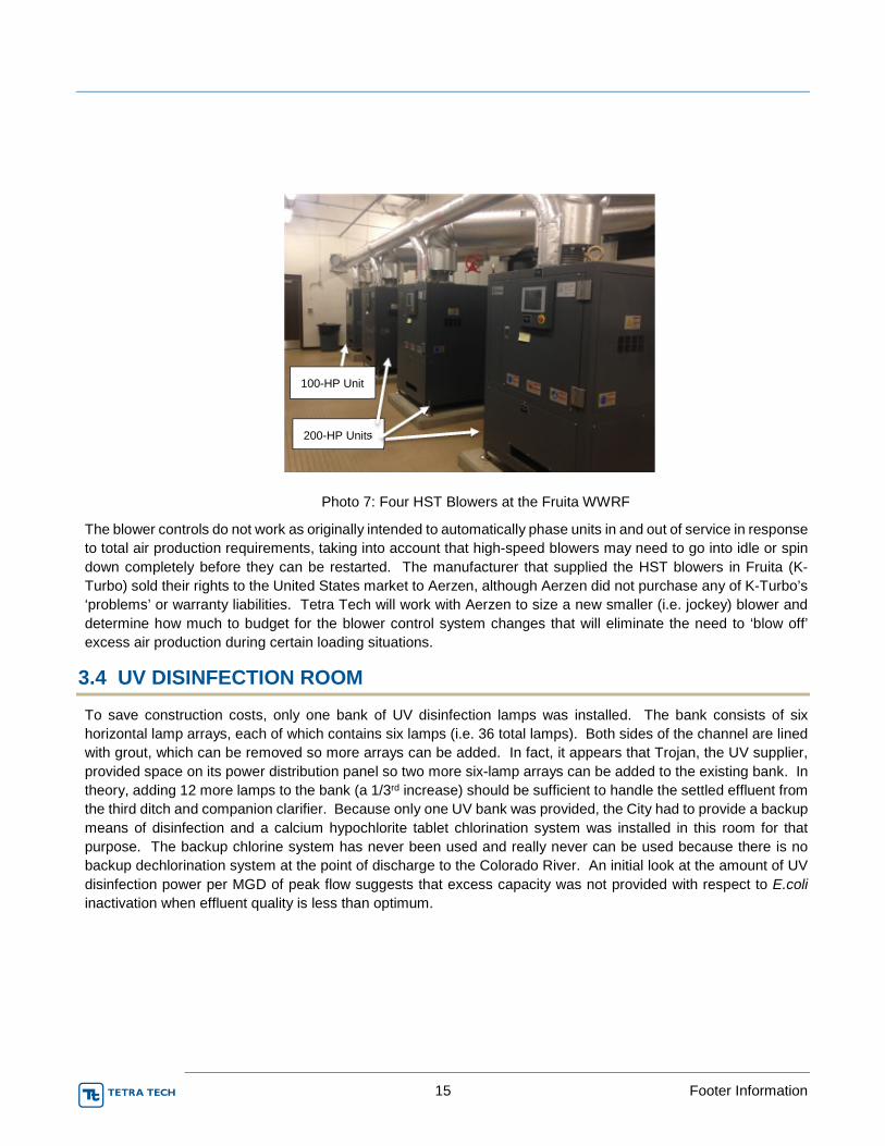
15 Footer Information
Photo 7: Four HST Blowers at the Fruita WWRF
The blower controls do not work as originally intended to automatically phase units in and out of service in response
to total air production requirements, taking into account that high-speed blowers may need to go into idle or spin
down completely before they can be restarted. The manufacturer that supplied the HST blowers in Fruita (K-
Turbo) sold their rights to the United States market to Aerzen, although Aerzen did not purchase any of K-Turbo’s
‘problems’ or warranty liabilities. Tetra Tech will work with Aerzen to size a new smaller (i.e. jockey) blower and
determine how much to budget for the blower control system changes that will eliminate the need to ‘blow off’
excess air production during certain loading situations.
3.4 UV DISINFECTION ROOM
To save construction costs, only one bank of UV disinfection lamps was installed. The bank consists of six
horizontal lamp arrays, each of which contains six lamps (i.e. 36 total lamps). Both sides of the channel are lined
with grout, which can be removed so more arrays can be added. In fact, it appears that Trojan, the UV supplier,
provided space on its power distribution panel so two more six-lamp arrays can be added to the existing bank. In
theory, adding 12 more lamps to the bank (a 1/3rd increase) should be sufficient to handle the settled effluent from
the third ditch and companion clarifier. Because only one UV bank was provided, the City had to provide a backup
means of disinfection and a calcium hypochlorite tablet chlorination system was installed in this room for that
purpose. The backup chlorine system has never been used and really never can be used because there is no
backup dechlorination system at the point of discharge to the Colorado River. An initial look at the amount of UV
disinfection power per MGD of peak flow suggests that excess capacity was not provided with respect to E.coli
inactivation when effluent quality is less than optimum.
100-HP Unit
200-HP Units
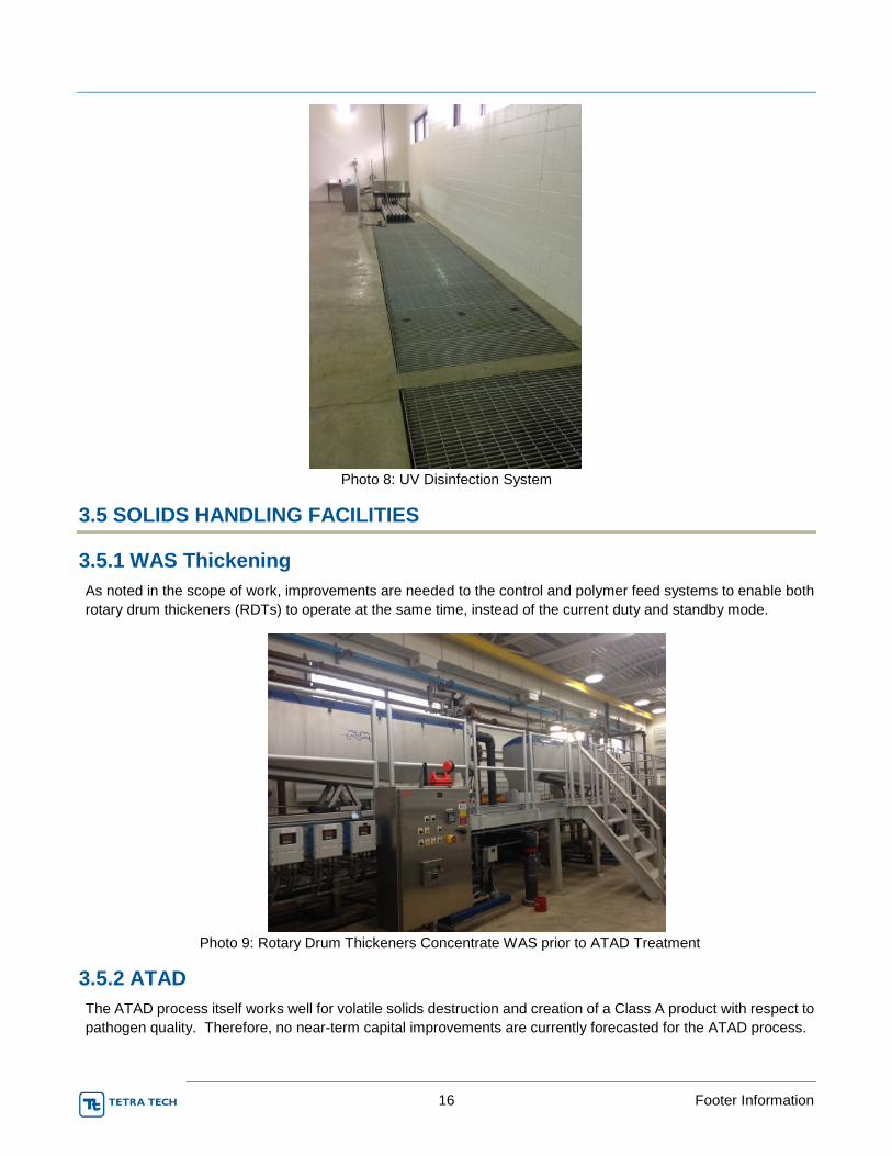
16 Footer Information
Photo 8: UV Disinfection System
3.5 SOLIDS HANDLING FACILITIES
3.5.1 WAS Thickening
As noted in the scope of work, improvements are needed to the control and polymer feed systems to enable both
rotary drum thickeners (RDTs) to operate at the same time, instead of the current duty and standby mode.
Photo 9: Rotary Drum Thickeners Concentrate WAS prior to ATAD Treatment
3.5.2 ATAD
The ATAD process itself works well for volatile solids destruction and creation of a Class A product with respect to
pathogen quality. Therefore, no near-term capital improvements are currently forecasted for the ATAD process.
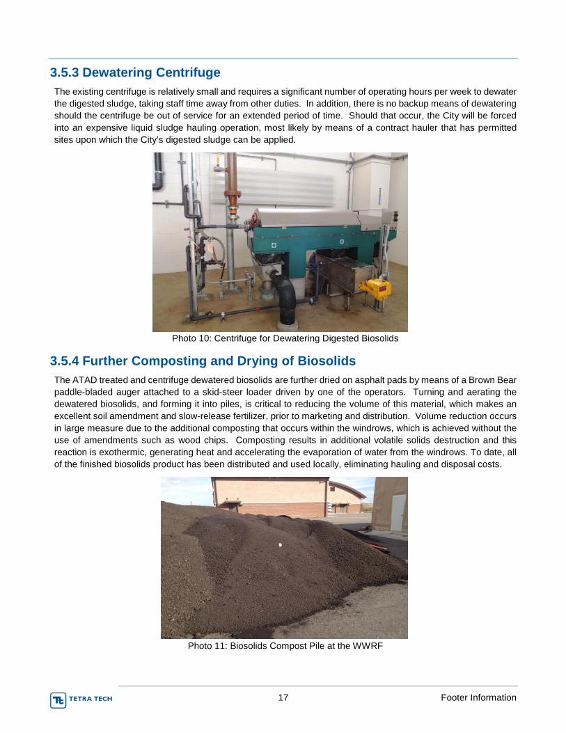
17 Footer Information
3.5.3 Dewatering Centrifuge
The existing centrifuge is relatively small and requires a significant number of operating hours per week to dewater
the digested sludge, taking staff time away from other duties. In addition, there is no backup means of dewatering
should the centrifuge be out of service for an extended period of time. Should that occur, the City will be forced
into an expensive liquid sludge hauling operation, most likely by means of a contract hauler that has permitted
sites upon which the City’s digested sludge can be applied.
Photo 10: Centrifuge for Dewatering Digested Biosolids
3.5.4 Further Composting and Drying of Biosolids
The ATAD treated and centrifuge dewatered biosolids are further dried on asphalt pads by means of a Brown Bear
paddle-bladed auger attached to a skid-steer loader driven by one of the operators. Turning and aerating the
dewatered biosolids, and forming it into piles, is critical to reducing the volume of this material, which makes an
excellent soil amendment and slow-release fertilizer, prior to marketing and distribution. Volume reduction occurs
in large measure due to the additional composting that occurs within the windrows, which is achieved without the
use of amendments such as wood chips. Composting results in additional volatile solids destruction and this
reaction is exothermic, generating heat and accelerating the evaporation of water from the windrows. To date, all
of the finished biosolids product has been distributed and used locally, eliminating hauling and disposal costs.
Photo 11: Biosolids Compost Pile at the WWRF

18 Footer Information
The Brown Bear paddle-bladed auger attachment was purchased used by the City of Fruita and had several
previous owners. Therefore, the Fruita WWRF will not see the full useful life from this equipment. In addition, the
auger is not the tallest that Brown Bear makes and the small windrows must be reformed into taller piles for
composting purposes. The cost of a new and larger paddle-bladed auger and a more powerful skid steer machine
to drive and hydraulically power the Brown Bear attachment, which will assure reliable operation of this important
biosolids volume reduction process, is included in the alternative development and budgeting section.
3.6 BIOFILTER
Biofilters are packed-bed reactors that use microbes for biological oxidation of odors. The existing biofilter that
treats foul air from the ATAD process is the type where the internal components, such as wood shards and
compost, break down over time and need to be removed and replaced every 2-4 years. Otherwise, the biofilter
bed compresses, shrinks, and cracks, allowing untreated odors into the air, and such is the case at Fruita.
A modular, durable-media biofilter will eliminate the need to remove and replace the media, and will provide for a
higher degree of odor control. Foul air is conveyed through the durable media where sorption and biological
treatment occurs. Odorous compounds are absorbed into the biofilm layer that resides on surface of the packing
material. The microorganisms that comprise the biofilm oxidize the nitrogen and sulfur-based compounds that are
the source of the odors.
3.7 CONTROL SYSTEMS
3.7.1 SCADA and HMI Screens
Tetra Tech previously provided a scope and cost opinion to the City for upgrade of 12 to 18 HMI screens. This
estimate will be reviewed with WWRF staff to determine (1) what type of changes need to be made and (2) if fewer
or more screens need to be upgraded, taking into account the above-noted improvements that might be
implemented by the City.
There are two principal phases for proposed SCADA system upgrades at the Fruita WWTP. Phase 1 will consist
of helping plant staff resolve immediate instrumentation and control (I&C) constraints, which currently limit certain
plant operations or consume more operator attention and electric power than desired. Phase 2 will be an upgrade
of the SCADA system to (1) improve the structure, function, and readability of existing HMI screens and (2)
concurrent operation of both RDTs. The Phase 1 improvements will be configured with an eye on Phase 2, which
will include a makeover of SCADA hierarchy and HMI screens.
In preparing this NAS report, the City and Tetra Tech identified the following Phase 1 SCADA limitations.
• Improve the operator's ability to mine data and import it into spreadsheets.
• Provide adjustable WAS control revisions.
• Add bi-directional HMI data flow for the controller provided by Thermal Process Systems (TPS).
3.8 OPERATIONS BUILDING
WWRF staff asked Tetra Tech to budget costs for expanding the Operations Building to provide additional space
for training and the larger staff compliment that may be needed as the WWRF handles more flow/load and is
required to do more to comply with future effluent limits. The additional space can be provided by expanding the
building to the east or re-tasking and renovating the garage area at the west side of the structure. Funds have
been budgeted so the City can implement either of these options, or another alternative that may be developed
prior to implementing this improvement.

19 Footer Information
4.0 FORECASTING REGULATORY COMPLIANCE REQUIREMENTS FOR2016-2025
4.1 CDPHE NUTRIENT QUALITY RULES
The Environmental Protection Agency (EPA) first established nutrient water quality criteria in 1998 to reduce the
excessive algae growth and the accelerated, cultural eutrophication caused by it. For example, excessive algae
levels can cause low DO conditions (hypoxia), fish kills, high pH episodes, and reduced recreational use of the
water. Algae can also create a wide variety of drinking water quality problems. These include complaints about
taste and odor and clogging of filters. In addition, hypoxia in the hypolimnion of a lake or reservoir can create
reducing conditions and cause the release of soluble iron and manganese, which are difficult to remove to low
concentrations. Elevated levels of iron and manganese will discolor potable water, typically resulting in numerous
complaints and eroding customer confidence in the public water supply.
EPA nutrient criteria are subdivided into “causal” and “response” categories. TN and TP are thought to be the
primary causative parameters that can be managed through point and nonpoint source control techniques. The
water quality response metrics selected by the EPA to measure algae growth are chlorophyll a and transparency
(i.e., turbidity for rivers and streams or secchi disk depth for standing bodies of water). Although many parameters
can be used to define the overall health of water body, EPA felt if the chlorophyll a content is low and transparency
is high, then good water quality will be assured. Table 4-1 presents the numeric criteria recommended by EPA for
water bodies within Ecoregion III, Xeric West, which is the ecoregion that includes Fruita.
Table 4-1 Recommended EPA Nutrient Quality Criteria for Water Bodies in Ecoregion III(1)
Criteria Units Rivers and Streams
TP μg-P/L 22
TN mg-N/L 0.38
Chlorophyll a μg/L 1.8
Turbidity NTUs 2.3
Secchi dish depth m N/A
(1)Based on EPA Publication 822-B-01-014, Ambient Water Quality Criteria Recommendations, December 2001.
States have the ability to adopt their own numeric nutrient criteria, or utilize EPA’s values. In 2012, after nearly 10
years of intensive work and stakeholder involvement, CDPHE promulgated its own set of nutrient quality rules,
Regulation 85 and revisions to Regulation 31. The purpose of Regulation 85 is to get medium and large WWRFs
located within high-priority watersheds moving forward with a level or nitrogen and phosphorous removal
comparable with what is achievable by means of proven BNR treatment techniques. The revisions to Regulation
31 set interim numeric nutrient values that may ultimately apply to all watersheds in the state. The long-term
regulatory requirement is for dischargers to comply with the in-stream TN and TP values set forth in Regulation 31.
Therefore, WRRFs that install facilities to comply with Regulation 85 may have to add supplemental facilities in the
future to comply with Regulation 31.
4.1.1 Regulation 85
Regulation 85 sets the following effluent limits for TP and TIN for all WWRFs larger than 2.0 MGD that are located
in what CDPHE has designated as high-priority watersheds (priority is based on adjacent population density and
the potential for public use of the waters). Compliance is based on running 12-month median and 95th percentile
effluent concentrations.

20 Footer Information
Table 4-2 Regulation 85 Effluent Limits
Parameter Running Annual Median Running Annual 95th
Percentile
TP, mg-P/L 1.0 2.5
TIN, mg-N/L 15 20
Notes:
Compliance based on running 12-month performance.
Fruita will get compliance schedule at next permit renewal in 2017.
4.1.2 Regulation 31
Regulation 31 includes interim, median annual in-stream numeric nutrient quality values. The interim in-stream TP
and TN values for warm water streams such as Colorado River at Fruita are 2.01 mg-N/L of TN, which includes TIN
plus organic nitrogen, and 0.17 mg-P/L for TP. Site-specific standards can be developed based on limiting in-stream
chlorophyll a to 150 mg/m2. The receiving stream cannot exceed Regulation 31 standards more than 1 year out of
5 and dischargers must demonstrate the ability to comply with Regulation 31 in order to opt out of Regulation 85.
The revisions to Regulation 31 were approved assuming these numeric nutrient values would not be established
as definitive water quality criteria until 2022, except in very limited cases.
Regulation 85 requires virtually all treatment plants in the state to collect nutrient quality data for their effluent
discharge and receiving waters, which for Fruita is the Colorado River. As part of the NAS project, Tetra Tech
recommended that Fruita revise its upstream monitoring location so in-stream quality data is more representative
of the total breadth and depth of the river. The quantity and quality of upstream dilution flow will determine if Fruita
can comply with Regulation 31 in-stream TP and TN limits and opt out of Regulation 85 effluent limits. In addition,
CDPHE may revise the interim numeric nutrient values in Regulation 31 based on stream water quality data
currently being collected by dischargers like Fruita.
Current average effluent TIN concentrations from the Fruita WWRF range from 5 mg-N/L to 10 mg-N/L and will
comply with Regulation 85 effluent limits. In addition, preliminary investigations indicate the City should be able to
comply with Regulation 31 in-stream TN values and opt out of Regulation 85 effluent TIN requirements. Data
suggests that to comply with Regulation 31 in-stream TP values, additional TP reduction may be needed at the
WWRF, but not to the same extent as would be required by Regulation 85. Even though WWRF staff and Tetra
Tech are evaluating low cost ways to further optimize TP removals, funds have been include in the near-term
planning period for additional TP removal facilities. The trigger mechanism for moving forward with Regulation 85
compliance or opting out of that rule by complying with the interim in-stream numeric nutrient values in Regulation
31, will be the 2017 renewal of the WRRF discharge permit.
4.2 TEMPERATURE RULE
CDPHE’s temperature rule, coupled with the presence of the threatened and endangered (T&E) aquatic life in the
Colorado River, may mean the effluent will have to meet in-stream temperature standards at end of pipe, without
benefit of dilution. Internal CDPHE guidance says the in-stream temperature rule will not be applied if no effluent
dilution is available, or if the dilution ratio is more than 10:1. The City needs to keep collecting effluent temperature
data, assess its compliance posture based on that data, and monitor CDPHE’s implementation of this rule over time
and with other dischargers, particularly those with T&E implications. Potential compliance alternatives could include
heat extraction from the effluent or installation of an effluent diffuser in the Colorado River to create a dilution ratio
of at least 10:1, plus leaving a ‘zone of passage’ for aquatic life of at least 50% of the low flow river width. However,
CDPHE has been moving slowly to implement this rule and is looking for low cost ways that dischargers can comply.

21 Footer Information
Therefore, there is a good chance the City will not have to construct facilities to address effluent temperature in the
near term and the 10-year budget does not include capital expenditures for this issue.
4.3 AMMONIA CRITERIA
In 2013, the Environmental Protection Agency (EPA) updated their ammonia criteria for protection of aquatic life
from toxicity. Although Colorado has yet to adopt the new ammonia criteria, that step will likely occur during the
2016-2025 planning period for the NAS. Investigations performed for other clients suggest that in worst case
situations, monthly average effluent limits could be lowered by 50%, and less of a change for daily maximum
standards. The robustly designed, high-SRT oxidation ditches at the WRRF provide a consistently high level of
ammonia oxidation (i.e., nitrification). Consequently, it is anticipated that the existing WRRF can meet reduced
ammonia limits due to EPA’s 2013 criteria document, although the operators may need to put slightly more
emphasis on aeration (nitrification) than anoxic zone nitrate reduction (denitrification).
4.4 ARSENIC
With respect to arsenic, CDPHE has established a statewide temporary modification (expires 12/31/21) while it tries
to determine if (1) the stream standard can be made less stringent while protecting designated beneficial uses or
(2) a treatment technology-based rule should be established. In either case, CDPHE does not intend that municipal
WWTPs be required to install arsenic removal facilities when treating normal domestic sewage not subject to
commercial or industrial sources of arsenic (such as the Fruita WWRF). For the purpose of this NAS, it will be
assumed that arsenic removal will not be a requirement during the planning period.
5.0 ALTERNATIVE DEVELOPMENT AND BUDGETING
This section summarizes the above-noted improvements that may be needed during the near-term planning period
(2016-2025). Budget estimates have been prepared for these improvements and then spread out over the 10-year
planning period based on recommendations by Tetra Tech and input from WRRF staff.
5.1 RECOMMENDED AND POTENTIAL PROJECTS
5.1.1 Headworks
5.1.1.1 Influent Channel and Pump Wetwell Corrosion
The best approach to making these repairs is to first install the second rotary drum screen that was deferred from
the original project during the value engineering review. Once the second unit is on line, the existing screen should
be removed and the concrete channel renovated and recoated, with a different and more robust coating system this
time. If hydraulics will allow, when the second screen is installed, WRRF staff would like to be able to run the
screens in series as well as parallel.
As noted above, there is severe concrete corrosion on the walls of the influent channel, extending from beginning
to end in the Headworks, including the influent pump wetwell. The corrosion penetrates into the reinforcing steel
and represents a threat to the structural integrity of the operating floor of the Headworks. Accordingly, budget has
been included to physically remove all corroded concrete, clean or replace corroded reinforcing steel, re-cast the
concrete walls, and then reseal the walls with a stout, acid-resistant liner. As discussed below, it is also
recommended that air ionization be used to chemically oxidize the H2S under the influent channel covers and reduce
the amount available to the sulfur-oxidizing bacteria that are the source of the concrete corrosion.

22 Footer Information
5.1.1.2 Wetwell Screening
For supplemental removal of grease from the perforated plate drum, it is recommended that the City install a
pressurized hot water distribution piping system in the Headworks. Fruita will also need to purchase hot water
generating equipment (e.g. a ‘Hotsy’) that can be either permanently installed in the Headworks or a mobile unit
that can be moved to other locations at the WWRF. The pressurized hot water can be sprayed at the outside of the
screen using a portable wand or by tying the hot water stream into the washwater system for the drum, and would
be available for other pressure washing needs in the Headworks. The hot water generating system can be powered
by electricity, natural gas, diesel, or gasoline, the selection among which will depend upon code-compliance
considerations and if the staff prefers a mobile unit or a fixed installation in the Headworks.
Hosty has recommended a high pressure, electric powered stationary washer. Because of the Class 1, Division 2
code classification rating of the screening and grit removal area, the Hotsy will be located in an adjoining,
unclassified space and the high pressure hot water ‘hard piped’ to several locations within Headworks where it is
needed. The Hotsy equipment package will include a 50-foot hose, wall-mounted hose reels, and quick connects
for the hard piping so the operators can take maximum advantage of the hot water for cleaning and equipment
maintenance once it is available.
5.1.1.3 H₂S Concentration and Air Ionization
Tetra Tech recommends the City implement improvements to reduce H2S levels within the Headworks Building.
These include making sure inlet and outlet ventilation ducts are clean and exhaust fans are working at full capacity.
Tetra Tech also suggests the City install an air ionization system to reduce airborne H2S levels within the channels
as well as the remainder of the operating floor area in the Headworks. An additional recommendation is that the
City set a 10-minute STEL for H2S at the WWRF, be it the current or proposed OSHA standards, the suggested
values set by the other occupational health organizations noted above, or something in between.
The inlet air ionization system (e.g., Trans Tech) will eliminate odor problems and significantly reduce corrosion,
increasing the life of concrete, instrumentation, and electrical equipment in the Headworks. Ionization will improve
the quality of the air within the Headworks, protecting the health of plant staff and anyone else who stays in that
building for more than 10 to 15 minutes.
The air ionization system utilizes the air space itself as the ‘reactor’ and eliminates the need to add chemicals or
use water for odor control. There is no effluent to handle and the equipment has a very small footprint. The air
ionization modules can be installed directly into the ventilation ducts on the fresh air side of an air handler. Fresh
air, passing over the ion tubes, picks up both positive and negative ions, forming clusters of ‘activated’ oxygen
molecules that oxidize odors, without generating ozone. Odors are eliminated at the source, so clean air is present
within the building and released to the atmosphere. With the addition of air ionization in the Headworks, it may be
possible to discontinue using the activated carbon canister that treats the foul air vented from the headspace of the
influent channels and pump wetwell.
Additionally, it is recommended to monitor the H₂S concentration at various locations within the Headworks Building.
This can be done over a 24-hour period using an OdaLog H₂S data logger. The data can be downloaded and
analyzed to evaluate airborne H₂S levels at various locations and times of day.
5.1.1.4 RAS Pumps
To improve operational control and reduce energy consumption at low flows and when the activated sludge is
settling well, staff would like to replace one of the 40-HP motors with 20-HP unit, resulting in one larger (40-HP)
and one smaller (20-HP) RAS pump for each clarifier. Further analysis is needed to determine if the pump impeller
connected to the downsized motor also needs to be changed out. The downsizing of one pump will enable the
operators to turn down RAS output to just that needed to maintain minimal sludge blankets in each clarifier. In case
one of the 40-HP pumps go out of service, the City will still meet CDPHE firm capacity pumping requirements for

23 Footer Information
two clarifiers. If a third oxidation ditch and secondary clarifier are installed in the future, the City may need to replace
the two, 20-HP motors so all four RAS pumps in the gallery are 40-HP units and in compliance with CDPHE firm
capacity criteria.
5.1.1.5 Hypochlorite Feed System
The existing ‘ad hoc’ scum chlorination system installed by the operators will continue to be utilized when needed
for filament control. Any and all improvements in the pump gallery will recognize the potential need to serve a third
oxidation ditch and secondary clarifier in the future.
5.1.2 Activated Sludge Complex
5.1.2.1 Anaerobic Selectors
Aquarius determine the layout, sizing, and cost to enlarge the anaerobic selector basins so they serve their original
purpose plus provide the typical volume required for Bio-P release. Currently, the selector tanks are common to
both/all oxidation ditch trains. That is, the mixed liquor is split to the ditches downstream of the selectors.
Discussions will be held with staff regarding whether to continue this mode, or dedicate an anaerobic basin to each
ditch, which might require a significant investment in raw wastewater and RAS piping modifications.
Aquarius has recommended installing a fine bubble diffuser in one of the two selector basins in order to create a
swing zone allowing for anaerobic, anoxic, and oxic conditions. Two removable fine bubble diffuser grids will be
installed into one of the selector basins, each with the dimensions of 16 feet by 16 feet. Each grid will include low
pressure membrane disc diffusers to provide mixing and oxic conditions and each grid will consist of 40 diffusers.
Concrete ballasts will be installed into the selector basin in order to keep the grid submerged. Metal framework will
provide the grid structure for the diffusers to be mounted and upon that the structure will be anchored into the
concrete ballasts. A flexible hose will connect the aeration grid to the air main at the top of the tank.
5.1.2.2 Oxidation Ditches
While PVC includes a UV inhibitor to reduce the rate at which it becomes brittle with sunlight exposure, Tt will
explore if more definitive means are needed to protect the exposed diffuser piping from the effects of the sun. The
original coating system never adhered well to steel mixer blades and all four mixers (two in each ditch) need to be
sandblasted and recoated to assure a long useful life for this equipment.
As noted previously, one potential near-term improvement is to relocate the tablet chlorination system from the UV
disinfection room to the Headworks pump gallery so chlorine can be fed to the RAS to further assist with filament
control.
5.1.2.3 Secondary Clarifiers
As noted above, corrosion of the metal surfaces that comprise the secondary mechanisms appears to be superficial
and can be handled through sandblasting and recoating. The need for minor metal repairs or replacements may
become evident after the sandblasting stage. The degree of corrosion experienced by the secondary clarifier sludge
and scum collection mechanisms is much less severe than the concrete corrosion in the Headworks Building, and
the recommended near-term budget priorities reflects this fact.
5.1.3 Aeration Blowers
The least expensive approach to installation of the jockey blower is to replace one of the three existing 200-HP
units with a new 100-HP unit since all of the required electrical equipment and air piping for it are already in place.
Tetra Tech can demonstrate that one, 200-HP blower can handle the full design load for one oxidation ditch and

24 Footer Information
half of the ATAD demands. Therefore, a complement of two, 200-HP blowers and two, 100-HP units will meet
CDPHE firm aeration capacity requirements. If the third ditch is ever needed, the fifth blower may or may not need
to be upsized depending upon the historical pattern of air demands at the time the ditch is added.
Over the years, many K-Turbo customers have asked Aerzen to service their machines. Since many of the K-Turbo
packages were under warranty, and some of the machines in the field were modified from the standard factory
design, Aerzen developed an audit program to point out proper installation and operation and maintenance (O&M)
techniques, and open up the possibility for Aerzen to service the machines after the warranty expired. As the K-
Turbo machines age, and customer needs continue to mount, Aerzen has stepped up this program, which is
designed to provide continuous monitoring of the K-Turbo machines, rapid response to issues, and ultimately to
replace the units with Aerzen machines that will be serviced and maintained by the Aerzen (USA) team. At Tetra
Tech’s request, Aerzen provided budget pricing for the following:
1. An audit of the existing four blowers and recommendations on service viability or necessary replacements.
2. An annual service agreement for four blowers that will include anticipated consumable parts and
replacement of any components due to failure, to be billed at time and material basis.
3. An Aerzen remote monitoring system for each blower, which will allow for communication access to be
determined by plant protocols (Fruita will need to provide the communication link at the WWRF).
4. A new Aerzen HST blower, rated for 100-HP, to replace one of the 200-HP blowers
5.1.4 UV Disinfection System
As noted above, the calcium hypochlorite system could be better used for RAS chlorination and filament control,
and should be relocated to the Headworks pump gallery for this purpose. If so, a second bank of UV lamps should
be installed immediately downstream of the existing bank (i.e. in series) to meet CDPHE redundancy requirements.
Capacity expansion for the third ditch would be provided by widening the channel and adding more horizontal UV
lamp arrays, the potential for which was designed into the existing UV bank (as noted above). A plastic channel
liner can be installed to facilitate the widening process in the future. There appears to be sufficient linear length of
channel to accommodate a second bank of UV lamps and to relocate the finger weirs that control the water level
over the UV lamps. Trojan has recommended that the new bank of UV lamps consist of eight horizontal arrays that
are six lamps deep, and that two more six-lamp arrays be added to the existing bank.
When relocating the finger weirs, Tetra Tech will determine if enough straight run of channel will remain upstream
of the effluent Parshall flume for accurate metering of the flow. If necessary, removable plastic flow straightening
vanes can be installed upstream of the flume, but this will be avoided, if possible, because the vanes will tend to
collect debris and need to be removed and cleaned from time-to-time.
5.1.5 Solids Handling Facility
5.1.5.1 WAS Thickening
As part of the polymer feed system improvements needed for parallel operation of the RDTs, Tetra Tech
investigated the feasibility and cost of installing wetted polymer aging tanks, which require new aged polymer feed
pumps. Although there is debate in the industry about the value of aging polymer prior to use, the purpose of
polymer aging is to give the polymer sufficient time to hydrate (react with water) and for full activation (elongation)
of the polymer molecule. Polymer aging tanks were common 20 to 30 years ago, but are less often used now in
order to cut capital costs and in response to polymer feed supplier assertions that their batching systems provide
for polymer activation without the need for aging. Velodyne has proposed a mixing tank and solution metering
systems that will supply the polymer needed for both the centrifuge and RDTs.

25 Footer Information
5.1.5.2 ATAD
As noted previously, the ATAD system works well for digestion/liquid composting of the WAS. The principal
question posed to Tetra Tech by WRRF staff is whether to make use of the third ATAD tank now for equalization
storage and treatment of liquid stream return flows from the RDTs (i.e. drumate) and centrifuge (i.e. centrate). This
is an operational enhancement question that will be discussed with WRRF staff over time in the content of improving
and/or stabilizing Bio-P removals. Therefore, no capital funds have been included in the near-term planning period
for improvements to the ATAD system.
5.1.5.3 Centrifuge
Tetra Tech developed a budget number for adding as second centrifuge, no smaller than the current one, that can
operate in parallel with the centrifuge currently in place.
5.1.5.4 Dewatering of Biosolids
The near-term budget includes funds for a new skid-steer loader and paddle bladed auger/aerator for supplemental
air drying or the dewatered biosolids. The loader will have an enclosed, heated, and air conditioned cab so
supplemental drying operations can occur year round and the driver is protected from unintended contact with the
material when the auger is in motion. Note that if biosolids is placed on the asphalt pads and not routinely aerated
by the Brown Bear, it will become septic and the source of uncontained odors. It has been recommended by Brown
Bear that a larger skid steer/compact track loader attachment will ensure proper biosolids volume reduction. The
R31-10 paddle aerator has a 31-inch diameter rotor and is nominally 10 feet wide. It was built to specifically work
with the Cat 299D XHP compact track loader. This equipment information is provided in the Appendix but not
quoted. The cost for the equipment will be budgeted from another improvement fund.
5.1.6 ATAD Biofilter
Tetra Tech received budget pricing from Biorem for two potential durable media biofiltration systems to replace the
existing biofilter that treats foul air from the ATAD process. With durable media biofilters, media replacement is
infrequent or not needed at all, such as at Broomfield, CO. If possible, the existing water-based scrubber will be
used to humidify the foul air before it enters the durable media biofilter. Biorem provided two options in terms of
durable media biofilter systems. The first s to reuse the existing wet scrubber for humidification, followed by their
Biosorben system, a durable media biofilter installed in a cast-in-place concrete vessel. The second option is for an
above-ground, package, modular biofilter with a self-contained pre-humidification section using the same Biosorben
media.
5.1.7 Control Systems
Potential instrumentation and control (I&C) system improvements are subdivided into two phases depending upon
the immediacy of their need and cost of implementation.
Phase 1 – Immediate I&C Improvements
The proposed solutions will be developed jointly with WRRF staff and implemented using the existing software
programming and without significant rework of the HMI displays.
• Improved Data Extraction/Reporting: For reporting, the City is currently using Excel to extract data
directly from the PLC. The current system will be expanded to provide the data needed for performance
optimization as well as internal and external reporting.
• Provide Adjustable WAS Control Revisions: Working with City operations staff, develop and implement
the desired software modifications to the existing system. Specific objectives include:
o Provide (RDT Screen) adjustable high and low level setpoints in WAS HOLDING TANK BOX.

26 Footer Information
o Two additional wasting modes will be added to the HMI and PLC logic. The first allows two time
cams to be set up such that when either cam is on, wasting will occur at the specified flowrate. The
second mode sets up continuous wasting at a specified flow rate. In this mode, wasting ceases
upon operator request via a HMI button, high liquid level in the WAS holding tank, or time expiration
based on an operator entered setpoint.
• Bi-Directional HMI Data Flow: Addition of this feature will enable plant staff to change the control
parameters, both locally and remotely, for the ATAD facilities.
• PLC and control power reliability issues: The plant currently feeds the PLC’s uninterrupted power supply
(UPS) with one 120V breaker sourced from the closest 120V panelboard. Both input/output (I/O) and PLC
processor power are then sourced from the PLC panel UPS.
The purpose of the UPS is to maintain power to the PLC system and hence provide continuity of the plant
control system through power loss or while waiting for the backup generator to energize in the event of a
power outage. To increase the level of reliability, decrease the load on the UPS’s, and improve the
diagnostic capability of the system, it is proposed that the I/O power be sourced from the panelboard and
not from the UPS. This should prolong the life of the UPS and allow for enhanced diagnostic screening at
the PLC level.
Additionally, in order to enhance the reliability of the influent pumping system and eliminate a potential
cause for failure and flooding of WWRF structures with raw wastewater, Tetra Tech suggests that the
existing drive run circuitry be reconfigured in such a manner that backup floats located in the wetwell will
provide another path to keep the pumps energized should the PLC circuitry fail.
Phase 2 – Longer Term SCADA Improvements
At this time, two major scope items have been identified for the Phase 2 SCADA system improvements: (1) upgrade
of the HMI screens and (2) simultaneous operation of the RDT units.
• HMI System Upgrade: This task provides for upgrades to the existing SCADA system to improve the
structure, content, navigation and presentation of the existing HMI screens. This phase will also include the
provision of a “limited functionality HMI” in the upper level operator’s room in the Solids Building.
• Concurrent Operation of the RDTs: Another Phase 2 SCADA enhancement is to rework programming
such that the operators can make concurrent use of the rotary drum thickeners (RDTs), which were
originally configured as “duty” and “standby” units. The programming changes are in addition to the minor
facility modifications necessary so both RDTs can operate simultaneously. These modifications will be
identified by Tetra Tech for implementation by others. Specific functional objectives of this task include:
o Add a second polymer dilution/blending system so each RDT will have (1) its own set of redundant
polymer feed pumps and (2) sufficient polymer feed capacity.
o Replace the local selector switch and add electrical relays so diluted polymer can be directed to
one or both RDTs at the same time.
o Remove polymer pump speed control from PLC and enable only local control.
o Provide red-lined shop drawings of the polymer system for the City to purchase additional
equipment, construct changes, and keep for maintenance.
o Coordinate any revisions that are needed to the ATAD tank knife gate controls to enable
simultaneous operation of the RDTs. Tetra Tech’s assumes that the supplier of the ATAD system
(Thermal Process Systems) will make any I&C adjustments that affect the operation of its system.
5.1.8 Big Data Analysis
Tetra Tech provided a budget price to provide data analytics assistance, with the primary focus on determining
which operation factors and setpoints will promote reliable and highly effective Bio-P removal.

27 Footer Information
5.2 CAPITAL IMPROVEMENT AND DEVELOPMENT SUMMARY

Project: Fruita WWRF-Needs Assessment Study
PN: 133-29161-16002
Date: 5/12/2016
Desc: Capital Improvement Plan and Development Summary
2016 2017 2018 2019 2020 2021 2022 2023 2024 2025Audit $0.00 $0.00
Annual Service (All 4 Blowers) $0.00 $0.00
Aerzen Remote Monitoring System+100 HP Blower $240,000.00 $240,000.00
New Master Control Panel $130,000.00 $130,000.00
Data Analysis for Bio-P Optimization $10,000.00 $10,000.00
Phase 1-Immediate I&C Improvements $12,000.00 $12,000.00
Phase 2-Longer Term SCADA Improvements $62,000.00 $62,000.00
2nd Influent Rotary Drum Screen $370,000.00 $370,000.00
Channel Concrete Removal/Concrete Renovation $280,000.00 $280,000.00
Air Ionization $700,000.00 $700,000.00
'Hotsy' $11,000.00 $11,000.00
Concurrent Operation of RDTs $240,000.00 $240,000.00
Polymer Aging Improvements $40,000.00 $40,000.00
RAS Pump-20 HP $50,000.00 $50,000.00
Coating (Headworks, Secondary Clarifiers, Oxidation Ditches)$260,000.00 $260,000.00
Above ground, modular biofilter $660,000.00 $660,000.00
Reg 31/85 Bio-P Improvements $1,070,000.00 $1,070,000.00
Regulation 85 Opt Out $10,000.00 $10,000.00
Centrifuge
Centrifuge Appurtenances
Centrifuge Audit
Relocation of Hypochlorite Feed System $0.00 $0.00
Operations Building Expansion $150,000.00 $150,000.00
$300,000.00
$510,000.00
Additional of Full Second UV Bank+2 extra lamps for existing
module$300,000.00
$510,000.00
Total Projected Costs for Each Year $0.00 $454,000.00 $1,361,000.00 $590,000.00 $2,250,000.00 $0.00 $300,000.00 $150,000.00 $0.00 $0.00
WWRF Improvments Total CostExpected Costs Per Year

28 Footer Information
5.3 ESTIMATED PROJECT COSTS
Planning level cost opinions have been prepared for each improvement project discussed above.
5.3.1 Cost Estimating Assumptions
Preliminary cost opinions were prepared for each of recommended or potential near-term improvement. Cost
opinions were developed using the Association for Advancement Cost Engineering (AACE) International’s cost
estimating classification system, which defines five separate classes of cost estimates. For a study or feasibility
level report, this is considered a Class 4 estimate, and the final costs could range between -30% on the low side to
+50% on the high side.
Construction costs consist of site work, mechanical equipment, concrete, pumps, chemical metering equipment,
piping valves, structural, electrical and instrumentation, etc. Bonds and insurance have been included at 2% and
contractor’s overhead and profit is assumed to be 15%. A 25% construction cost contingency is included for this
planning level stage. Total capital cost includes a 15% cost allowance for preparing engineering plans,
specifications, bidding and construction phase services, on-site inspection, incidental permits, survey, geotechnical,
legal, and City administrative costs. The percentage allowances for each improvement varies depending on the
level of difficulty as well as what was included, or not, in the vendor quote.
5.3.2 Total Project Cost Opinions
Table 5-4 is a capital cost summary of the proposed improvements for the Fruita WWRF. Details of project costs
are included in the Appendix. The total NAS improvements for the Fruita WWRF is estimated at approximately
$5,105,000 for all items listed. Some of the estimated costs for Regulation 85/31 requirements are order of
magnitude estimates since the conceptual elements need to be refined by additional studies and evaluation.
Table 5-1 Summary of Proposed Improvements
Capital Improvement Projects Cost
2016 - -
2017 Aeration Blowers
Audit $0
Annual Service (All 4 Blowers) $0
Aerzen Remote Monitoring System+100 HP Blower $240,000
New Master Control Panel $130,000
Data Analysis for Bio-P Optimization
Data Analysis for Bio-P Optimization $10,000
Control System
Phase 1-Immediate I&C Improvements $12,000
Phase 2-Longer Term SCADA Improvements $62,000
2018 Headworks
2nd Influent Rotary Drum Screen $370,000
Channel Concrete Removal/Concrete Renovation $280,000
Air Ionization $700,000
'Hotsy' $11,000
2019 Solids Handling Facilities
Concurrent Operation of RDTs $240,000

29 Footer Information
Capital Improvement Projects Cost
Polymer Aging Improvements $40,000
Headworks-Lower Level Pump Room
RAS Pump-20 HP $50,000
Coating (Headworks, Secondary Clarifiers, Oxidation Ditches) $260,000
2020 Biofilter
Above ground, modular biofilter $660,000
Reg 31/85 Bio-P Improvements
Reg 31/85 Bio-P Improvements $1,070,000
Regulation 85 Opt Out $10,000
Solids Handling Facilities
Centrifuge
$510,000Centrifuge Appurtenances
Centrifuge Audit
2021 - -
2022 UV Disinfection
Additional of Full Second UV Bank+2 extra lamps for existing module$300,000
Relocation of Hypochlorite Feed System $0
2023 Operations Building
Operations Building Expansion $150,000
2024 - -
2025 - -
Total Cost $5,105,000

30 Footer Information
APPENDIX A - DETAILED COST OPINIONS AND VENDOR QUOTES(WHERE APPLICABLE) FOR EACH NEAR-TERM IMPROVEMENT PROJECT

Project: Fruita WWRF-Needs Assessment Study
PN: 133-29161-16002
Date: 5/12/2016
Desc: 2016 Improvement Projects
Equipment Cost
Installation (0%)
Electrical I&C (0%)
Sitework (0%)
Contracts/Bonds/Insurance (0%)
Mobilization/Demobilization (0%)
Subtotal
Construction Contingency (0%)
Contractor Overhead and Profit (0%)
Subtotal
Engineering (0%)
Total
Note:
1. Project total rounded to the nearest $10,000
-
-

Project: Fruita WWRF-Needs Assessment Study
PN: 133-29161-16002
Date: 5/12/2016
Desc: 2017 Improvement Projects
Audit Equipment Cost $0 Equipment Cost $10,000 Equipment Cost $11,400
Installation (0%) $0 Installation (0%) $0 Installation (0%) $0
Electrical I&C (0%) $0 Electrical I&C (0%) $0 Electrical I&C (0%) $0
Sitework (0%) $0 Sitework (0%) $0 Sitework (0%) $0
Contracts/Bonds/Insurance (0%) $0 Contracts/Bonds/Insurance (0%) $0 Contracts/Bonds/Insurance (0%) $0
Mobilization/Demobilization (0%) $0 Mobilization/Demobilization (0%) $0 Mobilization/Demobilization (0%) $0
Subtotal $0 Subtotal $0 Subtotal $0
Construction Contingency (0%) $0 Construction Contingency (0%) $0 Construction Contingency (0%) $0
Contractor Overhead and Profit (0%) $0 Contractor Overhead and Profit (0%) $0 Contractor Overhead and Profit (0%) $0
Subtotal $0 Subtotal $0 Subtotal $0
Engineering (0%) $0 Engineering (0%) $0 Engineering (0%) $0
Total $0 Total $10,000 Total $12,000
Equipment Cost $0 Equipment Cost $61,500
Installation (0%) $0 Installation (0%) $0
Electrical I&C (0%) $0 Electrical I&C (0%) $0
Sitework (0%) $0 Sitework (0%) $0
Contracts/Bonds/Insurance (0%) $0 Contracts/Bonds/Insurance (0%) $0
Mobilization/Demobilization (0%) $0 Mobilization/Demobilization (0%) $0
Subtotal $0 Subtotal $0
Construction Contingency (0%) $0 Construction Contingency (0%) $0
Contractor Overhead and Profit (0%) $0 Contractor Overhead and Profit (0%) $0
Subtotal $0 Subtotal $0
Engineering (0%) $0 Engineering (0%) $0
Total $0 Total $62,000
Remote Monitoring $0
100 HP Blower $104,000
Subtotal $104,000
Installation (20%) $20,800
Electrical I&C (20%) $20,800
Sitework (0%) $0
Contracts/Bonds/Insurance (2%) $2,080
Mobilization/Demobilization (4%) $4,160
Subtotal $27,040
Construction Contingency (25%) $32,760
Contractor Overhead and Profit (15%) $19,656
Subtotal $52,416
Engineering (15%) $27,518
Total $240,000
Equipment Cost $80,000
Installation (20%) $16,000
Electrical I&C (15%) $12,000
Sitework (0%) $0
Contracts/Bonds/Insurance (0%) $0
Mobilization/Demobilization (0%) $0
Subtotal $12,000
Construction Contingency (10%) $9,200
Contractor Overhead and Profit (0%) $0
Subtotal $9,200
Engineering (10%) $10,120
Total $130,000
Note:
1. Project total rounded to the nearest $10,000
Control System
Phase 1-Immediate I&C
Improvements
Phase 2-Longer Term
SCADA Improvements
Blower Control
Improvements
Data Analysis for Bio-
P Optimization
Annual Service
Remote Monitoring+100
HP Blower
Data Analysis for Bio-P OptimizationAeration Blowers

Project: Fruita WWRF-Needs Assessment Study
PN: 133-29161-16002
Date: 5/12/2016
Desc: 2018 Improvement Projects
Equipment Cost $175,000
Installation (15%) $26,250
Electrical I&C (15%) $26,250
Sitework (0%) $0
Contracts/Bonds/Insurance (2%) $3,500
Mobilization/Demobilization (4%) $7,000
Subtotal $36,750
Construction Contingency (25%) $52,938
Contractor Overhead and Profit (15%) $31,763
Subtotal $84,700
Engineering (15%) $44,468
Total $370,000
Concete In Place (Installed) $100,000
Coating $70,000
Subtotal $170,000
Installation (0%) $0
Electrical I&C (0%) $0
Sitework (0%) $0
Contracts/Bonds/Insurance (2%) $3,400
Mobilization/Demobilization (4%) $6,800
Subtotal $10,200
Construction Contingency (25%) $45,050
Contractor Overhead and Profit (15%) $16,530
Subtotal $61,580
Engineering (15%) $36,267
Total $280,000
Air Ionization Equipment Cost $297,000
Installation (30%) $89,100
Electrical I&C (20%) $59,400
Sitework (0%) $0
Contracts/Bonds/Insurance (2%) $5,940
Mobilization/Demobilization (4%) $11,880
Subtotal $77,220
Construction Contingency (25%) $93,555
Contractor Overhead and Profit (15%) $56,133
Subtotal $149,688
Engineering (15%) $78,586
Total $700,000
Hosty Equipment Cost $11,000
Installation (0%) $0
Electrical I&C (0%) $0
Sitework (0%) $0
Contracts/Bonds/Insurance (0%) $0
Mobilization/Demobilization (4%) $0
Subtotal $0
Construction Contingency (25%) $0
Contractor Overhead and Profit (0%) $0
Subtotal $0
Engineering (0%) $0
Total $11,000
Note:
1. Project total rounded to the nearest $10,000
Headworks Channel and
Wetwell Concrete Renovation
and Coating
Headworks
2nd Influent Rotary Drum
Screen

Project: Fruita WWRF-Needs Assessment Study
PN: 133-29161-16002
Date: 5/12/2016
Desc: 2019 Improvement Projects
Equipment (Includes I&C Programming) $136,000 Equipment Cost $21,000.00 Equipment Cost $150,000
Replumbing $7,000 Installation (20%) $4,200.00 Installation (0%) $0
Subtotal $143,000 Electrical I&C (15%) $3,150 Electrical I&C (0%) $0
Installation (15%) $21,450 Sitework (0%) $0 Sitework (0%) $0
Electrical I&C (5%) $7,150 Contracts/Bonds/Insurance (2%) $420 Contracts/Bonds/Insurance (2%) $3,000
Sitework (0%) $0 Mobilization/Demobilization (4%) $840 Mobilization/Demobilization (4%) $6,000
Contracts/Bonds/Insurance (2%) $2,860 Subtotal $4,410 Subtotal $9,000
Mobilization/Demobilization (0%) $0 Construction Contingency (25%) $6,352.50 Construction Contingency (25%) $39,750
Subtotal $10,010 Contractor Overhead and Profit (15%) $3,811.50 Contractor Overhead and Profit (15%) $23,850
Construction Contingency (10%) $15,301 Subtotal $10,164 Subtotal $63,600
Contractor Overhead and Profit (10%) $15,301 Engineering (15%) $5,336.10 Engineering (15%) $33,390
Subtotal $30,602 Total $50,000.00 Total $260,000
Engineering (10%) $27,542
Total $240,000
Equipment Cost $15,000.00
Installation (30%) $4,500.00
Electrical I&C (10%) $1,500
Sitework (0%) $0
Contracts/Bonds/Insurance (2%) $300
Mobilization/Demobilization (4%) $600
Subtotal $2,400
Construction Contingency (25%) $4,350.00
Contractor Overhead and Profit (15%) $2,610.00
Subtotal $6,960
Engineering (15%) $3,654.00
Total $40,000.00
Note:
1. Project total rounded to the nearest $10,000
Polymer Aging
Improvements
Headworks-Lower Level Pump Room
RAS Pump-
20 HPCoating (Secondary
Clarifiers,
Oxidation Ditches)
Coating (Secondary Clarifiers, Oxidation Ditches)Solids Handling Facilites
Concurrent
Operation of
RDTs

Project: Fruita WWRF-Needs Assessment Study
PN: 133-29161-16002
Date: 5/12/2016
Desc: 2020 Improvement Projects
Equipment Cost $300,000.00 Equipment Cost $210,000.00
Installation (30%) $90,000.00 Appurtenances $20,000.00
Electrical I&C (10%) $30,000 Audit $4,000.00
Sitework (0%) $0 Subtotal $234,000.00
Contracts/Bonds/Insurance (2%) $6,000 Installation (20%) $46,800.00
Mobilization/Demobilization (4%) $12,000 Electrical I&C (20%) $46,800
Subtotal $48,000 Sitework (0%) $0
Construction Contingency (25%) $87,000.00 Contracts/Bonds/Insurance (2%) $4,680
Contractor Overhead and Profit (15%) $52,200.00 Mobilization/Demobilization (4%) $9,360
Subtotal $139,200 Subtotal $60,840
Engineering (15%) $73,080.00 Construction Contingency (25%) $73,710.00
Total $660,000.00 Contractor Overhead and Profit (15%) $44,226.00
Subtotal $117,936
Engineering (10%) $41,277.60
Total $510,000.00
Equipment Cost-Concrete $150,000.00
Equipment Cost-Excavation, Backfill,
Dewatering, etc. $200,000.00
Anaerobic Selectors (4) $60,000.00
Mixers (2) $30,000.00
Subtotal $440,000.00
Installation (30%) $132,000.00
Electrical I&C (25%) $110,000
Sitework (0%) $0
Contracts/Bonds/Insurance (2%) $8,800
Mobilization/Demobilization (4%) $17,600
Subtotal $136,400
Construction Contingency (25%) $144,100.00
Contractor Overhead and Profit (15%) $86,460.00
Subtotal $230,560
Engineering (15%) $121,044.00
Total $1,070,000.00
Note:
1. Project total rounded to the nearest $10,000
Reg 31/85 Bio-P Improvements
Above ground,
modular biofilter
Reg 31/85 Bio-P
Improvements
Biofilter Solids Handling Facilites
Centrifuge,
Centrifuge
Appurtenances
and Audit

Project: Fruita WWRF-Needs Assessment Study
PN: 133-29161-16002
Date: 5/12/2016
Desc: 2021 Improvement Projects
Equipment Cost
Installation (0%)
Electrical I&C (0%)
Sitework (0%)
Contracts/Bonds/Insurance (0%)
Mobilization/Demobilization (0%)
Subtotal
Construction Contingency (0%)
Contractor Overhead and Profit (0%)
Subtotal
Engineering (0%)
Total
Note:
1. Project total rounded to the nearest $10,000
-
-

Project: Fruita WWRF-Needs Assessment Study
PN: 133-29161-16002
Date: 5/12/2016
Desc: 2022 Improvement Projects
Equipment Cost $130,400
Installation (20%) $26,080
Electrical I&C (20%) $26,080
Sitework (0%) $0
Contracts/Bonds/Insurance (2%) $2,608
Mobilization/Demobilization (4%) $5,216
Subtotal $33,904
Construction Contingency (15%) $41,076.00
Contractor Overhead and Profit (15%) $24,645.60
Subtotal $65,722
Engineering (15%) $34,503.84
Total $300,000
Equipment Cost $0.00
Installation (0%) $0.00
Electrical I&C (0%) $0
Sitework (0%) $0
Contracts/Bonds/Insurance (0%) $0
Mobilization/Demobilization (0%) $0
Subtotal $0
Construction Contingency (0%) $0.00
Contractor Overhead and Profit (0%) $0.00
Subtotal $0
Engineering (0%) $0.00
Total $0.00
Note:
1. Project total rounded to the nearest $10,000
Relocation of
Hypochlorite Feed
System
UV Disinfection
Additional of Full
Second UV Bank+2
extra lamps for
existing module

Project: Fruita WWRF-Needs Assessment Study
PN: 133-29161-16002
Date: 5/12/2016
Desc: 2023 Improvement Projects
Equipment Cost-Single Allowance $150,000.00
Installation (0%) $0.00
Electrical I&C (0%) $0
Sitework (0%) $0
Contracts/Bonds/Insurance (0%) $0
Mobilization/Demobilization (0%) $0
Subtotal $0
Construction Contingency (0%) $0.00
Contractor Overhead and Profit (0%) $0.00
Subtotal $0
Engineering (0%) $0.00
Total $150,000.00
Note:
1. Project total rounded to the nearest $10,000
Operations Building
Operations Building
Expansion

Project: Fruita WWRF-Needs Assessment Study
PN: 133-29161-16002
Date: 5/12/2016
Desc: 2024 Improvement Projects
Equipment Cost
Installation (0%)
Electrical I&C (0%)
Sitework (0%)
Contracts/Bonds/Insurance (0%)
Mobilization/Demobilization (0%)
Subtotal
Construction Contingency (0%)
Contractor Overhead and Profit (0%)
Subtotal
Engineering (0%)
Total
Note:
1. Project total rounded to the nearest $10,000
-
-

Project: Fruita WWRF-Needs Assessment Study
PN: 133-29161-16002
Date: 5/12/2016
Desc: 2025 Improvement Projects
Equipment Cost
Installation (0%)
Electrical I&C (0%)
Sitework (0%)
Contracts/Bonds/Insurance (0%)
Mobilization/Demobilization (0%)
Subtotal
Construction Contingency (0%)
Contractor Overhead and Profit (0%)
Subtotal
Engineering (0%)
Total
Note:
1. Project total rounded to the nearest $10,000
-
-

Project: Fruita WWRF-Needs Assessment Study
PN: 133-29161-16002
Date: 5/12/2016
Desc: Project Summary
2016 - -
2017 Aeration Blowers
Audit $0
Annual Service (All 4 Blowers) $0
Aerzen Remote Monitoring System+100 HP Blower $240,000
New Master Control Panel $130,000
Data Analysis for Bio-P Optimization
Data Analysis for Bio-P Optimization $10,000
Control System
Phase 1-Immediate I&C Improvements $12,000
Phase 2-Longer Term SCADA Improvements $62,000
2018 Headworks
2nd Influent Rotary Drum Screen $370,000
Channel Concrete Removal/Concrete Renovation $280,000
Air Ionization $700,000
'Hotsy' $11,000
2019 Solids Handling Facilities
Concurrent Operation of RDTs $240,000
Polymer Aging Improvements $40,000
Headworks-Lower Level Pump Room
RAS Pump-20 HP $50,000
Coating (Headworks, Secondary Clarifiers, Oxidation Ditches) $260,000
2020 BiofilterAbove ground, modular biofilter $660,000
Reg 31/85 Bio-P Improvements
Reg 31/85 Bio-P Improvements $1,070,000
Regulation 85 Opt Out $10,000
Solids Handling FacilitiesCentrifuge
Centrifuge Appurtenances
Centrifuge Audit
2021 - -
2022 UV Disinfection
Relocation of Hypochlorite Feed System $0
2023 Operations BuildingOperations Building Expansion $150,000
2024 - -
2025 - -
$5,105,000
Additional of Full Second UV Bank+2 extra lamps for existing module
$510,000
$300,000
Capital Improvement Projects Cost
Total Cost

April 17, 2016
Tetra-TechMr. Tom SaxtonEngineer – Fruita Office1576 Sherman St., Suite 100Denver, CO 80203
REF: Fruita WWRF Tnemec Coating and Repair Recommendations
Dear Tom, please find the following coating and repair recommendations, plus cost estimate forthe Fruita WWRF existing collections system at the referenced plant.
Recommended Concrete Repair and Coating(2 application methods, depending upon site constraints)
This procedure is for repair of existing manholes, presently uncoated.Surface Preparation: All surfaces are to be pre-cleaned per SP12 with high-pressure waterblasting to remove organic matter, bio-film and contaminates prior to abrasive blasting. Allsurfaces shall then be prepared per SP13 Surface Preparation of Concrete to remove all looseand/or loosely adhered concrete to a sound condition and achieve an ICRI CSP5 condition. Testfor moisture using the “Plastic Film Tape Test” and proceed when dryness is confirmed. Clean-up all fines and debris prior to commencing coating operations.
Tnemec Systems depending on ambient ability to trowel or spray
System #1- Trowel Applied- Prep- SSPC-SP12 High and Ultra-High Pressure Water Jetting @ 4,000 psi (existing)
SSPC-SP13 (CSP 5) Abrasive Blast
- Mortar Coat- Series 218 MortarClad @ 1/8” – ½”
- Final Coat- Series 434 Perma-Shield H2S Epoxy @ 125 mils dft (trowel applied- 100ppm H2S or more-tested to 500 ppm)
System #2- Spray Applied- Prep- SSPC-SP12 High and Ultra-High Pressure Water Jetting @ 4,000 psi (existing)
SSPC-SP13 (CSP 5) Abrasive Blast
- Mortar Coat- Series 218 MortarClad @ 1/8” – ½”
- Final Coat- Series 436 Perma-Shield FR Epoxy @ 50-60 mils dft (50 ppm H2S or less) /100-120 mils dft (50 ppm H2S or more- tested to 500 ppm)

This document has been reviewed by the Tnemec Tech Service to confirm system(s) andpreparation requirements.
Sincerely,
Tom Quammen - Principal Rep. - Sr. Coating ConsultantIndependent Representatives for Tnemec CompanyProtective Coatings Intermountain, Inc.Office: 303-431-7334 Mobile: 303-513-1976Web Page: www.tnemec.com/pcimAssociations: CSI, AIA

C o n t i n u o u s C o r r o s i o n p r o t e C t i o n f o r w a s t e w a t e r f a C i l i t i e s .
H2s permeation resistant sulfuric acid resistant abrasion resistant increased film thickness sewage resistant rapid return to service 100% solids trowel or spray application options Chemical resistant
B enef i t s
For shielding wastewater facilities against corrosion, Tnemec’s Series 434 Perma-Shield H2S™, Series 435 Perma-Glaze™ and
Series 436 Perma-Shield FR™ offer the best protection in the industry.
Tnemec sought to specifically design these fluid-applied coatings to match
PVC liners' ability to resist the threat of hydrogen sulfide (H2S) gas permeation, without the seams and hassles. And as the leader in the wastewater industry for more than 50 years, Tnemec did just that. These products not only offer your facility ultimate protection against corrosion, they also extend its life and protect your investment, too.
The ProductsDesigned to resist the biological and chemical components typically found in wastewater streams, Series 434 Perma-Shield H2S, Series 435 Perma-Glaze and Series 436 Perma-Shield FR – all 100% solids hybrid epoxies – are derived from the same modern coatings technology and resin, but offer more options for protecting your facility. These products are ideal for: grit chambers, wet wells, lift stations, concrete pipes, aeration basins, launderers, digestors, headworks, clarifiers and other areas prone to sulfide corrosion.
Series 434 Perma-Shield H2S is an aggregate-reinforced mortar designed to reduce permeability and provide an impenetrable system to H2S gas. Since it is specifically formulated to withstand harsh wastewater environments, its resistance to abrasion, corrosion and impact allows facilities to not only last longer but perform better and avoid costly downtime as well. Series 434 is especially useful on rehab projects where substantial substrate loss has occurred.
Series 435 Perma-Glaze is a spray-applied epoxy coating that can be used alone as a high-build protective liner, a thin-film coating or as the chemical- and permeation-resistant glaze coat over Series 434 Perma-Shield H2S or Series 436 Perma-Shield FR.
Series 436 Perma-Shield FR is a spray-applied liner with fiberglass reinforcement, which allows for higher film build. It’s ideal for protection against corrosion in new construction and concrete rehabilitation projects. The reinforcing fiberglass also dissipates curing and impact stresses that typically develop in high-build liners, leading to better film integrity and a longer service life.
perma-shield system
434_435_436 flyer.indd 1 2/22/06 9:03:44 AM

The TestIn order to evaluate coating performance, Series 434 Perma-Shield H2S, Series 435 Perma-Glaze and Series 436 Perma-Shield FR all underwent the Severe Wastewater Analysis Test (S.W.A.T.). This accelerated wastewater corrosion testing program was developed by Tnemec, in conjunction with leading engineers, municipalities and testing laboratories to test a coating’s resistance to H2S permeation, which is the leading cause of coating failure within wastewater facilities. Out of the hundreds of coatings tested, Series 434 Perma-Shield H2S, Series 435 Perma-Glaze and Series 436 Perma-Shield FR tested excellent for permeation resistance, adhesion and visual inspection, making them the best long-term wastewater protection – and the only protection on which you can rely for your own facility’s needs.
Visit tnemeC at www.tnemeC.Com for all your Coating needs.
Coati
ng Im
peda
nce,
Log Z
(Z in
ohms
cm2 @
0.1
Hz)
A component of the S.W.A.T. test, Electrochemical Impedance Spectroscopy (EIS) is a method that uses electrical current to determine the level of coating degradation after exposure to a testing environment. Measuring a coating’s resistance as impedance to an electrical current before, during and after provides a correlation to its overall performance. The higher the resistance, the lower its permeability to gases, liquids, chlorides and ions, thus the more protection it offers. As shown below, the final impedance of the Perma-Shield products surpassed the competition,* proving them to be the ultimate protection for wastewater facilities.
Poor 4
eis impedanCe of CyCliC immersion test CoatingsInITIAL IMPEdAnCEFInAL IMPEdAnCE
10.210.3
10.7
9.1
434 435 436 A B C
0.0
10.9
7.2
11.4
4.3
9.5ExCELLEnT 10
Good 8
10.410.2
CorroSIonProTECTIon 6
BEGInS
For complete testing results, contact your local Tnemec representative.
* A: thick film amine cured epoxy B: multi-purpose industrial epoxy C: coal tar epoxy
Versatility of perma-sHield systemmortar and optional glaZe Coat
SErIES 218 MorTArCLAd rESUrFACEr at 1/16" (min.)
SErIES 434 PErMA-SHIELd H2S at 1/8"–1/4"
SErIES 435 PErMA-GLAZE at 15–20 mils dFT (optional)
ConCrETE
HigH-Build liner
SErIES 218 MorTArCLAd rESUrFACEr at 1/16" (min.)
SErIES 435 PErMA-GLAZE at 40–80 mils dFT
THIN-FILM COATINGSErIES 435 PErMA-GLAZE at 15–40 mils dFT
STEEL or ConCrETE*
ConCrETE
Published technical data and instructions are subject to change without notice. Contact your Tnemec technical representative for current technical data and instructions. Warranty information: The service life of Tnemec’s coatings will vary. For warranty, limitation of sellers’ liability, and product information, please refer to Tnemec’s Product data Sheets at www.tnemec.com or contact your Tnemec technical representative. © Tnemec Company, Inc. 2006 Printed in USA S10M206 YFLY434
tnemec Company incorpora ted 6800 Corpora te dr i ve Kansas C i t y, m issour i 64120 -1372 1- 800 -tnemeC1 fax : 816 - 483 -3969 w w w.tnemec .com
fiBer-reinforCed HigH-Build liner
SErIES 218 MorTArCLAd rESUrFACEr at 1/16" (min.)
SErIES 436 PErMA-SHIELd Fr at 50–125 mils dFT
ConCrETE
*For concrete, Series 218 MortarClad or a primer is recommended to minimize outgassing.
434_435_436 flyer.indd 2 2/22/06 9:03:45 AM

Technical Bulletin No. 10-85
February 2011
SUBJECT
An overview of the Tnemec severe wastewater field testing program.
PURPOSE
To explain how field testing is conducted and provide some early conclusions of this continuing program. This Tech Bulletin will show how some generic types of coatings perform similarly in S.W.A.T. and in certain aggressive wastewater headspaces.
GENERAL
The basis of both field study and S.W.A.T. began with the understanding that biogenic sulfide corrosion is widespread in wastewater collection systems and that sustainable, protective linging solutions are needed to extend the life of our wastewater infrastructure. With longer domestic sewage detention times, fewer heavy metals in the wastewater stream, and odor control structures in place, the headspaces in these systems are more destructive than ever to both protective coatings and substrates.
Figure 1: Testing racks installed with steel and concrete panels hanging in headspace zone
T N E M E C C O M P A N Y I N C O R P O R A T E D Page 1 of 6
T N E M E T E C H

T N E M E C C O M P A N Y I N C O R P O R A T E D
In 2007, Tnemec began to study real-life severe wastewater sites by installing test panels in the headspaces for ≈1 year intervals. Much like in S.W.A.T., the coatings are evaluated via Electrochemical Impedance Spectroscopy (EIS), as well as visually, to determine the degree of attack sustained by the coatings. An uncoated concrete sample was also placed in the site to measure concrete paste loss. All panels (12 for each site) were hung from a stainless steel rack in the vapor zone of the structure.
Site Location Structure Type Exposure DurationMcAllen, Texas Manhole More than 2 yearsConcord, New Hampshire Sludge Holding Basin 2 yearsDenver, Colorado Manhole 2 yearsBoise, Idaho Manhole 2 yearsKansas City, MO WWTP Influent Channel More than 1 yearHampton Roads, Virginia Grit Tank Effluent Channel Less than 1 yearAlachua, Florida Lift Station Less than 1 year
Table 1: List of test sites and durations of testing
Tnemec also made periodic visits to the sites to measure the levels of the different sewer gases present in the headspace. Gas concentrations varied from site to site, but the most severe sites generally had elevated levels of Hydrogen Sulfide (H2S), Carbon Dioxide (CO2) and Methane (CH4). Gas readings were normally taken upon panel installation and upon panel removal, although some sites had measurements taken during the exposure periods to obtain additional data.
Generic Type Substrate2 coats Polyamide Epoxy Steel2 coats Coal-Tar epoxy Steel2 coats Novolac Epoxy SteelAromatic Polyurethane Hybrid SteelFiber-Reinforced Polyamine Epoxy SteelPolyamine Epoxy Mortar Steel3 coats Polyamide Epoxy Concrete2 coats Novolac Epoxy ConcreteAromatic Polyurethane Hybrid ConcreteFiber-Reinforced Polyamine Epoxy ConcretePolyamine Epoxy Mortar ConcreteUncoated Concrete
Table 2: Standard array of testing coupons for field testing (first year)
Page 2 of 6
Technical Bulletin No. 10-85February 2011

T N E M E C C O M P A N Y I N C O R P O R A T E D
Performance of Coating Systems Tested (One year of testing minimum)
• The thin-film coatings did not perform well. Most of the polyamide epoxy (Series 66) and coal-tar epoxy (Series 46H) steel panels dropped significantly in terms of EIS resistance. Other forms of failure included blistering on both steel and concrete panels.
Page 3 of 6
Technical Bulletin No. 10-85February 2011
5
6
7
8
9
10
11
12
Initial 12 months
Impe
danc
e (lo
gZ) @
0.1
Hz
(Ohm
s*cm
²)
Series 66 EIS Field Comparison
Denver
KC
McAllen
Average
Boise
Concord
6
7
8
9
10
11
12
13
Initial 12 months
Impe
danc
e (lo
gZ) @
0.1
Hz
(Ohm
s*cm
²)
Series 46H EIS Field Comparison
Denver
KC
McAllen
Average
Boise
Concord

T N E M E C C O M P A N Y I N C O R P O R A T E D
• The novolac epoxy (Series 282) performed better than the other thin-film coatings, although it showed a slight decrease in EIS in all but one of the testing sites. The concrete coupons did not show any film defects.
• The steel panels coated with the 100% solids fiber-reinforced polyamine epoxy (Series 436) performed very well in terms of EIS, actually gaining some protection on average. The concrete panels showed no signs of sewer gas attack.
Page 4 of 6
Technical Bulletin No. 10-85February 2011
6
7
8
9
10
11
12
13
Initial 12 months
Impe
danc
e (lo
gZ) @
0.1
Hz
(Ohm
s*cm
²)
Series 282 EIS Field Comparison
Denver
KC
McAllen
Average
Boise
Concord
6
7
8
9
10
11
12
Initial 12 months
Impe
danc
e (lo
gZ) @
0.1
Hz
(Ohm
s*cm
²)
Series 436 EIS Field Comparison
Denver
KC
McAllen
Average
Boise
Concord

T N E M E C C O M P A N Y I N C O R P O R A T E D Page 5 of 6
Technical Bulletin No. 10-85February 2011
6
7
8
9
10
11
12
13
14
Initial 12 months
Impe
danc
e (lo
gZ) @
0.1
Hz
(Ohm
s*cm
²)
Series 406 EIS Field Comparison
Denver
KC
McAllen
Average
Boise
Concord
• The 100% solids polyamine epoxy mortar (Series 434) coated panels had a slight decrease in EIS on average, but remained well within the range of good protection. The concrete panels did not exhibit any blistering.
• The panels coated with polyurethane hybrid (Series 406) performed consistently well in terms of EIS, gaining almost as much resistance as the panels coated with the fiber-reinforced polyamine epoxy. The concrete panels also performed well.
6
7
8
9
10
11
12
Initial 12 months
Impe
danc
e (lo
gZ) @
0.1
Hz
(Ohm
s*cm
²)Series 434 EIS Field Comparison
Denver
KC
McAllen
Average
Boise
Concord
T N E M E C C O M P A N Y I N C O R P O R A T E D Page 6 of 6
Technical Bulletin No. 10-85February 2011
• The bare concrete cylinder lost significant cement paste in some testing sites, and lost very little to none in others. In Denver it lost an average of 0.18 inches (4.5 mm), in McAllen it lost 0.11 inches, (2.7 mm) and in Boise it lost 0.10 inches (2.6 mm). In the other sites, the concrete deterioration was not measurable.
Additional Information (All testing sites)
• Average sewer gas levels for all seven sites at the time this document was written are as follows: 293 ppm H2S, 5,593 ppm CO2 and 4,196 ppm CH4. These averages will change as more data is gathered.
• Sulfur crust accumulation has been observed on the panels at several of the testing sites. This phenomenon is generally seen only in the sites with very high (>300 ppm) levels of H2S.
ConclusionAs stated earlier, the wastewater field testing program is ongoing. Additional exposure to the various environments is necessary to further highlight the differences of various coating technologies. Since space in the test racks is limited, a coating must fail before being replaced by another one. In the future, more products made by competitors will be placed in our testing sites to provide more real-world data about their performance in severe wastewater environments
CP

PERMA-SHIELD ® MCU
PRODUCT DATA SHEET
SERIES 446
PRODUCT PROFILE
GENERIC DESCRIPTION Hydrophobic Aromatic Polyurethane
COMMON USAGE An advanced technology moisture-cured, hydrocarbon-modified coating providing excellent protection to steel andconcrete substrates in wastewater environments. Provides excellent resistance to H2S gas permeation, protects against MICand provides chemical resistance to domestic wastewater environments. It is user-friendly and rapid curing.
COLORS 1221 Black, 1222 Gray, 1223 Red. Note: Color will yellow and fade when exposed to UV light.
PERFORMANCE CRITERIA Contact your Tnemec representative for specific test results.
Published technical data and instructions are subject to change without notice. The online catalog at www.tnemec.comshould be referenced for the most current technical data and instructions or you may contact your Tnemec representativefor current technical data and instructions.
© March 24, 2014 by Tnemec Co., Inc.
COATING SYSTEM
PRIMERS Steel: Self-priming or Series 1, 66, N69, N69F, V69, V69F, N140, N140F, V140, V140F, 161.Concrete: Series 215, 217, 218.Note: When using Series 66, N69, V69, N140, V140 or 161 for immersion service, scarify the surface with fine abrasivebefore topcoating if the Series 66, N69, V69, N140, V140, or 161 prime coat has been exterior exposed for 60 days orlonger. When using N69F, V69F, N140F, or V140F for immersion service, scarify the surface with fine abrasive beforetopcoating if the N69F, V69F, N140F or V140F prime coat has been exterior exposed for 30 days or longer.
TOPCOATS Series 73, 446, 1074, 1074U, 1075, 1075U. Note: The following recoat windows apply: Series 1074/1074U or1075/1075U—3 days, Series 73—14 days, Series 446—30 days. Series 446 must be scarified or an additional “tie coat” of446 must be applied if recoat time has elapsed before topcoating with Series 73, 1074/1074U or 1075/1075U. Series 446must be scarified if recoat time has elapsed and Series 446 is the specified topcoat.
Published technical data and instructions are subject to change without notice. The online catalog at www.tnemec.comshould be referenced for the most current technical data and instructions or you may contact your Tnemec representativefor current technical data and instructions.
SURFACE PREPARATION
STEEL Immersion Service or Elevated H2S Environment: SSPC-SP10/NACE 2 Near-White Blast Cleaning with a minimum angularanchor profile of 2.0 mils.Non-Immersion Service: SSPC-SP6/NACE 3 Commercial Blast Cleaning with a minimum angular anchor profile of 2.0 mils.
CAST/DUCTILE IRON Contact your Tnemec representative or Tnemec Technical Service.
CONCRETE Allow new cast-in-place concrete to cure a minimum of 28 days at 75°F (24°C). Verify concrete dryness and prepareconcrete surfaces in accordance with NACE 6/SSPC-SP13 Joint Surface Preparation Standards and ICRI TechnicalGuidelines. Moisture vapor transmission should not exceed three lbs per 1,000 sq ft in a 24 hour period (Reference ASTMF 1869 "Standard Test Method for Measuring Moisture Vapor Emission Rate of Concrete Subfloor Using AnhydrousCalcium Chloride"). Relative humidity should not exceed 80% (Reference ASTM F 2170 "Standard Test Method forDetermining Relative Humidity in Concrete using in situ Probes"). Abrasive blast, shot-blast, water jet or mechanicallyabrade concrete surfaces to remove laitance, curing compounds, hardeners, sealers and other contaminants and toprovide a minimum ICRI-CSP 5 surface profile. Large cracks, voids and other surface imperfections should be filled with arecommended filler or surfacer.
ALL SURFACES Must be clean, dry and free of oil, grease, chalk and other contaminants.
Published technical data and instructions are subject to change without notice. The online catalog at www.tnemec.comshould be referenced for the most current technical data and instructions or you may contact your Tnemec representativefor current technical data and instructions.
TECHNICAL DATA
VOLUME SOLIDS 71.0 ± 2.0% (mixed) †
RECOMMENDED DFT 5.0 to 10.0 mils (125 to 250 microns) per coat.
CURING TIME Temperature To Handle Recoat Immersion
90°F (32°C) 3 hours 6 hrs 4 hours
75°F (24°C) 4.5 hours 8 hrs 4 hours
55°F (13°C) 8 hours 12 hrs 4 hours
35°F (2°C) 48 hours 16 hrs 16 hours
Curing time will vary with surface temperature, humidity and film thickness.
VOLATILE ORGANIC COMPOUNDS Unthinned: 1.98 lbs/gallon (237 grams/litre)Thinned 10% (No. 49 Thinner): 1.98 lbs/gallon (237 grams/litre)Thinned 10% (No. 2 Thinner): 2.46 lbs/gallon (295 grams/litre) †
HAPS Unthinned: 0.05 lbs/gal solidsThinned 10% (No. 49 Thinner): 0.05 lbs/gal solidsThinned 10% (No. 2 Thinner): 1.06 lbs/gal solids
THEORETICAL COVERAGE 1,150 mil sq ft/gal (28.2 m²/L at 25 microns). See APPLICATION for coverage rates. †
NUMBER OF COMPONENTS Two: Part A & Part B
PACKAGING PART A (Partially filled) PART B Yield (mixed)
Large Kit 1-5 gallon pail 1-1 gallon can 4 gallons
Small Kit 1-1 gallon can 1-1 quart can 1 gallon
NET WEIGHT PER GALLON 11.00 ± 0.25 lbs (4.99 ± .11 kg) (mixed) †
STORAGE TEMPERATURE Minimum 20°F (-7°C) Maximum 110°F (43°C)Prior to application, the material temperature should be above 60°F (16°C). It is suggested the material be stored at thistemperature at least 48 hours prior to use.
TEMPERATURE RESISTANCE (Dry) Continuous 250°F (121°C) Intermittent 300°F (149°C)
SHELF LIFE Part A & Part B: 12 months at recommended storage temperature.
FLASH POINT - SETA Part A: 84°F (29°C) Part B: >200°F (>93°C)
Page 1 of 2

HEALTH & SAFETY Paint products contain chemical ingredients which are considered hazardous. Read container label warning and MaterialSafety Data Sheet for important health and safety information prior to the use of this product.Keep out of the reach of children.
© March 24, 2014 by Tnemec Co., Inc.
PRODUCT DATA SHEET
PERMA-SHIELD ® MCU | SERIES 446
APPLICATION
COVERAGE RATES Dry Mils (Microns) Wet Mils (Microns) Sq Ft/Gal (m²/Gal)
Suggested 7.0 (178) 10.0 (250) 163 (15.1)
Minimum 5.0 (125) 7.0 (178) 227 (21.1)
Maximum 10.0 (250) 14.0 (350) 114 (10.5)
Allow for overspray and surface irregularities. Wet film thickness is rounded to the nearest 0.5 mil or 5 microns.Application of coating below suggested or above maximum recommended dry film thicknesses may adversely affectcoating performance. †
MIXING Power mix contents of the Part B container, making sure no pigment remains on the bottom. Scrape all of the Part B intothe Part A pail by using a flexible spatula. Continue agitation until the two components are thoroughly mixed. Do not usemixed material beyond pot life limits. Note: For optimum application properties, the material temperature should beabove 60°F (16°C).
THINNING Use No. 2 or No. 49 Thinner. Product may be thinned up to 5% per gallon for airless spray or up to 10% per gallon for airspray, brush or roller.
POT LIFE 90 minutes at 75°F (24°C) and 50% R.H. Caution: Application at film thicknesses exceeding 10.0 dry mils per coat or athumidity levels above/below the recommended range of 20% to 90% R.H. may adversely affect the properties of thecured film. When feasible keep containers of material covered during use.
SPRAY LIFE 60 minutes at 75°F (24°C) and 50% R.H.
APPLICATION EQUIPMENT Air Spray
Gun Fluid Tip Air Cap Air Hose ID Mat’l Hose ID AtomizingPressure Pot Pressure
DeVilbiss JGA .070 765 5/16” or 3/8”(7.9 or 9.5 mm)
3/8” or 1/2”(9.5 or 12.7
mm)
70-90 psi(4.8-6.2 bar)
15-25 psi(1.0-1.7 bar)
Low temperatures or longer hoses will require additional pressure. Use pressure pot equipped with an agitator and keeppressure pot at same level or higher than the spray gun. Compressed air must be dry.
Airless Spray
Tip Orifice Atomizing Pressure Mat’l Hose ID Manifold Filter
0.017”-0.021”(432-533 microns)
3400-4700 psi(234-324 bar)
1/4” or 3/8”(6.4 or 9.5 mm)
60 mesh(250 microns)
Use appropriate tip/atomizing pressure for equipment, applicator technique and weather conditions.Roller: Use a 3/8” or 1/2” (9.5 mm or 12.7 mm) synthetic woven nap cover. Multiple applications are required to obtainrecommended per coat thickness.Brush: Use high quality natural or synthetic bristle brushes. Multiple applications are required to obtain recommended percoat thickness.
SURFACE TEMPERATURE Minimum 35°F (2°C) Maximum 120°F (49°C)The surface should be dry and at least 5°F (3°C) above the dew point.
AMBIENT HUMIDITY Minimum 20% Maximum 90%
CLEANUP Flush and clean all equipment immediately after use with xylene or MEK.
† Values may vary with color.
PRODUCT DATA SHEET
PERMA-SHIELD ® MCU | SERIES 446
WARRANTY & LIMITATION OF SELLER'S LIABILITY: Tnemec Company, Inc. warrants only that its coatings represented herein meet the formulation standards of Tnemec Company, Inc. THEWARRANTY DESCRIBED IN THE ABOVE PARAGRAPH SHALL BE IN LIEU OF ANY OTHER WARRANTY, EXPRESSED OR IMPLIED, INCLUDING BUT NOT LIMITED TO, ANY IMPLIEDWARRANTY OF MERCHANTABILITY OR FITNESS FOR A PARTICULAR PURPOSE. THERE ARE NO WARRANTIES THAT EXTEND BEYOND THE DESCRIPTION ON THE FACE HEREOF. Thebuyer's sole and exclusive remedy against Tnemec Company, Inc. shall be for replacement of the product in the event a defective condition of the product should be found to exist and theexclusive remedy shall not have failed its essential purpose as long as Tnemec is willing to provide comparable replacement product to the buyer. NO OTHER REMEDY (INCLUDING, BUT NOTLIMITED TO, INCIDENTAL OR CONSEQUENTIAL DAMAGES FOR LOST PROFITS, LOST SALES, INJURY TO PERSON OR PROPERTY, ENVIRONMENTAL INJURIES OR ANY OTHER INCIDENTALOR CONSEQUENTIAL LOSS) SHALL BE AVAILABLE TO THE BUYER. Technical and application information herein is provided for the purpose of establishing a general profile of the coating andproper coating application procedures. Test performance results were obtained in a controlled environment and Tnemec Company makes no claim that these tests or any other tests, accuratelyrepresent all environments. As application, environmental and design factors can vary significantly, due care should be exercised in the selection and use of the coating.
Tnemec Company Incorporated 6800 Corporate Drive Kansas City, Missouri 64120-1372 1-800-TNEMEC1 Fax: 1-816-483-3969 www.tnemec.com
PDS446 Page 2 of 2

Perma-Shield ® MCU
Performance Criteria
SERIES 446
ABRASION
METHOD: ASTM D 4060, (CS-17 Wheel, 1,000 gram load).
SYSTEM: Series 446 Perma-Shield MCU cured seven days at 75°F (24°C).
REQUIREMENT: No more than 114 mg loss after 1,000 cycles, average of three tests.
© October 21, 2014 by Tnemec Co., Inc.
ADHESION
METHOD: ASTM D 3359 (5mm Crosshatch).
SYSTEM: 1) Two coats Series 446 Perma-Shield MCU applied to SSPC-SP10/NACE No.2 Near-White Metal Blast Cleaned steel andcured 14 days at 75°F (24°C).2) Series N69 HB Epoxoline II/two coats Series 446 Perma-Shield MCU applied to SSPC-SP10/NACE No. 2 Near-WhiteMetal Blast Cleaned steel cured 14 days at 75°F (24°C).3) Series 1 Omnithane/two coats Series 446 Perma-Shield MCU applied to SSPC-SP10/NACE No. 2 Near-White Metal BlastCleaned steel cured 14 days at 75°F (24°C).
REQUIREMENT: No less than a rating of 5B.
METHOD: ASTM D 4541 (Method E, Type V Tester).
SYSTEM: Two coats Series 446 Perma-Shield MCU applied to SSPC-SP10/NACE No. 2 Near-White Metal Blast Cleaned steel andcured seven days at 75°F (24°C).
REQUIREMENT: No less than 1,346 psi (9.28 MPa) pull, average of three tests. (TR5457)
METHOD: ASTM D 4541 (Method E, Type V Tester).
SYSTEM: Series 1 Omnithane/two coats Series 446 Perma-Shield MCU applied to SSPC-SP10/NACE No. 2 Near-White Metal BlastCleaned steel and cured 14 days at 75°F (24°C).
REQUIREMENT: No less than 1,360 psi (9.37 MPa) pull, average of three tests.
METHOD: ASTM D 4541 (Method E, Type V Tester).
SYSTEM: Series N69 Hi-Build Epoxoline II/two coats Series 446 Perma-Shield MCU applied to SSPC-SP10/NACE No. 2 Near-WhiteMetal Blast Cleaned steel and cured 14 days at 75°F (24°C).
REQUIREMENT: No less than 1,707 psi (11.76 MPa) pull, average of three tests.
CHEMICAL IMMERSION
METHOD: NACE TM 0174.
SYSTEM: Series N69 Hi-Build Epoxoline II/two coats Series 446 Perma-Shield MCU applied to SSPC-SP5/NACE No. 1 White MetalBlast Cleaned steel and cured 30 days at 75°F (24°C).
REQUIREMENT: No blistering, cracking, etching or delamination of film after seven days continuous immersion.
Reagents:
Acetic Acid, 5% Ferric Acid, 5% Potassium Hydroxide, 5%
Aluminum Oxide, 5% Ferric Acid, 45% Soda Ash, 1%
Calcium Hydroxide, 5% Formic Acid, 5% Soda Ash, 99%
Calcium Hypochlorite, 5% Hydrochloric Acid, 5% Sodium Hydroxide, 5%
Calcium Oxide, 1% Hydrochloric Acid, 30% Sodium Hydroxide, 20%
Citric Acid, 5% Lactic Acid, 5% Sodium Hydroxide, 50%
Citric Acid, 50% Nitric Acid, 5% Sodium Hypochlorite, 5%
Copper Sulfate, 5% Nitric Acid, 20% Sodium Hypochlorite, 13%
Copper Sulfate, 98% Phosphoric Acid, 5%
NOTE: This is a partial list of chemical data. Please refer to Tnemec's online Chemical Resistance Guide for a comprehensive listof chemicals and exposures.
Page 1 of 3

HUMIDITY
METHOD: ASTM D 4585.
SYSTEM: Two coats Series 446 Perma-Shield MCU applied to SSPC-SP10/NACE No. 2 Near-White Metal Blast Cleaned steel andcured 14 days at 75°F (24°C).
REQUIREMENT: No blistering, cracking, rusting or delamination of film after 1,000 hours exposure. (TR5452)
© October 21, 2014 by Tnemec Co., Inc.
Performance Criteria
Perma-Shield ® MCU | SERIES 446
METHOD: ASTM D 4585.
SYSTEM: Series N69 Hi-Build Epoxoline II/two coats Series 446 Perma-Shield MCU applied to SSPC-SP10/NACE No. 2 Near-WhiteMetal Blast Cleaned steel and cured 13 days at 75°F (24°C).
REQUIREMENT: No blistering, cracking, rusting or delamination of film after 1,000 hours exposure. (TR5456)
Performance Criteria
Perma-Shield ® MCU | SERIES 446
METHOD: ASTM D 4585.
SYSTEM: Series 1 Omnithane/two coats Series 446 Perma-Shield MCU applied to SSPC-SP10/NACE No. 2 Near-White Metal BlastCleaned steel and cured seven days at 75°F (24°C).
REQUIREMENT: No blistering, cracking, rusting or delamination of film after 2,000 hours exposure. (TR5463)
Performance Criteria
Perma-Shield ® MCU | SERIES 446
IMMERSION
METHOD: ASTM D 870.
SYSTEM: Two coats Series 446 Perma-Shield MCU applied to SSPC-SP10/NACE No. 2 Near-White Metal Blast Cleaned steel andcured seven days at 75°F (24°C).
REQUIREMENT: No blistering, cracking, rusting or delamination of film after two years continuous immersion in tap water at 75°F (24°C).(TR5464)
Performance Criteria
Perma-Shield ® MCU | SERIES 446
METHOD: ASTM D 870.
SYSTEM: Series 1 Omnithane/two coats Series 446 Perma-Shield MCU applied to SSPC-SP10/NACE No. 2 Near-White Metal BlastCleaned steel and cured seven days at 75°F (24°C).
REQUIREMENT: No blistering, cracking, rusting or delamination of film after 2,000 hours continuous immersion in deionized water at140°F (60°C). (TR5462)
Performance Criteria
Perma-Shield ® MCU | SERIES 446
METHOD: ASTM D 870.
SYSTEM: Two coats Series 446 Perma-Shield MCU applied to SSPC-SP10/NACE No. 2 Near-White Metal Blast Cleaned steel andcured 30 days at 75°F (24°C).
REQUIREMENT: No blistering, cracking, rusting or delamination of film after 1,000 hours continuous immersion in deionized water at140°F (60°C). (TR5455)
Performance Criteria
Perma-Shield ® MCU | SERIES 446
METHOD: ASTM D 870.
SYSTEM: Series N69 Hi-Build Epoxoline II/two coats Series 446 Perma-Shield MCU applied to SSPC-SP10/NACE No. 2 Near-WhiteMetal Blast Cleaned steel and cured 30 days at 75°F (24°C).
REQUIREMENT: No blistering, cracking, rusting or delamination of film after 1,000 hours continuous immersion in deionized water at140°F (60°C). (TR5454)
Performance Criteria
Perma-Shield ® MCU | SERIES 446
IMPACT
METHOD: ASTM D 2794.
SYSTEM: Series 446 Perma-Shield MCU applied to SSPC-SP7/NACE No. 4 Brush-Off Blast Cleaned steel and cured seven days at75°F (24°C).
REQUIREMENT: No visible cracking or delamination of film after 48 inch-pounds or less direct impact. (TR5460)
Performance Criteria
Perma-Shield ® MCU | SERIES 446
SALT SPRAY (FOG)
METHOD: ASTM B 117.
SYSTEM: Series 1 Omnithane/two coats Series 446 Perma-Shield MCU applied to SSPC-SP10/NACE No. 2 Near-White Metal BlastCleaned steel and cured seven days at 75°F (24°C).
REQUIREMENT: No blistering, cracking, rusting or delamination of film. No more than 1/16 inch rust creepage at scribe after 10,000 hoursexposure. (TR5459)
Performance Criteria
Perma-Shield ® MCU | SERIES 446
METHOD: ASTM B 117.
SYSTEM: Two coats Series 446 Perma-Shield MCU applied to SSPC-SP10/NACE No. 2 Near-White Metal Blast Cleaned steel andcured seven days at 75°F (24°C).
REQUIREMENT: No blistering, cracking, rusting or delamination of film. No more than 1/16 inch rust creepage at scribe after 10,000 hoursexposure. (TR5458)
Performance Criteria
Perma-Shield ® MCU | SERIES 446
Page 2 of 3

SEVERE WASTEWATER ANALYSIS TEST (S.W.A.T.)
METHOD: H2S Autoclave: 150°F (65°C), 500 ppm H2S, 4,000 ppm NaCl, 10% H2SO4
SYSTEM: Two coats Series 446 Perma-Shield MCU applied at 14 mils DFT to SSPC-SP10/NACE No. 2 Near-White Metal BlastCleaned steel and cured 30 days at 75°F (24°C).
REQUIREMENT: Initial impedance of 10.2 (log-Z). No blistering, cracking, checking or loss of adhesion. No more than 0.1 (log-Z)reduction in electrical impedance after 28 days exposure.
© October 21, 2014 by Tnemec Co., Inc.
Performance Criteria
Perma-Shield ® MCU | SERIES 446
TENSILE STRENGTH, ELONGATION, MODULUS OF ELASTICITY
METHOD: ASTM D 2370.
SYSTEM: Series 446 Perma-Shield MCU cured 30 days at 75°F (24°C).
REQUIREMENT: No less than 2,693 psi (18.6 MPa) tensile strength and 1,990 psi (13.7 MPa) tensile modulus of elasticity, average of 10tests. (TR5451)
Performance Criteria
Perma-Shield ® MCU | SERIES 446
WATER VAPOR TRANSMISSION
METHOD: ASTM D 1653, Method B Wet Cup
SYSTEM: Two coats Series 446 Perma-Shield MCU cured 30 days at 75°F (24°C).
REQUIREMENT: No more than 2.91 g/m² per 24 h water vapor transmission and no more than 0.21 perms water vapor permeability,average of three tests. (TR6624)
Performance Criteria
Perma-Shield ® MCU | SERIES 446
This product will meet or exceed the above test requirements established for the coating systems listed. Test performance results were obtained in a controlled environment and TnemecCompany makes no claim that these tests or any other tests accurately represent all environments. As application, environmental and design factors can vary significantly, due care should beexercised in the selection and use of the coating. Published technical data is subject to change without notice. The online catalog at www.tnemec.com should be referenced for the most currenttechnical data and instructions. For additional performance criteria and specific test results, contact Tnemec Company or its representative.
Tnemec Company Incorporated 6800 Corporate Drive Kansas City, Missouri 64120-1372 1-800-TNEMEC1 Fax: 1-816-483-3969 www.tnemec.com
PFC446 Page 3 of 3

BUDGET PROPOSAL
Project Name: Fruita, CO
Equipment: RPPS 1600/3
Date: March 03, 2016
Huber Contact: Regional Sales Manager: John Lewis Email Address: [email protected] Phone Number: (704) 904-5451
Represented By: Representative Firm: Goble Sampson Associates Representative Associate: Josh QueenPhone Number: (303) 770 6418
Huber Technology, Inc.
9735 NorthCross Center Court Suite A Huntersville, NC 28078
Phone: (704) 949-1010 Fax: (704) 949-1020

ITEM QUANTITY DESCRIPTION
1 1 ROTAMAT Fine Screens RPPS Model:RPPS 1600-3 Including:
• 304 stainless steel construction; pickled and passivatedin acid bath
• Shafted screw with integrated maintenance free bearing• 35º inclined auger tube• 35º inclined screen basket; diameter: 63” (1600 mm)• Perforated bar spacing: 3 mm• Main Drive Motor 230/460 VAC, 3 phase, 60 Hz, 2 HP,
Class 1/Division 1; SF 1.0• Integrated screenings spray washing system, IRGA• Compaction zone spray washing system• Dewatering zone spray washing system• Four (4) solenoid valves, 120 VAC, Class 1/Division 1, 2-
way brass body• Screen cover which will provide some odor control• Discharge chute with bagging unit• Pivoting supports• Anchor bolts
2 1 Spare Parts
• Two (2) replacement nylon brushes• One (1) complete lower bearing assembly• One (1) upper bearing located within the gearbox
3 1 Control Panel
• Enclosure, NEMA 12, Painted Steel• Main disconnect, non-fused type• Variable frequency drive, w/fused branch circuit
protection [2HP-max 3/60/480VAC, screen]• Current monitor – part of VFD• Control power transformer, single phase, 480-120VAC,
w/branch circuit fuses• Programmable logic controller, Allen-Bradley MicroLogix• Operator interface, Allen-Bradley PanelView 300 Micro• Panel heater w/thermostat• Alarm beacon• Alarm horn w/silence pushbutton• Milltronics Pointek, C1D2• 7-hole LCS, NEMA 7
4 1 Manufacturer’s services:
• One (1) trip, two (2) days onsite for installation, functionaltesting, field performance testing, and vendor training forthe screening equipment

• Additional services are available on a per diem rate uponrequest
Budgetary Price: $175,000
Technical Clarifications -Huber is supplying our standard screen and control panel as described in the above scope letter.
-Huber is supplying our standard PLC with no Ethernet

Model: HWE-403009C1-800-525-1976www.hotsy.com
Heating Coil: Special alloy stainless steel coil to provide efficient heat transfer from heat storage solution to high pressure water passing through the coil.
Heating Tank: No direct immersion of heating elements will be allowed to prevent scale build up or element burn-out. An 80 gallon B.T.U. storage tank for heat retention will be used. The water tank will be treated with a permafilm to prevent corrosion and galvanic action. A low heater solution “cut off switch” is to be placed in the tank to shut off the power to the elements should the level drop. The tank temperature shall be thermostatically controlled by a thermostat and 120 volt control circuit. The tank shall be fully insulated to provide almost 100% energy ef-
ficiency. Heating tank equipped with drain port.
Heating Elements: Calrod heaters are to be of the tubular design and encased in an incoloy sleeve for long life. Each pin must be able to be replaced
independently.
Controls: Machine shall have control panel and chassis with the following: • Lexan operating instructions and safety information in English,
French and Spanish attached by a high strength adhesive• Magnetic motor control with overload protection• Unloader with pressure switch• 120VAC control circuit• Solid state 15 second auto start/stop timer• Step-down transformer with primary and secondary protection to
meet NEC codes• All controls are located in an enclosure inside the machine to
protect from moisture• Heater controlled by 7 day timer
Detergent: Downstream non-adjusting detergent injector for
low-pressure application.
Dimensions: Length 34", Width 25", Height 52" • Net weight 640 lbs
Connections: Quick couplers with stainless steel support balls.
81-090 Updated: 4/15
Machine shall be equipped to operate with more than one spray gun at the discretion of the operator. Remote operation allows machine to turn on and off at spray gun.
Hoses: All hoses shall be 3/8" (9.52 mm) ID double steel braid type meeting or exceeding SAE100R2 performance specification. Rated at 5800 psi
(400 bar) at 250° F (121°C).
Trigger Spray Guns: Insulated safety spray gun supplied shall be rated at 12 gpm (45 lpm),
5000 psi (345 bar), and 300° F (149°C).
Wands: A 42" (107 cm) angulated wand with built in variable pressure control and remote detergent control valve. Insulated grab handle and wand
for operator protection.
Nozzles: Appropriate, color coded, identifiable high pressure nozzles for single spray gun operation shall be supplied in 0°, 15°, 25° & 40° flat spray pattern. The nozzle shall be of a hardened 420 stainless steel material with an interlock coupler nipple made of annealed 303 stainless steel
with 80 Rockwell hardness rating.
Drives/Pumps: Belt drive system with cast iron pulley/sealed bearings and adjustment bolts for proper belt tension and alignment. All belts to be covered by
safety machine cover.
High Pressure Pump: Ceramic plunger, oil bath crankcase type with forged brass head, rated 4.8 gpm (18 lpm) at 3500 psi (240 bar). Pump bypass loop shall be equipped with 190°F (88°C) thermal relief valve to protect pump
from high inlet water temperature.
Unloader Valve: The pressure washer shall be equipped with adjustable pressure trap-ping unloader valve suitable for single and multiple spray gun opera-
tion rated for 3600 psi (248 bar) and 7.8 gpm (29.5 lpm).
Frame: Machine shall be steel frame/cover assembly. Components to be located for service/inspection accessibility. All painted material will bepainted with an epoxy powder coating.
Discharge, gpm/lpm 3.5/13 Volts 460/3
Pressure, psi/bar 3000/207 Amps 59
Electric Motor, hp 7.5 Pump Rpm 1200
Type: Hot water, high pressure, electric powered stationary washer. Machine shall be capable of operating on fresh water. Machine shall be manually operated with appropriate safety controls. Must be ETL, UL, CGA or CSA certified. Must conform to UL standard 1776 for pressure washers. All equipment built in an ISO-9001; 2008 registered factory.
#(1.109-647.0)

Ionized Air Odor Control Systems for Fruita Regional Wastewater
Treatment Plant
Submitted to:
Caroline Verlander
Environmental Engineer
Tetra Tech
1576 Sherman Street, Suite 100
Denver, CO 80203
Revision 5
April 14, 2016
Cc Tom Moretto, MSC, LLC
Trans-Tech Energy and Environmental, Inc.
99 South 9th Street
Pittsburgh, PA 15203
Phone: 412-904-4203
Fax: 412-315-7589
www.trans-tech.org

2
TABLE OF CONTENTS
Page
Executive Summary ............................................................................................. 3
Introduction .......................................................................................................... 4
Concept ................................................................................................................. 5
System Design and Performance ......................................................................... 6
General Specifications ………………………………………………………….. 7
Prices ………………………………………………………………………….... 10
Scope of Supply………………………………………………………………… 10
BTXNA Model 50F5 Specifications…………………...………………………Appendix I
IM806v2 Ion Meter …………………………………………………………...Appendix II

3
EXECUTIVE SUMMARY
Air Ionization, is offered by Trans-Tech as an advanced and lower cost solution to odor,
corrosion, acid gas, VOC, and bacteria control. This air ionization system controls acid
and odor forming gases by oxidizing them at the source.
The ionization systems as proposed for Fruita Regional WWRF will eliminate odor
problems and significantly reduce corrosion increasing the life of instrumentation,
equipment, and infrastructure. This system will eliminate the need to add chemicals or
use water for odor control. There is no effluent to handle. These ionization systems have
little or no footprint, and require no piping to an end of pipe device.
Air ionizers, such as the Bentax of North America, Inc (BTXNA) 50F5's specified for
Fruita WWTP, are installed directly into the ventilation ducts on the fresh air inlet side of
an air handler. Fresh air, passing over the ion tubes picks, up both positive and negative
ions, forming highly oxidizing clusters of oxygen molecules that oxidize odors, without
problem ozone. Odors are eliminated at the source, so clean air can be expelled to the
neighborhood. Odors in tanks or sewer lines can be controlled in the same way with
Trans-Tech’s Ionization Systems.
A major benefit of the proposed system is simplicity of operation and maintenance.
Operating costs are much lower than “end of pipe” odor control systems. The ionization
systems specified for the Fruita WWTP Headworks Station will operate for an average of
$6,465 per year (based on a 20-year design life – see General Specifications Section for
more details). For the first five (5) years, the operating costs will only include power
($415 per year) and cleaning maintenance ($1,680 per year), totaling $2,095 annually, as
the original tubes and provided spare tubes should last five years or more. The $415 per
year power cost for ionization is a ninety eight percent (98%) power savings over a
similar sized biofilter. The only required maintenance is to clean two spare ionizer
modules once per week (1 hour of maintenance per module) on a PPM schedule. Please
see General Specifications for a breakout of O&M.
Corrosive acid gases are reduced in ionized air because the hydrogen sulfide and
ammonia, that react with water vapor to form these acids, are oxidized, so the acid gases
don’t have chance to form. Because these toxic gases are reacted to benign end products
such as nitrogen, carbon dioxide, and water, a healthy work environment is also provided.
Quotes are estimates for budgetary purposes only. Trans-Tech’s quote includes ionizer
hardware, ionizing air plenums to flange mount the ionizer modules, along with design
engineering, training, and field support.
Normally, duct fabrication, installation, and electrical wiring, are subcontracted out to
local HVAC and electrical contractors. These costs depend on materials of construction,
the complexity of the HVAC installation, local pricing, and required labor rates.
4
The Trans-Tech Ionization System, as designed, has been shown to eliminate odors,
while maintaining performance over the years. Please read our literature as well, to
discover why Trans-Tech’s Ionization System provides the simple and trouble free
solution to odor control.
INTRODUCTION
This proposal is submitted as a result of a request by Caroline Verlander, Environmental
Engineer for Tetra Tech, Denver, CO and Project Engineer for the Fruita Regional
WWRF project.
Oxygen Ionization Technology has been used successfully, and repeatedly, in plants
worldwide, to correct similar problems as exist at the Fruita WWTP.
Advantages of a Trans-Tech solution over other systems, such as biofilters, carbon
systems, or wet scrubbers include:
Typically a ninety-eight percent (98%) power savings over collect and treat
systems;
The systems are installed front end, not end of pipe, blowing ionized air into the
space to be treated and oxidizing odors at the source so a healthy, fresh, and safe air
environment is created for workers and visitors;
No use or transport of caustic chemicals or fluids is required;
No water is required;
A very small footprint as the ionizers can be integrated directly into existing HVAC
systems of a building, or in the case of a tank, mounted directly on the tank cover, so
no additional space requirements are necessary;
These systems have no mechanical moving parts, critical seams, pressure leaks, or
containment problems;
Equipment corrosion from sewage gas toxins is abated; and
Operating costs are dramatically lower than competitive systems, and sufficient to
recover initial capitalization.

5
CONCEPT
It is not necessary to collect exhaust gases or add chemicals to sludge to “scrub” the
pollutants out. The Trans-Tech system’s “chemical” source is oxygen, free in air. The
oxygen is ionized, both positively and negatively, and oxygen clusters of 10 to 60
molecules are formed, not ozone. These ion clusters restore the electrical conductivity to
the air, and create an oxidizing atmosphere that oxidizes toxins, such as ammonia,
methyl-mercaptan, hydrogen sulfide, and a host of other odorous gases generated by
waste treatment processes.
These ions are natural scrubbers that cleanse the air. They kill bacteria, remove odors,
reduce toxins, and keep these toxins from forming acid gases that deteriorate equipment
and corrode structures.
In normal applications, measured hydrogen sulfide levels are reduced by 90 percent or
greater, and can approach 100 percent depending on the level of the system design. We
design to levels sufficient to remove community odor, corrosion, and health and safety
concerns. Trans-Tech has measured up to 100 percent hydrogen sulfide and odor
reduction in a variety of applications.
These ionizers are used in wastewater treatment plants, hospitals, super markets, airlines,
and offices worldwide. Please see our web site at www.trans-tech.org for testimonials
from customers.

6
SYSTEM DESIGN AND PERFORMANCE
The areas to be treated include the Headworks with Grit Basin and Dumpster as well as
Pump Station Wet Wells 1 and 2. The areas to be addressed are listed in Table 1.
Table 1: Design Specifications Fruita WWTP all Stations
Headworks
Headworks Area Diameter Length Width Height Volume AC/H ACFM Modules
ft ft ft ft ft3 50F5
Channel 1 12 3 3 108 6 11
Channel 2 12 5 3 180 6 18
Channel 3 9 3 3 81 6 8
Channel 4 12 5 3 180 6 18
Channel 5 11 3 3 99 6 10
Channel 6 11 3 3 99 6 10
Channel 7 15.5 3 3 139.5 6 14
Channel 8 20 3 3 180 6 18
Channel 9 6.5 3 3 58.5 6 6
Grit Basin 10 3 236 6 24
Screenings Dumpster 12 12 18 2592 12 518
Grit Dumpster 14 10 18 2520 12 504
Total 6473 1158
Pump Station
Wet Well #1 16 10 6 960 6 96
Wet Well #2 16 10 6 960 6 96
Total 1920 192
Sub Total 8393 1350 7
Headworks Building 1600 SF 23’-4” 3733
Pump Gallery 1800 SF 15’ 27000
Mechanical Room 200 SF 17’ 3400
Sub Total 34133 7
1 spare
Grand Total 45526 13 9274 15
Trans-Tech will supply along with the ionizing hardware and other items provided in the
scope of supply, one (1) 304 stainless steel 12 gauge plenums for the Headworks.
It is recommended that a minimum of 6 AC/Hr., be available if for covered areas and 12
AC/Hr., for the working areas.

7
Figure 1: Provides a photo of a typical air ionization plenum for flange mounting
the ionizer modules.
GENERAL SPECIFICATIONS
A comprehensive range of controllers and control options are available. These range from
fixed discrete and analog adjustment of ion levels, to air quality detection with feedback,
and automatic controlling of ion output. For the Fruita WWTP system applications, the
RE600 (replaces prior model FS400) can control the ionizer modules for the Headworks.
The RE600 can control up to twelve (12) 50F5 ionizers. Ion levels can be adjusted in
increments of 20 percent, from 0 to 100 percent. There will be two separate air ionization
unit (AIU) plenums, one for the headworks building (AIU-1) and one for the covered
spaces (AIU-2); the channels and wet wells, etc. So two RE600 controllers will be
required. More sophisticated controls are not required.

8
Figure 2: Ion Level Controllers Manual and AIRCON Automatic Closed Loop
The model 50F5s and the controllers are powered by 110 VAC or 220 VAC, 50 Hz or 60
Hz, and are recommended for industrial applications. However, the 110 VAC modules
are recommended for the Fruita WWTP application. The model 50F5 tubes, (5 F tubes
per unit) are to be inspected and cleaned on intervals of three to four months, air filters
should be checked monthly. The 50F5s are removed by unscrewing fasteners, and
disconnecting the electrical connector for flange mounted applications. The tubes are
removed and cleaned with common liquid dish soap, then rinsed with water, dried, coated
with a dielectric silicone and reinstalled. One ionizer modules can be cleaned every week
(1 hours of maintenance) on a PPM schedule.
Tube life is approximately 43,800 hours (on average, approximately five (5) years of
service). Fourteen (14) spare tubes will be provided with the proposed system. It is
anticipated that very few tubes (if any) will have to be replaced in the first five years of
operation, with the exception of handling mishaps. With the Trans-Tech System, you
shouldn’t need to order replacement tubes for five plus years. When you do need to
replace tubes, you will have the fourteen (14) spares (valued at $446 per tube). So the

9
maintenance cost per year for the first three to four years will only be power and tube
cleanings estimated at $2,095 per year.
Total operating and maintenance costs (O&M) on an annual basis taken over a twenty
year life are estimated as follows for all Fruita WWTP treatment areas:
ITEM DESCRIPTION HEADWORKS
Cost $/YR
Tube cleaning Remove and clean every 4
months @ 1 hour per 50F5 at
$40.00 per hour
$1,680
Power for ionizers 35 Watts/50F5 ($0.10/KWh) $415
Tube life Replace 5 tubes per unit every
5 years @ $424 per tube
$4,370
Annual Average O&M $6,465
In calculating O&M costs, we have assumed you will need to replace each tube once
every five (5) years (as shown above). Over a design life of 20 years, including tube
replacement, cleaning and power, the average yearly O&M cost (using the fourteen (14)
spare tubes provided with the order) is $6,465 in 2016 dollars. For fifteen of the twenty
years you will spend only $2095 per year and the other five years will require tube
replacement as necessary.
Annual O&M cost of the proposed system normally runs 5 to 10 times less than a
similarly sized wet scrubber, and about 2 to 3 times less than the O&M cost of a biofilter.
System reliability is superior to any end of pipe system.
When comparing these costs to end of pipe systems such as a scrubber or biofilter,
please include all costs associated with these systems such as:
raw materials (water, chemicals, and media replacement)
annual hours of hands-on maintenance; and
power (these five tube modules use about the same amount of energy as a 35 watt
light bulb).
For example, the annual energy cost alone to operate a 10,000 CFM biofilter is $24,000
at $0.10 per kilowatt-hour for the 40 HP blower required to force the sour gas through a
resistant absorbing media. The same size Trans-Tech System uses 630 watts of power or
about $551.00 annually. This ninety-eight (98%) power savings, $23,499 annually,
accrues in the much reduced pressure drop through the Trans-Tech system and
minimal power cost to operate the ion modules. Energy costs are predicted to escalate
dramatically in the coming years (possibly including a carbon tax) while high tech costs
such as ion tubes are predicted to stay stable or even decline.

10
System Performance:
Trans-Tech’s system is designed to include enough ionizing power to reduce odors to
levels that minimize corrosion, and greatly improve health and safety, while eliminating
odor emission problems to the local community.
The number of ionizers required, which is critical for system performance, is a function
of baseline hydrogen sulfide or odor levels, as well as volume to be treated. Trans-Tech
has sized this system based on similarly sized applications, and design information
generated from those applications. The hydrogen sulfide in these applications was less
than 10 PPM at six to twelve (6-12) air changes per hour AC/Hr. Total hydrogen sulfide
reduction in these applications ranged from 80 percent to near 100 percent and
successfully eliminated neighborhood odor complaints.
Trans-Tech supplied electronic hardware is warranted for one year from date of purchase.
This hardware has operated dependably without service calls for over twenty years in
markets worldwide.
2016 PRICES1
Applications Volume (CU FT) CFM AC/Hr. USD
Headworks 45,526 9,274 6-12 $296,795
Total Price
all systems
1. Prices should be stable through 2016, however, if the system goes out to bid after the
first quarter of 2017, prices would need to be adjusted
SCOPE OF SUPPLY
ROLES:
Supplier: Trans-Tech Energy and Environmental, Inc.
Air ionization requirements (air flow specifications and hardware)
Engineering design support to Engineer and Contractor
Ionizing Hardware and documentation
Fabricate and supply headworks air ionization plenums AIU-1, AIU-2
Start-up training and field support
System performance testing
General Contractor:
HVAC design and shop drawings
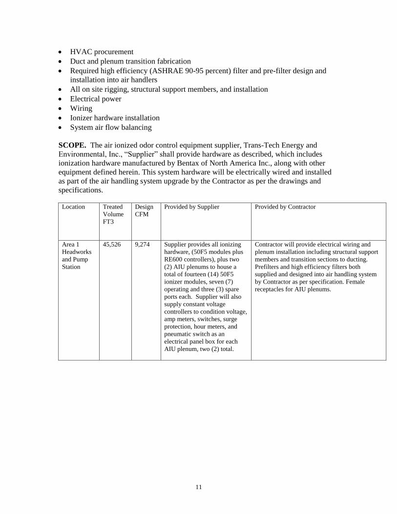
11
HVAC procurement
Duct and plenum transition fabrication
Required high efficiency (ASHRAE 90-95 percent) filter and pre-filter design and
installation into air handlers
All on site rigging, structural support members, and installation
Electrical power
Wiring
Ionizer hardware installation
System air flow balancing
SCOPE. The air ionized odor control equipment supplier, Trans-Tech Energy and
Environmental, Inc., “Supplier” shall provide hardware as described, which includes
ionization hardware manufactured by Bentax of North America Inc., along with other
equipment defined herein. This system hardware will be electrically wired and installed
as part of the air handling system upgrade by the Contractor as per the drawings and
specifications.
Location Treated
Volume
FT3
Design
CFM
Provided by Supplier Provided by Contractor
Area 1
Headworks
and Pump
Station
45,526 9,274 Supplier provides all ionizing
hardware, (50F5 modules plus
RE600 controllers), plus two
(2) AIU plenums to house a
total of fourteen (14) 50F5
ionizer modules, seven (7)
operating and three (3) spare
ports each. Supplier will also
supply constant voltage
controllers to condition voltage,
amp meters, switches, surge
protection, hour meters, and
pneumatic switch as an
electrical panel box for each
AIU plenum, two (2) total.
Contractor will provide electrical wiring and
plenum installation including structural support
members and transition sections to ducting.
Prefilters and high efficiency filters both
supplied and designed into air handling system
by Contractor as per specification. Female
receptacles for AIU plenums.

12
ITEMS INCLUDED IN CONTRACTOR SCOPE OF SUPPLY
ITEM DESCRIPTION QUANTITY
OPERATIONAL
1 AIR HANDLER MAU-1 HVAC
DESIGN AND DUCTING
1
2 SHOP DRAWINGS AS PER SPECIFICATION
3 INSTALL PLENUMS AIU-1 AND AIU-
2 DESIGN FABRICATE AND
INSTALL TRANSITION SECTIONS
TO PLENUMS
2
4 PREFILTER AND HIGH EFFICENCY
FILTER DESIGN AND
INSTALLATION FOR AIR HANDLER
MAU-1400
1
5 DESIGN AND INSTALL ALL
DUCTING, STRUCTURAL SUPPORT
MEMBERS FOR PLENUMS, ON SITE
RIGGING AND INSTALLATION
AS PER DRAWINGS AND
SPECIFICATION
6 PROVIDED DETAILED WIRING
DIAGRAMS BASED ON SUPPLIER
ELECTRICAL LAYOUTS AND
INSTALL WIRING/ELECTRICAL
POWER PANEL AND CONTROLS
AIU-1, AIU-2
AS PER DRAWINGS AND
SPECIFICATION
7 ELECTRICAL CONNECTORS
FEMALE 110 VAC FEMALE
RECEPTACLE STRIPS WIREMOLD
P/N J0B0B OR EQUIVALENT
20
8 AIR FLOW SYSTEM BALANCING 1
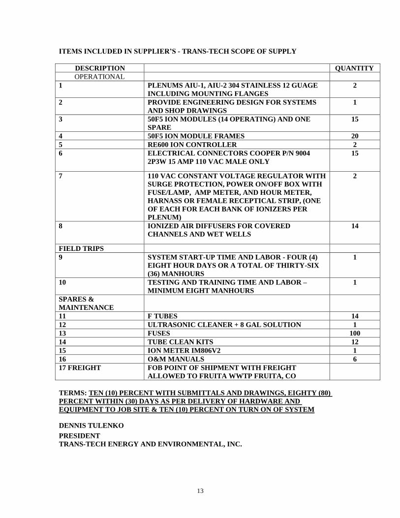
13
ITEMS INCLUDED IN SUPPLIER’S - TRANS-TECH SCOPE OF SUPPLY
DESCRIPTION QUANTITY
OPERATIONAL
1 PLENUMS AIU-1, AIU-2 304 STAINLESS 12 GUAGE
INCLUDING MOUNTING FLANGES
2
2 PROVIDE ENGINEERING DESIGN FOR SYSTEMS
AND SHOP DRAWINGS
1
3 50F5 ION MODULES (14 OPERATING) AND ONE
SPARE
15
4 50F5 ION MODULE FRAMES 20
5 RE600 ION CONTROLLER 2
6 ELECTRICAL CONNECTORS COOPER P/N 9004
2P3W 15 AMP 110 VAC MALE ONLY
15
7 110 VAC CONSTANT VOLTAGE REGULATOR WITH
SURGE PROTECTION, POWER ON/OFF BOX WITH
FUSE/LAMP, AMP METER, AND HOUR METER,
HARNASS OR FEMALE RECEPTICAL STRIP, (ONE
OF EACH FOR EACH BANK OF IONIZERS PER
PLENUM)
2
8 IONIZED AIR DIFFUSERS FOR COVERED
CHANNELS AND WET WELLS
14
FIELD TRIPS
9 SYSTEM START-UP TIME AND LABOR - FOUR (4)
EIGHT HOUR DAYS OR A TOTAL OF THIRTY-SIX
(36) MANHOURS
1
10 TESTING AND TRAINING TIME AND LABOR –
MINIMUM EIGHT MANHOURS
1
SPARES &
MAINTENANCE
11 F TUBES 14
12 ULTRASONIC CLEANER + 8 GAL SOLUTION 1
13 FUSES 100
14 TUBE CLEAN KITS 12
15 ION METER IM806V2 1
16 O&M MANUALS 6
17 FREIGHT FOB POINT OF SHIPMENT WITH FREIGHT
ALLOWED TO FRUITA WWTP FRUITA, CO
TERMS: TEN (10) PERCENT WITH SUBMITTALS AND DRAWINGS, EIGHTY (80)
PERCENT WITHIN (30) DAYS AS PER DELIVERY OF HARDWARE AND
EQUIPMENT TO JOB SITE & TEN (10) PERCENT ON TURN ON OF SYSTEM
DENNIS TULENKO
PRESIDENT
TRANS-TECH ENERGY AND ENVIRONMENTAL, INC.

14
APPENDIX I

15

16
APPENDIX II

FALCON ENVIRONMENTAL CORP. AT LONGMONT P.O. BOX 710 , FREDERICK, CO 80530
FAX (303) 833-4009 TELEPHONE (303) 833-9998
TO: Tetra Tech
ATTN: Caroline Verlander
FROM: Adam Pelican
DATE: March 17, 2016
SUBJECT: Fruita WWRF WEMCO Screw Centrifugal RAS Pump
NUMBER OF PAGES INCLUDING COVER SHEET: 10
**********************************************************************************************
Caroline,
The following is our quotation for the pump replacement of existing 40 HP WEMCO,
Model SFE5 Screw Centrifugal pump with a 20 HP WEMCO, Model SFE4 Screw
Centrifugal pump.
Item Qty. Description
1 1 WEMCO, Model SFE4-Y Horizontal Screw Centrifugal Pump with 20HP
1800 RPM Premium Efficiency Motor in the overhead opposed belt driven
orientation compatible with 3/60/460V power.
Please see the attached for the pump performance sheet, pump
construction data sheet, cut-sheets and warranty.
Total Price: $20,894 F.O.B Factory with full freight delivered to site. No taxes that may
apply are included. Price does include equipment start-up by Falcon Environmental for a
one-day trip.
Please allow 14-16 weeks for shipment of equipment after receipt of approved purchase
order and/or approval of submittal and drawings.
Notes:
1. Installation, anchor bolts, discharge piping, valves and fittings are not included. Payment terms: Net 30 days. 1.5% per month added on balances past 30 days. Seller
reserves the right to collect reasonable attorney fees and court costs in the event of non-
payment.
Thank you for this opportunity to quote products represented by Falcon Environmental.
Sincerely,
Adam J. Pelican

Page 5 of 13
Weir Specialty Pumps www.weirsp.com
Weir Specialty Pumps Quote No. 515534 16 Mar 2016 10:04 AM
Pump Performance DatasheetCustomer : FALCON SUPPLY COMPANYCustomer reference :Item number : 001Service :Quantity : 1
Quote number : 515534 Size : SFE4-Y HorizontalStages : 1Based on curve number : P25-D97Date last saved : 16 Mar 2016 10:04 AM
Operating ConditionsFlow, rated : 400 USgpmDifferential head / pressure, rated (requested) : 70.0 ftDifferential head / pressure, rated (actual) : 69.9 ftSuction pressure, rated / max : 0.00 / 0.00 psi.gNPSH available, rated : AmpleFrequency : 60 Hz
PerformanceSpeed, rated : 1575 rpmSpeed, maximum : 1800 rpmSpeed, minimum : 850 rpmEfficiency : 63.06 %NPSH required / margin required : - / 0.00 ftNs (imp. eye flow) / Nss (imp. eye flow) : N/A US UnitsMCSF : 185 USgpmHead maximum, rated speed : 104 ftHead rise to shutoff : 47.86 %Flow, best eff. point : 609 USgpmFlow ratio, rated / BEP : 65.66 %Speed ratio (rated / max) : 87.50 %Head ratio (rated speed / max speed) : 72.16 %Cq/Ch/Ce/Cn [ANSI/HI 9.6.7-2010] : 1.00 / 1.00 / 1.00 / 1.00Selection status : Acceptable
LiquidLiquid type : User definedAdditional liquid description :Solids diameter, max : 0.00 inSolids concentration, by volume : 0.00 %Temperature, max : 68.00 deg FFluid density, rated / max : 1.000 / 1.000 SGViscosity, rated : 1.00 cPVapor pressure, rated : 0.00 psi.a
MaterialMaterial selected : Standard
Pressure DataMaximum working pressure : 30.31 psi.gMaximum allowable working pressure : 60.00 psi.gMaximum allowable suction pressure : N/AHydrostatic test pressure : N/A
Driver & Power DataDriver sizing specification : Rated powerMargin over specification : 0.00 %Service factor : 1.00Power, hydraulic : 7.1 hpPower, rated : 11.2 hpPower, maximum, rated speed : 11.8 hpMinimum recommended motor rating : 15.0 hp / 11.2 kW
0
4
8
12
16
Pow
er -
hp Power
0
15
30
45
60
75
90
105
120
135
150
0
10
20
30
40
50
60
70
80
90
100
0 100 200 300 400 500 600 700 800 900 1,000 1,100 1,200 1,300
Hea
d - f
t
Effic
ienc
y - %
Flow - USgpm
1575 rpm
Efficiency
1800 rpm
850 rpm
MCSF

Page 6 of 13
Customer : FALCON SUPPLY COMPANY
Project :
Item number : 001
Service : -
Quantity of pumps : 1
Construction
Nozzle Size Rating(ANSI) Face Pos'n
Suction 6 in 125# FF Left
Discharge 4 in 125# FF Right
Impeller Type : Non-Clog
Impeller Design : Screw Centrifugal
Pump Orientation : Horizontal
Bearing Type (Rad/Thr) : Ball/Ball
Bearing Lubrication : GreaseRotation (view fromshaft-end) : CW
Materials
Casing : Cast Iron
Impeller : High Chrome
- : High Chrome (regulable)
Elastomer : Buna Wet End O-rings
Shaft : Steel
Sleeve : N/A
Baseplate, Connection and Guard
Baseplate Type : Belt Drive - Overhead Opposed
Baseplate Material : Steel
Orientation : Horizontal
Connection Type : Belt drive
Guard : Steel
Weights (Approx.)
Bareshaft pump : 359.0 lb
Baseplate : 0.00 lb
Driver : 315.0 lb
Total weight : 674.0 lb
Quote Number : 515534
Model / Size : SFE4-Y Horizontal
Stages : 1
Pump speed : 1,575
Date last saved : 16 Mar 2016 10:04 AM
Driver Information
Manufacturer : WSP Choice
Power : 20.0 hp
Service factor : 1.15
Speed : 1800
Orientation / Mounting : Horizontal/Foot
Driver type : Horizontal
Frame-size : 256T
Enclosure : TEFC, Severe Duty
Hazardous area class : N/A
Explosion rating : N/A
Volts / Phase / Hz : 460/3/60
Insulation : F
Temperature Rise : B
Motor mounted by : WSP
Seal, Gland and Piping
Seal Arrangement : Tandem
Seal Size : N/A
Manufacturer : Hidrostal
Gland Material : Stainless Steel
Seal Face Mat'l : Tungsten carbide/Silicon carbide
Throat Bushing : N/A
Seal Flush Plan : -
Seal Flush Construction : -
Weir Specialty Pumps 16.0.2.0
Construction Datasheet
Weir Specialty Pumps · 440 West 800 South · P.O. Box 209 (84110-0209) · Salt Lake City, UT 84101phone: 801 359 8731 · fax: 801 530 7828 · www.weirsp.com

Page 7 of 13

Page 8 of 13

Page 9 of 13

Page 10 of 13
1. SCOPE: acceptance upon PurchSeller sells iprovisions.
2. PRICES: federal, stamay be add
3. TERMS: and payablenotification Credit termwhich shall
Late paymeper monthwhichever regardless oand its custo
If Purchaserany moniespossession; immediatelypayments apayment fo
4. ITEMS equipment
Seller shalldescribed inshall compOccupationaand Seller hmanufactur
5. SECURITapplicable lright of repoin full. Purcencumber, In the evPurchaser’s entitled toattorney’s
GEN
Unless otherwof Purchaser’s
haser acceptingits equipment in
Prices are EXWte or local salesed to the price.
Unless otherwise in full, net‐30 of readiness s are subject tobe determined s
nts shall be char or the higheis less. Purchaof any paymenomer.
r is in default ofs of Purchaser adeclare all p
y due and payaare brought cur future shipme
INCLUDED: Edescribed in the
supply only n the order or inply with thoseal Health and Sahave identified are of the goods.
TY INTEREST: Tlaw, Seller retaossession, to thechaser will not ethe goods by anent legal actiobligations un
o recover its fees if it prev
Weir An Unin
NERAL T
ise agreed in purchase orde
g these terms n accordance wi
W. Prices do ns, use or other
se agreed, all indays from dateto ship, whicho Purchaser’s cresolely by Seller.
rged interest at st rate allowaaser shall pay tt schedule betw
f any payment Savailable to Sellayments for coable; stop all furrrent, and/or rnts.
ach sale inclue order.
those safety dn its proposal ane provisions oafety Act of 1970as specifically a.
o the extent ains a security e goods until Puencumber, nor pny liens or securon is necessander any order,court costs aails. Purchase
Page 1
EnviroTech Pu
Specialncorporated Di
TERMS a
writing, Seller’sr is conditionedand conditionsth the following
not include anytaxes and taxes
nvoices are duee of shipment orhever is earlieredit worthiness,
the rate of 1.5%ble under law,he full amount,ween Purchaser
Seller may offseter or in Seller’sompleted workrther work untirequire advance
udes only the
devices, if any,d drawings, andof the federa0 that Purchaserpplicable to the
allowable underinterest in, andrchaser has paidpermit others tority instrumentsary to enforce Seller shall beand reasonableer shall provide
1 of 3
umpsystems, I
ty Pumivision of THE W
nd CON
s d . g
y s
e r . ,
% , , r
t s k l e
e
, d l r e
r d d o . e e e e
insuraagain
6. SHSellerits redrawieffortany guarano liawhetdelive
Unlesfactorclaimshipmspecifnotifyof recshall
Unlespartiaunde
7. WAwith iis inco
8. PASellercosts by reapatenif thePurchSeller
9. SUsuspeSellerthe sreasostoragborne
nc d.b.a.
mps (SelWEIR GROUP P
DITIONS
ance for Seller’nst loss or damag
HIPMENTS ANDr all necessary inequested deliveing approvals, ts to meet the ssuch dates aranteed nor a terability to Purchaher direct or inery, regardless o
ss otherwise agry, Incoterms 2s for damage, ment directly agafied EXW, Purcy Seller of any dceipt. Purchasebe deemed as a
ss agreed otheral shipments of r the terms of th
ARRANTY: Selleits current appliorporated by ref
ATENTS: Purchar against all claand expenses tason of any infrnt or patents arie equipment haser’s detailedr.
USPENSION ORension, or delayr all reasonable suspension or onable profit. Age, disposition, e solely by Purch
GS
ler) PLC
S of SAL
’s benefit to prge until is the go
D DELIVERY: Punformation and ery schedule, inand Seller shahipment dates ire estimates orm of this agreemaser or its custondirect, for any of the severity of
greed, all shipm2010, and Purcdelay, or shortainst the carrierchaser shall insdamage or shortr agrees that faicceptance of th
rwise in the orcompleted itemhe order.
er warrants thecable Seller’s Prference here.
aser agrees thataims, demandsto which the Selringement or alleising out of perfis constructed d drawings or
R DELAY: If Pys Seller’s workand necessary delay, plus S
Additionally, all and/or resump
haser.
SD‐30 Rev. June
E
rotect Seller’s ioods are fully pa
rchaser must pinstructions regncluding any reall use its reasn the order. Hoonly and are nment. Seller shaomer for any dadelay in shipmf the delay.
ments are EXW Schaser shall matage arising fro. When shipmespect the goodtage within seveilure to so notifye goods.
rder, Seller mayms for partial pa
e goods in accoroduct warranty,
t it shall indemn, damages, peller may becomeeged infringemeformance of thisin accordance
designs submit
Purchaser requk, Purchaser shcosts incurred eller’s overheacharges and ri
ption of work s
e 2014
nterest id for.
provide garding equired sonable owever, neither all have mages,
ment or
Seller’s ake all om any ents are ds, and en days y Seller
y make ayment
ordance , which
nify the nalties, e liable ent of a s order e with tted to
uests a all pay due to ad and sks for hall be
Page 11 of 13
10. LIMITATNOTWITHSTTO THE CWHETHER REMEDY TPURPOSES, LIABILITY, INLOSS OF USCAPITAL; SUSPECIAL, COLLATERACLAIMS BY CUSTOMERSIMILAR TYor deferral exclusion ancost of capservices, doof contract downtime, threatened response tproperty anmeet othercustomers fpunitive, anlosses or characterize
SELLER’S AGCLAIMS ARISERVICES PAGREEMENNEGLIGENCSHALL NOT VALUE OF TTHE FOREGPURCHASERTHEIR ESSEN
11. CHANGobligated toof the worwriting to thschedule orto any lawrequiremenentitle Selletime of perf
Purchaser alabor, mateadjustment,approved in
12. CHANGPurchaser, Sof the good
TION OF LIABILITTANDING ANYTHCONTRARY, SELIN CONTRACT,
TO ACHIEVE ITTORT (INCLU
NDEMNITY, OR ASE, REVENUE, SAUBSTITUTE USE LIQUIDATED,
L, INCIDENTAL OPURCHASER FOS; OR ANY OPE. “Consequenof production,
nd loss of revenpital, overhead, owntime costs, or business intecosts relating trelease, remedo any hazardond equipment, contractual cofor any of the fond speculative damages of
ed.
GGREGATE LIABSING OUT OF OPROVIDED OR OT, WHETHER IN
CE), STRICT PRODEXCEED FIFTY
THE ORDER UNDGOING LIMITATIR’S REMEDIES UNNTIAL PURPOSE.
GES AND BACKCo make any chanrk unless Sellerhe details of ther other contractw, rule, regulatint which requireer to an equitabformance.
agrees not to reerials, or other , service or repn writing by an a
GES IN DESIGNSeller may modds in order to in
TY: HING ELSE IN THLLER SHALL NO, WARRANTY, TS INTENDED UDING NEGLIGANY OTHER LEGAVINGS, OR PROR PERFORMA
PUNITIVE, OR CONSEQUENOR DAMAGES OTHER LOSSES ntial Damages” , loss of produnue, profit or ancost of substituincreased cost oerruption, facilito cleanup, remdiation, or dispous material, ilosses resulting mmitments, claoregoing, and spdamages, as wany type no
BILITY TO PURCR RELATED TO GOTHERWISE RELN CONTRACT, TODUCT LIABILITY OPERCENT (50%)DER WHICH THEON SHALL APPLNDER THIS AGRE.
CHARGES: Sellnges in or additior and Purchase change and anytual modificatioion, order, codes any change ble adjustment i
eturn goods or costs incurred pair of goods uuthorized emplo
: Upon writtenify the design ancorporate impr
Page 2
HE AGREEMENTOT BE LIABLE,FAILURE OF AOR ESSENTIAL
GENCE), STRICTGAL THEORY FOROFIT; COSTS OFANCE; INDIRECT,
EXEMPLARY,NTIAL DAMAGES;OF PURCHASER'SOR COSTS OFshall mean lossct, loss of use,nticipated profit,ute products orof working, lossty, vessel, or rigoval, release orposal of or anynability to usefrom failure toims of a party’secial, incidental,well as indirecto matter how
HASER FOR ALLGOODS SOLD ORLATED TO THISORT (INCLUDINGOR OTHERWISE, OF THE TOTALE CLAIM AROSELY EVEN IF THEEEMENT FAIL OF
er shall not beons to the scoper first agree iny resulting price,ons. Any changede, standard orhereunder shalin the price and
backcharge forin modification,nless previouslyoyee of Seller.
n notification toand constructionrovements or to
2 of 3
T , A L T R F , , ; S F s , , r s g r y e o s , t w
L R S G , L . E F
e e n , e r l d
r , y
o n o
substspecifmodif
13. Dgoveralloy,part owhichorderconsidan exany gonce exportermi
14.furnisconnegoodsSeller
15. Frespodefaufailurobligacauseearth(whetriot oactiondate autholabor disturtransreasogive Forceend tMajeuperfoto the
16. interpUtah,The ContrPurchPurchsubmstate exclusconfli
titute material efied. No charfications made a
DUAL USE ITEMrnment export r Hastelloy C‐276of any order falh Seller is requir includes a dudered acceptedxport license. Fugood requiring Seller has that art license the oinated by Force
PROPRIETARY shed by Sellerection with thes and shall not br’s prior, written
FORCE MAJEURonsible to Purulted under or be or delay in ations under thied by, or resultshquake or explther war is declor other civil unrns, embargoes oof this agreemority; (g) nation
stoppages orbances; (i) sportation facilitonable control ofPurchaser notice Majeure eventhe failure or dure are minimizormance it shall e period of Force
GOVERNING Lpreted in accor, U.S.A., withouapplication of racts for the Inthaser shall comphaser irrevocablymit themselves or federal cousive jurisdictionicts arising from
GS
equal, or superrge shall be mat Seller’s option
MS: In accordanrules, items mad6 alloy, and Incoll into the categred to obtain aual use alloy, t until the U.S. gurthermore, theregulatory appapproval. If the rder will be conMajeure.
INFORMATIONr is solely fore maintenance be disclosed to an consent.
RE: Seller shrchaser, nor bbreached this afulfilling or p
is agreement if ss from, (a) acts losion; (c) warared or not), terest; (d) governor blockades in
ment; (f) action al or regional eor slowdowns shortage of aties; or (j) othef Seller (“Force ce within a reat and shall use elay and ensurzed. Should thebe extended foe Majeure and it
LAW: This rdance with thet regard to its cthe United Naternational Sale ply with all appliy and unconditito, the exclusivrts of Salt Laken and venue f or pursuant to
SD‐30 Rev. June
rior, to that orade to Purchasn.
nce with currende from Hastelloonel 718 alloy, fgory of “dual usn export licensethe order will government hase delivery schedproval shall onlgovernment densidered to hav
N: All inforr Purchaser’s and operation any third party w
hall not be liabbe deemed toagreement, for performing any such failure or dof God; (b) floor, invasion, hoerrorist threats oment order or leffect on or afby any govern
emergency; (h) or other ind
adequate power events beyoMajeure”). Selleasonable time reasonable effe the effects ofre ever be any tor a time periodts consequences
agreement she laws of the Stconflicts of lawsations Conventiof Goods is excicable laws. Selonally consent tve jurisdiction e County, Utah, for the resolutthis agreement.
e 2014
riginally ser for
nt U.S. oy C‐22 orming se,” for e. If an not be issued dule for y start nies an e been
mation use in of the
without
ble nor o have Seller's of its
delay is od, fire, stilities or acts, aw; (e) fter the mental strikes, dustrial wer or nd the er shall of the forts to f Force time of d equal s.
all be tate of s rules. ion on cluded. ler and to, and of the as the tion of .

Page 12 of 13
17. INDEMNPurchaser hliability incuclaims for pproperty, tSeller shall and settle ais conditionwarranty pproviding reclaim.
18. U.S. Purchaser awith applicasale, exporusage of thany export such goods used, expordisposed ofwith such abe a conditobligations regulations to comply wof the U.SDepartmentUnited Statexport or pultimate decountry listeCommerce restricted aTrade Con
NITY: Seller shaharmless from urred by Purchapersonal injury,o the extent chave the sole auany indemnifiedned on Purchaeriod, notifyingeasonable coop
EXPORT COMacknowledges thable export lawsrtation, transfehe goods providlicense requireshall not at anrted, sold, transf in a manner thapplicable exportion of Seller’s that compliancbe maintained with all applicabS. Commerce, ts or other agentes. Purchaser permit the re‐exestination of a ed by the Depaor the Depa
nd/or individualntrols’ Debarre
all indemnify, dany claim, cauaser as a result, death or damcaused by Selleuthority to direc claim. Seller’s aser (a) prompg Seller of any peration in the
PLIANCE: Fuhat Seller is reqs and regulationer, assignment,ded under the ements. Purchany time directly sferred, assigneat will result in rt laws and regucontinuing perce with such eat all times. Pble export laws Treasury, Statency regulating eagrees it will xport of any Serestricted and
rtment of State,artment of Trls on the Directod List and N
Page 3
efend and holdse of action ort of third party
mage to tangibleer's negligencect the defense ofindemnification
ptly, within theclaim, and (b)defense of any
urthermore, asuired to complys relating to the disposal, andorder, includingaser agrees thator indirectly be
ed, or otherwisenon‐complianceulations. It shalformance of itsxport laws andurchaser agreesand regulationse and Defensexports from thenot export, re‐eller good to and/or embargoed, Department ofreasury and/ororate of DefenseNonproliferation
3 of 3
d r y e . f n e ) y
s y e d g t e e e l s d s s e e ‐n d f r e n
SanctPersoof FoList oexporgood
To thutilizeprovisincorpto exagreepartieagentspecifregula
PURCHARMPENACOMPREGU
19. Eentiresuperrepreand isby an
tion List, Bureaon’s List, Entity Lreign Assets Coor any other U.Srt, re‐export orfor any prohibit
he extent that Pes agents or sion of the Sporate the obligport complianceements with sues. All contracts, affiliates, orfic requiremenations (including
CHASER AGREESMLESS FROM ALTIES, SANCTIOPLIANCE WITHULATIONS.
ENTIRE AGREEMe agreement rsedes anyesentations, or as not subject to n authorized offic
GS
u of Industry aList and Unverifontrol’s SpeciallyS. government lr permit the reted uses under t
Purchaser subcothird‐parties wServices to Segations of this pe into its respecuch sub‐contraccts entered intr third‐parties, nt to comply g U.S. export law
S TO INDEMNIFANY AND ALLONS AND FINESH APPLICABLE
MENT: This prbetween the y previous agreements, whmodification excer of each part
SD‐30 Rev. June
and Security’s fied List and they Designated Nalist. Nor will Cue‐export of anythe U.S. export la
ontracts its servwith respect teller, Purchaserprovision with rctive subcontraccted agents andto by Purchasemust also incwith all law
ws).
FY AND HOLD L COSTS, LIABS RELATED TOEXPORT LAWS
roposal expressparties heret
communichether oral or wxcept in writing, y.
e 2014
Denied e Office ationals stomer y Seller aws.
vices or to the r shall respect cts and d third er with clude a ws and
SELLER ILITIES, NON‐S AND
ses the o and cations, written, signed

Page 13 of 13
COVERAGworkmandesigned
WARRANproduct woccurs fir
REMEDIEperiod, Wor replacCLAIMS BARISES BCLAIM, (INCLUDILIMITATI
OWNER’discoveryfacility, o
EXCLUSIOduring mstorage, performeaccessorwarrantyproductsdamages
SELLER MWARRANPARTICUARISE FRSTATUTO
GE: WSP (Snship whend.
NTY PERIODwas placed irst.
ES: If the proWSP’s sole ocement of thBASED ON FBEFORE, DUHOWEVER ING NEGLIGONS OF LIAB
S OBLIGATIy. At Owner’or by returni
ONS: This wmaintenance;neglect, or aed outside ies not many. Seller shas. Seller shas or delays re
MAKES NO ONTIES INCLUULAR PURPOROM COURORY WARRA
Weir An Unin
L
Seller) warra operated
D: This warrinto service,
oduct fails dbligation afthe product. FAILURE OF RING, OR ADESCRIBED,GENCE), STBILITY FOUN
IONS: Owne’s expense, tng the prod
warranty doe; and defectaccident. ThSeller’s fa
nufactured all not be liaall not be esulting from
OTHER WARUDING, WITOSE, MERCHRSE OF DEAANTIES.
EnviroTech Pu
Speciancorporated Di
IMITED
ants its prounder the
ranty covers, or eighteen
due to defecter verificatiTHIS PARAGOR DEFECT AFTER THE A, IS BASED RICT LIABILND HERE OR
er shall notthe defect muct to Seller
es not applyts resulting fis warranty ctory withoby Seller aable for cosliable for am or related
RRANTIES, ETHOUT LIMHANTABILITALING OR U
umpsystems, I
lty Pumivision of THE W
D WARR
oducts to bnormal con
s a period n (18) month
ctive materiaon of the de
GRAPH PROVIN A PRODUAPPLICABLE ON CONT
LITY, OR OELSEWHERE
tify Seller omay be verifir’s factory.
y to consumfrom impropdoes not covout Seller’sre warrantests of remoany consequto defective
XPRESS OR MITATION, ATY, AND ANUSAGE OF T
nc d.b.a.
mps (WSWEIR GROUP P
RANTY
be free fromnditions for
of twelve (hs from the
als or workmefect, shall bVIDES THE EXUCT, WHETHWARRANTY
TRACT, WARTHERWISE, E IN THE TER
of a defect ed at Owne
mable itemsper installativer any expes prior auted only by oval, transpouential, spee products.
IMPLIED, AANY WARRNY IMPLIEDTRADE. SE
SP) PLC
m defects ir which the
(12) monthsdate of ship
manship witbe at its discXCLUSIVE REHER THE FAIY PERIOD ARRANTY, INAND IS S
RMS AND CO
within ten r’s site, at Se
s that are noion, operatioense for rephorization. the originaortation, or ecial, incide
AND DISCLAIRANTY OF D WARRANTELLER ALSO
GSD‐
n materialse products
s from thepment, which
hin the warcretion the rEMEDIES FOLURE OR DEAND WHETHDEMNITY, TUBJECT TOONDITIONS.
(10) days oeller’s autho
ormally repon, maintenpairs or alterEquipment l manufactureinstallationtal, or ind
MS ALL IMPFITNESS FOTY THAT CODISCLAIMS
‐31 Rev. June
s and were
date hever
ranty repair R ALL EFECT HER A TORT
O ALL
of its orized
laced ance, ration and
urer’s on of direct
PLIED OR A OULD S ALL
e 2014
1103 Mineral Springs Drive, Suite 300Port Washington, WI 53074
Phone: 262-268-1500; Fax: 262-268-1515Email: [email protected]
Low Pressure Membrane Disc Fine Bubble
Diffused Aeration Designfor
Fruita, COSelector Zones (2)
Consulting Engineer : Tetra Tech
Aquarius Project Number 5210-16
March 24, 2016

3/24/2016 Aeration Design Parameters
Aquarius Technologies Page 2
Project Information
Project Name: Fruita, CO
Aquarius Project Number: 5210-16
Tank or Process Label: Selector Zones (2)
Client Engineer Tetra Tech
Number Design Conditions: 1
Total Number Process Trains: 2
Number Passes Per Process Train: 1
Diffuser Model: Low Pressure Membrane Disc Fine Bubb
Tank Dimensions
Dim Common
Pass Number 1
Length ft 38 38Width ft 20 20
Water Depth ft 16.87 16.87Volume ft3/tank 12821.2
Surface Area ft2/tank 760Parallel Passes in each train 1
Number Taper Zones in pass 1Train Volume KCF/train 12.8212
Train Surface Area ft2/train 760Design Conditions (Given)
Condition Label Mix Air
Number Trains in Operation 1Design Safety Factor %
Diffuser submergence ft 15.87 15.87Plant Elevation ft
Plant Carbonaceous Loading lb-CBOD5/dPlant Autotrophic Loading lb-N/d
Carbonaceous Oxidation Coefficient O2/CBOD5Autotrophic Oxidation Coefficient O2/N
Carbonaceous Loading Rate lb-CBOD5/d-KCFAOR lb-O2/d
alphabeta 0.99theta 1.024
Water Temp. deg.COperating D.O. mg-O2/l
SOR lb-O2/dAir Rate SCFM 325
Design Conditions (Evaluated)
C*sc mg-O2/l 10.74Ct mg-O2/l
C20 mg-O2/l 9.14Ambient Pressure Psia 14.73
AOR/SOR

3/24/2016 Aeration System Layout
Aquarius Technologies Page 3
ITEM DimensionCommon or Total
GRID LAYOUT
Pass Number 1
Zone 1
Grid Number 1
Zone Length ft 38.00Zone Width ft 20.00
Zone Volume ft3/zone/tank 12,821Zone Surface Area ft2/zone/tank 760
Parallel Passes in Each Train 1Train Volume KCF/train 12.8212
Train Surface Area ft2/train 760Mark with "X" if unaerated
Orifice Diameter (13/64 is std.) inch 1/4
Design Fraction Avg. SOTR 100.0%Number Grids/tank/zone 2
Grid Length ft 19.0Inlet Temp deg.F 133
Compression Factor 0.755Max Drop Velocity @ 3 SCFM/disc fps 75
Required Dropleg Diameter in 4
Dropleg Velocity ft/s 41.1GRID DETAIL
Dist. Parallel with Length (L) or Width (W) of tank? W
Manifold at End (E) or Center ( C) of distributors? E
Dropleg at End (E) or Center ( C) of Manifold? E
Max Discs/dist 19Min Discs/dist 5Max Distributors/Grid 15Min Distributors/Grid 5
Design Number Discs/Distributor 8Design Number Distributors 5
Design Discs/Grid 40Design Density 4.2%
Design At/Ad 23.75Diffusers/Train 80 80
Distributor Spacing ft 3.40Disc Spacing ft 2.67

3/24/2016 Aeration Performance Table
Aquarius Technologies page 4
Dimension Common
CONDITION:
OVERALL SUMMARYTotal Number Diffusers in Plant 160
Total Number Grids in Plant 4Number Trains in Operation
Total Aerated Volume ft3Total AOR lbs-O2/plant-dAOR/SORTotal SOR lbs-O2/plant-d
Total Air Rate SCFM/plantDiffuser Air Rate SCFM/diff
SOTEMax Dropleg Pressure Psig
Est. Blower Pressure PsigEst. Blower Efficiency 0.7
Est. Blower Power BHPEst. Motor Load KW
Est. SAE lbs-O2/KWHOxygen Transfer Safety Factor 0.0%
Pass 1, Zone 1 - Grid 1
1 tank(s)/pass/train, 2 grid(s)/tank, 2 grid(s)/train, 4 grid(s) tota Sub-total Operating Volume ft3/zoneNumber Grids in Operation
Diffuser Floor Density 4.2%Number Diffusers in Operation
Diffuser Air Rate SCFM/diffSurface Mixing Rate SCFM/ft2
Sub-Total Air Rate SCFM/zoneSOTE
Sub-total SOR lbs-O2/d-zoneSOTR mg-O2/l-h
Diffuser Headloss in-waterDropleg Pressure Psig
Mix Air
112,821
2,1463254.06
26.35%7.527.82
13.410.98.2
al, 4 inch dropleg.12,821
2
804.063
32526.35%2,146111.617.57.52
Aerzen USA Corporation108 Independence WayCoatesville, PA 19320www.aerzenusa.com
Fruita WWRF Audit and Support Program
When Aerzen purchased the technology from KTurbo, it was with the intention of usingthe superior, integrated technology of the KTurbo design, and integrating it into anAerzen package design. We did not anticipate that KTurbo’s service organization wouldbe reduced to a single technician to service 186 machines in the US.
Over the years, KTurbo customers have asked Aerzen to service their machines. Sincemany of the KTurbo packages were under warranty, and many of the machines in thefield were modified from a standard factory design, Aerzen simply offered audits to pointout proper installation issues, and the potential for Aerzen to service the machines afterthe warranty expired. As these machines age, and the need of US customers continuesto mount, Aerzen has stepped up our program. This service program is designed toprovide continuous monitoring of the KTurbo machines, rapid response to issues, andultimately to replace the units with Aerzen turbo machines that will be serviced andmaintained by the Aerzen USA team.
Program Details:1. An audit will be done on the existing KTurbo machines. We will require the O&M
manuals (as built), any available layout drawings, and maintenance records, Ifthere were any operating issues, any records or documentation of root causeswill be needed, all in advance of the visit by Aerzen. Aerzen will also audit theexisting control system to determine if any changes are needed.
2. The KTurbo machines will be retrofitted with our Aerzen Remote monitoringsystem. This will provide immediate access for Aerzen to troubleshoot an issuewhen it happens. The system can be installed on all of the appropriate machines.
3. Aerzen will visit the customer site on an annual basis for a period of 5 years, toassist in maintaining the blowers, but will not be liable for any failures with thecurrent design.
4. In the event of machine failure, an Aerzen USA technician will visit the site afterremotely diagnosing the issue, and implement one of the following options:(A) Aerzen USA will replace components, if the component is a compatible
standard Aerzen component. This component and associated labor forinstallation will be charged on a time and material basis. The replacementcomponent will carry a one-year warranty. However, if there are issuesbeyond Aerzen’s control, that cause a repeat of the failure within the warrantyperiod, further replacement of the same component will also be charged.

Aerzen USA Corporation108 Independence WayCoatesville, PA 19320www.aerzenusa.com
- 2 -
(B) Aerzen will provide an entire machine replacement, at our discretion,depending on the cause of the issue, and if there is no available substitutecomponent. The entire machine replacement will only be supplied after therecommendations of blower control and surrounding installation environmentchanges are implemented.
5. At the end of the 5-year period, the customer will have a couple of potentialoptions:(A) If the original machine is still running, and the audit indicates that the KTurbo
machine is similar to the Aerzen design so that new Aerzen Turbocomponents can be used, the program can continue, or a new Aerzen Turboof comparable size to the KTurbo machine can be purchased.
(B) If the KTurbo machine was found to be a non-standard model, or if any of themajor components are obsolete or incompatible with current technology, theKTurbo machine will be replaced by a new Aerzen Turbo.
With either option, Aerzen will provide guidance on selection, installation (footprint,piping configuration), and integration into the existing control system. Note: anymodification of the control system other than software upgrades (such as air flow metersand air valves) can be provided by Aerzen USA at additional cost.
Cost of the Aerzen USA Turbo Products and Services:
Audit: $4,000.00• Includes visit and complete report• Recommendations on service viability or replacement will be included in report.
Annual Service (all four blowers): $8,500.00 (Total five-year cost: $42,500.00)• Includes anticipated consumable parts (see details below)• Replacement of any components due to failure to be billed at time and material.
Aerzen Remote Monitoring System: $3,000.00 per unit• Per blower price (to be installed on as many duty blowers as needed)• Price includes hardware and installation• Communication access to be determined by plant protocols

Aerzen USA Corporation108 Independence WayCoatesville, PA 19320www.aerzenusa.com
- 3 -
Budget Pricing for Replacement Units:
Aerzen TB 100-1.0S: $104,000.00
Replacement will be necessary if any of the following issues arise with the existingKTurbo machines:
• Catastrophic failure• Unsafe operating conditions from mechanical or electrical components and
connections within the package.• Major components without suitable Aerzen replacement (such as main motor
VFD)
Aerzen Turbo Scope of Supply• Single impeller turbo blower• Type C inlet, flange connection• Bump air foil bearings• High speed PM motor• Inverter• Sound enclosure• PM motor cooling system• Blow Off Valve and Silencer• Integrated Enclosure Air Filtration system• CPU• LCP (MICOM control, Touch Screen)• Set of necessary sensors (temp and pressure)• Cooling line backflow prevention• Aerzen Remote Monitoring unit• Customer to supply Ethernet connection (Optional cellular technology connection
available at additional cost).
Master Control Panel: $80,000.00• Budget price provided based on complete replacement of panel.• Audit will provide guidance on whether upgrade or replacement is required.• Change in programming only will significantly reduce cost.

Aerzen USA Corporation108 Independence WayCoatesville, PA 19320www.aerzenusa.com
- 4 -
Annual Service Program:• Aerzen certified technician or a factory trained representative that will perform all
annual PM maintenance tasks per the operations manual-1 trip per year. Filterreplacements at the 6 month mark to be done by the customer.• Consumable parts including fine and coarse filter replacement (2) times per
year are included.• On-site service labor is included• Travel expenses included
• 2-Year Machine Warranty on new Aerzen blower packages once installed• Transfer of remainder of service contract to new packages during 5-year life
• Annual Inspection• Free Technical Support 24x7• Consulting on Blower MCP and layout• Response time guarantee
• 24 hour remedy start
Exclusions from the Program:• Installation costs of new blower package(s)• Any pipe modifications to accommodate new blower package(s)• External control hardware or programming services and related costs• Isolation valve(s)• Process air backflow valve(s)• Installation hardware• Component replacement for existing KTurbo blowers (if available)
• Replacements will be provided by Aerzen on a time and material basis

PROPOSAL FOR THE CITY OF FRUITA EXPANSION, COQUOTE: LBGR12453/15/2016
The TrojanUV3000Plus™ is operating in over 1300 municipal wastewater plants around the world.Disinfecting over 17 billion gallons a day, the TrojanUV3000Plus™ has become
the reference standard in the industry.

Fruita Expansion LBGR12453/15/2016
- 2 -
May 12, 2016
In response to your request, we are pleased to provide the following TrojanUV3000Plus™ proposal for the FruitaExpansion project.
The TrojanUV3000PlusTM has been shown in over 1300 installations to provide dependable performance,simplified maintenance, and superior electrical efficiency. As explained in this proposal, the system incorporatesinnovative features to reduce O&M costs, including variable output electronic ballasts to provide dimmingcapability and Trojan’s revolutionary ActiClean-WWTM system – the industry’s only online chemical andmechanical quartz sleeve cleaning system. All Trojan installations are supported by a global network of certifiedService Representatives providing local service and support.
Please do not hesitate to call us if you have any questions regarding this proposal. Thank you for the opportunityto quote the TrojanUV3000Plus™ and we look forward to working with you on this project.
With best regards,
Tim Proctor
Tim Proctor3020 Gore RoadLondon, Ontario N5V 4T7Canada(519) 457 – 3400
Local Representative:Bill PerettiWACCO (Water Control Corporation)WestGold Center4380 So. Syracuse Street, Suite 450,Denver, CO 80237USA(303) 477-1970
DESIGN CRITERIAFRUITA EXPANSION
Peak Design Flow: 6.9 US_MGD
UV Transmittance: 65% (minimum)
Total Suspended Solids: 30 mg/l (30 Day Average, grab sample)
Disinfection Limit:2000 fecal coliform per 100 ml, based on a 30 day Geometric Mean ofconsecutive daily grab samples

Fruita Expansion LBGR12453/15/2016
- 3 -
DESIGN SUMMARYQUOTE: LBGR1245Based on the above design criteria, the TrojanUV3000Plus™ proposed consists of:
CHANNEL (Please reference Trojan layout drawings for details.)
Number of Channels: Existing
Approximate Channel Length Required: 14 ft
Channel Width Based on Number of UV Modules: 32 in
Channel Depth Recommended for UV Module Access: 54 in
UV MODULES
Total Number of Banks: 1 new bank + 2 additional modules
Number of Modules being Supplied: 10 (8 for new bank and 2 for existing bank)
Number of Lamps per Module: 6
Total Number of UV Lamps: 60
Maximum Power Draw: 15 kW
UV PANELS
Power Distribution Center Quantity: 1
System Control Center Quantity: Existing
MISCELLANEOUS EQUIPMENT
Level Controller Quantity: Existing to be used
Automatic Chemical / Mechanical Cleaning: Trojan ActiClean-WW™
Standard Spare Parts / Safety Equipment: Included
Other Equipment:
ELECTRICAL REQUIREMENTS
1. Each Power Distribution Center requires an electrical supply of one (1) 480 Volts, 3 phase, 4 wire (plusground), 14.8 kVA.
2. Electrical disconnects required per local code are not included in this proposal.
COMMERCIAL INFORMATION
Total Capital Cost: $130,400 (US$)
This price excludes any taxes that may be applicable and is valid for 90 days from the date of this letter.
EQUIPMENT WARRANTEES1. Trojan Technologies warrants all components of the system (excluding UV lamps) against faulty workmanship
and materials for a period of 12 months from date of start-up or 18 months after shipment, which ever comesfirst.
2. UV lamps purchased are warranted for 12,000 hours of operation or 3 years from shipment, whichever comesfirst. The warranty is pro-rated after 9,000 hours of operation. This means that if a lamp fails prior to 9,000hours of use, a new lamp is provided at no charge.
3. Electronic ballasts are warranted for 5 years, pro-rated after 1 year.


Project: Fruita Polymer Tank / Metering System Page 1 of 7 Date: 3/15/2016 Proposal #304124-A VeloDyne Budget Proposal
BUDGET PROPOSAL
Date of Proposal: 3-15-16
Proposal #: 304124
Revision: A
Proposal For: Caroline Verlander Environmental Engineer Water, Environment and Infrastructure Group TetraTech (720) 931-9375 [email protected]
Project: Fruita Polymer Feed Tank & Solution Metering System
Equipment: Polymer Feed Tank & Solution Metering System
Bid Opening: Budget
Engineer: TetraTech
Represented By: Bill Peretti Coombs Hopkins
Furnished By: Paul Plache Velocity Dynamics (VeloDyne) Boulder, CO 80301 Phone: (303) 530-3298 (ext. 202) [email protected]

Project: Fruita Polymer Tank / Metering System Page 2 of 7 Date: 3/15/2016 Proposal #304124-A VeloDyne Budget Proposal
Bid Type: Budget
Velocity Dynamics is pleased to offer the following proposal for the tank system and solution metering system(s), including options and accessories as indicated below.
One (1) model T-500 Tank System
Four (4) model MS-600P-PD1200 solution metering pump(s)
The system shall have the following design specifications: - Metering Pump Range (GPM): 1 to 10 - Secondary Dilution Water Flow Range (GPM): 2 to 20 - Power Required: 480 VAC, 3 PH, 60 Hz. - Maximum Water Required: 20 GPM @ 50 psi
Tank System(s):
Qty. Description
1 Tank System: A. Capacity (usable): 500 B. Construction: XLPE C. Configuration: Cylindrical, open top, flat bottom D. Fittings:
1. Discharge: 2”2. Overflow: 3”3. Level sensor: 1”4. Drain: 2”
E. Level sensor type: ultrasonic F. High-High tank level: float type
Solution Metering System(s):
Qty. Description
4 Solution Metering Pump System(s): A. Type: Progressive Cavity B. Construction: Stainless steel, Viton C. Shaft Seal: packing D. Capacity: 1 to 10 GPM E. Motor: 1.5 HP, 480V/3PH/60 Hz premium efficiency F. Secondary Dilution System:
1. Secondary dilution water control valve: Solenoid Valve2. Pressure gauge3. Rotameter Flow Meter Range: 2 to 20 GPM4. Rate adjusting valve5. Static mixer (sch. 40 clear PVC)
G. Solution Metering Pump Control System: 1. Enclosure: NEMA 4X (FRP)2. 480V, 3PH, 60Hz. Service3. Circuit breaker motor protection4. Numbered terminal block5. Terminal block legend6. VFD motor controller7. Line reactor8. Numbered wires9. Wire race-way10. NEMA 4X Conduit and fittings
Proposed Scope of Supply 543 S. Pierce Ave., Louisville, CO 80027 (303) 530-3298 • FAX (303) 530-3368 • www.polymersolution.com

Project: Fruita Polymer Tank / Metering System Page 3 of 7 Date: 3/15/2016 Proposal #304124-A VeloDyne Budget Proposal
H. Operator Interface – Discrete Selector Switch 1. System ON / OFF / REMOTE2. Metering Pump HAND / AUTO (AUTO = 4-20mA pacing)3. Ten-Turn Potentiometer – Metering Pump Control
I. Status / Alarm Indicators: 1. System Running Indication2. LED Display Metering Pump Rate3. VFD Fault Indication
J. Inputs (signals by others) 1. Remote Start / Stop (discrete dry contact)2. Pacing Signal Based on Process Flow (4-20mA)
K. Outputs: 1. System Running (discrete dry contact)2. Loss of Polymer Flow Alarm3. Common Alarm
L. Plumbing: Sch. 80 PVC (unless otherwise indicated) with Viton seals M. Skid: 304 stainless steel

Project: Fruita Polymer Tank / Metering System Page 4 of 7 Date: 3/15/2016 Proposal #304124-A VeloDyne Budget Proposal
Engineering & Documentation: A. Submittals for approval (electronic version in PDF & hard copies)
1. Detailed scope of supply2. Mechanical drawings (solids models in shaded isometric and wire orthogonal views)3. Mechanical component data sheets annotated for specific models, features, etc.4. Pump performance curves5. Electrical schematics with interconnecting layout6. Process & Instrumentation Drawings7. Process description8. Electrical component data sheets annotated for specific models, features, etc.9. PLC code and screen designs10. O&M Manuals for approval (electronic version in PDF & hard copies)
Factory Testing: A. VeloDyne’s standard factory testing is included. B. Certified factory test report shall be provided
Field Services: A. Number of trips: One (1) B. Number of days: Two (2) C. Certified field test report shall be provided D. Certification of proper installation E. Training plan
Clarifications & Exceptions: 1. Any changes to the above scope of supply may result in a change in price.2. Not included in this proposal: installation, chemicals, materials for interconnecting equipment unless specifically stated
above (wiring, conduit, piping & valves and supports for these materials), field painting, anchor bolts, taxes, bonds, duties.3. VeloDyne has proposed its’ standard equipment modified only to the extent to meet the project requirements as specified
and indicated in the project drawings, as interpreted by VeloDyne. If there are contradictions between project specificationsand drawings, this proposal is based on the written specifications, unless otherwise indicated.
4. This proposal is based on equipment delivery within one year of date of customer’s purchase order.
Commercial Terms: - Freight FOB Destination, Pre-Pay & Allow - Proposal Valid For: 180 Days - Payment Terms: Progress payments: Net 30 - Submittals: 4-6 weeks from date of receipt of purchase order - Shipment: 6-8 weeks from date of receipt of written approval & release for production but not to exceed 365 days from date
of purchase order.
* Note: lead times are estimates based on the current engineering and production work load at the time of bid. Actual lead times may vary based on the work loads at the time of order and or release for production – consult factory at time for order for actual lead times.
Budget Price per the Above Proposal: $67,740 (+/- 10%)

Project: Fruita Polymer Tank / Metering System Page 5 of 7 Date: 3/15/2016 Proposal #304124-A VeloDyne Budget Proposal
VELODYNE STANDARD TERMS & CONDITIONS OF SALE
All orders placed with Velocity Dynamics, Inc. d/b/a VeloDyne (the “Company” or “Seller”), if accepted, shall be accepted subject to VeloDyne Standard Terms and Conditions of Sale (“Terms and Conditions”) as set forth below and incorporated by reference into the Purchase Contract:
1. CONTRACT; OFFER AND ACCEPTANCE. These Terms and Conditions, together with the product descriptions, prices and other terms appearing on the face hereof or in a separate document submitted to you, (collectively, “our Quotation”), as such may result in a final Purchase Contract between us (all such documents collectively referred to as the “Contract”), shall constitute the only terms and conditions of our offer. If our Quotation is submitted in response to an offer made by you, whether your offer is in the form of a request for proposal or otherwise, our Quotation is expressly conditioned on your acceptance of these Terms and Conditions, which are incorporated into any offer, acceptance, response, acknowledgment, invoice, amendment and/or any other document issued by you or the Company in connection with your Order (the “Contract” or “Contract Documents”), and any reference thereto shall include these Terms and Conditions. No waiver, alteration, or modification of these Terms and Conditions shall be valid unless expressly agreed to in writing by the Company. In any event, we object to all additional or conflicting terms and conditions that may appear in your order or other form of acceptance you may submit to us in response to our Quotation. The Company shall supply to Purchaser the equipment and parts (the “Products”) in accordance with the design, manufacturing and performance specifications set forth in the Company’s Quote and incorporated in the Purchase Contract (including these Terms and Conditions). No representation, promise or warranty of any kind has been made by us except as set forth in the Contract, which conclusively supersedes all prior writings, representations and negotiations with respect thereto. The Company has no obligation to furnish other equipment, materials or services that may be shown in any plans and/or specifications except for those goods actually ordered by you for a project to which the goods ordered herein pertain. 2. PRICES. Unless otherwise noted in the Contract, prices are net Ex-Works our facility and firm for 30 days. Prices do not include: freight; permitting, licensing and/or export fees; labor charges; storage fees; or taxes. If you require the Company’s assistance for installation or set-up, we will invoice you at standard rates (please contact us for current pricing). Regarding taxes as set forth below, you will either (i) pay to the appropriate authority all applicable taxes and other government charges upon the production, sale, shipment or use of the goods and provide us with proof of payment; or (ii) provide us with a tax exemption certificate from the appropriate taxing authorities. You agree to provide us with written proof of payment of taxes (or exemption therefrom) within ninety (90) calendar days of your receipt of the goods. Time is of the essence. 3. CREDIT AND PAYMENT. Unless otherwise stated in the Contract, payment terms are net 30 days from the date of our invoice(s). Any payment outstanding beyond sixty (60) calendar days from the date of any Company invoice shall be subject to a late payment charge on the overdue balance in the amount of 1.5% per month calculated on the outstanding payment amount (or such lesser amount as is the maximum rate of interest allowed by law). Purchaser shall be responsible for all reasonable costs (including attorney’s fees) incurred by the Company while collecting any delinquent balance. For international shipments, payment terms are cash only (unless otherwise approved in writing by us). The Company may decline to deliver except for cash, or stop goods in transit, should we develop any reasonable doubt as to Purchaser’s financial responsibility. Pro-rata payments shall become due with partial shipments. If Purchaser is responsible for any delay in shipment: (a) the Company may treat the date of completion of goods as the date of shipment for purposes of invoice and payment, (b) completed goods shall be held at Purchaser’s cost and risk; and (c) Purchaser shall be responsible for reasonable storage and insurance expenses, with storage fees accruing at a rate of two percent (2%) of the Purchase Price per month or $500 per month, whichever is greater, beginning on the first day of the first calendar month following the date the equipment was scheduled to ship. If retainages are accepted by the Company, the retainage shall be based on an agreed upon percentage of the total invoice amount. Unless otherwise agreed in writing, (a) retainage will not be held for more than 180 calendar days from the date of shipment and (b) no retainage will be imposed for approval of shop drawings, O&M manuals or any other documentation.
4. DELIVERY AND ACCEPTANCE OF PRODUCTS; TRANSFER OF TITLE. (A) Products to be Used in the United States. Seller will deliver Products manufactured and to be used by Purchaser in the United States Ex-Works at our facility (“Shipping Point”) Incoterms 2010, or in such other manner as may be mutually agreed to by us and set forth in separate Shipping Terms under the Contract. On all shipments marked “Ex-Works (or EXW) Shipping Point,” the Company shall make the Products available to Purchaser at the Company’s facility, which shall constitute delivery, and Purchaser shall bear all costs and risks of moving the Products from our facility to Purchaser’s destination. Any claim for loss or damages in transit must be entered with the freight carrier and prosecuted by you. (B) Products to be Used Outside of the United States. Seller will deliver all Products to be used by Purchaser outside of the United States “FAS (Free Alongside Ship) Named Port of Shipment” (“Shipping Point”) Incoterms 2010, which means the Company will deliver the Products to the designated port, origin point or designated freight forwarder, with Purchaser bearing all costs and risk of loss or damage from the origin point to Purchaser’s destination point outside of the United States. Purchaser shall be responsible for payment of all sales and use taxes, or to recover such taxes through appropriate procedures and documentation under applicable law. (C) Shipping. Goods will be boxed or crated as Seller may deem proper for protection against normal handling, and extra charge will be made for preservation, waterproofing or similar added protection of goods. Routing and manner of shipment will be at Seller’s discretion, and may be insured at Purchaser’s expense, value to be stated at order price. (D) Delivery, Shipment & Installation Dates. Delivery, shipment and installation dates are estimates only, not guarantees, and unless otherwise specified, are calculated from the date of Seller’s receipt of complete technical data and approved drawings as such may be necessary to fulfill the Contract. In estimating such dates, no allowance has been made, nor shall we be liable directly or indirectly, for delays of third-party vendors, carriers or delays from labor difficulties, shortages, strikes or stoppages of any sort, fires, accidents, failure or delay in obtaining materials or manufacturing facilities, acts of government affecting us directly or indirectly, bad weather, or any cause beyond our control or causes designated as Acts of God or forced by any court of law, and the estimated delivery date shall be extended accordingly without penalty to the Company. We will not be liable for any damages or penalties whatsoever, whether direct, indirect, special or consequential, liquidated or otherwise, resulting from our failure to perform or delay in performing. Overtime and other expenses incurred to hasten delivery at Purchaser’s request shall be added to the quoted prices and charged to and paid for by Purchaser. Shipment of goods ready for delivery can be deferred beyond the date for delivery on with Seller’s written consent. (E) Delivery Terms. Seller’s obligation to deliver the goods shall be fulfilled when we have delivered the same in good condition to a carrier at the designated Shipping Point. Unless otherwise specified in the Contract, Purchaser shall be charged with and pay for the costs of all transportation, freight, insurance, loading, packaging and handling charges, taxes, duties, fees, storage, and all other charges applicable to the goods. Purchaser shall not be responsible for any taxes based on Seller’s income. (F) Title / Security. Title to the goods shall be retained by Seller as a vendor’s lien until such goods are paid for in full by the Purchaser, even though risk of loss shall be borne by Purchaser as set forth in paragraphs 4(A) and (B) respectively. Purchaser herby grants to Seller, and Seller hereby reserves, a purchase money security interest in and to the goods sold to Purchaser, together with all proceeds thereof, to secure Purchaser’s payment and performance. Purchaser agrees upon Seller’s request to do all acts and execute all documents reasonably necessary to assist Purchaser’s perfection and maintenance of any such security title and right of possession including, but not limited to, executing and filing documents with the appropriate governmental agency. (G) Cancellation and Returned Equipment. Orders may be canceled or amended only with our written consent, and must be returned within

Project: Fruita Polymer Tank / Metering System Page 6 of 7 Date: 3/15/2016 Proposal #304124-A VeloDyne Budget Proposal
30 days of Seller’s written authorization at Purchaser’s cost. If Purchaser returns the goods in the manner required under the previous sentence, and if the returned goods are (i) in substantially the same condition that existed on the date the Seller delivered the Products to you, undamaged; and (ii) not more than 12 months after the original Invoice date; the returned goods will, subject to the applicable handling charge, be accepted by the Seller for return. Used or discontinued goods or parts or equipment specially manufactured will not be accepted for credit unless specifically agreed to by the Seller in our sole discretion. Purchaser’s sole remedy for returns will be a credit for the purchase price less any handling charges. Returned goods are subject to a minimum of 20% restocking and handling charge. Returns found to be free of material and workmanship defects will be held for 30 days and if Purchaser does not provide the Seller with repair or return instructions, then we will scrap or resell the goods. Purchaser will be charged for placing returned goods in saleable condition, any sales expenses then incurred by us, plus a restocking charge and any out-going and in-coming transportation costs which the Company pays. (H) Acceptance by Purchaser. Purchaser shall conduct any incoming inspection tests on delivered Products within 10 days of delivery, and if delivery is made in multiple shipments, then Purchaser shall conduct incoming inspections of Products within 10 days of receipt of each delivery. In the event of a shortage, damage or discrepancy in any shipment, Purchaser shall promptly give notice to Seller in writing (at such address designated by Seller for such purpose) but in no event later than 30 days of the subject delivery, detailing the exact nature of the shortage, damage or discrepancy and provide such supporting documentation as Seller shall deem necessary and appropriate (i.e., photos, insurance reports, etc.). If such evidence indicates, in Seller’s reasonable judgment, that such shortage, damage or discrepancy existed at the time of delivery of the goods to the carrier, Seller will promptly deliver additional or substitute goods to Purchaser; provided, however, that Seller may, in its sole and absolute discretion, require Purchaser to return all damaged goods to the Company prior to delivery of substitute goods. If Purchaser shall fail to timely give Seller such written notice, the goods shall be deemed to conform to the requirements of the Contract, and Purchaser shall be deemed to have accepted the goods and shall pay for the goods in accordance therewith. (I) Purchaser’s Specifications. Purchaser shall be solely responsible for ensuring that all specifications, drawings, information, advice, recommendations or requests provided to the Company by Purchaser or any of its agents are accurate and suitable for Purchaser’s purposes. The Company’s examination or consideration of any such specifications, drawings, information, advice, recommendations or requests shall not result in any liability on the part of the Company. 5. TERMINATION. The Company shall have the right to cancel for default hereunder all or any part of Purchaser’s Order. This right of cancellation is in addition to and not in lieu of any other remedies that the Company may have in law or equity. 6. TAXES & IMPORT- EXPORT CHARGES. (A) Purchaser’s Responsibility for Taxes, Reports and Withholding. Seller shall be responsible for reporting and paying all state and federal income taxes associated with sales of equipment and products to Purchaser under this Contract. However, Purchaser shall be responsible for all liabilities or claims for taxes that any taxing authority having jurisdiction over this Contract may assess or levy relating to the Products or this Contract. Purchaser shall comply with all applicable tax requirements, file all registrations (including all Transaction and Sales Tax registrations) and reports, and take all actions necessary to make its tax payments (or secure exemptions from or reductions in payments of same). Within 90 days from the date of any payment by Purchaser under Seller’s Invoice, Purchaser shall provide Seller with tax receipts (or other proof of payment or written evidence of tax exemption) for all taxes to be paid by Purchaser under this Contract. (B) Import and Export Charges. Purchaser shall be solely responsible for all import and export charges, licenses, permits ad any other lawfully payable charge related to the import or export of Products under this Contract. (C) Export Controls & Related Regulations. Purchaser represents and warrants that it is not designated on, or associated with, any party
designated on any of the U.S. government restricted parties lists, including without limitation, the U.S. Commerce Department Bureau of Industry and Security (“BIS”) Denied Persons List; Entity List or Unverified List; the U.S. Treasury Department Office of Foreign Assets Control (“OFAC”) Specially Designated Nationals and Blocked Persons List; or the U.S. State Department Directorate of Defense Trade Controls (“DDTC”) Debarred Parties List. Purchaser shall comply with all applicable U.S. economic sanctions and export control laws and regulations, including without limitation, the regulations administered by the OFAC, the Export Administration Regulations administered by BIS, and the International Traffic in Arms Regulations administered by DDTC. Seller may terminate this Contract and discontinue any ongoing supply to or business with Purchaser immediately, without notice and without liability, upon Seller becoming aware that Purchaser is named on any restricted party list. 7. WARRANTY; LIMITED REMEDIES. (A) Seller Warranties. Seller shall provide the standard warranties provided in the form Warranty Agreement (a copy of which is attached and incorporated by reference into our Contract). (B) Assignment. Seller assigns to Purchaser all warranties given by manufacturers and vendors of Seller as such relate to the Products (equipment or components). These warranties are not exclusive. (C) Limitation on Damages. Other than as set forth in Paragraph 9 (Purchaser Indemnification) and any breaches of Paragraph 11 below (Confidentiality), each party’s cumulative liability for damages to the other party for any cause whatsoever, and regardless of the form of action, whether in contract or in tort, including but not limited to, negligence, shall be limited to the total Contract price of the goods sold hereunder, plus or minus, as applicable, the amounts of all unpaid accounts payable and receivable between the parties. In no event shall Seller’s liability exceed the limits of the Company’s insurance coverage. 8. SOLE REMEDY. The sole and exclusive remedy for breach of any non-warranty obligation of the Company and the sole remedy for the Company’s liability of any kind (including negligence) with respect to the goods and services provided to Purchaser shall be to use all commercially reasonable efforts to promptly cure such breach. Purchaser must prosecute any claim for a cause of action arising hereunder with one year from the date on which the facts that gave rise to the cause of action first occurred subject to the terms set forth in Section 14 (Governing Law and Resolution of Disputes). 9. INDEMNIFICATION. Purchaser shall hold harmless, indemnify and defend the Company (at the Company’s request) for any and all damages, liabilities, costs and expenses (including the costs of any dispute resolution, including but not limited to, attorneys’ fees and any other costs and expenses), fines, or losses in connection with any threatened or actual claims, actions, demands, investigations, suits, including but not limited to, claims or suits by third parties, arising out of any of the following: (a) Purchaser’s negligent or willful acts, or those of its employees and/or agents, (b) such goods being repaired or altered by persons other than Seller (unless expressly authorized in writing by the Seller), (c) any claim of patent infringement arising out of the manufacture by Seller of goods created in accordance with a design or specifications furnished to Seller by Purchaser, (d) in the event that Purchaser modifies, or combines with any non-Seller goods, any of the goods purchased from Seller, and such modification or combination results in the actual or alleged infringement of any intellectual property rights of any third party, (e) from goods produced by Seller according to Purchaser’s specifications, (f) any violations of export control laws by Purchaser, (g) any violations of state or federal tax laws by Purchaser, or (h) Purchaser’s breach of any provisions of these Terms and Conditions. 10. SELLER’S INTELLECTUAL PROPERTY INDEMNIFICATION. Seller will defend, indemnify and hold harmless Purchaser from and against any and all loss, damage, cost or expense arising as a result of any claim that the goods sold hereunder infringe any third party U.S. patent, copyright, trademark, trade secret or intellectual property right. Otherwise, Seller will not be liable for any claim of infringement. If you notify us promptly of any such claim of infringement and, if we so request, authorize us to defend or settle any suit or controversy involving such claim, we will indemnify you against the reasonable expenses of any such suit and will satisfy any judgment or settlement in which we acquiesce, but only to an amount not exceeding the price

Project: Fruita Polymer Tank / Metering System Page 7 of 7 Date: 3/15/2016 Proposal #304124-A VeloDyne Budget Proposal
paid for the allegedly infringing goods. If an injunction is issued against the further use of allegedly infringing goods, the Company shall have the option of procuring for you the right to use the goods, or replacing them with non-infringing goods, or modifying them so that they become non-infringing or of removing them and refunding the purchase price. The foregoing states the Company’s entire and exclusive liability with respect to a claim of infringement, and we will not be liable for any damages whatsoever suffered by reason of any infringement claimed, except as provided herein. 11.CONFIDENTIALITY.“Confidential Information” means any of theCompany’s business information, specifications and all related writings, drawings, designs, software applications and similar works or any other information disclosed by the Company that are disclosed as “Confidential” or proprietary. All Confidential Information shall be the exclusive property of the Company and we retain all right, title and interest in and to the same. Purchaser agrees to use Confidential Information for the exclusive purpose of performance under the Contract and not to disclose or provide any Confidential Information to any third party and to take all necessary measures to prevent any such disclosure by its employees, agents, contractors or consultants. Upon request of the Company or completion of the Contract, Purchaser shall return all Confidential Information to the Company and provide certification of such return. 12. TOOLING; SPECIAL JIGS, FIXTURES & PATTERNS. Chargesmade for tools, jigs, fixtures, patterns and equipment made or acquired by the Company in connection with your Order and utilized in manufacturing will be considered the exclusive property of the Company, without credit to Purchaser. 13. INSPECTION, RECORDS, AUDITS & PROPRIETARY DATA.Inspection of goods in our facility by Purchaser and/or its representative will be permitted, provided that (a) Purchaser gives reasonable written notice of its desire to inspect the goods, and (b) the inspection does not unduly interfere with the Company’s production work flow. Neither Purchaser nor any of Purchaser’s representatives shall have any right to examine or audit the Company’s cost accounts, books or records of any kind, or be entitled to, or have control over, any engineering or production prints, drawings or technical data which the Company, in our sole discretion, may consider in whole or in part to be proprietary to our business. 14. GOVERNING LAW & DISPUTE RESOLUTION.(A) Governing Law. The Contract and these Terms and Conditions are governed by and interpreted under the laws of the State of Colorado, without regard to its choice of law rules unless the matters in dispute come within the scope of Article 2 of the Uniform Commercial Code (UCC-Sales) prepared under the joint sponsorship of The
American Law Institute and the National Conference of Commissioners on Uniform State Laws, in which event the dispute shall be governed by and interpreted under the referenced Code in effect on the date of this Contract. (B) Dispute Resolution. Except for any action where the sole relief sought is an injunction, any controversy or claim arising out of or relating to the Contract and these Terms and Conditions, or the making, performance or interpretation hereof, and the dispute cannot be settled by direct negotiations, either Party may initiate mediation. If the parties fail to settle the dispute within 30 days of notice of mediation, either party may initiate binding arbitration under this paragraph. The place of arbitration shall be in the Boulder-Denver Metro-Area of Colorado, and shall be conducted by one arbitrator in accordance with the Commercial Arbitration Rules of the American Arbitration Association. Judgment upon any binding arbitration award may be entered in any court having jurisdiction thereof. 15. GENERAL PROVISIONS.(A) Prior Agreements. This Contract comprises the complete and exclusive agreement between the parties regarding the subject matter of this Contract, and supersedes all oral and written communications, negotiations, representations or agreements made or entered into before the Effective Date. (B) Amendments. No amendment to this Contract is effective unless made in writing and signed by authorized representatives of Purchaser and Seller. Specifications, drawings, price lists and documents of a technical nature prepared by Seller and submitted to Purchaser to describe the equipment and parts being purchased hereunder automatically become part of this Contract. (C) Survival. All provisions set forth herein regarding warranty, confidential information, indemnification, liability and limits thereon, and any other provisions that survive on their terms including all provisions relating to tax, import / export, inspection, dispute resolution and governing laws, and all causes of action which arose prior to completion or termination of this Contract shall survive indefinitely until, by their respective terms, they are no longer operative. (D) Conflicts. If a conflict exists between these Terms and Conditions and any other writings connected with this Contract, these Terms and Conditions shall prevail with respect to such conflict. In the event that any provisions of these Terms and Conditions is held to be illegal, invalid or unenforceable under the present or future law, rule or regulation, such provision shall be deemed stricken from these Terms and Conditions, but such illegality, invalidity or unenforceability shall not invalidate any of the other provisions of these Terms and Conditions.

67.00
8
9
10
11
A
A
1
3
3
42
SECTION A-A
5
66
7
NOTES -
1) MATERIAL IS CROSS-LINKED POLYETHYLENE
2) 515 TOTAL GALLONS, 475 GALLONS BETWEEN BOTTOM OF SIPHON ANDOVERFLOW
3) ALWAYS USE CONNECTIONS THAT ALLOW FOR EXPANSION ANDCONTRACTION OF XLPE TANK.
4) APPROXIMATE DRY WEIGHT IS 175 LBS
ITEM # NUMBER DESCRIPTION QTY
1 236-0354 TANK, 515 GAL X-LINK POLY 1
2 194-0100 BULKHEAD FITTING, 1/2" FNPT - 1/2 FNPT, PVC 1
3 194-0003 BULKHEAD FITTING, 2" FNPT - 2" FNPT, PVC 3
4 194-0002 BULKHEAD FITTING, 1.5" FNPT - 1.5" FNPT, PVC 1
5 194-0115 ELBOW, 90, 1 1/2" TXT, PVC 1
6 194-0672 ELBOW, 90, 2", TXT, SCH80, PVC 2
7 182-0493 SWITCH, LEVEL, FLOAT, 1/2" MNPT, 316 SS 1
8 194-0001 BULKHEAD FITTING, 1" FNPT - 1" FNPT, PVC 1
9 182-0126 CABLE, IFM, M12 RIGHT ANGLE, 5M, 4 WIRE, DC 1
10 182-0344 SENSOR, LEVEL, PRESSURE, 0-105 IN H2O, IFM 1
11 182-0348 ADAPTER, LEVEL SENSOR, 1" MNPT, IFM 1
REVISIONSREV ECO DESCRIPTION DATE APPROVEDA SO 2031 INITIAL RELEASE 8/26/14 A FUSS
D
C
B
AA
B
C
D
CAD GENERATED DRAWING, INTERPRETDRAWING PER ANSI Y14.5M - 1994
SCALE
SIZE
CAD FILE:
TANK ASSEMBLY, 500 GAL W/ BULK HEAD FITTINGS DWG. NO.
BSHEET OF
REV.
DATEAPPROVALSMODELED
DRAWN
PROJECT MGR
PURCHASING MGR
QUAL ENG
UNLESS OTHERWISE SPECIFIEDDIMENSIONS ARE IN INCHESTOLERANCES:DECIMALS ANGLES.XX = .015 1.XXX = .005
MATERIAL
FILENAME
DO NOT SCALE DRAWING
12345678
8 7 6 5 4 3 2 1THE INFORMATION CONTAINED IN THIS DRAWING IS THE SOLE PROPERTY OFVELOCITY DYNAMICS, INC. ANY REPRODUCTION IN PART OR WHOLE WITHOUT THEWRITTEN PERMISSION OF VELOCITY DYNAMICS, INC IS PROHIBITED
236-0727 A+1:20
A FUSS
A FUSS
C HEUSEL
D RICARDO
8/26/2014
8/26/2014
8/26/2014
8/26/2014
1 2
FILLET RADII TO BE .005 MAXIMUMBREAK ALL EDGES .005/.010
63MINIMUM
236-0727
NOTE: DRAWINGS ARE FOR GENERAL INFORMATION ONLY. SEE THE PROPOSED SCOPE OF SUPPLY FOR DETAILED INFORMATION ON PROPOSED EQUIPMENT.
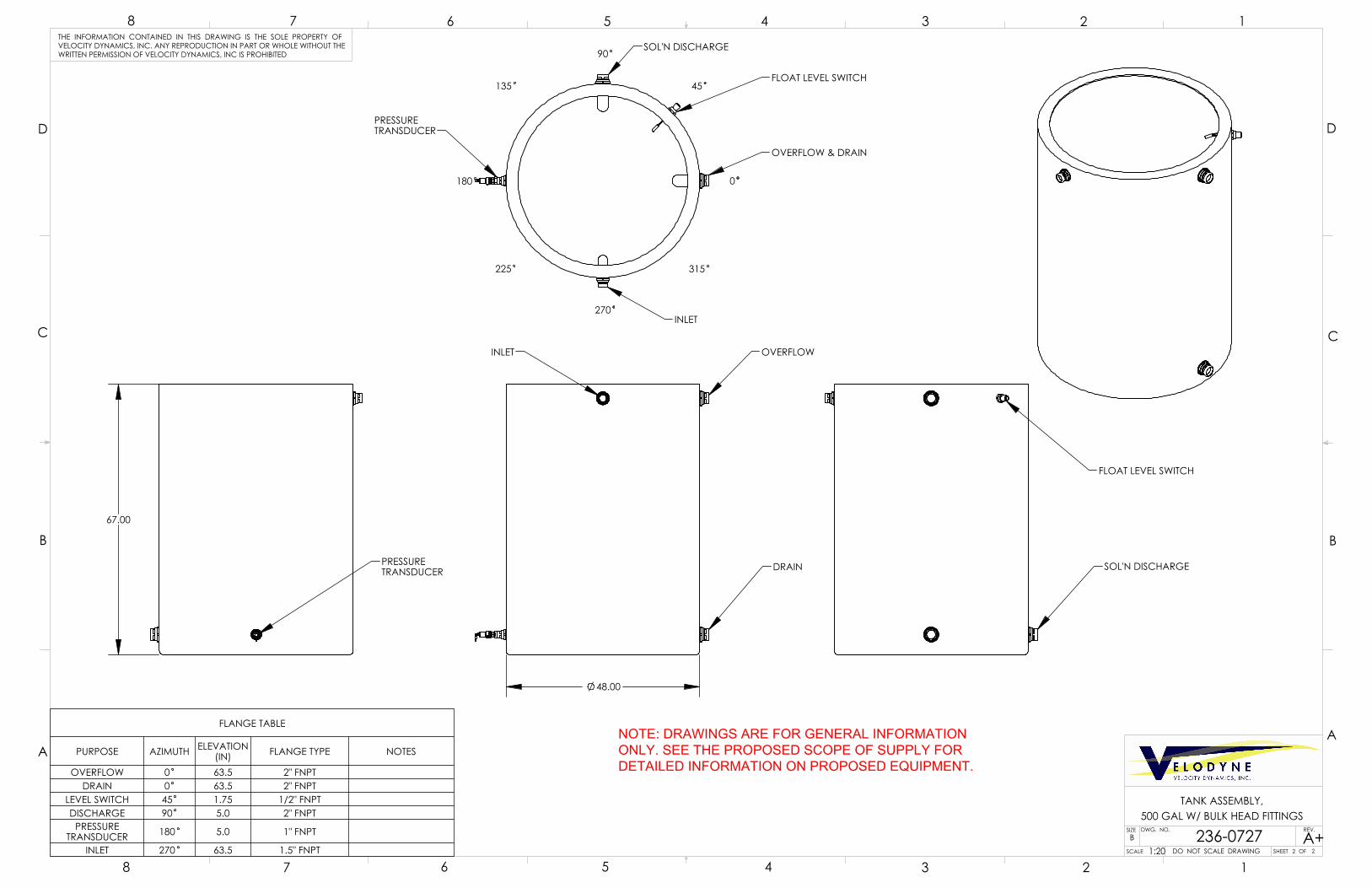
48.00
INLET OVERFLOW
DRAIN
67.00
PRESSURETRANSDUCER SOL'N DISCHARGE
FLOAT LEVEL SWITCH
PRESSURETRANSDUCER
OVERFLOW & DRAIN
INLET
SOL'N DISCHARGE
0
45
90
135
225
270
315
FLOAT LEVEL SWITCH
180
FLANGE TABLE
PURPOSE AZIMUTH ELEVATION(IN) FLANGE TYPE NOTES
OVERFLOW 0 63.5 2" FNPTDRAIN 0 63.5 2" FNPT
LEVEL SWITCH 45 1.75 1/2" FNPTDISCHARGE 90 5.0 2" FNPT
PRESSURE TRANSDUCER 180 5.0 1" FNPT
INLET 270 63.5 1.5" FNPT
D
C
B
AA
B
C
D
SCALE
SIZE DWG. NO.B
SHEET OF
REV.
TANK ASSEMBLY,
DO NOT SCALE DRAWING
12345678
8 7 6 5 4 3 2 1THE INFORMATION CONTAINED IN THIS DRAWING IS THE SOLE PROPERTY OFVELOCITY DYNAMICS, INC. ANY REPRODUCTION IN PART OR WHOLE WITHOUT THEWRITTEN PERMISSION OF VELOCITY DYNAMICS, INC IS PROHIBITED
236-0727 A+1:20 2 2
500 GAL W/ BULK HEAD FITTINGS
NOTE: DRAWINGS ARE FOR GENERAL INFORMATION ONLY. SEE THE PROPOSED SCOPE OF SUPPLY FOR DETAILED INFORMATION ON PROPOSED EQUIPMENT.
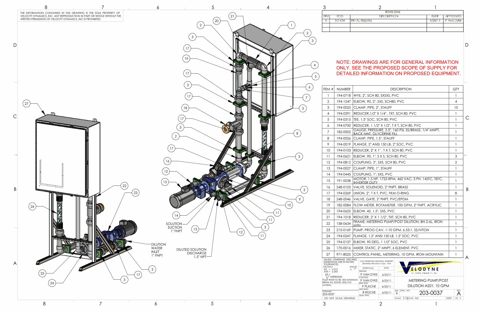
26
27
22
253
DILUTIONWATERINLET1" FNPT
173
24
23
15
3
DILUTED SOLUTIONDISCHARGE
1.5" NPT
SOLUTIONSUCTION
1" FNPT
3
2
17
19
17
3
17
18
17
2
17
16
14
12
1
2
3
3
3
3
312
11
11
10
11
9
5
6
7
8
13
2021
4
ITEM # NUMBER DESCRIPTION QTY
1 194-0718 WYE, 2", SCH 80, SXSXS, PVC 1
2 194-1247 ELBOW, 90, 2", SXS, SCH80, PVC 4
3 194-0025 CLAMP, PIPE, 2", STAUFF 10
4 194-0291 REDUCER,1/2" X 1/4" , TXT, SCH 80, PVC 1
5 194-0315 TEE, 1.5" SOC, SCH 80, PVC 1
6 194-0700 REDUCER, 1 1/2" X 1/2", T X T, SCH 80, PVC 1
7 182-0002 GAUGE, PRESSURE, 2.5", 160 PSI, SS/BRASS, 1/4" MNPT,BACK MNT, GLYCERINE FILL 1
8 194-0026 CLAMP, PIPE, 1.5", STAUFF 1
9 194-0019 FLANGE, 2" ANSI 150 LB, 2" SOC, PVC 1
10 194-0103 REDUCER, 2" X 1" , T X T, SCH 80, PVC 1
11 194-0621 ELBOW, 90, 1", S X S, SCH 80, PVC 3
12 194-0812 COUPLING, 2", SXS, SCH 80, PVC 2
13 194-0027 CLAMP, PIPE, 1", STAUFF 1
14 194-0445 COUPLING, 1", SXS, PVC 1
15 191-0038 MOTOR, 1.5 HP, 1725 RPM, 460 VAC, 3 PH, 145TC, TEFC,INVERTER DUTY 1
16 248-0103 VALVE, SOLENOID, 2" FNPT, BRASS 1
17 194-0269 UNION, 2", T X T, PVC, FKM O-RING 8
18 248-0046 VALVE, GATE, 2" FNPT, PVC/EPDM 1
19 182-0084 FLOW METER, ROTAMETER, 100 GPM, 2" FNPT, ACRYLIC 1
20 194-0625 ELBOW, 45, 1.5", SXS, PVC 1
21 194-1018 REDUCER, 2" X 1 1/2", TXT, SCH 80, PVC 1
22 158-0634 FRAME, METERING PUMP/POST DILUTION, BN 2-6L, IRONMTN 1
23 215-0169 PUMP, PROG CAV, 1-10 GPM, 6.53:1, SS/VITON 1
24 194-0247 FLANGE, 1.5" ANSI 150 LB, 1.5" SOC, PVC 1
25 194-0137 ELBOW, 90 DEG, 1 1/2" SOC, PVC 1
26 170-0016 MIXER, STATIC, 2" MNPT, 6 ELEMENT, PVC 1
27 971-8025 CONTROL PANEL, METERING, 10 GPM, IRON MOUNTAIN 1
D
C
B
AA
B
C
D
CAD GENERATED DRAWING, INTERPRETDRAWING PER ANSI Y14.5M - 1994
SCALE
SIZE
CAD FILE:
DWG. NO.B
SHEET OF
REV.
METERING PUMP/POST
DATEAPPROVALSDRAWN
CHECKED
RESP ENG
MFG ENG
QUAL ENG
UNLESS OTHERWISE SPECIFIEDDIMENSIONS ARE IN INCHESTOLERANCES:DECIMALS ANGLES.XX = .015 1.XXX = .005
MATERIAL
FILENAME
DO NOT SCALE DRAWING
12345678
8 7 6 5 4 3 2 1THE INFORMATION CONTAINED IN THIS DRAWING IS THE SOLE PROPERTY OFVELOCITY DYNAMICS, INC. ANY REPRODUCTION IN PART OR WHOLE WITHOUT THEWRITTEN PERMISSION OF VELOCITY DYNAMICS, INC IS PROHIBITED
203-0037 A1:16
P VAN DYKE
P VAN DYKE
P PLACHE
R ROCHE
6/23/11
6/23/11
6/23/11
6/23/11
1 2
FILLET RADII TO BE .005 MAXIMUMBREAK ALL EDGES .005/.010
63MINIMUM
DILUTION ASSY, 10 GPM
203-0037
NOTE: DRAWINGS ARE FOR GENERAL INFORMATION ONLY. SEE THE PROPOSED SCOPE OF SUPPLY FOR DETAILED INFORMATION ON PROPOSED EQUIPMENT.

55.31
69.26
71.63
2X 48.5
2X 24.5
50.0
26.0
4X .563 THRU
4.25
3.33
2X 3.33
4.000
9.161
2.642
D
C
B
AA
B
C
D
SCALE
SIZE DWG. NO.B
SHEET OF
REV.
METERING PUMP/POST
DO NOT SCALE DRAWING
12345678
8 7 6 5 4 3 2 1THE INFORMATION CONTAINED IN THIS DRAWING IS THE SOLE PROPERTY OFVELOCITY DYNAMICS, INC. ANY REPRODUCTION IN PART OR WHOLE WITHOUT THEWRITTEN PERMISSION OF VELOCITY DYNAMICS, INC IS PROHIBITED
203-0037 A1:20 2 2
DILUTION ASSY, 10 GPM
NOTE: DRAWINGS ARE FOR GENERAL INFORMATION ONLY. SEE THE PROPOSED SCOPE OF SUPPLY FOR DETAILED INFORMATION ON PROPOSED EQUIPMENT.
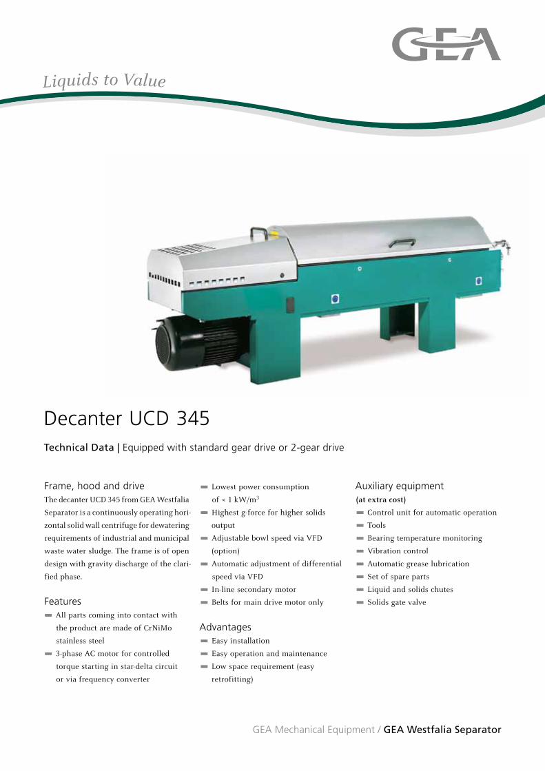
Frame, hood and driveThe decanter UCD 345 from GEA Westfalia
Separator is a continuously operating hori-
zontal solid wall centrifuge for dewatering
requirements of industrial and municipal
waste water sludge. The frame is of open
design with gravity discharge of the clari-
fied phase.
Features All parts coming into contact with
the product are made of CrNiMo
stainless steel
3-phase AC motor for controlled
torque starting in star-delta circuit
or via frequency converter
Lowest power consumption
of < 1 kW/m3
Highest g-force for higher solids
output
Adjustable bowl speed via VFD
(option)
Automatic adjustment of differential
speed via VFD
In-line secondary motor
Belts for main drive motor only
Advantages Easy installation
Easy operation and maintenance
Low space requirement (easy
retrofitting)
Auxiliary equipment(at extra cost)
Control unit for automatic operation
Tools
Bearing temperature monitoring
Vibration control
Automatic grease lubrication
Set of spare parts
Liquid and solids chutes
Solids gate valve
Liquids to Value
GEA Mechanical Equipment / GEA Westfalia Separator
Decanter UCD 345 Technical Data | Equipped with standard gear drive or 2-gear drive

Operating principles and constructional features
Technical Data UCD 345
The comparative capacity refers to various decanters from GEA Westfalia Separator and is below the max. throughput capacity. The effective capacity depends on the extent to which the inflowing mixture can be clarified, the level of solids contained in the feed, the dry matter content required in the discharged solids and the level of solids permissible in the clarified liquid. In general, the machine can be adjusted to take account of the above requirements.
21 3 4 5 6 7 8 9 10 11
1220 19 18 17 16 15 14 13
Operating principles and constructional features
ApplicationDewatering of municipal and
industrial waste water sludge
Dimensions in mm
Min. lifting capacity of trolley hoist for service and maintenance: 500 kg.
1 Secondary drive motor
2 Clutch
3 Scroll drive
4 Bowl drive
5 Bowl bearings
6 Bowl
7 Scroll
8 Housing
9 Separation chamber
10 Regulating ring
11 Feed
12 Feed tube
13 Bowl bearings
14 Gravity discharge of the
clarified liquid
15 Scroll bearings
16 Distributor
17 Solids discharge
18 Primary gear
19 Secondary gear
20 Primary drive motor
Components Standard Option
Bowl and scroll Stainless steel CrNiMo —
Liquid outlet Free Centripetal pump
Flight hard-facing Tungsten carbide Sintered tungsten carbide tiles
Solids outlet ports Exchangeable —
Seals, inner bearings NBR (Perbunan) P.T.F.E. / Viton
Drive 2-gear drive Fixed differential speed
Solids discharge — Slide valve
Solids chute — Upon request
Liquid chute — Upon request
Technical data
Bowl
Diameter 340 mm
L / D ratio 4.0
Speed max. 4500 rpm
g-force, (z) max. 3850 g
Comparative capacity 26,000 l / h
Bowl drive
Rating 18,5 kW
Speed at 50 Hz 3000 rpm
Speed at 60 Hz 3600 rpm
Scroll drive
Rating at 50 Hz 2,2 kW
Shipping data
Decanter weight 1875 kg
Case dimensions 3100 x850 x 1550 mm
Shipping weight gross 2150 kg
2 830
≥
≥
1470
1000
500
500
≥1.500
1.400
600
Werner-Habig-Straße 1 · 59302 Oelde (Germany) Phone +49 2522 77-0 · Fax +49 2522 77-2950 [email protected] · www.westfalia-separator.com
GEA Mechanical Equipment
GEA Westfalia Separator
The
info
rmat
ion
cont
aine
d in
thi
s br
ochu
re m
erel
y se
rves
as
a no
n-bi
ndin
g de
scrip
tion
of o
ur p
rodu
cts
and
is w
ithou
t gu
aran
tee.
Bin
ding
info
rmat
ion,
in p
artic
ular
rel
atin
g to
cap
acity
dat
a an
d su
itabi
lity
for
spec
ific
appl
icat
ions
, can
onl
y be
pro
vide
d w
ithin
the
fra
mew
ork
of c
oncr
ete
in
quiri
es. W
estf
alia
® a
nd W
estf
alia
Sep
arat
or® a
re r
egis
tere
d tr
adem
arks
of
GEA
Wes
tfal
ia S
epar
ator
Gm
bH. P
rinte
d on
chl
orin
e-fr
ee b
leac
hed
pape
r · P
rinte
d in
Ger
man
y · S
ubje
ct t
o m
odifi
catio
n · w
ww
.kab
utz.
de
9997
-116
3-01
0/12
08 E
N


QUOTATION: N~ []BRDWn~Bear CQrp.,P.O. Box 29, Corning, IA 50841 (515)322-4220Fax; (515) 322-3527 Website; www.brownbearcorp.com
NEW AREA CODE 641
Name & Address City of Fruita
325 East A.spen A.ve.
Fruita, Co. 81521Caroline [email protected]
970 858 9558
Date: 3-10-16Price List Ref. No.
16-1-1
One (1) new Brown Bear Model R31-10 with paddle aerator (less hydraulic tilt valve and cylinder), 79a backshield-moldboard box type construction, bolt on replaceable paddles with replaceable bolt onpaddle extensions, 1 x 4" skid blade and reversible crummer blade. Includes hoses and flat facecouplers to mount to the Cat 2720 XHP skid steer or Cat 2970 XHP or 2990 XHP compact trackloader.
$54,193.00
1,200.00
$55,393.00
Prices are F.O.B. Corning, Iowa, U.S. funds and subject to change without notice. Purchaser's order is accepted subject toBBC's price and terms & conditions in effect at time of shipment.
The warrant, terms & provisions on the reverse side are a part of this quotation. Brown Bear Corporation (BBC) makesno other represel itations or warranties, express or implied (AND EXPRESSLY DISCLAIMS THE IMPLIED WARRANTIESOF MERCHANTABILITY AND FITNESS) and has no other obligations to the purchaser except as provided on thereverse side hereof.
This equipment covered by warranty:
o A - New Equipment Limited Warranty & Parts & Laboro B - "Approved Equipment" Vendor Product Warranty
White - CUSTOMER COpy Canary - BBC'S COpy

BROWN BEAR CORPORATIONP.O. Box 29
Corning, Iowa 50841515-322-4220
The Srown Bear Corvoration, hereinafter referred to as "BBC', makes the following warranty to theoriginal puJdlase<, hefejrlafter referred to as "Purchaser", 01 new sac equipment Equipmentused less than 200 hours fO( demonstration is "new" fO( this purpose. BefO(e any warranty isallowed, SSC reserves the right to insist that any part or equipment be first retumed to SSC withtransportation prepaid by Purchaser for examination. Under these conditions Srown Bear.Corporation warrants new parts and equipment to Purchaser from the delivery date shown on the"Delivery Acknowiedgment and Registration".
SSC warrants equipment tt manufactures for 180 days 0( 1000 hoursafter delivery, whichever occurs first, but not to exceed sixconsecutive mOfrlhs from equipment delivery date, to be free fromdefects in material and worl<manship which, under normal use and&elVice, impairs the equipmenrs proper functioning. SSCs liabilityshall, at its option, be limned to: .
Repair or replace the defective part without charge forparts 0( installation labor or.lssue credn fO( the amount SSC paid for the palt
Replacement or repair parts installed in the equipment covered by this
warranty are warranted only for the remainder of any warranty as dsuch parts were original components of said equipment Replaced
parts fumished 0( installed by SBC Of rts authorized representative arewarranted from equipment delivery date Under Section 1.
SSC warranty shall not apply to component parts or accessories ofproducts not manufactured by SSC and which carry the warranty ofthe manufacturer thereof. tf a component part manufacturer's
warranty exceeds the SSC warranty the only Obligation SSC assumesis to attempt to obtain that componenrs warranty for the purchaser.
Any urlauthorized altering Q( tampering with the equipmenrs selVicehour recorder completely voids any BSC warranty. In addition, thefollowing is excluded from warranty.
Normal maintenance and service. See Section 9.Equipment Q( products which have been subject tomisuse, negligence, accident. unauthorized repair, or
substitution 01 parts not approved by SBC, or alterationor use of the equipment for a purpose for which the
equipment was not designed.
SSC warranty will not apply when failure is due to adefect in pians Q( specifications supplied to SBC by oron beha~ of the Purchaser.SSC warranty will not apply to damages that are theresutt of operator or maintenance negligence, for
example, failure to acknoWledge waming lights, warningbuzzers, and instrument readings, or operation after
dis=very 01 delectNe 0( worn parts.SSC warranty will not apply to products or parts used 0(
operated in submeryed applicabon.
SSC will repair, replace or refund the purchase price (as provided inSection 1) of new equipmen~ which at the time of delivery to thePurchaser, was deficient. or not in conformity 'N'ith the 'Mitten "Retail
Purchase Orde(', provided that the Purchaser giver SSC written noticeby mail 01 such deficiency, or deviation within 10 days followingreceipt at goods. THIS SHAU SE PURCHASER'S SOLE ANDEXCLUSIVE REMEDY for defICient Q( non-<:<:>nformingequipment attime of delrvery.
In no event shall BSC be liable fO( labor costs (except as provided inSection 1) expanded on such goods or consequential damages.
The provisions of this warranty are BBes sole obligation and exclude
all other warranties of rnef1:hantability andlO( fitness fO( a particularpurpose lNhether expressed or imphed or of equipment's conformance
to Suyers specifications. BBC EXPRESSLY DISClAIMS ANYIMPLIED WARRANTIES OF MERCHANTABILITY AND FITNESS.BBC further disclaims any responsibility whatsoever to the PUrchaser,or to any other person, for injury of person(s) or damage to or loss ofproperty or value caused by any product which has been subject tomisuse, negligence, accident, or misapplied, or modified or repaired
by unauthorized person(s), or improperty installed. BSC SHALL NOT
SE LIABLE TO PURCHASER OR ANY OTHER PERSON FOR LOSSOR DAMAGE DIRECTLY OR INDIRECTLY ARISING FROM THE USEOF THE EQUIPMENT OR FROM ANY OTHER CAUSE. In no event
will BBC be liable for incidental or consequential damages or injuriesincluding but not limtted to loss of profrts, rental of substitute equipmentor other commercial loss.
To secure warranty selVice the Purchaser shall make all arrangementsfor selVice and make the equipment available to BSC or it's authorizedDislJibutO( at its place of business. The Purchaser will pay waitingcharges at the current Labor rate if the machine is not CIV3ilable for
se1VK::ewhen arranged. When v..-oc1<. is not done at Brown Bear
Corporation Of at the business establishment 01 the DistribUtor,Purchaser must provide reasonable (d requested, sheltered) worl<ingconditions and a suitable place to perform warranty service. When twomen are required to perform warranty service, the Purchaser shall
~ake a man available to assist or, in the attemative, if BBe or the
Distributor provides the extra man, the Purchaser shall pay all additionalcharges. Purchaser shall pay for straight labor, any premium forovertime labor, and charges fO( making selVice calls which include, butare not limned to: tolls, mileage, meals, lodging and labor to and fromthe equipment The following conditions, payments, terms andlimnations must be additionally understood and agreed to by Purchaserto secure warranty service.
(a) On products manufactured by SSC and those componentswhich SSC or irs authorized DistributQ( is authorized toservice, for example, hydrostatic pumps, warranty service
will be performed by SSC or its Distributor.(b) All costs for parts and labor will be first charged to and
paid by the Purchaser. Parts must be returned,transportation prepaid, forinspection by SBC or the component manufacturer, if saidparts are warranted by SSC, BBC will credit the Purchaserthrough it's authorized Distributor, as appropriate underthe terms of Section 1.
(c) In some cases, for example in Canada, it may be
advantageous in BBC's opinion, for a warranty claim to be
processed by someone other than SSC or itsrepresentative. In these cases, for Purchaser to prevent
vo;ding this warranty, prior written authorization for cJaim
processing must be obtained from SBC. The Purchasershall be responsible fOf all costs incurred when thewarranty claim is processed. On determination cd thewarranty and upon receipt cd procd at parts and, dapplicable, labor performed to satisfy the claim, SSC will,at its option, reimburse the Purchaser for the lesser of :
SSC's cost of parts and labor or, the actual amount spentby the Purchaser.
(d) When BSC or irs authorized Distributor is not authorizedto service or repair a component, for example engines or
tires, it is the Purchasers complete responsibility to seek.
redress under the componenfs warranty. All charges
incurred shall be the responsibility of the Purchaser.
SSC shall have no obligation under this warranty unless the Distributorand the Purchaser have properly completed, dated and retumed therequired forms, which are, but not limited to, the "Retail Purchase
Orda(", the "Delivery Acknowiedgment and Registration", the 1nitialDelivery Inspection Report" and the "Ninety (90) Day Inspection Report'".
This warranty does not cover depreciation or damage caused by normalwear and tear, accident. lack of improper maintenance, improper
protection or storage or improper use.
The cost and replacement of selVice items as, for example, fihers,belts, brake linings, hydraulic fluid, 0 rings, wearing or cutting parts,tires, tubes, batteries, grease, lights and cab glass are the responsibilityof the Purchaser.
Normal maintenance inciudes, but is not limited to: tightening loose
bolts and nuts, tightening hoses and adapters, tire repair, clutch, brake
and cable adjustments.
(a) A property completed "Retail Purchase Orde(', a(b) Registration receipt, and a(c) Delivery receipt showing the date cd delivery.
No offtcer or employee ot BSC, or selling Distributor is authorized to
make any oral representations or warranty of merchantability or fitness
or to waive any of the foregoing terms and none shall be binding on
SBC.

R31 Compost aerator for High Flow Skid and Compact Track
Loaders
Universal skid loader hitch and flat face hydraulic couplers standard
Remote hydraulic units require minimum 30 GPM flow at 3000PSI, maximum 50 GPM at
5500PSI
Hydraulic 10 degree side to side tilt standard
Saw tooth paddle rotor with replaceable wear plates
Piston drive motor with planetary gear reduction into 120 roller chain final drive
Ability to stack windrows side by side
Skid loader mounted unit is very maneuverable
Right hand discharge
8’ or 10’ width’s available
3400 lbs.
Low Maintenance and big power in a compact unit
Brown Bear Corporation
P O Box 29
Corning, IA 50841
Ph# 641-322-4220
www.brownbearcorp.com
BIOREM Env ironmental Inc .100 Rawson Road, su ite 230 , V ic tor, NY 14564 Te leph one: (585 ) 92 4-22 20 ● Fax : ( 585) 924 - 8280 ● Em ai l : i n fo @bior em.b i z ● www. b iore m.b i z
May 2, 2016 To: Caroline Verlander Environmental Engineer Water, Environment and Infrastructure Group Tetra Tech 1576 Sherman St., Denver, CO 80203 RE: Fruita WWRF Caroline, Biorem Technologies, in association with our local representative, The Water Technology Group, is pleased to offer the following budgetary proposal for the above referenced project. Please contact Charles Greaves of WTG or myself if you have any questions regarding this proposal. We look forward to working together on this project and also look forward to meeting you next week. Sincerely,
Dean Parker Sales Manager BIOREM Technologies Inc. 585-455-0129 [email protected]

Modular Biofilter (BF) BUDGET PROPOSAL
#16-4028 Fruita WWRF
BIOREM® Group of Companies www.biorem.biz Page 1 of 5
1.0 Product Description The biofilter systems extract foul air for subsequent preconditioning in the humidification stage and oxidation through the Biosorbens® media bed prior to atmospheric discharge.
Odorous compounds in the air entering the biofilter are solubilized into the moisture layer surrounding the individual media particles or are adsorbed directly to their surface. Bacteria present within this moisture film utilize the compounds as substrate. The compounds are biologically oxidized to CO2, H2O and inorganic salts and clean air is discharged to atmosphere. It is critical that the filter creates an optimal environment to enhance microbial development. Maintaining proper air temperature, pH, moisture and nutrient levels are essential for favorable biofilter performance and removal efficiency
2.0 Project Details Process Parameter Value Flow Rate: 4,150 CFM Given Inlet Air Temperature: 40 - 100 oF Assumed Average Inlet H2S: 30 ppm Given Peak Inlet H2S: 50 ppm Assumed Design Parameter Value Model of Modular Biofilter: BF 36 Material of Construction: FRP Biofilter EBRT: 30 seconds Media Volume: 2,075 ft3 Vessel Dimensions: 40 ft length : 10 ft width : 9 ft height Water Consumption: 155 GPD Electrical - Main Power supply: 480V, 3Ph, 60Hz Empty Vessel Weight: (each vessel) 20,000 lbs Operational Weight: (each vessel) 180,000 lbs 3.0 System Performance
A. When loaded under average conditions the biofiltration system will achieve at least 99 percent removal of H2S when operating within the process parameters shown above.
B. When loaded under average conditions the biofilter system shall provide at least 90 percent odor removal for inlet concentration levels between 15,000 and 6,000 OU. For inlet concentration levels less than 6,000 OU, the outlet concentration levels shall be less than 600 OU. (Odor concentrations to be determined using ASTM-E679 with a 20 liter/minute odor panel presentation rate).

Modular Biofilter (BF) BUDGET PROPOSAL
#16-4028 Fruita WWRF
BIOREM® Group of Companies www.biorem.biz Page 2 of 5
4.0 Warranties
A. The Manufacturer warrants that the biofilter media will not compact, degrade or decompose for a period of 10 years from the date of Substantial Completion, provided that the system is operated in accordance with the Manufacturer’s printed Operation and Maintenance Manuals.
B. All mechanical components will be warranted free of manufacturing defects for a period of 12 months from Substantial Completion, or 18 months from shipment, whichever occurs first.
5.0 Scope of Supply
1. (1) Modular biofilter vessel with integral humidification chamber and removable covers. Material of construction to be 304 SS.
2. Humidification mass transfer packing, provided in boxes approximately 10 cubic feet in size.
3. Engineered biofilter media, provided in loose bulk.
4. (1) Rectangular flexible transition piece between fan and vessel inlet flange, 304 SS flange.
5. (1) 3 HP recirculation pump, Make/Model: Grundfos CRN.
6. Schedule 80 PVC manifold and spray nozzles for optimized coverage of humidification media.
7. Schedule 80 PVC manifold and spray nozzles for optimized coverage of biofilter media.
8. (1) 10 HP centrifugal FRP exhaust fan rated at 8” WC, TEFC, Class 1, Division 2 motor.
9. Control Panel:
i. NEMA 4X 304 stainless steel enclosure with pedestal legs.
ii. Door mounted fused disconnect.
iii. System ON pilot light.
iv. Motor starter and Hand/Off/Auto selector switch for exhaust fan.
v. Motor starter and Hand/Off/Auto selector switch for recirculation pump.
vi. Status lights (on when running) for fan and recirculation pump.
vii. Recirculation low flow alarm light.
viii. Alarm reset push button.
ix. Dry contacts for transmitting signals to remote location.
10. (1) Water panel housing the following instrumentation and fluid control valves:
i. (1) Pressure indicator on water supply line.
ii. (1) Temperature indicator in water recirculation line.
iii. (1) Flow indicator/switch, to display recirculated water flow rate, signal alarm and shut off recirculation pump in case of reduced water flow.

Modular Biofilter (BF) BUDGET PROPOSAL
#16-4028 Fruita WWRF
BIOREM® Group of Companies www.biorem.biz Page 3 of 5
iv. (1) Flow totalizing indicator, to display the amount of irrigation water delivered to the biofilter media.
v. (1) Flow indicator to display blow down water flow rate.
vi. (1) Lot fluid control valves and strainers.
11. Instrumentation and fluid control valves external to water panel:
i. (2) Differential pressure gauges to measure pressure drop across medias (local read).
ii. (1) Inlet air temperature indicator (local read).
iii. (2) Pressure indicators (water), on inlet and outlet sides of the recirculation pump.
iv. (1) Lot fluid control valves and strainers.
12. Winterization system: (All heaters come complete with thermostat for temperature control)
i. (1) 10 kW immersion heater for humidification sump.
ii. (1) Space heater for control panel.
iii. (1) Space heater for water panel.
13. Engineering Submittal Packages.
14. Operation and Maintenance Manuals.
15. Field Services will consist of two (2) consecutive days (1 trip) for system commissioning and operator training.
Note: System equipment proposed is designed for a NFPA 820 2012 Type C ventilation environment.

Modular Biofilter (BF) BUDGET PROPOSAL
#16-4028 Fruita WWRF
BIOREM® Group of Companies www.biorem.biz Page 4 of 5
The following items listed are to be supplied by the Contractor and are not in the Manufacturer’s Scope of Supply.
1. Provide all equipment offloading, temporary storage and placement.
2. Provide labor, materials and equipment for the installation and assembly of all Biorem supplied equipment and instrumentation. Supply and install all other materials or equipment required for a complete operational system.
3. Site preparation and clearing of materials.
4. Design and supply an appropriately sized reinforced concrete slab to handle full load of the biofilter vessel, fan, control panel, and water panel. Provide collection and analysis of any geo-technical data as required.
5. Supply and install all required protective coatings or paint such as UV paint for piping or concrete paint.
6. Supply and install all external water piping and drain piping to and from the biofilter vessel, water panel and other fluid equipment including heat tracing, insulation, piping supports, drainage traps where necessary and / or UV protective paint. If winterizing system, contractor to insulate differential pressure gauge enclosures.
7. Supply and install air ductwork to and from the biofilter system including exhaust stack, flexible connectors, interconnecting ducting, manual or actuated dampers, filters, insulation and piping supports, unless otherwise indicated above.
8. Supply and install all hardware, supports, guide wires, duct gaskets, expansion joints and connectors needed for a complete and operational system.
9. Supply make-up water at a minimum pressure of 40 psi. Water analysis for hardness or other parameters as necessary.
10. Provide main electrical service and system field wiring outside the main odor control panel. All electrical requirements for heat tracing and equipment not specifically provide by Biorem to be provided by others.
11. Media onsite storage and installation. The Contractor shall be required to remove biofilter covers, install and distribute media evenly across the biofilter, assemble media irrigation system and reinstall covers.
12. Provide duct balancing, and system functional, hydrostatic, vibration and performance testing to be conducted by OTHERS as may be specified.

Modular Biofilter (BF) BUDGET PROPOSAL
#16-4028 Fruita WWRF
BIOREM® Group of Companies www.biorem.biz Page 5 of 5
BUDGET QUOTATION May 2, 2016
QUOTATION #: 16-4028 Budget Price (US$)
01
BF 36 Modular Biofilter (Please refer to Section 5.0 for Scope of Supply) $312,000
01 Freight INCLUDED
01 Commissioning and Training INCLUDED NOTES: 1. All components are FOB jobsite. 2. Payment Terms: 10% upon approvals, 80% upon equipment delivery, 10% upon system commissioning. 3. Applicable taxes are extra. 4. Prices are guaranteed for 90 days, from date of quotation. 5. Submittals typically provided 4-6 weeks after acknowledgment of order and with confirmation of Biorem’s Project Manager.
Shipment is 12-14 weeks after approved submittals. TERMS & CONDITIONS PRICING Unless otherwise specified in writing by BIOREM® Technologies Inc, (BIOREM®) price does not include any taxes, excises, duties, tariffs or other governmental charges which BIOREM® may be required to pay or collect under existing or future law with respect to the sale, transportation, delivery, storage, installation or use of any of the equipment sold by BIOREM®. CANCELLATION Unless otherwise agreed in writing by the parties, the Buyer may not cancel the Order, except upon written notice and payment to Seller of an amount covering all costs incurred under the Order, all costs which arose out of the cancellation, and a cancellation fee of 50% of the Order Price. Materials received and Goods manufactured in part or whole under the Order prior to the time of cancellation shall be retained by and shall be property of the seller. When calculating the cancellation related costs, payments made by buyer to seller prior to cancellation shall be taken into account. LIMITATION OF LIABILITY –SELLER’S LIABILITY TO THE PRICE ALLOCABLE TO THE GOODS DETERMINED DEFECTIVE, AND IN NO EVENT WILL SELLER’S CUMULATIVE LIABILITY BE IN EXCESS OF THE TOTAL SALES ORDER PRICE, WHETHER ARISING UNDER WARRANTY, CONTRACT, NEGLIGENCE, STRICT LIABILITY, INDEMNIFICATION, OR ANY OTHER CAUSE OR COMBINATION OF CAUSES WHATSOEVER. SELLER WILL NOT BE LIABLE FOR ANY SPECIAL, INDIRECT, INCIDENTAL, OR CONSEQUENTIAL DAMAGES OR INDEMNIFICATION, OR ANY OTHER CAUSE OR COMBINATION OF CAUSES WHATSOEVER. THIS LIMITATION SHALL APPLY NOTWITHSTANDING ANY FAILURE OF ESSENTIAL PURPOSE OF ANY LIMITED REMEDY. BUYER’S REMEDIES ARE SPECIFICALLY LIMITED TO THE REPAIR OR REPLACEMENT OF THE GOODS AND IS EXCLUSIVE OF ALL OTHER REMEDIES. SHOULD THESE REMEDIES BE FOUND INADEQUATE OR TO HAVE FAILED THEIR ESSENTIAL PURPOSE FOR ANY REASON WHATSOEVER, BUYER AGREES THAT RETURN OF THE FULL SALES ORDER PRICE TO IT BY SELLER SHALL PREVENT REMEDIES FROM FAILING THEIR ESSENTIAL PURPOSE AND SHALL BE CONSIDERED BY BUYER AS A FAIR AND ADEQUATE REMEDY.

Concrete Biofilter Budget Proposal
#16-4028 - Fruita WWRF
BIOREM® Group of Companies www.biorem.biz Page 1 of 5
1.0 Product Description The biofilter system extracts foul air for subsequent preconditioning in the humidification stage and oxidation through the Biosorbens media bed prior to atmospheric discharge.
Odorous compounds in the air entering the biofilter are solubilized into the moisture layer surrounding the individual media particles or are adsorbed directly to their surface. Bacteria present within this moisture film utilize the compounds as substrate. The compounds are biologically oxidized to CO2, H2O and inorganic salts and clean air is discharged to atmosphere. It is critical that the biofilter creates an optimal environment to enhance microbial development. Maintaining proper air temperature, pH, moisture and nutrient levels are essential for favorable biofilter performance and removal efficiency.
2.0 Project Details Process Parameter Value Flow Rate: 4,150 CFM Given Inlet Air Temperature: 40 - 100 oF Assumed Average Inlet H2S: 30 ppm Given Peak Inlet H2S: 50 ppm Assumed Design Parameter Value Material of Construction: Concrete Configuration: (1) cells, up-flow, negative pressure Biofilter EBRT: 30 seconds Media Volume: 2,075 ft3 Footprint Dimensions: 15 ft length : 25 ft width (approx.) Water Consumption: 155 GPD Electrical - Main Power supply: 480V, 3Ph, 60Hz *Concrete Volume (estimate): 52 yrd3 *Concrete not in Biorem’s scope of supply, to be provided and installed by contractor. 3.0 System Performance
A. When loaded under average conditions the biofiltration system will achieve at least 99 percent removal of H2S when operating within the process parameters shown above.
B. When loaded under average conditions the biofilter system shall provide at least 90 percent odor removal for inlet concentration levels between 6,000 and 15,000 OU. For inlet concentration levels less than 6,000 OU, the outlet concentration levels shall be less than 600 OU. Odor concentrations to be determined using ASTM-E679 with a 20 litre/minute odor panel presentation rate.

Concrete Biofilter Budget Proposal
#16-4028 - Fruita WWRF
BIOREM® Group of Companies www.biorem.biz Page 2 of 5
4.0 Warranties
A. The Manufacturer warrants that the biofilter media will not compact, degrade or decompose for a period of 10 years from the date of Substantial Completion, provided that the system is operated in accordance with the Manufacturer’s printed Operation and Maintenance Manuals.
B. All mechanical components will be warranted free of manufacturing defects for a period of 12 months from Substantial Completion, or 18 months from shipment, whichever occurs first.
5.0 Scope of Supply
1. Engineered Biosorbens biofilter media, supplied in loose bulk.
2. 345 ft2 biofilter media support flooring, FRP grating and support beams.
3. (1) 3 HP recirculation pump, Make/Model: Grundfos CRN
4. Schedule 80 PVC manifold and spray nozzles for optimized coverage of humidifier packing media.
5. Schedule 80 PVC manifold and spray nozzles for optimized coverage of biofilter media bed.
6. (1) 10 HP centrifugal FRP exhaust fan rated at 8” WC, TEFC, Class 1, Division 2 motor.
7. Control Panel:
i. NEMA 4X 304 stainless steel enclosure with pedestal legs.
ii. Door mounted fused disconnect.
iii. System ON pilot light.
iv. Hand/Off/Auto selector switch for exhaust fan.
v. Motor starter and Hand/Off/Auto selector switch for recirculation pump.
vi. Status lights (on when running) for fan and recirculation pump.
vii. Recirculation low flow alarm light.
viii. Alarm reset push button.
ix. Dry contacts for transmitting signals to remote location.
8. (1) Water panel housing the following instrumentation and fluid control valves:
i. (1) Pressure indicator on water supply line.
ii. (1) Temperature indicator in water recirculation line.
iii. (1) Flow indicator/switch, to display recirculated water flow rate, signal alarm and shut off recirculation pump in case of reduced water flow.
iv. (1) Flow indicator to display blow down water flow rate.
v. (1) Flow totalizer, to display biofilter irrigation volume.
vi. (1) Lot fluid control valves and strainers.

Concrete Biofilter Budget Proposal
#16-4028 - Fruita WWRF
BIOREM® Group of Companies www.biorem.biz Page 3 of 5
9. Instrumentation and fluid control valves external to water panel:
i. (1) Differential pressure gauge to measure pressure drop across biofilter media.
ii. (1) Inlet air temperature indicator (local read).
iii. (1) Pressure indicator (water), on outlet side of recirculation pump.
iv. (1) Lot fluid control valves and strainers.
10. Winterization system: (All heaters come complete with thermostat for temperature control)
i. (1) 10 kW immersion heater for humidier sump.
ii. (1) Space heater for control panel.
iii. (1) Space heater for water panel.
11. Engineering Submittal Packages.
12. Operation and Maintenance Manuals.
13. Field Services will consist of two (2) consecutive days (1 trip) for system commissioning and operator training.
14. Performance testing will consist of two (2) consecutive days (1 trip) for system measurements including H2S as well as taking four (4) air samples for odor panel analysis.
Note: System equipment proposed is designed for a NFPA 820 2012 Type C ventilation environment.

Concrete Biofilter Budget Proposal
#16-4028 - Fruita WWRF
BIOREM® Group of Companies www.biorem.biz Page 4 of 5
The following items listed are to be supplied by the Contractor and are not in the Manufacturer’s Scope of Supply.
1. Provide all equipment offloading, temporary storage and placement.
2. Provide labor, materials and equipment for the installation and assembly of all Biorem supplied equipment and instrumentation. Supply and install all other materials or equipment required for a complete operational system.
3. Site preparation and clearing of materials.
4. Design and supply an appropriately sized concrete basin as per design criteria. Provide collection and analysis of any geo-technical data as required.
5. Supply and install all required protective coatings or paint such as UV paint for piping or concrete paint.
6. Supply and install all external water piping and drain piping to and from the odor control vessel, water panel and other fluid equipment including heat tracing, insulation, piping supports, drainage traps where necessary and / or UV protective paint. If winterizing system, contractor to insulate and heat-trace differential pressure gauge enclosures and associated piping.
7. Supply and install air ductwork to and from the odour control system including exhaust stack, flexible connectors, interconnecting ducting, manual or actuated dampers, filters, insulation and piping supports, unless otherwise indicated above.
8. Supply and install all hardware, supports, guide wires, duct gaskets, expansion joints and connectors needed for a complete and operational system.
9. Supply make-up water at a minimum pressure of 40 psi. Water analysis for hardness or other parameters as necessary.
10. Provide main electrical service and system field wiring outside the main odor control panel. All electrical requirements for heat tracing and equipment not specifically provide by Biorem to be provided by others.
11. Provide duct balancing, and system functional, hydrostatic, vibration and performance testing to be conducted by OTHERS as may be specified.

Concrete Biofilter Budget Proposal
#16-4028 - Fruita WWRF
BIOREM® Group of Companies www.biorem.biz Page 5 of 5
BUDGET QUOTATION May 2, 2016
QUOTATION #: 16-4028 Concrete vessel Budget Price (US$)
01
Concrete biofilter odor control system (Please refer to Section 5.0 for Scope of Supply) $227,000
01 Freight INCLUDED
01 Commissioning and Training INCLUDED NOTES: 1. All components are FOB jobsite. 2. Payment Terms: 10% upon approvals, 80% upon equipment delivery, 10% upon system commissioning. 3. Applicable taxes are extra. 4. Prices are guaranteed for 90 days, from date of quotation. 5. Submittals typically provided 4-6 weeks after acknowledgment of order and with confirmation of Biorem’s Project Manager.
Shipment is 12-14 weeks after approved submittals. TERMS & CONDITIONS PRICING Unless otherwise specified in writing by BIOREM® Technologies Inc, (BIOREM®) price does not include any taxes, excises, duties, tariffs or other governmental charges which BIOREM® may be required to pay or collect under existing or future law with respect to the sale, transportation, delivery, storage, installation or use of any of the equipment sold by BIOREM®. CANCELLATION Unless otherwise agreed in writing by the parties, the Buyer may not cancel the Order, except upon written notice and payment to Seller of an amount covering all costs incurred under the Order, all costs which arose out of the cancellation, and a cancellation fee of 50% of the Order Price. Materials received and Goods manufactured in part or whole under the Order prior to the time of cancellation shall be retained by and shall be property of the seller. When calculating the cancellation related costs, payments made by buyer to seller prior to cancellation shall be taken into account. LIMITATION OF LIABILITY –SELLER’S LIABILITY TO THE PRICE ALLOCABLE TO THE GOODS DETERMINED DEFECTIVE, AND IN NO EVENT WILL SELLER’S CUMULATIVE LIABILITY BE IN EXCESS OF THE TOTAL SALES ORDER PRICE, WHETHER ARISING UNDER WARRANTY, CONTRACT, NEGLIGENCE, STRICT LIABILITY, INDEMNIFICATION, OR ANY OTHER CAUSE OR COMBINATION OF CAUSES WHATSOEVER. SELLER WILL NOT BE LIABLE FOR ANY SPECIAL, INDIRECT, INCIDENTAL, OR CONSEQUENTIAL DAMAGES OR INDEMNIFICATION, OR ANY OTHER CAUSE OR COMBINATION OF CAUSES WHATSOEVER. THIS LIMITATION SHALL APPLY NOTWITHSTANDING ANY FAILURE OF ESSENTIAL PURPOSE OF ANY LIMITED REMEDY. BUYER’S REMEDIES ARE SPECIFICALLY LIMITED TO THE REPAIR OR REPLACEMENT OF THE GOODS AND IS EXCLUSIVE OF ALL OTHER REMEDIES. SHOULD THESE REMEDIES BE FOUND INADEQUATE OR TO HAVE FAILED THEIR ESSENTIAL PURPOSE FOR ANY REASON WHATSOEVER, BUYER AGREES THAT RETURN OF THE FULL SALES ORDER PRICE TO IT BY SELLER SHALL PREVENT REMEDIES FROM FAILING THEIR ESSENTIAL PURPOSE AND SHALL BE CONSIDERED BY BUYER AS A FAIR AND ADEQUATE REMEDY.


