Embed Size (px)
Citation preview
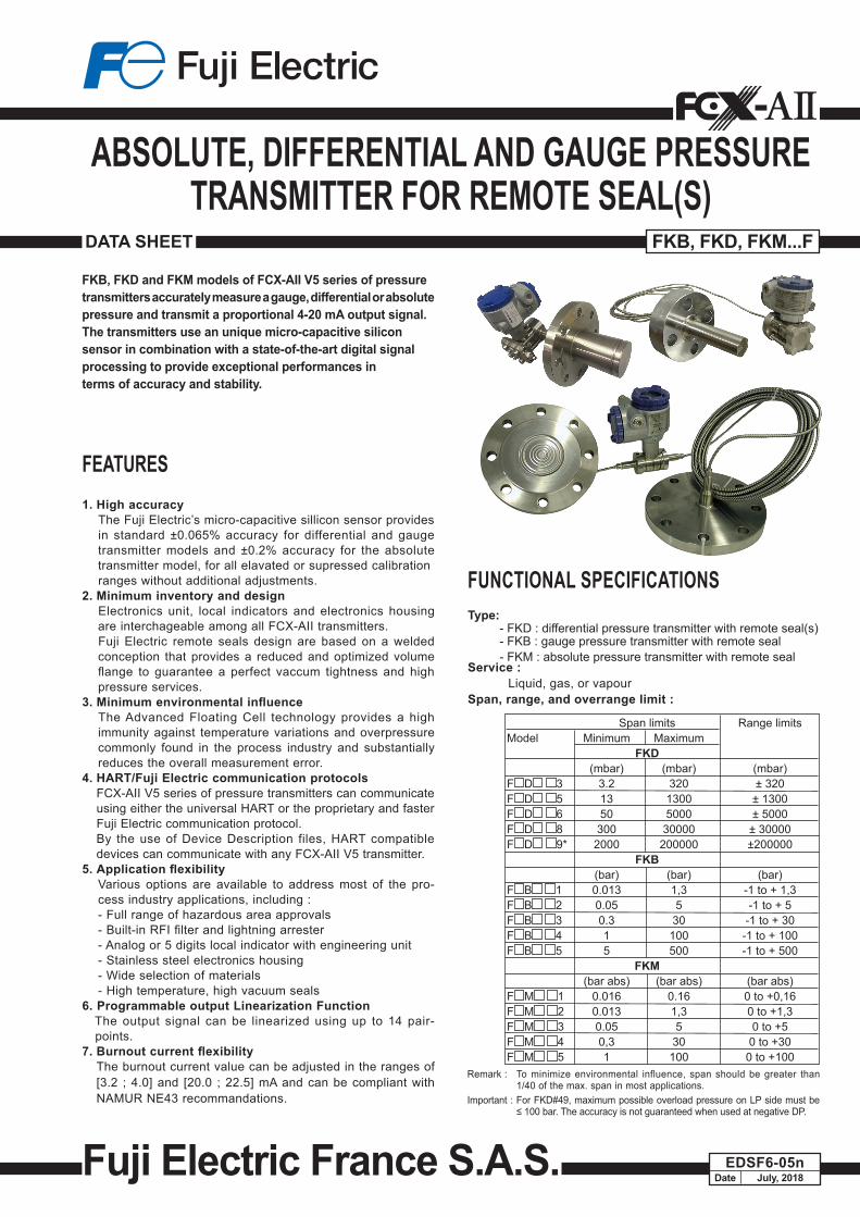
FKB, FKD and FKM models of FCX-AII V5 series of pressuretransmitters accurately measure a gauge, differential or absolute pressure and transmit a proportional 4-20 mA output signal.The transmitters use an unique micro-capacitive siliconsensor in combination with a state-of-the-art digital signalprocessing to provide exceptional performances interms of accuracy and stability.
FUNCTIONAL SPECIFICATIONSType: - FKD : differential pressure transmitter with remote seal(s) - FKB : gauge pressure transmitter with remote seal - FKM : absolute pressure transmitter with remote sealService : Liquid, gas, or vapourSpan, range, and overrange limit :
Remark : To minimize environmental influence, span should be greater than 1/40 of the max. span in most applications.
Important : For FKD#49, maximum possible overload pressure on LP side must be ≤ 100 bar. The accuracy is not guaranteed when used at negative DP.
ABSOLUTE, DIFFERENTIAL AND GAUGE PRESSURE TRANSMITTER FOR REMOTE SEAL(S)
DATA SHEET FKB, FKD, FKM...F
DateEDSF6-05n
July, 2018Fuji Electric France S.A.S.
Span limits Range limitsModel Minimum Maximum FKD (mbar) (mbar) (mbar)F D 3 3.2 320 ± 320F D 5 13 1300 ± 1300F D 6 50 5000 ± 5000F D 8 300 30000 ± 30000F D 9* 2000 200000 ±200000 FKB (bar) (bar) (bar)F B 1 0.013 1,3 -1 to + 1,3F B 2 0.05 5 -1 to + 5F B 3 0.3 30 -1 to + 30F B 4 1 100 -1 to + 100F B 5 5 500 -1 to + 500 FKM (bar abs) (bar abs) (bar abs)F M 1 0.016 0.16 0 to +0,16F M 2 0.013 1,3 0 to +1,3F M 3 0.05 5 0 to +5F M 4 0,3 30 0 to +30F M 5 1 100 0 to +100
FEATURES1. High accuracy
The Fuji Electric’s micro-capacitive sillicon sensor providesin standard ±0.065% accuracy for differential and gauge transmitter models and ±0.2% accuracy for the absolute transmitter model, for all elavated or supressed calibrationranges without additional adjustments.
2. Minimum inventory and designElectronics unit, local indicators and electronics housing are interchageable among all FCX-AII transmitters.Fuji Electric remote seals design are based on a welded conception that provides a reduced and optimized volume flange to guarantee a perfect vaccum tightness and high pressure services.
3.MinimumenvironmentalinfluenceThe Advanced Floating Cell technology provides a high immunity against temperature variations and overpressure commonly found in the process industry and substantially reduces the overall measurement error.
4. HART/Fuji Electric communication protocols FCX-AII V5 series of pressure transmitters can communicate
using either the universal HART or the proprietary and faster Fuji Electric communication protocol.
By the use of Device Description files, HART compatible devices can communicate with any FCX-AII V5 transmitter.
5.ApplicationflexibilityVarious options are available to address most of the pro-cess industry applications, including :- Full range of hazardous area approvals- Built-in RFI filter and lightning arrester- Analog or 5 digits local indicator with engineering unit- Stainless steel electronics housing- Wide selection of materials- High temperature, high vacuum seals
6. Programmable output Linearization FunctionThe output signal can be linearized using up to 14 pair-points.
7.Burnoutcurrentflexibility The burnout current value can be adjusted in the ranges of
[3.2 ; 4.0] and [20.0 ; 22.5] mA and can be compliant with NAMUR NE43 recommandations.
2
FKB, FKD, FKM...F
Configuration: Configuration of the FCX-AII V5 series of pressure transmitters
can be carried out by either using a Hand Held Terminal (ie. Fuji Electric FXW or third party HART terminal) or the 3 push-buttons optional indicator.
A third party HART hand held communicator can be used in combination with Fuji Electric FCX-AII V5 HART Device Description files (https://fieldcommgroup.org).Functions Fuji Electric
FXWThird party HART HHC
3 push buttons optional indicator
Display Set Display Set Display Set
Tag Nb v v v v v vModel Nb v v v v v vSerial Nb & Software re-vision v — v — v —
Engineering units v v v v v vUpper Range Value v — v — v —Measuring Range v v v v v vDamping v v v v v vOutput sig-nal type
Linear v v v v v vSquare Root v v v v v v
Burnout current v v v v v vCalibration v v v v v vOutput Adjust — v — v — vMeasuring Value v — v — v —Self Diagnosis v — v — v —Printer (option) v — — — — —External Adj Screw Lock v v v v v vTransmitter Display v v v v v vLinearization — — v v v vRerange v v v v v vSaturation Current v v v v v vWrite Protect v v v v v vHistory– Calibration History– Ambient T° History
vv
v—
vv
v—
vv
v—
Note 1 : The FXW firmware revision must be higher than 7.0 in order to address FCX-AII V5 “Saturation current”, “Write protect” and “History” functions.
Note 2 : The “Linearization” function is not accessible throught the 3 puh-buttons optional indicator.
Damping : The damping time constant can be adjusted within the
range of [0.06 to 32] seconds. Zero and span adjustment : Zero and span are ajustable remotly with a Hand Held
Communicator or locally with the external adjustment screw.Zero elevation/suppression : ±100 % of the URL for FKD models -1 bar to +100 % of the URL for FKB models 0 kPa abs to +100 % of the URL for FKM modelsNormal/reverse action : Selectable from a Hand Held Communicator.
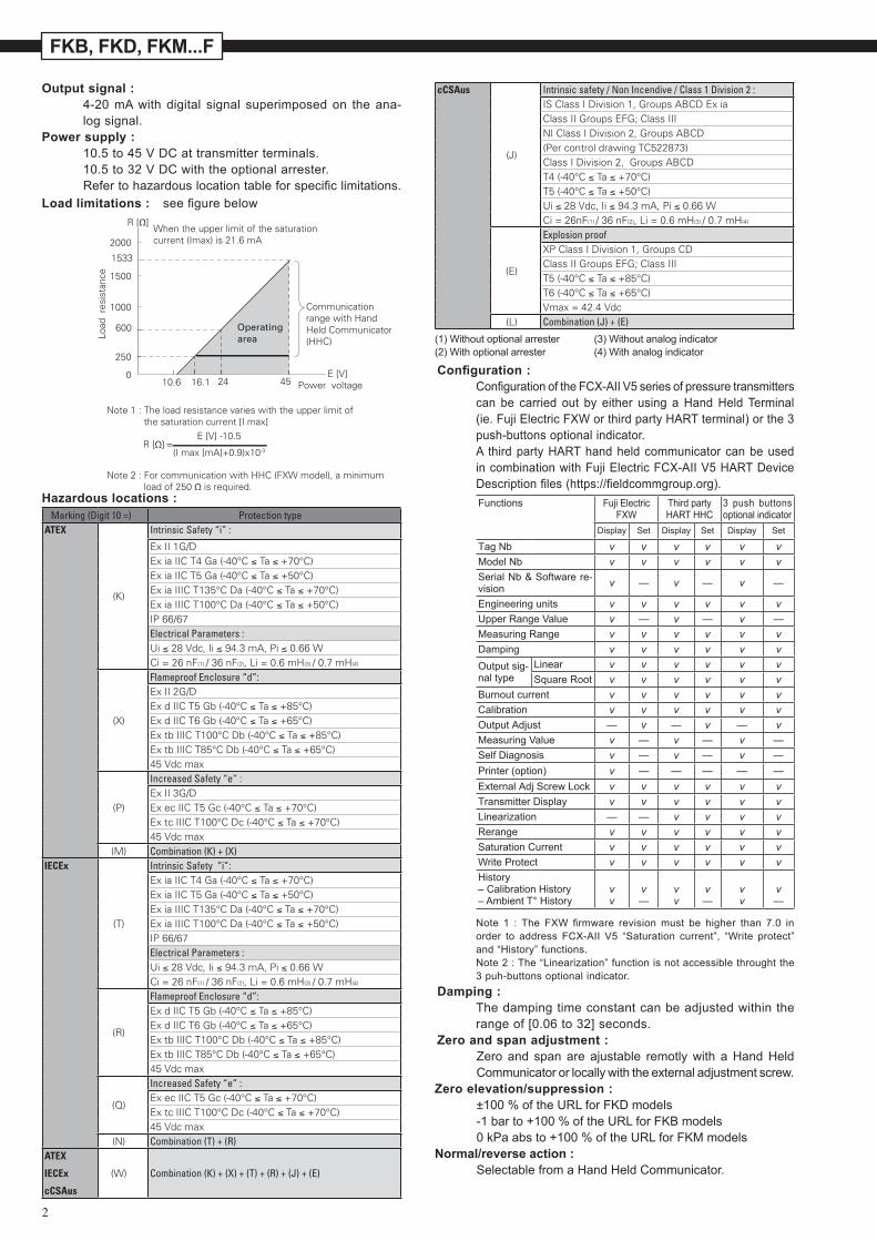
Load limitations : see figure below
Hazardous locations :
2000
R [Ω]
1500
1000
Load
res
ista
nce
250
0
1533
600 Operatingarea
Communication range with HandHeld Communicator(HHC)
24 4510.6 16.1E [V]
Power voltage
E [V] -10.5
(I max [mA]+0.9)x10-3R [Ω] =
When the upper limit of the saturationcurrent (Imax) is 21.6 mA
Note 1 : The load resistance varies with the upper limit of the saturation current [I max]
Note 2 : For communication with HHC (FXW model), a minimum load of 250 Ω is required.
Output signal : 4-20 mA with digital signal super imposed on the ana-
log signal.Power supply : 10.5 to 45 V DC at transmitter terminals. 10.5 to 32 V DC with the optional arrester. Refer to hazardous location table for specific limitations.
Marking (Digit 10 =) Protection typeATEX
(K)
Intrinsic Safety “i” :
Ex II 1G/DEx ia IIC T4 Ga (-40°C ≤ Ta ≤ +70°C)Ex ia IIC T5 Ga (-40°C ≤ Ta ≤ +50°C)Ex ia IIIC T135°C Da (-40°C ≤ Ta ≤ +70°C)Ex ia IIIC T100°C Da (-40°C ≤ Ta ≤ +50°C)IP 66/67Electrical Parameters :Ui ≤ 28 Vdc, Ii ≤ 94.3 mA, Pi ≤ 0.66 WCi = 26 nF(1) / 36 nF(2), Li = 0.6 mH(3) / 0.7 mH(4)
(X)
Flameproof Enclosure “d”:Ex II 2G/DEx d IIC T5 Gb (-40°C ≤ Ta ≤ +85°C)Ex d IIC T6 Gb (-40°C ≤ Ta ≤ +65°C)Ex tb IIIC T100°C Db (-40°C ≤ Ta ≤ +85°C)Ex tb IIIC T85°C Db (-40°C ≤ Ta ≤ +65°C)45 Vdc max
(P)
Increased Safety “e” :Ex II 3G/DEx ec IIC T5 Gc (-40°C ≤ Ta ≤ +70°C)Ex tc IIIC T100°C Dc (-40°C ≤ Ta ≤ +70°C)45 Vdc max
(M) Combination (K) + (X)IECEx
(T)
Intrinsic Safety “i”:Ex ia IIC T4 Ga (-40°C ≤ Ta ≤ +70°C)Ex ia IIC T5 Ga (-40°C ≤ Ta ≤ +50°C)Ex ia IIIC T135°C Da (-40°C ≤ Ta ≤ +70°C)Ex ia IIIC T100°C Da (-40°C ≤ Ta ≤ +50°C)IP 66/67Electrical Parameters :Ui ≤ 28 Vdc, Ii ≤ 94.3 mA, Pi ≤ 0.66 WCi = 26 nF(1) / 36 nF(2), Li = 0.6 mH(3) / 0.7 mH(4)
(R)
Flameproof Enclosure “d”:Ex d IIC T5 Gb (-40°C ≤ Ta ≤ +85°C)Ex d IIC T6 Gb (-40°C ≤ Ta ≤ +65°C)Ex tb IIIC T100°C Db (-40°C ≤ Ta ≤ +85°C)Ex tb IIIC T85°C Db (-40°C ≤ Ta ≤ +65°C)45 Vdc max
(Q)
Increased Safety “e” :Ex ec IIC T5 Gc (-40°C ≤ Ta ≤ +70°C)Ex tc IIIC T100°C Dc (-40°C ≤ Ta ≤ +70°C)45 Vdc max
(N) Combination (T) + (R)ATEX
IECEx
cCSAus
(W) Combination (K) + (X) + (T) + (R) + (J) + (E)
cCSAus
(J)
Intrinsic safety / Non Incendive / Class 1 Division 2 :IS Class I Division 1, Groups ABCD Ex iaClass II Groups EFG; Class IIINI Class I Division 2, Groups ABCD(Per control drawing TC522873)Class I Division 2, Groups ABCDT4 (-40°C ≤ Ta ≤ +70°C)T5 (-40°C ≤ Ta ≤ +50°C)Ui ≤ 28 Vdc, Ii ≤ 94.3 mA, Pi ≤ 0.66 WCi = 26nF(1) / 36 nF(2), Li = 0.6 mH(3) / 0.7 mH(4)
(E)
Explosion proofXP Class I Division 1, Groups CDClass II Groups EFG; Class IIIT5 (-40°C ≤ Ta ≤ +85°C)T6 (-40°C ≤ Ta ≤ +65°C)Vmax = 42.4 Vdc
(L) Combination (J) + (E)
(1) Without optional arrester (3) Without analog indicator(2) With optional arrester (4) With analog indicator
3
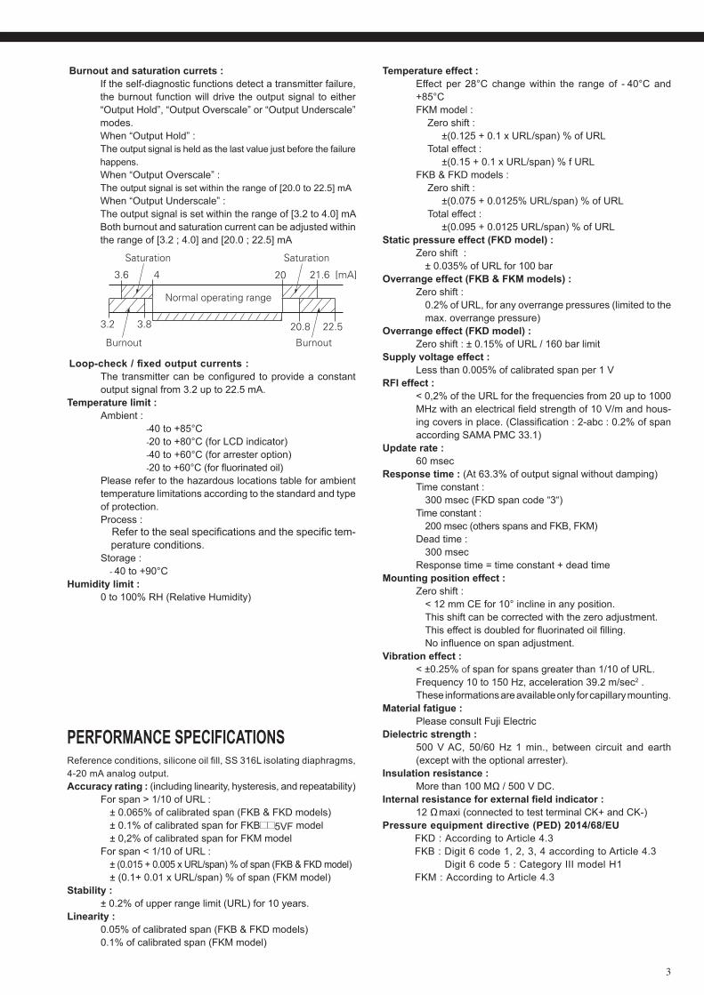
Burnout and saturation currets : If the self-diagnostic functions detect a transmitter failure,
the burnout function will drive the output signal to either “Output Hold”, “Output Overscale” or “Output Underscale” modes.
When “Output Hold” : The output signal is held as the last value just before the failure
happens. When “Output Overscale” : The output signal is set within the range of [20.0 to 22.5] mA When “Output Underscale” : The output signal is set within the range of [3.2 to 4.0] mA
Both burnout and saturation current can be adjusted within the range of [3.2 ; 4.0] and [20.0 ; 22.5] mA
3.2 3.8
3.6 4 20
20.8 22.5
21.6 [mA]
Normal operating range
Burnout
Saturation
Burnout
Saturation
Loop-check/fixedoutputcurrents: The transmitter can be configured to provide a constant
output signal from 3.2 up to 22.5 mA.Temperature limit : Ambient : -40 to +85°C -20 to +80°C (for LCD indicator) -40 to +60°C (for arrester option) -20 to +60°C (for fluorinated oil) Please refer to the hazardous locations table for ambient
temperature limitations according to the standard and type of protection.
Process : Refer to the seal specifications and the specific tem-perature conditions.
Storage : - 40 to +90°CHumidity limit : 0 to 100% RH (Relative Humidity)
PERFORMANCE SPECIFICATIONS Reference conditions, silicone oil fill, SS 316L isolating diaphragms, 4-20 mA analog output.Accuracy rating : (including linearity, hysteresis, and repeatability) For span > 1/10 of URL : ± 0.065% of calibrated span (FKB & FKD models) ± 0.1% of calibrated span for FKB 5VF model ± 0,2% of calibrated span for FKM model For span < 1/10 of URL : ± (0.015 + 0.005 x URL/span) % of span (FKB & FKD model) ± (0.1+ 0.01 x URL/span) % of span (FKM model)Stability : ± 0.2% of upper range limit (URL) for 10 years.Linearity : 0.05% of calibrated span (FKB & FKD models) 0.1% of calibrated span (FKM model)
Temperature effect : Effect per 28°C change within the range of - 40°C and
+85°C FKM model : Zero shift : ±(0.125 + 0.1 x URL/span) % of URL Total effect : ±(0.15 + 0.1 x URL/span) % f URL FKB & FKD models : Zero shift : ±(0.075 + 0.0125% URL/span) % of URL Total effect : ±(0.095 + 0.0125 URL/span) % of URLStatic pressure effect (FKD model) : Zero shift : ± 0.035% of URL for 100 barOverrange effect (FKB & FKM models) : Zero shift : 0.2% of URL, for any overrange pressures (limited to the max. overrange pressure)Overrange effect (FKD model) : Zero shift : ± 0.15% of URL / 160 bar limitSupply voltage effect : Less than 0.005% of calibrated span per 1 VRFI effect : < 0,2% of the URL for the frequencies from 20 up to 1000
MHz with an electrical field strength of 10 V/m and hous-ing covers in place. (Classification : 2-abc : 0.2% of span according SAMA PMC 33.1)
Update rate : 60 msecResponse time : (At 63.3% of output signal without damping) Time constant : 300 msec (FKD span code “3“) Time constant : 200 msec (others spans and FKB, FKM) Dead time : 300 msec Response time = time constant + dead timeMounting position effect : Zero shift : < 12 mm CE for 10° incline in any position. This shift can be corrected with the zero adjustment. This effect is doubled for fluorinated oil filling. No influence on span adjustment.Vibration effect : < ±0.25% of span for spans greater than 1/10 of URL. Frequency 10 to 150 Hz, acceleration 39.2 m/sec2 . These informations are available only for capillary mounting.Material fatigue : Please consult Fuji ElectricDielectric strength : 500 V AC, 50/60 Hz 1 min., between circuit and earth
(except with the optional arrester).Insulation resistance : More than 100 MΩ / 500 V DC.Internalresistanceforexternalfieldindicator: 12 Ω maxi (connected to test terminal CK+ and CK-)Pressure equipment directive (PED) 2014/68/EU FKD : According to Article 4.3 FKB : Digit 6 code 1, 2, 3, 4 according to Article 4.3 Digit 6 code 5 : Category III model H1 FKM : According to Article 4.3
4
FKB, FKD, FKM...F
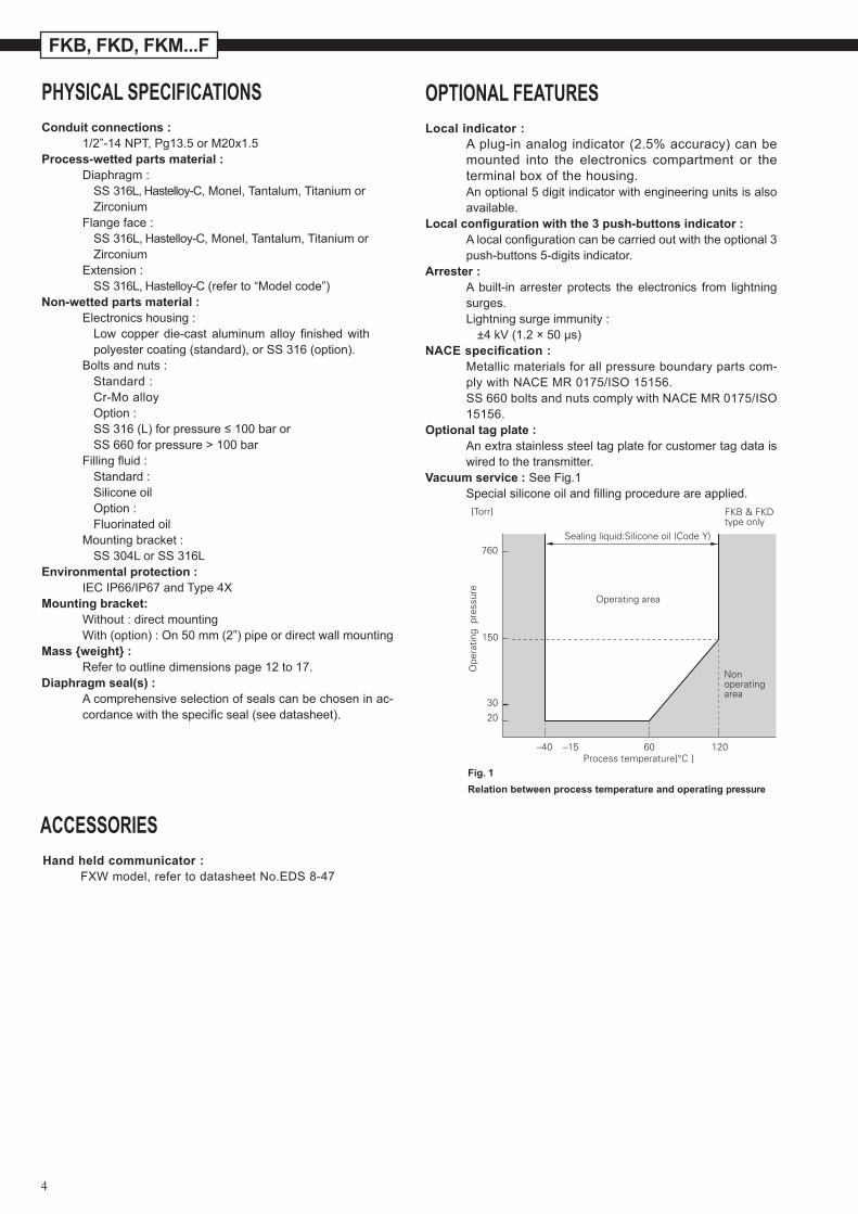
Sealing liquid:Silicone oil (Code Y)
Operating area
Nonoperatingarea
FKB & FKDtype only
760
150
20
30
[Torr]
Ope
ratin
g p
ress
ure
120–40 –15 60Process temperature[°C ]
Fig. 1 Relation between process temperature and operating pressure
ACCESSORIESHand held communicator : FXW model, refer to datasheet No.EDS 8-47
PHYSICAL SPECIFICATIONS Conduit connections : 1/2”-14 NPT, Pg13.5 or M20x1.5Process-wetted parts material : Diaphragm : SS 316L, Hastelloy-C, Monel, Tantalum, Titanium or Zirconium Flange face : SS 316L, Hastelloy-C, Monel, Tantalum, Titanium or Zirconium Extension : SS 316L, Hastelloy-C (refer to “Model code”)Non-wetted parts material : Electronics housing : Low copper die-cast aluminum alloy finished with
polyester coating (standard), or SS 316 (option). Bolts and nuts : Standard : Cr-Mo alloy Option : SS 316 (L) for pressure ≤ 100 bar or SS 660 for pressure > 100 bar Filling fluid : Standard : Silicone oil Option : Fluorinated oil Mounting bracket : SS 304L or SS 316LEnvironmental protection : IEC IP66/IP67 and Type 4XMounting bracket: Without : direct mounting With (option) : On 50 mm (2”) pipe or direct wall mountingMass weight : Refer to outline dimensions page 12 to 17.Diaphragm seal(s) : A comprehensive selection of seals can be chosen in ac-
cordance with the specific seal (see datasheet).
OPTIONAL FEATURES
Local indicator : A plug-in analog indicator (2.5% accuracy) can be
mounted into the electronics compartment or the terminal box of the housing.
An optional 5 digit indicator with engineering units is also available.
Localconfigurationwiththe3push-buttonsindicator: A local configuration can be carried out with the optional 3
push-buttons 5-digits indicator.Arrester : A built-in arrester protects the electronics from lightning
surges. Lightning surge immunity : ±4 kV (1.2 × 50 µs)NACEspecification: Metallic materials for all pressure boundary parts com-
ply with NACE MR 0175/ISO 15156. SS 660 bolts and nuts comply with NACE MR 0175/ISO
15156.Optional tag plate : An extra stainless steel tag plate for customer tag data is
wired to the transmitter.Vacuum service : See Fig.1 Special silicone oil and filling procedure are applied.
5
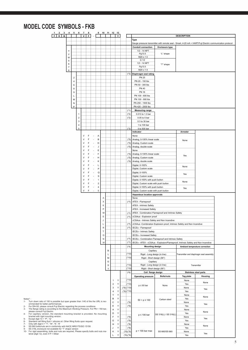
MODEL CODE SYMBOLS - FKB1 2 3 4 5 6 7 8 9 10 11 12 13F B V F - Y DESCRIPTION
Type
K
Gauge pressure transmitter with remote seal - Smart, 4-20 mA + HART/Fuji Electric communication protocol
Conduit connection Enclosure type
T 1/2 - 14 NPT
V Pg13.5 “L” shape
“T” shape
G 1/2W5678
M20 x 1.5
1/2 - 14 NPTPg13.5
M20 x 1.5
Diaphragm seal rating
2 PN 25
4 PN 20 - 150 lbs
6 PN 50 - 300 lbs
8 PN 40
9 PN 16
L PN 100 - 600 lbs
M PN 150 - 900 lbs
N PN 250 - 1500 lbs
P PN 420 - 2500 lbs
(*1) Measuring range
1 (*2)
(*2)
0.013 to 1.3 bar
2
(*3)
(*3)
0.05 to 5 bar
3 0.3 to 30 bar
4 1 to 100 bar
5 5 to 500 barIndicator Arrester
V F - A None
V F - B Analog, 0-100% linear scale
V F - D Analog, Custom scaleNone
V F - J Analog, double scale
V F - E None
V F - F Analog, 0-100% linear scaleYes
V F - H Analog, Custom scale
V F - K Analog, double scale
V F - 1 Digital, 0-100% with push buttonNone
V F - 2 Digital, Custom scale with push button
V F - 4 Digital, 0-100% with push button YesV F - 5 Digital, Custom scale with push button
V F - L Digital, 0-100% NoneV F - P Digital, Custom scale
V F - Q Digital, 0-100%
V F - S Digital, Custom scaleYes
(*7)
(*7)
(*7)
(*7)
(*7)
(*7)
(*7)
Hazardous location approvals
(*4)
(*10)
(*10)
(*10)(*10)
(*10)
(*10)
(*10)
(*10)
Mounting design Ambiant temperature correction
B Capillary
L Rigid - Long design (in line) Transmitter and diaphragm seal assembly
M Rigid - Short design (90°)
Rigid - Long design (in line)
Rigid - Short design (90°)
G Capillary
S Transmitter
TCell flange design Stainless steel parts
Operating pressure Bolts/nuts Tag plate Housing
1 Y
(*5)
(*5)
(*5)
(*5)
(*5)
(*5)
(*6)
(*9)
(*9)
(*9)
(*9)
(*9)
(*9)
None
NoneNone
2 Yp ≤ 50 bar
Yes
3 Y None
4 Y YesYes
Y Y NoneNone
B Y Yes
C YCarbon steel
None Yes
E Y Yes
A Y NoneNone
D Y Yes
F YSS 316(L) / SS 316(L)
None
G Y YesYes
H Y (*8) NoneNone
J Y (*8) Yes
K Y (*8) (*9)
(*9)
SS 660/SS 660 None Yes
L Y (*8) Yes
None
ATEX - Flameproof
ATEX - Intrinsic Safety
ATEX - Increased Safety
ATEX - Combination Flameproof and Intrinsic Safety
cCSAus - Explosion proof
cCSAus - Intrinsic Safety and Non Incendive
cCSAus -Combination Explosion proof, Intrinsic Safety and Non Incendive
IECEx - Flameproof
IECEx - Intrinsic Safety
IECEx - Increased Safety
IECEx - Combination Flameproof and Intrinsic Safety
IECEx - ATEX - cCSAus - Explosion/Flameproof, Intrinsic Safety and Non Incendive
A
X
K
P
M
E
J
L
R
T
Q
N
W
50 < p ≤ 100
p ≤ 100 bar
p = 100 bar max
Notes* : 1- Turn down ratio of 100 is possible but span greater than 1/40 of the the URL is rec-
ommended for better performances.2- For DN<50, please consult Fuji Electric regarding the process conditions3- The flange rating is according to the Maximum Working Pressure. For PN > 150 bar,
please consult Fuji Electric4- For capillary version, the standard mounting bracket is provided. No mounting
bracket with rigid mounting version.5- Except digit 10 = “P”, “Q”6- Standard cell filling fluid = silicone oil. Other filling fluids upon request.7- Only with digit 4 = “T”, “W”, “6”, “8”8- SS 660 bolts/nuts are in conformity with NACE MR0175/ISO 151569- SS 316L enclosure not available for “T” shape version10- For rigid assembling, bolts and nuts are required. Please specify bolts and nuts ma-
terial (digit 12), even if P < 50bar
6
FKB, FKD, FKM...F
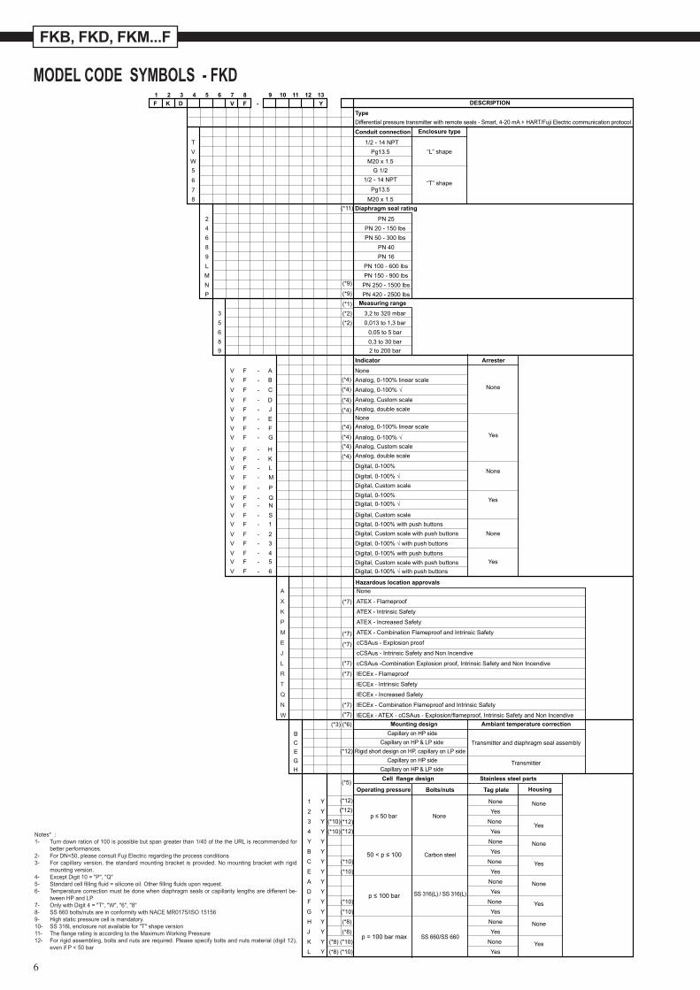
MODEL CODE SYMBOLS - FKD1 2 3 4 5 6 7 8 9 10 11 12 13
V F - Y DESCRIPTION
TypeF K D
Differential pressure transmitter with remote seals - Smart, 4-20 mA + HART/Fuji Electric communication protocolConduit connection
T 1/2 - 14 NPTV Pg13.5W M20 x 1.5
Diaphragm seal rating
2 PN 254 PN 20 - 150 lbs6 PN 50 - 300 lbs8 PN 409 PN 16L PN 100 - 600 lbsM PN 150 - 900 lbsN PN 250 - 1500 lbsP PN 420 - 2500 lbs
(*1)
(*9)
(*9)
(*11)
Measuring range
3 (*2) 3,2 to 320 mbar5 (*2) 0,013 to 1,3 bar6 0,05 to 5 bar8 0,3 to 30 bar9 2 to 200 bar
Indicator Arrester
V F - A NoneV F - B Analog, 0-100% linear scale
V F - D Analog, Custom scale
None
V F - J Analog, double scale
V F - E None
V F - F Analog, 0-100% linear scale
V F - H Analog, Custom scale
Yes
V F - K Analog, double scale
V F - 1 Digital, 0-100% with push buttonsNoneV F - 2
V F - 3
Digital, Custom scale with push buttons
V F - 4 Digital, 0-100% with push buttonsYesV F
F - 5
V - 6Digital, Custom scale with push buttons
V F - LV F - M
Digital, 0-100%None
V F - P Digital, Custom scale
V F - QV F - N
Digital, 0-100%Yes
Digital, Custom scaleV F - S
(*3) (*6) Mounting design Ambiant temperature correctionB Capillary on HP sideC Capillary on HP & LP side Transmitter and diaphragm seal assemblyE Rigid short design on HP, capillary on LP sideG Capillary on HP sideH Capillary on HP & LP side
Transmitter
Cell flange design Stainless steel parts
Operating pressure Bolts/nuts Tag plate Housing
1 Y
(*4)
V F - C Analog, 0-100% √
Analog, 0-100% √
Digital, 0-100% √
Digital, 0-100% √
Digital, 0-100% √ with push buttons
Digital, 0-100% √ with push buttons
(*4)
(*5)
(*12)
(*12)(*12)
(*12)(*12)
(*10)
(*10)
(*10)
(*10)
(*10)
(*10)
None None2 Y
(*4)
Yes
3 Y
(*4)
(*4)
V F - G (*4)(*4)
(*4)
None None
4 Y YesYes
Y Y None NoneB Y Yes
C YCarbon steel
None
E Y YesYes
A Y None NoneD Y Yes
F Y None YesG Y Yes
H Y (*8) None
J Y (*8) YesNone
K Y (*8) (*10)
(*10)
SS 660/SS 660None
L Y (*8) YesYes
p ≤ 50 bar
SS 316(L) / SS 316(L)
Hazardous location approvalsNone
ATEX - Flameproof
ATEX - Intrinsic Safety
ATEX - Increased Safety
ATEX - Combination Flameproof and Intrinsic Safety
cCSAus - Explosion proof
cCSAus - Intrinsic Safety and Non Incendive
cCSAus -Combination Explosion proof, Intrinsic Safety and Non Incendive
IECEx - Flameproof
IECEx - Intrinsic Safety
IECEx - Increased Safety
IECEx - Combination Flameproof and Intrinsic Safety
IECEx - ATEX - cCSAus - Explosion/flameproof, Intrinsic Safety and Non Incendive
(*7)
(*7)
(*7)
(*7)
(*7)
(*7)(*7)
A
X
K
P
M
E
J
L
R
T
Q
N
W
Enclosure type
“L” shape
“T” shape
5678
1/2 - 14 NPTPg13.5
M20 x 1.5
G 1/2
50 < p ≤ 100
p ≤ 100 bar
p = 100 bar max
Notes* : 1- Turn down ration of 100 is possible but span greater than 1/40 of the the URL is recommended for
better performances.2- For DN<50, please consult Fuji Electric regarding the process conditions3- For capillary version, the standard mounting bracket is provided. No mounting bracket with rigid
mounting version.4- Except Digit 10 = "P", "Q"5- Standard cell filling fluid = silicone oil. Other filling fluids upon request.6- Temperature correction must be done when diaphragm seals or capillarity lengths are different be-
tween HP and LP7- Only with Digit 4 = "T", "W", "6", "8"8- SS 660 bolts/nuts are in conformity with NACE MR0175/ISO 151569- High static pressure cell is mandatory.10- SS 316L enclosure not available for "T" shape version11- The flange rating is according to the Maximum Working Pressure12- For rigid assembling, bolts and nuts are required. Please specify bolts and nuts material (digit 12),
even if P < 50 bar
7
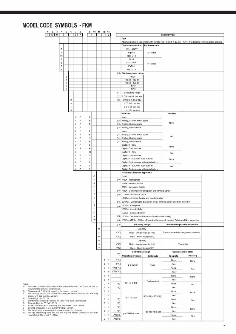
MODEL CODE SYMBOLS - FKM1 2 3 4 5 6 7 8 9 10 11 12 13
V F - Y DESCRIPTIONType
F K M
Absolute pressure transmitter with remote seal - Smart, 4-20 mA + HART/Fuji Electric communication protocol
Conduit connection Enclosure type
T 1/2 - 14 NPTV Pg13.5 “L” shape
“T” shape
W5678
M20 x 1.5
1/2 - 14 NPTPg13.5
M20 x 1.5
G 1/2
Diaphragm seal rating2 PN 254 PN 20 - 150 lbs6 PN 50 - 300 lbs8 PN 409 PN 16
(*1)
(*9)
Measuring range
1 (*2) 0.016 to 0.16 bar abs
2 (*2) 0.013 to 1.3 bar abs3 0.05 to 5 bar abs
4 0.3 to 30 bar abs5 1 to 100 bar abs
Indicator ArresterV F - A None
V F - B Analog, 0-100% linear scaleNoneV F - D Analog, Custom scale
V F - J Analog, double scaleV F - E NoneV F - F Analog, 0-100% linear scale
V F - H Analog, Custom scaleYes
V F - K Analog, double scale
V F - 1 Digital, 0-100% with push buttonsV F - 2 Digital, Custom scale with push buttons
None
V F - 4 Digital, 0-100% with push buttons
V F - 5 Digital, Custom scale with push buttonsYes
V F - L Digital, 0-100%None
V F - P Digital, Custom scaleV F - Q Digital, 0-100% YesV F - S Digital, Custom scale
(*6)
(*6)
(*6)
(*6)
(*6)
(*6)
(*6)
(*3)
(*10)
(*10)
(*10)
(*10)
(*10)
(*10)
(*10)
(*10)
Hazardous location approvals
Mounting design Ambiant temperature correction
B Capillary
L Rigid - Long design (in line) Transmitter and diaphragm seal assembly
M Rigid - Short design (90°)
Rigid - Long design (in line)
Rigid - Short design (90°)
G Capillary
S Transmitter
TStainless steel partsCell flange design
Bolts/nuts Tag plate Housing
1 Y
(*5)
(*8)
(*8)
(*8)
(*8)
(*8)
(*8)
None None2 Y
(*4)
(*4)
(*4)
(*4)
(*4)
(*4)
Yes
3 YNone
None Yes4 Y Yes
Y Y None
B Y YesNone
C YCarbon steel
None YesE Y Yes
A Y
SS 316(L) / SS 316(L)
None NoneD Y Yes
F Y None YesG Y Yes
H Y (*7) NoneNone
J Y (*7) Yes
K Y (*7) (*8)
(*8)
None
L Y (*7) YesYes
SS 660 / SS 660
Operating pressure
p ≤ 50 bar
None
ATEX - Flameproof
ATEX - Intrinsic Safety
ATEX - Increased Safety
ATEX - Combination Flameproof and Intrinsic Safety
cCSAus - Explosion proof
cCSAus - Intrinsic Safety and Non Incendive
cCSAus -Combination Explosion proof, Intrinsic Safety and Non Incendive
IECEx - Flameproof
IECEx - Intrinsic Safety
IECEx - Increased Safety
IECEx - Combination Flameproof and Intrinsic Safety
IECEx - ATEX - cCSAus - Explosion/flameproof, Intrinsic Safety and Non Incendive
A
X
K
P
M
E
J
L
R
T
Q
N
W
50 < p ≤ 100
p ≤ 100 bar
p = 100 bar max
Notes* : 1- Turn down ration of 100 is possible but span greater than 1/40 of the the URL is
recommended for better performances.2- Please consult Fuji Electric regarding the process conditions3- For capillary version, the standard mounting bracket is provided. No mounting
bracket with rigid mounting version.4- Except Digit 10 = "P", "Q"5- Standard cell filling fluid = silicone oil. Other filling fluids upon request.6- Only with Digit 4 = "T", "W", "6", "8"7- SS 660 bolts/nuts are in conformity with NACE MR0175/ISO 151568- SS 316L enclosure not available for "T" shape version9- The flange rating is according to the Maximum Working Pressure10- For rigid assembling, bolts and nuts are required. Please specify bolts and nuts
material (digit 12), even if P < 50bar
8
FKB, FKD, FKM...F
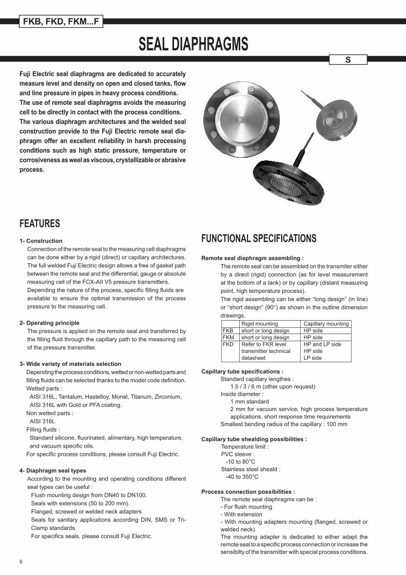
Fuji Electric seal diaphragms are dedicated to accurately measurelevelanddensityonopenandclosedtanks,flowand line pressure in pipes in heavy process conditions.The use of remote seal diaphragms avoids the measuring cell to be directly in contact with the process conditions.The various diaphragm architectures and the welded seal construction provide to the Fuji Electric remote seal dia-phragm offer an excellent reliability in harsh processing conditions such as high static pressure, temperature or corrosiveness as weel as viscous, crystallizable or abrasive process.
FEATURES1- Construction
Connection of the remote seal to the measuring cell diaphragmscan be done either by a rigid (direct) or capillary architectures.The full welded Fuji Electric design allows a free of gasket pathbetween the remote seal and the differential, gauge or absolutemeasuring cell of the FCX-AII V5 pressure transmitters.Depending the nature of the process, specific filling fluids areavailable to ensure the optimal transmission of the process pressure to the measuring cell.
2- Operating principleThe pressure is applied on the remote seal and transferred by the filling fluid through the capillary path to the measuring cell of the pressure transmitter.
3- Wide variety of materials selectionDepending the process conditions, wetted or non-wetted parts and filling fluids can be selected thanks to the model code definition.Wetted parts : AISI 316L, Tantalum, Hastelloy, Monel, Titanum, Zirconium, AISI 316L with Gold or PFA coating.Non wetted parts : AISI 316LFilling fluids : Standard silicone, fluorinated, alimentary, high temperature, and vacuum specific oils.For specific process conditions, please consult Fuji Electric.
4- Diaphragm seal typesAccording to the mounting and operating conditions different seal types can be useful :
Flush mounting design from DN40 to DN100.Seals with extensions (50 to 200 mm).Flanged, screwed or welded neck adaptersSeals for sanitary applications according DIN, SMS or Tri-Clamp standards.For specifics seals, please consult Fuji Electric.
FUNCTIONAL SPECIFICATIONSRemote seal diaphragm assembling :
The remote seal can be assembled on the transmiter either by a direct (rigid) connection (as for level measurement at the bottom of a tank) or by capillary (distant measuring point, high temperature process).The rigid assembling can be either “long design” (in line) or “short design” (90°) as shown in the outline dimension drawings.
Capillarytubespecifications:Standard capillary lengthes :
1.5 / 3 / 6 m (other upon request)Inside diameter :
1 mm standard 2 mm for vacuum service, high process temperature applications, short response time requirements
Smallest bending radius of the capillary : 100 mm
Capillary tube shealding possibilities :Temperature limit :PVC sleeve : -10 to 80°CStainless steel sheald : -40 to 350°C
Process connection possibilities :The remote seal diaphragms can be :- For flush mounting- With extension- With mounting adapters mounting (flanged, screwed or welded neck).The mounting adapter is dedicated to either adapt the remote seal to a specific process connection or increase the sensibilty of the transmitter with special process conditions.
Rigid mounting Capillary mounting FKB short or long design HP side FKM short or long design HP side FKD Refer to FKR level HP and LP side transmitter technical HP side datasheet LP side
SSEAL DIAPHRAGMS
9
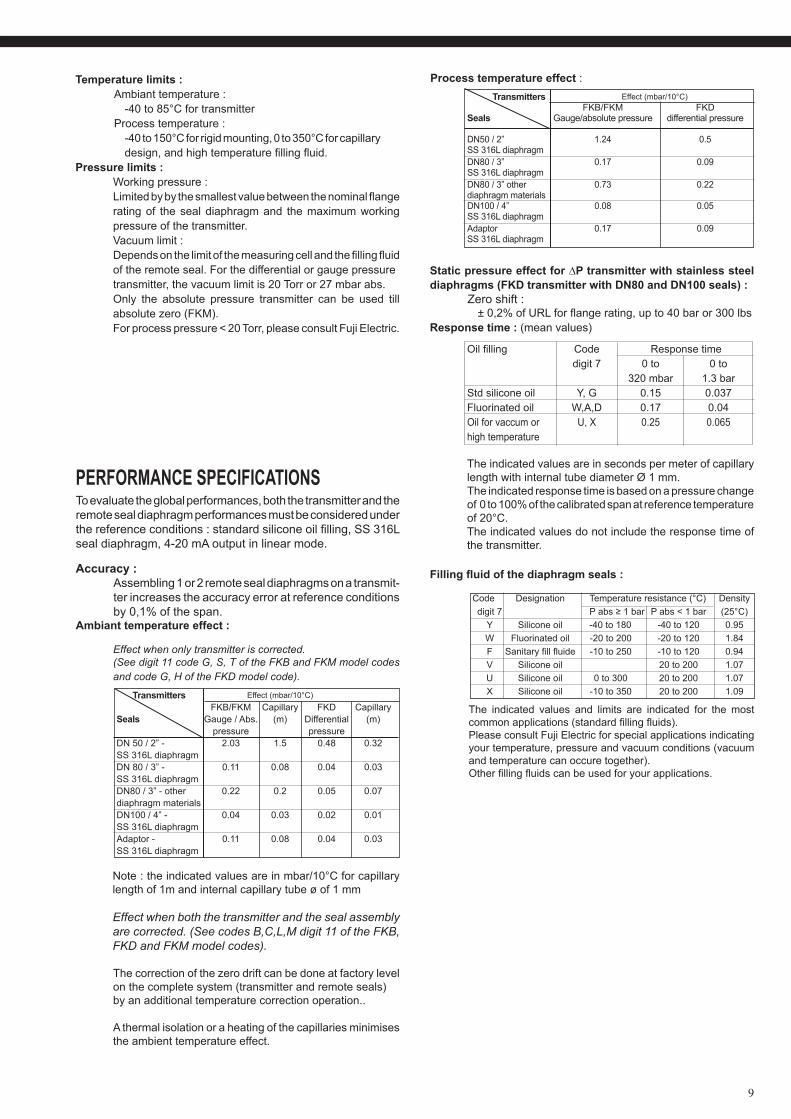
Effect when only transmitter is corrected.(See digit 11 code G, S, T of the FKB and FKM model codes and code G, H of the FKD model code).
Note : the indicated values are in mbar/10°C for capillary length of 1m and internal capillary tube ø of 1 mm
Effect when both the transmitter and the seal assembly are corrected. (See codes B,C,L,M digit 11 of the FKB, FKD and FKM model codes).
The correction of the zero drift can be done at factory levelon the complete system (transmitter and remote seals)by an additional temperature correction operation..
A thermal isolation or a heating of the capillaries minimises the ambient temperature effect.
Staticpressureeffectfor∆Ptransmitterwithstainlesssteeldiaphragms (FKD transmitter with DN80 and DN100 seals) :
Zero shift : ± 0,2% of URL for flange rating, up to 40 bar or 300 lbs
Response time : (mean values)
Oil filling Code Response time digit 7 0 to 0 to 320 mbar 1.3 barStd silicone oil Y, G 0.15 0.037Fluorinated oil W,A,D 0.17 0.04Oil for vaccum or U, X 0.25 0.065high temperature
The indicated values are in seconds per meter of capillary length with internal tube diameter Ø 1 mm.
The indicated response time is based on a pressure change of 0 to 100% of the calibrated span at reference temperature of 20°C.
The indicated values do not include the response time of the transmitter.
Fillingfluidofthediaphragmseals:
PERFORMANCE SPECIFICATIONSTo evaluate the global performances, both the transmitter and theremote seal diaphragm performances must be considered underthe reference conditions : standard silicone oil filling, SS 316L seal diaphragm, 4-20 mA output in linear mode.
Accuracy :Assembling 1 or 2 remote seal diaphragms on a transmit-ter increases the accuracy error at reference conditions by 0,1% of the span.
Ambiant temperature effect :
Process temperature effect :
The indicated values and limits are indicated for the most common applications (standard filling fluids).Please consult Fuji Electric for special applications indicating your temperature, pressure and vacuum conditions (vacuum and temperature can occure together).Other filling fluids can be used for your applications.
Code Designation Temperature resistance (°C) Density digit 7 P abs ≥ 1 bar P abs < 1 bar (25°C) Y Silicone oil -40 to 180 -40 to 120 0.95 W Fluorinated oil -20 to 200 -20 to 120 1.84 F Sanitary fill fluide -10 to 250 -10 to 120 0.94 V Silicone oil 20 to 200 1.07 U Silicone oil 0 to 300 20 to 200 1.07 X Silicone oil -10 to 350 20 to 200 1.09
Temperature limits :Ambiant temperature : -40 to 85°C for transmitter Process temperature : -40 to 150°C for rigid mounting, 0 to 350°C for capillary design, and high temperature filling fluid.
Pressure limits :Working pressure : Limited by by the smallest value between the nominal flangerating of the seal diaphragm and the maximum working pressure of the transmitter.Vacuum limit :Depends on the limit of the measuring cell and the filling fluid of the remote seal. For the differential or gauge pressuretransmitter, the vacuum limit is 20 Torr or 27 mbar abs.Only the absolute pressure transmitter can be used till absolute zero (FKM).For process pressure < 20 Torr, please consult Fuji Electric.
Transmitters Effect (mbar/10°C) FKB/FKM Capillary FKD Capillary Seals Gauge / Abs. (m) Differential (m) pressure pressureDN 50 / 2” - 2.03 1.5 0.48 0.32SS 316L diaphragmDN 80 / 3” - 0.11 0.08 0.04 0.03SS 316L diaphragmDN80 / 3” - other 0.22 0.2 0.05 0.07diaphragm materialsDN100 / 4” - 0.04 0.03 0.02 0.01SS 316L diaphragmAdaptor - 0.11 0.08 0.04 0.03SS 316L diaphragm
Transmitters Effect (mbar/10°C) FKB/FKM FKDSeals Gauge/absolute pressure differential pressure DN50 / 2” 1.24 0.5SS 316L diaphragmDN80 / 3” 0.17 0.09SS 316L diaphragmDN80 / 3” other 0.73 0.22diaphragm materialsDN100 / 4” 0.08 0.05SS 316L diaphragmAdaptor 0.17 0.09SS 316L diaphragm
10
FKB, FKD, FKM...F S
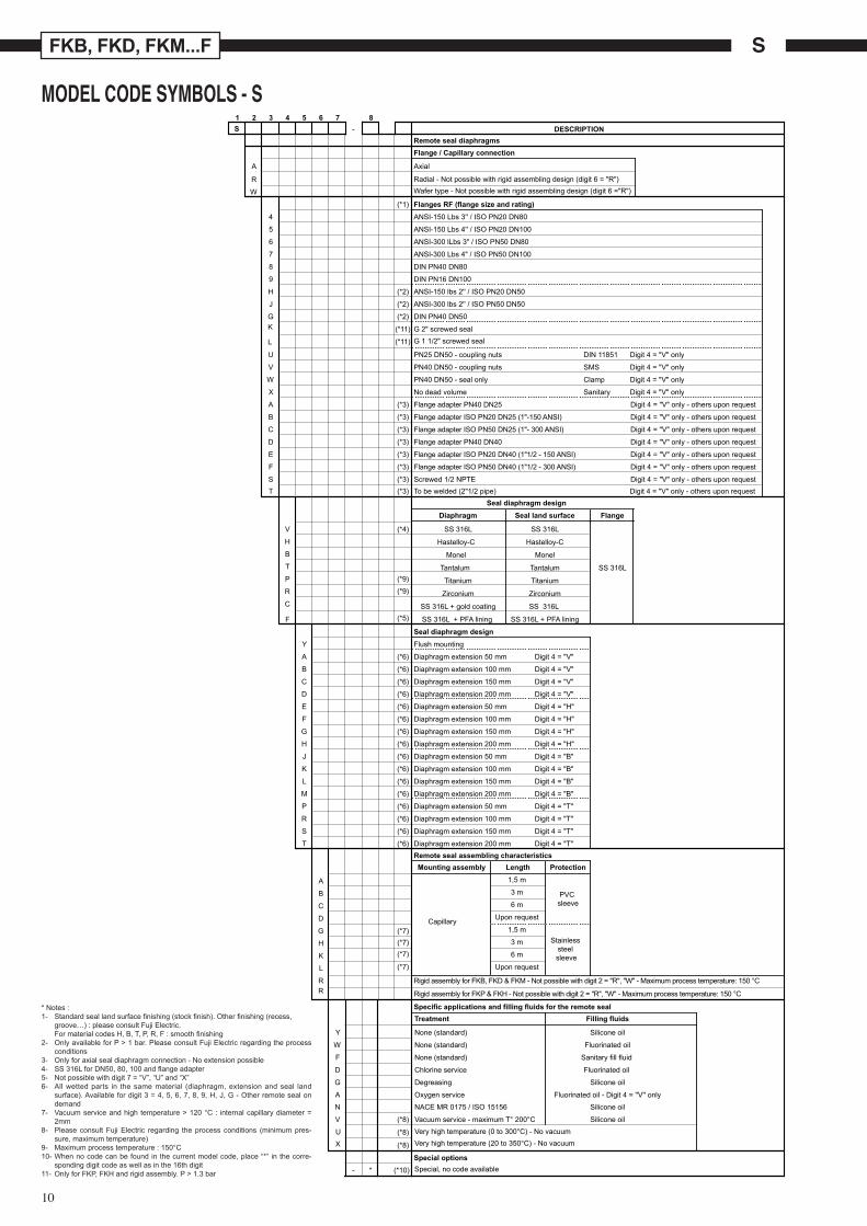
MODEL CODE SYMBOLS - S 1 2 3 4 5 6 7 8S - DESCRIPTION
A Axial
Remote seal diaphragmsFlange / Capillary connection
R Radial - Not possible with rigid assembling design (digit 6 = "R")
W Wafer type - Not possible with rigid assembling design (digit 6 ="R")
(*1) Flanges RF (flange size and rating) 4 ANSI-150 Lbs 3'' / ISO PN20 DN80
5 ANSI-150 Lbs 4'' / ISO PN20 DN100
6 ANSI-300 lLbs 3" / ISO PN50 DN80
7 ANSI-300 Lbs 4" / ISO PN50 DN100
8 DIN PN40 DN80
9 DIN PN16 DN100
H (*2) ANSI-150 lbs 2'' / ISO PN20 DN50
J (*2) ANSI-300 lbs 2'' / ISO PN50 DN50
GK
L
(*2)
(*11)
(*11)
DIN PN40 DN50
G 2" screwed sealG 1 1/2" screwed seal
U PN25 DN50 - coupling nuts DIN 11851 Digit 4 = "V" only
V PN40 DN50 - coupling nuts SMS Digit 4 = "V" only
W PN40 DN50 - seal only Clamp Digit 4 = "V" only
X No dead volume Sanitary Digit 4 = "V" only
A (*3) Flange adapter PN40 DN25 Digit 4 = "V" only - others upon request
B (*3) Flange adapter ISO PN20 DN25 (1"-150 ANSI) Digit 4 = "V" only - others upon request
C (*3) Flange adapter ISO PN50 DN25 (1"- 300 ANSI) Digit 4 = "V" only - others upon request
D (*3) Flange adapter PN40 DN40 Digit 4 = "V" only - others upon request
E (*3) Flange adapter ISO PN20 DN40 (1"1/2 - 150 ANSI) Digit 4 = "V" only - others upon request
F (*3) Flange adapter ISO PN50 DN40 (1"1/2 - 300 ANSI) Digit 4 = "V" only - others upon request
S (*3)
(*4)
Screwed 1/2 NPTE Digit 4 = "V" only - others upon requestT (*3) To be welded (2"1/2 pipe) Digit 4 = "V" only - others upon request
Seal diaphragm design Diaphragm Seal land surface Flange
V SS 316L SS 316L
H Hastelloy-C Hastelloy-CB Monel MonelT Tantalum Tantalum SS 316LP (*9)
(*9)Titanium Titanium
R Zirconium ZirconiumC SS 316L + gold coating SS 316L
F (*5)
(*6)
(*6)
(*6)
(*6)
(*6)
(*6)
(*6)
(*6)
(*6)
(*6)
(*6)
(*6)
(*6)
(*6)
(*6)
(*6)
SS 316L + PFA lining SS 316L + PFA lining
Seal diaphragm design Y Flush mounting
A Diaphragm extension 50 mm
B Diaphragm extension 100 mm Digit 4 = "V"
Digit 4 = "V"
Digit 4 = "V"
Digit 4 = "H"
Digit 4 = "H"
Digit 4 = "H"
Digit 4 = "H"
Digit 4 = "B"
Digit 4 = "B"
Digit 4 = "B"
Digit 4 = "B"
Digit 4 = "T"
Digit 4 = "T"
Digit 4 = "T"
Digit 4 = "T"
Digit 4 = "V"
C Diaphragm extension 150 mm
D Diaphragm extension 200 mm
E Diaphragm extension 50 mm
F Diaphragm extension 100 mm
G Diaphragm extension 150 mm
H Diaphragm extension 200 mm
J Diaphragm extension 50 mm
K Diaphragm extension 100 mm
L Diaphragm extension 150 mm
M Diaphragm extension 200 mm
P Diaphragm extension 50 mm
R Diaphragm extension 100 mm
S Diaphragm extension 150 mm
T Diaphragm extension 200 mmRemote seal assembling characteristics Mounting assembly Length Protection
A 1,5 m
B 3 m PVC sleeveC 6 m
D Upon request
G (*7)(*7)(*7)
(*7)
Capillary 1,5 m
H 3 m
K 6 m
Stainless steel sleeve
L Upon request
RR
Rigid assembly for FKB, FKD & FKM - Not possible with digit 2 = "R", "W" - Maximum process temperature: 150 °C
Rigid assembly for FKP & FKH - Not possible with digit 2 = "R", "W" - Maximum process temperature: 150 °C
Specific applications and filling fluids for the remote seal
Special options
Treatment Filling fluids
Y None (standard) Silicone oil
W None (standard) Fluorinated oil
F None (standard) Sanitary fill fluid
D Chlorine service Fluorinated oil
G Degreasing Silicone oil
A Oxygen service Fluorinated oil - Digit 4 = ''V'' only
N NACE MR 0175 / ISO 15156 Silicone oil
V (*8)
(*8)
(*8)
Vacuum service - maximum T° 200°C Silicone oil
UX
- * (*10)
Very high temperature (0 to 300°C) - No vacuumVery high temperature (20 to 350°C) - No vacuum
Special, no code available
* Notes :1- Standard seal land surface finishing (stock finish). Other finishing (recess,
groove…) : please consult Fuji Electric. For material codes H, B, T, P, R, F : smooth finishing
2- Only available for P > 1 bar. Please consult Fuji Electric regarding the process conditions
3- Only for axial seal diaphragm connection - No extension possible4- SS 316L for DN50, 80, 100 and flange adapter5- Not possible with digit 7 = “V”, “U” and “X”6- All wetted parts in the same material (diaphragm, extension and seal land
surface). Available for digit 3 = 4, 5, 6, 7, 8, 9, H, J, G - Other remote seal on demand
7- Vacuum service and high temperature > 120 °C : internal capillary diameter = 2mm
8- Please consult Fuji Electric regarding the process conditions (minimum pres-sure, maximum temperature)
9- Maximum process temperature : 150°C10- When no code can be found in the current model code, place “*” in the corre-
sponding digit code as well as in the 16th digit11- Only for FKP, FKH and rigid assembly. P > 1.3 bar
11
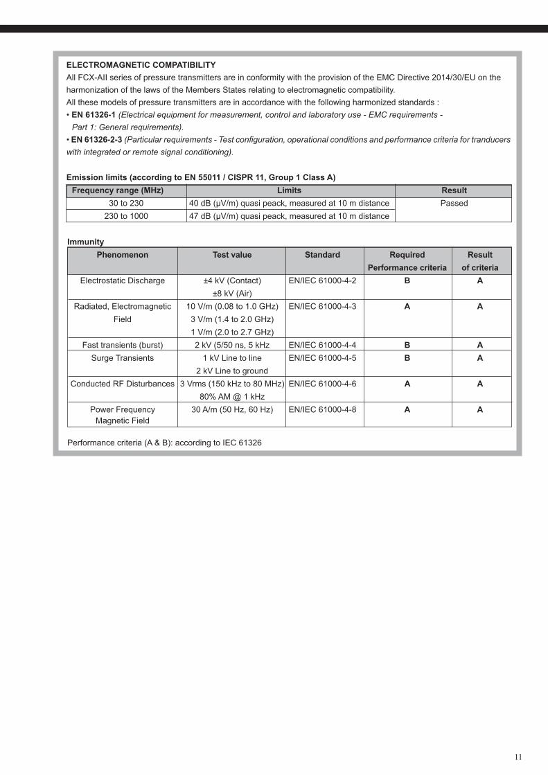
ELECTROMAGNETIC COMPATIBILITYAll FCX-AII series of pressure transmitters are in conformity with the provision of the EMC Directive 2014/30/EU on theharmonization of the laws of the Members States relating to electromagnetic compatibility.All these models of pressure transmitters are in accordance with the following harmonized standards :• EN 61326-1 (Electrical equipment for measurement, control and laboratory use - EMC requirements - Part 1: General requirements).• EN 61326-2-3 (Particular requirements - Test configuration, operational conditions and performance criteria for tranducers with integrated or remote signal conditioning).
Emission limits (according to EN 55011 / CISPR 11, Group 1 Class A) Frequency range (MHz) Limits Result 30 to 230 40 dB (µV/m) quasi peack, measured at 10 m distance Passed 230 to 1000 47 dB (µV/m) quasi peack, measured at 10 m distance
Immunity Phenomenon Test value Standard Required Result Performance criteria of criteria Electrostatic Discharge ±4 kV (Contact) EN/IEC 61000-4-2 B A ±8 kV (Air) Radiated, Electromagnetic 10 V/m (0.08 to 1.0 GHz) EN/IEC 61000-4-3 A A Field 3 V/m (1.4 to 2.0 GHz) 1 V/m (2.0 to 2.7 GHz) Fast transients (burst) 2 kV (5/50 ns, 5 kHz EN/IEC 61000-4-4 B A Surge Transients 1 kV Line to line EN/IEC 61000-4-5 B A 2 kV Line to ground Conducted RF Disturbances 3 Vrms (150 kHz to 80 MHz) EN/IEC 61000-4-6 A A 80% AM @ 1 kHz Power Frequency 30 A/m (50 Hz, 60 Hz) EN/IEC 61000-4-8 A A Magnetic Field Performance criteria (A & B): according to IEC 61326
12
FKB, FKD, FKM...F
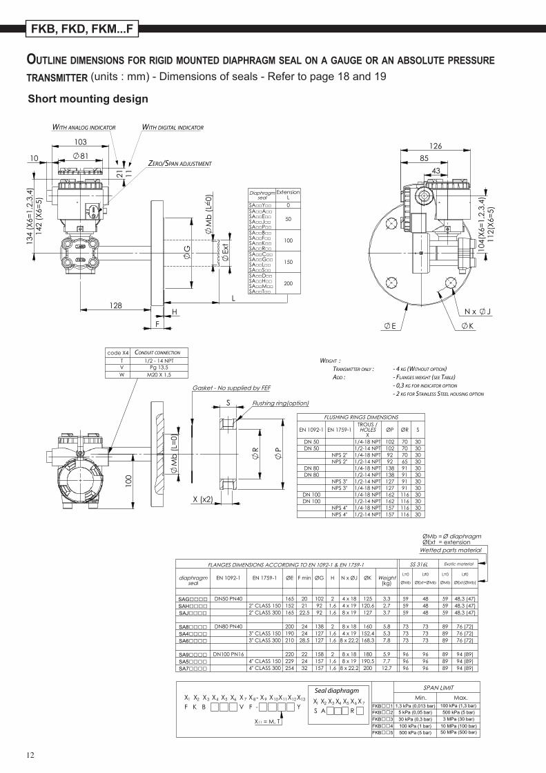
Outline dimensiOns fOr rigid mOunted diaphragm seal On a gauge Or an absOlute pressure transmitter (units : mm) - Dimensions of seals - Refer to page 18 and 19
S A R
G
F
R
P
S
E
TROUS / S
T
W
l
WITH DIGITAL INDICATORWITH ANALOG INDICATOR
ZERO/SPAN ADJUSTMENT
CONDUIT CONNECTION
Seal diaphragm
WEIGHT : TRANSMITTER ONLY : - 4 KG (WITHOUT OPTION) ADD : - FLANGES WEIGHT (SEE TABLE) - 0,3 KG FOR INDICATOR OPTION
- 2 KG FOR STAINLESS STEEL HOUSING OPTION
Short mounting design
13
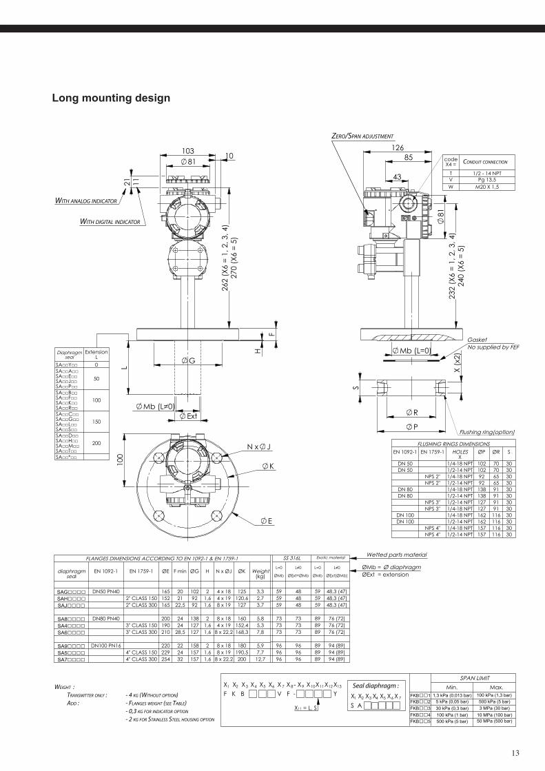
S A
F
G
R
P
S
E
S
T
W
l
WEIGHT : TRANSMITTER ONLY : - 4 KG (WITHOUT OPTION) ADD : - FLANGES WEIGHT (SEE TABLE) - 0,3 KG FOR INDICATOR OPTION
- 2 KG FOR STAINLESS STEEL HOUSING OPTION
Seal diaphragm :
WITH DIGITAL INDICATOR
WITH ANALOG INDICATOR
ZERO/SPAN ADJUSTMENT
CONDUIT CONNECTION
Long mounting design
14
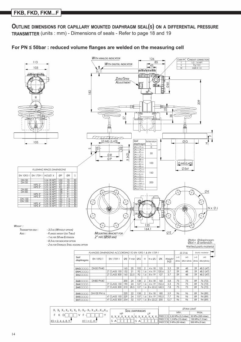
FKB, FKD, FKM...F
Outline dimensiOns fOr capillary mOunted diaphragm seal(s) On a differential pressure transmitter (units : mm) - Dimensions of seals - Refer to page 18 and 19
ForPN≤50bar:reducedvolumeflangesareweldedonthemeasuringcell
S AS A
F
G
P R
S
E
T
W
S
Code X4
SEAL DIAPHRAGMS
Seal diaphragm
Seal diaphragms
CONDUIT CONNECTIONWITH ANALOG INDICATOR
WITH DIGITAL INDICATOR
MOUNTING BRACKET FOR2” PIPE (Ø50 MM)
ZERO/SPANADJUSTMENT
WEIGHT : TRANSMITTER ONLY : - 3.5 KG (WITHOUT OPTION) ADD : - FLANGES WEIGHT (SEE TABLE) - 1 KG PER 50 MM EXTENSION
- 0.3 KG FOR INDICATOR OPTION
- 2 KG FOR STAINLESS STEEL HOUSING OPTION
15
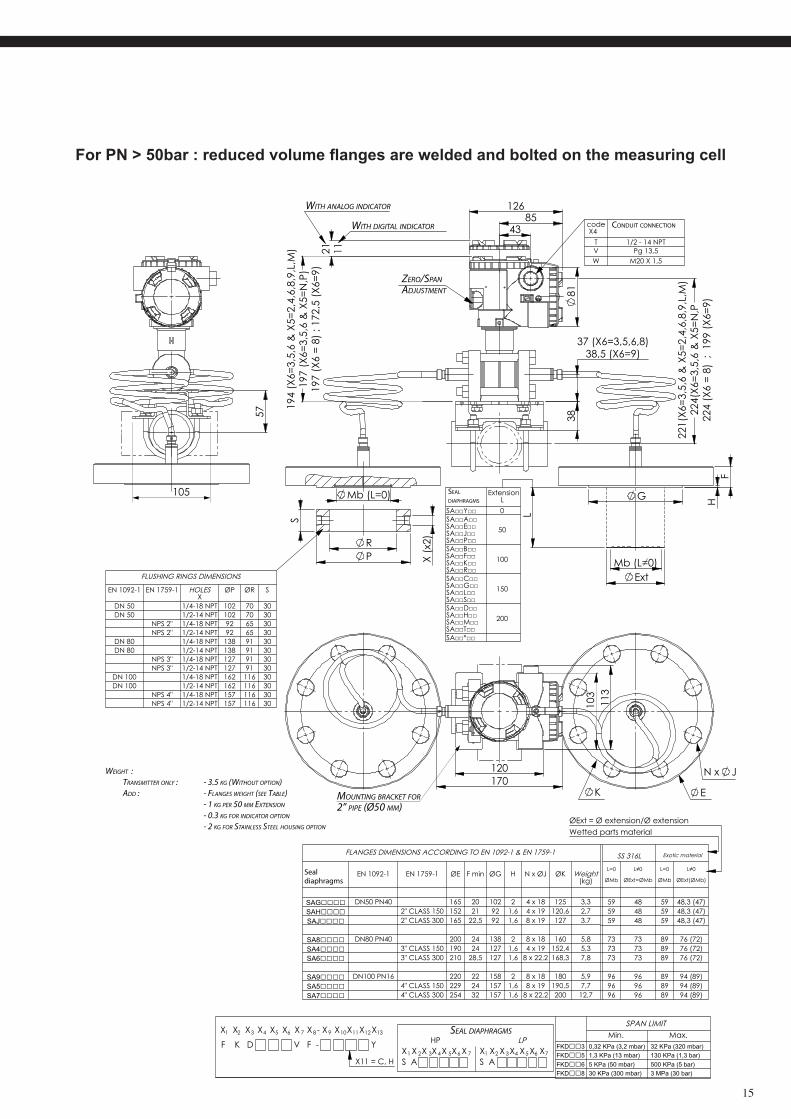
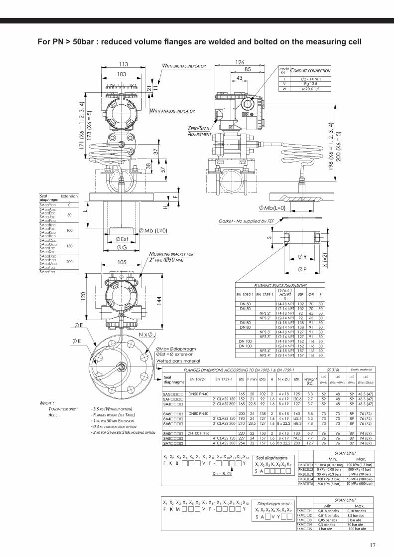
ForPN>50bar:reducedvolumeflangesareweldedandboltedonthemeasuringcell
S AS A
F
G
P R
S
E
T
W
S
SEAL DIAPHRAGMS
SEAL DIAPHRAGMS
Seal diaphragms
CONDUIT CONNECTION
WITH ANALOG INDICATOR
WITH DIGITAL INDICATOR
MOUNTING BRACKET FOR2” PIPE (Ø50 MM)
ZERO/SPANADJUSTMENT
WEIGHT : TRANSMITTER ONLY : - 3.5 KG (WITHOUT OPTION) ADD : - FLANGES WEIGHT (SEE TABLE) - 1 KG PER 50 MM EXTENSION
- 0.3 KG FOR INDICATOR OPTION
- 2 KG FOR STAINLESS STEEL HOUSING OPTION
16
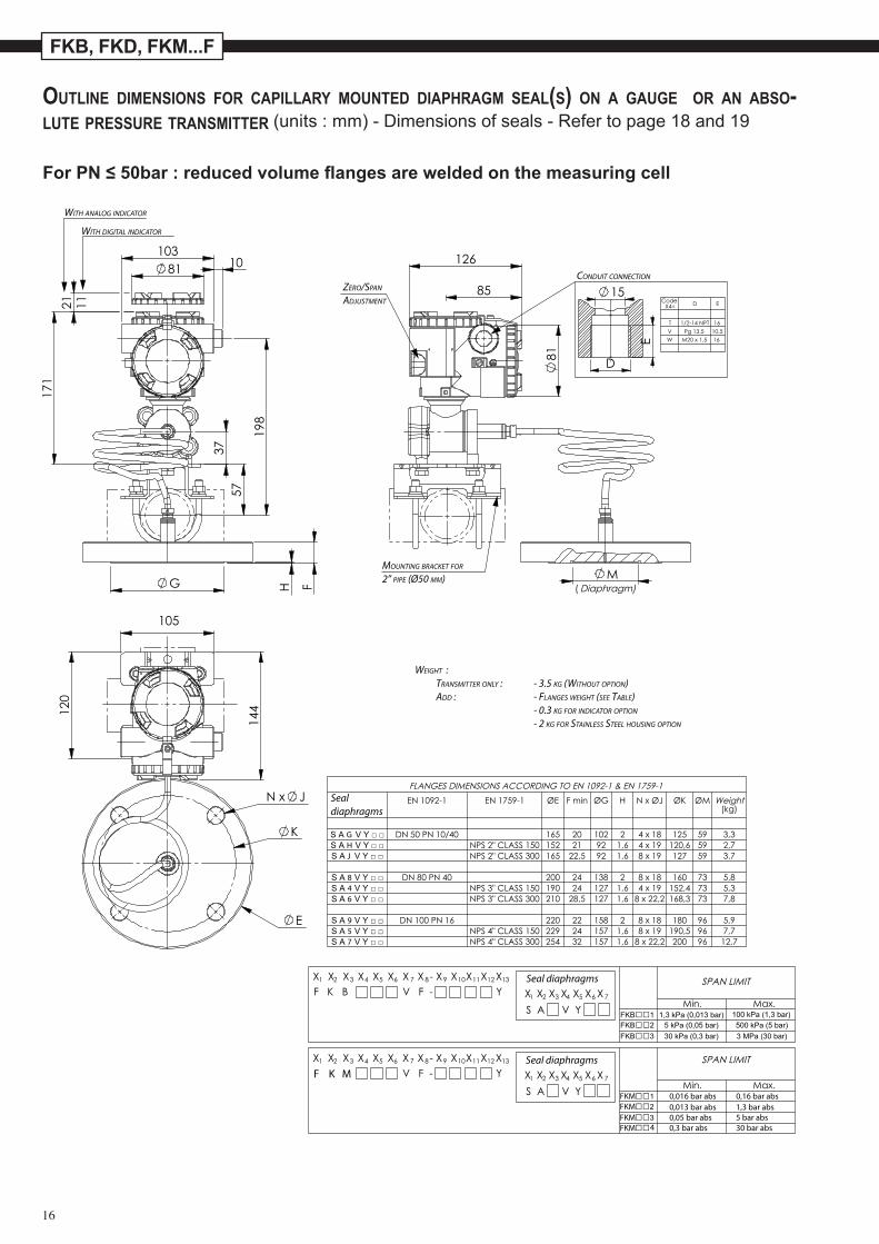
FKB, FKD, FKM...F
Outline dimensiOns fOr capillary mOunted diaphragm seal(s) On a gauge Or an absO-lute pressure transmitter (units : mm) - Dimensions of seals - Refer to page 18 and 19
ForPN≤50bar:reducedvolumeflangesareweldedonthemeasuringcell
FG
E
D
D E
M
E
F K M
FKM 0,016 bar abs 0,16 bar abs0,013 bar abs 1,3 bar abs0,05 bar abs 5 bar abs0,3 bar abs 30 bar abs
FKMFKMFKM 4
Seal diaphragms
Seal diaphragms
Seal diaphragms
CONDUIT CONNECTION
WITH ANALOG INDICATOR
WITH DIGITAL INDICATOR
MOUNTING BRACKET FOR
2” PIPE (Ø50 MM)
ZERO/SPAN
ADJUSTMENT
WEIGHT : TRANSMITTER ONLY : - 3.5 KG (WITHOUT OPTION) ADD : - FLANGES WEIGHT (SEE TABLE) - 0.3 KG FOR INDICATOR OPTION
- 2 KG FOR STAINLESS STEEL HOUSING OPTION
17
S A
F
G
S
R
P
E
T
W
TROUS / S
F K M FKM 0,016 bar abs 0,16 bar abs0,013 bar abs 1,3 bar abs0,05 bar abs 5 bar abs0,3 bar abs1 bar abs 100 bar abs
30 bar abs
FKMFKMFKMFKM
45
Seal diaphragms
Seal diaphragm
CONDUIT CONNECTION
Seal diaphragms
WITH ANALOG INDICATOR
WITH DIGITAL INDICATOR
MOUNTING BRACKET FOR2” PIPE (Ø50 MM)
ZERO/SPANADJUSTMENT
WEIGHT : TRANSMITTER ONLY : - 3.5 KG (WITHOUT OPTION) ADD : - FLANGES WEIGHT (SEE TABLE) - 1 KG PER 50 MM EXTENSION
- 0.3 KG FOR INDICATOR OPTION
- 2 KG FOR STAINLESS STEEL HOUSING OPTION
ForPN>50bar:reducedvolumeflangesareweldedandboltedonthemeasuringcell
18
FKB, FKD, FKM...F
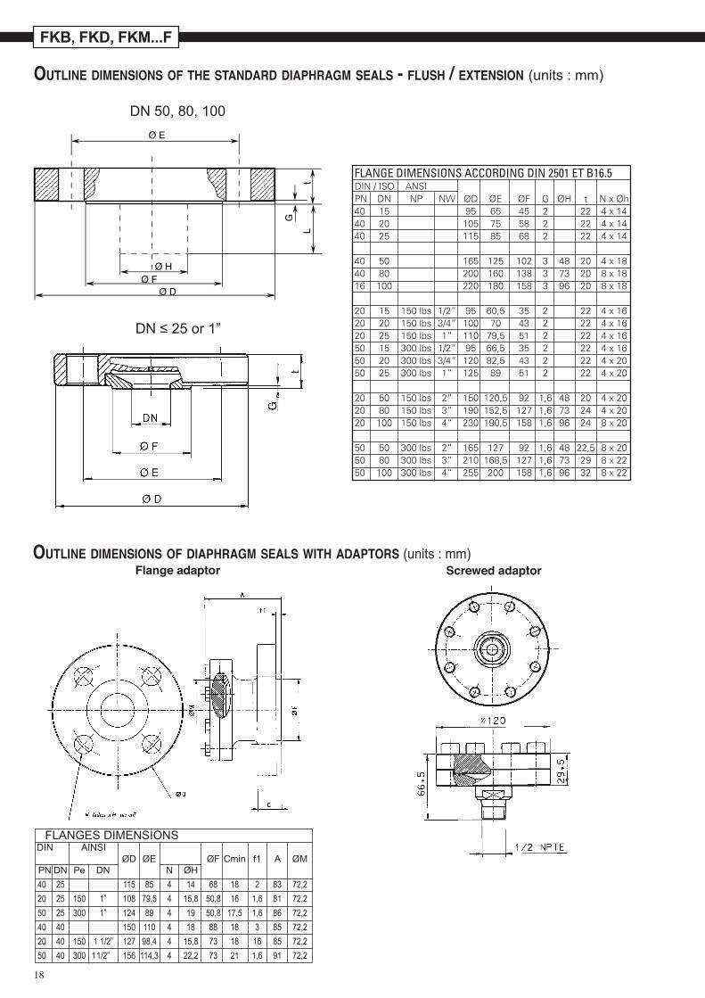
Outline dimensiOns Of the standard diaphragm seals - flush / extensiOn (units : mm)
Ø E
Ø HØ F
Ø DG
Lt
DN 50, 80, 100
DN ≤ 25 or 1”
Outline dimensiOns Of diaphragm seals with adaptOrs (units : mm)Screwed adaptorFlange adaptor
FLANGES DIMENSIONS DIN AINSI ØD ØE ØF Cmin f1 A ØM PN DN Pe DN N ØH 40 25 115 85 4 14 68 18 2 83 72,2 20 25 150 1” 108 79,5 4 15,8 50,8 16 1,6 81 72,2 50 25 300 1” 124 89 4 19 50,8 17,5 1,6 86 72,2 40 40 150 110 4 18 88 18 3 85 72,2 20 40 150 1 1/2” 127 98,4 4 15,8 73 18 16 85 72,2 50 40 300 1 1/2” 156 114,3 4 22,2 73 21 1,6 91 72,2
FLANGE DIMENSIONS ACCORDING DIN 2501 ET B16.5DIN / ISO ANSIPN DN NP NW ØD ØE ØF G ØH t N x Øh40 15 95 65 45 2 22 4 x 1440 20 105 75 58 2 22 4 x 1440 25 115 85 68 2 22 4 x 14 40 50 165 125 102 3 48 20 4 x 1840 80 200 160 138 3 73 20 8 x 1816 100 220 180 158 3 96 20 8 x 18
20 15 150 lbs 1/2” 95 60,5 35 2 22 4 x 1620 20 150 lbs 3/4” 100 70 43 2 22 4 x 1620 25 150 lbs 1” 110 79,5 51 2 22 4 x 1650 15 300 lbs 1/2” 95 66,5 35 2 22 4 x 1650 20 300 lbs 3/4” 120 82,5 43 2 22 4 x 2050 25 300 lbs 1” 125 89 51 2 22 4 x 20
20 50 150 lbs 2” 150 120,5 92 1,6 48 20 4 x 2020 80 150 lbs 3” 190 152,5 127 1,6 73 24 4 x 2020 100 150 lbs 4” 230 190,5 158 1,6 96 24 8 x 20
50 50 300 lbs 2” 165 127 92 1,6 48 22,5 8 x 2050 80 300 lbs 3” 210 168,5 127 1,6 73 29 8 x 2250 100 300 lbs 4” 255 200 158 1,6 96 32 8 x 22
19
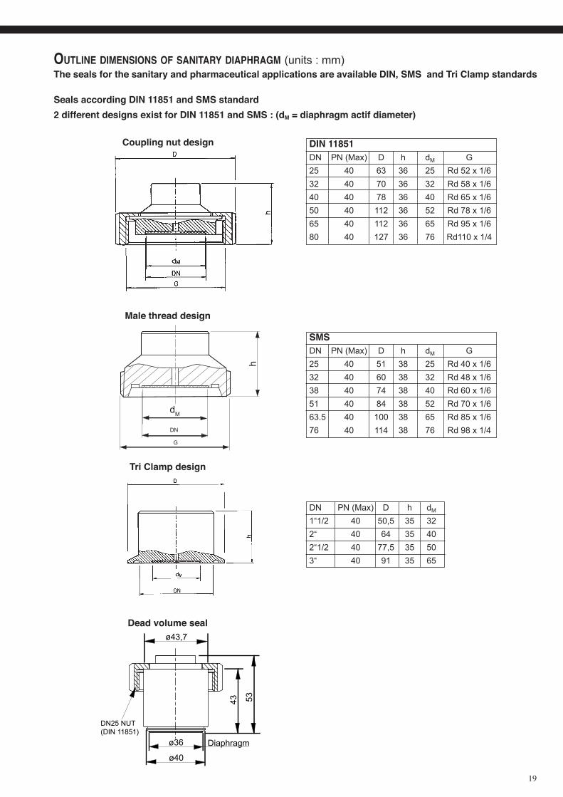
Outline dimensiOns Of sanitary diaphragm (units : mm)The seals for the sanitary and pharmaceutical applications are available DIN, SMS and Tri Clamp standards
Seals according DIN 11851 and SMS standard 2 different designs exist for DIN 11851 and SMS : (dM = diaphragm actif diameter)
Coupling nut design
Male thread design
h
dM
DN
G
DIN 11851DN PN (Max) D h dM G25 40 63 36 25 Rd 52 x 1/632 40 70 36 32 Rd 58 x 1/640 40 78 36 40 Rd 65 x 1/650 40 112 36 52 Rd 78 x 1/665 40 112 36 65 Rd 95 x 1/680 40 127 36 76 Rd110 x 1/4
SMSDN PN (Max) D h dM G25 40 51 38 25 Rd 40 x 1/632 40 60 38 32 Rd 48 x 1/638 40 74 38 40 Rd 60 x 1/651 40 84 38 52 Rd 70 x 1/663.5 40 100 38 65 Rd 85 x 1/676 40 114 38 76 Rd 98 x 1/4
Tri Clamp design
Dead volume seal
DN PN (Max) D h dM
1“1/2 40 50,5 35 322“ 40 64 35 40 2“1/2 40 77,5 35 50 3“ 40 91 35 65
ø36
ø40
53
ø43,7
Diaphragm
DN25 NUT (DIN 11851)
43
FKB, FKD, FKM...F
Fuji Electric can accept no responsability for possible errors in catalogues, brochures and other printed material. Fuji Electric reserves the right to alter its products without notice. This also applies to products already on order provided that such alterations can be made without subsequential changes being necessary in specifications already agreed. All trademarks in this material are property of the respective companies. all rights reserved.
Fuji Electric France S.A.S.46 rue Georges Besse - ZI du brézet - 63039 Clermont ferrandTél : 04 73 98 26 98 - Fax : 04 73 98 26 99Mail : [email protected] - web : www.fujielectric.fr
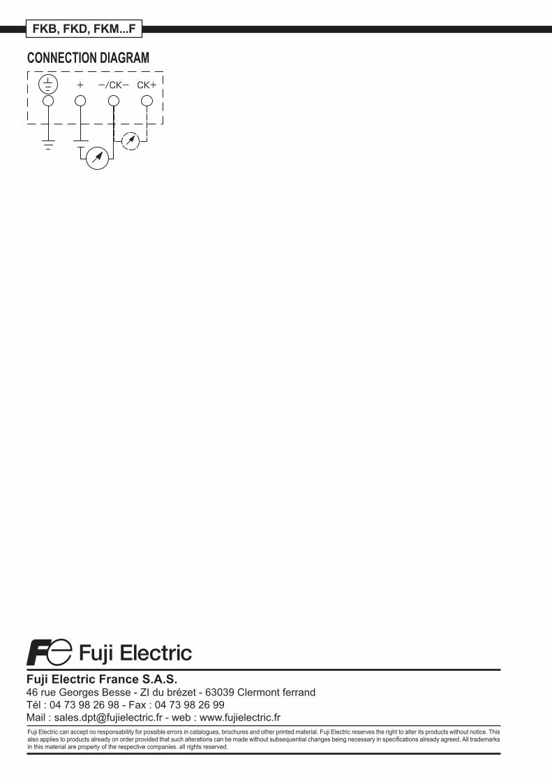
CONNECTION DIAGRAM