Embed Size (px)
Citation preview

COMPACT HYDROSmall hydropower solutions from the global leader
ANDRITZ HYDRO GmbHLunzerstrasse 78, 4031 Linz, AustriaPhone.: +43 (732) 6986 3473, Fax: +43 (732) 6980 2554
COMPACT HYDRO Division of ANDRITZ
HYDRO received in the last 5 year
orders of 560 units with an total in-
stalled capacity of 2.615 MW.
COMPACT HYDRO stands for water to
wire solutions. Every week, somewhere
on our planet, a compact plant star ts
energy production. With our record of
several hundred compact installations,
a wealth of experience is available for
your benefit.
We focus on the best solution – from
water to wire.
May 29 - June 3, Switz
erla
nd
Vis
it us at Booth 40/41
35A2011_RZ ZEK (Stave_Can) 216 x297.indd 1 21.04.2011 14:38:11 Uhr
J u n e 2 0 1 1
I N T E R N A T I O N A L H Y D R O
FUTURE TECHNOLOGY
H Y D R O
Titel ZeK-Global 2011.indd 1 27.05.11 08:44
ze
k H
YD
RO
– J
un
e 2
011
Umschlag ZEK Hydro 2011.indd 1 01.06.11 11:37

essential.
Made to measure reliable solutions for your hydro power applications.
www.marellimotori.com
Hydropower_A4_120_RRSOT2010.indd1 1 24/05/2011 11.35.26
Advanced technology.Planning and construction of hydropower plants - from the initial design to the completed installation.
Reliability beyond tomorrow.
Troyer SpAVia Karl v. Etzel 239049 - Vipiteno / Italy
Tel. +39 0472 765 195Fax +39 0472 766 356www.troyer.it / [email protected]
Umschlag ZEK Hydro 2011.indd 2 01.06.11 11:37

zek HYDRO 2011 03
With its '20-20-20' programme, which it introduced in 2008, the European Union has provideda clear map of the way ahead: In addition to requiring a 20 per cent increase of energy efficiencyand 20 per cent reduction of greenhouse gas emissions (compared to 1990 levels), the programmecalls for raising the share of renewables to 20 per cent by the year 2020. In addition to the expansion of existing wind power capacities, the key element in implementingthe 20-20-20 strategy will be hydropower - that form of electricity generation with the longest tra-dition on the Old Continent. The market has actually seen a lot of movement over the past few years. From Eastern Europe tothe Balkans, across the Alpine regions and Scandinavia, awareness has been growing of these coun-tries' own hydropower potential. This potential lies, on the one hand, in the improvement andrevitalisation of old facilities and the expansion and construction of pumped-storage plants; on theother hand, a lot of potential stands to be realised with the construction of small hydropower sta-tions of various types. After all, the latest estimates indicate that about 40 per cent of the econo-mically and ecologically sound utilisation potential still lies dormant. In Southeast Europe thefigure is even higher at 60 per cent. Thanks to the long-standing tradition of hydropower inEurope, the large number of old facilities alone holds great potential for improvement. At present,more than half of the existing hydropower stations are older than 60 years.Despite all efforts to raise the currently installed overall capacity of 180,000 megawatts, the expan-sion of hydropower operations is still progressing only at a moderate speed. To a large extent thisis due to the European Water Framework Directive, which focusses almost exclusively on the pro-tection of water bodies while changing the underlying conditions for the hydropower industrywith the introduction of various details. Especially the construction of new facilities is becomingextremely difficult - if not outright impossible - as a result. Nevertheless, a number of projects of various sizes are currently being implemented, primarily inNorway, Austria and Switzerland. These range from micro and small hydropower stations to large-scale pumped-storage facilities. More strongly than ever before we have to acknowledge today thatno other economically viable method of generating power causes fewer CO2 emissions thanhydropower. In hydropower facilities, most of these emissions are generated only by the buildingwork during the construction stage.This is a clear benefit not only to our environment, but also to a well-established industry. It is thelong tradition of hydropower in countries such as Austria, Germany or Scandinavia to whichtoday's industry leaders own their existence - and this applies not only to large hydropower. Firmsfrom these countries are also setting the technological pace in small and medium-sized hydropo-wer, which makes the quality and know-how of European manufacturers and consultants a valu-able and sought-after commodity the world over. At the same time, the UK has earned itself theposition as the world's technology leader in marine hydropower. This form of power generation isalso likely to play a crucial role in the future European energy market.Our main objectives for this first edition of zek HYDRO were to provide a representative selecti-on of successful hydropower projects, provide a platform for the key contributors to the industry,and report news from the world of hydropower technology. Our thanks go to the European SmallHydro Power Association, especially to their new Secretary General, Dirk Hendricks, who hasoffered his kind support in this media partnership and has lent his professional assistance from dayone. Finally, I would like to thank all those who have helped in getting the magazine off theground, and I wish all our readers a good time reading zek HYDRO 2011.
Roland GruberEditor-in-Chief
EUROPE'S FOCUS IS ON HYDROPOWER
To the point
003.qxp 01.06.2011 11:43 Uhr Seite 1
004-005.qxp 01.06.2011 11:52 Uhr Seite 1

004-005.qxp 01.06.2011 11:52 Uhr Seite 2

006-007.qxp 01.06.2011 11:52 Uhr Seite 1

006-007.qxp 01.06.2011 11:52 Uhr Seite 2
SHORT CUTS10 short news out of the world
of hydropower
03 Editorial08 Table of Content10 Masthead
table of contents
16 Hydropower: A Driving Force ForEU Energy Security[ ESHA-STATEMANT ]
18 A Networker Takes Over - TheNew President of ESHA[ INTERVIEW ]
20 A Unique Chance to Gather Expertise and Competence[ SHORT COURSES ]
22 Green Electricity from the Irrigation Canal[ TURKEY ]
25 Third Generation Family Business Opens a New Chapter [ SOUTH TYROL / ITALY ]
29 Bhutanese High Pressure Power Plant is Given the Green Light[ BHUTAN ]
32 New Concept for an Old Problem: Development of an Axial Hydro Cyclone[ APPLIED RESEARCH ]
36 Energy Converters of Supreme Level[ GERMANY ]
38 Braun Equips Power Plant on the Neckar River[ GERMANY ]
39 First Movable Power Plant to Generate Electricity[ GERMANY ]
44 Retirement for VeteranMachines[ SWITZERLAND ]
46 Clean Electricity for the Steirische Eisenwurzen Region[ AUSTRIA ]
48 Unrestricted Flow PassagesThrough Trash Rack Screens[ TECHNOLOGY ]
50 ILF Consulting Egineers are plan-ning Hydropower Plant Atdorf[ GERMANY ]
51 Kempten’s „Perfect Wave“[ GERMANY ]
54 Hydropower Made in Switzerland[ TECHNOLOGY ]
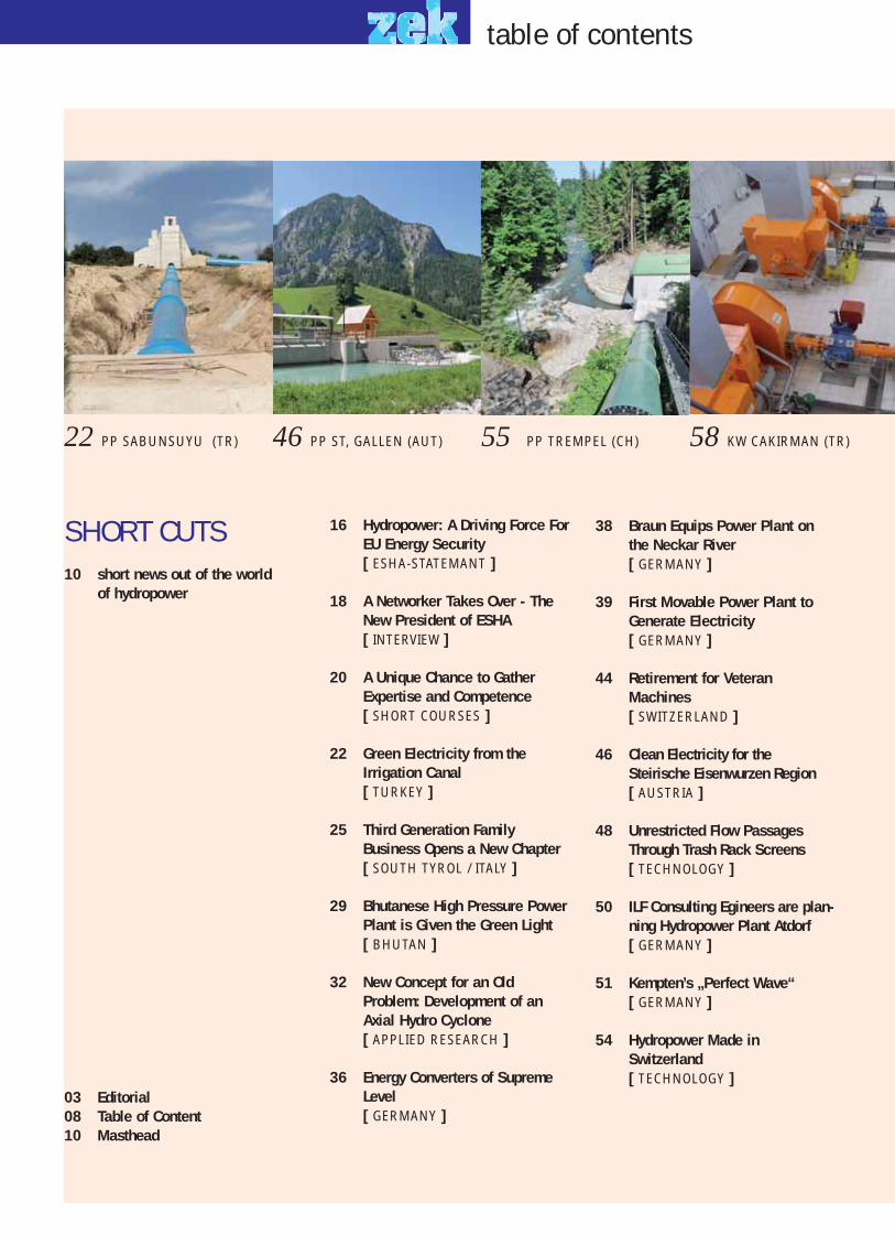
22 PP SABUNSUYU (TR) 46 PP ST, GALLEN (AUT) 55 PP TREMPEL (CH) 58 KW CAKIRMAN (TR) P
008-009.qxp 01.06.2011 11:53 Uhr Seite 2

55 Trempel Power Plant Shines in New Splendor[ SWITZERLAND ]
58 Austrian Technology for Turkish Top-Notch High-Pressure Power Station[ TURKEY ]
60 An Exceptional Combination Guar-antees Best Degrees of Efficiency[ AUSTRIA ]
64 Dual Use Snowmaking Plant[ SOUTH TYROL / ITALY ]
66 A Variety of Applications for HOBAS® CC-GRP Pipes[ TECHNOLOGY ]
68 Second Rebirth of an Industrial Landmark[ GERMANY ]
71 Hintermuhr Pumped Storage PP successfully expanded[ AUSTRIA ]
73 Growth Spurt for Machinery at Rhine Hydropower StationIffezheim[ GERMANY ]
76 High Quality Low-Pressure Tech-nology on the Eisack River[ SOUTH TYROL / ITALY ]
78 Long-term Reliability: A ConvincingArgument[ AUSTRIA ]
80 Construction to Start in Corum[ TURKEY ]
81 Voestalpine Marks a New Era with its Water Utilization Concept[ AUSTRIA ]
84 Vattenfall Invests in Wave Poweroff the Shetlands[ UNITED KINGDOM ]
86 Innovation at the Water Intake:The Grizzly[ TECHNOLOGY ]
PP KAINISCHTRAUM (AUT) 60 PP HORSTERMÜHLE (GER) 68 PP IFFEZHEIM (GER) 73 PELAMIS (UK) 84
Global Hydro U1
Marelli U2
Troyer U3
Andritz –VaTech U4
AEM 70
Amitech CH 63
Bernard & Partner 29
BHM-Ing. 11
Braun 38
EFG 61
F.EE 42
gmb 54
Gufler Metall 77
Hinteregger Bau 62
Hobas 67
HSI 43
Hydro-Solar 55
ILF- Beratende Ing. 15
Indar 24
Koncar 79
Kössler 21
Krebs & Aulich 42
Lukas 70
Muhr 53
Ossberger 49
Renexpo Bukarest 19
Roth GmbH 43
Schleith 73
Schweizer Wasserbau 75
Siemens 6–7, 28
Studio G 65
VAG 83
Wiegert & Bähr 56
Wild Metal 86
WKV-Volk 35
Advertisers zek HYDRO 2011
008-009.qxp 01.06.2011 11:53 Uhr Seite 3

10 2011 zek HYDRO
GLOBAL HYDRO ENERGY INAUGURATINGTHE NEW COMPANY BUILDINGDue to a strong expansion in the last fewyears the full range supplier of small-scalepower plants GHE, based in Upper Austria,was running at full capacity to process inco-ming orders. For this reason GHE decided toexpand its capacities at the site inNiederranna. The company invested anamount of about EU turbines are being setusing state-of-the-art technology. With thisgrowth an increase of the number of staff toapproximately 100 employees was inevitable.The official opening ceremony took place onMay 6th.
FIRST LARGE-SCALE HYDROPOWER PLANT IN TIBETIn November Sinohydro, one of China'sleading companies for hydraulic engineeringand hydropower, began with the constructi-on of a hydropower plant on the YarlungZangbo River. The river originates from theQinghai-Tibetan-Plateau and is the highestriver in the world. Outside of China the riveris better known as Brahmaputra River. Dueto its slope, it can be ideally used for hydro-power purposes. A total sum of CNY 7.9 bil-lion (EUR 900 million) is invested in thisproject. After its completion the Zangmupower plant will generate an annual totaloutput of 510.000 kWh. The first part of theproject is to be completed and put into ope-ration in 2014. The main goal is to cover thelack of electricity in the Central Tibetan area.
IMPORTANT AWARDS FOR HIGH-TECHFISH MIGRATION OF THE VERBUNDThe diversity of fish species in local rivers isof great importance to Verbund, Austria'sleading electricity company. In the past deca-des the company has built 15 fish ladders forits 89 river power plants in Austria. At thenewest power plants, such as the Villachpower plant on the Drau River, these laddersare high-tech products. They were construc-ted by using modular building concepts withready-made components. Furthermore thefish are being attracted directly to the bypasschannel by a hidden current pump.Observations show that more than 20 specieshave been counted, among them the raregrayling, a main fish of the Drau River. TheAustrian province of Carinthia presented theplant with the "Wasserlebenszeichen"("Water Signs of Life") award. The Ministryof the Environment awarded it with the"Neptun Water Prize".
Masthead
PUBLISHERS
Mag. Roland Gruber and Günter Seefried
PUBLISHING HOUSE
Gruber-Seefried-Zek Verlags OG
Lindaustraße 10, 4820 Bad Ischl
Tel. & Fax +43 (0) 6235-20 541
www.zek.at
EDITOR-IN-CHIEF
Mag. Roland Gruber, [email protected]
Mobile +43 (0)664-115 05 70
DEPUTY EDITOR-IN-CHIEF
Mag. Claudia Mantona,
Mobile +43 (0)664-214 06 14
MARKETING
Günter Seefried, [email protected]
Mobile +43 (0)664-3000 393
ADMINISTRATION
Erika Gallent, [email protected]
Mobile +43 (0)664-242 62 22
TRANSLATION
CPC | Crossing Paths Communications
Mag. Andreas Florian,
Mobile +43 (0)664-217 40 90
Reinhard Fischer,
PRODUCTION, PDF CREATION
MEDIA DESIGN: RIZNER.AT
Stabauergasse 5, 5020 Salzburg
Tel. +43 (0) 662 / 87 46 74
E-Mail: [email protected]
PRINTING
Druckerei Roser
Mayrwiesstraße 23,
5300 Hallwang /Salzburg
Tel. +43 (0) 662-661737
POST OFFICE
A-4820 Bad Ischl
BASIC GUIDELINES
zek HYDRO is a non-partisan
trade publication focussing
on hydropower.
PRICE INC. POSTAGE
€ 12,– / copy inc. VAT
zek HYDRO is published annually
Circulation: 4,400 copies
phot
o: J
oach
im-Z
imm
erm
ann_
pixe
lio.d
e
phot
o: z
ekph
oto:
VER
BUN
D
The independent Austrian company GHE offers itsclients all advantages of a flexible and innovativecompany, such as international experience in pro-jects from its worldwide exporting duties.
The first large-scale hydropower plant isbeing built in Tibet.
The award-winning fish ladder at the Villach power plant on the Drau River.
HYDRO
010-011.qxp 01.06.2011 11:54 Uhr Seite 2
zek HYDRO 2011 11
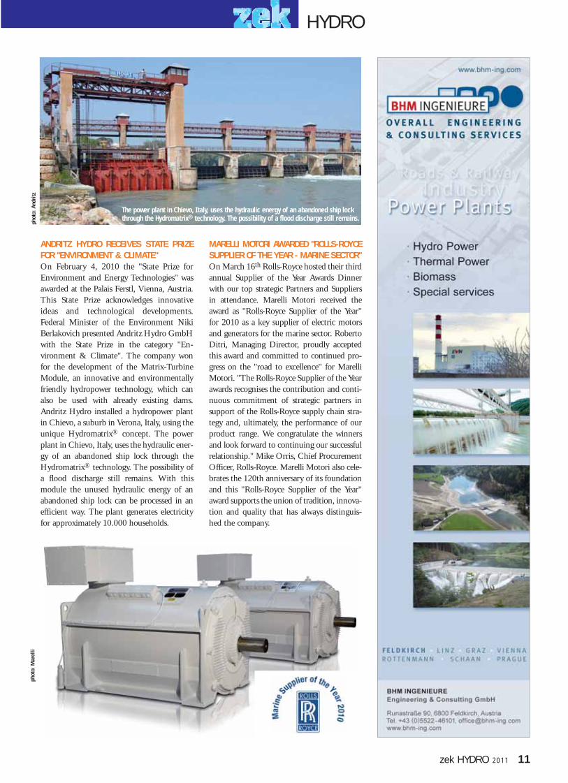
ANDRITZ HYDRO RECEIVES STATE PRIZEFOR "ENVIRONMENT & CLIMATE"On February 4, 2010 the "State Prize forEnvironment and Energy Technologies" wasawarded at the Palais Ferstl, Vienna, Austria.This State Prize acknowledges innovativeideas and technological developments.Federal Minister of the Environment NikiBerlakovich presented Andritz Hydro GmbHwith the State Prize in the category "En-vironment & Climate". The company wonfor the development of the Matrix-TurbineModule, an innovative and environmentallyfriendly hydropower technology, which canalso be used with already existing dams.Andritz Hydro installed a hydropower plantin Chievo, a suburb in Verona, Italy, using theunique Hydromatrix® concept. The powerplant in Chievo, Italy, uses the hydraulic ener-gy of an abandoned ship lock through theHydromatrix® technology. The possibility ofa flood discharge still remains. With thismodule the unused hydraulic energy of anabandoned ship lock can be processed in anefficient way. The plant generates electricityfor approximately 10.000 households.
MARELLI MOTORI AWARDED "ROLLS-ROYCESUPPLIER OF THE YEAR - MARINE SECTOR"On March 16th Rolls-Royce hosted their thirdannual Supplier of the Year Awards Dinnerwith our top strategic Partners and Suppliersin attendance. Marelli Motori received theaward as "Rolls-Royce Supplier of the Year"for 2010 as a key supplier of electric motorsand generators for the marine sector. RobertoDitri, Managing Director, proudly acceptedthis award and committed to continued pro-gress on the "road to excellence" for MarelliMotori. "The Rolls-Royce Supplier of the Yearawards recognises the contribution and conti-nuous commitment of strategic partners insupport of the Rolls-Royce supply chain stra-tegy and, ultimately, the performance of ourproduct range. We congratulate the winnersand look forward to continuing our successfulrelationship." Mike Orris, Chief ProcurementOfficer, Rolls-Royce. Marelli Motori also cele-brates the 120th anniversary of its foundationand this "Rolls-Royce Supplier of the Year"award supports the union of tradition, innova-tion and quality that has always distinguis-hed the company.
Foto
: Spu
tnik
AG
Die slowenische Photovoltaikanlage in GornjiPetrovci ist das größte PV-Kraftwerk der Region
Foto
: Hilb
er S
olar
phot
o: A
ndri
tzph
oto:
Mar
elli
The power plant in Chievo, Italy, uses the hydraulic energy of an abandoned ship lockthrough the Hydromatrix® technology. The possibility of a flood discharge still remains.
HYDRO
010-011.qxp 01.06.2011 11:54 Uhr Seite 3

12 2011 zek HYDRO
short cuts
ANDRITZ HYDRO TO EQUIP TWO PORTUGUESE POWER PLANTSElectricidade de Portugal (EDP), one of Europe's biggest energy com-panies, commissioned the international technology group ANDRITZto provide the entire electromechanical equipment for the two hydro-power plants, Ribeiradio and Ermida, on the Rio Vouga about 100 kmsouth-east of Porto. The plant is to be put into operation in early 2014.ANDRITZ HYDRO furnishes the Ribeiradio power plant, which isthe main stage with a head of 65 m and a flow rate of 125 m3/s, witha low-pressure Francis turbine with a blade wheel diameter of 3.7 mand an output of 77 MW. The Ermida power plant will be providedwith two double-regulated Compact Axial Turbines (1.950 mm bladewheel diameter and 3.8 MW output each). Both power plants will alsobe equipped with generators, control technology, equipment for steelconstruction for hydraulic engineering and auxiliary devices.
NEW ALSTOM HYDROPOWER PLANT ON THE SEYHAN RIVERPower company Alstom has announced the inauguration of a new tur-kish hydropower plant, which will produce enough electricity to supply640,000 homes. With a generating capacity of 320 MW, the Yedigozehydropower plant is located on Turkey's Seyhan River, and was inaugu-rated by the country's Prime Minister, Recep Tayyip Erdogan. Turkey'sSanko awarded the turkey supply and commissioning Yedigoze's twin170MW Francis hydro turbines and two 175 MVA hydro generators toAlstom in 2008. The new plant will form part of Sanko's programme tobuild additional renewable energy capacity, in line with the government'spush to increase the country's energy security by increasing its share ofrenewables. At the ceremony, Alstom's Turkey Country President, AdilTekin, said: "This project is another step in a long and productive part-nership with Sanko, as we continue in our mutual quest to deliver chea-per, cleaner power to Turkish consumers and businesses."
MINING COMPANY CONSIDERS UNDERGROUND HYDROPOWER PLANTSThe mining company RAG examines the development of undergroundhydropower plants for environmentally friendly energy production. Theidea is to let mine water rush down a pit with a depth of a few hundredmeters in order to initiate turbines to produce electricity. "We seriouslywant to make this project happen," says Bernd Tönjes, chairman of theboard of directors of RAG, in an interview with the German newspaper"Neue Ruhr/Neue Rhein Zeitung". Tönjes sees a huge potential in theunderground production of electricity. At the moment research con-tracts for regional universities are being prepared. Furthermore RAG isdeveloping specialized turbines with engine manufacturers. Accordingto RAG, an underground hydropower plant will generate an output ofa few hundred MW at a head of only 800 m. Locations for such under-ground hydropower plants could be the five coal mines still operating,Tönjes said.
THE USA WANTS TO PUSH THE EXPANSION OF HYDROPOWERUS Senator Lisa Murkowski has introduced a bill in the US Congress tosupport hydropower projects. According to the US NationalHydropower Association, the Hydropower Improvement Act is backeby nine other US senators, Republicans as well as Democrats. The mainidea of this bill is to accelerate and facilitate the expansion of hydropo-wer projects in the USA. Therefore a subsidies program is to be set up,which will encourage an increase of efficiency and an expansion of thecapacities of already existing and new power plants. There will also beextra incentives for small-scale plants. The expansion of hydropower isto be regulated at federal level. Furthermore a research and developmentprogram regarding hydropower is being considered. "Clean and reliablehydropower can help us achieve our goals for renewable energy," saysSenator Lisa Murkowski. (Source: IWR)
Works for the Yedigoze hydropower plant still in progress. The facility hasrecently been inaugurated.
ANDRITZ HYDRO provides the Portuguese Ribeiradio power plant with a low-pressure Francis turbine with an output of 77 MW.
Foto
: F.-
Gopp
_pix
elio
.de
The USA also want to expand theirsmall-scale hydropower landscape.
Mine water rushing into old coal minepits could power turbines in order to
produce electricity.
012-013.qxp 01.06.2011 11:55 Uhr Seite 2

zek HYDRO 2011 13
short cuts
HPC TO CONSTRUCT EURO 10M HYDRO PLANT IN HUNGARYEurope-based Hydro Power Consulting (HPC) will begin work to con-struct a HUF 2.7bn (€ 10m) hydroelectric power station on theHarmas-Koros river near Bekesszentandras in Hungary. The projectsecured HUF 1bn (€ 3.7m) grant through the government's EnergyOperative Program, while the rest of the investment will be providedby HPC, private donors and from bank loans. On completion, the two turbine facility is expected to deliver a 8.6GWof power annually. Work on the project is expected to be complete nextyear, reports bbjonline.hu.The company also plans to build anotherhydro plant on Hernád River, and it previously completed a similarpower station on the Raba River.HPC is active in the planning of hydropower plants worldwide. Theconsulting bureau is run by Dr. Kurt Wolfartsberger, a senior mechani-cal engineer with more than 37 years of experience in hydropower.
AQUAMARINE POWER SECURES 40MW LEWIS SEABED LEASESThe Western Isles could capitalise on Scotland's green energy boom.Aquamarine Power has secured seabed leases to capture up to 40MW ofwave energy off the west coast of Lewis. Following a series of meetingswith the local community, stakeholders and officials, Aquamarine Powerhas obtained leases from seabed owner the Crown Estate. This will enab-le the company to start environmental and feasibility studies and conti-nue working with the local community and other key groups on thepotential to install the so called Oyster wave energy technology.Aquamarine Power has secured two leases. One is a 10MW demonstra-tion lease for a site between Siadar and Fivepenny, known as the Galsonsite; the other is a 30MW lease granted under the Crown Estate's recent'Saltire Prize' leasing round - which offers an area of search between BàghDhail Beag and Tràigh Shanndaigh.
AFFORDABLE MINI-HYDRO POWER PLANTS FOR RURAL AREASThe Tanzania Engineering and Manufacturing Design Organization(Temdo) is working on a cheap and affordable mini-hydro power plantto provide sustainable power to people in rural areas. The new initiativeis geared to improve the living standards as well as reducing poverty inrural areas through improved access to electricity by small-scale enterpri-ses and households. Temdo senior official Philemon Kilasa said that thenew and cheap technology would mainly be delivered in remote areascurrently getting little or no electricity. "We have already designed thesmall machine for mini-hydro plant before advancing into other stages.These kinds of plants will be serving small communities in particularlocalities across Tanzania," said Kilasa. The pilot projects include the70kW micro-hydroelectric plant at Zege village in the UsambaraMountains, Njombe small power plant in Matembwe and similar plantsin Mavanga and Lugarawa villages.
PUMPED-STORAGE HYDRO SCHEME PLANNED FOR ALDERNEYTidal energy developer Alderney Renewable Energy is planning a smallpumped-storage hydro project on the island of Alderney in the ChannelIslands, media reports indicate. The pumped-storage hydropower sche-me would use tidal power devices, with an estimated combined capaci-ty of about 3-MW, to power a system that would pump sea water intoa land-based reservoir before releasing the water through at least onehydro turbine, reports indicate. The pumped-storage scheme wouldsupply an estimated 90 percent of the island's power demands. The Channel Islands are an archipelago of British Crown Dependenciesin the English Channel, off the French coast of Normandy. Recently, ARE signed an agreement to lease a site near Braye Harbour,Alderney, as the site of the turbine pump house and reservoir. The pro-ject could be completed by 2012, reports indicate.
HPC is going to construct a hydropowerplant on the Harmas-Koros river in Hungary.
ARE has already begun an environmental impact assessment to obtain marine consent from the Alderney Commission for Renewable Energy.
Oyster wave energy technology is plannedto be installed off the Scottish west coast.
Temdo-Engineers are working onaffordable mini-hydropower plants.
Several pilot projects in Tanzania havealready successfully been installed.
phot
o: A
quam
arin
e Po
wer
012-013.qxp 01.06.2011 11:55 Uhr Seite 3

SIEMENS: TRANSMISSION OF ECO-FRIENDLY HYDRO-BASED ELECTRICITY TO MEGACITIES IN THE GUANGDONG REGION Siemens Energy is to supply key components for the two high-voltagedirect-current transmission projects Nuozhadu-Guangdong andXiluodu-Guangdong in southern China. Purchaser is China SouthernPower Grid Company, Guangzhou. Nuozhadu-Guangdong will have atransmission capacity of 5,000 MW at a DC voltage of ± 800 kV andprovide electricity to the megacities in the Guangdong region, Xiluodu-Guangdong an overall capacity of 6,400 MW at ± 500 kV. Commis-sioning of the systems is scheduled for 2013. Large-capacity hydropower plants such as Nuozhadu and Xiluodo in southwest China willgenerate the eco-friendly CO2-free electricity for low-loss transmissionby the two new HVDC systems to the megacities Guangzhou, Jiang-men, Dongguan and Shenzhen. Alone the Xiluodo hydro power plantwill after completion in early 2013 have a total capacity of 12,600 MW.
STATKRAFT: OFFICIAL OPENING OF CAKIT POWER PLANT - AND THECOMPANY IS WORKING ON THREE OTHER PROJEKTS IN TURKEY „Turkey's demand for new energy is great, and I welcome Statkraft to
grow with Turkey", Taner Yildiz, Minister of Energy and Naturalresources, stated at the official opening of Cakit hydropower plant on12 October 2010. There is a great potential for developing renewableenergy in Turkey, and it could become one of the leading Europeancountries within this field. Turkey uses some 200 TWh of electricityannually, but it is expected that the demand will grow to 400 TWh by2020. At present, about 20 per cent of the total energy production isbased on hydropower, and there is a great potential for hydropowerdevelopment in Turkey. Statkraft is working on another three projectsin Turkey. If all are completed, the facilities will have a total capacity ofapproximately 550 MW and the average production capacity will beapproximately 1,800 GWh annually.
INCREASING CHINA’S HYDRO POWER CAPACITY: 2 NEW AWARDSFOR VOITH HYDROTwo Chinese utilities signed Voith Hydro for equipment of their newesthydro power projects: For the extension of Da Tang YanTan HydroPower Company's already existing plant Yan Tan, located at theHongshui River in Guangxi Zhuang Autonomous Region, Voith willsupply the generators for two 340 megawatt-units. Huanghe HydroPower Development Company is building Yang Qu hydro power planton the Yellow River and signed Voith Hydro for the supply of threeFrancis turbines with an output of 400 MW each. The overall value ofboth contracts runs up to about 350 million RMB (around 40 millionEuros). With these two projects 1,880 MW of new power generationcapacity will be installed. Today, China is generating 22 per cent of itselectricity from hydro power.
PHILIPPINES: BENGUET ELECTRIC TO GENERATE HYDROELECTRICPOWER FROM MINI-HYDROSAccording to a report vom Tendersinfo News the power distributor forBaguio City and the province, the Benguet Electric Cooperative, Inc.(BENECO), will soon produce its own hydroelectric power throughthe development of mini-hydros with initial steps underway. GarettWaytan, BENECO's engineer, said the company has just completed thefeasibility study of Man-asok river in Buguias that would serve as thewater source and site for the proposed hydroelectric power plant to pro-vide sizeable power requirements for its consumers. Joselito Villarey, theDepartment Manager of the corporate planning office, explained thatthe power plant will have a capacity of 3 MW sufficient to supply thepower requirements of the northern part of the province. Villarey saidthere are several requirements needed before securing permit.
Phot
o: S
IEM
ENS
The new plant for high-voltage direct current transmission in China collects energyfrom several hydroelectric power plants arranged like a string of pearls on theJinsha River, the upper course of the Yangtze. The majority of these dams are still at the planning stage or under construction – such as the Jinanqaio hydroelectricpower plant near the city of Lijiang. The photo shows the retaining structure and the four pipes through which water will flow into the turbine building.
Cakit power plant was decorated with appropriateflags for the official opening.
.
Phot
o:ST
ATKR
AFT
Voith is a leading provider of hydro power technology and pushes its further advancement. This photo shows the pumped storage power plant RaccoonMountain on the Tennessee River, USA, fitted with pump turbines and motorgenerators from Voith.
Phot
o: V
OITH
HYD
RO
Philippines: The Benguet Electric Cooperative, Inc. (BENECO) is planning to 30 per cent power requirement of consumers to be sourced out from the proposed mini-hydros which they intend to put up in the province. BENECOis also planning to set up mini-hydro power plants in Tuba.
Phot
o: R
icha
rd R
ühl/p
ixel
io.d
e
14 2011 zek HYDRO
short cuts
014-015.qxp 01.06.2011 11:44 Uhr Seite 2

CASCADE HYDROPOWER PLANT IN RUSSIAAlstom Hydro France, Alstom Russia and the Russian United Energy-Construction Corporation, or OEK, have signed an agreement withRusHydro, a hydro power generation company, to modernize theCascade of Kubansky hydropower plants in Russia. The agreementfollows an earlier Strategic Cooperation Agreement signed betweenAlstom and RusHydro in December 2010. Alstom will carry out therehabilitation of electro and hydro mechanical equipment as well asinstall a new instrumentation & control system. Its partner OEK willbe responsible for all civil works. The Kubansky Cascade hydropowerplant complex, RusHydro's subsidiary situated at the Kuban River(South of Russia) and extending for 235 km, includes eight hydro po-wer plants and one pumped storage power plant, with a total originalcapacity of over 460 MW. The modernization by Alstom could ensurea capacity increase from 10 per cent to 20 per cent (up to 550 MW).
TUNNEL UNDER NIAGARA FALLS TO INCREASE THE OUTPUT OFTHE HYDROPOWER PLANT SIR ADAM BECK GENERATING STATIONA 10.4 km tunnel under the Niagara Falls has been drilled to increasethe output of the hydropower plant, Sir Adam Beck GeneratingStation, in Ontario, Canada. The extension project, which is expectedto be finished in 2013, will increase the flow of water by 500 m3/secand could increase hydropower output by 1.6 TWh. “Niagara Falls isnot only the Honeymoon Capital of Canada, but a hub for clean ener-gy. This project has attracted CA&1 billion in new investment andcreated hundreds of new jobs in our community,” says Kim Craitor,MPP Niagara Falls. The project started 2005 and contained serveraldetails: Boring a tunnel 14.4 meters in diameter at a depth of up to140 meters below the City of Niagara Falls and the surrounding area.The tunnel will enhance the original engineering accomplishment ofthe Sir Adam Beck complex in transporting water along the NiagaraEscarpment to increase its energy output. The tunnel also will comple-ment the upgrading of the 16 generating units at the Sir Adam Beck2 station that was completed in May. The nine-year upgrading increa-sed the potential peak output of the 16 units by 194 MW. It was com-pleted ahead of schedule and about 15 per cent under its original bud-get estimate of $220-million. The Niagara Tunnel project will allowenough energy production to serve an additional 160,000 averagehomes. Average annual energy output from the Sir Adam BeckComplex is expected to be increased by 14 per cent. Currentlyapproximately 1,800 m3 of water per second are available from theQueenston Chippawa Power Canal and the two existing tunnels underNiagara Falls. An additional 500 m3 of water per second will be madeavailable via the new tunnel.
Phot
o: L
ance
reno
K
The Kubansky Cascade hydropower plant complex, situated at the Kuban River(South of Russia), includes eight hydro power plants and one pumped storage power plant, with a total original capacity of over 460 MW.
Niagara tunnel intake construction at the International Niagara Control Works withFalls in the background.
Tunnel excavation is from the outlet near the Sir Adam Beck Pump GeneratingStation (right end) to the intake at the International Niagara Control Works. The tunnel goes under the buried St. David's Gorge and parallels the corridor established for the existing SAB 2 tunnels under the City of Niagara Falls.
Phot
o: O
PG
Phot
o: O
PG
zek HYDRO 2011 15
short cuts
014-015.qxp 01.06.2011 11:44 Uhr Seite 3

mall hydropower (SHP) has longbeen established as one of thecleanest, most efficient and reliable
energy sources. It contributes to an annual 29million tons of CO2 avoidance which transla-tes to an annual € 766 million of avoidedCO2 costs. In addition, it enables local andregional energy independence and boostslocal economies by creating new job income.
Despite these figures, small hydropower stillhas a long way to go. In Europe, huge poten-tial for SHP lies in the upgrade and construc-tion of new schemes. This potential accountsto an additional 38,000 GWh in the EU-27and is defined as additional or remainingeconomically feasible potential, where envi-ronmental constraints have been taken intoaccount.
The true importance of hydropower in theRenewable Energy Source (RES) mix lies inthe fact that it is the only energy source whichcan ensure a constant electricity supply whereother RES lack the capacity to do so.Therefore, hydropower not only helps stabili-se the electricity grid due to its storage poten-tial but also greatly contributes to the develop-ment of smart grids.
HYDROPOWER: A DRIVING FORCE FOR EU ENERGY SECURITYToday hydropower generates about 70% of the EU's renewable energy. About 90% of this comes from large-scale schemes only.With more than 21 000 small hydropower installations in the EU-27 generating over 46 TWh of electricity per year, smallhydropower is enough to supply electricity for over 13 million households.
SPh
otos
: Mar
co B
arne
beck
_pix
elio
.de
Pumped-Storage Power PlantHohenwarthe by the river Saale /Deutschland.
Edersee Dam / Deutschland
HYDRO
16 2011 zek HYDRO
Phot
o: R
osel
Eck
stei
n_pi
xelio
.de
016-017.qxp 01.06.2011 11:48 Uhr Seite 2

With increased global electricity demand,there is an urgent need to reduce greenhousegas emissions and fight against climate changeand environmental degradation which resultfrom fossil fuel use. Small hydropower canhave a significant role in ensuring future ener-gy supply, a role that it unfortunately fails tofulfil due to several barriers that stand in theway of its development.The Water Framework Directive (WFD)which came into force in 2000 has had a con-siderable impact on SHP growth. Despitesafeguarding the good environmental status ofwater bodies, the Directive's interpretation at
national level has had direct negative conse-quences on the approval of new projects andthe allocation of concessions and permissions.For SHP producers this has meant long, cost-ly, complicated and non-transparent admini-strative procedures in the obtainment of licen-ses for operation of SHP plants.
In addition, the adoption of the EuropeanCommission's RES Directive in December2008 has meant that implementation of thetwo Directives is often conflicting due to litt-le or no coordination and a lack of knowled-ge-exchange between the respective ministriesin the Member States. One of the biggest chal-lenges for the SHP sector is the reconciliationof these two Directives.
SMALL HYDROPOWER IN THE EU-27 INFIGURESThe European Small Hydropower Association(ESHA) is currently leading an EU co-finan-ced project called the Stream Map which has,for the first time in history, created a centraldatabase with figures on the European hydro-power sector. The database is available to thegeneral public free-of-charge on www.streammap.esha.be and covers energy,policy and market data, potentials and fore-casts. The project will also prepare a roadmapoutlining the future of the hydropower sector.
Table 1- Small Hydropower Generation and the 2020Forecasts: National Renewable Energy Action Plans VsStream Map scenarios, source: ESHA
Mühlewerk Power Plant /Germany
HYDRO
zek HYDRO 2011 17
SMALL HYDROPOWER STRUGGLES TOMAKE HEADWAY IN AN ADVERSEEUROPEAN CLIMATE
016-017.qxp 01.06.2011 11:48 Uhr Seite 3

zek: Did the offer to become presidentcome as a surprise to you?
Gospodjinacki: : Indeed, it all wentvery fast. In mid May of last yearBernhard Pelikan told me that he wouldnot run for president again and suggestedthat I should succeed to his office.However, before I agreed I wanted tolearn about the roles of the president.After all, from an outside perspective, allyou see are representative tasks, but notthe regular every day routine. So I had totalk to a lot of people beforehand, gatherall the information I needed and finallymake myself available.
zek: Does this mean you are no longerin charge of the Slovenian Small Hydro-power Association?
Gospodjinacki: Yes, some of my previousfunctions in Slovenia have been comple-ted. And in order to succeed as presidentof ESHA, I had to dedicate myself fullyto my new role.
zek: Have you found the ideal settingsfor your undertaking?
Gospodjinacki: Absolutely! I have to saythat ESHA is basically an excellent team.When I took office the only thing Ichanged regarded the company structure.After all, I can only lead an organizati-on that I can truly manage. Of courseone cannot do this alone and that is whyI am glad that I can rely on competentand motivated staff. Honestly, I was tou-ched by all the support I received fromthe ESHA team in the beginning.
zek: Would you say the change in theESHA presidency was a smooth or rat-her a rough one?
Gospodjinacki: : It was definitely asmooth change. My predecessor,Bernhard Pelikan, is not only a goodfriend of mine, but he deserves thegreatest respect for his work of the last sixyears. It was his accomplishment to makeESHA a true family within a relativelyshort time. And this is not a simple job,considering the fact that the memberscome from all kinds of different fields,such as science, NGOs and businesses. Heemphasized scientific and university-related work within ESHA. We mustcontinue to pursue this effort. We arelucky that ESHA does not lose BernhardPelikan, since he will remain a valuablesupport as one of the two vice-presidents.
zek: What challenges will ESHA have toface in the next few years?
Gospodjinacki: We need to strengthenthree of our supporting pillars funda-mentally. First of all, we want to focus onthe collaboration with electricity andenergy providers, i.e. investors. We alsoneed to collaborate with manufacturersand of course with financial institutions.Suppliers need investors and vice versa.And both of them need to rely on finan-cial institutions as partners. We want toput more effort into becoming a platformand an interface. Numerous investorsapproach ESHA for information. That iswhy we need to expand our platform andnetwork even further. ESHA is the pri-mary contact regarding small-scalehydropower for Europe, on an interna-tional level we are an organization withthe best reputation. We want to furnishinvestors with comprehensive informati-on. The second important pillar repre-sents a stronger network with nationalorganizations. When possible and nee-ded, we want to support these organiza-
In the summer of last year, a new president was appointed for ESHA, the European Small Hydropower Association. Longtimepresident Prof. Dr. Bernhard Pelikan, who had been well-known outside of Austria as well, retired from his position. He wassucceeded by his good friend Marko Gospodjinacki, who had until then presided the Slovenian Small Hydropower Association.This change is a sign of continuity as well as of further development. zek magazine met the new president of ESHA and spoketo him about his role, his prospects and his goals during his term in office.
18 2011 zek HYDRO
A NETWORKER TAKES OVER - THE NEW PRESIDENT OF ESHA
phot
o: z
ek
Marko Gospodjinacki of Slovenia is the new Presidentof the European Small Hydropower Association -ESHA. He succeeds Prof. Bernhard Pelikan.
HYDRO
018-019.qxp 01.06.2011 13:11 Uhr Seite 2

economic and ecological interests at the sametime. After all, building power plants is notour hobby, but a necessity, as people need reli-able electricity supply.
zek: It looks as though you will be faced witha lot of work?
Gospodjinacki: Yes, of course. But we havestarted ambitiously last year. Our work is also ina state of constant acceleration, which is anothergoal for me - to keep up this acceleration.
zek: Would you think of yourself as a net-worker?
Gospodjinacki: Sure! Anyway, I hope I amone. The office of ESHA president is withouta doubt a big challenge for me. But again, Iwould like to emphasize that luckily I am notleft on my own. I have highly competent co-workers with me, who strongly support me,like the new Secretary General DirkHendricks. However it would be nice if wecould welcome more people to our team.
zek: Thank you very much for this inter-view and all the best for your upcomingchallenges!
zek HYDRO 2011 19
tions and provide them with more informati-on from ESHA. And the other way around,we would like to gain more information fromthem. Of course we are happy about anynational organization joining ESHA.
zek: The third pillar?
Gospodjinacki: The third important goal forme is to tear down existing barriers - especial-ly regarding the ecological field. I believe thatthe interdisciplinary communication between
hydropower experts and ecologists is fine, butthere are still some aspects that need to beimproved. I think the main problem is thatmisunderstandings and disagreements areoften caused by a lack of understanding ofeach other's vocabulary. Sometimes the twoparties speak two different languages. Weurgently need knowledge and scientificallybased, generally valid, understandable crite-ria with which we can reasonably elaborate
Marko Gospodjinacki takes over the office in the Renew-able Energy House, ESHA's registered seat in Brussels.
HYDRO
Former ESHA president Prof. Dr. Bernhard Pelikanwill remain as one of the two vice-presidents.
018-019.qxp 01.06.2011 13:11 Uhr Seite 3
o become a specialist in SustainableHydropower means to acquire the abi-lity of interdisciplinary engineering
and the feeling of how to find compromises.Interdisciplinary cooperation between expertsin the fields of construction works, hydrology,environment, spatial planning, electromecha-nical equipment and law is nowadays theusual way towards a successful project.The leading function in a hydropower projecthas necessarily to be taken by an engineer.This person has to know about the different"languages", the very many interests anddemands and how to manage and coordinatea project team.
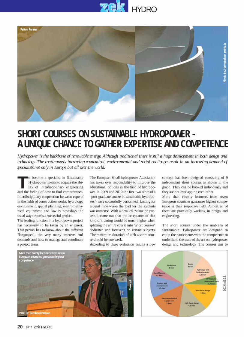
The European Small hydropower Associationhas taken over responsibility to improve theeducational options in the field of hydropo-wer. In 2009 and 2010 the first two series of a"post graduate course in sustainable hydropo-wer" were successfully performed. Lasting foraround nine weeks the load for the studentswas immense. With a detailed evaluation pro-cess it came out that the acceptance of thatkind of training would be much higher whensplitting the entire course into "short courses"dedicated and focussing on certain subjects.The maximum duration of such a short cour-se should be one week.According to these evaluation results a new
concept has been designed consisting of 9independent short courses as shown in thegraph. They can be booked individually andthey are not overlapping each other.More than twenty lecturers from sevenEuropean countries guarantee highest compe-tence in their respective field. Almost all ofthem are practically working in design andengineering.
The short courses under the umbrella ofSustainable Hydropower are designed toequip the participants with the competence tounderstand the state of the art on hydropowerdesign and technology. The courses aim to
SHORT COURSES ON SUSTAINABLE HYDROPOWER -A UNIQUE CHANCE TO GATHER EXPERTISE AND COMPETENCEHydropower is the backbone of renewable energy. Although traditional there is still a huge development in both design andtechnology. The continuously increasing economical, environmental and social challenges result in an increasing demand ofspecialists not only in Europe but all over the world.
T
Phot
os: P
aul-G
eorg
Mei
ster
_pix
elio
.de
Pelton Runner
Prof. Dr. Bernhard Pelikan
More than twenty lecturers from sevenEuropean countries guarantee highest competence.
HYDRO
20 2011 zek HYDRO
Phot
o: z
ek
TOP
ICS
020-021.qxp 01.06.2011 13:22 Uhr Seite 2

improve the understanding of concepts andsystems and enhance knowledge regardingtools and approaches. The courses will educa-te those involved in design, engineering andimplementation of advanced and sustainablehydropower concepts.Participants will receive a certificate of post-graduate in Sustainable Hydropower by LifeLong Learning Academy Technikum Wienand ESHA, European Small HydropowerAssociation, Brussels
Courses on Sustainable Hydropower are tailo-red to professionals in the hydro power busi-ness, to potential investors who want to learnabout the background of their business andgenerally to people who are interested in oneof the most colourful sectors of renewableenergy.The lectures will be held at Technikum Wienin Vienna, Austria in an excellently equippedseminar room close to the city centre. Theseries of courses will start beginning 2012.
The courses can be booked individually orclustered in groups.Free internet access, snacks, fruits, coffee, teaand water are available during the entire dura-tion of the course. Lunch is included in thecourse fees. More informations will be given by the direc-tor of the course, Prof. Bernhard PELIKAN,[email protected] and on the internet:www.esha.be www.lllacademy.at/hydropower
The short courses are designed to equip theparticipants with the competence to under-stand the state of the art on hydropowerdesign and technology. The picture shows a fine example of amodern high pressure small hydropowerplant in Southern Tyrolia.
HYDRO
zek HYDRO 2011 21
Phot
o: z
ek
020-021.qxp 01.06.2011 13:22 Uhr Seite 3

ne of the results of the dynamic econo-mic development in Turkey over thelast few years was a strong rise in the
demand for electricity. In efforts to reduce thecountry's dependence on imported electricity,the expansion of hydropower operations hasbeen stepped up successively. One of the localfirms committed to the environmentallyfriendly generation of hydroelectricity is ANGEnergy, a member of the KAYA group.According to ANG's self conception as a busi-ness, the protection of nature and the climateis one of their core values. It was therefore with considerable ambitionthat the firm, led by the group's 50% ownerBaver Kaya, approached the construction pro-ject for the Feke HEPP hydropower station.But after its launch in 2004, the project drag-ged on without being finished. "The main
problem was the commissioning. The con-tracted Indian turbine supplier showed a bla-tant lack of proper supervision. Six monthsafter the commissioning work had been laun-ched, there were still no turbines turning inthe power house. This was in part due to thefact that the machines had to be assembledon-site based on some sort of building blockssystem. The officials at ANG Energy, especial-ly Mr Baver Kaya himself, were deeply unhap-py with the situation", reports GHE's salesdirector, Ewald Karl.
GHE GETS SUPPORT INBut there was also another, much more bene-ficial side to the situation: as ANG Energybegan looking for support during this criticalphase of the project, they met GHE's repre-sentative for Turkey, who subsequently lent a
much needed helping hand in moving thedelayed construction project along towardsthe successful start-up of the machines. Thehappy ending of this project was not to bewithout its - very positive - consequences forGHE. "ANG Energy at that time was in themiddle of the tender process for the next eco-power project in Turkey: the SabunsuyuHEPP power station. At first it looked verymuch like the contract for the machine equip-ment would be awarded to a Chinese supplier.But thanks to our successful previous contact,the operators had taken notice of our serviceportfolio and requested a quote from us. Theirdecision in our favour was apparently a quickand easy one, as the order was signed, sealedand delivered within a matter of only sixweeks. That is spectacularly quick in the worldof international hydropower business," says
The Turkish hydropower market is boo-ming like few others today. In manyplaces awareness among local operatorsis growing that high-quality technologyalso stands for investment security.Among the beneficiaries of this trendare Austrian manufacturers such asGHE of the Upper Austrian town ofNiederranna, whose machines are ingrowing demand in the Turkish mar-ket. GHE's latest reference project is theSabunsuyu hydropower station near thetown of Adana, which has a bottleneckcapacity of more than 7 megawatts.The facility is equipped with turbinesand a comprehensive control technologypackage by GHE. Sabunsuyu HEPP isone of the 13 hydropower projects thatGlobal Hydro Energy has successfullyimplemented in Turkey by now. And itwill certainly not be the last.
O
22 2011 zek HYDRO
phot
o: G
HE
The two spiral Francis turbinesby GHE that were installed atTurkish hydropower stationSabunsuyu generate approxi-mately 27 GWh a year.
GREEN ELECTRICITY FROM THE IRRIGATION CANAL
The DN1500 steel penstock pipelinehas a length of about 1.4 km.
A special feature of the power house is the roof, whichis rail-mounted, making it easy to shift as needed.
A distinctive feature of the power station is the unique architecture of the intake. Fo
tos:
GHE
HYDRO
022-023.qxp 01.06.2011 13:23 Uhr Seite 2

zek HYDRO 2011 23
Karl, recalling the beginnings of the collabora-tion with ANG Energy.
NON-MATCHING PAIR OF MACHINESThe Sabunsuyu power station was to be instal-led near Adana, a city with more than a milli-on inhabitants, barely 50 km away from theSyrian border. ANG Energy had obtained therequired license for the hydroelectric utilisati-on of an irrigation channel that provideswater, especially during the dry summermonths, to the surrounding agricultural areasalong a stretch of about 11 km. The design ofthe plant is to use a flow volume of 6.2 m3/secat the intake from the irrigation channel andguiding it to the power house by way of a 1.4km long DN1500 steel penstock pipeline."Throughout the summer, the use of thewater for irrigation purposes takes clear prece-dence over its use for hydropower generation.As a result, the available overall water volumecan be very low at that time. This causes aspread of the water resources that suggestedthe use of a non-symmetric machine configu-ration: as it turned out, the optimum solutionwas the combination of a large spiral Francisturbine designed for 5923 kW at a flow capa-city of 4.9 m3/sec and a net head of 136metres, together with a smaller spiral Francis
Foto
: zek
GHE's Turkish client, represented by managing di-rector Baver Kaya (middle) during the official accep-tance procedure at GHE's manufacturing facilities,with Franz Hain (left) explaining relevant details.
turbine delivering 1621 kW at a design flowrate of 1.3 m3/sec and a net head of 141metres. When possible, the large machine isoperated at the optimum operating point, andthe smaller one acts as a water level regulator,"explains GHE project leader Franz Hain. Theturbines were to be installed in the powerhouse within ten months of receiving theorder. In addition to the turbines, the contractawarded to GHE included the two generators,the hydraulic aggregates, the turbine controlsystem „HEROS“ and the SCADA system,GHE's proven „THEMIS“ solution.
WORKING ON THE SAME WAVELENGTHThe delivery of the machines in late May andearly July of 2010 was followed by the com-missioning process, which was completed instages from July to September. As Hainexplains, "We had to do it in stages to accom-modate the fasting month of Ramadan, whenwork usually comes to a virtual standstill." Itwas a considerable challenge for the enginee-ring team as well, primarily because of theintense summer heat. In spite of it all, theUpper Austrian hydropower specialists arevery positive about their collaboration withANG Energy. "Being able to meet and consultpersonally with the decision makers of a pro-
ject in a foreign country is by no means some-thing to be taken for granted. Such kind ofprojects are usually managed without directpersonal contact to persons in charge, whichtends to extend the chain of decision-makingand complicate communication. Not so withthis client. The boss, Mr Baver Kaya, is him-self a very dedicated professional. He came toour Austrian head offices for the acceptance ofthe machines. He would even drop by theconstruction site every once in a while andmotivate his team - and he frequently talkedwith us as well. It was the kind of open attitu-de we would have expected only from opera-tors in our part of the world. Anyway, it con-tributed a lot to the excellent working condi-tions," says Ewald Karl, almost a little eupho-rically.The appreciation was mutual, as evidenced bythe very positive feedback from the owner andthe operator of the power station. In a perso-nal letter Mr Baver Kaya expressed his thanksto all the GHE employees who contributed tothe success of the Sabunsuyu hydropower sta-tion project. The letter put a big smile on thefaces of the turbine specialists. After all, it isthanks to satisfied clients like these that GHEwere able to expand their share of the boo-ming Turkish hydropower market.
Technical characteristics:Design flow rate: 6.2 m3/s Gross head: 144 m
Machine Set 1: Spiral Francis turbine Manufacturer: GHEDesign flow rate: 4.9 m3/s Net head: 135.87 mUnit speed: 750 rpm Runner diameter: 799 mm Capacity of Unit 1: 5,923 kW Generator: Synchronous Manufacturer: IndarGenerator: Nominal current: 6.3 kV Rated output: 7,000 kVA
Machine Set 2: Spiral Francis turbine Manufacturer: GHEDesign flow rate: 1.3 m3/s Net head: 141.26 mUnit speed: 1,500 rpm Runner diameter: 408 mm (16.1 in)Capacity of Unit 2: 1,621 kW Generator: Synchronous Manufacturer: IndarGenerator: Nominal current: 6.3 kV Rated output: 2,000 kVADesign capacity: 7.3 MW Annual production capacity: approx. 27 GWh
A CAD representation of the posi-tion of the two different spiralFrancis turbines in the powerhouse of the Sabunsuyu facility.The turbines are controlled via a best-point regulation scheme devised by GHE's software engi-neers: the smaller turbine is designed to regulate the available water; the level control functi-on is activated when the large turbine is in operation. Whenever possible, this larger turbineis operated at the optimum operating point, while the smaller one is acting as a regulator.
on the right: GHE's proven overriding SCADAcentre solution „THEMIS“ ensures a perfectadjustment of the power station's operation
to the available water resources.
HYDRO
022-023.qxp 01.06.2011 13:23 Uhr Seite 3

ith a clear focus on the quality ofthe installed machines, Mr BavaKaya, the managing operator of
the Sabunsuyu HEPP power station, put theresponsibility for the installation of the entireturbine system and the control and automati-on equipment into the able hands of Austrianhydropower specialist GHE. In the search forappropriate generators, the operator was
introduced by GHE to Indar Electric, a spe-cialist in the construction of rotationalmachines with 60 years of experience and avast know-how.The machinery provided for the Sanunsuyufacilities consists of two brushless synchro-nous generators that were custom adjusted tothe capacity level of the two attached Francisturbines.
Indar Generators comply with current inter-national legisation of the manufacture of elec-trical rotating machines. The knowledge ofthe physical phenomena that occur in syn-chronous generators, together with the latestsoftware to calculate finite elements has allo-wed Indar to otimize the electro-magneticdesign of the machines and thus obtain hig-her performances.
The Sabunsuyu HEPP power stationin the Turkish town of Andana nearthe Syrian coast today ranks as one ofthe region's showcase projects wherepower stations are concerned. There aremany reasons for this, not the least ofwhich are the two sets of machines,which have a total generating capacityof 8 megawatts. When selecting a sup-plier for the generators, the Turkishoperator decided in favour of the com-petence and quality of Indar Electric,an Ingeteam company.
24 2011 zek HYDRO
W
PUTTING QUALITY FIRSTOne of thwo Indar generators for theTurkish Sabunsuyu HEPP Power Plant.
phot
o: G
HE
HYDRO
024.qxp 01.06.2011 13:24 Uhr Seite 2

zek HYDRO 2011 25
A southern Tyrolean family-owned firm with a rich tradition, Troyer AG is well prepared to meet the latest challenges in thehydropower market. The firm's long-lasting success story began almost 80 years ago under its founder Valentin Troyer, thencontinued under the leadership of his three children Maria Luise, Herbert and Ernst and is still ongoing today with the thirdgeneration of Troyers keeping the business alive and well. The new associates, cousins Norbert and Stefan Troyer and SimoneBressan, can rely on the support of a modern infrastructure, extensive know-how and - most of all - on about 100 well-trai-ned and highly motivated employees. Even though the firm's name, its legal status and one of the buildings are new, the pro-ven philosophy of Troyer AG remains the same: to provide high quality, service and flexible solutions in the context of a fami-lial atmosphere that only a family business can offer.
TROYER AG: THIRD-GENERATION FAMILY BUSINESS OPENS A NEW CHAPTER
phot
o: z
ek
owever, the full order books and particularly positive develop-ment of business last year did come with a drawback for thefamily business from the town of Sterzing: space on the firm's
premises was getting increasingly sparse. The projects had becomemore extensive and complex, and the size of the turbines had grownaccordingly. Also, the number of employees had doubled over the pre-vious ten years to its current level of 100. The company with its long-standing tradition seemed to burst at the seams. "An expansion was unavoidable," says Simone Bressan. "The old pro-duction hall would have been too small for some of the latest large-scale contracts due to the dimensions of the turbines." Norbert Troyershares this view: "It was the right step taken at the right time - even ifthe expansion required great efforts in terms of time and costs, and alsopersonally."Once an adjoining property in Sterzing had been found and purcha-sed, it was time to proceed with investing in the new, 16 m high pro-duction hall. March 2009 saw the kick-off to the construction work,in the course of which 300 tons of steel were used. The constructionwent ahead smoothly and made quick progress, so that the projectcould be completed the same year before the start of the Christmas sea-son. The new manufacturing facilities were built immediately next tothe existing ten-year-old production hall, which still meets the latestrequirements. Early last year, the new building was finally ready formoving in.
VENTURING INTO NEW DIMENSIONSThe inauguration of the new building was accompanied by a comple-te organisational and logistic restructuring. As Norbert Troyer explains,"Module preassembly and sandblasting, as well as the paint shop, the
H
With its new production hall Troyer AG has ex-panded its production area to about 7,000 sqm.
Today, Troyer AG is also one of the best established providers of control and automationtechnology in the hydropower industry. The most prominent reference project was theEnerpass power station in the South Tyrolean Passeiertal region. The control and automa-tion technology as well the low- and medium-voltage level installations for the 26 MWpower station were all provided by Troyer.
HYDROph
oto:
Troy
er
025-027.qxp 01.06.2011 13:25 Uhr Seite 3

26 2011 zek HYDRO
warehouse and the welding and metalworking units weremoved from the 'old' hall to the new building. Electricaland electronic engineering, the machining stations such asmilling and turning and, of course, the electrical andmechanical engineering departments and the administrati-on all remained in the existing building." This gave theindividual workstations a lot more breathing space. Thenew hall measures 54 by 46 metres in length and width,respectively. The central aisle of the new building was set up as a stora-ge space for heavy unfinished parts as well as for raw mate-rials such as rods and shafts. The four mobile shelves notonly provide a clear overview of the stock, but thanks totheir ability to shift aside they only require one free accesspassage, making this shelving system a veritable little 'spacemiracle'. Several indoor cranes are available to ensure opti-mum handling of the modules and heavy machine parts."The new cranes alone represent an investment of about250,000 Euros," explains Simone Bressan. "The extraspace allowed us also to step up our investment in themachine park. Our focus was mainly on a new 3+2-axleCNC machining centre and CNC-controlled turning-and-milling machine, which had been on our to-do list for along time," says Stefan Troyer.
FOCUS ON AIR AND LIGHT One of the most convincing characteristics of the new buil-ding is the well-designed lighting concept, which is basedon light strips along the side walls in combination withglass-covered sun roofs. The brightness makes for a verypleasant work space with great visibility, which also ensuresproper working safety. In addition to that, a sophisticatedventilation system ensures a pleasant, healthy flow of airthroughout the hall.But the expansion work was not just limited to the newbuilding. In the existing, ten-year-old building, only few
SOME OF THE LATEST MILESTONES
Type: Medium-pressure power stationOperator: Town of SterzingWater body: EisackCatchment size: 126 km2
Gross head: 78 m Design flow rate: 4.4 m3/sTurbines: 3 Francis turbinesM1: 1.720 kW M2: 860 kW M3: 447 kWStandard capacity: 12 GWh
2007 saw the completion of one of thelatest-generation small-scale hydropo-wer stations in the Sterzing area. It wasequipped exclusively with hydropowertechnology 'made by Troyer AG'.
Type: High-pressure power stationOperator: EUM (Genossenschaft Energie-und Umweltbetriebe Moos)Water body: PfeldererbachCatchment size: 52 km2
Gross head: 473 m Design flow rate: 3 m3/sTurbines: 2 twin-jet Pelton turbinesBottleneck capacity: 12 MWStandard capacity: 50 GWh
At the time, this was not only SouthernTyrol's largest power station project butalso the largest contract Troyer had everbeen awarded.
Bergkristall-Stieber power station 2006 / 2007 Moos i. Passeier / Southern Tyrol
Lurx Power Station 2007 Sterzing / Southern Tyrol
Type: High-pressure power stationOperator: EtschwerkeWater body: SchnalserbachCatchment size: 215 km2
Gross head: 300 m Design flow rate: 2.2 m3/sTurbine: four-jet Pelton turbineOutput: 6 MWEfficiency improvement: > 10%
2004-2005 Troyer provided a new turbine andelectrical equipment to one of SouthernTyrol's foremost historical power stations,which began operations in 1912. The projectwas a first proof that the firm was also capa-ble of handling larger-sized contracts.
Schnalstalwerk 2004 / 2005 At the entry of the Schnalstal in Southern Tyrol
phot
o: Tr
oyer
HYDRO
025-027.qxp 01.06.2011 13:25 Uhr Seite 4

things remained the way they had been before. Whether atthe magazine, the electrical engineering shop or the offices- each department now provides a lot more room, with thelatest interior design solutions being installed in manyinstances. Overall, the industrial complex in Sterzing wasexpanded to 7,000 sqm - double the size of the originalpremises.
With the addition of a second factory building the familyfirm from Sterzing has added a second mainstay to its busi-ness. The new possibilities of the expanded machine parkhave allowed the firm to ready itself for the big challengesahead and has opened up new perspectives for the future.All-in-one solutions as trademark In setting the course for the future development of thefirm, the associates last November decided to change thelegal form of business and name of the firm. To enable aclear-cut regulation of the succession of the associates, thefirm was transformed into an "Aktiengesellschaft" (publiclimited company). Its new official name is now "TroyerAG". "The word 'Turbinenbau' ['Turbine Manufacturers']has been removed from the firm's name, as it had frequent-ly begged the question why the firm would call itself a 'tur-bine manufacturer' while manufacturing the electricalengineering components as well. Maria Luise Troyer, theformer and current president of the firm, explains the mainreason for the name change: "The name didn't quite cap-ture the full scope of our business, since we basically alsoprovide and install complete control and SCADA systemsfor power grid management, which doesn't really have toomuch to do with 'turbine manufacturing' as such anymore," she says. "Since it can be very difficult to express thefull scope of services of our company in a simple name andretain the Troyer name at the same time, we decided on'Troyer AG', which is short and to the point."Where the scope of services of the Southern Tyrolean fami-ly firm is concerned, everything remains the same. As befo-re, the firm will continue to provide its proven all-in-onesolutions. Troyer AG offers its customers a full service pak-kage that combines tradition with innovation: startingfrom the planning phase, this includes everything from theelectrical equipment to control and automation systems, allrequired power station control technology, and medium-voltage and heavy current equipment.
zek HYDRO 2011 27
REFERENCES THAT SPEAK FOR THEMSELVES
Reinbach Power Station 2007 / 2008 Sand i. Taufers / Southern Tyrol
Kraftwerk Melach Lower stage 2009 Kematen / Tyrol
Plunger 2010 Power Station Franzensfeste / South Tyrol
Type: Medium-pressure power stationOperator: Kematen Electric Utilities Water body: MelachCatchment size: 44 km2
Gross head: 49.60 m Design flow rate: 4.50 m3/sTurbines: 2 x Francis spiral turbinesM1: 655 kW / 1.5m3/s M2: 1.281 kW / 3 m3/sBottleneck capacity: 1.636 MWStandard capacity: 8 GWh
Two non-identical Francis spiral turbinesdeliver the largest share of self-generatedelectricity of the Tyrolean electric utilities.
Type: High-pressure power stationOperator: TEW Water body: ReinbachCatchment size: 52 km2
Gross head: 435 m Design flow rate: 4.80 m3/sTurbines: 2 x four-jet Pelton turbineM1: 655 kW / 1.5m3/s M2: 1.281 kW / 3 m3/sBottleneck capacity: 18 MWStandard capacity: 64 GWh
This 'plant of the century' in Sand in Tauferswas connected to the grid in May 2008. Itsgenerated output will provide clean electrici-ty for about 16,000 families.
Type: Low-pressure power stationOperator: Plunger & Sohn (private) Water body: EisackCatchment size: 126 km2
Height of drop: 17.70 m Design flow rate: 18 m3/sTurbines: 2 x Kaplan spiral turbinesFlow capacity: 1,370 kW eachBottleneck capacity: approx. 2.4 MWStandard capacity: 13.8 GWh
Formerly a small self-supply facility, itwas expanded into an ultra-modern low-pressure power station in 2010.
phot
o: Tr
oyer
HYDRO
025-027.qxp 01.06.2011 13:25 Uhr Seite 5

028.qxp 01.06.2011 13:27 Uhr Seite 1

zek HYDRO 2011 29
he South Asian Kingdom of Bhutan ischaracterized by the world's largestmountain system, the Himalaya. 80 %
of its land is situated above 2000 m sea level.One of the reasons why Bhutan's infrastruc-ture has progressed only slowly is the difficultaccessibility of the mountainous landscapewith two thirds of the land being coveredwith dense forests. However, due to its locati-on and topography, the Land of the ThunderDragon - as the country's name could betranslated - has seen strong growth in its mostimportant economic pillar: hydropower.Officials estimate that the potential forexpansion amounts to about 30.000 MW, anoutstanding figure for a country the size ofSwitzerland. At present not more than 6 to 8 %of this is being used. However, Bhutan alrea-dy counts as an appreciated exporter of elec-tricity. All its generated overage is delivered to
India, its large neighbor in the South. India'spower consumption continues to rise due tothe quickly developing economy on the sub-continent. In order to help cover India'spower consumption and of course promotedevelopments in electrification and infra-structure within its own borders, the royalleadership in Bhutan recently decided toextend its hydropower capacities to 12.000MW until 2020. This amounts to the samelevel of installed power that Austria, knownfor its large hydropower landscape, has at itsdisposal.
HUGE DEMAND FOR AUSTRIAN KNOW-HOWFigures show that hydropower is a major fac-tor for the small kingdom: 40 % of the natio-nal income stems from electricity exports.Hydropower is the backbone of Bhutan's eco-nomy. The leadership of Bhutan already laid
the groundwork for the expansion of hydro-power more than 30 years ago.Bhutan has cooperated early in the processwith Austria, which has been actively invol-ved in the expansion of hydropower projectsever since the early 1990s. The power plantsRangjung and Basochhu, for instance, havebeen constructed with the help of Austrianknow-how and financial support. "Bhutanhighly appreciates Austria's know-how regar-ding hydropower. The high quality and avai-lability of Austrian hydropower plants havegiven BERNARD a very good reputation,"says Johann Aichinger, head of the Hydro-power Department at BERNARD INGE-NIEURE. Aichinger is known for his pro-found knowledge of the situation in Bhutan.He, together with his team, was responsiblefor designing Rangjung, Basochhu UpperStage and Lower Stage. The owners of the
The Austrian-supported hydropower projectDagachhu, situated in the Himalayan Kingdomof Bhutan, continues to make positive headlines.It has been registered under the CleanDevelopment Mechanism defined in the KyotoProtocol as one of the projects for reducing CO2-emissions. Furthermore "Trade Finance Maga-zine" has awarded the construction project theinternationally acknowledged title "TradeFinance Deal of the Year 2009". It is planned toput the 114 MW-power plant project into ope-ration at the beginning of 2013. With an annu-al production of about 520 GWh it will contri-bute greatly to the electricity supply of the coun-try. While tunneling is in full progress on site, theAustrian University of Innsbruck has run com-prehensive model tests for the last couple ofmonths. These tests have resulted in importantoptimizations regarding inflow, flood dischargeand safety of the water catchment.
T
phot
o: K
atha
rina-
Hoye
r_pi
xelio
.de
Bhutan, the Himalayan kingdom, expands its enormous hydropo-wer capacities. Image: the Taktsang Monastery, also called "Tiger's Nest".
BHUTANESE HIGH PRESSURE POWER PLANT IS GIVEN THE GREEN LIGHT
HYDRO
029-031.qxp 01.06.2011 13:29 Uhr Seite 3
30 2011 zek HYDRO
Dagachhu power plant continue to rely onAustrian expertise.BERNARD INGENIEURE was commissio-ned with the planning, public tendering, fea-sibility study and the environmental impactassessment. The foundation for the Dagachhuproject was laid by the Austrian DevelopmentAgency (ADA) through their technical sup-port with the development of the project andthrough support by Bhutanese authorities.
INTERNATIONALLY ACKNOWLEDGEDCompared to the power plants Rangjung andBasochhu, which were funded on the basis ofgrants and soft loans, the financing structureof Dagachhu represents a developmentthrough a commercial finance model.Raiffeisen Zentralbank Österreich (RZB) andÖsterreichische Kontrollbank AG have sup-ported the project with a total amount ofEUR 41.2 million. This example of exportfinancing has been chosen as the "TradeFinance Deal of the Year 2009" by therenowned "Trade Finance Magazine". In across-border cooperation, the AsianDevelopment Bank (ADB) has funded bigparts of the project. Dagachhu is alsoBhutan's first hydropower project to befinanced partly through private funds. Theproject is supported by equity fromBhutanese Druk Green Power Corporation,which has founded the operating and con-structing company Dagachhu HydropowerCorporation (DHPC), and from Tata Powerof India. Another remarkable fact about theproject situated in the South-Western provin-ce of Dagana is its registration under theClean Development Mechanism of the KyotoProtocol. The emission certificates herebygenerated - Dagachhu has an amount of
about 500.000 units per year - are sold on theinternational emissions trading markets andare a contribution to the cost-efficiency of theproject.
SAFETY THROUGH MODEL TESTSWorks on the power plant project began in2009. The plant is to be put into operation atthe beginning of 2013. Dagachhu is a highhead power plant, consisting of a 20.5 m longweir, a settling basin with 3 chambers, anabout 9 km long headrace tunnel, a pressureshaft, a surge shaft, a powerhouse cavern withelectromechanical equipment, a transformercavern and a 220 kV SF6-switchyard.Before construction work began, comprehen-sive model tests and numerical simulationsregarding the planned weir were run. TheHindustan Construction Company (HCC)commissioned the Austrian University ofInnsbruck with the tests and simulations. Atthe Department of Infrastructure, Unit of
phot
omon
tage
: BER
NARD
INGE
NIEU
RE
phto
: BER
NARD
INGE
NIEU
RE
Hydraulic Engineering under the direction ofUniv. Prof. Dr. Markus Aufleger, these testswere run from April 2010 until January thisyear.
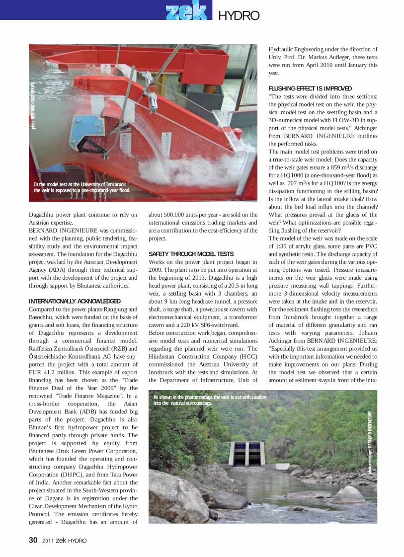
FLUSHING EFFECT IS IMPROVED"The tests were divided into three sections:the physical model test on the weir, the phy-sical model test on the seettling basin and a3D-numerical model with FLOW-3D in sup-port of the physical model tests," Aichingerfrom BERNARD INGENIEURE outlinesthe performed tasks.The main model test problems were tried ona true-to-scale weir model: Does the capacityof the weir gates ensure a 859 m3/s dischargefor a HQ1000 (a one-thousand-year flood) aswell as 707 m3/s for a HQ100? Is the energydissipation functioning in the stilling basin?Is the inflow at the lateral intake ideal? Howabout the bed load influx into the channel?What pressures prevail at the glacis of theweir? What optimizations are possible regar-ding flushing of the reservoir?The model of the weir was made on the scaleof 1:35 of acrylic glass, some parts are PVCand synthetic resin. The discharge capacity ofeach of the weir gates during the various ope-ning options was tested. Pressure measure-ments on the weir glacis were made usingpressure measuring wall tappings. Further-more 3-dimensional velocity measurementswere taken at the intake and in the reservoir.For the sediment flushing tests the researchersfrom Innsbruck brought together a range of material of different granularity and rantests with varying parameters. JohannAichinger from BERNARD INGENIEURE:"Especially this test arrangement provided uswith the important information we needed tomake improvements on our plans: Duringthe model test we observed that a certainamount of sediment stays in front of the inta-
In the model test at the University of Innsbruckthe weir is exposed to a one-thousand-year flood.
As shown in the photomontage the weir is set with caution into the natural surroundings.
HYDRO
029-031.qxp 01.06.2011 13:29 Uhr Seite 4

ANDRITZ HYDRO furnishes two identicalPelton turbines with six injectors and isresponsible for the steel construction forhydraulic engineering. Both companies havealready equipped Rangjung and Basochhu(Upper Stage and Lower Stage) power plants.It is a sign of great trust that the Bhutanesehave once again commissioned Austrian com-panies with the hydropower project on theDagachhu River.In addition another hydropower companyfrom Austria, which has gained a great repu-tation over the last decades, is part of theBhutan project: Braun Maschinenfabrik. Thecompany from Vöcklabruck, Upper Austria,was commissioned to provide the hydraulicsteel construction of the settling basin and theintake. Furthermore Braun Maschinenfabrikwill manufacture four trash rack cleaningmachines - one for the intake and three forthe settling basin - for the Himalayan king-dom.The two turbines have a design output of62.2 MW each. With a rotational speed of277.7 rpm, the turbines are constructed for anet head of 282 m and a design flow of 25m3/s. After its completion the Dagachhuhydropower plant will generate about 515GWh clean energy per year. Therefore theplant plays an important role in the realizati-on of the ambitious development goals of theBhutanese government. The increasing use ofthe powerful resource hydropower nowadaysis the main aspect of Bhutan's sustainabledevelopment. The kingdom will continue to sell the majorshare of the generated electricity to the bigneighbour in the South,India. All profits willbe invested in the public health sector, inschools and in the infrastructure of the coun-try. All Austrian companies involved enjoy agood reputation in Bhutan and are more thanhappy to contribute to this positive develop-ment.
ke. By installing a guide wall we were able tooptimize the flushing effect near the intake."
TESTING THE SETTLING EFFICIENCYOn the scale of 1:15 the team of theUniversity of Innsbruck created a model ofthe settling basin, which in reality is 130 mlong and consists of three chambers of 8.7 min width and of 9 to 13 m in depth each.They tested whether the design flow of 50m3/s is equally distributed to each of thethree chambers at a flow velocity as steady aspossible. Another test examined how theflushing ability of the sedimentation cham-bers and the quantity of sediment evolve, alt-hough the significance of the results of thelatter test is only limited due to scale effects.The test arrangements with quartz sand andsynthetic granules revealed interesting details,which helped optimize plant operations. Onthe basis of the 3D-velocity measurements invarious cross-profiles of the chambers atdesign flow, guide walls were ideally set up atthe inflow. A constant and efficient sedimen-tation of the sand is now possible.The FLOW-3D software was used for 3D-numerical CFD simulation of the reservoir
intake and the seettling basin. These numeri-cal simulations were run parallel to the physi-cal model tests. With this method it was pos-sible to calibrate the models and validate theresults.
EQUIPMENT FROM AUSTRIAWith the completion of the model tests,which were coordinated by BERNARDINGENIEURE, the realization of the projectin the Himalayan kingdom began. Construc-tion by means of heavy machines has startednot too long ago.Indian construction group HCC is responsi-ble for construction work. Austria providesnot only design know-how but also the enti-re electromechanical equipment and the steelconstruction for hydraulic engineering."Austrian Hydro Consortium Dagachhu",consisting of ALSTOM Austria GmbH(company in charge) and ANDRITZHYDRO GmbH, was commissioned withthe EUR 55 million contract. ALSTOMAustria GmbH provides two 70-MVA gene-rators as well as all electronics, includingautomation and protection system, with acontract value of EUR 30 million.
zek HYDRO 2011 31
Foto
: Die
ter-
Schü
tz_p
ixel
io.d
e
Results of the model tests were rather inter-esting. Amongst other results, the flushingcapacity in the reservoir without a guidewall (image) was found to be insufficient.The installation of a guide wall marks animprovement in the flushing capacity.
At present less than 10 % of the realizable hydropower potential is being used in Bhutan.By 2020 a total output of 12.000 MW is to be installed. The major share of the
generated electricity is sold to India, Bhutan's large neighbor to the South.
Technical Data
Gross Head: 305 m
Net Head: 282 m
Design Flow: 50 m3/s
Rotational Speed: 277.7 rpm
Turbines: 2 x Pelton Turbines With 6 Injectors
Brand: ANDRITZ HYDRO
Output: 114 kW
Generators: 2 x 1 Synchronous Generator
Output: 70 MVA each
Brand: ALSTOM
Energy Capability: 515 GWh
phot
o: B
ERNA
RDIN
GENI
EURE
HYDRO
029-031.qxp 01.06.2011 13:29 Uhr Seite 5

32 2011 zek HYDRO
NEW CONCEPT FOR AN OLD PROBLEM - DEVELOPMENT OF AN AXIAL HYDRO CYCLONE
1 BACKGROUNDFew years ago a hydropower plant was instal-led beneath a glacier near an ecological sensi-tive area. The plant is equipped with a Peltonturbine, power output 10 MW and a head of633 m. A water collector catches the flow andleads it to a sediment collection flume toseparate gravel and bigger particles above0.3mm. This collection flume will be flushedafter a certain time and sediment level.Smaller particles still remain at the dischargeand are transported through the pressure pipeto the hydro power plant resulting in heavywear on the Pelton buckets. After a fewmonth of operation the power decrease wasenormous [1].The first step to solve this problem began atthe runner himself. New designs of the run-ner and different coatings were used to extendthe runner operational lifetime. On the otherhand a new idea was born to solve this pro-blem. At the Institute for Energy systems andThermodynamics we discussed the idea toinstall an axial hydro cyclone directly to thepressure pipe for the desilting of the remai-ning particles. Axial cyclones are well knownin the field of industrial dust separation andare successfully used there. The applicabilityof this method for the desilting of turbineflow of a Hydropower Plant is investigatedsince 2008 within a research project at theInstitute.Based on specifications of TIWAG an axialhydro cyclone was developed followingPelzmann [2] and the VDI-Guidelines 3676[3]. This design should be optimized in thedirection of the lowest total pressure drop andhighest total degree of separation by themeans of CFD. After a first layout, followedby a parameter study we found some general
layout considerations resulting in a laborato-ry model for future investigations.After any optimizational steps this laboratorymodel should be transferred to the originalneeded model by dimensional analysis withspecial specifications of TIWAG to guaranteethe best application at optimal operationalconditions.
2 WORK PACKAGESAny work packages of the research project tilltoday shows table 1. A more detailed descrip-tion of work package 1, 2 and 3 has beenpublished at [4], [5], [6]. This article willfocus on the basics of work package 3 andhighlight the work done at work package 4till 6.
3 WORK PACKAGE 3: LABORATORY MODELThe study done at work package 1 and 2showed the proper way which specificationsshould be investigated further or not.
Conclusions are: reduction of friction areasand conservation of impulse to strengthen theswirl due to conical design elements.After some optimization steps we found ourfinal laboratory model. This was build and isnow tested (see Fig. 1).
Special consideration has been done to thelayout of the blades at this axial hydro cyclo-ne variant. Using the Zweifel criteria, this isused for the design of axial turbine bladessince years, a blade design was developedwhich minimizes the frictional areas in theflow diversion direction. Following from agiven number of blades and the flow diversi-on we get the axial chord length and the gra-duation angle of the blade row. The meancamber line wasn't developed by an ellipsebut with a more flexible kind of curve name-ly a Bezier spline of third order. This allows usto minimize the energy dissipation at flowdiversion by given blade profiles.
Table 1: Listing of the work packages till today
By Eduard DOUJAK, Vienna
Fig. 1: Improved design of the investigated laboratory model
HYDRO
Work package
1
3
4
5
6
2
Feasibilitystudy
Laboratorymodel
Laboratorymeasurements
CFD-Study
Optimization
Conceptual study
Title Main activity
Basic design tools for the development of a hydro cyclone have beenestablished and a first design has been created and investigated.
The best design of the conceptual study at work package 2 wasbrought to a laboratory model.
Measurements to determine the pressure drop have been investiga-ted.
The flow at the given geometry has been investigated using CFD.(Computational Fluid Dynamics)
The optimization potential of the geometry based on the results ofWP 4 and WP 5 has been determined.
The generated design of work package 1 has some weak points andshould be improved by a conceptual study. A lot of design parametershave to be investigated and resulted in a redesign of the hydrocyclone by three times.
032-035.qxp 01.06.2011 13:31 Uhr Seite 2

zek HYDRO 2011 33
The shown laboratory model (see Fig. 2) istested at the Hydraulic Laboratory of ourInstitute.
4 WORK PACKAGE 4: LABORATORY MEASUREMENTSFig. 3 shows the instrumentation of the axialhydro cyclone at the Hydraulic laboratory /
Vienna University of Technology. At the inletand outlet section the static pressure will bemeasured to determine the pressure drop ofthe whole cyclone. Additionally the staticpressure on the blades will be measured at 19points, 10 at the suction side and 9 on thepressure side. With this pressure measure-ment we can estimate if dangerous cavitationcould occur. Also discharge measurements ofthe inflow and at the separation outflow will
be done. An inspection glass showing two ofthe eight blades will give us the opportunityto observe any separation of the flow at thesuction side of the blade and the possibility tomake PIV measurements at this point.Fig. 4 shows the swirl at the separation tubefor the particles. This picture was taken at adischarge rate of about 80 l/s. It shows clear-
ly in the middle some kind of stable swirl fil-led with air. We observed this swirl only alower discharge rates and open downstreamflap valve. Also the instability of this swirlincreases with decreasing discharge rate.Rising the counter pressure at the end of thetest rig disappears this air filled swirl.After the swirl generation we installed anacrylic glass pipe to observe the swirl andto measure the single velocity components
(vz and v ) by means of LDV. This informati-on is needed for the calculation of the totalpressure drop by the following formula:
Fig. 5 and Fig. 6 show the LDV measurementsetup and the laser entrance points at theacrylic glass for the velocity measurements.
5 WORK PACKAGE 5: CFD CALCULATIONSThe CFD calculations were made withANSYS CFX. This article discusses only theCFX calculations and setup. As we expected aheavy swirling flow we started with thek- turbulence model, changed afterwards tothe k- -SST turbulence model due to inac-ceptable results of the k- model and foundfinally with the RSM model the expected
results which are comparable to measure-ments. The boundary conditions were set tovelocity inlet at the entrance and pressure out-let at the clear water outflow region. The pres-sure value of the outlet was according to themeasurements at the laboratory. For the sepa-rated flow we used a velocity outflow bounda-ry condition according up to 5% of the inflowdischarge. This separation discharge has alsobeen measured at the laboratory.
Fig. 2: 3D view of the laboratory model
Fig. 3: Laboratory instrumentation
Fig. 5: LDV measurement installation Fig. 6: Laser entrance points at the acrylic glass
Fig. 4: Swirl at the separation tube
HYDRO
032-035.qxp 01.06.2011 13:31 Uhr Seite 3
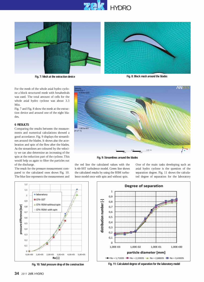
34 2011 zek HYDRO
the red line the calculated values with the k- -SST turbulence model. Green line showsthe calculated results by using the RSM turbu-lence model once with spin and without spin.
For the mesh of the whole axial hydro cyclo-ne a block structured mesh with hexahedralswas used. The total amount of cells for thewhole axial hydro cyclone was about 3.3Mio.Fig. 7 and Fig. 8 show the mesh at the extrac-tion device and around one of the eight bla-des.
6 RESULTSComparing the results between the measure-ments and numerical calculations showed agood accordance. Fig. 9 displays the streamli-nes around the blades. It shows also the acce-leration and spin of the flow after the blades.As the streamlines are coloured by the veloci-ty we can also determine an increasing of thespin at the reduction part of the cyclone. Thiswould help us again to filter the particles outof the discharge.The result for the pressure measurement com-pared to the calculated ones shows Fig. 10.The blue line represents the measurement and
One of the main tasks developing such anaxial hydro cyclone is the question of theseparation degree. Fig. 11 shows the calcula-ted degree of separation for the laboratory
Fig. 8: Block mesh around the bladesFig. 7: Mesh at the extraction device
Fig. 9: Streamlines around the blades
Fig. 11: Calculated degree of separation for the laboratory modelFig. 10: Total pressure drop of the construction
HYDRO
032-035.qxp 01.06.2011 13:31 Uhr Seite 4

zek HYDRO 2011 35
model. The separation curve was made for differentdischarges and different particle sizes according tothe needs of TIWAG. It shows that the medium dia-meter d50 correlates to a particle size of about 40µm.At this diameter 50% of the particles should be sepa-rated by a given discharge respectively a givenReynolds number. This result has to be verified by acorresponding measurement at the laboratory.
7 WORK PACKAGE 6: OPTIMIZATIONThe last work package encloses the results and ideasof the former work packages. An optimization exam-ple determined by using CFD shows Fig. 12 and Fig.13.An Austrian and international PCT patent applicati-on has been filed for the method of pressure pipedesilting by an axial hydro cyclone.
References[1] Maldet, R., "Pelton runner with high erosion caused by glaciersediment: Assessment and measures", 15. International Seminaron Hydropower Plants, Conference proceedings, Vienna, 2008.[2] Pelzmann, M., "Entwicklung und Betrieb einer Anlage zurdruckaufgeladenen Holzstaubverbrennung.", PhD thesis, Institutefor Energy Systems and Thermodynamics, Vienna University ofTechnology, Vienna, 2001[3] Verein Deutscher Ingenieure, "VDI 3676 -Massenkraftabscheider." April, 1998[4] Doujak, E.; Götsch H., "Entwicklung eines Axialzyklons zurTriebwasserentsandung - Ein erster Ansatz", 13. InternationalesAnwenderforum Kleinwasserkraftwerke, Tagungsbeitrag,Kempten, 2010[5] Doujak, E.; Götsch, H., "Pressure pipe desilting by an AxialHydro Cyclone - A first approach", HYDRO 2010, Conference pro-ceedings, Lisboa, Portugal, 2010[6] Doujak, E., Götsch, H., "Usage of an Axial Hydro Cyclone asSediment Separator", "16. Internationales SeminarWasserkraftanlagen", ISBN: 978-3-9501937-6-3; page 87 - 95,2010.
AuthorE. Doujak works since 1995 as an assistantprofessor at the Vienna University ofTechnology / Institutefor Energy Systemsand Thermodynamics /Department of Fluid-Flow Machinery inAustria. He is involvedin the investigations ofHydraulic Machinesand Plants as well asin uprating and refurbishment ofHydropower Plants.
Fig. 12: Old separator Fig. 13: New separator
Eduard DOUJAKGetreidemarkt 9, A-1060 WienTel.: +43 1 58801-302 404Fax: +43 1 58801-302 399E-Mail: [email protected]: www.iet.tuwien.ac.at
HYDRO
032-035.qxp 01.06.2011 13:31 Uhr Seite 5

n fact, years ago the idea of manufactu-ring generators first impulsed throughirritation. The founder of the company
and presently the Chairman, Manfred Volkwas exasperated many a times over the regular
generator manufacturers who were moreinterested in volume orders than custom builtunits that are required for the hydro industry,demanding unique design features.Furthermore, timely deliveries always led tounpleasant arguments. In keeping withWKV's manifested belief "100% Made inGermany" the only logical solution was to
have their own alternator manufacturingfacility.With no further hesitation, WKV AG inve-sted a double-digit amount of million Eurosinto the approximately 4000 square meterarea covering "Energiefabrik" (EnergyFactory), named in the style of the multiple-awarded "Zukunftsfabrik" (State-of-the-ArtFactory), where traditionally WKV hydro tur-bines are built. Volk hired some of the verybest specialists for designing and producingsynchronous alternators and as a first stepmanufactured alternators for their own orders.Afterwards, he commenced delivering alter-nators to other customers and also for otherpurposes.Again it emerged that the clocks are runningdifferently at WKV: They started producingthe complex and design-intense hydro poweralternators before they offered the relativelysimple alternators for diesel and gas engineapplications.
HIGH-TECH IN LARGE SCALEWhen entering the huge generator shop, visi-tors spontaneously get an impression aboutthe capacity of the plant. Heavy-duty cranesrated up to 120 tons and towering state-of-the-art machines going several meters highdominate the picture. For example, a rotorwinding machine meant for handling rotorsweighing up to 30 tons will catch your eyes. Inview of alternator ratings as high as 25 MVA,these dimensions are no surprise.There are various assembling areas for alterna-tors in horizontal and vertical configurations;one shop is reserved for coil manufacturingand stator winding.
A large impregnation plant equipped withboth vertical and horizontal pressure tanksand ovens where the components are turnedduring the drying process is one of the mostmodern and accomplished workshops of itskind worldwide.However, the "nerve centre" of the alternatorfactory is the test area, equipped with a desi-gned power input of 1200 kW. There are dif-ferent test locations for vertical and horizontalalternators. WKV offers their customers mostmodern measuring technology, a comfortablevisitors area including internet connectionand of course, a highly motivated team ofassessors, prepared for both standard testing aswell as sophisticated FATs.
ENERGY CONVERTERS OF SUPREME LEVEL Manufacture of special alternators for the hydro power industry is on top gear at WKV
At WKV AG located in the Badense Gutach in South-West Germany, clocks have always run slightly differently compared withtheir international competitors. The world renowned manufacturer of hydro turbines for decades operates an own – the firstnationwide – special factory manufacturing synchronous alternators for the hydro industry.
I
Phot
os: W
KV
Office and factory buildings in Gutach/Germany
Fine-balancing of rotors for low-vibration operation
Stator winding is manual work.
Rotor winding machine
Impregnation workshop
HYDRO
36 2011 zek HYDRO
036-037.qxp 01.06.2011 13:33 Uhr Seite 2

A UNIQUE FEATURESo far, WKV AG is the only company in thewhole world in the hydro power business, thatoffers turbines, process controls, SCADAsystems, switchgears as well as alternators - allmanufactured in one factory premises.This constellation provides a decisive and stra-tegic advantage in the international market."Based on production of all important com-
ponents in-house, we are in a position to deli-ver complete water-to-wire systems where allparts are perfectly optimized and fitting intoeach other", WKV's President Josef Haasexplains. "Imagine that efficiencies of hydropower systems are anyway very high, around90%, and the potential for optimization tendsto be within the per mill range. Well, this isexactly what our international customers turntheir attention to."Not least for that reason, also other hydroturbine suppliers are highly interested to gettheir synchronous alternators from an experi-enced specialist and not from a standard sup-plier where usually the sophisticated hydropower alternators are manufactured more orless "casually".
Alternator Sales Manager Eberhard Vogler:"The engineers in our design and manufactu-ring divisions are experienced in manufactu-ring serial and special machines since decades.They belong to the cream of the crop in theentire market. We know exactly what require-ments to be considered for bearing technolo-gy, over-speed capability and other criticaldesign features and we do have the know-how
and the passion for details to supply an opti-mized and high-quality product to our custo-mers."
HYDRO POWER AND MORE ...Besides special alternators for hydro turbines,WKV's scope of supply for synchronousmachines covers, alternators for every kind ofprime mover and many other applications.Greatest importance is attached to quality andflexibility of the products and of course custo-mer satisfaction.Vogler resumes: "By the way, I see no reasonwhy we shouldn't cooperate with competi-tors in the turbine market to deliver ouralternators to them. Benefit for both partiesis obvious!"
The concept is working successfully, provenby numerous deliveries. A considerable part ofthe currently scheduled production capacityamounting to several hundred MW of totaloutput is reserved for customers competing onthe turbine market.Manufacturing state and the production capa-city are sufficient for reasonable deliveries tomanufacturers of various prime movers such
as Diesel and gas engines or gas and steam tur-bines. Furthermore, special alternators formarine and offshore applications are also wit-hin WKV's capabilities.In particular, WKV's founder Manfred Volk ischeerful about creating a lot of new jobs evenin a period of economic crisis and of courseabout WKV sending another clear signal toGermany as a right location for industrial pro-duction.
Two company logos standing for two product lines
9 MVA alternator being prepared for shipping.
Vertical alternator beingmounted for testing
Final mounting of a vertical alternator 3,5 MVA alternator completed with Pelton runner
HYDRO
zek HYDRO 2011 37
Phot
os: W
KV
036-037.qxp 01.06.2011 13:33 Uhr Seite 3

raun Maschinenfabrik has successfullyplaced its hydropower products on themarket since 1959. One could think
that a company as renowned and long-esta-blished in the market as Braun Maschinen-fabrik is set in its ways. However, the collabo-ration between the company based inVöcklabruck, Upper Austria, and the Germanenergy company EnBW was something new.Braun provided the Kochendorf power planton the Neckar with a movable trash rackcleaning machine with a rake width of about3.4 m. The total rack width is 30.6 m with themachine running up and down bars with a
length of 39 m. One special feature of thismachine is its total number of 9 differentcleaning positions.
STRONG DEMAND FOR NEW PRODUCTBraun carried out all planning, calculations,construction, manufacturing, shop assemblyas well as testing tasks. In addition to this,Braun was responsible for the factory approvalby the client, transportation, on-site installati-on, enrollment of the client's staff, commis-sioning, test runs and the final approval.In 2005 Braun Maschinenfabrik entered thebusiness of manufacturing trash rack cleaning
machines on hydraulic cantilever arms andhas quickly gained an excellent reputation.Expertise and reliability are the hallmarks ofthe traditional company from Vöcklabruck.Figures show that Braun's machines do verywell in the market: German Lechwerke(Obere Donau Kraftwerke) commissionedBraun to provide four different German sites,Leipheim, Günzburg, Gundelfingen andFaimingen, with the same trash rack cleaningmachines on hydraulic cantilever arms as theone installed in the Kochendorf power plant.These cleaning machines are to be deliveredand put into operation within the next twoyears. Also Salzburg AG of Austria has orde-red a trash rack cleaning machine on ahydraulic cantilever arm from BraunMaschinenfabrik for 2012. Due to the positi-ve experience with Braun a follow-up order byEnBW has also recently been received. Afterall, experienced hydropower plant operatorsrely on quality in every aspect.
Although the traditional manufacturer Braun Maschinenfabrik is fairly new to developing trash rack cleaning machines onhydraulic cantilever arms, this field has rapidly contributed to the success of the company. Not long ago the German energycompany EnBW commissioned Braun Maschinenfabrik with the development of the first movable automatic trash rackcleaning machine on a hydraulic cantilever arm. In late fall last year, it was installed and put into operation at the histori-cally renowned Kochendorf power plant on the Neckar River.
B
EnBW orders the first trash rack cleaningmachine on a hydraulic cantilever armmanufactured by Braun Maschinenfabrikfor the Kochendorf Power Plant on theNeckar River.
grap
hics
: Bra
unph
otos
: Bra
un
38 2011 zek HYDRO
BRAUN EQUIPS POWER PLANT ON THE NECKAR RIVER
HYDRO
038.qxp 01.06.2011 13:34 Uhr Seite 2

HYDRO
zek HYDRO 2011 39
During the opening ceremony in early July 2010, the first hydropower plant of the Mittelbaden power station (EWM) wasput into operation on the Kinzig Dam in Gengenbach, Germany. The project which had cost EUR 3.8 million was met withgreat public interest. After all it is a worldwide unique prototype of a hydropower station which consists of a movable bodyentirely embedded in water. The nominal output of the EU-supported station is at 550 kW. It will provide electricity for appro-ximately 1200 households.
any guests of honour, companyrepresentatives and people inter-ested in hydropower took time on
this wonderful summer's day to witness theworld premiere of the first movable powerplant in action. And they were not disappoin-ted. The visitors learned about the functiona-lity as well as all ecological advantages of thepower plant on the Kinzig Dam.The construction of the power plant projecttook about one year. However, there is notmuch to see of the plant itself since all opera-tions take place entirely underwater. It is anabsolutely new concept based on the inventi-on and the five years of realization by thebrothers Andreas and Peter Roth and theirpartners. The two engineers had been dealingwith questions of the cost-effective and ecolo-gical use of hydropower at low-pressure sitesfor a long time.
THE COST-EFFICIENCY IS QUESTIONABLE„Let's take a look at the initial situation:There are still many unused low-pressure sites
in Europe with a head of less than five meters.Since they work without water diversionthese sites obtain licenses more easily.However, the disadvantage is that in mostcases bigger construction elements and plantcomponents are needed due to a higheramount of water. Another disadvantage isthat low-pressure plants are sensitive to headloss, e.g. in case of backwater. Furthermore,with bar spaces under 20 mm often a highamount of flotsam emerges, which of coursehas to be redirected around the plant.Besides, newly passed environmental specifi-cations require a risk-free fish passage fordescending fish near the ground and near the surface,“ degreed engineer Peter Rothdescribes the general conditions for new low-pressure plants. He concludes: „For thatreason the construction of low pressure powerplants nowadays is relatively expensive, whichmeans that their cost-efficiency is questio-nable.“In his opinion, the only goal should be toreduce construction costs and increase profits
and quality. Early in the process he saw theprospects of possible standardization and uni-fication of the power plant, the screen, theturbine and the generator – including theinflow and outflow. „In order to prevent anyconstruction risks, the design has to be repro-ducible and the hydraulic engineering as sim-ple as possible,“ says Roth.
THE FOCUS LIES ON THE „EJECTOR EFFECT“The answer of the two inventors to this que-stion was the following: constructing a simpletrough structure, if possible situated directlyat the weir station; realizing a power plantthat can be lifted so that bed load is redirec-ted directly, backwater is regulated and a fishpassage is made possible; developing a stan-dardized engine and power plant complexwhere all plant components are adjusted tothe system. This was when the concept of themovable hydropower plant was born. „Theidea was of course to construct a plant that isoptically and acoustically hardly noticeable.Furthermore we wanted to make use of the
M
FIRST MOVABLE POWER PLANT TO GENERATE ELECTRICITY
Not only is it barely visible, one can hardly hear the movable power plant on the Kinzig Dam.
Phot
o: R
oth
039-043.qxp 01.06.2011 13:35 Uhr Seite 1

so-called 'ejector-effect' which evolves at theend of the draft tube through differences inflow velocity. This effect has been well knownfor decades. However, it is hardly a standardprocess, although it enables us to use theenergy of higher amounts of outflow for anincrease in output.“ The integrated hydroe-lectric generating set played a central role inthe development. An efficient turbine tech-nology as well as a gearless and a comparati-vely highly efficient generator technologywere needed. The Roth brothers found com-petent partners in HSI Hydro Engineering astheir turbine provider and in Krebs & Aulichwhich provided the ideal generator for thispurpose.
INNOVATIVE GENERATOR TECHNOLOGYSince its foundation about 15 years ago thecompany Krebs & Aulich (K & A) has specia-
lized in developing and constructing electricengines charged by permanent magnets. Thatwas how the Roth brothers became aware ofK & A. From the beginning the Rothbrothers knew that the concept of a movablehydropower plant would only function with agenerator that at this point was nowhere to befound on the market: a generator (PMSG) fora bulb turbine unit charged by a permanentmagnet. Experts already knew that withPMSGs the avoidance of loss within the exci-tation system would result in a significantincrease of the degree of efficiency. „It waseven more important to us to be able to buildthinner synchronous generators, with a smal-ler diameter than the usual ones, when usingpermanent magnets to charge synchronousgenerators in a multipole construction. Wecould dispense with the cooling of themagnet wheel windings as well as with the
electronic control system in the excitation cir-cuit. This is an engine with a robustness com-parable to that of an asynchronous generator,but it is constructed in a lighter and morecompact way and furthermore it has advan-tages regarding its efficiency,“ says Peter Roth.After issuing a specification sheet Hydro-Energie Roth commissionned K & A with theconstruction of a permanent magnet-chargedgenerator that operates on the electrical net-work without a converter. The next step for K& A was to develop the first bulb generator(330 kW, 214 RPM) for underwater perfor-mance and to run tests. „The success of thenew bulb generator technology was the prere-quisite for the application at the movablepower plant,“ explains Roth. An essentialaspect during the development was to usecorrosion-resistant material for the magnet,which would influence the field strength onlyslightly when variations in temperatureoccurred. With these generators it is also pos-sible to adapt the generator voltage to thefuture changes in local network situationswithin the built-in generator through apatent registered system. The appropriatedesigns of the pole shoes and the damper cageguarantee safety from demagnetization of themagnets and an ideal voltage curve. This alsoresults in extremely quiet running and com-bined with the low-loss dynamo sheets inhigh degrees of efficiency (>96% at approx.15% of the nominal output). The inner highpressure control of the bulb constantly super-vises the state of the shaft seals (generatorshaft = turbine shaft).
FIRST PRACTICAL EXPERIENCEThe double regulated Kaplan turbines fromHSI proved to be similarly ideal for this pur-pose as their strength lies with the low andmiddle head levels. Moreover these turbines
40 2011 zek HYDRO
the movable power plant
Afterwards the power plant is heaved as a unit into a drilled pile trough
The power plant underwent awide range of dry runs.
Grap
hics
: Rot
h
Phot
o: R
oth
Phot
o: R
oth
HYDRO
trash rack cleaning machine
Kaplan bulb turbine
elevating device
rotation axis
floating debris valve
semicircular arch trash rack
permanent magnet generator
039-043.qxp 01.06.2011 13:35 Uhr Seite 2

are characterized by a compact, low maintenance and easy-to-assembleconstruction along with basic features, such as a high degree of efficien-cy and a long durability. HSI constructs Kaplan turbines for headsfrom 1 to 25 m, design flows from 2 to 40 m3/s and with an outputpower from 30 to 3.000 kW. Runner diameters may vary from 0.56 to3.0 m. HSI's know-how from its longtime experience in this field hasbeen a major aspect on the development of this ideal hydroelectricgenerating set.The first hydroelectric generating set with a water-cooled permanentmagnet generator and a HSI-turbine was tested in Faurndau in 2007.„This first set achieved a generator degree of efficiency of 96% at 214rotations - a first promising approach,“ according to Roth. From thenon even more important findings were made at the pilot station in BadSulza. „The generating set achieved 55 kW at a head of 1.7 m and adesign flow of 4.0 m3/s. We were able to thoroughly analyze the hydro-static uplift and to test the new curved bar screen system before thegenerating set as well as the ejector effect at the Bad Sulza pilot station.Furthermore we took tests for complete vibration analyses of the circu-lation of the power plant.“
THE CHALLENGE OF ELECTRICAL ENGINEERINGRelying on important findings and many positive results, one year agothe project on the Kinzig river was launched. As early as the initialphase of the construction more advantages of the power plant concept
revealed themselves: The construction of the trough structure wascompleted within 6 months and within the same time the switchboardgallery was built. The movable power plant was constructed as a com-plete unit at the HSI Hydro Engineering works. There it went throughall kinds of dry runs - starting with the generator test run, shift of theguide vanes and runner, the newly developed curved bar screen withsynchronous run monitoring, to the flushing apparatus on the back ofthe power plant and its entire sensor system.Further important aspects of the new power plant include control andinstrumentation systems as wells as automation. Clearly, for a movablepower plant like this, higher requirements to electrical engineeringhave to be met. The Bavarian company F.EE from Neunburg v.W.,Germany, performed all electrical engineering works for the two pilotstations and for the actual power plant on the Kinzig Dam. They paidparticular attention to the constant availability of all components nee-ded. „Diagnosable and decentralized inputs and outputs of the control,which can be programmed from memory, allow for a remote diagnosisof the sensor system. This was carried out redundantly on the inside ofthe generator bulb for safety reasons,“ says degreed engineer HeinrichReitinger from F.EE.Amongst other measures, a remotely operated time overcurrent protec-tion was applied. In order to reduce the number of cables running fromthe switchboard to the movable power plant all measuring and controlsignals are transmitted from the decentralized inputs and outputs tothe SPS via LAN. These double fiber optics not only have a high relia-bility but also prevent overvoltage situations. F.EE together withHydro-Energie Roth have developed a specific concept of machineprotection for the built-in permanent magnet generator. Because of thespecial construction method of the movable power plant, there arenaturally higher requirements to the pressure monitoring and densitymonitoring.
GOING INTO OPERATION QUICKLYAfter all tests had successfully been completed at the manufacturingworks, the plant was disassembled into two parts of 8 and 10 m inlength and prepared for transportation as heavy load to its final desti-nation in mid-March 2010. On the construction site the elements werethen reassembled and were heaved by two cranes with lifting capacitiesof up to 350 tons into the ready-made concrete trough. „Of course thiswas a job which required precision down to millimeters, but it workedperfectly straight away,“ summarizes Andreas Roth, brother of PeterRoth. After that, work continued to progress smoothly. Less than four
zek HYDRO 2011 41
Bird's eye view of the construction site on the Kinzig Dam.
Peter Roth explains the technology of the newpower plant during the opening ceremony.
Grap
hic:
Rot
hPh
oto:
Rot
h
Overview of the plant visualized as in the power plant control.
HYDRO
039-043.qxp 01.06.2011 13:35 Uhr Seite 3

42 2011 zek HYDRO
weeks passed from when the power plant washeaved into its final setting until it went intooperation.The first operating phase lived up to theexpectations of the manufacturer and theoperator. In spite of a small light bar space ofjust 15 mm, only minor screen losses wereobserved. The bar screen system worked effi-ciently and fast, flotsam was quickly redirec-ted. „During the operation we saw that eventhe upstream water level control through theflushing apparatus and the lifting system wor-ked perfectly. Moreover we managed to keepthe overall efficiency level as high as we hadexpected it to be. Regarding the ejector-effect,the amount of energy reclaimed by water cir-culating the power plant was even higherthan calculated,“ the inventor smiles.What is also of importance to locals and visi-tors of the Kinzig river is that no engine noisedisturbs the smooth purling of the river. Onecan hardly hear the engine.
ADVANTAGES IN CASE OF BACKWATERThe movable power plant in the Kinzig riveris basically constructed for a head of 3.20 mand a design flow of 20 m3/s. It easily achie-ves an output of 550 kW on generator termi-nals. The generator itself was designed for anoutput of 600 kW. This was planned in case
the water level exceeded the maximum capa-city of the engine and an increase of outputwas to be expected.However, the plant reaches its „output-turbo“when usual low pressure engines drop off oreven have to be shut off: in case of backwater.Peter Roth explains, „Let's say, in the Kinzigriver, in case of a backwater of 45 cm and at awater volume of 55 m3/s the average plant
will lose 21% output . With the movable,over- and underflow hydropower plant wewill gain 8% of the nominal output due tothe ejector-effect. Compared to a conventio-nal power plant, this specific operating situa-tion means an additional output of 36% or150 kW for the movable plant.“It is no surprise that the operator, theMittelbaden power station, is delighted over
At the Institute of Fluid Mechanics andHydraulic Machinery, University ofStuttgart, comprehensive flow simulati-ons were tested. The main subject wasthe energy gain through the ejector-effect. This effect evolves at the end ofthe draft tube through differences inflow velocity.
Grap
hics
: Rot
h
HYDRO
Ejector-Effect
Ejector-Effect in 2-D-simulationEjector-Effect in 3-D-simulation
Ejec
tor-
Effe
ct
Ejector-Effect as a function of head
Turbine Outflow
039-043.qxp 01.06.2011 13:35 Uhr Seite 4

zek HYDRO 2011 43
their new and unique power plant inGengenbach. „We are proud of this innovati-on. The hydropower plant has already provenduring its test runs that it will live up to ourexpectations regarding technology, economyand ecology. We managed to produce morethan 300.000 kWh electricity during our testruns,“ said Helmut Nitschke, chairman ofMittelbaden power station, at the openingceremony. Each year about 1.200 averagehouseholds are to be provided with clean elec-tricity from the Kinzig river.
A SYSTEM SETS A STUNNING EXAMPLEThe prototype of this plant situated inGengenbach also shows essential improve-ments as far as environmental protection isconcerned. Migratory fishes, such as salmons,are able to pass the hydropower plant easilythrough a channeling fish passage for bothascending and descending fishes. Hydrauliccylinders move the giant steel casing of theplant, including a turbine, a generator and ascreen. Nevertheless the plant offers the bestconditions for water and fish protectionaccording to contemporary scientific facts.Even groundfishes, such as eels, can pass easi-ly. Helmut Nitschke summarizes: „Not onlydo we generate electricity in an ecologicalway, but we enhance the ecological situation
of the Kinzig river with this plant.“ TodayGengenbach stands for a groundbreakingsystem that provides environmentally friend-ly, CO2-free, locally produced electricityusing state-of-the-art technology. The powerplant was supported by fundings of the EULIFE program and a capital investment of the
stockholders to the amount of EUR 3.8 mil-lion. It was clear that the power plant at theKinzig Dam would not remain the only oneof its kind for long. In the fall of the sameyear a similar construction has been put intooperation on the Grosser Deich inOffenburg, Germany.
Organisms of the Kinzig river are able to pass the plant upstream and down-stream via an integrated support of the fish passage for ascending fish.
HYDRO
Phot
o: R
oth
039-043.qxp 01.06.2011 13:35 Uhr Seite 5

44 2011 zek HYDRO
Auenbach were channelled and fed by way ofan open runlet into lake Obersee, which wasdammed up to a volume of 200,000 cubicmetres. After further expansions, the reservoircapacity today is about 650,000 cubicmetres," as Reumer explains.Since 1961 the water from Lake Obersee hastherefore been used in two stages: first withthe machines at the intermediate power stati-on in Rütiberg and again further down at thepower station in Risi am Talboden. Yet anot-her machine was installed at the Rütlibergpower house in the 1970s, which turbines thewater coming from the Brändbach streamlet.While these machines were to remain inplace, it was decided in 2005 to replace theother ones from 1961.
INSUFFICIENT FLOW CAPACITY"The old machine was basically still in wor-king order. But the mechanical controllerunit needed replacing, and some othermachine parts would have needed servicing,all of which would have cost about 450,000francs," says Paul Reumer. Besides that, the insufficient flow capacity ofthe machine had already been a sore pointwith the operators for a long time. "We get alot of heavy rain in these region. Since themachine had a maximum flow capacity ofonly 500 litres per second, it was unable toprocess the occasional excess volume of water.This is why a kind of 'energy deflector' was
built to drain off any excess water passed themachine and into the nearby Rütiberg pond.Of course that meant a loss of efficiency, as thedrained-off water was only turbined once,"explains the hydropower expert.
SUITABLE FOR THE SWISS TASTEBut these problems were to come to an end.The new turbine had to be one with a higherflow capacity. Other obvious evaluation crite-ria included the quality of the design, the effi-ciency and compliance with the latest techni-cal standards. "During the tender process, we conducted arather extensive analysis of the offers - and wewere actually a little surprised of the result.The solution submitted by an Austrian turbi-ne in combination with a Hitzinger genera-tor, made the winning score," says MartinSteiner, the successor of Paul Reumer, whohas retired already. "The machine," heexplains, "has a solid, very robust design - justthe way we Swiss like it". The factory appro-val went ahead successfully in August 2007.
MACHINE FOR AFRICAAt that time, modification work at the inter-mediate power station in Rütliberg was alrea-dy on the way. The dismantling and demoli-tion work had commenced immediately fol-lowing the shutdown of the station in mid-July. Despite the pressing time schedule, themachine parts were taken down and disas-
he 500th anniversary of the historicbattle of Näfels was to be a specialevent for the entire canton of Glarus.
And it was. On that November 6th - the yearwas 1888 - the first electric light went on inGlarus - an absolute novelty for the canton atthe time. The turbine used for this purposewas fed by a network of hydrants that hadbeen completed only shortly before. Twoyears after this kick-off event to the canton-wide spread of electricity, the first electricalstreet lights came on: the village's own electri-city provider had commenced operation ofthe first stationary power generating facilitywith a 12-horsepower unit.Over the following years and decades, thecapacity of the electricity supply in Näfels wasgradually expanded. 1924 marked the start-upof the Risi power station. The head offices ofEW Näfels are still located there, and two ofthe three machines installed in 1924 are still inoperation today. But not for much longer, asPaul Reumer, the station's long-standingmanager, emphasises. Soon the old machinesare to be replaced by newer, modern ones.
TWO-STAGE POWER STATION CONCEPTAnother important milestone in the develop-ment of EW Näfels was reached with theexpansion of the generating facilities into atwo-stage power station from 1958 until1961. "After years of thorough planning, lakeObersee's feeder rivulets Sulzbach and
RETIREMENT FOR VETERAN MACHINESIf they are well looked after, hydropower turbines can have a long useful life - sometimes even as long as the average humanlifespan. The 44 years old Pelton turbine at the Rütiberg central power station, which was operated by energy provider EWNäfels in the Swiss canton of Glarus, was still in good nick when the managers responsible decided in 2005 to have the enti-re set of machines replaced by new-generation units. The decision was taken based on economical considerations. By the endof October 2007, the new machines and the corresponding control system were officially inaugurated.
T
Design flow: 800 l/s Gross Head: 126 MeterOutput: 890 kW
Power Plant Rütiberg
In harvest 2007 the new machine units,including the new control system inNäfels were officially inaugurated.
HYDRO
044-045.qxp 01.06.2011 13:37 Uhr Seite 2

zek HYDRO 2011 45
sembled with great care. After all, the old machine was not yet destined forthe scrap heap. Instead, it was being prepared to be transported to theCongo, where the used machine units from Näfels were needed urgentlyto generate power for a local hospital. Great care was taken not only during the dismantling process, but alsowhen the pressure pipe in the power house was exposed. The 40 years oldsteel pipes, which were still in perfect working order, were not to be dama-ged during the removal of the machine's existing foundation base. Oncethe new foundation base had been put in and the new control system hadbeen installed, the actual installation of the machine was begun in earlyAugust. When the facilities finally began operation in mid-September, thenew turbine made contact with water from Lake Obersee for the first time.
ON EXCELLENT EFFICIENCY LEVEL"When we took the machine into operation we knew immediately that theefficiency level was excellent. The actual measured level of 955 kW wasquite a lot above the guaranteed level of 890 kW," says Martin Steiner witha smile. In November last year, the new machine units, including the new controlsystem, were officially inaugurated. Since then, the facility has been run-ning smoothly without a problem - and with greater efficiency. With arated speed of 500 rpm, the twin-jet Pelton turbine drives a brushless syn-chronous internal pole generator by Linz-based manufacturer Hitzinger.This generator is distinguished by its well-known high level of operationalsafety and high economic viability, which results chiefly from a high degreeof efficiency, the active prevention of transmission loss and the unit's com-pact design. The 8-ton synchronous generator in Näfels provides an effec-tive power of 1,170 kVA.
FUTURE CHALLENGESEW Näfels utilises the water from Lake Obersee with a generator capacityof 4,850 kVA. In total, the electricity provider, which is responsible for thesupply of electricity to the three Glarus communities of Näfels, Mollis andOberurnen, generates about 25 million kWh a year. This is a little less thanhalf of the consumption of the customers in EW Näfels' supply area. Theother half is purchased from Axpo."The last few decades were marked by a continuous expansion of our gene-rating capacities. And there is still a lot on our agenda for the near future.A basic analysis being conducted at the moment to see if another watersource from the Hochseetal could be turbined at the Rütiberg facilities.And owing to the ongoing community restructuring canton-wide reforms,we will likely also get new facilities that will need to be renovated or expan-ded," says Paul Reumer. Big challenges for small energy provider EWNäfels - but challenges that they are looking forward to with confidence.After all, which other electricity provider in Glarus would be better equip-ped to master these challenges than the one located at the very cradle ofthe canton's electric grid?
In the early 1960s the Rütibergpower station commenced opera-tion as part of a two-stage powergenerating facility.
Paul Reumer, long-standing director of EWNäfels. He supervised the renovation work withgreat commitment and personal dedication.
The generator was delivered ontime by Hitzinger and is carefully
hoisted into the power house.
Installation work at the twin-jet Pelton turbine grants a last glimpse of the Pelton runners.
Generator: synchronous
Brand: Hitzinger
Power: 1.170 kVA
Current: 1.689 A
Voltage: 400 V
Year of construction: 2007
Nominal speed: 500 rpm
Overspeed: 900 rpm (2 min)
Power factor: 0,8
Frequency: 50 Hz
Weight: 8.900 kg
Excitation Voltage: 96 V
KRAFTWERK RÜTIBERG / NÄFELS (Switzerland)
Technical Data Generator
The brushless synchronous internal pole generatorby Hitzinger is driven by a twin-jet Pelton turbine.
HYDRO
044-045.qxp 01.06.2011 13:37 Uhr Seite 3
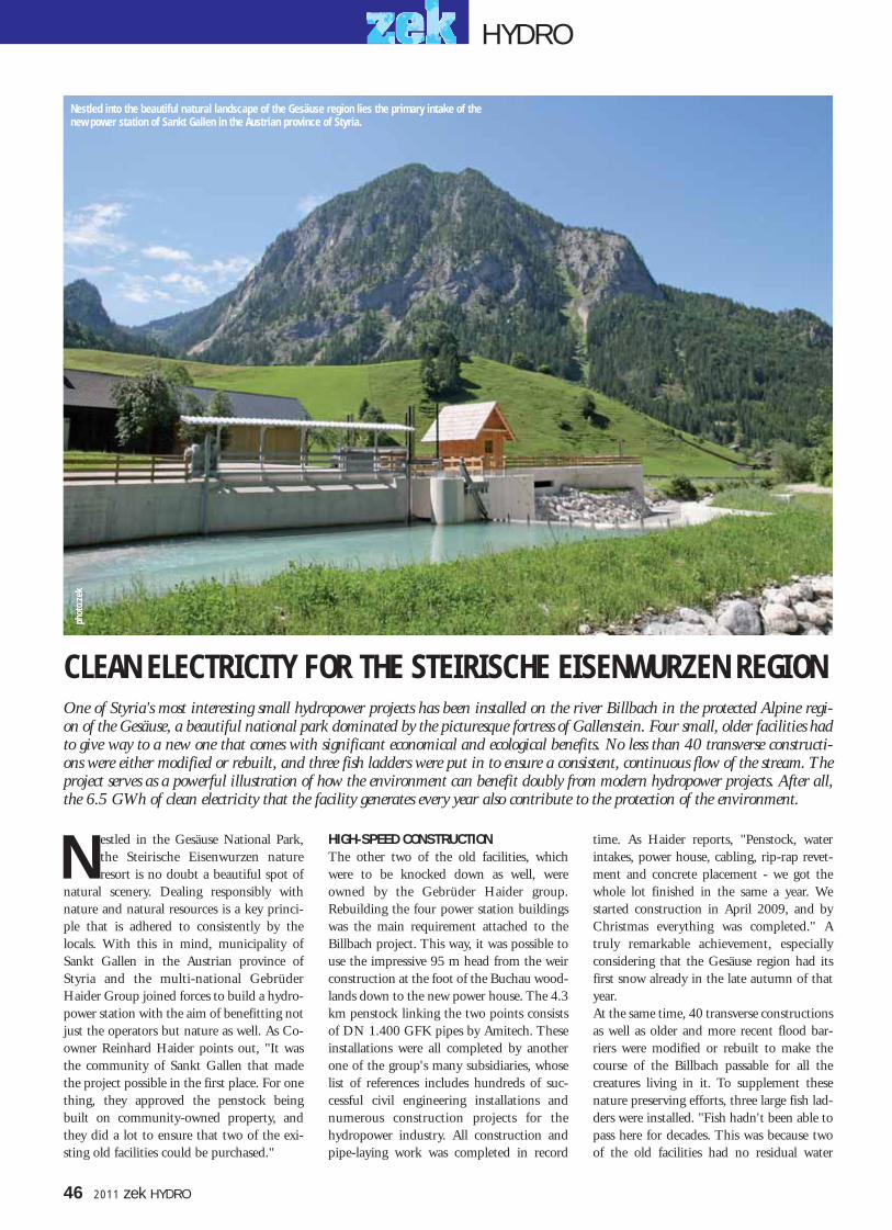
One of Styria's most interesting small hydropower projects has been installed on the river Billbach in the protected Alpine regi-on of the Gesäuse, a beautiful national park dominated by the picturesque fortress of Gallenstein. Four small, older facilities hadto give way to a new one that comes with significant economical and ecological benefits. No less than 40 transverse constructi-ons were either modified or rebuilt, and three fish ladders were put in to ensure a consistent, continuous flow of the stream. Theproject serves as a powerful illustration of how the environment can benefit doubly from modern hydropower projects. After all,the 6.5 GWh of clean electricity that the facility generates every year also contribute to the protection of the environment.
46 2011 zek HYDRO
phot
o:ze
k
CLEAN ELECTRICITY FOR THE STEIRISCHE EISENWURZEN REGION
estled in the Gesäuse National Park,the Steirische Eisenwurzen natureresort is no doubt a beautiful spot of
natural scenery. Dealing responsibly withnature and natural resources is a key princi-ple that is adhered to consistently by thelocals. With this in mind, municipality ofSankt Gallen in the Austrian province ofStyria and the multi-national GebrüderHaider Group joined forces to build a hydro-power station with the aim of benefitting notjust the operators but nature as well. As Co-owner Reinhard Haider points out, "It wasthe community of Sankt Gallen that madethe project possible in the first place. For onething, they approved the penstock beingbuilt on community-owned property, andthey did a lot to ensure that two of the exi-sting old facilities could be purchased."
HIGH-SPEED CONSTRUCTIONThe other two of the old facilities, whichwere to be knocked down as well, wereowned by the Gebrüder Haider group.Rebuilding the four power station buildingswas the main requirement attached to theBillbach project. This way, it was possible touse the impressive 95 m head from the weirconstruction at the foot of the Buchau wood-lands down to the new power house. The 4.3km penstock linking the two points consistsof DN 1.400 GFK pipes by Amitech. Theseinstallations were all completed by anotherone of the group's many subsidiaries, whoselist of references includes hundreds of suc-cessful civil engineering installations andnumerous construction projects for thehydropower industry. All construction andpipe-laying work was completed in record
time. As Haider reports, "Penstock, waterintakes, power house, cabling, rip-rap revet-ment and concrete placement - we got thewhole lot finished in the same a year. Westarted construction in April 2009, and byChristmas everything was completed." Atruly remarkable achievement, especiallyconsidering that the Gesäuse region had itsfirst snow already in the late autumn of thatyear.At the same time, 40 transverse constructionsas well as older and more recent flood bar-riers were modified or rebuilt to make thecourse of the Billbach passable for all thecreatures living in it. To supplement thesenature preserving efforts, three large fish lad-ders were installed. "Fish hadn't been able topass here for decades. This was because twoof the old facilities had no residual water
N
Nestled into the beautiful natural landscape of the Gesäuse region lies the primary intake of thenew power station of Sankt Gallen in the Austrian province of Styria.
HYDRO
046-047.qxp 01.06.2011 13:38 Uhr Seite 2

zek HYDRO 2011 47
The Haider family's bet is on hydropower. The newfacility is the operator's most powerful one so far. Ing. Reinhard Haider
flow, which meant that the riverbed wasdried out most of the time. Where the natu-ral environment is concerned, this has allchanged for the better. There is now a dyna-mic flow of residual water throughout theyear. This and the building modificationshave allowed the Billbach to become an eco-logically valuable body of flowing water,"says the operator.
PELTON PREFERREDThe concept behind the facilities basicallycalls for a primary intake with a lateralabstraction, a weir baffle and a horizontaltrash rack cleaner. Other elements include the4.3 km penstock and a secondary intake witha Tyrolean weir on the Schleierbach, as well asa 450 metre long diversion that feeds directlyinto the penstock. And, of course, the coreelement of the facility: the power house with
a six-nozzle vertical Pelton turbine by AndritzHydro. "Given the head of 95 metres and thedesign flow rate of 1.8 cubic metres persecond, we could have gone with a Francisturbine as well. However, in that case we pro-bably would have needed two machines,which would have put us quite literally in atight spot in terms of space. Another point infavour of the six-nozzle Pelton turbine wasthat it's fully adjustable. Plus, we have so farhad better experiences with Pelton than withFrancis turbines," explains Haider. ThePelton turbine that was installed is designedfor an output of 1.3 MW. Especially with the type of machines used inthis installation, as Haider emphasises, thequality must be absolutely flawless - and that,according to the operator, is the case bothwith the Andritz Hydro turbine and thedirectly coupled generator by Hitzinger.
INVESTING IN THE FUTUREA total of 6.5 GWh of electricity is generatedannually at the facility, which is co-owned bythe Gebrüder Haider group (90 per cent)and the municipality of Sankt Gallen. Thismakes the Billbach power station not onlythe costliest but also the most profitable oneof the group, which operates seven smallhydropower facilities in Austria, with othersalready in planning or under construction inAustria and abroad. When asked why hydro-power is in the focus of the family-ownedconstruction specialist, Haider has a simpleanswer: "We see it as an investment in thefuture. One the one hand, it helps us tosustain our industrial operations in the eventof an electricity shortage, and on the otherhand it's good for the environment. Theseare reasons enough for us."
One of the three newly installed fish ladders, imple-mented in the form of a near-natural channel.
The power house on the Bilbach
HYDRO
Technical characteristics:
Design flow rate: 1.8 m3/sNet head: 87.5 mGross head: approx. 95 mTurbine: 6-nozzle vertical Pelton turbine Turbine manufcatured by: Andritz Hydro Turbine power output: 1,375 kWRotational speed: 428.6Runner diameter: 865 mm (34 in)Generator: synchronous (Hitzinger)Power: 1.440 kW (cos phi 0,9)Current: 2.237 APenstock: 4.3 km (2.7 miles)
Penstock: DN 1400 / DN 1200Standard capacity: 6.5 GWh
phot
o: z
ekph
oto:
zek
phot
o: z
ek
046-047.qxp 01.06.2011 13:38 Uhr Seite 3

he National Power Organization ofMorocco (ONE) invested around 85million Euros into the development
of the hydropower station Tanafnit - El Borj,situated at the upper reaches of the Oum ErRbia River. Two thirds of the power stationhas been financed by funds from the GermanKfW (Kreditanstalt für Wiederaufbau),which is situated about 40 km north-east ofKhenifra, a city with a population of 80,000in Central Morocco. The main contract forthe electro-mechanical portion of the powerstation had been placed with an internationalconsortium, comprised of the companiesAndritz Hydro Austria, Cegelec France andKoncar, a generator manufacturer in Croatia.Annual generation totaling approx 220 milli-on kWhrs is achieved utilizing differentlysized turbine/generator sets with a totalinstalled capacity of 40 MW. The electricityproduced is transmitted to the town ofKhenifra via a 60 kV transmission line. Theplant has been in commercial operation sinceearly 2008.
MISSION IN MOROCCOThe new power station is of great importanceto the country's National Power Organization,but also for the City of Khenifra, being con-
sidered as one of the major prestige projects,undertaken in Central Morocco. According-ly, high emphasis was placed on the selectionof reliable mechanical equipment. Decisivefor an uninterrupted, efficient operation andconstant availability of the river flows avail-able, especially at a run-of-the-river plant, is aflow passage without losses at the water inta-ke structure. Such condition is possible only,
if no foreign debris gets stuck at the intakescreen, obstructing the water flow. Now-adays, most hydro plants are equipped withan automated trash rack cleaner (TRC).However, for the Tanafnit - El Borj hydropo-wer station, not any ones equipment wasaccepted, only a highly reliable, long lasting,top quality trash rack cleaner - as manufactu-red by OSSBERGER, would do.
OSSBERGER of Weissenburg/Bavaria in Germany is a name, best known in the field of hydropower. Especially the OSS-BERGER Cross-Flow Turbine, which has proven itself for decades, is synonymous with Hydropower. However, there is anot-her product line from this Bavarian company that isn't known as well yet: Its trash rack cleaning equipment, which is enjoy-ing worldwide acclaim, due to its high quality feature and adaptability. A good example is the newly installed traversing Cableoperated trash rake for the 40 MW hydropower station in Morocco, called Tanafnit - El Borj, where top performance is deman-ded under most severe conditions.
48 2011 zek HYDRO
T
UNRESTRICTED FLOW PASSAGESTROUGH TRASH RACK SCREENSUNRESTRICTED FLOW PASSAGESTROUGH TRASH RACK SCREENS
The trash rack cleaner at the Moroccan Hydropower Station Tanafnit - El Borj keeps three intake screens free of debris, even
at a remarkably steep rack inclination angle of 82 degrees.
A twin cable winch pulls the rake cartalong the screen panel
phFo
tos:
Oss
berg
er
HYDRO
048-049.qxp 01.06.2011 13:40 Uhr Seite 2

for fully automatic operation; however, canalso run by manual control.
REFERENCE IN NORTHERN INDIAMeanwhile, OSSBERGER can refer to a longlist of references for projects equipped withits trash rack cleaning machines. For exam-ple, the Shrinagar hydro plant in India, wasof great interest to the Bavarian company. Forthis power station with a capacity of 330MW, situated at the Atnanga River in theIndian Himalaya province of Uttaranchal,OSSBERGER supplied a cable operated sta-tionary trash rack cleaner of 4.4 meterswidth, cleaning a screen panel of almost 10meters length, at an inclination of 76 degrees.It is furnished with an Operator's cabin andhas a container capacity of 7 m3. Regardingits functionality - it can be compared withthe unit at the Moroccan power station - aperfect solution for intake flow passages wit-hout losses.
ONLY SMALL DRIVE SYSTEMS NECESSARYOperators of hydropower stations appreciatea quick and easy installation of their trashrake unit but later on, they want operationwithout problems occurring. In addition, it isexpected, that the drive system requires littleenergy to complete an effective cleaningcycle. All these features symbolize OSSBER-GER trash rack cleaners.
Apart from the cable operated rakes, theBavarian enterprise also offers typical, tradi-tional hydraulic trash rack cleaners as well asstationary chain driven units. Depending onthe width of the trash rack, the inclination ofthe screen or the height of the intake, diffe-rent rake types are required. These are selec-ted and designed by OSSBERGER to fit eachspecific application to its optimal usage. Theyensure a free flow at the intake screen - reli-able for decades.
zek HYDRO 2011 49
The conditions at the intake, trash racks withan inclination of 82 degrees, a screen panelwidth of 3 and a height of 15 meters, had tobe cleaned, which suggested the use of a cableoperated trash rack cleaner. This type is offe-red at OSSBERGER as one of their standarddesigns. Since there were three intake secti-ons, side by side, to be cleaned, the mostpractical solution was a traversing rake.Because of the local situation and theOperator's requirements, OSSBERGER desi-gned, manufactured and delivered a special,"tailored" unit. Of utmost importance was aminimum number of sub-assembled compo-nents to be prepared for shipment, to assureinstallation time is kept as short as possible.
LOW MAINTENANCE IS HIGHLY DEMANDEDThe trash rack cleaner is designed with a twincable winch, that pulls the rake cart along the
screen panel. The winch drive unit is furnis-hed with a torque dependent overload protec-tion. The rake cart measures 2.80 meters widewhile the traversing distance is 13 meters.The rake head travels downward by gravita-tional force before starting to collect anydebris. The engagement of the rake head isdone electromechanically at the bottom ofthe screen before continuing its upward tra-vel. As the rake head reaches the top position,the container apron swivels out to permitdischarge of the debris into the container.
The apron itself is actuated by a hydraulicdrive. The trash container, which travelsalong with the rake offers a volume of 5.5 m3
for the Tanafnit - El Borj project. Due to itsheavy duty solid design and simplicity, theOSSBERGER trash rake offers long lifeexpectancy with little maintenance. It offers
OSSBERGER supplied also the trash rack cleaning equipment for the 330 MW hydropower
station of Shrinagar in Northern India
Hydraulic trash rack cleaners offer optimalsolutions at smaller intake screens
phot
os: O
ssbe
rger
HYDRO
048-049.qxp 01.06.2011 13:40 Uhr Seite 3

HYDRO
he Atdorf power plant with a plannedoverall capacity of 1,400 MWel shallmake use of an elevation difference of
some 600 m between the Hornberg moun-tain and the Haselbachtal valley. The artifici-al Hornbergbecken II reservoir (storage capa-city: 9 million m3) forms the upper reservoir;the lower reservoir is situated in the Hasel-bachtal valley (storage capacity: 9 million m3),a tributary valley of the Rhine. The waterwayleads from the Hornbergbecken II reservoir to
the underground machinery hall (length:approx. 220 m, width: 26 m, height: 47 m)via a vertical pressure shaft; from there, it runsin a southwesterly direction to the Hasel-bachtal valley. The new cavern is situated clo-se to the cavern of the existing Wehr PumpedStorage Plant. The investment volume of thisnew construction project amounts to approx.1.2 billion EUR. In late December 2010, theconsortium consisting of „ILF ConsultingEngineers” (leader) and „ÅF Colenco” wasawarded the contract for the design servicesfor the Atdorf Pumped Storage Plant. Theservices include tender design, constructiondesign, construction and site supervision aswell as supervision of start-up.
ABOUT THE COMPANY:ILF Consulting Engineers (ILF) is a group ofindependent engineering and consultingfirms operating internationally. ILF helpsdemanding customers successfully executemajor industrial and infrastructure projects.In the main offices in Innsbruck and Munichand in more than 30 branch offices and sub-sidiaries worldwide, over 1,700 employeesdevelop and execute optimised and successfulproject solutions. The group operates in thesectors of energy and climate protection, wa-ter and environment, transport and structu-res, as well as oil and gas. More detailed information is available at:www.ilf.com
In order to meet future energy requirements in Germany, the company Schluchseewerk AG is planning to upgrade its powerplant capacities. The construction of the Atdorf Pumped Storage Plant in the southern part of the Black Forest is meant to helpimprove the integration of renewable energies into the energy supply system and contribute to the future security of supply.
ILF CONSULTING ENGINEERS ARE PLANNING A 1,400 MWHYDROPOWER PLANT IN ATDORF, GERMANY
50 2011 zek HYDRO
aerial photo of Haselbecken reservoir
Phot
o: S
chlu
chse
ewer
k AG
T
overview of PSP Atdorf
aerial photo of Hornbergbecken reservoir
Phot
o: S
chlu
chse
ewer
k AG
Grap
hik:
Sch
luch
seew
erk
AG
050.qxp 01.06.2011 13:41 Uhr Seite 2

zek HYDRO 2011 51
The new hydropower station at the Keselstraße in Kempten has been producing environmentally friendly power since December2009. A little over two years after the ground-breaking ceremony, the flooding and first trial runs of the machines mark thenext major milestone in the project. Operated by Allgäuer Überlandwerk GmbH (AÜW), the new power station features animpressive special architectural solution that houses an equally impressive array of hydropower technology. As required, thehydraulic steelwork has also been implemented in accordance with the highest standards. During an open day event on July 11,2010, the large new 'power pack' on the river Iller was officially introduced to the citizens of Kempten.
With
frie
ndly
per
mis
sion
of A
ÜW,p
hoto
: Brig
ida
Gonz
ales
KEMPTEN'S 'PERFECT WAVE'
or the Southern German Allgäu region,hydropower is a key element of thearea's energy supply. Today - as a hun-
dred years ago - it represents an impressiveand fascinating way of generating electricity.With the new, architecturally appealing high-output hydropower station at Kempten'sKeselstraße and the renovation of the hydro-power station at Füssener Straße, AÜW hasset another milestone on Allgäu's road to asustainable energy policy.Replacing former hydropower facilitiesfrom the 1950s, the new, highly efficienthydropower plant was constructed on theleft-hand bank of the river Iller. TheKeselstraße power station, as it is nowknown, is dimensioned for an optimiseddesign flow rate of 64 cubic metres persecond.November 2007 saw the official kick-offceremony, with children of AÜW employe-es breaking ground for the power station to
mark the official go-ahead for the constructi-on work. It was still early into the projectwhen the team saw itself faced with a hugeobstacle - by then the largest one in the enti-re course of the project. During the planningphase, the engineers had assumed the rockformations along the river banks to be solid.However, as it turned out, they had assumedwrong. As construction work got under way,it soon became clear to the team that what
they had hit was 'fissured' rock. To prevent itfrom breaking apart, the individual sectionshad to be 'nailed' together. The 'nails' thatwere used for this purpose were up to twelvemetres (40 ft) long and up to 40 mm (1 1/2in) thick. Eventually, operation 'ConstructionPit Safety' was completed successfully - aswere the other obstacle removing exercisesthat were to follow.
ELECTRICITY FOR 3,000 HOUSEHOLDSPreparatory work for the installation of themachines had already commenced inFebruary 2009. With the help of a 225-toncrane, the stationary turbine components -including the discharge ring and guide vaneassembly with stay vane ring - were hoistedinto place and connected to the previouslyinstalled suction pipes. The machine unitsfollowed at the end of October that year.The two Kaplan turbines are AndritzHydro models, each of them designed for a
F
The horizontal trash rack screen at theintake of the power house measures
almost 24 m (79 ft) in length.
phot
o: M
uhr
Not least because of its exceptional architectural solution the new Keselstraßepower plant now ranks as a new landmark of the town of Kempten.
HYDRO
051-053.qxp 01.06.2011 13:42 Uhr Seite 3

flow rate of 32 cubic metres per second. Both of these powerful turbinesfeature a rated output of 1,370 kW.Finally, on December 11, the time had come to flood the power stationand commence trial operation with the new machines. Taken together,the two machines will generate 10.5 million kWh of clean electricity ayear - all completely CO2-free. This way, the AÜW will be able to supplyabout 3,000 households and save 5,400 tons of CO2 emissions every year.
SINGLE SOURCED HYDRAULIC STEELWORKAÜW insisted that the machines and components comply with the hig-hest standards in quality and reliability. This applied particularly to thehydraulic construction steelwork, which was provided by single-sourcesupplier Muhr GmbH of Brannenburg am Wendelstein. As one wouldexpect with a project of this size, the contract awarded to the Bavariansteelworks and machine engineering specialist called for a long list ofcomponents and machinery. Apart from various reinforcements and anupstream coarse screen, the equipment provided for the intake structureincluded a weir baffle controlled by a hydraulic cylinder and a 6.33 m(20.76 ft) wide sluice gate in the form of a vertical rising gate. The gateassembly is controlled by way of a spindle stroke system whose drivemotor is equipped with a BUS system to monitor the current position ofthe gate. Muhr also provided three structurally identical stop logs toenable proper locking of the shutter weir.
TRAILBLAZING TECHNOLOGY AT THE TRASH RACK SCREENThe Bavarian hydropower specialists also provided the horizontal screenfor the intake structure, which is installed upstream of the turbine inta-kes. The screen measures about 24 metres (79 ft) in width and has aheight of almost 3 1/2 metres (11 1/2 ft). An efficient HYDRONICHBDV-6000 (HRRM) trash rack cleaner by Muhr is used to keep thehorizontally aligned grid bars of the trash rack screen free from debris. Itsspecial technology not only enables a complete cleaning cycle of the enti-re screen within a very short time, it also provides the highly useful opti-on of routing collected debris directly into a flushing channel or - as inthis case - closing the rake at the end of the cleaning cycle and disposingof the collected debris in a separate container. The trash rake bar is madefrom a synthetic material, which in and of itself allows it to operate at avery low noise level.But in addition to its technical advantages, there is an extra benefit to theHRRM at the Keselstraße power station, and that is Muhr's business phi-losophy of providing bespoke solutions that are tailored precisely to thecustomer's needs and wants. In this case, Muhr was able to adjust the lay-out of the trash rack cleaner so that an otherwise necessary (and architec-turally disruptive) modification of a nearby roofing structure could beavoided.
SMALLER COMPONENTS INCLUDEDMuhr GmbH also provided two identical turbine intake gates for thesluice structure at the intake; these are also implemented as vertical risinggates and are actuated via a hydraulic cylinder. To ensure reliable operati-on even during the cold winter months, the guide assemblies of the slui-ce gates are equipped with built-in heating. Both turbine intake gateshave a plate width of 7.68 m (25.2 ft) and plate height of 4.7 m (15.4 ft).Included in the delivery were two structurally identical turbine intaketrash racks measuring 7.5 m (24.6 ft) in width.In addition to the large, more 'spectacular' machines and facility equip-ment, the Muhr contract also included smaller components, including -among many others - two structurally identical pressure covers for themanhole at the turbine intake, two stop valves for draining the turbineintake channel, a guide vane shaft, a leak water pump with check valve,and a mobile submersible pump and gate valve with pipe assembly for
52 2011 zek HYDRO
The two identical turbine intake trash racks are each 7.5 m (24.6 ft) wide.
The drive unit of the shutter weir is designed to cause the shutter to close whenthe river is at full stream and the upstream level has reached its maximum.
Two dam beams are required for lockingthe two turbine discharge channels.
One of several stop logs is hoisted into position for the first time.
phot
os: M
uhr
HYDRO
051-053.qxp 01.06.2011 13:42 Uhr Seite 4

clearing the suction pipe and turbine intake.Winter: the construction worker's nemesis The reason for awarding the entire contractfor all hydraulic steelwork engineering andtrash rack components to Muhr was not justthe firm's proven outstanding quality ofwork. For the operators, it was also a crucialadvantage to have a single source supplier andtherefore only a single contact for the entireproject. This made things much easier, bothin terms of project management and coordi-nation.Throughout the construction phase, the pro-ject kept the mechanical fitters and construc-tion workers of Muhr GmbH more thanbusy. The main installation phase was kickedoff at the end of last year and continued untilearly this year. The freezing cold winter withlots of snow, ice, wind and even flooding tur-ned the Keselstraße construction site into abig challenge for the construction team, whostill managed to keep every single deadline.
EXCEPTIONAL EXTERIORToday the architecture of the facilities on theriver Iller is once again attracting a lot ofattention. That goes not only for the impres-sive listed buildings of the former spinningand weaving mill at the site. It also applies tothe new Keselstraße power station with its
unique exterior design, which is reminiscentof the dynamic, flowing streams of a river.Despite its spectacular exterior, which mayhave been inspired by the bizarre eroded rockformations along the Iller, the building fitssmoothly into the surrounding group oflisted historical buildings. "The organic large-scale construction of thefacilities can stir up all sorts of associations inthe observer," as members of contracted team
of architects Becker Architekten explain.What kind of associations it stirred up in thecitizens of Kempten became clear on July 11,2010, when the completion of the new powerstation was celebrated with a big family dayevent. One thing was more than evident thatday: With its new power station, the town ofKempten has got a new landmark - one thatalso stands as a symbol of modern technologyand environmental compatibility.
zek HYDRO 2011 53
Horizontal trash rack cleaner, model Muhr HYDRONIC HBDV-6000
phot
o: M
uhr
HYDRO
051-053.qxp 01.06.2011 13:42 Uhr Seite 5

HYDRO
he self-contained starting capability - that is, the ability to bestarted up without an external supply of power - is certainly akey benefit of the new series of 1.500 kVA synchronous genera-
tors. This allows hydropower stations to be started up one hundred percent safely and reliably without the need for mains power. What ismore, the Swiss specialists have given the new generator series a maxi-
mally space saving design. As a result, the generators fit and install easi-ly in locations where space is strictly limited: in underground power sta-tions, for example. With its new WO 500 L4, gmb AG introduces a new, brushless syn-chronous generator with a power generating capacity of 1.500 kVA ata nominal voltage of 400 V, nominal voltage of 2.166 A (50 Hz) androtational speed of 1.500 min-1. Making their products fully suitablefor daily use is a primary guiding principle for the Swiss engineers. Aspecially designed slide bearing solution, for example, helps to maximi-se operational safety while prolonging the useful life of the generators.Also, vibrations in the generators are kept at an extremely low level,thanks to a particularly stable construction. The gmb synchronousgenerators comply fully with the specific standards and requirements forhydropower generators. They are equipped with a damping windingand are designed to be operated both in isolation and in parallel.
STORAGE POWER STATION BIASCA RELIES ON GMB KNOW-HOW Since May 2010, synchronous generators by gmb AG have beenpowering the autarkic supply of four groups of horizontal-axis twinPelton turbines at the Biasca power station, which is operated by theLocarno-based Blenio Kraftwerke AG. As a redundant system, the gmbgenerators ensure the fail-safe operation of the Biasca facilities around theclock, 365 days a year. With an overall installed capacity of 400 MW andannual generating capacity of 835 GWh, the Blenio Kraftwerke AG isthe second-largest hydropower provider of the Swiss canton of Ticino.Using water from the Malvaglia reservoir, the Biasca station operatesfour groups of horizontal-axis twin Pelton turbines, i.e. one group of 80MW, 333,33 rpm units and three groups of 107 MW, 333,33 rpmunits, with a total volume of around 100 million cubic metres of waterpassing through every year.
REFERENCE INSTALLATIONS ALL OVER THE WORLDAs a subsidiary of Gebrüder Meier AG, gmb AG of Regensdorf nearZurich has several decades of experience in the development, construc-tion, manufacture and quality testing of electrical new machines. Syn-chronous generators for hydropower stations and permanent-magnetmotors are among gmb's foremost specialties. Reference installations ofgmb AG are working successfully in locations around the globe.
Headquartered in Regensdorf nearZurich, gmb Elektrische MaschinenAG specialises in synchronous genera-tors. The subsidiary of GebrüderMaier AG has recently introduced itsnew, powerful WO 500 L4 synchro-nous generator with self-containedstarting capabilities. Among the fore-most benefits of the unit is its ability tobe started up smoothly and safely evenwithout mains power. With its com-pact design, this new generation ofgenerators is also small and flexibleenough to be installed even in confinedspaces. At a nominal current of 400 V,the WO 500 L4 is designed for a totaloutput of 1.500 kVA.
HYDROPOWER MADE IN SWITZERLAND
THigh-tech made by gmb AG, Zurich. Rotor in final assembly.
Phot
o: g
mb
54 2011 zek HYDRO
054.qxp 01.06.2011 13:43 Uhr Seite 2

ver since the 19th century, power hasbeen generated from the Thur River atthe natural slope at Trempel-
Krummenau, Switzerland. The old plantalways fitted perfectly into the romantic land-scape at the remarkable gorge. The site itselfhas always been a beloved route for wanderers.When purchasing the property and the powerplant, the owners knew they were responsiblefor rebuilding the power plant in harmonywith the surrounding landscape. The plantwas originally built in 1924. It was partlyreconstructed twenty years later, but onlyminor changes had been made since then.
The new owner planned to rebuild the riverpower plant in two steps using the already exi-sting energy potential at the barrage to its fullextent. On April 10th 2007 the plant was shutdown and construction began. It only tookabout 7 months to complete the constructionon the plant.
WATER CATCHMENT - A MAJOR FACTOR For the general contractor Hydro-SolarEngineering the main aspect of the rebuildingproject was the design of the water catchment.The water catchment remained on the samespot, as a river diversion on the outside of the
Thur River's bend. It consists of a solid barra-ge, a bottom outlet with an attached flap gate,an intake structure, a sedimentation basinwith a pressure pipe intake as well as an equip-ment room including electromechanical devi-ces for the new catchment. Seasoned bed loadis flushed out through a huge bottom outlet(1.65 m x 4 m). The attached flap gate and thescumboard, before the intake into the sedi-mentation basin, drain off rough near-surfacefloating debris and floating ice. The gravelbarrier sticks out and hereby diminishes theamount and size of the gravel componentsthat are transported into the water catchment
The old Trempel power plant, which was built in the 1920s, had an output of about 350 kW. With a change of ownership anew era began for the plant. During the building season 2007 the traditional power plant was completely reconstructed in away to respect nature and the surrounding landscape. The outcome was truly satisfactory. Due to two new Francis spiral caseturbines the output has increased to 1800 kW and the annual production has tripled.
E
The new Trempel Power Plant on the Thur River is thebiggest plant in Toggenburg, Switzerland. It generatesan annual output of 8 million kWh on average.
Phot
os: H
ydro
-Sol
ar
TREMPEL POWER PLANT SHINES IN NEW SPLENDOR
zek HYDRO 2011 55
HYDRO
055-057.qxp 01.06.2011 13:45 Uhr Seite 1

by the river. Following the basin, the head gateis responsible for the shutdown of the plant incase of outage or high water. The head gateworks as a safety closing device and as a stoplog. It is controlled hydraulically. However, incase of emergency it closes only through itsdead load. A fine rack cleanses the processwater from small floating debris before it iswashed into the sedimentation basin. Anautomatic trash rack cleaner runs over the rackregularly.
1 METER ADDED IN HEIGHTThe old concrete weir plant had been pulleddown and replaced with a new barrage, whichwas lifted by 1 m. The outside granite covershows an improvement in design. "With theflap gate turned over, we achieve a free flowbreadth of 33 m. This guarantees a harmlessdrain of the Mean Diurnal High WaterInequality DHQ of 350 m3/s," degreed engi-neer Markus Hintermann from Hydro-Solarexplains. The water level is about 3.10 m
above the weir crest. The upper section of the80 m long penstock DN 1600 has been set upas a GRP pipe. The steep section, which isexposed to more rock slides, has been installedas a steel pipe.The rated residual flow of 415 l/s is takenfrom the flushing rinsing channel of the trashrack cleaner. The upper edge, breadth and thelongitudinal gradient of the rinsing channelare constructed in a way to ensure that anexact amount of 415 l/s enters the tailwater ofthe Thur River at steady, turbine-controlledwater levels. The water level at the dam is con-stantly recorded and the outlet residual flowcan be controlled at any time. The length ofthe residual flow stretch, from the weir sill tothe water return, is 150 m.
DECIDING ON THE RIGHT TURBINESThe original concept was to vertically install adouble regulated Kaplan turbine. "Due to thecavitation conditions of that rough area withmassive rock slides, a deep installation positi-
on combined with a steep attachment of theoutlet region to the Thur riverbed would havebeen necessary. This would have increased therisk of silting-up the outlet region of the ThurRiver, which is known for carrying a heavyamount of seasoned bed load," says the pro-ject manager of Hydro-Solar. Since the ownerswere aware of the great geological risks of thedeep installation position, they decided tohave the turbine concept analyzed once moreduring the public tenders.And indeed, the profound analyses showedthat the concept had to be reviewed. Theowners agreed on two identical Francis turbi-nes. A higher positioning of the turbines hasdiminished the excavation depth of the powerstation by 3.5 m and has resulted in about the
The pressure pipeline DN 1600
consists of one part GRP pipes and a second
part of steel pipes. It has a total length of 80 m.
A second analysis showed that the two identical Francis turbines were
more ideal than the previously intendeddouble regulated Kaplan turbine for
reasons of a smaller installation depth.
Technical Data:Design Flow: 8 m3/sGross Head: 26.27 mTurbines: 2 Francis Spiral TurbinesTurbine Brand: Wiegert & BährDesign Output: 1.800 kWPenstock: GRP and Steel DN 1600Penstock: 80 MetersGenerator: Hitzinger Synchronous Generator Energy Capability: approx. 8 GWh
Phot
os: H
ydro
-Sol
ar
HYDRO
56 2011 zek HYDRO
055-057.qxp 01.06.2011 13:45 Uhr Seite 2

same energy capability per year as before. "Ofcourse this meant an increase in the costs forelectromechanical equipment. But minimumrisks during construction work and a decreasein the construction costs have compensatedfor the investment," Hintermann admits.
CHANGE OF PLANS THROUGH FITThe two vertical Francis turbines, manufac-tured by Wiegert und Bähr, have a ratedwater volume of 4.0 m3/s each. Regardingthe original two-steps construction plan, theabsorption capacity of the turbine wouldhave been limited to 3.1 m3/s at first. Thecompletion of the construction would havebeen possible only in a second step. But luk-kily, political changes in Switzerland spoiledthe original plans of the power plant con-struction firm. In light of the newly enactedFiT (feed-in tariff ), the canton promptlyratified the applied concession extension fora rated water volume of 8 m3/s.
Both turbines are directly connected to thegenerator. The machine group consists of acombined axial and radial bearing on top ofthe generator. The guide bearing is set as waterlubricated bearing.
FLUCTUATING WATER VOLUMEThe direct drainage basin at the water catch-ment of the Trempel power plant spreadsacross an area of 165 km2. Its biggest part iscovered with vegetation or woods. There areno glacial zones. In the area around the Säntismountain and the Churfirsten mountainrange only summits and ridges above 1800 msea level are extremely rocky. The Thur Riverdepends highly on precipitation and therefo-re shows huge seasonal fluctuations of runoff.For years the Thur-Bütschwil station hasrecorded all measured data, which were thebasis of calculations for dry and wet years.The amount of usable water in an averageyear is 122 million m3, 45 % of which is mea-
sured during the winter season and 55 % inthe summer season.
ELECTRICITY FOR 2000 HOUSEHOLDSIt only took about 7 months to complete theconstruction on the renewed plant. As early asmid-November 2007 the power plant was putinto commercial operation again. State-of-the-art technology now controls the entireplant. The operators are able to check, moni-tor and control the plant via an internet-basedsupervisory control system.The energy capability per year has increased to8 million kWh since the plant has been com-pletely reconstructed. The output has tripledcompared to previous results. Furthermorethis electricity yield saves carbon dioxide emis-sions of approximately 2.800 tons. The rene-wed Trempel power plant generates clean elec-tricity for about 2000 average households.The traditional power plant itself shines in thesame splendor as it did back in its old days.
The power house was built in an area known for heavy rock slides.
These conditions played a major rolein the whole design of the power plant.
Construction and pipeline works were rather complica-ted due to the rough geological conditions.
Phot
os: H
ydro
-Sol
arPh
otos
: Hyd
ro-S
olar
HYDRO
zek HYDRO 2011 57
055-057.qxp 01.06.2011 13:45 Uhr Seite 3

urkey has two key factors in its favourthat contribute crucially to its status asone of the most important and stron-
gest growing hydropower markets today: onone hand, the country offers excellent hydro-logical and typographical conditions; and onthe other hand, it has been an interesting mar-ket for investors since 2001, when the natio-nal energy laws were amended to allow priva-te operators to obtain licenses for hydropowerstations. As many as 1,500 hydropower licen-ses are said to be currently in circulation.Among this sheer abundance of highly inter-esting projects, there is one that clearly standsout: the Cakirman hydropower station,which is named after the mountain river ofthe same name in the Erzurum province inAsia Minor, not far from the town ofErzincan. What makes this power station soobviously outstanding is the extraordinarilylong head. After all, the facility concept callsfor the water cascading down an incredible1,150 metres (almost 3,800 ft) by way of asingle gradient step. Given these conditions,it came as no surprise that the operators deci-ded to contract the extensive experience andvaluable know-how of a hydropower specia-list from the Alpine region for the project. Aconsultant established the contact with
Kössler GmbH, which had successfullyimplemented more than 34 power stations inTurkey and delivered about 70 turbines there.In May 2009 the Austrian hydropower spe-cialist was awarded the contract for the com-plete electromechanical equipment of thefacility, which included everything from a 36kV switching system and transformers to theconnection to the power grid.
SYSTEM SAFETY AT 160 BAR OF PRESSUREThe location for the construction project wasindeed a high Alpine setting. High up at analtitude of 2,490 metres, the water intake wasto be built on the slopes of mount Esence."The water intake was laid out as a classicTyrolean weir with attached sand trap.However, it was necessary to limit the rackwidth to an absolute minimum - 12 millime-
AUSTRIAN TECHNOLOGY FOR TURKISH TOP-NOTCH HIGH-PRESSURE POWER STATIONHydropower technology 'made in Austria' has earned itself an excellent reputation in the booming Turkish hydropower mar-ket. Austrian know-how is in particular demand for projects involving a high level of technical refinement. A good example isthe successful implementation of the Cakirman hydropower station in the Turkish province of Erzurum. With a head of 1,150m the Cakirman high-pressure power station is the country's current record holder. It was equipped by Kössler of St Georgenam Steinfeld and stands as an impressive reference project of the Lower Austrian traditional manufacturer.
T
Phot
os: K
össl
er
HYDRO
58 2011 zek HYDRO
The water intake was constructed at an altitude of 2,490 mon mount Esence in the Turkish province of Erzurum. Thepower house with the two Pelton turbines is situated about1,150 metres below.
The power house was constructed at 1,340 m above sea level
The two Pelton turbines have acapacity of 3.5 MW each.
intake
power house
058-059.qxp 01.06.2011 13:46 Uhr Seite 2

tres in this case," explains Kössler's projectmanager Johannes Daxelmüller. "This wasnecessary mainly because of the huge grosshead. Over a distance like that pebbles canreach speeds of up to 150 m/s [= 540 km/h or335 mph] at the jet. The sheer force of animpact would definitely cause massive dama-ge to the rotor and nozzles."The dimensions of the penstock are just asimpressive. A DN600 pressurised steel pipe-line was installed to cover the 4.1 km distancebetween the water intake and the powerhouse. The extensive dimensions of the con-struction posed a considerable challenge forthe Lower Austrian power station specialist,mostly due to the water hammer effect. AsDaxelmüller explains, "According to the spe-cifications, the main seal of the spherical valvehad to be controlled and closed by means ofa water hydraulic system. The resulting waterhammer impulse had to be kept below 15 %.And to make the system operationally safe,we had to ensure that it can be shut down inan emergency. The critical factors in achie-ving this were the low stroke of the main sealand the overall controllability of the system.
In the end, we decided on a DN250 / PN160 spherical valve with water-hydraulicallycontrolled main seal as the shut-off device."
SPECIAL CONSTRUCTION REQUIRED Another interesting challenge was the con-struction of the machine solution as the coreelement of the power station. AlthoughKössler had already installed a large numberof high-pressure power stations before,Cakirman was their first power station pro-ject with a head exceeding the 1,000 metremark. The operator of the facility, a local con-struction company, had decided on a two-turbine unit solution, for two reasons: firstly,to be able to react more flexibly to fluctuati-ons in the volume of motive water; andsecondly, to be able to sustain operation witha back-up turbine when performing mainten-ance or modification work on the other one.The machine concept developed by Kösslercalled for two horizontally aligned Pelton tur-bines, each of which is powered on by onlyone inner regulated nozzle . As project manager Daxelmüller reports, "thedesign of these machines is characterised spe-cifically by the straight pipes and the innerregulated nozzle. There is no pipe bend, as inmost externally regulated horizontal Peltonturbines. Of course, the crucial factor was thequality of the rotor, which in this case mustbe able to withstand extreme dynamic strain.To ensure maximum quality, the rotor wasmilled from a forged steel blank. The bucketon both turbines are 180 mm [7 in] wide."
MACHINE EFFICIENCY COMES IN PAIRS...With a speed of 1,000 revolutions per minu-te, each of the two high-pressure Pelton tur-bines drives a brushless synchronous genera-tor. Both machines are designed for a flowrate of 360 l/s. Given the gross head of 1,150metres, this produces a rated output of 3,550kW per machine. Both units are also equip-ped with self-contained starting capabilities,allowing them to be started up without theneed for an external power supply.To keep to the tight project schedule imposedby the operators, the Kössler team of engi-
Phot
os: K
össl
er
Phot
os: K
össl
er
HYDRO
zek HYDRO 2011 59
Water volume: 720 l/sGross head: 1,150 mLength of penstock: 4,100 m Penstock: Steel / DN 600 mm (23.6 in)Turbine: PeltonNumber of machines: 2Manufacturer: KösslerRotational speed: 1,000 rpmRated output: 3,550 kW eachAltitude: Intake: 2,490 m a.s.l.Altitude: Machine house 1,340 m a.s.l.Standard capacity: 24.5 GWh
Technical characteristics:
Turbine housing with straightintake during construction
The runner is milled from forged steel to ensure ultimate quality. The spherical valve is hydraulically controlled
The power house during construction. The outlet ofthe two turbines is visible below the water line.
Head-pond
neers worked at full capacity. As per the ope-rator's requirements, the power station was tobegin operation before winter season. In theend, all deadlines were duly be kept as sche-duled. Following the connection to the gridlast December, the power station received itsofficial approval by the Turkish authorities inFebruary this year.This marked the completion of one ofTurkey's most challenging small hydropowerprojects ever. With the power station up andrunning, Ezurum-based operators sent a let-ter to Kössler expressing their thanks toeveryone involved in the project. TheKössler team members were also awardedthe internationally recognised "Certificate ofGood Performance". Due to its exceptional-ly high head, the Cakirman power stationrepresents a true milestone and now occu-pies a special place on Kössler's long list ofreferences.
phot
o: K
össl
er
058-059.qxp 01.06.2011 13:46 Uhr Seite 3

reat efforts were made to ensure anenvironmentally friendly project:more than ten low weirs were made
passable in the Kainischtraun River, the weirwas reinstated and an exemplary fish passagefor ascending fish on the new water catchmentwas constructed. Degreed engineer Dr. MarioBachhiesl, project manager of ÖBf, even calledit "the Rolls Royce among fish passages". Itwas designed as a nature-oriented bypass chan-nel with small basins and pools in order to letorganisms of the Kainischtraun bypass theweir. Furthermore a dried-out billabong hasbeen reconnected to the Kainischtraun andrevitalized. It creates additional valuable floraand fauna habitat. The shore has been renatu-ralized with native wood typical in the region.
THE LONGEST PIPELINE IN AUSTRIAThe most important parts of the hydropowerplant are a water catchment with the extracti-
on on the side, the weir plant with a flexibleweir flap and a sedimentation basin, a 3.6 kmlong penstock and the power plant. The pipe-line with a length of 3.633 m is the longestFLOWTITE GRP penstock in Austria.
FLOWTITE GRP pipes are worldwide wellrenowned and manufactured by international-ly acting entities and licensees of the AMIAN-TIT Group using the filament winding tech-nology. The pipes and fittings for Kainisch-
The opening ceremony of the new small-scale hydropower plant of Österreichische Bundesforste (ÖBf) on the KainischtraunRiver, Ausseerland, Upper Austria, on July 23 2010 marked the completion of a project representing both cost-efficiency andsustainability. ÖBf invested about EUR 10 million, with EUR 1 million spent on accompanying ecological measures. Havingan energy capability of about 12.500 MWh, the new Kainischtraun power plant saves approximately 8.600 tons of climate-damaging CO2 each year.
G
60 2011 zek HYDRO
AN EXCEPTIONAL COMBINATION OF ENGINES GUARANTEES BEST DEGREESOF EFFICIENCY IN THE NEW POWER PLANT ON THE KAINISCHTRAUN RIVER
Environment Secretary and degreed engineer Niki Berlakovich (l) was glad to personally put into operationthe new small-scale hydropower plant of Österreichische Bundesforste (ÖBf) on the Kainischtraun River inPichl-Kainisch, near Bad Aussee, Upper Austria. On his right Georg Schöppl, MA, director of ÖBf.
HYDRO
An exceptional combination: 2 Francis turbines and 1 Pelton turbine by EFG - in the colors of ÖBf. Voltage stems from synchronous generators by Hitzinger.
060-063.qxp 01.06.2011 13:50 Uhr Seite 2

zek HYDRO 2011 61
traun were produced by AMITECH Germanyand have an impressive inner diameter of DN1800. They are designed for the pressureratings PN 6 as well as PN 12. The couplingshave been produced with the approved pressu-re coupling REKA system. ETERTEC, therepresentative of AMITECH Germany andlocal dealer of FLOWTITE pipe products inAustria, delivered FLOWTITE GRP pipes inlengths of 6 m and 12 m as well as 40 GRPpressure pipe fittings such as elbows and tees.Installing the penstock entirely undergroundwas one of the biggest challenges for thecommissioned construction company, G.Hinteregger & Söhne BaugesmbH, based inSalzburg, Austria. The largest part of the pipe-line had to be constructed in settings of limitedspace between the banks of the Kainisch-traunand the railway embankment. This made trans-porting material to and from the site even more
difficult. Comprehensive riprap along theriver's embankment was built as a flood controlmeasure and to protect the pipeline.Furthermore the construction company had tolay the control cable, the electricity cable as wellas the fiber-optic cable along the route of thepenstock. G. Hinteregger & Söhne was con-tracted with the entire construction and layingwork of the power plant project, i.e. the con-struction of the penstock, the water catchmentwith the concrete weir, the transformer stationand the power plant. Construction work beganin August 2008 and was successfully completedin November 2009.
AN EXCEPTIONAL ENSEMBLE OF ENGINESOne special chapter of the project process ofthe Kainischtraun power plant was dedicatedto the right choice of engines. "Due to anextremely high fluctuation of the water level,
which reaches a maximum of 5.000 l/s of usa-ble penstock water and then again a minimumof 100 l/s during the wintertime, we decidedon a rare combination of engines, two identi-cal Francis turbines and one Pelton turbine.One turbine alone could not have fulfilled therequirements," Werner Goldberger from thecommissioned turbine manufacturing compa-ny EFG explains the situation. The twoFrancis turbines were designed for a capacityof 2.000 l/s each, the Pelton turbine with fourinjectors was set for a capacity of 1.000 l/s.Together they are capable of handling thelicensed design flow of 5.000 l/s. The reasonfor this combination was basically to have thetwo Francis turbines run on their maximumdegree of efficiency, while the Pelton turbinefunctions as a correcting engine due to its flatefficiency curve. "In this way we were able tooptimize the total degree of efficiency. The
Technische Daten
Total Design Flow: 5.000 l/s Gross Head: 87 m Pelton Turbine: 4 Injectors Brand: EFG Qn: 1.000 l/sHead: 78.3 m (3-machines operation) 85 m (single machine operation)
Rotational Speed: 428.57 rpm Output: 680 kWFrancis Turbines: 2 Units Brand: EFG Qn: 2.000 l/sHead: 80.5 m (3-machines operation)
Rotational Speed: 1.000 rpm Output: 1476 kW (each)
Generators: Synchronous Hitzinger 1.900 kVA (each)
3 Butterfly Valves: DN700, PN16 DRL: GRP Brand: FLOWTITE Length: 3.643,6 mDRL: DN1800 1.606,4 m PN6 / 2.037,2 m PN12Flap Gate: 10 m x 1.50 m (Brand: GMT)Bottleneck Capacity: 3.500 kWMaximum Capacity: 12.500 MWh CO2-Equivalent: 8.600 t/year
The pipeline with a length of 3.633 m is the longest FLOWTITE GRP penstock in Austria
Concrete encasement of the GRP penstock
HYDRO
060-063.qxp 01.06.2011 13:51 Uhr Seite 3

FLYWHEEL MASS BRINGS SAFETYAnother innovation by EFG was developed inorder to obtain a high degree of safety in plantoperations. The reason for this was the risk ofa pressure surge, which plays an essential rolein the design of a power plant with a 3.6 kmlong pressure GRP pipeline combined withFrancis turbines. Werner Goldberger says:"With this power plant we avoided a compli-cated construction with a high risk of fault byleaving out side extractions and pressure reliefvalves. Instead we used precisely dimensionedflywheels for the machine unit which preventsthe penstock from exceeding the licensedlimits of any operating state at load shedding.These pressure patterns were calculated insimulation after the dimensioning of the tur-bines by EFG and the arrangement of all clo-sing and engine timings by TU Graz, Institute
result is still a total degree of efficiency(mechanical and electrical) of approximately90 %," the director of EFG emphasizes. TheFrancis turbines, developed in theTurboinstitute, located in Ljubljana, Slovenia,were one reason for this high efficiency. TheFrancis turbines were manufactured in a newX-Blade design. Young engineer Gero Pretisfrom EFG shortly explains the design: "Thedevelopment goes back to the 1980s whenengineers tried to change the inclination angleof the leading edge on the turbine blade of theFrancis wheel. On this basis we managed tocreate a cavitation-resistant system and aim athigher peak values of efficiency. Besides, it iseven easier to manufacture the new design."The Francis turbines for the new ÖBf - powerplant were tested at the independent testingfacilities of the Slovenian Turboinstitute. The
results exceeded the very high degree of effi-ciency that had been guaranteed before. Thisis a convincing reason why EFG has beenincreasingly counting on this new technologyfor years.
TECHNOLOGY FOR A "GREEN FUTURE"How do the three engines work together? Inorder to maintain the best performance of theFrancis turbines it is important to keep theirchangeover point above 50 % of the designflow. For this reason a sophisticated successionof entirely automatic operation modes wasdeveloped. The control unit was programmed,connected and embedded into the controlsystem by Siemens Österreich, which installedthe entire electrical engineering and controltechnology for the power plant and put theminto operation.
62 2011 zek HYDRO
phot
o: z
ek
The dimension of the pipeline manifoldwith a length of 13 m is impressiona-ble. Together with the turbine housing,it was manufactured by EFG in coope-ration with Tschurtschenthaler.On the right: managing director ofEFG, Werner Goldberger.
power house
HYDROph
oto:
zek
Your PartnerA-5021 Salzburg, P.O. Box 178 Bergerbräuhofstr. 27Telefon 0043 / 662 / 88 9 90 - 0 Telefax 0043 / 662 / 88 9 80 - 30e-mail: [email protected] http://www.hinteregger.co.at
060-063.qxp 01.06.2011 13:51 Uhr Seite 4

zek HYDRO 2011 63
for Hydraulic Fluidmachinery, had been com-pleted. The comparative measurement bet-ween the pressure levels in the simulation andthe operation levels when the plant was laun-ched hardly showed any deviation in the curvepattern and in the general level of pressuresurge.
EXPANSION OF KNOW-HOWGeorg Schöppl, MA, director of ÖBf, is trulysatisfied with the new plant: "Everything wor-ked very well during the first couple of months
of operation. The plant will generate a total of12.5 GWh of clean electricity per year, exactlyas planned. About 2.800 households can besupplied with electricity and an amount of8.000 tons of carbon dioxide can be saved."The new Kainischtraun power plant is the keyproject of the ÖBf small-scale hydropowerstrategy. It is a cornerstone in the developmentof sustainable energy projects, which will not
be the last one of its kind. "Kainischtraun isalready the third small-scale hydropower plantof Österreichische Bundesforste. With everyproject we expand our know-how and thatpays off," Schöppl feels certain. The nextpower plant of ÖBf waiting to be put intooperation is located in the Pinzgau region inSalzburg, Austria, which will start its operati-ons in the fall of 2011.
Another small innovation: The water cooler of thegenerators is controlled by a frequency converter.This means that the cooling efficiency is regulatedonly when necessary. In this way about 3.000 kWh ofthe plant's own consumption can be saved for eachinstalled cooling pump annually. No mixer is needed.A great idea, ideally realized by EFG and Siemens,which also provided the control unit.
HYDRO
water catchment in an ecological sensitive area
phot
o: z
ek
060-063.qxp 01.06.2011 13:51 Uhr Seite 5

he reason why more and more powerplant operators today opt forHOBAS® pipes is their high cost-effi-
ciency, says Othmar Vogler. At Hidroenergia2008 in Bled he used the platform to presentthe advantages of these pipes in detail and bymeans of two outstanding recent projects toan expert audience: "Our partners, plannersand power plant operators are constantlysearching for cost-efficient pipe systems. Dueto their longevity, corrosion resistance andhigh smoothness (hydraulics), the possibilityof beveled pipe ends as well as the trafficabi-lity with heavy goods vehicles HOBAS® CC-GRP Pipes fulfill these widely importantrequirements of cost-efficiency," adds thesales manager of HOBAS® Rohre Austria.One of the most famous high pressure powerplants of recent years is surely the Schwarzachpower plant, completed in 2007 by TIWAG,
Tiroler Wasserkraft AG. With an investmentvolume of EUR 26 million, the Tyroleanenergy provider has built a high pressurepower plant with an effective output of 9.9MW in East Tyrol, Austria. The design flowamounts to 4.6 m3/s, the gross head to 263meters. The high-alpine hydropower planthas an estimated 4 km long pressure pipelinewith an inner diameter of DN 1,600 mm.HOBAS® CC-GRP Pipes have passed thisendurance test with flying colors.
IDEAL FOR TIGHT RADIUSES In analyzing the tender results, several factorswere crucial for the plant operators. First, theoperators had to compare the prices offeredby the various providers. In this context, CC-GRP Pipes showed a clear advantage compa-red to metal pipes. Second, it was importantfor the operators to use as few elbow pieces
and bends as possible for optimal hydraulics.Concrete abutments were to be avoided."HOBAS® CC-GRP Pipes are especiallysuitable for tight curve radiuses. Through theflexible length of the pipes, the angular cutpipe ends and the pipes' deflection in thecouplings we achieve a tighter curve radius,"explains Othmar Vogler. This is surely signifi-cant for operators since it means they canavoid installing a number of elbows.HOBAS® offers CAD-based planning of thepipe route to operators in order to achieveoptimization in this area beforehand.
COMPUTER ASSISTED PLANNINGAnother advantage of HOBAS® CC-GRPPipes is the material's high level of resistance,which has successfully been proven in thepressure test of the Schwarzach power plant.During this test the pressure pipeline was
A VARIETY OF APPLICATIONS FOR HOBAS® CC-GRP PIPESFor decades, HOBAS® has been demonstrating high competence and experience in pressure pipes for power plants with theproduction of Centrifugally Cast (CC) GRP pipes at its location in Wietersdorf, in the Austrian province of Carinthia. Dueto their specific characteristics, CC-GRP pipes are perfectly suited for underground and above ground applications as well asinstallations on supports.. Othmar Vogler, degreed engineer and sales manager of HOBAS® Pipe Austria, speaks about themany practical examples that show the variety of applications for HOBAS CC-GRP Pipes.
T
Phot
os: H
OBAS
Phot
os: H
OBAS
Above Ground Pipeline: The Schenker Power Plant inLower Austria has been in operation for about 30 years.
Pipes installed in open trench for the SchwarzachPower Plant, HOBAS® CC-GRP Pipes DN 1600, PN 16.
Mühlau Power Plant, Innsbruck, Tyrol: HOBAS® CC-GRP Pipes DN 800, PN 6 to PN 18.
Loibl Power Plant, Carinthia, Austria: The powerplant consists of a timber-framed intake structure,the CC-GRP - pressure pipeline DN 1400, SN 5000PN 2 to PN 8 with a length of 2080 m and the powerplant with a subaqueous conduit.
Kleewein Power Plant, Kellerberg in Carinthia, Austria. A traverse with HOBAS® CC-GRP Pipes.
Tieferbach Power Plant, Bad Kleinkirchheim, in theAustrian province of Carinthia. Pipeline installed onsteel supports. No elbows were necessary for this in-stallation. Utilizing HOBAS® CC-GRP Pipes with angularcut pipe ends saves a considerable amount of fittings.
HYDRO
66 2011 zek HYDRO
066-067.qxp 01.06.2011 16:53 Uhr Seite 2

exposed to the 1.5-fold nominal pressure fora period of 12 hours. Regarding resistanceand corrosion resistance HOBAS® CC-GRPPipes show good results due to the characteri-stics of their material, with its mix of fiberglass, unsaturated polyester resins and rein-forcing material.The pressure test for the Schwarzach powerplant was successfully completed in December2007. Ever since then the pressure pipeline has
been functioning perfectly in the operation ofone of the most modern small-scale hydropowerplants in East Tyrol, according to Vogler.Othmar Vogler mentioned a second practicalexample of a successful application ofHOBAS® CC-GRP Pipes: the Carinthianpower plant in Tieferbach, which has beencompleted in 2006. For a good reason, accor-ding to Vogler, "The line was to be set onsteel suspensions directly along a busy main
road. Therefore it had to be adjusted to everysingle bend along this road. The CAD-basedplanning program enabled us to simulate thepipe route and produce all necessary pipe sec-tions in our factory beforehand, which wethen only had to connect on-site." Thisresults in enormous time savings. Not leastthrough an easier handling of the pipe secti-ons due to their reduced weight - yet anotheradvantage of HOBAS® CC-GRP Pipes.
Phot
os: H
OBAS
HYDRO
zek HYDRO 2011 67
Especially when laying pipes in alpine regions, weight is a majorfactor. HOBAS® CC-GRP Pipes are easy to handle due to their com-parably light weight - thus reducing costs.
HOBAS® CC-GRP Pipes are easy to store on the construction site. Due to their minimumwall roughness of 0.01 mm, these pipes are optimally suitable as pressure pipeline.
066-067.qxp 01.06.2011 16:53 Uhr Seite 3

hole books could be written aboutthe long and eventful history of theHorster Mühle in the western
German city of Essen. That history stretchesas far back as the twelfth century, when theHorster Mühle was a simple pre-industrialmill, and continues with the conversion into afactory in the eighteenth century and the lateradaption for carbide production, leading tothe more recent construction of the hydropo-wer plant, which was built in 1913 and exten-ded in 1923. Throughout all those years, theindustrial complex at Essen-Horst was alwaysa focal point of the town and the entire regi-on. As a historical side note, the place is alsothe documented birthplace of the originalinventor of the steam engine, FranzDinnendahl, who was born here in 1775.However, during the twentieth century thingskept quieting down around the former indu-strial hub - so much so, in fact, that the enti-re building complex was in danger of fallinginto complete disrepair. In 1977 the old tur-bines were shut down, bringing the era ofpower generation at the Horster Mühle to aclose - if only for a little while. It was only sixyears later that the power station was acquired
by a hydropower provider that soon wentabout bringing the old facilities back up toscratch. The efforts were crowned with successwhen in 1986 the facilities - now fitted withmodern guide vanes - began generating powerefficiently again. In hindsight, however, it isclear that the overall efficiency level was stillsignificantly below what would have beenpossible at the time, according to today'sowner and operator Rettenmaier, whichmanages a group of 20 small-scale hydropo-wer stations.
A STRING OF SURPRISES...Compared to other facilities operated byRettenmaier, the newly acquired HorsterMühle power station was clearly laggingbehind where technology was concerned. Thisprompted a quick decision in favour of a com-prehensive modernisation of the entire facili-ty. The contract was awarded to Waldthurn-based firm Lukas, one of the foremost andhighest-quality specialists in e-technology,control automation and hydraulic steelworkengineering. „The contract was a large one,and very important to us. But is was also a bigchallenge,“ says Hans Dittmann, Head of
Sales at Lukas. As he explains, „To us, thispower station was like a big bag of surprises.Wherever we looked, things were never whatwe had expected. You've got an undergroundcable sticking out at one end of a cable ductand an optical fibre cable at the other. Thingsof this sort happened all the time. The powergenerator cables were a whole separate story.As we were ready to connect the generatorcables, we realised to our surprise that thecross-sectional area of the cables decreasedsignificantly over the distance from theswitchbox to the generator. The mystery wassolved when we discovered that two cables ofdifferent cross-sectional area had been splicedtogether with a cable sleeve. Especially withpower cables, this sort of thing should be avoi-ded.“ Time and again, surprises of this kindwould cost Hans Dittmann's team quite a lotof extra effort.
CHALLENGING CHANGES The Lukas team was contracted by the opera-tor for a full replacement of the e-technologyequipment and the process and control tech-nology. This included numerous special solu-tions and required lots of fine-tuning. The
The old buildings of the Horster Mühle on the river Ruhr - formerly known as the Vogelsang factory - are considered a histo-rical industrial complex of the first order and one of the most prominent cultural and industrial landmarks of the westernGerman town of Essen. The hydropower station - also a listed building and an integral part of the Horster Mühle - was lastadapted a quarter of a century ago. By today's standards, however, this rejuvenation was not exactly optimal, which is why thefacility was never able to live up to its full potential. But things are looking up: improvement measures implemented in 2009by specialist Lukas have since achieved a 20 to 30 per cent increase in output. Behind the facade of a museum-like construc-tion, sleek high-tech hydropower technology now works to ensure top-level power generating efficiency.
W
68 2011 zek HYDRO
SECOND REBIRTH OF AN INDUSTRIAL LANDMARKSECOND REBIRTH OF AN INDUSTRIAL LANDMARK
Phot
o: z
ek
Since 1913 power has been generated from the waters of the Ruhr at the Horster Mühle hydropower station, previously known as the
'Vogelsang power station'. A full-scale renovation project has breathed new life into the listed industrial landmark.
HYDRO
068-070.qxp 01.06.2011 14:01 Uhr Seite 2

zek HYDRO 2011 69
HYDRO
Bavarian-based firm was also entrusted withthe replacement of the old generators and theinstallation of a new water screening system.This last point had been a particularly soreone with the operator. „The original trashcrack cleaning machine consisted of a basketthat was hydraulically pulled along a cranerunway,“ explains Helmut Salzer, power stati-on manager at Rettenmaier. „Due to the smallwidth of only 1 1/2 m [5 ft; ed.]), each trackon the screen had to be traced by the basket in20 positions for a single cleaning cycle. Themain problem was that when there was a lotof floating debris, the pressure of the motivewater against the screen would get too highfor this type of machine.“ A less than satisfac-tory situation to start with, as Salzer explains:„As a result of this, the cleaning basket wouldreach down only about a third of the screen,as the water pressure would prevent it fromreaching lower down.“ The concept for the required alterations wassoon clear to everyone involved in the project.Four high-quality screen cleaning machineswith jointed arms were to replace the oldsystem. The only question that became moreand more pressing was how it could be done.„Reconstruction projects like this one are usu-ally no problem if you have a place to set up acrane and if you are allowed to modify thebuilding where necessary. In this particularcase, we could forget about all of that. For onething, there was no way to get a crane in on
the landside, and since it's a listed building,even the slightest modification was out of thequestion,“ explains Dittman. For a while, theoption of bringing in a crane by way of a floatwas considered. The idea was soon discardedwhen it turned out that this alone would costabout as much as the four water screencleaners put together. „So we were extremelythankful to the Lukas team when they cameup with the perfect solution: they suggestedsetting up an auxiliary crane to enable theinstallation of the screen cleaning machines. Itworked beautifully,“ says Salzer. This comple-ted the first step in getting the power stationback in working order. Thanks to an opera-ting pressure of 70 bar, removing up to threetonnes of floating debris is no longer a pro-blem. The fully automated, hydraulic screencleaning machines with jointed arms nowensure an unobstructed inflow at the waterscreen.
SAFETY FIRSTAt the next stage of the project, it was time forthe Lukas team to focus its activities on theinside of the machine room, where a lot ofwork awaited the electricians of the Bavarianfirm. The old, insufficient 400 kW switchingsystem was removed and replaced with a morepowerful system that was designed to delivertwice the output. The old control system wasalso removed. In its place, a Simatic controlassembly - a well-proven industrial standard
system - was installed. Full compliance withthe strictest safety criteria and ease of operati-on were the two guiding principles where thecontrol equipment was concerned. The resul-ting setup includes a remote control optionand an integrated teleservice adaptor, whichallows the Lucas specialists to perform remotecontrolled tasks from their offices inWaldthurn at the operator's request. Where the operation of the power plant itselfwas concerned, safety was operatorRettenmaier's primary concern. "Right nextdoor, drinking water supplier Gelsenwasserdraws the water that's being pumped throughthe filtering facilities to supply drinking waterto the city of Essen. If the water level at thepower station goes down even slightly, this cancause a problem. The issue is serious, as itmight cost us our operating license if an unsafeoperation here at the power station were tothreaten the drinking water supply. That's whywe contracted the Lukas team to set up themost accurate water level control possible."This included the installation of an emergencybackup power generator. Both the sluice gatesand turbines are used to control the water levelin the reservoir. In the event of a power failure,the 44 kW emergency backup generator kicksin. It is dimensioned to enable the hydraulicpumps to activate the four sluice gates. To beabsolutely sure, the Lukas team replaced alllevel gauging equipment, level gauging probes,and so on, as well.
The new medium-voltage switching facility was up-scaled to twice its original size by specialist firm Lukas. (le)
Like the whole building, the old machines also enjoy protective status and continue to be maintained for museum purposes.
The marble switchboard remains in place, even tough the analogue controls no longer show actual power station readings.
Up to 120 bar of operating pressure allow the four fully automatedtrash crack cleaners to press on effortlessly in their cleaning duty.
The entire control system underwent a complete renewal. Today it works based on a Simatic solution.
Phot
os: z
ek
Phot
os: z
ek
Technical characteristics: Overall design flow rate: 35 m3/sec
Gross head: 2.97 m
Turbine system: 4 Kaplan / bulb turbines
Turbine power output: 0.454 MW
Rotational speed: 157 / 610 rpm
Generator: 4 x synchronous AEM
Generating capacity: 500 kW each
068-070.qxp 01.06.2011 14:01 Uhr Seite 3

WANTED: NEW HYDRAULIC SYSTEMThe entire hydraulic system of the turbinecontrol assembly also had to be replaced. Aparticular speciality of the old control conceptwas that the guide vane was controlled by onlyone cylinder and in only one direction inorder to open it. Closing was supposed to beeffected by a special weight, which apparentlydid not always work. „That was another nastysurprise for us: When we had tested themachines, we had opened the guide vane allthe way, but then we were unable to close itagain. The guide ring was placed at such anunfavourable angle that the pulling force ofthe weight simply wasn't enough. It took aquite a lot of effort to finally close it,“ reports
Dittmann. In the end, it was only logical andconsistent when it was decided to put an endto the old configuration. In place of the oldone, a new hydraulic aggregate was installed.The cylinder now controls both the openingand closing motions. A hydraulic accumulatornow provides the necessary standby power toclose the guide vanes even in case of a power fai-lure. As an additional fail safety feature, a manu-al pump was installed, and to be absolutely sure,the closing weight was retained as well.There is also a subtle, but very useful specialdetail to the solution: while the old 11 kWhydraulic pumps were kept in permanent ope-ration, the newly installed 4 kW pump is setin motion only when needed. The costs savedthis way over the course of an operating yearare quite considerable.
SYNCHRONOUS REPLACES ASYNCHRONOUSWhile the Kaplan turbines from the 1980sremained in place, the old asynchronous gene-rators were being removed, as they failed tomeet the high quality requirements and werealso based on a less than favourable design.They were replaced by synchronous genera-tors - not least because these require no idlecurrent capacitor, a wearing part that wouldhave to be replaced every ten years. Both theoperator and the project managers at Lukaswanted top-quality generators. They decidedin favour of machines by AEM, the
Anhaltische Elektro-Motorenwerk DessauGmbH. „There are top manufacturers, thereare good ones, and there are cheap ones“,quips Hans Dittmann, quickly adding that„AEM belong to the first category. So far, ourexperience with these generators has been not-hing but positive, so we could give the opera-tor our full support in their decision.“ The new synchronous generators are designedfor a maximum output of 500 kVA at a nomi-nal rotational speed of 600 rpm, with an over-load capacity of up to ten per cent. The Lukasteam had all four generators installed bySeptember, thus completing their contract.
CUTTING-EDGE TECHNOLOGYThe control panels of the first modifiedmachines showed immediately performancereadings that were higher by far than everbefore. As a result of the extensive modernisa-tion efforts, the projected goal - a perfor-mance increase of 30 per cent - could beachieved as expected. A new era is set to dawn at the well-agedpower station with its listed historical buil-dings. As so many decades ago, the installedequipment once again is the latest that con-temporary technology has to offer. If thechanges to the site in the 1980s were alreadycelebrated as the facilities' 'rebirth', theHorster Mühle is now well set for what mightbe called its impressive 'second rebirth'.
70 2011 zek HYDRO
The asynchronous machines have been replaced by four mark AEM synchronous generators.
Phot
os: z
ek
HYDRO
068-070.qxp 01.06.2011 14:01 Uhr Seite 4

zek HYDRO 2011 71
he Hintermuhr storage power plantwas constructed in 1991 and was thebiggest hydropower plant of the
Lungau district in Salzburg, Austria, at thattime. Lake Rotgüldensee was used as the sto-rage basin. All essential devices, such aspower plant, water tunnel system, pressuretunnel as well as switchboard and substationwere operating from the inside of the moun-tain. This complex construction was primari-ly chosen to protect the natural environmentand the sensitive landscape of the surroun-ding national park.The Hintermuhr power plant had so fargenerated enough electricity for approxima-tely 20.000 households.
BASIC CONSIDERATIONS"When we launched the power plant we hadalready planned a second stage of expansion.We intended to install a second machine unit,identical or similar to the one already instal-led," degreed engineer Bernd Stögner, divisionmanager for special projects of Salzburg AG,explains.The basic specifications by the project opera-tors stated that as many machines and parts ofthe already existing infrastructure of the plantas possible were to be used. "Originally wehad the idea to build the lower reservoir,which is necessary for the pumped storage,near the underground hydroelectric powerplant. However, we had to drop this idea dueto the high risk of avalanches in this area. Thisis why we decided to use the Öllschützen
reservoir, which is just up the river from thecavern, as lower reservoir. The distance fromthe reservoir to the power plant is ideal toobtain the necessary suction pressure for apump-turbine," says degreed engineer JosefFeldbauer, project manager of the consultancyin charge BHM INGENIEURE.BHM INGENIEURE was responsible for thegeneral design, detail engineering and the pre-paration of the submission for the Environ-mental Impact Assessment (EIA), the detailedplanning and the public tenders for compo-nents and equipment for the steel constructi-on for hydraulic engineering. In addition therenowned consultancy was commissionedwith the practical plan for the entire construc-tion of the plant as well as with on-site buil-ding supervision. BHM INGENIEURE havealso provided all inventory and final approvaldocumentations.
STORAGE CAPACITY DOUBLEDIn the conceptual design of the pumped stora-ge plant, the Öllschützen reservoir is used as thelow reservoir, whereas Lake Rotgüldensee witha capacity of approx. 15 million m3 representsthe upper reservoir. Before the expansion of thesite, the capacity of the Öllschützen reservoiramounted to about 150.000 m3, which was toosmall for a pumped storage operation. Anexpansion to twice its size was inevitable. The EIA plan submission started in September2004. Previously, however the AustrianCommission for Reservoirs had to examine theplanned reconstruction and the lifting of the
dam at the Öllschützen reservoir. The EIAapproval was obtained in December 2005 andconstruction work began in August 2006.As the headrace tunnel to Lake Rotgüldenseehad already existed, only a short connectingtunnel to the new pump-turbine had to bedug. By comparison, it was more complex tobuild the 1.72 km long connecting tunnelfrom the Öllschützen reservoir to the cavern.As Feldbauer puts it: "In the course of the pro-ject development it was an essential decisionto have the headrace tunnel dug downwardsfrom the Öllschützen reservoir towards thecavern. In this way we avoided complex trans-ports from the tunnel into the valley and thenup again to the area of the Öllschützen reser-voir. This measure was one more reason forthe local community to accept this project."
THE LIMITS OF FEASIBILITYFurthermore the construction work compri-sed the installation of a 72 m high verticalpressure shaft with a surge chamber and theexpansion work in the cavern for the installa-tion of the pump-turbine. It was especiallythis undertaking that caused concern at thecompany in charge. "This was the critical partof the planning. To build in the new pump-turbines was a huge challenge. The depth andthe breadth of the cavern had to be expanded.Practically all existing longitudinal pipelineswere affected. The support bars of the 100-toncrane in the machine hall were hovering aboveground and we had to stabilize them,"Feldbauer reports.
In the fall of 2009 the energy companyfor the Austrian province of Salzburg,Salzburg AG, completed the expansionof the Hintermuhr pumped storagepower plant in the Lungau district.Construction on the project had takenthree years. The output tripled from 36MW to 104 MW due to a pumped sto-rage operation. The new pumped stora-ge plant was primarily built to coverdaily consumption peaks. It is now thebiggest hydropower plant of the energycompany for the province of Salzburg.
T
HINTERMUHR PUMPED STORAGE POWERPLANT SUCCESSFULLY EXPANDED
All important construction ele-ments of the pumped storage
power plant are assembled in thecavern, inside the mountain.
Especially planning the installationof the new Francis pump-turbine
was a huge challenge for the desi-gners of the plant as well as for
the manufacturers of the engine.
HYDRO
Surge Chamber
Armor-CasedDiagonal Shaft Vertical Shaft
Escape Tunnel
Access Tunnel
Underwater TunnelPelton Turbine
Pelton Turbine
Valve Cavern
Lower Pressure Tunnel
Francis Pump-Turbine
Transformer Cavern
grap
hics
: Sal
zbur
g AG
071-072.qxp 01.06.2011 14:15 Uhr Seite 3

72 2011 zek HYDRO
Bernd Stögner outlines the situation on thesite as equally dramatic: "We had to do car-ving work and detonations of a depth of upto 17 m. It was seriously difficult and dange-rous, so we had to admit that we had takenour performances to the limit. We were luckythat the construction was completed withalmost no accidents." In total, about 2.000m3 of rock was cleared in the area of themachine cavern.Since the final construction plans of the engi-ne manufacturer stated that the originally cal-culated space, especially for the side units, wastoo small, an additional side-cavern had to becreated. "For us as planners, this meant toresolve a chaotic situation of pipelines andtunnels without any collisions. A complex,but interesting task," says Feldbauer.The new underwater connecting tunnel andthe corresponding vertical shaft to the surgechamber were built using the already existingvalve cavern at a lower level, in a narrowly spa-ced area and at a minimal distance to theinstalled devices.BHM project manager Josef Feldbauer tells ofone important condition that was to be consi-dered throughout the entire construction
period: "The power plant operations of theoriginal plant had to continue with only someminor restrictions. For this reason we had tomake sure that the highest possible protectionagainst dust and shock was guaranteed."
DIFFICULT GEOLOGY
The expansion of the Öllschützen reservoirwas again a complex task for everyone invol-ved. "The problem here was that the geologi-cal settings did not match our predictions. Wewere lucky to have very competent partnerswith us, who came up with technical solutionsto help us expand the total capacity to300.000 m3 in the end," says Stögner.
AN ENVIRONMENTALLY FRIENDLYEXPANSION
During the construction period precautionswere taken to protect the local fauna and flora.An ecological supervision team was responsi-ble for the professional removal, temporarystorage and recovery of the local vegetation.The repopulation of various local species ofbirds was supported through hardwood refo-restation and the retention of deadwood.Furthermore a pool was created at the head
The idyllic landscape around the Öllschützen reser-voir: Measures were taken to enhance the ecologi-cal environment surrounding the power plant. In anenvironmental impact assessment the whole expan-
sion project received a positive evaluation.
of the Öllschützen reservoir in order to gua-rantee a fish passage. Numerous smaller fee-ders, which are known to be a breedingground for local fish, were connected. Thisenhanced the entire ecological system. In acomprehensive environmental impact assess-ment the whole expanded site received apositive evaluation.
PRECISELY DESIGNED MACHINE UNITThe heart of the new power plant is thereversible vertical Francis turbine with a digi-tal speed regulator and the attached motor-generator. Andritz Hydro provided the enti-re machine unit with all correspondingequipment. However, the engineers ofAndritz Hydro had to face a few challengeswith this order. In the original plan, thesecond machine unit was set exactly the sameway as the first unit, in a horizontal position.For this reason all power plant devices, suchas the indoor crane, the access tunnel, thevalve cavern etc., were planned in a horizon-tal design. So the pumped storage enginewith a vertical axis had to be adjusted tothese settings.Another difficult situation for the construc-tors was the combination of a high rotationalspeed (1.000 rpm) and a relatively smallmachine unit. This led to an exceptionalmechanical load. A high level of precision indesign and manufacture, as well as reliablematerials were required in this situation.Model tests were run beforehand in order toproduce the ideal design for the engine of thenew pumped storage plant.The design output of the new pumped stora-ge turbine is 74 MW. This means an increaseof the total output of the plant to 104 MW. Inperiods of low consumption, water is pumpedfrom the Öllschützen reservoir into LakeRotgüldensee. In periods when consumptionpeaks, water is processed through the turbines.The new hydropower plant was put into ope-ration at the end of 2008.
phot
o: S
alzb
urg
AG
phot
o: S
alzb
urg
AG
phot
o: S
alzb
urg
AG
The experts of Andritz Hydro installedthe new Francis pump-turbine undernarrow spaced conditions.
Installation of thespherical valve
HYDRO
071-072.qxp 01.06.2011 14:15 Uhr Seite 4

zek HYDRO 2011 73
One of the largest power station construction sites can currently be found these days in the French-German upper Rhine regionbetween Basel and Karlsruhe. Since early July 2009, efforts have been at full blast to add a fifth machine, specified to deliver38 MW, to the hydropower facilities at the Iffezheim power station. The completion of the reconstruction project, which will bemarked by the official commissioning of the new machine units, is scheduled for spring 2012. With a total installed capacity of148 MW, the hydropower station at the German-French border will be one of Europe's largest run-of-the-river power plants.
GROWTH SPURT FOR MACHINERY AT RHINEHYDROPOWER STATION IFFEZHEIM
phot
o: E
nBW
hroughout its history, the river Rhinehas been influencing life along itsbanks. For centuries it consisted of a
meandering maze of rivers up to three kilo-metres wide, which seemed to shift their
course with each high water. The Rhine'shighest water level so far was recorded in1926, with a flow rate of 12,000 cubicmetres per second. However, this was at atime when the banks had already been
straightened. After all, the Rhine has notonly influenced life around it but has likewi-se been influenced by it as well. As early as1840 the German grand duchy of Badensigned a joint agreement with France to
T
Construction work is well under way at theIffezheim power station. With the installation ofanother turbine, it is set to become Europe'slargest run-of-the-river power plant.
HYDRO
073-075.qxp 01.06.2011 14:20 Uhr Seite 3

74 2011 zek HYDRO
Excavation in theconstruction base
installation of the draft tube
straighten the river Rhine. The agreementwas implemented based on the plans of anengineer from Baden named JohannGottfried Tulla.But protection against high water would notremain the only beneficial outcome of thestraightening project; it would also providethe basis for hydropower generation. In 1928the artificial 'Canal d'Alsace' side channelwas dug on the French side for this very pur-pose, and four power stations were builtalong its course. Barrages were added atGambsheim in 1969 and Iffezheim in 1974.Each of the two barrage facilities include alock, a weir field and a hydropower station.The Iffezheim hydropower station beganoperations in 1978.
MACHINE QUARTET WITH 110 MWThe Iffezheim facilities are situated on theright bank of the Rhine river, in line with theweir, the Rhine dam and the lock. The plantis operated by Rheinkraftwerk IffezheimGmbH (RKI), which is owned in equal sha-res by EnBW Kraftwerke AG and Electricitéde France (EDF). Although a joint French-German property, the weir facility itself isalso operated by RKI.The weir structure consists of six weir fields,
each measuring 20 m in width. It is designedfor a maximum flood discharge of 7,500cubic metres per second. The existing powerstation is able to process up to 1,100 cubicmetres of motive water per second. Fouridentically constructed Kaplan bulb turbinesensure an effective electricity yield, each pro-viding a flow capacity of 275 cubic metresper second, for a total overall capacity of 110MW and rated generator output of 29,000kVA. At the current drop height of 9.8 m,the four machine units will generate about740 million kWh of power during a normalyear. This is the equivalent of the consump-tion of 200,000 average households.
FIFTH TURBINE ON THE WAYBut the capacity limit has not been reachedyet. Adding a fifth turbine was not only pos-sible but also turned out to be an economi-cally sensible course of action. Once thesupervisory board of RKI GmbH had madethe decision, EnBWCEO Hans-Peter Villisin September 2008 made the officialannouncement that the Iffezheim power sta-tion was to be fitted with a fifth turbine,which would provide another 38 MW. Theproject is managed jointly by EnBW andEDF.
The kick-off to the actual construction workfinally went ahead in July 2009. Huge con-struction machines kept rolling onto the10,000 sqm building site - giants such as the120-ton cable excavator for heaving the dia-phragm walls of the foundation pit intoplace, or the two large-scale drilling rigs forremoving obstacles from the buildingground. Three construction pits with depthsof up to 35 metres had to be dug: the mainconstruction pit for the future machine buil-ding, a headwater construction pit for thepower station's water inlet and a tailwaterconstruction pit for the water outlet. As a first step, the existing crane runway baseand the pit for floating debris were removed.This was followed by extensive drilling workalong the diaphragm wall. These walls con-sist of 70 panels, each 1.5 m thick and 45 mdeep. Between 60 and 100 tons of reinfor-cing steel and 200 to 400 cubic metres ofconcrete went into the construction of eachpanel. In total, this adds up to 16,000 cubicmetres of diaphragm wall concrete.
Design flow rate: 1,100 m3/s
Average height of drop: 11 m
Turbines: 4 bulb-type turbines
Max. total output: 108 MW
Fishway: 1 bevel gear turbine
Max. output capacity: 1.2 MW
Standard capacity: approx. 740 GWh
New turbine: Kaplan bulb turbine
Manufacturer: Andritz Hydro
Rotor diameter: 6.8 m
Design flow rate: 400 m3/s
Max. output capacity: 38.0 MW
RAV Turbine 5: 122 GWh
Total production from 2012: approx. 862 GWh
Technical characteristics of theexisting power station:
The Iffezheim Power Plant / longitudinal section
HYDRO
water gauge
runout
intake
073-075.qxp 01.06.2011 14:20 Uhr Seite 4

KEEPING BUSY AT THE CONSTRUCTION SITEBoth the removal of obstructions and the installation of the dia-phragm walls were continued with great determination far into thewinter months. Even record-breaking sub-freezing temperaturesand masses of new-fallen snow could not bring work in December2009 and January 2010 to a standstill.An essential part of the construction work consisted of the re-installation of the cabling between the power plant and substation.In view of an imminent bridge renovation, the existing cable routewas abandoned. In future, five cable routes will run underneaththe bed of the river Rhine. For this purpose, empty pipes wereinstalled in wash-drilled tunnels about eight metres below the riverbed along a 220 metre stretch. Once the pipes were in place, the100 kV cables and other cabling were threaded through them,bringing this part of the project to a successful conclusion.
A TEAM OF COMPETENT PARTNERSThe excavation of the construction pits and the structural shellwork were contracted out to RKW Iffezheim, a joint venture ofSchleith GmbH Rheinfelden and Implenia Zurich. Within thispartnership, Schleith heads the technical part of the project, with itsearthworks department acting as sub-contractor to the Iffezheimproject team, with responsibility for all earth-moving, demolitionwork and the disposal of excavation material and rubble. Projectresponsibility for the provision of pontoons, waterworks suppliesand divers was awarded to Schweizer Wasserbau AG, which also actsas a consultant to the project team in matters of technology.Two particular challenges the project team were confronted withwere the considerable depths at which the demolition and excava-tion work had to be carried out, and the confined spatial conditi-ons on the building site.A few figures may help to illustrate the impressive dimensions ofthe overall construction project: The excavated soil volume, accor-ding to Schleith, amounted to about 31,000 cubic metres of dryand 50,000 cubic metres of moist material, which translates to arecorded total weight of 8,000 tons of dry and 10,500 tons ofmoist material. About 27,500 cubic metres of special concretewent into the construction of the power station. In total, about65,000 cubic meters of concrete and 10,000 tons of constructionsteel were used throughout the site. By now, all construction workhas been completed.
40 MW POWER PACKBy the autumn of this year, the 400-plus ton turbine by AndritzHydro will be delivered and installed as well. Measuring 6.8 m indiameter, the Kaplan bulb turbine has a generating capacity of 38MW. This model has a design flow rate of 400 cubic metres persecond and is manufactured based on the bulb turbine design, aproven concept for low-pressure facilities. In bulb-type turbinearrangements, the generator is linked directly to the horizontallyaligned turbine shaft, with the generator housing being fullyimmersed in the water stream.The reconstruction work will boost the total output to approxima-tely 150 MW, making the Iffezheim hydropower station the lar-gest one of its kind on the river Rhine and one of the largest run-of-the-river power plants in all of Europe. The average annualpower output will increase from currently 740 million kWh toapproximately 860 million kWh, delivering environmentallyfriendly hydropower for an extra 85,000 people. At the same time,generating the extra 122 million kWh will save about 110,000tons of CO2 a year from the beginning of 2012.
zek HYDRO 2011 75
works on the pontoon
october 2010: water inthe construction pit
Foto
: Sch
leith
phot
o: S
chle
ith
HYDRO
073-075.qxp 01.06.2011 14:20 Uhr Seite 5

HYDRO
hen the South Tyrolean provincialgovernment placed the Eisack Riverunder protection as part of a new
water management plan in 2009, this put anend to various large-scale hydropower projects.But at the same time smaller projects got a bet-ter chance of being realized, as plants alreadypossessing riparian rights and projects with amedial effective output of 3 MW were exemptfrom this regulation. The output of the tradi-tional plant of Plunger & Sohn, a re-nownedsawmill in Franzensfeste on the Eisack, wasnowhere close to this limit. After all it hadbeen built for the self-supply of the nearbysawmill. The operators knew that it was neces-sary to make improvements regarding ecologyas well as the plant's energy efficiency. Theyhad already come up with the idea of recon-structing the plant a couple of years earlier, butplans had regularly failed each time talks oflarge-scale hydropower projects had arisen inFranzensfeste. However, through the waterexploitation plan all projects for large-scalepower plants were put on hold, and Plunger &Sohn now had the option to renew their plantand expand it moderately within the riparianrights specifications.
FOCUS ON ECOLOGYTroyer AG was commissioned with the cons-truction project in 2009. Under the directionof Troyer AG a project for a diversion power
plant was developed, where improvementsregarding energy efficiency met ecologicalimprovements. “The main condition was toreconstruct the plant with the focus on its eco-logical features. In early summer, when highwater levels occur more often, the Eisack Riverhas 28 m3/s on average. The plant had beenconstructed for an output of 18 m3/s. On basisof these data we could assume that the planthad surplus water from May until August. Inaddition to this, relatively high standards forresidual flow had been set. The solution was toleave 5 l/s in the course of the river for eachkm2 of the drainage basin. Since the drainagebasin of the Eisack spreads across an area of650 km2, the compensation water amount is3.25 m3/s. During the period from April untilthe end of October this amount is increased byan additional 1.3 l/s3 - a whole lot of residualflow“, says Markus Zössmayer, project mana-ger of Troyer AG.
SIGNS OF A NEW ERAThe heart of the power plant, in the first levelbelow ground, consists of two identical Kaplanspiral turbines with an outer diameter of 6,4 m.They have been manufactured by Troyer AGand are the biggest Kaplan turbines ever builtby the traditional manufacturer from Sterzing.Two years before, Troyer AG was selected bestbidder in the public tenders. The two 5-bladeKaplan spiral turbines are constructed for a
It has been a long family tradition for the sawmill Plunger & Sohn to operate a small hydropower plant on the Eisack Riverin the South Tyrolean village of Franzensfeste. The plant is small and reliable, but the site has an even greater energy efficien-cy potential. Changes have been made with the help of local hydropower experts. Within the past two years Troyer AG fromSterzing, South Tyrol, and experts in steel construction for hydraulic engineering, Gufler Metall, have created a state-of-the-art low-pressure power plant. Now a higher electricity output meets ecological improvements on this sensitive power plant site.The two new Kaplan turbines have been in operation without intermission since end of September 2010.
W
76 2011 zek HYDRO
HIGH-QUALITY LOW-PRESSURE TECHNOLOGY ONTHE EISACK RIVER
The two flap gates at the water catchment of the new Plunger power plant are just under12 m wide. Each flap gate is operated by two hydraulic cylinders.
design output of 1.4 MW each at a head of17.7 m and a usable design flow of 9 m3/seach. The power plant will generate about13.8 million kWh of clean electricity forSouth Tyrol each year. For the Franzensfesteoperators the renewed power plant represents anew era of hydropower. Today the generatedelectricity is not only used for self-supply, butis also delivered into the network of the BrixenMunicipal Utilities Company.
HOW TO MAKE THE MOST OF LIMITEDSPACEA challenge for the plans of Troyer AG werethe conditions of tight space on site. In spite ofthe shortage of space a complex water abstrac-tion system was created. It consists of a weirplant with two radial gates including hydrauli-cally operated fish belly flap gates and the fishpassage, an about 100 m long sedimentationbasin with three chambers and the waterabstraction chamber, all of which are attachedto the penstock. The latter is structured by arectangular armored concrete pressure chan-nel, whose walls were cast on site and attachedto each other by means of special connectingelements.
LOCAL HYDRAULIC STEEL CONSTRUCTIONEXPERTISEIt is no secret that South Tyrol can rely on localtechnological expertise regarding small-scale
Phot
o: G
ufle
r
076-077.qxp 01.06.2011 14:21 Uhr Seite 2

HYDRO
zek HYDRO 2011 77
hydropower. Some companies have emerged inthe field of steel construction for hydraulicengineering and offer state-of-the-art solutionsfor hydropower plants. They have all accumu-lated an impressionable reference list. One ofthe top companies in this field is Gufler Metallfrom Moos in Passeier. Within the last coupleof years there has hardly been a large-scalehydropower plant in South Tyrol that was con-structed without the help of this company. It isnot surprising that Gufler Metall has providedthe entire hydraulic steel construction for thenew flagship power plant Plunger on theEisack. Gotthard Gufler founded the company in1991. It has evolved into an essential player inthe field of steel construction for hydraulicengineering for South Tyrol's power plantsever since. In 2008 the business was turnedinto a corporation. With 12 employees, GuflerMetall focuses on metal construction, steelconstruction for hydraulic engineering andcasting of steel pressure pipes.
COMPREHENSIVE HYDRAULIC STEELCONSTRUCTIONIn 2009 the company was commissioned toprovide the entire hydraulic steel constructionfor the small-scale power plant on the Eisack.This included the 3.45 m long fine rack, twoflap gates with a clear width of 11.75 m and aheight of 1.8 m each, three sluices as pipe burstsafety devices with a clear width of 3 m eachand a height of 2.7 m. In addition to this, threescouring sluices, a scouring sluice for coarsersediments, three shut-off flaps, shut-off sluicesfor the power plant and two pipe burst safetylugs DN2400 had to be provided. Further-more all casting work of the water catchment aswell as on the power plant was done by GuflerMetall. The DIN EN805 pressure test for theconcrete duct has also been successfully com-pleted by the team from the Passeier Valley.
TIGHT SCHEDULE FOR COMPANIESAnother task performed by the company wasconstructing a pipe bridge for a drinking water
Phot
o: G
ufle
r
The installation of the shut-offflaps on the sedimentationbasin was rather difficultbecause of limited space on the site.
Gufler Metall built a 48 m long pipe bridge for adrinking water pipeline by laying a DN 150 steelpipe across the Eisack River.
Phot
o: G
ufle
r
pipeline. A steel pipe type DN150 had to beinstalled on a framework with a length of 48 macross the Eisack. Even in this field GuflerMetall has gained a lot of experience andknow-how. According to Alfred Gufler, direc-tor of Gufler Metall, the biggest challenge du-ring construction work was to build in the bigflap gates, which were not easy to handle dueto their clear width of 11.75 m. Both flap gatesare operated by two hydraulic cylinders andfunction as an effective flood discharge. Even the construction of the pipe burst safetysluices and the shut-off flaps on the sedimen-tation basin had some hidden challenges. Thetime schedule for construction was very tightand the existing space between the Eisack Ri-ver and the nearby main road was extremelynarrow. However, with the Franzensfeste pro-ject Gufler Metall could again live up to its re-putation as a reliable and competent expert insteel construction for hydraulic engineeringand could add another flagship power plant toits reference list with the Plunger power plant.
steel construction for hydraulic engineering,welding for penstocks, steel constructions
076-077.qxp 01.06.2011 14:21 Uhr Seite 3

HYDRO
fter almost a decade in the Europeanhydropower industry one is bound toknow all the movers and shakers -
manufacturers, planners, operators, as well asother contributors and interested parties. Thisapplies particularly to professionals likeManfred Stadlmann, whose distinctive com-municative abilities have allowed him to buildan extensive network of business relationshipsthroughout the industry. Since autumn 2010he has been the official regional representativefor Koncar generators, engines and electricalsolutions for Austria and its bordering coun-tries (except Slovenia). Stadlmann, a native ofUpper Austria, not only has a strong affinityfor hydropower; he also has a very technology-focussed professional background. As long-standing managing director of BaumüllerAustria GmbH, he was already well familiarwith control and drive systems engineering.Becoming acquainted with the technical sideof the hydropower business was therefore noproblem for him. During the past few years hedeveloped a particular professional interest ingenerators. It was during this time that hecame to realise the distinctive benefits of themachines by Koncar, which he now represents.“What appealed to me was the incredibleamount of know-how that their products are
built on. Well, that and the fact that they havea very Western way of thinking and working. Ihad a good look at their technical documenta-tion - for me that says a lot about a company.And their documentation was first-rate. In theend it was an easy decision for me to take onthe regional representation of Koncar. I canendorse their products fully and wholehearted-ly“, says Manfred Stadlmann.
MACHINES FOR EVERY PERFORMANCE LEVELAnother characteristic of the Koncar productsthat caught Stadlmann's enthusiasm was theproducts' unusually wide coverage of perfor-mance levels. “This is something that hardlyany other supplier out there can do: offeringpowerful generators for both small-scale andlarge-scale facilities. Koncar's product portfoliocovers the full capacity range from 300 kVA
Product longevity, reliability and goodservice are much more decisive argu-ments when purchasing a hydropowergenerator than, say, the second decimalpoint of the product's efficiency rating.One of the small group of establishedproviders that profit from the good qua-lity and reputation of their machines isCroatian manufacturer Koncar, whichis well set to gain a strong footing in theGerman-speaking market. It was onlyrecently that long-standing hydropowerinsider Manfred Stadlmann of Linz hastaken on the regional representation ofKoncar generators for Austria and itsbordering countries (except Slovenia).He can see a large potential for theCroatian machines, which enjoy greatmarket appeal because of their exceptio-nally wide coverage of performancelevels. zek used the opportunity to askwell-established hydropower providerWels Strom about their experience withtheir Koncar generator.
A
78 2011 zek HYDRO
LONG-TERM RELIABILITY: A CONVINCINGARGUMENT
A Koncar synchronous generator has been installed at the Breitenbach power station of Wels Strom. The Upper Austrian electricity provider rates their experience with the machine as very positive.
Phot
os: z
ek
through to 300 MVA. That alone says quite alot“, explains Stadlmann. To a large extent it isthis support of a wide range of performancelevels that has earned the Zagreb-based firm itsextensive know-how and experience. This, hesays, is the deciding factor for medium-termbusiness perspectives. “Considering that demand for pumped-stora-ge plants - even smaller ones - is growing cons-tantly, a firm that can already offer market-ready pump motors for these kinds of powerplants is perfectly prepared for that market“.But Stadlmann sees yet another benefit thatcould boost Koncar's future perspectives in theCentral European market: “Over the past fewyears, Koncar has been investing quite a lot oftime and money in the further development ofits low-speed generators. We know from prac-tical experience that this strategy has paid off
078-079.qxp 03.06.2011 12:43 Uhr Seite 2

HYDRO
zek HYDRO 2011 79
and that the performance of the machines isquite outstanding now.” Manfred Stadlmann has no doubt that amanufacturer whose machines are installedall over the world also stands a good chanceof gaining a good footing in the Alpine regi-on and beyond. The first Koncar machines inthis region were already installed a few yearsago. One of the larger ones can be found atthe Breitenbach power station, which is ope-rated by well-established Upper Austrianelectricity provider Wels Strom. zek wantedto find out more about their experience withtheir Koncar generator over the past fiveyears. For this purpose, zek was granted aninterview by managing director of WelsStrom, Ernst Inführ. As it turned out, he didhave a lot of good things to say about themachine of the Croatian manufacturer.
“NO PRIMA DONNA - A POWERFUL WORK MACHINE”
Ernst Inführ, Managing Director of Wels Strom, talks about the firm'sexperience with their Koncar generator at the Breitenbach power station.
zek: Mr. Inführ, how important is hydropower for Wels Strom?Inführ: For reasons of tradition alone, it is of tremendous importance to us. As youmay know, the Wels utilities were formed from 'Wasserkraft Traunleiten'['Traunleiten Hydropower']. The Traunleiten power station was built around the turnof the 20th century. In those days it was already the main supplier of electricity forthe local utilities - and it still is today. The overall capacity of the plant is about 10megawatts. Considering that between a quarter and a third of our electricity comesfrom hydropower, it is easy to see the great significance of this form of power gene-ration for Wels Strom.
zek: The Breitenbach power station was fitted with a Koncar genera-tor. Can you tell us a little bit about your experience with it?Inführ: We were offered the Koncar generator as part of a full-service solution byour turbine supplier. And I must say that Koncar did an excellent job throughout.That included everything from the technical documentation - which was very high-standard - to the manufacturing process, the official acceptance in Zagreb, andthe delivery and installation.
zek: What were the particularly positive things you noticed?Inführ: When someone has been in hydropower technology for a while and theyhave got the experience that comes with that, you just know it by the way theyhandle the tools. And I can tell you, the engineers from Koncar definitely had a lotof experience. The coordination and collaboration between them and our team wentvery smoothly indeed.
zek: Also in keeping to the schedule and meeting deadlines?Inführ: Absolutely.
zek: How would you describe the particular machine that you have got?Inführ: I would say that this generator is definitely no 'prima donna' - on thecontrary, it's a classic, powerful, solid work machine.
zek: What can you say about its life cycle and reliability?Inführ: Well, I think the machine will still be running forty years from now.
Ernst Inführ, Managing Director of Wels Strom (left), and Manfred Stadlmann(www.hydropower.at) in front of a picture of the Traunleiten power station from 1949.The painting shows a contemporary view of the most powerful power station of the operator, which also happens to be the one with the richest tradition.
zek: Based on your experience with the Koncar generator, have youever recommended these machines to other operators?Inführ: Yes, we have, actually. We were asked about them by a well-known turbine manufacturer, and based on our reference letter they have now contractedKoncar as a supplier of generators for their solutions. They, too, were convinced of the exceptional quality.
zek: Thank you very much for talking to us.
078-079.qxp 03.06.2011 12:44 Uhr Seite 3

he last of the two main contracts forthe construction of the Kargi powerplant was signed on 17 December, and
this means we are ready for construction startat the site in Corum province, northernTurkey.The contract for delivering the electromecha-nical equipment, which comprise the innerworkings of the power plant, was awarded tothe Austrian company Voith Hydro, incooperation with Turkish Voith Hydro Ltd.Sti. og Siemens Sanayi ve Ticaret A.S. Theconstruction work itself will be carried out byTurkish contractor Gülermak. The invest-ments in the project will total NOK 2 billion.Voith Hydro, with a branch in Ankara andhead office in St. Poelten, Austria, will toget-her with its partners, deliver two vertical
Francis turbines, with an installed capacity of51.8 MW each. The contract also includesgenerators, transformers and the powerplant's control systems. Four major European suppliers were pre-qua-lified for the contract, which was finally awar-ded to Voith Hydro.
11.5 KM TUNNEL TO BE DRILLEDThe other major contract in the Kargi projectwas awarded to Turkish contractor Gülermak,based in Ankara. The company competedagainst 48 other pre-qualified contractors.Only one non-Turkish company submitted abid. The contract gives Gülermak the overallresponsibility for the 11.5-kilometre tunnelfrom the dam to the power plant, as well as
construction of the dam, the bypass structu-re, the intake and the power plant building.The tunnel which will lead the water fromthe dam, through the mountain down to thepower station will be drilled using a massiveTunnel Boring Machine (TBM). The machi-nery is between 100 and 150 metres long,and will drill the 10-metre diameter tunnel ina single pass.As many as 400 construction workers will beinvolved in the construction of the powerplant, which will be completed by the end of2013.
ELECTRICITY FOR 150.000 HOUSEHOLDSConstruction of the 102 MW power plantwill commence in January, and will providean energy-starved Turkey with 470 GWh ofclean hydropower annually once it is finished.The annual production at the plant will beable to supply 150,000 Turkish householdswith electricity.The Kargi power plant will be constructednear the town of Osmancik in Corum pro-vince, northern Turkey. The power plant willutilise a 75-metre elevation difference inTurkey's longest river, River Kizilirmak. Thiswill be Statkraft's second hydropower plant inTurkey. The first is Cakit power plant, whichwas opened in the autumn of 2010.
Statkraft's objective in Turkey is to developprofitable power plants which will makelasting economic, social and environmentalcontributions in the communities where theyare built. Turkey has a vast hydropowerpotential, and our ventures here form animportant part of our strategy to be a globalhydropower developer.
Both the main contracts are now in place for construction to commence at the Kargi power plant near the town of Osmancikin Corum province, Statkraft's second hydropower plant in Turkey. The facility will generate 470 GWh of eco-friendly energy annually, enough to supply 150,000 Turkish households. It will be completed by the end of 2013.
80 2011 zek HYDRO
T
CONSTRUCTION TO START IN TURKEY
The Kargi Power Plant will utilise a 75-metre elevation difference in Turkey’s longest river, River Kizilirmak.
The Kargi Power Plant will generate 470 GWh annually. It should be completed by the end of 2013.
phot
o: S
tatk
raft
phot
o: S
tatk
raft
HYDRO
080.qxp 01.06.2011 14:27 Uhr Seite 2

zek HYDRO 2011 81
With completion of the constructon work, the cooling water pumps have reached aperformance capacity of 8 m3/s. They supply the industrial site with cooling water.
TECHNICAL DATA OVERVIEW:Cooling Water Pumps: 4 Units Energy Production Hydropower: Water Concept:Pressure Head: 66 m Turbines: 2 Francis Spiral Turbines Pipeline: Length 4 x 2.3 kmFlow Rate: 2.08 m3/s Brand: Kössler Material: SteelRotational Speed: 690 to 950 rpm Net Head: 35.35 m Inflow DN 1.200 / Outflow DN 1.400Engine Rotational Speed: 989 rpm Net Flow Rate: 5 m3/s Surge Chamber: H = 60.5 m / Ø = 7.5 m Engine Output: 1.700 kW Turbine Output: 1.474 kW Air Chamber: Vol. = 70 m3 / Pressure = 10 barBrand: Andritz Rotational Speed: 500 rpm Effluent Weir - Equalizing Reservoir: 6.20 m
Along with the expansion of its production capacity, voestalpine Stahl Donawitz has made great infrastructural changes at its site in Leoben/ Styria, Austria. Therefore a new energy concept was needed. The main aspect of this concept was to build a steam power plant with com-bined heat and power (CHP). The degree of electrical efficiency was almost doubled by comprehensively exploiting all produced byproductgases, blast furnace gas and converter gas, as well as using the produced waste heat from the blast furnace, the steelmaking shop and the twobar and rod rolling mills by means of the high-pressure boiler plant and steam turbines (Power Plant Block 01). One part of this compre-hensive concept was named "Wasserkonzept 20k" ("Water Concept 20k"). Here, within the last few years, especially the supply system of thecooling water has been rearranged and huge efforts have been made to optimize it regarding its energy efficiency, ecology and plant safety.An ensemble of pumps has been installed that transports considerable amounts of water from the Mur River into the plant in Donawitz.Furthermore two state-of-the-art Francis turbines have been installed to generate electricity from the energy of the water flowing back intothe river, thus helping decrease electricity demands. The steel company invested a total amount of about EUR 55 million in this project.
Dr. Christian Hackl, energy division manager, has developed the entire energy concept. The realization of the energy concept at theDonawitz steel plant site was separated into two projects. Power Plant Block 01, being the larger and more complex part, was headed byDr. Hackl. The second project, Water Concept 20k, was headed by degreed engineer Markus Forsthuber.
COOLING WATER - PROCESS WATER - PENSTOCK WATERVOESTALPINE MARKS A NEW ERA WITH ITS WATER UTILIZATION CONCEPT
The water installation on the Mur River consists of outstanding hydropower technology - from high-capacitypumps and various safety devices to state-of-the-art turbines and generators.
The two Francis spiral turbines, manufactured byKössler, are set up in the machine hall of the MurRiver water installation. They have a nominal outputof 1.5 MW each.
phot
os: z
ek
HYDRO
081.qxp 01.06.2011 14:27 Uhr Seite 3

he sophisticated "Wasserkonzept 20k"("Water concept 20k") was realizedwith a high level of redundancies and
safety precautions in order to guarantee thesupply of process and cooling water for theindustrial site. Consistently, the focus regar-ding the installed valves was on quality andfunctionality. Not least because of the out-standing consultancy competence of its staff,renowned VAG-Armaturen GmbH was com-missioned with the project. Together withplanners and representatives of voestalpineStahl a perfect design adjusted ideally to thesettings was created.
Altogether the company provided 4 plungervalves, 60 units of butterfly valves, 2 diskcheck valves, 2 air valves and 42 dismantlingjoints, all in different dimensions and pressu-re ratings. VAG was responsible for thedimensioning, the design and the delivery ofthe valves. Here the self-developed planningsoftware VAG UseCAD® was of great assi-stance to the team.
EXTREME OPERATION SETTINGSAmongst other devices, especially the fourplunger valves were of importance for theproject. Two of them are installed within the
bypass lines. In case of turbine fault they areresponsible for the discharge of water throughthe bypass lines. These VAG RIKO® PlungerValves DN 1200 PN 10 feature a hydraulicbreak and lift unit to quickly and safely openthe plunger valves in case of power outage.The other two plunger valves, VAG RIKO®
DN 1000 PN 10, were installed as a short-cutbetween the supply and return lines. In caseof fault, when the condenser has to be separa-ted from the cooling circuit and at the sametime the cooling water pumps cannot be shutoff, the plunger valves have to be capable oftransporting a flow rate of 2.5 m3/s from the
Valves are the main aspect of the safety concept of the water supply system of voestalpine Stahl Donawitz GmbH in Leoben /Styria, Austria. Their main task is to block or divert water flows, whenever necessary. As they represent important safety devi-ces for all engines, it is essential that these valves are available at all times. Reliability is the predominant quality feature.
82 2011 zek HYDRO
RELIABLE VALVES FOR SAFE OPERATIONS
phot
o: z
ek
In case of a machine shutdown the entire water is divertedthrough a bypass-system into the Mur River by two plunger
valves with hydraulic break and lift units.
Even in case of outage the plunger valve has to becapable of opening the bypass-line.
A short-cut between the supply and the return lines can beinitiated by the two plunger valves DN 1000.
T
HYDRO
082-083.qxp 01.06.2011 14:30 Uhr Seite 2

rangements. The operators had every reasonto be satisfied with the performance of theirpartner VAG. Today the valve ensemble ofVAG is a major factor in the security systemof "Wasserkonzept 20k".
zek HYDRO 2011 83
supply line into the return line within 20seconds. Therefore exact calculations werenecessary. The result of these calculations wasthat a slotted sleeve cylinder SZ35 was requi-red for a cavitation-free operation. The extre-me load case was tested practically in presenceof VAG and its industrial partnerKontinentale. The system completed the testrun successfully and was acquired by the ope-rator.
RISK OF CAVITATION AVERTEDThe risk of cavitation had a major impact onthe planning. Due to high primary pressureand a diversion against atmospheric pressurethis subject had to be taken very seriously.Therefore the engineers of VAG had to facethe challenge of avoiding cavitation withinthe bypass valves. The solution was to installair valves that had been calculated preciselybeforehand. One air valve was set directlyafter the plunger valve in the pipeline. Thisguarantees a cavitation-free flow rate of 5.96 m3/s for each bypass line into the MurRiver at full-load operation.The engineers of VAG were tasked with ela-borating the ideal technical planning for cavi-tation solutions, however they had to choosea rather cost-saving method. Furthermore the
project schedule stated very short deliveryperiods. It was only possible to meet all dead-lines through a flexible Kanban-based sche-duling process, which had the advantage ofoffering a quick handling of short-notice rear-
VAG EKN® Butterfly Valves for thepressure ratings 10 and 16 bar.
HYDRO
For voestalpine Steel
Four pros forDonawitz
For over 130 years VAG fittings have
been the products of choice wherever
water is treated, stored or distributed.
More than 100 fittings and extensions
for the intelligent cooling water system
of the foundry are provided by VAG.
www.vag-group.com
We move water
The VAG DUOJET ventilation valve is in-dispensable when it comes to pressureequalisation in supply systems.
The VAG RIKO plunger valve controls thevolume and pressure even of largeamounts of water with perfect precision.
The VAG SKR check valve achievesimpressively short closing times andprevents pressure surges.
The VAG EKN butterfly valve: well desi-gned and continuously improved bymore than half a century of experience.
082-083.qxp 01.06.2011 14:30 Uhr Seite 3

egir has been working for the chanceto develop an area off the Shetlandsfor wave power generation since 2009.
Now that permission has been granted byThe Crown Estate, owner of the seabed in theUK, Aegir is ready to proceed with, amongother things, environmental studies and eva-luation of the area in order to secure authori-sation for development from the Scottish aut-horities. The plan is to begin with a project inwhich Pelamis' wave energy converters will be
placed in a sea area off the south-westernShetland coast. The capacity of the project,10 megawatt MW, should represent the equi-valent electricity consumption of roughly8,500 households."The Shetland Islands, with their waveresources, offer considerable scope for develo-ping marine energy generation, if the necessa-ry network connections to the mainland arecompleted. So we are pleased to have the aut-horisation to begin our studies," says Veijo
Huusko, Head of Ocean Energy at Vattenfalland Aegir chairman. "We see our renewable wave resources as asignificant potential energy source and anasset for our municipality. We intend toencourage development in this area, in aresponsible and sustainable way with com-munity participation," says Alastair Cooper,chairman of the Economic & DevelopmentCommittee of Shetland Island Council. "The Aegir project is a good example of what
Vattenfall has formed a joint venture company, Aegir Wave Power, together with the Scottish wave power technology compa-ny Pelamis Wave Power. The company has today obtained authorisation to continue development of an area close to theShetland Islands for wave power generation. Aegir, in which Vattenfall owns a 51% share, has been working to develop thisarea since 2009, and regards the authorisation as a breakthrough which will allow continued site investigations and analysis.
84 2011 zek HYDRO
A
VATTENFALL INVESTS IN WAVE POWEROFF THE SHETLANDS
SPR build
Pelamis P2 on tow in the Firth of Forth. The Pelamis is an offshorewave energy converter, operating in water depths greater than 50m, usually 2-10 km from the coast.
SPR tube transport
phot
o: P
elam
is W
ave
Powe
r Ltd
.
phot
o: P
elam
is W
ave
Powe
r Ltd
.
HYDRO
084-085.qxp 01.06.2011 14:32 Uhr Seite 2

machine orders for our P2 machine, one forScottishPower Renewables and one forE.ON.
OPERATIONS & MAINTENANCEPWP is firmly of the view that the aggressiveoffshore environment is incompatible withany requirement for access to the machinewhile on-site. It is far preferable to bring themachine to a suitable maintenance facility:why bring the garage to the car when you canbring the car to the garage? The Pelamismachine is uniquely configured for such anoffsite maintenance strategy as it is long andthin and easily towable with small vessels, andits shallow draft requires only a few metres ofwater to enter sheltered facilities.
More informations on:www.pelamiswave.com
zek HYDRO 2011 85
a network connection can bring to an econo-my. We look forward to the start of a newmarine-based industry for Shetland's long-term development," says Alastair Cooperwith regards to the planned electricity cableto the Scottish mainland. As part of the investigative work made possi-ble by the agreement, Aegir plans to deploywave measuring equipment off Shetland'ssouth-western coast in the coming weeks, todetermine just how rich this source of energyis. Aegir will also conduct a wide range of stu-dies in order to assess the advantages and con-sequences of further development, with adecision expected in 2015.
PELAMIS AND THE TECHNIQUE BEHINDThe Pelamis absorbs the energy of oceanwaves and converts it into electricity. Themachine sits 'snake-like' on the surface of thewater, comprising a number of cylindricalsections joined together by hinged joints. Aswaves pass down the length of the machinethese sections flex relative to one another.The motion at each joint is resisted byhydraulic cylinders which pump fluid intohigh pressure accumulators allowing electricalgeneration to be smooth and continuous.Control of the resistance applied by thehydraulic cylinders allows generation to bemaximised when waves are small, and themachine response to be minimised in storms.All generation systems are sealed and dryinside the machines and power is transmittedto shore using standard subsea cables andequipment.
SECOND GENERATION - THE P2The P2 Pelamis machine is the second-gene-ration Pelamis design and draws on over 12years of development work and operationalexperience, including the build and test offour P1 Pelamis machines. The P2 machine is180m long, 4m in diameter and weighs 1300tonnes (mostly sand ballast). The P2 machinehas five sections and four hinged, universal
joints which allow flexing motion in twodirections. Each joint has a compact powermodule, analogous to the nacelle of a windturbine, which houses the power take offequipment. This includes the motor-genera-tors, accumulators and hydraulic cylinders.The four power modules operate indepen-dently from one another and each systemprovides redundancy of all main components.The power modules have a modular con-struction and the central assemblies for acomplete machine can fit in a single shippingcontainer.The P2 Pelamis is rated at 750 kW with a tar-get capacity factor of 25-40 percent, depen-ding on the conditions at the chosen projectsite. On average one machine will providesufficient power to meet the annual electrici-ty demand of approximately 500 homes.To date, PWP has secured two commercial
In the longer term it is believed that wave power projectsusing Pelamis machines have the potential to become
one of the least cost forms of generation, particularly ifthe cost of conventional generation continues to rise.
Inside a P2 section showing the power module,hydraulic cylinders, and storage accumulators.The Pelamis absorbs the energy of ocean waves and converts it into electricity.
phot
o: P
elam
is W
ave
Powe
r Ltd
.gr
aphi
cs: P
elam
is W
ave
Powe
r Ltd
.
grap
hics
: Pel
amis
Wav
e Po
wer L
td.
HYDRO
084-085.qxp 01.06.2011 14:32 Uhr Seite 3

HYDRO
he sediment and debris carried down-hill by the stream poses a considerabledanger to the installed turbine. How-
ever, even the most durable protective coa-tings will slow down the wear and corrosionof a high-pressure turbine blade only slightly,especially in constructions where the motivewater carries large volumes of sediment rightup to the turbines. Over time, this will typi-cally result in unscheduled downtimes. Inextreme cases, the turbine rotors need repla-cing every year, running up extra costs thatare inhibitively high for private operators. Afunctional approach to solving the problemconsists in efficient screening in combinationwith a de-sanding system. Patented and mar-keted by Wild Metal, the “Grizzly” - a self-cleaning special screen for filtering surfacewaters - carries this approach even further.
Based on the positive experiences with thefirst screening grills of this kind at otherpower stations, the operator of the Sagbachstation decided to have a similar constructioninstalled at their water intake. The visible suc-cess of their decision has proved them right.
KEEPING SAND AT BAYThe “Grizzly” is a largely self-cleaning protec-tive screen for hydropower and drinkingwater systems, which does not require anyactive propulsion. It consists basically of adurable grating made from hot-tip galvanisedsteel, which sits above a fine screen and issupported by protective rods whose shape fol-low the natural flow of the water. Thanks to asuspension frame, the whole device detacheseasily from the building structure. Attachedbelow the protective grating at the same water
level is the fine screen, whose physical specifi-cations are tailored to the local requirements.This is followed by a filter screen, which ismade from acid-proof high-grade steel. It isdesigned to keep out at least 90 per cent ofthe dregs and floating debris with a grain dia-meter of 0.3 mm at a fine screen gap width of0.55 mm, and 0.5 mm at a fine screen gapwidth of 1 mm. The Coanda effect, whichcauses liquid jet flows to attach themselves tonearby surfaces, combined with the shearingeffect of the profile rods, causes the water toflow into the intake while keeping out debrissuch as leaves, needles and sand. The screenitself is largely self-cleaning, and the unwan-ted floating debris is carried off by the water.As a positive ecological side effect, most of thesmaller stream-living animals are preventedfrom getting into the motive water system.Each water intake is unique, and the “Grizzly”screen must be adjusted to the local conditi-ons. As the Sagbach installation shows, themethod used by the “Grizzly” works perfect-ly. From time to time, the operator will haveto remove the masses of sand that tend toaccumulate at the bottom of the stream belowthe grill. Due to the large amounts of solidmatter involved, the fine screen also needsreplacing once every few years, but that isrelatively easy to do, both financially and interms of the workload involved. In the end,the effort is well worth it, as the turbine rotoris prevented from failing prematurely as aresult of wear and corrosion.
Installed in 2010 in the beautiful South Tyrolean Sarntal region, the Sagbach hydropower station needed an effective meansof filtering the motive water at the intake. As the mountain stream typically carries large amounts of sediment, the decision wasmade to use a new, patented system by specialist Wild Metal from the South Tyrolean town of Ratschings. Since then, the instal-led self-cleaning special screen, which exploits the so-called Coanda effect, has been working very satisfactorily. Most of the sandcan be efficiently filtered out and eliminated.
INNOVATION AT THE WATER INTAKE: THE GRIZZLY
The “Grizzly” is a water screening grill designed by specialist Wild Metal.Designed primarily as a self-cleaning protective water screen, it keepsmost of the floating debris and sediments away from the motive waterstream. left: Power station at Sagbach / right: Power station at Valtigl.Ph
oto:
:zek
Phot
o: W
ild M
etal
86 2011 zek HYDRO
T
086.qxp 03.06.2011 12:43 Uhr Seite 2

essential.
Made to measure reliable solutions for your hydro power applications.
www.marellimotori.com
Hydropower_A4_120_RRSOT2010.indd1 1 24/05/2011 11.35.26
Advanced technology.Planning and construction of hydropower plants - from the initial design to the completed installation.
Reliability beyond tomorrow.
Troyer SpAVia Karl v. Etzel 239049 - Vipiteno / Italy
Tel. +39 0472 765 195Fax +39 0472 766 356www.troyer.it / [email protected]
Umschlag ZEK Hydro 2011.indd 2 01.06.11 11:37

COMPACT HYDROSmall hydropower solutions from the global leader
ANDRITZ HYDRO GmbHLunzerstrasse 78, 4031 Linz, AustriaPhone.: +43 (732) 6986 3473, Fax: +43 (732) 6980 2554
COMPACT HYDRO Division of ANDRITZ
HYDRO received in the last 5 year
orders of 560 units with an total in-
stalled capacity of 2.615 MW.
COMPACT HYDRO stands for water to
wire solutions. Every week, somewhere
on our planet, a compact plant star ts
energy production. With our record of
several hundred compact installations,
a wealth of experience is available for
your benefit.
We focus on the best solution – from
water to wire.
May 29 - June 3, Switz
erla
nd
Vis
it us at Booth 40/41
35A2011_RZ ZEK (Stave_Can) 216 x297.indd 1 21.04.2011 14:38:11 Uhr
J u n e 2 0 1 1
I N T E R N A T I O N A L H Y D R O
FUTURE TECHNOLOGY
H Y D R O
Titel ZeK-Global 2011.indd 1 27.05.11 08:44
ze
k H
YD
RO
– J
un
e 2
011
Umschlag ZEK Hydro 2011.indd 1 01.06.11 11:37


