Embed Size (px)
Citation preview
To reduce the impacts on global warming, the packaging materials of this product are recyclable and reusable. GIGABYTE works with you to protect the environment.
For more product details, please visit GIGABYTE's website.
GA-IMB410M
User's ManualRev. 1001
Copyright© 2020 GIGA-BYTE TECHNOLOGY CO., LTD. All rights reserved.The trademarks mentioned in this manual are legally registered to their respective owners.
DisclaimerInformation in this manual is protected by copyright laws and is the property of GIGABYTE.Changes to the specifications and features in this manual may be made by GIGABYTE without prior notice. No part of this manual may be reproduced, copied, translated, transmitted, or published in any form or by any means without GIGABYTE's prior written permission.
� In order to assist in the use of this product, carefully read the User's Manual. � For product-related information, check on our website at: https://www.gigabyte.com
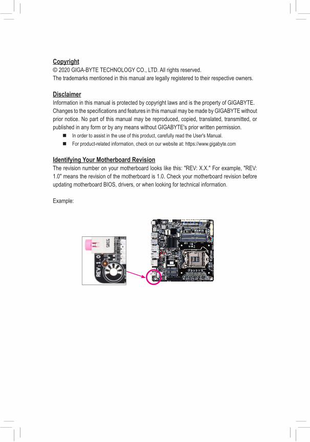
Identifying Your Motherboard RevisionThe revision number on your motherboard looks like this: "REV: X.X." For example, "REV: 1.0" means the revision of the motherboard is 1.0. Check your motherboard revision before updating motherboard BIOS, drivers, or when looking for technical information.
Example:
- 3 -
Table of Contents
GA-IMB410M Motherboard Layout ..................................................................................4
Chapter 1 Hardware Installation .....................................................................................51-1 Installation Precautions .................................................................................... 51-2 Product Specifications ...................................................................................... 61-3 Installing the CPU ............................................................................................ 91-4 Installing the Memory ....................................................................................... 91-5 Installing an Expansion Card ......................................................................... 101-6 Back Panel Connectors .................................................................................. 101-7 Internal Connectors ........................................................................................ 12
Chapter 2 BIOS Setup ..................................................................................................222-1 Startup Screen ............................................................................................... 222-2 The Main Menu .............................................................................................. 232-3 System ........................................................................................................... 242-4 Peripherals ..................................................................................................... 252-5 Chipset ........................................................................................................... 282-6 BIOS ............................................................................................................... 302-7 Power ............................................................................................................. 332-8 Save & Exit ..................................................................................................... 34
Chapter 3 Appendix ......................................................................................................35Drivers Installation ..................................................................................................... 35
Regulatory Notices .................................................................................................... 36Contact Us ................................................................................................................ 37
- 4 -
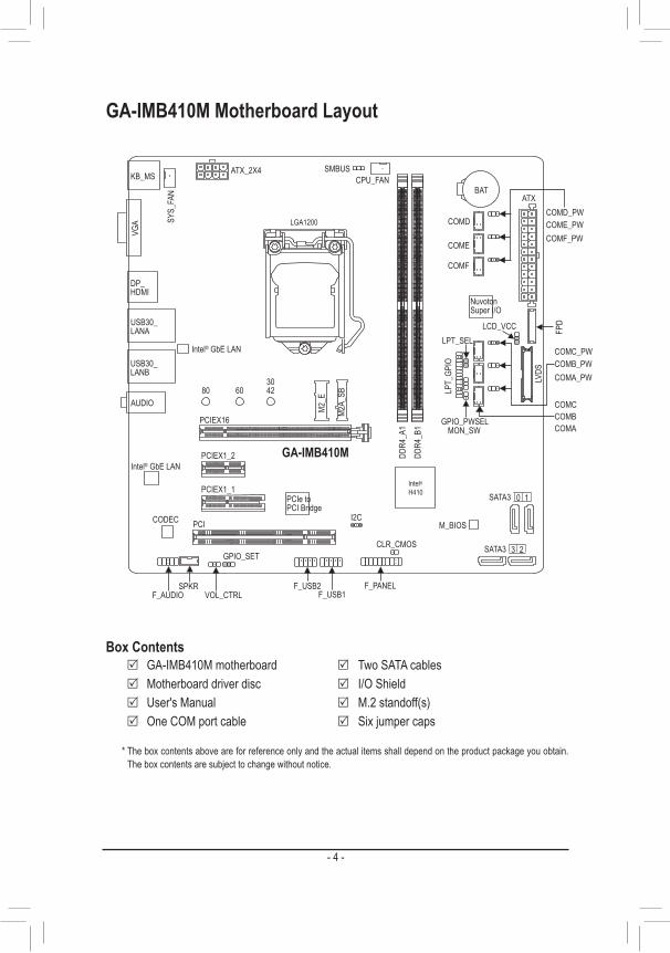
GA-IMB410M Motherboard Layout
* The box contents above are for reference only and the actual items shall depend on the product package you obtain. The box contents are subject to change without notice.
KB_MS CPU_FANSY
S_FA
N ATX
GA-IMB410M
AUDIODD
R4_A
1DD
R4_B
1
BAT
ATX_2X4
CODEC M_BIOS
VGA
PCIEX16
PCIEX1_1
PCIEX1_2
Nuvoton Super I/O
Intel® GbE LAN
LCD_VCC
SPKR F_PANELF_USB1
SATA3
0 1
USB30_LANB
USB30_ LANA
VOL_CTRLF_AUDIO
M2A_
SB80 60 42
PCI
CLR_CMOSFP
D
DP_HDMI
PCIe to PCI Bridge
LGA1200
M2_E
3 2
SATA3
LVDS
LPT_
GPIO
LPT_SEL
COMD
COME
COMF
COMD_PWCOME_PWCOMF_PW
Intel® H410
GPIO_SET
I2C
GPIO_PWSELMON_SW
COMCCOMBCOMA
COMC_PWCOMB_PWCOMA_PW
Intel® GbE LAN
F_USB2
SMBUS
30
Box Contents 5 GA-IMB410M motherboard 5 Two SATA cables 5 Motherboard driver disc 5 I/O Shield 5 User's Manual 5 M.2 standoff(s) 5 One COM port cable 5 Six jumper caps

Chapter 1 Hardware Installation1-1 Installation PrecautionsThe motherboard contains numerous delicate electronic circuits and components which can become damaged as a result of electrostatic discharge (ESD). Prior to installation, carefully read the user's manual and follow these procedures:
• Prior to installation, make sure the chassis is suitable for the motherboard. • Prior to installation, do not remove or break motherboard S/N (Serial Number) sticker or
warranty sticker provided by your dealer. These stickers are required for warranty validation. • Always remove the AC power by unplugging the power cord from the power outlet before
installing or removing the motherboard or other hardware components. • When connecting hardware components to the internal connectors on the motherboard, make
sure they are connected tightly and securely. • When handling the motherboard, avoid touching any metal leads or connectors. • It is best to wear an electrostatic discharge (ESD) wrist strap when handling electronic
components such as a motherboard, CPU or memory. If you do not have an ESD wrist strap, keep your hands dry and first touch a metal object to eliminate static electricity.
• Prior to installing the motherboard, please have it on top of an antistatic pad or within an electrostatic shielding container.
• Before connecting or unplugging the power supply cable from the motherboard, make sure the power supply has been turned off.
• Before turning on the power, make sure the power supply voltage has been set according to the local voltage standard.
• Before using the product, please verify that all cables and power connectors of your hardware components are connected.
• To prevent damage to the motherboard, do not allow screws to come in contact with the motherboard circuit or its components.
• Make sure there are no leftover screws or metal components placed on the motherboard or within the computer casing.
• Do not place the computer system on an uneven surface. • Do not place the computer system in a high-temperature or wet environment. • Turning on the computer power during the installation process can lead to damage to system
components as well as physical harm to the user. • If you are uncertain about any installation steps or have a problem related to the use of the
product, please consult a certified computer technician. • If you use an adapter, extension power cable, or power strip, ensure to consult with its installation
and/or grounding instructions.
- 5 -
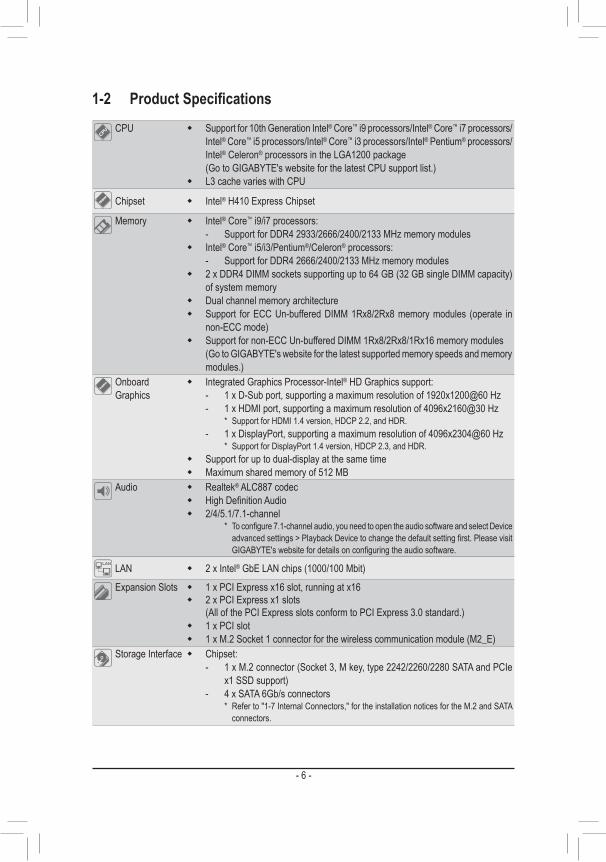
1-2 ProductSpecificationsCPU � Support for 10th Generation Intel® Core™ i9 processors/Intel® Core™ i7 processors/
Intel® Core™ i5 processors/Intel® Core™ i3 processors/Intel® Pentium® processors/Intel® Celeron® processors in the LGA1200 package(Go to GIGABYTE's website for the latest CPU support list.)
� L3 cache varies with CPU
Chipset � Intel® H410 Express Chipset
Memory � Intel® Core™ i9/i7 processors:- Support for DDR4 2933/2666/2400/2133 MHz memory modules
� Intel® Core™ i5/i3/Pentium®/Celeron® processors:- Support for DDR4 2666/2400/2133 MHz memory modules
� 2 x DDR4 DIMM sockets supporting up to 64 GB (32 GB single DIMM capacity) of system memory
� Dual channel memory architecture � Support for ECC Un-buffered DIMM 1Rx8/2Rx8 memory modules (operate in
non-ECC mode) � Support for non-ECC Un-buffered DIMM 1Rx8/2Rx8/1Rx16 memory modules
(Go to GIGABYTE's website for the latest supported memory speeds and memory modules.)
Onboard Graphics
� Integrated Graphics Processor-Intel® HD Graphics support: - 1 x D-Sub port, supporting a maximum resolution of 1920x1200@60 Hz - 1 x HDMI port, supporting a maximum resolution of 4096x2160@30 Hz
* Support for HDMI 1.4 version, HDCP 2.2, and HDR. - 1 x DisplayPort, supporting a maximum resolution of 4096x2304@60 Hz
* Support for DisplayPort 1.4 version, HDCP 2.3, and HDR. � Support for up to dual-display at the same time � Maximum shared memory of 512 MB
Audio � Realtek® ALC887 codec � High Definition Audio � 2/4/5.1/7.1-channel
* To configure 7.1-channel audio, you need to open the audio software and select Device advanced settings > Playback Device to change the default setting first. Please visit GIGABYTE's website for details on configuring the audio software.
LAN � 2 x Intel® GbE LAN chips (1000/100 Mbit)
Expansion Slots � 1 x PCI Express x16 slot, running at x16 � 2 x PCI Express x1 slots
(All of the PCI Express slots conform to PCI Express 3.0 standard.) � 1 x PCI slot � 1 x M.2 Socket 1 connector for the wireless communication module (M2_E)
Storage Interface � Chipset:- 1 x M.2 connector (Socket 3, M key, type 2242/2260/2280 SATA and PCIe
x1 SSD support)- 4 x SATA 6Gb/s connectors
* Refer to "1-7 Internal Connectors," for the installation notices for the M.2 and SATA connectors.
- 6 -
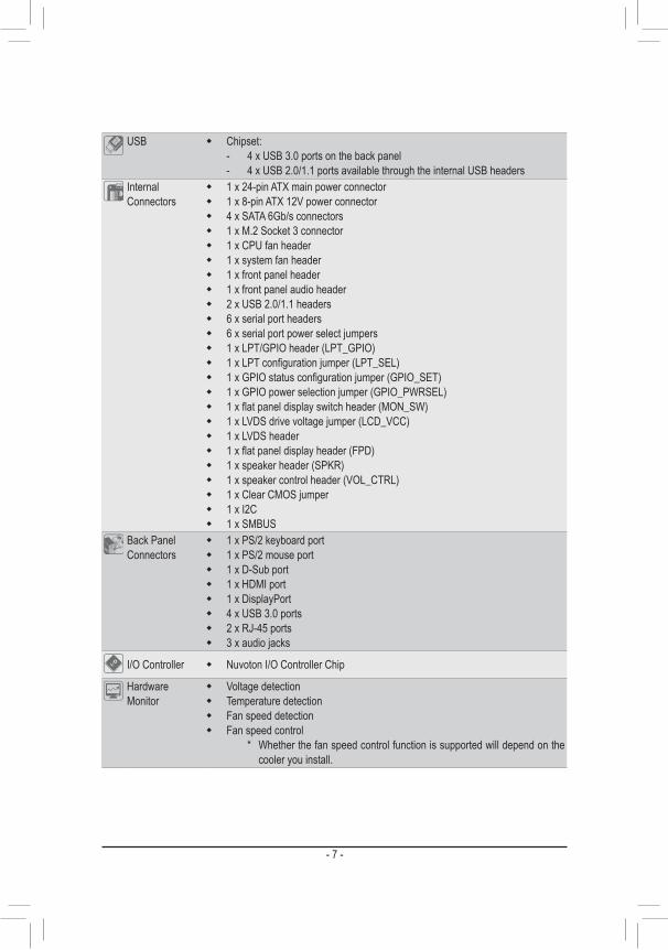
USB � Chipset:- 4 x USB 3.0 ports on the back panel- 4 x USB 2.0/1.1 ports available through the internal USB headers
Internal Connectors
� 1 x 24-pin ATX main power connector � 1 x 8-pin ATX 12V power connector � 4 x SATA 6Gb/s connectors � 1 x M.2 Socket 3 connector � 1 x CPU fan header � 1 x system fan header � 1 x front panel header � 1 x front panel audio header � 2 x USB 2.0/1.1 headers � 6 x serial port headers � 6 x serial port power select jumpers � 1 x LPT/GPIO header (LPT_GPIO) � 1 x LPT configuration jumper (LPT_SEL) � 1 x GPIO status configuration jumper (GPIO_SET) � 1 x GPIO power selection jumper (GPIO_PWRSEL) � 1 x flat panel display switch header (MON_SW) � 1 x LVDS drive voltage jumper (LCD_VCC) � 1 x LVDS header � 1 x flat panel display header (FPD) � 1 x speaker header (SPKR) � 1 x speaker control header (VOL_CTRL) � 1 x Clear CMOS jumper � 1 x I2C � 1 x SMBUS
Back Panel Connectors
� 1 x PS/2 keyboard port � 1 x PS/2 mouse port � 1 x D-Sub port � 1 x HDMI port � 1 x DisplayPort � 4 x USB 3.0 ports � 2 x RJ-45 ports � 3 x audio jacks
I/O Controller � Nuvoton I/O Controller Chip
Hardware Monitor
� Voltage detection � Temperature detection � Fan speed detection � Fan speed control
* Whether the fan speed control function is supported will depend on the cooler you install.
- 7 -
Please visit the Support\Utility List page on GIGABYTE's website to download the latest version of apps.
Please visit GIGABYTE's website for support lists of CPU, memory modules, SSDs, and M.2 devices.
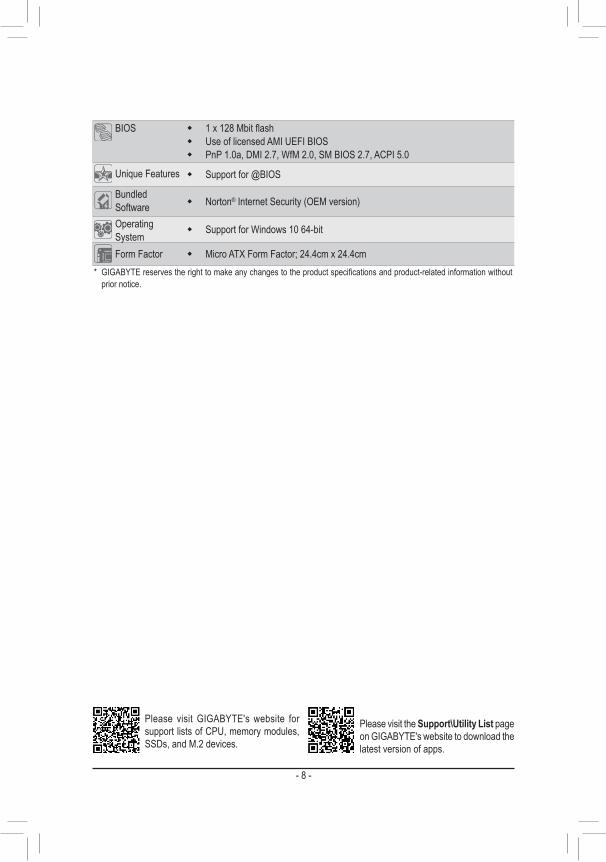
BIOS � 1 x 128 Mbit flash � Use of licensed AMI UEFI BIOS � PnP 1.0a, DMI 2.7, WfM 2.0, SM BIOS 2.7, ACPI 5.0
Unique Features � Support for @BIOS
Bundled Software � Norton® Internet Security (OEM version)
Operating System
� Support for Windows 10 64-bit
Form Factor � Micro ATX Form Factor; 24.4cm x 24.4cm* GIGABYTE reserves the right to make any changes to the product specifications and product-related information without
prior notice.
- 8 -
Please visit GIGABYTE's website for details on hardware installation.
1-3 Installing the CPU
1-4 Installing the MemoryRead the following guidelines before you begin to install the memory: • Make sure that the motherboard supports the memory. It is recommended that memory of the same
capacity, brand, speed, and chips be used.(Go to GIGABYTE's website for the latest supported memory speeds and memory modules.)
• Always turn off the computer and unplug the power cord from the power outlet before installing the memory to prevent hardware damage.
• Memory modules have a foolproof design. A memory module can be installed in only one direction. If you are unable to insert the memory, switch the direction.
DualChannelMemoryConfigurationThis motherboard provides two memory sockets and supports Dual Channel Technology. After the memory is installed, the BIOS will automatically detect the specifications and capacity of the memory. Enabling Dual Channel memory mode will double the original memory bandwidth.
Read the following guidelines before you begin to install the CPU: • Make sure that the motherboard supports the CPU.
(Go to GIGABYTE's website for the latest CPU support list.) • Always turn off the computer and unplug the power cord from the power outlet before installing the
CPU to prevent hardware damage. • Locate the pin one of the CPU. The CPU cannot be inserted if oriented incorrectly. (Or you may
locate the notches on both sides of the CPU and alignment keys on the CPU socket.) • Apply an even and thin layer of thermal grease on the surface of the CPU. • Do not turn on the computer if the CPU cooler is not installed, otherwise overheating and damage
of the CPU may occur. • Set the CPU host frequency in accordance with the CPU specifications. It is not recommended
that the system bus frequency be set beyond hardware specifications since it does not meet the standard requirements for the peripherals. If you wish to set the frequency beyond the standard specifications, please do so according to your hardware specifications including the CPU, graphics card, memory, hard drive, etc.
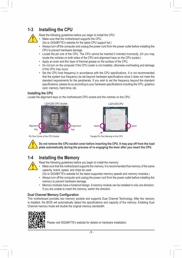
Installing the CPULocate the alignment keys on the motherboard CPU socket and the notches on the CPU.
Do not remove the CPU socket cover before inserting the CPU. It may pop off from the load plate automatically during the process of re-engaging the lever after you insert the CPU.
Triangle Pin One Marking on the CPU
NotchNotch
LGA1200 CPU
Alignment Key
Alignment Key
LGA1200 CPU Socket
Pin One Corner of the CPU Socket
- 9 -
1-5 Installing an Expansion CardRead the following guidelines before you begin to install an expansion card: • Make sure the motherboard supports the expansion card. Carefully read the manual that came
with your expansion card. • Always turn off the computer and unplug the power cord from the power outlet before installing an
expansion card to prevent hardware damage.
Due to CPU limitations, read the following guidelines before installing the memory in Dual Channel mode.1. Dual Channel mode cannot be enabled if only one memory module is installed.2. When enabling Dual Channel mode with two memory modules, it is recommended that memory of
the same capacity, brand, speed, and chips be used.
The two DDR4 memory sockets are divided into two channels and each channel has one memory socket as following:
�Channel A: DDR4_A1 �Channel B: DDR4_B1
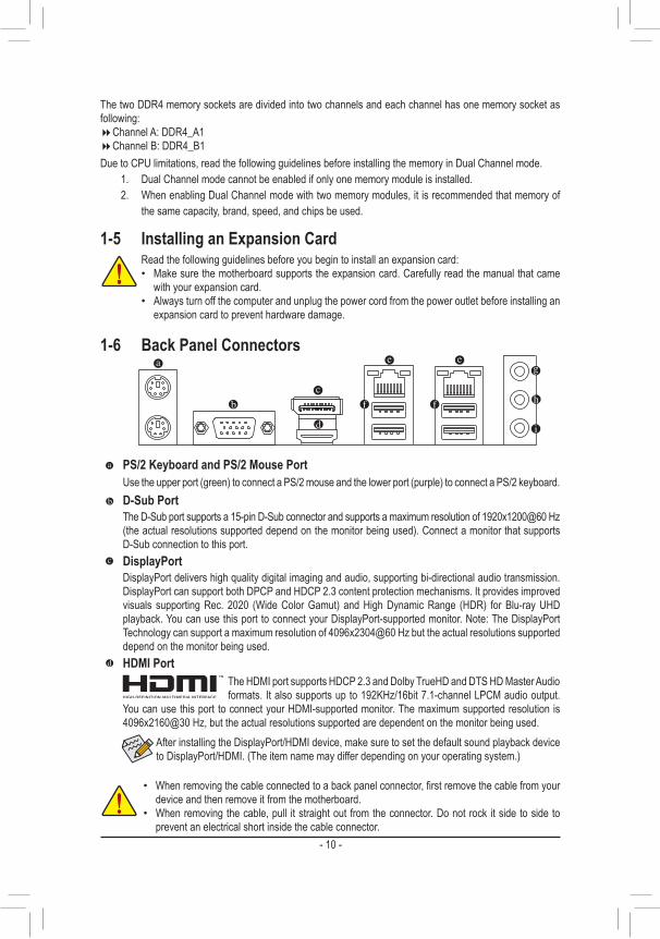
1-6 Back Panel Connectors
PS/2 Keyboard and PS/2 Mouse PortUse the upper port (green) to connect a PS/2 mouse and the lower port (purple) to connect a PS/2 keyboard.D-Sub PortThe D-Sub port supports a 15-pin D-Sub connector and supports a maximum resolution of 1920x1200@60 Hz (the actual resolutions supported depend on the monitor being used). Connect a monitor that supports D-Sub connection to this port.DisplayPortDisplayPort delivers high quality digital imaging and audio, supporting bi-directional audio transmission. DisplayPort can support both DPCP and HDCP 2.3 content protection mechanisms. It provides improved visuals supporting Rec. 2020 (Wide Color Gamut) and High Dynamic Range (HDR) for Blu-ray UHD playback. You can use this port to connect your DisplayPort-supported monitor. Note: The DisplayPort Technology can support a maximum resolution of 4096x2304@60 Hz but the actual resolutions supported depend on the monitor being used.HDMI Port
The HDMI port supports HDCP 2.3 and Dolby TrueHD and DTS HD Master Audio formats. It also supports up to 192KHz/16bit 7.1-channel LPCM audio output.
You can use this port to connect your HDMI-supported monitor. The maximum supported resolution is 4096x2160@30 Hz, but the actual resolutions supported are dependent on the monitor being used.
• When removing the cable connected to a back panel connector, first remove the cable from your device and then remove it from the motherboard.
• When removing the cable, pull it straight out from the connector. Do not rock it side to side to prevent an electrical short inside the cable connector.
After installing the DisplayPort/HDMI device, make sure to set the default sound playback device to DisplayPort/HDMI. (The item name may differ depending on your operating system.)
- 10 -
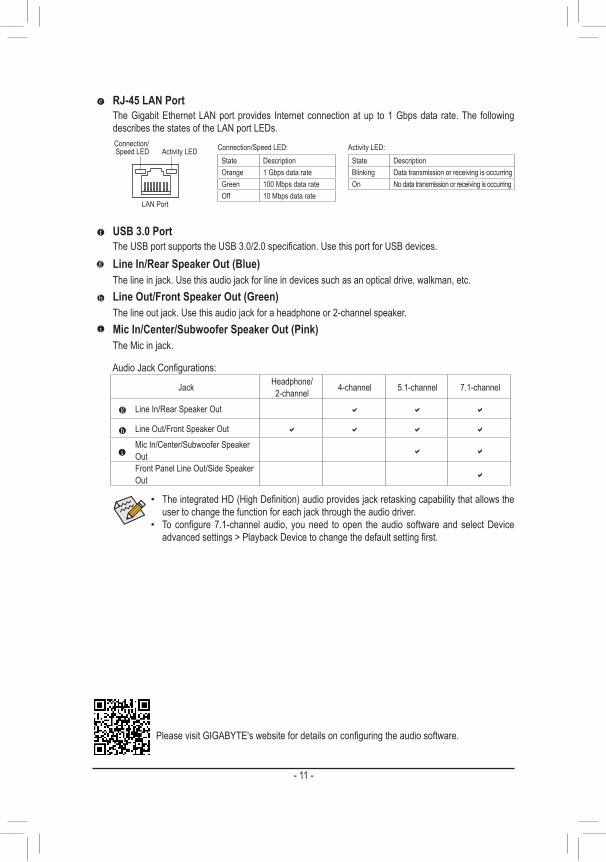
RJ-45 LAN PortThe Gigabit Ethernet LAN port provides Internet connection at up to 1 Gbps data rate. The following describes the states of the LAN port LEDs.
USB 3.0 PortThe USB port supports the USB 3.0/2.0 specification. Use this port for USB devices.Line In/Rear Speaker Out (Blue)The line in jack. Use this audio jack for line in devices such as an optical drive, walkman, etc.Line Out/Front Speaker Out (Green)The line out jack. Use this audio jack for a headphone or 2-channel speaker.Mic In/Center/Subwoofer Speaker Out (Pink)The Mic in jack.
Activity LEDConnection/Speed LED
LAN Port
Activity LED:Connection/Speed LED:State DescriptionOrange 1 Gbps data rateGreen 100 Mbps data rateOff 10 Mbps data rate
State DescriptionBlinking Data transmission or receiving is occurringOn No data transmission or receiving is occurring
Audio Jack Configurations:
Jack Headphone/ 2-channel 4-channel 5.1-channel 7.1-channel
Line In/Rear Speaker Out a a a
Line Out/Front Speaker Out a a a a
Mic In/Center/Subwoofer Speaker Out a a
Front Panel Line Out/Side Speaker Out a
Please visit GIGABYTE's website for details on configuring the audio software.
• The integrated HD (High Definition) audio provides jack retasking capability that allows the user to change the function for each jack through the audio driver.
• To configure 7.1-channel audio, you need to open the audio software and select Device advanced settings > Playback Device to change the default setting first.
- 11 -
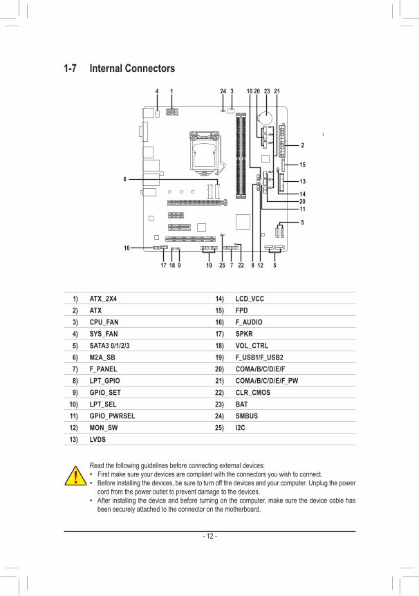
1-7 Internal Connectors
Read the following guidelines before connecting external devices: • First make sure your devices are compliant with the connectors you wish to connect. • Before installing the devices, be sure to turn off the devices and your computer. Unplug the power
cord from the power outlet to prevent damage to the devices. • After installing the device and before turning on the computer, make sure the device cable has
been securely attached to the connector on the motherboard.
4 1 3
2
1) ATX_2X42) ATX3) CPU_FAN4) SYS_FAN5) SATA3 0/1/2/36) M2A_SB7) F_PANEL8) LPT_GPIO9) GPIO_SET
10) LPT_SEL11) GPIO_PWRSEL12) MON_SW13) LVDS
14) LCD_VCC15) FPD16) F_AUDIO17) SPKR18) VOL_CTRL19) F_USB1/F_USB220) COMA/B/C/D/E/F21) COMA/B/C/D/E/F_PW22) CLR_CMOS23) BAT24) SMBUS25) I2C
5
5
6
7 22251991817
16
24
15
13
14
2320
20
21
8 12
11
10
- 12 -
DEBUG PORT
131
2412
ATX
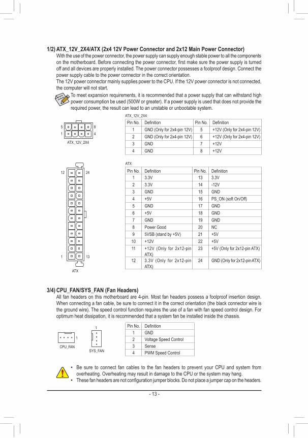
To meet expansion requirements, it is recommended that a power supply that can withstand high power consumption be used (500W or greater). If a power supply is used that does not provide the required power, the result can lead to an unstable or unbootable system.
ATX:
Pin No. Definition Pin No. Definition1 3.3V 13 3.3V2 3.3V 14 -12V3 GND 15 GND4 +5V 16 PS_ON (soft On/Off)5 GND 17 GND6 +5V 18 GND7 GND 19 GND8 Power Good 20 NC9 5VSB (stand by +5V) 21 +5V
10 +12V 22 +5V11 +12V (Only for 2x12-pin
ATX)23 +5V (Only for 2x12-pin ATX)
12 3.3V (Only for 2x12-pin ATX)
24 GND (Only for 2x12-pin ATX)
1/2) ATX_12V_2X4/ATX (2x4 12V Power Connector and 2x12 Main Power Connector) With the use of the power connector, the power supply can supply enough stable power to all the components
on the motherboard. Before connecting the power connector, first make sure the power supply is turned off and all devices are properly installed. The power connector possesses a foolproof design. Connect the power supply cable to the power connector in the correct orientation.
The 12V power connector mainly supplies power to the CPU. If the 12V power connector is not connected, the computer will not start.
ATX_12V_2X4:Pin No. Definition Pin No. Definition
1 GND (Only for 2x4-pin 12V) 5 +12V (Only for 2x4-pin 12V)2 GND (Only for 2x4-pin 12V) 6 +12V (Only for 2x4-pin 12V)3 GND 7 +12V4 GND 8 +12V
DEBUG PORT
ATX_12V_2X4
4185
3/4) CPU_FAN/SYS_FAN (Fan Headers) All fan headers on this motherboard are 4-pin. Most fan headers possess a foolproof insertion design.
When connecting a fan cable, be sure to connect it in the correct orientation (the black connector wire is the ground wire). The speed control function requires the use of a fan with fan speed control design. For optimum heat dissipation, it is recommended that a system fan be installed inside the chassis.
• Be sure to connect fan cables to the fan headers to prevent your CPU and system from overheating. Overheating may result in damage to the CPU or the system may hang.
• These fan headers are not configuration jumper blocks. Do not place a jumper cap on the headers.
DEBUG PORT
1
Pin No. Definition1 GND2 Voltage Speed Control3 Sense4 PWM Speed Control
DEBU
G PO
RT
1
SYS_FANCPU_FAN
- 13 -
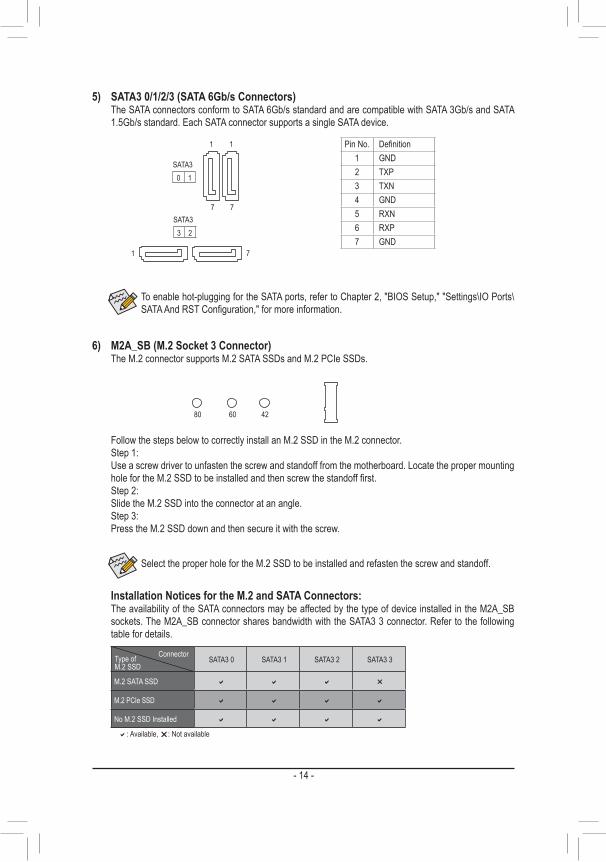
5) SATA3 0/1/2/3 (SATA 6Gb/s Connectors) The SATA connectors conform to SATA 6Gb/s standard and are compatible with SATA 3Gb/s and SATA
1.5Gb/s standard. Each SATA connector supports a single SATA device.
Pin No. Definition1 GND2 TXP3 TXN4 GND5 RXN6 RXP7 GND
SATA30 1
77
DEBUG PORTDEBUG PORT
DEBUG PORT
DEBUG PORT
11
To enable hot-plugging for the SATA ports, refer to Chapter 2, "BIOS Setup," "Settings\IO Ports\SATA And RST Configuration," for more information.
71
SATA33 2
Select the proper hole for the M.2 SSD to be installed and refasten the screw and standoff.
6) M2A_SB (M.2 Socket 3 Connector) The M.2 connector supports M.2 SATA SSDs and M.2 PCIe SSDs.
F_USB30 F_�U������
�B_��� �
F_� �������� F_� �������������
����_���������B�
B��S_��������B�
S�B_���������B�
���_���S����S_������_���������B�
���_��U���_���������B�
������������
� ����������������������������������
����������������������S� �� ����������
���
123
���
123
���
123
�� �
1 2 3
1
1
1
1
B��S�S�����������������
����S���������������
�_S� ��
����S�������S��������U���
���
123��
� �����������������������������S������3� B��S�S���������S���
����
�������������������U����� �_���_�� 3
F_USB3��F�����������
S� �� _�������
S� �� _�������
S� �� _�������
������������������������S���F�����
������������
��B_�
��B_�
�������F�
��_�0�
S�������S����
��_�0���������F��������
��_��F�
���_����������
�_��������
��_������_B�
������������
U��
S� �� _S��
���_�������� S���F_���������
B� �
USB�0_�B
��B_�
��B_��
F_USB3����� F_USB30�3��
����
���_���
������
��_3��������������U�
S��_���
80 60 42
Installation Notices for the M.2 and SATA Connectors:The availability of the SATA connectors may be affected by the type of device installed in the M2A_SB sockets. The M2A_SB connector shares bandwidth with the SATA3 3 connector. Refer to the following table for details.
SATA3 0 SATA3 1 SATA3 2 SATA3 3
M.2 SATA SSD a a a r
M.2 PCIe SSD a a a a
No M.2 SSD Installed a a a a
a: Available, r: Not available
ConnectorType of M.2 SSD
Follow the steps below to correctly install an M.2 SSD in the M.2 connector.Step 1:Use a screw driver to unfasten the screw and standoff from the motherboard. Locate the proper mounting hole for the M.2 SSD to be installed and then screw the standoff first.Step 2:Slide the M.2 SSD into the connector at an angle.Step 3:Press the M.2 SSD down and then secure it with the screw.
- 14 -
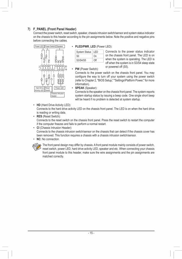
The front panel design may differ by chassis. A front panel module mainly consists of power switch, reset switch, power LED, hard drive activity LED, speaker and etc. When connecting your chassis front panel module to this header, make sure the wire assignments and the pin assignments are matched correctly.
7) F_PANEL (Front Panel Header) Connect the power switch, reset switch, speaker, chassis intrusion switch/sensor and system status indicator
on the chassis to this header according to the pin assignments below. Note the positive and negative pins before connecting the cables.
System Status LEDS0 OnS3/S4/S5 Off
• PW (Power Switch): Connects to the power switch on the chassis front panel. You may
configure the way to turn off your system using the power switch (refer to Chapter 2, "BIOS Setup," "Settings\Platform Power," for more information).
• SPEAK (Speaker): Connects to the speaker on the chassis front panel. The system reports
system startup status by issuing a beep code. One single short beep will be heard if no problem is detected at system startup.
• PLED/PWR_LED (Power LED):Connects to the power status indicator on the chassis front panel. The LED is on when the system is operating. The LED is off when the system is in S3/S4 sleep state or powered off (S5).
• HD (Hard Drive Activity LED): Connects to the hard drive activity LED on the chassis front panel. The LED is on when the hard drive
is reading or writing data. • RES (Reset Switch):
Connects to the reset switch on the chassis front panel. Press the reset switch to restart the computer if the computer freezes and fails to perform a normal restart.
• CI (Chassis Intrusion Header): Connects to the chassis intrusion switch/sensor on the chassis that can detect if the chassis cover has
been removed. This function requires a chassis with a chassis intrusion switch/sensor. • NC: No connection.
PLED
-
PW-
SPEA
K+
SPEA
K-PLED
+
PW+
HD-
RES+
HD+
RES-
Hard Drive Activity LED
Reset Switch
DEBUG PORT
Power LED
12
1920
CI- CI
+
Power LED
Chassis Intrusion Header
Power Switch Speaker
NC NCPW
R_LE
D-PW
R_LE
D-PW
R_LE
D+
- 15 -
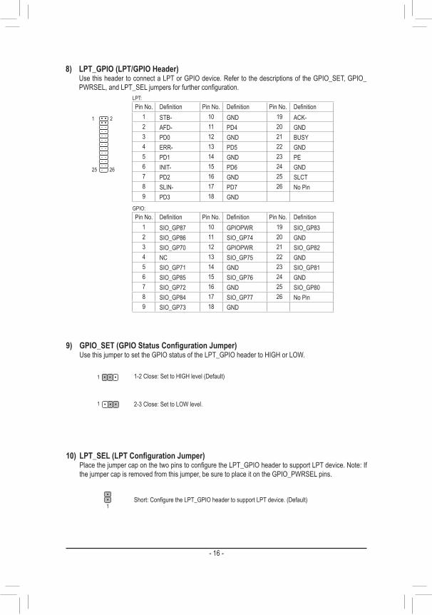
8) LPT_GPIO (LPT/GPIO Header) Use this header to connect a LPT or GPIO device. Refer to the descriptions of the GPIO_SET, GPIO_
PWRSEL, and LPT_SEL jumpers for further configuration.
eDP
����
2625
21
Pin No. Definition Pin No. Definition Pin No. Definition1 STB- 10 GND 19 ACK-2 AFD- 11 PD4 20 GND3 PD0 12 GND 21 BUSY4 ERR- 13 PD5 22 GND5 PD1 14 GND 23 PE6 INIT- 15 PD6 24 GND7 PD2 16 GND 25 SLCT8 SLIN- 17 PD7 26 No Pin9 PD3 18 GND
LPT:
Pin No. Definition Pin No. Definition Pin No. Definition1 SIO_GP87 10 GPIOPWR 19 SIO_GP832 SIO_GP86 11 SIO_GP74 20 GND3 SIO_GP70 12 GPIOPWR 21 SIO_GP824 NC 13 SIO_GP75 22 GND5 SIO_GP71 14 GND 23 SIO_GP816 SIO_GP85 15 SIO_GP76 24 GND7 SIO_GP72 16 GND 25 SIO_GP808 SIO_GP84 17 SIO_GP77 26 No Pin9 SIO_GP73 18 GND
GPIO:
9) GPIO_SET(GPIOStatusConfigurationJumper) Use this jumper to set the GPIO status of the LPT_GPIO header to HIGH or LOW.
1-2 Close: Set to HIGH level (Default)
2-3 Close: Set to LOW level.
1
1
10) LPT_SEL(LPTConfigurationJumper) Place the jumper cap on the two pins to configure the LPT_GPIO header to support LPT device. Note: If
the jumper cap is removed from this jumper, be sure to place it on the GPIO_PWRSEL pins.
Short: Configure the LPT_GPIO header to support LPT device. (Default)1
- 16 -
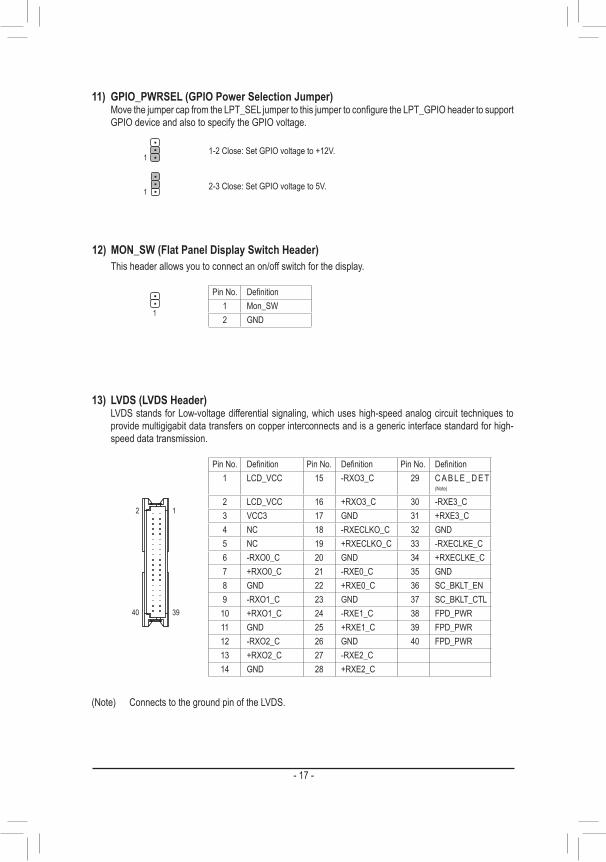
11) GPIO_PWRSEL (GPIO Power Selection Jumper) Move the jumper cap from the LPT_SEL jumper to this jumper to configure the LPT_GPIO header to support
GPIO device and also to specify the GPIO voltage.
1-2 Close: Set GPIO voltage to +12V.
2-3 Close: Set GPIO voltage to 5V.
1
1
12) MON_SW (Flat Panel Display Switch Header) This header allows you to connect an on/off switch for the display.
Pin No. Definition1 Mon_SW2 GND
1
13) LVDS (LVDS Header) LVDS stands for Low-voltage differential signaling, which uses high-speed analog circuit techniques to
provide multigigabit data transfers on copper interconnects and is a generic interface standard for high-speed data transmission.
2 1
40 39
Pin No. Definition Pin No. Definition Pin No. Definition1 LCD_VCC 15 -RXO3_C 29 C A B L E _ D E T
(Note)
2 LCD_VCC 16 +RXO3_C 30 -RXE3_C3 VCC3 17 GND 31 +RXE3_C4 NC 18 -RXECLKO_C 32 GND5 NC 19 +RXECLKO_C 33 -RXECLKE_C6 -RXO0_C 20 GND 34 +RXECLKE_C7 +RXO0_C 21 -RXE0_C 35 GND8 GND 22 +RXE0_C 36 SC_BKLT_EN9 -RXO1_C 23 GND 37 SC_BKLT_CTL
10 +RXO1_C 24 -RXE1_C 38 FPD_PWR11 GND 25 +RXE1_C 39 FPD_PWR12 -RXO2_C 26 GND 40 FPD_PWR13 +RXO2_C 27 -RXE2_C14 GND 28 +RXE2_C
(Note) Connects to the ground pin of the LVDS.
- 17 -

15) FPD (Flat Panel Display Header) The FPD is a high-speed interface connecting the output of a video controller in a laptop computer, computer
monitor or LCD television set to the display panel. Most laptops, LCD computer monitors and LCD TVs use this interface internally. The header conforms to FPD specification.
1
8
Pin No. Definition1 BKLT_EN2 BKLT_PWM3 BKLT_PWR4 BKLT_PWR5 BKLT_GND/Brightness_GND6 BKLT_GND/Brightness_GND7 Brightness_Up8 Brightness_Down
14) LCD_VCC (LVDS Drive Voltage Jumper) This jumper can be used to provide different screen voltage settings.
1
1
1-2 Close: Set to 3V. (Default)
2-3 Close: Set to 5V.
16) F_AUDIO (Front Panel Audio Header) The front panel audio header supports High Definition audio (HD). You may connect your chassis front
panel audio module to this header. Make sure the wire assignments of the module connector match the pin assignments of the motherboard header. Incorrect connection between the module connector and the motherboard header will make the device unable to work or even damage it.
Pin No. Definition Pin No. Definition1 MIC2_L 6 Sense2 GND 7 FAUDIO_JD3 MIC2_R 8 No Pin4 NC 9 LINE2_L5 LINE2_R 10 Sense
12
910
Some chassis provide a front panel audio module that has separated connectors on each wire instead of a single plug. For information about connecting the front panel audio module that has different wire assignments, please contact the chassis manufacturer.
- 18 -
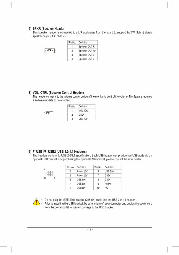
17) SPKR (Speaker Header) This speaker header is connected to a L/R audio pins from the board to support the 3W (4ohm) stereo
speaker on your AIO chassis.
1 4
Pin No. Definition1 Speaker OUT R-2 Speaker OUT R+3 Speaker OUT L-4 Speaker OUT L+
18) VOL_CTRL (Speaker Control Header) The header connects to the volume control button of the monitor to control the volume. This feature requires
a software update to be enabled.
Pin No. Definition1 VOL_DW2 GND3 VOL_UP
1
19) F_USB1/F_USB2 (USB 2.0/1.1 Headers) The headers conform to USB 2.0/1.1 specification. Each USB header can provide two USB ports via an
optional USB bracket. For purchasing the optional USB bracket, please contact the local dealer.
Pin No. Definition Pin No. Definition1 Power (5V) 6 USB DY+2 Power (5V) 7 GND3 USB DX- 8 GND4 USB DY- 9 No Pin5 USB DX+ 10 NC
• Do not plug the IEEE 1394 bracket (2x5-pin) cable into the USB 2.0/1.1 header. • Prior to installing the USB bracket, be sure to turn off your computer and unplug the power cord
from the power outlet to prevent damage to the USB bracket.
10
9 1
2
- 19 -
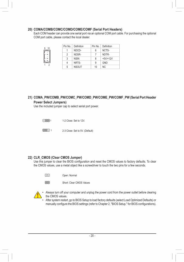
20) COMA/COMB/COMC/COMD/COME/COMF (Serial Port Headers) Each COM header can provide one serial port via an optional COM port cable. For purchasing the optional
COM port cable, please contact the local dealer.
Pin No. Definition Pin No. Definition1 NDCD- 6 NCTS-2 NDSR- 7 NDTR-3 NSIN 8 +5V/+12V4 NRTS- 9 GND5 NSOUT 10 NC
1 2
9 10
21) COMA_PW/COMB_PW/COMC_PW/COMD_PW/COME_PW/COMF_PW (Serial Port Header Power Select Jumpers)
Use the included jumper cap to select serial port power.
1-2 Close: Set to 12V.
2-3 Close: Set to 5V. (Default)1
1
22) CLR_CMOS (Clear CMOS Jumper) Use this jumper to clear the BIOS configuration and reset the CMOS values to factory defaults. To clear
the CMOS values, use a metal object like a screwdriver to touch the two pins for a few seconds.
• Always turn off your computer and unplug the power cord from the power outlet before clearing the CMOS values.
• After system restart, go to BIOS Setup to load factory defaults (select Load Optimized Defaults) or manually configure the BIOS settings (refer to Chapter 2, "BIOS Setup," for BIOS configurations).
Open: Normal
Short: Clear CMOS Values
- 20 -
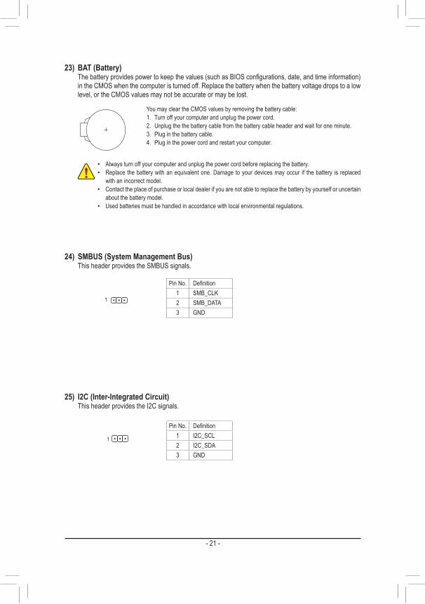
23) BAT (Battery) The battery provides power to keep the values (such as BIOS configurations, date, and time information)
in the CMOS when the computer is turned off. Replace the battery when the battery voltage drops to a low level, or the CMOS values may not be accurate or may be lost.
You may clear the CMOS values by removing the battery cable:1. Turn off your computer and unplug the power cord.2. Unplug the the battery cable from the battery cable header and wait for one minute.3. Plug in the battery cable.4. Plug in the power cord and restart your computer.
• Always turn off your computer and unplug the power cord before replacing the battery. • Replace the battery with an equivalent one. Damage to your devices may occur if the battery is replaced
with an incorrect model. • Contact the place of purchase or local dealer if you are not able to replace the battery by yourself or uncertain
about the battery model. • Used batteries must be handled in accordance with local environmental regulations.
25) I2C (Inter-Integrated Circuit) This header provides the I2C signals.
Pin No. Definition1 I2C_SCL2 I2C_SDA3 GND
1
24) SMBUS (System Management Bus) This header provides the SMBUS signals.
Pin No. Definition1 SMB_CLK2 SMB_DATA3 GND
1
- 21 -
Chapter 2 BIOS SetupBIOS (Basic Input and Output System) records hardware parameters of the system in the CMOS on the motherboard. Its major functions include conducting the Power-On Self-Test (POST) during system startup, saving system parameters and loading operating system, etc. BIOS includes a BIOS Setup program that allows the user to modify basic system configuration settings or to activate certain system features.When the power is turned off, the battery on the motherboard supplies the necessary power to the CMOS to keep the configuration values in the CMOS.To access the BIOS Setup program, press the <Delete> key during the POST when the power is turned on.To upgrade the BIOS, use either the GIGABYTE Q-Flash or @BIOS utility. • Q-Flash allows the user to quickly and easily upgrade or back up BIOS without entering the operating system. • @BIOS is a Windows-based utility that searches and downloads the latest version of BIOS from the Internet
and updates the BIOS.
• Because BIOS flashing is potentially risky, if you do not encounter problems using the current version of BIOS, it is recommended that you not flash the BIOS. To flash the BIOS, do it with caution. Inadequate BIOS flashing may result in system malfunction.
• It is recommended that you not alter the default settings (unless you need to) to prevent system instability or other unexpected results. Inadequately altering the settings may result in system's failure to boot. If this occurs, try to clear the CMOS values and reset the board to default values. (Refer to the "Load Optimized Defaults" section in this chapter or introductions of the battery/clear CMOS jumper in Chapter 1 for how to clear the CMOS values.)
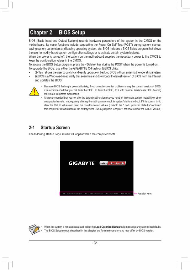
2-1 Startup ScreenThe following startup Logo screen will appear when the computer boots.
• When the system is not stable as usual, select the Load Optimized Defaults item to set your system to its defaults. • The BIOS Setup menus described in this chapter are for reference only and may differ by BIOS version.
Function Keys
- 22 -
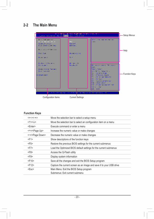
2-2 The Main Menu
Function Keys<f><g> Move the selection bar to select a setup menu<h><i> Move the selection bar to select an configuration item on a menu<Enter> Execute command or enter a menu<+>/<Page Up> Increase the numeric value or make changes<->/<Page Down> Decrease the numeric value or make changes<F1> Show descriptions of the function keys<F5> Restore the previous BIOS settings for the current submenus<F7> Load the Optimized BIOS default settings for the current submenus<F8> Access the Q-Flash utility<F9> Display system information<F10> Save all the changes and exit the BIOS Setup program<F12> Capture the current screen as an image and save it to your USB drive<Esc> Main Menu: Exit the BIOS Setup program
Submenus: Exit current submenu
Setup Menus
Function Keys
Help
Configuration Items Current Settings
- 23 -
2-3 System
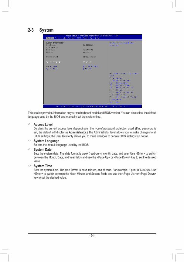
This section provides information on your motherboard model and BIOS version. You can also select the default language used by the BIOS and manually set the system time.
& Access Level Displays the current access level depending on the type of password protection used. (If no password is
set, the default will display as Administrator.) The Administrator level allows you to make changes to all BIOS settings; the User level only allows you to make changes to certain BIOS settings but not all.
& System Language Selects the default language used by the BIOS.
& System Date Sets the system date. The date format is week (read-only), month, date, and year. Use <Enter> to switch
between the Month, Date, and Year fields and use the <Page Up> or <Page Down> key to set the desired value.
& System Time Sets the system time. The time format is hour, minute, and second. For example, 1 p.m. is 13:00:00. Use
<Enter> to switch between the Hour, Minute, and Second fields and use the <Page Up> or <Page Down> key to set the desired value.
- 24 -
2-4 Peripherals
(Note) This item is present only when you install a CPU that supports this feature.
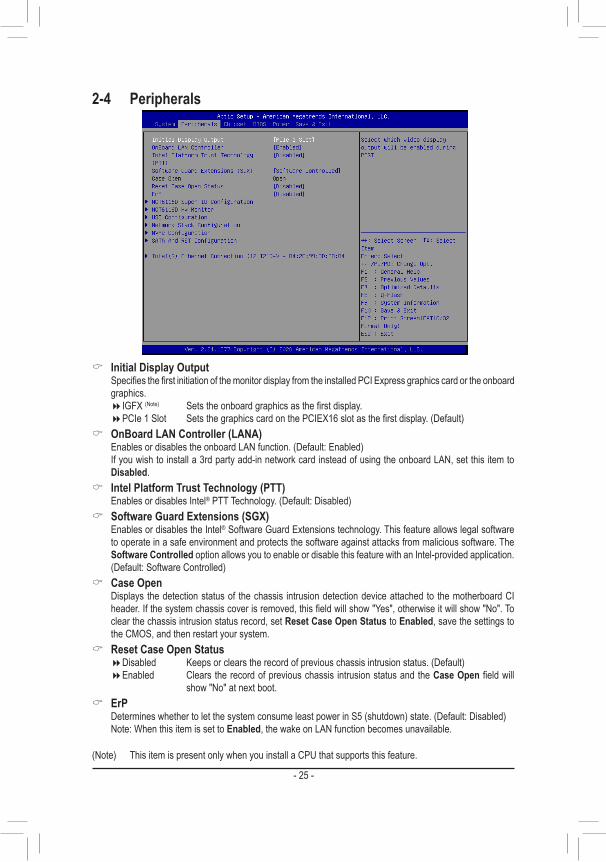
& Initial Display Output Specifies the first initiation of the monitor display from the installed PCI Express graphics card or the onboard
graphics. �IGFX (Note) Sets the onboard graphics as the first display. �PCIe 1 Slot Sets the graphics card on the PCIEX16 slot as the first display. (Default)
& OnBoard LAN Controller (LANA) Enables or disables the onboard LAN function. (Default: Enabled) If you wish to install a 3rd party add-in network card instead of using the onboard LAN, set this item to
Disabled. & Intel Platform Trust Technology (PTT)
Enables or disables Intel® PTT Technology. (Default: Disabled) & Software Guard Extensions (SGX)
Enables or disables the Intel® Software Guard Extensions technology. This feature allows legal software to operate in a safe environment and protects the software against attacks from malicious software. The Software Controlled option allows you to enable or disable this feature with an Intel-provided application. (Default: Software Controlled)
& Case Open Displays the detection status of the chassis intrusion detection device attached to the motherboard CI
header. If the system chassis cover is removed, this field will show "Yes", otherwise it will show "No". To clear the chassis intrusion status record, set Reset Case Open Status to Enabled, save the settings to the CMOS, and then restart your system.
& Reset Case Open Status �Disabled Keeps or clears the record of previous chassis intrusion status. (Default) �Enabled Clears the record of previous chassis intrusion status and the Case Open field will
show "No" at next boot. & ErP
Determines whether to let the system consume least power in S5 (shutdown) state. (Default: Disabled) Note: When this item is set to Enabled, the wake on LAN function becomes unavailable.
- 25 -
` NCT6116DSuperIOConfiguration & SerialPort1/2/3/4/5/6Configuration(OnboardCOMA/B/C/D/E/FConnector)
Enables or disables the onboard serial port. & ParallelPortConfiguration(OnboardLPT_GPIOConnector)
Enables or disables the onboard parallel port.
` NCT6116D HW Monitor Displays system health status, including system temperature, fan speeds, and voltage values.
` USBConfiguration & Legacy USB Support
Allows USB keyboard/mouse to be used in MS-DOS. (Default: Enabled) & XHCI Hand-off
Determines whether to enable XHCI Hand-off feature for an operating system without XHCI Hand-off support. (Default: Enabled)
& USB Mass Storage Driver Support Enables or disables support for USB storage devices. (Default: Enabled)
& Mass Storage Devices Displays a list of connected USB mass storage devices. This item appears only when a USB storage device
is installed.
` NetworkStackConfiguration & Network Stack
Disables or enables booting from the network to install a GPT format OS, such as installing the OS from the Windows Deployment Services server. (Default: Disabled)
& Ipv4 PXE Support Enables or disables IPv4 PXE Support. This item is configurable only when Network Stack is enabled.
& Ipv4 HTTP Support Enables or disables HTTP boot support for IPv4. This item is configurable only when Network Stack is
enabled. & Ipv6 PXE Support
Enables or disables IPv6 PXE Support. This item is configurable only when Network Stack is enabled. & Ipv6 HTTP Support
Enables or disables HTTP boot support for IPv6. This item is configurable only when Network Stack is enabled.
& PXE boot wait time Allows you to configure how long to wait before you can press <Esc> to abort the PXE boot.
& Media detect count Allows you to set the number of times to check the presence of media.
` NVMeConfiguration Displays information on your M.2 NVME PCIe SSD if installed.
- 26 -
` SATAAndRSTConfiguration & SATA Controller(s)
Enables or disables the integrated SATA controllers. (Default: Enabled) & SATA Mode Selection
Specifies the operating mode of the integrated SATA controllers. �AHCI Configures the SATA controllers to AHCI mode. Advanced Host Controller Interface
(AHCI) is an interface specification that allows the storage driver to enable advanced Serial ATA features such as Native Command Queuing and hot plug. (Default)
& Aggressive LPM Support Enables or disables the power saving feature, ALPM (Aggressive Link Power Management), for the Chipset
SATA controllers. (Default: Disabled) & Port 0/1/2/3
Enables or disables each SATA port. (Default: Enabled) & Hot plug
Enables or disable the hot plug capability for each SATA port. (Default: Disabled) & ConfiguredaseSATA
Enables or disables support for external SATA devices.
� Intel(R) Ethernet Connection This sub-menu provides information on LAN configuration and related configuration options.
- 27 -
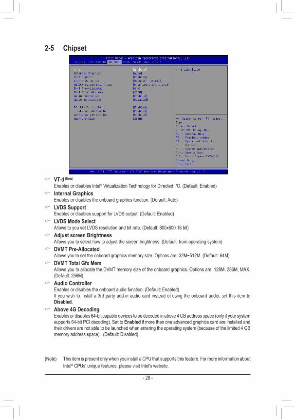
& VT-d (Note)
Enables or disables Intel® Virtualization Technology for Directed I/O. (Default: Enabled) & Internal Graphics
Enables or disables the onboard graphics function. (Default: Auto) & LVDS Support
Enables or disables support for LVDS output. (Default: Enabled) & LVDS Mode Select
Allows to you set LVDS resolution and bit rate. (Default: 800x600 18 bit) & Adjust screen Brightness
Allows you to select how to adjust the screen brightness. (Default: from operating system) & DVMT Pre-Allocated
Allows you to set the onboard graphics memory size. Options are: 32M~512M. (Default: 64M) & DVMT Total Gfx Mem
Allows you to allocate the DVMT memory size of the onboard graphics. Options are: 128M, 256M, MAX. (Default: 256M)
& Audio Controller Enables or disables the onboard audio function. (Default: Enabled) If you wish to install a 3rd party add-in audio card instead of using the onboard audio, set this item to
Disabled. & Above 4G Decoding
Enables or disables 64-bit capable devices to be decoded in above 4 GB address space (only if your system supports 64-bit PCI decoding). Set to Enabled if more than one advanced graphics card are installed and their drivers are not able to be launched when entering the operating system (because of the limited 4 GB memory address space). (Default: Disabled)
2-5 Chipset
(Note) This item is present only when you install a CPU that supports this feature. For more information about Intel® CPUs' unique features, please visit Intel's website.
- 28 -

& PCH LAN Controller (LANB) Enables or disables the Intel® GbE LAN function. (Default: Enabled) If you wish to install a 3rd party add-in network card instead of using the onboard LAN, set this item to
Disabled. & Wake on LAN Enable
Enables or disables the wake on LAN function. (Default: Enabled) & IOAPIC 24-119 Entries
Enables or disables this function. (Default: Enabled) & Aperture Size
Allows you to set the maximum amount of system memory that can be allocated to the graphics card. (Default: 256MB)
- 29 -
2-6 BIOS
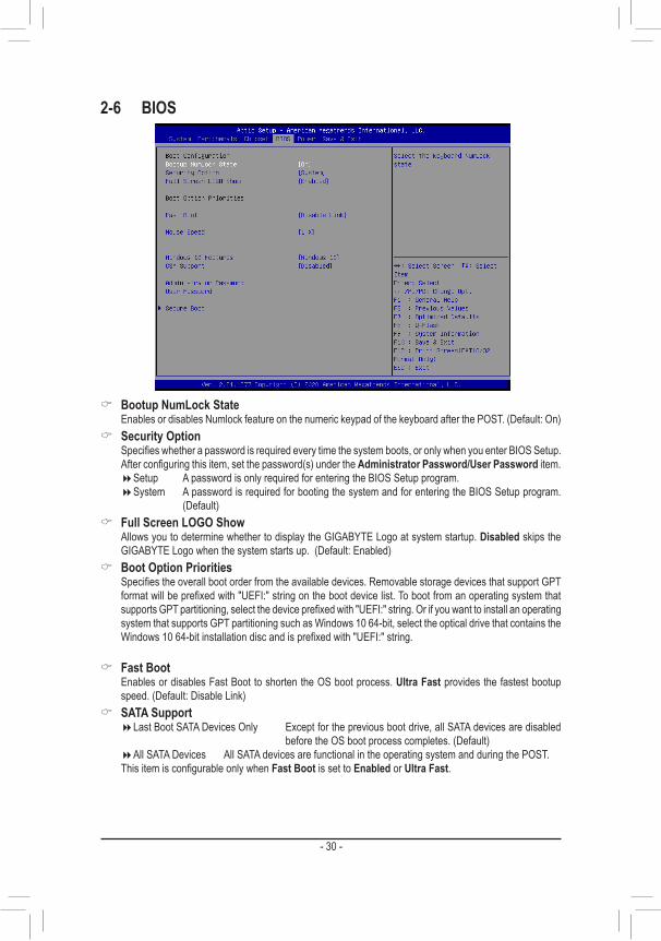
& Bootup NumLock State Enables or disables Numlock feature on the numeric keypad of the keyboard after the POST. (Default: On)
& Security Option Specifies whether a password is required every time the system boots, or only when you enter BIOS Setup.
After configuring this item, set the password(s) under the Administrator Password/User Password item. �Setup A password is only required for entering the BIOS Setup program. �System A password is required for booting the system and for entering the BIOS Setup program.
(Default) & Full Screen LOGO Show
Allows you to determine whether to display the GIGABYTE Logo at system startup. Disabled skips the GIGABYTE Logo when the system starts up. (Default: Enabled)
& Boot Option Priorities Specifies the overall boot order from the available devices. Removable storage devices that support GPT
format will be prefixed with "UEFI:" string on the boot device list. To boot from an operating system that supports GPT partitioning, select the device prefixed with "UEFI:" string. Or if you want to install an operating system that supports GPT partitioning such as Windows 10 64-bit, select the optical drive that contains the Windows 10 64-bit installation disc and is prefixed with "UEFI:" string.
& Fast Boot Enables or disables Fast Boot to shorten the OS boot process. Ultra Fast provides the fastest bootup
speed. (Default: Disable Link) & SATA Support
�Last Boot SATA Devices Only Except for the previous boot drive, all SATA devices are disabled before the OS boot process completes. (Default)
�All SATA Devices All SATA devices are functional in the operating system and during the POST. This item is configurable only when Fast Boot is set to Enabled or Ultra Fast.
- 30 -
& VGA Support Allows you to select which type of operating system to boot.
�Auto Enables legacy option ROM only. �EFI Driver Enables EFI option ROM. (Default)
This item is configurable only when Fast Boot is set to Enabled or Ultra Fast. & USB Support
�Disable Link All USB devices are disabled before the OS boot process completes. �Full Initial All USB devices are functional in the operating system and during the POST.
(Default) �Partial Initial Part of the USB devices are disabled before the OS boot process completes.
This item is configurable only when Fast Boot is set to Enabled. This function is disabled when Fast Boot is set to Ultra Fast.
& NetWork Stack Driver Support �Disable Link Disables booting from the network. (Default) �Enabled Enables booting from the network.
This item is configurable only when Fast Boot is set to Enabled or Ultra Fast. & Next Boot After AC Power Loss
�Normal Boot Enables normal bootup upon the return of the AC power. (Default) �Fast Boot Keeps the Fast Boot settings upon the return of the AC power.
This item is configurable only when Fast Boot is set to Enabled or Ultra Fast.
& Mouse Speed Allows you to set the mouse cursor movement speed. (Default: 1 X)
& Windows 10 Features Allows you to select the operating system to be installed. (Default: Windows 10)
& CSM Support Enables or disables UEFI CSM (Compatibility Support Module) to support a legacy PC boot process.
�Enabled Enables UEFI CSM. �Disabled Disables UEFI CSM and supports UEFI BIOS boot process only. (Default)
& LAN PXE Boot Option ROM Allows you to select whether to enable the legacy option ROM for the LAN controller. (Default: Disabled) This item is configurable only when CSM Support is set to Enabled.
& Storage Boot Option Control Allows you to select whether to enable the UEFI or legacy option ROM for the storage device controller.
�Do not launch Disables option ROM. �UEFI Enables UEFI option ROM only. �Legacy Enables legacy option ROM only. (Default)
This item is configurable only when CSM Support is set to Enabled. & Other PCI devices
Allows you to select whether to enable the UEFI or Legacy option ROM for the PCI device controller other than the LAN, storage device, and graphics controllers.
�Do not launch Disables option ROM. �UEFI Enables UEFI option ROM only. (Default) �Legacy Enables legacy option ROM only.
This item is configurable only when CSM Support is set to Enabled.
- 31 -
& Administrator Password Allows you to configure an administrator password. Press <Enter> on this item, type the password, and
then press <Enter>. You will be requested to confirm the password. Type the password again and press <Enter>. You must enter the administrator password (or user password) at system startup and when entering BIOS Setup. Differing from the user password, the administrator password allows you to make changes to all BIOS settings.
& User Password Allows you to configure a user password. Press <Enter> on this item, type the password, and then press
<Enter>. You will be requested to confirm the password. Type the password again and press <Enter>. You must enter the administrator password (or user password) at system startup and when entering BIOS Setup. However, the user password only allows you to make changes to certain BIOS settings but not all.
To cancel the password, press <Enter> on the password item and when requested for the password, enter the correct one first. When prompted for a new password, press <Enter> without entering any password. Press <Enter> again when prompted to confirm.
NOTE: Before setting the User Password, be sure to set the Administrator Password first. ` Secure Boot
Allows you to enable or disable Secure Boot and configure related settings. This item is configurable only when CSM Support is set to Disabled.
- 32 -
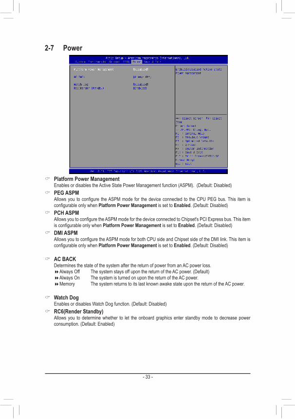
& Platform Power Management Enables or disables the Active State Power Management function (ASPM). (Default: Disabled)
& PEG ASPM Allows you to configure the ASPM mode for the device connected to the CPU PEG bus. This item is
configurable only when Platform Power Management is set to Enabled. (Default: Disabled) & PCH ASPM
Allows you to configure the ASPM mode for the device connected to Chipset's PCI Express bus. This item is configurable only when Platform Power Management is set to Enabled. (Default: Disabled)
& DMI ASPM Allows you to configure the ASPM mode for both CPU side and Chipset side of the DMI link. This item is
configurable only when Platform Power Management is set to Enabled. (Default: Disabled)
& AC BACK Determines the state of the system after the return of power from an AC power loss.
�Always Off The system stays off upon the return of the AC power. (Default) �Always On The system is turned on upon the return of the AC power. �Memory The system returns to its last known awake state upon the return of the AC power.
& Watch Dog Enables or disables Watch Dog function. (Default: Disabled)
& RC6(Render Standby) Allows you to determine whether to let the onboard graphics enter standby mode to decrease power
consumption. (Default: Enabled)
2-7 Power
- 33 -
2-8 Save & Exit
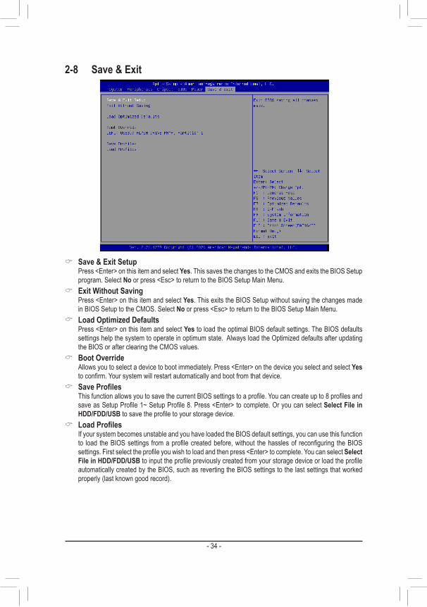
& Save & Exit Setup Press <Enter> on this item and select Yes. This saves the changes to the CMOS and exits the BIOS Setup
program. Select No or press <Esc> to return to the BIOS Setup Main Menu. & Exit Without Saving
Press <Enter> on this item and select Yes. This exits the BIOS Setup without saving the changes made in BIOS Setup to the CMOS. Select No or press <Esc> to return to the BIOS Setup Main Menu.
& Load Optimized Defaults Press <Enter> on this item and select Yes to load the optimal BIOS default settings. The BIOS defaults
settings help the system to operate in optimum state. Always load the Optimized defaults after updating the BIOS or after clearing the CMOS values.
& Boot Override Allows you to select a device to boot immediately. Press <Enter> on the device you select and select Yes
to confirm. Your system will restart automatically and boot from that device. & SaveProfiles
This function allows you to save the current BIOS settings to a profile. You can create up to 8 profiles and save as Setup Profile 1~ Setup Profile 8. Press <Enter> to complete. Or you can select Select File in HDD/FDD/USB to save the profile to your storage device.
& LoadProfiles If your system becomes unstable and you have loaded the BIOS default settings, you can use this function
to load the BIOS settings from a profile created before, without the hassles of reconfiguring the BIOS settings. First select the profile you wish to load and then press <Enter> to complete. You can select Select File in HDD/FDD/USB to input the profile previously created from your storage device or load the profile automatically created by the BIOS, such as reverting the BIOS settings to the last settings that worked properly (last known good record).
- 34 -
Chapter 3 Appendix
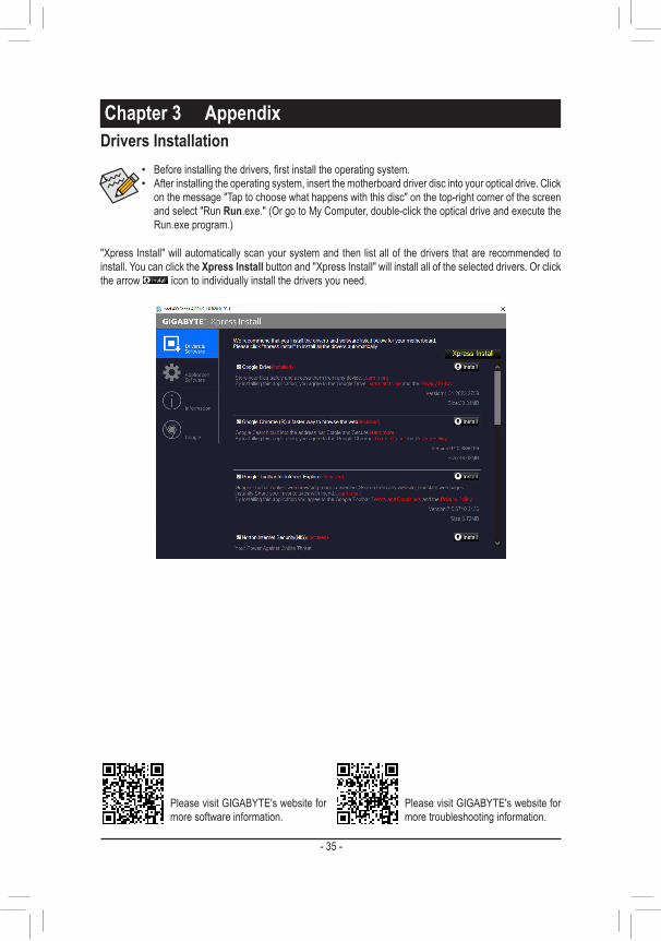
• Before installing the drivers, first install the operating system. • After installing the operating system, insert the motherboard driver disc into your optical drive. Click
on the message "Tap to choose what happens with this disc" on the top-right corner of the screen and select "Run Run.exe." (Or go to My Computer, double-click the optical drive and execute the Run.exe program.)
Drivers Installation
"Xpress Install" will automatically scan your system and then list all of the drivers that are recommended to install. You can click the Xpress Install button and "Xpress Install" will install all of the selected drivers. Or click the arrow icon to individually install the drivers you need.
Please visit GIGABYTE's website for more software information.
Please visit GIGABYTE's website for more troubleshooting information.
- 35 -
Regulatory NoticesUnited States of America, Federal Communications Commission Statement
This equipment has been tested and found to comply with the limits for a Class B digital device, pursuant to Part 15 of the FCC Rules. These limits are designed to provide reasonable protection against harmful interference in a residential installation. This equipment generates, uses and can radiate radio frequency energy and, if not installed and used in accordance with manufacturer's instructions, may cause harmful interference to radio communications. However, there is no guarantee that interference will not occur in a particular installation. If this equipment does cause harmful interference to radio or television reception, which can be determined by turning the equipment off and on, the user is encouraged to try to correct the interference by one or more of the following measures: • Reorient or relocate the receiving antenna. • Increase the separation between the equipment and receiver. • Connect the equipment to an outlet on a circuit different from that to
which the receiver is connected. • Consult the dealer or an experienced radio/TV technician for help.
Canadian Department of Communications StatementThis digital apparatus does not exceed the Class B limits for radio noise emissions from digital apparatus set out in the Radio Interference Regulations of the Canadian Department of Communications. This class B digital apparatus complies with Canadian ICES-003.
Avis de conformité à la réglementation d'Industrie CanadaCet appareil numérique de la classe B est conforme à la norme NMB-003 du Canada.
European Union (EU) CE Declaration of ConformityThis device complies with the following directives: Electromagnetic Compatibility Directive 2014/30/EU, Low-voltage Directive 2014/35/EU, RoHS directive (recast) 2011/65/EU & the 2015/863 Statement. This product has been tested and found to comply with all essential requirements of the Directives.
European Union (EU) RoHS (recast) Directive 2011/65/EU & the European Commission Delegated Directive (EU) 2015/863 StatementGIGABYTE products have not intended to add and safe from hazardous substances (Cd, Pb, Hg, Cr+6, PBDE, PBB, DEHP, BBP, DBP and DIBP). The parts and components have been carefully selected to meet RoHS requirement. Moreover, we at GIGABYTE are continuing our efforts to develop products that do not use internationally banned toxic chemicals.
European Union (EU) Community Waste Electrical & Electronic Equipment (WEEE) Directive StatementGIGABYTE will fulfill the national laws as interpreted from the 2012/19/EU WEEE (Waste Electrical and Electronic Equipment) (recast) directive. The WEEE Directive specifies the treatment, collection, recycling and disposal of electric and electronic devices and their components. Under the Directive, used equipment must be marked, collected separately, and disposed of properly.
WEEE Symbol StatementThe symbol shown below is on the product or on its packaging, which indicates that this product must not be disposed of with other waste. Instead, the device should be taken to the waste collection centers for activation of the treatment, collection, recycling and disposal procedure.
For more information about where you can drop off your waste equipment for recycling, please contact your local government office, your household waste disposal service or where you purchased the product for details of environmentally safe recycling.
End of Life Directives-RecyclingThe symbol shown below is on the product or on its packaging, which indicates that this product must not be disposed of with other waste. Instead, the device should be taken to the waste collection centers for activation of the treatment, collection, recycling and disposal procedure.
Déclaration de Conformité aux Directives de l'Union européenne (UE)Cet appareil portant la marque CE est conforme aux directives de l'UE suivantes: directive Compatibilité Electromagnétique 2014/30/UE, directive Basse Tension 2014/35/UE et directive RoHS II 2011/65/UE. La conformité à ces directives est évaluée sur la base des normes européennes harmonisées applicables.
European Union (EU) CE-KonformitätserklärungDieses Produkte mit CE-Kennzeichnung erfüllen folgenden EU-Richtlinien: EMV-Richtlinie 2014/30/EU, Niederspannungsrichtlinie 2014/30/EU und RoHS-Richtlinie 2011/65/EU erfüllt. Die Konformität mit diesen Richtlinien wird unter Verwendung der entsprechenden Standards zurEuropäischen Normierung beurteilt.
CE declaração de conformidadeEste produto com a marcação CE estão em conformidade com das seguintes Diretivas UE: Diretiva Baixa Tensão 2014/35/EU; Diretiva CEM 2014/30/EU; Diretiva RSP 2011/65/UE. A conformidade com estas diretivas é verificada utilizando as normas europeias harmonizadas.
CE Declaración de conformidadEste producto que llevan la marca CE cumplen con las siguientes Directivas de la Unión Europea: Directiva EMC (2014/30/EU), Directiva de bajo voltaje (2014/35/EU), Directiva RoHS (recast) (2011/65/EU). El cumplimiento de estas directivas se evalúa mediante las normas europeas armonizadas.
Dichiarazione di conformità CEQuesto prodotto è conforme alle seguenti direttive: Direttiva sulla compatibilità elettromagnetica 2014/30/UE, Direttiva sulla bassa tensione 2014/35/UE, Direttiva RoHS (rifusione) 2011/65/UE. Questo prodotto è stato testato e trovato conforme a tutti i requisiti essenziali delle Direttive.
Supplier's Declaration of Conformity47 CFR § 2.1077 Compliance Information
Product Name: MotherboardTrade Name: GIGABYTEModel Number: GA-IMB410M
Responsible Party – U.S. Contact Information: G.B.T. Inc. Address: 17358 Railroad street, City Of Industry, CA91748Tel.: 1-626-854-9338Internet contact information: https://www.gigabyte.com
FCC Compliance Statement: This device complies with Part 15 of the FCC Rules, Subpart B, Unintentional Radiators. Operation is subject to the following two conditions: (1) This device may not cause harmful interference, and (2) this device must accept any interference received, including interference that may cause undesired operation.
- 36 -
Contact Us
GIGA-BYTE TECHNOLOGY CO., LTD.Address: No.6, Baoqiang Rd., Xindian Dist., New Taipei City 231, TaiwanTEL: +886-2-8912-4000, FAX: +886-2-8912-4005Tech. and Non-Tech. Support (Sales/Marketing) : https://esupport.gigabyte.comWEB address (English): https://www.gigabyte.comWEB address (Chinese): https://www.gigabyte.com/tw
• GIGABYTE eSupportTo submit a technical or non-technical (Sales/Marketing) question, please link to: https://esupport.gigabyte.com
- 37 -


