Embed Size (px)
Citation preview
Gasoline Engines - Alpha / Bravo Models2001, Mercury Marine 90-860168003 201
0
CA940
Identification RecordPLEASE RECORD THE FOLLOWING INFORMATION:
1.
Engine Model andHorsepower
Engine SerialNumber
2.
Transom Assembly SerialNumber (Sterndrive)
GearRatio
Sterndrive UnitSerial Number
3.
Transmission Model(Inboard)
GearRatio
TransmissionSerial Number
4.
Propeller Number Pitch Diameter
5.
Hull Identification Number(HIN)
PurchaseDate
6.
Boat Manufacturer BoatModel
Length
7.
Exhaust Gas Emissions Certificate Number (Europe Only)
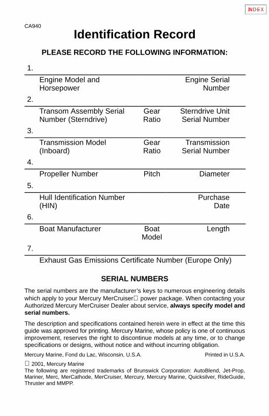
SERIAL NUMBERS
The serial numbers are the manufacturer’s keys to numerous engineering detailswhich apply to your Mercury MerCruiser power package. When contacting yourAuthorized Mercury MerCruiser Dealer about service, always specify model andserial numbers.
The description and specifications contained herein were in effect at the time thisguide was approved for printing. Mercury Marine, whose policy is one of continuousimprovement, reserves the right to discontinue models at any time, or to changespecifications or designs, without notice and without incurring obligation.
Mercury Marine, Fond du Lac, Wisconsin, U.S.A. Printed in U.S.A.
2001, Mercury Marine The following are registered trademarks of Brunswick Corporation: AutoBlend, Jet-Prop,Mariner, Merc, MerCathode, MerCruiser, Mercury, Mercury Marine, Quicksilver, RideGuide,Thruster and MMPP.
1
CA910
71352
ABC12345Z123
-19 48-12345
71345
4
5 1
2
2,7
7
2
1
44
5
746771,2
COLOR CODE
MERCRUISER
Division of Mercury MarineStillwater, OK, U.S.A.
SPECIFICATIONSMODEL MCM 4.3LX/4.3LXH GEN +.
DISPLACEMENT 262 CID. . . . . . . . .
IGNITION TIMING 10 BTDC. . . . . . .
CYL. FIRING ORDER 1-6-5-4-3-2. . .
SPARK PLUGS AC-MR43LTS. . . . .
ENGINE ROTATION LH. . . . . . . . . . .
MAX W.O.T. rpm 4400-4800. . . . . . .
IDLE rpm IN NEUTRAL 650. . . . . . . .
PLUG GAP .045’. . . . . . . . . . . . . . . . .
For Fuel and Oilrequirements refer toOperations & Maintenance Manual
SERIAL NUMBERS
748492
2 76454

2
CA961
THIS PAGE IS INTENTIONALLY BLANK
3
CA859
Welcome!You have selected one of the finest marine power packagesavailable. It incorporates numerous design features to assureoperating ease and durability.
With proper care and maintenance, you will thoroughly enjoy usingthis product for many boating seasons. To ensure maximumperformance and carefree use, we ask that you thoroughly read thismanual.
The Operation, Maintenance and Warranty Manual contains specificinstructions for using and maintaining your product. We suggest thatthis manual remain with the product for ready reference wheneveryou are on the water.
Thank you for purchasing one of our Mercury MerCruiser products.We sincerely hope your boating will be pleasant!
Consumer Affairs Department
CA741
Warranty MessageThe product you have purchased comes with a limited warrantyfrom Mercury Marine; the terms of the warranty are set forth in theWarranty Sections of this manual. The warranty statement containsa description of what is covered, what is not covered, the duration ofcoverage, how to best obtain warranty coverage, importantdisclaimers and limitations of damages, and other relatedinformation. Please review this important information.
4
TABLE OF CONTENTSPage
Warranty Information 6
Owner Warranty Registration 6. . . . . . . . . . . . . . . . . . . . . . . . . International Owner Registration 7. . . . . . . . . . . . . . . . . . . . . . Mercury MerCruiser Limited Warranty 8. . . . . . . . . . . . . . . . . 3 Year Limited Warranty Against Corrosion Failure 12. . . . . . Transferable Warranty 15. . . . . . . . . . . . . . . . . . . . . . . . . . . . . . . Mercury Product Protection Plan 16. . . . . . . . . . . . . . . . . . . . . .
Read This Manual Thoroughly 18
General Information 21
Lanyard Stop Switch 21. . . . . . . . . . . . . . . . . . . . . . . . . . . . . . . . Exhaust Emissions 23. . . . . . . . . . . . . . . . . . . . . . . . . . . . . . . . . Wave And Wake Jumping 25. . . . . . . . . . . . . . . . . . . . . . . . . . . Impact With Underwater Hazards 26. . . . . . . . . . . . . . . . . . . . . Operating With Low Water Inlets In Shallow Water 28. . . . . . Drive Unit Impact Protection 29. . . . . . . . . . . . . . . . . . . . . . . . . Safe Boating Suggestions 30. . . . . . . . . . . . . . . . . . . . . . . . . . . Protecting People In The Water 34. . . . . . . . . . . . . . . . . . . . . . . High-Speed And High-Performance Boat Operation 35. . . . .
Conditions Affecting Operation 36
Important Information 42
Operation And Maintenance 42. . . . . . . . . . . . . . . . . . . . . . . . . Freezing Temperature Operation 44. . . . . . . . . . . . . . . . . . . . . Drain Plug and Bilge Pump 44. . . . . . . . . . . . . . . . . . . . . . . . . . Emissions Information (Europe Only) 45. . . . . . . . . . . . . . . . . . Attention Required After Submersion 45. . . . . . . . . . . . . . . . . . Trailering Boat 46. . . . . . . . . . . . . . . . . . . . . . . . . . . . . . . . . . . . . Launching And Boat Operation Care 46. . . . . . . . . . . . . . . . . . Stolen Power Package 47. . . . . . . . . . . . . . . . . . . . . . . . . . . . . . Replacement Service Parts 47. . . . . . . . . . . . . . . . . . . . . . . . . . Do-It-Yourself Maintenance Suggestions 48. . . . . . . . . . . . . . . Multiple EFI Engine Battery Precautions 50. . . . . . . . . . . . . . . Diagnosing EFI Problems (If Equipped) 51. . . . . . . . . . . . . . . . 20-Hour Break-In Period 52. . . . . . . . . . . . . . . . . . . . . . . . . . . . . After Break-In Period 53. . . . . . . . . . . . . . . . . . . . . . . . . . . . . . . . End of First Season Checkup 53. . . . . . . . . . . . . . . . . . . . . . . .
5
Page
Operation 54Instrumentation 55. . . . . . . . . . . . . . . . . . . . . . . . . . . . . . . . . . . . . Audio Warning System 56. . . . . . . . . . . . . . . . . . . . . . . . . . . . . . Electrical System Overload Protection 58. . . . . . . . . . . . . . . . . Remote Controls 62. . . . . . . . . . . . . . . . . . . . . . . . . . . . . . . . . . . Power Trim 64. . . . . . . . . . . . . . . . . . . . . . . . . . . . . . . . . . . . . . . . Starting, Shifting And Stopping 67. . . . . . . . . . . . . . . . . . . . . . . Operation Chart 71. . . . . . . . . . . . . . . . . . . . . . . . . . . . . . . . . . . .
Specifications 72Fuel Recommendations 72. . . . . . . . . . . . . . . . . . . . . . . . . . . . . Seacock Size Recommendation 75. . . . . . . . . . . . . . . . . . . . . . Crankcase Oil 75. . . . . . . . . . . . . . . . . . . . . . . . . . . . . . . . . . . . . . Engine 77. . . . . . . . . . . . . . . . . . . . . . . . . . . . . . . . . . . . . . . . . . . .
Maintenance 83Maintenance Aids 83. . . . . . . . . . . . . . . . . . . . . . . . . . . . . . . . . . Fluid Capacities 84. . . . . . . . . . . . . . . . . . . . . . . . . . . . . . . . . . . . Maintenance Chart 86. . . . . . . . . . . . . . . . . . . . . . . . . . . . . . . . . Checking Fluids 89. . . . . . . . . . . . . . . . . . . . . . . . . . . . . . . . . . . . Fuel Pump Sight Tube Inspection 3.0L Models 93. . . . . . . . . Changing Fluids 94. . . . . . . . . . . . . . . . . . . . . . . . . . . . . . . . . . . . Changing Water Separating Fuel Filter 99. . . . . . . . . . . . . . . . Cleaning Flame Arrestor and Related Components 102. . . . . Lubrication 104. . . . . . . . . . . . . . . . . . . . . . . . . . . . . . . . . . . . . . . . . Propeller 108. . . . . . . . . . . . . . . . . . . . . . . . . . . . . . . . . . . . . . . . . . Drive Belts 120. . . . . . . . . . . . . . . . . . . . . . . . . . . . . . . . . . . . . . . . . Corrosion And Corrosion Protection 128. . . . . . . . . . . . . . . . . . . Emissions (Europe Only) 134. . . . . . . . . . . . . . . . . . . . . . . . . . . . Battery 138. . . . . . . . . . . . . . . . . . . . . . . . . . . . . . . . . . . . . . . . . . . . Inspection And Maintenance 139. . . . . . . . . . . . . . . . . . . . . . . . .
Cold Weather or Extended Storage 140Power Package Lay Up 140. . . . . . . . . . . . . . . . . . . . . . . . . . . . . Draining Instructions 145. . . . . . . . . . . . . . . . . . . . . . . . . . . . . . . . Flushing Cooling System 158. . . . . . . . . . . . . . . . . . . . . . . . . . . . Battery Winter Storage 161. . . . . . . . . . . . . . . . . . . . . . . . . . . . . . Power Package Recommissioning 162. . . . . . . . . . . . . . . . . . . .
Troubleshooting 164
Owner Service Assistance 173
6
CA455
Warranty Information
Owner Warranty RegistrationUNITED STATES AND CANADA ONLY
• It is important that your selling dealer fills out the WarrantyRegistration Card completely and mails it to the factoryimmediately upon sale of the new product.
• It identifies name and address of the original purchaser, productmodel and serial number(s), date of sale, type of use and sellingdealer’s code, name and address. The dealer also certifies thatyou are the original purchaser and user of the product.
• Upon receipt of the Warranty Registration Card at the factory, youwill be issued a plastic Owner Warranty Registration Card whichis your only valid registration identification. It must be presentedto the servicing dealer should warranty service be required.Warranty claims will not be accepted without presentation of thiscard.
• A temporary Owner Warranty Registration Card will be presentedto you when you purchase the product. It is valid only for 30 daysfrom date of sale while your plastic Owner Warranty RegistrationCard is being processed. Should your product need serviceduring this period, present the temporary registration card to thedealer. He will attach it to your warranty claim form.
• Because of your selling dealer’s continuing personal interest inyour satisfaction, the product should be returned to him forwarranty service.
• If your plastic card is not received within 30 days from date of newproduct sale, please contact your selling dealer.
• The product warranty is not effective until the product is registeredat the factory.
• NOTICE: Registration lists must be maintained by factory anddealer on marine products sold in the United States, shouldnotification under the Federal Boat Safety Act be required.
7
International Owner RegistrationOUTSIDE THE UNITED STATES AND CANADA
• It is important that your selling dealer fills out the WarrantyRegistration Card completely and mails it to the distributor orMarine Power Service Center responsible for administering thewarranty registration/claim program for your area.
• The Warranty Registration Card identifies your name andaddress, product model and serial number(s), date of sale, typeof use and the selling distributor’s/dealer’s code number, nameand address. The distributor/dealer also certifies that you are theoriginal purchaser and user of the product.
• A copy of the Warranty Registration Card, designated as the“Purchaser’s Copy,” MUST be given to you immediately after thecard has been completely filled out by the sellingdistributor/dealer. This card represents your factory registrationidentification, and should be retained by you for future use whenrequired. Should you ever require warranty service on thisproduct, your dealer may ask you for the Warranty RegistrationCard to verify date of purchase and to use the information on thecard to prepare the warranty claim form(s).
• In some countries, the Marine Power Service Center will issueyou a permanent (plastic) Warranty Registration Card within 30days after receiving the “Factory Copy” of the WarrantyRegistration Card from your distributor/dealer. If you receive aplastic Warranty Registration Card, you may discard the“Purchaser’s Copy” that you received from the distributor/dealerwhen you purchased the product. Ask your distributor/dealer ifthis plastic card program applies to you.
• For further information concerning the Warranty RegistrationCard and its relationship to Warranty Claim processing, refer tothe “International Warranty.” Refer to “Table of Contents.”
IMPORTANT: Registration lists must be maintained by thefactory and dealer in some countries by law. It is our desire tohave ALL products registered at the factory should it ever benecessary to contact you. Make sure your dealer/distributorfills out the warranty registration card immediately and sendsthe factory copy to the Marine Power International ServiceCenter for your area.
8
CC1048
Warranty PoliciesMercury MerCruiser One Year Limited Warranty(Gasoline Fueled Products Only)
WHAT IS COVERED
Mercury Marine warrants its new products to be free of defects in ma-terial and workmanship during the period described below.
DURATION OF COVERAGE
This Limited Warranty provides coverage for either one (1) year fromthe date the product is first sold to a recreational use retail purchaser,or the date on which the product is first put into service, whicheveroccurs first. Commercial users of these products receive warrantycoverage of either one (1) year from the date of first retail sale, or theaccumulation of 500 hours of operation, whichever occurs first. Com-mercial use is defined as any work or employment related use of theproduct, or any use of the product which generates income, for anypart of the warranty period, even if the product is only occasionallyused for such purposes. The repair or replacement of parts, or theperformance of service under this warranty, does not extend the lifeof this warranty beyond its original expiration date. Unexpired war-ranty coverage can be transferred from one recreational use cus-tomer to a subsequent recreational use customer upon proper re-registration of the product. Unexpired warranty coverage cannot betransferred either to or from a commercial use customer.
9
CONDITIONS THAT MUST BE MET IN ORDER TO OBTAINWARRANTY COVERAGE
Warranty coverage is available only to retail customers that pur-chase from a Dealer authorized by Mercury Marine to distribute theproduct in the country in which the sale occurred, and then only afterthe Mercury Marine specified pre-delivery inspection process iscompleted and documented. Warranty coverage becomes availableupon proper registration of the product by the authorized dealer. In-accurate warranty registration information regarding recreationaluse, or subsequent change of use from recreational to commercial(unless properly re-registered) may void the warranty at the sole dis-cretion of Mercury Marine. Routine maintenance outlined in the Op-eration and Maintenance Manual must be timely performed in orderto obtain warranty coverage. Mercury Marine reserves the right tomake any warranty coverage contingent upon proof of proper main-tenance.
WHAT MERCURY WILL DO
Mercury’s sole and exclusive obligation under this warranty is limitedto, at our option, repairing a defective part, replacing such part orparts with new or Mercury Marine certified re-manufactured parts, orrefunding the purchase price of the Mercury product. Mercury re-serves the right to improve or modify products from time to time with-out assuming an obligation to modify products previously manufac-tured.
10
HOW TO OBTAIN WARRANTY COVERAGE
The customer must provide Mercury with a reasonable opportunityto repair, and reasonable access to the product for warranty service.Warranty claims shall be made by delivering the product for inspec-tion to a Mercury dealer authorized to service the product. If purchas-er cannot deliver the product to such a dealer, written notice must begiven to Mercury. We will then arrange for the inspection and any cov-ered repair. Purchaser in that case shall pay for all related transporta-tion charges and/or travel time. If the service provided is not coveredby this warranty, purchaser shall pay for all related labor and materi-al, and any other expenses associated with that service. Purchasershall not, unless requested by Mercury, ship the product or parts ofthe product directly to Mercury. The warranty registration card is theonly valid registration identification and must be presented to thedealer at the time warranty service is requested in order to obtaincoverage.
WHAT IS NOT COVERED
This limited warranty does not cover routine maintenance items, tuneups, adjustments, normal wear and tear, damage caused by abuse,abnormal use, use of a propeller or gear ratio that does not allow theengine to run in its recommended RPM range (see the Operation andMaintenance Manual), operation of the product in a manner incon-sistent with the recommended operation/duty cycle section of theOperation and Maintenance Manual, neglect, accident, submersion,improper installation (proper installation specifications and tech-niques are set forth in the installation instructions for the product), im-proper service, use of an accessory or part which damages the Mer-cury product and was not manufactured or sold by us, jet pumpimpellers and liners, operation with fuels, oils or lubricants which arenot suitable for use with the product (see the Operation and Mainte-nance Manual), alteration or removal of parts, water entering the en-gine through the fuel intake, air intake or exhaust system or damageto the product from insufficient cooling water caused by blockage ofthe cooling system by a foreign body, running the engine out of water,mounting the engine too high on the transom, or running the boat withthe engine trimmed out too far. Use of the product for racing or othercompetitive activity, or operating with a racing type lower unit, at anypoint, even by a prior owner of the product, voids the warranty.
11
Expenses related to haul-out, launch, towing, storage, telephone,rental, inconvenience, slip fees, insurance coverage, loan pay-ments, loss of time, loss of income, or any other type of incidental orconsequential damages are not covered by this warranty. Also, ex-penses associated with the removal and/or replacement of boatpartitions or material caused by boat design for access to the productare not covered by this warranty.
No individual or entity, including Mercury Marine authorized dealers,has been given authority by Mercury Marine to make any affirmation,representation or warranty regarding the product, other than thosecontained in this limited warranty, and if made, shall not be enforce-able against Mercury Marine.
DISCLAIMERS AND LIMITATIONS
THE IMPLIED WARRANTIES OF MERCHANTABILITY ANDFITNESS FOR A PARTICULAR PURPOSE ARE EXPRESSLYDISCLAIMED. TO THE EXTENT THAT THEY CANNOT BE DIS-CLAIMED, THE IMPLIED WARRANTIES ARE LIMITED INDURATION TO THE LIFE OF THE EXPRESS WARRANTY. INCI-DENTAL AND CONSEQUENTIAL DAMAGES ARE EXCLUDEDFROM COVERAGE UNDER THIS WARRANTY. SOME STATES/COUNTRIES DO NOT ALLOW FOR THE DISCLAIMERS, LIM-ITATIONS AND EXCLUSIONS IDENTIFIED ABOVE, AS A RE-SULT, THEY MAY NOT APPLY TO YOU. THIS WARRANTYGIVES YOU SPECIFIC LEGAL RIGHTS, AND YOU MAY ALSOHAVE OTHER LEGAL RIGHTS WHICH VARY FROM STATE TOSTATE AND COUNTRY TO COUNTRY.
12
CC1049
3 Year Limited Warranty Against Corrosion(Worldwide)
WHAT IS COVERED
Mercury Marine warrants that each new Mercury, Mariner, MercuryRacing, Sport Jet, M2 Jet Drive, tracker by Mercury Marine Outboard,MerCruiser Inboard or sterndrive engine (Product) will not be ren-dered inoperative as a direct result of corrosion for the period of timedescribed below.
DURATION OF COVERAGE
This limited corrosion warranty provides coverage for three (3) yearsfrom either the date the product is first sold, or the date on which theproduct is first put into service, whichever occurs first. The repair andreplacement of parts, or the performance of service under this war-ranty does not extend the life of this warranty beyond its original expi-ration date. Unexpired warranty coverage can be transferred to sub-sequent (noncommercial use) purchaser upon proper re-registrationof the product.

13
CONDITIONS THAT MUST BE MET IN ORDER TO OBTAINWARRANTY COVERAGE
Warranty coverage is available only to retail customers that pur-chase from a Dealer authorized by Mercury Marine to distribute theproduct in the country in which the sale occurred, and then only afterthe Mercury Marine specified pre-delivery inspection process iscompleted an documented. Warranty coverage becomes availableupon proper registration of the product by the authorized dealer. Cor-rosion prevention devices specified in the Operation and Mainte-nance Manual must be in use on the boat, and routine maintenanceoutlined in the Operation and Maintenance Manual and must betimely performed (including without limitation the replacement ofsacrificial anodes, use of specified lubricants, and touch-up nicksand scratches) in order to maintain warranty coverage. Mercury Ma-rine reserves the right to make warranty coverage contingent uponproof of proper maintenance.
WHAT MERCURY WILL DO
Mercury’s sole and exclusive obligation under this warranty is limitedto, at our option, repairing a corroded part, replacing such part orparts with new or Mercury Marine certified re-manufactured parts, orrefunding the purchase price of the Mercury product. Mercury re-serves the right to improve or modify products from time to time with-out assuming an obligation to modify products previously manufac-tured.
14
HOW TO OBTAIN WARRANTY COVERAGE
The customer must provide Mercury with a reasonable opportunityto repair, and reasonable access to the product for warranty service.Warranty claims shall be made by delivering the product for inspec-tion to a Mercury dealer authorized to service the product. If purchas-er cannot deliver the product to such a dealer, written notice must begiven to Mercury. We will then arrange for the inspection and any cov-ered repair. Purchaser in that case shall pay for all related transporta-tion charges and/or travel time. If the service provided is not coveredby this warranty, purchaser shall pay for all related labor and materi-al, and any other expenses associated with that service. Purchasershall not, unless requested by Mercury, ship the product or parts ofthe product directly to Mercury. The warranty registration card is theonly valid registration identification and must be presented to thedealer at the time warranty service is requested in order to obtaincoverage.
WHAT IS NOT COVERED
This limited warranty does not cover electrical system corrosion; cor-rosion resulting from damage, corrosion which causes purely cos-metic damage, abuse or improper service; corrosion to accessories,instruments, steering systems; corrosion to factory installed jet driveunit; damage due to marine growth; product sold with less than a oneyear limited Product warranty; replacement parts (parts purchasedby the Customer); products used in a commercial application. Com-mercial use is defined as any work or employment related use of theproduct, or any use of the product which generates income, for anypart of warranty period, even if the product is only occasionally usedfor such purposes.
15
CA459
Transferable WarrantyThe product warranty is transferable to a subsequent purchaser, butonly for the remainder of the unused portion of the limited warranty.This will not apply to products used for commercial applications.
Direct Sale By Owner• The second owner can be registered as the new owner and retain
the unused portion of the limited warranty by sending the formerowner’s plastic Owner Warranty Registration Card and a copy ofthe bill of sale to show proof of ownership. In the United States andCanada, mail to:
Mercury MarineAttn: Warranty Registration DepartmentW6250 West Pioneer RoadP.O. Box 1939Fond du Lac, WI 54936-1939
• A new Owner Warranty Registration Card will be issued with thenew owner’s name and address. Registration records will bechanged on the factory computer registration file.
• There is no charge for this service.
Outside the United States and Canada, please contact thedistributor in your country, or the Marine Power InternationalService Center closest to you, for the transferable warrantyprocedure that would apply to you.
16
CA862
Mercury Product Protection Plan
United States And Canada Only(Certain performance products, triple engine installations, andcommercial applications are excluded)
The Mercury Product Protection Plan provides coverage againstunexpected mechanical and electrical breakdowns that may occurbeyond the standard limited warranty.
The optional Mercury Product Protection Plan is the only FactoryPlan available for your engine.
Two, three or four - year term plans can be purchased up to 12months after the original engine registration date.
See your participating Mercury MerCruiser dealer for completeprogram details.

17
CA961
THIS PAGE IS INTENTIONALLY BLANK
18
CA755
Read This Manual ThoroughlyIF YOU DON’T UNDERSTAND ANY PORTION, CONTACT YOURDEALER FOR A DEMONSTRATION OF ACTUAL STARTINGAND OPERATING PROCEDURES.
NOTICEThroughout this publication, and on your power package,WARNINGS and CAUTIONS, accompanied by the InternationalHazard Symbol ! , may be used to alert the installer/user to specialinstructions concerning a particular service or operation that may behazardous if performed incorrectly or carelessly. Observe themcarefully.
These “Safety Alerts” alone cannot eliminate the hazards that theysignal. Strict compliance with these special instructions whileperforming the service, plus “common sense” operation, are majoraccident prevention measures.
WARNINGWARNING-Hazards or unsafe practices which could result insevere personal injury or death.
19
CAUTIONCAUTION-Hazards or unsafe practices which could result inminor personal injury or product or property damage.
IMPORTANT: - Indicates information or instructions that arenecessary for proper operation and/or maintenance.
WARNINGThe operator (driver) is responsible for the correct and safeoperation of the boat, the equipment aboard and the safety ofall occupants aboard. We strongly recommend that the opera-tor read this Operation, Maintenance and Warranty Manualand thoroughly understand the operational instructions forthe power package and all related accessories before the boatis used.
20
CC942
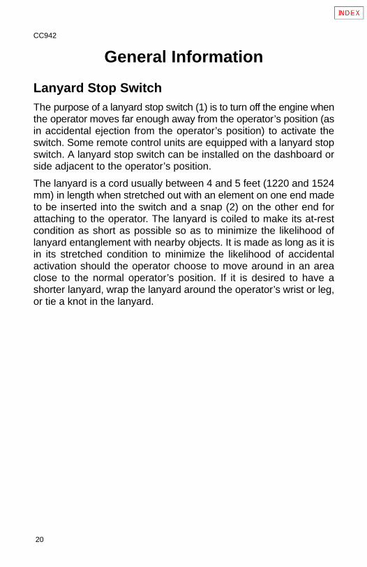
General Information
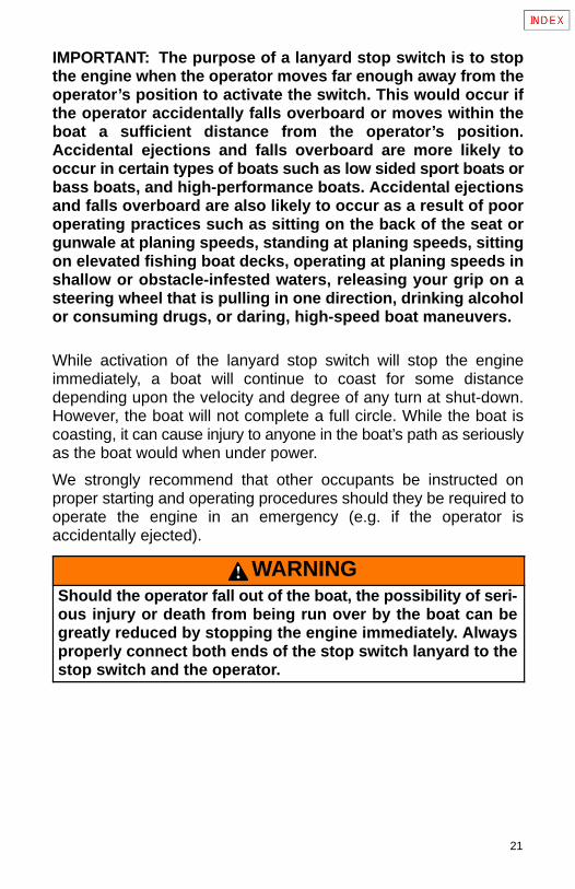
Lanyard Stop SwitchThe purpose of a lanyard stop switch (1) is to turn off the engine whenthe operator moves far enough away from the operator’s position (asin accidental ejection from the operator’s position) to activate theswitch. Some remote control units are equipped with a lanyard stopswitch. A lanyard stop switch can be installed on the dashboard orside adjacent to the operator’s position.
The lanyard is a cord usually between 4 and 5 feet (1220 and 1524mm) in length when stretched out with an element on one end madeto be inserted into the switch and a snap (2) on the other end forattaching to the operator. The lanyard is coiled to make its at-restcondition as short as possible so as to minimize the likelihood oflanyard entanglement with nearby objects. It is made as long as it isin its stretched condition to minimize the likelihood of accidentalactivation should the operator choose to move around in an areaclose to the normal operator’s position. If it is desired to have ashorter lanyard, wrap the lanyard around the operator’s wrist or leg,or tie a knot in the lanyard.
21
IMPORTANT: The purpose of a lanyard stop switch is to stopthe engine when the operator moves far enough away from theoperator’s position to activate the switch. This would occur ifthe operator accidentally falls overboard or moves within theboat a sufficient distance from the operator’s position.Accidental ejections and falls overboard are more likely tooccur in certain types of boats such as low sided sport boats orbass boats, and high-performance boats. Accidental ejectionsand falls overboard are also likely to occur as a result of pooroperating practices such as sitting on the back of the seat orgunwale at planing speeds, standing at planing speeds, sittingon elevated fishing boat decks, operating at planing speeds inshallow or obstacle-infested waters, releasing your grip on asteering wheel that is pulling in one direction, drinking alcoholor consuming drugs, or daring, high-speed boat maneuvers.
While activation of the lanyard stop switch will stop the engineimmediately, a boat will continue to coast for some distancedepending upon the velocity and degree of any turn at shut-down.However, the boat will not complete a full circle. While the boat iscoasting, it can cause injury to anyone in the boat’s path as seriouslyas the boat would when under power.
We strongly recommend that other occupants be instructed onproper starting and operating procedures should they be required tooperate the engine in an emergency (e.g. if the operator isaccidentally ejected).
WARNINGShould the operator fall out of the boat, the possibility of seri-ous injury or death from being run over by the boat can begreatly reduced by stopping the engine immediately. Alwaysproperly connect both ends of the stop switch lanyard to thestop switch and the operator.
22
CA619
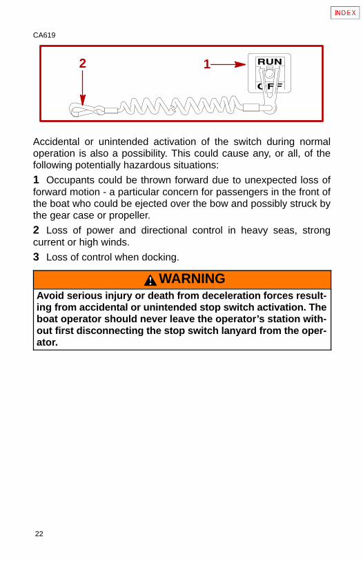
2 1
Accidental or unintended activation of the switch during normaloperation is also a possibility. This could cause any, or all, of thefollowing potentially hazardous situations:
1 Occupants could be thrown forward due to unexpected loss offorward motion - a particular concern for passengers in the front ofthe boat who could be ejected over the bow and possibly struck bythe gear case or propeller.
2 Loss of power and directional control in heavy seas, strongcurrent or high winds.
3 Loss of control when docking.
WARNINGAvoid serious injury or death from deceleration forces result-ing from accidental or unintended stop switch activation. Theboat operator should never leave the operator’s station with-out first disconnecting the stop switch lanyard from the oper-ator.
23
CA766
Exhaust Emissions
CA641
Courtesy of ABYC
1
CA767
Be Alert To Carbon Monoxide PoisoningCarbon monoxide is present in the exhaust fumes of all internalcombustion engines including the outboards, sterndrives andinboard engines that propel boats, as well as the generators thatpower various boat accessories. Carbon monoxide is a deadly gasthat is odorless, colorless and tasteless.
Early symptoms of carbon monoxide poisoning, which should not beconfused with seasickness or intoxication, include headache,dizziness, drowsiness, and nausea.
WARNINGAvoid the combination of a running engine and poor ventila-tion. Prolonged exposure to carbon monoxide in sufficientconcentration can lead to unconsciousness, brain damage ordeath.
GOOD VENTILATION
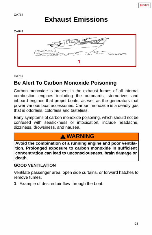
Ventilate passenger area, open side curtains, or forward hatches toremove fumes.
1 Example of desired air flow through the boat.
24
CA642
3A
3B Courtesy of ABYC
2A
2B
CA643
POOR VENTILATION
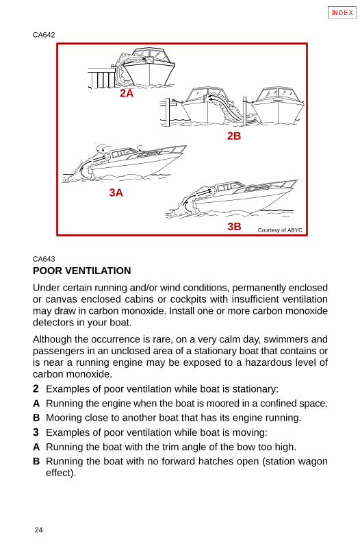
Under certain running and/or wind conditions, permanently enclosedor canvas enclosed cabins or cockpits with insufficient ventilationmay draw in carbon monoxide. Install one or more carbon monoxidedetectors in your boat.
Although the occurrence is rare, on a very calm day, swimmers andpassengers in an unclosed area of a stationary boat that contains oris near a running engine may be exposed to a hazardous level ofcarbon monoxide.
2 Examples of poor ventilation while boat is stationary:A Running the engine when the boat is moored in a confined space.B Mooring close to another boat that has its engine running.
3 Examples of poor ventilation while boat is moving:A Running the boat with the trim angle of the bow too high.B Running the boat with no forward hatches open (station wagon
effect).
25
CD543
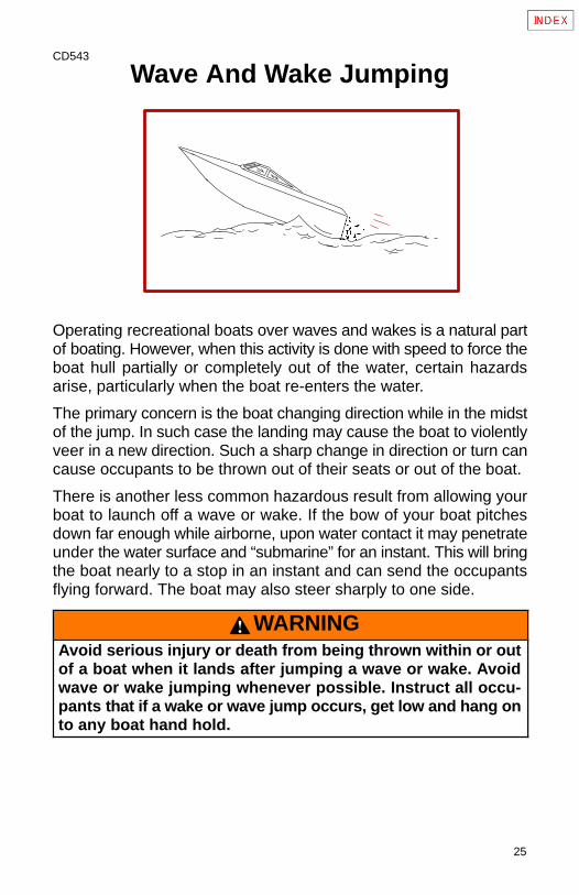
Wave And Wake Jumping
Operating recreational boats over waves and wakes is a natural partof boating. However, when this activity is done with speed to force theboat hull partially or completely out of the water, certain hazardsarise, particularly when the boat re-enters the water.
The primary concern is the boat changing direction while in the midstof the jump. In such case the landing may cause the boat to violentlyveer in a new direction. Such a sharp change in direction or turn cancause occupants to be thrown out of their seats or out of the boat.
There is another less common hazardous result from allowing yourboat to launch off a wave or wake. If the bow of your boat pitchesdown far enough while airborne, upon water contact it may penetrateunder the water surface and “submarine” for an instant. This will bringthe boat nearly to a stop in an instant and can send the occupantsflying forward. The boat may also steer sharply to one side.
WARNINGAvoid serious injury or death from being thrown within or outof a boat when it lands after jumping a wave or wake. Avoidwave or wake jumping whenever possible. Instruct all occu-pants that if a wake or wave jump occurs, get low and hang onto any boat hand hold.
26
CD544
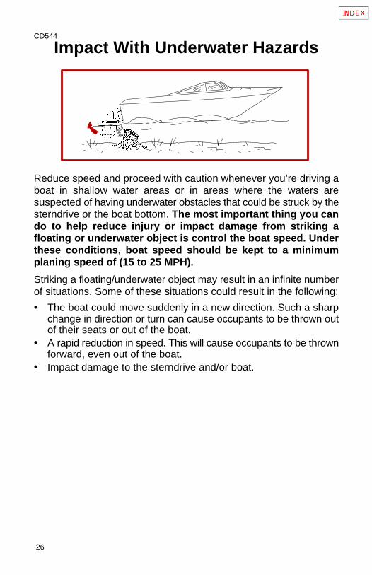
Impact With Underwater Hazards
Reduce speed and proceed with caution whenever you’re driving aboat in shallow water areas or in areas where the waters aresuspected of having underwater obstacles that could be struck by thesterndrive or the boat bottom. The most important thing you cando to help reduce injury or impact damage from striking afloating or underwater object is control the boat speed. Underthese conditions, boat speed should be kept to a minimumplaning speed of (15 to 25 MPH).
Striking a floating/underwater object may result in an infinite numberof situations. Some of these situations could result in the following:
• The boat could move suddenly in a new direction. Such a sharpchange in direction or turn can cause occupants to be thrown outof their seats or out of the boat.
• A rapid reduction in speed. This will cause occupants to be thrownforward, even out of the boat.
• Impact damage to the sterndrive and/or boat.
27
Keep in mind, one of the most important things you can do to helpreduce injury or impact damage in these situations is control the boatspeed. Boat speed should be kept to a minimum planing speed whendriving in waters known to have underwater obstacles.
After striking a submerged object, stop engine as soon as possibleand inspect the sterndrive unit for any broken or loose parts. Ifdamage is present or suspected, the power package should be takento an authorized dealer for a thorough inspection and necessaryrepair.
The boat should also be checked for any hull fractures, transomfractures, water leaks.
Operating a damaged sterndrive could cause additional damage toother parts of the power package, or could affect control of the boat.If continued running is necessary, do so at greatly reduced speeds.
WARNINGAvoid serious injury or death from loss of boat control. Con-tinued boating with major impact damage can result in suddencomponent failure with or without subsequent impacts, Havethe power package thoroughly inspected and any necessaryrepairs made.
28
CB795
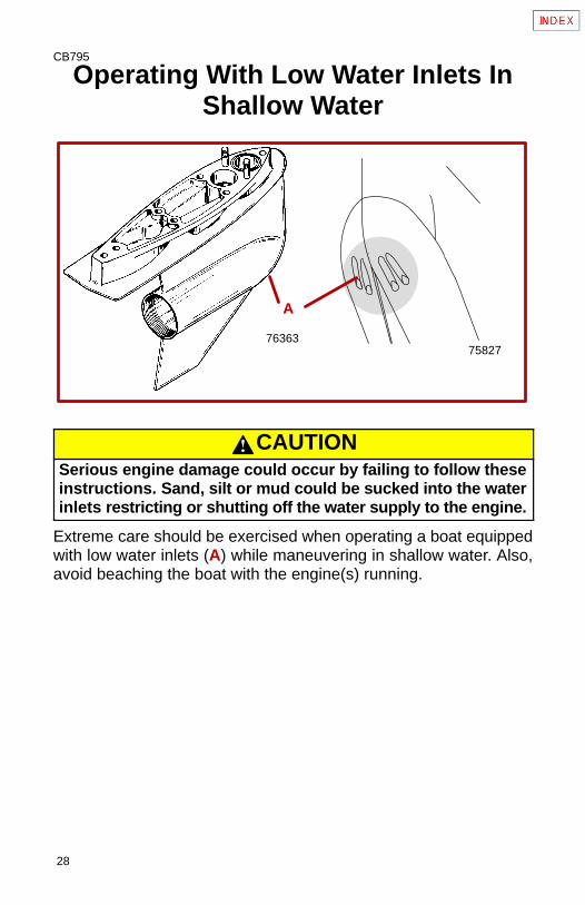
Operating With Low Water Inlets InShallow Water
7582776363
A
CAUTIONSerious engine damage could occur by failing to follow theseinstructions. Sand, silt or mud could be sucked into the waterinlets restricting or shutting off the water supply to the engine.
Extreme care should be exercised when operating a boat equippedwith low water inlets (A) while maneuvering in shallow water. Also,avoid beaching the boat with the engine(s) running.
29
CA866
Drive Unit Impact ProtectionThe Power Trim hydraulic system is designed to provide impactprotection for drive unit. If a submerged object is struck while boat ismoving forward, the hydraulic system will cushion the kickup of driveunit as it clears the object, reducing damage to unit. After drive unithas cleared object, the hydraulic system allows drive unit to returnto original operating position, preventing loss of steering control andengine overspeed.
Use extreme caution when operating in shallow water or whereunderwater objects are known to be present. Use extreme care toprevent striking submerged object while operating in REVERSE. Noimpact protection is provided in REVERSE.
If drive unit should strike a submerged object, stop engine as soonas possible and inspect drive unit for damage. If damage is presentor suspected, boat should be taken to an Authorized MercuryMerCruiser Dealer for thorough inspection and necessary repair.Operating a damaged drive unit could cause additional damage toother parts of drive unit, or could affect control of boat. If continuedrunning is necessary, do so at greatly reduced speeds.
IMPORTANT: Impact protection system cannot be designed toensure total protection from impact damage under allconditions.
30
CA476
Safe Boating SuggestionsIn order to safely enjoy the waterways, familiarize yourself with localand other governmental boating regulations and restrictions, andconsider the following suggestions.
• Know and obey all nautical rules and laws of the waterways.Boat operators should complete a boating safety course. Coursesare offered in the U.S.A. by (1) The U.S. Coast Guard Auxiliary,(2) The Power Squadron, (3) The Red Cross and (4) your stateor provincial boating law enforcement agency. Inquiries may bemade to the Boating Hotline, 1-800-368-5647 or the Boat U.S.Foundation information number 1-800-336-BOAT.
We strongly recommend that all powerboat operators attend one ofthese courses.
You should also review the NMMA Sources of Waterway Informationbooklet. It lists regional sources of safety, cruising and localnavigation and is available at no charge by writing to:
Sources of Waterway InformationNational Marine Manufacturers Association410 N. Michigan AvenueChicago, IL 60611 U.S.A.
• Perform safety checks and required maintenance. Follow aregular schedule and ensure that all repairs are properly made.
• Check safety equipment on board. Here are suggestions of thetypes of safety equipment to carry when boating:
1 Approved fire extinguisher(s); paddle or oar.
2 Signal devices: flashlight, rockets or flares, flag and whistle orhorn.
3 Spare propeller, thrust hubs and an appropriate wrench.
4 Tools for necessary minor repairs; first aid kit and book.
31
5 Anchor and extra anchor line; water-proof storage containers.
6 Manual bilge pump and extra drain plugs; compass and map orchart of area.
7 Spare operating equipment; batteries, bulbs, fuses, etc.
8 Transistor radio.
9 Drinking water.
• Know signs of weather change and avoid foul weather andrough-sea boating.
• Tell someone where you are going and when you expect toreturn.
• Passenger boarding. Stop the engine whenever passengers areboarding, unloading or are near the back (stern) of the boat. Justshifting the drive unit into neutral is not sufficient.
• Use personal flotation devices. Federal Law requires that therebe a U. S. Coast Guard approved, wearable-type life jacket(personal flotation device), correctly sized and readily accessiblefor every person on board, plus a throwable cushion or ring. Westrongly advise that everyone wear a life jacket at all times whilein the boat.
• Prepare other boat operators. Instruct at least one person onboard in the basics of starting and operating the engine and boathandling in case the driver becomes disabled or falls overboard.
32
• Do not overload your boat. Most boats are rated and certifiedfor maximum load (weight) capacities (refer to your boat capacityplate). Know your boat’s operating and loading limitations. Knowif your boat will float if full of water. When in doubt, contact yourdealer or the boats manufacturer.
• Make sure everyone in the boat is properly seated. Don’t allowanyone to sit or ride on any part of the boat that was not intendedfor such use. This includes backs of seats, gunwales, transom,bow, decks, raised fishing seats, any rotating fishing seat;anywhere that sudden unexpected acceleration, suddenstopping, unexpected loss of boat control or sudden boatmovement could cause a person to be thrown overboard or intothe boat. See that all passengers have a proper seat and are init before any boat movement.
• Never be under the influence of alcohol or drugs whileboating (it is the law). They impair your judgment and greatlyreduce your ability to react quickly.
• Know your boating area and avoid hazardous locations.
33
• Be alert. The operator of the boat is responsible by law to“maintain a proper lookout by sight (and hearing).” The operatormust have an unobstructed view particularly to the front. Nopassengers, load, or fishing seats should block the operators viewwhen operating the boat above idle or planing transition speed.Watch “the other guy,” the water and your wake.
• Never drive your boat directly behind a water skier in casethe skier falls. As an example, your boat traveling at 25 miles perhour (40 km/hr) in 5 seconds will overtake a fallen skier who was200 feet in front of you.
• Watch fallen skiers. When using your boat for water skiing orsimilar activities, always keep a fallen or down skier on theoperator’s side of the boat while returning to attend the skier. Theoperator should always have the down skier in sight and neverback up to the skier or anyone in the water.
• Report accidents. Boat operators are required by law to file aBoating Accident Report with their state boating law enforcementagency when their boat is involved in certain boating accidents.A boating accident must be reported if (1) there is loss of life orprobable loss of life, (2) there is personal injury requiring medicaltreatment beyond first aid, (3) there is damage to boats or otherproperty where the damage value exceeds $500.00 or (4) thereis complete loss of the boat. Seek further assistance from locallaw enforcement.
34
CA282
Protecting People In The Water
While You Are CruisingIt is very difficult for a person standing or floating in the water to takequick action to avoid a boat heading in his/her direction even at slowspeed.
Always slow down and exercise extreme caution any time you areboating in an area where there might be people in the water.
Whenever a boat is moving (coasting) and the drive unit is in neutralposition, there is sufficient force by the water on the propeller tocause the propeller to rotate. This neutral propeller rotation cancause serious injury.
While Boat Is StationaryShift the drive unit into neutral and shut off the engine before allowingpeople to swim or be in the water near your boat.
WARNINGStop your engine immediately whenever anyone in the wateris near your boat. Serious injury to the person in the water islikely if contacted by a rotating propeller, a moving boat, amoving gear case, or any solid device rigidly attached to amoving boat or gear case.
35
CC828
High-Speed And High-PerformanceBoat Operation
If your boat is considered a high-speed or high-performance boatwith which you are unfamiliar, we recommend that you never operateit at its high speed capability without first requesting an initialorientation and familiarization demonstration ride with your dealer oran operator experienced with your boat. For additional information,obtain a copy of our “Hi-Performance Boat Operation” booklet (PartNumber 90-849250--1) from your dealer, distributor, or MercuryMarine.
36
CA958
Conditions Affecting OperationWeight Distribution (Passengers And Gear)Inside The BoatShifting weight to rear (stern):
• Generally increases speed and engine rpm.
• At extremes, can cause boat to porpoise.
• Causes bow to bounce in choppy water.
• Increases danger of following wave splashing into boat whencoming off plane.
Shifting weight to front (bow):
• Improves ease of planing.
• Improves rough water ride.
• At extremes, can cause boat to veer back and forth (bow steer).
CA959
Bottom Of BoatTo maintain maximum speed, the boat bottom should be:
• Clean, free of barnacles and marine growth.
• Free of distortion; nearly flat where it contacts the water.
• Straight and smooth, fore and aft.
Marine vegetation may accumulate when boat is docked. Thisgrowth must be removed before operation; it may clog water inletsand cause engine to overheat.
37
CA9
CavitationCavitation occurs when water flow cannot follow the contour of afast-moving underwater object, such as a gear housing or propeller.Cavitation permits the propeller to speed up, but the boat speed toreduce. Cavitation can seriously erode the surface of the gearhousing or propeller. Common causes of cavitation are:
• Weeds or other debris snagged on propeller or gear housing.
• Bent propeller blade or damaged gear housing skeg.
• Raised burrs or sharp edges on propeller or gear housing.
CA10
VentilationVentilation is caused by surface air or exhaust gases which areintroduced around the propeller resulting in propeller speedup anda reduction in boat speed. Excessive ventilation is annoying andusually caused by:
• Drive unit trimmed out too far.
• A missing propeller diffuser ring.
• A damaged propeller or gear housing, which allows exhaustgases to escape between propeller and gear housing.
• Drive unit installed too high on transom.
38
CB822
Propeller Selection
IMPORTANT: Installed propeller must allow engine to run at itsspecified maximum wide open throttle revolutions per minute(rpm). Use an accurate service tachometer to verify engineoperating rpm.
It is the responsibility of the boat manufacturer and/or the sellingdealer to equip the power package with the correct propellers. Referto Specifications for engine WOT and operating rpm range.
IMPORTANT: The engines covered in this manual are equippedwith an rpm rev-limiter that is set to an upper (or limited) rpmamount. This limit is slightly above the normal operating rangeof the engine and is designed to help prevent damage fromexcessive engine rpm. Once the rpm drops into therecommended operating rpm range normal engine operationresumes.
Select a propeller that will allow the engine power package to operateat or near the top end of the recommended WOT operating rpmrange with a normal load. High rpm, caused by an excessive trimangle, should not be used in determining correct propeller selection.
39
If full throttle operation is below the recommended range, thepropeller must be changed to prevent loss of performance andpossible engine damage. On the other hand, operating an engineabove the recommended operating rpm range will cause higher thannormal wear and/or damage.
After initial propeller selection, the following common problems mayrequire that the propeller be changed to a lower pitch.
• Warmer weather and greater humidity cause a loss of rpm.
• Operating in a higher elevation causes a loss of rpm.
• Operating with a damaged propeller or dirty boat bottom causesa loss of rpm.
• Operating with increased load (additional passengers, pullingskiers) causes a loss or rpm.
For better acceleration, such as is needed for water skiing, use thenext lower pitch propeller. Do not operate at full throttle when usingthe lower pitch propeller but not pulling skiers.
40
CA960
How Elevation And Climate Affect PerformanceElevation has a very noticeable effect on the wide open throttlepower of an engine. Since air gets thinner as elevation increases, theengine begins to starve for air. Humidity, barometric pressure andtemperature do have a noticeable effect on the density of air. Heatand humidity thin the air. This condition can become particularlyannoying when the propeller testing was done on a cool, dry day.Then later; on a hot, sultry day, the boat doesn’t seem to have thesame performance.
Although some performance can be regained by dropping to a lowerpitch propeller, the basic problem still exists. In some cases, a gearratio change to more reduction is possible and very beneficial.
Summer conditions of high temperature, low barometric pressureand high humidity all combine to reduce the engine power. This, inturn, is reflected in decreased boat speeds, as much as 2 or 3 milesper hour in some cases. Nothing will regain this speed for the boater,but the coming of cool, dry weather.
In pointing out the practical consequences of weather effects, anengine running on a hot, humid, summer day, may encounter a lossof as much as 14% of the horsepower it would produce on a dry, briskspring or fall day. With the drop in available horsepower, thispropeller will, in effect, become too large. Consequently, the engineoperates at less than its recommended rpm. This will result in furtherloss of horsepower at the propeller with another decrease in boatspeed. This secondary loss, however, can be somewhat regained byswitching to a lower-pitch propeller that allows the engine to againrun at recommended rpm.
41
For boaters to realize optimum engine performance under changingweather conditions, it is essential that the engine be propped to allowit to operate at or near the top end of the recommended maximumrpm range at WOT with a normal boat load.
Not only does this allow the engine to develop full power, but equallyimportant is the fact that the engine also will be operating in an rpmrange that discourages detonation. This, of course, enhances overallreliability and durability of the engine.
42
CA863
Important Information
Operation And MaintenanceOWNER/OPERATOR RESPONSIBILITIES
It is the operator’s responsibility to perform all safety checks; toensure that all lubrication and maintenance instructions arecomplied with for safe operation and to return the unit to anAuthorized Mercury MerCruiser Dealer for a periodic checkup.
Normal maintenance service and replacement parts are theresponsibility of the owner/operator and as such, are not considereddefects in workmanship or material within the terms of the warranty.Individual operating habits and usage contribute to the need formaintenance service.
Proper maintenance and care of your power package will assureoptimum performance and dependability, and will keep your overalloperating expenses at a minimum. See your Authorized MercuryMerCruiser Dealer for service aids.
43
CA864
DEALER RESPONSIBILITIES
In general, a dealer’s responsibilities to the customer includepredelivery inspection and preparation such as:
• Make sure that the boat is properly equipped.
• Prior to delivery, make certain that the Mercury MerCruiser powerpackage and other equipment are in proper operating condition.
• Make all necessary adjustments for maximum efficiency.
• Familiarize the customer with the on-board equipment.
• Explain and demonstrate the operation of the power package andboat.
• At the time of delivery, the dealer should provide you with a copyof a Predelivery Inspection Checklist.
• Your selling dealer should fill out the Warranty Registration Cardcompletely and mail it to the factory immediately upon sale of thenew product.
44
CA865
Freezing Temperature Operation
IMPORTANT: If boat is operated during periods of freezingtemperature, precautions must be taken to prevent freezingdamage to power package. Damage caused by freezing IS NOTcovered by Mercury MerCruiser Limited Warranty.
CA867
Drain Plug and Bilge PumpThe engine compartment in your boat is a natural place for water tocollect. For this reason, boats are normally equipped with a drainplug and/or a bilge pump. It is very important to check these items ona regular basis to ensure that the water level does not rise to comein contact with your power package. Components on your engine willbe damaged if submerged. Damage caused by submersion is notcovered by the Mercury MerCruiser Limited Warranty.
45
CA868
Emissions Information (Europe Only)Your engine may be equipped with special design features andspecial tuning to minimize the emission output from the engine. If so,it is very important that you strictly adhere to the following:
• Recommended maintenance schedules particularly the ignitionsystem.
• Proper engine tuning procedures to ensure these features remainin good operating order.
• Proper steps to maintain the engine within specifications.
Use only Mercury MerCruiser replacement parts to ensurecompliance with emission regulations.
IMPORTANT: The testing dealer or agency will be equippedwith the appropriate test equipment and adapters for thisengine. Refer to “Emissions Testing” procedure found later inthis manual.
CA869
Attention Required After Submersion• Before recovery, contact an Authorized Mercury MerCruiser
Dealer.
• After recovery, immediate service by an Authorized MercuryMerCruiser Dealer is required to prevent serious damage topower package.
46
CA870
Trailering BoatBoat can be trailered with drive unit in “up” or “down” position.Adequate road clearance is required between road and gear housingskeg when trailering with drive unit in “down” position.
If adequate road clearance is a problem, place drive unit in full trailerposition and support with an optional trailer kit which is available fromyour Authorized Mercury MerCruiser Dealer.
CA20
Launching And Boat Operation Care
CAUTIONDuring launching from a trailer, if the unloading ramp is steepor the trailer bed must be tilted, the boat may enter the waterrapidly and at a steep angle. This may force water through theexhaust system into the cylinders. The more weight on thetransom, the more likely this is to occur.
Slowing down rapidly or stopping suddenly may cause a fol-lowing wave to “swamp” the transom. In this instance, watermay enter the cylinders through the exhaust system.
When backing up rapidly, the same situation may occur asstated in the preceding paragraph.
In any of these situations, water entering the engine could causesevere damage to internal parts. Refer to “Attention Required AfterSubmersion.”
47
CA21
Stolen Power PackageIf your power package is stolen, immediately advise the localauthorities and Mercury Marine of the model and serial number(s)and to whom the recovery is to be reported. This “Stolen Motor”information is placed into a file at Mercury Marine to aid authoritiesand dealers in recovery of stolen motors.
CA871
Replacement Service Parts
WARNINGElectrical, ignition and fuel system components on MercuryMerCruiser gasoline power packages are designed andmanufactured to comply with U.S. Coast Guard rules andregulations to minimize risks of fire or explosion.
Use of replacement electrical, ignition or fuel system compo-nents, which do not comply to these rules and regulations,could result in a fire or explosion hazard and should beavoided.
When servicing the electrical, ignition and fuel systems, it isextremely important that all components are properlyinstalled and tightened. If not, any electrical or ignitioncomponent would permit sparks to ignite fuel vapors from fuelsystem leaks, if they existed.
Marine engines are expected to operate at or near full-throttle formost of their life. They are also expected to operate in both fresh andsaltwater environments. These conditions require numerous specialparts. Care should be exercised when replacing marine engine partsas specifications are quite different from those of the standardautomotive engine.
48
For example, one of the most important, and probably the leastsuspected special replacement part, is the cylinder head gasket.Since saltwater is highly corrosive, the steel-type automotive headgasket cannot be used. A marine engine head gasket uses specialmaterials to resist corrosive action.
Since marine engines must be capable of running at or nearmaximum rpm much of the time, special valve springs, valve lifters,pistons, bearings, camshafts and other heavy-duty moving parts arerequired for long life and peak performance.
These are but a few of the many special modifications that arerequired in Mercury MerCruiser marine engines to provide long lifeand dependable performance.
CA872
Do-It-Yourself Maintenance SuggestionsIf you are one of those persons who likes to do-it-yourself, here aresome suggestions for you.
• Present-day marine equipment, such as your MercuryMerCruiser power package, are highly technical pieces ofmachinery. Electronic ignition and special fuel delivery systemsprovide greater fuel economies, but also are more complex for theuntrained mechanic.
• Do not attempt any repairs which are not covered in this manualunless you are aware of the precautions (“Cautions” and“Warnings”) and procedures required. Your safety is of ourconcern.
• If you attempt to service the product yourself, we suggest you or-der the service manual for that model. The service manual out-lines the correct procedures to follow. It is written for the trainedmechanic, so there may be procedures you don’t understand. Donot attempt repairs if you do not understand the procedures.
49
• There are special tools and equipment that are required toperform some repairs. Do not attempt these repairs unless youhave these special tools and/or equipment. You can causedamage to the product in excess of the cost a dealer would chargeyou.
• Also, if you partially disassemble an engine or drive assembly andare unable to repair it, the dealer’s mechanic must reassemble thecomponents and test to determine the problem. This will cost youmore than taking it to the dealer immediately upon having aproblem. It may be a very simple adjustment to correct theproblem.
• Do not telephone the dealer, service office or the factory toattempt for them to diagnose a problem or request the repairprocedure. It is difficult for them to diagnose a problem over thetelephone.
• Your Authorized Dealer is there to service your power package.They have qualified factory-trained mechanics.
It is recommended you have the dealer do periodic maintenancechecks on your power package. Have them winterize it in the fall andservice it before the boating season. This will reduce the possibilityof any problems occurring during your boating season when youwant trouble-free boating pleasure.
50
CC1004
NOTE: All references to EFI models apply to EFI and MPI engines.
CA782
Multiple EFI Engine Battery PrecautionsSituation
Alternators: Alternators are designed to charge the battery thatsupplies electrical power to the engine that the alternator is mountedon. When batteries for two different engines are connected, onealternator will supply all of the charging current for both batteries.Normally, the other engine’s alternator will not be required to supplyany charging current.
EFI Electronic Control Module (ECM): The ECM requires a stablevoltage source. During multiple engine operation, an onboardelectrical device may cause a sudden drain of voltage at the engine’sbattery. The voltage may go below the ECM’s minimum requiredvoltage. Also, the alternator on the other engine may now startcharging. This could cause a voltage spike in the engine’s electricalsystem.
In either case, the ECM could shut off. When the voltage returns tothe range that the ECM requires, the ECM will reset itself. The enginewill now run normally. This ECM shut down usually happens so fastthat the engine just appears to have an ignition miss.
51
Recommendations
Batteries: Boats with multi-engine EFI power packages requireeach engine be connected to its own battery. This ensures that theengine’s Electronic Control Module (ECM) has a stable voltagesource.
Battery Switches: Battery switches should always be positioned soeach engine is running off its own battery. DO NOT operate engineswith switches in BOTH or ALL position. In an emergency, anotherengine’s battery can be used to start an engine with a dead battery.
Battery Isolators: Isolators can be used to charge an auxiliarybattery used for powering accessories in the boat. They should notbe used to charge the battery of another engine in the boat unlessthe type of isolator is specifically designed for this purpose.
Generators: The generator’s battery should be considered anotherengine’s battery.
CA873
Diagnosing EFI Problems (If Equipped)NOTE: All references to EFI models apply to EFI and MPI engines.
Your Authorized Mercury MerCruiser Dealer has the proper servicetools for diagnosing problems on Electronic Fuel Injection (EFI)Systems. The Electronic Control Module (ECM) on these engineshas the ability to detect some problems with the system when theyoccur, and store a “Trouble Code” in the ECM’s memory. This codecan then be read later by a service technician using a specialdiagnostic tool.
52
CA413
20-Hour Break-In Period
IMPORTANT: The first 20 hours of operation is the enginebreak-in period. Correct break-in is essential to obtainminimum oil consumption and maximum engine performance.During this break-in period, the following rules must beobserved:
• Do not operate below 1500 rpm for extended periods of time forfirst 10 hours. Shift into gear as soon as possible after starting andadvance throttle above 1500 rpm if conditions permit safeoperation.
• Do not operate at one speed consistently for extended periods.
• Do not exceed 3/4 throttle during first 10 hours. During next 10hours, occasional operation at full throttle is permissible (5minutes at a time maximum).
• Avoid full throttle acceleration from IDLE speed.
• Do not operate at full throttle until engine reaches normaloperating temperature.
• Frequently check crankcase oil level. Add oil if needed. It isnormal for oil consumption to be high during break-in period.
53
CA874
After Break-In PeriodTo help extend the life of your Mercury MerCruiser power package,the following recommendations should be considered;
• Use a propeller that allows the engine to operate at or near the topof the maximum rpm range (See “Specifications” section) whenat full throttle with a normal boat load.
• Operation at 3/4 throttle setting or lower is recommended. Refrainfrom prolonged operation at maximum (full throttle) rpm.
CA875
End of First Season CheckupAt the end of the first season of operation, an Authorized MercuryMerCruiser Dealer should be contacted to discuss and/or performvarious scheduled maintenance items. If you are in an area wherethe product is operated continuously (year-round operation), youshould contact your dealer at the end of the first 100 hours ofoperation, or once yearly, whichever occurs first.
54
CA26
70514 70515 70516
70523 70517
7052270518
70521 70520 70519
1 2 3
4
5
678
9
10
55
CA470
Operation
InstrumentationThe following is a brief explanation of instrumentation typically foundon some boats. The owner/operator should be familiar with allinstruments and their functions on the boat. Because of the largevariety of instrumentation and manufacturers, you should have yourboat dealer explain the particular gauges and normal readings thatwill appear on your style gauges.
1 Speedometer: Indicates boat speed.
2 Tachometer: Indicates engine rpm.
3 Oil Pressure Gauge: Indicates engine oil pressure.
4 Battery Meter: Indicates battery voltage.
5 Water Temperature Gauge: Indicates engine operatingtemperature.
6 Fuel Gauge: Indicates quantity of fuel in tank.
7 Power Trim Gauge: Indicates drive unit angle (trim up/out anddown/in).
8 Hour Meter: Records engine running time.
9 Bilge Blower Switch: Operates bilge blower (If so equipped - See“Starting, Shifting and Stopping” procedure).
10 Ignition Switch: Allows operator to start and stop engine.
56
CB218
705161
2
3
76230
70518
57
CA963
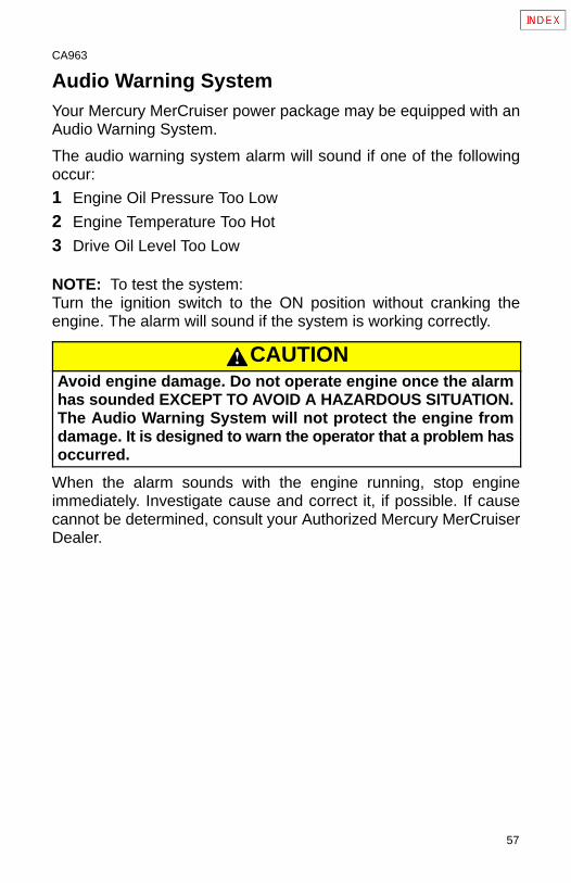
Audio Warning SystemYour Mercury MerCruiser power package may be equipped with anAudio Warning System.
The audio warning system alarm will sound if one of the followingoccur:
1 Engine Oil Pressure Too Low
2 Engine Temperature Too Hot
3 Drive Oil Level Too Low
NOTE: To test the system:Turn the ignition switch to the ON position without cranking theengine. The alarm will sound if the system is working correctly.
CAUTIONAvoid engine damage. Do not operate engine once the alarmhas sounded EXCEPT TO AVOID A HAZARDOUS SITUATION.The Audio Warning System will not protect the engine fromdamage. It is designed to warn the operator that a problem hasoccurred.
When the alarm sounds with the engine running, stop engineimmediately. Investigate cause and correct it, if possible. If causecannot be determined, consult your Authorized Mercury MerCruiserDealer.
58
CB758
748981A
74907275989
1C
3
76037
1B
59
CB775
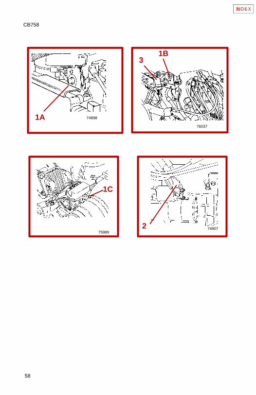
Electrical System Overload ProtectionIf an electrical overload occurs, a fuse will blow or the circuit breakerwill trip open. The cause must be found and corrected beforereplacing fuse or resetting circuit breaker.
1 A circuit breaker provides protection for engine wiring harnessand instrumentation power lead. Reset by pushing RESET button IN.A Carburetor ModelsB EFI Models Except 7.4L MPIC 7.4L MPI
NOTE: In an emergency, when engine must be operated and causefor high current draw cannot be located and corrected, turn OFF ordisconnect all accessories connected to engine and instrumentationwiring. Reset circuit breaker. If breaker remains open, electrical over-load has not been eliminated. Further checks must be made on elec-trical system.
2 A 90 Amp fuse is located on the large post of the starter solenoid.This fuse is designed to protect the engine wiring harness if an elec-trical overload occurs.
3 On EFI Models: Three fuses are located on the port side of theengine. These fuses control various EFI circuits.A Fuel Pump Fuse - 15 AmpB ECM / Injector Fuse - 10 AmpC ECM / Battery Fuse - 15 Amp
60
CB654
70525
570526
70527
705287
6
54

61
CA941
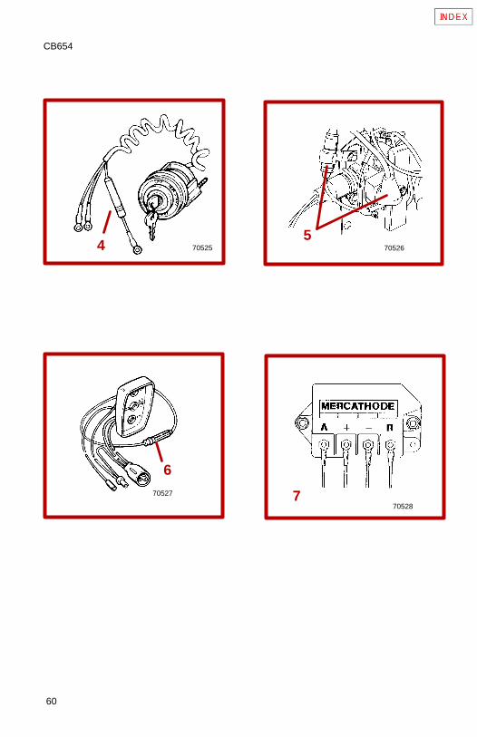
4 A 20 amp fuse may be located in ignition switch “I” terminal leadto protect electrical system. Check for blown fuse if key is turned toSTART and nothing happens (and circuit breaker is not tripped).
5 The Power Trim System is protected from overload by 110 ampfuse and a 20 amp in-line fuse on Power Trim pump.
6 Quicksilver Three-Button Power Trim Control Panel is further pro-tected by a 20 amp in-line fuse.
7 The Quicksilver MerCathode System has a 20 amp in-line fuse inthe wire which connects to positive (+) terminal on controller. If fuseis blown, system will not operate and a loss of corrosion protectionwill result.
62
CA933
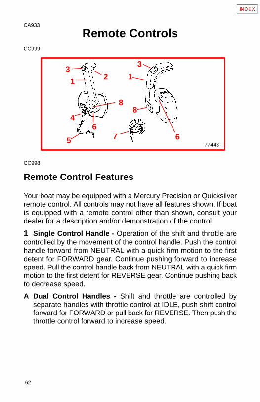
Remote ControlsCC999
77443
1
3
4
8
123
5 7
8
66
CC998
Remote Control Features
Your boat may be equipped with a Mercury Precision or Quicksilverremote control. All controls may not have all features shown. If boatis equipped with a remote control other than shown, consult yourdealer for a description and/or demonstration of the control.
1 Single Control Handle - Operation of the shift and throttle arecontrolled by the movement of the control handle. Push the controlhandle forward from NEUTRAL with a quick firm motion to the firstdetent for FORWARD gear. Continue pushing forward to increasespeed. Pull the control handle back from NEUTRAL with a quick firmmotion to the first detent for REVERSE gear. Continue pushing backto decrease speed.
A Dual Control Handles - Shift and throttle are controlled byseparate handles with throttle control at IDLE, push shift controlforward for FORWARD or pull back for REVERSE. Then push thethrottle control forward to increase speed.
63
2 Neutral Release Lever - Prevents accidental shift and throttleengagement. Neutral lock button must be pushed IN to move thecontrol handle out of NEUTRAL.
3 Trim/Tilt Button(if Equipped) - Refer to Power Trim Operation.
4 Lanyard Stop Switch - Turns ignition OFF whenever theoperator (when attached to the lanyard) moves far enough awayfrom the operator’s position to activate the switch. Refer to theLanyard Stop Switch safety explanation and Warning in the GeneralInformation Section.
5 Lanyard - Refer to the lanyard stop switch safety explanation andwarning in the General Information Section.
6 Throttle Friction Adjustment - Console controls require coverremoval for adjustment.
7 Ignition Key Switch - OFF, ON, START.
8 Throttle Only Button - Allows engine throttle advancementwithout shifting the engine. This is done by disengaging the shiftmechanism from the control handle. The throttle only button can bedepressed only when the remote control handle is in the NEUTRALposition, and should only be used to assist in starting the engine.
64
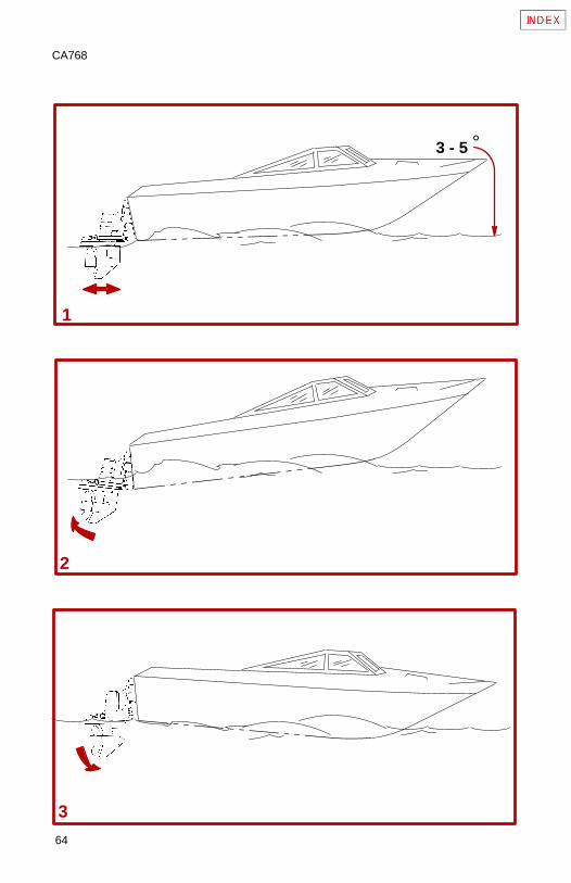
CA768
3
1
2
°3 - 5
65
CA418
Power TrimPower Trim allows the operator to adjust the drive angle, whileunderway, to provide the ideal boat angle for varying load and waterconditions. Also, the Power Trim system “Trailering” feature allowsthe operator to raise and lower the drive unit for trailering, beaching,launching and low speed (below 1200 rpm engine speed), shallowwater operation.
CAUTIONNever trim the drive unit UP/OUT using TRAILER switch whileboat is underway at engine speeds above 1200 rpm. Use ex-treme caution when operating with drive unit raised. Severedamage to the drive unit may result if unit is raised beyond thegimbal ring support flanges at engine speeds above 1200 rpm.
1 In most cases, best overall performance is obtained with the driveunit adjusted so the boat bottom will run at a 3° to 5° angle to thewater.
2 Trimming Drive Unit UP/OUT Can:
• Generally increase top speed.
• Increase clearance over submerged objects or a shallow bottom.
• Cause boat to accelerate and plane off slower.
• In excess, cause boat “porpoising” (bouncing) or propellerventilation.
• Cause engine overheating if trimmed UP/OUT to a point whereany cooling water intake holes are above the water line.
3 Trimming Drive Unit DOWN/IN Can:
• Help the boat accelerate and plane off quicker.
• Generally improve the ride in choppy water.
66
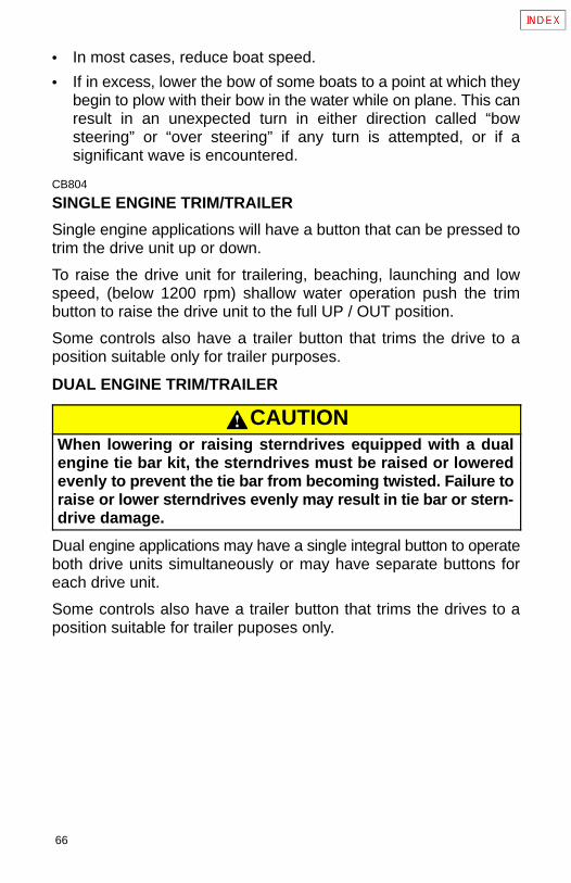
• In most cases, reduce boat speed.
• If in excess, lower the bow of some boats to a point at which theybegin to plow with their bow in the water while on plane. This canresult in an unexpected turn in either direction called “bowsteering” or “over steering” if any turn is attempted, or if asignificant wave is encountered.
CB804
SINGLE ENGINE TRIM/TRAILER
Single engine applications will have a button that can be pressed totrim the drive unit up or down.
To raise the drive unit for trailering, beaching, launching and lowspeed, (below 1200 rpm) shallow water operation push the trimbutton to raise the drive unit to the full UP / OUT position.
Some controls also have a trailer button that trims the drive to aposition suitable only for trailer purposes.
DUAL ENGINE TRIM/TRAILER
CAUTIONWhen lowering or raising sterndrives equipped with a dualengine tie bar kit, the sterndrives must be raised or loweredevenly to prevent the tie bar from becoming twisted. Failure toraise or lower sterndrives evenly may result in tie bar or stern-drive damage.
Dual engine applications may have a single integral button to operateboth drive units simultaneously or may have separate buttons foreach drive unit.
Some controls also have a trailer button that trims the drives to aposition suitable for trailer puposes only.
67
CA757
Starting, Shifting And Stopping
WARNINGBefore starting engine, operate bilge blower for at least fiveminutes to remove any explosive fumes from engine compart-ment. If boat is not equipped with a bilge blower, open enginehatch and leave open while starting engine.
CAUTIONIt is good practice to ventilate the engine compartment priorto servicing any engine components to remove any fuel va-pors which may cause difficulty breathing or be an irritant.
IMPORTANT: Observe the following:• Do not start engine without water being supplied to seawater
pickup pump (to prevent pump or engine damage).• Do not operate starter motor continuously for more than 30
seconds.• On Carbureted Engines: When engine starts, quickly reduce
throttle setting to avoid exceeding 1500 rpm.• Never shift drive unit unless engine is at idle rpm.
Perform the following as appropriate:
1 Check all items listed in OPERATION CHART.
2 Perform any other necessary checks, as indicated by your dealer,or specified in your boat owner’s manual.
3 Place drive unit in full down/in position.
4 Place control handle in NEUTRAL.
68
5 Refer to A or B as appropriate for your model.A Carbureted Engine - Push THROTTLE ONLY button and position
throttle setting as follows:COLD ENGINE - Move control/throttle lever to full throttle, thenreturn to about 1/4 throttle. In extreme cold it may be necessaryto pump lever more than once.WARM ENGINE - Move control/throttle lever to 1/4 throttle posi-tion.FLOODED ENGINE - Move control/throttle lever to full throttle. Beprepared to decrease engine speed to 1000-1500 rpm as soon asengine starts.
B EFI Engine - Position throttle setting as follows:COLD ENGINE - Leave in neutral/idle speed position.WARM ENGINE - Leave in neutral/idle speed position.FLOODED ENGINE - Turn ignition switch to ON position. Pushthe THROTTLE ONLY button and place the throttle lever at 50%position. Attempt to start engine. As soon as engine starts, returnthrottle to the idle position.
6 Turn ignition key to START. Release key when engine starts andallow switch to return to RUN position.
7 Carbureted Engines - Move control/throttle lever back todecrease engine rpm to 1000-1500 rpm if necessary.
8 Check oil pressure gauge immediately after engine starts. If oilpressure is not within specified range (see SPECIFICATIONS), stopengine immediately and determine cause.
9 If engine is cold, run engine for 1 or 2 minutes at fast idle(1000-1500 rpm).
69
10After engine has warmed up, check water temperature gauge toensure that engine temperature is not abnormally high. If it is, stopengine immediately and determine cause.
11 Be sure charging system is functioning correctly.
12Observe power package for fuel, oil, water and exhaust leaks.
13To shift drive unit, return control/throttle lever to NEUTRAL. Movecontrol/shift lever with a firm, quick motion forward to shift toFORWARD gear, or backward to shift to REVERSE. After shiftingdrive unit, advance throttle to desired setting.
14Move control/shift lever to NEUTRAL and allow engine to drop toIDLE speed. If engine has been run at high speed for a long periodof time, allow engine to cool by running at IDLE speed for 3 to 5minutes.
15Turn ignition key to OFF.
CC829
CAUTIONTo avoid possible ingestion of water that can damage enginecomponents:
• Do not turn the ignition key off when the engine is runningabove idle speed.
• Do not use the lanyard stop switch to shut off the engineabove idle speed.
• When coming off plane, if a large following wave may rollover the boat’s transom, apply a short, light burst of throttleto minimize the wave action against the stern of the boat.
• Do not come off plane quickly, shift into reverse and shutoff engine.
70
CB575
IMPORTANT: Avoid stopping engine if the drive unit is in gear.If engine does stop with drive unit in gear, refer to the followingprocedure:1 Push and pull repeatedly on remote control handle until han-dle returns to the neutral detent position. This may take severaltries if the power package was operating above idle RPM whenthe engine stopped.2 After handle returns to the neutral detent position, resumenormal starting procedures.
71
CA971
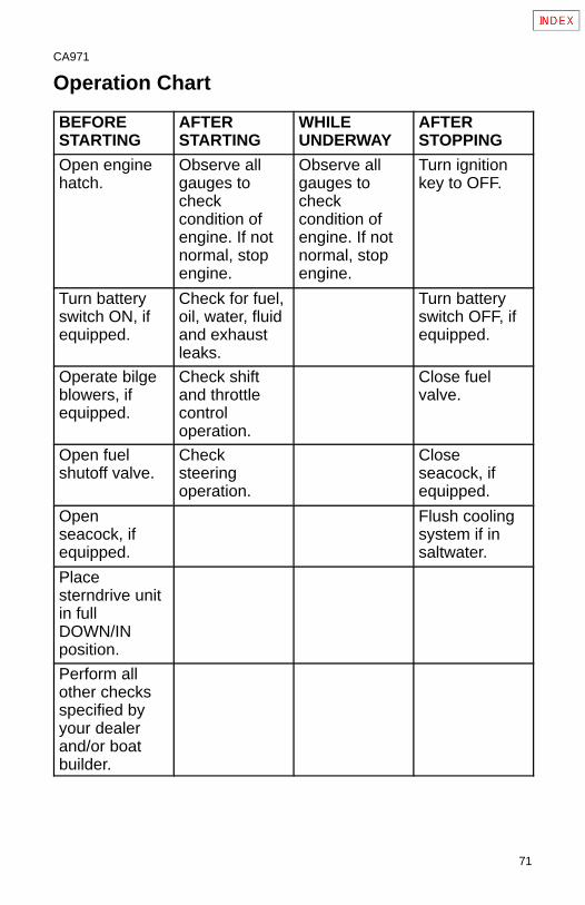
Operation Chart
BEFORESTARTING
AFTERSTARTING
WHILEUNDERWAY
AFTERSTOPPING
Open enginehatch.
Observe allgauges tocheckcondition ofengine. If notnormal, stopengine.
Observe allgauges tocheckcondition ofengine. If notnormal, stopengine.
Turn ignitionkey to OFF.
Turn batteryswitch ON, ifequipped.
Check for fuel,oil, water, fluidand exhaustleaks.
Turn batteryswitch OFF, ifequipped.
Operate bilgeblowers, ifequipped.
Check shiftand throttlecontroloperation.
Close fuelvalve.
Open fuelshutoff valve.
Checksteeringoperation.
Closeseacock, ifequipped.
Openseacock, ifequipped.
Flush coolingsystem if insaltwater.
Placesterndrive unitin fullDOWN/INposition.
Perform allother checksspecified byyour dealerand/or boatbuilder.
72
CA877
Specifications
Fuel Recommendations
IMPORTANT: Use of improper gasoline can damage yourengine seriously. Engine damage resulting from use ofimproper gasoline is considered misuse of engine, and damagecaused thereby will not be covered under the limited warranty.
FUEL RATINGS
Mercury MerCruiser engines will operate satisfactorily when using amajor brand of unleaded gasoline as follows:
USA and Canada - having a posted pump Octane Rating of 87(R+M)/2 minimum. Premium gasoline [92 (R+M)/2 Octane] is alsoacceptable. DO NOT use leaded gasoline.
Outside USA and Canada - having a posted pump Octane Ratingof 90 RON minimum. Premium gasoline (98 RON) is alsoacceptable. If unleaded gasoline is not available, use a major brandof leaded gasoline.
CA878
USING REFORMULATED (OXYGENATED) GASOLINES(USA ONLY)
This type of gasoline is required in certain areas of the USA. The twotypes of “oxygenates” used in these fuels is Alcohol (Ethanol) orEther (MTBE or ETBE). If Ethanol is the “oxygenate” that is used inthe gasoline in your area, refer to “Gasolines Containing Alcohol”also.
These “Reformulated Gasolines” are acceptable for use in yourMercury MerCruiser engine.
73
CA879
GASOLINES CONTAINING ALCOHOL
If the gasoline in your area contains either “methanol” (methylalcohol) or “ethanol” (ethyl alcohol), you should be aware of certainadverse effects that can occur. These adverse effects are moresevere with “methanol.” Increasing the percentage of alcohol in thefuel can also worsen these adverse effects.
Some of these adverse effects are caused because the alcohol in thegasoline can absorb moisture from the air, resulting in a separationof the water/alcohol from the gasoline in the fuel tank.
The fuel system components on your Mercury MerCruiser engine willwithstand up to 10% alcohol content in the gasoline. We do not knowwhat percentage your boat’s fuel system will withstand. Contact yourboat manufacturer for specific recommendations on the boats fuelsystem components (fuel tanks, fuel lines, and fittings). Be awarethat gasolines containing alcohol may cause increased:
• Corrosion of metal parts.
• Deterioration of rubber or plastic parts.
• Fuel permeation through rubber fuel lines.
• Starting and operating difficulties.
74
WARNINGFIRE AND EXPLOSION HAZARD: Fuel leakage from any partof fuel system can be a fire and explosion hazard which cancause serious bodily injury or death. Careful periodic inspec-tion of entire fuel system is mandatory, particularly after stor-age. All fuel components including fuel tanks, whether plasticmetal or fiberglass, fuel lines, fittings, fuel filters and carbure-tors/fuel injection components should be inspected for leak-age, softening, hardening, swelling or corrosion. Any sign ofleakage or deterioration requires replacement before furtherengine operation.
Because of possible adverse effects of alcohol in gasoline, it isrecommended that only alcohol-free gasoline be used wherepossible. If only fuel containing alcohol is available, or if the presenceof alcohol is unknown, increased inspection frequency for leaks andabnormalities is required.IMPORTANT: When operating a Mercury MerCruiser engine ongasoline containing alcohol, storage of gasoline in the fuel tankfor long periods should be avoided. Long periods of storage,common to boats, create unique problems. In carsalcohol-blend fuels normally are consumed before they canabsorb enough moisture to cause trouble, but boats often sitidle long enough for phase separation to take place. In addition,internal corrosion may take place during storage if alcohol haswashed protective oil films from internal components.
75
CB789
FUEL SYSTEM ADDITIVES (V6 AND 5.0L/305 CID MODELS)
To maximize the life of valves and valve seats on your MercuryMerCruiser engine, use Quicksilver Valve Lubricant(92-826259A12) regularly.
CC540
Seacock Size RecommendationSeacock used must have an internal cross-sectional area equal toor greater than hose to prevent restricting waterflow. Install valve inan area where it will be easily accessible and supported adequatelyto prevent hose fatigue. A 1-1/4 in. (32 mm) brass ball or gate valveis suggested.
CA693
Crankcase OilTo help obtain optimum engine performance and to providemaximum protection, we strongly recommend the use of Quicksilver4-Cycle 25W-40 Marine Engine Oil. This oil is a special blend of25-weight and 40-weight oils for marine engines. If not available, agood grade, straight weight, detergent automotive oil of correctviscosity, with an API classification of SH, CF/CF-2, may be used.
In those areas where Quicksilver 4-Cycle 25W-40 Marine Engine Oilor a recommended straight weight oil are not available, amulti-viscosity 20W-40 or, as a second but less preferable choice,20W-50, with API service ratings of SH, CF/CF-2 may be used.
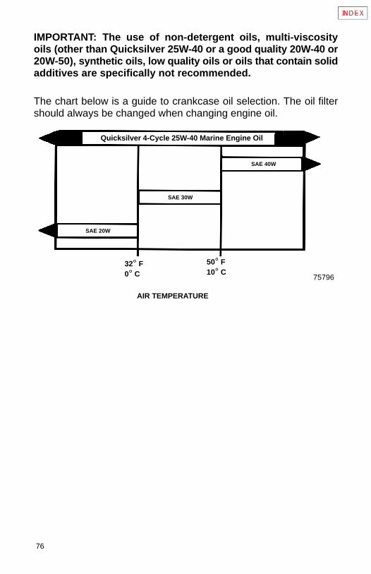
76
IMPORTANT: The use of non-detergent oils, multi-viscosityoils (other than Quicksilver 25W-40 or a good quality 20W-40 or20W-50), synthetic oils, low quality oils or oils that contain solidadditives are specifically not recommended.
The chart below is a guide to crankcase oil selection. The oil filtershould always be changed when changing engine oil.
75796
Quicksilver 4-Cycle 25W-40 Marine Engine Oil
SAE 20W
SAE 30W
SAE 40W
32° F0° C
50° F10° C
AIR TEMPERATURE
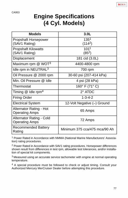
77
CA953
Engine Specifications(4 Cyl. Models)
Models 3.0L
Propshaft Horsepower(SAV1 Rating)
1351
(1142)
Propshaft Kilowatts(SAV1 Rating)
1011
(852)
Displacement 181 cid (3.0L)
Maximum rpm @ WOT3 4400-4800 rpm
Idle rpm in NEUTRAL3 700 rpm
Oil Pressure @ 2000 rpm 30-60 psi (207-414 kPa)
Min. Oil Pressure @ Idle 4 psi (28 kPa)
Thermostat 160° F (71° C)
Timing @ Idle rpm4 2° ATDC
Firing Order 1-3-4-2
Electrical System 12-Volt Negative (–) Ground
Alternator Rating - HotOperating Amps
65 Amps
Alternator Rating - ColdOperating Amps
72 Amps
Recommended BatteryRating
Minimum 375 cca/475 mca/90 Ah
1 Power Rated in Accordance with NMMA (National Marine Manufacturers’ Associa-tion) rating procedures.2 Power Rated in Accordance with SAV1 rating procedures. Horsepower differencesshown result from differences in test rpm, allowable test tolerances, and/or installa-tion of special kit components.3 Measured using an accurate service tachometer with engine at normal operatingtemperature.4 A special procedure must be followed to check or adjust timing. Consult yourAuthorized Mercury MerCruiser Dealer before attempting this procedure.
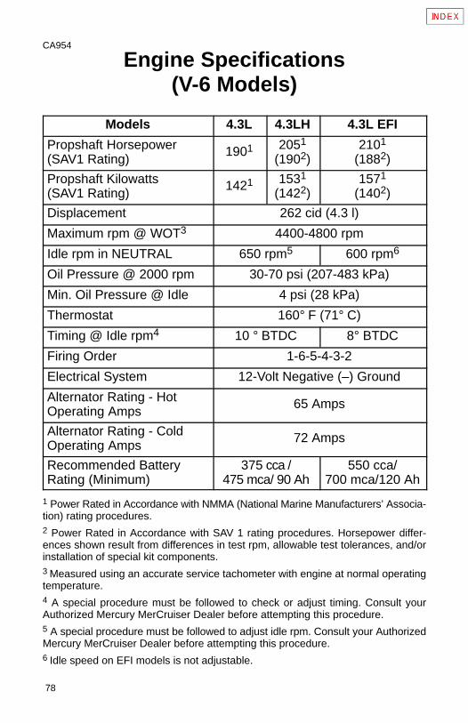
78
CA954
Engine Specifications(V-6 Models)
Models 4.3L 4.3LH 4.3L EFI
Propshaft Horsepower(SAV1 Rating)
1901 2051
(1902)2101
(1882)
Propshaft Kilowatts(SAV1 Rating)
1421 1531
(1422)1571
(1402)
Displacement 262 cid (4.3 l)
Maximum rpm @ WOT3 4400-4800 rpm
Idle rpm in NEUTRAL 650 rpm5 600 rpm6
Oil Pressure @ 2000 rpm 30-70 psi (207-483 kPa)
Min. Oil Pressure @ Idle 4 psi (28 kPa)
Thermostat 160° F (71° C)
Timing @ Idle rpm4 10 ° BTDC 8° BTDC
Firing Order 1-6-5-4-3-2
Electrical System 12-Volt Negative (–) Ground
Alternator Rating - HotOperating Amps
65 Amps
Alternator Rating - ColdOperating Amps
72 Amps
Recommended BatteryRating (Minimum)
375 cca /475 mca/ 90 Ah
550 cca/700 mca/120 Ah
1 Power Rated in Accordance with NMMA (National Marine Manufacturers’ Associa-tion) rating procedures.2 Power Rated in Accordance with SAV 1 rating procedures. Horsepower differ-ences shown result from differences in test rpm, allowable test tolerances, and/orinstallation of special kit components.3 Measured using an accurate service tachometer with engine at normal operatingtemperature.4 A special procedure must be followed to check or adjust timing. Consult yourAuthorized Mercury MerCruiser Dealer before attempting this procedure.5 A special procedure must be followed to adjust idle rpm. Consult your AuthorizedMercury MerCruiser Dealer before attempting this procedure.6 Idle speed on EFI models is not adjustable.
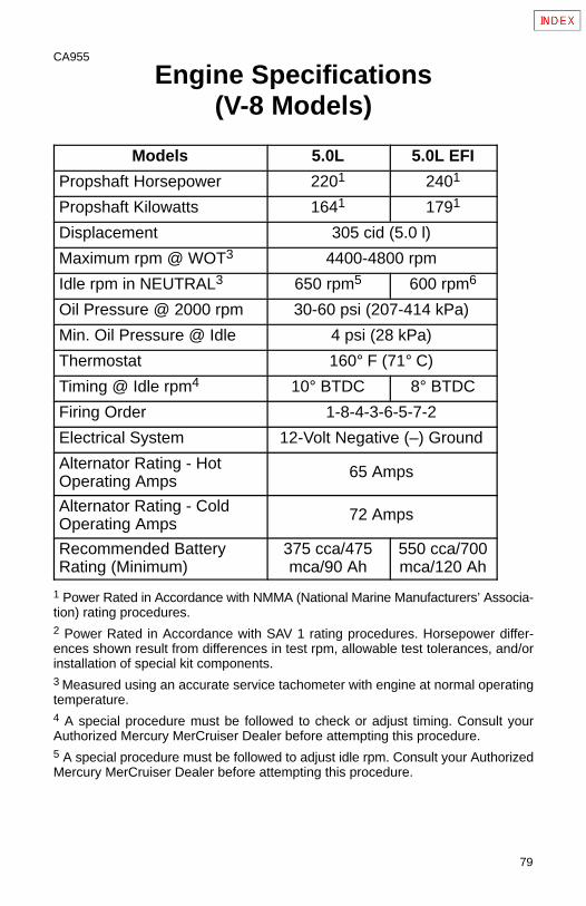
79
CA955
Engine Specifications(V-8 Models)
Models 5.0L 5.0L EFI
Propshaft Horsepower 2201 2401
Propshaft Kilowatts 1641 1791
Displacement 305 cid (5.0 l)
Maximum rpm @ WOT3 4400-4800 rpm
Idle rpm in NEUTRAL3 650 rpm5 600 rpm6
Oil Pressure @ 2000 rpm 30-60 psi (207-414 kPa)
Min. Oil Pressure @ Idle 4 psi (28 kPa)
Thermostat 160° F (71° C)
Timing @ Idle rpm4 10° BTDC 8° BTDC
Firing Order 1-8-4-3-6-5-7-2
Electrical System 12-Volt Negative (–) Ground
Alternator Rating - HotOperating Amps
65 Amps
Alternator Rating - ColdOperating Amps
72 Amps
Recommended BatteryRating (Minimum)
375 cca/475mca/90 Ah
550 cca/700mca/120 Ah
1 Power Rated in Accordance with NMMA (National Marine Manufacturers’ Associa-tion) rating procedures.2 Power Rated in Accordance with SAV 1 rating procedures. Horsepower differ-ences shown result from differences in test rpm, allowable test tolerances, and/orinstallation of special kit components.3 Measured using an accurate service tachometer with engine at normal operatingtemperature.4 A special procedure must be followed to check or adjust timing. Consult yourAuthorized Mercury MerCruiser Dealer before attempting this procedure.5 A special procedure must be followed to adjust idle rpm. Consult your AuthorizedMercury MerCruiser Dealer before attempting this procedure.
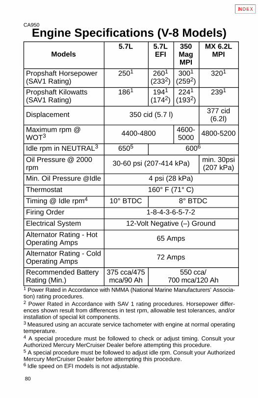
80
CA950
Engine Specifications (V-8 Models)
Models5.7L 5.7L
EFI350MagMPI
MX 6.2LMPI
Propshaft Horsepower(SAV1 Rating)
2501 2601
(2332)3001
(2592)3201
Propshaft Kilowatts(SAV1 Rating)
1861 1941
(1742)2241
(1932)2391
Displacement 350 cid (5.7 l) 377 cid(6.2l)
Maximum rpm @WOT3 4400-4800 4600-
50004800-5200
Idle rpm in NEUTRAL3 6505 6006
Oil Pressure @ 2000rpm
30-60 psi (207-414 kPa) min. 30psi(207 kPa)
Min. Oil Pressure @Idle 4 psi (28 kPa)
Thermostat 160° F (71° C)
Timing @ Idle rpm4 10° BTDC 8° BTDC
Firing Order 1-8-4-3-6-5-7-2
Electrical System 12-Volt Negative (–) Ground
Alternator Rating - HotOperating Amps
65 Amps
Alternator Rating - ColdOperating Amps
72 Amps
Recommended BatteryRating (Min.)
375 cca/475mca/90 Ah
550 cca/700 mca/120 Ah
1 Power Rated in Accordance with NMMA (National Marine Manufacturers’ Associa-tion) rating procedures.2 Power Rated in Accordance with SAV 1 rating procedures. Horsepower differ-ences shown result from differences in test rpm, allowable test tolerances, and/orinstallation of special kit components.3 Measured using an accurate service tachometer with engine at normal operatingtemperature.4 A special procedure must be followed to check or adjust timing. Consult yourAuthorized Mercury MerCruiser Dealer before attempting this procedure.5 A special procedure must be followed to adjust idle rpm. Consult your AuthorizedMercury MerCruiser Dealer before attempting this procedure.6 Idle speed on EFI models is not adjustable.
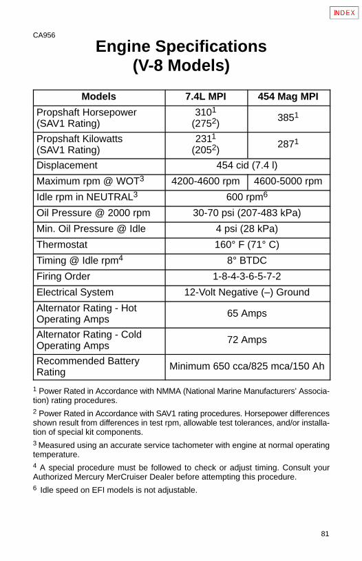
81
CA956
Engine Specifications(V-8 Models)
Models 7.4L MPI 454 Mag MPI
Propshaft Horsepower(SAV1 Rating)
3101
(2752)3851
Propshaft Kilowatts(SAV1 Rating)
2311
(2052)2871
Displacement 454 cid (7.4 l)
Maximum rpm @ WOT3 4200-4600 rpm 4600-5000 rpm
Idle rpm in NEUTRAL3 600 rpm6
Oil Pressure @ 2000 rpm 30-70 psi (207-483 kPa)
Min. Oil Pressure @ Idle 4 psi (28 kPa)
Thermostat 160° F (71° C)
Timing @ Idle rpm4 8° BTDC
Firing Order 1-8-4-3-6-5-7-2
Electrical System 12-Volt Negative (–) Ground
Alternator Rating - HotOperating Amps
65 Amps
Alternator Rating - ColdOperating Amps
72 Amps
Recommended BatteryRating
Minimum 650 cca/825 mca/150 Ah
1 Power Rated in Accordance with NMMA (National Marine Manufacturers’ Associa-tion) rating procedures.2 Power Rated in Accordance with SAV1 rating procedures. Horsepower differencesshown result from differences in test rpm, allowable test tolerances, and/or installa-tion of special kit components.3 Measured using an accurate service tachometer with engine at normal operatingtemperature.4 A special procedure must be followed to check or adjust timing. Consult yourAuthorized Mercury MerCruiser Dealer before attempting this procedure.6 Idle speed on EFI models is not adjustable.
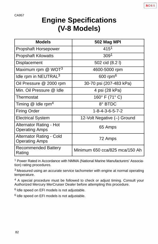
82
CA957
Engine Specifications(V-8 Models)
Models 502 Mag MPI
Propshaft Horsepower 4151
Propshaft Kilowatts 3091
Displacement 502 cid (8.2 l)
Maximum rpm @ WOT3 4600-5000 rpm
Idle rpm in NEUTRAL3 600 rpm6
Oil Pressure @ 2000 rpm 30-70 psi (207-483 kPa)
Min. Oil Pressure @ Idle 4 psi (28 kPa)
Thermostat 160° F (71° C)
Timing @ Idle rpm4 8° BTDC
Firing Order 1-8-4-3-6-5-7-2
Electrical System 12-Volt Negative (–) Ground
Alternator Rating - HotOperating Amps
65 Amps
Alternator Rating - ColdOperating Amps
72 Amps
Recommended BatteryRating
Minimum 650 cca/825 mca/150 Ah
1 Power Rated in Accordance with NMMA (National Marine Manufacturers’ Associa-tion) rating procedures.3 Measured using an accurate service tachometer with engine at normal operatingtemperature.4 A special procedure must be followed to check or adjust timing. Consult yourAuthorized Mercury MerCruiser Dealer before attempting this procedure.6 Idle speed on EFI models is not adjustable.6 Idle speed on EFI models is not adjustable.
83
CB811
Maintenance
WARNINGAlways disconnect battery cables from battery before work-ing around electrical system components to prevent injury toyourself or damage to electrical system should a wire be acci-dentally shorted.
IMPORTANT: Refer to MAINTENANCE CHART for completelisting of all scheduled maintenance to be performed. Somelistings can be done by owner/operator, while others should beperformed by an Authorized Mercury MerCruiser Dealer. Beforeattempting maintenance or repair procedures not covered inthis manual, it is recommended that a Mercury MerCruiserService Manual be purchased and read thoroughly.
NOTE: Maintenance points are color coded for ease ofidentification. See the decal on engine for identification.
• Blue-Coolant• Yellow-Engine Oil• Orange-Fuel
Maintenance Aids1 Power Steering System - Quicksilver Power Trim and SteeringFluid or Dexron III automatic transmission fluid (ATF).
2 Propeller Shaft - Quicksilver Special Lubricant 101.
3 Sterndrive Unit - Quicksilver High Performance Gear Lube.
4 All Exterior Surfaces - Quicksilver Primer and Spray Paint andQuicksilver Corrosion Guard.
84
5 Power Trim System - Quicksilver Power Trim and Steering Fluid,or SAE 10W-30 motor oil.
6 Crankcase Oil - Quicksilver 4-Cycle Marine Engine Oil (Refer toSpecifications for alternatives and oil recommendations for varyingambient temperatures.)
7 Closed Cooling System Coolant - Extended Life Ethylene Glycol5/100 Antifreeze/Coolant mixed 50/50 with purified water. If this isnot available, use a 50/50 mixture of ethylene glycol antifreeze andtap water. Areas where temperatures generally do not go below32° F (0° C), rust inhibitor and tap water is acceptable.
CA970
Fluid Capacities
NOTICE
Engine Measurements: U.S. Quarts (Liters)Sterndrive Measurements: U.S. Fluid Ounces (Milliliters)All capacities are approximate fluid measures.
Engine
Engine Model MCM 181 cid / 3.0L
Crankcase Oil (With Filter) 1 4 (3.8)
Seawater Cooling System 2 9 (8.5)
Closed Cooling System 9 (8.5)
Engine Model MCM 262 cid / 4.3L
Crankcase Oil (With Filter) 1 4-1/2 (4.3)
Seawater Cooling System 2 15 (14.1)
Closed Cooling System 20 (19)
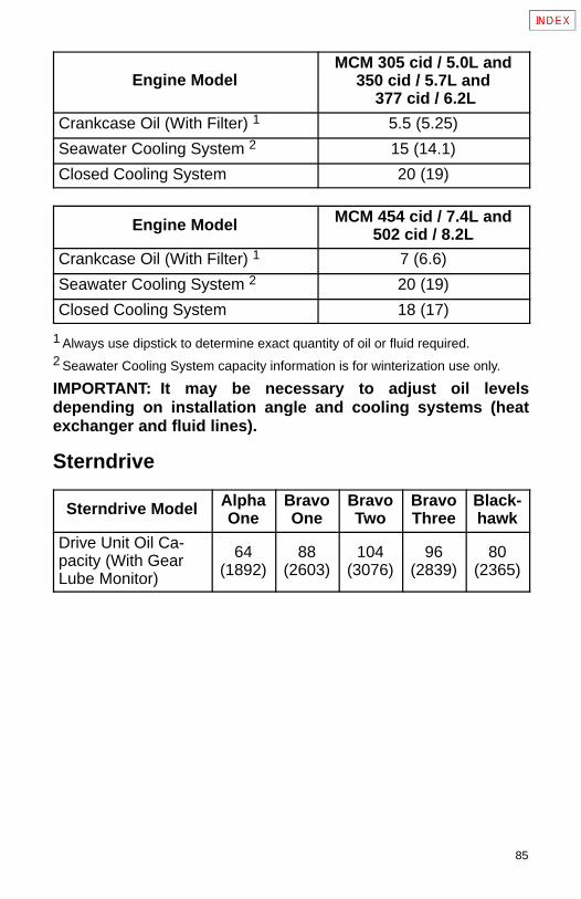
85
Engine ModelMCM 305 cid / 5.0L and
350 cid / 5.7L and 377 cid / 6.2L
Crankcase Oil (With Filter) 1 5.5 (5.25)
Seawater Cooling System 2 15 (14.1)
Closed Cooling System 20 (19)
Engine Model MCM 454 cid / 7.4L and502 cid / 8.2L
Crankcase Oil (With Filter) 1 7 (6.6)
Seawater Cooling System 2 20 (19)
Closed Cooling System 18 (17)
1 Always use dipstick to determine exact quantity of oil or fluid required.2 Seawater Cooling System capacity information is for winterization use only.
IMPORTANT: It may be necessary to adjust oil levelsdepending on installation angle and cooling systems (heatexchanger and fluid lines).
Sterndrive
Sterndrive Model AlphaOne
BravoOne
BravoTwo
BravoThree
Black-hawk
Drive Unit Oil Ca-pacity (With GearLube Monitor)
64(1892)
88(2603)
104(3076)
96(2839)
80(2365)
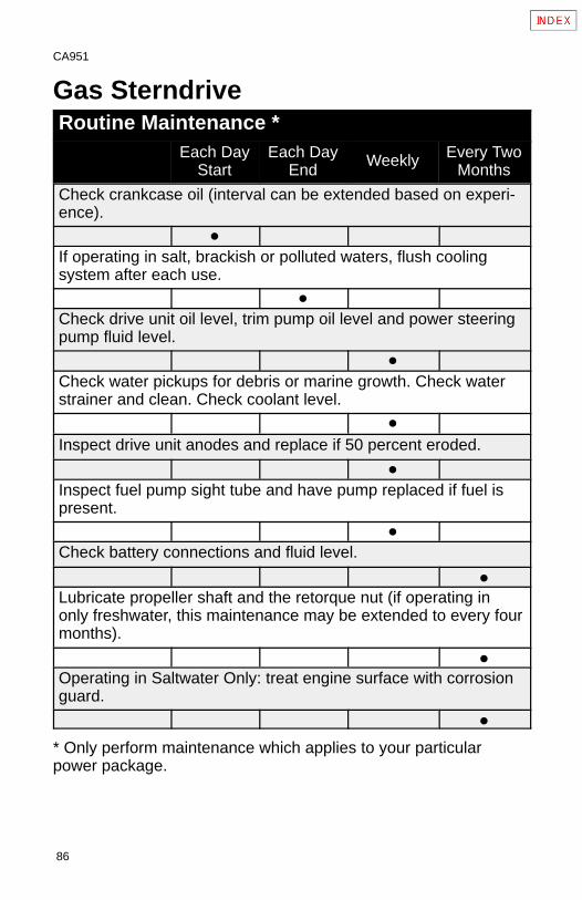
86
CA951
Gas SterndriveRoutine Maintenance *
Each DayStart
Each DayEnd
Weekly Every TwoMonths
Check crankcase oil (interval can be extended based on experi-ence).
�
If operating in salt, brackish or polluted waters, flush coolingsystem after each use.
�
Check drive unit oil level, trim pump oil level and power steeringpump fluid level.
�
Check water pickups for debris or marine growth. Check waterstrainer and clean. Check coolant level.
�
Inspect drive unit anodes and replace if 50 percent eroded.
�
Inspect fuel pump sight tube and have pump replaced if fuel ispresent.
�
Check battery connections and fluid level.
�
Lubricate propeller shaft and the retorque nut (if operating inonly freshwater, this maintenance may be extended to every fourmonths).
�
Operating in Saltwater Only: treat engine surface with corrosionguard.
�
* Only perform maintenance which applies to your particularpower package.
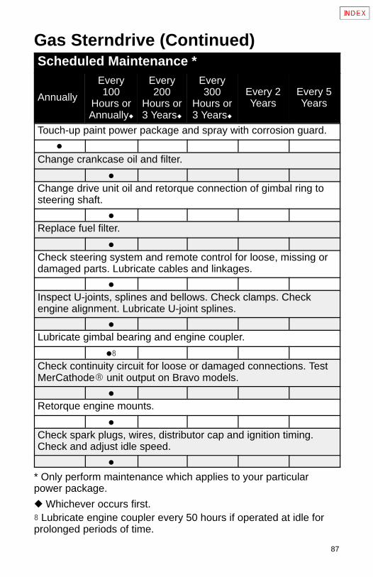
87
Gas Sterndrive (Continued)Scheduled Maintenance *
Annually
Every100
Hours orAnnually�
Every200
Hours or3 Years�
Every300
Hours or3 Years�
Every 2Years
Every 5Years
Touch-up paint power package and spray with corrosion guard.
�
Change crankcase oil and filter.
�
Change drive unit oil and retorque connection of gimbal ring tosteering shaft.
�
Replace fuel filter.
�
Check steering system and remote control for loose, missing ordamaged parts. Lubricate cables and linkages.
�
Inspect U-joints, splines and bellows. Check clamps. Checkengine alignment. Lubricate U-joint splines.
�
Lubricate gimbal bearing and engine coupler.
��
Check continuity circuit for loose or damaged connections. TestMerCathode� unit output on Bravo models.
�
Retorque engine mounts.
�
Check spark plugs, wires, distributor cap and ignition timing.Check and adjust idle speed.
�
* Only perform maintenance which applies to your particularpower package.
� Whichever occurs first.� Lubricate engine coupler every 50 hours if operated at idle forprolonged periods of time.
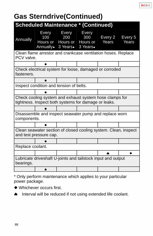
88
Gas Sterndrive(Continued)Scheduled Maintenance * (Continued)
Annually
Every100
Hours orAnnually�
Every200
Hours or3 Years�
Every300
Hours or3 Years�
Every 2Years
Every 5Years
Clean flame arrestor and crankcase ventilation hoses. ReplacePCV valve.
�
Check electrical system for loose, damaged or corrodedfasteners.
�
Inspect condition and tension of belts.
�
Check cooling system and exhaust system hose clamps fortightness. Inspect both systems for damage or leaks.
�
Disassemble and inspect seawater pump and replace worncomponents.
�
Clean seawater section of closed cooling system. Clean, inspectand test pressure cap.
�
Replace coolant.
� �
Lubricate driveshaft U-joints and tailstock input and outputbearings.
�
* Only perform maintenance which applies to your particularpower package.
� Whichever occurs first.
� Interval will be reduced if not using extended life coolant.
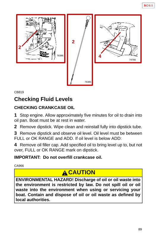
89
2
4
76385
74766
76386
2
CB819
Checking Fluid LevelsCHECKING CRANKCASE OIL
1 Stop engine. Allow approximately five minutes for oil to drain intooil pan. Boat must be at rest in water.
2 Remove dipstick. Wipe clean and reinstall fully into dipstick tube.
3 Remove dipstick and observe oil level. Oil level must be betweenFULL or OK RANGE and ADD. If oil level is below ADD:
4 Remove oil filler cap. Add specified oil to bring level up to, but notover, FULL or OK RANGE mark on dipstick.
IMPORTANT: Do not overfill crankcase oil.
CA966
CAUTIONENVIRONMENTAL HAZARD! Discharge of oil or oil waste intothe environment is restricted by law. Do not spill oil or oilwaste into the environment when using or servicing yourboat. Contain and dispose of oil or oil waste as defined bylocal authorities.
90
5
570546
77108
CA886
CHECKING POWER STEERING PUMP FLUID
Stop engine and position drive unit straight back.
5 Remove FILLCAP/DIPSTICK and observe level. Add specifiedfluid if required. Reinstall FILLCAP/DIPSTICK.
IMPORTANT: If fluid is not visible in pump, contact yourAuthorized Mercury MerCruiser Dealer.
91
6
70547
7
71340
CA887
CHECKING ENGINE COOLANT - CLOSED COOLED MODELSONLY
WARNINGAvoid serious injury from burns. Do not remove coolant capwhen engine is hot. Coolant may discharge violently.
6 Check coolant level in coolant recovery bottle. Add specifiedcoolant as required.
7 Periodically remove cap from coolant reservoir to ensure thatcoolant recovery system is functioning properly. Coolant level mustbe at top of reservoir filler neck. If coolant is low, inspect gasket in capfor damage and replace if necessary. To have cap tested, contactyour Authorized Mercury MerCruiser Dealer. Inspect coolantrecovery system for leaks.
92
75028
1
75988
1
CA888
CHECKING DRIVE UNIT OIL
NOTE: Oil level will fluctuate during operation. Oil level should bechecked with cold engine before starting.
1 Check gear lube monitor oil level. Keep oil level at or near FULLline. If any water is visible at the bottom of monitor or appears at theoil fill/drain plug and/or if oil appears discolored, contact yourAuthorized Mercury MerCruiser Dealer immediately. Both conditionsmay indicate a water leak somewhere in the drive unit.
IMPORTANT: If more than 2 fl. oz. (59ml) of Quicksilver HighPerformance Gear Lube is required to fill monitor, a seal may beleaking. Damage to drive unit may occur due to lack oflubrication. Contact your Authorized Mercury MerCruiserDealer for service.
CA966
CAUTIONENVIRONMENTAL HAZARD! Discharge of oil or oil waste intothe environment is restricted by law. Do not spill oil or oilwaste into the environment when using or servicing yourboat. Contain and dispose of oil or oil waste as defined bylocal authorities.
93
70979
2A
71425
3
CA942
CHECKING POWER TRIM PUMP FLUID
Place drive unit in full down/in position.
2 Remove fill cap from reservoir and observe oil level. Level mustbe up to, but not over bottom of filler neck. Add Quicksilver PowerTrim and Steering Fluid or SAE 10W-30 motor oil, if required, to bringlevel to bottom of filler neck. Replace cap.A Check that “Cap plug” has been removed from filler neck and
discarded.B Fill cap is vented.
CA889
Fuel Pump Sight Tube Inspection3.0L Models3 The engine fuel pump is equipped with a sight tube which givesvisible evidence of a ruptured fuel pump diaphragm.
If fuel is visible in tube, fuel pump should be replaced by yourAuthorized Mercury MerCruiser Dealer immediately.
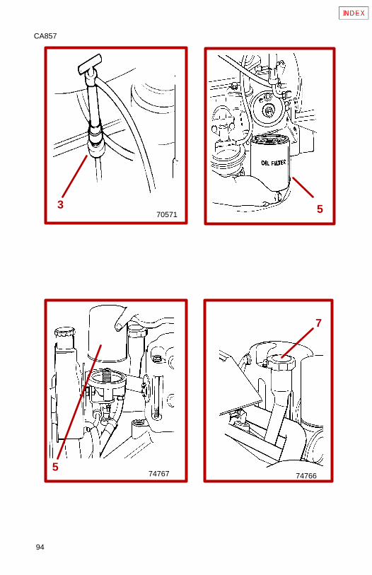
94
CA857
3
5
70571
74767 74766
7
5
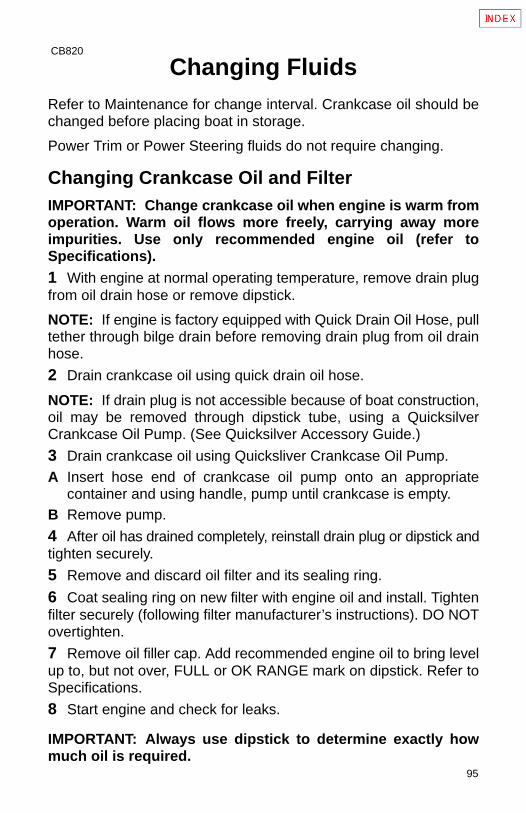
95
CB820
Changing FluidsRefer to Maintenance for change interval. Crankcase oil should bechanged before placing boat in storage.
Power Trim or Power Steering fluids do not require changing.
Changing Crankcase Oil and FilterIMPORTANT: Change crankcase oil when engine is warm fromoperation. Warm oil flows more freely, carrying away moreimpurities. Use only recommended engine oil (refer toSpecifications).1 With engine at normal operating temperature, remove drain plugfrom oil drain hose or remove dipstick.
NOTE: If engine is factory equipped with Quick Drain Oil Hose, pulltether through bilge drain before removing drain plug from oil drainhose.
2 Drain crankcase oil using quick drain oil hose.
NOTE: If drain plug is not accessible because of boat construction,oil may be removed through dipstick tube, using a QuicksilverCrankcase Oil Pump. (See Quicksilver Accessory Guide.)
3 Drain crankcase oil using Quicksliver Crankcase Oil Pump.A Insert hose end of crankcase oil pump onto an appropriate
container and using handle, pump until crankcase is empty.B Remove pump.
4 After oil has drained completely, reinstall drain plug or dipstick andtighten securely.
5 Remove and discard oil filter and its sealing ring.
6 Coat sealing ring on new filter with engine oil and install. Tightenfilter securely (following filter manufacturer’s instructions). DO NOTovertighten.
7 Remove oil filler cap. Add recommended engine oil to bring levelup to, but not over, FULL or OK RANGE mark on dipstick. Refer toSpecifications.
8 Start engine and check for leaks.
IMPORTANT: Always use dipstick to determine exactly howmuch oil is required.
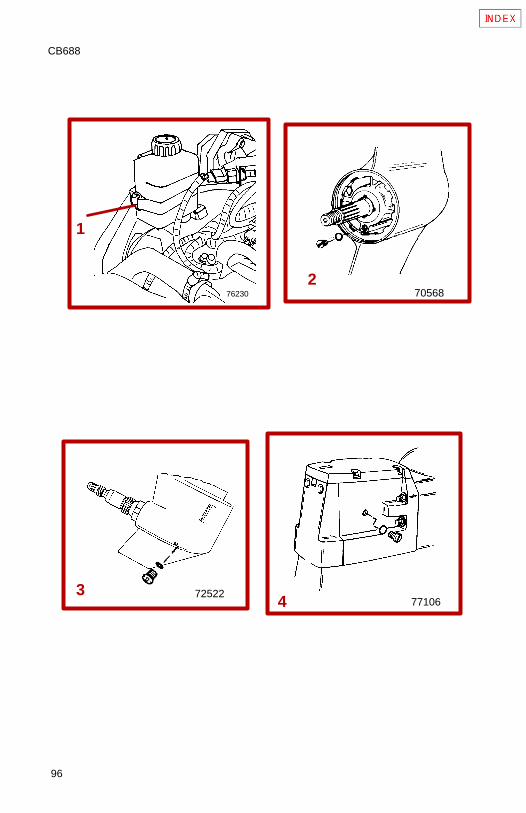
96
CB688
50132
1
270568
3 72522
76230
4 77106
97
CA967
Changing Drive Unit Oil1 Remove gear lube monitor bottle from bracket.
2 Empty contents into suitable container.
3 Install monitor in bracket.
4 Bravo One Models: Remove propeller, place drive unit in full trimlimit IN position, remove OIL FILL/DRAIN SCREW and sealingwasher, and drain oil.
5 All Other Models: Place drive unit in full trim limit OUT position,remove OIL FILL/DRAIN SCREW and sealing washer, and drain oil.
6 Remove OIL VENT screw and sealing washer. Allow oil to draincompletely.
IMPORTANT: If any water drained from OIL FILL/DRAIN hole, orif oil appears milky, drive unit is leaking and should be checkedimmediately by your Authorized Mercury MerCruiser Dealer.
7 Lower drive unit so propeller shaft is level. Fill drive unit, throughOIL FILL/DRAIN hole, with specified gear lube until an air-freestream of lubricant flows from OIL VENT hole.
IMPORTANT: Use only Quicksilver High Performance GearLube in drive unit.
8 Install OIL VENT screw and sealing washer.
9 Continue to pump gear lube into the gear lube monitor circuit untilgear lube appears in the gear lube monitor.
10Fill monitor to FILL mark. Ensure that rubber gasket is inside cap.Install cap; DO NOT overtighten.
11 Remove pump from OIL FILL/DRAIN hole. Quickly install sealingwasher and OIL FILL/DRAIN screw. Tighten securely.
12Bravo One and Alpha Models: Grease propeller shaft heavily,with specified lubricant (Refer to Propeller Installation). Reinstallpropeller and torque nut to 55 lb-ft (75 Nm) MINIMUM.
13Recheck oil level after first use.
IMPORTANT: Oil level in gear lube monitor will rise and fallduring drive operation; always check oil level when drive is cooland engine is shut down.

98
CA961
THIS PAGE IS INTENTIONALLY BLANK
99
CA968
Changing Water Separating FuelFilter
WARNINGAvoid Fire or Explosion: Fuel injection system is pressurizedduring operation. Use care when removing water separatingfuel filter. Fuel could spray on hot engine causing fire or explo-sion. Allow engine to cool down before attempting to removethe water separating fuel filter in the following procedure.Also, hold a clean shop towel over the water separating fuelfilter when removing it, to help avoid fuel spraying on the en-gine.
WARNINGBe careful when changing water separating fuel filter. Gaso-line is extremely flammable and highly explosive under cer-tain conditions. Be sure ignition key is OFF. Do not smoke orallow spark or open flame in area when changing fuel filter.Wipe up any spilled fuel immediately.
WARNINGMake sure no fuel leaks exist before closing engine hatch.
EFI Models
CAUTIONThe electric fuel pump and factory installed water separatingfuel filter have been carefully designed to function properly to-gether. Do not install additional fuel filters and/or water sepa-rating fuel filters between fuel tank and engine.
The installation of additional filters may cause:
• Fuel Vapor Locking• Difficult Warm-Starting• Piston Detonation Due to Lean Fuel Mixture• Poor Driveability
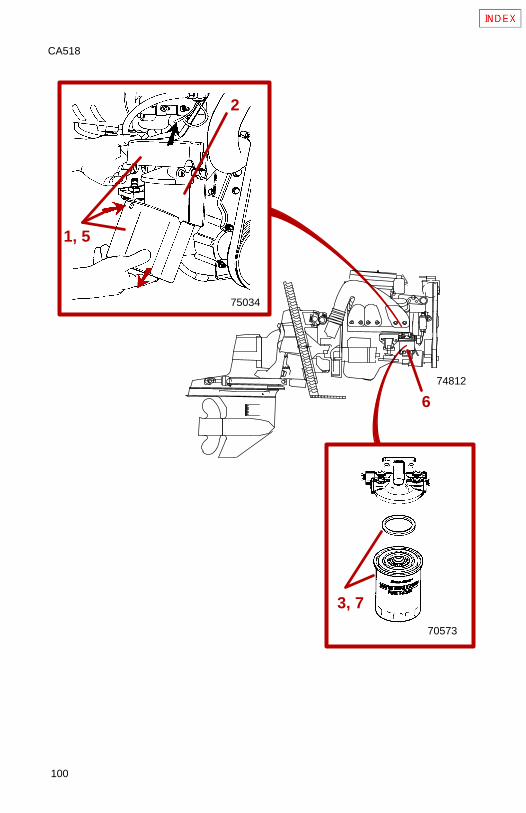
100
CA518
3, 7
70573
74812
75034
1, 5
2
6
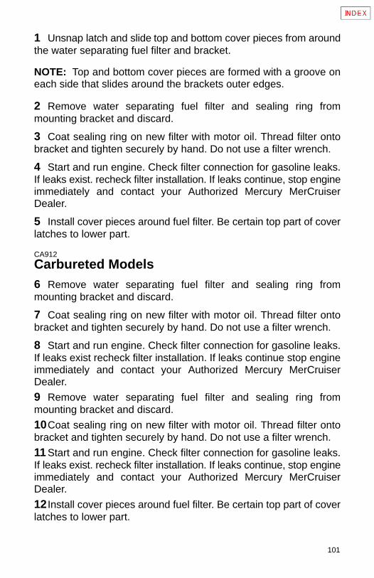
101
1 Unsnap latch and slide top and bottom cover pieces from aroundthe water separating fuel filter and bracket.
NOTE: Top and bottom cover pieces are formed with a groove oneach side that slides around the brackets outer edges.
2 Remove water separating fuel filter and sealing ring frommounting bracket and discard.
3 Coat sealing ring on new filter with motor oil. Thread filter ontobracket and tighten securely by hand. Do not use a filter wrench.
4 Start and run engine. Check filter connection for gasoline leaks.If leaks exist. recheck filter installation. If leaks continue, stop engineimmediately and contact your Authorized Mercury MerCruiserDealer.
5 Install cover pieces around fuel filter. Be certain top part of coverlatches to lower part.
CA912
Carbureted Models6 Remove water separating fuel filter and sealing ring frommounting bracket and discard.
7 Coat sealing ring on new filter with motor oil. Thread filter ontobracket and tighten securely by hand. Do not use a filter wrench.
8 Start and run engine. Check filter connection for gasoline leaks.If leaks exist recheck filter installation. If leaks continue stop engineimmediately and contact your Authorized Mercury MerCruiserDealer.
9 Remove water separating fuel filter and sealing ring frommounting bracket and discard.
10Coat sealing ring on new filter with motor oil. Thread filter ontobracket and tighten securely by hand. Do not use a filter wrench.
11 Start and run engine. Check filter connection for gasoline leaks.If leaks exist. recheck filter installation. If leaks continue, stop engineimmediately and contact your Authorized Mercury MerCruiserDealer.
12 Install cover pieces around fuel filter. Be certain top part of coverlatches to lower part.
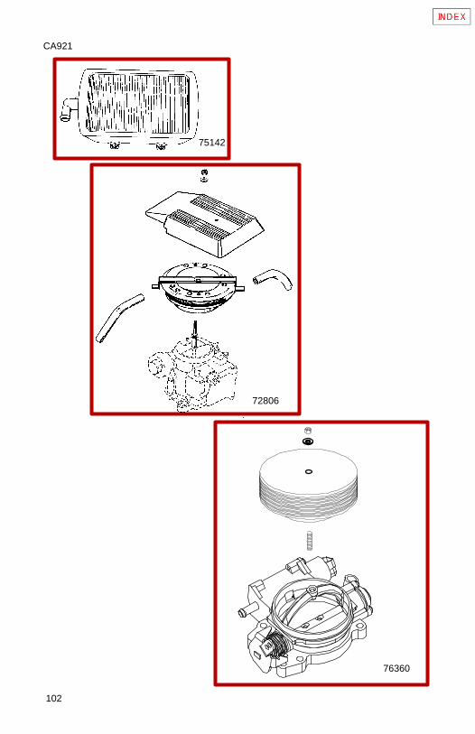
102
CA921
75142
76360
72806
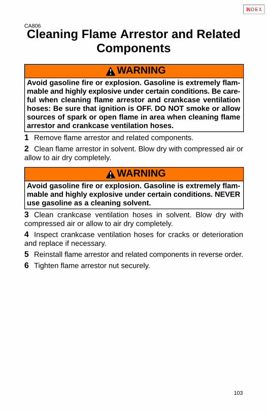
103
CA806
Cleaning Flame Arrestor and RelatedComponents
WARNINGAvoid gasoline fire or explosion. Gasoline is extremely flam-mable and highly explosive under certain conditions. Be care-ful when cleaning flame arrestor and crankcase ventilationhoses: Be sure that ignition is OFF. DO NOT smoke or allowsources of spark or open flame in area when cleaning flamearrestor and crankcase ventilation hoses.
1 Remove flame arrestor and related components.
2 Clean flame arrestor in solvent. Blow dry with compressed air orallow to air dry completely.
WARNINGAvoid gasoline fire or explosion. Gasoline is extremely flam-mable and highly explosive under certain conditions. NEVERuse gasoline as a cleaning solvent.
3 Clean crankcase ventilation hoses in solvent. Blow dry withcompressed air or allow to air dry completely.
4 Inspect crankcase ventilation hoses for cracks or deteriorationand replace if necessary.
5 Reinstall flame arrestor and related components in reverse order.
6 Tighten flame arrestor nut securely.
104
CA922
7A
713591
3
71903
71904
71901
2
7B74941
7C 71480
7D
75454
6
71357
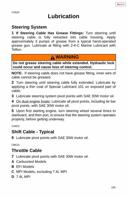
105
CA524
Lubrication
Steering System1 If Steering Cable Has Grease Fittings: Turn steering untilsteering cable is fully retracted into cable housing. Applyapproximately 3 pumps of grease from a typical hand-operatedgrease gun. Lubricate at fitting with 2-4-C Marine Lubricant withTeflon.
WARNINGDo not grease steering cable while extended. Hydraulic lockcould occur and cause loss of steering control.
NOTE: If steering cable does not have grease fitting, inner wire ofcable cannot be greased.
2 Turn steering until steering cable fully extended. Lubricate byapplying a thin coat of Special Lubricant 101 on exposed part ofcable.
3 Lubricate steering system pivot points with SAE 30W motor oil.
4 On dual engine boats: Lubricate all pivot points, including tie barpivot points, with SAE 30W motor oil.
5 Upon first starting engine, turn steering wheel several times tostarboard, and then port, to ensure that the steering system operatesproperly, before getting underway.
CA923
Shift Cable - Typical6 Lubricate pivot points with SAE 30W motor oil.
CB613
Throttle Cable7 Lubricate pivot points with SAE 30W motor oil.A Carbureted ModelsB EFI ModelsC MPI Models, excluding 7.4L MPID 7.4L MPI
106
CA930
77044
715693
571347
A
77068
1
71346
4
107
CA938
Drive Unit and Transom Assembly1 Lubricate gimbal bearing by applying approximately 8-10 pumpsof grease from a typical hand-operated grease gun using QuicksilverU-Joint and Gimbal Bearing Grease.A Alpha Models - Lubricate hinge pins by applying a couple of
pumps of grease from a typical hand-operated grease gun usingQuicksilver 2-4-C Marine Lubricant with Teflon.
2 For propeller shaft lubrication, see PROPELLER.
CA929
Engine Coupler3 Lubricate engine coupler splines through grease fittings oncoupler by applying approximately 8-10 pumps of grease from atypical hand-operated grease gun using Quicksilver Engine CouplerSpline Grease. If boat is operated at idle for prolonged periods oftime, coupler should be lubricated Bravo Models - every 50 hours;Alpha Models - every 150 hours.
NOTE: Alpha Models - Your engine is equipped with a sealedengine coupler and Perm-a-Lube U-joints. The sealed coupler andshaft splines can be lubricated without removing the drive unit. ThePerm-a-Lube U-joints do not require lubrication.
NOTE: Bravo Models - Your engine is equipped with a sealedengine coupler. The sealed coupler and shaft splines can belubricated without removing the drive unit.
NOTE: Bravo Models - The crosses and bearings on the driveU-joint will need to be lubricated through the grease fittings. ApplyQuicksilver U-joint and Gimbal Bearing Grease from a typical hand-operated grease gun until a small amount of grease begins to pushout. The sterndrive unit must be removed to grease these fittings.
CB777
Drive Shaft Extension Models4 Lubricate drive shaft grease fittings, at transom end, by applyingapproximately 10 - 12 pumps of grease from a typical hand-operatedgrease gun using Quicksilver U-joint and Gimbal Bearing Grease.
5 Lubricate drive shaft grease fittings, at engine end, by applyingapproximately 3 - 4 pumps of grease from a typical hand-operatedgrease gun using Quicksilver U-joint and Gimbal Bearing Grease.
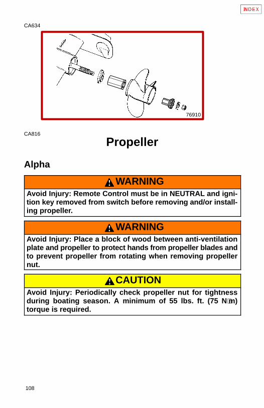
108
CA634
76910
CA816
Propeller
Alpha
WARNINGAvoid Injury: Remote Control must be in NEUTRAL and igni-tion key removed from switch before removing and/or install-ing propeller.
WARNINGAvoid Injury: Place a block of wood between anti-ventilationplate and propeller to protect hands from propeller blades andto prevent propeller from rotating when removing propellernut.
CAUTIONAvoid Injury: Periodically check propeller nut for tightnessduring boating season. A minimum of 55 lbs. ft. (75 N⋅m)torque is required.
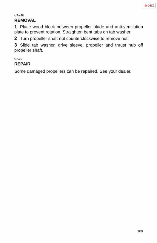
109
CA746
REMOVAL1 Place wood block between propeller blade and anti-ventilationplate to prevent rotation. Straighten bent tabs on tab washer.
2 Turn propeller shaft nut counterclockwise to remove nut.
3 Slide tab washer, drive sleeve, propeller and thrust hub offpropeller shaft.
CA79
REPAIR
Some damaged propellers can be repaired. See your dealer.
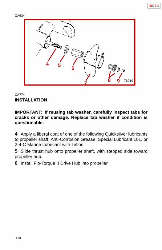
110
CA634
4 5 6
78 769109
CA774
INSTALLATION
IMPORTANT: If reusing tab washer, carefully inspect tabs forcracks or other damage. Replace tab washer if condition isquestionable.
4 Apply a liberal coat of one of the following Quicksilver lubricantsto propeller shaft: Anti-Corrosion Grease, Special Lubricant 101, or2-4-C Marine Lubricant with Teflon.
5 Slide thrust hub onto propeller shaft, with stepped side towardpropeller hub.
6 Install Flo-Torque II Drive Hub into propeller.
111
NOTE: The drive sleeve is tapered and will slide fully into the propel-ler as the nut is tightened and properly torqued.
7 Align splines and place propeller on propeller shaft.
8 Install drive sleeve and locking tab washer.
9 Install propeller nut. Tighten nut securely. A minimum of 55 lbs. ft.(75 N·m) torque is required. Bend three tabs on tab washer down intogrooves in spline washer. After first use, bend the three tabs straight,retighten propeller nut to minimum 55 lbs. ft. torque (75 N·m). Bendtabs back down into spline washer. Check propeller at least after 20hours of operation. Do not operate with loose propeller.
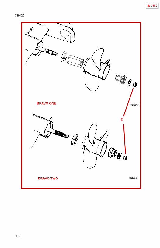
112
CB422
BRAVO ONE
BRAVO TWO
2
76910
70561
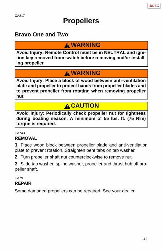
113
CA817
Propellers
Bravo One and Two
WARNINGAvoid Injury: Remote Control must be in NEUTRAL and igni-tion key removed from switch before removing and/or install-ing propeller.
WARNINGAvoid Injury: Place a block of wood between anti-ventilationplate and propeller to protect hands from propeller blades andto prevent propeller from rotating when removing propellernut.
CAUTIONAvoid Injury: Periodically check propeller nut for tightnessduring boating season. A minimum of 55 lbs. ft. (75 N⋅m)torque is required.
CA743
REMOVAL1 Place wood block between propeller blade and anti-ventilationplate to prevent rotation. Straighten bent tabs on tab washer.
2 Turn propeller shaft nut counterclockwise to remove nut.
3 Slide tab washer, spline washer, propeller and thrust hub off pro-peller shaft.
CA79
REPAIR
Some damaged propellers can be repaired. See your dealer.
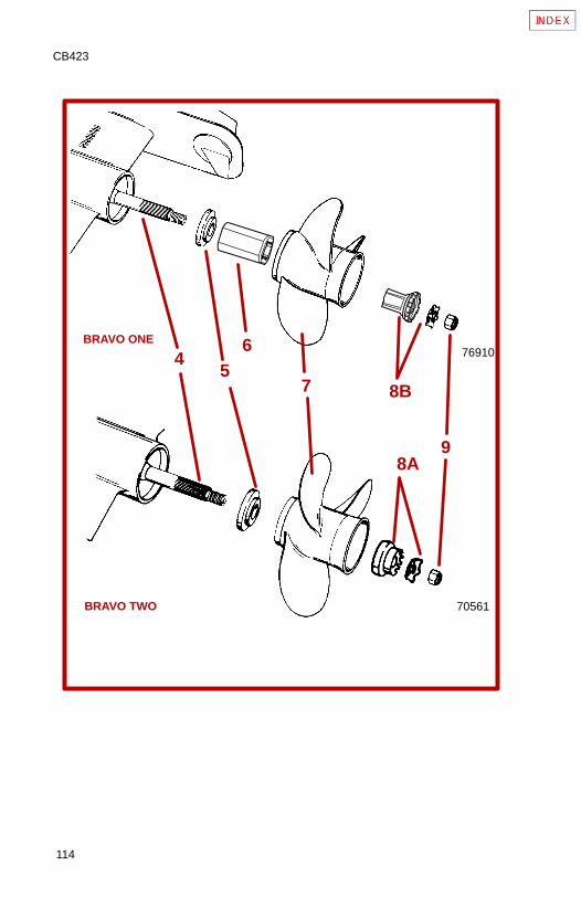
114
CB423
45
6
7
9
70561
BRAVO ONE
BRAVO TWO
76910
8B
8A
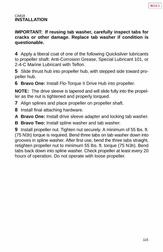
115
CA818INSTALLATION
IMPORTANT: If reusing tab washer, carefully inspect tabs forcracks or other damage. Replace tab washer if condition isquestionable.
4 Apply a liberal coat of one of the following Quicksilver lubricantsto propeller shaft: Anti-Corrosion Grease, Special Lubricant 101, or2-4-C Marine Lubricant with Teflon.
5 Slide thrust hub into propeller hub, with stepped side toward pro-peller hub.
6 Bravo One: Install Flo-Torque II Drive Hub into propeller.
NOTE: The drive sleeve is tapered and will slide fully into the propel-ler as the nut is tightened and properly torqued.
7 Align splines and place propeller on propeller shaft.
8 Install final attaching hardware.A Bravo One: Install drive sleeve adapter and locking tab washer.B Bravo Two: Install spline washer and tab washer.
9 Install propeller nut. Tighten nut securely. A minimum of 55 lbs. ft.(75 N⋅m) torque is required. Bend three tabs on tab washer down intogrooves in spline washer. After first use, bend the three tabs straight,retighten propeller nut to minimum 55 lbs. ft. torque (75 N⋅m). Bendtabs back down into spline washer. Check propeller at least every 20hours of operation. Do not operate with loose propeller.
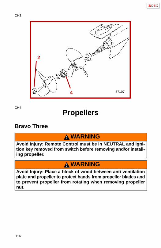
116
CH3
771074
2
CH4
Propellers
Bravo Three
WARNINGAvoid Injury: Remote Control must be in NEUTRAL and igni-tion key removed from switch before removing and/or install-ing propeller.
WARNINGAvoid Injury: Place a block of wood between anti-ventilationplate and propeller to protect hands from propeller blades andto prevent propeller from rotating when removing propellernut.
117
CAUTIONAvoid Injury: Periodically check propeller nut for tightnessduring boating season. A minimum of 55 lbs. ft. (75 N⋅m)torque is required.
REMOVAL (BRAVO THREE DRIVE)1 Place wood block between propeller blades and anti-ventilationplate to prevent rotation.
2 Turn aft propeller shaft nut (1-7/16 in. or 37mm) counterclockwiseto remove nut.
3 Slide propeller and thrust hub off propeller shaft.
4 Turn front propeller shaft nut (2-3/4 in. or 70mm) counterclock-wise to remove nut.
5 Slide propeller and thrust hub off propeller shaft.
REPAIR
Some damaged propellers can be repaired. See your dealer.
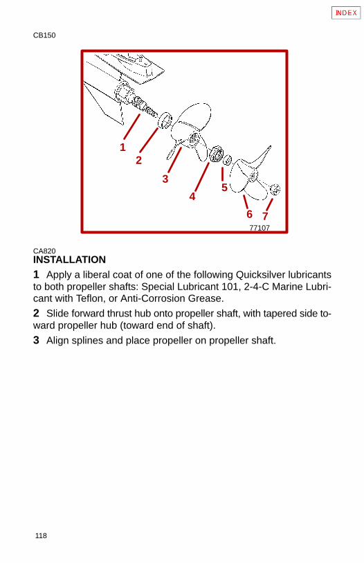
118
CB150
12
45
76
3
77107
CA820INSTALLATION1 Apply a liberal coat of one of the following Quicksilver lubricantsto both propeller shafts: Special Lubricant 101, 2-4-C Marine Lubri-cant with Teflon, or Anti-Corrosion Grease.
2 Slide forward thrust hub onto propeller shaft, with tapered side to-ward propeller hub (toward end of shaft).
3 Align splines and place propeller on propeller shaft.
119
4 Install propeller nut. Tighten nut securely. A minimum of 100 lbs.ft. (136 N·m) torque is required. Check propeller at least after 20hours of operation. Do not operate with loose propeller.
5 Slide aft thrust hub onto propeller shaft, with tapered side towardpropeller hub (toward end of shaft).
6 Align splines and place propeller on propeller shaft.
7 Install propeller nut. Tighten nut securely. A minimum of 60 lbs. ft.(81 N·m) torque is required. Check propeller at least after 20 hoursof operation. Do not operate with loose propeller.
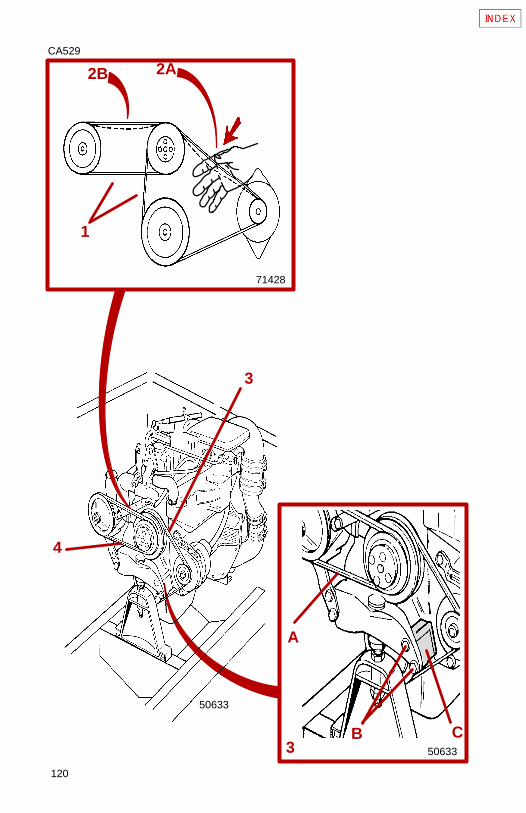
120
CA529
2A2B
71428
50633
3
4
1
3
A
B C50633
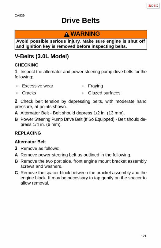
121
CA839
Drive Belts
WARNINGAvoid possible serious injury. Make sure engine is shut offand ignition key is removed before inspecting belts.
V-Belts (3.0L Model)CHECKING1 Inspect the alternator and power steering pump drive belts for thefollowing:
• Excessive wear • Fraying
• Cracks • Glazed surfaces
2 Check belt tension by depressing belts, with moderate handpressure, at points shown.A Alternator Belt - Belt should depress 1/2 in. (13 mm).B Power Steering Pump Drive Belt (If So Equipped) - Belt should de-
press 1/4 in. (6 mm).
REPLACING
Alternator Belt3 Remove as follows:
A Remove power steering belt as outlined in the following.B Remove the two port side, front engine mount bracket assembly
screws and washers.C Remove the spacer block between the bracket assembly and the
engine block. It may be necessary to tap gently on the spacer toallow removal.
122
D Loosen the alternator as outlined below. Remove and replace thealternator belt.
E Replace the spacer block between the bracket assembly and theengine block. Install the two screws using the flat and lock wash-ers removed previously. Torque the two screws to 21 lb. ft. (28N·m).
F Install power steering belt. Adjust tension of both drive belts asoutlined in the following.
Power Steering Pump Drive Belt4 Remove drive belt as follows:A Loosen power steering pump attaching bolts and mounting bolts.B Pivot power steering pump toward engine, as required, until belt
can be removed.C Install new drive belt on pulleys. Adjust tension as outlined in the
following.
Adjusting Tension - Alternator or Power Steering Pump DriveBelt5 Loosen alternator or power steering pump attaching bolts andmounting bolts (if not already accomplished). Adjust tension asfollows:A Pivot alternator or power steering pump, away from engine, as re-
quired, until the correct deflection of the belt is obtained at locationspecified above.
B After obtaining correct tension, torque the alternator and/or powersteering pump attaching bolts and mounting bolts to specifica-tions. Refer to “Specifications.”
6 Operate the engine for a short period of time. Recheck beltadjustment.

123
CA961
THIS PAGE IS INTENTIONALLY BLANK
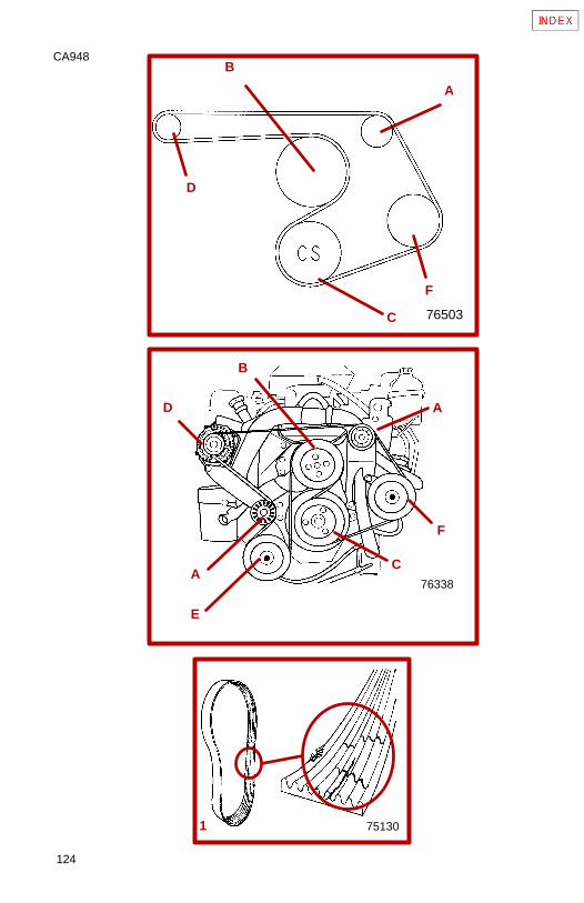
124
CA948
751301
D
F
A
C
B
76503
76338
D
F
A
A
C
B
E
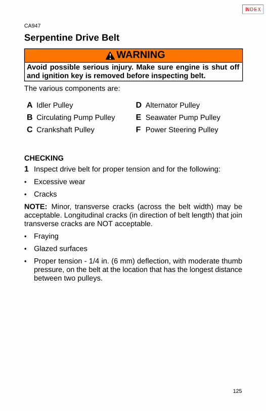
125
CA947
Serpentine Drive Belt
WARNINGAvoid possible serious injury. Make sure engine is shut offand ignition key is removed before inspecting belt.
The various components are:
A Idler Pulley D Alternator Pulley
B Circulating Pump Pulley E Seawater Pump Pulley
C Crankshaft Pulley F Power Steering Pulley
CHECKING1 Inspect drive belt for proper tension and for the following:
• Excessive wear
• Cracks
NOTE: Minor, transverse cracks (across the belt width) may beacceptable. Longitudinal cracks (in direction of belt length) that jointransverse cracks are NOT acceptable.
• Fraying
• Glazed surfaces
• Proper tension - 1/4 in. (6 mm) deflection, with moderate thumbpressure, on the belt at the location that has the longest distancebetween two pulleys.
126
CA928
REPLACING AND / OR ADJUSTING TENSION
IMPORTANT: If a belt is to be reused, it should be installed inthe same direction of rotation as before.
1 Remove drive belt as follows:
NOTE: The upper, left (port) idler pulley is the belt adjustment pulley.
A Loosen 5/8 in. locking nut on adjustment stud.B Turn adjustment stud and loosen belt. Remove belt.
2 Install drive belt on pulleys and adjust tension as follows:
3 Loosen 5/8 in. locking nut on adjustment stud. Leave wrench onadjustment stud.
NOTE: Belt deflection is to be measured on the belt at the locationthat has the longest distance between two (2) pulleys. Normally thislocation is between the alternator and the belt adjustment pulley. Thislocation will be different on engines with closed cooling or modelswithout power steering.
4 Use 5/16 in. socket and tighten adjusting stud until the correctdeflection of the belt is obtained at location specified above.
5 While holding adjustment stud at the correct belt tension, tighten5/8 in. locking nut.
6 Operate the engine for a short period of time. Recheck beltadjustment.

127
CA961
THIS PAGE IS INTENTIONALLY BLANK
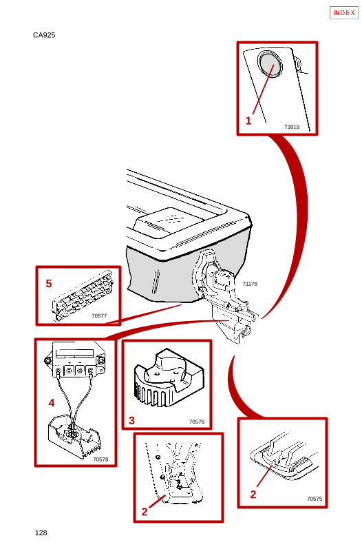
128
CA925
70578
70577
705752
4
5 71176
173919
2
705763

129
CA926
Corrosion And Corrosion ProtectionWhenever two or more dissimilar metals (like those found on thesterndrive) are submerged in a conductive solution, such assaltwater, polluted water, or water with a high mineral content, achemical reaction takes place causing electrical current to flowbetween metals. The electrical current flow causes the metal that ismost chemically active, or anodic, to erode. This is known asgalvanic corrosion and, if not controlled, it will in time cause the needfor replacement of power package components exposed to water.
IMPORTANT: Replace sacrificial anodes if eroded 50% or more.
1 Universal Anodic Plate - serves as a sacrificial anode.
2 Anodic Plate - serves as a sacrificial anode.
3 Block (if equipped) - Is mounted to underside of gimbal housingand serves as a sacrificial anode.
4 MerCathode System (if equipped) - Electrode assemblyreplaces Anodic block.
System should be tested to ensure adequate output.
Test should be made where boat is moored, using QuicksilverReference Electrode and Test Meter. Contact your AuthorizedMercury MerCruiser Dealer to arrange for this test.
5 Anode Kit (if equipped) - Mounted to boat transom. Acts as asacrificial anode.
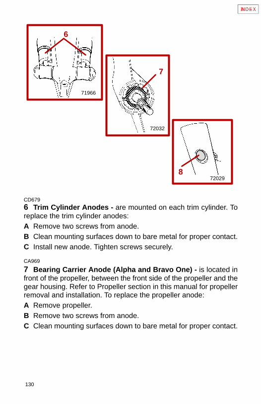
130
72032
7
720298
71966
6
CD679
6 Trim Cylinder Anodes - are mounted on each trim cylinder. Toreplace the trim cylinder anodes:A Remove two screws from anode.B Clean mounting surfaces down to bare metal for proper contact.C Install new anode. Tighten screws securely.
CA969
7 Bearing Carrier Anode (Alpha and Bravo One) - is located infront of the propeller, between the front side of the propeller and thegear housing. Refer to Propeller section in this manual for propellerremoval and installation. To replace the propeller anode:A Remove propeller.B Remove two screws from anode.C Clean mounting surfaces down to bare metal for proper contact.
131
D Install new anode. Tighten screws securely.E Reinstall propeller. See Propeller Installation for proper tighten-
ing.
8 Bearing Carrier Anode - is located in front of the propeller,between the front side of the propeller and the gear housing. Referto Propeller section in this manual for propeller removal andinstallation.
9 Gear Housing Anode (Bravo Two and Three) - is located in thesplash plate, just above the propellers.
CA965
In addition to the corrosion protection devices, the following stepsshould be taken to inhibit corrosion:
IMPORTANT: Corrosion damage that results from the improperapplication of anti-fouling paint will not be covered by thelimited warranty.
1 Painting Boat Hull or Boat Transom: Anti-fouling paint may beapplied to boat hull and boat transom but you must observe thefollowing precautions:
IMPORTANT: DO NOT paint anodes or MerCathode Systemreference electrode and anode, as this will render themineffective as galvanic corrosion inhibitors.
IMPORTANT: If anti-fouling protection is required for boat hullor boat transom, copper or tin base paints, if not prohibited bylaw, can be used. If using copper or tin based anti-foulingpaints, observe the following:
132
2 Avoid any electrical interconnection between the MercuryMerCruiser Product, Anodic Blocks, or MerCathode Systemand the paint by allowing a minimum of 1-1/2 in. (40 mm)UNPAINTED area on transom of the boat around these items.3 Painting Drive Unit or Transom Assembly: Drive unit andtransom assembly should be painted with a good quality marine paintor an anti-fouling paint that DOES NOT contain copper, tin, or anyother material that could conduct electrical current. Do not paint drainholes, anodes, MerCathode system, and items specified by boatmanufacturer.
4 Spray power package components on inside of boat annually withQuicksilver Corrosion Guard to protect finish from dulling andcorrosion. External power package components may also besprayed.
5 All lubrication points, especially steering system, shift and throttlelinkages, should be kept well lubricated.
6 Flush cooling system periodically, preferably after each use.

133
CA961
THIS PAGE IS INTENTIONALLY BLANK
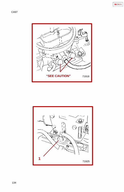
134
CA97
171925
71918“SEE CAUTION”
135
CA474
Emissions(Europe Only)
CA893
The following information applies only to engines with a specialemissions kit installed. If the kit has been installed, your enginecomplies with SAV1 Regulations.
CA398
Sealed Carburetor Mixture ScrewsThe carburetor on this engine has seals on the carburetor mixturescrews. These seals prevent adjustment of the fuel mixture settings.
CAUTIONDo not remove mixture screw seals and/or attempt to adjustfuel mixture setting. Tampering with the mixture setting onthis engine could affect the exhaust emissions level, thusvoiding the emissions certification. These seals should onlybe removed by an authorized dealer or emissions testingagency.
CA894
Changing Positive Crankcase Ventilation Valve (PCV)This engine is equipped with a positive crankcase ventilation valve(PCV). This valve should be changed every 100 hours of operationor at least once a year, whichever occurs first.
1 Remove PCV valve from port valve cover. Disconnect it from thehose and discard valve. Install new PCV valve in valve cover andreconnect hose. Ensure valve is tightly seated in valve cover.
Use only Mercury MerCruiser replacement parts to ensurecompliance with emission regulations.
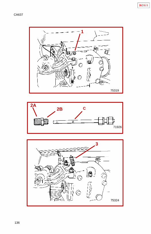
136
CA637
75319
75324
71926
1
2A2B
3
C
137
CA913
Emissions Testing
Your engine is equipped with special design features and special tun-ing to minimize the emission output from the engine. You should fol-low:
• Recommended maintenance schedules particularly as to the igni-tion system.
• Proper engine tuning procedures to ensure these features remainin good operating order.
• Proper steps to maintain the engine within specifications.
Use only Mercury MerCruiser replacement parts to ensure com-pliance with emission regulations.
CA638
Installing Test Probes
IMPORTANT: The testing dealer or agency will be equippedwith the appropriate test equipment and adapters for thisengine. The test probes should be installed as follows:
1 Remove plugs from both exhaust elbows.
2 Install exhaust elbow adapter fittings as follows.A Apply Loctite Pipe Sealant with Teflon to threads that go into
elbow.B Install fittings into elbows. Tighten fittings securely.
3 Insert exhaust probes (C) into fittings and tighten securely.
The testing agency will connect their adapters and test equipment tothe probes to conduct the test. Once the test is complete, they shouldremove the test probes and fittings, apply Quicksilver Perfect Sealto the threads of both plugs and reinstall them into elbows.
138
CA478
Miscellaneous Maintenance
BatteryAll lead acid batteries discharge when not in use. Recharge every 30to 45 days, or when specific gravity drops below batterymanufacturer’s specifications.
Refer to specific instructions and warnings accompanying yourbattery. If this information is not available, observe the followingprecautions when handling a battery.
WARNINGAvoid serious injury from gasoline fire or explosion. Do notuse jumper cables and a booster battery to start engine. Donot recharge a weak battery in the boat. Remove battery andrecharge in a ventilated area away from fuel vapors, sparks orflames.
WARNINGBatteries contain acid which can cause severe burns-Avoidcontact with skin, eyes and clothing. Batteries also producehydrogen and oxygen gases when being charged. This explo-sive gas escapes fill/vent cell caps and may form an explosiveatmosphere around the battery for several hours after it hasbeen charged. Sparks or flames can ignite the gas and causean explosion which may shatter the battery and could causeblindness or other serious injury.
Safety glasses and rubber gloves are recommended whenhandling batteries or filling with electrolyte. Hydrogen gasesthat escape from the battery during charging are explosive.When charging batteries, be sure battery compartment or areawhere batteries are located, is well-vented. Battery electrolyteis a corrosive acid and should be handled with care. If electro-lyte is spilled or splashed on any part of the body, immediatelyflush the exposed area with liberal amounts of water and ob-tain medical aid as soon as possible.
139
CA962
Inspection And MaintenanceInspect power package often, and at regular intervals, to helpmaintain its top operating performance and correct potentialproblems before they occur. The entire power package should bechecked carefully, including all accessible engine parts.
Check for loose, damaged or missing parts, hoses and clamps;tighten or replace as required.
Check plug leads and electrical leads for damage.
Remove and inspect propeller. If badly nicked, bent or cracked, seeyour Authorized Mercury Mercruiser Dealer.
Repair nicks and corrosion damage on power package exteriorfinish. Use Quicksilver spray paints - see your Authorized MercuryMerCruiser Dealer.
140
CA896
Cold Weather Or Extended Storage
Power Package Lay Up
IMPORTANT: Mercury MerCruiser Strongly recommends thatthis service should be performed by an Authorized MercuryMerCruiser Dealer. Damage caused by freezing IS NOT coveredby the Mercury MerCruiser Limited Warranty.
WARNINGBe sure engine compartment is well ventilated and no gaso-line vapors are present during the following operation to pre-vent a potential fire hazard.
WARNINGFuel and gases from a battery are flammable and/or explosive.DO NOT smoke while working on the engine or related compo-nents.
CAUTIONDO NOT operate engine without water flowing through seawa-ter pickup pump, as pump impeller may be damaged and sub-sequent overheating damage to engine or stern drive unit mayresult.
141
IMPORTANT: Before starting engine, a water source must beattached to the seawater intake openings in gear housing,and/or seawater pickup pump. Follow all warnings, andflushing attachments procedures stated, in Flushing CoolingSystem.
CAUTIONSterndrive unit should be stored in full DOWN position. Uni-versal Joint bellows may develop a set if unit is stored inraised position and may fail when unit is returned to service.
1 Fill fuel tanks with fresh gasoline (that does not contain alcohol)and a sufficient amount of Quicksilver Gasoline Stabilizer for MarineEngines to treat gasoline. Follow instructions on container.
2 If boat is to be placed in storage with fuel containing alcoholin fuel tanks (if fuel without alcohol is not available): Fuel tanksshould be drained as low as possible and Quicksilver GasolineStabilizer for Marine Engines added to any fuel remaining in the tank.Refer to Fuel Requirements for additional information.
NOTE: If desired, a portable fuel tank can be used to perform theremainder of the power package lay up procedures. Be sure to addan appropriate amount of Gasoline Stabilizer to the portable tank.
3 Run engine sufficiently to bring it up to normal operatingtemperature and allow fuel with Quicksilver Gasoline Stabilizer tocirculate thru fuel system. Shut off engine.
4 Change oil and oil filter.
5 Flush cooling system. Refer to Flushing Cooling Systemprocedure shown earlier in this manual.
6 Proceed to the following instructions appropriate for your model,for additional fuel system preparation.
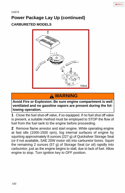
142
CA575
Power Package Lay Up (continued)CARBURETED MODELS
75844
WARNINGAvoid Fire or Explosion: Be sure engine compartment is wellventilated and no gasoline vapors are present during the fol-lowing operation.
1 Close the fuel shut-off valve, if so equipped. If no fuel shut off valveis present, a suitable method must be employed to STOP the flow offuel from the fuel tank to the engine before proceeding.
2 Remove flame arrestor and start engine. While operating engineat fast idle (1000-1500 rpm), fog internal surfaces of engine bysquirting approximately 8 ounces (227 g) of Quicksilver Storage Seal(or if not available, SAE 20W motor oil) into carburetor bores. Squirtthe remaining 2 ounces (57 g) of Storage Seal (or oil) rapidly intocarburetor, just as the engine begins to stall, due to lack of fuel. Allowengine to stop. Turn ignition key to OFF position.
143
CA576
Power Package Lay Up (continued)EFI MODELS WITH COOL FUEL SYSTEM
WARNINGAvoid Fire or Explosion: Be sure engine compartment is wellventilated and no gasoline vapors are present during the fol-lowing operation.
WARNINGAvoid Fire or Explosion: Fuel injection system is pressurizedduring operation. Use care when removing water separatingfuel filter. Fuel could spray on hot engine causing fire or explo-sion. Allow engine to cool down before attempting to removethe water separating fuel filter in the following procedure.Also, hold a clean shop towel over the water separating fuelfilter when removing it, to help avoid fuel spraying on the en-gine.
1 Close the fuel shut-off valve, if so equipped. If no fuel shut off valveis present, a suitable method must be employed to STOP the flow offuel from the fuel tank to the engine before proceeding.
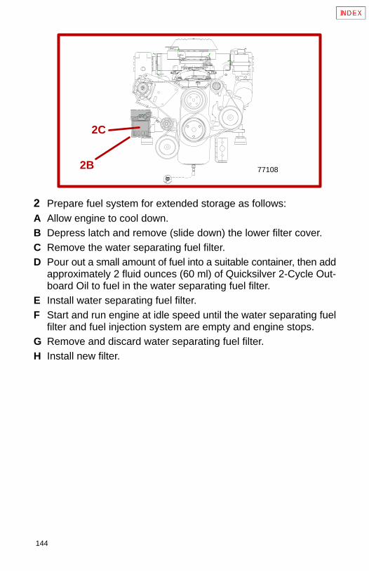
144
2C
2B 77108
2 Prepare fuel system for extended storage as follows:A Allow engine to cool down.B Depress latch and remove (slide down) the lower filter cover.C Remove the water separating fuel filter.D Pour out a small amount of fuel into a suitable container, then add
approximately 2 fluid ounces (60 ml) of Quicksilver 2-Cycle Out-board Oil to fuel in the water separating fuel filter.
E Install water separating fuel filter.F Start and run engine at idle speed until the water separating fuel
filter and fuel injection system are empty and engine stops.G Remove and discard water separating fuel filter.H Install new filter.
145
CA798
Draining
CA853
Seawater (Raw-Water) Cooled ModelsNOTE: This procedure will not work with 3.0L Single Point DrainSystem. See specific instructions later in this manual.
CAUTIONIf boat is to remain in water after draining, seawater inlet hosemust be removed and plugged to prevent a siphoning actionthat may occur, allowing seawater to flow from the drain holesor removed hoses.
IMPORTANT: Boat must be as level as possible to ensurecomplete draining of cooling system.
CAUTIONSeawater section of cooling system MUST BE COMPLETELYdrained for winter storage, or immediately after cold weatheruse, if the possibility of freezing temperatures exists. Failureto comply may result in trapped water causing freeze and/orcorrosion damage to engine. Damage caused by freezing ISNOT covered by the Mercury MerCruiser Limited Warranty.
1 Ensure engine is as level as possible to ensure complete drainingof cooling system.
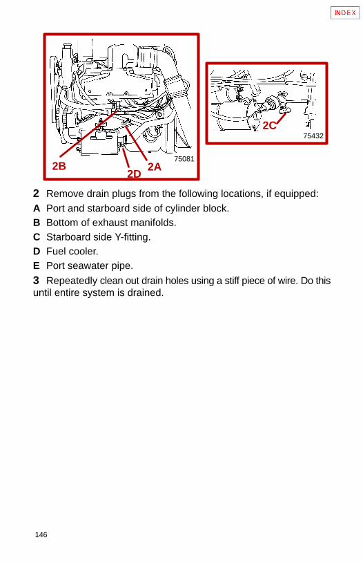
146
2C75432
750812A
2D2B
2 Remove drain plugs from the following locations, if equipped:A Port and starboard side of cylinder block.B Bottom of exhaust manifolds.C Starboard side Y-fitting.D Fuel cooler.E Port seawater pipe.
3 Repeatedly clean out drain holes using a stiff piece of wire. Do thisuntil entire system is drained.
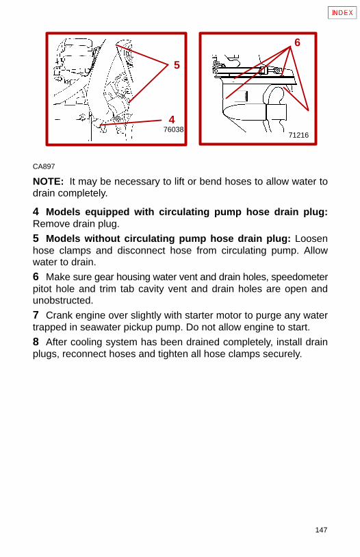
147
76038
5
6
71216
4
CA897
NOTE: It may be necessary to lift or bend hoses to allow water todrain completely.
4 Models equipped with circulating pump hose drain plug:Remove drain plug.
5 Models without circulating pump hose drain plug: Loosenhose clamps and disconnect hose from circulating pump. Allowwater to drain.
6 Make sure gear housing water vent and drain holes, speedometerpitot hole and trim tab cavity vent and drain holes are open andunobstructed.
7 Crank engine over slightly with starter motor to purge any watertrapped in seawater pickup pump. Do not allow engine to start.
8 After cooling system has been drained completely, install drainplugs, reconnect hoses and tighten all hose clamps securely.
148
IMPORTANT: Mercury MerCruiser recommends that propyleneglycol (a nontoxic and environmentally safe) antifreeze be usedin the seawater section of the cooling system for cold weatheror extended storage. Make sure that the propylene glycolantifreeze contains a rust inhibitor and is recommended for usein marine engines. Be certain to follow the propylene glycolmanufacturer’s recommendations.
9 For additional assurance against freezing and rust, fill the coolingsystem with a mixture of antifreeze and tap water mixed tomanufacturer’s recommendation to protect engine to the lowesttemperature to which it will be exposed during cold weather orextended storage.
A Remove thermostat housing or hose and fill with coolant untilblock and head are full. If thermostat housing was removed, re-install and tighten cover bolts securely.
B Remove water hose from exhaust manifold and fill manifoldwith coolant. Reinstall hose and tighten clamp securely.
Store boat with drive unit in full DOWN/IN position.
149
CA898
Closed Cooled (Coolant) ModelsThe following information outlines the procedures for draining theseawater section of the closed cooling systems.
IMPORTANT: Drain seawater section of closed cooling systemonly.
CAUTIONIf boat is to remain in water after draining, seawater inlet hosemust be removed and plugged to prevent a siphoning actionthat may occur allowing seawater to flow from the drain holesor removed hoses.
IMPORTANT: Boat must be as level as possible to ensurecomplete draining of cooling system.
CAUTIONSeawater section of cooling system MUST BE COMPLETELYdrained for winter storage or immediately after cold weatheruse if the possibility of freezing temperatures exist. Failure tocomply may result in trapped water causing freeze and/or cor-rosion damage to engine. Damage caused by freezing IS NOTcovered by the Mercury MerCruiser Limited Warranty.
IMPORTANT: Closed cooling section must be kept filledyear-round with recommended coolant. If engine will beexposed to freezing temperatures, make sure closed coolingsection is filled with an ethylene glycol antifreeze and watersolution properly mixed to protect engine to lowesttemperature to which it will be exposed. Quicksilver PremixedMarine Engine Coolant is already mixed.
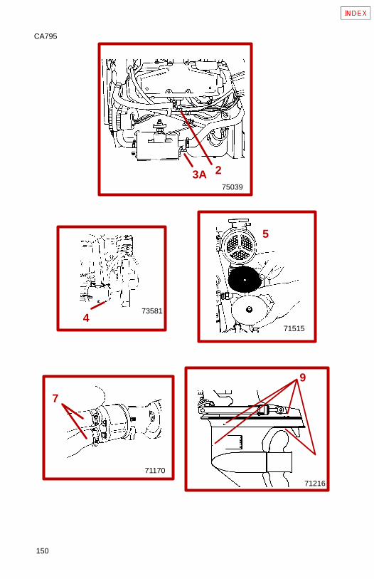
9
71216
735814
75039
3A 2
71515
5
71170
7
150
CA795
151
CA796
IMPORTANT: Do not use Propylene Glycol Antifreeze in theclosed cooling section of the engine.
1 Ensure engine is as level as possible to ensure complete drainingof cooling system.
2 Remove drain plug(s) from bottom of exhaust manifold(s).
3 Remove drain plug from A or B, depending on model:
A Fuel cooler.B Port seawater pipe.
4 3.0L: Remove aft (rear) drain plug from heat exchanger.
5 All Other Models: Remove end caps, sealing washers andgaskets from heat exchangers.
6 Repeatedly clean out drain holes using a stiff piece of wire. Do thisuntil entire system is drained.
7 On models with seawater pickup pump, loosen clamps andremove both hoses.
8 Crank engine over slightly with starter motor to purge any watertrapped in seawater pickup pump. DO NOT allow engine to start.
9 Make sure gear housing water vent and drain holes, speedometerpitot hole and trim tab cavity vent and drain holes are open andunobstructed.
10After seawater section of cooling system has been drainedcompletely, reinstall all components. Reconnect all hoses andtighten hose clamps securely.
Store boat with drive unit in full DOWN/IN position.
152
CA797
76242
2A
2B
762433B
3A
762444A
762447A
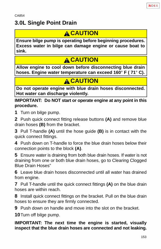
153
CA854
3.0L Single Point Drain
CAUTIONEnsure bilge pump is operating before beginning procedures.Excess water in bilge can damage engine or cause boat tosink.
CAUTIONAllow engine to cool down before disconnecting blue drainhoses. Engine water temperature can exceed 160° F ( 71° C).
CAUTIONDo not operate engine with blue drain hoses disconnected.Hot water can discharge violently.
IMPORTANT: Do NOT start or operate engine at any point in thisprocedure.
1 Turn on bilge pump.
2 Push quick connect fitting release buttons (A) and remove bluedrain hoses (B) from the bracket.
3 Pull T-handle (A) until the hose guide (B) is in contact with thequick connect fittings.
4 Push down on T-handle to force the blue drain hoses below theirconnection points to the block (A).5 Ensure water is draining from both blue drain hoses. If water is notdraining from one or both blue drain hoses, go to Clearing CloggedBlue Drain Hoses”
6 Leave blue drain hoses disconnected until all water has drainedfrom engine.
7 Pull T-handle until the quick connect fittings (A) on the blue drainhoses are within reach.
8 Install quick connect fittings on the bracket. Pull on the blue drainhoses to ensure they are firmly connected.
9 Push down on handle and move into the slot on the bracket.
10Turn off bilge pump.
IMPORTANT: The next time the engine is started, visuallyinspect that the blue drain hoses are connected and not leaking.
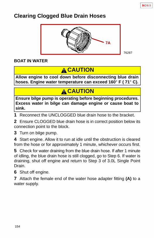
154
Clearing Clogged Blue Drain Hoses
76287
7A
BOAT IN WATER
CAUTIONAllow engine to cool down before disconnecting blue drainhoses. Engine water temperature can exceed 160° F ( 71° C).
CAUTIONEnsure bilge pump is operating before beginning procedures.Excess water in bilge can damage engine or cause boat tosink.
1 Reconnect the UNCLOGGED blue drain hose to the bracket.
2 Ensure CLOGGED blue drain hose is in correct position below itsconnection point to the block.
3 Turn on bilge pump.
4 Start engine. Allow it to run at idle until the obstruction is clearedfrom the hose or for approximately 1 minute, whichever occurs first.
5 Check for water draining from the blue drain hose. If after 1 minuteof idling, the blue drain hose is still clogged, go to Step 6. If water isdraining, shut off engine and return to Step 3 of 3.0L Single PointDrain.
6 Shut off engine.
7 Attach the female end of the water hose adapter fitting (A) to awater supply.
155
8 Attach the CLOGGED blue drain hose to the male end on thewater hose adapter fitting.
9 Fully open the water supply and allow it to run for 1 minute.
10Turn off the water supply.
11 Disconnect the water hose adapter from the blue drain hose andthe water hose.
12Push down on T-handle to force the blue drain hoses down belowtheir connection points to the block.
13Check for water draining from the blue drain hose. If blue drainhose is still clogged, shut off the bilge pump and reattach the bluedrain hoses following Steps 7 - 9 in 3.0L Single Point Drain. The unitwill need to be serviced by an authorized Mercury MerCruiser dealer.If water is draining, return to Step 4 of 3.0L Single Point Drain.
BOAT OUT OF WATER
Engine Not Running1 Attach the water hose adapter fitting to a water supply.
2 Attach the clogged blue drain hose to the male end on the waterhose adapter fitting.
3 Turn on bilge pump.
4 Fully open the water supply and allow it to run for 1 minute.
5 Turn off the water supply.
6 Disconnect the water hose adapter from the blue drain hose andthe water hose.
7 Check for water draining from the blue drain hose. If water isdraining, return to Step 3 of 3.0L Single Point Drain. If water is notdraining, go to Boat Out of Water - Engine Running. If you cannotperform the engine running procedure, the unit will need to beserviced by an authorized Mercury MerCruiser dealer.
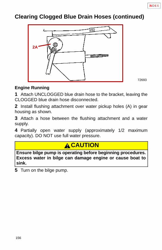
156
Clearing Clogged Blue Drain Hoses (continued)
72693
2A
Engine Running1 Attach UNCLOGGED blue drain hose to the bracket, leaving theCLOGGED blue drain hose disconnected.
2 Install flushing attachment over water pickup holes (A) in gearhousing as shown.
3 Attach a hose between the flushing attachment and a watersupply.
4 Partially open water supply (approximately 1/2 maximumcapacity). DO NOT use full water pressure.
CAUTIONEnsure bilge pump is operating before beginning procedures.Excess water in bilge can damage engine or cause boat tosink.
5 Turn on the bilge pump.
157
CAUTIONDo not run engine above 1300 rpm. Suction created byseawater pickup pump may collapse water supply hose,causing engine to overheat.
WARNINGBe certain the area around propeller is clear and no one isstanding nearby. To avoid possible injury, remove propeller.
CAUTIONWatch temperature gauge on dash to ensure that engine doesnot overheat.
6 Start engine. Allow it to run at idle until the obstruction is clearedfrom the hose or for approximately 1 minute, whichever occurs first.
7 Shut off engine.
8 Shut off water supply to flushing attachment. Remove hose andflushing attachment.
9 Check for water draining from the blue drain hose. If blue drainhose is still clogged, shut off the bilge pump and reattach the bluedrain hoses following Steps 7 - 9 in 3.0L Single Point Drain. The unitwill need to be serviced by an authorized Mercury MerCruiser dealer.If water is draining, return to Step 3 of 3.0L Single Point Drain.
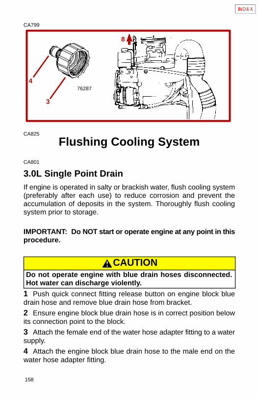
158
CA799
762874
3
8
CA825
Flushing Cooling System
CA801
3.0L Single Point DrainIf engine is operated in salty or brackish water, flush cooling system(preferably after each use) to reduce corrosion and prevent theaccumulation of deposits in the system. Thoroughly flush coolingsystem prior to storage.
IMPORTANT: Do NOT start or operate engine at any point in thisprocedure.
CAUTIONDo not operate engine with blue drain hoses disconnected.Hot water can discharge violently.
1 Push quick connect fitting release button on engine block bluedrain hose and remove blue drain hose from bracket.
2 Ensure engine block blue drain hose is in correct position belowits connection point to the block.
3 Attach the female end of the water hose adapter fitting to a watersupply.
4 Attach the engine block blue drain hose to the male end on thewater hose adapter fitting.

159
5 Fully open the water supply and allow it to run for 10 minutes.
6 Turn off the water supply.
7 Disconnect the water hose adapter from the blue drain hose andthe water hose.
8 Pull T-handle until the quick connect fittings on the blue drainhoses are within reach.
9 Install quick connect fittings on the bracket. Pull on the hoses toensure they are firmly connected.
10Push down on handle and move into the slot on the bracket.
IMPORTANT: The next time the engine is started, visuallyinspect that the blue drain hoses are connected and not leaking.
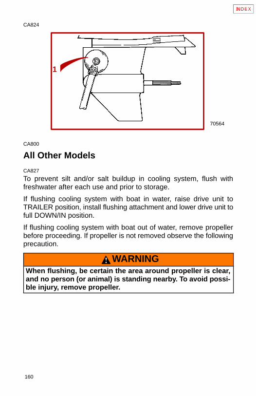
160
CA824
1
70564
CA800
All Other Models
CA827
To prevent silt and/or salt buildup in cooling system, flush withfreshwater after each use and prior to storage.
If flushing cooling system with boat in water, raise drive unit toTRAILER position, install flushing attachment and lower drive unit tofull DOWN/IN position.
If flushing cooling system with boat out of water, remove propellerbefore proceeding. If propeller is not removed observe the followingprecaution.
WARNINGWhen flushing, be certain the area around propeller is clear,and no person (or animal) is standing nearby. To avoid possi-ble injury, remove propeller.
161
1 Install Quicksilver flushing attachment (or equivalent) over waterintake openings in gear housing.
2 Connect hose between flushing attachment and water sourcevalve.
3 With drive unit in normal operating position, partially open watersource valve (about 1/2 maximum).
4 Place drive in NEUTRAL, idle speed position and start engine.
CAUTIONAvoid possible engine damage.
• Do NOT run engine continuously at idle rpm.
• Do NOT run engine above 1500 rpm.
5 Slowly advance throttle until engine reaches 1300 rpm(+/–100 rpm).
CAUTIONWatch temperature gauge on dash to ensure that engine doesnot overheat.
6 Operate engine with drive in NEUTRAL, for about 10 minutes oruntil discharge water is clear.
7 Slowly return throttle to idle speed position.
8 Stop engine
9 Shut off water and remove flushing attachment.
CA115
Battery Winter StorageFollow battery manufacturer’s instructions for storage.
162
CA116
Power Package Recommissioning
WARNINGTo prevent possible injury or damage to equipment, do not in-stall battery until all maintenance has been performed on en-gine.
1 Check that all cooling system hoses are connected properly andhose clamps are tight.
CAUTIONWhen installing battery, be sure to connect NEGATIVE (–) bat-tery cable to NEGATIVE (–) battery terminal and POSITIVE (+)battery cable to POSITIVE (+) battery terminal. If battery cablesare reversed, electrical system damage will result.
2 Install fully-charged battery. Clean battery cable clamps andterminals and reconnect cables (see CAUTION listed above).Tighten each cable clamp securely when connecting.
3 Coat terminal connections with a battery terminal anti-corrosionagent.
163
4 Perform all checks in Operation Chart in the BEFORE STARTINGcolumn.
CAUTIONRefer to FLUSHING COOLING SYSTEM before starting en-gine.
5 Start engine and closely observe instrumentation to make surethat all systems are functioning correctly.
6 Carefully inspect engine for fuel, oil, fluid, water and exhaustleaks.
7 Check steering system, shift and throttle control for properoperation.
8 Check fuel pump sight tube (if so equipped) for evidence of fuel(indicating a ruptured fuel pump diaphragm).
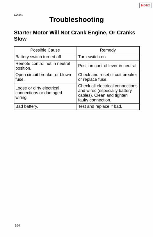
164
CA442
Troubleshooting
Starter Motor Will Not Crank Engine, Or CranksSlow
Possible Cause Remedy
Battery switch turned off. Turn switch on.
Remote control not in neutralposition.
Position control lever in neutral.
Open circuit breaker or blownfuse.
Check and reset circuit breakeror replace fuse.
Loose or dirty electricalconnections or damagedwiring.
Check all electrical connectionsand wires (especially batterycables). Clean and tightenfaulty connection.
Bad battery. Test and replace if bad.
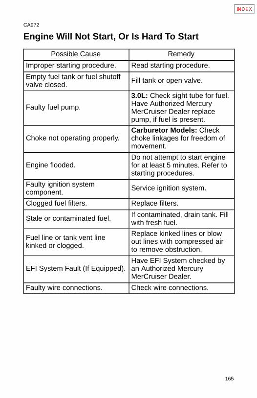
165
CA972
Engine Will Not Start, Or Is Hard To Start
Possible Cause Remedy
Improper starting procedure. Read starting procedure.
Empty fuel tank or fuel shutoffvalve closed.
Fill tank or open valve.
Faulty fuel pump.
3.0L: Check sight tube for fuel.Have Authorized MercuryMerCruiser Dealer replacepump, if fuel is present.
Choke not operating properly.Carburetor Models: Checkchoke linkages for freedom ofmovement.
Engine flooded.Do not attempt to start enginefor at least 5 minutes. Refer tostarting procedures.
Faulty ignition systemcomponent.
Service ignition system.
Clogged fuel filters. Replace filters.
Stale or contaminated fuel. If contaminated, drain tank. Fillwith fresh fuel.
Fuel line or tank vent linekinked or clogged.
Replace kinked lines or blowout lines with compressed airto remove obstruction.
EFI System Fault (If Equipped).Have EFI System checked byan Authorized MercuryMerCruiser Dealer.
Faulty wire connections. Check wire connections.
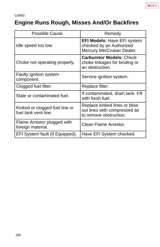
166
CA900
Engine Runs Rough, Misses And/Or Backfires
Possible Cause Remedy
Idle speed too low.EFI Models: Have EFI systemchecked by an AuthorizedMercury MerCruiser Dealer.
Choke not operating properly.Carburetor Models: Checkchoke linkages for binding oran obstruction.
Faulty ignition systemcomponent.
Service ignition system.
Clogged fuel filter. Replace filter.
Stale or contaminated fuel. If contaminated, drain tank. Fillwith fresh fuel.
Kinked or clogged fuel line orfuel tank vent line.
Replace kinked lines or blowout lines with compressed airto remove obstruction.
Flame Arrestor plugged withforeign material.
Clean Flame Arrestor.
EFI System fault (If Equipped). Have EFI System checked.
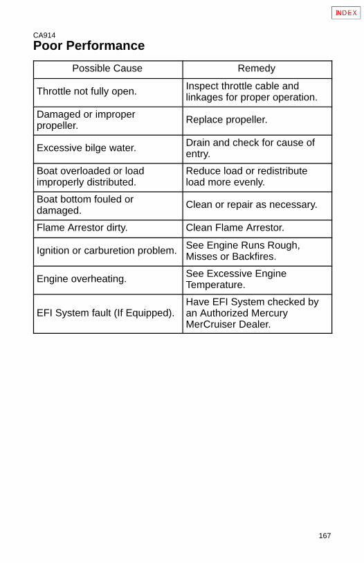
167
CA914
Poor Performance
Possible Cause Remedy
Throttle not fully open. Inspect throttle cable andlinkages for proper operation.
Damaged or improperpropeller.
Replace propeller.
Excessive bilge water. Drain and check for cause ofentry.
Boat overloaded or loadimproperly distributed.
Reduce load or redistributeload more evenly.
Boat bottom fouled ordamaged.
Clean or repair as necessary.
Flame Arrestor dirty. Clean Flame Arrestor.
Ignition or carburetion problem. See Engine Runs Rough,Misses or Backfires.
Engine overheating. See Excessive EngineTemperature.
EFI System fault (If Equipped).Have EFI System checked byan Authorized MercuryMerCruiser Dealer.
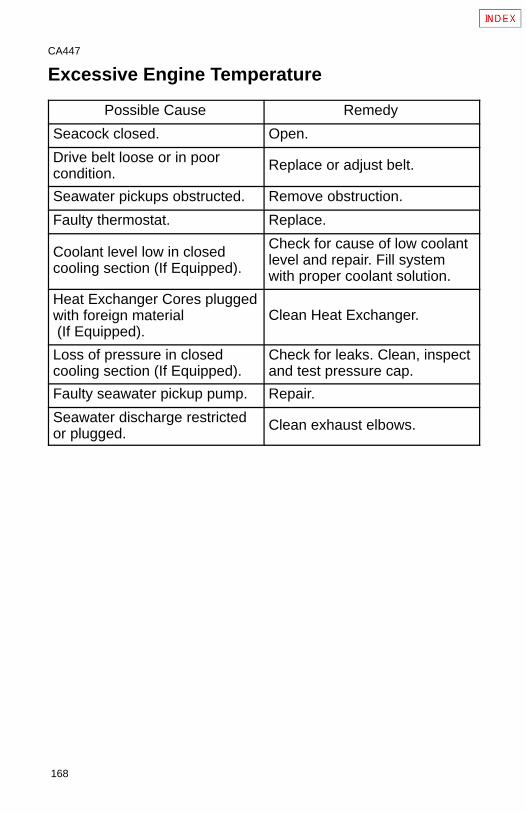
168
CA447
Excessive Engine Temperature
Possible Cause Remedy
Seacock closed. Open.
Drive belt loose or in poorcondition.
Replace or adjust belt.
Seawater pickups obstructed. Remove obstruction.
Faulty thermostat. Replace.
Coolant level low in closedcooling section (If Equipped).
Check for cause of low coolantlevel and repair. Fill systemwith proper coolant solution.
Heat Exchanger Cores pluggedwith foreign material (If Equipped).
Clean Heat Exchanger.
Loss of pressure in closedcooling section (If Equipped).
Check for leaks. Clean, inspectand test pressure cap.
Faulty seawater pickup pump. Repair.
Seawater discharge restrictedor plugged.
Clean exhaust elbows.
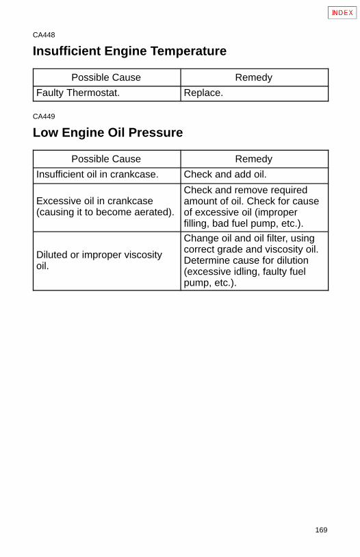
169
CA448
Insufficient Engine Temperature
Possible Cause Remedy
Faulty Thermostat. Replace.
CA449
Low Engine Oil Pressure
Possible Cause Remedy
Insufficient oil in crankcase. Check and add oil.
Excessive oil in crankcase(causing it to become aerated).
Check and remove requiredamount of oil. Check for causeof excessive oil (improperfilling, bad fuel pump, etc.).
Diluted or improper viscosityoil.
Change oil and oil filter, usingcorrect grade and viscosity oil.Determine cause for dilution(excessive idling, faulty fuelpump, etc.).
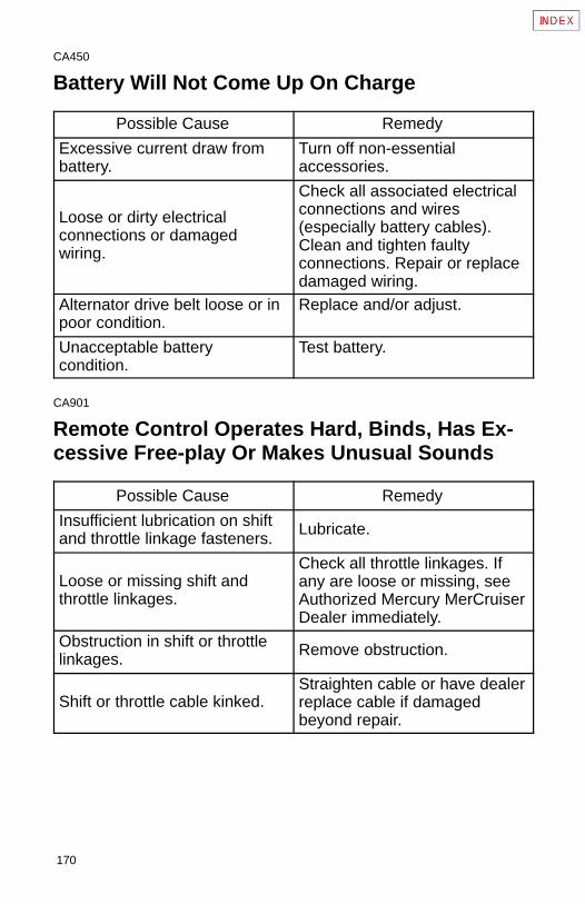
170
CA450
Battery Will Not Come Up On Charge
Possible Cause Remedy
Excessive current draw frombattery.
Turn off non-essentialaccessories.
Loose or dirty electricalconnections or damagedwiring.
Check all associated electricalconnections and wires(especially battery cables).Clean and tighten faultyconnections. Repair or replacedamaged wiring.
Alternator drive belt loose or inpoor condition.
Replace and/or adjust.
Unacceptable batterycondition.
Test battery.
CA901
Remote Control Operates Hard, Binds, Has Ex-cessive Free-play Or Makes Unusual Sounds
Possible Cause Remedy
Insufficient lubrication on shiftand throttle linkage fasteners.
Lubricate.
Loose or missing shift andthrottle linkages.
Check all throttle linkages. Ifany are loose or missing, seeAuthorized Mercury MerCruiserDealer immediately.
Obstruction in shift or throttlelinkages.
Remove obstruction.
Shift or throttle cable kinked.Straighten cable or have dealerreplace cable if damagedbeyond repair.
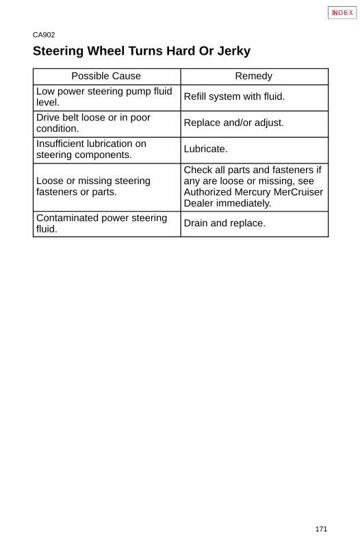
171
CA902
Steering Wheel Turns Hard Or Jerky
Possible Cause Remedy
Low power steering pump fluidlevel.
Refill system with fluid.
Drive belt loose or in poorcondition.
Replace and/or adjust.
Insufficient lubrication onsteering components.
Lubricate.
Loose or missing steeringfasteners or parts.
Check all parts and fasteners ifany are loose or missing, seeAuthorized Mercury MerCruiserDealer immediately.
Contaminated power steeringfluid.
Drain and replace.
172
CA453
Power Trim Does Not Operate(Motor Doesn’t Run)
Possible Cause Remedy
Blown fuse. Replace fuse.
Loose or dirty electricalconnections or damagedwiring.
Check all associated electricalconnections and wires(especially battery cables).Clean and tighten faultyconnection. Repair or replacewiring.
CA454
Power Trim Does Not Operate (Motor Runs ButDrive Unit Does Not Move)
Possible Cause Remedy
Trim pump oil level low. Fill pump with oil.
Drive unit binding in gimbalring.
Check for obstruction.
173
CA903
Owner Service Assistance
Local Repair ServiceAlways return your Mercury MerCruiser powered boat to your localAuthorized Dealer, should the need for service arise. Only he has thefactory trained mechanics, knowledge, special tools and equipmentand the genuine Quicksilver parts and accessories* to properlyservice your engine should the need occur. He knows your enginebest.
* Quicksilver parts and accessories are engineered and built byMercury Marine, specifically for Mercury MerCruiser sterndrivesand inboards.
Service Away From HomeIf you are away from your local dealer and the need arises for service,contact the nearest Authorized Dealer. Refer to the Yellow Pages ofthe telephone directory. If, for any reason, you cannot obtain service,contact the nearest Regional Service Center. Outside the UnitedStates and Canada, contact the nearest Marine Power InternationalService Center.
Parts And Accessories InquiriesAll inquiries concerning Quicksilver replacement parts andaccessories should be directed to your local Authorized Dealer. Thedealer has the necessary information to order parts and accessoriesfor you should he not have them in stock. Only Authorized Dealerscan purchase genuine Quicksilver parts and accessories from thefactory. Mercury Marine does not sell to unauthorized dealers orretail customers. When inquiring on parts and accessories, thedealer requires the motor model and serial number(s) to order thecorrect parts.
EXTRA HELP
174
CA904
Resolving A ProblemSatisfaction with your Mercury MerCruiser product is very importantto your dealer and to us. If you ever have a problem, question orconcern about your power package, contact your dealer or anyAuthorized Mercury MerCruiser Dealership. If additional assistanceis required, take these steps.
1 Talk with the dealership’s sales manageror service manager. If this has already beendone, then contact the owner of thedealership.
2 Should you have a question, concern orproblem that cannot be resolved by yourdealership, please contact Mercury MarineService Office for assistance. Mercury Marinewill work with you and your dealership toresolve all problems.
The following information will be neededby the service office:
• Your name and address
• Daytime telephone number
• Model and serial numbers for your power package
• The name and address of your dealership
• Nature of problem
Mercury Marine Service Offices are listed on the next page.
175
CA915
Mercury Marine Service OfficesFor assistance, call, fax, or write. Please include your daytimetelephone number with mail and fax correspondence.
Telephone FaxMail
United States
(405) 743-6566 (405) 743-6570Mercury MerCruiser3003 N. Perkins Rd.Stillwater, OK 74075
Canada
(905) 567-MERC(6372)
(905) 567-8515Mercury Marine Ltd.2395 Meadowpine Blvd.Mississauga, OntarioCanada L5N 7W6
Australia, Pacific
(61) (3) 791-5822 (61) (3) 793-5880Mercury Marine Australia132-140 Frankston RoadDandenong,Victoria 3164Australia
Europe, Middle East, Africa
(32) (87) 32 • 32 •11
(32) (87) 31 • 19 •65
Marine Power - Europe, Inc.Parc Industriel de Petit-RechainB-4800 VerviersBelgium
Mexico, Central America, South America, Caribbean
(305) 385-9585 (305) 385-5507Mercury Marine - Latin America & Caribbean9010 S.W. 137th Ave.Suite 226Miami, FL 33186 U.S.A.
Japan
81-53-426-2500 81-53-423-2510Mercury Marine - Japan283-1 Anshin-choHamamatsuShizuoka, 435-0005 Japan
Asia, Singapore
5466160 5467789Mercury Marine Singapore72 Loyang WaySingapore 508762
176
CA463
Customer Service Literature
English LanguageEnglish language publications are available from:
Mercury MarineAttn: Publications Department
W6250 West Pioneer RoadP.O. Box 1939
Fond du Lac, WI 54936-1939
Outside the United States and Canada, contact the nearestMercury Marine or Marine Power International Service Centerfor further information.
When ordering be sure to:
1. List your product, model, year and serial number(s).
2. Check the literature and quantities you want.
3. Enclose full remittance in check or money order (NO C.O.D.’s).
CA781
Other LanguagesTo obtain an Operation, Maintenance and Warranty Manual inanother language, contact the nearest Mercury Marine or MarinePower International Service Center for information. A list of partnumbers for other languages is provided with your power package.
caa781
Andre sprogKontakt det nærmeste Mercury Marine eller Marine PowerInternational servicecenter for oplysninger om hvordan du kananskaffe en Betjenings– og vedligeholdelsesmanual på et andetsprog. En liste med reservedelsnumre for andre sprog leveressammen med din power–pakke.
177
cab781
Andere talenVoor het verkrijgen van een Handleiding voor gebruik en onderhoudin andere talen dient u contact op te nemen met het dichtstbijzijndeinternationale servicecentrum van Mercury Marine of Marine Powervoor informatie hierover. Een lijst met onderdeelnummers voorandere talen wordt bij uw motorinstallatie geleverd.
cac781
Muut kieletSaadaksesi Käyttö– ja huolto–ohjekirjoja muilla kielillä, ota yhteyslähimpään Mercury Marine tai Marine Power Internationalhuoltokeskukseen, josta saat lähempiä tietoja. Moottorisi mukanaseuraa monikielinen varaosanumeroluettelo.
cad781
Autres languesPour obtenir un Manuel d’utilisation et d’entretien dans une autrelangue, contactez le centre de service après–vente internationalMercury Marine ou Marine Power le plus proche pour touteinformation. Une liste des numéros de pièces en d’autres languesaccompagne votre bloc–moteur.
cae781
Andere SprachenUm eine Betriebs– und Wartungsanleitung in einer anderen Sprachezu erhalten, wenden Sie sich an das nächste Mercury Marine oderMarine Power International Service Center. Eine Liste mitTeilenummern für Fremdsprachen ist im Lieferumfang Ihres Motorsenthalten.
caf781
Altre linguePer ottenere il manuale di funzionamento e manutenzione in altralingua, contattate il centro assistenza internazionale Mercury Marineo Marine Power più vicino. In dotazione con il gruppo motore, vienefornito l’elenco dei codici prodotto dei componenti venduti all’estero.
178
cag781
Andre språkYtterligere informasjon om bruks– og vedlikeholdshåndbok på andrespråk kan fås ved henvendelse til nærmeste internasjonaleservicecenter for Mercury Marine eller Marine Power. En liste overdelenumre for andre språk følger med aggregatet.
cah781
Outros IdiomasPara obter um Manual de Operação e Manutenção em outro idioma,contate o Centro de Serviço Internacional de “Marine Power”(Potência Marinha) ou a Mercury Marine mais próxima para obterinformações. Uma lista de números de referência para outrosidiomas é fornecida com o seu pacote de propulsão.
caj781
Otros idiomasPara obtener un Manual de operación y mantenimiento en otroidioma, póngase en contacto con el centro de servicio más cercanode Mercury Marine o Marine Power International para recibirinformación. Con su conjunto motriz se entrega una lista de losnúmeros de pieza para los otros idiomas.
cak781
Andra språkFör att få Instruktions– och underhållsböcker på andra språk,kontakta närmaste Mercury Marine eller Marine Power Internationalservicecenter, som kan ge ytterligare information. En förteckningöver artikelnummer på andra språk medföljer ditt kraftpaket.
CAm781
����� ���������� �� �������� ��� ����ρ���� ������ρ���� ��� ����ρ��� ����� ����, ����������� �� �� �������ρ� ������� ����ρ���ρ��� ��� Mercury Marine ��� Marine Power ��� ���ρ� �ρ���. !������� ��"�� �� �����"���� ��# ���� �������� �ρ�������ρ�������� ��� ����� �����.
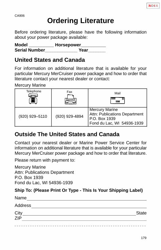
179
CA906
Ordering LiteratureBefore ordering literature, please have the following informationabout your power package available:
Model __________ Horsepower__________Serial Number_____________ Year_______
United States and CanadaFor information on additional literature that is available for yourparticular Mercury MerCruiser power package and how to order thatliterature contact your nearest dealer or contact:Mercury Marine
Telephone Fax Mail
(920) 929–5110 (920) 929-4894
Mercury MarineAttn: Publications DepartmentP.O. Box 1939Fond du Lac, WI 54936-1939
Outside The United States and CanadaContact your nearest dealer or Marine Power Service Center forinformation on additional literature that is available for your particularMercury MerCruiser power package and how to order that literature.
Please return with payment to:
Mercury MarineAttn: Publications DepartmentP.O. Box 1939Fond du Lac, WI 54936-1939
Ship To: (Please Print Or Type - This Is Your Shipping Label)
Name
Address
City StateZIP