Embed Size (px)
Citation preview

PLEASE SCROLL DOWN FOR ARTICLE
This article was downloaded by: [NEICON Consortium]On: 29 October 2009Access details: Access Details: [subscription number 783448439]Publisher Taylor & FrancisInforma Ltd Registered in England and Wales Registered Number: 1072954 Registered office: Mortimer House,37-41 Mortimer Street, London W1T 3JH, UK
Journal of Modern OpticsPublication details, including instructions for authors and subscription information:http://www.informaworld.com/smpp/title~content=t713191304
Generation and selection of laser beams represented by a superposition of twoangular harmonicsS. N. Khonina a; V. V. Kotlyar a; V. A. Soifer a; K. Jefimovs b; J. Turunen b
a Image Processing Systems Institute, Russian Academy of Sciences, Samara, Russia b Department ofPhysics, University of Joensuu, Joensuu, Finland
Online Publication Date: 01 March 2004
To cite this Article Khonina, S. N., Kotlyar, V. V., Soifer, V. A., Jefimovs, K. and Turunen, J.(2004)'Generation and selection of laserbeams represented by a superposition of two angular harmonics',Journal of Modern Optics,51:5,761 — 773
To link to this Article: DOI: 10.1080/09500340408235551
URL: http://dx.doi.org/10.1080/09500340408235551
Full terms and conditions of use: http://www.informaworld.com/terms-and-conditions-of-access.pdf
This article may be used for research, teaching and private study purposes. Any substantial orsystematic reproduction, re-distribution, re-selling, loan or sub-licensing, systematic supply ordistribution in any form to anyone is expressly forbidden.
The publisher does not give any warranty express or implied or make any representation that the contentswill be complete or accurate or up to date. The accuracy of any instructions, formulae and drug dosesshould be independently verified with primary sources. The publisher shall not be liable for any loss,actions, claims, proceedings, demand or costs or damages whatsoever or howsoever caused arising directlyor indirectly in connection with or arising out of the use of this material.

J0URN.AI. OF R.IOI)ERN OPTICS, 20 MARCH 2004 VOL. 51, NO. 5 , 761-773
+ Taylor ti Francis 0 Taylor h Francis Croup
Generation and selection of laser beams represented by a superposition of two angular harmonics
S. N. K H O N I N A t , V. V. KOTLYART, V. A. SOIFER? , K. JEFIMOVSS" and J. T U R U N E N T t Image Processing Systems Institute, Russian Academy of Sciences, 151 Molodogvardejskaya, Samara 443001, Russia $Department of Physics, University of Joensuu, P.O. Box 11 1, FIN-801 01 Joensuu, Finland
(Received 21 July ZOO,?; revised version 7 Nooember 2003)
Abstract. T h e properties of fields generated by diffractive phase-only optical elements that generate combinations of two angular harmonic fields with different harmonic indices in Fraunhofer and Fresnel regions are investigated theoretically and experimentally. Camomile shaped diffraction patterns are predicted and observed. I t is shown that multi-order diffractive phase elements can be used to both generate these beams and to identify the weights of different angular harmonics in a given incident laser beam.
1. Introduction Diffractive optical elements (DOES) are well known to be capable of sophis-
ticated wavefront transformations. In [ l , 21 the diffraction of a laser beam by a phase helical filter of transmittance T(cp) = exp(icp), where cp is the azimuth angle in the light field cross-section, is considered. For the first time, in [3] this D O E type was considered with reference to the optical implementation of the first-order Hankel transform.
In this paper, we discuss the diffraction of the Gaussian and plane laser beam by a phase DOE whose transmittance function T(cp) is given by a superposition of two angular harmonics:
uhe re n and m are integers. In [4-91 the interference pattern produced by two Gauss-Laguerre modes
( G L ) with different azimuth angles is considered. If the GL modes were propagated at an angle to each other [5] the interference pattern was in the form of a several-prong fork. If , however, two GL modes, with one of them being possibly a plain Gaussian beam, are propagated coaxially the interference pattern is in the form of radial spokes outgoing from the common centre o r m-start spiral fringes [4, 6-91.
These types of interference pattern are required for analysis of the helical phase of the light field [4, 5, 91, for studying wavefront singularities dynamics [6], for
"Author for correspondence; e-mail: kjefimov(urcc.joensuu.fi
Downloaded By: [NEICON Consortium] At: 12:22 29 October 2009

762 S. N . Khonina et al.
microparticle manipulation (microparticle controlled rotation) [7], and for demonstration of Doppler’s rotation effect [8].
The interference patterns of two angular harmonics (1) and two GL modes [4, 6-91 have much in common, but there are differences. In this paper, the interference pattern produced by two angular harmonics, equation ( l ) , is produced using a DOE. Because of this, the curvature of the two wavefronts is strictly the same. As a result, the interference pattern, or putting it more exactly, the diffraction pattern of the Gaussian beam by a DOE with transmission (1) has the form of radial spokes. Because the intensity in the centre is zero, the spokes look much like camomile petals (figure 2). In references [4, 6-91 two interfering beams have somewhat different radii, and because of this the spokes outgoing from the same centre are no longer radial.
There is another distinction. With increasing difference between the numbers of the two harmonics, the overlap area is decreased. As a result, the camomile petals in the diffraction pattern become curtailed (figure 2). This effect does not occur if the interference is between two identical GL modes [4, 6-81 or the GL mode interferes with a coaxial plane wave [9].
In [lo] a relationship for the normalized orbital angular momentum of a light field is derived by decomposing the field complex amplitude in terms of angular harmonics:
where
11=-00
is the light field complex amplitude, r is the radial distance from the origin, w = 2 m is the angular frequency of the monochromatic light, and JoJ is the projection on the propagation axis z of the orbital angular momentum vector. Integral expressions for the orbital and spin angular momentums of light field are derived in [l 1 , 121.
Applying equation (2) to the light field defined in equation (1) yields
- d o z = n + m. Note that I, is equal to the area of the DOE or the fragment of the illuminating plane wave passing through its aperture.
In [13, 141, the DOES were used to experimentally measure the orbital angular momentum for multi-mode GL and Bessel beams. The issue of measuring the orbital angular momentum (OAM) of an individual photon was discussed in recent papers [15, 161. In [15] the OAM of individual photons was measured using two identical amplitude filters (in the form of a grating with dislocation) with an efficiency of 18%). With these filters, it turned out to be possible to determine OAM with orbital number m =0, f l , f 2 .
( 5 )
Downloaded By: [NEICON Consortium] At: 12:22 29 October 2009
Laser beams represented by a superposition of two angular harmonics 763
In [16] a multi-stage scheme is proposed for measuring the OAM of individual photons. Every stage presents a Mach-Zender interferometer, with Dove prisms found in both arms and rotated relative to each other by some angle. For the AOM of an individual photon to be determined uniquely a hologram is placed in one arm of the interferometer.
Measuring the OAM of individual photons is critical for super-dense infor- mation encoding and for purposes of quantum calculations [16]. A photon with a definite integral value m of the orbital angular momentum is treated in the above-mentioned problems as a separate channel of information transmission.
The angular harmonics in equation (1) describe a wavefront singularity, for in passing around the origin of the polar coordinates ( r , q ) the phase of the light field acquires a delay of 2x72, where n is the angular harmonic number. The angular harmonics can be generated not only by the phase-modulating DOEs but also by the amplitude-modulating DOEs [ 171 and amplitude diffraction gratings with dislocations [18, 191.
In this paper, we derive formulae describing Fresnel and Fraunhofer diffraction of the Gaussian beam by a phase DOE of transmittance equal to a single arbitrary- order angular harmonic. Besides, it is shown that the far-field/Fourier-plane intensity distribution in the diffraction pattern of the Gaussian/plane beam by the DOE that generates a superposition of two angular harmonics has a characteristic 'camomile-shaped' modulation in the azimuth angle.
The results of experiments on generation and selection of the laser beams being a superposition of two angular harmonics with different numbers are also discussed. Such light fields are generated using a 20-order binary-phase DOE. Every angular harmonic found in these beams is selected using a 24-order binary- phase DOE. Experimental and estimated patterns are in good agreement. T h e techniques to design multi-order DOEs are described in [20], and the technology for fabricating binary-phase DOEs used in this work is discussed in [lo].
2.
exp(-r2/w2), where w is the waist radius, by a phase DOE of transmittance
Diffraction of the Gaussian beam by a helical phase filter Consider the Fraunhofer diffraction of the Gaussian beam of amplitude
In this case, the light complex amplitude in the Fourier plane of a spherical lens of focal length f is given b y the Fourier integral:
ik f" exp( - $) exp(inq) exp r p cos(q - 0) r dr dq, (7) 1 E d p , 0) = - - 2Tf 0 0
where k=27s/EL is the light wavenumber, while (r,cp) and ( p , 0 ) are the polar coordinates in the DOE plane and in the lens focal plane, respectively. Equation (7) reduces to the nth order Hankel transform:
Downloaded By: [NEICON Consortium] At: 12:22 29 October 2009

764 S. N . Khonina et al.
where ill 2n
J , (x ) = 275 lo exp(-ix cos t + int)dt (9)
and J l l ( x ) is the Bessel function of the nth order and first kind. The integral in equation (8) can be calculated using the reference expression
[21]:
where I , (x) is a modified Bessel function of nth order, related to the Bessel function of the first kind by the formula
I , , (x) = (-i)”J,l(ix). (11)
In view of equation (lo), we have instead of (8):
where wo= 2flkw is the waist radius of the Gaussian beam in the Fourier plane.
describes the Gaussian beam Note that with n = 0 (i.e. there is no DOE) the right-hand side of equation (12)
since
Considering equation (12), the light field intensity in the Fourier plane for the DOE transmittance of equation (1) takes the form
I,,,I(P, 6 ) = IE?t(P, 8) + ~ m ( P , @ I 2 (1 5)
where
From equation (15), it is seen that the light intensity distribution of the Gaussian beam diffracted by the DOE of transmittance defined by the sum of two angular harmonics features a characteristic ‘camomile-shaped’ modulation in the angle 8, with the number of the camomile petals being equal to In-mi.
From comparison of equation (1 5) and the relationship for the beam intensity immediately behind the DOE
Downloaded By: [NEICON Consortium] At: 12:22 29 October 2009

Laser beams represented by a superposition of two angular harmonics 765
the ‘camomile-petal’ pattern is seen to be rotated with respect to the ‘camomile’ in the Fourier plane by nj2.
In the Fresnel diffraction zone, the Gaussian beam complex amplitude having passed through the phase DOE of transmittance equal to the angular harmonic function will take the form similar to that in equation (12). Actually, applying the Fresnel transform instead of the Fourier transform to equation (8) we obtain:
exp (ikz) exp (in0) exp E,f(P, 0, z ) = ~
(18)
(-i)”+’ k
x 1; exp( - 2) exp( i & r2)J,](; r p ) r dr ,
z
where z is the distance from the D O E to the observation plane. Instead of equation (12) we now get:
where
kw2 R&)= 22 1+, ,and zo =-. ( I:) 2
I t follows directly from equation (19) that the diffraction of a Gaussian beam by the phase D O E of the transmittance defined by the angular harmonic function originates a laser beam that preserves its structure in the course of propagation, being a free space mode u p to a scale.
I t can be demonstrated that the intensity distribution pattern in the Fourier plane, equation (15) will not change if the D O E defined in equation (1) is illuminated by a plane circular beam of radius R instead of the Gaussian beam. Actually, for the plane beam we get instead of equation (8):
Using the reference relationships [21], equation (20) can be rewritten as follows:
where x = ((kR)/( f ) ) p is a dimensionless radial variable.
Downloaded By: [NEICON Consortium] At: 12:22 29 October 2009
766 S. N . Khonina et al.
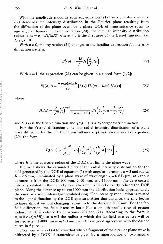
With the amplitude modulus squared, equation (21) has a circular structure and describes the intensity distribution in the Fourier plane resulting from the diffraction of the plane beam by a phase DOE of transmittance equal to one angular harmonic. From equation (20), the circular intensity distribution radius is po = ((ylJ)/(kR)) where yln is the first zero of the Bessel function, i.e.
With n = 0, the expression (21) changes to the familiar expression for the Airy J n ( Y l n ) = 0.
diffraction pattern:
With n = 1, the expression (21) can be given in a closed form [ l , 21:
where
and H,(x) is the Struve function and 1F2(. . .) is a hypergeometric function. For the Fresnel diffraction zone, the radial intensity distribution of a plane
wave diffracted by the DOE of transmittance exp(inv) takes instead of equation (20), the form
where R is the aperture radius of the DOE that limits the plane wave. Figure 1 shows the estimated plots of the radial intensity distribution for the
field generated by the DOE of equation (6) with angular harmonic n = 2 and radius R = 2.5 mm, illuminated by a plane wave of wavelength 1 = 0.633 pm, at various distances z from the DOE: 100 mm, 2000 mm, and 15000 mm. The zero central intensity related to the helical phase character is found directly behind the DOE plane. Along the distance up to z = 1000 mm the distribution looks approximately the same as a wide intensity-modulated ring. The intensity modulation is related to the light diffraction by the DOE aperture. After that distance, the ring begins to taper almost without changing radius up to the distance 5000mm. For the far- field diffraction, the field intensity looks like a smooth-profile ring of greater radius, which is defined by equations (20) and (21). According to the formula po = ((yl,z)/(kR)), at n = 2 the radius at which the far-field ring centre will be formed at z = 15000 mm is po 3 mm, which is in good agreement with the dashed curve in figure 1.
From equation (21) it follows that when a fragment of the circular plane wave is diffracted by a DOE of transmittance given by a superposition of two angular
Downloaded By: [NEICON Consortium] At: 12:22 29 October 2009

Laser beams represented by a superposition of two angular harmonics 767
harmonics, equation (1 ), the intensity distribution of the diffraction pattern in the Fourier plane will be similar to that in equation (1 5):
C&? 0) = IEH(P, 0) + ~ H h J , @ ) I 2
where
It follows from equation ( 2 7 ) that a 'camomile-shaped' diffraction pattern will be formed in the Fourier plane, with In-ml 'petals'. This conclusion has been confirmed experimentally (see figure 3).
3. Experiment Figure 2 shows an experimental setup for generating and selecting laser beams
resulting from the diffraction of a fragment of the circular plane wave by a phase DOE of transmittance given by the sum of two angular harmonics, equation (1).
In figure 2 , the Gaussian beam from a He-Ne laser 1 of power 2 m W and wavelength 0.6328 pm is expanded by a collimator 2 . A circular diaphragm 3 cuts
I
1.0 - z=100mm z=2000 mm z=15000 mm
- - - - - - - - ................
2.5 6.0
Figure 1 . Radial intensity distribution of the field produced by helical D O E of equation (6) with angular harmonic n = 2 and radius R = 2.5 mm, illuminated by a plane wave of i. = 0.633 pm, at various distances z from the D O E plane.
Figure 2. Optical setup for phase-DOE-aided generation and selection of laser beams, a superposition of angular harmonics: 1 - He-Ne laser, 2 - collimator, 3 - diaphragm to extract a plane circular-section beam, 4 - 20-order DOE1 to form beams represented by a superposition of two angular harmonics, 5 - diaphragm extracting one beam under analysis, 6 - 24-order DOE2 to select the angular harmonics, 7 - spherical lens, 8 - CCD-camera, and 9 - computer.
Downloaded By: [NEICON Consortium] At: 12:22 29 October 2009

768 S. N . Khonina et al.
Figure 3. (a) T h e binary phase of the 20-order DOE to generate a beam composed of the sum of two angular harmonics with the numbers ( n ) + ( m ) ranging from f l to f 5 ; (b ) the chart of the orders’ arrangement; some Fraunhoffer-zone orders resulting from the plane wave diffraction by the DOE; ( c ) the estimated and (6) experimental patterns.
a central part of the laser beam about 5 mm in diameter. After the diaphragm 3, the beam approximating a plane circular wave illuminates a phase optical element 4 (DOEl) that forms 20 diffraction orders propagated at different angles to the optical axis. Each diffraction order is the sum of two angular harmonics with the numbers n and m taking the values n,m = f l , f2,. . . , f 5 .
Figure 3(a) shows a binary phase of DOEl : black is zero phase, white means a phase shift of 17 radians. This DOE was fabricated using electron beam lithography and reactive ion etching using the procedure already described in reference [lo]. The size of DOEl is 5 x 5 mm2, the number of 5 x 5 pm2 pixels is 1000 x 1000, the binary relief depth being 690nm. For the He-Ne laser and a SiO2 substrate, the optimal depth was 692.5 nm.
Figure 3(b) depicts the diffraction orders generated by DOEl in the Fourier plane. Each diffraction order is a Fourier image of the sum of two angular
Downloaded By: [NEICON Consortium] At: 12:22 29 October 2009

Laser beams represented by a superposition of two angular harmonics
5.39 nun
769
- *
(0) (b ) ( c ) (4 Figure 4. Experimentally measured cross-section intensity distributions for the beams
composed of the sum of two angular harmonics with the numbers (n)+(m): ( a ) (l)+(-2), ( h ) ( l )+( -3) , ( c ) (2)+(-3), and (d) (2)+(-4) at the distance z = 1200mm mm from the DOEl.
harmonics with the numbers ( n ) + ( m ) . Figure 3(r ) shows the calculated and 3(d) the experimental diffraction patterns that occur if the lens 7 and CCD-camera 8 are placed immediately behind the DOEl 4.
From figure 3(c) and 3 ( 4 it is seen that, first, the experiment is in good agreement with the calculation, and, second, the Fraunhofer diffraction pattern for every single beam is indeed ‘camomile-shaped’, with the number of ‘petals’ being equal to the modulus of the difference in the numbers of the two angular harmonics. T h e intensity distribution in figure 3 ( c ) is described by the formula (24). Note that the form of cross-section intensity distribution for each beam shown in figure 3( r ) and 3(d) was not preserved over the entire distance of the beam propagation. However, it is already in the Fresnel zone that the ‘petal-shaped’ intensity in the beam cross-section is formed.
Figure 4 depicts experimentally recorded cross-section intensity distributions for four beams at a distance of z = 1200 mm from the D O E l . Each beam is a sum of two angular harmonics numbered: n = 1, m = - 2 (figure 4 ( a ) ) , n = 1, m = -3 (figure 4(h)), n = 2, m = -3 (figure 4(c)), and n = 2 , m = -4 (figure 4 ( 4 ) . From figure 4 it is seen that all the beams feature ‘petal-shaped’ intensity structures, the number of petals being equal to the modulus of the difference in the numbers of angular harmonics. However, an additional intensity modulation caused by the diffraction of the plane wave by the edges of diaphragm 3 can be seen (figure 2).
T o optically identify the numbers of the angular harmonics found in laser beams, a 24-order binary-phase DOE2 of size 10 x 10mm2 with 1000 x 1000 pixels each of size 10 x 10 pm2 and a binary relief depth of 695 nm was designed and fabricated. Figure 5(a) shows the binary phase of this D O E (black - zero phase, white - phase IT radians). Figure 5 ( b ) depicts the location and the numbers of the 24 diffraction orders generated by this DOE, the number being equal to the number of the matching angular harmonic. When the DOE2 is illuminated b y a fragment of the circular plane beam 24 diffraction rings defined by equation (1 9) are generated in the Fourier plane. T h e rings are shown in figure 5 ( c ) (calculation) and figure 5(d) (experiment). From figure 5 ( c ) and 5(d) it is seen that the
Downloaded By: [NEICON Consortium] At: 12:22 29 October 2009

770 S. N . Khonina et al.
Figure 5 . (a) Binary phase of the 24-order DOE matched to the angular harmonics with the numbers n ranging from f l to f 1 2 ; ( b ) chart of the orders’ arrangement; (c) estimated and (6) experimental patterns of Fraunhoffer diffraction of plane wave by DOE.
Downloaded By: [NEICON Consortium] At: 12:22 29 October 2009

Laser beams represented by a superposition of two angular harmonics 771
Figure 6. Result of experiment to identify numbers of angular harmonics found in DOEl-produced laser beams (figure 2(a)), (n)+(m): ( a ) (-1)+(3), ( b ) (-2)+(6), (c) (4)+(-5), (4 (-1)+(2).
Fraunhofer diffraction of the plane wave by the DOE of transmission function defined by the angular harmonic produces a ring whose radius is proportional to the modulus of the angular harmonic number.
The difference between figure 5(d) and 5(c) is that there is a zero order in figure 5(d), which is caused by a larger-than-DOE illuminating beam cross-section. As a rule, the optical system alignment errors significantly distort the central order. I t is from these considerations that the central order was not used in designing the optical elements.
The DOE2 was used for angular harmonic selection in the following way. In the optical system in figure 2(a) diaphragm 5 that passes only one of the laser beams is placed at a distance of z = 1200 mm behind the DOE 4, where the diffraction orders are spatially separated. A second DOE 6 (figure 5(a)) is placed behind the diaphragm 5 and forms 24 diffraction orders in the rear focal plane of
Downloaded By: [NEICON Consortium] At: 12:22 29 October 2009

772 S. N . Khonina et al.
a spherical lens 7 of focus f= 200mm (see figure 5(d)). This pattern is recorded using a CCD-camera 8 connected to the computer 9.
Figure 6 shows some results of the experiment on identifying the numbers of the angular harmonics in the laser beams generated by the DOE1 (figure 3(n)). In figure 6 the diffraction orders with local central intensity maxima proportional to the energy weight of the angular beam harmonic are encircled. At the same time, the exact intensity zero is found at the centres of the other orders. It is seen that the angular harmonics with the numbers -1 and 3 are found in figure 6(a), -2 and 6 in figure 6(b), 4 and -5 in figure 6(c), and -1 and 2 in figure 6 ( 4 .
This optical system can be used to measure with an acceptable accuracy (of up to l0”h) the orbital angular momentum of various beams, as was done in [13, 141. Note, however, that in [13, 141 a DOE matching only to nine angular harmonics was used, while in this paper we demonstrate the efficient operation of a 24-order DOE to identify the angular harmonics with the numbers ranging from f l to f 1 2 .
4. Conclusions In this paper, the following main results have been described: Analytical expressions for the Fraunhofer and Fresnel diffraction patterns for
the Gaussian and plane light beams diffracted by a phase DOE whose transmit- tance is given by the angular harmonic with an arbitrary number n have been derived (formulae (12), (19), and (21)).
Analytical expressions for the Fraunhofer diffraction intensity distribution of the Gaussian and plane beams by a phase DOE with transmittance given by the sum of two angular harmonics have been derived (formulae (15) and (26)). The diffraction pattern is shown to be a ‘camomile-shaped’, with the number of ‘petals’ being equal to the modulus of the difference of the angular harmonic numbers.
A 20-order binary-phase DOE to generate laser beams of wavelength 0.633 pm given by a superposition of two angular harmonics with the numbers ranging from f l to f 5 has been designed and fabricated (figure 3).
A 24-order binary-phase DOE to generate laser beams of wavelength 0.633 pm with a single angular harmonic with numbers ranging from f l to zt12 has been designed and fabricated (figure 5 ) .
I t has been demonstrated that the 24-order DOE matched to the angular harmonics allows the identification of these harmonics in laser beams of wave- length 0.633pm (figure 6) and can be used for measuring the orbital angular momentum of the light fields.
Acknowledgements The work was financially supported by the C R D F (grant REC-SA-014-02)
and the presidential grants of Russian Federation MD-209.2003.01 and NS- 1007.2003.1.
References [ l ] KHONINA, S. N., KCYI’LYAR, V. V., SOIFER, V. A., SHINKARYEV, M. V . , and
USPLENIEV, G. V., 1992, Opt. Commun., 91(3-4), 158.
Downloaded By: [NEICON Consortium] At: 12:22 29 October 2009

Laser beams represented by a superposition of two angular harmonics 773
[2] KHONINA, S. N., KOTLYAR, V. V., SHINKARYEV, M. V., SOIFER, V. A., and
[3] BEREZNY, A. E., PROKHOROV, A. M., SISAKIAN, I. N., and SOIFER, V. A., 1984, Sov.
r41 HARRIS, M., HILL, C. A., and VAUGHAN, J. M., 1994, Opt. Commun., 106(4-6), 161.
USPLENIEV, G. V., 1992, J. Mod. Opt., 39, 1147.
Phys. Dokl., 29, 115.
[5] HARRIS, M., HILL, C. A., TAPSTER, P. R., and VAUGHAN, J. M., 1994, Phys. Rev. A, 49. 3119.
[6] SOSKIN, M. S., GORSHKOV, V. N., and VASNETSOV, M. V., 1997, Phys. Rev. A, 56,
[7] PATERSON, L., MACDONALD, M. P., ARLT, J., SIBBETT, W., BRYANT, P. E., and
[8] BASISTIY, I . V., SLYUSAR, V. V., SOSKIN, M. S., and VASNETSOV, M. V., 2003, Opt.
[9] PADGETT, M., ARLT, J., SIMPSON, N., and ALLEN, L., 1996, Am. J. Phys., 64(1), 77. [lo] KHONINA, S. N., KOTLYAR, V. V., SOIFER, V. A., PAAKKONEN, P., SIMONEN, J., and
[ l l ] ALLEN, L., BEIJERSBERGEN, M. W., SPREEUW, R. J. C., and WOERDMAN, J. P., 1992,
[12] ALLEN, L., PADGETT, M. G., and BABIKER, M., 1999, Progr. Opt., 39, 291. [13] KHONINA, S. N., KOTLYAR, V. V., SOIFER, V. A,, PAAKKONEN, P., and TURUNEN, J.,
[14] KOTLYAR, V. V., KHONINA, S. N., SOIFER, V. A., and WANG, Y., 2002, Autometriya,
[15] MAIR, A., VAZIRI, A,, WEIHS, G., and ZEILINGER, A., 2001, Nature, 412, 313. [16] LEACH, J., PADGETT, M. J., BARNETT, S. M., FRANKE-ARNOLD, S., and COURTIAL, J.,
[17] HECKENBERG, N. R., McDu, R., SMITH, C. P., and WHITE, A. G., 1992, Opt. Lett.,
4064.
DHOLAKIA, K., 2001, Science, 292, 912.
Lett., 28, 1185.
TURUNEN, J., 2001, J . Mod. Opt., 48, 1543.
Phys. Rev. A, 45, 8185.
2001, Opt. Memory Neural Netw., 10(4), 241.
38(3), 33 (in Russian).
2002, Phys. Rev. Lett., 88(25), 257901.
17, 221. [18] BAZHENOV, V. Yu., SOSKIN, M. S., and VASNETSOV, M. V., 1993, J. Mod. Opt., 39,
985. [19] BASISTIY, I . V., BAZHENOV, V. Yu., SOSKIN, M. S., and VASNETSOV, M. V., 1993,
[20] SOIFER, V. A., 2002, Methods for Computer Design of Dzflractive Optical Elements (New
[21] PRUDNIKOV, A. P., BRICHKOV, Y. A,, and MARICHEV, 0. I., 1983, Integrals and Series.
Opt. Commun., 103, 422.
York: John Wiley & Sons).
Special Functions (Moscow: Nauka) (in Russian).
Downloaded By: [NEICON Consortium] At: 12:22 29 October 2009


