Embed Size (px)
Citation preview

International Geosynthetics SocietyIGS Education Committee
Training Course on Geosynthetics8IGG, Yokohama, 2006
Geosynthetics in Drainage and Filtration
Prof. J.P. GourcUniversity of Grenoble, France

1
11
Geosynthetics in Drainage and Filtration
Prof. J.P. GourcUniversity of Grenoble, France
International Geosynthetics SocietyIGS Education Committee
Training Course on Geosynthetics 8IGG, Yokohama, 2006
22
Hydraulic functions of geosynthetics
-1- Separation
-3- Drainage
-2- Filter
Container
2
33
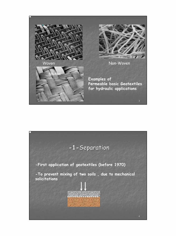
Woven Geotextiles
Woven
Examples ofPermeable basic Geotextilesfor hydraulic applications
Non-Woven
monofilament
Slit-film
Needle-punched
44
--11--SeparationSeparation
-First application of geotextiles (before 1970)
-To prevent mixing of two soils , due to mechanicalsolicitations

3
55
66
RoadsRoadsRailwayRailway
Parking area,…Parking area,…
Applications ofGeosynthetics for Separation

4
77
88Highway embankment

5
99
To avoid such a difficult situation !
1010
geotextiles are used to prevent road base materials from penetrating into soft underlying soft subgrade, thus maintaining design thickness and roadway integrity
geotextile separators also prevent fine-grained subgrade soils from being pumped into permeable, granular road bases
geotextile

6
1111
1212

7
1313
Separation function is nota clearly independant function:
-Solicitation isn’t only mechanicalbut also hydraulic
-Separation function is correlated to reinforcement & filtration functions
1414
Punching of the Soft soil
FillSettlement
Embankment on very soft soilEmbankment on very soft soil
Geosynthetic
(Tensile mobilization)

8
1515
Embankment on soft soil
(Northern Canada)
1616
subsoil
subgrade
ballast
Geotextile
Railway
Geotextile (risk of abrasion)

9
1717
Pollution Pollution ofof thethe ballast layer,ballast layer,due to due to pumpingpumping
ofof fine fine particlesparticles ofof thethe subsoilsubsoil
1818

10
1919
2020
--22--FiltrationFiltration
( Complex phenomenon ! )
-To prevent the instability of soil
subjected to hydrodynamic stresses
-To mobilize a low passive resistance
to water flow in the same time ,

11
2121
Filtration with geosynthetics
Filter Application – Trench Drain
Without filtration(pipe clogging)
2222
Trench with geosynthetic filter

12
2323
French drain
2424
Requirements for an Efficient Filter
• To be permeable enough
• To NOT retain the fines particles (in a first step)
• To Retain the soil

13
2525
Design Criteria for Geosynthetic Filters
. Soil Retention ( to prevent piping)
. Permeability (to insure adequate flow)
. Long Term Effectiveness ( to prevent clogging)
. Survivability-Durability (to prevent damaging during installation)
2626
Filtration function:
Mechanism of retention
To promote equilibrium of particles
after limited washout of finer particles
by inducing a self-filtration zone (bridging)
at the interface (Lafleur,1989).

14
2727
Mechanism of Retention:-Retain largest (upstream)particles first
-Retain by bridging effect finer particles
2828
Filtration Behaviour
Retention of soil but not full clogging!• « Clogging »: the voids of a medium are progressively filled by solid matter to the point that the passage of water is restricted.
• Internal Clogging:- By mineral particles.- By precipitation and chemical deposition in the voids by water containing iron, de-icing salts.- By biological growth encrustation in aerobic conditions.
Both result in a decrease in the hydraulic conductivity.

15
2929
Sample of non-wovenwith partial clogging
3030
Performance test : Long-Term Flow Test(to assess clogging/piping risk)
Outlet
OverFlow
Soil
Geotextile
Constant Head
• Simple
• 10 to 1,000 Hours
• Initial SoilCompaction
• RepresentativeGradient flow

16
3131
Koerner, 1994; Bhatia et al 1990
Flow
Rat
e (V
ol/T
ime)
Log Time (Hrs)1 10 100 1000
A
B
C
B - Piping
A - Stable
C - Clogging
Results from Long-Term Flow Test
3232
Standard test:
Gradient Ratio Test
(ASTM D5101)
Outlet
Soil
Geotextile
Constant Head
• Corps of Engrs
• Benefit = 24 hrs test
• Measure Hydr Heads
• Determine Head Loss
• Calc Gradient Ratio
Manometers
2"
1"
A
B
C
Gradient Ratio =
HeadB - HeadC25 mm
HeadA - HeadB50 mm

17
3333
GR Implications< 1 Piping= 1 Stable > 1 Clogging> 3 Severe Clogging
- Gradient Ratio, GR < 1
- Mass of Piped Particles, Mp < 2500 g/m2
Fannin, et al., (1994):
Gradient Ratio Acceptance Criteria:
3434
Tentative of modelizationof the retention of soil particles through the geosynthetic thickness

18
3535
3636
ConstrictionsConstrictions
Diameter of incribed circlesbetween fibers

19
3737
0
2
1
mm
Soil sideConstrictions dans
une couche unitaire
(3 ensembles de 8 trousde même taille)
Ouvertures de l’empilement de 3 couches unitaires :Tailles minimalesdes constrictions rencontrées le long d’un chemin d’écoulement
couche unitaire
couche unitaire
ModellingModelling ofof a a GeotextileGeotextile as a as a stackstack ofof unit unit layerslayers((FaureFaure--GourcGourc))
Modelization of the retention of soil particlesthrough the geosynthetic thickness
Particle likely to cross the geotextile thickness
3838
Opening Size « O »
Diameter of the biggest particlelikely to cross the geosynthetic

20
3939
One of the standard testsOne of the standard testsfor “Opening Size” measurementfor “Opening Size” measurement
4040
0
10
20
30
40
50
60
70
80
90
100
0.0100.1001.000
Diameter of Opening (mm)
Perc
ent F
iner
Heavy Wt GT
Lite Wt GT
95
O95 O95
Of O95 = Size such as 95% soil mass passes
Opening SizeSoil passing through the geosynthetic

21
4141
Basic Basic RetentionRetention criterioncriterion
( ) ( )soil85 or 95filterf dO ≤
Of opening size of the filter
d85 or 95 representative of the biggest soil particles
4242
40
60
80
100
120
140
160
0 1 2 3 4 5 6
Epaisseur du géotextile (mm)
Ouv
ertu
re d
e fil
trat
ion
max
imum
(µm
) Geotextiles • same structure (n, df)• different thickness
(Faure-Gourc)
Geotextile thickness
Opening size
Variation of « opening size » with non-woven geotextile thickness

22
4343
0
200
400
600
800
0 1 2 3 4
Of/d85
toile de tamis
tissé de bandelettes
non-tissé
Masse de sol passé (g/m2)
σ = 100 kPai = 1
Performance test:Influence of the geosynthetic structure
on the loss of soil mass
Faure, 1988
Outlet
OverFlow
Soil
Geotextile
Constant Head •
•
Loss of soil mass
4444
Normal hydraulic conductivityNormal hydraulic conductivity

23
4545
PERMITTIVITY, Ψ (Cross-Plane Flow)
Darcy’s Law q = kiA
= kn∆h/t A
ψ = kn/t = q/∆h*A
ψ = Permittivity, s-1
ASTM D 4491 Water Permeability of Geotextiles by Permittivity.
qGeotextile
4646
ψallow =ψult
FSCB * FCR * FIN * FCC * FBC
FSCB = soil clogging and blinding (2 to 10)
FCR = creep (1 to 3)
FIN = intrusion (1.0 to 1.2)
FCC = chemical clogging (1.0 to 1.5)
FBC = biological clogging (1 to 10)(for geotextiles, Koerner 1998)

24
4747
Applications of geosynthetics
as FILTERS
4848
Bank protection

25
4949
FilterFilter for for bankbank protectionprotection
5050
Silt fence
Sediments
Geotextile
Sediment-carrying
sheet runoff
Water surface
“Clear” water
Turbid water
Mai
n su
ppor
t pos
ts
Clo
gged
fabr
icFl
ow
H
X
h1
h2
26
5151
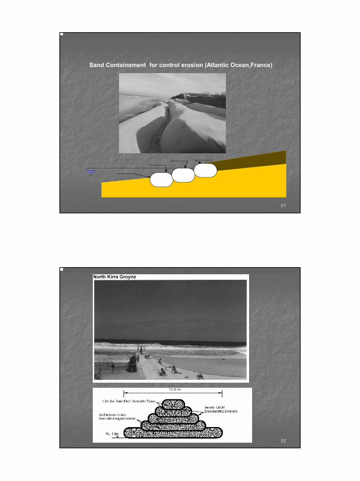
Sand Containement for control erosion (Atlantic Ocean,France)
5252
27
5353
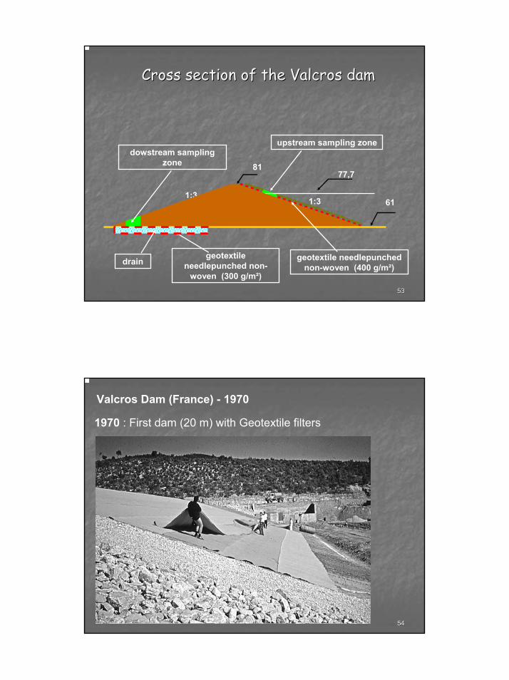
Cross section of the Cross section of the ValcrosValcros damdam
8177,7
611:3
1:3
dowstream sampling zone
upstream sampling zone
draingeotextile
needlepunched non-woven (300 g/m²)
geotextile needlepunchednon-woven (400 g/m²)
5454
Valcros Dam (France) - 1970
1970 : First dam (20 m) with Geotextile filters

28
5555
Dam of Samira (Niger) H : 18 m - 2001
5656
--33--DrainageDrainage
-To transfer water,leachate, gazalong the geosynthetic ( in its thickness)
-Adequate flow capacity under design loads to convey maximum anticipated seepage during design life.-Long-term performance considerations.

29
5757
GEONETS
5858
Geonets can convey liquid and gas within their channels.

30
5959
The drain core of a geocomposite can also be:
GEOMAT CUSPATED SHEET
6060
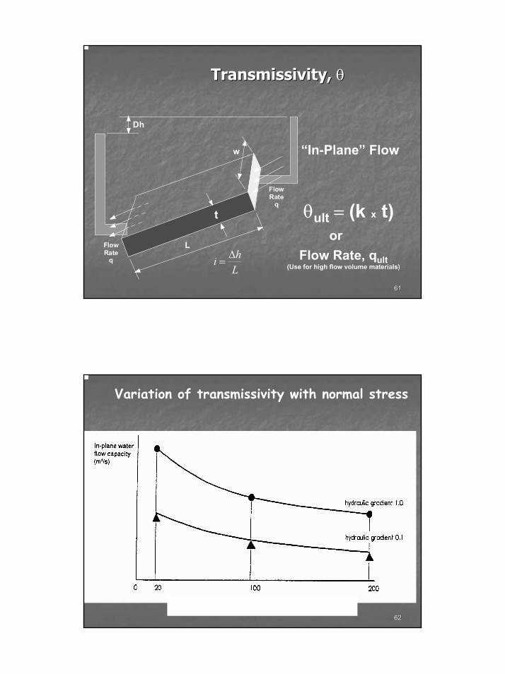
Transmissivity, Ө or Flow Rate, q
31
6161
TransmissivityTransmissivity, , θθ
t
FlowRate
q
FlowRate
q
w
L
Dh
θult = (k x t)
Lhi ∆=
“In-Plane” Flow
Flow Rate, qult(Use for high flow volume materials)
or
6262
Normal compressive stress (kPa)
Variation of transmissivity with normal stress

32
6363
GeonetsGeonets and geotextiles and geotextiles
can be installed separately or can be installed separately or can be combined can be combined
to form a drainage geocomposite.to form a drainage geocomposite.
6464
GEOCOMPOSITE
Geotextile filter
Geonetdrain
33
6565
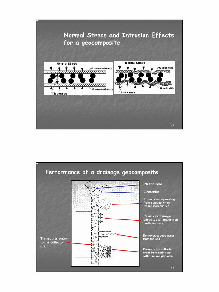
Normal Stress and Intrusion Effects for a geocomposite
Polymeric Ribs
6666
Performance of a drainage geocomposite
Plastic core
Geotextile
Transports waterto the collectordrain
Protects waterproofing from damage when trench is backfilled
Retains its drainage capacity even under high earth pressure
Removes excess water from the soil
Prevents the collectordrain from silting upwith fine soil particles

34
6767
θallow =θult
FCR * FIN * FCC * FBC
FCR = creep (1.0 to 2.5)
FIN = intrusion (1.0 to 2.5)
FCC = chemical clogging (1.0 to 2.0)
FBC = biological clogging (1.0 to 10)(For Drainage Composites, Koerner 1998)
Transmissivity:
6868
Highway edge drain

35
6969
Geocomposite Drain
Filter
Retaining structure
7070
Drainage behind a retaining structure

36
7171
14lWeephole14lWeephole14lWeephole
Filter Application - Wall Drains
7272
FILL(Draining) SETTLEMENT
de
CO
MPR
ESSI
BLE
SOFT
CLA
Y
DRAINING LAYER
H
Vertical Consolidation Drains (wick drains)

37
7373
Typical core structures
for wick drains
7474

38
7575
mini-drain
filter
Non wovenlayer
Distance entre mini- drains
d= 0.25 , 0.50, 1 , 2 m
Specific drainage geocomposite
7676
Drainagebeneath an embankment

39
7777
Fluid transferts in a landfillmany applications for geosynthetics
Gravity flow
Run-off
Waste
Collection of biogaz
Bottom & Slopesliners
RainfallTop cover
Leachate
7878
geopipe
geopipe
Confinement of waste , using mineral / geosynthetic barriers
40
7979
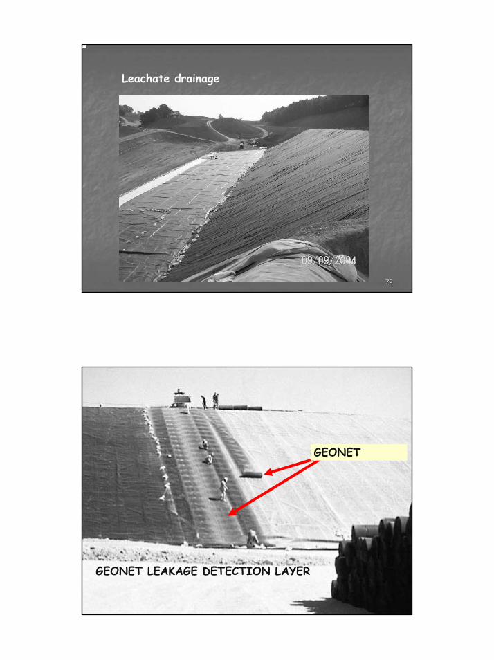
Leachate drainage
8080
GEONET LEAKAGE DETECTION LAYER
GEONET

41
8181
Key Properties for Geosynthetics in Key Properties for Geosynthetics in Drainage and Filtration ApplicationsDrainage and Filtration Applications
TransmissivityTransmissivity, , θθ, in, in--plane permeability, kplane permeability, k
Permittivity, Permittivity, ψψ, cross, cross--plane permeability kplane permeability k⊥⊥
Opening Size Opening Size (AOS or EOS)(AOS or EOS)
Index Tests Index Tests vsvs Performance TestsPerformance Tests
8282
Thank you very much for yout attention.
Enjoy the Yokohama 8th ICG !
A special thank you to my colleaguesfor their documents used for this training course:
J.Bowders,Y.H.Faure,J.P.Giroud,B.Koerner,A.Rollin,…


