Embed Size (px)
Citation preview
Mohammed Z. Al-Faiz et al., International Journal of Emerging Trends in Engineering Research, 3(4), April 2015, 01 - 07
1
ABSTRACT This study proposes a procedure to find a path using an A* algorithm between start and goal locations in the satellite image. In this procedure the buildings in a satellite image are detected depending on roof color, and the search area is divided into a grid depending on the approximate cell decomposition method. The selected path is sent to autonomous robot via Wi-Fi communication as a series of set points for real implementation in an outdoor environment. The mobile robot navigates its way to each point in the path using Global Positioning System (GPS) and digital compass, and 5 sharp IR sensors are used for detecting and avoiding all obstacles in its way. A Proportional-Integral-Derivative (PID) controller is used to make the robot move in a straight line and obtains minimum perturbations to the goal by controlling the speed of each side of the mobile robot motors depending on the digital compass readings. From the obtained results, the path of the mobile robot without PID controller deviated by up to more than 2 meters from the selected path, but when using a PID controller the deviations decreased to less than 1 meter. The mobile robot reached a distance of less than three meters from the final target, an error attributable to GPS accuracy. Key words: Autonomous robot, A* algorithm, GPS, satellite image. 1. INTRODUCTION According to Sandier (1998) [1], A robot device is an instrumented mechanism used in science or industry to take the place of a human being. Mobile robots can move from one place to another. This capability is difficult because many more things can go wrong if the robot is free to move around rather than being bolted to one place.
Autonomous mobile robots must contain everything, including a brain and a power supply (Knudsen, 1999) [4].
Autonomous navigation of a mobile robot involves self-steering of the robot based on computational resources. Oroko and Nyakoe (2012) suggest that there are many ways to approach mobile robot navigation, with path planning and obstacle avoidance [3].
The path planning problem concerns finding the path from the start location to the target location and can be classified mainly into two classes: global and local path planning.
Abbas (2012) [8] points out that in global path planning, the environment surrounding the robot is known and the path which avoids the obstacle is selected, where in local path planning, the environment surrounding the robot is unknown, and sensors are used to detect the obstacles and avoid collision.
The path planning problem has been studied much less for outdoor vehicles than for indoor vehicles. While this may be because outdoor environments are much less cluttered than indoor, it is more likely that the ease of use, and the size and complexity of indoor mobile robots makes them more practical experimental vehicles. Many algorithms can be used to find the best path to the goal, such as depth-first, breadth-first, and heuristic searches such as A* and best-first, according to Giesbrecht(2004) [5].
In many outdoor applications, the robots can determine their coordinates by using the GPS (global positioning system), ideal for this purpose, according to Zogg (2002) [6], as it provides the position information that can enable the robot as well the user to control the robot path.
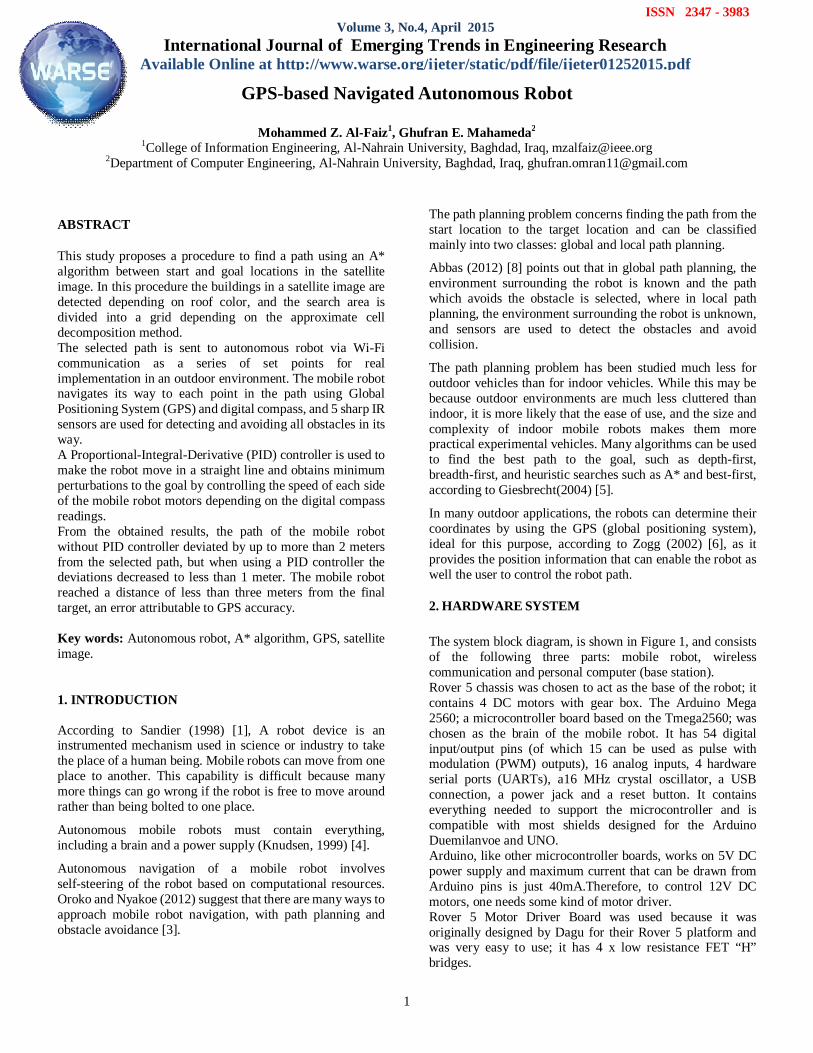
2. HARDWARE SYSTEM The system block diagram, is shown in Figure 1, and consists of the following three parts: mobile robot, wireless communication and personal computer (base station). Rover 5 chassis was chosen to act as the base of the robot; it contains 4 DC motors with gear box. The Arduino Mega 2560; a microcontroller board based on the Tmega2560; was chosen as the brain of the mobile robot. It has 54 digital input/output pins (of which 15 can be used as pulse with modulation (PWM) outputs), 16 analog inputs, 4 hardware serial ports (UARTs), a16 MHz crystal oscillator, a USB connection, a power jack and a reset button. It contains everything needed to support the microcontroller and is compatible with most shields designed for the Arduino Duemilanvoe and UNO. Arduino, like other microcontroller boards, works on 5V DC power supply and maximum current that can be drawn from Arduino pins is just 40mA.Therefore, to control 12V DC motors, one needs some kind of motor driver. Rover 5 Motor Driver Board was used because it was originally designed by Dagu for their Rover 5 platform and was very easy to use; it has 4 x low resistance FET “H” bridges.
GPS-based Navigated Autonomous Robot
Mohammed Z. Al-Faiz1, Ghufran E. Mahameda2
1College of Information Engineering, Al-Nahrain University, Baghdad, Iraq, [email protected] 2Department of Computer Engineering, Al-Nahrain University, Baghdad, Iraq, [email protected]
ISSN 2347 - 3983 Volume 3, No.4, April 2015
International Journal of Emerging Trends in Engineering Research Available Online at http://www.warse.org/ijeter/static/pdf/file/ijeter01252015.pdf
Mohammed Z. Al-Faiz et al., International Journal of Emerging Trends in Engineering Research, 3(4), April 2015, 01 - 07
2
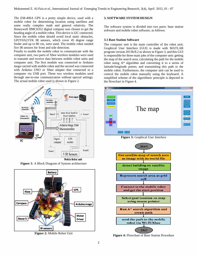
The EM-406A GPS is a pretty simple device, used with a mobile robot for determining location using satellites and some really complex math and general relativity. The Honeywell HMC6352 digital compass was chosen to get the heading angle of a mobile robot. This device is I2C connected. Since the mobile robot should avoid local static obstacles, GP2Y0A21YK IR sensors, which cover 45 degree range finder and up to 80 cm, were used. The mobile robot needed five IR sensors for front and side detection. Finally to enable the mobile robot to communicate with the computer unit, two parts of Xbee wireless modules were used to transmit and receive data between mobile robot units and computer unit. The first module was connected to Arduino mega carried with mobile robot and the second was connected with Arduino UNO or Xbee adapter that connected to a computer via USB port. These two wireless modules used through one-to-one communication without special settings. The actual mobile robot used is shown in Figure 2.
Figure 1: A Block Diagram of System architecture
Figure 2: Mobile Robot Unit
3. SOFTWARE SYSTEM DESIGN The software system is divided into two parts: base station software and mobile robot software, as follows:
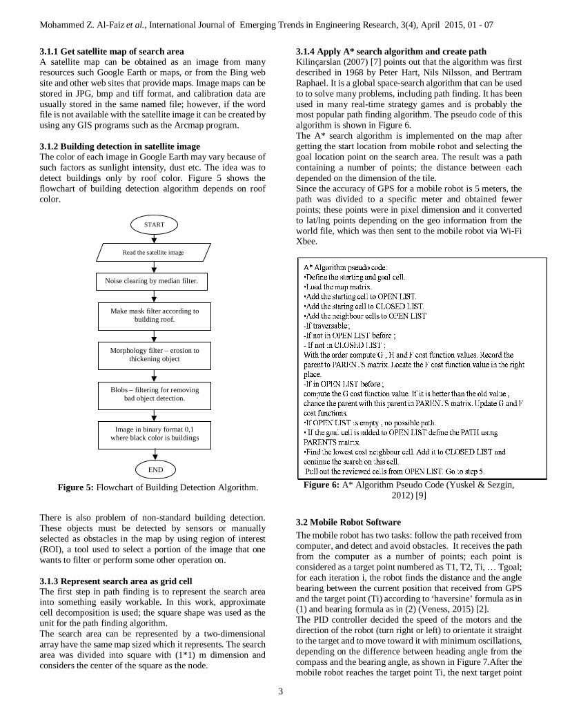
3.1 Base Station Software The computer unit is the main controller of the robot unit; Graphical User Interface (GUI) is made with MATLAB program version 2013b/8.2 as shown in Figure 3, and this GUI is responsible for three main jobs of the computer unit: getting the map of the search area; calculating the path for the mobile robot using A* algorithm and converting it to a series of latitude/longitude points; and transmitting this path to the mobile robot. Furthermore, the computer unit can be used to control the mobile robot manually using the keyboard. A simplified scheme of the algorithmic principle is depicted in the flowchart in Figure 4.
Figure 3: Graphical User Interface
Figure 4: Flowchart of Base Station Procedure
Mohammed Z. Al-Faiz et al., International Journal of Emerging Trends in Engineering Research, 3(4), April 2015, 01 - 07
3
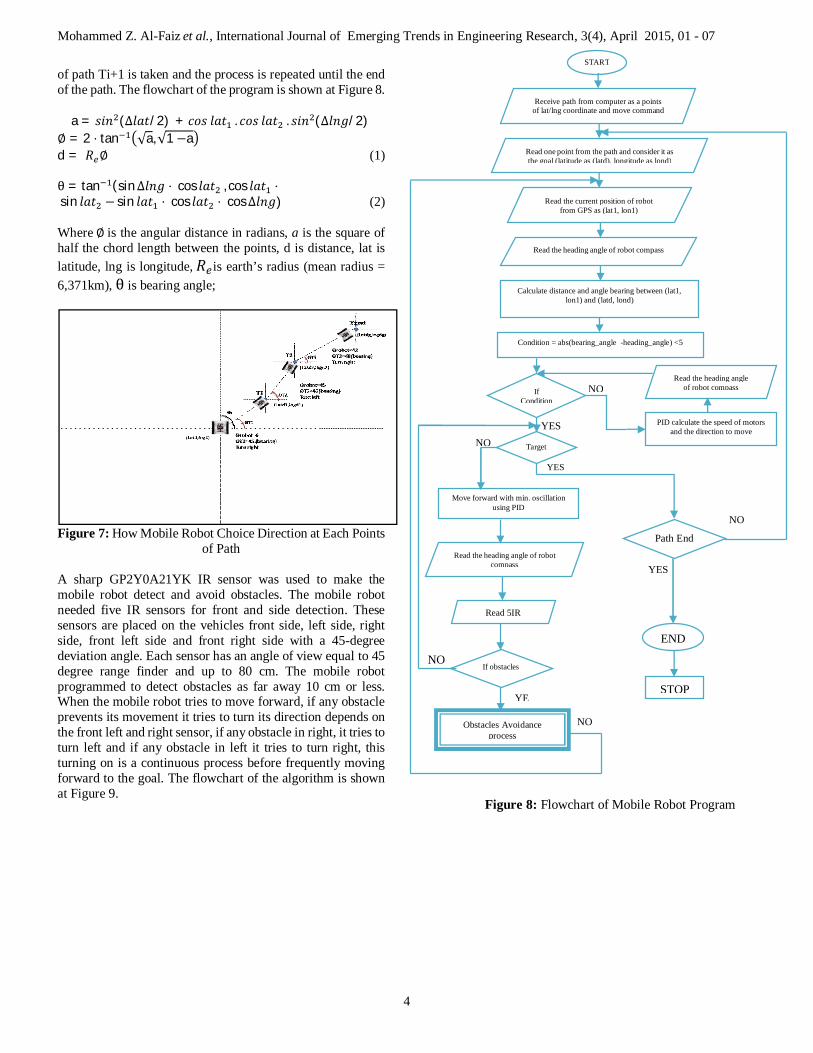
3.1.1 Get satellite map of search area A satellite map can be obtained as an image from many resources such Google Earth or maps, or from the Bing web site and other web sites that provide maps. Image maps can be stored in JPG, bmp and tiff format, and calibration data are usually stored in the same named file; however, if the word file is not available with the satellite image it can be created by using any GIS programs such as the Arcmap program. 3.1.2 Building detection in satellite image The color of each image in Google Earth may vary because of such factors as sunlight intensity, dust etc. The idea was to detect buildings only by roof color. Figure 5 shows the flowchart of building detection algorithm depends on roof color.
There is also problem of non-standard building detection. These objects must be detected by sensors or manually selected as obstacles in the map by using region of interest (ROI), a tool used to select a portion of the image that one wants to filter or perform some other operation on. 3.1.3 Represent search area as grid cell The first step in path finding is to represent the search area into something easily workable. In this work, approximate cell decomposition is used; the square shape was used as the unit for the path finding algorithm. The search area can be represented by a two-dimensional array have the same map sized which it represents. The search area was divided into square with (1*1) m dimension and considers the center of the square as the node.
3.1.4 Apply A* search algorithm and create path Kilinçarslan (2007) [7] points out that the algorithm was first described in 1968 by Peter Hart, Nils Nilsson, and Bertram Raphael. It is a global space-search algorithm that can be used to to solve many problems, including path finding. It has been used in many real-time strategy games and is probably the most popular path finding algorithm. The pseudo code of this algorithm is shown in Figure 6. The A* search algorithm is implemented on the map after getting the start location from mobile robot and selecting the goal location point on the search area. The result was a path containing a number of points; the distance between each depended on the dimension of the tile. Since the accuracy of GPS for a mobile robot is 5 meters, the path was divided to a specific meter and obtained fewer points; these points were in pixel dimension and it converted to lat/lng points depending on the geo information from the world file, which was then sent to the mobile robot via Wi-Fi Xbee.
Figure 6: A* Algorithm Pseudo Code (Yuskel & Sezgin,
2012) [9]
3.2 Mobile Robot Software The mobile robot has two tasks: follow the path received from computer, and detect and avoid obstacles. It receives the path from the computer as a number of points; each point is considered as a target point numbered as T1, T2, Ti, … Tgoal; for each iteration i, the robot finds the distance and the angle bearing between the current position that received from GPS and the target point (Ti) according to ‘haversine’ formula as in (1) and bearing formula as in (2) (Veness, 2015) [2]. The PID controller decided the speed of the motors and the direction of the robot (turn right or left) to orientate it straight to the target and to move toward it with minimum oscillations, depending on the difference between heading angle from the compass and the bearing angle, as shown in Figure 7.After the mobile robot reaches the target point Ti, the next target point
START
Read the satellite image
Noise clearing by median filter.
Make mask filter according to building roof.
Morphology filter – erosion to thickening object
Blobs – filtering for removing bad object detection.
END
Image in binary format 0,1 where black color is buildings
Figure 5: Flowchart of Building Detection Algorithm.
Mohammed Z. Al-Faiz et al., International Journal of Emerging Trends in Engineering Research, 3(4), April 2015, 01 - 07
4
of path Ti+1 is taken and the process is repeated until the end of the path. The flowchart of the program is shown at Figure 8.
a = 푠푖푛 (∆푙푎푡/2) + 푐표푠 푙푎푡 . 푐표푠 푙푎푡 . 푠푖푛 (∆푙푛푔/2) ∅ = 2 ⋅ tan √a,√1−a d = 푅 ∅ (1) θ = tan (sin∆푙푛푔 ⋅ cos 푙푎푡 , cos 푙푎푡 ⋅ sin 푙푎푡 − sin 푙푎푡 ⋅ cos 푙푎푡 ⋅ cos∆푙푛푔) (2) Where ∅ is the angular distance in radians, a is the square of half the chord length between the points, d is distance, lat is latitude, lng is longitude, 푅 is earth’s radius (mean radius = 6,371km), θ is bearing angle;
Figure 7: How Mobile Robot Choice Direction at Each Points
of Path
A sharp GP2Y0A21YK IR sensor was used to make the mobile robot detect and avoid obstacles. The mobile robot needed five IR sensors for front and side detection. These sensors are placed on the vehicles front side, left side, right side, front left side and front right side with a 45-degree deviation angle. Each sensor has an angle of view equal to 45 degree range finder and up to 80 cm. The mobile robot programmed to detect obstacles as far away 10 cm or less. When the mobile robot tries to move forward, if any obstacle prevents its movement it tries to turn its direction depends on the front left and right sensor, if any obstacle in right, it tries to turn left and if any obstacle in left it tries to turn right, this turning on is a continuous process before frequently moving forward to the goal. The flowchart of the algorithm is shown at Figure 9.
Read one point from the path and consider it as the goal (latitude as (latd), longitude as lond)
Figure 8: Flowchart of Mobile Robot Program
Receive path from computer as a points of lat/lng coordinate and move command
START
Read the heading angle of robot compass
YES NO
NO
NO
YES
YE
NO
YES
NO
Read the current position of robot from GPS as (lat1, lon1)
Calculate distance and angle bearing between (lat1, lon1) and (latd, lond)
Condition = abs(bearing_angle -heading_angle) <5
Read the heading angle of robot compass
If obstacles
Move forward with min. oscillation using PID
Read 5IR
Obstacles Avoidance process
Target
Path End
END
If Condition
STOP
PID calculate the speed of motors and the direction to move
Read the heading angle of robot compass
Mohammed Z. Al-Faiz et al., International Journal of Emerging Trends in Engineering Research, 3(4), April 2015, 01 - 07
5
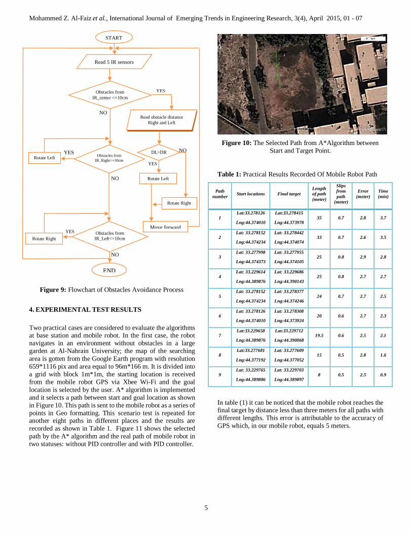
4. EXPERIMENTAL TEST RESULTS Two practical cases are considered to evaluate the algorithms at base station and mobile robot. In the first case, the robot navigates in an environment without obstacles in a large garden at Al-Nahrain University; the map of the searching area is gotten from the Google Earth program with resolution 659*1116 pix and area equal to 96m*166 m. It is divided into a grid with block 1m*1m, the starting location is received from the mobile robot GPS via Xbee Wi-Fi and the goal location is selected by the user. A* algorithm is implemented and it selects a path between start and goal location as shown in Figure 10. This path is sent to the mobile robot as a series of points in Geo formatting. This scenario test is repeated for another eight paths in different places and the results are recorded as shown in Table 1. Figure 11 shows the selected path by the A* algorithm and the real path of mobile robot in two statuses: without PID controller and with PID controller.
Figure 10: The Selected Path from A*Algorithm between
Start and Target Point.
Table 1: Practical Results Recorded Of Mobile Robot Path
Path number Start locations Final target
Length of path (meter)
Slips from path
(meter)
Error (meter)
Time (min)
1 Lat:33.278126
Lng:44.374010
Lat:33.278415
Lng:44.373978 35 0.7 2.8 3.7
2 Lat: 33.278152
Lng:44.374234
Lat: 33.278442
Lng:44.374074 33 0.7 2.6 3.5
3 Lat: 33.277998
Lng:44.374373
Lat: 33.277955
Lng:44.374105 25 0.8 2.9 2.8
4 Lat: 33.229614
Lng:44.389876
Lat: 33.229686
Lng:44.390143 25 0.8 2.7 2.7
5 Lat: 33.278152
Lng:44.374234
Lat: 33.278377
Lng:44.374246 24 0.7 2.7 2.5
6 Lat: 33.278126
Lng:44.374010
Lat: 33.278308
Lng:44.373924 20 0.6 2.7 2.3
7 Lat:33.229658
Lng:44.389876
Lat:33.229712
Lng:44.390068 19.5 0.6 2.5 2.1
8 Lat:33.277681
Lng:44.377192
Lat: 33.277609
Lng:44.377052 15 0.5 2.8 1.6
9 Lat: 33.229765
Lng:44.389886
Lat: 33.229703
Lng:44.389897 8 0.5 2.5 0.9
In table (1) it can be noticed that the mobile robot reaches the final target by distance less than three meters for all paths with different lengths. This error is attributable to the accuracy of GPS which, in our mobile robot, equals 5 meters.
Figure 9: Flowchart of Obstacles Avoidance Process
YES
NO YES
YES
NO
YES
NO
NO
Obstacles from IR_center <=10cm
Rotate Right
Move forward
Read obstacle distance Right and Left
DL>DR
Rotate Left
Obstacles from IR_Right<=10cm Rotate Left
Read 5 IR sensors
START
Rotate Right
END
Obstacles from IR_Left<=10cm
Mohammed Z. Al-Faiz et al., International Journal of Emerging Trends in Engineering Research, 3(4), April 2015, 01 - 07
6
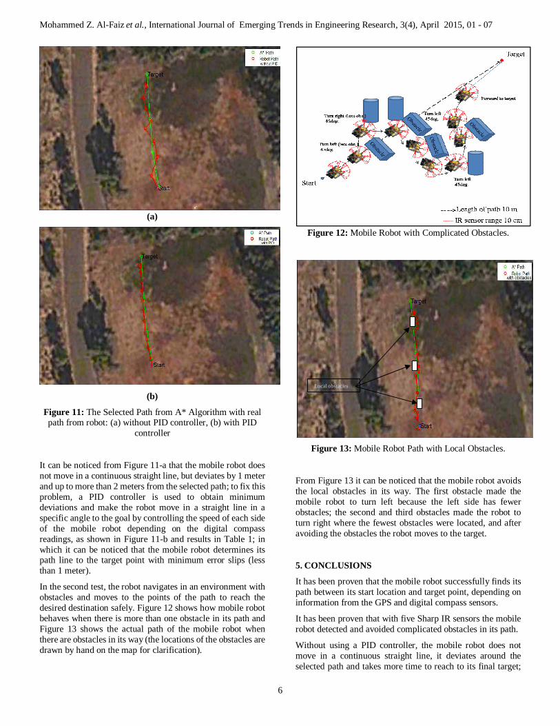
(a)
(b)
Figure 11: The Selected Path from A* Algorithm with real path from robot: (a) without PID controller, (b) with PID
controller
It can be noticed from Figure 11-a that the mobile robot does not move in a continuous straight line, but deviates by 1 meter and up to more than 2 meters from the selected path; to fix this problem, a PID controller is used to obtain minimum deviations and make the robot move in a straight line in a specific angle to the goal by controlling the speed of each side of the mobile robot depending on the digital compass readings, as shown in Figure 11-b and results in Table 1; in which it can be noticed that the mobile robot determines its path line to the target point with minimum error slips (less than 1 meter).
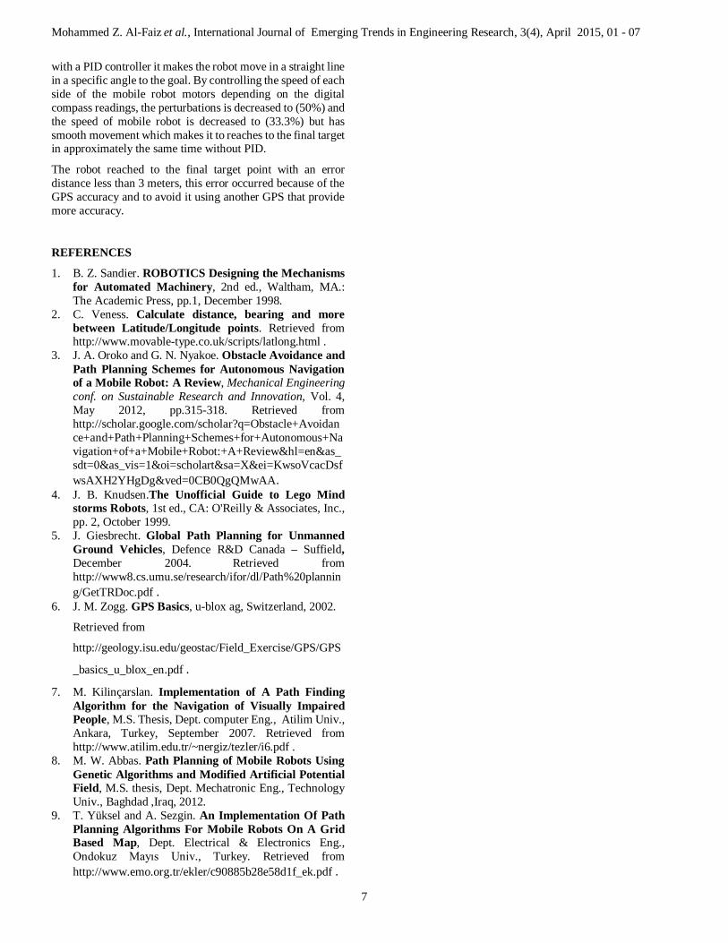
In the second test, the robot navigates in an environment with obstacles and moves to the points of the path to reach the desired destination safely. Figure 12 shows how mobile robot behaves when there is more than one obstacle in its path and Figure 13 shows the actual path of the mobile robot when there are obstacles in its way (the locations of the obstacles are drawn by hand on the map for clarification).
Figure 12: Mobile Robot with Complicated Obstacles.
Figure 13: Mobile Robot Path with Local Obstacles.
From Figure 13 it can be noticed that the mobile robot avoids the local obstacles in its way. The first obstacle made the mobile robot to turn left because the left side has fewer obstacles; the second and third obstacles made the robot to turn right where the fewest obstacles were located, and after avoiding the obstacles the robot moves to the target.
5. CONCLUSIONS
It has been proven that the mobile robot successfully finds its path between its start location and target point, depending on information from the GPS and digital compass sensors.
It has been proven that with five Sharp IR sensors the mobile robot detected and avoided complicated obstacles in its path.
Without using a PID controller, the mobile robot does not move in a continuous straight line, it deviates around the selected path and takes more time to reach to its final target;
Local obstacles
Mohammed Z. Al-Faiz et al., International Journal of Emerging Trends in Engineering Research, 3(4), April 2015, 01 - 07
7
with a PID controller it makes the robot move in a straight line in a specific angle to the goal. By controlling the speed of each side of the mobile robot motors depending on the digital compass readings, the perturbations is decreased to (50%) and the speed of mobile robot is decreased to (33.3%) but has smooth movement which makes it to reaches to the final target in approximately the same time without PID.
The robot reached to the final target point with an error distance less than 3 meters, this error occurred because of the GPS accuracy and to avoid it using another GPS that provide more accuracy.
REFERENCES
1. B. Z. Sandier. ROBOTICS Designing the Mechanisms for Automated Machinery, 2nd ed., Waltham, MA.: The Academic Press, pp.1, December 1998.
2. C. Veness. Calculate distance, bearing and more between Latitude/Longitude points. Retrieved from http://www.movable-type.co.uk/scripts/latlong.html .
3. J. A. Oroko and G. N. Nyakoe. Obstacle Avoidance and Path Planning Schemes for Autonomous Navigation of a Mobile Robot: A Review, Mechanical Engineering conf. on Sustainable Research and Innovation, Vol. 4, May 2012, pp.315-318. Retrieved from http://scholar.google.com/scholar?q=Obstacle+Avoidance+and+Path+Planning+Schemes+for+Autonomous+Navigation+of+a+Mobile+Robot:+A+Review&hl=en&as_sdt=0&as_vis=1&oi=scholart&sa=X&ei=KwsoVcacDsfwsAXH2YHgDg&ved=0CB0QgQMwAA.
4. J. B. Knudsen.The Unofficial Guide to Lego Mind storms Robots, 1st ed., CA: O'Reilly & Associates, Inc., pp. 2, October 1999.
5. J. Giesbrecht. Global Path Planning for Unmanned Ground Vehicles, Defence R&D Canada – Suffield, December 2004. Retrieved from http://www8.cs.umu.se/research/ifor/dl/Path%20planning/GetTRDoc.pdf .
6. J. M. Zogg. GPS Basics, u-blox ag, Switzerland, 2002.
Retrieved from
http://geology.isu.edu/geostac/Field_Exercise/GPS/GPS
_basics_u_blox_en.pdf .
7. M. Kilinçarslan. Implementation of A Path Finding Algorithm for the Navigation of Visually Impaired People, M.S. Thesis, Dept. computer Eng., Atilim Univ., Ankara, Turkey, September 2007. Retrieved from http://www.atilim.edu.tr/~nergiz/tezler/i6.pdf .
8. M. W. Abbas. Path Planning of Mobile Robots Using Genetic Algorithms and Modified Artificial Potential Field, M.S. thesis, Dept. Mechatronic Eng., Technology Univ., Baghdad ,Iraq, 2012.
9. T. Yüksel and A. Sezgin. An Implementation Of Path Planning Algorithms For Mobile Robots On A Grid Based Map, Dept. Electrical & Electronics Eng., Ondokuz Mayıs Univ., Turkey. Retrieved from http://www.emo.org.tr/ekler/c90885b28e58d1f_ek.pdf .


