Embed Size (px)
Citation preview
1DtqldtoppmtRdasnpobdswwsa
spzs
1564 J. Opt. Soc. Am. B/Vol. 24, No. 7 /July 2007 Stivala et al.
Guided-wave frequency doubling in surfaceperiodically poled lithium niobate:
competing effects
S. Stivala,1,2 A. Pasquazi,1 L. Colace,1 G. Assanto,1,* A. C. Busacca,2 M. Cherchi,2 S. Riva-Sanseverino,2,3
A. C. Cino,3 and A. Parisi3
1Department of Electronic Engineering, and Nonlinear Optics and OptoElectronics Laboratory (NooEL),Consorzio Nazionale Italiano di Struttura della Materia (CNISM), Istituto Nazionale di Fisica Nucleare (INFN),
University “Roma Tre,” Via della Vasca Navale 84, 00146 Rome, Italy2Department of Electrical, Electronic and Telecommunication Engineering, University of Palermo,
Viale delle Scienze, 90128 Palermo, Italy3Centro per la Ricerca Elettronica in Sicilia (CRES), Via Regione Siciliana 49, 90046 Monreale (PA), Italy
*Corresponding author: [email protected]
Received January 16, 2007; revised March 22, 2007; accepted March 22, 2007;posted March 28, 2007 (Doc. ID 78916); published June 15, 2007
We carried out second-harmonic generation in quasi-phase-matched �-phase lithium niobate channelwaveguides realized by proton exchange and surface periodic poling. Owing to a limited ferroelectric domaindepth, we could observe the interplay between second-harmonic generation and self-phase modulation due tocascading and cubic effects, resulting in a nonlinear resonance shift. Data reduction allowed us to evaluateboth the quadratic nonlinearity in the near infrared as well as the depth of the uninverted domains. © 2007Optical Society of America
OCIS codes: 190.2620, 190.4390.
(r[anw
2WAhf[LUtuoTgeemoaidpda
. INTRODUCTIONespite its extensive use and numerous applications since
he advent of electric field assisted periodic poling foruasi-phase-matched (QPM) parametric interactions,ithium niobate (LN) remains one of the most investigatedielectrics for harmonic generation (HG) [1–4]. Severalechniques have been developed for periodic poling basedn LN ferroelectric properties, including electric fieldoling and electron bombardment [5–7]. In addition,rocesses for waveguide fabrication in LN have beenastered. The most successful are those based on
itanium in-diffusion and proton exchange (PE) [8,9].ecently, aiming at the realization of shorter and shorteromain lengths for QPM-HG at lower wavelengths [10],s well as counterpropagating wave mixing [11–14],urface periodic poling (SPP) was introduced as a tech-ique to better control mark-to-space ratios in short-eriod QPM [10,15,16]. Surface periodic poling relies onverpoling a ferroelectric substrate and yields surface-ound periodic poled patterns with shallow domainepths as compared to the thickness of the treated sub-trate [15]. This approach, used in conjunction withaveguides of comparable depth, is expected to push for-ard some of the existing frontiers in backward HG by
hort-period QPM, presently limited to high-order inter-ctions [17–21].In this paper, we report the first results on picosecond
econd-harmonic generation (SHG) in surface periodicallyoled channel waveguides realized by proton exchange in-cut LN. The experimental results exhibit a linearhift of the SHG resonance with fundamental frequency
0740-3224/07/071564-7/$15.00 © 2
FF) excitation in the near infrared. The latter shift,eadily interpreted in terms of both quadratic cascading22–30] from the homogeneous portion of the waveguidend Kerr self-focusing, allowed us to infer the quadraticonlinearity and the domain depth in PE-SPP LNaveguides.
. SURFACE PERIODICALLY POLEDAVEGUIDES IN LITHIUM NIOBATE
lbeit initially demonstrated a few years ago, SPP of LNas only been recently combined with PE for waveguideabrication in order to enhance the nonlinear response31]. The 500 �m thick z-cut substrates of congruentN were spin-coated with photoresist (1.3 �m thick) andV exposed to define a �=16.8 �m periodic pattern on
he −z surface. The samples were then electric field poledsing 1.3 kV voltage pulses over a 10 kV bias in order tovercome the LN coercive field ��22 kV/mm�.o this extent, the −z surface was connected to theround and the +z to the high-voltage (HV) electrode,nsuring a uniform field distribution by means of anlectrolyte gel [15]. Applied voltage and current wereonitored via the HV generator–amplifier and an
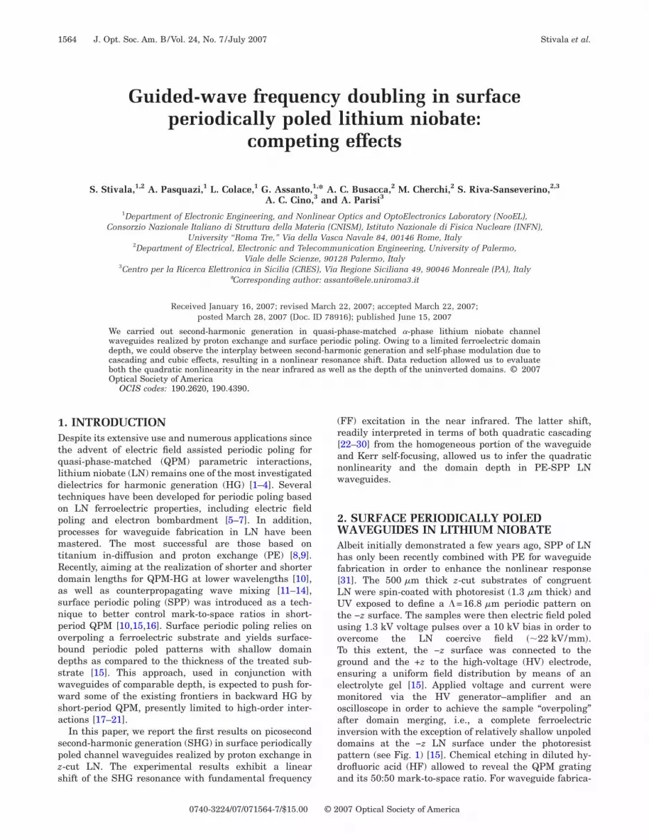
scilloscope in order to achieve the sample “overpoling”fter domain merging, i.e., a complete ferroelectricnversion with the exception of relatively shallow unpoledomains at the −z LN surface under the photoresistattern (see Fig. 1) [15]. Chemical etching in diluted hy-rofluoric acid (HF) allowed to reveal the QPM gratingnd its 50:50 mark-to-space ratio. For waveguide fabrica-
007 Optical Society of America

twdHLtowtecQndaungmfNN==atf
3SPEn
deasmfipei1tacvmVmsatt
dp
Ffi
FWfng
Fwp
Fcp
Stivala et al. Vol. 24, No. 7 /July 2007 /J. Opt. Soc. Am. B 1565
ion, the poled LN was initially coated with a SiO2 layer,here channel openings, from 1 to 7 �m in width, wereefined by standard photolithography and wet etching inF. Proton exchange was then carried out by dipping theN sample by the sealed-ampoule method [32] in a solu-ion of benzoic acid and lithium benzoate (3%) in order tobtain low-proton-concentration (� phase [33]) channelaveguides supporting TM-polarized modes. We verified
he compatibility between SPP and PE by chemicallytching the samples and using scanning electron micros-opy. Figure 2(b) is the optical micrograph of a typicalPM channel after HF etching. We also employed the pla-ar waveguides formed on the +z face of the samples foristributed (prism and/or grating) coupling at 632.8 nmnd evaluating the extraordinary index profile versus zsing the standard WKB technique [34]. This yieldede�z�=2.2027+0.0150 exp�−�z /2.601�1.8355�, i.e., a wave-uide depth of 2.6 �m, as shown in Fig. 2(a). Using Sell-eier equations [35] and measured TM effective indices
rom planar waveguides at �FF=1.55 �m (single mode,0=2.1395) and �SH=775 nm (two modes, N0=2.1845 and1=2.1801), respectively, we derived the profiles ne�z��ne�z�+ne�0� with ne�0�=2.1381 and �ne�z�0.01185 exp�−�z /2.601�1.8355� at �FF and ne�0�=2.1788nd �ne�z�=0.01395 exp�−�z /2.601�1.8355� at �SH, respec-ively, to be employed in the interpretation of the datarom SHG in the SPP-PE channels.
. SECOND-HARMONIC GENERATION INURFACE PERIODIC POLINGROTON-EXCHANGED LITHIUM NIOBATExperiments on SHG were carried out to characterize theonlinear response of the QPM channels. To minimize the
ig. 1. (Color online) Comparison of (a) bulk poling via electriceld and (b) surface poling owing to overpoling.
ig. 2. (a) Extraordinary index profile calculated by inverseKB from distributed coupling data. The dots are measured ef-
ective indices at 632.8 nm; the solid curve is a WKB fit. (b) Scan-ing electron microphotograph of a typical sample: the PE wave-uide is clearly visible on the inverted domain grating.
etrimental effects of photorefractive damage [36], wemployed a source operating at a repetition rate of 10 Hznd producing 25 ps pulses in the near infrared. Theource, sketched in Fig. 3, consisted of an optical para-etric generator fed by a tunable oscillator and an ampli-ed frequency-doubled Nd:YAG pump at 1.064 �m. A dis-ersive element (grating) was introduced in the cavity toffectively narrow the pulse linewidth to �2 cm−1 in thenterval of wavelength tunability between 1.1 and.6 �m. Following a spectrometer and a single-pulse au-ocorrelator, the beam was spatially filtered, collimated,nd end-fire coupled in the channels through a 20� mi-roscope objective. A TEM00 spot of waist w0�3.6 �m pro-ided the best in-coupling efficiency. The output funda-ental and second-harmonic profiles were imaged withidicon and Si-CCD cameras, respectively, using a 63�icroscope objective; energy and peak power were mea-
ured with Ge and Si photodiodes and a dual-input boxcarverager. All measurements were taken at room tempera-ure with the aid of a Peltier cell and a temperature con-roller.
Second-harmonic generation measurements were con-ucted either at a fixed wavelength by varying the FF in-ut power or by scanning the FF wavelength, ratioing the
ig. 3. (Color online) Setup for SHG measurements. HWP, half-ave-plate; BS, beam splitter; OB, microscope objective; PD,hotodetector.
ig. 4. Measured (open circles) and predicted (solid curve) SHGonversion efficiency versus FF wavelength for a launched peakower of 2 kW.

stwoLFttst�ccPr
o(cfsas
sS
4Ctstctlpc�svggfgqa1ntmc
poQwcertimpacontat
wa
Fett
Fv
Fa
1566 J. Opt. Soc. Am. B/Vol. 24, No. 7 /July 2007 Stivala et al.
econd-harmonic output to the fundamental input to ob-ain the conversion efficiency. At variance with [37], pulsealk-off and group-velocity dispersion were uninfluent,wing to the picosecond pulse duration and sample length=1 cm. Typical results versus wavelength are shown inig. 4 for an FF input peak power of 2 kW: even thoughhe data (symbols) are plotted versus wavelength ratherhan detuning, a sinclike shape is apparent and in sub-tantial agreement with the expected one for cw excita-ion (solid curve). The full width at half maximum is1 nm, yielding an effective QPM grating length of 1 cm,
oincident with the sample length. Despite the low effi-iency, the latter result confirmed a good uniformity of theE poled sample in both QPM grating and waveguide pa-ameters [38].
By repeating the SHG scan at higher peak powers webserved that the wavelength of maximum conversionthe FF resonance wavelength for SHG) shifted with ex-itation, as visible in Fig. 5. Otherwise stated, when per-orming a power scan at fixed FF wavelength, the conver-ion efficiency first increased with power (as expected)nd then decreased. By adjusting �FF, conversely, we ob-erved a linear dependence in maximum conversion to
ig. 5. SHG resonance shift in wavelength for increasing peakxcitations 7.4, 8.9, 11.2, and 12.7 kW from left to right, respec-ively. The experimental values (open circles) are numerically in-erpolated using Eq. (2) (solid curves).
ig. 6. (a) Peak SHG wavelength shift and (b) maximum con-ersion efficiency versus FF peak power.
econd harmonic (SH) [see Fig. 6(b)], as well as in peakHG wavelength [see Fig. 6(a)].
. MODEL AND DATA REDUCTIONonsidering the measured conversion efficiencies, using
he standard model of an ideal (first-order, 50:50 mark-to-pace) QPM channel waveguide and taking into accounthe measured modal overlap integral (input and output),oupling, and Fresnel losses—as well as material absorp-ion at FF and SH—we could estimate an effective non-inear coefficient �2 orders of magnitude smaller thanreviously reported d33 values in LN [35]. Since no appre-iable reduction in nonlinearity can be attributed to PE in-phase waveguides [33], a low (effective) nonlinear re-ponse can be ascribed to the limited depth of the nonin-erted domains as compared to the depth of the wave-uide; hence, to the limited overlap between (FF and SH)uided modes and the transverse size of the periodicerroelectric (nonlinear) grating. In fact, for the wave-uide depth evaluated in the previous section and the ac-uired transverse distributions of TM eigenmodes at FFnd SH (see Fig. 7), domains extending into z for less than–2 �m from the surface would greatly limit the perti-ent effective area. The latter would imply light propaga-ion and QPM in a partially inverted medium, with detri-ental effects on SHG and a nonlinear phase shift due to
ascading under phase mismatch [22,23].Therefore, in order to quantitatively interpret the ex-
erimental data, we took into account not only the peri-dically poled transverse region providing first-orderPM, but also the homogeneously inverted portion of theaveguides extending in z below the actual domains. This
ontribution is not expected to alter the peak conversionfficiency as the SH generated in the completely invertedegion is not phase matched, but it should play an impor-ant role in the phase coherently accumulated by the FFn propagation, therefore, on the wavelength for maxi-
um conversion [22,24,29]. A cascaded ��2� :��2� process inhase mismatch can mimic a ��3� response, giving rise ton equivalent Kerr response (i.e., an index change) thatan combine with or even dominate the cubic nonlinearityf the bulk material itself [23] and shift the SHG reso-ance [37]. Since the QPM grating extended well beyondhe channel width (Fig. 2), no particular care needs bedopted along the other transverse coordinate �y�, wherehe domains can be assumed infinitely wide.
For monochromatic TM-polarized first-order guided-ave modes at FF and SH, we write the electric field E ofn x-propagating eigenmode as
ig. 7. (a) FF and (b) SH output intensity modal distributionss imaged with a Vidicon tube and a CCD camera, respectively.
E
wtsrggtbmpt
w(t(tKso
If−b�tc
w
dt
w(Qdhgmp
seosd
hp
Stivala et al. Vol. 24, No. 7 /July 2007 /J. Opt. Soc. Am. B 1567
�x,y,z;t� =1
2Eu�x,y,z;t�exp�iut − iux� + c.c.,
Eu =� 2�0
Nu�−�
� �−�
�
�eu�y,z��2dydz
u�x�eu�y,z�, �1�
ith eu�y ,z� the dimensionless transverse profile, u�x , t�he slowly varying amplitude (in space and time) mea-ured in �W, �0 the vacuum impedance, Nu the effectiveefractive index, and u=uNu /c the guided-wave propa-ation constant. In the presence of a rectangular QPMrating with limited-depth inverted domains and an in-rinsic third-order response, assuming a negligible contri-ution from higher-order modes at SH (non-quasi-phase-atched to the FF fundamental mode) and a first-order
erturbation, the coupled-mode equations for SHG takehe form
wx +wt
cw= − w*v��1 exp�− i�1x� + i�2 exp�− i�2x��
− in2
2
�FF�fww�w�2 + 2fwv�v�2�w −
�w
2,
vx +vt
cv= w2��1 exp�i�1x� − i�2 exp�i�2x��
− in2
4
�FF�2fvw�w�2 + fvv�v�2�v −
�v
2, �2�
ith w�x , t� and v�x , t� being the amplitudes [u�x , t� in Eq.1)] of fundamental and second-harmonic fields, respec-ively; cw and cv (�w and �v) being the group velocitieslinear absorption coefficients) at FF and SH, respec-ively; and n2 being the nonresonant intensity-dependenterr coefficient [39]. The third-order nonlinear effects,
elf- and cross-phase modulation, are weighed by theverlap integrals fjk:
fjk
�−�
+��−�
+�
�ej�y,z��2�ek�y,z��2dydz
�−�
+��−�
+�
�ej�y,z��2dydz�−�
+��−�
+�
�ek�y,z��2dydz
�j,k = v,w�. �3�
n Eq. (2), we also distinguished the SHG contributionsrom unpoled (�2, �2=v−2w) and poled (�1, �1=�2kG) regions of the waveguide [40], respectively, governedy mismatches �i �i=1,2� and nonlinear coefficients �ii=1,2�, with kG=2 /� the wave-vector contribution ofhe QPM grating with period �. The constants �1 and �2an be expressed as
�i = deffi�i�8 2�0fSHG
�FF2 Nw
2 Nv, �4�
ith f the SHG overlap integral
SHGfSHG �
−�
+��−�
+�
ev*�y,z�ew
2 �y,z�dydz�2
�−�
+��−�
+�
�ew�y,z��2dydz�2�−�
+��−�
+�
�ev�y,z��2dydz
,
�5�
eff1=2d33/ , deff2
=d33, and �i parameters accounting forhe waveguide section
�1 =
�−�
+��Z0
+�
ev*�y,z�ew
2 �y,z�dydz
�−�
+��−�
+�
ev*�y,z�ew
2 �y,z�dydz
,
�2 =
�−�
+��−�
Z0
ev*�y,z�ew
2 �y,z�dydz
�−�
+��−�
+�
ev*�y,z�ew
2 �y,z�dydz
= 1 − �1, �6�
ith Z0 delimiting the domain depth d. Note that in Eq.2) we did not include the cubic nonlinearity due to thePM grating [41]. In fact, the low conversion efficiency in-icates that d0 is quite smaller than the waveguide depth,ence �2 :�1 and the induced Kerr term �1 :�1 can be ne-lected when compared with the cascaded effect stem-ing from the phase-mismatched SHG in the uniformly
oled channel.While Eqs. (2) model SHG in a partially poled QPM
ample, as we deal with picosecond SHG in our low-fficiency samples and focus on the power-dependent shiftf the peak conversion wavelength, we can leave out ab-orption and temporal walk-off as well as the cubic termsepending on the SH field [42,43], reducing the system to
w�x,��x = − w*v��1 exp�− i�1x� + i�2 exp�− i�2x��
− i2
�FFn2fww�w�2w,
v�x,��x = w2��1 exp�i�1x� − i�2 exp�i�2x��
− i8
�FFn2fvw�w�2v, �7�
aving introduced �= t−x /cw and �w�2=w02 for the x=0 in-
ut power.Defining
w = W exp�− i2
�FFn2fwwwo
2x ,
v = V exp�− i8
�FFn2fvwwo
2x , �8�
t
Fc
Ipr
f�c
w
Fw�
Efbcmtshww
ppltcscs=pcS
soltt�cS−p
���=dd[a�r
5Wfcrweentpmpidtmt
ATtt
R
1568 J. Opt. Soc. Am. B/Vol. 24, No. 7 /July 2007 Stivala et al.
�ki = �i +8
�FFn2fvwwo
2 −4
�FFn2fwwwo
2 �i = 1,2�, �9�
he coupled equations for W�x ,�� and V�x ,�� take the form
Wx = − W*V��1 exp�− i�k1x� + i�2 exp�− i�k2x��,
Vx = W2��1 exp�i�k1x� − i�2 exp�i�k2x��. �10�
inally, since �k2��k1 and �2��1, neglecting rapidly os-illating terms such as sin���2−�1�x�,
Wxx + i�k2Wx � − �22��W�2 − �V�2�W. �11�
n the small conversion limit and after defining the FFhase � as in W=wog���exp�−i�� with g��� the FF tempo-al profile, Eq. (11) admits the solution [23]
� = −�k2x
2��1 +
4�22wo
2g���2
��k2�2 − 1� � −�2
2wo2g���2
�2x,
or low powers wo2��k2 /�2
2; in the same limit �2�8 /�FF�n2fwvwo
2, �4 /�FF�n2fwwwo2 and the cascading
ontribution is self-defocusing [22–29].For the SH output,
�v�2 = �12wo
4g4���L2 sinc2��1 + �Cwo2g2����
L
2� , �12�
ith L as the sample length and
�C =8
�FFn2fvw −
4
�FFn2fww +
2�22
�2.
rom Eq. (12), the peak efficiency �0 (the SHG resonantavelength in the limit of zero FF power) corresponds to1+�Cwo
2g2���=0; therefore, at first order,
� = �C�o
kGwo
2g2��� + �o. �13�
xpression (13) is consistent with the linear trend weound experimentally (Fig. 6) for a positive �C, therebyoth cross-phase modulation (with a positive n2) and cas-ading (with �2�0) dominate the � shift. Since no per-anent or semipermanent material effects such as hys-
eresis, memory, or damage could be detected in theamples, other effects (photorefractive, photovoltaic,igher order) potentially contributing to a resonance-avelength shift were entirely negligible in ouraveguides.We numerically solved Eq. (2) assuming a Gaussian
rofile for the FF pulses, a propagation length L=1 cm,ropagation losses of �w=�v=0.2 cm−1 at both wave-engths (accounting for both the �-phase waveguides andhe domain inversion [44,45]), and an input coupling effi-iency of 73% consistent with the experimentally mea-ured throughput of 60%. The overlap integrals were cal-ulated from the acquired intensity distributions andhown in Fig. 7, resulting in effective areas 1/ fww52.99 �m2 and 1/ fvv=23.11 �m2 for FF and SH self-hase modulation, respectively; 1/ fwv=44.08 �m2 forross-phase modulation and 1/ fSHG=76.68 �m2 for SHG.ince both cubic and quadratic terms contribute to the
hift [expression (13)], we adopted Kerr coefficients previ-usly measured by independent methods and reported initerature in order to estimate the pertinent QPM quanti-ies, i.e., nonlinearity d33 and the constant �1 related tohe depth d of the domains. The latter was extracted from1 using a modal solver. The index profile along z was re-onstructed from the experimental data as described inection 1; along y we used a generalized Gaussian exp��y /WG��� with � and WG parameters to best fit the modalrofiles (Fig. 7).The largest value of n2�10�10−20 m2/W [46] provided
1=0.0104, corresponding to d33=16.5 pm/V and d440 nm. Conversely, the smallest reported n2�510−20 m2/W [47] gave �1=0.0095, corresponding to d3318 pm/V and d�430 nm. Therefore, while the domainepth is marginally affected by the size of n2, the qua-ratic response appears lower than previously reported38]. Noticeably, neglecting the third-order nonlinearityltogether but keeping the propagation losses, we found1=0.0088, with d33=19.5 pm/V and d�420 nm. Theseesults are perfectly consistent with expression (13).
. CONCLUSIONSe carried out the first experimental demonstration of
requency doubling in proton-exchanged lithium niobatehannel waveguides quasi-phase-matched via surface pe-iodic poling. Despite a good mark-to-space ratio of 50:50,e found that a limited depth of the noninverted ferro-lectric domains not only limited the overall conversionfficiency to the second harmonic, but also induced a non-egligible quadratic cascading. The latter combined withhe inherent cubic response of the crystal to yield an ap-reciable SHG resonance shift in wavelength. The experi-ental results confirm the compatibility of �-phase
roton-exchanged waveguides with surface periodic pol-ng even for periods exceeding 16 �m but pinpoint therawback of rather shallow domains as compared withhe waveguide index profile. Work is in progress to opti-ize the PE-SPP technology and achieve deeper ferroelec-
ric domains.
CKNOWLEDGMENTShis work was funded by the Italian Ministry for Scien-
ific Research through PRIN 2005098337 and, in part,hrough project APQ RS-19 (CIPE 17/2002, BCNanolab).
EFERENCES1. E. J. Lim, M. M. Fejer, and R. L. Byer, “Second-harmonic
generation of green light in periodically poled planarlithium niobate waveguide,” Electron. Lett. 25, 174–175(1989).
2. K. El Hadi, M. Sundheimer, P. Aschieri, P. Baldi, M. P. DeMicheli, D. B. Ostrowsky, and F. Laurell, “Quasi-phase-matched parametric interactions in proton-exchangedlithium niobate waveguides,” J. Opt. Soc. Am. B 14,3197–3203 (1997).
3. J. Webjörn, S. Siala, D. W. Nam, R. G. Waarts, and R. J.Lang, “Visible laser sources based on frequency doubling innonlinear waveguides,” IEEE J. Quantum Electron. 33,1673–1686 (1997).
4. K. R. Parameswaran, R. K. Route, J. R. Kurz, R. V.

1
1
1
1
1
1
1
1
1
1
2
2
2
2
2
2
2
2
2
2
3
3
3
3
3
3
3
3
3
3
4
4
4
4
Stivala et al. Vol. 24, No. 7 /July 2007 /J. Opt. Soc. Am. B 1569
Roussev, M. M. Fejer, and M. Fujimura, “Highly efficientsecond-harmonic generation in waveguides formed byannealed and reverse proton in periodically poled lithiumniobate,” Opt. Lett. 27, 179–181 (2002).
5. V. Shur, E. Rumyantsev, R. Batchko, G. Miller, M. Fejer,and R. Byer, “Physical basis of the domain engineering inthe bulk ferroelectrics,” Ferroelectrics 221, 157–159(1999).
6. M. Yamada, N. Nada, M. Saitoh, and K. Watanabe, “First-order quasi-phase matched LiNbO3 waveguide periodicallypoled by applying an external field for efficient blue second-harmonic generation,” Appl. Phys. Lett. 62, 435–436(1993).
7. H. Ito, C. Takyu, and H. Inaba, “Fabrication of periodicdomain grating in LiNbO3 by electron beam writing forapplication of nonlinear optical processes,” Electron. Lett.27, 1221–1222 (1991).
8. S. Miyazawa, “Ferroelectric domain inversion in Ti-diffusedLiNbO3 optical waveguide,” J. Appl. Phys. 50, 4599–4603(1979).
9. J. L. Jackel, C. E. Rice, and J. J. Veselka, “Proton exchangefor high-index waveguides in LiNbO3,” Appl. Phys. Lett.41, 607–608 (1982).
0. A. C. Busacca, C. L. Sones, R. W. Eason, and S. Mailis,“First order quasi-phase matched blue light generation insurface poled Ti-indiffused lithium niobate waveguide,”Appl. Phys. Lett. 84, 4430–4432 (2004).
1. Y. J. Ding, S. J. Lee, and J. B. Khurgin, “Transverselypumped counterpropagating optical parametric oscillationand amplification,” Phys. Rev. Lett. 75, 429–432 (1995).
2. C. Conti, G. Assanto, and S. Trillo, “Cavityless oscillationsthrough backward quasi-phase-matched second harmonicgeneration,” Opt. Lett. 24, 1139–1141 (1999).
3. K. Gallo, P. Baldi, M. De Micheli, D. B. Ostrowsky, and G.Assanto, “Cascading phase shift and multivalued responsein counterpropagating frequency-nondegenerateparametric amplifiers,” Opt. Lett. 25, 966–968 (2000).
4. G. D. Landry and T. A. Maldonado, “Counterpropagatingquasi-phase matching: a generalized analysis,” J. Opt. Soc.Am. B 21, 1509–1520 (2004).
5. A. C. Busacca, C. L. Sones, V. Apostopoulos, R. W. Eason,and S. Mailis, “Surface domain engineering in congruentlithium niobate single crystals: a route to submicronperiodic poling,” Appl. Phys. Lett. 81, 4946–4948 (2002).
6. A. C. Busacca, A. C. Cino, S. Riva Sanseverino, M. Ravaro,and G. Assanto, “Silica masks for improved surface polingof lithium niobate,” Electron. Lett. 41, 92–93 (2005).
7. J. U. Kang, Y. J. Ding, W. K. Burns, and J. S. Melinger,“Backward second-harmonic generation in periodicallypoled bulk LiNbO3,” Opt. Lett. 22, 862–864 (1997).
8. X. Gu, R. Y. Korotkov, Y. J. Ding, J. U. Kang, and J. B.Khurgin, “Backward second-harmonic generation inperiodically poled lithium niobate,” J. Opt. Soc. Am. B 15,1561–1566 (1998).
9. X. Gu, M. Makarov, Y. J. Ding, J. B. Khurgin, and W. P.Risk, “Backward second-harmonic and third-harmonicgeneration in a periodically poled potassium titanylphosphate waveguide,” Opt. Lett. 24, 127–129 (1999).
0. X. Mu, I. B. Zotova, Y. J. Ding, and W. P. Risk, “Backwardsecond-harmonic generation in submicron-period ion-exchanged KTiOPO waveguide,” Opt. Commun. 181,153–159 (2000).
1. C. Canalias, V. Pasiskevicius, M. Fokine, and F. Laurell,“Backward quasi-phase-matched second-harmonicgeneration in submicrometer periodically poled flux-grownKTiOPO4,” Appl. Phys. Lett. 86, 181105 (2005).
2. R. De Salvo, D. J. Hagan, M. Sheik-Bahae, G. I. Stegeman,and E. W. Van Stryland, “Self-focusing and self-defocusingby cascaded second-order effects in KTP,” Opt. Lett. 17,28–30 (1992).
3. G. I. Stegeman, M. Sheik-Bahae, E. W. Van Stryland, andG. Assanto, “Large nonlinear phase shifts in second-ordernonlinear-optical process,” Opt. Lett. 18, 13–15 (1993).
4. G. Assanto, G. I. Stegeman, M. Sheik-Bahae, and E. W. VanStryland, “Coherent interactions for all-optical signal
processing via quadratic nonlinearities,” IEEE J. QuantumElectron. 31, 673–681 (1995).
5. A. Kobyakov, U. Peschel, R. Muschall, G. Assanto, V. P.Torchigin, and F. Lederer, “An analytical approach to all-optical modulation by cascading,” Opt. Lett. 20, 1686–1688(1995).
6. G. Assanto, Z. Wang, D. J. Hagan, and E. W. Van Stryland,“All-optical modulation via nonlinear cascading in Type IIsecond harmonic generation,” Appl. Phys. Lett. 67,2120–2122 (1995).
7. G. Assanto, “Transistor action through nonlinear cascadingin Type II interactions,” Opt. Lett. 20, 1595–1597 (1995).
8. P. Di Trapani, A. Bramati, S. Minardi, W. Chinaglia, C.Conti, S. Trillo, J. Kilius, and G. Valiulis, “Focusing versusdefocusing nonlinearities due to parametric wave mixing,”Phys. Rev. Lett. 87, 183902 (2001).
9. G. Assanto and G. I. Stegeman, “Nonlinear optics basics:cascading,” in Encyclopedia of Modern Optics, R. D.Guenther, D. G. Steel, and L. D. Bayvel, eds. (Elsevier,2005), Vol. 3, pp. 207–212.
0. A. Kobyakov, F. Lederer, O. Bang, and Y. S. Kivshar,“Nonlinear phase shift and all-optical switching in quasiphase matched quadratic media,” Opt. Lett. 23, 506–508(1998).
1. A. C. Busacca, M. Cherchi, S. Riva Sanseverino, A. C. Cino,A. Parisi, S. Stivala, L. Colace, and G. Assanto, “Protonexchanged channel waveguides compatible with surfacedomain engineering in lithium niobate crystals,”Conference on Lasers and Electro-Optics (Optical Society ofAmerica, 2006), paper CMB4.
2. M. De Micheli, D. B. Ostrowsky, J. P. Barety, C. Canali, A.Carnera, G. Mazzi, and M. Papuchon, “Crystalline andoptical quality of proton exchanged waveguides,” J.Lightwave Technol. 4, 743–745 (1986).
3. L. Chanvillard, P. Aschièri, P. Baldi, D. B. Ostrowsky, M.De Micheli, L. Huang, and D. J. Bamford, “Soft protonexchange on periodically poled LiNbO3: a simple waveguidefabrication process for highly efficient nonlinearinteractions,” Appl. Phys. Lett. 76, 1089–1091 (2000).
4. J. M. White and P. F. Heidrich, “Optical waveguiderefractive index profiles determined from measurement ofmode indices: a simple analysis,” Appl. Opt. 15, 151–155(1976).
5. Crystal Technology Inc., http://www.crystaltechnology.com/docs/LNopt.pdf.
6. E. Glavas, J. M. Cabrera, and P. D. Townsend, “Acomparison of optical damage in different types of LiNbO3waveguides,” J. Phys. D 22, 611–616 (1989).
7. Z. Zheng, A. M. Weiner, K. R. Parameswaran, M.-H. Chou,and M. M. Fejer, “Femtosecond second-harmonicgeneration in periodically poled lithium niobatewaveguides with simultaneous strong pump depletion andgroup velocity walk-off,” J. Opt. Soc. Am. B 19, 839–848(2002).
8. M. M. Fejer, G. A. Magel, D. H. Jundt, and R. L. Byer,“Quasi-phase-matched second-harmonic generation: tuningand tolerances,” IEEE J. Quantum Electron. 28, 2631–2654(1992).
9. G. I. Stegeman and G. Assanto, “Nonlinear integratedoptical devices,” in Integrated Optical Circuits andComponents: Design and Application, E. J. Murphy, ed.(Dekker, 1999), pp. 381–418; and references therein.
0. T. Suhara and H. Nishihara, “Theoretical analysis ofwaveguide second-harmonic generation phase matchedwith uniform and chirped gratings,” IEEE J. QuantumElectron. 26, 1265–1276 (1990).
1. C. B. Clausen, O. Bang, and Y. S. Kivshar, “Spatial solitonsand induced Kerr effects in quasi-phase-matched quadraticmedia,” Phys. Rev. Lett. 78, 4749–4752 (1997).
2. J. T. Manassah and O. R. Cockings, “Induced phasemodulation of generated second-harmonic signal,” Opt.Lett. 12, 1005–1007 (1987).
3. S. Cussat-Blanc, R. Maleck Rassoul, A. Ivanov, E. Freysz,and A. Ducasse, “Influence of cascading phenomena on atype I second-harmonic wave generated by an intense

4
4
4
4
1570 J. Opt. Soc. Am. B/Vol. 24, No. 7 /July 2007 Stivala et al.
femtosecond pulse: application to the measurement of theeffective second-order coefficient,” Opt. Lett. 23, 1585–1587(1998).
4. X. F. Cao, R. V. Ramaswamy, and R. Srivastava,“Characterization of annealed proton exchanged LiNbO3waveguides for nonlinear frequency conversion,” J.Lightwave Technol. 10, 1302–1310 (1992).
5. Y. N. Korkishko, V. A. Fedorov, M. P. De Micheli, P. Baldi,K. El Hadi, and A. Leycuras, “Relationships betweenstructural and optical properties of proton-exchangedwaveguides on Z-cut lithium niobate,” Appl. Opt. 36,
7056–7060 (1999).6. R. De Salvo, A. A. Said, D. J. Hagan, E. W. Van Stryland,and M. Sheik-Bahae, “Infrared to ultravioletmeasurements of two-photon absorption in wide bandgapsolids,” IEEE J. Quantum Electron. 32, 1324–1333(1996).
7. I. A. Kulagin, R. A. Ganeev, R. I. Tugushev, A. I.Ryasnyansky, and T. Usmanov, “Analysis of third-ordernonlinear susceptibilities of quadratic nonlinear opticalcrystals,” J. Opt. Soc. Am. B 23, 75–80 (2006).


