Embed Size (px)
Citation preview

®
Hardware Installation Guide
Product Model: xStack® DES-3528/DES-3552 Series
Layer 2 Managed Stackable Fast Ethernet Switch

©Copyright 2009. All rights reserved.
_________________________________________________________________________________ Information in this document is subject to change without notice. © 2009 D-Link Corporation. All rights reserved. Reproduction in any manner whatsoever without the written permission of D-Link Corporation is strictly forbidden. Trademarks used in this text: D-L ink and the D-LINK logo are trademarks of D-Link Corporation; Microsoft and Windows are registered trademarks of Microsoft Corporation. Other trademarks and trade names may be used in this document to refer to either the entities claiming the marks and names or their products. D-Link Corporation disclaims any proprietary interest in trademarks and trade names other than its own. July 2009 P/N 651ES3500055G

xStack® DES-3528/DES-3552 Series Layer 2 Stackable Fast Ethernet Managed Switch User Manual
ii
FCC Warning
This equipment has been tested and found to comply with the limits for a Class A digital device, pursuant to Part 15 of the FCC Rules. These limits are designed to provide reasona ble protec tion against harmful interference when the equipment is operated in a commercial envir onment. This equipment ge nerates, uses, and can radiate r adio freq uency ene rgy and, if not installed and use d in accordance with this man ual, ma y cause harmful interference to radio communications. Operation of this equipment in a resident ial area is likely to cause harmful interference in which case the user will be required to correct the interference at their expense.
CE Mark Warning
This is a Class A product. In a domestic environment, this produ ct may cause ra dio interference in which case the user ma y be required to take adequate measures.
Warnung!
Dies ist ein Produkt der Klasse A. Im Wohnbereich kann dieses Produkt Funkstoerungen verursachen. In diesem Fall kann vom Benutzer verlangt werden, angemessene Massnahmen zu ergreifen.
Precaución!
Este es un producto de Clase A. En un entorno doméstico, puede causar interferencias de radio, en cuyo case, puede requerirse al usuario para que adopte las medidas adecuadas.
Attention!
Ceci est un produit de classe A. Dans un environnement domestique, ce produit pourrait causer des interférences radio, auquel cas l`utilisateur devrait prendre les mesures adéquates.
Attenzione! Il presente prodotto appartiene alla classe A. Se utilizzato in ambiente domestico il prodotto può causare interferenze radio, nel cui caso è possibile che l`utente debba assumere provvedimenti adeguati.
VCCI Warning
この装置は、クラス A 情報技術装置です。この装置を家庭環境で使用すると電波妨害を引き起こすことがあります。
この場合には使用者が適切な対策を講ずるよう要求されることがあります。 VCCI-A

xStack® DES-3528/DES-3552 Series Layer 2 Stackable Fast Ethernet Managed Switch User Manual
iii
Table of Contents
Intended Readers............................................................................................................................................................................ v Typographical Conventions ............................................................................................................................................................................v
Notes, Notices, and Cautions ......................................................................................................................................................... v Safety Instructions ........................................................................................................................................................................ vi
Safety Cautions ..............................................................................................................................................................................................vi General Precautions for Rack-Mountable Products ..................................................................................................................................... vii Protecting Against Electrostatic Discharge ................................................................................................................................................. viii
Introduction......................................................................................................................................................1 Gigabit Ethernet Technology ..........................................................................................................................................................................1 Switch Description ..........................................................................................................................................................................................1 Features...........................................................................................................................................................................................................2 Ports ................................................................................................................................................................................................................3 Front-Panel Components.................................................................................................................................................................................4 LED Indicators................................................................................................................................................................................................5 Rear Panel Description....................................................................................................................................................................................8 Side Panel Description ....................................................................................................................................................................................8 Gigabit Combo Ports.......................................................................................................................................................................................9
Installation......................................................................................................................................................11 Package Contents ..........................................................................................................................................................................................11 Before You Connect to the Network .............................................................................................................................................................11 Installing the Switch without the Rack..........................................................................................................................................................12 Installing the Switch in a Rack......................................................................................................................................................................12 Mounting the Switch in a Standard 19" Rack................................................................................................................................................13 Power On (AC Power) ..................................................................................................................................................................................13 Power Failure (AC Power)............................................................................................................................................................................13 Connecting DC Power to the DES-3528DC..................................................................................................................................................14
Connecting the Switch ...................................................................................................................................15 Switch to End Node ......................................................................................................................................................................................15 Switch to Hub or Switch ...............................................................................................................................................................................15 Connecting To Network Backbone or Server................................................................................................................................................16
Introduction to Switch Management ...........................................................................................................17 Management Options ................................................................................................................................................................... 17
Web-based Management Interface ................................................................................................................................................................17 SNMP-based Management............................................................................................................................................................................17 Connecting the Console Port (RS-232 DCE) ................................................................................................................................................17 First Time Connecting to the Switch.............................................................................................................................................................19 Password Protection ......................................................................................................................................................................................19 SNMP Settings..............................................................................................................................................................................................20 IP Address Assignment .................................................................................................................................................................................21
Web-based Switch Configuration.................................................................................................................23

xStack® DES-3528/DES-3552 Series Layer 2 Stackable Fast Ethernet Managed Switch User Manual
iv
Introduction.................................................................................................................................................................................. 23 Login to Web Manager .................................................................................................................................................................................23 Web-based User Interface .............................................................................................................................................................................24 Web Pages.....................................................................................................................................................................................................25
Technical Specifications ................................................................................................................................26
Cable Lengths.................................................................................................................................................34
Glossary ..........................................................................................................................................................35
Warranties and Tech Support Information ................................................................................................38

xStack® DES-3528/DES-3552 Series Layer 2 Stackable Fast Ethernet Managed Switch User Manual
v
Intended Readers The DES-3528/DES-3552 Switch Series Hardware Installation Guide contains i nformation fo r setup and management of the Switch. This ma nual is inten ded fo r network man agers familiar with network manag ement concepts and terminology.
Typographical Conventions Convention Description
[ ] In a comma nd line, square brackets indicate an optional ent ry. For example: [co py filename] means that optionally you can type copy followed by the name of the file. Do not type the brackets.
Bold font Indicates a button, a toolbar icon, menu, or menu item. For example: Open the File menu and choose Cancel. Used for emphasis. May also indicate system messages or prompts appearing on your scre en. For examp le: Y ou have mail. Bold font is also used to represent filename s, pro gram nam es and co mmands. For example: use the copy command.
Boldface Typewriter Font
Indicates commands and responses to prom pts that must be typed exa ctly as pri nted in the manual.
Initial capital letter Indicates a wind ow nam e. Name s of keys on the keyboard have initial capitals. Fo r example: Click Enter.
Italics Indicates a windo w name or a field. Also ca n indica te a variables or para meter that is replaced with an appro priate word or string. For example: type filename me ans that you should type the actual filename instead of the word shown in italic.
Menu Name > Menu Option
Menu Name > Menu Option Indicates the menu structu re. Device > Port > Port Properties means the Port Propertie s menu opti on under the Port menu option that is located under the Device menu.
Notes, Notices, and Cautions
A NOTE indicates important information that helps you make better use of your device.
A NOTICE indicates either potential da mage to ha rdware or lo ss of data and t ells you how to avoid the problem.
A CAUTION indicates a potential for property damage, personal injury, or death.

xStack® DES-3528/DES-3552 Series Layer 2 Stackable Fast Ethernet Managed Switch User Manual
vi
Safety Instructions Use the following safety guidelines to ensure your own personal safety and to help protect your system from potential damage. Throughout this document, the cauti on icon ( ) is used to indicate cautions and precautions that you need to review and follow.
Safety Cautions
To redu ce t he risk of bodily injury, electri cal shock, fire and damage to the equipm ent, observe the following precautions.
• Observe an d fo llow service mark ings. D o no t s ervice any p roduct ex cept as expl ained in your system documentation. Opening or removing covers that are marked with the triangular symbol with a lightning bolt may expose you to electrical shock. Only a trained service technician should service components inside these compartments.
• If any of the following conditions occur, unplug the produ ct from the electri cal outlet and re place the part o r contact your trained service provider:
The power cable, extension cable, or plug is damaged.
An object has fallen into the product.
The product has been exposed to water.
The product has been dropped or damaged.
The product does not operate correctly when you follow the operating instructions.
• Keep your system away from radiators and heat sources. Also, do not block cooling vents.
• Do not spill food or liqui ds on your system components, and never operate the product in a wet enviro nment. If the system gets wet, see the appro priate se ction in your trouble shooting guide or co ntact your trained service provider.
• Do n ot pu sh any obje cts into the op enings of your sy stem. Doing so can cause fire o r electric shock by shorting out interior components.
• Use the product only with approved equipment.
• Allow the product to cool before removing covers or touching internal components.
• Operate the product only from the type of external power source indicated on the electrical ratings label. If you are not sure of the type of power source required, consult your service provider or local power company.
• To help avoi d damaging your system, be su re the voltage on th e power supply is set to match the p ower available at your location:
115 volts (V)/60 hertz (Hz) in most of North and South America and some Far Eastern countries
100 V/50 Hz in eastern Japan and 100 V/60 Hz in western Japan
230 V/50 Hz in most of Europe, the Middle East, and the Far East
48VDC for DES-3528DC
• Also, be sure that attached devices are electrically rated to operate with the power available in your location.
• Use only a pproved power cable(s). If you have not been provided with a power cable for y our system or for any AC-powered option intende d for yo ur system, purcha se a power cable that is approve d for use in your country. The power cable must be rated for the product and for the voltage and current marke d on the product's electrical ratings label. The voltage and current rating of the cable should be greater than the ratings marked on the product.

xStack® DES-3528/DES-3552 Series Layer 2 Stackable Fast Ethernet Managed Switch User Manual
vii
• To help prevent electric shock, plug the system and peripheral power cables into properly grounded electrical outlets. These cable s are equipped wi th three-p rong pl ugs to help ensu re p roper gro unding. Do not use adapter plugs or remove the grou nding prong from a cable. If you must use an extens ion cable, use a 3-wire cable with properly grounded plugs.
• Observe extensi on ca ble and powe r strip ratin gs. Make sure that the total ampere ratin g of all product s plugged into the extension cable or power strip does not exceed 80 percent of the ampere ratings limit for the extension cable or power strip.
• To help protect your system from sudden, transient increases and decreases in electrical power, use a surge suppressor, line conditioner, or uninterruptible power supply (UPS).
• Position system cables and power cables carefully; route cables so that they cannot be stepped on or tripped over. Be sure that nothing rests on any cables.
• Do n ot modi fy power cables or pl ugs. Co nsult a lic ensed el ectrician or your po wer company for site modifications. Always follow your local/national wiring rules.
• When con necting or di sconnecting po wer to hot-pl uggable po wer su pplies, if offered with your syste m, observe the following guidelines:
Install the power supply before connecting the power cable to the power supply.
Unplug the power cable before removing the power supply.
If the system has multiple sources of power, disconnect power from the system by unplugging all power
cables from the power supplies.
• Move products with ca re; ensure that all caste rs and/or stabilizers are firmly connected to the system. Avoid sudden stops and uneven surfaces.
General Precautions for Rack-Mountable Products
Observe the following preca utions for rack stabilit y and safe ty. Also, refer to the rack installation do cumentation accompanying the system and the rack for specific caution statements and procedures.
• Systems are considered to be components in a rack. Thus, "component" refers to any sy stem as well as to various peripherals or supporting hardware.
• Before working on the rack, make sure that the stab ilizers are secured to the rack, extended to the floor, and that the full weight of the rack re sts on the floor. In stall front a nd side sta bilizers on a si ngle rack or front stabilizers for joined multiple racks before working on the rack.
• Always load the rack from the bottom up, and load the heaviest item in the rack first.
• Make sure that the rack is level and stable before extending a component from the rack.
• Use caution when pressing the component rail release latches and sliding a component into or out of a rack; the slide rails can pinch your fingers.
• After a component is inserted into the rack, ca refully extend the rail into a lo cking position, and then slide the component into the rack.
• Do not overload the AC su pply branch circuit that provides power to the rack. The total rack load should not exceed 80 percent of the branch circuit rating.
• Ensure that proper airflow is provided to components in the rack.
• Do not step on or stand on any component when servicing other components in a rack.

xStack® DES-3528/DES-3552 Series Layer 2 Stackable Fast Ethernet Managed Switch User Manual
viii
NOTE: A qualified electri cian must perform all connections to DC power and to safety grounds. All electrical wiring must comply with applicable local, regional or national codes and practices.
CAUTION: Never defeat t he ground conductor o r operate the equipment in the ab sence of a suitably installed ground conductor. Contact the appropriate electrical inspection authority or an electrician if you are uncertain that suitable grounding is available.
CAUTION: The system chassis must be positively gr ounded to th e rack cabin et frame. Do not attempt to conne ct powe r to the system until grounding cabl es are connected. A qualified electrical inspector must inspect completed power and safety g round wiring. An energy hazard will exist if the safety ground cable is omitted or disconnected.
Protecting Against Electrostatic Discharge Static electri city can h arm delicate compon ents i nside y our system. To prevent static damag e, discharge static electricity from your body before you touch any of the electronic components, such as the microprocessor. You can do so by periodically touching an unpainted metal surface on the chassis.
You can also take the following steps to prevent damage from electrostatic discharge (ESD):
1. When unpacking a static-sensitive component from its shipping carton, do not remove t he component from the antistati c packin g ma terial until yo u are ready to install t he comp onent in y our system. Ju st bef ore unwrapping the antistatic packaging, be sure to discharge static electricity from your body.
2. When transporting a sensitive component, first place it in an antistatic container or packaging. 3. Handle all se nsitive components in a static-safe are a. If possible, use anti static floor pa ds, workbench pads
and an antistatic grounding strap.

xStack® DES-3528/DES-3552 Series Layer 2 Stackable Fast Ethernet Managed Switch User Manual
1
Section 1
Introduction Gigabit Ethernet Technology
Switch Description
Features
Ports
Front-Panel Components
LED Indicators
Rear Panel Description
Side Panel Description
Gigabit Combo Ports
The DES-35 28/DES-3552 Series a re l ayer 2 Fa st Et hernet swit ches an d me mbers of the D-Lin k xStack ® family. Ranging from 10/100Mbps edge switches to core gi gabit switches, the xStack ® switch fami ly has be en future-proof designed to provide a stacking architecture with fault tolera nce, flexibility, port density, robust security and maximum throughput with a user-friendly management interface for the networking professional.
The following manual de scribes the in stallation, maintenance and configurations concerning the xStack ® DES-3528, DES-3528DC, DES-3528P and DES-35 52 swit ches. Please take note that if this devi ce was pu rchased outside o f Europe, certain cosmetic differences between the actual switch and images in this docume nt will be apparent to th e reader, such as the faceplate and the manual cover. The DES-3528/DES-3552 Series has already joined the xStack® family for th e Europe an market and is soo n to be xStack ® converted, uni versally. Cha nges are m ade to the appearance of the device only and no configuration or internal hardware alterations occur.
NOTE: For t he re mainder of this man ual, all versi ons of the DES-3528, DES-3528P, DE S-3528DC and DES-3552 switches will be referred to as simply the Switch or the DES-3528.
Gigabit Ethernet Technology Gigabit Ethernet is an extensi on of IEEE 802.3 Ethernet utilizi ng the same packet structure, format, and support for CSMA/CD protocol, full d uplex, flow c ontrol, an d manag ement object s, but with a tenfo ld increa se i n theoretical throughput o ver 100M bps Fast Ethern et and a on e hund red-fold increa se over 10M bps Ethernet. Since it is compatible with all 10Mbps and 100Mbps Ethernet environments, Gigabit Ethernet provides a straightforward upgrade without wasting a company's existing investment in hardware, software, and trained personnel.
The in creased sp eed and extra ba ndwidth offe red by Gigabi t Ethernet a re essential to copi ng with the net work bottlenecks that frequently develop as computers and their busses get faste r and more users using applications that generate more traffic. Upgrading key components, such as your backbone and servers to Gigabit Ethernet can greatly improve network response times as well as significantly speed up the traffic between your sub networks.
Gigabit Ethernet enabl es fast optical fi ber connections to sup port video co nferencing, complex imaging, and simil ar data-intensive applications. Likewise, since data transfers occur 10 times fa ster than Fast Ethernet, servers o utfitted with Gigabit Ethernet NIC's are able to perform 10 times the number of operations in the same amount of time.
In addition, the pheno menal band width delivered by Gigabit Et hernet is the most cost -effective method to take advantage of today and tomorrow's rapidly improving switching and routing internetworking technologies.
Switch Description The DES-35 28/DES-3552 Switch Seri es is e quipped with unshielded twist ed-pair (UTP ) ca ble po rts providin g dedicated 10 or 100 Mbps bandwidth. The Switch has 24/48 UTP ports and Auto MDI-X/MDI-II convertible ports that can be used for uplinking to another switch. These ports can be used for conne cting PCs, printe rs, servers, hub s,

xStack® DES-3528/DES-3552 Series Layer 2 Stackable Fast Ethernet Managed Switch User Manual
2
routers, switches and other networking devices. The dual speed ports use standard twisted-pair cabling and are ideal for segmenting networks into small, connected sub networks for superior performance. Each 10/100 port can support up to 200 Mbps of throughput in full-duplex mode.
In addition, the Switch has 2 SFP combo ports. These two-gigabit combo ports are ideal for connecting to a server or network backbone. This stackable Switch enables the network to use some of the mo st demanding multimedia and imaging a pplications concurrently with other user applications without creat ing bottlene cks. The b uilt-in co nsole interface can be used to configure the Switch's settings for prio rity queuing, VLANs, and port trun k group s, port monitoring, and port speed.
Features • IEEE 802.3 10BASE-T compliant
• IEEE 802.3u 100BASE-TX compliant
• IEEE 802.1p Priority Queues
• IEEE 802.3x flow control in full duplex mode
• IEEE 802.3ad Link Aggregation Control Protocol support.
• IEEE 802.1X Port-based and MAC-based Access Control
• IEEE 802.1Q VLAN
• IEEE 802.1D Spanning Tree, IEEE 802.1W Rapid Spanning Tree and IEEE 802.1s Multiple Spanning Tree support
• Access Control List (ACL) support
• Single IP Management support
• Access Authentication Control utilizing TACACS, XTACACS and TACACS+
• Dual Image Firmware
• Simple Network Time Protocol support
• MAC Notification support
• Asymmetric VLAN support
• System and Port Utilization support
• System Log Support
• Support port-based enable and disable
• Address table: Supports up to 16K MAC addresses per device
• Supports a packet buffer of up to 1 Mbyte
• Supports Port-based VLAN Groups
• Port Trunking with flexible load distribution and fail-over function
• IGMP Snooping support
• SNMP support
• Secure Sockets Layer (SSL) and Secure Shell (SSH) support
• Port Mirroring support
• MIB support for:
• RFC1213 MIB II
• RFC1493 Bridge
• RFC1907 SNMPv2 MIB
• RFC1757, 2819 RMON
• RFC2021 RMONv2
• RFC1643, 2358, 2665 Ether-like MIB
• RFC2233, 2863 Interface MIB
• Private MIB
• RFC2674 for 802.1p
• RFC2618 RADIUS Authentication Client
• RFC2620 RADIUS Accounting Client
• RFC2925 Ping & Traceroute
• IEEE 802.1X MIB
• RS-232 DCE console port for Switch management
• Provides parallel LED display for port status such as link/act, speed, etc.
• High performance switching engine performs forwarding and filtering at full wire speed, maximum 14, 881 packets/sec on each 10Mbps Ethernet port, and maximum 148,810 packet/sec on 100Mbps Fast Ethernet port.
• Full- and half-duplex for both 10Mbps and 100Mbps connections. Full duplex allows the switch port to simultaneously transmit and receive data. It only works with connections to full-duplex-capable end stations and switches. Connections to a hub must take place at half-duplex
• Support broadcast storm filteringF
• Non-blocking store and forward switching scheme capability to support rate adaptation and protocol conversion
• Supports by-port Egress/Ingress rate control.
• Supports IP-MAC Port Binding.
• Efficient self-learning and address recognition mechanism enables forwarding rate at wire speed
• Supports STP Loopback Detection
• Safeguard Engine Support

xStack® DES-3528/DES-3552 Series Layer 2 Stackable Fast Ethernet Managed Switch User Manual
3
Ports The following table lists the relative ports that are present within each switch:
Device Features DES-3528 DES-3528DC DES-3528P DES-3552
10/100BASE-T Ports 24 Ports 24 Ports 24 Ports 48 Ports
PoE Function Alternative A N/A N/A 24 Ports N/A
1000Base-T/SFP Combo Ports 2 Ports 2 Ports 2 Ports 2 Ports
1000Base-T Ports 2 Ports 2 Ports 2 Ports 2 Ports
DCE RS-232 DB-9 Console Port One Female One Female One Female One Female
The follo wing table list s the feature s and compatibility for each type of port presen t in the DES-352 8/DES-3528DC/DES-3528P/DES-3552.
10/100 BASE-T SFP 1000BASE-T
IEEE 802.3 compliant
IEEE 802.3u compliant
IEEE 802.3x flow control support in full-duplex
IEEE 802.3af compliant (DES-3528P only)
Auto MDI-X/MDI-II c ross over support
SFP Transceivers Supported: DEM-310GT (1000BASE-LX) DEM-311GT (1000BASE-SX) DEM-314GT (1000BASE-LHX) DEM-315GT (1000BASE-ZX) DEM-312GT2 (1000BASE-SX) DEM-210 (Single Mode 100BASE-FX) DEM-211 (Multi Mode 100BASE-FX)
WDM Transceiver Supported: DEM-330T (TX-1550/RX-1310nm), up to 10km,Single-Mode DEM-330R (TX-1310/RX-1550nm), up to 10km,Single-Mode DEM-331T (TX-1550/RX-1310nm), up to 40km, Single-Mode DEM-331R (TX-1310/RX-1550nm), up to 40km, Single-Mode Compliant to the following standards:
1. IEEE 802.3z compliance 2. IEEE 802.3u compliance
IEEE 802.3 compliant
IEEE 802.3u compliant
IEEE 802.3ab compliant
IEEE 802.3z compliant
IEEE 802.3x flow control support i n full-duplex
NOTE: The SFP comb o ports on th e Switch cannot be used simultaneously with the corresponding 1000BASE-T ports. If both ports are in use at the same time (ex . port 25 of the SFP and port 2 5 of the 1000BA SE-T), the SFP ports will take pri ority over the combo ports and render the 1000BASE-T ports inoperable.

xStack® DES-3528/DES-3552 Series Layer 2 Stackable Fast Ethernet Managed Switch User Manual
4
NOTE: For customers interested in D-View, D-Link Corporation's proprietary SNMP management software, go to the D-Link Website (www.dlink.com) and download the software and manual.
Front-Panel Components DES-3528
• Twenty-four 10/100Mbps BASE-T ports
• Two Combo 1000BASE-T/SFP ports located to the right
• Two 1000BASE-T ports located to the rear
• One female DCE RS-232 DB-9 console port
• LEDs for Power, Console, RPS, Master, Link/Act/Speed for each port
Figure 1- 1. Front Panel View of the DES-3528 switch
DES-3528P
• Twenty-four 10/100Mbps BASE-T ports
• Two Combo 1000BASE-T/SFP ports located to the right
• Two 1000BASE-T ports located to the rear
• One female DCE RS -232 DB-9 console port
• One PoE Select Button
• LEDs for Power, Console, RPS, MS, Link, PoE, Link/Act/Speed for each port
Figure 1- 2. Front Panel View of the DES-3528P switch
DES-3528DC
• Twenty-four 10/100Mbps BASE-T ports
• Two Combo 1000BASE-T/SFP ports located to the right
• Two 1000BASE-T ports located to the rear
• One female DCE RS-232 DB-9 console port
• LEDs for Power, Console, Master, Link/Act/Speed for each port
Figure 1- 3. Front Panel View of the DES-3528DC switch
DES-3552
• Forty-eight 10/100Mbps BASE-T ports
• Two Combo 1000BASE-T/SFP ports located to the right

xStack® DES-3528/DES-3552 Series Layer 2 Stackable Fast Ethernet Managed Switch User Manual
5
• Two 1000BASE-T ports located to the rear
• One female DCE RS -232 DB-9 console port
• LEDs for Power, Console, RPS, Master, Link/Act/Speed for each port
Figure 1- 4. Front Panel View of the DES-3552 switch
LED Indicators The Switch supports LED indicators for Power, Console, RPS, Master (on DES-3528P, this LED is fo r MS) and Po rt LEDs. The following shows the LED indicators for the DES-3528/DES-3552 switch series along with an explanation of each indicator. LEDs and their corresponding meanings are displayed below.
Figure 1- 5. LED Indicators on DES-3528 switch
Figure 1- 6. LED Indicators on DES-3552 switch
Figure 1- 7. LED Indicators on DES-3528DC switch
Figure 1- 8. LED Indicators on DES-3528P switch

xStack® DES-3528/DES-3552 Series Layer 2 Stackable Fast Ethernet Managed Switch User Manual
6
LED indicators for DES-3528/DES-3528DC/DES-3552/DES-3528P Location LED Indicative Color Status Description
Solid Light Power On Power Green
Light off Power Off
Solid Light Console on
Blinking POST is in progress. Console Green
Light off Console off
Solid Light RPS is in Use RPS (Not for DES-3528DC) Green
Light Off RPS Off
Solid Light When the device is the stacking master.
Master(MS) Green
Light off Not the Stacking Master.
Per Device
Stacking ID Green Cap able 1-8
The Box ID is assigned either by the user (static mode) or by the system (automatic mode). When the box becomes a primary master the 7 segments work bi-functionally. The box ID and “H” indicate the primary Master and the display on other switches will be shown in turn. That is boxID- > H -> boxID -> H…
Link/Act/Speed Green Solid Light Link/Act/Speed Mode Mode Select Button (DES-3528P only) PoE Green Solid Light PoE Mode
Solid Green When there i s a secure 1 00Mbps Fast Ethernet con nection (or link) at any of the ports.
Blinking GreenWhen there is reception or transmission (i.e. Activity—Act) of data occurring at a Fast Ethernet connected port.
Solid Amber When th ere is a secure 10Mbps Ethernet con nection (or link) at any of the ports.
Blinking AmberWhen there is reception or transmission (i.e. Ac tivity—Act) of data occu rring at an Ethernet connected port.
Link/Act/Speed Green/Amber
Light off No link
Solid Green Power device is connected.
LED Per 10/100 Mbps Port
PoE (DES-3528P only)
Green
Blinking Port has detected an error condition.

xStack® DES-3528/DES-3552 Series Layer 2 Stackable Fast Ethernet Managed Switch User Manual
7
Light off
Power device may receiv e power from an AC p ower source or no 802.3af/802.3at PD is found.
Solid Green When there is a secure 1000Mb ps connection (or link) at any of the ports.
Blinking GreenWhen there is reception or transmission (i.e. Activity--Act) of data occurring at a 1000Mbps connected port.
Solid Amber When there is a se cure 10/100M bps Fast Ethern et conne ction (or link) at any of the ports.
Blinking Amber
When there is reception or transmission (i.e. Activity—Act) of data occurring at a 10/100Mbps Fast Etherne t conn ected port.
LED Per GE Port Link/Act/Speed Green/Amber
Light off No link
Solid Green When there is a secure 1000Mb ps connection (or link) at the ports.
Blinking GreenWhen there is reception or transmission (i.e. Activity--Act) of data occurring at a 1000Mbps connected port.
Solid Amber When there is a se cure 100 Mbps connection (or link) at any of the ports.
Blinking AmberWhen there is reception or transmission (i.e. Activity—Act) of data occurring at a 100Mbs connected ports.
LED per SFP Port Link/Act/Speed Green/Amber
Light off No link

xStack® DES-3528/DES-3552 Series Layer 2 Stackable Fast Ethernet Managed Switch User Manual
8
Rear Panel Description The DES-3528 rea r panel contains po rts 27 a nd 28, ( 1000BASE-T), an AC power connector, and an outlet for an optional external RPS.
Figure 1- 9. Rear panel view of the DES-3528
The DES-3528P rear panel c ontains ports 27 and 28, (1000BASE-T), an A C power connector, and an outlet for an optional external RPS.
Figure 1- 10. Rear panel view of the DES-3528P
The DES-3552 rear panel contains ports 51 and 52, (100 0BASE-T), RS-232 DCE Diagnostic port (console port ), an AC power connector, and an outlet for an optional external RPS.
Figure 1- 11. Rear panel view of the DES-3552
The AC p ower conn ector is a stan dard three -pronged conn ector that su pports the p ower cord. Plug -in the femal e connector of the provide d power cord i nto this socket, and the male side of the cord into a power outlet. The Switch automatically adjusts its power setting to any supply voltage in the range from 100 ~ 240 VAC at 50 ~ 60 Hz.
The rear panel also includes an outlet f or an optional external power supply. When power fails, the opti onal external RPS will take over all the power immediately and automatically.
The rear panel of the DES-3528DC includes po rts 27 and 28, (1000BASE-T) , and an openi ng desi gned to accommodate the DC power wiring assembly. See the installation instructions in Section 2 for details.
Figure 1- 12. Rear panel view of the DES-3528DC
Side Panel Description The left and right-hand panel of the DES-3528 and DES-3528DC Switch co ntains a he at vent. The he at vents are used to dissipate heat. Do not block these openings, and leave at least 6 inches of space at the rear and sides of the Switch for proper ventilation. Be reminded that without proper heat dissipation and air circulation, system components might overheat, which could lead to system failure.
xStack® DES-3528/DES-3552 Series Layer 2 Stackable Fast Ethernet Managed Switch User Manual
9
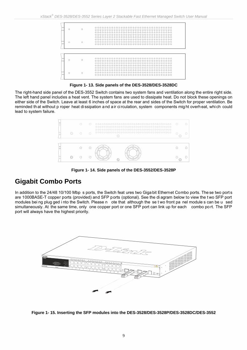
Figure 1- 13. Side panels of the DES-3528/DES-3528DC
The right-hand side panel of the DES-3552 Switch contains two system fans and ventilation along the entire right side. The left hand panel includes a heat vent. The system fans are used to dissipate heat. Do not block these openings on either side of the Switch. Leave at least 6 inches of space at the rear and sides of the Switch for proper ventilation. Be reminded th at without p roper heat di ssipation a nd a ir ci rculation, system components mig ht overh eat, whi ch could lead to system failure.
Figure 1- 14. Side panels of the DES-3552/DES-3528P
Gigabit Combo Ports In addition to the 24/48 10/100 Mbp s ports, the Switch feat ures two Giga bit Ethernet Combo ports. The se two port s are 1000BASE-T copper ports (provided) and SFP ports (optional). See the di agram below to view the t wo SFP port modules bei ng plug ged i nto the Switch. Please n ote that although the se t wo front pa nel module s can be u sed simultaneously. At the same time, only one copper port or one SFP port can link up for each combo po rt. The SFP port will always have the highest priority.
Figure 1- 15. Inserting the SFP modules into the DES-3528/DES-3528P/DES-3528DC/DES-3552

xStack® DES-3528/DES-3552 Series Layer 2 Stackable Fast Ethernet Managed Switch User Manual
10
Figure 1- 16. Installing the SFP Module

xStack® DES-3528/DES-3552 Series Layer 2 Stackable Fast Ethernet Managed Switch User Manual
11
Section 2
Installation Package Contents
Before You Connect to the Network
Installing the Switch without the Rack
Installing the Switch in a Rack
Mounting the Switch in a Standard 19" Rack
Power On (AC Power)
Power Failure (AC Power)
Connecting DC Power to the DES-3528DC
Package Contents Open the shi pping carton of the Switch and carefull y unpack its contents. The carton should contain the following items:
One xStack® stand-alone switch
One AC power cord*
Registration card
Mounting kit (two brackets and screws)
Four rubber feet with adhesive backing
RS-232 console cable
If any item is found missing or damaged, please contact your local D-Link Reseller for replacement.
* Please Note the DES-3528DC Switch does not require an AC power cord therefore none is provided.
Before You Connect to the Network The site where you install the Switch may greatly affect its performance. Please follow these guidelines for setting up the Switch.
• Install the Switch on a sturdy, level surface that can support at least 6.6 lb (3 kg) of weight for DES-3528/DES-3528DC, at least 13.2 lb (6 kg ) of wei ght for D ES-3552/DES-3528P. Do not place he avy objects o n the Switch.
• The power outlet should be within 1.82 meters (6 feet) of the Switch.
• Visually inspect the power cord and see that it is fully secured to the AC power port.
• Make sure that there is proper he at dissipation from and adequat e ventilation arou nd the Switch. Leave at least 10 cm (4 inches) of space at the front and rear of the Switch for ventilation.
• Install the Switch in a fairly cool and dry place for the acceptable temperature and humidity operating ranges.
• Install the Switch in a site free from st rong electromagnetic field generators (such as motors), vibration, dust, and direct exposure to sunlight.
• When installing the Switch on a level surfa ce, attach the rubber feet to the bottom of the d evice. The rubber feet cushions help protect the casing from scratches and prevent it from scratching other surfaces.

xStack® DES-3528/DES-3552 Series Layer 2 Stackable Fast Ethernet Managed Switch User Manual
12
Installing the Switch without the Rack When installing the Switch on a deskt op or shelf, the rubb er feet included with the Switch shoul d first be attached. Attach these cushioning feet on the bottom at each corner of the device. Allow enough ventilation space between the Switch and any other objects in the vicinity.
Figure 2- 1. Preparing the Switch for installation on a desktop or shelf
Installing the Switch in a Rack The Switch can be mounted in a standard 19" rack. Use the following diagrams to guide you.
Figure 2- 2. Fasten mounting brackets to the Switch
Fasten the mounting brackets to the S witch using the screws provided. With the brackets attached securely, you ca n mount the Switch in a standard rack as shown in Figure 2-3 below.

xStack® DES-3528/DES-3552 Series Layer 2 Stackable Fast Ethernet Managed Switch User Manual
13
Mounting the Switch in a Standard 19" Rack
CAUTION: Installing syste ms in a rack without the front and side stabili zers installed could cause the rack to tip over, potentiall y resultin g in bodily in jury unde r certai n circu mstances. The refore, alway s install the stabilizers before insta lling components in the ra ck. After installing components in a rack, do not pull mo re than one component out of the ra ck on its slide assemblies at one time. The weight of more than one extended component could cause the rack to tip over and may result in injury.
Figure 2- 3. Installing the Switch in a rack
Power On (AC Power) Plug one end of the AC p ower cord into the powe r connector of the Switch a nd the other end into the local po wer source outlet.
After the Switch is powered on, the LED indicators will momentarily blin k. This blinking of the LED indicators represents a reset of the system.
Power Failure (AC Power) As a precaution for A C p ower supply units, in th e event of a powe r failure, unplu g the Switch. Wh en power ha s resumed, plug the Switch back in.
xStack® DES-3528/DES-3552 Series Layer 2 Stackable Fast Ethernet Managed Switch User Manual
14
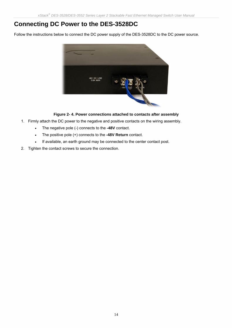
Connecting DC Power to the DES-3528DC Follow the instructions below to connect the DC power supply of the DES-3528DC to the DC power source.
Figure 2- 4. Power connections attached to contacts after assembly
1. Firmly attach the DC power to the negative and positive contacts on the wiring assembly.
• The negative pole (-) connects to the -48V contact.
• The positive pole (+) connects to the -48V Return contact.
• If available, an earth ground may be connected to the center contact post.
2. Tighten the contact screws to secure the connection.
xStack® DES-3528/DES-3552 Series Layer 2 Stackable Fast Ethernet Managed Switch User Manual
15
Section 3
Connecting the Switch Switch to End Node
Switch to Hub or Switch
Connecting To Network Backbone or Server
NOTE: All 24/48 high-performance NWay Ethernet ports can support both MDI-II and MDI-X connections.
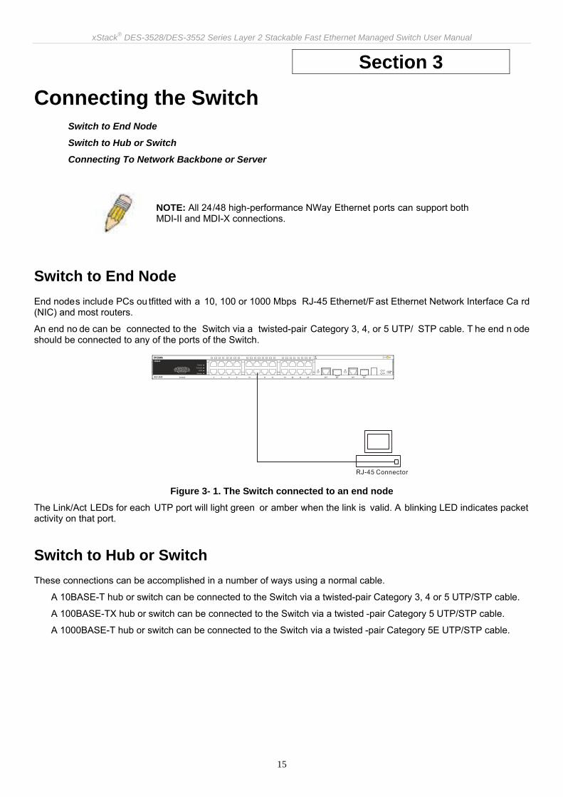
Switch to End Node End nodes include PCs ou tfitted with a 10, 100 or 1000 Mbps RJ-45 Ethernet/F ast Ethernet Network Interface Ca rd (NIC) and most routers.
An end no de can be connected to the Switch via a twisted-pair Category 3, 4, or 5 UTP/ STP cable. T he end n ode should be connected to any of the ports of the Switch.
Figure 3- 1. The Switch connected to an end node
The Link/Act LEDs for each UTP port will light green or amber when the link is valid. A blinking LED indicates packet activity on that port.
Switch to Hub or Switch These connections can be accomplished in a number of ways using a normal cable.
A 10BASE-T hub or switch can be connected to the Switch via a twisted-pair Category 3, 4 or 5 UTP/STP cable.
A 100BASE-TX hub or switch can be connected to the Switch via a twisted -pair Category 5 UTP/STP cable.
A 1000BASE-T hub or switch can be connected to the Switch via a twisted -pair Category 5E UTP/STP cable.

xStack® DES-3528/DES-3552 Series Layer 2 Stackable Fast Ethernet Managed Switch User Manual
16
Figure 3- 2. The Switch connected to a normal (non-Uplink) port on a hub or switch using a straight or
crossover cable
Connecting To Network Backbone or Server The two SFP combo ports are ideal for linking to a network backbone or server. The copper ports operate at a speed of 1000, 100 or 10Mbps in full or half duplex mode. The fiber optic ports can operate at 100Mbps or 1000Mbps in full duplex mode.
Connections to the Gigabit Ethernet po rts are m ade using fiber optic cable or Category 5E copper cable, depending on the type of port. A valid connection is indicated when the Link LED is lit.
Figure 3- 3. Connecting the Switch to a Server

xStack® DES-3528/DES-3552 Series Layer 2 Stackable Fast Ethernet Managed Switch User Manual
17
Section 4
Introduction to Switch Management Management Options
Web-based Management Interface
SNMP-Based Management
Connecting the Console Port (RS-232 DCE)
First Time Connecting to the Switch
Password Protection
SNMP Settings
IP Address Assignment
Management Options This system may be man aged out-of-band through the con sole port on the fro nt panel o r in-band using Telnet. The user may also choose the web-based management, accessible through a web browser.
Web-based Management Interface After you have su ccessfully installed the Switch, yo u can configure the Swit ch, monitor th e LED pa nel, and display statistics g raphically usin g a web b rowser, such a s Ne tscape Navigator (v ersion 6.2.3 and hi gher) or Mi crosoft® Internet Explorer (version 6.0).
SNMP-based Management You can manage the S witch with an SNMP-compatible console prog ram. The Switch su pports SNMP version 1.0, version 2.0 and version 3.0. The SNMP agent decodes the incoming SNMP messages and responds to requests with MIB objects stored in the database. The SNMP agent updates the MIB objects to generate statistics and counters.
Connecting the Console Port (RS-232 DCE) The Switch p rovides an RS-232 serial port that enables a co nnection to a computer or terminal for monitoring an d configuring the Switch. This port is a female DB-9 connector, impleme nted as a data co mmunications equipm ent (DCE) connection.
To use the console port, you need the following equipment:
A terminal or a computer with both a serial port and the ability to emulate a terminal.
A null modem or Parallel RS-232 cable with a male DB-9 connector for the console port on the Switch.
To connect a terminal to the console port:
1. Connect the male conne ctor of the RS -232 cable di rectly to the console po rt on the Switch, and tighten t he captive retaining screws.
2. Connect the other e nd of the cabl e to a terminal o r to the serial connector of a comp uter running termina l emulation software. Set the terminal emulation software as follows:
3. Select the appropriate serial port (COM port 1 or COM port 2).
4. Set the data rate to 115200 baud.
5. Set the data format to 8 data bits, 1 stop bit, and no parity.
6. Set flow control to none.
7. Und er Properties, select VT100 for Emulation mode.

xStack® DES-3528/DES-3552 Series Layer 2 Stackable Fast Ethernet Managed Switch User Manual
18
8. Select Terminal keys f or Function, Arrow, an d Ctrl key s. Ensu re that you sele ct Te rminal keys (not Windows keys).
9. After you have correctly set up the terminal, plug the power cable into the power receptacle on the back of the Switch. The boot sequence appears in the terminal.
10. After the boot sequence completes, the console login screen displays.
11. If you have not logged into the command line interface (CLI) p rogram, press the Enter key at the User n ame and password prompts. There i s no de fault user name and password for the Switch. The administrator must first create user na mes and password s. If you have previou sly set up use r accounts, log in and contin ue to configure the Switch.
12. Enter the commands to complete you r desi red ta sks. Many commands requi re admini strator-level a ccess privileges. Read the next section fo r more information on setting up user accounts. See the DES-3528/DES-3552 Switch Series CLI Manual on the do cumentation CD f or a li st of all com mands an d ad ditional information on using the CLI.
13. When you h ave co mpleted you r tasks, exit the session with t he log out co mmand or close th e em ulator program.
14. Make sure the terminal or PC you are using to make this connection is configured to match these settings.
If you are having proble ms making this conne ction on a PC, ma ke sure the e mulation is set to VT-100. You will be able to set the emulation by clicking o n the File menu in you HyperTerminal window, clicking on Properties in the drop-down menu, and then clicking the Settings tab. This is where you will find the Emulation options. If you still d o not see anything, try rebooting the Switch by disconnecting its power supply.
Once connected to the console, the screen below will appear on your console screen. This is where the user will enter commands to perform all the available management functions. The Switch will prompt the user to ente r a user name and a password. Upon the initial connection, there is no user name or password and therefore just press “enter” twice to access the command line interface.
DES-3528 Fast Ethernet Switch
Command Line Interface
Firmware: Build 2.00.B033 Copyright(C) 2009 D-Link Corporation. All rights reserved.
Username:
Figure 4- 1. Initial screen after first connection
NOTE: When you use HyperTerminal with the Microsoft® Windo ws® 2000 operating sys-tem, ensure that you have Windo ws 2000 Service Pack 2 or later installed. Wi ndows 2000 Service Pa ck 2 allows yo u to use arro w keys in HyperTerminal's VT100 em ulation. See www.microsoft.com for information on Windows 2000 service packs.

xStack® DES-3528/DES-3552 Series Layer 2 Stackable Fast Ethernet Managed Switch User Manual
19
First Time Connecting to the Switch The Switch supports user-based security that can allow you to pre vent unauthorized users from accessing the Switch or changing its settings. This section tells how to log onto the Switch.
NOTE: The passwords used to access the Switch are case-sensitive; therefore, "S" is not the same as "s."
When you first connect to the Switch, you will be presented with the first login screen.
NOTE: Press Ctrl+R to ref resh the scre en. This command can be used at a ny time to force the console program in the Switch to refresh the console screen.
Press Enter in both the Username and Password fields. You will be given access to the command prompt DES-3528:5# shown below:
There is no initial username or password. Leave the Username and Password fields blank.
DES-3528 Fast Ethernet Switch
Command Line Interface
Firmware: Build 2.00.B033 Copyright(C) 2009 D-Link Corporation. All rights reserved.
Username:
PassWord:
DES-3528:5#
Figure 4- 2. Command Prompt
NOTE: The first user automatically gets Administrator level privileges. It is recommended to create at least one Admin-level user account for the Switch.
Password Protection The Switch does not have a default user name and password. One of the first tasks when settings up the Switch is to create user accounts. Once logge d in using a pred efined administrator-level user name, users will have privileged access to the Switch's management software. After your initial login, define new pa sswords for both def ault user na mes to prevent un authorized access to the Switch, and record the passwords for future reference.
To create an administrator-level account for the Switch, follow these steps:
At the CLI login prompt, enter create account admin followed by the <user name> and press the Enter key.
The Switch will then prompt the user for a password. Type the <password> used for the adm inistrator account being created and press the Enter key.
Again, the user will be prompted to enter the same password again to verify it. Type the same password and press the Enter key.
Successful creation of the new administrator account will be verified by a Success message.

xStack® DES-3528/DES-3552 Series Layer 2 Stackable Fast Ethernet Managed Switch User Manual
20
NOTE: Passwords are ca se sensitive. User names and passwo rds can be up to 15 characters in length.
The sample belo w illu strates a successful creati on of a new admi nistrator-level account with th e user n ame "newmanager".
DES-3528:5# create account admin newmanager Command: create account admin newmanager Enter a case-sensitive new password: ******** Enter the new password again for confirmation: ******** Success.
DES-3528:5#
Figure 4- 3. New administrator level account
NOTICE: CLI configuration commands only modify the running configuration file and are not saved when t he Switch is rebooted. To save all your configuration changes in n onvolatile sto rage, you m ust use th e sa ve comma nd to copy the running configuration file to the startup configuration.
SNMP Settings Simple Net work Management Proto col (SNMP ) is an OS I La yer 7 (Appli cation Laye r) designed sp ecifically for managing an d monitorin g network dev ices. SNMP enabl es net work ma nagement station s to read and modify th e settings of gateways, routers, switches, and other network devices. Use SNMP to configure system features for proper operation, monitor performance and detect potential problems in the Switch, switch group or network.
Managed devices that sup port SNMP i nclude software (referred to as a n agent), which runs locally on the device. A defined set of variables (managed objects) is maintained by the SNMP agent and used to manage the device. These objects are defined in a Manage ment Informatio n Base (M IB), which pro vides a sta ndard p resentation of the information controlled by the on-board SNMP agent. SNMP defines both the format of the MIB specifications and the protocol used to access this information over the network.
The Switch supports SNMP versions 1, 2c, and 3. You can specify which version of SNMP you want to use to monitor and control the Switch. T he three versions of SNMP vary in the level of se curity provided between the management station and the network device.
In SNMP v.1 and v.2, use r authentication is accomp lished using ' community strings', which function like passwords. The remote user SNMP application and the Switch SNMP must use the same community string. SNMP packets from any station that has not been authenticated are ignored (dropped).
The default community strings for the Switch used for SNMP v.1 and v.2 management access are:
public - Allows authorized management stations to retrieve MIB objects.
private - Allows authorized management stations to retrieve and modify MIB objects.
SNMP v.3 u ses a more sop histicated authenticati on pro cess that is sepa rated into two parts. The first part is to maintain a list of users an d their attribu tes that are a llowed to act as SNMP managers. The se cond part descri bes what each user on that list can do as an SNMP manager.
The Switch allows groups of users to be listed and configured with a shared set of privileges. The SNMP version may also be set for a listed group of SNMP managers. Thus, you may create a group of SNMP managers that are allowed to view rea d-only information or receive traps u sing SNMP v.1 while assig ning a highe r level of secu rity to another group, granting read/write privileges using SNMP v.3.
xStack® DES-3528/DES-3552 Series Layer 2 Stackable Fast Ethernet Managed Switch User Manual
21
Using SNMP v.3 individual use rs or groups of SNMP m anagers can be allowed to pe rform o r be restricted fro m performing specific SNMP management functions. The functions allowed o r restricted a re defined using the Object Identifier (OID) associated with a specific MIB. An additional layer of security is available for SNMP v.3 in that SNMP messages may be encrypted. To read more about how to configure SNMP v.3 settings for the Switch read the section entitled Management.
Traps Traps are messages that alert network personnel of events that occur on the Switch. The events can be as serious as a reboot (so meone a ccidentally turne d OFF the Switch ), or less se rious like a port st atus ch ange. The Switch generates traps and se nds them to the trap recipient (or net work manager). Typical trap s include trap messag es for Authentication Failure, Topology Change and Broadcast\Multicast Storm.
MIBs The Switch in the Management Information Base (MIB) stores management and counter information. The Switch uses the standard MIB-II Management Information Base m odule. Consequently, values fo r MIB o bjects can b e retrieved from any SNMP-based network management software. In addition to the s tandard MIB-II, the Switch also supports its own proprietary enterprise MIB as an extended Ma nagement Information Base. Specifying the MIB Object Identifier may also retrieve the proprietary MIB. MIB values can be either read-only or read-write.
IP Address Assignment Each Switch must be assigned its own IP Address, which is used for communication with an SNMP network manager or other TCP/IP application (for exam ple BOOTP, TFTP). The Switch' s default IP address is 10.90.9 0.90. You can change the default Switch IP address to meet the specification of your networking address scheme.
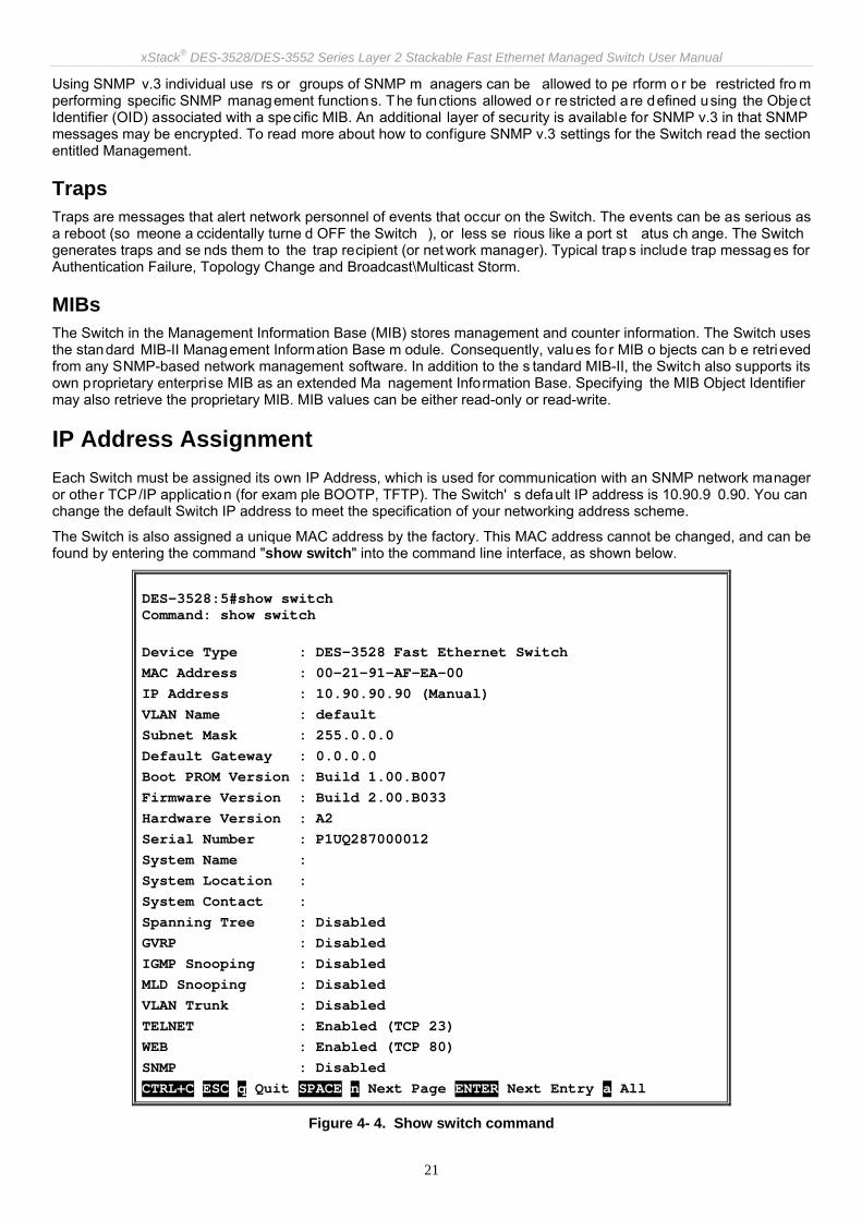
The Switch is also assigned a unique MAC address by the factory. This MAC address cannot be changed, and can be found by entering the command "show switch" into the command line interface, as shown below.
DES-3528:5#show switch Command: show switch
Device Type : DES-3528 Fast Ethernet Switch MAC Address : 00-21-91-AF-EA-00 IP Address : 10.90.90.90 (Manual) VLAN Name : default Subnet Mask : 255.0.0.0 Default Gateway : 0.0.0.0 Boot PROM Version : Build 1.00.B007 Firmware Version : Build 2.00.B033 Hardware Version : A2 Serial Number : P1UQ287000012 System Name : System Location : System Contact : Spanning Tree : Disabled GVRP : Disabled IGMP Snooping : Disabled MLD Snooping : Disabled VLAN Trunk : Disabled TELNET : Enabled (TCP 23) WEB : Enabled (TCP 80) SNMP : Disabled CTRL+C ESC q Quit SPACE n Next Page ENTER Next Entry a All
Figure 4- 4. Show switch command

xStack® DES-3528/DES-3552 Series Layer 2 Stackable Fast Ethernet Managed Switch User Manual
22
The Switch's MAC address can also be found from the Web management program on the Switch Information (Basic Settings) window on the Configuration menu.
The IP addre ss for the Switch must be set before it can be mana ged with the Web -based manager. The Switch IP address can be automatically set using BOOTP or DHCP protocols, in which case the actual address assigned to the Switch must be known.
The IP address may be set using the Command Line Interface (CLI) over the console serial port as follows:
Starting at the command line prompt, enter the commands config ipif System ipaddress xxx.xxx.xxx.xxx/yyy.yyy.yyy.yyy
Where the x's rep resent the IP addre ss to be assig ned to the IP interface n amed System and the y's repre sent the corresponding subnet mask.
Alternatively, you can en ter config ipif System ipaddress xxx.xxx.xxx.xxx/z. Where the x's rep resent the IP address to be assigned to the IP interface named System and the z represents the corresponding number of subnets in CIDR notation.
The IP interface named System on the Switch can be assigned an IP address and subnet mask, and then be used to connect a management station to the Switch's Telnet or Web-based management agent.
DES-3528:5#config ipif System ipaddress 10.90.90.90/255.0.0.0 Command: config ipif System ipaddress 10.90.90.90/8 Success.
DES-3528:5#
Figure 4- 5. Assigning the Switch an IP Address
In the above example, the Switch was assigned an I P address of 10.90.90.9 0 with a su bnet mask of 255 .0.0.0. (the CIDR form was used to set the address (10.90.9 0.90/8). The system message Success indicates that the command was executed successfully. The Switch can now be configured and managed via Telnet and the CLI or via the Web-based management.

xStack® DES-3528/DES-3552 Series Layer 2 Stackable Fast Ethernet Managed Switch User Manual
23
Section 5
Web-based Switch Configuration Introduction
Login to Web Manager
Web-based User Interface
Web Pages
Introduction All software functions of the Switch can be managed, configured and monitored via the embedded web-based (HTML) interface. The Switch can be manag ed from remote stat ions anywhere on the network thro ugh a stan dard browser such as Opera, Netscape Navigator/Communicator, or Micr osoft Internet Explore r. The bro wser acts as a universal access tool and can communicate directly with the Switch using the HTTP protocol.
The Web-based management module a nd the Con sole program (and Telnet) a re different ways to access the sam e internal switching software and configu re it. Thus, all settings encountered in web-based management are the same as those found in the console program.
Login to Web Manager To begin m anaging the Switch, sim ply run the bro wser you ha ve installed o n your co mputer and p oint it to the IP address you have defined for the dev ice. Th e URL in the address bar sh ould read som ething like: http://123.123.123.123, where the numbers 123 represent the IP address of the Switch.
NOTE: The Factory default IP address for the Switch is 10.90.90.90.
This opens the management module's user authentication window, as seen below.
Figure 5- 1. Enter Network Password dialog
Enter “admin” in both the User Name and Password fields and click OK. This will open the Web-based user interface. The Switch management features available in the web-based manager are explained below.

xStack® DES-3528/DES-3552 Series Layer 2 Stackable Fast Ethernet Managed Switch User Manual
24
Web-based User Interface The u ser inte rface provide s a ccess to various Swit ch co nfiguration an d ma nagement windows, allo ws you to view performance statistics, and permits you to graphically monitor the system status.
Areas of the User Interface The figure be low shows the user interface. The u ser interface is di vided into three distin ct areas a s described in the table.
Figure 5- 2. Main Web-Manager page
Area Function
Area 1 Select the folder or wi ndow to be displ ayed. The folder ico ns can be opene d to display the hyper-linked window buttons and subfolders contained within them. Cli ck the D-Link logo to go t o the D-Link website.
Area 2 Presents a graphical near real -time image of the f ront panel of the Switch. T his area displays the Switch's port s and expa nsion modul es, sho wing por t activity, duplex mode, or flow control, depending on the specified mode.
Various areas of the grap hic can be selected for performing management functions, including port configuration.
Area 1
Area 2
Area 3

xStack® DES-3528/DES-3552 Series Layer 2 Stackable Fast Ethernet Managed Switch User Manual
25
Area 3 Presents switch information based on your selection and the entry of configuration data.
NOTICE: Any changes made to the Switch configuration during the current session must be saved in the Save Changes web menu (explained below) or use the command line interface (CLI) command save.
Web Pages When you connect to the management mode of the Switch with a web browser, a login window is displayed. Enter a user name and password to access the Switch's management mode.
Below is a list and description of the main folders available in the web interface:
Configuration – A detailed discussio n about conf iguring some of the basic functions of the Switch, including accessing the System Informatio n, Serial Port Settin gs, IP Addres s, Port Configuration, Static ARP Settings, Use r Accounts, System Log Configuration, System Severity Settings, DHCP R elay, DHCP Local Relay Settings, DHCP Auto Config uration Settin gs, MAC Ad dress A ging Time, Web Settings, Telnet Settings , Pas sword Encryption, Clipaging Settings , Firmware Informatio n, Dual Configuration Settings , PPPoE Circuit ID Insertion Settings , Ping Test, SNTP Settings, MAC Notification Settings, PoE, SNMP Settings, sFlow, Stacking Mode Settings, Time Range Settings, and Single IP Management.
L2 Features – A discussi on of the Lay er 2 featu res on the Sw itch, including Jumbo Frame, 802.1Q VLA N, Voice VLAN, Subenet VLAN, QinQ, 802.1v Protocol VLA N, RSPAN S ettings, GV RP Setti ngs, GVRP Timer Settings, Asymmetric VLAN Settings , MAC-bas ed VLAN Settings , PVID Auto As sign Settings, VLAN Trunk Settings , Port Trunking, LACP Port Settings, Traffic Segmentati on, IGMP Snoopi ng, ML D Snoopi ng, Port Mirror, Loopba ck Detection Set tings, BPDU Protection Se ttings, Spann ing Tree, Fo rwarding & Fil tering, LLDP, CFM, an d Ethernet OAM.
L3 Features – A discussi on of the Lay er 3 featu res on the Swit ch, inc luding Ipv4 Interface Settings , Ipv4 Default Route Settings, Gratuitous ARP, ARP Spoofing Pre vention Settings, D NS Relay, DHCP Server an d Policy Route Settings.
QoS – Fe atures info rmation on S witch QoS fun ctions, in cluding HO L Blocking Preve ntion, Bandwi dth Control, Traffic Control, 802.1p Default Priority, 802.1p Use r Priority, QoS Scheduling Mechanism, QoS Scheduling, CoS Bandwidth Control Settings and SRED.
Security – Features information on S witch security functions, including Safeguard Engine, Trusted Host, IP-MAC-Port Binding, Port Security, DHCP Server Scree ning, 802.1X, SSL Settings, SSH, Access Authentication Contr ol, MAC-based Access Control, Web Authentication, JWAC, NetBIOS Filtering Settings, and Multiple Authentication.
ACL – Discussion on the ACL functions of the Switch, including ACL Configuration Wizard, Access Profile List, CPU Access Profile List, ACL Finder, and ACL Flow Meter.
Monitoring – Features in formation about the monitoring fun ctions on the Swit ch including, Device Status, Cabl e Diagnostic, CPU Utilization, Port Utilization, Packet Size, Packets, Errors, Port Access Control, Browse ARP Table, Browse Route Table, Br owse VLAN , Show VLAN Por ts, Br owse Voic e VLAN D evice, Br owse DHCP Ser ver Dynamic Binding, Brow se DHCP Co nflict IP, Browse Se ssion Table, MLD Snoopi ng, IGMP Snoopin g, Etherne t OAM, JWAC Authentication State, MBA Authenticatio n State, WAC Authentication State, ARP & FDB Ta ble, MAC Address Table, and System Log.
NOTE: Be sure to configure the user name a nd password in the Use r Accounts window before connecting the Switch to the greater network.
xStack® DES-3528/DES-3552 Series Layer 2 Stackable Fast Ethernet Managed Switch User Manual
26
Appendix A
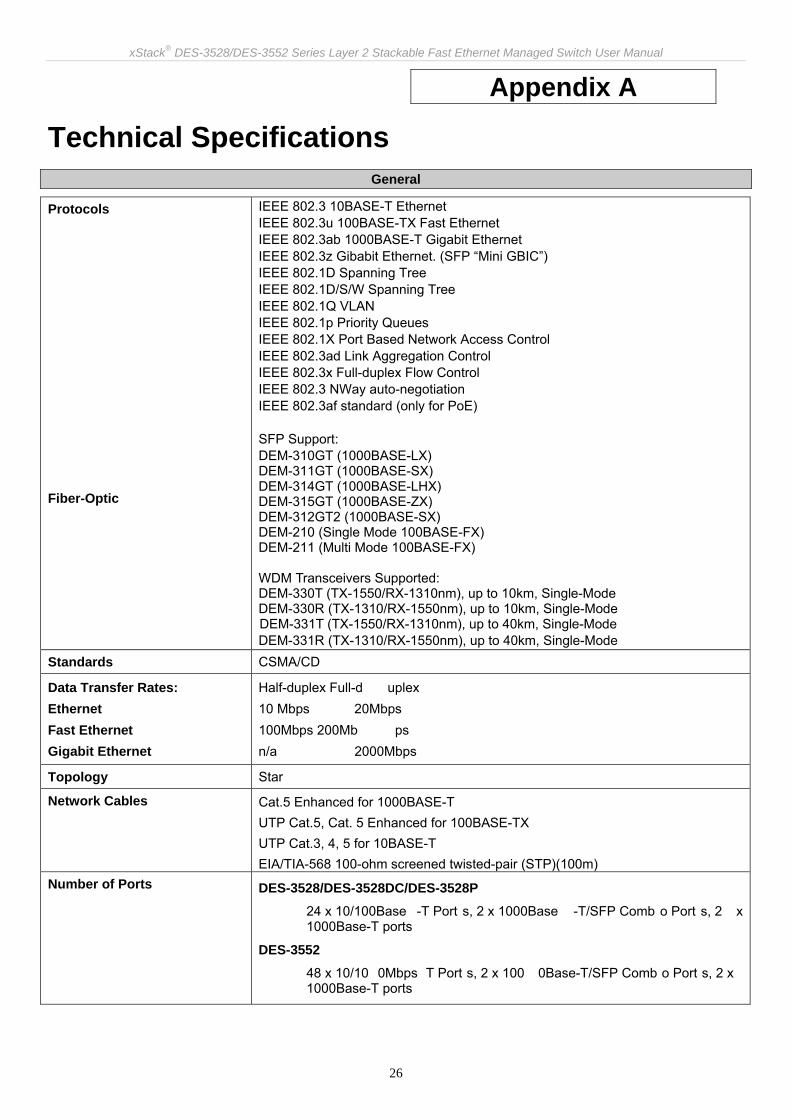
Technical Specifications General
Protocols Fiber-Optic
IEEE 802.3 10BASE-T Ethernet IEEE 802.3u 100BASE-TX Fast Ethernet IEEE 802.3ab 1000BASE-T Gigabit Ethernet IEEE 802.3z Gibabit Ethernet. (SFP “Mini GBIC”) IEEE 802.1D Spanning Tree IEEE 802.1D/S/W Spanning Tree IEEE 802.1Q VLAN IEEE 802.1p Priority Queues IEEE 802.1X Port Based Network Access Control IEEE 802.3ad Link Aggregation Control IEEE 802.3x Full-duplex Flow Control IEEE 802.3 NWay auto-negotiation IEEE 802.3af standard (only for PoE) SFP Support: DEM-310GT (1000BASE-LX) DEM-311GT (1000BASE-SX) DEM-314GT (1000BASE-LHX) DEM-315GT (1000BASE-ZX) DEM-312GT2 (1000BASE-SX) DEM-210 (Single Mode 100BASE-FX) DEM-211 (Multi Mode 100BASE-FX)
WDM Transceivers Supported: DEM-330T (TX-1550/RX-1310nm), up to 10km, Single-Mode DEM-330R (TX-1310/RX-1550nm), up to 10km, Single-Mode DEM-331T (TX-1550/RX-1310nm), up to 40km, Single-Mode DEM-331R (TX-1310/RX-1550nm), up to 40km, Single-Mode
Standards CSMA/CD
Data Transfer Rates: Ethernet Fast Ethernet Gigabit Ethernet
Half-duplex Full-d uplex 10 Mbps 20Mbps 100Mbps 200Mb ps n/a 2000Mbps
Topology Star
Network Cables
Cat.5 Enhanced for 1000BASE-T UTP Cat.5, Cat. 5 Enhanced for 100BASE-TX UTP Cat.3, 4, 5 for 10BASE-T EIA/TIA-568 100-ohm screened twisted-pair (STP)(100m)
Number of Ports DES-3528/DES-3528DC/DES-3528P
24 x 10/100Base -T Port s, 2 x 1000Base -T/SFP Comb o Port s, 2 x 1000Base-T ports
DES-3552
48 x 10/10 0Mbps T Port s, 2 x 100 0Base-T/SFP Comb o Port s, 2 x 1000Base-T ports

xStack® DES-3528/DES-3552 Series Layer 2 Stackable Fast Ethernet Managed Switch User Manual
27
Physical and Environmental
Internal Power Supply DES-3528
Input: 100~240V, AC/0.5A(Max), 50~60Hz
Output: 12V, 1.2A(Max)
Internal universal power supply
DES-3552
Input: 100~240V, AC/0.8A(Max), 50~60Hz
Output: 12V, 2.1A(Max)
Internal universal power supply
DES-3528P
Input: 100~240V, AC/6.3A(Max), 50~60Hz
Output: 50V, 7.5A(Max), 12V, 1.4A(Max)
Internal universal power supply
DES-3528DC
DC Power Input: 36-75 V,DC/ 0.6A (Max)
Output: 12V, 1.2A (Max)
Internal universal power supply.
DES-3528/DES-3552
Provides one connector on the re ar panel to in stall an optio nal external RPS (DPS-200) to enhan ce the reliability. When the internal po wer fails, the optional ext ernal RPS will take over all the power imm ediately and automatically.
DES-3528P
Provides one connector on the re ar panel to in stall an optio nal external RPS (DPS-600) to enhan ce the reliability. When the internal po wer fails, the optional ext ernal RPS will take over all the power imm ediately and automatically.
Power Consumption DES-3528
Max. 20.5 watts
DES-3528DC
Max. 18.38 watts
DES-3552
Max. 33.1 watts
DES-3528P
Max. 505.1 watts
Operating Temperature 0 - 45°C
Storage Temperature -40 - 70°C
Humidity Operation Relative Humidity: 5 - 95% non-condensing.
Storage Relative Humidity: 5 – 95% non-condensing.
Dimensions DES-3528/DES-3528DC 441(W) x 210(D) x 44(H) mm
DES-3552/DES-3528P

xStack® DES-3528/DES-3552 Series Layer 2 Stackable Fast Ethernet Managed Switch User Manual
28
441(W) x 310(D) x 44(H) mm
Weight DES-3528
2.51kg (5.53lbs)
DES-3528DC
2.52kg (5.55lbs)
DES-3552
4.09kg (9.01lbs)
DES-3528P
5.42kg (11.94lbs)
EMI CE Class A, FCC Class A, C-Tick, VCCI
Safety CB Report, UL
LED indicators for DES-3528/DES-3528DC/DES-3552/DES-3528P Location LED Indicative Color Status Description
Solid Light Power On Power Green
Light off Power Off
Solid Light Console on
Blinking POST is in progress. Console Green
Light off Console off
Solid Light RPS is in Use RPS(Not for DES-3528DC) Green
Light Off RPS Off
Solid Light When the device is the stacking master.
Master(MS) Green
Light off Not the Stacking Master.
Per Device
Stacking ID Green Cap able 1-8
The Box ID is assigned either by the user (static mode) or by the system (automatic mode). When the box becomes a primary master the 7 segments work bi-functionally. The box ID and “H” indicate the primary Master and the display on other switches will be shown in turn. That is boxID- > H -> boxID -> H…
Link/Act/Speed Green Solid Light Link/Act/Speed Mode Mode Select Button (DES-3528P only) PoE Green Solid Light PoE Mode
LED Per 10/100 Mbps Port Link/Act/Speed Green/Amber Solid Green When there i s a secure 1 00Mbps Fast Ethernet con nection (or link) at any of the ports.

xStack® DES-3528/DES-3552 Series Layer 2 Stackable Fast Ethernet Managed Switch User Manual
29
Blinking GreenWhen there is reception or transmission (i.e. Activity—Act) of data occurring at a Fast Ethernet connected port.
Solid Amber When th ere is a secure 10Mbps Ethernet con nection (or link) at any of the ports.
Blinking AmberWhen there is reception or transmission (i.e. Ac tivity—Act) of data occu rring at an Ethernet connected port.
Light off No link
Solid Green Power device is connected.
Blinking Port has detected an error condition.
PoE (DES-3528P only)
Green
Light off Power device may receiv e power from an AC p ower source or no 802.3af/802.3at PD is found.
Solid Green When there is a secure 1000Mb ps connection (or link) at any of the ports.
Blinking GreenWhen there is reception or transmission (i.e. Activity--Act) of data occurring at a 1000Mbps connected port.
Solid Amber When there is a se cure 10/100M bps Fast Ethern et conne ction (or link) at any of the ports.
Blinking Amber
When there is reception or transmission (i.e. Activity—Act) of data occurring at a 10/100Mbps Fast Etherne t conn ected port.
LED Per GE Port Link/Act/Speed Green/Amber
Light off No link
Solid Green When there is a secure 1000Mb ps connection (or link) at the ports.
Blinking GreenWhen there is reception or transmission (i.e. Activity--Act) of data occurring at a 1000Mbps connected port.
Solid Amber When there is a se cure 100 Mbps connection (or link) at any of the ports.
Blinking AmberWhen there is reception or transmission (i.e. Activity—Act) of data occurring at a 100Mbs connected ports.
LED per SFP Port Link/Act/Speed Green/Amber
Light off No link

xStack® DES-3528/DES-3552 Series Layer 2 Stackable Fast Ethernet Managed Switch User Manual
30
Performance
Feature Detailed Description
Wire speed on all FE/GE ports Full-wire speed (full-duplex) operation on all FE/GE ports
Forwarding Mode Store and Forward
Switching Capacity DES-3528/DES-3528DC/DES-3528P
12.8Gbps
DES-3552
17.6Gbps
64 Byte system packet fo rwarding rate
DES-3528/DES-3528DC/DES-3528P
9.5 million 64-byte packets per second.
DES-3552
13.1 million 64-byte packets per second.
Priority Queues 8 Priority Queues per port
MAC Address Table Supports 16K MAC address
Transmission Method Store-and-forward
Packet Buffer 1 MB per device
Packet Filtering/Forward Rate 14,881 pps (10M port)
148,810 pps (100M port)
1,488,100 pps (1 Gbps port)
Forwarding Table Age Time Max age: 10-1000000 seconds. Default = 300.
Port Functions
Feature Detailed Description
Console Port DCE RS-232 DB-9 for out-of-band configuration of the software features.
10/100BaseT ports
Compliant to following standards:
• IEEE 802.3 compliance
• IEEE 802.3u compliance
• Support Half/Full-Duplex operations
• All ports support Auto MDI-X/MDI-II cross over
• IEEE 802.3x Flow Cont rol support for Full-Duplex mode, Back Pressure when Half-Duplex mode, and Head-of-line blocking prevention.
• Compliant IEEE802.3af standard(only for PoE)

xStack® DES-3528/DES-3552 Series Layer 2 Stackable Fast Ethernet Managed Switch User Manual
31
Combo ports
2 combo 1000BASE-T/SFP ports
1000BASE-T ports compliant to following standards:
• IEEE 802.3 compliance
• IEEE 802.3u compliance
• IEEE 802.3ab compliance
• Support Full-Duplex operations
• IEEE 802.3x Flow Control support for Full-Duplex mode, back pressure when Half-Duplex mode, and Head-of-line blocking prevention
SFP Transceivers Supported:
• DEM-310GT (1000BASE-LX)
• DEM-311GT (1000BASE-SX)
• DEM-314GT (1000BASE-LHX)
• DEM-315GT (1000BASE-ZX)
• DEM-312GT2 (1000BASE-SX)
• DEM-210 (Single Mode 100BASE-FX)
• DEM-211 (Multi Mode 100BASE-FX)
WDM Transceiver Supported:
• DEM-330T (TX-1550/RX-1310nm),up to 10km,Single-Mode
• DEM-330R (TX-1310/RX-1550nm), up to 10km,Single-Mode
• DEM-331T (TX-1550/RX-1310nm), up to 40km, Single-Mode
• DEM-331R (TX-1310/RX-1550nm), up to 40km, Single-Mode
Compliant to following standards:
• IEEE 802.3z compliance
• IEEE 802.3u compliance
1000BASE-T ports
1000BASE-T ports compliant to following standards:
• IEEE 802.3 compliance
• IEEE 802.3u compliance
• IEEE 802.3ab compliance
• Support Full-Duplex operations
• IEEE 802.3x Flow Control support for Full -Duplex mode, back pressure when Half-Duplex mode, and Head-of-line blocking prevention

xStack® DES-3528/DES-3552 Series Layer 2 Stackable Fast Ethernet Managed Switch User Manual
32
PoE Features DES-3528P
Feature Detailed Description
PoE Capable Ports DES-3528P: Port 1-24
Power feeding for PoE
DES-3528P
Per port 7W (Default)
Port 1~8 1~30W
Port 9~24 1~15.4W
Output capacity for PoE 370W
Power consumption Max. 505.1W
PoE Specification
1. Supplies power to PD device up to 15.4W per port, meeting IEEE802.3af standards
2. Auto discovery feature, automatically recognize the connection of PD device and immediately sends power to it
3. Auto disable port if the port current is over 350mA while other ports remain active
4. Active circuit protection, automatically disables the port if there is a short while other ports remain active
5. PSE provides the power following the classification below
Class Usage Max power used by PD
0 Default 15.4W
1 Optional 4.0W
2 Optional 7.0W
3 Optional 15.4W
4 User define 30W (only ports 1~8), but this can configure the power restriction upto 35W.
6. DES-3528P follows the standard PSE pin-out standard of Alternative A which sends out power over number 1,2,3,6 pins of 8 wires of CAT5 UTP cable.
7. DES-3528P works with all D-Link 802.3af capable devices. 8. DES- 3528P works with all non-802.3af capable D-Link AP, IP Cam and IP
phone via DWL-P50.

xStack® DES-3528/DES-3552 Series Layer 2 Stackable Fast Ethernet Managed Switch User Manual
33
FE Port Pin Assignment for Data Pairs: (MDI-X)
PIN# Signal Description
1 Receive+ Positive Receive signal
2 Receive- Negation Receive signal
3 Transmit+ Positive Transmit signal
4
5
6 Transmit- Negation Transmit signal
7
8
FE Port PSE Pinout Assignment for Power Pairs: (alternative A MDI-X)
PIN# Signal Description
1 Negative Vport Negative power signal
2 Negative Vport Negative power signal
3 Positive Vport Positive power signal
4
5
6 Positive Vport Positive power signal
7
8

xStack® DES-3528/DES-3552 Series Layer 2 Stackable Fast Ethernet Managed Switch User Manual
34
Appendix B
Cable Lengths Use the following table to as a guide for the maximum cable lengths.
Standard Media Type Maximum Distance
SFP 1000BASE-LX, Single-mode fiber module
1000BASE-SX, Multi-mode fiber module
1000BASE-LHX, Single-mode fiber module
1000BASE-ZX, Single-mode fiber module
10km
550m
40km
80km
1000BASE-T Category 5e UTP Cable 100m
100BASE-TX Category 5 and Category 5e UTP Cable (100 Mbps) 100m
10BASE-T Category 3, 4, 5, and 5e UTP Cable (10 Mbps) 100m
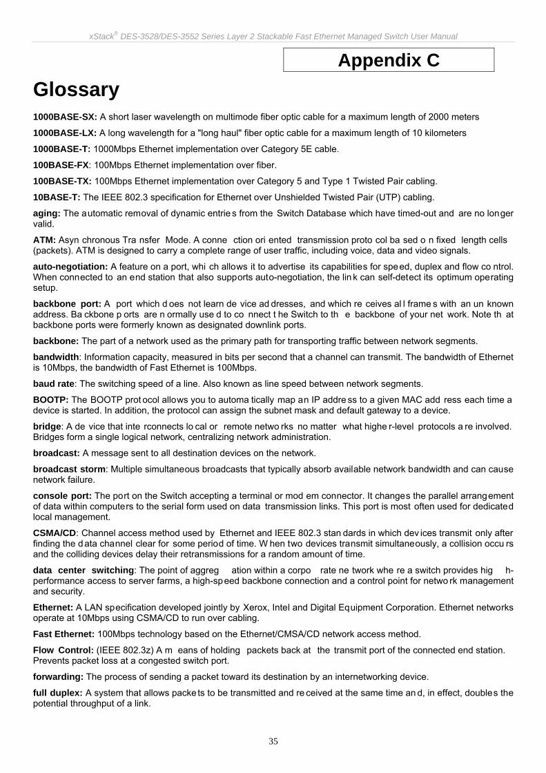
xStack® DES-3528/DES-3552 Series Layer 2 Stackable Fast Ethernet Managed Switch User Manual
35
Appendix C Glossary 1000BASE-SX: A short laser wavelength on multimode fiber optic cable for a maximum length of 2000 meters
1000BASE-LX: A long wavelength for a "long haul" fiber optic cable for a maximum length of 10 kilometers
1000BASE-T: 1000Mbps Ethernet implementation over Category 5E cable.
100BASE-FX: 100Mbps Ethernet implementation over fiber.
100BASE-TX: 100Mbps Ethernet implementation over Category 5 and Type 1 Twisted Pair cabling.
10BASE-T: The IEEE 802.3 specification for Ethernet over Unshielded Twisted Pair (UTP) cabling.
aging: The automatic removal of dynamic entrie s from the Switch Database which have timed-out and are no longer valid.
ATM: Asyn chronous Tra nsfer Mode. A conne ction ori ented transmission proto col ba sed o n fixed length cells (packets). ATM is designed to carry a complete range of user traffic, including voice, data and video signals.
auto-negotiation: A feature on a port, whi ch allows it to advertise its capabilities for speed, duplex and flow co ntrol. When connected to an end station that also supports auto-negotiation, the lin k can self-detect its optimum operating setup.
backbone port: A port which d oes not learn de vice ad dresses, and which re ceives al l frame s with an un known address. Ba ckbone p orts are n ormally use d to co nnect t he Switch to th e backbone of your net work. Note th at backbone ports were formerly known as designated downlink ports.
backbone: The part of a network used as the primary path for transporting traffic between network segments.
bandwidth: Information capacity, measured in bits per second that a channel can transmit. The bandwidth of Ethernet is 10Mbps, the bandwidth of Fast Ethernet is 100Mbps.
baud rate: The switching speed of a line. Also known as line speed between network segments.
BOOTP: The BOOTP prot ocol allows you to automa tically map an IP addre ss to a given MAC add ress each time a device is started. In addition, the protocol can assign the subnet mask and default gateway to a device.
bridge: A de vice that inte rconnects lo cal or remote netwo rks no matter what highe r-level protocols a re involved. Bridges form a single logical network, centralizing network administration.
broadcast: A message sent to all destination devices on the network.
broadcast storm: Multiple simultaneous broadcasts that typically absorb available network bandwidth and can cause network failure.
console port: The port on the Switch accepting a terminal or mod em connector. It changes the parallel arrangement of data within computers to the serial form used on data transmission links. This port is most often used for dedicated local management.
CSMA/CD: Channel access method used by Ethernet and IEEE 802.3 stan dards in which dev ices transmit only after finding the data channel clear for some period of time. W hen two devices transmit simultaneously, a collision occu rs and the colliding devices delay their retransmissions for a random amount of time.
data center switching: The point of aggreg ation within a corpo rate ne twork whe re a switch provides hig h-performance access to server farms, a high-speed backbone connection and a control point for netwo rk management and security.
Ethernet: A LAN specification developed jointly by Xerox, Intel and Digital Equipment Corporation. Ethernet networks operate at 10Mbps using CSMA/CD to run over cabling.
Fast Ethernet: 100Mbps technology based on the Ethernet/CMSA/CD network access method.
Flow Control: (IEEE 802.3z) A m eans of holding packets back at the transmit port of the connected end station. Prevents packet loss at a congested switch port.
forwarding: The process of sending a packet toward its destination by an internetworking device.
full duplex: A system that allows packe ts to be transmitted and re ceived at the same time an d, in effect, doubles the potential throughput of a link.

xStack® DES-3528/DES-3552 Series Layer 2 Stackable Fast Ethernet Managed Switch User Manual
36
half duplex: A system that allows packets to be transmitted and received, but not at the same time. Contrast with full duplex.
IP address: Internet Prot ocol a ddress. A unique identifier fo r a device atta ched to a network u sing TCP/IP. The address is written as fou r octets separated with full -stops (periods), and is made up of a network section, an optional subnet section and a host section.
IPX: Internetwork Packet Exchange. A protocol allowing communication in a NetWare network.
LAN - Local Area Network: A network of connected computing resources (such as PCs, printers, servers) covering a relatively small geographic area (usually not larger than a floor or building). Characterized by high data rates and low error rates.
latency: The delay betwe en the time a device receives a p acket and the ti me the pa cket is forward ed out of th e destination port.
line speed: See baud rate.
main port: The port in a resilient link that carries data traffic in normal operating conditions.
MDI - Medium Dependent Interface: An Ethernet port connection where the transmitter of one device is connected to the receiver of another device.
MDI-X - Medium Dependent Interface Cross-over: An Ethernet port con nection whe re th e internal tra nsmit and receive lines are crossed.
MIB - Management Information Base: Store s a device's ma nagement cha racteristics a nd pa rameters. MIBs are used by the Simple Network Ma nagement Protocol (SNMP) to contain attri butes of thei r manag ed systems. The Switch contains its own internal MIB.
multicast: Single packet s copied to a specific subset of netwo rk addresses. These add resses are spe cified in the destination-address field of the packet.
protocol: A set of rul es for co mmunication bet ween device s on a network. T he rul es di ctate fo rmat, timing, sequencing and error control.
resilient link: A pair of ports that can b e configured so that one will take over data transmission should the other fail. See also main port and standby port.
RJ-45: Standard 8-wire connectors for IEEE 802.3 10BASE-T networks.
RMON: Remote Monitori ng. A subset of SNMP MIB II that allows m onitoring and ma nagement capabilities by addressing up to ten different groups of information.
RPS - Redundant Power System: A device that provides a backup source of power when connected to the Switch.
server farm: A cluster of servers in a centralized location serving a large user population.
SLIP - Serial Line Internet Protocol: A protocol, which allows IP to run over a serial line connection.
SNMP - Simple Network Management Protocol: A proto col o riginally d esigned to be u sed i n man aging T CP/IP internets. SNMP is presently implemented on a wide range of computers and networking equipment and may be used to manage many aspects of network and end station operation.
Spanning Tree Protocol (STP): A b ridge-based system for p roviding faul t toleran ce on netwo rks. STP works by allowing you to implement parallel path s for network traffic, and ensure that redundant paths are disabled when the main paths are operational and enabled if the main paths fail.
stack: A group of network devices that are integrated to form a single logical device.
standby port: The port in a resilient link that will take over data transmission if the main port in the link fails.
switch: A device, which filters, forwa rds and floo ds packets based on the pa cket's destination address. The Switch learns the addresses associated with each switch port and bui lds tables based on this information to be use d for the switching decision.
TCP/IP: A layered set of comm unications protocols providing T elnet terminal emulation, FTP file transf er, and oth er services for communication among a wide range of computer equipment.
Telnet: A TCP/IP application proto col that provides virtual terminal service, letting a use r log in to anoth er computer system and access a host as if the user were connected directly to the host.
TFTP - Trivial File Transfer Protocol: Allows you to transfer files (such as software upgrades) from a remote device using your switch's local management capabilities.

xStack® DES-3528/DES-3552 Series Layer 2 Stackable Fast Ethernet Managed Switch User Manual
37
UDP - User Datagram Protocol: An Internet standard protocol that allo ws an application program on one device to send a datagram to an application program on another device.
VLAN - Virtual LAN: A grou p of loca tion- and top ology-independent devices that comm unicate as if they are on a common physical LAN.
VLT - Virtual LAN Trunk: A Switch-to-Switch link which carries traffic for all the VLANs on each Switch.
VT100: A type of terminal that uses ASCII characters. VT100 screens have a text-based appearance.

Subject to the terms and conditions set forth herein, D-Link Systems, Inc. (“D-Link”) provides this lifetime product warranty for hardware: • Only for products purchased, delivered and used within the fifty states of the United States, the District of Columbia, U.S. Possessions or
Protectorates, U.S. Military Installations, or addresses with an APO or FPO, and; • Only with proof of purchase. Product Warranty: D-Link warrants that the hardware portion of the D-Link product, including internal and external power supplies and fans (“Hardware”), will be free from material defects in workmanship and materials under normal use from the date of original retail purchase of the product (“Warranty Period”), except as otherwise stated herein. The customer's sole and exclusive remedy and the entire liability of D-Link and its suppliers under this Warranty will be, at D-Link’s option, to repair or replace the defective Hardware during the Warranty Period at no charge to the owner or to refund the actual purchase price paid. Any repair or replacement will be rendered by D-Link at an Authorized D-Link Service Office. The replacement hardware need not be new or have an identical make, model or part. D-Link may, at its option, replace the defective Hardware or any part thereof with any reconditioned product that D-Link reasonably determines is substantially equivalent (or superior) in all material respects to the defective Hardware. Repaired or replacement hardware will be warranted for the remainder of the original Warranty Period or ninety (90) days, whichever is longer, and is subject to the same limitations and exclusions. If a material defect is incapable of correction, or if D-Link determines that it is not practical to repair or replace the defective Hardware, the actual price paid by the original purchaser for the defective Hardware will be refunded by D-Link upon return to D-Link of the defective Hardware. All Hardware or part thereof that is replaced by D-Link, or for which the purchase price is refunded, shall become the property of D-Link upon replacement or refund. Software Warranty: D-Link warrants that the software portion of the product (“Software”) will substantially conform to D-Link’s then current functional specifications for the Software, as set forth in the applicable documentation, from the date of original retail purchase of the Software for a period of ninety (90) days (“Software Warranty Period”), provided that the Software is properly installed on approved hardware and operated as contemplated in its documentation. D-Link further warrants that, during the Software Warranty Period, the magnetic media on which D-Link delivers the Software will be free of physical defects. The customer's sole and exclusive remedy and the entire liability of D-Link and its suppliers under this Limited Warranty will be, at D-Link’s option, to replace the non-conforming Software (or defective media) with software that substantially conforms to D-Link’s functional specifications for the Software or to refund the portion of the actual purchase price paid that is attributable to the Software. Except as otherwise agreed by D-Link in writing, the replacement Software is provided only to the original licensee, and is subject to the terms and conditions of the license granted by D-Link for the Software. Replacement Software will be warranted for the remainder of the original Warranty Period and is subject to the same limitations and exclusions. If a material non-conformance is incapable of correction, or if D-Link determines in its sole discretion that it is not practical to replace the non-conforming Software, the price paid by the original licensee for the non-conforming Software will be refunded by D-Link; provided that the non-conforming Software (and all copies thereof) is first returned to D-Link. The license granted respecting any Software for which a refund is given automatically terminates. Non-Applicability of Warranty: The Warranty provided hereunder for D-Link's products will not be applied to and does not cover any products obtained through a special or unique pricing agreement, if such agreement provides for warranty terms different from those normally provided with the product or set forth herein, nor to any refurbished product and any product purchased through the inventory clearance or liquidation sale or other sales in which D-Link, the sellers, or the liquidators expressly disclaim their warranty obligation pertaining to the product and in that case, the product is being sold "As-Is" without any warranty whatsoever including, without limitation, the Warranty as described herein, notwithstanding anything stated herein to the contrary. Submitting A Claim: The customer shall return the product to the original purchase point based on its return policy. In case the return policy period has expired and the product is within warranty, the customer shall submit a claim to D-Link as outlined below: • The customer must submit with the product as part of the claim a written description of the Hardware defect or Software nonconformance in sufficient
detail to allow D-Link to confirm the same, along with proof of purchase of the product (such as a copy of the dated purchase invoice for the product).
• The customer must obtain a Case ID Number from D-Link Technical Support by going to https://support.dlink.com, who will attempt to assist the customer in resolving any suspected defects with the product. If the product is considered defective, the customer must obtain a Return Material Authorization (“RMA”) number by completing the RMA form and entering the assigned Case ID Number at https://rma.dlink.com/.
• After an RMA number is issued, the defective product must be packaged securely in the original or other suitable shipping package to ensure that it will not be damaged in transit, and the RMA number must be prominently marked on the outside of the package. Include any manuals or accessories in the shipping package.
• The customer is responsible for all in-bound shipping charges to D-Link. No Cash on Delivery (“COD”) is allowed. Products sent COD will either be rejected by D-Link or become the property of D-Link. Products shall be fully insured by the customer and shipped to D-Link Systems, Inc., 17595 Mt. Herrmann, Fountain Valley, CA 92708. D-Link will not be held responsible for any packages that are lost in transit to D-Link. The repaired or replaced packages will be shipped to the customer via UPS Ground or any common carrier selected by D-Link. Return shipping charges shall be prepaid by D-Link if you use an address in the United States, otherwise we will ship the product to you freight collect. Expedited shipping is available upon request and provided shipping charges are prepaid by the customer.
D-Link may reject or return any product that is not packaged and shipped in strict compliance with the foregoing requirements, or for which an RMA number is not visible from the outside of the package. The product owner agrees to pay D-Link’s reasonable handling and return shipping charges for any product that is not packaged and shipped in accordance with the foregoing requirements, or that is determined by D-Link not to be defective or non-conforming. What Is Not Covered: The Warranty provided herein by D-Link does not cover: Products that, in D-Link’s judgment, have been subjected to abuse, accident, alteration, modification, tampering, negligence, misuse, faulty installation, lack of reasonable care, repair or service in any way that is not contemplated in the documentation for the product, or if the model or serial number has been altered, tampered with, defaced or removed; Initial installation, installation and removal of the product for repair, and shipping costs; Operational adjustments covered in the operating manual for the product, and normal maintenance; Damage that occurs in shipment, due to act of God, failures due to power surge, and cosmetic damage; Any hardware, software, firmware or other products or services provided by anyone other than D-Link; and Products that have been purchased from inventory clearance or liquidation sales or other sales in which D-Link, the sellers, or the liquidators expressly disclaim their warranty obligation pertaining to the product. While necessary maintenance or repairs on your Product can be performed by any company, we recommend that you use only an Authorized D-Link Service Office. Improper or incorrectly performed maintenance or repair voids this Warranty. Disclaimer of Other Warranties: EXCEPT AS SPECIFICALLY SET FORTH ABOVE OR AS REQUIRED BY LAW, THE PRODUCT IS PROVIDED “AS-IS” WITHOUT ANY WARRANTY OF ANY KIND WHATSOEVER INCLUDING, WITHOUT LIMITATION, ANY WARRANTY OF MERCHANTABILITY, FITNESS FOR A PARTICULAR PURPOSE AND NON-INFRINGEMENT. IF ANY IMPLIED WARRANTY CANNOT BE DISCLAIMED IN ANY TERRITORY WHERE A PRODUCT IS SOLD, THE DURATION OF SUCH IMPLIED WARRANTY SHALL BE LIMITED TO NINETY (90) DAYS. EXCEPT AS EXPRESSLY COVERED UNDER THE WARRANTY PROVIDED HEREIN, THE ENTIRE RISK AS TO THE QUALITY, SELECTION AND PERFORMANCE OF THE PRODUCT IS WITH THE PURCHASER OF THE PRODUCT.

Limitation of Liability: TO THE MAXIMUM EXTENT PERMITTED BY LAW, D-LINK IS NOT LIABLE UNDER ANY CONTRACT, NEGLIGENCE, STRICT LIABILITY OR OTHER LEGAL OR EQUITABLE THEORY FOR ANY LOSS OF USE OF THE PRODUCT, INCONVENIENCE OR DAMAGES OF ANY CHARACTER, WHETHER DIRECT, SPECIAL, INCIDENTAL OR CONSEQUENTIAL (INCLUDING, BUT NOT LIMITED TO, DAMAGES FOR LOSS OF GOODWILL, LOSS OF REVENUE OR PROFIT, WORK STOPPAGE, COMPUTER FAILURE OR MALFUNCTION, FAILURE OF OTHER EQUIPMENT OR COMPUTER PROGRAMS TO WHICH D-LINK’S PRODUCT IS CONNECTED WITH, LOSS OF INFORMATION OR DATA CONTAINED IN, STORED ON, OR INTEGRATED WITH ANY PRODUCT RETURNED TO D-LINK FOR WARRANTY SERVICE) RESULTING FROM THE USE OF THE PRODUCT, RELATING TO WARRANTY SERVICE, OR ARISING OUT OF ANY BREACH OF THIS WARRANTY, EVEN IF D-LINK HAS BEEN ADVISED OF THE POSSIBILITY OF SUCH DAMAGES. THE SOLE REMEDY FOR A BREACH OF THE FOREGOING WARRANTY IS REPAIR, REPLACEMENT OR REFUND OF THE DEFECTIVE OR NON-CONFORMING PRODUCT. THE MAXIMUM LIABILITY OF D-LINK UNDER THIS WARRANTY IS LIMITED TO THE PURCHASE PRICE OF THE PRODUCT COVERED BY THE WARRANTY. THE FOREGOING EXPRESS WRITTEN WARRANTIES AND REMEDIES ARE EXCLUSIVE AND ARE IN LIEU OF ANY OTHER WARRANTIES OR REMEDIES, EXPRESS, IMPLIED OR STATUTORY. Lifetime Warranty: IF LOCAL LAW MANDATES THE USE OF A DEFINITION OF “LIFETIME WARRANTY” DIFFERENT FROM THAT PROVIDED HEREIN, THEN THE LOCAL LAW DEFINITION WILL SUPERSEDE AND TAKE PRECEDENCE, TO THE EXTENT NECESSARY TO COMPLY. Governing Law: This Warranty shall be governed by the laws of the State of California. Some states do not allow exclusion or limitation of incidental or consequential damages, or limitations on how long an implied warranty lasts, so the foregoing limitations and exclusions may not apply. This Warranty provides specific legal rights and you may also have other rights which vary from state to state. Trademarks: D-Link is a registered trademark of D-Link Systems, Inc. Other trademarks or registered trademarks are the property of their respective owners. Copyright Statement: No part of this publication or documentation accompanying this product may be reproduced in any form or by any means or used to make any derivative such as translation, transformation, or adaptation without permission from D-Link Corporation/D-Link Systems, Inc., as stipulated by the United States Copyright Act of 1976 and any amendments thereto. Contents are subject to change without prior notice. Copyright 2009 by D-Link Corporation/D-Link Systems, Inc. All rights reserved. CE Mark Warning: This is a Class A product. In a residential environment, this product may cause radio interference, in which case the user may be required to take adequate measures. FCC Statement: This equipment has been tested and found to comply with the limits for a Class A digital device, pursuant to part 15 of the FCC Rules. These limits are designed to provide reasonable protection against harmful interference in a commercial installation. This equipment generates, uses, and can radiate radio frequency energy and, if not installed and used in accordance with the instructions, may cause harmful interference to radio communication. However, there is no guarantee that interference will not occur in a particular installation. Operation of this equipment in a residential environment is likely to cause harmful interference to radio or television reception. If this equipment does cause harmful interference to radio or television reception, which can be determined by turning the equipment off and on, the user is encouraged to try to correct the interference by one or more of the following measures: • Reorient or relocate the receiving antenna. • Increase the separation between the equipment and receiver. • Connect the equipment into an outlet on a circuit different from that to which the receiver is connected. • Consult the dealer or an experienced radio/TV technician for help. For detailed warranty information applicable to products purchased outside the United States, please contact the corresponding local D-Link office.

Product Registration
Register your D-Link product online at http://support.dlink.com/register/ Product registration is entirely voluntary and failure to complete or return this form will not diminish your warranty rights.

LIMITED WARRANTY (Exclude USA, Europe, China and Taiwan) D-Link provides this limited warranty for its product only to the person or entity who originally purchased the product from D-Link or its authorized reseller or distributor. D-Link would fulfill the warranty obligation according to the local warranty policy in which you purchased our products. Limited Hardware Warranty: D-Link warrants that the hardware portion of the D-Link products described below (“Hardware”) will be free from material defects in workmanship and materials from the date of original retail purchase of the Hardware, for the period set forth below applicable to the product type (“Warranty Period”) if the Hardware is used and serviced in accordance with applicable documentation; provided that a completed Registration Card is returned to an Authorized D-Link Service Office within ninety (90) days after the date of original retail purchase of the Hardware. If a completed Registration Card is not received by an authorized D-Link Service Office within such ninety (90) period, then the Warranty Period shall be ninety (90) days from the date of purchase. Product Type Warranty Period Product (including Power Supplies and Fans) One (1) Year Spare parts and pare kits Ninety (90) days D-Link’s sole obligation shall be to repair or replace the defective Hardware at no charge to the original owner. Such repair or replacement will be rendered by D-Link at an Authorized D-Link Service Office. The replacement Hardware need not be new or of an identical make, model or part; D-Link may in its discretion replace the defective Hardware (or any part thereof) with any reconditioned product that D-Link reasonably determines is substantially equivalent (or superior) in all material respects to the defective Hardware. The Warranty Period shall extend for an additional ninety (90) days after any repaired or replaced Hardware is delivered. If a material defect is incapable of correction, or if D-Link determines in its sole discretion that it is not practical to repair or replace the defective Hardware, the price paid by the original purchaser for the defective Hardware will be refunded by D-Link upon return to D-Link of the defective Hardware. All Hardware (or part thereof) that is replaced by D-Link, or for which the purchase price is refunded, shall become the property of D-Link upon replacement or refund. Limited Software Warranty: D-Link warrants that the software portion of the product (“Software”) will substantially conform to D-Link’s then current functional specifications for the Software, as set forth in the applicable documentation, from the date of original delivery of the Software for a period of ninety (90) days (“Warranty Period”), if the Software is properly installed on approved hardware and operated as contemplated in its documentation. D-Link further warrants that, during the Warranty Period, the magnetic media on which D-Link delivers the Software will be free of physical defects. D-Link’s sole obligation shall be to replace the non-conforming Software (or defective media) with software that substantially conforms to D-Link’s functional specifications for the Software. Except as otherwise agreed by D-Link in writing, the replacement Software is provided only to the original licensee, and is subject to the terms and conditions of the license granted by D-Link for the Software. The Warranty Period shall extend for an additional ninety (90) days after any replacement Software is delivered. If a material non-conformance is incapable of correction, or if D-Link determines in its sole discretion that it is not practical to replace the non-conforming Software, the price paid by the original licensee for the non-conforming Software will be refunded by D-Link; provided that the non-conforming Software (and all copies thereof) is first returned to D-Link. The license granted respecting any Software for which a refund is given automatically terminates. What You Must Do For Warranty Service: Registration Card. The Registration Card provided at the back of this manual must be completed and returned to an Authorized D-Link Service Office for each D-Link product within ninety (90) days after the product is purchased and/or licensed. The addresses/telephone/fax list of the nearest Authorized D-

Link Service Office is provided in the back of this manual. FAILURE TO PROPERLY COMPLETE AND TIMELY RETURN THE REGISTRATION CARD MAY AFFECT THE WARRANTY FOR THIS PRODUCT. Submitting A Claim. Any claim under this limited warranty must be submitted in writing before the end of the Warranty Period to an Authorized D-Link Service Office. The claim must include a written description of the Hardware defect or Software nonconformance in sufficient detail to allow D-Link to confirm the same. The original product owner must obtain a Return Material Authorization (RMA) number from the Authorized D-Link Service Office and, if requested, provide written proof of purchase of the product (such as a copy of the dated purchase invoice for the product) before the warranty service is provided. After an RMA number is issued, the defective product must be packaged securely in the original or other suitable shipping package to ensure that it will not be damaged in transit, and the RMA number must be prominently marked on the outside of the package. The packaged product shall be insured and shipped to Authorized D-Link Service Office with all shipping costs prepaid. D-Link may reject or return any product that is not packaged and shipped in strict compliance with the foregoing requirements, or for which an RMA number is not visible from the outside of the package. The product owner agrees to pay D-Link’s reasonable handling and return shipping charges for any product that is not packaged and shipped in accordance with the foregoing requirements, or that is determined by D-Link not to be defective or non-conforming. What Is Not Covered: This limited warranty provided by D-Link does not cover: Products that have been subjected to abuse, accident, alteration, modification, tampering, negligence, misuse, faulty installation, lack of reasonable care, repair or service in any way that is not contemplated in the documentation for the product, or if the model or serial number has been altered, tampered with, defaced or removed; Initial installation, installation and removal of the product for repair, and shipping costs; Operational adjustments covered in the operating manual for the product, and normal maintenance; Damage that occurs in shipment, due to act of God, failures due to power surge, and cosmetic damage; and Any hardware, software, firmware or other products or services provided by anyone other than D-Link. Disclaimer of Other Warranties: EXCEPT FOR THE LIMITED WARRANTY SPECIFIED HEREIN, THE PRODUCT IS PROVIDED “AS-IS” WITHOUT ANY WARRANTY OF ANY KIND INCLUDING, WITHOUT LIMITATION, ANY WARRANTY OF MERCHANTABILITY, FITNESS FOR A PARTICULAR PURPOSE AND NON-INFRINGEMENT. IF ANY IMPLIED WARRANTY CANNOT BE DISCLAIMED IN ANY TERRITORY WHERE A PRODUCT IS SOLD, THE DURATION OF SUCH IMPLIED WARRANTY SHALL BE LIMITED TO NINETY (90) DAYS. EXCEPT AS EXPRESSLY COVERED UNDER THE LIMITED WARRANTY PROVIDED HEREIN, THE ENTIRE RISK AS TO THE QUALITY, SELECTION AND PERFORMANCE OF THE PRODUCT IS WITH THE PURCHASER OF THE PRODUCT. Limitation of Liability: TO THE MAXIMUM EXTENT PERMITTED BY LAW, D-LINK IS NOT LIABLE UNDER ANY CONTRACT, NEGLIGENCE, STRICT LIABILITY OR OTHER LEGAL OR EQUITABLE THEORY FOR ANY LOSS OF USE OF THE PRODUCT, INCONVENIENCE OR DAMAGES OF ANY CHARACTER, WHETHER DIRECT, SPECIAL, INCIDENTAL OR CONSEQUENTIAL (INCLUDING, BUT NOT LIMITED TO, DAMAGES FOR LOSS OF

GOODWILL, WORK STOPPAGE, COMPUTER FAILURE OR MALFUNCTION, LOSS OF INFORMATION OR DATA CONTAINED IN, STORED ON, OR INTEGRATED WITH ANY PRODUCT RETURNED TO D-LINK FOR WARRANTY SERVICE) RESULTING FROM THE USE OF THE PRODUCT, RELATING TO WARRANTY SERVICE, OR ARISING OUT OF ANY BREACH OF THIS LIMITED WARRANTY, EVEN IF D-LINK HAS BEEN ADVISED OF THE POSSIBILITY OF SUCH DAMAGES. THE SOLE REMEDY FOR A BREACH OF THE FOREGOING LIMITED WARRANTY IS REPAIR, REPLACEMENT OR REFUND OF THE DEFECTIVE OR NON-CONFORMING PRODUCT. GOVERNING LAW: This Limited Warranty shall be governed by the laws of the state of Singapore. Trademarks D-Link is a registered trademark of D-Link Corporation/ D-Link International Ptd Ltd. All other trademarks belong to their respective proprietors. Copyright Statement No part of this publication may be reproduced in any form or by any means or used to make any derivative such as translation, transformation, or adaptation without permission from D-Link Corporation/ D-Link International Ptd Ltd. FCC Warning This equipment has been tested and found to comply with the limits for a Class A digital device, pursuant to Part 15 of the FCC Rules. These limits are designed to provide reasonable protection against harmful interference when the equipment is operated in a commercial environment. This equipment generates, uses, and can radiate radio frequency energy and, if not installed and used in accordance with this manual, may cause harmful interference to radio communications. Operation of this equipment in a residential area is likely to cause harmful interference in which case the user will be required to correct the interference at his own expense.

Tech Support
Technical Support You can find software updates and user documentation on the D-
Link website.
D-Link provides free technical support for customers within the United States and within Canada for the duration of the service period, and warranty confirmation service, during the warranty
period on this product. U.S. and Canadian customers can contact D-Link technical support through our website, or by phone.
Tech Support for customers within the United States: D-Link Technical Support over the Telephone:
USA - 877-DLINK-55 (877-354-6555) D-Link Technical Support over the Internet:
http://support.dlink.com
Tech Support for customers within Canada: D-Link Technical Support over the Telephone:
877-354-6560 D-Link Technical Support over the Internet:
http://support.dlink.com

Technical Support United Kingdom (Mon-Fri)
Home Wireless/Broadband 0871 873 3000 (9.00am–06.00pm, Sat 10.00am-02.00pm) Managed, Smart, & Wireless Switches, or Firewalls 0871 873 0909 (09.00am – 05.30pm)
(BT 10ppm, other carriers may vary.) Ireland (Mon-Fri)
All Products 1890 886 899 (09.00am-06.00pm, Sat 10.00am-02.00pm)
€0.05ppm peak, €0.045ppm off peak Times
Internet http://www.dlink.co.uk
ftp://ftp.dlink.co.uk
Technische Unterstützung
Deutschland: Web: http://www.dlink.de E-Mail: [email protected] Telefon: +49(0)1805 2787 0,14 € pro Minute Zeiten: Mo. –Fr. 09:00 – 17:30 Uhr Österreich: Web: http://www.dlink.at E-Mail: [email protected] Telefon: +43(0)820 480084 0,116 € pro Minute Zeiten: Mo. –Fr. 09:00 – 17:30 Uhr Schweiz: Web: http://www.dlink.ch E-Mail: [email protected] Telefon: +41(0)848 331100 0,08 CHF pro Minute Zeiten: Mo. –Fr. 09:00 – 17:30 Uhr * Gebühren aus Mobilnetzen und von anderen Providern können abweichen.
* Gebühren aus Mobilnetzen und von anderen Providern können abweichen.

Assistance technique Assistance technique D-Link par téléphone : 0820 0803 03
0.12 € la minute : Du lundi au vendredi de 9h à 19h Assistance technique D-Link sur internet :
http://www.dlink.fr
Technical Support Tech Support for customers within the Netherlands: 0900 501 2007 / www.dlink.nl / €0.15ppm anytime.
Tech Support for customers within Belgium: 070 66 06 40 / www.dlink.be / €0.175ppm peak, €0.0875ppm off peak
Tech Support for customers within Luxemburg: +32 70 66 06 40 / www.dlink.be
Asistencia Técnica Asistencia Técnica Telefónica de D-Link: +34 902 30 45 45
0,067 €/min De Lunes a Viernes de 9:00 a 19:00
http://www.dlink.es
Supporto tecnico Supporto Tecnico dal lunedì al venerdì dalle ore 9.00 alle ore 19.00 con orario
continuato Telefono: 199400057
http://www.dlink.it/support

Pomoc techniczna Telefoniczna pomoc techniczna firmy D-Link: 0 801 022 021 Pomoc techniczna firmy D-Link świadczona przez Internet:
URL: http://www.dlink.pl e-mail: [email protected]
Technická podpora Web: http://www.dlink.cz/suppport/
E-mail: [email protected] Telefon: 225 281 553
Telefonická podpora je v provozu: PO- PÁ od 09.00 do 17.00 Pevna linka 1,78 CZK/min - mobil 5.40 CZK/min
Technikai Támogatás Tel. : 06 1 461-3001 Fax : 06 1 461-3004
Land Line 14,99 HUG/min - Mobile 49.99,HUF/min email : [email protected] URL : http://www.dlink.hu
Teknisk Support D-Link Teknisk telefon Support: 820 00 755
(Hverdager 08:00-20:00) D-Link Teknisk Support over Internett: http://www.dlink.no
Teknisk Support D-Link teknisk support over telefonen: Tlf. 7026 9040
Åbningstider: kl. 08:00 – 20:00 D-Link teknisk support på Internettet: http://www.dlink.dk

Teknistä tukea asiakkaille Suomessa: Arkisin klo. 9 - 21
numerosta : 06001 5557 Internetin kautta : http://www.dlink.fi
Τεχνική Υποστήριξη D-Link Hellas Support Center Κεφαλληνίας 64, 11251 Αθήνα,
Τηλ: 210 86 11 114 (Δευτέρα- Παρασκευή 09:00-17:00) Φαξ: 210 8611114
http://www.dlink.gr/support
Assistência Técnica Assistência Técnica da D-Link na Internet:
http://www.dlink.pt e-mail: [email protected]
Teknisk Support D-Link Teknisk Support via telefon: 0900-100 77 00
Vardagar 08.00-20.00 D-Link Teknisk Support via Internet: http://www.dlink.se

Tehnička podrška Hvala vam na odabiru D-Link proizvoda. Za dodatne informacije, podršku i upute za korištenje uređaja, molimo vas da posjetite D-Link internetsku
stranicu na www.dlink.eu www.dlink.biz/hr
Tehnična podpora Zahvaljujemo se vam, ker ste izbrali D-Link proizvod. Za vse nadaljnje
informacije, podporo ter navodila za uporabo prosimo obiščite D-Link - ovo spletno stran www.dlink.eu
www.dlink.biz/sl
Suport tehnica Vă mulţumim pentru alegerea produselor D-Link. Pentru mai multe informaţii,
suport şi manuale ale produselor vă rugăm să vizitaţi site-ul D-Link www.dlink.eu www.dlink.ro

Technical Support You can find software updates and user documentation on the D-Link website.
Tech Support for customers in Australia:
Tel: 1300-766-868 24/7 Technical Support
Web: http://www.dlink.com.au E-mail: [email protected]
India: Tel: 1800-233-0000 (MTNL & BSNL Toll Free)
+91-832-2885700 (GSM, CDMS & Others) Web: www.dlink.co.in
E-Mail: [email protected] [email protected]
Indonesia, Malaysia, Singapore and Thailand: Tel: +62-21-5731610 (Indonesia) Tel: 1800-882-880 (Malaysia) Tel: +65 6501 4200 (Singapore) Tel: +66-2-719-8978/9 (Thailand)
24/7, for English Support only Web: http://www.dlink.com.sg/support/
E-mail: [email protected] Korea:
Tel: +82-2-2028-1815 Monday to Friday 9:00am to 6:00pm
Web: http://www.d-link.co.kr E-mail: [email protected]
New Zealand: Tel: 0800-900-900
24/7 Technical Support Web: http://www.dlink.co.nz E-mail: [email protected]

Technical Support You can find software updates and user documentation on the D-Link website.
Tech Support for customers in Egypt:
Tel: +202-2919035, +202-2919047 Sunday to Thursday 9:00am to 5:00pm
Web: http://support.dlink-me.com E-mail: [email protected]
Iran: Tel: +98-21-88880918,19
Saturday to Thursday 9:00am to 5:00pm Web: http://support.dlink-me.com
E-mail: [email protected] [email protected]
Israel: Magshimim 20, Petach Tikva 49348
Main Tel: 972-3-9215173 Customer Support Tel: 972-3-9212886
Web: www.dlink.co.il
Pakistan: Tel: +92-21-4548158 +92-21-4548310
Monday to Friday 10:00am to 6:00pm Web: http://support.dlink-me.com
E-mail: [email protected]
South Africa and Sub Sahara Region: Tel: +27-12-665-2165
08600 DLINK (for South Africa only) Monday to Friday 8:30am to 9:00pm South Africa Time
Web: http://www.d-link.co.za E-mail: [email protected]
Turkey: Tel: +90-212-2895659
Monday to Friday 9:00am to 6:00pm Web: http://www.dlink.com.tr
E-mail: [email protected]
U.A.E and North Africa: Tel: +971-4-4278127 (U.A.E)
Sunday to Thursday 9.00AM to 6.00PM GMT+4 Web: http://www.dlink-me.com
E-mail: [email protected]
Saudi ARABIA (KSA): Tel: +966 01 217 0008 Fax: +966 01 217 0009
Saturday to Wednesday 9.30AM to 6.30PM Thursdays 9.30AM to 2.00 PM
E-mail: [email protected]

Техническая поддержка
Обновления программного обеспечения и документация доступны на Интернет-сайте D-Link.
D-Link предоставляет бесплатную поддержку для клиентов
в течение гарантийного срока.
Клиенты могут обратиться в группу технической поддержки D-Link по телефону или через Интернет.
Техническая поддержка D-Link:
+7(495) 744-00-99
Техническая поддержка через Интернет http://www.dlink.ru
e-mail: [email protected]

SOPORTE TÉCNICO Usted puede encontrar actualizaciones de softwares o firmwares y
documentación para usuarios a través de nuestro sitio www.dlinkla.com
SOPORTE TÉCNICO PARA USUARIOS EN LATINO AMERICA Soporte técnico a través de los siguientes teléfonos de D-Link
PAIS NUMERO HORARIO
Argentina 0800 - 12235465 Lunes a Viernes 08:00am a 21:00pm
Chile 800 - 835465 ó (02) 5941520 Lunes a Viernes 08:00am a 21:00pm
Colombia 01800 - 9525465 Lunes a Viernes 06:00am a 19:00pm
Costa Rica 0800 - 0521478 Lunes a Viernes 05:00am a 18:00pm
Ecuador 1800 - 035465 Lunes a Viernes 06:00am a 19:00pm
El Salvador 800 - 6335 Lunes a Viernes 05:00am a 18:00pm
Guatemala 1800 - 8350255 Lunes a Viernes 05:00am a 18:00pm
México 01800 - 1233201 Lunes a Viernes 06:00am a 19:00pm
Panamá 011 008000525465 Lunes a Viernes 05:00am a 18:00pm
Perú 0800 - 00968 Lunes a Viernes 06:00am a 19:00pm
Venezuela 0800 - 1005767 Lunes a Viernes 06:30am a 19:30pm
Soporte Técnico de D-Link a través de Internet www.dlinkla.com
e-mail: [email protected] & [email protected]

Suporte Técnico Você pode encontrar atualizações de software e documentação de
usuário no site da D-Link Brasil.
A D-Link fornece suporte técnico gratuito para clientes no Brasil durante o período de vigência da garantia deste produto.
Suporte Técnico para clientes no Brasil:
Website para suporte: www.dlink.com.br/suporte
e-mail: [email protected]
Telefones para contato: Clientes de São Paulo: 2755 6950
Clientes das demais regiões: 0800 70 24 104 Segunda à Sexta-feira, das 9:00h às 21:00h
Sábado, das 9:00h às 15:00h

D-Link 友訊科技 台灣分公司 技術支援資訊
如果您還有任何本使用手冊無法協助您解決的產品相關問題,台灣 地區用戶可以透過我們的網站、電子郵件或電話等方式與D-Link台灣
地區技術支援工程師聯絡。
D-Link 免付費技術諮詢專線 0800-002-615
服務時間:週一至週五,早上9:00到晚上9:00
(不含周六、日及國定假日)
網 站:http://www.dlink.com.tw
電子郵件:[email protected]
如果您是台灣地區以外的用戶,請參考D-Link網站全球各地
分公司的聯絡資訊以取得相關支援服務。
產品保固期限、台灣區維修據點查詢,請參考以下網頁說明:
http://www.dlink.com.tw
產品維修:
使用者可直接送至全省聯強直營維修站或請洽您的原購買經銷商。

Dukungan Teknis
Update perangkat lunak dan dokumentasi pengguna dapat diperoleh pada situs web D-Link.
Dukungan Teknis untuk pelanggan:
Dukungan Teknis D-Link melalui telepon:
Tel: +62-21-5731610
Dukungan Teknis D-Link melalui Internet: Email : [email protected]
Website : http://support.dlink.co.id

Technical Support
この度は弊社製品をお買い上げいただき、誠にありがとうご
ざいます。
下記弊社 Web サイトからユーザ登録及び新製品登録を
行っていただくと、ダウンロードサービスにて
サポート情報、ファームウェア、ユーザマニュアルを
ダウンロードすることができます。
ディーリンクジャパン Web サイト URL:http://www.dlink-jp.com

技术支持
办公地址:北京市东城区北三环东路 36 号 环球贸易中心 B 座26F 02-05 室 邮编: 100013
技术支持中心电话:8008296688/ (028)66052968
技术支持中心传真:(028)85176948
各地维修中心地址请登陆官方网站查询
网址:http://www.dlink.com.cn
办公时间:周一到周五,早09:00到晚18:00

Registration Card All Countries and Regions Excluding USA
Print, type or use block letters. Your name: Mr./Ms_____________________________________________________________________________ Organization: ________________________________________________ Dept. ____________________________ Your title at organization: ________________________________________________________________________ Telephone: _______________________________________ Fax:________________________________________ Organization's full address: ______________________________________________________________________ ____________________________________________________________________________________________ Country: _____________________________________________________________________________________ Date of purchase (Month/Day/Year): _______________________________________________________________
Product Model Product Serial No. * Product installed in type of computer
* Product installed in computer serial No.
(* Applies to adapters only) Product was purchased from: Reseller's name: ______________________________________________________________________________ Telephone: _______________________________________ Answers to the following questions help us to support your product: 1. Where and how will the product primarily be used? Home Office Travel Company Business Home Business Personal Use 2. How many employees work at installation site? 1 employee 2-9 10-49 50-99 100-499 500-999 1000 or more 3. What network protocol(s) does your organization use ? XNS/IPX TCP/IP DECnet Others_____________________________ 4. What network operating system(s) does your organization use ? D-Link LANsmart Novell NetWare NetWare Lite SCO Unix/Xenix PC NFS 3Com 3+Open Cisco Network Banyan Vines DECnet Pathwork Windows NT Windows 98 Windows 2000/ME Windows XP Others__________________________________________ 5. What network management program does your organization use ? D-View HP OpenView/Windows HP OpenView/Unix SunNet Manager Novell NMS NetView 6000 Others________________________________________ 6. What network medium/media does your organization use ? Fiber-optics Thick coax Ethernet Thin coax Ethernet 10BASE-T UTP/STP 100BASE-TX 1000BASE-T Wireless 802.11b and 802.11g wireless 802.11a Others_________________ 7. What applications are used on your network? Desktop publishing Spreadsheet Word processing CAD/CAM Database management Accounting Others_____________________ 8. What category best describes your company? Aerospace Engineering Education Finance Hospital Legal Insurance/Real Estate Manufacturing Retail/Chain store/Wholesale Government Transportation/Utilities/Communication VAR System house/company Other________________________________ 9. Would you recommend your D-Link product to a friend? Yes No Don't know yet 10.Your comments on this product? __________________________________________________________________________________________ __________________________________________________________________________________________


