Embed Size (px)
Citation preview
Contents lists available at SciVerse ScienceDirect
Journal of Sound and Vibration
Journal of Sound and Vibration 331 (2012) 1426–1440
0022-46
doi:10.1
n Corr
E-m
laurent.
journal homepage: www.elsevier.com/locate/jsvi
Harmonic Green’s functions for flexural waves in semi-infinite plateswith arbitrary boundary conditions and high-frequencyapproximation for convex polygonal plates
Jacques Cuenca n, Franc-ois Gautier, Laurent Simon
LAUM, CNRS, Universite du Maine, Avenue Olivier Messiaen, 72085 Le Mans, France
a r t i c l e i n f o
Article history:
Received 11 August 2010
Received in revised form
7 November 2011
Accepted 7 November 2011
Handling Editor: S. Ilankodescribing the response of a point-driven polygonal plate as a superposition of
Available online 20 November 2011
0X/$ - see front matter & 2011 Elsevier Ltd.
016/j.jsv.2011.11.006
esponding author. Tel.: þ44 23 8059 5930;
ail addresses: jacques.cuenca.etu@univ-leman
[email protected] (L. Simon).
a b s t r a c t
This paper provides a method for obtaining the harmonic Green’s function for flexural
waves in semi-infinite plates with arbitrary boundary conditions and a high frequency
approximation of the Green’s function in the case of convex polygonal plates, by using a
generalised image source method. The classical image source method consists in
contributions from the original source and virtual sources located outside of the plate,
which represent successive reflections on the boundaries. The proposed approach
extends the image source method to plates including boundaries that induce coupling
between propagating and evanescent components of the field and on which reflection
depends on the angle of incidence. This is achieved by writing the original source as a
Fourier transform representing a continuous sum of propagating and evanescent plane
waves incident on the boundaries. Thus, the image source contributions arise as
continuous sums of reflected plane waves. For semi-infinite plates, the exact Green’s
function is obtained for an arbitrary set of boundary conditions. For polygonal plates,
a high-frequency approximation of the Green’s function is obtained by neglecting
evanescent waves for the second and subsequent reflections on the edges. The method
is compared to exact and finite element solutions and evaluated in terms of its
frequency range of applicability.
& 2011 Elsevier Ltd. All rights reserved.
1. Introduction
Flexural vibrations of thin plate structures used in automotive, aeronautic and aerospace engineering applications arehighly responsible for radiated noise and structural damage, for which accurate predictive tools are crucial. In particular,mid- and high-frequency vibrations of plates require the development of new methods and models due to the increasingdemand in terms of comfort and reliability of structures.
The knowledge of the harmonic Green’s function for flexural waves in a polygonal plate having arbitrary shape andarbitrary boundary conditions is of valuable interest, for it can be considered as the most elementary and general problemin many applications. Such has been the aim of a vast number of papers and monographs for various decades. The mostpopular methods are based on modal expansion (see e.g. Refs. [1–7] and the references therein). However, analyticalmodal expansion is limited to few geometries and sets of boundary conditions. Furthermore, modal expansion in general
All rights reserved.
fax: þ33 243833520.
s.fr, [email protected] (J. Cuenca), [email protected] (F. Gautier),

J. Cuenca et al. / Journal of Sound and Vibration 331 (2012) 1426–1440 1427
becomes impractical in the presence of high damping and at high frequencies, where modal density is significant, so thatconsidering modes individually is not appropriate. An implicit representation of Green’s function of a polygonal plate ofarbitrary shape and having arbitrary boundary conditions can be obtained by using the integral formulation [8]. Thenumerical implementation of the integral formulation is performed by using the boundary element method (BEM) [9,10],which relies on the discretisation of the boundary and is well-adapted to arbitrarily shaped enclosed domains. However,the maximum discretisation interval must be significantly smaller than the wavelength, which is restrictive in terms ofcomputational efficiency at high frequencies.
Nowadays, the most commonly used numerical tools for predicting the vibrations of thin structures are finite elementmethods (FEMs) (see e.g. Ref. [11]) and statistical energy analysis (SEA) [12]. Similar to BEM, FEM is known to provide solutionsthat converge towards the exact solutions as the size of the elements tends to zero. However, its computational limitations withfrequency are comparable to those of BEM. On the other hand, SEA is applicable above a lower frequency limit and does notpresent a higher frequency limit [13]. However, the main restrictions of classical SEA are that it provides spatially averaged powerfor each substructure of the considered system and that narrow-band or harmonic excitation are difficult to deal with [14]. BothFEM and SEA are well known and accepted by researchers and engineers and they are complementary in terms of their frequencyrange of application. However, due to their intrinsic limitations, other methods have arisen, aiming at extending FEM to higherfrequencies or providing SEA with the capability of predicting the spatial distribution of vibrations within a given structure.A complete review of such methods would be out of scope here and hence the reader is referred to Refs. [15–17] and thereferences therein. An alternative method that has been given significant attention for mid- and high-frequency analysis is theray-tracing method. The latter allows to estimate the energy distribution inside enclosed spaces and has been used efficiently forflexural motion in thin plates [15]. However, it is based on the assumption that every wave in the domain is uncorrelated fromany other, which makes it impossible for it to account for interferences. Furthermore, the ray method considers only propagatingwaves, for which it is unable to predict the complete flexural wave field in a thin plate [18].
Recently, attention has been paid to the image source method as an alternative predictive tool for high frequencyflexural vibrations of polygonal plates. The classical image source method consists in representing successive wavereflections on the boundaries of a point-driven polygonal plate as virtual sources. Such virtual sources are obtained fromsuccessive symmetries of the original source with respect to the edges of the plate. Accordingly, the amplitudes of theimage sources are given as the product of the amplitude of the original source (i.e. the driving point) and the reflectioncoefficients of the successive edges at which reflection occurs. Gunda et al. [19] showed that the image source method, ascommonly used in room acoustics [20], is efficient for obtaining the response of beams and rectangular plates with simplysupported and roller supported plates. In a previous paper [21], the authors examined the case of arbitrarily shaped convexpolygonal plates with all edges simply supported, by using the image source method. The method provides exact Green’sfunctions of plates of four polygonal geometries and gives efficient approximations in the case of convex polygonal platesof arbitrary geometry. The main feature of the method is that the accuracy of the computed responses increases withfrequency and structural damping, contrarily to modal expansion or finite element methods. Therefore, it can be used as analternative tool for studying the vibrations of polygonal plates at high frequencies and for highly damped regimes.
The fundamental limitation of the classical image source method is that it is restricted to the case of polygonal plateswith boundaries that are characterised by a constant reflection coefficient, which is the case for simply supported androller supported edges. Reflection on edges with more general boundary conditions, involves wave conversion betweenpropagating and evanescent components of the field and depends on the angle of incidence of waves and on frequency[22]. The most extensive work on such types of boundary conditions has been done by Gunda et al. [23], who derived theexact harmonic Green’s function of a semi-infinite plate in the particular cases of clamped and free edges. To the best ofour knowledge, the case of arbitrary boundary conditions has not been treated and needs further analysis.
The purpose of this paper is to extend the image source method to arbitrary boundary conditions in order to obtain exactharmonic Green’s functions for semi-infinite plates and approximated harmonic Green’s functions for convex polygonal plates.The key point of the method consists in describing the source as a continuous sum of plane waves. Using the reflection matrix ofeach edge, the successive reflections on the boundaries are described by classical reflection laws for plane waves and areinterpreted as generalised image sources. The plate response is then obtained as a superposition of the image sourcecontributions.
The paper is organised as follows. First, the Green’s function of an infinite plate is expressed as a continuous sum ofpropagating and evanescent plane waves, which describes the original source. A general expression of the exact harmonicGreen’s function of a semi-infinite plate is then obtained for an arbitrary set of boundary conditions. For polygonal plates,the semi-infinite plate Green’s function is used at each edge for calculating the contributions of image sources, whichrepresent successive reflections of waves on the boundaries. The approximation of the contributions of image sourcescorresponding to the second and subsequent reflections by neglecting evanescent waves is then discussed. The results arecompared to the exact solution on a square plate and to a finite element solution on an arbitrary polygonal plate, bothincluding simply supported and clamped edges.
2. Green’s function of an infinite plate
Consider an infinite plate harmonically excited at point r0 ¼ ðx0,m0Þ, perpendicularly to the ðx,mÞ plane, as shown inFig. 1. The time factor e�jot is implicit in the following, o being the excitation circular frequency, and the Sommerfeld

Fig. 1. Green’s problem for an infinite plate. r0, source point; r, observation point.
J. Cuenca et al. / Journal of Sound and Vibration 331 (2012) 1426–14401428
radiation condition [24] is henceforth assumed. The Green’s function of flexural vibrations G1 follows the equation [22]
Dðr4�k4
f ÞG1ðr,r0; kf Þ ¼ dðr�r0Þ, (1)
where the flexural rigidity D depends on Young’s modulus E, Poisson’s ratio n and the plate thickness h in the form
D¼Eh3
12ð1�n2Þ(2)
and the flexural wavenumber takes the form
kf ¼ o2 rh
D
� �1=4
, (3)
where r is the density of the plate material. According to the time dependence e�jot , structural damping is included inYoung’s modulus by writing
E¼ E0ð1�jZÞ, (4)
where Z is the structural damping ratio.For modelling semi-infinite and polygonal plates, discussed later on in Sections 3 and 4, the Green’s function of the
infinite plate G1 describes the direct contribution of the source to the displacement field of the plate, which is also theincident field on the boundaries. Thus, it is convenient to write G1 in rectangular coordinates in order to describe wavereflection in a local coordinate system for each boundary. For such purpose, we use arbitrarily oriented coordinates ðx,mÞ,where x is referred to as the axial coordinate, collinear to a given boundary, and m is referred to as the transversecoordinate, normal to the boundary. The Green’s function G1 is then obtained using one-dimensional Fourier transform ofEq. (1) on coordinate x, as detailed in Appendix A, and can be written as
G1ðx,m,x0,m0; kf Þ ¼j
8pk2f D
Z þ1�1
ejkxðx�x0Þej
ffiffiffiffiffiffiffiffiffiffik2
f �k2x
p9m�m09ffiffiffiffiffiffiffiffiffiffiffiffiffiffi
k2f �k2
x
q þ je�
ffiffiffiffiffiffiffiffiffiffiffik2
f þk2x
p9m�m09ffiffiffiffiffiffiffiffiffiffiffiffiffiffiffi
k2f þk2
x
q0B@
1CA dkx, (5)
which appears as a sum of plane waves. Fig. 2 shows the transverse wavenumbers kð1Þm ¼ffiffiffiffiffiffiffiffiffiffiffiffiffiffik2
f �k2x
qand kð2Þm ¼ j
ffiffiffiffiffiffiffiffiffiffiffiffiffiffiffik2
f þk2x
qas
functions of the axial wavenumber kx. As a convention, the principal square root (i.e. the root whose real part is positive) is
henceforth used. From Fig. 2 and Eq. (5), it can be observed that the term ejffiffiffiffiffiffiffiffiffiffik2
f �k2x
p9m�m09=
ffiffiffiffiffiffiffiffiffiffiffiffiffiffik2
f �k2x
qrepresents a propagating
wave for 9kx9o9kf 9 and an evanescent wave for 9kx949kf 9. Similarly, the term je�ffiffiffiffiffiffiffiffiffiffiffik2
f þk2x
p9m�m09=
ffiffiffiffiffiffiffiffiffiffiffiffiffiffiffik2
f þk2x
qrepresents an
evanescent wave for all values of kx. Note that the flexural wavenumber kf is complex because of structural damping, as
defined in Eq. (4), and has an imaginary part that is small compared to its real part. This implies that the propagating termpresents a slight decrease in amplitude with distance and that the evanescent term presents a slow oscillatory behaviour.

Fig. 3. Green’s problem for a semi-infinite plate. r0, original source; rs , image source; r, observation point.
Fig. 2. Transverse wavenumbers as functions of kx . Lower curve, kð1Þm ¼ffiffiffiffiffiffiffiffiffiffiffiffiffiffik2
f �k2x
q; upper curve, kð2Þm ¼ j
ffiffiffiffiffiffiffiffiffiffiffiffiffiffiffik2
f þk2x
q.
J. Cuenca et al. / Journal of Sound and Vibration 331 (2012) 1426–1440 1429
3. Green’s function of a semi-infinite plate
3.1. Formulation of the problem
Considering a semi-infinite plate O, excited by a point source at r0 as represented in Fig. 3, Green’s function GO is thesolution of the generic set of equations
Dðr4�k4
f ÞÞGOðr,r0; kf Þ ¼ dðr�r0Þ, r 2 O, ðaÞ
Boundary conditions, r 2 qO, ðbÞ
((6)
where the boundary conditions are here assumed to be linear and homogeneous along the edge. As in the case of theinfinite plate discussed above, the Sommerfeld radiation condition is here considered. The displacement field at r can beobtained as the superposition of the infinite plate Green’s function G1 and the reflected field from the boundary, denotedGs, which is later on interpreted as the contribution of an image source located at point rs. The general solution of Eq. (6) isthen
GOðr,r0; kf Þ ¼ G1ðr,r0; kf ÞþGsðr,rs,mb; kf Þ, (7)
where mb is the location of the boundary, as depicted in Fig. 3, such that the location of the image source isrs ¼ ðxs,msÞ ¼ ðx0,2mb�m0Þ. The aim of the following is to determine Gs in the most general case, i.e. without assumingany particular set of boundary conditions for the edge.
The integrand of Eq. (5) contains two plane waves travelling from m0 in their respective half-planes m4m0 and mom0.The latter represents a plane wave incident on the boundary qO, located along axis m¼ mb, which can be written as
wiðx,m,x0,m0,mb; kf Þ ¼ ejkxðx�x0ÞðAe�jffiffiffiffiffiffiffiffiffiffik2
f �k2x
pðm�mbÞ þBe
ffiffiffiffiffiffiffiffiffiffiffik2
f þk2x
pðm�mbÞÞ, (8)
J. Cuenca et al. / Journal of Sound and Vibration 331 (2012) 1426–14401430
where
A¼j
8pk2f D
e�jffiffiffiffiffiffiffiffiffiffik2
f �k2x
pðmb�m0Þffiffiffiffiffiffiffiffiffiffiffiffiffiffi
k2f �k2
x
q , B¼j
8pk2f D
jeffiffiffiffiffiffiffiffiffiffiffik2
f þk2x
pðmb�m0Þffiffiffiffiffiffiffiffiffiffiffiffiffiffiffi
k2f þk2
x
q : (9)
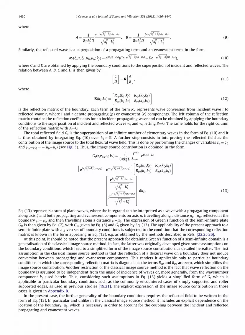
Similarly, the reflected wave is a superposition of a propagating term and an evanescent term, in the form
wrðx,m,x0,m0,mb; kf Þ ¼ ejkxðx�x0ÞðCejffiffiffiffiffiffiffiffiffiffik2
f �k2x
pðm�mbÞ þDe�
ffiffiffiffiffiffiffiffiffiffiffik2
f þk2x
pðm�mbÞÞ, (10)
where C and D are obtained by applying the boundary conditions to the superposition of incident and reflected waves. Therelation between A, B, C and D is then given by
C
D
� �¼ R
A
B
� �, (11)
where
Rðkx,kf Þ ¼Rppðkx,kf Þ Repðkx,kf Þ
Rpeðkx,kf Þ Reeðkx,kf Þ
" #(12)
is the reflection matrix of the boundary. Each term of the form Rir represents wave conversion from incident wave i toreflected wave r, where i and r denote propagating (p) or evanescent (e) components. The left column of the reflectionmatrix contains the reflection coefficients for an incident propagating wave and can be obtained by applying the boundaryconditions to the superposition of incident and reflected waves wi and wr letting B¼0. The same holds for the right columnof the reflection matrix with A¼0.
The total reflected field Gs is the superposition of an infinite number of elementary waves in the form of Eq. (10) and itis thus obtained by integrating Eq. (10) over kx 2 R. A further step consists in interpreting the reflected field as thecontribution of the image source to the total flexural wave field. This is done by performing the changes of variables xs ¼ x0
and mb�m0 ¼�ðmb�msÞ (see Fig. 3). Thus, the image source contribution is obtained in the form
Gsðr,rs,mb; kf Þ ¼j
8pk2f D
Z þ1�1
ejkxðx�xsÞ
ejffiffiffiffiffiffiffiffiffiffik2
f �k2x
pðm�mbÞ e�
ffiffiffiffiffiffiffiffiffiffiffik2
f þk2x
pðm�mbÞ
h i Rppðkx,kf Þ Repðkx,kf Þ
Rpeðkx,kf Þ Reeðkx,kf Þ
" #
ejffiffiffiffiffiffiffiffiffiffik2
f �k2x
pðmb�msÞffiffiffiffiffiffiffiffiffiffiffiffiffiffi
k2f �k2
x
q
je�
ffiffiffiffiffiffiffiffiffiffiffik2
f þk2x
pðmb�msÞffiffiffiffiffiffiffiffiffiffiffiffiffiffiffi
k2f þk2
x
q
2666666664
3777777775
dkx: (13)
Eq. (13) represents a sum of plane waves, where the integrand can be interpreted as a wave with a propagating componentalong axis x and both propagating and evanescent components on axis m, travelling along a distance mb�m0, reflected at theboundary m¼ mb and then travelling along a distance m�mb. The expression of Green’s function of the semi-infinite plateGO is then given by Eq. (7), with G1 given by Eq. (5) and Gs given by Eq. (13). The applicability of the present approach to asemi-infinite plate with a given set of boundary conditions is subjected to the condition that the corresponding reflectionmatrix is known in the form appearing in Eq. (13), e.g. as obtained by the methods described in Refs. [22,25,26].
At this point, it should be noted that the present approach for obtaining Green’s function of a semi-infinite domain is ageneralisation of the classical image source method. In fact, the latter was originally developed given some assumptions onthe boundary conditions, which lead to a simplified form of the image source contribution, as detailed hereafter. The firstassumption in the classical image source method is that the reflection of a flexural wave on a boundary does not induceconversion between propagating and evanescent components. This renders it applicable only to particular boundaryconditions in which the corresponding reflection matrix is diagonal, i.e. the terms Rep and Rpe are zero, which simplifies theimage source contribution. Another restriction of the classical image source method is the fact that wave reflection on theboundary is assumed to be independent from the angle of incidence of waves or, more generally, from the wavenumbercomponent kx used herein. Thus, considering such assumptions in Eq. (13) yields a simplified form of Gs which isapplicable to particular boundary conditions such as the commonly encountered cases of simply supported and rollersupported edges, as used in previous studies [19,21]. The explicit expression of the image source contribution in thosecases is given in Appendix B.
In the present case, the further generality of the boundary conditions requires the reflected field to be written in theform of Eq. (13). In particular and unlike in the classical image source method, it includes an explicit dependence on thelocation of the boundary, mb, which is necessary in order to account for the coupling between the incident and reflectedpropagating and evanescent waves.

Table 1Boundary conditions and corresponding reflection matrices for a simply supported, roller, clamped or free edge at m¼ mb .
Boundary conditions Reflection matrix Rðkx ,kf Þ
Simply supported wðx,mbÞ ¼ 0
Mmðx,mbÞ ¼ 0
(�1 0
0 �1
� �
Roller qw
qmðx,mbÞ ¼ 0
Vmðx,mbÞ ¼ 0
8><>:
1 0
0 1
� �
Clamped wðx,mbÞ ¼ 0
qw
qmðx,mbÞ ¼ 0
8><>: �
ffiffiffiffiffiffiffiffiffiffiffiffiffiffiffik2
f þk2x
q�j
ffiffiffiffiffiffiffiffiffiffiffiffiffiffik2
f �k2x
qffiffiffiffiffiffiffiffiffiffiffiffiffiffiffik2
f þk2x
qþ j
ffiffiffiffiffiffiffiffiffiffiffiffiffiffik2
f �k2x
q �2ffiffiffiffiffiffiffiffiffiffiffiffiffiffiffik2
f þk2x
qffiffiffiffiffiffiffiffiffiffiffiffiffiffiffik2
f þk2x
qþ j
ffiffiffiffiffiffiffiffiffiffiffiffiffiffik2
f �k2x
q�2j
ffiffiffiffiffiffiffiffiffiffiffiffiffiffik2
f �k2x
qffiffiffiffiffiffiffiffiffiffiffiffiffiffiffik2
f þk2x
qþ j
ffiffiffiffiffiffiffiffiffiffiffiffiffiffik2
f �k2x
qffiffiffiffiffiffiffiffiffiffiffiffiffiffiffik2
f þk2x
q�j
ffiffiffiffiffiffiffiffiffiffiffiffiffiffik2
f �k2x
qffiffiffiffiffiffiffiffiffiffiffiffiffiffiffik2
f þk2x
qþ j
ffiffiffiffiffiffiffiffiffiffiffiffiffiffik2
f �k2x
q
2666666664
3777777775
Free Mmðx,mbÞ ¼ 0
Vmðx,mbÞ ¼ 0
(ad�bc
adþbc
�2ac
adþbc�2bd
adþbc�
ad�bc
adþbc
26664
37775
a¼ k2f þð1�nÞk
2x
b¼�k2f þð1�nÞk
2x
c¼�ffiffiffiffiffiffiffiffiffiffiffiffiffiffiffik2
f þk2x
qðk2
f �ð1�nÞk2x Þ
d¼ jffiffiffiffiffiffiffiffiffiffiffiffiffiffik2
f �k2x
qðk2
f þð1�nÞk2xÞ
J. Cuenca et al. / Journal of Sound and Vibration 331 (2012) 1426–1440 1431
3.2. Examples of Green’s functions for semi-infinite plates with simply supported, roller supported, clamped or free edges
To the best of our knowledge, the most significant work so far on determining explicit expressions of Green’s functionsfor flexural waves in semi-infinite plates has been done by Gunda et al. [23], where the Green’s functions of clamped andfree semi-infinite plates are obtained by applying appropriate corrections respectively to the simply supported and rollerboundary conditions. Such expressions are thus used as a benchmark for the present approach, as detailed below.
Table 1 summarises the boundary conditions of simply supported, roller, clamped and free edges and theircorresponding reflection matrices, where w and qw=qm respectively denote the normal displacement and the slope alongdirection m, and
Mm ¼�Dq2w
qm2þn q
2w
qx2
!(14)
and
Vm ¼�Dq3w
qm3þð2�nÞ q3w
qx2qm
!(15)
respectively denote the bending moment and the total shear force.By replacing the reflection matrix of a simply supported, roller, clamped or free edge in Eq. (13), it can be verified that
Green’s function given by Eq. (7) is identical to Eqs. (19), (22), (44) and (62) of Ref. [23], respectively. The main advantageof the present method is that it provides the Green’s function of a semi-infinite plate regardless of the specific boundaryconditions, as long as the corresponding reflection matrix is known.
4. Approximation of the Green’s function of a convex polygonal plate
4.1. Formulation of the problem
Considering a polygonal plate O, as depicted in Fig. 4, the Green’s function GO is the solution of the generic set of Eq. (6),where the boundary qO forms a closed line and thus yields an infinite number of reflections in the plate, which are in turndescribed by an infinite number of image sources. In addition to specular wave reflection, described by image sources, theplate corners induce an additional contribution to the field, corresponding to wave diffraction [27,28]. However, the

Fig. 4. Green’s problem for a convex polygonal plate. r0, original source; rs , image source of first order; rs0 , image source of second order; r, observation
point; � � � � � �, validity zones of image sources.
J. Cuenca et al. / Journal of Sound and Vibration 331 (2012) 1426–14401432
corresponding correction terms are significant only at low frequencies, as shown by Gunda et al. [29]. On that account, wepropose an approximation of the Green’s function of the polygonal plate in the form of a superposition of the contributionsfrom the original source and the image sources, as
~GOðr,r0; kf Þ ¼ G1ðr,r0; kf ÞþX1s ¼ 1
Gsðr,rs,mðsÞb ; kf Þ, (16)
where the terms Gs represent the contributions of image sources to the displacement field, s being the image source index.The aim of the following is to determine the image source contributions Gs.
4.2. Geometrical construction of image sources
Wave reflections at the boundaries of the domain are described by means of image sources, which are obtained bysuccessive symmetries of the original source on the different plate edges. Thus, for a polygonal plate having Nv vertices, theoriginal source generates Nv sources, one with respect to each edge. Subsequently, each image source generates Nv�1 newimage sources. The pattern resulting from such geometrical procedure corresponds to what one would observe by standingwith a source of light in a polygonal room made of mirrors. The location of an image source s originating at edge p from asource located at rm, i.e. its ‘‘mother’’ source, takes the form
rs ¼�rmþ2vpþ2ðrm�vpÞ � ðvpþ1�vpÞ
9vpþ1�vp92
ðvpþ1�vpÞ, (17)
where vp and vpþ1 are the locations of the vertices of the generator edge, as illustrated in Fig. 4.Furthermore, the edges of the plate are of finite length. As shown by Mechel [20], the reflected field giving rise to a
given image source is therefore valid in the zone delimited by the image source position rs and the vertices vp and vpþ1 ofthe generator edge, as represented by the dotted lines in Fig. 4. The geometrical validity conditions of an image sourcelocated at rs for an observation point r are given by
ððvpþ1�rsÞ � ðr�rsÞÞ � z40, ðaÞ
ððr�rsÞ � ðvp�rsÞÞ � z40, ðbÞ
((18)
where � denotes cross product and z is the unitary vector such that ðx,y,zÞ forms a right-handed basis. The validityconditions are included in a function Vðr,rsÞ such that
Vðr,rsÞ ¼1 in the validity zone,
0 elsewhere:
((19)

J. Cuenca et al. / Journal of Sound and Vibration 331 (2012) 1426–1440 1433
4.3. First wave reflection on the boundaries
The contributions of the image sources of first order, i.e. directly generated from the original source at each one of theedges, can be computed using the approach developed above for semi-infinite plates, i.e. from Eq. (13), using a localcoordinate system ðx,mÞ for each edge. Each image source contribution is then valid in the area defined by function Vðr,rsÞ.For a plate having Nv vertices, the contributions of image sources of first order, i.e. the first Nv image sources, can beexpressed as
GðIÞs ðr,rs,mðsÞb ; kf Þ ¼ Vðr,rsÞj
8pk2f D
Z þ1�1
ejkxðx�xsÞ½ejffiffiffiffiffiffiffiffiffiffik2
f �k2x
pðm�mðsÞ
bÞ e�
ffiffiffiffiffiffiffiffiffiffiffik2
f þk2x
pðm�mðsÞ
b�
RðsÞppðkx,kf Þ RðsÞepðkx,kf Þ
RðsÞpeðkx,kf Þ RðsÞee ðkx,kf Þ
24
35
ejffiffiffiffiffiffiffiffiffiffik2
f �k2x
pðmðsÞ
b�msÞffiffiffiffiffiffiffiffiffiffiffiffiffiffi
k2f �k2
x
q
je�
ffiffiffiffiffiffiffiffiffiffiffik2
f þk2x
pðmðsÞ
b�msÞffiffiffiffiffiffiffiffiffiffiffiffiffiffiffi
k2f þk2
x
q
2666666664
3777777775
dkx, (20)
where m¼ mðsÞb defines the boundary giving rise to source s in the local coordinate system ðx,mÞ, i.e. the symmetry axisbetween r0 and rs, and RðsÞir are the different terms of the corresponding reflection matrix, which couples incident (i) wavesfrom the original source to reflected (r) waves.
4.4. Second and subsequent wave reflections on the boundaries
The contribution of an image source of first order acts in turn as the incident field on another boundary and generates animage source of second order. The exact form of the contribution of an image source of second order cannot be derived using thesame procedure as for image sources of first order and an approximation is proposed, as detailed in the following. In the abovederivation, leading to the contribution of an image source of first order, the incident and reflected fields are considered as sums ofplane waves expressed in the local coordinate system ðx,mÞ of the edge where the reflection occurs. The incident and reflectedplane waves are written in a separated-variable form in Eqs. (8) and (10), respectively, which both include a propagatingcomponent along the x axis and a superposition of propagating and evanescent components along the m axis, making it possibleto use a reflection matrix for plane waves, Eq. (12). However, a propagating wave with amplitude decreasing along its frontcannot be written in such separated-variable form using two different coordinate systems in the general case, as detailed inAppendix C. As a consequence, an individual plane wave resulting from the first reflection, i.e. Eq. (10), cannot be written in theform of Eq. (8) in the local coordinate system of another edge where a second reflection may take place. Therefore, thecontribution of image sources of second and higher orders cannot be obtained in its complete form from the concept of individualplane wave reflection. For the purposes of the present paper, no attempt is made to compute the exact expression, which wouldrequire a rather different approach. However, the wavelength being sufficiently short compared to the plate dimensions, theevanescent components can be neglected, thus solving the difficulty of the coordinate change. The contributions of the imagesources associated to the second and subsequent wave reflections on the boundaries are then approximated by their propagatingcomponent, in the form
GðIIÞs ðr,rs; kf Þ ¼ Vðr,rsÞj
8pk2f D
Z 9kf 9
�9kf 9ejkxðx�xsÞAðsÞppðkx,kf Þ
ejffiffiffiffiffiffiffiffiffiffik2
f �k2x
pðm�msÞffiffiffiffiffiffiffiffiffiffiffiffiffiffi
k2f �k2
x
q dkx, (21)
where AðsÞpp is the amplitude weight of image source s, resulting from the successive reflections of propagating waves. In the
considered integration domain, defined by �9kf 9okxo9kf 9, the transverse wavenumber coordinate km ¼ffiffiffiffiffiffiffiffiffiffiffiffiffiffik2
f �k2x
qis real, as
shown in Fig. 2, such that the wavenumber coordinates kx and km are related to the flexural wavenumber by
k2f ¼ k2
xþk2m: (22)
Alternatively, the use of wavenumber polar coordinates yields
kx ¼ 9kf 9 cos ðyÞ, (23)
where y is the orientation of the plane propagating wave defined by kx with respect to the reflecting edge, as shown in Fig. 4.
Thus, the amplitude weight AðsÞpp is obtained as the product of the scalar reflection coefficients Rpp of the edges that successively
participate in the construction of image source s, in the form
AðsÞppðyÞ ¼YNðsÞ
n ¼ 1
RðsÞn ðy,anÞ, (24)

J. Cuenca et al. / Journal of Sound and Vibration 331 (2012) 1426–14401434
where n¼ 1, . . . ,NðsÞ denotes the order of reflection on edges for each image source s and an is the orientation of edge n withrespect to the global coordinate system (x,y), as illustrated in Fig. 4.
At this point it is important to notice that some particular types of edges present reflection properties that are independentfrom the angle of incidence of waves and do not induce wave conversion, which implies that the associated reflection matrix isconstant and diagonal. This is the case for simply supported and roller supported edges, for example. For plates having exclusivelysuch kinds of boundary conditions, each image source contribution is obtained simply from the product of the contribution of itsmother source by the reflection coefficient of the edge, as detailed in Appendix B. In those cases, the exact form of thecontribution of an image source of any reflection order is known and there is no need of neglecting evanescent waves.
4.5. Approximated Green’s function and domain of applicability
The approximated Green’s function of the polygonal plate is obtained from Eq. (16), by considering Eqs. (5), (20) and(21) for the original source, first and second-order image sources, respectively, in the form
~GOðr,r0; kf Þ ¼ G1ðr,r0; kf ÞþXNv
s ¼ 1
GðIÞs ðr,rs,mðsÞb ; kf ÞþX1
s ¼ Nv þ1
GðIIÞs ðr,rs; kf Þ, (25)
where Nv is the number of vertices or edges of the plate. The solution is then known for arbitrary boundary conditions aslong as the reflection matrix of the edges are known in the form of Eq. (12). The obtained Green’s function is anapproximation based on neglecting evanescent waves in the calculation of the contributions of second-order imagesources, GðIIÞs . In fact, the displacement field related to the terms Repðkx,kf Þ, Rpeðkx,kf Þ and Reeðkx,kf Þ of the reflection matricesis of low amplitude as long as both the source and the observation point are sufficiently distant from the edges. As aconsequence, the proposed solution is inaccurate in the nearfield of the edges. In particular, the approach is not adapted toplates including sharp angles, since a given edge may be in the nearfield of another edge, leading to cumulative errors inthe construction of image sources. The convergence of the series in Eq. (25) is then subjected to the distance from thesource (and/or the observation point) to the edges, relatively to the wavelength. Furthermore, the damping ratio Z of theplate material also governs the convergence of the solution since a low number of reflections is needed to accuratelycompute the field in a highly damped plate.
5. Numerical implementation
In this section, the numerical implementation of Eq. (25) is discussed. By formulating Eq. (21) as
GðIIÞs ðr,rs; kf Þ ¼ Vðr,rsÞj
8pk2f D
Z 1�1
ukx
29kf 9
!ejkxðx�xsÞAðsÞppðkx,kf Þ
ejffiffiffiffiffiffiffiffiffiffik2
f �k2x
pðm�msÞffiffiffiffiffiffiffiffiffiffiffiffiffiffi
k2f �k2
x
q dkx, (26)
where
ukx
29kf 9
!¼
1, kx 2 ½�9kf 9,9kf 9�,
0 elsewhere
((27)
is the rectangular window function of span 29kf 9 centred on kx ¼ 0, the integral in Eqs. (20) and (26) is interpreted as anone-dimensional inverse spatial Fourier transform from wavenumber coordinate kx to space coordinate x. The numerical
Fig. 5. Square plate with three simply supported (SS) edges and one clamped (C) edge.

J. Cuenca et al. / Journal of Sound and Vibration 331 (2012) 1426–1440 1435
implementation of such expressions is performed by using discrete inverse spatial Fourier transform in order to takeadvantage of a fast Fourier transform algorithm in terms of computational efficiency.
Furthermore, practical implementation requires the image source series to be truncated. Thus, image sources outside atruncation circle of radius rt are ignored. The dimensionless parameter g is used for controlling the truncation distancewith respect to an arbitrary characteristic length rc of the plate, in the form
g¼ rt
rc, (28)
Fig. 6. Amplitude of Green’s function for the square plate. (a) Exact; (b) proposed method; (c)–(g) displacement field on vertical lines l1 to l5; —, exact;
� � � � � �, proposed method. (h) Error as a function of abscissa, from Eq. (30).

J. Cuenca et al. / Journal of Sound and Vibration 331 (2012) 1426–14401436
where, by respectively denoting S and p the total area and the perimeter of the plate, rc is taken as
rc ¼pS
p, (29)
which is the average distance between two successive image sources, also referred to as the mean free path of waves in theplate [12].
6. Results
In this section, the harmonic responses of different polygonal plates with various boundary conditions are computedand compared to exact or numerical solutions of reference. The main purpose is to validate the present method and toevaluate the errors due to neglecting edge effects. Two plates are tested: a Levy-type plate, for which the analytical Green’sfunction is known, and an arbitrary polygonal plate, for which the response is computed by using the finite elementmethod (FEM). For both plates, one edge is clamped and the others are simply supported.
6.1. Levy-type plate: comparison to the exact solution
There exist only few sets of boundary conditions leading to an analytical expression of the response of a polygonal plate[6]. Rectangular plates with two opposite edges simply supported, i.e. Levy-type plates, are well-known configurationsallowing an analytical solution [7,22]. A square plate, as shown in Fig. 5, is here considered, with simply supported edgesalong y¼0, y¼L and x¼0, and a clamped edge along x¼L.
In the following, the side length of the plate is L¼ 1 m and the thickness is h¼ 2 mm. The plate material is steel, withdensity r¼ 7850 kg m�3, Young’s modulus E0 ¼ 210 GPa and Poisson’s ratio n¼ 0:3. The structural damping ratio is chosenas Z¼ 0:07. The plate is excited by a harmonic point source at r0 ¼ ð0:41 m,0:3 mÞ at the frequency f ¼ 3 kHz. At thisfrequency, the modal overlap factor [21] is equal to 42, i.e. there is an average of 42 resonances in a �3 dB resonance band,which indicates that the computation is done in a significantly high-frequency regime. The solution of reference isobtained analytically by classical modal superposition [22], to which is compared the solution obtained by the proposedmethod, with g¼ 6 (488 sources). The number of points for the fast Fourier transform is NF¼1024.
In order to quantify the accuracy of the proposed method, an error indicator is computed for each vertical line of the plate, as
eðxÞ ¼PN
i ¼ 1 9wðx,yiÞ�wðrefÞðx,yiÞ92
PNi ¼ 1 9wðrefÞðx,yiÞ9
2, (30)
where N is the number of points on the vertical line at abscissa x and where wðx,yiÞ and wðrefÞðx,yiÞ are respectively thedisplacement fields obtained by the present method and from the reference solution. Eq. (30) thus represents a mean quadraticerror on each vertical line of the plate, normalised by the mean quadratic value of the reference solution.
Fig. 6(a) and (b) shows the real part of the Green’s function, respectively obtained by the exact solution and theproposed approximation. Fig. 6(c)–(g) shows the displacement field on vertical lines l1 to l5, respectively defined byx1 ¼ 0:013L, x2 ¼ 0:484L, x3 ¼ 0:956L, x4 ¼ 0:972L and x5 ¼ 0:987L. Furthermore, Fig. 6(h) shows the error e as a function ofx. The agreement is satisfactory in the whole plate, except near the clamped edge, within a distance comparable to half thewavelength, which in the present case is equal to l=2¼ 0:0405L¼ 4:05 cm.
Fig. 7. Polygonal plate for comparison of the proposed approach to FEM with clamped (C) and simply supported (SS) boundaries. r0 ¼ ð0:125,0:3Þ, source;
r1 ¼ ð0:245778,0:350778Þ, r2 ¼ ð0:245778,0:073775Þ and r3 ¼ ð0:245778,0:058386Þ, observation points. Coordinates are in meters.

J. Cuenca et al. / Journal of Sound and Vibration 331 (2012) 1426–1440 1437
Simply supported edges do not induce wave conversion between propagating and evanescent components, as observedin the corresponding reflection matrix in Table 1. In fact, edge effects near such boundaries are of low influence on theglobal displacement field since they correspond to pure evanescent waves generated at the source that reflect back. On theother hand, as recalled in Table 1, the reflection matrix of the clamped edge involves wave conversion betweenpropagating and evanescent waves. Thus, propagating waves incident on the clamped boundary give rise to evanescentwaves, which are neglected for sources of second and higher orders. As a consequence, higher discrepancies appear nearthe clamped edge.
6.2. Arbitrary polygonal plates: comparison to FEM
In order to validate the proposed method in a more general configuration, an arbitrary polygonal plate is considered, asshown in Fig. 7.
The response of the plate is computed as a function of frequency at three different observation points, r1, r2 and r3, for apoint source at r0, for two different values of the structural damping ratio, Z¼ 0:07 and Z¼ 0:14, by the proposed methodand by FEM.
Fig. 8. Modulus of Green’s function of the polygonal plate as a function of frequency computed by the proposed method (� � � � � �) and by FEM (—), for
Z¼ 0:07 (left column) and Z¼ 0:14 (right column), at points (a,b) r1, (c,d) r2 and (e,f) r3. (h,g) Error at points: —, r1; - - - - -, r2; � � � � � �, r3.

J. Cuenca et al. / Journal of Sound and Vibration 331 (2012) 1426–14401438
For obtaining the plate response as a function of frequency, the computation detailed above is performed at 99 differentfrequencies, from 80 Hz to 8 kHz, with the truncation parameter set to g¼ 4. The number of points of the fast Fouriertransform is NF¼1024. A total of 46 056 nodes is considered in the finite element model, giving rise to 91 319 lineartriangular elements. The average element length is 3 mm and the eigenmodes are computed up to the frequency 12 kHz, atwhich the wavelength is greater than 13 times the average element length.
The error of the response for a given observation point in the plate is computed by using an indicator as a function offrequency, given by
eðf Þ ¼9wðf Þ�wðrefÞðf Þ92
1
N
PNi ¼ 1 9wðrefÞðf iÞ9
2, (31)
where N is the number of frequencies for the computation of the response and w(f) and wðrefÞðf Þ are the responsescomputed, respectively, by the proposed method and by FEM at a given point. Eq. (31) thus represents the quadratic errorat each frequency, normalised by the mean quadratic value of the reference solution over the frequency range of thesimulations.
Fig. 8 shows the modulus of Green’s function as a function of frequency, for the chosen parameters. The computedresponses are in accordance with the finite element predictions in the central region of the plate, as observed on thedisplacement fields at the selected observation points r1 and r2. As the observation point reaches the clamped boundary atpoint r3, the image source method no longer predicts the field accurately. Moreover, Fig. 8 shows that the accuracy of theproposed method increases with frequency and structural damping ratio. That is to say that, for a given accuracy to bereached, the number of needed image sources decreases with frequency and damping. Such behaviour of the accuracy isopposite to that of the finite element method, which is limited in terms of computational time to low frequencies and highquality factors.
7. Conclusion
This paper provides a method for obtaining the harmonic Green’s function of the flexural vibrations of thin semi-infinite plates and an approximation of Green’s function of convex polygonal plates by using a generalised image sourcemethod. The latter consists in considering the Green’s function of a semi-infinite or finite domain as the superposition of thecontributions from the original source and its image sources with respect to the boundaries, which represent successivewave reflections. The original source contribution is described by the infinite plate Green’s function, and is written as acontinuous sum of propagating and evanescent plane waves, incident on the boundaries. The contributions of image sourcesthus arise as continuous sums of reflected plane waves. For semi-infinite plates, a general expression of the exact Green’sfunction is obtained for arbitrary boundary conditions, as long as the reflection matrix of the boundary is known. Forpolygonal plates, the image sources representing the first reflection at each one of the edges are obtained from the Green’sfunction of the corresponding semi-infinite plate in the local coordinate system of the edge at which reflection occurs. Theplane waves therein are in a separated variable form that cannot be transposed to local coordinate systems of other edges.Therefore, the contributions of image sources representing the second and subsequent reflections on boundaries cannot beobtained in their complete form. However, after the second reflection and at high frequencies, the distance travelled bywaves is much larger than their wavelength. An approximation of the Green’s function is then written by neglectingevanescent waves in the calculation of the image sources of second and subsequent orders. Comparisons to exact and finiteelement method simulated responses show that the displacement field is accurately predicted outside the nearfield area ofthe edges, which decreases with frequency and structural damping. The approximations of the Green’s functions obtained bythe proposed method are applicable to any set of boundary conditions of which the reflection matrices are known.
A significant advantage of the method developed in this paper is that wave propagation, geometry and boundaryconditions can be treated separately. Work is ongoing along this direction for using it as a tool for modelling andcharacterising mid- and high-frequency vibrations of plates of complex shapes and arbitrary boundary conditions.
Appendix A. Green’s function of an infinite plate in rectangular coordinates
By defining one-dimensional spatial Fourier transform and inverse transform as
wðkx,mÞ ¼F x½wðx,mÞ� ¼ 1ffiffiffiffiffiffi2pp
Z þ1�1
wðx,mÞe�jkxx dx (32)
and
wðx,mÞ ¼F�1x ½wðkx,mÞ� ¼ 1ffiffiffiffiffiffi
2pp
Z þ1�1
wðkx,mÞejkxx dkx: (33)

J. Cuenca et al. / Journal of Sound and Vibration 331 (2012) 1426–1440 1439
Fourier transform of Eq. (1) yields
Dq4
qm4�2k2
xq2
qm2þk4
x�k4f
!G1ðkx,m,x0,m0; kf Þ ¼
e�jkxx0ffiffiffiffiffiffi2pp dðm�m0Þ: (34)
Using the associated homogeneous equation and taking into account Sommerfeld radiation condition [24] and thecontinuity of the displacement field at m¼ m0 yields the Fourier transform of Green’s function in the form
G1ðkx,m,x0,m0; kf Þ ¼ Aejkð1Þm 9m�m09þBejkð2Þm 9m�m09, (35)
where
kð1Þm ¼ffiffiffiffiffiffiffiffiffiffiffiffiffiffik2
f �k2x
q, kð2Þm ¼ j
ffiffiffiffiffiffiffiffiffiffiffiffiffiffiffik2
f þk2x
q: (36)
The expressions of A and B are obtained by integrating Eq. (34) on the interval m 2 ½m0�e,m0þe� with e-0 and using theproperty of continuity of the slope at m0. Green’s function in the spatial domain is then obtained by inverse Fouriertransform and is given in Eq. (5).
Appendix B. Image source contribution in the case of reflection without angular dependence
The purpose of this appendix is to give the expression of the image source contribution used in the classical imagesource method, which arises as a particular case of the approach proposed herein, in the case where the boundaryconditions are described by a reflection matrix of the form
Rðkx,kf Þ ¼R 0
0 R
� �: (37)
This is the case in particular for simply supported (R¼�1) or roller (R¼1) boundary conditions (see Table 1).For a semi-infinite plate, it can be observed from Eq. (13) that, in the particular case of a reflection matrix proportional
to the identity matrix, the image source contribution is described by the infinite plate Green’s function multiplied by theconstant reflection coefficient, as
Gsðr,rs; kf Þ ¼ RG1ðr,rs; kf Þ, r 2 O: (38)
It is worth noting that the position of the boundary only appears implicitly in the location of the image source in Eq. (38)due to the absence of coupling between propagating and evanescent components.
In the case of a polygonal plate in which the reflection matrices of the different boundaries are in the form of Eq. (37),the integrand of Eq. (20) can be written in the form of Eq. (8) in the local coordinate system of the edge at which a secondreflection may take place. Thus, the contributions from image sources of any reflection order can be written as
Gsðr,rs; kf Þ ¼ Vðr,rsÞAðsÞG1ðr,rs; kf Þ, r 2 O, (39)
where AðsÞ is the amplitude weight of source s and is independent from the wavenumber coordinate kx. The amplitudeweight of source s is given by
AðsÞ ¼YNðsÞ
n ¼ 1
RðsÞn , (40)
in which RðsÞn is the reflection coefficient of the edge number n that is needed for the construction of source s. Furthermore,boundaries characterised by a reflection matrix satisfying Eq. (37) are a particular case allowing the calculation of exactGreen’s functions of several polygonal geometries, as shown in a previous paper [21].
Appendix C. Impossibility of variable separation for waves of multiple types in two different coordinate systems
As mentioned in Section 4.4, a wave that is propagating in one direction of space and attenuating in another cannot bewritten in a separated-variable form in two different coordinate systems in the general case. This appendix aims at
Fig. 9. Two coordinate systems with different orientations.

J. Cuenca et al. / Journal of Sound and Vibration 331 (2012) 1426–14401440
showing that explicitly. Two coordinate systems differing from an angle a by rotation about the z axis are considered, asshown in Fig. 9.
A plane wave can be represented in coordinate system ðx,mÞ by the separated-variable expression
wðx,mÞ ¼ ejkxxejkmm, kx 2 R, km 2 C, (41)
where km ¼ kð1Þm ¼ffiffiffiffiffiffiffiffiffiffiffiffiffiffik2
f �k2x
qor km ¼ kð2Þm ¼ j
ffiffiffiffiffiffiffiffiffiffiffiffiffiffiffik2
f þk2x
q. The coordinate change
x¼ x cosðaÞþy sinðaÞ,m¼�x sinðaÞþy cosðaÞ
((42)
yields the expression of w in coordinate system (x,y) as
wðx,yÞ ¼ eðjkx cosðaÞ�jkm sinðaÞÞxeðjkx sinðaÞþ jkm cosðaÞÞy: (43)
It is easily observed that there does not exist a pair ðkx,kyÞ that satisfies
ejkxxejkyy ¼ ejkxxejkmm, kx 2 R, ky 2 C: (44)
References
[1] L.A. Bergman, J.K. Hall, G.G.G. Lueschen, D.M. McFarland, Dynamic Green’s functions for Levy plates, Journal of Sound and Vibration 162 (2) (1993)281–310.
[2] R.D. Blevins, Formulas for Natural Frequencies and Mode Shape, Krieger, 1993.[3] D.J. Gorman, Vibration Analysis of Plates by the Superposition Method, World Scientific, Singapore, 1999.[4] S.W. Kang, Free vibration analysis of arbitrarily shaped plates with a mixed boundary condition using non-dimensional dynamic influence functions,
Journal of Sound and Vibration 256 (3) (2002) 533–549.[5] S.W. Kang, S.N. Atluri, Free vibration analysis of arbitrarily shaped polygonal plates with simply supported edges using a sub-domain method,
Journal of Sound and Vibration 327 (3–5) (2009) 271–284.[6] A. Leissa, Vibration of Plates, NASA, Washington, DC, 1969.[7] W. Soedel, Vibrations of Shells and Plates, Marcel Dekker, New York, 2004.[8] L. Lyamshev, The theory of vibrations of nonhomogeneous elastic plates, Soviet Physics—Acoustics 10 (1) (1964) 65–69.[9] M. Stern, A general boundary integral formulation for the numerical solution of plate bending problems, International Journal of Solids and Structures
15 (1979) 769–782.[10] F. Hartmann, R. Zotemantel, The direct boundary element method in plate bending, International Journal for Numerical Methods in Engineering 23
(1986) 2049–2069.[11] O. Zienkiewicz, R. Taylor, The Finite Element Method for Solid and Structural Mechanics, Butterworth-Heinemann, 2005.[12] R.H. Lyon, R.G. Dejong, Theory and Application of Statistical Energy Analysis, Butterworth-Heinemann, Boston, 1995.[13] A.L. Bot, V. Cotoni, Validity diagrams of statistical energy analysis, Journal of Sound and Vibration 329 (2) (2010) 221–235.[14] F.J. Fahy, Statistical energy analysis: a critical overview, Philosophical Transactions: Physical Sciences and Engineering 346 (1681) (1994) 431–447.[15] K.-S. Chae, J.-G. Ih, Prediction of vibrational energy distribution in the thin plate at high-frequency bands by using the ray tracing method, Journal of
Sound and Vibration 240 (2) (2001) 263–292.[16] B. Mace, D. Duhamel, M. Brennan, L. Hinke, Finite element prediction of wave motion in structural waveguides, Journal of the Acoustical Society of
America 117 (5) (2005) 2835–2843.[17] C. Vanmaele, D. Vandepitte, W. Desmet, An efficient wave based prediction technique for plate bending vibrations, Computer Methods in Applied
Mechanics and Engineering 196 (33–34) (2007) 3178–3189.[18] A.L. Bot, A. Bocquillet, Comparison of an integral equation on energy and the ray-tracing technique in room acoustics, The Journal of the Acoustical
Society of America 108 (4) (2000) 1732–1740, doi:10.1121/1.1287848.[19] R. Gunda, S.M. Vijayakar, R. Singh, Method of the images for the harmonic response of beams an rectangular plates, Journal of Sound and Vibration
185 (2) (1995) 791–808.[20] F.P. Mechel, Improved mirror source method in room acoustics, Journal of Sound and Vibration 256 (6) (2002) 873–940.[21] J. Cuenca, F. Gautier, L. Simon, The image source method for calculating the vibrations of simply supported convex polygonal plates, Journal of Sound
and Vibration 322 (4–5) (2009) 1048–1069.[22] K.J. Graff, Wave Motion in Elastic Solids, Dover, New York, 1991.[23] R. Gunda, S.M. Vijayakar, R. Singh, J.E. Farstad, Harmonic Green’s functions of a semi-infinite plate with clamped or free edges, Journal of the
Acoustical Society of America 103 (2) (1998) 888–899.[24] A. Sommerfeld, Partial Differential Equations in Physics: Lectures on Theoretical Physics, Academic Press, New York, 1949.[25] B. Mace, Wave reflection and transmission in beams, Journal of Sound and Vibration 97 (2) (1984) 237–246.[26] Z. Wang, A. Norris, Waves in cylindrical shells with circumferential submembers: a matrix approach, Journal of the Acoustical Society of America 181
(3) (1995) 457–484.[27] V.A. Borovikov, Flexural plane wave scattering by the thin elastic quarter plane in the case of pinched boundary, in: Days on Diffraction 2006, IEEE, St.
Petersburg2006, pp. 49–63.[28] V.A. Borovikov, The scattering of a plane flexural wave by a sector of a thin elastic plate with a supported edge, Journal of Applied Mathematics and
Mechanics 71 (3) (2007) 449–452.[29] R. Gunda, S.M. Vijayakar, R. Singh, Flexural vibration of an infinite wedge, Journal of the Acoustical Society of America 102 (1) (1997) 326–334.


