Embed Size (px)
Citation preview
HASIL PERHITUNGAN PV ELITE 2016
DESIGN CALCULATION
In Accordance with ASME Section VIII Division 1
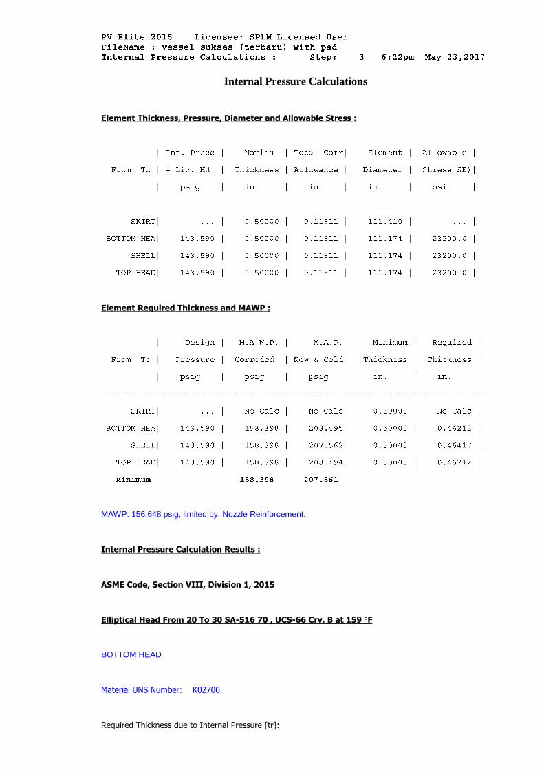
Internal Pressure Calculations
Element Thickness, Pressure, Diameter and Allowable Stress :
Element Required Thickness and MAWP :
MAWP: 156.648 psig, limited by: Nozzle Reinforcement.
Internal Pressure Calculation Results :
ASME Code, Section VIII, Division 1, 2015
Elliptical Head From 20 To 30 SA-516 70 , UCS-66 Crv. B at 159 °F
BOTTOM HEAD
Material UNS Number: K02700
Required Thickness due to Internal Pressure [tr]:
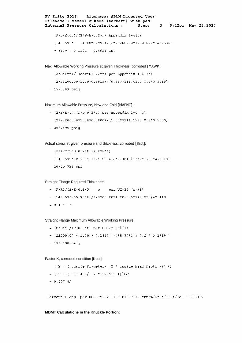
Max. Allowable Working Pressure at given Thickness, corroded [MAWP]:
Maximum Allowable Pressure, New and Cold [MAPNC]:
Actual stress at given pressure and thickness, corroded [Sact]:
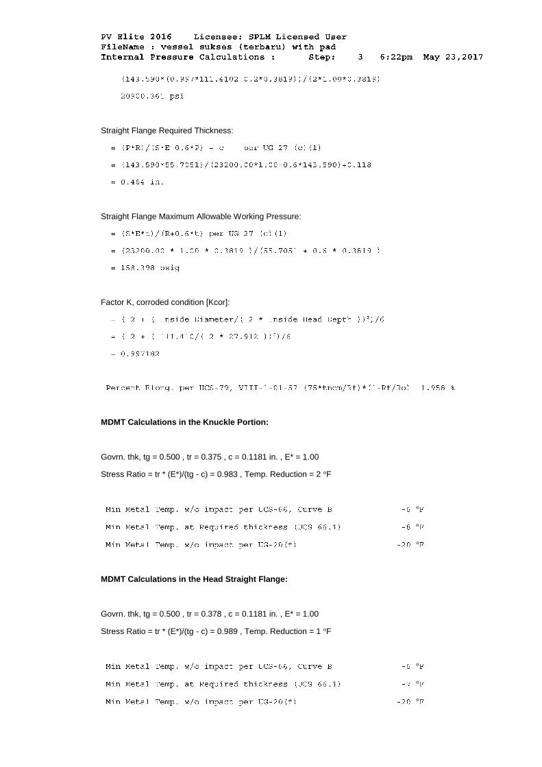
Straight Flange Required Thickness:
Straight Flange Maximum Allowable Working Pressure:
Factor K, corroded condition [Kcor]:
MDMT Calculations in the Knuckle Portion:
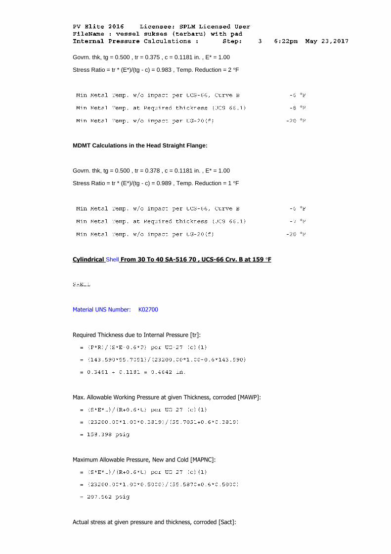
Govrn. thk, tg = 0.500 , tr = 0.375 , c = 0.1181 in. , E* = 1.00
Stress Ratio = tr * (E*)/(tg - c) = 0.983 , Temp. Reduction = 2 °F
°
°
°
MDMT Calculations in the Head Straight Flange:
Govrn. thk, tg = 0.500 , tr = 0.378 , c = 0.1181 in. , E* = 1.00
Stress Ratio = tr * (E*)/(tg - c) = 0.989 , Temp. Reduction = 1 °F
°
°
°
Cylindrical Shell From 30 To 40 SA-516 70 , UCS-66 Crv. B at 159 °F
Material UNS Number: K02700
Required Thickness due to Internal Pressure [tr]:
Max. Allowable Working Pressure at given Thickness, corroded [MAWP]:
Maximum Allowable Pressure, New and Cold [MAPNC]:
Actual stress at given pressure and thickness, corroded [Sact]:
Minimum Design Metal Temperature Results:
Govrn. thk, tg = 0.500 , tr = 0.378 , c = 0.1181 in. , E* = 1.00
Stress Ratio = tr * (E*)/(tg - c) = 0.989 , Temp. Reduction = 1 °F
°
°
°
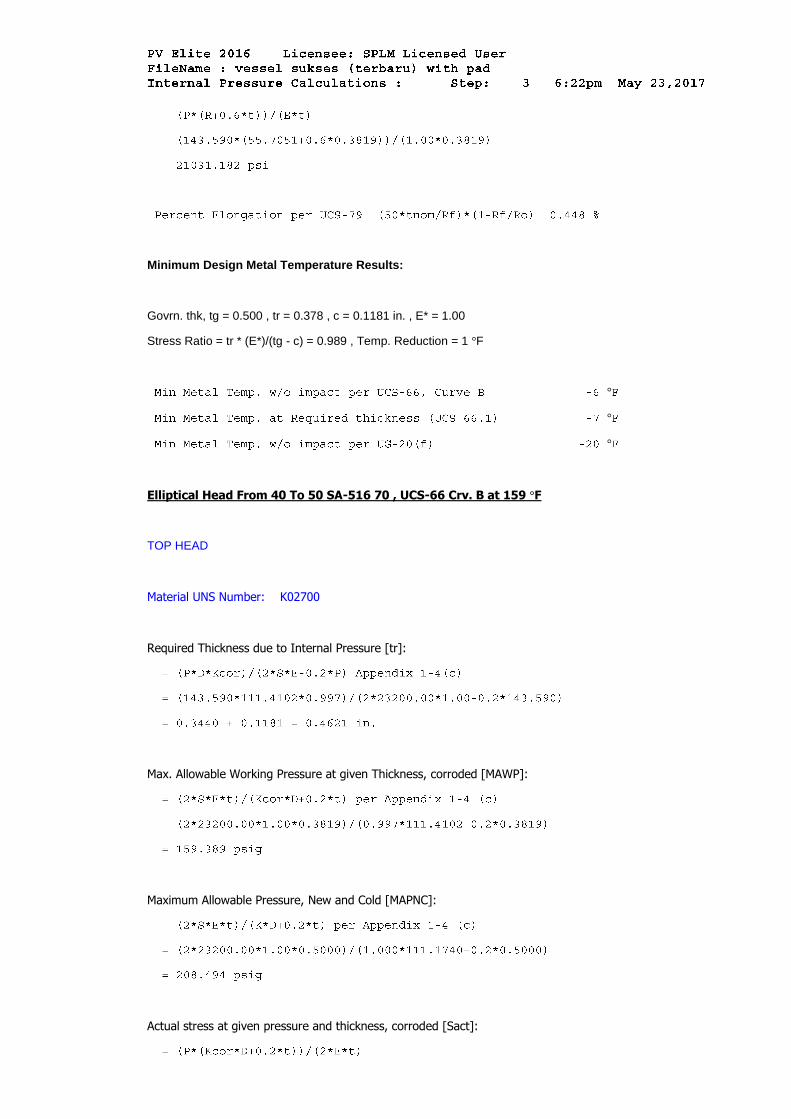
Elliptical Head From 40 To 50 SA-516 70 , UCS-66 Crv. B at 159 °F
TOP HEAD
Material UNS Number: K02700
Required Thickness due to Internal Pressure [tr]:
Max. Allowable Working Pressure at given Thickness, corroded [MAWP]:
Maximum Allowable Pressure, New and Cold [MAPNC]:
Actual stress at given pressure and thickness, corroded [Sact]:
Straight Flange Required Thickness:
Straight Flange Maximum Allowable Working Pressure:
Factor K, corroded condition [Kcor]:
MDMT Calculations in the Knuckle Portion:
Govrn. thk, tg = 0.500 , tr = 0.375 , c = 0.1181 in. , E* = 1.00
Stress Ratio = tr * (E*)/(tg - c) = 0.983 , Temp. Reduction = 2 °F
°
°
°
MDMT Calculations in the Head Straight Flange:
Govrn. thk, tg = 0.500 , tr = 0.378 , c = 0.1181 in. , E* = 1.00
Stress Ratio = tr * (E*)/(tg - c) = 0.989 , Temp. Reduction = 1 °F
°
°
°
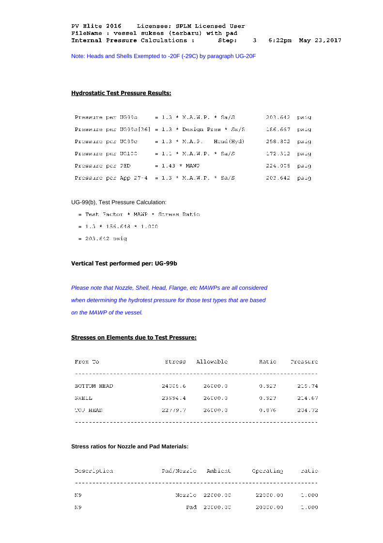
Note: Heads and Shells Exempted to -20F (-29C) by paragraph UG-20F
Hydrostatic Test Pressure Results:
UG-99(b), Test Pressure Calculation:
Vertical Test performed per: UG-99b
Please note that Nozzle, Shell, Head, Flange, etc MAWPs are all considered
when determining the hydrotest pressure for those test types that are based
on the MAWP of the vessel.
Stresses on Elements due to Test Pressure:
Stress ratios for Nozzle and Pad Materials:
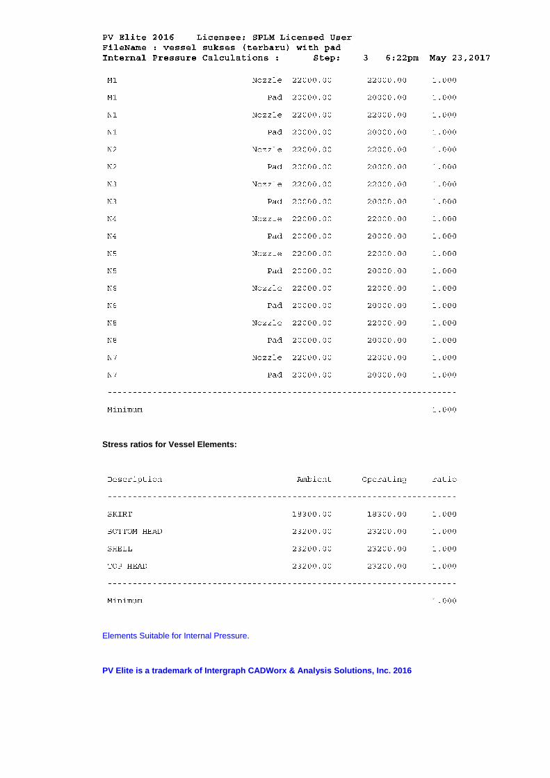
Stress ratios for Vessel Elements:
Elements Suitable for Internal Pressure.
PV Elite is a trademark of Intergraph CADWorx & Analysis Solutions, Inc. 2016
Wind Load Calculation
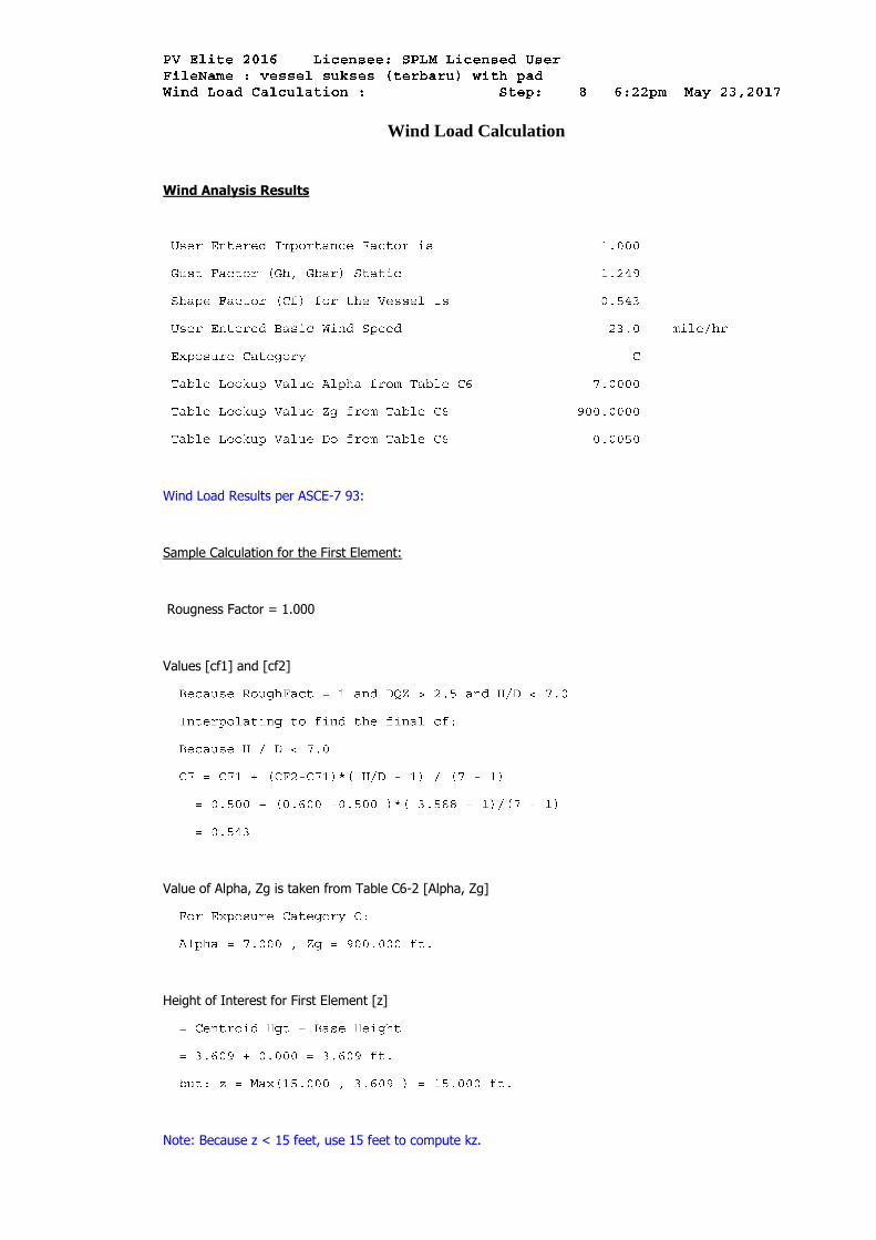
Wind Analysis Results
Wind Load Results per ASCE-7 93:
Sample Calculation for the First Element:
Rougness Factor = 1.000
Values [cf1] and [cf2]
Value of Alpha, Zg is taken from Table C6-2 [Alpha, Zg]
Height of Interest for First Element [z]
Note: Because z < 15 feet, use 15 feet to compute kz.
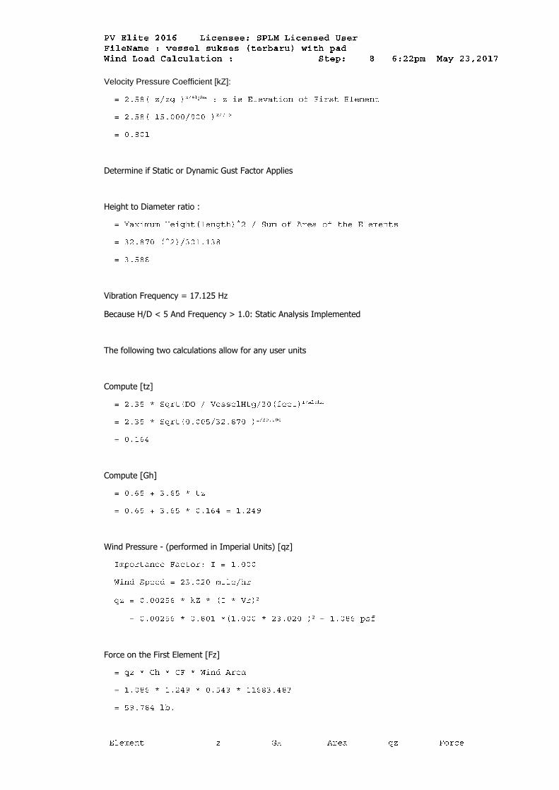
Velocity Pressure Coefficient [kZ]:
Determine if Static or Dynamic Gust Factor Applies
Height to Diameter ratio :
Vibration Frequency = 17.125 Hz
Because H/D < 5 And Frequency > 1.0: Static Analysis Implemented
The following two calculations allow for any user units
Compute [tz]
Compute [Gh]
Wind Pressure - (performed in Imperial Units) [qz]
²
²
Force on the First Element [Fz]
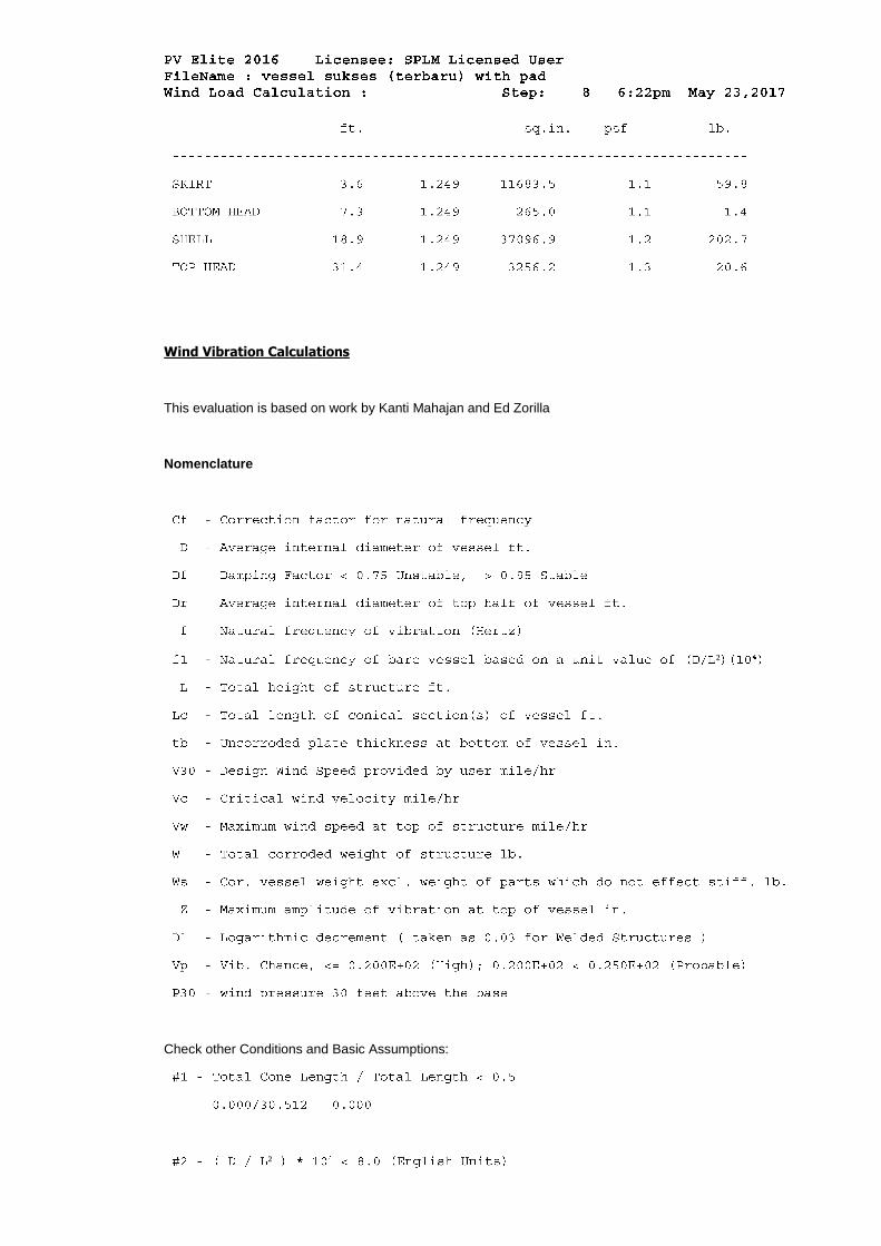
Wind Vibration Calculations
This evaluation is based on work by Kanti Mahajan and Ed Zorilla
Nomenclature
²
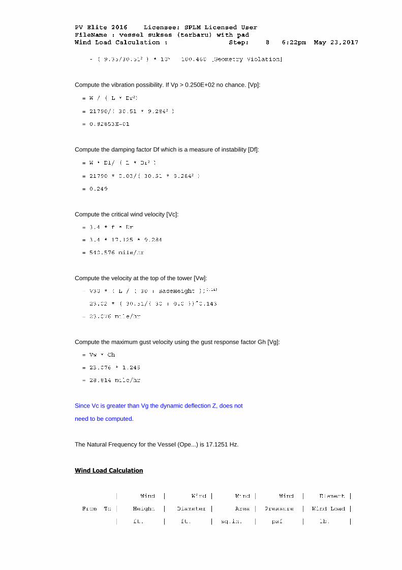
Check other Conditions and Basic Assumptions:
²
²
Compute the vibration possibility. If Vp > 0.250E+02 no chance. [Vp]:
²
²
Compute the damping factor Df which is a measure of instability [Df]:
²
²
Compute the critical wind velocity [Vc]:
Compute the velocity at the top of the tower [Vw]:
Compute the maximum gust velocity using the gust response factor Gh [Vg]:
Since Vc is greater than Vg the dynamic deflection Z, does not
need to be computed.
The Natural Frequency for the Vessel (Ope...) is 17.1251 Hz.
Wind Load Calculation

PV Elite is a trademark of Intergraph CADWorx & Analysis Solutions, Inc. 2016
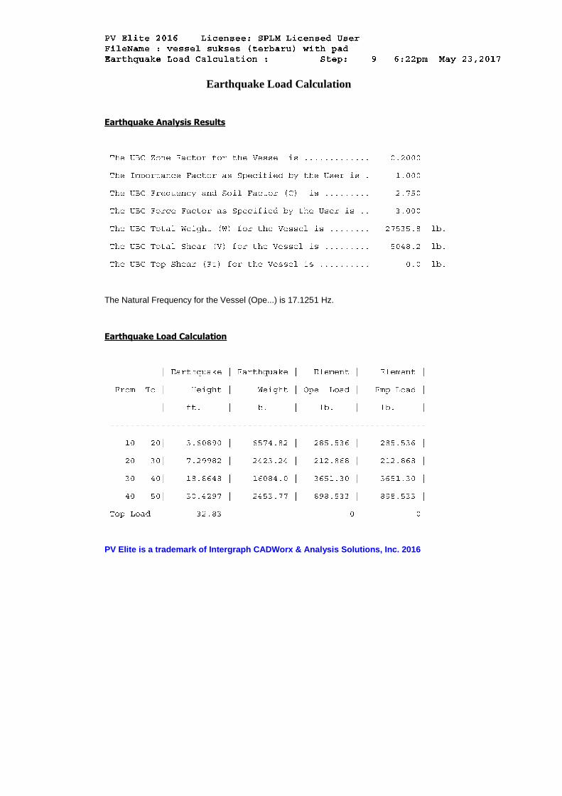
Earthquake Load Calculation
Earthquake Analysis Results
The Natural Frequency for the Vessel (Ope...) is 17.1251 Hz.
Earthquake Load Calculation
PV Elite is a trademark of Intergraph CADWorx & Analysis Solutions, Inc. 2016
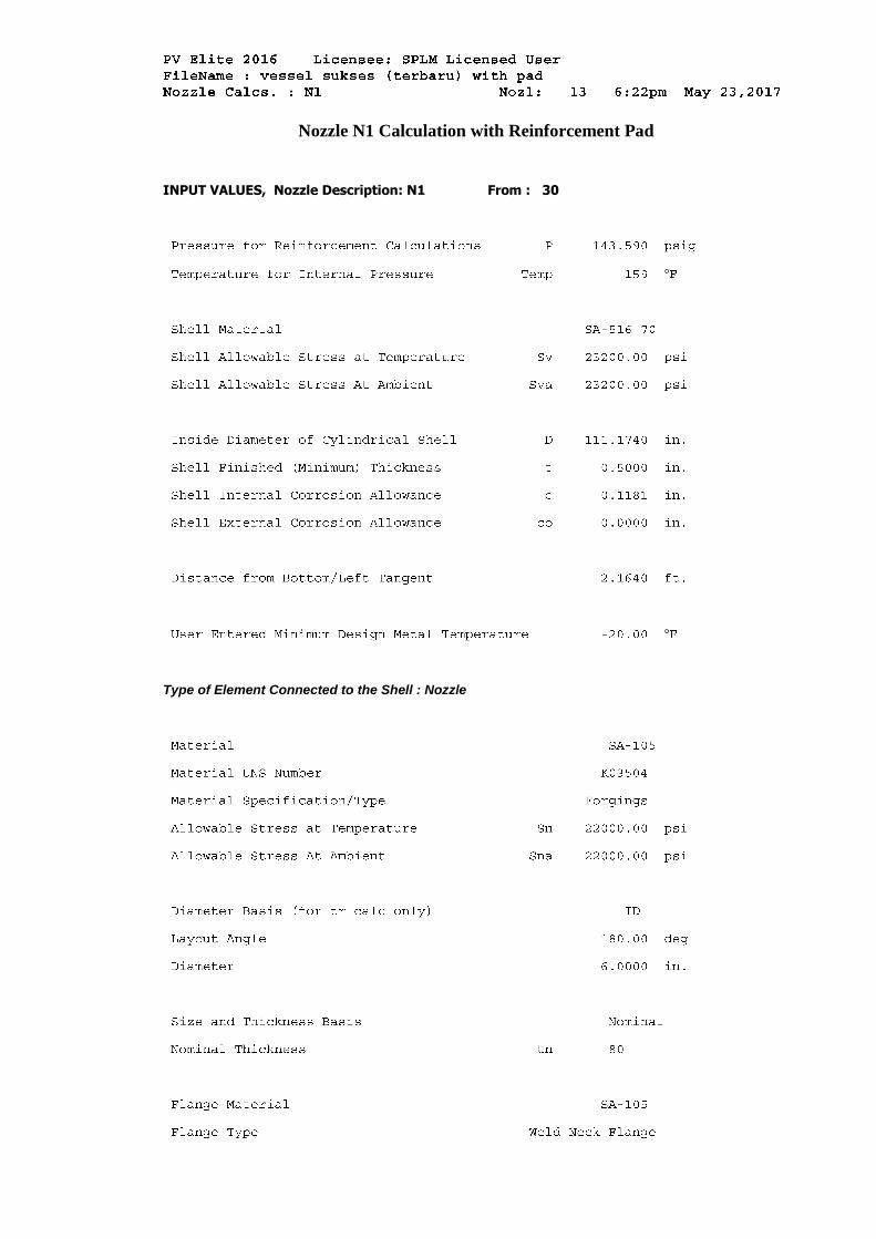
Nozzle N1 Calculation with Reinforcement Pad
INPUT VALUES, Nozzle Description: N1 From : 30
°
°
Type of Element Connected to the Shell : Nozzle

The Pressure Design option was Design Pressure + static head.
Nozzle Sketch (may not represent actual weld type/configuration)
Insert/Set-in Nozzle With Pad, no Inside projection
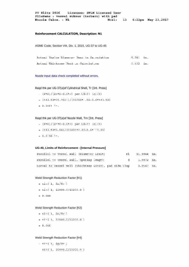
Reinforcement CALCULATION, Description: N1
ASME Code, Section VIII, Div. 1, 2015, UG-37 to UG-45
Nozzle input data check completed without errors.
Reqd thk per UG-37(a)of Cylindrical Shell, Tr [Int. Press]
Reqd thk per UG-37(a)of Nozzle Wall, Trn [Int. Press]
UG-40, Limits of Reinforcement : [Internal Pressure]
Weld Strength Reduction Factor [fr1]:
Weld Strength Reduction Factor [fr2]:
Weld Strength Reduction Factor [fr4]:
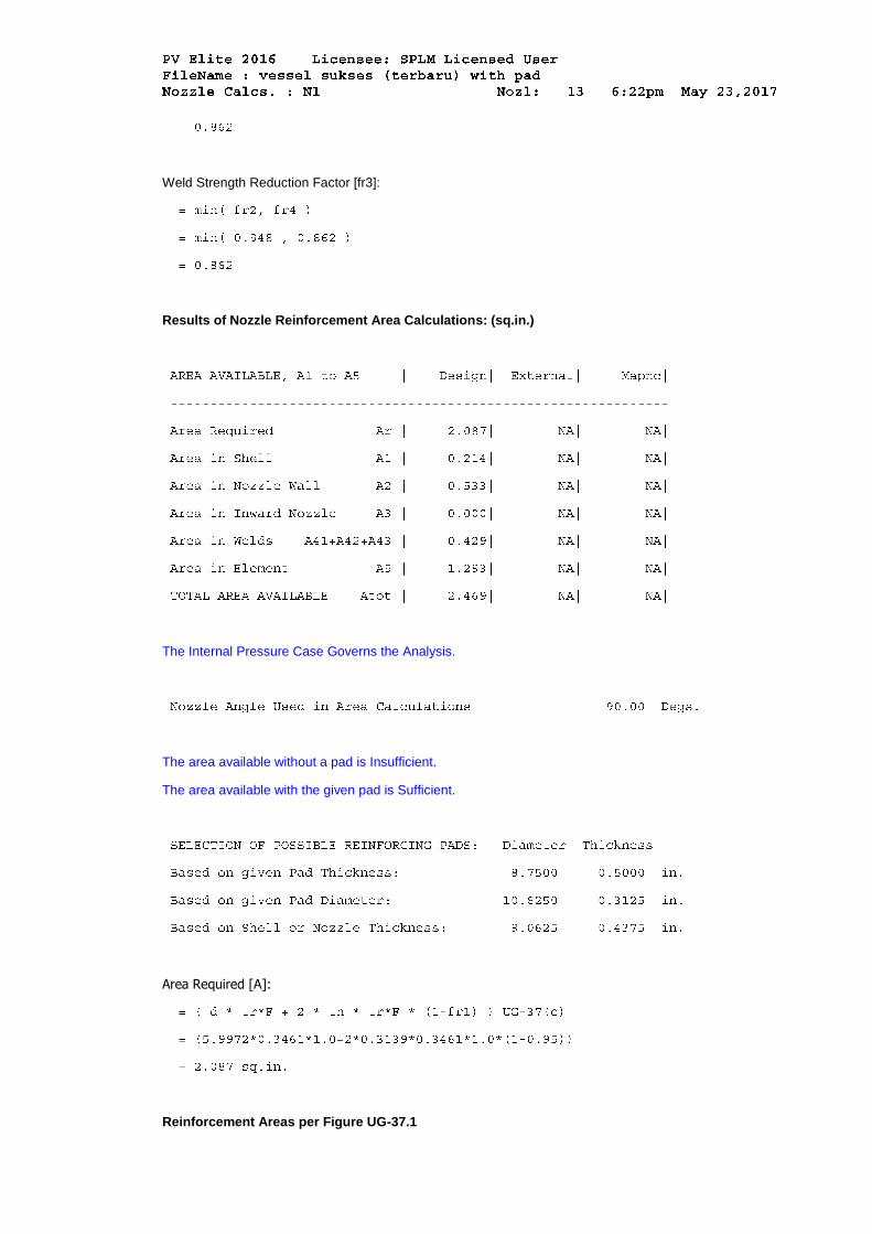
Weld Strength Reduction Factor [fr3]:
Results of Nozzle Reinforcement Area Calculations: (sq.in.)
The Internal Pressure Case Governs the Analysis.
The area available without a pad is Insufficient.
The area available with the given pad is Sufficient.
Area Required [A]:
Reinforcement Areas per Figure UG-37.1
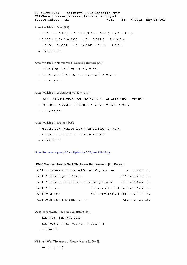
Area Available in Shell [A1]:
Area Available in Nozzle Wall Projecting Outward [A2]:
Area Available in Welds [A41 + A42 + A43]:
² ² ²
²
Area Available in Element [A5]:
Note: Per user request, A5 multiplied by 0.75, see UG-37(h).
UG-45 Minimum Nozzle Neck Thickness Requirement: [Int. Press.]
Determine Nozzle Thickness candidate [tb]:
Minimum Wall Thickness of Nozzle Necks [tUG-45]:
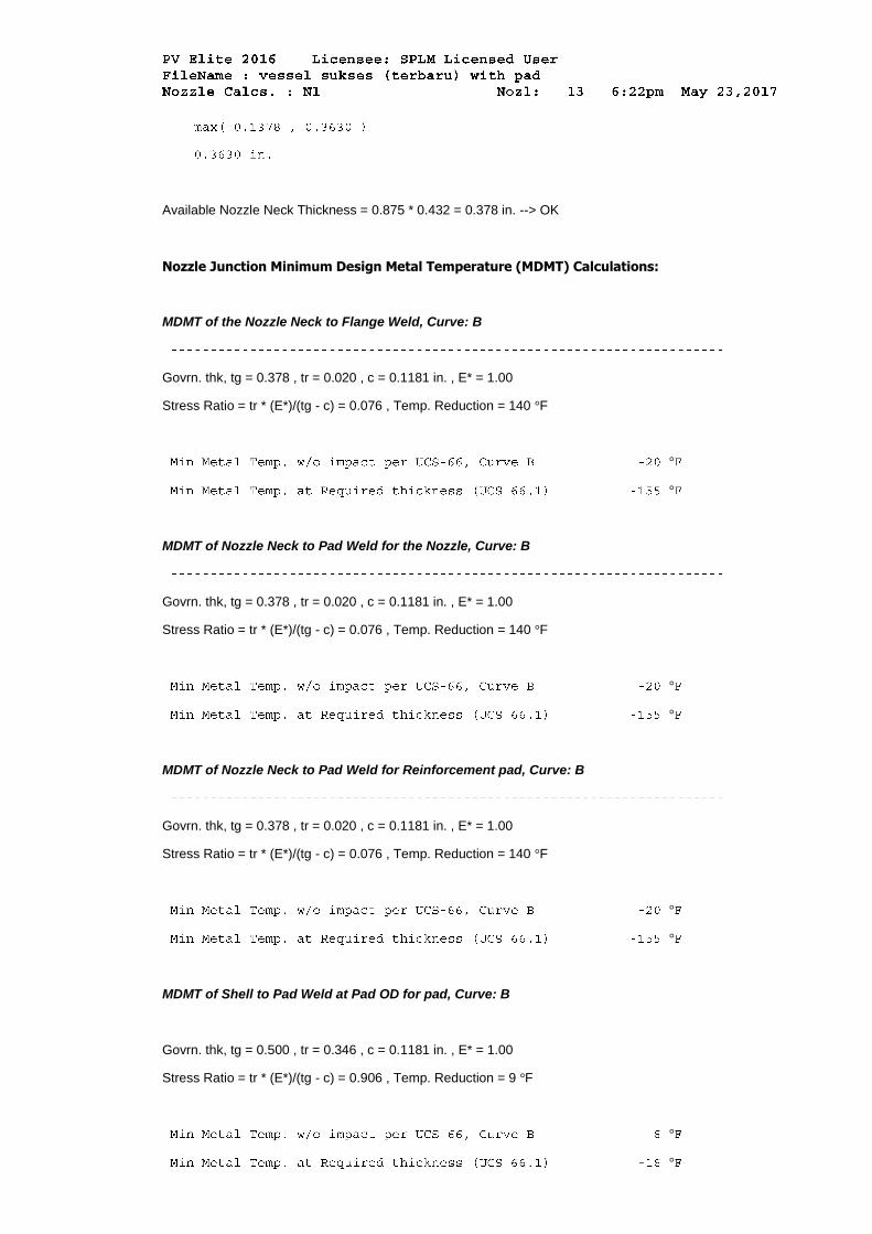
Available Nozzle Neck Thickness = 0.875 * 0.432 = 0.378 in. --> OK
Nozzle Junction Minimum Design Metal Temperature (MDMT) Calculations:
MDMT of the Nozzle Neck to Flange Weld, Curve: B
Govrn. thk, tg = 0.378 , tr = 0.020 , c = 0.1181 in. , E* = 1.00
Stress Ratio = tr * (E*)/(tg - c) = 0.076 , Temp. Reduction = 140 °F
°
°
MDMT of Nozzle Neck to Pad Weld for the Nozzle, Curve: B
Govrn. thk, tg = 0.378 , tr = 0.020 , c = 0.1181 in. , E* = 1.00
Stress Ratio = tr * (E*)/(tg - c) = 0.076 , Temp. Reduction = 140 °F
°
°
MDMT of Nozzle Neck to Pad Weld for Reinforcement pad, Curve: B
Govrn. thk, tg = 0.378 , tr = 0.020 , c = 0.1181 in. , E* = 1.00
Stress Ratio = tr * (E*)/(tg - c) = 0.076 , Temp. Reduction = 140 °F
°
°
MDMT of Shell to Pad Weld at Pad OD for pad, Curve: B
Govrn. thk, tg = 0.500 , tr = 0.346 , c = 0.1181 in. , E* = 1.00
Stress Ratio = tr * (E*)/(tg - c) = 0.906 , Temp. Reduction = 9 °F
°
°
°
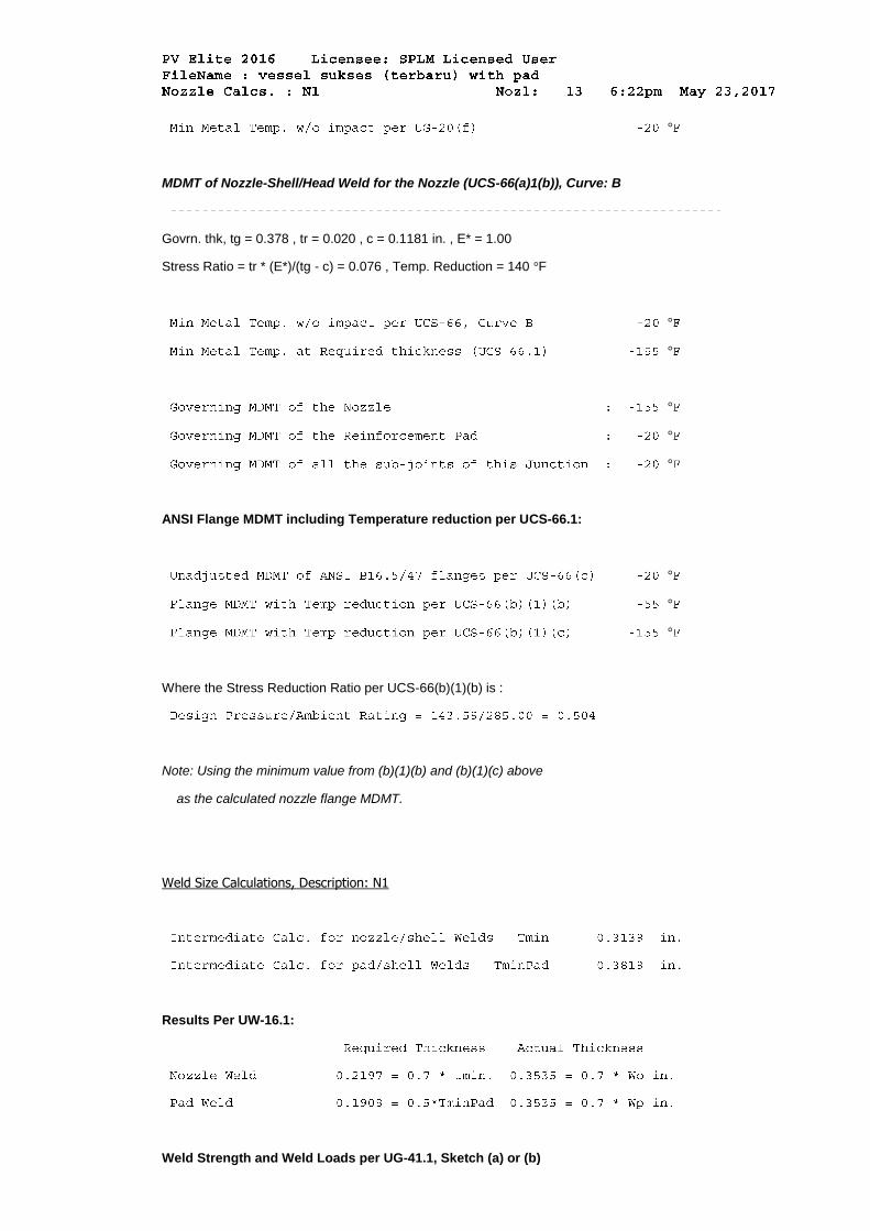
MDMT of Nozzle-Shell/Head Weld for the Nozzle (UCS-66(a)1(b)), Curve: B
Govrn. thk, tg = 0.378 , tr = 0.020 , c = 0.1181 in. , E* = 1.00
Stress Ratio = tr * (E*)/(tg - c) = 0.076 , Temp. Reduction = 140 °F
°
°
°
°
°
ANSI Flange MDMT including Temperature reduction per UCS-66.1:
°
°
°
Where the Stress Reduction Ratio per UCS-66(b)(1)(b) is :
Note: Using the minimum value from (b)(1)(b) and (b)(1)(c) above
as the calculated nozzle flange MDMT.
Weld Size Calculations, Description: N1
Results Per UW-16.1:
Weld Strength and Weld Loads per UG-41.1, Sketch (a) or (b)
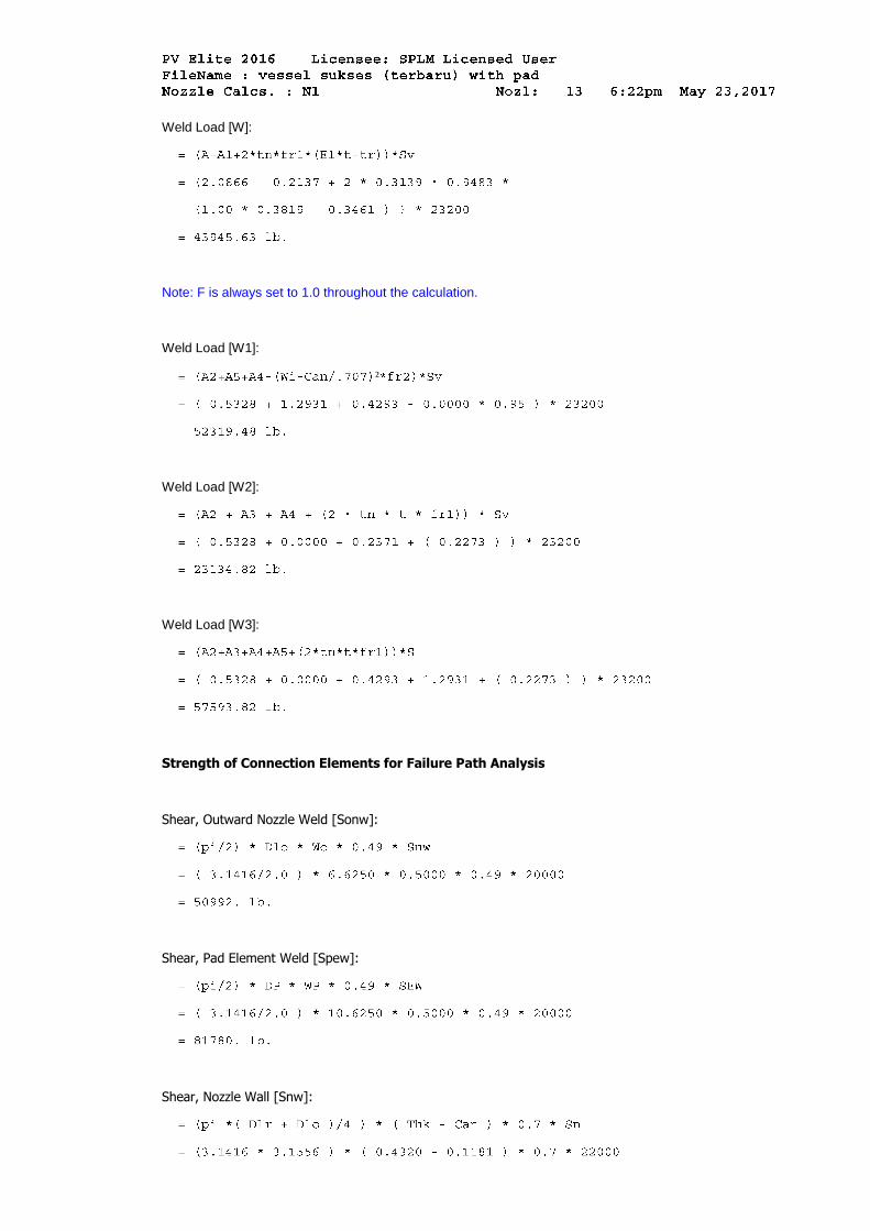
Weld Load [W]:
Note: F is always set to 1.0 throughout the calculation.
Weld Load [W1]:
²
Weld Load [W2]:
Weld Load [W3]:
Strength of Connection Elements for Failure Path Analysis
Shear, Outward Nozzle Weld [Sonw]:
Shear, Pad Element Weld [Spew]:
Shear, Nozzle Wall [Snw]:
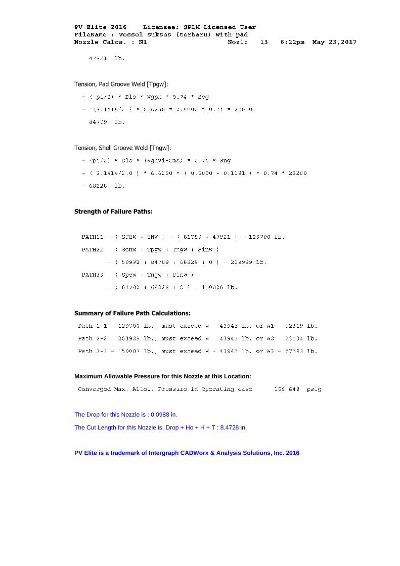
Tension, Pad Groove Weld [Tpgw]:
Tension, Shell Groove Weld [Tngw]:
Strength of Failure Paths:
Summary of Failure Path Calculations:
Maximum Allowable Pressure for this Nozzle at this Location:
The Drop for this Nozzle is : 0.0988 in.
The Cut Length for this Nozzle is, Drop + Ho + H + T : 8.4728 in.
PV Elite is a trademark of Intergraph CADWorx & Analysis Solutions, Inc. 2016