Embed Size (px)
Citation preview
Our instruments' quality level is the results of the product continuous development. This can bring about differences between the information written in this manual and the instru-ment that you have purchased. We cannot entirely exclude errors in the manual, for which we apologize. The data, figures and descriptions contained in this manual cannot be legally asserted. We reserve the right to make changes and correction without prior notice.
REV. 1.031 Jan. 2006
HD3456.2
- - 2
Conductivity meter – pH meter – Thermometer HD3456.2
- - 3
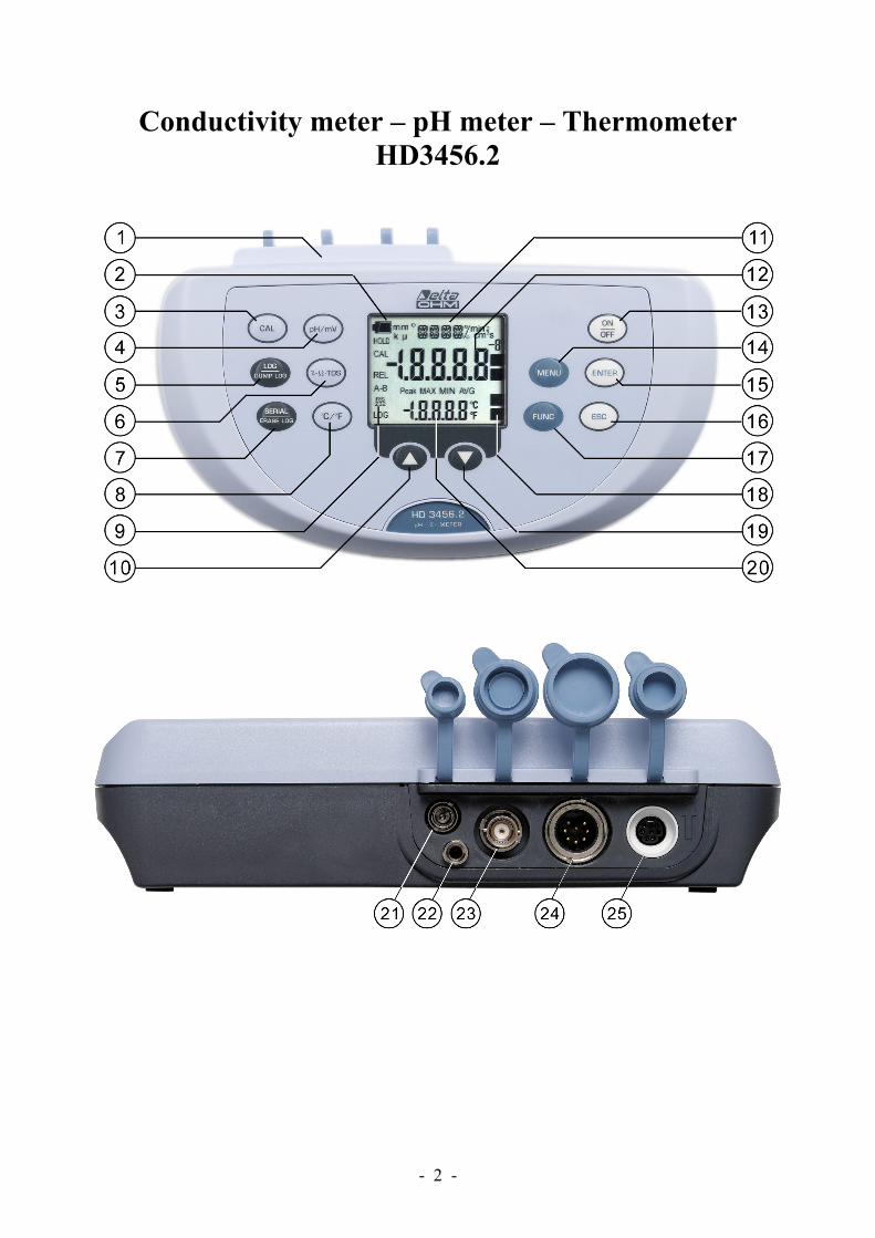
HD3456.2 1. Connectors 2. Battery symbol: displays the battery charge level. The symbol does not appear when the ex-
ternal power supply is connected. 3. CAL key: it starts the conductivity probe or pH electrode calibration. 4. pH/mV key: changes the main variable measurement between pH and mV. 5. LOG/DUMP LOG key: during normal operation, starts and ends the saving of the data in
the internal memory; in the menu, starts the data transfer from the instrument's memory to the PC.
6. χ-Ω-TDS key: changes the main variable measurement between conductivity, resistivity, to-tal dissolved solids (TDS) and salinity.
7. SERIAL/ERASE LOG key: starts and ends the data transfer to the serial/USB communica-tion port. In the menu, clears the data contained in the instrument's memory.
8. °C/°F key: when the probe is not connected, allows manual modification of the temperature. When double pressed, changes the unit of measurement for the temperature from degrees Celsius to Fahrenheit.
9. Function indicators. 10. Key : in the menu, increases the current value. 11. Line for symbols and comments. 12. Main display line. 13. ON-OFF/AUTO-OFF key: turns the instrument on and off; when pressed together with the
ENTER key, disables the automatic turn off. 14. MENU key: allows access to and exit from the menu. 15. ENTER key: in the menu, confirms the current selection; when pressed together with the
ON/OFF key, disables the automatic turn off. 16. ESC key: in the menu, cancels the operation in progress without making changes. 17. FUNC key: during normal operation displays the maximum (MAX), the minimum (MIN)
and the average (AVG) of current measurements. 18. pH electrode efficiency indicators. 19. Key : in the menu, decreases the current value. 20. Secondary display line. 21. External mains power supply connector input 12Vdc for ∅ 5.5mm - 2.1mm connector . 22. Socket for ∅ 4 mm standard plug for the reference electrode pH/ISE. 23. BNC connector for the pH/mV electrode. 24. 8-pole DIN45326 connector, input for combined 4-ring or 2-ring conductivity/temperature
probes, for direct 4 wire Pt100 temperature probes and 2 wire Pt1000 probes complete with TP47 module.
25. 8-pole MiniDin connector for RS232C connection using cable HD2110CSNM, for USB 2.0 connection using cable HD2101/USB, and for S-print-BT printer connection using cable HD2110CSP.
- - 4
INTRODUCTION
The instrument series HD34… is made up of 4 bench top instruments for electrochemical measures: pH, conductivity, dissolved oxygen and temperature.
The HD3456.2 measures pH, mV, redox potential (ORP), conductivity, resistivity in liquids, to-tal dissolved solids (TDS) and salinity using combined 4-ring and 2-ring conductivity/temperature probes. Temperature is measured by Pt100 or Pt1000 immersion, penetration or contact probes. It is possible to simultaneously connect the following to the instrument: a pH electrode and a com-bined conductivity/temperature probe or electrode pH, a pH electrode and a temperature probe. The temperature is always displayed while for the quantities linked to pH (pH - mV) or conductivity (conductivity - liquid resistivity - total dissolved solids - salinity) the display is selected respectively using the keys pH/mV and χ-Ω-TDS. Printing and logging always includes three parameters: tem-perature – pH or mV – χ or Ω or TDS or g/l. The pH electrode calibration, as well as manual, can be carried out on one, two or three points and the calibration sequence can be chosen from a list of 13 buffers. The probe calibration can be performed automatically in one or more of the 147μS, 1413μS, 12880μS or 111800μS/cm conductivity standard solutions.
The displayed data can be stored (datalogger) and can be transferred to PC or serial printer thanks to the multi-standard serial ports RS232C and USB2.0 and software DeltaLog9 (Vers.2.0 o later). The storing and printing parameters can be set from menu.
Other common function of this instrument series include: Max, Min and Avg function, the Auto-HOLD function, the automatic turning off which can also be disabled.
The instruments have IP66 protection degree.
- - 5
KEYBOARD AND MENU DESCRIPTION Foreword The instrument keyboard is composed of single-function keys, like the MENU key, and double-function keys such as the LOG/DUMP LOG key. In the double-keys, the function in the upper part is the "main function", while the one in the bottom part is the "secondary function". When the instrument is in standard measurement mode, the main function is active. In the menu, the secondary function is enabled. The pressing of a key is accompanied by a short confirmation beep: a longer beep sounds if the wrong key is pressed. The following can be seen on the display at the same time:
1. pH (or mV) and temperature 2. conductivity (or resistivity or total dissolved solids or salinity) and temperature.
It is not possible to see pH (or mV) and conductivity at the same time: one measurement or the other must be selected using the "pH/mV" and "χ-Ω-TDS" keys. In direct print and when logging three quantities are captured at the same time: pH/mV, conductivity and tempera-ture. Each key specific function is described in detail below.
ON-OFF key
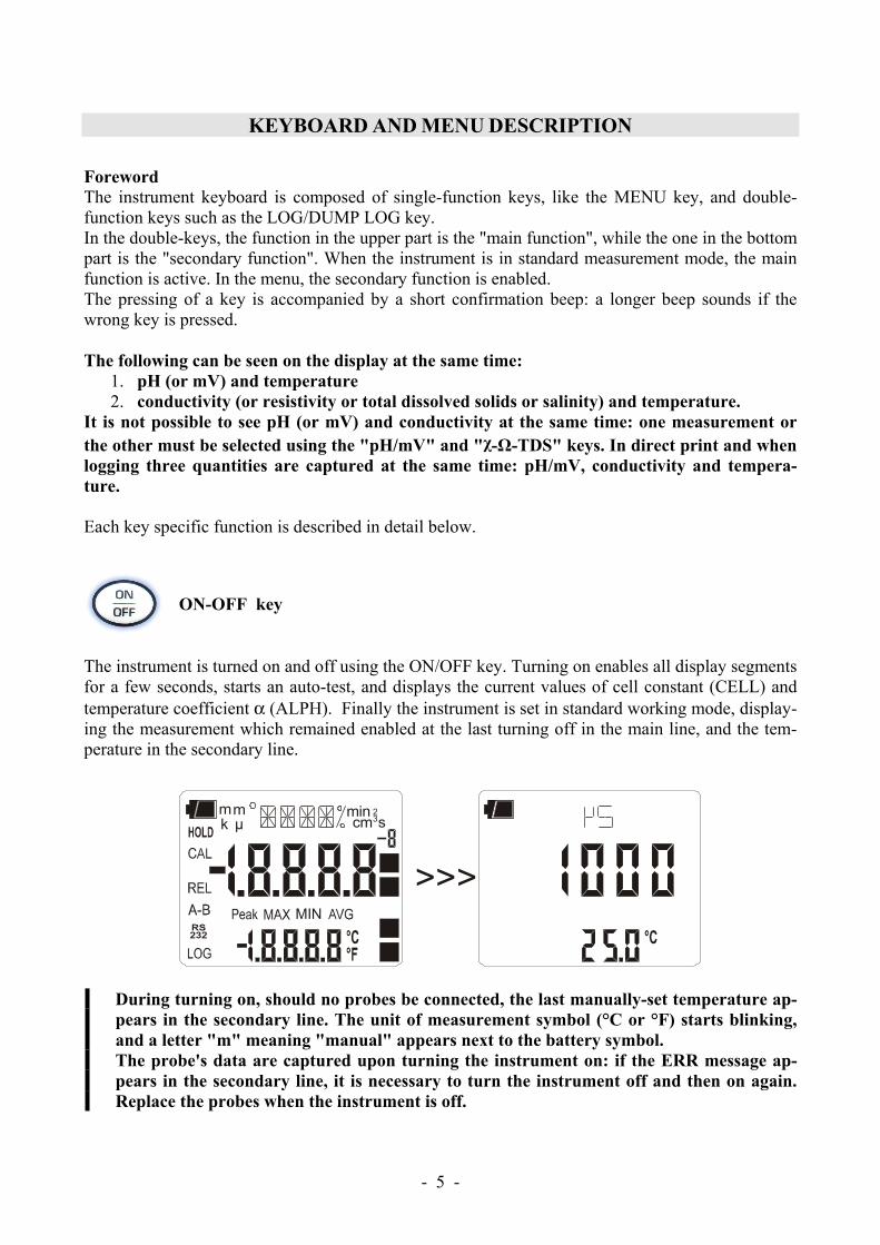
The instrument is turned on and off using the ON/OFF key. Turning on enables all display segments for a few seconds, starts an auto-test, and displays the current values of cell constant (CELL) and temperature coefficient α (ALPH). Finally the instrument is set in standard working mode, display-ing the measurement which remained enabled at the last turning off in the main line, and the tem-perature in the secondary line.
MIN
cmmin
s23
mµm
k
>>>
During turning on, should no probes be connected, the last manually-set temperature ap-pears in the secondary line. The unit of measurement symbol (°C or °F) starts blinking, and a letter "m" meaning "manual" appears next to the battery symbol. The probe's data are captured upon turning the instrument on: if the ERR message ap-pears in the secondary line, it is necessary to turn the instrument off and then on again. Replace the probes when the instrument is off.
- - 6
+
Automatic turning off
The instrument has an AutoPowerOff function that automatically turns the instrument off after about 8 minutes if no key is pressed during the intervening time. The AutoPowerOff function can be dis-abled by holding the CAL key pressed down when turning the instrument on: the battery symbol will blink to remind the user that the instrument can only be turned off by pressing the <ON/OFF> key. The automatic turning off function is disabled when external power is used. On the other hand, it cannot be disabled when the batteries are discharged.
ENTER key
In the menu, the ENTER key confirms the current parameter and then goes to the next one. Pressed together with the ON/OFF key, disables the automatic turn off.
MENU Key
The first menu item is accessed by initially pressing on the MENU key; press ENTER to go to the following items. To modify the item displayed, use the arrow keys ( and ). The current value is confirmed by pressing the ENTER key and the display moves on to the next parameter. If pressing ESC the setting is cancelled. To exit the menu, press the MENU key at any time. The menu items are listed in this order:
1) Management of memorized data: the message "LOG_DUMP_or_ERAS" (Transfer data or erase) is scrolled in the comment line. The center figure reports the number of free mem-ory pages (FREE). All memory data are permanently erased by pressing SE-RIAL/EraseLOG. By pressing LOG/DumpLOG, the data transfer of the logged data on the serial port is started: the "BAUD-RATE" must have previously been set to the maximum value (please see the menu items described below and the paragraph "STORING AND TRANSFERRING DATA TO A PERSONAL COMPUTER" on page 36).
2) Identifier of the sample being measured: it is an automatically increased progressive number associated with the single PRINT function (print interval set to 0) for the printing of labels. The index appears in the single sample printing together with date, time, conduc-tivity (liquid resistivity, total dissolved solids or salinity) and temperature or pH (or mV) measured values. This menu item allows the value of the first sample to be set: each time the PRINT key is pressed, the identification ID in the printing is increased by 1 allowing pro-gressive measurement of all measured samples. If the Auto-Hold function, described below in this chapter, is enabled, the print time interval is forced to zero. Pressing SERIAL only causes the print to occur when the measurement has stabilized (HOLD symbol still). Later, it is possible to repeat the print at will, but while the HOLD mode is on, the sample identifier number is not increased. This is useful when more labels must be printed with the same identification code without increasing the code each time.
- - 7
The message "SMPL ID UNT=RSET SER=PRNT" is scrolled in the comment line: using the arrows ( and ) the currently measured sample identifier value can be changed. By holding the °C/°F (Unit) key down the proposed number is rapidly set to zero. The instrument's heading information will be printed using the SERIAL key.
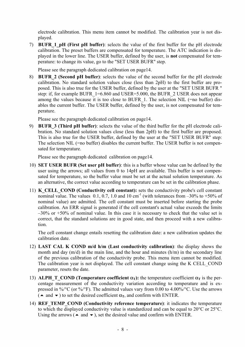
3) AUTO-HOLD function: the instrument normally operates in continuous view mode (de-fault setting). In this mode the displayed measurement is updated every second. If the Auto-Hold function is enabled, the instrument performs the measurement and when it stabilizes it goes in HOLD mode. To update the display indication, press FUNC. The Auto-Hold func-tion is applied to the pH measurement, conductivity and all resulting measurements. In the following figure you can see an example of the measurement process with the Auto-Hold function enabled. A probe is immersed into a liquid at conductivity χ1 and, to perform the measurement, the FUNC key is pressed: The conductivity measurement raises progres-sively reaching the final value. The HOLD symbol blinks. In the stretch indicated by 1, the measurement remains stable for 10 seconds, within two digits: at the end of this interval (point 2), the instrument goes into HOLD mode, presenting the final stable value.
2 digit10s
t
χχ1
4) Print and log interval sets the interval in seconds between two loggings or data transfers to the serial port. The interval can be set from 0s, 1s, 5s, 10s, 15s, 30s, 60s (1min), 120s (2min), 300s (5min), 600s (10min), 900s (15min), 1200s (20min), 1800s (30min) and 3600s (1 hour). If the value 0 is set, SERIAL works on command: the sending of data to the serial port is performed each time the key is pressed. Recording (LOG) is performed with one second intervals even if the interval is set to 0. With an interval from 1 to 3600s, con-tinuous data transfer is started when the SERIAL key is pressed. To end the recording (LOG) and continuous data transfer operations (SERIAL with an interval greater than 0), press the same key again.
5) Sleep_Mode_LOG (Automatic turning off during recording): this function controls the instrument's automatic turning off during logging, occurring between the capture of a sample and the next one. When the interval is lower than 60 seconds, the instrument will always remain on. With intervals greater than or equal to 60 seconds, it is possible to turn off the in-strument between loggings: it will turn on at the moment of sampling and will turn off im-mediately afterwards, thus increasing the battery life. Using the arrows select YES and con-firm using ENTER in order to enable the automatic turning off, select NO and confirm to disable it and keep the instrument on continuously.
Note: even if Sleep_Mode_LOG=YES is selected, the instrument does not turn off for less than one minute intervals.
6) LAST CAL pH m/d h/m (Last pH calibration): the display shows the month and day (m/d) in the main line, and the hour and minutes (h/m) in the secondary line of the last pH
- - 8
electrode calibration. This menu item cannot be modified. The calibration year is not dis-played.
7) BUFR_1_pH (First pH buffer): selects the value of the first buffer for the pH electrode calibration. The preset buffers are compensated for temperature. The ATC indication is dis-played in the lower line. The USER buffer, defined by the user, is not compensated for tem-perature: to change its value, go to the "SET USER BUFR" step.
Please see the paragraph dedicated calibration on page14. 8) BUFR_2 (Second pH buffer): selects the value of the second buffer for the pH electrode
calibration. No standard solution values close (less than 2pH) to the first buffer are pro-posed. This is also true for the USER buffer, defined by the user at the "SET USER BUFR " step: if, for example BUFR_1=6.860 and USER=5.000, the BUFR_2 USER does not appear among the values because it is too close to BUFR_1. The selection NIL (=no buffer) dis-ables the current buffer. The USER buffer, defined by the user, is not compensated for tem-perature.
Please see the paragraph dedicated calibration on page14. 9) BUFR_3 (Third pH buffer): selects the value of the third buffer for the pH electrode cali-
bration. No standard solution values close (less than 2pH) to the first buffer are proposed. This is also true for the USER buffer, defined by the user at the "SET USER BUFR" step: The selection NIL (=no buffer) disables the current buffer. The USER buffer is not compen-sated for temperature.
Please see the paragraph dedicated calibration on page14.
10) SET USER BUFR (Set user pH buffer): this is a buffer whose value can be defined by the user using the arrows; all values from 0 to 14pH are available. This buffer is not compen-sated for temperature, so the buffer value must be set at the actual solution temperature. As an alternative, the correct value according to temperature can be set in the calibration phase.
11) K_CELL_COND (Conductivity cell constant): sets the conductivity probe's cell constant nominal value. The values 0.1, 0.7, 1.0 and 10 cm-1 (with tolerances from –30% to +50% of nominal value) are admitted. The cell constant must be inserted before starting the probe calibration. An ERR signal is generated if the cell constant's actual value exceeds the limits –30% or +50% of nominal value. In this case it is necessary to check that the value set is correct, that the standard solutions are in good state, and then proceed with a new calibra-tion.
The cell constant change entails resetting the calibration date: a new calibration updates the calibration date.
12) LAST CAL K COND m/d h/m (Last conductivity calibration): the display shows the month and day (m/d) in the main line, and the hour and minutes (h/m) in the secondary line of the previous calibration of the conductivity probe. This menu item cannot be modified. The calibration year is not displayed. The cell constant change using the K CELL_COND parameter, resets the date.
13) ALPH_T_COND (Temperature coefficient αT): the temperature coefficient αT is the per-centage measurement of the conductivity variation according to temperature and is ex-pressed in %/°C (or %/°F). The admitted values vary from 0.00 to 4.00%/°C. Use the arrows ( and ) to set the desired coefficient αT, and confirm with ENTER.
14) REF_TEMP_COND (Conductivity reference temperature): it indicates the temperature to which the displayed conductivity value is standardized and can be equal to 20°C or 25°C. Using the arrows ( and ), set the desired value and confirm with ENTER.
- - 9
15) TDS COND (Conversion factor χ/TDS): it represents the ratio between the measured con-ductivity value and the total quantity of dissolved solids in the solution, expressed in mg/l (ppm) or g/l (ppt). This conversion factor depends on the nature of the salts present in the solution: in the field of water quality treatment and control, where the main component is CaCO3 (Calcium Carbonate), a value of 0.5 is usually used. For agriculture water, for fertil-izers preparation, and in hydroponics, a factor of about 0.7 is used. Using the arrows ( and
), set the desired value, selecting it in the 0.4…0.8 range, and confirm with ENTER.
16) RCD MODE (Record mode): the instrument captures a pH, a conductivity and a tempera-ture value every second. If the RCD MODE parameter is set to "conductivity", the maxi-mum (MAX) and minimum (MIN) values displayed using FUNC refer to conductivity: the indicated temperature and pH are those measured at the maximum and minimum conductiv-ity and are not the maximum and minimum temperature and pH. Similarly, if the RCD MODE parameter is set to "pH", the maximum and minimum values displayed using FUNC refer to pH: the indicated temperature and conductivity are those measured at the maximum and minimum pH and are not the maximum and minimum tem-perature and conductivity.
If the RCD MODE parameter is set to "tp" (=temperature), the maximum and minimum values displayed using FUNC refer to temperature: the indicated conductivity and pH are those measured at the maximum and minimum temperature and are not the maximum and minimum conductivity and/or pH.
Finally, if the RCD MODE parameter is set to "Indep" (=independent), the maximum and minimum values displayed using FUNC are independent: the indicated pH, conductivity and temperature are the maximum and minimum measured values but are not necessarily re-ferred to the same measurement moment (factory default).
17) Probe type: the message "PRBE_TYPE" is scrolled in the comment line. The main line in the center of the display shows the type of temperature probe connected to the instrument. Conductivity/temperature combined probes with Pt100 or Pt1000 sensor, or temperature only probes can be connected to the input:
• 4 wire PT100 using the TP47 module • 2 wire PT1000 using the TP47 module
Upon being turned on, the instrument automatically detects the temperature probes: the Probe Type menu item is configured by the instrument and cannot be modified by the user. If no temperature probe or combined probe with temperature sensor is connected, the in-strument selects the Pt1000 sensor.
18) YEAR: to set the current year. Use the arrows to modify this parameter and confirm using ENTER.
19) MNTH (month): to set the current month. Use the arrows to modify this parameter and con-firm using ENTER.
20) DAY: to set the current day. Use the arrows to modify this parameter and confirm using ENTER.
21) HOUR: to set the current hour. Use the arrows to modify this parameter and confirm using ENTER.
22) MIN: to set the current minutes. In order to correctly synchronize the minute, it is possible to reset the seconds by pressing the °C/°F key. Use the arrows to set the current minute plus one, and as soon as that minute is reached press °C/°F: this synchronizes the time to the
second. Press ENTER to go onto the next item.
- - 10
23) BAUD_RATE: indicates the frequency used for the serial communication with the PC. Values from 1200 to 38400 baud. Use the arrows to modify this parameter and confirm us-ing ENTER. The communication between instrument and PC (or serial port printer) only works if the instrument and PC baud rates are the same. If the USB connection is used this parameter value is automatically set (please see the details on page36).
FUNC key
It enables the display and logging of the maximum (MAX), minimum (MIN) and average (AVG) value of the pH, mV, conductivity, liquid resistivity, total dissolved solids, salinity and temperature measurements, updating them with the acquisition of new samples. The acquisition frequency is once a second. To switch from pH to mV, press the "pH/mV" key. Use the χ-Ω-TDS key to switch from conductiv-ity to liquid resistivity, to total dissolved solids or to salinity.
The MAX, MIN and AVG measurements remain in the memory until the instrument is on, even after exiting the calculation function. To reset the previous values and restart with a new meas-urement session, press FUNC until the message "FUNC CLR" appears, then use the arrows to select YES and confirm using ENTER.
According to settings in the "RCD Mode" menu item, the maximum, minimum and average indications have different meanings: please see the description of this MENU key. Attention: the data captured using the Record function cannot be transferred to PC
ESC key
In the menu, the key clears or cancels the active function (ESC).
CAL key
It starts the variable (pH or conductivity) calibration (please see the chapter dedicated to pH, page14, and conductivity, page20 calibration).
pH/mV key
Changes the main variable measurement between pH and mV. The selected parameter is used for display, printing and logging.
The instrument has an Auto-Hold function, which can be set in the MENU, that "freezes" the measurement automatically when it has been stable (within 1 mV) for over 10 seconds: the mes-sage HOLD is displayed. To perform a new measurement, it is necessary to press the FUNC key. The HOLD message starts blinking, while the display follows the actual measurement trend, until it stabilizes again and the HOLD message remains still.
- - 11
NOTE: when the Auto-Hold function is enabled, the measurement in mV is disabled. To restore the display in mV, disable the Auto-Hold function in the menu.
LOG/DumpLOG key
In measurement mode, this function starts and stops the logging of a data block to be saved in the instrument's internal memory. The data logging frequency is set in the "Print and log interval" menu parameter. The data logged between a start and subsequent stop represent a single session.
When the logging function is on, the LOG indication is displayed, the battery symbol blinks and a beep is issued each time a logging occurs; the battery symbol does not appear when using an external power supply. To end the logging, press LOG. If the Auto-HOLD function is enabled (please see the menu), the data logging is disabled. The HD3456.2 can turn off during logging between one capture and the next: the function is controlled by the Sleep_Mode_LOG parameter. When the logging interval is less than one minute, the logging instrument remains on; with an interval of at least one minute, it turns off between one capture and the next if the parameter Sleep_Mode_LOG=YES.
>>>
Dump LOG
When the LOG key is pressed after the MENU key, the transfer of the logged data on the serial port is started.
Please see the paragraph dedicated to data transfer on page36.
χ-Ω-TDS (conductivity - resistivity - total dissolved solids - salinity) key
Changes the main variable measurement between conductivity, resistivity, total dissolved solids (TDS) and salinity. The selected parameter is used for display, printing, and logging.
The instrument has an Auto-Hold function, which can be set in the MENU, that "freezes" the meas-urement automatically when it has been stable (within 1 digit) for over 10 seconds: the message HOLD is displayed. To perform a new measurement, it is necessary to press the FUNC key. The HOLD message starts blinking, while the display follows the actual measurement trend, until it stabilizes again and the HOLD message remains still.
SERIAL/EraseLOG key
In measurement mode, this function starts and stops the data transfer to the RS232C serial output.
- - 12
According to the settings entered in the Print and log interval menu item, a single sample can be printed if Print and log interval=0 or a continuous indefinite printing of the measured data can be set up if Print and log interval=1…3600. The printing operation is accompanied by the display of the RS232 symbol and the blinking of the battery symbol; when using an external power supply the battery symbol does not appear. Press SERIAL to end the continuous printing. Before starting the printing with SERIAL, set the baud rate. To do so, select the Baud Rate menu item and select the maximum value equal to 38400 baud by using the arrows. Confirm by pressing ENTER. The DeltaLog9 software for PC will automatically set the baud rate value during connection. If you are using a different program than DeltaLog9, be sure the baud rate is the same for both the instrument and the PC: the communication will only work in this way.
>>>
Erase memory
When pressed after the MENU key, the SERIAL key permanently erases all the data contained in the instrument's memory.
°C/°F key
When the temperature probe is connected, the measured value is used to compensate the conductiv-ity measurement. The key changes the unit of measurement from degrees Celsius to Fahrenheit. If the probe is not present, the compensation temperature must be entered manually: to manually change the value shown in the display lower line, press °C/°F once. The temperature indicated starts blinking. While the display is blinking, it is possible to change the compensation temperature using the arrows ( and ). Confirm using ENTER. The display stops blinking, and the temperature displayed is used for compensation. If the temperature probe is not present, to change the unit of measurement between °C and °F, it is necessary to press twice the °C/°F key.
Up Arrow
When used in the menu, it increases the current variable value. If the temperature probe is not pre-sent, it increases the temperature value for pH and conductivity measurement compensation.
Down Arrow
When used in the menu, it decreases the current variable value. During measurement, if the tem-perature probe is not present, it decreases the temperature value for pH and conductivity measure-ment compensation.
- - 13
PH MEASUREMENT
The instrument works with pH measurement electrodes, redox potential measurement electrodes (ORP), and specific ion electrodes. The pH measurement must always be accompanied by a tem-perature measurement. The probes with 4 wire Pt100, 2 wire Pt1000 sensors may be used for meas-uring temperature or for the automatic compensation of the Nernst coefficient with the pH elec-trode.
The pH or mV indication is displayed in the main line by pressing the "pH/mV" key; the secondary line shows the temperature. If no temperature probe with temperature sensor is connected, the sec-ondary line shows the manual temperature.
The electrode for pH measurement The electrode for pH measurement, generally in glass, generates an electrical signal proportional to the pH according to Nernst law. Of this signal the following aspects are considered: Zero point: The pH where the electrode generates a potential of 0 mV. In most electrodes, this value is found at about 7pH. Offset or Asymmetry Potential: mV generated by an electrode when immersed in a buffer solution at 7pH. Generally oscillates between ± 20 mV. Slope: response of the electrode expressed in mV per pH units. The theoretical electrode slope at 25°C is 59.16 mV/pH. When the electrode is new the slope is close to the theoretical value. Sensitivity: it is the electrode's slope expression in relative terms. It is obtained by dividing the ac-tual value of the slope by the theoretical value, and is expressed as a %. The asymmetry potential and the slope vary in time with the use of the electrode, which necessitates regular calibration.
The pH electrodes must be calibrated using the standard solutions (see the pH calibration chapter below). The ORP and specific ion electrodes do not need calibration as their absolute voltage is measured. The redox standard solutions are only used to check the quality of a redox elec-trode. No calibration of the temperature sensor is required by the user: the 4 wire and 2 wire probes with direct input are checked for conformity with class A tolerance according to norm IEC751 - BS1904 - DIN43760. The probes are detected during turn on, and this cannot be performed when the instrument is already on, therefore if a probe is connected and the instrument is on, it is necessary to turn it off and on.
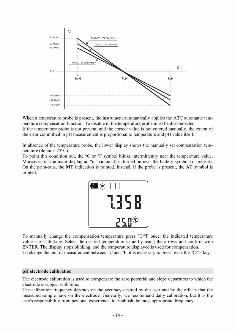
Automatic or manual pH compensation In a correct measurement of pH, the results need to be expressed together with the temperature value at which the reading is performed. The electrode slope varies according to the temperature in a known mode according to Nernst law: e.g., a 1pH variation, that at 25°C means 59.16mV, at 100°C means 74.04mV.
- - 14
6pH 7pH
pH
8pH
74.04mV
-74.04mV
59.16mV
-59.16mV
54.20mV
-54.20mV
0mV
mV
T=100°C, 74.04mV/pH
T=25°C, 59.16mV/pH
T=0°C, 54.20mV/pH
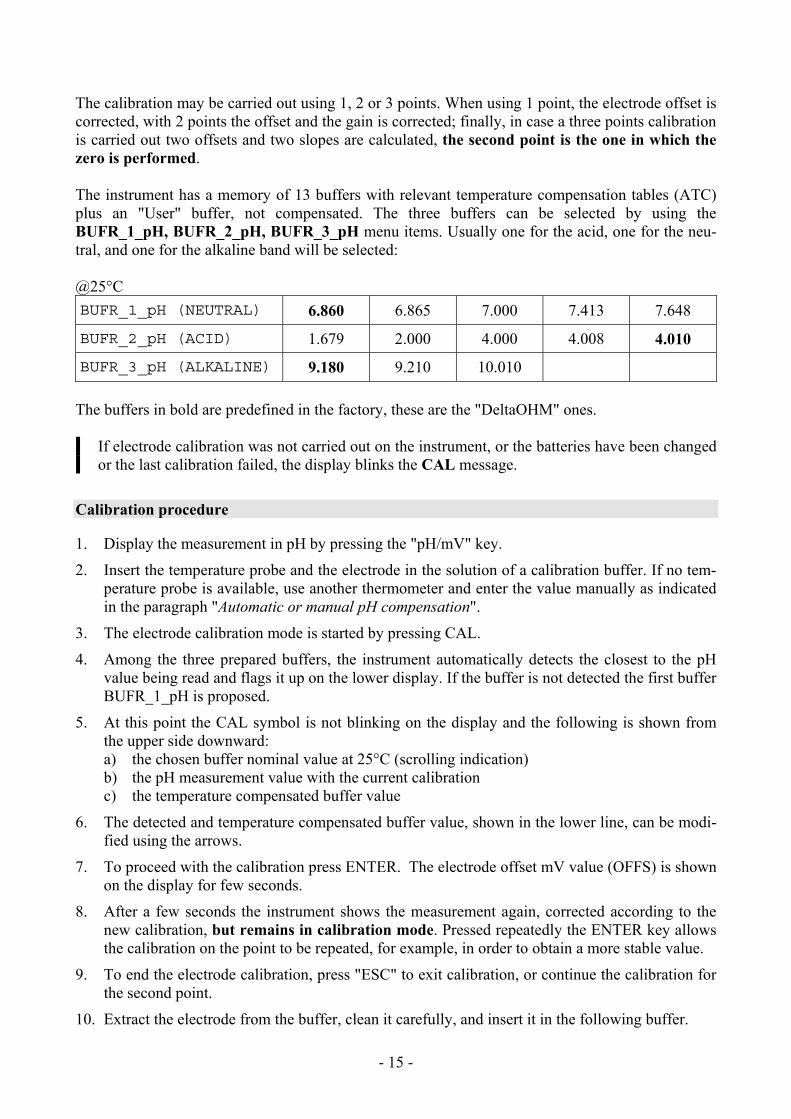
When a temperature probe is present, the instrument automatically applies the ATC automatic tem-perature compensation function. To disable it, the temperature probe must be disconnected. If the temperature probe is not present, and the correct value is not entered manually, the extent of the error committed in pH measurement is proportional to temperature and pH value itself. In absence of the temperature probe, the lower display shows the manually set compensation tem-perature (default=25°C). To point this condition out, the °C or °F symbol blinks intermittently near the temperature value. Moreover, on the main display an "m" (manual) is turned on near the battery symbol (if present). On the print-outs, the MT indication is printed. Instead, if the probe is present, the AT symbol is printed.
To manually change the compensation temperature press °C/°F once: the indicated temperature value starts blinking. Select the desired temperature value by using the arrows and confirm with ENTER. The display stops blinking, and the temperature displayed is used for compensation. To change the unit of measurement between °C and °F, it is necessary to press twice the °C/°F key.
pH electrode calibration The electrode calibration is used to compensate the zero potential and slope departures to which the electrode is subject with time. The calibration frequency depends on the accuracy desired by the user and by the effects that the measured sample have on the electrode. Generally, we recommend daily calibration, but it is the user's responsibility from personal experience, to establish the most appropriate frequency.
- - 15
The calibration may be carried out using 1, 2 or 3 points. When using 1 point, the electrode offset is corrected, with 2 points the offset and the gain is corrected; finally, in case a three points calibration is carried out two offsets and two slopes are calculated, the second point is the one in which the zero is performed. The instrument has a memory of 13 buffers with relevant temperature compensation tables (ATC) plus an "User" buffer, not compensated. The three buffers can be selected by using the BUFR_1_pH, BUFR_2_pH, BUFR_3_pH menu items. Usually one for the acid, one for the neu-tral, and one for the alkaline band will be selected: @25°C BUFR_1_pH (NEUTRAL) 6.860 6.865 7.000 7.413 7.648
BUFR_2_pH (ACID) 1.679 2.000 4.000 4.008 4.010
BUFR_3_pH (ALKALINE) 9.180 9.210 10.010 The buffers in bold are predefined in the factory, these are the "DeltaOHM" ones.
If electrode calibration was not carried out on the instrument, or the batteries have been changed or the last calibration failed, the display blinks the CAL message.
Calibration procedure
1. Display the measurement in pH by pressing the "pH/mV" key.
2. Insert the temperature probe and the electrode in the solution of a calibration buffer. If no tem-perature probe is available, use another thermometer and enter the value manually as indicated in the paragraph "Automatic or manual pH compensation".
3. The electrode calibration mode is started by pressing CAL.
4. Among the three prepared buffers, the instrument automatically detects the closest to the pH value being read and flags it up on the lower display. If the buffer is not detected the first buffer BUFR_1_pH is proposed.
5. At this point the CAL symbol is not blinking on the display and the following is shown from the upper side downward: a) the chosen buffer nominal value at 25°C (scrolling indication) b) the pH measurement value with the current calibration c) the temperature compensated buffer value
6. The detected and temperature compensated buffer value, shown in the lower line, can be modi-fied using the arrows.
7. To proceed with the calibration press ENTER. The electrode offset mV value (OFFS) is shown on the display for few seconds.
8. After a few seconds the instrument shows the measurement again, corrected according to the new calibration, but remains in calibration mode. Pressed repeatedly the ENTER key allows the calibration on the point to be repeated, for example, in order to obtain a more stable value.
9. To end the electrode calibration, press "ESC" to exit calibration, or continue the calibration for the second point.
10. Extract the electrode from the buffer, clean it carefully, and insert it in the following buffer.
- - 16
11. Press the MENU key .
12. The instrument displays the value detected on the new buffer: continue by repeating the steps from point 4.
NOTES: • After calibration, the instrument displays an electrode quality indication:
• No signal: electrode functioning. • 1 small square blinking on the lower right: electrode almost exhausted. • 2 small squares blinking on the lower right: electrode exhausted to be replaced.
• The 3 point calibration must always be carried out according to the fixed sequence: NEU-TRAL>>ACID>>BASIC. The basic buffer must be the last in the sequence.
• Without having pressed ENTER at all, the calibration is interrupted by pressing ESC; the previous values will continue to be used.
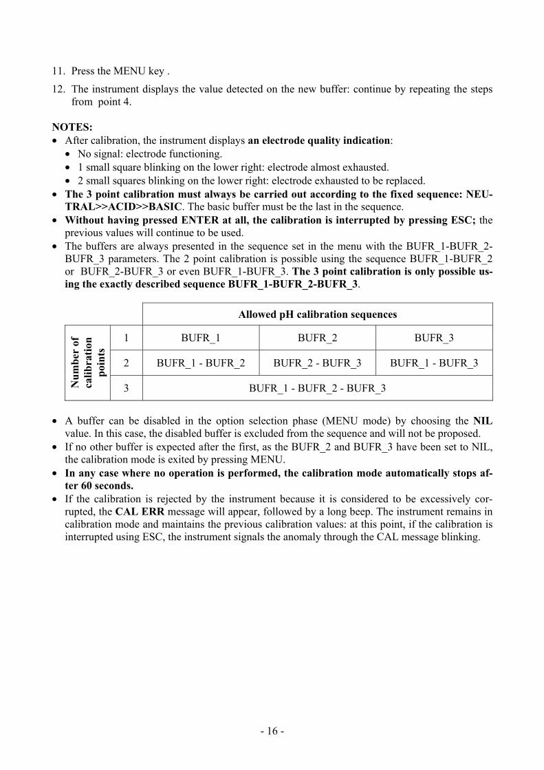
• The buffers are always presented in the sequence set in the menu with the BUFR_1-BUFR_2-BUFR_3 parameters. The 2 point calibration is possible using the sequence BUFR_1-BUFR_2 or BUFR_2-BUFR_3 or even BUFR_1-BUFR_3. The 3 point calibration is only possible us-ing the exactly described sequence BUFR_1-BUFR_2-BUFR_3.
Allowed pH calibration sequences
1 BUFR_1 BUFR_2 BUFR_3
2 BUFR_1 - BUFR_2 BUFR_2 - BUFR_3 BUFR_1 - BUFR_3
Num
ber
of
calib
ratio
n po
ints
3 BUFR_1 - BUFR_2 - BUFR_3
• A buffer can be disabled in the option selection phase (MENU mode) by choosing the NIL
value. In this case, the disabled buffer is excluded from the sequence and will not be proposed. • If no other buffer is expected after the first, as the BUFR_2 and BUFR_3 have been set to NIL,
the calibration mode is exited by pressing MENU. • In any case where no operation is performed, the calibration mode automatically stops af-
ter 60 seconds. • If the calibration is rejected by the instrument because it is considered to be excessively cor-
rupted, the CAL ERR message will appear, followed by a long beep. The instrument remains in calibration mode and maintains the previous calibration values: at this point, if the calibration is interrupted using ESC, the instrument signals the anomaly through the CAL message blinking.
- - 17
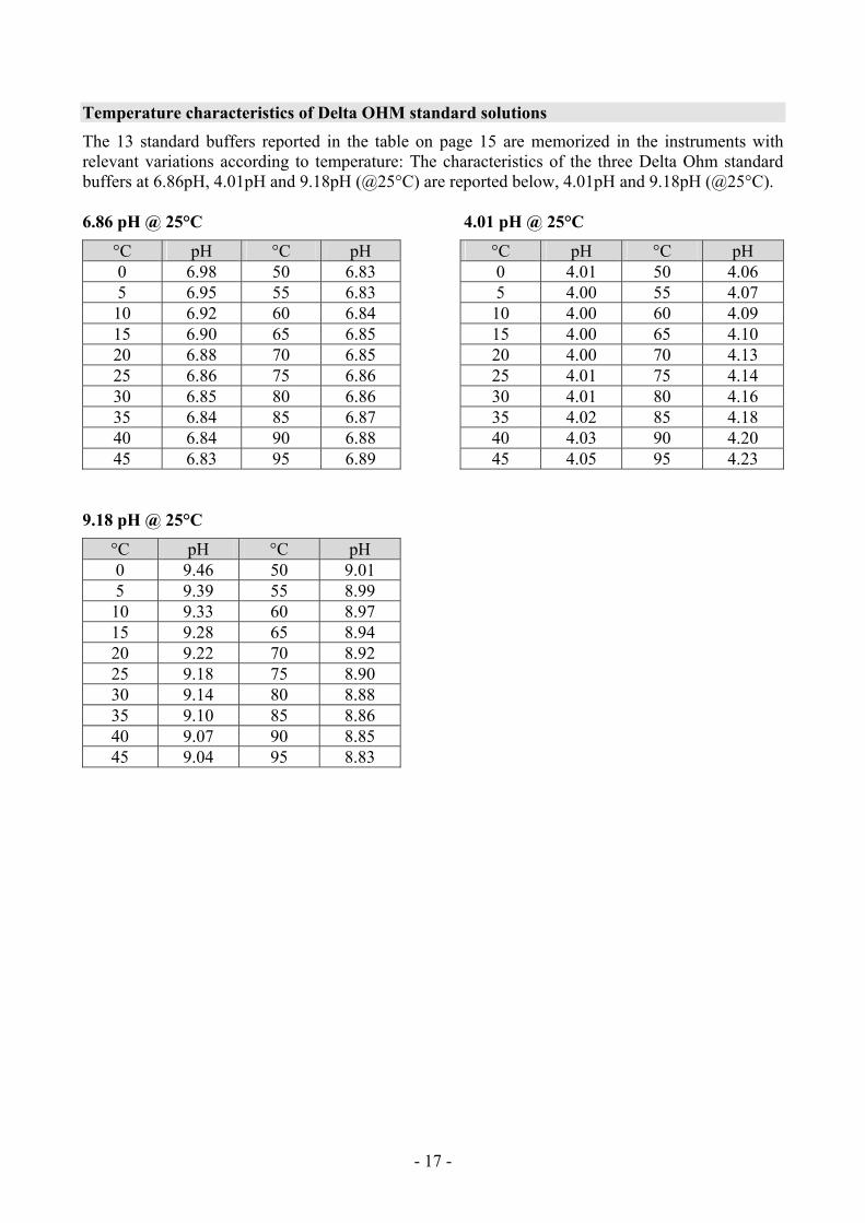
Temperature characteristics of Delta OHM standard solutions The 13 standard buffers reported in the table on page 15 are memorized in the instruments with relevant variations according to temperature: The characteristics of the three Delta Ohm standard buffers at 6.86pH, 4.01pH and 9.18pH (@25°C) are reported below, 4.01pH and 9.18pH (@25°C). 6.86 pH @ 25°C 4.01 pH @ 25°C
°C pH °C pH °C pH °C pH 0 6.98 50 6.83 0 4.01 50 4.06 5 6.95 55 6.83 5 4.00 55 4.07 10 6.92 60 6.84 10 4.00 60 4.09 15 6.90 65 6.85 15 4.00 65 4.10 20 6.88 70 6.85 20 4.00 70 4.13 25 6.86 75 6.86 25 4.01 75 4.14 30 6.85 80 6.86 30 4.01 80 4.16 35 6.84 85 6.87 35 4.02 85 4.18 40 6.84 90 6.88 40 4.03 90 4.20 45 6.83 95 6.89 45 4.05 95 4.23
9.18 pH @ 25°C
°C pH °C pH 0 9.46 50 9.01 5 9.39 55 8.99 10 9.33 60 8.97 15 9.28 65 8.94 20 9.22 70 8.92 25 9.18 75 8.90 30 9.14 80 8.88 35 9.10 85 8.86 40 9.07 90 8.85 45 9.04 95 8.83
- - 18
CONDUCTIVITY MEASUREMENT
The instruments work with conductivity/temperature combined probes, 4-rings and 2- rings only conductivity probes, or temperature probes. The 4 wire Pt100, 2 wire Pt1000 probes may be used for measuring temperature, which is used for the automatic compensation of the conductivity.
The instrument obtains the following from the measurement of conductivity:
• the liquid resistivity measurement (Ω, kΩ, MΩ),
• the concentration of total dissolved solids (TDS) according to the χ/TDS conversion factor, which can be modified using the menu,
• the salinity (NaCl quantity in the solution, expressed in g/l).
The conductivity, resistivity, TDS or salinity indication is displayed in the main line by pressing χ-Ω-TDS; the secondary line shows the temperature.
The conductivity probes must be periodically calibrated. To facilitate this operation, four automatic calibration solutions are provided:
• 0.001 Molar KCl solution (147μS/cm @25°C),
• 0.01 Molar KCl solution (1413μS/cm @25°C),
• 0.1 Molar KCl solution (12880μS/cm @25°C),
• 1 Molar KCl solution (111800μS/cm @25°C), User calibration of the temperature sensor is not required: the 4 wire and 2 wire probes with di-rect input are checked for conformity with class A tolerance according to norm IEC751 - BS1904 - DIN43760. The probes are detected during turn on, and this cannot be performed when the instrument is already on, therefore if a probe is connected and the instrument is on, it must be turned off and back on again.
Standard probe The standard 4-electrode combined conductivity/temperature probe code is SP06T. The cell measurement zone is delimited by a bell in Pocan. A positioning key, present in the probe's end part, orients the bell correctly when the probe is introduced. For cleaning, simply pull the bell along the probe's axis without rotating it. It is not possible to perform measurements without this bell.
This probe's temperature measuring range is -50°C … +90°C.
4- -rings or 2- -rings probes The HD3456.2 uses 4-rings or 2--rings probes for conductivity measurement. The 4-rings probes are preferred to measure high conductivity solutions, either over an extended range or in presence of pollutants. The 2-rings probes operate in a shorter measurement range but with an accuracy comparable with the 4-rings probes.
- - 19
The probes can be in glass or plastic: the first can work in presence of aggressive pollutants, the lat-ter are more resistant to collisions, and so more suitable for industrial use.
Cells with temperature sensor All probes are fitted with a built-in Pt100 or Pt1000 temperature sensor: the simultaneous measure-ment of conductivity and temperature allows automatic correction of the effect of the latter on the solution conductivity.
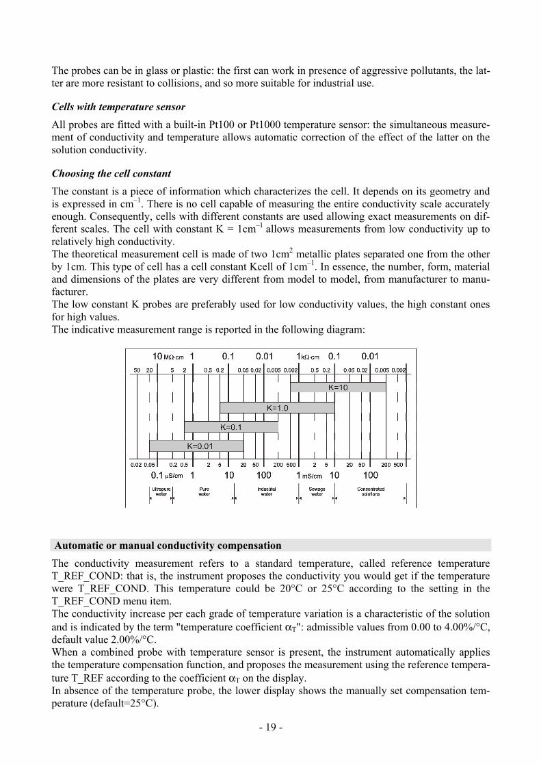
Choosing the cell constant The constant is a piece of information which characterizes the cell. It depends on its geometry and is expressed in cm–1. There is no cell capable of measuring the entire conductivity scale accurately enough. Consequently, cells with different constants are used allowing exact measurements on dif-ferent scales. The cell with constant K = 1cm–1 allows measurements from low conductivity up to relatively high conductivity. The theoretical measurement cell is made of two 1cm2 metallic plates separated one from the other by 1cm. This type of cell has a cell constant Kcell of 1cm–1. In essence, the number, form, material and dimensions of the plates are very different from model to model, from manufacturer to manu-facturer. The low constant K probes are preferably used for low conductivity values, the high constant ones for high values. The indicative measurement range is reported in the following diagram:
Automatic or manual conductivity compensation The conductivity measurement refers to a standard temperature, called reference temperature T_REF_COND: that is, the instrument proposes the conductivity you would get if the temperature were T_REF_COND. This temperature could be 20°C or 25°C according to the setting in the T_REF_COND menu item. The conductivity increase per each grade of temperature variation is a characteristic of the solution and is indicated by the term "temperature coefficient αT": admissible values from 0.00 to 4.00%/°C, default value 2.00%/°C. When a combined probe with temperature sensor is present, the instrument automatically applies the temperature compensation function, and proposes the measurement using the reference tempera-ture T_REF according to the coefficient αT on the display. In absence of the temperature probe, the lower display shows the manually set compensation tem-perature (default=25°C).
- - 20
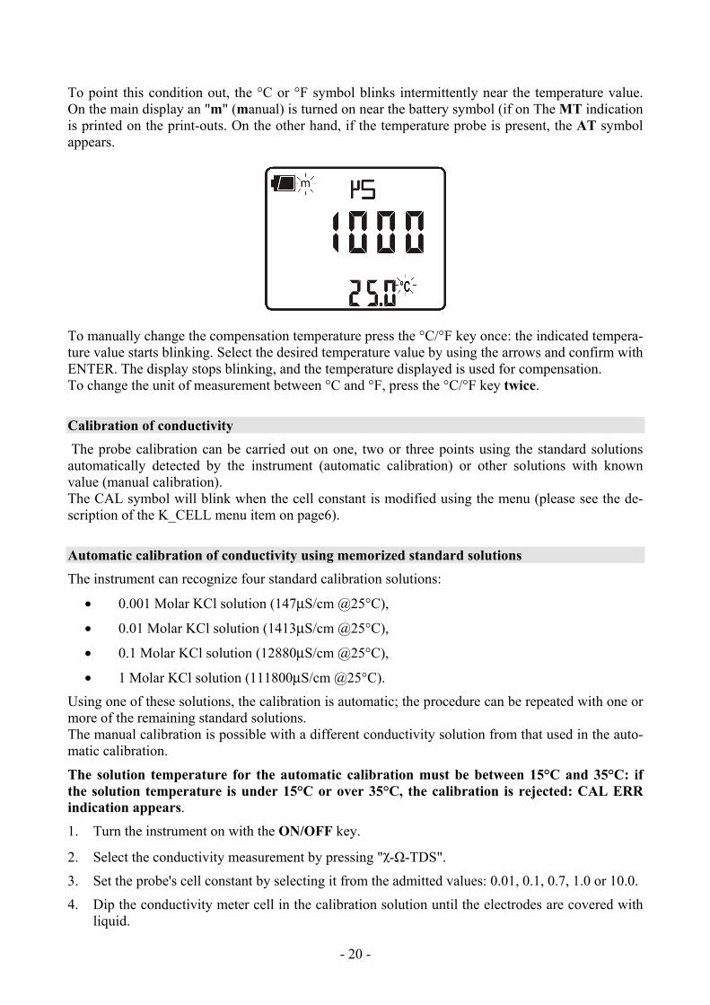
To point this condition out, the °C or °F symbol blinks intermittently near the temperature value. On the main display an "m" (manual) is turned on near the battery symbol (if on The MT indication is printed on the print-outs. On the other hand, if the temperature probe is present, the AT symbol appears.
To manually change the compensation temperature press the °C/°F key once: the indicated tempera-ture value starts blinking. Select the desired temperature value by using the arrows and confirm with ENTER. The display stops blinking, and the temperature displayed is used for compensation. To change the unit of measurement between °C and °F, press the °C/°F key twice.
Calibration of conductivity The probe calibration can be carried out on one, two or three points using the standard solutions automatically detected by the instrument (automatic calibration) or other solutions with known value (manual calibration). The CAL symbol will blink when the cell constant is modified using the menu (please see the de-scription of the K_CELL menu item on page6).
Automatic calibration of conductivity using memorized standard solutions The instrument can recognize four standard calibration solutions:
• 0.001 Molar KCl solution (147μS/cm @25°C),
• 0.01 Molar KCl solution (1413μS/cm @25°C),
• 0.1 Molar KCl solution (12880μS/cm @25°C),
• 1 Molar KCl solution (111800μS/cm @25°C).
Using one of these solutions, the calibration is automatic; the procedure can be repeated with one or more of the remaining standard solutions. The manual calibration is possible with a different conductivity solution from that used in the auto-matic calibration.
The solution temperature for the automatic calibration must be between 15°C and 35°C: if the solution temperature is under 15°C or over 35°C, the calibration is rejected: CAL ERR indication appears.
1. Turn the instrument on with the ON/OFF key.
2. Select the conductivity measurement by pressing "χ-Ω-TDS".
3. Set the probe's cell constant by selecting it from the admitted values: 0.01, 0.1, 0.7, 1.0 or 10.0.
4. Dip the conductivity meter cell in the calibration solution until the electrodes are covered with liquid.
- - 21
5. Stir the probe lightly to remove any possible air inside the measurement cell.
6. If the conductivity probe is not fitted with temperature sensor, press °C/°F and, using the ar-rows, enter the sample solution temperature value manually (manual setting of temperature). Confirm by pressing ENTER.
7. Press the CAL key. The unit of measurement (μS/cm or mS/cm) appears on the comment line. The central line shows the solution conductivity value at the measured temperature, or if the probe is not present, at the manually-set temperature. In the lower line, the closest temperature compensated standard buffer value.
If the measurement is in TDS, resistivity or salinity, by pressing CAL, the instrument goes automatically into conductivity calibration mode.
8. Press ENTER to confirm the displayed value. The cell constant nominal value (KCELL) and the set temperature coefficient αT are displayed. Pressed repeatedly the ENTER key allows the calibration on the point to be repeated, for example, in order to obtain a more stable value.
9. To end the probe calibration, press χ-Ω-TDS.
10. Rinse the probe with water. If you are then going to perform low conductivity measurements, we recommend rinsing the probe using distilled or bidistilled water.
The instrument is calibrated and ready for use.
Calibration of conductivity using non memorized standard solutions Manual calibration is possible at any calibration solution and temperature if it is within the instru-ment measurement limits and provided that you know the solution's conductivity at the temperature at which the calibration is performed. Proceed as follows:
1. Turn the instrument on with the ON/OFF key.
2. Select the conductivity measurement by pressing "χ-Ω-TDS".
3. Set the probe's cell constant by selecting it from the admitted values: 0.01, 0.1, 0.7, 1.0 or 10.0.
4. Dip the conductivity meter cell into a known conductivity solution until the electrodes are cov-ered with liquid.
5. Stir the probe lightly to remove any possible air inside the measurement cell.
6. Press MENU, and then FUNC/ENTER until the item ALPH appears. The temperature coeffi-cient αT is displayed. Note down the value displayed as it must be set again at the end of the procedure. Set the value to 0.00. This excludes the temperature compensation during the con-ductivity measurement.
7. Measure the temperature by pressing °C/°F. According to the temperature detected, determine the calibration solution conductivity using the table specifying the conductivity according to temperature.
8. Select the conductivity measurement by pressing χ-Ω-TDS.
9. Press the CAL key. The CAL symbol is turned on. The unit of measurement (μS/cm or mS/cm) appears on the comment line. If the calibration solution conductivity is sufficiently close (-30% to +50%) to one of the standard solutions, the secondary line displays the value. Otherwise it displays the calculated value according to current settings. In the central line the solution con-ductivity value is indicated according to the cell constant current settings.
- - 22
10. Use the arrows to select the conductivity value determined at point 7 and confirm using EN-TER. If the ERR indication appears, see the note below.
11. The cell constant nominal value (KCELL) and the temperature coefficient αT set to 0 are dis-played. Pressed repeatedly the ENTER key allows the calibration on the point to be repeated, for example, in order to obtain a more stable value.
12. To end the probe calibration, press χ-Ω-TDS.
13. Go back to the MENU and select ALPH: re-enter the temperature coefficient as it was before the calibration.
14. Rinse the probe with water. If you are then going to perform low conductivity measurements, we recommend rinsing the probe using distilled or bidistilled water.
The instrument is now calibrated and ready for use. NOTES: • Without having pressed ENTER at all, the calibration is interrupted by pressing ESC; the
previous values will continue to be used. • Upon confirming the calibration by using ENTER, the instrument checks that the correction to
the conductivity does not exceed the 70% or 150% limits of the theoretical value. If the calibra-tion is rejected because it is considered to be excessively corrupted, the CAL ERR message will appear, followed by a long beep. The instrument remains in calibration mode and maintains the previous calibration values: at this point, if the calibration is interrupted using ESC, the instru-ment signals the anomaly through the CAL message blinking.
• The most frequent causes of error are due to the probe malfunctioning (deposits, dirt,…) or to the standard solutions deterioration (bad preservation conditions, alteration due to pollution with dif-ferent conductivity solutions,…).
• If the measurement is in TDS, resistivity or salinity, on the pressing of CAL, the instrument goes automatically in conductivity calibration.
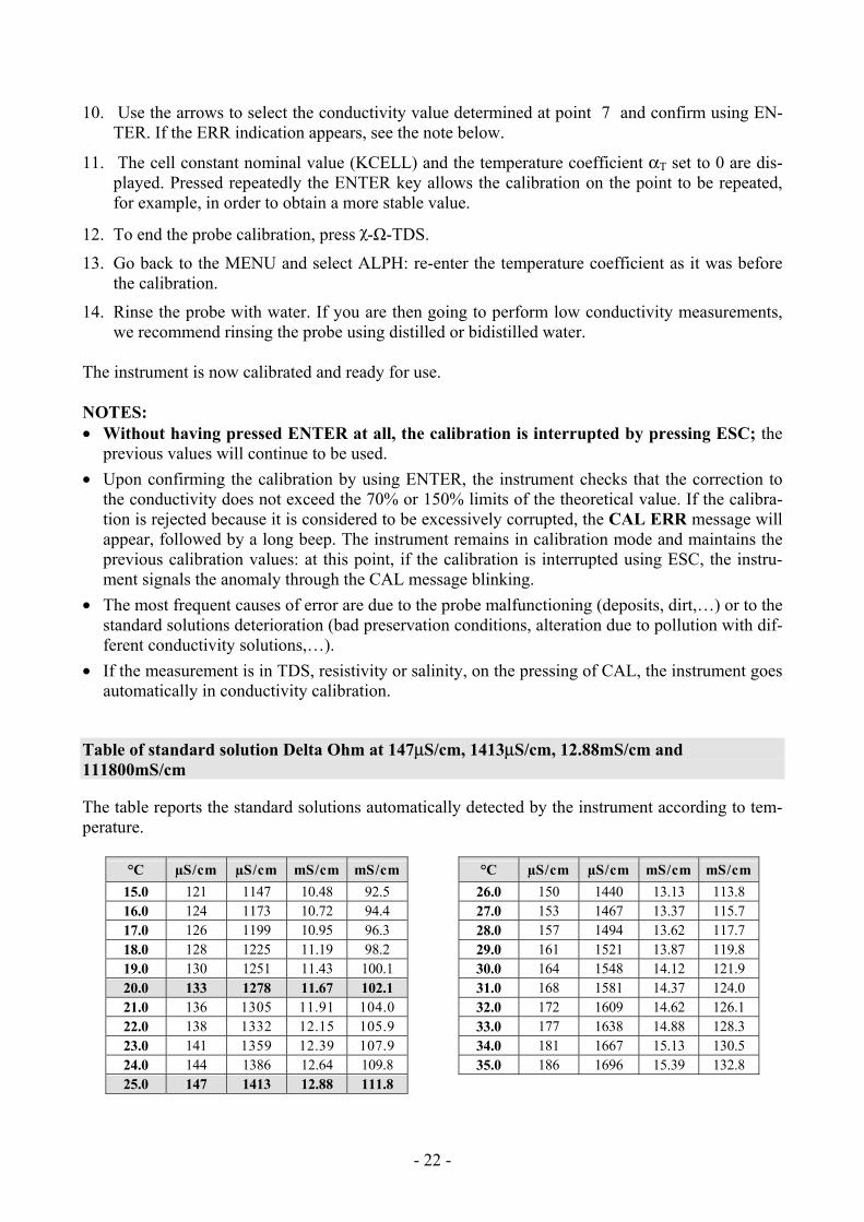
Table of standard solution Delta Ohm at 147μS/cm, 1413μS/cm, 12.88mS/cm and 111800mS/cm
The table reports the standard solutions automatically detected by the instrument according to tem-perature.
°C µS/cm µS/cm mS/cm mS/cm °C µS/cm µS/cm mS/cm mS/cm15.0 121 1147 10.48 92.5 26.0 150 1440 13.13 113.8 16.0 124 1173 10.72 94.4 27.0 153 1467 13.37 115.7 17.0 126 1199 10.95 96.3 28.0 157 1494 13.62 117.7 18.0 128 1225 11.19 98.2 29.0 161 1521 13.87 119.8 19.0 130 1251 11.43 100.1 30.0 164 1548 14.12 121.9 20.0 133 1278 11.67 102.1 31.0 168 1581 14.37 124.0 21.0 136 1305 11.91 104.0 32.0 172 1609 14.62 126.1 22.0 138 1332 12.15 105.9 33.0 177 1638 14.88 128.3 23.0 141 1359 12.39 107.9 34.0 181 1667 15.13 130.5 24.0 144 1386 12.64 109.8 35.0 186 1696 15.39 132.8 25.0 147 1413 12.88 111.8
- - 23
DIRECT INPUT INTO Pt100 AND Pt1000 TEMPERATURE PROBES WITH TP47MODULE The instrument accepts the input of Platinum temperature probes with resistances of 100Ω and 1000Ω. The Pt100 are connected to 4 wires, the Pt1000 to 2 wires, with the excitation current chosen mini-mizing the sensor self-heating effects. The 4 wire and 2 wire probes with direct input are checked for conformity with class A toler-ance according to norm IEC751 - BS1904 - DIN43760. The temperature probes are automatically detected by the instrument (please see the description of the Probe Type menu on page 9). The °C or °F unit of measurement can be chosen for display, printing, and logging using the °C/°F key.
How to measure The temperature measurement by immersion is carried out by inserting the probe in the liquid for at least 60mm; the sensor is housed in the end part of the probe. In the temperature measurement by penetration the probe tip must be inserted to a depth of at least 60mm, the sensor is housed in the end part of the probe. When measuring the temperature on frozen blocks it is convenient to use a mechanical tool to bore a cavity in which to insert the tip probe. In order to perform a correct contact measurement, the measurement surface must be even and smooth, and the probe must be perpendicular to the measurement plane. So as to obtain the correct measurement, the insertion of a drop of oil or heat-conductive paste is useful (do not use water or solvents). This method also improves the response time.
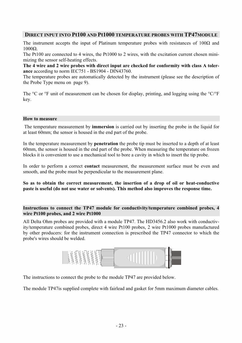
Instructions to connect the TP47 module for conductivity/temperature combined probes, 4 wire Pt100 probes, and 2 wire Pt1000 All Delta Ohm probes are provided with a module TP47. The HD3456.2 also work with conductiv-ity/temperature combined probes, direct 4 wire Pt100 probes, 2 wire Pt1000 probes manufactured by other producers: for the instrument connection is prescribed the TP47 connector to which the probe's wires should be welded.
The instructions to connect the probe to the module TP47 are provided below. The module TP47is supplied complete with fairlead and gasket for 5mm maximum diameter cables.
- - 24
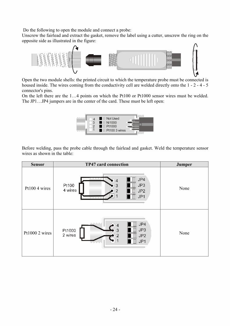
Do the following to open the module and connect a probe: Unscrew the fairlead and extract the gasket, remove the label using a cutter, unscrew the ring on the opposite side as illustrated in the figure:
Open the two module shells: the printed circuit to which the temperature probe must be connected is housed inside. The wires coming from the conductivity cell are welded directly onto the 1 - 2 - 4 - 5 connector's pins. On the left there are the 1…4 points on which the Pt100 or Pt1000 sensor wires must be welded. The JP1…JP4 jumpers are in the center of the card. These must be left open:
1234
Pt100 3 wiresPt1000Ni1000Not Used
Before welding, pass the probe cable through the fairlead and gasket. Weld the temperature sensor wires as shown in the table:
Sensor TP47 card connection Jumper
Pt100 4 wires
None
Pt1000 2 wires
None
- - 25
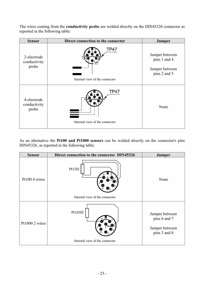
The wires coming from the conductivity probe are welded directly on the DIN45326 connector as reported in the following table:
Sensor Direct connection to the connector Jumper
2-electrode conductivity
probe
Internal view of the connector
Jumper between pins 1 and 4
Jumper between
pins 2 and 5
4-electrode conductivity
probe
Internal view of the connector
None
As an alternative the Pt100 and Pt1000 sensors can be welded directly on the connector's pins DIN45326, as reported in the following table:
Sensor Direct connection to the connector DIN45326 Jumper
Pt100 4 wires
Pt100
Internal view of the connector
None
Pt1000 2 wires
Pt1000
Internal view of the connector
Jumper between pins 6 and 7
Jumper between
pins 3 and 8
- - 26
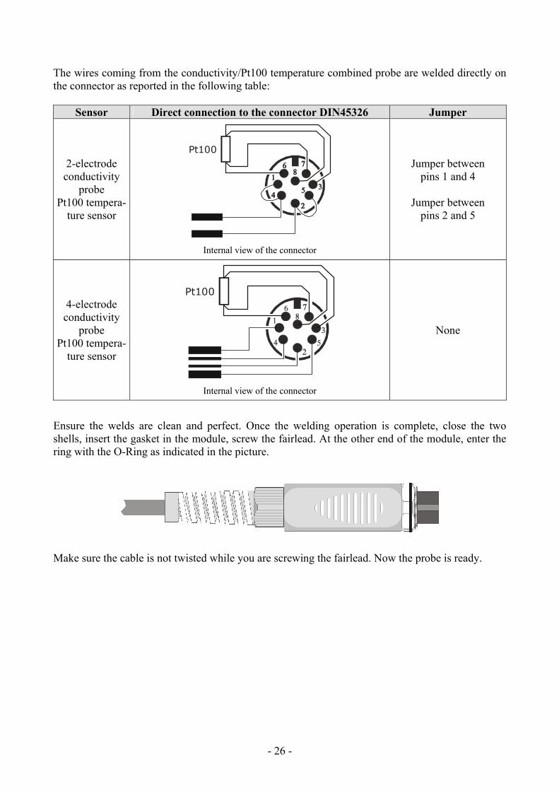
The wires coming from the conductivity/Pt100 temperature combined probe are welded directly on the connector as reported in the following table:
Sensor Direct connection to the connector DIN45326 Jumper
2-electrode conductivity
probe Pt100 tempera-
ture sensor
Pt100
Internal view of the connector
Jumper between pins 1 and 4
Jumper between
pins 2 and 5
4-electrode conductivity
probe Pt100 tempera-
ture sensor
Pt100
Internal view of the connector
None
Ensure the welds are clean and perfect. Once the welding operation is complete, close the two shells, insert the gasket in the module, screw the fairlead. At the other end of the module, enter the ring with the O-Ring as indicated in the picture.
Make sure the cable is not twisted while you are screwing the fairlead. Now the probe is ready.
- - 27
WARNINGS AND OPERATING INSTRUCTIONS
1. Do not expose the probes to gases or liquids that could corrode the material of the sensor or the probe itself. Clean the probe carefully after each measurement.
2. Do not bend the probe connectors or force them upward or downward.
3. Do not bend or force the contacts when inserting the probe connector into the instrument.
4. Do not bend, deform or drop the probes, as this could cause irreparable damage.
5. Always select the most suitable probe for your application.
6. Do not use probes in presence of corrosive gases or liquids. The sensor container is made of AISI 316 stainless steel, while the contact probe container is made from AISI 316 stainless steel plus silver. Avoid contact between the probe surface and any sticky surface or substance that could corrode or damage it.
7. Above 400°C and below –40°C, avoid violent blows or thermal shocks to Platinum temperature probes as this could cause irreparable damage.
8. To obtain reliable measurements, temperature variations that are too rapid must be avoided.
9. Temperature probes for surface measurements (contact probes) must be held perpendicular against the surface. Apply oil or heat-conductive paste between the surface and the probe in or-der to improve contact and reduce reading time. Whatever you do, do not use water or solvent for this purpose. A contact measurement is always very hard to perform. It has high levels of uncertainty and depends on the ability of the operator.
10. Temperature measurements on non-metal surfaces usually require a great deal of time due to the low heat conductivity of non-metal materials.
11. Probes are not insulated from their external casing; be very careful not to come into contact with live parts (above 48V). This could be extremely dangerous for the instrument as well as for the operator, who could be electrocuted.
12. Avoid taking measurements in presence of high frequency sources, microwave ovens or large magnetic fields; results may not be very reliable.
13. Clean the probe carefully after use.
14. The instrument is water resistant and IP66, but is not watertight and therefore should not be immersed in water without closing the free connectors using caps. The probe connectors must be fitted with sealing gaskets. Should the instrument fall into the water, check for any water in-filtration. Gently handle the instrument in such a way as to prevent any water infiltration from the connectors' side.
Notes on pH electrodes use
The average life of a pH electrode is about one year according to the use and maintenance per-formed.
The electrodes used at high temperatures or in highly alkaline environments have a shorter life.
The new electrodes must be conditioned for half a day by immersing them into a buffer at 6.86pH or 4pH.
Calibrate the electrode with solutions closer to the values being measured. A new electrode must always be calibrated at neutral pH (6.86pH) first point and at least a second point.
- - 28
Some of the most frequent problems and their possible solutions are reported below.
Wrong pH measurement. Carry out the following checks:
Check that the diaphragm is not obstructed and possibly clean it using the HD62PT solution.
Check that the reference system is not contaminated and, in case of a filling type electrode, replace the electrolyte with the KCL3M solution (electrodes KP63, KP64 and KP90) or the PROTELYTE solution (electrodes KP61, KP71 and KP80).
Check that no air bubbles are present in the electrode tip and that it is sufficiently immersed.
Even dirt residuals deposited on the membrane can alter the measurement: use the HD62PP solu-tion for protein cleaning.
Slow response or wrong measurements. Possible causes are aging or erosion of the membrane or a connector short circuiting.
Storage. Keep the electrode immersed in the HD62SC solution.
Notes on conductivity measurement The service life of a cell can be unlimited, provided that the necessary maintenance is performed and that it does not break. Some of the most frequent problems and their possible solutions are re-ported below.
Measurement of conductivity different from the expected value. Check that the cell used is suit-able for the measurement range. Check that the cell is not dirty, that there are no air bubbles inside it. Calibrate again using the appropriate standard.
Slow response or instability. Check that the cell is not dirty, that there are no traces of oil or air bubbles inside it. If you work with a black Platinum cell, new platinum-coating of the electrode could be necessary.
Cell constant value not accepted. Check that the standard solutions are in good condition, that the probe's constant cell value coincides with that selected in the instrument and that the solution tem-perature is within the range 15…35°C.
- - 29
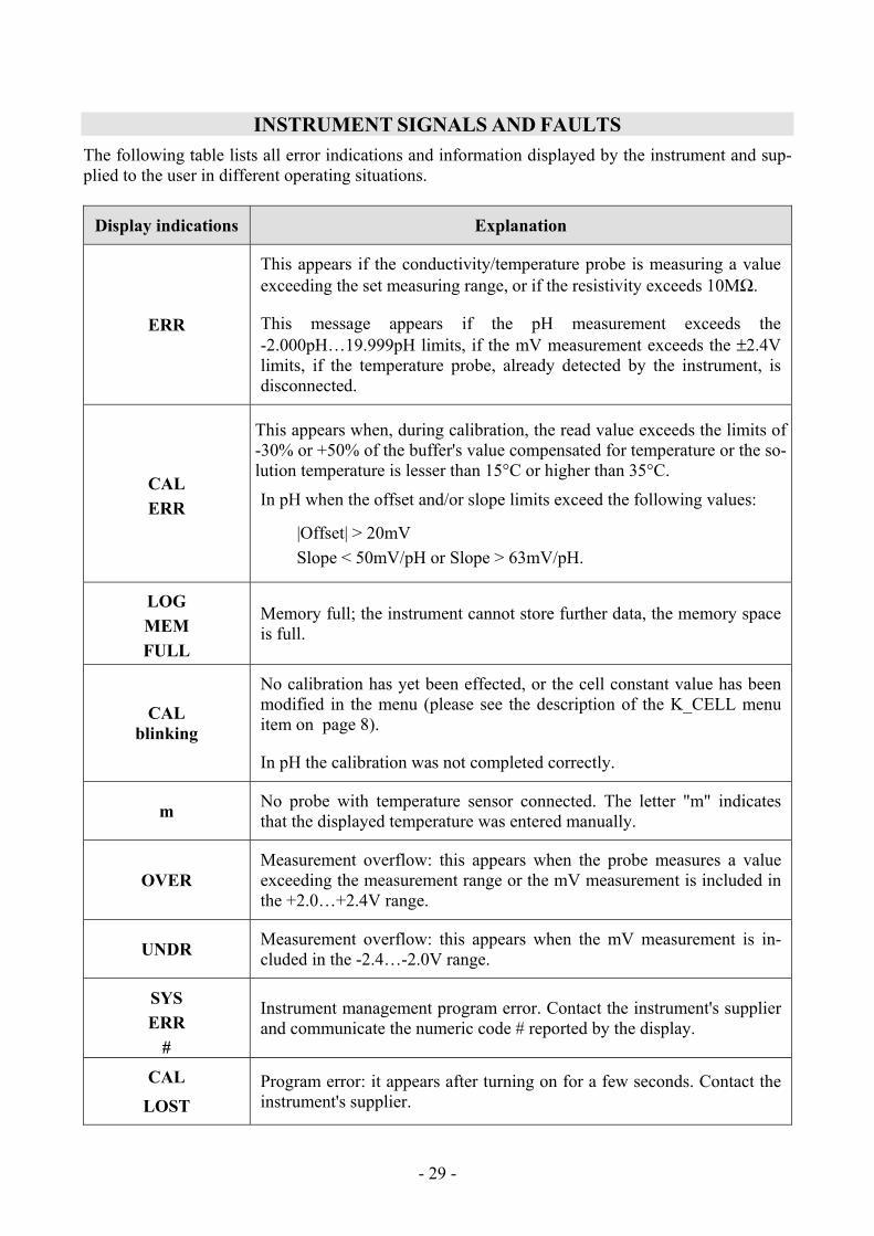
INSTRUMENT SIGNALS AND FAULTS The following table lists all error indications and information displayed by the instrument and sup-plied to the user in different operating situations.
Display indications Explanation
ERR
This appears if the conductivity/temperature probe is measuring a value exceeding the set measuring range, or if the resistivity exceeds 10MΩ.
This message appears if the pH measurement exceeds the -2.000pH…19.999pH limits, if the mV measurement exceeds the ±2.4V limits, if the temperature probe, already detected by the instrument, is disconnected.
CAL ERR
This appears when, during calibration, the read value exceeds the limits of -30% or +50% of the buffer's value compensated for temperature or the so-lution temperature is lesser than 15°C or higher than 35°C.
In pH when the offset and/or slope limits exceed the following values:
|Offset| > 20mV Slope < 50mV/pH or Slope > 63mV/pH.
LOG MEM FULL
Memory full; the instrument cannot store further data, the memory space is full.
CAL blinking
No calibration has yet been effected, or the cell constant value has been modified in the menu (please see the description of the K_CELL menu item on page 8).
In pH the calibration was not completed correctly.
m No probe with temperature sensor connected. The letter "m" indicates that the displayed temperature was entered manually.
OVER Measurement overflow: this appears when the probe measures a value exceeding the measurement range or the mV measurement is included in the +2.0…+2.4V range.
UNDR Measurement overflow: this appears when the mV measurement is in-cluded in the -2.4…-2.0V range.
SYS ERR
#
Instrument management program error. Contact the instrument's supplier and communicate the numeric code # reported by the display.
CAL
LOST Program error: it appears after turning on for a few seconds. Contact the instrument's supplier.

- - 30
Display indications Explanation
BATT TOO LOW
CHNG NOW Indication of insufficient battery charge appearing on turning on. The in-strument issues a long beep and turns off. Replace the batteries.
- - 31
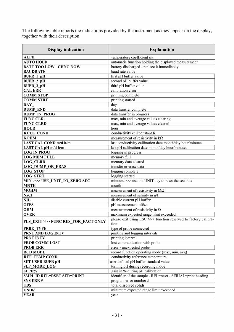
The following table reports the indications provided by the instrument as they appear on the display, together with their description.
Display indication Explanation ALPH temperature coefficient αT AUTO HOLD automatic function holding the displayed measurement BATT TOO LOW - CHNG NOW battery discharged - replace it immediately BAUDRATE baud rate value BUFR_1_pH first pH buffer value BUFR_2_pH second pH buffer value BUFR_3_pH third pH buffer value CAL ERR calibration error COMM STOP printing complete COMM STRT printing started DAY_ day DUMP_END data transfer complete DUMP_IN_PROG data transfer in progress FUNC CLR max, min and average values clearing FUNC CLRD max, min and average values cleared HOUR hour KCEL_COND conductivity cell constant K KOHM measurement of resistivity in kΩ LAST CAL COND m/d h/m last conductivity calibration date month/day hour/minutes LAST CAL pH m/d h/m last pH calibration date month/day hour/minutes LOG IN PROG logging in progress LOG MEM FULL memory full LOG_CLRD memory data cleared LOG_DUMP_OR_ERAS transfer or erase data LOG_STOP logging complete LOG_STRT logging started MIN >>> USE_UNIT_TO_ZERO SEC minutes >>> use the UNIT key to reset the seconds MNTH month MOHM measurement of resistivity in MΩ NaCl measurement of salinity in g/l NIL disable current pH buffer OFFS pH measurement offset OHM measurement of resistivity in Ω OVER maximum expected range limit exceeded
PLS_EXIT >>> FUNC RES_FOR_FACT ONLY please exit using ESC >>> function reserved to factory calibra-tion
PRBE_TYPE type of probe connected PRNT AND LOG INTV printing and logging intervals PRNT INTV printing interval PROB COMM LOST lost communication with probe PROB ERR error - unexpected probe RCD MODE record function operating mode (max, min, avg) REF_TEMP COND conductivity reference temperature SET USER BUFR pH user defined pH buffer standard value SLP_MODE_LOG turning off during recording mode SLPE% gain in % during pH calibration SMPL ID REL=RSET SER=PRINT identifier of the sample - REL=reset - SERIAL=print heading SYS ERR # program error number # TDS total dissolved solids UNDR minimum expected range limit exceeded YEAR year
- - 32
LOW BATTERY WARNING AND BATTERY REPLACEMENT The battery symbol on the display constantly shows the battery charge status. To the extent that batteries have dis-charged, the symbol "empties". When the charge decreases still further it starts blinking …
If you wish to continue using the instrument, remove the flat batteries and supply it using the exter-nal power supply. Data stored on memory are maintained even without power supply. If the battery charge level is insufficient, the following message appears when you turn the in-strument on:
BATT TOO LOW CHNG NOW
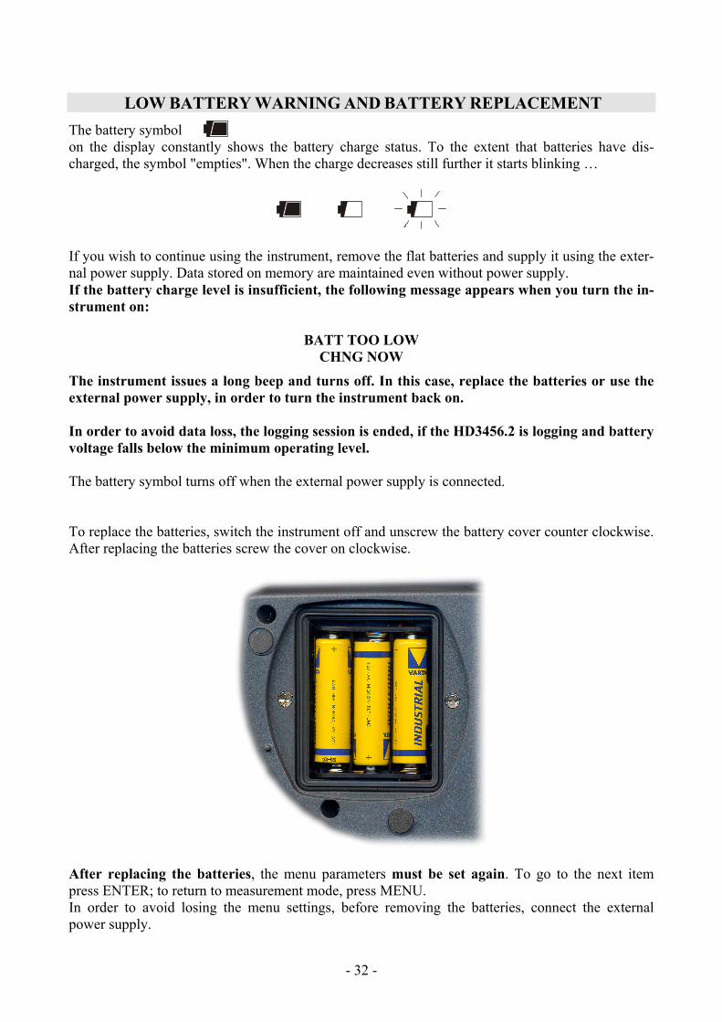
The instrument issues a long beep and turns off. In this case, replace the batteries or use the external power supply, in order to turn the instrument back on. In order to avoid data loss, the logging session is ended, if the HD3456.2 is logging and battery voltage falls below the minimum operating level. The battery symbol turns off when the external power supply is connected. To replace the batteries, switch the instrument off and unscrew the battery cover counter clockwise. After replacing the batteries screw the cover on clockwise.
After replacing the batteries, the menu parameters must be set again. To go to the next item press ENTER; to return to measurement mode, press MENU. In order to avoid losing the menu settings, before removing the batteries, connect the external power supply.
- - 33
MALFUNCTIONING UPON TURNING ON AFTER BATTERY REPLACEMENT After replacing the batteries, the instrument may not restart correctly; in this case, repeat the opera-tion. After disconnecting the batteries, wait a few minutes in order to allow circuit condensers to discharge completely; then reinsert the batteries.
WARNING ABOUT BATTERY USE
• Batteries should be removed when the instrument is not used for an extended time. • Flat batteries must be replaced immediately. • Avoid batteries leaking. • Always use good quality leakproof alkaline batteries. Sometimes on the market, it is possi-
ble to find new batteries with an insufficient charge capacity.
INSTRUMENT STORAGE Instrument storage conditions:
• Temperature: -25…+65°C. • Humidity: less than 90%RH without condensation. • Do not store the instrument in places where:
Humidity is high. The instrument may be exposed to direct sunlight. The instrument may be exposed to a source of high temperature. The instrument may be exposed to strong vibrations. The instrument may be exposed to steam, salt or any corrosive gas.
MAINTENANCE
The instrument case is made of ABS plastic and the protections are rubber: do not use any incom-patible solvent for cleaning. In the conductivity/temperature combined probe the bell and the body of the probe are made of Po-can, the conductivity and temperature sensors are made of Platinum. During the use control the compatibility of these materials with the liquid that you want to measure. The probe must be preserved in a dry space. At regular intervals check that no deposits or corrosion are present on the sensitive part of the probe. Do not use any abrasive product for cleaning.
- - 34
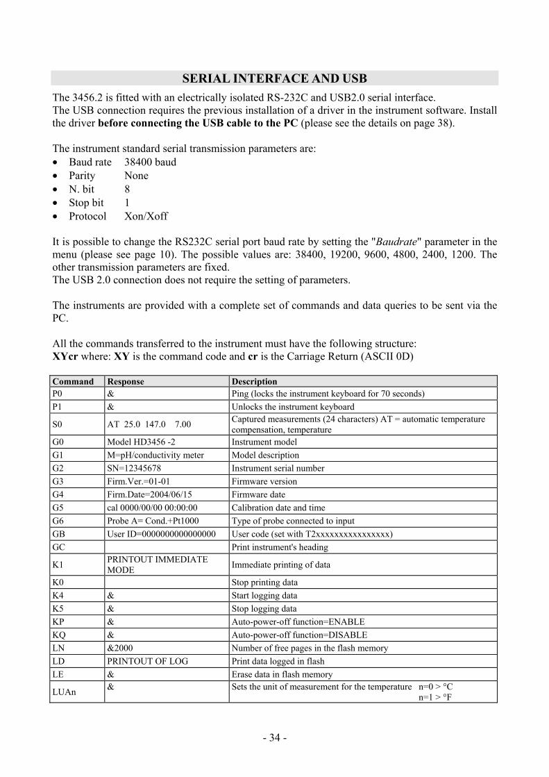
SERIAL INTERFACE AND USB The 3456.2 is fitted with an electrically isolated RS-232C and USB2.0 serial interface. The USB connection requires the previous installation of a driver in the instrument software. Install the driver before connecting the USB cable to the PC (please see the details on page 38). The instrument standard serial transmission parameters are: • Baud rate 38400 baud • Parity None • N. bit 8 • Stop bit 1 • Protocol Xon/Xoff It is possible to change the RS232C serial port baud rate by setting the "Baudrate" parameter in the menu (please see page 10). The possible values are: 38400, 19200, 9600, 4800, 2400, 1200. The other transmission parameters are fixed. The USB 2.0 connection does not require the setting of parameters. The instruments are provided with a complete set of commands and data queries to be sent via the PC. All the commands transferred to the instrument must have the following structure: XYcr where: XY is the command code and cr is the Carriage Return (ASCII 0D) Command Response Description P0 & Ping (locks the instrument keyboard for 70 seconds) P1 & Unlocks the instrument keyboard S0 AT 25.0 147.0 7.00 Captured measurements (24 characters) AT = automatic temperature
compensation, temperature G0 Model HD3456 -2 Instrument model G1 M=pH/conductivity meter Model description G2 SN=12345678 Instrument serial number G3 Firm.Ver.=01-01 Firmware version G4 Firm.Date=2004/06/15 Firmware date G5 cal 0000/00/00 00:00:00 Calibration date and time G6 Probe A= Cond.+Pt1000 Type of probe connected to input GB User ID=0000000000000000 User code (set with T2xxxxxxxxxxxxxxxx) GC Print instrument's heading K1 PRINTOUT IMMEDIATE
MODE Immediate printing of data K0 Stop printing data K4 & Start logging data K5 & Stop logging data KP & Auto-power-off function=ENABLE KQ & Auto-power-off function=DISABLE LN &2000 Number of free pages in the flash memory LD PRINTOUT OF LOG Print data logged in flash LE & Erase data in flash memory LUAn & Sets the unit of measurement for the temperature n=0 > °C
n=1 > °F
- - 35
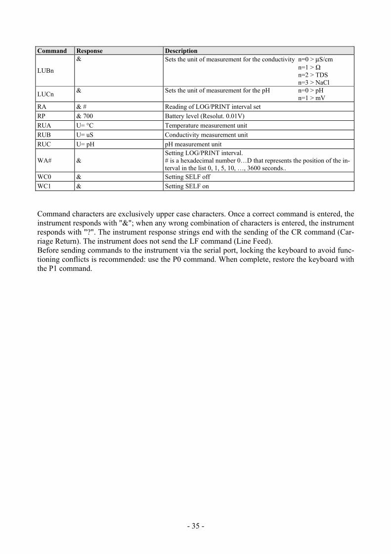
Command Response Description
LUBn
& Sets the unit of measurement for the conductivity n=0 > μS/cm n=1 > Ω n=2 > TDS n=3 > NaCl
LUCn & Sets the unit of measurement for the pH n=0 > pH n=1 > mV
RA & # Reading of LOG/PRINT interval set RP & 700 Battery level (Resolut. 0.01V) RUA U= °C Temperature measurement unit RUB U= uS Conductivity measurement unit RUC U= pH pH measurement unit
WA# & Setting LOG/PRINT interval. # is a hexadecimal number 0…D that represents the position of the in-terval in the list 0, 1, 5, 10, …, 3600 seconds..
WC0 & Setting SELF off WC1 & Setting SELF on Command characters are exclusively upper case characters. Once a correct command is entered, the instrument responds with "&"; when any wrong combination of characters is entered, the instrument responds with "?". The instrument response strings end with the sending of the CR command (Car-riage Return). The instrument does not send the LF command (Line Feed). Before sending commands to the instrument via the serial port, locking the keyboard to avoid func-tioning conflicts is recommended: use the P0 command. When complete, restore the keyboard with the P1 command.
- - 36
STORING AND TRANSFERRING DATA TO A PC The 3456.2 instrument can be connected to a personal computer via an RS232C serial port, and exchange data and information through the DeltaLog9 software (Version 2.0 or later versions) running in a Windows operating environment. The measured values can be sent directly to the PC, through the SERIAL function in real time or store them in the internal memory using Logging function (LOG key) in their internal memory. If necessary, the data stored in the memory can be transferred to a PC later.
THE LOGGING FUNCTION
The Logging function allows the recording up to 20,000 sets of three measurements [T-χ-pH] regis-tered by the probes connected to the inputs. Logging always includes three parameters. Each set of three data is composed of: temperature in °C or °F, conductivity or resistivity or TDS or NaCl, pH or mV.
The logged parameters are selected using the “°C/°F”, “pH/mV” and “χ-Ω-TDS” keys.
The time interval between two consecutive measurements can be set from 1 second to 1 hour. The logging starts by pressing the LOG key and ends by pressing the same key again: the data memo-rized in this way form a continuous block of samples.
See the description of the menu items on page 6.
If the automatic turning off option between two recordings (MENU >> Sleep_Mode_LOG) is en-abled, upon pressing the LOG key the instrument logs the first data and turns off. 15 seconds before the next logging instant, it turns on again to capture the new sample, and then turns off.
The data stored in the memory can be transferred to a PC using the DUMP LOG command: MENU >> LOG. During data transfer the display shows the message DUMP; to stop the data transfer press ESC on the instrument or on the PC.
CLEARING THE MEMORY To clear the memory use the Erase Log function (MENU >> SERIAL/Erase Log). The instrument starts clearing the internal memory; at the end of the operation, it goes back to nor-mal display. NOTES: • Data transfer does not cause the memory to be erased; the operation can be repeated as many
times as required. • The stored data remain in the memory independently of battery charge conditions. • In order to print the data to a parallel interface printer, you must use a parallel-serial adaptor (not
supplied). • The direct connection between instrument and printer via a USB connector does not work. • Some keys are disabled during logging. The following keys work: ON/OFF, FUNC (Max-Min-
Avg) and SERIAL. • The recording started with the display in Max-Min-Avg mode proceeds normally with the actual
measured values. Only the display shows respectively the Max, Min or Avg values. • The logging is disabled, if the Auto-HOLD function is enabled. • It is possible to activate both the logging (LOG) and direct transfer (PRINT) functions at the
same time.
- - 37
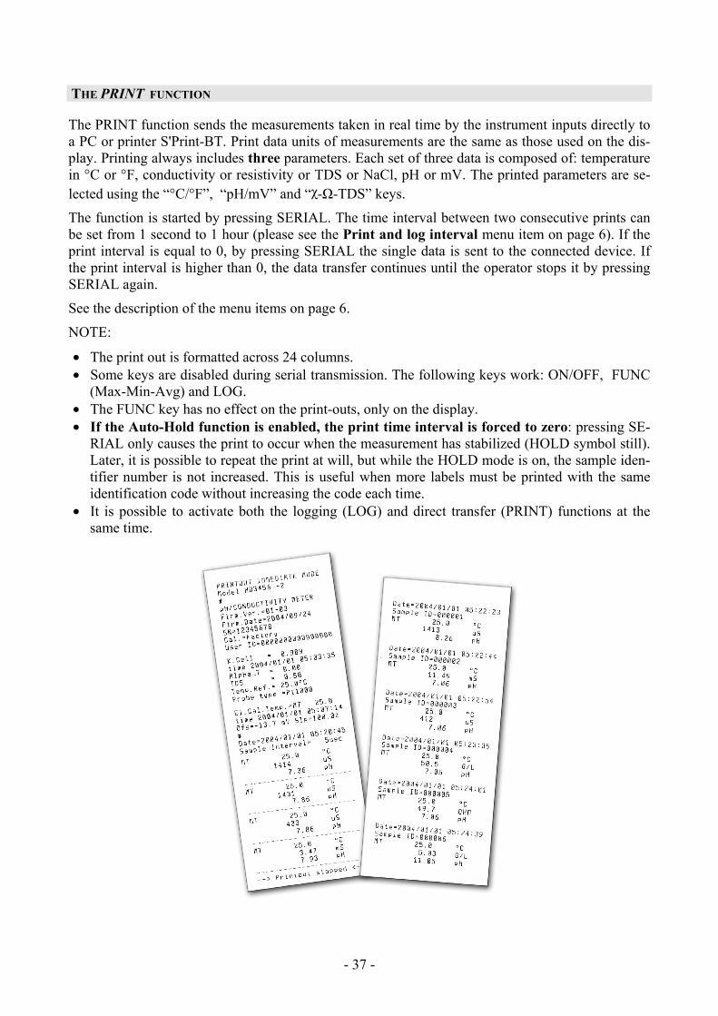
THE PRINT FUNCTION
The PRINT function sends the measurements taken in real time by the instrument inputs directly to a PC or printer S'Print-BT. Print data units of measurements are the same as those used on the dis-play. Printing always includes three parameters. Each set of three data is composed of: temperature in °C or °F, conductivity or resistivity or TDS or NaCl, pH or mV. The printed parameters are se-lected using the “°C/°F”, “pH/mV” and “χ-Ω-TDS” keys.
The function is started by pressing SERIAL. The time interval between two consecutive prints can be set from 1 second to 1 hour (please see the Print and log interval menu item on page 6). If the print interval is equal to 0, by pressing SERIAL the single data is sent to the connected device. If the print interval is higher than 0, the data transfer continues until the operator stops it by pressing SERIAL again.
See the description of the menu items on page 6.
NOTE:
• The print out is formatted across 24 columns. • Some keys are disabled during serial transmission. The following keys work: ON/OFF, FUNC
(Max-Min-Avg) and LOG. • The FUNC key has no effect on the print-outs, only on the display. • If the Auto-Hold function is enabled, the print time interval is forced to zero: pressing SE-
RIAL only causes the print to occur when the measurement has stabilized (HOLD symbol still). Later, it is possible to repeat the print at will, but while the HOLD mode is on, the sample iden-tifier number is not increased. This is useful when more labels must be printed with the same identification code without increasing the code each time.
• It is possible to activate both the logging (LOG) and direct transfer (PRINT) functions at the same time.
- - 38
CONNECTION TO A PC The connection to the RS232C serial port of the PC uses the cable with code HD2110CSNM: sub D 9-pole female connector on one end – 8-pole MiniDin on the other end. The connection to the USB port uses the cable with code HD2101/USB: USB type A connector on one end – 8-pole MiniDin on the other end. The instrument is supplied with the DeltaLog9 software (version from 2.0) that manages the con-nection, data transfer, graphic presentation, and printing operations of the captured or logged meas-urements. The DeltaLog9 software is complete with "On-line Help" (also in PDF format) describing its characteristics and functions. The HD3456.2 instrument is compatible with the HyperTerminal communication program supplied with the Windows operating systems (from Windows 98 to Windows XP).
CONNECTION TO THE RS232C SERIAL PORT
1. The measurement instrument must be switched off. 2. Using the Delta Ohm HD2110CSNM cable, connect the measurement instrument to the first free
serial port (COM) of the PC. 3. Turn on the instrument and set the baud rate to 38400 (MENU >> ENTER until the Baud Rate
parameter >> select 38400 using the arrows >> confirm with ENTER). The parameter remains in the memory until replacement of the batteries.
4. Launch the DeltaLog9 application and press CONNECT. Wait for the connection to occur and follow the indications on the screen. For a description of the DeltaLog9 application, please refer to its on-line Help.
CONNECTION TO THE USB 2.0 PORT
The USB connection requires the installation of the drivers. They are contained in the Delta-Log9 CD-Rom (Version 2.0 or later versions). Proceed as follows:
1. Do not connect the instrument to the USB port until you are expressly requested to do it. 2. Insert the DeltaLog9 CD-Rom, and select the “Install/Remove USB driver" item”.
3. The application checks the presence of the drivers on the PC: the installation starts if they are not present; if they are already installed, the drivers are removed by pressing the key.
4. The installation wizard prompts the software user license: to proceed, the software usage terms must be accepted - click on YES.
5. On the next page the folder where the drivers will be installed is indicated: confirm without modifying.
6. Complete the installation by clicking on Finish. Wait few seconds until the DeltaLog9 page appears.
7. Close DeltaLog9.
- - 39
8. Connect the instrument to the PC USB port. When Windows detects the new device, the "New software installation wizard" is started”.
9. If you are asked for the authorization to search an updated driver, answer NO and continue .
10. In the installation window, select “Install from a list or specific location”.
11. In the next window select “Search for the best driver in these locations” and “Include this lo-cation in the search”.
12. Using Browse, indicate the installation folder provided at point 5:
C:\Program Files\Texas Instruments\USB-Serial Adapter Confirm with OK..
13. If you get the message that the software did not pass the Windows Logo testing, select “Con-tinue”.
14. The USB driver are installed: at the end, click on “Finish .
15. The installation wizard requests the files location once more: repeat the just described steps and provide the location of the same folder (see point 12).
16. Wait: the operation could take a few minutes..
17. The installation procedure is now complete: the device will be detected on each new connec-tion automatically.
In order to check if the entire operation was successful, in CONTROL PANEL double click on SYSTEM. Select "Device Manager" and connect the instrument to the USB port . The following items should appear:
• “UMP Devices >> UMP3410 Unitary driver" and "Ports (COM and LPT) >> UMP3410 Se-rial Port (COM#)" for Windows 98 e Windows Me,
• “Multiport serial boards >> TUSB3410 Device” and "Ports (COM and LPT) >> USB-Serial Port (COM#)” for Windows 2000, NT e Xp.
When the USB cable is disconnected, these two items disappear and come back when it is con-nected again. Notes. 1. If the instrument is connected to the USB port before installing the drivers, Windows signals the
presence of an unknown device: in this case, cancel the operation and repeat the procedure illus-trated at the beginning of this section.
2. In the documentation supplied with the DeltaLog9 CD-Rom, is included a detailed version of
this chapter with pictures. Moreover, the necessary steps to remove the USB drivers are reported.
- - 40
FUNCTIONING NOTES AND OPERATING SECURITY Authorized use Comply with the technical specifications outlined in the chapter “TECHNICAL CHARACTERIS-TICS”. Its use is authorized only in conformity with the instructions written in this manual. Any dif-ferent use is considered improper. General instructions on security This instrument has been manufactured and tested according to safety regulation EN 61010-1 con-cerning electronic measurement instruments and was delivered ex factory in perfect security condi-tions. Its regular functioning and operating security can be ensured only if all the normal safety measures as well as the specifications described in this manual are complied with. Its regular functioning and operating security can be ensured only within the climatic conditions specified in the chapter “TECHNICAL CHARACTERISTICS”. Do not use or store the instrument in ways and/or places in which there are:
• Quick environment temperature changes that could cause condensation. • Corrosive or inflammable gases. • Direct vibrations or shocks against the instrument. • High intensity electromagnetic fields, static electricity.
If the instrument is moved from a cold to a hot environment, the condensation can disturb its func-tioning. In this case, you need to wait for the instrument to reach the environment temperature be-fore using it. User obligations The user of the instrument must ensure that the following regulations and directives concerning the handling of hazardous materials are complied with:
CEE directives on job safety National laws on job safety Accident prevention regulations
- - 41
INSTRUMENT TECHNICAL CHARACTERISTICS
Measured quantities pH, mV, χ, Ω, TDS, NaCl, °C, °F
Instrument Dimensions (Length x Width x Height) 220x120x55mm Weight 460g (complete with batteries) Materials ABS, rubber Display 2x4½ digits plus symbols Visible area: 52x42mm
Operating conditions Operating temperature -5…50°C Warehouse temperature -25…65°C Working relative humidity 0…90%RH without condensation Protection degree IP66
Power Batteries 3 type AA batteries Autonomy (only batteries) 100 hours with 1800mAh alkaline batteries Power absorbed with instrument off 20μA Mains (cod. SWD10) Output mains adapter 100-240Vac/12Vdc-1A
Security of memorized data Unlimited
Time Date and time Schedule in real time
Accuracy 1min/month max departure
Measured values storing Type 2000 pages containing 10 samples each Quantity 20000 sets of measures composed of [pH
or mV], [χ or Ω or TDS or NaCl], [°C or °F] depending on the configuration.
Selectable storage interval 1s, 5s, 10s, 15s, 30s, 1min, 2min, 5min, 10min, 15min, 20min, 30min and 1hour
Interface RS232C Type RS232C electrically isolated Baud rate Can be set from 1200 to 38400 baud Data bit 8 Parity None Stop bit 1 Flow Control Xon/Xoff Serial cable length Max 15m Selectable print interval immediate or 1s, 5s, 10s, 15s, 30s, 1min,
2min, 5min, 10min, 15min, 20min, 30min and 1hour
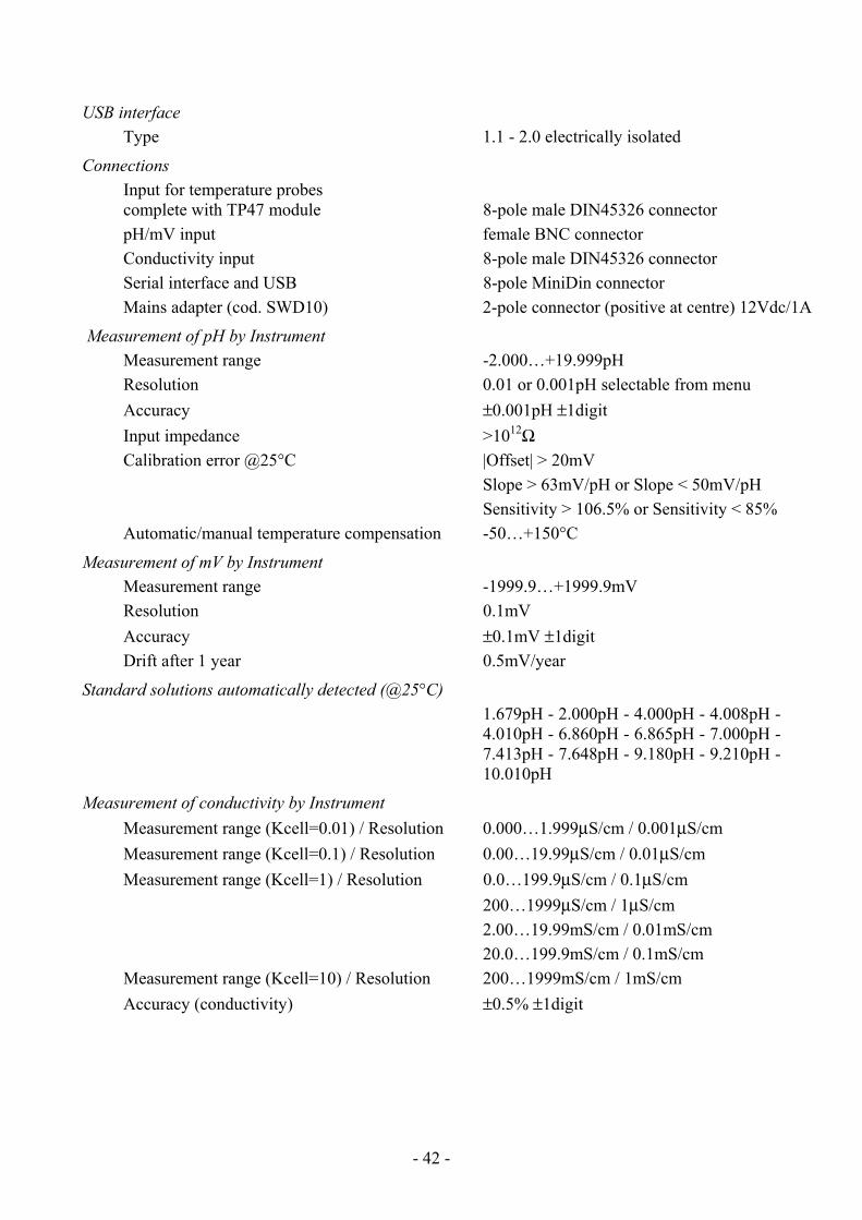
- - 42
USB interface Type 1.1 - 2.0 electrically isolated
Connections Input for temperature probes complete with TP47 module 8-pole male DIN45326 connector pH/mV input female BNC connector Conductivity input 8-pole male DIN45326 connector Serial interface and USB 8-pole MiniDin connector Mains adapter (cod. SWD10) 2-pole connector (positive at centre) 12Vdc/1A
Measurement of pH by Instrument Measurement range -2.000…+19.999pH Resolution 0.01 or 0.001pH selectable from menu Accuracy ±0.001pH ±1digit Input impedance >1012Ω Calibration error @25°C |Offset| > 20mV Slope > 63mV/pH or Slope < 50mV/pH Sensitivity > 106.5% or Sensitivity < 85% Automatic/manual temperature compensation -50…+150°C
Measurement of mV by Instrument Measurement range -1999.9…+1999.9mV Resolution 0.1mV Accuracy ±0.1mV ±1digit Drift after 1 year 0.5mV/year
Standard solutions automatically detected (@25°C) 1.679pH - 2.000pH - 4.000pH - 4.008pH -
4.010pH - 6.860pH - 6.865pH - 7.000pH - 7.413pH - 7.648pH - 9.180pH - 9.210pH - 10.010pH
Measurement of conductivity by Instrument Measurement range (Kcell=0.01) / Resolution 0.000…1.999μS/cm / 0.001μS/cm Measurement range (Kcell=0.1) / Resolution 0.00…19.99μS/cm / 0.01μS/cm Measurement range (Kcell=1) / Resolution 0.0…199.9μS/cm / 0.1μS/cm 200…1999μS/cm / 1μS/cm 2.00…19.99mS/cm / 0.01mS/cm 20.0…199.9mS/cm / 0.1mS/cm Measurement range (Kcell=10) / Resolution 200…1999mS/cm / 1mS/cm Accuracy (conductivity) ±0.5% ±1digit
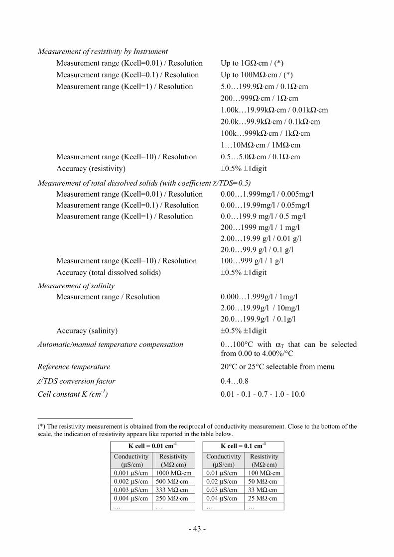
- - 43
Measurement of resistivity by Instrument Measurement range (Kcell=0.01) / Resolution Up to 1GΩ⋅cm / (*) Measurement range (Kcell=0.1) / Resolution Up to 100MΩ⋅cm / (*) Measurement range (Kcell=1) / Resolution 5.0…199.9Ω⋅cm / 0.1Ω⋅cm 200…999Ω⋅cm / 1Ω⋅cm 1.00k…19.99kΩ⋅cm / 0.01kΩ⋅cm 20.0k…99.9kΩ⋅cm / 0.1kΩ⋅cm 100k…999kΩ⋅cm / 1kΩ⋅cm 1…10MΩ⋅cm / 1MΩ⋅cm Measurement range (Kcell=10) / Resolution 0.5…5.0Ω⋅cm / 0.1Ω⋅cm Accuracy (resistivity) ±0.5% ±1digit
Measurement of total dissolved solids (with coefficient χ/TDS=0.5) Measurement range (Kcell=0.01) / Resolution 0.00…1.999mg/l / 0.005mg/l Measurement range (Kcell=0.1) / Resolution 0.00…19.99mg/l / 0.05mg/l Measurement range (Kcell=1) / Resolution 0.0…199.9 mg/l / 0.5 mg/l 200…1999 mg/l / 1 mg/l 2.00…19.99 g/l / 0.01 g/l 20.0…99.9 g/l / 0.1 g/l Measurement range (Kcell=10) / Resolution 100…999 g/l / 1 g/l Accuracy (total dissolved solids) ±0.5% ±1digit
Measurement of salinity Measurement range / Resolution 0.000…1.999g/l / 1mg/l 2.00…19.99g/l / 10mg/l 20.0…199.9g/l / 0.1g/l Accuracy (salinity) ±0.5% ±1digit
Automatic/manual temperature compensation 0…100°C with αT that can be selected from 0.00 to 4.00%/°C
Reference temperature 20°C or 25°C selectable from menu
χ/TDS conversion factor 0.4…0.8
Cell constant K (cm-1) 0.01 - 0.1 - 0.7 - 1.0 - 10.0
(*) The resistivity measurement is obtained from the reciprocal of conductivity measurement. Close to the bottom of the scale, the indication of resistivity appears like reported in the table below.
K cell = 0.01 cm-1 K cell = 0.1 cm-1 Conductivity
(μS/cm) Resistivity (MΩ⋅cm)
Conductivity (μS/cm)
Resistivity (MΩ⋅cm)
0.001 μS/cm 1000 MΩ⋅cm 0.01 μS/cm 100 MΩ⋅cm 0.002 μS/cm 500 MΩ⋅cm 0.02 μS/cm 50 MΩ⋅cm 0.003 μS/cm 333 MΩ⋅cm 0.03 μS/cm 33 MΩ⋅cm 0.004 μS/cm 250 MΩ⋅cm 0.04 μS/cm 25 MΩ⋅cm … … … …
- - 44
Standard solutions automatically detected (@25°C) 147μS/cm
1413μS/cm
12880μS/cm
111800μS/cm
Measurement of temperature by Instrument Pt100 measurement range -50…+200°C Pt1000 measurement range -50…+200°C Resolution 0.1°C Accuracy ±0.25°C Drift after 1 year 0.1°C/year
EMC standard regulations Security EN61000-4-2, EN61010-1 level 3 Electrostatic discharge EN61000-4-2 level 3 Electric fast transients EN61000-4-4 level 3, EN61000-4-5 level 3 Voltage variations EN61000-4-11 Electromagnetic interference susceptibility IEC1000-4-3 Electromagnetic interference emission EN55020 class B
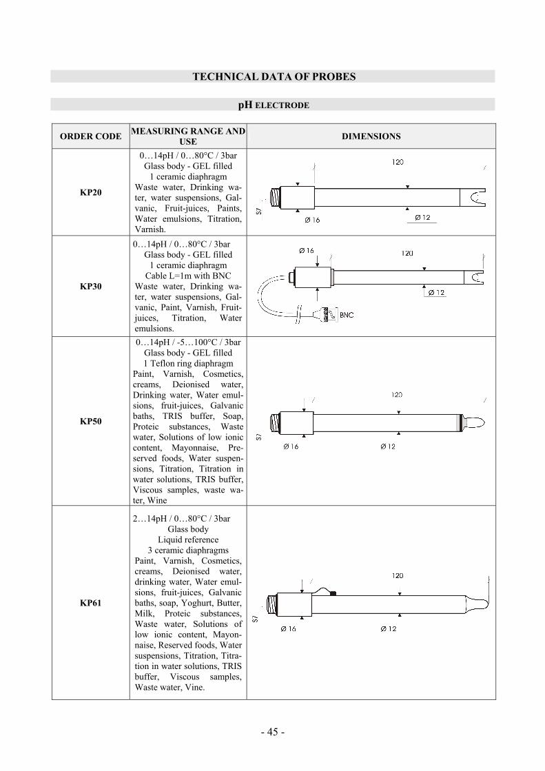
- - 45
TECHNICAL DATA OF PROBES
pH ELECTRODE
ORDER CODE MEASURING RANGE AND USE DIMENSIONS
KP20
0…14pH / 0…80°C / 3bar Glass body - GEL filled
1 ceramic diaphragm Waste water, Drinking wa-ter, water suspensions, Gal-vanic, Fruit-juices, Paints, Water emulsions, Titration, Varnish.
KP30
0…14pH / 0…80°C / 3bar Glass body - GEL filled
1 ceramic diaphragm Cable L=1m with BNC
Waste water, Drinking wa-ter, water suspensions, Gal-vanic, Paint, Varnish, Fruit-juices, Titration, Water emulsions.
KP50
0…14pH / -5…100°C / 3bar Glass body - GEL filled 1 Teflon ring diaphragm
Paint, Varnish, Cosmetics, creams, Deionised water, Drinking water, Water emul-sions, fruit-juices, Galvanic baths, TRIS buffer, Soap, Proteic substances, Waste water, Solutions of low ionic content, Mayonnaise, Pre-served foods, Water suspen-sions, Titration, Titration in water solutions, TRIS buffer, Viscous samples, waste wa-ter, Wine
KP61
2…14pH / 0…80°C / 3bar Glass body
Liquid reference 3 ceramic diaphragms
Paint, Varnish, Cosmetics, creams, Deionised water, drinking water, Water emul-sions, fruit-juices, Galvanic baths, soap, Yoghurt, Butter, Milk, Proteic substances, Waste water, Solutions of low ionic content, Mayon-naise, Reserved foods, Water suspensions, Titration, Titra-tion in water solutions, TRIS buffer, Viscous samples, Waste water, Vine.
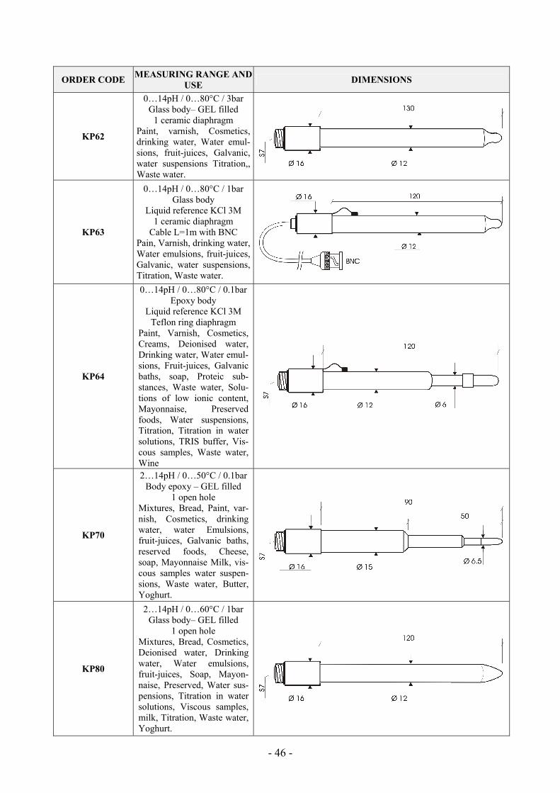
- - 46
ORDER CODE MEASURING RANGE AND USE DIMENSIONS
KP62
0…14pH / 0…80°C / 3bar Glass body– GEL filled
1 ceramic diaphragm Paint, varnish, Cosmetics, drinking water, Water emul-sions, fruit-juices, Galvanic, water suspensions Titration,, Waste water.
KP63
0…14pH / 0…80°C / 1bar Glass body
Liquid reference KCl 3M 1 ceramic diaphragm
Cable L=1m with BNC Pain, Varnish, drinking water, Water emulsions, fruit-juices, Galvanic, water suspensions, Titration, Waste water.
KP64
0…14pH / 0…80°C / 0.1bar Epoxy body
Liquid reference KCl 3M Teflon ring diaphragm
Paint, Varnish, Cosmetics, Creams, Deionised water, Drinking water, Water emul-sions, Fruit-juices, Galvanic baths, soap, Proteic sub-stances, Waste water, Solu-tions of low ionic content, Mayonnaise, Preserved foods, Water suspensions, Titration, Titration in water solutions, TRIS buffer, Vis-cous samples, Waste water, Wine
KP70
2…14pH / 0…50°C / 0.1bar Body epoxy – GEL filled
1 open hole Mixtures, Bread, Paint, var-nish, Cosmetics, drinking water, water Emulsions, fruit-juices, Galvanic baths, reserved foods, Cheese, soap, Mayonnaise Milk, vis-cous samples water suspen-sions, Waste water, Butter, Yoghurt.
KP80
2…14pH / 0…60°C / 1bar Glass body– GEL filled
1 open hole Mixtures, Bread, Cosmetics, Deionised water, Drinking water, Water emulsions, fruit-juices, Soap, Mayon-naise, Preserved, Water sus-pensions, Titration in water solutions, Viscous samples, milk, Titration, Waste water, Yoghurt.
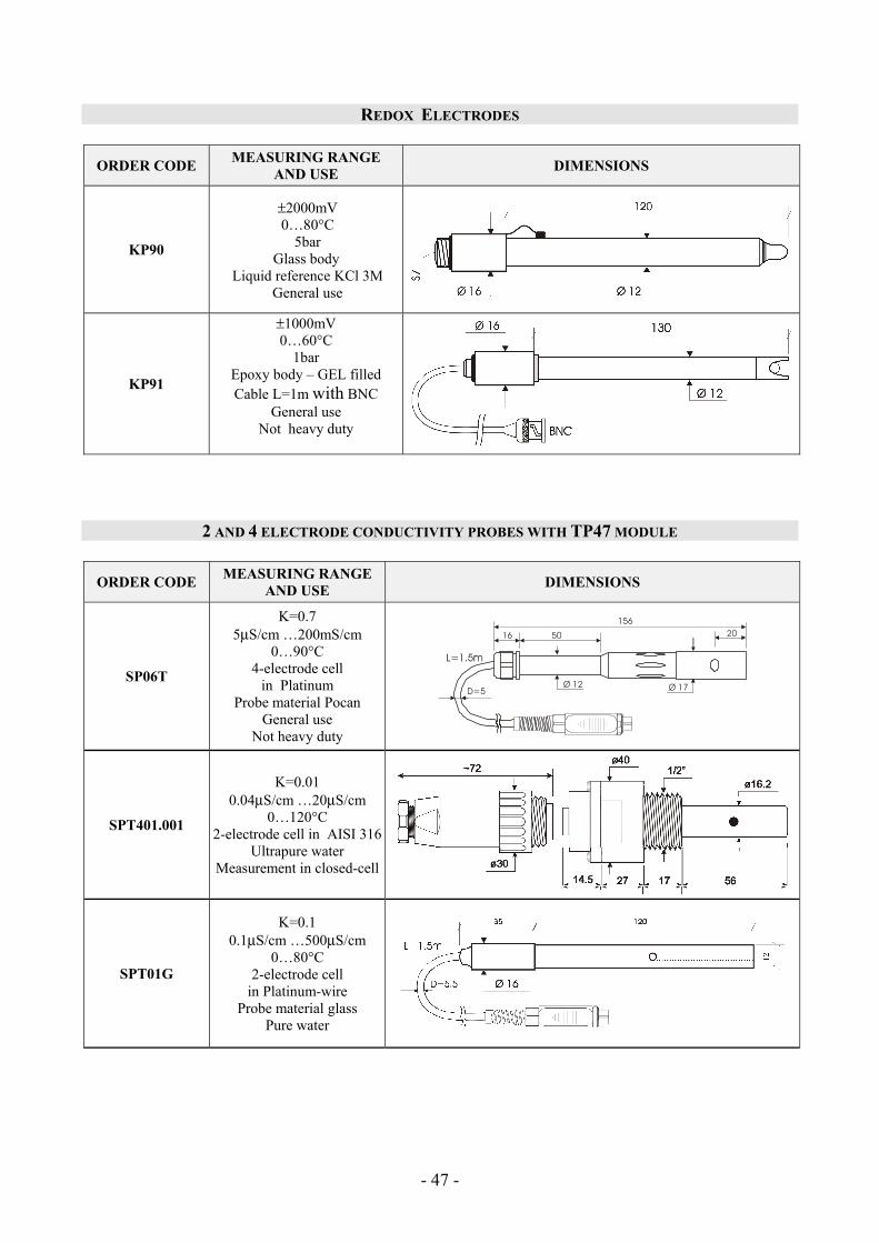
- - 47
REDOX ELECTRODES
ORDER CODE MEASURING RANGE AND USE DIMENSIONS
KP90
±2000mV 0…80°C
5bar Glass body
Liquid reference KCl 3M General use
KP91
±1000mV 0…60°C
1bar Epoxy body – GEL filled Cable L=1m with BNC
General use Not heavy duty
2 AND 4 ELECTRODE CONDUCTIVITY PROBES WITH TP47 MODULE
ORDER CODE MEASURING RANGE AND USE DIMENSIONS
SP06T
K=0.7 5μS/cm …200mS/cm
0…90°C 4-electrode cell
in Platinum Probe material Pocan
General use Not heavy duty
Ø 17
15620
Ø 12
16 50
D=5
SPT401.001
K=0.01 0.04μS/cm …20μS/cm
0…120°C 2-electrode cell in AISI 316
Ultrapure water Measurement in closed-cell
SPT01G
K=0.1 0.1μS/cm …500μS/cm
0…80°C 2-electrode cell
in Platinum-wire Probe material glass
Pure water
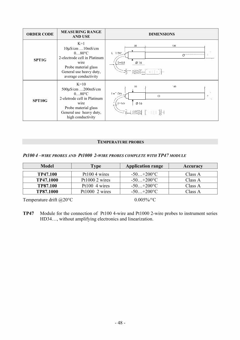
- - 48
ORDER CODE MEASURING RANGE AND USE DIMENSIONS
SPT1G
K=1 10μS/cm …10mS/cm
0…80°C 2-electrode cell in Platinum
wire Probe material glass
General use heavy duty, average conductivity
SPT10G
K=10 500μS/cm …200mS/cm
0…80°C 2-eletrode cell in Platinum
wire Probe material glass
General use heavy duty, high conductivity
TEMPERATURE PROBES
Pt100 4 –WIRE PROBES AND Pt1000 2-WIRE PROBES COMPLETE WITH TP47 MODULE
Model Type Application range Accuracy
TP47.100 Pt100 4 wires -50…+200°C Class A TP47.1000 Pt1000 2 wires -50…+200°C Class A TP87.100 Pt100 4 wires -50…+200°C Class A TP87.1000 Pt1000 2 wires -50…+200°C Class A
Temperature drift @20°C 0.005%/°C
TP47 Module for the connection of Pt100 4-wire and Pt1000 2-wire probes to instrument series
HD34…, without amplifying electronics and linearization.
- - 49
ORDER CODES
HD3456.2K The kit is composed of: instrument HD3456.2 datalogger, for the measurement of pH - redox - conductivity - resistivity - TDS - salinity - temperature, 3 1.5V alka-line batteries, operating manual, software DeltaLog9 version 2.0.
pH/mV electrodes, conductivity probes, temperature probes, standard refer-ence solutions for different measurement types, connection cables for pH electrodes with S7 connector, cables for data download to PC or printer have to be ordered separately.
HD2110CSNM 8-pole connection cable Mini Din - Sub D 9-pole female for RS232C, for connec-tion to PC without USB input.
HD2101/USB Connection cable USB 2.0 connector type A - 8-pole Mini Din for connection to PC with USB input.
SWD10 Stabilized power supply at 100-240Vac/12Vdc-1A mains voltage.
S’print-BT Portable, serial input, 24 column thermal printer, 58mm paper width.
HD2110CSP Connection cable for instruments series HD34…to printer S’print-BT.
HD22.2 Laboratory electrode holder composed of basis plate with incorporated magnetic stirrer, staff and replaceable electrode holder. Height max. 380mm. For ∅12mm electrodes.
HD22.3 Laboratory electrode holder with metal basis plate. Flexible electrode holder for free positioning. For Ø 12mm probes.
TP47 Module for the connection of Pt100 4-wire and Pt1000 2-wire probes to instru-ment series HD34…, without amplifying electronics and linearization.
PH ELECTRODES
KP20 Combined pH electrode for common use, GEL filled with screw connector S7 Ep-oxy body.
KP30 Combined pH electrode for common use, GEL filled, cable 1m with BNC, Epoxy body.
KP 50 Combined pH electrode for common use, varnish, emulsions GEL filled, with screw connector S7, glass body.
KP 61 Combined pH electrode, 3 diaphragms for milk, cream, etc. Protelyte electrolyte, with screw connector S7, glass body.
KP 62 Combined pH electrode, 1 diaphragm for pure water, Paint, varnish, GEL filled, with screw connector S7, glass body.
KP 63 Combined pH electrode for common use, varnish, cable 1 m with BNC, electro-lyte KCl 3M glass body.
KP 64 Combined pH electrode for water, varnish, emulsions, etc., electrolyte KCl 3M with screw connector S7, glass body.
KP 70 Combined pH electrode, micro diam.... 6.5mm, GEL filled, bread, mixtures, cheese, etc., with screw connector S7, glass body.
KP 80 Combined pointed pH electrode, electrolyte, with screw connector S7, glass body.
- - 50
CP Extension cable 1.5m with BNC connectors on one side and S7 on the other side for electrode with S7 connector.
CP5 Extension cable 5m with BNC connectors on one side and S7 on the other side for electrode with S7 connector.
CE S7 screw connector for pH electrode. BNC Female BNC for electrode extension. ORP Electrodes
KP90 REDOX PLATINUM electrode, with screw connector S7, electrolyte KCl 3M, glass body.
KP91 REDOX PLATINUM electrode general use not heavy duty GEL filled, cable 1m with BNC, glass body.
pH STANDARD SOLUTIONS
HD8642 Standard solution 4.01pH - 200cc.
HD8672 Standard solution 6.86pH - 200cc.
HD8692 Standard solution 9.18pH - 200cc.
REDOX STANDARD SOLUTIONS
HDR220 Redox standard solution 220mV 0,5 l.
HDR468 Redox standard solution 468mV 0,5 l.
ELETTROLYTE SOLUTIONS
KCL 3M 100ml ready for use solution for refilling of the electrodes KP63, KP64, and KP90.
PROTELYTE 100ml ready for use solution for refilling of the electrodes KP61, KP71, and KP80.
CLEANING AND MAINTENANCE
HD62PT Diaphragm cleaning (tiourea in HCl) – 500ml.
HD62PP Protein cleaning (pepsin in HCl) – 500ml.
HD62RF Regeneration (fluorhydric acid) – 500ml.
HD62SC Solution for electrode preservation – 500ml.
- - 51
CONDUCTIVITY PROBES AND COMBINED CONDUCTIVITY AND TEMPERATURE PROBES
SP06T Combined conductivity and temperature 4-electrode cell in Platinum, body in Po-can. Cell constant K = 0.7. Measurement range 5μS/cm …200mS/cm, 0…90°C.
SPT401.001 Combined conductivity and temperature 2- electrode cell in stainless steel AISI 316. Cell constant K = 0.01. Measurement range 0.04μS/cm …20μS/cm, 0…120°C. Measurement in closed-cell.
SPT01G Combined conductivity and temperature 2-electrode Platinum-wire cell, glass body. Cell constant K = 0.1. Measurement range 0.1μS/cm …500μS/cm, 0…80°C.
SPT1G Combined conductivity and temperature 2-electrode Platinum-wire cell, glass body. Cell constant K = 1. Measurement range 10μS/cm …10mS/cm, 0…80°C.
SPT10G Combined conductivity and temperature 2-electrode Platinum-wire cell, glass body. Cell constant K = 10. Measurement range 500μS/cm …200mS/cm, 0…80°C.
STANDARD CONDUCTIVITY CALIBRATION SOLUTIONS
HD8747 Standard calibration solution 0.001mol/l equal to 147μS/cm @25°C - 200cc.
HD8714 Standard calibration solution 0.01mol/l equal to 1413μS/cm @25°C - 200cc.
HD8712 Standard calibration solution 0.1mol/l equal to 12880μS/cm @25°C - 200cc.
HD87111 Standard calibration solution 1mol/l equal to 111800μS/cm @25°C - 200cc. .
TEMPERATURE PROBES COMPLETE WITH TP47 MODULE
TP47.100 Direct 4 wire Pt100 sensor immersion probe. Probe's stem Ø 3mm, length 230mm. 4 wire connection cable with connector, length 2 metres.
TP47.1000 Pt1000 sensor immersion probe. Probe's stem Ø 3mm, length 230mm. 2 wire con-nection cable with connector, length 2 metres.
TP87.100 Pt100 sensor immersion probe. Probe's stem Ø 3mm, length 70mm. Connection cable 4 wires with connector, length 1 metre.
TP87.1000 Pt1000 sensor immersion probe. Probe's stem Ø 3mm, length 70mm. Connection cable 2 wires with connector, length 1 metre.
TP47 Module for the connection of Pt100 4-wire and Pt1000 2-wire probes to instru-ment series HD34…, without amplifying electronics and linearization. (the connection instructions are outlined on page23).
- - 52
CONTENTS INTRODUCTION ............................................................................................................................................................ 4
KEYBOARD AND MENU DESCRIPTION.................................................................................................................. 5
PH MEASUREMENT.................................................................................................................................................... 13
Automatic or manual pH compensation.................................................................................................................. 13 pH electrode calibration .......................................................................................................................................... 14 Calibration procedure.............................................................................................................................................. 15 Temperature characteristics of Delta OHM standard solutions............................................................................... 17
CONDUCTIVITY MEASUREMENT.......................................................................................................................... 18
Automatic or manual conductivity compensation................................................................................................... 19 Calibration of conductivity...................................................................................................................................... 20 Automatic calibration of conductivity using memorized standard solutions .......................................................... 20 Calibration of conductivity using non memorized standard solutions .................................................................... 21 Table of standard solution Delta Ohm at 147μS/cm, 1413μS/cm, 12.88mS/cm and 111800mS/cm...................... 22
DIRECT INPUT INTO Pt100 AND Pt1000 TEMPERATURE PROBES WITH TP47MODULE ........................ 23
How to measure ...................................................................................................................................................... 23 Instructions to connect the TP47 module for conductivity/temperature combined probes, 4 wire Pt100 probes, and 2 wire Pt1000 .......................................................................................................................................................... 23
WARNINGS AND OPERATING INSTRUCTIONS.................................................................................................. 27
Notes on pH electrodes use ..................................................................................................................................... 27 Notes on conductivity measurement ....................................................................................................................... 28
INSTRUMENT SIGNALS AND FAULTS .................................................................................................................. 29
LOW BATTERY WARNING AND BATTERY REPLACEMENT ......................................................................... 32
INSTRUMENT STORAGE........................................................................................................................................... 33
MAINTENANCE ............................................................................................................................................................. 33
SERIAL INTERFACE AND USB................................................................................................................................. 34
STORING AND TRANSFERRING DATA TO A PC ............................................................................................... 36
THE LOGGING FUNCTION .............................................................................................................................................. 36 CLEARING THE MEMORY............................................................................................................................................... 36 THE PRINT FUNCTION................................................................................................................................................. 37
CONNECTION TO A PC............................................................................................................................................. 38
CONNECTION TO THE RS232C SERIAL PORT ................................................................................................................. 38 CONNECTION TO THE USB 2.0 PORT ............................................................................................................................. 38
FUNCTIONING NOTES AND OPERATING SECURITY....................................................................................... 40
INSTRUMENT TECHNICAL CHARACTERISTICS .............................................................................................. 41
TECHNICAL DATA OF PROBES ............................................................................................................................. 45 pH ELECTRODE ............................................................................................................................................................. 45 REDOX ELECTRODES ................................................................................................................................................... 47 2 AND 4 ELECTRODE CONDUCTIVITY PROBES WITH TP47 MODULE ............................................................................... 47 TEMPERATURE PROBES ................................................................................................................................................. 48 Pt100 4 –WIRE PROBES AND Pt1000 2-WIRE PROBES COMPLETE WITH TP47 MODULE................................................. 48

- - 53
ORDER CODES ............................................................................................................................................................. 49
PH ELECTRODES ........................................................................................................................................................... 49

- - 54

- - 55
- - 56
GARANZIA GUARANTEE
GARANTIE GARANTIA
Questo certificato deve accompagnare l'apparecchio spedito al centro assistenza. IMPORTANTE: La garanzia è operante solo se il presente tagliando sarà compilato in tutte le sue parti.
This guarantee must be sent together with the instrument to our service centre. N.B.: Guarantee is valid only if coupon has been correctly filled in all details.
Le certificat doit porter le cachet du revendeur et la date d'achat. A défaut, la garantie sera comptée à partir de la date de la sortie d'usine. ATTENTION: Pour bénéficier de la garantie, le présent certificat doit obligatoirement accompagner l'appa-reil présumé défectueux.
Dieser Garantieschein muss der Spedition beigelegt werden, wenn das Gerät an das Kundendienstzent-rum gesandt wird. WICHTIG: Die Garantie ist nur gültig, wenn dieser Abschnitt bis ins Einzelne ausgefüllt ist.
Este certificado debe acompañar al aparato enviado al centro de asistencia. IMPORTANTE: La garantía es válida solo si el presente cupón ha sido completado en su totalidad.
Instrument type HD3456.2
Serial number
RENEWALS
Date Date
Inspector Inspector
Date Date
Inspector Inspector
Date Date
Inspector Inspector
C E C O N F O R M I T Y Safety EN61000-4-2, EN61010-1 LEVEL 3 Electrostatic discharge EN61000-4-2 LEVEL 3 Electric fast transients EN61000-4-4 LEVEL 3 Voltage variations EN61000-4-11
Electromagnetic interference susceptibility IEC1000-4-3 Electromagnetic interference emission EN55020 class B


