Embed Size (px)
Citation preview
Pocket Guide
Viega® Heating and Cooling Solutions

Viega 1-800-976-9819 www.viega.us2
Thank you for choosing Viega. Welcome!
Viega’s global legacy of excellence began in 1899 when our founder, Franz-Anselm Viegener of Attendorn, Germany, introduced an innovative brass beer tap. In 1901, Viegener’s company began manufacturing home plumbing products. In 1999, Viega came to North America, revolutionizing plumbing, heating and pipe joining systems. The Viega ProPress® system helped installers make reliable press connections in less time with less labor than conventional pipe joining methods.Other innovative Viega solutions for plumbing include versatile PEX piping options and trustworthy PEX press fittings. Viega Heating and Cooling Solutions offer systems with complete support and service every step of the way.By choosing to install Viega Heating and Cooling Solutions, you have joined the ranks of installers across the country who believe there is no substitute for quality. Viega has a history of bringing excellence and innovation to the hydronic industry.It is the business of our engineers to research and develop complete systems that provide you the most effective and easy-to-use products available. In the following pages, you will be guided through the layout, installation and start-up of our residential and commercial products.Call 800-976-9819 for your local District Manager and wholesale location.
Viega Heating and Cooling Solutions Pocket Guide
Viega 1-800-976-9819 www.viega.us3
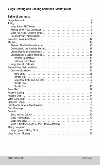
Table of contents
Viega Heating and Cooling Solutions Pocket Guide
Design Information . . . . . . . . . . . . . . . . . . . . . . . . . . . . . . . . . . . . . . . . . . . . . . . . . . . 4Tubing . . . . . . . . . . . . . . . . . . . . . . . . . . . . . . . . . . . . . . . . . . . . . . . . . . . . . . . . . . . . 5
Viega Barrier PEX Tubing . . . . . . . . . . . . . . . . . . . . . . . . . . . . . . . . . . . . . . . . . . . . 5Making a PEX Press Connection . . . . . . . . . . . . . . . . . . . . . . . . . . . . . . . . . . . . . . . 6Viega PEX Repair Coupling Wrap . . . . . . . . . . . . . . . . . . . . . . . . . . . . . . . . . . . . . . 7PEX Expansion Compensation . . . . . . . . . . . . . . . . . . . . . . . . . . . . . . . . . . . . . . . . 8
Insulation Recommendations . . . . . . . . . . . . . . . . . . . . . . . . . . . . . . . . . . . . . . . . . . 12Manifolds . . . . . . . . . . . . . . . . . . . . . . . . . . . . . . . . . . . . . . . . . . . . . . . . . . . . . . . . . 14
Stainless Manifold Considerations . . . . . . . . . . . . . . . . . . . . . . . . . . . . . . . . . . . . 15Connecting to the Stainless Manifold . . . . . . . . . . . . . . . . . . . . . . . . . . . . . . . . . . 16Copper Manifold Considerations . . . . . . . . . . . . . . . . . . . . . . . . . . . . . . . . . . . . . . 18Connecting to a Copper Manifold . . . . . . . . . . . . . . . . . . . . . . . . . . . . . . . . . . . . . 18
ProPress Connection . . . . . . . . . . . . . . . . . . . . . . . . . . . . . . . . . . . . . . . . . . . . 18Soldering Instructions . . . . . . . . . . . . . . . . . . . . . . . . . . . . . . . . . . . . . . . . . . . 19
Viega Manifold Cabinets . . . . . . . . . . . . . . . . . . . . . . . . . . . . . . . . . . . . . . . . . . . . 21Panels, Plates, Traks and Mats . . . . . . . . . . . . . . . . . . . . . . . . . . . . . . . . . . . . . . . . . 22
Concrete Installation . . . . . . . . . . . . . . . . . . . . . . . . . . . . . . . . . . . . . . . . . . . . . . 22Rapid Grid . . . . . . . . . . . . . . . . . . . . . . . . . . . . . . . . . . . . . . . . . . . . . . . . . . . . 25Climate Mat . . . . . . . . . . . . . . . . . . . . . . . . . . . . . . . . . . . . . . . . . . . . . . . . . . . 28Suspended Slabs and Thin Slab . . . . . . . . . . . . . . . . . . . . . . . . . . . . . . . . . . . . 32Climate Panel . . . . . . . . . . . . . . . . . . . . . . . . . . . . . . . . . . . . . . . . . . . . . . . . . 38Climate Trak . . . . . . . . . . . . . . . . . . . . . . . . . . . . . . . . . . . . . . . . . . . . . . . . . . 45
Snow Melt . . . . . . . . . . . . . . . . . . . . . . . . . . . . . . . . . . . . . . . . . . . . . . . . . . . . . . . . 49Pressure Testing . . . . . . . . . . . . . . . . . . . . . . . . . . . . . . . . . . . . . . . . . . . . . . . . . . . 54Pressure Drop . . . . . . . . . . . . . . . . . . . . . . . . . . . . . . . . . . . . . . . . . . . . . . . . . . . . . . 54Valve Sizing Chart . . . . . . . . . . . . . . . . . . . . . . . . . . . . . . . . . . . . . . . . . . . . . . . . . . . 58Circulator Sizing . . . . . . . . . . . . . . . . . . . . . . . . . . . . . . . . . . . . . . . . . . . . . . . . . . . . 60Selecting the Percent Glycol Mixture . . . . . . . . . . . . . . . . . . . . . . . . . . . . . . . . . . . . . 63Floor Coverings . . . . . . . . . . . . . . . . . . . . . . . . . . . . . . . . . . . . . . . . . . . . . . . . . . . . . 64Controls . . . . . . . . . . . . . . . . . . . . . . . . . . . . . . . . . . . . . . . . . . . . . . . . . . . . . . . . . . 67
Basic Heating Control . . . . . . . . . . . . . . . . . . . . . . . . . . . . . . . . . . . . . . . . . . . . . . 67Viega Thermostats . . . . . . . . . . . . . . . . . . . . . . . . . . . . . . . . . . . . . . . . . . . . . . . . 70Viega Zone Valve . . . . . . . . . . . . . . . . . . . . . . . . . . . . . . . . . . . . . . . . . . . . . . . . . 81Viega 0-10V Powerhead for 1¼" Stainless Manifold . . . . . . . . . . . . . . . . . . . . . . . 85
Mixing Equipment . . . . . . . . . . . . . . . . . . . . . . . . . . . . . . . . . . . . . . . . . . . . . . . . . . . 88Viega Hydronic Mixing Block . . . . . . . . . . . . . . . . . . . . . . . . . . . . . . . . . . . . . . . . 88
Viega Product Glossary . . . . . . . . . . . . . . . . . . . . . . . . . . . . . . . . . . . . . . . . . . . . . . 96
Viega 1-800-976-9819 www.viega.us4
Design Information
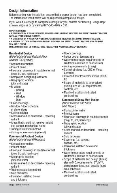
Residential Design(Bill of Material and Radiant Floor Heating [RFH] report) • Contact information• Project name• Floor plan drawings in readable format
(dwg, tif, pdf, hard copy)• Completed design request form• Geographic location
(city and state)• R-values
- Ceiling - Wall - Window - Door
• Floor coverings• Window / door schedule
or dimensions• Ceiling heights• Areas marked or described – receiving
radiant• Areas that should not receive radiant
(i.e. garage, mechanical room)• Tubing installation method• Zoning requirements (optional)Commercial Radiant Design(Bill of Material and RFH report)• Contact information• Project name• Floor plan drawings in readable format
(dwg, tif, pdf, hard copy)• Geographic location
(city and state)• Areas marked or described – receiving
radiant• Tubing installation method• Slab thickness• Insulation installed below
and thickness
• Floor coverings• Indoor design temperature• Water temperature requirements or
limitations (related to heat source)• Zoning requirements (if any)• Control strategy (i.e. DDC or Viega
Controls)• Provided heat loss calculations (BTUh/
ft2)• Scope of materials to be provided
(tubing size w/O.C. requirements, controls, etc.)
• Manifold locations indicated on drawings
Commercial Snow Melt Design (Bill of Material and Snow Melt Report)• Contact information• Project name• Floor plan drawings in readable format
(dwg, tif, pdf, hard copy)• Geographic location
(city and state)• Areas marked or described – receiving
radiant• Slab thickness• Coverings (i.e. pavers,
asphalt, etc.)• Insulation installed below and
thickness• Water temperature requirements or
limitations (related to heat source)• Scope of materials and design (Tubing
size w/O.C. requirements, BTUh/ft2, glycol percentage, etc., usually found on a schedule)
• Manifold locations indicated on drawings
Before starting your installation, ensure that a proper design has been completed. The information listed below will be required to complete a design. If you would like Viega to complete a design for you, contact our Heating Design Dept. at www.viega.us or by calling 877-843-4262 x 351.
IMPORTANT NOTE:• A GREEN DOT ON A VIEGA PROPRESS AND MEGAPRESS FITTING INDICATES THE SMART CONNECT FEATURE WITH AN EPDM SEALING ELEMENT. • A GREEN DOT ON A VIEGA PEX PRESS POLYMER FITTING INDICATES THE SMART CONNECT FEATURE. • A YELLOW DOT ON A MEGAPRESSG FITTING INDICATES THE SMART CONNECT FEATURE WITH AN HNBR SEALING ELEMENT. FOR A CURRENT LIST OF APPLICATIONS, PLEASE VISIT WWW.VIEGA.US/APPLICATIONS.
Viega 1-800-976-9819 www.viega.us5
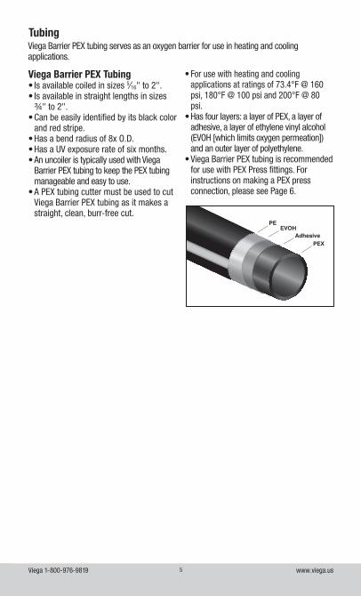
Tubing
PEEVOH
AdhesivePEX
Viega Barrier PEX tubing serves as an oxygen barrier for use in heating and cooling applications.
Viega Barrier PEX Tubing• Is available coiled in sizes 5⁄16" to 2".• Is available in straight lengths in sizes
¾" to 2".• Can be easily identified by its black color
and red stripe.• Has a bend radius of 8x O.D.• Has a UV exposure rate of six months.• An uncoiler is typically used with Viega
Barrier PEX tubing to keep the PEX tubing manageable and easy to use.
• A PEX tubing cutter must be used to cut Viega Barrier PEX tubing as it makes a straight, clean, burr-free cut.
• For use with heating and cooling applications at ratings of 73.4°F @ 160 psi, 180°F @ 100 psi and 200°F @ 80 psi.
• Has four layers: a layer of PEX, a layer of adhesive, a layer of ethylene vinyl alcohol (EVOH [which limits oxygen permeation]) and an outer layer of polyethylene.
• Viega Barrier PEX tubing is recommended for use with PEX Press fittings. For instructions on making a PEX press connection, please see Page 6.
Viega 1-800-976-9819 www.viega.us6
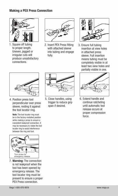
Making a PEX Press Connection
2. Insert PEX Press fitting with attached sleeve into tubing and engage fully.
3. Ensure full tubing insertion at view holes in attached press sleeve. Full insertion means tubing must be completely visible in at least two view holes and partially visible in one.
4. Position press tool perpendicular over press sleeve, resting it against the tool locator ring.
Note: The tool locator ring must be in the factory-installed position while making a press to ensure a consistent leakproof connection. It may be necessary to rotate the tool locator ring to avoid interference between the ring and tool.
1. Square off tubing to proper length. Uneven, jagged or irregular cuts will produce unsatisfactory connections.
PureFlow
1/2”
PureFlow
1/2”
PureFlow
1/2”
6. Extend handle and continue ratcheting until automatic tool release occurs at proper compression force.
5. Close handles, using trigger to reduce grip span if desired.
PureFlow
1/2”
Turn screw for emergency release
7. Warning: The connection is not leakproof when the tool has been opened by emergency release. The tool locator ring must be present to ensure a proper PEX Press connection.
Viega 1-800-976-9819 www.viega.us7
Viega PEX Repair Coupling Wrap
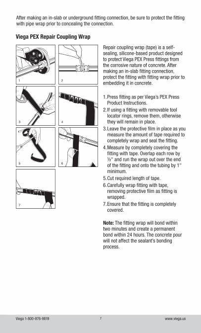
After making an in-slab or underground fitting connection, be sure to protect the fitting with pipe wrap prior to concealing the connection.
1 2
3 4
5 6
7
Repair coupling wrap (tape) is a self-sealing, silicone-based product designed to protect Viega PEX Press fittings from the corrosive nature of concrete. After making an in-slab fitting connection, protect the fitting with fitting wrap prior to embedding it in concrete.
1. Press fitting as per Viega’s PEX Press Product Instructions.
2. If using a fitting with removable tool locator rings, remove them, otherwise they will remain in place.
3. Leave the protective film in place as you measure the amount of tape required to completely wrap and seal the fitting.
4. Measure by completely covering the fitting with tape. Overlap each row by ½" and run the wrap out over the end of the fitting and onto the tubing by 1" minimum.
5. Cut required length of tape.6. Carefully wrap fitting with tape,
removing protective film as fitting is wrapped.
7. Ensure that the fitting is completely covered.
Note: The fitting wrap will bond within two minutes and create a permanent bond within 24 hours. The concrete pour will not affect the sealant’s bonding process.
Viega 1-800-976-9819 www.viega.us8
PEX Expansion Compensation
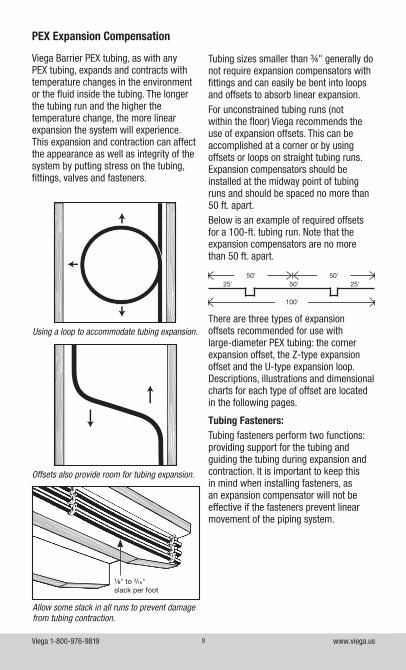
Viega Barrier PEX tubing, as with any PEX tubing, expands and contracts with temperature changes in the environment or the fluid inside the tubing. The longer the tubing run and the higher the temperature change, the more linear expansion the system will experience. This expansion and contraction can affect the appearance as well as integrity of the system by putting stress on the tubing, fittings, valves and fasteners.
Tubing sizes smaller than ¾" generally do not require expansion compensators with fittings and can easily be bent into loops and offsets to absorb linear expansion.For unconstrained tubing runs (not within the floor) Viega recommends the use of expansion offsets. This can be accomplished at a corner or by using offsets or loops on straight tubing runs. Expansion compensators should be installed at the midway point of tubing runs and should be spaced no more than 50 ft. apart.Below is an example of required offsets for a 100-ft. tubing run. Note that the expansion compensators are no more than 50 ft. apart.
There are three types of expansion offsets recommended for use with large-diameter PEX tubing: the corner expansion offset, the Z-type expansion offset and the U-type expansion loop. Descriptions, illustrations and dimensional charts for each type of offset are located in the following pages.
Tubing Fasteners:Tubing fasteners perform two functions: providing support for the tubing and guiding the tubing during expansion and contraction. It is important to keep this in mind when installing fasteners, as an expansion compensator will not be effective if the fasteners prevent linear movement of the piping system.
Using a loop to accommodate tubing expansion.
Allow some slack in all runs to prevent damage from tubing contraction.
100'
25'25' 50'50' 50'
Offsets also provide room for tubing expansion.
⅛" to 3/16"slack per foot
Viega 1-800-976-9819 www.viega.us9
Linear Expansion:To calculate linear expansion for PEX tubing, use the following formula:
∆L = PEX expansion rate
100' x 10°Fx ∆T x tubing length ft
Where:
Viega Barrier PEX tubing expansion rate =0.96" per 100' per 10°F
∆T = Change in temperature (in °F)
For example:40' of 1" Viega Barrier PEX tubing going from 70°F to 130°F
∆L = 0.96"1000
x 60° x 40' = 2.30"
∆L = 2.30"
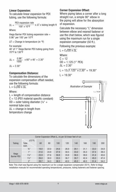
Corner Expansion Offset:Where piping takes a corner after a long straight run, a simple 90° elbow in the piping will allow for the absorption of expansion. Calculate the necessary “L” dimension between elbow and nearest fastener or use the chart below, which was figured using the maximum run for a single expansion compensator (50 ft.).Following the previous example: L = C√OD x ∆L
Where: C = 12OD = 1.125 (1" PEX)∆L = 2.30"
L = 12√1.125" x 2.30" = 19.30"
L = 19.30"Compensation Distance: To calculate the dimensions of the expansion compensation offset needed, use the following formula: L = C√OD x ∆L
Where: L = length of compensation distanceC = 12 (PEX material specific constant)OD = outer tubing diameter (⅛" + nominal tube size) ∆L = change in length from temperature change
Illustration of Example
L
L = 19.30"
Corner Expansion Offset (L, in) per 50 linear feet of run
Tubing ∆T(°F)Tube nom.
60 80 100 120 140 160 180 200
Viega Barrier PEX
¾" 19.0 22.0 24.6 26.9 29.1 31.1 33.0 34.81" 21.6 24.9 27.9 30.5 33.0 35.3 37.4 39.4
1¼" 23.9 27.6 30.8 33.8 36.5 39.0 41.4 43.61½" 26.0 30.0 33.5 36.7 39.7 42.4 45.0 47.42" 29.7 34.3 38.3 42.0 45.3 48.5 51.4 54.2
Note: This chart was figured using the maximum run for a single expansion compensator (50 ft.). Refer to Viega installation manuals for recommended operating temperatures, pressures, tubing fasteners and fastener spacing.
Viega 1-800-976-9819 www.viega.us10
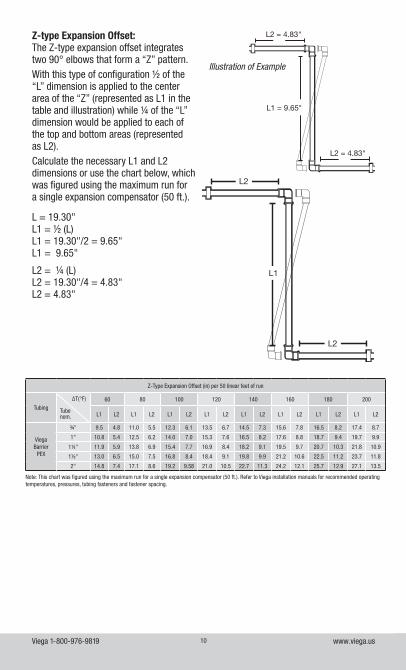
Z-type Expansion Offset:The Z-type expansion offset integrates two 90° elbows that form a “Z” pattern. With this type of configuration ½ of the “L” dimension is applied to the center area of the “Z” (represented as L1 in the table and illustration) while ¼ of the “L” dimension would be applied to each of the top and bottom areas (represented as L2). Calculate the necessary L1 and L2 dimensions or use the chart below, which was figured using the maximum run for a single expansion compensator (50 ft.).
L = 19.30"L1 = ½ (L)L1 = 19.30"/2 = 9.65"L1 = 9.65"
L2 = ¼ (L)L2 = 19.30"/4 = 4.83"L2 = 4.83"
L1
L2
L2
L1 = 9.65"
L2 = 4.83"
L2 = 4.83"
Illustration of Example
Z-Type Expansion Offset (in) per 50 linear feet of run
Tubing
∆T(°F)
Tube nom.
60 80 100 120 140 160 180 200
L1 L2 L1 L2 L1 L2 L1 L2 L1 L2 L1 L2 L1 L2 L1 L2
Viega Barrier
PEX
¾" 9.5 4.8 11.0 5.5 12.3 6.1 13.5 6.7 14.5 7.3 15.6 7.8 16.5 8.2 17.4 8.7
1" 10.8 5.4 12.5 6.2 14.0 7.0 15.3 7.6 16.5 8.2 17.6 8.8 18.7 9.4 19.7 9.9
1¼" 11.9 5.9 13.8 6.9 15.4 7.7 16.9 8.4 18.2 9.1 19.5 9.7 20.7 10.3 21.8 10.9
1½" 13.0 6.5 15.0 7.5 16.8 8.4 18.4 9.1 19.8 9.9 21.2 10.6 22.5 11.2 23.7 11.8
2" 14.8 7.4 17.1 8.6 19.2 9.58 21.0 10.5 22.7 11.3 24.2 12.1 25.7 12.9 27.1 13.5
Note: This chart was figured using the maximum run for a single expansion compensator (50 ft.). Refer to Viega installation manuals for recommended operating temperatures, pressures, tubing fasteners and fastener spacing.
Viega 1-800-976-9819 www.viega.us11
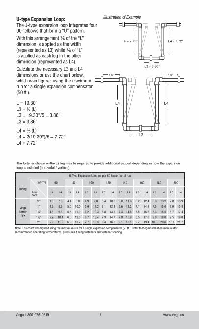
U-type Expansion Loop:The U-type expansion loop integrates four 90° elbows that form a “U” pattern. With this arrangement ⅕ of the “L” dimension is applied as the width (represented as L3) while ⅖ of “L” is applied as each leg in the other dimension (represented as L4). Calculate the necessary L3 and L4 dimensions or use the chart below, which was figured using the maximum run for a single expansion compensator (50 ft.).
L = 19.30"L3 = ⅕ (L)L3 = 19.30"/5 = 3.86"L3 = 3.86"
L4 = ⅖ (L)L4 = 2(19.30")/5 = 7.72"L4 = 7.72"
L4
L3
L4
4-6" 4-6"
Illustration of Example
L4 = 7.72"
L3 = 3.86"
L4 = 7.72"
U-Type Expansion Loop (in) per 50 linear feet of run
Tubing
∆T(°F)
Tube nom.
60 80 100 120 140 160 180 200
L3 L4 L3 L4 L3 L4 L3 L4 L3 L4 L3 L4 L3 L4 L3 L4
Viega Barrier
PEX
¾" 3.8 7.6 4.4 8.8 4.9 9.8 5.4 10.8 5.8 11.6 6.2 12.4 6.6 13.2 7.0 13.9
1" 4.3 8.6 5.0 10.0 5.6 11.2 6.1 12.2 6.6 13.2 7.1 14.1 7.5 15.0 7.9 15.8
1¼" 4.8 9.6 5.5 11.0 6.2 12.3 6.8 13.5 7.3 14.6 7.8 15.6 8.3 16.5 8.7 17.4
1½" 5.2 10.4 6.0 12.0 6.7 13.4 7.3 14.7 7.9 15.9 8.5 17.0 9.0 18.0 9.5 19.0
2" 5.9 11.9 6.9 13.7 7.7 15.3 8.4 16.8 9.1 18.1 9.7 19.4 10.3 20.6 10.8 21.7
Note: This chart was figured using the maximum run for a single expansion compensator (50 ft.). Refer to Viega installation manuals for recommended operating temperatures, pressures, tubing fasteners and fastener spacing.
The fastener shown on the L3 leg may be required to provide additional support depending on how the expansion loop is installed (horizontal / vertical).
Viega 1-800-976-9819 www.viega.us12
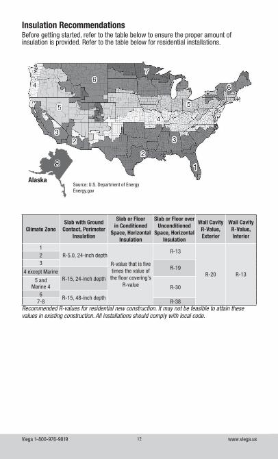
Insulation Recommendations
Climate ZoneSlab with Ground
Contact, Perimeter Insulation
Slab or Floor in Conditioned
Space, Horizontal Insulation
Slab or Floor over Unconditioned
Space, Horizontal Insulation
Wall Cavity R-Value, Exterior
Wall Cavity R-Value, Interior
1R-5.0, 24-inch depth
R-value that is five times the value of
the floor covering’s R-value
R-13
R-20 R-13
23
R-194 except Marine
R-15, 24-inch depth5 and Marine 4 R-30
6R-15, 48-inch depth
7-8 R-38Recommended R-values for residential new construction. It may not be feasible to attain these values in existing construction. All installations should comply with local code.
AlaskaSource: U.S. Department of EnergyEnergy.gov
Before getting started, refer to the table below to ensure the proper amount of insulation is provided. Refer to the table below for residential installations.
Viega 1-800-976-9819 www.viega.us13
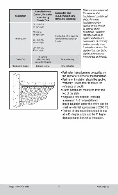
Application
Slab with Ground Contact, Perimeter
Insulation by Climate Zone
Suspended Slab (e.g. between floors) Horizontal Insulation
Heating Only
CZ 1-2: R-7.5, 12-inch depth
CZ 3: R-10, 24-inch depth
CZ 4-5: R-15, 24-inch depth
CZ 6-8: R-20, 48-inch depth
R-value that is five times the value of the floor covering’s R-value.
Cooling OnlyR-5 where
chilled slab abuts unconditioned space
Same as heating
Heating and Cooling Same as heating Same as heating
Minimum recommended R-values for slab insulation of conditioned slabs. Perimeter insulation may be applied on the interior or exterior of the foundation. Perimeter insulation should be applied vertically or a combination of vertically and horizontally, when it extends to at least the depth of the slab. Listed depths are measured from the top of the slab.
• Perimeter insulation may be applied on the interior or exterior of the foundation.
• Perimeter insulation should be applied vertically. Please refer to tables for reference of depth.
• Listed depths are measured from the top of the slab.
• Viega also recommends installing a minimum R-5 horizontal foam board insulation under the entire slab for small residential applications (<2000 ft2).
• The top of this insulation should be cut at a 45-degree angle and be 4" higher than a piece of horizontal insulation.
Viega 1-800-976-9819 www.viega.us14
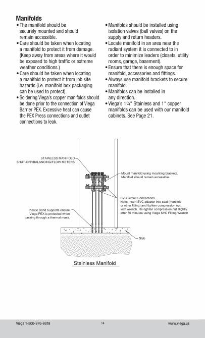
Stainless Manifold
Slab
Mount manifold using mounting brackets.Manifold should remain accessible.
SVC Circuit ConnectionsNote: Insert SVC adapter into seat (manifoldor other fitting) and tighten compression nutwith wrench. Re-tighten compression nut slightlyafter 30 minutes using Viega SVC Fitting Wrench.
STAINLESS MANIFOLDSHUT-OFF/BALANCING/FLOW METERS
Plastic Bend Supports ensure Viega PEX is protected when
passing through a thermal mass.
Manifolds• The manifold should be
securely mounted and should remain accessible.
• Care should be taken when locating a manifold to protect it from damage. (Keep away from areas where it would be exposed to high traffic or extreme weather conditions.)
• Care should be taken when locating a manifold to protect it from job site hazards (i.e. manifold box packaging can be used to protect).
• Soldering Viega’s copper manifolds should be done prior to the connection of Viega Barrier PEX. Excessive heat can cause the PEX Press connections and outlet connections to leak.
• Manifolds should be installed using isolation valves (ball valves) on the supply and return headers.
• Locate manifold in an area near the radiant system it is connected to in order to minimize leaders (closets, utility rooms, garage, basement).
• Ensure that there is enough space for manifold, accessories and fittings.
• Always use manifold brackets to secure manifold.
• Manifolds can be installed in any direction.
• Viega’s 1¼" Stainless and 1" copper manifolds can be used with our manifold cabinets. See Page 21.
Viega 1-800-976-9819 www.viega.us15
Stainless Manifold Considerations• Orientation of the manual air bleeder/
purge valve on the Stainless Manifolds can be flipped.
• Stainless Manifold end caps are 1" NPT and removable for extended and flow- through applications.
• When extending the Stainless Manifold, use thread paste and Teflon tape on the 1" NPT manifold connection.
• Make sure that the rubber inlet gasket is placed in union connection for proper seal.
• Do NOT use thread paste or Teflon tape on the union connection for Stainless Manifolds.
• Use only Viega’s manifold adapters to connect to manifold.
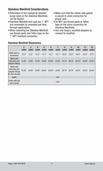
2 outlet
3 outlet
4 outlet
5 outlet
6 outlet
7 outlet
8 outlet
9 outlet
10outlet
11 outlet
12 outlet
Width with no accessories
10.2" 10.2" 12.2" 14.1" 16.1" 18.1" 20.0" 22.0" 24.0" 25.9" 27.9"
Width with ball valve and
adapter fittings 14.95" 14.95" 16.95" 18.85" 20.85" 22.85" 24.75" 26.75" 28.75" 30.65" 32.62"
Width with ball valve and
adapter fittings for flow through
16.95" 16.95" 18.95" 20.85" 22.85" 24.85" 26.75" 28.75" 30.75" 32.62" 34.65"
Depth 3.6"
Depth with ball valve handle
4.26"
Stainless Manifold Dimensions
Viega 1-800-976-9819 www.viega.us16
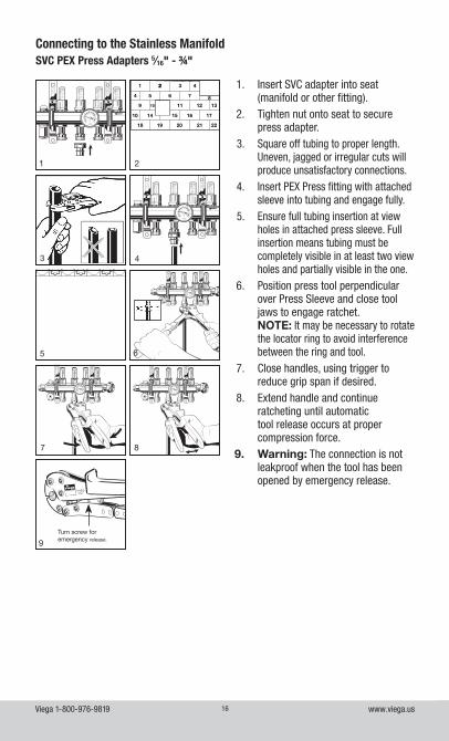
Connecting to the Stainless ManifoldSVC PEX Press Adapters 5⁄16" - ¾"
1
1 22 3 4
4 5 6 7 89 1110 12 13
10 14 15 16 17
18 19 20 21 22
2
1 22 3 4
4 5 6 7 89 1110 12 13
10 14 15 16 17
18 19 20 21 22
3 4
1. Insert SVC adapter into seat (manifold or other fitting).
2. Tighten nut onto seat to secure press adapter.
3. Square off tubing to proper length. Uneven, jagged or irregular cuts will produce unsatisfactory connections.
4. Insert PEX Press fitting with attached sleeve into tubing and engage fully.
5. Ensure full tubing insertion at view holes in attached press sleeve. Full insertion means tubing must be completely visible in at least two view holes and partially visible in the one.
6. Position press tool perpendicular over Press Sleeve and close tool jaws to engage ratchet. NOTE: It may be necessary to rotate the locator ring to avoid interference between the ring and tool.
7. Close handles, using trigger to reduce grip span if desired.
8. Extend handle and continue ratcheting until automatic tool release occurs at proper compression force.
9. Warning: The connection is not leakproof when the tool has been opened by emergency release.
6
PureFlow
1/2”
Turn screw for emergency release.9
7 8
5
Viega 1-800-976-9819 www.viega.us17
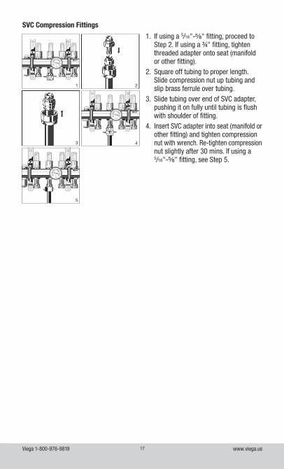
SVC Compression Fittings
2
3
5
4
1
1. If using a 5/16"-⅝" fitting, proceed to Step 2. If using a ¾" fitting, tighten threaded adapter onto seat (manifold or other fitting).
2. Square off tubing to proper length. Slide compression nut up tubing and slip brass ferrule over tubing.
3. Slide tubing over end of SVC adapter, pushing it on fully until tubing is flush with shoulder of fitting.
4. Insert SVC adapter into seat (manifold or other fitting) and tighten compression nut with wrench. Re-tighten compression nut slightly after 30 mins. If using a 5/16"-⅝" fitting, see Step 5.
Viega 1-800-976-9819 www.viega.us18
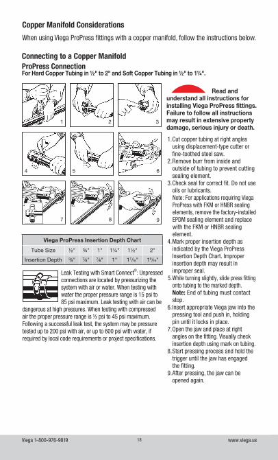
When using Viega ProPress fittings with a copper manifold, follow the instructions below.
Copper Manifold Considerations
Connecting to a Copper ManifoldProPress ConnectionFor Hard Copper Tubing in ½" to 2" and Soft Copper Tubing in ½" to 1¼".
Viega ProPress Insertion Depth Chart
Tube Size ½" ¾" 1" 1¼" 1½" 2"
Insertion Depth ¾" ⅞" ⅞" 1" 17/16" 19/16"
1 2 3
4 5 6
7 8 9
1. Cut copper tubing at right angles using displacement-type cutter or fine-toothed steel saw.
2. Remove burr from inside and outside of tubing to prevent cutting sealing element.
3. Check seal for correct fit. Do not use oils or lubricants. Note: For applications requiring Viega ProPress with FKM or HNBR sealing elements, remove the factory-installed EPDM sealing element and replace with the FKM or HNBR sealing element.
4. Mark proper insertion depth as indicated by the Viega ProPress Insertion Depth Chart. Improper insertion depth may result in improper seal.
5. While turning slightly, slide press fitting onto tubing to the marked depth. Note: End of tubing must contact stop.
6. Insert appropriate Viega jaw into the pressing tool and push in, holding pin until it locks in place.
7. Open the jaw and place at right angles on the fitting. Visually check insertion depth using mark on tubing.
8. Start pressing process and hold the trigger until the jaw has engaged the fitting.
9. After pressing, the jaw can be opened again.
Leak Testing with Smart Connect®: Unpressed connections are located by pressurizing the system with air or water. When testing with water the proper pressure range is 15 psi to 85 psi maximum. Leak testing with air can be
dangerous at high pressures. When testing with compressed air the proper pressure range is ½ psi to 45 psi maximum. Following a successful leak test, the system may be pressure tested up to 200 psi with air, or up to 600 psi with water, if required by local code requirements or project specifications.
!Read and
understand all instructions for installing Viega ProPress fittings. Failure to follow all instructions may result in extensive property damage, serious injury or death.
Viega 1-800-976-9819 www.viega.us19
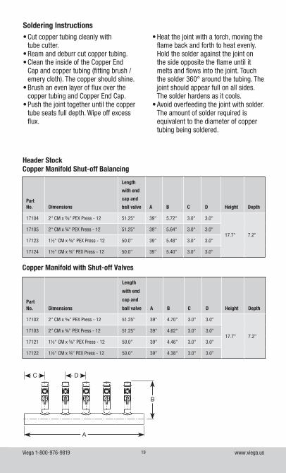
Header Stock
• Cut copper tubing cleanly with tube cutter.
• Ream and deburr cut copper tubing.• Clean the inside of the Copper End
Cap and copper tubing (fitting brush / emery cloth). The copper should shine.
• Brush an even layer of flux over the copper tubing and Copper End Cap.
• Push the joint together until the copper tube seats full depth. Wipe off excess flux.
• Heat the joint with a torch, moving the flame back and forth to heat evenly. Hold the solder against the joint on the side opposite the flame until it melts and flows into the joint. Touch the solder 360° around the tubing. The joint should appear full on all sides. The solder hardens as it cools.
• Avoid overfeeding the joint with solder. The amount of solder required is equivalent to the diameter of copper tubing being soldered.
Soldering Instructions
Part No. Dimensions
Length
with end
cap and
ball valve A B C D Height Depth
17104 2" CM x ⅝" PEX Press - 12 51.25" 39" 5.72" 3.0" 3.0"
17.7" 7.2"17105 2" CM x ¾" PEX Press - 12 51.25" 39" 5.64" 3.0" 3.0"
17123 1½" CM x ⅝" PEX Press - 12 50.0" 39" 5.48" 3.0" 3.0"
17124 1½" CM x ¾" PEX Press - 12 50.0" 39" 5.40" 3.0" 3.0"
Copper Manifold Shut-off Balancing
Part No. Dimensions
Length
with end
cap and
ball valve A B C D Height Depth
17102 2" CM x ⅝" PEX Press - 12 51.25" 39" 4.70" 3.0" 3.0"
17.7" 7.2"17103 2" CM x ¾" PEX Press - 12 51.25" 39" 4.62" 3.0" 3.0"
17121 1½" CM x ⅝" PEX Press - 12 50.0" 39" 4.46" 3.0" 3.0"
17122 1½" CM x ¾" PEX Press - 12 50.0" 39" 4.38" 3.0" 3.0"
Copper Manifold with Shut-off Valves
A
C D
B
Viega 1-800-976-9819 www.viega.us20
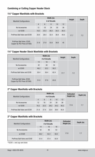
Manifold Configurations
Width (in)Height Depth
# of Circuits
4 6 8 10 12
17.7 7.2
No Accessories 12 18 24 30 36
w/ ECVD 16.2 22.2 28.2 34.2 40.2
ProPress Ball Valve and ECVD 20.4 26.4 32.4 38.4 44.4
ProPress Ball Valve, ECVD,Copper By PEX Press (87580)
21.8 27.8 33.8 39.8 45
1½" Copper Manifolds with Brackets
Manifold Configurations
Width (in)Height Depth
# of Circuits
14 16 18
17.7 7.2
No Accessories 42 48 54
w/ ECVD 46.2 52.2 58.2
ProPress Ball Valve and ECVD 50.4 56.4 62.4
ProPress Ball Valve, ECVD,Copper By PEX Press (87580)
51.8 57.8 63.8
1½" Copper Header Stock Manifolds with Brackets
Combining or Cutting Copper Header Stock
Manifold Configurations
Width (in) Estimated Height (in) Depth (in)
# of Circuits
14 16 18
17.8 7.7
No Accessories 42 48 54
w/ ECVD 46.2 52.2 58.2
ProPress Ball Valve and ECVD 51.4 57.4 63.4
2" Copper Manifolds with Brackets
Manifold Configurations
Width (in) Estimated Height (in) Depth (in)
# of Circuits
4 6 8 10 12
17.8 7.7No Accessories 12 18 24 30 36
w/ ECVD 16.2 22.2 28.2 34.2 40.2
ProPress Ball Valve and ECVD 21.4 27.4 33.4 39.4 45.4
2" Copper Manifolds with Brackets
**ECVD = end cap vent drain
Viega 1-800-976-9819 www.viega.us21
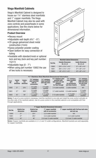
Viega Manifold CabinetsViega's Manifold Cabinet is designed to house our 1¼" stainless steel manifolds and 1" copper manifolds. The Viega Manifold Cabinet may also be used with zone controls and powerheads in some applications. See the charts below for dimensional information. Product Overview• Recess mount• Adjustable wall depth (4½" - 6")• 20-gauge galvanized sheet metal
construction (1mm)• Epoxy polyester powder coating• Open bottom for easy connection of
tubing• Available with standard knob or optional
lock and key (lock and key part number: 15217)
• Adjustable legs (0 - 7")• When using part number 15802 the use
of two locks is necessary
1¼" Stainless Steel Manifold Dimensional Information
Part No.
Interior box
dimension
Exterior box
dimension
1¼" stainless steel manifold
with no accessories
1¼" stainless steel manifold with ball valve
set
1¼" stainless steel manifold with
ball valve set and adapters
for flow through
1¼" stainless steel manifold
with no accessories
and Zone Control
1¼" stainless steel manifold with ball valve set and Zone
Control
15800 21" 22⅝" 2-6 outlet manifold
2-5 outlet manifold 2-4 outlet manifold 2 outlet manifold N/A
15801 27" 28⅜" 2-9 outlet manifold
2-8 outlet manifold 2-7 outlet manifold 2-4 outlet manifold 2-3 outlet
manifold
15802 45" 46" 2-12 outlet manifold
2-12 outlet manifold 2-12 outlet manifold 2-12 outlet
manifold2-12 outlet manifold
Notes: If use of a zone control is necessary, hold the manifold to one side and install the zone control vertically on the other side of the manifold cabinet. Use of a zone control in the manifold cabinet is not compatible with flow through applications.
1" Copper Manifold Dimensional Information
Part No.Interior box dimension
Exterior box dimension
1" copper manifold with no accessories
1" copper manifold with ProPress ball valve and end cap
15800 21" 22⅝" 2,3,4 outlet manifold N/A
15801 27" 28⅜" 2,3,4 outlet manifold 2,3,4 outlet manifold
15802 45" 46" 2,3,4 and 12 outlet manifold 2,3,4 and 12 outlet manifold
Notes: Copper manifolds are available in 2, 3, 4 and 12 outlet configurations. Manifold brackets are sold separately for copper manifolds.
Manifold Cabinet Dimensions
Part No.Outside Dimension
W x H x DInside Dimension
W x H x D
15800 22⅝" x 31¼" x 4½" 21" x 28" x 4½"
15801 28⅝" x 31¼" x 4½" 27" x 28" x 4½"
15802 46" x 31¼" x 4¼" 45" x 28" x 4¼"
Viega 1-800-976-9819 www.viega.us22
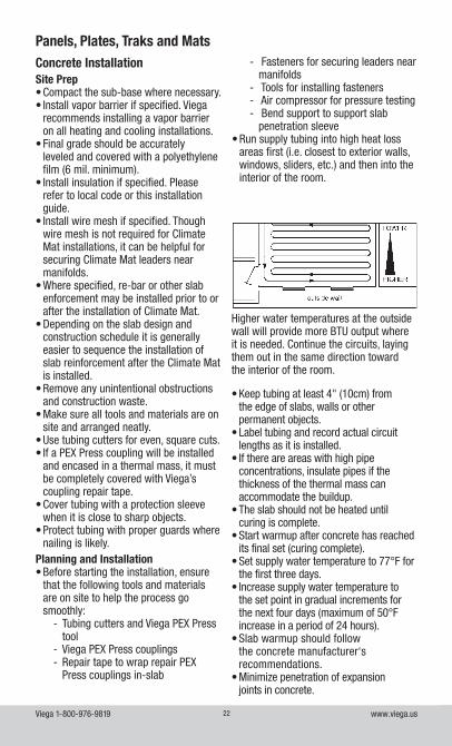
Panels, Plates, Traks and MatsConcrete Installation
Higher water temperatures at the outside wall will provide more BTU output where it is needed. Continue the circuits, laying them out in the same direction toward the interior of the room.
Site Prep• Compact the sub-base where necessary.• Install vapor barrier if specified. Viega
recommends installing a vapor barrier on all heating and cooling installations.
• Final grade should be accurately leveled and covered with a polyethylene film (6 mil. minimum).
• Install insulation if specified. Please refer to local code or this installation guide.
• Install wire mesh if specified. Though wire mesh is not required for Climate Mat installations, it can be helpful for securing Climate Mat leaders near manifolds.
• Where specified, re-bar or other slab enforcement may be installed prior to or after the installation of Climate Mat.
• Depending on the slab design and construction schedule it is generally easier to sequence the installation of slab reinforcement after the Climate Mat is installed.
• Remove any unintentional obstructions and construction waste.
• Make sure all tools and materials are on site and arranged neatly.
• Use tubing cutters for even, square cuts. • If a PEX Press coupling will be installed
and encased in a thermal mass, it must be completely covered with Viega’s coupling repair tape.
• Cover tubing with a protection sleeve when it is close to sharp objects.
• Protect tubing with proper guards where nailing is likely.
Planning and Installation• Before starting the installation, ensure
that the following tools and materials are on site to help the process go smoothly:
- Tubing cutters and Viega PEX Press tool
- Viega PEX Press couplings - Repair tape to wrap repair PEX Press couplings in-slab
- Fasteners for securing leaders near manifolds
- Tools for installing fasteners - Air compressor for pressure testing - Bend support to support slab penetration sleeve
• Run supply tubing into high heat loss areas first (i.e. closest to exterior walls, windows, sliders, etc.) and then into the interior of the room.
• Keep tubing at least 4" (10cm) from the edge of slabs, walls or other permanent objects.
• Label tubing and record actual circuit lengths as it is installed.
• If there are areas with high pipe concentrations, insulate pipes if the thickness of the thermal mass can accommodate the buildup.
• The slab should not be heated until curing is complete.
• Start warmup after concrete has reached its final set (curing complete).
• Set supply water temperature to 77°F for the first three days.
• Increase supply water temperature to the set point in gradual increments for the next four days (maximum of 50°F increase in a period of 24 hours).
• Slab warmup should follow the concrete manufacturer‘s recommendations.
• Minimize penetration of expansion joints in concrete.
Viega 1-800-976-9819 www.viega.us23
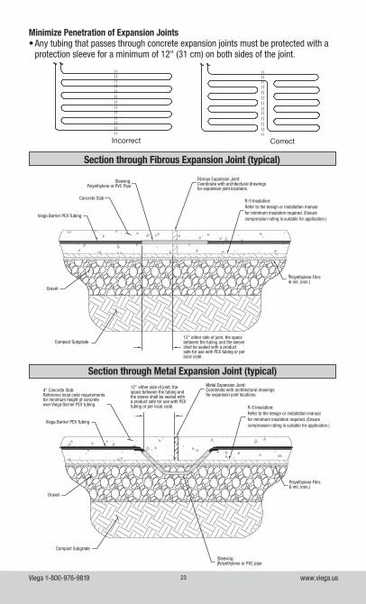
Minimize Penetration of Expansion Joints• Any tubing that passes through concrete expansion joints must be protected with a
protection sleeve for a minimum of 12" (31 cm) on both sides of the joint.
Incorrect Correct
Section through Fibrous Expansion Joint (typical)
Section through Metal Expansion Joint (typical)
Viega Barrier PEX Tubing
Gravel
Compact Subgrade
R-5 Insulation:Refer to the design or installation manual for minimum insulation required. (Ensure compression rating is suitable for application.)
Concrete Slab
Fibrous Expansion Joint:Coordinate with architectural drawings for expansion joint locations.
Polyethylene Film:6 mil. (min.)
Sleeving:Polyethylene or PVC Pipe
12" either side of joint, the space between the tubing and the sleeve shall be sealed with a product safe for use with PEX tubing or per local code.
Viega Barrier PEX Tubing
R-5 Insulation:Refer to the design or installation manual for minimum insulation required. (Ensure compression rating is suitable for application.)
4" Concrete Slab:Reference local code requirements for minimum height of concrete over Viega Barrier PEX tubing.
12" either side of joint, the space between the tubing and the sleeve shall be sealed with a product safe for use with PEX tubing or per local code.
Metal Expansion Joint:Coordinate with architectural drawings for expansion joint locations.
Gravel
Polyethylene Film:6 mil. (min.)
Compact Subgrade
Sleeving:Polyethylene or PVC pipe
Viega 1-800-976-9819 www.viega.us24
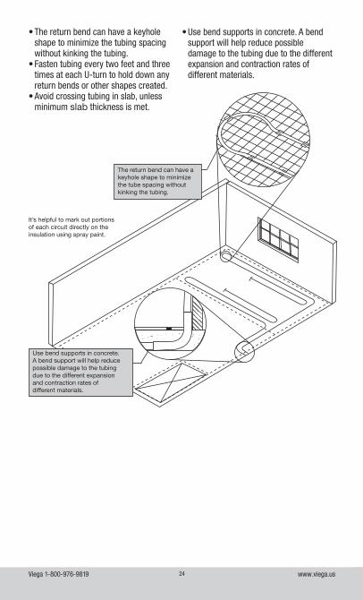
• Use bend supports in concrete. A bend support will help reduce possible damage to the tubing due to the different expansion and contraction rates of different materials.
The return bend can have a keyhole shape to minimize the tube spacing without kinking the tubing.
Use bend supports in concrete.A bend support will help reduce possible damage to the tubing due to the different expansion and contraction rates of different materials.
It’s helpful to mark out portions of each circuit directly on the insulation using spray paint.
• The return bend can have a keyhole shape to minimize the tubing spacing without kinking the tubing.
• Fasten tubing every two feet and three times at each U-turn to hold down any return bends or other shapes created.
• Avoid crossing tubing in slab, unless minimum slab thickness is met.
Viega 1-800-976-9819 www.viega.us25
Installing the Tubing in the PanelReview your radiant design to find the proper spacing for the tubing. To ensure that the runs are properly spaced, simply count the number of knobs and flats in between the tubing and multiply by 3.• Place the tubing between the knobs.• Using your hand or foot, push the tubing
in between knobs.• Make sure the tubing is fully inserted
in the panel as you make a corner. TIP: When you make a turn, ensure the PEX is fully seated in the outside radius against the knobs before beginning or continuing a run.
• Continue installing the tubing until the entire area has been completed.
• The tubing should start and end at the manifold location.
• Before starting the installation, ensure that the following tools and materials are on site to help the process go smoothly:
- Tubing cutters and Viega PEX Press Tool - Viega PEX Press Couplings - Repair tape to wrap repair PEX Press couplings in-slab
- Air compressor for pressure testing - Bend supports for slab penetrations sleeve
- The use of foam staples is not required for the installation of tubing in this product. However, you may find them useful in preventing the tubing from lifting at offsets or return bends.
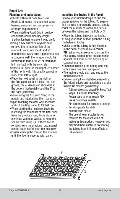
Planning and Installation• Check with local code to ensure
Rapid Grid meets the specified vapor barrier, insulation and compressive strength requirements.
• When installing Rapid Grid in outdoor conditions, add temporary weight (re-bar, lumber) to prevent wind uplift.
• Using a box cutter or keyhole saw, remove the tongue portion of the interlock from both the 4' and 2' dimensions; every time a panel touches a concrete wall, the tongue should be removed so that a full 2" of insulation is in contact with the concrete.
• Place a full panel in the upper left corner of the north wall; it is usually easiest to work from left to right.
• Place the next panel to the right of the first panel so that it locks into the groove; the 4' dimension should be at the bottom (horizontally) and the 2' to the right (vertically).
• Move along the first row, filling in the panels and interlocking them together.
• Upon reaching the east wall, measure and cut the final panel to fill that row.
• When starting the next row, begin by installing the remnants of the final panel from the previous row; this is done to eliminate waste as well as to keep the seams from lining up. If there are no remains from the previous row, a panel can be cut in half to start the next row.
• Continue filling the rows in this manner until the floor is covered with panel.
Rapid Grid
2'
4'
Viega 1-800-976-9819 www.viega.us26
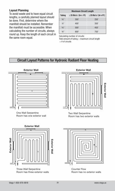
Layout PlanningTo avoid waste and to have equal circuit lengths, a carefully planned layout should be done. First, determine where the manifold should be installed. Remember the manifold must be accessible. When calculating the number of circuits, always round up. Keep the length of each circuit in the same room equal.
Calculating number of circuits:Total amount of tubing ÷ maximum circuit length = # of circuits
Maximum Circuit Length
Tubing ≤ 25 Btu’s / (hr x ft2) ≥ 25 Btu’s / (hr x ft2 )
⅜" 300' 250'
½" 400' 350'
⅝" 500' 450'
¾" 800' 750'
Circuit Layout Patterns for Hydronic Radiant Floor Heating
Exterior Wall Exterior Wall
Exterio
r Wall
Exterior Wall
Exterio
r WallE
xter
ior
Wal
l
One Wall SerpentineRoom has one exterior wall
Two Wall SerpentineRoom has two exterior walls
Three Wall SerpentineRoom has three exterior walls
Counter FlowRoom has no exterior walls
Viega 1-800-976-9819 www.viega.us27
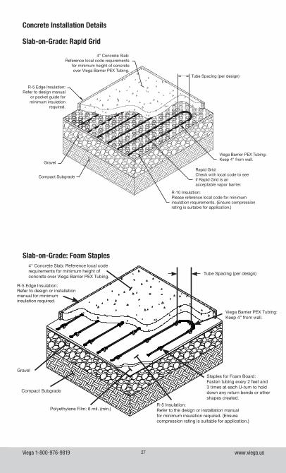
Concrete Installation Details
Slab-on-Grade: Rapid Grid
Slab-on-Grade: Foam Staples
Staples for Foam Board:Fasten tubing every 2 feet and 3 times at each U-turn to hold down any return bends or other shapes created.
Tube Spacing (per design)
R-5 Edge Insulation:Refer to design or installation manual for minimum insulation required.
Compact Subgrade
Gravel
Viega Barrier PEX Tubing: Keep 4" from wall.
4" Concrete Slab: Reference local code requirements for minimum height of concrete over Viega Barrier PEX Tubing.
Polyethylene Film: 6 mil. (min.)R-5 Insulation:Refer to the design or installation manual for minimum insulation required. (Ensure compression rating is suitable for application.)
R-5 Edge Insulation:Refer to design manual
or pocket guide for minimum insulation
required.
4" Concrete Slab:Reference local code requirements
for minimum height of concrete over Viega Barrier PEX Tubing.
Tube Spacing (per design)
Viega Barrier PEX Tubing:Keep 4" from wall.
Rapid Grid:Check with local code to see if Rapid Grid is an acceptable vapor barrier.
R-10 Insulation:Please reference local code for minimum insulation requirements. (Ensure compression rating is suitable for application.)
Gravel
Compact Subgrade
Viega 1-800-976-9819 www.viega.us28
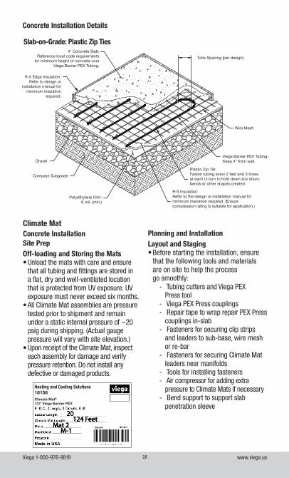
Concrete Installation Details
Slab-on-Grade: Plastic Zip Ties4" Concrete Slab:
Reference local code requirements for minimum height of concrete over
Viega Barrier PEX Tubing.
R-5 Edge Insulation:Refer to design or
installation manual for minimum insulation
required.
Tube Spacing (per design)
Viega Barrier PEX Tubing:Keep 4" from wall.
Wire Mesh
Plastic Zip Tie:Fasten tubing every 2 feet and 3 times at each U-turn to hold down any return bends or other shapes created.
R-5 Insulation:Refer to the design or installation manual for minimum insulation required. (Ensure compression rating is suitable for application.)
Gravel
Compact Subgrade
Polyethylene Film:6 mil. (min.)
Climate MatConcrete InstallationSite PrepOff-loading and Storing the Mats• Unload the mats with care and ensure
that all tubing and fittings are stored in a flat, dry and well-ventilated location that is protected from UV exposure. UV exposure must never exceed six months.
• All Climate Mat assemblies are pressure tested prior to shipment and remain under a static internal pressure of ~20 psig during shipping. (Actual gauge pressure will vary with site elevation.)
• Upon receipt of the Climate Mat, inspect each assembly for damage and verify pressure retention. Do not install any defective or damaged products.
20124 Feet
Mat 2M-1
Heating and Cooling Solutions18158Climate Mat®
1/2" Viega Barrier PEX
Planning and InstallationLayout and Staging• Before starting the installation, ensure
that the following tools and materials are on site to help the process go smoothly:
- Tubing cutters and Viega PEX Press tool
- Viega PEX Press couplings - Repair tape to wrap repair PEX Press couplings in-slab
- Fasteners for securing clip strips and leaders to sub-base, wire mesh or re-bar
- Fasteners for securing Climate Mat leaders near manifolds
- Tools for installing fasteners - Air compressor for adding extra pressure to Climate Mats if necessary
- Bend support to support slab penetration sleeve
Viega 1-800-976-9819 www.viega.us29
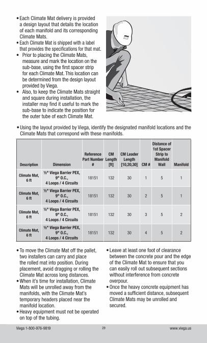
• Each Climate Mat delivery is provided a design layout that details the location of each manifold and its corresponding Climate Mats.
• Each Climate Mat is shipped with a label that provides the specifications for that mat.
• Prior to placing the Climate Mats, measure and mark the location on the sub-base, using the first spacer strip for each Climate Mat. This location can be determined from the design layout provided by Viega.
• Also, to keep the Climate Mats straight and square during installation, the installer may find it useful to mark the sub-base to indicate the position for the outer tube of each Climate Mat.
Description Dimension
Reference Part Number
#
CM Length
[ft]
CM Leader Length
[10,20,30] CM #
Distance of 1st Spacer
Strip to Manifold
Wall Manifold
Climate Mat, 6 ft
½" Viega Barrier PEX, 9" O.C.,
4 Loops / 4 Circuits18151 132 30 1 5 1
Climate Mat, 6 ft
½" Viega Barrier PEX, 9" O.C.,
4 Loops / 4 Circuits18151 132 30 2 5 1
Climate Mat, 6 ft
½" Viega Barrier PEX, 9" O.C.,
4 Loops / 4 Circuits18151 132 30 3 5 2
Climate Mat, 6 ft
½" Viega Barrier PEX, 9" O.C.,
4 Loops / 4 Circuits18151 132 30 4 5 2
• Using the layout provided by Viega, identify the designated manifold locations and the Climate Mats that correspond with these manifolds.
• To move the Climate Mat off the pallet, two installers can carry and place the rolled mat into position. During placement, avoid dragging or rolling the Climate Mat across long distances.
• When it’s time for installation, Climate Mats will be unrolled away from the manifolds, with the Climate Mat’s temporary headers placed near the manifold location.
• Heavy equipment must not be operated on top of the tubing.
• Leave at least one foot of clearance between the concrete pour and the edge of the Climate Mat to ensure that you can easily roll out subsequent sections without interference from concrete overpour.
• Once the heavy concrete equipment has moved a sufficient distance, subsequent Climate Mats may be unrolled and secured.
Viega 1-800-976-9819 www.viega.us30
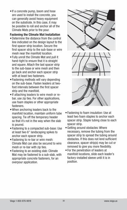
• Fastening to foam insulation: Use at least two foam staples to anchor each spacer strip. Staple tubing close to each spacer strip.
• Getting around obstacles: Where necessary, remove the tubing from the spacer strip to spread the tubing around obstacles. If this does not lend sufficient clearance, spacer strip(s) may be cut or removed to give you more flexibility.
• For the penetration of leaders at manifold locations, slide each leader’s factory-installed sleeve until it is in position.
• If a concrete pump, boom and hose are used to install the concrete, you can generally avoid heavy equipment on the substrate. In this case, it may be possible to roll and anchor all of the Climate Mats prior to the pour.
Fastening the Climate Mat Installation• Determine the distance from the control
line indicated on the design layout to the first spacer strip location. Secure the first spacer strip to the sub-base or wire mesh near the manifold location.
• Fully unroll the Climate Mat and pull it hand-tight to ensure that it is straight and square. Attach the last spacer strip to the sub-base or wire mesh and then go back and anchor each spacer strip with at least two fasteners.
• Fastening methods will vary depending on the sub-base. Fasten leaders at two-foot intervals between the first spacer strip and the manifold.
• If attaching leaders to wire mesh or re-bar, use zip ties. For other applications, use foam staples or other appropriate fasteners.
• When anchoring leaders back to the manifold location, maintain uniform tube spacing. Tie off the temporary header so that it’s not in the way when the slab is poured.
• Fastening to a compacted sub-base: Use at least two 6" landscaping spikes to anchor each spacer strip.
• Fastening to re-bar or wire mesh: Climate Mat can also be secured to wire mesh or re-bar with zip ties.
• Fastening to an existing slab: Climate Mat may be fastened to a sub-slab, with appropriate concrete fasteners, for an overpour application.
Viega 1-800-976-9819 www.viega.us31
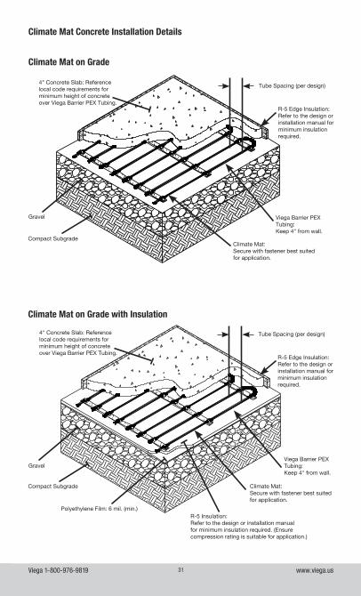
Climate Mat Concrete Installation Details
Climate Mat on Grade
Climate Mat:Secure with fastener best suited for application.
Tube Spacing (per design)
Compact Subgrade
Gravel Viega Barrier PEX Tubing: Keep 4" from wall.
R-5 Edge Insulation:Refer to the design or installation manual for minimum insulation required.
Climate Mat on Grade with Insulation
Climate Mat:Secure with fastener best suited for application.
Tube Spacing (per design)
Compact Subgrade
GravelViega Barrier PEX Tubing: Keep 4" from wall.
R-5 Edge Insulation:Refer to the design or installation manual for minimum insulation required.
Polyethylene Film: 6 mil. (min.)R-5 Insulation:Refer to the design or installation manual for minimum insulation required. (Ensure compression rating is suitable for application.)
4" Concrete Slab: Reference local code requirements for minimum height of concrete over Viega Barrier PEX Tubing.
4" Concrete Slab: Reference local code requirements for minimum height of concrete over Viega Barrier PEX Tubing.
Viega 1-800-976-9819 www.viega.us32
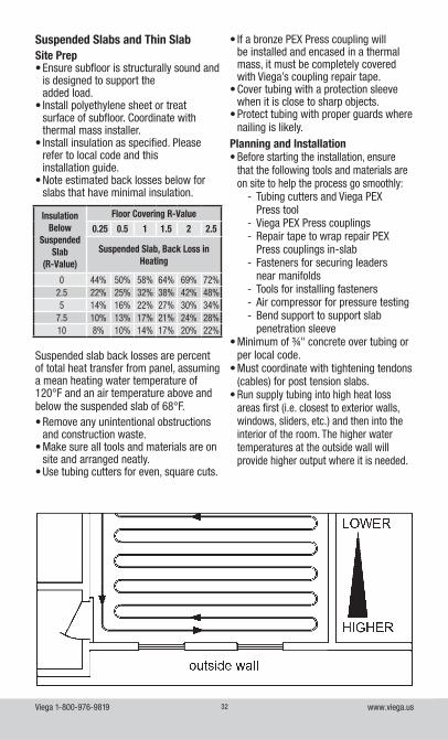
Suspended slab back losses are percent of total heat transfer from panel, assuming a mean heating water temperature of 120°F and an air temperature above and below the suspended slab of 68°F.• Remove any unintentional obstructions
and construction waste.• Make sure all tools and materials are on
site and arranged neatly.• Use tubing cutters for even, square cuts.
Suspended Slabs and Thin SlabSite Prep• Ensure subfloor is structurally sound and
is designed to support the added load.
• Install polyethylene sheet or treat surface of subfloor. Coordinate with thermal mass installer.
• Install insulation as specified. Please refer to local code and this installation guide.
• Note estimated back losses below for slabs that have minimal insulation.
Insulation Below
Suspended Slab
(R-Value)
Floor Covering R-Value
0.25 0.5 1 1.5 2 2.5
Suspended Slab, Back Loss in Heating
0 44% 50% 58% 64% 69% 72%2.5 22% 25% 32% 38% 42% 48%5 14% 16% 22% 27% 30% 34%
7.5 10% 13% 17% 21% 24% 28%10 8% 10% 14% 17% 20% 22%
• If a bronze PEX Press coupling will be installed and encased in a thermal mass, it must be completely covered with Viega’s coupling repair tape.
• Cover tubing with a protection sleeve when it is close to sharp objects.
• Protect tubing with proper guards where nailing is likely.
Planning and Installation• Before starting the installation, ensure
that the following tools and materials are on site to help the process go smoothly:
- Tubing cutters and Viega PEX Press tool
- Viega PEX Press couplings - Repair tape to wrap repair PEX Press couplings in-slab
- Fasteners for securing leaders near manifolds
- Tools for installing fasteners - Air compressor for pressure testing - Bend support to support slab penetration sleeve
• Minimum of ¾" concrete over tubing or per local code.
• Must coordinate with tightening tendons (cables) for post tension slabs.
• Run supply tubing into high heat loss areas first (i.e. closest to exterior walls, windows, sliders, etc.) and then into the interior of the room. The higher water temperatures at the outside wall will provide higher output where it is needed.

Viega 1-800-976-9819 www.viega.us33
• Keep tubing at least 4" (10cm) from the edge of slabs, walls or other permanent objects.
• Label tubing and record actual circuit lengths as it is installed.
• If there are areas with high pipe concentrations, insulate pipes if the thickness of the thermal mass can accommodate the buildup.
• Minimize penetration of expansion joints in concrete applications.
Incorrect Correct
• Any tubing that passes through concrete expansion joints must be protected with a protection sleeve for a minimum of 12" (31cm) on both sides of the joint. Cross-sections of sleeving at expansion joints are provided in the illustrations below.
• It is not necessary to sleeve tubing as it passes through control joints in radiant applications.
Section through Fibrous Expansion Joint (typical)
• The return bend can have a keyhole shape to minimize the tubing spacing without kinking the tubing.
• Fasten tubing every two feet and three times at each U-turn to hold down any return bends or other shapes created.
Minimize Penetration of Joints
• Do not cross tubing in a slab unless minimum slab thickness is met.
• Use bend supports in concrete. A bend support will help reduce possible damage to the tubing due to the different expansion and contraction rates of different materials.
Viega Barrier PEX Tubing
R-5 Insulation:Refer to the design or installation manual for minimum insulation required. (Ensure compression rating is suitable for application.)
12" either side of joint, the space between the tubing and the sleeve shall be sealed with a product safe for use with PEX tubing or per local code.
Gravel
Compact Subgrade
Concrete Slab
Fibrous Expansion Joint:Coordinate with architectural drawings for expansion joint locations.
Polyethylene Film:6 mil. (min.)
Sleeving:Polyethylene or PVC Pipe
Viega 1-800-976-9819 www.viega.us34
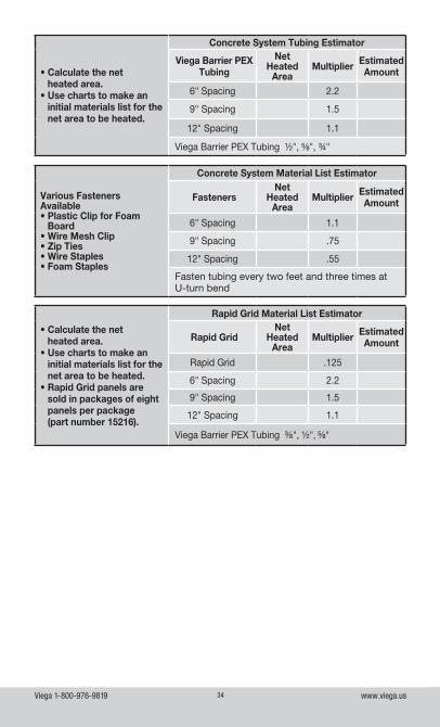
• Calculate the net heated area.
• Use charts to make an initial materials list for the net area to be heated.
Concrete System Tubing Estimator
Viega Barrier PEX Tubing
Net Heated
AreaMultiplier Estimated
Amount
6" Spacing 2.2
9" Spacing 1.5
12" Spacing 1.1
Viega Barrier PEX Tubing ½", ⅝", ¾"
Various FastenersAvailable• Plastic Clip for Foam
Board• Wire Mesh Clip• Zip Ties• Wire Staples• Foam Staples
Concrete System Material List Estimator
FastenersNet
HeatedArea
Multiplier EstimatedAmount
6" Spacing 1.1
9" Spacing .75
12" Spacing .55
Fasten tubing every two feet and three times at U-turn bend
• Calculate the net heated area.
• Use charts to make an initial materials list for the net area to be heated.
• Rapid Grid panels are sold in packages of eight panels per package (part number 15216).
Rapid Grid Material List Estimator
Rapid GridNet
HeatedArea
Multiplier EstimatedAmount
Rapid Grid .125
6" Spacing 2.2
9" Spacing 1.5
12" Spacing 1.1
Viega Barrier PEX Tubing ⅜", ½", ⅝"
Viega 1-800-976-9819 www.viega.us35
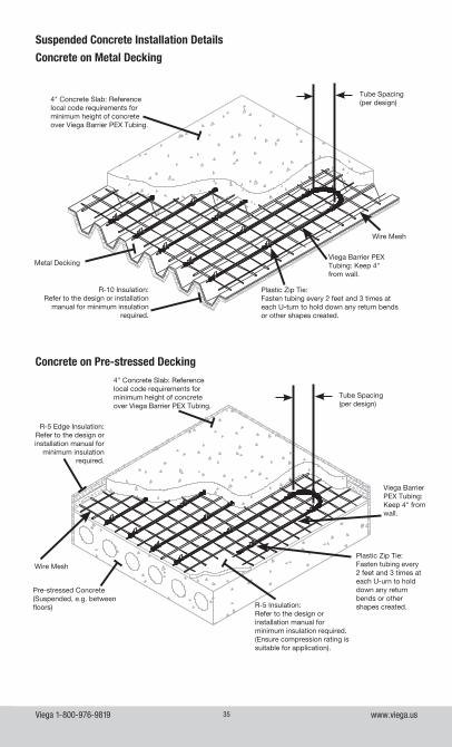
Suspended Concrete Installation Details
Concrete on Metal Decking
Concrete on Pre-stressed Decking
Wire Mesh
Viega Barrier PEX Tubing: Keep 4" from wall.
Viega Barrier PEX Tubing: Keep 4" from wall.
Wire Mesh
Plastic Zip Tie:Fasten tubing every 2 feet and 3 times at each U-turn to hold down any return bends or other shapes created.
Tube Spacing(per design)
R-10 Insulation:Refer to the design or installation
manual for minimum insulation required.
Metal Decking
Pre-stressed Concrete(Suspended, e.g. between floors)
R-5 Edge Insulation:Refer to the design or installation manual for
minimum insulation required.
Tube Spacing(per design)
Plastic Zip Tie:Fasten tubing every 2 feet and 3 times at each U-urn to hold down any return bends or other shapes created.R-5 Insulation:
Refer to the design or installation manual for minimum insulation required. (Ensure compression rating is suitable for application).
4" Concrete Slab: Reference local code requirements for minimum height of concrete over Viega Barrier PEX Tubing.
4" Concrete Slab: Reference local code requirements for minimum height of concrete over Viega Barrier PEX Tubing.
Viega 1-800-976-9819 www.viega.us36
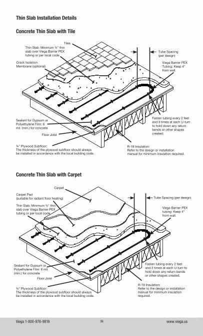
Concrete Thin Slab with Tile
R-19 Insulation:Refer to the design or installation manual for minimum insulation required.
Thin Slab: Minimum ¾" thin slab over Viega Barrier PEX tubing or per local code
Tube Spacing (per design)
Tiles
Viega Barrier PEX Tubing: Keep 4" from wall.
Fasten tubing every 2 feet and 3 times at each U-turn to hold down any return bends or other shapes created.
Crack Isolation Membrane (optional)
Floor Joist
¾" Plywood Subfloor:The thickness of the plywood subfloor should always be installed in accordance with the local building code.
Sealant for Gypsum or Polyethylene Film: 6 mil. (min.) for concrete
Concrete Thin Slab with Carpet
R-19 Insulation:Refer to the design or installation manual for minimum insulation required.
Tube Spacing (per design)
Carpet
Viega Barrier PEX tubing: Keep 4" from wall.
Fasten tubing every 2 feet and 3 times at each U-turn to hold down any return bends or other shapes created.
Carpet Pad (suitable for radiant floor heating)
Floor Joist
¾" Plywood Subfloor:The thickness of the plywood subfloor should always be installed in accordance with the local building code.
Sealant for Gypsum or Polyethylene Film: 6 mil. (min.) for concrete
Thin Slab Installation Details
Thin Slab: Minimum ¾" thin slab over Viega Barrier PEX tubing or per local code
Viega 1-800-976-9819 www.viega.us37
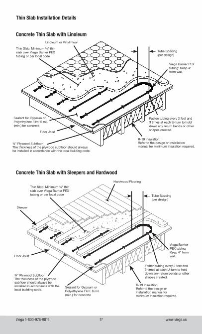
Thin Slab Installation Details
Concrete Thin Slab with Linoleum
R-19 Insulation:Refer to the design or installation manual for minimum insulation required.
Tube Spacing(per design)
¾" Plywood Subfloor:The thickness of the plywood subfloor should always be installed in accordance with the local building code.
Viega Barrier PEX tubing: Keep 4" from wall.
Fasten tubing every 2 feet and 3 times at each U-turn to hold down any return bends or other shapes created.
Linoleum or Vinyl Floor
Floor Joist
Sealant for Gypsum or Polyethylene Film: 6 mil. (min.) for concrete
Concrete Thin Slab with Sleepers and Hardwood
R-19 Insulation:Refer to the design or installation manual for minimum insulation required.
Tube Spacing(per design)
¾" Plywood Subfloor:The thickness of the plywood subfloor should always be installed in accordance with the local building code.
Sleeper
Viega Barrier PEX tubing: Keep 4" from wall.
Fasten tubing every 2 feet and 3 times at each U-turn to hold down any return bends or other shapes created.
Hardwood Flooring
Floor Joist
Sealant for Gypsum or Polyethylene Film: 6 mil. (min.) for concrete
Thin Slab: Minimum ¾" thin slab over Viega Barrier PEX tubing or per local code
Thin Slab: Minimum ¾" thin slab over Viega Barrier PEX tubing or per local code
Viega 1-800-976-9819 www.viega.us38
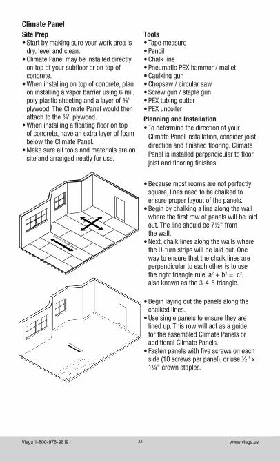
Climate Panel
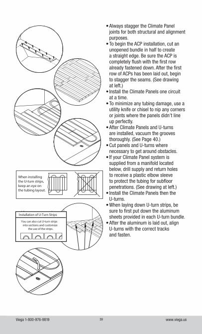
Direction of climate panels
• Because most rooms are not perfectly square, lines need to be chalked to ensure proper layout of the panels.
• Begin by chalking a line along the wall where the first row of panels will be laid out. The line should be 7½" from the wall.
• Next, chalk lines along the walls where the U-turn strips will be laid out. One way to ensure that the chalk lines are perpendicular to each other is to use the right triangle rule, a2 + b2 = c2, also known as the 3-4-5 triangle.
• Begin laying out the panels along the chalked lines.
• Use single panels to ensure they are lined up. This row will act as a guide for the assembled Climate Panels or additional Climate Panels.
• Fasten panels with five screws on each side (10 screws per panel), or use ½" x 1¼" crown staples.
Site Prep• Start by making sure your work area is
dry, level and clean.• Climate Panel may be installed directly
on top of your subfloor or on top of concrete.
• When installing on top of concrete, plan on installing a vapor barrier using 6 mil. poly plastic sheeting and a layer of ¾" plywood. The Climate Panel would then attach to the ¾" plywood.
• When installing a floating floor on top of concrete, have an extra layer of foam below the Climate Panel.
• Make sure all tools and materials are on site and arranged neatly for use.
Tools• Tape measure• Pencil• Chalk line• Pneumatic PEX hammer / mallet• Caulking gun• Chopsaw / circular saw• Screw gun / staple gun• PEX tubing cutter• PEX uncoilerPlanning and Installation• To determine the direction of your
Climate Panel installation, consider joist direction and finished flooring. Climate Panel is installed perpendicular to floor joist and flooring finishes.
Viega 1-800-976-9819 www.viega.us39
• Always stagger the Climate Panel joints for both structural and alignment purposes.
• To begin the ACP installation, cut an unopened bundle in half to create a straight edge. Be sure the ACP is completely flush with the first row already fastened down. After the first row of ACPs has been laid out, begin to stagger the seams. (See drawing at left.)
• Install the Climate Panels one circuit at a time.
• To minimize any tubing damage, use a utility knife or chisel to nip any corners or joints where the panels didn’t line up perfectly.
• After Climate Panels and U-turns are installed, vacuum the grooves thoroughly. (See Page 40.)
• Cut panels and U-turns where necessary to get around obstacles.
• If your Climate Panel system is supplied from a manifold located below, drill supply and return holes to receive a plastic elbow sleeve to protect the tubing for subfloor penetrations. (See drawing at left.)
• Install the Climate Panels then the U-turns.
• When laying down U-turn strips, be sure to first put down the aluminum sheets provided in each U-turn bundle.
• After the aluminum is laid out, align U-turns with the correct tracks and fasten.
When installing the U-turn strips, keep an eye on the tubing layout.
When installing the U-turn strips, keep an eye on the tubing layout.
When installing the U-turn strips, keep an eye on the tubing layout.
Installation of U-Turn Strips
You can also cut U-turn stripsinto sections and customize
the use of the strips.
Installation of U-Turn Strips
You can also cut U-turn stripsinto sections and customize
the use of the strips.
Installation of U-Turn Strips
You can also cut U-turn stripsinto sections and customize
the use of the strips.
Viega 1-800-976-9819 www.viega.us40
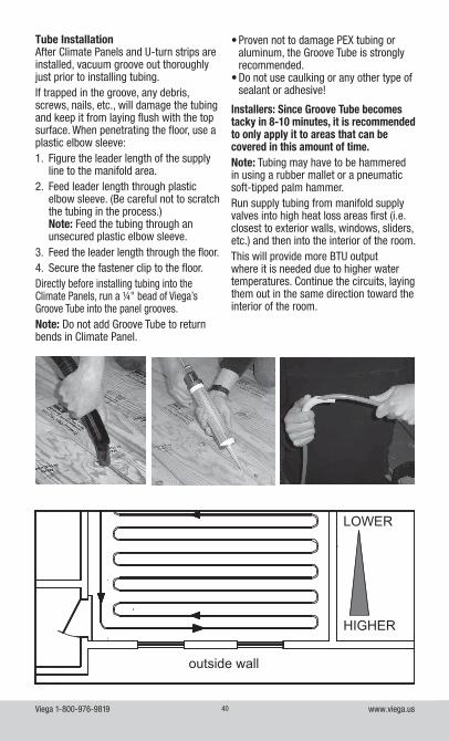
Tube InstallationAfter Climate Panels and U-turn strips are installed, vacuum groove out thoroughly just prior to installing tubing.If trapped in the groove, any debris, screws, nails, etc., will damage the tubing and keep it from laying flush with the top surface. When penetrating the floor, use a plastic elbow sleeve:1. Figure the leader length of the supply
line to the manifold area.2. Feed leader length through plastic
elbow sleeve. (Be careful not to scratch the tubing in the process.) Note: Feed the tubing through an unsecured plastic elbow sleeve.
3. Feed the leader length through the floor.4. Secure the fastener clip to the floor.Directly before installing tubing into the Climate Panels, run a ¼" bead of Viega’s Groove Tube into the panel grooves.Note: Do not add Groove Tube to return bends in Climate Panel.
outside wall
HIGHER
LOWER
• Proven not to damage PEX tubing or aluminum, the Groove Tube is strongly recommended.
• Do not use caulking or any other type of sealant or adhesive!
Installers: Since Groove Tube becomes tacky in 8-10 minutes, it is recommended to only apply it to areas that can be covered in this amount of time.Note: Tubing may have to be hammered in using a rubber mallet or a pneumatic soft-tipped palm hammer.Run supply tubing from manifold supply valves into high heat loss areas first (i.e. closest to exterior walls, windows, sliders, etc.) and then into the interior of the room.This will provide more BTU output where it is needed due to higher water temperatures. Continue the circuits, laying them out in the same direction toward the interior of the room.
Viega 1-800-976-9819 www.viega.us41
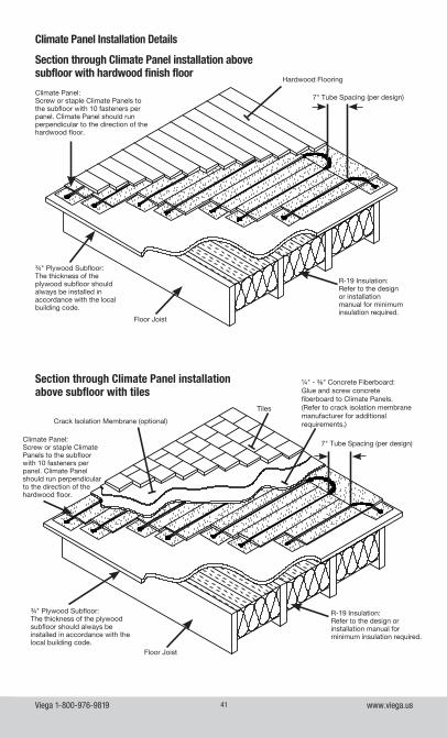
Climate Panel Installation Details
Hardwood Flooring
7" Tube Spacing (per design)Climate Panel:Screw or staple Climate Panels to the subfloor with 10 fasteners per panel. Climate Panel should run perpendicular to the direction of the hardwood floor.
¾" Plywood Subfloor:The thickness of the plywood subfloor should always be installed in accordance with the local building code.
Floor Joist
R-19 Insulation:Refer to the design or installation manual for minimum insulation required.
¼" - ⅜" Concrete Fiberboard:Glue and screw concrete fiberboard to Climate Panels. (Refer to crack isolation membrane manufacturer for additional requirements.)
Climate Panel:Screw or staple Climate Panels to the subfloor with 10 fasteners per panel. Climate Panel should run perpendicular to the direction of the hardwood floor.
¾" Plywood Subfloor:The thickness of the plywood subfloor should always be installed in accordance with the local building code.
Floor Joist
R-19 Insulation:Refer to the design or installation manual for minimum insulation required.
Tiles
Crack Isolation Membrane (optional)
Section through Climate Panel installation above subfloor with hardwood finish floor
Section through Climate Panel installation above subfloor with tiles
7" Tube Spacing (per design)
Viega 1-800-976-9819 www.viega.us42
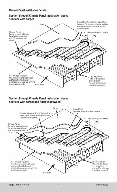
Climate Panel Installation Details
Section through Climate Panel installation above subfloor with carpet
Section through Climate Panel installation above subfloor with carpet and finished plywood
Carpet Pad (suitable for radiant floor heating): For minimum height buildup, install carpet and pad directly over Climate Panels.
Climate Panel:Screw or staple Climate Panels to the subfloor with 10 fasteners per panel.
¾" Plywood Subfloor:The thickness of the plywood subfloor should always be installed in accordance with the local building code. Floor Joist
R-19 Insulation:Refer to the design or installation manual for minimum insulation required.
Carpet
7" Tube Spacing (per design)
Floor Joist
Carpet Carpet Pad(suitable for radiant floor heating)
Climate Panel:Screw or staple Climate Panels to the subfloor with 10 fasteners per panel.
¾" Plywood Subfloor:The thickness of the plywood subfloor should always be installed in accordance with the local building code.
R-19 Insulation:Refer to the design or installation manual for minimum insulation required.
If height allows, a ¼" - ⅜" finish plywood cover sheet can be installed over the Climate Panel system. 7" Tube Spacing (per design)
Viega 1-800-976-9819 www.viega.us43
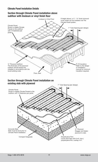
Climate Panel Installation Details
Section through Climate Panel installation on existing slab with plywood
¾" Plywood:Stagger and fasten plywood to slab.
Climate Panel:Screw or staple Climate Panels to the subfloor with 10 fasteners per panel.
Polyethylene Film:Cover level slab with 6 mil. (min.) polyethylene film, overlap 4-6".
Compact Subgrade
Concrete Slab:Slab must be level prior to Climate Panel installation.
Section through Climate Panel installation above subfloor with linoleum or vinyl finish floor
Floor Joist
Linoleum or Vinyl Floor
Climate Panel:Screw or staple Climate Panels to the subfloor with 10 fasteners per panel.
¾" Plywood Subfloor:The thickness of the plywood subfloor should always be installed in accordance with the local building code.
R-19 Insulation:Refer to the design or installation manual for minimum insulation required.
If height allows, a ¼" - ⅜" finish plywood cover sheet can be installed over the Climate Panel system.
7" Tube Spacing (per design)
7" Tube Spacing (per design)
Viega 1-800-976-9819 www.viega.us44
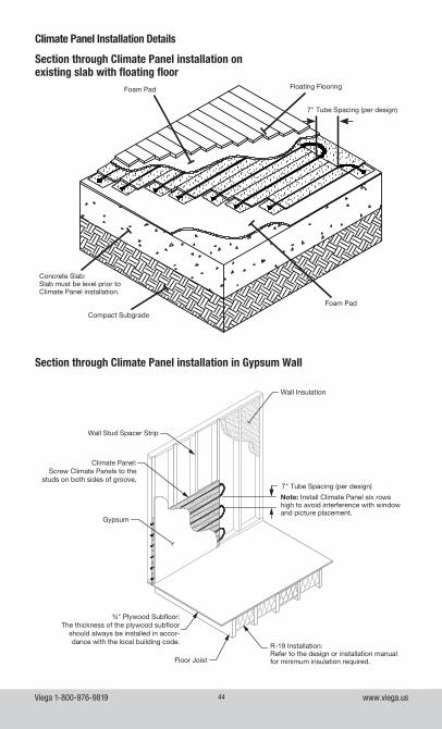
Climate Panel Installation Details
Section through Climate Panel installation on existing slab with floating floor
Section through Climate Panel installation in Gypsum Wall
Foam Pad
Compact Subgrade
Concrete Slab:Slab must be level prior to Climate Panel installation.
Floating FlooringFoam Pad
7" Tube Spacing (per design)
Note: Install Climate Panel six rows high to avoid interference with window and picture placement.
7" Tube Spacing (per design)
Wall Insulation
Wall Stud Spacer Strip
Gypsum
Floor Joist
Climate Panel:Screw Climate Panels to the
studs on both sides of groove.
¾" Plywood Subfloor:The thickness of the plywood subfloor
should always be installed in accor-dance with the local building code.
R-19 Installation:Refer to the design or installation manual for minimum insulation required.
Viega 1-800-976-9819 www.viega.us45
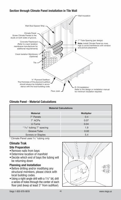
Climate TrakSite Preparation• Remove nails from bays• Determine location of manifold• Decide which end of bays the tubing will
be returning downPlanning and Installation• Before drilling and/or modifying any
structural members, please check with local building codes.
• Using a right-angle drill with a 1¼" bit, drill a series of holes through the center of each floor joist (keep at least 3" from subfloor).
Climate Panel - Material Calculations
Material Calculations
Material Multiplier
7" Panels 0.47" ACPs 0.07U-Turns 0.04
* 5⁄16" tubing 7" spacing 1.9Groove Tube 0.02
Screws or Staples 5.4* Climate Panel uses 5⁄16" tubing only
Section through Climate Panel installation in Tile Wall
Note: Install Climate Panel six rows high to avoid interference with window and picture placement.
7" Tube Spacing (per design)
Wall Insulation
Wall Stud Spacer Strip
Tile
Crack Isolation Membrane (Optional)
Floor Joist
Climate Panel:Screw Climate Panels to the
studs on both sides of groove.
Concrete Fiberboard (Refer to crack Isolation
membrane manufacturer for additional requirements)
¾" Plywood Subfloor:The thickness of the plywood subfloor
should always be installed in accor-dance with the local building code. R-19 Installation:
Refer to the design or installation manual for minimum insulation required.
Viega 1-800-976-9819 www.viega.us46
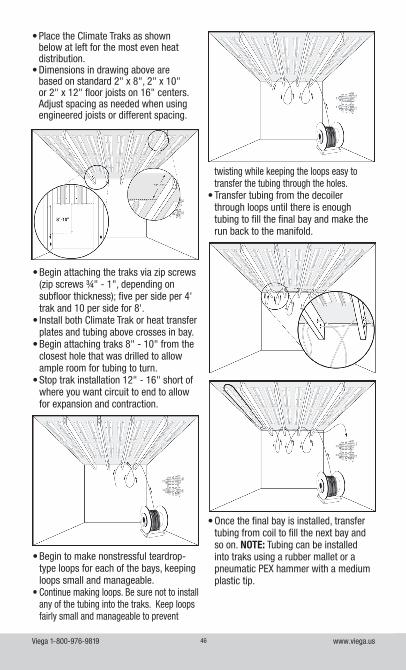
• Begin attaching the traks via zip screws (zip screws ¾" - 1", depending on subfloor thickness); five per side per 4' trak and 10 per side for 8'.
• Install both Climate Trak or heat transfer plates and tubing above crosses in bay.
• Begin attaching traks 8" - 10" from the closest hole that was drilled to allow ample room for tubing to turn.
• Stop trak installation 12" - 16" short of where you want circuit to end to allow for expansion and contraction.
• Begin to make nonstressful teardrop-type loops for each of the bays, keeping loops small and manageable.
• Continue making loops. Be sure not to install any of the tubing into the traks. Keep loops fairly small and manageable to prevent
• Place the Climate Traks as shown below at left for the most even heat distribution.
• Dimensions in drawing above are based on standard 2" x 8", 2" x 10" or 2" x 12" floor joists on 16" centers. Adjust spacing as needed when using engineered joists or different spacing.
twisting while keeping the loops easy to transfer the tubing through the holes.
• Transfer tubing from the decoiler through loops until there is enough tubing to fill the final bay and make the run back to the manifold.
• Once the final bay is installed, transfer tubing from coil to fill the next bay and so on. NOTE: Tubing can be installed into traks using a rubber mallet or a pneumatic PEX hammer with a medium plastic tip.
Viega 1-800-976-9819 www.viega.us47
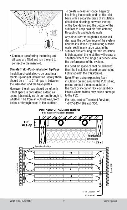
Climate Trak - Post-Installation Tip Page
Fr om Decoiler
To Manifold
Insi
de W
all
Out
side
Wal
l
Insulation Blocking
Insulation should always be used in a staple-up radiant installation. Ideally there should be a 1" to 2" air gap in between the insulation and the traks/plates.However, the air gap should be left only if that space is considered a dead air space (absolutely no air current through it, whether it be from an outside wall, from below or through holes in the subfloor).
BFoil Face or Radiant Barrier
R-19 Insulation (per design)
To create a dead air space, begin by insulating the outside ends of the joist bays with a separate piece of insulation (insulation blocking) between the top of the foundation and the bottom of the subfloor to keep cold air from entering through sills and outside walls.Any air current through this space will decrease the performance of the system and the insulation. By insulating outside walls, sealing any large gaps in the subfloor and ensuring that the insulation is tight against the joist, this will create a situation where the air gap is beneficial to the performance of the system.If a dead air space cannot be achieved, then the insulation should be pushed up lightly against the traks/plates.Note: When using expanding foam insulation on and around the PEX tubing, please contact the manufacturer of the foam or Viega for PEX compatibility issues. Some foams may cause damage to the PEX.For help, contact Technical Services, 1-877-843-4262 ext. 350.
• Continue transferring the tubing until all bays are filled and run the end to connect to the manifold.
Viega 1-800-976-9819 www.viega.us48
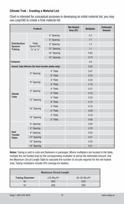
Climate Trak - Creating a Material List
Chart is intended for conceptual purposes in developing an initial material list; you may use LoopCAD to create a final material list.
Notes: Tubing is sold in coils and fasteners in packages. Where multipliers are located in the table, multiply the net heated area by the corresponding multiplier to derive the estimated amount. Use the Maximum Circuit Length Table to calculate the number of circuits required for the net heated area. Tubing multipliers include 10% overage for leaders.
Maximum Circuit Length
Tubing Diameter ≤25 Btu/ft2 26-35 Btu/ft2
⅜" 300 250
½" 400 350
ProductsNet HeatedArea (ft2)
MultiplierEstimated Amount
Distribution System Tubing
ViegaBarrier PEX,⅜" or ½"
6" Spacing 2.2
8" Spacing 1.7
9" Spacing 1.5
12" Spacing 1.1
16" Spacing 0.85
18" Spacing 0.75
Fasteners 4.6
Groove Tube Silicone (for heat transfer plates only) 0.02
Climate Traks
6" Spacing4" Plate 0.47
8" Plate 0.23
8" Spacing4" Plate 0.35
8" Plate 0.18
9" Spacing4" Plate 0.31
8" Plate 0.16
12" Spacing4" Plate 0.23
8" Plate 0.12
16" Spacing4" Plate 0.18
8" Plate 0.09
18" Spacing4" Plate 0.16
8" Plate 0.08
Heat Transfer Plates
6" Spacing 0.93
8" Spacing 0.70
9" Spacing 0.62
12" Spacing 0.47
16" Spacing 0.35
18" Spacing 0.31
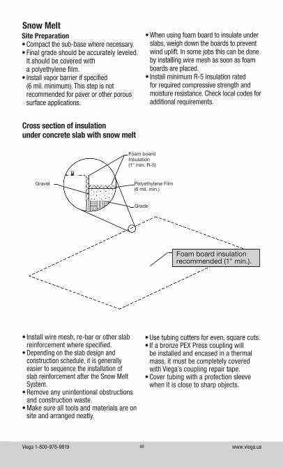
Viega 1-800-976-9819 www.viega.us49
Snow Melt
Foam board Insulation(1" min. R-5)
Polyethylene Film(6 mil. min.)
Gravel
Grade
Foam board insulation recommended (1" min.).
Cross section of insulationunder concrete slab with snow melt
Site Preparation• Compact the sub-base where necessary.• Final grade should be accurately leveled.
It should be covered with a polyethylene film.
• Install vapor barrier if specified (6 mil. minimum). This step is not recommended for paver or other porous surface applications.
• When using foam board to insulate under slabs, weigh down the boards to prevent wind uplift. In some jobs this can be done by installing wire mesh as soon as foam boards are placed.
• Install minimum R-5 insulation rated for required compressive strength and moisture resistance. Check local codes for additional requirements.
• Install wire mesh, re-bar or other slab reinforcement where specified.
• Depending on the slab design and construction schedule, it is generally easier to sequence the installation of slab reinforcement after the Snow Melt System.
• Remove any unintentional obstructions and construction waste.
• Make sure all tools and materials are on site and arranged neatly.
• Use tubing cutters for even, square cuts. • If a bronze PEX Press coupling will
be installed and encased in a thermal mass, it must be completely covered with Viega’s coupling repair tape.
• Cover tubing with a protection sleeve when it is close to sharp objects.
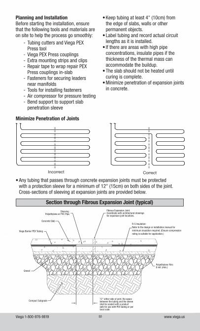
Viega 1-800-976-9819 www.viega.us50
• Keep tubing at least 4" (10cm) from the edge of slabs, walls or other permanent objects.
• Label tubing and record actual circuit lengths as it is installed.
• If there are areas with high pipe concentrations, insulate pipes if the thickness of the thermal mass can accommodate the buildup.
• The slab should not be heated until curing is complete.
• Minimize penetration of expansion joints in concrete.
Minimize Penetration of Joints
Incorrect Correct
• Any tubing that passes through concrete expansion joints must be protected with a protection sleeve for a minimum of 12" (15cm) on both sides of the joint. Cross-sections of sleeving at expansion joints are provided below.
Section through Fibrous Expansion Joint (typical)
Planning and InstallationBefore starting the installation, ensure that the following tools and materials are on site to help the process go smoothly:
- Tubing cutters and Viega PEX Press tool
- Viega PEX Press couplings - Extra mounting strips and clips - Repair tape to wrap repair PEX Press couplings in-slab
- Fasteners for securing leaders near manifolds
- Tools for installing fasteners - Air compressor for pressure testing - Bend support to support slab penetration sleeve
Viega Barrier PEX Tubing
R-5 Insulation:Refer to the design or installation manual for minimum insulation required. (Ensure compression rating is suitable for application.)
12" either side of joint, the space between the tubing and the sleeve shall be sealed with a product safe for use with PEX tubing or per local code.
Gravel
Compact Subgrade
Concrete Slab
Fibrous Expansion Joint:Coordinate with architectural drawings for expansion joint locations.
Polyethylene Film:6 mil. (min.)
Sleeving:Polyethylene or PVC Pipe
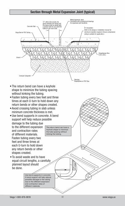
Viega 1-800-976-9819 www.viega.us51
Section through Metal Expansion Joint (typical)
The return bend can have a keyhole shape to minimize the tube spacing without kinking the tubing.
Use bend supports in concrete.A bend support will help reduce possible damage to the tubing due to the different expansion and contraction rates of different materials.
• The return bend can have a keyhole shape to minimize the tubing spacing without kinking the tubing.
• Fasten tubing every two feet and three times at each U-turn to hold down any return bends or other shapes created.
• Avoid crossing tubing in slab unless minimum concrete thickness is met.
• Use bend supports in concrete. A bend support will help reduce possible damage to the tubing due to the different expansion and contraction rates of different materials. Fasten tubing every two feet and three times at each U-turn to hold down any return bends or other shapes created.
• To avoid waste and to have equal circuit lengths, a carefully planned layout should be done.
Viega Barrier PEX Tubing
R-5 Insulation:Refer to the design or installation manual for minimum insulation required. (Ensure compression rating is suitable for application.)
12" either side of joint, the space between the tubing and the sleeve shall be sealed with a product safe for use with PEX tubing or per local code.
Gravel
Compact Subgrade
Concrete Slab
Metal Expansion Joint:Coordinate with architectural drawings for expansion joint locations.
Polyethylene Film:6 mil. (min.)
Sleeving:Polyethylene or PVC Pipe
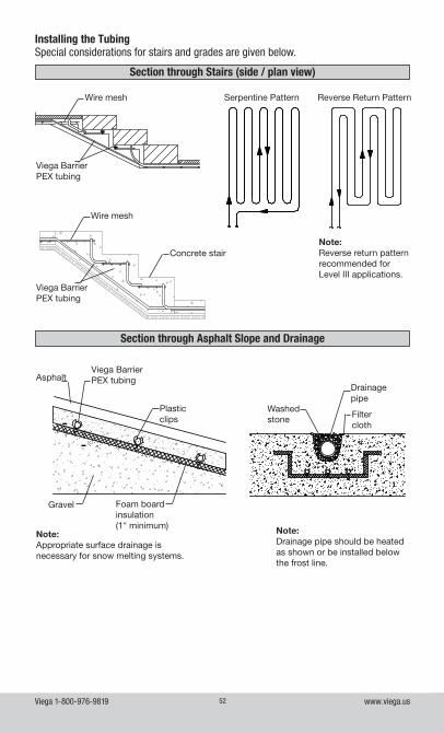
Viega 1-800-976-9819 www.viega.us52
Installing the TubingSpecial considerations for stairs and grades are given below.
Section through Asphalt Slope and Drainage
Note:Appropriate surface drainage is necessary for snow melting systems.
Note:Drainage pipe should be heated as shown or be installed below the frost line.
Viega Barrier PEX tubingAsphalt
Plasticclips
Foam board insulation(1" minimum)
Gravel
Drainagepipe
Washedstone Filter
cloth
Section through Stairs (side / plan view)
Wire mesh
Wire mesh
Concrete stair
Viega Barrier PEX tubing
Viega Barrier PEX tubing
Note:Reverse return pattern recommended for Level III applications.
Serpentine Pattern Reverse Return Pattern
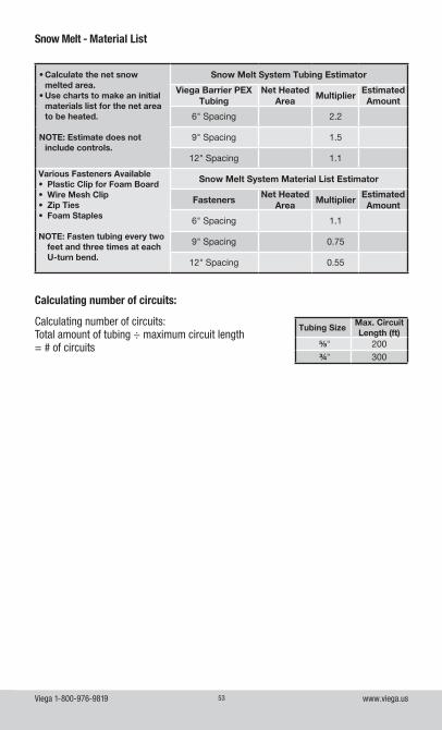
Viega 1-800-976-9819 www.viega.us53
Snow Melt - Material List
Calculating number of circuits:
• Calculate the net snow melted area.
• Use charts to make an initial materials list for the net area to be heated.
NOTE: Estimate does not include controls.
Snow Melt System Tubing Estimator
Viega Barrier PEX Tubing
Net HeatedArea
MultiplierEstimated Amount
6" Spacing 2.2
9" Spacing 1.5
12" Spacing 1.1
Various Fasteners Available• Plastic Clip for Foam Board• Wire Mesh Clip• Zip Ties• Foam Staples
NOTE: Fasten tubing every two feet and three times at each U-turn bend.
Snow Melt System Material List Estimator
FastenersNet Heated
AreaMultiplier
Estimated Amount
6" Spacing 1.1
9" Spacing 0.75
12" Spacing 0.55
Tubing SizeMax. Circuit Length (ft)
⅝" 200¾" 300
Calculating number of circuits: Total amount of tubing ÷ maximum circuit length = # of circuits
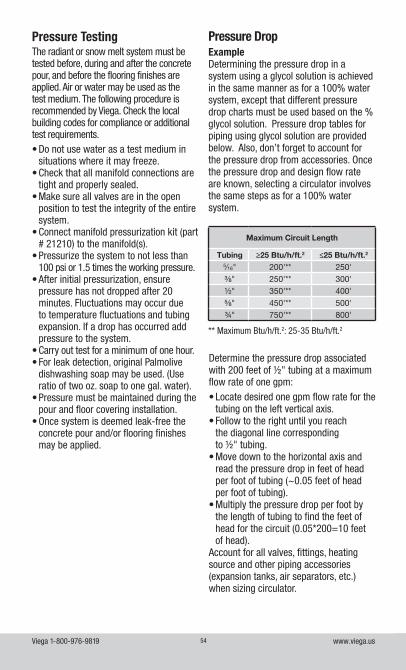
Viega 1-800-976-9819 www.viega.us54
Maximum Circuit Length
Tubing ≥25 Btu/h/ft.2 ≤25 Btu/h/ft.2
5⁄16" 200'** 250'⅜" 250'** 300'½" 350'** 400'⅝" 450'** 500'¾" 750'** 800'
** Maximum Btu/h/ft.2: 25-35 Btu/h/ft.2
Pressure Testing The radiant or snow melt system must be tested before, during and after the concrete pour, and before the flooring finishes are applied. Air or water may be used as the test medium. The following procedure is recommended by Viega. Check the local building codes for compliance or additional test requirements. • Do not use water as a test medium in
situations where it may freeze. • Check that all manifold connections are
tight and properly sealed. • Make sure all valves are in the open
position to test the integrity of the entire system.
• Connect manifold pressurization kit (part # 21210) to the manifold(s).
• Pressurize the system to not less than 100 psi or 1.5 times the working pressure.
• After initial pressurization, ensure pressure has not dropped after 20 minutes. Fluctuations may occur due to temperature fluctuations and tubing expansion. If a drop has occurred add pressure to the system.
• Carry out test for a minimum of one hour. • For leak detection, original Palmolive
dishwashing soap may be used. (Use ratio of two oz. soap to one gal. water).
• Pressure must be maintained during the pour and floor covering installation.
• Once system is deemed leak-free the concrete pour and/or flooring finishes may be applied.
Pressure DropExampleDetermining the pressure drop in a system using a glycol solution is achieved in the same manner as for a 100% water system, except that different pressure drop charts must be used based on the % glycol solution. Pressure drop tables for piping using glycol solution are provided below. Also, don’t forget to account for the pressure drop from accessories. Once the pressure drop and design flow rate are known, selecting a circulator involves the same steps as for a 100% water system.
Determine the pressure drop associated with 200 feet of ½" tubing at a maximum flow rate of one gpm:• Locate desired one gpm flow rate for the
tubing on the left vertical axis.• Follow to the right until you reach
the diagonal line corresponding to ½" tubing.
• Move down to the horizontal axis and read the pressure drop in feet of head per foot of tubing (~0.05 feet of head per foot of tubing).
• Multiply the pressure drop per foot by the length of tubing to find the feet of head for the circuit (0.05*200=10 feet of head).
Account for all valves, fittings, heating source and other piping accessories (expansion tanks, air separators, etc.) when sizing circulator.
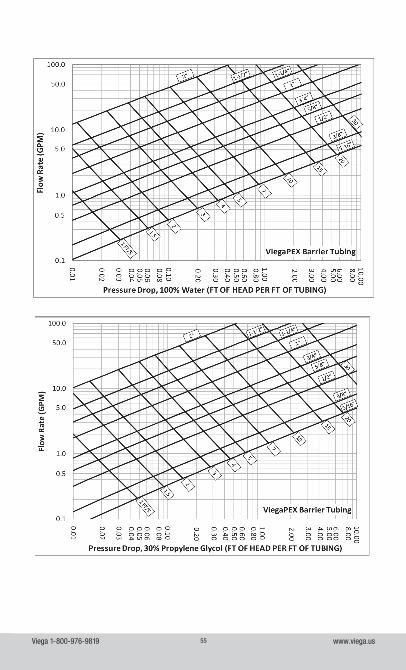
Viega 1-800-976-9819 www.viega.us55
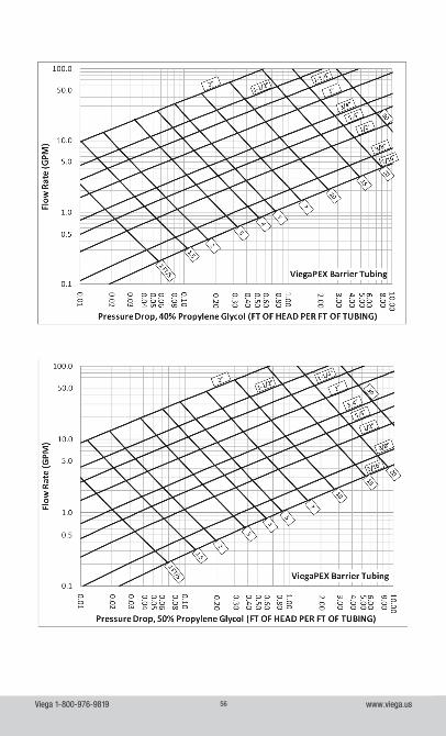
Viega 1-800-976-9819 www.viega.us56
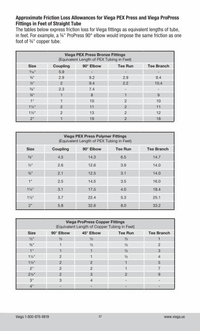
Viega 1-800-976-9819 www.viega.us57
Viega ProPress Copper Fittings(Equivalent Length of Copper Tubing in Feet)
Size 90° Elbow 45° Elbow Tee Run Tee Branch
½" ½ ½ ½ 1
¾" 1 ½ ½ 2
1" 1 1 ½ 3
1¼" 2 1 ½ 4
1½" 2 2 1 5
2" 2 2 1 7
2½" 2 3 2 9
3" 3 4 - -
4" - - - -
Approximate Friction Loss Allowances for Viega PEX Press and Viega ProPress Fittings in Feet of Straight TubeThe tables below express friction loss for Viega fittings as equivalent lengths of tube, in feet. For example, a ¾" ProPress 90° elbow would impose the same friction as one foot of ¾" copper tube.
Viega PEX Press Bronze Fittings(Equivalent Length of PEX Tubing in Feet)
Size Coupling 90° Elbow Tee Run Tee Branch 5/16" 5.9 - - -⅜" 2.9 9.2 2.9 9.4½" 2 9.4 2.2 10.4
⅝" 2.3 7.4 - -
¾" 1 8 1 9
1" 1 10 2 10
1¼" 2 11 2 11
1½" 2 13 2 12
2" 1 19 2 18
Viega PEX Press Polymer Fittings (Equivalent Length of PEX Tubing in Feet)
Size Coupling 90° Elbow Tee Run Tee Branch
⅜" 4.5 14.3 6.5 14.7
½" 2.6 12.6 3.9 14.0
¾" 2.1 12.5 3.1 14.0
1" 2.5 14.5 3.5 16.0
1¼" 3.1 17.5 4.0 18.4
1½" 3.7 22.4 5.3 25.1
2" 5.8 32.6 8.0 33.2
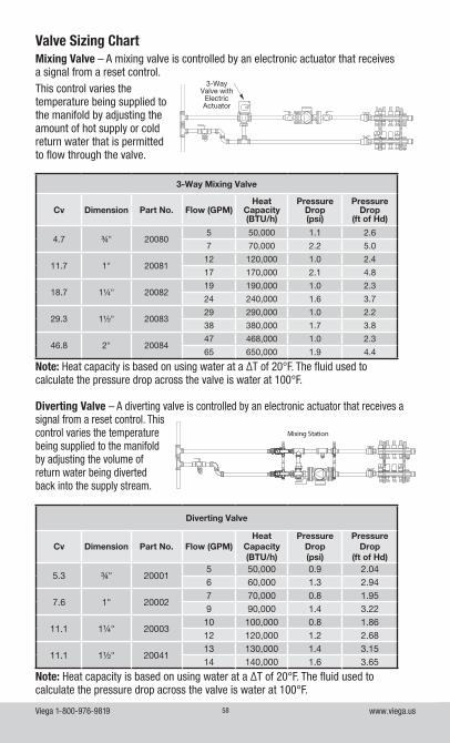
Viega 1-800-976-9819 www.viega.us58
Mixing Valve – A mixing valve is controlled by an electronic actuator that receives a signal from a reset control. This control varies the temperature being supplied to the manifold by adjusting the amount of hot supply or cold return water that is permitted to flow through the valve.
3-Way Mixing Valve
Cv Dimension Part No. Flow (GPM)Heat
Capacity (BTU/h)
Pressure Drop (psi)
Pressure Drop
(ft of Hd)
4.7 ¾" 200805 50,000 1.1 2.6
7 70,000 2.2 5.0
11.7 1" 2008112 120,000 1.0 2.4
17 170,000 2.1 4.8
18.7 1¼" 2008219 190,000 1.0 2.3
24 240,000 1.6 3.7
29.3 1½" 2008329 290,000 1.0 2.2
38 380,000 1.7 3.8
46.8 2" 2008447 468,000 1.0 2.3
65 650,000 1.9 4.4
Note: Heat capacity is based on using water at a ∆T of 20°F. The fluid used to calculate the pressure drop across the valve is water at 100°F.
Valve Sizing Chart
3 Way Valve with Electric Actuator
3-Way Valve with
Electric Actuator
Diverting Valve – A diverting valve is controlled by an electronic actuator that receives a signal from a reset control. This control varies the temperature being supplied to the manifold by adjusting the volume of return water being diverted back into the supply stream.
Mixing Station
Diverting Valve
Cv Dimension Part No. Flow (GPM)Heat
Capacity (BTU/h)
Pressure Drop (psi)
Pressure Drop
(ft of Hd)
5.3 ¾" 200015 50,000 0.9 2.046 60,000 1.3 2.94
7.6 1" 200027 70,000 0.8 1.959 90,000 1.4 3.22
11.1 1¼" 2000310 100,000 0.8 1.8612 120,000 1.2 2.68
11.1 1½" 2004113 130,000 1.4 3.1514 140,000 1.6 3.65
Note: Heat capacity is based on using water at a ∆T of 20°F. The fluid used to calculate the pressure drop across the valve is water at 100°F.
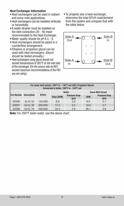
Viega 1-800-976-9819 www.viega.us59
Note: For 200°F boiler water, use the above chart.
For snow melt system, 100°F in - 130°F out (40% Propylene Glycol) Connected to boiler, 180°F in - 150°F out
Part Number Description BTU/hBoiler Snow Melt Circuit
Flow (GPM)Pressure Drop
(psi)GPM
Pressure Drop (psi)
22006 5x12,16 125,000 8.6 2.9 9.0 3.122007 5x12, 36 250,000 17.2 2.2 18.0 2.722008 5x12, 70 500,000 34.4 2.8 36.1 3.6
Heat Exchanger Information• Heat exchangers can be used in radiant
and snow melt applications.• Heat exchangers can be installed vertically
or horizontally.• A water strainer must be installed on
the inlet connection (20 - 40 mesh recommended) to the Heat Exchanger.
• Water quality should be pH 6.5 - 8.• Heat exchangers should be piped in a
counterflow arrangement.• Ethylene or propylene glycol can be
used with heat exchangers. (Glycol should be tested annually.)
• Heat exchangers using glycol should not exceed temperatures of 285°F on the inlet side of the exchanger. (On the source side do NOT exceed maximum recommendations of the PEX you are using.)
• To properly size a heat exchanger, determine the total BTU/h load/demand from the system and compare that with the table below.
Side AOut
Side BOut
Side BIn
Side AIn
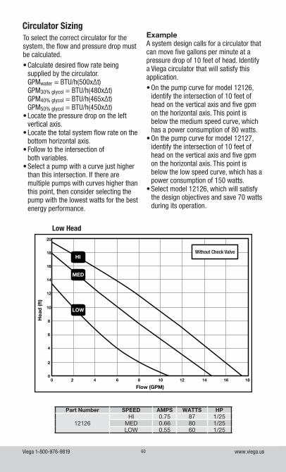
Viega 1-800-976-9819 www.viega.us60
Circulator Sizing
Part Number SPEED AMPS WATTS HP
12126HI 0.75 87 1/25
MED 0.66 80 1/25LOW 0.55 60 1/25
Low Head
To select the correct circulator for the system, the flow and pressure drop must be calculated.• Calculate desired flow rate being
supplied by the circulator. GPMwater = BTU/h(500x∆t) GPM30% glycol = BTU/h(480x∆t) GPM40% glycol = BTU/h(465x∆t) GPM50% glycol = BTU/h(450x∆t)
• Locate the pressure drop on the left vertical axis.
• Locate the total system flow rate on the bottom horizontal axis.
• Follow to the intersection of both variables.
• Select a pump with a curve just higher than this intersection. If there are multiple pumps with curves higher than this point, then consider selecting the pump with the lowest watts for the best energy performance.
ExampleA system design calls for a circulator that can move five gallons per minute at a pressure drop of 10 feet of head. Identify a Viega circulator that will satisfy this application.• On the pump curve for model 12126,
identify the intersection of 10 feet of head on the vertical axis and five gpm on the horizontal axis. This point is below the medium speed curve, which has a power consumption of 80 watts.
• On the pump curve for model 12127, identify the intersection of 10 feet of head on the vertical axis and five gpm on the horizontal axis. This point is below the low speed curve, which has a power consumption of 150 watts.
• Select model 12126, which will satisfy the design objectives and save 70 watts during its operation.
Without Check ValveHI
MED
LOW
20
18
16
14
12
10
8
6
4
2
00 2 4 6 8 10 12 14 16 18
Hea
d (f
t)
Flow (GPM)
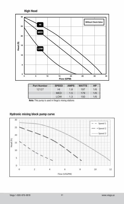
Viega 1-800-976-9819 www.viega.us61
Part Number SPEED AMPS WATTS HP
12127 HI 1.8 197 1/6MED 1.5 179 1/6LOW 1.3 150 1/6
High Head
Without Check ValveHI
MED
LOWHea
d (f
t)
Flow (GPM)
30
25
20
15
10
5
00 5 10 15 20 25 30 35
0
5
10
15
20
25
30
0 2 4 6 8 10 12
Hea
d (F
t)
Flow (USGPM)
Speed 1
Speed 2
Speed 3
Hydronic mixing block pump curve
Note: This pump is used in Viega’s mixing stations
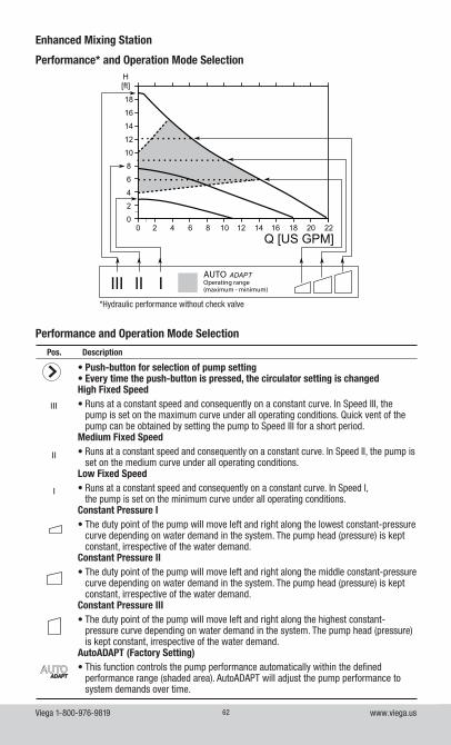
Viega 1-800-976-9819 www.viega.us62
AUTO ADAPTOperating range(maximum - minimum)
*Hydraulic performance without check valve
Performance* and Operation Mode Selection
Enhanced Mixing Station
Performance and Operation Mode Selection
Pos. Description
• Push-button for selection of pump setting• Every time the push-button is pressed, the circulator setting is changedHigh Fixed Speed• Runs at a constant speed and consequently on a constant curve. In Speed III, the
pump is set on the maximum curve under all operating conditions. Quick vent of the pump can be obtained by setting the pump to Speed III for a short period.
Medium Fixed Speed• Runs at a constant speed and consequently on a constant curve. In Speed II, the pump is
set on the medium curve under all operating conditions.Low Fixed Speed• Runs at a constant speed and consequently on a constant curve. In Speed I,
the pump is set on the minimum curve under all operating conditions.Constant Pressure I• The duty point of the pump will move left and right along the lowest constant-pressure
curve depending on water demand in the system. The pump head (pressure) is kept constant, irrespective of the water demand.
Constant Pressure II• The duty point of the pump will move left and right along the middle constant-pressure
curve depending on water demand in the system. The pump head (pressure) is kept constant, irrespective of the water demand.
Constant Pressure III• The duty point of the pump will move left and right along the highest constant-
pressure curve depending on water demand in the system. The pump head (pressure) is kept constant, irrespective of the water demand.
AutoADAPT (Factory Setting)• This function controls the pump performance automatically within the defined
performance range (shaded area). AutoADAPT will adjust the pump performance to system demands over time.
III
II
I
ADAPTADAPT
III
II
I
ADAPTADAPT
III
II
I
ADAPTADAPT
III
II
I
ADAPTADAPT
III
II
I
ADAPTADAPT
III
II
I
ADAPTADAPT
III
II
I
ADAPTADAPT
III
II
I
ADAPTADAPT
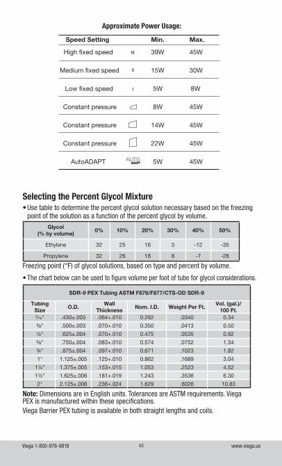
Viega 1-800-976-9819 www.viega.us63
Approximate Power Usage:
High fixed speed 39W 45W
Medium fixed speed 15W 30W
Low fixed speed 5W 8W
Constant pressure 8W 45W
Constant pressure 14W 45W
Constant pressure 22W 45W
AutoADAPT 5W 45W
Speed Setting Min. Max.
III
II
I
ADAPTADAPT
III
II
I
ADAPTADAPT
III
II
I
ADAPTADAPT
III
II
I
ADAPTADAPT
III
II
I
ADAPTADAPT
III
II
I
ADAPTADAPT
III
II
I
ADAPTADAPT
• Use table to determine the percent glycol solution necessary based on the freezing point of the solution as a function of the percent glycol by volume.
Glycol (% by volume)
0% 10% 20% 30% 40% 50%
Ethylene 32 25 16 3 -12 -35
Propylene 32 26 18 8 -7 -28
Freezing point (°F) of glycol solutions, based on type and percent by volume.
• The chart below can be used to figure volume per foot of tube for glycol considerations.
Note: Dimensions are in English units. Tolerances are ASTM requirements. Viega PEX is manufactured within these specifications.Viega Barrier PEX tubing is available in both straight lengths and coils.
SDR-9 PEX Tubing ASTM F876/F877/CTS-OD SDR-9
Tubing Size
O.D.Wall
ThicknessNom. I.D. Weight Per Ft.
Vol. (gal.)/ 100 Ft.
5⁄16" .430±.003 .064+.010 0.292 .0340 0.34
⅜" .500±.003 .070+.010 0.350 .0413 0.50
½" .625±.004 .070+.010 0.475 .0535 0.92
⅝" .750±.004 .083+.010 0.574 .0752 1.34
¾" .875±.004 .097+.010 0.671 .1023 1.82
1" 1.125±.005 .125+.010 0.862 .1689 3.04
1¼" 1.375±.005 .153+.015 1.053 .2523 4.52
1½" 1.625±.006 .181+.019 1.243 .3536 6.30
2" 2.125±.006 .236+.024 1.629 .6026 10.83
Selecting the Percent Glycol Mixture
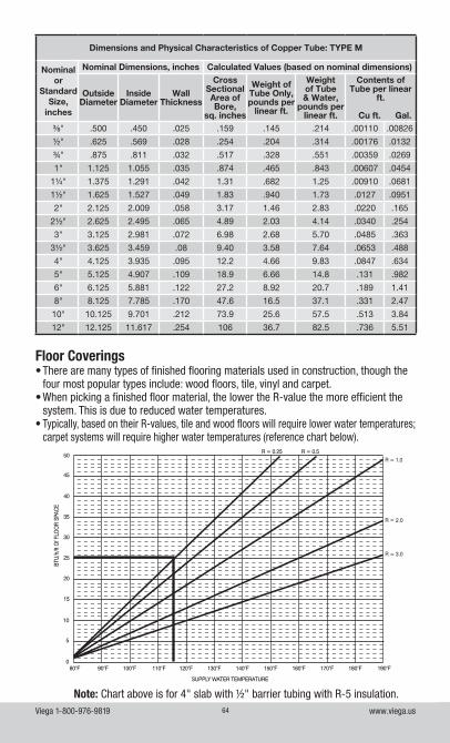
Viega 1-800-976-9819 www.viega.us64
Dimensions and Physical Characteristics of Copper Tube: TYPE M
Nominal or
Standard Size,
inches
Nominal Dimensions, inches Calculated Values (based on nominal dimensions)
Outside Diameter
Inside Diameter
Wall Thickness
Cross Sectional Area of Bore,
sq. inches
Weight of Tube Only, pounds per
linear ft.
Weight of Tube & Water,
pounds per linear ft.
Contents of Tube per linear
ft.
Cu ft. Gal.⅜" .500 .450 .025 .159 .145 .214 .00110 .00826
½" .625 .569 .028 .254 .204 .314 .00176 .0132
¾" .875 .811 .032 .517 .328 .551 .00359 .0269
1" 1.125 1.055 .035 .874 .465 .843 .00607 .0454
1¼" 1.375 1.291 .042 1.31 .682 1.25 .00910 .0681
1½" 1.625 1.527 .049 1.83 .940 1.73 .0127 .0951
2" 2.125 2.009 .058 3.17 1.46 2.83 .0220 .165
2½" 2.625 2.495 .065 4.89 2.03 4.14 .0340 .254
3" 3.125 2.981 .072 6.98 2.68 5.70 .0485 .363
3½" 3.625 3.459 .08 9.40 3.58 7.64 .0653 .488
4" 4.125 3.935 .095 12.2 4.66 9.83 .0847 .634
5" 5.125 4.907 .109 18.9 6.66 14.8 .131 .982
6" 6.125 5.881 .122 27.2 8.92 20.7 .189 1.41
8" 8.125 7.785 .170 47.6 16.5 37.1 .331 2.47
10" 10.125 9.701 .212 73.9 25.6 57.5 .513 3.84
12" 12.125 11.617 .254 106 36.7 82.5 .736 5.51
Floor Coverings• There are many types of finished flooring materials used in construction, though the
four most popular types include: wood floors, tile, vinyl and carpet.• When picking a finished floor material, the lower the R-value the more efficient the
system. This is due to reduced water temperatures.• Typically, based on their R-values, tile and wood floors will require lower water temperatures;
carpet systems will require higher water temperatures (reference chart below).
150°F140°F130°F120°F110°F90°F 100°F80°F 160°F 170°F 180°F 190°F
50
45
40
35
30
25
20
15
10
5
0
R = 0.5R = 0.25
R = 3.0
R = 2.0
R = 1.0
TOTA
L R-
VALU
E O
F FI
NIS
H F
LOO
R AB
OVE
SU
BFLO
OR
SUPPLY WATER TEMPERATURE
BTU
/h/ft
Of F
LOO
R SP
ACE
Note: Chart above is for 4" slab with ½" barrier tubing with R-5 insulation.
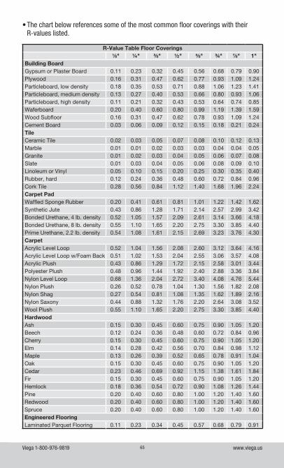
Viega 1-800-976-9819 www.viega.us65
• The chart below references some of the most common floor coverings with their R-values listed.
R-Value Table Floor Coverings⅛" ¼" ⅜" ½" ⅝" ¾" ⅞" 1"
Building BoardGypsum or Plaster Board 0.11 0.23 0.32 0.45 0.56 0.68 0.79 0.90Plywood 0.16 0.31 0.47 0.62 0.77 0.93 1.09 1.24Particleboard, low density 0.18 0.35 0.53 0.71 0.88 1.06 1.23 1.41Particleboard, medium density 0.13 0.27 0.40 0.53 0.66 0.80 0.93 1.06Particleboard, high density 0.11 0.21 0.32 0.43 0.53 0.64 0.74 0.85Waferboard 0.20 0.40 0.60 0.80 0.99 1.19 1.39 1.59Wood Subfloor 0.16 0.31 0.47 0.62 0.78 0.93 1.09 1.24Cement Board 0.03 0.06 0.09 0.12 0.15 0.18 0.21 0.24TileCeramic Tile 0.02 0.03 0.05 0.07 0.08 0.10 0.12 0.13Marble 0.01 0.01 0.02 0.03 0.03 0.04 0.04 0.05Granite 0.01 0.02 0.03 0.04 0.05 0.06 0.07 0.08Slate 0.01 0.03 0.04 0.05 0.06 0.08 0.09 0.10Linoleum or Vinyl 0.05 0.10 0.15 0.20 0.25 0.30 0.35 0.40Rubber, hard 0.12 0.24 0.36 0.48 0.60 0.72 0.84 0.96Cork Tile 0.28 0.56 0.84 1.12 1.40 1.68 1.96 2.24Carpet PadWaffled Sponge Rubber 0.20 0.41 0.61 0.81 1.01 1.22 1.42 1.62Synthetic Jute 0.43 0.86 1.28 1.71 2.14 2.57 2.99 3.42Bonded Urethane, 4 lb. density 0.52 1.05 1.57 2.09 2.61 3.14 3.66 4.18Bonded Urethane, 8 lb. density 0.55 1.10 1.65 2.20 2.75 3.30 3.85 4.40Prime Urethane, 2.2 lb. density 0.54 1.08 1.61 2.15 2.69 3.23 3.76 4.30CarpetAcrylic Level Loop 0.52 1.04 1.56 2.08 2.60 3.12 3.64 4.16Acrylic Level Loop w/Foam Back 0.51 1.02 1.53 2.04 2.55 3.06 3.57 4.08Acrylic Plush 0.43 0.86 1.29 1.72 2.15 2.58 3.01 3.44Polyester Plush 0.48 0.96 1.44 1.92 2.40 2.88 3.36 3.84Nylon Level Loop 0.68 1.36 2.04 2.72 3.40 4.08 4.76 5.44Nylon Plush 0.26 0.52 0.78 1.04 1.30 1.56 1.82 2.08Nylon Shag 0.27 0.54 0.81 1.08 1.35 1.62 1.89 2.16Nylon Saxony 0.44 0.88 1.32 1.76 2.20 2.64 3.08 3.52Wool Plush 0.55 1.10 1.65 2.20 2.75 3.30 3.85 4.40HardwoodAsh 0.15 0.30 0.45 0.60 0.75 0.90 1.05 1.20Beech 0.12 0.24 0.36 0.48 0.60 0.72 0.84 0.96Cherry 0.15 0.30 0.45 0.60 0.75 0.90 1.05 1.20Elm 0.14 0.28 0.42 0.56 0.70 0.84 0.98 1.12Maple 0.13 0.26 0.39 0.52 0.65 0.78 0.91 1.04Oak 0.15 0.30 0.45 0.60 0.75 0.90 1.05 1.20Cedar 0.23 0.46 0.69 0.92 1.15 1.38 1.61 1.84Fir 0.15 0.30 0.45 0.60 0.75 0.90 1.05 1.20Hemlock 0.18 0.36 0.54 0.72 0.90 1.08 1.26 1.44Pine 0.20 0.40 0.60 0.80 1.00 1.20 1.40 1.60Redwood 0.20 0.40 0.60 0.80 1.00 1.20 1.40 1.60Spruce 0.20 0.40 0.60 0.80 1.00 1.20 1.40 1.60Engineered FlooringLaminated Parquet Flooring 0.11 0.23 0.34 0.45 0.57 0.68 0.79 0.91
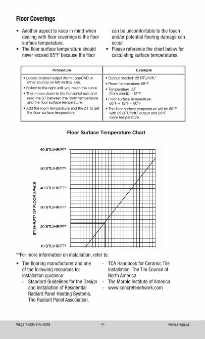
Viega 1-800-976-9819 www.viega.us66
• Another aspect to keep in mind when dealing with floor coverings is the floor surface temperature.
• The floor surface temperature should never exceed 85°F because the floor
can be uncomfortable to the touch and/or potential flooring damage can occur.
• Please reference the chart below for calculating surface temperatures.
Floor Coverings
• The flooring manufacturer and one of the following resources for installation guidance:
-Standard Guidelines for the Design and Installation of Residential Radiant Panel Heating Systems. The Radiant Panel Association.
Floor Surface Temperature Chart
Procedure Example
• Locate desired output (from LoopCAD or other source) on left vertical axis.
• Follow to the right until you reach the curve.
• Then move down to the horizontal axis and read the ∆T between the room temperature and the floor surface temperature.
• Add the room temperature and the ∆T to get the floor surface temperature.
• Output needed: 25 BTU/h/ft.2
• Room temperature: 68°F
• Temperature ∆T (from chart): ~ 12°F
• Floor surface temperature: 68°F + 12°F = 80°F
• The floor surface temperature will be 80°F with 25 BTU/h/ft.2 output and 68°F room temperature.
**For more information on installation, refer to:
- TCA Handbook for Ceramic Tile Installation. The Tile Council of North America.
- The Marble Institute of America. - www.concretenetwork.com
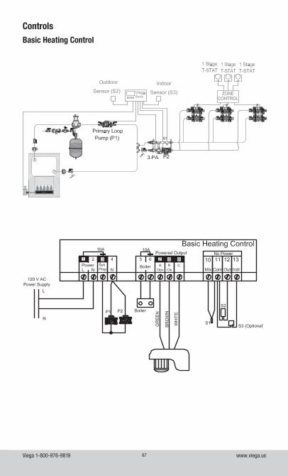
Viega 1-800-976-9819 www.viega.us67
ControlsBasic Heating Control
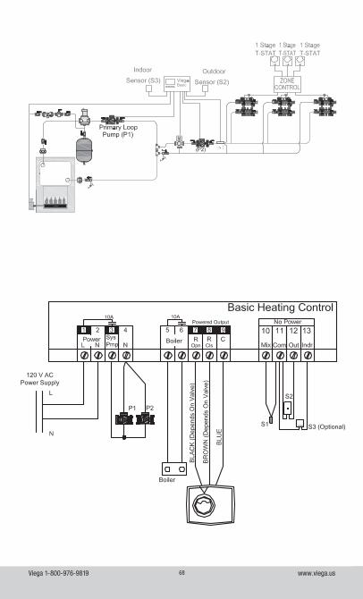
Viega 1-800-976-9819 www.viega.us68
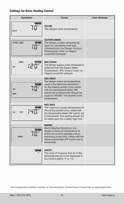
Viega 1-800-976-9819 www.viega.us69
Settings for Basic Heating Control
Symptom Cause User Settings
ROOMThe desired room temperature.
OUTDR DSGNThe design outdoor temperature used for calculating heat loss. Obtained from the Design Outdoor Temperature Chart, or Viega’s LoopCAD Software*.
MIX DSGNThe design supply water temperature obtained from the Supply Water Temperature / BTU Output Chart, or Viega’s LoopCAD software.
MIX INDRThe design indoor air temperature used in the heat loss calculation* for the heating system (only visible with the Advanced/Installer DIP switch set to Advanced). Should be equal to “ROOM,” the desired room temperature.
MIX MAXThe maximum supply temperature for the mixing system (only visible with the Advanced/Installer DIP switch set to Advanced). This setting should not be relied upon for a safety high limit.
WWSDWarm Weather Shutdown; the design outdoor air temperature at which the control operates only in exercising mode (only visible with the Advanced/Installer DIP switch set to Advanced).
UNITSThe units of measure that all of the temperatures are to be displayed in the control (either °F or °C).
* See corresponding installation manuals, i.e. Concrete System, Climate Panel or Climate Trak, for appropriate charts.
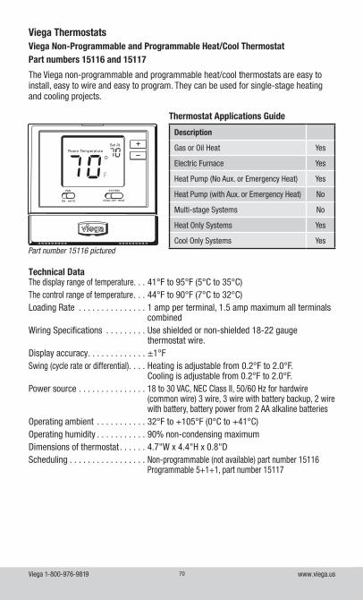
Viega 1-800-976-9819 www.viega.us70
Viega Thermostats
The Viega non-programmable and programmable heat/cool thermostats are easy to install, easy to wire and easy to program. They can be used for single-stage heating and cooling projects.
Technical DataThe display range of temperature. . . 41°F to 95°F (5°C to 35°C)The control range of temperature . . . 44°F to 90°F (7°C to 32°C)Loading Rate . . . . . . . . . . . . . . . 1 amp per terminal, 1.5 amp maximum all terminals
combinedWiring Specifications . . . . . . . . . Use shielded or non-shielded 18-22 gauge
thermostat wire.Display accuracy . . . . . . . . . . . . . ±1°FSwing (cycle rate or differential) . . . . Heating is adjustable from 0.2°F to 2.0°F.
Cooling is adjustable from 0.2°F to 2.0°F.Power source . . . . . . . . . . . . . . . 18 to 30 VAC, NEC Class II, 50/60 Hz for hardwire
(common wire) 3 wire, 3 wire with battery backup, 2 wire with battery, battery power from 2 AA alkaline batteries
Operating ambient . . . . . . . . . . . 32°F to +105°F (0°C to +41°C)Operating humidity . . . . . . . . . . . 90% non-condensing maximumDimensions of thermostat . . . . . . 4.7"W x 4.4"H x 0.8"DScheduling . . . . . . . . . . . . . . . . . Non-programmable (not available) part number 15116
Programmable 5+1+1, part number 15117
Viega Non-Programmable and Programmable Heat/Cool ThermostatPart numbers 15116 and 15117
Thermostat Applications Guide
Description
Gas or Oil Heat Yes
Electric Furnace Yes
Heat Pump (No Aux. or Emergency Heat) Yes
Heat Pump (with Aux. or Emergency Heat) No
Multi-stage Systems No
Heat Only Systems Yes
Cool Only Systems YesPart number 15116 pictured
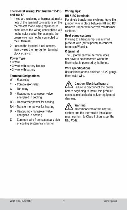
Viega 1-800-976-9819 www.viega.us71
Wiring Tips:RH & RC terminalsFor single transformer systems, leave the jumper wire in place between RH and RC. Remove jumper wire for two transformer systems.Heat pump systemsIf wiring to a heat pump, use a small piece of wire (not supplied) to connect terminals W and Y.C terminalThe C (common wire) terminal does not have to be connected when the thermostat is powered by batteries.
Wire specifications Use shielded or non-shielded 18-22 gauge thermostat wire.
Thermostat Wiring: Part Number 15116 and 151171. If you are replacing a thermostat, make
note of the terminal connections on the thermostat that is being replaced. In some cases the wiring connections will not be color coded. For example, the green wire may not be connected to the G terminal.
2. Loosen the terminal block screws. Insert wires then re-tighten terminal block screws.
Power Type• 3 wire• 3 wire with battery backup• 2 wire with battery
Terminal DesignationsW - Heat relayY - Compressor relayG - Fan relayO - Heat pump changeover valve
energized in coolingRC - Transformer power for coolingRH - Transformer power for heatingB - Heat pump changeover valve
energized in heatingC - Common wire from secondary side
of cooling system transformer
Caution: Electrical hazardFailure to disconnect the power
before beginning to install this product can cause electrical shock or equipment damage.
Warning:All components of the control
system and the thermostat installation must conform to Class II circuits per the NEC Code.
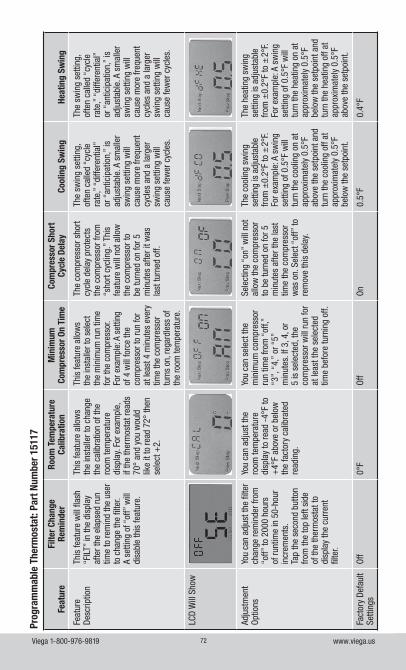
Viega 1-800-976-9819 www.viega.us72
Feat
ure
Filte
r Cha
nge
Rem
inde
rRo
om T
empe
ratu
re
Calib
ratio
nM
inim
um
Com
pres
sor O
n Ti
me
Com
pres
sor S
hort
Cy
cle
Dela
yCo
olin
g Sw
ing
Heat
ing
Swin
g
Feat
ure
Desc
riptio
nTh
is fe
atur
e w
ill fl
ash
“FILT
” in
the
disp
lay
afte
r the
ela
psed
run
time
to re
min
d th
e us
er
to c
hang
e th
e fil
ter.
A se
tting
of “
off”
will
di
sabl
e th
is fe
atur
e.
This
feat
ure
allo
ws
the
inst
alle
r to
chan
ge
the
calib
ratio
n of
the
room
tem
pera
ture
di
spla
y. Fo
r exa
mpl
e,
if th
e th
erm
osta
t rea
ds
70°
and
you
wou
ld
like
it to
read
72°
then
se
lect
+2.
This
feat
ure
allo
ws
the
inst
alle
r to
sele
ct
the
min
imum
run
time
for t
he c
ompr
esso
r. Fo
r exa
mpl
e: A
set
ting
of 4
will
forc
e th
e co
mpr
esso
r to
run
for
at le
ast 4
min
utes
eve
ry
time
the
com
pres
sor
turn
s on
, reg
ardl
ess
of
the
room
tem
pera
ture
.
The
com
pres
sor s
hort
cycl
e de
lay
prot
ects
th
e co
mpr
esso
r fro
m
“sho
rt cy
clin
g.”
This
fe
atur
e w
ill n
ot a
llow
th
e co
mpr
esso
r to
be tu
rned
on
for 5
m
inut
es a
fter i
t was
la
st tu
rned
off.
The
swin
g se
tting
, of
ten
calle
d “c
ycle
ra
te,”
“di
ffere
ntia
l”
or “
antic
ipat
ion,
” is
ad
just
able
. A s
mal
ler
swin
g se
tting
will
ca
use
mor
e fre
quen
t cy
cles
and
a la
rger
sw
ing
setti
ng w
ill
caus
e fe
wer
cyc
les.
The
swin
g se
tting
, of
ten
calle
d “c
ycle
ra
te,”
“di
ffere
ntia
l”
or “
antic
ipat
ion,
” is
ad
just
able
. A s
mal
ler
swin
g se
tting
will
ca
use
mor
e fre
quen
t cy
cles
and
a la
rger
sw
ing
setti
ng w
ill
caus
e fe
wer
cyc
les.
LCD
Will
Sho
w
Adju
stm
ent
Optio
nsYo
u ca
n ad
just
the
filte
r ch
ange
rem
inde
r fro
m
“off”
to 2
000
hour
s of
runt
ime
in 5
0-ho
ur
incr
emen
ts.
Tap
the
seco
nd b
utto
n fro
m th
e to
p le
ft si
de
of th
e th
erm
osta
t to
disp
lay
the
curr
ent
filte
r.
You
can
adju
st th
e ro
om te
mpe
ratu
re
disp
lay
to re
ad -
4°F
to
+4°
F ab
ove
or b
elow
th
e fa
ctor
y ca
libra
ted
read
ing.
You
can
sele
ct th
e m
inim
um c
ompr
esso
r ru
n tim
e fro
m “
off,”
“3
”, “
4,”
or “
5”
min
utes
. If 3
, 4, o
r 5
is s
elec
ted,
the
com
pres
sor w
ill ru
n fo
r at
leas
t the
sel
ecte
d tim
e be
fore
turn
ing
off.
Sele
ctin
g “o
n” w
ill n
ot
allo
w th
e co
mpr
esso
r to
be
turn
ed o
n fo
r 5
min
utes
afte
r the
last
tim
e th
e co
mpr
esso
r w
as o
n. S
elec
t “of
f” to
re
mov
e th
is d
elay
.
The
cool
ing
swin
g se
tting
is a
djus
tabl
e fro
m ±
0.2°
F to
±2°
F. Fo
r exa
mpl
e: A
sw
ing
setti
ng o
f 0.5
°F w
ill
turn
the
cool
ing
on a
t ap
prox
imat
ely
0.5°
F ab
ove
the
setp
oint
and
tu
rn th
e co
olin
g of
f at
appr
oxim
atel
y 0.
5°F
belo
w th
e se
tpoi
nt.
The
heat
ing
swin
g se
tting
is a
djus
tabl
e fro
m ±
0.2°
F to
±2°
F. Fo
r exa
mpl
e: A
sw
ing
setti
ng o
f 0.5
°F w
ill
turn
the
heat
ing
on a
t ap
prox
imat
ely
0.5°
F be
low
the
setp
oint
and
tu
rn th
e he
atin
g of
f at
appr
oxim
atel
y 0.
5°F
abov
e th
e se
tpoi
nt.
Fact
ory
Defa
ult
Setti
ngs
Off
0°F
Off
On0.
5°F
0.4°
F
Prog
ram
mab
le T
herm
osta
t: Pa
rt N
umbe
r 151
17
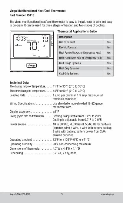
Viega 1-800-976-9819 www.viega.us73
The Viega multifunctional heat/cool thermostat is easy to install, easy to wire and easy to program. It can be used for three stages of heating and two stages of cooling.
Viega Multifunctional Heat/Cool ThermostatPart Number 15118
Technical DataThe display range of temperature. . . . . 41°F to 95°F (5°C to 35°C)The control range of temperature . . . . . 44°F to 90°F (7°C to 32°C)Loading Rate . . . . . . . . . . . . . . . . . 1 amp per terminal, 1.5 amp maximum all
terminals combinedWiring Specifications . . . . . . . . . . . Use shielded or non-shielded 18-22 gauge
thermostat wire.Display accuracy . . . . . . . . . . . . . . . ±1°FSwing (cycle rate or differential) . . . . . . Heating is adjustable from 0.2°F to 2.0°F.
Cooling is adjustable from 0.2°F to 2.0°F.Power source . . . . . . . . . . . . . . . . . 18 to 30 VAC, NEC Class II, 50/60 Hz for hardwire
(common wire) 3 wire, 3 wire with battery backup, 2 wire with battery, battery power from 2 AA alkaline batteries
Operating ambient . . . . . . . . . . . . . 32°F to +105°F (0°C to +41°C)Operating humidity . . . . . . . . . . . . . 90% non-condensing maximumDimensions of thermostat . . . . . . . . 4.7"W x 4.4"H x 1.1"DScheduling . . . . . . . . . . . . . . . . . . . 5+1+1, 7 day, none
Thermostat Applications Guide
Description
Gas or Oil Heat Yes
Electric Furnace Yes
Heat Pump (No Aux. or Emergency Heat) Yes
Heat Pump (with Aux. or Emergency Heat) Yes
Multi-stage Systems Yes
Heat Only Systems Yes
Cool Only Systems Yes
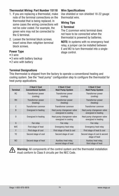
Viega 1-800-976-9819 www.viega.us74
Thermostat Wiring: Part Number 151181. If you are replacing a thermostat, make
note of the terminal connections on the thermostat that is being replaced. In some cases the wiring connections will not be color coded. For example, the green wire may not be connected to the G terminal.
2. Loosen the terminal block screws. Insert wires then retighten terminal block screws.
Power Type• 3 wire• 3 wire with battery backup• 2 wire with battery
Wire Specifications Use shielded or non-shielded 18-22 gauge thermostat wire.
Wiring TipsC TerminalThe C (common wire) terminal does not have to be connected when the thermostat is powered by batteries.NOTE: In systems with no emergency heat relay, a jumper can be installed between E and W2 to turn thermostat into a single-stage control.
Terminal DesignationsThis thermostat is shipped from the factory to operate a conventional heating and cooling system. See the “heat pump” configuration step to configure the thermostat for heat pump applications.
Terminal2 Heat 2 Cool
Conventional System2 Heat 2 Cool
Heat Pump System3 Heat 2 Cool
Heat Pump System
RC Transformer power(cooling)
Transformer power(cooling)
Transformer power(cooling)
RH Transformer power(heating)
Transformer power(heating)
Transformer power(heating)
C Transformer common Transformer common Transformer common
B Energized in heating Heat pump changeover valve energized in cooling
Heat pump changeover valve energized in heating
O Energized in heating Heat pump changeover valve energized in cooling
Heat pump changeover valve energized in heating
G Fan relay Fan relay Fan relay
W/E First stage of heat Emergency heat relay Emergency heat relay
Y First stage of cool First stage of heat & cool First stage of heat & cool
Y2 Second stage of cool Second stage of cool Second stage of cool & second stage of heat
W2 Second stage of heat Auxiliary heat relay, second stage of heat
Auxilary heat relay, third stage of heat
Warning: All components of the control system and the thermostat installation must conform to Class II circuits per the NEC Code.
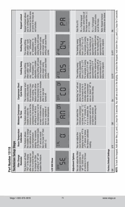
Viega 1-800-976-9819 www.viega.us75
Tech
nici
an S
etup
Ste
psFi
lter C
hang
e Re
min
der
Room
Tem
pera
ture
Ca
libra
tion
Min
imum
Com
pres
sor
On T
ime
Com
pres
sor S
hort
Cy
cle
Dela
yCo
olin
g Sw
ing
Heat
ing
Swin
gKe
ypad
Loc
kout
This
feat
ure
will
flas
h “F
ILT”
in th
e di
spla
y af
ter t
he e
laps
ed ru
n tim
e to
rem
ind
the
user
to
cha
nge
the
filte
r. A
setti
ng o
f “of
f” w
ill
disa
ble
this
feat
ure.
This
feat
ure
allo
ws
the
inst
alle
r to
chan
ge
the
calib
ratio
n of
the
room
tem
pera
ture
di
spla
y. Fo
r exa
mpl
e,
if th
e th
erm
osta
t rea
ds
70°
and
you
wou
ld
like
it to
read
72°
then
se
lect
+2.
This
feat
ure
allo
ws
the
inst
alle
r to
sele
ct th
e m
inim
um ru
n tim
e fo
r the
co
mpr
esso
r. Fo
r exa
mpl
e:
A se
tting
of 4
will
forc
e th
e co
mpr
esso
r to
run
for
at le
ast 4
min
utes
eve
ry
time
the
com
pres
sor
turn
s on
, reg
ardl
ess
of
the
room
tem
pera
ture
.
The
com
pres
sor s
hort
cycl
e de
lay
prot
ects
th
e co
mpr
esso
r fro
m
“sho
rt cy
clin
g.”
This
fe
atur
e w
ill n
ot a
llow
th
e co
mpr
esso
r to
be
turn
ed o
n fo
r 5 m
inut
es
afte
r it w
as la
st
turn
ed o
ff.
The
swin
g se
tting
, of
ten
calle
d “c
ycle
ra
te,”
“di
ffere
ntia
l”
or “
antic
ipat
ion,
” is
ad
just
able
. A s
mal
ler
swin
g se
tting
will
cau
se
mor
e fre
quen
t cyc
les
and
a la
rger
sw
ing
setti
ng w
ill c
ause
few
er
cycl
es.
The
swin
g se
tting
, of
ten
calle
d “c
ycle
ra
te,”
“di
ffere
ntia
l”
or “
antic
ipat
ion,
” is
ad
just
able
. A s
mal
ler
swin
g se
tting
will
cau
se
mor
e fre
quen
t cyc
les
and
a la
rger
sw
ing
setti
ng w
ill c
ause
few
er
cycl
es.
Keyp
ad lo
ckou
t allo
ws
you
to c
onfig
ure
the
ther
mos
tat s
o th
at n
one
or s
ome
of th
e ke
ys d
o no
t fun
ctio
n.
LCD
Will
Sho
w
Adju
stm
ent O
ptio
ns
You
can
adju
st th
e fil
ter
chan
ge re
min
der f
rom
“o
ff” to
200
0 ho
urs
of ru
ntim
e in
50-
hour
in
crem
ents
.
You
can
adju
st th
e ro
om te
mpe
ratu
re
disp
lay
to re
ad -
4°F
to
+4°
F ab
ove
or b
elow
th
e fa
ctor
y-ca
libra
ted
read
ing.
You
can
sele
ct th
e m
inim
um c
ompr
esso
r ru
n tim
e fro
m “
off,”
“3,
” “4
” or
“5”
min
utes
. If 3
, 4
or 5
is s
elec
ted,
the
com
pres
sor w
ill ru
n fo
r at
leas
t the
sel
ecte
d tim
e be
fore
turn
ing
off.
Sele
ctin
g “o
n” w
ill n
ot
allo
w th
e co
mpr
esso
r to
be
turn
ed o
n fo
r 5
min
utes
afte
r the
last
tim
e th
e co
mpr
esso
r w
as o
n. S
elec
t “of
f” to
re
mov
e th
is d
elay
.
The
cool
ing
swin
g se
tting
is a
djus
tabl
e fro
m ±
0.2°
F to
±2°
F. Fo
r exa
mpl
e: A
sw
ing
setti
ng o
f 0.5
°F w
ill
turn
the
cool
ing
on a
t ap
prox
imat
ely
0.5°
F ab
ove
the
setp
oint
and
tu
rn th
e co
olin
g of
f at
appr
oxim
atel
y 0.
5°F
belo
w th
e se
tpoi
nt.
The
heat
ing
swin
g se
tting
is a
djus
tabl
e fro
m ±
0.2°
F to
±2°
F. Fo
r exa
mpl
e: A
sw
ing
setti
ng o
f 0.5
°F w
ill
turn
the
heat
ing
on a
t ap
prox
imat
ely
0.5°
F be
low
the
setp
oint
and
tu
rn th
e he
atin
g of
f at
appr
oxim
atel
y 0.
5°F
abov
e th
e se
tpoi
nt.
Pick
PA
or F
U
PA =
Par
tial k
eypa
d lo
ckou
t, w
hich
lock
s al
l th
e ke
ys e
xcep
t the
+
or
– k
eys.
FU =
Ful
l key
pad
lock
out,
whi
ch lo
cks
out a
ll th
e ke
ys.
Note
: Key
pad
lock
out
inst
ruct
ions
are
bel
ow.
Fact
ory
Defa
ult S
ettin
gs
Off
0°F
Off
On0.
5°F
0.4°
FPA
NOTE
: To
lock
the
keyp
ad, h
old
dow
n th
e +
and
–
key
s fo
r 3 s
econ
ds. Y
ou w
ill s
ee a
lock
in th
e di
spla
y. To
unl
ock
the
keyp
ad, h
old
dow
n th
e +
and
–
key
s fo
r 3 s
econ
ds.
Part
Num
ber 1
5118
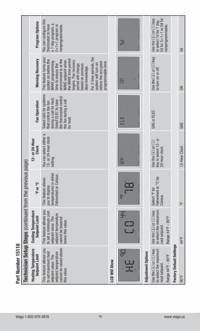
Viega 1-800-976-9819 www.viega.us76
Tech
nici
an S
etup
Ste
ps (c
ontin
ued
from
the
prev
ious
pag
e)He
atin
g Te
mpe
ratu
re
Setp
oint
Lim
itCo
olin
g Te
mpe
ratu
re
Setp
oint
Lim
it°F
or °
C12
- or
24-
Hour
Cl
ock
Fan
Oper
atio
nM
orni
ng R
ecov
ery
Prog
ram
Opt
ions
This
feat
ure
allo
ws
you
to s
et m
axim
um h
eat
setp
oint
val
ue. T
he
setp
oint
tem
pera
ture
ca
nnot
be
rais
ed a
bove
th
is v
alue
.
This
feat
ure
allo
ws
you
to s
et a
min
imum
coo
l se
tpoi
nt v
alue
. The
se
tpoi
nt te
mpe
ratu
re
cann
ot b
e lo
wer
ed
belo
w th
is v
alue
.
This
feat
ure
allo
ws
you
to d
ispl
ay
tem
pera
ture
s in
eith
er
Fahr
enhe
it or
Cel
sius
.
You
can
sele
ct e
ither
a
12-
or 2
4-ho
ur c
lock
se
tting
.
Sele
ct G
AS fo
r sys
tem
s th
at c
ontro
l the
fan
durin
g a
call
for h
eat.
Sele
ct E
LEC
to h
ave
the
ther
mos
tat c
ontro
l th
e fa
n du
ring
a ca
ll fo
r hea
t.
This
feat
ure
turn
s yo
ur
syst
em o
n be
fore
the
WAK
E pr
ogra
mm
ing
time
to e
nsur
e th
e en
viro
nmen
t is
at th
e W
AKE
setp
oint
whe
n th
e W
AKE
time
perio
d be
gins
. The
reco
very
pe
riod
will
cha
nge
base
d on
pre
viou
s da
ys k
now
ledg
e.
For 2
tim
e pe
riods
, the
sy
stem
will
turn
on
befo
re th
e oc
cupi
ed
prog
ram
mab
le ti
me.
You
can
conf
igur
e th
is
ther
mos
tat t
o ha
ve
a 7-
day
prog
ram
, a
5+1+
1 pr
ogra
m o
r no
npro
gram
mab
le.
LCD
Will
Sho
w
Adju
stm
ent O
ptio
ns
Use
the
+ o
r –
key
to
sel
ect t
he m
axim
um
heat
set
poin
t.
Rang
e 44
°F -
90°
F
Use
the
+ o
r –
key
to
sel
ect t
he m
inum
um
cool
set
poin
t.
Rang
e 44
°F -
90°
F
Sele
ct °
F fo
r Fa
hren
heit
or °
C fo
r Ce
lsiu
s
Use
the
+ o
r –
ke
y to
sel
ect 1
2- o
r 24
-hou
r clo
ck.
GAS
or E
LEC
Use
the
+ o
r –
key
to
turn
on
or o
ff.Us
e th
e +
or
– k
ey
to s
elec
t 7d
for 7
day
, 5d
for 5
+1+
1 or
0d
for
nonp
rogr
amm
able
.
Fact
ory
Defa
ult S
ettin
gs
90°F
44°F
°F12
-Hou
r Clo
ckGA
SON
5d
Part
Num
ber 1
5118
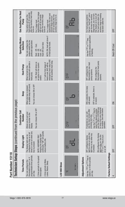
Viega 1-800-976-9819 www.viega.us77
Tech
nici
an S
etup
Ste
ps (c
ontin
ued
from
the
prev
ious
pag
e)
Tim
e Pe
riods
Disp
lay
Ligh
tCo
ntra
ctor
Cal
l Nu
mbe
rBe
epHe
at P
ump
Oper
atin
g M
odes
Se
lect
ion
Gas
Auxi
liary
for H
eat
Pum
p
You
can
conf
igur
e th
is
ther
mos
tat t
o ha
ve 2
or 4
pr
ogra
mm
able
tim
e pe
riods
pe
r day
.
2 tim
e pe
riods
is O
ccup
ied/
Unoc
cupi
ed.
4 tim
e pe
riods
is W
ake,
Le
ave,
Ret
urn,
Sle
ep.
The
disp
lay
light
can
be
conf
igur
ed to
sta
y on
at a
ll tim
es o
r com
e on
whe
n an
y ke
y is
pre
ssed
.
NOTE
: HAR
DWIR
E ON
LY
Keep
ing
the
disp
lay
light
co
ntin
ually
“ON
” w
ill g
reat
ly
redu
ce b
atte
ry li
fe.
Allo
ws
you
to p
ut y
our
phon
e nu
mbe
r in
the
disp
lay.
You
can
choo
se O
N or
OFF
Whe
n an
y ke
y is
pre
ssed
, an
aud
ible
bee
p w
ill s
ound
.
You
can
choo
se O
N or
OFF
Whe
n tu
rned
on
the
ther
mos
tat w
ill o
pera
te a
he
at p
ump.
1. E
M. H
eat w
ill s
how
as
an o
ptio
n in
the
syst
em
switc
h.
2. Y
will
be
first
sta
ge o
f he
at &
coo
l, W
/E w
ill b
e em
erge
ncy
heat
rela
y &
W2
will
be
auxi
liary
hea
t rel
ay.
You
can
conf
igur
e th
e sy
stem
sw
itch
for t
he
parti
cula
r app
licat
ion:
Heat
- O
ff -
Cool
,He
at -
Off,
Cool
- O
ff,He
at-O
ff-Co
ol-A
uto
NOTE
: EM
, Hea
t will
sho
w if
in
hea
t pum
p m
ode.
This
opt
ion
will
turn
the
heat
pum
p of
f 45
seco
nds
afte
r the
aux
iliar
y he
at re
lay
turn
s on
.
For 2
-sta
ge h
eat
appl
icat
ions
, the
firs
t sta
ge
will
turn
off
45 s
econ
ds
afte
r the
aux
iliar
y st
age
turn
s on
.
For 3
-sta
ge h
eat
appl
icat
ions
, the
firs
t and
se
cond
sta
ge w
ill tu
rn
off 4
5 se
cond
s af
ter t
he
auxi
liary
sta
ge tu
rns
on.
LCD
Will
Sho
w
Adju
stm
ent O
ptio
ns
Use
the
+
or
– k
ey to
se
lect
2 o
r 4 ti
me
perio
ds
per d
ay.
OFF
conf
igur
es d
ispl
ay
light
to c
ome
on w
hen
the
light
key
or a
ny o
ther
key
is
pre
ssed
.
ON c
onfig
ures
the
disp
lay
light
to s
tay
on. U
se th
e +
or
– k
ey to
turn
on
or o
ff.
If se
lect
ed o
n, y
ou w
ill
see
the
inpu
t scr
een
afte
r pr
essi
ng n
ext s
tep.
Use
the
+ o
r –
key
to
sele
ct th
e de
sire
d nu
mbe
r an
d th
e FA
N or
SYS
TEM
key
to
mov
e fro
m o
ne c
hara
cter
to
ano
ther
. See
not
e be
low
op
erat
ion.
ON is
sel
ecte
d, th
e be
ep
will
sou
nd.
OFF
is s
elec
ted,
ther
e is
no
sou
nd.
OFF
conf
igur
es th
e th
erm
osta
t for
non
-hea
t pu
mp
syst
ems.
ON c
onfig
ures
the
ther
mos
tat f
or h
eat p
ump
syst
ems.
Use
the
+ o
r –
key
un
til th
e de
sire
d ap
plic
atio
n is
flas
hing
.
For h
eat p
ump
syst
ems
that
are
“du
al fu
el”
(use
a
gas
furn
ace
for a
uxili
ary
stag
e he
at),
you
can
turn
th
is fe
atur
e on
to tu
rn o
ff th
e he
at p
ump
whe
n th
e au
xilia
ry s
tage
of h
eatin
g ha
s be
en c
alle
d fo
r.
Fact
ory
Defa
ult S
ettin
gs
4OF
FOF
FON
OFF
Heat
-Off-
Cool
OFF
Part
Num
ber 1
5118
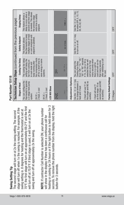
Viega 1-800-976-9819 www.viega.us78
Tech
nici
an S
etup
Ste
ps (c
ontin
ued
from
the
pre
viou
s p
age)
Stag
es o
f Hea
tCo
olin
g Fa
n De
lay
Satis
fy S
etpo
int
Stag
ing
Dela
y
You
can
conf
igur
e th
e th
erm
osta
t to
oper
ate
a 3-
stag
e he
at p
ump
syst
em.
2H 2
C =
2
heat
, 2 c
ool
3H 2
C =
3
heat
, 2 c
ool
The
cool
ing
fan
dela
y se
tting
will
del
ay th
e fa
n fro
m c
omin
g on
in
coo
l mod
e an
d ke
ep ru
nnin
g af
ter
the
com
pres
sor s
huts
of
f for
a s
hort
time
to
save
ene
rgy
in s
ome
syst
ems.
This
feat
ure
allo
ws
the
ther
mos
tat t
o ke
ep
mul
tiple
sta
ges
of h
eat
or c
ool e
nerg
ized
unt
il se
tpoi
nt is
sat
isfie
d.
This
feat
ure
allo
ws
a de
lay
to o
ccur
whe
n a
seco
nd a
nd th
ird s
tage
is
nee
ded.
Thi
s al
low
s th
e pr
evio
us s
tage
ex
tra ti
me
to s
atis
fy
setp
oint
.
LCD
Will
Sho
w
Ad
just
men
t O
pti
ons
Use
the
+
or
– k
ey
to c
hang
e be
twee
n 2
heat
and
3 h
eat
2 he
at w
ill u
se Y
1 as
fir
st s
tage
and
W2
as
auxi
liary
.
3 he
at w
ill u
se Y
1 as
firs
t sta
ge, Y
2 as
se
cond
sta
ge a
nd W
2 as
aux
iliar
y.
You
can
sele
ct th
e Co
olin
g Fa
n De
lay
from
“Of
f,” “
15,”
“30
,”
“60”
or “
90”
seco
nds.
If
15, 3
0, 6
0 or
90
is
sele
cted
the
fan
will
no
t tur
n on
for t
hat
man
y se
cond
s w
hen
ther
e is
a c
all f
or
cool
and
will
run
for
that
man
y se
cond
s af
ter s
atis
fyin
g a
call
for c
ool.
Use
the
+ o
r –
key
to
turn
on
or o
ff.Us
e th
e +
or
– k
ey
to s
elec
t OFF
, 5, 1
0, 1
5,
30, 4
5, 6
2, 9
0.
Fact
ory
Defa
ult S
ettin
gs
2 S
tage
sO
FFO
FFO
FF
Swin
g Se
tting
Tip
The
seco
nd s
tage
will
turn
on
at 2
x th
e sw
ing
setti
ng. T
he s
econ
d st
age
will
turn
off
whe
n 1x
the
swin
g is
reac
hed.
For
exa
mpl
e, if
the
swin
g se
tting
is .8
deg
rees
for h
eatin
g an
d th
e th
erm
osta
t is
set a
t 70
°F, t
he fi
rst s
tage
will
turn
on
at a
ppro
xim
atel
y 69
.2°F
and
the
first
w
ill tu
rn o
ff at
70.
8°F.
If th
ird s
tage
is u
sed,
it w
ill tu
rn o
n at
3x
the
swin
g an
d tu
rn o
ff at
app
roxi
mat
ely
2x th
e sw
ing.
NOTE
: If c
ontra
ctor
Cal
l Num
ber i
s se
lect
ed O
N, y
our p
hone
num
ber
will
sho
w in
the
disp
lay
if th
ere
has
been
a c
ontin
uous
cal
l for
he
atin
g or
coo
ling
for 2
4 ho
urs
or if
the
light
but
ton
is h
eld
dow
n fo
r 3
seco
nds.
To
rem
ove
the
phon
e nu
mbe
r fro
m th
e di
spla
y, ho
ld th
e lig
ht
butto
n fo
r 3 s
econ
ds.
Part
Num
ber 1
5118
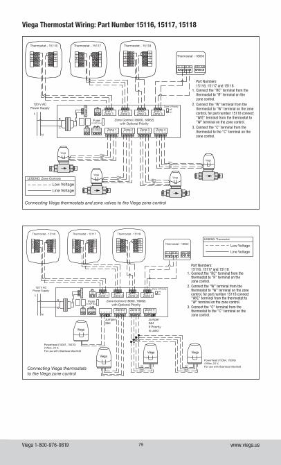
Viega 1-800-976-9819 www.viega.us79
Viega Thermostat Wiring: Part Number 15116, 15117, 15118
N/O N/CCOM
W CR W CR W CR W CR
1 2 3 4
L
N
Viega
ViegaViega
Viega
R
C
C C R W NTC A/B
1 2 3 4 1 2 3 4 1 2 3 4
COBW
RHRCGY
COBW
RHRCGY
COB
W/E
RH
GY
W2 Y2
RC
Connecting Viega thermostats to the Viega zone control
Part Numbers:15116, 15117 and 15118
1. Connect the "RC" terminal from the thermostat to "R" terminal on the zone control.
2. Connect the "W" terminal from the thermostat to "W" terminal on the zone control, for part number 15118 connect "W/E" terminal from the thermostat to "W" terminal on the zone control.
3. Connect the "C" terminal from the thermostat to the "C" terminal on the zone control.
Thermostat - 15116
120 V AC Power Supply
Powerhead (15064, 15069) 4 Wire, 24 V, For use with Stainless Manifold
Powerhead (15061, 15070) 2 Wire, 24 V, For use with Stainless Manifold
Thermostat - 15117 Thermostat - 15118
Thermostat - 18050
LEGEND: Thermostat
Low Voltage
Line Voltage
Zone Control (18060, 18062) with Optional Priority
Fuse(5 AMP Max)
Jumper 3&4
Jumper 3&4 If Priority is used
Zone 2Zone 1
Zone 2
Zone 3
Zone 3
Zone 4
Zone 4
Zone 4 Priority
Zone 4 Relay
offon
IsolatedEnd
Switch
Pump End
Switch
Pow
er In
YellowYellow
RedRed
YellowYellow
RedRed
N/O N/CCOM
WCR W CR W CR WCR
1 2 3 4
L
N
R
C
C C R W NTC A/B
1 2 3 4 1 2 3 4 1 2 3 4
COBW
RHRCGY
COBW
RHRCGY
COB
W/E
RH
GY
W2 Y2
RC
Viega
Viega
Viega
Viega
Part Numbers:15116, 15117 and 15118
1. Connect the "RC" terminal from the thermostat to "R" terminal on the zone control.
2. Connect the "W" terminal from the thermostat to "W" terminal on the zone control, for part number 15118 connect "W/E" terminal from the thermostat to "W" terminal on the zone control.
3. Connect the "C" terminal from the thermostat to the "C" terminal on the zone control.
Connecting Viega thermostats and zone valves to the Viega zone control
Thermostat - 15116
120 V ACPower Supply
Zone Control (18060, 18062) with Optional Priority
LEGEND: Zone Controls
Low Voltage
Line Voltage
Fuse(5 AMP Max)
Zone 1
Zone 2Zone 1
Zone 2
Zone 3
Zone 3
Zone 4
Zone 4
Zone 4 Priority
Zone 4 Relay
offon
IsolatedEnd
Switch
Pump End
Switch
Yellow
Yellow
Yellow
Yellow
Yellow
Yellow
Yellow
Yellow
Red
Red
Red
Red
Red
Red
Red
Red
Pow
er In
Thermostat - 15117 Thermostat - 15118
Thermostat - 18050
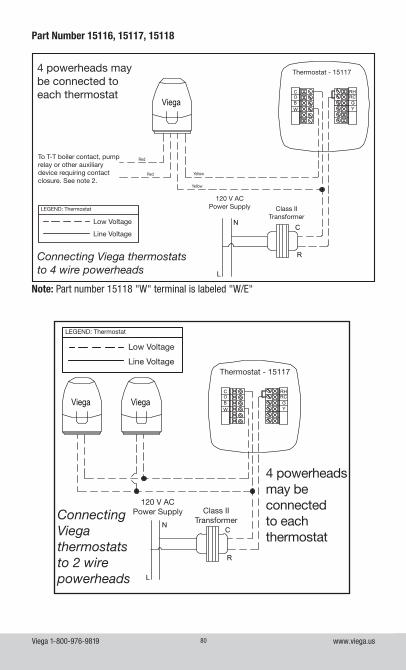
Viega 1-800-976-9819 www.viega.us80
Part Number 15116, 15117, 15118
Note: Part number 15118 "W" terminal is labeled "W/E"
Connecting Viega thermostats to 4 wire powerheads
4 powerheads may be connected to each thermostat
C
R
N
L
ViegaCOBW
RHRCGY
Yellow
Yellow
Red
Red
LEGEND: Thermostat
Low Voltage
Line Voltage
Thermostat - 15117
120 V AC Power Supply
To T-T boiler contact, pump relay or other auxiliary device requiring contact closure. See note 2.
Class II Transformer
Connecting Viega thermostats to 2 wire powerheads
4 powerheads may be connected to each thermostat
C
R
N
L
COBW
RHRCGY
ViegaViega
LEGEND: Thermostat
Low Voltage
Line VoltageThermostat - 15117
120 V AC Power Supply Class II
Transformer
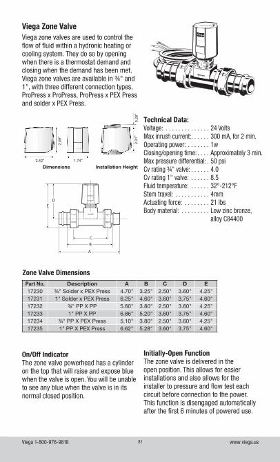
Viega 1-800-976-9819 www.viega.us81
Viega Zone ValveViega zone valves are used to control the flow of fluid within a hydronic heating or cooling system. They do so by opening when there is a thermostat demand and closing when the demand has been met. Viega zone valves are available in ¾" and 1", with three different connection types, ProPress x ProPress, ProPress x PEX Press and solder x PEX Press.
Technical Data:Voltage: . . . . . . . . . . . . . . 24 VoltsMax inrush current: . . . . . . 300 mA, for 2 min.Operating power: . . . . . . . 1wClosing/opening time: . . . . Approximately 3 min.Max pressure differential: . 50 psiCv rating ¾" valve: . . . . . . 4.0Cv rating 1" valve: . . . . . . 8.5Fluid temperature: . . . . . . 32°-212°FStem travel: . . . . . . . . . . . 4mmActuating force: . . . . . . . . 21 lbsBody material: . . . . . . . . . Low zinc bronze,
alloy C84400
Zone Valve DimensionsPart No. Description A B C D E17230 ¾" Solder x PEX Press 4.70" 3.25" 2.50" 3.60" 4.25"17231 1" Solder x PEX Press 6.25" 4.60" 3.60" 3.75" 4.60"17232 ¾" PP X PP 5.60" 3.80" 2.50" 3.60" 4.25"17233 1" PP X PP 6.86" 5.20" 3.60" 3.75" 4.60"17234 ¾" PP X PEX Press 5.10" 3.80" 2.50" 3.60" 4.25"17235 1" PP X PEX Press 6.62" 5.28" 3.60" 3.75" 4.60"
ED
A
BC
Dimensions Installation Height
2.42"
2.09
"
1.74"
2.01
"0.
28"
On/Off IndicatorThe zone valve powerhead has a cylinder on the top that will raise and expose blue when the valve is open. You will be unable to see any blue when the valve is in its normal closed position.
Initially-Open FunctionThe zone valve is delivered in the open position. This allows for easier installations and also allows for the installer to pressure and flow test each circuit before connection to the power. This function is disengaged automatically after the first 6 minutes of powered use.
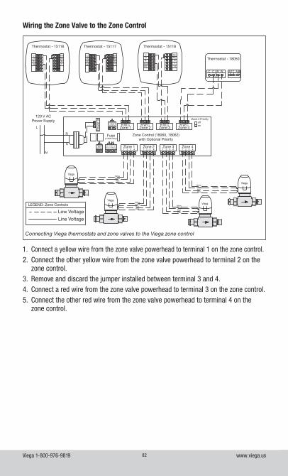
Viega 1-800-976-9819 www.viega.us82
1. Connect a yellow wire from the zone valve powerhead to terminal 1 on the zone control.2. Connect the other yellow wire from the zone valve powerhead to terminal 2 on the
zone control.3. Remove and discard the jumper installed between terminal 3 and 4.4. Connect a red wire from the zone valve powerhead to terminal 3 on the zone control.5. Connect the other red wire from the zone valve powerhead to terminal 4 on the
zone control.
Wiring the Zone Valve to the Zone Control
N/O N/CCOM
WCR W CR W CR WCR
1 2 3 4
L
N
R
C
C C R W NTC A/B
1 2 3 4 1 2 3 4 1 2 3 4
COBW
RHRCGY
COBW
RHRCGY
COB
W/E
RH
GY
W2 Y2
RC
Viega
Viega
Viega
Viega
Connecting Viega thermostats and zone valves to the Viega zone control
Thermostat - 15116
120 V ACPower Supply
Zone Control (18060, 18062) with Optional Priority
LEGEND: Zone Controls
Low Voltage
Line Voltage
Fuse(5 AMP Max)
Zone 1
Zone 2Zone 1
Zone 2
Zone 3
Zone 3
Zone 4
Zone 4
Zone 4 Priority
Zone 4 Relay
offon
IsolatedEnd
Switch
Pump End
Switch
Yellow
Yellow
Yellow
Yellow
Yellow
Yellow
Yellow
Yellow
Red
Red
Red
Red
Red
Red
Red
Red
Pow
er In
Thermostat - 15117 Thermostat - 15118
Thermostat - 18050
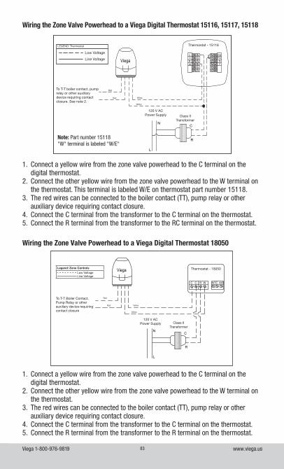
Viega 1-800-976-9819 www.viega.us83
1. Connect a yellow wire from the zone valve powerhead to the C terminal on the digital thermostat.
2. Connect the other yellow wire from the zone valve powerhead to the W terminal on the thermostat. This terminal is labeled W/E on thermostat part number 15118.
3. The red wires can be connected to the boiler contact (TT), pump relay or other auxiliary device requiring contact closure.
4. Connect the C terminal from the transformer to the C terminal on the thermostat.5. Connect the R terminal from the transformer to the RC terminal on the thermostat.
Wiring the Zone Valve Powerhead to a Viega Digital Thermostat 15116, 15117, 15118
1. Connect a yellow wire from the zone valve powerhead to the C terminal on the digital thermostat.
2. Connect the other yellow wire from the zone valve powerhead to the W terminal on the thermostat.
3. The red wires can be connected to the boiler contact (TT), pump relay or other auxiliary device requiring contact closure.
4. Connect the C terminal from the transformer to the C terminal on the thermostat.5. Connect the R terminal from the transformer to the R terminal on the thermostat.
Wiring the Zone Valve Powerhead to a Viega Digital Thermostat 18050
C C R W NTC A/B
C
R
N
L
Viega Thermostat - 18050
120 V AC Power Supply
To T-T Boiler Contact, Pump Relay or other auxiliary device requiring contact closure
Yellow
Yellow
Red
Red
Class II Transformer
Legend: Zone Controls
Low Voltage Line Voltage
Note: Part number 15118"W" terminal is labeled "W/E"
C
R
N
L
ViegaCOBW
RHRCGY
Yellow
Yellow
Red
Red
LEGEND: Thermostat
Low Voltage
Line Voltage
Thermostat - 15116
120 V AC Power Supply
To T-T boiler contact, pump relay or other auxiliary device requiring contact closure. See note 2.
Class II Transformer
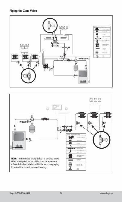
Viega 1-800-976-9819 www.viega.us84
BaseboardZone (s)
ZoneValve
Pressure Differential Bypass Valve
Stainless Manifold w/Flow Gauges
Circulator
Draw Off (Purge Valve)
LEGEND:
Hydronic Mixing Block
Spring check
Make - Up Water
Diaphram-TypeExpansion Tank
Hydronic Mixing Block
Viega
Piping the Zone Valve
ViegaBasic
Viega Viega Viega
BaseboardZone (s)
ZoneValve
Pressure Differential Bypass Valve
Stainless Manifold w/Flow Gauges
Circulator
Draw Off (Purge Valve)
LEGEND:
Enhanced Mixing Station
Spring check
Make - Up Water
Diaphram-TypeExpansion Tank
Enhanced Mixing Station
Viega
ViegaBasic
Viega Viega Viega
BaseboardZone (s)
ZoneValve
Pressure Differential Bypass Valve
Stainless Manifold w/Flow Gauges
Circulator
Draw Off (Purge Valve)
LEGEND:
Enhanced Mixing Station
Spring check
Make - Up Water
Diaphram-TypeExpansion Tank
Enhanced Mixing Station
Viega
NOTE: The Enhanced Mixing Station is pictured above. Other mixing stations should incorporate a pressure differential valve installed within the secondary piping to protect the pump from dead heading.
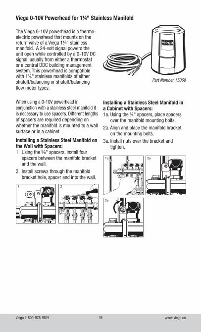
Viega 1-800-976-9819 www.viega.us85
Viega 0-10V Powerhead for 1¼" Stainless Manifold
The Viega 0-10V powerhead is a thermo-electric powerhead that mounts on the return valve of a Viega 1¼" stainless manifold. A 24-volt signal powers the unit open while controlled by a 0-10V DC signal, usually from either a thermostat or a central DDC building management system. This powerhead is compatible with 1¼" stainless manifolds of either shutoff/balancing or shutoff/balancing flow meter types.
Part Number 15068
100200300400500600
100200300400500600
100200300400500600
100200300400500600
100200300400500600
100200300400500600
100200300400500600
100200300400500600
1 2
When using a 0-10V powerhead in conjunction with a stainless steel manifold it is necessary to use spacers. Different lengths of spacers are required depending on whether the manifold is mounted to a wall surface or in a cabinet.
Installing a Stainless Steel Manifold on the Wall with Spacers:1. Using the ⅝" spacers, install four
spacers between the manifold bracket and the wall.
2. Install screws through the manifold bracket hole, spacer and into the wall.
100200300400500600
100200300400500600
100200300400500600
100200300400500600
100200300400500600
10 10
2020
30
3040
4050
5060
60
70
70
80
80
90
90
100 110120
130140
150
160
170
180
190
100200300400500600
100200300400500600
1a
3a
2a
Installing a Stainless Steel Manifold in a Cabinet with Spacers:1a. Using the ¼" spacers, place spacers
over the manifold mounting bolts.2a. Align and place the manifold bracket
on the mounting bolts.3a. Install nuts over the bracket and
tighten.
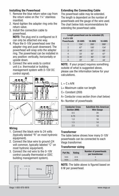
Viega 1-800-976-9819 www.viega.us86
Installing the Powerhead1. Remove the blue return valve cap from
the return valve on the 1¼" stainless manifold.
2. Hand-tighten the adapter ring onto the return valve.
3. Install the connection cable to powerhead. NOTE: The plug end is configured so it can only be attached one way.
4. Place the 0-10V powerhead over the adapter ring and push downward. The powerhead will snap onto the adapter ring. The powerhead can be installed in any position: vertically, horizontally or upside down.
5. Connect the wire ends to control unit (i.e. thermostat or building management system with 0-10V DC control signal).
100200300400500600
100200300400500600
100200300400500600
100200300400500600
100200300400500600
100200300400500600
10 10
2020
30
3040
4050
5060
60
70
70
80
80
90
90
100 110120
130140
150
160
170
180
190
100200300400500600
100200300400500600
100200300400500600
100200300400500600
100200300400500600
100200300400500600
100200300400500600
100200300400500600
10 10
2020
30
3040
4050
5060
60
70
70
80
80
90
90
100 110120
130140
150
160
170
180
190
100200300400500600
100200300400500600
100200300400500600
100200300400500600
100200300400500600
100200300400500600
100200300400500600
100200300400500600
10 10
2020
30
3040
4050
5060
60
70
70
80
80
90
90
100 110120
130140
150
160
170
180
190
100200300400500600
100200300400500600
1
3
2
4
Wiring
Wiring1. Connect the black wire to 24 volts
(typically labeled “R” on most hydronic equipment).
2. Connect the blue wire to ground (24 volt common, typically labeled “C” on most hydronic equipment).
3. Connect the red wire to the 0-10V control (usually thermostat or DDC building management system).
Extending the Connecting CableThe powerhead cable may be extended. The length is dependent on the number of powerheads and the gauge of the wire used. The chart below lists recommendations for extending the powerhead cable.
NOTE: If your project requires something outside of what is suggested above, please use the information below for your calculations.
L = C x A/NL= Maximum cable run lengthC= Constant (269)A= Conductor cross section (from chart below)N= Number of powerheads
Length powerhead can be extended (ft)# of 0-10V
Powerheads 20 AWG 18 AWG 16 AWG1 134' 200' 269'2 67' 100' 134'3 44' 67' 89'4 33' 50' 67'5 26' 40' 53'6 22' 33' 44'
Conductor Cross Section (MM)
Substitute this American Wire Gauge
0.5 200.75 181.0 161.5 142.5 12
TransformerThe table below shows how many 0-10V powerheads can be connected to each Viega transformer.
Transformer sizing
Part No. RatingNumber of powerheads
per transformer18008 40 VA 6
18020 75 VA 12
NOTE: The table above is figured based on 6 W per powerhead.
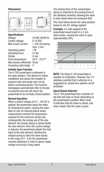
Viega 1-800-976-9819 www.viega.us87
Dimensions
2.42"
2.09
"
1.74"
2.01
"0.
28"
Initially Open FunctionThe 0-10V powerhead is delivered in the open position. This allows for easier installation and allows the installer to pressure test and purge each circuit before connecting power. This function disengages automatically after 6 minutes of powered use and will return the powerhead to its normally closed position.
Normal OperationWhen a control voltage of 0.5 - 10V DC is applied, the powerhead opens the valve by retracting its piston, causing the valve stem to rise. An internal optical stroke measurement controls the temperature required for the maximum stroke and, consequently, the energy use of the wax element. No excess energy is stored inside the wax element. Once the control voltage is reduced, the powerhead adapts the heat input to the wax element, allowing the integral spring to drive the valve closed. In the range of 0 - 0.5V, the powerhead remains stationary in order to ignore ripple voltage occurring in long cables.
SpecificationsVoltage: 24 VAC 50/60 HzControl voltage: 0-10 VDCMax inrush current: < 320 mA during
max. 2 min.Operating power 1 WActuating force: 21 lbs.Stroke: 4 mmFluid temperature: 32°F - 212°FMax pressure differential: 50 psiConnecting cable length: 3'
NOTE: The Viega 0-10V powerhead is capable of modulation. However, the 1¼" stainless manifold that it attaches to is suggested for simple two-position on/off activation.
Open/Closed IndicatorThe 0-10V powerhead has a cylinder on top that will raise or lower depending on the powerhead’s position. When flush, it indicates that the valve is closed, and when raised, that the valve is open.
The closing force of the compression spring is matched to the closing force of the stainless manifold, allowing the valve to stay closed when de-energized (NC).The chart below shows the valve position based on the DC voltage applied.Example: 4.5 volts applied to the powerhead would result in a 2 mm valve stroke, causing the valve to open approximately 50%.
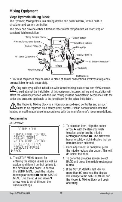
Viega 1-800-976-9819 www.viega.us88
Mixing EquipmentViega Hydronic Mixing BlockThe Hydronic Mixing Block is a mixing device and boiler control, with a built-in circulator and system controller. The block can provide either a fixed or reset water temperature via start/stop or constant fluid circulation.
¾" Solder Connection*
Part No 56160
Wiring Terminal Block
Delivery Fitting (3)
¾" Solder Connection*
Return Fitting (2)
Fitting Clip
Supply Fitting (1)
Backplate
Display Screen
Adjustment ButtonsPressure/Temperature Sensor
* ProPress tailpieces may be used in place of solder connections. ProPress tailpieces are available for sale separately.
Only suitably qualified individuals with formal training in electrical and HVAC controls should attempt the installation of this equipment. Incorrect wiring and installation will
affect the warranty provided with this unit. Wiring must be completed in accordance with the codes and practices applicable to the jurisdiction for the actual installation.
The Hydronic Mixing Block is a microprocessor-based controller and as such is not to be regarded as a safety (limit) control. Please consult and install the
heating or cooling appliance in accordance with the manufacturer’s recommendations.
ProgrammingSETUP MENU
1. The SETUP MENU is used for entering the design values as well as assigning different control options to the circulator and boiler. To access the SETUP MENU, push the middle rectangular button on the STATUS MENU. Use the up and down arrow keys to scroll through the various settings.
2. To select an item, align the cursor arrow with the item you wish to select and press the middle rectangular button . The arrow will become solid, which indicates that an item has been selected.
3. Once adjustment is complete, push the middle rectangular button. This will de-select the item.
4. To go to the previous screen, select BACK and press the middle rectangular button.
5. If the SETUP MENU is left idle for more than 90 seconds, the display will change to the STATUS MENU and the Hydronic Mixing Block will begin operating.
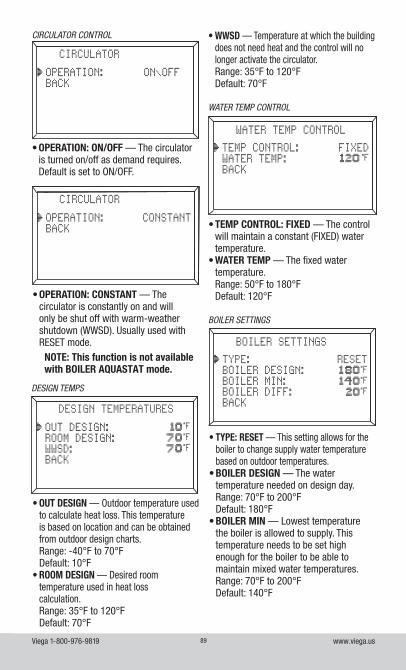
Viega 1-800-976-9819 www.viega.us89
• WWSD — Temperature at which the building does not need heat and the control will no longer activate the circulator.Range: 35°F to 120°FDefault: 70°F
CIRCULATOR CONTROL
• OPERATION: ON/OFF — The circulator is turned on/off as demand requires. Default is set to ON/OFF.
• OPERATION: CONSTANT — The circulator is constantly on and will only be shut off with warm-weather shutdown (WWSD). Usually used with RESET mode.
NOTE: This function is not available with BOILER AQUASTAT mode.
• OUT DESIGN — Outdoor temperature used to calculate heat loss. This temperature is based on location and can be obtained from outdoor design charts. Range: -40°F to 70°FDefault: 10°F
• ROOM DESIGN — Desired room temperature used in heat loss calculation. Range: 35°F to 120°FDefault: 70°F
DESIGN TEMPS
• TEMP CONTROL: FIXED — The control will maintain a constant (FIXED) water temperature.
• WATER TEMP — The fixed water temperature.Range: 50°F to 180°FDefault: 120°F
WATER TEMP CONTROL
• TYPE: RESET — This setting allows for the boiler to change supply water temperature based on outdoor temperatures.
• BOILER DESIGN — The water temperature needed on design day.Range: 70°F to 200°FDefault: 180°F
• BOILER MIN — Lowest temperature the boiler is allowed to supply. This temperature needs to be set high enough for the boiler to be able to maintain mixed water temperatures.Range: 70°F to 200°FDefault: 140°F
BOILER SETTINGS
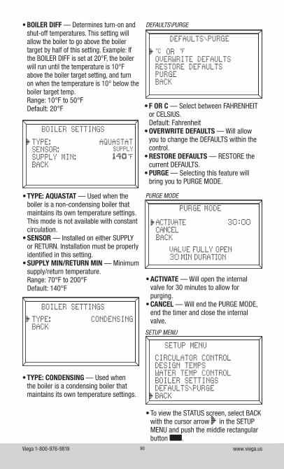
Viega 1-800-976-9819 www.viega.us90
• TYPE: AQUASTAT — Used when the boiler is a non-condensing boiler that maintains its own temperature settings. This mode is not available with constant circulation.
• SENSOR — Installed on either SUPPLY or RETURN. Installation must be properly identified in this setting.
• SUPPLY MIN/RETURN MIN — Minimum supply/return temperature.Range: 70°F to 200°FDefault: 140°F
• TYPE: CONDENSING — Used when the boiler is a condensing boiler that maintains its own temperature settings.
• BOILER DIFF — Determines turn-on and shut-off temperatures. This setting will allow the boiler to go above the boiler target by half of this setting. Example: If the BOILER DIFF is set at 20°F, the boiler will run until the temperature is 10°F above the boiler target setting, and turn on when the temperature is 10° below the boiler target temp.Range: 10°F to 50°FDefault: 20°F • F OR C — Select between FAHRENHEIT
or CELSIUS. Default: Fahrenheit
• OVERWRITE DEFAULTS — Will allow you to change the DEFAULTS within the control.
• RESTORE DEFAULTS — RESTORE the current DEFAULTS.
• PURGE — Selecting this feature will bring you to PURGE MODE.
DEFAULTS\PURGE
PURGE MODE
• ACTIVATE — Will open the internal valve for 30 minutes to allow for purging.
• CANCEL — Will end the PURGE MODE, end the timer and close the internal valve.
• To view the STATUS screen, select BACK with the cursor arrow in the SETUP MENU and push the middle rectangular button .
SETUP MENU
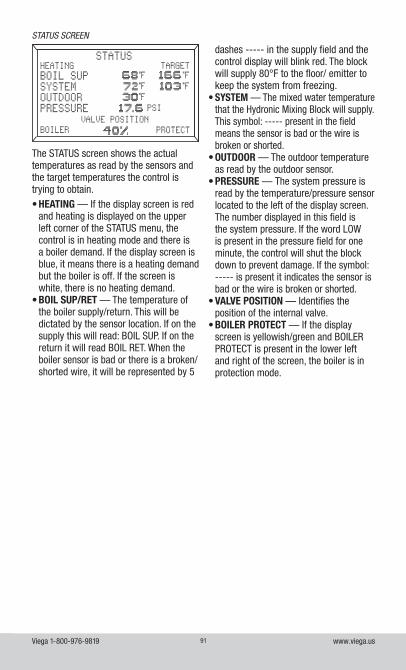
Viega 1-800-976-9819 www.viega.us91
The STATUS screen shows the actual temperatures as read by the sensors and the target temperatures the control is trying to obtain.• HEATING — If the display screen is red
and heating is displayed on the upper left corner of the STATUS menu, the control is in heating mode and there is a boiler demand. If the display screen is blue, it means there is a heating demand but the boiler is off. If the screen is white, there is no heating demand.
• BOIL SUP/RET — The temperature of the boiler supply/return. This will be dictated by the sensor location. If on the supply this will read: BOIL SUP. If on the return it will read BOIL RET. When the boiler sensor is bad or there is a broken/ shorted wire, it will be represented by 5
STATUS SCREEN
dashes ----- in the supply field and the control display will blink red. The block will supply 80°F to the floor/ emitter to keep the system from freezing.
• SYSTEM — The mixed water temperature that the Hydronic Mixing Block will supply. This symbol: ----- present in the field means the sensor is bad or the wire is broken or shorted.
• OUTDOOR — The outdoor temperature as read by the outdoor sensor.
• PRESSURE — The system pressure is read by the temperature/pressure sensor located to the left of the display screen. The number displayed in this field is the system pressure. If the word LOW is present in the pressure field for one minute, the control will shut the block down to prevent damage. If the symbol: ----- is present it indicates the sensor is bad or the wire is broken or shorted.
• VALVE POSITION — Identifies the position of the internal valve.
• BOILER PROTECT — If the display screen is yellowish/green and BOILER PROTECT is present in the lower left and right of the screen, the boiler is in protection mode.
Viega 1-800-976-9819 www.viega.us92
Screen Color Indicator Status
Light Blue/Gray No heat demand
Solid Red Heat demand, boiler running
Yellow/Green Heat demand, boiler running but in boiler protection mode
Dark Blue Heat demand, boiler satisfied
Blinking RedFailed boiler sensor or broken/shorted wire. Under this condition the block will supply
80°F fluid to the floor/emitter to keep the system from freezing
Blinking Purple PURGE MODE, will open valve for 30-min. duration to allow for purging
Testing the Hydronic Mixing BlockWhen piping is complete, test the Hydronic Mixing Block and system piping.1. Ensure air vent cap is tight before testing.2. Pressurize the system to a maximum
of 100 psi for one hour.3. Once the system maintains 100 psi for
one hour, carefully remove air pressure from the system and fill with fluid.
Purging1. Shut the power off to the boiler.2. Purge with only cool water. If the
boiler is hot it should be cooled down prior to purging. This is done to protect the floor coverings from surface temperatures above 85°F.
3. Plug in the Hydronic Mixing Block. Allow it to run through its initial setup and bring you to the STATUS screen.
4. From the STATUS screen push the middle rectangular button.
5. DEFAULTS/PURGE6. Select PURGE7. Select ACTIVATE
• Selecting ACTIVATE will cause the screen to turn purple, at which time the internal valve will open. Once the valve is open, the screen will blink purple and start a 30-minute timer to allow for purging.
• If more time is needed, ACTIVATE may be selected as many times as necessary to complete system purging.
• If less time is needed purge can be canceled by selecting CANCEL.
8. Allow the Hydronic Mixing Block to be filled with fluid from the supply side piping.
9. Close the valve on the return piping to the boiler.
10. Open the purge valve to allow trapped air to be eliminated.
11. Continue to allow fluid to run into the block and out the purge valve until all air is removed from the system.
12. Once purging is complete, return all valves to normal operating position.
13. Open the air vent cap to allow air to escape under normal operation. NOTE: See Page 94 for piping and purge valve configurations.
14. Once the Hydronic Mixing Block, boiler and piping have been purged and properly pressurized, restart the boiler.
Testing the SensorsOUTDOOR SENSOR / BOILER SENSOR1a. Outdoor Sensor
• Use a thermometer to read the outdoor temperature.
1b. Boiler Sensor• Use an infrared or digital
thermometer to read the temperature where the boiler sensor attaches.
2. Using an ohm meter capable of measuring 10kΩ, measure the resistance present at the sensor.3. Using the resistance chart on Page 18 of the Hydronic Mixing Block Product Instructions, compare the measured temperature/ohm reading to what is in the chart. If reading is off by ± 5% the sensor is bad.NOTE: Do not apply voltage to the sensors as this will damage them.
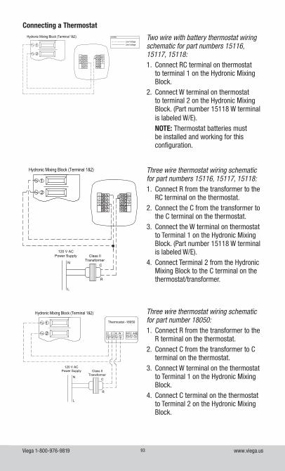
Viega 1-800-976-9819 www.viega.us93
Two wire with battery thermostat wiring schematic for part numbers 15116, 15117, 15118:1. Connect RC terminal on thermostat
to terminal 1 on the Hydronic Mixing Block.
2. Connect W terminal on thermostat to terminal 2 on the Hydronic Mixing Block. (Part number 15118 W terminal is labeled W/E).NOTE: Thermostat batteries must be installed and working for this configuration.
Three wire thermostat wiring schematic for part numbers 15116, 15117, 15118:1. Connect R from the transformer to the
RC terminal on the thermostat.2. Connect the C from the transformer to
the C terminal on the thermostat.3. Connect the W terminal on thermostat
to Terminal 1 on the Hydronic Mixing Block. (Part number 15118 W terminal is labeled W/E).
4. Connect Terminal 2 from the Hydronic Mixing Block to the C terminal on the thermostat/transformer.
Connecting a Thermostat
Three wire thermostat wiring schematic for part number 18050:1. Connect R from the transformer to the
R terminal on the thermostat.2. Connect C from the transformer to C
terminal on the thermostat.3. Connect W terminal on the thermostat
to Terminal 1 on the Hydronic Mixing Block.
4. Connect C terminal on the thermostat to Terminal 2 on the Hydronic Mixing Block.
COBW
RHRCGY
1
2
Hydronic Mixing Block (Terminal 1&2)
Line VoltageLow Voltage
LEGEND
Class IITransformer
C
R
120 V ACPower Supply
N
L
COBW
RHRCGY
1
2
Hydronic Mixing Block (Terminal 1&2)
Line VoltageLow Voltage
LEGEND: Zone Controls
C C R W NTC A/B
Thermostat -18050
Class IITransformer
C
R
120 V ACPower Supply
N
L
1
2
Hydronic Mixing Block (Terminal 1&2)
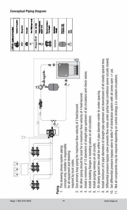
Viega 1-800-976-9819 www.viega.us94
Conceptual Piping Diagram
Pipi
ng1.
Th
is d
raw
ing
show
s sy
stem
pip
ing
conc
ept o
nly.
Inst
alle
r is
resp
onsi
ble
for a
ll eq
uipm
ent a
nd d
etai
ling
requ
ired
by lo
cal c
odes
.2.
Si
ze p
rimar
y lo
op p
ipin
g fo
r max
imum
flow
vel
ocity
of 2
feet
/sec
ond.
3.
All o
ther
pip
ing
shou
ld b
e si
zed
for a
max
imum
flow
vel
ocity
of 4
feet
/sec
ond.
4.
Inst
all a
min
imum
of 1
2 di
amet
ers
of s
traig
ht p
ipe
upst
ream
of a
ll ci
rcul
ator
s an
d ch
eck
valv
es.
5.
Inst
all i
sola
ting
flang
es o
r iso
latin
g va
lves
on
all c
ircul
ator
s.6.
In
stal
l pur
ging
val
ve(s
) on
all c
ircui
ts.
7.
All c
lose
ly s
pace
d te
es s
hall
be w
ithin
4 p
ipe
diam
eter
cen
ter t
o ce
nter
spa
cing
.8.
In
stal
l min
imum
of 6
pip
e di
amet
ers
of s
traig
ht p
ipe
upst
ream
and
dow
nstre
am o
f all
clos
ely
spac
ed te
es.
9.
Diffe
rent
ial p
ress
ure
bypa
ss v
alve
pre
vent
s flo
w n
oise
und
er p
artia
l loa
d co
nditi
ons
(som
e ci
rcui
ts c
lose
d).
10.
Set d
iffer
entia
l pre
ssur
e by
pass
val
ve to
del
ta P
of d
istri
butio
n sy
stem
with
all
zone
s op
en +
1 ps
i.11
. No
t all
com
pone
nts
may
be
requ
ired
depe
ndin
g on
con
trol s
trate
gy (i
.e. c
onst
ant c
ircul
atio
n).
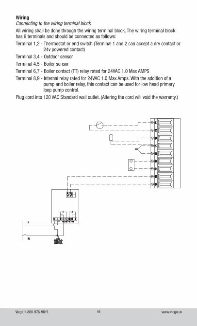
Viega 1-800-976-9819 www.viega.us95
Pipi
ng1.
Th
is d
raw
ing
show
s sy
stem
pip
ing
conc
ept o
nly.
Inst
alle
r is
resp
onsi
ble
for a
ll eq
uipm
ent a
nd d
etai
ling
requ
ired
by lo
cal c
odes
.2.
Si
ze p
rimar
y lo
op p
ipin
g fo
r max
imum
flow
vel
ocity
of 2
feet
/sec
ond.
3.
All o
ther
pip
ing
shou
ld b
e si
zed
for a
max
imum
flow
vel
ocity
of 4
feet
/sec
ond.
4.
Inst
all a
min
imum
of 1
2 di
amet
ers
of s
traig
ht p
ipe
upst
ream
of a
ll ci
rcul
ator
s an
d ch
eck
valv
es.
5.
Inst
all i
sola
ting
flang
es o
r iso
latin
g va
lves
on
all c
ircul
ator
s.6.
In
stal
l pur
ging
val
ve(s
) on
all c
ircui
ts.
7.
All c
lose
ly s
pace
d te
es s
hall
be w
ithin
4 p
ipe
diam
eter
cen
ter t
o ce
nter
spa
cing
.8.
In
stal
l min
imum
of 6
pip
e di
amet
ers
of s
traig
ht p
ipe
upst
ream
and
dow
nstre
am o
f all
clos
ely
spac
ed te
es.
9.
Diffe
rent
ial p
ress
ure
bypa
ss v
alve
pre
vent
s flo
w n
oise
und
er p
artia
l loa
d co
nditi
ons
(som
e ci
rcui
ts c
lose
d).
10.
Set d
iffer
entia
l pre
ssur
e by
pass
val
ve to
del
ta P
of d
istri
butio
n sy
stem
with
all
zone
s op
en +
1 ps
i.11
. No
t all
com
pone
nts
may
be
requ
ired
depe
ndin
g on
con
trol s
trate
gy (i
.e. c
onst
ant c
ircul
atio
n).
WiringConnecting to the wiring terminal blockAll wiring shall be done through the wiring terminal block. The wiring terminal block has 9 terminals and should be connected as follows:Terminal 1,2 - Thermostat or end switch (Terminal 1 and 2 can accept a dry contact or
24v powered contact)Terminal 3,4 - Outdoor sensor Terminal 4,5 - Boiler sensor Terminal 6,7 - Boiler contact (TT) relay rated for 24VAC 1.0 Max AMPSTerminal 8,9 - Internal relay rated for 24VAC 1.0 Max Amps. With the addition of a
pump and boiler relay, this contact can be used for low head primary loop pump control.
Plug cord into 120 VAC Standard wall outlet. (Altering the cord will void the warranty.)
Viega 1-800-976-9819 www.viega.us96
Viega Product Glossary
0-10VDC Powerhead: The Viega 0-10V powerhead is a thermo-electric powerhead that mounts on the return valve of a Viega 1¼" stainless manifold. A 24-volt signal powers the unit open while controlled by a 0-10V DC signal, usually from either a thermostat or a central DDC building management system. This powerhead is compatible with 1¼" stainless manifolds of either shutoff/balancing or shutoff/balancing flow meter types.
3-Speed Circulator Pump: Viega offers two (low and high head) three-speed, wet rotor, direct drive in-line circulator pumps designed for residential and light commercial applications. These circulators are quiet and maintenance-free, making them ideal to use in primary and/or secondary loop piping.
Advanced Snow Melt Control: The Viega Advanced Snow Melt Control provides full automatic snow and ice detection in open-air spaces such as driveways, parking areas, ramps, stairs and flat roofs. The control operates a floating action actuator or a variable speed injection pump to provide both boiler and slab protection. Viega’s Advanced Snow Melt Control is equipped with a Snow Melt Sensor that measures the slab temperature, surface temperature and surface moisture level. When the control is not in Melting mode, the system can either be shut down or it can be maintained at an idle temperature for faster response and improved safety.
Assembled Climate Panels (ACP): Climate Panels that are sold pre-assembled as an easier method of installation.
Basic Digital Setpoint Control II: General-purpose temperature control with a wide range of applications in the HVAC industry. This control provides two isolated SPDT relay contacts. The two relays are controlled by a watertight sensor. Included with the Basic Digital Setpoint Control. This control is commonly used as basic heating and/or cooling system control for commercial and residential slab application.
Basic Heating Control: The Viega Basic Heating Control is designed to control the supply water temperature to a hydronic system in order to provide outdoor reset operation. The Basic Heating Control uses a floating action actuator mounted on a diverting or mixing valve to regulate the supply water temperature. The control has a Liquid Crystal Display (LCD) to view system status and operating information.
Climate Panel: A dry heating panel that uses grooved plywood panels backed with aluminum as an attachment media for 5⁄16" PEX tubing. Designed to go under any type of floor covering – hardwood, carpet, tile or vinyl. This gives homeowners a great deal of flexibility when designing their new home.
Climate Mat: A pre-engineered, pre-assembled roll-out radiant loop, used in concrete pour radiant applications. Climate Mats are available in 10 different configurations and shipped to the customer tested and ready to install.
Climate Trak: A extruded aluminum track system used for radiant heating applications in both new construction and retrofit applications. The product is designed to strongly grip the PEX tubing without air gaps or the need for sealant/adhesives, ensuring high heat conduction. Climate Traks are fastened tightly to the underside of subfloor for maximum system performance. Available in 4' and 8' lengths, this system utilizes ⅜" and ½" tubing.
Viega 1-800-976-9819 www.viega.us97
Constant Circulation: Technology employed by the Hydronic Mixing Block and the Basic Heating Control where the pump is active throughout entire heating or cooling season to maintain constant flow through heated area. Temperature is controlled by resetting the water temperature to match the desired output.
Diverting Valve: Used to adjust fluid temperature in hydronic applications. Diverting valves are available from Viega in ¾" - 1½" sizes. These valves are used in Viega mixing stations.
Groove Tube: Groove Tube is a silicone-based caulking with additives that aid in heat transfer. It is used in Climate Panel and Heat Transfer Plates for installations.
Heat Exchanger: A product that transfers heat from one fluid to another without mixing them.
Heat Transfer Plates: Light-gauge aluminum plates intended to be secured under the subfloor in between the floor joists, and used for radiant heating. The plates are 5" wide, 19" long and are available for use with ⅜" and ½" tubing.
Hydronic Mixing Block: The Hydronic Mixing Block is a mixing device and boiler control with a built-in circulator and system controller. The block can provide either a fixed or reset water temperature via start/stop, or constant fluid circulation.
Mixing Station: A Viega component that supplies water temperature modulation when connected to a variety of heat sources such as conventional or condensing boilers, water heaters or geothermal heat pumps.
Mixing Valve: A valve used to regulate fluid temperature. These valves are ideal for mixing fluid to control temperature in heating, cooling and snow-ice melting system applications. The valves can be controlled both manually or automatically with the use of an actuator.
Mixing Valve Actuator: A 24-volt motorized control device used to adjust the outlet fluid temperature from a three- or four-way mixing valve.
Outdoor Reset Control: A control method that adjusts the mixed water temperature based on the outdoor temperature.
Proportional Actuator: An actuator is used in electronic temperature control systems that use hot and/or cold water as the controlled medium in radiant heating systems, snow melting or other temperature mixing applications. The actuator is designed for operation by a 0-10 V DC controller such as a DDC system. This actuator will not work with Viega controls such as the Basic Heating Control.
Powerhead: A two-position actuator for zone control that mounts on the return valve of the Stainless Manifold. A 24 VAC signal actuates the head to open the valve. The position of the valve is normally closed. Upon opening the valve, the integral SPST contacts close. Viega offers a two- and four-wire model.
Pump and Boiler Relay: An electrical device that, through the use of a thermostat or other switching device, can trigger a call for heat as well as circulator activation.
Secondary Piping: Piping that is either directly connected to primary piping or originates off manifolds fed by primary piping but is not located within a radiant emitter.
Series Piping: Piping that connects manifolds or radiant emitters from end to end, creating one continuous loop.
Viega 1-800-976-9819 www.viega.us98
SVC: Abbreviation for Standard Viega Connection. This is important to know as any threaded connection with this identification will be a standard proprietary Viega thread. These threads are used on Viega manifolds as well as a variety of threaded fittings.
Thermostatic Mixing Valve: Used to adjust fluid temperature in a hydronic application. This type of valve will maintain a constant supply temperature when supplied with varying supply and return fluid temperatures.
Three-Position Actuator: A 24-volt motorized control device used to adjust the output fluid temperature from the Viega diverting valve.
Viega Barrier PEX: Tubing produced from cross-linkable, high-density polyethylene resin. This cross-linkable resin is produced by grafting organo-silane molecules onto a base polyethylene chain. A catalyst that initiates the cross-linking process is blended with the resin before extrusion. Cross-linking is conducted after extrusion by exposing the tubing to heat and moisture (steam). Viega Barrier PEX includes four layers. The first layer is the cross-linked, high-density polyethylene. The second layer is an adhesive for the third layer, the ethylene vinyl alcohol layer (EVOH oxygen barrier). The fourth layer is another thin layer of polyethylene, put on the outside to protect the EVOH layer from damage. EVOH is highly resistant to the passage of oxygen.
Zone Control: A wiring and switching center for individual and/or multiroom control. The zone control simplifies wiring between thermostats and powerheads. LED lights on housing indicate individual zone heat demand. Available as a 4 or 6 zone, both with priority. Zone control includes optional circulator activation function and built-in transformer.
Zone Valve: Viega zone valves are used to control the flow of fluid within a hydronic heating or cooling system. They do so by opening when there is a thermostat demand and closing when the demand has been met. Viega zone valves are available in ¾" and 1" with three different connection types: ProPress x ProPress, ProPress x PEX Press and solder x PEX Press.


Viega LLC585 Interlocken Blvd. Broomfield, CO 80021 Phone (800) 976-9819 Fax (800) 976-9817 www.viega.us [email protected] PG-PR 724888 0621 Heating and Cooling Solutions
This document is subject to updates. For the most current Viega technical literature please visit www.viega.us.
©2021, Viega®, GeoFusion®, ManaBloc®, MegaPress®, ProPress®, SeaPress®, Smart Connect®, Climate Mat®, Climate Panel®, Climate Trak®, PureFlow®, XL®, XL-C®, Visign®, Visign for Style®, Visign for More®, Visign for Care®, Visign for Public®, Viega Eco Plus®, and Viega: Connected in quality® are trademarks of Viega Holding GmbH & Co. KG. Eco Brass® is a registered trademark of Mitsubishi Shindoh Co., LTD. RIDGID® is a registered trademark of RIDGID, Inc. LoopCAD® is a registered trademark of Avenir Software Inc. Radel® R is a registered trademark of Solvay Advanced Polymers, LLC. LEED® is a registered trademark of the U.S. Green Building Council®.