Embed Size (px)
Citation preview
HIGH ENERGY PARTICLE COLLIDERS: PAST 20 YEARS, NEXT 20 YEARS AND BEYOND
VLADIMIR D. SHILTSEV
Fermilab Accelerator Physics Center, PO Box 500, MS221, Batavia, IL, 60510, USA
Abstract: Particle colliders for high energy physics have been in the forefront of scientific discoveries
for more than half a century. The accelerator technology of the collider has progressed immensely, while
the beam energy, luminosity, facility size and the cost have grown by several orders of magnitude. The
method of colliding beams has not fully exhausted its potential but its pace of progress has greatly
slowed down. In this paper we very briefly review the method and the history of colliders, discuss in
detail the developments over the past two decades and the directions of the R&D toward near future
colliders which are currently being explored. Finally, we make an attempt to look beyond the current
horizon and outline the changes in the paradigm required for the next breakthroughs.
Content:
1. Introduction, colliders of today
a. The method
b. Brief history of the colliders, beam physics and key technologies
c. Past 20 years - achievements and problems solved
2. Next 20 years: physics, technologies and machines
a. LHC upgrades and lower energy colliders
b. Post-LHC energy frontier lepton colliders: ILC, CLIC, Muon Collider
3. Beyond 2030’s: new methods and paradigm shift
a. Possible development of colliders in the resource-limited world
b. Future technologies: acceleration in microstructures, in plasma and in crystals
c. Luminosity limits
4. Conclusions
Chapter 1: Introduction, Colliders of Today
Particle accelerators have been widely used for physics research since the early 20th
century
and have greatly progressed both scientifically and technologically since then.
To gain an insight into the physics of elementary particles, one accelerates them to very high
kinetic energy, let them impact on other particles, and detect products of the reactions that
transform the particles into other particles. It is estimated that in the post-1938 era, accelerator
science has influenced almost 1/3 of physicists and physics studies and on average contributed to
physics Nobel Prize-winning research every 2.9 years [1]. Colliding beam facilities which
produce high-energy collisions (interactions) between particles of approximately oppositely
directed beams did pave the way for progress since the 1960’s.
The center of mass (CM) energy Ecm for a head-on collision of two particles with masses m1,
m2 and energies E1 and E2 is
2/142
2
2
2
42
1
2
1
42
2
2
121 2)(2 cmEcmEcmmEEEcm . (1)
For many decades, the only arrangement of accelerator experiments was a fixed target setup
where a beam of particles accelerated with a particle accelerator hit a stationary target set into
the path of the beam. In this case, as follows from Eq. (1), for high energy accelerators E>> mc2,
the CM energy is Ecm(2Emc2)1/2
. For example, E=1000 GeV protons hitting stationary protons
mc21 GeV can produce reactions with about 43 GeV energy. A more effective colliding beam
set-up in which two beams of particles are accelerated and directed against each other, has much
higher center of mass energy of Ecm2(E1E2)1/2
. In the case of two equal masses of particles (e.g.
protons and protons, or protons and antiprotons) colliding with the same energy E of 1000 GeV,
one gets Ecm=2E or 2000 GeV. Such an obvious advantage led to the first practical proposals of
colliding-beam storage rings in the late 1950’s [2,3].
Almost three dozen of colliders reached operational stage between the late 50’s and now.
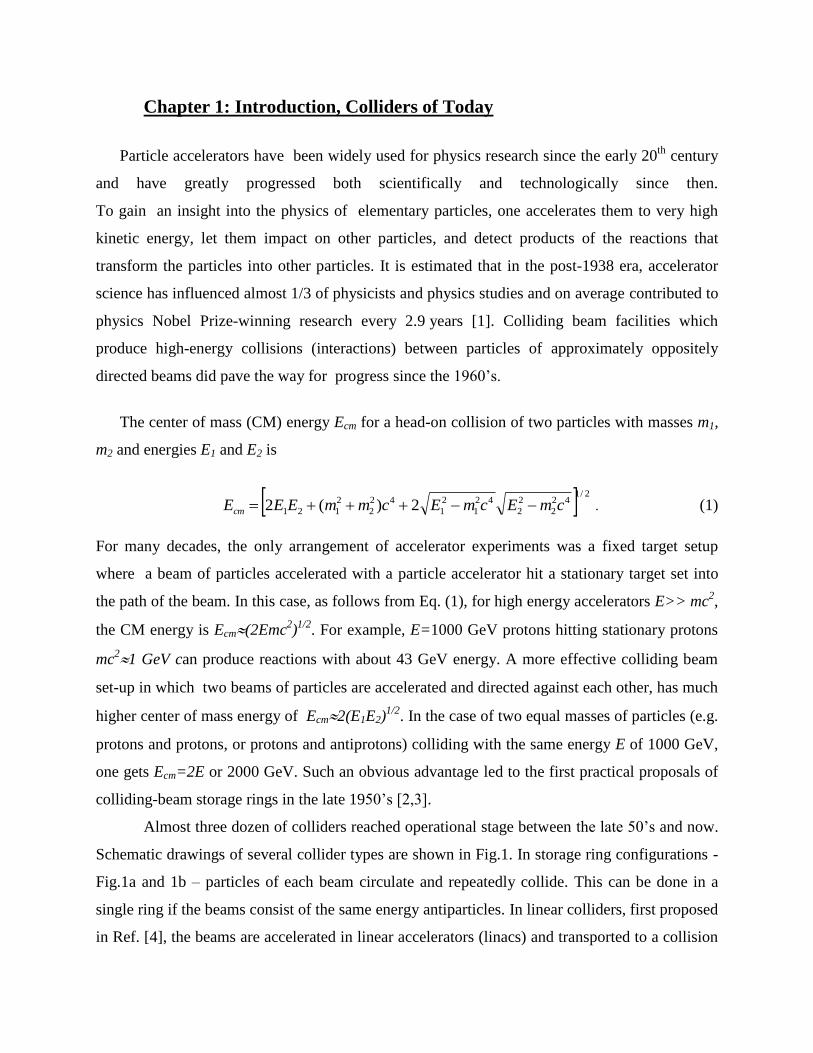
Schematic drawings of several collider types are shown in Fig.1. In storage ring configurations -
Fig.1a and 1b – particles of each beam circulate and repeatedly collide. This can be done in a
single ring if the beams consist of the same energy antiparticles. In linear colliders, first proposed
in Ref. [4], the beams are accelerated in linear accelerators (linacs) and transported to a collision
point: either in the simple two linac configurations depicted in Fig.1c, or with use of the same
linac and two arcs as in Fig.1d. Another possible linac-ring configuration is shown in Fig.1e.
Figure 1: Schematics of particle collider types.
The first colliding lepton beam facilities were built in the early 1960s almost
simultaneously at three laboratories: e-e- colliders AdA at the Frascati laboratory near Rome in
Italy, the VEP-1 collider in the Novosibirsk Institute of Nuclear Physics (USSR) and the
Princeton-Stanford Colliding Beam Experiment at Stanford (USA). Their center of mass energies
were 1 GeV or less. Construction of the first hadron (proton-proton) collider, the Intersecting
Storage Rings, began at CERN (Switzerland) in 1966, and in 1971, this collider was operational
and eventually reached Ecm=63 GeV. The first linear collider was the e-e+ SLAC Linear
Collider (SLC) constructed at Stanford in the late 1980’s. Detail discussions on the history of
colliders can be found, e.g., in [5, 6], Ref.[7] gives an overview of the development of the
colliding beams facilities in Novosibirsk. (As this article is not intended to be a historical
overview, only the most recent relevant references will be provided below.)
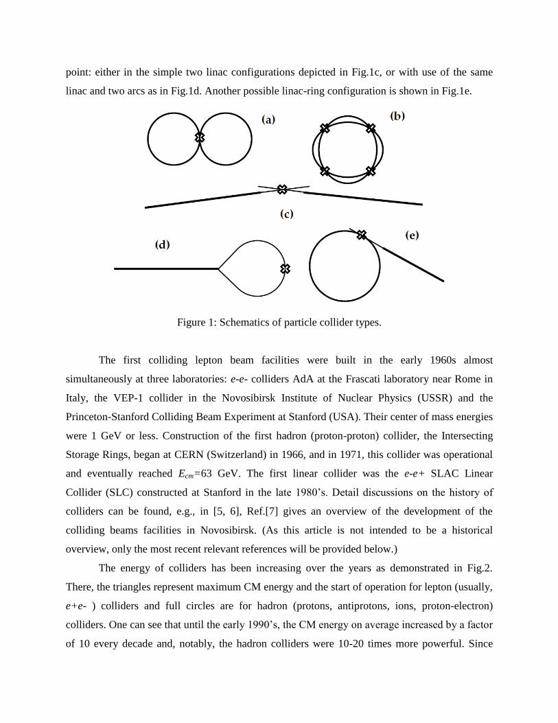
The energy of colliders has been increasing over the years as demonstrated in Fig.2.
There, the triangles represent maximum CM energy and the start of operation for lepton (usually,
e+e- ) colliders and full circles are for hadron (protons, antiprotons, ions, proton-electron)
colliders. One can see that until the early 1990’s, the CM energy on average increased by a factor
of 10 every decade and, notably, the hadron colliders were 10-20 times more powerful. Since
then, following the demands of high energy physics, the paths of the colliders diverged to reach
record high energies in the particle reaction. The Large Hadron Colider (LHC) was built at
CERN, while new e+e- colliders called “particle factories” were focused on detail exploration
of phenomena at much lower energies.
Figure 2: Colliders over the decades.
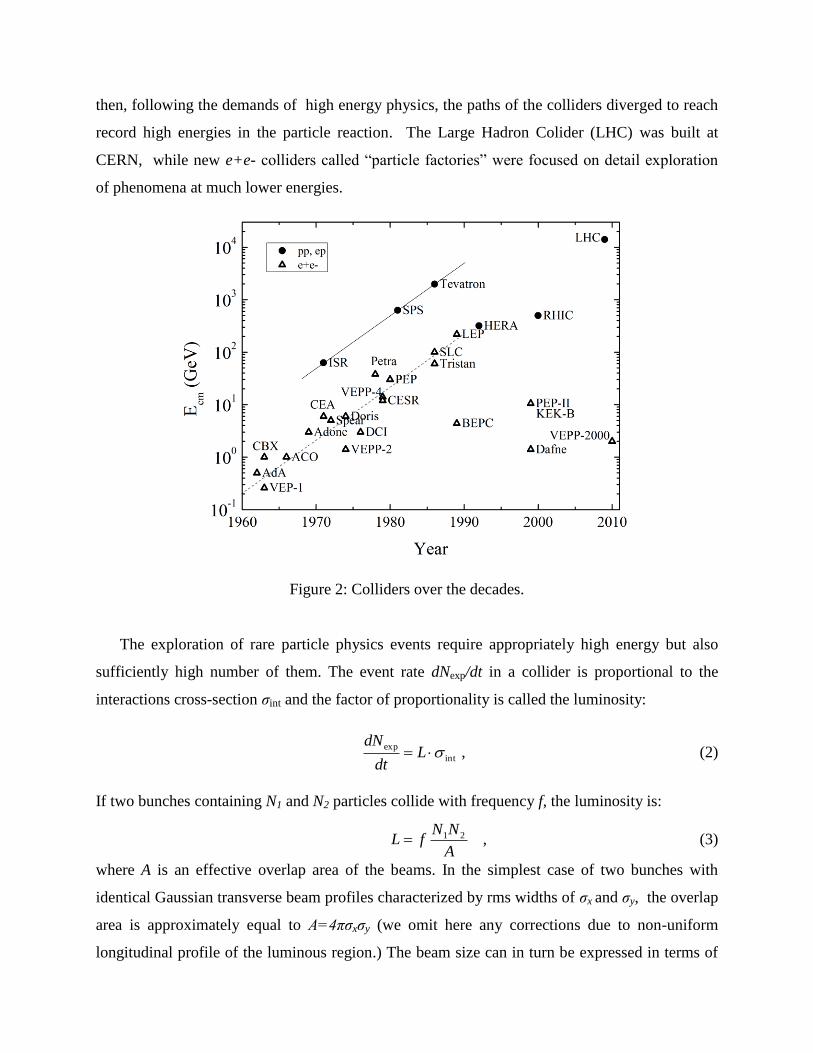
The exploration of rare particle physics events require appropriately high energy but also
sufficiently high number of them. The event rate dNexp/dt in a collider is proportional to the
interactions cross-section σint and the factor of proportionality is called the luminosity:
int
exp L
dt
dN , (2)
If two bunches containing N1 and N2 particles collide with frequency f, the luminosity is:
A
NNfL 21 , (3)
where A is an effective overlap area of the beams. In the simplest case of two bunches with
identical Gaussian transverse beam profiles characterized by rms widths of σx and σy, the overlap
area is approximately equal to A=4πσxσy (we omit here any corrections due to non-uniform
longitudinal profile of the luminous region.) The beam size can in turn be expressed in terms of
the rms normalized transverse emittance (which is an approximate adiabatic invariant of
particle motion during acceleration) and the amplitude function β (which is a beam optics
quantity determined by accelerator transverse, most often magnetic, focusing system):
2 , (4)
=E/mc2 is the relativistic Lorentz factor. So, the basic equation for the luminosity (3) can now
be re-written in terms of emittances and the amplitude functions at the interaction point (which
we denote by asterisks) as
**
21
4 yyxx
NNfL
. (5)
Therefore to achieve high luminosity, one has to maximize population of bunches with as low as
possible emittances and to collide them at high frequency at locations where the focusing beam
optics provide the lowest values of the amplitude functions β*x,y. Increasing the beam energy
and thus, factor in Eq.(5), is, generally speaking, of help, too.
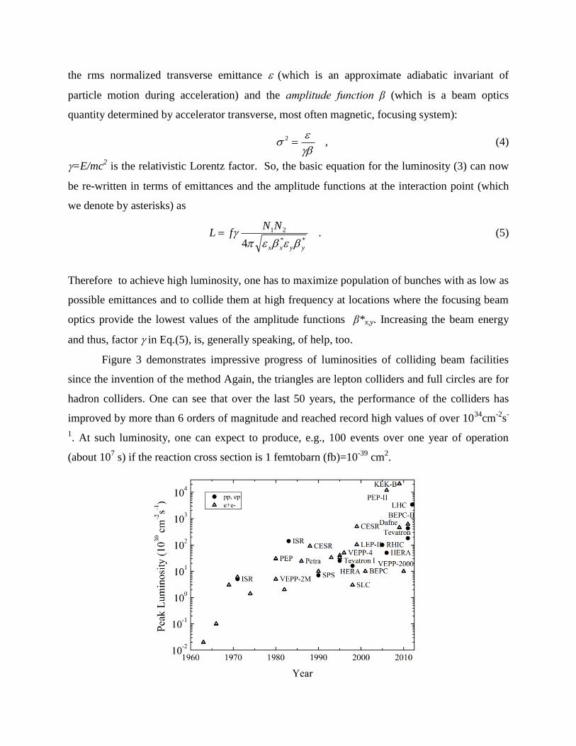
Figure 3 demonstrates impressive progress of luminosities of colliding beam facilities
since the invention of the method Again, the triangles are lepton colliders and full circles are for
hadron colliders. One can see that over the last 50 years, the performance of the colliders has
improved by more than 6 orders of magnitude and reached record high values of over 1034
cm-2
s-
1. At such luminosity, one can expect to produce, e.g., 100 events over one year of operation
(about 107 s) if the reaction cross section is 1 femtobarn (fb)=10
-39 cm
2.
Figure 3: Peak luminosities of particle colliders.
Needless to say such great progress in both the energy and the luminosity of colliders has
come from numerous advances in accelerator science and technology. The format of this article
does not allow us to go through all the advances in detail – an interested reader can be referred
for details to, e.g., a comprehensive handbook [6] – but it is worth at least a list major ones, as
they will be relevant to our subsequent discussion on future colliders. References provided below
will be given only to relatively recent development of the last two decades.
The maximum energy of colliders is determined by practical considerations, of which the
first is the size of the facility. For a linear collider, beam energy is product of average
accelerating gradient G and length of the linac l:
leGE . (6)
In (the only) linear collider SLC, the average gradient in a 3-km-long linac, which was powered
at a frequency of 2.856 GHz (RF=10.5cm RF wavelength in normal-conducting copper
structures), did eventually reach some 21 MV/m. Notably, as the length of the linac did not
change, the beam energy approximately tripled over 30 years of operation because of upgrades,
such as quadrupling the number of RF power sources (pulsed klystrons), increasing the peak
output power of the klystrons from 35 MW to 65 MW, and further increasing the power by
compressing the length of the RF pulses.
In circular colliders, the maximum momentum and energy of ultra-relativistic particle is
determined by the radius of the ring R and average magnetic field B of bending magnets:
ReBpc or ][][3.0][ mRTBGeVE . (7)
Again, evolution of energy was driven by practical considerations: e.g., maximum field of
normal conducting magnets of about 2T at some moment was not adequate for the energy
demands because of required longer accelerator tunnels and increasing magnet power
consumption. Development of superconducting (SC) magnets – see Fig.4 - which employ high
electric current carrying NbTi wires cooled by liquid Helium below 5K, opened the way to
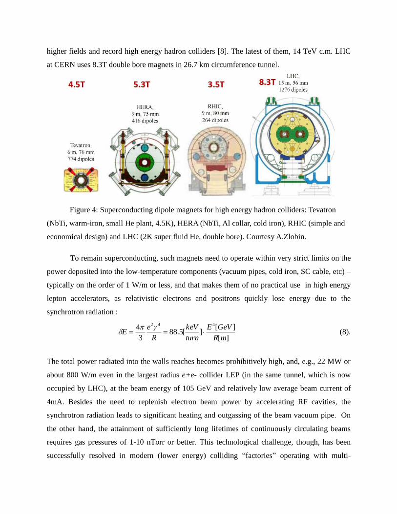
higher fields and record high energy hadron colliders [8]. The latest of them, 14 TeV c.m. LHC
at CERN uses 8.3T double bore magnets in 26.7 km circumference tunnel.
Figure 4: Superconducting dipole magnets for high energy hadron colliders: Tevatron
(NbTi, warm-iron, small He plant, 4.5K), HERA (NbTi, Al collar, cold iron), RHIC (simple and
economical design) and LHC (2K super fluid He, double bore). Courtesy A.Zlobin.
To remain superconducting, such magnets need to operate within very strict limits on the
power deposited into the low-temperature components (vacuum pipes, cold iron, SC cable, etc) –
typically on the order of 1 W/m or less, and that makes them of no practical use in high energy
lepton accelerators, as relativistic electrons and positrons quickly lose energy due to the
synchrotron radiation :
][
][][5.88
3
4 442
mR
GeVE
turn
keV
R
eE
(8).
The total power radiated into the walls reaches becomes prohibitively high, and, e.g., 22 MW or
about 800 W/m even in the largest radius e+e- collider LEP (in the same tunnel, which is now
occupied by LHC), at the beam energy of 105 GeV and relatively low average beam current of
4mA. Besides the need to replenish electron beam power by accelerating RF cavities, the
synchrotron radiation leads to significant heating and outgassing of the beam vacuum pipe. On
the other hand, the attainment of sufficiently long lifetimes of continuously circulating beams
requires gas pressures of 1-10 nTorr or better. This technological challenge, though, has been
successfully resolved in modern (lower energy) colliding “factories” operating with multi-
Ampere beams. Radiation of protons (ions) is smaller by a significant factor (γp/γe) 4
=(me/mp)4 –
see Eq.(8) - but still can be of a certain concern at very high energy, high current SC
accelerators, e.g., LHC.
From the very beginning of the colliders, it was understood that their effective operation
required stability of particle’s motion in the rings. It is desired for particles to exhibit bound
transverse oscillations in the fields of focusing magnets, e.g., as in the solution of Hill’s equation
])(cos[)()( ssAsx , (9)
where the phase ψ(s) advances around the ring and determines so called tune, or the number of
such betatron oscillations per turn:
)(2
1sdv
. (10)
Imperfections of the guiding magnetic fields can lead to multi-turn instabilities due to linear or
non-linear resonances and cause particles to leave the acceptable aperture. At first, this was
avoided by careful choice of the tune(s) – which is usually set away from integer or rational
values νn/m - and with careful construction of the magnets. Magnetic field quality is given by
the multipole coefficients in the expansion:
n
n
nnyxR
iyxiabBBiB
00
0 )( , (11)
where R0 is the reference radius, the pole number is 2(n+1) and bn(an) are the normal (skew)
multipole coefficients, and b0 is unity. Over the years, collider magnet builders have perfected
the magnet designs to the level of few 10-4
in the undesired multipoles – this was particularly
challenging for SC magnets where such quality required very tight tolerances of less than a few
dozen microns for the placements and position stability of the conductor coils under enormous
magnetic forces [8]. Even more demanding were the field quality tolerances for the special, very
strong magnets now routinely used in modern colliders to over-compress beams at the interaction
points and arrange minimal possible beta-functions at the collision points x,y* - per Eq. (5) such
magnets have greatly helped to achieve higher luminosities.
Unfortunately, the growing demand for luminosity led to orders of magnitude stronger
non-linearity due to the very nature of the colliders – namely, due to electric and magnetic forces
of the opposite bunch at the interaction points. The nonlinearity due to the collisions is
characterized by dimensionless parameter called the “beam-beam parameter” or the “beam-beam
tune shift”:
*
,
*
,
**,)(2 yx
yx
yx
cyx
Nr
, (12)
(here, all the parameters are for the opposite bunch, and rc=e2/mc
2 is the classical radius of the
particles) and can reach the value of ξ~0.03 in hadron colliders to ~0.13 in lepton colliders.
Beyond this limit, a variety of so called “beam-beam effects” have usually led to intolerable
operational conditions due to beam losses, beam size blowups, etc. From Eqs.(3) and (5) one can
see that the path to higher luminosity via higher beam intensity and smaller beam size almost
automatically leads to higher beam-beam parameters. To get around the above-mentioned
“beam-beam limit” several methods have been implemented over the decades, including a)
making a careful choice of working tunes away from the most detrimental resonances; b)
operation with very flat bunches (wide in horizontal plane and narrow in the vertical – see
Eq.(12)); c) breaking beams into a significant number of bunches separated in all but a few
interaction points, so the single bunch intensity N is reduced; and, more recently, e)
compensation of the beam-beam effects using electron lenses [9]; f) reduction of the strength of
the beam-beam resonance in the “round beams” scheme with strongly coupled vertical and
horizontal motion [10] and by g) using so called “crab-waist” collision method that beneficially
modifies the geometry of the colliding bunch profiles only at the interaction points [11].
Despite all the inventions, the beam-beam effects are still considered to be setting a not fully
resolved limit on the performance of most colliders.
There are two ways to achieve high luminosity within the beam-beam limit – either to
increase the beam current I=e f N or to decrease the beam emittance . In addition to the
synchrotron radiation power which grows linearly with I, the major limitations on the current
come from so-called coherent beam instabilities and from the demands of the radiation
protection from inevitable particle losses. The instabilities are caused by beam interaction with
the electromagnetic fields induced by the beam itself in the vacuum cambers and RF cavities, or
caused by unstable clouds of secondary particles, like electrons or ions, which are formed around
the circulating beams [12, 13]. Beam-based transverse and longitudinal feedback systems and
electron/ion clearing (either by weak magnetic or electric field or by modulation of the primary
beam current profile make the secondaries unstable) are now in routine use to avoid the coherent
instabilities. Incoherent particle losses may have a variety of causes: unstable single particle
motion, diffusion due to scattering on residual vacuum molecules or on the other particles within
the bunch, high-frequency noises in the guiding magnetic field or the EM fields of RF cavities,
ground motion and man-made vibrations, etc. To avoid damage or excessive irradiation of the
accelerator components so they can be accessed and maintained if necessary in the tunnel,
sophisticated collimation systems are utilized which usually employ a series of targets (which
scatter the halo particles) and absorbers (which intercept the particles in dedicated locations)
[14], or use more sophisticated techniques like collimation by bent crystals [15] or by hollow
electron beams [16].
As for the quest for smaller beam emittances (phase space area) the paths of the lepton
and hadron colliders were different. In the electron machines where any transverse errors are
naturally damped by the synchrotron radiation, the emittance is determined by quantum
fluctuations of the radiation which excite mostly horizontal oscillations – therefore, the challenge
is to design focusing beam optics to minimize the effect in the horizontal plane, and avoid its
coupling to the vertical plane, ideally below 1% [17]. Hadron collides cannot enjoy fast damping
due to the synchrotron radiation, at least for energies less than 10 TeV, so for them the only ways
to progress for were either generate low-emittance (high brightness) beams in the sources or
arrange beam “cooling” (phase space reduction, usually at the low or medium energy
accelerators in the injector chain), using either “stochastic cooling” or “electron cooling”
methods, and the latter has been recently exemplified in the relativistic regime [18].
Operation of the colliders with progressively smaller and smaller beams brought up many issues
relevant to alignment of magnets, vibrations and long-term tunnel stability [19]. Radiation
backgrounds in high-energy physics detectors necessitated careful design of the accelerator-
detector interface in high luminosity colliders. High energy physics demands for polarized beam
collisions and very precise c.m. energy calibration of about (δE/E)~10-5
have been largely
satisfied by, correspondingly, the development of polarized particle sources married with
sophisticated methods to maintain beam polarization along the acceleration chain [20] and by
novel method of “resonant depolarization” [21, 17].
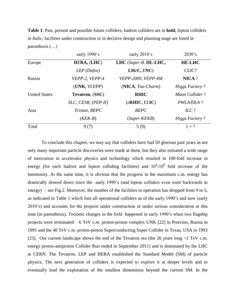
Table 1: Past, present and possible future colliders; hadron colliders are in bold, lepton colliders
in Italic, facilities under construction or in decisive design and planning stage are listed in
parenthesis (…)
early 1990‘s early 2010’s 2030’s
Europe HERA, (LHC)
LEP (Dafne)
LHC (Super-B, HL-LHC,
LHeC, ENC)
HE-LHC
CLIC?
Russia VEPP-2, VEPP-4
(UNK, VLEPP)
VEPP-2000, VEPP-4M
(NICA, Tau-Charm)
NICA ?
Higgs Factory ?
United States Tevatron, (SSC)
SLC, CESR, (PEP-II)
RHIC
(eRHIC, ELIC)
Muon Collider ?
PWLA/DLA ?
Asia Tristan, BEPC
(KEK-B)
BEPC
(Super-KEKB)
ILC ?
Higgs Factory ?
Total 9 (7) 5 (9) 1 + ?
To conclude this chapter, we may say that colliders have had 50 glorious past years as not
only many important particle discoveries were made at them, but they also initiated a wide range
of innovation in accelerator physics and technology which resulted in 100-fold increase in
energy (for each hadron and lepton colliding facilities) and 104-10
6 fold increase of the
luminosity. At the same time, it is obvious that the progress in the maximum c.m. energy has
drastically slowed down since the early 1990’s (and lepton colliders even went backwards in
energy) – see Fig.2. Moreover, the number of the facilities in operation has dropped from 9 to 5,
as indicated in Table 1 which lists all operational colliders as of the early 1990’s and now (early
2010’s) and accounts for the projects under construction or under serious consideration at this
time (in parenthesis). Tectonic changes in the field happened in early 1990’s when two flagship
projects were terminated – 6 TeV c.m. proton-proton complex UNK [22] in Protvino, Russia in
1991 and the 40 TeV c.m. proton-proton Superconducting Super Collider in Texas, USA in 1993
[23]. Our current landscape shows the end of the Tevatron era (the 26 years long ~2 TeV c.m.
energy proton-antiproton Collider Run ended in September 2011) and is dominated by the LHC
at CERN. The Tevatron, LEP and HERA established the Standard Model (SM) of particle
physics. The next generation of colliders is expected to explore it at deeper levels and to
eventually lead the exploration of the smallest dimensions beyond the current SM. In the
following chapters we outline possible colliders for the next 20 years and take a look into the
issues and options for the even more distant future.
Chapter 2: Next 20 Years: Physics, Technologies and Machines
The future of the collider is ultimately driven by the demands of particle physics, but
should stay within the limits of the available technologies and financial resources. All the
projects currently under construction or at the design stage (see Table 1) satisfy those three
requirements and, thus have good prospects of becoming operational and deliver results in the
next 20 years. Schematically they can be categorized by the area of the promising physics as
follows:
Energy Frontier : the LHC luminosity upgrade project HL-LHC [24] will employ novel SC
magnet technology based on the Nb3Sn superconductors for tighter focusing at the interaction
points and quintuple the performance of the energy frontier machine by mid-2020’s to 5·1034
cm-
2s
-1 with luminosity leveling at 14 TeV c.m. energy in proton-proton collisions and will enable to
obtain about 250 fb-1
of the integrated luminosity per year with ultimate goal of 3000 fb-1
for
both ATLAS and CMS experiments.
Low-energy hadron collisions: investigation of the mixed phase of quark–gluon matter and
polarization phenomena at relatively low hadron energies has recently become of significant
interest for the high energy physics community, and it is the main goal of the Nuclotron-based
Ion Collider fAcility (NICA) currently under construction at JINR (Dubna, Russia) [25]. NICA
will allow for the study of ion-ion (Au+79
) and ion-proton collisions in the energy range of 1-4.5
GeV/amu with average luminosity of 1027
cm−2
s−1
and also polarized proton-proton (5-12.6
GeV) and deuteron-deuteron (2-5.8 GeV/amu) collisions – in that regime luminosities up to
1031
cm−2
s−1
are foreseen. The plans indicate start of operation and first physics results later in
this decade.
Electron-hadron collisions: deep inelastic electron-nucleon scattering is in the focus of a new
electron-hadron collider project, the LHeC [26], in which polarized electrons of 60 GeV to
possibly 140 GeV collide with LHC protons of 7000 GeV with design luminosity of about 1033
cm−2
s−1
. This would exceed the integrated luminosity collected at the previous ep collider
HERA at DESY by two orders of magnitude in a 20 times wider kinematic range in the
momentum transfer Q2. Similar approach of reusing an existing beam facility and adding an
accelerator for another species is taken in two collider projects in the US – eRHIC at BNL [27]
and Electron-Ion Collider (ELIC) at JLab [28]. The eRHIC design is based on one of the existing
RHIC(Relativistic Heavy Ion Collider) hadron rings which can accelerate polarized nuclear
beam to 100 GeV/nucleon and polarized protons upto 250 GeV for, and a new 20-30 GeV multi-
pass energy-recovery linac (ERL) to accelerate polarized electrons; the luminosity varies from
1033
cm−2
s−1
to 1034
cm−2
s−1
depending on the energy and species. The ELIC proposal re-uses
the CEBAF 3-7 GeV polarized electron accelerator and requires the construction of a 30 to 150
GeV storage ring for ions (p, d, 3He and Li, and unpolarized light to medium ion species). The
attainment of very high luminosities in the ELIC, from 5·1033
cm-2
s-1
to 1035
cm-2
s-1
, an ERL-
based continuous electron cooling facility is anticipated to provide low emittance and
simultaneously very short ion bunches. Though with lower c.m. energy than LHeC, both of the
projects in the US have the advantage of colliding both electron and ion species with polarized
spins. It is believed that not more than one of the two can be supported and constructed.
Complementary physics programs can be realized at the proposed electron-nucleon
collider ENC at the upcoming Facility for Antiproton and Ion Research FAIR at GSI Darmstadt
(Germany) by utilizing the 15 GeV antiproton high-energy storage ring HESR for polarized
proton and deuteron beams, with the addition of a 3.3 GeV storage ring for polarized electrons
[29]. This will enable electron-nucleon collisions up to a center-of-mass energy upto 14 GeV
with peak luminosities in the range of 1032
to 1033
cm−2
s−1
.
Electron-positron factories: In the late 1990’s – early 2000’s, two asymmetric-energy e+e− B-
factories, the KEKB collider for the Belle experiment at KEK and the PEPII collider for the
BaBar experiment at SLAC, had achieved tremendous success in confirmation of the Standard
Model (SM) in the quark flavor sector and indicated that the Kobayashi-Maskawa mechanism is
the dominant source of the observed CP violation in nature. Despite that, two fundamental
questions remain unanswered in the flavor sector of quarks and leptons: a) it is not clear why the
SM includes too many parameters and b) there is still a serious problem with the matter-
antimatter asymmetry in the universe. To extend physics reach beyond two B-factories, much
higher (by a factor of 40 or so) luminosity Super-B factories are either set up or considered for
construction – one in Italy [30] and another in Japan [31]. Both are asymmetric-energy e+e−
colliders with beam energies of about 4 GeV and 7 GeV and with a design luminosity
approaching 1036
cm−2
s−1
, which is to be achieved via somewhat higher beam currents and very
small beta-functions at the interaction points y*~0.3mm made possible by employment of the
above mentioned “crab waist” scheme. The physics run of the Super-KEKB in Japan is expected
in 2015 and the physics run will start in 2015. Ultimately, Belle II detector should collect
40 times more B-meson samples per second than its predecessor – roughly 800 BB pairs per
second and accumulate an integrated luminosity of 50 ab–1
=50,000 fb–1
by 2021.
Many similar technical solutions, e.g. the “crab waist”, will also be employed in the
project of TauCharm factory in Novosibirsk (Russia) [32] which calls for c.m. collision energy
variable from 3 GeV to 4.5 GeV (from J/psi resonances to charm barions), luminosity in excess
of 1035
cm−2
s−1
and longitudinal polarization of at least one (electron) beam.
If one will project at the very end of the next 20 years, then the landscape of the collider
physics is much less certain, there are several directions to advance and the choice between the
options will be based upon the results from the LHC. The relevant results are expected to be
available starting in 2012-2013 (e.g., anticipated discovery of the Higgs boson) but they might
easily slip well into the 2020’s. Let us look into five possibilities for an after-LHC collider of
2030’s.
Higher energy LHC: One of the most feasible opportunities is an energy upgrade of the LHC to
33 TeV c.m. proton-proton collisions [33]. The HE-LHC in the existing LHC tunnel will require
20T dipole magnets which are currently thought possible via combination of the NbTi, Nb3Sn
and HTS (high-temperature superconductor) SC magnet technology. Such a collider could follow
the HL-LHC and start operation in the early 2030’s. Despite the (presumed) feasibility of the
machine, its energy reach is limited to ~2.5 times the LHC energy and it is not fully clear yet
whether such a (relatively) small energy advance will justify its construction.
Higgs Factory: The Higgs boson with mass mH of about 125 GeV has been recently discovered
at the LHC, and the detailed studies and precise measurements of this unique spin-0 elementary
particle might be of enough significant interest to justify construction of a e+e- collider – a
dedicated “Higgs factory”. The maximum cross-section, and arguably the optimal centre-of-
mass energy for studies of a number of Higgs boson properties, is at Ecm ~ mH + (110±10) GeV
~240 GeV, and several opportunities for the facility are now under discussion, including one
based on the ILC-type linear collider (see below) as well as several ring-ring versions [34]. The
biggest challenge for the latter is the requirement to replenish energy loss of electrons and
positrons due to the synchrotron radiation of the order of 10 GeV per turn even in 20-km or
longer tunnels - see Eq.(8) – that with necessity means extensive use of high gradient SC RF
accelerating cavities. Other challenges toward attainment of the required luminosity of ~1034
cm−2
s−1
(equivalent to 20,000 events per year under assumption of the e+e- HZ cross section
of about 200 femtobarn (fb)=2·10-34
cm2) will be significant electric power consumption on the
order of 100 MW needed for continuous acceleration of ~10 mA of beam current and the need
for very small beam emittances and very large momentum acceptance of the ring to
accommodate the energy losses at the interaction points (see discussion on the beamstrahlung
effect below). A cost saving option of the Higgs factory in an existing tunnel, e.g., 26.7 km long
LHC tunnel or 21 km long UNK tunnel, looks particularly attractive.
Alternative way for production of the Higgs bosons is in the reaction +-H (so called
s-channel reaction) which has advantageously large cross section for muons, (m/me)2~40,000
times higher than for electrons, and (another advantage) needs a +- collider with factor of two
lower c.m. energy Ecm~mH. The third advantage of that scheme is significantly smaller c.m.
energy spread δEcm/Ecm~ 0.01-0.003% (compared to ~0.2% for the e+e- factories) that allows
much better study of the outstandingly narrow width Higgs particle decays [35]. Production of
~4,000 events per year will require luminosity of at least 1031
cm−2
s−1
which seems to be very
challenging because of the short muon lifetime and difficulties of the muon production (see
discussion on high energy muon colliders below).
Energy Frontier Lepton Collider: It is presently widely believed that a multi-TeV lepton collider
will be needed to follow the LHC discoveries. The physics program that could be pursued by a
new lepton collider with sufficient luminosity, would include understanding the mechanism
behind mass generation and electroweak symmetry breaking; searching for, and possibly
discovering, super-symmetric particles; and hunting for signs of extra space-time dimensions and
quantum gravity. By the beginning of the 2020’s, the results obtained from the LHC will be
expected to more precisely establish the desired lepton collider energy. The most viable options
currently under consideration are e+e− linear colliders ILC (International Linear Collider) [36]
and CLIC (Compact Linear Collider) [37] or μ+μ− Muon Collider [38]. Each of these options
has its own advantages, challenges and issues [39, 37].
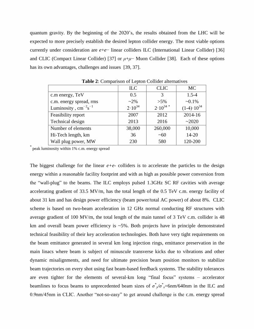
Table 2: Comparison of Lepton Collider alternatives
ILC CLIC MC
c.m energy, TeV
c.m. energy spread, rms
Luminosity , cm−2
s−1
0.5
~2%
2·1034
3
>5%
2·1034
*
1.5-4
~0.1%
(1-4)·1034
Feasibility report
Technical design
2007
2013
2012
2016
2014-16
~2020
Number of elements
Hi-Tech length, km
Wall plug power, MW
38,000
36
230
260,000
~60
580
10,000
14-20
120-200 *
peak luminosity within 1% c.m. energy spread
The biggest challenge for the linear e+e- colliders is to accelerate the particles to the design
energy within a reasonable facility footprint and with as high as possible power conversion from
the “wall-plug” to the beams. The ILC employs pulsed 1.3GHz SC RF cavities with average
accelerating gradient of 33.5 MV/m, has the total length of the 0.5 TeV c.m. energy facility of
about 31 km and has design power efficiency (beam power/total AC power) of about 8%. CLIC
scheme is based on two-beam acceleration in 12 GHz normal conducting RF structures with
average gradient of 100 MV/m, the total length of the main tunnel of 3 TeV c.m. collider is 48
km and overall beam power efficiency is ~5%. Both projects have in principle demonstrated
technical feasibility of their key acceleration technologies. Both have very tight requirements on
the beam emittance generated in several km long injection rings, emittance preservation in the
main linacs where beam is subject of minuscule transverse kicks due to vibrations and other
dynamic misalignments, and need for ultimate precision beam position monitors to stabilize
beam trajectories on every shot using fast beam-based feedback systems. The stability tolerances
are even tighter for the elements of several-km long “final focus” systems – accelerator
beamlines to focus beams to unprecedented beam sizes of σ*
y/σ*
x=6nm/640nm in the ILC and
0.9nm/45nm in CLIC. Another “not-so-easy” to get around challenge is the c.m. energy spread
induced by beamstrahlung (the energy loss caused by radiation of gamma quanta by the
incoming electron due to its interaction with the EM field electron (positron) bunch moving in
the opposite direction) during the very moment of collision of short bunches with rms length of
σz =50-300 m, that for parameters of interest can be approximated as :
zx
erN
E
E
2
32
, (13)
and reach several % or even 10% - see Table 2. The induced radiation generates undesirable
background in the detectors, makes handling of the beams after the collision more sophisticated
and, most importantly, sets limitation on the energy resolution of the narrow resonances such as
in the Higgs- and expected Z’-boson decay reactions.
Muons, which can be thought of as a heavy electrons, are essentially free of all
synchrotron radiation related effects, which are proportional to the fourth power of the Lorentz
factor 4, and, thus, (m/me)
4 = (207)
4 = 210
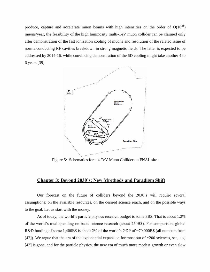
9 times smaller. So, a multi-TeV +-
collider [39]
can be circular and therefore have a compact geometry that will fit on existing accelerator sites
(see Fig.5 for a possible schematic of a MC facility on the 6×7 km FNAL site ). The collider has
a potentially higher energy reach than linear e+e- colliders, its c.m. energy spread in a 1.5-4
TeV + -
collider can be as small as 0.1%, requires less AC power and operates with
significantly smaller number of elements requiring high reliability and individual control for
effective operation - see Table 2. Additional attraction of a Muon Collider(MC) is its possible
synergy with the Neutrino Factory concept [40] as beam generation and injection complex of that
facility and of a MC are similar (perhaps identical) [41]. As mentioned above, due to higher
mass of the muon and superb energy resolution, a Higgs factory based on low(er) energy + -
collisions is very attractive, too.
The biggest challenges of a MC come from the very short lifetime of the muon - 0=2s
is just long enough to allow acceleration to high energy before the muon decays into an electron,
a muon-type neutrino and an electron-type antineutrino ( ee ) – and from the methods
of the muon production as tertiary particles in the reactions ...... pN , so, the
beams of muons are generated with very large emittances. A high-energy, 1-5 TeV c.m., high-
luminosity O(1034
) cm−2
s−1
muon collider seems will require a factor of O(106) reduction of the
6-dimensional muon beam phase space volume (muon cooling). Though there has been
significant progress over the past decade in developing the concepts and technologies needed to
produce, capture and accelerate muon beams with high intensities on the order of O(1021
)
muons/year, the feasibility of the high luminosity multi-TeV muon collider can be claimed only
after demonstration of the fast ionization cooling of muons and resolution of the related issue of
normalconducting RF cavities breakdown in strong magnetic fields. The latter is expected to be
addressed by 2014-16, while convincing demonstration of the 6D cooling might take another 4 to
6 years [39].
Figure 5: Schematics for a 4 TeV Muon Collider on FNAL site.
Chapter 3: Beyond 2030’s: New Mrethods and Paradigm Shift
Our forecast on the future of colliders beyond the 2030’s will require several
assumptions: on the available resources, on the desired science reach, and on the possible ways
to the goal. Let us start with the money.
As of today, the world’s particle physics research budget is some 3B$. That is about 1.2%
of the world’s total spending on basic science research (about 250B$). For comparison, global
R&D funding of some 1,400B$ is about 2% of the world’s GDP of ~70,000B$ (all numbers from
[42]). We argue that the era of the exponential expansion for most out of ~200 sciences, see, e.g.
[43] is gone, and for the particle physics, the new era of much more modest growth or even slow
down of the financial support began in the 1990’s - as one can also conclude from Fig.2 above.
Despite the fact that most of today’s scientific leaders in the scientific societies, governments and
universities came of age during previous “golden era” and have not yet fully adjusted to new
realities, we will base our predictions on the assumption that the field will stay approximately
within the current financial limits, while still vigorously exploring new methods and directions.
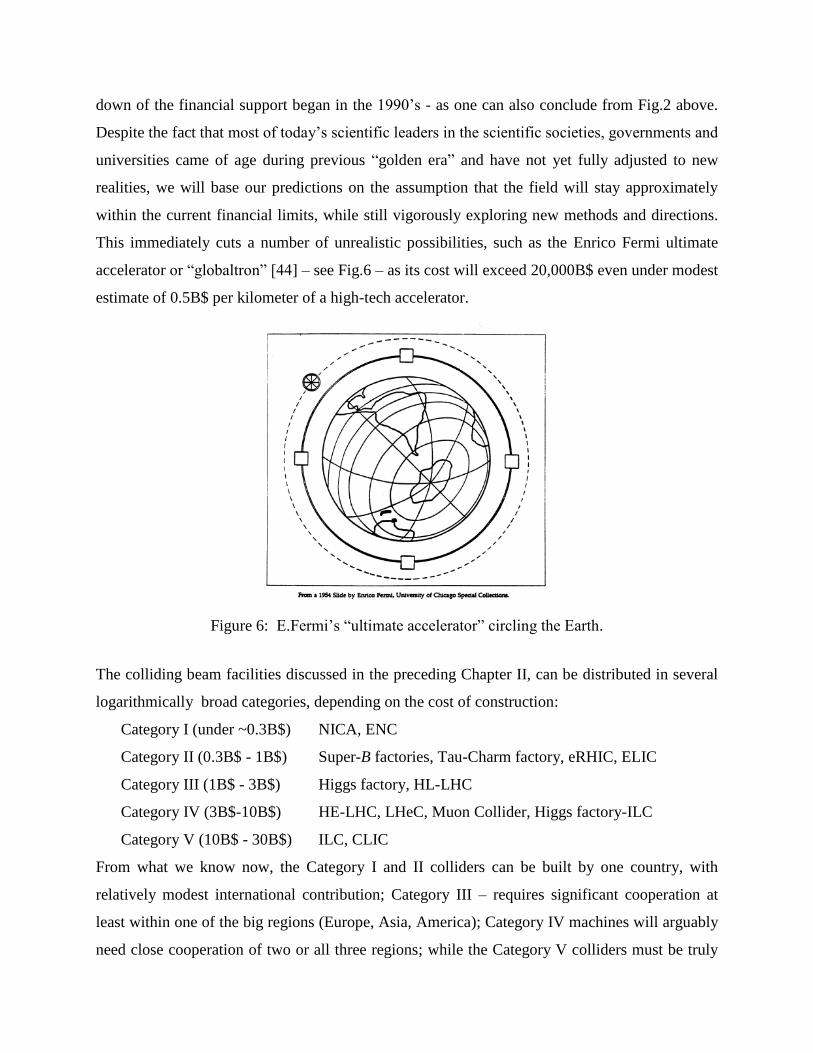
This immediately cuts a number of unrealistic possibilities, such as the Enrico Fermi ultimate
accelerator or “globaltron” [44] – see Fig.6 – as its cost will exceed 20,000B$ even under modest
estimate of 0.5B$ per kilometer of a high-tech accelerator.
Figure 6: E.Fermi’s “ultimate accelerator” circling the Earth.
The colliding beam facilities discussed in the preceding Chapter II, can be distributed in several
logarithmically broad categories, depending on the cost of construction:
Category I (under ~0.3B$) NICA, ENC
Category II (0.3B$ - 1B$) Super-B factories, Tau-Charm factory, eRHIC, ELIC
Category III (1B$ - 3B$) Higgs factory, HL-LHC
Category IV (3B$-10B$) HE-LHC, LHeC, Muon Collider, Higgs factory-ILC
Category V (10B$ - 30B$) ILC, CLIC
From what we know now, the Category I and II colliders can be built by one country, with
relatively modest international contribution; Category III – requires significant cooperation at
least within one of the big regions (Europe, Asia, America); Category IV machines will arguably
need close cooperation of two or all three regions; while the Category V colliders must be truly
international. Following our basic assumption (that the particle physics budget will not grow
much beyond ~3B$ in current prices), it is hard to imagine that any of the projects in Category V
are possible, as none of the possible scenarios – “do nothing but construction for 3-10 years” or
“carve some 1/3 of the budget for construction and finish it in 10-30 years”, or doing that at even
slower pace – none of these seem realistic, especially for the energy reach being only comparable
to the LHC. Category III machines appear totally feasible financially, but they only add to
exploration of the phenomena discovered by the LHC, thus, there always will be an alternative
“why don’t we just run LHC longer?” Finally, we are left with Category IV colliders which
appear to be on the border of financial affordability. There is a problem, though, with them –
they have limited energy reach, equivalent to some 5 TeV c.m. energy in parton collisions (that
is the Muon Collider energy, and the HE-LHC c.m. energy divided by an equivalent number of
partons in proton 33/(6-10)=3-5 TeV). It is not whatsoever certain whether there be a demanding
physics case for such kind of c.m. energies to justify the required significant investment.
Below we will offer some possibilities for physics reach of far future colliders within
approximate budget of 10B$ (in current prices). The cost models of the modern colliders are
quite complicated and do not fit the scope of this article, but one may safely assume that the
future facility of such cost should not exceed 10 or few 10’s of km in length and simultaneously
require less than 10 to few 10’s of MW of beam power (or correspondingly stay under ~100MW
of AC wall power consumption). Can such colliders reach energies orders of magnitude beyond
current – namely, 100-1000 TeV?
To get to the energies of interest within given footprint, one needs fast acceleration. At
present, three main opportunities for high energy colliders are being actively discussed which
can be schematically classified by the type of media used for acceleration – solid state structures,
plasma and crystals. (Below we reference the most recent reviews.)
Acceleration in dielectric structures: Most of present day accelerators employ radiofrequency
fields (fRF <10-30 GHz) in resonant normal-conducting or SC structures powered by
conventional RF sources and are in general limited to gradients of ~100 MV/m due to surface
breakdown phenomena. Combination of direct beam excitation (or wakefields radiated by a
short intense ‘‘driving’’ bunch of electrons propagating in a high impedance environment) and
hard dielectric materials (quartz, diamond, garnets, etc – which are characterized by lower power
losses and higher breakdown gradients than metals) for structure fabrication, allow accelerating
gradients of ~100 MV/m and ~1 GV/m in microwave O(10) GHz and THz dielectric structures
[45], correspondingly. Conceptually, a dielectric wakefield accelerator (DWA)-based linear
collider would consist of a large number of ~100 GeV modules (stages) with some ~0.3 GeV/m
gradient each driven by a separate ~1 GeV high intensity electron beam. Even without going into
difficulties associated with staging, cost and power considerations, it is hard to imagine that more
than 3 TeV c.m. energy DWA facility can fit within a 10 km site.
Further increase of the gradient to ~1-3 GV/m is thought to be possible in m scale
dielectric structures driven by lasers operating in optical or near-infrared regime [46]. In various
options either external fiber lasers are coupled to the structures or semiconductor lasers can be
integrated on the same slab right next to the microcells they power. Advantage of such an
approach is that laser power sources can operate at very high repetition rates of ~10-100 MHz,
that helps to get higher luminosity – see again Eq.(5) – but again, a 10 TeV c.m. energy collider
will require ~12 km of the total linac length [47]. To be of note that staging of sequential
accelerating modules made of smaller size structures (microns vs millimeters) will require
proportionally tighter synchronization, alignment and mechanical stability tolerances to keep
beam trajectories and emittances under control.
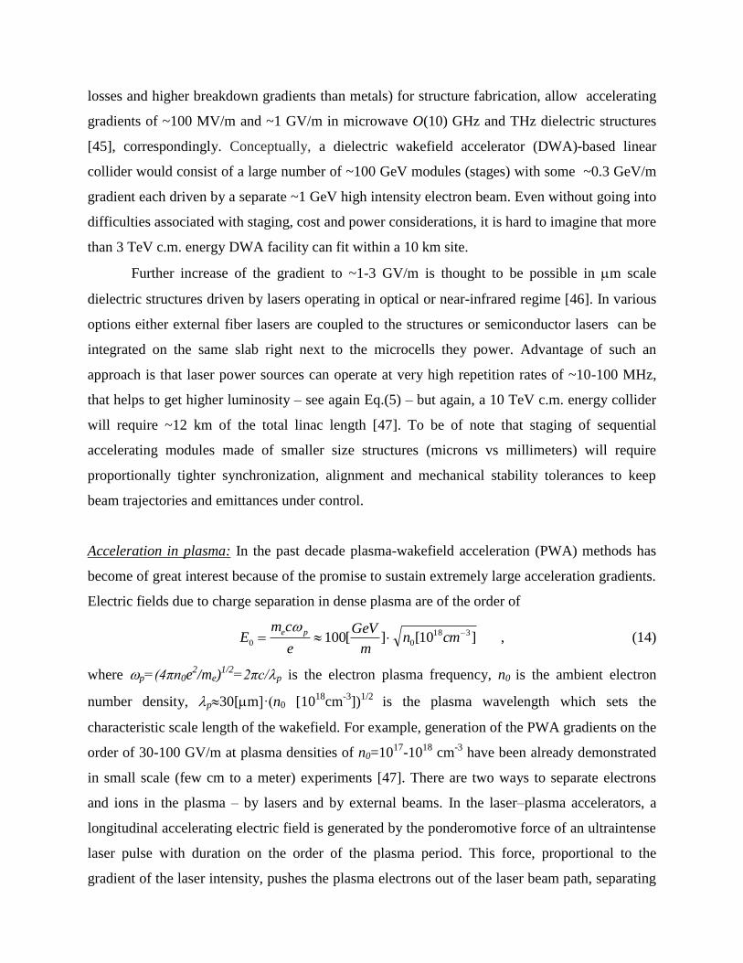
Acceleration in plasma: In the past decade plasma-wakefield acceleration (PWA) methods has
become of great interest because of the promise to sustain extremely large acceleration gradients.
Electric fields due to charge separation in dense plasma are of the order of
]10[][100 318
00
cmnm
GeV
e
cmE
pe , (14)
where p=(4πn0e2/me)
1/2=2πc/p is the electron plasma frequency, n0 is the ambient electron
number density, p30[m]·(n0 [1018
cm-3
])1/2
is the plasma wavelength which sets the
characteristic scale length of the wakefield. For example, generation of the PWA gradients on the
order of 30-100 GV/m at plasma densities of n0=1017
-1018
cm-3
have been already demonstrated
in small scale (few cm to a meter) experiments [47]. There are two ways to separate electrons
and ions in the plasma – by lasers and by external beams. In the laser–plasma accelerators, a
longitudinal accelerating electric field is generated by the ponderomotive force of an ultraintense
laser pulse with duration on the order of the plasma period. This force, proportional to the
gradient of the laser intensity, pushes the plasma electrons out of the laser beam path, separating
them from the less mobile ions. This creates a travelling longitudinal electric field, in the wake of
the laser pulse, with a phase velocity close to the speed of light – i.e., as needed for accelerating
relativistic particles. The structure of the wakefield has broad phase space where negatively
charged particles can be both accelerated and focused. Depletion of the laser energy determines
the energy gain and the length of a single acceleration stage after which a new laser pulse must
be coupled into plasma for further acceleration. Practical considerations indicate that this stage-
to-stage distance is on the order of 1 m, and minimization of the total linac length requires
operation at relatively low densities n0~1017
cm-3
and energy gain per stage of 10 GeV and
average gradient ~5TeV/km [48].
Alternative LWA concept involves the passage of an ultra relativistic electron bunch
through a stationary plasma (either pre-formed by ionizing a gas by a laser or through field-
ionization by the Coulomb field of the relativistic electron bunch itself). The plasma electrons
are repelled by the bunch. Generating large amplitude wakefields requires short high density
electron bunches compressed in all three spatial dimensions to sizes smaller than p – e.g.,
bunches of few 1010
electrons of few m’s spot size and ~10 m long. The wake produces a high
gradient accelerating field Eq.(14) and transverse focusing for a negatively charged witness
bunch behind the drive bunch [49]. The figure of merit in wakefield accelerators (plasma or
dielectric) is the transformer ratio RT=(maximum accelerating field behind the drive bunch)/ (the
maximum decelerating field inside the drive bunch) which is limited to ~2 for a finite length,
longitudinally symmetric drive bunches and can reach somewhat reach higher values only for
specially prepared triangular bunch current shapes. A proposed beam-PWA collider design [50]
consists of a conventional 25 GeV electron drive beam accelerator, which produces drive
bunches distributed in counter-propagating directions to many (dozens to hundreds, depending
on the final energy) one meter long plasma cells for both the electron and positron arms of the
collider. Though each cell provides 25 GeV energy gain (RT1), an average geometric
accelerating gradient reaches only 0.25 TeV/km after taking into account some 100 meter long
cell-to-cell gaps needed to bring up a fresh drive beam to the next cell from a single source of the
high intensity 25 GeV electron bunches. As in other schemes, serious issues associated with
staging and transfers from one cell to another (alignment, synchronization, etc) are anticipated.
The number of stages can be significantly reduced if higher energy drive beams are available,
e.g., some 0.6 TeV energy gain might be possible in a single ~400m plasma cell driven by 1 TeV
protons if such high energy proton bunches can be compressed longitudinally to under 1mm
bunch length and kept tightly focused transversely [51]. Without going into practical
considerations and just projecting such gradients further one can think of an ultimate ~10 TeV
collider within 10 km footprint.
Acceleration in crystal channels: The density of charge carriers (conduction electrons) in solids
n0~1022-23
cm-3
is significantly higher than what was considered above in plasma, and
correspondingly, the longitudinal fields of upto 100 GeV/cm or 10 TV/m are possible – see
Eq.(14). The new effects at higher densities are due to intense energy radiation in high fields and
increased scattering rates which result in fast pitch-angle diffusion over distances of ld
~1[m]·E[TeV]. The latter leads to particles escaping from the driving field; thus, it was
suggested that particles are accelerated in solids along major crystallographic directions, which
provide a channeling effect in combination with low emittance determined by an Ångström-scale
aperture of the atomic “tubes.” Channeling with nanotubes is also being discussed. Positively
charged particles are channeled more robustly, as they are repelled from ions and thus experience
weaker scattering. Radiation emission due to betatron oscillations between the atomic planes is
thought to be the major source of energy dissipation, and the maximum beam energies are
limited to about 0.3 TeV for positrons, 104 TeV for muons and 10
6 TeV for protons [52]. X-ray
lasers can efficiently excite solid plasma and accelerate particles inside a crystal channel
waveguide, though ultimate acceleration gradients ~10TeV/m might require relativistic
intensities, exceeding those conceivable for x-rays as of today [53]. Moreover, only disposable
crystal accelerators, e.g., in the form of fibers or films, are possible at such high externally
excited fields which would exceed the ionization thresholds and destroy the periodic atomic
structure of the crystal (so acceleration will take place only in a short time before full
dissociation of the lattice). For the laser and plasma fields of about 1 GV/cm=0.1 TV/m or less,
reusable crystal accelerators can probably be built which can survive multiple pulses [54]. Side
injection of powerful x-ray pulses into continuous fiber of 0.1 – 10 km long fiber allows to avoid
multiple staging issues intrinsic to other methods and reach 10-1000 TeV energies, if the
imperfections like crystal dislocations are kept under control and unintended crystal curvatures
are less than inverse “critical” radius Rc ~2[m]·E[TeV] – so the channeling conditions remain
[15].
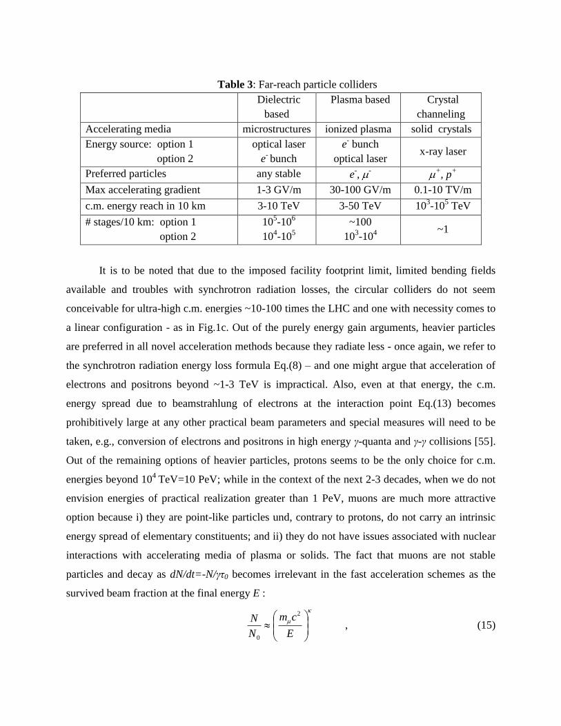
Table 3: Far-reach particle colliders
Dielectric
based
Plasma based Crystal
channeling
Accelerating media microstructures ionized plasma solid crystals
Energy source: option 1
option 2
optical laser
e- bunch
e- bunch
optical laser x-ray laser
Preferred particles any stable e-, -
+, p
+
Max accelerating gradient 1-3 GV/m 30-100 GV/m 0.1-10 TV/m
c.m. energy reach in 10 km 3-10 TeV 3-50 TeV 103-10
5 TeV
# stages/10 km: option 1
option 2
105-10
6
104-10
5
~100
103-10
4
~1
It is to be noted that due to the imposed facility footprint limit, limited bending fields
available and troubles with synchrotron radiation losses, the circular colliders do not seem
conceivable for ultra-high c.m. energies ~10-100 times the LHC and one with necessity comes to
a linear configuration - as in Fig.1c. Out of the purely energy gain arguments, heavier particles
are preferred in all novel acceleration methods because they radiate less - once again, we refer to
the synchrotron radiation energy loss formula Eq.(8) – and one might argue that acceleration of
electrons and positrons beyond ~1-3 TeV is impractical. Also, even at that energy, the c.m.
energy spread due to beamstrahlung of electrons at the interaction point Eq.(13) becomes
prohibitively large at any other practical beam parameters and special measures will need to be
taken, e.g., conversion of electrons and positrons in high energy γ-quanta and γ-γ collisions [55].
Out of the remaining options of heavier particles, protons seems to be the only choice for c.m.
energies beyond 104
TeV=10 PeV; while in the context of the next 2-3 decades, when we do not
envision energies of practical realization greater than 1 PeV, muons are much more attractive
option because i) they are point-like particles und, contrary to protons, do not carry an intrinsic
energy spread of elementary constituents; and ii) they do not have issues associated with nuclear
interactions with accelerating media of plasma or solids. The fact that muons are not stable
particles and decay as dN/dt=-N/γτ0 becomes irrelevant in the fast acceleration schemes as the
survived beam fraction at the final energy E :
E
cm
N
N2
0
, (15)
is very close to 1 as soon as the exponent κ=(mc/τ0G)<<1/ln(E/mc2) or, conversely, the
average accelerating gradient G>>3 MeV/m – the condition that easily holds for any scheme
considered above (see Table 3). Note that at G>>0.3 TeV/m, one can think of accelerating tau
leptons, though production of needed quantities of τ particles is questionable.
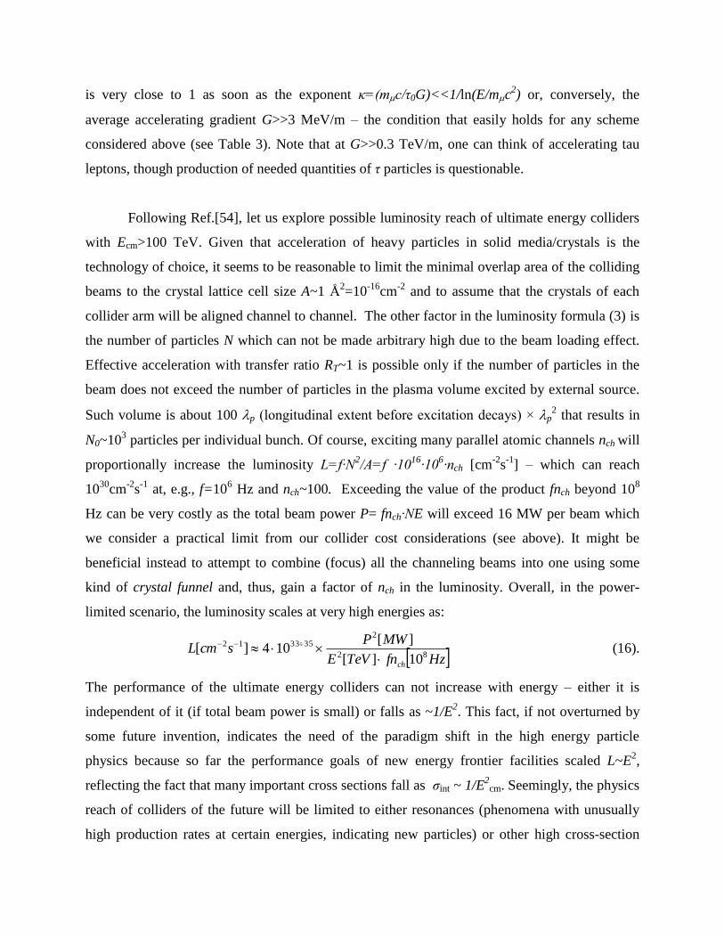
Following Ref.[54], let us explore possible luminosity reach of ultimate energy colliders
with Ecm>100 TeV. Given that acceleration of heavy particles in solid media/crystals is the
technology of choice, it seems to be reasonable to limit the minimal overlap area of the colliding
beams to the crystal lattice cell size A~1 Å2=10
-16cm
-2 and to assume that the crystals of each
collider arm will be aligned channel to channel. The other factor in the luminosity formula (3) is
the number of particles N which can not be made arbitrary high due to the beam loading effect.
Effective acceleration with transfer ratio RT~1 is possible only if the number of particles in the
beam does not exceed the number of particles in the plasma volume excited by external source.
Such volume is about 100 p (longitudinal extent before excitation decays) × p2 that results in
N0~103 particles per individual bunch. Of course, exciting many parallel atomic channels nch will
proportionally increase the luminosity L=f·N2/A=f ·10
16·10
6·nch [cm
-2s
-1] – which can reach
1030
cm-2
s-1
at, e.g., f=106 Hz and nch~100. Exceeding the value of the product fnch beyond 10
8
Hz can be very costly as the total beam power P= fnch·NE will exceed 16 MW per beam which
we consider a practical limit from our collider cost considerations (see above). It might be
beneficial instead to attempt to combine (focus) all the channeling beams into one using some
kind of crystal funnel and, thus, gain a factor of nch in the luminosity. Overall, in the power-
limited scenario, the luminosity scales at very high energies as:
HzfnTeVE
MWPscmL
ch
82
2353312
10][
][104][
(16).
The performance of the ultimate energy colliders can not increase with energy – either it is
independent of it (if total beam power is small) or falls as ~1/E2. This fact, if not overturned by
some future invention, indicates the need of the paradigm shift in the high energy particle
physics because so far the performance goals of new energy frontier facilities scaled L~E2,
reflecting the fact that many important cross sections fall as σint ~ 1/E2
cm. Seemingly, the physics
reach of colliders of the future will be limited to either resonances (phenomena with unusually
high production rates at certain energies, indicating new particles) or other high cross-section
reactions. Still, even scaling as in Eq.(16) is much better than what other alternative sources of
ultra-high energy particles can offer. For example, the number of cosmic ray events falls with the
c.m. energy Ecm(2Emc2)1/2
even faster, approximately as ~1/E7
cm and at the highest energies of
Ecm~500 TeV, or E~108 TeV, the event rates are extremely low - of about few per week even for
the largest area observatories.
Conclusions:
The colliding beam method was a smashing success so far - almost 3 dozens colliders
have been built over the past half-century and c.m. energies of about 10 TeV have been
achieved. At the same time, the pace of the energy progress has greatly slowed down due to
increasing size, complexity and cost of the facilities, and as the result, the number of colliders
currently in operation is about half of what we had 20 years ago. The prospects of facilities for
the next 20 years are not very clear today, they will be dependent on the discoveries at the
current machines, foremost, at the LHC.
It seems that economic realities will impose severe constrains for any far-future collider
beyond 2030 to be built under about 10B$ at current price, within footprint of some 10 km, and
with total electric power consumption of 10’s to 100MW. As discussed in the previous chapter,
there are possibilities which even currently conceivable methods can offer to reach ultra high
energies on the order of 100-1000 TeV within the abovementioned limits. The quest for the
energy will come at the price of the expected luminosities and will require at least three
paradigm shifts : 1) development of the new technology based on ultrahigh acceleration
gradients ~0.1-10 TeV/m in crystals; 2) acceleration of heavier particles, preferably, muons; and
3) new approaches to physics research with luminosity limited to ~1030-32
cm-2
s-1
.
As any other shift in the mainstream accelerator technology, the required switch to
acceleration of muons in linear crystal structures will take a decade or two for an R&D program
to address several key issues: a) development of economical high-intensity coherent X-ray
sources, e.g., based on table-top ~GeV scale electron accelerators [56, 57]; b) understanding the
most effective mechanisms of coupling the X-ray power to the excitation of the lattice - that can
probably be studied even at the existing high power coherent X-ray sources, like LCLS in the US
or Spring-8 in Japan; c) efficient production, injection and manipulation of nm-size muon beams
(this program can effectively gain momentum out of the current research toward a muon
collider); d) methods of combination of multiple crystal channeling beams into one (experiments
at existing high energy proton machines might provide an important input there). As in the past,
as soon as the main technology issues are address, a great boost to the new development can be
given by a test facility where the new acceleration methods are used for exploration of
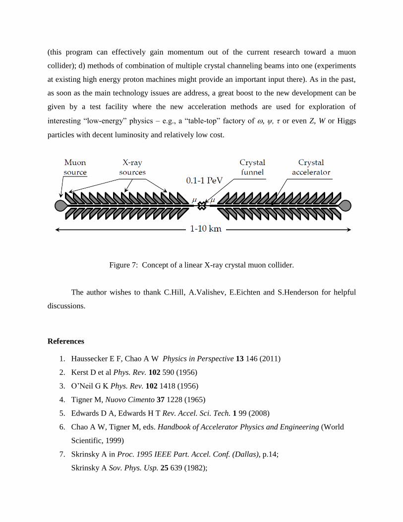
interesting “low-energy” physics – e.g., a “table-top” factory of , ψ, τ or even Z, W or Higgs
particles with decent luminosity and relatively low cost.
Figure 7: Concept of a linear X-ray crystal muon collider.
The author wishes to thank C.Hill, A.Valishev, E.Eichten and S.Henderson for helpful
discussions.
References
1. Haussecker E F, Chao A W Physics in Perspective 13 146 (2011)
2. Kerst D et al Phys. Rev. 102 590 (1956)
3. O’Neil G K Phys. Rev. 102 1418 (1956)
4. Tigner M, Nuovo Cimento 37 1228 (1965)
5. Edwards D A, Edwards H T Rev. Accel. Sci. Tech. 1 99 (2008)
6. Chao A W, Tigner M, eds. Handbook of Accelerator Physics and Engineering (World
Scientific, 1999)
7. Skrinsky A in Proc. 1995 IEEE Part. Accel. Conf. (Dallas), p.14;
Skrinsky A Sov. Phys. Usp. 25 639 (1982);
Budker G Sov. Phys. Usp. 9 534 (1967)
8. Tollestrup A, Todesco E Rev. Accel. Sci. Tech. 1 185 (2008)
9. Shiltsev V Phys. Rev. Lett. 99 244801 (2007)
10. Danilov V, et al in Proc. 1996 European Part. Accel. Conf. (Spain), p.1149
11. Raimondi P, Shatilov D, Zobov M, arxiv: physics/0702033 (2007)
12. Ohmi K Phys. Rev. Lett. 75 1526 (1995)
13. Raubenheimer T, Zimmermann F Phys. Rev. E 52 5487 (1995)
14. Mokhov N, et al JINST 6 T08005 (2011)
15. Biryukov V, Chesnokov Yu, Kotov V Crystal Channeling and Its Application at High
Energy Accelerators (Springer–Verlag, Berlin, Heidelburg, 1997)
16. Stancari G, et al Phys. Rev. Lett. 107 084802 (2011)
17. Brandt D, et al Rep. Prog. Phys. 63 939 (2000)
18. Nagaitsev S, et al Phys. Rev. Lett. 96 044801 (2006)
19. Shiltsev V Phys. Rev. ST Accel. Beams 13 094801 (2010)
20. Alexeev I, et al Nucl. Instr. Meth. Phys. Res. A 499 392 (2003)
21. Shatunov Yu, Skrinsky A Particle World 1 35 (1989)
22. Yarba V in Proc. 1991 IEEE Part. Accel. Conf. (San Francisco), p.2913
23. Wojcicki S Rev. Accel. Sci. Tech. 2 265 (2009)
24. Rossi L in Proc. 2011 Intl. Part. Accel. Conf. (Spain), p.908
25. Trubnikov G, et al in Proc. 2010 Russian Part. Accel. Conf. (Protvino), p.14
26. Klein M in Proc. 2011 Intl. Part. Accel. Conf. (Spain), p.908
27. Ptitsyn V, et al in Proc. 2011 Intl. Part. Accel. Conf. (Spain), p.3726
28. Ahmed S, et al in Proc. 2011 IEEE Part. Accel. Conf. (New York), p.2306
29. Lehrach A, et al J. Phys.: Conf. Ser. 295 012156 (2011)
30. Bagiani M, Raimondi P, Seeman J, arxiv:1009.6178
31. Abe T, et al arxiv:1011.0352
32. Levichev E Phys. Particles and Nuclei Lett. 5 554 (2008)
33. The High Energy Large Hadron Collider Preprint CERN-2011-003 (2011)
34. Blondel A, Zimmermann F, arxiv:1112:2518
35. C.Ankenbrandt, et al Phys. Rev. ST Accel Beams 2 081001 (1999).
36. ILC Reference Design Report ILC-Report-2007-001, http://www.linearcollider.org
37. Delahaye J P Mod. Phys. Lett. A 26 2997 (2011)
38. S.Geer Annu. Rev. Nucl. Part. Sci. 59:347–65 (2009)
39. Shiltsev V Mod. Phys. Lett. A 25 567 (2010)
40. The Neutrino Factory Int’l Scoping Study Accelerator Working Group Report, JINST 4
P07001 (2009)
41. Poklonskiy A, Neuffer D Int.J.Mod.Phys. A24 959 (2009)
42. 2012 Global R&D Funding Forecast Batelle R&D Magazine (Dec. 2011)
43. Shiltsev V Mod. Phys. Lett. A 26 761 (2011)
44. Cronin J (ed.) Fermi Remembered (University of Chicago Press, 2004)
45. Gai W in AIP Conf. Proc. 1086 3 (2008)
46. Bermel P, et al ICFA Beam Dynamics Newsletter 56 91 (2011)
47. Leemans W ICFA Beam Dynamics Newsletter 56 10 (2011)
48. Schroeder C, et al Phys. Rev. ST Accel. Beams 13 1013014 (2010)
49. Muggli P in AIP Conf. Proc. 1299 52 (2010)
50. Seryi A Nucl. Instr. Meth A 623 23 (2010)
51. Caldwell A, Lotov K, Pukhov A, Simon F Nature Phys. 5 363 (2009)
52. Dodin I, Fisch N Phys. Plasmas 15 103105 (2008)
53. Tajima T, Cavenago M Phys. Rev. Lett. 59 1440 (1987)
54. Chen P, Noble R AIP Conf. Proc. 398 273 (1997)
55. Telnov V arxiv:0908.3136
56. Schlenvoigt H, et al Nature Phys. 4 130 (2008)
57. Kneip S, et al Nature Phys. 6 980 (2010)


