Embed Size (px)
Citation preview
www.rsc.org/loc
ISSN 1473-0197
Lab on a ChipMiniaturisation for chemistry, physics, biology, materials science and bioengineering
PAPERJérémie Léonard et al.High-throughput time-correlated single photon counting
Volume 14 Number 22 21 November 2014 Pages 4297–4436
Lab on a Chip
PAPER
4338 | Lab Chip, 2014, 14, 4338–4343 This journal is © The R
a IPCMS, Institut de Physique et Chimie des Matériaux de Strasbourg,
Université de Strasbourg, CNRS UMR 7504, F-67034 Strasbourg Cedex 2, France.
E-mail: [email protected] ICube, Laboratoire des sciences de l'ingénieur, de l'informatique et de l'imagerie,
Université de Strasbourg, CNRS UMR 7357, F-67412 Illkirch Cedex, France
† Electronic supplementary information (ESI) available: IRF, reference fluorescencedecay of Fl, fluorescence decay fitting procedures, and demonstration of all6 equations in the paper and of the fitting function in Fig. 4. See DOI:10.1039/c4lc00780h
Cite this: Lab Chip, 2014, 14, 4338
Received 4th July 2014,Accepted 14th August 2014
DOI: 10.1039/c4lc00780h
www.rsc.org/loc
High-throughput time-correlated singlephoton counting†
Jérémie Léonard,*a Norbert Dumas,b Jean-Pascal Caussé,b Sacha Maillot,a
Naya Giannakopoulou,a Sophie Barrea and Wilfried Uhringb
We demonstrate time-correlated single photon counting (TCSPC) in microfluidic droplets under
high-throughput conditions. We discuss the fundamental limitations in the photon acquisition rate imposed
by the single photon detection technique and show that it does not preclude accurate fluorescence
lifetime (FLT) measurements at a droplet throughput exceeding 1 kHz with remarkable sensitivity. This work
paves the way for the implementation of innovative biomolecular interaction assays relying on the FLT
detection of nanosecond-lived fluorophores for high-throughput biotechnological applications, including
high-throughput screening or cell sorting potentially allowed by droplet microfluidics or other fast sample
handling facilities.
A Introduction
Luminescence intensity detection is widely used for sensitivediagnosis in high-throughput biotechnological applicationsincluding high-throughput screening (HTS) or fluorescence-activated cell sorting (FACS). Whenever biomolecular interac-tions are assayed, the fluorescence quantum yield (QY) offluorescently labeled molecules can be significantly reducedupon interaction with other molecules in vivo or in vitro. Thisis what occurs, e.g. in FRET-based (Förster resonance energytransfer) assays where the fluorescence yield of the excited“donor” molecule is quenched if its excitation energy is effi-ciently transferred to a FRET “acceptor” in close proximity.
Rather than fluorescence intensity detection, fluorescencelifetime (FLT) detection is potentially much more accurate toassay biomolecular interactions because the latter is anintrinsic determination of the fluorescence QY, while theformer may be influenced by other parameters such as fluoro-phore concentration or excitation light intensity. This is, forinstance, the reason why fluorescence lifetime imagingmicroscopy (FLIM)1 has been intensively developed (e.g. forcell biology); only FLIM can distinguish the locations where
biomolecules do or do not interact with each other in a cell,independent of concentration heterogeneities. For the samereason, FLT detection is expected to enhance the reliability ofbiomolecular interaction assays.2–4
The so-called time-resolved (TR) FRET assays have beenintensively developed for HTS based on the delayeddetection of the fluorescence intensity of very long-livedfluorophores (up to the μs or ms range) mostly derived fromlanthanides.5–7 Although this approach is efficient at discrim-inating the relevant signal from background luminescence, itfundamentally remains an intensity measurement approach.In order to really resolve the fluorescence decay kinetics andin particular measure the FLT of common, nanosecond-livedchromophores, time-correlated single photon counting(TCSPC) is the most sensitive technique that can be used(down to the single photon detection level). However, it isusually believed to be inapplicable to high-throughput appli-cations because counting photons one by one would take toomuch time.8,9
Here, we demonstrate the implementation of very highthroughput TCSPC in droplet microfluidics. This technologyis very promising for HTS10,11 or FACS12 with precise andlow-consumption sample handling. Most importantly, weshow that up to a few thousand photons can be detected perdroplet, allowing one to infer an accurate FLT in each indi-vidual droplet circulating at a kHz rate through the focusedspot of a pulsed laser diode. The intrinsic limitations due tosingle-photon detection are discussed in view of its applica-tion to HTS, showing that excellent performance, quantified,e.g. by the Z′ factor,13 is achievable with very high sensitivityand high throughput. This work demonstrates the feasibilityof high-throughput assays of biomolecular interactions based
oyal Society of Chemistry 2014

Lab on a Chip Paper
on the FLT detection of usual fluorescent probes, the vastmajority of which are nanosecond-lived, including, e.g. fluo-rescent proteins used in vivo cell assays.
B Materials and methods
Microfluidic chips made of polydimethylsiloxane (PDMS)were obtained by rapid prototyping.14 The T-junction previ-ously described15 was used to produce water-in-oil dropletswith a typical volume of 150 pL, containing 300 nM fluores-cein (Fl) in PBS buffer (phosphate buffered saline, 10 mM,pH = 7.4) and circulating in a 50 μm × 50 μm channel. Thedroplet's fluorescence emission was excited by 450 nm lightfrom a laser diode (LD) pulsed at a repetition rate of 50 MHzby a home-made controller.16 Less than 100 μW of averagepower was used. Fig. 1A illustrates the experimental set-up.A home-made fluorescence microscope was built using adichroic mirror (Semrock) to reflect the excitation light andtransmit the higher-wavelength fluorescence photons. A40× objective (Leica HCX PL FL, NA = 0.6) was used to focusthe laser beam on the microfluidic channel and collectthe fluorescence emitted by the droplets. A camera objective( f = 50 mm, Senko) focuses the fluorescence light on asingle-photon avalanche diode (SPAD, id100, ID Quantique).A notch filter (DNPF457) rejects the residual excitation light.
The photon detection signal delivered by the SPAD andthe 50 MHz square signal triggering the pulsed laser emis-sion were acquired on two channels of a 6 GHz LeCroy oscil-loscope with a sampling period of 200 or 500 ps. A single
This journal is © The Royal Society of Chemistry 2014
Fig. 1 A) Experimental set-up: DM = dichroic mirror, L1, L2 =objectives, NF = notch filter. In the photograph of the microfluidic chip(10 μs exposure time on a CCD camera), the droplets contain potassiumpermanganate solution to visualize them with maximum contrast. TCSPCexperiments were performed on droplets containing 300 nM fluoresceinin PBS buffer. B) Instantaneous photon detection rate as a function ofabsolute time. The passage of the successive droplets in the laser spot iseasily detected (vertical dashed lines). Background light emission (BLE)from the microfluidic chip is detected in between the droplets.C) Histogram (bin time = 100 ps) of the detection times relative to thepreceding laser pulse of all the 774 fluorescence photons detected in asingle droplet.
acquisition covers a time period of 2 to 5 ms, during whichonly a few droplets pass through the laser focus. Several tensof such acquisitions were performed in a loop and theacquired data were post-processed to detect the signal risingedges in both channels and measure the time delay betweeneach single photon detection event and the preceding laserpulse. The photon detection events were then counted overa 40 microsecond sliding window to reveal the passage ofindividual droplets through the laser focus, as shown inFig. 1B. Within each individual droplet, a histogram of thephoton detection times may be plotted, as shown inFig. 1C. In addition, a similar histogram may be plotted forthe photons detected in between the droplets, thus reveal-ing the time-resolved background light emission (BLE) ofthe microfluidic chip.
C ResultsFLT measurement accuracy
Fig. 2 displays the fluorescence decay kinetics of Fl in PBSbuffer, resulting from the sum of the TCSPC histogramsobtained for many individual droplets. Two experimentalconditions have been realized: a) droplets of 300 nM Fl inPBS buffer, with a laser power as low as 12 μW, yielding inaverage 880 detected photons per droplet and a FLT of4.10 ns, and b) droplets of 300 nM Fl and ~0.5 M I− in PBSbuffer, with an excitation power of 100 μW, yielding a typicalnumber of 1500 detected photons per droplet and a FLT of0.64 ns, which is strongly reduced by collisional quenchingwith I−.17 The time-resolved BLE signal is summed overintervals between droplets and may be corrected for. TheBLE-corrected fluorescence decay curves are fitted to a mono-exponential curve convoluted with a 200 ps FWHM Gaussianfunction representing the instrument response function (IRF)
Lab Chip, 2014, 14, 4338–4343 | 4339
Fig. 2 Sum of the fluorescence decay signals and the correspondingbackground light emission (BLE) measured by TCSPC in (A) 94 dropletsof 300 nM Fl and (B) 230 droplets of 300 nM FL and ~0.5 M I− for twodifferent laser powers P, 12 μW and 100 μW, respectively. The BLE can besubtracted from the droplet signal yielding the Fl fluorescence decaysignal (blue traces and monoexponential least-square fits in red).(B) displays an extreme case where the BLE contributes to as much as~35% of the total number of photons detected. Under these conditions,BLE correction shows errors (BLE > total signal between 6 ns and 15 ns)as low as ~1% of the maximum signal.
Lab on a ChipPaper
using a least-square minimization algorithm (see the ESI†).As a reference measurement, the fluorescence decay of pure Flin PBS buffer was also measured in a conventional fluorescencecuvette with a streak camera and appeared to be mono-exponential with a time constant of 4.13 ± 0.02 ns (see the ESI†),demonstrating the remarkable accuracy of the FLT measuredunder the present conditions. The accuracy and sensitivityof the experiment are limited by the BLE which increaseslike the laser power and becomes relatively more intensewhen the concentration or the FLT (i.e. fluorescence QY) isreduced. Under the present conditions, the BLE measurementand correction allow a reliable determination of the FLT evenunder conditions where the BLE accounts for 1/3 of the totalphoton number (see Fig. 2B).
Coefficient of variation
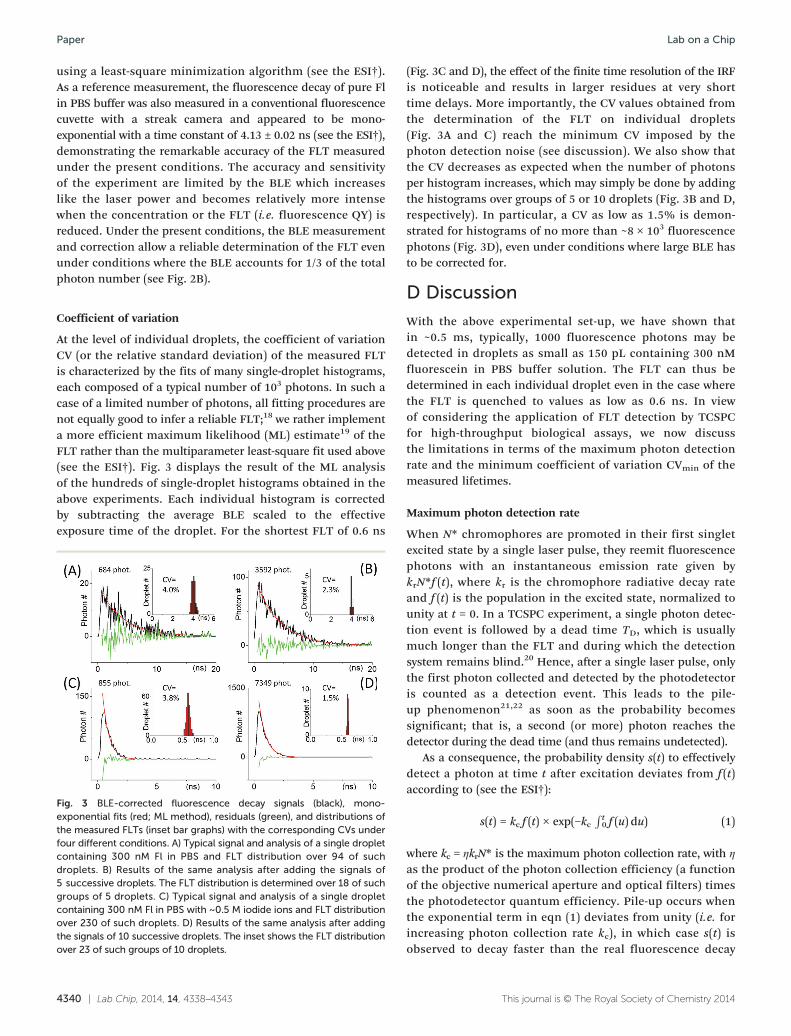
At the level of individual droplets, the coefficient of variationCV (or the relative standard deviation) of the measured FLTis characterized by the fits of many single-droplet histograms,each composed of a typical number of 103 photons. In such acase of a limited number of photons, all fitting procedures arenot equally good to infer a reliable FLT;18 we rather implementa more efficient maximum likelihood (ML) estimate19 of theFLT rather than the multiparameter least-square fit used above(see the ESI†). Fig. 3 displays the result of the ML analysisof the hundreds of single-droplet histograms obtained in theabove experiments. Each individual histogram is correctedby subtracting the average BLE scaled to the effectiveexposure time of the droplet. For the shortest FLT of 0.6 ns
4340 | Lab Chip, 2014, 14, 4338–4343
Fig. 3 BLE-corrected fluorescence decay signals (black), mono-exponential fits (red; ML method), residuals (green), and distributions ofthe measured FLTs (inset bar graphs) with the corresponding CVs underfour different conditions. A) Typical signal and analysis of a single dropletcontaining 300 nM Fl in PBS and FLT distribution over 94 of suchdroplets. B) Results of the same analysis after adding the signals of5 successive droplets. The FLT distribution is determined over 18 of suchgroups of 5 droplets. C) Typical signal and analysis of a single dropletcontaining 300 nM Fl in PBS with ~0.5 M iodide ions and FLT distributionover 230 of such droplets. D) Results of the same analysis after addingthe signals of 10 successive droplets. The inset shows the FLT distributionover 23 of such groups of 10 droplets.
(Fig. 3C and D), the effect of the finite time resolution of the IRFis noticeable and results in larger residues at very shorttime delays. More importantly, the CV values obtained fromthe determination of the FLT on individual droplets(Fig. 3A and C) reach the minimum CV imposed by thephoton detection noise (see discussion). We also show thatthe CV decreases as expected when the number of photonsper histogram increases, which may simply be done by addingthe histograms over groups of 5 or 10 droplets (Fig. 3B and D,respectively). In particular, a CV as low as 1.5% is demon-strated for histograms of no more than ~8 × 10³ fluorescencephotons (Fig. 3D), even under conditions where large BLE hasto be corrected for.
D Discussion
With the above experimental set-up, we have shown thatin ~0.5 ms, typically, 1000 fluorescence photons may bedetected in droplets as small as 150 pL containing 300 nMfluorescein in PBS buffer solution. The FLT can thus bedetermined in each individual droplet even in the case wherethe FLT is quenched to values as low as 0.6 ns. In viewof considering the application of FLT detection by TCSPCfor high-throughput biological assays, we now discussthe limitations in terms of the maximum photon detectionrate and the minimum coefficient of variation CVmin of themeasured lifetimes.
Maximum photon detection rate
When N* chromophores are promoted in their first singletexcited state by a single laser pulse, they reemit fluorescencephotons with an instantaneous emission rate given bykrN*f (t), where kr is the chromophore radiative decay rateand f (t) is the population in the excited state, normalized tounity at t = 0. In a TCSPC experiment, a single photon detec-tion event is followed by a dead time TD, which is usuallymuch longer than the FLT and during which the detectionsystem remains blind.20 Hence, after a single laser pulse, onlythe first photon collected and detected by the photodetectoris counted as a detection event. This leads to the pile-up phenomenon21,22 as soon as the probability becomessignificant; that is, a second (or more) photon reaches thedetector during the dead time (and thus remains undetected).
As a consequence, the probability density s(t) to effectivelydetect a photon at time t after excitation deviates from f (t)according to (see the ESI†):
s(t) = kc f (t) × exp(−kcR t0 f (u) du) (1)
where kc = ηkrN* is the maximum photon collection rate, with η
as the product of the photon collection efficiency (a functionof the objective numerical aperture and optical filters) timesthe photodetector quantum efficiency. Pile-up occurs whenthe exponential term in eqn (1) deviates from unity (i.e. forincreasing photon collection rate kc), in which case s(t) isobserved to decay faster than the real fluorescence decay
This journal is © The Royal Society of Chemistry 2014
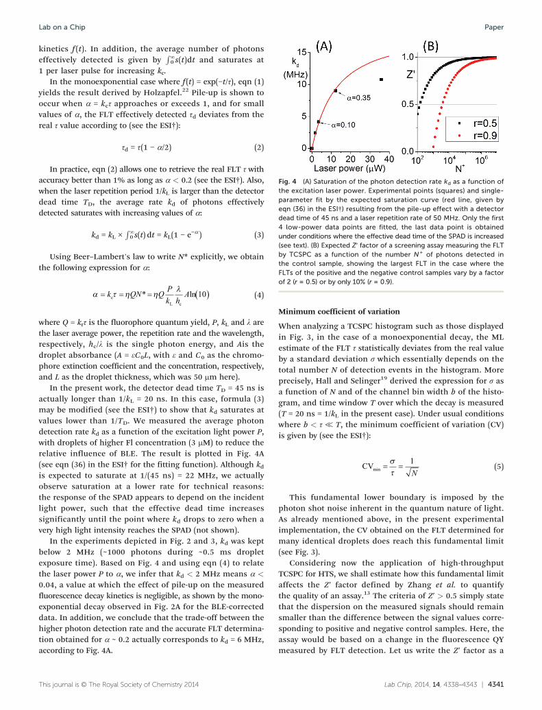
Fig. 4 (A) Saturation of the photon detection rate kd as a function ofthe excitation laser power. Experimental points (squares) and single-parameter fit by the expected saturation curve (red line, given byeqn (36) in the ESI†) resulting from the pile-up effect with a detectordead time of 45 ns and a laser repetition rate of 50 MHz. Only the first4 low-power data points are fitted, the last data point is obtainedunder conditions where the effective dead time of the SPAD is increased(see text). (B) Expected Z′ factor of a screening assay measuring the FLTby TCSPC as a function of the number N+ of photons detected inthe control sample, showing the largest FLT in the case where theFLTs of the positive and the negative control samples vary by a factorof 2 (r = 0.5) or by only 10% (r = 0.9).
Lab on a Chip Paper
kinetics f (t). In addition, the average number of photonseffectively detected is given by
R∞0 s(t)dt and saturates at
1 per laser pulse for increasing kc.In the monoexponential case where f (t) = exp(−t/τ), eqn (1)
yields the result derived by Holzapfel.22 Pile-up is shown tooccur when α = kcτ approaches or exceeds 1, and for smallvalues of α, the FLT effectively detected τd deviates from thereal τ value according to (see the ESI†):
τd = τ(1 − α/2) (2)
In practice, eqn (2) allows one to retrieve the real FLT τ withaccuracy better than 1% as long as α < 0.2 (see the ESI†). Also,when the laser repetition period 1/kL is larger than the detectordead time TD, the average rate kd of photons effectivelydetected saturates with increasing values of α:
kd = kL ×R∞0 s(t) dt = kL(1 − e−α ) (3)
Using Beer–Lambert's law to write N* explicitly, we obtainthe following expression for α:
k QN Q Pk h
AcL c
* ln 10 (4)
where Q = krτ is the fluorophore quantum yield, P, kL and λ arethe laser average power, the repetition rate and the wavelength,respectively, hc/λ is the single photon energy, and Ais thedroplet absorbance (A = εC0L, with ε and C0 as the chromo-phore extinction coefficient and the concentration, respectively,and L as the droplet thickness, which was 50 μm here).
In the present work, the detector dead time TD = 45 ns isactually longer than 1/kL = 20 ns. In this case, formula (3)may be modified (see the ESI†) to show that kd saturates atvalues lower than 1/TD. We measured the average photondetection rate kd as a function of the excitation light power P,with droplets of higher Fl concentration (3 μM) to reduce therelative influence of BLE. The result is plotted in Fig. 4A(see eqn (36) in the ESI† for the fitting function). Although kdis expected to saturate at 1/(45 ns) = 22 MHz, we actuallyobserve saturation at a lower rate for technical reasons:the response of the SPAD appears to depend on the incidentlight power, such that the effective dead time increasessignificantly until the point where kd drops to zero when avery high light intensity reaches the SPAD (not shown).
In the experiments depicted in Fig. 2 and 3, kd was keptbelow 2 MHz (~1000 photons during ~0.5 ms dropletexposure time). Based on Fig. 4 and using eqn (4) to relatethe laser power P to α, we infer that kd < 2 MHz means α <
0.04, a value at which the effect of pile-up on the measuredfluorescence decay kinetics is negligible, as shown by the mono-exponential decay observed in Fig. 2A for the BLE-correcteddata. In addition, we conclude that the trade-off between thehigher photon detection rate and the accurate FLT determina-tion obtained for α ~ 0.2 actually corresponds to kd = 6 MHz,according to Fig. 4A.
This journal is © The Royal Society of Chemistry 2014
Minimum coefficient of variation
When analyzing a TCSPC histogram such as those displayedin Fig. 3, in the case of a monoexponential decay, the MLestimate of the FLT τ statistically deviates from the real valueby a standard deviation σ which essentially depends on thetotal number N of detection events in the histogram. Moreprecisely, Hall and Selinger19 derived the expression for σ asa function of N and of the channel bin width b of the histo-gram, and time window T over which the decay is measured(T = 20 ns = 1/kL in the present case). Under usual conditionswhere b < τ ≪ T, the minimum coefficient of variation (CV)is given by (see the ESI†):
CVmin
1N
(5)
This fundamental lower boundary is imposed by thephoton shot noise inherent in the quantum nature of light.As already mentioned above, in the present experimentalimplementation, the CV obtained on the FLT determined formany identical droplets does reach this fundamental limit(see Fig. 3).
Considering now the application of high-throughputTCSPC for HTS, we shall estimate how this fundamental limitaffects the Z′ factor defined by Zhang et al. to quantifythe quality of an assay.13 The criteria of Z′ > 0.5 simply statethat the dispersion on the measured signals should remainsmaller than the difference between the signal values corre-sponding to positive and negative control samples. Here, theassay would be based on a change in the fluorescence QYmeasured by FLT detection. Let us write the Z′ factor as a
Lab Chip, 2014, 14, 4338–4343 | 4341
Lab on a ChipPaper
function of the number of photons N+ detected in the(positive or negative) control sample yielding the largest FLTτ+, and therefore imposing the most stringent condition tolimit pile-up effects (e.g. α = kcτ
+ < 0.2). We also define
r
1 , the ratio between the FLTs of both control samples.
Assuming that the minimum value of CV (CVmin) is realized, asis the case in the present work, we obtain (see the ESI†):
Z
N r1 3 3 1 3
1 (6)
Fig. 4B plots the expected Z′ factor (formula (6)) as afunction of N+ for two values of r. It shows that even whenthe FLTs of the control samples vary by no more than 10%(r = 0.9), a number of no more than 104 detected photonsper sample is enough to achieve a Z′ factor as high as 0.7,ensuring an effective screening assay.
Realistic conditions
The present work combining droplet microfluidics andTCSPC demonstrates that 300 nM fluorescein in 150 pL ofdroplets are enough to emit detectable fluorescence photonsat a collection rate of 6MHzwith a pulsed laser diode (emittingno more than a few 10 μW average power) under conditionswhere pile-up limitations do not restrict the accuracy of FLTdetermination. Several 104 photons per dropletmay thus easilybe detected by slightly reducing the flow speed down to a fewhundred droplets per second. Hence, even if the FLT of bothcontrol samples would not differ by more than 10%, we showthat under these conditions, a Z′ factor of 0.7 or more is easilyachievable in the screening of over 100 samples per second,containing less than 50 attomoles (the content of 1 singledroplet) of a nanosecond-lived fluorophore.
The limitation in sensitivity is imposed by BLE which maybecome relatively intense when the fluorophore concentra-tion or its FLT is reduced. Under the conditions shown inFig. 2B where the BLE is so intense that its subtractionbecomes less accurate, the average BLE rate is as large as~700 kHz for an average excitation power of 100 μW. Thislevel would certainly be reduced by optimizing the excitationwavelength, the fluorescence light collection and filteringand the microfluidic chip design. Indeed, up to nearly3 orders of magnitude lower BLE rates have been demonstratedwith similar excitation wavelength and average power in PDMSmicrofluidic devices dedicated to single-molecule spectroscopyexperiments.23
Conclusions
It is often believed that extremely low counting rates (e.g.0.01 photon per laser pulse) are compulsory to avoid pile-up.Here, we show that as many as 0.2 detection event per laserpulse (eqn (3) with α = 0.2) still allows FLT determinationwith 1% accuracy, which is in practice sufficient for enabling
4342 | Lab Chip, 2014, 14, 4338–4343
effective biomolecular interaction assays. We demonstrate anexperimental implementation where a photon counting rateas large as 6 MHz, limited only by the photodetector deadtime, allows such a level of accuracy. We illustrate the poten-tial application of TCSPC to high-throughput biochemicalassays by showing that very good Z′ factors would be achievedfor HTS protocols relying on the FLT measurement ofnanosecond-lived chromophores with a limited number ofphotons per sample. In this work, droplet microfluidics isused as a prototypical tool for manipulating very low samplevolumes at very high throughput; that is, under conditionswhich are very challenging for the implementation of TCSPC.However, the demonstration is obviously applicable toconventional microplate readers, flow cytometers or othersample handling devices. This proof-of-principle experimentthus paves the way for the use of FLT detection in high-throughput FLT sensing by TCSPC with nanosecond-livedfluorophores, including recently developed fluorescentprobes24,25 for DNA–protein interaction assays and geneticallyencodable fluorescent proteins26 for in vivo assays, e.g. cellsorting. In the latter case, fluorophore concentrations maynot be controlled accurately and intrinsic characterization ofbiomolecular interactions by FLT detection would certainlybe a significant improvement.
Acknowledgements
This work was supported by the “FEMTOSTACK” ANR-2010-BLAN-1529-01 grant, the Region Alsace and the InstitutCarnot MICA. We thank Olivier Crégut for technical assistance.
Notes and references
1 P. I. H. Bastiaens and A. Squire, Trends Cell Biol.,
1999, 9, 48.2 D. M. Gakamsky, R. B. Dennis and S. D. Smith, Anal.
Biochem., 2011, 409, 89.3 S. Pritz, G. Meder, K. Doering, P. Drueckes, J. Woelcke,
L. M. Mayr and U. Hassiepen, J. Biomol. Screening, 2011,16, 65.4 R. L. Cornea, S. J. Gruber, E. L. Lockamy, J. M. Muretta,
D. Jin, J. Chen, R. Dahl, T. Bartfai, K. M. Zsebo,G. D. Gillispie and D. D. Thomas, J. Biomol. Screening,2013, 18, 97.5 F. Degorce, A. Card, S. Soh, E. Trinquet, G. P. Knapik and
B. Xie, Curr. Chem. Genomics, 2009, 3.6 J.-C. G. Bünzli, Chem. Rev., 2010, 110, 2729.
7 H. Bazin, M. Préaudat, E. Trinquet and G. Mathis,Spectrochim. Acta, Part A, 2001, 57, 2197.8 E. Ben Ishay, G. Hazan, G. Rahamim, D. Amir and E. Haas,
Rev. Sci. Instrum., 2012, 83, 084301.9 J. M. Muretta, A. Kyrychenko, A. S. Ladokhin, D. J. Kast,
G. D. Gillispie and D. D. Thomas, Rev. Sci. Instrum.,2010, 81, 103101.
10 M. T. Guo, A. Rotem, J. A. Heyman and D. A. Weitz,
Lab Chip, 2012, 12, 2146.This journal is © The Royal Society of Chemistry 2014
Lab on a Chip Paper
11 O. J. Miller, A. El Harrak, T. Mangeat, J.-C. Baret, L. Frenz,
B. El Debs, E. Mayot, M. L. Samuels, E. K. Rooney andP. Dieu, Proc. Natl. Acad. Sci. U. S. A., 2012, 109, 378.12 J.-C. Baret, O. J. Miller, V. Taly, M. Ryckelynck, A. El-Harrak,
L. Frenz, C. Rick, M. L. Samuels, J. B. Hutchison,J. J. Agresti, D. R. Link, D. A. Weitz and A. D. Griffiths,Lab Chip, 2009, 9, 1850.13 J.-H. Zhang, T. D. Y. Chung and K. R. Oldenburg, J. Biomol.
Screening, 1999, 4, 67.14 D. C. Duffy, J. C. McDonald, O. J. A. Schueller and
G. M. Whitesides, Anal. Chem., 1998, 70, 4974.15 S. Maillot, A. Carvalho, J.-P. Vola, C. Boudier, Y. Mely,
S. Haacke and J. Leonard, Lab Chip, 2014, 14, 1767–1774.16 W. Uhring, C. V. Zint and J. Bartringer, Proc. SPIE,
2004, 5452, 583.17 J. Q. Umberger and V. K. LaMer, J. Am. Chem. Soc.,
1945, 67, 1099.This journal is © The Royal Society of Chemistry 2014
18 M. Maus, M. Cotlet, J. Hofkens, T. Gensch, F. C. De Schryver,
J. Schaffer and C. A. M. Seidel, Anal. Chem., 2001, 73, 2078.19 P. Hall and B. Selinger, J. Phys. Chem., 1981, 85, 2941.
20 W. Becker, Advanced time-correlated single photon countingtechniques, Springer, 2005, vol. 81.21 P. B. Coates, J. Phys. E: Sci. Instrum., 1968, 1, 878.
22 C. Holzapfel, Rev. Sci. Instrum., 1974, 45, 894. 23 S. H. Pfeil, C. E. Wickersham, A. Hoffmann and E. A. Lipman,Rev. Sci. Instrum., 2009, 80.24 D. Dziuba, V. Y. Postupalenko, M. Spadafora, A. S. Klymchenko,
V. Guérineau, Y. Mély, R. Benhida and A. Burger, J. Am. Chem.Soc., 2012, 134, 10209.
25 A. V. Strizhak, V. Y. Postupalenko, V. V. Shvadchak,
N. Morellet, E. Guittet, V. G. Pivovarenko, A. S. Klymchenkoand Y. Mély, Bioconjugate Chem., 2012, 23, 2434.26 A. Miyawaki, J. Llopis, R. Heim, J. M. McCaffery, J. A. Adams,
M. Ikura and R. Y. Tsien, Nature, 1997, 388, 882.Lab Chip, 2014, 14, 4338–4343 | 4343


