Embed Size (px)
Citation preview
12 AE Proceedings of the 13th Int. AMME Conference, 27-29 May, 2008
13th International Conference on Applied Mechanics and Mechanical Engineering.
Military Technical College Kobry El-Kobbah,
Cairo, Egypt.
HISTORICAL REVIEW
OF VARIABLE VALVE ACTUATION SYSTEMS
PATRIZIO NUCCIO* and MARIO R. MARZANO*
ABSTRACT The internal combustion reciprocating engines that are usually employed in automotive applications need high torque at low revolution speeds to quickly increase car velocity without shifting gears. However, high power at top speed is required to obtain an adequate maximum speed as well as sufficient acceleration, through up-shifting. Designers can decide, according to different valve-timing diagrams, whether to improve torque at low speeds or power at top speeds. Unfortunately, both these improvements cannot be carried out at the same time, if the valve-timing diagram does not change with the engine revolution speed. Therefore, the current solutions for ordinary mass-produced automotive engines are often a compromise between torque and power performance. A suitable choice of intake-valve and exhaust-valve timing, by means of Variable Valve Actuation (VVA), could instead satisfy both these requirements at the same time and even reduce fuel consumption and pollutant emissions. The aim of this review is to outline some of the most significant proposals over the last forty years as far as VVA systems are concerned. KEY WORDS Variable Valve Actuation System NOMENCLATURE BDC bottom dead centre bmep brake mean effective pressure bsfc brake specific fuel consumption BTDC before top dead centre EGR exhaust gas recirculation EIVC early intake valve closing EVC exhaust valve closing EVO exhaust valve opening HSSV high-speed solenoid valve imep indicated mean effective pressure
* Professor, Department of Energetics, Politecnico di Torino, Italy
13 AE Proceedings of the 13th Int. AMME Conference, 27-29 May, 2008
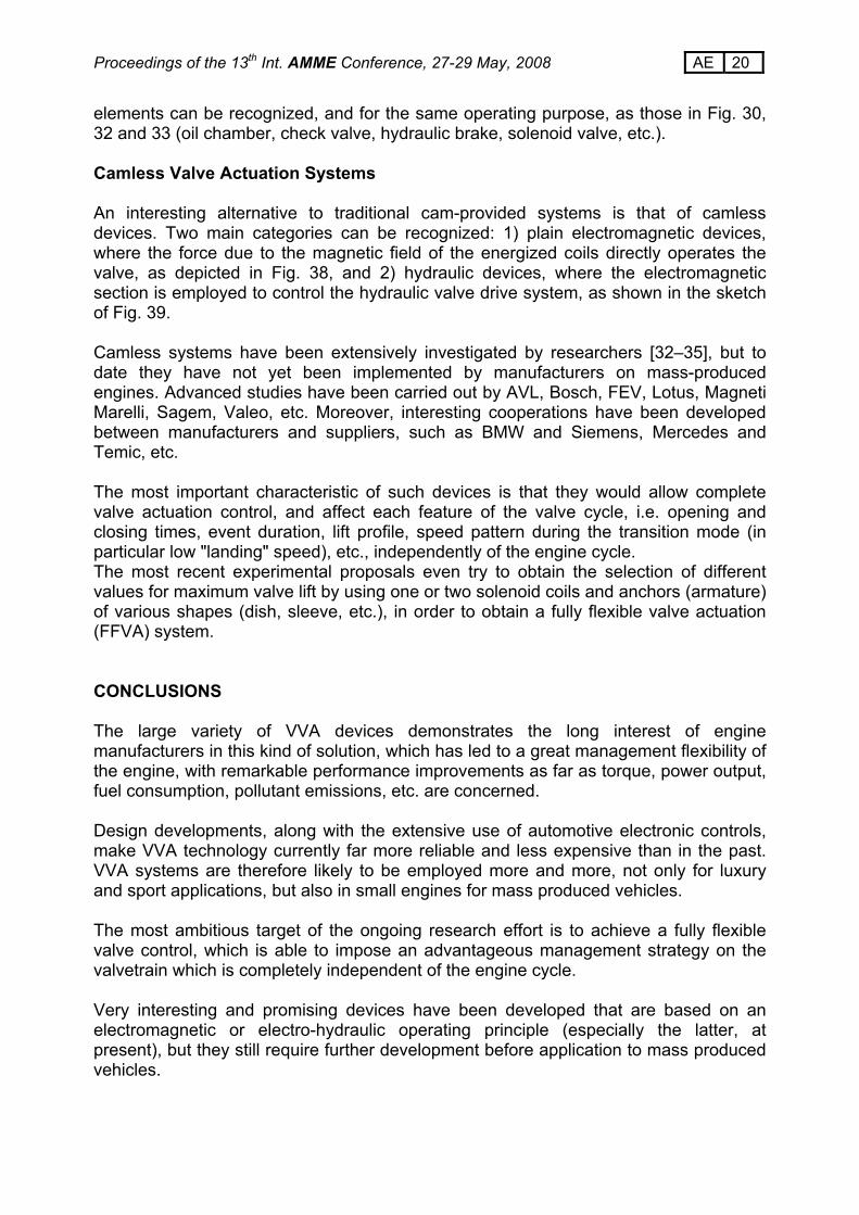
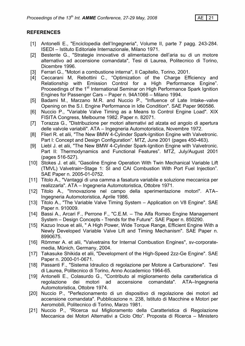
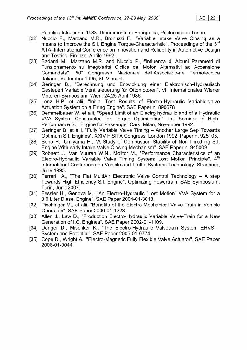
IVC intake valve closing IVO intake valve opening LIVC late intake valve closing RPM revolution per minute TDC top dead centre VVA variable valve actuation WOT wide open throttle INTRODUCTION As is well known, four stroke i.e. engines always need a valvetrain system to replace working fluid. This is usually a cam-actuated system with poppet valves whose motion is obtained directly through a cam profile and a tappet or through an interposed connecting rod, a rocker arm or a finger-follower, see Fig. 1. In the past, different solutions were utilized, such as sliding valves, rotating or sleeve types, as shown in Fig. 2, but all these solutions went no further for various different reasons [1]. The basic problem, which still remains essentially unsolved, is the high pressure that produces large forces on the valve system. The poppet valve instead is simply pushed harder against its seat, and these forces have no effect on the valve-actuating mechanism. All these valvetrain systems, however, do not allow any change in valve events, that is, the phase, the lift and the duration cannot be changed when the engine is running. As far as the valve lift diagram is concerned, it should be observed that the opening and the closing events cannot be instantaneous, and the gas flow accelerates and decelerates with a certain delay, owing to its inertia; therefore, some advance in opening and some delay in closing are required for advantageous operations. In Fig. 3, where the engine working cycle is depicted, in terms of pressure versus displacement, an example is shown of a valve timing solution featuring advance and delay times (with respect to the dead centres) for both the intake and the exhaust valves. Valve timing can influence many features of engine performance, by improving some of them and making some others worse. Therefore, when the valve timing is fixed, it must reach a compromise among many opposite requirements. Remarkable improvements can instead be obtained using variable valve actuation, according to different strategies and techniques; in particular to obtain:
• High Torque at Low Engine Speed • High Power at Top Engine Speed • Improvement in Fuel Economy • Reduction in Pollutant Emissions • Better Idle Quality • NOx Reduction by Means of Internal EGR Control • Port Deactivation for Charge Motion Control or Engine Modular Operation • Suitable VVA management with turbocharging • More Efficient Engine Brake System for Diesel-Powered Vehicles
Some of these points are examined here and discussed in detail.
14 AE Proceedings of the 13th Int. AMME Conference, 27-29 May, 2008
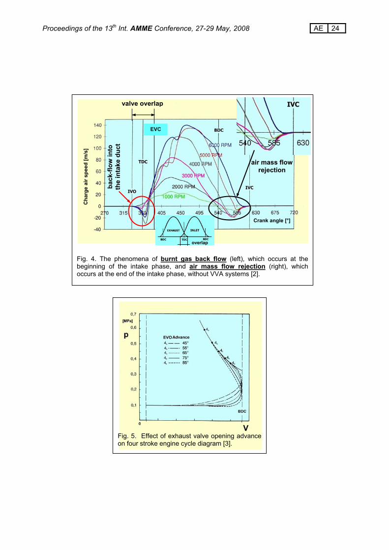
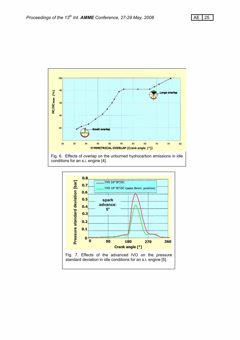
FLUID EXCHANGE The process of filling the cylinder with fresh air (or an air-fuel mixture) can be analysed with the help of Fig. 4 which shows the charge air speed through the intake valve versus crank angle for different engine speeds with constant valve events [2]. At first, the analysis is limited to the last part of the intake phase, when the movement of the piston, after BDC, is inverted and the air continues to flow into the cylinder because of the inertia phenomenon. The air flow towards the cylinder therefore vanishes with a certain crank angle delay with respect to BDC. Moreover, this delay differs, according to the different engine speeds. If the intake valve closing delay (always in terms of crank angle) exceeds the points where the air speed decreases to zero, reject phenomenon occurs and the piston expels the air through the intake valve, that is, the air speed increases in the opposite direction. The main effects of the intake valve closing delay concern: the engine volumetric efficiency, the torque characteristic and the load control of s.i. engines. These features are analysed in detail later, in a separate section of this report. As far as the discharge of burnt gas is concerned, Figure 5 shows the effect of different exhaust valve opening advances on the indicated cycle work and the related pumping losses [3]. An optimum trade-off can be searched for, between the lost and recovered cycle work, due to the employed opening advance. Figure 4 also shows the intake valve opening advance and the exhaust valve closing delay (with respect to the TDC), which are responsible for the "valve overlap", that is the phase when both valves are open at the same time. At the beginning of the intake phase, the valve opening advance pre-arranges the intake valve in an open position when the fresh air (or mixture) begins to flow into the cylinder after top dead centre and reduces the throttling between the valve and its seat. In this first part of the intake stroke, the air is unable to enter the cylinder because of the presence of a residual gas pressure that produces a back-flow into the intake manifold when the exhaust valve is still open. This internal exhaust gas recirculation, during the valve overlap, affects the combustion process and, as a consequence, the pollutant emissions. Figure 6 shows the effects of a symmetrical overlap on the unburned hydrocarbons in idle conditions for a spark ignition engine [4]: with a diminution of the overlap, the backflow of the exhaust gases into the intake system can be reduced and, due to a more complete combustion, a significant reduction in HC emissions is obtained. Another important consequence of the right choice of valve timing concerns the improvement in the combustion process in idle conditions. This is clearly shown in Fig. 7, where the standard deviation of the pressure vs crank-angle appears to be lower, in correspondence to a smaller intake valve opening advance, and a better idle quality is obtained [5].
15 AE Proceedings of the 13th Int. AMME Conference, 27-29 May, 2008
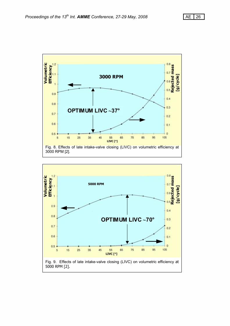
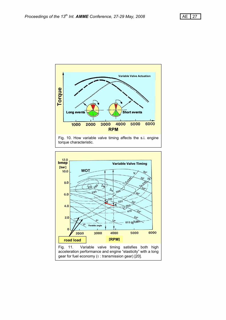
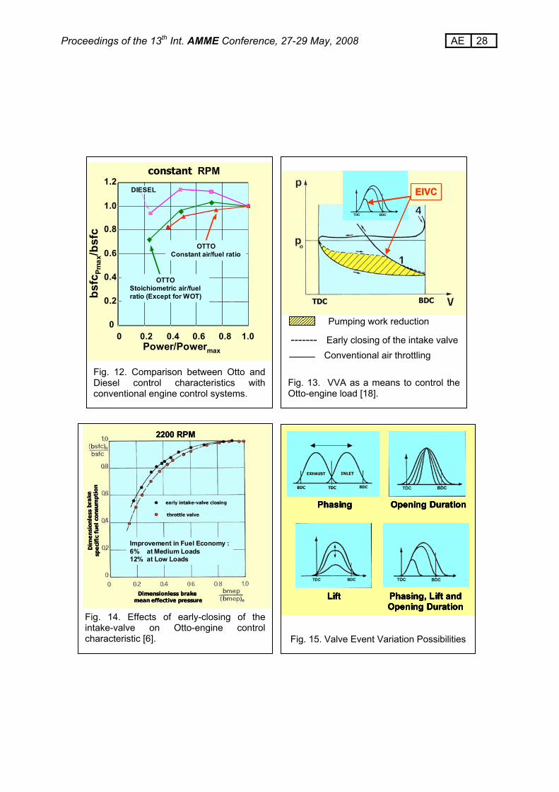
THE EFFECTS OF THE INTAKE VALVE CLOSING DELAY Volumetric Efficiency Because of the variable inertia phenomena of the gas flowing towards the cylinder, a suitable closure delay of the intake valve needs to be chosen according to the different engine speeds, if a high volumetric efficiency has to be reached. Fig.s 8 and 9 show the optimum delay for maximum volumetric efficiency valve closing for two different engine speeds, where the higher speed obviously needs a longer crank angle delay [2]. It should also be noticed that a small rejected mass amount is, nevertheless, present at this maximum. Torque Characteristic As volumetric efficiency greatly affects torque characteristic, designers can decide whether to obtain higher torque at low speeds or higher power at top speeds, according to the chosen valve-timing diagram. Unfortunately, both these requirements cannot be satisfied at the same time, if the valve-timing diagram does not change with the engine revolution speed. Figure 10 shows an example of two torque characteristics of an s.i. engine, obtained with valve timing for high torque at low speeds (short events, dashed line) and for high torque at high speed (long events, dotted line). The full line instead shows the optimised torque characteristic with a VVA system installed on the engine. Figure 11 shows a WOT engine characteristic with high torque at low speeds (obtained thanks to VVA) which provides a satisfactory “elasticity” with a long gear (i.e. permits an acceptable car acceleration to be obtained without shifting gear). The use of a long gear is advantageous because is responsible of fuel consumption decrease. For instance, if point A, which represents a steady-state condition at 110 km/h in 4th gear, moves to point B, at the same vehicle speed in 5th gear, along the constant power curve "C", a remarkable reduction in fuel consumption of about 6% is obtained. Unfortunately, if an ordinary engine characteristic (without VVA) is employed, the torque reduction with speed makes acceleration resources too weak. VVA, instead, helps to avoid such a drawback and allows to exploit the fuel consumption decrease (due to long gear) maintaining good acceleration performances. In Fig. 11 can also be seen that, thanks to VVA (i.e. thanks to high torque at low speed), the difference between engine torque and road-load-torque in point B (∆B) is not much lower than in point A (∆A). Load Control of S.I. Engines A different application of VVA, involving only the intake valve, has been employed for s.i. engine load control, in conjunction with - or even instead of - traditional intake throttling in order to obtain a control characteristic that is similar to that of the Diesel engine. Figure 12 shows a comparison between Diesel and Otto control characteristics with a conventional engine control system: air throttling considerably penalizes s.i. engines because it contributes to the bsfc increase at part-load with respect to the bsfc value at WOT. As an alternative, see Fig. 13, the total amount of the air/fuel mixture flowing into the combustion chamber during the intake period can be varied through appropriate advanced intake valve closing (in place of, or in conjunction with, the
16 AE Proceedings of the 13th Int. AMME Conference, 27-29 May, 2008
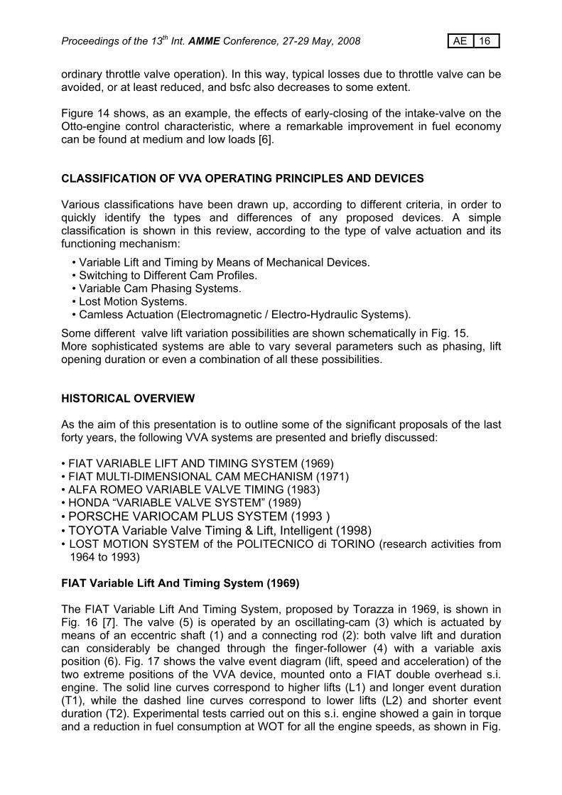
ordinary throttle valve operation). In this way, typical losses due to throttle valve can be avoided, or at least reduced, and bsfc also decreases to some extent. Figure 14 shows, as an example, the effects of early-closing of the intake-valve on the Otto-engine control characteristic, where a remarkable improvement in fuel economy can be found at medium and low loads [6]. CLASSIFICATION OF VVA OPERATING PRINCIPLES AND DEVICES Various classifications have been drawn up, according to different criteria, in order to quickly identify the types and differences of any proposed devices. A simple classification is shown in this review, according to the type of valve actuation and its functioning mechanism:
• Variable Lift and Timing by Means of Mechanical Devices. • Switching to Different Cam Profiles. • Variable Cam Phasing Systems. • Lost Motion Systems. • Camless Actuation (Electromagnetic / Electro-Hydraulic Systems).
Some different valve lift variation possibilities are shown schematically in Fig. 15. More sophisticated systems are able to vary several parameters such as phasing, lift opening duration or even a combination of all these possibilities. HISTORICAL OVERVIEW As the aim of this presentation is to outline some of the significant proposals of the last forty years, the following VVA systems are presented and briefly discussed: • FIAT VARIABLE LIFT AND TIMING SYSTEM (1969) • FIAT MULTI-DIMENSIONAL CAM MECHANISM (1971) • ALFA ROMEO VARIABLE VALVE TIMING (1983) • HONDA “VARIABLE VALVE SYSTEM” (1989) • PORSCHE VARIOCAM PLUS SYSTEM (1993 ) • TOYOTA Variable Valve Timing & Lift, Intelligent (1998) • LOST MOTION SYSTEM of the POLITECNICO di TORINO (research activities from
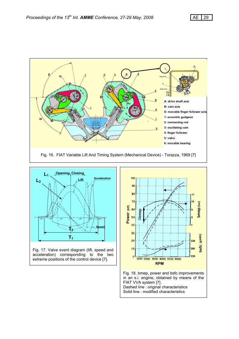
1964 to 1993) FIAT Variable Lift And Timing System (1969) The FIAT Variable Lift And Timing System, proposed by Torazza in 1969, is shown in Fig. 16 [7]. The valve (5) is operated by an oscillating-cam (3) which is actuated by means of an eccentric shaft (1) and a connecting rod (2): both valve lift and duration can considerably be changed through the finger-follower (4) with a variable axis position (6). Fig. 17 shows the valve event diagram (lift, speed and acceleration) of the two extreme positions of the VVA device, mounted onto a FIAT double overhead s.i. engine. The solid line curves correspond to higher lifts (L1) and longer event duration (T1), while the dashed line curves correspond to lower lifts (L2) and shorter event duration (T2). Experimental tests carried out on this s.i. engine showed a gain in torque and a reduction in fuel consumption at WOT for all the engine speeds, as shown in Fig.
17 AE Proceedings of the 13th Int. AMME Conference, 27-29 May, 2008
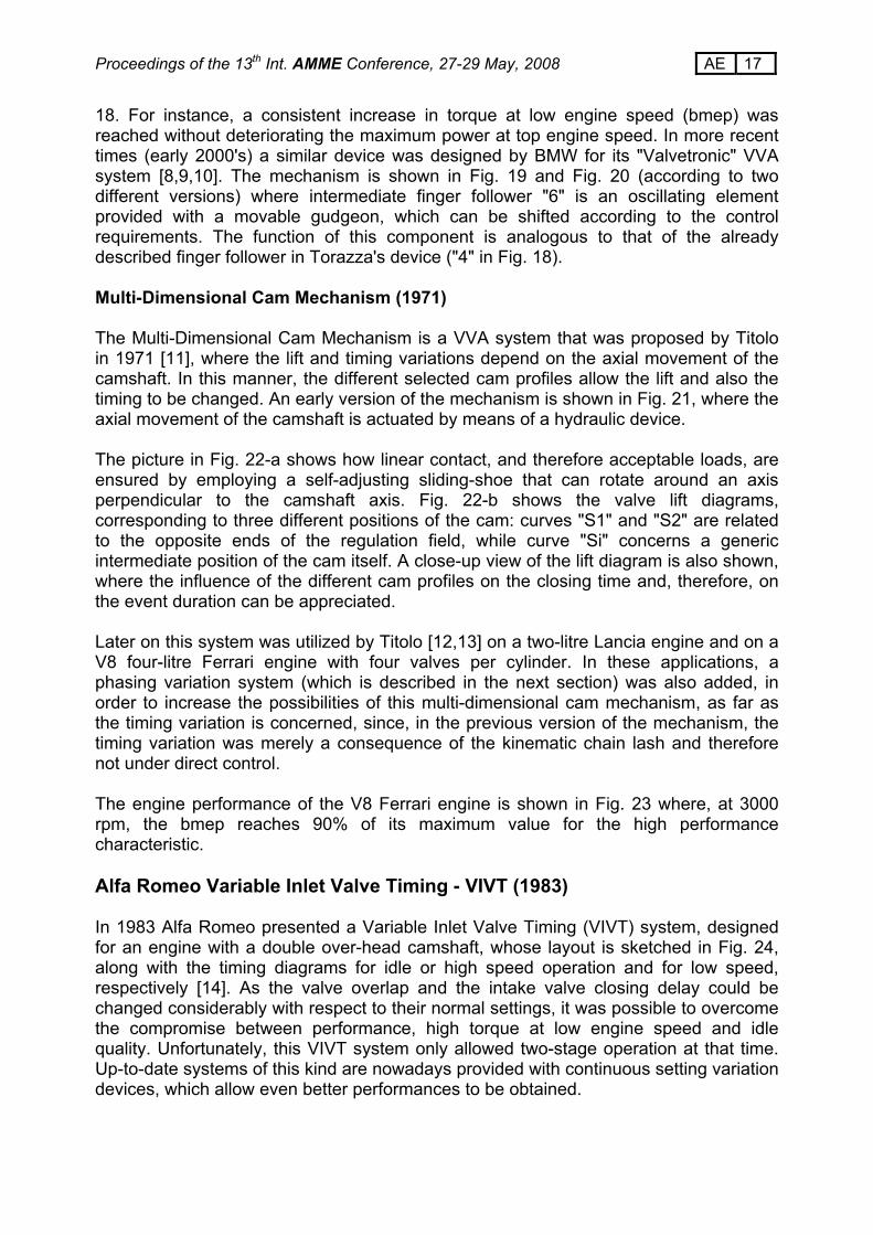
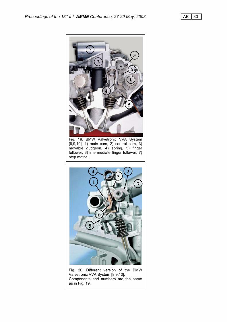
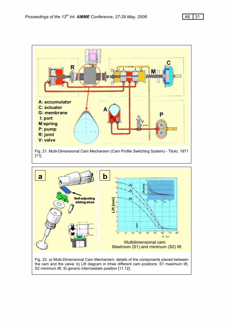
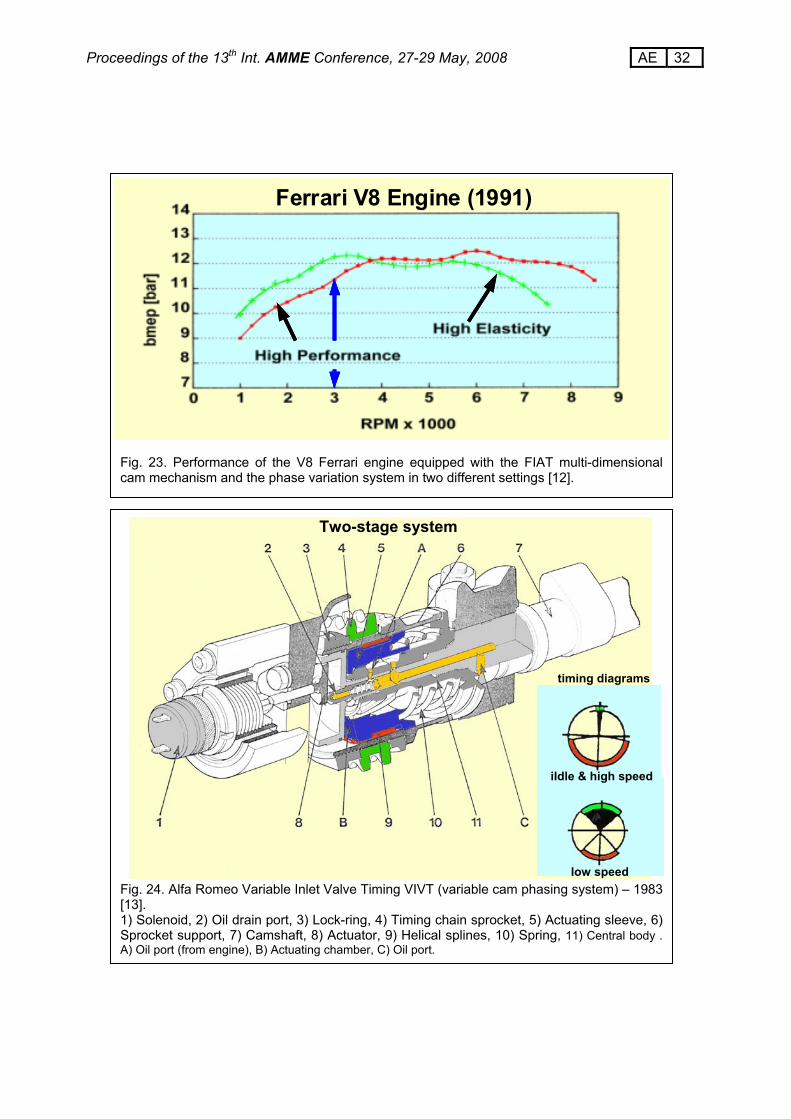
18. For instance, a consistent increase in torque at low engine speed (bmep) was reached without deteriorating the maximum power at top engine speed. In more recent times (early 2000's) a similar device was designed by BMW for its "Valvetronic" VVA system [8,9,10]. The mechanism is shown in Fig. 19 and Fig. 20 (according to two different versions) where intermediate finger follower "6" is an oscillating element provided with a movable gudgeon, which can be shifted according to the control requirements. The function of this component is analogous to that of the already described finger follower in Torazza's device ("4" in Fig. 18). Multi-Dimensional Cam Mechanism (1971) The Multi-Dimensional Cam Mechanism is a VVA system that was proposed by Titolo in 1971 [11], where the lift and timing variations depend on the axial movement of the camshaft. In this manner, the different selected cam profiles allow the lift and also the timing to be changed. An early version of the mechanism is shown in Fig. 21, where the axial movement of the camshaft is actuated by means of a hydraulic device. The picture in Fig. 22-a shows how linear contact, and therefore acceptable loads, are ensured by employing a self-adjusting sliding-shoe that can rotate around an axis perpendicular to the camshaft axis. Fig. 22-b shows the valve lift diagrams, corresponding to three different positions of the cam: curves "S1" and "S2" are related to the opposite ends of the regulation field, while curve "Si" concerns a generic intermediate position of the cam itself. A close-up view of the lift diagram is also shown, where the influence of the different cam profiles on the closing time and, therefore, on the event duration can be appreciated. Later on this system was utilized by Titolo [12,13] on a two-litre Lancia engine and on a V8 four-litre Ferrari engine with four valves per cylinder. In these applications, a phasing variation system (which is described in the next section) was also added, in order to increase the possibilities of this multi-dimensional cam mechanism, as far as the timing variation is concerned, since, in the previous version of the mechanism, the timing variation was merely a consequence of the kinematic chain lash and therefore not under direct control. The engine performance of the V8 Ferrari engine is shown in Fig. 23 where, at 3000 rpm, the bmep reaches 90% of its maximum value for the high performance characteristic. Alfa Romeo Variable Inlet Valve Timing - VIVT (1983) In 1983 Alfa Romeo presented a Variable Inlet Valve Timing (VIVT) system, designed for an engine with a double over-head camshaft, whose layout is sketched in Fig. 24, along with the timing diagrams for idle or high speed operation and for low speed, respectively [14]. As the valve overlap and the intake valve closing delay could be changed considerably with respect to their normal settings, it was possible to overcome the compromise between performance, high torque at low engine speed and idle quality. Unfortunately, this VIVT system only allowed two-stage operation at that time. Up-to-date systems of this kind are nowadays provided with continuous setting variation devices, which allow even better performances to be obtained.
18 AE Proceedings of the 13th Int. AMME Conference, 27-29 May, 2008
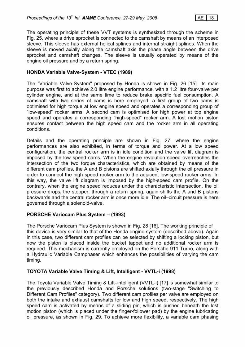
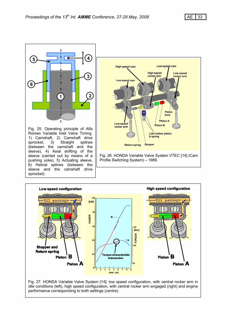
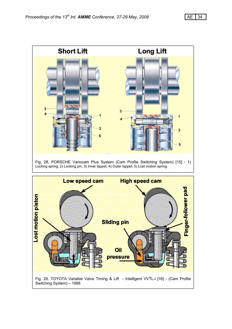
The operating principle of these VVT systems is synthesized through the scheme in Fig. 25, where a drive sprocket is connected to the camshaft by means of an interposed sleeve. This sleeve has external helical splines and internal straight splines. When the sleeve is moved axially along the camshaft axis the phase angle between the drive sprocket and camshaft changes. The sleeve is usually operated by means of the engine oil pressure and by a return spring. HONDA Variable Valve-System - VTEC (1989) The "Variable Valve-System" proposed by Honda is shown in Fig. 26 [15]. Its main purpose was first to achieve 2.0 litre engine performance, with a 1.2 litre four-valve per cylinder engine, and at the same time to reduce brake specific fuel consumption. A camshaft with two series of cams is here employed: a first group of two cams is optimised for high torque at low engine speed and operates a corresponding group of "low-speed" rocker arms. A second cam is optimised for high power at top engine speed and operates a corresponding "high-speed" rocker arm. A lost motion piston ensures contact between the high speed cam and the rocker arm in all operating conditions. Details and the operating principle are shown in Fig. 27, where the engine performances are also exhibited, in terms of torque and power. At a low speed configuration, the central rocker arm is in idle condition and the valve lift diagram is imposed by the low speed cams. When the engine revolution speed overreaches the intersection of the two torque characteristics, which are obtained by means of the different cam profiles, the A and B pistons are shifted axially through the oil pressure in order to connect the high speed rocker arm to the adjacent low-speed rocker arms. In this way, the valve lift diagram is imposed by the high-speed cam profile. On the contrary, when the engine speed reduces under the characteristic intersection, the oil pressure drops, the stopper, through a return spring, again shifts the A and B pistons backwards and the central rocker arm is once more idle. The oil–circuit pressure is here governed through a solenoid-valve. PORSCHE Variocam Plus System – (1993) The Porsche Variocam Plus System is shown in Fig. 28 [16]. The working principle of this device is very similar to that of the Honda engine system (described above). Again in this case, two different cam profiles can be selected by shifting a locking piston, but now the piston is placed inside the bucket tappet and no additional rocker arm is required. This mechanism is currently employed on the Porsche 911 Turbo, along with a Hydraulic Variable Camphaser which enhances the possibilities of varying the cam timing. TOYOTA Variable Valve Timing & Lift, Intelligent - VVTL-i (1998) The Toyota Variable Valve Timing & Lift–intelligent (VVTL-i) [17] is somewhat similar to the previously described Honda and Porsche solutions (two-stage "Switching to Different Cam Profiles" category). Two different cam profiles per valve are employed on both the intake and exhaust camshafts for low and high speed, respectively. The high speed cam is activated by means of a sliding pin, which is pushed beneath the lost motion piston (which is placed under the finger-follower pad) by the engine lubricating oil pressure, as shown in Fig. 29. To achieve more flexibility, a variable cam phasing
19 AE Proceedings of the 13th Int. AMME Conference, 27-29 May, 2008
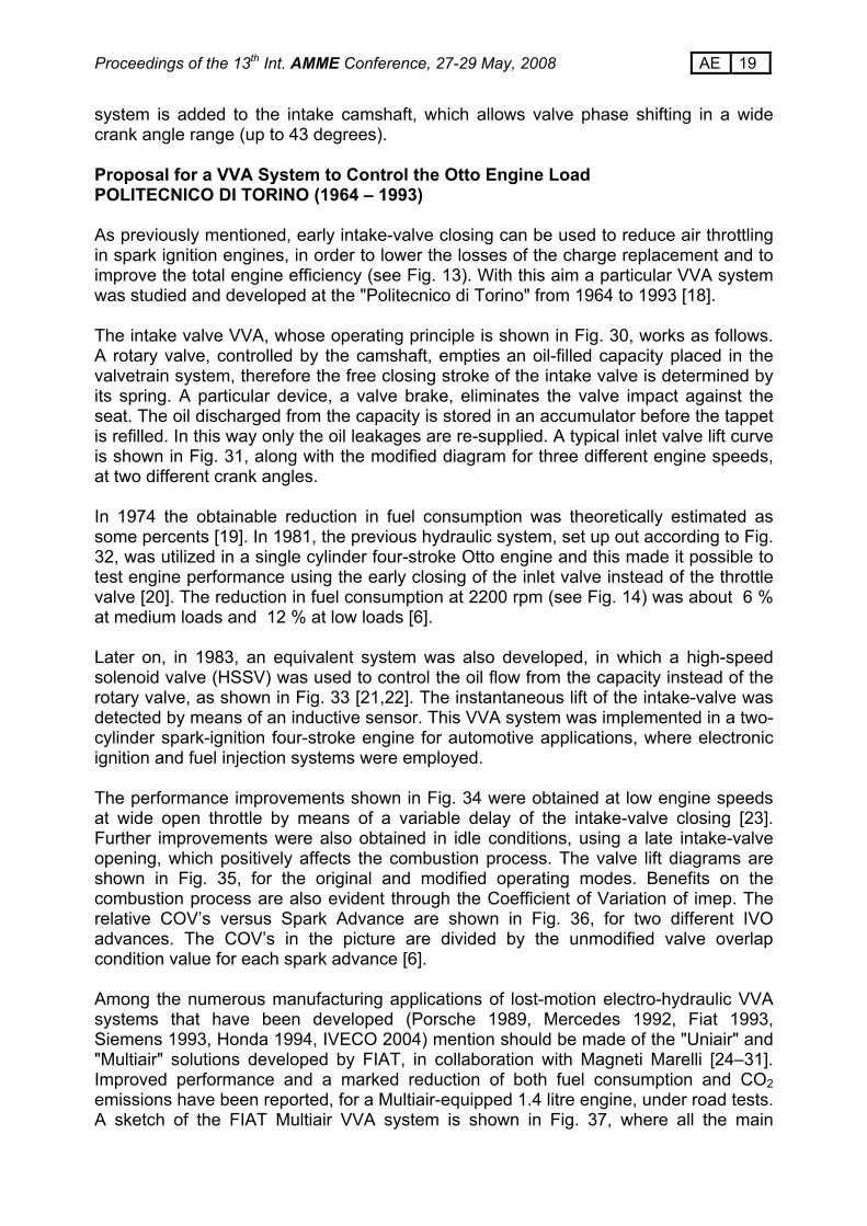
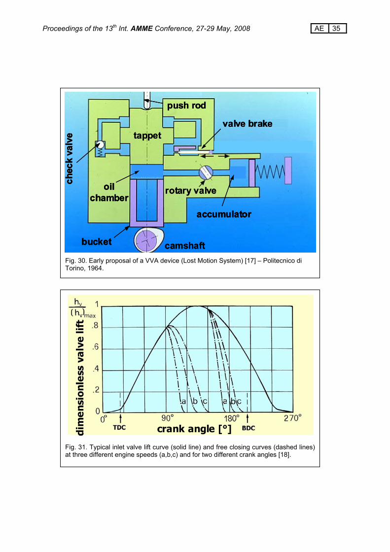
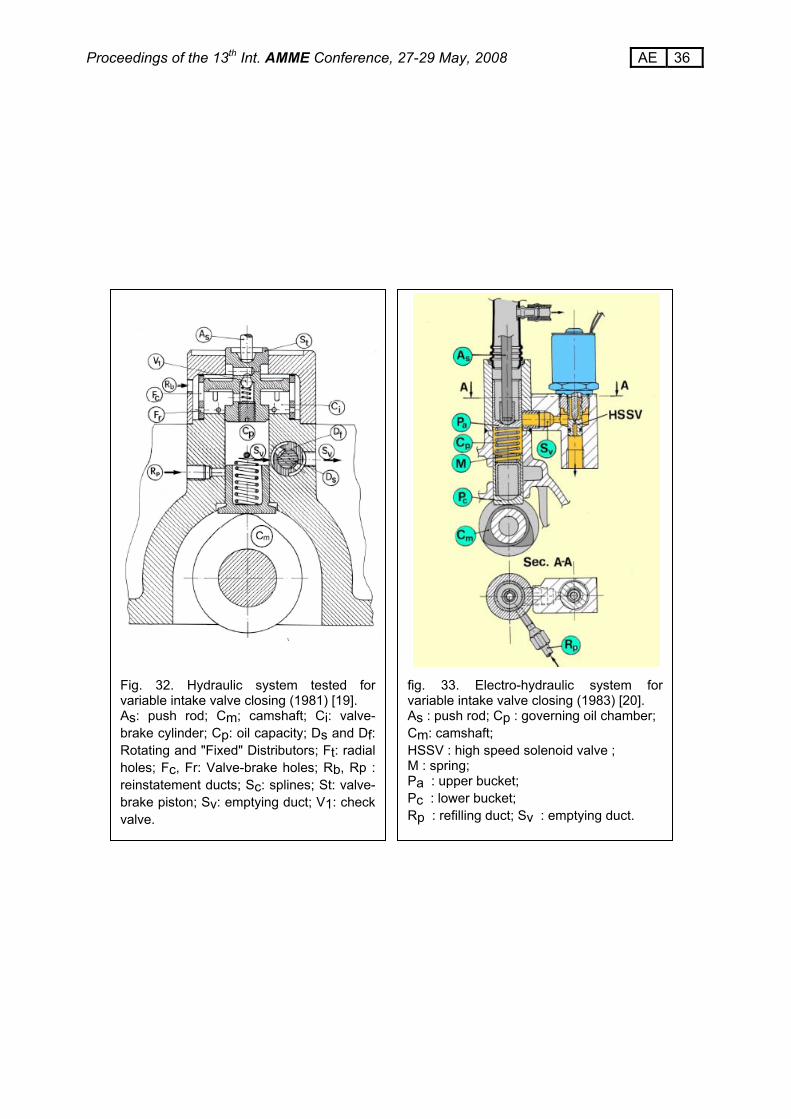
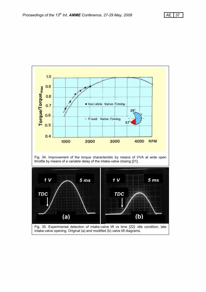
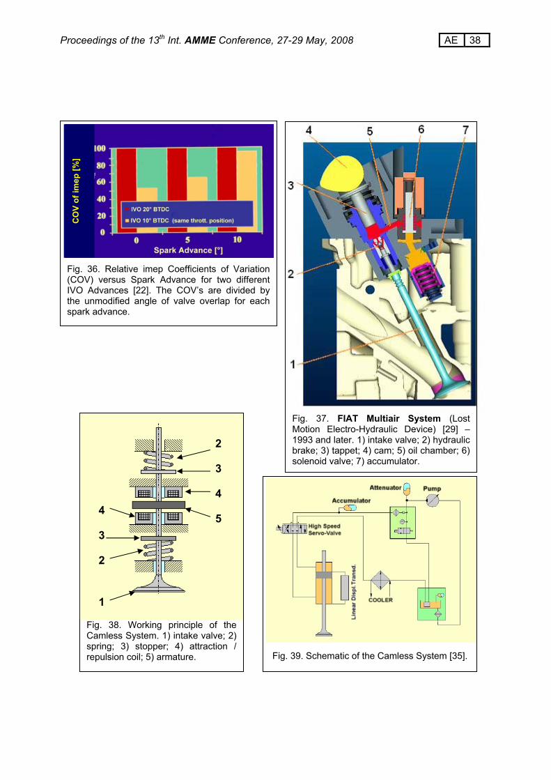
system is added to the intake camshaft, which allows valve phase shifting in a wide crank angle range (up to 43 degrees). Proposal for a VVA System to Control the Otto Engine Load POLITECNICO DI TORINO (1964 – 1993) As previously mentioned, early intake-valve closing can be used to reduce air throttling in spark ignition engines, in order to lower the losses of the charge replacement and to improve the total engine efficiency (see Fig. 13). With this aim a particular VVA system was studied and developed at the "Politecnico di Torino" from 1964 to 1993 [18]. The intake valve VVA, whose operating principle is shown in Fig. 30, works as follows. A rotary valve, controlled by the camshaft, empties an oil-filled capacity placed in the valvetrain system, therefore the free closing stroke of the intake valve is determined by its spring. A particular device, a valve brake, eliminates the valve impact against the seat. The oil discharged from the capacity is stored in an accumulator before the tappet is refilled. In this way only the oil leakages are re-supplied. A typical inlet valve lift curve is shown in Fig. 31, along with the modified diagram for three different engine speeds, at two different crank angles. In 1974 the obtainable reduction in fuel consumption was theoretically estimated as some percents [19]. In 1981, the previous hydraulic system, set up out according to Fig. 32, was utilized in a single cylinder four-stroke Otto engine and this made it possible to test engine performance using the early closing of the inlet valve instead of the throttle valve [20]. The reduction in fuel consumption at 2200 rpm (see Fig. 14) was about 6 % at medium loads and 12 % at low loads [6]. Later on, in 1983, an equivalent system was also developed, in which a high-speed solenoid valve (HSSV) was used to control the oil flow from the capacity instead of the rotary valve, as shown in Fig. 33 [21,22]. The instantaneous lift of the intake-valve was detected by means of an inductive sensor. This VVA system was implemented in a two-cylinder spark-ignition four-stroke engine for automotive applications, where electronic ignition and fuel injection systems were employed. The performance improvements shown in Fig. 34 were obtained at low engine speeds at wide open throttle by means of a variable delay of the intake-valve closing [23]. Further improvements were also obtained in idle conditions, using a late intake-valve opening, which positively affects the combustion process. The valve lift diagrams are shown in Fig. 35, for the original and modified operating modes. Benefits on the combustion process are also evident through the Coefficient of Variation of imep. The relative COV’s versus Spark Advance are shown in Fig. 36, for two different IVO advances. The COV’s in the picture are divided by the unmodified valve overlap condition value for each spark advance [6]. Among the numerous manufacturing applications of lost-motion electro-hydraulic VVA systems that have been developed (Porsche 1989, Mercedes 1992, Fiat 1993, Siemens 1993, Honda 1994, IVECO 2004) mention should be made of the "Uniair" and "Multiair" solutions developed by FIAT, in collaboration with Magneti Marelli [24–31]. Improved performance and a marked reduction of both fuel consumption and CO2 emissions have been reported, for a Multiair-equipped 1.4 litre engine, under road tests. A sketch of the FIAT Multiair VVA system is shown in Fig. 37, where all the main
20 AE Proceedings of the 13th Int. AMME Conference, 27-29 May, 2008
elements can be recognized, and for the same operating purpose, as those in Fig. 30, 32 and 33 (oil chamber, check valve, hydraulic brake, solenoid valve, etc.). Camless Valve Actuation Systems An interesting alternative to traditional cam-provided systems is that of camless devices. Two main categories can be recognized: 1) plain electromagnetic devices, where the force due to the magnetic field of the energized coils directly operates the valve, as depicted in Fig. 38, and 2) hydraulic devices, where the electromagnetic section is employed to control the hydraulic valve drive system, as shown in the sketch of Fig. 39. Camless systems have been extensively investigated by researchers [32–35], but to date they have not yet been implemented by manufacturers on mass-produced engines. Advanced studies have been carried out by AVL, Bosch, FEV, Lotus, Magneti Marelli, Sagem, Valeo, etc. Moreover, interesting cooperations have been developed between manufacturers and suppliers, such as BMW and Siemens, Mercedes and Temic, etc. The most important characteristic of such devices is that they would allow complete valve actuation control, and affect each feature of the valve cycle, i.e. opening and closing times, event duration, lift profile, speed pattern during the transition mode (in particular low "landing" speed), etc., independently of the engine cycle. The most recent experimental proposals even try to obtain the selection of different values for maximum valve lift by using one or two solenoid coils and anchors (armature) of various shapes (dish, sleeve, etc.), in order to obtain a fully flexible valve actuation (FFVA) system. CONCLUSIONS The large variety of VVA devices demonstrates the long interest of engine manufacturers in this kind of solution, which has led to a great management flexibility of the engine, with remarkable performance improvements as far as torque, power output, fuel consumption, pollutant emissions, etc. are concerned. Design developments, along with the extensive use of automotive electronic controls, make VVA technology currently far more reliable and less expensive than in the past. VVA systems are therefore likely to be employed more and more, not only for luxury and sport applications, but also in small engines for mass produced vehicles. The most ambitious target of the ongoing research effort is to achieve a fully flexible valve control, which is able to impose an advantageous management strategy on the valvetrain which is completely independent of the engine cycle. Very interesting and promising devices have been developed that are based on an electromagnetic or electro-hydraulic operating principle (especially the latter, at present), but they still require further development before application to mass produced vehicles.
21 AE Proceedings of the 13th Int. AMME Conference, 27-29 May, 2008
REFERENCES
[1] Antonelli E., "Enciclopedia dell’Ingegneria", Volume II, parte 7 pagg. 243-284. ISEDI – Istituto Editoriale Internazionale, Milano 1971.
[2] Bestente G., "Strategie innovative di alimentazione dell’aria su di un motore alternativo ad accensione comandata", Tesi di Laurea, Politecnico di Torino, Dicembre 1996.
[3] Ferrari G., "Motori a combustione interna", Il Capitello, Torino, 2001. [4] Ceccarani M, Rebottini C., “Optimization of the Charge Efficiency and
Relationship with Emission Control for a High Performance Engine”. Proceedings of the 1st International Seminar on High Performance Spark Ignition Engines for Passenger Cars – Paper n. 94A1066 – Milano 1994.
[5] Badami M., Marzano M.R. and Nuccio P., "Influence of Late Intake–valve Opening on the S.I. Engine Performance in Idle Condition". SAE Paper 960586.
[6] Nuccio P., "Variable Valve Timing as a Means to Control Engine Load". XIX FISITA Congress, Melbourne 1982. Paper n. 82071.
[7] Torazza G., "Distribuzione per motori alternativi ad alzata ed angolo di apertura delle valvole variabili". ATA – Ingegneria Automotoristica, Novembre 1972.
[8] Flierl R. et alii, "The New BMW 4-Cylinder Spark-Ignition Engine with Valvetronic. Part I: Concept and Design Configuration”. MTZ, June 2001 (pages 450-463).
[9] Liebl J. et alii, "The New BMW 4-Cylinder Spark-Ignition Engine with Valvetronic. Part II: Thermodynamics and Functional Features”. MTZ, July/August 2001 (pages 516-527).
[10] Stokes J. et alii, “Gasoline Engine Operation With Twin Mechanical Variable Lift (TMVL) Valvetrain~Stage 1: SI and CAI Combustion With Port Fuel Injection”. SAE Paper n. 2005-01-0752.
[11] Titolo A., "Vantaggi di una camma a fasatura variabile e soluzione meccanica per realizzarla". ATA – Ingegneria Automotoristica, Ottobre 1971.
[12] Titolo A., "Innovazione nel campo della sperimentazione motori". ATA–Ingegneria Automotoristica, Aprile 1986.
[13] Titolo A., "The Variable Valve Timing System – Application on V8 Engine". SAE Paper n. 910009.
[14] Bassi A., Arcari F., Perrone F., "C.E.M. – The Alfa Romeo Engine Management System – Design Concepts - Trends for the Future". SAE Paper n. 850290.
[15] Kazuo Inoue et alii, " A High Power, Wide Torque Range, Efficient Engine With a Newly Developed Variable Valve Lift and Timing Mechanism". SAE Paper n. 8990675.
[16] Römmer A. et alii, "Valvetrains for Internal Combustion Engines", sv-corporate-media, Münich, Germany, 2004.
[17] Takasuke Shikida et alii, "Development of the High-Speed 2zz-Ge Engine". SAE Paper n. 2000-01-0671.
[18] Passanti F., "Sistema Idraulico di regolazione per Motore a Carburazione". Tesi di Laurea, Politecnico di Torino, Anno Accademico 1964-65.
[19] Antonelli E., Colasurdo G., "Contributo al miglioramento della caratteristica di regolazione dei motori ad accensione comandata". ATA–Ingegneria Automotoristica, Ottobre 1974.
[20] Nuccio P., "Perfezionamento di un dispositivo di regolazione dei motori ad accensione comandata". Pubblicazione n. 238, Istituto di Macchine e Motori per Aeromobili, Politecnico di Torino, Marzo 1981.
[21] Nuccio P., “Ricerca sul Miglioramento della Caratteristica di Regolazione Meccanica dei Motori Alternativi a Ciclo Otto”. Proposta di Ricerca – Ministero
22 AE Proceedings of the 13th Int. AMME Conference, 27-29 May, 2008
Pubblica Istruzione, 1983. Dipartimento di Energetica, Politecnico di Torino. [22] Nuccio P., Marzano M.R., Bronuzzi F., "Variable Intake Valve Closing as a
means to Improve the S.I. Engine Torque-Characteristic". Proceedings of the 3rd ATA–International Conference on Innovation and Reliability in Automotive Design and Testing. Firenze, Aprile 1992.
[23] Badami M., Marzano M.R. and Nuccio P., "Influenza di Alcuni Parametri di Funzionamento sull’Irregolarità Ciclica dei Motori Alternativi ad Accensione Comandata". 50° Congresso Nazionale dell’Associazio-ne Termotecnica Italiana, Settembre 1995, St. Vincent.
[24] Geringer B., "Berechnung und Entwicklung einer Elektronisch-Hydraulisch Gesteuert Variable Ventilsteuerung für Ottomotoren". VII Internationales Wiener Motoren-Symposium. Wien, 24,25 April 1986.
[25] Lenz H.P. et alii, "Initial Test Results of Electro-Hydraulic Variable-valve Actuation System on a Firing Engine". SAE Paper n. 890678
[26] Demmelbauer W. et alii, "Speed Limit of an Electro hydraulic and of a Hydraulic VVA System Constructed for Torque Optimization". Int. Seminar in High-Performance S.I. Engine for Passenger Cars. Milan, November 1992.
[27] Geringer B. et alii, "Fully Variable Valve Timing – Another Large Sep Towards Optimum S.I. Engines". XXIV FISITA Congress, London 1992. Paper n. 925103.
[28] Sono H., Umiyama H., "A Study of Combustion Stability of Non-Throttling S.I. Engine With early Intake Valve Closing Mechanism". SAE Paper n. 945009
[29] Robnett J., Van Vuuren W.N., Molitor M., "Performance Characteristics of an Electro-Hydraulic Variable Valve Timing System: Lost Motion Principle". 4th International Conference on Vehicle and Traffic Systems Technology. Strasburg, June 1993.
[30] Ferrari A., "The Fiat MultiAir Electronic Valve Control Technology – A step Towards High Efficiency S.I. Engine". Optimizing Powertrain, SAE Symposium. Turin, June 2007.
[31] Fessler H., Genova M., "An Electro-Hydraulic "Lost Motion" VVA System for a 3.0 Liter Diesel Engine". SAE Paper 2004-01-3018.
[32] Pischinger M., et alii, "Benefits of the Electro-Mechanical Valve Train in Vehicle Operation". SAE Paper 2000-01-1223.
[33] Allen J., Law D., "Production Electro-Hydraulic Variable Valve-Train for a New Generation of I.C. Engines". SAE Paper 2002-01-1109.
[34] Denger D., Mischker K., "The Electro-Hydraulic Valvetrain System EHVS – System and Potential". SAE Paper 2005-01-0774.
[35] Cope D., Wright A., "Electro-Magnetic Fully Flexible Valve Actuator". SAE Paper 2006-01-0044.
23 AE Proceedings of the 13th Int. AMME Conference, 27-29 May, 2008
Fig. 2. Unconventional valvetrains with sliding valves [2]. a) Itala, Daracq (1906), b) Cross (1920-1940), c) Aspin (1933-1977), d) NSU (1955), e) Bristol Hercules (1939), f) Knight (1903).
DesmodromicDesmodromicDesmodromic
Fig. 1. Conventional valvetrains with poppet valves [1].
Fig. 3. Four-stroke exhaust and intake process. Shaded area indicates work losses related to the Exhaust Valve Opening Advance and to pumping effect [1].
4 - EVO ; 6s- EVC 6A - IVO ; 1 - IVC
24 AE Proceedings of the 13th Int. AMME Conference, 27-29 May, 2008
Fig. 5. Effect of exhaust valve opening advance on four stroke engine cycle diagram [3].
Fig. 4. The phenomena of burnt gas back flow (left), which occurs at the beginning of the intake phase, and air mass flow rejection (right), which occurs at the end of the intake phase, without VVA systems [2].
ba
ck-fl
ow in
to
the
inta
ke d
uct
valve overlap
EVC
overlap
air mass flow rejection
Crank angle [°]
Cha
rge
air s
peed
[m/s
]
25 AE Proceedings of the 13th Int. AMME Conference, 27-29 May, 2008
Fig. 6. Effects of overlap on the unburned hydrocarbon emissions in idle conditions for an s.i. engine [4].
Large overlap
Small overlap
Large overlap
Small overlap
Large overlapLarge overlap
Small overlapSmall overlap
Fig. 7. Effects of the advanced IVO on the pressure standard deviation in idle conditions for an s.i. engine [5].
Pres
sure
sta
ndar
d de
viat
ion
[bar
]
spark advance:
5°
26 AE Proceedings of the 13th Int. AMME Conference, 27-29 May, 2008
Fig. 8. Effects of late intake-valve closing (LIVC) on volumetric efficiency at 3000 RPM [2].
Vol
um
etri
c Ef
fici
enc
y
3000 RPM
Rej
ecte
d m
ass
[g/c
ycle
]
OPTIMUM LIVC ∼37°
Vol
um
etri
c Ef
fici
enc
y
3000 RPM
Rej
ecte
d m
ass
[g/c
ycle
]
Vol
um
etri
c Ef
fici
enc
y
3000 RPM
Rej
ecte
d m
ass
[g/c
ycle
]
Vol
um
etri
c Ef
fici
enc
y
3000 RPM
Vol
um
etri
c Ef
fici
enc
y
3000 RPM
Rej
ecte
d m
ass
[g/c
ycle
]
OPTIMUM LIVC ∼37°OPTIMUM LIVC ∼37°
Fig. 9. Effects of late intake-valve closing (LIVC) on volumetric efficiency at 5000 RPM [2].
Vol
um
etri
c Ef
fici
enc
y
OPTIMUM LIVC ∼70°
Re j
ect e
d m
a ss
[g/ c
ycl e
]
Vol
um
etri
c Ef
fici
enc
y
OPTIMUM LIVC ∼70°
Vol
um
etri
c Ef
fici
enc
yV
olu
met
ric
Effi
cie
ncy
OPTIMUM LIVC ∼70°OPTIMUM LIVC ∼70°
Re j
ect e
d m
a ss
[g/ c
ycl e
]5000 RPM
27 AE Proceedings of the 13th Int. AMME Conference, 27-29 May, 2008
Fig. 10. How variable valve timing affects the s.i. engine torque characteristic.
Long events Short events
Variable Valve Actuation
Long events Short events
Variable Valve Actuation
Long events Short events
Variable Valve Actuation
Fig. 11. Variable valve timing satisfies both high acceleration performance and engine “elasticity” with a long gear for fuel economy (τ : transmission gear) [20].
road load [RPM]
WOT
28 AE Proceedings of the 13th Int. AMME Conference, 27-29 May, 2008
Fig. 12. Comparison between Otto and Diesel control characteristics with conventional engine control systems.
Power/Powermax
0
0.2
0.4
0.6
0.8
1.0
1.2
0 0.2 0.4 0.6 0.8 1.0
DIESEL
OTTOConstant air/fuel ratio
bsfc
Pmax
/bsf
c
constant rpmRPM
OTTO Stoichiometric air/fuel ratio (Except for WOT)
Power/Powermax
0
0.2
0.4
0.6
0.8
1.0
1.2
0 0.2 0.4 0.6 0.8 1.0
DIESEL
OTTOConstant air/fuel ratio
bsfc
Pmax
/bsf
c
constant rpmRPM
OTTO Stoichiometric air/fuel ratio (Except for WOT)
EIVCEIVCEIVC
------- Early closing of the intake valve Conventional air throttling
Pumping work reduction
Fig. 13. VVA as a means to control the Otto-engine load [18].
Fig. 14. Effects of early-closing of the intake-valve on Otto-engine control characteristic [6].
Improvement in Fuel Economy :6% at Medium Loads12% at Low Loads
2200 RPM
Dim
ensi
onle
ss b
rake
sp
ecif
ic f
uel c
onsu
mpt
ion
Dimensionless brakemean effective pressure
Improvement in Fuel Economy :6% at Medium Loads12% at Low Loads
2200 RPM
Dim
ensi
onle
ss b
rake
sp
ecif
ic f
uel c
onsu
mpt
ion
Dimensionless brakemean effective pressure
Improvement in Fuel Economy :6% at Medium Loads12% at Low Loads
2200 RPM
Dim
ensi
onle
ss b
rake
sp
ecif
ic f
uel c
onsu
mpt
ion
Dimensionless brakemean effective pressure
Fig. 15. Valve Event Variation Possibilities
Lift Phasing, Lift and Opening Duration
Opening DurationPhasing
Lift Phasing, Lift and Opening Duration
Opening DurationPhasing
Lift Phasing, Lift and Opening Duration
Lift Lift Phasing, Lift and Opening DurationPhasing, Lift and Opening Duration
Opening DurationPhasing Opening DurationOpening DurationPhasing Phasing
29 AE Proceedings of the 13th Int. AMME Conference, 27-29 May, 2008
Fig. 16. FIAT Variable Lift And Timing System (Mechanical Device) - Torazza, 1969 [7]
A: drive shaft axis
B: cam axis
D: movable finger follower axis
1: eccentric gudgeon
2: connecting rod
3: oscillating cam
4: finger follower
5: valve
6: movable bearing
Fig. 17. Valve event diagram (lift, speed and acceleration) corresponding to the two extreme positions of the control device [7].
L1 L2
T2
T1
Fig. 18. bmep, power and bsfc improvements in an s.i. engine, obtained by means of the FIAT VVA system [7]. Dashed line : original characteristics Solid line : modified characteristics
∆bm
ep∆
bmep
30 AE Proceedings of the 13th Int. AMME Conference, 27-29 May, 2008
Fig. 19. BMW Valvetronic VVA System [8,9,10]. 1) main cam, 2) control cam, 3) movable gudgeon, 4) spring, 5) finger follower, 6) intermediate finger follower, 7) step motor.
Fig. 20. Different version of the BMW Valvetronic VVA System [8,9,10]. Components and numbers are the same as in Fig. 19.
1
2
73
4
5
6
31 AE Proceedings of the 13th Int. AMME Conference, 27-29 May, 2008
Fig. 21. Multi-Dimensional Cam Mechanism (Cam Profile Switching System) - Titolo, 1971 [11].
A: accumulatorC: actuatorG: membraneI: port
M:springP: pumpR: jointV: valve
A: accumulatorC: actuatorG: membraneI: port
M:springP: pumpR: jointV: valve
Fig. 22. a) Multi-Dimensional Cam Mechanism: details of the components placed between the cam and the valve; b) Lift diagram in trhee different cam positions: S1 maximum lift, S2 minimum lift, Si generic intermediate position [11,12].
Self-adjustingsliding-shoe
Self-adjustingsliding-shoe
Self-adjustingsliding-shoe
Self-adjustingsliding-shoe
a b
32 AE Proceedings of the 13th Int. AMME Conference, 27-29 May, 2008
Two - stage system
Fig. 23. Performance of the V8 Ferrari engine equipped with the FIAT multi-dimensional cam mechanism and the phase variation system in two different settings [12].
Ferrari V8 Engine (1991) Ferrari V8 Engine (1991)
Fig. 24. Alfa Romeo Variable Inlet Valve Timing VIVT (variable cam phasing system) – 1983 [13]. 1) Solenoid, 2) Oil drain port, 3) Lock-ring, 4) Timing chain sprocket, 5) Actuating sleeve, 6) Sprocket support, 7) Camshaft, 8) Actuator, 9) Helical splines, 10) Spring, 11) Central body . A) Oil port (from engine), B) Actuating chamber, C) Oil port.
Two-stage system
low speed
timing diagrams
iIdle & high speed
33 AE Proceedings of the 13th Int. AMME Conference, 27-29 May, 2008
Fig. 27. HONDA Variable Valve System [14]: low speed configuration, with central rocker arm in idle conditions (left), high speed configuration, with central rocker arm engaged (right) and engine performance corresponding to both settings (centre).
Torque-characteristic intersection
Low speed configuration
Piston BPiston A
Stopper and Return spring
High speed configuration
Piston APiston BTorque-characteristic
intersectionTorque-characteristic
intersectionTorque-characteristic
intersection
Low speed configuration
Piston BPiston A
Stopper and Return spring
Low speed configuration
Piston BPiston A
Stopper and Return spring
Piston BPiston BPiston APiston A
Stopper and Return spring Stopper and
Return spring
High speed configuration
Piston APiston B
High speed configuration
Piston APiston B
Piston APiston APiston BPiston B
Fig. 26. HONDA Variable Valve System VTEC [14] (Cam Profile Switching System) – 1989.
Fig. 25. Operating principle of Alfa Romeo Variable Inlet Valve Timing. 1) Camshaft, 2) Camshaft drive sprocket, 3) Straight splines (between the camshaft and the sleeve), 4) Axial shifting of the sleeve (carried out by means of a pushing yoke), 5) Actuating sleeve, 6) Helical splines (between the sleeve and the camshaft drive sprocket).
4
1 2
3
5
6
34 AE Proceedings of the 13th Int. AMME Conference, 27-29 May, 2008
Fig. 28. PORSCHE Variocam Plus System (Cam Profile Switching System) [15] - 1) Locking spring, 2) Locking pin, 3) Inner tappet, 4) Outer tappet, 5) Lost motion spring.
Short Lift Long LiftShort Lift Long Lift
Fig. 29. TOYOTA Variable Valve Timing & Lift - Intelligent VVTL-i [16] - (Cam Profile Switching System) – 1998
Low speed cam
Lost
mot
ion
p ist
on
Sliding pin
Fing
er-fo
llow
er p
adHigh speed cam
Oilpressure
Low speed cam
Lost
mot
ion
p ist
on
Sliding pin
Fing
er-fo
llow
er p
adHigh speed cam
Oilpressure
Low speed camLow speed cam
Lost
mot
ion
p ist
onLo
st m
otio
n p i
ston
Sliding pinSliding pin
Fing
er-fo
llow
er p
adFi
nger
-follo
wer
pad
High speed camHigh speed cam
Oilpressure
Oilpressure
35 AE Proceedings of the 13th Int. AMME Conference, 27-29 May, 2008
Fig. 30. Early proposal of a VVA device (Lost Motion System) [17] – Politecnico di Torino, 1964.
rotary valve
push rod
valve brake
accumulator
chec
k va
lve
bucket camshaft
tappet
oilchamber
rotary valve
push rod
valve brake
accumulator
chec
k va
lve
bucket camshaft
tappet
oilchamber
rotary valve
push rodpush rod
valve brakevalve brake
accumulatoraccumulator
chec
k va
lve
chec
k va
lve
bucketbucket camshaft
tappet
oilchamber
oilchamber
Fig. 31. Typical inlet valve lift curve (solid line) and free closing curves (dashed lines) at three different engine speeds (a,b,c) and for two different crank angles [18].
dim
ensi
onle
ss v
alve
lift
crank angle [°]dim
ensi
onle
ss v
alve
lift
crank angle [°]
36 AE Proceedings of the 13th Int. AMME Conference, 27-29 May, 2008
fig. 33. Electro-hydraulic system for variable intake valve closing (1983) [20]. As : push rod; Cp : governing oil chamber; Cm: camshaft; HSSV : high speed solenoid valve ; M : spring; Pa : upper bucket; Pc : lower bucket; Rp : refilling duct; Sv : emptying duct.
Fig. 32. Hydraulic system tested for variable intake valve closing (1981) [19]. As: push rod; Cm; camshaft; Ci: valve-brake cylinder; Cp: oil capacity; Ds and Df: Rotating and "Fixed" Distributors; Ft: radial holes; Fc, Fr: Valve-brake holes; Rb, Rp : reinstatement ducts; Sc: splines; St: valve-brake piston; Sv: emptying duct; V1: check valve.
37 AE Proceedings of the 13th Int. AMME Conference, 27-29 May, 2008
Fig. 34. Improvement of the torque characteristic by means of VVA at wide open throttle by means of a variable delay of the intake-valve closing [21].
Fig. 35. Experimental detection of intake-valve lift vs time [22]: idle condition, late intake-valve opening. Original (a) and modified (b) valve lift diagrams.
5 ms1 V
TDC
(b)
5 ms
(a)
1 V
TDC
38 AE Proceedings of the 13th Int. AMME Conference, 27-29 May, 2008
Fig. 38. Working principle of the Camless System. 1) intake valve; 2) spring; 3) stopper; 4) attraction / repulsion coil; 5) armature.
1
2
3
4
2
3
4
5
Fig. 37. FIAT Multiair System (Lost Motion Electro-Hydraulic Device) [29] – 1993 and later. 1) intake valve; 2) hydraulic brake; 3) tappet; 4) cam; 5) oil chamber; 6) solenoid valve; 7) accumulator.
Fig. 36. Relative imep Coefficients of Variation (COV) versus Spark Advance for two different IVO Advances [22]. The COV’s are divided by the unmodified angle of valve overlap for each spark advance.
CO
V of
imep
[%]
Fig. 39. Schematic of the Camless System [35].


