Embed Size (px)
Citation preview

Note: Within nine months of the publication of the mention of the grant of the European patent in the European PatentBulletin, any person may give notice to the European Patent Office of opposition to that patent, in accordance with theImplementing Regulations. Notice of opposition shall not be deemed to have been filed until the opposition fee has beenpaid. (Art. 99(1) European Patent Convention).
Printed by Jouve, 75001 PARIS (FR)
(19)E
P2
125
419
B1
��&�� � �������(11) EP 2 125 419 B1
(12) EUROPEAN PATENT SPECIFICATION
(45) Date of publication and mention of the grant of the patent: 01.02.2012 Bulletin 2012/05
(21) Application number: 08726259.8
(22) Date of filing: 29.02.2008
(51) Int Cl.:B60K 17/02 (2006.01) B60K 23/00 (2006.01)
F16H 57/02 (2012.01)
(86) International application number: PCT/US2008/002687
(87) International publication number: WO 2008/108977 (12.09.2008 Gazette 2008/37)
(54) HYDRAULIC ACTUATION VALVE ARRANGEMENT FOR DUAL CLUTCH TRANSMISSION
HYDRAULISCHE BETÄTIGUNGSVENTILANORDNUNG FÜR EIN DOPPELKUPPLUNGSGETRIEBE
DISPOSITIF À SOUPAPE DE COMMANDE HYDRAULIQUE POUR TRANSMISSION À DOUBLE EMBRAYAGE
(84) Designated Contracting States: DE FR
(30) Priority: 02.03.2007 US 904698 P
(43) Date of publication of application: 02.12.2009 Bulletin 2009/49
(73) Proprietor: BorgWarner, Inc.Auburn Hills, MI 48326 (US)
(72) Inventors: • BUCHANAN, Mark
Rochester Hills, MI 48309 (US)
• KOENIG, MelissaHowell, MI 48843 (US)
• LAURENT, ChristopheLake Orion, MI 48360 (US)
(74) Representative: Leckel, UlfLeckel Patentanwaltskanzlei P6 Nr.10 (2 Floor)68161 Mannheim (DE)
(56) References cited: US-A- 5 486 146 US-A1- 2006 005 647US-B1- 6 292 731 US-B2- 6 898 992US-B2- 6 953 417 US-B2- 7 073 407US-B2- 7 127 961 US-B2- 7 155 993

EP 2 125 419 B1
2
5
10
15
20
25
30
35
40
45
50
55
Description
FIELD OF THE INVENTION
[0001] The present invention relates to control sys-tems for dual clutch transmissions.
BACKGROUND OF THE INVENTION
[0002] US2006005647A1 is considered to be the mostrelevant prior art document. It discloses a control systemfor a multiple clutch transmission, said transmission hav-ing at least three synchronizers with opposed acting pres-sure chambers to alternately selectively synchronize thegears with a rotating shaft, said control system compris-ing a pressure source, a sump and a first and a secondmultiplex valve.[0003] Other examples of dual clutch transmissionsare described in U.S. Patents and Patent Applications5,711,409; 6,996,989; 6,887,184; 6,909,955;2006/0101933A1; and 2006/0207655A1. A control sys-tem for a dual clutch transmission is shown in Koenig etal., US Patent 6,898,992 (commonly assigned). It is de-sirable that a control system for a dual clutch transmissionprevent simultaneous engagement of synchronizedgears. It is also desirable that the control system for adual clutch transmission offer as much operational ca-pacity as possible when a given component of the controlsystem is non operational.
SUMMARY OF THE INVENTION
[0004] To make manifest the above noted and otherdesires, a revelation of the present invention is broughtforth. The present invention in a preferred embodimentprovides a control system for a multiple clutch transmis-sion, the transmission having at least three synchronizerswith opposed acting alpha and beta pressure chambersto alternately selectively synchronize alpha or beta gearswith a rotating shaft. The control system includes a pres-sure source, a sump, a first multiplex valve having a firstposition allowing fluid communication of alpha and betachambers for two synchronizers with the pressure sourceand diverting alpha and beta pressure chambers of re-maining synchronizers to the sump. The first multiplexvalve also has a second position reversing the abovenoted action. A second multiplex valve is included fluidlyconnected with the first multiplex valve having a first po-sition connecting alpha and beta chambers of a givensynchronizer with the pressure source and alpha and be-ta chambers of the other synchronizer with the sump.The second multiplex valve also has a second positionreversing the above noted action. A first actuator regu-lator valve is included fluidly connected with the secondmultiplex valve for selectively connecting said alphachamber with one of a set including the pressure sourceand the sump. A second actuator regulator valve is in-cluded fluidly connected with the second multiplex valve
for selectively connecting said beta chamber with one ofa set including the pressure source and the sump.[0005] Other features of the invention will becomemore apparent to those skilled in the art as the inventionis further revealed in the accompanying drawings andDetailed Description of the Invention.
BRIEF DESCRIPTION OF THE DRAWINGS
[0006]
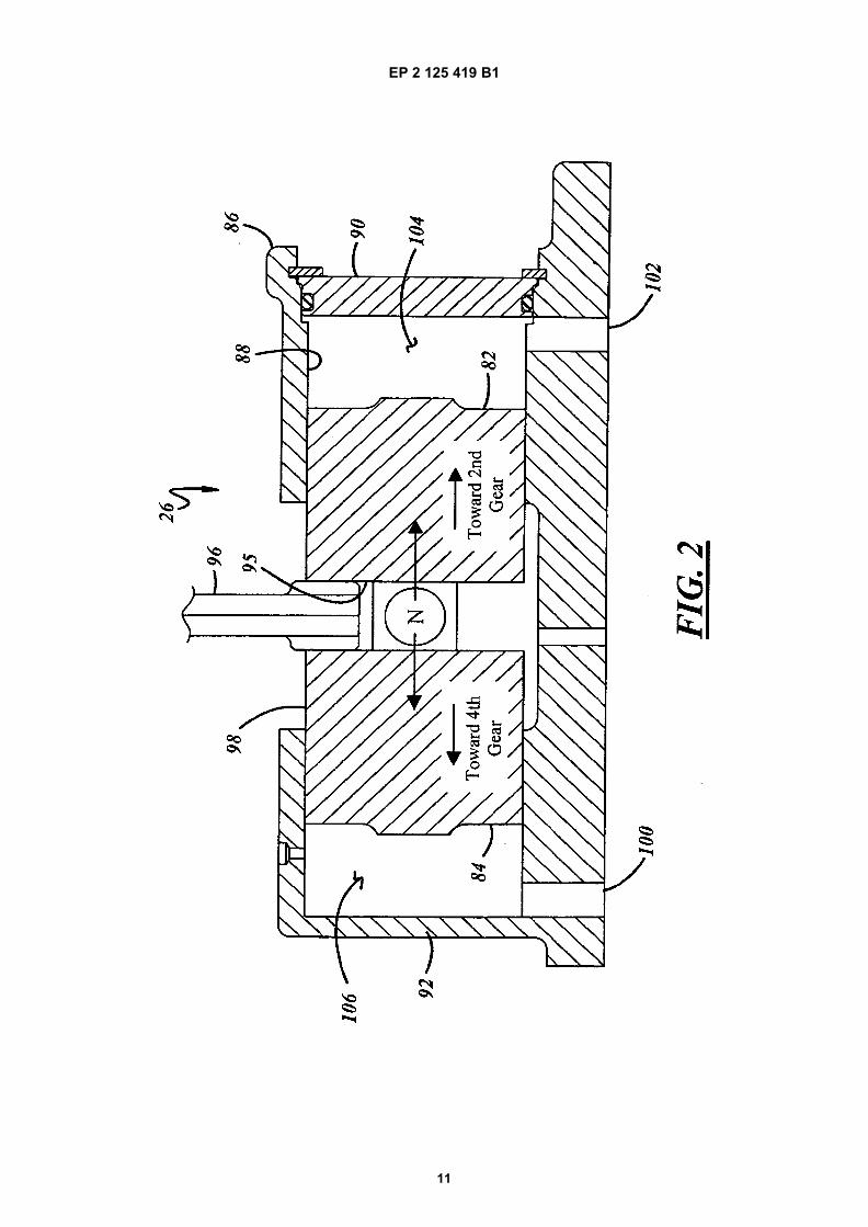
Figure 1 is schematic view of a dual clutch transmis-sion.Figure 2 is a sectioned view of an actuator for a syn-chronizer utilized in the dual clutch transmission ofFigure 1.Figure 3 is a hydraulic schematic of a control systemof the present invention.
DETAILED DESCRIPTION OF THE INVENTION
[0007] A representative dual clutch transmission thatmay be controlled by the present invention is generallyindicated at 10 in the schematic illustrated in FIG. 1. Spe-cifically, as shown in FIG. 1, the dual clutch transmission10 includes a dual, coaxial clutch assembly generally in-dicated at 12, a first input shaft, generally indicated at14, a second input shaft, generally indicated at 16, thatis coaxial to the first, a counter shaft, generally indicatedat 18, an output shaft 20, a reverse counter shaft 22, aplurality of synchronizers, generally indicated at 24, anda plurality of shift actuators generally indicated at 26 (FIG.2).[0008] The dual clutch transmission 10 forms a portionof a vehicle powertrain and is responsible for taking atorque input from a prime mover, such as an internal com-bustion engine, and transmitting the torque through se-lectable gear ratios to the vehicle drive wheels. The dualclutch transmission 10 operatively routes the appliedtorque from the engine through the dual, coaxial clutchassembly 12 to either the first input shaft 14 or the secondinput shaft 16. The input shafts 14 and 16 include a firstseries of gears, which are in constant mesh with a secondseries of gears disposed on the counter shaft 18. Eachone of the first series of gears interacts with one of thesecond series of gears to provide the different gear ratiossets used for transferring torque. The counter shaft 18also includes a first output gear that is in constant meshwith a second output gear disposed on the output shaft20. The plurality of synchronizers 24 are disposed on thetwo input shafts 14, 16 and on the counter shaft 18 andare operatively controlled by the plurality of shift actuators26 to selectively engage one of the alternate gear ratiosets. Thus, torque is transferred from the engine to thedual, coaxial clutch assembly 12, to one of the inputshafts 14 or 16, to the counter shaft 18 through one ofthe gear ratio sets, and to the output shaft 20. The outputshaft 20 further provides the output torque to the remain-
1 2

EP 2 125 419 B1
3
5
10
15
20
25
30
35
40
45
50
55
der of the powertrain. Additionally, the reverse countershaft 22 includes an intermediate gear that is disposedbetween one of the first series of gears and one of thesecond series of gears, which allows for a reverse rota-tion of the counter shaft 18 and the output shaft 20. Eachof these components will be discussed in greater detailbelow.[0009] Specifically, the dual, coaxial clutch assembly12 includes a first clutch mechanism 32 and a secondclutch mechanism 34. The first clutch mechanism 32 is,in part, physically connected to a portion of the engineflywheel (not shown) and is, in part, physically attachedto the first input shaft 14, such that the first clutch mech-anism 32 can operatively and selectively engage or dis-engage the first input shaft 14 to and from the flywheel.Similarly, the second clutch mechanism 34 is, in part,physically connected to a portion of the flywheel and is,in part, physically attached to the second input shaft 16,such that the second clutch mechanism 34 can opera-tively and selectively engage or disengage the secondinput shaft 16 to and from the flywheel. As can be seenfrom FIG. 1, the first and second clutch mechanisms 32,34 are coaxial and co-centric such that the outer case 28of the first clutch mechanism 32 fits inside of the outercase 36 of the second clutch mechanism 34. Similarly,the first and second input shafts 14, 16 are also coaxialand co-centric such that the second input shaft 16 is hol-low having an inside diameter sufficient to allow the firstinput shaft 14 to pass through and be partially supportedby the second input shaft 16. The first input shaft 14 in-cludes a first input gear 38 and a third input gear 42. Thefirst input shaft 14 is longer in length than the secondinput shaft 16 so that the first input gear 38 and a thirdinput gear 42 are disposed on the portion of the first inputshaft 14 that extends beyond the second input shaft 16.The second input shaft 16 includes a sixth input gear 40,a fourth input gear 44, a second input gear 46, and areverse input gear 48. As shown in FIG. 1, the sixth inputgear 40 and the reverse input gear 48 are fixedly sup-ported on the second input shaft 16 and the fourth inputgear 44 and second input gear 46 are rotatably supportedabout the second input shaft 16 upon bearing assemblies50 so that their rotation is unrestrained unless the ac-companying synchronizer is engaged, as will be dis-cussed in greater detail below.[0010] In the preferred embodiment, the counter shaft18 is a single, one-piece shaft that includes the opposing,or counter, gears to those on the inputs shafts 14, 16. Asshown in FIG. 1, the counter shaft 18 includes a firstcounter gear 52, a sixth counter gear 54, a third countergear 56, a fourth counter gear 58, a second counter gear60, and a reverse counter gear 62. The counter shaft 18fixedly retains the fourth counter gear 58 and secondcounter gear 60, while first, sixth, third, and reverse coun-ter gears 52, 54, 56, 62 are supported about the countershaft 18 by bearing assemblies 50 so that their rotationis unrestrained unless the accompanying synchronizeris engaged as will be discussed in greater detail below.
The counter shaft 18 also fixedly retains a first drive gear64 that meshingly engages the corresponding seconddriven gear 66 on the output shaft 20. The second drivengear 66 is fixedly mounted on the output shaft 20. Theoutput shaft 20 extends outward from the transmission10 to provide an attachment for the remainder of the pow-ertrain.[0011] In a preferred embodiment, the reverse countershaft 22 is a relatively short shaft having a single reverseintermediate gear 72 that is disposed between, andmeshingly engaged with, the reverse input gear 48 onthe second input shaft 16 and the reverse counter gear62 on the counter shaft 18. Thus, when the reverse gears48, 62, and 72 are engaged, the reverse intermediategear 72 on the reverse counter shaft 22 causes the coun-ter shaft 18 to turn in the opposite rotational directionfrom the forward gears thereby providing a reverse rota-tion of the output shaft 20. It should be appreciated thatall of the shafts of the dual clutch transmission 10 aredisposed and rotationally secured within the transmis-sion 10 by some manner of bearing assembly such asroller bearings, for example, shown at 68 in FIG. 1.[0012] The engagement and disengagement of thevarious forward and reverse gears is accomplished bythe actuation of the synchronizers 24 within the trans-mission. As shown in FIG. 1 in this example of a dualclutch transmission 10, four synchronizers 74, 76, 78,and 80 are utilized to shift through the six forward gearsand reverse. It should be appreciated that there are avariety of known types of synchronizers that are capableof engaging a gear to a shaft and that the particular typeemployed for the purposes of this discussion is beyondthe scope of the present invention. Generally speaking,any type of synchronizer that is movable by a shift forkor like device may be employed. As shown in the repre-sentative example of FIG. 1, the synchronizers are twosided, dual actuated synchronizers, such that they en-gage one gear to its respective shaft when moved off acenter neutralized position to the right and engage an-other gear to its respective shaft when moved to the left.Specifically with reference to FIG. 1, synchronizer 78 canbe actuated to the left to engage the first counter gear52 on the counter shaft 18 or actuated to the right toengage the third counter gear 56. Synchronizer 80 canbe actuated to the left to engage the reverse counter gear62 or actuated to the right to engage the sixth countergear 54. Likewise, synchronizer 74 can be actuated tothe left to engage the fourth input gear 44 or actuated tothe right to engage the second input gear 46. Synchro-nizer 76 is actuated to the right to directly engage theend of the first input shaft 14 to the output shaft 20 therebyproviding a direct 1:1 (one to one) drive ratio for fifth gear.There is no gear set to engage to the left of synchronizer76.[0013] To actuate the synchronizers 74, 76, 78, and80, this representative example of a dual clutch trans-mission 10 utilizes hydraulically driven shift actuators 26with attached shift forks to selectively move the synchro-
3 4

EP 2 125 419 B1
4
5
10
15
20
25
30
35
40
45
50
55
nizers so that they engage or disengage (neutralize) thedesired gears. As shown in FIG. 2, the shift actuators 26are essentially two way or dual hydraulic valve assem-blies that are driven back and forth linearly, in parallel toone of the input shafts 14, 16 or the counter shaft 18, tomove a shift fork 96, and ultimately one of the pluralityof synchronizers 24 in and out of engagement. It shouldbe appreciated from the description that follows that othertypes of actuators that are capable of driving a shift forkback and forth to move a synchronizer may also be em-ployed with the method of the present invention. Theseinclude mechanical actuators, hydro-mechanical actua-tors, electromechanical actuators, electrical actuators,and the like.[0014] Referring to FIG. 2, the hydraulically operatedshift actuators 26 include an outer case 86 that includesa main bore 88 having two cylindrically shaped ends 90,92. A piston 98 is slidably disposed within the main bore88 of the case 86. The piston 98 includes two opposingsealed heads 82 and 84. The interaction of each pistonhead 82 and 84 within its respective cylinder end 90, 92forms alpha and beta pressure or expansion chambers106, 104.[0015] Between the piston heads 82 and 84 is a gap.Positioned within the gap 95 is the shift fork 96. To actuatethe synchronize 74 to the right to actuate the second gearratio, fluid is injected into alpha expansion chamber 106through inlet-outlet 100 to move the piston and shift fork96 to the right causing synchronizer 80 to engage thesecond input gear 46 to the shaft 16. A detent mechanism(not shown) connected with the linkage with the shift fork96 holds the shift fork 96 in to hold its actuated position.To release the second input gear 46 from its shaft 16,the beta expansion chamber 104 is pressurized throughinlet 102 and the piston 98 and shift fork 96 are shiftedback to a detented neutral position. A slight pressuriza-tion of the expansion chamber 106 is temporarily main-tained to prevent overtravel of the piston 98 and inad-vertent engagement of fourth input gear 44 to the shaft16.[0016] Figure 3 illustrates a hydraulic control systemfor the first and second clutches 32, 34 and for synchro-nizers 74, 76, 78 and 80. The control system 7 has anoil sump 120. To provide a source of pressurize oil orfluid, a pump 122 is connected to the sump 120 via asuction filter 124. The pump 122 delivers pressurized flu-id to lines 126 and 128. A pump relief valve 127 connectedto line 126 prevents over pressurization in line 126. Fluidin line 128 passes through pressure filter 130 into lines132 and 134. The line 134 is connected with a variablebleed solenoid (VBS.) 136. The VBS 136 controls oper-ation of a main line pressure regulator valve 140. Whenat least partially actuated by VBS 136, the valve 140 con-nects line 126 with a lube regulator valve 142. A VBS144 controls valve 142 to control lubrication of the clutch-es 32, 34 via a clutch lube line 146. Clutch lube line 146is connected with the clutch lubrication system. Valve140 is also fluidly connected with an oil. cooler limit valve
148. An outlet of the valve 148 is looped back to in inletside of the pump 122. Valve 142 additionally delivers fluidto oil cooler 150. Variable force solenoids (VFS) 152, 154control the pressure within their respective clutches 32and 34 by selectively communicating to the clutches withthe line 134 or with the sump 120.[0017] The control system for the synchronizers in-cludes a first multiplex valve 160. The first multiplex valve160 has a first position allowing delivery of pressurizefluid to synchronizers 74 and 76. Synchronizers 78 and80 are diverted to the sump 120. In a second position ofthe first multiplex valve 160 the reverse occurs allowingdelivery of pressurize fluid to synchronizers 78 and 80with synchronizers 74 and 76 being diverted to the sump.An on/off solenoid valve 162 controls operation of thefirst multiplex valve 160.[0018] A second multiplex valve 164 is fluidly connect-ed with the first multiplex valve 160. The second multiplexvalve 164 has a first position allowing pressurized fluidconnection of alpha and beta chambers of the synchro-nizer 74 (when the first multiplex valve 160 is in the firstposition). The alpha and beta chambers of synchronizer76 are diverted to the sump 120. When the second mul-tiplex valve 164 is placed in the second position by anon/off solenoid 166, the fluid connections of the secondmultiplex valve 164 are reversed. The alpha chambersfor the synchronizers 74, 76, 78, and 80 include pressurechambers for odd and even gear ratios.[0019] To actuate the alpha chamber there is provideda first actuator regulator valve 170. First actuator regu-lator valve 170 has a biased position connecting the alphachamber to the sump 120. In a second position, the firstactuator regulator valve 170 connects the alpha chamberwith the line 132. A proportional solenoid valve providedby VBS solenoid valve 174 controls the first actuator reg-ulator valve 170. In like manner, VBS 176 controls thesecond actuator regulator valve 180 for the beta chamberof the synchronizer 74.[0020] To control the synchronizer 76 the first multiplexvalve 160 is in the first position and the second multiplexvalve is placed in the second position. To control syn-chronizer 80 or synchronizer 78 the first multiplex valve160 is placed in the second position. For synchronizer80, the second multiplex valve 164 is in the first position.For control of the synchronizer 78, the second multiplexvalve 164 is placed in the second position.[0021] To place the second input gear 46 into engage-ment with the shaft 16, the first multiplex valve 160 andsecond multiplex valve 162 are placed in the first position.The first regulator valve 170 is turned on to pressurizethe alpha expansion chamber 106 moving the piston 98and shift fork 96 to the right. A position sensor 97 is usedto inform or confirm the fact to the transmission electroniccontroller (not shown) that the transmission 10 is in thesecond gear. A major advantage of the present controlsystem for the synchronizers is that no two gears of thetransmission can be actuated at the same time. If thesecond input gear 46 is being actuated, all of the pressure
5 6

EP 2 125 419 B1
5
5
10
15
20
25
30
35
40
45
50
55
chambers of the synchronizers 80, 78 and 76 are divertedto the sump. If a control system failure causes the secondactuator regulator valve 180 to pressurize the beta ex-pansion chamber 104 of the shift actuator 26 for synchro-nizer 74, the pressure within the opposing beta 104 andalpha 106 expansion chambers act against each pre-venting any simultaneous gear activation (however whenthe alpha chamber 106 is depressurized the above notedfailure causes the gear (fourth input gear 44) associatedwith the beta chamber to be stuck on). Another advantageof the present control system is that most valve failuresallow at least one odd gear and at least one even gearto still operate. Failure of the first multiplex valve 160 inthe first position allows operation of synchronizer 74 pro-viding second and fourth gears. Additionally, fifth andneutral gears of synchronizer 76 are available. Uponsuch a failure, the transmission controller programs thetransmission 10 to operate in second, fourth and fifth gearratios dependent upon vehicle speed in a "limp" homemode of operation.[0022] A failure of the first multiplex valve 160 in thesecond position still allows for operation of the reverse,six gear, third gear and first. Failure of the second mul-tiplex valve 164 in the first position will still allow operationof the second, fourth, sixth and reverse gears. Failure ofany one given actuator valve still allows for partial gearoperation. Failure of the actuator regulator valve 170 inthe on position will freeze (be detented) second inputgear 46 with the shaft 16. To get another gear for "limp"home operation, the transmission controller opens theclutch 34. Engaged clutch 32 is utilized to rotate the shaft14. The controller of the transmission then picks a gearratio from a set of gear ratios associated with the shafts14 or 20 (first, third or fifth) gear to be utilized for "limp"home mode of operation. The transmission controllerthen alternates between second and one gear from theset of first, third or fifth gear. As long as a forward travelgear is engaged when one of the actuator regulatorvalves 170, 180 fails, the transmission will have two gearratios of forward operation in the "limp" home mode ofoperation.[0023] Still another advantage of the present inventionover other control systems as shown in Koenig et al. USPatent 6,898,992 (commonly assigned) is that only twohigh flow rate solenoid actuator regulator valves 170, 180are required.[0024] While preferred embodiments of the present in-vention have been disclosed, it is to be understood it hasbeen described by way of example only, and variousmodifications can be made without departing from thespirit and scope of the invention as it is encompassed inthe following claims.
Claims
1. A control system for a multiple clutch transmission(10), said transmission having at least three synchro-
nizers (74, 76, 78, 80) with opposed acting alpha andbeta pressure chambers (106, 104) to alternately se-lectively synchronize alpha or beta gears (44, 46)with a rotating shaft (14, 16), said control systemcomprising:
a pressure source (122);a sump (120);a first multiplex valve (160) having a first positionallowing fluid communication of alpha and betachambers for two synchronizers with said pres-sure source and diverting alpha and beta pres-sure chambers of remaining synchronizers tosaid sump, said first multiplex valve having asecond position reversing the above action;a second multiplex valve (164) fluidly connectedwith said first multiplex valve having a first posi-tion connecting alpha and beta chambers of agiven synchronizer with said pressure sourceand alpha and beta chambers of said other syn-chronizer with said sump, said second multiplexvalve having a second position reversing theabove action;a first actuator regulator valve (170) fluidly con-nected with said second multiplex valve (164)for selectively connecting said alpha chamberwith one of said pressure source (122) and saidsump (120); anda second actuator regulator valve (180) fluidlyconnected with said second multiplex valve(164) for selectively connecting said beta cham-ber with one of said pressure source and saidsump.
2. A control system as described in claim 1 wherein atleast one of said actuator regulator valves is control-led by a proportional solenoid valve.
3. A control system as described in claim 1 wherein atleast one of said actuator regulator valves is control-led by a variable bleed solenoid valve.
4. A control system as described in claim 1 wherein atleast one of said actuator regulator valves is biasedto connect said chamber to a sump.
5. A control system as described in claim 1 wherein atleast one of said multiplex valves is controlled by anon/off solenoid valve.
6. A control system as described in claim 1 whereinsaid alpha chambers include pressure chambers foreven and odd gear ratios.
7. A control system as described in claim 6 where upona failure of said first multiplex valve said control sys-tem can still operate at least one even gear ratio andone odd gear ratio.
7 8
EP 2 125 419 B1
6
5
10
15
20
25
30
35
40
45
50
55
8. A control system as described in claim 6 where uponfailure of said second multiplex valve said controlsystem can still operate at least one even gear ratioand one odd gear ratio.
9. A control system as described in claim 6 whereinupon failure of one of said actuator regulator valveswhen said control system is operating in forward gearratio said control system can still operate at least twogear ratios.
10. A multiple clutch transmission (10) comprising:
at least three synchronizers (74, 76, 78, 80) withopposed acting alpha and beta pressure cham-bers (106, 104) to alternately selectively syn-chronize alpha or beta gears (44, 46) with oneor more rotating shafts (14, 16), said transmis-sion having a control system comprising:a pressure source (122);a sump (120);a first multiplex valve (160) having a first positionallowing fluid communication of alpha and be achambers for two synchronizers with said pres-sure source and diverting alpha and beta pres-sure chambers of remaining synchronizers tosaid sump, said first multiplex valve having asecond position reversing the above action;a second multiplex valve (164) fluidly connectedwith said first multiplex valve having a first posi-tion connecting alpha and beta chambers of agiven synchronizer with said pressure sourceand alpha and beta chambers of said other syn-chronizer with said sump, said second multiplexvalve having a second position reversing theabove action;a first actuator regulator valve (170) fluidly con-nected with said second multiplex valve (164)fo selectively connecting said alpha chamberwith one of said pressure source (122) and saidsump (120) anda second actuator regulator valve (180) fluidlyconnected with said second multiplex valve(164) for selectively connecting said beta cham-ber with one of said pressure source and saidsump.
11. A multiple clutch transmission as described in claim10 wherein said alpha chambers include pressurechambers for even and odd gear ratios.
12. A multiple clutch transmission as described in claim11 where upon a failure of said first multiplex valvesaid control system can still operate at least one evengear ratio and one odd gear ratio.
13. A multiple clutch transmission as described in claim11 where upon a failure of said second multiplex
valve said control system can still operate at leastone even gear ratio and one odd gear ratio.
14. A control system as described in claim 10 whereinfailure of one of said actuator regulator valves whensaid control system is operating said in a forwardgear ratio, said control system can still operate atleast two gear ratios.
Patentansprüche
1. Steuersystem für ein Mehrfachkupplungsgetriebe(10), wobei das Getriebe mindestens drei Synchro-nisiereinrichtungen (74, 76, 78, 80) mit entgegenge-setzt wirkenden Alpha- und Beta-Druckkammern(106, 104) zum abwechselnden gezielten Synchro-nisieren von Alpha- und Betazahnrädern (44, 46) miteiner Drehwelle (14, 16) aufweist, wobei das Steu-ersystem Folgendes umfasst:
eine Druckquelle (122);einen Sumpf (120);ein erstes Multiplexventil (160) mit einer erstenPosition, die eine Strömungsverbindung von Al-pha- und Beta-Kammern für zwei Synchronisier-einrichtungen mit der Druckquelle und Umleitenvon Alpha- und Beta-Druckkammern der ver-bleibenden Synchronisiereinrichtungen zu demSumpf gestattet, wobei das erste Multiplexventileine zweite Position aufweist, die den obigenVorgang umkehrt;ein zweites Multiplexventil (164), das mit demersten Multiplexventil strömungsverbunden istund eine erste Position aufweist, die die Alpha-und Beta-Kammern einer gegebenen Synchro-nisiereinrichtung mit der Druckquelle verbindetund die Alpha- und Beta-Kammern der anderenSynchronisiereinrichtung mit dem Sumpf ver-bindet, wobei das zweite Multiplexventil einezweite Position aufweist, die den obigen Vor-gang umkehrt;ein erstes Aktuatorregelventil (170), das mitdem zweiten Multiplexventil (164) zur gezieltenVerbindung der Alpha-Kammer mit der Druck-quelle (122) oder dem Sumpf (120) strömungs-verbunden ist; undein zweites Aktuatorregelventil (180), das mitdem zweiten Multiplexventil (164) zur gezieltenVerbindung der Beta-Kammer mit der Druck-quelle oder dem Sumpf strömungsverbundenist.
2. Steuersystem nach Anspruch 1, wobei mindestenseines der Aktuatorregelventile durch ein Proportio-nalmagnetventil gesteuert wird.
3. Steuersystem nach Anspruch 1, wobei mindestens
9 10

EP 2 125 419 B1
7
5
10
15
20
25
30
35
40
45
50
55
eines der Aktuatorregelventile durch ein Magnetven-til mit variablem Ablass gesteuert wird.
4. Steuersystem nach Anspruch 1, wobei mindestenseines der Aktuatorregelventile zur Verbindung derKammer mit einem Sumpf vorgespannt ist.
5. Steuersystem nach Anspruch 1, wobei mindestenseines der Multiplexventile durch ein Ein/Aus-Ma-gnetventil gesteuert wird.
6. Steuersystem nach Anspruch 1, wobei die Alpha-Kammern Druckkammern für gerade und ungeradeGangstufen enthalten.
7. Steuersystem nach Anspruch 6, wobei bei Versagendes ersten Multiplexventils das Steuersystem immernoch mindestens eine gerade Gangstufe und eineungerade Gangstufe betreiben kann.
8. Steuersystem nach Anspruch 6, wobei bei Versagendes zweiten Multiplexventils das Steuersystem im-mer noch mindestens eine gerade Gangstufe undeine ungerade Gangstufe betreiben kann.
9. Steuersystem nach Anspruch 6, wobei bei Versageneines der Aktuatorregelventile, wenn das Steuersy-stem in der Vorwärtsgangstufe betrieben wird, dasSteuersystem immer noch mindestens zwei Gang-stufen betreiben kann.
10. Mehrfachkupplungsgetriebe (10), umfassend:
mindestens drei Synchronisiereinrichtungen(74, 76, 78, 80) mit entgegengesetzt wirkendenAlpha- und Beta-Druckkammern (106, 104) zumabwechselnden gezielten Synchronisieren vonAlpha- und Betazahnrädern (44, 46) mit eineroder mehreren Drehwellen (14, 16), wobei dasGetriebe ein Steuersystem aufweist, das Fol-gendes umfasst:
eine Druckquelle (122);einen Sumpf (120);ein erstes Multiplexventil (160) mit einer er-sten Position, die eine Strömungsverbin-dung von Alpha- und Beta-Kammern fürzwei Synchronisiereinrichtungen mit derDruckquelle und Umleiten von Alpha- undBeta-Druckkammern der verbleibendenSynchronisiereinrichtungen zu dem Sumpfgestattet, wobei das erste Multiplexventil ei-ne zweite Position aufweist, die den obigenVorgang umkehrt;ein zweites Multiplexventil (164), das mitdem ersten Multiplexventil strömungsver-bunden ist und eine erste Position aufweist,die die Alpha- und Beta-Kammern einer ge-
gebenen Synchronisiereinrichtung mit derDruckquelle verbindet und die Alpha- undBeta-Kammern der anderen Synchronisier-einrichtung mit dem Sumpf verbindet, wobeidas zweite Multiplexventil eine zweite Posi-tion aufweist, die den obigen Vorgang um-kehrt;ein erstes Aktuatorregelventil (170), das mitdem zweiten Multiplexventil (164) zur ge-zielten Verbindung der Alpha-Kammer mitder Druckquelle (122) oder dem Sumpf(120) strömungsverbunden ist; undein zweites Aktuatorregelventil (180), dasmit dem zweiten Multiplexventil (164) zurgezielten Verbindung der Beta-Kammer mitder Druckquelle oder dem Sumpf strö-mungsverbunden ist.
11. Mehrfachkupplungsgetriebe nach Anspruch 10, wo-bei die Alpha-Kammern Druckkammern für geradeund ungerade Gangstufen enthalten.
12. Mehrfachkupplungsgetriebe nach Anspruch 11, wo-bei bei Versagen des ersten Multiplexventils dasSteuersystem immer noch mindestens eine geradeGangstufe und eine ungerade Gangstufe betreibenkann.
13. Mehrfachkupplungsgetriebe nach Anspruch 11, wo-bei bei Versagen des zweiten Multiplexventils dasSteuersystem immer noch mindestens eine geradeGangstufe und eine ungerade Gangstufe betreibenkann.
14. Mehrfachkupplungsgetriebe nach Anspruch 10, wo-bei bei Versagen eines der Aktuatorregelventile,wenn das Steuersystem in der Vorwärtsgangstufebetrieben wird, das Steuersystem immer noch min-destens zwei Gangstufen betreiben kann.
Revendications
1. Système de commande pour une transmission à em-brayages multiples (10), ladite transmission ayantau moins trois synchroniseurs (74, 76, 78, 80), avecdes chambres de pression à actions opposées alphaet bêta (106, 104) pour synchroniser sélectivementen alternance des rapports alpha ou bêta (44, 46)avec un arbre de rotation (14, 16), ledit système decommande comprenant :
une source de pression (122) ;un puisard (120) ;une première soupape multiplex (160) ayantune première position permettant la communi-cation des chambres alpha et bêta de deux syn-chroniseurs avec ladite source de pression et
11 12

EP 2 125 419 B1
8
5
10
15
20
25
30
35
40
45
50
55
déviant les chambres de pression alpha et bêtades synchroniseurs restants vers ledit puisard,ladite soupape multiplex ayant une deuxièmeposition inversant ladite action ;une deuxième soupape multiplex (164) connec-tée fluidiquement à ladite première soupapemultiplexe ayant une première position connec-tant les chambres alpha et bêta d’un synchroni-seur donné à ladite source de pression et leschambres alpha et bêta dudit autre synchroni-seur audit puisard, ladite deuxième soupapemultiplex ayant une deuxième position inversantladite action ;une première soupape de régulation d’action-neur (170) connectée fluidiquement à laditedeuxième soupape multiplex (164) pour con-necter de manière sélective ladite chambre al-pha soit à ladite source de pression (122) soitaudit puisard (120) ; etune deuxième soupape de régulation d’action-neur (180) connectée fluidiquement à laditedeuxième soupape multiplex (164) pour con-necter de manière sélective ladite chambre bêtasoit à ladite source de pression soit audit pui-sard.
2. Système de commande selon la revendication 1,dans lequel au moins l’une desdites soupapes derégulation d’actionneur est commandée par uneélectrovanne proportionnelle.
3. Système de commande selon la revendication 1,dans lequel au moins l’une desdites soupapes derégulation d’actionneur est commandée par uneélectrovanne de purge variable.
4. Système de commande selon la revendication 1,dans lequel au moins l’une desdites soupapes derégulation d’actionneur est sollicitée de manière àconnecter ladite chambre à un puisard.
5. Système de commande selon la revendication 1,dans lequel au moins l’une desdites soupapes mul-tiplex est commandée par une électrovanne mar-che/arrêt.
6. Système de commande selon la revendication 1,dans lequel lesdites chambres alpha comportent deschambres de pression pour des rapports de vitessepairs et impairs.
7. Système de commande selon la revendication 6,dans lequel, en cas de défaillance de ladite premièresoupape multiplex, ledit système de commande peutencore faire fonctionner au moins un rapport de vi-tesse pair et un rapport de vitesse impair.
8. Système de commande selon la revendication 6,
dans lequel, en cas de défaillance de ladite deuxiè-me soupape multiplex, ledit système de commandepeut encore faire fonctionner au moins un rapportde vitesse pair et un rapport de vitesse impair.
9. Système de commande selon la revendication 6,dans lequel, en cas de défaillance de l’une desditessoupapes de régulation d’actionneur lorsque le sys-tème de commande fonctionne avec un rapport devitesse de marche avant, ledit système de comman-de peut encore faire fonctionner au moins deux rap-ports de vitesse.
10. Transmission à embrayages multiples (10) compre-nant
au moins trois synchroniseurs (74, 76, 78, 80)avec des chambres de pression à actions op-posées alpha et bêta (106, 104) pour synchro-niser de manière sélective en alternance desrapports alpha ou bêta (44, 46) avec un ou plu-sieurs arbres de rotation (14, 16), ladite trans-mission ayant un système de commandecomprenant :
une source de pression (122) ;un puisard (120) ;une première soupape multiplex (160)ayant une première position permettant lacommunication fluidique de chambres al-pha et bêta de deux synchroniseurs avecladite source de pression et déviant leschambres de pression alpha et bêta dessynchroniseurs restants vers ledit puisard,ladite première soupape multiplex ayantune deuxième position inversant laditeaction ;une deuxième soupape multiplex (164) con-nectée fluidiquement à ladite première sou-pape multiplexe ayant une première posi-tion connectant les chambres alpha et bêtad’un synchroniseur donné à ladite sourcede pression et les chambres alpha et bêtadudit autre synchroniseur audit puisard, la-dite deuxième soupape multiplex ayant unedeuxième position inversant ladite action ;une première soupape de régulation d’ac-tionneur (170) connectée fluidiquement àladite deuxième soupape multiplex (164)pour connecter de manière sélective laditechambre alpha soit à ladite source de pres-sion (122) soit audit puisard (120) ; etune deuxième soupape de régulation d’ac-tionneur (180) connectée fluidiquement àladite deuxième soupape multiplex (164)pour connecter de manière sélective laditechambre bêta soit à ladite source de pres-sion soit audit puisard.
13 14

EP 2 125 419 B1
9
5
10
15
20
25
30
35
40
45
50
55
11. Transmission à embrayages multiples selon la re-vendication 10, dans laquelle lesdites chambres al-pha incluent des chambres de pression pour des rap-ports de vitesse pairs et impairs.
12. Transmission à embrayages multiples selon la re-vendication 11, dans laquelle, en cas de défaillancede ladite première soupape multiplex, ledit systèmede commande peut encore faire fonctionner aumoins un rapport de vitesse pair et un rapport devitesse impair.
13. Transmission à embrayages multiples selon la re-vendication 11, dans laquelle, en cas de défaillancede ladite deuxième soupape multiplex, ledit systèmede commande peut encore faire fonctionner aumoins un rapport de vitesse pair et un rapport devitesse impair.
14. Transmission à embrayages multiples selon la re-vendication 10, dans laquelle, en cas de défaillancede l’une desdites soupapes de régulation d’action-neur lorsque le système de commande fonctionneavec un rapport de vitesse de marche avant, leditsystème de commande peut encore faire fonctionnerau moins deux rapports de vitesse.
15 16

EP 2 125 419 B1
10
EP 2 125 419 B1
11

EP 2 125 419 B1
12

EP 2 125 419 B1
13
REFERENCES CITED IN THE DESCRIPTION
This list of references cited by the applicant is for the reader’s convenience only. It does not form part of the Europeanpatent document. Even though great care has been taken in compiling the references, errors or omissions cannot beexcluded and the EPO disclaims all liability in this regard.
Patent documents cited in the description
• US 2006005647 A1 [0002]• US 5711409 A [0003]• US 6996989 B [0003]• US 6887184 B [0003]
• US 6909955 B [0003]• US 20060101933 A1 [0003]• US 20060207655 A1 [0003]• US 6898992 B, Koenig [0003] [0023]


