Embed Size (px)
Citation preview
Hotel Reservation System Based Local Area Network
at Samarinda
Heny Pratiwi
Teknik Informatika, STMIK Widya Cipta Dharma, Samarinda, Indonesia
Abstract—The Hotel industry is one of the most vibrant
businesses today, however, the current hotel reservation system is
still largely unfamiliar with computerized processes. The process
of logging in and outgoing guests still use simple office
applications without formulas and without database-based. Any
receipt of payment submitted to the guest also cannot be
automatically printed from the office application. Every month
an incoming and outgoing guest report will be made abased on
notes from the hotel reservation. The hotel reservation system
will be built using Visual Basic 6.0 and network-based
programming languages. In this study, data collection techniques
used are literature study and documentation, interviews,
observation, data analysis, needs analysis, and technology
analysis. Analysis methods and design system used in this
research are Flow of Document (FOD) and Data Flow Diagram
(DFD). Testing the system using black box testing method, by
testing the program interface to analyze the input and do all the
functional requirements of the program.
Keywords—system; reservation; hotel; local area network
I. INTRODUCTION
Hotel reservation system based Local Area Network is a computerized system with handling hotel problems that exist in Samarinda. The hotel-based hotel reservation system includes data collection of incoming and outgoing guest activities. Now, the hotel's on-going reservation system, has not used a computerized process. The process that occurs is logging in and outgoing guests still use simple office applications without formulas and without database-based.
Any bills of payment submitted to the guest also cannot be automatically printed from the office application. Every month an incoming guest report will be made from the hotel reservation process that has been done as well as reports on the activities of incoming guests and guests out at the hotel. Based on the current system, there are still problems such as the need for a long time in terms of the accumulated use of laundry services and restaurants used by guests. Because of that, it need help to solve the problems encountered, made a hotel-based reservation system network. With this system, we expected to handle the constraints faced in the hotel reservation system a, make it easier for the administration in guest data processing, transactions incoming and outgoing guests and printing reports required by the management.
II. LITERATURE REVIEW
A. Hotel Reservation
A hotel reservation system, commonly known as a central reservation system (CRS) is a computerized system that stores and distributes information of a hotel, resort or other lodging facilities [1].
B. Local Area Network
LANs connect computers and peripheral devices in a limited physical area, such as a business, office, a limited physical area, such as a business, office, laboratory or college campus by means of permanent links (wires) that transmit data rapidly [2].
A local area network (LAN) is a communication network that interconnects a variety of data communicating devices within a small geographic area and broadcasts data at high data transfer rates with very low error rates. Since the local area network first appeared in the 1970s, its use has become widespread in commercial and academic environments.
A LAN is a high-speed data network that covers a relatively small geographic area. It typically connects workstations, personal computers, printers, servers, and other devices. LANs offer computer users many advantages, including shared access to devices and applications, file exchange between connected users, and communication between users via electronic mail and other applications [3].
A LAN consists of two or more personal computer, printers and high capacity disk storage device called printers and high capacity disk storage device called file servers, which enable each computer on the file servers, which enable each computer on the network to access a common of files.
LAN topologies define the manner in which network devices are organized. Four common LAN topologies exist: bus, ring, star, and tree. These topologies are logical architectures, but the actual devices need not be physically organized in these configurations. Logical bus and ring topologies, for example, are commonly organized physically as a star. A bus topology is a linear LAN architecture in which transmissions from network stations propagate the length of the medium and are received by all other stations. Of the three most widely used LAN implementations, Ethernet/IEEE 802.3 networks—including 100BaseT—implement a bus topology, which is illustrated in Figure 1.
Copyright © 2018, the Authors. Published by Atlantis Press. This is an open access article under the CC BY-NC license (http://creativecommons.org/licenses/by-nc/4.0/).
2017 International Conference on Education and Technology (2017 ICEduTech)Advances in Intelligent Systems Research (AISR), volume 144
17
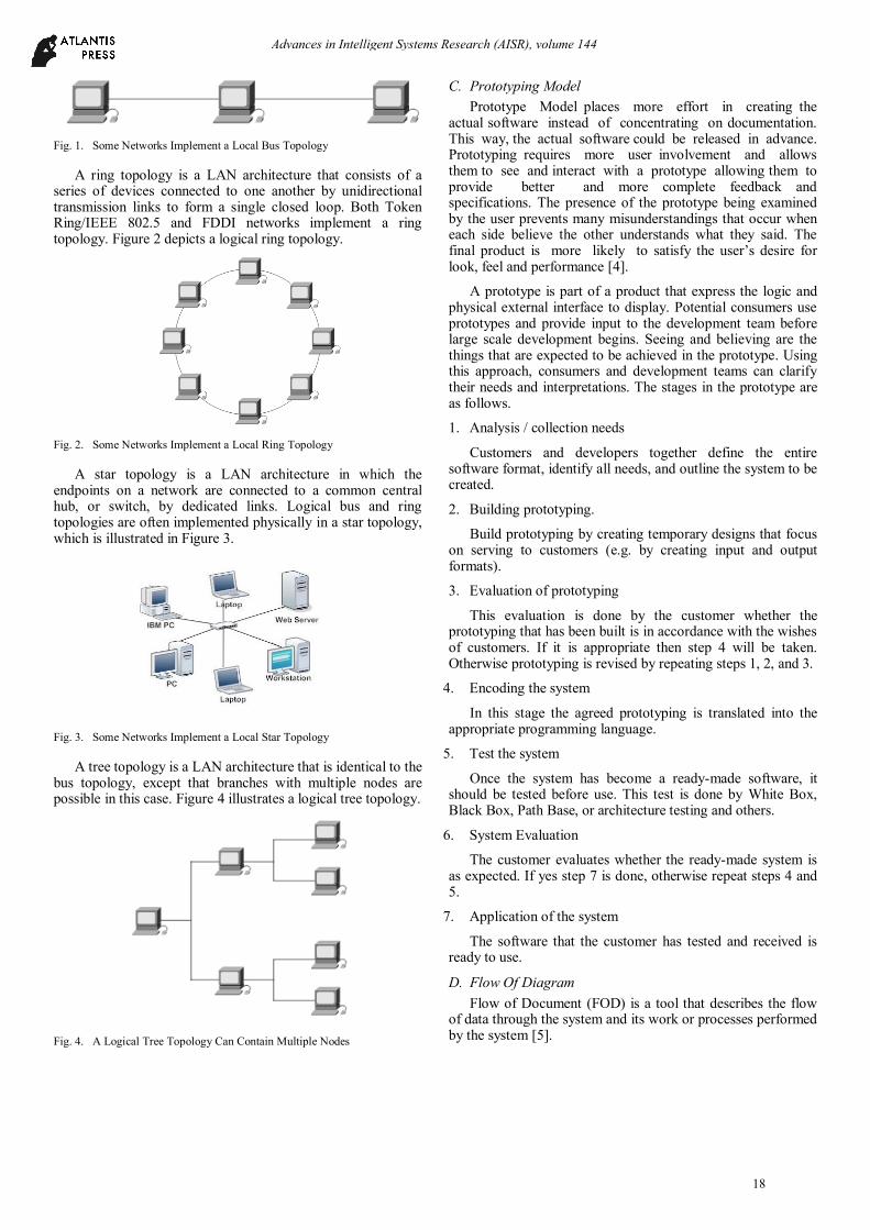
Fig. 1. Some Networks Implement a Local Bus Topology
A ring topology is a LAN architecture that consists of a series of devices connected to one another by unidirectional transmission links to form a single closed loop. Both Token Ring/IEEE 802.5 and FDDI networks implement a ring topology. Figure 2 depicts a logical ring topology.
Fig. 2. Some Networks Implement a Local Ring Topology
A star topology is a LAN architecture in which the endpoints on a network are connected to a common central hub, or switch, by dedicated links. Logical bus and ring topologies are often implemented physically in a star topology, which is illustrated in Figure 3.
Fig. 3. Some Networks Implement a Local Star Topology
A tree topology is a LAN architecture that is identical to the bus topology, except that branches with multiple nodes are possible in this case. Figure 4 illustrates a logical tree topology.
Fig. 4. A Logical Tree Topology Can Contain Multiple Nodes
C. Prototyping Model
Prototype Model places more effort in creating the actual software instead of concentrating on documentation. This way, the actual software could be released in advance. Prototyping requires more user involvement and allows them to see and interact with a prototype allowing them to provide better and more complete feedback and specifications. The presence of the prototype being examined by the user prevents many misunderstandings that occur when each side believe the other understands what they said. The final product is more likely to satisfy the user’s desire for look, feel and performance [4].
A prototype is part of a product that express the logic and physical external interface to display. Potential consumers use prototypes and provide input to the development team before large scale development begins. Seeing and believing are the things that are expected to be achieved in the prototype. Using this approach, consumers and development teams can clarify their needs and interpretations. The stages in the prototype are as follows.
1. Analysis / collection needs
Customers and developers together define the entire software format, identify all needs, and outline the system to be created.
2. Building prototyping.
Build prototyping by creating temporary designs that focus on serving to customers (e.g. by creating input and output formats).
3. Evaluation of prototyping
This evaluation is done by the customer whether the prototyping that has been built is in accordance with the wishes of customers. If it is appropriate then step 4 will be taken. Otherwise prototyping is revised by repeating steps 1, 2, and 3.
4. Encoding the system
In this stage the agreed prototyping is translated into the appropriate programming language.
5. Test the system
Once the system has become a ready-made software, it should be tested before use. This test is done by White Box, Black Box, Path Base, or architecture testing and others.
6. System Evaluation
The customer evaluates whether the ready-made system is as expected. If yes step 7 is done, otherwise repeat steps 4 and 5.
7. Application of the system
The software that the customer has tested and received is ready to use.
D. Flow Of Diagram
Flow of Document (FOD) is a tool that describes the flow of data through the system and its work or processes performed by the system [5].
Advances in Intelligent Systems Research (AISR), volume 144
18
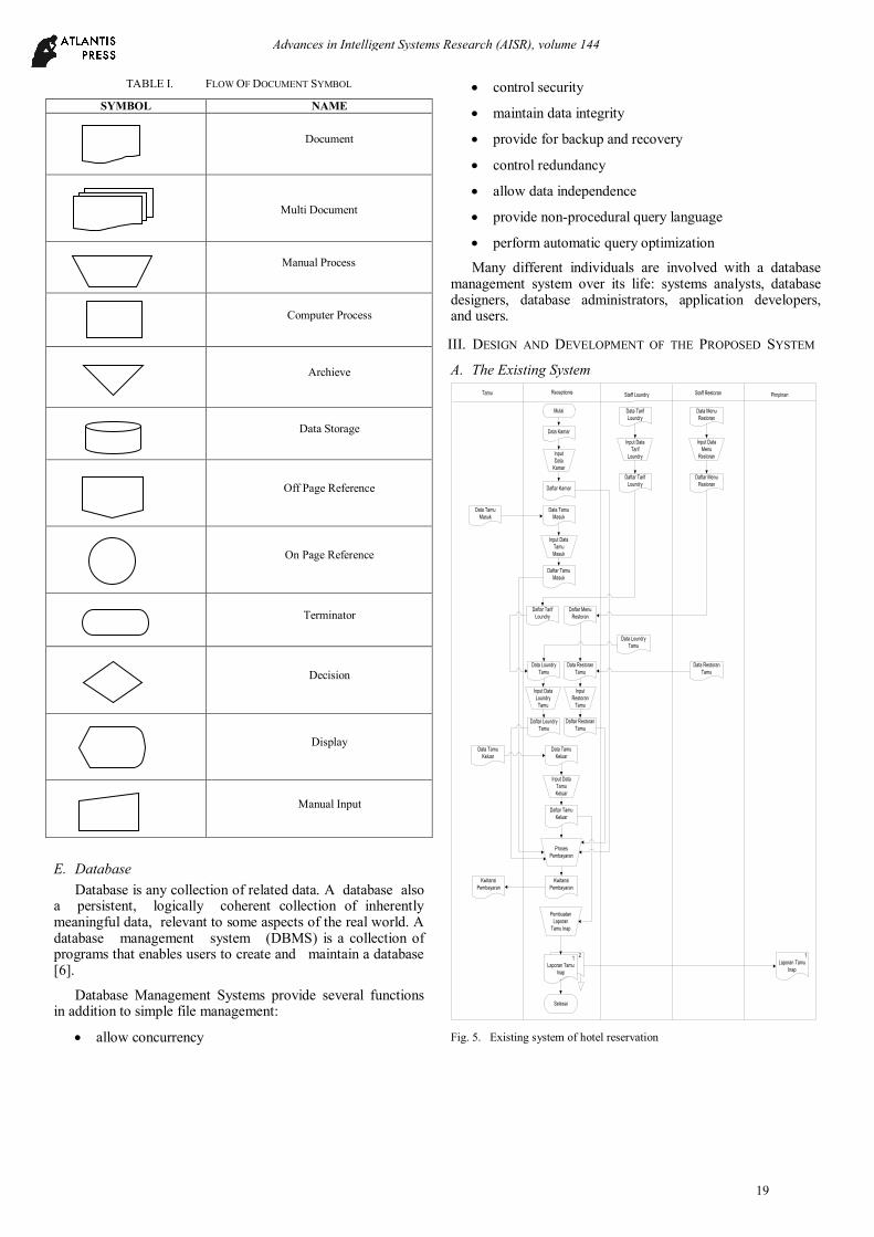
TABLE I. FLOW OF DOCUMENT SYMBOL
SYMBOL NAME
Document
Multi Document
Manual Process
Computer Process
Archieve
Data Storage
Off Page Reference
On Page Reference
Terminator
Decision
Display
Manual Input
E. Database
Database is any collection of related data. A database also a persistent, logically coherent collection of inherently meaningful data, relevant to some aspects of the real world. A database management system (DBMS) is a collection of programs that enables users to create and maintain a database [6].
Database Management Systems provide several functions in addition to simple file management:
allow concurrency
control security
maintain data integrity
provide for backup and recovery
control redundancy
allow data independence
provide non-procedural query language
perform automatic query optimization
Many different individuals are involved with a database management system over its life: systems analysts, database designers, database administrators, application developers, and users.
III. DESIGN AND DEVELOPMENT OF THE PROPOSED SYSTEM
A. The Existing System
Tamu Receptionis Staff Loundry
Mulai
Data Kamar
Input
Data
Kamar
Daftar Kamar
Pembuatan
Laporan
Tamu Inap
1
Laporan Tamu
Inap
2 1
Laporan Tamu
Inap
Selesai
Data Tamu
Masuk
Input Data
Tamu
Masuk
Daftar Tamu
Masuk
Data Tamu
Masuk
Data Loundry
Tamu
Input Data
Loundry
Tamu
Daftar Loundry
Tamu
Data Restoran
Tamu
Input
Restoran
Tamu
Daftar Restoran
Tamu
Data Tamu
Keluar
Input Data
Tamu
Keluar
Daftar Tamu
Keluar
Data Tamu
Keluar
Proses
Pembayaran
Kwitansi
Pembayaran
Kwitansi
Pembayaran
Staff Restoran Pimpinan
Data Tarif
Loundry
Data Menu
Restoran
Input Data
Tarif
Loundry
Input Data
Menu
Restoran
Daftar Tarif
Loundry
Daftar Menu
Restoran
Daftar Tarif
Loundry
Daftar Menu
Restoran
Data Loundry
Tamu
Data Restoran
Tamu
Fig. 5. Existing system of hotel reservation
Advances in Intelligent Systems Research (AISR), volume 144
19
B. The Proposed System
Tamu Receptionis Staff Loundry
Mulai
Data Kamar
Data Tamu
Masuk
Input Data
Kamar
Pendataan
Kamar
Tabel Kamar
2 1
Laporan Daftar
Kamar
Data Tamu
Masuk
Input Data
Tamu Masuk
Pendataan
Tamu Masuk
Tabel Tamu
Masuk
1
Laporan Daftar
Kamar
Data Loundry
Tamu
Input Data
Loundry Tamu
Pendataan
Loundry Tamu
Tabel Loundry
Tamu
Data Restoran
Tamu
Input Data
Restoran Tamu
Pendataan
Restoran
Tamu
Tabel Restoran
Tamu
Data Tamu
Keluar
Data Tamu
Keluar
Input Data
Tamu Keluar
Pendataan
Tamu Keluar
Tabel Tamu
Keluar
Pembayaran
Kwitansi
Pembayaran
Kwitansi
Pembayaran
Pembuatan
Laporan
2 1
Laporan Daftar
Tamu Inap
1
Laporan Daftar
Tamu Inap
Selesai
2 1
Laporan Daftar
Loundry
1
Laporan Daftar
Loundry
2 1
Laporan Daftar
Layanan
Restoran
1
Laporan Daftar
Layanan
Restoran
2 1
Laporan Grafik
Tamu Hotel
1
Laporan Grafik
Tamu Hotel
Staff Restoran Pimpinan
Data Tarif
Loundry
Input Data Tarif
Loundry
Pendataan
Tarif Loundry
Tabel Tarif
Loundry
Data Menu
Restoran
Input Data Menu
Restoran
Pendataan
Menu
Restoran
Tabel Menu
Restoran
Laporan
Daftar Kamar
Laporan
Daftar
Loundry
Laporan Daftar
Layanan
Restoran
Laporan
Daftar Tamu
Inap
Laporan
Grafik Tamu
Hotel
Laporan
Daftar Kamar
Laporan
Daftar
Loundry
Laporan Daftar
Layanan
Restoran
Laporan
Daftar Tamu
Inap
Laporan
Grafik Tamu
Hotel
Administrator
Data Jenis
Kamar
Input Data Jenis
Kamar
Pendataan
Jenis Kamar
Tabel Jenis Kamar
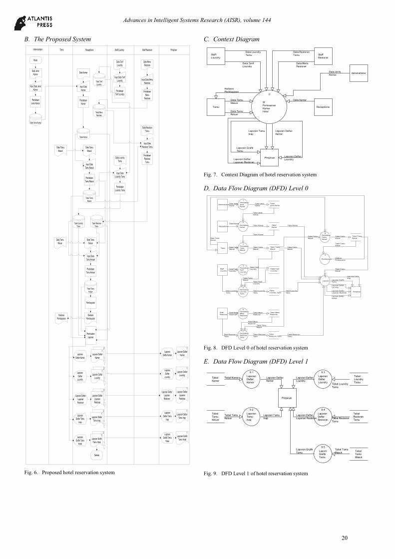
Fig. 6. Proposed hotel reservation system
C. Context Diagram
Fig. 7. Context Diagram of hotel reservation system
D. Data Flow Diagram (DFD) Level 0
Fig. 8. DFD Level 0 of hotel reservation system
E. Data Flow Diagram (DFD) Level 1
Fig. 9. DFD Level 1 of hotel reservation system
0
SI
Pemesanan
Kamar
Hotel
Tamu Receptionis
Pimpinan
Staff
Loundry
Staff
Restoran
Administrator
Data Tamu
Masuk
Data Kamar
Data Tamu
Keluar
Data Menu
Restoran
Laporan Grafik
Tamu
Laporan Tamu
Inap
Laporan Daftar
Kamar
Kwitansi
Pembayaran
Laporan Daftar
LoundryLaporan Daftar
Layanan Restoran
Data Loundry
Tamu
Data Tarif
Loundry
Data Restoran
Tamu
Data Jenis
Kamar
2
Pendataan
Kamar
3
Pendataan
Tamu
Masuk
Receptionis
5
Pendataan
Loundry
Tamu
7
Pendataan
Restoran
Tamu
8
Pendataan
Tamu
Keluar
9
Pembayaran
Tamu
Tabel
Kamar
Tabel Tamu
Masuk
Tabel
Loundry Tamu
Tabel
Restoran Tamu
Tabel Tamu
Keluar
10
Laporan
Pimpinan
4
Pendataan
Tarif
Loundry
Staff
Loundry
Tabel Tarif
Loundry
6
Pendataan
Menu
Restoran
Staff
Restoran
Tabel Menu
Restoran
Administrator
1
Pendataan
Jenis
Kamar
Tabel
Jenis Kamar
Data Kamar
Data Tamu
Masuk
Tabel Tarif
Loundry
Tabel Menu
Restoran
Tabel Tarif
Loundry
Tabel Kamar
Tabel Tamu
Masuk
Tabel Loundry
Tamu
Tabel Restoran
Tamu
Tabel Tamu
Keluar
Tabel Kamar
Tabel Tamu
Masuk
Tabel Tamu
Masuk
Data Menu
Restoran
Tabel Tamu
Keluar
Data Tarif
Loundry
Data Loundry
Tamu
Data Restoran
Tamu
Tabel Menu
Restoran
Data Tamu
Keluar
Kwitansi
Pembayaran
Tabel Tamu
Masuk
Tabel Tamu
Keluar
Tabel Tamu
Masuk
Tabel Kamar
Laporan Daftar
Layanan Restoran
Tabel Loundry
Tamu
Laporan Daftar
Loundry
Tabel Restoran
Tamu
Laporan Tamu
Inap
Laporan Daftar
Kamar
Laporan Grafik
Tamu
Data Jenis
Kamar
Tabel Jenis
Kamar
Tabel Jenis
Kamar
Tabel
Kamar
Tabel
Tamu
Keluar
Pimpinan
9.1
Laporan
Daftar
Kamar
9.2
Laporan
Tamu
Inap
9.3
Laporan
Daftar
Loundry
9.4
Laporan
Daftar
Restoran
Tabel
Loundry
Tamu
Tabel
Restoran
Tamu
Tabel
Tamu
Masuk
9.5
Laporn
Grafik
Tamu
Tabel Kamar
Tabel Tamu
Keluar
Laporan Tamu
Inap
Laporan Daftar
Kamar
Tabel Loundry
Tamu
Tabel Restoran
Tamu
Laporan Daftar
Loundry
Laporan Daftar
Layanan Restoran
Tabel Tamu
Masuk
Laporan Grafik
Tamu
Advances in Intelligent Systems Research (AISR), volume 144
20
F. Hierarchy Plus Input-Process-Output (HIPO) Sistem Informasi
Pemesanan Kamar pada
Hotel Grand Jamrud 2
Samarinda
Berbasis Local Area
Network (LAN)
2
Pendataan
Kamar
3
Pendataan
Tamu Masuk
5
Pendataan
Loundry Tamu
7
Pendataan
Restoran
Tamu
8
Pendataan
Tamu Keluar
10.1
Laporan Daftar
Kamar
10.2
Laporan Tamu
Inap
9
Pembayaran
10
Laporan
10.3
Laporan Daftar
Loundry
10.4
Laporan Daftar
Layanan
Restoran
10.5
Laporan Grafik
Tamu
4
Pendataan
Tarif Loundry
6
Pendataan
Menu
Restoran
1
Pendataan
Jenis Kamar
Fig. 10. HIPO of hotel reservation system
G. Entity Relationship Diagram (ERD)
Tamu Masuk
Loundry Tamu
Tarif
Id_kamar
Tgl_Masuk
Alamat
ID_TamuNama_Tamu
Id_Masuk
Memakai
Id_Masuk
Jasa_Loundry
Tamu Keluar
KamarMemesan
Melakukan
JenisKode_Kamar
Tgl_Masuk Tgl_Keluar
No_Kamar
Type_Bed
Id_Masuk Lama_Inap
Restoran Tamu Memakai
Tarif
Id_Masuk Menu
Harga
Id_kamar
Tarif Loundry
Tarif
Kode_Loundry
Jasa_Loundry
Memakai
Menu Restoran
Kode_menu
Menu
Harga
Memesan
Fig. 11. ERD of hotel reservation system
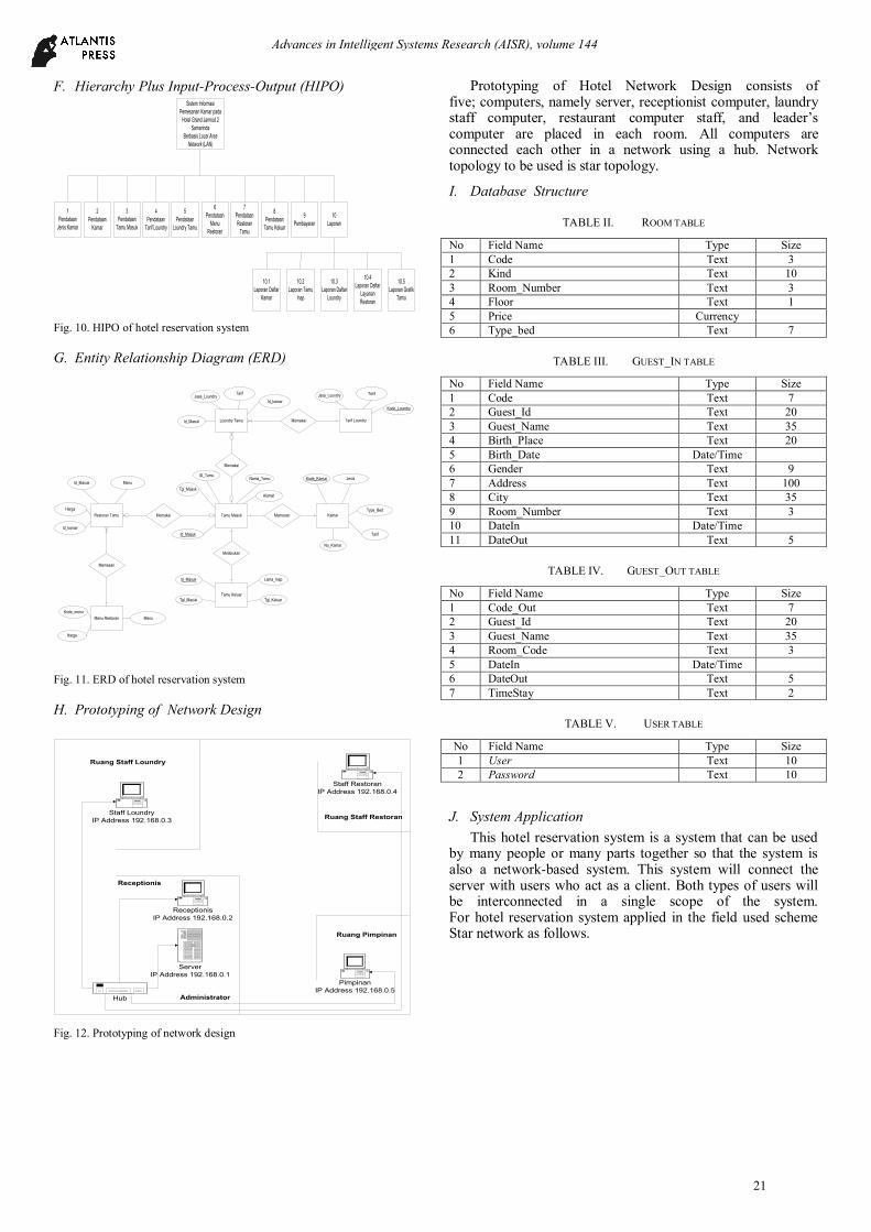
H. Prototyping of Network Design
Hub
Ruang Staff Restoran
Ruang Staff Loundry
Ruang Pimpinan
Receptionis
Administrator
Server
IP Address 192.168.0.1
Staff Loundry
IP Address 192.168.0.3
Pimpinan
IP Address 192.168.0.5
Receptionis
IP Address 192.168.0.2
Staff Restoran
IP Address 192.168.0.4
Fig. 12. Prototyping of network design
Prototyping of Hotel Network Design consists of five; computers, namely server, receptionist computer, laundry staff computer, restaurant computer staff, and leader’s computer are placed in each room. All computers are connected each other in a network using a hub. Network topology to be used is star topology.
I. Database Structure
TABLE II. ROOM TABLE
No Field Name Type Size
1 Code Text 3
2 Kind Text 10
3 Room_Number Text 3
4 Floor Text 1
5 Price Currency
6 Type_bed Text 7
TABLE III. GUEST_IN TABLE
No Field Name Type Size
1 Code Text 7
2 Guest_Id Text 20
3 Guest_Name Text 35
4 Birth_Place Text 20
5 Birth_Date Date/Time
6 Gender Text 9
7 Address Text 100
8 City Text 35
9 Room_Number Text 3
10 DateIn Date/Time
11 DateOut Text 5
TABLE IV. GUEST_OUT TABLE
No Field Name Type Size
1 Code_Out Text 7
2 Guest_Id Text 20
3 Guest_Name Text 35
4 Room_Code Text 3
5 DateIn Date/Time
6 DateOut Text 5
7 TimeStay Text 2
TABLE V. USER TABLE
No Field Name Type Size
1 User Text 10
2 Password Text 10
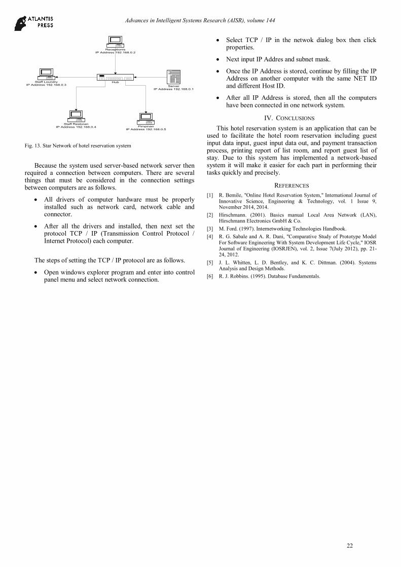
J. System Application
This hotel reservation system is a system that can be used by many people or many parts together so that the system is also a network-based system. This system will connect the server with users who act as a client. Both types of users will be interconnected in a single scope of the system. For hotel reservation system applied in the field used scheme Star network as follows.
Advances in Intelligent Systems Research (AISR), volume 144
21
Server
IP Address 192.168.0.1
Staff Loundry
IP Address 192.168.0.3
Pimpinan
IP Address 192.168.0.5
Receptionis
IP Address 192.168.0.2
Hub
Staff Restoran
IP Address 192.168.0.4
Fig. 13. Star Network of hotel reservation system
Because the system used server-based network server then required a connection between computers. There are several things that must be considered in the connection settings between computers are as follows.
All drivers of computer hardware must be properly installed such as network card, network cable and connector.
After all the drivers and installed, then next set the protocol TCP / IP (Transmission Control Protocol / Internet Protocol) each computer.
The steps of setting the TCP / IP protocol are as follows.
Open windows explorer program and enter into control panel menu and select network connection.
Select TCP / IP in the netwok dialog box then click properties.
Next input IP Addres and subnet mask.
Once the IP Address is stored, continue by filling the IP Address on another computer with the same NET ID and different Host ID.
After all IP Address is stored, then all the computers have been connected in one network system.
IV. CONCLUSIONS
This hotel reservation system is an application that can be used to facilitate the hotel room reservation including guest input data input, guest input data out, and payment transaction process, printing report of list room, and report guest list of stay. Due to this system has implemented a network-based system it will make it easier for each part in performing their tasks quickly and precisely.
REFERENCES
[1] R. Bemile, "Online Hotel Reservation System," International Journal of Innovative Science, Engineering & Technology, vol. 1 Issue 9, November 2014, 2014.
[2] Hirschmann. (2001). Basics manual Local Area Network (LAN), Hirschmann Electronics GmbH & Co.
[3] M. Ford. (1997). Internetworking Technologies Handbook.
[4] R. G. Sabale and A. R. Dani, "Comparative Study of Prototype Model For Software Engineering With System Development Life Cycle," IOSR Journal of Engineering (IOSRJEN), vol. 2, Issue 7(July 2012), pp. 21-24, 2012.
[5] J. L. Whitten, L. D. Bentley, and K. C. Dittman. (2004). Systems Analysis and Design Methods.
[6] R. J. Robbins. (1995). Database Fundamentals.
Advances in Intelligent Systems Research (AISR), volume 144
22


