Embed Size (px)
Citation preview

HAL Id: lirmm-03164135https://hal-lirmm.ccsd.cnrs.fr/lirmm-03164135
Submitted on 11 Nov 2021
HAL is a multi-disciplinary open accessarchive for the deposit and dissemination of sci-entific research documents, whether they are pub-lished or not. The documents may come fromteaching and research institutions in France orabroad, or from public or private research centers.
L’archive ouverte pluridisciplinaire HAL, estdestinée au dépôt et à la diffusion de documentsscientifiques de niveau recherche, publiés ou non,émanant des établissements d’enseignement et derecherche français ou étrangers, des laboratoirespublics ou privés.
How Frequency Injection Locking Can Train OscillatoryNeural Networks to Compute in Phase
Aida Todri-Sanial, Stefania Carapezzi, Corentin Delacour, MadeleineAbernot, Thierry Gil, Elisabetta Corti, Siegfried Karg, Juan Núñez, Manuel
Jiménez Través, María José Avedillo de Juan, et al.
To cite this version:Aida Todri-Sanial, Stefania Carapezzi, Corentin Delacour, Madeleine Abernot, Thierry Gil, et al..How Frequency Injection Locking Can Train Oscillatory Neural Networks to Compute in Phase.IEEE Transactions on Neural Networks and Learning Systems, IEEE, 2022, 33 (5), pp.1996-2009.10.1109/TNNLS.2021.3107771. lirmm-03164135

IEEE TRANSACTIONS ON NEURAL NETWORKS AND LEARNING SYSTEMS VOL. X, NO. Y, MONTH 2021 1
How Frequency Injection Locking Can TrainOscillatory Neural Networks to Compute in PhaseAida Todri-Sanial, Stefania Carapezzi, Corentin Delacour, Madeleine Abernot, Thierry Gil, Elisabetta Corti,
Siegfried F. Karg, Juan Nunez, Manuel Jimenez, Maria J. Avedillo, Bernabe Linares-Barranco
Abstract—Brain-inspired computing employs devices and ar-chitectures that emulate biological functions for more adaptiveand energy efficient systems. Oscillatory neural networks arean alternative approach in emulating biological functions ofthe human brain and suitable for solving large and complexassociative problems. In this work, we investigate the dynamics ofcoupled oscillators to implement such oscillatory neural networks.By harnessing the complex dynamics of coupled oscillatorysystems, we forge a novel computation model – information isencoded in the phase of oscillations. Coupled interconnectedoscillators can exhibit various behaviors due to the strength of thecoupling. Here, we present a novel method based on subharmonicinjection locking (SHIL) for controlling the oscillatory states ofcoupled oscillators that allow them to lock in frequency withdistinct phase differences. Circuit-level simulation results indicateSHIL effectiveness and its applicability to large-scale oscillatorynetworks for pattern recognition.
Index Terms—oscillatory neural networks, subharmonic injec-tion locking, oscillator dynamics, pattern recognition
I. Introduction
INNOVATIONS in CMOS technology and the continuousscaling roadmap of transistors outlined by Moore’s predic-
tion have enabled today’s powerful computers and handhelddevices. Mere miniaturization of devices was initially sufficientto reduce transistors’ area and power requirements, yet scalingfor sub-100nm technology nodes was not enough [1], [2], [3],[4]. Two main paths were taken to change the device materialsto reduce its parasitics, and change the device geometry forbetter channel control.Nevertheless, despite advancements in the transistor device
and fabrication technologies, CMOS faces physical barriers –as scaling is approaching a fundamental physical limit withthe transistor channel length becoming comparable to the sizeof a handful of atoms. Such channel lengths lead to significantleakage currents and suffer from lower yield due to highprocess variations. Consequently, this would translate to morepower consumption and more expensive chips, which wouldbe an overkill to what Moore’s law has been promising so far.Despite the ongoing research on novel device geometries
and channel materials, there is a tremendous effort to explore
This work was supported by the European Union’s Horizon 2020 researchand innovation program, EU H2020 NEURONN (www.neuronn.eu) projectunder Grant 871501.
A. Todri-Sanial, S. Carapezzi, C. Delacour, M. Abernot, and Th. Gil arewith the Microelectronics Department, LIRMM, University of Montpellier,CNRS, Montpellier, France, e-mail: [email protected].
E. Corti and S. F. Karg are with the IBM Research Zurich, Switzerland.J. Nunez, M. Jimenez, M. J. Avedillo and B. Linares-Barranco are with the
Institute of Microelectronics of Sevilla (IMSE), CSIC, Spain.Manuscript received Month, Day, Year; revised Month, Day, Year.
oscillator
coupling
Input: Frequency Injection locking
Phase-based Computation with Oscillatory Neural Network
Output: Phase differences among oscillators
Fig. 1. Illustration of the proposed phase-based computation via coupledoscillators for implementing an oscillatory neural network (ONN).
innovative non-Von Neumann computing architectures to meetthe requirements of data-centric applications [5], [6], [7].In the classical von Neuman architecture, data moves frommemory to the processor, which for processing large datasetsbecomes infeasible as a large amount of power is consumed indata movement, hence, the memory-wall problem arises [5].This problem is exacerbated for more data-centric applications,such as image segmentation and pattern recognition that re-quire online training and learning, such as in the autonomouscar technology or edge computing in IoTs [6].Non-Von Neumann architectures like brain-inspired archi-
tectures based on neural networks have drawn a lot of interestas we gained more understanding of how the brain and neuronswork. Neural networks aim to mimic the parallelism of thebrain and their implementation in resource-intensive hardwaresuch as CPUs, GPUs and TPUs have revolutionized AI ap-plications [7]. For example, current CMOS implementationsof neural networks such as Google’s Tensor Processing Unitcan offer up 86X more computations per watt [8]. Even thoughthese systems are more power-efficient than a CPU due to theirarchitecture, the CMOS implementations of neural networkswill eventually face the problems described earlier (powerconsumption and memory-wall problems). Thus, ideally, oneneeds devices, materials, and computing architecture that offerthe advantages of the biological system [11].Novel brain-inspired neuromorphic architectures such as
oscillatory neural networks (ONNs) [10] and coupled os-cillator networks [22] have emerged as an alternative andenergy-efficient architecture (Fig. 1), especially for associativememory applications [11]. They are inspired by neuroscienceand understanding of brain activity – neurons in the humanbrain fire periodically [23] and synchronization of neuronsmight correspond to recognize faces or to learn of wordsand music [24], [25]. Highly inspired from Hopfield neural

IEEE TRANSACTIONS ON NEURAL NETWORKS AND LEARNING SYSTEMS VOL. X, NO. Y, MONTH 2021 2
networks [9], ONNs compute based on the coupling weightsconnected among oscillators which also serves as its memory.
Mathematical concepts to computing with oscillators havebeen established since the late 90s [10], [12], [13]. The mainattribute of ONN is its suitability for associative memoryproblems such as pattern recognition. However, ONNs havedrawn a lot of interest in recent years due to their low-powercomputing capability, and it is being explored for other typesof applications. Others have investigated ONNs for buildingIsing Machines [20], [21] or solving NP-hard combinatorialoptimization problems, such as traveling salesman problem[19]. Moreover, ONNs have been experimentally validated forother applications such as image saliency detection [14], graphcoloring [15], as digital filters for speeding up computationsin convolutional neural networks [16], implementing Hopfieldneural networks for pattern recognition applications [17], [18],and deep associative neural network implementation [51].
In this work, we investigate the dynamics of coupledoscillators as remarkably, such networks can implement awide range of mathematical functions relating input statesto output states. Furthermore, we introduce a subharmonicinjection method which, when associated with learning rulesfor unsupervised learning such as Hebbian learning rules,ONN can learn efficiently by allowing oscillators to lockand synchronize. Our contributions can be summarized as 1)development of an analytical platform for deriving coupledoscillator dynamics, 2) development and implementation ofsubharmonic injection method for inducing oscillators to lockin the same frequency with distinctive phase differences, 3)reporting on ONN learning capability on various benchmarksfor pattern recognition applications. These results will incitefurther investigations to study ONN scalability, capacity, andtheir specialized hardware implementations.
II. Introduction of Oscillatory Neural Networks
A. ONN Computing PrincipleONNs are inspired by the synchronization behavior of
oscillators found in nature, such as in the human brain [11],[25]. Regularly firing (or spiking) neurons can be describedas oscillators. At the level of large neuron ensembles, thesynchronized activity of a large number of neurons gives riseto macroscopic oscillations, which can be observed as brainwaves on electroencephalogram (EEG) [12], [13], [27]. Byemulating neurons as oscillators, we investigate the frequencydomain dynamics between neurons or the phase relationsbetween oscillators.
ONNs differ from artificial neural networks (ANNs) orspiking neural networks (SNNs). In ANNs, information isencoded on the voltage amplitude of the neuron activation bycalculating the weighted sum of the states of pre synapses [43].In contrast, in SNNs, the time of individual spikes constitutesthe basis of information encoding [44], [45], [46], [47], [48],[49]. An in-depth review on ANN and SNNs can be found in[50]. Alternatively, in an ONN, the information is encoded onthe phase difference between oscillating neurons. Computingin phase allows for ultra-low power computing, as the signalvoltage amplitude can be low [35], [36], [17]. To illustrate,
phase difference 0o between any two oscillators means theyare in-phase, or their logic value is 0. When an oscillator has aphase difference of 180o with respect to a reference oscillator,then the oscillator is out-of-phase, or it has a logic value 1.Stable phase relations are obtained from the synchronization
of the coupled oscillator dynamics. Stable phase patternscorrespond to the memorized patterns in the network [11].Oscillators synchronize at the same switching frequency andconverge to a phase-locked pattern [11], [12], [27]. But toexploit such a computing principle, ideally, one needs uni-form oscillators switching at the same frequency. Althoughat a small-scale ONN, oscillator uniformity can be somewhatattained depending on the oscillator design; however, to im-plement large-scale ONN and exploit its functionality, a robustmethod is needed to allow oscillators to lock and enable ONNlearning. In the following subsections, we describe the buildingblocks of ONN, such as the implementation of the oscillator,coupling elements, and parameters used in this work.
B. Neuron – Oscillator ImplementationIn literature, there are various approaches for implementing
artificial neurons based on oscillating principle [11], [12],[27]. Spin-torque oscillators [28], [29], [30], [31], in whichthe magnetization of thin ferromagnetic layer is induced intosustained oscillations through the application of bias currentor external magnetic field, have been shown to be capableof frequency locking, enabling the path toward neuromorphiccomputing. Other approaches are based on implementing mi-cro electro-mechanical-systems (MEMS) resonators that areconfigured to self-oscillate as the oscillating element in theneural networks [32]. Digital architectures based on CMOS-based ring oscillators were developed by [35], [36] for patternrecognition. Alternatively, analog ONN architectures based onphase-locked loops (PLLs) as neurons were developed by [37].Alternatively, novel devices and materials are explored to
emulate biological oscillatory behavior. Oscillators based onphase change materials such as vanadium oxide (VO2) havebeen recently developed. VO2 relaxation oscillators, whichrely on a precise switching between metallic and insulatingstates, have been successfully synchronized using resistiveand capacitive coupling to implement associative memoryoperations and image recognition [17], [18], [39]. VO2 deviceacts as a hysteresis resistor with two states, insulating andmetallic, which changes phase around a critical temperature of68oC. In this work, we model such oscillators fabricated withphase change material VO2 as in [18]. Devices have a 50-nmthick layer of VO2 grown on top of 1 µm thermal S iO2 on asilicon substrate. A two-terminal device is realized by etchingrectangles into the VO2 and depositing two Ni/Au contacts atboth ends. The size of the VO2 devices has 0.2 µm channellength and 1 µm channel width. The resistivity of the VO2 inthe insulator state was of ρins = 10 Ω cm, while in the metallicstate was of ρmet = 0.8 Ω cm.
C. Synapse – Coupling Element ImplementationPrecise modulation of the coupling conductance between
neurons has a significant role in efficiently representing the

IEEE TRANSACTIONS ON NEURAL NETWORKS AND LEARNING SYSTEMS VOL. X, NO. Y, MONTH 2021 3
VO2
RS CP
VDD
Vout
VO2
CPVG
VDD
Vout
Device voltageVH Vth
Negative differential resistance (NDR) region
Cur
rent
OFF
ON
Device voltageVH Vth
Increasing VGS
Cur
rent
OFF
ON
(a) (b)
(c) (d)
VDD/RS
oscillatory region
oscillatory region
Fig. 2. Illustration of (a) VO2 device with a resistor in series, RS , (b) I-V characteristic of device, (c) VO2 device with NMOS transistor in series,and (d) I-V characteristics with transistor’s loadline. Gate voltage of transistorcan be used to bias the VO2 device at various current levels at the negativedifferential resistance (NDR) region allowing more oscillatory states.
synaptic weights in oscillatory neural networks. Several ap-proaches have been explored, from metal-oxide resistive de-vices (RRAM), phase change memristors to novel memristordevices based on 1D/2D materials. In [33], memristive synap-tic architectures have been proposed that showed their feasibil-ity and effectiveness for both spiking and non-spiking neuralnetworks. Phase change memory devices have been widelyexplored to implement the synaptic weights. In [34], RRAM-based oscillators and synapses are used to implement the ana-log functionality of ONNs. An ONN with programmable resis-tive synapses was implemented in a 28nm CMOS technologynode for pattern recognition [38]. Alternatively, the couplingbetween oscillators can be realized by either, capacitive Ccoupling only, resistive R coupling only, or both resistive andcapacitive, RC coupling [11], [17], [18], [39].
In this work, we focus on coupled oscillators to study theirdynamics and oscillatory stable states in ONN for patternrecognition application. In biological neurons, the couplinghas been measured by electrophysiological observation wherethe postsynaptic potential is less than 1 mV (i.e., representing aweak coupling) and the action potential is approximately 100mV (i.e., representing a strong coupling) [11], [12]. In thiswork, we investigate RC coupling to understand the dynamicsof coupled oscillators and their phase differences. Table 1 givesthe list of parameters and their respective values that are usedin this work.
III. Controlling the Dynamics of Coupled OscillatorsA. Analytical formulation
Here, we present our analytical method for deriving thephase dynamics of coupled oscillators. First, we illustrate the
TABLE IList of parameters used for simulations in this work.
Parameter ValueVDD 2.5 VVG 2.5 V peak-to-peak (1.25 V DC)Fosc 700 kHz (natural frequency)Tosc 1/FoscRins 100.2 kΩRmet 0.99 kΩVH 1 VVth 1.99 VCP 100 pFCC 0.05 pFRC vary from 1 kΩ to 1MΩ
NMOS (W,L) HSPICE default values (1e-04 m)
oscillatorSinusoidal voltage
𝑓(2𝜔)
DC Bias Voltage
AC output voltage
𝑓(𝜔) ≈ 𝜔'
VO2
CPVG
VDD
Vout
(b)(a)
𝑓(2𝜔)
𝑓(𝜔) ≈ 𝜔'
Fig. 3. Illustration of (a) sub-harmonic injection locking (SHIL) technique,where wo is the natural frequency of oscillator, and (b) SHIL applied toVO2 oscillator where the output signal oscillates at the half frequency of VGsinusoidal signal when w = wo.
necessary mathematical formulations for a single oscillator,and then we turn to networks of coupled oscillators as thecentral focus. We describe how the concept of encoding inphase can be applied to oscillatory networks. We describei) initialization or oscillator initial switching time and ii)frequency locking via load transistor gate voltage VG forinvestigating ONN synchronization and phase dynamics.Coupled oscillators can exhibit attractive dynamics that
represent synchronized states. In Fig. 2a, the concept of drivingthe oscillator dynamics via supply voltage VDD initializationwith a resistive load [17], [18], [39] is illustrated. Note thatoscillations happen when the voltage across the VO2 deviceincreases above a threshold voltage Vth and the device changesfrom insulating to metallic state with resistance Rmet. Whenthe voltage decreases below a lower threshold voltage, VH ,it changes back to the insulating state with resistance Rins.The external capacitance CP to the device ensures gradualtransition (i.e., charging and discharging) of the voltage acrossthe device. The series resistance with the VO2 device providesthe load line VDD/RS as shown in Fig.2b. The output voltageoscillates when the load line resides in the negative differentialresistance (NDR) region. But, in contrast to previous worksthat control the supply voltage VDD to initiate oscillations, weuse an NMOS transistor where its gate voltage dynamicallycontrols the load resistance, as illustrated in Fig. 2c. Control-ling the load line via NMOS transistor’s gate voltage enablesus to explore more oscillatory states, hence, more states toencode information in an ONN (as shown in Fig. 2d).An important feature of an oscillator that we exploit is
how its phase responds to external signals – in this study,the NMOS transistor gate voltage VG. External signals can be
IEEE TRANSACTIONS ON NEURAL NETWORKS AND LEARNING SYSTEMS VOL. X, NO. Y, MONTH 2021 4
VDD
V
time
‘1’
‘0’
V
time
‘1’‘0’
𝜋
Phase difference
VO2
CP1VG1
VDD
(a)
Input (Phase Initialization)
Output (Phase Difference)
VO2
CP2VG2
VDD
CC
RC
Vout1
Coupling
(b)
(c)
Vout2ic1 ic2
charging
discharging
charging
discharging
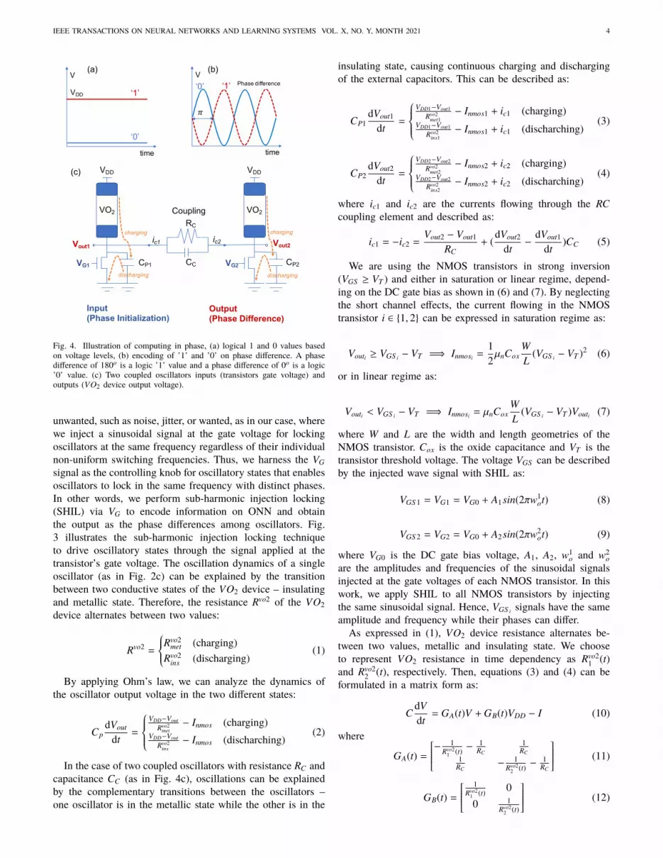
Fig. 4. Illustration of computing in phase, (a) logical 1 and 0 values basedon voltage levels, (b) encoding of ’1’ and ’0’ on phase difference. A phasedifference of 180o is a logic ’1’ value and a phase difference of 0o is a logic’0’ value. (c) Two coupled oscillators inputs (transistors gate voltage) andoutputs (VO2 device output voltage).
unwanted, such as noise, jitter, or wanted, as in our case, wherewe inject a sinusoidal signal at the gate voltage for lockingoscillators at the same frequency regardless of their individualnon-uniform switching frequencies. Thus, we harness the VG
signal as the controlling knob for oscillatory states that enablesoscillators to lock in the same frequency with distinct phases.In other words, we perform sub-harmonic injection locking(SHIL) via VG to encode information on ONN and obtainthe output as the phase differences among oscillators. Fig.3 illustrates the sub-harmonic injection locking techniqueto drive oscillatory states through the signal applied at thetransistor’s gate voltage. The oscillation dynamics of a singleoscillator (as in Fig. 2c) can be explained by the transitionbetween two conductive states of the VO2 device – insulatingand metallic state. Therefore, the resistance Rvo2 of the VO2device alternates between two values:
Rvo2 =
Rvo2met (charging)
Rvo2ins (discharging)
(1)
By applying Ohm’s law, we can analyze the dynamics ofthe oscillator output voltage in the two different states:
CpdVout
dt=
VDD−Vout
Rvo2met− Inmos (charging)
VDD−Vout
Rvo2ins− Inmos (discharching)
(2)
In the case of two coupled oscillators with resistance RC andcapacitance CC (as in Fig. 4c), oscillations can be explainedby the complementary transitions between the oscillators –one oscillator is in the metallic state while the other is in the
insulating state, causing continuous charging and dischargingof the external capacitors. This can be described as:
CP1dVout1
dt=
VDD1−Vout1
Rvo2met1
− Inmos1 + ic1 (charging)VDD1−Vout1
Rvo2ins1
− Inmos1 + ic1 (discharching)(3)
CP2dVout2
dt=
VDD2−Vout2
Rvo2met2
− Inmos2 + ic2 (charging)VDD2−Vout2
Rvo2ins2
− Inmos2 + ic2 (discharching)(4)
where ic1 and ic2 are the currents flowing through the RCcoupling element and described as:
ic1 = −ic2 =Vout2 − Vout1
RC+ (
dVout2
dt−
dVout1
dt)CC (5)
We are using the NMOS transistors in strong inversion(VGS ≥ VT ) and either in saturation or linear regime, depend-ing on the DC gate bias as shown in (6) and (7). By neglectingthe short channel effects, the current flowing in the NMOStransistor i ∈ 1, 2 can be expressed in saturation regime as:
Vouti ≥ VGS i − VT =⇒ Inmosi =12µnCox
WL
(VGS i − VT )2 (6)
or in linear regime as:
Vouti < VGS i − VT =⇒ Inmosi = µnCoxWL
(VGS i − VT )Vouti (7)
where W and L are the width and length geometries of theNMOS transistor. Cox is the oxide capacitance and VT is thetransistor threshold voltage. The voltage VGS can be describedby the injected wave signal with SHIL as:
VGS 1 = VG1 = VG0 + A1sin(2πw1ot) (8)
VGS 2 = VG2 = VG0 + A2sin(2πw2ot) (9)
where VG0 is the DC gate bias voltage, A1, A2, w1o and w2
oare the amplitudes and frequencies of the sinusoidal signalsinjected at the gate voltages of each NMOS transistor. In thiswork, we apply SHIL to all NMOS transistors by injectingthe same sinusoidal signal. Hence, VGS i signals have the sameamplitude and frequency while their phases can differ.As expressed in (1), VO2 device resistance alternates be-
tween two values, metallic and insulating state. We chooseto represent VO2 resistance in time dependency as Rvo2
1 (t)and Rvo2
2 (t), respectively. Then, equations (3) and (4) can beformulated in a matrix form as:
CdVdt
= GA(t)V + GB(t)VDD − I (10)
where
GA(t) =
− 1Rvo2
1 (t) −1
RC
1RC
1RC
− 1Rvo2
2 (t) −1
RC
(11)
GB(t) =
1Rvo2
1 (t) 0
0 1Rvo2
2 (t)
(12)

IEEE TRANSACTIONS ON NEURAL NETWORKS AND LEARNING SYSTEMS VOL. X, NO. Y, MONTH 2021 5
C =
[CP1 + CC −CC
−CC CP2 + CC
](13)
VDD =
[VDD1VDD2
]; I =
[Inmos1Inmos2
]; V =
[Vout1Vout2
](14)
For a system of n coupled oscillators, GA(t) and GB(t) are n-by-n conductance matrices, C is the n-by-n capacitance matrix,VDD and I are n-by-1 vectors representing the voltage andcurrent biases of the oscillators. V is the n-by-1 vector thatcontains the output node voltages of the oscillatory network.Note that if the NMOS transistors are biased in linear regime(7), I is proportional to V and can be rewritten as:
I =
[µnCox
WL (VGS 1 − VT ) 0
0 µnCoxWL (VGS 2 − VT )
] [Vout1Vout2
](15)
To obtain the output voltages, we solve the nonlinear systemin (10). Solving the set of equations when subjected to asinusoidal input voltage, oscillators lock in frequency whichis close to the oscillator’s natural (or free-running) frequency,wo = 1/To. The output voltages will be in the form [40] of:
Vouti (t) = Aicos(2πwo(t + θi(t))) (16)
where Ai is the oscillation amplitude and θi(t) is the instan-taneous phase. To compute in phase, we determine the phasedifferences between oscillators. For example, once frequencylocking occurs, we compute the phase difference betweenoscillator Vout1 and Vout2 as θ2(t)−θ1(t) to represent the encodedoutput as either a logic 0 or 1. For example, as illustrated inFig. 4a and Fig. 4b, a logic 0 is obtained when the phasedifference between oscillators is close to 0, whereas a logic1 is obtained when the phase difference between oscillatorsis 180o. But oscillator dynamics and phase difference dependon several parameters, such as i) uniformity or variability ofoscillators and their respective Rmet, Rins VH , Vth, ii) appliedsupply voltages, VDD, iii) coupling elements RC and CC toinduce either weak or strong coupling, iv) applied gate voltageVG frequencies, and v) applied learning rules and algorithmto train ONN. In section IV, we answer these questions bystudying ONN dynamics for pattern recognition application.
B. ONN Numerical SolverThe system of equations (10) is difficult to solve analytically
because of the VO2 nonlinear behavior. However, it can besolved numerically (such as in Matlab) by approximating thederivative at time t = k dt with integration time step of 1 ns:
dV(t)dt≈
V(k dt
)− V
((k − 1) dt
)dt
(17)
The insulating-metal transition (IMT) thresholds of the VO2device can be expressed as:Vth+ = VDD − VH
Vth− = VDD − Vth(18)
To emulate the IMT behavior of VO2 devices while solvingthe problem numerically, we keep track of the state of each
a) HSPICE b) MATLAB
c) HSPICE vs MATLAB
a) HSPICE b) MATLAB
c) HSPICE vs MATLAB d)
Fig. 5. Two coupled oscillators are simulated with a resistive load of 20 kΩ (asin Fig. 2a) and with RC = 100 kΩ. The second oscillator is turned on 1 µs afterthe first one. a) HSpice simulations. b) Matlab simulations with integrationtime step of 1 ns. c) Comparison between the HSpice and Matlab waveforms.The transient dynamics and the phase relations at steady-state match whereasthe frequencies do not. Matlab simulation shows a frequency deviation of 4.5% with respect to the steady-state frequency f = 206.2 kHz computed withHSpice. d) Discrepancy between HSpice vs. Matlab for different size ONN.
device i ∈ 1, 2 and update its resistance value. More precisely,we test the following sets of conditions:
Vouti [k] − Vouti [k − 1] ≥ 0Vouti [k] ≥ Vth+
=⇒ Rvo2i [k + 1] = Rvo2
ins (19)
Vouti [k] − Vouti [k − 1] ≤ 0Vouti [k] ≤ Vth−
=⇒ Rvo2i [k + 1] = Rvo2
met (20)
If none of these conditions is fulfilled, then the VO2 devicestays in the same resistive state as Rvo2
i [k + 1] = Rvo2i [k]. It is
important to note that this approach ignores many featuresof the VO2 device, such as its intrinsic time constant toswitch from one state to another. Therefore, the frequencyof oscillators differs from circuit simulations (i.e., HSpice).The frequency deviation of the numerical solver vs. circuitsimulation is around 4.5% difference. Nevertheless, our modelaccurately captures the transient oscillatory dynamics and theexact phase difference between oscillators (Fig. 5), which arealso the most important characteristics for computing withONNs.
IV. Controlling the Dynamics of Oscillatory NeuralNetworks
The thrust of this work is to use a network of driven coupledoscillators to recognize stored patterns based on their collectivebehavior and phase dynamics. First, we present a network oftwo coupled oscillators as a case study to illustrate how tocompute with phase and highlight the importance of couplingparasitics, the initial state of the network (input delays) andlearning rules. Second, we describe how the SHIL method canbe injected via VG to lock oscillators for pattern recognition.

IEEE TRANSACTIONS ON NEURAL NETWORKS AND LEARNING SYSTEMS VOL. X, NO. Y, MONTH 2021 6
VDD1
VDD2Vout2
Vout1
Frequency locked Phase difference measuredSettling Time
Vout1 Vout2
VDD1
VDD2Vout2
Vout1
Vout1Vout2
VO2
100pFVG1
VDD
Vout2
VO2
100pFVG2
VDD
0.05pF
100kΩ
Vout1
Ocs1 Ocs2
output
a) b) d)
c)
0 5e-07 1e-06 1.5e-06 2e-06 2.5e-06time
Nod
e Vo
ltage
(V)
0
0
.5
1
1.5
2
2.5
Nod
e Vo
ltage
(V)
0 2e-05 4e-05 6e-05 8e-05 0.0001time
0
0.5
1
1.
5
2
2.
5
Fig. 6. Two coupled oscillator simulation. a) Initialization of oscillators.The second oscillator is initialized with an initial switching delay after thefirst oscillator. b) Schematic of two coupled oscillators with RC=100 kΩ andCC=0.05 pF. c) Oscillation cycles depicting the time for oscillators to settleand lock. Once the frequency is locked, then the phase difference betweenoscillators is obtained. d) Image representation of the phase difference.Oscillator with a phase difference of 180o, the first oscillator is logic 0 (orwhite pixel), whereas the second oscillator is logic 1 (or black pixel).
A. Initialization of Oscillators
Initialization is the switching start time of oscillators. At firstglance, one can think to start all the oscillators simultaneously,but this leads to incorrect or even chaotic ONN dynamics.Therefore, the switching start time of oscillators plays animportant role in the ONN dynamics as it represents theinput test pattern. Thus, the start of oscillators switching timerepresents the phases of the encoded test pattern. For example,in Fig. 6a, for two-coupled oscillators, the first oscillatorturns on at T1=0. The second oscillator turns on at T2=230ns representing 10% of oscillator period Tosc=2.3 µs andcorresponding to an input test pattern of a phase of 0o forthe first oscillator and 36o for the second oscillator. In otherwords, a white pixel for the first oscillator and a light-graypixel for the second oscillator. Hence, the switching start timeof oscillators must be set as an input switching delay, S W as afraction of the oscillator period (0 to 50% Tosc) correspondingto an input phase θ = S W
Tosc360o. Once oscillator dynamics settle
in a few cycles, the output phase difference can be measured.The first oscillator has an output phase of 0o (white pixel) andthe second oscillator has a phase of 180o (black pixel).
Initialization impacts the time needed for the oscillators toreach steady-state (i.e., settling time), but also it affects thefinal phase difference between oscillators, hence the successof identifying the correct stored pattern. Both initialization andcoupling weights (resistive and capacitance coupling) can alterONN settling time and final output phase. Fig. 7a representsthe impact of initialization of two oscillators when an inputswitching delay of 10% Tosc is introduced. We observe cycle-by-cycle changes in the phase difference between the twooscillators until they reach a steady-state. The final oscillatorwaveforms are in 180o phase difference, indicating the correctidentification of the stored pattern. Fig. 7b shows the evolutionof instantaneous phase differences between the two oscillatorswhen varying the coupling resistance RC , which shows theinterdependence between initialization and coupling.
Frequency locked, phase stabilizedSettling time
starting phase
Output phase 180o
Number of cycles increase with RC
For fixed input delay SW=10%TocsIf Rc < 20k then Output phase 0o
If Rc ≥ 31k then Output phase 180o
b)
a)
Fig. 7. a) The instantaneous phase difference between the two oscillators foreach cycle. The second oscillator starts with an initial delay corresponding to10% of oscillator period Tosc or an initial phase of 36o. b) The instantaneousphase difference between the two oscillators for each cycle with varyingcoupling resistance RC from 1k Ω to 101 kΩ.
B. Impact of CouplingCoupling between oscillators can vary in topology (such
as all-connected or subset of connected oscillators) and typeof coupling (such as resistive-only, capacitive-only, or bothresistive and capacitive). In this work, we investigate RCcoupling between oscillators, as illustrated in Fig.6. Thecapacitive coupling is set to 0.05pF for all coupling, whilethe resistance coupling is varied to represent weak or strongcoupling. Typically, the weak coupling is a large resistancevalue, whereas a strong coupling has a low resistance value.Fig. 8a shows the output phase difference between the twooscillators when resistive coupling varies from 1 kΩ to 100 kΩ
– such range represents a strong coupling between oscillators.We notice for small resistance values (< 20 kΩ), oscillators arein-phase (phase difference 0o) but with coupling resistances >20 kΩ oscillators turn out-of-phase (phase difference 180o).Simultaneously, we also vary the input switching delay of thesecond oscillator (i.e., switching delay (SW) from 10% to 40%of Tosc) while varying resistance coupling, as shown in Fig.8b. We observe that with the increase of input switching delay,oscillators require a lower coupling resistance to change fromin-phase to out-of-phase.We also investigate large coupling resistance values from
100 kΩ to 1 MΩ – such range represents weak couplingbetween oscillators. Fig. 9a shows the output phase differences

IEEE TRANSACTIONS ON NEURAL NETWORKS AND LEARNING SYSTEMS VOL. X, NO. Y, MONTH 2021 7
Ocs1 Ocs2
output
Ocs1 Ocs2
output
Strong Coupling
a)
b)
Resistive coupling, RC
0 20kΩ 40kΩ 60kΩ 80kΩ 100kΩResistive coupling, RC
0 20kΩ 40kΩ 60kΩ 80kΩ 100kΩ
Out
put P
hase
(o)
0
5
0
100
150
20
0
0
5
0
100
15
0
200
Out
put P
hase
(o)
Fig. 8. Strong coupling simulations. a) The output phase difference betweenthe two oscillators when varying resistive coupling RC between 1 kΩ to 100kΩ with 10% of Tosc input switching delay for the second oscillator. b) Outputphase difference for strong coupling while varying the input switching delayon the second oscillator.
180°
150°
100°
60°
Weak Couplinga)
Strong to Weak Coupling
Resistive coupling, RC (Ω)0 200kΩ 400kΩ 600kΩ 800kΩ 1MΩ
50
1
00
150
2
00
2
50O
utpu
t Pha
se (o
)
050
100
1
50
200
250
O
utpu
t Pha
se (o
)
103 104 105 106
Resistive coupling, RC
b)
Fig. 9. a) Output phase difference with weak coupling of resistance values 100kΩ to 1 MΩ for various switching delays. Phase dynamics differ with weakcoupling providing more possibilities to encode different phase configurationsbetween 0o to 180o that can enable various shades of grey for images. b)Overall phase difference evolution with resistive coupling (from strong toweak coupling) while varying input switching delay of the second oscillator.
between the two oscillators with resistance coupling valuesfrom 100 kΩ to 1 MΩ and various input switching delays.Interestingly, we observe that various output phases can be ob-tained for different input switching delays. Such weak couplingenables to encode more distinct and subtler phase differencessuch as 150o, 100o, or 60o to allow more possibility to encodevarious phase configurations such as shades of grey in animage. The overall impact of resistance coupling is representedin Fig. 9b.
C. Sub-harmonic Injection Frequency LockingInjection locking (IL) is an attractive phenomenon in non-
linear coupled oscillators as it enables frequency lockingamong oscillators [29]. When an external signal is appliedto an oscillator, the oscillator locks on to the external signalfrequency whose frequency is close to the oscillator’s naturalfrequency, also termed as fundamental harmonic IL. It is alsopossible for an oscillator to lock at a frequency that is an exactsub-multiple frequency of the externally applied signal – orsub-harmonic injection locking. In this work, we apply the sub-harmonic injection locking as an effective method to facilitatefrequency locking among oscillators to reach steady-state sophase differences can be computed. We apply the externalfrequency signal to the gate voltage of the NMOS transistor.For a single oscillator case, we use the same configuration asin Fig. 2c with VDD=2.5 V and Cp=100 pF. Fig. 10 shows
Vout Iout
b)
18.65µs 18.85µs 19.05µstime
0.45
0
.72
0
.99
1
.26
1
.53
Vo
ltage
(V)
IoutVout
time
0
0
.4
0
.8
1.2
1
.6
Volta
ge(V
)
0 20µs 40µs 60µs 80µs 100µs
0
0
.4
0.
8
1
1.4
1
.8
Cur
rent
(mA)
a)
Cur
rent
(mA)
0
0.
4
0.8
1
1
.4
1.8
Fig. 10. Output voltage waveform for a single oscillator case. The outputfrequency follows the natural frequency of the oscillator of 250 kHz, whereasapplied VG is 500 kHz.
Pattern identified
Osc1 Osc2
Memorized pattern
Input VG Frequency (Hz)
Inpu
t Sw
itchi
ng D
elay
(% o
f Tos
c)
Output Phase (o) when RC=100kΩ
Fig. 11. Map of oscillatory states and output phase difference (o) between twooscillators with VG frequency injection locking from 100kHz to 900kHz as afunction of input switching delay (0% to 50%) on the second oscillator withcoupling resistance RC=100 kΩ. The boxes with a value of -1 represent thechaotic oscillatory states where phase dynamics are unstable. VG frequencytuning allows to identify the oscillatory states that retrieve the memorizedpattern.
the output voltage waveform for a single oscillator where theapplied VG is of 2.5 V peak-to-peak (1.25 V DC level) at 500kHz frequency. The output voltage oscillates with 250 kHzfrequency, half of the VG input frequency, as expected basedon the SHIL method.In the case of two coupled oscillators (Fig. 6b), we apply
the same sinusoidal external signal at the gate terminals ofboth NMOS transistors. To understand the SHIL method, wevary the applied sinusoidal signal frequency from 100 kHzto 900 kHz while introducing an input switching delay to thesecond oscillator from 0% to 50% of Tosc. Both oscillatorslock in frequency, which is a sub-multiple of the input VG
frequency. Measured phase differences are shown in Fig. 11.We observe at low frequencies, even though the oscillatorslock in frequency, the correct pattern is not found as thephase differences are less than 180o. We also notice oscillatorystates with unstable phase differences from cycle to cycle, andthey are marked with ’-1’. We notice several cases where thecorrect pattern is found at higher frequencies, such as 700kHz or 800 kHz. It is also important to note that SHIL canalso be used as a frequency tuning method to find the correctpattern, such as when the second oscillator has an input delayof 10% Tosc. Overall, the SHIL method allows oscillators to

IEEE TRANSACTIONS ON NEURAL NETWORKS AND LEARNING SYSTEMS VOL. X, NO. Y, MONTH 2021 8
Fig. 12. Relationship between coupling resistance, phase encoding andHebbian learning coefficients.
lock and gives a wide range of oscillatory states (with incorrectand correct patterns). Next, we explore how to use the SHILmethod together with learning rules to lead to oscillatory stateswith stored patterns only.
D. Learning RulesWe apply Hebbian learning to ONN, which is one of the
most commonly used learning rules based on the dynamics ofbiological systems [41], [42]. The learning rules can memorizeblack-and-white images represented in a vectorized form asξk=(ξk
1, ξk2,..., ξ
kn) where k=1,...,m, and m is the number of
stored patterns. ξki represents the oscillatory state of ith neuron.
If two oscillators should oscillate in-phase such as ξki =ξ
kj , then
their phase difference is zero or θi=θ j, and if ξki =-ξ
kj means
oscillators are out-of-phase or θi=θ j+180o. The connectionmatrix element ci j [10], [11], [12] using the Hebbian learningrule can be derived as:
ci j =1n
m∑k=1
ξki ξ
kj (21)
where n is the number of neurons or oscillators. By inter-twining the SHIL method with Hebbian learning rules, wedevelop an ONN system that allows oscillators to collectivelylock in frequency (sub-multiple of input VG frequency) withdistinct phase relations. Determining the coupling weights viaHebbian learning rules together with injection locking addsplasticity to the ONN system; in a sense, the system canchange its parameters to learn the frequencies of the periodicinput signal. The interest in combining injection locking withHebbian learning is that the whole learning process is dynamicand does not require any external signal processing. It meansthat ONN can adapt its frequency to any periodic input. Asshown in the next section, ONN can learn, achieve frequencylocking with distinct phases and retrieve memorized patterns.Such learning shares similarities with the learning in biologicalneural networks [44].
Stored images/patterns
Vectorize images
Compute Hebbian Coefficients
Apply MappingHebbian Coefficient conversion to
Coupling Weights
Apply SHIL on ONN (HSPICE) Obtain Oscillator Voltage Waveforms
Compute Cycle-by-Cycle Oscillators Phase Differences
Initialize ONN (fuzzy pattern)
Pattern Recognition –Display Found Image/Pattern
Fig. 13. Description of the pattern recognition flow for ONN based on phasedynamics. The pattern recognition flow is based on the sub-harmonic injectionlocking method with Hebbian learning rules.
To apply the learning rule to ONN, we must translate ormap the Hebbian coefficients ci j to resistive coupling values.To do so, we rely on our simulation insights from two-coupledoscillators to deduce a one-to-one mapping between Hebbiancoefficients and resistance coupling. Thorough simulationswith varying resistive coupling values (as in Fig. 9b) prompta direct mapping approach between Hebbian coefficients andresistive coupling values. Fig. 12 depicts the relationship be-tween the coupling resistance (i.e., strong and weak coupling),phase encoding (white for 0o phase difference, black for 180o
phase difference) and learning Hebbian coefficients. As weare interested in encoding only black or white patterns, weapply non-complex Hebbian coefficients. Coefficients for out-of-phase encoding (or black) are represented in the range of30 kΩ to 100 kΩ, and coefficients for in-phase (or white)encoding are represented in the range of 1 kΩ to 30 kΩ.
V. Pattern Recognition with ONNWe have developed a pattern recognition flow for ONN
based on the sub-harmonic injection locking method appliedwith Hebbian learning rules. The flow includes several steps asdescribed in Fig. 13. The first step is to construct a vectorizedimage of the stored pattern in the ONN. The number ofstored patterns in ONN can vary with ONN size. Once thepatterns are vectorized, the Hebbian learning rule (15) isapplied to obtain the connection matrix with coefficients, ci j.Based on the obtained Hebbian coefficients, a direct mappingis applied to translate the Hebbian coefficients to resistivecoupling values. The initialization of the ONN is appliedbased on the pattern to be recognized, such as a fuzzy patternor image. We apply a sub-harmonic injection method to theONN circuit and obtain each oscillator waveform. We post-process each oscillator waveform in Matlab to get the phasedifference among oscillators. The first oscillator serves as areference, and the phase differences are measured with respectto the first oscillator. The recognized pattern or image isreconstructed from the computed phase differences. In thefollowing subsections, we describe ONN pattern recognition

IEEE TRANSACTIONS ON NEURAL NETWORKS AND LEARNING SYSTEMS VOL. X, NO. Y, MONTH 2021 9
Input Delay SW=0% Input Delay SW=10%
Input Delay SW=20% Input Delay SW=30%
Input Delay SW=40% Input Delay SW=50%
Memorized patterns
Osc1 Osc2 Osc3
Fig. 14. Simulations of three coupled oscillator network. First oscillatorswitches at T1=0, third oscillator switches at T3=50% Tosc (Tosc=1.42 µs),whereas the initialization of the second oscillator varies from 0% to 50% ofTosc. The restored pattern for each initialization case while VG input frequencyis varying 100 kHz to 900 kHz. Both memorized patterns are restored, butfor some states, phase differences are not completely 180o, hence the greystates.
on ONN circuits with three coupled oscillators and 10x6coupled oscillators.
A. Three Coupled Oscillators StudyTo illustrate the phase dynamics in an ONN for pattern
recognition, we study three-coupled oscillators, where alloscillators are identical. The list of parameters is in Table I.There are two stored patterns (as shown on the top of Fig.14) and the Hebbian coefficients are derived as c12=0, c13=-1 and c23=0, where white (in-phase) is encoded as ’1’ andblack (out-of-phase) as ’-1’. We apply the same sinusoidalinput signal to VG for each oscillator. Initialization is appliedto all three oscillators, such as the first oscillator switches atT1=0, third oscillator switches at T3=50% Tosc, whereas theinitialization of the second oscillator varies from 0% to 50%of Tosc. Fig. 14 shows the restored patterns while frequencytuning is applied using VG with frequency from 100 kHzto 900 kHz. As both VG frequency and switching delay arevaried, the stored patterns are successfully retrieved for mostcases. All the restored patterns are valid as either one ofthe memorized patterns is recognized, even though the phasedifferences are not entirely 180o (grey pixels). We suspect thatthe applied direct mapping method for converting Hebbiancoefficients to resistive coupling values could be the primaryreason for such variance. We illustrate one of these restoredpatterns. The input conditions are shown in Fig. 15a, andthe output voltage waveforms for each oscillator are plottedin Fig. 15b. Frequency locking (Fig. 15c) at 150 kHz, finalphase differences and restored pattern (Fig. 15d) and frequencyharmonics via Fourier transform (Fig. 15e) are shown. Weobserve that the initial cycles are unstable, hence the settling
Osc2
Osc1
Osc3
a)
b)
Settling time
c) d)
Phase measuredFrequency locked
e)
Input Delay SW=0% Tosc on Osc1Input SHIL VG frequency 400kHz on all oscillatorsInput Delay SW=20% Tosc on Osc2
Input Delay SW=50% Tosc on Osc3
Output pattern:
Fig. 15. a) Initialization of three coupled oscillators. b) Voltage waveform ofoscillators showing their settling time. c) Frequency harmonics of oscillatorsshowing they are locked at 150 kHz. d) Phase difference of oscillator per eachcycle of simulation and output pattern, e) Fourier transform showing lockedfrequency harmonics of three oscillators.
time needed for oscillators to lock in the same frequencyand reach a steady state. Once all three oscillators lock infrequency, they achieve distinct phases of 155o for the secondoscillator and 150o for the third oscillator. The stored patternsare retrieved with distinct phase differences up to 155o but notfully 180o (or black pixel), hence, they are represented in darkgrey pixel.
B. 10x6 Coupled Oscillators StudyHere we implement a 10x6 oscillatory neural network. Five
patterns are stored with the digits 0, 1, 2, 3, and 4 (Fig. 16)and parameters used are in Table I. By applying the Hebbianlearning rule, we obtain coefficients (with values -1 to 1) thatwe map to resistance coupling values (Fig. 12). The switchingtime of oscillators (or initialization) is applied to representthe test pattern (or a fuzzy digit). For example, as shown inFig. 17, switching input delays on each oscillator are appliedto show the fuzzy digit 0 as a start image. The applied VG
sinusoidal input signal at each oscillator has a frequency of1.2 MHz. Such frequency is chosen based on our preliminaryassessment with VG frequency tuning from 200 kHz to 2 MHz.The applied frequency 1.2 MHz provides stable oscillations(not in a chaotic regime); however, other suitable frequenciessuch as 900 kHz or 1 MHz can also be used. The phasedifference is computed relative to the first oscillator (top left-hand corner). This also explains that some restored imageshave an inverse color (white digit on black background) dueto the phase difference with respect to the first oscillator. Thecycle-by-cycle evolution of the restored digit 0 is representedin Fig. 17. We observe that the digit 0 is almost restored,although some oscillators (on top and bottom) did not settleat 180o phase difference, hence, they are grey pixels.Similarly, we also investigate the other stored digits and their
restored patterns, as shown in Fig. 18. Overall, we notice thatthe memorized digits were restored, but some oscillators still

IEEE TRANSACTIONS ON NEURAL NETWORKS AND LEARNING SYSTEMS VOL. X, NO. Y, MONTH 2021 10
Fig. 16. Stored images of the digits 0, 1, 2, 3, and 4 on the 10x6 ONN.
Start image Frequency locked by IL. Cycle-by-cycle pattern recognition.
cycle 1 cycle 41 cycle 101 cycle 151 cycle 201 cycle 239
Fig. 17. Cycle-by-cycle representation of the pattern restoration process fordigit 0. Sub-harmonic injection locking allows oscillators to lock in frequency,while phase varies from cycle to cycle, oscillator settle and pattern is restored.
do not achieve a complete either in-/out-of-phase state. Fromour assessment, we find that the mapping process of deter-mining the resistive coupling values plays a crucial role in thecoupling between oscillators and requires further optimization.Nevertheless, the proposed method of frequency locking withHebbian learning rules shows promising results in training60 oscillators and restoring memorized patterns. Additionally,we measure the accuracy of the 10x6 ONN by varying thenumber of noisy input pixels from 0 to 50%. It is importantto note that 50% is the maximum noise as more noise wouldrevert the image (such as black pixels into white and viceversa). For example, a 60% noise would mean a reverted imagewith 10% noise. We randomly choose noisy pixels with valuesfrom -1 to +1 according to a uniform random distribution. Wemeasure the number of correct output pixels after 5, 10, 20cycles without SHIL, where data points are obtained after 30trials each. We observe that accuracy decreases with time asoscillators’ phases drift without SHIL. Phase drift means thatthe phase difference between oscillators changes from cycleto cycle. If phase measurements are done after 5, 10, or 20cycles, phase drifts among oscillators increase. In contrast,when we apply SHIL to ONN, accuracy is improved, andno phase drifting is observed. This is because SHIL allowskeeping oscillators locked once they are settled. Fig. 19 showsthe accuracy and settling time vs. noise input pixels.
C. SHIL on ONN Hardware Experimental ResultsTo validate our proposed SHIL on ONN approach, we
developed a small scale ONN hardware on a printed circuitboard (PCB) with off-the-shelf components. We test the SHILmethod with four single-ended coupled oscillators (Fig. 20).ONN PCB is composed of four oscillators, six fully connectedsynapses (coupling elements) and an FPGA to interface thePCB with Matlab to issue commands and read the phases.
1) Two coupled oscillators experiment results: We coupletwo oscillators with a 100 k Ω resistor to assess if oscillators
Fig. 18. 10x6 coupled oscillators network and phase difference withVG frequency injection locking. Both memorized patterns are found anddepending on the VG frequency and chosen resistive coupling values.
Fig. 19. a) The number of correct ouput pixels measured after 5, 10, 20cycles without SHIL. Phase drifts induces a decrease in accuracy with time.(b) ONN settling time vs. noise pixels.
can lock to both 0o and 180o phase states. We notice thatthe 180o phase state is less stable than the 0o phase state.In Fig. 21a, we observe that oscillators do not lock to 180o
phase after initialization. We believe the type of waveform,noise, and variability impact the 180o phase state stability. Tomitigate this problem, we apply SHIL by injecting a high-frequency signal like in Fig. 21b, and the two oscillators lockto the desired 180o phase state.2) Four coupled oscillators experiment results: We perform
a simple pattern recognition experiment using four coupledoscillators, as in Fig. 22. As in the two coupled oscillatorsexperiment, we observe that the four oscillators do not lock to180o phases without SHIL due to oscillator non-uniformitiesand variabilities. We apply SHIL and ONN locks to either 0o
and 180o phase states and retrieves the correct pattern. Thisshows that the SHIL method will be important to use in ONNhardware implementation where oscillator non-uniformitiesand variabilities are present.
VI. Discussion and Future WorkThe research presented here started with a mathematical
puzzle: How can we collectively control the dynamics ofoscillators in an oscillatory neural network to learn andrecognize in phase? In the course of addressing this issuewith oscillatory neural networks, we found that the sub-harmonic injection locking mechanism can boost the ONN’sability to lock in frequency and by applying Hebbian learningrules, ONNs can learn patterns (by distinct phase differencesbetween oscillators). We also observed that the initializationof the oscillator switching time has a strong impact onthe ONN synchronization and learning. As such, this workcan further incite research to the new found puzzle of how

IEEE TRANSACTIONS ON NEURAL NETWORKS AND LEARNING SYSTEMS VOL. X, NO. Y, MONTH 2021 11
Fig. 20. a) Custom PCB design to test SHIL on 4 coupled oscillators. FPGAcontrols oscillatorsâĂŹ initialization and reads output phases. ONN is fullyconnected with 6 synapses. b) Op-amp relaxation oscillator is based on aninverting Schmitt trigger. We apply the SHIL signal to the gate of Q1. c)Example of two training patterns and corresponding synaptic values obtainedusing the Hebbian rule. (o.c. stands for open circuit).
Fig. 21. a) Two oscillators coupled by R=100kΩ. a) Without SHIL, thetwo oscillators do not converge to a 180o phase state. b) we apply SHILby injecting a high-frequency signal @ 120 kHz enables 180o phase lockingbetween the two oscillators.
sub-harmonic controlled oscillations in ONN contribute tolearning. The challenge is now to follow up the preliminaryresults presented here with a more detailed assessment ofhow the basic principle of the ONN learning algorithm (sub-harmonic injection locking with Hebbian or other learningrules) and more importantly, the mapping of Hebbian learningcoefficients translate to resistance coupling weights can shedlight on mathematical [52], oscillatory neural network learningand efficient ONN hardware implementation [53].
VII. Conclusion
In this work, we have shown that the phase dynamics ofoscillators can be exploited to achieve pattern recognition withoscillatory neural networks. We have presented a new learningalgorithm that leverages sub-harmonic injection locking andHebbian learning rules to train oscillatory neural networks.Injecting a periodic input signal to the oscillators can be usedto lock them in the same periodic or sub-periodic frequency,which can be used to compute phase differences among os-cillators. We apply Hebbian learning rules to update couplingweights and translate the obtained Hebbian coefficients intoresistance coupling values. The value of resistive couplingvaries as a function of the sign of Hebbian coefficients. A
Fig. 22. ONN inference with a noisy input image. Without SHIL, ONNconverges towards a wrong pattern. Oscillators do not converge towards 180o
phase due to oscillators non-uniformity. With SHIL applied at 2x fosc, 180o
phase can be achieved and ONN retrieves the correct pattern.
challenge remains on mapping more accurately the Hebbiancoefficients to resistive coupling values. As a consequence, themapping problem appears as a crucial parameter during theONN design and training. Our study has shown that the newlearning algorithm can recognize a large number of correlatedinput patterns based on the phase difference among oscillators,and it displays a good recognition capability on various sizeONNs.
Acknowledgment
This work is supported by the European Union’s Horizon2020 research and innovation program, EU H2020 NEURONN(www.neuronn.eu) project under Grant No. 871501.
References
[1] K. Mistry, C. Allen, C. Auth, B. Beattie, D. Bergstrom, M. Bost, M.Brazier, M. Buehler, A. Cappellani, R. Chau, et al., A 45nm logictechnology with high-k+ metal gate transistors, strained silicon, 9 cuinterconnect layers, 193nm dry patterning, and 100% pb-free packaging,IEEE International Electron Devices Meeting, pp. 247-250, 2007.
[2] N. Loubet, T. Hook, P. Montanini, C.-W. Yeung, S. Kanakasabapathy,M. Guillom, T. Yamashita, J. Zhang, X. Miao, J. Wang, et al., Stackednanosheet gate-all-around transistor to enable scaling beyond finfet, IEEESymposium on VLSI Technology, pp. T230-T231, 2017.
[3] Heterogenous Integration Roadmap (HIR),https://eps.ieee.org/technology/heterogeneous-integration-roadmap.html,Online Edition 2020.
[4] M. M. S. Aly, M. Gao, G. Hills, C.-S. Lee, G. Pitner, M. M. Shulaker,T. F. Wu, M. Asheghi, J. Bokor, F. Franchetti, et al., Energy-efficientabundant-data computing: The n3xt 1,000 x, Computer, vol. 48, no. 12,pp. 24-33, 2015.
[5] S.-C. Lin, Y. Zhang, C.-H. Hsu, M. Skach, M. E. Haque, L. Tang, J.Mars, The architectural implications of autonomous driving: Constraintsand acceleration, ACM SIGPLAN Notices, vol. 53, pp. 751-766, ACM,2018.
[6] M. Merenda, C. Porcaro, and D. Iero, Edge machine learning for AI-enabled IoT devices: a review, Sensors, vol. 20, no. 9, 2533, 2020.
[7] A. James, The Why, What and How of Artificial General IntelligenceChip Development, IEEE Transactions on Cognitive and DevelopmentalSystems doi: 10.1109/TCDS.2021.3069871

IEEE TRANSACTIONS ON NEURAL NETWORKS AND LEARNING SYSTEMS VOL. X, NO. Y, MONTH 2021 12
[8] N. Jouppi, C. Young, N. Patil, D. Patterson, Motivation for and evaluationof the first tensor processing unit, IEEE Micro, vol. 38, no. 3, pp. 10-19,2018.
[9] J. J. Hopfield, Neural networks and physical systems with emergentcollective computational abilities, Proceedings of the National Academyof Sciences 79, 2554-2558, 1982. doi:10.1073/pnas.79.8.2554
[10] F. C. Hoppensteadt and E. M. Izhikevich, Pattern recognition viasynchronization in phaselocked loop neural networks, IEEE Transactionson Neural Networks, vol. 11, no. 3, pp. 734-738, 2000.
[11] G. Csaba, and W. Porod, Coupled oscillators for computing: a reviewand perspective, Appl. Phys. Rev., vol. 7, 011302, 2020.
[12] E. M. Izhikevich, Computing with Oscillators, Neural Networks, 2000.[13] F. C. Hoppensteadt and E. M. Izhikevich. Weakly Connected Neural
Networks. Applied Mathematical Sciences, 126, Springer, 1997.[14] N. Shukla, A. Parihar, E. Freeman, H. Paik, G. Stone, V. Narayanan,
H.Wen, Z. Cai, V. Gopalan, R. Engel-Herbert, et al., Synchronized chargeoscillations in correlated electron systems, Scientific reports, vol. 4, p.4964, 2014.
[15] A. Parihar, N. Shukla, S. Datta, A. Raychowdhury, Synchronizationof Pairwise-Coupled, Identical Relaxation Oscillators based on Metal-Insulator Phase Transition Devices: A Model Study, Journal of AppliedPhysics, 117:054902, 2015.
[16] E. Corti, J. Cornejo Jimenez, K.M. Niang, J. Robertson, K. Moselund,B. Gotsmann, et al., Coupled VO2 oscillators circuit as analog first layerfilter in convolutional neural networks. Frontiers in Neuroscience 15, 19,2021. doi:10.3389/fnins.2021.628254
[17] E. Corti, B. Gotsmann, K. Moselund, I. Stolichnov, A. Ionescu, S.Karg, Resistive coupled VO2 oscillators for image recognition, IEEEInternational Conference on Rebooting Computing, pp. 1-7, 2018.doi:10.1109/ICRC.2018.8638626
[18] E. Corti, A. Khanna, K. Niang, J. Robertson, K. Moselund, B. Gots-mann, S. Datta, S. Karg, Time-delay encoded image recognition in anetwork of resistively coupled vo on si oscillators, IEEE Electron DeviceLetters, 41, 629-632, 2020. doi:10.1109/LED.2020.2972006
[19] T. Endo, and K. Takeyama, Neural network using oscillators, Electronicsand Communications in Japan – Part III: Fundamental Electronic Sci-ence, 75, 51-59, 1992. doi:https://doi.org/10.1002/ecjc. 352 4430750505
[20] J. Chou, S. Bramhavar, S. Ghosh, W. Herzog, Analog coupled oscil-lator based weighted Ising machine, Scientific Reports, 9:14786, 2019.https://doi.org/10.1038/s41598-019-49699-5
[21] T. Wang and J. Roychowdhury, Oscillator-based Ising machine, 2017.https://arxiv.org/abs/1709.08102
[22] D. Wang, D. Terman, Locally excitatory globally inhibitory oscillatornetworks, IEEE transactions on neural networks, vol. 6, no. 1, pp. 283-286, 1995.
[23] D. Vodenicarevic, Rhythms and oscillations: a vision for nanoelectronics,PhD thesis, Paris-Sud University, 2017.
[24] M. Romera, P. Talatchian, S. Tsunegi, F. A. Araujo, V. Cros, P.Bortolotti, J. Trastoy, K. Yakushiji, A. Fukushima, H. Kubota, et al.,Vowel recognition with four coupled spin-torque nanooscillators, Nature,vol. 563, no. 7730, p. 230, 2018.
[25] M. B. Sachs, H. F. Voigt, and E. D. Young, Auditory nerve representationof vowels in background noise, Journal of neurophysiology, vol. 50, no.1, pp. 27-45, 1983.
[26] T. C. Jackson, A. A. Sharma, J. A. Bain, J. A. Weldon, L. Pileggi,Oscillatory neural networks based on nano-oscillators and multi-levelrram cells, IEEE journal on Emerging and Selected Topics in Circuitsand Systems, vol. 5, no. 2, pp. 230-241, 2015.
[27] F. C. Hoppensteadt and E. M. Izhikevich, Synchronization of MEMSresonators and mechanical neurocomputing. IEEE Transactions of Cir-cuits and Systems -l: Fundamental Theory and Applications, 48, 133,2001.
[28] M. Sharad, D. Fan, K. Roy, Energy-efficient and robust associativecomputing with injection-locked dual pillar spin-torque oscillators. IEEETransactions on Magnetics, 51, 1 2015.
[29] D. Fan, S. Maji, K. Yogendra, M. Sharad, K. Roy, Injection-locked spinhall-induced coupled-oscillators for energy efficient associative comput-ing. IEEE Transactions on Nanotechnology, 14,1083, 2015.
[30] G. Csaba, and W. Porod, Computational study of spin-torque oscillatorinteractions for non-boolean computing applications. IEEE Transactionson Magnetics 49, 4447, 2013.
[31] K. Yogendra, D. Fan, Y. Shim, M. Koo, K. Roy. Computing withcoupled spin torque nano oscillators. 21st Asia and South Pacific DesignAutomation Conference (ASP-DAC) 312, 2016.
[32] A. Kumar and P. Mohanty, Autoassociative Memory and Pattern Recog-nition in Micromechanical Oscillator Networks, Scientific Reports, 7:41,2017.
[33] I. Boybat, M. L. Gallo, S.R. Nandakumar, T. Moraitis, Th. Parnell,T. Tuma, B. Rajendran, Y. Leblebici, A. Sebastian, E. Eleftheriou,Neuromorphic Computing with Multi-Memresistive Synapses, NatureCommunications, 9, 2514, 2018.
[34] T. C. Jackson, A. A. Sharma, J. A. Bain, J. A. Weldon, L. Pileggi,An RRAM-based Oscillatory Neural Network, IEEE Latin AmericanSymposium on Circuits and Systems, 2015.
[35] G. Csaba, T. Ytterdal, W. Porod, Oscillatory neural network from ringoscillators. International Workshop on Cellular Nanoscale Networks andtheir Applications pp. 1-2, 2006.
[36] M. J. Cotter, Y. Fang, S. P. Levitan, D. M. Chiarulli, V. Narayanan,Computational architectures based on coupled oscillators. IEEE ComputerSociety Annual Symposium, pp. 130-135, 2014.
[37] R. Shi, T. C. Jackson, B. Swenson, S. Kar, L. Pileggi, On the design ofphase locked loop oscillatory neural networks: Mitigation of transmissiondelay effects. Proceedings of the Neural Networks (IJCNN), pp. 2039-2046, 2016.
[38] T. Jackson, S. Pagliarini, L. Pileggi, An Oscillatory Neural Networkwith Programmable Resistive Synapses in 28nm CMOS, |IEEE ICRC,pp.118-124, 2018.
[39] E. Corti, B. Gotsmann, K. Moselund, A. Ionescu, J. Robertson, S.Karg, Scaled Resistively Coupled VO2 Oscillators for NeuromorphicComputing, Solid State Electronics, 2020.
[40] P. Vanassche, G. Gielen, W. Sansen, On the Difference between TwoWidely Publicized Methods for Analyzing Oscillator Phase Behavior,IEEE ICCAD, 2002.
[41] N. Caporale and Y. Dan, Spike Timing-Dependent Plasticity: A HebbianLearning Rule, Annual Review of Neuroscience, vol. 31, no. 1, pp. 25-46,2008.
[42] L. Abbott, S. Nelson, Synaptic plasticity: taming the beast. Nat Neurosci3, 1178-1183 (2000). https://doi.org/10.1038/81453
[43] J. D. Kendall and S. Kumar, The building blocks of a brain-inspiredcomputer, Applied Physics Reviews, 7, 011305, 2020.
[44] R. Gutig, To spike, or when to spike?, Current Opinion in Neurobiology,vol. 25, pp. 143-139, 2014.
[45] W. Maass, Noise as a Resource for Computation and Learning inNetworks of Spiking Neurons, Proceedings of the IEEE, vol. 102, no.5, pp. 860-880, 2014, doi: 10.1109/JPROC.2014.2310593.
[46] A. Steimer, W. Maass, and R. Douglas, Belief Propagation in Networksof Spiking Neurons, Neural Computation, vol. 21, no. 9, pp. 2502-2523,Sep. 2009, doi: 10.1162/neco.2009.08-08-837.
[47] S. Shapero, M. Zhu, J. Hasler, and C. Rozell, Optimal SparseApproximation With Integrate and Fire Neurons, International Jour-nal of Neural Systems, vol. 24, no. 05, p. 1440001, 2014, doi:10.1142/S0129065714400012.
[48] L. Rossello, V. Canals, A. Oliver, and A. Morro, Studying the Role ofSynchronized and Chaotic Spiking Neural Ensembles in Neural Informa-tion Processing, International Journal of Neural Systems, vol. 24, no. 05,p. 1430003, 2014, doi: 10.1142/S0129065714300034.
[49] T. Serrano-Gotarredona, T. Masquelier, T. Prodromakis, G. Indiveri, andB. Linares-Barranco, STDP and STDP variations with memristors forspiking neuromorphic learning systems, Frontiers in Neuroscience, vol.7, 2013, doi: 10.3389/fnins.2013.00002.
[50] H. Paugam-Moisy and S. Bohte, Computing with Spiking NeuronNetworks, Handbook of Natural Computing, Springer-Verlag, Chapter 10,pp. 335-376, 2012. doi: 10.1007/978-3-540-92910-9-10.
[51] J. Liu, M. Gong, H. He, Deep associative neural network for associativememory based on unsupervised representation learning, Neural Networks,2019.
[52] C. Delacour and A. Todri-Sanial, Mapping Hebbian Learning Rules toCoupling Resistances for Oscillatory Neural Networks, working paper orpreprint, https://hal-lirmm.ccsd.cnrs.fr/lirmm-03197299, 2021.
[53] M. Abernot, T. Gil, M. Jimenez, J. Nunez, M. J. Avedillo, B. Linares-Barranco, T. Hardelin, T. Gonos, A. Todri-Sanial, Digital Implementa-tion of Oscillatory Neural Network for Image Recognition Application,working paper or preprint, https://hal-lirmm.ccsd.cnrs.fr/lirmm-03185020,2021.


