Embed Size (px)
Citation preview
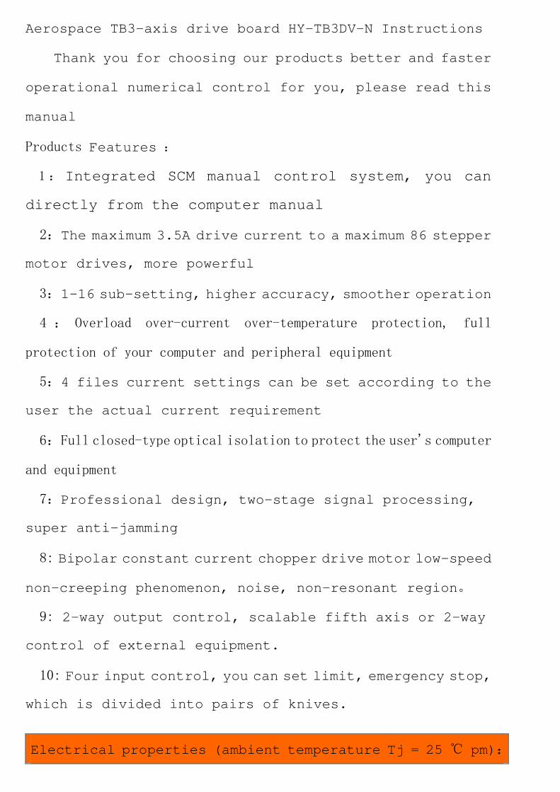
Aerospace TB3-axis drive board HY-TB3DV-N Instructions
Thank you for choosing our products better and faster
operational numerical control for you, please read this
manual
Products Features :
1 : Integrated SCM manual control system, you can
directly from the computer manual
2:The maximum 3.5A drive current to a maximum 86 stepper
motor drives, more powerful
3:1-16 sub-setting, higher accuracy, smoother operation
4 : Overload over-current over-temperature protection, full
protection of your computer and peripheral equipment
5:4 files current settings can be set according to the
user the actual current requirement
6:Full closed-type optical isolation to protect the user's computer
and equipment
7:Professional design, two-stage signal processing,
super anti-jamming
8: Bipolar constant current chopper drive motor low-speed
non-creeping phenomenon, noise, non-resonant region。
9: 2-way output control, scalable fifth axis or 2-way
control of external equipment.
10: Four input control, you can set limit, emergency stop,
which is divided into pairs of knives.
Electrical properties (ambient temperature Tj = 25 ℃ pm):
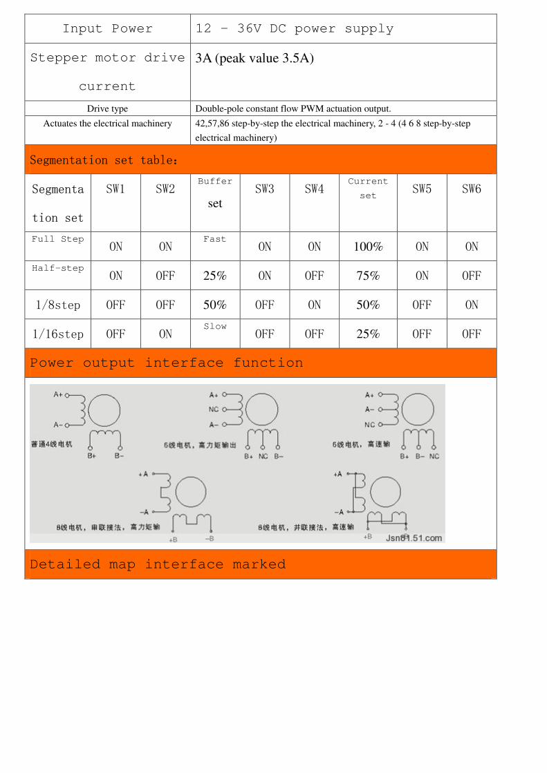
Input Power 12 - 36V DC power supply
Stepper motor drive
current
3A (peak value 3.5A)
Drive type Double-pole constant flow PWM actuation output.
Actuates the electrical machinery 42,57,86 step-by-step the electrical machinery, 2 - 4 (4 6 8 step-by-step
electrical machinery)
Segmentation set table:
Segmenta
tion set
SW1 SW2
Buffer
set SW3 SW4
Current
set SW5 SW6
Full Step
ON ON
Fast
ON ON 100% ON ON
Half-step ON OFF 25% ON OFF 75% ON OFF
1/8step OFF OFF 50% OFF ON 50% OFF ON
1/16step OFF ON
Slow
OFF OFF 25% OFF OFF
Power output interface function
Detailed map interface marked
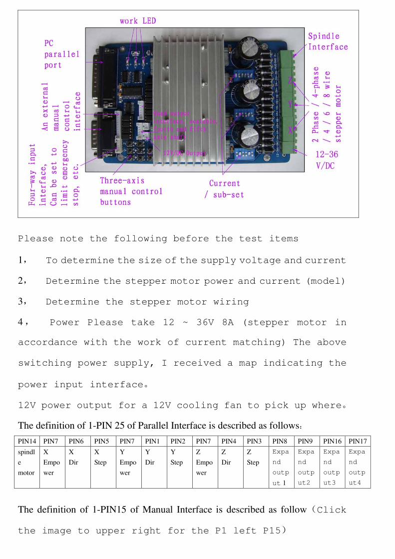
Please note the following before the test items
1, To determine the size of the supply voltage and current
2, Determine the stepper motor power and current (model)
3, Determine the stepper motor wiring
4, Power Please take 12 ~ 36V 8A (stepper motor in
accordance with the work of current matching) The above
switching power supply, I received a map indicating the
power input interface。
12V power output for a 12V cooling fan to pick up where。
The definition of 1-PIN 25 of Parallel Interface is described as follows:
PIN14 PIN7 PIN6 PIN5 PIN7 PIN1 PIN2 PIN7 PIN4 PIN3 PIN8 PIN9 PIN16 PIN17
spindl
e
motor
X
Empo
wer
X
Dir
X
Step
Y
Empo
wer
Y
Dir
Y
Step
Z
Empo
wer
Z
Dir
Z
Step
Expa
nd
outp
ut 1
Expa
nd
outp
ut2
Expa
nd
outp
ut3
Expa
nd
outp
ut4
The definition of 1-PIN15 of Manual Interface is described as follow(Click
the image to upper right for the P1 left P15)
P1 P2 P3 P4 P5 P6 P7 P8 P9 P10 P11 P12 P13 P14 P15
Y
Step
X
Step
Y
Dir
Z
Dir
Inp
ut 1
Inp
ut2
Inp
ut 3
Inp
ut 4
X
Dir
Emp
owe
r
Z
Step
5V
vdd
Emp
ty
Emp
ty
GN
D
Limit Switch Description
Input 1 Input 2 Input 3 Input 4
Corresponding
parallel P10
Corresponding
parallel P11
Corresponding
parallel P12
Corresponding
parallel P13
Output Interface Definition:
P1 P2 P3 P4 P5 P6 P7 P8 P9 P10 P11 P12 P13 P14 P15 P16 P17
VD
D
GN
D
XA
+
XA- XB
+
XB- YA
+
YA- YB
+
YB- ZA
+
ZA- ZB+ ZB- MO
/V+
GN
D
MO
-
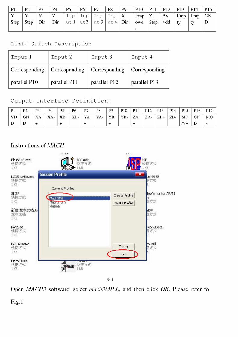
Instructions of MACH
图 1
Open MACH3 software, select mach3MILL, and then click OK. Please refer to
Fig.1
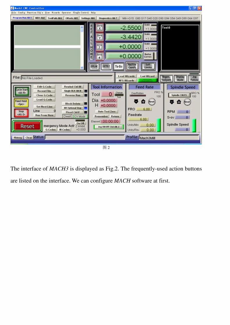
图 2
The interface of MACH3 is displayed as Fig.2. The frequently-used action buttons
are listed on the interface. We can configure MACH software at first.
。
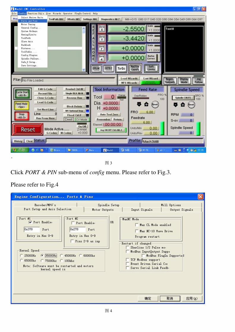
图 3
Click PORT & PIN sub-menu of config menu. Please refer to Fig.3.
Please refer to Fig.4
图 4
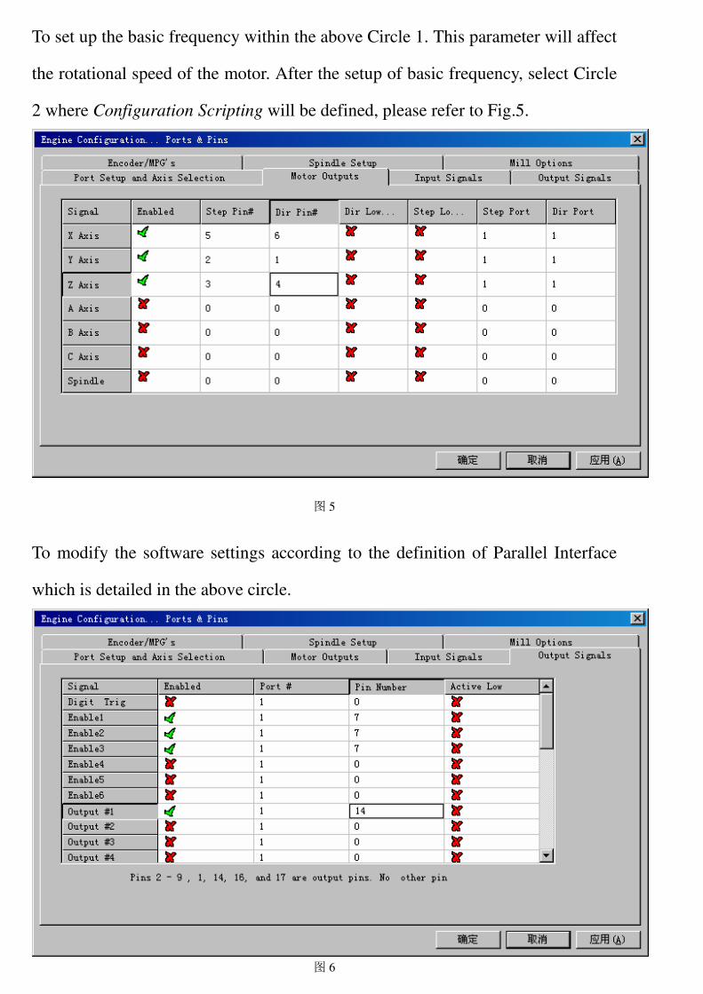
To set up the basic frequency within the above Circle 1. This parameter will affect
the rotational speed of the motor. After the setup of basic frequency, select Circle
2 where Configuration Scripting will be defined, please refer to Fig.5.
图 5
To modify the software settings according to the definition of Parallel Interface
which is detailed in the above circle.
图 6
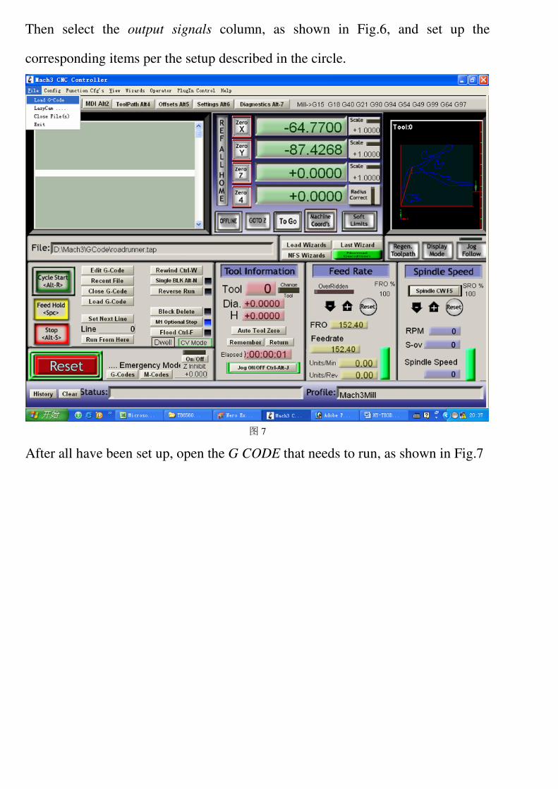
Then select the output signals column, as shown in Fig.6, and set up the
corresponding items per the setup described in the circle.
图 7
After all have been set up, open the G CODE that needs to run, as shown in Fig.7
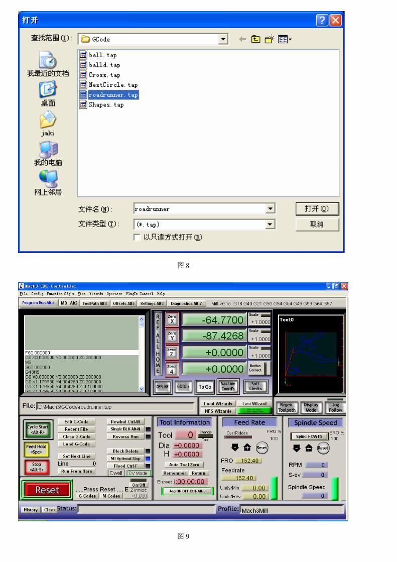
图 8
图 9
After G CODE has been opened, you may see the red button RESET flashing.
Click RESET to stop the flashing and then press CYCLESTART at the location of
Circle 2。
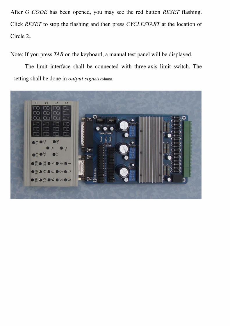
Note: If you press TAB on the keyboard, a manual test panel will be displayed.
The limit interface shall be connected with three-axis limit switch. The
setting shall be done in output signals column.