Embed Size (px)
Citation preview
TRELLEBORG SEALING SOLUTIONS
YOUR PARTNER FOR SEALING TECHNOLOGY
Hydraulic seals – linear

ISO 9001:2008 ISO/TS 16949:2009
Your Partner for Sealing Technology
Trelleborg Sealing Solutions is a major international developer, manufacturer and supplier of seals, bearings and molded components in polymers. We are uniquely placed to offer dedicated design and development from our market-leading product and material portfolio: a one-stop-shop providing the best in elastomer, silicone, thermoplastic, PTFE and composite technologies for applications in aerospace, industrial and automotive industries.
With 50 years of experience, Trelleborg Sealing Solutions engineers support customers with design, prototyping, production, test and installation using state-of-the-art design tools. An international network of over 70 facilities worldwide includes over 20 manu- facturing sites, strategically-positioned research and development centers, including materials and development laboratories and locations specializing in design and applications.
Developing and formulating materials in-house, we utilize the resource of our material database, including over 2,000
proprietary compounds and a range of unique products.Trelleborg Sealing Solutions fulfills challenging service requirements, supplying standard parts in volume or a single custom-manufactured component, through our integrated logistical support, which effectively delivers over 40,000 sealing products to customers worldwide.
Facilities are certified to ISO 9001:2008 and ISO/TS 16949:2009. Trelleborg Sealing Solutions is backed by the experience and resources of Trelleborg Group, one of the world’s foremost experts in polymer technology.
The information in this brochure is intended to be for general reference purposes only and is not intended to be a specific recommendation for any individual application.
The application limits for pressure, temperature, speed and media given are maximum values determined in laboratory conditions. In application, due to the interaction of operating
parameters, maximum values may not be achieved. It is vital therefore, that customers satisfy themselves as to the suitability of product and material for each of their individual
applications. Any reliance on information is therefore at the user‘s own risk. In no event will Trelleborg Sealing Solutions be liable for any loss, damage, claim or expense directly
or indirectly arising or resulting from the use of any information provided in this brochure. While every effort is made to ensure the accuracy of information contained herewith,
Trelleborg Sealing Solutions cannot warrant the accuracy or completeness of information.
To obtain the best recommendation for a specific application, please contact your local Trelleborg Sealing Solutions marketing company.
This edition supersedes all previous brochures. This brochure or any part of it may not be reproduced without permission.
® All trademarks are the property of Trelleborg Group. The turquoise color is a registered trademark of Trelleborg Group. © 2017, Trelleborg Group. All rights reserved.
2 ˙ TRELLEBORG SEALING SOLUTIONS Lastest information available at www.tss.trelleborg.com ˙ Edition January 2017
3
Linear Seals
Introduction
Rod Seals
Piston Seals
Scrapers
Slydring® - Wear Rings
Contents

4

Introduction
TRELLEBORG SEALING SOLUTIONS • 5Latest information available at www.tss.trelleborg.com • Edition January 2017
Introduction
6 • TRELLEBORG SEALING SOLUTIONS Latest information available at www.tss.trelleborg.com • Edition January 2017
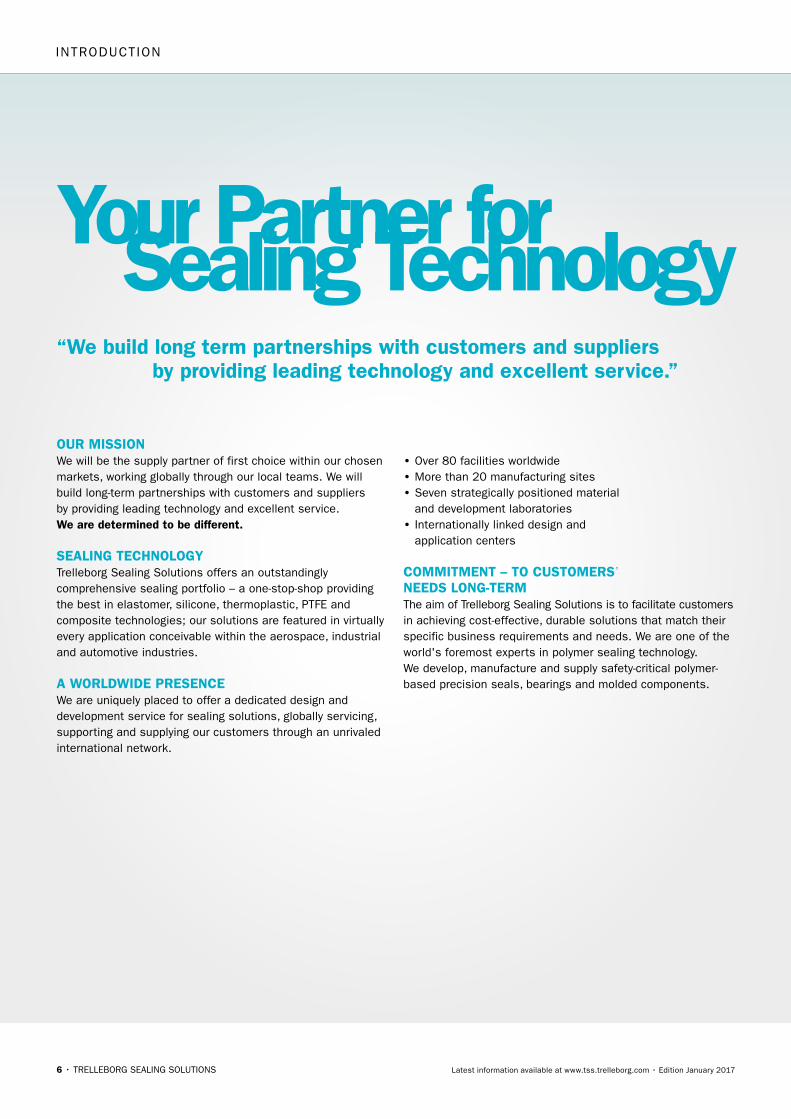
Our MissiOn We will be the supply partner of first choice within our chosen markets, working globally through our local teams. We will build long-term partnerships with customers and suppliers by providing leading technology and excellent service. We are determined to be different.
sealing technOlOgyTrelleborg Sealing Solutions offers an outstandingly comprehensive sealing portfolio – a one-stop-shop providingthe best in elastomer, silicone, thermoplastic, PTFE and composite technologies; our solutions are featured in virtually every application conceivable within the aerospace, industrial and automotive industries.
a WOrldWide presenceWe are uniquely placed to offer a dedicated design and development service for sealing solutions, globally servicing, supporting and supplying our customers through an unrivaledinternational network.
• Over 80 facilities worldwide• More than 20 manufacturing sites• Seven strategically positioned material
and development laboratories• Internationally linked design and
application centers
cOMMitMent – tO custOMers’needs lOng-terMThe aim of Trelleborg Sealing Solutions is to facilitate customers in achieving cost-effective, durable solutions that match their specific business requirements and needs. We are one of the world's foremost experts in polymer sealing technology. We develop, manufacture and supply safety-critical polymer- based precision seals, bearings and molded components.
Your Partner forSealing Technology
INTROducTION
“We build long term partnerships with customers and suppliers by providing leading technology and excellent service.”
TRELLEBORG SEALING SOLUTIONS • 7Latest information available at www.tss.trelleborg.com • Edition January 2017
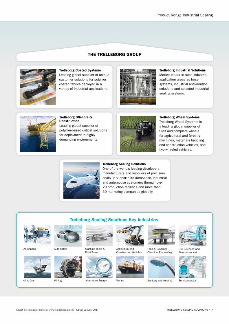
trelleborg sealing solutions Key industries
Automotive Food & Beverage, Chemical Processing
Marine
Machine Tools & Fluid Power
Agriculture and Construction Vehicles
Oil & Gas
Aerospace Life Sciences and Pharmaceutical
Mining Alternative Energy
Product Range Industrial Sealing
the trellebOrg grOup
trelleborg coated systemsLeading global supplier of unique customer solutions for polymer-coated fabrics deployed in a variety of industrial applications.
trelleborg Offshore & constructionLeading global supplier of polymer-based critical solutions for deployment in highly demanding environments.
trelleborg Wheel systemsTrelleborg Wheel Systems is a leading global supplier of tires and complete wheels for agricultural and forestry machines, materials handling and construction vehicles, and two-wheeled vehicles.
trelleborg industrial solutionsMarket leader in such industrial application areas as hose systems, industrial antivibration solutions and selected industrial sealing systems.
trelleborg sealing solutionsOne of the world’s leading developers, manufacturers and suppliers of precision seals. It supports its aerospace, industrial and automotive customers through over 20 production facilities and more than 50 marketing companies globally.
SemiconductorSanitary and Heating
8 • TRELLEBORG SEALING SOLUTIONS Latest information available at www.tss.trelleborg.com • Edition January 2017
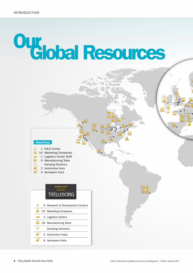
OurGlobal Resources
1 R & D Center 14 Marketing Companies 1 Logistics Center SCM 9 Manufacturing Sites Damping Solutions 2 Automotive Hubs 4 Aerospace Hubs
9 Research & Development Centers
53 Marketing Companies
4 Logistics Centers
26 Manufacturing Sites
Damping Solutions
5 Automotive Hubs
8 Aerospace Hubs
OurGlobal Resources
americas
INTROducTION

TRELLEBORG SEALING SOLUTIONS • 9Latest information available at www.tss.trelleborg.com • Edition January 2017
How local is your global seal supplier?
www.global-but-local.com
1 R & D Center 17 Marketing Companies 2 Logistics Centers SCM 2 Manufacturing Sites Damping Solutions 2 Automotive Hubs 2 Aerospace Hubs
europe
7 R & D Centers 22 Marketing Companies 1 Logistics Center SCM 15 Manufacturing Sites Damping Solutions 1 Automotive Hub 2 Aerospace Hubs
asia
82worldwidelocations
5,300employees
More than
2,000proprietary material
formulations
Product Range Industrial Sealing
10 • TRELLEBORG SEALING SOLUTIONS Latest information available at www.tss.trelleborg.com • Edition January 2017
•AmericanVariseal•Busak+Shamban•DowtySeals•ChaseWalton•Forsheda•GNL•Impervia•Nordex•Orkot•PalmerChenard
•Polypac•SSF•SFMedical•Shamban•Silcofab•Silcotech•Skega•Stefa•Wills
WOrld renOWned naMes unitedWe own many of the longest established and leading names within the seal industry. These include:
•Turcon® aQ seal®
•D-A-SCompactSeal® •Turcon® double delta® •Turcon® excluder® •Turcon® glyd ring® t •Turcon® hatseal•Zurcon® l-cup® •Turcite® slydring® •Turcite® b-slydway®
•Turcon® stepseal® 2K•Turcon® stepseal®V •V-Ring® •Turcon® Varilip® pdr •Turcon®Variseal® •Turcon®VLSeal® •Turcon®Wedgpak® •WillsRings® •Zurcon® Wynseal
Our piOneering prOductsTrelleborg Sealing Solutions is pioneering and is continuously developing innovative products.
•HiMod® •Isolast® •Orkot® •Turcite®
•Turcon®
•Turel® •Zurcon®
prOprietary MaterialsOngoing development has yielded some of the most successful sealing and bearing materials available.
Products, Brandsand Materials
to design a solution for your specific needs, contact your localTrelleborgSealingSolutionsmarketingcompany.
Decades of experience designing and manufacturing polymer solutions has led Trelleborg Sealing Solutions to develop, manufacture and supply a range of unique materials and proprietary product designs, many of which have become industry standards. Development is ongoing, ensuring that our solutions meet the changing needs of our customers, as well as the latest industry trends and regulations.
INTROducTION

TRELLEBORG SEALING SOLUTIONS • 11Latest information available at www.tss.trelleborg.com • Edition January 2017
Product Range Industrial Sealing

12 • TRELLEBORG SEALING SOLUTIONS Latest information available at www.tss.trelleborg.com • Edition January 2017
Filmsand Animations
View atyoutube.com/trelleborgseals
View attss.trelleborg.com/
films
Online 24-7A range of films specific to different industries and products are available to view on the Trelleborg Sealing Solutions website or via YouTube.
SeeINGISBeLIeVING Complex sealing configurations can feature a large number of sealing elements. Trying to illustrate these on a 2-D page is difficult and can never properly show their function or characteristics. Trelleborg Sealing Solutions turned to the latest graphic technologies to produce 3-D animations of applications and typical sealing solutions for them.
INTROducTION

TRELLEBORG SEALING SOLUTIONS • 13Latest information available at www.tss.trelleborg.com • Edition January 2017
Product Range Industrial Sealing

14 • TRELLEBORG SEALING SOLUTIONS Latest information available at www.tss.trelleborg.com • Edition January 2017
+
–
+?
ONLINeTOOLSMAkeLIFeeASIeRTrelleborg Sealing Solutions has developed a number of online tools that make the working life of an engineer specifying seals easier. All these industry-leading tools are available free-of-charge from the Trelleborg Sealing Solutions website at www.tss.trelleborg.com. To use these advanced services all you have to do is register on the Members Area.
There is also a continually increasing range of innovative engineering apps available for smartphones, both for iOS and Android devices. Just search for "Trelleborg" in the App Store or GooglePlay to find the tools to optimize your daily productivity.
O-ring calculatorAn industry-leading tool, the easy to use O-Ring calculator includes sizing capabilities, compression forces, design parameter recommendations and complete measurements.Results and comments may be printed, shared or filed as PDF.
Materials search and ChemicalCompatibilityCheckThese two programs allow you to find out the compatibility of sealing materials to hundreds of different media and help identify the most suitable material for your application.
DigitalServices
Very good suitability
Good suitability
Limited suitability
Unsuitable
Insufficient information
INTROducTION
TRELLEBORG SEALING SOLUTIONS • 15Latest information available at www.tss.trelleborg.com • Edition January 2017
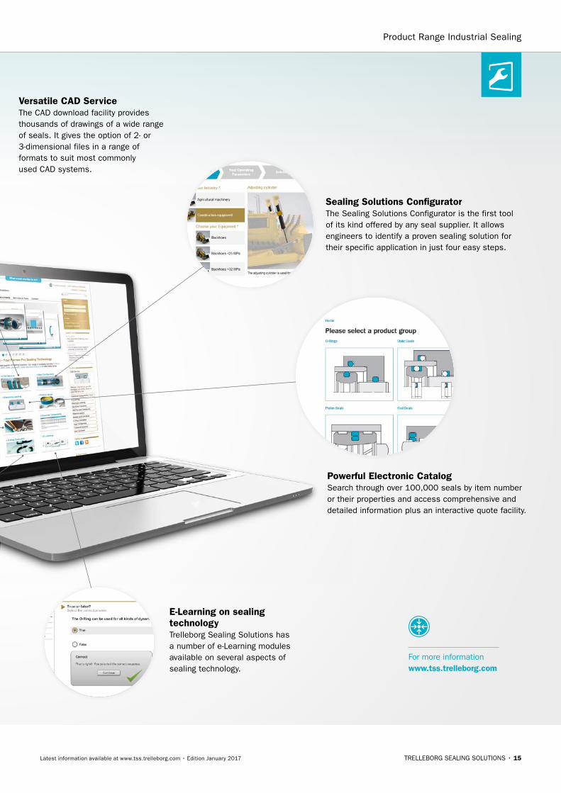
sealing solutions configuratorThe Sealing Solutions Configurator is the first tool of its kind offered by any seal supplier. It allows engineers to identify a proven sealing solution for their specific application in just four easy steps.
VersatileCADService The CAD download facility provides thousands of drawings of a wide range of seals. It gives the option of 2- or 3-dimensional files in a range of formats to suit most commonly used CAD systems.
powerful electronic catalog Search through over 100,000 seals by item number or their properties and access comprehensive and detailed information plus an interactive quote facility.
e-learning on sealing technologyTrelleborg Sealing Solutions has a number of e-Learning modules available on several aspects of sealing technology.
For more information www.tss.trelleborg.com
Product Range Industrial Sealing

16 • TRELLEBORG SEALING SOLUTIONS Latest information available at www.tss.trelleborg.com • Edition January 2017
Mobile Appsand ServicesWe understand the needs of engineers on the go. Check out our latest mobile tools and apps, ranging from an O-Ring calculator to unit and hardness converters. Just search for "Trelleborg" in the App Store or Google Play to find the tools to optimize your daily productivity.
ISOFits& tolerances appSimply enter the nominal
diameter and select the
tolerance classes for bore
and shaft to find the complete
ISO fits definition with all
relevant values including type
of fit, with handy graphs to
illustrate the classes by bore
and shaft.
technical glossary appThis app provides definitions of more than 2,000 terms from the world of sealing technology and engineering.
aerospace grooveselector appThis app covers two of the most important SAE aerospace groove standards for hydraulic systems, AS4716 Rev B and AS5857 Rev A, making it really easy to find the size of grooves and hardware needed.
installation instructions appVideos demonstrate thebest practice methods for installing seals, providing all relevant documentation within the interface, guiding you to a successful installation of Radial Oil Seals and Turcon® and Zurcon® rod and piston seals.
unit & hardnessconverter appIntuitive and very easy to use,simply select the dimension and enter the value for conversion. The app offers a wide range of engineering and scientific units for each dimension.
INTROducTION

TRELLEBORG SEALING SOLUTIONS • 17Latest information available at www.tss.trelleborg.com • Edition January 2017
hydrauliccylinder calculatorQuickly calculate areas and volumes in cylinders, extraction and retraction forces, time velocity and outflow by entering the requisite dimensions and parameters of the cylinder. In compliance with ISO 3320, ISO 3321 and ISO 4393.
tubing and hose appDeveloped specially for life sciences engineers, this app helps you to easily choose the correct tubing and hose based on material, pressure and dimensions, removing the need to search through catalogs.
Material compability appCross reference a wide variety of different materials with chemical environments to find the most effective compounds for your application. Select up to 20 materials at once to produce an easy to read compatibility chart with recommendations for use.
in the groove appOur in the groove magazine provides news, technical and product information on seals, as well as insights into the markets they are used in. The magazine is also available in print and as an interactive PDF.
For more information www.tss.trelleborg.com
O-ring calculator appWhen a user enters installation specifications into the O-Ring Calculator app, such as the bore or rod/shaft diameter, the app quickly calculates O-Ring and housing dimensions in both metric and inch.
Available on theapp stOre
Many MOre apps
available
Android App ongoogle play
Product Range Industrial Sealing

18
TRELLEBORG SEALING SOLUTIONS • 19Latest information available at www.tss.trelleborg.com • Edition January 2017
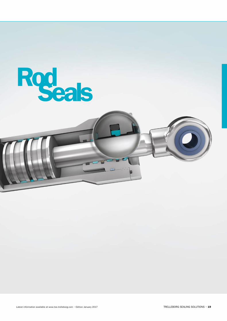
RodSeals

20
21
Contents
23 Choice of Sealing Element
29 Design Instructions
31 Installation Instructions
36 Quality Criteria
36 Storage Instructions
39 Turcon®Stepseal®2K
53 Turcon®Stepseal®V
65 Zurcon®Rimseal
73 POLYPAC®- Veepac CH
85 POLYPAC®- Veepac CH/G5
91 POLYPAC®- Selemaster SM
97 POLYPAC®- Balsele
113 Zurcon®L-Cup®
121 Zurcon®U-Cup, Type RU2
127 Zurcon®U-Cup, Type RU6
133 Zurcon®U-Cup, Type RU9
143 Zurcon®Buffer Seal
151 Turcon®Variseal®M2
161 Turcon®VL Seal®
173 Turcon®Glyd Ring®
183 Turcon®Glyd Ring®T
193 Turcon®Glyd Ring®Hz
205 Turcon®AQ-Seal®with Bean Seal
215 Turcon®AQ-Seal®5 with Bean Seal
223 Zurcon®Wynseal M
233 Turcon®Double Delta®
243 Additional Seals

22
Choice of the Sealing Element
23
® ®
® ®
NOTE ON ORDERING
® ®
®
Choice of Sealing Element
24
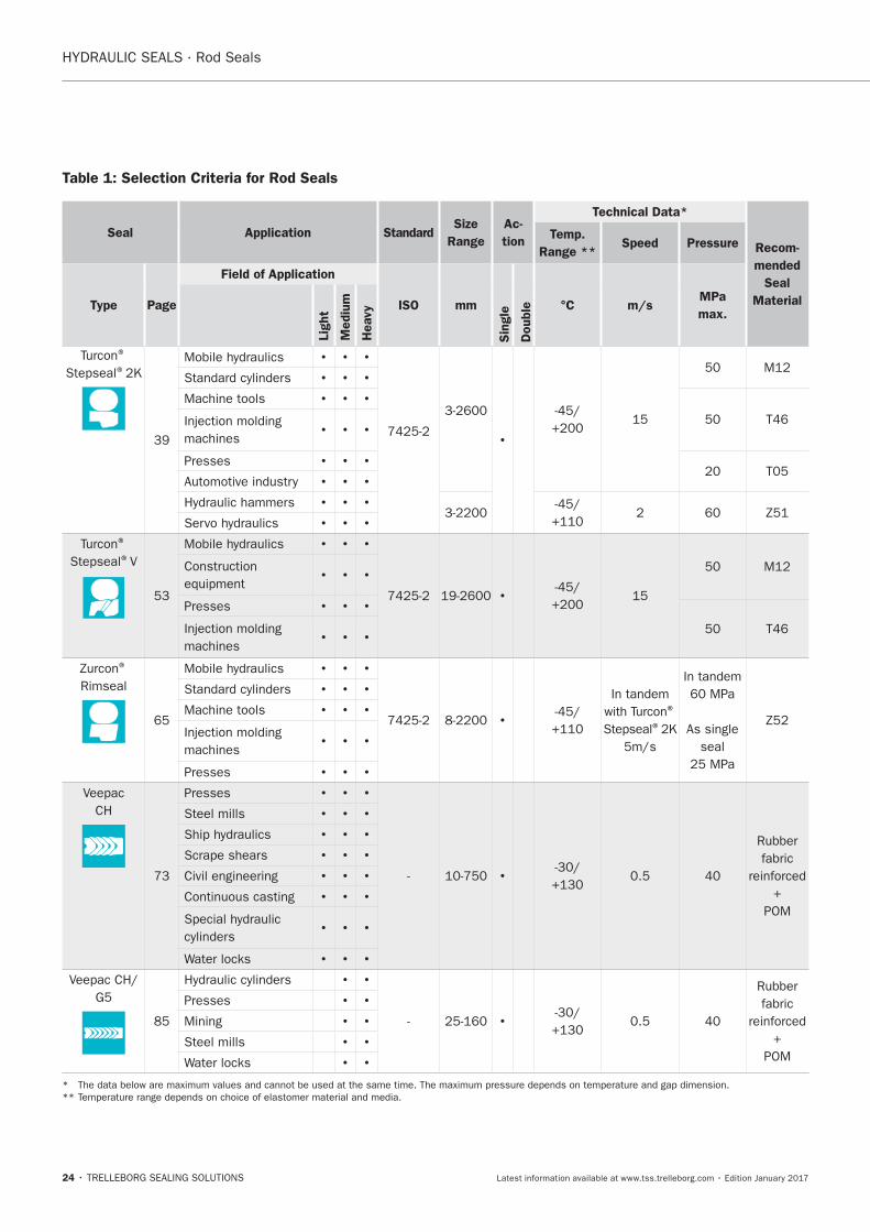
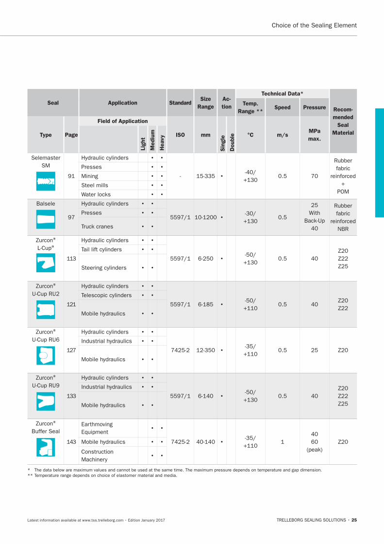
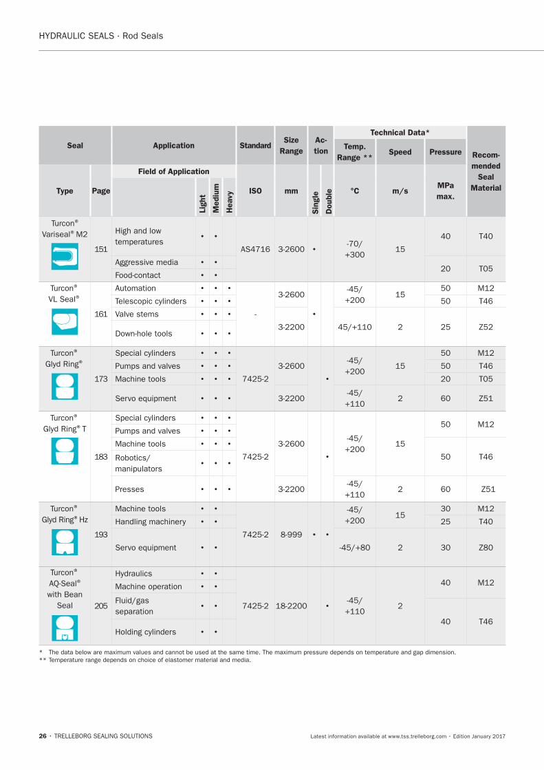
Table 1: Selection Criteria for Rod Seals
Seal Application StandardSize
Range
Ac-
tion
Technical Data*
Recom-
mended
Seal
Material
Temp.
Range **Speed Pressure
Type Page
Field of Application
ISO mm
Sin
gle
Double °C m/s
MPa
max.Lig
ht
Mediu
m
Heavy
® ®
Machine tools
machines
Presses
®
®V
Presses
machines
®
Rimseal
®
®
As single
seal
Machine tools
machines
Presses
CH
Presses
fabric
+
POM
Steel mills
Civil engineering
fabric
+
POM
Presses
Mining
Steel mills
*
**
Choice of the Sealing Element
25
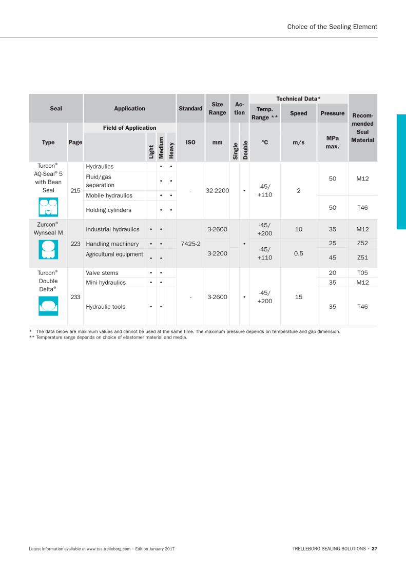
Seal Application StandardSize
Range
Ac-
tion
Technical Data*
Recom-
mended
Seal
Material
Temp.
Range **Speed Pressure
Type Page
Field of Application
ISO mm
Sin
gle
Double °C m/s
MPa
max.Lig
ht
Mediu
m
Heavy
Selemaster
SMfabric
+
POM
Presses
Mining
Steel mills
Balsele
fabric
NBR
Presses
®
®
®
®
®
® Earthmoving
*
**
26
Seal Application StandardSize
Range
Ac-
tion
Technical Data*
Recom-
mended
Seal
Material
Temp.
Range **Speed Pressure
Type Page
Field of Application
ISO mm
Sin
gle
Double °C m/s
MPa
max.Lig
ht
Mediu
m
Heavy
®
Variseal®
®
VL Seal®
Valve stems
®
®
Machine tools
®
®T
Machine tools
Presses
®
®
Machine tools
®
®
with Bean
Seal
*
**
Choice of the Sealing Element
27
Seal Application StandardSize
Range
Ac-
tion
Technical Data*
Recom-
mended
Seal
Material
Temp.
Range **Speed Pressure
Type Page
Field of Application
ISO mm
Sin
gle
Double °C m/s
MPa
max.Lig
ht
Mediu
m
Heavy
®
®
with Bean
Seal
®
®
Delta®
Valve stems
*
**
28
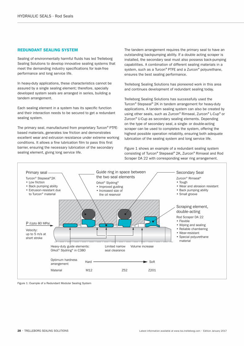
REDUNDANT SEALING SYSTEM
®
® ®
® ®
® ® ®or ®
® ® ®
Optimum hardnessarrangement Hard Soft
Volume increaseLimited narrowseal clearance
Heavy-duty guide elements:Orkot® Slydring® in C380
Material M12 Z52 Z201
Turcon® Stepseal®2K
to Turcon® material
Primary seal
Orkot® Slydring®
the oil reservoir
the two seal elements Zurcon® Rimseal®
Tough
Secondary Seal
Rod Scraper DA 22
ping and sealing
ear-resistant
material
Scraping element,
Velocity:up to 5 m/s atshort stroke
(Upto 80 MPa)P
29
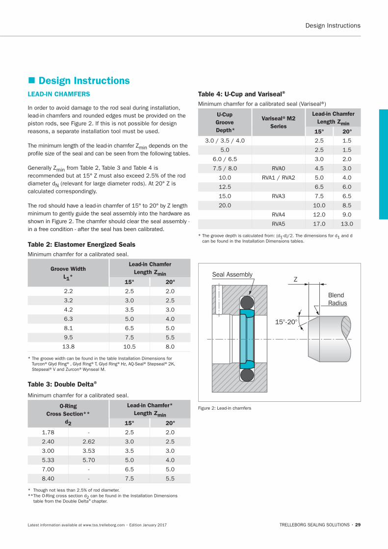
Design Instructions LEAD-IN CHAMFERS
min
min
N
Table 2: Elastomer Energized Seals
Groove Width
L1*
Lead-in Chamfer
Length Zmin
15° 20°
Table 3: Double Delta®
O-Ring
Cross Section**
d2
Lead-in Chamfer*
Length Zmin
15° 20°
®
Table 4: U-Cup and Variseal®
U-Cup
Groove
Depth*
Variseal®M2
Series
Lead-in Chamfer
Length Zmin
15° 20°
BlendRadius
Seal Assembly
15°-20°
Z
30
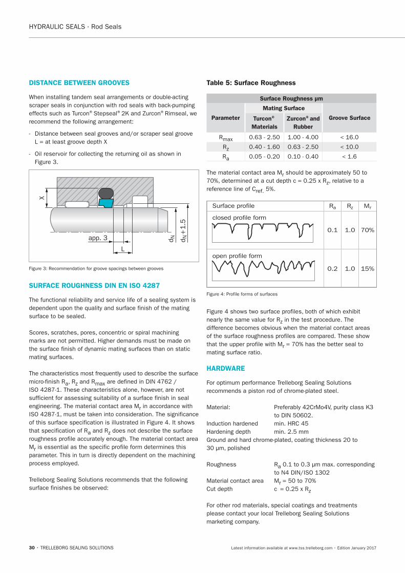
DISTANCE BETWEEN GROOVES
® ® ®
d N+
1.5
X
d Napp. 3
L
SURFACE ROUGHNESS DIN EN ISO 4287
a
engineering. The material contact area Mr
a
Mr
Table 5: Surface Roughness
Surface Roughness μm
Parameter
Mating Surface
Groove SurfaceTurcon®
Materials
Zurcon®and
Rubber
R
R
Ra
The material contact area Mr
reference line of Cref.
Surface profile
closed profile form
open profile form
Rz MrRa
0.1 1.0 70%
0.2 1.0 15%
r
HARDWARE
a
Material contact area Mr
31
Installation Instructions
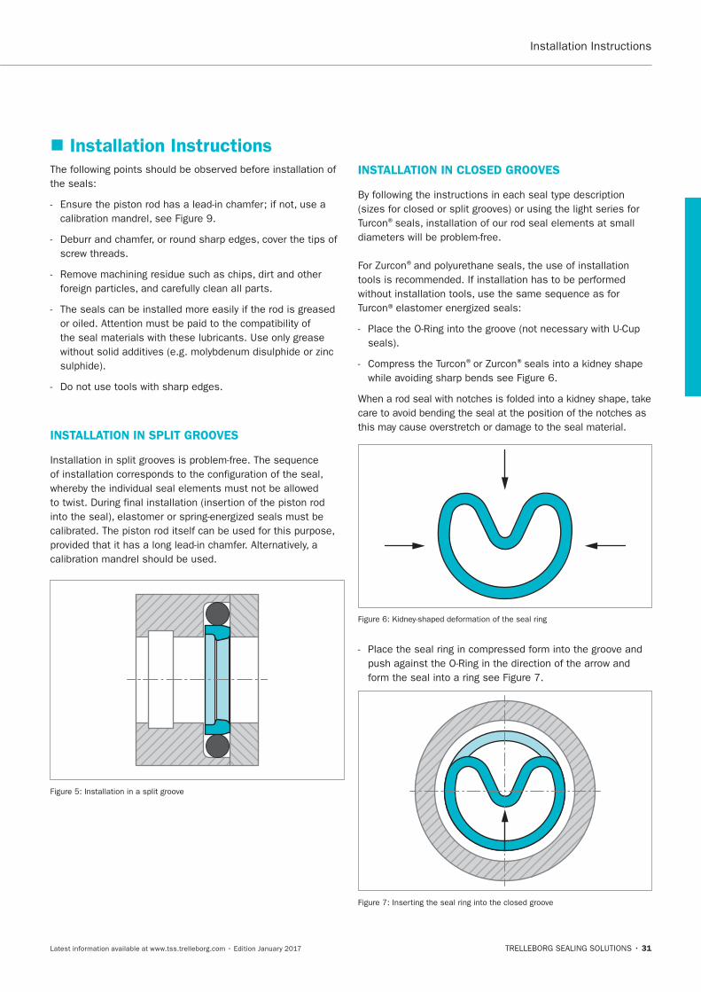
INSTALLATION IN SPLIT GROOVES
INSTALLATION IN CLOSED GROOVES
®
®
® ®
32
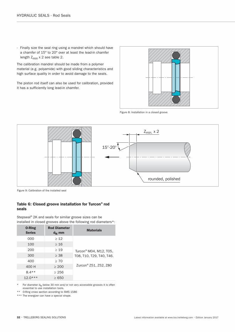
min
15°-20°
rounded, polished
Zmin. x 2
Table 6: Closed groove installation for Turcon®rod seals
®
O-Ring
Series
Rod Diameter
dN mmMaterials
®
®
N
33
INSTALLATION OF AQ-SEAL®AND AQ-SEAL®5 WITH QUAD-RING® OR BEAN SEAL:
®
® ®
®
®
Seal® ®
INSTALLATION HINT
® ® ® or Bean Seals ®
Seal® ®
®
®
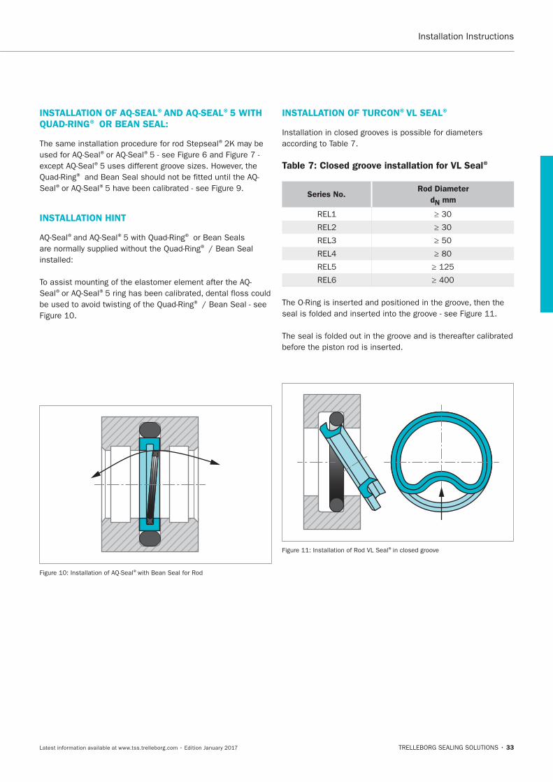
INSTALLATION OF TURCON®VL SEAL®
Table 7: Closed groove installation for VL Seal®
Series No.Rod Diameter
dN mm
®
34
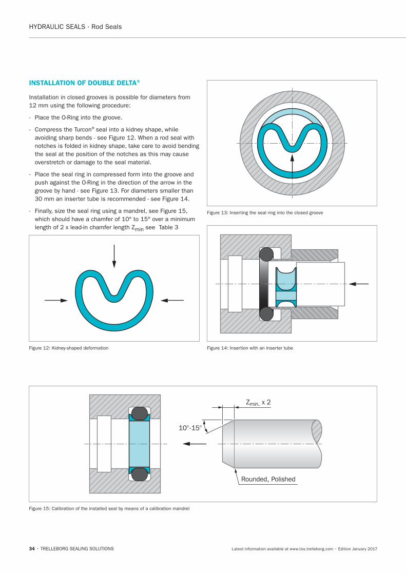
INSTALLATION OF DOUBLE DELTA®
®
min
10°-15°
Rounded, Polished
Zmin. x 2
35
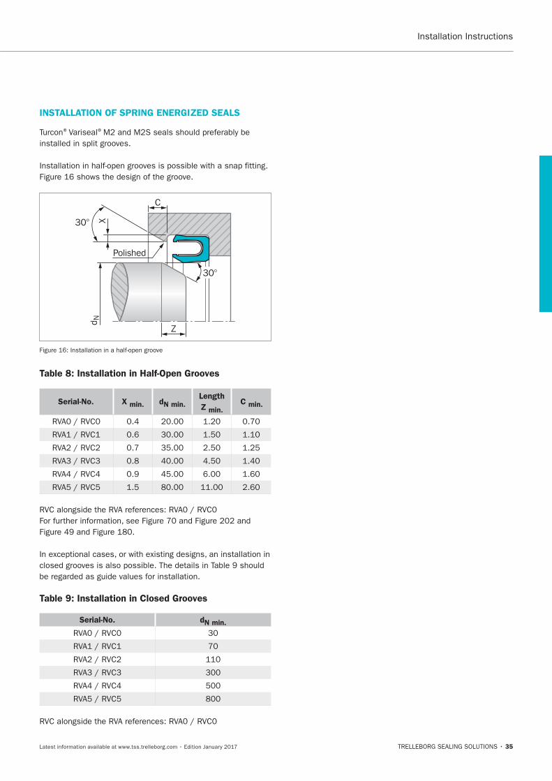
INSTALLATION OF SPRING ENERGIZED SEALS
®Variseal®
Table 8: Installation in Half-Open Grooves
Serial-No. X min. dN min. Length
Z min. C min.
Table 9: Installation in Closed Grooves
Serial-No. dN min.
36
Quality Criteria
Storage Instructions
classes.
Heat
Humidity
Light
coating or screen.
Radiation
Oxygen and ozone
37
Deformation
Contact with liquid and semi-solid materials
Contact with metal and non-metals
other.
Cleaning
Shelf life and shelf life control
EPDM
®
®
Rubber details / seals in assembled components

38
Turcon®Stepseal®2K
TRELLEBORG SEALING SOLUTIONS • 39Latest information available at www.tss.trelleborg.com • Edition January 2017
Single-acting
Rubber-energized plastic-faced seal
Material:Turcon®, Zurcon®and Elastomer
Turcon®Stepseal®2K

40
® ®
41
Description
® ®
®
® ®
®
®or ®
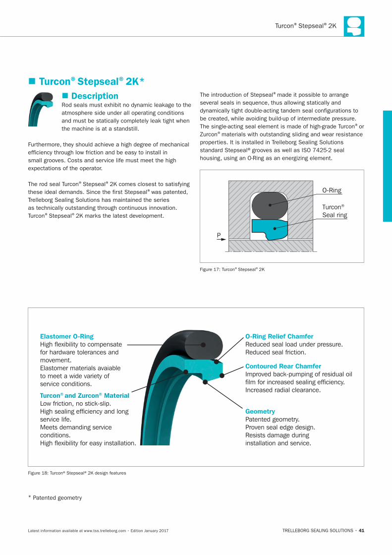
O-Ring
Turcon® Seal ring
P
® ®
Turcon®Stepseal®2K*
Elastomer O-RingHigh flexibility to compensatefor hardware tolerances and movement. Elastomer materials avaiableto meet a wide variety of service conditions.
O-Ring Relief ChamferReduced seal load under pressure.Reduced seal friction.
GeometryPatented geometry.Proven seal edge design.Resists damage duringinstallation and service.
Contoured Rear Chamfer Improved back-pumping of residual oilfilm for increased sealing efficiency.Increased radial clearance.
Turcon® and Zurcon® MaterialLow friction, no stick-slip. High sealing efficiency and long service life.Meets demanding service conditions. High flexibility for easy installation.
*
HYDRAULIC SEALS · Rod Seals
42
METHOD OF OPERATION
® ®
®
®
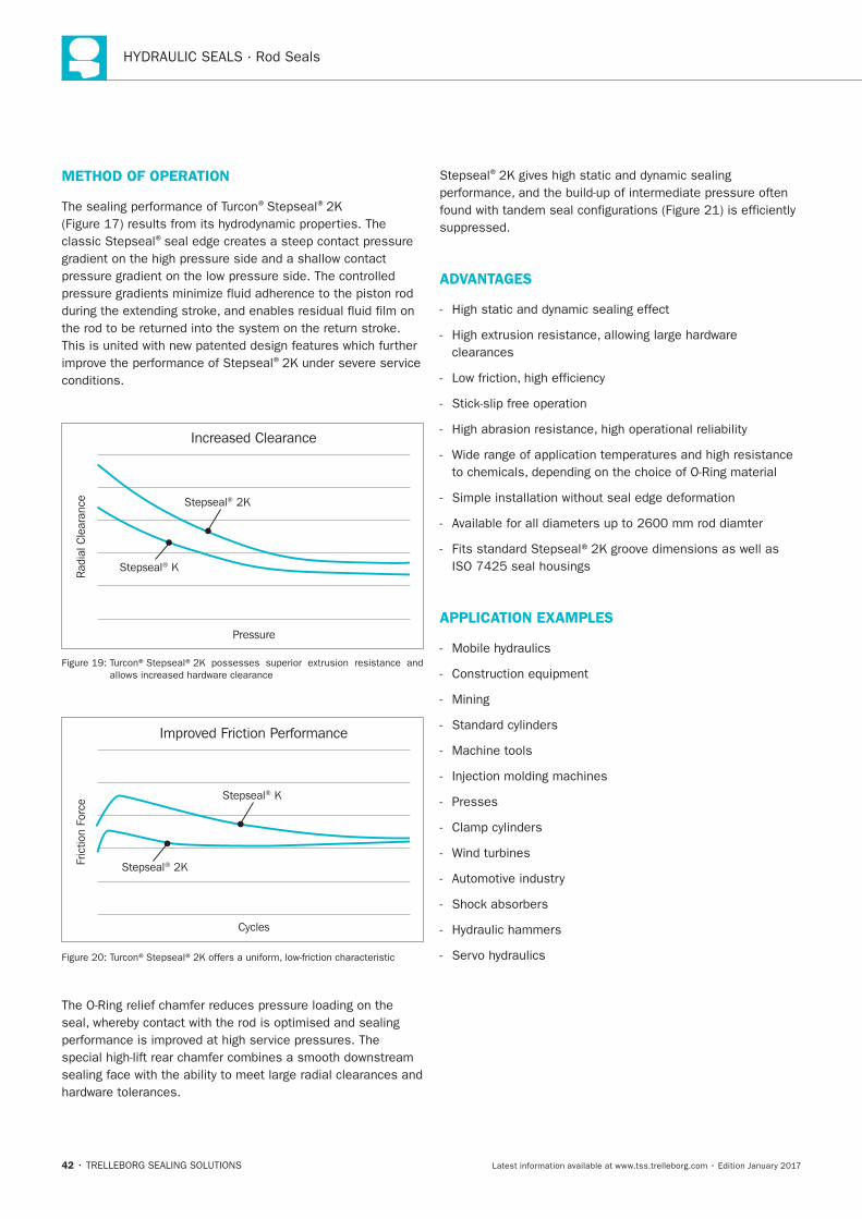
Increased Clearance
Rad
ial C
lear
ance
Pressure
Stepseal® 2K
Stepseal® K
Improved Friction Performance
Fric
tion
Forc
e
Cycles
Stepseal® 2K
Stepseal® K
®
ADVANTAGES
clearances
APPLICATION EXAMPLES
Mining
Machine tools
Presses
Turcon®Stepseal®2K
43
OPERATING CONDITIONS
Pressure:
Speed:
Temperature:
Media:
Clearance:
S
IMPORTANT NOTE
SERIES
grooves.
Table 10: Available Range
Series No. Rod Diameter
dN
ISO GROOVE
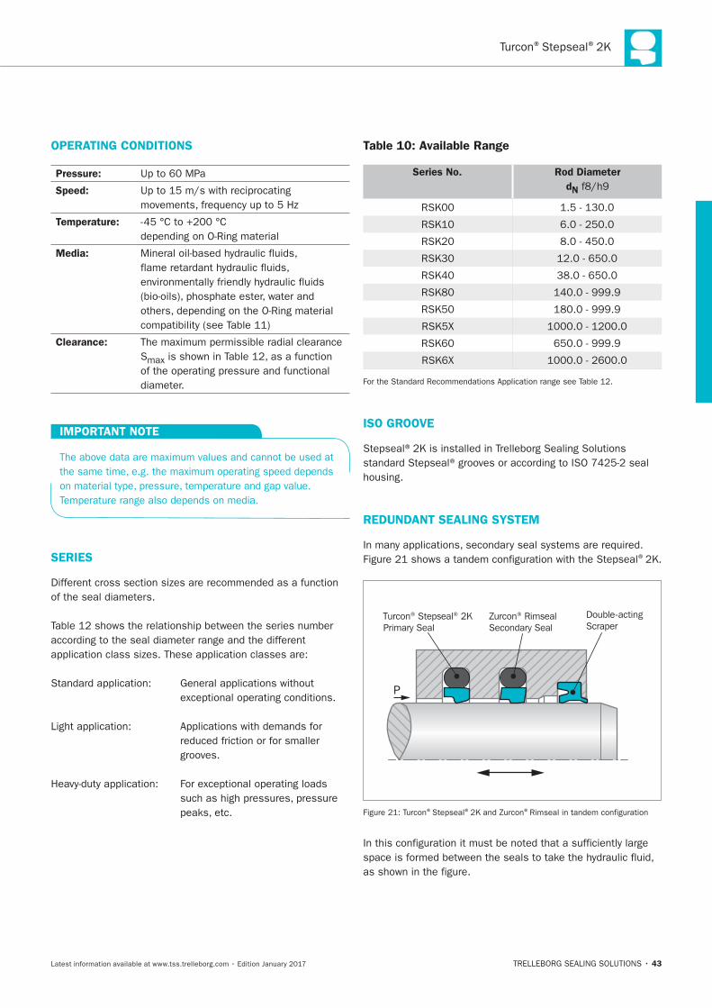
REDUNDANT SEALING SYSTEM
®
Turcon® Stepseal® 2KPrimary Seal
Zurcon® RimsealSecondary Seal
Double-actingScraper
P
® ® ®
HYDRAULIC SEALS · Rod Seals
44
® ®.
®
® ® ® ®
® ® ® ®
INSTALLATION INSTRUCTIONS
®
RECOMMENDED MATERIALS
Turcon®Stepseal®2K in Turcon®M12
Turcon®Stepseal®2K in Turcon®T46
®materials are available.
Turcon®Stepseal®2K
45
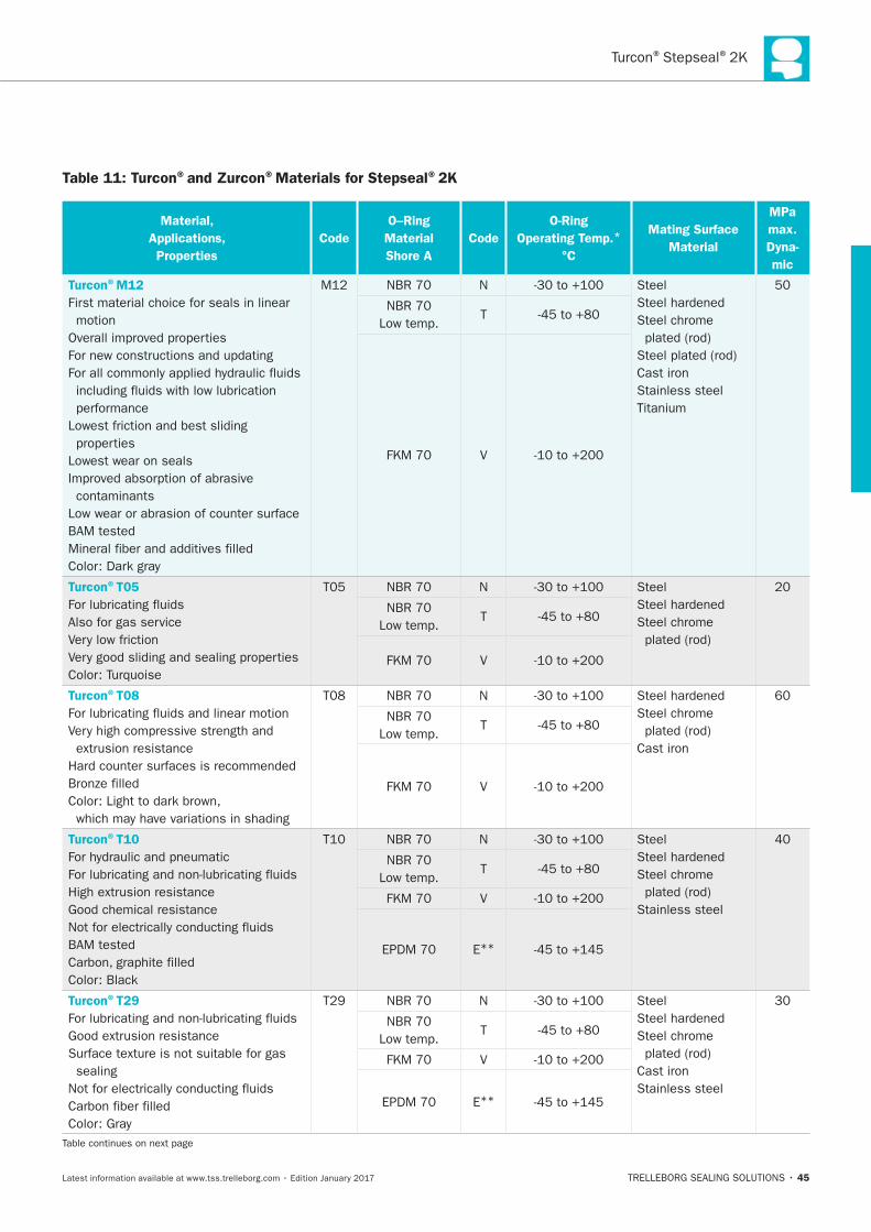
Table 11: Turcon®and Zurcon®Materials for Stepseal®2K
Material,
Applications,
Properties
Code
O–Ring
Material
Shore A
Code
O-Ring
Operating Temp.*
°C
Mating Surface
Material
MPa
max.
Dyna-
mic
Turcon®M12
First material choice for seals in linear
motion
Lowest wear on seals
contaminants
N Steel
Steel chrome
Cast iron
Stainless steel
T
V
Turcon®T05
Also for gas service
N Steel
Steel chrome
T
V
Turcon®T08
N
Steel chrome
Cast iron
T
V
Turcon®T10
N Steel
Steel chrome
Stainless steel
T
V
E**
Turcon®T29
sealing
N Steel
Steel chrome
Cast iron
Stainless steel
T
V
E**
HYDRAULIC SEALS · Rod Seals
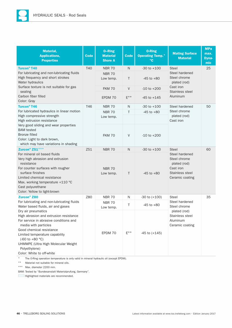
46
Material,
Applications,
Properties
Code
O–Ring
Material
Shore A
Code
O-Ring
Operating Temp.*
°C
Mating Surface
Material
MPa
max.
Dyna-
mic
Turcon®T40
sealing
N Steel
Steel chrome
Cast iron
Stainless steel
T
V
E**
Turcon®T46
N
Steel chrome
Cast iron
T
V
Zurcon®Z51***
resistance
N Steel
Steel chrome
Cast iron
Stainless steel
Ceramic coating
T
Zurcon®Z80
N Steel
Steel chrome
Stainless steel
Ceramic coating
T
E**
*
**
***
Turcon®Stepseal®2K
47
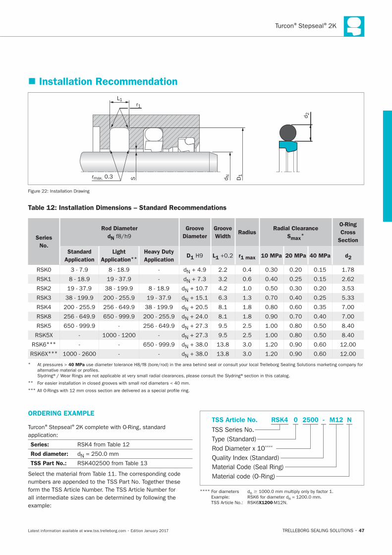
Installation Recommendation
L1
Srmax. 0.3
r1
D1
d N
d 2
Installation Drawing
Table 12: Installation Dimensions – Standard Recommendations
Series
No.
Rod Diameter
dN
Groove
Diameter
Groove
Width Radius
Radial Clearance
Smax*
O-Ring
Cross
Section
Standard
Application
Light
Application**
Heavy Duty
Application D1 L1 r1 max 10 MPa 20 MPa 40 MPa d2
N
N
N
N
N
N
N
N
***N
***N
* 40 MPa
**
***
ORDERING EXAMPLE
® ®
Series:
Rod diameter: N
TSS Part No.:Material Code (Seal Ring)
TSS Series No.TSS Article No. M122500 N
Material code (O-Ring)
Rod Diameter x 10****
RSK4
Quality Index (Standard)
-
Type (Standard)
0
****n �
n =
X1200
HYDRAULIC SEALS · Rod Seals
48
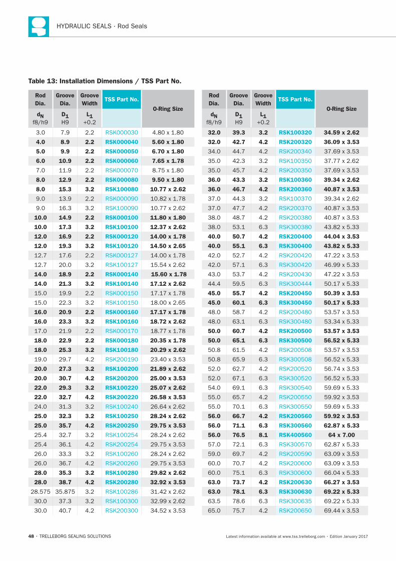
Table 13: Installation Dimensions / TSS Part No.
Rod
Dia.
Groove
Dia.
Groove
WidthTSS Part No.
O-Ring SizedN D1 L1
4.0 8.9 2.2 RSK000040 5.60 x 1.80
5.0 9.9 2.2 RSK000050 6.70 x 1.80
6.0 10.9 2.2 RSK000060 7.65 x 1.78
8.0 12.9 2.2 RSK000080 9.50 x 1.80
8.0 15.3 3.2 RSK100080 10.77 x 2.62
10.0 14.9 2.2 RSK000100 11.80 x 1.80
10.0 17.3 3.2 RSK100100 12.37 x 2.62
12.0 16.9 2.2 RSK000120 14.00 x 1.78
12.0 19.3 3.2 RSK100120 14.50 x 2.65
14.0 18.9 2.2 RSK000140 15.60 x 1.78
14.0 21.3 3.2 RSK100140 17.12 x 2.62
16.0 20.9 2.2 RSK000160 17.17 x 1.78
16.0 23.3 3.2 RSK100160 18.72 x 2.62
18.0 22.9 2.2 RSK000180 20.35 x 1.78
18.0 25.3 3.2 RSK100180 20.29 x 2.62
20.0 27.3 3.2 RSK100200 21.89 x 2.62
20.0 30.7 4.2 RSK200200 25.00 x 3.53
22.0 29.3 3.2 RSK100220 25.07 x 2.62
22.0 32.7 4.2 RSK200220 26.58 x 3.53
25.0 32.3 3.2 RSK100250 28.24 x 2.62
25.0 35.7 4.2 RSK200250 29.75 x 3.53
28.0 35.3 3.2 RSK100280 29.82 x 2.62
28.0 38.7 4.2 RSK200280 32.92 x 3.53
Rod
Dia.
Groove
Dia.
Groove
WidthTSS Part No.
O-Ring SizedN D1 L1
32.0 39.3 3.2 RSK100320 34.59 x 2.62
32.0 42.7 4.2 RSK200320 36.09 x 3.53
36.0 43.3 3.2 RSK100360 39.34 x 2.62
36.0 46.7 4.2 RSK200360 40.87 x 3.53
40.0 50.7 4.2 RSK200400 44.04 x 3.53
40.0 55.1 6.3 RSK300400 43.82 x 5.33
45.0 55.7 4.2 RSK200450 50.39 x 3.53
45.0 60.1 6.3 RSK300450 50.17 x 5.33
50.0 60.7 4.2 RSK200500 53.57 x 3.53
50.0 65.1 6.3 RSK300500 56.52 x 5.33
56.0 66.7 4.2 RSK200560 59.92 x 3.53
56.0 71.1 6.3 RSK300560 62.87 x 5.33
56.0 76.5 8.1 RSK400560 64 x 7.00
63.0 73.7 4.2 RSK200630 66.27 x 3.53
63.0 78.1 6.3 RSK300630 69.22 x 5.33
Turcon®Stepseal®2K
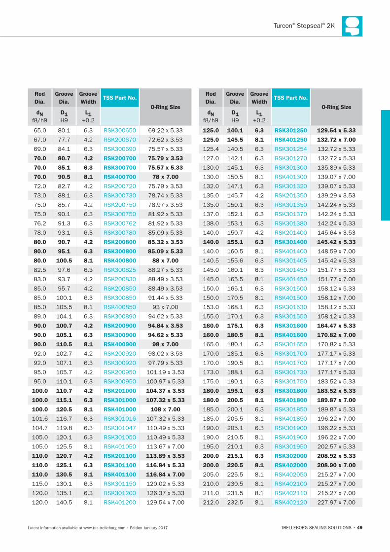
49
Rod
Dia.
Groove
Dia.
Groove
WidthTSS Part No.
O-Ring SizedN D1 L1
70.0 80.7 4.2 RSK200700 75.79 x 3.53
70.0 85.1 6.3 RSK300700 75.57 x 5.33
70.0 90.5 8.1 RSK400700 78 x 7.00
80.0 90.7 4.2 RSK200800 85.32 x 3.53
80.0 95.1 6.3 RSK300800 85.09 x 5.33
80.0 100.5 8.1 RSK400800 88 x 7.00
90.0 100.7 4.2 RSK200900 94.84 x 3.53
90.0 105.1 6.3 RSK300900 94.62 x 5.33
90.0 110.5 8.1 RSK400900 98 x 7.00
100.0 110.7 4.2 RSK201000 104.37 x 3.53
100.0 115.1 6.3 RSK301000 107.32 x 5.33
100.0 120.5 8.1 RSK401000 108 x 7.00
110.0 120.7 4.2 RSK201100 113.89 x 3.53
110.0 125.1 6.3 RSK301100 116.84 x 5.33
110.0 130.5 8.1 RSK401100 116.84 x 7.00
Rod
Dia.
Groove
Dia.
Groove
WidthTSS Part No.
O-Ring SizedN D1 L1
125.0 140.1 6.3 RSK301250 129.54 x 5.33
125.0 145.5 8.1 RSK401250 132.72 x 7.00
140.0 155.1 6.3 RSK301400 145.42 x 5.33
160.0 175.1 6.3 RSK301600 164.47 x 5.33
160.0 180.5 8.1 RSK401600 170.82 x 7.00
180.0 195.1 6.3 RSK301800 183.52 x 5.33
180.0 200.5 8.1 RSK401800 189.87 x 7.00
200.0 215.1 6.3 RSK302000 208.92 x 5.33
200.0 220.5 8.1 RSK402000 208.90 x 7.00
HYDRAULIC SEALS · Rod Seals
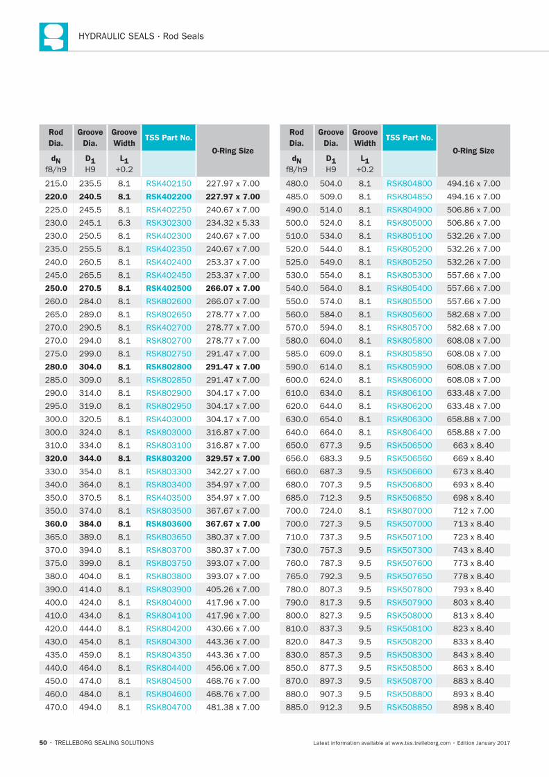
50
Rod
Dia.
Groove
Dia.
Groove
WidthTSS Part No.
O-Ring SizedN D1 L1
220.0 240.5 8.1 RSK402200 227.97 x 7.00
250.0 270.5 8.1 RSK402500 266.07 x 7.00
280.0 304.0 8.1 RSK802800 291.47 x 7.00
320.0 344.0 8.1 RSK803200 329.57 x 7.00
360.0 384.0 8.1 RSK803600 367.67 x 7.00
Rod
Dia.
Groove
Dia.
Groove
WidthTSS Part No.
O-Ring SizedN D1 L1
Turcon®Stepseal®2K
51
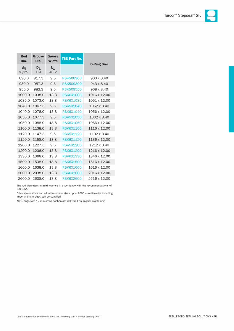
Rod
Dia.
Groove
Dia.
Groove
WidthTSS Part No.
O-Ring SizedN D1 L1
bold

HYDRAULIC SEALS · Rod Seals
52
Turcon®Stepseal®V
TRELLEBORG SEALING SOLUTIONS • 53Latest information available at www.tss.trelleborg.com • Edition January 2017
Single-acting
Rubber-energized plastic-faced seal
Material:Turcon®, Zurcon®and Elastomer
Turcon®Stepseal®V

54
V
55
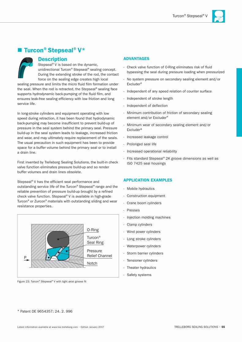
Turcon®Stepseal®
Description
sealing face
service life.
O-Ring
Notch
Turcon® Seal Ring
PressureRelief ChannelP
*
APPLICATION EXAMPLES
56
CHARACTERISTICS
IMPROVED FRICTION PERFORMANCE
® ®
FEATURES
®
®
®
®
® ®
® ®
® ®
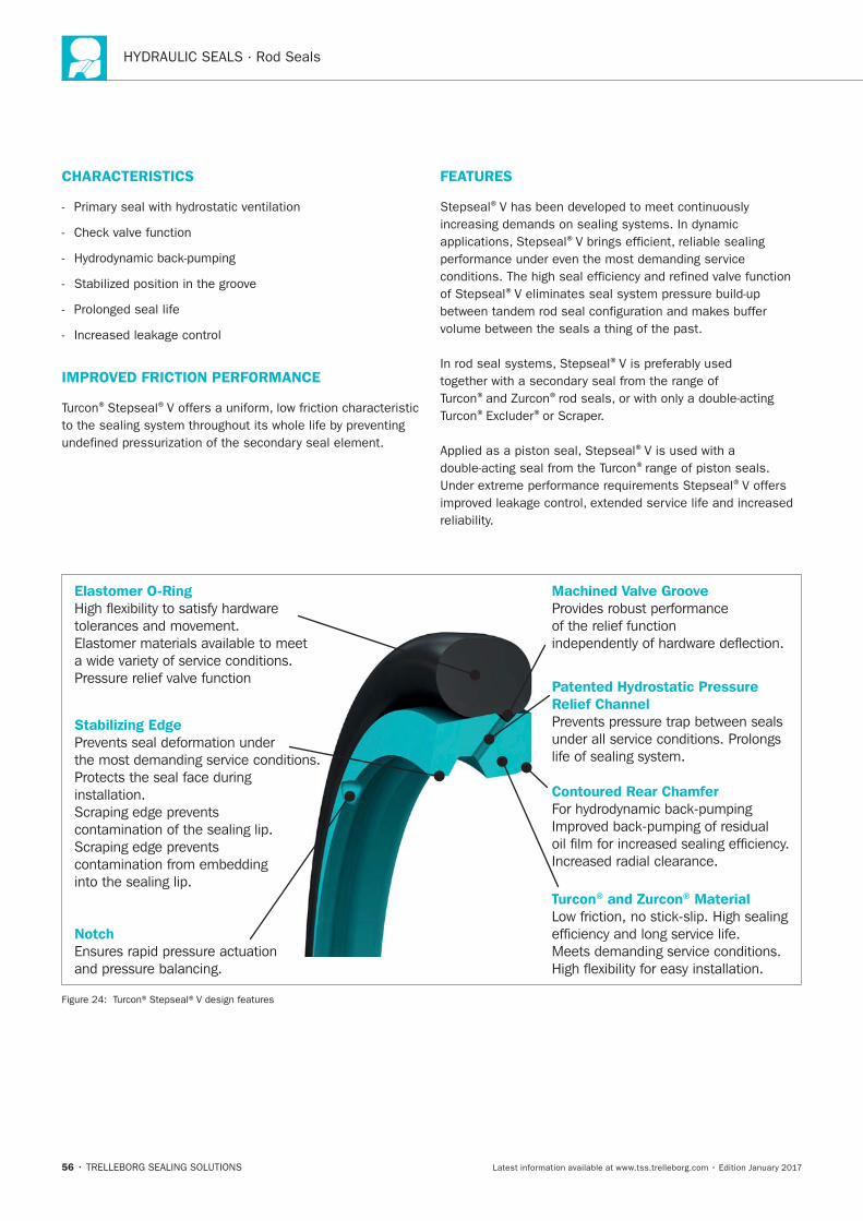
®V offers
Machined Valve GrooveProvides robust performanceof the relief functionindependently of hardware deflection.
Patented Hydrostatic PressureRelief ChannelPrevents pressure trap between sealsunder all service conditions. Prolongslife of sealing system.
Contoured Rear ChamferFor hydrodynamic back-pumpingImproved back-pumping of residualoil film for increased sealing efficiency.Increased radial clearance.
Turcon® and Zurcon® MaterialLow friction, no stick-slip. High sealingefficiency and long service life.Meets demanding service conditions.High flexibility for easy installation.
Elastomer O-RingHigh flexibility to satisfy hardwaretolerances and movement.Elastomer materials available to meeta wide variety of service conditions.Pressure relief valve function
Stabilizing EdgePrevents seal deformation underthe most demanding service conditions.Protects the seal face duringinstallation.Scraping edge preventscontamination of the sealing lip.Scraping edge prevents contamination from embeddinginto the sealing lip.
NotchEnsures rapid pressure actuationand pressure balancing.
Turcon®Stepseal®V
57
OPERATING CONDITIONS
Pressure: ® ®
®
Speed:
Temperature:
Media:
Clearance:
S
IMPORTANT NOTE
SERIES
grooves.
Table 14: Available Range
Series No.Rod Diameter
dN
RSV5X
RSV6X
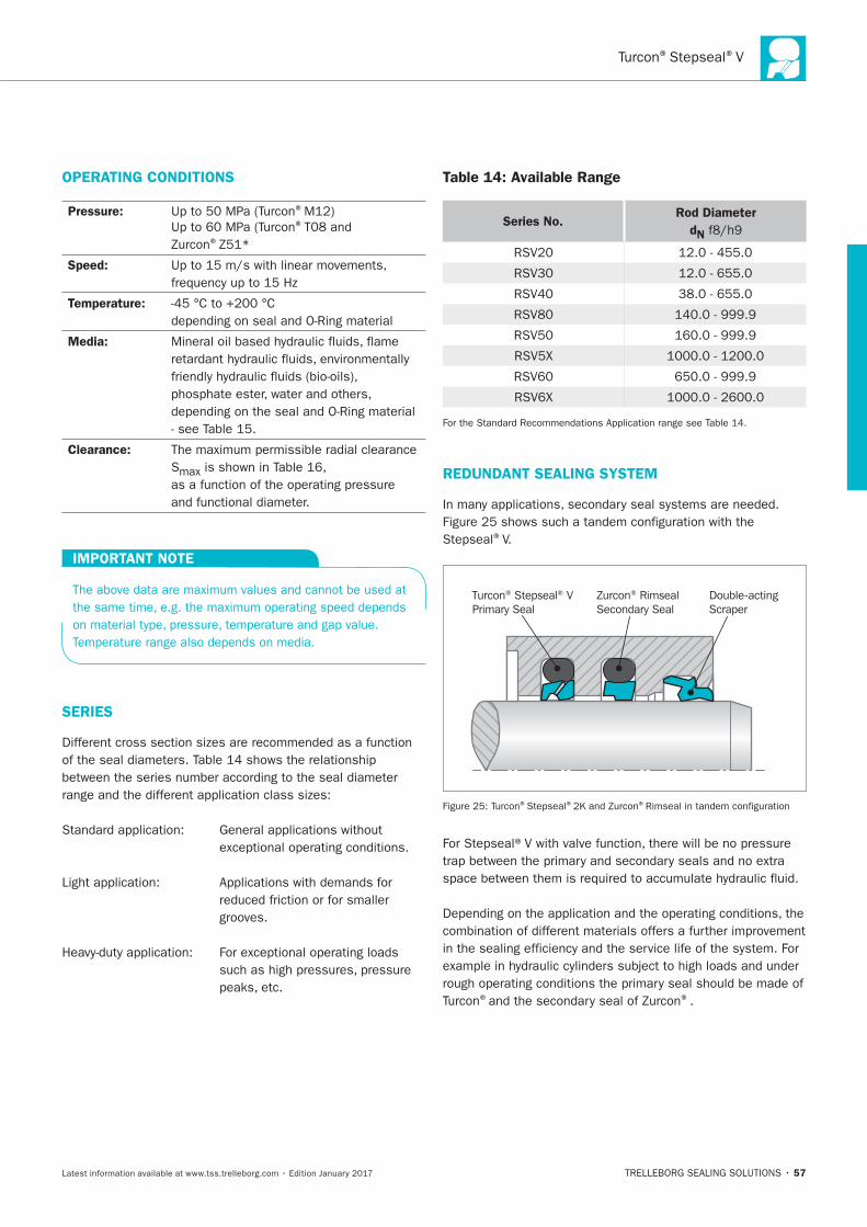
REDUNDANT SEALING SYSTEM
Stepseal®V.
Turcon® Stepseal® VPrimary Seal
Zurcon® RimsealSecondary Seal
Double-actingScraper
®Stepseal® ®
® ®.
HYDRAULIC SEALS · Rod Seals
58
INSTALLATION INSTRUCTIONS
RECOMMENDED MATERIALS
Turcon®Stepseal® ®M12
linear, short stroke or helical movements in mineral oils, flame
Turcon®Stepseal® ®T46
materials are available.
® ®V
59
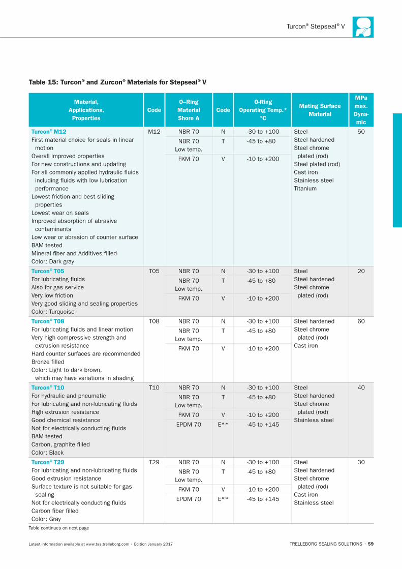
Table 15: Turcon®and Zurcon®Materials for Stepseal®V
Material,
Applications,
Properties
Code
O–Ring
Material
Shore A
Code
O-Ring
Operating Temp.*
°C
Mating Surface
Material
MPa
max.
Dyna-
mic
Turcon®M12
First material choice for seals in linear
motion
Lowest wear on seals
contaminants
N Steel
Steel chrome
Cast iron
Stainless steel
T
V
Turcon®T05
Also for gas service
N Steel
Steel chrome T
V
Turcon®T08
N
Steel chrome
Cast iron
T
V
Turcon®T10
N Steel
Steel chrome
Stainless steel
T
V
E**
Turcon®T29
sealing
N Steel
Steel chrome
Cast iron
Stainless steel
T
V
E**

60
Material,
Applications,
Properties
Code
O–Ring
Material
Shore A
Code
O-Ring
Operating Temp.*
°C
Mating Surface
Material
MPa
max.
Dyna-
mic
Turcon®T40
sealing
N Steel
Steel chrome
Cast iron
Stainless steel
T
V
E**
Turcon®T46
N
Steel chrome
Cast iron
T
V
Zurcon®Z51***
resistance
finish
N Steel
Steel chrome
Cast iron
Stainless steel
Ceramic coating
T
Zurcon®Z80
N Steel
Steel chrome
Stainless steel
Ceramic coating
T
E**
® ®V
61
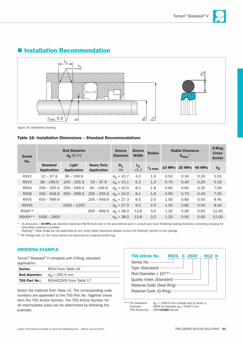
Installation Recommendation
L1
Srmax. 0.3
r1
D1
d N
d 2
Installation Drawing
Table 16: Installation Dimensions – Standard Recommendations
Series
No.
Rod Diameter
dN
Groove
Diameter
Groove
Width Radius
Radial Clearance
Smax*
O-Ring
Cross
Section
Standard
Application
Light
Application
Heavy Duty
Application
D1
L1 r1 max 10 MPa 20 MPa 40 MPa d2
N
N
N
RSV8 N
N
N
N
N
40 MPa
**
ORDERING EXAMPLE
® ®
Series:
Rod diameter: N
TSS Part No.:
Material Code (Seal Ring)
Series No.
TSS Article No. M122500 N
Material Code (O-Ring)
Rod Diameter x 10***
RSV4
Quality Index (Standard)
-
Type (Standard)
0
N �
N =
X1200
62
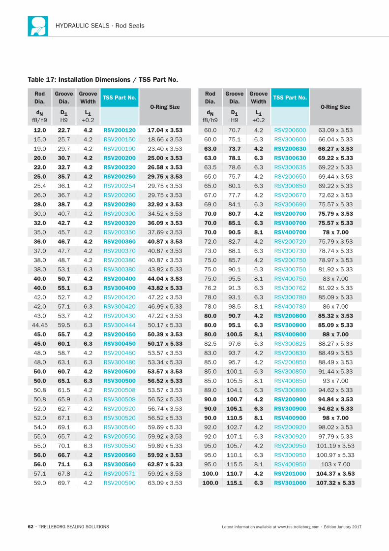
Table 17: Installation Dimensions / TSS Part No.
Rod
Dia.
Groove
Dia.
Groove
WidthTSS Part No.
O-Ring SizedN D1 L1
12.0 22.7 4.2 RSV200120 17.04 x 3.53
20.0 30.7 4.2 RSV200200 25.00 x 3.53
22.0 32.7 4.2 RSV200220 26.58 x 3.53
25.0 35.7 4.2 RSV200250 29.75 x 3.53
28.0 38.7 4.2 RSV200280 32.92 x 3.53
32.0 42.7 4.2 RSV200320 36.09 x 3.53
36.0 46.7 4.2 RSV200360 40.87 x 3.53
40.0 50.7 4.2 RSV200400 44.04 x 3.53
40.0 55.1 6.3 RSV300400 43.82 x 5.33
45.0 55.7 4.2 RSV200450 50.39 x 3.53
45.0 60.1 6.3 RSV300450 50.17 x 5.33
50.0 60.7 4.2 RSV200500 53.57 x 3.53
50.0 65.1 6.3 RSV300500 56.52 x 5.33
56.0 66.7 4.2 RSV200560 59.92 x 3.53
56.0 71.1 6.3 RSV300560 62.87 x 5.33
Rod
Dia.
Groove
Dia.
Groove
WidthTSS Part No.
O-Ring SizedN D1 L1
63.0 73.7 4.2 RSV200630 66.27 x 3.53
63.0 78.1 6.3 RSV300630 69.22 x 5.33
70.0 80.7 4.2 RSV200700 75.79 x 3.53
70.0 85.1 6.3 RSV300700 75.57 x 5.33
70.0 90.5 8.1 RSV400700 78 x 7.00
80.0 90.7 4.2 RSV200800 85.32 x 3.53
80.0 95.1 6.3 RSV300800 85.09 x 5.33
80.0 100.5 8.1 RSV400800 88 x 7.00
90.0 100.7 4.2 RSV200900 94.84 x 3.53
90.0 105.1 6.3 RSV300900 94.62 x 5.33
90.0 110.5 8.1 RSV400900 98 x 7.00
100.0 110.7 4.2 RSV201000 104.37 x 3.53
100.0 115.1 6.3 RSV301000 107.32 x 5.33
® ®V
63
Rod
Dia.
Groove
Dia.
Groove
WidthTSS Part No.
O-Ring SizedN D1 L1
100.0 120.5 8.1 RSV401000 108 x 7.00
110.0 125.1 6.3 RSV301100 116.84 x 5.33
110.0 130.5 8.1 RSV401100 116.84 x 7.00
125.0 140.1 6.3 RSV301250 129.54 x 5.33
125.0 145.5 8.1 RSV401250 132.72 x 7.00
140.0 150.7 4.2 RSV201400 145.64 x 3.53
140.0 155.1 6.3 RSV301400 145.42 x 5.33
140.0 160.5 8.1 RSV401400 148.59 x 7.00
160.0 175.1 6.3 RSV301600 164.47 x 5.33
160.0 180.5 8.1 RSV401600 170.82 x 7.00
180.0 195.1 6.3 RSV301800 183.52 x 5.33
Rod
Dia.
Groove
Dia.
Groove
WidthTSS Part No.
O-Ring SizedN D1 L1
180.0 200.5 8.1 RSV401800 189.87 x 7.00
200.0 215.1 6.3 RSV302000 208.92 x 5.33
200.0 220.5 8.1 RSV402000 208.90 x 7.00
220.0 240.5 8.1 RSV402200 227.97 x 7.00
225.0 245.5 8.1 RSV402250 240.67 x 7.00
250.0 270.5 8.1 RSV402500 266.07 x 7.00
280.0 304.0 8.1 RSV802800 291.47 x 7.00
320.0 344.0 8.1 RSV803200 329.57 x 7.00
360.0 384.0 8.1 RSV803600 367.67 x 7.00
64
Rod
Dia.
Groove
Dia.
Groove
WidthTSS Part No.
O-Ring SizedN D1 L1
Rod
Dia.
Groove
Dia.
Groove
WidthTSS Part No.
O-Ring SizedN D1 L1
bold
Zurcon®Rimseal
TRELLEBORG SEALING SOLUTIONS • 65Latest information available at www.tss.trelleborg.com • Edition January 2017
RimsealSingle-acting
Rubber-energized plastic-faced seal
Material:Zurcon®and Elastomer
Zurcon®

HYDRAULIC SEALS · Rod Seals
66
Zurcon®Rimseal
67
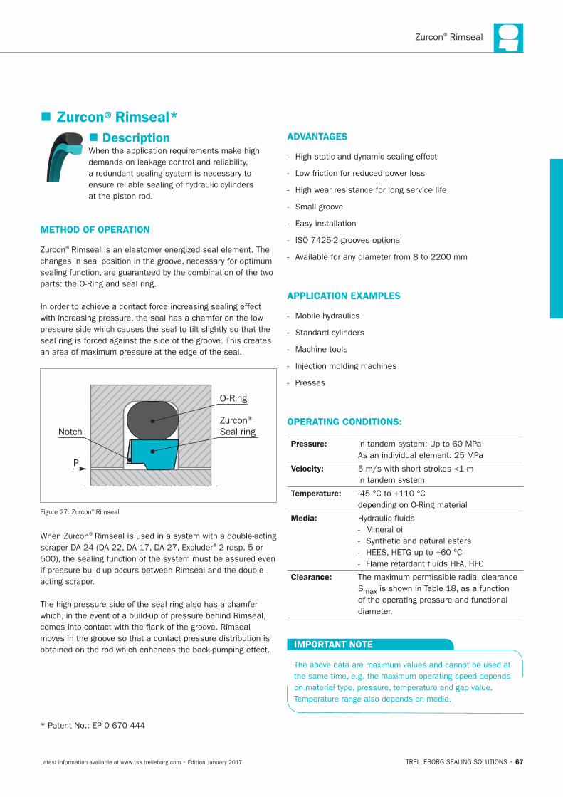
Description
METHOD OF OPERATION
®
O-Ring
NotchZurcon® Seal ring
P
®Rimseal
®
®
acting scraper.
ADVANTAGES
-
-
- High wear resistance for long service life
- Small groove
-
-
-
APPLICATION EXAMPLES
-
-
- Machine tools
-
- Presses
OPERATING CONDITIONS:
Pressure:
Velocity:
Temperature:
Media:
- Mineral oil
-
-
-
Clearance:
Smax
IMPORTANT NOTE
Zurcon®Rimseal*
HYDRAULIC SEALS · Rod Seals
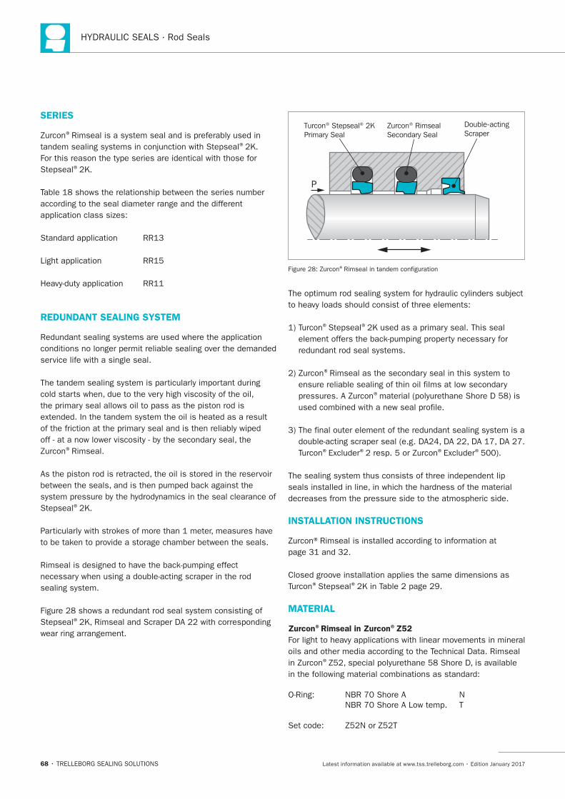
68
SERIES
®
®
®
REDUNDANT SEALING SYSTEM
service life with a single seal.
®Rimseal.
®
®
wear ring arrangement.
Turcon® Stepseal® 2KPrimary Seal
Zurcon® RimsealSecondary Seal
Double-actingScraper
P
®
® ®
®
®
® ® ® ®
INSTALLATION INSTRUCTIONS
® ®
MATERIAL
Zurcon®Rimseal in Zurcon®Z52
®
®Rimseal
69
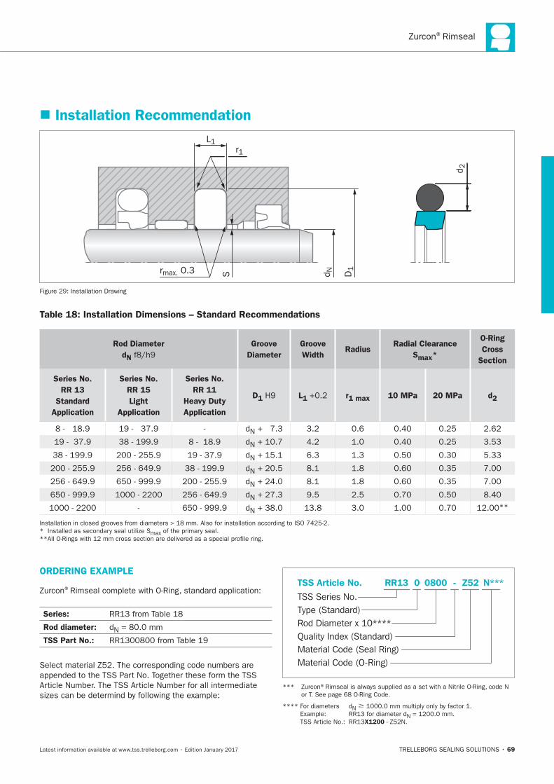
Installation Recommendation
L1
rmax. 0.3 S
r1
D1
d N
d 2
Installation Drawing
Table 18: Installation Dimensions – Standard Recommendations
Rod Diameter
dN
Groove
Diameter
Groove
Width Radius
Radial Clearance
Smax*
O-Ring
Cross
Section
Series No.
RR 13
Standard
Application
Series No.
RR 15
Light
Application
Series No.
RR 11
Heavy Duty
Application
D1 L1 r1 max 10 MPa 20 MPa d2
N
N
N
N
N
N
N**
ORDERING EXAMPLE
®
Series:
Rod diameter: N
TSS Part No.:Material Code (Seal Ring)
TSS Series No.
TSS Article No. Z520800 N***
Material Code (O-Ring)
Rod Diameter x 10****
RR13
Quality Index (Standard)
-
Type (Standard)
0
**** N �
N
X1200
HYDRAULIC SEALS · Rod Seals
70
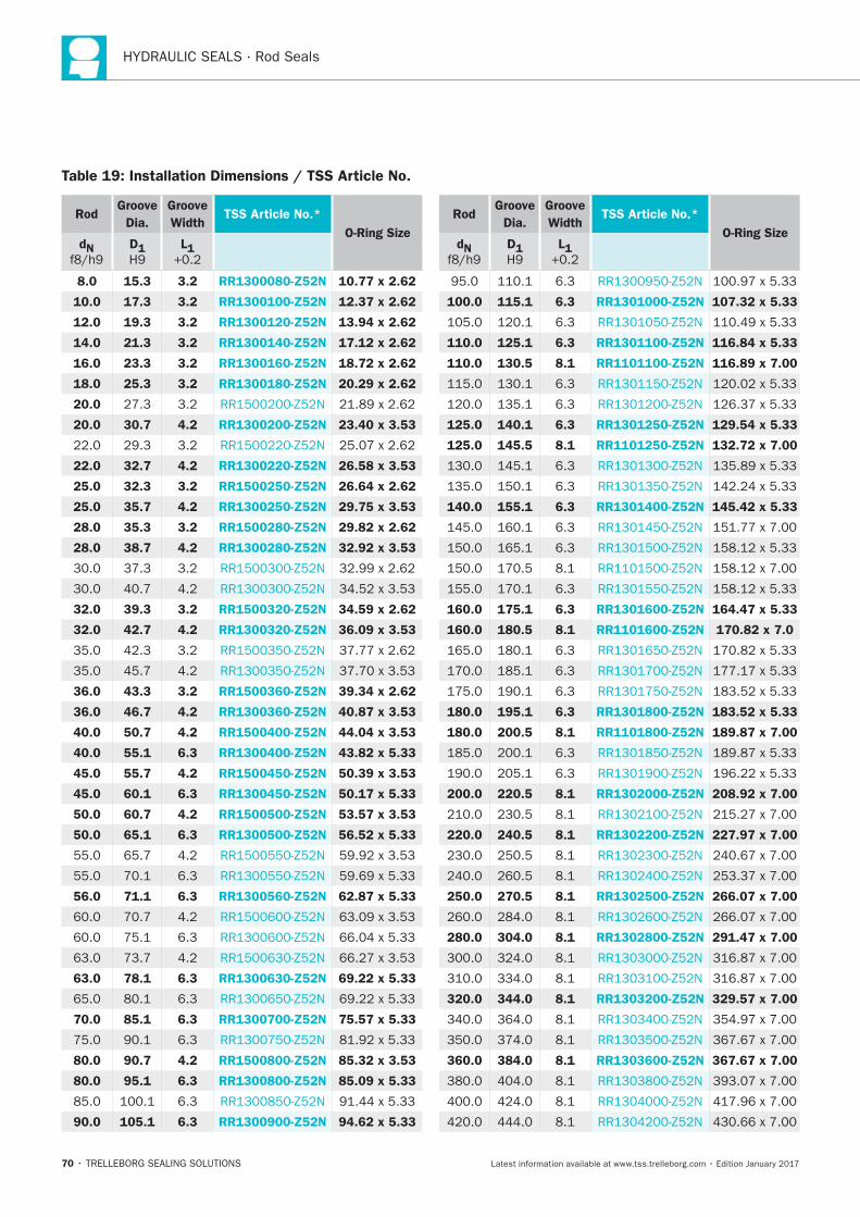
Table 19: Installation Dimensions / TSS Article No.
RodGroove
Dia.
Groove
WidthTSS Article No.*
O-Ring SizedN D1 L1
8.0 15.3 3.2 RR1300080-Z52N 10.77 x 2.62
10.0 17.3 3.2 RR1300100-Z52N 12.37 x 2.62
12.0 19.3 3.2 RR1300120-Z52N 13.94 x 2.62
14.0 21.3 3.2 RR1300140-Z52N 17.12 x 2.62
16.0 23.3 3.2 RR1300160-Z52N 18.72 x 2.62
18.0 25.3 3.2 RR1300180-Z52N 20.29 x 2.62
20.0
20.0 30.7 4.2 RR1300200-Z52N 23.40 x 3.53
22.0 32.7 4.2 RR1300220-Z52N 26.58 x 3.53
25.0 32.3 3.2 RR1500250-Z52N 26.64 x 2.62
25.0 35.7 4.2 RR1300250-Z52N 29.75 x 3.53
28.0 35.3 3.2 RR1500280-Z52N 29.82 x 2.62
28.0 38.7 4.2 RR1300280-Z52N 32.92 x 3.53
32.0 39.3 3.2 RR1500320-Z52N 34.59 x 2.62
32.0 42.7 4.2 RR1300320-Z52N 36.09 x 3.53
36.0 43.3 3.2 RR1500360-Z52N 39.34 x 2.62
36.0 46.7 4.2 RR1300360-Z52N 40.87 x 3.53
40.0 50.7 4.2 RR1500400-Z52N 44.04 x 3.53
40.0 55.1 6.3 RR1300400-Z52N 43.82 x 5.33
45.0 55.7 4.2 RR1500450-Z52N 50.39 x 3.53
45.0 60.1 6.3 RR1300450-Z52N 50.17 x 5.33
50.0 60.7 4.2 RR1500500-Z52N 53.57 x 3.53
50.0 65.1 6.3 RR1300500-Z52N 56.52 x 5.33
56.0 71.1 6.3 RR1300560-Z52N 62.87 x 5.33
63.0 78.1 6.3 RR1300630-Z52N 69.22 x 5.33
70.0 85.1 6.3 RR1300700-Z52N 75.57 x 5.33
80.0 90.7 4.2 RR1500800-Z52N 85.32 x 3.53
80.0 95.1 6.3 RR1300800-Z52N 85.09 x 5.33
90.0 105.1 6.3 RR1300900-Z52N 94.62 x 5.33
RodGroove
Dia.
Groove
WidthTSS Article No.*
O-Ring SizedN D1 L1
100.0 115.1 6.3 RR1301000-Z52N 107.32 x 5.33
110.0 125.1 6.3 RR1301100-Z52N 116.84 x 5.33
110.0 130.5 8.1 RR1101100-Z52N 116.89 x 7.00
125.0 140.1 6.3 RR1301250-Z52N 129.54 x 5.33
125.0 145.5 8.1 RR1101250-Z52N 132.72 x 7.00
140.0 155.1 6.3 RR1301400-Z52N 145.42 x 5.33
160.0 175.1 6.3 RR1301600-Z52N 164.47 x 5.33
160.0 180.5 8.1 RR1101600-Z52N 170.82 x 7.0
180.0 195.1 6.3 RR1301800-Z52N 183.52 x 5.33
180.0 200.5 8.1 RR1101800-Z52N 189.87 x 7.00
200.0 220.5 8.1 RR1302000-Z52N 208.92 x 7.00
220.0 240.5 8.1 RR1302200-Z52N 227.97 x 7.00
250.0 270.5 8.1 RR1302500-Z52N 266.07 x 7.00
280.0 304.0 8.1 RR1302800-Z52N 291.47 x 7.00
320.0 344.0 8.1 RR1303200-Z52N 329.57 x 7.00
360.0 384.0 8.1 RR1303600-Z52N 367.67 x 7.00
Zurcon®Rimseal
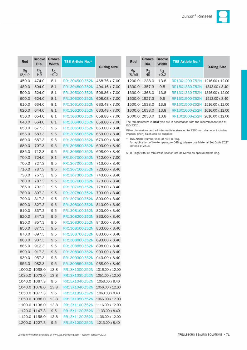
71
RodGroove
Dia.
Groove
WidthTSS Article No.*
O-Ring SizedN D1 L1
RodGroove
Dia.
Groove
WidthTSS Article No.*
O-Ring SizedN D1 L1
T bold
Other
*

HYDRAULIC SEALS · Rod Seals
72
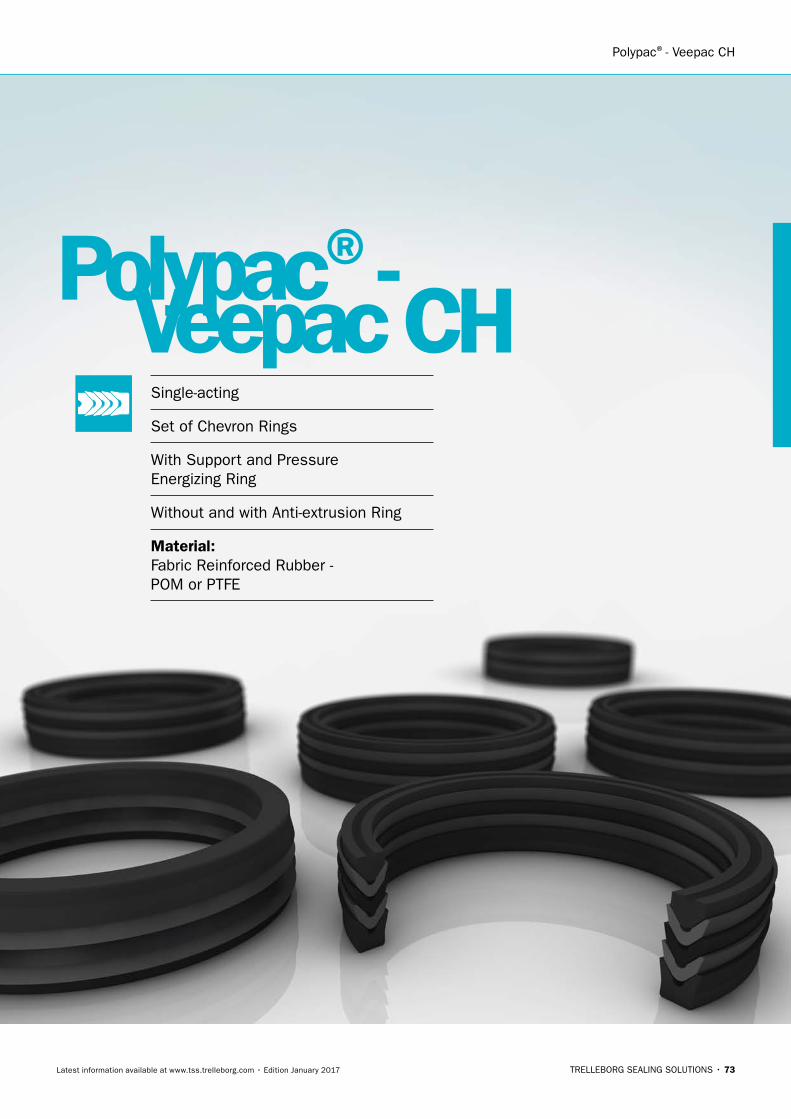
Polypac®- Veepac CH
TRELLEBORG SEALING SOLUTIONS • 73Latest information available at www.tss.trelleborg.com • Edition January 2017
Single-acting
Set of Chevron Rings
With Support and Pressure Energizing Ring
Without and with Anti-extrusion Ring
Material:Fabric Reinforced Rubber - POM or PTFE
Polypac®- Veepac CH

74
POLYPAC®- Veepac CH
75
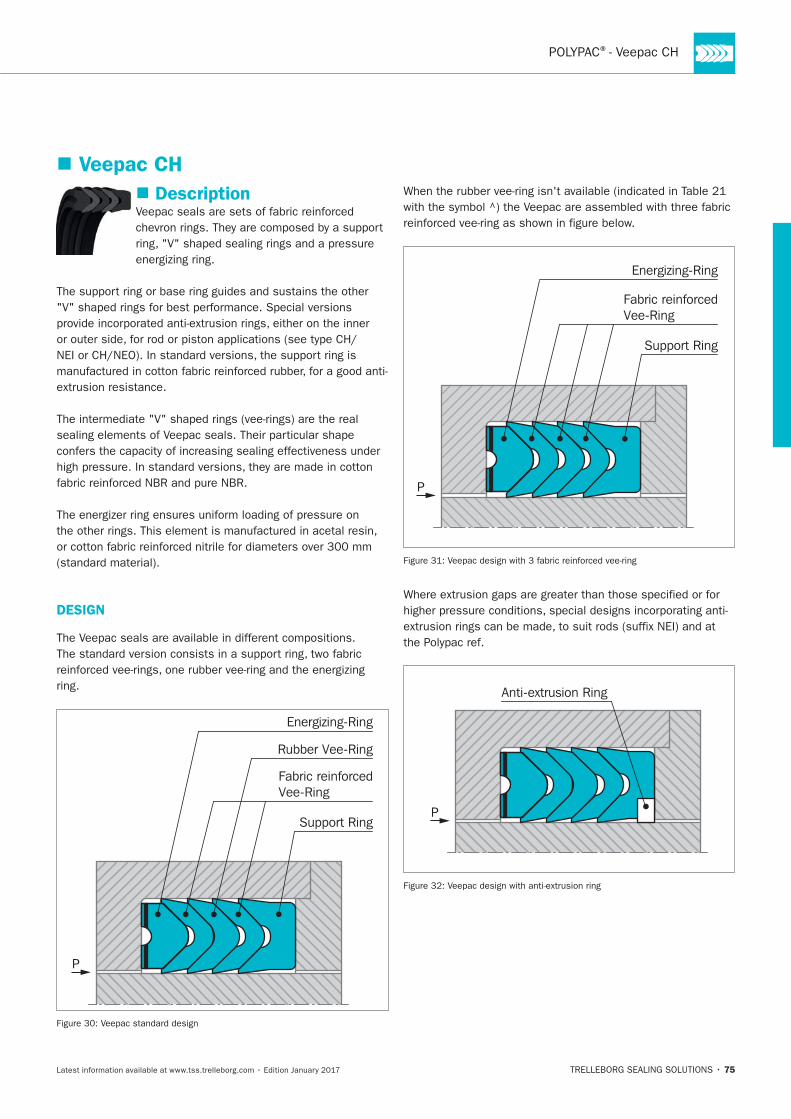
Description
energizing ring.
DESIGN
ring.
Support Ring
Energizing-Ring
Rubber Vee-Ring
Fabric reinforcedVee-Ring
P
Support Ring
Energizing-Ring
Fabric reinforcedVee-Ring
P
P
Anti-extrusion Ring
Veepac CH
HYDRAULIC SEALS · Rod Seals
76
ADVANTAGES
-
-
-
-
-
APPLICATION EXAMPLES
-
-
-
-
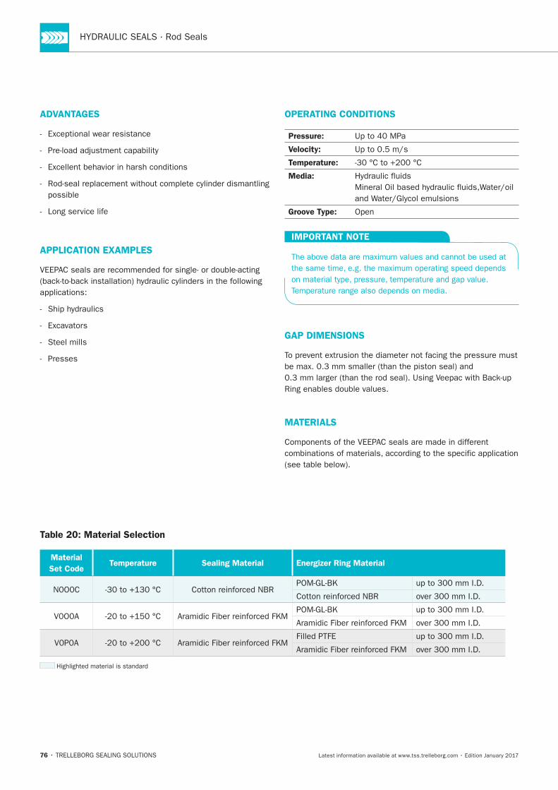
OPERATING CONDITIONS
Pressure:
Velocity:
Temperature:
Media:
Groove Type:
IMPORTANT NOTE
GAP DIMENSIONS
MATERIALS
Table 20: Material Selection
Material
Set CodeTemperature Sealing Material Energizer Ring Material
POLYPAC®- Veepac CH
77
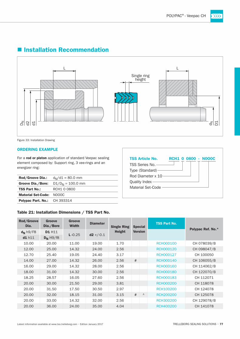
Installation Recommendation
L L
Single ringheight
D1
d1d2 d NDN
Installation Drawing
ORDERING EXAMPLE
For a rod or piston
Rod/Groove Dia.: N
Groove Dia./Bore: N
TSS Part No.:
Material Set-Code:
Polypac Part. No.:
N0O0CRCH1 0800 -
Material Set-Code
TSS Series No.TSS Article No.
Rod Diameter x 10Quality Index
Type (Standard)
0
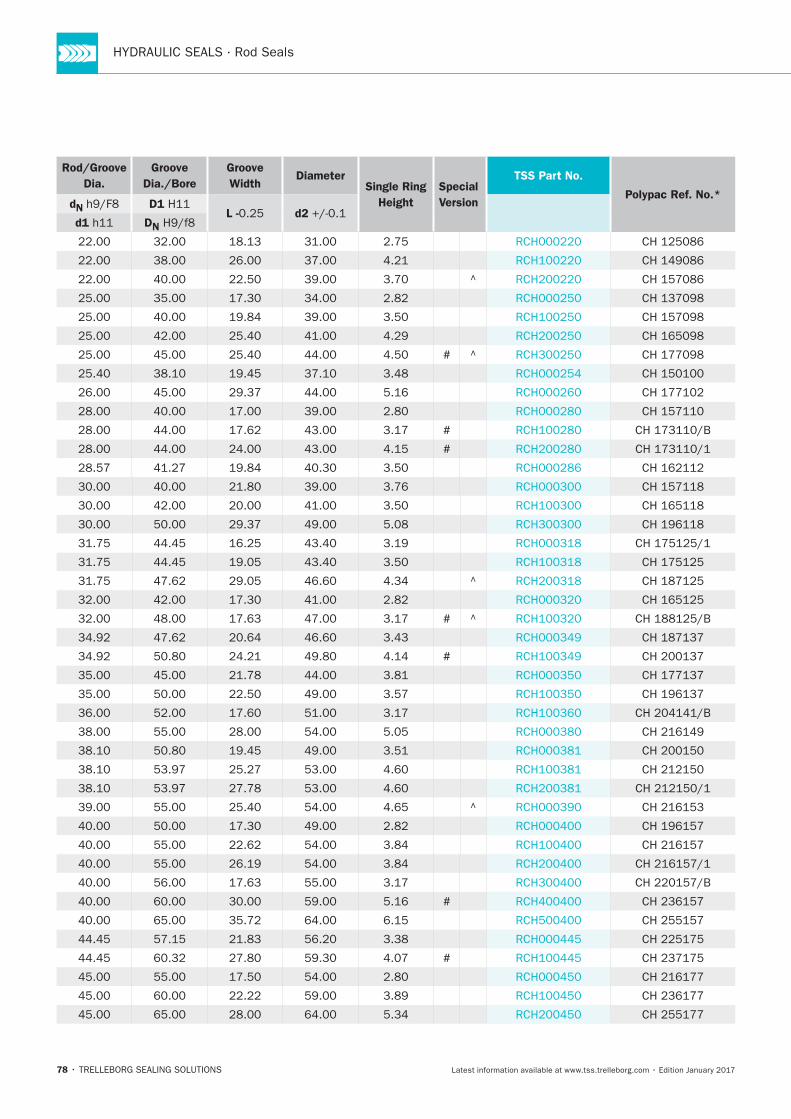
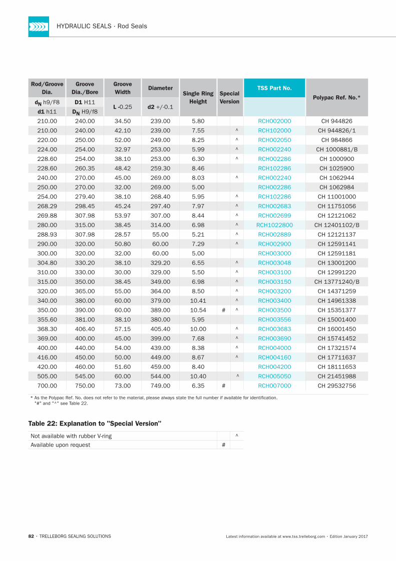
Table 21: Installation Dimensions / TSS Part No.
Rod/Groove
Dia.
Groove
Dia./Bore
Groove
WidthDiameter
Single Ring
Height
Special
Version
TSS Part No.
Polypac Ref. No.*dN D1
L - d2d1 DN
#
# ^
78
Rod/Groove
Dia.
Groove
Dia./Bore
Groove
WidthDiameter
Single Ring
Height
Special
Version
TSS Part No.
Polypac Ref. No.*dN D1
L - d2d1 DN
#
#
#
#
#
#
#
POLYPAC®- Veepac CH
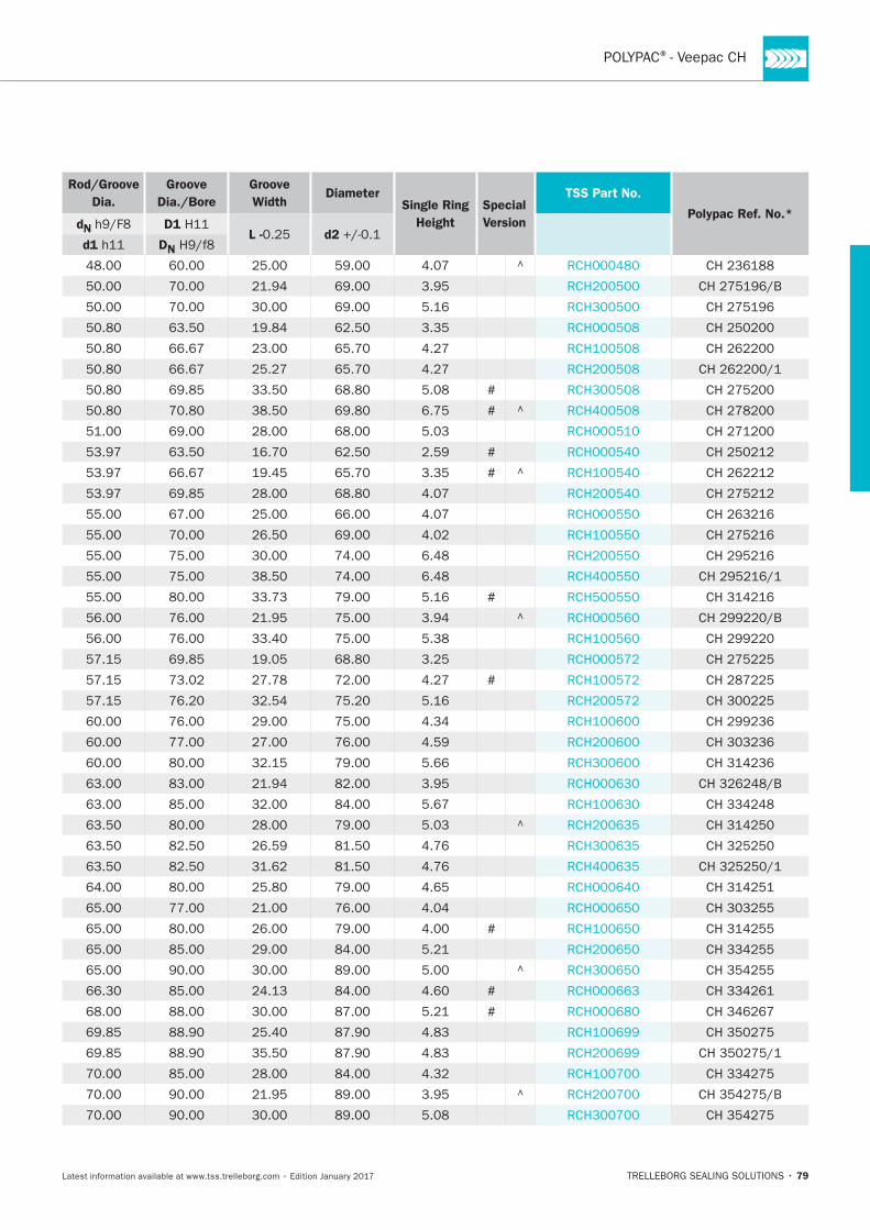
79
Rod/Groove
Dia.
Groove
Dia./Bore
Groove
WidthDiameter
Single Ring
Height
Special
Version
TSS Part No.
Polypac Ref. No.*dN D1
L - d2d1 DN
^
#
# ^
#
# ^
#
^
#
^
#
^
#
#
^
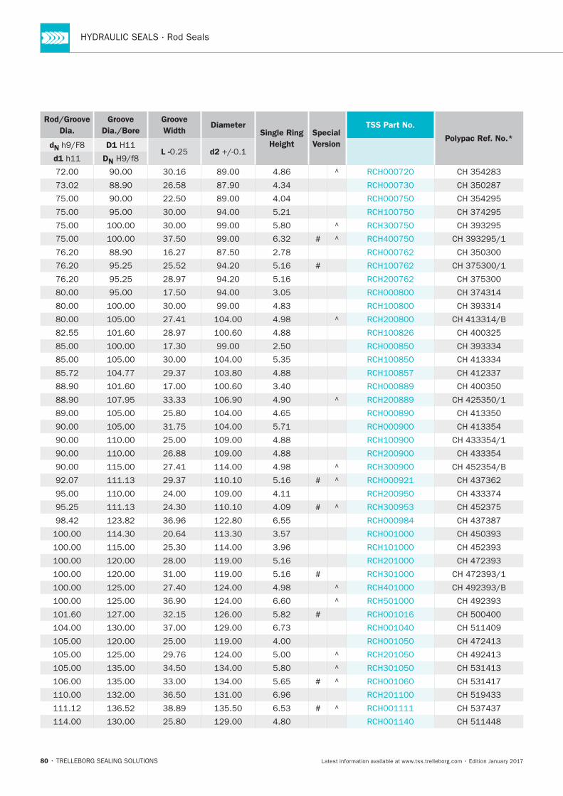
80
Rod/Groove
Dia.
Groove
Dia./Bore
Groove
WidthDiameter
Single Ring
Height
Special
Version
TSS Part No.
Polypac Ref. No.*dN D1
L - d2d1 DN
^
^
# ^
#
^
^
^
# ^
# ^
#
^
^
#
^
^
# ^
# ^
POLYPAC®
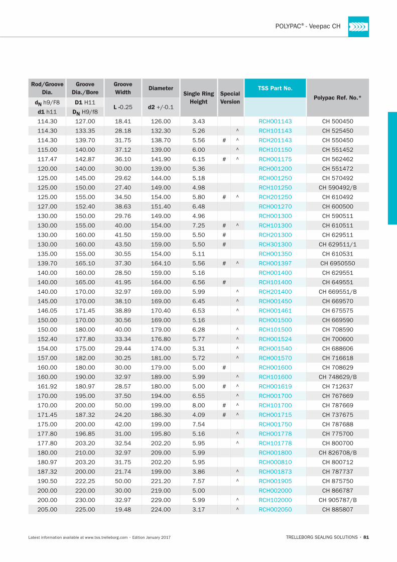
81
Rod/Groove
Dia.
Groove
Dia./Bore
Groove
WidthDiameter
Single Ring
Height
Special
Version
TSS Part No.
Polypac Ref. No.*dN D1
L - d2d1 DN
#
#
#
#
#
#
#
#
#
#
#
#
82
Rod/Groove
Dia.
Groove
Dia./Bore
Groove
WidthDiameter
Single Ring
Height
Special
Version
TSS Part No.
Polypac Ref. No.*dN D1
L - d2d1 DN
#
#
Table 22: Explanation to "Special Version"
#
POLYPAC®
83
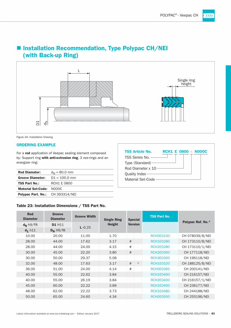
Installation Recommendation, Type Polypac CH/NEI (with Back-up Ring)
L
D1 d N
Single ringheight
Installation Drawing
ORDERING EXAMPLE
For a rod
with anti-extrusion ring
Rod Diamater: N
Groove Diameter:
TSS Part No.:
Material Set-Code:
Polypac Part. No.:
N0O0CRCH1 0800 -
Material Set-Code
TSS Series No.TSS Article No.
Rod Diameter x 10Quality Index
Type (Standard)
E
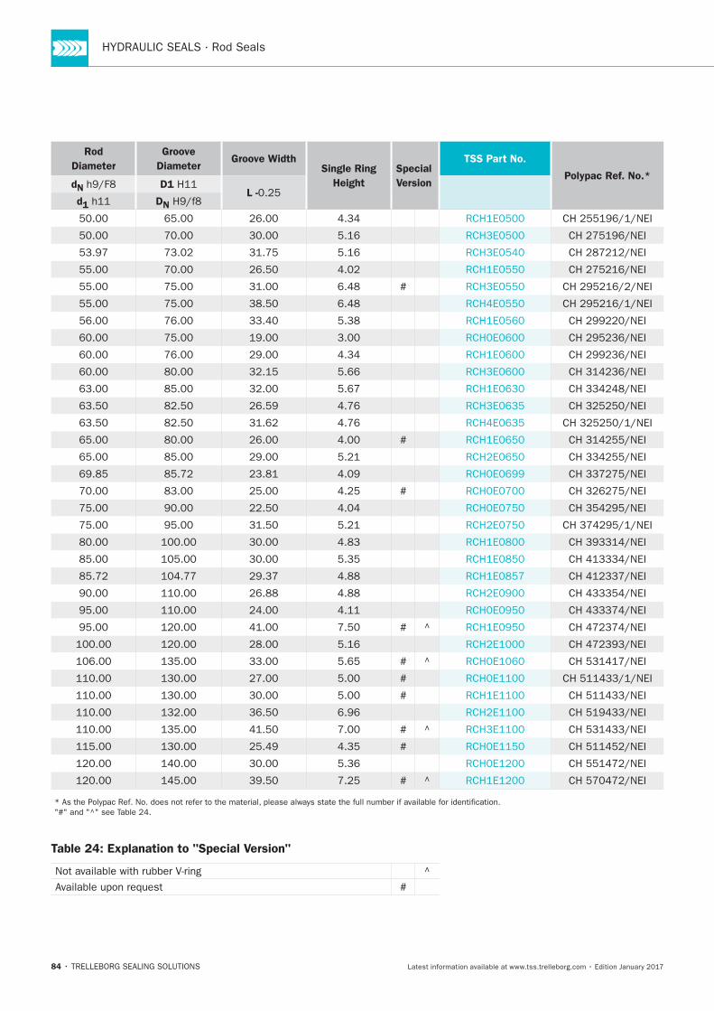
Table 23: Installation Dimensions / TSS Part No.
Rod
Diameter
Groove
DiameterGroove Width
Single Ring
Height
Special
Version
TSS Part No.
Polypac Ref. No.*dN D1
L -d1 DN
#
#
#
#
#
84
Rod
Diameter
Groove
DiameterGroove Width
Single Ring
Height
Special
Version
TSS Part No.
Polypac Ref. No.*dN D1
L -d1 DN
#
#
#
#
#
#
#
#
#
#
Table 24: Explanation to "Special Version"
#
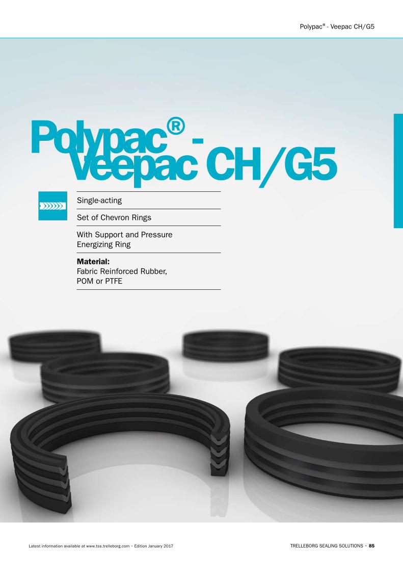
Polypac®- Veepac CH/G5
TRELLEBORG SEALING SOLUTIONS • 85Latest information available at www.tss.trelleborg.com • Edition January 2017
Polypac®-Veepac CH/G5Single-acting
Set of Chevron Rings
With Support and Pressure Energizing Ring
Material:Fabric Reinforced Rubber, POM or PTFE

HYDRAULIC SEALS · Rod Seals
86
POLYPAC®- Veepac CH/G5
87
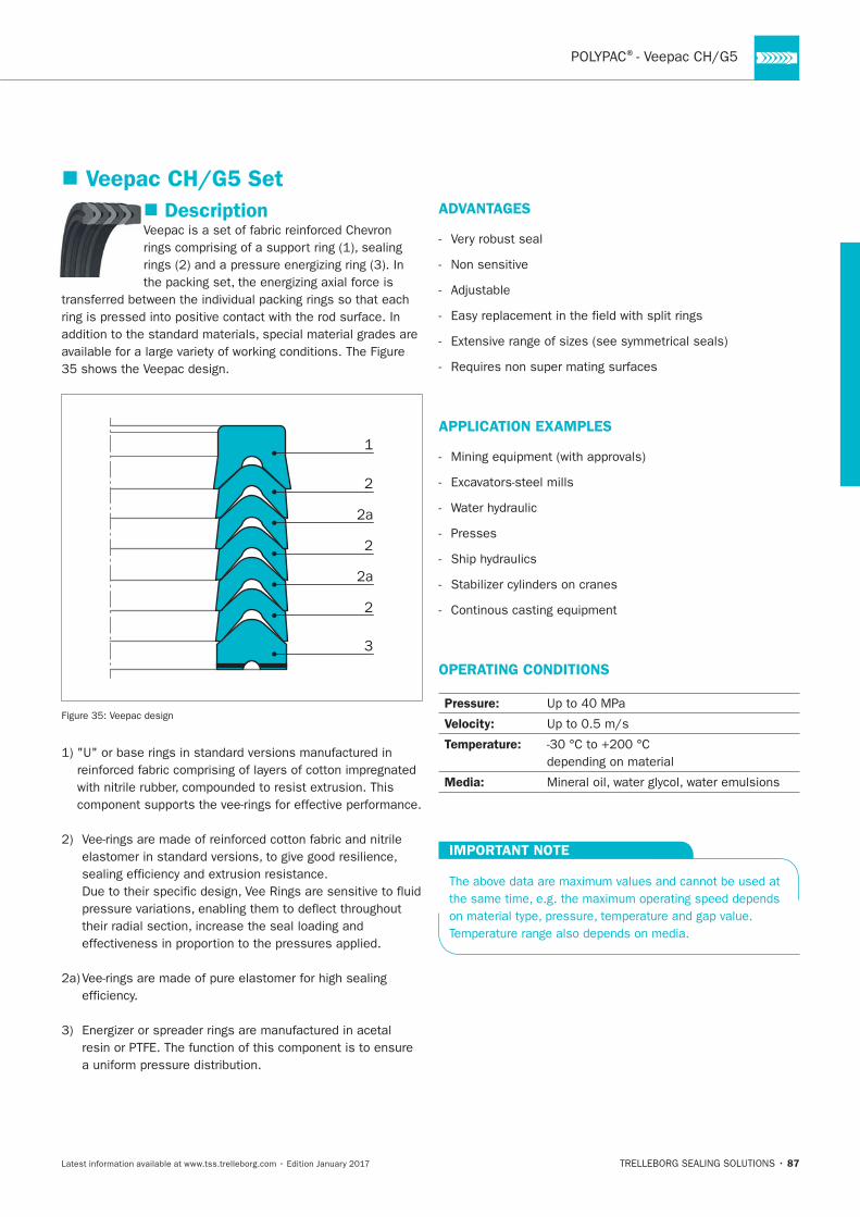
Description
1
2
2a
2
2a
2
3
ADVANTAGES
Non sensitive
APPLICATION EXAMPLES
Presses
OPERATING CONDITIONS
Pressure:
Velocity:
Temperature:
Media:
IMPORTANT NOTE
Veepac CH/G5 Set
88
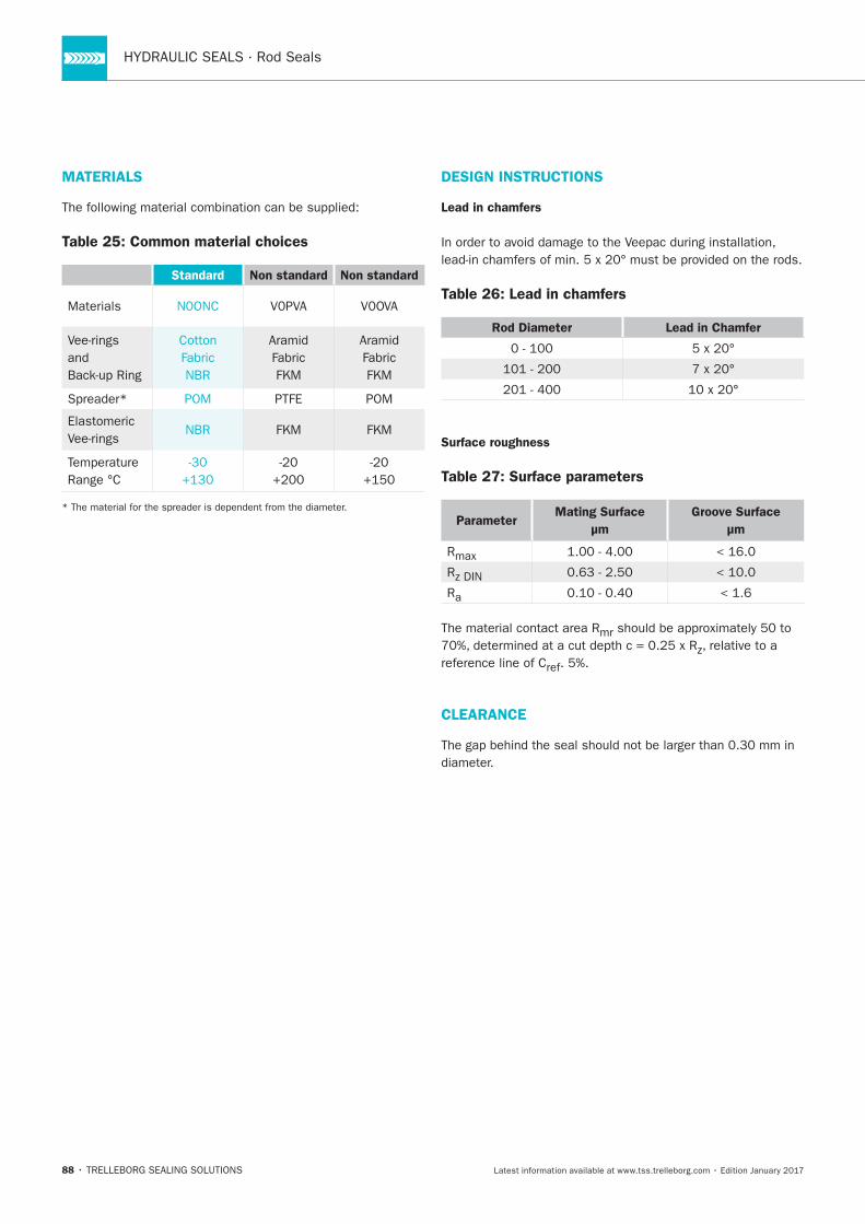
MATERIALS
Table 25: Common material choices
Standard Non standard Non standard
Materials
Cotton
NBR
Elastomeric NBR
DESIGN INSTRUCTIONS
Lead in chamfers
Table 26: Lead in chamfers
Rod Diameter Lead in Chamfer
Surface roughness
Table 27: Surface parameters
ParameterMating Surface
μm
Groove Surface
μm
R
R
Ra
The material contact area Rmr, relative to a
reference line of Cref
CLEARANCE
POLYPAC®- Veepac CH/G5
89
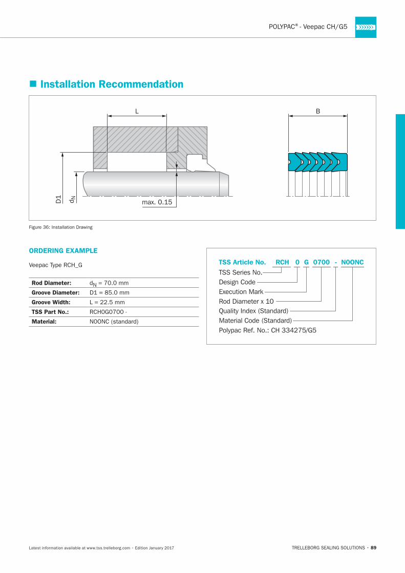
Installation Recommendation
L B
max. 0.15D1 d N
Installation Drawing
ORDERING EXAMPLE
Rod Diameter: N
Groove Diameter:
Groove Width:
TSS Part No.:
Material: Material Code (Standard)
TSS Series No.TSS Article No. N0ONCG
Rod Diameter x 10
RCH
Quality Index (Standard)
0700
Design Code
0
Execution Mark
-
Polypac Ref. No.: CH 334275/G5
90
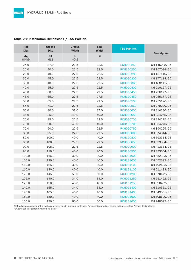
Table 28: Installation Dimensions / TSS Part No.
Rod
Dia.
Groove
Dia.
Groove
Width
Seal
WidthTSS Part No.
DescriptiondN D1 L B
Polypac®- Selemaster SM
TRELLEBORG SEALING SOLUTIONS • 91Latest information available at www.tss.trelleborg.com • Edition January 2017
Polypac®-Selemaster SMSingle-acting
Compact Rod Seal
With Anti-extrusion Ring
Material:Rubber + Fabric Reinforced Rubber + POM

92
93
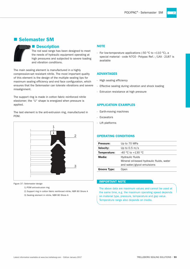
Description
misalignment.
1
2
3
NOTE
available
APPLICATION EXAMPLES
OPERATING CONDITIONS
Pressure:
Temperature:
Media:
Groove Type:
IMPORTANT NOTE
Selemaster SM
HYDRAULIC SEALS · Rod Seals
94
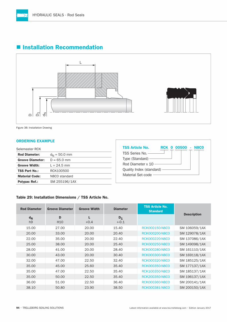
Installation Recommendation
D1
D d N
L
ORDERING EXAMPLE
Rod Diameter:
Groove Diameter:
Groove Width:
TSS Part No.:
Material Code:
Polypac Ref.:
Material Set-code
TSS Series No.
TSS Article No. N8C0
Rod Diameter x 10
RCK
Quality Index (standard)
-
Type (Standard)
0 00500
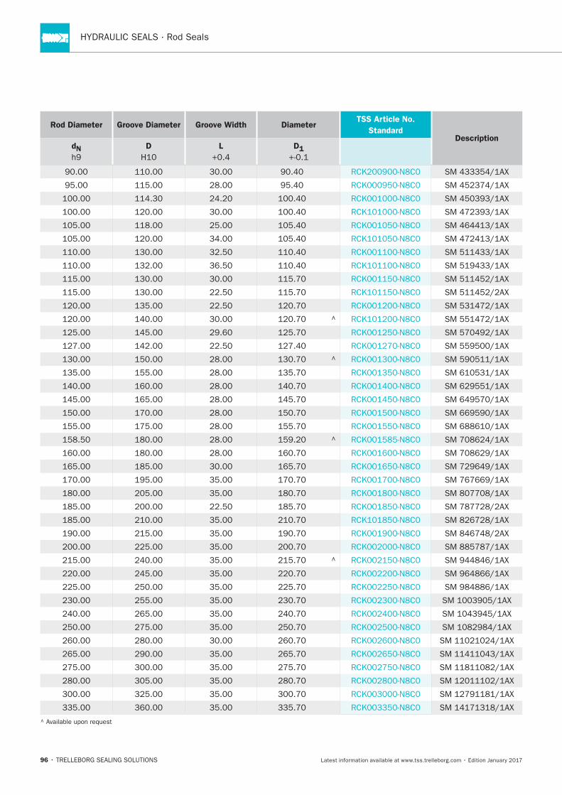
Table 29: Installation Dimensions / TSS Article No.
Rod Diameter Groove Diameter Groove Width DiameterTSS Article No.
StandardDescription
dN D L D1
POLYPAC®
95
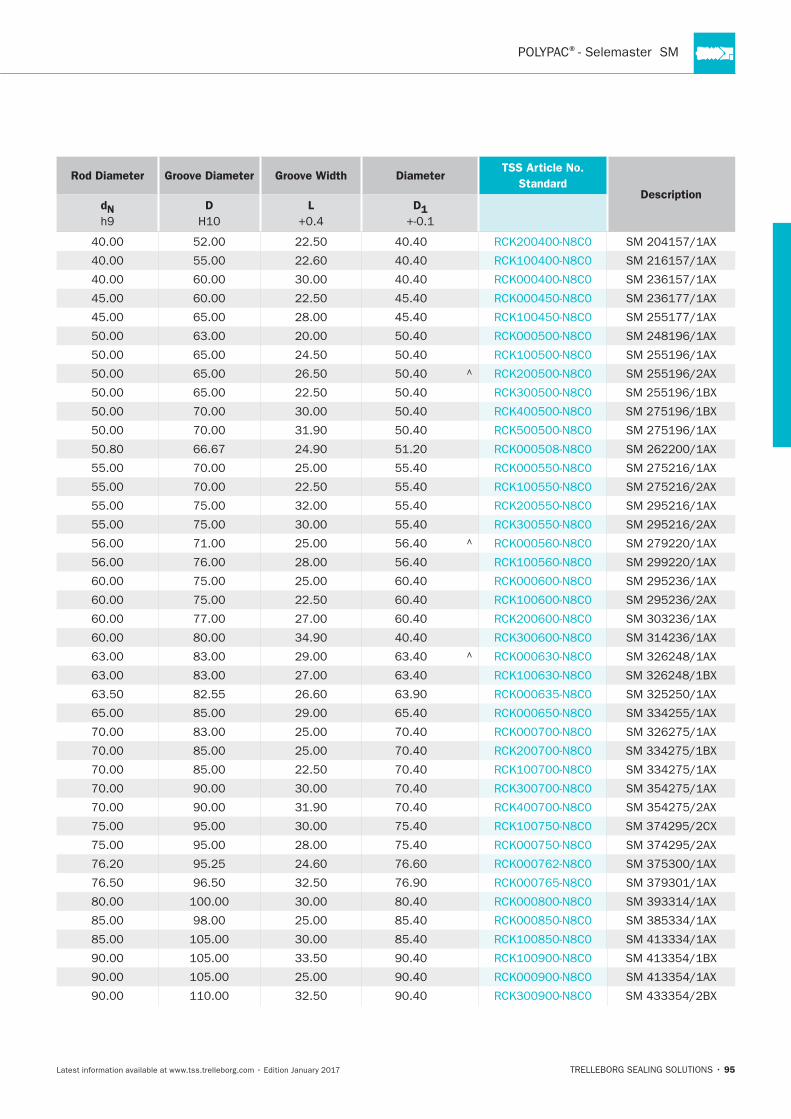
Rod Diameter Groove Diameter Groove Width DiameterTSS Article No.
StandardDescription
dN D L D1
96
Rod Diameter Groove Diameter Groove Width DiameterTSS Article No.
StandardDescription
dN D L D1
Polypac®- Balsele
TRELLEBORG SEALING SOLUTIONS • 97Latest information available at www.tss.trelleborg.com • Edition January 2017
Single-acting
Compact Seal
Without and with Back-up Ring
Material:Fabric Reinforced NBR + POM
Polypac®-Balsele

HYDRAULIC SEALS · Rod Seals
98
POLYPAC®
99
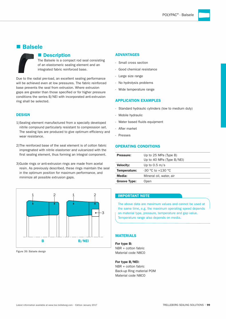
Description
DESIGN
wear resistance.
B B/NEI
ADVANTAGES
Small cross section
APPLICATION EXAMPLES
Presses
OPERATING CONDITIONS
Pressure:
Velocity:
Temperature:
Media:
Groove Type:
IMPORTANT NOTE
MATERIALS
For type B:
NBR + cotton fabric
For type B/NEI:
NBR + cotton fabric
Balsele
HYDRAULIC SEALS · Rod Seals
100
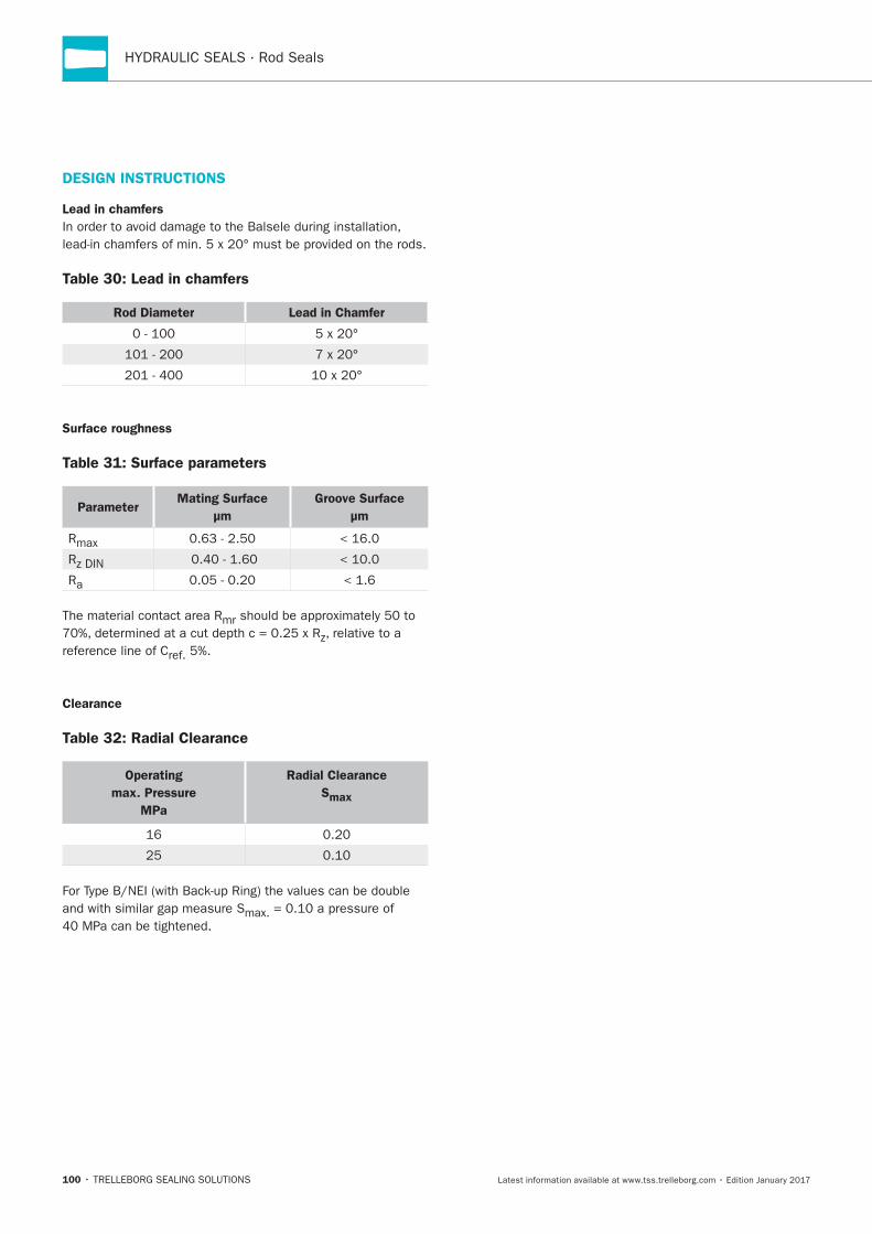
DESIGN INSTRUCTIONS
Lead in chamfers
Table 30: Lead in chamfers
Rod Diameter Lead in Chamfer
Surface roughness
Table 31: Surface parameters
ParameterMating Surface
μm
Groove Surface
μm
z
Clearance
Table 32: Radial Clearance
Operating
max. Pressure
MPa
Radial Clearance
Smax
POLYPAC®- Balsele
101
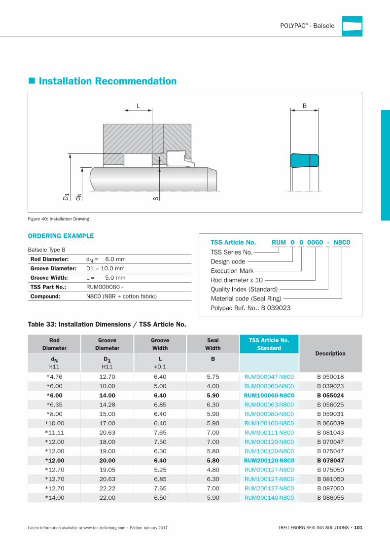
Installation Recommendation
D1
d N
L B
S
ORDERING EXAMPLE
Rod Diameter:
Groove Diameter:
Groove Width:
TSS Part No.:
Compound: Material code (Seal Ring)
TSS Series No.TSS Article No. N8C00
Rod diameter x 10
RUM
Quality Index (Standard)
0060
Design code
0
Execution Mark
-
Polypac Ref. No.: B 039023
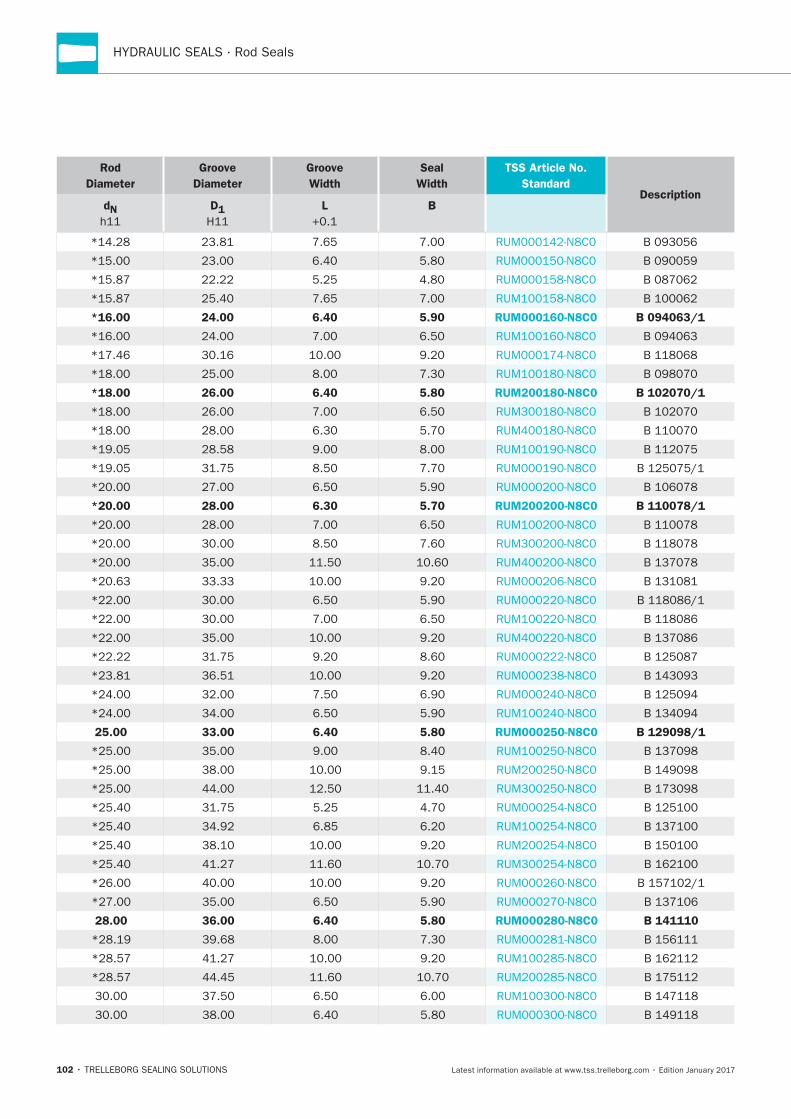
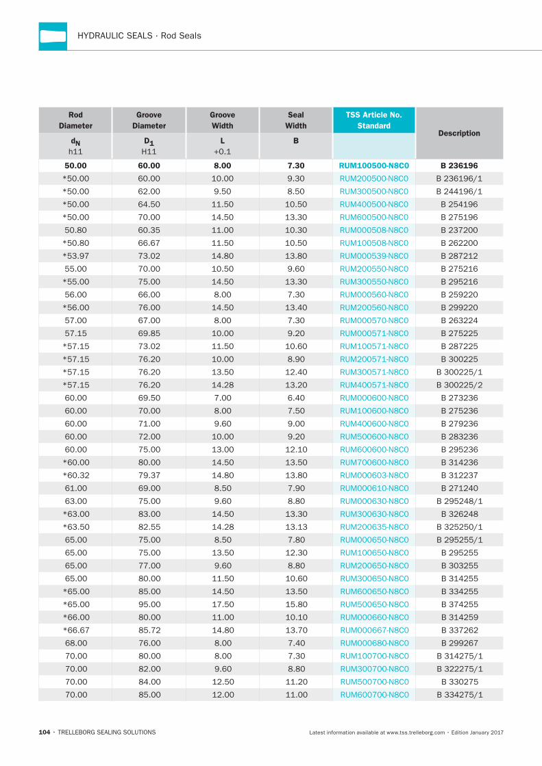
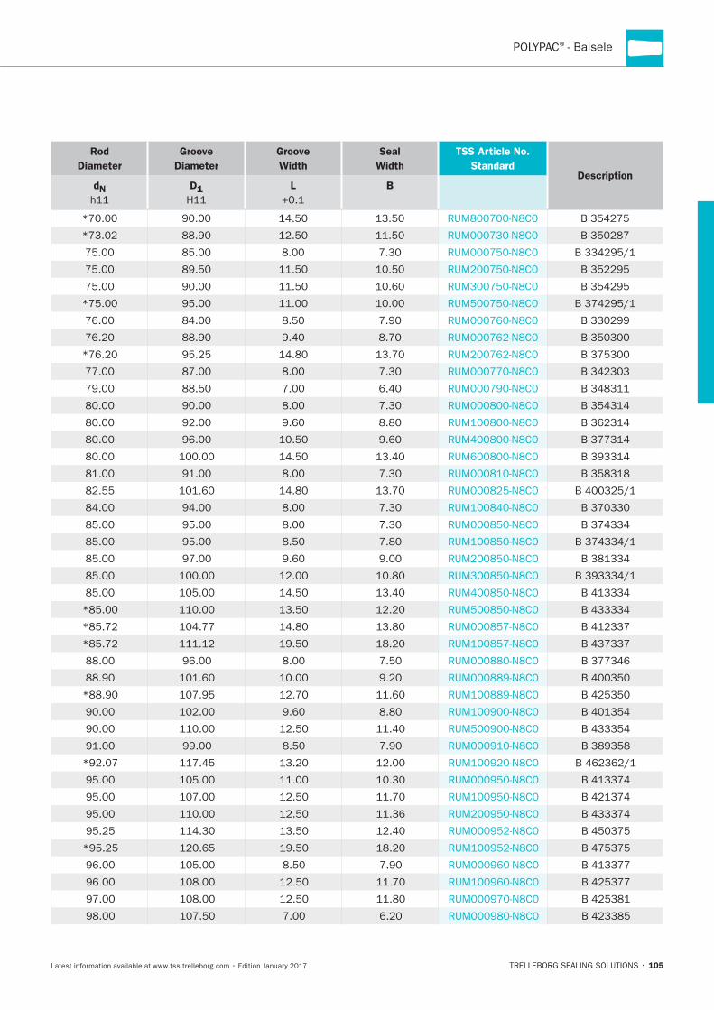
Table 33: Installation Dimensions / TSS Article No.
Rod
Diameter
Groove
Diameter
Groove
Width
Seal
Width
TSS Article No.
StandardDescription
dN D1 L B
*6.00 14.00 6.40 5.90 RUM100060-N8C0 B 055024
*12.00 20.00 6.40 5.80 RUM200120-N8C0 B 078047
HYDRAULIC SEALS · Rod Seals
102
Rod
Diameter
Groove
Diameter
Groove
Width
Seal
Width
TSS Article No.
StandardDescription
dN D1 L B
*16.00 24.00 6.40 5.90 RUM000160-N8C0 B 094063/1
*18.00 26.00 6.40 5.80 RUM200180-N8C0 B 102070/1
*20.00 28.00 6.30 5.70 RUM200200-N8C0 B 110078/1
25.00 33.00 6.40 5.80 RUM000250-N8C0 B 129098/1
28.00 36.00 6.40 5.80 RUM000280-N8C0 B 141110

POLYPAC®- Balsele
103
Rod
Diameter
Groove
Diameter
Groove
Width
Seal
Width
TSS Article No.
StandardDescription
dN D1 L B
40.00 50.00 8.00 7.40 RUM100400-N8C0 B 196157/3
45.00 55.00 8.00 7.30 RUM100450-N8C0 B 216177
HYDRAULIC SEALS · Rod Seals
104
Rod
Diameter
Groove
Diameter
Groove
Width
Seal
Width
TSS Article No.
StandardDescription
dN D1 L B
50.00 60.00 8.00 7.30 RUM100500-N8C0 B 236196
POLYPAC®
105
Rod
Diameter
Groove
Diameter
Groove
Width
Seal
Width
TSS Article No.
StandardDescription
dN D1 L B

HYDRAULIC SEALS · Rod Seals
106
Rod
Diameter
Groove
Diameter
Groove
Width
Seal
Width
TSS Article No.
StandardDescription
dN D1 L B
POLYPAC®- Balsele
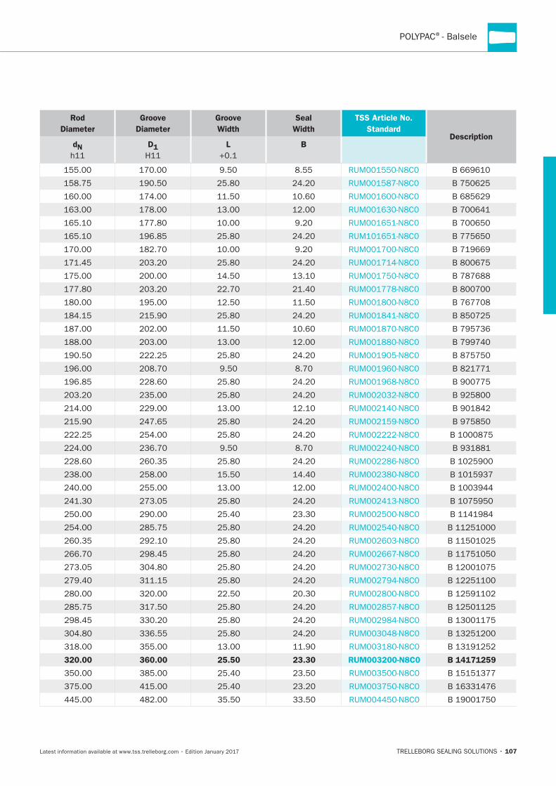
107
Rod
Diameter
Groove
Diameter
Groove
Width
Seal
Width
TSS Article No.
StandardDescription
dN D1 L B
320.00 360.00 25.50 23.30 RUM003200-N8C0 B 14171259
HYDRAULIC SEALS · Rod Seals
108
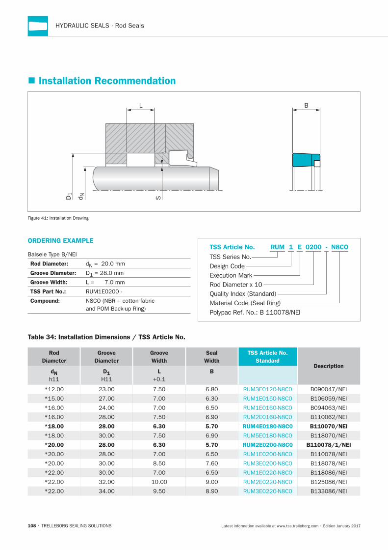
Installation Recommendation
D1
d N
L
S
B
Installation Drawing
ORDERING EXAMPLE
Rod Diameter: N
Groove Diameter: D
Groove Width:
TSS Part No.:
Compound: Material Code (Seal Ring)
TSS Series No.TSS Article No. N8COE
Rod Diameter x 10
RUM
Quality Index (Standard)
0200
Design Code
1
Execution Mark
-
Polypac Ref. No.: B 110078/NEI
Table 34: Installation Dimensions / TSS Article No.
Rod
Diameter
Groove
Diameter
Groove
Width
Seal
Width
TSS Article No.
StandardDescription
dN D1 L B
*18.00 28.00 6.30 5.70 RUM4E0180-N8C0 B110070/NEI
*20.00 28.00 6.30 5.70 RUM2E0200-N8C0 B110078/1/NEI
109
POLYPAC®
Rod
Diameter
Groove
Diameter
Groove
Width
Seal
Width
TSS Article No.
StandardDescription
dN D1 L B
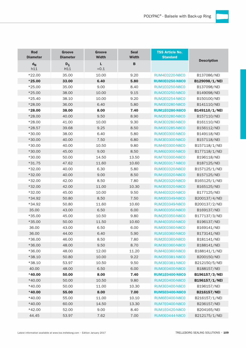
*25.00 33.00 6.40 5.80 RUM0E0250-N8C0 B129098/1/NEI
*28.00 38.00 8.00 7.40 RUM1E0280-N8C0 B149110/1/NEI
*40.00 50.00 8.00 7.40 RUM1E0400-N8C0 B196157/3/NEI
B196157/1/NEI
*40.00 55.00 8.00 7.00 RUM5E0400-N8C0 B216157/NEI
HYDRAULIC SEALS · Rod Seals
110
Rod
Diameter
Groove
Diameter
Groove
Width
Seal
Width
TSS Article No.
StandardDescription
dN D1 L B
45.00 55.00 8.00 7.30 RUM1E0450-N8C0 B216177/NEI
50.00 60.00 8.00 7.30 RUM1E0500-N8C0 B236196/NEI
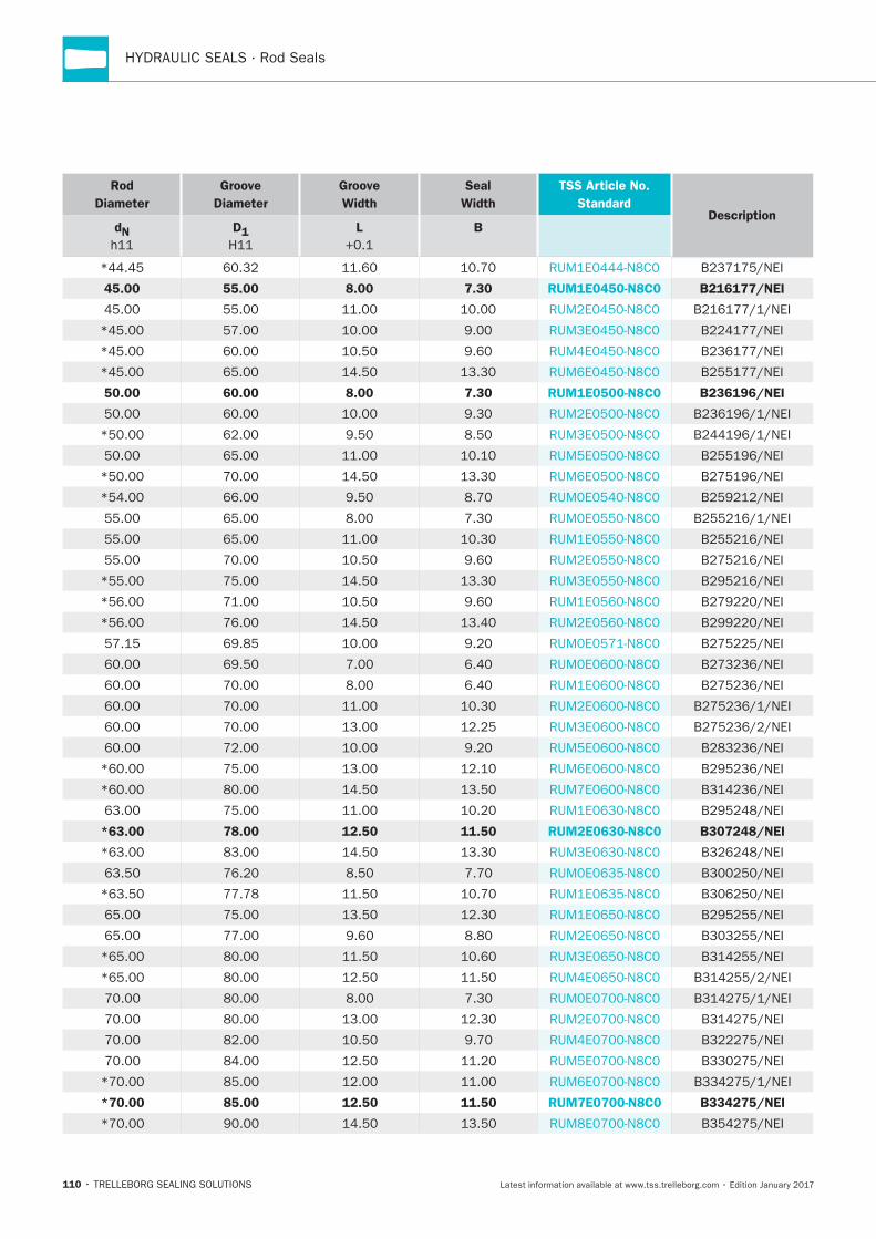
*63.00 78.00 12.50 11.50 RUM2E0630-N8C0 B307248/NEI
*70.00 85.00 12.50 11.50 RUM7E0700-N8C0 B334275/NEI

111
POLYPAC®
Rod
Diameter
Groove
Diameter
Groove
Width
Seal
Width
TSS Article No.
StandardDescription
dN D1 L B
90.00 105.00 9.50 8.70 RUM2E0900-N8C0 B413354/NEI
90.00 105.00 12.50 11.60 RUM3E0900-N8C0 B413354/1/NEI
*90.00 110.00 12.50 11.40 RUM5E0900-N8C0 B433354/NEI
110.00 130.00 12.50 11.40 RUM1E1100-N8C0 B511433/NEI
HYDRAULIC SEALS · Rod Seals
112
Rod
Diameter
Groove
Diameter
Groove
Width
Seal
Width
TSS Article No.
StandardDescription
dN D1 L B
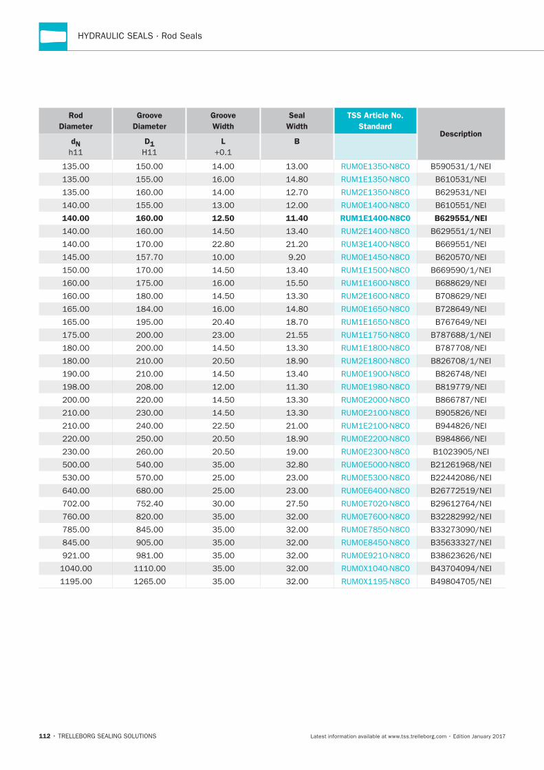
140.00 160.00 12.50 11.40 RUM1E1400-N8C0 B629551/NEI
Zurcon® L-Cup®
TRELLEBORG SEALING SOLUTIONS • 113Latest information available at www.tss.trelleborg.com • Edition January 2017
Zurcon®Single-acting
Low Friction Properties
Material:Zurcon®
L-Cup

HYDRAULIC SEALS · Rod Seals
114
Zurcon® L-Cup®
115
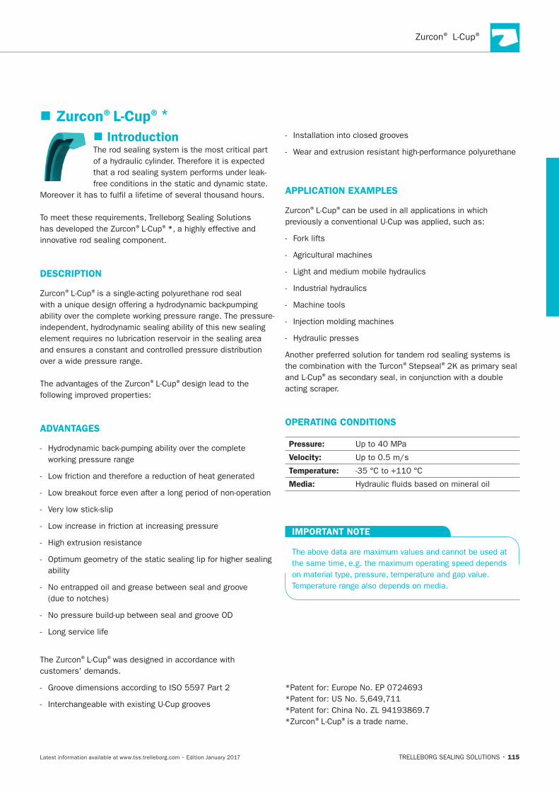
Introduction
® ®*
DESCRIPTION
® ®
® ®
ADVANTAGES
® ®
APPLICATION EXAMPLES
® ®
® ®
®
OPERATING CONDITIONS
Pressure:
Velocity:
Temperature:
Media:
IMPORTANT NOTE
® ®
Zurcon®L-Cup®*
HYDRAULIC SEALS · Rod Seals
116
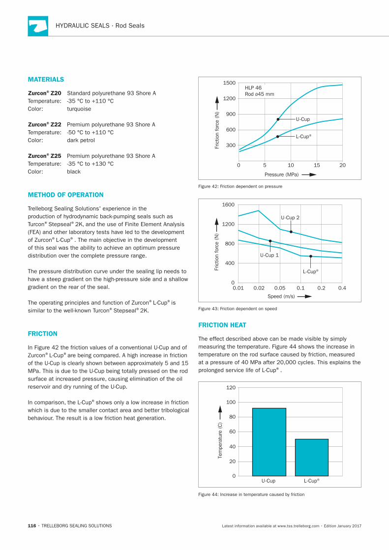
MATERIALS
Zurcon®Z20
Zurcon®Z22
Zurcon®Z25
METHOD OF OPERATION
® ®
® ®
® ®
® ®
FRICTION
® ®
®
300
600
900
0 5 10 15 20
1200
HLP 46Rod Ø45 mm
1500
U-Cup
L-Cup®
Fric
tion
forc
e (N
)
Pressure (MPa)
400
800
1200
00.01 0.02 0.05 0.1 0.2 0.4
1600
U-Cup 1
U-Cup 2
L-Cup®Fric
tion
forc
e (N
)
Speed (m/s)
FRICTION HEAT
®
0
120
20
40
60
80
100
Tem
pera
ture
(C
)
U-Cup L-Cup®
Zurcon® L-Cup®
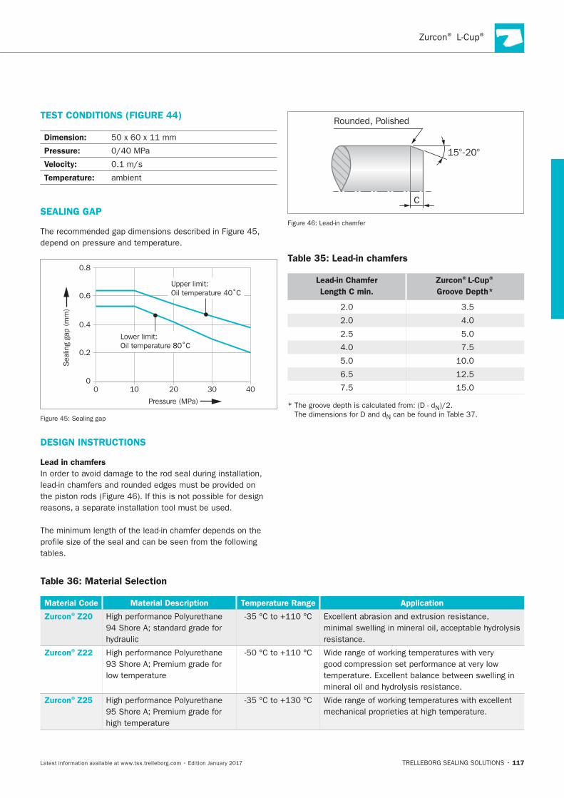
117
TEST CONDITIONS (FIGURE 44)
Dimension:
Pressure:
Velocity:
Temperature:
SEALING GAP
40
Pressure (MPa)
00
0.2
0.4
0.6
0.8
10 20 30
Sea
ling
gap
(mm
)
Upper limit:Oil temperature 40˚C
Lower limit:Oil temperature 80˚C
DESIGN INSTRUCTIONS
Lead in chamfers
C
Rounded, Polished
15°-20°
Table 35: Lead-in chamfers
Lead-in Chamfer
Length C min.
Zurcon®L-Cup®
Groove Depth*
Table 36: Material Selection
Material Code Material Description Temperature Range Application
Zurcon®Z20
Zurcon®Z22
Zurcon®Z25
HYDRAULIC SEALS · Rod Seals
118
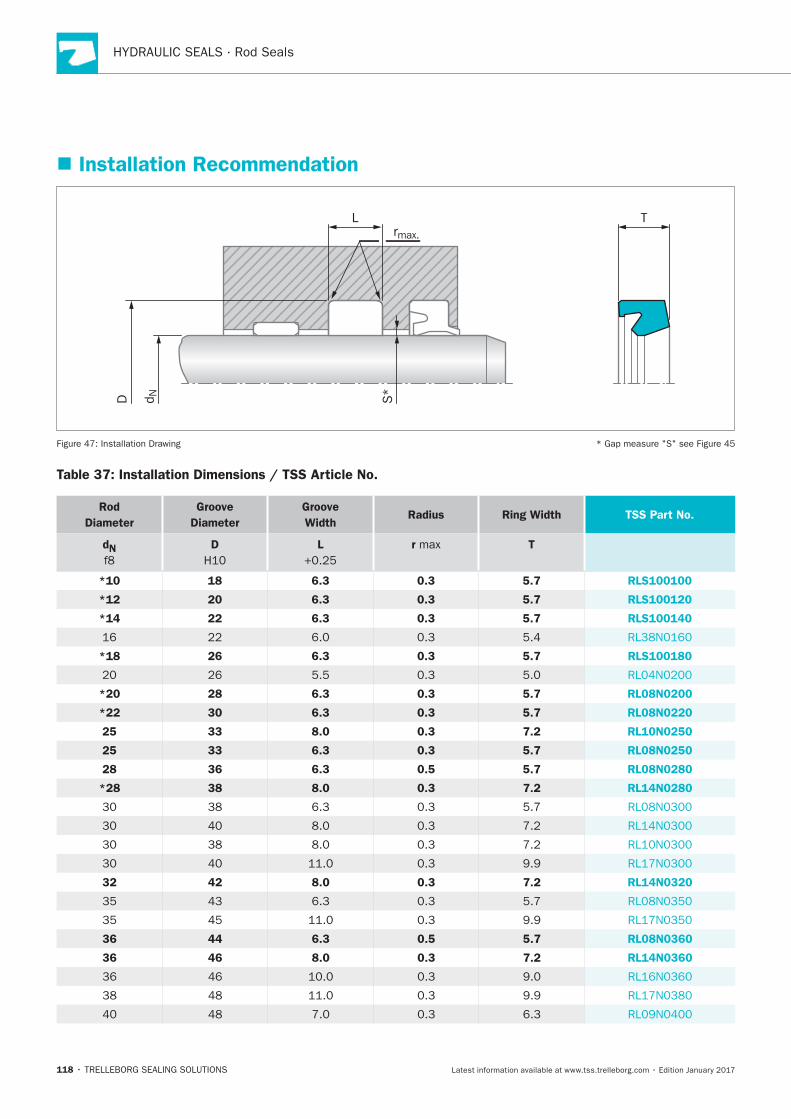
Installation Recommendation
rmax.
D S*
d N
L T
Table 37: Installation Dimensions / TSS Article No.
Rod
Diameter
Groove
Diameter
Groove
WidthRadius Ring Width TSS Part No.
dN D L r T
*10 18 6.3 0.3 5.7 RLS100100
*12 20 6.3 0.3 5.7 RLS100120
*14 22 6.3 0.3 5.7 RLS100140
*18 26 6.3 0.3 5.7 RLS100180
*20 28 6.3 0.3 5.7 RL08N0200
*22 30 6.3 0.3 5.7 RL08N0220
25 33 8.0 0.3 7.2 RL10N0250
25 33 6.3 0.3 5.7 RL08N0250
28 36 6.3 0.5 5.7 RL08N0280
*28 38 8.0 0.3 7.2 RL14N0280
32 42 8.0 0.3 7.2 RL14N0320
36 44 6.3 0.5 5.7 RL08N0360
36 46 8.0 0.3 7.2 RL14N0360
Zurcon® L-Cup®
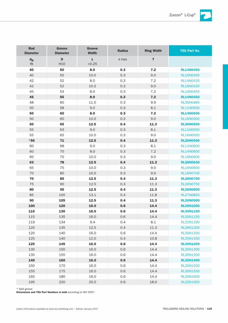
119
Rod
Diameter
Groove
Diameter
Groove
WidthRadius Ring Width TSS Part No.
dN D L r T
40 50 8.0 0.3 7.2 RL14N0400
45 55 8.0 0.3 7.2 RL14N0450
50 60 8.0 0.3 7.2 RL14N0500
50 65 12.5 0.4 11.3 RL26N0500
*56 71 12.5 0.4 11.3 RL26N0560
63 78 12.5 0.4 11.3 RL26N0630
70 85 12.5 0.4 11.3 RL26N0700
80 95 12.5 0.4 11.3 RL26N0800
90 105 12.5 0.4 11.3 RL26N0900
100 120 16.0 0.6 14.4 RL30N1000
110 130 16.0 0.6 14.4 RL30N1100
125 145 16.0 0.6 14.4 RL30N1250
140 160 16.0 0.6 14.4 RL30N1400
Dimensions and TSS Part Numbers in bold

HYDRAULIC SEALS · Rod Seals
120
Zurcon®U-Cup RU2
TRELLEBORG SEALING SOLUTIONS • 121Latest information available at www.tss.trelleborg.com • Edition January 2017
Zurcon®Single-acting U-Cup
Asymmetric, Double Lip, Compact
Material:Zurcon®
U-Cup RU2

HYDRAULIC SEALS · Rod Seals
122
®
123
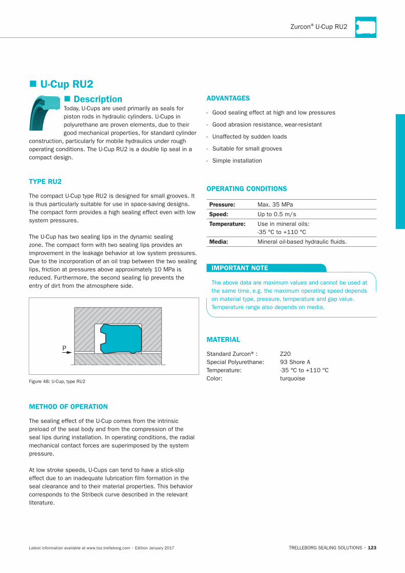
Description
TYPE RU2
P
METHOD OF OPERATION
ADVANTAGES
OPERATING CONDITIONS
Pressure:
Speed:
Temperature:
Media:
IMPORTANT NOTE
MATERIAL
U-Cup RU2
HYDRAULIC SEALS · Rod Seals
124
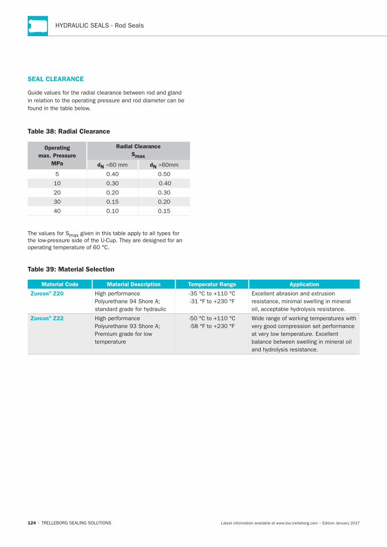
SEAL CLEARANCE
Table 38: Radial Clearance
Operating
max. Pressure
MPa
Radial Clearance
Smax
dN dN
5
Table 39: Material Selection
Material Code Material Description Temperatur Range Application
Zurcon®Z20
Zurcon®Z22
Zurcon®U-Cup RU2
125
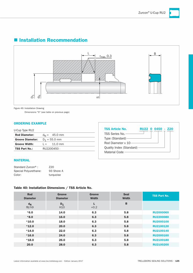
Installation Recommendation
L
S
Brmax. 0.3
D1
d N
Table 40: Installation Dimensions / TSS Article No.
Rod
Diameter
Groove
Diameter
Groove
Width
Seal
WidthTSS Part No.
dN D1 L B
*6.0 14.0 6.3 5.8 RU2000060
*8.0 16.0 6.3 5.8 RU2200080
*10.0 18.0 6.3 5.8 RU2000100
*12.0 20.0 6.3 5.8 RU2100120
*14.0 22.0 6.3 5.8 RU2100140
*16.0 24.0 6.3 5.8 RU2000160
*18.0 26.0 6.3 5.8 RU2100180
20.0 28.0 6.3 5.8 RU2100200
ORDERING EXAMPLE
Rod Diameter:
Groove Diameter: D
Groove Width:
TSS Part No.:
MATERIAL
Material Code
TSS Series No.
TSS Article No. Z20
Rod Diameter x 10
RU22
Quality Index (Standard)
-
Type (Standard)
0 0450
HYDRAULIC SEALS · Rod Seals
126
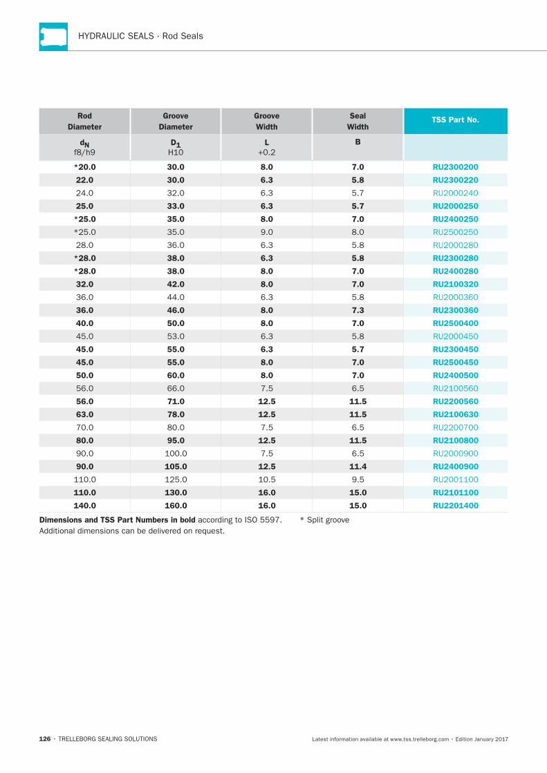
Rod
Diameter
Groove
Diameter
Groove
Width
Seal
WidthTSS Part No.
dN D1 L B
*20.0 30.0 8.0 7.0 RU2300200
22.0 30.0 6.3 5.8 RU2300220
25.0 33.0 6.3 5.7 RU2000250
*25.0 35.0 8.0 7.0 RU2400250
*28.0 38.0 6.3 5.8 RU2300280
*28.0 38.0 8.0 7.0 RU2400280
32.0 42.0 8.0 7.0 RU2100320
36.0 46.0 8.0 7.3 RU2300360
40.0 50.0 8.0 7.0 RU2500400
45.0 55.0 6.3 5.7 RU2300450
45.0 55.0 8.0 7.0 RU2500450
50.0 60.0 8.0 7.0 RU2400500
56.0 71.0 12.5 11.5 RU2200560
63.0 78.0 12.5 11.5 RU2100630
80.0 95.0 12.5 11.5 RU2100800
90.0 105.0 12.5 11.4 RU2400900
110.0 130.0 16.0 15.0 RU2101100
140.0 160.0 16.0 15.0 RU2201400
Dimensions and TSS Part Numbers in bold
Zurcon®U-Cup RU6
TRELLEBORG SEALING SOLUTIONS • 127Latest information available at www.tss.trelleborg.com • Edition January 2017
Single-acting U-Cup
Rubber Energized
Material:Zurcon®+ NBR
Zurcon®U-Cup RU6

128
129
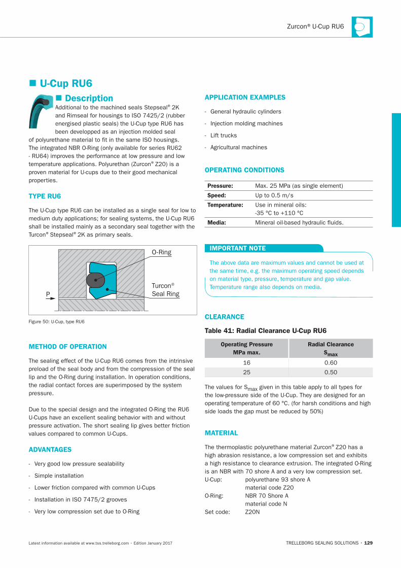
Description®
®
TYPE RU6
® ®
P
O-Ring
Turcon® Seal Ring
METHOD OF OPERATION
ADVANTAGES
APPLICATION EXAMPLES
OPERATING CONDITIONS
Pressure:
Speed:
Temperature:
Media:
IMPORTANT NOTE
CLEARANCE
Table 41: Radial Clearance U-Cup RU6
Operating Pressure
MPa max.
Radial Clearance
Smax
MATERIAL
®
U-Cup RU6
130
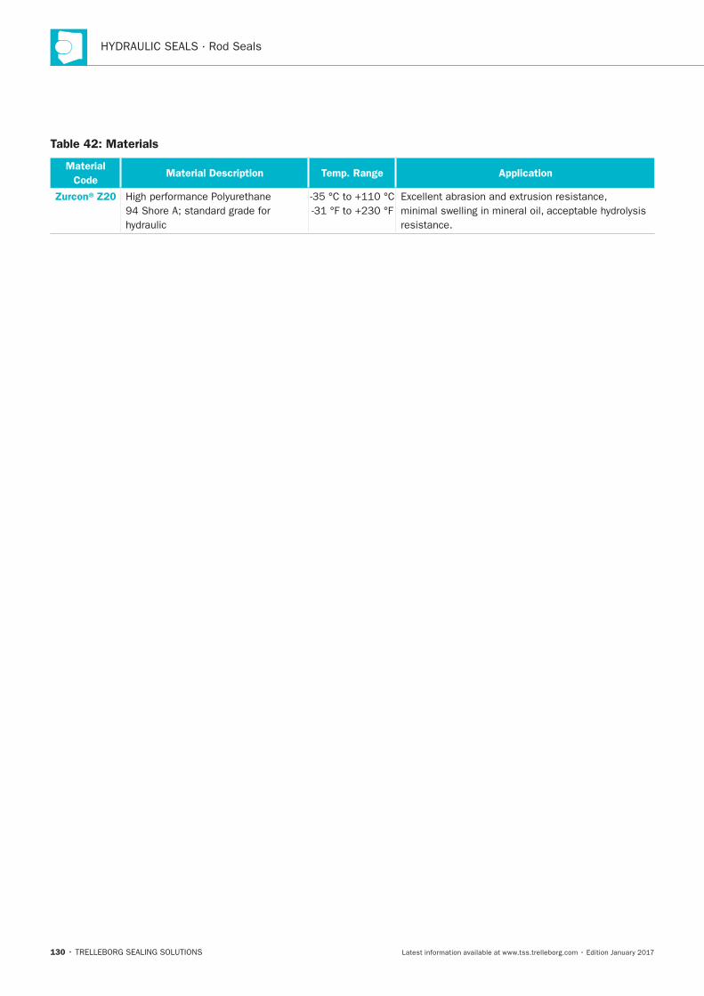
Table 42: Materials
Material
CodeMaterial Description Temp. Range Application
Zurcon®Z20
resistance.
131
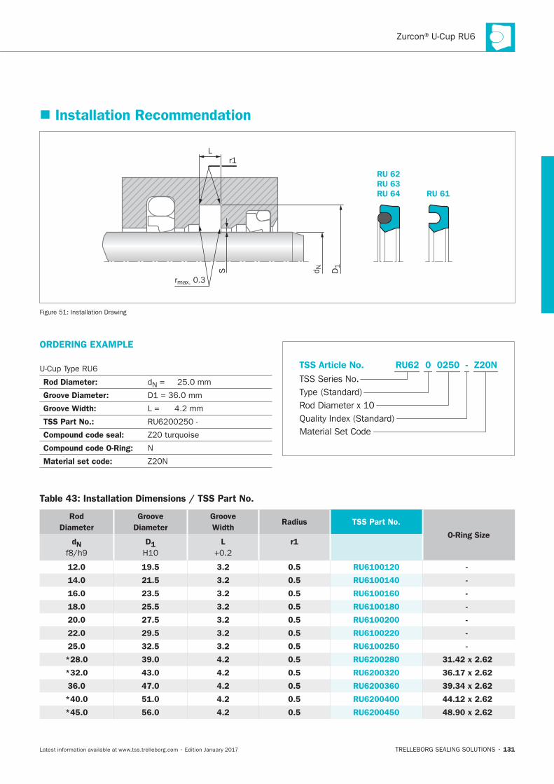
Installation Recommendation
RU 61
RU 62RU 63RU 64
L
S
rmax. 0.3
r1
D1
d NInstallation Drawing
ORDERING EXAMPLE
Rod Diameter: N
Groove Diameter:
Groove Width:
TSS Part No.:
Compound code seal:
Compound code O-Ring: N
Material set code:
Material Set Code
TSS Series No.
TSS Article No.
Rod Diameter x 10Quality Index (Standard)
Type (Standard)
Z20NRU62 - 0 0250
Table 43: Installation Dimensions / TSS Part No.
Rod
Diameter
Groove
Diameter
Groove
WidthRadius TSS Part No.
O-Ring SizedN D1 L r1
12.0 19.5 3.2 0.5 RU6100120 -
14.0 21.5 3.2 0.5 RU6100140 -
16.0 23.5 3.2 0.5 RU6100160 -
18.0 25.5 3.2 0.5 RU6100180 -
20.0 27.5 3.2 0.5 RU6100200 -
22.0 29.5 3.2 0.5 RU6100220 -
25.0 32.5 3.2 0.5 RU6100250 -
*28.0 39.0 4.2 0.5 RU6200280 31.42 x 2.62
*32.0 43.0 4.2 0.5 RU6200320 36.17 x 2.62
36.0 47.0 4.2 0.5 RU6200360 39.34 x 2.62
*40.0 51.0 4.2 0.5 RU6200400 44.12 x 2.62
*45.0 56.0 4.2 0.5 RU6200450 48.90 x 2.62
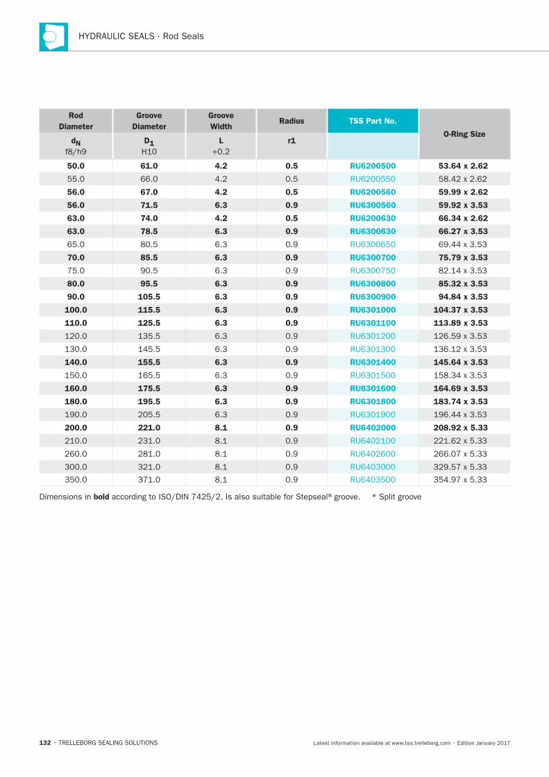
132
Rod
Diameter
Groove
Diameter
Groove
WidthRadius TSS Part No.
O-Ring SizedN D1 L r1
50.0 61.0 4.2 0.5 RU6200500 53.64 x 2.62
56.0 67.0 4.2 0.5 RU6200560 59.99 x 2.62
56.0 71.5 6.3 0.9 RU6300560 59.92 x 3.53
63.0 74.0 4.2 0.5 RU6200630 66.34 x 2.62
63.0 78.5 6.3 0.9 RU6300630 66.27 x 3.53
70.0 85.5 6.3 0.9 RU6300700 75.79 x 3.53
80.0 95.5 6.3 0.9 RU6300800 85.32 x 3.53
90.0 105.5 6.3 0.9 RU6300900 94.84 x 3.53
100.0 115.5 6.3 0.9 RU6301000 104.37 x 3.53
110.0 125.5 6.3 0.9 RU6301100 113.89 x 3.53
140.0 155.5 6.3 0.9 RU6301400 145.64 x 3.53
160.0 175.5 6.3 0.9 RU6301600 164.69 x 3.53
180.0 195.5 6.3 0.9 RU6301800 183.74 x 3.53
200.0 221.0 8.1 0.9 RU6402000 208.92 x 5.33
Dimensions in bold
Zurcon®U-Cup RU9
TRELLEBORG SEALING SOLUTIONS • 133Latest information available at www.tss.trelleborg.com • Edition January 2017
Single-acting U-Cup
New U-Cup Design
Material:Zurcon®
Zurcon®U-Cup RU9

134
135
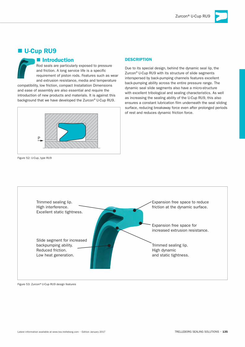
Introduction
®
P
DESCRIPTION
®
U-Cup RU9
T
High interference.
T.
Low heat generation.
136
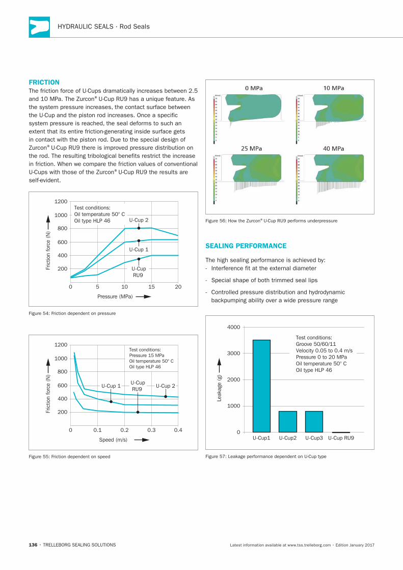
FRICTION
®
®
®
0 5 10 15 20
200
400
600
800
1000Test conditions:Oil temperature 50° COil type HLP 46
1200
U-Cup 2
U-Cup 1
U-CupRU9
Fric
tion
forc
e (N
)
Pressure (MPa)
200
400
600
0 0.1 0.2 0.3 0.4
800
1000
Test conditions:Pressure 15 MPaOil temperature 50° COil type HLP 46
1200
U-Cup 2U-Cup 1U-CupRU9
Fric
tion
forc
e (N
)
Speed (m/s)
®
SEALING PERFORMANCE
1000
2000
U-Cup1 U-Cup2 U-Cup3 U-Cup RU9
3000
4000
Test conditions:Groove 50/60/11Velocity 0.05 to 0.4 m/sPressure 0 to 20 MPaOil temperature 50° COil type HLP 46
0
Leak
age
(g)
137
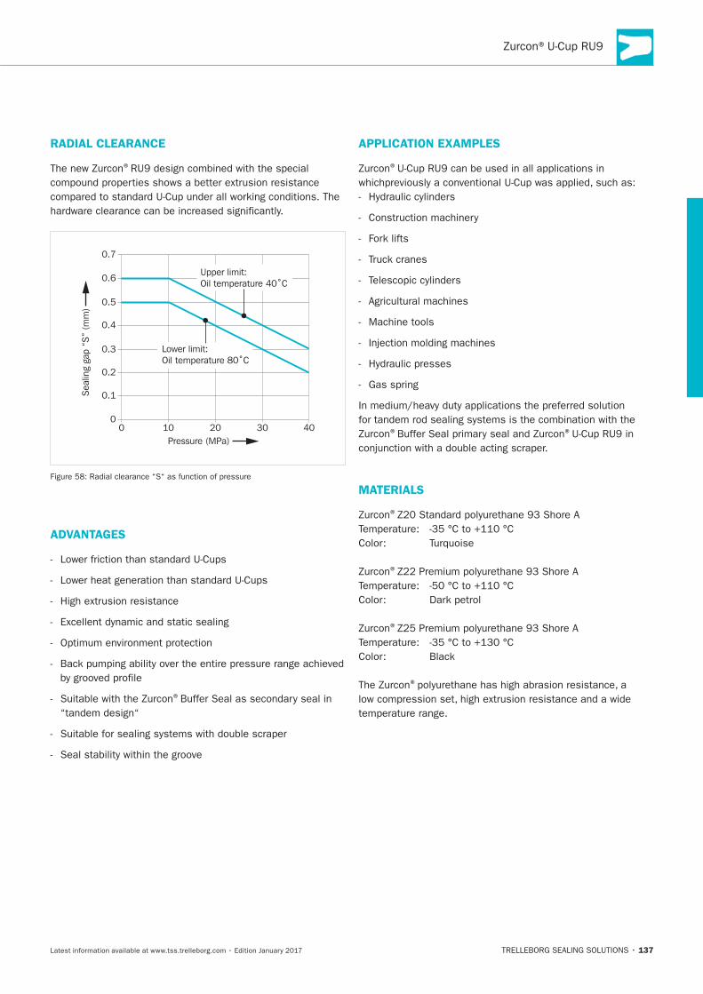
RADIAL CLEARANCE
®
Pressure (MPa)
0
0.1
0.2
0.3
0.4
0.5
0.6
0.7
0 10 20 30 40
Sea
ling
gap
“S”
(mm
)
Lower limit:Oil temperature 80˚C
Upper limit:Oil temperature 40˚C
ADVANTAGES
®
APPLICATION EXAMPLES
®
Machine tools
® ®
MATERIALS
®
®
®
®
138
OPERATING CONDITIONS
Pressure:
Velocity:
Temperature: ®
Media:
IMPORTANT NOTE
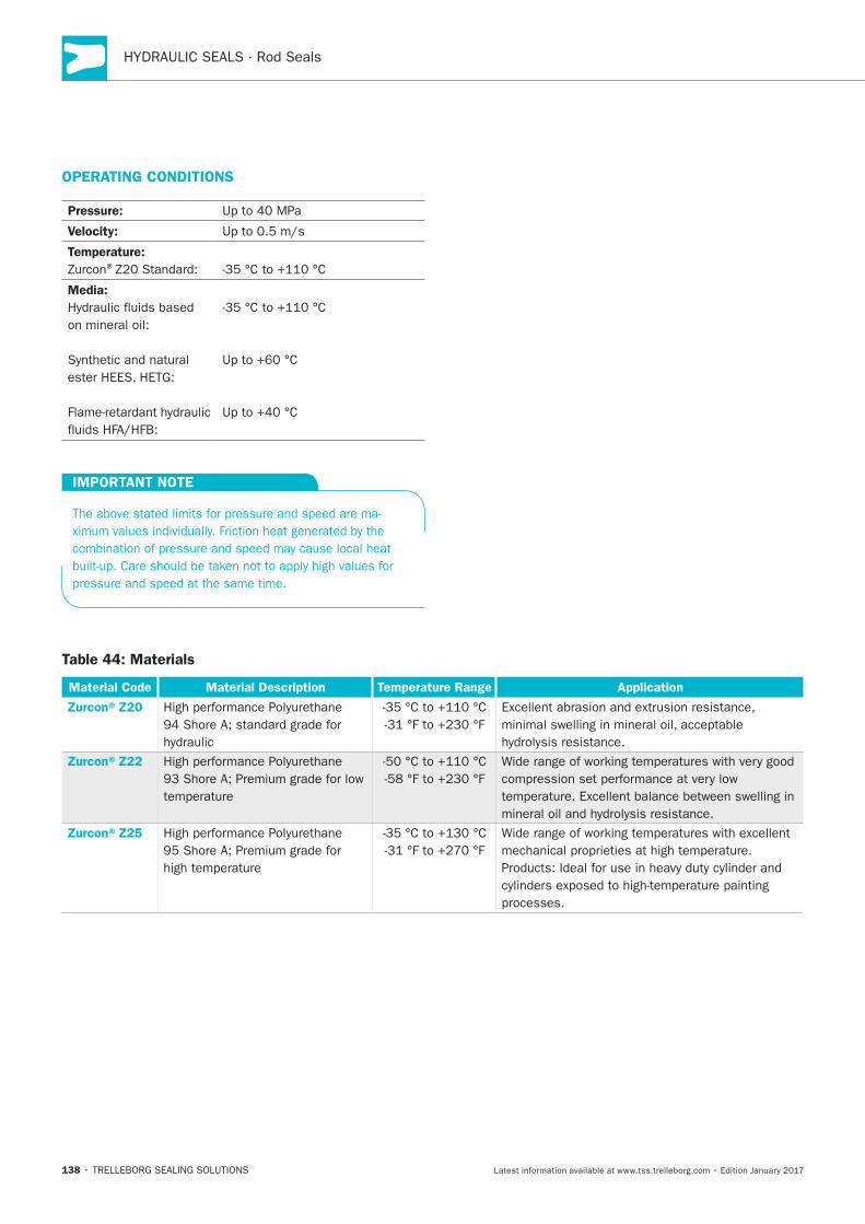
Table 44: Materials
Material Code Material Description Temperature Range Application
Zurcon®Z20
Zurcon®Z22
Zurcon®Z25
139
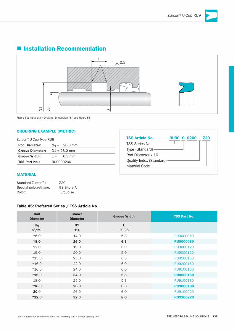
Installation Recommendation
L
S
rmax. 0.3
d ND1
ORDERING EXAMPLE (METRIC)
®
Rod Diameter: N
Groove Diameter:
Groove Width:
TSS Part No.:
MATERIAL
®
Material Code
TSS Series No.
TSS Article No. Z20
Rod Diameter x 10
RU90
Quality Index (Standard)
-
Type (Standard)
0 0200
Table 45: Preferred Series / TSS Article No.
Rod
Diameter
Groove
Diameter Groove Width TSS Part No.
dN
D1 L
*8.0 16.0 6.3 RU9000080
*16.0 24.0 6.3 RU9000160
*18.0 26.0 6.3 RU9000180
20
*22.0 32.0 8.0 RU9100220
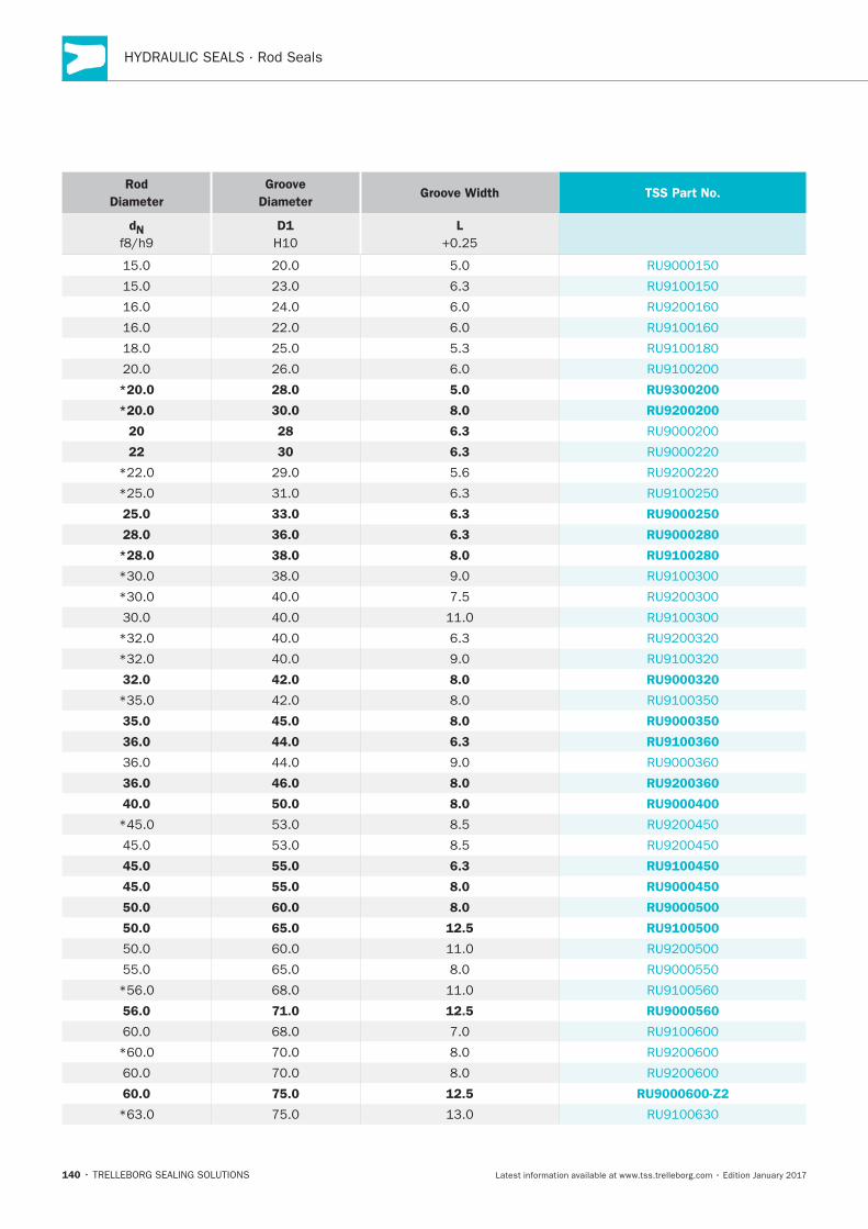
140
Rod
Diameter
Groove
Diameter Groove Width TSS Part No.
dN
D1 L
*20.0 28.0 5.0 RU9300200
*20.0 30.0 8.0 RU9200200
20 28 6.3
22 30 6.3
25.0 33.0 6.3 RU9000250
28.0 36.0 6.3 RU9000280
*28.0 38.0 8.0 RU9100280
32.0 42.0 8.0 RU9000320
35.0 45.0 8.0 RU9000350
36.0 44.0 6.3 RU9100360
36.0 46.0 8.0 RU9200360
40.0 50.0 8.0 RU9000400
45.0 55.0 6.3 RU9100450
45.0 55.0 8.0 RU9000450
50.0 60.0 8.0 RU9000500
50.0 65.0 12.5 RU9100500
56.0 71.0 12.5 RU9000560
60.0 75.0 12.5 RU9000600-Z2
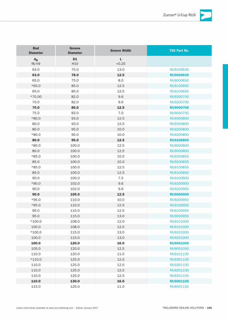
141
Rod
Diameter
Groove
Diameter Groove Width TSS Part No.
dN
D1 L
63.0 78.0 12.5 RU9000630
70.0 85.0 12.5 RU9000700
80.0 95.0 12.5 RU9100800
90.0 105.0 12.5 RU9000900
100.0 120.0 16.0 RU9001000
110.0 130.0 16.0 RU9001100
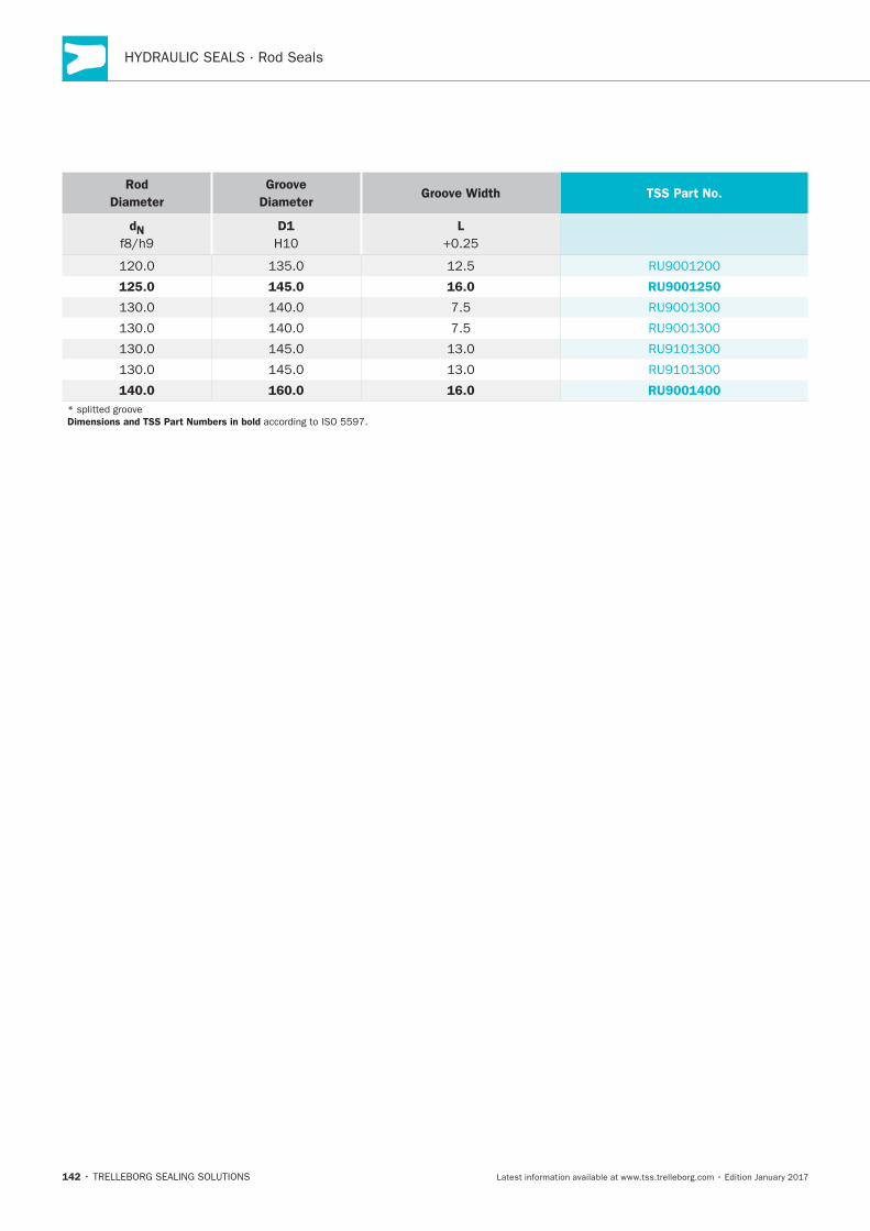
142
Rod
Diameter
Groove
Diameter Groove Width TSS Part No.
dN
D1 L
125.0 145.0 16.0 RU9001250
140.0 160.0 16.0 RU9001400
Dimensions and TSS Part Numbers in bold
Zurcon®Buffer Seal
TRELLEBORG SEALING SOLUTIONS • 143Latest information available at www.tss.trelleborg.com • Edition January 2017
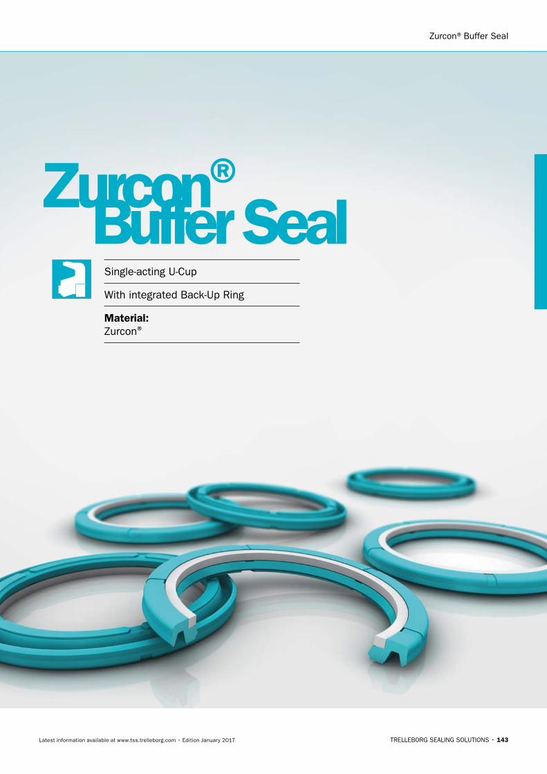
Single-acting U-Cup
With integrated Back-Up Ring
Material:Zurcon®
Zurcon®Buffer Seal

144
145
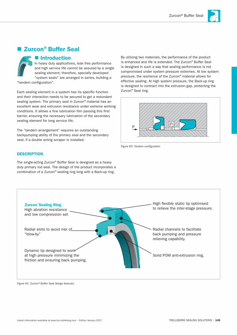
Introduction
®material has an
sealing element for long service life.
DESCRIPTION
®
®
®
®material allows for
®Seal ring.
PPi
Zurcon®Buffer Seal
Zurcon®Sealing Ring
High abration resistance
.
.
.
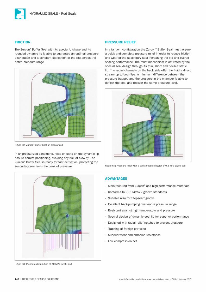
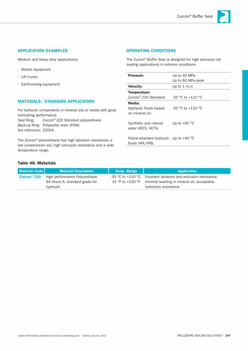
146
FRICTION
®
®
®
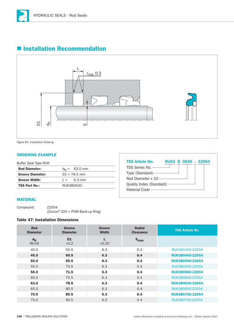
PRESSURE RELIEF
®
ADVANTAGES
®
®groove
147
APPLICATION EXAMPLES
MATERIALS - STANDARD APPLICATION
®
®
OPERATING CONDITIONS
®
Pressure:
Velocity:
Temperature: ®
Media:
Table 46: Materials
Material Code Material Description Temp. Range Application
Zurcon®Z20
148
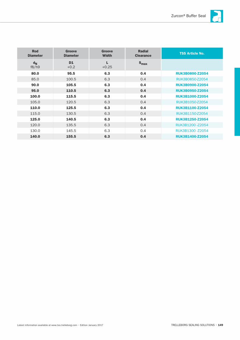
Installation Recommendation
SD1
d N
Lrmax. 0.3
Installation Drawing
ORDERING EXAMPLE
Rod Diameter: N
Groove Diameter:
Groove Width:
TSS Part No.:
MATERIAL
®
Material Code
TSS Series No.
TSS Article No.
Rod Diameter x 10Quality Index (Standard)
Type (Standard)
Z2054RUK3 - B 0630
Table 47: Installation Dimensions
Rod
Diameter
Groove
Diameter
Groove
Width
Radial
ClearanceTSS Article No.
dN D1 L Smax
45.0 60.5 6.3 0.4 RUK3B0450-Z2054
50.0 65.5 6.3 0.4 RUK3B0500-Z2054
56.0 71.5 6.3 0.4 RUK3B0560-Z2054
63.0 78.5 6.3 0.4 RUK3B0630-Z2054
70.0 85.5 6.3 0.4 RUK3B0700-Z2054
149
Rod
Diameter
Groove
Diameter
Groove
Width
Radial
ClearanceTSS Article No.
dN D1 L Smax
80.0 95.5 6.3 0.4 RUK3B0800-Z2054
90.0 105.5 6.3 0.4 RUK3B0900-Z2054
95.0 110.5 6.3 0.4 RUK3B0950-Z2054
100.0 115.5 6.3 0.4 RUK3B1000-Z2054
110.0 125.5 6.3 0.4 RUK3B1100-Z2054
125.0 140.5 6.3 0.4 RUK3B1250-Z2054
140.0 155.5 6.3 0.4 RUK3B1400-Z2054

150
Turcon®Variseal®M2
TRELLEBORG SEALING SOLUTIONS • 151Latest information available at www.tss.trelleborg.com • Edition January 2017
Single-acting
Spring Energized Plastic U-Cup
Material:Turcon®and Zurcon®
Turcon®Variseal® M2

152
153
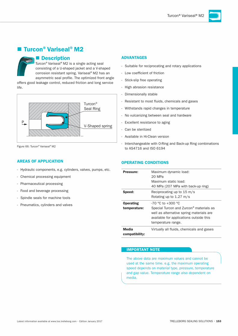
Description®Variseal®
®
life.
P
Turcon® Seal Ring
V-Shaped spring
®Variseal®
AREAS OF APPLICATION
ADVANTAGES
Low coefficient of friction
High abrasion resistance
OPERATING CONDITIONS
Pressure:
Speed:
Operating
temperature:
®materials as
Media
compatibility:
IMPORTANT NOTE
Turcon®Variseal®M2
154
GENERAL
®Variseal®
Variseal®
®Variseal®
® ®
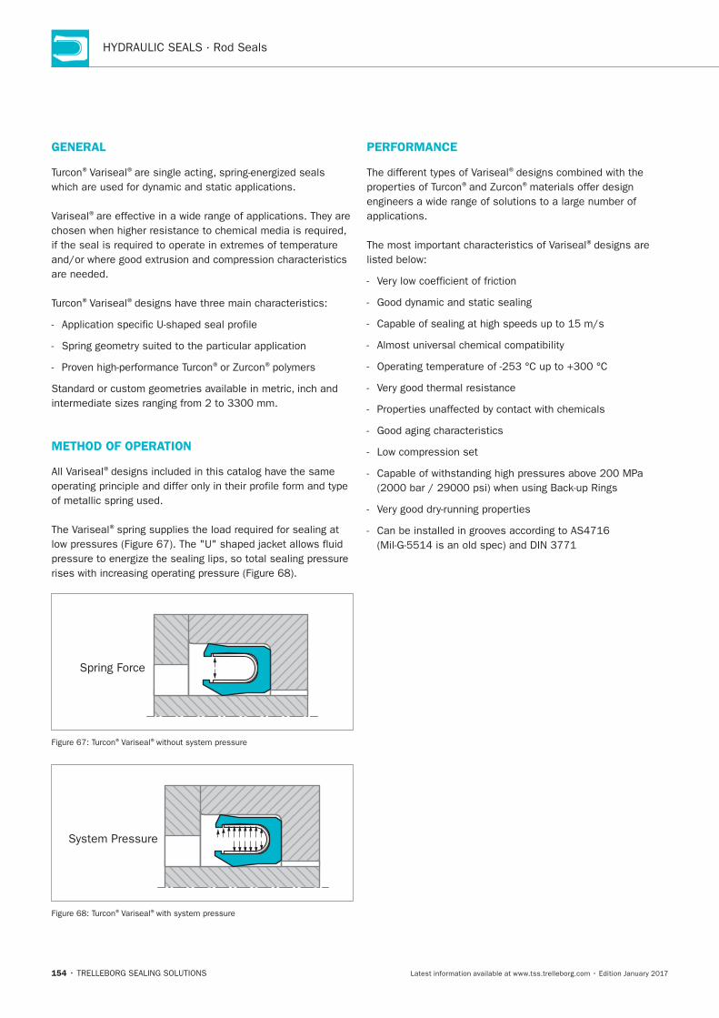
METHOD OF OPERATION
All Variseal®
The Variseal®
Spring Force
®Variseal®
System Pressure
®Variseal®
PERFORMANCE
®
® ®
®
155
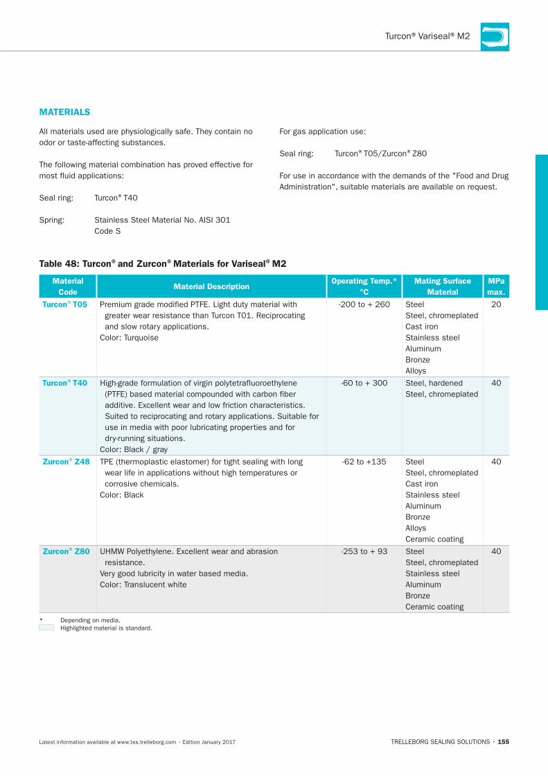
Table 48: Turcon®and Zurcon®Materials for Variseal®M2
Material
Code Material Description
Operating Temp.*
°C
Mating Surface
Material
MPa
max.
Turcon®T05 Steel
Cast iron
Stainless steel
Turcon®T40
Zurcon®Z48
corrosive chemicals.
Steel
Cast iron
Stainless steel
Ceramic coating
Zurcon®Z80
resistance.
Steel
Stainless steel
Ceramic coating
MATERIALS
®
® ®
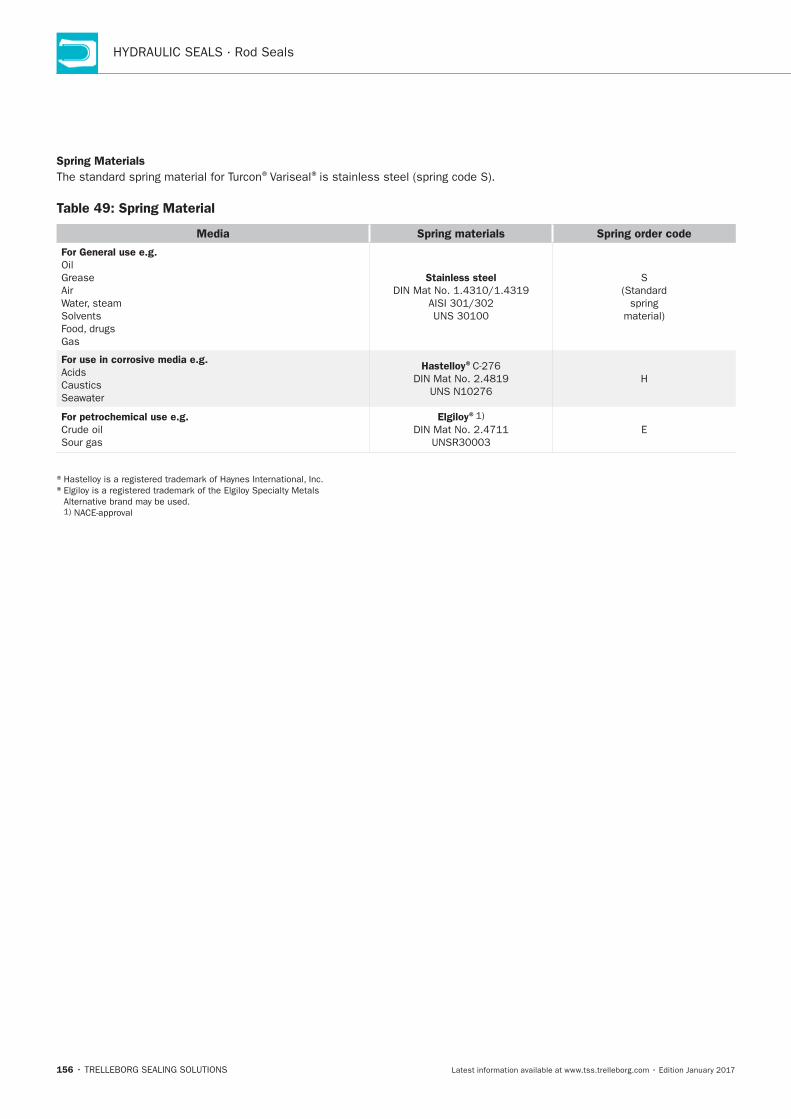
156
Spring Materials®Variseal®
Table 49: Spring Material
Media Spring materials Spring order code
For General use e.g.
Oil
Grease
Air
Solvents
Gas
Stainless steel S
For use in corrosive media e.g.
Seawater
Hastelloy®
H
For petrochemical use e.g.
Elgiloy®
E
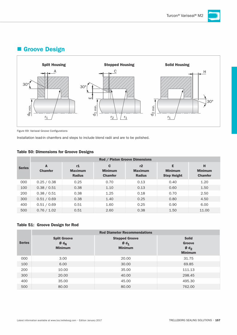
157
Groove Design
Split Housing Stepped Housing Solid Housing
r1
30°
A C
dN
min
.
30°
30°
r2 r1
d1 m
in.
E
H
d2 m
in.
r1
Table 50: Dimensions for Groove Designs
Series
Rod / Piston Groove Dimensions
A
Chamfer
r1
Maximum
Radius
C
Minimum
Chamfer
r2
Maximum
Radius
E
Minimum
Step Height
H
Minimum
Chamfer
Table 51: Groove Design for Rod
Series
Rod Diameter Recommendations
Split Groove
Ø dN
Minimum
Stepped Groove
Ø d1
Minimum
Solid
Groove
Ø d2
Minimum
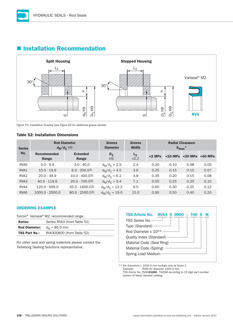
158
Installation Recommendation
Split Housing Stepped Housing
Variseal® M2
RVA
h
S
L1
h
S d N h
9
D1
H9
d 1 h
9
D1
H9
30°30°
L1
Table 52: Installation Dimensions
Series
No.
Rod Diameter
dN/d1
Groove
Diameter
Groove
Width
Radial Clearance
Smax*
Recommended
Range
Extended
Range
D1 L1
<2 MPa <10 MPa <20 MPa <40 MPa
N
N
N
N
N
N
ORDERING EXAMPLE
® Variseal®
Series:
Rod Diameter: N
TSS Part No.:
Material Code (Seal Ring)
TSS Series No.
TSS Article No.
Material Code (Spring)Spring Load Medium
Rod Diameter x 10**Quality Index (Standard)
Type (Standard)
T400800 SRVA3 - M0
X1200
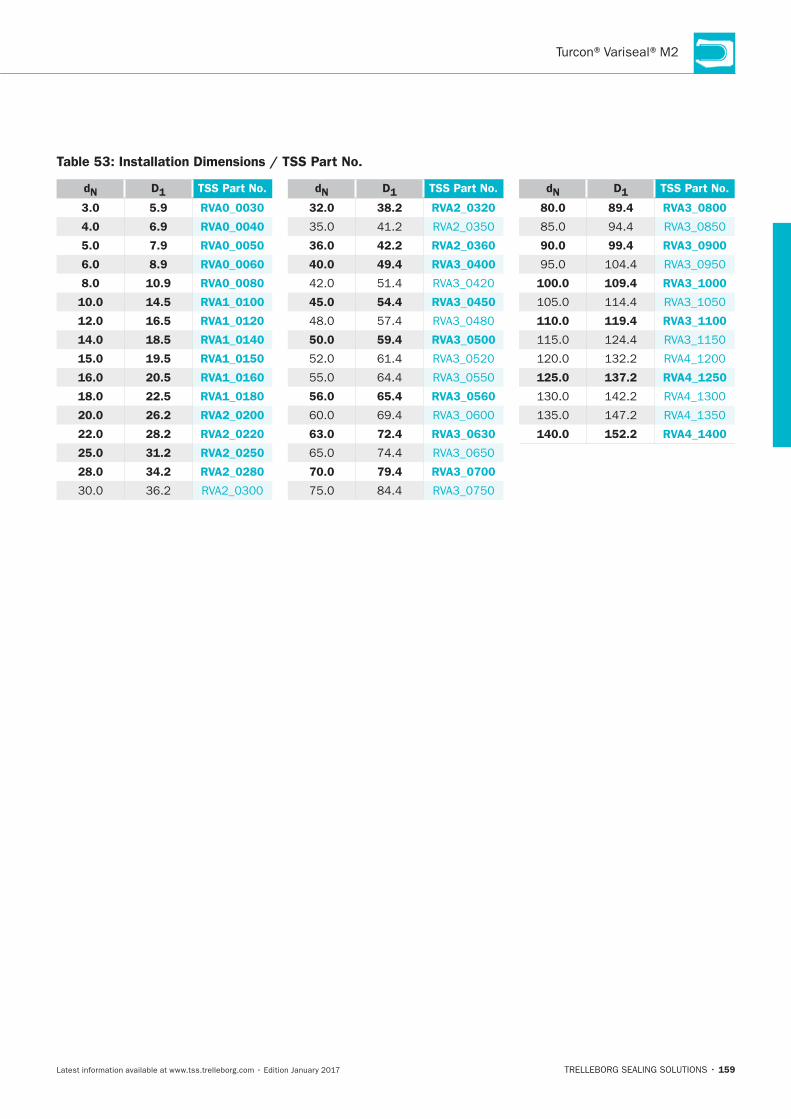
159
Table 53: Installation Dimensions / TSS Part No.
dN D1 TSS Part No.
3.0 5.9 RVA0_0030
4.0 6.9 RVA0_0040
5.0 7.9 RVA0_0050
6.0 8.9 RVA0_0060
8.0 10.9 RVA0_0080
10.0 14.5 RVA1_0100
12.0 16.5 RVA1_0120
14.0 18.5 RVA1_0140
15.0 19.5 RVA1_0150
16.0 20.5 RVA1_0160
18.0 22.5 RVA1_0180
20.0 26.2 RVA2_0200
22.0 28.2 RVA2_0220
25.0 31.2 RVA2_0250
28.0 34.2 RVA2_0280
dN D1 TSS Part No.
32.0 38.2 RVA2_0320
36.0 42.2 RVA2_0360
40.0 49.4 RVA3_0400
45.0 54.4 RVA3_0450
50.0 59.4 RVA3_0500
56.0 65.4 RVA3_0560
63.0 72.4 RVA3_0630
70.0 79.4 RVA3_0700
dN D1 TSS Part No.
80.0 89.4 RVA3_0800
90.0 99.4 RVA3_0900
100.0 109.4 RVA3_1000
110.0 119.4 RVA3_1100
125.0 137.2 RVA4_1250
140.0 152.2 RVA4_1400

160
Turcon®VL Seal®
TRELLEBORG SEALING SOLUTIONS • 161Latest information available at www.tss.trelleborg.com • Edition January 2017
Single-acting
Rubber-energized plastic-faced seal
Material:Turcon®, Zurcon®and Elastomer
Turcon®VL Seal®

162
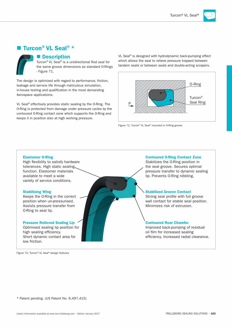
163
Elastomer O-Ring
High flexibility to satisfy hardware
tolerances. High static sealing
function. Elastomer materials
available to meet a wide
variety of service conditions.
Stabilising Wing
Keeps the O-Ring in the correct
position when un-pressurised.
Assists pressure transfer from
O-Ring to seal lip.
Pressure Relieved Sealing Lip
Optimised sealing lip position for
high sealing efficiency.
Short dynamic contact area for
low friction.
Contoured O-Ring Contact Zone
Stabilizes the O-Ring position in
the seal groove. Secures optimal
pressure transfer to dynamic sealing
lip. Prevents O-Ring nibbling.
Stabilised Groove Contact
Strong seal profile with full groove
wall contact for stable seal position.
Minimizes risk of extrusion.
Contoured Rear Chamfer
Improved back-pumping of residual
oil film for increased sealing
efficiency. Increased radial clearance.
Turcon®VL Seal®*
Description®VL Seal®
VL Seal®
VL Seal®
O-Ring
Turcon® Seal RingP
®VL Seal®
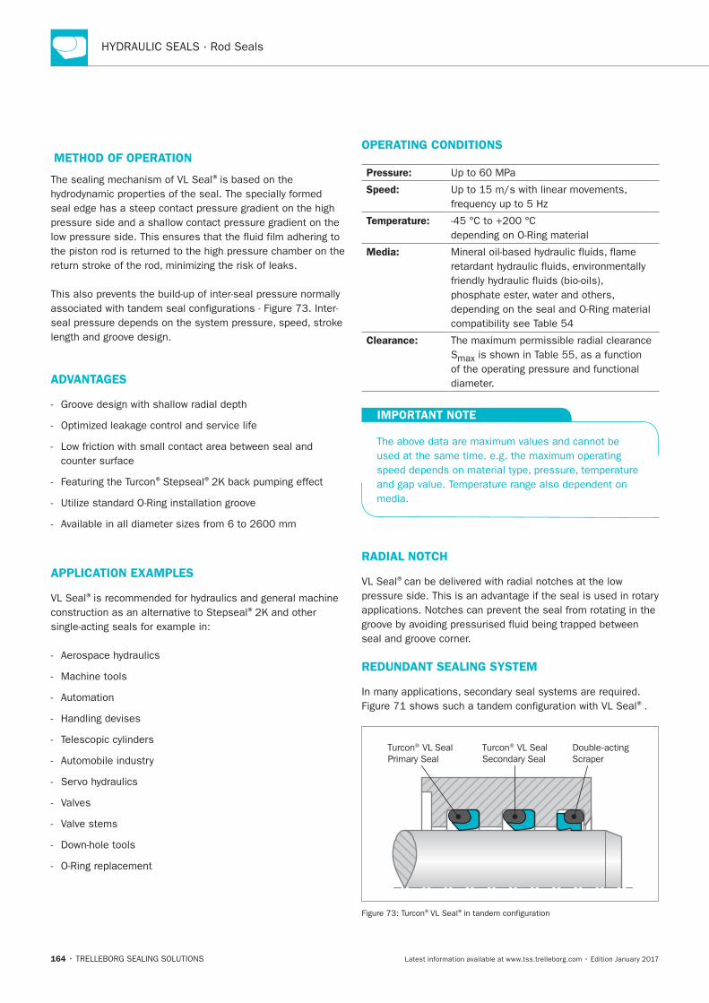
164
METHOD OF OPERATION
The sealing mechanism of VL Seal®
ADVANTAGES
® ®
APPLICATION EXAMPLES
VL Seal®
®
Machine tools
Valves
Valve stems
OPERATING CONDITIONS
Pressure:
Speed:
Temperature:
Media:
Clearance:
S
IMPORTANT NOTE
RADIAL NOTCH
VL Seal®
REDUNDANT SEALING SYSTEM
®.
Turcon® VL SealPrimary Seal
Turcon® VL SealSecondary Seal
Double-actingScraper
®VL Seal®
165
INSTALLATION INSTRUCTIONS
VL Seal®
® ® ®Variseal®
VL Seal® to
RECOMMENDED MATERIALS
Turcon®VL Seal ®in Turcon®M12
Turcon®VL Seal ®in Turcon®T46
® ®as an alternative to
®materials are available.
.
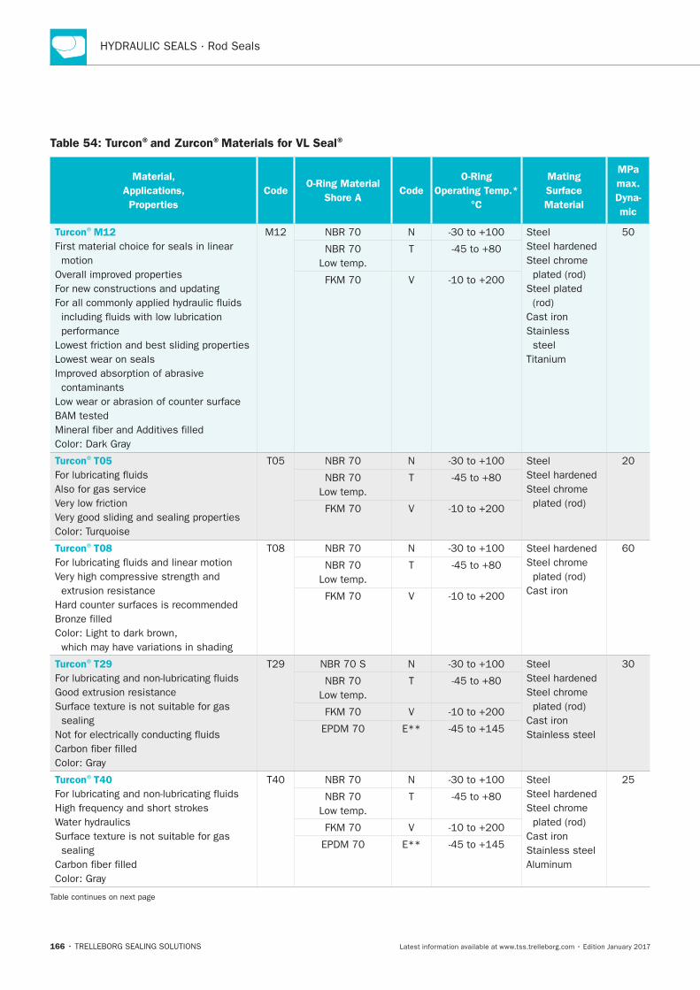
166
Table 54: Turcon®and Zurcon®Materials for VL Seal®
Material,
Applications,
Properties
CodeO-Ring Material
Shore ACode
O-Ring
Operating Temp.*
°C
Mating
Surface
Material
MPa
max.
Dyna-
mic
Turcon®M12
First material choice for seals in linear
motion
Lowest wear on seals
contaminants
N Steel
Steel chrome
Cast iron
Stainless
steel
T
V
Turcon®T05
Also for gas service
N Steel
Steel chrome T
V
Turcon®T08
N
Steel chrome
Cast iron
T
V
Turcon®T29
sealing
N Steel
Steel chrome
Cast iron
Stainless steel
T
V
E**
Turcon®T40
sealing
N Steel
Steel chrome
Cast iron
Stainless steel
T
V
E**
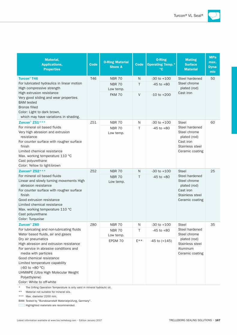
167
Material,
Applications,
Properties
CodeO-Ring Material
Shore ACode
O-Ring
Operating Temp.*
°C
Mating
Surface
Material
MPa
max.
Dyna-
mic
Turcon®T46
N
Steel chrome
Cast iron
T
V
Zurcon®Z51***
resistance
finish
N Steel
Steel chrome
Cast iron
Stainless steel
Ceramic coating
T
Zurcon®Z52***
abrasion resistance
finish
N Steel
Steel chrome
Cast iron
Stainless steel
Ceramic coating
T
Zurcon®Z80
N Steel
Steel chrome
Stainless steel
Ceramic coating
T
E**
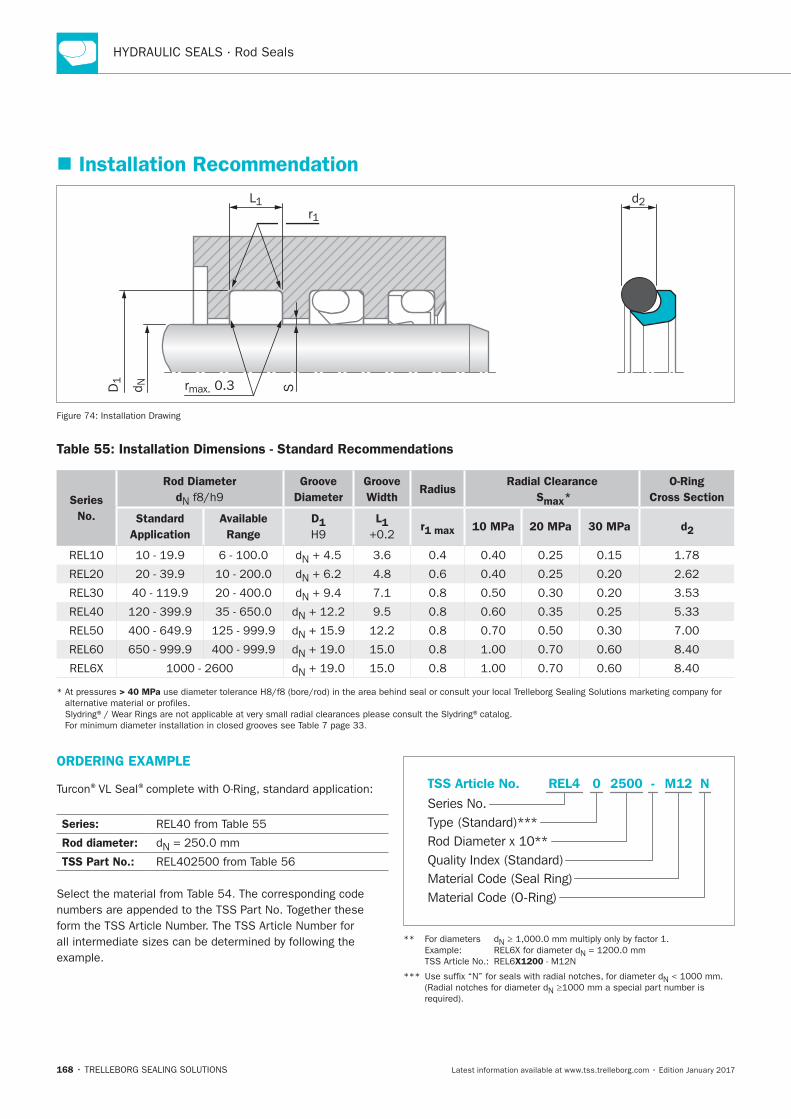
168
Installation Recommendation
Sd ND1 rmax. 0.3
r1L1 d2
Installation Drawing
Table 55: Installation Dimensions - Standard Recommendations
Series
No.
Rod Diameter
dN
Groove
Diameter
Groove
Width Radius
Radial Clearance
Smax*
O-Ring
Cross Section
Standard
Application
Available
Range
D1 L1 r1 max 10 MPa 20 MPa 30 MPa d2
N
N
N
N
N
N
N
> 40 MPa
.
ORDERING EXAMPLE
®VL Seal®
Series:
Rod diameter: N
TSS Part No.:
Select the material from .
Material Code (Seal Ring)
Series No.
TSS Article No. M122500 N
Material Code (O-Ring)
Rod Diameter x 10**
REL4
Quality Index (Standard)
-
Type (Standard)***
0
N
N
X1200
N
N
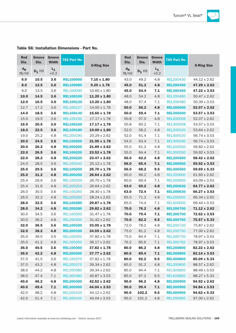
169
Table 56: Installation Dimensions - Part No.
Rod
Dia.
Groove
Dia.
Groove
WidthTSS Part No.
O-Ring SizedN
D1 L1
6.0 10.5 3.6 REL100060 7.10 x 1.80
8.0 12.5 3.6 REL100080 9.25 x 1.78
10.0 14.5 3.6 REL100100 11.20 x 1.80
12.0 16.5 3.6 REL100120 13.20 x 1.80
14.0 18.5 3.6 REL100140 15.60 x 1.78
16.0 20.5 3.6 REL100160 17.17 x 1.78
18.0 22.5 3.6 REL100180 19.00 x 1.80
20.0 24.5 3.6 REL100200 21.95 x 1.78
20.0 26.2 4.8 REL200200 21.89 x 2.62
22.0 26.5 3.6 REL100220 23.52 x 1.78
22.0 28.2 4.8 REL200220 23.47 x 2.62
25.0 29.5 3.6 REL100250 26.70 x 1.78
25.0 31.2 4.8 REL200250 26.64 x 2.62
28.0 32.5 3.6 REL100280 29.87 x 1.78
28.0 34.2 4.8 REL200280 29.82 x 2.62
32.0 36.5 3.6 REL100320 33.05 x 1.78
32.0 38.2 4.8 REL200320 34.59 x 2.62
36.0 40.5 3.6 REL100360 37.82 x 1.78
36.0 42.2 4.8 REL200360 37.77 x 2.62
40.0 46.2 4.8 REL200400 42.52 x 2.62
40.0 49.4 7.1 REL300400 44.04 x 3.53
Rod
Dia.
Groove
Dia.
Groove
WidthTSS Part No.
O-Ring SizedN
D1 L1
45.0 51.2 4.8 REL200450 47.29 x 2.62
45.0 54.4 7.1 REL300450 47.22 x 3.53
50.0 56.2 4.8 REL200500 52.07 x 2.62
50.0 59.4 7.1 REL300500 53.57 x 3.53
56.0 62.2 4.8 REL200560 58.42 x 2.62
56.0 65.4 7.1 REL300560 59.92 x 3.53
56.0 68.2 9.5 REL400560 59.69 x 5.33
63.0 69.2 4.8 REL200630 64.77 x 2.62
63.0 72.4 7.1 REL300630 66.27 x 3.53
70.0 76.2 4.8 REL200700 71.12 x 2.62
70.0 79.4 7.1 REL300700 72.62 x 3.53
70.0 82.2 9.5 REL400700 75.57 x 5.33
80.0 86.2 4.8 REL200800 82.22 x 2.62
80.0 89.4 7.1 REL300800 82.14 x 3.53
80.0 92.2 9.5 REL400800 85.09 x 5.33
90.0 96.2 4.8 REL200900 94.92 x 2.62
90.0 99.4 7.1 REL300900 94.84 x 3.53
90.0 102.2 9.5 REL400900 94.62 x 5.33
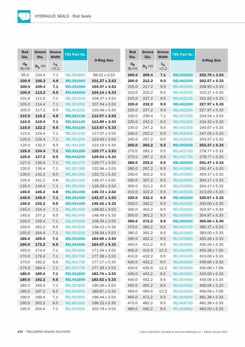
170
Rod
Dia.
Groove
Dia.
Groove
WidthTSS Part No.
O-Ring SizedN
D1 L1
100.0 106.2 4.8 REL201000 101.27 x 2.62
100.0 109.4 7.1 REL301000 104.37 x 3.53
100.0 112.2 9.5 REL401000 104.14 x 5.33
110.0 116.2 4.8 REL201100 113.97 x 2.62
110.0 119.4 7.1 REL301100 113.89 x 3.53
110.0 122.2 9.5 REL401100 113.67 x 5.33
125.0 134.4 7.1 REL301250 129.77 x 3.53
125.0 137.2 9.5 REL401250 129.54 x 5.33
140.0 146.2 4.8 REL201400 145.72 x 2.62
140.0 149.4 7.1 REL301400 142.47 x 3.53
140.0 152.2 9.5 REL401400 145.42 x 5.33
160.0 169.4 7.1 REL301600 164.69 x 3.53
160.0 172.2 9.5 REL401600 164.47 x 5.33
180.0 189.4 7.1 REL301800 183.74 x 3.53
180.0 192.2 9.5 REL401800 183.52 x 5.33
Rod
Dia.
Groove
Dia.
Groove
WidthTSS Part No.
O-Ring SizedN
D1 L1
200.0 209.4 7.1 REL302000 202.79 x 3.53
200.0 212.2 9.5 REL402000 202.57 x 5.33
220.0 232.2 9.5 REL402200 227.97 x 5.33
250.0 262.2 9.5 REL402500 253.37 x 5.33
280.0 292.2 9.5 REL402800 291.47 x 5.33
320.0 332.2 9.5 REL403200 329.57 x 5.33
360.0 372.2 9.5 REL403600 365.00 x 5.30
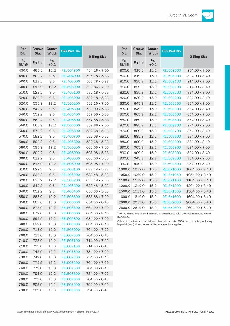
171
Rod
Dia.
Groove
Dia.
Groove
WidthTSS Part No.
O-Ring SizedN
D1 L1
Rod
Dia.
Groove
Dia.
Groove
WidthTSS Part No.
O-Ring SizedN
D1 L1
bold

172
Turcon®Glyd Ring®
TRELLEBORG SEALING SOLUTIONS • 173Latest information available at www.tss.trelleborg.com • Edition January 2017
Double-acting
Rubber-energized plastic-faced seal
Material:Turcon®, Zurcon®and Elastomer
Turcon®Glyd Ring®

174
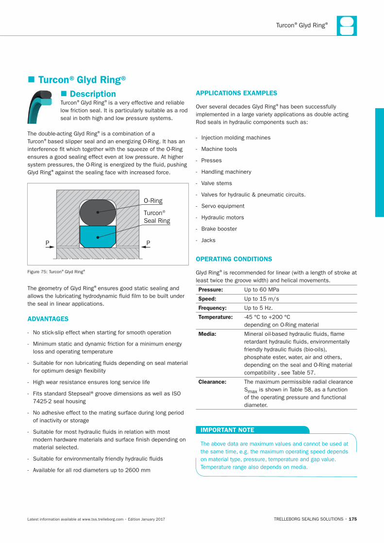
® ®
175
Description® ®
®is a combination of a ®
®
O-Ring
Turcon® Seal Ring
P P
® ®
®
ADVANTAGES
APPLICATIONS EXAMPLES
®
Machine tools
Presses
Valve stems
OPERATING CONDITIONS
®
Pressure:
Speed:
Frequency:
Temperature:
Media:
Clearance:
S
IMPORTANT NOTE
Turcon®Glyd Ring®
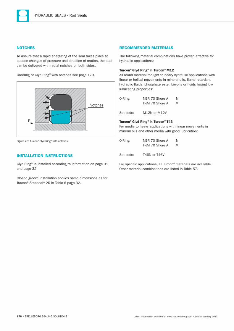
176
NOTCHES
®
P
Notches
® ®with notches
INSTALLATION INSTRUCTIONS
RECOMMENDED MATERIALS
Turcon®Glyd Ring®in Turcon®M12
Turcon®Glyd Ring®in Turcon®T46
®materials are available.

® ®
177
Table 57: Turcon®and Zurcon®Materials for Glyd Ring®
Material,
Applications,
Properties
Code
O-Ring
Material
Shore A
Code
O-Ring
Operating Temp.*
°C
Mating Surface
Material
MPa
max.
Dyna-
mic
Turcon®M12
First material choice for seals in linear
motion
Lowest wear on seals
contaminanants
N Steel
Steel chrome
Cast iron
Stainless steel
T
V
Turcon®T05
Also for gas service
N Steel
Steel chrome T
V
Turcon®T08
N
Steel chrome
Cast iron
T
V
Turcon®T10
N Steel
Steel chrome
Stainless steel
T
V
E**
Turcon®T29
sealing
N Steel
Steel chrome
Cast iron
Stainless steel
T
V
E**
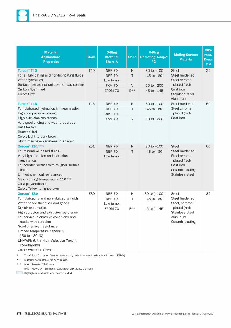
178
Material,
Applications,
Properties
Code
O-Ring
Material
Shore A
Code
O-Ring
Operating Temp.*
°C
Mating Surface
Material
MPa
max.
Dyna-
mic
Turcon®T40
N Steel
Steel chrome
Cast iron
Stainless steel
T
V
E**
Turcon®T46
N
Steel chrome
Cast iron
T
V
Zurcon®Z51***
resistance
finish
N Steel
Steel chrome
Cast iron
Ceramic coating
Stainless steel
T
Zurcon®Z80
N Steel
Stainless steel
Ceramic coating
T
E**
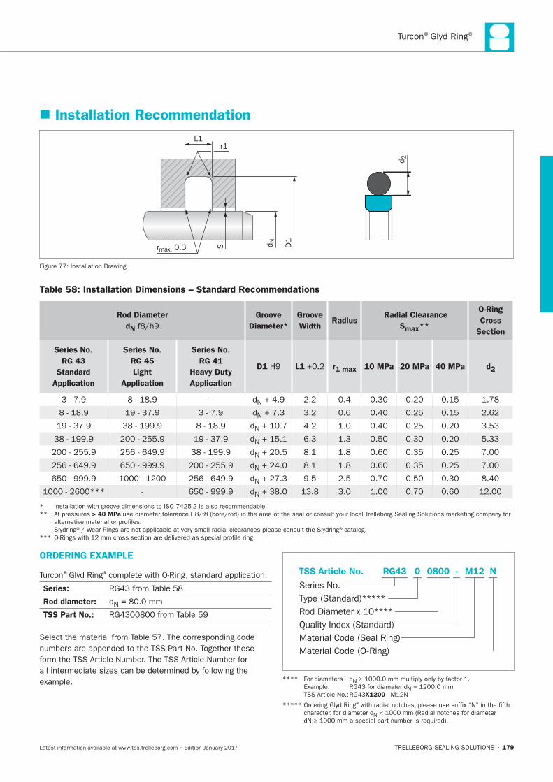
® ®
179
Installation Recommendation
rmax. 0.3 D1d N
L1r1
S
d 2
Installation Drawing
Table 58: Installation Dimensions – Standard Recommendations
Rod Diameter
dN
Groove
Diameter*
Groove
WidthRadius
Radial Clearance
Smax**
O-Ring
Cross
Section
Series No.
RG 43
Standard
Application
Series No.
RG 45
Light
Application
Series No.
RG 41
Heavy Duty
Application
D1 L1 r1 max 10 MPa 20 MPa 40 MPa d2
N
N
N
N
N
N
N
N
> 40 MPa
ORDERING EXAMPLE
® ®
Series:
Rod diameter: N
TSS Part No.:
Material Code (Seal Ring)
Series No.
TSS Article No. M120800 N
Material Code (O-Ring)
Rod Diameter x 10****
RG43
Quality Index (Standard)
-
Type (Standard)*****
0
N
N
X1200
®
N
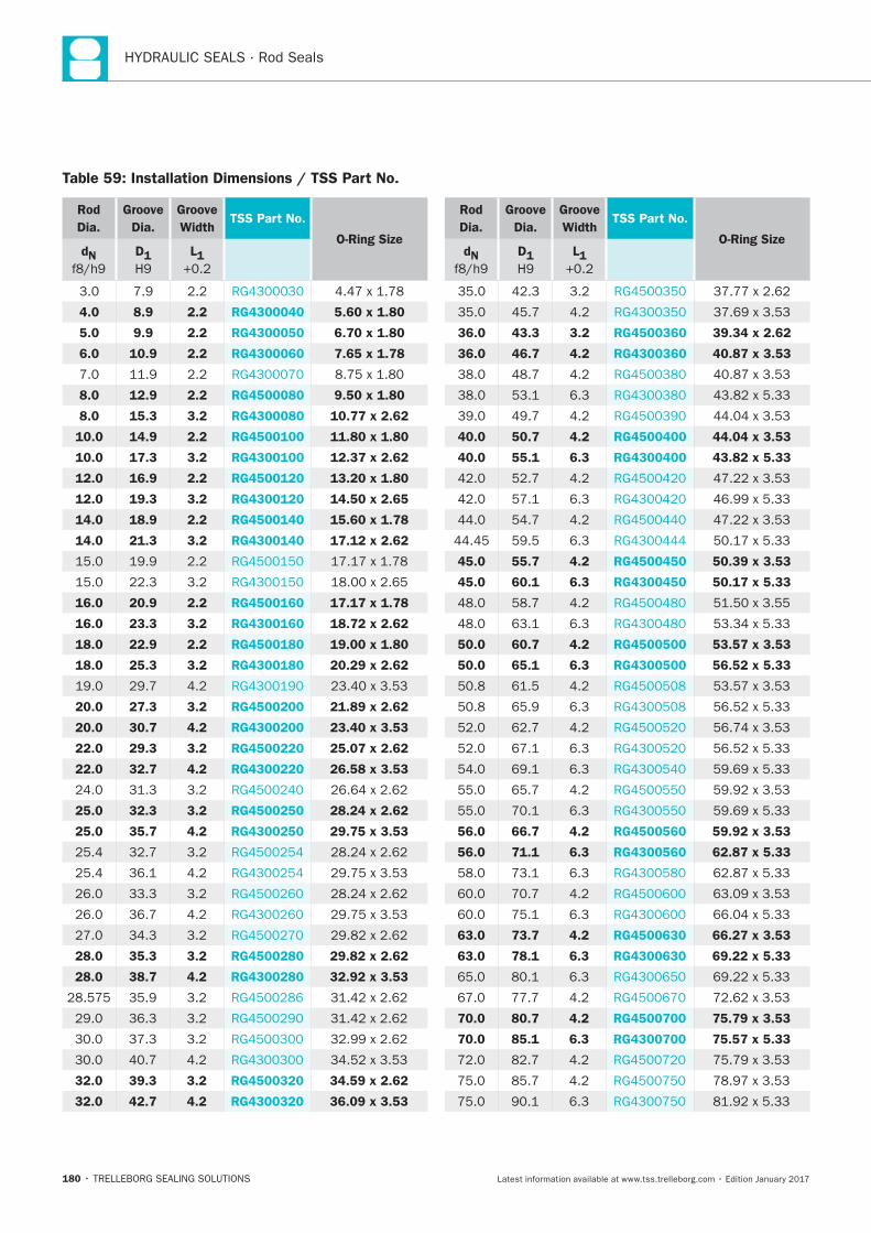
180
Table 59: Installation Dimensions / TSS Part No.
Rod
Dia.
Groove
Dia.
Groove
WidthTSS Part No.
O-Ring SizedN D1 L1
4.0 8.9 2.2 RG4300040 5.60 x 1.80
5.0 9.9 2.2 RG4300050 6.70 x 1.80
6.0 10.9 2.2 RG4300060 7.65 x 1.78
8.0 12.9 2.2 RG4500080 9.50 x 1.80
8.0 15.3 3.2 RG4300080 10.77 x 2.62
10.0 14.9 2.2 RG4500100 11.80 x 1.80
10.0 17.3 3.2 RG4300100 12.37 x 2.62
12.0 16.9 2.2 RG4500120 13.20 x 1.80
12.0 19.3 3.2 RG4300120 14.50 x 2.65
14.0 18.9 2.2 RG4500140 15.60 x 1.78
14.0 21.3 3.2 RG4300140 17.12 x 2.62
16.0 20.9 2.2 RG4500160 17.17 x 1.78
16.0 23.3 3.2 RG4300160 18.72 x 2.62
18.0 22.9 2.2 RG4500180 19.00 x 1.80
18.0 25.3 3.2 RG4300180 20.29 x 2.62
20.0 27.3 3.2 RG4500200 21.89 x 2.62
20.0 30.7 4.2 RG4300200 23.40 x 3.53
22.0 29.3 3.2 RG4500220 25.07 x 2.62
22.0 32.7 4.2 RG4300220 26.58 x 3.53
25.0 32.3 3.2 RG4500250 28.24 x 2.62
25.0 35.7 4.2 RG4300250 29.75 x 3.53
28.0 35.3 3.2 RG4500280 29.82 x 2.62
28.0 38.7 4.2 RG4300280 32.92 x 3.53
32.0 39.3 3.2 RG4500320 34.59 x 2.62
32.0 42.7 4.2 RG4300320 36.09 x 3.53
Rod
Dia.
Groove
Dia.
Groove
WidthTSS Part No.
O-Ring SizedN D1 L1
36.0 43.3 3.2 RG4500360 39.34 x 2.62
36.0 46.7 4.2 RG4300360 40.87 x 3.53
40.0 50.7 4.2 RG4500400 44.04 x 3.53
40.0 55.1 6.3 RG4300400 43.82 x 5.33
45.0 55.7 4.2 RG4500450 50.39 x 3.53
45.0 60.1 6.3 RG4300450 50.17 x 5.33
50.0 60.7 4.2 RG4500500 53.57 x 3.53
50.0 65.1 6.3 RG4300500 56.52 x 5.33
56.0 66.7 4.2 RG4500560 59.92 x 3.53
56.0 71.1 6.3 RG4300560 62.87 x 5.33
63.0 73.7 4.2 RG4500630 66.27 x 3.53
63.0 78.1 6.3 RG4300630 69.22 x 5.33
70.0 80.7 4.2 RG4500700 75.79 x 3.53
70.0 85.1 6.3 RG4300700 75.57 x 5.33
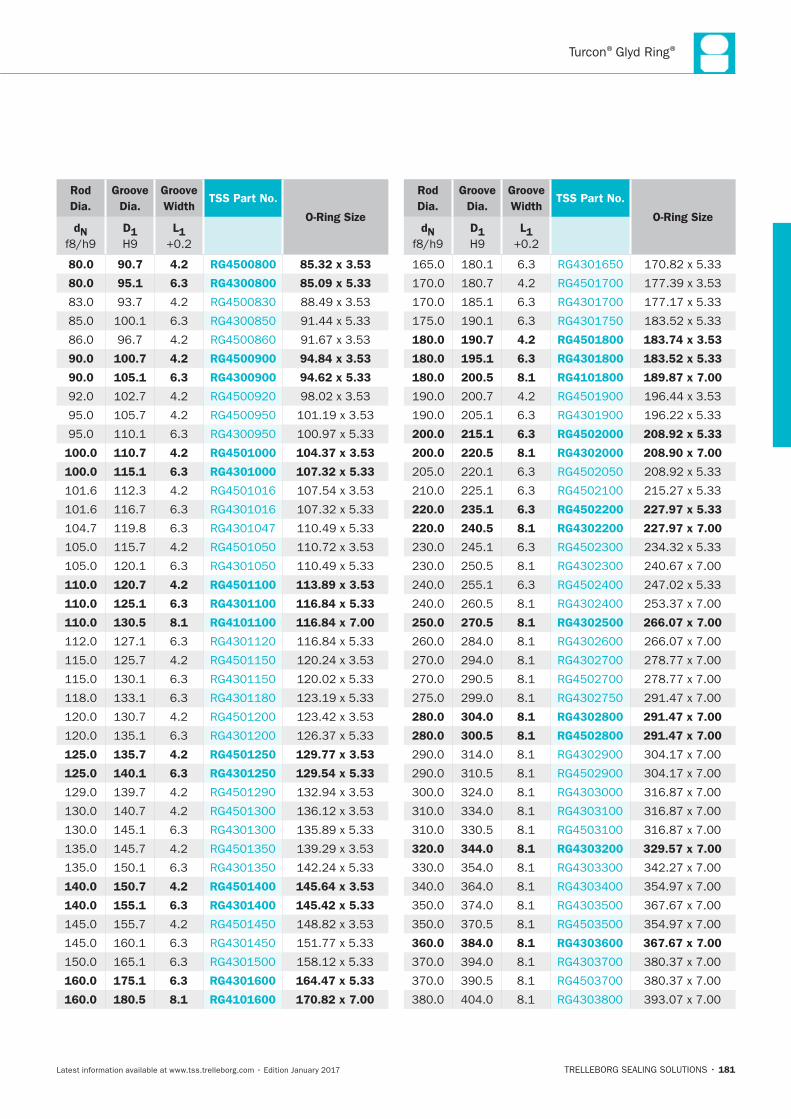
® ®
181
Rod
Dia.
Groove
Dia.
Groove
WidthTSS Part No.
O-Ring SizedN D1 L1
80.0 90.7 4.2 RG4500800 85.32 x 3.53
80.0 95.1 6.3 RG4300800 85.09 x 5.33
90.0 100.7 4.2 RG4500900 94.84 x 3.53
90.0 105.1 6.3 RG4300900 94.62 x 5.33
100.0 110.7 4.2 RG4501000 104.37 x 3.53
100.0 115.1 6.3 RG4301000 107.32 x 5.33
110.0 120.7 4.2 RG4501100 113.89 x 3.53
110.0 125.1 6.3 RG4301100 116.84 x 5.33
110.0 130.5 8.1 RG4101100 116.84 x 7.00
125.0 135.7 4.2 RG4501250 129.77 x 3.53
125.0 140.1 6.3 RG4301250 129.54 x 5.33
140.0 150.7 4.2 RG4501400 145.64 x 3.53
140.0 155.1 6.3 RG4301400 145.42 x 5.33
160.0 175.1 6.3 RG4301600 164.47 x 5.33
160.0 180.5 8.1 RG4101600 170.82 x 7.00
Rod
Dia.
Groove
Dia.
Groove
WidthTSS Part No.
O-Ring SizedN D1 L1
180.0 190.7 4.2 RG4501800 183.74 x 3.53
180.0 195.1 6.3 RG4301800 183.52 x 5.33
180.0 200.5 8.1 RG4101800 189.87 x 7.00
200.0 215.1 6.3 RG4502000 208.92 x 5.33
200.0 220.5 8.1 RG4302000 208.90 x 7.00
220.0 235.1 6.3 RG4502200 227.97 x 5.33
220.0 240.5 8.1 RG4302200 227.97 x 7.00
250.0 270.5 8.1 RG4302500 266.07 x 7.00
280.0 304.0 8.1 RG4302800 291.47 x 7.00
280.0 300.5 8.1 RG4502800 291.47 x 7.00
320.0 344.0 8.1 RG4303200 329.57 x 7.00
360.0 384.0 8.1 RG4303600 367.67 x 7.00
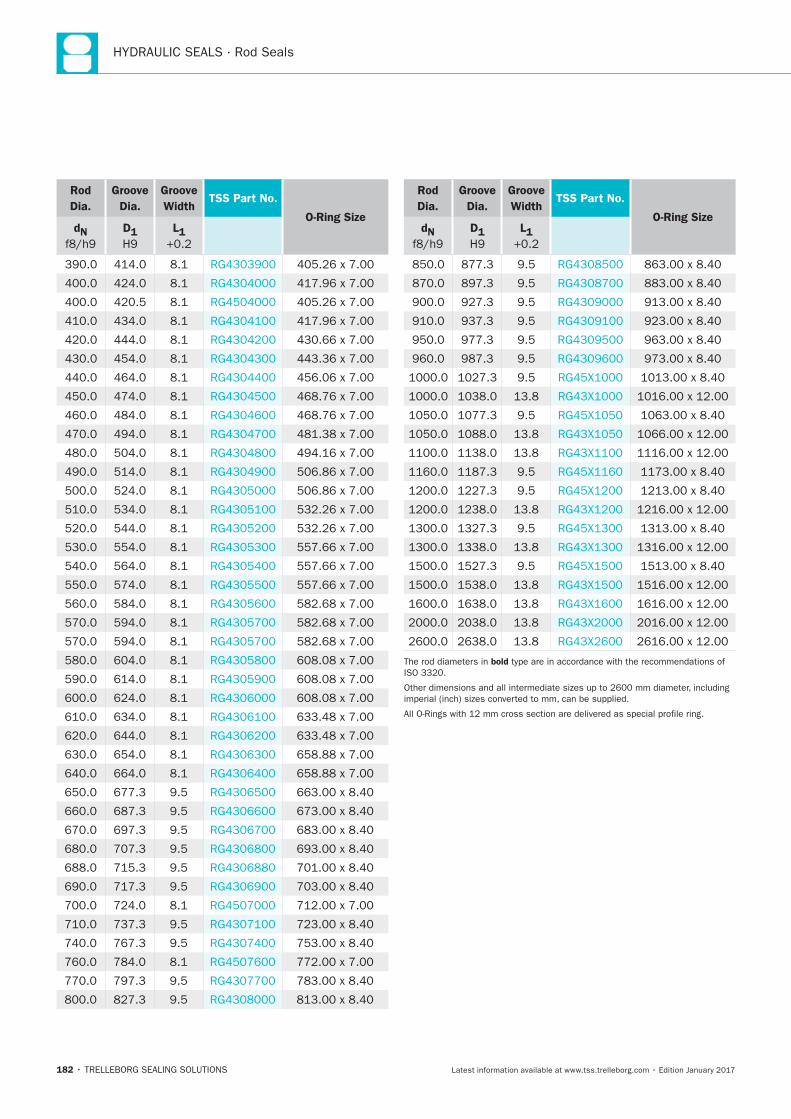
182
Rod
Dia.
Groove
Dia.
Groove
WidthTSS Part No.
O-Ring SizedN D1 L1
Rod
Dia.
Groove
Dia.
Groove
WidthTSS Part No.
O-Ring SizedN D1 L1
bold
TRELLEBORG SEALING SOLUTIONS • 183Latest information available at www.tss.trelleborg.com • Edition January 2017
Turcon®Glyd Ring®T
Double-acting
Rubber-energized plastic-faced seal
Material:Turcon®, Zurcon®and Elastometer
Turcon®Glyd Ring®T

184
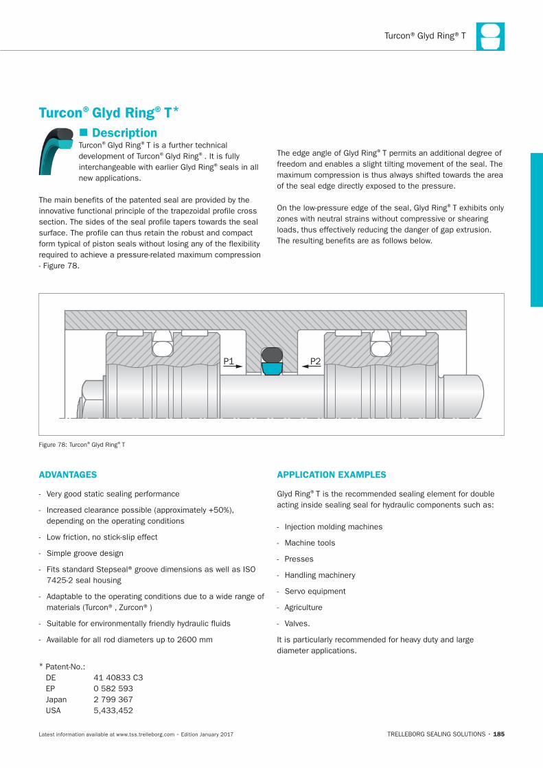
185
Description® ®
® ®
®seals in all
®
®
Turcon®Glyd Ring®T*
P1 P2
® ®T
ADVANTAGES
*
APPLICATION EXAMPLES
®
Machine tools
Presses
Valves.
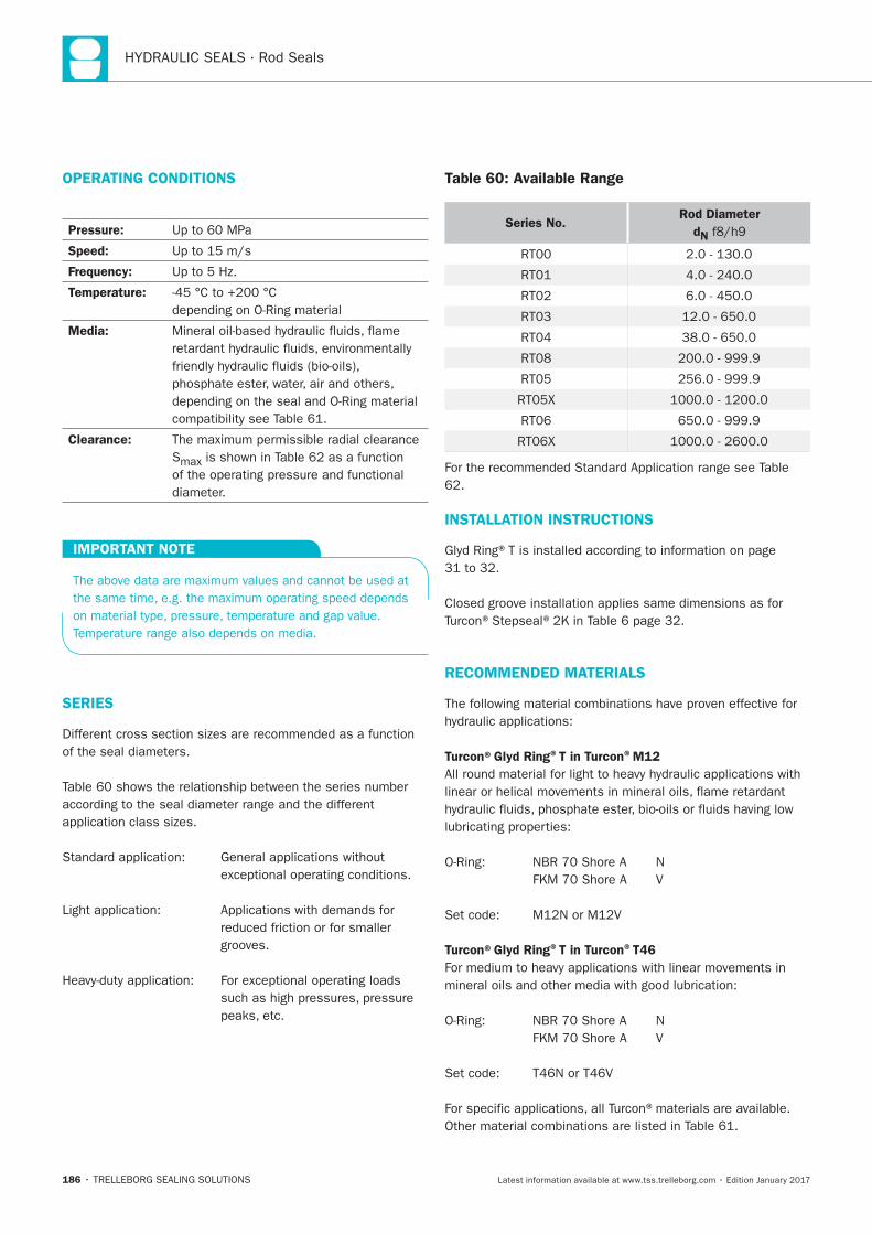
186
OPERATING CONDITIONS
Pressure:
Speed:
Frequency:
Temperature:
Media:
Clearance:
S
IMPORTANT NOTE
SERIES
grooves.
Table 60: Available Range
Series No.Rod Diameter
dN
INSTALLATION INSTRUCTIONS
RECOMMENDED MATERIALS
Turcon®Glyd Ring®T in Turcon®M12
Turcon®Glyd Ring®T in Turcon®T46
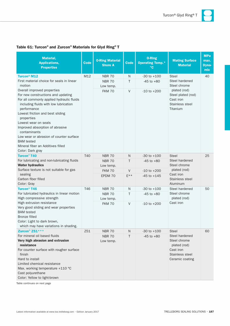
187
Table 61: Turcon®and Zurcon®Materials for Glyd Ring®T
Material,
Applications,
Properties
CodeO-Ring Material
Shore ACode
O-Ring
Operating Temp.*
°C
Mating Surface
Material
MPa
max.
Dyna-
mic
Turcon®M12
First material choice for seals in linear
motion
Lowest wear on seals
contaminants
N Steel
Steel chrome
Cast iron
Stainless steel
T
V
Turcon®T40
Water hydraulics
sealing
N Steel
Steel chrome
Cast iron
Stainless steel
T
V
E**
Turcon®T46 N
Steel chrome
Cast iron
T
V
Zurcon®Z51***
Very high abrasion and extrusion
resistance
finish
N Steel
Steel chrome
Cast iron
Stainless steel
Ceramic coating
T
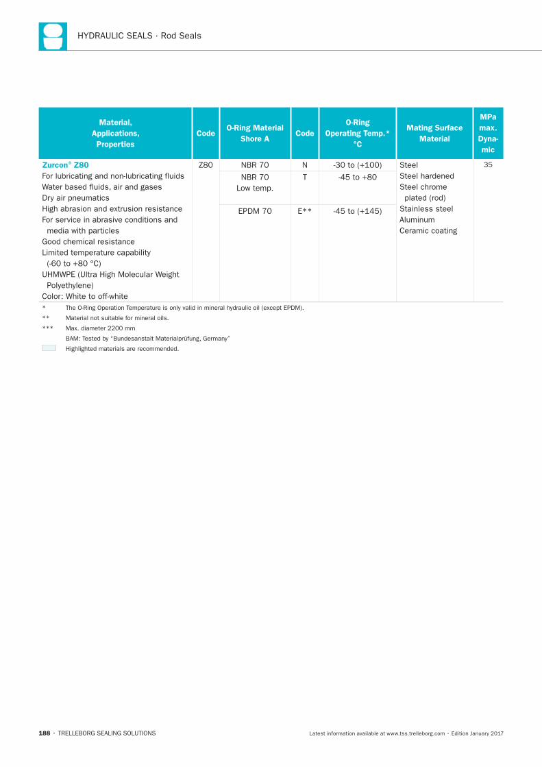
188
Material,
Applications,
Properties
CodeO-Ring Material
Shore ACode
O-Ring
Operating Temp.*
°C
Mating Surface
Material
MPa
max.
Dyna-
mic
Zurcon®Z80
N Steel
Steel chrome
Stainless steel
Ceramic coating
T
E**
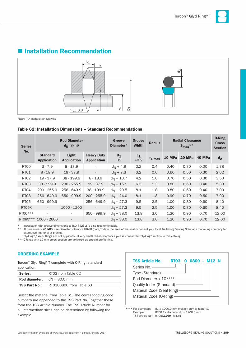
189
Installation Recommendation
D1
r1L1
rmax. 0.3 d NS
d 2
Installation Drawing
Table 62: Installation Dimensions – Standard Recommendations
Series
No.
Rod Diameter
dN
Groove
Diameter*
Groove
Width Radius
Radial Clearance
Smax**
O-Ring
Cross
Section
Standard
Application
Light
Application
Heavy Duty
Application
D1
L1 r1 max 10 MPa 20 MPa 40 MPa d2
N
N
N
N
N
N
N
N
N
N
40 MPa
ORDERING EXAMPLE
® ®
Series:
Rod diameter:
TSS Part No.:
Material Code (Seal Ring)
Series No.
TSS Article No. M120800 N
Material Code (O-Ring)
Rod Diameter x 10****
RT03
Quality Index (Standard)
-
Type (Standard)
0
N
N
X1200
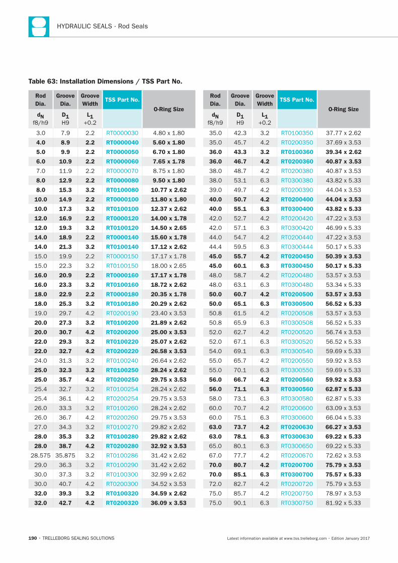
190
Table 63: Installation Dimensions / TSS Part No.
Rod
Dia.
Groove
Dia.
Groove
WidthTSS Part No.
O-Ring SizedN D1 L1
4.0 8.9 2.2 RT0000040 5.60 x 1.80
5.0 9.9 2.2 RT0000050 6.70 x 1.80
6.0 10.9 2.2 RT0000060 7.65 x 1.78
8.0 12.9 2.2 RT0000080 9.50 x 1.80
8.0 15.3 3.2 RT0100080 10.77 x 2.62
10.0 14.9 2.2 RT0000100 11.80 x 1.80
10.0 17.3 3.2 RT0100100 12.37 x 2.62
12.0 16.9 2.2 RT0000120 14.00 x 1.78
12.0 19.3 3.2 RT0100120 14.50 x 2.65
14.0 18.9 2.2 RT0000140 15.60 x 1.78
14.0 21.3 3.2 RT0100140 17.12 x 2.62
16.0 20.9 2.2 RT0000160 17.17 x 1.78
16.0 23.3 3.2 RT0100160 18.72 x 2.62
18.0 22.9 2.2 RT0000180 20.35 x 1.78
18.0 25.3 3.2 RT0100180 20.29 x 2.62
20.0 27.3 3.2 RT0100200 21.89 x 2.62
20.0 30.7 4.2 RT0200200 25.00 x 3.53
22.0 29.3 3.2 RT0100220 25.07 x 2.62
22.0 32.7 4.2 RT0200220 26.58 x 3.53
25.0 32.3 3.2 RT0100250 28.24 x 2.62
25.0 35.7 4.2 RT0200250 29.75 x 3.53
28.0 35.3 3.2 RT0100280 29.82 x 2.62
28.0 38.7 4.2 RT0200280 32.92 x 3.53
32.0 39.3 3.2 RT0100320 34.59 x 2.62
32.0 42.7 4.2 RT0200320 36.09 x 3.53
Rod
Dia.
Groove
Dia.
Groove
WidthTSS Part No.
O-Ring SizedN D1 L1
36.0 43.3 3.2 RT0100360 39.34 x 2.62
36.0 46.7 4.2 RT0200360 40.87 x 3.53
40.0 50.7 4.2 RT0200400 44.04 x 3.53
40.0 55.1 6.3 RT0300400 43.82 x 5.33
45.0 55.7 4.2 RT0200450 50.39 x 3.53
45.0 60.1 6.3 RT0300450 50.17 x 5.33
50.0 60.7 4.2 RT0200500 53.57 x 3.53
50.0 65.1 6.3 RT0300500 56.52 x 5.33
56.0 66.7 4.2 RT0200560 59.92 x 3.53
56.0 71.1 6.3 RT0300560 62.87 x 5.33
63.0 73.7 4.2 RT0200630 66.27 x 3.53
63.0 78.1 6.3 RT0300630 69.22 x 5.33
70.0 80.7 4.2 RT0200700 75.79 x 3.53
70.0 85.1 6.3 RT0300700 75.57 x 5.33
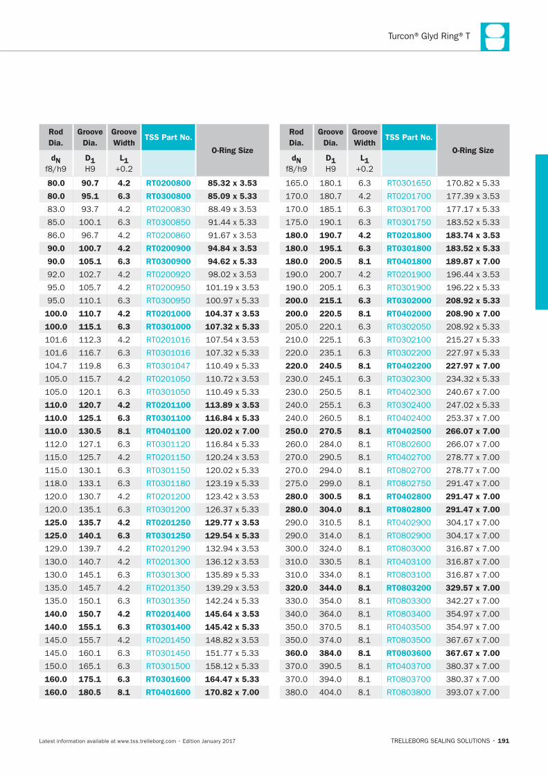
191
Rod
Dia.
Groove
Dia.
Groove
WidthTSS Part No.
O-Ring SizedN D1 L1
80.0 90.7 4.2 RT0200800 85.32 x 3.53
80.0 95.1 6.3 RT0300800 85.09 x 5.33
90.0 100.7 4.2 RT0200900 94.84 x 3.53
90.0 105.1 6.3 RT0300900 94.62 x 5.33
100.0 110.7 4.2 RT0201000 104.37 x 3.53
100.0 115.1 6.3 RT0301000 107.32 x 5.33
110.0 120.7 4.2 RT0201100 113.89 x 3.53
110.0 125.1 6.3 RT0301100 116.84 x 5.33
110.0 130.5 8.1 RT0401100 120.02 x 7.00
125.0 135.7 4.2 RT0201250 129.77 x 3.53
125.0 140.1 6.3 RT0301250 129.54 x 5.33
140.0 150.7 4.2 RT0201400 145.64 x 3.53
140.0 155.1 6.3 RT0301400 145.42 x 5.33
160.0 175.1 6.3 RT0301600 164.47 x 5.33
160.0 180.5 8.1 RT0401600 170.82 x 7.00
Rod
Dia.
Groove
Dia.
Groove
WidthTSS Part No.
O-Ring SizedN D1 L1
180.0 190.7 4.2 RT0201800 183.74 x 3.53
180.0 195.1 6.3 RT0301800 183.52 x 5.33
180.0 200.5 8.1 RT0401800 189.87 x 7.00
200.0 215.1 6.3 RT0302000 208.92 x 5.33
200.0 220.5 8.1 RT0402000 208.90 x 7.00
220.0 240.5 8.1 RT0402200 227.97 x 7.00
250.0 270.5 8.1 RT0402500 266.07 x 7.00
280.0 300.5 8.1 RT0402800 291.47 x 7.00
280.0 304.0 8.1 RT0802800 291.47 x 7.00
320.0 344.0 8.1 RT0803200 329.57 x 7.00
360.0 384.0 8.1 RT0803600 367.67 x 7.00
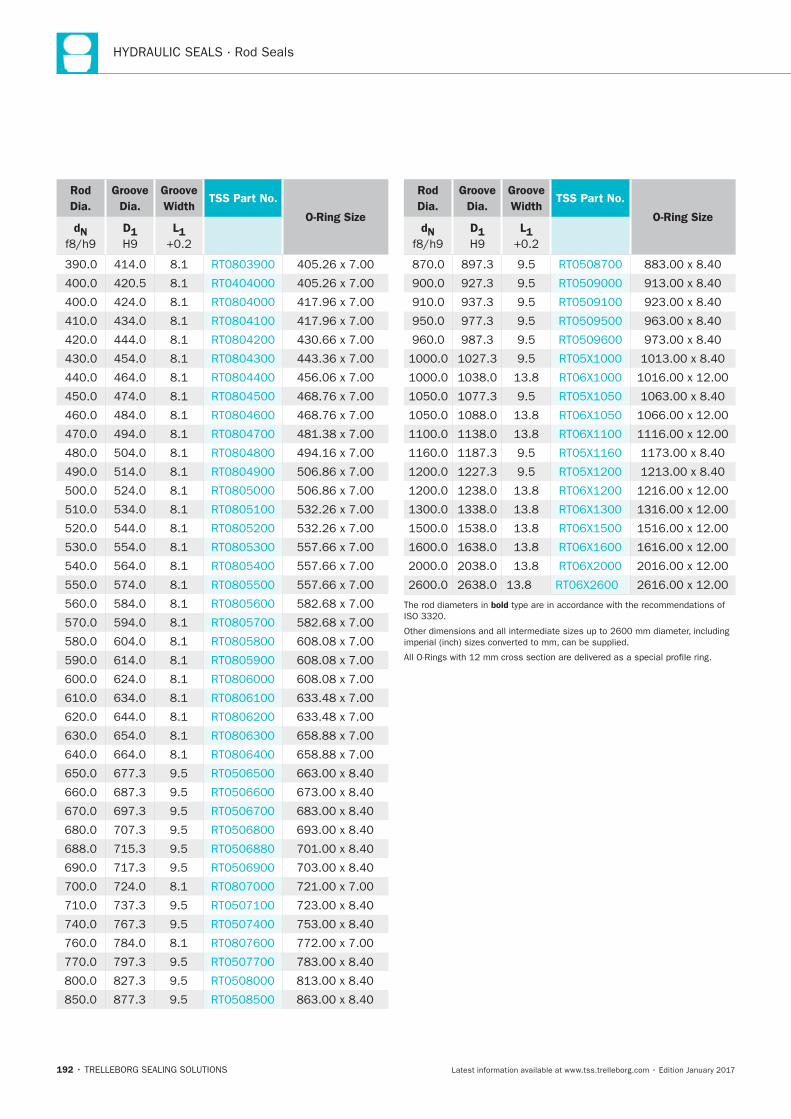
192
Rod
Dia.
Groove
Dia.
Groove
WidthTSS Part No.
O-Ring SizedN D1 L1
Rod
Dia.
Groove
Dia.
Groove
WidthTSS Part No.
O-Ring SizedN D1 L1
bold
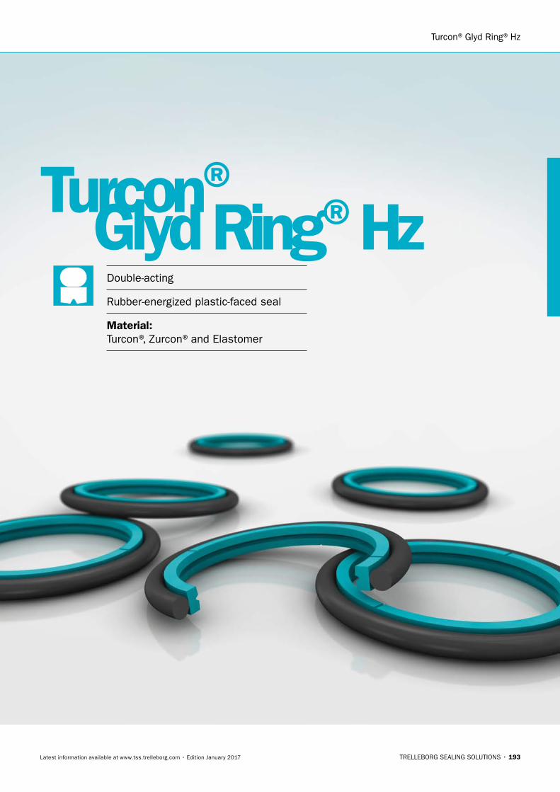
Turcon®Glyd Ring®Hz
TRELLEBORG SEALING SOLUTIONS • 193Latest information available at www.tss.trelleborg.com • Edition January 2017
Double-acting
Rubber-energized plastic-faced seal
Material:Turcon®, Zurcon®and Elastomer
Turcon®Glyd Ring®Hz

194
HYDRAULIC SEALS · Rod Seals
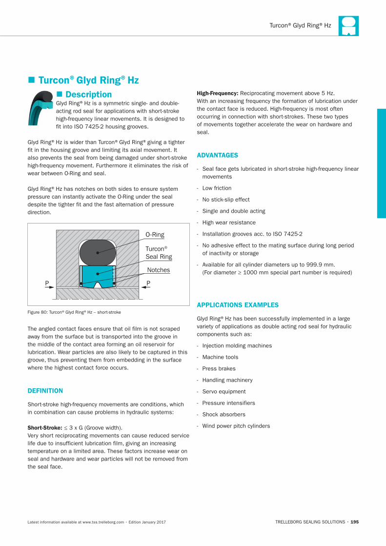
Turcon®Glyd Ring®Hz
195
Description
O-Ring
Turcon® Seal Ring
P P
Notches
DEFINITION
Short-Stroke:
High-Frequency:
ADVANTAGES
APPLICATIONS EXAMPLES
Turcon®Glyd Ring®Hz
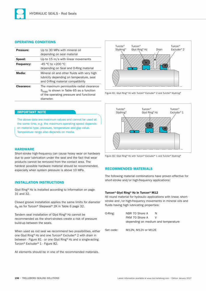
196
HYDRAULIC SEALS · Rod Seals
OPERATING CONDITIONS
Pressure:
Speed:
Frequency:
Media:
Clearance:
IMPORTANT NOTE
HARDWARE
INSTALLATION INSTRUCTIONS
Turcite®
Slydring®Turcon® Glyd Ring® Hz
Turcon® Excluder® 2Drain
Turcon® Glyd Ring® Hz
Turcite®
Slydring®Turcon® Excluder® 1
RECOMMENDED MATERIALS
Turcon®Glyd Ring®Hz in Turcon®M12
Turcon®Glyd Ring®Hz
197
Turcon®Glyd Ring®Hz in Turcon®T49
Turcon®Glyd Ring®Hz in Turcon®T40
Zurcon®Glyd Ring®Hz in Zurcon®Z80
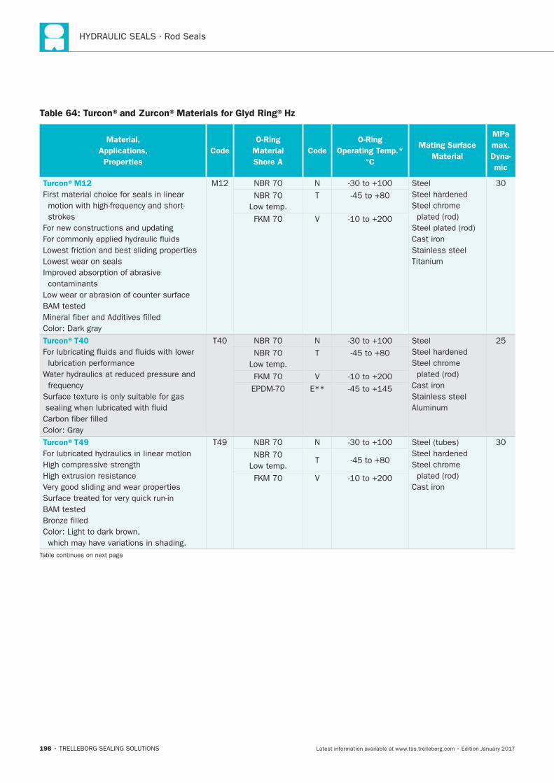
198
HYDRAULIC SEALS · Rod Seals
Table 64: Turcon®and Zurcon®Materials for Glyd Ring®Hz
Material,
Applications,
Properties
Code
O-Ring
Material
Shore A
Code
O-Ring
Operating Temp.*
°C
Mating Surface
Material
MPa
max.
Dyna-
mic
Turcon®M12
V
Turcon®T40
V
Turcon®T49
V
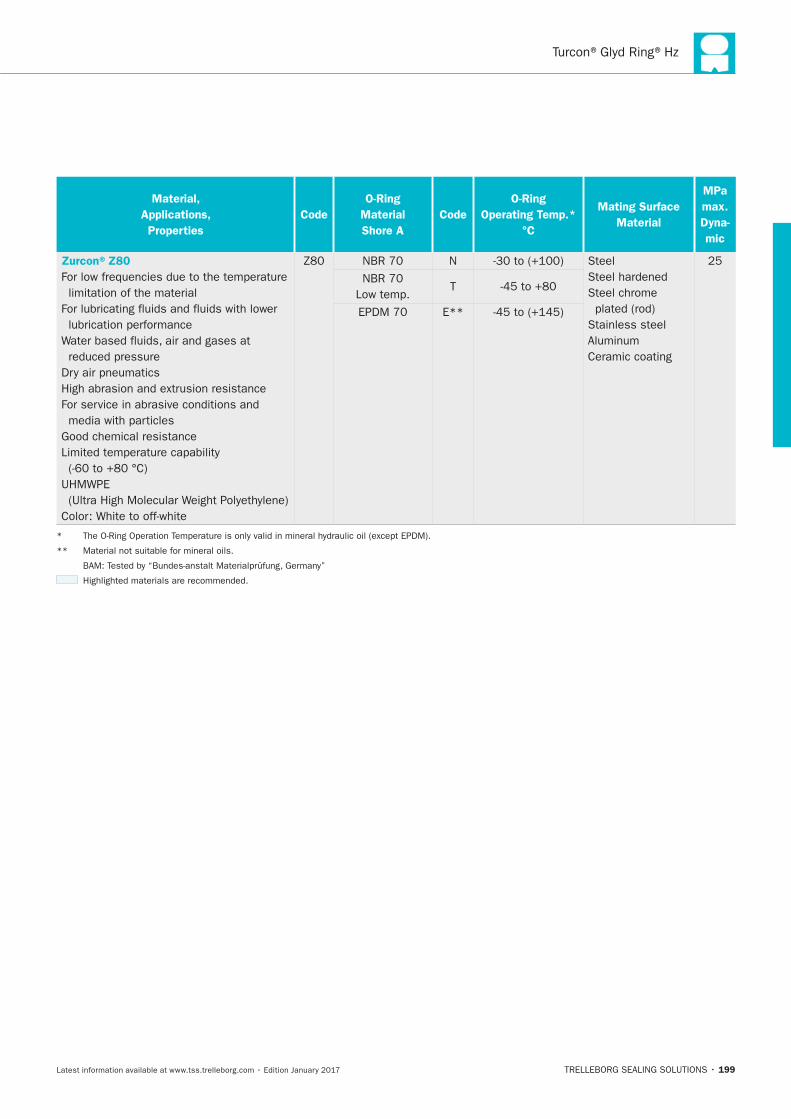
Turcon®Glyd Ring®Hz
199
Material,
Applications,
Properties
Code
O-Ring
Material
Shore A
Code
O-Ring
Operating Temp.*
°C
Mating Surface
Material
MPa
max.
Dyna-
mic
Zurcon®Z80
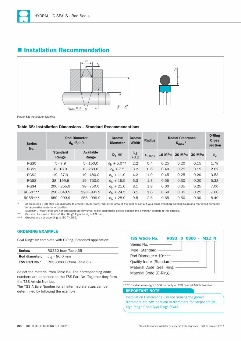
200
HYDRAULIC SEALS · Rod Seals
Installation Recommendation
D1
r1L1
rmax. 0.3 d NS
d 2
Table 65: Installation Dimensions – Standard Recommendations
Series
No.
Rod Diameter
dN
Groove
Diameter
Groove
WidthRadius
Radial Clearance
Smax*
O-Ring
Cross
Section
Standard
Range
Available
RangeD1
L1 r 10 MPa 20 MPa 30 MPa d2
ORDERING EXAMPLE
Series:
Rod diameter:
TSS Part No.:
Material Code (Seal Ring)
Series No.
TSS Article No. M120800 N
Material Code (O-Ring)
Rod Diameter x 10****
RGS3
Quality Index (Standard)
-
Type (Standard)
0
IMPORTANT NOTE
not
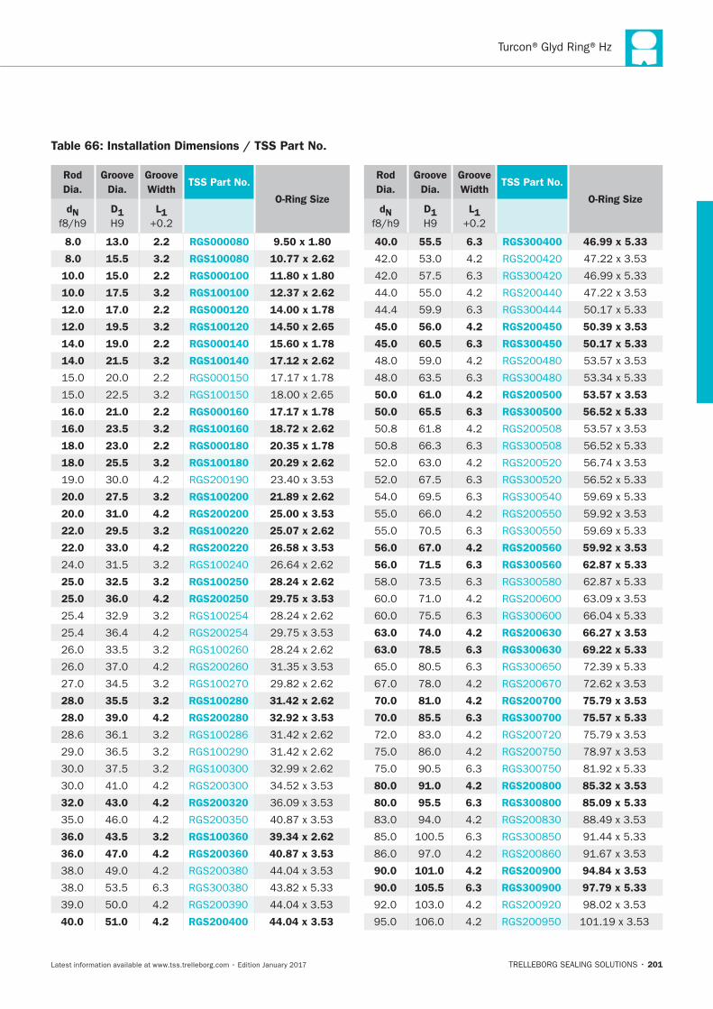
Turcon®Glyd Ring®Hz
201
Rod
Dia.
Groove
Dia.
Groove
WidthTSS Part No.
O-Ring SizedN D1 L1
8.0 13.0 2.2 RGS000080 9.50 x 1.80
8.0 15.5 3.2 RGS100080 10.77 x 2.62
10.0 15.0 2.2 RGS000100 11.80 x 1.80
10.0 17.5 3.2 RGS100100 12.37 x 2.62
12.0 17.0 2.2 RGS000120 14.00 x 1.78
12.0 19.5 3.2 RGS100120 14.50 x 2.65
14.0 19.0 2.2 RGS000140 15.60 x 1.78
14.0 21.5 3.2 RGS100140 17.12 x 2.62
16.0 21.0 2.2 RGS000160 17.17 x 1.78
16.0 23.5 3.2 RGS100160 18.72 x 2.62
18.0 23.0 2.2 RGS000180 20.35 x 1.78
18.0 25.5 3.2 RGS100180 20.29 x 2.62
20.0 27.5 3.2 RGS100200 21.89 x 2.62
20.0 31.0 4.2 RGS200200 25.00 x 3.53
22.0 29.5 3.2 RGS100220 25.07 x 2.62
22.0 33.0 4.2 RGS200220 26.58 x 3.53
25.0 32.5 3.2 RGS100250 28.24 x 2.62
25.0 36.0 4.2 RGS200250 29.75 x 3.53
28.0 35.5 3.2 RGS100280 31.42 x 2.62
28.0 39.0 4.2 RGS200280 32.92 x 3.53
32.0 43.0 4.2 RGS200320
36.0 43.5 3.2 RGS100360 39.34 x 2.62
36.0 47.0 4.2 RGS200360 40.87 x 3.53
40.0 51.0 4.2 RGS200400 44.04 x 3.53
Rod
Dia.
Groove
Dia.
Groove
WidthTSS Part No.
O-Ring SizedN D1 L1
40.0 55.5 6.3 RGS300400 46.99 x 5.33
45.0 56.0 4.2 RGS200450 50.39 x 3.53
45.0 60.5 6.3 RGS300450 50.17 x 5.33
50.0 61.0 4.2 RGS200500 53.57 x 3.53
50.0 65.5 6.3 RGS300500 56.52 x 5.33
56.0 67.0 4.2 RGS200560 59.92 x 3.53
56.0 71.5 6.3 RGS300560 62.87 x 5.33
63.0 74.0 4.2 RGS200630 66.27 x 3.53
63.0 78.5 6.3 RGS300630 69.22 x 5.33
70.0 81.0 4.2 RGS200700 75.79 x 3.53
70.0 85.5 6.3 RGS300700 75.57 x 5.33
80.0 91.0 4.2 RGS200800 85.32 x 3.53
80.0 95.5 6.3 RGS300800 85.09 x 5.33
90.0 101.0 4.2 RGS200900 94.84 x 3.53
90.0 105.5 6.3 RGS300900 97.79 x 5.33
Table 66: Installation Dimensions / TSS Part No.
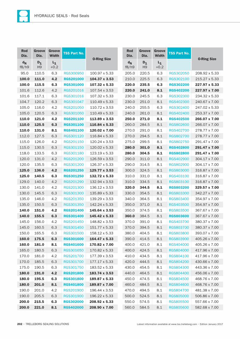
202
HYDRAULIC SEALS · Rod Seals
Rod
Dia.
Groove
Dia.
Groove
WidthTSS Part No.
O-Ring SizedN D1 L1
100.0 111.0 4.2 RGS201000 104.37 x 3.53
100.0 115.5 6.3 RGS301000 107.32 x 5.33
110.0 121.0 4.2 RGS201100 113.89 x 3.53
110.0 125.5 6.3 RGS301100 116.84 x 5.33
110.0 131.0 8.1 RGS401100 120.02 x 7.00
125.0 136.0 4.2 RGS201250 129.77 x 3.53
125.0 140.5 6.3 RGS301250 132.72 x 5.33
140.0 151.0 4.2 RGS201400 145.64 x 3.53
140.0 155.5 6.3 RGS301400 145.42 x 5.33
160.0 175.5 6.3 RGS301600 164.47 x 5.33
160.0 181.0 8.1 RGS401600 170.82 x 7.00
180.0 191.0 4.2 RGS201800 183.74 x 3.53
180.0 195.5 6.3 RGS301800 189.87 x 5.33
180.0 201.0 8.1 RGS401800 189.87 x 7.00
200.0 215.5 6.3 RGS302000 208.92 x 5.33
200.0 221.0 8.1 RGS402000 208.90 x 7.00
Rod
Dia.
Groove
Dia.
Groove
WidthTSS Part No.
O-Ring SizedN D1 L1
220.0 235.5 6.3 RGS302200 227.97 x 5.33
220.0 241.0 8.1 RGS402200 227.97 x 7.00
250.0 271.0 8.1 RGS402500 266.07 x 7.00
280.0 301.0 8.1 RGS402800 291.47 x 7.00
280.0 304.5 8.1 RGS802800 291.47 x 7.00
320.0 344.5 8.1 RGS803200 329.57 x 7.00
360.0 RGS803600
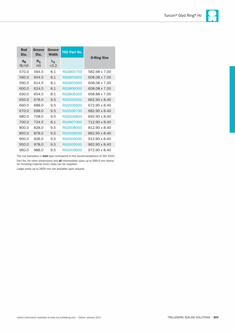
Turcon®Glyd Ring®Hz
203
Rod
Dia.
Groove
Dia.
Groove
WidthTSS Part No.
O-Ring SizedN D1 L1
bold
all

204
HYDRAULIC SEALS · Rod Seals
TRELLEBORG SEALING SOLUTIONS • 205Latest information available at www.tss.trelleborg.com • Edition January 2017
Turcon®AQ-Seal®Bean Seal
Double-acting
Rubber-energized plastic-faced seal
Material:Turcon®, and Zurcon®and Elastometer
Turcon®AQ-Seal® with Bean Seal

206
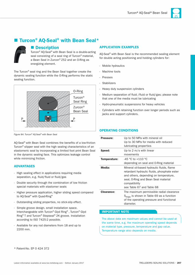
207
Description® ®
®
®
®
Turcon® Seal Ring
Zurcon® Bean Seal
O-Ring
P P
® ®with Bean Seal
®
®
ADVANTAGES
® ®
® ® ®
Ring® ® ®
APPLICATION EXAMPLES
®
Machine tools
Presses
OPERATING CONDITIONS
Pressure:
Speed:
movements
Temperature:
Media:
Clearance:
S
IMPORTANT NOTE
Turcon®AQ-Seal® with Bean Seal*
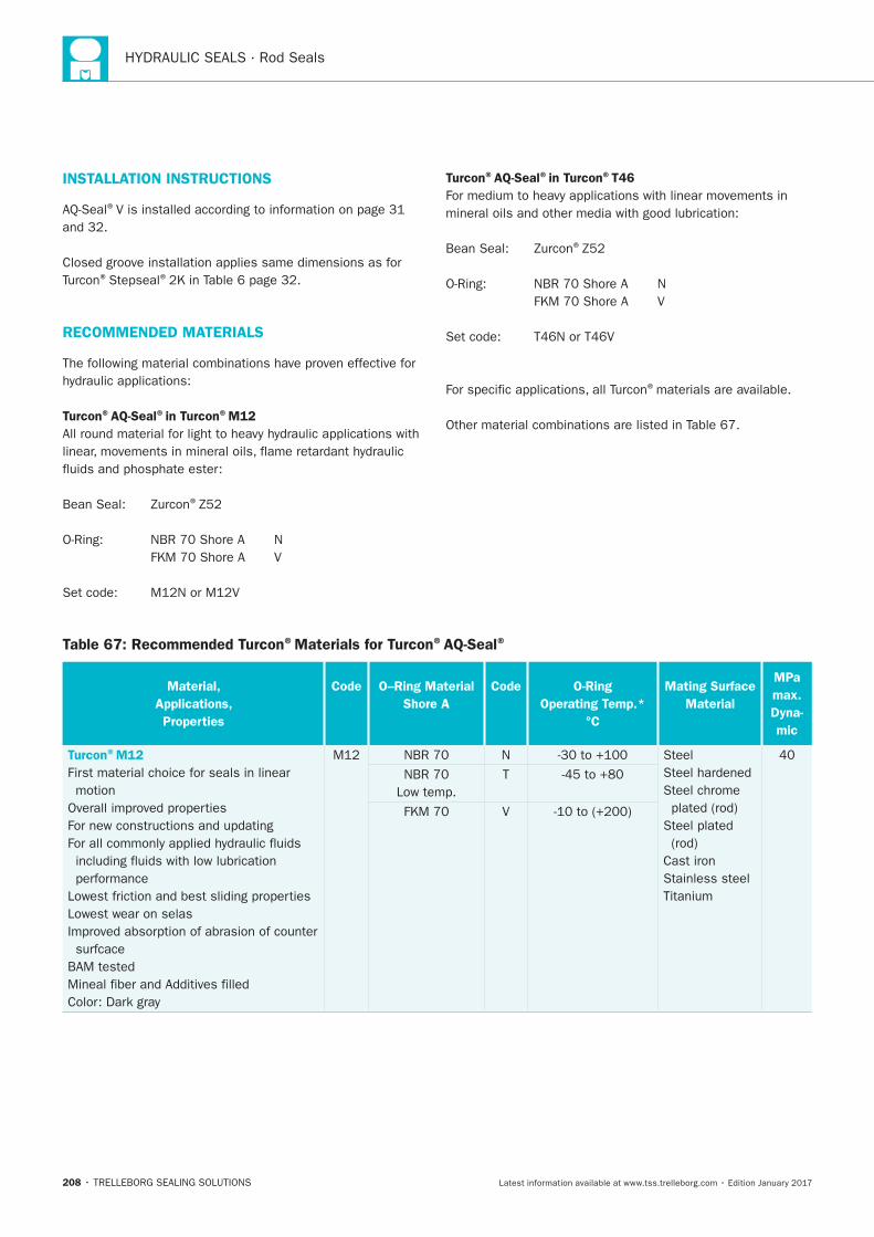
208
INSTALLATION INSTRUCTIONS
®
® ®
RECOMMENDED MATERIALS
Turcon®AQ-Seal®in Turcon®M12
®
Turcon®AQ-Seal®in Turcon®T46
®
®materials are available.
Table 67: Recommended Turcon®Materials for Turcon®AQ-Seal®
Material,
Applications,
Properties
Code
O–Ring Material
Shore A
Code
O-Ring
Operating Temp.*
°C
Mating Surface
Material
MPa
max.
Dyna-
mic
Turcon®M12
First material choice for seals in linear
motion
Lowest wear on selas
N Steel
Steel chrome
Cast iron
Stainless steel
T
V
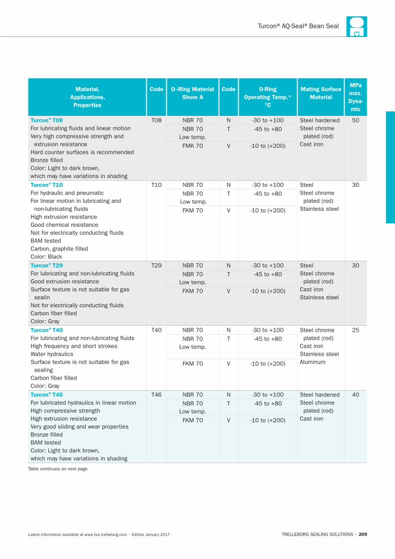
209
Material,
Applications,
Properties
Code
O–Ring Material
Shore A
Code
O-Ring
Operating Temp.*
°C
Mating Surface
Material
MPa
max.
Dyna-
mic
Turcon®T08
N
Steel chrome
Cast iron
T
V
Turcon®T10
N Steel
Steel chrome
Stainless steel
T
V
Turcon®T29
sealin
N Steel
Steel chrome
Cast iron
Stainless steel
T
V
Turcon®T40
sealing
N Steel chrome
Cast iron
Stainless steel
T
V
Turcon®T46
N
Steel chrome
Cast iron
T
V
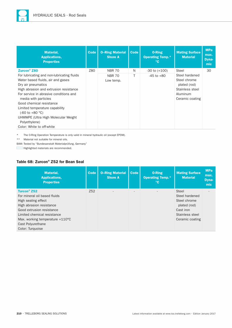
210
Material,
Applications,
Properties
Code
O–Ring Material
Shore A
Code
O-Ring
Operating Temp.*
°C
Mating Surface
Material
MPa
max.
Dyna-
mic
Zurcon®Z80
N Steel
Steel chrome
Stainless steel
Ceramic coating
T
Table 68: Zurcon®Z52 for Bean Seal
Material,
Applications,
Properties
Code
O–Ring Material
Shore A
Code
O-Ring
Operating Temp.*
°C
Mating Surface
Material
MPa
max.
Dyna-
mic
Turcon®Z52
High sealing effect
High abrasion resistance
Steel
Steel chrome
Cast iron
Stainless steel
Ceramic coating
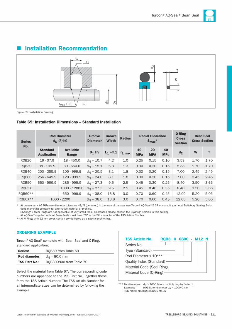
211
Installation Recommendation
D1
r1L1
rmax. 0.3 d NS
d 2
W
T
Installation Drawing
Table 69: Installation Dimensions – Standard Installation
Series
No.
Rod Diameter
dN
Groove
Diameter
Groove
WidthRadius
Radial Clearance
Smax*
O-Ring
Cross
Section
Bean Seal
Cross Section
Standard
Application
Available
RangeD1 L1 r1 max
10
MPa
20
MPA
40
MPad2 W T
N
N
N
N
N
N
N
N
40 MPa
®
ORDERING EXAMPLE
® ®
Series:
Rod diameter: N
TSS Part No.:
Material Code (Seal Ring)
Series No.
TSS Article No. M120800 N
Material Code (O-Ring)
Rod Diameter x 10***
RQB3
Quality Index (Standard)
-
Type (Standard)
0
N
N
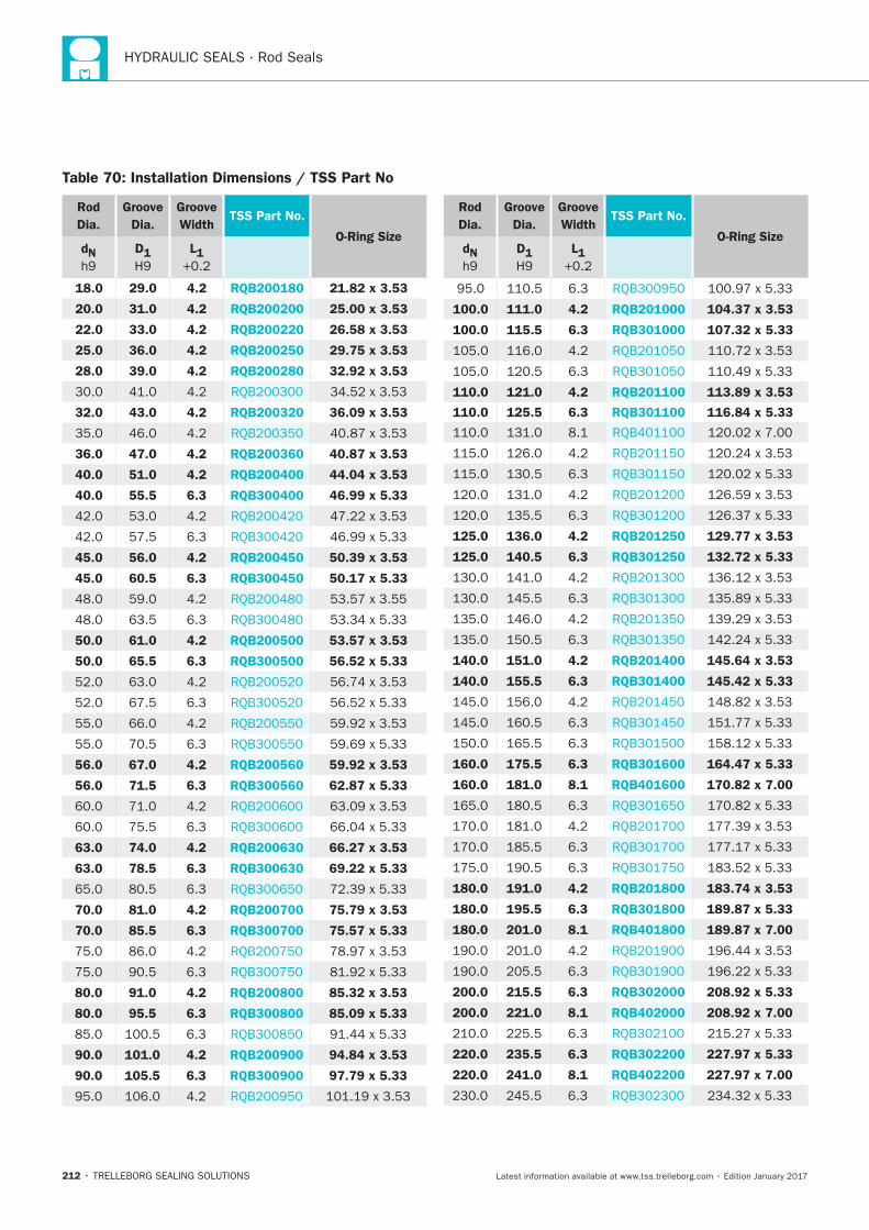
212
Table 70: Installation Dimensions / TSS Part No
Rod
Dia.
Groove
Dia.
Groove
WidthTSS Part No.
O-Ring SizedN D1 L1
18.0 29.0 4.2 RQB200180 21.82 x 3.53
20.0 31.0 4.2 RQB200200 25.00 x 3.53
22.0 33.0 4.2 RQB200220 26.58 x 3.53
25.0 36.0 4.2 RQB200250 29.75 x 3.53
28.0 39.0 4.2 RQB200280 32.92 x 3.53
32.0 43.0 4.2 RQB200320 36.09 x 3.53
36.0 47.0 4.2 RQB200360 40.87 x 3.53
40.0 51.0 4.2 RQB200400 44.04 x 3.53
40.0 55.5 6.3 RQB300400 46.99 x 5.33
45.0 56.0 4.2 RQB200450 50.39 x 3.53
45.0 60.5 6.3 RQB300450 50.17 x 5.33
50.0 61.0 4.2 RQB200500 53.57 x 3.53
50.0 65.5 6.3 RQB300500 56.52 x 5.33
56.0 67.0 4.2 RQB200560 59.92 x 3.53
56.0 71.5 6.3 RQB300560 62.87 x 5.33
63.0 74.0 4.2 RQB200630 66.27 x 3.53
63.0 78.5 6.3 RQB300630 69.22 x 5.33
70.0 81.0 4.2 RQB200700 75.79 x 3.53
70.0 85.5 6.3 RQB300700 75.57 x 5.33
80.0 91.0 4.2 RQB200800 85.32 x 3.53
80.0 95.5 6.3 RQB300800 85.09 x 5.33
90.0 101.0 4.2 RQB200900 94.84 x 3.53
90.0 105.5 6.3 RQB300900 97.79 x 5.33
Rod
Dia.
Groove
Dia.
Groove
WidthTSS Part No.
O-Ring SizedN D1 L1
100.0 111.0 4.2 RQB201000 104.37 x 3.53
100.0 115.5 6.3 RQB301000 107.32 x 5.33
110.0 121.0 4.2 RQB201100 113.89 x 3.53
110.0 125.5 6.3 RQB301100 116.84 x 5.33
125.0 136.0 4.2 RQB201250 129.77 x 3.53
125.0 140.5 6.3 RQB301250 132.72 x 5.33
140.0 151.0 4.2 RQB201400 145.64 x 3.53
140.0 155.5 6.3 RQB301400 145.42 x 5.33
160.0 175.5 6.3 RQB301600 164.47 x 5.33
160.0 181.0 8.1 RQB401600 170.82 x 7.00
180.0 191.0 4.2 RQB201800 183.74 x 3.53
180.0 195.5 6.3 RQB301800 189.87 x 5.33
180.0 201.0 8.1 RQB401800 189.87 x 7.00
200.0 215.5 6.3 RQB302000 208.92 x 5.33
200.0 221.0 8.1 RQB402000 208.92 x 7.00
220.0 235.5 6.3 RQB302200 227.97 x 5.33
220.0 241.0 8.1 RQB402200 227.97 x 7.00
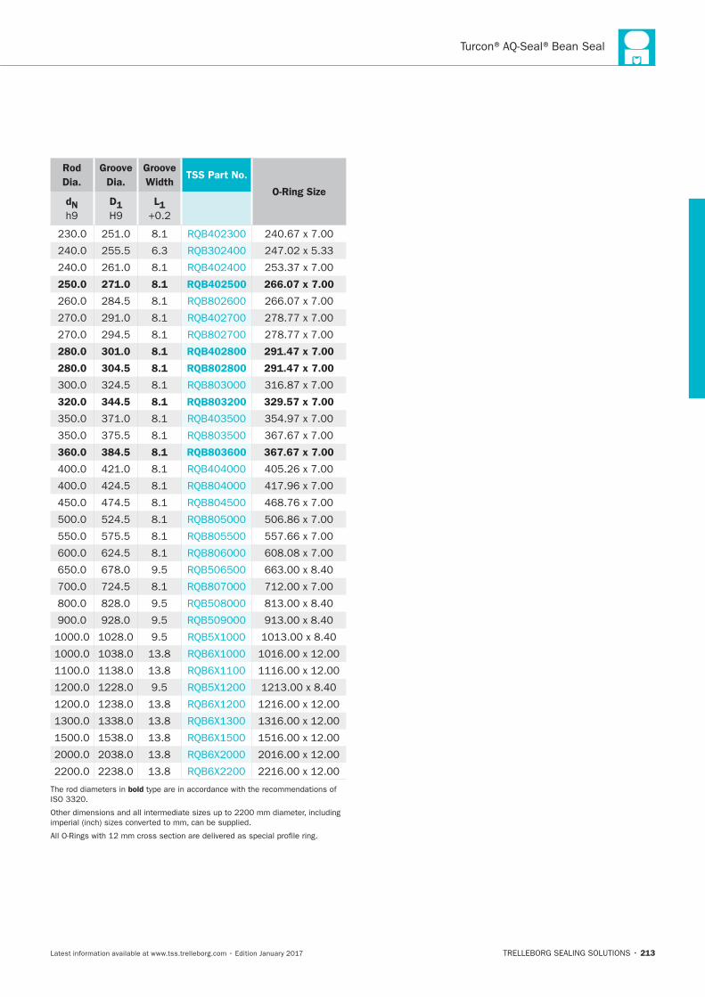
213
Rod
Dia.
Groove
Dia.
Groove
WidthTSS Part No.
O-Ring SizedN D1 L1
250.0 271.0 8.1 RQB402500 266.07 x 7.00
280.0 301.0 8.1 RQB402800 291.47 x 7.00
280.0 304.5 8.1 RQB802800 291.47 x 7.00
320.0 344.5 8.1 RQB803200 329.57 x 7.00
360.0 384.5 8.1 RQB803600 367.67 x 7.00
bold

214
Turcon®AQ-Seal®5 Bean Seal
TRELLEBORG SEALING SOLUTIONS • 215Latest information available at www.tss.trelleborg.com • Edition January 2017
Double-acting
Rubber-energized plastic-faced seal
Material:Turcon®, Zurcon®and Elastomer
Turcon® AQ-Seal®5with Bean Seal

216
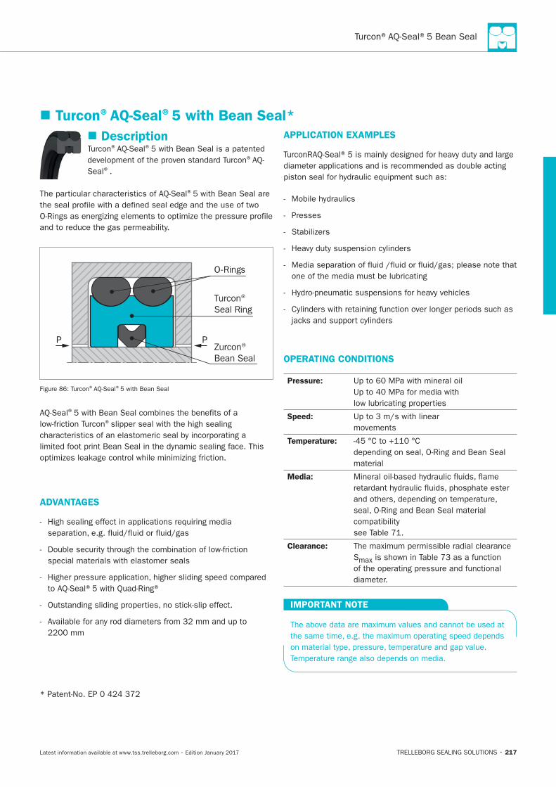
217
Description® ®
®
Seal®.
®
Turcon® Seal Ring
Zurcon® Bean Seal
O-Rings
P P
® ®
®
®
ADVANTAGES
APPLICATION EXAMPLES
Presses
OPERATING CONDITIONS
Pressure:
Speed:
movements
Temperature:
material
Media:
Clearance:
S
IMPORTANT NOTE
Turcon®AQ-Seal®5 with Bean Seal*
218
INSTALLATION INSTRUCTIONS
®
RECOMMENDED MATERIALS
Turcon®AQ-Seal®5 in Turcon®M12
®
Turcon®AQ-Seal®5 in Turcon®T46
®
®materials are available.
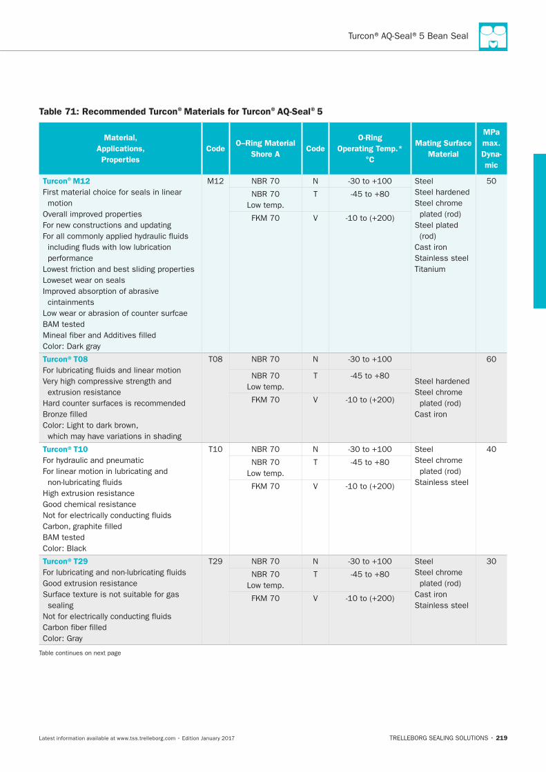
219
Table 71: Recommended Turcon®Materials for Turcon®AQ-Seal®5
Material,
Applications,
Properties
CodeO–Ring Material
Shore ACode
O-Ring
Operating Temp.*
°C
Mating Surface
Material
MPa
max.
Dyna-
mic
Turcon®M12
First material choice for seals in linear
motion
Loweset wear on seals
cintainments
N Steel
Steel chrome
Cast iron
Stainless steel
T
V
Turcon®T08
N
Steel chrome
Cast iron
T
V
Turcon®T10
N Steel
Steel chrome
Stainless steel
T
V
Turcon®T29
sealing
N Steel
Steel chrome
Cast iron
Stainless steel
T
V
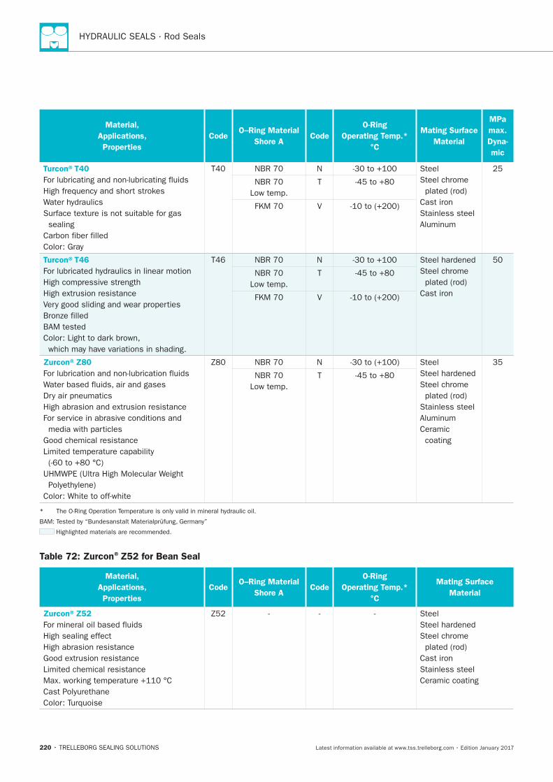
220
Material,
Applications,
Properties
CodeO–Ring Material
Shore ACode
O-Ring
Operating Temp.*
°C
Mating Surface
Material
MPa
max.
Dyna-
mic
Turcon®T40
sealing
N Steel
Steel chrome
Cast iron
Stainless steel
T
V
Turcon®T46 N
Steel chrome
Cast iron
T
V
Zurcon®Z80
N Steel
Steel chrome
Stainless steel
Ceramic
coating
T
Table 72: Zurcon®Z52 for Bean Seal
Material,
Applications,
Properties
CodeO–Ring Material
Shore ACode
O-Ring
Operating Temp.*
°C
Mating Surface
Material
Zurcon®Z52
High sealing effect
High abrasion resistance
Steel
Steel chrome
Cast iron
Stainless steel
Ceramic coating
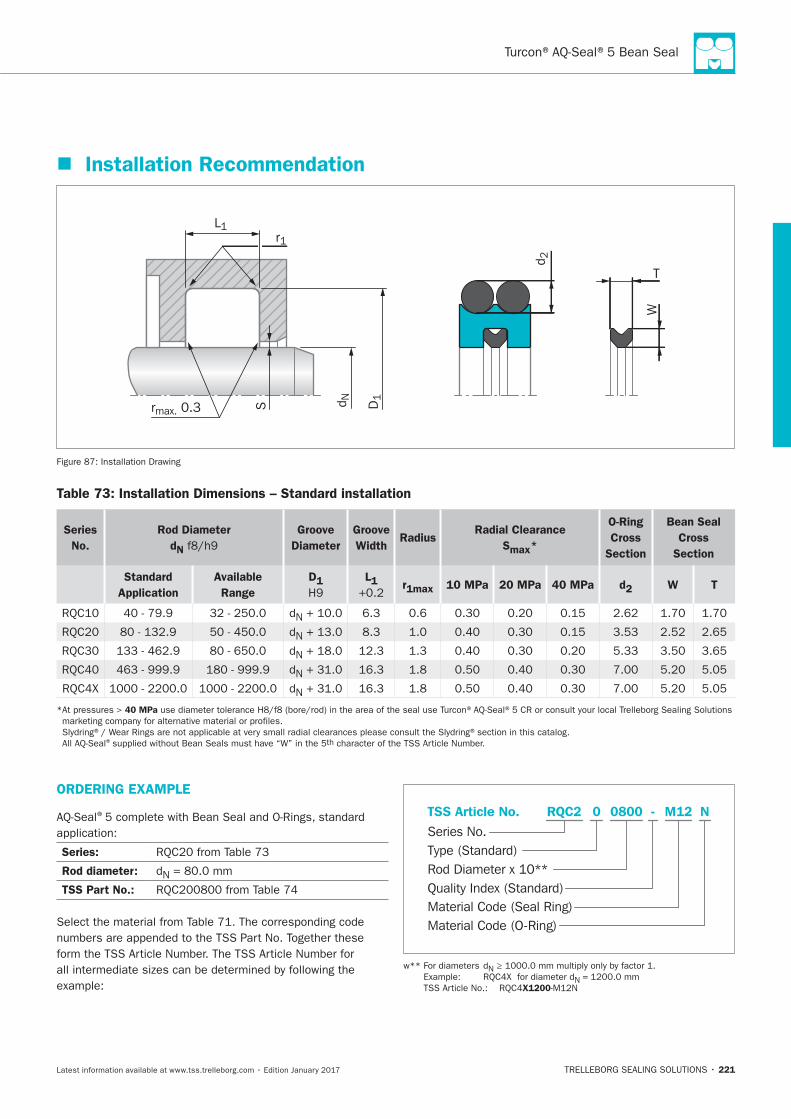
221
Installation Recommendation
D1
r1L1
rmax. 0.3 d NS
d 2
W
T
Installation Drawing
Table 73: Installation Dimensions – Standard installation
Series
No.
Rod Diameter
dN
Groove
Diameter
Groove
WidthRadius
Radial Clearance
Smax*
O-Ring
Cross
Section
Bean Seal
Cross
Section
Standard
Application
Available
Range
D1 L1 r1max 10 MPa 20 MPa 40 MPa d2 W T
N
N
N
N
N
40 MPa
® th
ORDERING EXAMPLE
®
Series:
Rod diameter: N
TSS Part No.:
Material Code (Seal Ring)
Series No.
TSS Article No. M120800 N
Material Code (O-Ring)
Rod Diameter x 10**
RQC2
Quality Index (Standard)
-
Type (Standard)
0
N
N =
X1200
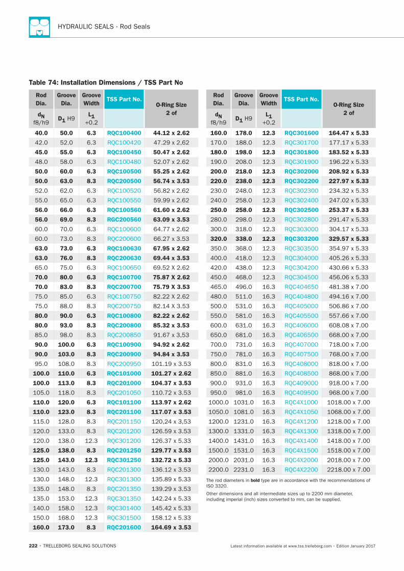
222
Table 74: Installation Dimensions / TSS Part No
Rod
Dia.
Groove
Dia.
Groove
WidthTSS Part No.
O-Ring Size
2 ofdN D1
L1
40.0 50.0 6.3 RQC100400 44.12 x 2.62
45.0 55.0 6.3 RQC100450 50.47 x 2.62
50.0 60.0 6.3 RQC100500 55.25 x 2.62
50.0 63.0 8.3 RQC200500 56.74 x 3.53
56.0 66.0 6.3 RQC100560 61.60 x 2.62
56.0 69.0 8.3 RGC200560 63.09 x 3.53
63.0 73.0 6.3 RQC100630 67.95 x 2.62
63.0 76.0 8.3 RQC200630 69.44 x 3.53
70.0 80.0 6.3 RQC100700 75.87 X 2.62
70.0 83.0 8.3 RQC200700 75.79 X 3.53
80.0 90.0 6.3 RQC100800 82.22 x 2.62
80.0 93.0 8.3 RQC200800 85.32 x 3.53
90.0 100.0 6.3 RQC100900 94.92 x 2.62
90.0 103.0 8.3 RQC200900 94.84 x 3.53
100.0 110.0 6.3 RQC101000 101.27 x 2.62
100.0 113.0 8.3 RQC201000 104.37 x 3.53
110.0 120.0 6.3 RQC101100 113.97 x 2.62
110.0 123.0 8.3 RQC201100 117.07 x 3.53
125.0 138.0 8.3 RQC201250 129.77 x 3.53
125.0 143.0 12.3 RQC301250 132.72 x 5.33
160.0 173.0 8.3 RQC201600 164.69 x 3.53
Rod
Dia.
Groove
Dia.
Groove
WidthTSS Part No.
O-Ring Size
2 ofdN D1
L1
160.0 178.0 12.3 RQC301600 164.47 x 5.33
180.0 198.0 12.3 RQC301800 183.52 x 5.33
200.0 218.0 12.3 RQC302000 208.92 x 5.33
220.0 238.0 12.3 RQC302200 227.97 x 5.33
250.0 258.0 12.3 RQC302500 253.37 x 5.33
320.0 338.0 12.3 RQC303200 329.57 x 5.33
bold
Zurcon®Wynseal M
TRELLEBORG SEALING SOLUTIONS • 223Latest information available at www.tss.trelleborg.com • Edition January 2017
Double-acting
Rubber-energized plastic-faced seal
Material:Turcon®, Zurcon®and Elastomer
Zurcon®Wynseal M

224
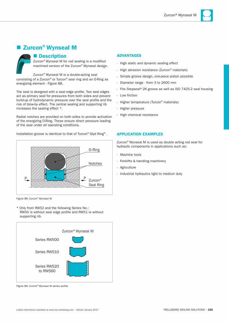
225
Description®
®
®
® ®
increases the sealing effect *.
® ®.
Zurcon® Seal Ring
O-Ring
P
Notches
P
®
Zurcon® Wynseal M
Series RW500
Series RW510
Series RW520to RW560
®
ADVANTAGES
®
Low friction
®
High chemical resistance
APPLICATION EXAMPLES
®
Machine tools
Zurcon®Wynseal M
226
OPERATING CONDITIONS
Pressure:
Speed:
Temperature:
Media:
see
Clearance:
clearance S is shown in
IMPORTANT NOTE
INSTALLATION INSTRUCTIONS
®
® ® .
RECOMMENDED MATERIALS
Turcon®Wynseal M in Zurcon®Z52
Turcon®Wynseal M in Turcon®M12
®materials are available.
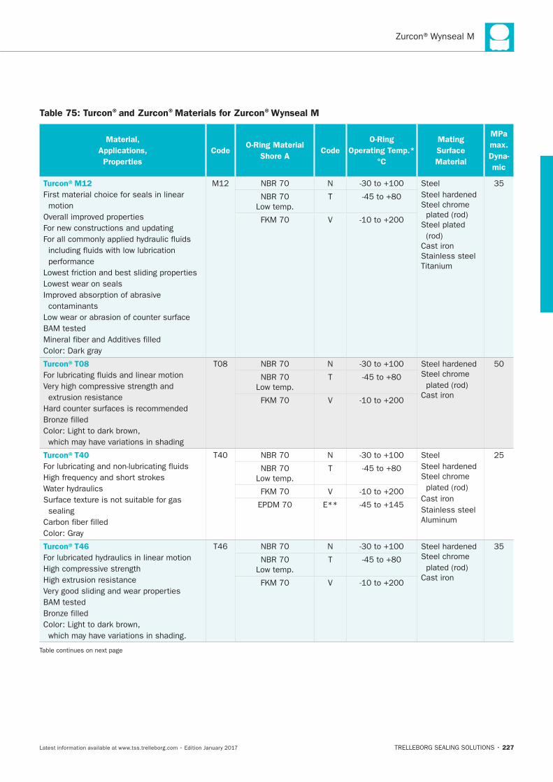
227
Table 75: Turcon®and Zurcon®Materials for Zurcon®Wynseal M
Material,
Applications,
Properties
CodeO-Ring Material
Shore ACode
O-Ring
Operating Temp.*
°C
Mating
Surface
Material
MPa
max.
Dyna-
mic
Turcon®M12
First material choice for seals in linear
motion
Lowest wear on seals
contaminants
N Steel
Steel chrome
Cast iron
Stainless steel
T
V
Turcon®T08
N
Steel chrome
Cast iron
T
V
Turcon®T40
sealing
N Steel
Steel chrome
Cast iron
Stainless steel
T
V
E**
Turcon®T46
N
Steel chrome
Cast iron
T
V
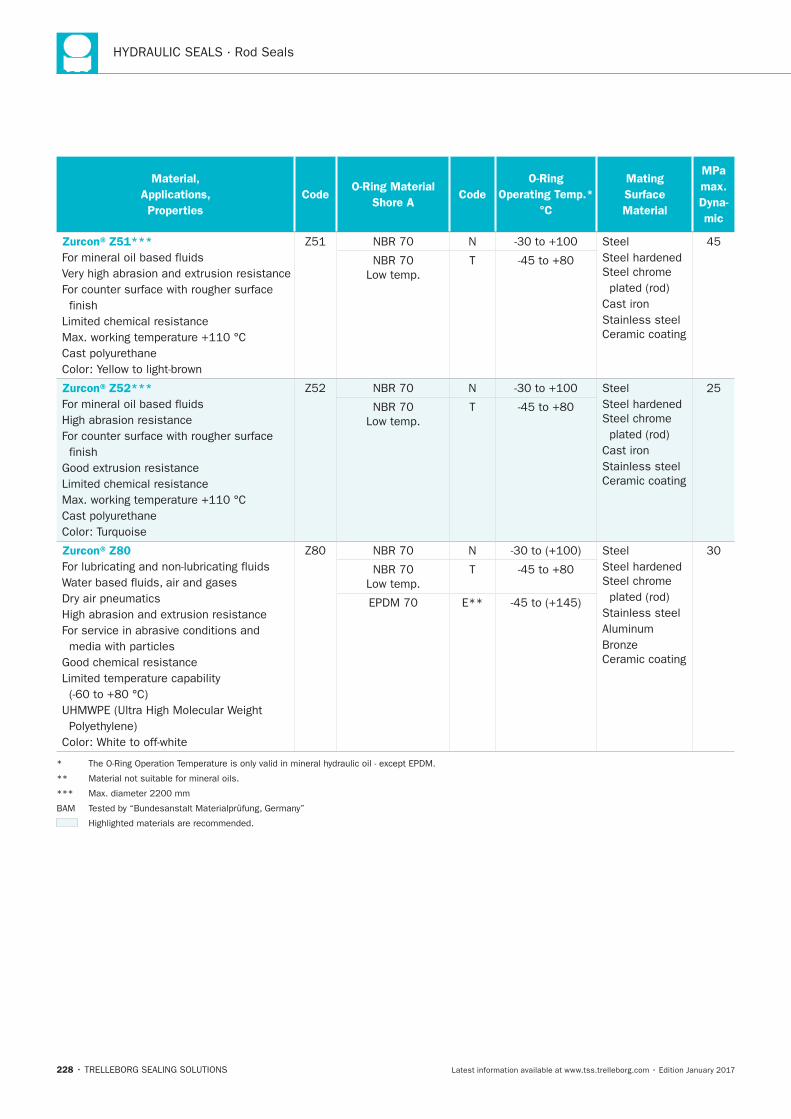
228
Material,
Applications,
Properties
CodeO-Ring Material
Shore ACode
O-Ring
Operating Temp.*
°C
Mating
Surface
Material
MPa
max.
Dyna-
mic
Zurcon®Z51***
finish
N Steel
Steel chrome
Cast iron
Stainless steel
Ceramic coating
T
Zurcon®Z52***
High abrasion resistance
finish
N Steel
Steel chrome
Cast iron
Stainless steel
Ceramic coating
T
Zurcon®Z80
N Steel
Steel chrome
Stainless steel
Ceramic coating
T
E**
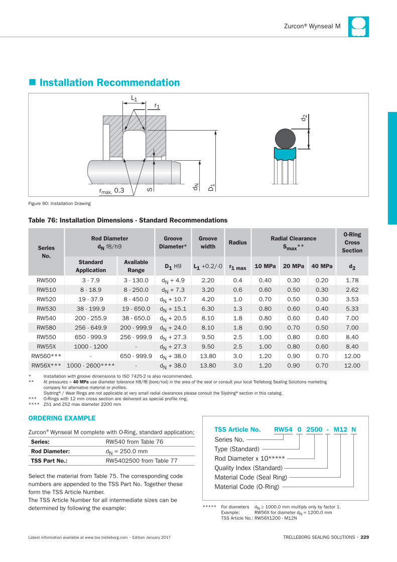
229
Installation Recommendation
D1
r1L1
rmax. 0.3 d NS
d 2
Installation Drawing
Table 76: Installation Dimensions - Standard Recommendations
Series
No.
Rod Diameter
dN
Groove
Diameter*
Groove
widthRadius
Radial Clearance
Smax**
O-Ring
Cross
Section
Standard
Application
Available
RangeD1 L1 r1 max 10 MPa 20 MPa 40 MPa d2
N
N
N
N
N
N
N
N
N
N
** 40 MPa
ORDERING EXAMPLE
®
Series:
Rod Diameter: N
TSS Part No.:
Material Code (Seal Ring)
Series No.
TSS Article No. M122500 N
Material Code (O-Ring)
Rod Diameter x 10*****
RW54
Quality Index (Standard)
-
Type (Standard)
0
N
N =
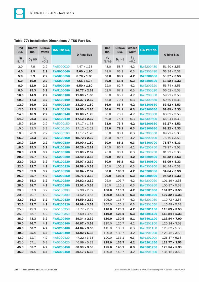
230
Rod
Dia.
Groove
Dia.
Groove
WidthTSS Part No.
O-Ring SizedN
D1 L1
4.0 8.9 2.2 RW5000040 5.60 x 1.80
5.0 9.9 2.2 RW5000050 6.70 x 1.80
6.0 10.9 2.2 RW5000060 7.65 x 1.78
8.0 12.9 2.2 RW5000080 9.50 x 1.80
8.0 15.3 3.2 RW5100080 10.77 x 2.62
10.0 14.9 2.2 RW5000100 11.80 x 1.80
10.0 17.3 3.2 RW5100100 12.37 x 2.62
12.0 16.9 2.2 RW5000120 13.20 x 1.80
12.0 19.3 3.2 RW5100120 14.50 x 2.65
14.0 18.9 2.2 RW5000140 15.60 x 1.78
14.0 21.3 3.2 RW5100140 17.12 x 2.62
16.0 23.3 3.2 RW5100160 18.72 x 2.62
18.0 22.9 2.2 RW5000180 19.00 x 1.80
18.0 25.3 3.2 RW5100180 20.29 x 2.62
20.0 27.3 3.2 RW5100200 21.89 x 2.62
20.0 30.7 4.2 RW5200200 23.40 x 3.53
22.0 29.3 3.2 RW5100220 25.07 x 2.62
22.0 32.7 4.2 RW5200220 26.58 x 3.53
25.0 32.3 3.2 RW5100250 26.64 x 2.62
25.0 35.7 4.2 RW5200250 29.75 x 3.53
28.0 35.3 3.2 RW5100280 29.82 x 2.62
28.0 38.7 4.2 RW5200280 32.92 x 3.53
32.0 39.3 3.2 RW5100320 34.59 x 2.62
32.0 42.7 4.2 RW5200320 36.09 x 3.53
36.0 43.3 3.2 RW5100360 39.34 x 2.62
36.0 46.7 4.2 RW5200360 40.87 x 3.53
40.0 50.7 4.2 RW5200400 44.04 x 3.53
40.0 55.1 6.3 RW5300400 43.82 x 5.33
45.0 55.7 4.2 RW5200450 50.39 x 3.53
45.0 60.1 6.3 RW5300450 50.17 x 5.33
Rod
Dia.
Groove
Dia.
Groove
WidthTSS Part No.
O-Ring SizedN
D1 L1
50.0 60.7 4.2 RW5200500 53.57 x 3.53
50.0 65.1 6.3 RW5300500 56.52 x 5.33
56.0 66.7 4.2 RW5200560 59.92 x 3.53
56.0 71.1 6.3 RW5300560 59.69 x 5.33
63.0 73.7 4.2 RW5200630 66.27 x 3.53
63.0 78.1 6.3 RW5300630 69.22 x 5.33
70.0 85.1 6.3 RW5300700 75.57 x 5.33
80.0 90.7 4.2 RW5200800 85.32 x 3.53
80.0 95.1 6.3 RW5300800 85.09 x 5.33
90.0 100.7 4.2 RW5200900 94.84 x 3.53
90.0 105.1 6.3 RW5300900 94.62 x 5.33
100.0 110.7 4.2 RW5201000 104.37 x 3.53
100.0 115.1 6.3 RW5301000 107.32 x 5.33
110.0 120.7 4.2 RW5201100 113.89 x 3.53
110.0 125.1 6.3 RW5301100 116.84 x 5.33
110.0 130.5 8.1 RW5401100 116.84 x 7.00
125.0 135.7 4.2 RW5201250 129.77 x 3.53
125.0 140.1 6.3 RW5301250 129.54 x 5.33
Table 77: Installation Dimensions / TSS Part No.
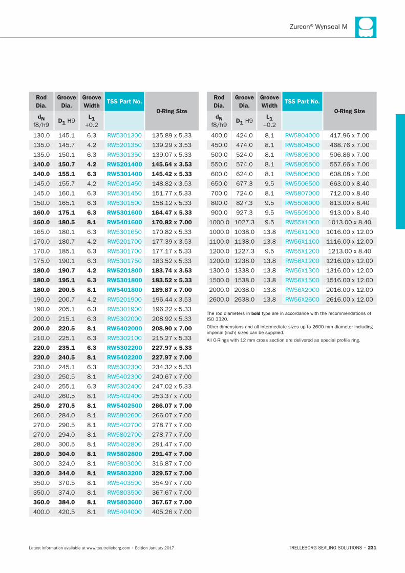
231
Rod
Dia.
Groove
Dia.
Groove
WidthTSS Part No.
O-Ring SizedN
D1 L1
140.0 150.7 4.2 RW5201400 145.64 x 3.53
140.0 155.1 6.3 RW5301400 145.42 x 5.33
160.0 175.1 6.3 RW5301600 164.47 x 5.33
160.0 180.5 8.1 RW5401600 170.82 x 7.00
180.0 190.7 4.2 RW5201800 183.74 x 3.53
180.0 195.1 6.3 RW5301800 183.52 x 5.33
180.0 200.5 8.1 RW5401800 189.87 x 7.00
200.0 220.5 8.1 RW5402000 208.90 x 7.00
220.0 235.1 6.3 RW5302200 227.97 x 5.33
220.0 240.5 8.1 RW5402200 227.97 x 7.00
250.0 270.5 8.1 RW5402500 266.07 x 7.00
280.0 304.0 8.1 RW5802800 291.47 x 7.00
320.0 344.0 8.1 RW5803200 329.57 x 7.00
360.0 384.0 8.1 RW5803600 367.67 x 7.00
Rod
Dia.
Groove
Dia.
Groove
WidthTSS Part No.
O-Ring SizedN
D1 L1
bold

232
Turcon® Double Delta®
TRELLEBORG SEALING SOLUTIONS • 233Latest information available at www.tss.trelleborg.com • Edition January 2017
Double-acting
Rubber-energized plastic-faced seal
For O-Ring Grooves
Material:Turcon®, Zurcon®and Elastomer
Turcon®Double Delta®

234
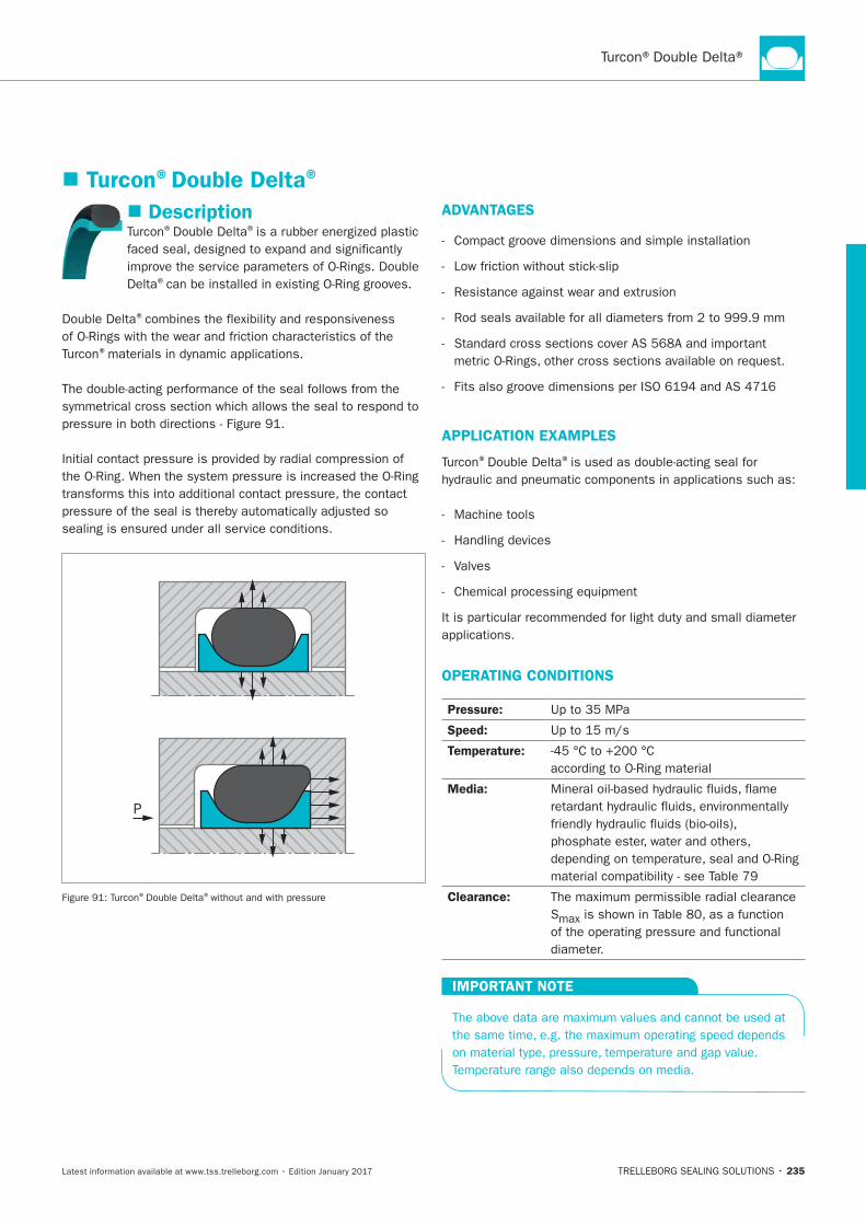
235
Description® ®
Delta®
®
®
P
® ®
ADVANTAGES
APPLICATION EXAMPLES
® ®
Machine tools
Valves
OPERATING CONDITIONS
Pressure:
Speed:
Temperature:
Media:
Clearance:
S
IMPORTANT NOTE
Turcon®Double Delta®
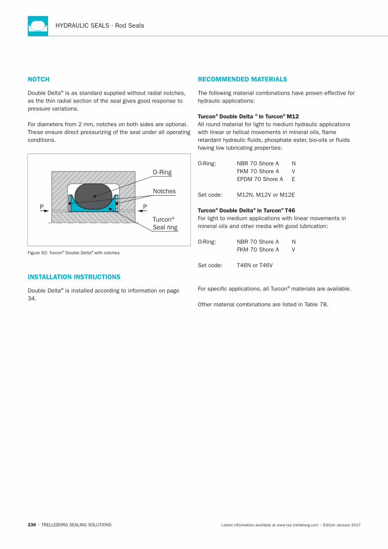
236
RECOMMENDED MATERIALS
Turcon®Double Delta ®in Turcon®M12
Turcon®Double Delta®in Turcon®T46
®materials are available.
NOTCH
®
P P
Notches
Turcon® Seal ring
O-Ring
® ®with notches
INSTALLATION INSTRUCTIONS
®
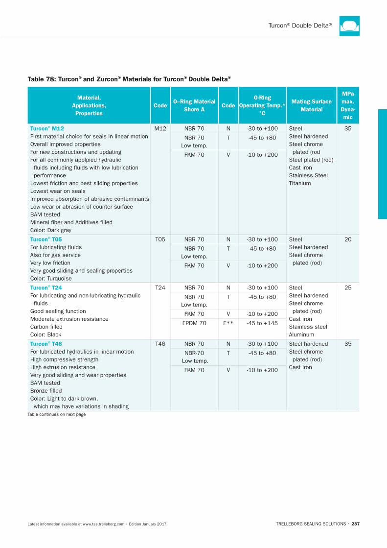
237
Table 78: Turcon®and Zurcon®Materials for Turcon®Double Delta®
Material,
Applications,
Properties
CodeO–Ring Material
Shore ACode
O-Ring
Operating Temp.*
°C
Mating Surface
Material
MPa
max.
Dyna-
mic
Turcon®M12
First material choice for seals in linear motion
Lowest wear on seals
N Steel
Steel chrome
Cast iron
Stainless Steel
T
V
Turcon®T05
Also for gas service
N Steel
Steel chrome T
V
Turcon®T24
N Steel
Steel chrome
Cast iron
Stainless steel
T
V
E**
Turcon®T46
N
Steel chrome
Cast iron
T
V
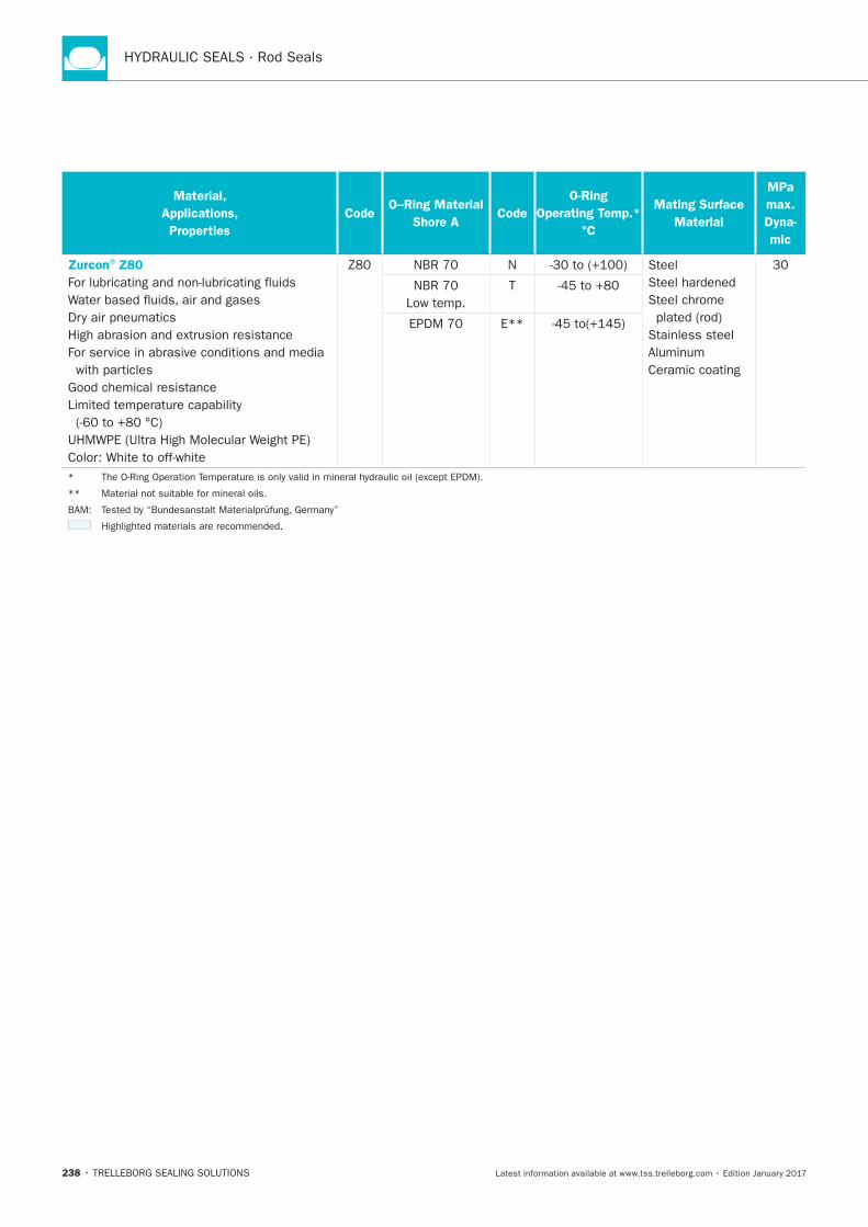
238
Material,
Applications,
Properties
CodeO–Ring Material
Shore ACode
O-Ring
Operating Temp.*
°C
Mating Surface
Material
MPa
max.
Dyna-
mic
Zurcon®Z80
N Steel
Steel chrome
Stainless steel
Ceramic coating
T
E**
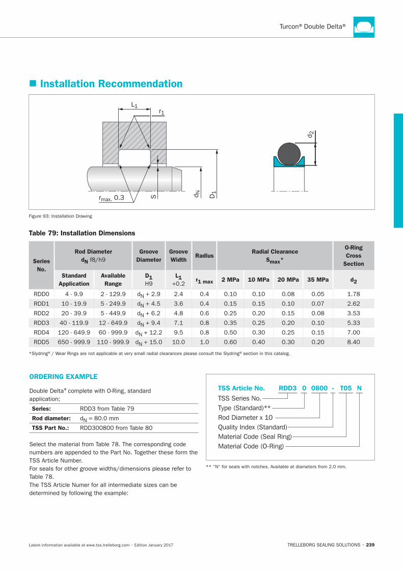
239
Installation Recommendation
rmax. 0.3 d NS
d 2
D1
r1L1
Installation Drawing
Table 79: Installation Dimensions
Series
No.
Rod Diameter
dN
Groove
Diameter
Groove
Width Radius
Radial Clearance
Smax*
O-Ring
Cross
Section
Standard
Application
Available
Range
D1 L1 r1 max 2 MPa 10 MPa 20 MPa 35 MPa d2
N
N
N
N
N
N
ORDERING EXAMPLE
®
Series:
Rod diameter: N
TSS Part No.:
Material Code (Seal Ring)
TSS Series No.
TSS Article No. T050800 N
Material Code (O-Ring)
Rod Diameter x 10
RDD3
Quality Index (Standard)
-
Type (Standard)**
0
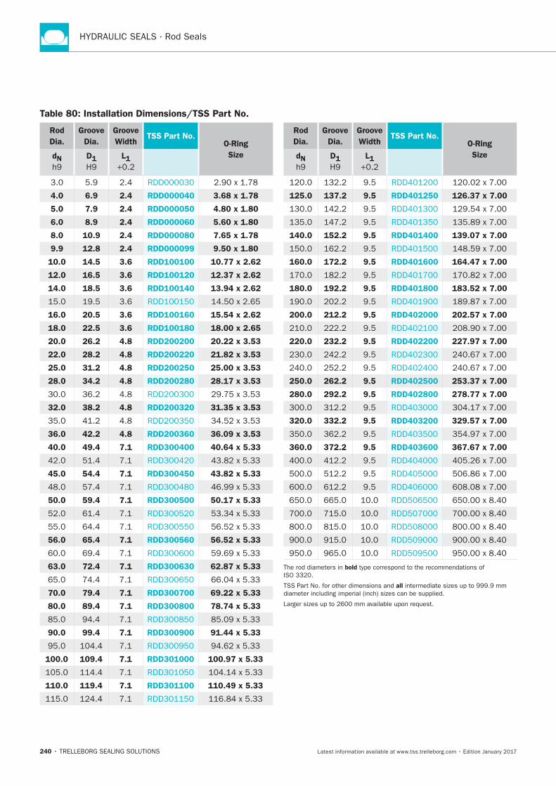
240
Rod
Dia.
Groove
Dia.
Groove
Width TSS Part No.
O-Ring
Size dN
D1
L1
4.0 6.9 2.4 RDD000040 3.68 x 1.78
5.0 7.9 2.4 RDD000050 4.80 x 1.80
6.0 8.9 2.4 RDD000060 5.60 x 1.80
8.0 10.9 2.4 RDD000080 7.65 x 1.78
9.9 12.8 2.4 RDD000099 9.50 x 1.80
10.0 14.5 3.6 RDD100100 10.77 x 2.62
12.0 16.5 3.6 RDD100120 12.37 x 2.62
14.0 18.5 3.6 RDD100140 13.94 x 2.62
16.0 20.5 3.6 RDD100160 15.54 x 2.62
18.0 22.5 3.6 RDD100180 18.00 x 2.65
20.0 26.2 4.8 RDD200200 20.22 x 3.53
22.0 28.2 4.8 RDD200220 21.82 x 3.53
25.0 31.2 4.8 RDD200250 25.00 x 3.53
28.0 34.2 4.8 RDD200280 28.17 x 3.53
32.0 38.2 4.8 RDD200320 31.35 x 3.53
36.0 42.2 4.8 RDD200360 36.09 x 3.53
40.0 49.4 7.1 RDD300400 40.64 x 5.33
45.0 54.4 7.1 RDD300450 43.82 x 5.33
50.0 59.4 7.1 RDD300500 50.17 x 5.33
56.0 65.4 7.1 RDD300560 56.52 x 5.33
63.0 72.4 7.1 RDD300630 62.87 x 5.33
70.0 79.4 7.1 RDD300700 69.22 x 5.33
80.0 89.4 7.1 RDD300800 78.74 x 5.33
90.0 99.4 7.1 RDD300900 91.44 x 5.33
100.0 109.4 7.1 RDD301000 100.97 x 5.33
110.0 119.4 7.1 RDD301100 110.49 x 5.33
Rod
Dia.
Groove
Dia.
Groove
Width TSS Part No.
O-Ring
Size dN
D1
L1
125.0 137.2 9.5 RDD401250 126.37 x 7.00
140.0 152.2 9.5 RDD401400 139.07 x 7.00
160.0 172.2 9.5 RDD401600 164.47 x 7.00
180.0 192.2 9.5 RDD401800 183.52 x 7.00
200.0 212.2 9.5 RDD402000 202.57 x 7.00
220.0 232.2 9.5 RDD402200 227.97 x 7.00
250.0 262.2 9.5 RDD402500 253.37 x 7.00
280.0 292.2 9.5 RDD402800 278.77 x 7.00
320.0 332.2 9.5 RDD403200 329.57 x 7.00
360.0 372.2 9.5 RDD403600 367.67 x 7.00
bold
all
Table 80: Installation Dimensions/TSS Part No.
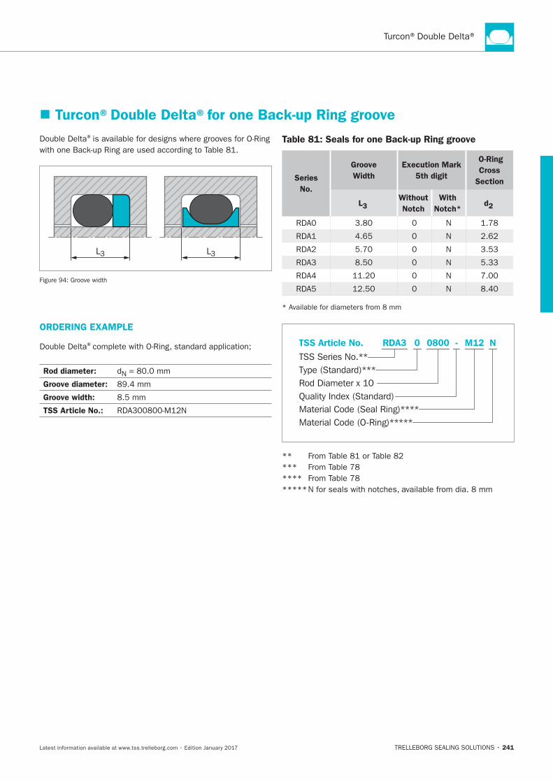
241
®
L3 L3
Table 81: Seals for one Back-up Ring groove
Series
No.
Groove
Width
Execution Mark
5th digit
O-Ring
Cross
Section
L3 Without
Notch
With
Notch* d2
N
N
N
N
N
N
Turcon®Double Delta®for one Back-up Ring groove
ORDERING EXAMPLE
®
Rod diameter: N
Groove diameter:
Groove width:
TSS Article No.: Material Code (Seal Ring)****
TSS Series No.**
TSS Article No. M120800 N
Material Code (O-Ring)*****
Rod Diameter x 10
RDA3
Quality Index (Standard)
-
Type (Standard)***
0
**
***
****
*****
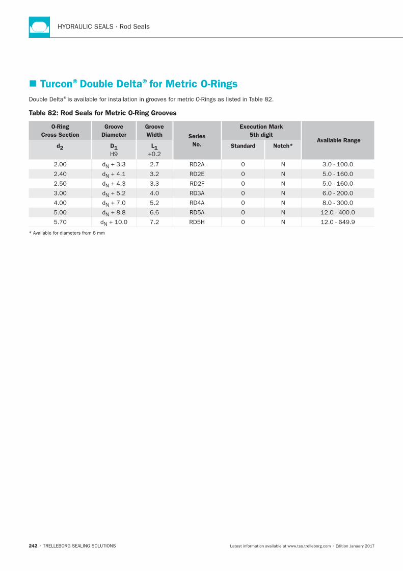
242
Turcon®Double Delta®for Metric O-Rings
®
Table 82: Rod Seals for Metric O-Ring Grooves
O-Ring
Cross Section
Groove
Diameter
Groove
Width Series
No.
Execution Mark
5th digit Available Range
d2 D1
L1
Standard
Notch*
N N
N N
N N
N N
N N
N + 8.8 N
N N
Additional Seals
TRELLEBORG SEALING SOLUTIONS • 243Latest information available at www.tss.trelleborg.com • Edition January 2017
Available upon Request
Old Series
Special Series
AdditionalSeals

244
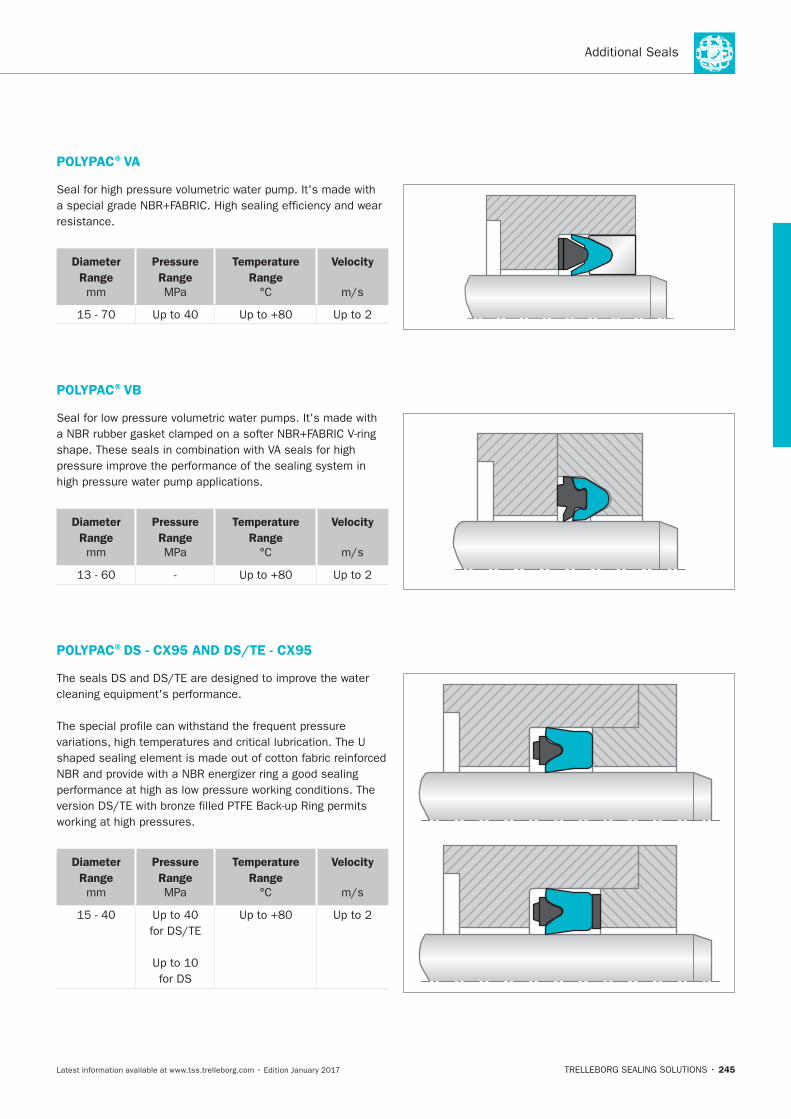
245
POLYPAC®VA
resistance.
Diameter
Range
mm
Pressure
Range
MPa
Temperature
Range
Velocity
POLYPAC®VB
Diameter
Range
mm
Pressure
Range
MPa
Temperature
Range
Velocity
POLYPAC®DS - CX95 AND DS/TE - CX95
Diameter
Range
mm
Pressure
Range
MPa
Temperature
Range
Velocity
for DS
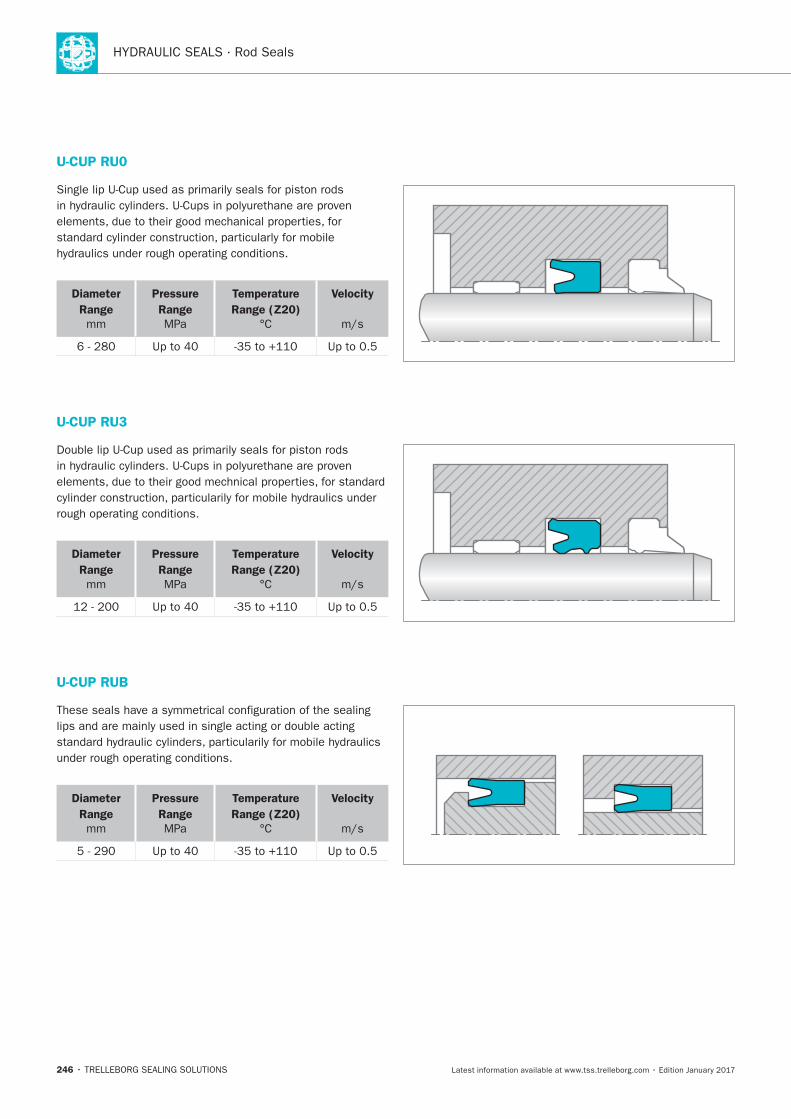
246
U-CUP RU0
Diameter
Range
mm
Pressure
Range
MPa
Temperature
Range (Z20)
Velocity
U-CUP RU3
Diameter
Range
mm
Pressure
Range
MPa
Temperature
Range (Z20)
Velocity
U-CUP RUB
Diameter
Range
mm
Pressure
Range
MPa
Temperature
Range (Z20)
Velocity
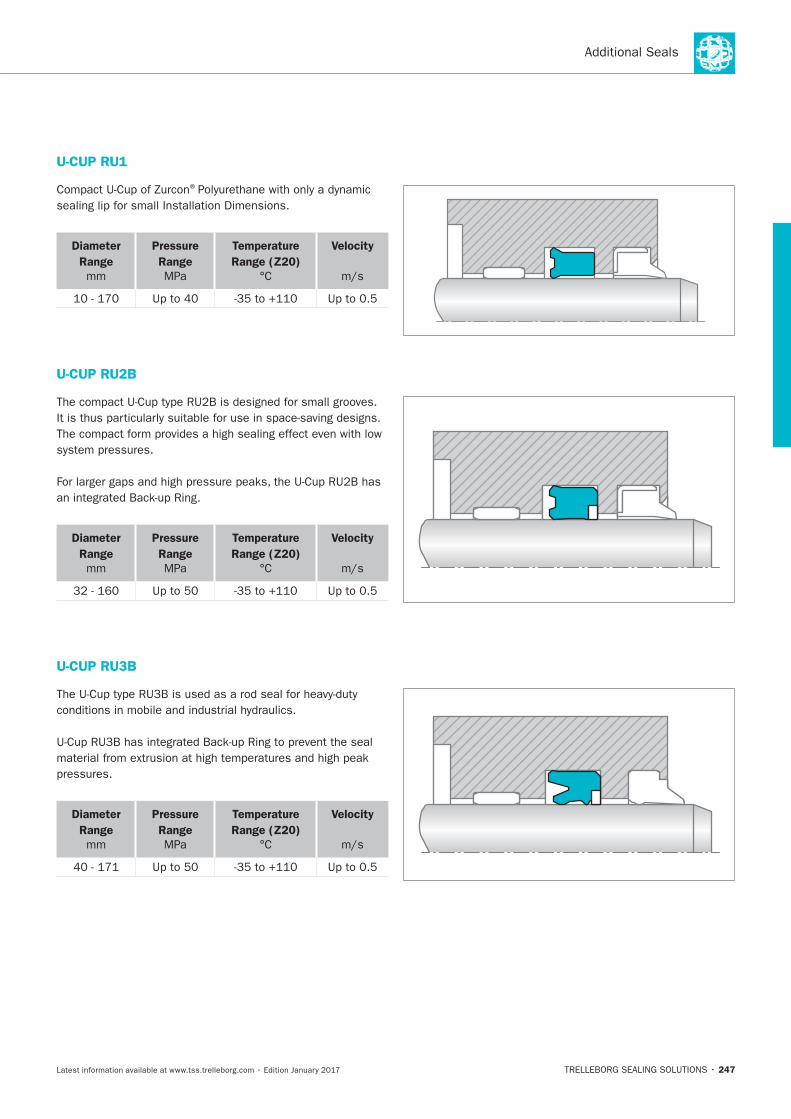
247
U-CUP RU1
®
Diameter
Range
mm
Pressure
Range
MPa
Temperature
Range (Z20)
Velocity
U-CUP RU2B
Diameter
Range
mm
Pressure
Range
MPa
Temperature
Range (Z20)
Velocity
U-CUP RU3B
Diameter
Range
mm
Pressure
Range
MPa
Temperature
Range (Z20)
Velocity
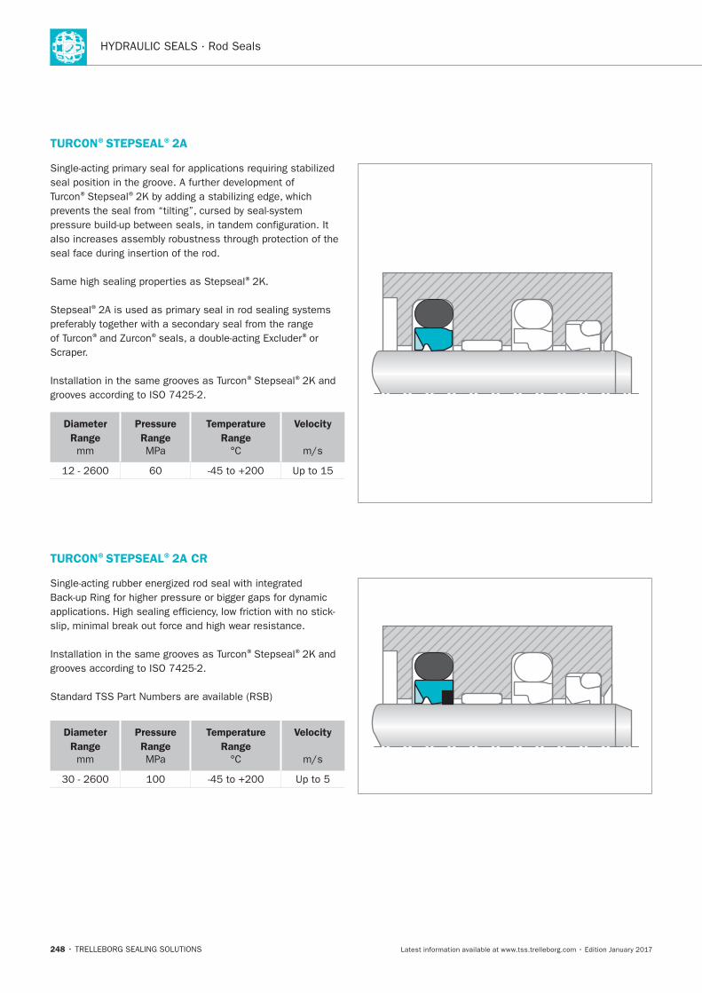
248
TURCON®STEPSEAL®2A
® ®
®
®
® ® ®or
® ®
Diameter
Range
mm
Pressure
Range
MPa
Temperature
Range
Velocity
TURCON®STEPSEAL®2A CR
® ®
Diameter
Range
mm
Pressure
Range
MPa
Temperature
Range
Velocity
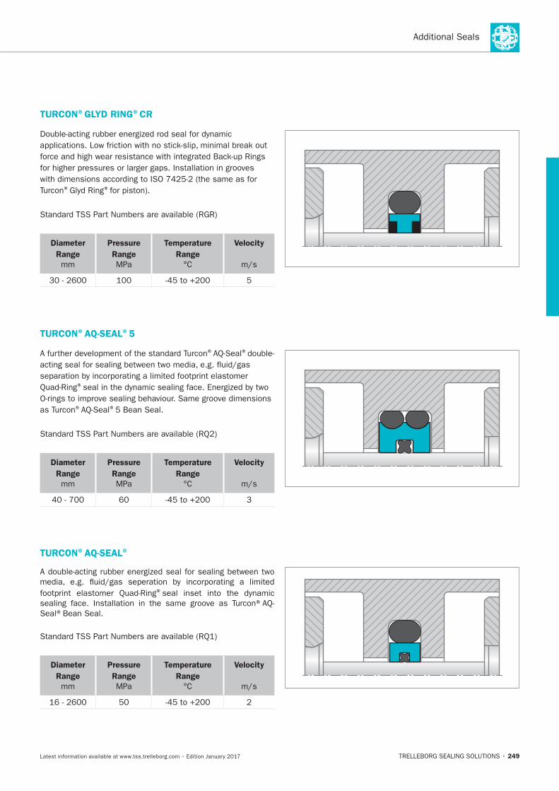
249
TURCON®GLYD RING®CR
® ®
Diameter
Range
mm
Pressure
Range
MPa
Temperature
Range
Velocity
TURCON®AQ-SEAL®5
® ®
®
® ®
Diameter
Range
mm
Pressure
Range
MPa
Temperature
Range
Velocity
TURCON®AQ-SEAL®
®
Seal®Bean Seal.
Diameter
Range
mm
Pressure
Range
MPa
Temperature
Range
Velocity
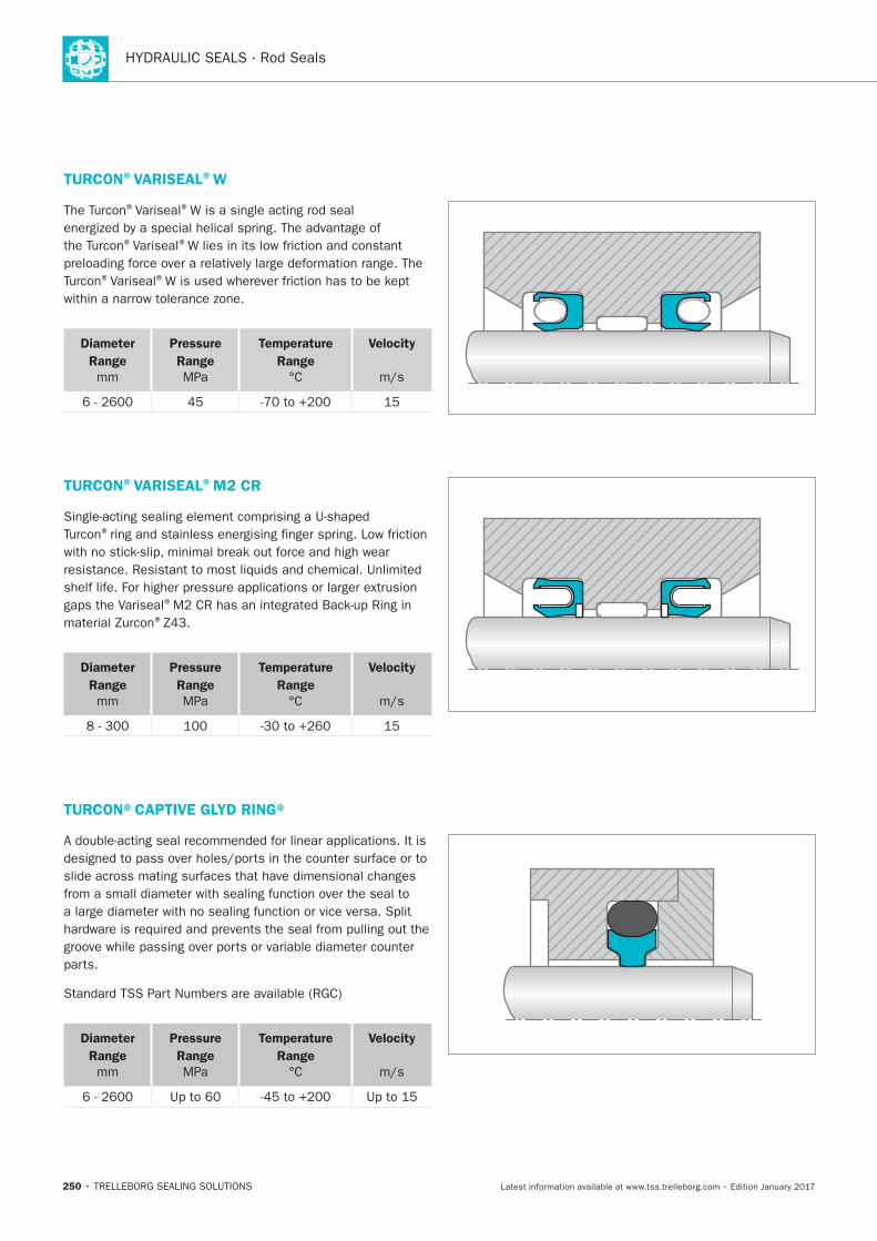
250
TURCON®VARISEAL®W
®Variseal®
®Variseal®
®Variseal®
Diameter
Range
mm
Pressure
Range
MPa
Temperature
Range
Velocity
TURCON®VARISEAL®M2 CR
®
®
®
Diameter
Range
mm
Pressure
Range
MPa
Temperature
Range
Velocity
TURCON®CAPTIVE GLYD RING®
Diameter
Range
mm
Pressure
Range
MPa
Temperature
Range
Velocity
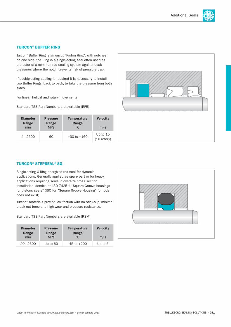
251
TURCON®BUFFER RING
®
Diameter
Range
mm
Pressure
Range
MPa
Temperature
Range
Velocity
TURCON®STEPSEAL®SG
Diameter
Range
mm
Pressure
Range
MPa
Temperature
Range
Velocity
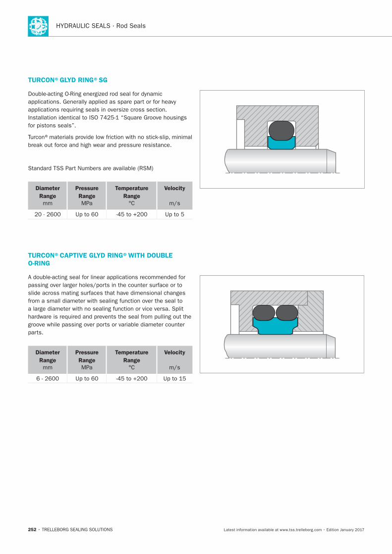
252
TURCON®GLYD RING®SG
Diameter
Range
mm
Pressure
Range
MPa
Temperature
Range
Velocity
TURCON®CAPTIVE GLYD RING®WITH DOUBLE O-RING
Diameter
Range
mm
Pressure
Range
MPa
Temperature
Range
Velocity
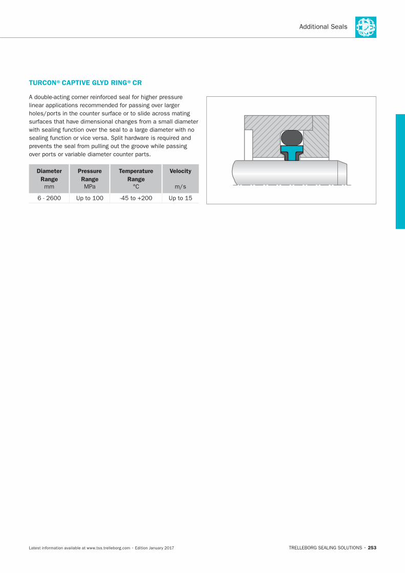
253
TURCON®CAPTIVE GLYD RING®CR
Diameter
Range
mm
Pressure
Range
MPa
Temperature
Range
Velocity

254
TRELLEBORG SEALING SOLUTIONS • 255Latest information available at www.tss.trelleborg.com • Edition January 2017
PistonSeals

HYDRAULIC SEALS · Piston Seals
256
257
Content
258 Choice of the Sealing Element
262 Design Instructions
264 Installation of Piston Seals
269 Turcon®Glyd Ring®
279 Turcon®Glyd Ring®T
289 Turcon®Glyd Ring®Hz
299 Zurcon® Glyd Ring®D
305 Zurcon®Glyd Ring®P
311 Turcon®AQ-Seal®5
321 Turcon®AQ-Seal®
331 Turcon®Stepseal®2K
341 Turcon®Stepseal®V
351 Turcon®Double Delta®
359 Turcon®Variseal®M2
367 Turcon®VL Seal®
377 Zurcon®U-Cup PUA
383 Zurcon®Wynseal
389 Zurcon®Wynseal M
399 POLYPAC®- PHD/P
405 Compact Seal POLYPAC®-
Duopac DPS/DPC
413 POLYPAC®- Veepac CH
419 POLYPAC®- Veepac CH/G1
423 POLYPAC®- Selemaster DSM
429 Additional Seals
Contents
HYDRAULIC SEALS · Piston Seals
258
® ®
® ®
NOTE ON ORDERING
®
®
Choice of the Sealing Element
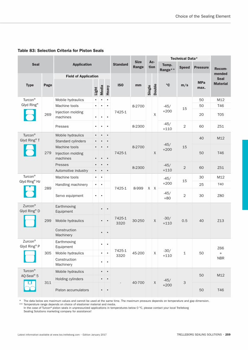
259
Choice of the Sealing Element
Table 83: Selection Criteria for Piston Seals
Seal Application StandardSize
Range
Ac-
tion
Technical Data*
Recom-
mended
Seal
Material
Temp.
Range**Speed Pressure
Type Page
Field of Application
ISO mm
Sin
gle
Double °C m/s
MPa
max.
Lig
ht
Media
Heavy
® ®
X
Machine tools
machines
Presses
® ®T
X
Machine tools
machines
Presses
® ®
Machine tools
X X
® ®D
Earthmoving
X
® ®P
Earthmoving
X
+
NBR
® ®
X
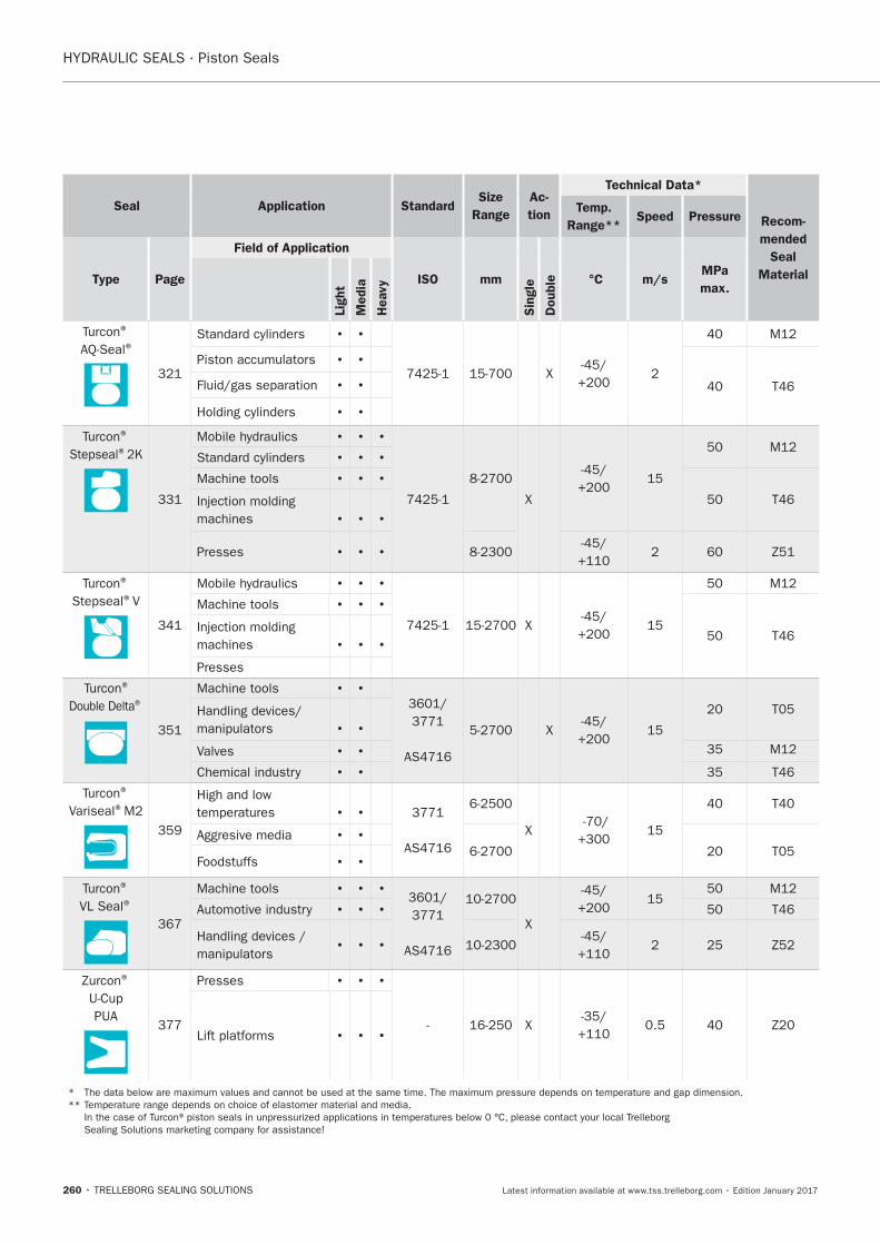
HYDRAULIC SEALS · Piston Seals
260
Seal Application StandardSize
Range
Ac-
tion
Technical Data*
Recom-
mended
Seal
Material
Temp.
Range**Speed Pressure
Type Page
Field of Application
ISO mm
Sin
gle
Double °C m/s
MPa
max.
Lig
ht
Media
Heavy
® ®
X
® ®
X
Machine tools
machines
Presses
® ®V
X
Machine tools
machines
Presses
®
®
Machine tools
X
Valves
®
Variseal®
X
®
VL Seal®Machine tools
X
®
PUA
Presses
X
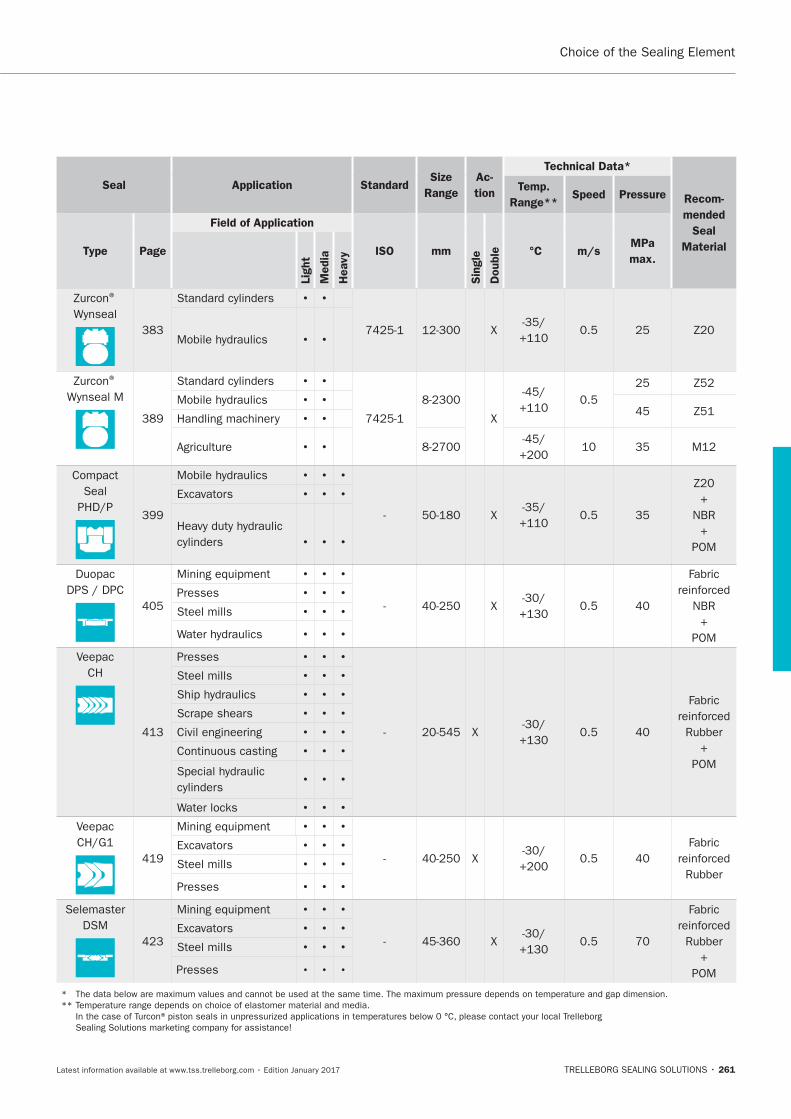
261
Seal Application StandardSize
Range
Ac-
tion
Technical Data*
Recom-
mended
Seal
Material
Temp.
Range**Speed Pressure
Type Page
Field of Application
ISO mm
Sin
gle
Double °C m/s
MPa
max.
Lig
ht
Media
Heavy
®
X
®
X
Seal
X
+
NBR
+
POM
X
Fabric
NBR
+
POM
Presses
Steel mills
CH
Presses
X
Fabric
+
POM
Steel mills
Civil engineering
X
Fabric
Steel mills
Presses
Selemaster
DSM
X
Fabric
+
POM
Steel mills
Presses
Choice of the Sealing Element
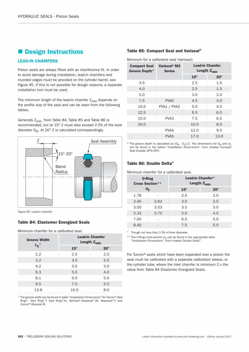
HYDRAULIC SEALS · Piston Seals
262
Design Instructions
LEAD-IN CHAMFERS
min
tables.
min.
N
BlendRadius
Seal Assembly
15°-20°
Z
Table 84: Elastomer Energized Seals
Groove Width
L1*
Lead-in Chamfer
Length Zmin
15° 20°
*
Table 85: Compact Seal and Variseal®
Compact Seal
Groove Depth*
Variseal®M2
Series
Lead-in Chamfer
Length Zmin
15° 20°
N N
Table 86: Double Delta®
O-Ring
Cross Section**
d2
Lead-in Chamfer*
Length Zmin
15° 20°
*
** ®.
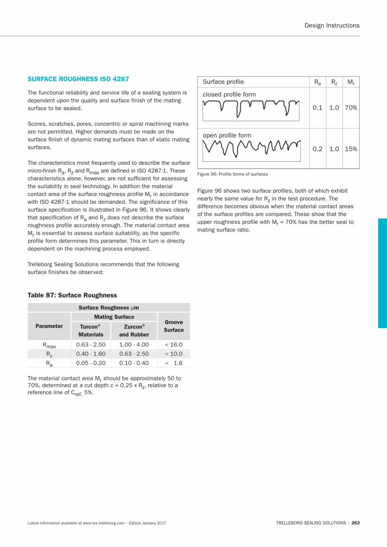
263
SURFACE ROUGHNESS ISO 4287
a
r
a
Mr
Table 87: Surface Roughness
Surface Roughness μm
Parameter
Mating Surface Groove
SurfaceTurcon®
Materials
Zurcon®
and Rubber
R
R
Ra
The material contact area Mr
reference line of Cref.
m
R MrRa
r
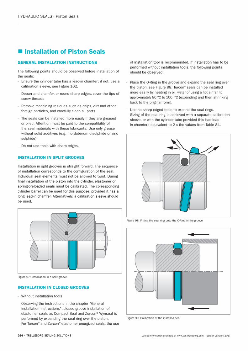
HYDRAULIC SEALS · Piston Seals
264
GENERAL INSTALLATION INSTRUCTIONS
INSTALLATION IN SPLIT GROOVES
INSTALLATION IN CLOSED GROOVES
® ®
®
Installation of Piston Seals
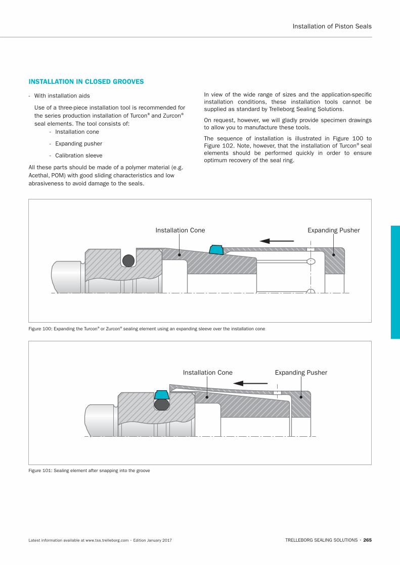
265
Installation of Piston Seals
Installation Cone Expanding Pusher
® ®
Installation Cone Expanding Pusher
®seal
INSTALLATION IN CLOSED GROOVES
® ®
Installation cone
Calibration sleeve
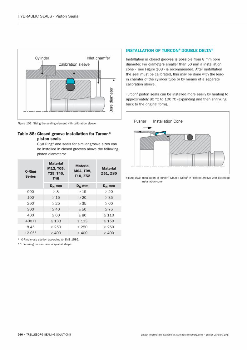
HYDRAULIC SEALS · Piston Seals
266
Bor
e di
amet
er
Cylinder
Calibration sleeve
Inlet chamfer
Table 88: Closed groove installation for Turcon® piston seals
O-Ring
Series
Material
M12, T05,
T29, T40,
T46
Material
M04, T08,
T10, Z52
Material
Z51, Z80
DN mm DN mm DN mm
*
**
INSTALLATION OF TURCON®DOUBLE DELTA®
calibration sleeve.
®
Pusher Installation Cone
® ®
Installation cone
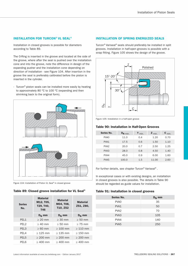
267
INSTALLATION FOR TURCON®VL SEAL®
®
Installation of Piston VL Seal®
Table 89: Closed groove installation for VL Seal®
Series
No.
Material
M12, T05,
T29, T40,
T46
Material
M04, T08,
T10, Z52
Material
Z51, Z80,
DN mm DN mm DN mm
INSTALLATION OF SPRING ENERGIZED SEALS
®Variseal®
15°-20°
30°
DN
yC
ZPolished
Table 90: Installation in Half-Open Grooves
Series No. DN min. Y min. Z min. C min.
®Variseal®.
Table 91: Installation in closed grooves
Series No. DN mm
Installation of Piston Seals
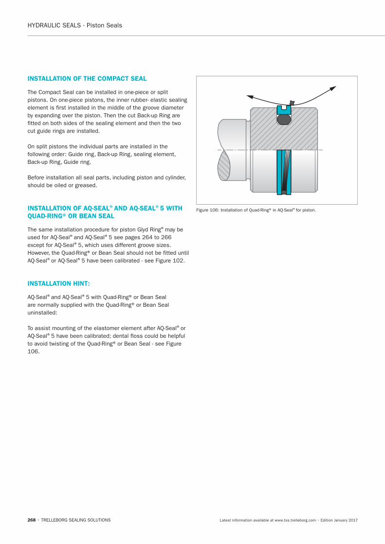
HYDRAULIC SEALS · Piston Seals
268
INSTALLATION OF THE COMPACT SEAL
INSTALLATION OF AQ-SEAL®AND AQ-SEAL®5 WITH QUAD-RING® OR BEAN SEAL
®
® ®
®
® ®
INSTALLATION HINT:
® ®
®or ®
®
Turcon® Glyd Ring®
TRELLEBORG SEALING SOLUTIONS • 269Latest information available at www.tss.trelleborg.com • Edition January 2017
Turcon®Glyd Ring®
Double-acting
Rubber-energized plastic-faced seal
Material:Turcon®, Zurcon®and Elastomer

HYDRAULIC SEALS · Piston Seals
270
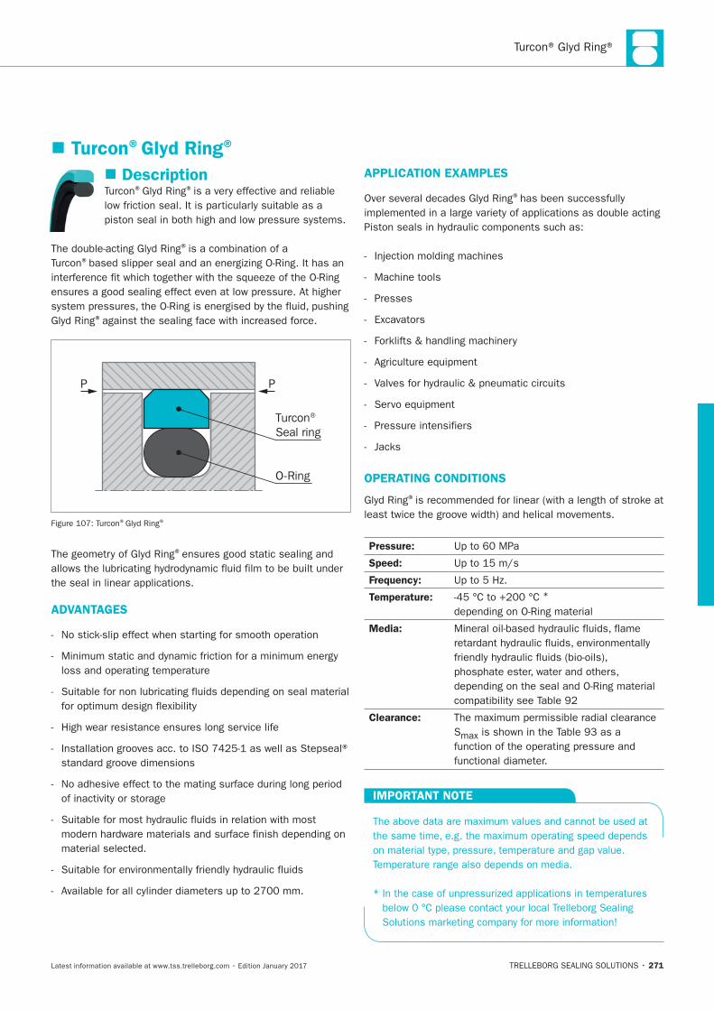
271
Description® ®
®is a combination of a ®
®
P P
Turcon® Seal ring
O-Ring
® ®
®
ADVANTAGES
APPLICATION EXAMPLES
®
Machine tools
Presses
OPERATING CONDITIONS
®
Pressure:
Speed:
Frequency:
Temperature: *
Media:
Clearance:
S
IMPORTANT NOTE
Turcon®Glyd Ring®
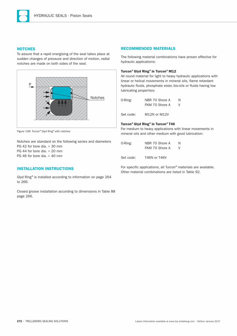
HYDRAULIC SEALS · Piston Seals
272
NOTCHES
P
Notches
® ®with notches
INSTALLATION INSTRUCTIONS
®
RECOMMENDED MATERIALS
Turcon®Glyd Ring®in Turcon®M12
Turcon®Glyd Ring®in Turcon®T46
®materials are available.
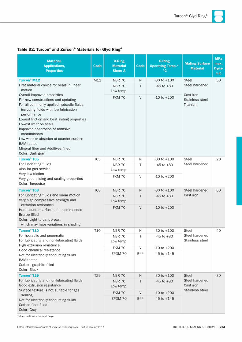
Turcon® Glyd Ring®
273
Table 92: Turcon®and Zurcon®Materials for Glyd Ring®
Material,
Applications,
Properties
Code
O-Ring
Material
Shore A
Code
O-Ring
Operating Temp.*
°C
Mating Surface
Material
MPa
max.
Dyna-
mic
Turcon®M12
First material choice for seals in linear
motion
Lowest wear on seals
contaminants
N Steel
Cast iron
Stainless steel
T
V
Turcon®T05
Also for gas service
N Steel
T
V
Turcon®T08
N
Cast iron T
V
Turcon®T10
N Steel
Stainless steel T
V
E**
Turcon®T29
sealing
N Steel
Cast iron
Stainless steel
T
V
E**
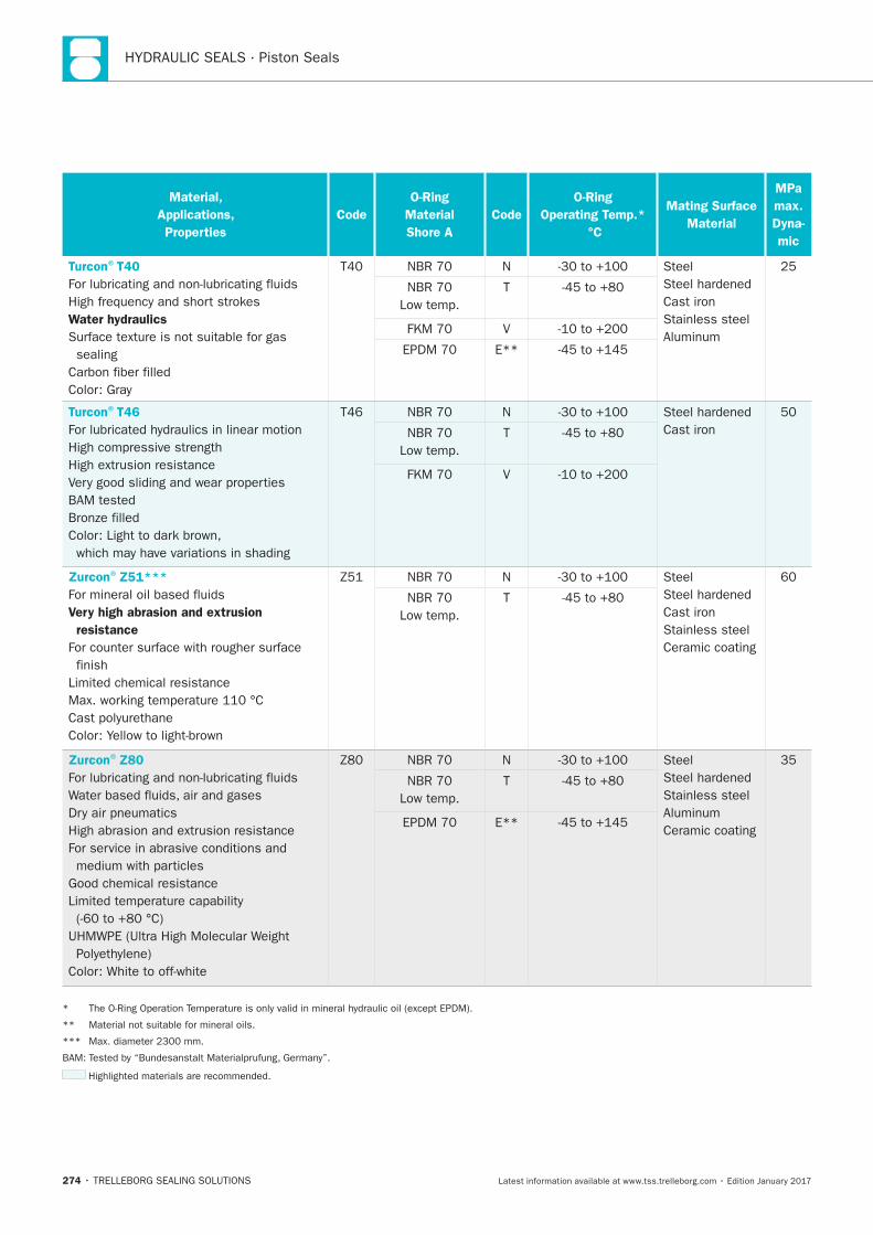
HYDRAULIC SEALS · Piston Seals
274
Material,
Applications,
Properties
Code
O-Ring
Material
Shore A
Code
O-Ring
Operating Temp.*
°C
Mating Surface
Material
MPa
max.
Dyna-
mic
Turcon®T40
Water hydraulics
sealing
N Steel
Cast iron
Stainless steel
T
V
E**
Turcon®T46
N
Cast iron T
V
Zurcon®Z51***
Very high abrasion and extrusion
resistance
finish
N Steel
Cast iron
Stainless steel
Ceramic coating
T
Zurcon®Z80
N Steel
Stainless steel
Ceramic coating
T
E**
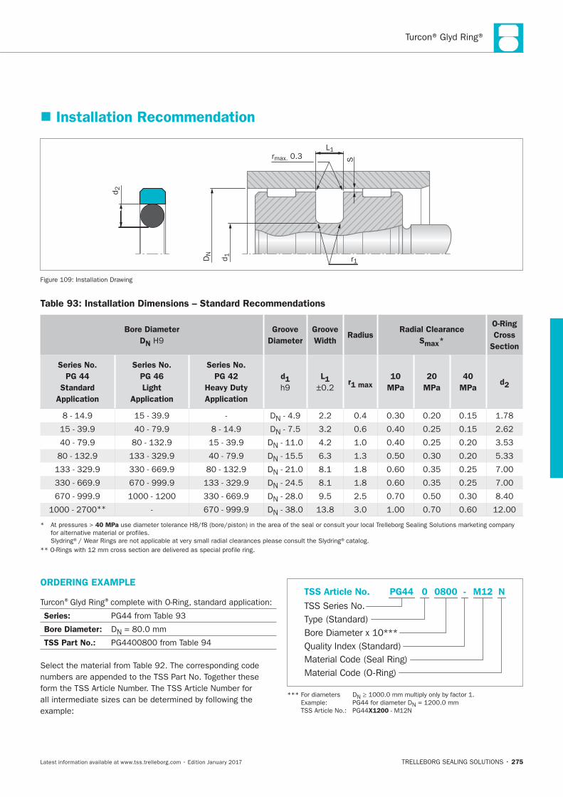
Turcon® Glyd Ring®
275
Installation Recommendation
S
L1rmax. 0.3
r1
d2
DN
d1
Installation Drawing
Table 93: Installation Dimensions – Standard Recommendations
Bore Diameter
DN
Groove
Diameter
Groove
Width Radius
Radial Clearance
Smax*
O-Ring
Cross
Section
Series No.
PG 44
Standard
Application
Series No.
PG 46
Light
Application
Series No.
PG 42
Heavy Duty
Application
d1
L1
r1 max
10
MPa
20
MPa
40
MPa d2
DN
DN
DN
DN
DN
DN
DN
** DN
40 MPa
ORDERING EXAMPLE
® ®
Series:
Bore Diameter: DN
TSS Part No.:
Material Code (Seal Ring)
TSS Series No.
TSS Article No. M120800 N
Material Code (O-Ring)
Bore Diameter x 10***
PG44
Quality Index (Standard)
-
Type (Standard)
0
N
N
X1200
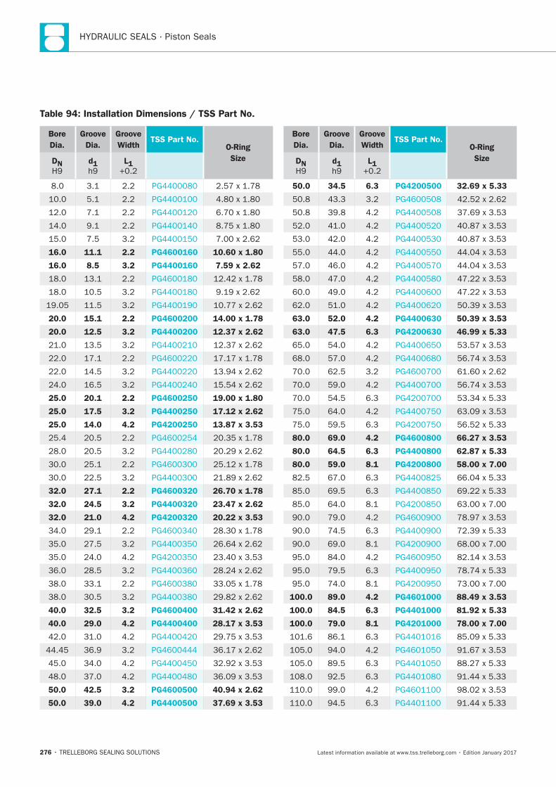
HYDRAULIC SEALS · Piston Seals
276
Bore
Dia.
Groove
Dia.
Groove
WidthTSS Part No.
O-Ring
SizeDN d1 L1
16.0 11.1 2.2 PG4600160 10.60 x 1.80
16.0 8.5 3.2 PG4400160 7.59 x 2.62
20.0 15.1 2.2 PG4600200 14.00 x 1.78
20.0 12.5 3.2 PG4400200 12.37 x 2.62
25.0 20.1 2.2 PG4600250 19.00 x 1.80
25.0 17.5 3.2 PG4400250 17.12 x 2.62
25.0 14.0 4.2 PG4200250 13.87 x 3.53
32.0 27.1 2.2 PG4600320 26.70 x 1.78
32.0 24.5 3.2 PG4400320 23.47 x 2.62
32.0 21.0 4.2 PG4200320 20.22 x 3.53
40.0 32.5 3.2 PG4600400 31.42 x 2.62
40.0 29.0 4.2 PG4400400 28.17 x 3.53
50.0 42.5 3.2 PG4600500 40.94 x 2.62
50.0 39.0 4.2 PG4400500 37.69 x 3.53
Bore
Dia.
Groove
Dia.
Groove
WidthTSS Part No.
O-Ring
SizeDN d1 L1
50.0 34.5 6.3 PG4200500 32.69 x 5.33
63.0 52.0 4.2 PG4400630 50.39 x 3.53
63.0 47.5 6.3 PG4200630 46.99 x 5.33
80.0 69.0 4.2 PG4600800 66.27 x 3.53
80.0 64.5 6.3 PG4400800 62.87 x 5.33
80.0 59.0 8.1 PG4200800 58.00 x 7.00
100.0 89.0 4.2 PG4601000 88.49 x 3.53
100.0 84.5 6.3 PG4401000 81.92 x 5.33
100.0 79.0 8.1 PG4201000 78.00 x 7.00
Table 94: Installation Dimensions / TSS Part No.
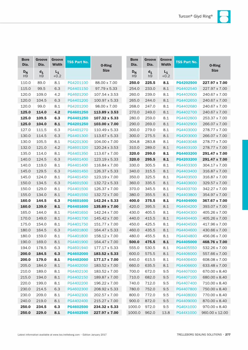
Turcon® Glyd Ring®
277
Bore
Dia.
Groove
Dia.
Groove
WidthTSS Part No.
O-Ring
SizeDN d1 L1
125.0 114.0 4.2 PG4601250 113.89 x 3.53
125.0 109.5 6.3 PG4401250 107.32 x 5.33
125.0 104.0 8.1 PG4201250 103.00 x 7.00
160.0 144.5 6.3 PG4601600 142.24 x 5.33
160.0 139.0 8.1 PG4401600 135.89 x 7.00
200.0 184.5 6.3 PG4602000 183.52 x 5.33
200.0 179.0 8.1 PG4402000 177.17 x 7.00
250.0 234.5 6.3 PG4602500 234.32 x 5.33
250.0 229.0 8.1 PG4402500 227.97 x 7.00
Bore
Dia.
Groove
Dia.
Groove
WidthTSS Part No.
O-Ring
SizeDN d1 L1
250.0 225.5 8.1 PG4202500 227.97 x 7.00
320.0 299.0 8.1 PG4403200 291.47 x 7.00
320.0 295.5 8.1 PG4203200 291.47 x 7.00
400.0 375.5 8.1 PG4404000 367.67 x 7.00
500.0 475.5 8.1 PG4405000 468.76 x 7.00
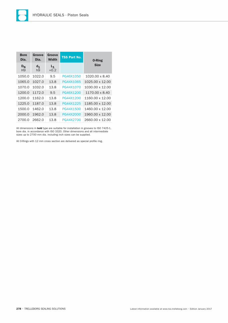
HYDRAULIC SEALS · Piston Seals
278
Bore
Dia.
Groove
Dia.
Groove
WidthTSS Part No.
O-Ring
SizeDN d1 L1
bold
Turcon® Glyd Ring® T
TRELLEBORG SEALING SOLUTIONS • 279Latest information available at www.tss.trelleborg.com • Edition January 2017
Turcon®Glyd Ring®T
Double-acting
Rubber-energized plastic-faced seal
Material:Turcon®, Zurcon®and Elastomer

HYDRAULIC SEALS · Piston Seals
280
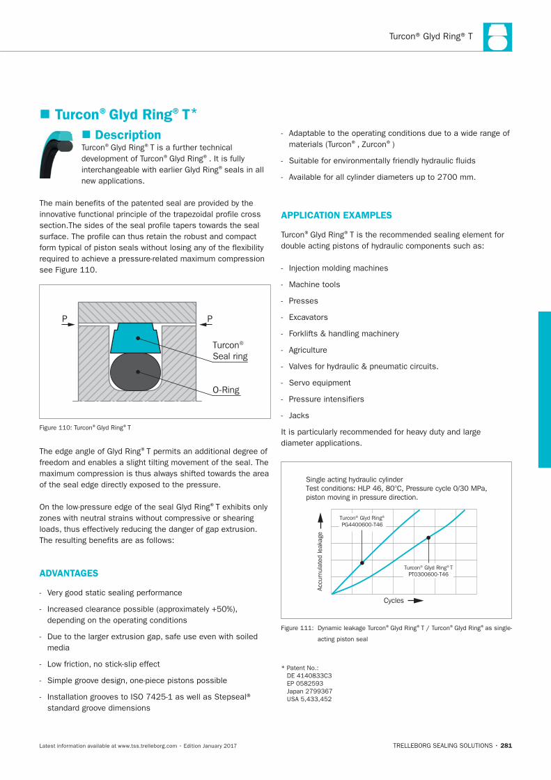
281
Description® ®
® ®
®seals in all
PP
Turcon® Seal ring
O-Ring
® ®T
®
®
ADVANTAGES
® ®)
APPLICATION EXAMPLES
® ®
Machine tools
Presses
Single acting hydraulic cylinderTest conditions: HLP 46, 80°C, Pressure cycle 0/30 MPa,piston moving in pressure direction.
Cycles
Accu
mul
ated
leak
age
Turcon® Glyd Ring®
PG4400600-T46
Turcon® Glyd Ring® TPT0300600-T46
® ® ® ®
Turcon®Glyd Ring®T*
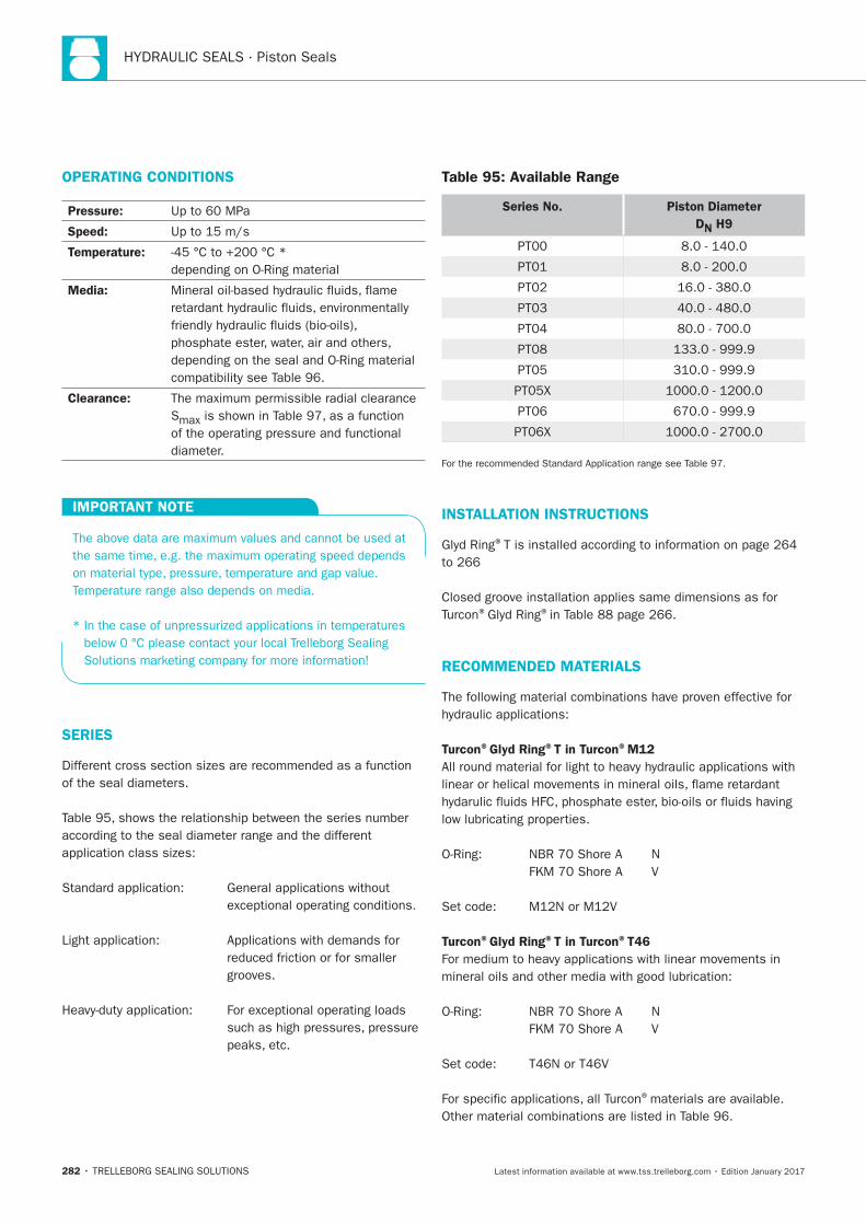
HYDRAULIC SEALS · Piston Seals
282
OPERATING CONDITIONS
Pressure:
Speed:
Temperature:
Media:
Clearance:
S
IMPORTANT NOTE
SERIES
grooves.
Table 95: Available Range
Series No. Piston Diameter
DN H9
INSTALLATION INSTRUCTIONS
®
® ®
RECOMMENDED MATERIALS
Turcon®Glyd Ring®T in Turcon®M12
Turcon®Glyd Ring®T in Turcon®T46
®materials are available.
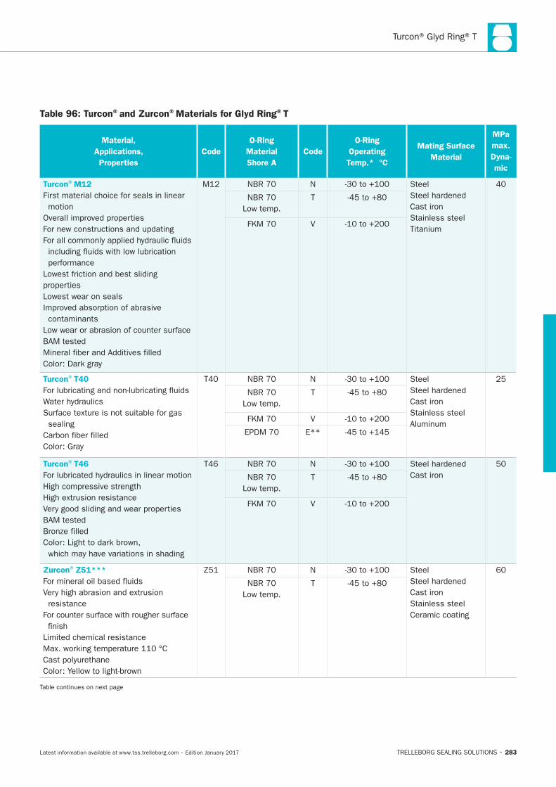
Turcon® Glyd Ring® T
283
Table 96: Turcon®and Zurcon®Materials for Glyd Ring®T
Material,
Applications,
Properties
Code
O-Ring
Material
Shore A
Code
O-Ring
Operating
Temp.* °C
Mating Surface
Material
MPa
max.
Dyna-
mic
Turcon®M12
First material choice for seals in linear
motion
performance
properties
Lowest wear on seals
contaminants
N Steel
Cast iron
Stainless steel
Low temp.
T
V
Turcon®T40
sealing
N Steel
Cast iron
Stainless steel
Low temp.
T
V
E**
Turcon®T46
High compressive strength
T46 N
Cast iron
Low temp.
T
V
Zurcon®Z51***
resistance
finish
Color: Yellow to light-brown
N Steel
Cast iron
Stainless steel
Ceramic coating
Low temp.
T
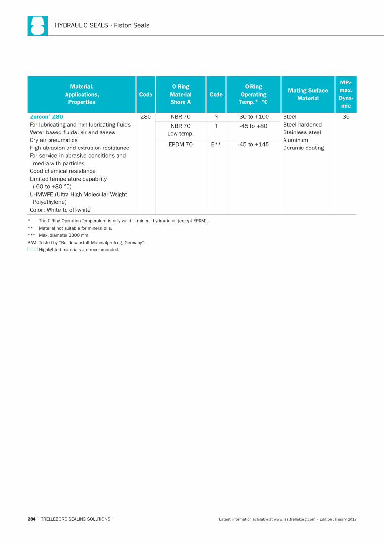
HYDRAULIC SEALS · Piston Seals
284
Material,
Applications,
Properties
Code
O-Ring
Material
Shore A
Code
O-Ring
Operating
Temp.* °C
Mating Surface
Material
MPa
max.
Dyna-
mic
Zurcon®Z80
Color: White to off-white
N Steel
Stainless steel
Ceramic coating
35
Low temp.
T
E**
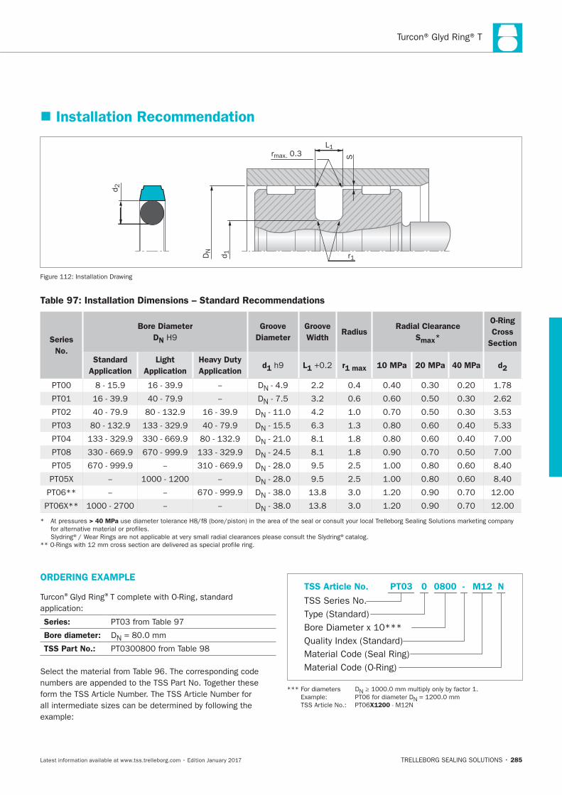
285
Installation Recommendation
r1
d2
DN
d1
S
L1rmax. 0.3
Installation Drawing
Table 97: Installation Dimensions – Standard Recommendations
Series
No.
Bore Diameter
DN
Groove
Diameter
Groove
Width Radius
Radial Clearance
Smax*
O-Ring
Cross
Section
Standard
Application
Light
Application
Heavy Duty
Applicationd1 L1 r1 max 10 MPa 20 MPa 40 MPa d2
DN
DN
DN
DN
DN
DN
DN
DN
DN
DN
> 40 MPa
ORDERING EXAMPLE
® ®
Series:
Bore diameter: DN
TSS Part No.:Material Code (Seal Ring)
TSS Series No.
TSS Article No. M120800 N
Material Code (O-Ring)
Bore Diameter x 10***
PT03
Quality Index (Standard)
-
Type (Standard)
0
N
N
X1200
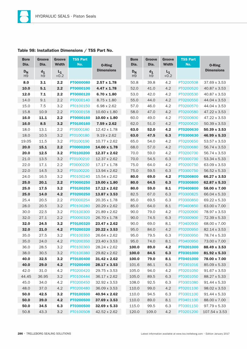
HYDRAULIC SEALS · Piston Seals
286
Bore
Dia.
Groove
Dia.
Groove
Width
TSS Part
No. O-Ring
DimensionsDN d1 L1
8.0 3.1 2.2 PT0000080 2.57 x 1.78
10.0 5.1 2.2 PT0000100 4.47 x 1.78
12.0 7.1 2.2 PT0000120 6.70 x 1.80
16.0 11.1 2.2 PT0000160 10.60 x 1.80
16.0 8.5 3.2 PT0100160 7.59 x 2.62
20.0 15.1 2.2 PT0000200 14.00 x 1.78
20.0 12.5 3.2 PT0100200 12.37 x 2.62
25.0 20.1 2.2 PT0000250 19.00 x 1.80
25.0 17.5 3.2 PT0100250 17.12 x 2.62
25.0 14.0 4.2 PT0200250 13.87 x 3.53
32.0 24.5 3.2 PT0100320 23.47 x 2.62
32.0 21.0 4.2 PT0200320 20.22 x 3.53
40.0 32.5 3.2 PT0100400 31.42 x 2.62
40.0 29.0 4.2 PT0200400 28.17 x 3.53
50.0 42.5 3.2 PT0100500 40.94 x 2.62
50.0 39.0 4.2 PT0200500 37.69 x 3.53
50.0 34.5 6.3 PT0300500 32.69 x 5.33
Bore
Dia.
Groove
Dia.
Groove
Width
TSS Part
No. O-Ring
DimensionsDN d1 L1
63.0 52.0 4.2 PT0200630 50.39 x 3.53
63.0 47.5 6.3 PT0300630 46.99 x 5.33
80.0 69.0 4.2 PT0200800 66.27 x 3.53
80.0 64.5 6.3 PT0300800 62.87 x 5.33
80.0 59.0 8.1 PT0400800 58.00 x 7.00
100.0 89.0 4.2 PT0201000 88.49 x 3.53
100.0 84.5 6.3 PT0301000 81.92 x 5.33
100.0 79.0 8.1 PT0401000 78.00 x 7.00
Table 98: Installation Dimensions / TSS Part No.
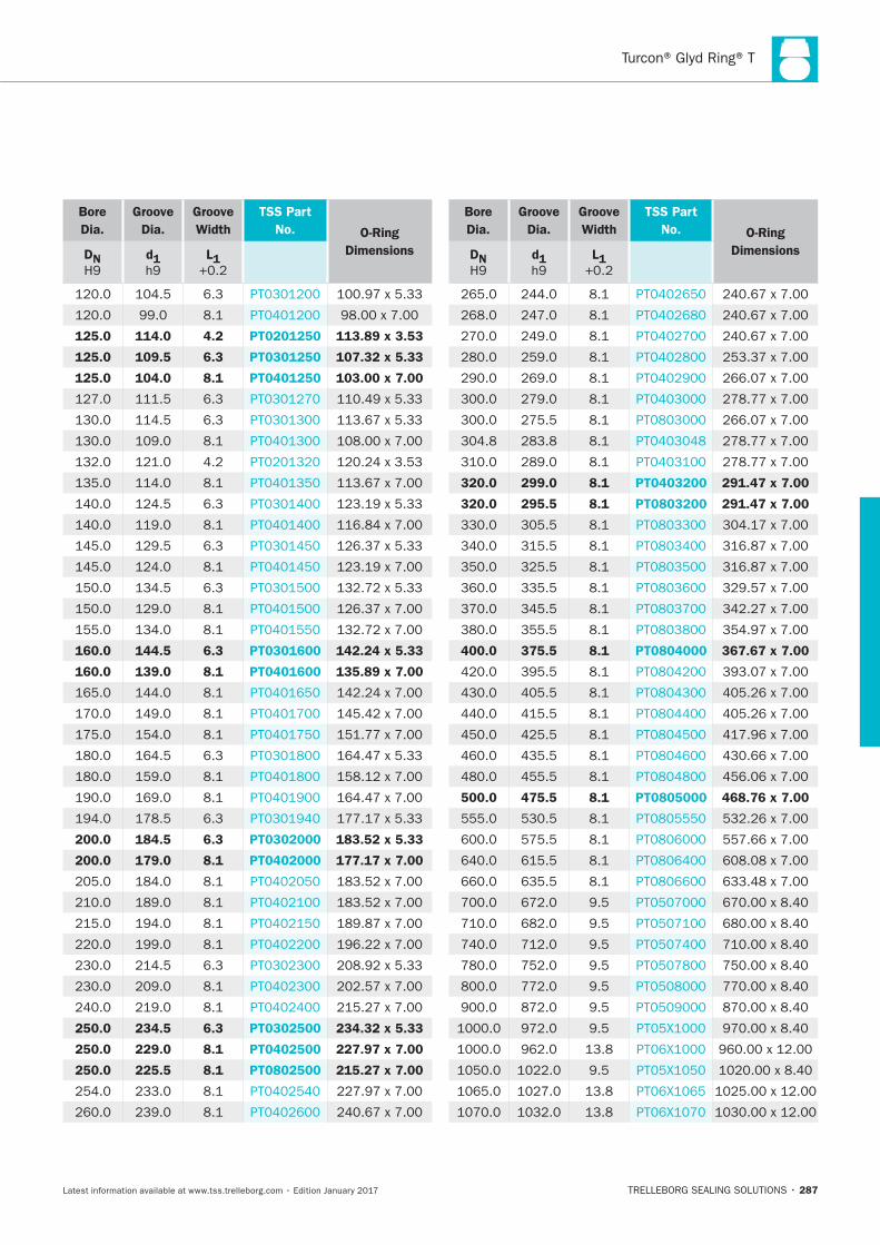
287
Bore
Dia.
Groove
Dia.
Groove
Width
TSS Part
No. O-Ring
DimensionsDN d1 L1
125.0 114.0 4.2 PT0201250 113.89 x 3.53
125.0 109.5 6.3 PT0301250 107.32 x 5.33
125.0 104.0 8.1 PT0401250 103.00 x 7.00
160.0 144.5 6.3 PT0301600 142.24 x 5.33
160.0 139.0 8.1 PT0401600 135.89 x 7.00
200.0 184.5 6.3 PT0302000 183.52 x 5.33
200.0 179.0 8.1 PT0402000 177.17 x 7.00
250.0 234.5 6.3 PT0302500 234.32 x 5.33
250.0 229.0 8.1 PT0402500 227.97 x 7.00
250.0 225.5 8.1 PT0802500 215.27 x 7.00
Bore
Dia.
Groove
Dia.
Groove
Width
TSS Part
No. O-Ring
DimensionsDN d1 L1
320.0 299.0 8.1 PT0403200 291.47 x 7.00
320.0 295.5 8.1 PT0803200 291.47 x 7.00
400.0 375.5 8.1 PT0804000 367.67 x 7.00
500.0 475.5 8.1 PT0805000 468.76 x 7.00
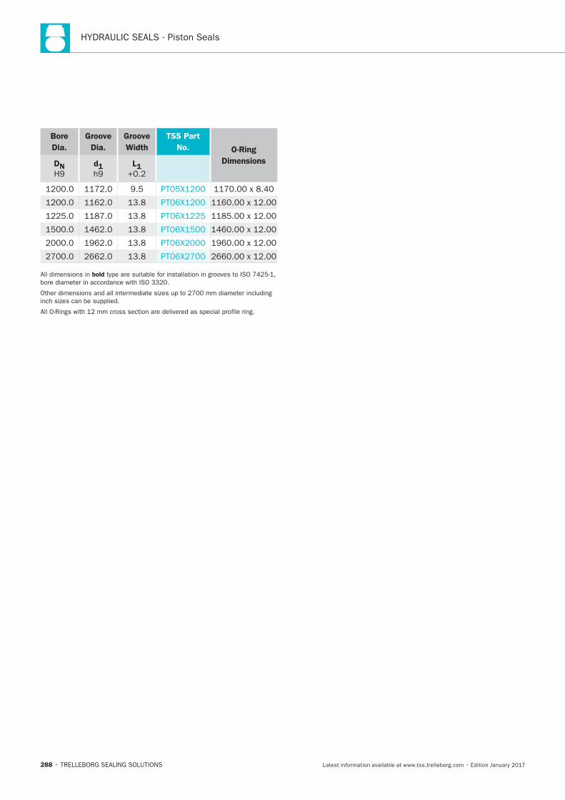
HYDRAULIC SEALS · Piston Seals
288
Bore
Dia.
Groove
Dia.
Groove
Width
TSS Part
No. O-Ring
DimensionsDN d1 L1
bold
Turcon® Glyd Ring® Hz
TRELLEBORG SEALING SOLUTIONS • 289Latest information available at www.tss.trelleborg.com • Edition January 2017
Turcon®Glyd Ring®Hz
Double-acting
Rubber-energized plastic-faced seal
Material:Turcon®, Zurcon®and Elastomer

HYDRAULIC SEALS · Piston Seals
290
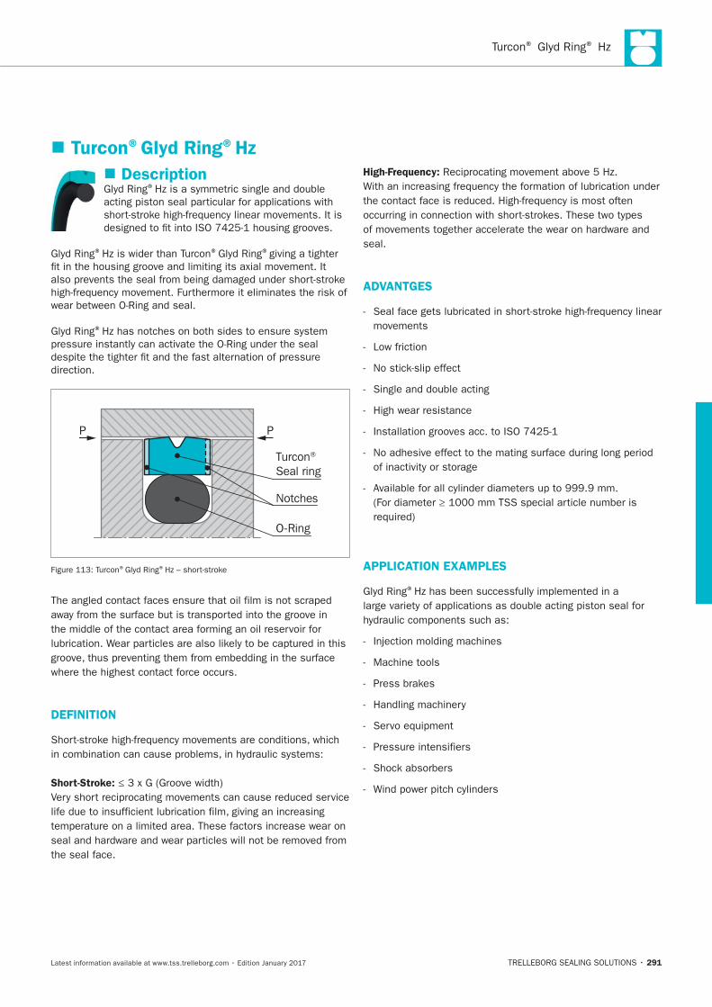
® ®
291
Description®
® ® ®giving a tighter
®
P
Turcon® Seal ring
O-Ring
P
Notches
® ®
DEFINITION
Short-Stroke:
the seal face.
High-Frequency:
seal.
ADVANTGES
movements
Low friction
High wear resistance
APPLICATION EXAMPLES
®
Machine tools
Turcon®Glyd Ring®Hz
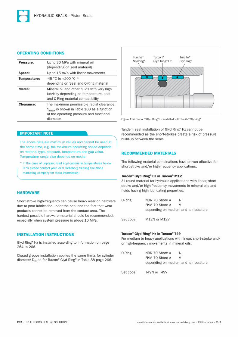
HYDRAULIC SEALS · Piston Seals
292
OPERATING CONDITIONS
Pressure:
Speed:
Temperature:
Media:
Clearance:
S
IMPORTANT NOTE
HARDWARE
INSTALLATION INSTRUCTIONS
®
N® ®
Turcite®
Slydring®Turcite®
Slydring®Turcon® Glyd Ring® Hz
® ® ® ®
®
RECOMMENDED MATERIALS
Turcon®Glyd Ring®Hz in Turcon®M12
Turcon®Glyd Ring®Hz in Turcon®T49
® ®
293
Turcon®Glyd Ring®Hz in Turcon®T40 Zurcon®Glyd Ring®Hz in Zurcon®Z80
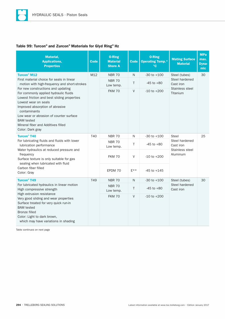
HYDRAULIC SEALS · Piston Seals
294
Table 99: Turcon®and Zurcon®Materials for Glyd Ring®Hz
Material,
Applications,
Properties
Code
O-Ring
Material
Shore A
Code
O-Ring
Operating Temp.*
°C
Mating Surface
Material
MPa
max.
Dyna-
mic
Turcon®M12
First material choice for seals in linear
Lowest wear on seals
contaminants
N
Cast iron
Stainless steel
T
V
Turcon®T40
N Steel
Cast iron
Stainless steel
T
V
E**
Turcon®T49
N
Cast iron
T
V
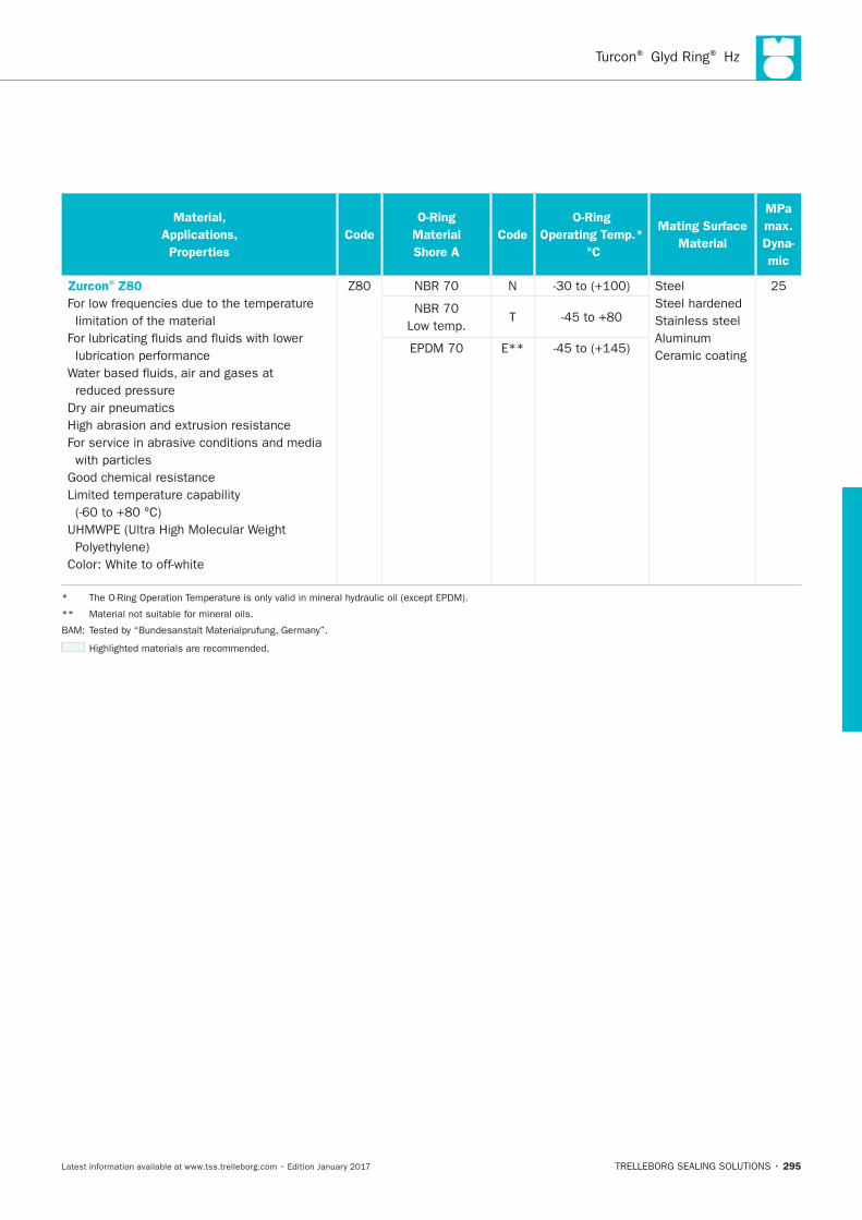
Turcon® Glyd Ring® Hz
295
Material,
Applications,
Properties
Code
O-Ring
Material
Shore A
Code
O-Ring
Operating Temp.*
°C
Mating Surface
Material
MPa
max.
Dyna-
mic
Zurcon®Z80
limitation of the material
N Steel
Stainless steel
Ceramic coating
T
E**
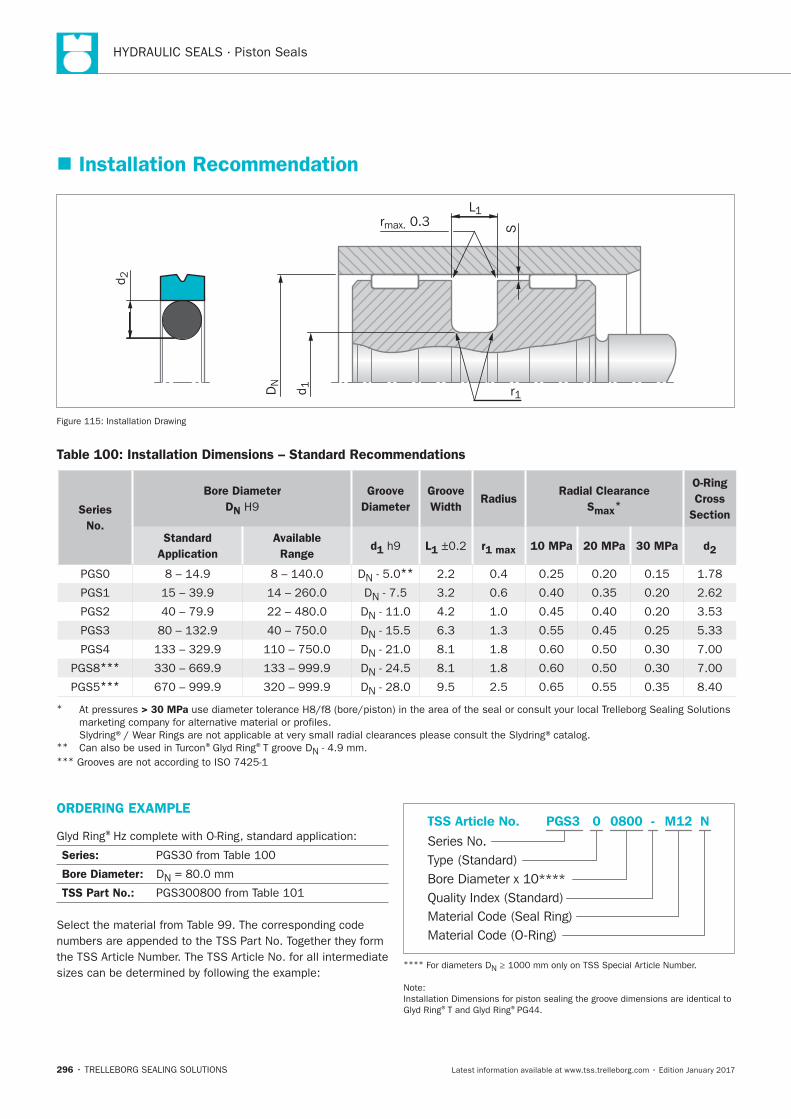
HYDRAULIC SEALS · Piston Seals
296
Installation Recommendation
S
L1rmax. 0.3
d 2
DN
d 1 r1
Installation Drawing
Table 100: Installation Dimensions – Standard Recommendations
Series
No.
Bore Diameter
DN
Groove
Diameter
Groove
Width Radius
Radial Clearance
Smax*
O-Ring
Cross
Section
Standard
Application
Available
Ranged1 L1 r1 max 10 MPa 20 MPa 30 MPa d2
DN**
DN
DN
DN
DN
*** DN
*** DN
* > 30 MPa
** ® ®T groove DN***
ORDERING EXAMPLE
®
Series:
Bore Diameter: DN
TSS Part No.:
Material Code (Seal Ring)
Series No.
TSS Article No. M120800 N
Material Code (O-Ring)
Bore Diameter x 10****
PGS3
Quality Index (Standard)
-
Type (Standard)
0
****N
® ®
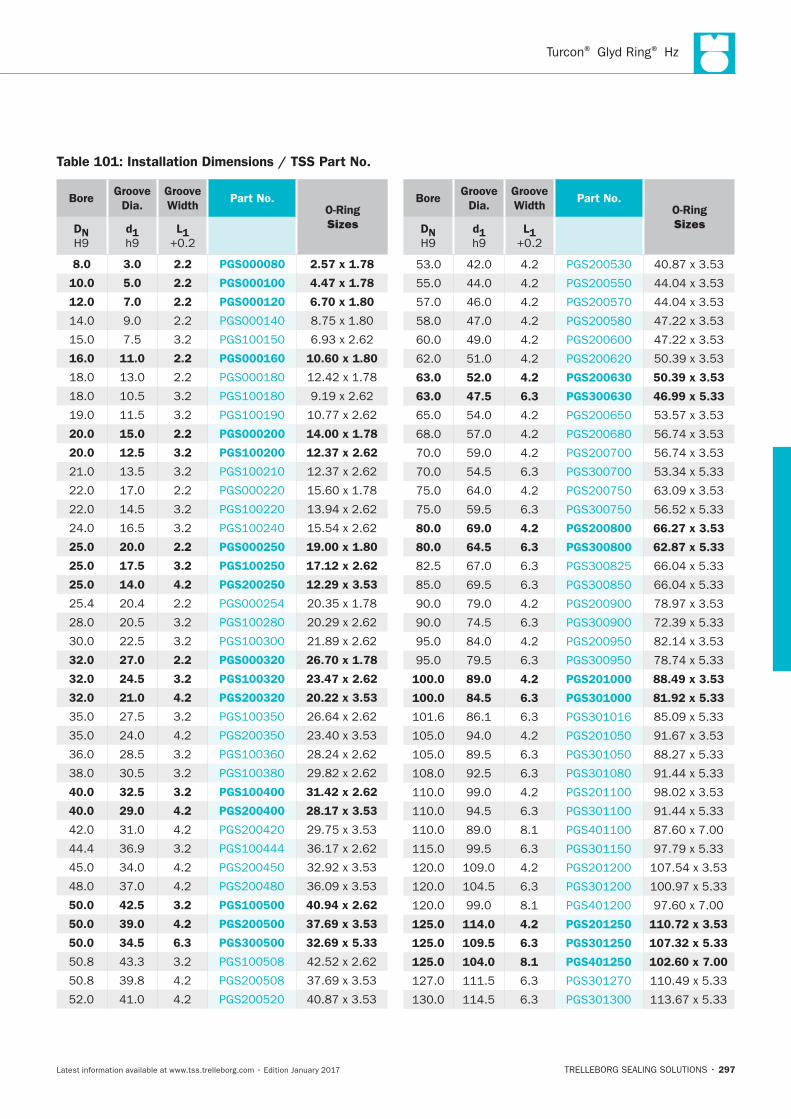
Turcon® Glyd Ring® Hz
297
Bore Groove
Dia.
Groove
Width Part No.
O-Ring
Sizes DN
d1
L1
8.0 3.0 2.2 PGS000080 2.57 x 1.78
10.0 5.0 2.2 PGS000100 4.47 x 1.78
12.0 7.0 2.2 PGS000120 6.70 x 1.80
16.0 11.0 2.2 PGS000160 10.60 x 1.80
20.0 15.0 2.2 PGS000200 14.00 x 1.78
20.0 12.5 3.2 PGS100200 12.37 x 2.62
25.0 20.0 2.2 PGS000250 19.00 x 1.80
25.0 17.5 3.2 PGS100250 17.12 x 2.62
25.0 14.0 4.2 PGS200250 12.29 x 3.53
32.0 27.0 2.2 PGS000320 26.70 x 1.78
32.0 24.5 3.2 PGS100320 23.47 x 2.62
32.0 21.0 4.2 PGS200320 20.22 x 3.53
40.0 32.5 3.2 PGS100400 31.42 x 2.62
40.0 29.0 4.2 PGS200400 28.17 x 3.53
50.0 42.5 3.2 PGS100500 40.94 x 2.62
50.0 39.0 4.2 PGS200500 37.69 x 3.53
50.0 34.5 6.3 PGS300500 32.69 x 5.33
Bore Groove
Dia.
Groove
Width Part No.
O-Ring
Sizes DN
d1
L1
63.0 52.0 4.2 PGS200630 50.39 x 3.53
63.0 47.5 6.3 PGS300630 46.99 x 5.33
80.0 69.0 4.2 PGS200800 66.27 x 3.53
80.0 64.5 6.3 PGS300800 62.87 x 5.33
100.0 89.0 4.2 PGS201000 88.49 x 3.53
100.0 84.5 6.3 PGS301000 81.92 x 5.33
125.0 114.0 4.2 PGS201250 110.72 x 3.53
125.0 109.5 6.3 PGS301250 107.32 x 5.33
125.0 104.0 8.1 PGS401250 102.60 x 7.00
Table 101: Installation Dimensions / TSS Part No.
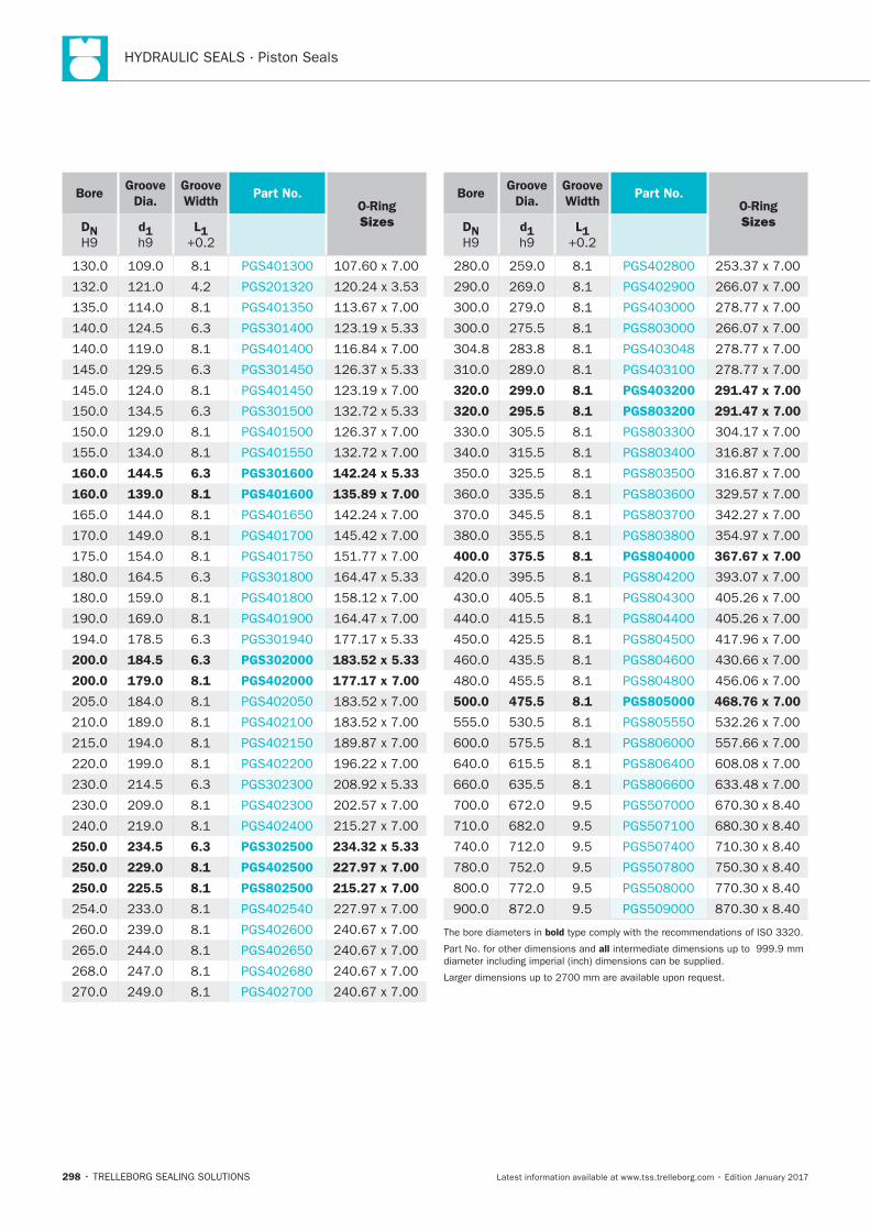
HYDRAULIC SEALS · Piston Seals
298
Bore Groove
Dia.
Groove
Width Part No.
O-Ring
Sizes DN
d1
L1
160.0 144.5 6.3 PGS301600 142.24 x 5.33
160.0 139.0 8.1 PGS401600 135.89 x 7.00
200.0 184.5 6.3 PGS302000 183.52 x 5.33
200.0 179.0 8.1 PGS402000 177.17 x 7.00
250.0 234.5 6.3 PGS302500 234.32 x 5.33
250.0 229.0 8.1 PGS402500 227.97 x 7.00
250.0 225.5 8.1 PGS802500 215.27 x 7.00
Bore Groove
Dia.
Groove
Width Part No.
O-Ring
Sizes DN
d1
L1
320.0 299.0 8.1 PGS403200 291.47 x 7.00
320.0 295.5 8.1 PGS803200 291.47 x 7.00
400.0 375.5 8.1 PGS804000 367.67 x 7.00
500.0 475.5 8.1 PGS805000 468.76 x 7.00
bold
all
Zurcon® Glyd Ring®D
TRELLEBORG SEALING SOLUTIONS • 299Latest information available at www.tss.trelleborg.com • Edition January 2017
Zurcon®Glyd Ring®D
Double-acting
Rubber-energized plastic-faced seal
High Extrusion Resistance
Material:Zurcon®and Elastomer

HYDRAULIC SEALS · Piston Seals
300
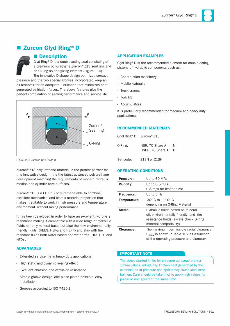
Zurcon® Glyd Ring®D
301
Description
P P
Zurcon® Seal ring
O-Ring
ADVANTAGES
APPLICATION EXAMPLES
RECOMMENDED MATERIALS
OPERATING CONDITIONS
Pressure:
Velocity:
Frequency:
Temperature:
Media:
Clearance:
IMPORTANT NOTE
Zurcon Glyd Ring®D
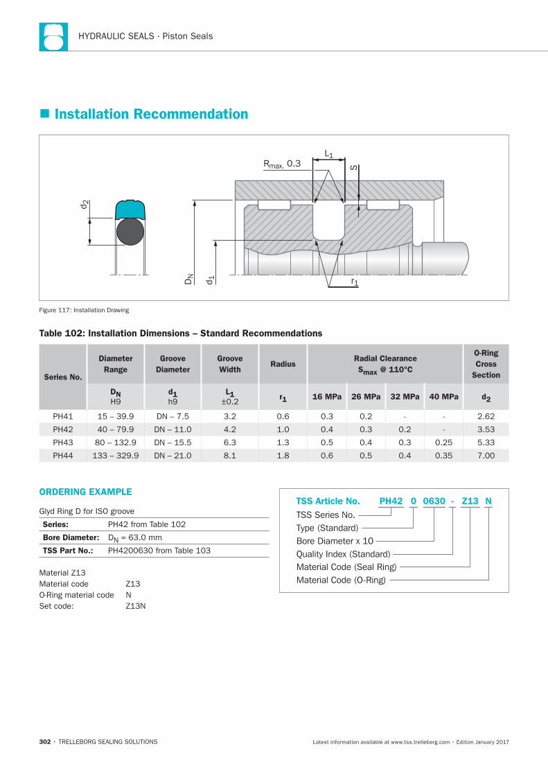
HYDRAULIC SEALS · Piston Seals
302
Installation Recommendation
SRmax. 0.3
DN
L1
d 1 r1
d 2
Table 102: Installation Dimensions – Standard Recommendations
Series No.
Diameter
Range
Groove
Diameter
Groove
WidthRadius
Radial Clearance
Smax @ 110°C
O-Ring
Cross
Section
DN d1 L1 r1 16 MPa 26 MPa 32 MPa 40 MPa d2
ORDERING EXAMPLE
Series:
Bore Diameter:
TSS Part No.:
Material Code (Seal Ring)
TSS Series No.
TSS Article No. Z130630 N
Material Code (O-Ring)
Bore Diameter x 10
PH42
Quality Index (Standard)
-
Type (Standard)
0
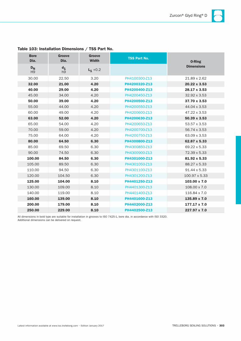
Zurcon® Glyd Ring®D
TRELLEBORG SEALING SOLUTIONS • 303Latest information available at www.tss.trelleborg.com • Edition January 2017
BoreDia.
GrooveDia.
GrooveWidth
TSS Part No.O-Ring
DimensionsDN H9
d1 h9
L1 +0.2
30.00 22.50 3.20 PH4100300-Z13 21.89 x 2.62
32.00 21.00 4.20 PH4200320-Z13 20.22 x 3.53
40.00 29.00 4.20 PH4200400-Z13 28.17 x 3.53
45.00 34.00 4.20 PH4200450-Z13 32.92 x 3.53
50.00 39.00 4.20 PH4200500-Z13 37.70 x 3.53
55.00 44.00 4.20 PH4200550-Z13 44.04 x 3.53
60.00 49.00 4.20 PH4200600-Z13 47.22 x 3.53
63.00 52.00 4.20 PH4200630-Z13 50.39 x 3.53
65.00 54.00 4.20 PH4200650-Z13 53.57 x 3.53
70.00 59.00 4.20 PH4200700-Z13 56.74 x 3.53
75.00 64.00 4.20 PH4200750-Z13 63.09 x 3.53
80.00 64.50 6.30 PH4300800-Z13 62.87 x 5.33
85.00 69.50 6.30 PH4300850-Z13 69.22 x 5.33
90.00 74.50 6.30 PH4300900-Z13 72.39 x 5.33
100.00 84.50 6.30 PH4301000-Z13 81.92 x 5.33
105.00 89.50 6.30 PH4301050-Z13 88.27 x 5.33
110.00 94.50 6.30 PH4301100-Z13 91.44 x 5.33
120.00 104.50 6.30 PH4301200-Z13 100.97 x 5.33
125.00 104.00 8.10 PH4401250-Z13 103.00 x 7.0
130.00 109.00 8.10 PH4401300-Z13 108.00 x 7.0
140.00 119.00 8.10 PH4401400-Z13 116.84 x 7.0
160.00 139.00 8.10 PH4401600-Z13 135.89 x 7.0
200.00 179.00 8.10 PH4402000-Z13 177.17 x 7.0
250.00 229.00 8.10 PH4402500-Z13 227.97 x 7.0
All dimensions in bold type are suitable for installation in grooves to ISO 7425-1, bore dia. in accordance with ISO 3320. Additional dimensions can be delivered on request.
Table 103: Installation Dimensions / TSS Part No.
005_Piston_GlydRing_D.indd 303 19.12.2016 11:18:39

HYDRAULIC SEALS · Piston Seals
304
Zurcon® Glyd Ring® P
TRELLEBORG SEALING SOLUTIONS • 305Latest information available at www.tss.trelleborg.com • Edition January 2017
Zurcon®Glyd Ring P®
Double-acting
Rubber-energized plastic-faced seal
Step Cut Sealing Element
Material:Zurcon®Polyamid + NBR

HYDRAULIC SEALS · Piston Seals
306
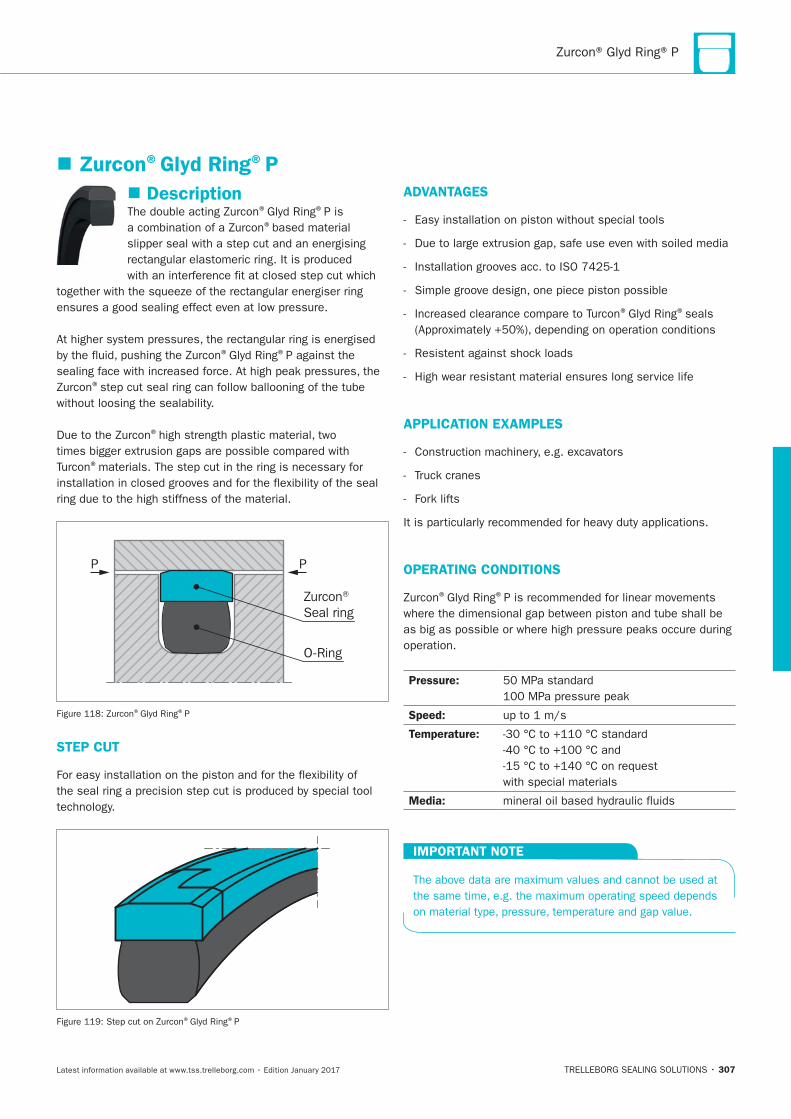
307
Description® ®P is ®
® ®P against the
®
®
®
PP
Zurcon® Seal ring
O-Ring
® ®P
STEP CUT
® ®P
ADVANTAGES
® ®seals
APPLICATION EXAMPLES
OPERATING CONDITIONS
® ®
Pressure:
Speed:
Temperature:
Media:
IMPORTANT NOTE
Zurcon®Glyd Ring®P
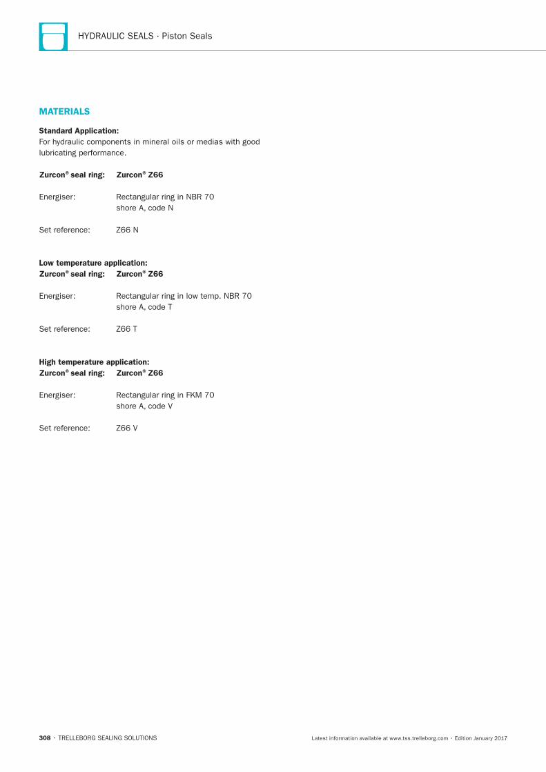
HYDRAULIC SEALS · Piston Seals
308
MATERIALS
Standard Application:
Zurcon®seal ring: Zurcon®Z66
Low temperature application:
Zurcon®seal ring: Zurcon®Z66
High temperature application:
Zurcon®seal ring: Zurcon®Z66
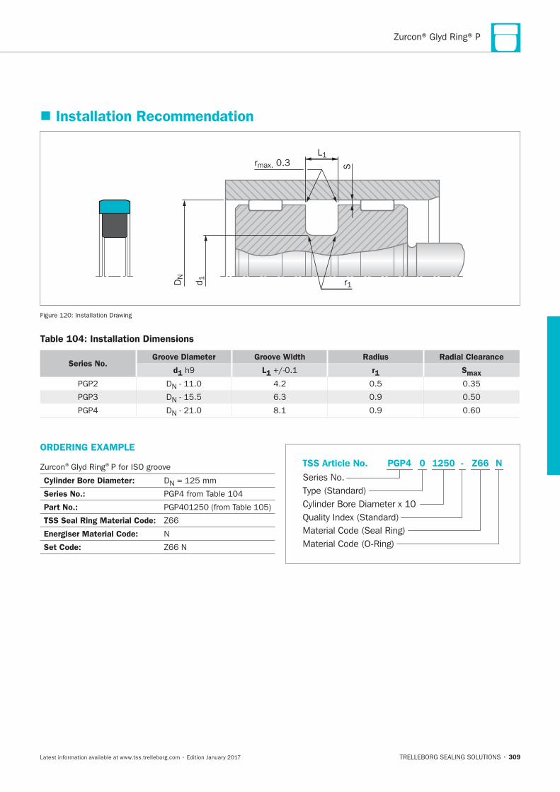
309
ORDERING EXAMPLE
® ®P for ISO groove
Cylinder Bore Diameter: DN
Series No.:
Part No.:
TSS Seal Ring Material Code:
Energiser Material Code: N
Set Code:
Material Code (Seal Ring)
Series No.
TSS Article No. Z661250 N
Material Code (O-Ring)
Cylinder Bore Diameter x 10
PGP4
Quality Index (Standard)
-
Type (Standard)
0
Installation Recommendation
S
L1rmax. 0.3
r1DN
d1
Installation Drawing
Table 104: Installation Dimensions
Series No.Groove Diameter Groove Width Radius Radial Clearance
d1 L1 r1 Smax
DN
DN
DN
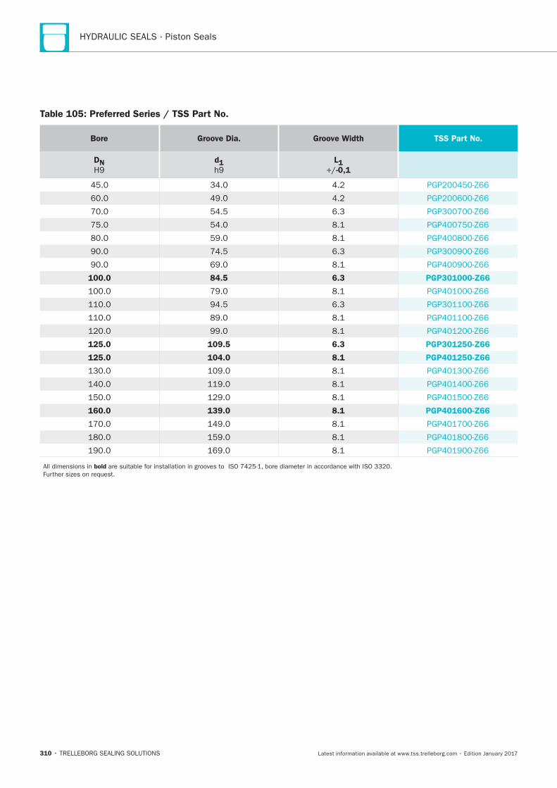
HYDRAULIC SEALS · Piston Seals
310
Table 105: Preferred Series / TSS Part No.
Bore Groove Dia. Groove Width TSS Part No.
DN
d1
L1
-0,1
100.0 84.5 6.3 PGP301000-Z66
125.0 109.5 6.3 PGP301250-Z66
125.0 104.0 8.1 PGP401250-Z66
160.0 139.0 8.1 PGP401600-Z66
bold
Turcon® AQ-Seal® 5
TRELLEBORG SEALING SOLUTIONS • 311Latest information available at www.tss.trelleborg.com • Edition January 2017
Turcon®AQ-Seal®5
Double-acting
Rubber-energized plastic-faced seal
Material:Turcon®, Zurcon®and Elastomer

HYDRAULIC SEALS · Piston Seals
312
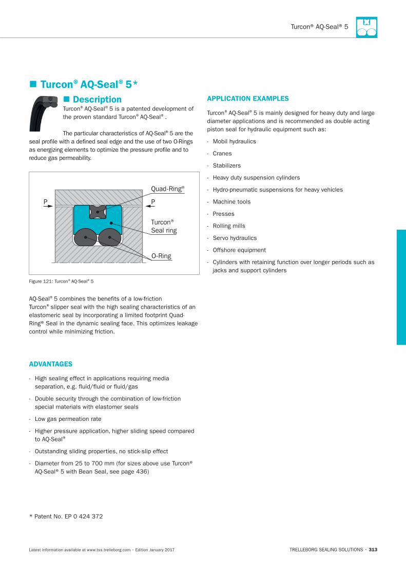
313
Description® ®
® ®.
®
P P
Turcon® Seal ring
Quad-Ring®
O-Ring
® ®
®
®
ADVANTAGES
®
APPLICATION EXAMPLES
® ®
Cranes
Machine tools
Presses
Rolling mills
Turcon®AQ-Seal®5*
HYDRAULIC SEALS · Piston Seals
314
OPERATING CONDITIONS
Pressure:
Speed:
Temperature: **
material
Media:
see
Clearance:
S
IMPORTANT NOTE
**
INSTALLATION INSTRUCTIONS
®
RECOMMENDED MATERIALS
Turcon®AQ-Seal®5 in Turcon®M12
Turcon®AQ-Seal®5 in Turcon®T46
®materials are available.
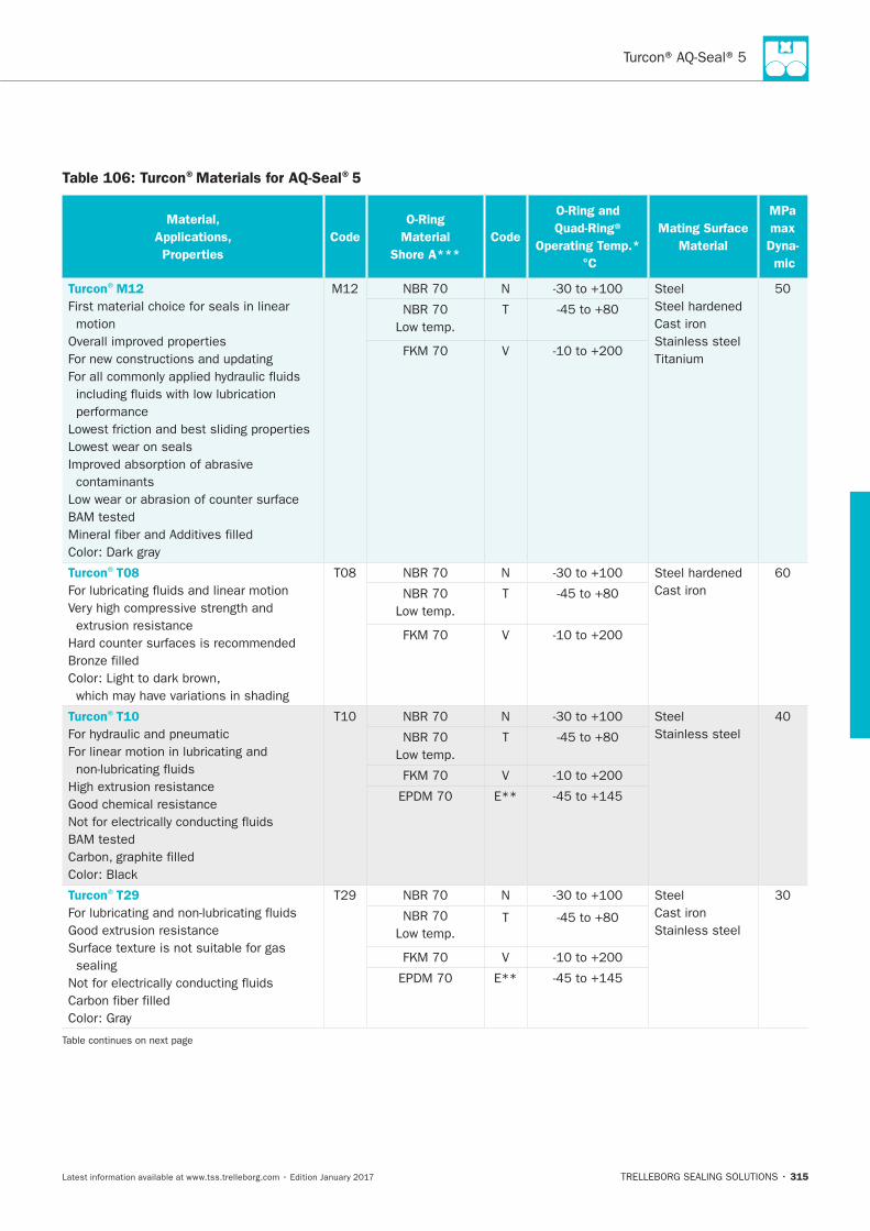
315
Table 106: Turcon®Materials for AQ-Seal®5
Material,
Applications,
Properties
Code
O-Ring
Material
Shore A***
Code
O-Ring and
Quad-Ring®
Operating Temp.*
°C
Mating Surface
Material
MPa
max
Dyna-
mic
Turcon®M12
First material choice for seals in linear
motion
Lowest wear on seals
contaminants
N Steel
Cast iron
Stainless steel
T
V
Turcon®T08
N
Cast iron T
V
Turcon®T10
N Steel
Stainless steel T
V
E**
Turcon®T29
sealing
N Steel
Cast iron
Stainless steel
T
V
E**
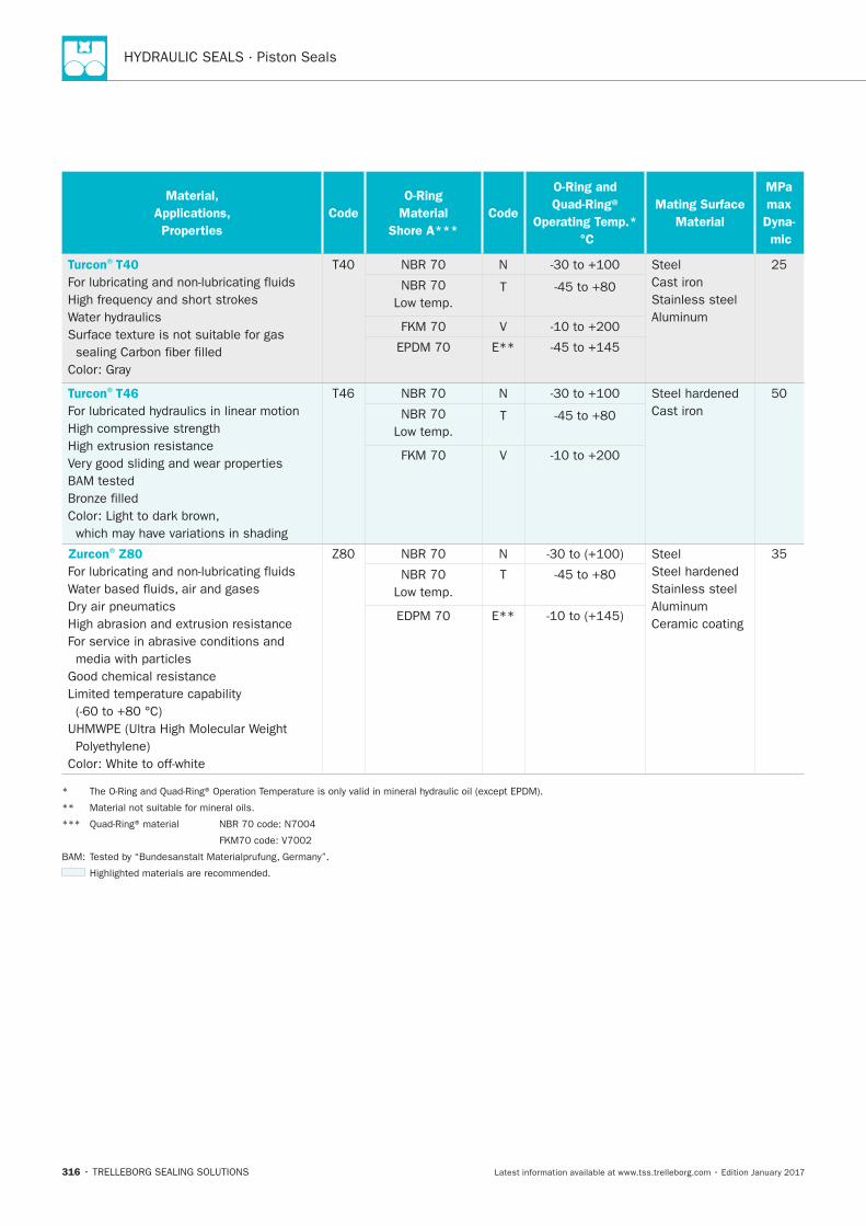
HYDRAULIC SEALS · Piston Seals
316
Material,
Applications,
Properties
Code
O-Ring
Material
Shore A***
Code
O-Ring and
Quad-Ring®
Operating Temp.*
°C
Mating Surface
Material
MPa
max
Dyna-
mic
Turcon®T40
N Steel
Cast iron
Stainless steel T
V
E**
Turcon®T46
N
Cast iron T
V
Zurcon®Z80
N Steel
Stainless steel
Ceramic coating
T
E**
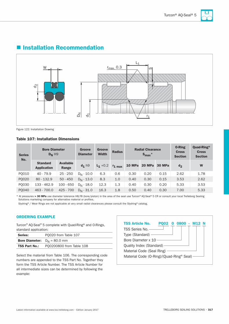
317
Installation Recommendation
S
L1
rmax. 0.3
r1
d2
DN
d1
W
Installation Drawing
Table 107: Installation Dimensions
Series
No.
Bore Diameter
DN
Groove
Diameter
Groove
Width Radius
Radial Clearance
Smax*
O-Ring
Cross
Section
Quad-Ring®
Cross
Section
Standard
Application
Available
Range d1 L1 r1 max 10 MPa 20 MPa 30 MPa d2 W
DN
DN
DN
DN
> 30 MPa
ORDERING EXAMPLE
® ®
Series:
Bore Diameter: DN
TSS Part No.:
Material Code (Seal Ring)
TSS Series No.
TSS Article No. M120800 N
Material Code (O-Ring)/(Quad-Ring® Seal)
Bore Diameter x 10
PQ02
Quality Index (Standard)
-
Type (Standard)
0
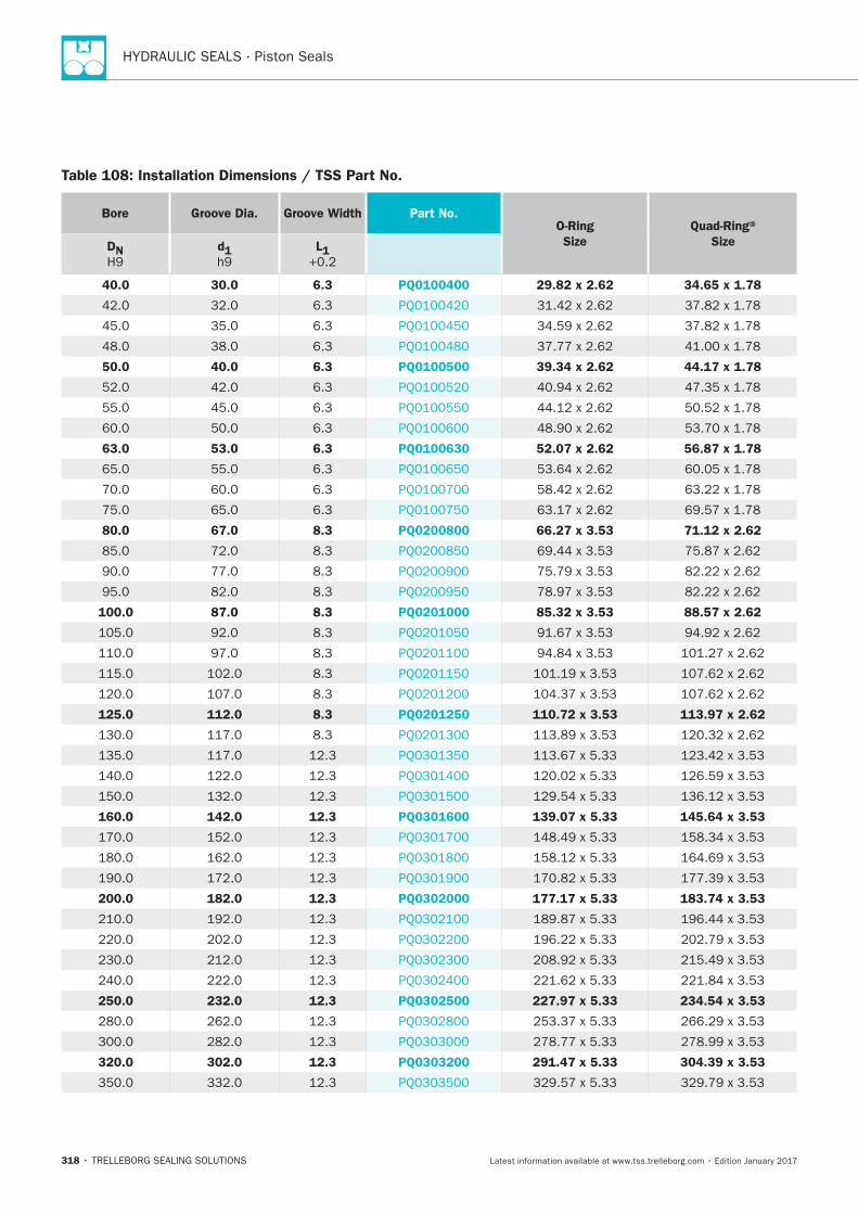
HYDRAULIC SEALS · Piston Seals
318
Table 108: Installation Dimensions / TSS Part No.
Bore Groove Dia. Groove Width Part No. O-Ring
Size
Quad-Ring®
Size DN
d1
L1
40.0 30.0 6.3 PQ0100400 29.82 x 2.62 34.65 x 1.78
50.0 40.0 6.3 PQ0100500 39.34 x 2.62 44.17 x 1.78
63.0 53.0 6.3 PQ0100630 52.07 x 2.62 56.87 x 1.78
80.0 67.0 8.3 PQ0200800 66.27 x 3.53 71.12 x 2.62
100.0 87.0 8.3 PQ0201000 85.32 x 3.53 88.57 x 2.62
125.0 112.0 8.3 PQ0201250 110.72 x 3.53 113.97 x 2.62
160.0 142.0 12.3 PQ0301600 139.07 x 5.33 145.64 x 3.53
200.0 182.0 12.3 PQ0302000 177.17 x 5.33 183.74 x 3.53
250.0 232.0 12.3 PQ0302500 227.97 x 5.33 234.54 x 3.53
320.0 302.0 12.3 PQ0303200 291.47 x 5.33 304.39 x 3.53
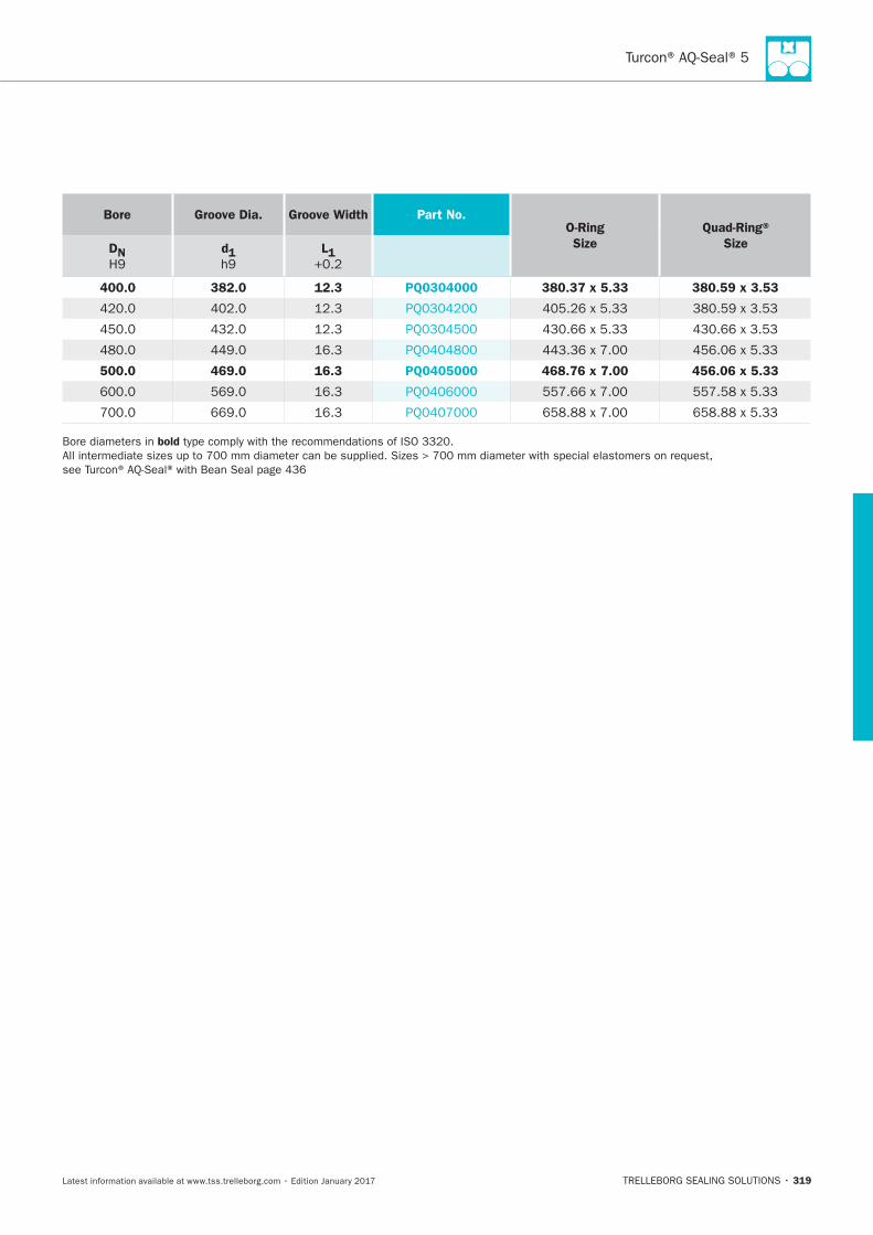
Turcon® AQ-Seal® 5
319
Bore Groove Dia. Groove Width Part No. O-Ring
Size
Quad-Ring®
Size DN
H9
d1
h9
L1
400.0 382.0 12.3 PQ0304000 380.37 x 5.33 380.59 x 3.53
500.0 469.0 16.3 PQ0405000 468.76 x 7.00 456.06 x 5.33
bold

HYDRAULIC SEALS · Piston Seals
320
Turcon® AQ-Seal®
TRELLEBORG SEALING SOLUTIONS • 321Latest information available at www.tss.trelleborg.com • Edition January 2017
Turcon®AQ-Seal®
Double-acting
Rubber-energized plastic-faced seal
Material:Turcon®, Zurcon®and Elastomer

HYDRAULIC SEALS · Piston Seals
322
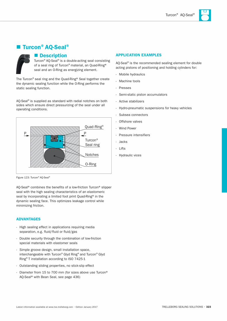
® ®
323
Description® ®
®
®
®
P P
Turcon® Seal ring
Notches
O-Ring
Quad-Ring®
® ®
seal with the high sealing characteristics of an elastomeric
ADVANTAGES
® ® ®
Ring®
APPLICATION EXAMPLES
®
Machine tools
Presses
Offshore valves
Lifts
Turcon®AQ-Seal®
HYDRAULIC SEALS · Piston Seals
324
OPERATING CONDITIONS
*
material
clearance S
IMPORTANT NOTE
*
INSTALLATION INSTRUCTIONS
®
® ®
RECOMMENDED MATERIALS
Turcon®AQ-Seal®in Turcon®M12
Turcon®AQ-Seal®in Turcon®T46
®materials are available.
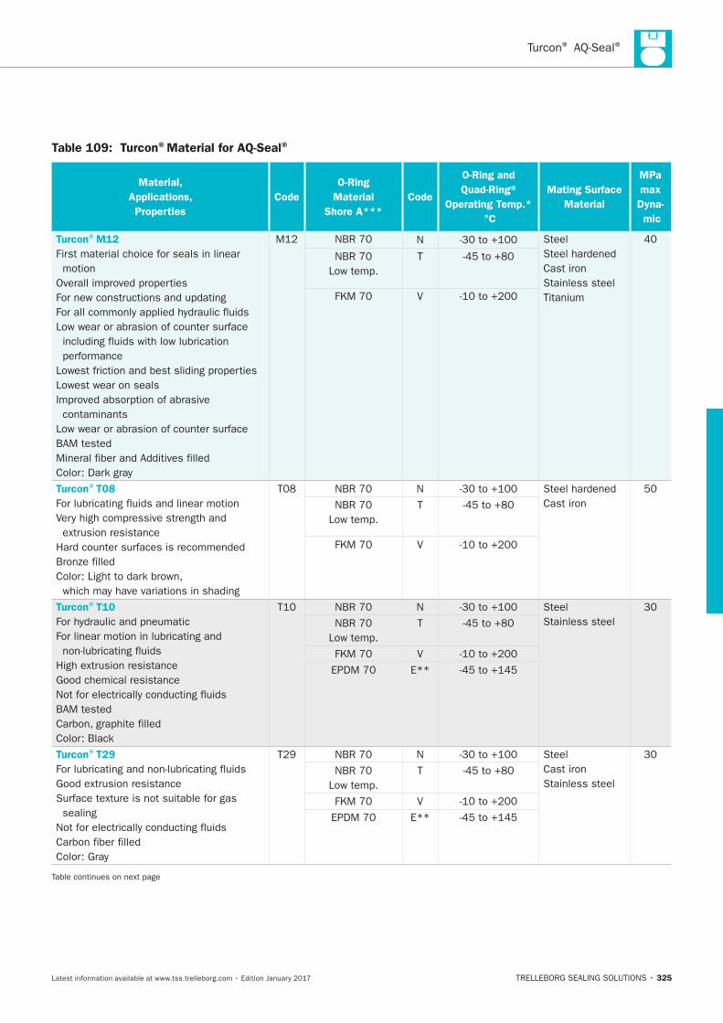
® ®
325
Table 109: Turcon®Material for AQ-Seal®
Material,
Applications,
Properties
Code
O-Ring
Material
Shore A***
Code
O-Ring and
Quad-Ring®
Operating Temp.*
°C
Mating Surface
Material
MPa
max
Dyna-
mic
Turcon®M12
First material choice for seals in linear
motion
Lowest wear on seals
contaminants
N Steel
Cast iron
Stainless steel
T
V
Turcon®T08
N
Cast iron T
V
Turcon®T10
N Steel
Stainless steel T
V
E**
Turcon®T29
sealing
N Steel
Cast iron
Stainless steel
T
V
E**
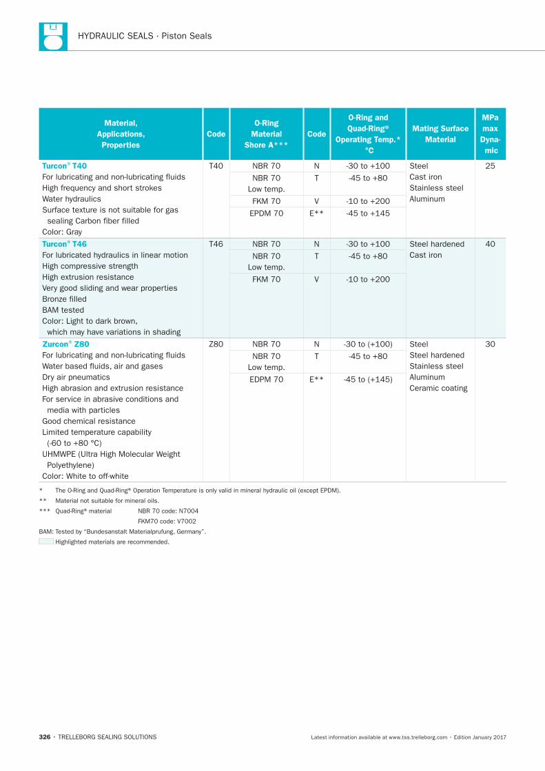
HYDRAULIC SEALS · Piston Seals
326
Material,
Applications,
Properties
Code
O-Ring
Material
Shore A***
Code
O-Ring and
Quad-Ring®
Operating Temp.*
°C
Mating Surface
Material
MPa
max
Dyna-
mic
Turcon®T40
N Steel
Cast iron
Stainless steel T
V
E**
Turcon®T46
N
Cast iron T
V
Zurcon®Z80
N Steel
Stainless steel
Ceramic coating
T
E**
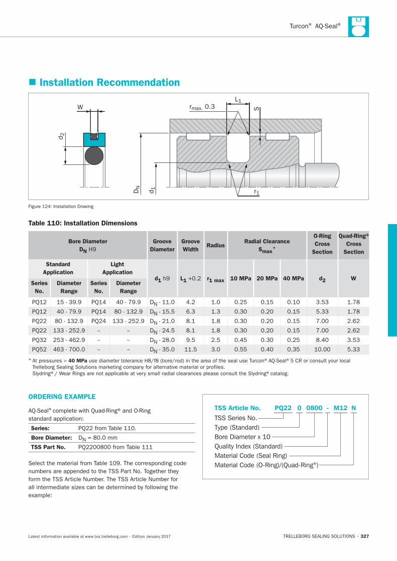
® ®
327
Installation Recommendation
S
L1rmax. 0.3
r1
d2
DN
d1
W
Installation Drawing
Table 110: Installation Dimensions
Bore Diameter
DN
Groove
Diameter
Groove
Width Radius
Radial Clearance
Smax*
O-Ring
Cross
Section
Quad-Ring®
Cross
Section
Standard
Application
Light
Application d1 L1 r1 max 10 MPa 20 MPa 40 MPa d2 W
Series
No.
Diameter
Range
Series
No.
Diameter
Range
DN
DN
DN
DN
DN
DN
* 40 MPa
ORDERING EXAMPLE
®
Series:
Bore Diameter: DN
TSS Part No.
Material Code (Seal Ring)
TSS Series No.
TSS Article No. M120800 N
Material Code (O-Ring)/(Quad-Ring®)
Bore Diameter x 10
PQ22
Quality Index (Standard)
-
Type (Standard)
0
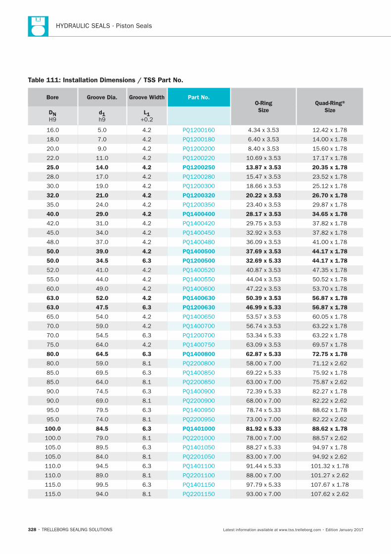
HYDRAULIC SEALS · Piston Seals
328
Table 111: Installation Dimensions / TSS Part No.
Bore Groove Dia. Groove Width Part No. O-Ring
Size
Quad-Ring®
Size DN
d1
L1
25.0 14.0 4.2 PQ1200250 13.87 x 3.53 20.35 x 1.78
32.0 21.0 4.2 PQ1200320 20.22 x 3.53 26.70 x 1.78
40.0 29.0 4.2 PQ1400400 28.17 x 3.53 34.65 x 1.78
50.0 39.0 4.2 PQ1400500 37.69 x 3.53 44.17 x 1.78
50.0 34.5 6.3 PQ1200500 32.69 x 5.33 44.17 x 1.78
63.0 52.0 4.2 PQ1400630 50.39 x 3.53 56.87 x 1.78
63.0 47.5 6.3 PQ1200630 46.99 x 5.33 56.87 x 1.78
80.0 64.5 6.3 PQ1400800 62.87 x 5.33 72.75 x 1.78
100.0 84.5 6.3 PQ1401000 81.92 x 5.33 88.62 x 1.78
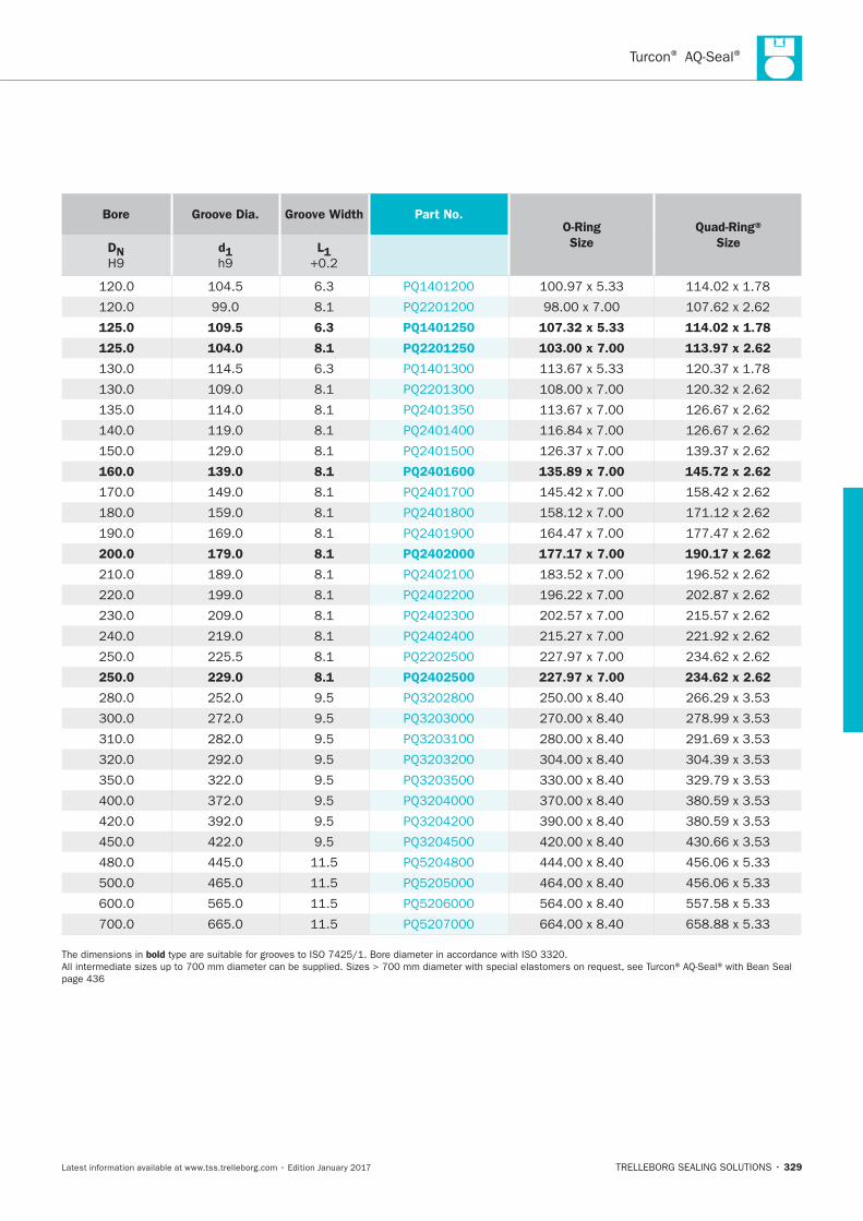
® ®
329
Bore Groove Dia. Groove Width Part No. O-Ring
Size
Quad-Ring®
Size DN
d1
L1
125.0 109.5 6.3 PQ1401250 107.32 x 5.33 114.02 x 1.78
125.0 104.0 8.1 PQ2201250 103.00 x 7.00 113.97 x 2.62
160.0 139.0 8.1 PQ2401600 135.89 x 7.00 145.72 x 2.62
200.0 179.0 8.1 PQ2402000 177.17 x 7.00 190.17 x 2.62
250.0 229.0 8.1 PQ2402500 227.97 x 7.00 234.62 x 2.62
bold

HYDRAULIC SEALS · Piston Seals
330
Turcon® Stepseal® 2K
TRELLEBORG SEALING SOLUTIONS • 331Latest information available at www.tss.trelleborg.com • Edition January 2017
Turcon®Stepseal®2K
Single-acting
Rubber-energized plastic-faced seal
Material:Turcon®, Zurcon®and Elastomer

HYDRAULIC SEALS · Piston Seals
332
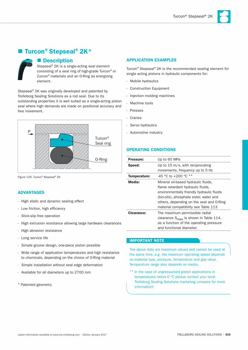
333
Description®
®or ®
element.
®
free movement.
P
Turcon® Seal ring
O-Ring
® ®
ADVANTAGES
High abrasion resistance
Long service life
*
APPLICATION EXAMPLES
® ®
Machine tools
Presses
Cranes
OPERATING CONDITIONS
Pressure:
Speed:
Temperature: **
Media:
Clearance:
clearance S
IMPORTANT NOTE
**
Turcon®Stepseal®2K*
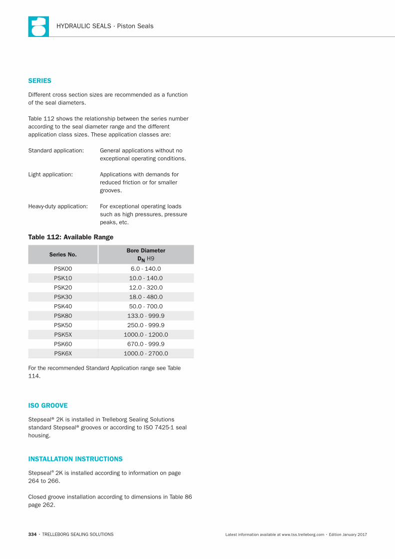
HYDRAULIC SEALS · Piston Seals
334
SERIES
grooves.
Table 112: Available Range
Series No. Bore Diameter
DN
ISO GROOVE
INSTALLATION INSTRUCTIONS
®
335
RECOMMENDED MATERIALS
Turcon®Stepseal®2K in Turcon®M12
Turcon®Stepseal®2K in Turcon®T46
®materials are available.
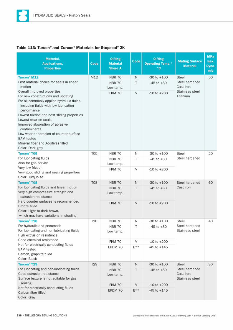
HYDRAULIC SEALS · Piston Seals
336
Table 113: Turcon®and Zurcon®Materials for Stepseal®2K
Material,
Applications,
Properties
Code
O-Ring
Material
Shore A
Code O-Ring
Operating Temp.*
°C
Mating Surface
Material
MPa
max.
Dyna-
mic
Turcon®M12
First material choice for seals in linear
motion
Lowest wear on seals
contaminants
N Steel
Cast iron
Stainless steel
T
V
Turcon®T05
Also for gas service
N Steel
T
V
Turcon®T08
N
Cast iron
T
V
Turcon®T10
N Steel
Stainless steel
T
V
E**
Turcon®T29
sealing
N Steel
Cast iron
Stainless steel
T
V
E**
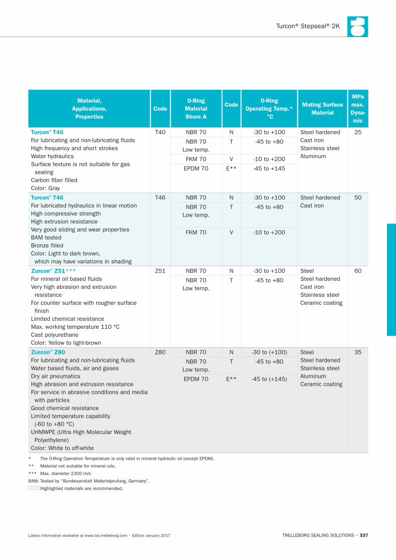
337
Material,
Applications,
Properties
Code
O-Ring
Material
Shore A
Code O-Ring
Operating Temp.*
°C
Mating Surface
Material
MPa
max.
Dyna-
mic
Turcon®T40
sealing
N
Cast iron
Stainless steel T
V
E**
Turcon®T46
N
Cast iron
T
V
Zurcon®Z51***
resistance
finish
N Steel
Cast iron
Stainless steel
Ceramic coating
T
Zurcon®Z80
N Steel
Stainless steel
Ceramic coating
T
E**
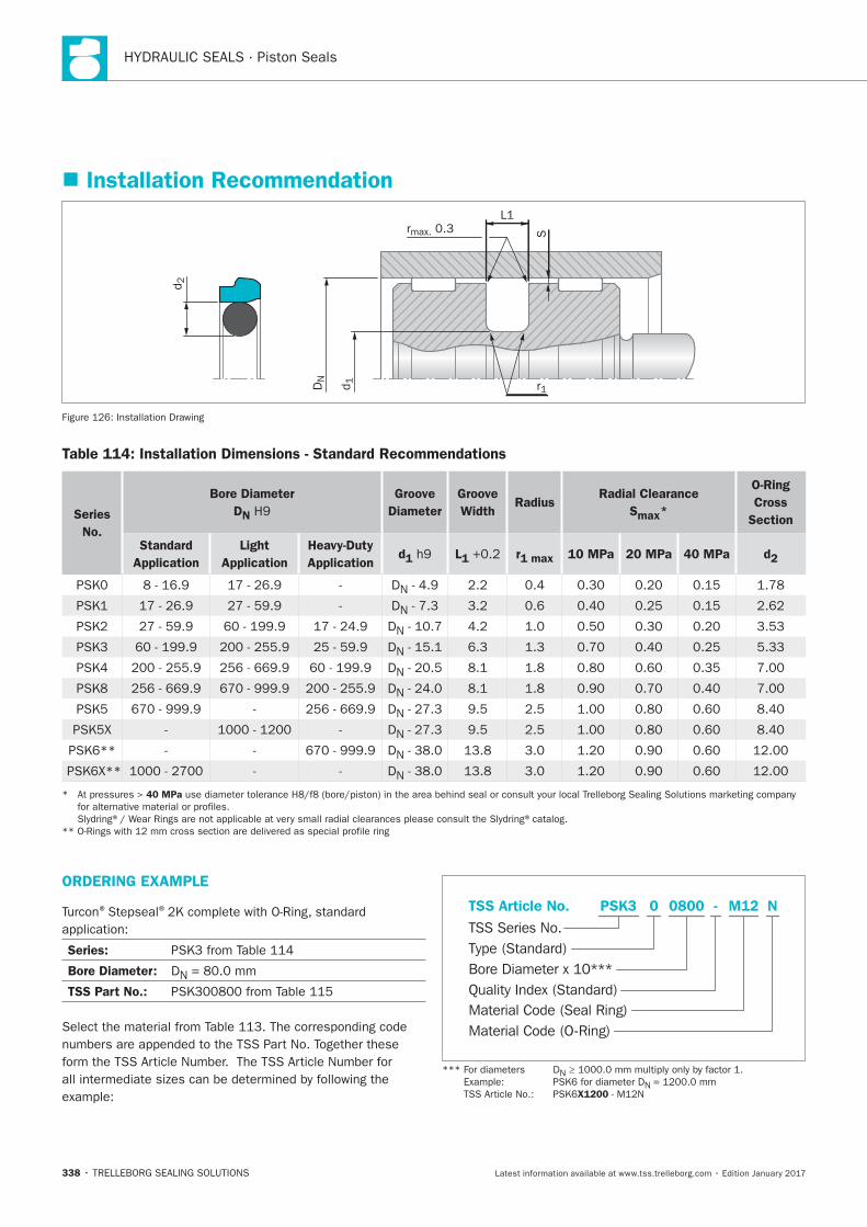
HYDRAULIC SEALS · Piston Seals
338
Installation Recommendation
S
L1rmax. 0.3
r1
d2
DN
d1
Installation Drawing
Table 114: Installation Dimensions - Standard Recommendations
Series
No.
Bore Diameter
DN
Groove
Diameter
Groove
Width Radius
Radial Clearance
Smax*
O-Ring
Cross
Section
Standard
Application
Light
Application
Heavy-Duty
Application d1 L1 r1 max 10 MPa 20 MPa 40 MPa d2
DN
DN
DN
DN
DN
DN
DN
DN
DN
DN
40 MPa
ORDERING EXAMPLE
® ®
Series:
Bore Diameter: DN
TSS Part No.:
Material Code (Seal Ring)
TSS Series No.
TSS Article No. M120800 N
Material Code (O-Ring)
Bore Diameter x 10***
PSK3
Quality Index (Standard)
-
Type (Standard)
0
N
N
X1200
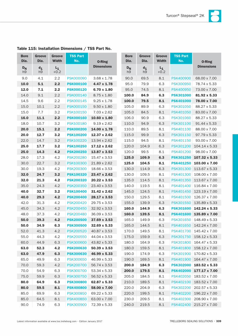
339
Bore
Dia.
Groove
Dia.
Groove
Width
TSS Part
No. O-Ring
DimensionsDN d1 L1
10.0 5.1 2.2 PSK000100 4.47 x 1.78
12.0 7.1 2.2 PSK000120 6.70 x 1.80
16.0 11.1 2.2 PSK000160 10.60 x 1.80
20.0 15.1 2.2 PSK000200 14.00 x 1.78
20.0 12.7 3.2 PSK100200 12.37 x 2.62
25.0 17.7 3.2 PSK100250 17.12 x 2.62
25.0 14.3 4.2 PSK200250 13.87 x 3.53
32.0 24.7 3.2 PSK100320 23.47 x 2.62
32.0 21.3 4.2 PSK200320 20.22 x 3.53
40.0 32.7 3.2 PSK100400 31.42 x 2.62
40.0 29.3 4.2 PSK200400 28.17 x 3.53
50.0 39.3 4.2 PSK200500 37.69 x 3.53
50.0 34.9 6.3 PSK300500 32.69 x 5.33
63.0 52.3 4.2 PSK200630 50.39 x 3.53
63.0 47.9 6.3 PSK300630 46.99 x 5.33
80.0 64.9 6.3 PSK300800 62.87 x 5.33
80.0 59.5 8.1 PSK400800 58.00 x 7.00
Bore
Dia.
Groove
Dia.
Groove
Width
TSS Part
No. O-Ring
DimensionsDN d1 L1
100.0 84.9 6.3 PSK301000 81.92 x 5.33
100.0 79.5 8.1 PSK401000 78.00 x 7.00
125.0 109.9 6.3 PSK301250 107.32 x 5.33
125.0 104.5 8.1 PSK401250 103.00 x 7.00
160.0 144.9 6.3 PSK301600 142.24 x 5.33
160.0 139.5 8.1 PSK401600 135.89 x 7.00
200.0 184.9 6.3 PSK302000 183.52 x 5.33
200.0 179.5 8.1 PSK402000 177.17 x 7.00
Table 115: Installation Dimensions / TSS Part No.
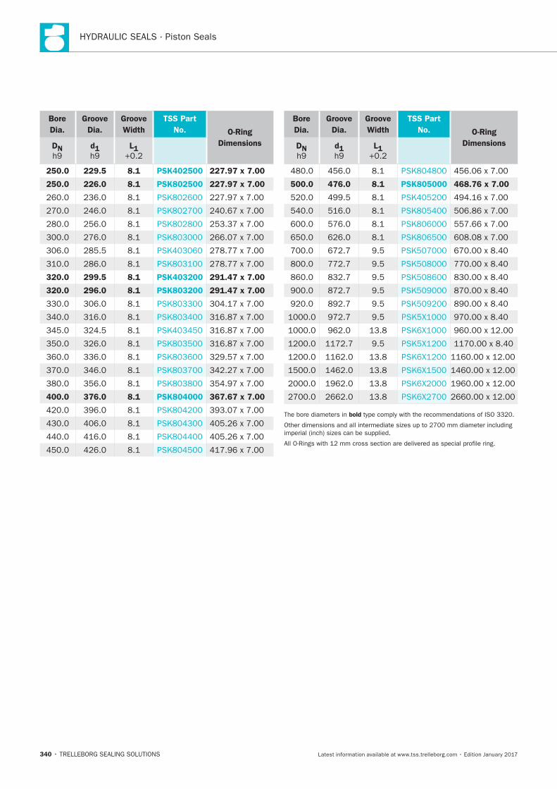
HYDRAULIC SEALS · Piston Seals
340
Bore
Dia.
Groove
Dia.
Groove
Width
TSS Part
No. O-Ring
DimensionsDN d1 L1
250.0 229.5 8.1 PSK402500 227.97 x 7.00
250.0 226.0 8.1 PSK802500 227.97 x 7.00
320.0 299.5 8.1 PSK403200 291.47 x 7.00
320.0 296.0 8.1 PSK803200 291.47 x 7.00
400.0 376.0 8.1 PSK804000 367.67 x 7.00
Bore
Dia.
Groove
Dia.
Groove
Width
TSS Part
No. O-Ring
DimensionsDN d1 L1
500.0 476.0 8.1 PSK805000 468.76 x 7.00
bold
Turcon®Stepseal® V
TRELLEBORG SEALING SOLUTIONS • 341Latest information available at www.tss.trelleborg.com • Edition January 2017
Turcon®Stepseal®V
Single-acting
Rubber-energized plastic-faced seal
Material:Turcon®, Zurcon®and Elastomer

HYDRAULIC SEALS · Piston Seals
342
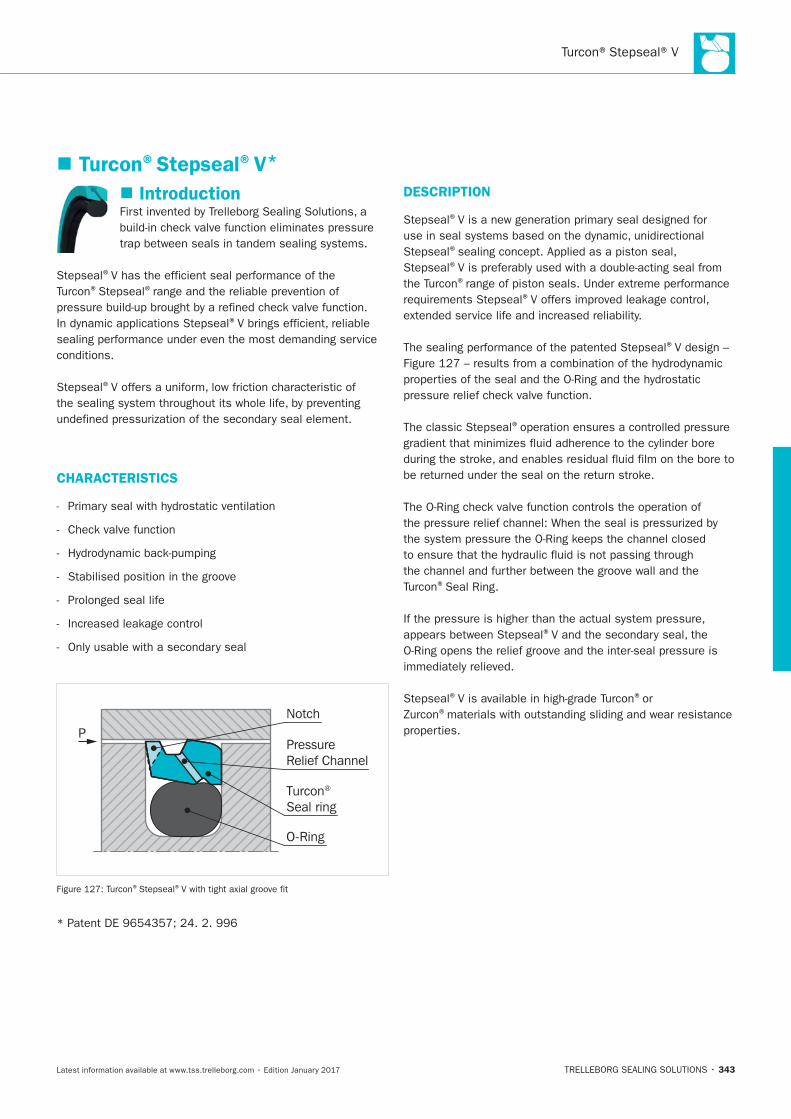
343
Turcon®Stepseal®V*
Introduction
®
® ®
®
®
CHARACTERISTICS
PPressure Relief Channel
Turcon® Seal ring
O-Ring
Notch
® ®
DESCRIPTION
®
®
®
®
®
®
®
®Seal Ring.
®
® ®or ®
HYDRAULIC SEALS · Piston Seals
344
ADVANTAGES:
element
® ®
APPLICATION EXAMPLES
Piling Barges
OPERATING CONDITIONS
Pressure: ®
® ®
Speed:
Temperature: *
Media:
Clearance:
S
IMPORTANT NOTE
*
SERIES
grooves.
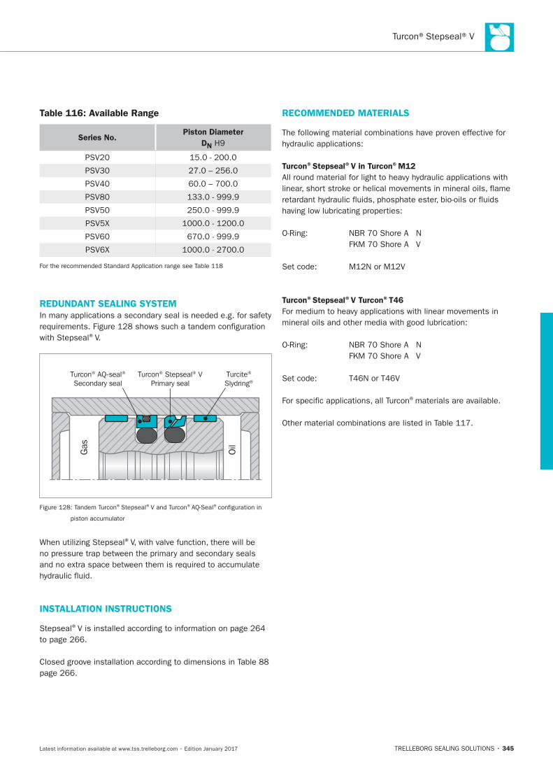
345
Table 116: Available Range
Series No.Piston Diameter
DN
REDUNDANT SEALING SYSTEM
®V.
Gas
Oil
Turcon® AQ-seal®
Secondary sealTurcite®
Slydring®Turcon® Stepseal® V
Primary seal
® ® ® ®
®
INSTALLATION INSTRUCTIONS
®
RECOMMENDED MATERIALS
Turcon®Stepseal®V in Turcon®M12
Turcon®Stepseal®V Turcon®T46
®materials are available.

HYDRAULIC SEALS · Piston Seals
346
Table 117: Turcon®and Zurcon®Materials for Stepseal®V
Material,
Applications,
Properties
Code
O–Ring
Material
Shore A
Code
O-Ring
Operating Temp.*
°C
Mating Surface
Material
MPa
max.
Dyna-
mic
Turcon®M12
First material choice for seals in linear
motion
Lowest wear on seals
contaminants
N Steel
Cast iron
Stainless steel
T
V
Turcon®T05
Also for gas service
N Steel
T
V
Turcon®T08
N
Cast iron T
V
Turcon®T10
N Steel
Stainless steel T
V
E**
Turcon®T29
sealing
N Steel
Cast iron
Stainless steel
T
V
E**
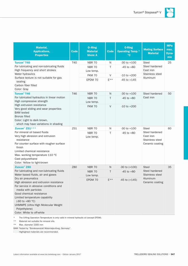
347
Material,
Applications,
Properties
Code
O–Ring
Material
Shore A
Code
O-Ring
Operating Temp.*
°C
Mating Surface
Material
MPa
max.
Dyna-
mic
Turcon®T40
sealing
N Steel
Cast iron
Stainless steel
T
V
E**
Turcon®T46
N
Cast iron T
V
Zurcon®Z51***
resistance
finish
N Steel
Cast iron
Stainless steel
Ceramic coating
T
Zurcon®Z80
N Steel
Stainless steel
Ceramic coating
T
E**
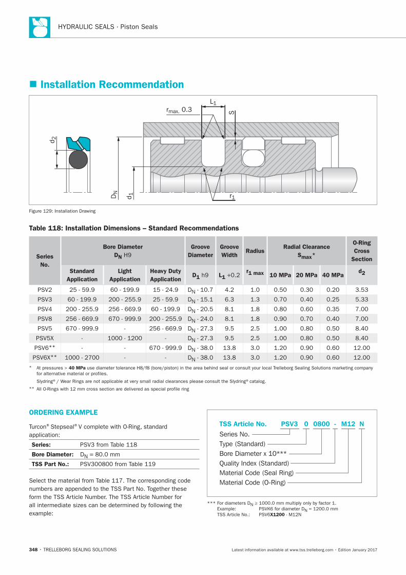
HYDRAULIC SEALS · Piston Seals
348
ORDERING EXAMPLE
® ®
Series:
Bore Diameter: DN
TSS Part No.:
Material Code (Seal Ring)
Series No.
TSS Article No. M120800 N
Material Code (O-Ring)
Bore Diameter x 10***
PSV3
Quality Index (Standard)
-
Type (Standard)
0
N
N
X1200
Installation Recommendation
Srmax. 0.3
r1
L1
d 2
DN
d 1
Installation Drawing
Table 118: Installation Dimensions – Standard Recommendations
Series
No.
Bore Diameter
DN
Groove
Diameter
Groove
WidthRadius
Radial Clearance
Smax*
O-Ring
Cross
Section
Standard
Application
Light
Application
Heavy Duty
ApplicationD1 L1
r1 max 10 MPa 20 MPa 40 MPad2
DN
DN
DN
DN
DN
DN
** DN
** DN
* 40 MPa
**
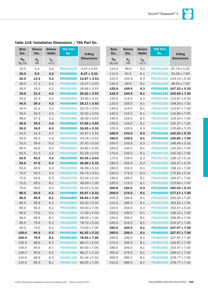
349
Table 119: Installation Dimensions / TSS Part No.
Bore
Dia.
Groove
Dia.
Groove
Width
TSS Part
No. O-Ring
DimensionsDN d1 L1
20.0 9.3 4.2 PSV200200 8.47 x 3.53
25.0 14.3 4.2 PSV200250 13.87 x 3.53
32.0 21.3 4.2 PSV200320 20.22 x 3.53
40.0 29.3 4.2 PSV200400 28.17 x 3.53
50.0 39.3 4.2 PSV200500 37.69 x 3.53
50.0 34.9 6.3 PSV300500 32.69 x 5.33
63.0 52.3 4.2 PSV200630 50.39 x 3.53
63.0 47.9 6.3 PSV300630 46.99 x 5.33
80.0 64.9 6.3 PSV300800 62.87 x 5.33
80.0 59.5 8.1 PSV400800 58.00 x 7.00
100.0 84.9 6.3 PSV301000 81.92 x 5.33
100.0 79.5 8.1 PSV401000 78.00 x 7.00
Bore
Dia.
Groove
Dia.
Groove
Width
TSS Part
No. O-Ring
DimensionsDN d1 L1
125.0 109.9 6.3 PSV301250 107.32 x 5.33
125.0 104.5 8.1 PSV401250 103.00 x 7.00
160.0 144.9 6.3 PSV301600 142.24 x 5.33
160.0 139.5 8.1 PSV401600 135.89 x 7.00
200.0 184.9 6.3 PSV302000 183.52 x 5.33
200.0 179.5 8.1 PSV402000 177.17 x 7.00
250.0 229.5 8.1 PSV402500 227.97 x 7.00
250.0 226.0 8.1 PSV802500 227.97 x 7.00
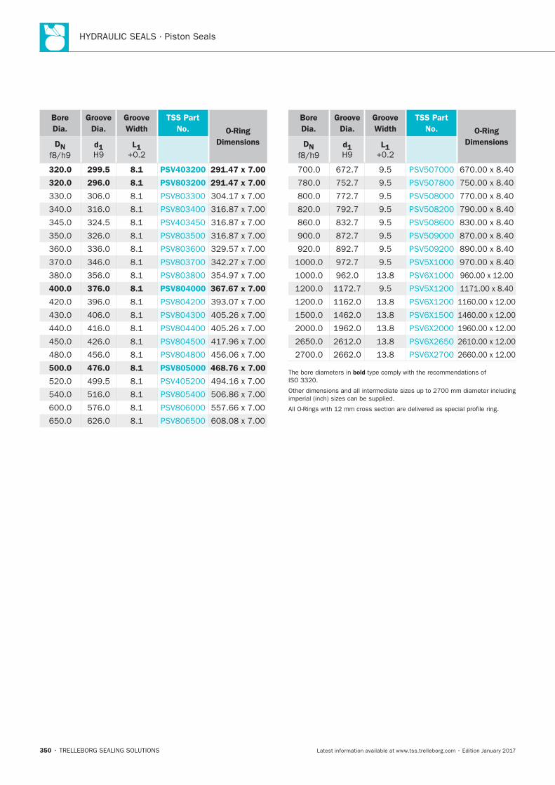
HYDRAULIC SEALS · Piston Seals
350
Bore
Dia.
Groove
Dia.
Groove
Width
TSS Part
No. O-Ring
DimensionsDN d1 L1
320.0 299.5 8.1 PSV403200 291.47 x 7.00
320.0 296.0 8.1 PSV803200 291.47 x 7.00
400.0 376.0 8.1 PSV804000 367.67 x 7.00
500.0 476.0 8.1 PSV805000 468.76 x 7.00
Bore
Dia.
Groove
Dia.
Groove
Width
TSS Part
No. O-Ring
DimensionsDN d1 L1
bold
Turcon® Double Delta®
TRELLEBORG SEALING SOLUTIONS • 351Latest information available at www.tss.trelleborg.com • Edition January 2017
Turcon®Double Delta®
Double-acting
Rubber-energized plastic-faced seal
For O-Ring Grooves
Material:Turcon®, Zurcon®and Elastomer

HYDRAULIC SEALS · Piston Seals
352
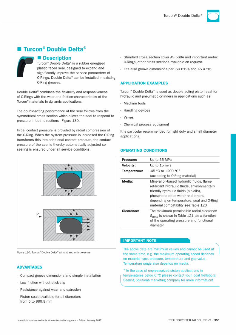
353
Description® ®
®
®
®
P
® ®
ADVANTAGES
APPLICATION EXAMPLES
® ®
Machine tools
Valves
OPERATING CONDITIONS
Pressure:
Velocity:
Temperature: *
Media:
Clearance:
S
IMPORTANT NOTE
*
Turcon®Double Delta®
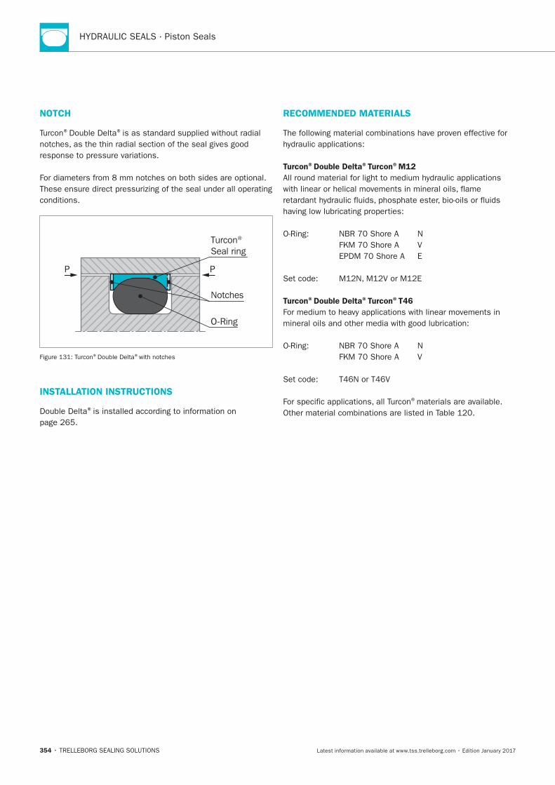
HYDRAULIC SEALS · Piston Seals
354
NOTCH
® ®
P P
Notches
Turcon® Seal ring
O-Ring
® ®with notches
INSTALLATION INSTRUCTIONS
®
RECOMMENDED MATERIALS
Turcon®Double Delta®Turcon®M12
Turcon®Double Delta®Turcon®T46
®materials are available.
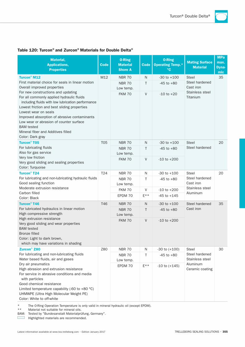
355
Table 120: Turcon®and Zurcon®Materials for Double Delta®
Material,
Applications,
Properties
Code
O-Ring
Material
Shore A
Code
O-Ring
Operating Temp.*
°C
Mating Surface
Material
MPa
max.
Dyna-
mic
Turcon®M12
First material choice for seals in linear motion
Lowest wear on seals
N Steel
Cast iron
Stainless steel
T
V
Turcon®T05
Also for gas service
N Steel
T
V
Turcon®T24
N Steel
Cast iron
Stainless steel
T
V
E**
Turcon®T46
N
Cast iron T
V
Zurcon®Z80
N Steel
Stainless steel
Ceramic coating
T
E**
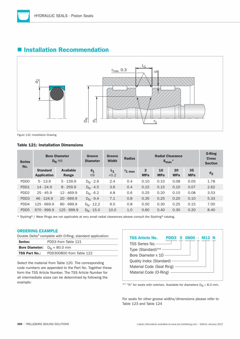
HYDRAULIC SEALS · Piston Seals
356
ORDERING EXAMPLE®
Series:
Bore Diameter: DN
TSS Part No.:
Material Code (Seal Ring)
TSS Series No.
TSS Article No. M120800 N
Material Code (O-Ring)
Bore Diameter x 10
PDD3
Quality Index (Standard)
-
Type (Standard)**
0
**N ≥
Installation Recommendation
S
L1rmax. 0.3
r1
d 2
DN
d 1
Installation Drawing
Table 121: Installation Dimensions
Series
No.
Bore Diameter
DN
Groove
Diameter
Groove
WidthRadius
Radial Clearance
Smax*
O-Ring
Cross
Section
Standard
Application
Available
Range
d1 L1 r1 max 2
MPa
10
MPa
20
MPa
35
MPa d2
DN
DN
DN
DN
DN
DN
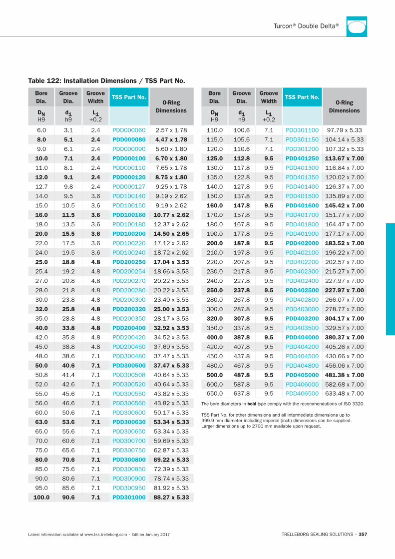
357
Bore
Dia.
Groove
Dia.
Groove
WidthTSS Part No.
O-Ring
DimensionsDN d1 L1
8.0 5.1 2.4 PDD000080 4.47 x 1.78
10.0 7.1 2.4 PDD000100 6.70 x 1.80
12.0 9.1 2.4 PDD000120 8.75 x 1.80
16.0 11.5 3.6 PDD100160 10.77 x 2.62
20.0 15.5 3.6 PDD100200 14.50 x 2.65
25.0 18.8 4.8 PDD200250 17.04 x 3.53
32.0 25.8 4.8 PDD200320 25.00 x 3.53
40.0 33.8 4.8 PDD200400 32.92 x 3.53
50.0 40.6 7.1 PDD300500 37.47 x 5.33
63.0 53.6 7.1 PDD300630 53.34 x 5.33
80.0 70.6 7.1 PDD300800 69.22 x 5.33
100.0 90.6 7.1 PDD301000 88.27 x 5.33
Bore
Dia.
Groove
Dia.
Groove
WidthTSS Part No.
O-Ring
DimensionsDN d1 L1
125.0 112.8 9.5 PDD401250 113.67 x 7.00
160.0 147.8 9.5 PDD401600 145.42 x 7.00
200.0 187.8 9.5 PDD402000 183.52 x 7.00
250.0 237.8 9.5 PDD402500 227.97 x 7.00
320.0 307.8 9.5 PDD403200 304.17 x 7.00
400.0 387.8 9.5 PDD404000 380.37 x 7.00
500.0 487.8 9.5 PDD405000 481.38 x 7.00
bold
Table 122: Installation Dimensions / TSS Part No.
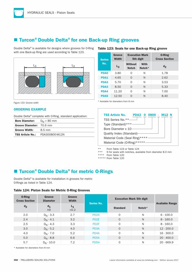
HYDRAULIC SEALS · Piston Seals
358
®
L3 L3
Table 123: Seals for one Back-up Ring groove
Series
No.
Groove
Width
Execution Mark
5th digit
O-Ring
Cross Section
L3Without
Notch
With
Notch* d2
PDA0 N
PDA1 N
PDA2 N
PDA3 N
PDA4 N
PDA5 N
Turcon®Double Delta®for one Back-up Ring grooves
ORDERING EXAMPLE
®
Bore Diameter: DN
Groove Diameter:
Groove Width:
TSS Article No.:
Material Code (Seal Ring)****
TSS Series No.**
TSS Article No. M120800 N
Material Code (O-Ring)*****
Bore Diameter x 10
PDA3
Quality Index (Standard)
-
Type (Standard)***
0
Turcon®Double Delta®for metric O-Rings
®is available for installation in grooves for metric
Table 124: Piston Seals for Metric O-Ring Grooves
O-Ring
Cross Section
Groove
Diameter
Groove
Width Series No.
Execution Mark 5th digit
Available Range d2 d1
L1
Standard Notch*
DN N
DN N
DN N
DN N
DN N
DN N
DN N
Turcon®Variseal® M2
TRELLEBORG SEALING SOLUTIONS • 359Latest information available at www.tss.trelleborg.com • Edition January 2017
Turcon®Variseal®M2
Single-acting
Spring-energized plastic-U-Cup
Material:Turcon®and Zurcon®

HYDRAULIC SEALS · Piston Seals
360
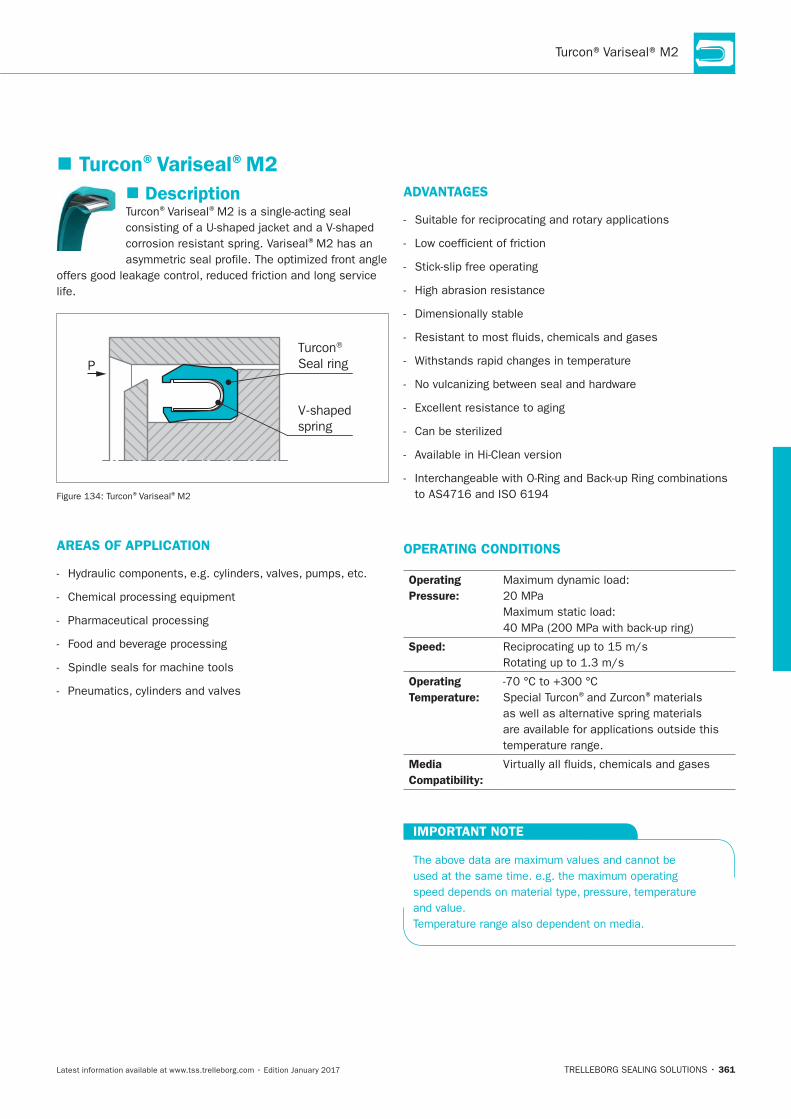
361
Description®Variseal®
®
life.
PTurcon® Seal ring
V-shaped spring
®Variseal®
AREAS OF APPLICATION
ADVANTAGES
Low coefficient of friction
High abrasion resistance
OPERATING CONDITIONS
Operating
Pressure:
Speed:
Operating
Temperature: ® ®materials
Media
Compatibility:
IMPORTANT NOTE
Turcon®Variseal®M2
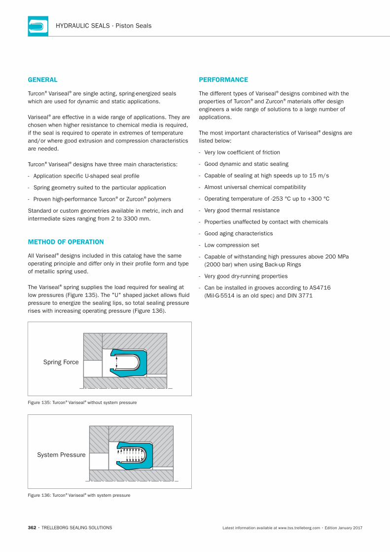
HYDRAULIC SEALS · Piston Seals
362
GENERAL
®Variseal®
Variseal®
®Variseal®
® ®
METHOD OF OPERATION
All Variseal®
The Variseal®
Spring Force
®Variseal®
System Pressure
®Variseal®
PERFORMANCE
®
® ®
®
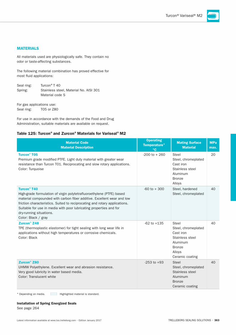
363
Table 125: Turcon®and Zurcon®Materials for Variseal®M2
Material Code
Material Description
Operating
Temperature*
°C
Mating Surface
Material
MPa
max.
Turcon®T05
Steel
Cast iron
Stainless steel
Turcon®T40
Zurcon®Z48
Steel
Cast iron
Stainless steel
Ceramic coating
Zurcon®Z80 Steel
Stainless steel
Ceramic coating
*
Installation of Spring Energized Seals
MATERIALS
®
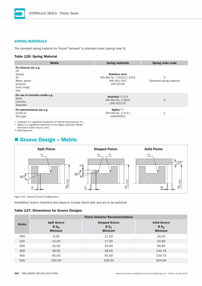
HYDRAULIC SEALS · Piston Seals
364
SPRING MATERIALS
®Variseal®
Table 126: Spring Material
Media Spring materials Spring order code
For General use e.g.
Oil
Grease
Air
Solvents
Gas
Stainless steel
S
For use in corrosive media e.g.
Seawater
Hastelloy®
H
For petrochemical use e.g.
Elgiloy®
E
Groove Design – Metric
Split Piston Stepped Piston Solid Piston
30°
A HC D1 m
in.
DN
min
.
D2 m
in.
30°
30°
r2 r1
E
r1 r1
Table 127: Dimensions for Groove Designs
Series
Piston Diameter Recommendations
Split Groove
Ø DN
Minimum
Stepped Groove
Ø D1
Minimum
Solid Groove
Ø D2
Minimum
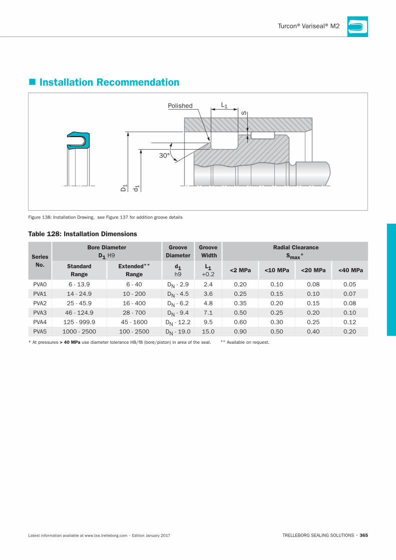
365
Installation Recommendation
S
d1
L1
30°
D1
Polished
Table 128: Installation Dimensions
Series
No.
Bore Diameter
D1
Groove
Diameter
Groove
Width
Radial Clearance
Smax*
Standard
Range
Extended**
Range
d1 L1 <2 MPa <10 MPa <20 MPa <40 MPa
DN
DN
DN
DN
DN
DN
> 40 MPa **
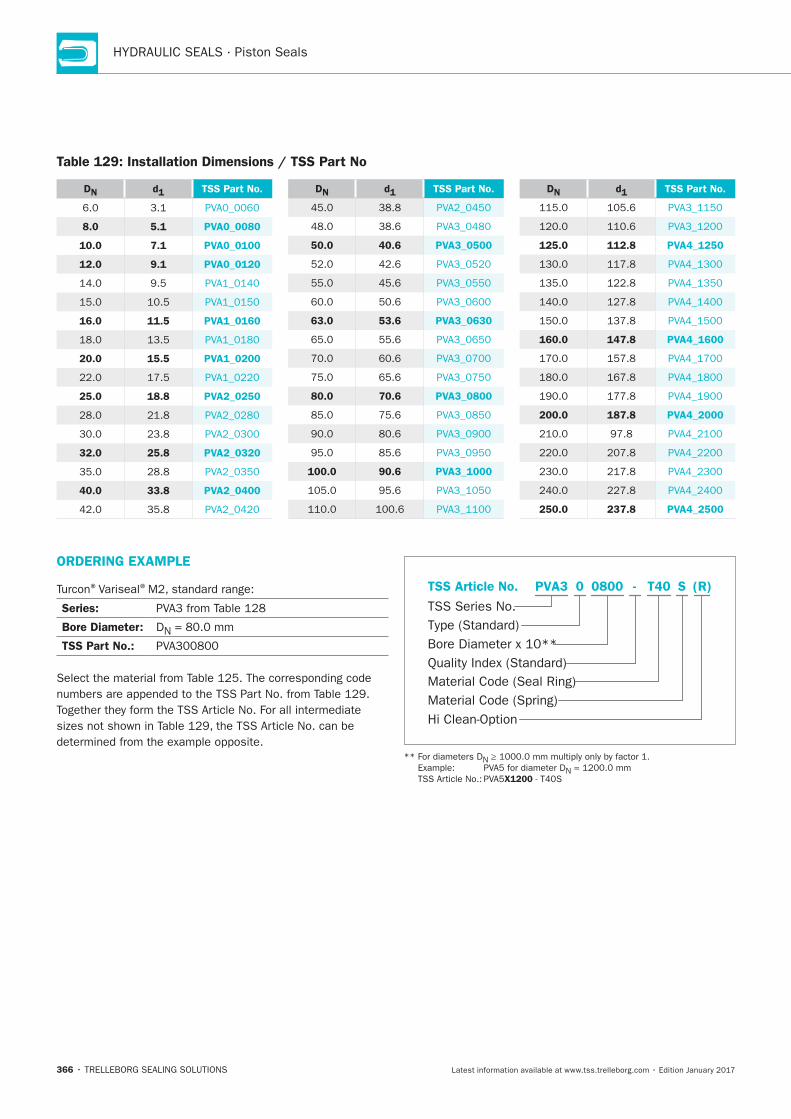
HYDRAULIC SEALS · Piston Seals
366
ORDERING EXAMPLE
®Variseal®
Series:
Bore Diameter: DN
TSS Part No.:
Material Code (Seal Ring)
TSS Series No.
TSS Article No.
Material Code (Spring)
Hi Clean-Option
Bore Diameter x 10**
Quality Index (Standard)
Type (Standard)
T400800 SPVA3 - (R)0
N
N
X1200
DN d1 TSS Part No.
8.0 5.1 PVA0_0080
10.0 7.1 PVA0_0100
12.0 9.1 PVA0_0120
16.0 11.5 PVA1_0160
20.0 15.5 PVA1_0200
25.0 18.8 PVA2_0250
32.0 25.8 PVA2_0320
40.0 33.8 PVA2_0400
DN d1 TSS Part No.
50.0 40.6 PVA3_0500
63.0 53.6 PVA3_0630
80.0 70.6 PVA3_0800
100.0 90.6 PVA3_1000
DN d1 TSS Part No.
125.0 112.8 PVA4_1250
160.0 147.8 PVA4_1600
200.0 187.8 PVA4_2000
250.0 237.8 PVA4_2500
Table 129: Installation Dimensions / TSS Part No
Turcon®VL Seal®
TRELLEBORG SEALING SOLUTIONS • 367Latest information available at www.tss.trelleborg.com • Edition January 2017
Turcon®VL Seal®
Double-acting
Rubber-energized plastic-faced seal
Material:Turcon®, Zurcon®and Elastomer

HYDRAULIC SEALS · Piston Seals
368
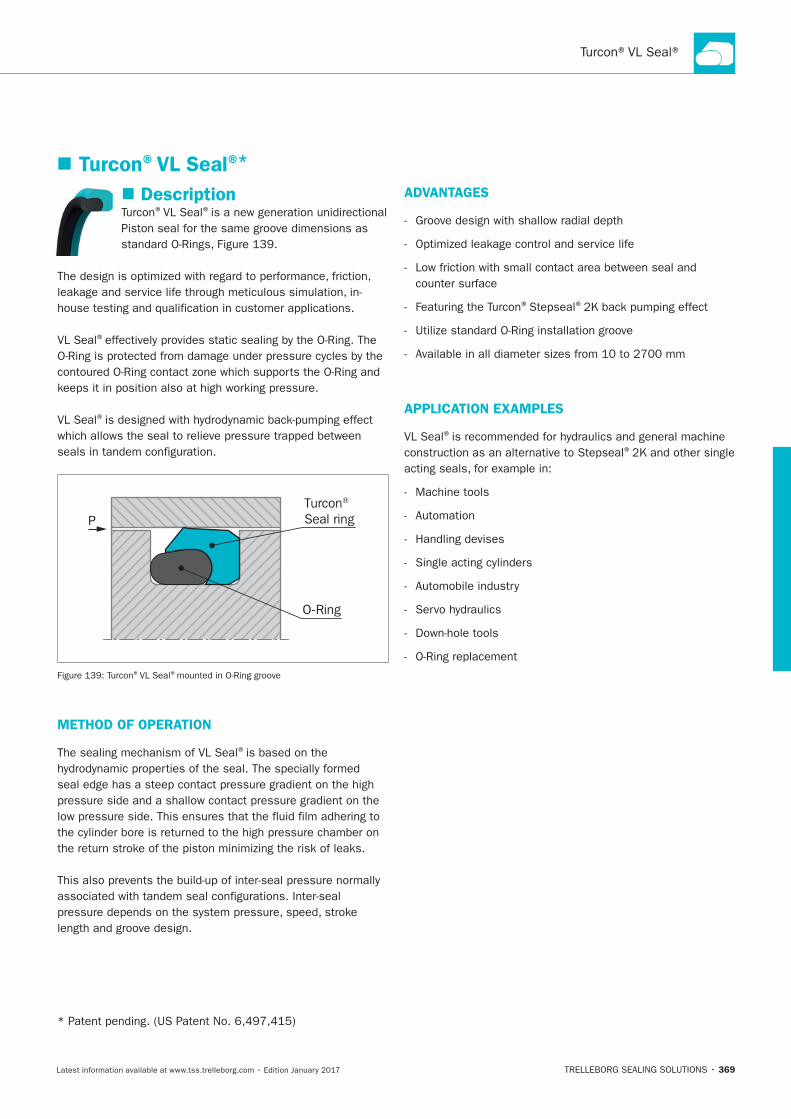
369
Description®VL Seal®
VL Seal®
VL Seal®
PTurcon® Seal ring
O-Ring
®VL Seal®
METHOD OF OPERATION
The sealing mechanism of VL Seal®
ADVANTAGES
® ®
APPLICATION EXAMPLES
VL Seal®
®
Machine tools
Turcon®VL Seal®*
HYDRAULIC SEALS · Piston Seals
370
OPERATING CONDITIONS
Pressure:
Speed: ®materials
with linear movements
Temperature: *
material
Media:
Clearance:
S
RADIAL NOTCH
VL Seal®
INSTALLATION INSTRUCTIONS
VL Seal®
® ® ®Variseal®
VL Seal®
RECOMMENDED MATERIALS
Turcon®VL Seal®Turcon®M12
Turcon®VL Seal®Turcon®T46
® ®as alternative to
®materials are available.
IMPORTANT NOTE
*
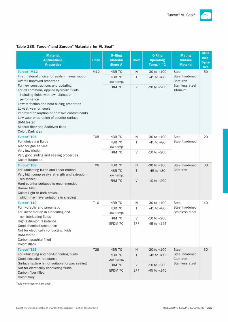
371
Table 130: Turcon®and Zurcon®Materials for VL Seal®
Material,
Applications,
Properties
Code
O–Ring
Material
Shore A
Code
O-Ring
Operating
Temp.* °C
Mating
Surface
Material
MPa
max.
Dyna-
mic
Turcon®M12
First material choice for seals in linear motion
Lowest wear on seals
N Steel
Cast iron
Stainless steel
T
V
Turcon®T05
Also for gas service
N Steel
T
V
Turcon®T08
resistance
N
Cast iron T
V
Turcon®T10
N Steel
Stainless steel T
V
E**
Turcon®T29
N Steel
Cast iron
Stainless steel
T
V
E**
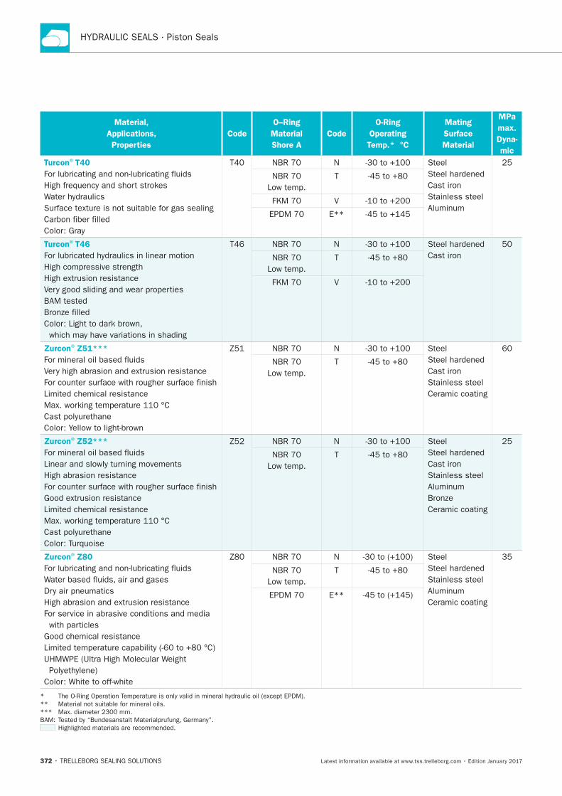
HYDRAULIC SEALS · Piston Seals
372
Material,
Applications,
Properties
Code
O–Ring
Material
Shore A
Code
O-Ring
Operating
Temp.* °C
Mating
Surface
Material
MPa
max.
Dyna-
mic
Turcon®T40
N Steel
Cast iron
Stainless steel
T
V
E**
Turcon®T46
N
Cast iron T
V
Zurcon®Z51***
N Steel
Cast iron
Stainless steel
Ceramic coating
T
Zurcon®Z52***
High abrasion resistance
N Steel
Cast iron
Stainless steel
Ceramic coating
T
Zurcon®Z80
N Steel
Stainless steel
Ceramic coating
T
E**
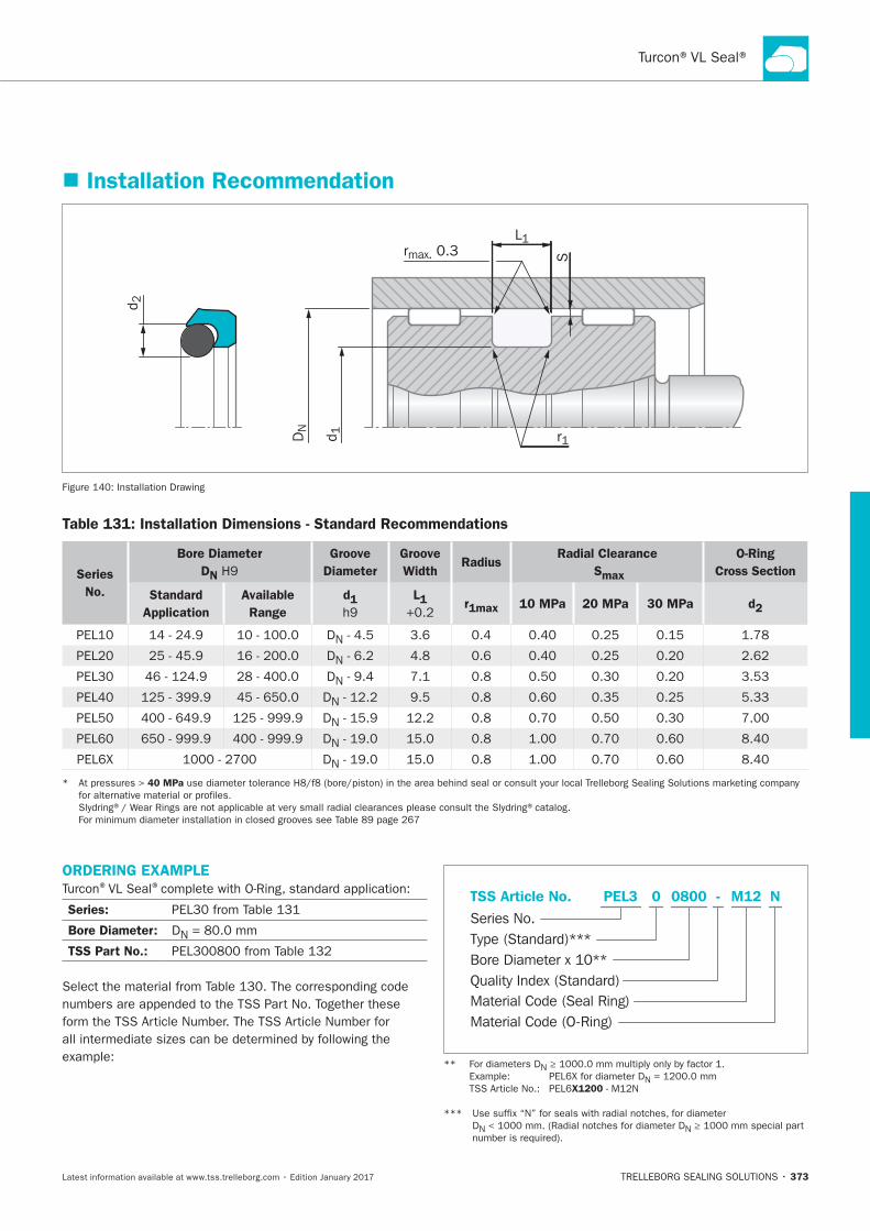
373
Installation Recommendation
Srmax. 0.3
r1
d 2
DN
d 1
L1
Installation Drawing
Table 131: Installation Dimensions - Standard Recommendations
Series
No.
Bore Diameter
DN
Groove
Diameter
Groove
Width Radius
Radial Clearance
Smax
O-Ring
Cross Section
Standard
Application
Available
Range
d1 L1 r1max 10 MPa 20 MPa 30 MPa d2
DN
DN
DN
DN
DN
DN
DN
40 MPa
ORDERING EXAMPLE®VL Seal®
Series:
Bore Diameter: DN
TSS Part No.:
Material Code (Seal Ring)
Series No.
TSS Article No. M120800 N
Material Code (O-Ring)
Bore Diameter x 10**
PEL3
Quality Index (Standard)
-
Type (Standard)***
0
N
N
X1200
DN N
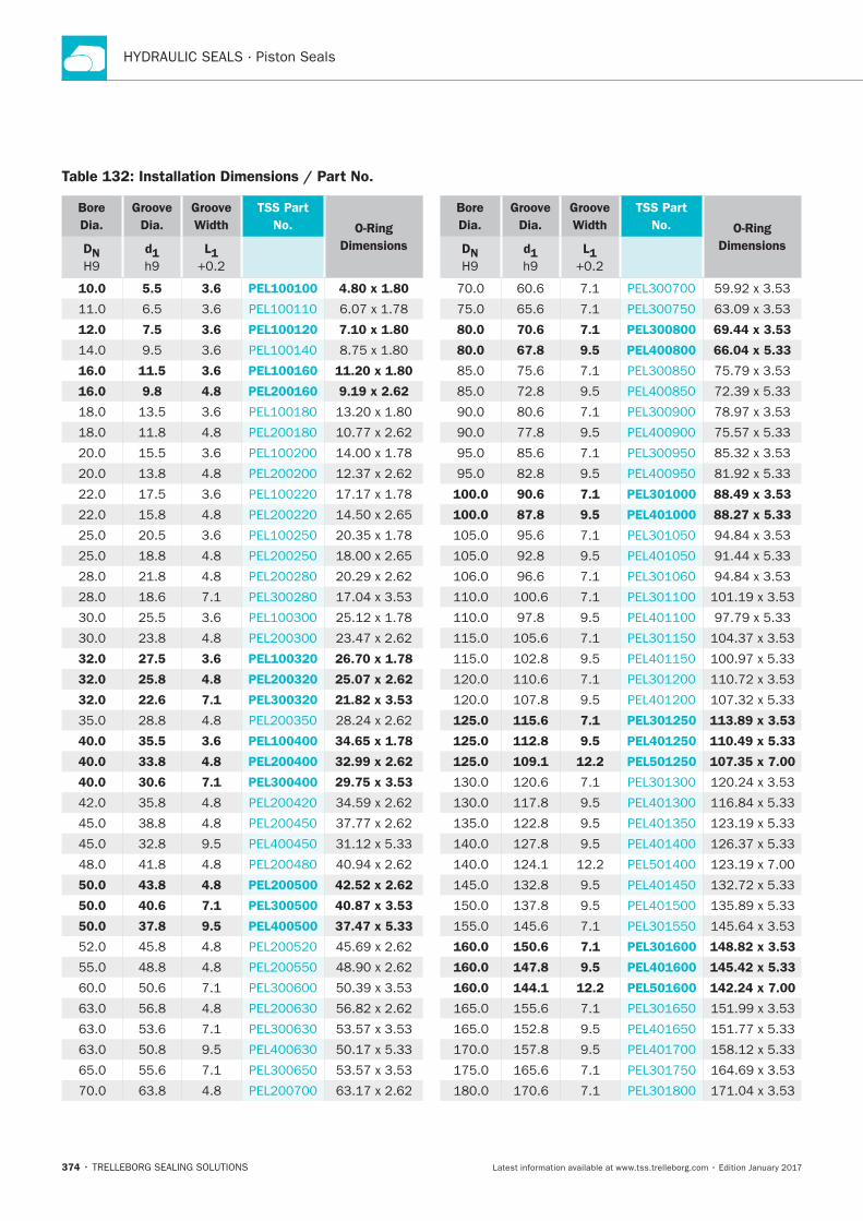
HYDRAULIC SEALS · Piston Seals
374
Bore
Dia.
Groove
Dia.
Groove
Width
TSS Part
No. O-Ring
DimensionsDN d1 L1
10.0 5.5 3.6 PEL100100 4.80 x 1.80
12.0 7.5 3.6 PEL100120 7.10 x 1.80
16.0 11.5 3.6 PEL100160 11.20 x 1.80
16.0 9.8 4.8 PEL200160 9.19 x 2.62
32.0 27.5 3.6 PEL100320 26.70 x 1.78
32.0 25.8 4.8 PEL200320 25.07 x 2.62
32.0 22.6 7.1 PEL300320 21.82 x 3.53
40.0 35.5 3.6 PEL100400 34.65 x 1.78
40.0 33.8 4.8 PEL200400 32.99 x 2.62
40.0 30.6 7.1 PEL300400 29.75 x 3.53
50.0 43.8 4.8 PEL200500 42.52 x 2.62
50.0 40.6 7.1 PEL300500 40.87 x 3.53
50.0 37.8 9.5 PEL400500 37.47 x 5.33
Table 132: Installation Dimensions / Part No.
Bore
Dia.
Groove
Dia.
Groove
Width
TSS Part
No. O-Ring
DimensionsDN d1 L1
80.0 70.6 7.1 PEL300800 69.44 x 3.53
80.0 67.8 9.5 PEL400800 66.04 x 5.33
100.0 90.6 7.1 PEL301000 88.49 x 3.53
100.0 87.8 9.5 PEL401000 88.27 x 5.33
125.0 115.6 7.1 PEL301250 113.89 x 3.53
125.0 112.8 9.5 PEL401250 110.49 x 5.33
125.0 109.1 12.2 PEL501250 107.35 x 7.00
160.0 150.6 7.1 PEL301600 148.82 x 3.53
160.0 147.8 9.5 PEL401600 145.42 x 5.33
160.0 144.1 12.2 PEL501600 142.24 x 7.00
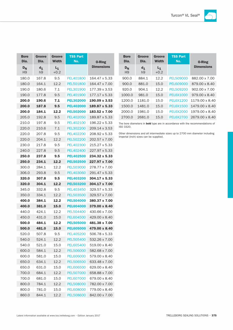
375
Bore
Dia.
Groove
Dia.
Groove
Width
TSS Part
No. O-Ring
DimensionsDN d1 L1
200.0 190.6 7.1 PEL302000 190.09 x 3.53
200.0 187.8 9.5 PEL402000 189.87 x 5.33
200.0 184.1 12.2 PEL502000 183.52 x 7.00
250.0 237.8 9.5 PEL402500 234.32 x 5.33
250.0 234.1 12.2 PEL502500 227.97 x 7.00
320.0 307.8 9.5 PEL403200 304.17 x 5.33
320.0 304.1 12.2 PEL503200 304.17 x 7.00
400.0 384.1 12.2 PEL504000 380.37 x 7.00
400.0 381.0 15.0 PEL604000 379.00 x 8.40
500.0 484.1 12.2 PEL505000 481.38 x 7.00
500.0 481.0 15.0 PEL605000 479.00 x 8.40
Bore
Dia.
Groove
Dia.
Groove
Width
TSS Part
No. O-Ring
DimensionsDN d1 L1
bold

HYDRAULIC SEALS · Piston Seals
376
Zurcon®U-Cup PUA
TRELLEBORG SEALING SOLUTIONS • 377Latest information available at www.tss.trelleborg.com • Edition January 2017
Zurcon®U-Cup PUASingle-acting
Asymmetric, Single Lip
For O-Ring Grooves
Material:Zurcon®

HYDRAULIC SEALS · Piston Seals
378
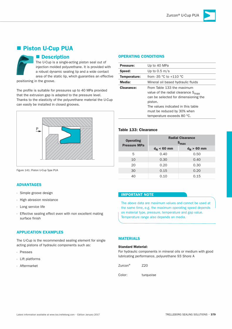
379
Description
P
ADVANTAGES
High abrasion resistance
Long service life
APPLICATION EXAMPLES
Presses
OPERATING CONDITIONS
Pressure:
Speed:
Temperature:
Media:
Clearance:
Table 133: Clearance
Operating
Pressure MPa
Radial Clearance
Smax
dN < 60 mm dN > 60 mm
IMPORTANT NOTE
MATERIALS
Standard Material:
®
Piston U-Cup PUA
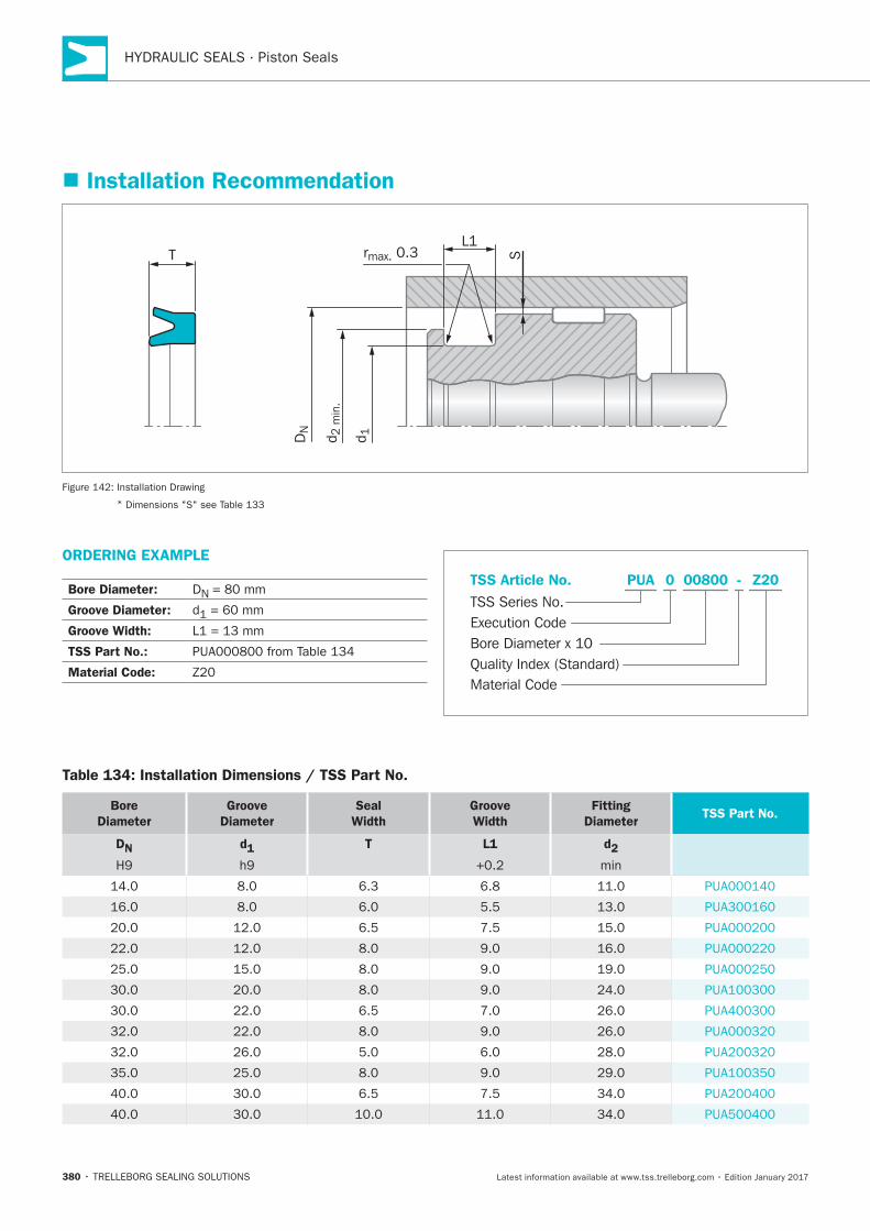
HYDRAULIC SEALS · Piston Seals
380
ORDERING EXAMPLE
Bore Diameter: DN
Groove Diameter:
Groove Width:
TSS Part No.:
Material Code:Material Code
TSS Series No.
TSS Article No.
Bore Diameter x 10Quality Index (Standard)
Execution Code
Z20PUA - 0 00800
Installation Recommendation
Srmax. 0.3
d 2 m
in.
d 1DN
L1T
Installation Drawing
*
Table 134: Installation Dimensions / TSS Part No.
Bore
Diameter
Groove
Diameter
Seal
Width
Groove
Width
Fitting
DiameterTSS Part No.
DN
d1
T L1
d2
min
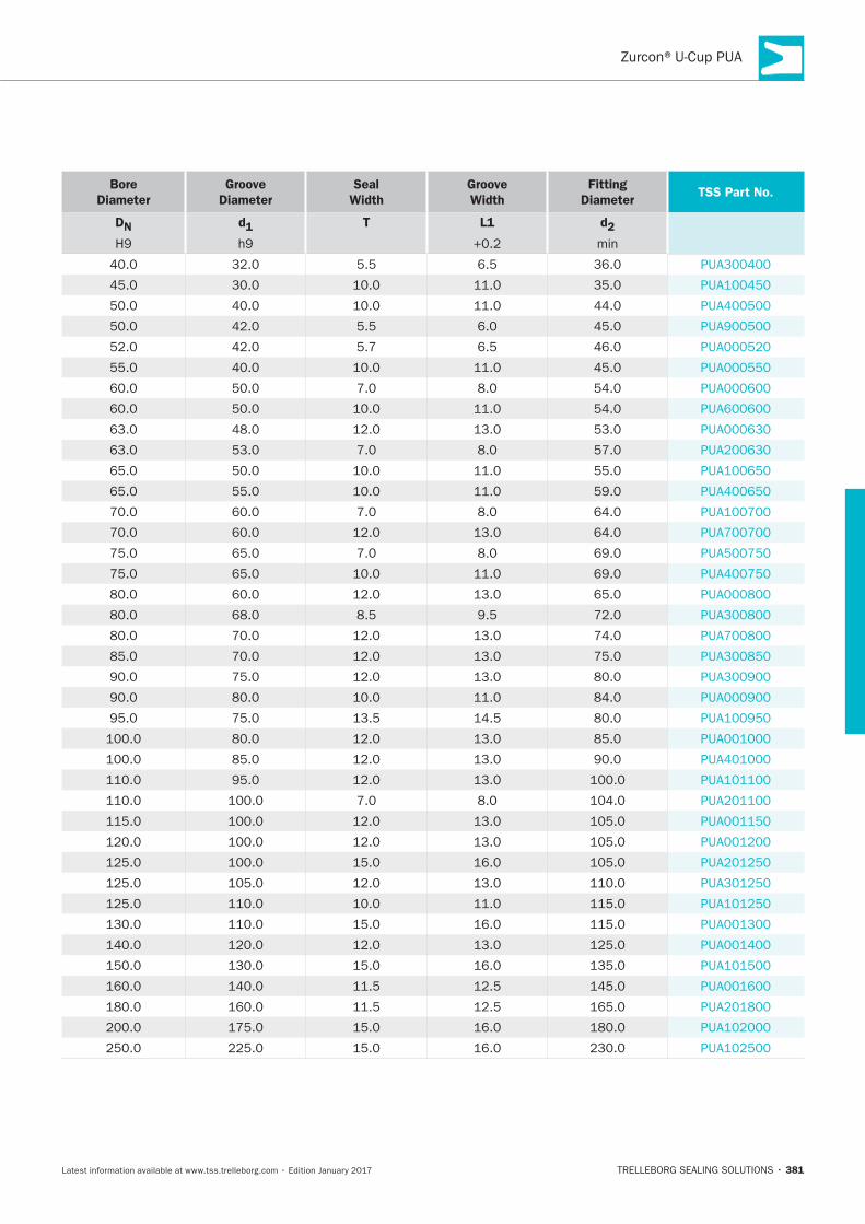
381
Bore
Diameter
Groove
Diameter
Seal
Width
Groove
Width
Fitting
DiameterTSS Part No.
DN
d1
T L1
d2
min

HYDRAULIC SEALS · Piston Seals
382
Zurcon®Wynseal
TRELLEBORG SEALING SOLUTIONS • 383Latest information available at www.tss.trelleborg.com • Edition January 2017
Zurcon®WynsealDouble-acting
Rubber-energized plastic-faced seal
High static and dynamic sealing effect
Material:Zurcon®+ NBR

HYDRAULIC SEALS · Piston Seals
384
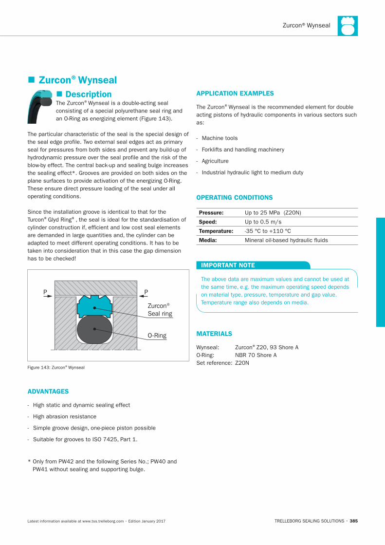
385
Description®
® ®
P P
Zurcon® Seal ring
O-Ring
®
ADVANTAGES
High abrasion resistance
APPLICATION EXAMPLES
®
Machine tools
OPERATING CONDITIONS
Pressure:
Speed:
Temperature:
Media:
IMPORTANT NOTE
MATERIALS
®
Zurcon®Wynseal
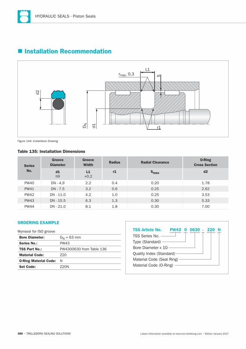
HYDRAULIC SEALS · Piston Seals
386
S
L1rmax. 0.3
r1
d2
DN
d1
Installation Drawing
Table 135: Installation Dimensions
Series
No.
Groove
Diameter
Groove
Width Radius Radial Clearance
O-Ring
Cross Section
d1 L1 r1 Smax d2
Installation Recommendation
ORDERING EXAMPLE
Bore Diameter: DN
Series No.:
TSS Part No.:
Material Code:
O-Ring Material Code: N
Set Code:
Material Code (Seal Ring)
TSS Series No.
TSS Article No. Z200630 N
Material Code (O-Ring)
Bore Diameter x 10
PW43
Quality Index (Standard)
-
Type (Standard)
0
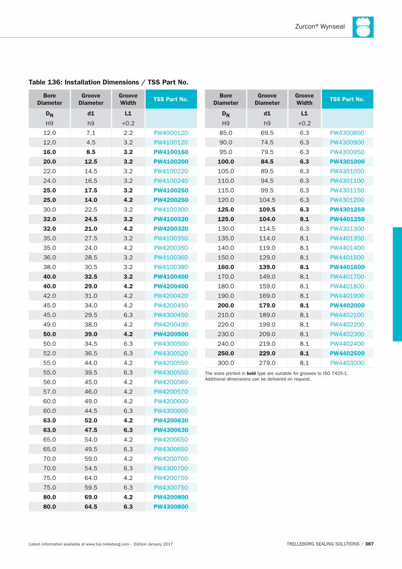
387
Bore
Diameter
Groove
Diameter
Groove
WidthTSS Part No.
DN d1 L1
16.0 8.5 3.2 PW4100160
20.0 12.5 3.2 PW4100200
25.0 17.5 3.2 PW4100250
25.0 14.0 4.2 PW4200250
32.0 24.5 3.2 PW4100320
32.0 21.0 4.2 PW4200320
40.0 32.5 3.2 PW4100400
40.0 29.0 4.2 PW4200400
50.0 39.0 4.2 PW4200500
63.0 52.0 4.2 PW4200630
63.0 47.5 6.3 PW4300630
80.0 69.0 4.2 PW4200800
80.0 64.5 6.3 PW4300800
Bore
Diameter
Groove
Diameter
Groove
WidthTSS Part No.
DN d1 L1
100.0 84.5 6.3 PW4301000
125.0 109.5 6.3 PW4301250
125.0 104.0 8.1 PW4401250
160.0 139.0 8.1 PW4401600
200.0 179.0 8.1 PW4402000
250.0 229.0 8.1 PW4402500
bold
Table 136: Installation Dimensions / TSS Part No.

HYDRAULIC SEALS · Piston Seals
388
Zurcon®Wynseal M
TRELLEBORG SEALING SOLUTIONS • 389Latest information available at www.tss.trelleborg.com • Edition January 2017
Zurcon®Wynseal MDouble-acting
Rubber-energized plastic-faced seal
Material:Turcon®, Zurcon®and Elastomer

HYDRAULIC SEALS · Piston Seals
390
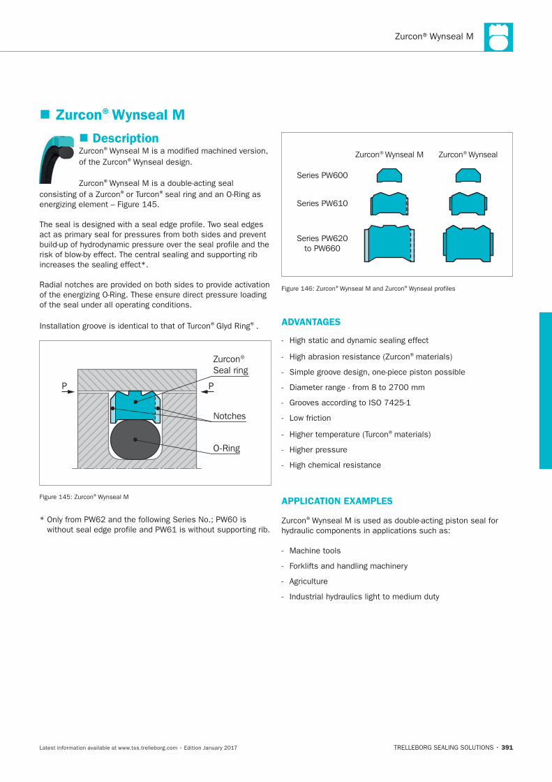
391
Zurcon®Wynseal M
Description®
® .
®
® ®
increases the sealing effect*.
® ®.
P P
Zurcon® Seal ring
O-Ring
Notches
®
Zurcon® Wynseal M Zurcon® Wynseal
Series PW600
Series PW610
Series PW620to PW660
® ®
ADVANTAGES
®materials)
Low friction
®materials)
High chemical resistance
APPLICATION EXAMPLES
®
Machine tools
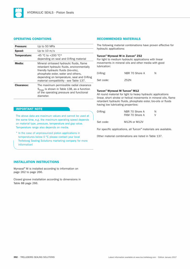
HYDRAULIC SEALS · Piston Seals
392
OPERATING CONDITIONS
Pressure:
Speed:
Temperature:
Media:
Clearance:
S
IMPORTANT NOTE
*
INSTALLATION INSTRUCTIONS
®
RECOMMENDED MATERIALS
Turcon®Wynseal M in Zurcon®Z52
Turcon®Wynseal M Turcon®M12
®materials are available.
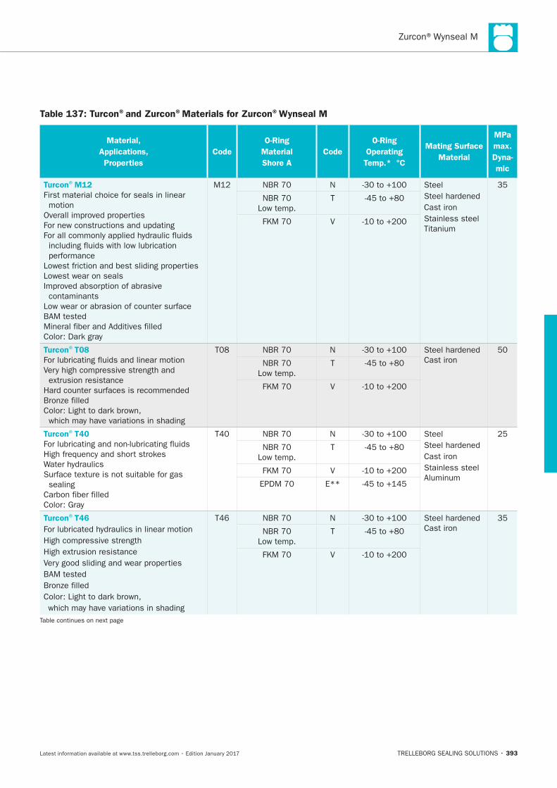
393
Table 137: Turcon®and Zurcon®Materials for Zurcon®Wynseal M
Material,
Applications,
Properties
Code
O-Ring
Material
Shore A
Code
O-Ring
Operating
Temp.* °C
Mating Surface
Material
MPa
max.
Dyna-
mic
Turcon®M12
First material choice for seals in linear
motion
Lowest wear on seals
contaminants
N Steel
Cast iron
Stainless steel
T
V
Turcon®T08
N
Cast iron T
V
Turcon®T40
sealing
N Steel
Cast iron
Stainless steel
T
V
E**
Turcon®T46
N
Cast iron T
V
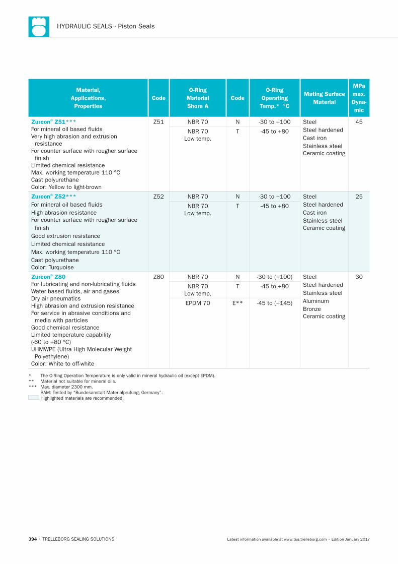
HYDRAULIC SEALS · Piston Seals
394
Material,
Applications,
Properties
Code
O-Ring
Material
Shore A
Code
O-Ring
Operating
Temp.* °C
Mating Surface
Material
MPa
max.
Dyna-
mic
Zurcon®Z51***
resistance
finish
N Steel
Cast iron
Stainless steel
Ceramic coating
T
Zurcon®Z52***
High abrasion resistance
finish
N Steel
Cast iron
Stainless steel
Ceramic coating
T
Zurcon®Z80
N Steel
Stainless steel
Ceramic coating
T
E**
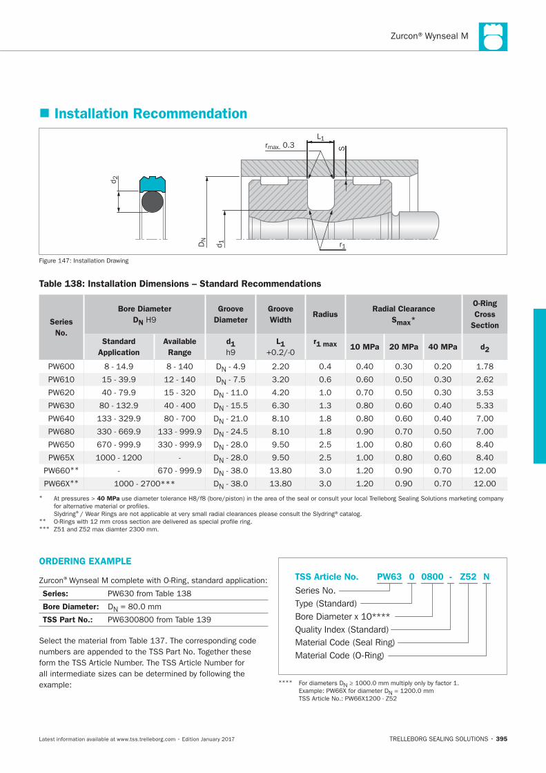
395
Installation Recommendation
Srmax. 0.3
DN
L1
d 1 r1
d 2
Installation Drawing
Table 138: Installation Dimensions – Standard Recommendations
Series
No.
Bore Diameter
DN
Groove
Diameter
Groove
WidthRadius
Radial Clearance
Smax*
O-Ring
Cross
Section
Standard
Application
Available
Range
d1 L1 r1 max 10 MPa 20 MPa 40 MPa d2
DN
DN
DN
DN
DN
DN
DN
DN
** DN
** DN
* 40 MPa
® ** ***
ORDERING EXAMPLE
®
Series:
Bore Diameter: DN
TSS Part No.:
Material Code (Seal Ring)
Series No.
TSS Article No. Z520800 N
Material Code (O-Ring)
Bore Diameter x 10****
PW63
Quality Index (Standard)
-
Type (Standard)
0
****N
N
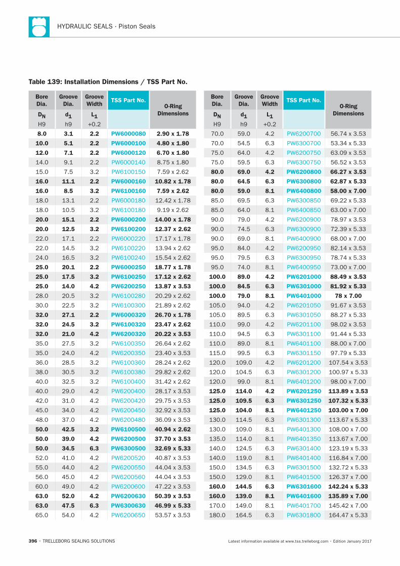
HYDRAULIC SEALS · Piston Seals
396
Bore
Dia.
Groove
Dia.
Groove
WidthTSS Part No.
O-Ring
DimensionsDN d1 L1
8.0 3.1 2.2 PW6000080 2.90 x 1.78
10.0 5.1 2.2 PW6000100 4.80 x 1.80
12.0 7.1 2.2 PW6000120 6.70 x 1.80
16.0 11.1 2.2 PW6000160 10.82 x 1.78
16.0 8.5 3.2 PW6100160 7.59 x 2.62
20.0 15.1 2.2 PW6000200 14.00 x 1.78
20.0 12.5 3.2 PW6100200 12.37 x 2.62
25.0 20.1 2.2 PW6000250 18.77 x 1.78
25.0 17.5 3.2 PW6100250 17.12 x 2.62
25.0 14.0 4.2 PW6200250 13.87 x 3.53
32.0 27.1 2.2 PW6000320 26.70 x 1.78
32.0 24.5 3.2 PW6100320 23.47 x 2.62
32.0 21.0 4.2 PW6200320 20.22 x 3.53
50.0 42.5 3.2 PW6100500 40.94 x 2.62
50.0 39.0 4.2 PW6200500 37.70 x 3.53
50.0 34.5 6.3 PW6300500 32.69 x 5.33
63.0 52.0 4.2 PW6200630 50.39 x 3.53
63.0 47.5 6.3 PW6300630 46.99 x 5.33
Table 139: Installation Dimensions / TSS Part No.
Bore
Dia.
Groove
Dia.
Groove
WidthTSS Part No.
O-Ring
DimensionsDN d1 L1
80.0 69.0 4.2 PW6200800 66.27 x 3.53
80.0 64.5 6.3 PW6300800 62.87 x 5.33
80.0 59.0 8.1 PW6400800 58.00 x 7.00
100.0 89.0 4.2 PW6201000 88.49 x 3.53
100.0 84.5 6.3 PW6301000 81.92 x 5.33
100.0 79.0 8.1 PW6401000 78 x 7.00
125.0 114.0 4.2 PW6201250 113.89 x 3.53
125.0 109.5 6.3 PW6301250 107.32 x 5.33
125.0 104.0 8.1 PW6401250 103.00 x 7.00
160.0 144.5 6.3 PW6301600 142.24 x 5.33
160.0 139.0 8.1 PW6401600 135.89 x 7.00
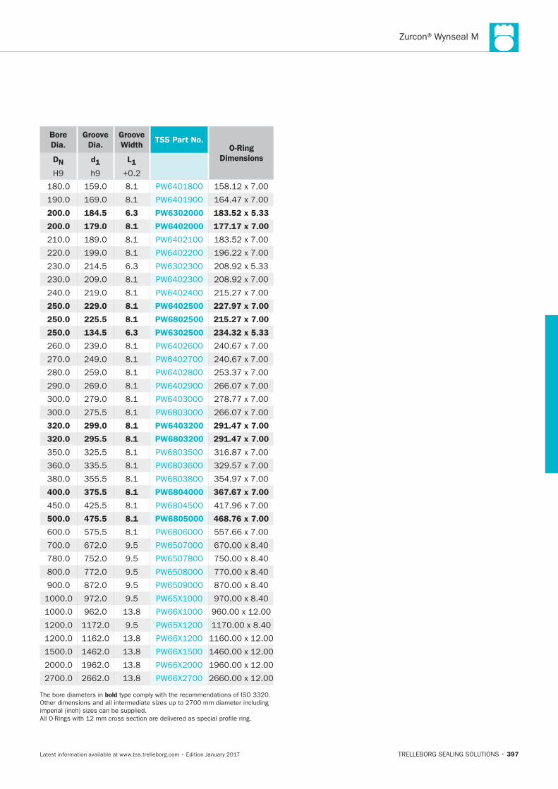
397
Bore
Dia.
Groove
Dia.
Groove
WidthTSS Part No.
O-Ring
DimensionsDN d1 L1
200.0 184.5 6.3 PW6302000 183.52 x 5.33
200.0 179.0 8.1 PW6402000 177.17 x 7.00
250.0 229.0 8.1 PW6402500 227.97 x 7.00
250.0 225.5 8.1 PW6802500 215.27 x 7.00
250.0 134.5 6.3 PW6302500 234.32 x 5.33
320.0 299.0 8.1 PW6403200 291.47 x 7.00
320.0 295.5 8.1 PW6803200 291.47 x 7.00
400.0 375.5 8.1 PW6804000 367.67 x 7.00
500.0 475.5 8.1 PW6805000 468.76 x 7.00
bold

HYDRAULIC SEALS · Piston Seals
398

POLYPAC®- PHD/P
TRELLEBORG SEALING SOLUTIONS • 399Latest information available at www.tss.trelleborg.com • Edition January 2017
POLYPAC®- PHD/PDouble-acting
Heavy Duty, High Pressure
Excellent Leakage Control
Material:Zurcon®, NBR Elastomer + POM

HYDRAULIC SEALS · Piston Seals
400
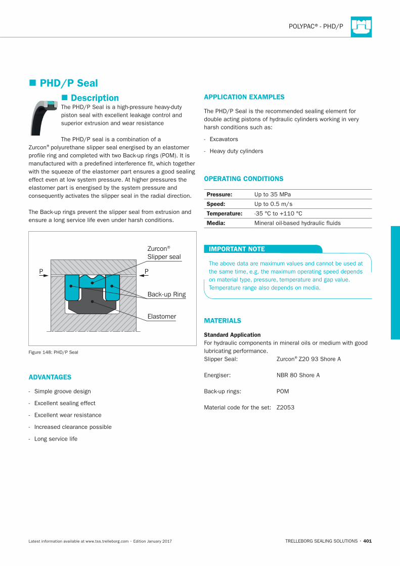
401
Description
®
P P
Zurcon® Slipper seal
Elastomer
Back-up Ring
ADVANTAGES
Long service life
APPLICATION EXAMPLES
OPERATING CONDITIONS
Pressure:
Speed:
Temperature:
Media:
IMPORTANT NOTE
MATERIALS
Standard Application
®
PHD/P Seal
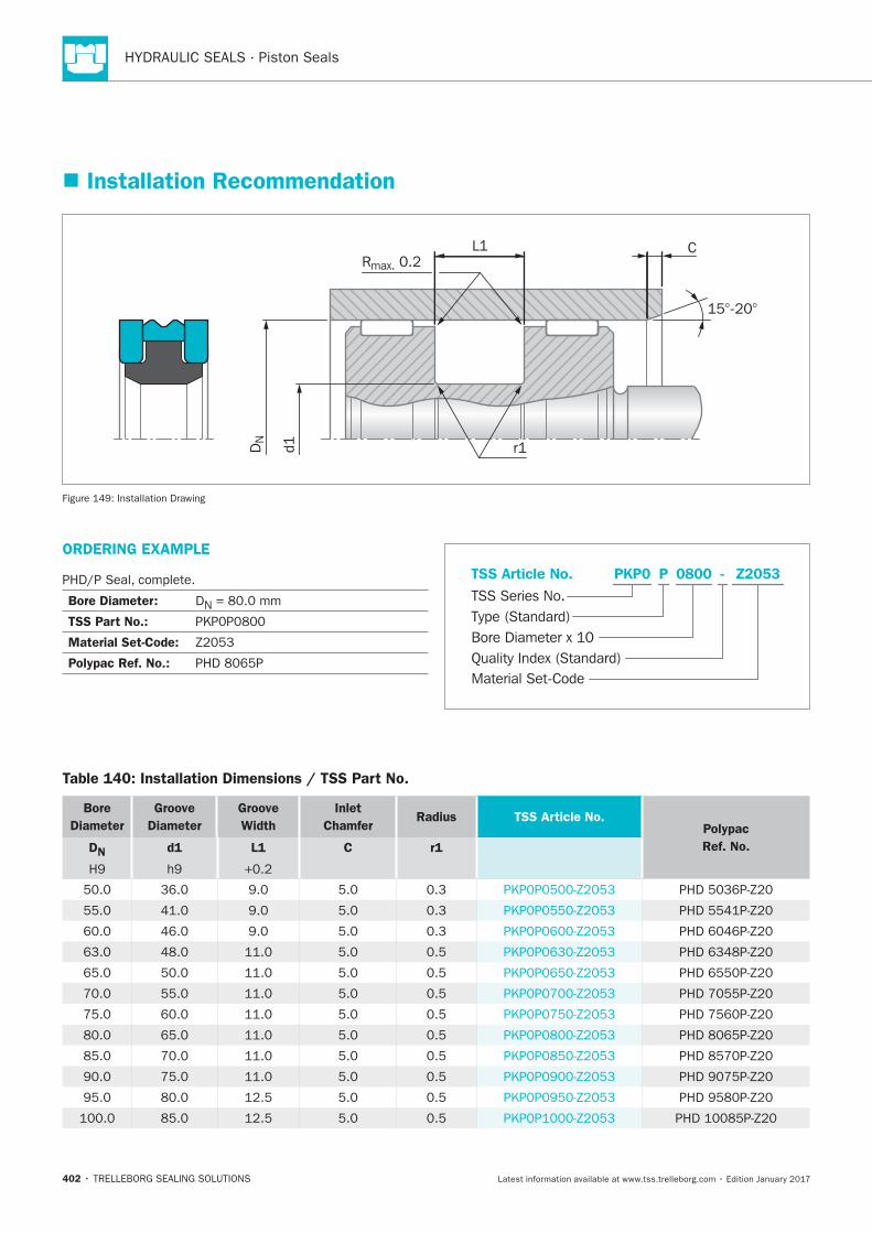
HYDRAULIC SEALS · Piston Seals
402
ORDERING EXAMPLE
Bore Diameter: DN
TSS Part No.:
Material Set-Code:
Polypac Ref. No.:
Z2053PKP0 0800 -
Material Set-Code
TSS Series No.TSS Article No.
Bore Diameter x 10Quality Index (Standard)
Type (Standard)
P
Installation Recommendation
L1Rmax. 0.2
r1DN
d1
C
15°-20°
Installation Drawing
Table 140: Installation Dimensions / TSS Part No.
Bore
Diameter
Groove
Diameter
Groove
Width
Inlet
Chamfer Radius TSS Article No.
Polypac
Ref. No. DN
d1
L1
C r1
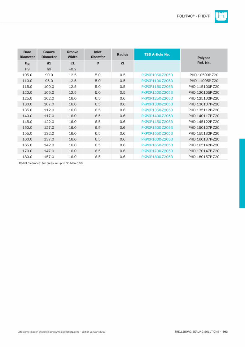
403
Bore
Diameter
Groove
Diameter
Groove
Width
Inlet
Chamfer Radius TSS Article No.
Polypac
Ref. No. DN
d1
L1
C r1

HYDRAULIC SEALS · Piston Seals
404
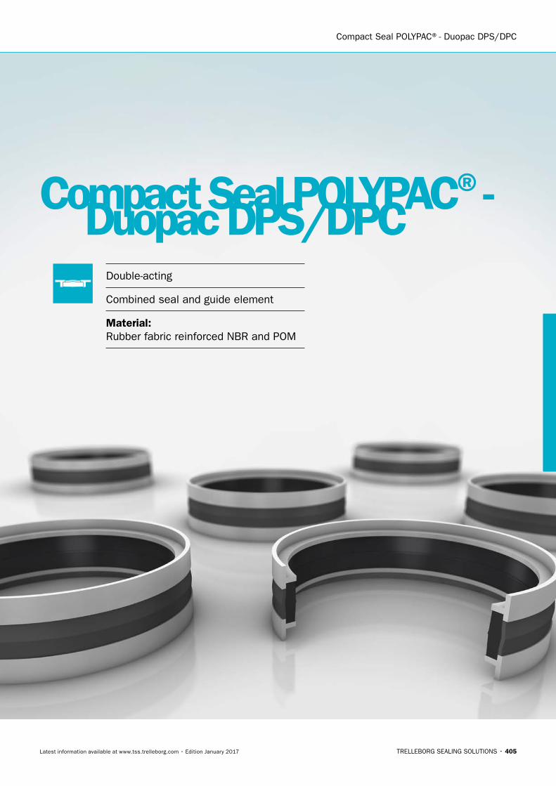
Compact Seal POLYPAC®- Duopac DPS/DPC
TRELLEBORG SEALING SOLUTIONS • 405Latest information available at www.tss.trelleborg.com • Edition January 2017
Compact Seal POLYPAC® -Duopac DPS/DPCDouble-acting
Combined seal and guide element
Material:Rubber fabric reinforced NBR and POM

HYDRAULIC SEALS · Piston Seals
406
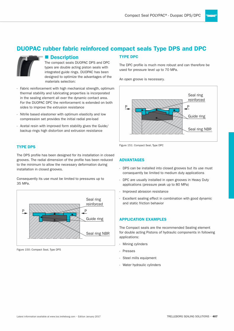
407
Description
TYPE DPS
P P
Seal ring NBR
Guide ring
Seal ringreinforced
TYPE DPC
Seal ring NBR
Guide ring
Seal ringreinforced
P P
ADVANTAGES
APPLICATION EXAMPLES
Presses
DUOPAC rubber fabric reinforced compact seals Type DPS and DPC
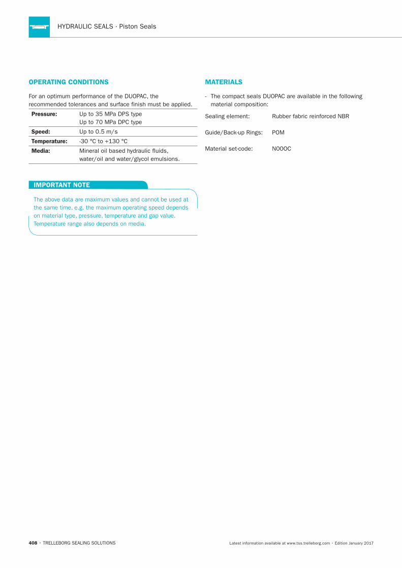
HYDRAULIC SEALS · Piston Seals
408
OPERATING CONDITIONS
Pressure:
Speed:
Temperature:
Media:
IMPORTANT NOTE
MATERIALS
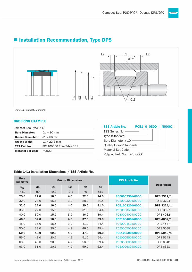
409
DN
d3 d2 d1
L1 L2L2r0.2
r0.2
Installation Drawing
Installation Recommendation, Type DPS
ORDERING EXAMPLE
Bore Diameter: DN
Groove Diameter:
Groove Width:
TSS Part No.:
Material Set-Code:
N00OCPCE1 0800 -
Material Set-Code
TSS Series No.TSS Article No.
Bore Diameter x 10Quality Index (Standard)
Type (Standard)
0
Polypac Ref. No.: DPS 8066
Table 141: Installation Dimensions / TSS Article No.
Bore
DiameterGroove Dimensions TSS Article No.
DescriptionDN d1 L1 L2 d2 d3
25.0 17.0 10.0 4.0 22.0 24.0 PCE000250-N00OC DPS 2517/1
32.0 24.0 10.0 4.0 29.0 31.0 PCE100320-N00OC DPS 3224/1
40.0 32.0 10.0 4.0 37.0 39.0 PCE100400-N00OC DPS 4032/1
50.0 40.0 12.5 4.0 47.0 49.0 PCE100500-N00OC DPS 5040/1
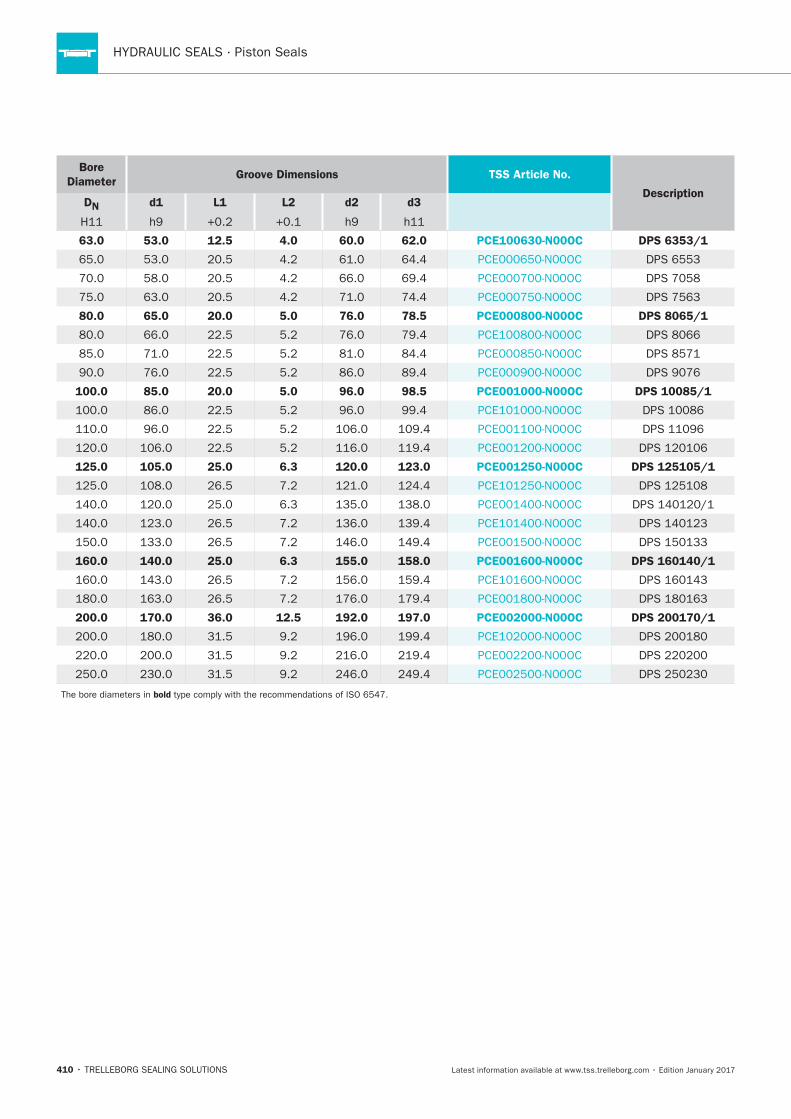
HYDRAULIC SEALS · Piston Seals
410
Bore
DiameterGroove Dimensions TSS Article No.
DescriptionDN d1 L1 L2 d2 d3
63.0 53.0 12.5 4.0 60.0 62.0 PCE100630-N00OC DPS 6353/1
80.0 65.0 20.0 5.0 76.0 78.5 PCE000800-N00OC DPS 8065/1
100.0 85.0 20.0 5.0 96.0 98.5 PCE001000-N00OC DPS 10085/1
125.0 105.0 25.0 6.3 120.0 123.0 PCE001250-N00OC DPS 125105/1
160.0 140.0 25.0 6.3 155.0 158.0 PCE001600-N00OC DPS 160140/1
200.0 170.0 36.0 12.5 192.0 197.0 PCE002000-N00OC DPS 200170/1
bold
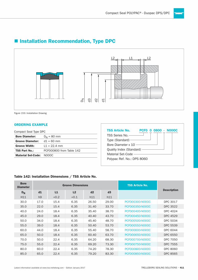
411
DN
d3 d2 d1
L1 L2L2
Installation Drawing
Installation Recommendation, Type DPC
ORDERING EXAMPLE
Bore Diameter: DN
Groove Diameter:
Groove Width:
TSS Part No.:
Material Set-Code:
N00OCPCF0 0800 -
Material Set-Code
TSS Series No.TSS Article No.
Bore Diameter x 10Quality Index (Standard)
Type (Standard)
0
Polypac Ref. No.: DPS 8060
Table 142: Installation Dimensions / TSS Article No.
Bore
DiameterGroove Dimensions TSS Article No.
DescriptionDN
d1
L1
L2 d2
d3
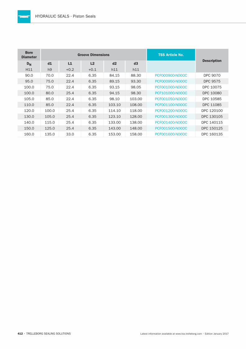
HYDRAULIC SEALS · Piston Seals
412
Bore
DiameterGroove Dimensions TSS Article No.
DescriptionDN
d1
L1
L2 d2
d3
POLYPAC®- Veepac CH
TRELLEBORG SEALING SOLUTIONS • 413Latest information available at www.tss.trelleborg.com • Edition January 2017
PolyPac®- Veepac CHSingle-acting
Set of Chevron Ring
With Support and Pressure Energizing Ring
Without and with Anti-extrusion Ring
Material:Fabric Reinforced Rubber - POM or PTFE

HYDRAULIC SEALS · Piston Seals
414
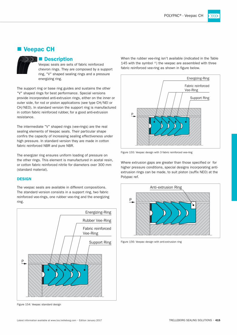
415
Veepac CH
Description
resistance.
DESIGN
ring.
P
Support Ring
Energizing-Ring
Rubber Vee-Ring
Fabric reinforcedVee-Ring
P
Support Ring
Energizing-Ring
Fabric reinforcedVee-Ring
P
Anti-extrusion Ring
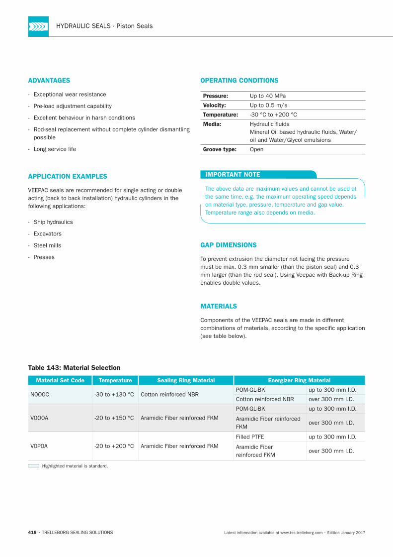
HYDRAULIC SEALS · Piston Seals
416
ADVANTAGES
Long service life
APPLICATION EXAMPLES
Steel mills
Presses
OPERATING CONDITIONS
Pressure:
Velocity:
Temperature:
Media:
Groove type:
IMPORTANT NOTE
GAP DIMENSIONS
MATERIALS
Table 143: Material Selection
Material Set Code Temperature Sealing Ring Material Energizer Ring Material
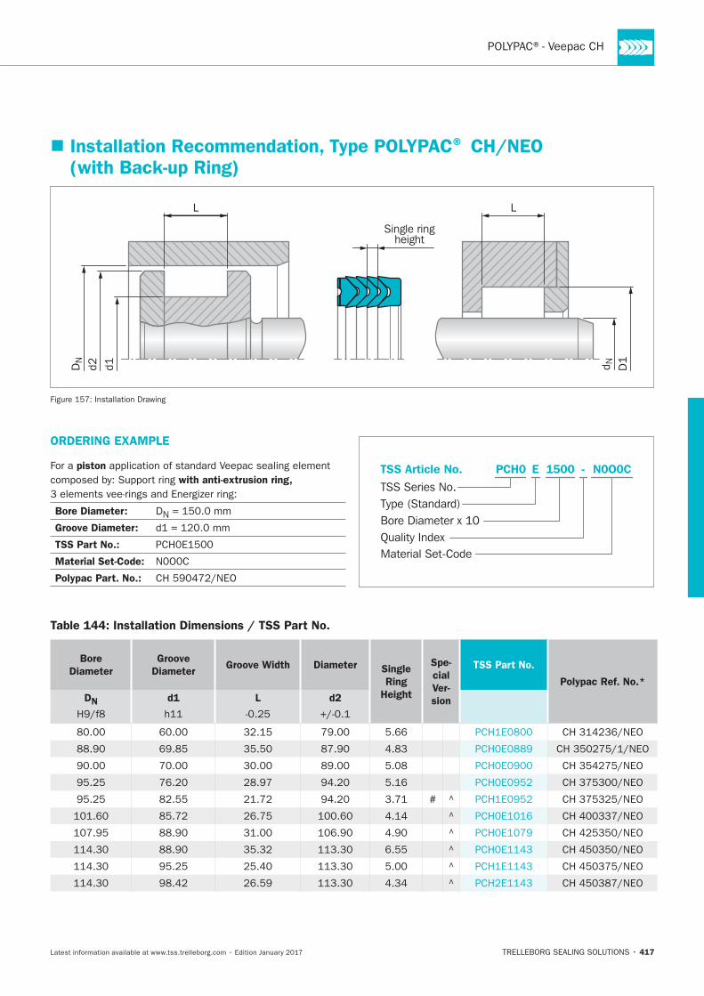
417
Table 144: Installation Dimensions / TSS Part No.
Bore
Diameter
Groove
Diameter Groove Width Diameter Single
Ring
Height
Spe-
cial
Ver-
sion
TSS Part No.
Polypac Ref. No.*
DN
d1
L
d2
#
Installation Recommendation, Type POLYPAC® CH/NEO (with Back-up Ring)
L L
Single ringheight
D1
d1d2 d NDN
Installation Drawing
ORDERING EXAMPLE
For a piston
with anti-extrusion ring,
Bore Diameter: DN
Groove Diameter:
TSS Part No.:
Material Set-Code:
Polypac Part. No.:
N0O0CPCH0 1500 -
Material Set-Code
TSS Series No.TSS Article No.
Bore Diameter x 10Quality Index
Type (Standard)
E
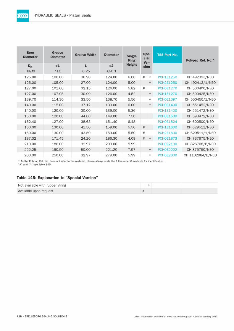
HYDRAULIC SEALS · Piston Seals
418
Bore
Diameter
Groove
Diameter Groove Width Diameter Single
Ring
Height
Spe-
cial
Ver-
sion
TSS Part No.
Polypac Ref. No.*
DN
d1
L
d2
#
#
#
#
#
Table 145: Explanation to "Special Version"
#
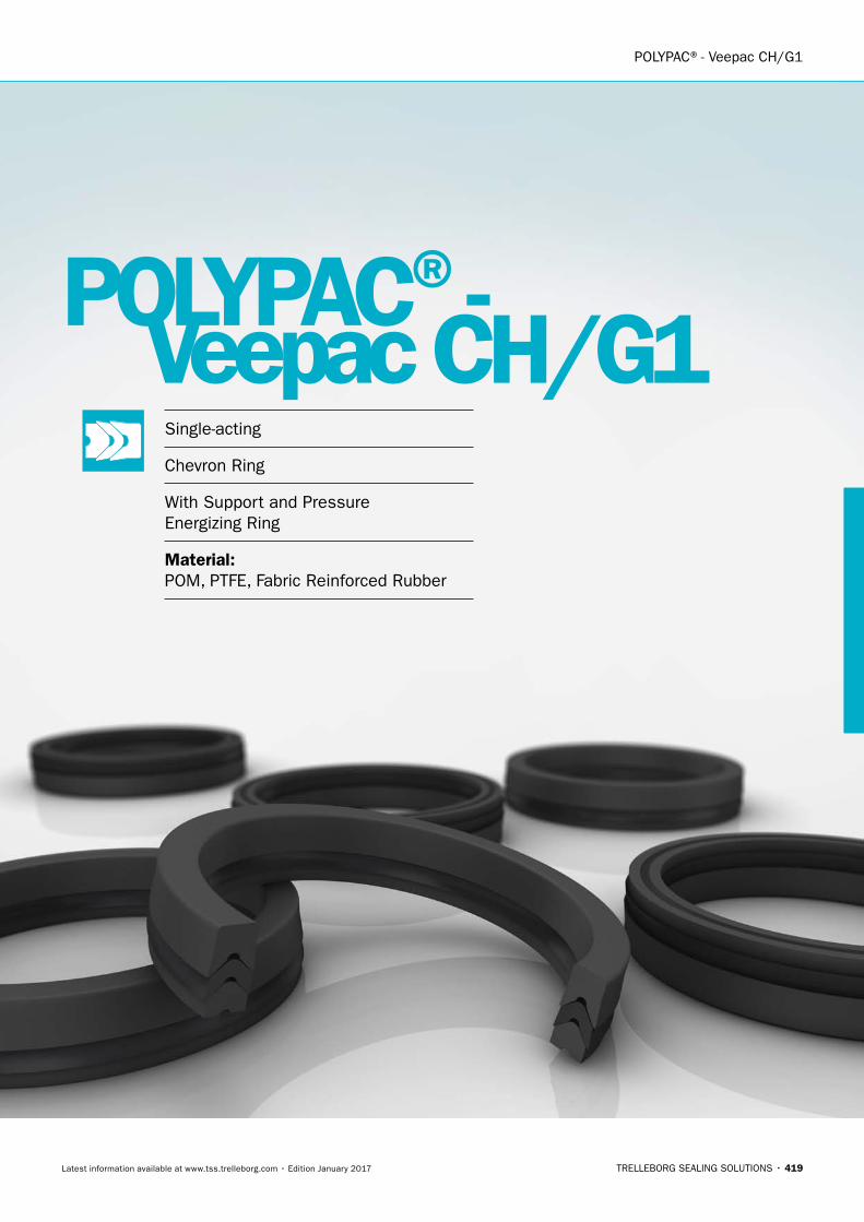
POLYPAC®- Veepac CH/G1
TRELLEBORG SEALING SOLUTIONS • 419Latest information available at www.tss.trelleborg.com • Edition January 2017
PolyPac®- Veepac CH/G1Single-acting
Chevron Ring
With Support and PressureEnergizing Ring
Material:POM, PTFE, Fabric Reinforced Rubber

HYDRAULIC SEALS · Piston Seals
420
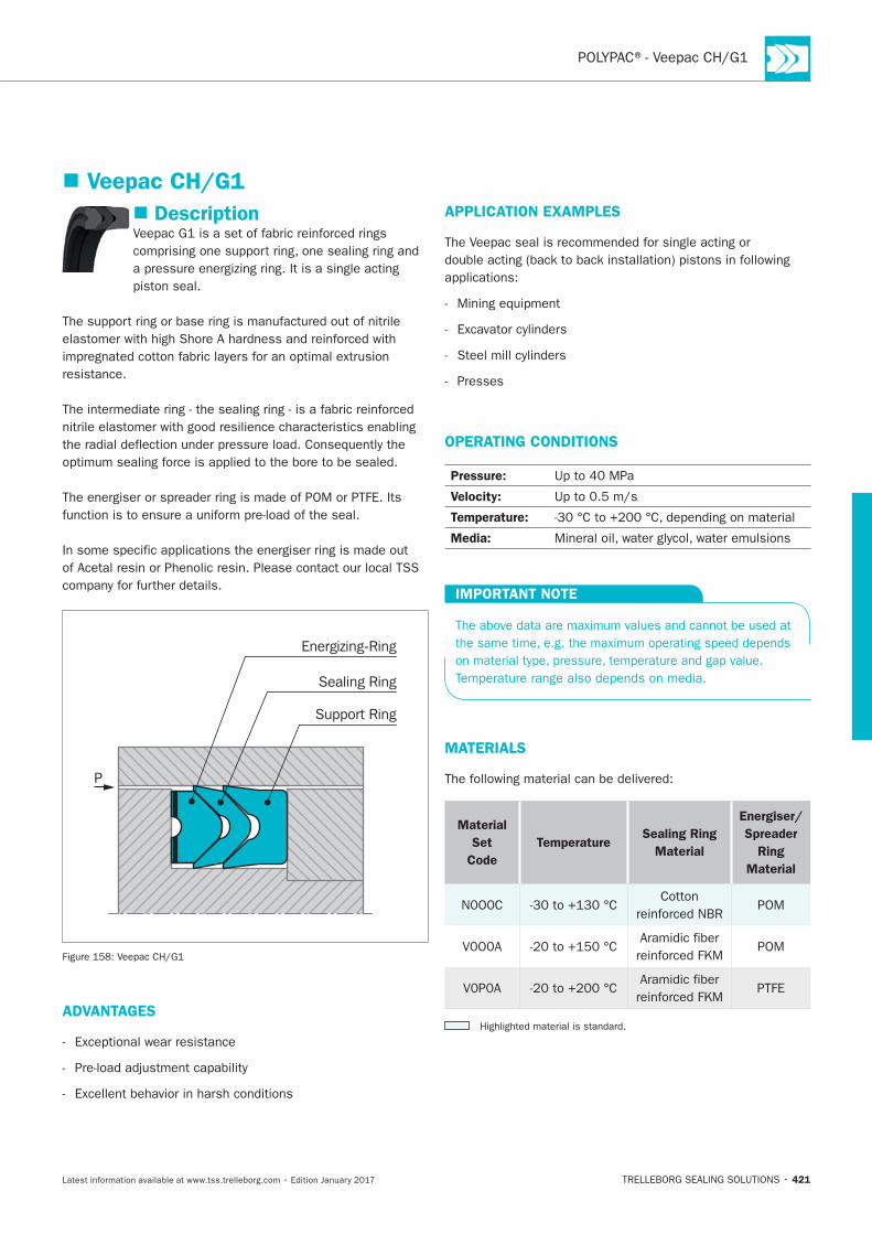
421
Description
resistance.
P
Support Ring
Energizing-Ring
Sealing Ring
ADVANTAGES
APPLICATION EXAMPLES
Presses
OPERATING CONDITIONS
Pressure:
Velocity:
Temperature:
Media:
IMPORTANT NOTE
MATERIALS
Material
Set
Code
TemperatureSealing Ring
Material
Energiser/
Spreader
Ring
Material
Cotton POM
POM
PTFE
Veepac CH/G1
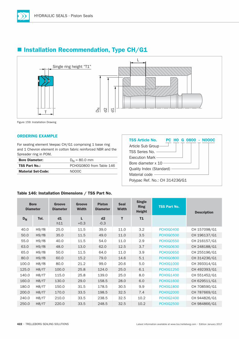
HYDRAULIC SEALS · Piston Seals
422
Installation Recommendation, Type CH/G1
L
d1d2DN
Single ring height “T1”
T
Installation Drawing
ORDERING EXAMPLE
Bore Diameter: DN
TSS Part No.:
Material Set-Code:Material code
Article Sub GroupTSS Article No. N0O0CG
Bore diameter x 10
PC
Quality Index (Standard)
0800
TSS Series No.
H0
Execution Mark
-
Polypac Ref. No.: CH 314236/G1
Table 146: Installation Dimensions / TSS Part No.
Bore
Diameter
Groove
Diameter
Groove
Width
Piston
Diameter
Seal
Width
Single
Ring
Height
TSS Part No.
Description
DN Tol. d1 L
d2 T T1
PolyPac®- Selemaster DSMDouble-acting
Compact Piston Seal
Material:NBR + Fiber Reinforced NBR + POM
POLYPAC®- Selemaster DSM
TRELLEBORG SEALING SOLUTIONS • 423Latest information available at www.tss.trelleborg.com • Edition January 2017

HYDRAULIC SEALS · Piston Seals
424
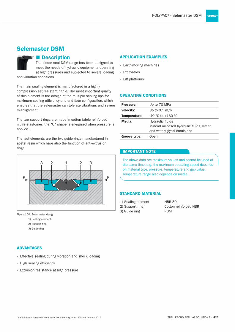
425
Description
misalignment.
rings.
PP
12 23 3
ADVANTAGES
APPLICATION EXAMPLES
OPERATING CONDITIONS
Pressure:
Velocity:
Temperature:
Media:
Groove type:
IMPORTANT NOTE
STANDARD MATERIAL
Selemaster DSM
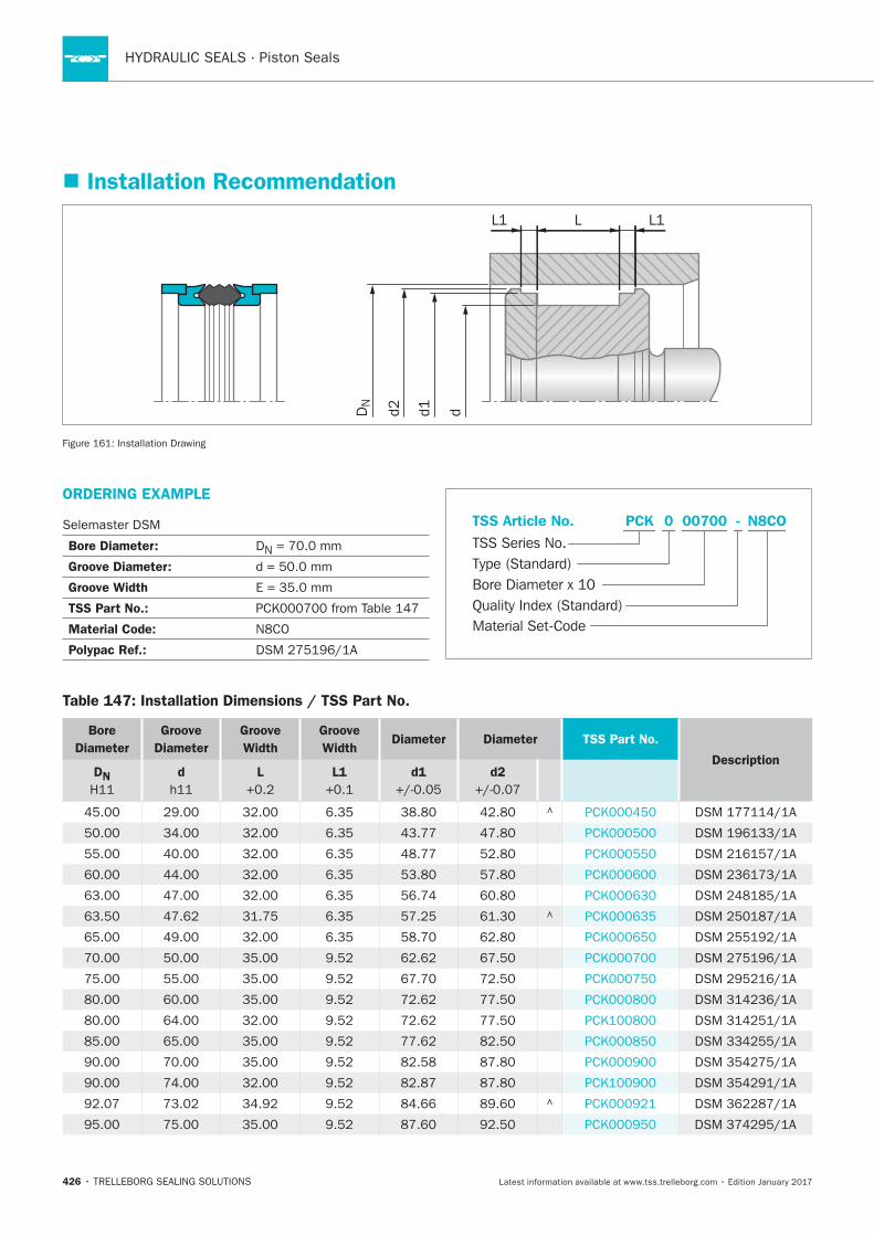
HYDRAULIC SEALS · Piston Seals
426
ORDERING EXAMPLE
Selemaster DSM
Bore Diameter: DN
Groove Diameter:
Groove Width
TSS Part No.:
Material Code:
Polypac Ref.:
Material Set-Code
TSS Series No.
TSS Article No.
Bore Diameter x 10Quality Index (Standard)
Type (Standard)
N8COPCK - 0 00700
Installation Recommendation
L
d1d2DN
L1 L1
dInstallation Drawing
Table 147: Installation Dimensions / TSS Part No.
Bore
Diameter
Groove
Diameter
Groove
Width
Groove
Width Diameter Diameter TSS Part No.
DescriptionDN
d
L
L1
d1
d2
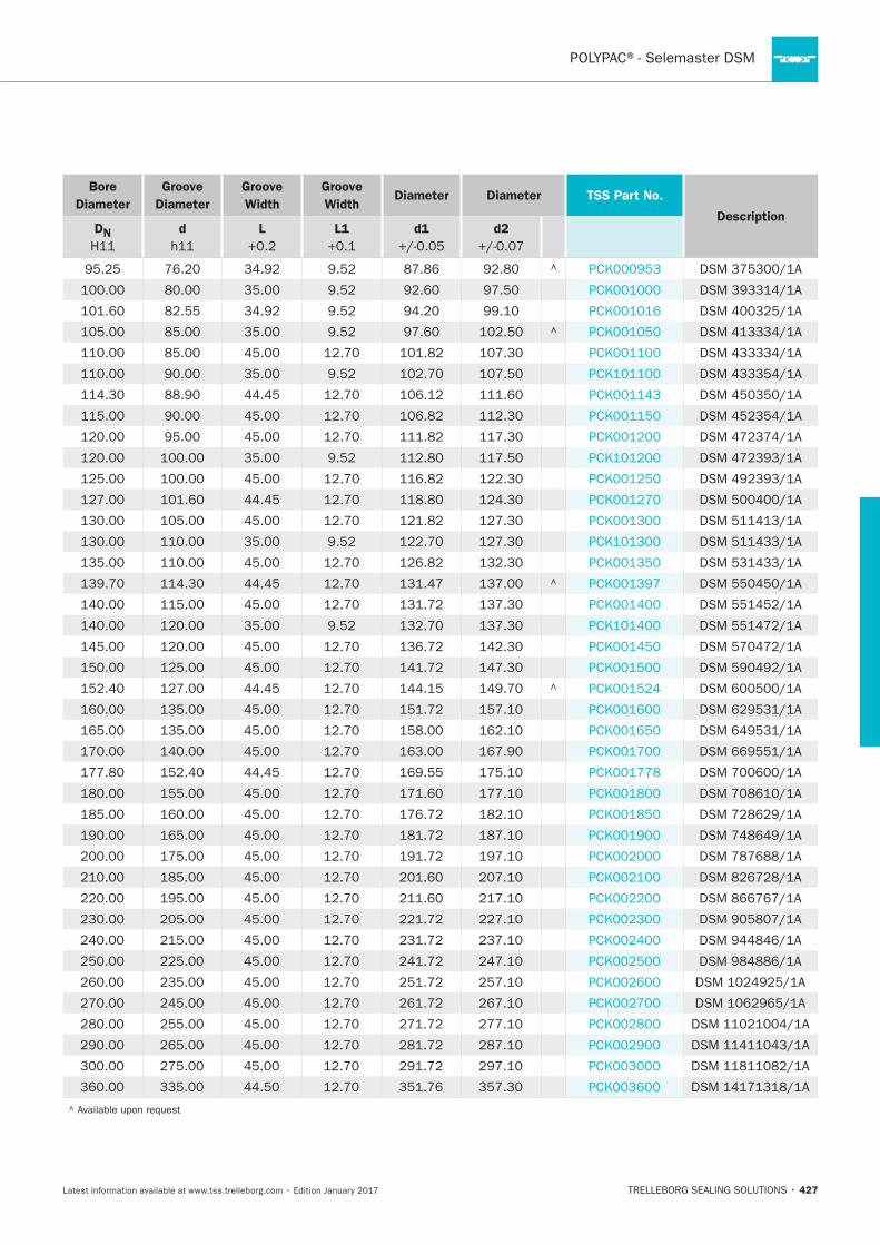
427
Bore
Diameter
Groove
Diameter
Groove
Width
Groove
Width Diameter Diameter TSS Part No.
DescriptionDN
d
L
L1
d1
d2

HYDRAULIC SEALS · Piston Seals
428
Additional Piston Seals
TRELLEBORG SEALING SOLUTIONS • 429Latest information available at www.tss.trelleborg.com • Edition January 2017
AdditionalSealsAvailable upon Request
Old Series
Special Series

HYDRAULIC SEALS · Piston Seals
430
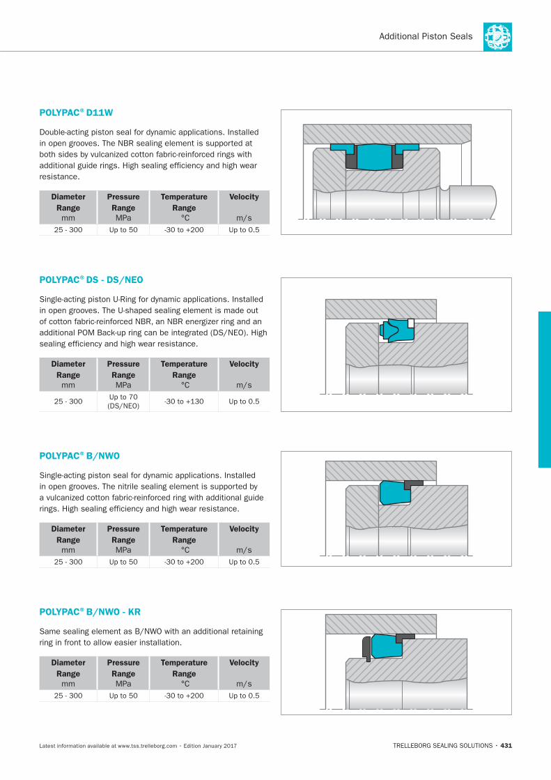
431
POLYPAC®D11W
resistance.
Diameter
Range
mm
Pressure
Range
MPa
Temperature
Range
Velocity
POLYPAC®DS - DS/NEO
Diameter
Range
mm
Pressure
Range
MPa
Temperature
Range
Velocity
POLYPAC®B/NWO
Diameter
Range
mm
Pressure
Range
MPa
Temperature
Range
Velocity
POLYPAC®B/NWO - KR
ring in front to allow easier installation.
Diameter
Range
mm
Pressure
Range
MPa
Temperature
Range
Velocity
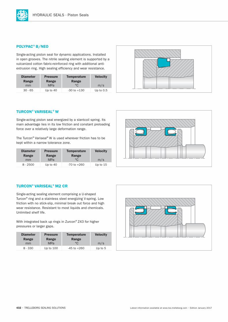
HYDRAULIC SEALS · Piston Seals
432
POLYPAC®B/NEO
Diameter
Range
mm
Pressure
Range
MPa
Temperature
Range
Velocity
TURCON®VARISEAL®W
®Variseal®
Diameter
Range
mm
Pressure
Range
MPa
Temperature
Range
Velocity
TURCON®VARISEAL®M2 CR
®
®
Diameter
Range
mm
Pressure
Range
MPa
Temperature
Range
Velocity
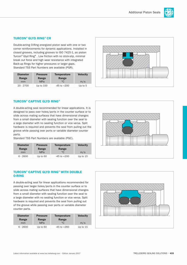
433
TURCON®GLYD RING®CR
® ®
Diameter
Range
mm
Pressure
Range
MPa
Temperature
Range
Velocity
TURCON®CAPTIVE GLYD RING®
Diameter
Range
mm
Pressure
Range
MPa
Temperature
Range
Velocity
TURCON®CAPTIVE GLYD RING®WITH DOUBLE O-RING
Diameter
Range
mm
Pressure
Range
MPa
Temperature
Range
Velocity
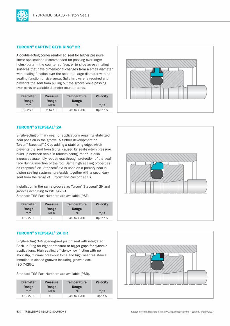
HYDRAULIC SEALS · Piston Seals
434
TURCON®CAPTIVE GLYD RING®CR
Diameter
Range
mm
Pressure
Range
MPa
Temperature
Range
Velocity
TURCON®STEPSEAL®2A
® ®
® ®
® ®seals.
® ®
Diameter
Range
mm
Pressure
Range
MPa
Temperature
Range
Velocity
TURCON®STEPSEAL®2A CR
Diameter
Range
mm
Pressure
Range
MPa
Temperature
Range
Velocity
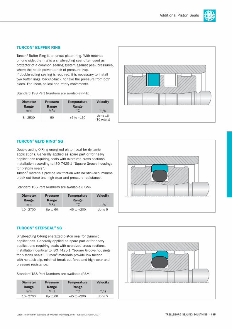
435
TURCON®BUFFER RING
®
Diameter
Range
mm
Pressure
Range
MPa
Temperature
Range
Velocity
TURCON®GLYD RING®SG
®
Diameter
Range
mm
Pressure
Range
MPa
Temperature
Range
Velocity
TURCON®STEPSEAL®SG
®
Diameter
Range
mm
Pressure
Range
MPa
Temperature
Range
Velocity
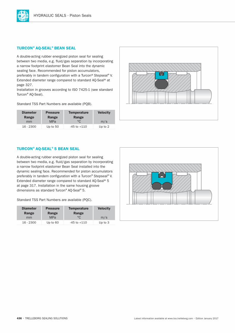
HYDRAULIC SEALS · Piston Seals
436
TURCON®AQ-SEAL®BEAN SEAL
®V.
®
Diameter
Range
mm
Pressure
Range
MPa
Temperature
Range
Velocity
TURCON®AQ-SEAL®5 BEAN SEAL
® ®V.
® ®
Diameter
Range
mm
Pressure
Range
MPa
Temperature
Range
Velocity
TRELLEBORG SEALING SOLUTIONS • 437Latest information available at www.tss.trelleborg.com • Edition January 2017
Scrapers

HYDRAULIC SEALS · Scrapers
438
Scrapers
439
Contents
440 Choice of Scraper Element
445 Turcon®Excluder®2
453 Turcon®Excluder®5
461 Turcon®Excluder®F
471 Turcon®Excluder®S
483 Turcon®Excluder®1 and 113
493 Scraper DA 17
499 Zurcon®Scraper DA 22
505 Zurcon®Scraper DA 24 &
DA 24 Venting version
511 Scraper WRM
519 Zurcon®Scraper ASW
525 Zurcon®Scraper WNE
531 Zurcon®Scraper WNV
535 Scraper WSA
541 Zurcon®Scraper SWP
547 Metal Scraper
553 Turcon®Variseal®M2S
561 Additional Scrapers
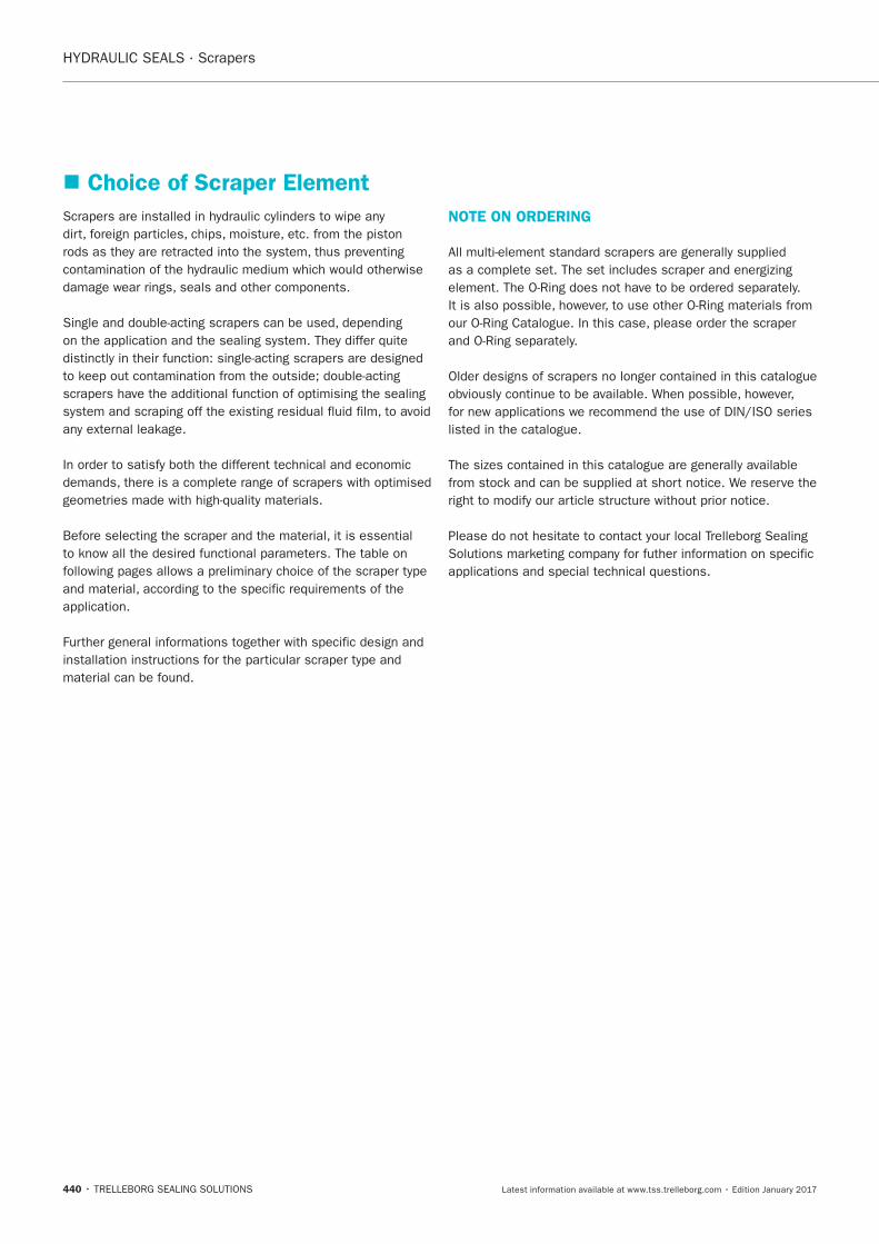
HYDRAULIC SEALS · Scrapers
440
Choice of Scraper Element
NOTE ON ORDERING
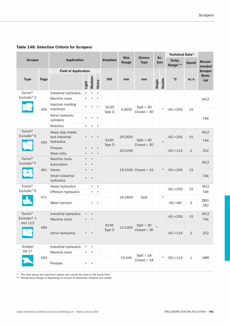
Scrapers
441
Table 148: Selection Criteria for Scrapers
Scraper Application StandardSize
Range
Groove
Type
Ac-
tion
Technical Data*
Recom-
mended
Scraper
Mate-
rial
Temp.
Range**Speed
Type Page
Field of Application
ISO mm mm
Sin
gle
Double °C m/s
Lig
ht
Mediu
m
Heavy
® ®
445
T46
Robotics
® ®5
453 T46
Presses
Steel mills
® ®F
Valves
T46
® ®S
Split
T46
®
T46
Scraper
NBR
Presses
*
**
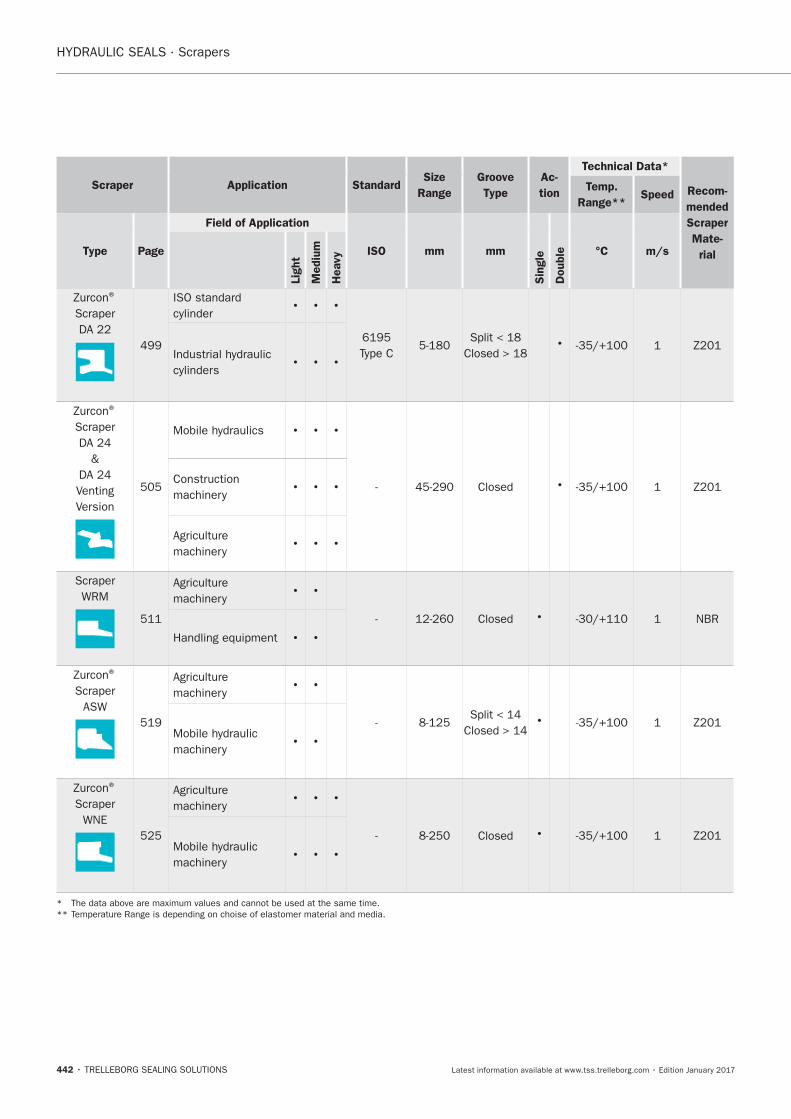
HYDRAULIC SEALS · Scrapers
442
Scraper Application StandardSize
Range
Groove
Type
Ac-
tion
Technical Data*
Recom-
mended
Scraper
Mate-
rial
Temp.
Range**Speed
Type Page
Field of Application
ISO mm mm
Sin
gle
Double °C m/s
Lig
ht
Mediu
m
Heavy
®
Scraper
®
Scraper
&
Venting
Version
Scraper
NBR
®
Scraper
®
Scraper
*
**
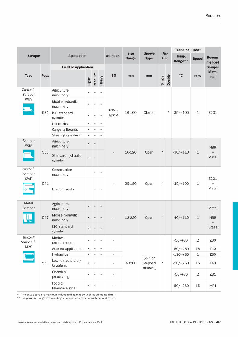
Scrapers
443
Scraper Application StandardSize
Range
Groove
Type
Ac-
tion
Technical Data*
Recom-
mended
Scraper
Mate-
rial
Temp.
Range**Speed
Type Page
Field of Application
ISO mm mm
Sin
gle
Double °C m/s
Lig
ht
Mediu
m
Heavy
®
Scraper
Scraper
535 Open
NBR
Metal
®
Scraper
Open
MetalLink pin seals
Metal
Scraper
Open
Metal
NBR
Brass
Variseal®
553
Marine
environments
Split or
processing
MF4
*
**

HYDRAULIC SEALS · Scrapers
444
Turcon®Excluder®2
TRELLEBORG SEALING SOLUTIONS • 445Latest information available at www.tss.trelleborg.com • Edition January 2017
Turcon®Excluder®2
Double-acting
Rubber-energized Double-acting scraper
Material:Turcon®, Zurcon®and Elastomer

HYDRAULIC SEALS · Scrapers
446
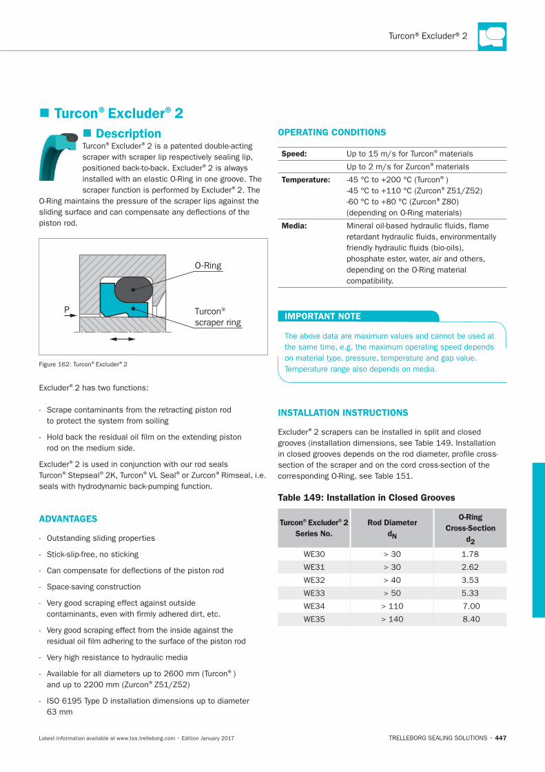
447
Description® ®
®
®
Turcon® scraper ring
O-Ring
P
® ®
®
®
®Stepseal® ®VL Seal® ®
ADVANTAGES
®) ®
63 mm
OPERATING CONDITIONS
Speed: ®materials
®materials
Temperature: ®) ®
®
Media:
IMPORTANT NOTE
INSTALLATION INSTRUCTIONS
®
Table 149: Installation in Closed Grooves
Turcon®Excluder®2
Series No.
Rod Diameter
dN
O-Ring
Cross-Section
d2
3.53
5.33
Turcon®Excluder®2
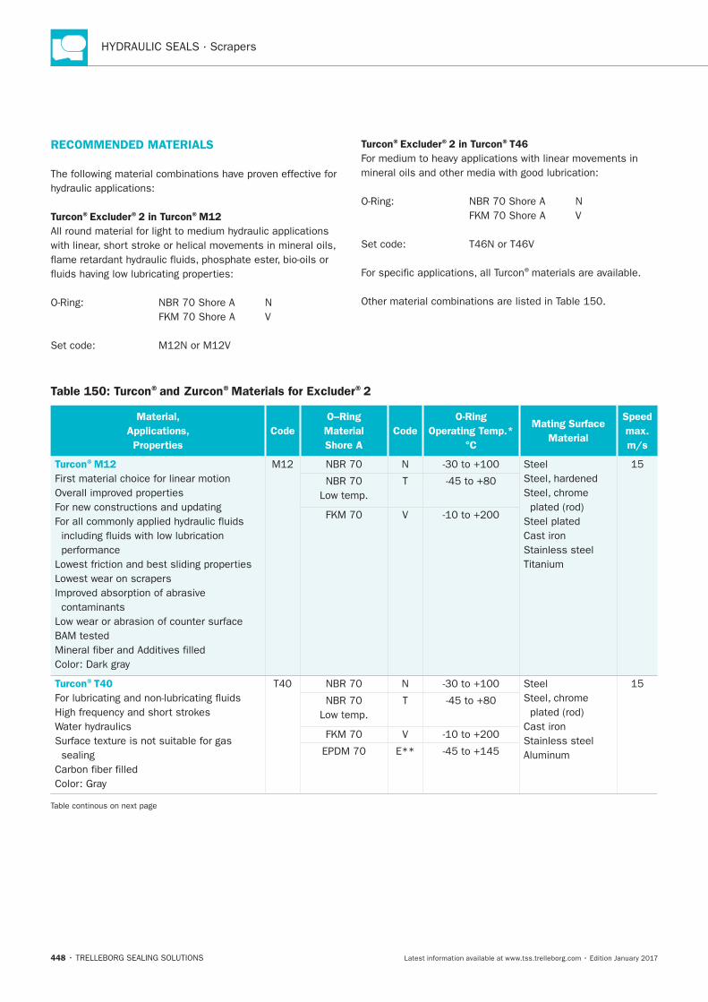
HYDRAULIC SEALS · Scrapers
448
Table 150: Turcon®and Zurcon®Materials for Excluder®2
Material,
Applications,
Properties
Code
O–Ring
Material
Shore A
Code
O-Ring
Operating Temp.*
°C
Mating Surface
Material
Speed
max.
m/s
Turcon®M12
performance
Lowest wear on scrapers
contaminants
N Steel
Cast iron
Stainless steel
Low temp.
T
V
Turcon®T40
sealing
N Steel
Cast iron
Stainless steel
Low temp.
T
V
E**
RECOMMENDED MATERIALS
Turcon®Excluder®2 in Turcon®M12
Turcon®Excluder®2 in Turcon®T46
®materials are available.
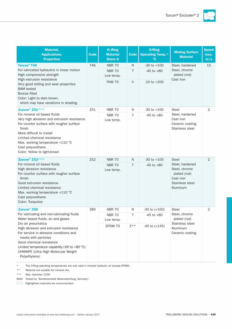
Turcon®Excluder®2
449
Material,
Applications,
Properties
Code
O–Ring
Material
Shore A
Code
O-Ring
Operating Temp.*
°C
Mating Surface
Material
Speed
max.
m/s
Turcon®T46
T46 N
Cast iron
Low temp.
T
V
Zurcon®Z51***
N Steel
Cast iron
Ceramic coating
Stainless steel
Low temp.
T
Zurcon®Z52***
N Steel
Cast iron
Stainless steel
Low temp.
T
Zurcon®Z80
N Steel
Stainless steel
Ceramic coating
Low temp.
T
E**
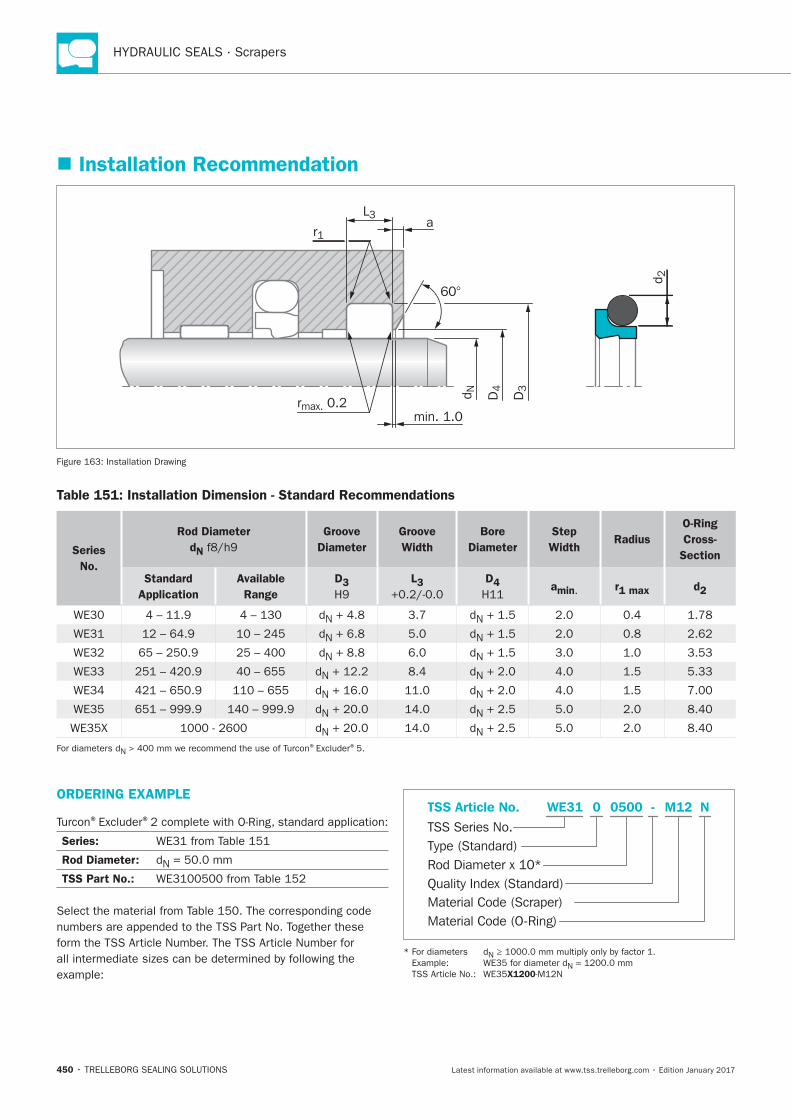
HYDRAULIC SEALS · Scrapers
450
ORDERING EXAMPLE
® ®
Series:
Rod Diameter: N
TSS Part No.:
Material Code (Scraper)
TSS Series No.
TSS Article No. M120500 N
Material Code (O-Ring)
Rod Diameter x 10*
WE31
Quality Index (Standard)
-
Type (Standard)
0
N
N
X1200
Installation Recommendation
60°
D3
D4d N
d 2
L3
r1
rmax. 0.2min. 1.0
a
Installation Drawing
Table 151: Installation Dimension - Standard Recommendations
Series
No.
Rod Diameter
dN
Groove
Diameter
Groove
Width
Bore
Diameter
Step
Width Radius
O-Ring
Cross-
Section
Standard
Application
Available
Range
D3 L3 D4 amin. r1 max d2
N N
N N
N N 3.53
N N 5.33
N N
N N
N N
N® ®5.
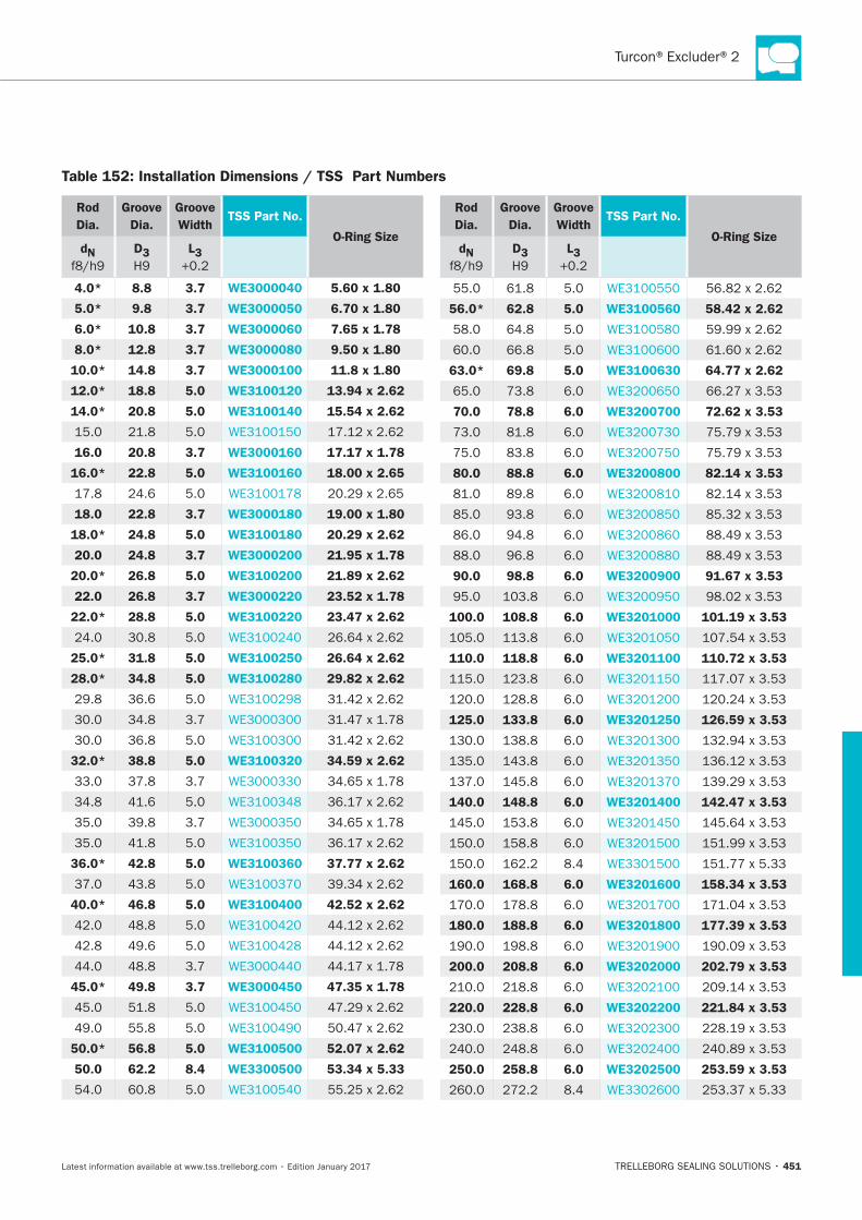
Turcon®Excluder®2
451
Table 152: Installation Dimensions / TSS Part Numbers
Rod
Dia.
Groove
Dia.
Groove
WidthTSS Part No.
O-Ring SizedN D3 L3
4.0* 8.8 3.7 WE3000040 5.60 x 1.80
5.0* 9.8 3.7 WE3000050 6.70 x 1.80
6.0* 10.8 3.7 WE3000060 7.65 x 1.78
8.0* 12.8 3.7 WE3000080 9.50 x 1.80
10.0* 14.8 3.7 WE3000100 11.8 x 1.80
12.0* 18.8 5.0 WE3100120 13.94 x 2.62
14.0* 20.8 5.0 WE3100140 15.54 x 2.62
16.0 20.8 3.7 WE3000160 17.17 x 1.78
16.0* 22.8 5.0 WE3100160 18.00 x 2.65
18.0 22.8 3.7 WE3000180 19.00 x 1.80
18.0* 24.8 5.0 WE3100180 20.29 x 2.62
20.0 24.8 3.7 WE3000200 21.95 x 1.78
20.0* 26.8 5.0 WE3100200 21.89 x 2.62
22.0 26.8 3.7 WE3000220 23.52 x 1.78
22.0* 28.8 5.0 WE3100220 23.47 x 2.62
25.0* 31.8 5.0 WE3100250 26.64 x 2.62
28.0* 34.8 5.0 WE3100280 29.82 x 2.62
36.6
32.0* 38.8 5.0 WE3100320 34.59 x 2.62
36.0* 42.8 5.0 WE3100360 37.77 x 2.62
40.0* 46.8 5.0 WE3100400 42.52 x 2.62
45.0* 49.8 3.7 WE3000450 47.35 x 1.78
50.0* 56.8 5.0 WE3100500 52.07 x 2.62
50.0 62.2 8.4 WE3300500 53.34 x 5.33
Rod
Dia.
Groove
Dia.
Groove
WidthTSS Part No.
O-Ring SizedN D3 L3
56.0* 62.8 5.0 WE3100560 58.42 x 2.62
63.0* 69.8 5.0 WE3100630 64.77 x 2.62
70.0 78.8 6.0 WE3200700 72.62 x 3.53
80.0 88.8 6.0 WE3200800 82.14 x 3.53
90.0 98.8 6.0 WE3200900 91.67 x 3.53
100.0 108.8 6.0 WE3201000 101.19 x 3.53
110.0 118.8 6.0 WE3201100 110.72 x 3.53
125.0 133.8 6.0 WE3201250 126.59 x 3.53
140.0 148.8 6.0 WE3201400 142.47 x 3.53
160.0 168.8 6.0 WE3201600 158.34 x 3.53
180.0 188.8 6.0 WE3201800 177.39 x 3.53
200.0 208.8 6.0 WE3202000 202.79 x 3.53
220.0 228.8 6.0 WE3202200 221.84 x 3.53
250.0 258.8 6.0 WE3202500 253.59 x 3.53
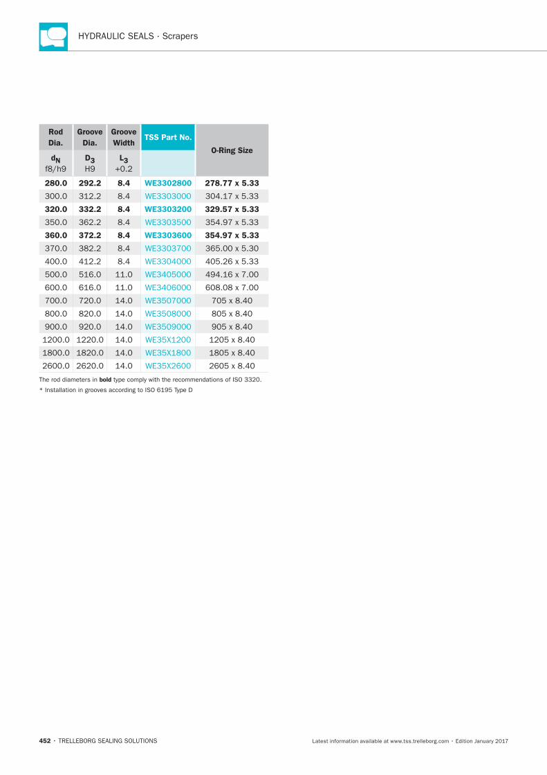
HYDRAULIC SEALS · Scrapers
452
Rod
Dia.
Groove
Dia.
Groove
WidthTSS Part No.
O-Ring SizedN D3 L3
280.0 292.2 8.4 WE3302800 278.77 x 5.33
320.0 332.2 8.4 WE3303200 329.57 x 5.33
360.0 372.2 8.4 WE3303600 354.97 x 5.33
bold
Turcon®Excluder®5
TRELLEBORG SEALING SOLUTIONS • 453Latest information available at www.tss.trelleborg.com • Edition January 2017
Turcon®Excluder®5
Double-acting
Rubber-energized Double-acting Scraper
Material:Turcon®, Zurcon®and Elastomer

HYDRAULIC SEALS · Scrapers
454
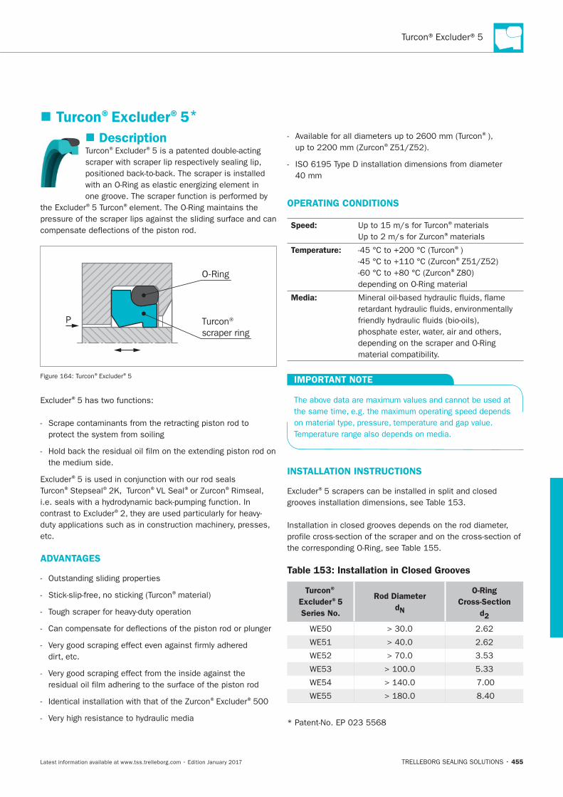
455
Description® ®
® ®
Turcon® scraper ring
O-Ring
P
® ®5
®
®
®Stepseal® ®VL Seal® ®
®
etc.
ADVANTAGES
®material)
® ®
® ®
OPERATING CONDITIONS
Speed: ®materials®materials
Temperature: ®) ®
®
Media:
IMPORTANT NOTE
INSTALLATION INSTRUCTIONS
®
Table 153: Installation in Closed Grooves
Turcon®
Excluder®5
Series No.
Rod Diameter
dN
O-Ring
Cross-Section
d2
3.53
5.33
Turcon®Excluder®5*
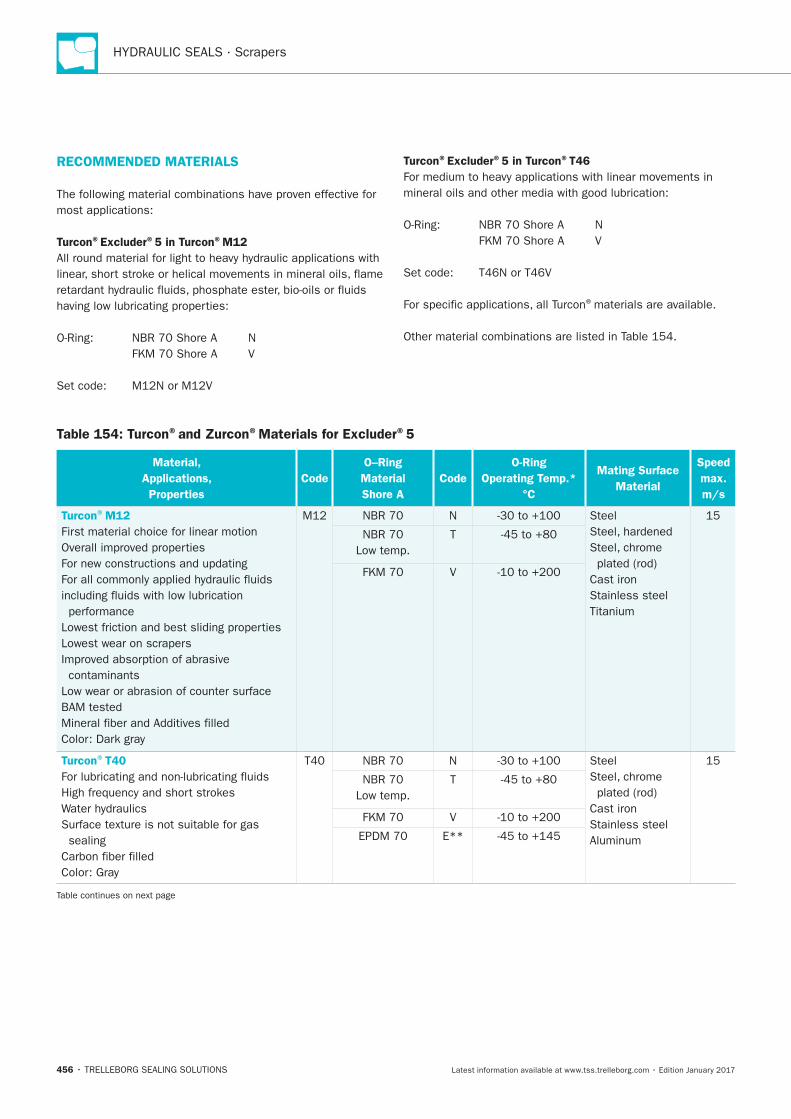
HYDRAULIC SEALS · Scrapers
456
Table 154: Turcon®and Zurcon®Materials for Excluder®5
Material,
Applications,
Properties
Code
O–Ring
Material
Shore A
Code
O-Ring
Operating Temp.*
°C
Mating Surface
Material
Speed
max.
m/s
Turcon®M12
performance
Lowest wear on scrapers
contaminants
N Steel
Cast iron
Stainless steel
Low temp.
T
V
Turcon®T40
sealing
N Steel
Cast iron
Stainless steel
Low temp.
T
V
E**
RECOMMENDED MATERIALS
Turcon®Excluder®5 in Turcon®M12
Turcon®Excluder®5 in Turcon®T46
®materials are available.
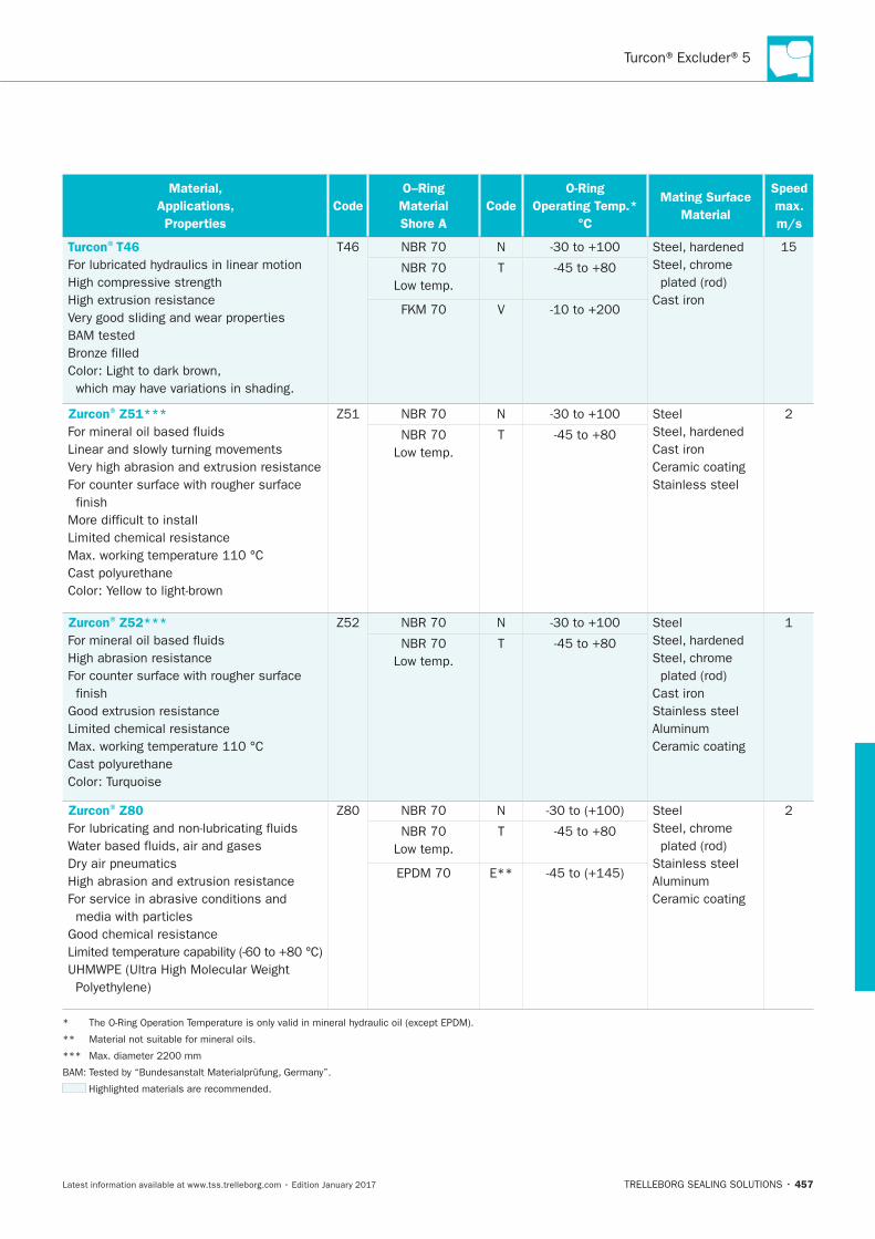
Turcon®Excluder®5
457
Material,
Applications,
Properties
Code
O–Ring
Material
Shore A
Code
O-Ring
Operating Temp.*
°C
Mating Surface
Material
Speed
max.
m/s
Turcon®T46
T46 N
Cast iron
T
V
Zurcon®Z51***
N Steel
Cast iron
Ceramic coating
Stainless steel
T
Zurcon®Z52***
N Steel
Cast iron
Stainless steel
Ceramic coating
T
Zurcon®Z80
N Steel
Stainless steel
Ceramic coating
T
E**
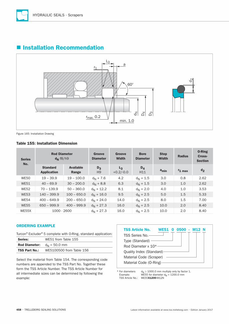
HYDRAULIC SEALS · Scrapers
458
Installation Recommendation
60°
D3
D4d N
d 2
rmax. 0.2min. 1.0
r1
L3a
Installation Drawing
Table 155: Installation Dimension
Series
No.
Rod Diameter
dN
Groove
Diameter
Groove
Width
Bore
Diameter
Step
Width Radius
O-Ring
Cross-
Section
Standard
Application
Available
Range
D3 L3 D4 amin r1 max d2
N N
N 6.3 N
N N
N N
N N
N N
N N
ORDERING EXAMPLE
® ®
Series:
Rod Diameter: N
TSS Part No.:
Material Code (Scraper)
TSS Series No.
TSS Article No. M120500 N
Material Code (O-Ring)
Rod Diameter x 10*
WE51
Quality Index (Standard)
-
Type (Standard)
0
N
N
X1200
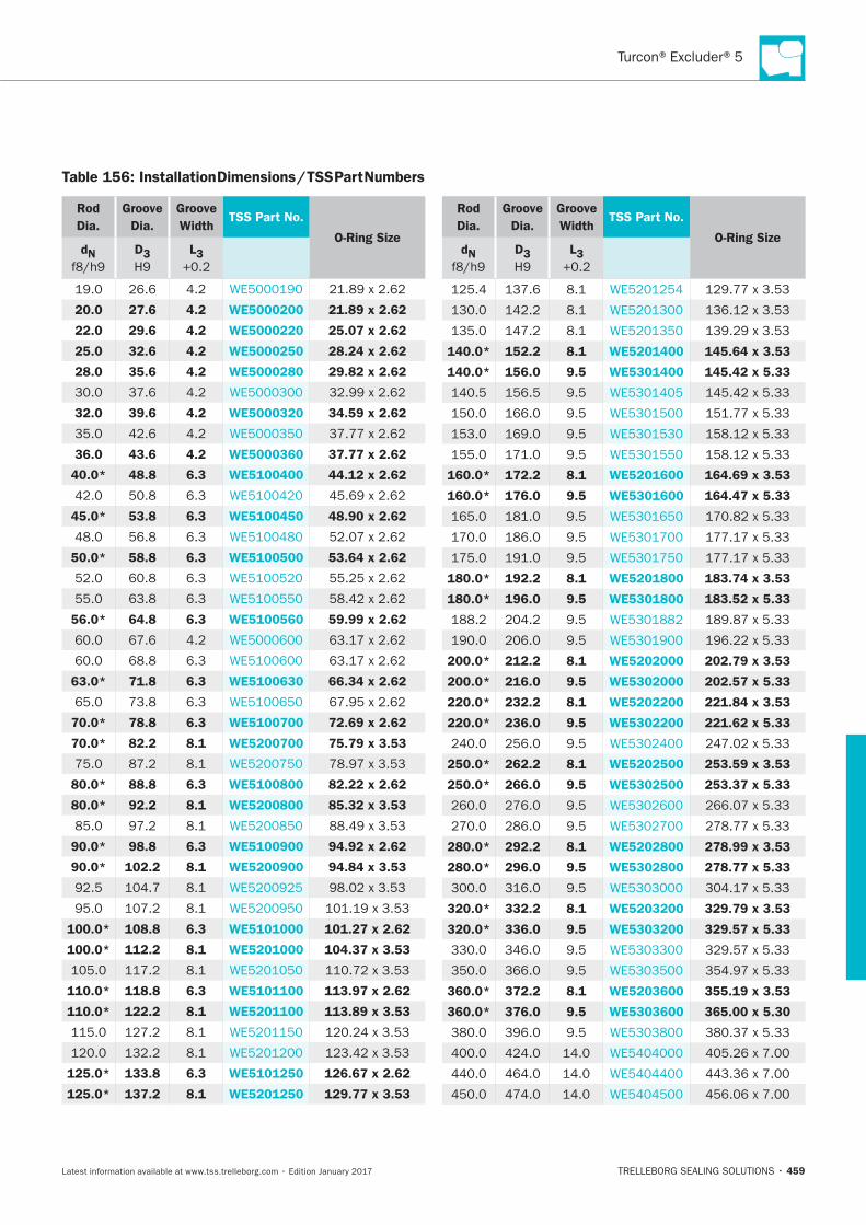
459
Table 156: Installation Dimensions / TSS Part Numbers
Rod
Dia.
Groove
Dia.
Groove
WidthTSS Part No.
O-Ring SizedN D3 L3
20.0 27.6 4.2 WE5000200 21.89 x 2.62
22.0 29.6 4.2 WE5000220 25.07 x 2.62
25.0 32.6 4.2 WE5000250 28.24 x 2.62
28.0 35.6 4.2 WE5000280 29.82 x 2.62
32.0 39.6 4.2 WE5000320 34.59 x 2.62
36.0 43.6 4.2 WE5000360 37.77 x 2.62
40.0* 48.8 6.3 WE5100400 44.12 x 2.62
6.3
45.0* 53.8 6.3 WE5100450 48.90 x 2.62
6.3
50.0* 58.8 6.3 WE5100500 53.64 x 2.62
6.3
6.3
56.0* 64.8 6.3 WE5100560 59.99 x 2.62
6.3
63.0* 71.8 6.3 WE5100630 66.34 x 2.62
6.3
70.0* 78.8 6.3 WE5100700 72.69 x 2.62
70.0* 82.2 8.1 WE5200700 75.79 x 3.53
80.0* 88.8 6.3 WE5100800 82.22 x 2.62
80.0* 92.2 8.1 WE5200800 85.32 x 3.53
90.0* 98.8 6.3 WE5100900 94.92 x 2.62
90.0* 102.2 8.1 WE5200900 94.84 x 3.53
100.0* 108.8 6.3 WE5101000 101.27 x 2.62
100.0* 112.2 8.1 WE5201000 104.37 x 3.53
110.0* 118.8 6.3 WE5101100 113.97 x 2.62
110.0* 122.2 8.1 WE5201100 113.89 x 3.53
125.0* 133.8 6.3 WE5101250 126.67 x 2.62
125.0* 137.2 8.1 WE5201250 129.77 x 3.53
Rod
Dia.
Groove
Dia.
Groove
WidthTSS Part No.
O-Ring SizedN D3 L3
140.0* 152.2 8.1 WE5201400 145.64 x 3.53
140.0* 156.0 9.5 WE5301400 145.42 x 5.33
160.0* 172.2 8.1 WE5201600 164.69 x 3.53
160.0* 176.0 9.5 WE5301600 164.47 x 5.33
180.0* 192.2 8.1 WE5201800 183.74 x 3.53
180.0* 196.0 9.5 WE5301800 183.52 x 5.33
200.0* 212.2 8.1 WE5202000 202.79 x 3.53
200.0* 216.0 9.5 WE5302000 202.57 x 5.33
220.0* 232.2 8.1 WE5202200 221.84 x 3.53
220.0* 236.0 9.5 WE5302200 221.62 x 5.33
250.0* 262.2 8.1 WE5202500 253.59 x 3.53
250.0* 266.0 9.5 WE5302500 253.37 x 5.33
280.0* 292.2 8.1 WE5202800 278.99 x 3.53
280.0* 296.0 9.5 WE5302800 278.77 x 5.33
320.0* 332.2 8.1 WE5203200 329.79 x 3.53
320.0* 336.0 9.5 WE5303200 329.57 x 5.33
360.0* 372.2 8.1 WE5203600 355.19 x 3.53
360.0* 376.0 9.5 WE5303600 365.00 x 5.30
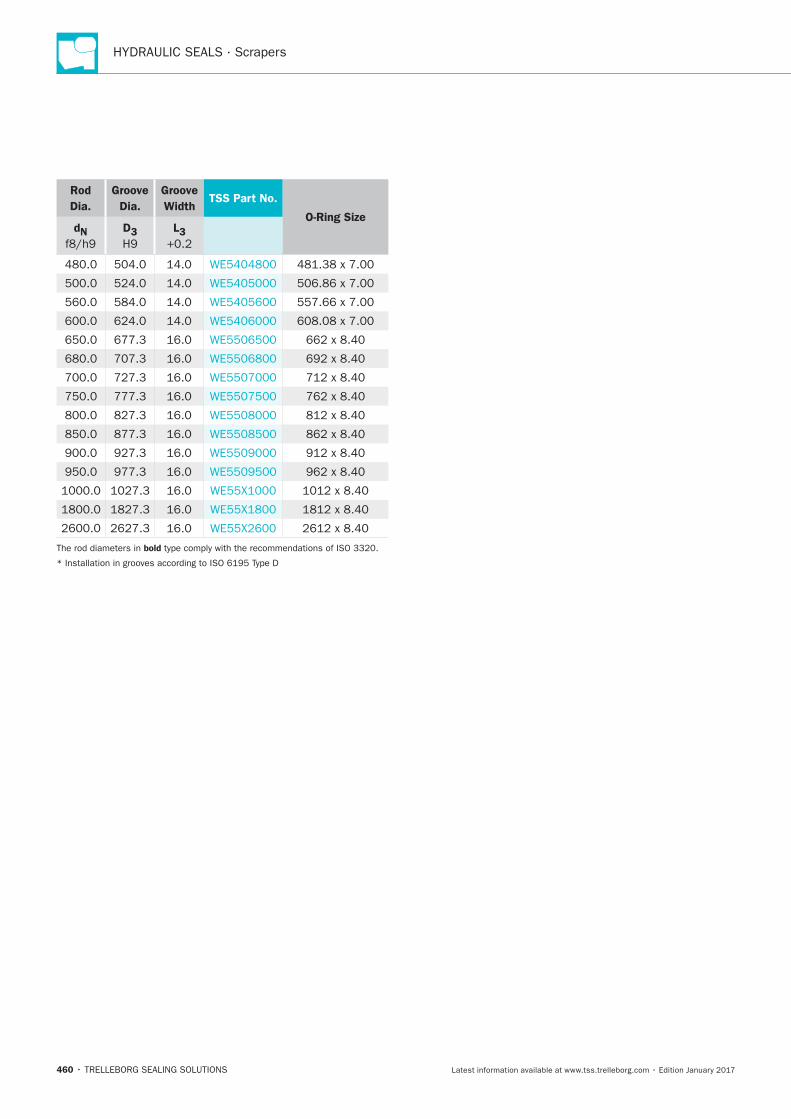
HYDRAULIC SEALS · Scrapers
460
Rod
Dia.
Groove
Dia.
Groove
WidthTSS Part No.
O-Ring SizedN D3 L3
bold
Turcon®Excluder®F
TRELLEBORG SEALING SOLUTIONS • 461Latest information available at www.tss.trelleborg.com • Edition January 2017
Turcon®Excluder®F
Double-acting
Rubber-energized Double-acting Scraper
Material:Turcon®, Zurcon®and Elastomer

HYDRAULIC SEALS · Scrapers
462
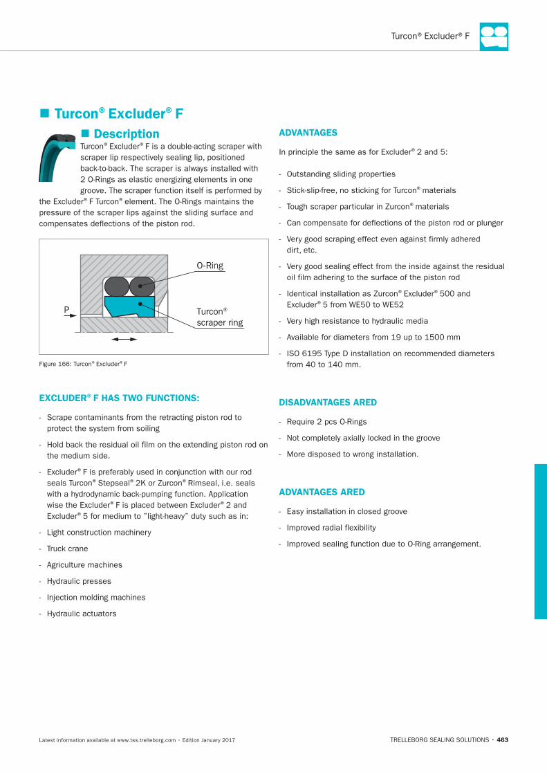
463
Turcon®Excluder®F
Description® ®
® ®
Turcon® scraper ring
O-Ring
P
® ®F
EXCLUDER®F HAS TWO FUNCTIONS:
®
®Stepseal® ®
® ®
®
ADVANTAGES
®
®materials
®materials
® ®
®
DISADVANTAGES ARED
ADVANTAGES ARED
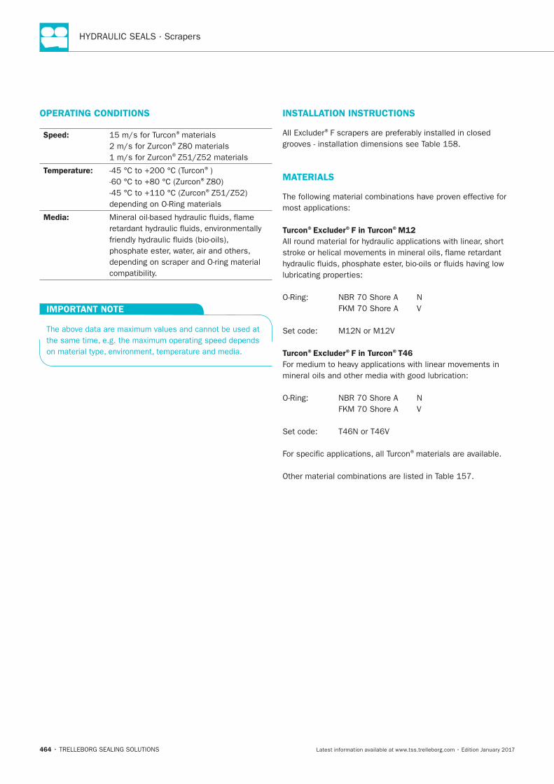
HYDRAULIC SEALS · Scrapers
464
OPERATING CONDITIONS
Speed: ®materials®
®
Temperature: ®)®
®
Media:
IMPORTANT NOTE
INSTALLATION INSTRUCTIONS
®
MATERIALS
Turcon®Excluder®F in Turcon®M12
Turcon®Excluder®F in Turcon®T46
®materials are available.
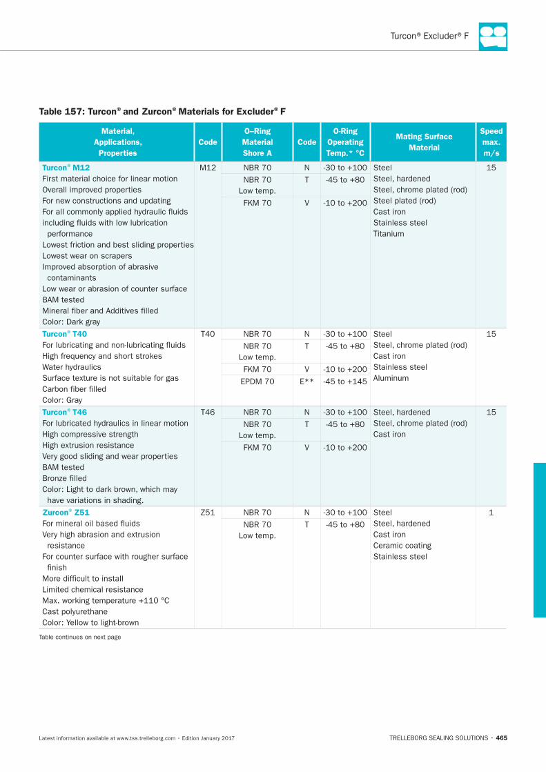
465
Table 157: Turcon®and Zurcon®Materials for Excluder®F
Material,
Applications,
Properties
Code
O–Ring
Material
Shore A
Code
O-Ring
Operating
Temp.* °C
Mating Surface
Material
Speed
max.
m/s
Turcon®M12
performance
Lowest wear on scrapers
contaminants
N Steel
Cast iron
Stainless steel
Low temp.
T
V
Turcon®T40
N Steel
Cast iron
Stainless steel
Low temp.
T
V
E**
Turcon®T46
T46 N
Cast iron
Low temp.
T
V
Zurcon®Z51
resistance
N Steel
Cast iron
Ceramic coating
Stainless steel
Low temp.
T

HYDRAULIC SEALS · Scrapers
466
Material,
Applications,
Properties
Code
O–Ring
Material
Shore A
Code
O-Ring
Operating
Temp.* °C
Mating Surface
Material
Speed
max.
m/s
Zurcon®Z52
Z52 N Steel
Cast iron
Stainless steel
Ceramic coating
Low temp.
T
Zurcon®Z80
Z80 N Steel
Stainless steel
Ceramic coating
Low temp.
T
E**
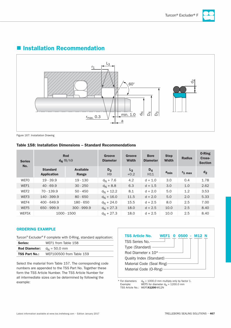
Turcon®Excluder®F
467
Installation Recommendation
60°
D3
D4d N
d 2
L3
rmax. 0.3 min. 1.0
r1
a
Installation Drawing
Table 158: Installation Dimensions – Standard Recommendations
Series
No.
Rod
dN
Groove
Diameter
Groove
Width
Bore
Diameter
Step
WidthRadius
O-Ring
Cross-
Section
Standard
Application
Available
Range
D3 L3 D4 amin r1 max d2
N
N 6.3
N 3.53
N 5.33
N
N
N
ORDERING EXAMPLE
® ®
Series:
Rod Diameter: N
TSS Part No.:
Material Code (Seal Ring)
TSS Series No.
TSS Article No. M120500 N
Material Code (O-Ring)
Rod Diameter x 10*
WEF1
Quality Index (Standard)
-
Type (Standard)
0
N
N
X1200
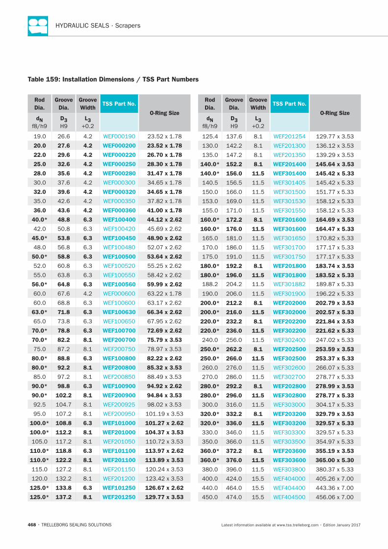
HYDRAULIC SEALS · Scrapers
468
Table 159: Installation Dimensions / TSS Part Numbers
Rod
Dia.
Groove
Dia.
Groove
WidthTSS Part No.
O-Ring SizedN D3 L3
20.0 27.6 4.2 WEF000200 23.52 x 1.78
22.0 29.6 4.2 WEF000220 26.70 x 1.78
25.0 32.6 4.2 WEF000250 28.30 x 1.78
28.0 35.6 4.2 WEF000280 31.47 x 1.78
32.0 39.6 4.2 WEF000320 34.65 x 1.78
36.0 43.6 4.2 WEF000360 41.00 x 1.78
40.0* 48.8 6.3 WEF100400 44.12 x 2.62
6.3
45.0* 53.8 6.3 WEF100450 48.90 x 2.62
6.3
50.0* 58.8 6.3 WEF100500 53.64 x 2.62
6.3
6.3
56.0* 64.8 6.3 WEF100560 59.99 x 2.62
6.3
63.0* 71.8 6.3 WEF100630 66.34 x 2.62
6.3
70.0* 78.8 6.3 WEF100700 72.69 x 2.62
70.0* 82.2 8.1 WEF200700 75.79 x 3.53
80.0* 88.8 6.3 WEF100800 82.22 x 2.62
80.0* 92.2 8.1 WEF200800 85.32 x 3.53
90.0* 98.8 6.3 WEF100900 94.92 x 2.62
90.0* 102.2 8.1 WEF200900 94.84 x 3.53
100.0* 108.8 6.3 WEF101000 101.27 x 2.62
100.0* 112.2 8.1 WEF201000 104.37 x 3.53
110.0* 118.8 6.3 WEF101100 113.97 x 2.62
110.0* 122.2 8.1 WEF201100 113.89 x 3.53
125.0* 133.8 6.3 WEF101250 126.67 x 2.62
125.0* 137.2 8.1 WEF201250 129.77 x 3.53
Rod
Dia.
Groove
Dia.
Groove
WidthTSS Part No.
O-Ring SizedN D3 L3
140.0* 152.2 8.1 WEF201400 145.64 x 3.53
140.0* 156.0 11.5 WEF301400 145.42 x 5.33
160.0* 172.2 8.1 WEF201600 164.69 x 3.53
160.0* 176.0 11.5 WEF301600 164.47 x 5.33
180.0* 192.2 8.1 WEF201800 183.74 x 3.53
180.0* 196.0 11.5 WEF301800 183.52 x 5.33
200.0* 212.2 8.1 WEF202000 202.79 x 3.53
200.0* 216.0 11.5 WEF302000 202.57 x 5.33
220.0* 232.2 8.1 WEF202200 221.84 x 3.53
220.0* 236.0 11.5 WEF302200 221.62 x 5.33
250.0* 262.2 8.1 WEF202500 253.59 x 3.53
250.0* 266.0 11.5 WEF302500 253.37 x 5.33
280.0* 292.2 8.1 WEF202800 278.99 x 3.53
280.0* 296.0 11.5 WEF302800 278.77 x 5.33
320.0* 332.2 8.1 WEF203200 329.79 x 3.53
320.0* 336.0 11.5 WEF303200 329.57 x 5.33
360.0* 372.2 8.1 WEF203600 355.19 x 3.53
360.0* 376.0 11.5 WEF303600 365.00 x 5.30
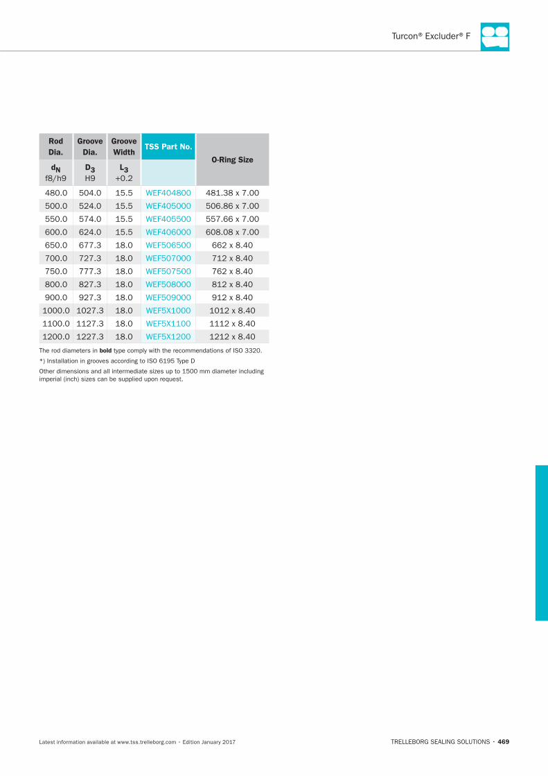
Turcon®Excluder®F
469
Rod
Dia.
Groove
Dia.
Groove
WidthTSS Part No.
O-Ring SizedN D3 L3
bold

HYDRAULIC SEALS · Scrapers
470
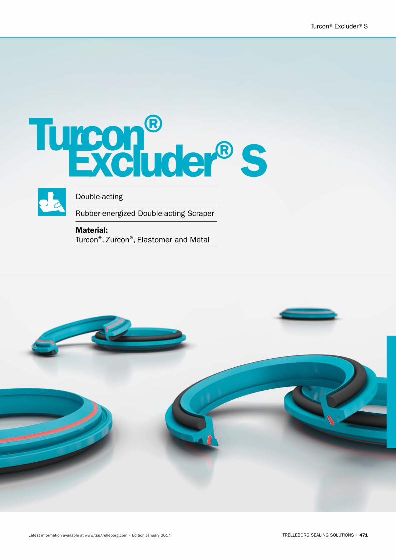
Turcon®Excluder®S
TRELLEBORG SEALING SOLUTIONS • 471Latest information available at www.tss.trelleborg.com • Edition January 2017
Turcon®Excluder®S
Double-acting
Rubber-energized Double-acting Scraper
Material:Turcon®, Zurcon®, Elastomer and Metal

HYDRAULIC SEALS · Scrapers
472
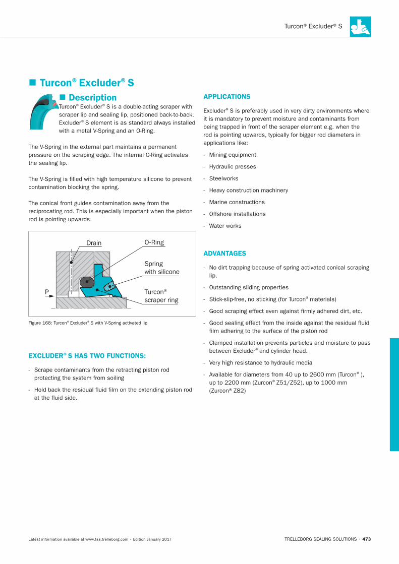
Turcon®Excluder®S
473
Turcon®Excluder®S
Description® ®
®
Turcon® scraper ring
O-RingDrain
Springwith silicone
P
® ®
EXCLUDER®S HAS TWO FUNCTIONS:
APPLICATIONS
®
ADVANTAGES
®
®
®
®
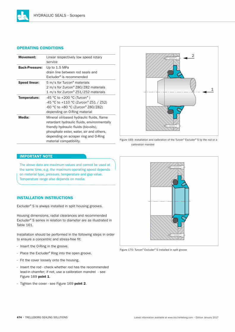
HYDRAULIC SEALS · Scrapers
474
OPERATING CONDITIONS
Movement:
Back-Pressure:
®
Speed linear: ®
®
®
Temperature: ® ®
®
Media:
IMPORTANT NOTE
INSTALLATION INSTRUCTIONS
®
®
®
point 1
point 2
2
1
® ®
® ®
Turcon®Excluder®S
475
RECOMMENDED MATERIALS
Excluder®S in Turcon®M12
Excluder®S in Turcon®T46
Excluder®S in Zurcon®Z80/Z82
®
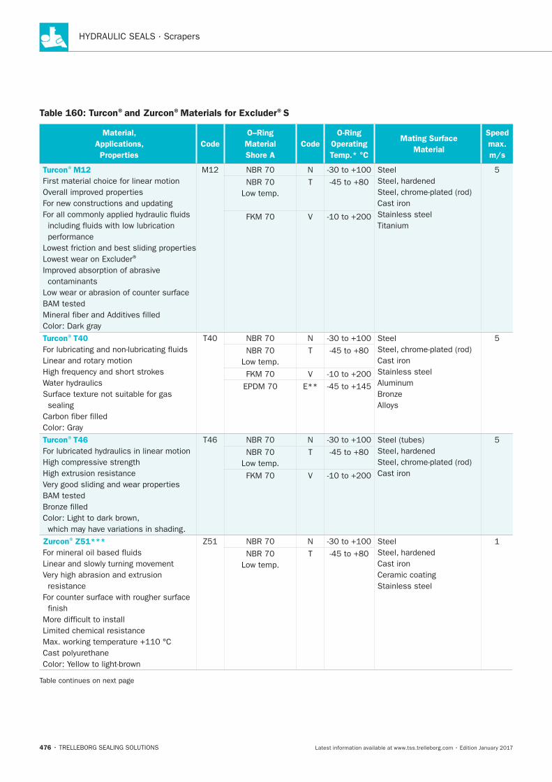
HYDRAULIC SEALS · Scrapers
476
Table 160: Turcon®and Zurcon®Materials for Excluder®S
Material,
Applications,
Properties
Code
O–Ring
Material
Shore A
Code
O-Ring
Operating
Temp.* °C
Mating Surface
Material
Speed
max.
m/s
Turcon®M12
®
Turcon®T40
Turcon®T46
Zurcon®Z51***
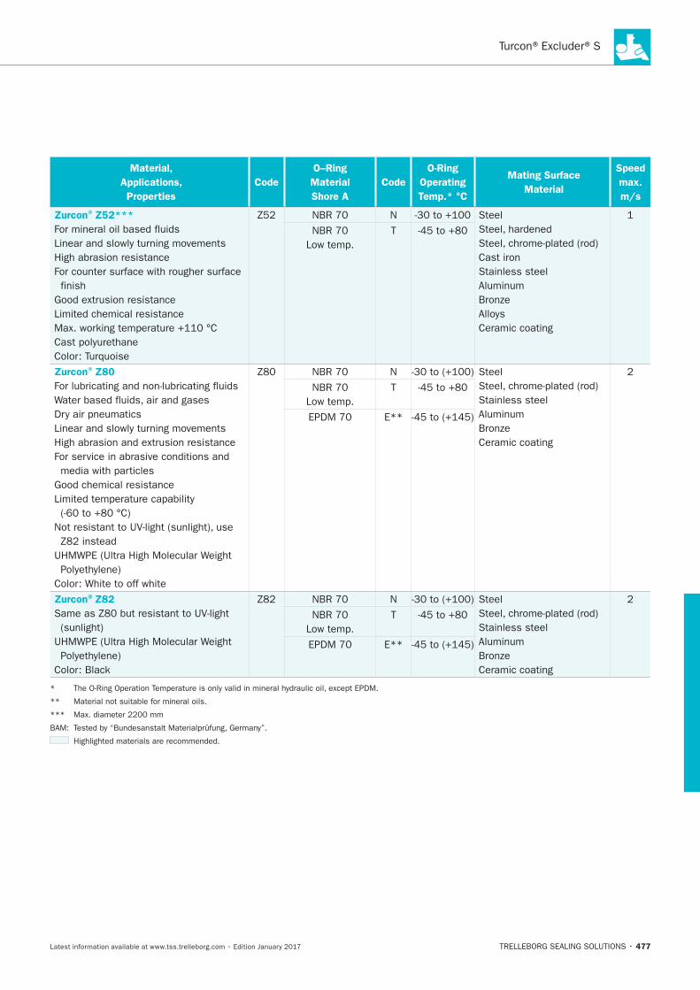
Turcon®Excluder®S
477
Material,
Applications,
Properties
Code
O–Ring
Material
Shore A
Code
O-Ring
Operating
Temp.* °C
Mating Surface
Material
Speed
max.
m/s
Zurcon®Z52***
Zurcon®Z80
Zurcon®Z82
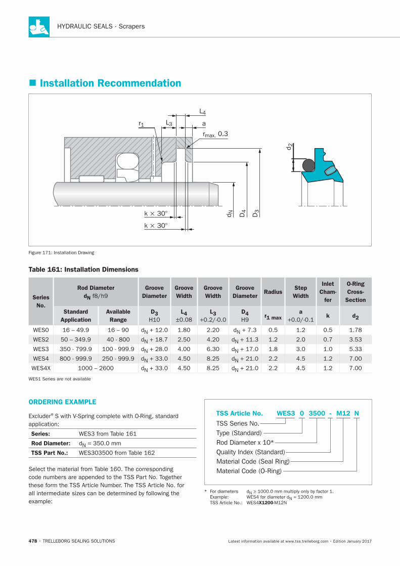
HYDRAULIC SEALS · Scrapers
478
Installation Recommendation
k × 30° D3
D4
d N
d 2
r1rmax. 0.3
L3
L4
a
k × 30°
Table 161: Installation Dimensions
Series
No.
Rod Diameter
dN
Groove
Diameter
Groove
Width
Groove
Width
Groove
DiameterRadius
Step
Width
Inlet
Cham-
fer
O-Ring
Cross-
Section
Standard
Application
Available
Range
D3 L4 L3 D4 r1 max
a k d2
ORDERING EXAMPLE
®
Series:
Rod Diameter:
TSS Part No.:
Material Code (Seal Ring)
TSS Series No.
TSS Article No. M123500 N
Material Code (O-Ring)
Rod Diameter x 10*
WES3
Quality Index (Standard)
-
Type (Standard)
0
X1200
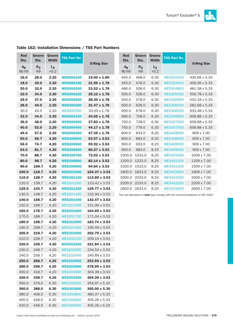
Turcon®Excluder®S
479
Table 162: Installation Dimensions / TSS Part Numbers
Rod
Dia.
Groove
Dia.
Groove
WidthTSS Part No.
O-Ring SizedN D3 L3
16.0 28.0 2.20 WES000160 19.00 x 1.80
18.0 30.0 2.20 WES000180 21.95 x 1.78
20.0 32.0 2.20 WES000200 23.52 x 1.78
22.0 34.0 2.20 WES000220 25.12 x 1.78
25.0 37.0 2.20 WES000250 28.30 x 1.78
28.0 40.0 2.20 WES000280 31.47 x 1.78
32.0 44.0 2.20 WES000320 34.65 x 1.78
36.0 48.0 2.20 WES000360 37.82 x 1.78
40.0 52.0 2.20 WES000400 44.17 x 1.78
45.0 57.0 2.20 WES000450 47.35 x 1.78
50.0 68.7 4.20 WES200500 53.57 x 3.53
56.0 74.7 4.20 WES200560 59.92 x 3.53
63.0 81.7 4.20 WES200630 66.27 x 3.53
70.0 88.7 4.20 WES200700 72.62 x 3.53
80.0 98.7 4.20 WES200800 82.14 x 3.53
90.0 108.7 4.20 WES200900 94.84 x 3.53
100.0 118.7 4.20 WES201000 104.37 x 3.53
110.0 128.7 4.20 WES201100 113.89 x 3.53
125.0 143.7 4.20 WES201250 129.77 x 3.53
140.0 158.7 4.20 WES201400 142.47 x 3.53
160.0 178.7 4.20 WES201600 164.69 x 3.53
180.0 198.7 4.20 WES201800 183.74 x 3.53
200.0 218.7 4.20 WES202000 202.79 x 3.53
220.0 238.7 4.20 WES202200 221.84 x 3.53
250.0 268.7 4.20 WES202500 253.59 x 3.53
280.0 298.7 4.20 WES202800 278.99 x 3.53
320.0 338.7 4.20 WES203200 304.39 x 3.53
360.0 388.0 6.30 WES303600 365.00 x 5.30
Rod
Dia.
Groove
Dia.
Groove
WidthTSS Part No.
O-Ring SizedN D3 L3
bold
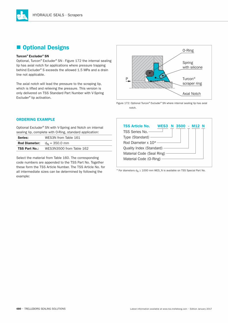
HYDRAULIC SEALS · Scrapers
480
Optional Designs
Turcon®Excluder®SN® ®
®
®
Turcon® scraper ring
O-Ring
Springwith silicone
Axial Notch
P
® ®
ORDERING EXAMPLE
®
Series:
Rod Diameter:
TSS Part No.:
Material Code (Seal Ring)
TSS Series No.
TSS Article No. M123500 N
Material Code (O-Ring)
Rod Diameter x 10*
WES3
Quality Index (Standard)
-
Type (Standard)
N
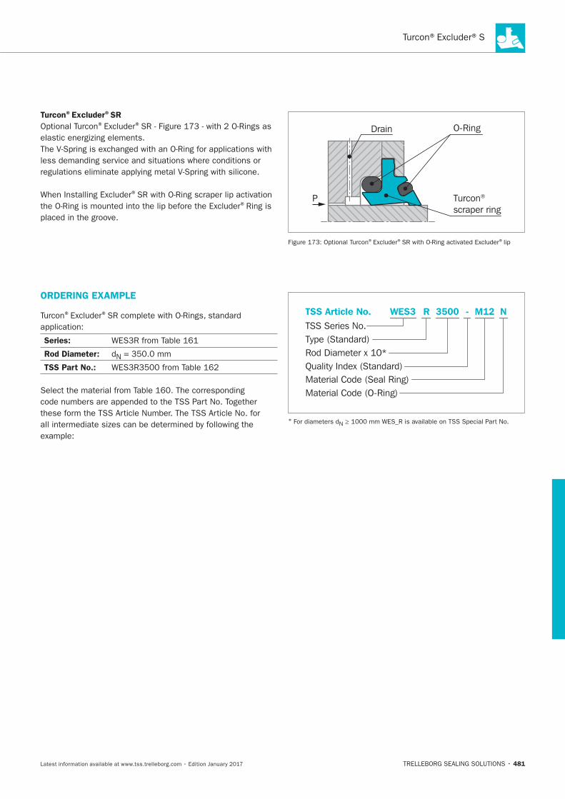
Turcon®Excluder®S
481
Turcon®Excluder®SR® ®
®
®Turcon® scraper ring
O-RingDrain
P
® ® ®
ORDERING EXAMPLE
® ®
Series:
Rod Diameter:
TSS Part No.:
Material Code (Seal Ring)
TSS Series No.
TSS Article No. M123500 N
Material Code (O-Ring)
Rod Diameter x 10*
WES3
Quality Index (Standard)
-
Type (Standard)
R

HYDRAULIC SEALS · Scrapers
482
Turcon®Excluder®1 and Excluder®113
TRELLEBORG SEALING SOLUTIONS • 483Latest information available at www.tss.trelleborg.com • Edition January 2017
Turcon®Excluder®1 and
Double-acting
Rubber-energized Double-acting Scraper
Material:Turcon®, Zurcon®and Elastomer
Excluder®113

HYDRAULIC SEALS · Scrapers
484
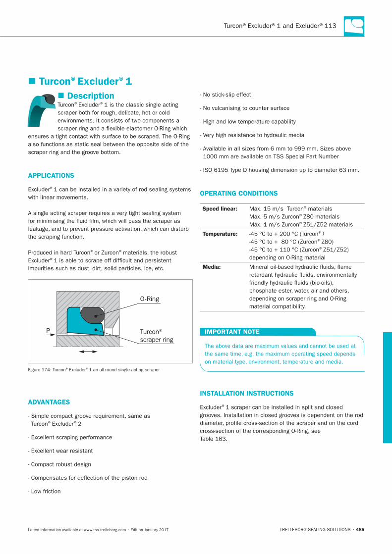
Turcon®Excluder®1 and Excluder®113
485
Turcon®Excluder®1
Description® ®
APPLICATIONS
®
® ®
®
Turcon® scraper ring
O-Ring
P
® ®
ADVANTAGES
® ®
OPERATING CONDITIONS
Speed linear: ®
®
®
Temperature: ®)
®
®
Media:
IMPORTANT NOTE
INSTALLATION INSTRUCTIONS
®
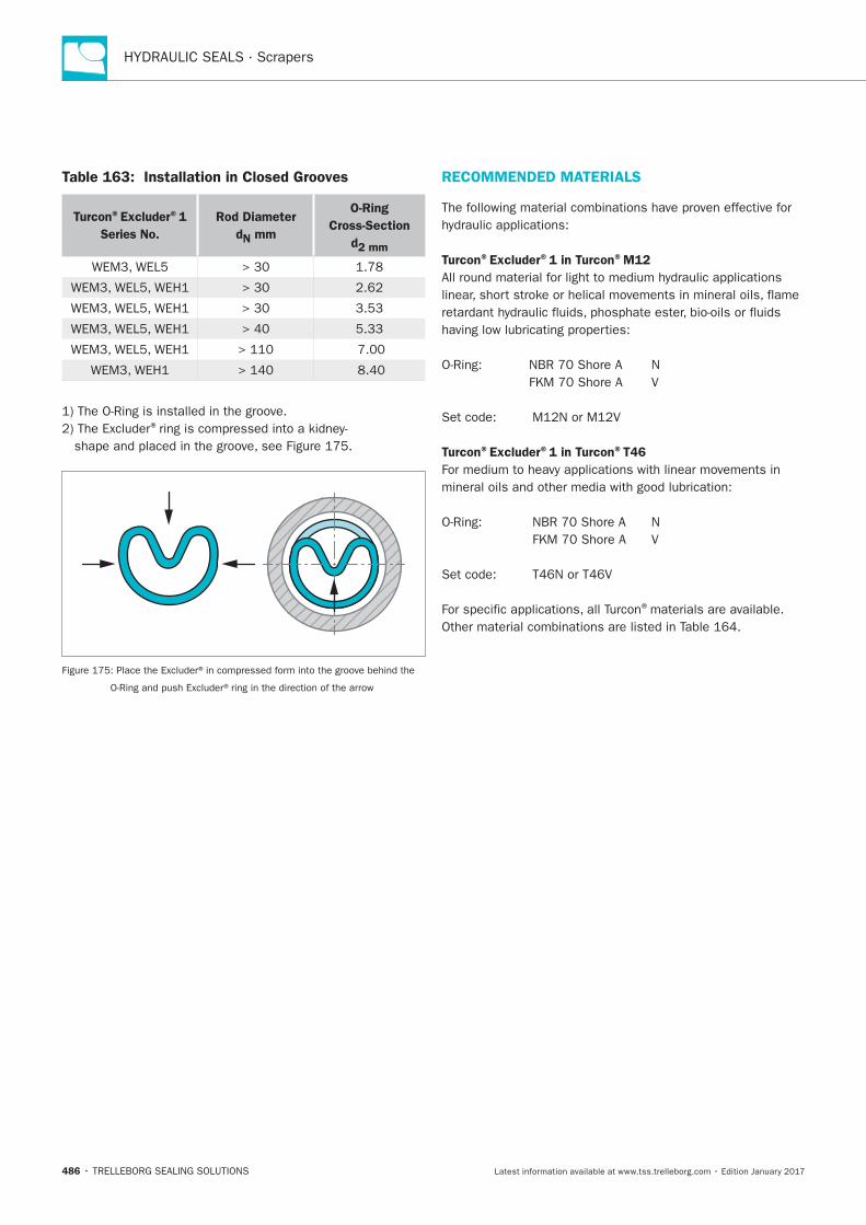
HYDRAULIC SEALS · Scrapers
486
Table 163: Installation in Closed Grooves
Turcon®Excluder®1
Series No.
Rod Diameter
dN mm
O-Ring
Cross-Section
d2 mm
®
RECOMMENDED MATERIALS
Turcon®Excluder®1 in Turcon®M12
Turcon®Excluder®1 in Turcon®T46
®
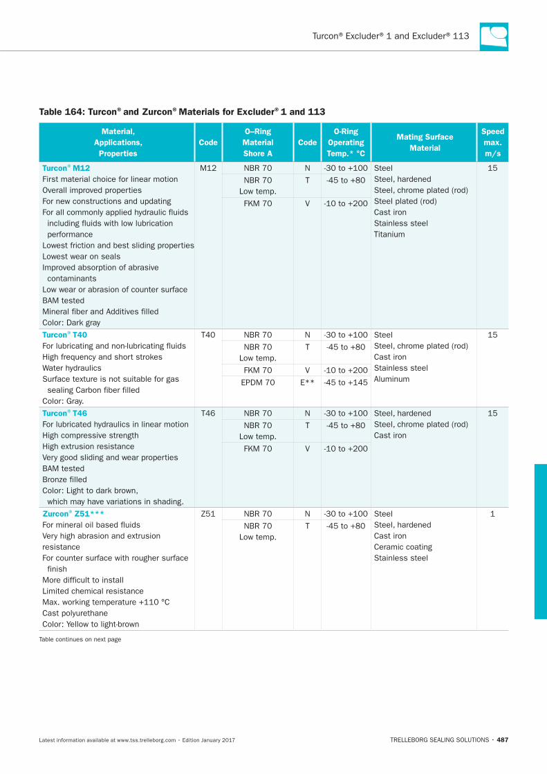
Turcon®Excluder®1 and Excluder®113
487
Table 164: Turcon®and Zurcon®Materials for Excluder®1 and 113
Material,
Applications,
Properties
Code
O–Ring
Material
Shore A
Code
O-Ring
Operating
Temp.* °C
Mating Surface
Material
Speed
max.
m/s
Turcon®M12
Turcon®T40
Turcon®T46
Zurcon®Z51***
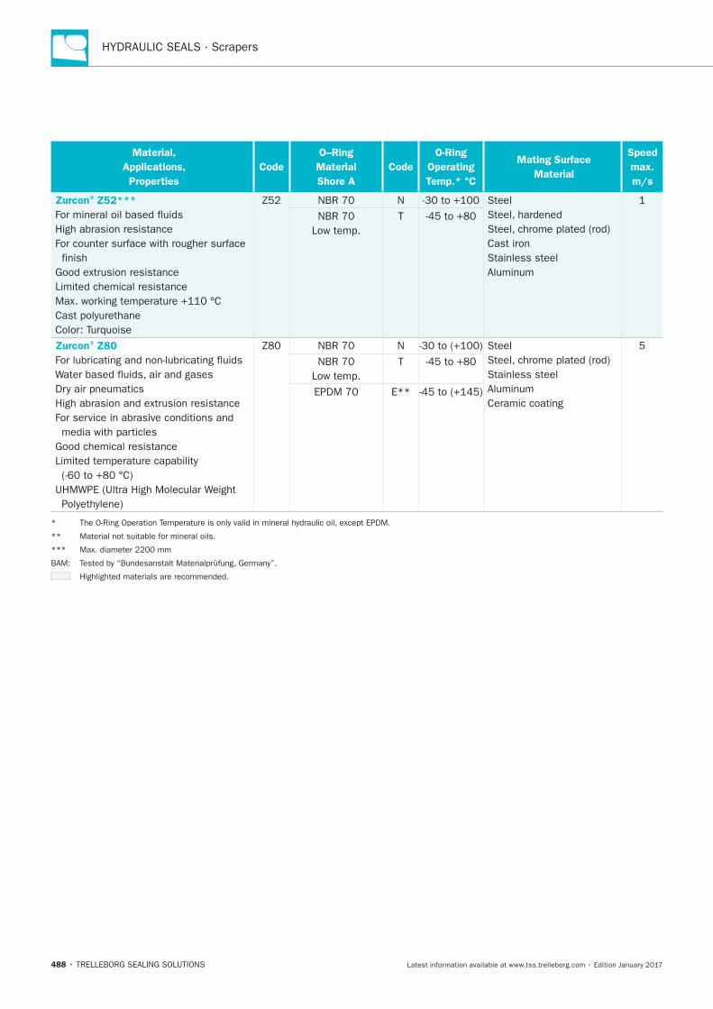
HYDRAULIC SEALS · Scrapers
488
Material,
Applications,
Properties
Code
O–Ring
Material
Shore A
Code
O-Ring
Operating
Temp.* °C
Mating Surface
Material
Speed
max.
m/s
Zurcon®Z52***
Zurcon®Z80
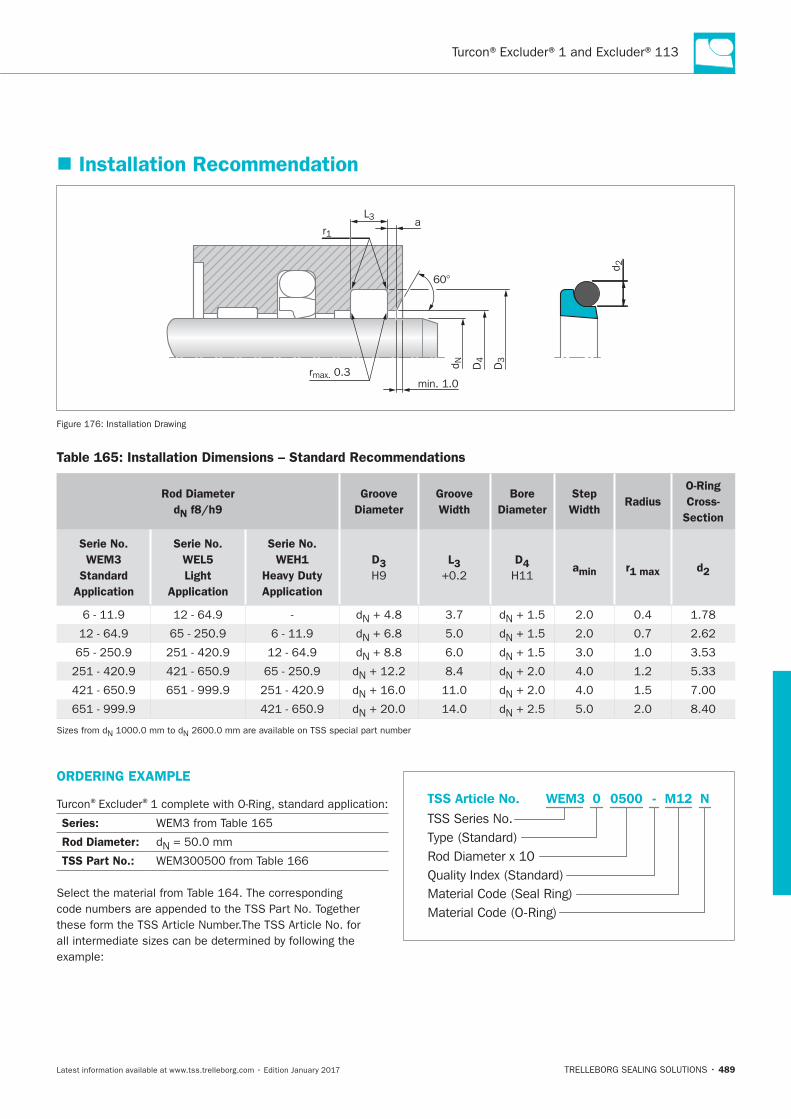
Turcon®Excluder®1 and Excluder®113
489
Installation Recommendation
60°
D3
D4d N
d 2
L3
r1
rmax. 0.3min. 1.0
a
Table 165: Installation Dimensions – Standard Recommendations
Rod Diameter
dN f8/h9
Groove
Diameter
Groove
Width
Bore
Diameter
Step
WidthRadius
O-Ring
Cross-
Section
Serie No.
WEM3
Standard
Application
Serie No.
WEL5
Light
Application
Serie No.
WEH1
Heavy Duty
Application
D3 L3 D4 amin r1 max d2
ORDERING EXAMPLE
® ®
Series:
Rod Diameter:
TSS Part No.:
Material Code (Seal Ring)
TSS Series No.
TSS Article No. M120500 N
Material Code (O-Ring)
Rod Diameter x 10
WEM3
Quality Index (Standard)
-
Type (Standard)
0
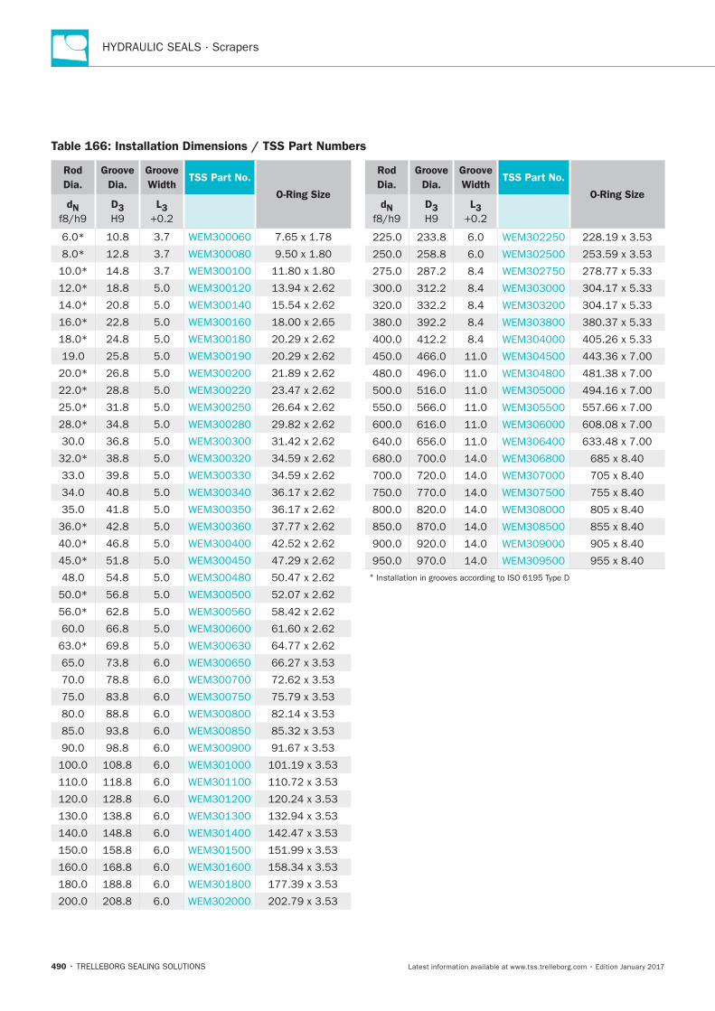
HYDRAULIC SEALS · Scrapers
490
Table 166: Installation Dimensions / TSS Part Numbers
Rod
Dia.
Groove
Dia.
Groove
WidthTSS Part No.
O-Ring SizedN D3 L3
Rod
Dia.
Groove
Dia.
Groove
WidthTSS Part No.
O-Ring SizedN D3 L3
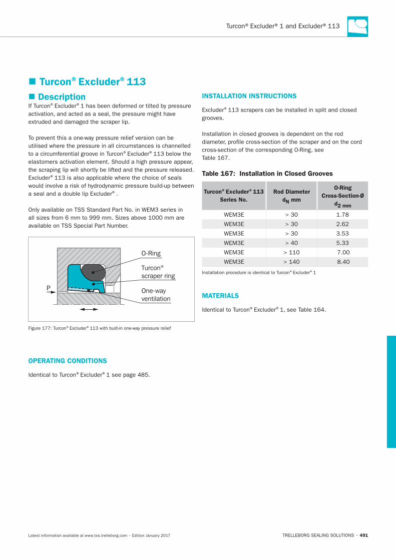
Turcon®Excluder®1 and Excluder®113
491
Turcon®Excluder®113
Description® ®
® ®
®
®
Turcon® scraper ring
O-Ring
One-wayventilation
P
® ®
OPERATING CONDITIONS
® ®
INSTALLATION INSTRUCTIONS
®
Table 167: Installation in Closed Grooves
Turcon®Excluder®113
Series No.
Rod Diameter
dN mm
O-Ring
Cross-Section-Ø
d2 mm
® ®
MATERIALS
® ®
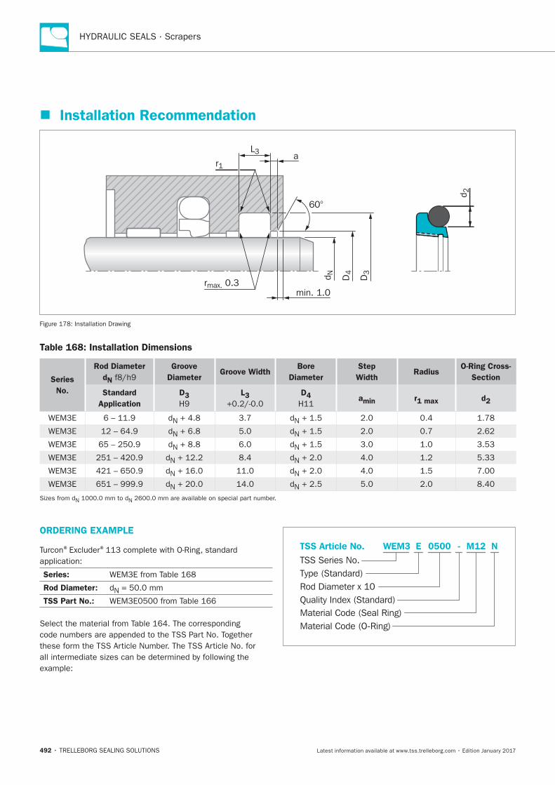
HYDRAULIC SEALS · Scrapers
492
Installation Recommendation
60°
D3
D4d N
d 2
L3
r1
rmax. 0.3min. 1.0
a
Table 168: Installation Dimensions
Series
No.
Rod Diameter
dN
Groove
Diameter Groove Width
Bore
Diameter
Step
Width Radius
O-Ring Cross-
Section
Standard
Application
D3 L3 D4 amin r1 max d2
ORDERING EXAMPLE
® ®
Series:
Rod Diameter:
TSS Part No.:
Material Code (Seal Ring)
TSS Series No.
TSS Article No. M120500 N
Material Code (O-Ring)
Rod Diameter x 10
WEM3
Quality Index (Standard)
-
Type (Standard)
E
Scraper DA 17
TRELLEBORG SEALING SOLUTIONS • 493Latest information available at www.tss.trelleborg.com • Edition January 2017
ScraperDA 17Double-acting
Material:Rubber

HYDRAULIC SEALS · Scrapers
494
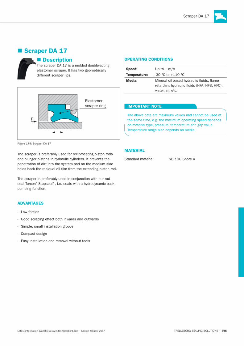
495
Description
Elastomerscraper ring
P
®Stepseal®
ADVANTAGES
Low friction
OPERATING CONDITIONS
Speed:
Temperature:
Media:
IMPORTANT NOTE
MATERIAL
Scraper DA 17
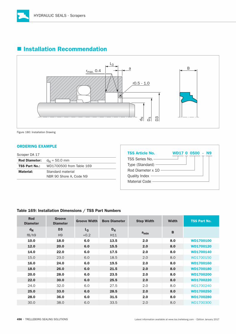
HYDRAULIC SEALS · Scrapers
496
ORDERING EXAMPLE
Rod Diameter: N
TSS Part No.:
Material:
N9WD17 0 -
Material Code
TSS Series No.TSS Article No.
Rod Diameter x 10Quality Index
Type (Standard)
0500
Installation Recommendation
D3
D4d N
L3
rmax. 0.4a B
r0.5 - 1.0
Installation Drawing
Table 169: Installation Dimensions / TSS Part Numbers
Rod
Diameter
Groove
DiameterGroove Width Bore Diameter Step Width Width TSS Part No.
dN D3 L3 D4 amin B
10.0 18.0 6.0 13.5 2.0 8.0 WD1700100
12.0 20.0 6.0 15.5 2.0 8.0 WD1700120
14.0 22.0 6.0 17.5 2.0 8.0 WD1700140
16.0 24.0 6.0 19.5 2.0 8.0 WD1700160
18.0 26.0 6.0 21.5 2.0 8.0 WD1700180
20.0 28.0 6.0 23.5 2.0 8.0 WD1700200
22.0 30.0 6.0 25.5 2.0 8.0 WD1700220
25.0 33.0 6.0 28.5 2.0 8.0 WD1700250
28.0 36.0 6.0 31.5 2.0 8.0 WD1700280
33.5
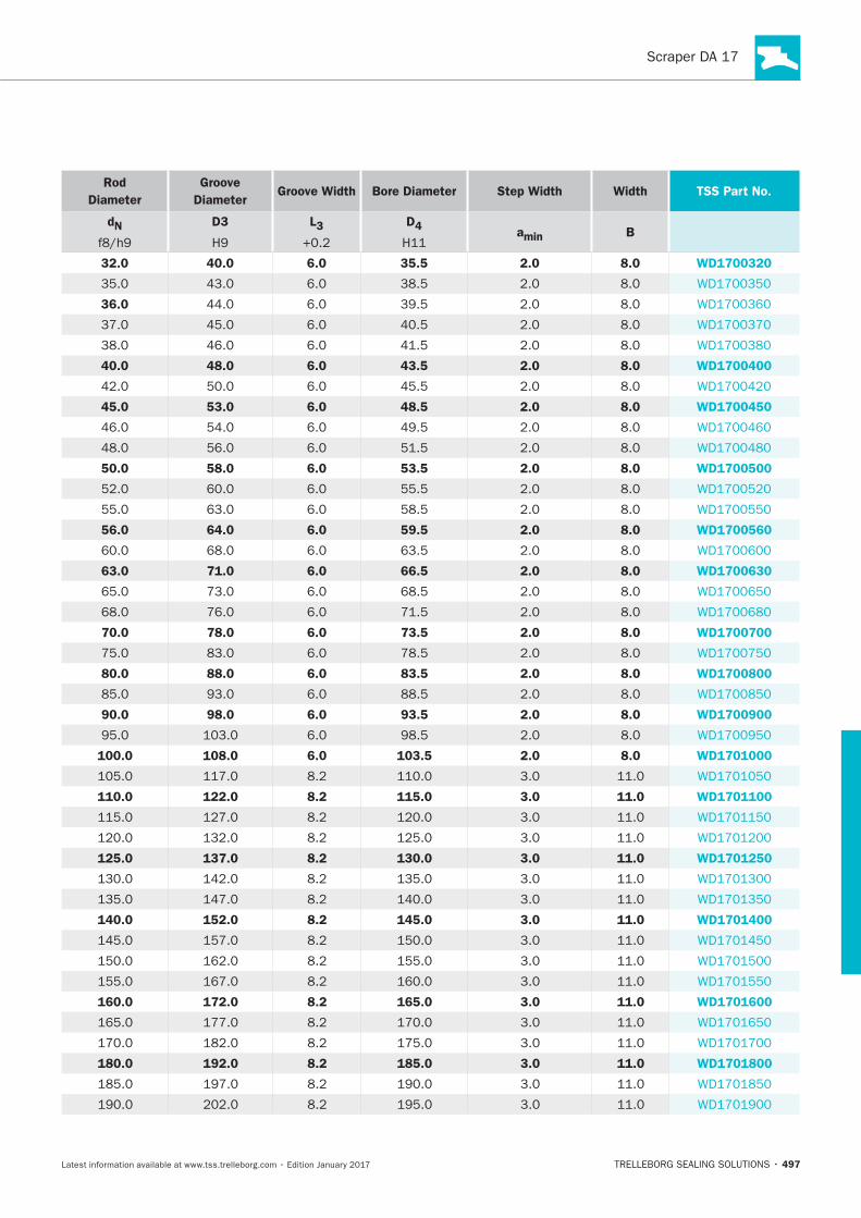
497
Rod
Diameter
Groove
DiameterGroove Width Bore Diameter Step Width Width TSS Part No.
dN D3 L3 D4 amin B
32.0 40.0 6.0 35.5 2.0 8.0 WD1700320
36.0
40.0 48.0 6.0 43.5 2.0 8.0 WD1700400
45.5
45.0 53.0 6.0 48.5 2.0 8.0 WD1700450
50.0 58.0 6.0 53.5 2.0 8.0 WD1700500
55.5
56.0 64.0 6.0 59.5 2.0 8.0 WD1700560
63.5
63.0 71.0 6.0 66.5 2.0 8.0 WD1700630
70.0 78.0 6.0 73.5 2.0 8.0 WD1700700
80.0 88.0 6.0 83.5 2.0 8.0 WD1700800
90.0 98.0 6.0 93.5 2.0 8.0 WD1700900
100.0 108.0 6.0 103.5 2.0 8.0 WD1701000
110.0 122.0 8.2 115.0 3.0 11.0 WD1701100
125.0 137.0 8.2 130.0 3.0 11.0 WD1701250
140.0 152.0 8.2 145.0 3.0 11.0 WD1701400
160.0 172.0 8.2 165.0 3.0 11.0 WD1701600
180.0 192.0 8.2 185.0 3.0 11.0 WD1701800
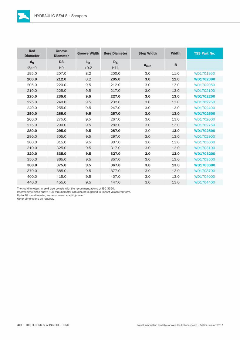
HYDRAULIC SEALS · Scrapers
498
Rod
Diameter
Groove
DiameterGroove Width Bore Diameter Step Width Width TSS Part No.
dN D3 L3 D4 amin B
200.0 212.0 205.0 3.0 11.0 WD1702000
220.0 235.0 9.5 227.0 3.0 13.0 WD1702200
250.0 265.0 9.5 257.0 3.0 13.0 WD1702500
280.0 295.0 9.5 287.0 13.0 WD1702800
320.0 335.0 9.5 327.0 3.0 13.0 WD1703200
360.0 375.0 9.5 367.0 3.0 13.0 WD1703600
bold
Zurcon® Scraper DA 22
TRELLEBORG SEALING SOLUTIONS • 499Latest information available at www.tss.trelleborg.com • Edition January 2017
Zurcon®Scraper DA 22
Double-acting
Material:Zurcon®

HYDRAULIC SEALS · Scrapers
500
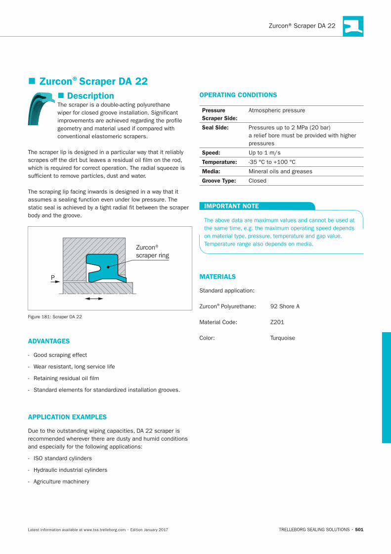
501
Description
conventional elastomeric scrapers.
Zurcon®
scraper ring
P
ADVANTAGES
APPLICATION EXAMPLES
OPERATING CONDITIONS
Pressure
Scraper Side:
Seal Side:
Speed:
Temperature:
Media:
Groove Type:
IMPORTANT NOTE
MATERIALS
®
Zurcon®Scraper DA 22
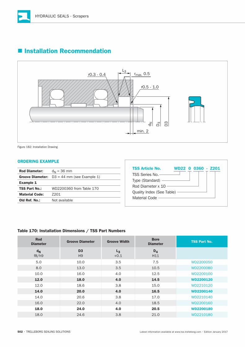
HYDRAULIC SEALS · Scrapers
502
ORDERING EXAMPLE
Rod Diameter: N = 36 mm
Groove Diameter:
Example 1
TSS Part No.:
Material Code:
Old Ref. No.: Not availableMaterial Code
TSS Series No.
TSS Article No.
Rod Diameter x 10Quality Index (See Table)
Type (Standard)
Z201WD22 - 0 0360
Installation Recommendation
min. 2
D3
D4d N
L3rmax. 0.5
r0.5 - 1.0
r0.3 - 0.4
Installation Drawing
Table 170: Installation Dimensions / TSS Part Numbers
Rod
DiameterGroove Diameter Groove Width
Bore
DiameterTSS Part No.
dN D3 L3 D4
3.5
3.5
12.0 18.0 4.0 14.5 WD2200120
14.0 20.0 4.0 16.5 WD2200140
18.0 24.0 4.0 20.5 WD2200180
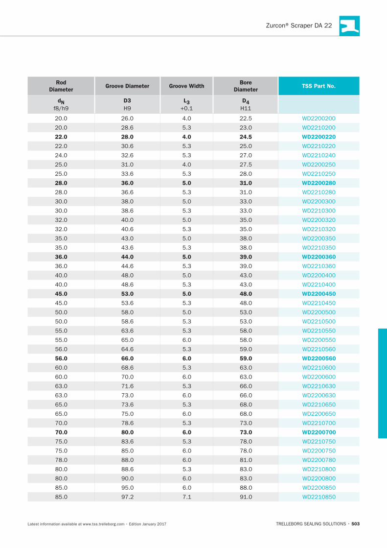
503
Rod
DiameterGroove Diameter Groove Width
Bore
DiameterTSS Part No.
dN D3 L3 D4
5.3
22.0 28.0 4.0 24.5 WD2200220
5.3
5.3
33.6 5.3
28.0 36.0 5.0 31.0 WD2200280
36.6 5.3
5.3
5.3
43.6 5.3
36.0 44.0 5.0 39.0 WD2200360
44.6 5.3
5.3
45.0 53.0 5.0 48.0 WD2200450
53.6 5.3
5.3
63.6 5.3
64.6 5.3
56.0 66.0 6.0 59.0 WD2200560
5.3
5.3
5.3
5.3
70.0 80.0 6.0 73.0 WD2200700
5.3
5.3
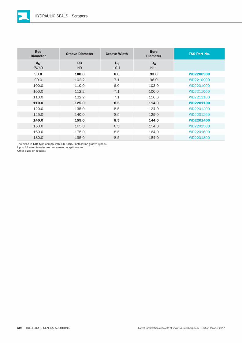
HYDRAULIC SEALS · Scrapers
504
Rod
DiameterGroove Diameter Groove Width
Bore
DiameterTSS Part No.
dN D3 L3 D4
90.0 100.0 6.0 93.0 WD2200900
110.0 125.0 8.5 114.0 WD2201100
140.0 155.0 8.5 144.0 WD2201400
bold
Zurcon® Scraper DA 24
TRELLEBORG SEALING SOLUTIONS • 505Latest information available at www.tss.trelleborg.com • Edition January 2017
Double-acting
Material:Zurcon®
Zurcon®Scraper DA 24 & Venting Version

HYDRAULIC SEALS · Scrapers
506
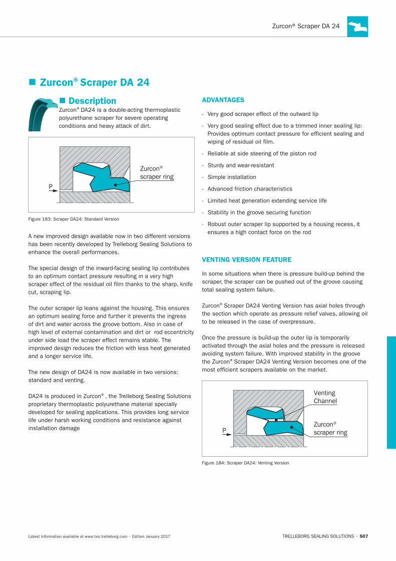
507
Zurcon®Scraper DA 24
Description®
Zurcon® scraper ring
P
®
ADVANTAGES
Simple installation
VENTING VERSION FEATURE
®
®
VentingChannel
Zurcon® scraper ringP
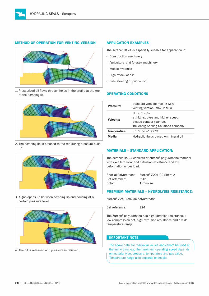
HYDRAULIC SEALS · Scrapers
508
METHOD OF OPERATION FOR VENTING VERSION APPLICATION EXAMPLES
OPERATING CONDITIONS
Pressure:
Velocity:
Temperature:
Media:
MATERIALS – STANDARD APPLICATION:
®
®
PREMIUM MATERIALS – HYDROLYSIS RESISTANCE:
®
®
IMPORTANT NOTE
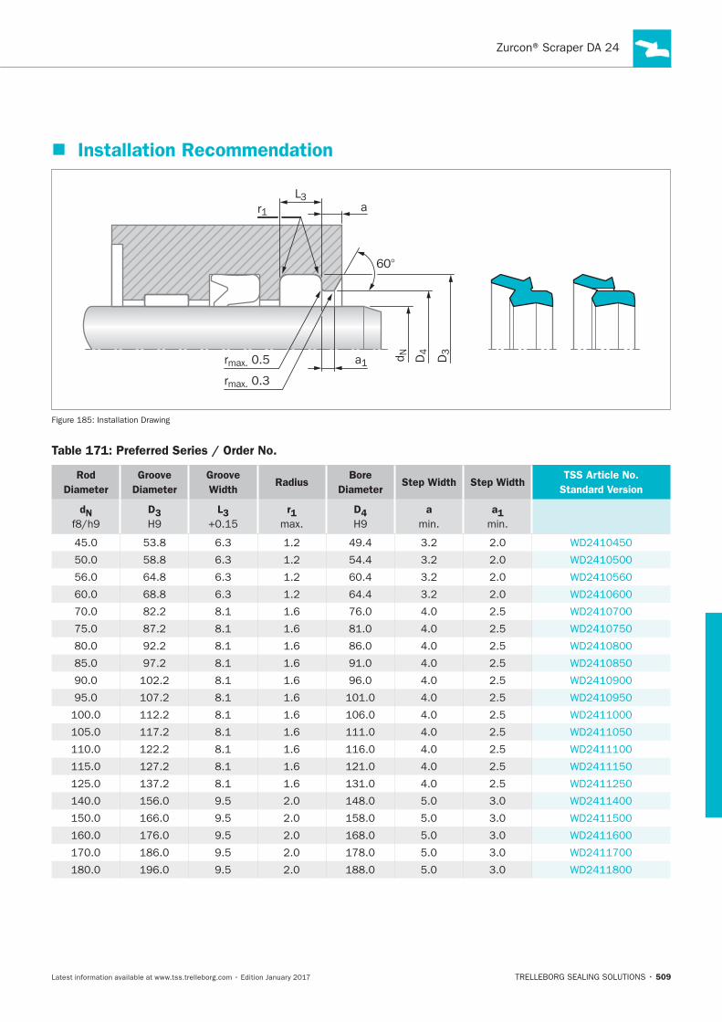
509
Installation Recommendation
60°
D3
D4d N
L3r1
a1
rmax. 0.3
rmax. 0.5
a
Installation Drawing
Table 171: Preferred Series / Order No.
Rod
Diameter
Groove
Diameter
Groove
WidthRadius
Bore
DiameterStep Width Step Width
TSS Article No.
Standard Version
dN D3 L3 r1 D4 a
min.
a1
min.
6.3
6.3 54.4
6.3
6.3 64.4
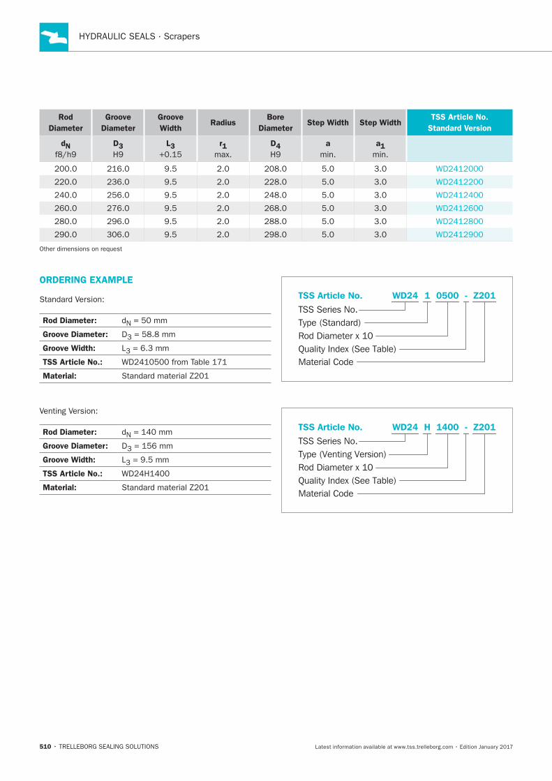
HYDRAULIC SEALS · Scrapers
510
Rod
Diameter
Groove
Diameter
Groove
WidthRadius
Bore
DiameterStep Width Step Width
TSS Article No.
Standard Version
dN D3 L3 r1 D4 a
min.
a1
min.
ORDERING EXAMPLE
Rod Diameter: N
Groove Diameter: D3
Groove Width: L3 = 6.3 mm
TSS Article No.:
Material:
Material Code
TSS Series No.
TSS Article No.
Rod Diameter x 10Quality Index (See Table)
Type (Standard)
Z201WD24 - 1 0500
Rod Diameter: N
Groove Diameter: D3
Groove Width: L3
TSS Article No.:
Material:Material Code
TSS Series No.
TSS Article No.
Rod Diameter x 10Quality Index (See Table)
Type (Venting Version)
Z201WD24 - H 1400
Scraper WRM
TRELLEBORG SEALING SOLUTIONS • 511Latest information available at www.tss.trelleborg.com • Edition January 2017
Single-acting
Material:NBR Elastomer
ScraperWRM

HYDRAULIC SEALS · Scrapers
512
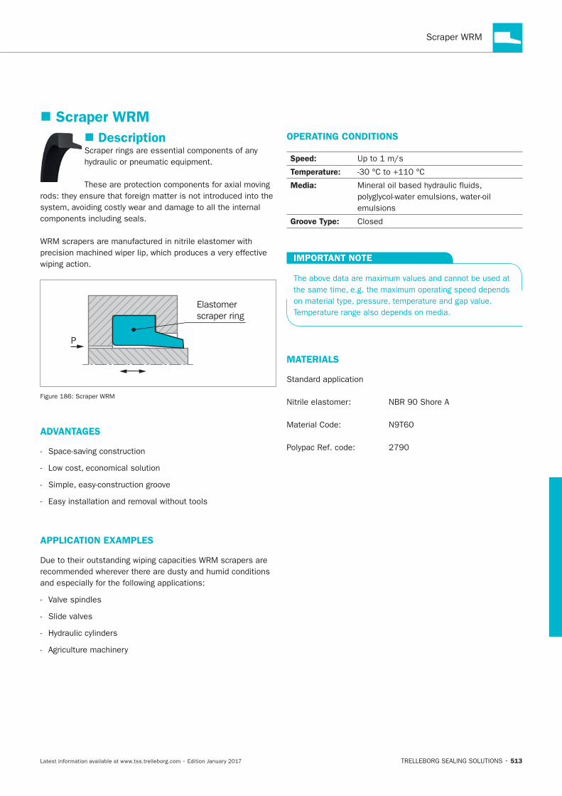
513
Description
wiping action.
Elastomerscraper ring
P
ADVANTAGES
APPLICATION EXAMPLES
OPERATING CONDITIONS
Speed:
Temperature:
Media:
Groove Type:
IMPORTANT NOTE
MATERIALS
Scraper WRM
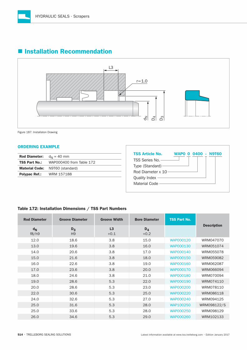
HYDRAULIC SEALS · Scrapers
514
Installation Recommendation
D4d N
L3
r=1.0
D3
Installaton Drawing
ORDERING EXAMPLE
Rod Diameter: N
TSS Part No.:
Material Code:
Polypac Ref.:
Material Code
TSS Series No.
TSS Article No.
Rod Diameter x 10Quality Index
Type (Standard)
N9T60WAP0 - 0 0400
Table 172: Installation Dimensions / TSS Part Numbers
Rod Diameter Groove Diameter Groove Width Bore Diameter TSS Part No.
DescriptiondN
D3
L3
D4
5.3
5.3
5.3
5.3
5.3
33.6 5.3
34.6 5.3
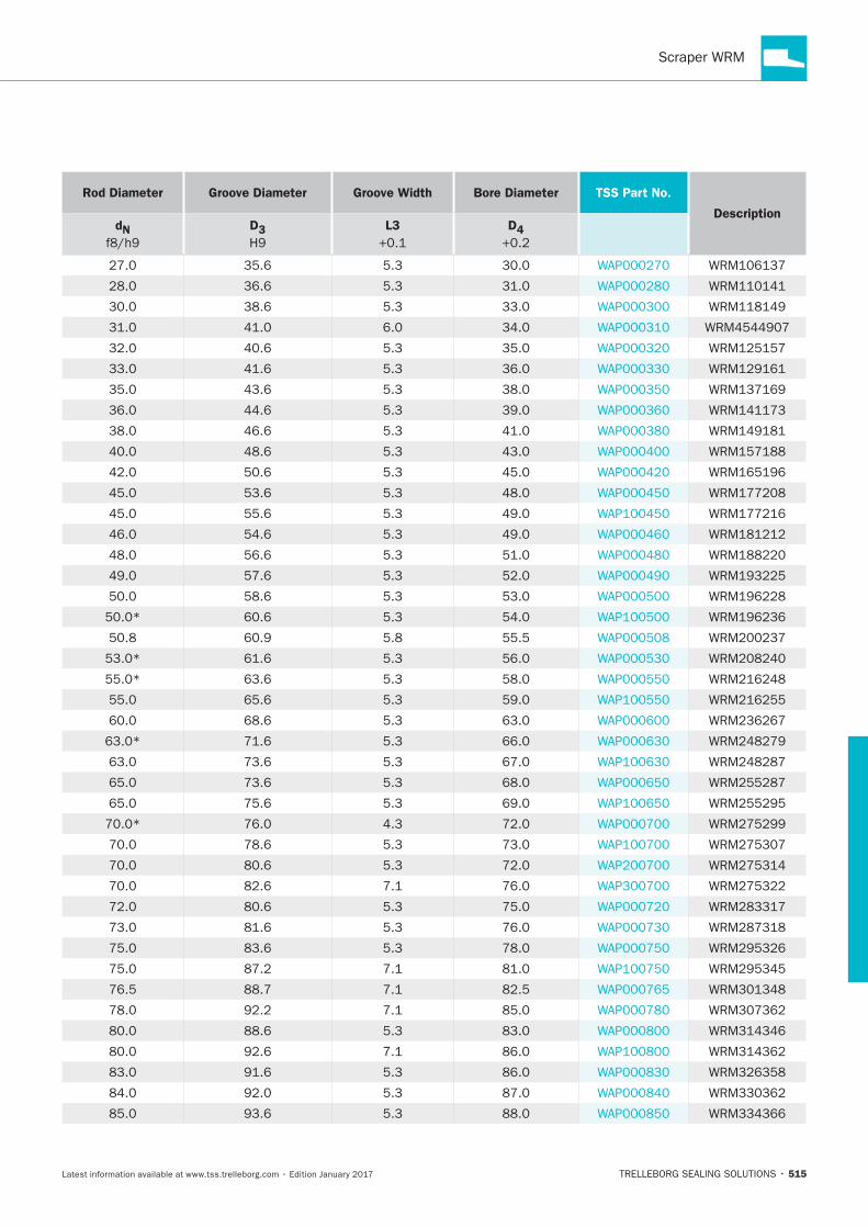
515
Rod Diameter Groove Diameter Groove Width Bore Diameter TSS Part No.
DescriptiondN
D3
L3
D4
35.6 5.3
36.6 5.3
5.3
5.3
5.3
43.6 5.3
44.6 5.3
46.6 5.3
5.3
5.3
53.6 5.3
55.6 5.3
54.6 5.3
56.6 5.3
5.3
5.3
5.3
55.5
5.3
63.6 5.3
65.6 5.3
5.3
5.3
5.3
5.3
5.3
4.3
5.3
5.3
5.3
5.3
5.3
5.3
5.3
5.3
5.3

HYDRAULIC SEALS · Scrapers
516
Rod Diameter Groove Diameter Groove Width Bore Diameter TSS Part No.
DescriptiondN
D3
L3
D4
5.3
5.3
5.3
5.3
6.3
5.3
5.3
5.3
6.3
5.3
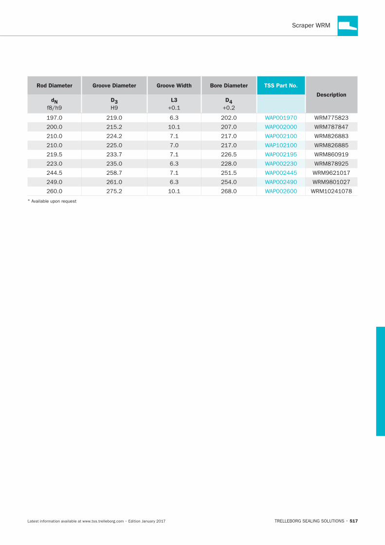
517
Rod Diameter Groove Diameter Groove Width Bore Diameter TSS Part No.
DescriptiondN
D3
L3
D4
6.3
6.3
6.3
*

HYDRAULIC SEALS · Scrapers
518
Zurcon®Scraper ASW
TRELLEBORG SEALING SOLUTIONS • 519Latest information available at www.tss.trelleborg.com • Edition January 2017
Single-acting
Material:Zurcon®
Zurcon®Scraper ASW

HYDRAULIC SEALS · Scrapers
520

521
Zurcon®Scraper ASW
Description
scraper.
Zurcon®
scraper ring
P
ADVANTAGES
Simple installation
OPERATING CONDITIONS
Speed:
Temperature:
Media:
IMPORTANT NOTE
MATERIAL
®
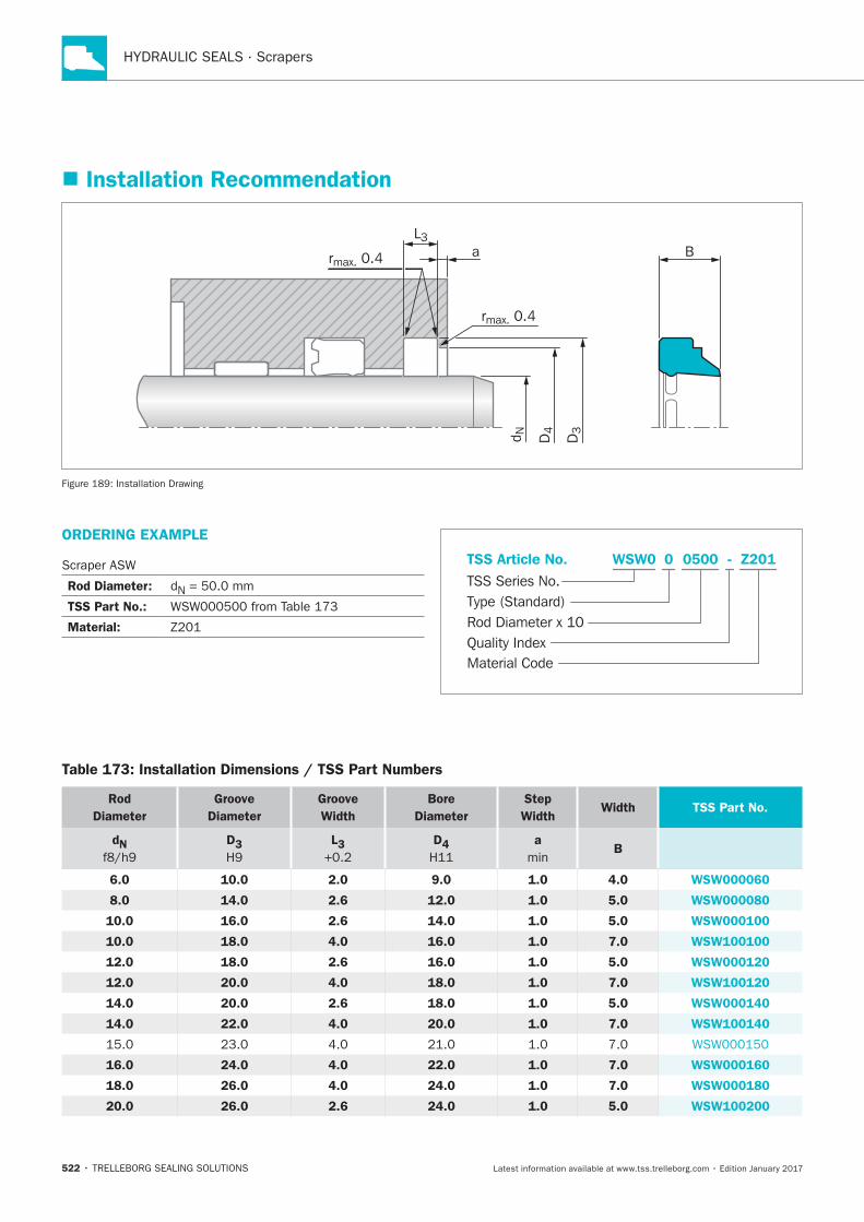
HYDRAULIC SEALS · Scrapers
522
Installation Recommendation
D4d N
L3
rmax. 0.4
rmax. 0.4
a B
D3
Installation Drawing
ORDERING EXAMPLE
Rod Diameter: N
TSS Part No.:
Material:
Material Code
TSS Series No.
TSS Article No.
Rod Diameter x 10Quality Index
Type (Standard)
Z201WSW0 - 0 0500
Table 173: Installation Dimensions / TSS Part Numbers
Rod
Diameter
Groove
Diameter
Groove
Width
Bore
Diameter
Step
Width Width TSS Part No.
dN D3 L3
D4
a
min B
6.0 10.0 2.0 9.0 1.0 4.0 WSW000060
8.0 14.0 2.6 12.0 1.0 5.0 WSW000080
10.0 16.0 2.6 14.0 1.0 5.0 WSW000100
10.0 18.0 4.0 16.0 1.0 7.0 WSW100100
12.0 18.0 2.6 16.0 1.0 5.0 WSW000120
12.0 20.0 4.0 18.0 1.0 7.0 WSW100120
14.0 20.0 2.6 18.0 1.0 5.0 WSW000140
14.0 22.0 4.0 20.0 1.0 7.0 WSW100140
16.0 24.0 4.0 22.0 1.0 7.0 WSW000160
18.0 26.0 4.0 24.0 1.0 7.0 WSW000180
20.0 26.0 2.6 24.0 1.0 5.0 WSW100200
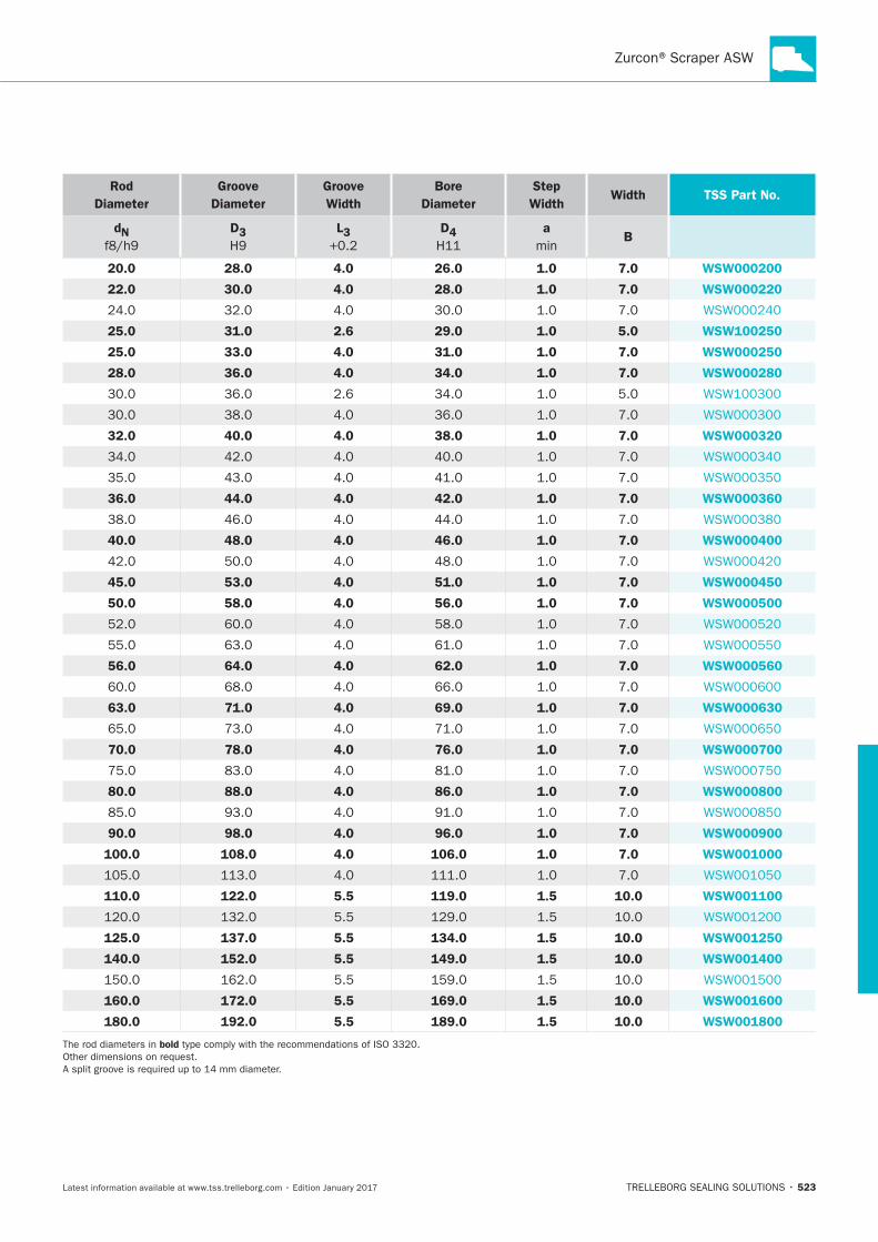
523
Rod
Diameter
Groove
Diameter
Groove
Width
Bore
Diameter
Step
Width Width TSS Part No.
dN D3 L3
D4
a
min B
20.0 28.0 4.0 26.0 1.0 7.0 WSW000200
22.0 30.0 4.0 28.0 1.0 7.0 WSW000220
25.0 31.0 2.6 29.0 1.0 5.0 WSW100250
25.0 33.0 4.0 31.0 1.0 7.0 WSW000250
28.0 36.0 4.0 34.0 1.0 7.0 WSW000280
32.0 40.0 4.0 38.0 1.0 7.0 WSW000320
36.0 44.0 4.0 42.0 1.0 7.0 WSW000360
40.0 48.0 4.0 46.0 1.0 7.0 WSW000400
45.0 53.0 4.0 51.0 1.0 7.0 WSW000450
50.0 58.0 4.0 56.0 1.0 7.0 WSW000500
56.0 64.0 4.0 62.0 1.0 7.0 WSW000560
63.0 71.0 4.0 69.0 1.0 7.0 WSW000630
70.0 78.0 4.0 76.0 1.0 7.0 WSW000700
80.0 88.0 4.0 86.0 1.0 7.0 WSW000800
90.0 98.0 4.0 96.0 1.0 7.0 WSW000900
100.0 108.0 4.0 106.0 1.0 7.0 WSW001000
110.0 122.0 5.5 119.0 1.5 10.0 WSW001100
5.5
125.0 137.0 5.5 134.0 1.5 10.0 WSW001250
140.0 152.0 5.5 149.0 1.5 10.0 WSW001400
5.5
160.0 172.0 5.5 169.0 1.5 10.0 WSW001600
180.0 192.0 5.5 189.0 1.5 10.0 WSW001800
bold

HYDRAULIC SEALS · Scrapers
524
Zurcon®Scraper WNE
TRELLEBORG SEALING SOLUTIONS • 525Latest information available at www.tss.trelleborg.com • Edition January 2017
Zurcon®Scraper WNE
Single-acting
Dynamic + Static Sealing Lip
Material:Zurcon®

HYDRAULIC SEALS · Scrapers
526
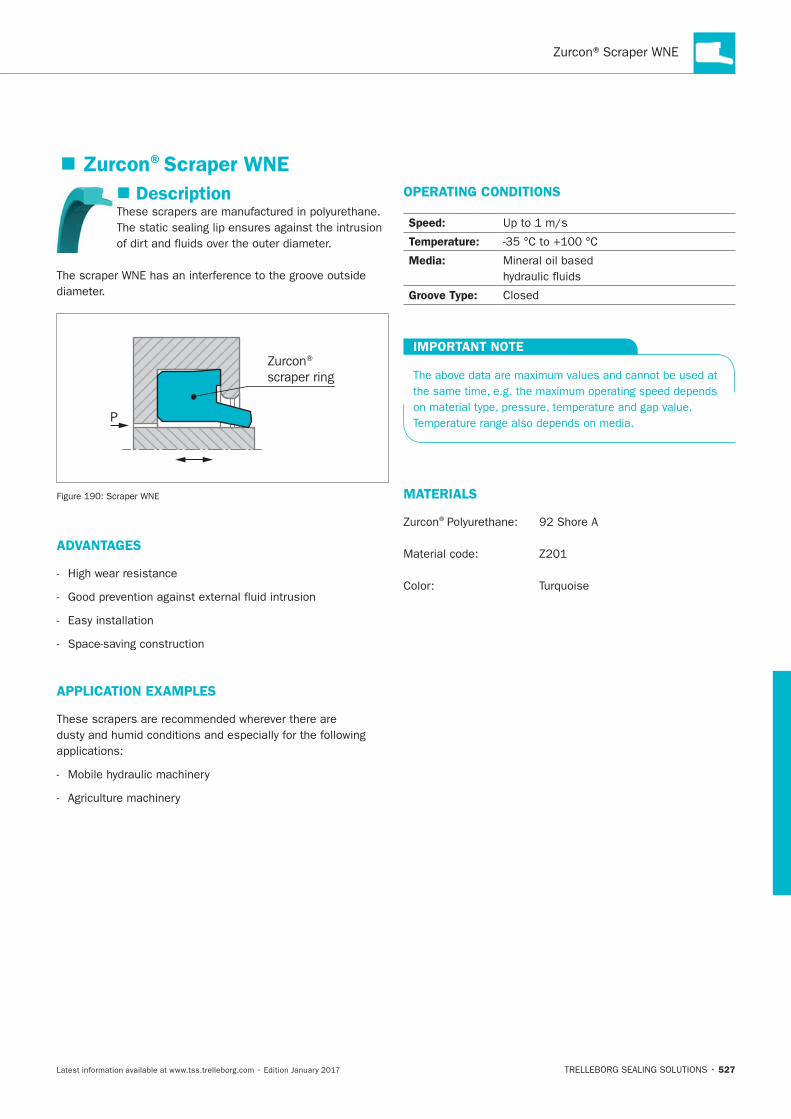
527
Description
Zurcon®
scraper ring
P
ADVANTAGES
APPLICATION EXAMPLES
OPERATING CONDITIONS
Speed:
Temperature:
Media:
Groove Type:
IMPORTANT NOTE
MATERIALS
®
Zurcon®Scraper WNE
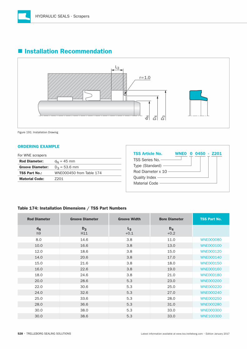
HYDRAULIC SEALS · Scrapers
528
Installation Recommendation
D4d N
r=1.0
D3
L3
Installation Drawing
ORDERING EXAMPLE
Rod Diameter: N = 45 mm
Groove Diameter: D3 = 53.6 mm
TSS Part No.:
Material Code:
Material Code
TSS Series No.
TSS Article No.
Rod Diameter x 10Quality Index
Type (Standard)
Z201WNE0 - 0 0450
Table 174: Installation Dimensions / TSS Part Numbers
Rod Diameter Groove Diameter Groove Width Bore Diameter TSS Part No.
dN
D3
L3
D4
5.3
5.3
5.3
33.6 5.3
36.6 5.3
5.3
5.3
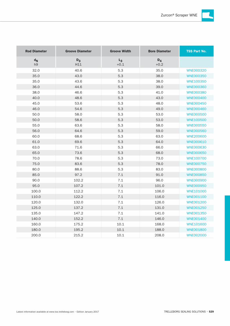
529
Rod Diameter Groove Diameter Groove Width Bore Diameter TSS Part No.
dN
D3
L3
D4
5.3
5.3
43.6 5.3
44.6 5.3
46.6 5.3
5.3
53.6 5.3
54.6 5.3
5.3
5.3
63.6 5.3
64.6 5.3
5.3
5.3
5.3
5.3
5.3
5.3
5.3

HYDRAULIC SEALS · Scrapers
530
Zurcon® Scraper WNV
TRELLEBORG SEALING SOLUTIONS • 531Latest information available at www.tss.trelleborg.com • Edition January 2017
Zurcon®Scraper WNV
Double-acting
Material:Zurcon®

HYDRAULIC SEALS · Scrapers
532
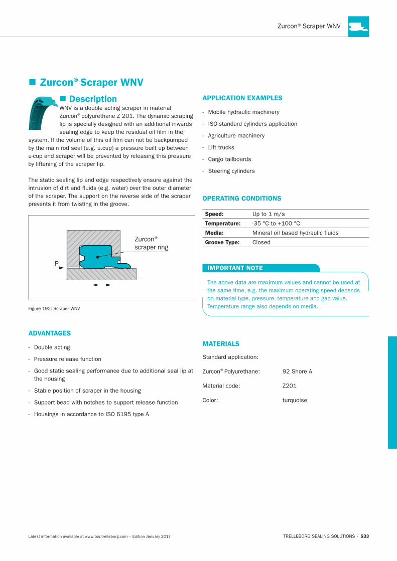
533
Description
®
Zurcon®
scraper ring
P
ADVANTAGES
APPLICATION EXAMPLES
OPERATING CONDITIONS
Speed:
Temperature:
Media:
Groove Type:
IMPORTANT NOTE
MATERIALS
®
Zurcon®Scraper WNV
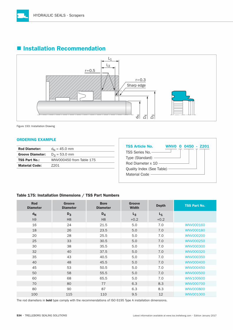
HYDRAULIC SEALS · Scrapers
534
ORDERING EXAMPLE
Rod Diameter: N
Groove Diameter: D3
TSS Part No.:
Material Code:
Material Code
TSS Series No.
TSS Article No.
Rod Diameter x 10Quality Index (See Table)
Type (Standard)
Z201WNV0 - 0 0450
Installation Recommendation
D4d N
L3
L1
r=0.3
r=0.5
Sharp edge
D3
Installation Drawing
Table 175: Installation Dimensions / TSS Part Numbers
Rod
Diameter
Groove
Diameter
Bore
Diameter
Groove
WidthDepth TSS Part No.
dN D3 D4 L3 L1
33
35.5
35 43
45.5
45 53
55.5
65.5
6.3
6.3
bold
Scraper WSA
TRELLEBORG SEALING SOLUTIONS • 535Latest information available at www.tss.trelleborg.com • Edition January 2017
ScraperWSASingle-acting
With Metal Case
For open Groove Assembly
Material:NBR and Metal

HYDRAULIC SEALS · Scrapers
536
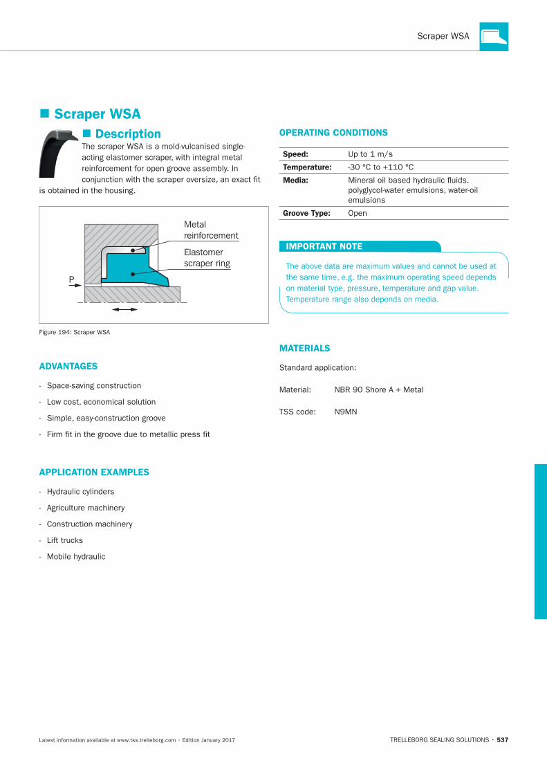
537
Scraper WSA
Description
P
Metalreinforcement
Elastomerscraper ring
ADVANTAGES
APPLICATION EXAMPLES
OPERATING CONDITIONS
Speed:
Temperature:
Media:
Groove Type: Open
IMPORTANT NOTE
MATERIALS
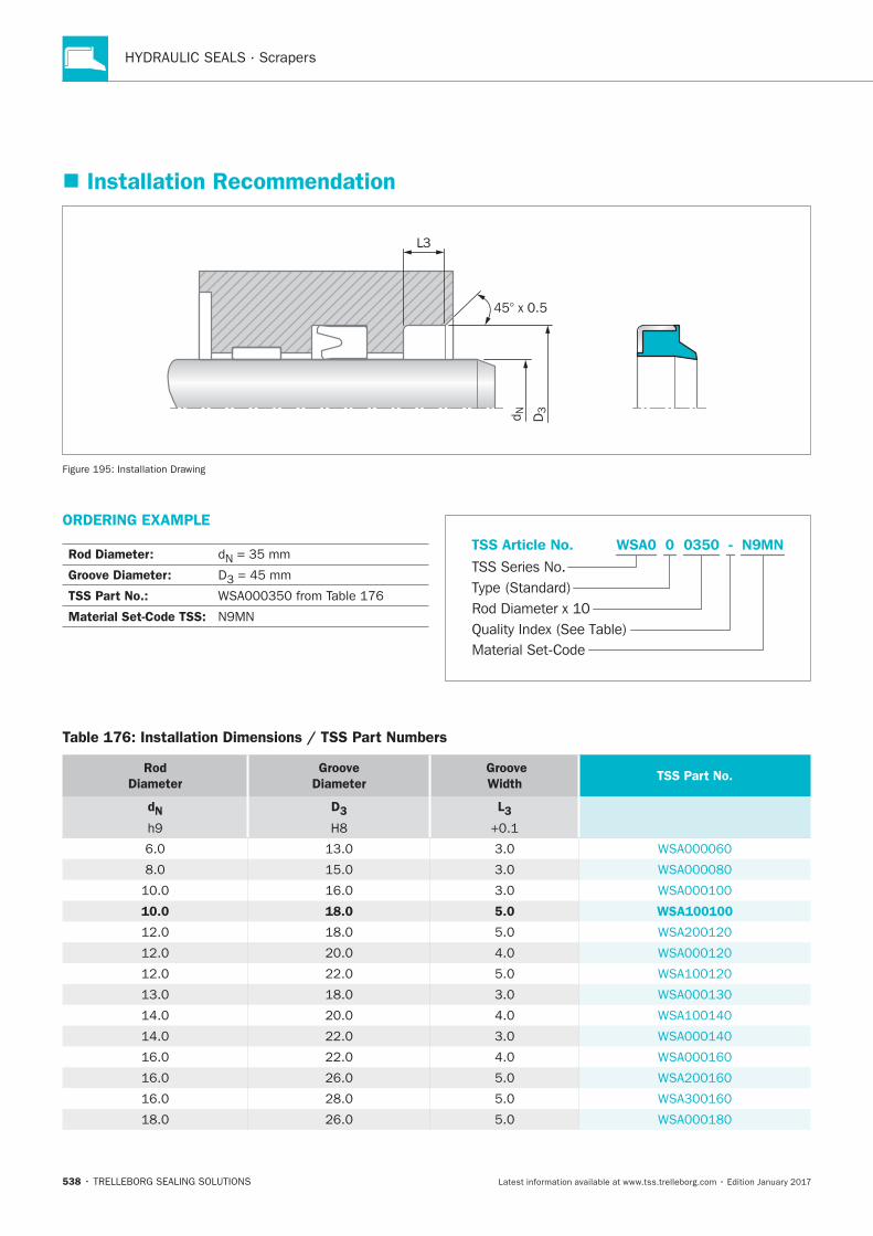
HYDRAULIC SEALS · Scrapers
538
Installation Recommendation
d N
L3
D3
45° x 0.5
Installation Drawing
ORDERING EXAMPLE
Rod Diameter: N = 35 mm
Groove Diameter: D3 = 45 mm
TSS Part No.:
Material Set-Code TSS:
Material Set-Code
TSS Series No.
TSS Article No.
Rod Diameter x 10Quality Index (See Table)
Type (Standard)
N9MNWSA0 - 0 0350
Table 176: Installation Dimensions / TSS Part Numbers
Rod
Diameter
Groove
Diameter
Groove
Width TSS Part No.
dN
D3
L3
10.0 18.0 5.0 WSA100100
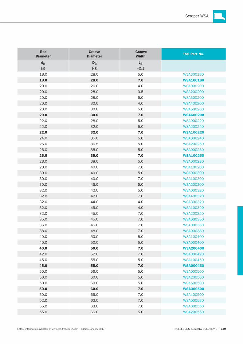
539
Rod
Diameter
Groove
Diameter
Groove
Width TSS Part No.
dN
D3
L3
18.0 28.0 7.0 WSA100180
3.5
20.0 30.0 7.0 WSA600200
22.0 32.0 7.0 WSA100220
36.5
25.0 35.0 7.0 WSA100250
40.0 50.0 7.0 WSA200400
45.0 55.0 7.0 WSA000450
50.0 60.0 7.0 WSA300500
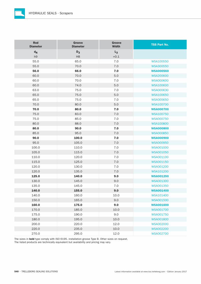
HYDRAULIC SEALS · Scrapers
540
Rod
Diameter
Groove
Diameter
Groove
Width TSS Part No.
dN
D3
L3
56.0 66.0 7.0 WSA000560
70.0 80.0 7.0 WSA000700
80.0 90.0 7.0 WSA000800
90.0 100.0 7.0 WSA000900
125.0 140.0 9.0 WSA001250
140.0 155.0 9.0 WSA001400
160.0 175.0 9.0 WSA001600
bold
Zurcon® Scraper SWP
TRELLEBORG SEALING SOLUTIONS • 541Latest information available at www.tss.trelleborg.com • Edition January 2017
Zurcon®Scraper SWP
Single-acting
Metal Reinforcement
For open Groove Assembly
Material:Zurcon®+ Metal

HYDRAULIC SEALS · Scrapers
542
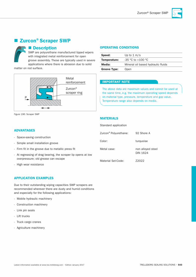
543
Description
P
Metalreinforcement
Zurcon®
scraper ring
ADVANTAGES
Simple small installation groove
APPLICATION EXAMPLES
Link pin seals
OPERATING CONDITIONS
Speed:
Temperature:
Media:
Groove Type: Open
IMPORTANT NOTE
MATERIALS
®
Zurcon®Scraper SWP
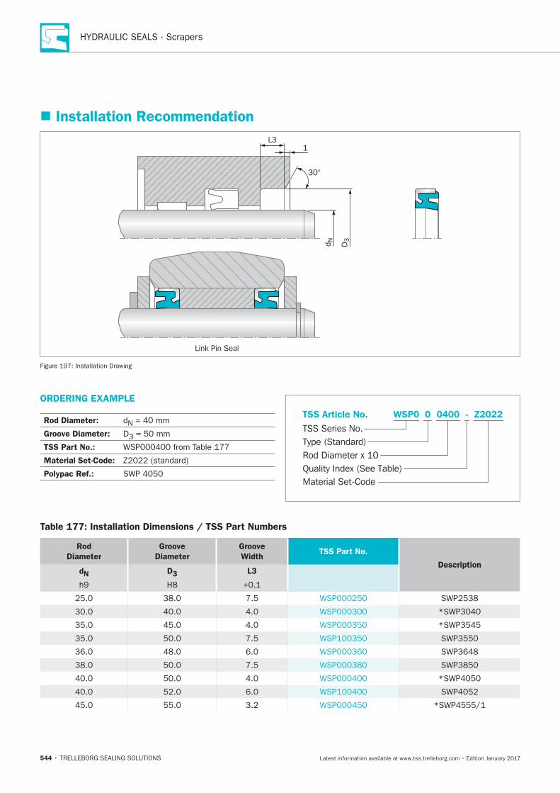
HYDRAULIC SEALS · Scrapers
544
Installation Recommendation
1
Link Pin Seal
L3
d N D3
30°
Installation Drawing
ORDERING EXAMPLE
Rod Diameter: N
Groove Diameter: D3
TSS Part No.:
Material Set-Code:
Polypac Ref.:Material Set-Code
TSS Series No.
TSS Article No.
Rod Diameter x 10Quality Index (See Table)
Type (Standard)
Z2022WSP0 - 0 0400
Table 177: Installation Dimensions / TSS Part Numbers
Rod
Diameter
Groove
Diameter
Groove
WidthTSS Part No.
DescriptiondN D3 L3
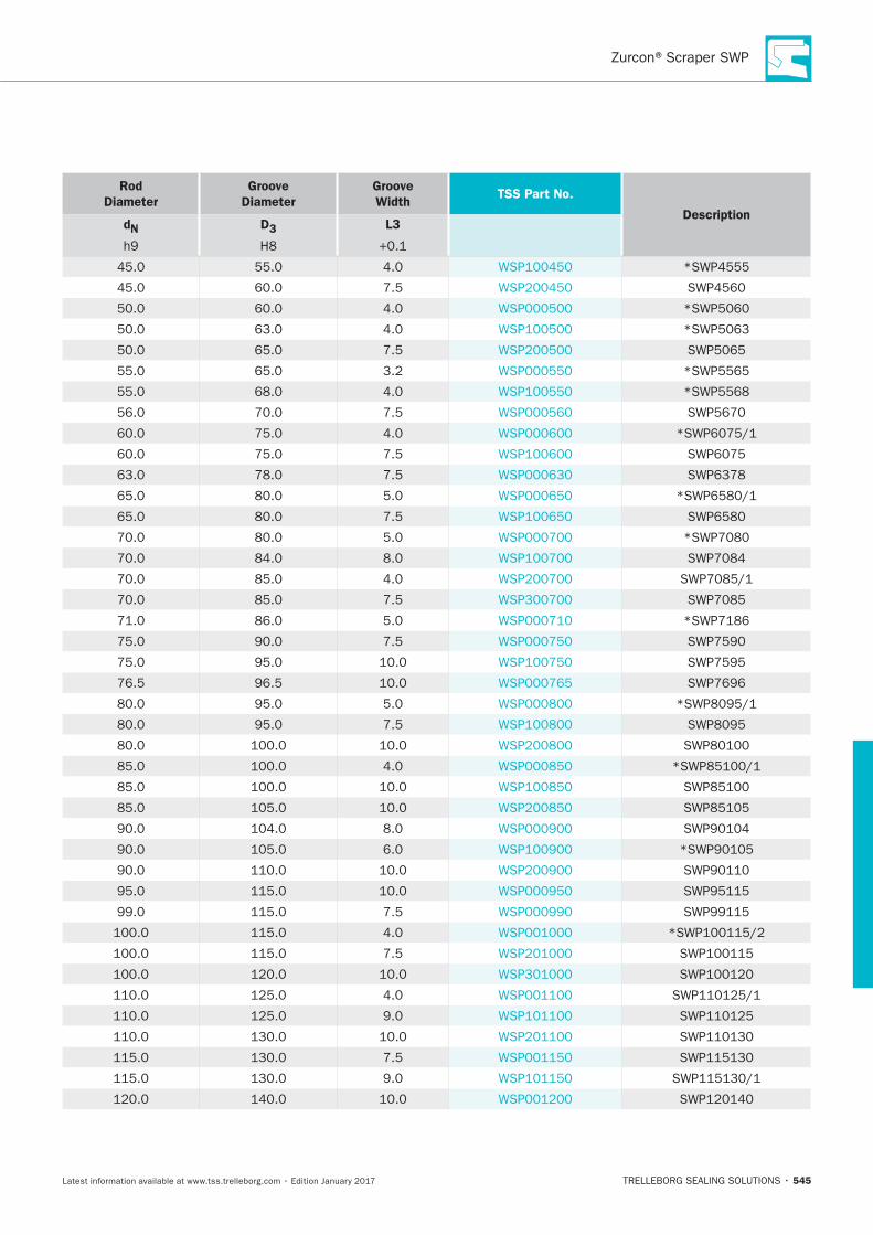
545
Rod
Diameter
Groove
Diameter
Groove
WidthTSS Part No.
DescriptiondN D3 L3
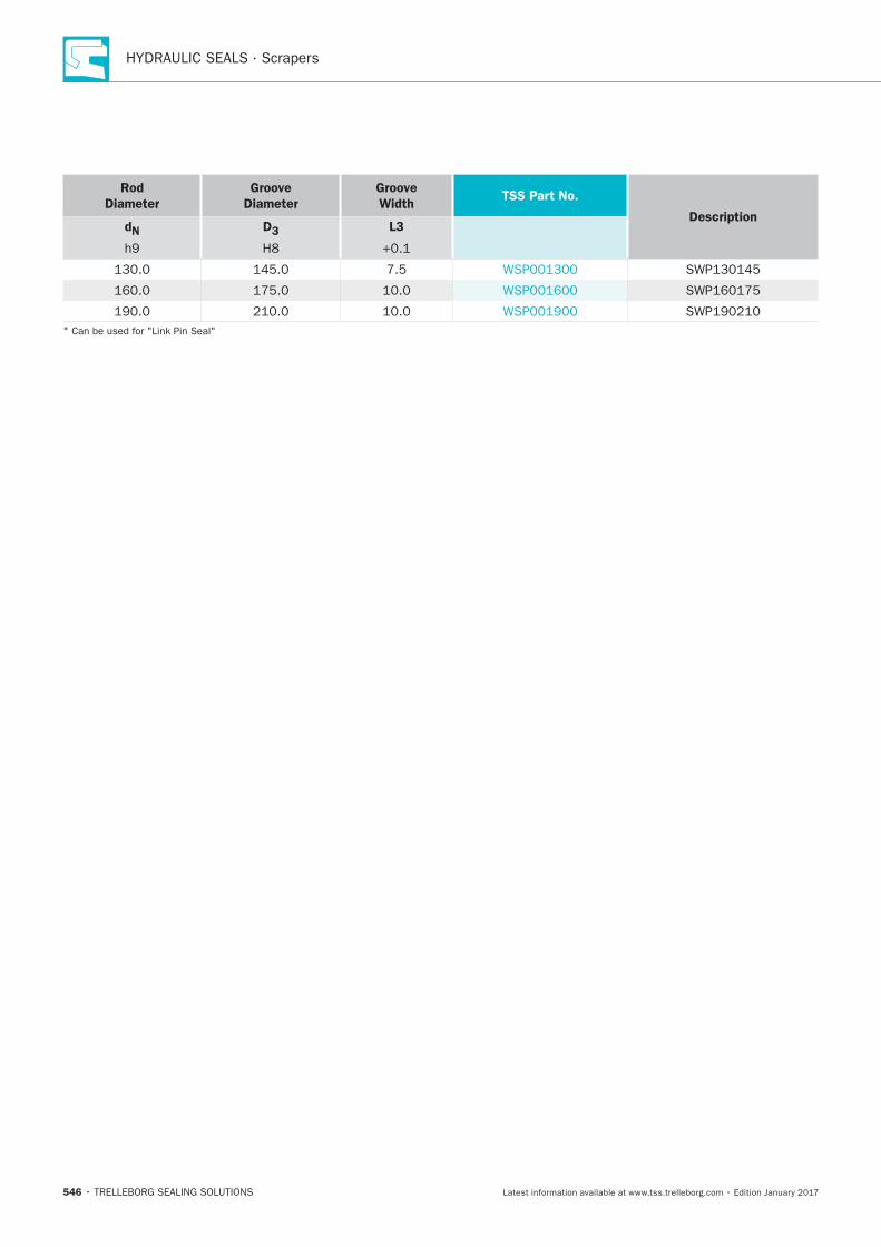
HYDRAULIC SEALS · Scrapers
546
Rod
Diameter
Groove
Diameter
Groove
WidthTSS Part No.
DescriptiondN D3 L3
*
Metal Scraper
TRELLEBORG SEALING SOLUTIONS • 547Latest information available at www.tss.trelleborg.com • Edition January 2017
MetalScraper Single-acting
Metal and Elastomer Scrapers Lips
Material:NBR, Metal and Brass

HYDRAULIC SEALS · Scrapers
548
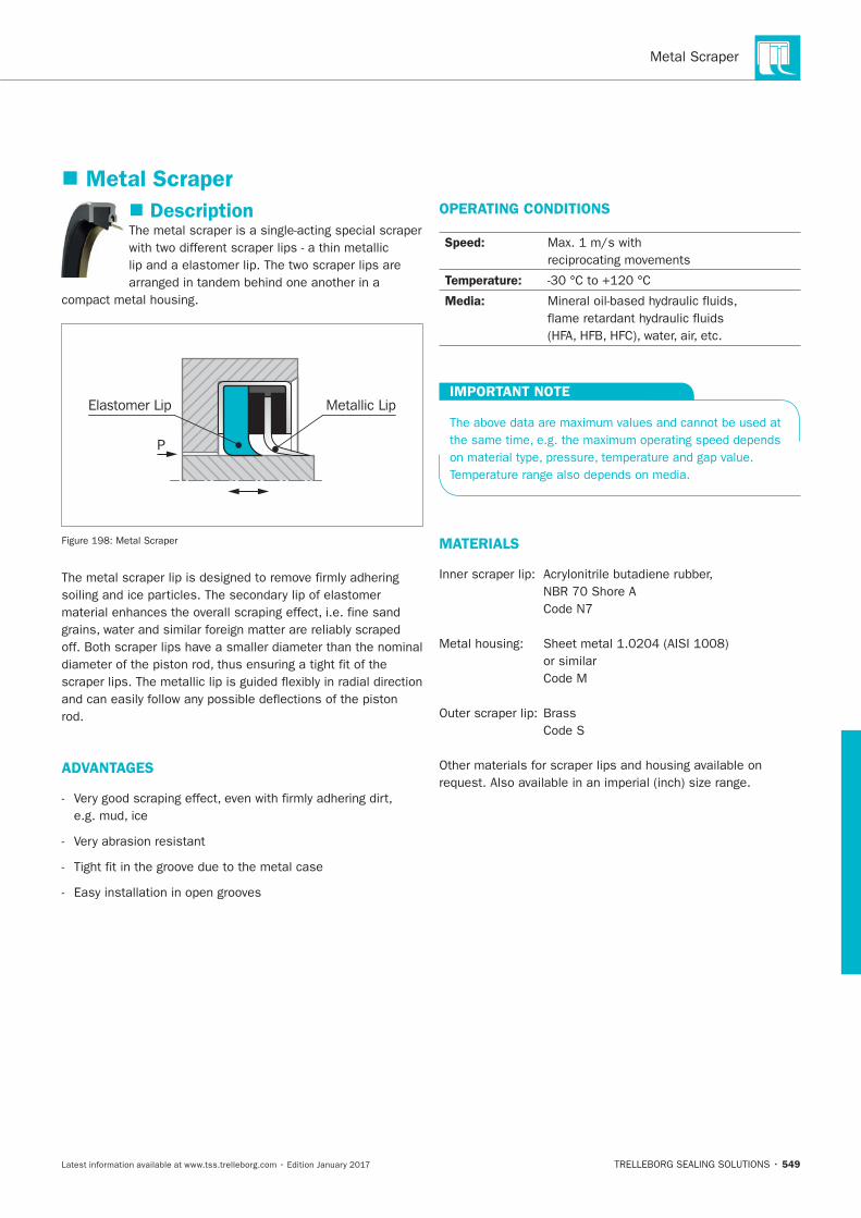
Metal Scraper
549
Metal Scraper
Description
Elastomer Lip Metallic Lip
P
Metal Scraper
ADVANTAGES
OPERATING CONDITIONS
Speed:
reciprocating movements
Temperature:
Media:
IMPORTANT NOTE
MATERIALS
or similar
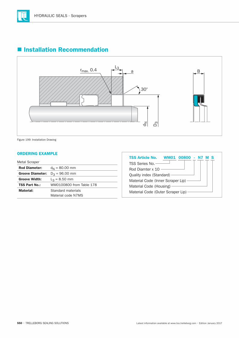
HYDRAULIC SEALS · Scrapers
550
Installation Recommendation
aL3
d N D3
30°
rmax. 0.4 B
Installation Drawing
ORDERING EXAMPLE
Metal Scraper
Rod Diameter: N
Groove Diameter: D3
Groove Width: L3
TSS Part No.:
Material:
Material Code (Inner Scraper Lip)
TSS Series No.TSS Article No.
Material Code (Housing)Material Code (Outer Scraper Lip)
Quality index (Standard)Rod Diamter x 10
N700800 MWM01 - S
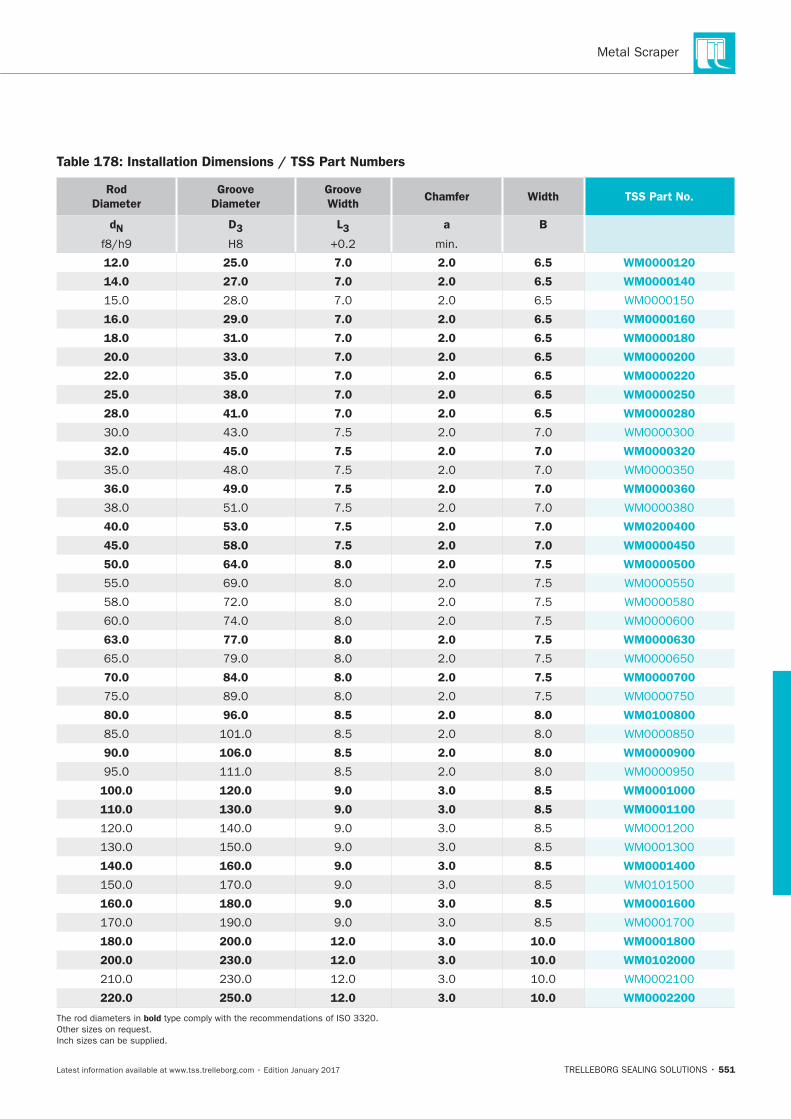
Metal Scraper
551
Table 178: Installation Dimensions / TSS Part Numbers
Rod
Diameter
Groove
Diameter
Groove
Width Chamfer Width TSS Part No.
dN D3 L3 a
min.
B
12.0 25.0 7.0 2.0 6.5 WM0000120
14.0 27.0 7.0 2.0 6.5 WM0000140
6.5
16.0 29.0 7.0 2.0 6.5 WM0000160
18.0 31.0 7.0 2.0 6.5 WM0000180
20.0 33.0 7.0 2.0 6.5 WM0000200
22.0 35.0 7.0 2.0 6.5 WM0000220
25.0 38.0 7.0 2.0 6.5 WM0000250
28.0 41.0 7.0 2.0 6.5 WM0000280
32.0 45.0 7.5 2.0 7.0 WM0000320
36.0 49.0 7.5 2.0 7.0 WM0000360
40.0 53.0 7.5 2.0 7.0 WM0200400
45.0 58.0 7.5 2.0 7.0 WM0000450
50.0 64.0 8.0 2.0 7.5 WM0000500
63.0 77.0 8.0 2.0 7.5 WM0000630
70.0 84.0 8.0 2.0 7.5 WM0000700
80.0 96.0 8.5 2.0 8.0 WM0100800
90.0 106.0 8.5 2.0 8.0 WM0000900
100.0 120.0 9.0 3.0 8.5 WM0001000
110.0 130.0 9.0 3.0 8.5 WM0001100
140.0 160.0 9.0 3.0 8.5 WM0001400
160.0 180.0 9.0 3.0 8.5 WM0001600
180.0 200.0 12.0 3.0 10.0 WM0001800
200.0 230.0 12.0 3.0 10.0 WM0102000
220.0 250.0 12.0 3.0 10.0 WM0002200
bold

HYDRAULIC SEALS · Scrapers
552
Turcon® Variseal® M2S
TRELLEBORG SEALING SOLUTIONS • 553Latest information available at www.tss.trelleborg.com • Edition January 2017
Turcon®Variseal®M2S
Single-acting
Spring-energized plastic U-Cup
Material:Turcon®and Zurcon®

HYDRAULIC SEALS · Scraper
554
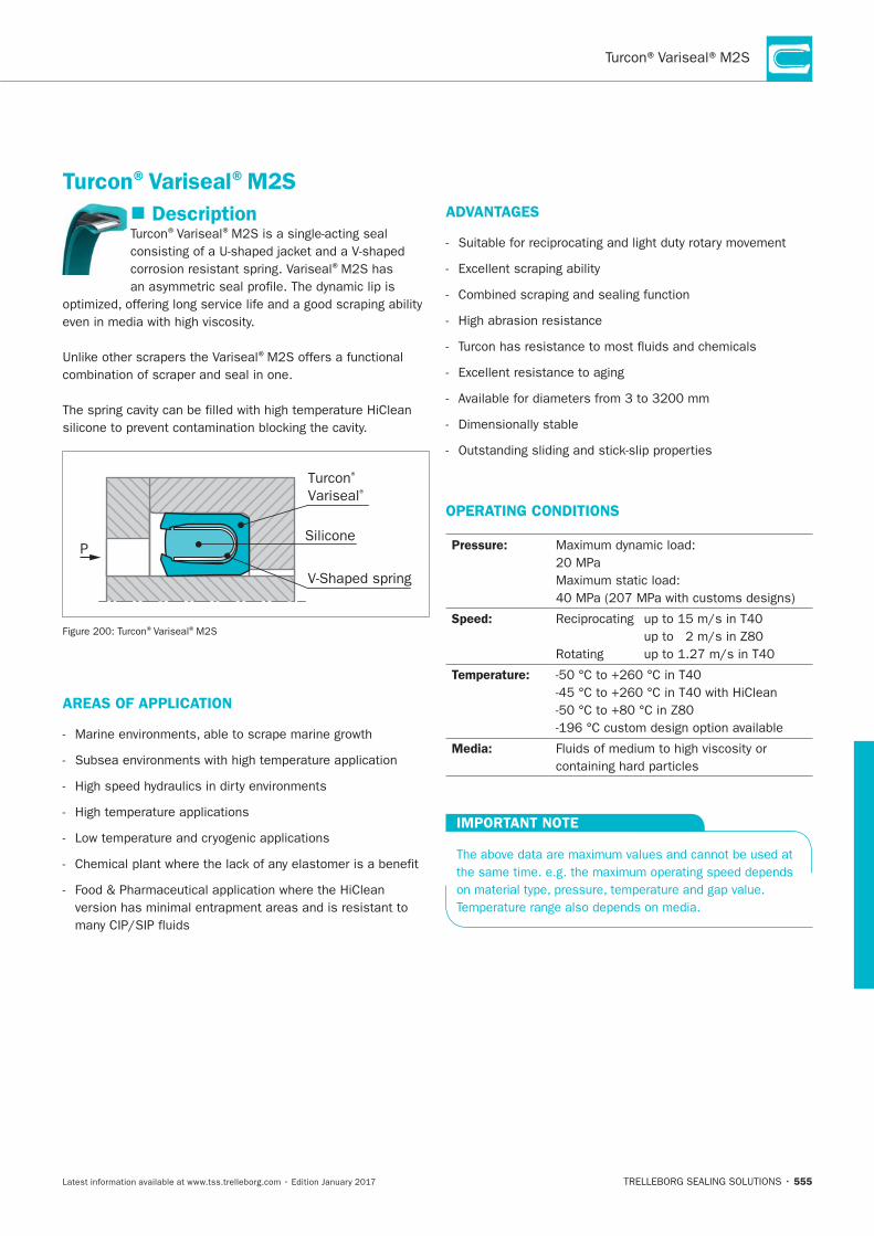
555
Description®Variseal®
corrosion resistant spring. Variseal®
®
Silicone
Turcon®
Variseal®
V-Shaped spring
P
®Variseal®
AREAS OF APPLICATION
ADVANTAGES
OPERATING CONDITIONS
Pressure:
Speed:
Temperature:
Media:
IMPORTANT NOTE
Turcon®Variseal®M2S
HYDRAULIC SEALS · Scraper
556
MATERIALS
®
®
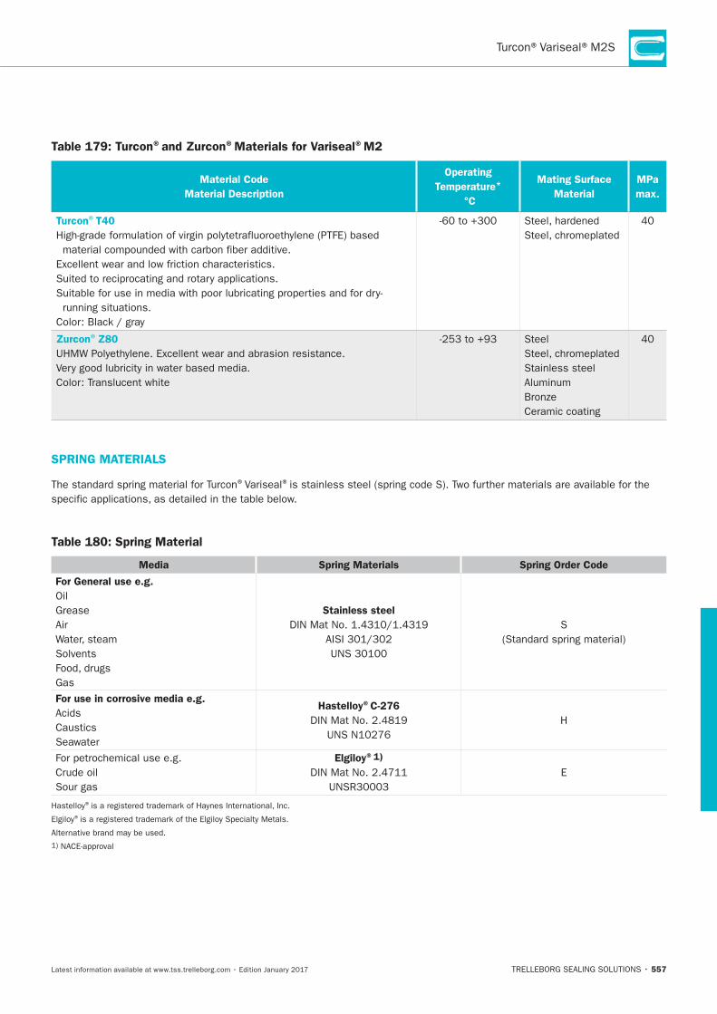
557
Table 179: Turcon®and Zurcon®Materials for Variseal®M2
Material Code
Material Description
Operating
Temperature*
°C
Mating Surface
Material
MPa
max.
Turcon®T40
Zurcon®Z80 Steel
Stainless steel
Ceramic coating
SPRING MATERIALS
®Variseal®
Table 180: Spring Material
Media Spring Materials Spring Order Code
For General use e.g.
Oil
Grease
Air
Solvents
Gas
Stainless steel
S
For use in corrosive media e.g.
Seawater
Hastelloy®C-276
H
Elgiloy®1)
E
®
®
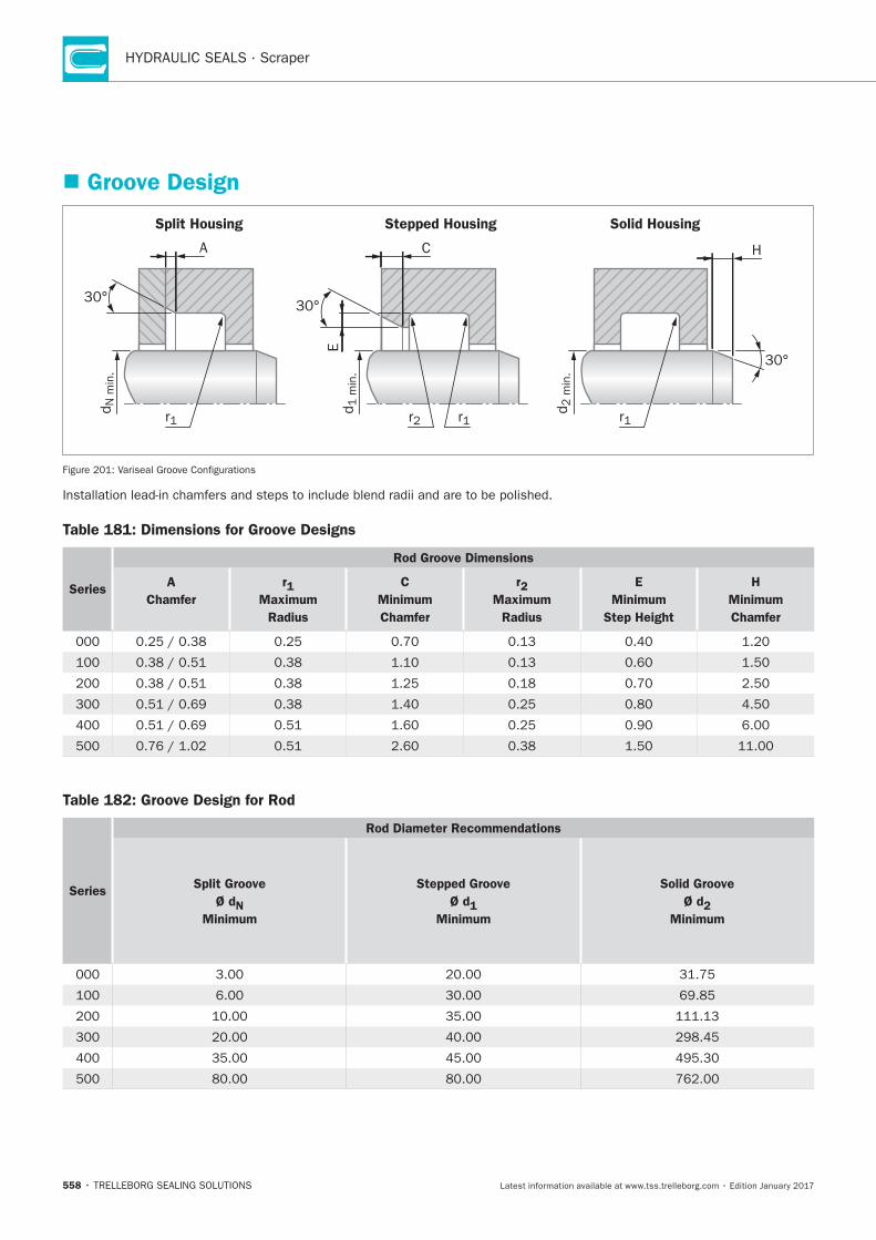
HYDRAULIC SEALS · Scraper
558
Groove Design
Split Housing Stepped Housing Solid Housing
r1
30°
A C
dN
min
.
30°
30°
r2 r1
d1 m
in.
E
H
d2 m
in.
r1
Table 181: Dimensions for Groove Designs
Series
Rod Groove Dimensions
A
Chamfer
r1
Maximum
Radius
C
Minimum
Chamfer
r2
Maximum
Radius
E
Minimum
Step Height
H
Minimum
Chamfer
Table 182: Groove Design for Rod
Series
Rod Diameter Recommendations
Split Groove
Ø dN
Minimum
Stepped Groove
Ø d1
Minimum
Solid Groove
Ø d2
Minimum
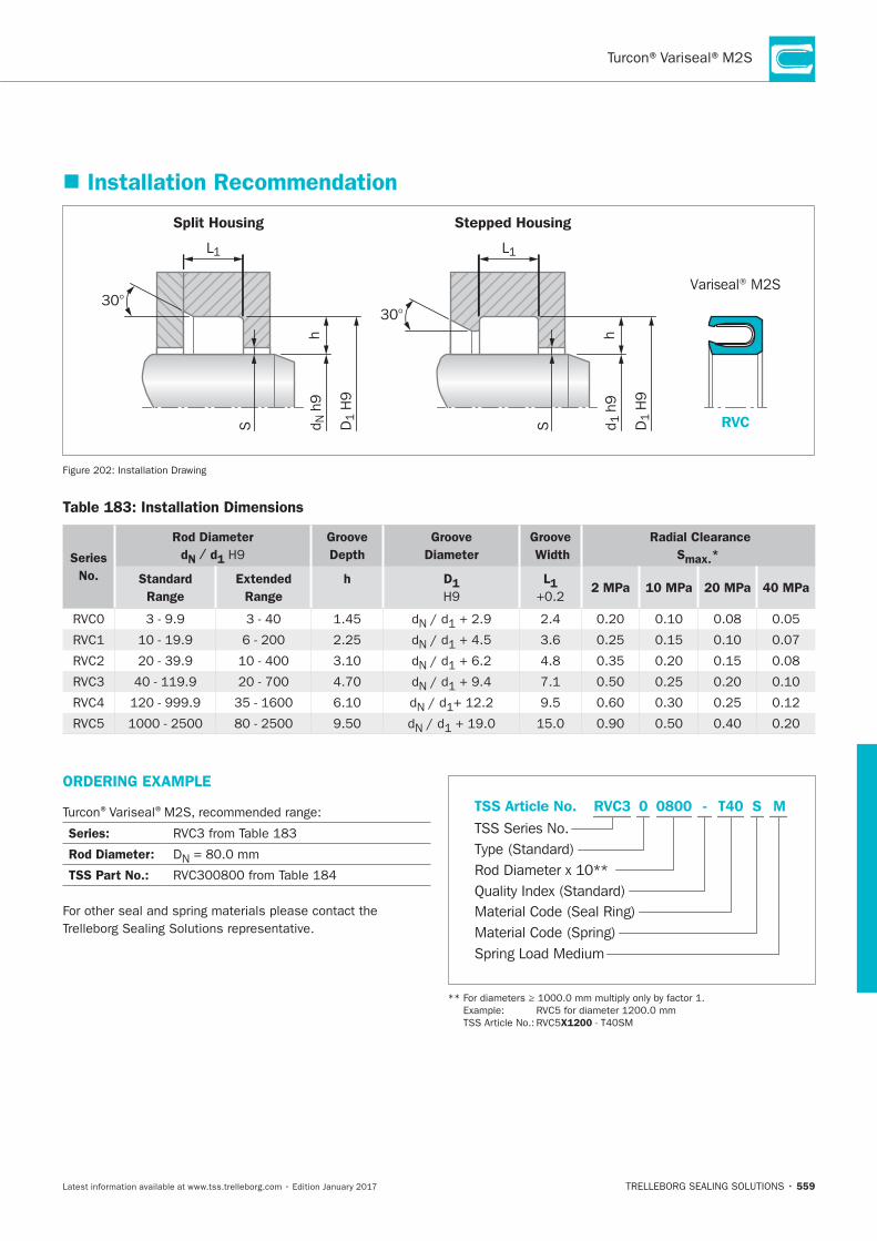
559
Installation Recommendation
Split Housing Stepped Housing
RVC
Variseal® M2S
h
S
h
S
30°30°
L1 L1
d N h
9
D1
H9
d 1 h
9
D1
H9
Installation Drawing
Table 183: Installation Dimensions
Series
No.
Rod Diameter
dN / d1
Groove
Depth
Groove
Diameter
Groove
Width
Radial Clearance
Smax.*
Standard
Range
Extended
Range
h D1 L1 2 MPa 10 MPa 20 MPa 40 MPa
N
N 3.6
N
RVC3 N
RVC4 N
RVC5 N
ORDERING EXAMPLE
®Variseal®
Series:
Rod Diameter: DN
TSS Part No.:
Material Code (Seal Ring)
TSS Series No.
TSS Article No.
Material Code (Spring)Spring Load Medium
Rod Diameter x 10**Quality Index (Standard)
Type (Standard)
T400800 SRVC3 - M0
X1200
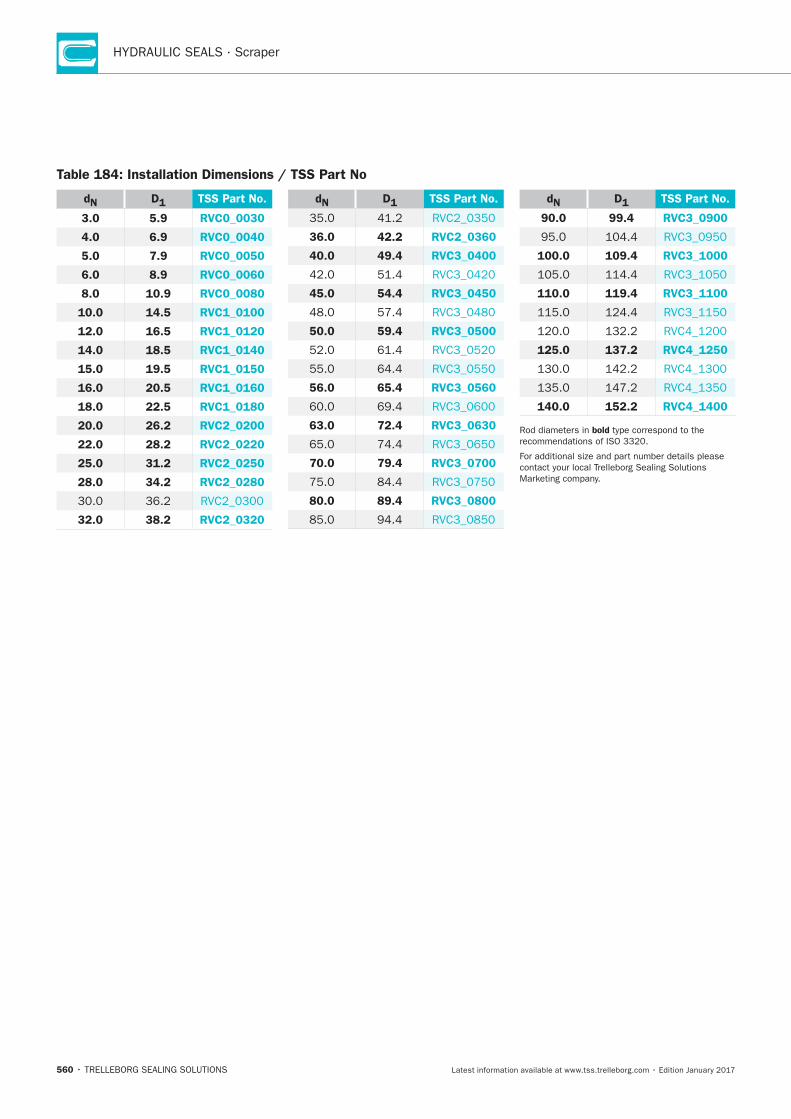
HYDRAULIC SEALS · Scraper
560
Table 184: Installation Dimensions / TSS Part No
dN D1 TSS Part No.
3.0 5.9 RVC0_0030
4.0 6.9 RVC0_0040
5.0 7.9 RVC0_0050
6.0 8.9 RVC0_0060
8.0 10.9 RVC0_0080
10.0 14.5 RVC1_0100
12.0 16.5 RVC1_0120
14.0 18.5 RVC1_0140
15.0 19.5 RVC1_0150
16.0 20.5 RVC1_0160
18.0 22.5 RVC1_0180
20.0 26.2 RVC2_0200
22.0 28.2 RVC2_0220
25.0 31.2 RVC2_0250
28.0 34.2 RVC2_0280
32.0 38.2 RVC2_0320
dN D1 TSS Part No.
36.0 42.2 RVC2_0360
40.0 49.4 RVC3_0400
45.0 54.4 RVC3_0450
50.0 59.4 RVC3_0500
64.4
56.0 65.4 RVC3_0560
63.0 72.4 RVC3_0630
70.0 79.4 RVC3_0700
80.0 89.4 RVC3_0800
dN D1 TSS Part No.
90.0 99.4 RVC3_0900
100.0 109.4 RVC3_1000
110.0 119.4 RVC3_1100
125.0 137.2 RVC4_1250
140.0 152.2 RVC4_1400
bold
Additional Scrapers
TRELLEBORG SEALING SOLUTIONS • 561Latest information available at www.tss.trelleborg.com • Edition January 2017
AdditonalScrapersAvailable upon Request
Old Series
Special Series

HYDRAULIC SEALS · Scrapers
562
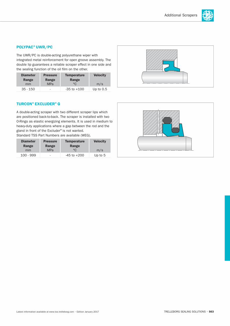
563
POLYPAC®UWR/PC
Diameter
Range
mm
Pressure
Range
MPa
Temperature
Range
Velocity
TURCON®EXCLUDER®G
®
Diameter
Range
mm
Pressure
Range
MPa
Temperature
Range
Velocity
Up to 5

HYDRAULIC SEALS · Scrapers
564
TRELLEBORG SEALING SOLUTIONS • 565Latest information available at www.tss.trelleborg.com • Edition January 2017
Slydring®Wear Rings

HYDRAULIC SEALS · Slydring®
566
Slydring®– Wear Rings
567
Contents
568 Choice of Slydring®
571 Design Instructions
573 Turcite®Slydring®for Piston and Rod
576 Zurcon®Slydring®for Piston and Rod
585 HiMod®Slydring®for Piston and Rod
606 Orkot®Slydring®for Piston and Rod
HYDRAULIC SEALS · Slydring®
568
Choice of Slydring®
®
MATERIALS
®
®
®
®
®
®
®
®
D ®
TOLERANCES
®
® ®
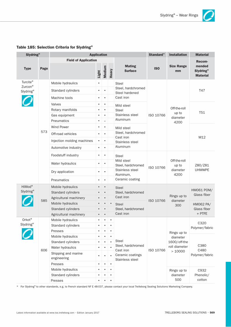
Slydring®– Wear Rings
569
Table 185: Selection Criteria for Slydring ®
Slydring® Application Standard* Installation Material
Type Page
Field of Application
Mating
SurfaceISO
Size Range
mm
Recom-
mended
Slydring®
MaterialLig
ht
Mediu
m
Heavy
®
®
®
® ®
® ®
®
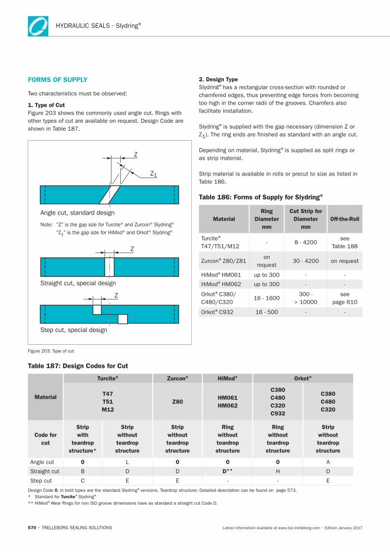
HYDRAULIC SEALS · Slydring®
570
FORMS OF SUPPLY
1. Type of Cut
Angle cut, standard design
Straight cut, special design
Step cut, special design
Note: “Z” is the gap size for Turcite® and Zurcon® Slydring®
“Z1” is the gap size for HiMod® and Orkot® Slydring®
Z1
Z
Z
Z
2. Design Type
®
Z
®
Table 186: Forms of Supply for Slydring®
Material
Ring
Diameter
mm
Cut Strip for
Diameter
mm
Off-the-Roll
®
®
®
®
®
®
Table 187: Design Codes for Cut
Material
Turcite® Zurcon® HiMod® Orkot®
T47
T51
M12
Z80 HM061
HM062
C380
C480
C320
C932
C380
C480
C320
Code for
cut
Strip
with
teardrop
structure*
Strip
without
teardrop
structure
Strip
without
teardrop
structure
Ring
without
teardrop
structure
Ring
without
teardrop
structure
Strip
without
teardrop
structure
0 0 0 0
D D D** H D
C
0 ®
Turcite® ®
®
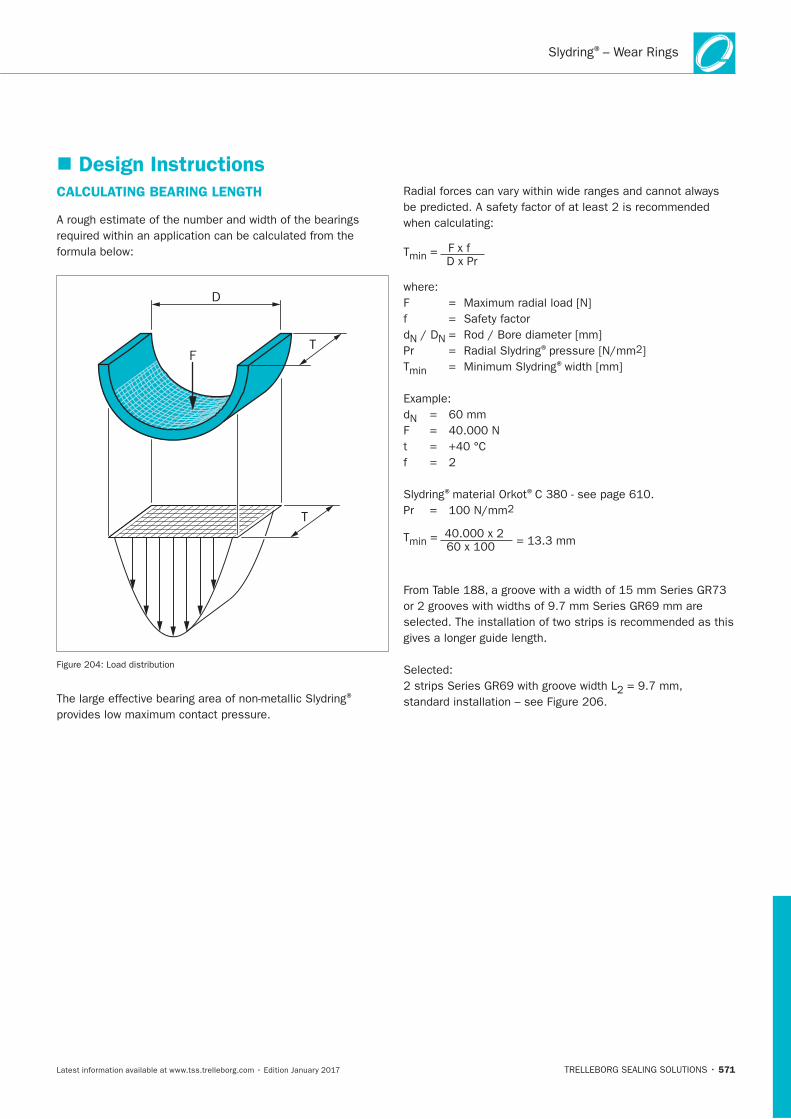
Slydring®– Wear Rings
571
Design InstructionsCALCULATING BEARING LENGTH
D
FT
T
®
=
®
®
® ®
=
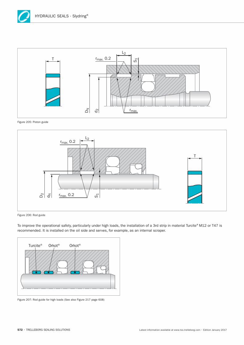
HYDRAULIC SEALS · Slydring®
572
T
rmax.
L2
S1rmax. 0.2
DN
d 2
T
rmax. 0.2L2
S1rmax. 0.2D2
d N
®
Orkot® Orkot®Turcite®
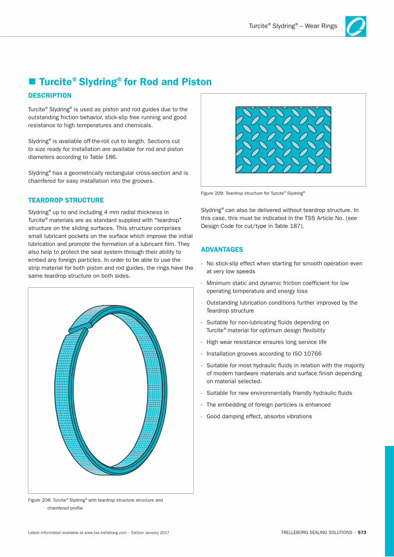
Turcite Slydring – Wear Rings® ®
573
DESCRIPTION
® ®
®
®
TEARDROP STRUCTURE
®
®
® ®
® ®
®
ADVANTAGES
®
Turcite®Slydring®for Rod and Piston
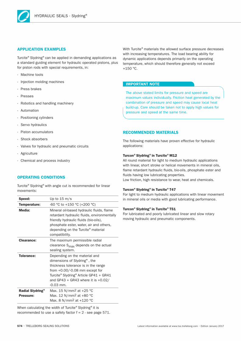
HYDRAULIC SEALS · Slydring®
574
APPLICATION EXAMPLES
® ®
Presses
OPERATING CONDITIONS
® ®
Speed:
Temperature:
Media:
®material
Clearance:
clearance S
Tolerance:®
® ®
Radial Slydring®
Pressure:
® ®it is
®
IMPORTANT NOTE
RECOMMENDED MATERIALS
Turcon®Slydring®in Turcite®M12
Turcon®Slydring®in Turcite®T47
Turcon®Slydring®in Turcite®T51
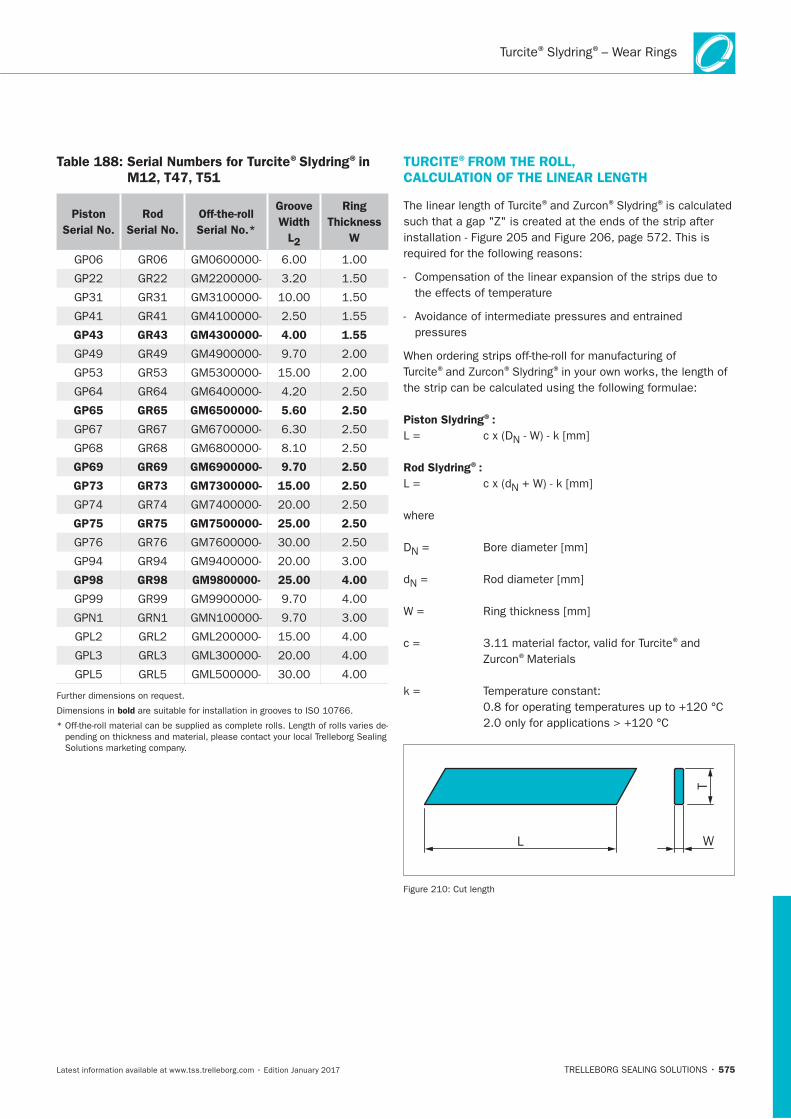
575
Table 188: Serial Numbers for Turcite®Slydring®in M12, T47, T51
Piston
Serial No.
Rod
Serial No.
Off-the-roll
Serial No.*
Groove
Width
L2
Ring
Thickness
W
GP43 GR43 GM4300000- 4.00 1.55
GP65 GR65 GM6500000- 5.60 2.50
GP69 GR69 GM6900000- 9.70 2.50
GP73 GR73 GM7300000- 15.00 2.50
GP75 GR75 GM7500000- 25.00 2.50
GP98 GR98 GM9800000- 25.00 4.00
Dimensions in bold
TURCITE®FROM THE ROLL, CALCULATION OF THE LINEAR LENGTH
® ® ®
® ® ®
Piston Slydring®:
N
Rod Slydring®:
N
DN
N
®
®Materials
L W
T
Turcite Slydring – Wear Rings® ®
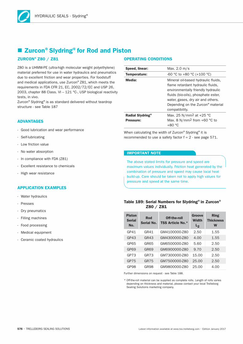
HYDRAULIC SEALS · Slydring®
576
ZURCON®Z80 / Z81
®
® ®
ADVANTAGES
APPLICATION EXAMPLES
OPERATING CONDITIONS
Speed, linear:
Temperature:
Media:
®
Radial Slydring®
Pressure:
® ®
IMPORTANT NOTE
Table 189: Serial Numbers for Slydring®in Zurcon®
Z80 / Z81
Piston
Serial
No.
Rod
Serial No.
Off-the-roll
TSS Article No.*
Groove
Width
L2
Ring
Thickness
W
Zurcon®Slydring®for Rod and Piston
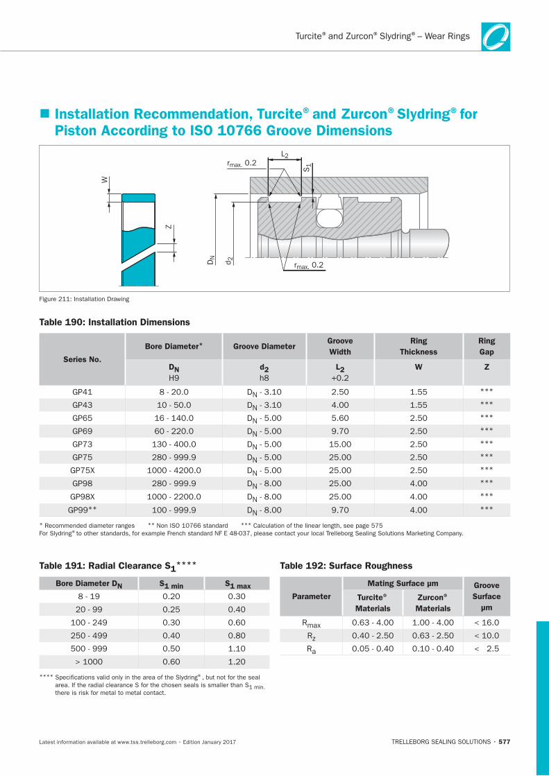
® ® ®– Wear Rings
577
Installation Recommendation, Turcite®and Zurcon®Slydring®for Piston According to ISO 10766 Groove Dimensions
L2
S1rmax. 0.2
rmax. 0.2DN
d 2
W
Z
Installation Drawing
Table 190: Installation Dimensions
Series No.
Bore Diameter* Groove DiameterGroove
Width
Ring
Thickness
Ring
Gap
DN
H9
d2 L2 W Z
DN***
DN***
DN***
DN***
DN***
DN***
DN***
DN***
DN***
GP99** DN***
* ** *** ®
Table 191: Radial Clearance S1****
Bore Diameter DN S1 min S1 max
**** ®
there is risk for metal to metal contact.
Table 192: Surface Roughness
Parameter
Mating Surface μm Groove
Surface
μm
Turcite®
Materials
Zurcon®
Materials
R
R
Ra
HYDRAULIC SEALS · Slydring®
578
ORDERING EXAMPLE
®
Groove Width:
Ring Thickness:
Material: ®
Standard Design:
TSS Part No.:
Material No.
TSS Series No.
TSS Article No. M12
Bore Diameter x 10
GP69
Quality Index (Standard)
-
Design Code (Standard)
0 1000
ORDERING EXAMPLE FOR DN ≥ 1000 MM
®
Groove Width:
Ring Thickness:
Material: ®
TSS Part No.:
Material No.
TSS Series No.
TSS Article No. T47
Bore Diameter x 1*
GP98
Quality Index (Standard)
-
Design Code
X 2700
*
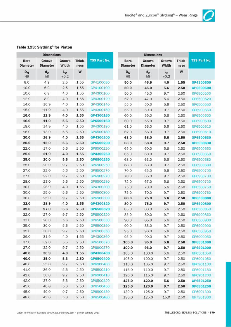
579
Table 193: Slydring®for Piston
Dimensions
TSS Part No.Bore
Diameter
Groove
Diameter
Groove
Width
Thick-
ness
DN d2 L2 W
16.0 12.9 4.0 1.55 GP4300160
16.0 11.0 5.6 2.50 GP6500160
20.0 16.9 4.0 1.55 GP4300200
20.0 15.0 5.6 2.50 GP6500200
25.0 21.9 4.0 1.55 GP4300250
25.0 20.0 5.6 2.50 GP6500250
32.0 28.9 4.0 1.55 GP4300320
32.0 27.0 5.6 2.50 GP6500320
40.0 36.9 4.0 1.55 GP4300400
40.0 35.0 5.6 2.50 GP6500400
Dimensions
TSS Part No.Bore
Diameter
Groove
Diameter
Groove
Width
Thick-
ness
DN d2 L2 W
50.0 46.9 4.0 1.55 GP4300500
50.0 45.0 5.6 2.50 GP6500500
63.0 58.0 5.6 2.50 GP6500630
63.0 58.0 9.7 2.50 GP6900630
80.0 75.0 5.6 2.50 GP6500800
80.0 75.0 9.7 2.50 GP6900800
100.0 95.0 5.6 2.50 GP6501000
100.0 95.0 9.7 2.50 GP6901000
125.0 120.0 5.6 2.50 GP6501250
125.0 120.0 9.7 2.50 GP6901250
® ® ®– Wear Rings
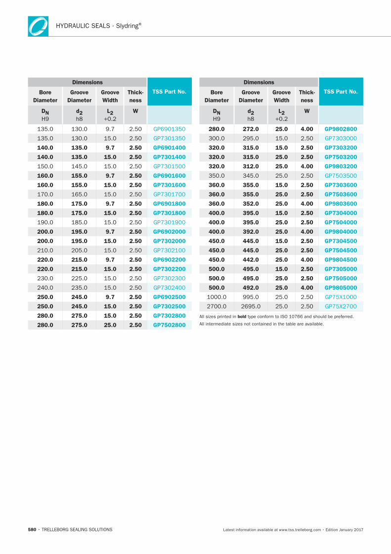
HYDRAULIC SEALS · Slydring®
580
Dimensions
TSS Part No.Bore
Diameter
Groove
Diameter
Groove
Width
Thick-
ness
DN d2 L2 W
140.0 135.0 9.7 2.50 GP6901400
140.0 135.0 15.0 2.50 GP7301400
160.0 155.0 9.7 2.50 GP6901600
160.0 155.0 15.0 2.50 GP7301600
180.0 175.0 9.7 2.50 GP6901800
180.0 175.0 15.0 2.50 GP7301800
200.0 195.0 9.7 2.50 GP6902000
200.0 195.0 15.0 2.50 GP7302000
220.0 215.0 9.7 2.50 GP6902200
220.0 215.0 15.0 2.50 GP7302200
250.0 245.0 9.7 2.50 GP6902500
250.0 245.0 15.0 2.50 GP7302500
280.0 275.0 15.0 2.50 GP7302800
280.0 275.0 25.0 2.50 GP7502800
Dimensions
TSS Part No.Bore
Diameter
Groove
Diameter
Groove
Width
Thick-
ness
DN d2 L2 W
280.0 272.0 25.0 4.00 GP9802800
320.0 315.0 15.0 2.50 GP7303200
320.0 315.0 25.0 2.50 GP7503200
320.0 312.0 25.0 4.00 GP9803200
360.0 355.0 15.0 2.50 GP7303600
360.0 355.0 25.0 2.50 GP7503600
360.0 352.0 25.0 4.00 GP9803600
400.0 395.0 15.0 2.50 GP7304000
400.0 395.0 25.0 2.50 GP7504000
400.0 392.0 25.0 4.00 GP9804000
450.0 445.0 15.0 2.50 GP7304500
450.0 445.0 25.0 2.50 GP7504500
450.0 442.0 25.0 4.00 GP9804500
500.0 495.0 15.0 2.50 GP7305000
500.0 495.0 25.0 2.50 GP7505000
500.0 492.0 25.0 4.00 GP9805000
bold
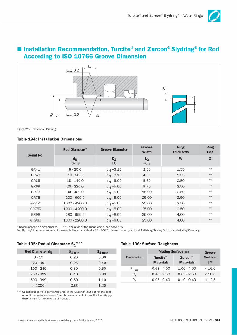
581
Installation Recommendation, Turcite®and Zurcon®Slydring®for Rod According to ISO 10766 Groove Dimension
rmax. 0.2L2
S1rmax. 0.2D2
d N
Z
W
Table 194: Installation Dimensions
Serial No.
Rod Diameter* Groove DiameterGroove
Width
Ring
Thickness
Ring
Gap
dN D2 L2 W Z
**
**
**
**
**
**
**
**
**
**
* ** ®
Table 195: Radial Clearance S1***
Rod Diameter dN S1 min S1 max
*** ®
Table 196: Surface Roughness
Parameter
Mating Surface μm Groove
Surface
μm
Turcite®
Materials
Zurcon®
Materials
® ® ®– Wear Rings
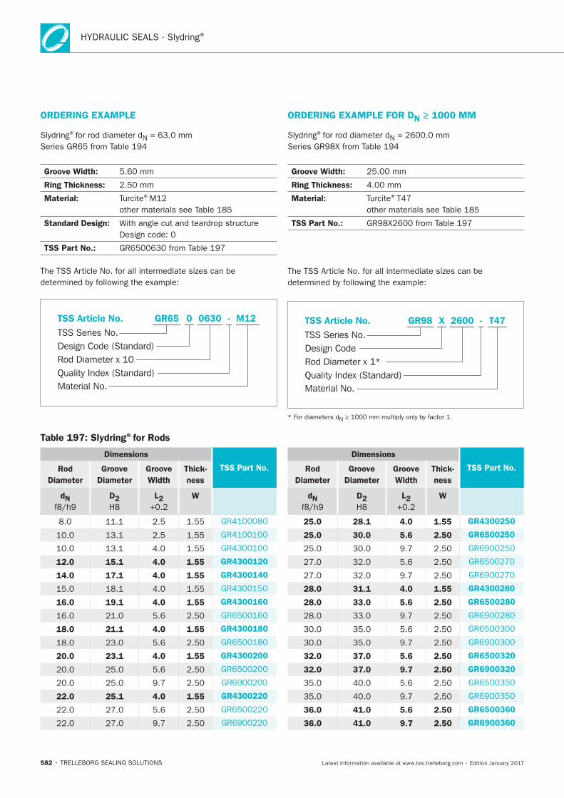
HYDRAULIC SEALS · Slydring®
582
ORDERING EXAMPLE
®
Groove Width:
Ring Thickness:
Material: ®
Standard Design:
TSS Part No.:
Material No.
TSS Series No.
TSS Article No.
Rod Diameter x 10Quality Index (Standard)
Design Code (Standard)
M12GR65 - 0 0630
ORDERING EXAMPLE FOR DN ≥ 1000 MM
®
Groove Width:
Ring Thickness:
Material: ®
TSS Part No.:
Material No.
TSS Series No.
TSS Article No. T47
Rod Diameter x 1*
GR98
Quality Index (Standard)
-
Design Code
X 2600
Table 197: Slydring®for Rods
Dimensions
TSS Part No.Rod
Diameter
Groove
Diameter
Groove
Width
Thick-
ness
dN D2 L2 W
12.0 15.1 4.0 1.55 GR4300120
14.0 17.1 4.0 1.55 GR4300140
16.0 19.1 4.0 1.55 GR4300160
18.0 21.1 4.0 1.55 GR4300180
20.0 23.1 4.0 1.55 GR4300200
22.0 25.1 4.0 1.55 GR4300220
Dimensions
TSS Part No.Rod
Diameter
Groove
Diameter
Groove
Width
Thick-
ness
dN D2 L2 W
25.0 28.1 4.0 1.55 GR4300250
25.0 30.0 5.6 2.50 GR6500250
28.0 31.1 4.0 1.55 GR4300280
28.0 33.0 5.6 2.50 GR6500280
32.0 37.0 5.6 2.50 GR6500320
32.0 37.0 9.7 2.50 GR6900320
36.0 41.0 5.6 2.50 GR6500360
36.0 41.0 9.7 2.50 GR6900360
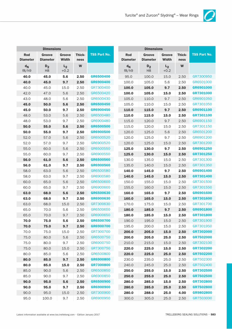
583
Dimensions
TSS Part No.Rod
Diameter
Groove
Diameter
Groove
Width
Thick-
ness
dN D2 L2 W
40.0 45.0 5.6 2.50 GR6500400
40.0 45.0 9.7 2.50 GR6900400
45.0 50.0 5.6 2.50 GR6500450
45.0 50.0 9.7 2.50 GR6900450
50.0 55.0 5.6 2.50 GR6500500
50.0 55.0 9.7 2.50 GR6900500
56.0 61.0 5.6 2.50 GR6500560
56.0 61.0 9.7 2.50 GR6900560
63.0 68.0 5.6 2.50 GR6500630
63.0 68.0 9.7 2.50 GR6900630
70.0 75.0 5.6 2.50 GR6500700
70.0 75.0 9.7 2.50 GR6900700
80.0 85.0 9.7 2.50 GR6900800
80.0 85.0 15.0 2.50 GR7300800
90.0 95.0 5.6 2.50 GR6500900
90.0 95.0 9.7 2.50 GR6900900
Dimensions
TSS Part No.Rod
Diameter
Groove
Diameter
Groove
Width
Thick-
ness
dN D2 L2 W
100.0 105.0 9.7 2.50 GR6901000
100.0 105.0 15.0 2.50 GR7301000
110.0 115.0 9.7 2.50 GR6901100
110.0 115.0 15.0 2.50 GR7301100
125.0 130.0 9.7 2.50 GR6901250
125.0 130.0 15.0 2.50 GR7301250
140.0 145.0 9.7 2.50 GR6901400
140.0 145.0 15.0 2.50 GR7301400
160.0 165.0 9.7 2.50 GR6901600
160.0 165.0 15.0 2.50 GR7301600
180.0 185.0 9.7 2.50 GR6901800
180.0 185.0 15.0 2.50 GR7301800
200.0 205.0 15.0 2.50 GR7302000
200.0 205.0 25.0 2.50 GR7502000
220.0 225.0 15.0 2.50 GR7302200
220.0 225.0 25.0 2.50 GR7502200
250.0 255.0 15.0 2.50 GR7302500
250.0 255.0 25.0 2.50 GR7502500
280.0 285.0 15.0 2.50 GR7302800
280.0 285.0 25.0 2.50 GR7502800
280.0 288.0 25.0 4.00 GR9802800
® ® ®– Wear Rings
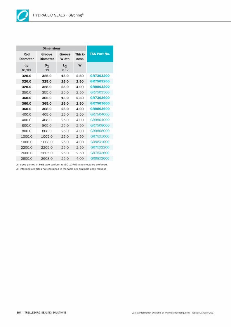
HYDRAULIC SEALS · Slydring®
584
Dimensions
TSS Part No.Rod
Diameter
Groove
Diameter
Groove
Width
Thick-
ness
dN D2 L2 W
320.0 325.0 15.0 2.50 GR7303200
320.0 325.0 25.0 2.50 GR7503200
320.0 328.0 25.0 4.00 GR9803200
360.0 365.0 15.0 2.50 GR7303600
360.0 365.0 25.0 2.50 GR7503600
360.0 368.0 25.0 4.00 GR9803600
bold
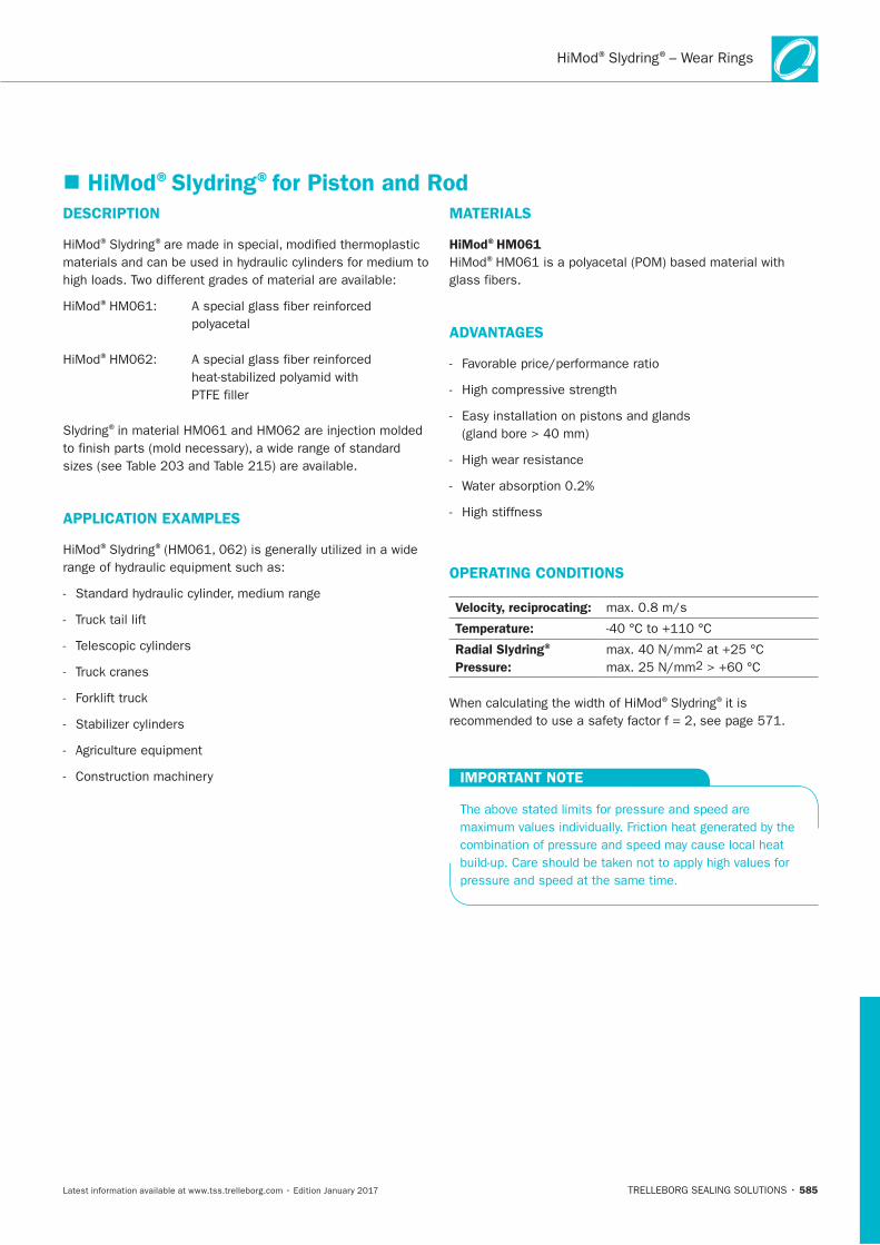
® ®– Wear Rings
585
HiMod®Slydring®for Piston and RodDESCRIPTION
® ®
®
®
PTFE filler
®
APPLICATION EXAMPLES
® ®
MATERIALS
HiMod®HM061®
glass fibers.
ADVANTAGES
High wear resistance
High stiffness
OPERATING CONDITIONS
Velocity, reciprocating:
Temperature:
Radial Slydring®
Pressure:
® ®it is
IMPORTANT NOTE
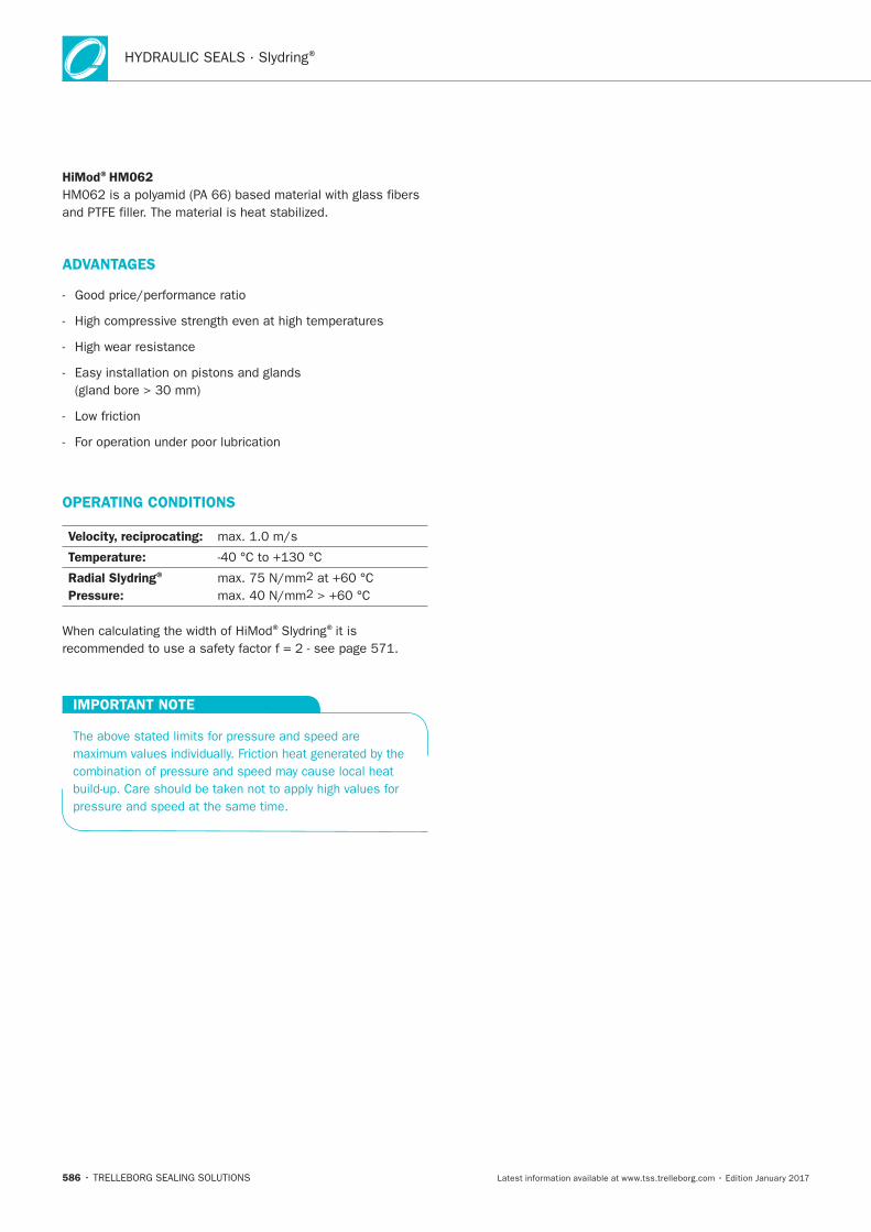
HYDRAULIC SEALS · Slydring®
586
HiMod®HM062
ADVANTAGES
-
-
-
-
-
-
OPERATING CONDITIONS
Velocity, reciprocating:
Temperature:
Radial Slydring®
Pressure:
® ®
IMPORTANT NOTE
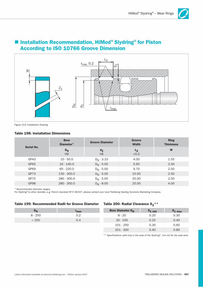
587
Installation Recommendation, HiMod®Slydring®for Piston According to ISO 10766 Groove Dimension
rmax.
Z1
L2
S1rmax. 0.2
DN
d 2
W
Table 198: Installation Dimensions
Serial No.
Bore
Diameter*Groove Diameter
Groove
Width
Ring
Thickness
DN
H9
d2 L2 W
* ®
Table 199: Recommended Radii for Groove Diameter
DN rmax
Table 200: Radial Clearance S1**
Bore Diameter DN S1 min S1 max
** ®
® ®– Wear Rings
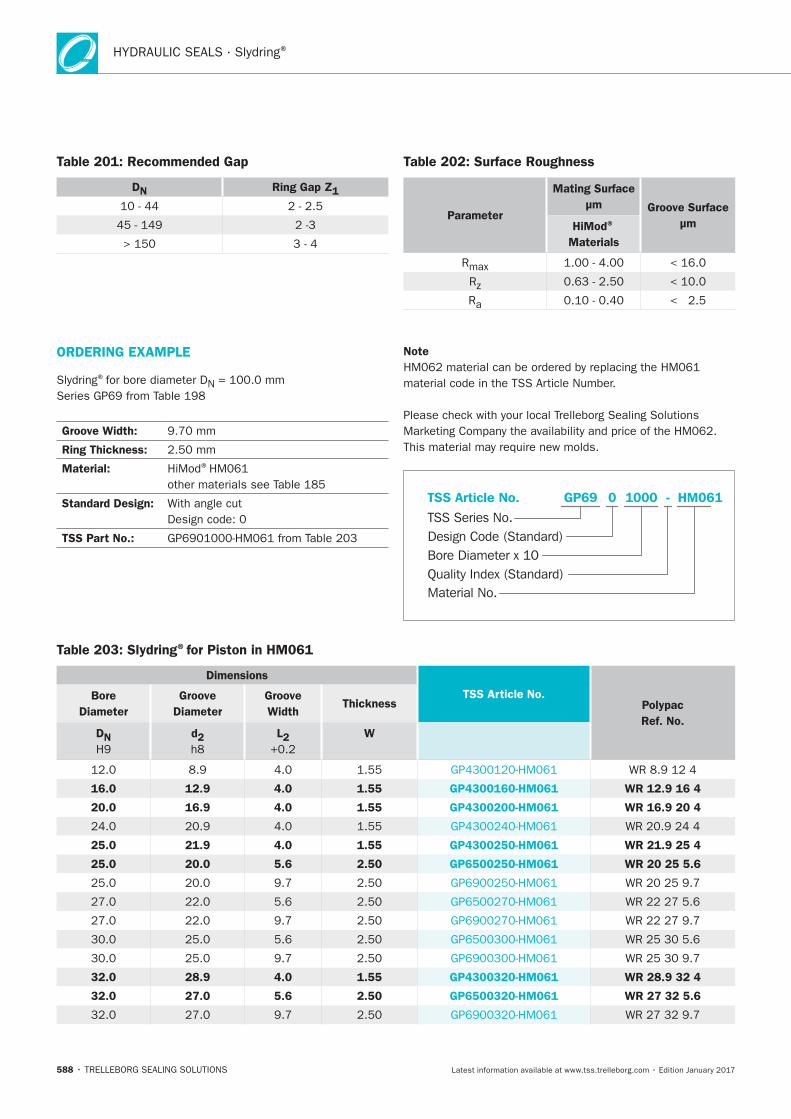
HYDRAULIC SEALS · Slydring®
588
Table 201: Recommended Gap
DN Ring Gap Z1
Table 202: Surface Roughness
Parameter
Mating Surface
μm Groove Surface
μmHiMod®
Materials
Table 203: Slydring®for Piston in HM061
Dimensions
TSS Article No.Polypac
Ref. No.
Bore
Diameter
Groove
Diameter
Groove
Width Thickness
DN
H9
d2
L2
W
16.0 12.9 4.0 1.55 GP4300160-HM061 WR 12.9 16 4
20.0 16.9 4.0 1.55 GP4300200-HM061 WR 16.9 20 4
25.0 21.9 4.0 1.55 GP4300250-HM061 WR 21.9 25 4
25.0 20.0 5.6 2.50 GP6500250-HM061 WR 20 25 5.6
32.0 28.9 4.0 1.55 GP4300320-HM061 WR 28.9 32 4
32.0 27.0 5.6 2.50 GP6500320-HM061 WR 27 32 5.6
ORDERING EXAMPLE
®
Groove Width:
Ring Thickness:
Material: ®
Standard Design:
TSS Part No.:
Note
Material No.
TSS Series No.
TSS Article No.
Bore Diameter x 10Quality Index (Standard)
Design Code (Standard)
HM061GP69 - 0 1000
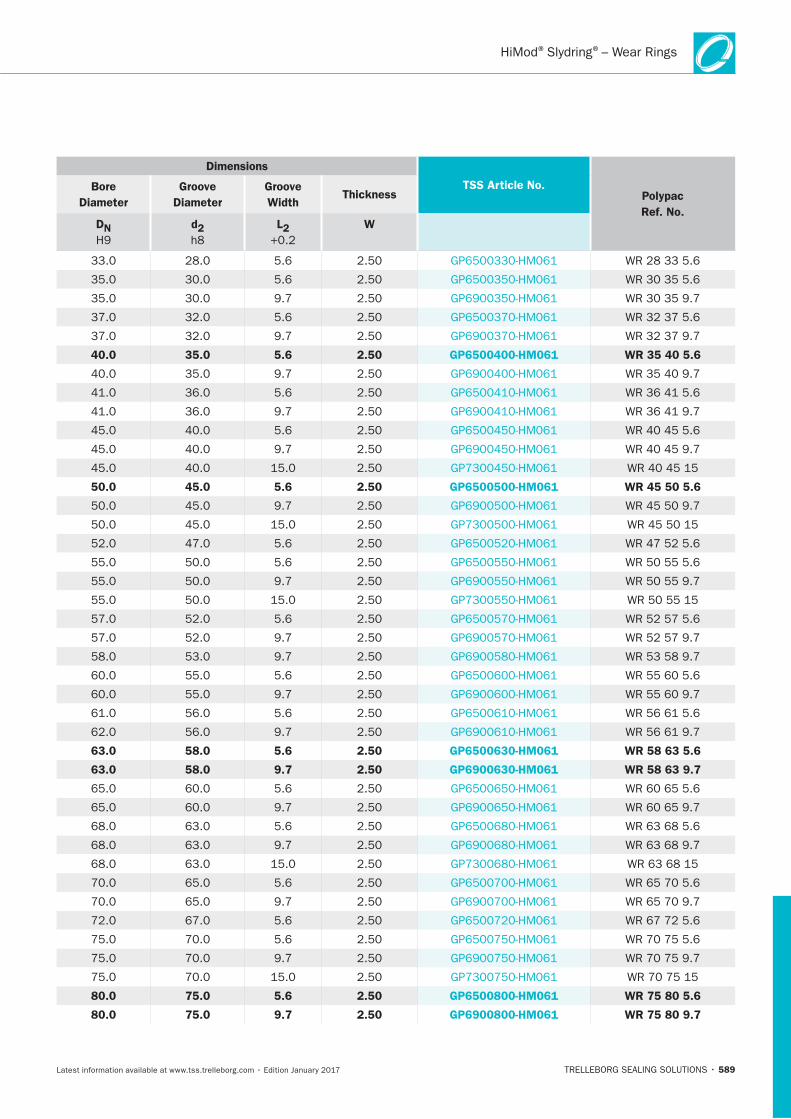
589
Dimensions
TSS Article No.Polypac
Ref. No.
Bore
Diameter
Groove
Diameter
Groove
Width Thickness
DN
H9
d2
L2
W
40.0 35.0 5.6 2.50 GP6500400-HM061 WR 35 40 5.6
50.0 45.0 5.6 2.50 GP6500500-HM061 WR 45 50 5.6
63.0 58.0 5.6 2.50 GP6500630-HM061 WR 58 63 5.6
63.0 58.0 9.7 2.50 GP6900630-HM061 WR 58 63 9.7
80.0 75.0 5.6 2.50 GP6500800-HM061 WR 75 80 5.6
80.0 75.0 9.7 2.50 GP6900800-HM061 WR 75 80 9.7
® ®– Wear Rings
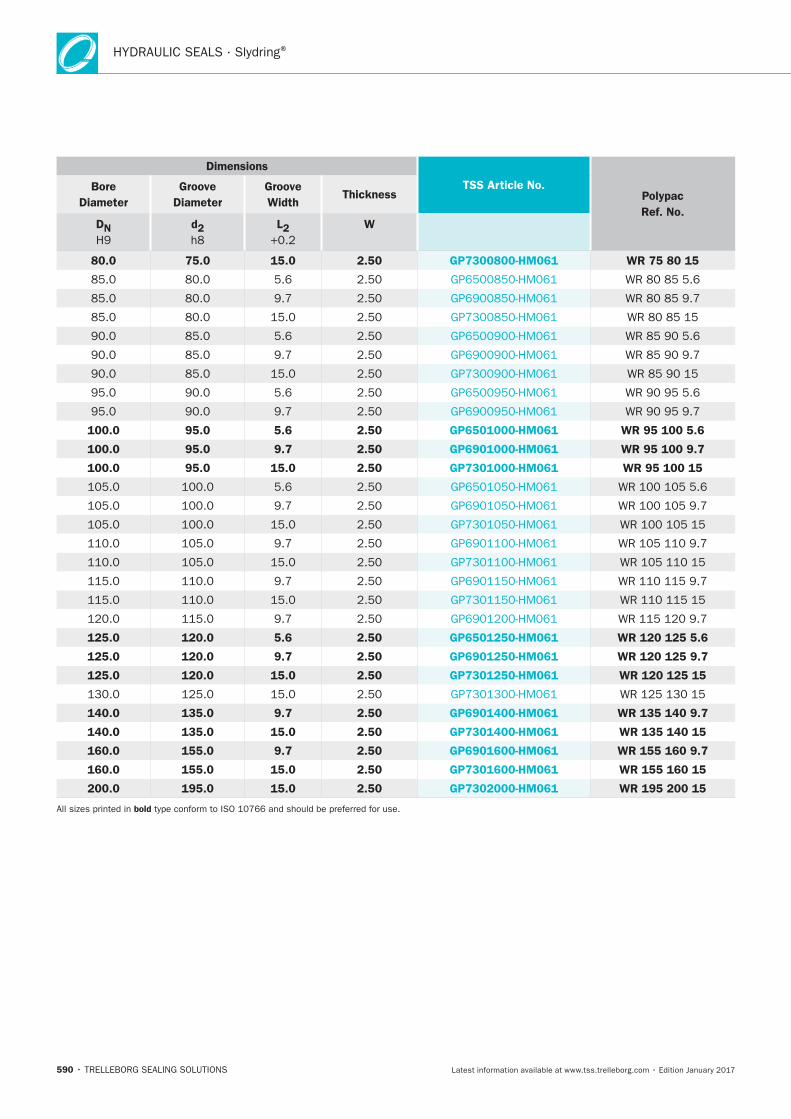
HYDRAULIC SEALS · Slydring®
590
Dimensions
TSS Article No.Polypac
Ref. No.
Bore
Diameter
Groove
Diameter
Groove
Width Thickness
DN
H9
d2
L2
W
80.0 75.0 15.0 2.50 GP7300800-HM061 WR 75 80 15
100.0 95.0 5.6 2.50 GP6501000-HM061 WR 95 100 5.6
100.0 95.0 9.7 2.50 GP6901000-HM061 WR 95 100 9.7
100.0 95.0 15.0 2.50 GP7301000-HM061 WR 95 100 15
125.0 120.0 5.6 2.50 GP6501250-HM061 WR 120 125 5.6
125.0 120.0 9.7 2.50 GP6901250-HM061 WR 120 125 9.7
125.0 120.0 15.0 2.50 GP7301250-HM061 WR 120 125 15
140.0 135.0 9.7 2.50 GP6901400-HM061 WR 135 140 9.7
140.0 135.0 15.0 2.50 GP7301400-HM061 WR 135 140 15
160.0 155.0 9.7 2.50 GP6901600-HM061 WR 155 160 9.7
160.0 155.0 15.0 2.50 GP7301600-HM061 WR 155 160 15
200.0 195.0 15.0 2.50 GP7302000-HM061 WR 195 200 15
bold
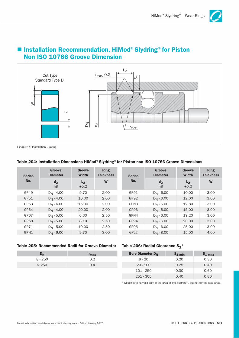
591
Installation Recommendation, HiMod®Slydring®for Piston Non ISO 10766 Groove Dimension
Cut TypeStandard Type D
W
Z
rmax.
L2
S1rmax. 0.2
DN
d 2
Table 204: Installation Dimensions HiMod®Slydring®for Piston non ISO 10766 Groove Dimensions
Table 205: Recommended Radii for Groove Diameter
DN rmax
Table 206: Radial Clearance S1*
Bore Diameter DN S1 min S1 max
* ®
Series
No.
Groove
Diameter
Groove
Width
Ring
Thickness
d2 L2 W
Series
No.
Groove
Diameter
Groove
Width
Ring
Thickness
d2 L2 W
® ®– Wear Rings
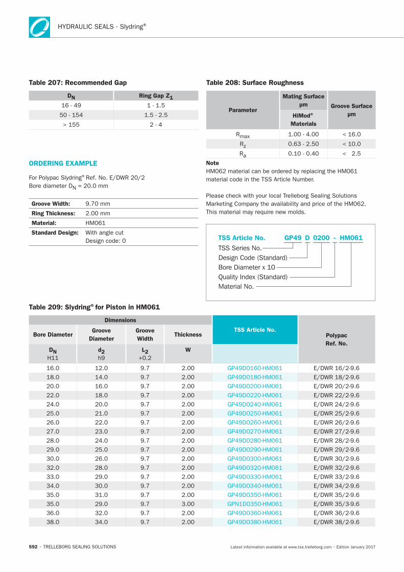
HYDRAULIC SEALS · Slydring®
592
Table 207: Recommended Gap
DN Ring Gap Z1
Table 208: Surface Roughness
Parameter
Mating Surface
μm Groove Surface
μmHiMod®
Materials
Table 209: Slydring®for Piston in HM061
Dimensions
TSS Article No. Polypac
Ref. No.
Bore Diameter Groove
Diameter
Groove
Width Thickness
DN
d2
L2 W
ORDERING EXAMPLE
®
Groove Width:
Ring Thickness:
Material:
Standard Design:
Note
HM061GP49 0200 -
Material No.
TSS Series No.TSS Article No.
Bore Diameter x 10Quality Index (Standard)
Design Code (Standard)
D
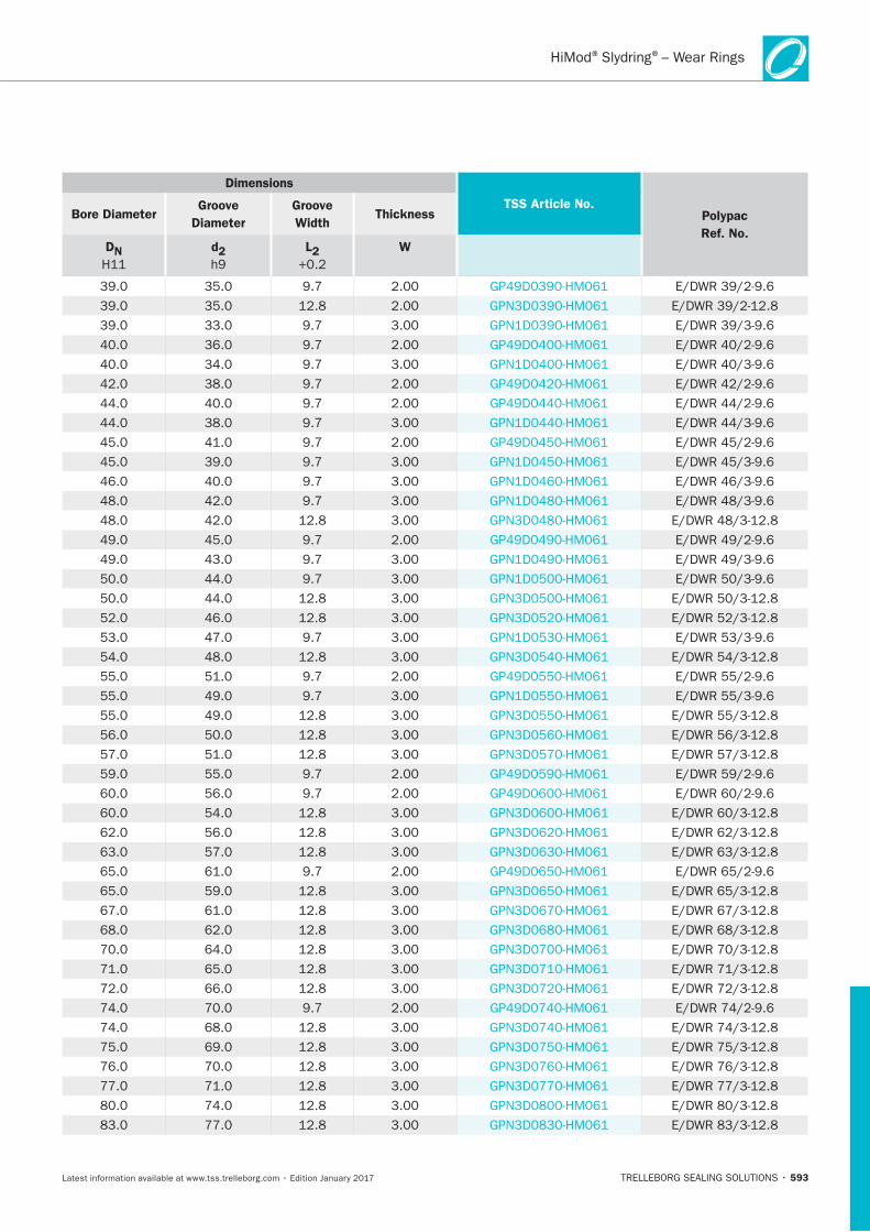
593
Dimensions
TSS Article No. Polypac
Ref. No.
Bore Diameter Groove
Diameter
Groove
Width Thickness
DN
d2
L2 W
® ®– Wear Rings
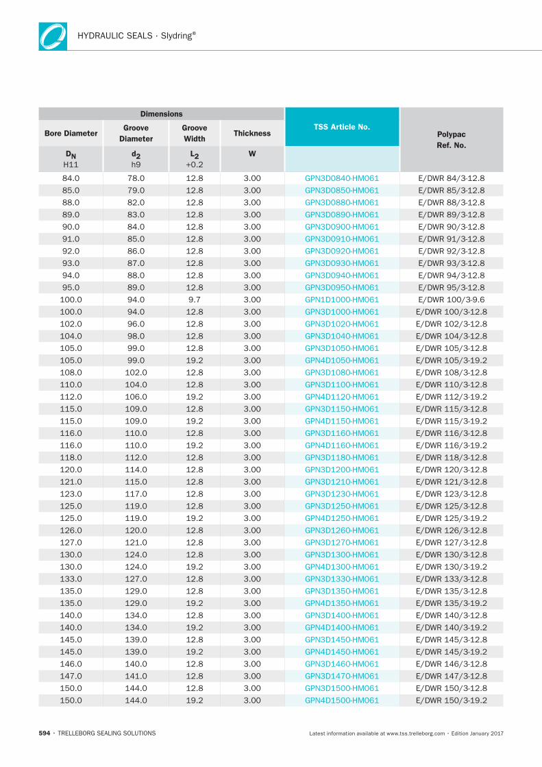
HYDRAULIC SEALS · Slydring®
594
Dimensions
TSS Article No. Polypac
Ref. No.
Bore Diameter Groove
Diameter
Groove
Width Thickness
DN
d2
L2 W
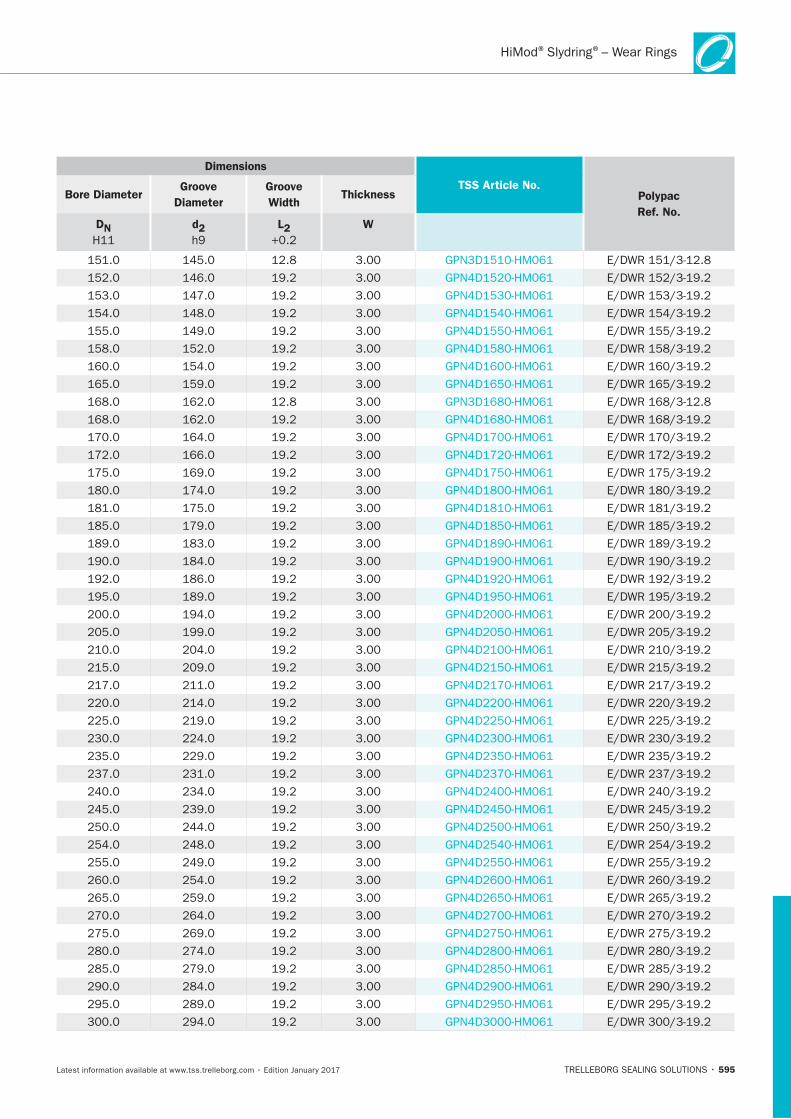
595
Dimensions
TSS Article No. Polypac
Ref. No.
Bore Diameter Groove
Diameter
Groove
Width Thickness
DN
d2
L2 W
® ®– Wear Rings
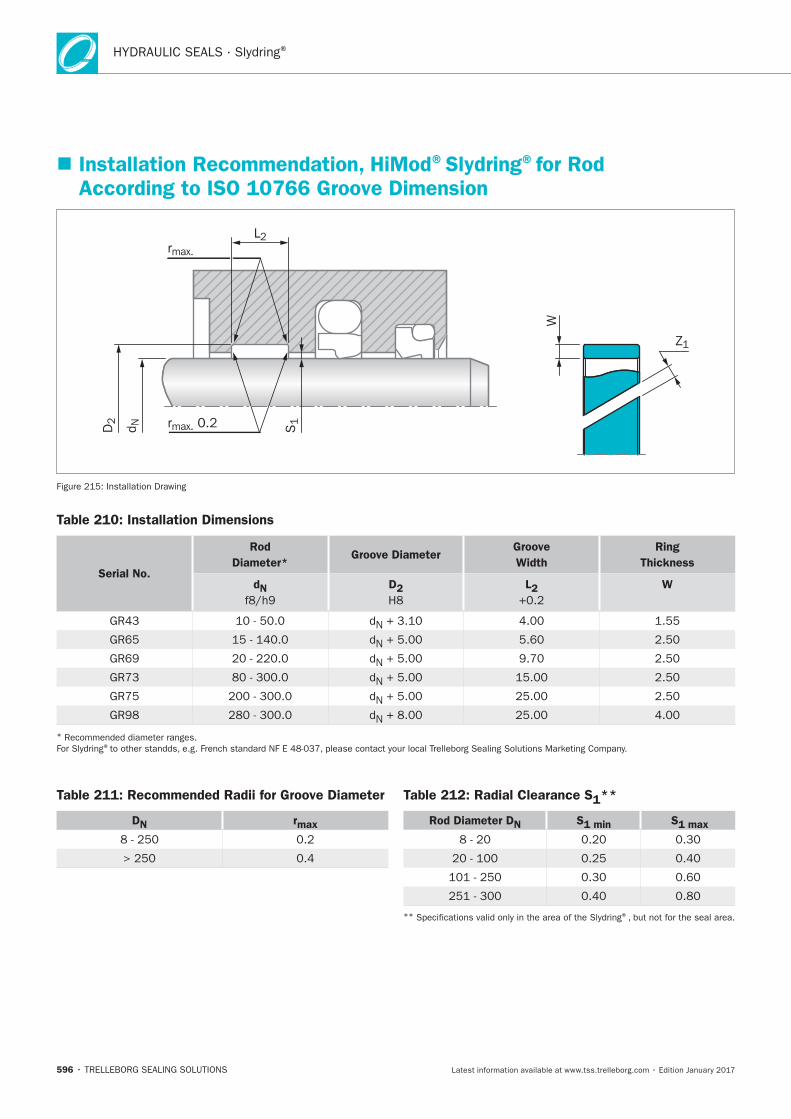
HYDRAULIC SEALS · Slydring®
596
Installation Recommendation, HiMod®Slydring®for Rod According to ISO 10766 Groove Dimension
rmax.
L2
S1rmax. 0.2D2
d N
W
Z1
Table 210: Installation Dimensions
Serial No.
Rod
Diameter*Groove Diameter
Groove
Width
Ring
Thickness
dN D2 L2 W
* ®
Table 211: Recommended Radii for Groove Diameter
DN rmax
Table 212: Radial Clearance S1**
Rod Diameter DN S1 min S1 max
** ®
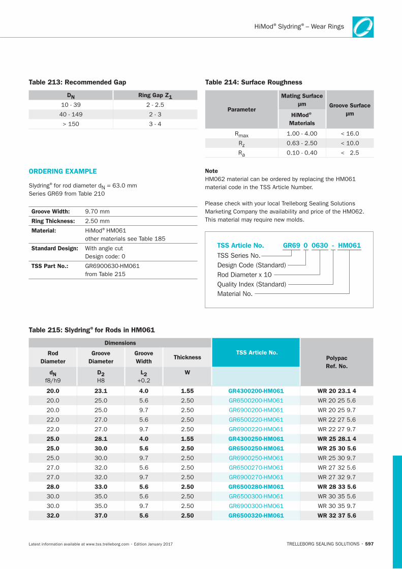
597
Table 213: Recommended Gap
DN Ring Gap Z1
Table 214: Surface Roughness
Parameter
Mating Surface
μm Groove Surface
μmHiMod®
Materials
Table 215: Slydring®for Rods in HM061
Dimensions
TSS Article No. Polypac
Ref. No.
Rod
Diameter
Groove
Diameter
Groove
Width Thickness
dN
D2 L2
W
20.0 23.1 4.0 1.55 GR4300200-HM061 WR 20 23.1 4
25.0 28.1 4.0 1.55 GR4300250-HM061 WR 25 28.1 4
25.0 30.0 5.6 2.50 GR6500250-HM061 WR 25 30 5.6
28.0 33.0 5.6 2.50 GR6500280-HM061 WR 28 33 5.6
32.0 37.0 5.6 2.50 GR6500320-HM061 WR 32 37 5.6
ORDERING EXAMPLE
®
Groove Width:
Ring Thickness:
Material: ®
Standard Design:
TSS Part No.:
Note
HM061GR69 0630 -
Material No.
TSS Series No.TSS Article No.
Rod Diameter x 10Quality Index (Standard)
Design Code (Standard)
0
® ®– Wear Rings
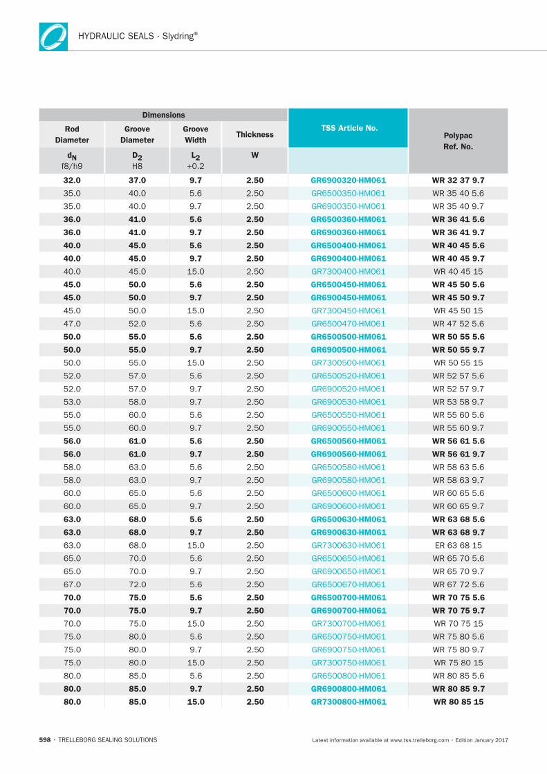
HYDRAULIC SEALS · Slydring®
598
Dimensions
TSS Article No. Polypac
Ref. No.
Rod
Diameter
Groove
Diameter
Groove
Width Thickness
dN
D2 L2
W
32.0 37.0 9.7 2.50 GR6900320-HM061 WR 32 37 9.7
36.0 41.0 5.6 2.50 GR6500360-HM061 WR 36 41 5.6
36.0 41.0 9.7 2.50 GR6900360-HM061 WR 36 41 9.7
40.0 45.0 5.6 2.50 GR6500400-HM061 WR 40 45 5.6
40.0 45.0 9.7 2.50 GR6900400-HM061 WR 40 45 9.7
45.0 50.0 5.6 2.50 GR6500450-HM061 WR 45 50 5.6
45.0 50.0 9.7 2.50 GR6900450-HM061 WR 45 50 9.7
50.0 55.0 5.6 2.50 GR6500500-HM061 WR 50 55 5.6
50.0 55.0 9.7 2.50 GR6900500-HM061 WR 50 55 9.7
56.0 61.0 5.6 2.50 GR6500560-HM061 WR 56 61 5.6
56.0 61.0 9.7 2.50 GR6900560-HM061 WR 56 61 9.7
63.0 68.0 5.6 2.50 GR6500630-HM061 WR 63 68 5.6
63.0 68.0 9.7 2.50 GR6900630-HM061 WR 63 68 9.7
70.0 75.0 5.6 2.50 GR6500700-HM061 WR 70 75 5.6
70.0 75.0 9.7 2.50 GR6900700-HM061 WR 70 75 9.7
80.0 85.0 9.7 2.50 GR6900800-HM061 WR 80 85 9.7
80.0 85.0 15.0 2.50 GR7300800-HM061 WR 80 85 15
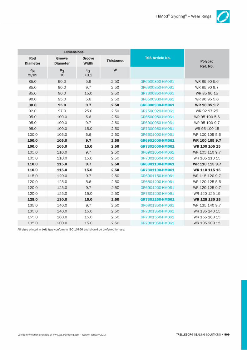
599
Dimensions
TSS Article No. Polypac
Ref. No.
Rod
Diameter
Groove
Diameter
Groove
Width Thickness
dN
D2 L2
W
90.0 95.0 9.7 2.50 GR6900900-HM061 WR 90 95 9.7
100.0 105.0 9.7 2.50 GR6901000-HM061 WR 100 105 9.7
100.0 105.0 15.0 2.50 GR7301000-HM061 WR 100 105 15
110.0 115.0 9.7 2.50 GR6901100-HM061 WR 110 115 9.7
110.0 115.0 15.0 2.50 GR7301100-HM061 WR 110 115 15
125.0 130.0 15.0 2.50 GR7301250-HM061 WR 125 130 15
bold
® ®– Wear Rings
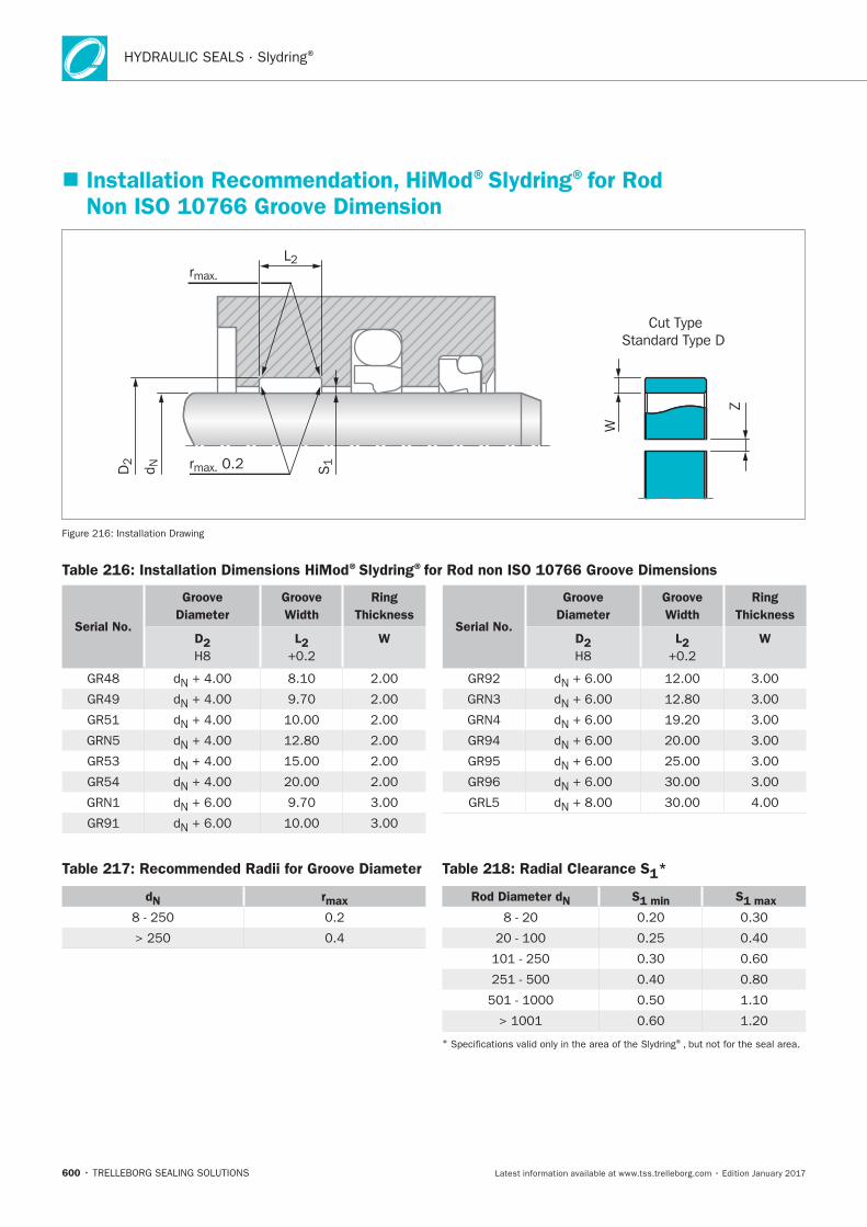
HYDRAULIC SEALS · Slydring®
600
Installation Recommendation, HiMod®Slydring®for Rod Non ISO 10766 Groove Dimension
Cut TypeStandard Type D
W
rmax.
L2
S1rmax. 0.2D2
d N
Z
Table 216: Installation Dimensions HiMod®Slydring®for Rod non ISO 10766 Groove Dimensions
Table 217: Recommended Radii for Groove Diameter
dN rmax
Table 218: Radial Clearance S1*
Rod Diameter dN S1 min S1 max
* ®
Serial No.
Groove
Diameter
Groove
Width
Ring
Thickness
D2 L2 WSerial No.
Groove
Diameter
Groove
Width
Ring
Thickness
D2 L2 W
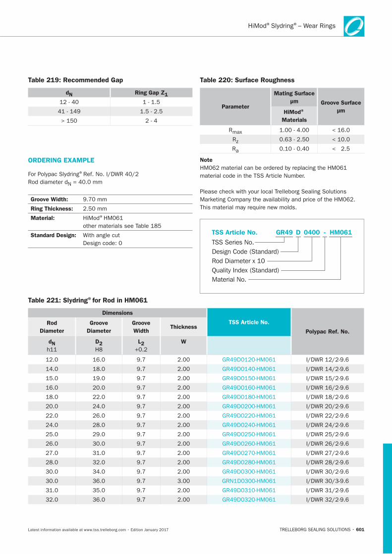
601
Table 219: Recommended Gap
dN Ring Gap Z1
Table 220: Surface Roughness
Parameter
Mating Surface
μm Groove Surface
μmHiMod®
Materials
Table 221: Slydring®for Rod in HM061
Dimensions
TSS Article No.
Polypac Ref. No.
Rod
Diameter
Groove
Diameter
Groove
Width Thickness
dN
D2 L2 W
ORDERING EXAMPLE
®
Groove Width:
Ring Thickness:
Material: ®
Standard Design:
Note
HM061GR49 0400 -
Material No.
TSS Series No.
TSS Article No.
Rod Diameter x 10Quality Index (Standard)
Design Code (Standard)
D
® ®– Wear Rings
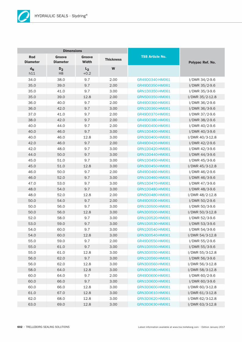
HYDRAULIC SEALS · Slydring®
602
Dimensions
TSS Article No.
Polypac Ref. No.
Rod
Diameter
Groove
Diameter
Groove
Width Thickness
dN
D2 L2 W
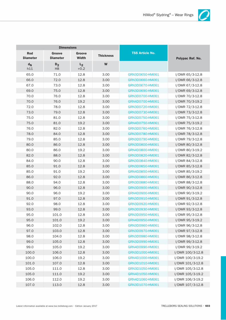
603
Dimensions
TSS Article No.
Polypac Ref. No.
Rod
Diameter
Groove
Diameter
Groove
Width Thickness
dN
D2 L2 W
® ®– Wear Rings
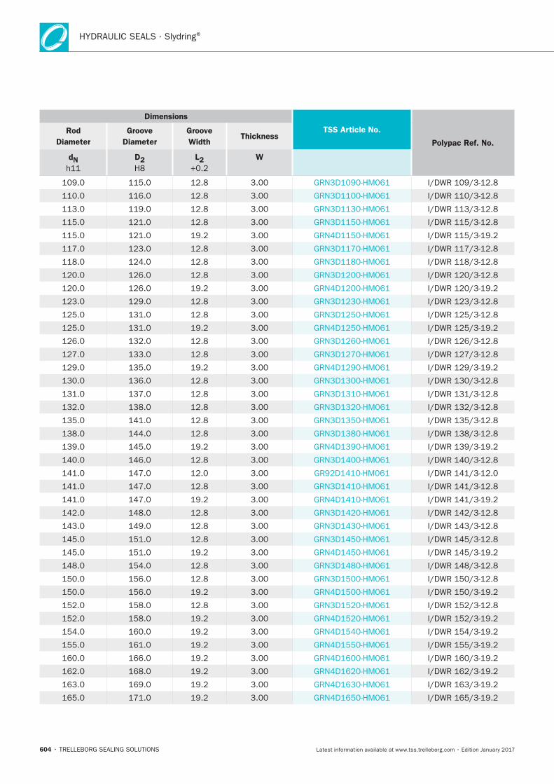
HYDRAULIC SEALS · Slydring®
604
Dimensions
TSS Article No.
Polypac Ref. No.
Rod
Diameter
Groove
Diameter
Groove
Width Thickness
dN
D2 L2 W
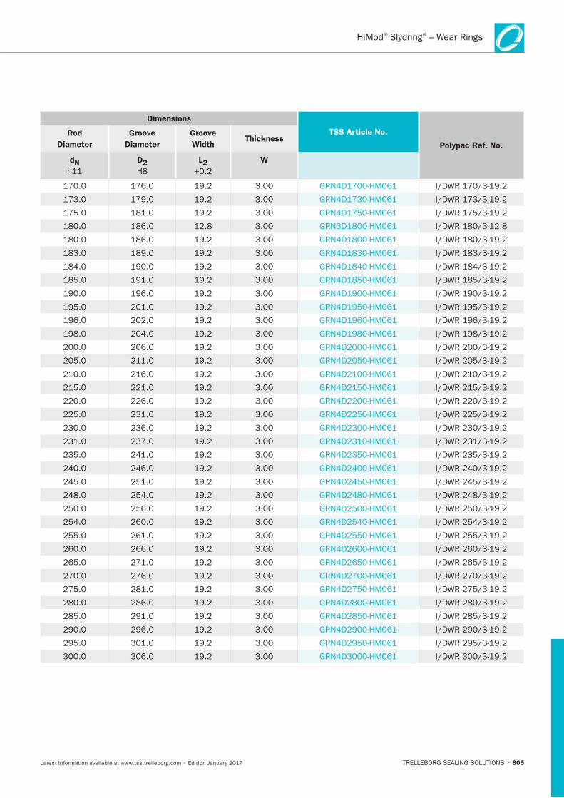
605
Dimensions
TSS Article No.
Polypac Ref. No.
Rod
Diameter
Groove
Diameter
Groove
Width Thickness
dN
D2 L2 W
® ®– Wear Rings
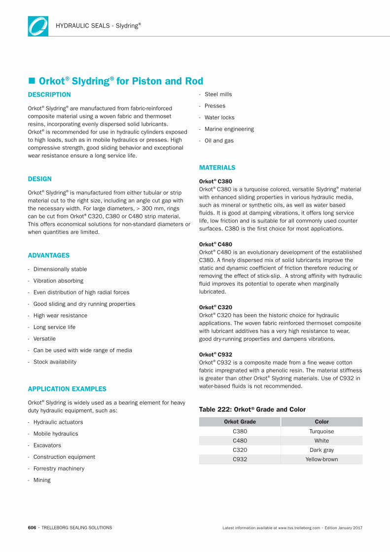
HYDRAULIC SEALS · Slydring®
606
Orkot®Slydring®for Piston and RodDESCRIPTION
® ®
®
DESIGN
® ®
®
ADVANTAGES
APPLICATION EXAMPLES
®
MATERIALS
Orkot®C380® ®
Orkot®C480®
Orkot®C320®
Orkot®C932®
®
Table 222: Orkot®Grade and Color
Orkot Grade Color
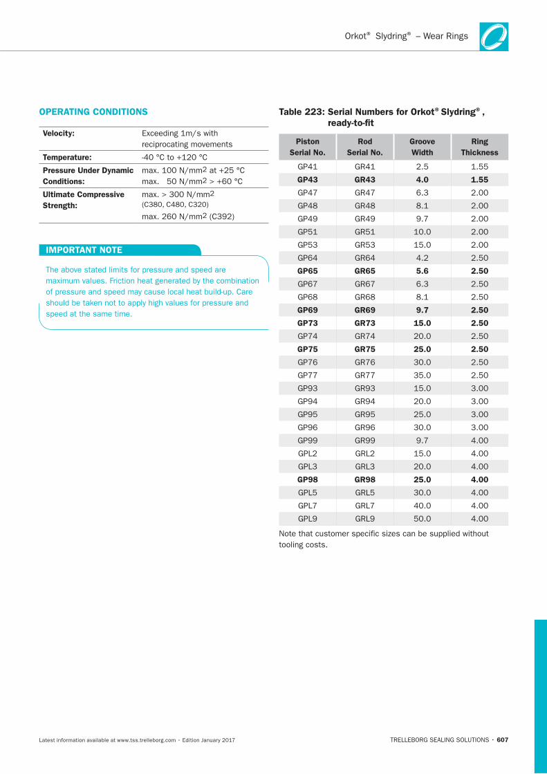
Orkot Slydring – Wear Rings® ®
607
OPERATING CONDITIONS
Velocity:
Temperature:
Pressure Under Dynamic
Conditions:
Ultimate Compressive
Strength:
IMPORTANT NOTE
Table 223: Serial Numbers for Orkot®Slydring®, ready-to-fit
Piston
Serial No.
Rod
Serial No.
Groove
Width
Ring
Thickness
GP43 GR43 4.0 1.55
GP65 GR65 5.6 2.50
GP69 GR69 9.7 2.50
GP73 GR73 15.0 2.50
GP75 GR75 25.0 2.50
GP98 GR98 25.0 4.00
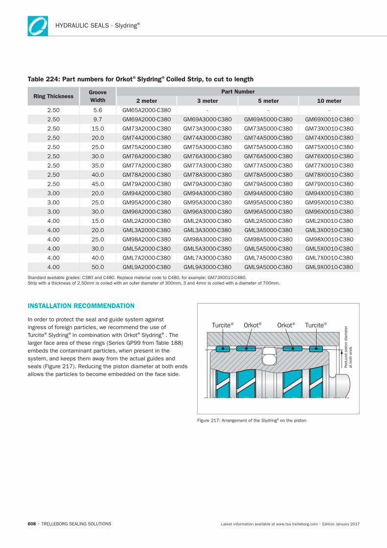
HYDRAULIC SEALS · Slydring®
608
Table 224: Part numbers for Orkot®Slydring®Coiled Strip, to cut to length
Ring ThicknessGroove
Width
Part Number
2 meter 3 meter 5 meter 10 meter
INSTALLATION RECOMMENDATION
® ® ® ®
Red
uced
pis
ton
diam
eter
at b
oth
ends
Orkot®Orkot® Turcite®Turcite®
®
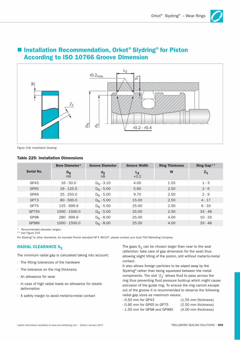
609
Installation Recommendation, Orkot®Slydring®for Piston According to ISO 10766 Groove Dimension
L2
S1
DN
d 2
Z1
W
r0.2max.
r0.2 - r0.4
Table 225: Installation Dimensions
Serial No.
Bore Diameter* Groove Diameter Groove Width Ring Thickness Ring Gap**
DN d2 L2 W Z1
D
D
D
D
D
D
D
D
* **
®
RADIAL CLEARANCE S1
®
Orkot Slydring – Wear Rings® ®
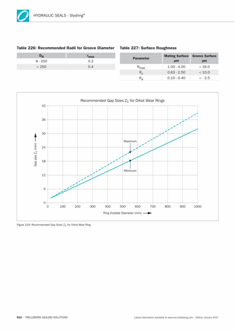
HYDRAULIC SEALS · Slydring®
610
Table 226: Recommended Radii for Groove Diameter
DN rmax
Table 227: Surface Roughness
ParameterMating Surface
μm
Groove Surface
μm
Ring Outside Diameter (mm)
Maximum
Minimum
0 100 200 300 400 500 600 700 800 900 10000
6
12
18
24
30
36
42
Recommended Gap Sizes Z1 for Orkot Wear Rings
Gap
siz
e Z 1
(m
m)
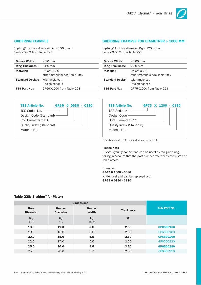
611
ORDERING EXAMPLE
®
Groove Width:
Ring Thickness:
Material: ®
Standard Design:
TSS Part No.:
Material No.
TSS Series No.
TSS Article No.
Rod Diameter x 10Quality Index (Standard)
Design Code (Standard)
C380GR69 - 0 0630
ORDERING EXAMPLE FOR DIAMETRER > 1000 MM
®
Groove Width:
Ring Thickness:
Material: ®
Standard Design:
TSS Part No.:
Material No.
TSS Series No.
TSS Article No.
Bore Diameter x 1*Quality Index (Standard)
Design Code
C380GP75 - X 1200
*
Please Note® ®
GP69 0 1000 - C380
GR69 0 0950 - C380
Table 228: Slydring®for Piston
Dimensions
TSS Part No.Bore
Diameter
Groove
Diameter
Groove
Width Thickness
DN d2 L2 W
16.0 11.0 5.6 2.50 GP6500160
20.0 15.0 5.6 2.50 GP6500200
25.0 20.0 5.6 2.50 GP6500250
Orkot Slydring – Wear Rings® ®
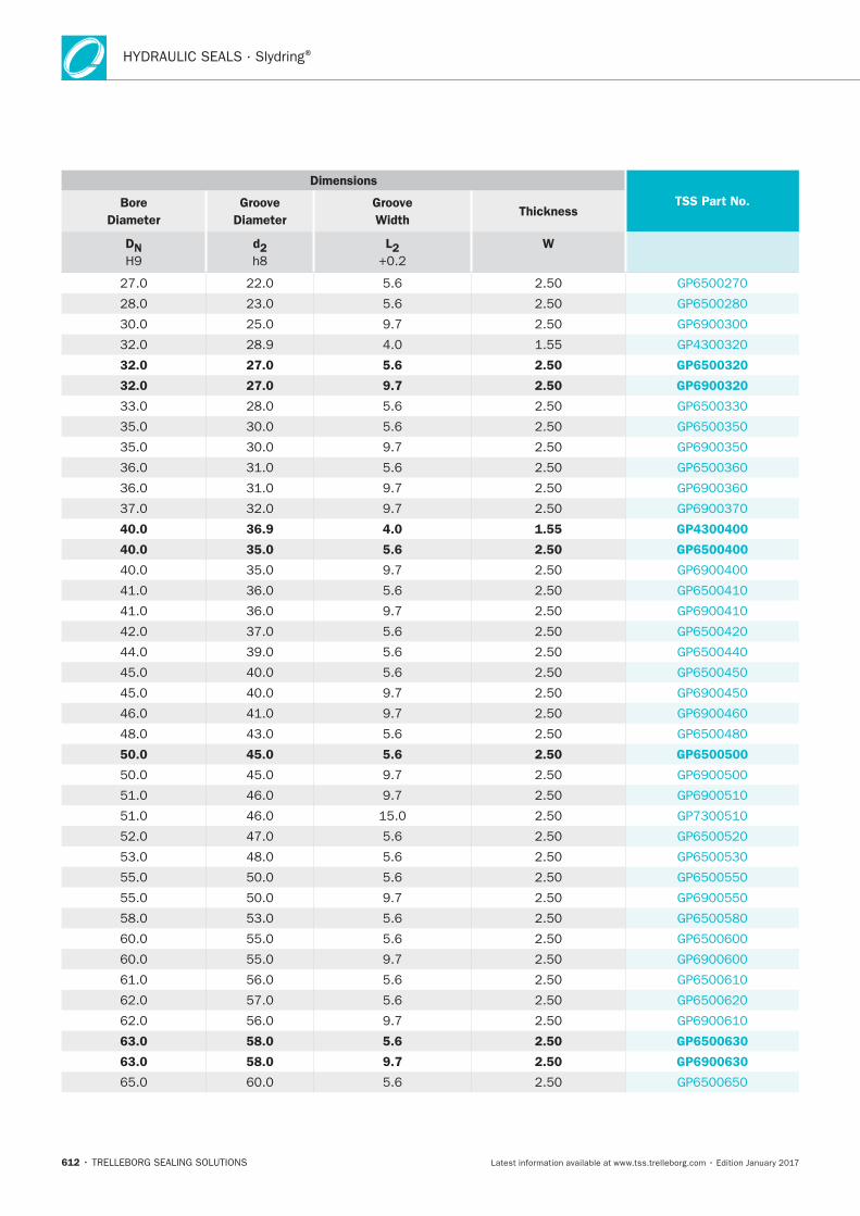
HYDRAULIC SEALS · Slydring®
612
Dimensions
TSS Part No.Bore
Diameter
Groove
Diameter
Groove
Width Thickness
DN d2 L2 W
32.0 27.0 5.6 2.50 GP6500320
32.0 27.0 9.7 2.50 GP6900320
40.0 36.9 4.0 1.55 GP4300400
40.0 35.0 5.6 2.50 GP6500400
50.0 45.0 5.6 2.50 GP6500500
63.0 58.0 5.6 2.50 GP6500630
63.0 58.0 9.7 2.50 GP6900630
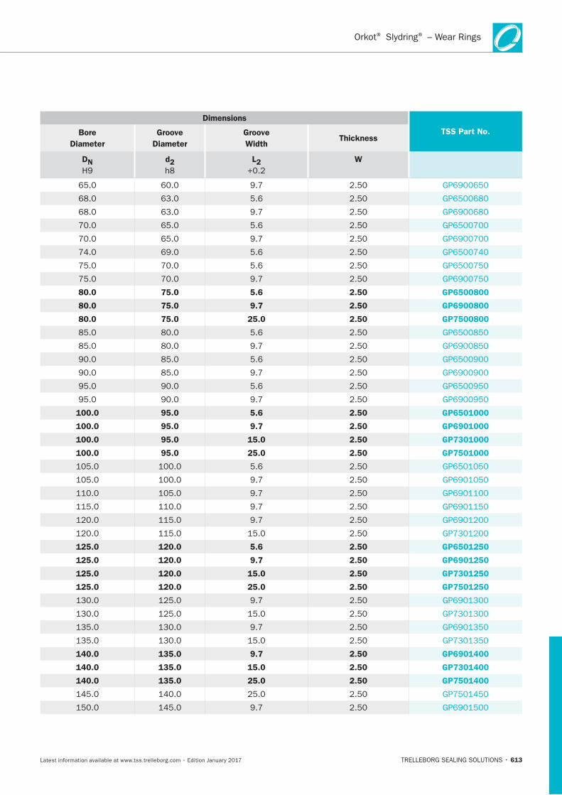
613
Dimensions
TSS Part No.Bore
Diameter
Groove
Diameter
Groove
Width Thickness
DN d2 L2 W
80.0 75.0 5.6 2.50 GP6500800
80.0 75.0 9.7 2.50 GP6900800
80.0 75.0 25.0 2.50 GP7500800
100.0 95.0 5.6 2.50 GP6501000
100.0 95.0 9.7 2.50 GP6901000
100.0 95.0 15.0 2.50 GP7301000
100.0 95.0 25.0 2.50 GP7501000
125.0 120.0 5.6 2.50 GP6501250
125.0 120.0 9.7 2.50 GP6901250
125.0 120.0 15.0 2.50 GP7301250
125.0 120.0 25.0 2.50 GP7501250
140.0 135.0 9.7 2.50 GP6901400
140.0 135.0 15.0 2.50 GP7301400
140.0 135.0 25.0 2.50 GP7501400
Orkot Slydring – Wear Rings® ®
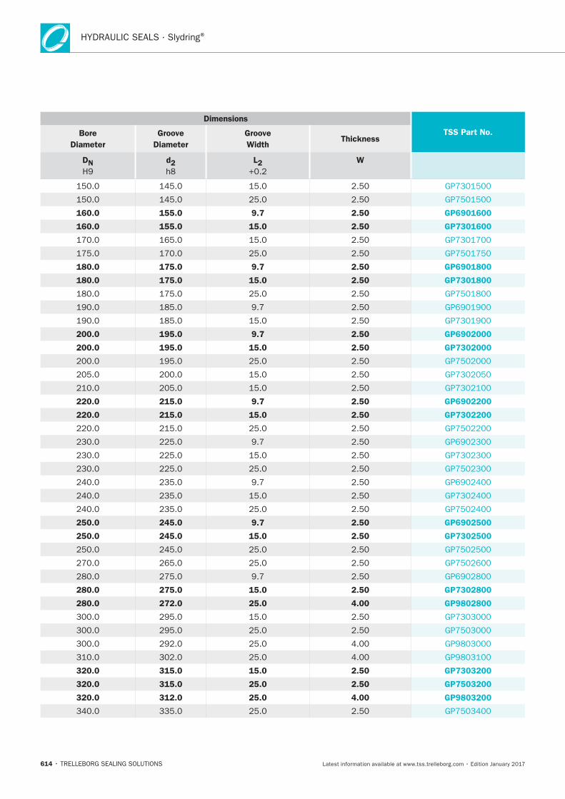
HYDRAULIC SEALS · Slydring®
614
Dimensions
TSS Part No.Bore
Diameter
Groove
Diameter
Groove
Width Thickness
DN d2 L2 W
160.0 155.0 9.7 2.50 GP6901600
160.0 155.0 15.0 2.50 GP7301600
180.0 175.0 9.7 2.50 GP6901800
180.0 175.0 15.0 2.50 GP7301800
200.0 195.0 9.7 2.50 GP6902000
200.0 195.0 15.0 2.50 GP7302000
220.0 215.0 9.7 2.50 GP6902200
220.0 215.0 15.0 2.50 GP7302200
250.0 245.0 9.7 2.50 GP6902500
250.0 245.0 15.0 2.50 GP7302500
280.0 275.0 15.0 2.50 GP7302800
280.0 272.0 25.0 4.00 GP9802800
320.0 315.0 15.0 2.50 GP7303200
320.0 315.0 25.0 2.50 GP7503200
320.0 312.0 25.0 4.00 GP9803200
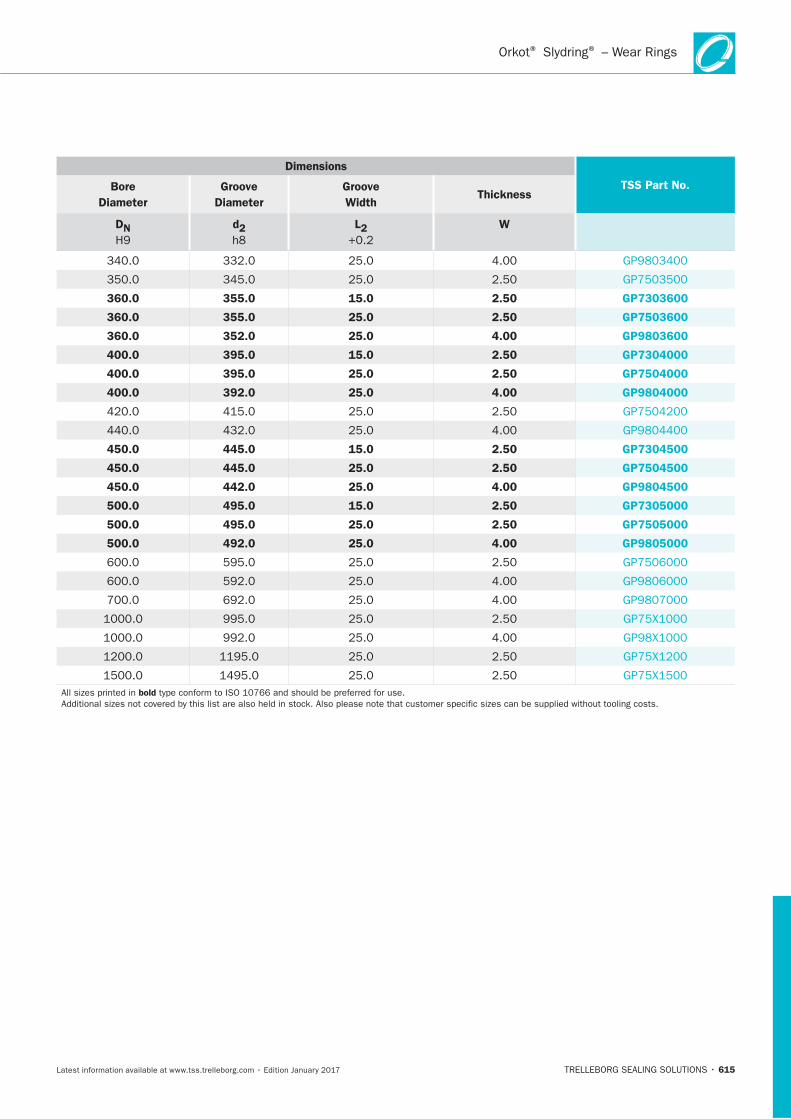
615
Dimensions
TSS Part No.Bore
Diameter
Groove
Diameter
Groove
Width Thickness
DN d2 L2 W
360.0 355.0 15.0 2.50 GP7303600
360.0 355.0 25.0 2.50 GP7503600
360.0 352.0 25.0 4.00 GP9803600
400.0 395.0 15.0 2.50 GP7304000
400.0 395.0 25.0 2.50 GP7504000
400.0 392.0 25.0 4.00 GP9804000
450.0 445.0 15.0 2.50 GP7304500
450.0 445.0 25.0 2.50 GP7504500
450.0 442.0 25.0 4.00 GP9804500
500.0 495.0 15.0 2.50 GP7305000
500.0 495.0 25.0 2.50 GP7505000
500.0 492.0 25.0 4.00 GP9805000
bold
Orkot Slydring – Wear Rings® ®
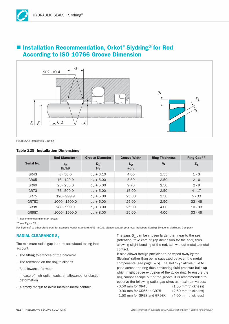
HYDRAULIC SEALS · Slydring®
616
Installation Recommendation, Orkot®Slydring®for Rod According to ISO 10766 Groove Dimension
r0.2 - r0.4L2
S1rmax. 0.2D2
d N
W
Z1
Table 229: Installation Dimensions
Serial No.
Rod Diameter* Groove Diameter Groove Width Ring Thickness Ring Gap**
dN D2 L2 W Z1
*
**
®
RADIAL CLEARANCE S1
®
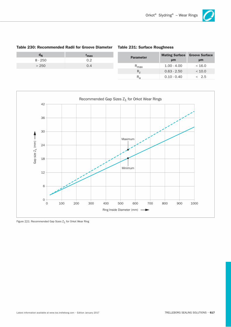
617
Table 230: Recommended Radii for Groove Diameter
dN rmax
Table 231: Surface Roughness
ParameterMating Surface
μm
Groove Surface
μm
Ring Inside Diameter (mm)
Maximum
Minimum
0 100 200 300 400 500 600 700 800 900 10000
6
12
18
24
30
36
42
Recommended Gap Sizes Z1 for Orkot Wear Rings
Gap
siz
e Z 1
(m
m)
Orkot Slydring – Wear Rings® ®
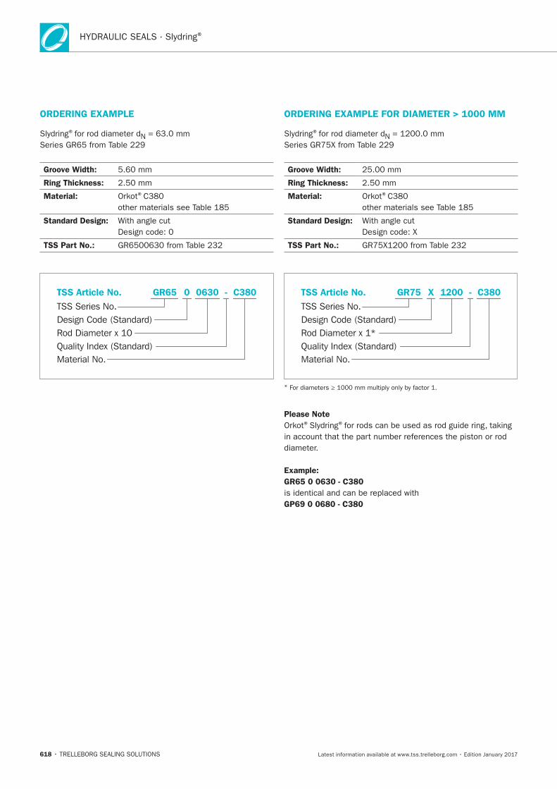
HYDRAULIC SEALS · Slydring®
618
ORDERING EXAMPLE
®
Groove Width:
Ring Thickness:
Material: ®
Standard Design:
TSS Part No.:
Material No.
TSS Series No.
TSS Article No.
Rod Diameter x 10Quality Index (Standard)
Design Code (Standard)
C380GR65 - 0 0630
ORDERING EXAMPLE FOR DIAMETER > 1000 MM
®
Groove Width:
Ring Thickness:
Material: ®
Standard Design:
TSS Part No.:
Material No.
TSS Series No.
TSS Article No.
Rod Diameter x 1*Quality Index (Standard)
Design Code (Standard)
C380GR75 - X 1200
*
Please Note® ®
Example:
GR65 0 0630 - C380
GP69 0 0680 - C380
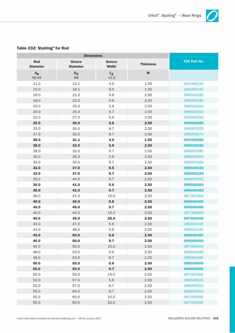
619
Table 232: Slydring®for Rod
Dimensions
TSS Part No. Rod
Diameter
Groove
Diameter
Groove
Width Thickness
dN
D2 L2
W
25.0 30.0 5.6 2.50 GR6500250
28.0 31.1 4.0 1.55 GR4300280
28.0 33.0 5.6 2.50 GR6500280
32.0 37.0 5.6 2.50 GR6500320
32.0 37.0 9.7 2.50 GR6900320
36.0 41.0 5.6 2.50 GR6500360
36.0 41.0 9.7 2.50 GR6900360
40.0 45.0 5.6 2.50 GR6500400
40.0 45.0 9.7 2.50 GR6900400
40.0 45.0 25.0 2.50 GR7500400
45.0 50.0 5.6 2.50 GR6500450
45.0 50.0 9.7 2.50 GR6900450
50.0 55.0 5.6 2.50 GR6500500
50.0 55.0 9.7 2.50 GR6900500
Orkot Slydring – Wear Rings® ®
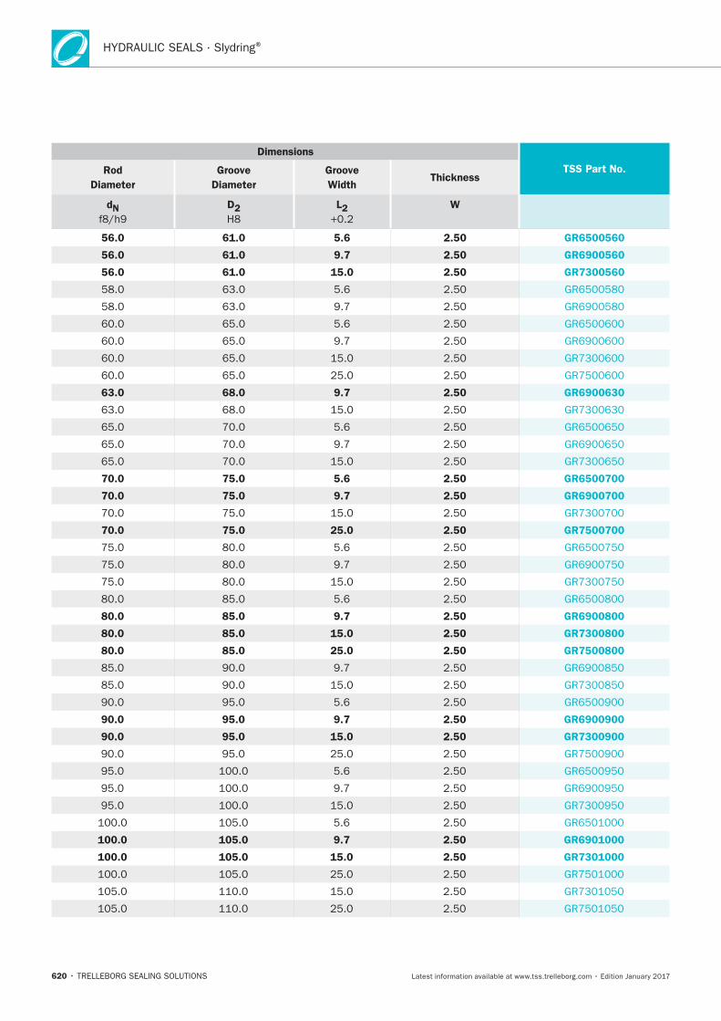
HYDRAULIC SEALS · Slydring®
620
Dimensions
TSS Part No. Rod
Diameter
Groove
Diameter
Groove
Width Thickness
dN
D2 L2
W
56.0 61.0 5.6 2.50 GR6500560
56.0 61.0 9.7 2.50 GR6900560
56.0 61.0 15.0 2.50 GR7300560
63.0 68.0 9.7 2.50 GR6900630
70.0 75.0 5.6 2.50 GR6500700
70.0 75.0 9.7 2.50 GR6900700
70.0 75.0 25.0 2.50 GR7500700
80.0 85.0 9.7 2.50 GR6900800
80.0 85.0 15.0 2.50 GR7300800
80.0 85.0 25.0 2.50 GR7500800
90.0 95.0 9.7 2.50 GR6900900
90.0 95.0 15.0 2.50 GR7300900
100.0 105.0 9.7 2.50 GR6901000
100.0 105.0 15.0 2.50 GR7301000
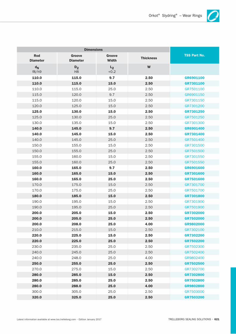
621
Dimensions
TSS Part No. Rod
Diameter
Groove
Diameter
Groove
Width Thickness
dN
D2 L2
W
110.0 115.0 9.7 2.50 GR6901100
110.0 115.0 15.0 2.50 GR7301100
125.0 130.0 15.0 2.50 GR7301250
140.0 145.0 9.7 2.50 GR6901400
140.0 145.0 15.0 2.50 GR7301400
160.0 165.0 9.7 2.50 GR6901600
160.0 165.0 15.0 2.50 GR7301600
160.0 165.0 25.0 2.50 GR7501600
180.0 185.0 15.0 2.50 GR7301800
200.0 205.0 15.0 2.50 GR7302000
200.0 205.0 25.0 2.50 GR7502000
200.0 208.0 25.0 4.00 GR9802000
220.0 225.0 15.0 2.50 GR7302200
220.0 225.0 25.0 2.50 GR7502200
250.0 255.0 25.0 2.50 GR7502500
280.0 285.0 15.0 2.50 GR7302800
280.0 285.0 25.0 2.50 GR7502800
280.0 288.0 25.0 4.00 GR9802800
320.0 325.0 25.0 2.50 GR7503200
Orkot Slydring – Wear Rings® ®
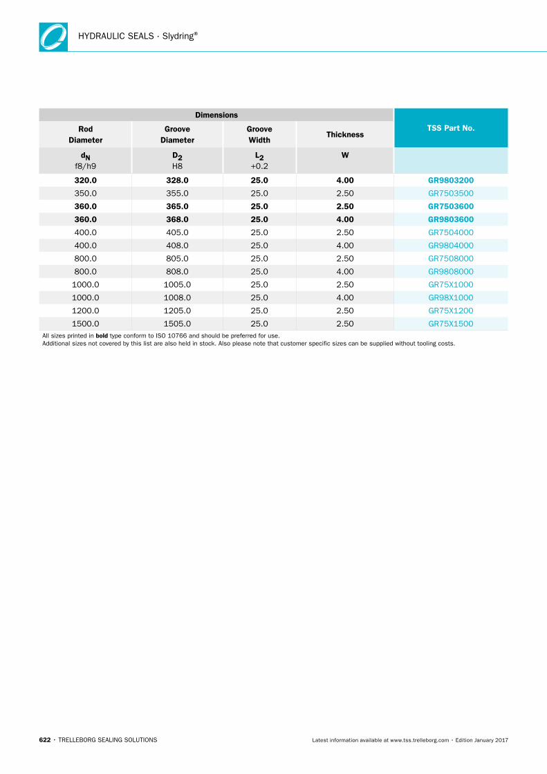
HYDRAULIC SEALS · Slydring®
622 • TRELLEBORG SEALING SOLUTIONS Latest information available at www.tss.trelleborg.com • Edition January 2017
Dimensions
TSS Part No. Rod Diameter
Groove Diameter
Groove Width
Thickness
dN f8/h9
D2 H8
L2 +0.2
W
320.0 328.0 25.0 4.00 GR9803200
350.0 355.0 25.0 2.50 GR7503500
360.0 365.0 25.0 2.50 GR7503600
360.0 368.0 25.0 4.00 GR9803600
400.0 405.0 25.0 2.50 GR7504000
400.0 408.0 25.0 4.00 GR9804000
800.0 805.0 25.0 2.50 GR7508000
800.0 808.0 25.0 4.00 GR9808000
1000.0 1005.0 25.0 2.50 GR75X1000
1000.0 1008.0 25.0 4.00 GR98X1000
1200.0 1205.0 25.0 2.50 GR75X1200
1500.0 1505.0 25.0 2.50 GR75X1500All sizes printed in bold type conform to ISO 10766 and should be preferred for use. Additional sizes not covered by this list are also held in stock. Also please note that customer specific sizes can be supplied without tooling costs.
WWW.TSS.TRELLEBORG.COM
LOCAL CONTACTS
EUROPE
Austria – Vienna (Slovenia) +43 (0) 1 406 47 33 Belgium – Dion-Valmont (Luxembourg)+32 (0) 10 22 57 50 Bulgaria – Sofia (Albania, Azerbaijan, Belarus, Bosnia and Herzegovina, Greece, Kosovo, Macedonia, Montenegro, Romania, Serbia, Ukraine)+359 (0) 2 969 95 99 Croatia – Zagreb +385 (0) 1 24 56 387 Czech Republic – Rakovnik (Slovakia)+420 313 529 111Denmark – Copenhagen +45 48 22 80 80 Finland – Vantaa (Estonia, Latvia)+358 (0) 207 12 13 50 France – Maisons-Laffitte +33 (0) 1 30 86 56 00
Germany – Stuttgart+49 (0) 711 7864 0 Hungary – Budaörs +36 (06) 23 50 21 21 Italy – Livorno +39 0586 22 6111 The Netherlands – Rotterdam +31 (0) 10 29 22 111 Norway – Oslo+47 22 64 60 80 Poland – Warsaw (Lithuania)+48 (0) 22 863 30 11Russia – Moscow +7 495 627 57 22 Spain – Madrid (Portugal)+34 (0) 91 71057 30Sweden – Jönköping +46 (0) 36 34 15 00
Switzerland – Crissier +41 (0) 21 631 41 11Turkey – Istanbul+90 216 569 73 00 United Kingdom – Solihull (Eire)+44 (0) 121 744 1221
Aerospace Hub Europe, North (UK and Nordic Countries) +44 (0) 121 744 1221Aerospace Hub Europe, South & West (Continental Europe and Middle East) +33 (0) 1 30 86 56 00Automotive Hub Europe +49 (0) 711 7864 0
AMERICAS
Americas Regional +1 260 749 9631Brazil – São José dos Campos+55 12 3932 7600Canada Central – Etobicoke, ON+1 416 213 9444Canada East – Montreal, QC+1 514 284 1114Canada West – Langley, BC+1 604 539 0098Mexico – Mexico City+52 55 57 19 50 05
ASIA PACIFIC
Asia Pacific Regional+65 6 577 1778China – Hong Kong+852 2366 9165China – Shanghai+86 (0) 21 6145 1830India – Bangalore+91 (0) 80 3372 9000Japan – Tokyo+81 (0) 3 5633 8008Korea – Seoul+82 (0) 2 761 3471
USA, Great Lakes – Fort Wayne, IN+1 260 482 4050USA, East – Mt. Juliet, TN+1 615 800 8340USA, Midwest – Schaumburg, IL+1 630 539 5500USA, Northern California – Fresno, CA+1 559 449 6070USA, Northwest – Portland, OR+1 503 595 6565USA, Southwest – Houston, TX+1 713 461 3495
Aerospace Hub Airframe+1 303 469 1357Aerospace Hub Distribution & Engineering+1 260 749 9631Aerospace Hub East +1 610 828 3209Aerospace Hub West +1 310 371 1025Automotive Hub North America+1 734 354 1250Automotive Hub South America +55 12 3932 7600
Malaysia – Kuala Lumpur+60 (0) 3 90549266Taiwan – Taichung+886 4 2382 8886Vietnam – Ho Chi Minh City+84 8 6288 6407Singapore and all other countries in South and East Asia, Australasia+65 6 577 1778
Aerospace Hub China +86 (0) 21 6145 1830Aerospace Hub Singapore +65 6 577 1778Automotive Hub China +86 (0) 21 6145 1830Automotive Hub India +91 (0) 80 3372 9200
AFRICA, CENTRAL ASIA AND MIDDLE EAST
Details available at www.tss.trelleborg.com
99G
BG
0C
AT0117
WWW.TSS.TRELLEBORG.COM
facebook.com/TrelleborgSealingSolutions
twitter.com/TrelleborgSeals
youtube.com/TrelleborgSeals
linkedin.com/company/trelleborg-sealing-solutions
Trelleborg is a world leader in engineered polymer solutions that seal, damp and protect critical applications in demanding environments. Its innovative engineered solutions accelerate performance for customers in a sustainable way. The Trelleborg Group has local presence in over 40 countries around the world.


