Embed Size (px)
Citation preview
ibm.com/redbooks
Front cover
IBM zEnterprise BC12 Technical Guide
Octavian LascuHua Bin ChuIvan DobošLuiz Fadel
Wolfgang FriesParwez Hamid
Fernando E NogalFrank PackheiserEwerson Palacio
Martijn RaaveVicente Ranieri Jr.
Andre SpahniChen Zhu
Explains virtualizing and managing the infrastructure for complex workloads
Describes the zEnterprise System, and related features and functions
Discusses zEnterprise hardware and software capabilities

International Technical Support Organization
IBM zEnterprise BC12 Technical Guide
February 2014
SG24-8138-00

© Copyright International Business Machines Corporation 2014. All rights reserved.Note to U.S. Government Users Restricted Rights -- Use, duplication or disclosure restricted by GSA ADP ScheduleContract with IBM Corp.
First Edition (February 2014)
This edition applies to the IBM zEnterprise 114.
Note: Before using this information and the product it supports, read the information in “Notices” on page xv.
Contents
Notices . . . . . . . . . . . . . . . . . . . . . . . . . . . . . . . . . . . . . . . . . . . . . . . . . . . . . . . . . . . . . . . . .xvTrademarks . . . . . . . . . . . . . . . . . . . . . . . . . . . . . . . . . . . . . . . . . . . . . . . . . . . . . . . . . . . . . xvi
Preface . . . . . . . . . . . . . . . . . . . . . . . . . . . . . . . . . . . . . . . . . . . . . . . . . . . . . . . . . . . . . . . . xviiAuthors. . . . . . . . . . . . . . . . . . . . . . . . . . . . . . . . . . . . . . . . . . . . . . . . . . . . . . . . . . . . . . . . . xviiNow you can become a published author, too! . . . . . . . . . . . . . . . . . . . . . . . . . . . . . . . . . . .xxComments welcome. . . . . . . . . . . . . . . . . . . . . . . . . . . . . . . . . . . . . . . . . . . . . . . . . . . . . . . xxiStay connected to IBM Redbooks publications . . . . . . . . . . . . . . . . . . . . . . . . . . . . . . . . . . xxi
Chapter 1. Introducing the IBM zEnterprise BC12 . . . . . . . . . . . . . . . . . . . . . . . . . . . . . . 11.1 Highlights of the zBC12. . . . . . . . . . . . . . . . . . . . . . . . . . . . . . . . . . . . . . . . . . . . . . . . . . 3
1.1.1 Processor and memory. . . . . . . . . . . . . . . . . . . . . . . . . . . . . . . . . . . . . . . . . . . . . . 31.1.2 Capacity and performance . . . . . . . . . . . . . . . . . . . . . . . . . . . . . . . . . . . . . . . . . . . 41.1.3 I/O subsystem and I/O features . . . . . . . . . . . . . . . . . . . . . . . . . . . . . . . . . . . . . . . 51.1.4 Virtualization . . . . . . . . . . . . . . . . . . . . . . . . . . . . . . . . . . . . . . . . . . . . . . . . . . . . . . 61.1.5 Increased flexibility with z/VM-mode partitions . . . . . . . . . . . . . . . . . . . . . . . . . . . . 61.1.6 IBM System z Advanced Workload Analysis Reporter . . . . . . . . . . . . . . . . . . . . . . 71.1.7 The zAware mode logical partition . . . . . . . . . . . . . . . . . . . . . . . . . . . . . . . . . . . . . 71.1.8 Flash Express . . . . . . . . . . . . . . . . . . . . . . . . . . . . . . . . . . . . . . . . . . . . . . . . . . . . . 71.1.9 10GbE RoCE Express . . . . . . . . . . . . . . . . . . . . . . . . . . . . . . . . . . . . . . . . . . . . . . 81.1.10 IBM zEnterprise Data Compression Express . . . . . . . . . . . . . . . . . . . . . . . . . . . . 81.1.11 IBM Mobile Systems Remote . . . . . . . . . . . . . . . . . . . . . . . . . . . . . . . . . . . . . . . . 81.1.12 Reliability, availability, and serviceability. . . . . . . . . . . . . . . . . . . . . . . . . . . . . . . . 9
1.2 A technical overview of zBC12 . . . . . . . . . . . . . . . . . . . . . . . . . . . . . . . . . . . . . . . . . . . . 91.2.1 Models . . . . . . . . . . . . . . . . . . . . . . . . . . . . . . . . . . . . . . . . . . . . . . . . . . . . . . . . . . 91.2.2 Model upgrade paths . . . . . . . . . . . . . . . . . . . . . . . . . . . . . . . . . . . . . . . . . . . . . . 111.2.3 Frame . . . . . . . . . . . . . . . . . . . . . . . . . . . . . . . . . . . . . . . . . . . . . . . . . . . . . . . . . . 111.2.4 Processor drawer . . . . . . . . . . . . . . . . . . . . . . . . . . . . . . . . . . . . . . . . . . . . . . . . . 121.2.5 I/O connectivity: PCIe and InfiniBand . . . . . . . . . . . . . . . . . . . . . . . . . . . . . . . . . . 141.2.6 I/O subsystems . . . . . . . . . . . . . . . . . . . . . . . . . . . . . . . . . . . . . . . . . . . . . . . . . . . 141.2.7 Coupling and Server Time Protocol connectivity . . . . . . . . . . . . . . . . . . . . . . . . . 181.2.8 Special-purpose features . . . . . . . . . . . . . . . . . . . . . . . . . . . . . . . . . . . . . . . . . . . 201.2.9 Reliability, availability, and serviceability. . . . . . . . . . . . . . . . . . . . . . . . . . . . . . . . 23
1.3 Hardware Management Consoles and Support Elements . . . . . . . . . . . . . . . . . . . . . . 241.4 IBM zEnterprise BladeCenter Extension Model 003 . . . . . . . . . . . . . . . . . . . . . . . . . . . 24
1.4.1 Blades . . . . . . . . . . . . . . . . . . . . . . . . . . . . . . . . . . . . . . . . . . . . . . . . . . . . . . . . . . 251.4.2 IBM WebSphere DataPower Integration Appliance XI50 for zEnterprise . . . . . . . 25
1.5 Unified Resource Manager . . . . . . . . . . . . . . . . . . . . . . . . . . . . . . . . . . . . . . . . . . . . . . 261.6 Operating systems and software. . . . . . . . . . . . . . . . . . . . . . . . . . . . . . . . . . . . . . . . . . 26
1.6.1 Supported operating systems . . . . . . . . . . . . . . . . . . . . . . . . . . . . . . . . . . . . . . . . 261.6.2 IBM compilers . . . . . . . . . . . . . . . . . . . . . . . . . . . . . . . . . . . . . . . . . . . . . . . . . . . . 27
Chapter 2. Central processor complex hardware components . . . . . . . . . . . . . . . . . . 292.1 Frames and drawers . . . . . . . . . . . . . . . . . . . . . . . . . . . . . . . . . . . . . . . . . . . . . . . . . . . 30
2.1.1 The zBC12 frame . . . . . . . . . . . . . . . . . . . . . . . . . . . . . . . . . . . . . . . . . . . . . . . . . 302.1.2 PCIe I/O drawer and I/O drawer features . . . . . . . . . . . . . . . . . . . . . . . . . . . . . . . 31
2.2 Processor drawer concept . . . . . . . . . . . . . . . . . . . . . . . . . . . . . . . . . . . . . . . . . . . . . . 332.2.1 Processor drawer interconnect topology. . . . . . . . . . . . . . . . . . . . . . . . . . . . . . . . 352.2.2 Oscillator . . . . . . . . . . . . . . . . . . . . . . . . . . . . . . . . . . . . . . . . . . . . . . . . . . . . . . . . 35
© Copyright IBM Corp. 2014. All rights reserved. iii
2.2.3 Pulse per second . . . . . . . . . . . . . . . . . . . . . . . . . . . . . . . . . . . . . . . . . . . . . . . . . 352.2.4 System control . . . . . . . . . . . . . . . . . . . . . . . . . . . . . . . . . . . . . . . . . . . . . . . . . . . 362.2.5 Processor drawer power . . . . . . . . . . . . . . . . . . . . . . . . . . . . . . . . . . . . . . . . . . . . 37
2.3 Single-chip module . . . . . . . . . . . . . . . . . . . . . . . . . . . . . . . . . . . . . . . . . . . . . . . . . . . . 382.4 Processor units and storage control chips . . . . . . . . . . . . . . . . . . . . . . . . . . . . . . . . . . 39
2.4.1 Processor unit chip . . . . . . . . . . . . . . . . . . . . . . . . . . . . . . . . . . . . . . . . . . . . . . . . 392.4.2 Processor unit (core) . . . . . . . . . . . . . . . . . . . . . . . . . . . . . . . . . . . . . . . . . . . . . . 402.4.3 Processor unit characterization. . . . . . . . . . . . . . . . . . . . . . . . . . . . . . . . . . . . . . . 422.4.4 Storage control chip . . . . . . . . . . . . . . . . . . . . . . . . . . . . . . . . . . . . . . . . . . . . . . . 422.4.5 Cache levels structure . . . . . . . . . . . . . . . . . . . . . . . . . . . . . . . . . . . . . . . . . . . . . 43
2.5 Memory . . . . . . . . . . . . . . . . . . . . . . . . . . . . . . . . . . . . . . . . . . . . . . . . . . . . . . . . . . . . . 442.5.1 Memory subsystem topology . . . . . . . . . . . . . . . . . . . . . . . . . . . . . . . . . . . . . . . . 452.5.2 Redundant array of independent memory. . . . . . . . . . . . . . . . . . . . . . . . . . . . . . . 462.5.3 Memory configurations . . . . . . . . . . . . . . . . . . . . . . . . . . . . . . . . . . . . . . . . . . . . . 462.5.4 Memory upgrades . . . . . . . . . . . . . . . . . . . . . . . . . . . . . . . . . . . . . . . . . . . . . . . . . 492.5.5 Preplanned memory . . . . . . . . . . . . . . . . . . . . . . . . . . . . . . . . . . . . . . . . . . . . . . . 49
2.6 Reliability, availability, and serviceability. . . . . . . . . . . . . . . . . . . . . . . . . . . . . . . . . . . . 502.7 Connectivity. . . . . . . . . . . . . . . . . . . . . . . . . . . . . . . . . . . . . . . . . . . . . . . . . . . . . . . . . . 50
2.7.1 Redundant I/O interconnect . . . . . . . . . . . . . . . . . . . . . . . . . . . . . . . . . . . . . . . . . 522.8 Model configurations . . . . . . . . . . . . . . . . . . . . . . . . . . . . . . . . . . . . . . . . . . . . . . . . . . . 53
2.8.1 Upgrades . . . . . . . . . . . . . . . . . . . . . . . . . . . . . . . . . . . . . . . . . . . . . . . . . . . . . . . 552.8.2 Concurrent PU conversions . . . . . . . . . . . . . . . . . . . . . . . . . . . . . . . . . . . . . . . . . 552.8.3 Model capacity identifier . . . . . . . . . . . . . . . . . . . . . . . . . . . . . . . . . . . . . . . . . . . . 552.8.4 Model capacity identifier and MSU values . . . . . . . . . . . . . . . . . . . . . . . . . . . . . . 562.8.5 Capacity BackUp . . . . . . . . . . . . . . . . . . . . . . . . . . . . . . . . . . . . . . . . . . . . . . . . . 572.8.6 On/Off Capacity on Demand and CPs . . . . . . . . . . . . . . . . . . . . . . . . . . . . . . . . . 60
2.9 Power and cooling. . . . . . . . . . . . . . . . . . . . . . . . . . . . . . . . . . . . . . . . . . . . . . . . . . . . . 602.9.1 Power considerations . . . . . . . . . . . . . . . . . . . . . . . . . . . . . . . . . . . . . . . . . . . . . . 612.9.2 High-voltage DC power . . . . . . . . . . . . . . . . . . . . . . . . . . . . . . . . . . . . . . . . . . . . . 612.9.3 Internal Battery Feature . . . . . . . . . . . . . . . . . . . . . . . . . . . . . . . . . . . . . . . . . . . . 622.9.4 Power capping . . . . . . . . . . . . . . . . . . . . . . . . . . . . . . . . . . . . . . . . . . . . . . . . . . . 622.9.5 Power estimation tool . . . . . . . . . . . . . . . . . . . . . . . . . . . . . . . . . . . . . . . . . . . . . . 622.9.6 Cooling requirements . . . . . . . . . . . . . . . . . . . . . . . . . . . . . . . . . . . . . . . . . . . . . . 62
2.10 Summary of zBC12 structure . . . . . . . . . . . . . . . . . . . . . . . . . . . . . . . . . . . . . . . . . . . 63
Chapter 3. Central processor complex system design . . . . . . . . . . . . . . . . . . . . . . . . . 653.1 Overview . . . . . . . . . . . . . . . . . . . . . . . . . . . . . . . . . . . . . . . . . . . . . . . . . . . . . . . . . . . . 663.2 Design highlights . . . . . . . . . . . . . . . . . . . . . . . . . . . . . . . . . . . . . . . . . . . . . . . . . . . . . . 663.3 Processor drawer design . . . . . . . . . . . . . . . . . . . . . . . . . . . . . . . . . . . . . . . . . . . . . . . 67
3.3.1 Cache levels and memory structure . . . . . . . . . . . . . . . . . . . . . . . . . . . . . . . . . . . 683.3.2 Processor drawer interconnect topology. . . . . . . . . . . . . . . . . . . . . . . . . . . . . . . . 70
3.4 Processor unit design . . . . . . . . . . . . . . . . . . . . . . . . . . . . . . . . . . . . . . . . . . . . . . . . . . 713.4.1 Out-of-order execution . . . . . . . . . . . . . . . . . . . . . . . . . . . . . . . . . . . . . . . . . . . . . 723.4.2 Superscalar processor . . . . . . . . . . . . . . . . . . . . . . . . . . . . . . . . . . . . . . . . . . . . . 753.4.3 Compression and cryptography accelerators on a chip . . . . . . . . . . . . . . . . . . . . 753.4.4 Decimal floating point accelerator . . . . . . . . . . . . . . . . . . . . . . . . . . . . . . . . . . . . . 763.4.5 IEEE floating point . . . . . . . . . . . . . . . . . . . . . . . . . . . . . . . . . . . . . . . . . . . . . . . . 773.4.6 Processor error detection and recovery . . . . . . . . . . . . . . . . . . . . . . . . . . . . . . . . 773.4.7 Branch prediction . . . . . . . . . . . . . . . . . . . . . . . . . . . . . . . . . . . . . . . . . . . . . . . . . 783.4.8 .Wild branch . . . . . . . . . . . . . . . . . . . . . . . . . . . . . . . . . . . . . . . . . . . . . . . . . . . . . 783.4.9 Translation lookaside buffer . . . . . . . . . . . . . . . . . . . . . . . . . . . . . . . . . . . . . . . . . 793.4.10 Instruction fetching, decoding, and grouping . . . . . . . . . . . . . . . . . . . . . . . . . . . 793.4.11 Extended translation facility . . . . . . . . . . . . . . . . . . . . . . . . . . . . . . . . . . . . . . . . 79
iv IBM zEnterprise BC12 Technical Guide
3.4.12 Instruction set extensions . . . . . . . . . . . . . . . . . . . . . . . . . . . . . . . . . . . . . . . . . . 803.4.13 Transactional execution . . . . . . . . . . . . . . . . . . . . . . . . . . . . . . . . . . . . . . . . . . . 803.4.14 Runtime instrumentation . . . . . . . . . . . . . . . . . . . . . . . . . . . . . . . . . . . . . . . . . . . 80
3.5 Processor unit functions . . . . . . . . . . . . . . . . . . . . . . . . . . . . . . . . . . . . . . . . . . . . . . . . 803.5.1 Overview . . . . . . . . . . . . . . . . . . . . . . . . . . . . . . . . . . . . . . . . . . . . . . . . . . . . . . . . 803.5.2 Central processors . . . . . . . . . . . . . . . . . . . . . . . . . . . . . . . . . . . . . . . . . . . . . . . . 823.5.3 Integrated Facility for Linux. . . . . . . . . . . . . . . . . . . . . . . . . . . . . . . . . . . . . . . . . . 833.5.4 Internal coupling facilities . . . . . . . . . . . . . . . . . . . . . . . . . . . . . . . . . . . . . . . . . . . 833.5.5 System z Application Assist Processors . . . . . . . . . . . . . . . . . . . . . . . . . . . . . . . . 853.5.6 System z Integrated Information Processor . . . . . . . . . . . . . . . . . . . . . . . . . . . . . 883.5.7 The zAAP on zIIP capability . . . . . . . . . . . . . . . . . . . . . . . . . . . . . . . . . . . . . . . . . 893.5.8 System Assist Processors. . . . . . . . . . . . . . . . . . . . . . . . . . . . . . . . . . . . . . . . . . . 903.5.9 Reserved processors . . . . . . . . . . . . . . . . . . . . . . . . . . . . . . . . . . . . . . . . . . . . . . 913.5.10 Integrated firmware processor . . . . . . . . . . . . . . . . . . . . . . . . . . . . . . . . . . . . . . 913.5.11 Processor unit assignment . . . . . . . . . . . . . . . . . . . . . . . . . . . . . . . . . . . . . . . . . 913.5.12 Sparing rules. . . . . . . . . . . . . . . . . . . . . . . . . . . . . . . . . . . . . . . . . . . . . . . . . . . . 923.5.13 Increased flexibility with z/VM-mode partitions . . . . . . . . . . . . . . . . . . . . . . . . . . 93
3.6 Memory design . . . . . . . . . . . . . . . . . . . . . . . . . . . . . . . . . . . . . . . . . . . . . . . . . . . . . . . 933.6.1 Overview . . . . . . . . . . . . . . . . . . . . . . . . . . . . . . . . . . . . . . . . . . . . . . . . . . . . . . . . 933.6.2 Central storage . . . . . . . . . . . . . . . . . . . . . . . . . . . . . . . . . . . . . . . . . . . . . . . . . . . 953.6.3 Expanded storage. . . . . . . . . . . . . . . . . . . . . . . . . . . . . . . . . . . . . . . . . . . . . . . . . 953.6.4 Hardware system area . . . . . . . . . . . . . . . . . . . . . . . . . . . . . . . . . . . . . . . . . . . . . 96
3.7 Logical partitioning . . . . . . . . . . . . . . . . . . . . . . . . . . . . . . . . . . . . . . . . . . . . . . . . . . . . 963.7.1 Overview . . . . . . . . . . . . . . . . . . . . . . . . . . . . . . . . . . . . . . . . . . . . . . . . . . . . . . . . 963.7.2 Storage operations . . . . . . . . . . . . . . . . . . . . . . . . . . . . . . . . . . . . . . . . . . . . . . . 1013.7.3 Reserved storage . . . . . . . . . . . . . . . . . . . . . . . . . . . . . . . . . . . . . . . . . . . . . . . . 1043.7.4 Logical partition storage granularity . . . . . . . . . . . . . . . . . . . . . . . . . . . . . . . . . . 1053.7.5 LPAR dynamic storage reconfiguration. . . . . . . . . . . . . . . . . . . . . . . . . . . . . . . . 105
3.8 Intelligent resource director . . . . . . . . . . . . . . . . . . . . . . . . . . . . . . . . . . . . . . . . . . . . . 1063.9 Clustering technology . . . . . . . . . . . . . . . . . . . . . . . . . . . . . . . . . . . . . . . . . . . . . . . . . 107
3.9.1 Coupling facility control code . . . . . . . . . . . . . . . . . . . . . . . . . . . . . . . . . . . . . . . 1093.9.2 Dynamic CF dispatching . . . . . . . . . . . . . . . . . . . . . . . . . . . . . . . . . . . . . . . . . . . 111
Chapter 4. Central processor complex I/O system structure . . . . . . . . . . . . . . . . . . . 1134.1 Introduction to InfiniBand and PCIe . . . . . . . . . . . . . . . . . . . . . . . . . . . . . . . . . . . . . . 114
4.1.1 InfiniBand specification . . . . . . . . . . . . . . . . . . . . . . . . . . . . . . . . . . . . . . . . . . . . 1144.1.2 Data, signaling, and link rates. . . . . . . . . . . . . . . . . . . . . . . . . . . . . . . . . . . . . . . 1154.1.3 PCIe . . . . . . . . . . . . . . . . . . . . . . . . . . . . . . . . . . . . . . . . . . . . . . . . . . . . . . . . . . 115
4.2 I/O system overview . . . . . . . . . . . . . . . . . . . . . . . . . . . . . . . . . . . . . . . . . . . . . . . . . . 1164.2.1 Characteristics . . . . . . . . . . . . . . . . . . . . . . . . . . . . . . . . . . . . . . . . . . . . . . . . . . 1164.2.2 Summary of supported I/O features . . . . . . . . . . . . . . . . . . . . . . . . . . . . . . . . . . 117
4.3 I/O drawers . . . . . . . . . . . . . . . . . . . . . . . . . . . . . . . . . . . . . . . . . . . . . . . . . . . . . . . . . 1174.4 PCIe I/O drawers. . . . . . . . . . . . . . . . . . . . . . . . . . . . . . . . . . . . . . . . . . . . . . . . . . . . . 1204.5 I/O drawer and PCIe I/O drawer offerings. . . . . . . . . . . . . . . . . . . . . . . . . . . . . . . . . . 1244.6 Fanouts . . . . . . . . . . . . . . . . . . . . . . . . . . . . . . . . . . . . . . . . . . . . . . . . . . . . . . . . . . . . 124
4.6.1 HCA2-C fanout (FC 0162). . . . . . . . . . . . . . . . . . . . . . . . . . . . . . . . . . . . . . . . . . 1264.6.2 PCIe copper fanout (FC 0169) . . . . . . . . . . . . . . . . . . . . . . . . . . . . . . . . . . . . . . 1274.6.3 HCA2-O (12xIFB) fanout (FC 0163) . . . . . . . . . . . . . . . . . . . . . . . . . . . . . . . . . . 1274.6.4 HCA2-O LR (1xIFB) fanout (FC 0168) . . . . . . . . . . . . . . . . . . . . . . . . . . . . . . . . 1284.6.5 HCA3-O (12xIFB) fanout (FC 0171) . . . . . . . . . . . . . . . . . . . . . . . . . . . . . . . . . . 1294.6.6 HCA3-O LR (1xIFB) fanout (FC 0170) . . . . . . . . . . . . . . . . . . . . . . . . . . . . . . . . 1314.6.7 Fanout considerations. . . . . . . . . . . . . . . . . . . . . . . . . . . . . . . . . . . . . . . . . . . . . 1314.6.8 Fanout summary . . . . . . . . . . . . . . . . . . . . . . . . . . . . . . . . . . . . . . . . . . . . . . . . . 132
Contents v
4.7 I/O feature cards . . . . . . . . . . . . . . . . . . . . . . . . . . . . . . . . . . . . . . . . . . . . . . . . . . . . . 1334.7.1 I/O feature card types ordering information. . . . . . . . . . . . . . . . . . . . . . . . . . . . . 1334.7.2 PCHID report . . . . . . . . . . . . . . . . . . . . . . . . . . . . . . . . . . . . . . . . . . . . . . . . . . . 135
4.8 Connectivity. . . . . . . . . . . . . . . . . . . . . . . . . . . . . . . . . . . . . . . . . . . . . . . . . . . . . . . . . 1364.8.1 Feature support and configuration rules . . . . . . . . . . . . . . . . . . . . . . . . . . . . . . . 1374.8.2 Enterprise Systems Connection channels . . . . . . . . . . . . . . . . . . . . . . . . . . . . . 1404.8.3 FICON channels . . . . . . . . . . . . . . . . . . . . . . . . . . . . . . . . . . . . . . . . . . . . . . . . . 1414.8.4 OSA-Express5S . . . . . . . . . . . . . . . . . . . . . . . . . . . . . . . . . . . . . . . . . . . . . . . . . 1444.8.5 OSA-Express4S . . . . . . . . . . . . . . . . . . . . . . . . . . . . . . . . . . . . . . . . . . . . . . . . . 1474.8.6 OSA-Express3 . . . . . . . . . . . . . . . . . . . . . . . . . . . . . . . . . . . . . . . . . . . . . . . . . . 1484.8.7 OSA-Express for ensemble connectivity. . . . . . . . . . . . . . . . . . . . . . . . . . . . . . . 1514.8.8 HiperSockets. . . . . . . . . . . . . . . . . . . . . . . . . . . . . . . . . . . . . . . . . . . . . . . . . . . . 152
4.9 Parallel Sysplex connectivity . . . . . . . . . . . . . . . . . . . . . . . . . . . . . . . . . . . . . . . . . . . . 1534.9.1 Coupling links . . . . . . . . . . . . . . . . . . . . . . . . . . . . . . . . . . . . . . . . . . . . . . . . . . . 1534.9.2 Oscillator card . . . . . . . . . . . . . . . . . . . . . . . . . . . . . . . . . . . . . . . . . . . . . . . . . . . 160
4.10 Cryptographic functions . . . . . . . . . . . . . . . . . . . . . . . . . . . . . . . . . . . . . . . . . . . . . . 1604.10.1 CPACF functions (FC 3863) . . . . . . . . . . . . . . . . . . . . . . . . . . . . . . . . . . . . . . . 1604.10.2 Crypto Express4S feature (FC 0865) . . . . . . . . . . . . . . . . . . . . . . . . . . . . . . . . 1604.10.3 Crypto Express3 feature (FC 0864) . . . . . . . . . . . . . . . . . . . . . . . . . . . . . . . . . 1604.10.4 Crypto Express3-1P feature (FC 0871). . . . . . . . . . . . . . . . . . . . . . . . . . . . . . . 161
4.11 Integrated firmware processor . . . . . . . . . . . . . . . . . . . . . . . . . . . . . . . . . . . . . . . . . 1614.12 Flash Express . . . . . . . . . . . . . . . . . . . . . . . . . . . . . . . . . . . . . . . . . . . . . . . . . . . . . . 1614.13 10GbE RoCE Express . . . . . . . . . . . . . . . . . . . . . . . . . . . . . . . . . . . . . . . . . . . . . . . 1624.14 The zEDC Express . . . . . . . . . . . . . . . . . . . . . . . . . . . . . . . . . . . . . . . . . . . . . . . . . . 163
Chapter 5. Central processor complex channel subsystem . . . . . . . . . . . . . . . . . . . . 1655.1 Channel subsystem. . . . . . . . . . . . . . . . . . . . . . . . . . . . . . . . . . . . . . . . . . . . . . . . . . . 166
5.1.1 Multiple CSSs concept . . . . . . . . . . . . . . . . . . . . . . . . . . . . . . . . . . . . . . . . . . . . 1665.1.2 CSS elements . . . . . . . . . . . . . . . . . . . . . . . . . . . . . . . . . . . . . . . . . . . . . . . . . . . 1675.1.3 Multiple subchannel sets. . . . . . . . . . . . . . . . . . . . . . . . . . . . . . . . . . . . . . . . . . . 1675.1.4 Parallel access volumes and extended address volumes. . . . . . . . . . . . . . . . . . 1695.1.5 Logical partition name and identification. . . . . . . . . . . . . . . . . . . . . . . . . . . . . . . 1705.1.6 Physical channel ID . . . . . . . . . . . . . . . . . . . . . . . . . . . . . . . . . . . . . . . . . . . . . . 1715.1.7 Channel spanning . . . . . . . . . . . . . . . . . . . . . . . . . . . . . . . . . . . . . . . . . . . . . . . . 1715.1.8 Multiple CSS construct . . . . . . . . . . . . . . . . . . . . . . . . . . . . . . . . . . . . . . . . . . . . 1735.1.9 Adapter ID. . . . . . . . . . . . . . . . . . . . . . . . . . . . . . . . . . . . . . . . . . . . . . . . . . . . . . 173
5.2 Input/output configuration management . . . . . . . . . . . . . . . . . . . . . . . . . . . . . . . . . . . 1735.3 Channel subsystem summary. . . . . . . . . . . . . . . . . . . . . . . . . . . . . . . . . . . . . . . . . . . 1745.4 System-initiated channel path identifier reconfiguration . . . . . . . . . . . . . . . . . . . . . . . 1755.5 Multipath initial program load (IPL) . . . . . . . . . . . . . . . . . . . . . . . . . . . . . . . . . . . . . . . 176
Chapter 6. Cryptography . . . . . . . . . . . . . . . . . . . . . . . . . . . . . . . . . . . . . . . . . . . . . . . . 1776.1 Cryptographic synchronous functions . . . . . . . . . . . . . . . . . . . . . . . . . . . . . . . . . . . . . 1786.2 Cryptographic asynchronous functions . . . . . . . . . . . . . . . . . . . . . . . . . . . . . . . . . . . . 178
6.2.1 Secure key functions. . . . . . . . . . . . . . . . . . . . . . . . . . . . . . . . . . . . . . . . . . . . . . 1786.3 CPACF protected key . . . . . . . . . . . . . . . . . . . . . . . . . . . . . . . . . . . . . . . . . . . . . . . . . 179
6.3.1 Other key functions . . . . . . . . . . . . . . . . . . . . . . . . . . . . . . . . . . . . . . . . . . . . . . . 1816.4 PKCS #11 Overview . . . . . . . . . . . . . . . . . . . . . . . . . . . . . . . . . . . . . . . . . . . . . . . . . . 183
6.4.1 The PKCS #11 model . . . . . . . . . . . . . . . . . . . . . . . . . . . . . . . . . . . . . . . . . . . . . 1836.4.2 The z/OS PKCS #11 implementation . . . . . . . . . . . . . . . . . . . . . . . . . . . . . . . . . 1856.4.3 Secure IBM Enterprise PKCS #11 (EP11) coprocessor . . . . . . . . . . . . . . . . . . . 187
6.5 Cryptographic feature codes . . . . . . . . . . . . . . . . . . . . . . . . . . . . . . . . . . . . . . . . . . . . 1886.6 CP Assist for Cryptographic Function . . . . . . . . . . . . . . . . . . . . . . . . . . . . . . . . . . . . . 189
vi IBM zEnterprise BC12 Technical Guide
6.7 Crypto Express4S . . . . . . . . . . . . . . . . . . . . . . . . . . . . . . . . . . . . . . . . . . . . . . . . . . . . 1896.8 Crypto Express3 . . . . . . . . . . . . . . . . . . . . . . . . . . . . . . . . . . . . . . . . . . . . . . . . . . . . . 191
6.8.1 Crypto Express3 coprocessor . . . . . . . . . . . . . . . . . . . . . . . . . . . . . . . . . . . . . . . 1956.8.2 Crypto Express3 accelerator. . . . . . . . . . . . . . . . . . . . . . . . . . . . . . . . . . . . . . . . 1966.8.3 Configuration rules . . . . . . . . . . . . . . . . . . . . . . . . . . . . . . . . . . . . . . . . . . . . . . . 197
6.9 Tasks that are run by PCIe Crypto Express . . . . . . . . . . . . . . . . . . . . . . . . . . . . . . . . 1986.9.1 PCIe Crypto Express as a CCA coprocessor . . . . . . . . . . . . . . . . . . . . . . . . . . . 1996.9.2 PCIe Crypto Express as an EP11 coprocessor . . . . . . . . . . . . . . . . . . . . . . . . . 2006.9.3 PCIe Crypto Express as an accelerator . . . . . . . . . . . . . . . . . . . . . . . . . . . . . . . 2006.9.4 IBM CCA enhancements . . . . . . . . . . . . . . . . . . . . . . . . . . . . . . . . . . . . . . . . . . 201
6.10 TKE workstation feature . . . . . . . . . . . . . . . . . . . . . . . . . . . . . . . . . . . . . . . . . . . . . . 2026.10.1 TKE 7.0 Licensed Internal Code . . . . . . . . . . . . . . . . . . . . . . . . . . . . . . . . . . . . 2036.10.2 TKE 7.1 Licensed Internal Code . . . . . . . . . . . . . . . . . . . . . . . . . . . . . . . . . . . . 2046.10.3 TKE 7.2 Licensed Internal Code . . . . . . . . . . . . . . . . . . . . . . . . . . . . . . . . . . . . 2056.10.4 Logical partition, TKE host, and TKE target . . . . . . . . . . . . . . . . . . . . . . . . . . . 2066.10.5 Optional smart card reader . . . . . . . . . . . . . . . . . . . . . . . . . . . . . . . . . . . . . . . . 206
6.11 Cryptographic functions comparison. . . . . . . . . . . . . . . . . . . . . . . . . . . . . . . . . . . . . 2076.12 Software support . . . . . . . . . . . . . . . . . . . . . . . . . . . . . . . . . . . . . . . . . . . . . . . . . . . . 209
Chapter 7. IBM zEnterprise BladeCenter Extension Model 003 . . . . . . . . . . . . . . . . . 2117.1 IBM zBX concepts. . . . . . . . . . . . . . . . . . . . . . . . . . . . . . . . . . . . . . . . . . . . . . . . . . . . 2127.2 IBM zBX hardware description . . . . . . . . . . . . . . . . . . . . . . . . . . . . . . . . . . . . . . . . . . 213
7.2.1 IBM zBX racks . . . . . . . . . . . . . . . . . . . . . . . . . . . . . . . . . . . . . . . . . . . . . . . . . . 2147.2.2 Top of rack (TOR) switches . . . . . . . . . . . . . . . . . . . . . . . . . . . . . . . . . . . . . . . . 2167.2.3 IBM zBX BladeCenter chassis . . . . . . . . . . . . . . . . . . . . . . . . . . . . . . . . . . . . . . 2177.2.4 IBM zBX blades . . . . . . . . . . . . . . . . . . . . . . . . . . . . . . . . . . . . . . . . . . . . . . . . . 2207.2.5 Power distribution unit. . . . . . . . . . . . . . . . . . . . . . . . . . . . . . . . . . . . . . . . . . . . . 225
7.3 IBM zBX entitlements, firmware, and upgrades . . . . . . . . . . . . . . . . . . . . . . . . . . . . . 2257.3.1 IBM zBX management . . . . . . . . . . . . . . . . . . . . . . . . . . . . . . . . . . . . . . . . . . . . 2277.3.2 IBM zBX firmware . . . . . . . . . . . . . . . . . . . . . . . . . . . . . . . . . . . . . . . . . . . . . . . . 227
7.4 IBM zBX connectivity . . . . . . . . . . . . . . . . . . . . . . . . . . . . . . . . . . . . . . . . . . . . . . . . . 2287.4.1 Intranode management network . . . . . . . . . . . . . . . . . . . . . . . . . . . . . . . . . . . . . 2297.4.2 Primary and alternate HMCs. . . . . . . . . . . . . . . . . . . . . . . . . . . . . . . . . . . . . . . . 2317.4.3 Intraensemble data network . . . . . . . . . . . . . . . . . . . . . . . . . . . . . . . . . . . . . . . . 2337.4.4 Network connectivity rules with zBX . . . . . . . . . . . . . . . . . . . . . . . . . . . . . . . . . . 2367.4.5 Network security considerations with zBX . . . . . . . . . . . . . . . . . . . . . . . . . . . . . 2367.4.6 IBM zBX storage connectivity . . . . . . . . . . . . . . . . . . . . . . . . . . . . . . . . . . . . . . . 238
7.5 IBM zBX connectivity examples . . . . . . . . . . . . . . . . . . . . . . . . . . . . . . . . . . . . . . . . . 2417.5.1 A single node ensemble with a zBX . . . . . . . . . . . . . . . . . . . . . . . . . . . . . . . . . . 2417.5.2 Dual node ensemble with a single zBX. . . . . . . . . . . . . . . . . . . . . . . . . . . . . . . . 2427.5.3 Dual node ensemble with two zBXs . . . . . . . . . . . . . . . . . . . . . . . . . . . . . . . . . . 243
7.6 References . . . . . . . . . . . . . . . . . . . . . . . . . . . . . . . . . . . . . . . . . . . . . . . . . . . . . . . . . 244
Chapter 8. Software support . . . . . . . . . . . . . . . . . . . . . . . . . . . . . . . . . . . . . . . . . . . . . 2458.1 Operating systems summary . . . . . . . . . . . . . . . . . . . . . . . . . . . . . . . . . . . . . . . . . . . 2468.2 Support by operating system . . . . . . . . . . . . . . . . . . . . . . . . . . . . . . . . . . . . . . . . . . . 246
8.2.1 IBM z/OS. . . . . . . . . . . . . . . . . . . . . . . . . . . . . . . . . . . . . . . . . . . . . . . . . . . . . . . 2478.2.2 IBM z/VM . . . . . . . . . . . . . . . . . . . . . . . . . . . . . . . . . . . . . . . . . . . . . . . . . . . . . . 2478.2.3 IBM z/VSE. . . . . . . . . . . . . . . . . . . . . . . . . . . . . . . . . . . . . . . . . . . . . . . . . . . . . . 2478.2.4 IBM z/TPF . . . . . . . . . . . . . . . . . . . . . . . . . . . . . . . . . . . . . . . . . . . . . . . . . . . . . . 2478.2.5 Linux on System z. . . . . . . . . . . . . . . . . . . . . . . . . . . . . . . . . . . . . . . . . . . . . . . . 2478.2.6 IBM zBC12 functions support summary . . . . . . . . . . . . . . . . . . . . . . . . . . . . . . . 248
8.3 Support by function . . . . . . . . . . . . . . . . . . . . . . . . . . . . . . . . . . . . . . . . . . . . . . . . . . . 260
Contents vii
8.3.1 Single system image. . . . . . . . . . . . . . . . . . . . . . . . . . . . . . . . . . . . . . . . . . . . . . 2608.3.2 IBM zAAP support. . . . . . . . . . . . . . . . . . . . . . . . . . . . . . . . . . . . . . . . . . . . . . . . 2628.3.3 IBM zIIP support . . . . . . . . . . . . . . . . . . . . . . . . . . . . . . . . . . . . . . . . . . . . . . . . . 2638.3.4 The zAAP on zIIP capability . . . . . . . . . . . . . . . . . . . . . . . . . . . . . . . . . . . . . . . . 2638.3.5 Transactional Execution . . . . . . . . . . . . . . . . . . . . . . . . . . . . . . . . . . . . . . . . . . . 2648.3.6 Maximum main storage size . . . . . . . . . . . . . . . . . . . . . . . . . . . . . . . . . . . . . . . . 2648.3.7 Flash Express . . . . . . . . . . . . . . . . . . . . . . . . . . . . . . . . . . . . . . . . . . . . . . . . . . . 2658.3.8 IBM zEnterprise Data Compression Express . . . . . . . . . . . . . . . . . . . . . . . . . . . 2668.3.9 10GbE RoCE Express . . . . . . . . . . . . . . . . . . . . . . . . . . . . . . . . . . . . . . . . . . . . 2678.3.10 Large page support . . . . . . . . . . . . . . . . . . . . . . . . . . . . . . . . . . . . . . . . . . . . . . 2678.3.11 Guest support for execute-extensions facility . . . . . . . . . . . . . . . . . . . . . . . . . . 2688.3.12 Hardware decimal floating point . . . . . . . . . . . . . . . . . . . . . . . . . . . . . . . . . . . . 2688.3.13 Up to 30 logical partitions . . . . . . . . . . . . . . . . . . . . . . . . . . . . . . . . . . . . . . . . . 2698.3.14 Separate LPAR management of PUs . . . . . . . . . . . . . . . . . . . . . . . . . . . . . . . . 2698.3.15 Dynamic LPAR memory upgrade . . . . . . . . . . . . . . . . . . . . . . . . . . . . . . . . . . . 2698.3.16 LPAR physical capacity limit enforcement . . . . . . . . . . . . . . . . . . . . . . . . . . . . 2708.3.17 Capacity Provisioning Manager . . . . . . . . . . . . . . . . . . . . . . . . . . . . . . . . . . . . 2708.3.18 Dynamic PU add . . . . . . . . . . . . . . . . . . . . . . . . . . . . . . . . . . . . . . . . . . . . . . . . 2718.3.19 HiperDispatch . . . . . . . . . . . . . . . . . . . . . . . . . . . . . . . . . . . . . . . . . . . . . . . . . . 2718.3.20 The 63.75-KB Subchannels . . . . . . . . . . . . . . . . . . . . . . . . . . . . . . . . . . . . . . . 2718.3.21 Multiple subchannel sets. . . . . . . . . . . . . . . . . . . . . . . . . . . . . . . . . . . . . . . . . . 2728.3.22 IPL from an alternate subchannel set . . . . . . . . . . . . . . . . . . . . . . . . . . . . . . . . 2728.3.23 MIDAW facility. . . . . . . . . . . . . . . . . . . . . . . . . . . . . . . . . . . . . . . . . . . . . . . . . . 2728.3.24 HiperSockets Completion Queue . . . . . . . . . . . . . . . . . . . . . . . . . . . . . . . . . . . 2738.3.25 HiperSockets integration with the intraensemble data network . . . . . . . . . . . . 2738.3.26 HiperSockets Virtual Switch Bridge. . . . . . . . . . . . . . . . . . . . . . . . . . . . . . . . . . 2738.3.27 HiperSockets Multiple Write Facility . . . . . . . . . . . . . . . . . . . . . . . . . . . . . . . . . 2748.3.28 HiperSockets IPv6 . . . . . . . . . . . . . . . . . . . . . . . . . . . . . . . . . . . . . . . . . . . . . . 2748.3.29 HiperSockets Layer 2 support. . . . . . . . . . . . . . . . . . . . . . . . . . . . . . . . . . . . . . 2758.3.30 HiperSockets network traffic analyzer for Linux on System z . . . . . . . . . . . . . . 2758.3.31 FICON Express8S . . . . . . . . . . . . . . . . . . . . . . . . . . . . . . . . . . . . . . . . . . . . . . 2758.3.32 FICON Express8. . . . . . . . . . . . . . . . . . . . . . . . . . . . . . . . . . . . . . . . . . . . . . . . 2768.3.33 IBM z/OS discovery and autoconfiguration. . . . . . . . . . . . . . . . . . . . . . . . . . . . 2778.3.34 High performance FICON . . . . . . . . . . . . . . . . . . . . . . . . . . . . . . . . . . . . . . . . . 2788.3.35 Request node identification data. . . . . . . . . . . . . . . . . . . . . . . . . . . . . . . . . . . . 2798.3.36 24k subchannels for the FICON Express . . . . . . . . . . . . . . . . . . . . . . . . . . . . . 2798.3.37 Extended distance FICON . . . . . . . . . . . . . . . . . . . . . . . . . . . . . . . . . . . . . . . . 2808.3.38 Platform and name server registration in FICON channel . . . . . . . . . . . . . . . . 2808.3.39 FICON link incident reporting . . . . . . . . . . . . . . . . . . . . . . . . . . . . . . . . . . . . . . 2818.3.40 FCP provides increased performance. . . . . . . . . . . . . . . . . . . . . . . . . . . . . . . . 2818.3.41 N-Port ID virtualization . . . . . . . . . . . . . . . . . . . . . . . . . . . . . . . . . . . . . . . . . . . 2818.3.42 OSA-Express5S 10-Gigabit Ethernet LR and SR . . . . . . . . . . . . . . . . . . . . . . . 2818.3.43 OSA-Express5S Gigabit Ethernet LX and SX. . . . . . . . . . . . . . . . . . . . . . . . . . 2828.3.44 OSA-Express5S 1000BASE-T Ethernet . . . . . . . . . . . . . . . . . . . . . . . . . . . . . . 2838.3.45 OSA-Express4S 10-Gigabit Ethernet LR and SR . . . . . . . . . . . . . . . . . . . . . . . 2838.3.46 OSA-Express4S Gigabit Ethernet LX and SX. . . . . . . . . . . . . . . . . . . . . . . . . . 2848.3.47 OSA-Express3 10-Gigabit Ethernet LR and SR . . . . . . . . . . . . . . . . . . . . . . . . 2858.3.48 OSA-Express3 Gigabit Ethernet LX and SX . . . . . . . . . . . . . . . . . . . . . . . . . . . 2858.3.49 OSA-Express3 1000BASE-T Ethernet . . . . . . . . . . . . . . . . . . . . . . . . . . . . . . . 2868.3.50 OSA for IBM zAware. . . . . . . . . . . . . . . . . . . . . . . . . . . . . . . . . . . . . . . . . . . . . 2878.3.51 Open Systems Adapter for Ensemble. . . . . . . . . . . . . . . . . . . . . . . . . . . . . . . . 2878.3.52 Intranode management network . . . . . . . . . . . . . . . . . . . . . . . . . . . . . . . . . . . . 2888.3.53 Intraensemble data network . . . . . . . . . . . . . . . . . . . . . . . . . . . . . . . . . . . . . . . 288
viii IBM zEnterprise BC12 Technical Guide
8.3.54 OSA-Express5S and OSA-Express4S NCP support (OSN) . . . . . . . . . . . . . . . 2898.3.55 Integrated Console Controller . . . . . . . . . . . . . . . . . . . . . . . . . . . . . . . . . . . . . . 2898.3.56 VLAN management enhancements . . . . . . . . . . . . . . . . . . . . . . . . . . . . . . . . . 2908.3.57 GARP VLAN Registration Protocol . . . . . . . . . . . . . . . . . . . . . . . . . . . . . . . . . . 2908.3.58 Inbound workload queuing for OSA-Express5S, OSA-Express4S, and
OSA-Express3 . . . . . . . . . . . . . . . . . . . . . . . . . . . . . . . . . . . . . . . . . . . . . . . . . . 2908.3.59 Inbound workload queuing for Enterprise Extender . . . . . . . . . . . . . . . . . . . . . 2918.3.60 Query and display OSA configuration. . . . . . . . . . . . . . . . . . . . . . . . . . . . . . . . 2918.3.61 Link aggregation support for z/VM . . . . . . . . . . . . . . . . . . . . . . . . . . . . . . . . . . 2928.3.62 QDIO data connection isolation for z/VM . . . . . . . . . . . . . . . . . . . . . . . . . . . . . 2928.3.63 QDIO interface isolation for z/OS . . . . . . . . . . . . . . . . . . . . . . . . . . . . . . . . . . . 2928.3.64 QDIO optimized latency mode . . . . . . . . . . . . . . . . . . . . . . . . . . . . . . . . . . . . . 2928.3.65 Large send for IPv6 packets . . . . . . . . . . . . . . . . . . . . . . . . . . . . . . . . . . . . . . . 2938.3.66 OSA-Express5S and OSA-Express4S checksum offload. . . . . . . . . . . . . . . . . 2938.3.67 Checksum offload for IPv4 packets when in QDIO mode. . . . . . . . . . . . . . . . . 2938.3.68 Adapter interruptions for QDIO . . . . . . . . . . . . . . . . . . . . . . . . . . . . . . . . . . . . . 2948.3.69 OSA Dynamic LAN idle . . . . . . . . . . . . . . . . . . . . . . . . . . . . . . . . . . . . . . . . . . . 2948.3.70 OSA Layer 3 Virtual MAC for z/OS environments. . . . . . . . . . . . . . . . . . . . . . . 2948.3.71 QDIO Diagnostic Synchronization. . . . . . . . . . . . . . . . . . . . . . . . . . . . . . . . . . . 2958.3.72 Network Traffic Analyzer . . . . . . . . . . . . . . . . . . . . . . . . . . . . . . . . . . . . . . . . . . 2958.3.73 Program-directed re-IPL . . . . . . . . . . . . . . . . . . . . . . . . . . . . . . . . . . . . . . . . . . 2958.3.74 Coupling over InfiniBand. . . . . . . . . . . . . . . . . . . . . . . . . . . . . . . . . . . . . . . . . . 2958.3.75 Dynamic I/O support for InfiniBand CHPIDs . . . . . . . . . . . . . . . . . . . . . . . . . . . 296
8.4 Cryptographic Support . . . . . . . . . . . . . . . . . . . . . . . . . . . . . . . . . . . . . . . . . . . . . . . . 2968.4.1 CP Assist for Cryptographic Function . . . . . . . . . . . . . . . . . . . . . . . . . . . . . . . . . 2978.4.2 Crypto Express4S . . . . . . . . . . . . . . . . . . . . . . . . . . . . . . . . . . . . . . . . . . . . . . . . 2978.4.3 Crypto Express3 and Crypto Express3-1P . . . . . . . . . . . . . . . . . . . . . . . . . . . . . 2988.4.4 Web deliverables . . . . . . . . . . . . . . . . . . . . . . . . . . . . . . . . . . . . . . . . . . . . . . . . 2988.4.5 IBM z/OS Integrated Cryptographic Service Facility FMIDs . . . . . . . . . . . . . . . . 2988.4.6 ICSF migration considerations . . . . . . . . . . . . . . . . . . . . . . . . . . . . . . . . . . . . . . 301
8.5 IBM z/OS migration considerations. . . . . . . . . . . . . . . . . . . . . . . . . . . . . . . . . . . . . . . 3018.5.1 General guidelines . . . . . . . . . . . . . . . . . . . . . . . . . . . . . . . . . . . . . . . . . . . . . . . 3018.5.2 Hardware Configuration Definition . . . . . . . . . . . . . . . . . . . . . . . . . . . . . . . . . . . 3018.5.3 InfiniBand coupling links . . . . . . . . . . . . . . . . . . . . . . . . . . . . . . . . . . . . . . . . . . . 3018.5.4 Large page support . . . . . . . . . . . . . . . . . . . . . . . . . . . . . . . . . . . . . . . . . . . . . . . 3028.5.5 HiperDispatch . . . . . . . . . . . . . . . . . . . . . . . . . . . . . . . . . . . . . . . . . . . . . . . . . . . 3028.5.6 Capacity Provisioning Manager . . . . . . . . . . . . . . . . . . . . . . . . . . . . . . . . . . . . . 3038.5.7 Decimal floating point and z/OS XL C/C++ considerations. . . . . . . . . . . . . . . . . 3038.5.8 IBM System z Advanced Workload Analysis Reporter . . . . . . . . . . . . . . . . . . . . 304
8.6 Coupling facility and CFCC considerations. . . . . . . . . . . . . . . . . . . . . . . . . . . . . . . . . 3048.7 MIDAW facility . . . . . . . . . . . . . . . . . . . . . . . . . . . . . . . . . . . . . . . . . . . . . . . . . . . . . . . 306
8.7.1 MIDAW technical description . . . . . . . . . . . . . . . . . . . . . . . . . . . . . . . . . . . . . . . 3078.7.2 Extended format data sets . . . . . . . . . . . . . . . . . . . . . . . . . . . . . . . . . . . . . . . . . 3098.7.3 Performance benefits . . . . . . . . . . . . . . . . . . . . . . . . . . . . . . . . . . . . . . . . . . . . . 310
8.8 Input/output configuration program . . . . . . . . . . . . . . . . . . . . . . . . . . . . . . . . . . . . . . . 3108.9 Worldwide port name tool . . . . . . . . . . . . . . . . . . . . . . . . . . . . . . . . . . . . . . . . . . . . . . 3118.10 Device Support Facilities. . . . . . . . . . . . . . . . . . . . . . . . . . . . . . . . . . . . . . . . . . . . . . 3118.11 IBM zBX Model 003 software support . . . . . . . . . . . . . . . . . . . . . . . . . . . . . . . . . . . . 311
8.11.1 IBM Blades . . . . . . . . . . . . . . . . . . . . . . . . . . . . . . . . . . . . . . . . . . . . . . . . . . . . 3128.11.2 IBM WebSphere DataPower Integration Appliance XI50 for zEnterprise . . . . . 312
8.12 Software licensing considerations. . . . . . . . . . . . . . . . . . . . . . . . . . . . . . . . . . . . . . . 3138.12.1 MLC pricing metrics . . . . . . . . . . . . . . . . . . . . . . . . . . . . . . . . . . . . . . . . . . . . . 3138.12.2 Advanced workload license charges. . . . . . . . . . . . . . . . . . . . . . . . . . . . . . . . . 315
Contents ix
8.12.3 Advanced entry workload license charges . . . . . . . . . . . . . . . . . . . . . . . . . . . . 3158.12.4 System z new application license charges . . . . . . . . . . . . . . . . . . . . . . . . . . . . 3158.12.5 Select application license charges . . . . . . . . . . . . . . . . . . . . . . . . . . . . . . . . . . 3168.12.6 Midrange workload license charges . . . . . . . . . . . . . . . . . . . . . . . . . . . . . . . . . 3168.12.7 Parallel Sysplex license charges. . . . . . . . . . . . . . . . . . . . . . . . . . . . . . . . . . . . 3178.12.8 System z International Program License Agreement . . . . . . . . . . . . . . . . . . . . 317
8.13 References . . . . . . . . . . . . . . . . . . . . . . . . . . . . . . . . . . . . . . . . . . . . . . . . . . . . . . . . 318
Chapter 9. System upgrades . . . . . . . . . . . . . . . . . . . . . . . . . . . . . . . . . . . . . . . . . . . . . 3199.1 Upgrade types. . . . . . . . . . . . . . . . . . . . . . . . . . . . . . . . . . . . . . . . . . . . . . . . . . . . . . . 320
9.1.1 Overview of upgrade types . . . . . . . . . . . . . . . . . . . . . . . . . . . . . . . . . . . . . . . . . 3209.1.2 Terminology related to CoD for zBC12 systems. . . . . . . . . . . . . . . . . . . . . . . . . 3219.1.3 Permanent upgrades . . . . . . . . . . . . . . . . . . . . . . . . . . . . . . . . . . . . . . . . . . . . . 3239.1.4 Temporary upgrades. . . . . . . . . . . . . . . . . . . . . . . . . . . . . . . . . . . . . . . . . . . . . . 324
9.2 Concurrent upgrades . . . . . . . . . . . . . . . . . . . . . . . . . . . . . . . . . . . . . . . . . . . . . . . . . 3259.2.1 Model upgrades . . . . . . . . . . . . . . . . . . . . . . . . . . . . . . . . . . . . . . . . . . . . . . . . . 3259.2.2 Customer Initiated Upgrade facility . . . . . . . . . . . . . . . . . . . . . . . . . . . . . . . . . . . 3279.2.3 Summary of concurrent upgrade functions . . . . . . . . . . . . . . . . . . . . . . . . . . . . . 330
9.3 Miscellaneous equipment specification upgrades. . . . . . . . . . . . . . . . . . . . . . . . . . . . 3319.3.1 MES upgrade for processors . . . . . . . . . . . . . . . . . . . . . . . . . . . . . . . . . . . . . . . 3329.3.2 MES upgrade for memory. . . . . . . . . . . . . . . . . . . . . . . . . . . . . . . . . . . . . . . . . . 3329.3.3 Preplanned Memory feature . . . . . . . . . . . . . . . . . . . . . . . . . . . . . . . . . . . . . . . . 3329.3.4 MES upgrades for the zBX . . . . . . . . . . . . . . . . . . . . . . . . . . . . . . . . . . . . . . . . . 333
9.4 Permanent upgrade through the CIU facility . . . . . . . . . . . . . . . . . . . . . . . . . . . . . . . . 3359.4.1 Ordering . . . . . . . . . . . . . . . . . . . . . . . . . . . . . . . . . . . . . . . . . . . . . . . . . . . . . . . 3379.4.2 Retrieval and activation. . . . . . . . . . . . . . . . . . . . . . . . . . . . . . . . . . . . . . . . . . . . 338
9.5 On/Off Capacity on Demand . . . . . . . . . . . . . . . . . . . . . . . . . . . . . . . . . . . . . . . . . . . . 3399.5.1 Overview . . . . . . . . . . . . . . . . . . . . . . . . . . . . . . . . . . . . . . . . . . . . . . . . . . . . . . . 3409.5.2 Ordering . . . . . . . . . . . . . . . . . . . . . . . . . . . . . . . . . . . . . . . . . . . . . . . . . . . . . . . 3419.5.3 On/Off CoD testing . . . . . . . . . . . . . . . . . . . . . . . . . . . . . . . . . . . . . . . . . . . . . . . 3449.5.4 Activation and deactivation . . . . . . . . . . . . . . . . . . . . . . . . . . . . . . . . . . . . . . . . . 3459.5.5 Termination . . . . . . . . . . . . . . . . . . . . . . . . . . . . . . . . . . . . . . . . . . . . . . . . . . . . . 3459.5.6 IBM z/OS capacity provisioning . . . . . . . . . . . . . . . . . . . . . . . . . . . . . . . . . . . . . 346
9.6 Capacity for Planned Event. . . . . . . . . . . . . . . . . . . . . . . . . . . . . . . . . . . . . . . . . . . . . 3509.7 Capacity BackUp. . . . . . . . . . . . . . . . . . . . . . . . . . . . . . . . . . . . . . . . . . . . . . . . . . . . . 352
9.7.1 Ordering . . . . . . . . . . . . . . . . . . . . . . . . . . . . . . . . . . . . . . . . . . . . . . . . . . . . . . . 3529.7.2 CBU activation and deactivation . . . . . . . . . . . . . . . . . . . . . . . . . . . . . . . . . . . . . 3549.7.3 Automatic CBU for Geographically Dispersed Parallel Sysplex . . . . . . . . . . . . . 356
9.8 Nondisruptive upgrades . . . . . . . . . . . . . . . . . . . . . . . . . . . . . . . . . . . . . . . . . . . . . . . 3569.9 Summary of capacity on demand offerings. . . . . . . . . . . . . . . . . . . . . . . . . . . . . . . . . 360
Chapter 10. Reliability, availability, and serviceability. . . . . . . . . . . . . . . . . . . . . . . . . 36310.1 IBM zBC12 availability characteristics . . . . . . . . . . . . . . . . . . . . . . . . . . . . . . . . . . . 36410.2 IBM zBC12 RAS functions . . . . . . . . . . . . . . . . . . . . . . . . . . . . . . . . . . . . . . . . . . . . 365
10.2.1 Scheduled outages . . . . . . . . . . . . . . . . . . . . . . . . . . . . . . . . . . . . . . . . . . . . . . 36610.2.2 Unscheduled outages . . . . . . . . . . . . . . . . . . . . . . . . . . . . . . . . . . . . . . . . . . . . 367
10.3 IBM zBC12 enhanced driver maintenance . . . . . . . . . . . . . . . . . . . . . . . . . . . . . . . . 36810.4 RAS capability for the HMC and SE . . . . . . . . . . . . . . . . . . . . . . . . . . . . . . . . . . . . . 36910.5 RAS capability for zBX . . . . . . . . . . . . . . . . . . . . . . . . . . . . . . . . . . . . . . . . . . . . . . . 37010.6 Considerations for IBM PowerHA in a zBX environment . . . . . . . . . . . . . . . . . . . . . 37210.7 IBM System z Advanced Workload Analysis Reporter . . . . . . . . . . . . . . . . . . . . . . . 37410.8 RAS capability for Flash Express . . . . . . . . . . . . . . . . . . . . . . . . . . . . . . . . . . . . . . . 375
Chapter 11. Environmental requirements . . . . . . . . . . . . . . . . . . . . . . . . . . . . . . . . . . . 377
x IBM zEnterprise BC12 Technical Guide
11.1 IBM zBC12 power and cooling . . . . . . . . . . . . . . . . . . . . . . . . . . . . . . . . . . . . . . . . . 37811.1.1 Power consumption . . . . . . . . . . . . . . . . . . . . . . . . . . . . . . . . . . . . . . . . . . . . . 37810.8.1 Balanced Power Plan Ahead . . . . . . . . . . . . . . . . . . . . . . . . . . . . . . . . . . . . . . 37911.1.2 Internal Battery Feature . . . . . . . . . . . . . . . . . . . . . . . . . . . . . . . . . . . . . . . . . . 37911.1.3 Emergency power-off . . . . . . . . . . . . . . . . . . . . . . . . . . . . . . . . . . . . . . . . . . . . 38011.1.4 Cooling requirements . . . . . . . . . . . . . . . . . . . . . . . . . . . . . . . . . . . . . . . . . . . . 380
11.2 IBM zBC12 physical specifications . . . . . . . . . . . . . . . . . . . . . . . . . . . . . . . . . . . . . . 38111.2.1 Weights and dimensions. . . . . . . . . . . . . . . . . . . . . . . . . . . . . . . . . . . . . . . . . . 38111.2.2 Three-in-one (3-in-1) bolt-down kit . . . . . . . . . . . . . . . . . . . . . . . . . . . . . . . . . . 381
11.3 IBM zBX environmental components . . . . . . . . . . . . . . . . . . . . . . . . . . . . . . . . . . . . 38211.3.1 IBM zBX configurations. . . . . . . . . . . . . . . . . . . . . . . . . . . . . . . . . . . . . . . . . . . 38211.3.2 IBM zBX power components. . . . . . . . . . . . . . . . . . . . . . . . . . . . . . . . . . . . . . . 38211.3.3 IBM zBX cooling . . . . . . . . . . . . . . . . . . . . . . . . . . . . . . . . . . . . . . . . . . . . . . . . 38411.3.4 IBM zBX physical specifications . . . . . . . . . . . . . . . . . . . . . . . . . . . . . . . . . . . . 385
11.4 Energy management. . . . . . . . . . . . . . . . . . . . . . . . . . . . . . . . . . . . . . . . . . . . . . . . . 38711.4.1 Power estimation tool . . . . . . . . . . . . . . . . . . . . . . . . . . . . . . . . . . . . . . . . . . . . 38811.4.2 Query maximum potential power . . . . . . . . . . . . . . . . . . . . . . . . . . . . . . . . . . . 38811.4.3 System Activity Display and Monitors Dashboard. . . . . . . . . . . . . . . . . . . . . . . 38911.4.4 IBM Systems Director Active Energy Manager . . . . . . . . . . . . . . . . . . . . . . . . . 39011.4.5 Unified Resource Manager: Energy management . . . . . . . . . . . . . . . . . . . . . . 391
Chapter 12. Hardware Management Console and Support Element . . . . . . . . . . . . . 39312.1 Introduction to HMC and SE . . . . . . . . . . . . . . . . . . . . . . . . . . . . . . . . . . . . . . . . . . . 39412.2 SE driver support with new HMC . . . . . . . . . . . . . . . . . . . . . . . . . . . . . . . . . . . . . . . 394
12.2.1 HMC FC 0092 changes . . . . . . . . . . . . . . . . . . . . . . . . . . . . . . . . . . . . . . . . . . 39512.3 HMC and SE enhancements and changes . . . . . . . . . . . . . . . . . . . . . . . . . . . . . . . . 395
12.3.1 HMC media support . . . . . . . . . . . . . . . . . . . . . . . . . . . . . . . . . . . . . . . . . . . . . 39812.3.2 Tree Style user interface and Classic Style user interface . . . . . . . . . . . . . . . . 398
12.4 HMC and SE connectivity . . . . . . . . . . . . . . . . . . . . . . . . . . . . . . . . . . . . . . . . . . . . . 39812.4.1 Hardware prerequisites news . . . . . . . . . . . . . . . . . . . . . . . . . . . . . . . . . . . . . . 40012.4.2 TCP/IP Version 6 on HMC and SE . . . . . . . . . . . . . . . . . . . . . . . . . . . . . . . . . . 40112.4.3 Assigning addresses to HMC and SE. . . . . . . . . . . . . . . . . . . . . . . . . . . . . . . . 401
12.5 Remote Support Facility . . . . . . . . . . . . . . . . . . . . . . . . . . . . . . . . . . . . . . . . . . . . . . 40212.5.1 Security characteristics . . . . . . . . . . . . . . . . . . . . . . . . . . . . . . . . . . . . . . . . . . . 40212.5.2 RSF connections to IBM and Enhanced IBM Service Support System . . . . . . 40312.5.3 HMC and SE remote operations . . . . . . . . . . . . . . . . . . . . . . . . . . . . . . . . . . . . 404
12.6 HMC and SE key capabilities . . . . . . . . . . . . . . . . . . . . . . . . . . . . . . . . . . . . . . . . . . 40412.6.1 Central processor complex management . . . . . . . . . . . . . . . . . . . . . . . . . . . . . 40512.6.2 Logical partition management . . . . . . . . . . . . . . . . . . . . . . . . . . . . . . . . . . . . . . 40512.6.3 Operating system communication. . . . . . . . . . . . . . . . . . . . . . . . . . . . . . . . . . . 40612.6.4 HMC and SE microcode . . . . . . . . . . . . . . . . . . . . . . . . . . . . . . . . . . . . . . . . . . 40712.6.5 Monitoring . . . . . . . . . . . . . . . . . . . . . . . . . . . . . . . . . . . . . . . . . . . . . . . . . . . . . 41012.6.6 IBM Mobile Systems Remote . . . . . . . . . . . . . . . . . . . . . . . . . . . . . . . . . . . . . . 41312.6.7 Capacity on demand (CoD) support . . . . . . . . . . . . . . . . . . . . . . . . . . . . . . . . . 41312.6.8 Feature on demand (FoD) support . . . . . . . . . . . . . . . . . . . . . . . . . . . . . . . . . . 41412.6.9 Server Time Protocol support . . . . . . . . . . . . . . . . . . . . . . . . . . . . . . . . . . . . . . 41512.6.10 NTP customer and server support on HMC . . . . . . . . . . . . . . . . . . . . . . . . . . 41612.6.11 Security and user ID management . . . . . . . . . . . . . . . . . . . . . . . . . . . . . . . . . 41812.6.12 System Input/Output Configuration Analyzer on the SE and HMC. . . . . . . . . 41912.6.13 Automated operations. . . . . . . . . . . . . . . . . . . . . . . . . . . . . . . . . . . . . . . . . . . 42012.6.14 Cryptographic support. . . . . . . . . . . . . . . . . . . . . . . . . . . . . . . . . . . . . . . . . . . 42012.6.15 IBM z/VM virtual machine management . . . . . . . . . . . . . . . . . . . . . . . . . . . . . 42212.6.16 Installation support for z/VM using the HMC. . . . . . . . . . . . . . . . . . . . . . . . . . 423
Contents xi
12.7 HMC in an ensemble. . . . . . . . . . . . . . . . . . . . . . . . . . . . . . . . . . . . . . . . . . . . . . . . . 42312.7.1 Unified Resource Manager . . . . . . . . . . . . . . . . . . . . . . . . . . . . . . . . . . . . . . . . 42312.7.2 Ensemble definition and management . . . . . . . . . . . . . . . . . . . . . . . . . . . . . . . 42612.7.3 HMC availability . . . . . . . . . . . . . . . . . . . . . . . . . . . . . . . . . . . . . . . . . . . . . . . . 42712.7.4 Considerations for multiple HMCs. . . . . . . . . . . . . . . . . . . . . . . . . . . . . . . . . . . 42812.7.5 HMC browser session to a primary HMC . . . . . . . . . . . . . . . . . . . . . . . . . . . . . 42812.7.6 HMC ensemble topology. . . . . . . . . . . . . . . . . . . . . . . . . . . . . . . . . . . . . . . . . . 428
Chapter 13. Performance . . . . . . . . . . . . . . . . . . . . . . . . . . . . . . . . . . . . . . . . . . . . . . . . 43113.1 LSPR workload suite. . . . . . . . . . . . . . . . . . . . . . . . . . . . . . . . . . . . . . . . . . . . . . . . . 43213.2 Fundamental components of workload capacity performance . . . . . . . . . . . . . . . . . 43313.3 Relative nest intensity . . . . . . . . . . . . . . . . . . . . . . . . . . . . . . . . . . . . . . . . . . . . . . . . 43413.4 LSPR workload categories based on relative nest intensity . . . . . . . . . . . . . . . . . . . 43513.5 Relating production workloads to LSPR workloads . . . . . . . . . . . . . . . . . . . . . . . . . 43613.6 Workload performance variation . . . . . . . . . . . . . . . . . . . . . . . . . . . . . . . . . . . . . . . . 438
Appendix A. IBM zAware . . . . . . . . . . . . . . . . . . . . . . . . . . . . . . . . . . . . . . . . . . . . . . . . 441Troubleshooting in complex IT environments . . . . . . . . . . . . . . . . . . . . . . . . . . . . . . . . . . 442Introducing the IBM zAware . . . . . . . . . . . . . . . . . . . . . . . . . . . . . . . . . . . . . . . . . . . . . . . . 442
Value of IBM zAware . . . . . . . . . . . . . . . . . . . . . . . . . . . . . . . . . . . . . . . . . . . . . . . . . . 444IBM z/OS Solutions to improve problem diagnostic procedures. . . . . . . . . . . . . . . . . . 445
IBM zAware Technology . . . . . . . . . . . . . . . . . . . . . . . . . . . . . . . . . . . . . . . . . . . . . . . . . . 445Training period . . . . . . . . . . . . . . . . . . . . . . . . . . . . . . . . . . . . . . . . . . . . . . . . . . . . . . . 450Priming IBM zAware . . . . . . . . . . . . . . . . . . . . . . . . . . . . . . . . . . . . . . . . . . . . . . . . . . . 450IBM zAware ignore message support . . . . . . . . . . . . . . . . . . . . . . . . . . . . . . . . . . . . . . 450IBM zAware graphical user interface . . . . . . . . . . . . . . . . . . . . . . . . . . . . . . . . . . . . . . 451IBM zAware is complementary to your existing tools . . . . . . . . . . . . . . . . . . . . . . . . . . 451
IBM zAware prerequisites . . . . . . . . . . . . . . . . . . . . . . . . . . . . . . . . . . . . . . . . . . . . . . . . . 451IBM zAware features and ordering . . . . . . . . . . . . . . . . . . . . . . . . . . . . . . . . . . . . . . . . 451IBM zAware operating requirements. . . . . . . . . . . . . . . . . . . . . . . . . . . . . . . . . . . . . . . 454
Configuring and using the IBM zAware virtual appliance. . . . . . . . . . . . . . . . . . . . . . . . . . 455
Appendix B. Channel options . . . . . . . . . . . . . . . . . . . . . . . . . . . . . . . . . . . . . . . . . . . . 457
Appendix C. Flash Express . . . . . . . . . . . . . . . . . . . . . . . . . . . . . . . . . . . . . . . . . . . . . . 461Flash Express overview . . . . . . . . . . . . . . . . . . . . . . . . . . . . . . . . . . . . . . . . . . . . . . . . . . . 462Using Flash Express . . . . . . . . . . . . . . . . . . . . . . . . . . . . . . . . . . . . . . . . . . . . . . . . . . . . . 464Security on Flash Express . . . . . . . . . . . . . . . . . . . . . . . . . . . . . . . . . . . . . . . . . . . . . . . . . 467
Integrated Key Controller . . . . . . . . . . . . . . . . . . . . . . . . . . . . . . . . . . . . . . . . . . . . . . . 467Key serving topology. . . . . . . . . . . . . . . . . . . . . . . . . . . . . . . . . . . . . . . . . . . . . . . . . . . 469Error recovery scenarios . . . . . . . . . . . . . . . . . . . . . . . . . . . . . . . . . . . . . . . . . . . . . . . . 470
Appendix D. Valid zBC12 On/Off Capacity on Demand upgrades . . . . . . . . . . . . . . . 471
Appendix E. RoCE. . . . . . . . . . . . . . . . . . . . . . . . . . . . . . . . . . . . . . . . . . . . . . . . . . . . . . 475Overview . . . . . . . . . . . . . . . . . . . . . . . . . . . . . . . . . . . . . . . . . . . . . . . . . . . . . . . . . . . . . . 476
Remote Direct Memory Access technology overview. . . . . . . . . . . . . . . . . . . . . . . . . . 476Shared Memory Communications–RDMA . . . . . . . . . . . . . . . . . . . . . . . . . . . . . . . . . . 477
Hardware . . . . . . . . . . . . . . . . . . . . . . . . . . . . . . . . . . . . . . . . . . . . . . . . . . . . . . . . . . . . . . 47810GbE RoCE Express Feature. . . . . . . . . . . . . . . . . . . . . . . . . . . . . . . . . . . . . . . . . . . 47910GbE RoCE Express configuration sample . . . . . . . . . . . . . . . . . . . . . . . . . . . . . . . . 481Hardware Configuration Definition definitions . . . . . . . . . . . . . . . . . . . . . . . . . . . . . . . . 482
Software exploitation . . . . . . . . . . . . . . . . . . . . . . . . . . . . . . . . . . . . . . . . . . . . . . . . . . . . . 484SMC-R support overview . . . . . . . . . . . . . . . . . . . . . . . . . . . . . . . . . . . . . . . . . . . . . . . 484
xii IBM zEnterprise BC12 Technical Guide
SMC-R use cases for z/OS-to-z/OS communication . . . . . . . . . . . . . . . . . . . . . . . . . . 485Enabling SMC-R support in z/OS Communications Server . . . . . . . . . . . . . . . . . . . . . 486
Appendix F. IBM zEnterprise Data Compression Express . . . . . . . . . . . . . . . . . . . . . 487Overview . . . . . . . . . . . . . . . . . . . . . . . . . . . . . . . . . . . . . . . . . . . . . . . . . . . . . . . . . . . . . . 488IBM zEDC Express . . . . . . . . . . . . . . . . . . . . . . . . . . . . . . . . . . . . . . . . . . . . . . . . . . . . . . 488Software support . . . . . . . . . . . . . . . . . . . . . . . . . . . . . . . . . . . . . . . . . . . . . . . . . . . . . . . . 489
Appendix G. Native PCI/e . . . . . . . . . . . . . . . . . . . . . . . . . . . . . . . . . . . . . . . . . . . . . . . . 491Design of native PCIe input/output adapter management . . . . . . . . . . . . . . . . . . . . . . . . . 492About native PCIe . . . . . . . . . . . . . . . . . . . . . . . . . . . . . . . . . . . . . . . . . . . . . . . . . . . . . . . 492Integrated firmware processor . . . . . . . . . . . . . . . . . . . . . . . . . . . . . . . . . . . . . . . . . . . . . . 492Resource group . . . . . . . . . . . . . . . . . . . . . . . . . . . . . . . . . . . . . . . . . . . . . . . . . . . . . . . . . 493Native PCIe feature plugging rules . . . . . . . . . . . . . . . . . . . . . . . . . . . . . . . . . . . . . . . . . . 494Management tasks. . . . . . . . . . . . . . . . . . . . . . . . . . . . . . . . . . . . . . . . . . . . . . . . . . . . . . . 494
Firmware update . . . . . . . . . . . . . . . . . . . . . . . . . . . . . . . . . . . . . . . . . . . . . . . . . . . . . . 495Error recovery . . . . . . . . . . . . . . . . . . . . . . . . . . . . . . . . . . . . . . . . . . . . . . . . . . . . . . . . 495Maintenance tasks . . . . . . . . . . . . . . . . . . . . . . . . . . . . . . . . . . . . . . . . . . . . . . . . . . . . 495
IBM zEDC Express . . . . . . . . . . . . . . . . . . . . . . . . . . . . . . . . . . . . . . . . . . . . . . . . . . . . . . 49510GbE RoCE Express . . . . . . . . . . . . . . . . . . . . . . . . . . . . . . . . . . . . . . . . . . . . . . . . . . . . 495Defining native PCIe features . . . . . . . . . . . . . . . . . . . . . . . . . . . . . . . . . . . . . . . . . . . . . . 496
Appendix H. IBM System z10 Business Class to IBM zEnterprise BC12 upgrade checklist. . . . . . . . . . . . . . . . . . . . . . . . . . . . . . . . . . . . . . . . . . . . . . . . . . . 499
Related publications . . . . . . . . . . . . . . . . . . . . . . . . . . . . . . . . . . . . . . . . . . . . . . . . . . . . 511IBM Redbooks publications . . . . . . . . . . . . . . . . . . . . . . . . . . . . . . . . . . . . . . . . . . . . . . . . 511Other publications . . . . . . . . . . . . . . . . . . . . . . . . . . . . . . . . . . . . . . . . . . . . . . . . . . . . . . . 511Online resources . . . . . . . . . . . . . . . . . . . . . . . . . . . . . . . . . . . . . . . . . . . . . . . . . . . . . . . . 512How to get IBM Redbooks publications . . . . . . . . . . . . . . . . . . . . . . . . . . . . . . . . . . . . . . . 513Help from IBM . . . . . . . . . . . . . . . . . . . . . . . . . . . . . . . . . . . . . . . . . . . . . . . . . . . . . . . . . . 513
Contents xiii

xiv IBM zEnterprise BC12 Technical Guide

Notices
This information was developed for products and services offered in the U.S.A.
IBM may not offer the products, services, or features discussed in this document in other countries. Consult your local IBM representative for information on the products and services currently available in your area. Any reference to an IBM product, program, or service is not intended to state or imply that only that IBM product, program, or service may be used. Any functionally equivalent product, program, or service that does not infringe any IBM intellectual property right may be used instead. However, it is the user's responsibility to evaluate and verify the operation of any non-IBM product, program, or service.
IBM may have patents or pending patent applications covering subject matter described in this document. The furnishing of this document does not grant you any license to these patents. You can send license inquiries, in writing, to: IBM Director of Licensing, IBM Corporation, North Castle Drive, Armonk, NY 10504-1785 U.S.A.
The following paragraph does not apply to the United Kingdom or any other country where such provisions are inconsistent with local law: INTERNATIONAL BUSINESS MACHINES CORPORATION PROVIDES THIS PUBLICATION “AS IS” WITHOUT WARRANTY OF ANY KIND, EITHER EXPRESS OR IMPLIED, INCLUDING, BUT NOT LIMITED TO, THE IMPLIED WARRANTIES OF NON-INFRINGEMENT, MERCHANTABILITY OR FITNESS FOR A PARTICULAR PURPOSE. Some states do not allow disclaimer of express or implied warranties in certain transactions, therefore, this statement may not apply to you.
This information could include technical inaccuracies or typographical errors. Changes are periodically made to the information herein; these changes will be incorporated in new editions of the publication. IBM may make improvements and/or changes in the product(s) and/or the program(s) described in this publication at any time without notice.
Any references in this information to non-IBM websites are provided for convenience only and do not in any manner serve as an endorsement of those websites. The materials at those websites are not part of the materials for this IBM product and use of those websites is at your own risk.
IBM may use or distribute any of the information you supply in any way it believes appropriate without incurring any obligation to you.
Any performance data contained herein was determined in a controlled environment. Therefore, the results obtained in other operating environments may vary significantly. Some measurements may have been made on development-level systems and there is no guarantee that these measurements will be the same on generally available systems. Furthermore, some measurements may have been estimated through extrapolation. Actual results may vary. Users of this document should verify the applicable data for their specific environment.
Information concerning non-IBM products was obtained from the suppliers of those products, their published announcements or other publicly available sources. IBM has not tested those products and cannot confirm the accuracy of performance, compatibility or any other claims related to non-IBM products. Questions on the capabilities of non-IBM products should be addressed to the suppliers of those products.
This information contains examples of data and reports used in daily business operations. To illustrate them as completely as possible, the examples include the names of individuals, companies, brands, and products. All of these names are fictitious and any similarity to the names and addresses used by an actual business enterprise is entirely coincidental.
COPYRIGHT LICENSE:
This information contains sample application programs in source language, which illustrate programming techniques on various operating platforms. You may copy, modify, and distribute these sample programs in any form without payment to IBM, for the purposes of developing, using, marketing or distributing application programs conforming to the application programming interface for the operating platform for which the sample programs are written. These examples have not been thoroughly tested under all conditions. IBM, therefore, cannot guarantee or imply reliability, serviceability, or function of these programs.
© Copyright IBM Corp. 2014. All rights reserved. xv

Trademarks
IBM, the IBM logo, and ibm.com are trademarks or registered trademarks of International Business Machines Corporation in the United States, other countries, or both. These and other IBM trademarked terms are marked on their first occurrence in this information with the appropriate symbol (® or ™), indicating US registered or common law trademarks owned by IBM at the time this information was published. Such trademarks may also be registered or common law trademarks in other countries. A current list of IBM trademarks is available on the Web at http://www.ibm.com/legal/copytrade.shtml
The following terms are trademarks of the International Business Machines Corporation in the United States, other countries, or both:
AIX®BladeCenter®CICS®Cognos®DataPower®DB2®DB2 Connect™DB2 Universal Database™developerWorks®Distributed Relational Database
Architecture™Domino®DRDA®DS8000®ECKD™ESCON®eServer™FICON®GDPS®Geographically Dispersed Parallel
Sysplex™Global Business Services®Global Technology Services®HACMP™
HiperSockets™HyperSwap®IBM®IBM Systems Director Active Energy
Manager™IMS™Language Environment®Lotus®MQSeries®OMEGAMON®Parallel Sysplex®Passport Advantage®POWER®Power Systems™POWER6®POWER7®PowerHA®PowerPC®PowerVM®PR/SM™Processor Resource/Systems
Manager™pureScale®RACF®
Redbooks®Redpapers™Redbooks (logo) ®Resource Link®Resource Measurement Facility™RETAIN®RMF™System p®System Storage®System x®System z®System z10®System z9®SystemMirror®Tivoli®VTAM®WebSphere®z/Architecture®z/OS®z/VM®z/VSE®z10™z9®zEnterprise®
The following terms are trademarks of other companies:
Intel, Intel logo, Intel Inside logo, and Intel Centrino logo are trademarks or registered trademarks of Intel Corporation or its subsidiaries in the United States and other countries.
Linux is a trademark of Linus Torvalds in the United States, other countries, or both.
Microsoft, Windows, Windows NT, and the Windows logo are trademarks of Microsoft Corporation in the United States, other countries, or both.
Java, and all Java-based trademarks and logos are trademarks or registered trademarks of Oracle and/or its affiliates.
UNIX is a registered trademark of The Open Group in the United States and other countries.
Other company, product, or service names may be trademarks or service marks of others.
xvi IBM zEnterprise BC12 Technical Guide
Preface
The popularity of the Internet and the affordability of information technology (IT) hardware and software have resulted in a dramatic increase in the number of applications, architectures, and platforms. Workloads have changed. Many applications, including mission-critical ones, are deployed on a variety of platforms, and the IBM® System z® design has adapted to this change. It takes into account a wide range of factors, including compatibility and investment protection, to match the IT requirements of an enterprise.
This IBM Redbooks® publication provides information about the IBM zEnterprise® BC12 (zBC12), an IBM scalable mainframe server. IBM is taking a revolutionary approach by integrating separate platforms under the well-proven System z hardware management capabilities, while extending System z qualities of service to those platforms.
The zEnterprise System consists of the zBC12 central processor complex, the IBM zEnterprise Unified Resource Manager, and the IBM zEnterprise BladeCenter® Extension (zBX). The zBC12 is designed with improved scalability, performance, security, resiliency, availability, and virtualization. The zBC12 provides the following improvements over its predecessor, the IBM zEnterprise 114 (z114):
� Up to a 36% performance boost per core running at 4.2 GHz� Up to 58% more capacity for traditional workloads� Up to 62% more capacity for Linux workloads
The zBX infrastructure works with the zBC12 to enhance System z virtualization and management through an integrated hardware platform that spans mainframe, IBM POWER7®, and IBM System x® technologies. The federated capacity from multiple architectures of the zEnterprise System is managed as a single pool of resources, integrating system and workload management across the environment through the Unified Resource Manager.
This book provides an overview of the zBC12 and its functions, features, and associated software support. Greater detail is offered in areas relevant to technical planning. This book is intended for systems engineers, consultants, planners, and anyone who wants to understand zEnterprise System functions and plan for their usage. It is not intended as an introduction to mainframes. Readers are expected to be generally familiar with existing IBM System z technology and terminology.
Authors
This book was produced by a team of specialists from around the world working at the International Technical Support Organization (ITSO), Poughkeepsie Center.
Octavian Lascu is a Senior IT Consultant for IBM Romania with over 20 years of experience. He specializes in designing and supporting complex IT infrastructure environments (systems, storage, and networking), including high availability solutions, disaster recovery solutions, and high-performance computing deployments. He has developed and taught over 50 workshops for technical audiences around the world. He has authored several Redbooks and IBM Redpapers™ publications.
© Copyright IBM Corp. 2014. All rights reserved. xvii
Hua Bin Chu is an Advisory I/T Specialist in China. He has seven years of experience with IBM Global Technology Services® (GTS), and in supporting clients of large System z products. His areas of expertise include IBM z/OS®, IBM Parallel Sysplex®, System z HA solutions, and IBM Geographically Dispersed Parallel Sysplex™ (IBM GDPS®).
Ivan Doboš is an IBM Certified Consulting IT Specialist working as a mainframe consultant at IBM Systems and Technology Group (STG) Lab Services Central & Eastern Europe. He has 15 years of experience with System z. He joined IBM in 2003, and worked in different sales and technical roles supporting mainframe clients. He was a Technical Leader for Linux on System z projects in the System z Benchmark Center, an IT Optimization Consultant in the System z New Technology Center, and a Mainframe Technical Sales Manager in Central & Eastern Europe. During the past ten years, he has worked with many clients, and spent most of his time supporting new workloads on System z projects. Ivan has authored several Redbooks and Redpapers publications.
Luiz Fadel is an IBM Distinguished Engineer responsible for supporting System z for the Latin America region, part of the Growth Markets Unit (GMU). He joined IBM in 1969, and has supported Large Systems ever since, including working on two assignments with the ITSO. Luiz is a member of the Latin America Advanced Technical Support team. This team is responsible for handling Client Critical Situation and client claims within System z, Early Support Programs, new product installations, internal product announcements, and second-level client support. In addition, the team manages complex proof of concepts (POCs). He is also a member of the zChampions team, and the co-author of several Redbooks publications.
Wolfgang Fries is a Senior Consultant for the System z hardware (HW) Support Center in Germany. He spent several years at the European Support Center in Montpellier, France, providing international support for System z servers. Wolfgang has more than 35 years of experience in supporting large System z clients. His areas of expertise include System z servers and connectivity. Wolfgang has co-authored a number of Redbooks publications.
Parwez Hamid has been an Executive IT Consultant with the STG, and a Technical Staff member of the IBM UK Technical Council. During the past 39 years he has worked in various IT roles within IBM. Since 1988, he has worked with many IBM mainframe clients, mainly introducing new technology. Currently, he works as a Consultant for System z in Poughkeepsie, and provides technical support for the IBM System z hardware product portfolio. Parwez continues to co-author Redbooks publications, and he prepares technical material for worldwide announcements about System z servers. Parwez works closely with System z product development in Poughkeepsie, and provides input and feedback for future product plans. Parwez teaches and presents at numerous IBM user group and internal conferences, and teaches at ITSO Workshops.
Fernando E Nogal is an IBM Certified Consulting IT Specialist working as an STG Technical Consultant for the Spain, Portugal, Greece, and Israel integrated marketing team (IMT). He specializes in advanced infrastructures and architectures. In his more than 30 years with IBM, he has held a variety of technical positions, mainly providing support for mainframe clients. Previously, he was on assignment to the Europe Middle East and Africa (EMEA) System z Technical Support group, working full-time on complex solutions for e-business. His job includes presenting and consulting in architectures and infrastructures. He also provides strategic guidance to System z clients regarding the establishment and enablement of advanced technologies on System z, including the z/OS, IBM z/VM®, and Linux environments. He is a zChampion, and a member of the System z Business Leaders Council. An accomplished writer, he has authored and co-authored over 30 IBM Redbooks publications, and several technical papers.
xviii IBM zEnterprise BC12 Technical Guide
Frank Packheiser is a Senior zIT Specialist at the Field Technical Sales Support office in Germany. He has 21 years of experience in zEnterprise, System z, IBM zSeries, and predecessor mainframe servers. He has worked for 10 years for the IBM education center in Germany, developing and providing professional training. He also provides professional services to System z and mainframe clients. In the years 2008 and 2009 he supported clients in Middle East / North Africa (MENA) as a zIT Architect. In addition to co-authoring several Redbooks publications since 1999, he has been an ITSO guest speaker on ITSO workshops for the last two years.
Ewerson Palacio is an IBM Distinguished Engineer and a Certified Consulting IT Specialist for Large Systems in Brazil. He has more than 40 years of experience in IBM Large Systems. Ewerson holds a Computer Science degree from Sao Paulo University. His areas of expertise include System z servers technical and client support, mainframe architecture, infrastructure implementation, and design. He is an ITSO System z hardware official speaker. He has also presented technical ITSO seminars, workshops, and private sessions to IBM clients, IBM IT Architects, IT Specialists, and IBM Business Partners around the globe. He has also been a System z Hardware Top Gun training designer, developer, and instructor for the latest generations of the IBM high-end servers. Ewerson leads the Mainframe Specialty Services Area (MF-SSA) part of the GTS Delivery, Technology, and Engineering (DT&E) group, and he is an IBM Academy of Technology member.
Martijn Raave is a certified System z Client Technical Specialist for STG in the Netherlands. Over a period of 15 years, his professional career has (r)evolved around the mainframe platform. Before joining IBM through a strategic outsourcing deal in 2005, he worked for a large Dutch client as a systems programmer with expertise in the areas of z/OS, (Globally Dispersed) Parallel Sysplex, and hardware. Four years ago he decided to explore other aspects of the mainframe environment within IBM, and joined STG in his current role. As a Client Technical Specialist, he supports several Dutch System z clients, IBM Business Partners, and IBM sales representatives on technical topics and in sales engagements. He's also a board member of Guide Share Europe (GSE) Netherlands.
Vicente Ranieri Jr. is an Executive IT Specialist and the Lead Architect at the High End Design Center in Latin America. He has more than 30 years of experience working for IBM, and his areas of expertise include System z security, IBM Parallel Sysplex, System z hardware, and z/OS. Vicente has co-authored several IBM Redbooks publications. He has also been an ITSO guest speaker since 2001, teaching System z security update workshops worldwide. Vincente is certified as a Distinguished IT Specialist by the Open group, and he is a member of the zChampions team, the Technology Leadership Council – Brazil, and the IBM Academy of Technology.
Andre Spahni is a Senior Support Center Representative working for GTS in Switzerland. He has 11 years of experience working with and supporting System z clients. André has been working for the Technical Support Competence Center (TSCC) Hardware FE System z for Switzerland, Germany, and Austria since 2008. His areas of expertise include System z hardware, Parallel Sysplex, and connectivity.
Chen Zhu is a Consulting System Service Representative at GTS in Shanghai, China. He joined IBM in 1998 to support and maintain System z products for clients throughout China. Chen has been working in the Technical Support Group (TSG) providing second-level support to System z clients since 2005. His areas of expertise include System z hardware, Parallel Sysplex, Tape Library, and IBM FICON® connectivity.
Preface xix

Thanks to the following people for their contributions to this project:
William G. WhiteITSO, Poughkeepsie Center
Ivan Bailey, Connie Beuselinck, Patty Driever, Jeff Frey, Steve Fellenz, Michael Jordan, Gary King, Bill Kostenko, Jeff Kubala, Kelly Ryan, Lisa Schloemer, Jaya Srikrishnan, Peter Yocom, Martin ZiskindIBM Poughkeepsie
Gregory HutchisonIBM Advanced Technical Skills (ATS), North America
Friedemann Baitinger and Klaus WernerIBM Germany
Brian Tolan, Brian Valentine, and Eric WeinmannIBM Endicott
Garry SullivanIBM Rochester
Jerry StevensIBM Raleigh
John P. TroyIBM Hartford
Gerard Laumay and Laurent BoudonIBM Montpellier
ITSO:
Robert HaimowitzIBM Raleigh
Ella BuslovichIBM Poughkeepsie
Now you can become a published author, too!
Here’s an opportunity to spotlight your skills, grow your career, and become a published author - all at the same time! Join an ITSO residency project and help write a book in your area of expertise, while honing your experience using leading-edge technologies. Your efforts will help to increase product acceptance and customer satisfaction, as you expand your network of technical contacts and relationships. Residencies run from two to six weeks in length, and you can participate either in person or as a remote resident working from your home base.
Find out more about the residency program, browse the residency index, and apply online at the following website:
ibm.com/redbooks/residencies.html
xx IBM zEnterprise BC12 Technical Guide
Comments welcome
Your comments are important to us!
We want our books to be as helpful as possible. Send us your comments about this book or other IBM Redbooks publications in one of the following ways:
� Use the online Contact us review Redbooks form:
ibm.com/redbooks
� Send your comments in an email:
� Mail your comments:
IBM Corporation, International Technical Support OrganizationDept. HYTD Mail Station P0992455 South RoadPoughkeepsie, NY 12601-5400
Stay connected to IBM Redbooks publications
� Find us on Facebook:
http://www.facebook.com/IBMRedbooks
� Follow us on Twitter:
http://twitter.com/ibmredbooks
� Look for us on LinkedIn:
http://www.linkedin.com/groups?home=&gid=2130806
� Explore new Redbooks publications, residencies, and workshops with the IBM Redbooks weekly newsletter:
https://www.redbooks.ibm.com/Redbooks.nsf/subscribe?OpenForm
� Stay current on recent Redbooks publications with RSS Feeds:
http://www.redbooks.ibm.com/rss.html
Preface xxi

xxii IBM zEnterprise BC12 Technical Guide
Chapter 1. Introducing the IBM zEnterprise BC12
The IBM zEnterprise BC12 (zBC12) server is the successor to the zEnterprise 114 (z114), and is the fourth member of the zEnterprise central processor complex (CPC) family. Similarly to the IBM zEnterprise EC12 (zEC12), the zBC12 was designed to help overcome problems in today’s information technology (IT) infrastructure, and to provide a foundation for the future.
Together with the zEC12, zBC12 continues the evolution of integrated hybrid systems, introducing the zEnterprise BladeCenter Extension (zBX) Model 003, and an updated zEnterprise Unified Resource Manager (URM).
The zBC12, when managed by the URM, with or without a zBX attached, constitutes a node in a zEnterprise ensemble. An ensemble is a collection of up to eight highly virtualized heterogeneous zEnterprise nodes. It has dedicated networks for management and data transfer across the virtualized system images. The ensemble is managed as a single logical entity by the URM functions, and multiple diverse workloads can be deployed across its resources.
Figure 1-1 on page 2 shows the elements of an ensemble node with the zBC12.
The zBC12 CPC has the same newly designed six-core chip as the zEC12, operating at a clock speed of 4.2 GHz. The zBC12 is a scalable symmetric multiprocessor (SMP) that can be configured with up to 13 processors running concurrent production tasks, and with up to 512 GB of memory.
Introduced with the zBC12, and also available on the zEC12, are several PCIe I/O features. These features include data compression, decompression acceleration, and Remote Direct Memory Access (RDMA) over Converged Ethernet (RoCE).
The zBC12 also supports previously announced technologies, such as the use of Storage Class Memory through the Flash Express feature, and the IBM System z Advanced Workload Analysis Reporter (IBM zAware). This appliance has leading edge pattern recognition analytics that use heuristic techniques, and represents the next generation of system health monitoring.
1
© Copyright IBM Corp. 2014. All rights reserved. 1
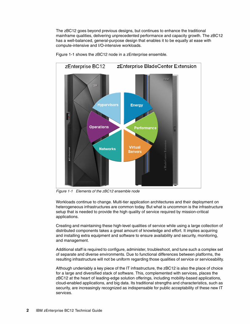
The zBC12 goes beyond previous designs, but continues to enhance the traditional mainframe qualities, delivering unprecedented performance and capacity growth. The zBC12 has a well-balanced, general-purpose design that enables it to be equally at ease with compute-intensive and I/O-intensive workloads.
Figure 1-1 shows the zBC12 node in a zEnterprise ensemble.
Figure 1-1 Elements of the zBC12 ensemble node
Workloads continue to change. Multi-tier application architectures and their deployment on heterogeneous infrastructures are common today. But what is uncommon is the infrastructure setup that is needed to provide the high quality of service required by mission-critical applications.
Creating and maintaining these high-level qualities of service while using a large collection of distributed components takes a great amount of knowledge and effort. It implies acquiring and installing extra equipment and software to ensure availability and security, monitoring, and management.
Additional staff is required to configure, administer, troubleshoot, and tune such a complex set of separate and diverse environments. Due to functional differences between platforms, the resulting infrastructure will not be uniform regarding those qualities of service or serviceability.
Although undeniably a key piece of the IT infrastructure, the zBC12 is also the place of choice for a large and diversified stack of software. This, complemented with services, places the zBC12 at the heart of leading-edge solution offerings, including mobility-based applications, cloud-enabled applications, and big data. Its traditional strengths and characteristics, such as security, are increasingly recognized as indispensable for public acceptability of these new IT services.
2 IBM zEnterprise BC12 Technical Guide
The IBM holistic approach to System z design includes hardware, software, and procedures. It takes into account a wide range of factors, including compatibility and investment protection, therefore ensuring a tighter fit with the IT requirements of the entire enterprise.
Elements of the zBC12The remainder of this chapter provides an overview of IBM zEnterprise BC12 features and functions.
1.1 Highlights of the zBC12
This section reviews some of the most important features and functions of zBC12:
� Processor and memory� Capacity and performance� I/O subsystem and I/O features� Virtualization� Increased flexibility with z/VM-mode partitions� IBM System z Advanced Workload Analysis Reporter� The zAware mode logical partition� Flash Express� 10GbE RoCE Express� IBM zEnterprise Data Compression Express� IBM Mobile Systems Remote� Reliability, availability, and serviceability
1.1.1 Processor and memory
IBM continues its technology leadership with the zBC12. The server is built using an IBM SCMs design and processor drawers. Up to two processor drawers are supported per CPC. Each processor drawer contains three single-chip modules (SCMs), which host the newly designed complementary metal-oxide semiconductor (CMOS) 13S1 processor units, storage control (SC) chips, and connectors for I/O.
The superscalar processor has a second-generation out-of-order instruction execution unit, redesigned caches, and an expanded instruction set that includes a Transactional Execution Facility, for better performance.
Depending on the model, the zBC12 can support from a minimum of 8 GB to a maximum of 496 GB of usable memory, with up to 256 GB per processor drawer. In addition, a fixed amount of 16 GB is reserved for the hardware system area (HSA), and is not part of customer-purchased memory. Memory is implemented as a redundant array of independent memory (RAIM). To use the RAIM function, up to 320 GB can be physically installed per processor drawer, for a system total of 640 GB.
1 CMOS 13S is a 32-nanometer CMOS logic fabrication process.
Chapter 1. Introducing the IBM zEnterprise BC12 3
1.1.2 Capacity and performance
The zBC12 CPC provides a record level of processing and I/O capacity over the previous midsize System z servers. This capacity is achieved both by increasing the performance of the individual processor units, and by increasing the number of processor units (PUs) per server. The increased performance and the total system capacity available, along with possible energy savings, offer the opportunity to consolidate diverse applications on a single platform, with real financial savings.
The introduction of new technologies and features helps to ensure that the zBC12 is an innovative, security-rich platform that can help maximize resource utilization and provide the ability to integrate applications and data across the enterprise.
The zBC12 has two model offerings ranging from 1 - 13 configurable PUs, with a maximum of six central processors (CPs). Model H06 has one processor drawer and the model H13 has two. Each processor drawer houses, in addition to other components, two PU SCMs, one with four active cores, the other with five active cores.
Model H13 is estimated to provide up to 56% more single-system image capacity for z/OS, z/VM and IBM z/VSE® workloads than the largest z114 model, with a larger memory and additional PCIe-based I/O features. This comparison is based on the Large Systems Performance Reference (LSPR) mixed workload analysis. For more information about performance and workload variation, see Chapter 13, “Performance” on page 431.
The zBC12 continues to offer a wide range of capacity settings with 26 capacity levels, for up to six central processors, giving a total of 156 distinct capacity settings in the system. The zBC12 delivers scalability and granularity to meet the needs of small to medium-sized enterprises, while also satisfying the mission-critical transaction and data processing requirements. The zBC12 continues to offer all the specialty engines that are available with IBM zEnterprise System.
Workload variabilityConsult the Large System Performance Reference (LSPR) when considering performance on the zBC12. The range of performance ratings across the individual LSPR workloads is likely to have a large spread. More performance variation of individual logical partitions (LPARs) exists because the effect of other partitions’ fluctuating resource requirements can be more pronounced with the increased numbers of partitions and additional PUs available. For more information, read 13.6, “Workload performance variation” on page 438.
For detailed performance information, see the LSPR website:
https://www-304.ibm.com/servers/resourcelink/lib03060.nsf/pages/lsprindex
The MSU ratings are available from the following website:
http://www-03.ibm.com/systems/z/resources/swprice/reference/exhibits/
Capacity on demandOn-demand enhancements enable customers to have more flexibility in managing and administering their temporary capacity requirements. The zBC12 supports the architectural approach for temporary offerings that was introduced with the IBM z10™, which has the potential to change thinking about on-demand capacity. Within the zBC12, one or more flexible configuration definitions can be available to solve multiple temporary situations, and multiple capacity configurations can be active simultaneously.
4 IBM zEnterprise BC12 Technical Guide
Up to 200 staged records can be created for many scenarios, and up to eight of them can be installed on the server at any given time. After they are installed, the activation of the records can be done manually, or the z/OS Capacity Provisioning Manager can automatically invoke the activation when Workload Manager (WLM) policy thresholds are reached. Tokens are available that can be purchased for On/Off Capacity on Demand (CoD), either before or after execution.
1.1.3 I/O subsystem and I/O features
The zBC12 supports both a PCIe and InfiniBand I/O infrastructure. PCIe features are installed in PCIe I/O drawers. Up to two PCIe I/O drawers are supported, providing slots for up to 64 I/O features. When upgrading a z114 or IBM System z10® Business Class (z10 BC) to a zBC12, one I/O drawer (which was introduced with the z10 BC and supports up to eight features) is also supported. The I/O cages of previous System z servers are not supported.
There are up to eight high-performance fanouts for data communications between the processor drawers and the I/O infrastructure. The multiple channel subsystems (CSS) architecture permits up to two CSSs, each with 256 channels. I/O constraint relief, using two subchannel sets, enables access to a greater number of logical volumes. The zBC12 enables to initial program load (IPL) from subchannel set 1 (SS1) in addition to subchannel set 0.
In addition, the system I/O buses take advantage of PCIe technology and InfiniBand technology, which is also used in coupling links. The zBC12 connectivity supports the following I/O or special purpose features:
� Storage connectivity:
– Fibre Channel connection (FICON):
• FICON Express8S 10KM LX and SX2
• FICON Express8 10KM LX and SX• FICON Express4 10KM LX and SX (four port cards only)• FICON Express4-2C 4KM LX and SX
� Networking connectivity:
– Open Systems Adapter (OSA):
• OSA-Express5S 10 GbE LR and SR3
• OSA-Express5S GbE LX and SX• OSA-Express5S 1000BASE-T Ethernet4
• OSA-Express4S 10 GbE LR and SR• OSA-Express4S GbE LX and SX• OSA-Express3 10 GbE LR and SR• OSA-Express3 GbE LX and SX• OSA-Express3-2P Gbe SX • OSA-Express3 1000BASE-T Ethernet • OSA-Express3-2P 1000BASE-T Ethernet
– IBM HiperSockets™
– 10GbE RoCE
� Coupling and Server Time Protocol (STP) connectivity
– Parallel Sysplex InfiniBand (PSIFB) coupling links– Internal Coupling links (IC)– InterSystem Channel-3 (ISC-3), peer mode only
2 Lucent Connector (LC) duplex (Long Wave, or LX) and Standard Connector (SC) duplex (Short Wave, or SX)3 10 gigabit Ethernet (GbE) Long Reach (LR) and Short Reach (SR)4 1000 megabits per second (Mbps) baseband signaling twisted pair (1000BASE-T) Ethernet
Chapter 1. Introducing the IBM zEnterprise BC12 5
In addition, zBC12 supports the following special function features, which are installed on the PCIe I/O drawers or I/O drawers:
� Cryptography:– Crypto Express4S– Crypto Express3 – Crypto Express3-1P
� Flash Express� zEDC Express
1.1.4 Virtualization
The IBM Processor Resource/Systems Manager™ (PR/SM™) is Licensed Internal Code (LIC) that manages and virtualizes all the installed and enabled system resources as a single large SMP system. This virtualization enables full sharing of the installed resources with high security and efficiency, by configuring up to 605 LPARs (each of which has logical processors, memory, and I/O resources) assigned from the installed books and features.
LPAR configurations can be dynamically adjusted to optimize the virtual servers’ workloads. For details, see “Modes of operation” on page 99.
On zBC12, PR/SM has been enhanced to support an option to limit the amount of physical processor capacity used by an individual LPAR. This occurs when a PU defined as a CP or an Integrated Facility for Linux (IFL) is shared across a set of LPARs. For a definition of these PU types, see 1.2.1, “Models” on page 9.
This enhancement is designed to provide enforced physical capacity limit as an absolute (versus relative) limit. Physical capacity limit enforcement is not affected by changes to the logical or physical configuration of the system. This physical capacity limit can be specified in units of CPs or IFLs.
The zBC12 provides improvements to the PR/SM HiperDispatch function. HiperDispatch provides work alignment to logical processors, and alignment of logical processors to physical processors. This alignment optimizes cache utilization, minimizes inter-book communication, and optimizes z/OS and z/VM V6R3 work dispatching, with the result of increasing throughput.
The zBC12 supports the definition of up to 32 HiperSockets. HiperSockets provide for memory communication across LPARs without the need of any I/O adapters, and have VLAN capability. HiperSockets have been extended to bridge to an ensemble internode data network.
1.1.5 Increased flexibility with z/VM-mode partitions
The zBC12 provides for the definition of a z/VM-mode LPAR containing a mix of processor types, including CPs and specialty processors, such as IFLs, System z Integrated Information Processors (zIIPs), System z Application Assist Processors (zAAPs), and Internal Coupling Facilities (ICFs). For a definition of these types see 1.2.1, “Models” on page 9.
5 Up to 30 LPARs for zBC12.
6 IBM zEnterprise BC12 Technical Guide
The z/VM V5R4 software and later supports this capability, which increases flexibility and simplifies system management. In a single LPAR, z/VM can perform the following tasks:
� Manage guests that use Linux on System z on IFLs, IBM z/Virtual Storage Extended (z/VSE), IBM z/Transaction Processing Facility (z/TPF), and z/OS on CPs.
� Run designated z/OS workloads, such as parts of IBM Distributed Relational Database Architecture™ (IBM DRDA®) for IBM DB2® processing and XML, on zIIPs.
� Use zAAPs to provide an economical Java execution environment under z/OS.
1.1.6 IBM System z Advanced Workload Analysis Reporter
IBM System z Advanced Workload Analysis Reporter (IBM zAware) is a feature introduced with the zEC12, also available on the zBC12, that embodies the next generation of system monitoring. IBM zAware is designed to offer a near real-time continuous learning, diagnostics, and monitoring capability. This function helps pinpoint and resolve potential problems quickly enough to minimize their effects on your business.
The ability to tolerate service disruptions is diminishing. In a continuously available environment, any disruption can have grave consequences. This negative effect is especially true when the disruption lasts days (or even hours).
However, increased system complexity makes it more probable that errors occur, and those errors are also increasingly complex. Some incidents’ early symptoms go undetected for long periods of time, and can grow to become large problems. Systems often experience soft failures (sick but not dead) which are much more difficult or unusual to detect.
IBM zAware is designed to help in those circumstances. For more information, see Appendix A, “IBM zAware” on page 441.
1.1.7 The zAware mode logical partition
The zBC12 enables a zAware LPAR mode to be defined. Either CPs or IFLs can be configured to the partition. This special partition is defined for the exclusive use of the zAware offering. The zAware feature requires a special licence.
1.1.8 Flash Express
Flash Express is an innovative optional feature introduced with the zEC12, also available with the zBC12. It is intended to provide performance improvements and better availability for critical business workloads that cannot afford any hits to service levels. Flash Express is easy to configure, requires no special skills, and provides rapid time-to-value.
Flash Express implements Storage Class Memory through internal Not AND (NAND) Flash solid-state drive (SSD), in a PCIe card form factor. The Flash Express feature is designed to enable each LPAR to be configured with its own Storage Class Memory address space.
Chapter 1. Introducing the IBM zEnterprise BC12 7
Flash Express is used by the following system components:
� The z/OS V1R13 (or later), for handling z/OS paging activity and switched virtual channel (SVC) memory dumps.
� Coupling facility control code (CFCC) Level 19, to use Flash Express as an overflow device for shared queue data. This provides emergency capacity to handle IBM WebSphere® MQ shared queue buildups during abnormal situations, such as when putters are putting to the shared queue, but getters are transiently not getting from the shared queue.
� Red Hat Enterprise Linux (RHEL), for use as temporary storage.
Additional functions of Flash Express are expected to be introduced later, including 2 GB page support and dynamic reconfiguration.
For more information see Appendix C, “Flash Express” on page 461.
1.1.9 10GbE RoCE Express
The 10GbE RoCE Express feature is designed to provide fast memory-to-memory communications between two CPCs. It is transparent to applications.
Use of the 10GbE RoCE Express feature helps reduce consumption of central processing unit (CPU) resources for applications utilizing the TCP/IP stack (such as WebSphere accessing a DB2 database). Its use also helps to reduce network latency with memory-to-memory transfers using Shared Memory Communications-RDMA (SMC-R) in z/OS V2R1.
This feature, exclusive to the zEC12 and the zBC12, is installed in the PCIe I/O drawer. A maximum of 16 features can be installed. One port per feature is supported by z/OS.
1.1.10 IBM zEnterprise Data Compression Express
The growth of data that needs to be captured, transferred, and stored for large periods of time is not relenting. On the contrary, software-implemented compression algorithms are costly in terms of processor resources, and storage costs are not negligible either.
IBM zEnterprise Data Compression (zEDC) Express, an optional feature exclusive to the zEC12 and the zBC12, addresses those requirements by providing hardware-based acceleration for data compression and decompression. The zEDC provides data compression with lower CPU consumption than previously existing compression technology on System z.
For more information, see Appendix F, “IBM zEnterprise Data Compression Express” on page 487.
1.1.11 IBM Mobile Systems Remote
IBM Mobile Systems Remote (IBM Remote), developed by IBM, is a mobile application that is intended to help customers monitor and manage their zEnterprise environment from a mobile communication device (such as smartphones or tablets). By interfacing with the zEnterprise Hardware Management Console (HMC), the application enables authorized personnel to hold in the palm of their hands almost all of the information normally viewed on the HMC. Customers will be able to monitor their zEnterprise CP and, in case of an ensemble, also the BladeCenters and installed blades in the zBX.
8 IBM zEnterprise BC12 Technical Guide
For more information on this freely downloadable application, and links to the different application stores, see the IBM Mobile Systems Remote website:
http://ibmremote.com/
1.1.12 Reliability, availability, and serviceability
System reliability, availability, and serviceability (RAS) are areas of continuous IBM focus. The objective is to reduce, or eliminate if possible, all sources of planned and unplanned outages, with the objective of keeping the system running. It is a design objective to provide higher availability with a focus on reducing outages.
With a properly configured zBC12, further reduction of outages can be attained through improved nondisruptive replace, repair, and upgrade functions for memory and I/O adapters. In addition, zBC12 has extended nondisruptive capability to download and install LIC updates.
Enhancements include removing pre-planning requirements with the fixed 16 GB HSA. Customer-purchased memory is not used for I/O configurations, and it is no longer required to reserve capacity to avoid disruption when adding new features. With a fixed amount of 16 GB for the HSA, maximums are configured and IPLed so that later insertion can be dynamic, which eliminates the need for a power-on reset of the server.
This approach provides many high-availability and nondisruptive operations capabilities that differentiate it in the marketplace. The ability to cluster multiple systems in a Parallel Sysplex takes the commercial strengths of the z/OS platform to higher levels of system management, competitive price/performance ratio, scalable growth, and continuous availability.
1.2 A technical overview of zBC12
This section briefly provides an overview of the major elements of the zBC12:
� Models� Model upgrade paths� Frame� Processor drawer� I/O connectivity: PCIe and InfiniBand� I/O subsystems� Coupling and Server Time Protocol connectivity� Special-purpose features
– Cryptography– Flash Express– The zEDC Express feature
� Reliability, availability, and serviceability
1.2.1 Models
The zBC12 has a machine type of 2828. Two models are offered: H06 and H13. The last two digits of each model name indicate the maximum number of PUs available for purchase. A PU is the generic term for the IBM z/Architecture® processor on the SCM.
Chapter 1. Introducing the IBM zEnterprise BC12 9
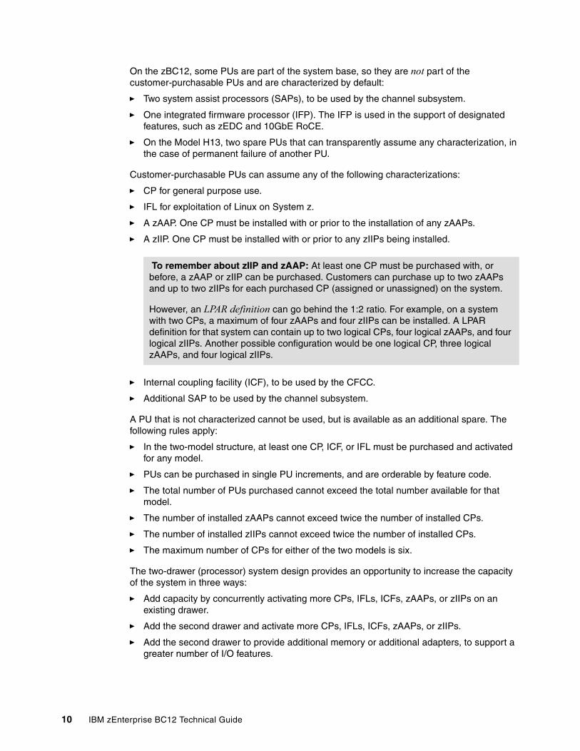
On the zBC12, some PUs are part of the system base, so they are not part of the customer-purchasable PUs and are characterized by default:
� Two system assist processors (SAPs), to be used by the channel subsystem.
� One integrated firmware processor (IFP). The IFP is used in the support of designated features, such as zEDC and 10GbE RoCE.
� On the Model H13, two spare PUs that can transparently assume any characterization, in the case of permanent failure of another PU.
Customer-purchasable PUs can assume any of the following characterizations:
� CP for general purpose use.
� IFL for exploitation of Linux on System z.
� A zAAP. One CP must be installed with or prior to the installation of any zAAPs.
� A zIIP. One CP must be installed with or prior to any zIIPs being installed.
� Internal coupling facility (ICF), to be used by the CFCC.
� Additional SAP to be used by the channel subsystem.
A PU that is not characterized cannot be used, but is available as an additional spare. The following rules apply:
� In the two-model structure, at least one CP, ICF, or IFL must be purchased and activated for any model.
� PUs can be purchased in single PU increments, and are orderable by feature code.
� The total number of PUs purchased cannot exceed the total number available for that model.
� The number of installed zAAPs cannot exceed twice the number of installed CPs.
� The number of installed zIIPs cannot exceed twice the number of installed CPs.
� The maximum number of CPs for either of the two models is six.
The two-drawer (processor) system design provides an opportunity to increase the capacity of the system in three ways:
� Add capacity by concurrently activating more CPs, IFLs, ICFs, zAAPs, or zIIPs on an existing drawer.
� Add the second drawer and activate more CPs, IFLs, ICFs, zAAPs, or zIIPs.
� Add the second drawer to provide additional memory or additional adapters, to support a greater number of I/O features.
To remember about zIIP and zAAP: At least one CP must be purchased with, or before, a zAAP or zIIP can be purchased. Customers can purchase up to two zAAPs and up to two zIIPs for each purchased CP (assigned or unassigned) on the system.
However, an LPAR definition can go behind the 1:2 ratio. For example, on a system with two CPs, a maximum of four zAAPs and four zIIPs can be installed. A LPAR definition for that system can contain up to two logical CPs, four logical zAAPs, and four logical zIIPs. Another possible configuration would be one logical CP, three logical zAAPs, and four logical zIIPs.
10 IBM zEnterprise BC12 Technical Guide
1.2.2 Model upgrade paths
A zBC12 Model H06 can be upgraded to a Model H13, and the Model H13 can be upgraded to an air-cooled zEC12 Model H20. All of these upgrades are disruptive (that is, the machine is unavailable during these upgrades). Any z10 BC or z114 model can be upgraded to any zBC12 model, which is also disruptive. Figure 1-2 shows a diagram of the upgrade paths.
Upgrade a z114 to a zBC12When a z114 is upgraded to a zBC12, the z114 driver level must be at least 93. If a zBX is involved, the driver 93 must be at bundle 27 or higher. When upgrading a z114 that controls a zBX Model 002 to a zBC12, the zBX is upgraded to a Model 003.
That upgrade is disruptive, as shown in Figure 1-2.
Figure 1-2 IBM zEnterprise BC12 upgrades
1.2.3 Frame
The zBC12 has a single frame, which is known as the A frame. The frame contains CPC components that include:
� Up to two processor drawers� PCIe I/O drawers� Optional I/O drawer, which holds I/O features and special purpose features Power supplies� An optional internal battery feature (IBF)� Cooling units (air cooling)� Support elements
Chapter 1. Introducing the IBM zEnterprise BC12 11
1.2.4 Processor drawerThe zBC12 design employs processor drawers containing SCMs. Using two drawers provides for better capacity granularity. Each processor drawer houses two SCMs with System z processor chips, and one SCM with a SC chip, memory, and I/O interconnects.
Single-chip module technologyThe zBC12 is built on the proven superscalar microprocessor architecture of zEC12. In each processor drawer, there are three SCMs. Two SCMs have one PU chip each, and one SCM has a storage control chip. The zBC12 system is air-cooled by using an evaporator/heat sink.
Processor featuresThe processor chip has a hexa-core design and operates at 4.2 GHz. One processor chip has four active cores, and the other processor chip has five active cores.
The SCMs are interconnected with high-speed internal communications links, in a fully connected star topology through the L4 cache, which enables the system to be operated and controlled by the PR/SM facility as a memory and cache-coherent symmetric multiprocessor (SMP) system.
On the model H13, the PU configuration includes two spare PUs per CPC. Two SAPs are available, regardless of the model. The remaining PUs can be characterized in the following way:
� A minimum of six CPs� A maximum of 13 IFL� Up to eight zAAPs6
� Up to eight zIIPs6
� A maximum of 13 ICF processors� A maximum of two additional SAPs
Each core on the PU chip includes a dedicated coprocessor for data compression and cryptographic functions, such as the CP Assist for Cryptographic Function (CPACF). This configuration is an improvement over z114, where two cores shared a coprocessor.
Hardware data compression can play a significant role in improving performance and saving costs over carrying out the compression in software. Note that the zEDC Express feature offers additional performance and savings over the coprocessor. Their functions are not interchangeable.
Having standard, clear key cryptographic coprocessors that are integrated with the processor provides high-speed cryptography for protecting data.
Each core on the PU has its own hardware decimal-floating point unit, designed according to a standardized, open algorithm. Much of today’s commercial computing is decimal floating-point, so on-core hardware decimal floating-point meets the requirements of business and user applications. It also provides improved performance, precision, and function.
In the unlikely case of a permanent core failure, each core can be individually replaced by one of the available spares. Core sparing is transparent to the operating system and applications.
6 Currently the ratio for zIIP to CP and zAAP to CP has been boosted to 2:1. For details, see Table 2-6 on page 54.
12 IBM zEnterprise BC12 Technical Guide
Transactional Execution FacilityThe z/Architecture was expanded with the Transactional Execution Facility. This set of instructions enables defining groups of instructions that are run atomically. That is, either all of the results are committed or none are. The facility provides for faster and more scalable multi-threaded execution, and is known in academia as hardware transactional memory.
Out-of-order executionThe zBC12 has a superscalar microprocessor with out-of-order (OOO) execution to achieve faster throughput. With OOO, instructions might not execute in the original program order, although results are presented in the original order. For instance, OOO enables a few instructions to complete while another instruction is waiting. Up to three instructions can be decoded per cycle, and up to seven instructions can be executed per cycle.
Concurrent processor unit conversionsThe zBC12 supports concurrent conversion between various PU types, providing flexibility to meet changing business environments. CPs, IFLs, zAAPs, zIIPs, ICFs, and optional SAPs can be converted to CPs, IFLs, zAAPs, zIIPs, ICFs, and optional SAPs.
Memory subsystem and topologyThe zBC12 employs the memory technology that was introduced with the IBM zEnterprise 196 (z196), which includes buffered dual inline memory modules (DIMM). For this purpose, IBM has developed a chip that controls communication with the PU and drives the address and control from DIMM to DIMM. The DIMM capacities are 4, 8, 16, and 32 GB.
Memory topology provides the following benefits:
� RAIM for protection at the dynamic random access memory (DRAM), DIMM, and memory channel levels
� Maximum of 496 GB of user-configurable memory (maximum of 640 GB of physical memory with a maximum of 496 GB configurable to a single LPAR)
� One memory port for each PU chip, with up to two independent memory ports per processor drawer
� Asymmetrical memory size and DRAM technology across drawers
� Large memory pages (1 MB and 2 GB)
� Key storage
� Storage protection key array kept in physical memory
� Storage protection (memory) key also kept in every L2 and L3 cache directory entry
� Large (16 GB) fixed-size HSA, which eliminates having to plan for an HSA
PCIe fanout hot-plugThe PCIe fanout provides the path for data between memory and the PCIe I/O cards through the PCIe 8 GBps bus. The PCIe fanout is hot-pluggable. In the event of an outage, a redundant I/O interconnect enables a PCIe fanout to be concurrently repaired without loss of access to its associated I/O domains. Up to four PCIe fanouts are available per processor drawer.
Host channel adapter fanout hot-plugA host channel adapter (HCA) fanout provides the path for data between memory and the I/O features using InfiniBand cables. The HCA fanout is hot-pluggable. In the event of an outage, an HCA fanout can be concurrently repaired without the loss of access to its associated I/O features, using redundant I/O interconnect. Up to four HCA fanouts are available per drawer.
Chapter 1. Introducing the IBM zEnterprise BC12 13
1.2.5 I/O connectivity: PCIe and InfiniBandThe zBC12 offers various improved features and exploits technologies, such as PCIe, InfiniBand, and Ethernet. In this section, we briefly review the most relevant I/O capabilities.
The zBC12 takes advantage of PCIe Gen 2 to implement the following features:
� An I/O bus, which implements the PCIe infrastructure. This is the preferred infrastructure, and can be used alongside InfiniBand.
� PCIe fanouts, which provide 8 GBps connections to the PCIe I/O features.
The zBC12 takes advantage of InfiniBand to implement the following features:
� A 6 GBps I/O bus, which includes the InfiniBand infrastructure.
This I/O bus replaces the self-timed interconnect bus that is found in System z servers prior to IBM z9®.
� Parallel Sysplex coupling links using InfiniBand. 12xIFB coupling links for local connections, and 1xIFB coupling links for extended distance connections between any two zEnterprise CPCs and z10 CPCs. The 12xIFB link has a bandwidth of 6 GBps.
� HCA for InfiniBand (HCA3) are designed to deliver up to 40% faster coupling link service times than HCA2.
1.2.6 I/O subsystems
The zBC12 I/O subsystem is identical to the z114 subsystem, which draws on developments from z10, and also includes a PCIe infrastructure. The I/O subsystem is supported by both a PCIe bus and an I/O bus, similar to that of the z114.
It includes the InfiniBand Double Data Rate (IB-DDR) infrastructure, which replaces the self-timed interconnect that was found in the prior System z servers. This infrastructure is designed to reduce overhead and latency, and provide increased throughput. The I/O expansion network uses the InfiniBand Link Layer (IB-DDR).
The zBC12 also offers two I/O infrastructure elements for holding the I/O features: up to two PCIe I/O drawers for PCIe features, and one I/O drawer for non-PCIe features.
PCIe I/O drawerThe PCIe I/O drawer, together with the PCIe I/O features, offers improved granularity and capacity over previous I/O infrastructures, and can be concurrently added and removed in the field, easing planning. A PCIe I/O drawer occupies one drawer slot, the same as an I/O drawer, yet it offers 32 I/O card slots, a 14% increase in capacity. Only PCIe features are supported, in any combination. Up to two PCIe I/O drawers are supported.
I/O drawer On the zBC12, one I/O drawer is supported when carried forward on upgrades from z114 or z10 BC. For a new zBC12 installation, it is not possible to have an I/O drawer.
I/O drawers can accommodate up to eight I/O features in any combination, and can be concurrently added and removed in the field. Based on the number of I/O features that are carried forward, the configurator determines the number of required I/O drawers.
14 IBM zEnterprise BC12 Technical Guide
Native PCIe and integrated firmware processorNative PCIe was introduced with the zEDC and RoCE Express features, which are managed in a way different from the traditional PCIe features:
� The device drivers for these adapters are available in the operating system.
� The diagnostics for the adapter layer functions of the native PCIe features are taken care of by LIC designated as a resource group, which runs on the IFP. For availability, two resource groups are present and share the IFP.
During the ordering process of the native PCIe features, features of the same type are evenly spread across the two resources groups (RG1 and RG2) for availability and serviceability reasons. Resource groups are automatically activated when these features are present in the CPC.
I/O and special-purpose features The zBC12 supports the following PCIe features, which can only be installed in the PCIe I/O drawers:
� FICON Express8S SX and 10 kilometers (km) LX (Fibre Channel connection)� OSA-Express5S 10 GbE LR and SR, GbE LX and SX, and 1000BASE-T Ethernet� OSA-Express4S 10 GbE LR and SR, GbE LX and SX� 10GbE RoCE� Crypto Express4S� Flash Express� The zEDC Express
Note that OSA-Express4S features are only available when carried forward on an upgrade.
When carried forward on an upgrade, the zBC12 also supports up to one I/O drawer on which the following features can be installed:
� FICON Express8 10 km LX and SX� FICON Express4 10 km LX and SX� FICON Express4-2C SX� OSA-Express3 10 GbE LR and SR� OSA-Express3 10 GbE LX and SX (includes OSA-Express3-2P)� OSA-Express3 1000BASE-T (includes OSA-Express3-2P)� Crypto Express3 � Crypto Express3-1P� ISC-3 coupling links (peer-mode only)
Note that the I/O drawer supports a maximum of eight features.
In addition, InfiniBand coupling links, which attach directly to the processor drawers, are supported.
FICON channelsUp to 64 features with up to 128 FICON Express8S channels are supported. The FICON Express8S features support a link data rate of 2, 4, or 8 Gbps.
Up to eight features with up to 32 FICON Express8 or FICON Express4 channels are supported:
� The FICON Express8 features support a link data rate of 2, 4, or 8 Gbps. � The FICON Express4 features support a link data rate of 1, 2, or 4 Gbps.
The zBC12 continues to support, when carried forward, the FICON-Express4-2C features.
Chapter 1. Introducing the IBM zEnterprise BC12 15
The zBC12 FICON features support the following protocols:
� FICON (FC) and High Performance FICON for System z (zHPF). The zHPF offers improved access to data, of special importance to online transaction processing (OLTP) applications.
� Channel-to-channel (CTC).
� Fibre Channel Protocol (FCP).
FICON also offers the following capabilities:
� Modified Indirect Data Address Word (MIDAW) facility. This provides more capacity over native FICON channels for programs that process data sets that use striping and compression, such as DB2, Virtual Storage Access Method (VSAM), partitioned data set extended (PDSE), hierarchical file system (HFS), and z/OS file system (zFS). It does so by reducing channel, director, and control unit processor usage.
� Enhanced problem determination, analysis, and manageability of the SAN by providing registration information to the fabric name server for both FICON and FCP.
Open Systems AdapterThe zBC12 enables any mix of the supported OSA Ethernet features, for up to 96 ports of LAN connectivity. For example, up to 48 OSA-Express5S features, in any combination, can be installed in the PCIe I/O drawer. OSA-Express3 features are plugged into an I/O drawer. Up to eight OSA-Express3 features are supported.
Each OSA-Express3 that is installed in an I/O drawer reduces by two the number of OSA-Express5S or OSA-Express4S features permitted.
OSM and OSX channel path identifier typesThe zBC12 provides OSA-Express5S, OSA-Express4S, and OSA-Express3 channel path identifier (CHPID) types OSA-Express for URM (OSM) and OSA-Express for zBX (OSX) for zBX connections:
� OSM
Provides connectivity to the intranode management network (INMN). Connects the zBC12 to the zBX through the bulk power hubs (BPHs) for the use of the URM functions in the HMC. Exclusively uses OSA-Express5S 1000BASE-T Ethernet or OSA-Express3 1000BASE-T Ethernet.
� OSX
Provides connectivity to the intraensemble data network (IEDN). Supplies a data connection from the zBC12 to the zBX. Uses OSA-Express5S 10 GbE, preferably, but can also use OSA-Express4S 10 GbE, or OSA-Express3 10 GbE features.
OSA-Express5S, OSA-Express4S, and OSA-Express3 features highlightsThe zBC12 supports five OSA Express5S features, four OSA-Express4S features, and seven OSA-Express3 features. OSA-Express5S features are a technology refresh of the OSA-Express4S features:
� OSA-Express5S 10 GbE LR� OSA-Express5S 10 GbE SR� OSA-Express5S GbE LX� OSA-Express5S GbE SX� OSA-Express5S Ethernet 1000BASE-T Ethernet� OSA-Express4S 10 GbE LR� OSA-Express4S 10 GbE SR� OSA-Express4S GbE LX
16 IBM zEnterprise BC12 Technical Guide
� OSA-Express4S GbE SX� OSA-Express3 10 GbE LR� OSA-Express3 10 GbE SR� OSA-Express3 GbE LX� OSA-Express3 GbE SX� OSA-Express3-2P Gbe SX � OSA-Express3 1000BASE-T Ethernet� OSA-Express3-2P 1000BASE-T Ethernet
Note that the OSA-Express4S 1000BASE-T Ethernet feature is not available on the zBC12. Also, the zBC12 continues to support, when carried forward, the OSA-Express3-2P features.
OSA-Express features provide the important benefits for TCP/IP traffic, namely reduced latency and improved throughput for standard and jumbo frames. Performance enhancements are the result of the data router function present in all OSA-Express features. What previously was performed in firmware, the OSA Express5S, OSA-Express4S, and OSA-Express3 perform in hardware.
Additional logic in the IBM application-specific integrated circuit (ASIC), included with the feature, handles packet construction, inspection, and routing, enabling packets to flow between host memory and the LAN at line speed without firmware intervention.
With the data router, the store and forward technique in direct memory access (DMA) is no longer used. The data router enables a direct host memory-to-LAN flow. This configuration avoids a hop, and is designed to reduce latency and to increase throughput for standard frames (1492-byte) and jumbo frames (8992-byte).
For more information about the OSA features, see 4.8, “Connectivity” on page 136.
HiperSocketsThe HiperSockets function, which is also known as internal queued direct I/O (internal QDIO or iQDIO), is an integrated function of the zBC12 that provides users with attachments to up to 32 high-speed virtual LANs, with minimal system and network resource usage.
HiperSockets can be customized to accommodate varying traffic sizes. Because HiperSockets does not use an external network, it can free up system and network resources, eliminating attachment costs while improving availability and performance.
HiperSockets eliminates the need of using I/O subsystem operations, and of traversing an external network connection to communicate between LPARs in the same zBC12 server. HiperSockets offers significant value in server consolidation by connecting many virtual servers, and it can be used instead of certain coupling link configurations in a Parallel Sysplex.
HiperSockets was extended to enable integration with IEDN, which extends the reach of the HiperSockets network outside the CPC to the entire ensemble, and displays it as a single Layer 2 network.
10GbE RoCE ExpressThe 10GbE RoCE Express feature is an RDMA-capable network interface card. The 10GbE RoCE Express feature is exclusive to the zEC12 and zBC12, and is installed in the PCIe I/O drawer. Each feature has one PCIe adapter. A maximum of 16 features can be installed.
Chapter 1. Introducing the IBM zEnterprise BC12 17
The 10GbE RoCE Express feature utilizes an SR laser as the optical transceiver, and supports use of a multimode fiber optic cable terminated with an LC duplex connector. Both point-to-point connection and switched connection with an enterprise-class 10 GbE switch are supported.
Support is provided by z/OS, which supports one port per feature.
For more information see Appendix E, “RoCE” on page 475
1.2.7 Coupling and Server Time Protocol connectivity
Support for Parallel Sysplex includes the CFCC and coupling links.
Coupling links supportCoupling connectivity in support of Parallel Sysplex environments is provided on the zBC12 by the following features:
� 12xIFB coupling links offer up to 6 GBps of bandwidth between zEC12, zBC12, z196, z114, or z10 systems for a distance up to 150 m (492 feet). With the introduction ofHCA3-O, a new type of InfiniBand coupling links (12xIFB), improved service times can be obtained.
� 1xIFB up to 5 Gbps connection bandwidth between zEC12, zBC12, z196, z114, and z10 servers for a distance up to 10 km (6.2 miles). The new HCA3-O LR (1xIFB) type has doubled the number of links per fanout card, compared to type HCA2-O LR (1xIFB).
� Internal Coupling channels (ICs), operating at memory speed.
� ISC-37 operating at 2 Gbps and supporting an unrepeated link data rate of 2 Gbps over 9 µm single-mode fiber optic cabling with an LC Duplex connector.
All coupling link types can be used to carry Server Time Protocol (STP) messages. The zBC12 does not support ICB4 connectivity.
CFCC Level 19CFCC Level 19 is available for the zBC12. CFCC Level 19 introduces the following enhancements:
� Performance improvements. Coupling Thin Interrupts:– Improve the performance in shared CF engines environments.– Improve the response time of asynchronous CF requests.
� Resiliency enhancements. Flash Express supports and provides cost-effective standby capacity to help manage the potential overflow of WebSphere MQ shared queues.
7 Only available on zBC12 when carried forward during an upgrade.
Removal of ISC-3 support on System z: The zEC12 and zBC12 are planned to be the last high-end System z servers to offer support of the ISC-3 for Parallel Sysplex environments at extended distances. ISC-3 will not be supported on future high-end System z servers as carry-forward on an upgrade. Previously, the z196 and z114 servers were announced to be the last to offer ordering of ISC-3. Enterprises should continue upgrading from ISC-3 features to 12xIFB or 1xIFB coupling links.
18 IBM zEnterprise BC12 Technical Guide
Also included are enhancements provided by CFCC Level 18:
� Performance enhancements:
– Dynamic structure size alter improvement – DB2 GBP cache bypass– Cache structure management
� Coupling channel reporting improvement, enabling IBM Resource Measurement Facility™ (RMF™) to differentiate between various InfiniBand link types, and detect if a coupling link using InfiniBand (CIB) is running in a degraded state.
� Serviceability enhancements:
– Additional structure control info in CF dumps– Enhanced CFCC tracing support– Enhanced Triggers for CF nondisruptive dumping
CF structure sizing changes are expected when upgrading from CFCC Level 17 (or earlier) to CFCC Level 19. Review the CF LPAR size by using the CFSizer tool:
http://www.ibm.com/systems/z/cfsizer
Server Time Protocol facilitySTP is a server-wide facility that is implemented in the LIC of System z servers (including servers running as stand-alone CFs). STP presents a single view of time to Processor Resource/Systems Manager (PR/SM), and provides the capability for multiple servers to maintain time synchronization with each other. Any System z server can be enabled for STP by installing the STP feature. Each server that needs to be configured in a Coordinated Timing Network (CTN) must be STP-enabled.
The STP feature is designed to be the supported method for maintaining time synchronization between System z servers and coupling facilities. The STP design uses the CTN concept, which is a collection of servers and coupling facilities that are time-synchronized to a time value called coordinated server time.
Network Time Protocol (NTP) customer support is available to the STP code on the zEC12, zBC12, z196, z114, and z10. With this functionality, the zEC12, zBC12, z196, z114, and z10 can be configured to use an NTP server as an external time source (ETS).
This implementation answers the need for a single time source across the heterogeneous platforms in the enterprise, enabling an NTP server to become the single time source for the zEC12, zBC12, z196, z114, and z10, and other servers that have NTP customers (UNIX, Microsoft Windows NT, and other customers). NTP can only be used for an STP-only CTN, where no server can have an active connection to an IBM Sysplex Timer.
The time accuracy of an STP-only CTN is improved by adding as the ETS device an NTP server with the pulse per second (PPS) output signal. This type of ETS is available from various vendors that offer network timing solutions.
Improved security can be obtained by providing NTP server support on the HMC, because the HMC is normally attached to the private dedicated LAN for System z maintenance and support. For zBC12, authentication support is added to the HMC’s NTP communication with NTP time servers.
A zBC12 cannot be connected to a Sysplex Timer. Generally, change to an STP-only CTN for existing environments. A zBC12 can be a Stratum 2 or Stratum 3 server in a Mixed CTN if at least one IBM System z10 is attached to the Sysplex Timer operating as the Stratum 1 server. However, you should use two System z10s acting as the Stratum 1 server whenever possible.
Chapter 1. Introducing the IBM zEnterprise BC12 19
1.2.8 Special-purpose features
This section describes several features that, although installed in the PCIe I/O drawer or in the I/O drawer, provide specialized functions without actually performing I/O operations (no data is moved between the CPC and externally attached devices).
CryptographyIntegrated cryptographic features provide leading cryptographic performance and functionality. RAS support is unmatched in the industry, and the cryptographic solution has received the highest standardized security certification (FIPS 140-2 Level 48). The Crypto cards enable you to add or move Cryptographic Coprocessors to LPARs dynamically, without pre-planning.
The zBC12 implements one of the industry-accepted standards, Public Key Cryptography Standards (PKCS) #11, which is provided by RSA Laboratories from RSA, the security division of EMC Corporation. It also implements the IBM Common Cryptographic Architecture (CCA) in its cryptographic features.
CP Assist for Cryptographic FunctionThe CPACF offers the full complement of the Advanced Encryption Standard (AES) algorithm and Secure Hash Algorithm (SHA), along with the Data Encryption Standard (DES) algorithm. Support for CPACF is available through a group of instructions that are known as the Message-Security Assist (MSA). Callable services for z/OS Integrated Cryptographic Service Facility (ICSF) and the z90 Crypto device driver running on Linux for System z also invoke CPACF functions.
ICSF is a base element of z/OS. It uses the available cryptographic functions, CPACF, or PCIe cryptographic features to balance the workload and help address the bandwidth requirements of your applications.
CPACF must be explicitly enabled by using a no-charge enablement feature code (FC 3863), except for the SHAs, which are shipped enabled with each server.
The enhancements to CPACF are exclusive to the zEnterprise CPCs, and they are supported by z/OS, z/VM, z/VSE, z/TPF, and Linux on System z.
Configurable Crypto Express4S featureThe Crypto Express4S represents the newest generation of cryptographic feature that is designed to complement the cryptographic capabilities of the CPACF. It is an optional feature of the zBC12 server generation. The Crypto Express4S feature is designed to provide port granularity for increased flexibility, with one PCIe adapter per feature. For availability reasons, a minimum of two features are required.
Statement of Direction: The zEC12 and zBC12 will be the last servers to support connections to a Mixed CTN, (external time reference provided by the Sysplex Timer - 9037). After zEC12 and zBC12, if time synchronization is needed, (such as to support a base or Parallel Sysplex), STP is required. In addition, all servers participating in the CTN must be configured in STP-only mode.
8 Federal Information Processing Standards (FIPS)140-2 Security Requirements for Cryptographic Modules
20 IBM zEnterprise BC12 Technical Guide
The Crypto Express4S is a state-of-the-art, tamper-sensing, and tamper-responding programmable cryptographic feature that provides a secure cryptographic environment. Each adapter contains a tamper-resistant hardware security module (HSM). The HSM can be configured as a Secure IBM CCA coprocessor, as a Secure IBM Enterprise PKCS #11 (EP11) coprocessor, or as an accelerator:
� Secure IBM CCA coprocessor is for secure key encrypted transactions that use CCA callable services (default).
� Secure IBM EP11 coprocessor implements an industry-standardized set of services that adhere to the PKCS #11 specification v2.20 and more recent amendments.
This new cryptographic coprocessor mode introduced the PKCS #11 secure key function.
� Accelerator for public key and private key cryptographic operations is used with SSL/TLS acceleration.
FIPS 140-2 certification is supported only when Crypto Express4S is configured as a CCA or an EP11 coprocessor.
Configurable Crypto Express3 featureThe Crypto Express3 is an optional feature available only on a carry-forward basis in zBC12. Each feature has two PCIe adapters. Each adapter can be configured as a secure coprocessor or as an accelerator:
� Crypto Express3 Coprocessor is for secure key encrypted transactions (default).
� Crypto Express3 Accelerator is for SSL/TLS acceleration.
The zBC12 supports, when carried forward, the Crypto Express3-1P feature. This feature has one PCIe adapter, and can also be configured as a coprocessor or as an accelerator.
Trusted Key Entry workstation and support for smart card readersThe Trusted Key Entry (TKE) workstation and the TKE 7.3 LIC are optional features on the zBC12. The TKE workstation offers a security-rich solution for basic local and remote key management. For authorized personnel, it provides a method for key identification, exchange, separation, update, backup, and a secure hardware-based key loading for operational and master keys. TKE also provides a secure management of host cryptographic module and host capabilities.
Support for an optional smart card reader attached to the TKE workstation enables the use of smart cards that contain an embedded microprocessor and associated memory for data storage. Access to, and the use of, confidential data on the smart cards is protected by a user-defined personal identification number (PIN).
When Crypto Express4S is configured as a Secure IBM EP11 coprocessor, the TKE workstation is required to manage the Crypto Express4S feature. If the smart card reader feature is installed in the TKE workstation, the new smart card part 74Y0551 is required for EP11 mode.
For more information about the Cryptographic features, see Chapter 6, “Cryptography” on page 177.
Flash ExpressThe Flash Express optional feature is intended to provide performance improvements and better availability for critical business workloads that cannot afford any degradation to service levels. Flash Express is easy to configure, requires no special skills, and provides rapid time-to-value.
Chapter 1. Introducing the IBM zEnterprise BC12 21
Flash Express implements Storage Class Memory in a PCIe card form factor. Each Flash Express card implements internal NAND Flash SSD, and has a capacity of 1.4 TB of usable storage. Cards are installed in pairs, which provides mirrored data to ensure a high level of availability and redundancy. A maximum of four pairs of cards (eight features) can be installed on a zBC12, for a maximum capacity of 5.6 TB of storage.
The Flash Express feature is designed to enable each LPAR to be configured with its own Storage Class Memory address space. It is used for paging. Flash Express can be used, for instance, to hold pageable 1 MB pages.
Encryption is included to improve data security. Data security is ensured through a unique key that is stored on the IBM Support Element (SE) hard disk drive (HDD). It is mirrored for redundancy. Data on the Flash Express feature is protected with this key, and is only usable on the system with the key that encrypted it. The Secure Key Store is implemented by using a smart card that is installed in the SE. The smart card (one pair, so you have one for each SE) contains the following items:
� A unique key that is personalized for each system
� A small cryptographic engine that can run a limited set of security functions within the smart card
Flash Express is supported by z/OS V1R13 (at minimum) for handling z/OS paging activity, support for 1 MB pageable pages, and SVC memory dumps.
Support was added to the CFCC to use Flash Express as an overflow device for shared queue data to provide emergency capacity to handle WebSphere MQ shared queue buildups during abnormal situations, such as when putters are putting to the shared queue, but getters are transiently not getting from the shared queue.
Flash memory is assigned to a CF image via HMC panels. Coupling facility resource management (CFRM) policy definition permits the desired amount of Storage Class Memory to be used by a particular structure, on a structure-by-structure base. Additionally, RHEL can now use Flash Express for temporary storage. Additional functions of Flash Express are expected to be introduced later, including 2 GB page support and dynamic reconfiguration for Flash Express.
For more information see Appendix C, “Flash Express” on page 461.
The zEDC Express featureThe zEDC Express feature, an optional feature exclusive to zEC12 and zBC12, provides hardware-based acceleration for data compression and decompression, with lower CPU consumption than previously existing compression technology on System z.
Use of the zEDC Express feature by z/OS V2R1 zEnterprise Data Compression acceleration capability is designed to deliver an integrated solution to help reduce CPU consumption, optimize performance of compression related tasks, and enable more efficient use of storage resources, while providing a lower cost of computing, and also helping to optimize the cross-platform exchange of data.
You can install 1 - 8 features on the system. There is one PCIe adapter/compression coprocessor per feature, which implements compression as defined by RFC1951 (DEFLATE).
A zEDC Express feature can be shared by up to 15 LPARs.
For more information see Appendix F, “IBM zEnterprise Data Compression Express” on page 487.
22 IBM zEnterprise BC12 Technical Guide
1.2.9 Reliability, availability, and serviceability
The zBC12 RAS strategy is a building-block approach developed to meet the customer’s stringent requirements for continuous reliable operation. The following list shows these building blocks:
� Error prevention� Error detection� Recovery� Problem determination� Service structure� Change management� Measurement� Analysis
The initial focus is on preventing failures from occurring in the first place. This is accomplished in the following ways:
� Using Hi-Rel (highest reliability) components� Using screening, sorting, burn-in, and run-in� Taking advantage of technology integration
For LIC and hardware design, failures are eliminated through the following means:
� Rigorous design rules� Design walk-through� Peer reviews� Element, subsystem, and system simulation� Extensive engineering and manufacturing testing
The RAS strategy is focused on a recovery design that is necessary to mask errors and make them transparent to customer operations. An extensive hardware recovery design was implemented to detect and correct memory array faults. In cases where total transparency cannot be achieved, you can restart the server with the maximum capacity possible.
The zBC12 has the following RAS improvements, among others:
� Improved error detection for the L3 / L4 memory cache� IBM zAware to detect abnormal behavior of z/OS� OSA firmware changes to increase concurrent maintenance change level (MCL) capability� Digital temperature sensor (DTS) and on-chip temperature sensor on the PU chips
Examples of the reduced effect of planned and unplanned system outages include the following components:
� Hot-pluggable PCIe I/O drawers and I/O drawers� Redundant I/O interconnect� Concurrent PCIe fanout hot-plug� HCA-O and HCA-C fanout card hot-plug� Enhanced driver maintenance
For more information, see Chapter 10, “Reliability, availability, and serviceability” on page 363.
Chapter 1. Introducing the IBM zEnterprise BC12 23
1.3 Hardware Management Consoles and Support Elements
The HMCs and SEs are appliances that together provide hardware platform management for a System z server, and for the ensemble nodes when the zEnterprise CPC is a member of an ensemble. In an ensemble, the HMC is used to manage, monitor, and operate one or more zEnterprise CPCs, and their associated LPARs and zBXs. Also, when the zEnterprise is a member of an ensemble, the HMC9 has a global (ensemble) management function, but the SE has local (node) management responsibility.
When tasks are performed on the HMC, the commands are sent to one or more SEs, which then issue commands to their zEnterprise CPCs and zBXs. To promote high availability, an ensemble configuration requires a pair of HMCs in primary and alternate roles.
1.4 IBM zEnterprise BladeCenter Extension Model 003
The zBX Model 003 improves infrastructure reliability by extending the mainframe systems management and service across a set of heterogeneous compute elements in an ensemble.
The zBX Model 003 is available as an optional system to work along with the zBC12 server, and consists of the following components:
� Up to four IBM 42U Enterprise racks.
� Up to eight BladeCenter chassis with up to 14 blades each.
� Up to 11210 blades.
� INMN top-of-rack (TOR) switches. The INMN provides connectivity between the zBC12 SEs and the zBX, for management purposes.
� IEDN TOR switches. The IEDN is used for data paths between the zBC12 and the zBX, and the other ensemble members, and also for customer data access. The IEDN point-to-point connections use Media Access Control (MAC) addresses, not IP addresses (Layer 2 connection).
� Some 8 Gbps FC switch modules for connectivity to a SAN.
� Advanced management modules (AMMs) for monitoring and management functions for all the components in the BladeCenter.
� Power distribution units (PDUs) and cooling fans.
� Optional acoustic rear door or optional rear door heat exchanger.
The zBX is configured with redundant components to provide qualities of service similar to those of System z, such as the capability for concurrent upgrades and repairs.
Geographically Dispersed Parallel Sysplex/Peer-to-Peer Remote Copy (GDPS/PPRC) and geographically dispersed IBM DB2 pureScale® cluster/IBM System Storage® Global Mirror (GDPS/GM) support zBX hardware components, providing workload failover for automated multi-site recovery. These capabilities help facilitate the management of planned and unplanned outages across zEC12 and zBC12 clusters.
9 From Version 2.11 and later. See 12.7, “HMC in an ensemble” on page 423.10 The maximum number of blades varies according to the blade type and blade function.
24 IBM zEnterprise BC12 Technical Guide
1.4.1 Blades
There are two types of blades that can be installed and operated in the zBX:
� Optimizer blades:
– IBM WebSphere DataPower® Integration Appliance XI50 for zEnterprise blades
� IBM blades:
– A selected subset of IBM POWER7 blades– A selected subset of IBM BladeCenter HX5 blades
These blades have been thoroughly tested to ensure compatibility and manageability in the IBM zEnterprise System environment:
� IBM POWER7 blades are virtualized by IBM PowerVM® Enterprise Edition, and the virtual servers run the IBM AIX® operating system.
� IBM BladeCenter HX5 blades are virtualized using an integrated hypervisor for IBM System x, and the virtual servers run Linux on System x:
– RHEL operating system– SUSE Linux Enterprise Server (SLES) operating system– Select Microsoft Windows Server operating systems
The zEnterprise enablement for the blades is specified with an entitlement feature code to be configured on the zEnterprise CPCs.
1.4.2 IBM WebSphere DataPower Integration Appliance XI50 for zEnterprise
The IBM WebSphere DataPower Integration Appliance XI50 for zEnterprise (DataPower XI50z) is a multifunctional appliance that can help provide multiple levels of XML optimization.
This configuration streamlines and secures valuable service-oriented architecture (SOA) applications. It also provides drop-in integration for heterogeneous environments by enabling core enterprise service bus (ESB) functionality:
� Routing� Bridging� Transformation� Event handling
DataPower X150z can help to simplify, govern, and enhance the network security for XML and web services.
When the DataPower XI50z is installed in zBX, URM provides integrated management for the appliance. This configuration simplifies control and operations:
� Change management� Energy monitoring� Problem detection� Problem reporting� Dispatch of an IBM System z Service Representative, if needed
Chapter 1. Introducing the IBM zEnterprise BC12 25
1.5 Unified Resource Manager
The URM is the integrated management fabric that executes on the HMC and SE. The URM consists of six management areas (see Figure 1-1 on page 2):
� Operational controls (Operations)
Includes extensive operational controls for various management functions.
� Virtual server lifecycle management (Virtual servers).
Enables directed and dynamic virtual server provisioning across hypervisors from a single uniform point of control.
� Hypervisor management (Hypervisors)
Enables the management of hypervisors and support for application deployment.
� Energy management (Energy)
Provides energy monitoring and management capabilities that can be used to better understand the power and cooling demands of the zEnterprise System.
� Network management (Networks)
Creates and manages virtual networks, including access control, which enables virtual servers to be connected together.
� Workload awareness and platform performance management (Performance)
Manages CPU resources across virtual servers hosted in the same hypervisor instance to achieve workload performance policy objectives.
The URM provides energy monitoring and management, goal-oriented policy management, increased security, virtual networking, and storage configuration management for the physical and logical resources of a given ensemble.
1.6 Operating systems and software
The zBC12 is supported by a large set of software, including independent software vendor (ISV) applications. This section lists only the supported operating systems. Using various features might require the latest releases. Further information is available in Chapter 8, “Software support” on page 245.
1.6.1 Supported operating systems
Using some features might require the latest releases. The following list includes the supported operating systems for zBC12:
� z/OS version 2 release 1� z/OS V1 R13 with program temporary fixes (PTFs)� z/OS V1 R12 with PTFs� z/OS V1 R11 with the IBM Lifecycle Extension with PTFs11
� z/VM V6 R3 with PTFs� z/VM V6 R2 with PTFs� z/VM V5 R4 with PTFs� z/VSE V4 R3 or later with PTFs� z/TPF V1 R1
11 The z/OS V1 R11 requires IBM Lifecycle Extension.
26 IBM zEnterprise BC12 Technical Guide
� Linux on System z distributions:– SLES 10 and SLES 11– RHEL 5 and RHEL 6
The following operating systems support IBM blades on the zBX Model 003:
� For the POWER7 blades, AIX Version 5 Release 3 or later, with PowerVM Enterprise Edition
� For the System x blades:
– Linux on System x (64-bit only):• Red Hat RHEL 5.5, 5.6, 5.7, 6.0, and 6.1• SUSE SLES 10 (SP4), 11 SP1
– Microsoft Windows Server 2012, Windows Server 2008 R2 and Windows Server 2008 SP2 (Datacenter Edition is suggested), 64-bit only
Together with support for IBM WebSphere software, full support for SOA, web services, Java Platform, Enterprise Edition (Java EE), Linux, and Open Standards, the zEnterprise BC12 is intended to be a platform of choice for the integration of the newest generations of applications with existing applications and data.
1.6.2 IBM compilers
IBM's compilers for z/OS that can exploit zEC12 and zBC12 are:
� Enterprise Common Business Oriented Language (COBOL) for z/OS� Enterprise PL/I for z/OS� IBM z/OS XL C/C++
The compilers increase the return on your investment in zEC12 or zBC12 hardware by maximizing application performance on System z, leveraging the compilers' advanced optimization technology to exploit the z/Architecture. Through their support of web services, XML, and Java, they allow for the modernization of existing assets in web-based applications. They support the latest IBM Middleware products (CICS®, DB2, and IMS™), enabling applications to leverage their latest capabilities. In order to fully exploit the capabilities of the zBC12, you must compile using the minimum level of each compiler specified in Table 1-1.
Table 1-1 Minimum compiler levels
In order to obtain the best performance, the ARCH(10) option, which grants the compiler permission to use machine instructions that are only available in the zEC12 and zBC12, should be specified. Because the ARCH(10) option results in the generated application using instructions that are only available in the zEC12 and zBC12, the application will not run on earlier versions of hardware.
If the application needs to run on the zBC12 as well as on older hardware, specify the ARCH option corresponding to the oldest hardware on which the application needs to run. For more information, refer to the documentation for the ARCH option in the guide for the corresponding compiler product.
C/C++ z/OS 1.13 XL C/C++ with PTFs: UK80670, UK80671, UK80039, UK79899 or z/OS 2.1 XL C/C++
COBOL Enterprise COBOL for z/OS 5.1
PL/I Enterprise PL/I for z/OS 4.4
Chapter 1. Introducing the IBM zEnterprise BC12 27

28 IBM zEnterprise BC12 Technical Guide
Chapter 2. Central processor complex hardware components
This chapter introduces IBM zEnterprise BC12 (zBC12) hardware components, significant features and functions, and their characteristics and options. The main objective of this chapter is to explain the zBC12 hardware building blocks, and how these components interconnect from a physical point of view. This information can be useful for planning purposes, and can help to define configurations that fit your requirements.
This chapter provides information about the following topics:
� Frames and drawers� Processor drawer concept� Single-chip module� Processor units and storage control chips� Memory� Reliability, availability, and serviceability� Connectivity� Model configurations � Power and cooling� Summary of zBC12 structure
2
© Copyright IBM Corp. 2014. All rights reserved. 29
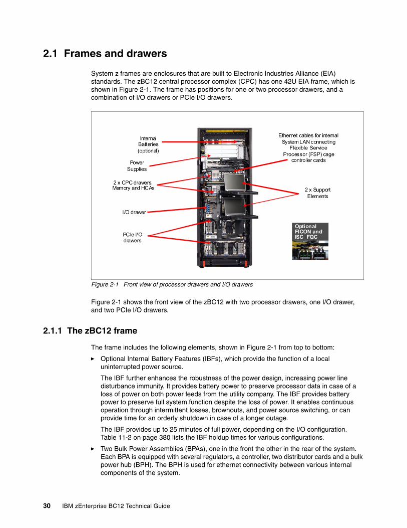
2.1 Frames and drawers
System z frames are enclosures that are built to Electronic Industries Alliance (EIA) standards. The zBC12 central processor complex (CPC) has one 42U EIA frame, which is shown in Figure 2-1. The frame has positions for one or two processor drawers, and a combination of I/O drawers or PCIe I/O drawers.
Figure 2-1 Front view of processor drawers and I/O drawers
Figure 2-1 shows the front view of the zBC12 with two processor drawers, one I/O drawer, and two PCIe I/O drawers.
2.1.1 The zBC12 frame
The frame includes the following elements, shown in Figure 2-1 from top to bottom:
� Optional Internal Battery Features (IBFs), which provide the function of a local uninterrupted power source.
The IBF further enhances the robustness of the power design, increasing power line disturbance immunity. It provides battery power to preserve processor data in case of a loss of power on both power feeds from the utility company. The IBF provides battery power to preserve full system function despite the loss of power. It enables continuous operation through intermittent losses, brownouts, and power source switching, or can provide time for an orderly shutdown in case of a longer outage.
The IBF provides up to 25 minutes of full power, depending on the I/O configuration. Table 11-2 on page 380 lists the IBF holdup times for various configurations.
� Two Bulk Power Assemblies (BPAs), one in the front the other in the rear of the system. Each BPA is equipped with several regulators, a controller, two distributor cards and a bulk power hub (BPH). The BPH is used for ethernet connectivity between various internal components of the system.
InternalBatteries(optional)
PowerSupplies
I/O drawer
2 x CPC drawers, Memory and HCAs 2 x Support
Elements
Ethernet cables for internal System LAN connecting
Flexible Service Processor (FSP) cage
controller cards
PCIe I/O drawers
Optional FICON and ISC FQC
30 IBM zEnterprise BC12 Technical Guide
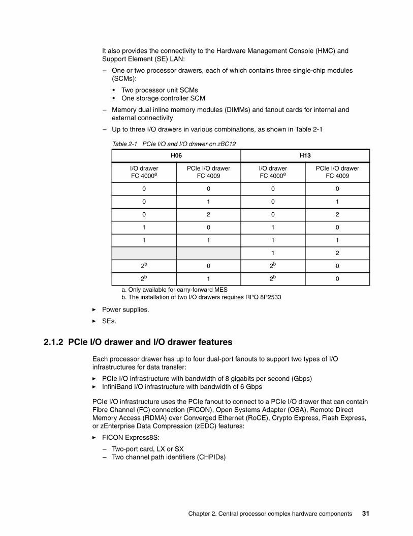
It also provides the connectivity to the Hardware Management Console (HMC) and Support Element (SE) LAN:
– One or two processor drawers, each of which contains three single-chip modules (SCMs):
• Two processor unit SCMs• One storage controller SCM
– Memory dual inline memory modules (DIMMs) and fanout cards for internal and external connectivity
– Up to three I/O drawers in various combinations, as shown in Table 2-1
Table 2-1 PCIe I/O and I/O drawer on zBC12
� Power supplies.
� SEs.
2.1.2 PCIe I/O drawer and I/O drawer features
Each processor drawer has up to four dual-port fanouts to support two types of I/O infrastructures for data transfer:
� PCIe I/O infrastructure with bandwidth of 8 gigabits per second (Gbps)� InfiniBand I/O infrastructure with bandwidth of 6 Gbps
PCIe I/O infrastructure uses the PCIe fanout to connect to a PCIe I/O drawer that can contain Fibre Channel (FC) connection (FICON), Open Systems Adapter (OSA), Remote Direct Memory Access (RDMA) over Converged Ethernet (RoCE), Crypto Express, Flash Express, or zEnterprise Data Compression (zEDC) features:
� FICON Express8S:
– Two-port card, LX or SX– Two channel path identifiers (CHPIDs)
H06 H13
I/O drawerFC 4000a
a. Only available for carry-forward MES
PCIe I/O drawerFC 4009
I/O drawerFC 4000a
PCIe I/O drawerFC 4009
0 0 0 0
0 1 0 1
0 2 0 2
1 0 1 0
1 1 1 1
1 2
2b
b. The installation of two I/O drawers requires RPQ 8P2533
0 2b 0
2b 1 2b 0
Chapter 2. Central processor complex hardware components 31
� OSA-Express5S feature:
– OSA-Express5S 10 Gb Ethernet (GbE)
• One-port card, LR or SR• One CHPID
– OSA-Express5S GbE (two-port card, LX or SX, and one CHPID)– OSA-Express5S 1000 megabits per second (Mbps) 1000BASE-T Ethernet (two-port
card and one CHPID)
� OSA-Express4S feature (only for carry-forward miscellaneous equipment specification, or MES):
– OSA-Express4S 10 GbE (one-port card, LR or SR, and one CHPID)– OSA-Express4S GbE (two-port card, LX and SX, and one CHPID)
� 10GbE RoCE Express:
– Two-port card, but the ports cannot be used simultaneously. Depending on the configuration, a port is activated via function ID (FID) to a dedicated logical partition (LPAR).
– A CHPID is not required.
� Crypto Express4S:
– Each Crypto Express4S feature holds one PCIe cryptographic adapter. – Each adapter can be configured during installation:
• As a Secure IBM Common Cryptographic Architecture (CCA) coprocessor
• As a Secure IBM Enterprise Public Key Cryptography Standards (PKCS) #11 (EP11) coprocessor
• As an accelerator
� Flash Express:
– Each Flash Express feature occupies two I/O slots, but does not have a CHPID type.– LPARs in all channel subsystems (CSSs) have access to the features.
� zEDC Express:
• The zEDC Express feature occupies one I/O slot, but does not have a CHPID type.• Up to 15 partitions can share the feature concurrently.
InfiniBand I/O infrastructure uses the host channel adapter2-copper (HCA2-C) fanout to connect to an I/O drawer that can contain a variety of FICON, Coupling Link, OSA-Express, and Cryptographic features:
� FICON features, in FICON or Fibre Channel Protocol (FCP) modes:
– FICON Express4-2C SX (two-port card and two CHPIDs)– FICON Express4 channels (four-port card, LX or SX, and four CHPIDs)– FICON Express8 channels (four-port card, LX or SX, and four CHPIDs)
� InterSystem Channel (ISC-3) links (up to four coupling links, two links per daughter card). Two daughter cards (ISC-D) plug into one mother card (ISC-M).
� OSA-Express features:
– OSA-Express3 10 GbE (two-port card, LR or SR, and two CHPIDs)– OSA-Express3 GbE (four-port card, LX or SX, and two CHPIDs)– OSA-Express3 1000BASE-T Ethernet (four-port card and two CHPIDs)– OSA-Express3-2P GbE SX (two-port card and one CHPID)– OSA-Express3-2P 1000BASE-T Ethernet (two-port card and one CHPID)– OSA-Express2 GbE SX (two-port card, SX or LX, and two CHPIDs)– OSA-Express2 1000BASE-T Ethernet (two-ports card and two CHPIDs)
32 IBM zEnterprise BC12 Technical Guide
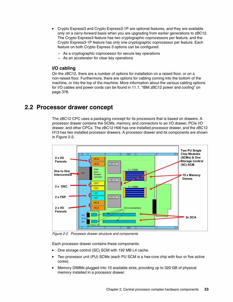
� Crypto Express3 and Crypto Express3-1P are optional features, and they are available only on a carry-forward basis when you are upgrading from earlier generations to zBC12. The Crypto Express3 feature has two cryptographic coprocessors per feature, and the Crypto Express3-1P feature has only one cryptographic coprocessor per feature. Each feature on both Crypto Express 3 options can be configured:
– As a cryptographic coprocessor for secure key operations– As an accelerator for clear key operations
I/O cablingOn the zBC12, there are a number of options for installation on a raised floor, or on a non-raised floor. Furthermore, there are options for cabling coming into the bottom of the machine, or into the top of the machine. More information about the various cabling options for I/O cables and power cords can be found in 11.1, “IBM zBC12 power and cooling” on page 378.
2.2 Processor drawer concept
The zBC12 CPC uses a packaging concept for its processors that is based on drawers. A processor drawer contains the SCMs, memory, and connectors to an I/O drawer, PCIe I/O drawer, and other CPCs. The zBC12 H06 has one installed processor drawer, and the zBC12 H13 has two installed processor drawers. A processor drawer and its components are shown in Figure 2-2.
Figure 2-2 Processor drawer structure and components
Each processor drawer contains these components:
� One storage control (SC) SCM with 192 MB L4 cache.
� Two processor unit (PU) SCMs (each PU SCM is a hex-core chip with four or five active cores).
� Memory DIMMs plugged into 10 available slots, providing up to 320 GB of physical memory installed in a processor drawer.
PU SCM
SC SCM
PU SCM
HCA
HCA
HCA
HCA
inter procdrawer connect
PU SCM
SC SCM
PU SCM
HCA
HCA
HCA
HCA
inter procdrawer connect
2 x I/O Fanouts
2 x OSC
2 x FSP
2 x I/O Fanouts
2x DCA
10 x MemoryDimms
Drw to DrwInterconnect
Two PU Single Chip Modules (SCMs) & One Storage Control (SC) SCM
Chapter 2. Central processor complex hardware components 33
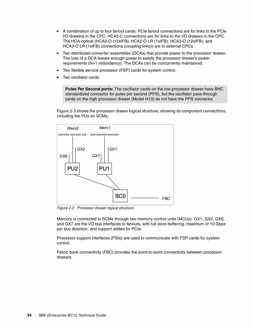
� A combination of up to four fanout cards. PCIe fanout connections are for links to the PCIe I/O drawers in the CPC, HCA2-C connections are for links to the I/O drawers in the CPC. The HCA-optical (HCA2-O (12xIFB), HCA2-O LR (1xIFB), HCA3-O (12xIFB), and HCA3-O LR (1xIFB) connections (coupling links)) are to external CPCs.
� Two distributed converter assemblies (DCAs) that provide power to the processor drawer. The loss of a DCA leaves enough power to satisfy the processor drawer’s power requirements (N+1 redundancy). The DCAs can be concurrently maintained.
� Two flexible service processor (FSP) cards for system control.
� Two oscillator cards.
Figure 2-3 shows the processor drawer logical structure, showing its component connections, including the PUs on SCMs.
Figure 2-3 Processor drawer logical structure
Memory is connected to SCMs through two memory control units (MCUs). GX1, GX2, GX6, and GX7 are the I/O bus interfaces to fanouts, with full store buffering, maximum of 10 Gbps per bus direction, and support added for PCIe.
Processor support interfaces (PSIs) are used to communicate with FSP cards for system control.
Fabric book connectivity (FBC) provides the point-to-point connectivity between processor drawers.
Pulse Per Second ports: The oscillator cards on the low processor drawer have BNC standardized connector for pulse per second (PPS), but the oscillator pass-through cards on the high processor drawer (Model H13) do not have the PPS connector.
PU1PU1PU2PU2
SC0SC0
Mem1
GX1
FBC
Mem2
GX2
GX6 GX7
34 IBM zEnterprise BC12 Technical Guide
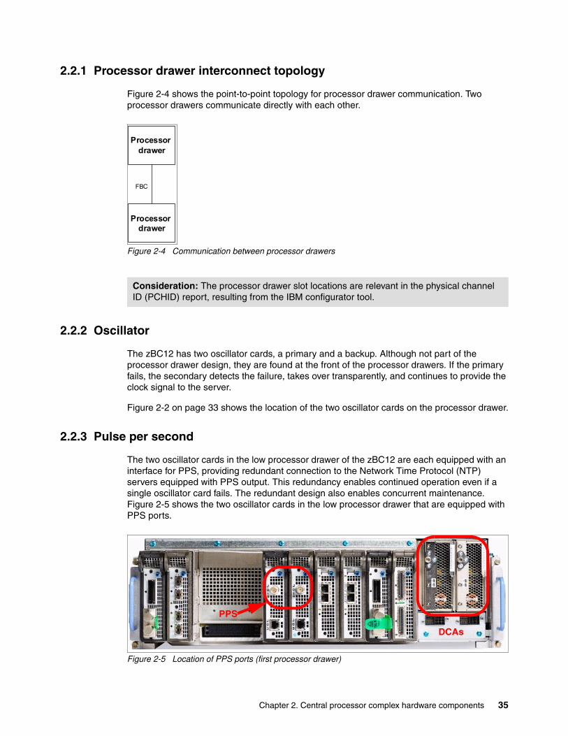
2.2.1 Processor drawer interconnect topology
Figure 2-4 shows the point-to-point topology for processor drawer communication. Two processor drawers communicate directly with each other.
Figure 2-4 Communication between processor drawers
2.2.2 Oscillator
The zBC12 has two oscillator cards, a primary and a backup. Although not part of the processor drawer design, they are found at the front of the processor drawers. If the primary fails, the secondary detects the failure, takes over transparently, and continues to provide the clock signal to the server.
Figure 2-2 on page 33 shows the location of the two oscillator cards on the processor drawer.
2.2.3 Pulse per second
The two oscillator cards in the low processor drawer of the zBC12 are each equipped with an interface for PPS, providing redundant connection to the Network Time Protocol (NTP) servers equipped with PPS output. This redundancy enables continued operation even if a single oscillator card fails. The redundant design also enables concurrent maintenance. Figure 2-5 shows the two oscillator cards in the low processor drawer that are equipped with PPS ports.
Figure 2-5 Location of PPS ports (first processor drawer)
Consideration: The processor drawer slot locations are relevant in the physical channel ID (PCHID) report, resulting from the IBM configurator tool.
Processor drawer
FBC
Processor drawer
PPS
DCAs
Chapter 2. Central processor complex hardware components 35
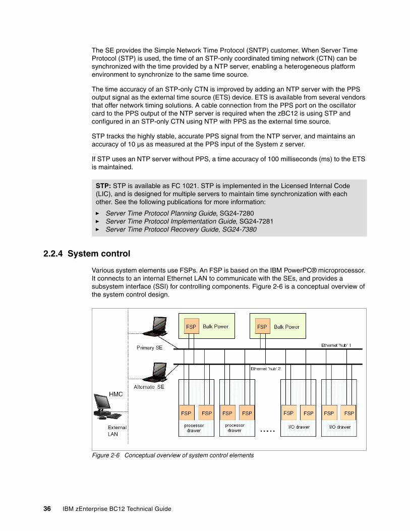
The SE provides the Simple Network Time Protocol (SNTP) customer. When Server Time Protocol (STP) is used, the time of an STP-only coordinated timing network (CTN) can be synchronized with the time provided by a NTP server, enabling a heterogeneous platform environment to synchronize to the same time source.
The time accuracy of an STP-only CTN is improved by adding an NTP server with the PPS output signal as the external time source (ETS) device. ETS is available from several vendors that offer network timing solutions. A cable connection from the PPS port on the oscillator card to the PPS output of the NTP server is required when the zBC12 is using STP and configured in an STP-only CTN using NTP with PPS as the external time source.
STP tracks the highly stable, accurate PPS signal from the NTP server, and maintains an accuracy of 10 µs as measured at the PPS input of the System z server.
If STP uses an NTP server without PPS, a time accuracy of 100 milliseconds (ms) to the ETS is maintained.
2.2.4 System control
Various system elements use FSPs. An FSP is based on the IBM PowerPC® microprocessor. It connects to an internal Ethernet LAN to communicate with the SEs, and provides a subsystem interface (SSI) for controlling components. Figure 2-6 is a conceptual overview of the system control design.
Figure 2-6 Conceptual overview of system control elements
STP: STP is available as FC 1021. STP is implemented in the Licensed Internal Code (LIC), and is designed for multiple servers to maintain time synchronization with each other. See the following publications for more information:
� Server Time Protocol Planning Guide, SG24-7280� Server Time Protocol Implementation Guide, SG24-7281� Server Time Protocol Recovery Guide, SG24-7380
36 IBM zEnterprise BC12 Technical Guide
One typical FSP operation is to control a power supply. An SE sends a command to the FSP to activate the power supply. The FSP (using SSI connections) cycles the various components of the power supply, monitors the success of each step and the resulting voltages, and reports this status to the SE.
Most system elements are duplexed (for redundancy), and each element has an FSP. There are two internal Ethernet LANs and two SEs for redundancy. There is also crossover capability between the LANs, so that both SEs can operate on both LANs.
The SEs, in turn, are connected to one or two (external) LANs (Ethernet only), and the HMCs are connected to the same external LANs. One or more HMCs can be used, but, in an ensemble, two (a primary and an alternate1) are mandatory. Additional HMCs can operate a zBC12 when it is not a member of an ensemble.
If the zBC12 server is not a member of an ensemble, the controlling HMCs are stateless (there is no system status kept on the HMCs), and therefore system operations are not affected if any HMC is disconnected. At that time, the system can be managed from either SE.
However, if the zBC12 is defined as a node of an ensemble, its HMC will be the authoritative owning (stateful) component for platform management, configuration, and policies. This applies to a scope that spans all user-replaceable-module-managed nodes (CPCs and zEnterprise BladeCenter Extensions (zBXs)) in the collection (ensemble).
In this case, the HMC is no longer simply a console or access point for configuration and policies (otherwise owned by each of the managed CPCs). The HMC of an ensemble also has an active role in ongoing system monitoring and adjustment. This role requires that the HMC is paired with an active backup (alternate) HMC1.
2.2.5 Processor drawer power
Each processor drawer gets its power from two DCAs in the processor drawer (see Figure 2-5 on page 35). The DCAs provide the power for the processor drawer. Loss of one DCA leaves enough power to satisfy processor drawer power requirements. The DCAs can be concurrently maintained, and are accessed from the rear of the frame.
1 These HMCs must be running with Version 2.12.1 or later. See section 12.7, “HMC in an ensemble” on page 423 for more information.
Important: For ensemble configurations, the primary and the alternate HMCs must be connected to the same virtual LAN (VLAN) and have IP addresses belonging to the same subnet to enable the alternate HMC to take over the IP address in case the primary HMC fails.
Chapter 2. Central processor complex hardware components 37
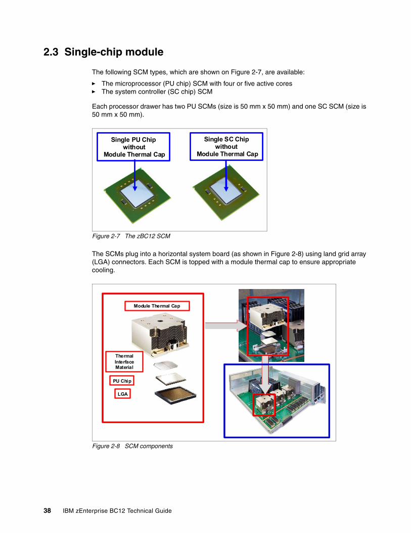
2.3 Single-chip module
The following SCM types, which are shown on Figure 2-7, are available:
� The microprocessor (PU chip) SCM with four or five active cores � The system controller (SC chip) SCM
Each processor drawer has two PU SCMs (size is 50 mm x 50 mm) and one SC SCM (size is 50 mm x 50 mm).
Figure 2-7 The zBC12 SCM
The SCMs plug into a horizontal system board (as shown in Figure 2-8) using land grid array (LGA) connectors. Each SCM is topped with a module thermal cap to ensure appropriate cooling.
Figure 2-8 SCM components
Single PU Chipwithout
Module Thermal Cap
Single SC Chipwithout
Module Thermal Cap
Module Thermal Cap
PU Chip
LGA
Thermal Interface Material
38 IBM zEnterprise BC12 Technical Guide
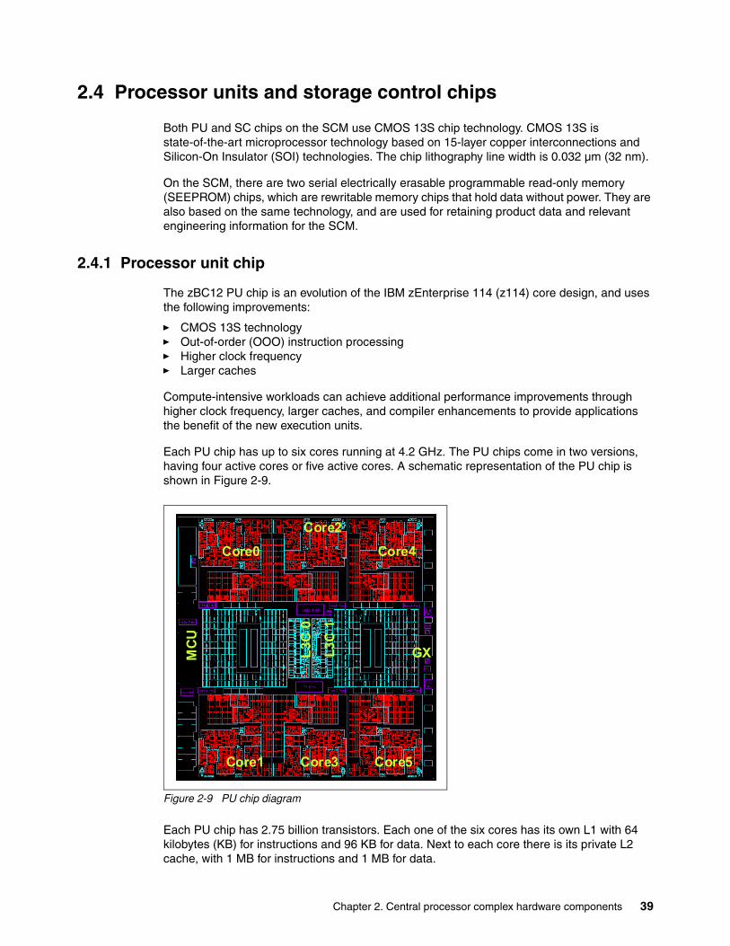
2.4 Processor units and storage control chips
Both PU and SC chips on the SCM use CMOS 13S chip technology. CMOS 13S is state-of-the-art microprocessor technology based on 15-layer copper interconnections and Silicon-On Insulator (SOI) technologies. The chip lithography line width is 0.032 µm (32 nm).
On the SCM, there are two serial electrically erasable programmable read-only memory (SEEPROM) chips, which are rewritable memory chips that hold data without power. They are also based on the same technology, and are used for retaining product data and relevant engineering information for the SCM.
2.4.1 Processor unit chip
The zBC12 PU chip is an evolution of the IBM zEnterprise 114 (z114) core design, and uses the following improvements:
� CMOS 13S technology� Out-of-order (OOO) instruction processing� Higher clock frequency� Larger caches
Compute-intensive workloads can achieve additional performance improvements through higher clock frequency, larger caches, and compiler enhancements to provide applications the benefit of the new execution units.
Each PU chip has up to six cores running at 4.2 GHz. The PU chips come in two versions, having four active cores or five active cores. A schematic representation of the PU chip is shown in Figure 2-9.
Figure 2-9 PU chip diagram
Each PU chip has 2.75 billion transistors. Each one of the six cores has its own L1 with 64 kilobytes (KB) for instructions and 96 KB for data. Next to each core there is its private L2 cache, with 1 MB for instructions and 1 MB for data.
L3
C 0
L3
C 1
GXMC
U
Core0
Core1
Core2
Core3
Core4
Core5
L3
C 0
L3
C 1
GXMC
U
Core0
Core1
Core2
Core3
Core4
Core5
Chapter 2. Central processor complex hardware components 39
There is one 24 MB L3 cache. The L3 cache is a store-in shared cache across all six cores in the PU chip. It has 96 x 512 KB enhanced dynamic random access memory (eDRAM) macros, dual address-sliced and dual store pipe support, an integrated on-chip coherency manager, cache, and cross-bar switch.The L3 directory filters queries from local L4. Both L3 slices can deliver up to 160 Gbps bandwidth to each core simultaneously. The L3 cache interconnects the six cores, GX I/O buses, and memory controllers (MCs) with SC chips.
The memory controller (MC) function controls access to memory. The GX I/O bus controls the interface to the fanouts accessing the I/O. The chip controls traffic between the cores, memory, I/O, and the L4 cache on the SC chip.
There is also one dedicated coprocessor (CoP) for data compression and encryption functions for each core. The compression unit is integrated with the Central Processor (CP) Assist for Cryptographic Function (CPACF), benefiting from combining (or sharing) the use of buffers and interfaces. The assist provides high-performance hardware encrypting and decrypting support for clear key operations. For details, see 3.4.3, “Compression and cryptography accelerators on a chip” on page 75.
2.4.2 Processor unit (core)
Each processor unit, or core, is a superscalar, out-of-program-order processor, having the following six execution units:
� Two fixed-point (integer)� Two load/store� One binary floating point� One decimal floating point
Up to three instructions can be decoded per cycle, and up to seven instructions or operations can be executed per cycle. The instructions’ run can occur out of program order. In addition, memory address generation and memory accesses can also occur out of program order. Each core has special circuitry to make execution and memory accesses appear in the correct order to software.
Not all instructions are directly run by the hardware. This is the case for several complex instructions. Some are run by millicode, and some are broken into multiple operations that are then run by the hardware.
The following functional areas are implemented on each core, as shown in Figure 2-10 on page 41:
Instruction sequence unit (ISU)
This new unit (ISU) enables the OOO pipeline. It keeps track of register names, OOO instruction dependency, and handling of instruction resource dispatch.
This unit is also central to performance measurement through a function called instrumentation.
Instruction fetching unit (IFU) (prediction)
These units contain the instruction cache, branch prediction logic, instruction fetching controls, and buffers. Its relative size is the result of the elaborate branch prediction design. For more information, see 3.4.2, “Superscalar processor” on page 75.
Instruction decode unit (IDU)
The IDU is fed from the IFU buffers, and is responsible for the parsing and decoding of all z/Architecture operation codes.
40 IBM zEnterprise BC12 Technical Guide
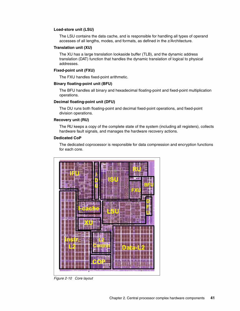
Load-store unit (LSU)
The LSU contains the data cache, and is responsible for handling all types of operand accesses of all lengths, modes, and formats, as defined in the z/Architecture.
Translation unit (XU)
The XU has a large translation lookaside buffer (TLB), and the dynamic address translation (DAT) function that handles the dynamic translation of logical to physical addresses.
Fixed-point unit (FXU)
The FXU handles fixed-point arithmetic.
Binary floating-point unit (BFU)
The BFU handles all binary and hexadecimal floating-point and fixed-point multiplication operations.
Decimal floating-point unit (DFU)
The DU runs both floating-point and decimal fixed-point operations, and fixed-point division operations.
Recovery unit (RU)
The RU keeps a copy of the complete state of the system (including all registers), collects hardware fault signals, and manages the hardware recovery actions.
Dedicated CoP
The dedicated coprocessor is responsible for data compression and encryption functions for each core.
Figure 2-10 Core layout
Data-L2
LSU
ISU
RU
FXUBFU
DFU
COP
L2Control
XU
I-cache
IFU
Instr.L2
IDU
Data-L2
LSU
ISU
RU
FXUBFU
DFU
COP
L2Control
XU
I-cache
IFU
Instr.L2
IDU
Chapter 2. Central processor complex hardware components 41
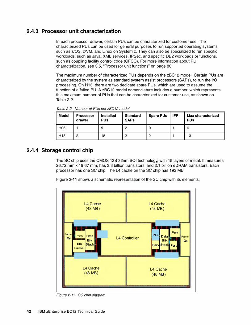
2.4.3 Processor unit characterization
In each processor drawer, certain PUs can be characterized for customer use. The characterized PUs can be used for general purposes to run supported operating systems, such as z/OS, z/VM, and Linux on System z. They can also be specialized to run specific workloads, such as Java, XML services, IPSec, and specific DB2 workloads or functions, such as coupling facility control code (CFCC). For more information about PU characterization, see 3.5, “Processor unit functions” on page 80.
The maximum number of characterized PUs depends on the zBC12 model. Certain PUs are characterized by the system as standard system assist processors (SAPs), to run the I/O processing. On H13, there are two dedicate spare PUs, which are used to assume the function of a failed PU. A zBC12 model nomenclature includes a number, which represents this maximum number of PUs that can be characterized for customer use, as shown on Table 2-2.
Table 2-2 Number of PUs per zBC12 model
2.4.4 Storage control chip
The SC chip uses the CMOS 13S 32nm SOI technology, with 15 layers of metal. It measures 26.72 mm x 19.67 mm, has 3.3 billion transistors, and 2.1 billion eDRAM transistors. Each processor has one SC chip. The L4 cache on the SC chip has 192 MB.
Figure 2-11 shows a schematic representation of the SC chip with its elements.
Figure 2-11 SC chip diagram
Model Processor drawer
Installed PUs
Standard SAPs
Spare PUs IFP Max characterized PUs
H06 1 9 2 0 1 6
H13 2 18 2 2 1 13
L4 Controller
L4 Cache(48 MB)
L4 Cache(48 MB)
L4 Cache(48 MB)
L4 Cache(48 MB)
Fabric
IOsTOD Data
Bit-StackClk
Repower
PLL
Perv Perv
PervDataBit-
Stack
Fabric
IOs
42 IBM zEnterprise BC12 Technical Guide
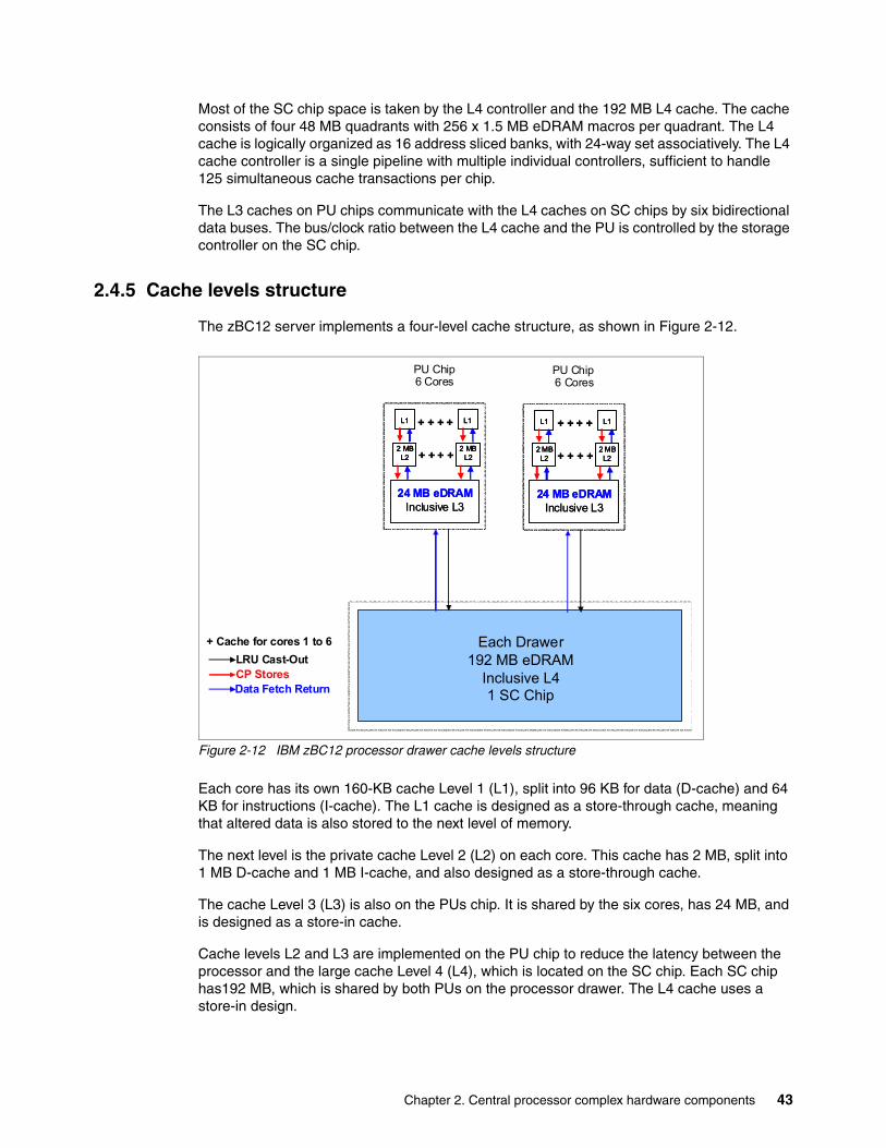
Most of the SC chip space is taken by the L4 controller and the 192 MB L4 cache. The cache consists of four 48 MB quadrants with 256 x 1.5 MB eDRAM macros per quadrant. The L4 cache is logically organized as 16 address sliced banks, with 24-way set associatively. The L4 cache controller is a single pipeline with multiple individual controllers, sufficient to handle 125 simultaneous cache transactions per chip.
The L3 caches on PU chips communicate with the L4 caches on SC chips by six bidirectional data buses. The bus/clock ratio between the L4 cache and the PU is controlled by the storage controller on the SC chip.
2.4.5 Cache levels structure
The zBC12 server implements a four-level cache structure, as shown in Figure 2-12.
Figure 2-12 IBM zBC12 processor drawer cache levels structure
Each core has its own 160-KB cache Level 1 (L1), split into 96 KB for data (D-cache) and 64 KB for instructions (I-cache). The L1 cache is designed as a store-through cache, meaning that altered data is also stored to the next level of memory.
The next level is the private cache Level 2 (L2) on each core. This cache has 2 MB, split into 1 MB D-cache and 1 MB I-cache, and also designed as a store-through cache.
The cache Level 3 (L3) is also on the PUs chip. It is shared by the six cores, has 24 MB, and is designed as a store-in cache.
Cache levels L2 and L3 are implemented on the PU chip to reduce the latency between the processor and the large cache Level 4 (L4), which is located on the SC chip. Each SC chip has192 MB, which is shared by both PUs on the processor drawer. The L4 cache uses a store-in design.
Each Drawer192 MB eDRAM
Inclusive L41 SC Chip
LRU Cast-OutCP StoresData Fetch Return
PU Chip6 Cores
PU Chip6 Cores
24 MB eDRAMInclusive L3
L1
2 MBL2
L1
2 MBL2
+ + + +
+ + + +
24 MB eDRAMInclusive L3
L1L1
2 MBL2
2 MBL2
L1L1
2 MBL2
2 MBL2
+ + + +
+ + + +
+ Cache for cores 1 to 6
24 MB eDRAMInclusive L3
L1
2 MBL2
L1
2 MBL2
+ + + +
+ + + +
24 MB eDRAMInclusive L3
L1L1
2 MBL2
2 MBL2
L1L1
2 MBL2
2 MBL2
+ + + +
+ + + +
Chapter 2. Central processor complex hardware components 43
2.5 Memory
Maximum physical memory size is directly related to the number of processor drawers in the system. Each processor drawer can contain up to 320 GB of physical memory, for a total of 640 GB of installed memory per system.
A zBC12 server has more memory installed than ordered. Part of the physically installed memory is used to implement the redundant array of independent memory (RAIM) design. This results in up to 256 GB of available memory per processor drawer, and up to 512 GB per system with fixed 16 GB hardware system area (HSA). Table 2-3 shows the maximum and minimum memory sizes that a customer can order for each zBC12 model, with separate increments.
Table 2-3 The zBC12 server memory sizes
On zBC12 servers, the memory increment is 8 GB for customer memory sizes up to 112 GB and 32 GB for memory sizes greater than 144 GB. Memory is physically organized in the following manner:
� A processor drawer always contains a minimum of 40 GB of physically installed memory.
� A processor drawer can have more memory installed than enabled. The excess amount of memory can be enabled by a LIC load when required by the installation.
� Memory upgrades are satisfied from already-installed unused memory capacity until exhausted. When no more unused memory is available from the installed memory cards, either the cards must be upgraded to a higher capacity or the second processor drawer with additional memory must be installed.
Model Number of processor drawers Increment (GB) Customer memory (GB)
H06 1 8 8 - 112
H06 1 32 144 - 240
H13 2 8 16 - 112
H13 2 32 144 - 496
44 IBM zEnterprise BC12 Technical Guide
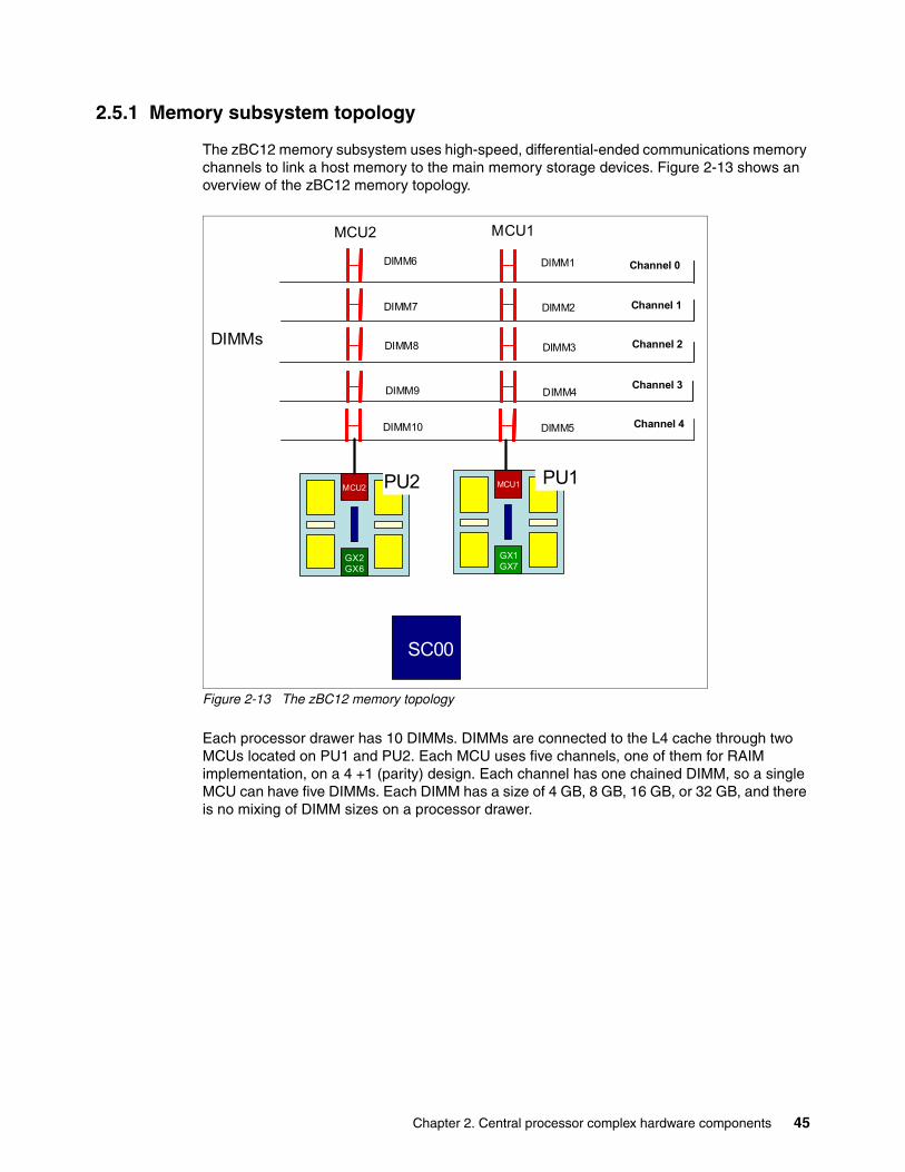
2.5.1 Memory subsystem topology
The zBC12 memory subsystem uses high-speed, differential-ended communications memory channels to link a host memory to the main memory storage devices. Figure 2-13 shows an overview of the zBC12 memory topology.
Figure 2-13 The zBC12 memory topology
Each processor drawer has 10 DIMMs. DIMMs are connected to the L4 cache through two MCUs located on PU1 and PU2. Each MCU uses five channels, one of them for RAIM implementation, on a 4 +1 (parity) design. Each channel has one chained DIMM, so a single MCU can have five DIMMs. Each DIMM has a size of 4 GB, 8 GB, 16 GB, or 32 GB, and there is no mixing of DIMM sizes on a processor drawer.
MCU2
DIMM6 Channel 0
Channel 1
Channel 2
Channel 3
Channel 4
DIMMs
SC0
SC1
MCU2
GX2GX6
MCU1
GX1GX7
PU1PU2
SC00
DIMM7
DIMM8
DIMM9
DIMM1
DIMM2
DIMM3
DIMM4
DIMM10 DIMM5
MCU1
Chapter 2. Central processor complex hardware components 45
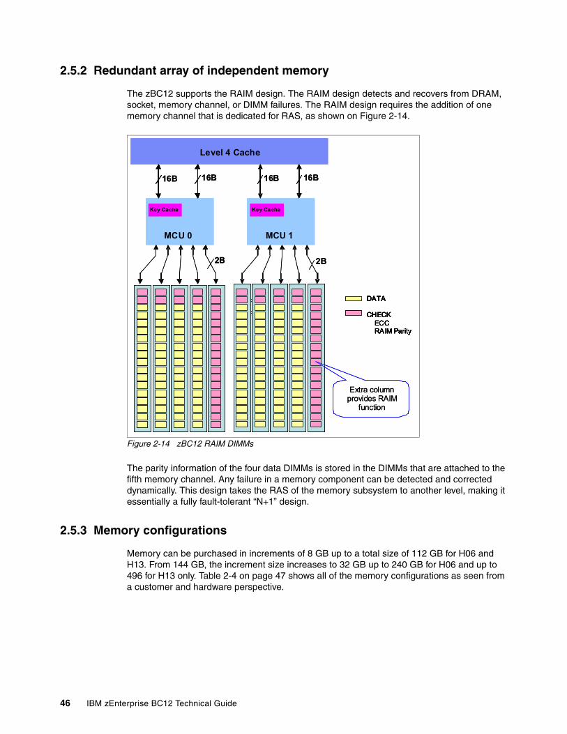
2.5.2 Redundant array of independent memory
The zBC12 supports the RAIM design. The RAIM design detects and recovers from DRAM, socket, memory channel, or DIMM failures. The RAIM design requires the addition of one memory channel that is dedicated for RAS, as shown on Figure 2-14.
Figure 2-14 zBC12 RAIM DIMMs
The parity information of the four data DIMMs is stored in the DIMMs that are attached to the fifth memory channel. Any failure in a memory component can be detected and corrected dynamically. This design takes the RAS of the memory subsystem to another level, making it essentially a fully fault-tolerant “N+1” design.
2.5.3 Memory configurations
Memory can be purchased in increments of 8 GB up to a total size of 112 GB for H06 and H13. From 144 GB, the increment size increases to 32 GB up to 240 GB for H06 and up to 496 for H13 only. Table 2-4 on page 47 shows all of the memory configurations as seen from a customer and hardware perspective.
DATA
CHECK
DATA
CHECKECCRAIM Parity
DATA
CHECKECCRAIM Parity
Level 4 Cache
Key Cache
MCU 0
Key Cache
MCU 1
Extra column provides RAIM
function
16B 16B 16B 16B
2B 2B
DATA
CHECK
DATA
CHECK
DATA
CHECKECCRAIM Parity
DATA
CHECKECCRAIM Parity
Level 4 Cache
Key Cache
MCU 0
DATA
CHECKECCRAIM Parity
DATA
CHECKECCRAIM Parity
Level 4 Cache
Key Cache
MCU 0
Key Cache
MCU 1
Extra column provides RAIM
function
16B 16B 16B 16B
2B 2B
46 IBM zEnterprise BC12 Technical Guide
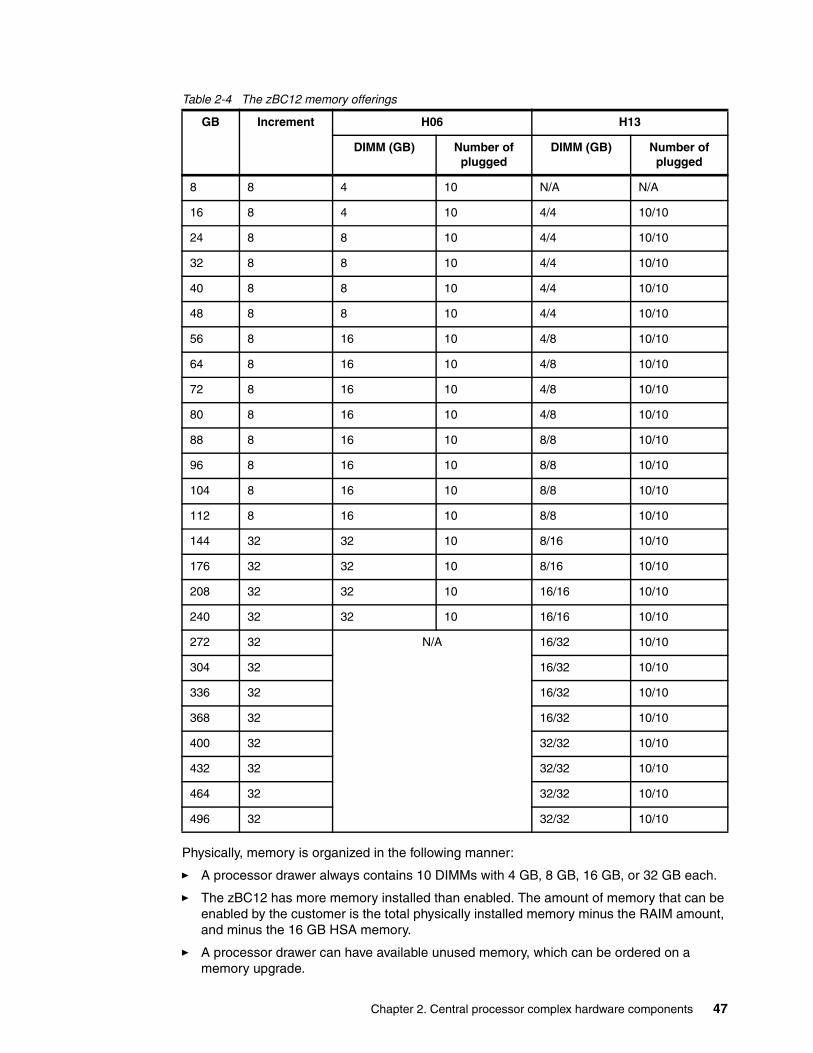
Table 2-4 The zBC12 memory offerings
Physically, memory is organized in the following manner:
� A processor drawer always contains 10 DIMMs with 4 GB, 8 GB, 16 GB, or 32 GB each.
� The zBC12 has more memory installed than enabled. The amount of memory that can be enabled by the customer is the total physically installed memory minus the RAIM amount, and minus the 16 GB HSA memory.
� A processor drawer can have available unused memory, which can be ordered on a memory upgrade.
GB Increment H06 H13
DIMM (GB) Number of plugged
DIMM (GB) Number of plugged
8 8 4 10 N/A N/A
16 8 4 10 4/4 10/10
24 8 8 10 4/4 10/10
32 8 8 10 4/4 10/10
40 8 8 10 4/4 10/10
48 8 8 10 4/4 10/10
56 8 16 10 4/8 10/10
64 8 16 10 4/8 10/10
72 8 16 10 4/8 10/10
80 8 16 10 4/8 10/10
88 8 16 10 8/8 10/10
96 8 16 10 8/8 10/10
104 8 16 10 8/8 10/10
112 8 16 10 8/8 10/10
144 32 32 10 8/16 10/10
176 32 32 10 8/16 10/10
208 32 32 10 16/16 10/10
240 32 32 10 16/16 10/10
272 32 N/A 16/32 10/10
304 32 16/32 10/10
336 32 16/32 10/10
368 32 16/32 10/10
400 32 32/32 10/10
432 32 32/32 10/10
464 32 32/32 10/10
496 32 32/32 10/10
Chapter 2. Central processor complex hardware components 47
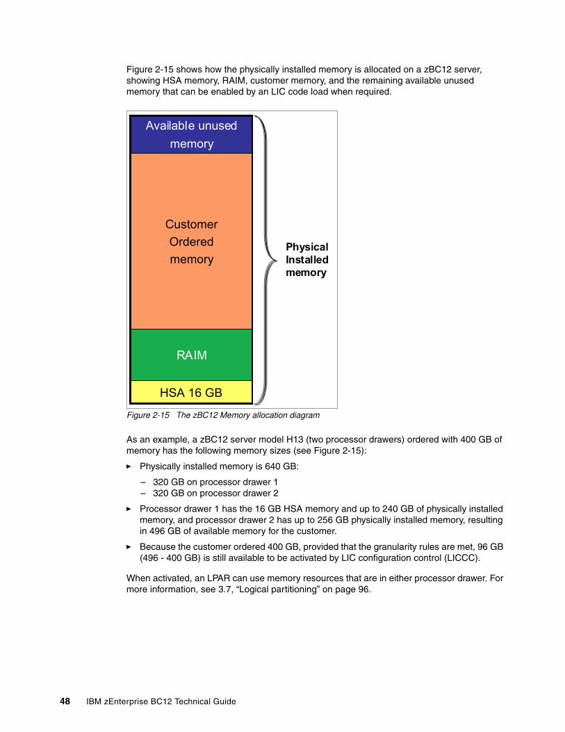
Figure 2-15 shows how the physically installed memory is allocated on a zBC12 server, showing HSA memory, RAIM, customer memory, and the remaining available unused memory that can be enabled by an LIC code load when required.
Figure 2-15 The zBC12 Memory allocation diagram
As an example, a zBC12 server model H13 (two processor drawers) ordered with 400 GB of memory has the following memory sizes (see Figure 2-15):
� Physically installed memory is 640 GB:
– 320 GB on processor drawer 1– 320 GB on processor drawer 2
� Processor drawer 1 has the 16 GB HSA memory and up to 240 GB of physically installed memory, and processor drawer 2 has up to 256 GB physically installed memory, resulting in 496 GB of available memory for the customer.
� Because the customer ordered 400 GB, provided that the granularity rules are met, 96 GB (496 - 400 GB) is still available to be activated by LIC configuration control (LICCC).
When activated, an LPAR can use memory resources that are in either processor drawer. For more information, see 3.7, “Logical partitioning” on page 96.
Available unused
memory
Customer
Ordered
memory
RAIM
HSA 16 GB
Available unused
memory
Customer
Ordered
memory
RAIM
HSA 16 GB
PhysicalInstalledmemory
48 IBM zEnterprise BC12 Technical Guide
2.5.4 Memory upgrades
Memory upgrades are satisfied from already installed unused memory capacity until it is exhausted. When no more unused memory is available from the installed memory cards (DIMMs), one of the following additions must occur:
� Memory cards have to be upgraded to a higher capacity.� An additional processor drawer with additional memory is necessary.� DIMMs must be added.
A memory upgrade is concurrent when it requires no change of the physical memory cards. A memory card change is disruptive. See 2.8, “Model configurations” on page 53. If all or part of the additional memory is enabled for customer use (if it was purchased), it can become available to an active LPAR if this partition has reserved storage defined. For more information, see 3.7.3, “Reserved storage” on page 104. Alternately, additional memory can be used by an already defined LPAR that is activated after the memory addition.
2.5.5 Preplanned memory
Preplanned memory provides the ability to plan for nondisruptive permanent memory upgrades. When preparing in advance for a future memory upgrade, note that memory can be pre-plugged in, based on a target capacity. The pre-plugged memory can be made available through an LICCC update. You can request this LICCC through one of these sources:
� Order it from IBM Resource Link® (login is required):
http://www.ibm.com/servers/resourcelink/
� Order it from an IBM representative.
The installation and activation of any preplanned memory requires the purchase of the required feature codes (FC), which are described in Table 2-5. The payment for plan-ahead memory is a two-phase process. One charge takes place when the plan-ahead memory is ordered, and another charge takes place when the prepaid memory is activated for actual use. For the exact terms and conditions, contact your IBM representative.
Table 2-5 Feature codes for plan-ahead memory
You install preplanned memory by ordering FC 1993. The ordered amount of plan-ahead memory is charged with a reduced price compared to the normal price for memory. One FC 1993 is needed for each 8 GB physical increment.
The activation of installed pre-planned memory is achieved by ordering FC 1903, which causes the other portion of the previously contracted charge price to be invoiced. FC 1903 indicates 8 GB (or 32 GB in larger configurations) of LICCC increments of memory capacity.
Memory z114 feature code
Preplanned memoryCharged when physical memory is installed. Used for tracking the quantity of physical increments of plan-ahead memory capacity.
FC 1993
Preplanned memory activationCharged when plan-ahead memory is enabled. Used for tracking the quantity of increments of plan-ahead memory being activated.
FC 1903
Memory upgrades: Normal memory upgrades use up the plan-ahead memory first.
Chapter 2. Central processor complex hardware components 49
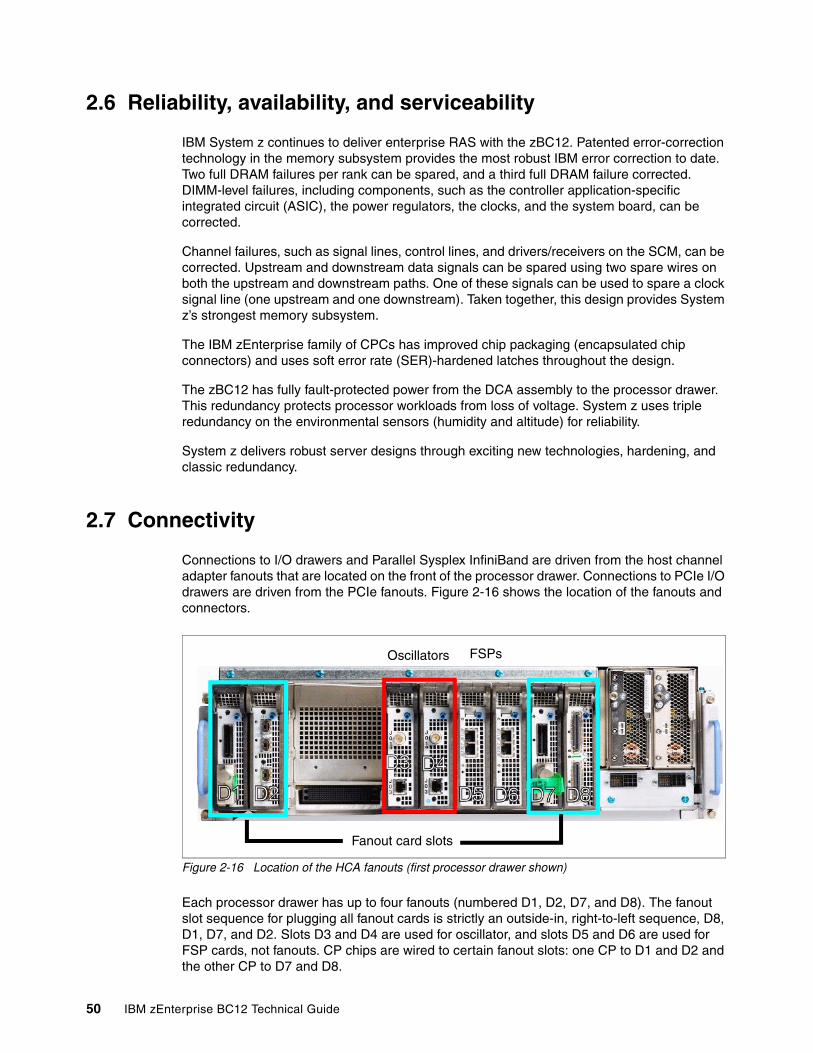
2.6 Reliability, availability, and serviceability
IBM System z continues to deliver enterprise RAS with the zBC12. Patented error-correction technology in the memory subsystem provides the most robust IBM error correction to date. Two full DRAM failures per rank can be spared, and a third full DRAM failure corrected. DIMM-level failures, including components, such as the controller application-specific integrated circuit (ASIC), the power regulators, the clocks, and the system board, can be corrected.
Channel failures, such as signal lines, control lines, and drivers/receivers on the SCM, can be corrected. Upstream and downstream data signals can be spared using two spare wires on both the upstream and downstream paths. One of these signals can be used to spare a clock signal line (one upstream and one downstream). Taken together, this design provides System z’s strongest memory subsystem.
The IBM zEnterprise family of CPCs has improved chip packaging (encapsulated chip connectors) and uses soft error rate (SER)-hardened latches throughout the design.
The zBC12 has fully fault-protected power from the DCA assembly to the processor drawer. This redundancy protects processor workloads from loss of voltage. System z uses triple redundancy on the environmental sensors (humidity and altitude) for reliability.
System z delivers robust server designs through exciting new technologies, hardening, and classic redundancy.
2.7 Connectivity
Connections to I/O drawers and Parallel Sysplex InfiniBand are driven from the host channel adapter fanouts that are located on the front of the processor drawer. Connections to PCIe I/O drawers are driven from the PCIe fanouts. Figure 2-16 shows the location of the fanouts and connectors.
Figure 2-16 Location of the HCA fanouts (first processor drawer shown)
Each processor drawer has up to four fanouts (numbered D1, D2, D7, and D8). The fanout slot sequence for plugging all fanout cards is strictly an outside-in, right-to-left sequence, D8, D1, D7, and D2. Slots D3 and D4 are used for oscillator, and slots D5 and D6 are used for FSP cards, not fanouts. CP chips are wired to certain fanout slots: one CP to D1 and D2 and the other CP to D7 and D8.
Fanout card slots
Oscillators FSPs
50 IBM zEnterprise BC12 Technical Guide
There is a possible degrade mode if one CP chip is lost, which is the reason for the fanout plugging order. A fanout can be repaired concurrently with the use of redundant I/O interconnect. See 2.7.1, “Redundant I/O interconnect” on page 52.
Six types of fanouts are available:
� HCA2-C provides copper connections for InfiniBand I/O interconnect to all I/O, ISC-3, and Crypto Express features in I/O drawers.
� PCIe fanout provides copper connections for PCIe I/O interconnect to all I/O features in PCIe I/O drawers.
� HCA2-O (12xIFB) provides optical connections for 12xIFB. The HCA2-O (12xIFB) provides a point-to-point connection over a distance of up to 150 m (492.17 ft.), using four 12x Multi-Fiber Push-On (MPO) fiber connectors and Optical Multimode 3 (OM3) fiber optic cables (50/125 µm).
Any zBC12 to zBC12, IBM zEnterprise EC12 (zEC12), IBM zEnterprise 196 (z196), z114, or System z10 connections use a 12-lane InfiniBand link at 6 Gbps.
� The HCA2-O LR (1xIFB) fanout provides optical connections for 1xIFB and supports InfiniBand LR coupling links for distances of up to 10 kilometers (km), or 6.21 miles, and up to 100 km (62.1 miles) when repeated through a System z-qualified dense wavelength division multiplexing (DWDM). This fanout is supported on zEC12, zBC12, z196, z114, and System z10.
InfiniBand LR coupling links operate at up to 5.0 Gbps (1x IB-Double Data Rate (DDR)) between two CPCs or automatically scale down to 2.5 Gbps (1x IB-Single Data Rate (SDR)), depending on the capability of the attached equipment.
� HCA3-O (12xIFB) provides optical connections for 12xIFB or 12xIFB3 for coupling links. For details, see “12xIFB and 12xIFB3 protocols” on page 130. The HCA3-O (12xIFB) provides a point-to-point connection over a distance of up to 150 m (492.17 ft.), using four 12x MPO fiber connectors and OM3 fiber optic cables (50/125 µm). This fanout is supported on zEC12, zBC12, z196, and z114.
Any zBC12 to zBC12, zEC12, z196, z114, or System z10 connections use a 12-lane InfiniBand link at 6 Gbps.
� The HCA3-O LR (1xIFB) fanout provides optical connections for 1xIFB and supports InfiniBand LR coupling links for distances of up to 10 km (6.21 miles) and up to 100 km (62.1 miles) when repeated through a System z-qualified DWDM. This fanout is supported on zEC12, zBC12, z196, and z114.
InfiniBand LR coupling links operate at up to 5.0 Gbps between two servers, or automatically scale down to 2.5 Gbps, depending on the capability of the attached equipment.
Up to four fanouts can be installed on the zBC12 H06. Up to eight fanouts can be installed on the zBC12 H13.
Chapter 2. Central processor complex hardware components 51
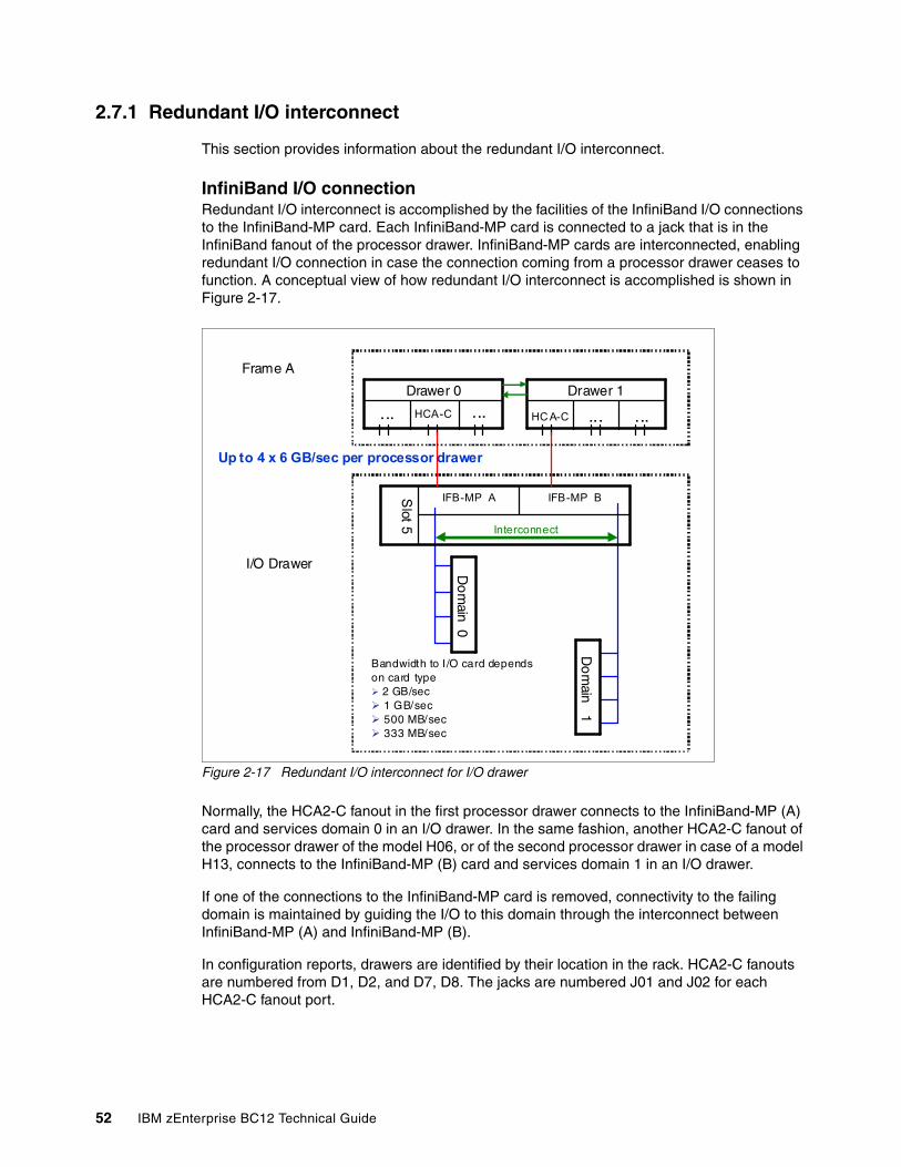
2.7.1 Redundant I/O interconnect
This section provides information about the redundant I/O interconnect.
InfiniBand I/O connectionRedundant I/O interconnect is accomplished by the facilities of the InfiniBand I/O connections to the InfiniBand-MP card. Each InfiniBand-MP card is connected to a jack that is in the InfiniBand fanout of the processor drawer. InfiniBand-MP cards are interconnected, enabling redundant I/O connection in case the connection coming from a processor drawer ceases to function. A conceptual view of how redundant I/O interconnect is accomplished is shown in Figure 2-17.
Figure 2-17 Redundant I/O interconnect for I/O drawer
Normally, the HCA2-C fanout in the first processor drawer connects to the InfiniBand-MP (A) card and services domain 0 in an I/O drawer. In the same fashion, another HCA2-C fanout of the processor drawer of the model H06, or of the second processor drawer in case of a model H13, connects to the InfiniBand-MP (B) card and services domain 1 in an I/O drawer.
If one of the connections to the InfiniBand-MP card is removed, connectivity to the failing domain is maintained by guiding the I/O to this domain through the interconnect between InfiniBand-MP (A) and InfiniBand-MP (B).
In configuration reports, drawers are identified by their location in the rack. HCA2-C fanouts are numbered from D1, D2, and D7, D8. The jacks are numbered J01 and J02 for each HCA2-C fanout port.
...... HCA-C
Drawer 0
......HC A-C
Drawer 1
Do
main
0
Do
main
1
Interconnect
IFB-MP BIFB-MP ASlot 5
Bandwidth to I/O card depends on card type 2 GB/sec 1 GB/sec 500 MB/sec 333 MB/sec
I/O Drawer
Up to 4 x 6 GB/sec per processor drawer
Frame A
52 IBM zEnterprise BC12 Technical Guide
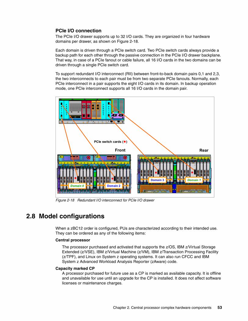
PCIe I/O connectionThe PCIe I/O drawer supports up to 32 I/O cards. They are organized in four hardware domains per drawer, as shown on Figure 2-18.
Each domain is driven through a PCIe switch card. Two PCIe switch cards always provide a backup path for each other through the passive connection in the PCIe I/O drawer backplane. That way, in case of a PCIe fanout or cable failure, all 16 I/O cards in the two domains can be driven through a single PCIe switch card.
To support redundant I/O interconnect (RII) between front-to-back domain pairs 0,1 and 2,3, the two interconnects to each pair must be from two separate PCIe fanouts. Normally, each PCIe interconnect in a pair supports the eight I/O cards in its domain. In backup operation mode, one PCIe interconnect supports all 16 I/O cards in the domain pair.
Figure 2-18 Redundant I/O interconnect for PCIe I/O drawer
2.8 Model configurations
When a zBC12 order is configured, PUs are characterized according to their intended use. They can be ordered as any of the following items:
Central processor
The processor purchased and activated that supports the z/OS, IBM z/Virtual Storage Extended (z/VSE), IBM z/Virtual Machine (z/VM), IBM z/Transaction Processing Facility (z/TPF), and Linux on System z operating systems. It can also run CFCC and IBM System z Advanced Workload Analysis Reporter (zAware) code.
Capacity marked CPA processor purchased for future use as a CP is marked as available capacity. It is offline and unavailable for use until an upgrade for the CP is installed. It does not affect software licenses or maintenance charges.
PCIe
FANOUT
PCIe
FANOUT
PCIe
FANOUT
PCIe
FANOUT
Front
Domain 0 Domain 2Domain 0Domain 0 Domain 2Domain 2
Domain 3 Domain 1Domain 3Domain 3 Domain 1Domain 1
Rear
PCIe switch cards ()
Chapter 2. Central processor complex hardware components 53
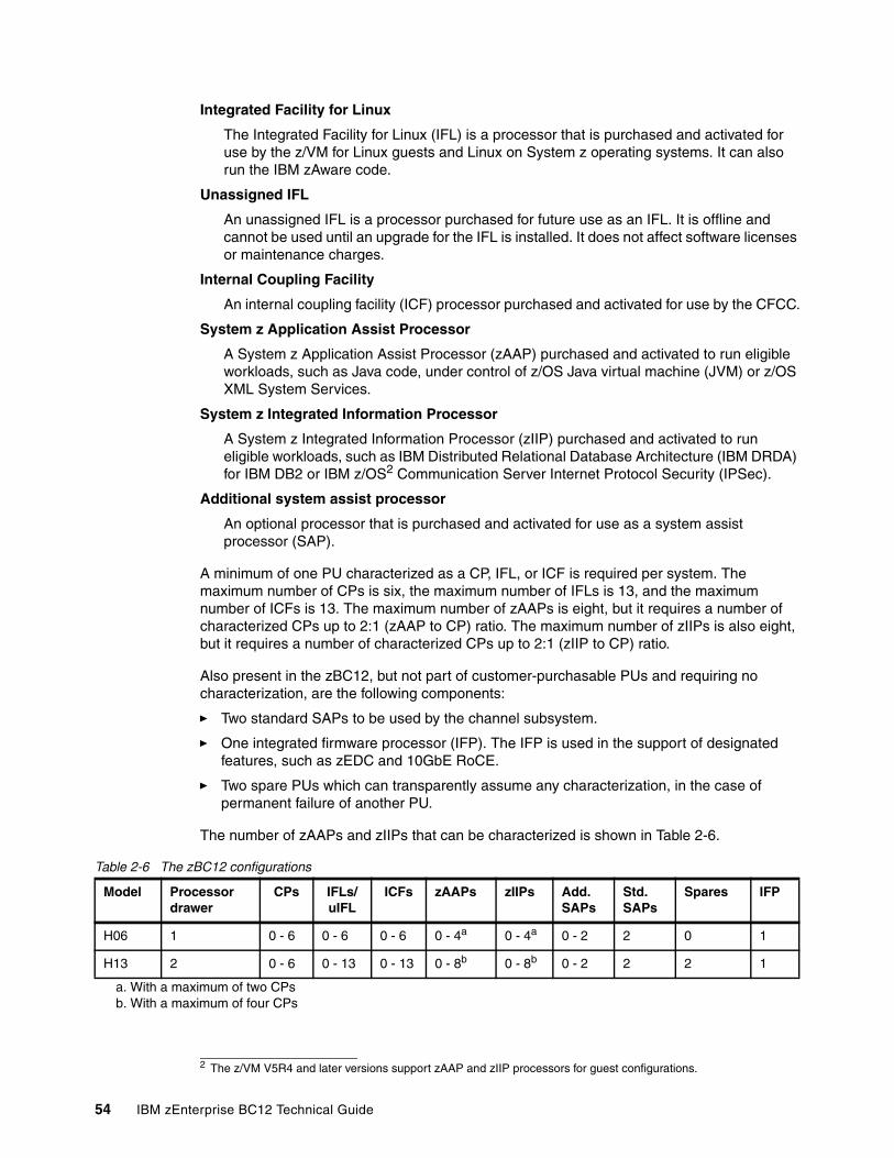
Integrated Facility for Linux
The Integrated Facility for Linux (IFL) is a processor that is purchased and activated for use by the z/VM for Linux guests and Linux on System z operating systems. It can also run the IBM zAware code.
Unassigned IFL
An unassigned IFL is a processor purchased for future use as an IFL. It is offline and cannot be used until an upgrade for the IFL is installed. It does not affect software licenses or maintenance charges.
Internal Coupling Facility
An internal coupling facility (ICF) processor purchased and activated for use by the CFCC.
System z Application Assist Processor
A System z Application Assist Processor (zAAP) purchased and activated to run eligible workloads, such as Java code, under control of z/OS Java virtual machine (JVM) or z/OS XML System Services.
System z Integrated Information Processor
A System z Integrated Information Processor (zIIP) purchased and activated to run eligible workloads, such as IBM Distributed Relational Database Architecture (IBM DRDA) for IBM DB2 or IBM z/OS2 Communication Server Internet Protocol Security (IPSec).
Additional system assist processor
An optional processor that is purchased and activated for use as a system assist processor (SAP).
A minimum of one PU characterized as a CP, IFL, or ICF is required per system. The maximum number of CPs is six, the maximum number of IFLs is 13, and the maximum number of ICFs is 13. The maximum number of zAAPs is eight, but it requires a number of characterized CPs up to 2:1 (zAAP to CP) ratio. The maximum number of zIIPs is also eight, but it requires a number of characterized CPs up to 2:1 (zIIP to CP) ratio.
Also present in the zBC12, but not part of customer-purchasable PUs and requiring no characterization, are the following components:
� Two standard SAPs to be used by the channel subsystem.
� One integrated firmware processor (IFP). The IFP is used in the support of designated features, such as zEDC and 10GbE RoCE.
� Two spare PUs which can transparently assume any characterization, in the case of permanent failure of another PU.
The number of zAAPs and zIIPs that can be characterized is shown in Table 2-6.
Table 2-6 The zBC12 configurations
2 The z/VM V5R4 and later versions support zAAP and zIIP processors for guest configurations.
Model Processor drawer
CPs IFLs/uIFL
ICFs zAAPs zIIPs Add. SAPs
Std. SAPs
Spares IFP
H06 1 0 - 6 0 - 6 0 - 6 0 - 4a
a. With a maximum of two CPs
0 - 4a 0 - 2 2 0 1
H13 2 0 - 6 0 - 13 0 - 13 0 - 8b
b. With a maximum of four CPs
0 - 8b 0 - 2 2 2 1
54 IBM zEnterprise BC12 Technical Guide
Not all PUs on a given model are required to be characterized. The zBC12 model nomenclature is based on the number of PUs available for customer use in each configuration.
A capacity marker identifies that a certain number of CPs have been purchased. This number of purchased CPs is higher than or equal to the number of CPs actively used. The capacity marker marks the availability of purchased but unused capacity that is intended to be used as CPs in the future.
This capacity usually has this status for software-charging reasons. Unused CPs are not a factor when establishing the millions of service units (MSU) value that is used for charging monthly license charge (MLC) software, or when charged on a per-processor basis.
2.8.1 Upgrades
Concurrent CP, IFL, ICF, zAAP, zIIP, or SAP upgrades are done within a zBC12. Concurrent upgrades require available PUs. Concurrent processor upgrades require that additional PUs are installed (at a prior time) but not activated.
Spare PUs are used to replace defective PUs. On the model H06n eventual unassigned PUs will be used as spares. A fully configured H06 does not have any spares. The model H13 always has two dedicated spares.
If an upgrade request cannot be accomplished within the given H06 configuration, a hardware upgrade to model H13 is required. The upgrade enables the addition of another processor drawer to accommodate the required capacity. The upgrade from H06 to H13 is disruptive.
You can upgrade an IBM System z10 Business Class (z10 BC) or a z114 to a zBC12 preserving the server serial number (S/N). The I/O cards are also moved up (with certain restrictions).
2.8.2 Concurrent PU conversions
Assigned CPs, assigned IFLs, and unassigned IFLs, ICFs, zAAPs, zIIPs, and SAPs can be converted to other assigned or unassigned feature codes. Most conversions are not disruptive. In exceptional cases, the conversion can be disruptive (for example, when a model H06 with six CPs is converted to an all-IFL system). In addition, an LPAR might be disrupted if PUs must be freed before they can be converted.
2.8.3 Model capacity identifier
To recognize how many PUs are characterized as CPs, the store system information (STSI) instruction returns a value that can be seen as a model capacity identifier (MCI), which determines the number and speed of characterized CPs. Characterization of a PU as an IFL, an ICF, a zAAP, or a zIIP is not reflected in the output of the STSI instruction, because these characterizations have no effect on software charging. More information about the STSI output is shown in “Processor identification” on page 357.
Important: Upgrades from System z114 and System z10 BC are disruptive.
Capacity identifiers: Within a zBC12, all CPs have the same capacity identifier. Specialty engines (IFLs, zAAPs, zIIPs, and ICFs) operate at full speed.
Chapter 2. Central processor complex hardware components 55
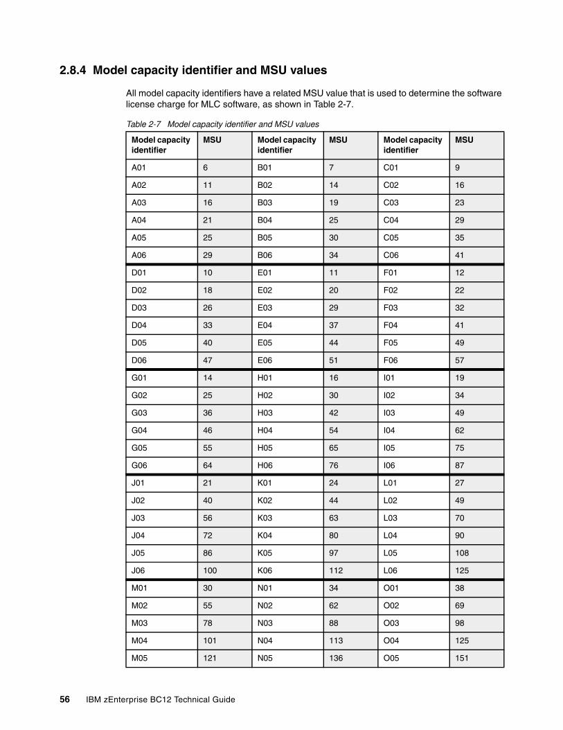
2.8.4 Model capacity identifier and MSU values
All model capacity identifiers have a related MSU value that is used to determine the software license charge for MLC software, as shown in Table 2-7.
Table 2-7 Model capacity identifier and MSU values
Model capacity identifier
MSU Model capacity identifier
MSU Model capacity identifier
MSU
A01 6 B01 7 C01 9
A02 11 B02 14 C02 16
A03 16 B03 19 C03 23
A04 21 B04 25 C04 29
A05 25 B05 30 C05 35
A06 29 B06 34 C06 41
D01 10 E01 11 F01 12
D02 18 E02 20 F02 22
D03 26 E03 29 F03 32
D04 33 E04 37 F04 41
D05 40 E05 44 F05 49
D06 47 E06 51 F06 57
G01 14 H01 16 I01 19
G02 25 H02 30 I02 34
G03 36 H03 42 I03 49
G04 46 H04 54 I04 62
G05 55 H05 65 I05 75
G06 64 H06 76 I06 87
J01 21 K01 24 L01 27
J02 40 K02 44 L02 49
J03 56 K03 63 L03 70
J04 72 K04 80 L04 90
J05 86 K05 97 L05 108
J06 100 K06 112 L06 125
M01 30 N01 34 O01 38
M02 55 N02 62 O02 69
M03 78 N03 88 O03 98
M04 101 N04 113 O04 125
M05 121 N05 136 O05 151
56 IBM zEnterprise BC12 Technical Guide
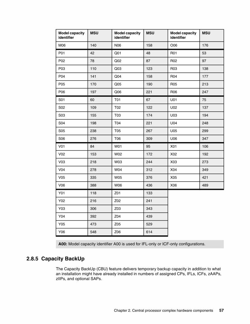
2.8.5 Capacity BackUp
The Capacity BackUp (CBU) feature delivers temporary backup capacity in addition to what an installation might have already installed in numbers of assigned CPs, IFLs, ICFs, zAAPs, zIIPs, and optional SAPs.
M06 140 N06 158 O06 176
P01 42 Q01 48 R01 53
P02 78 Q02 87 R02 97
P03 110 Q03 123 R03 138
P04 141 Q04 158 R04 177
P05 170 Q05 190 R05 213
P06 197 Q06 221 R06 247
S01 60 T01 67 U01 75
S02 109 T02 122 U02 137
S03 155 T03 174 U03 194
S04 198 T04 221 U04 248
S05 238 T05 267 U05 299
S06 276 T06 309 U06 347
V01 84 W01 95 X01 106
V02 153 W02 172 X02 192
V03 218 W03 244 X03 273
V04 278 W04 312 X04 349
V05 335 W05 376 X05 421
V06 388 W06 436 X06 489
Y01 118 Z01 133
Y02 216 Z02 241
Y03 306 Z03 343
Y04 392 Z04 439
Y05 473 Z05 529
Y06 548 Z06 614
A00: Model capacity identifier A00 is used for IFL-only or ICF-only configurations.
Model capacity identifier
MSU Model capacity identifier
MSU Model capacity identifier
MSU
Chapter 2. Central processor complex hardware components 57
There are several CBU types:
� CBU for CP � CBU for IFL� CBU for ICF� CBU for zAAP� CBU for zIIP� Optional SAPs
When CBU for CP is added within the same capacity setting range (indicated by the model capacity indicator) as the currently assigned PUs, the total number of active PUs (the sum of all assigned CPs, IFLs, ICFs, zAAPs, zIIPs, and optional SAPs) plus the number of CBUs cannot exceed the total number of PUs available in the system.
When CBU for CP capacity is acquired by switching from one capacity setting to another, no more CBU can be requested than the total number of PUs available for that capacity setting.
CBU and granular capacityWhen CBU for CP is ordered, it replaces lost capacity for disaster recovery. Specialty engines (ICFs, IFLs, zAAPs, and zIIPs) always run at full capacity, and also when running as CBU to replace lost capacity for disaster recovery.
When you order CBU, specify the maximum number of CPs, ICFs, IFLs, zAAPs, zIIPs, and SAPs to be activated for disaster recovery. If disaster strikes, you decide how many of each of the contracted CBUs of any type must be activated. The CBU rights are registered in one or more records on the server. Up to eight records can be active, and they contain several CBU activation variations that apply to the installation.
You can test the CBU. The number of free CBU test activations in each CBU record is now determined by the number of years that are purchased with the CBU record. (For example, a 3-year CBU record has three test activations, and a 1-year CBU record has one test activation.) You can increase the number of tests up to a maximum of 15 for each CBU record.
The real activation of CBU lasts up to 90 days with a grace period of two days to prevent sudden deactivation when the 90-day period expires. The contract duration can be set from 1 - 5 years.
The CBU record describes the following properties related to the CBU:
� Number of CP CBUs that it is possible to activate� Number of IFL CBUs that it is possible to activate� Number of ICF CBUs that it is possible to activate� Number of zAAP CBUs that it is possible to activate� Number of zIIP CBUs that it is possible to activate� Number of SAP CBUs that it is possible to activate� Number of additional CBU tests possible for this CBU record� Number of total CBU years ordered (duration of the contract)� Expiration date of the CBU contract
The record content of the CBU configuration is documented in the IBM configurator output, as shown in Example 2-1 on page 59. In the example, one CBU record is made for a 5-year CBU contract without additional CBU tests for the activation of one CP CBU.
58 IBM zEnterprise BC12 Technical Guide
Example 2-1 Simple CBU record and related configuration features
On Demand Capacity Selections:NEW00001 - CBU - CP(1) - Years(5) - Tests(0) Expiration(09/10/2013)
Resulting feature numbers in configuration:
6817 Total CBU Years Ordered 5 6818 CBU Records Ordered 1 6820 Single CBU CP-Year 5
In Example 2-2, a second CBU record is added to the same configuration for two CP CBUs, two IFL CBUs, two zAAP CBUs, and two zIIP CBUs, with five additional tests and a 5-year CBU contract. The result is now a total number of 10 years of CBU ordered, which is the standard five years in the first record and an additional five years in the second record.
Two CBU records from which to choose are in the system. Five additional CBU tests have been requested, and because there is a total of five years contracted for a total of 3 CP CBUs, two IFL CBUs, two zAAPs, and two zIIP CBUs, they are shown as 15, 10, 10, and 10 CBU years for their respective types.
Example 2-2 Second CBU record and resulting configuration features
NEW00002 - CBU - CP(2) - IFL(2) - zAAP(2) - zIIP(2) Tests(5) - Years(5)
Resulting cumulative feature numbers in configuration:
6817 Total CBU Years Ordered 10 6818 CBU Records Ordered 2 6819 5 Additional CBU Tests 1 6820 Single CBU CP-Year 15 6822 Single CBU IFL-Year 10 6826 Single CBU zAAP-Year 10 6828 Single CBU zIIP-Year 10
CBU for CP rulesConsider the following guidelines when planning for CBU for CP capacity:
� The total CBU CP capacity features are equal to the number of added CPs plus the number of permanent CPs changing capacity level. For example, if two CBU CPs are added to the current model D03, and the capacity level does not change, the D03 becomes D05: (D03 + 2 = D05).
If the capacity level changes to an E06, the numbers of additional CPs (3) are added to the three CPs of the D03, resulting in a total number of CBU CP capacity features of six: (3 + 3 = 6).
� The CBU cannot decrease the number of CPs.
� The CBU cannot lower the capacity setting.
On/Off Capacity on Demand: Activation of CBU for CPs, IFLs, ICFs, zAAPs, zIIPs, and SAPs can be activated together with On/Off Capacity on Demand (CoD) temporary upgrades. Both facilities can be implemented on one system, and can be activated simultaneously.
Chapter 2. Central processor complex hardware components 59
CBU for specialty enginesSpecialty engines (ICFs, IFLs, zAAPs, and zIIPs) run at full capacity for all capacity settings, which also applies to CBU for specialty engines. Note that the CBU record can contain larger numbers of CBUs than can fit in the current model.
Unassigned IFLs are ignored. They are considered spares and are available for use as CBUs. When an unassigned IFL is converted to an assigned IFL, or when additional PUs are characterized as IFLs, the number of CBUs of any type that can be activated is decreased.
2.8.6 On/Off Capacity on Demand and CPs
On/Off CoD provides temporary capacity for all types of characterized PUs. Relative to granular capacity, On/Off CoD for CPs is treated similarly to the way CBU is handled.
On/Off CoD and granular capacityWhen temporary capacity requested by On/Off CoD for CPs matches the model capacity identifier range of the permanent CP feature, the total number of active CP equals the sum of the number of permanent CPs plus the number of temporary CPs ordered. For example, when a model capacity identifier D03 has two CPs added temporarily, it becomes a model capacity identifier D05.
When the addition of temporary capacity requested by On/Off CoD for CPs results in a cross-over from one capacity identifier range to another, the total number of CPs active when the temporary CPs are activated is equal to the number of temporary CPs ordered. For example, when a configuration with model capacity identifier D03 specifies four temporary CPs through On/Off CoD, the result is a server with model capacity identifier E05.
A cross-over does not necessarily mean that the CP count for the additional temporary capacity will increase. The same D03 can temporarily be upgraded to a server with model capacity identifier F03. In this case, the number of CPs does not increase, but additional temporary capacity is achieved.
On/Off CoD guidelinesWhen you request temporary capacity, consider the following guidelines:
� Temporary capacity must be greater than permanent capacity.� Temporary capacity cannot be more than double the purchased capacity.� On/Off CoD cannot decrease the number of engines on the server.� Adding more engines than are currently installed is not possible.
Appendix D, “Valid zBC12 On/Off Capacity on Demand upgrades” on page 471 shows possible On/Off CoD CP upgrades. For more information about temporary capacity increases, see Chapter 9, “System upgrades” on page 319.
2.9 Power and cooling
As environmental concerns raise the focus on energy consumption, the zBC12 offers a holistic focus on the environment. New efficiencies and functions, such as power capping, enable a dramatic reduction of energy usage and floor space when consolidating workloads from distributed servers.
60 IBM zEnterprise BC12 Technical Guide

The power service specifications for the zEnterprise CPCs are the same as their particular predecessors, but the power consumption is more efficient. A fully loaded zBC12 CPC maximum power consumption is nearly the same as a z114. However, with a maximum performance ratio of 1.58:1, it has a much higher exploitation on the same footprint.
2.9.1 Power considerations
The zEnterprise CPCs operate with two completely redundant power supplies. Each power supply has an individual power cord for the zBC12.
For redundancy, the servers have two power feeds. Power cords attach either 50/60 hertz (Hz), alternating current (AC) power single-phase3 200 to 415 volt (v) or three-phase 200 to 480 V AC power, or 380 to 520 V direct current (DC) power. The total loss of one power feed has no effect on system operation.
There is a Balanced Power Plan Ahead feature available for future growth, also assuring adequate and balanced power with AC power cord selection using three-phase power. With this feature, downtimes for upgrading a server will be eliminated by including the maximum power requirements in terms of Bulk Power Regulators (BPR) and power cords to your installation. For ancillary equipment, such as the HMC, its display, and its modem, additional single-phase outlets are required.
The power requirements depend on the number of processor and I/O drawers in the zBC12. Table 11-1 on page 379 shows the maximum power consumption tables for the various configurations and environments.
The zBC12 can operate in raised floor and non-raised floor environments. For both types of installation, an overhead power cable option for the top exit of the cables is available. In the case of a non-raised floor environment, the Top Exit Power and Top Exit I/O Cabling features are mandatory.
2.9.2 High-voltage DC power
In data centers today, many businesses pay increasingly expensive electric bills, and are running out of power. The zEnterprise CPC High Voltage Direct Current power feature adds nominal 380 to 520 volt DC input power capability to the existing System z AC power capability. It enables CPCs to directly use the high voltage (HV) DC distribution in new, green data centers. A direct HV DC data center power design can improve data center energy efficiency by removing the need for a DC to AC inversion step.
The zEnterprise CPCs bulk power supplies have been modified to support HV DC so the only difference in shipped hardware to implement the option is the DC power cords. Because HV DC is a new technology, there are multiple proposed standards.
The zEnterprise CPC supports both ground-referenced and dual-polarity HV DC supplies, such as +/- 190 V or +/- 260 V, or +380 V, and other supplies. Beyond the data center, uninterruptible power supply (UPS), and power distribution energy savings, a zEnterprise CPC run on HV DC power will draw 1 - 3% less input power. HV DC does not change the number of power cords that a system requires.
3 Only available on select zBC12 configurations, see Figure 11-1 on page 378.
Chapter 2. Central processor complex hardware components 61
2.9.3 Internal Battery Feature
IBF is an optional feature on the zEnterprise CPC server. See Figure 2-1 on page 30 for the zBC12 for a pictorial view of the location of this feature. This optional IBF provides the function of a local uninterrupted power source (UPS).
The IBF further enhances the robustness of the power design, increasing power line disturbance immunity. It provides battery power to preserve processor data in case of a loss of power on all four AC feeds from the utility company. The IBF can hold power briefly during a brownout, or for orderly shutdown in case of a longer outage. The values for the holdup time depend on the I/O configuration, as shown in Table 11-2 on page 380.
2.9.4 Power capping
The zBC12 supports power capping, which gives the ability to control the maximum power consumption and reduce cooling requirements (especially with zBX). To use power capping, you must order FC 0020, Automate Firmware Suite.
This feature is used to enable the Automate suite of functionality that is associated with the IBM zEnterprise Unified Resource Manager (URM). The Automate suite includes representation of resources in a workload context, goal-oriented monitoring and management of resources, and energy management.
2.9.5 Power estimation tool
The Power estimator tool for the zEnterprise CPCs enables you to enter your precise server configuration to produce an estimate of power consumption:
1. Log in to Resource Link with any user ID.2. Go to Planning → Tools → Power Estimation Tools.3. Specify the quantity for the features that are installed in your system.
This tool estimates the power consumption for the specified configuration. The tool does not verify that the specified configuration can be physically built.
2.9.6 Cooling requirements
The zBC12 is an air-cooled system. It requires chilled air, ideally coming from under the raised floor, to fulfill the air cooling requirements. The chilled air is usually provided through perforated floor tiles. The amount of chilled air that is required for a variety of temperatures under the floor of the computer room is indicated in the zEnterprise BC12 Installation Manual: Physical Planning, GC28-6923.
Power consumption: The exact power consumption for your system will vary. The object of the tool is to produce an estimation of the power requirements to aid you in planning for your system installation. Actual power consumption after installation can be confirmed on the HMC System Activity Display.
62 IBM zEnterprise BC12 Technical Guide
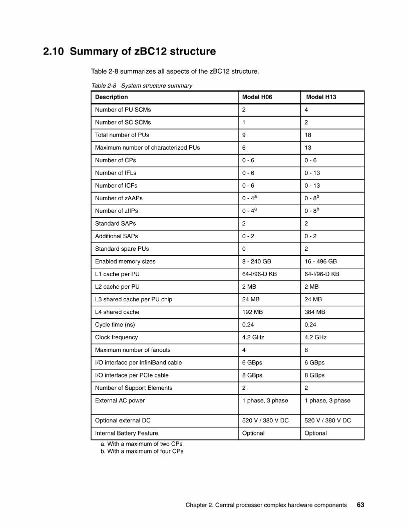
2.10 Summary of zBC12 structure
Table 2-8 summarizes all aspects of the zBC12 structure.
Table 2-8 System structure summary
Description Model H06 Model H13
Number of PU SCMs 2 4
Number of SC SCMs 1 2
Total number of PUs 9 18
Maximum number of characterized PUs 6 13
Number of CPs 0 - 6 0 - 6
Number of IFLs 0 - 6 0 - 13
Number of ICFs 0 - 6 0 - 13
Number of zAAPs 0 - 4a
a. With a maximum of two CPs
0 - 8b
b. With a maximum of four CPs
Number of zIIPs 0 - 4a 0 - 8b
Standard SAPs 2 2
Additional SAPs 0 - 2 0 - 2
Standard spare PUs 0 2
Enabled memory sizes 8 - 240 GB 16 - 496 GB
L1 cache per PU 64-I/96-D KB 64-I/96-D KB
L2 cache per PU 2 MB 2 MB
L3 shared cache per PU chip 24 MB 24 MB
L4 shared cache 192 MB 384 MB
Cycle time (ns) 0.24 0.24
Clock frequency 4.2 GHz 4.2 GHz
Maximum number of fanouts 4 8
I/O interface per InfiniBand cable 6 GBps 6 GBps
I/O interface per PCIe cable 8 GBps 8 GBps
Number of Support Elements 2 2
External AC power 1 phase, 3 phase 1 phase, 3 phase
Optional external DC 520 V / 380 V DC 520 V / 380 V DC
Internal Battery Feature Optional Optional
Chapter 2. Central processor complex hardware components 63

64 IBM zEnterprise BC12 Technical Guide
Chapter 3. Central processor complex system design
This chapter provides information about how the IBM zEnterprise BC12 System (zBC12) central processor (CP) complex (CPC) is designed. You can use this information to understand the functions that make the zBC12 a server that suits a broad mix of workloads for enterprises.
We cover the following topics:
� Overview� Design highlights� Processor drawer design� Processor unit design� Processor unit functions� Memory design� Logical partitioning� Intelligent resource director� Clustering technology
3
© Copyright IBM Corp. 2014. All rights reserved. 65
3.1 Overview
The design of the zBC12 symmetric multiprocessor (SMP) is the next step in an evolutionary trajectory stemming from the introduction of CMOS technology in 1994. Over time, the design has been adapted to the changing requirements dictated by the shift toward new types of applications, on which customers are becoming more and more dependent.
The zBC12 offers high levels of serviceability, availability, reliability, resilience, and security. It fits in the IBM strategy in which mainframes play a central role in creating an intelligent, energy-efficient, integrated infrastructure. The zBC12 is designed so that the server and everything around it (operating systems, middleware, storage, security, and network technologies supporting open standards) is important for the infrastructure, and for helping customers to achieve their business goals.
The modular I/O drawer and PCIe I/O drawer design aim to reduce planned and unplanned outages by offering concurrent repair, replace, and upgrade functions for I/O. The zBC12, with its ultra-high frequency, large high-speed buffers (caches) and memory, superscalar processor design, out-of-order (OOO) core execution, and flexible configuration options, is the next implementation in the mid-sized server area to address the ever-changing IT environment.
3.2 Design highlights
The physical packaging of the zBC12 compares to the packaging used for IBM zEnterprise 114 (z114) systems. Its processor drawer design creates the opportunity to address the ever-increasing costs related to building systems with ever-increasing capacities, and offers unprecedented capacity settings to meet consolidation needs in the mid-size world.
The zBC12 continues the line of mainframe processors that are compatible with an earlier version. It introduces more complex instructions that are run by millicode, and more complex instructions that are broken down into multiple operations. It uses 24, 31, and 64-bit addressing modes, multiple arithmetic formats, and multiple address spaces for robust interprocess security.
The zBC12 system design, which is covered in this and subsequent chapters, has the following major objectives:
� Offers a flexible infrastructure to concurrently accommodate a wide range of operating systems and applications, from the traditional systems (for example, z/OS and z/VM) to the world of Linux and e-business.
� Offers state-of-the-art integration capability for server consolidation, offering virtualization techniques:
– Logical partitioning, which enables 30 independent logical servers
– The z/VM product, which can virtualize hundreds to thousands of servers as independently running virtual machines
– HiperSockets, which implement virtual local area networks (LANs) between LPARs within a server
This integration capability enables a logical and virtual server coexistence, and maximizes system use and efficiency, by sharing hardware resources.
66 IBM zEnterprise BC12 Technical Guide
� Offers high performance to achieve the outstanding response times required by new workload-type applications. This performance is achieved by the following means:
– High frequency, superscalar processor technology– Improved out-of-order core execution– Large high speed buffers (cache) and memory– Architecture– High-bandwidth channels
This configuration offers second-to-none data rate connectivity.
� Offers the high scalability required by the most demanding applications, both from single-system and clustered-systems points of view, compared to IBM System z10 Business Class (z10 BC).
� Offers the capability of concurrent upgrades for processors, memory, and I/O connectivity, avoiding CPC outages in planned situations.
� Implements a system with high availability and reliability, from the redundancy of critical elements and sparing components of a single system, to the clustering technology of the Parallel Sysplex environment.
� Has broad internal and external connectivity offerings, supporting open standards, such as gigabit Ethernet (GbE), and Fibre Channel Protocol (FCP) for the SCSI.
� Provides leading cryptographic performance. Every processor unit (PU) has a dedicated CP Assist for Cryptographic Function (CPACF). Optional Crypto Express features with Cryptographic Coprocessors provide the highest standardized security certification1.These optional features can also be configured as Cryptographic Accelerators to enhance the performance of Secure Sockets Layer/Transport Layer Security (SSL/TLS) transactions.
� Self-manages and self-optimizes, adjusting itself on workload changes to achieve the best system throughput, using the Intelligent Resource Director or the Workload Manager (WLM) functions, assisted by HiperDispatch.
� Has a balanced system design, providing large data rate bandwidths for high-performance connectivity, and processor and system capacity.
The following sections describe the zBC12 system structure, showing a logical representation of the data flow from PUs, caches, memory cards, and a variety of interconnect capabilities.
3.3 Processor drawer design
The zBC12 is available in two models:
� H06 with a single processor drawer.� H13 with two processor drawers, offering additional flexibility for I/O and coupling
expansion, and increased specialty engine capability.
Up to 13 processor unit cores, and up to 512 GB of memory, including the 16 GB fixed hardware system area (HSA), can be characterized. Memory has up to four memory controllers, using a five-channel redundant array of independent memory (RAIM) protection, with DIMM bus cyclic redundancy check (CRC) error retry.
The four-level cache hierarchy is implemented with eDRAM (embedded) caches. Up until recently, eDRAM was considered to be too slow for this purpose, but a break-through in IBM technology has demonstrated the opposite.
1 Federal Information Processing Standards (FIPS)140-2 Security Requirements for Cryptographic Modules
Chapter 3. Central processor complex system design 67
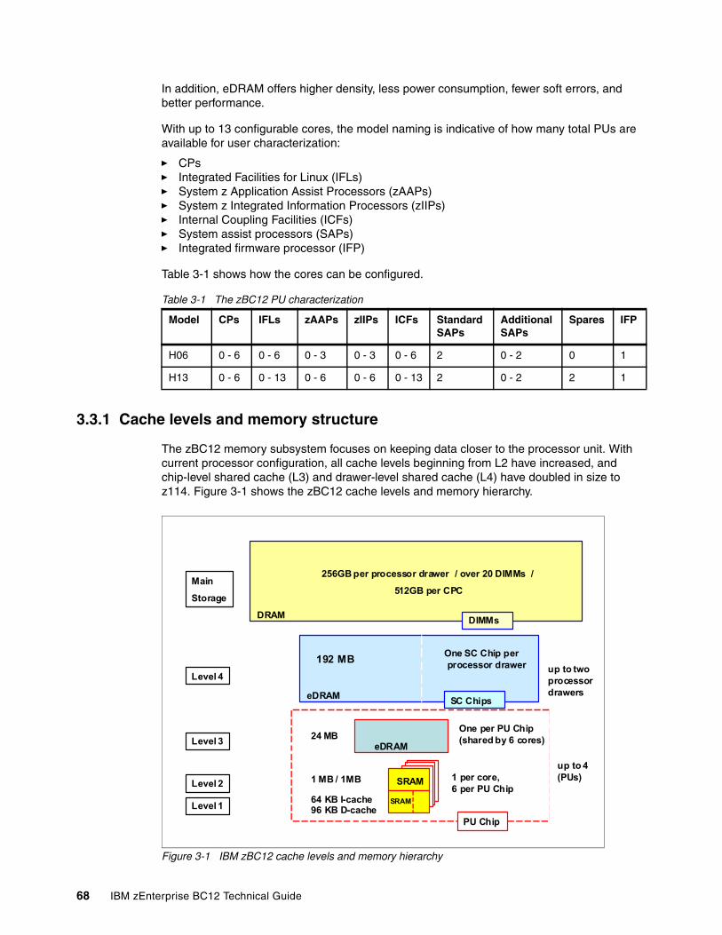
In addition, eDRAM offers higher density, less power consumption, fewer soft errors, and better performance.
With up to 13 configurable cores, the model naming is indicative of how many total PUs are available for user characterization:
� CPs� Integrated Facilities for Linux (IFLs)� System z Application Assist Processors (zAAPs)� System z Integrated Information Processors (zIIPs)� Internal Coupling Facilities (ICFs)� System assist processors (SAPs)� Integrated firmware processor (IFP)
Table 3-1 shows how the cores can be configured.
Table 3-1 The zBC12 PU characterization
3.3.1 Cache levels and memory structure
The zBC12 memory subsystem focuses on keeping data closer to the processor unit. With current processor configuration, all cache levels beginning from L2 have increased, and chip-level shared cache (L3) and drawer-level shared cache (L4) have doubled in size to z114. Figure 3-1 shows the zBC12 cache levels and memory hierarchy.
Figure 3-1 IBM zBC12 cache levels and memory hierarchy
Model CPs IFLs zAAPs zIIPs ICFs Standard SAPs
Additional SAPs
Spares IFP
H06 0 - 6 0 - 6 0 - 3 0 - 3 0 - 6 2 0 - 2 0 1
H13 0 - 6 0 - 13 0 - 6 0 - 6 0 - 13 2 0 - 2 2 1
Level 1
Level 3
Level 4
Main
Storage
Level 2 SRAM
SRAM
eDRAM
eDRAM
DRAM
64 KB I-cache 96 KB D-cache
1 per core, 6 per PU Chip
1 MB / 1MB
24 MBOne per PU Chip (shared by 6 cores)
192 MBOne SC Chip per processor drawer
256GB per processor drawer / over 20 DIMMs /
512GB per CPC
PU Chip
SC Chips
DIMMs
up to twoprocessordrawers
up to 4 (PUs)
68 IBM zEnterprise BC12 Technical Guide
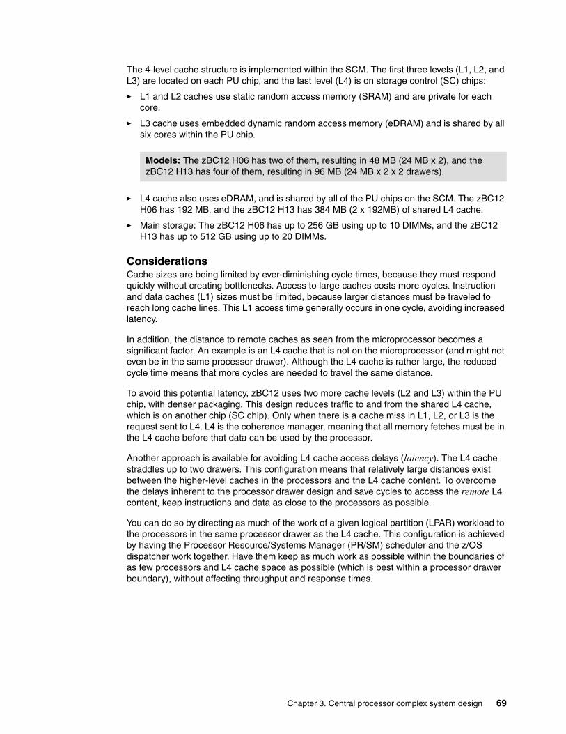
The 4-level cache structure is implemented within the SCM. The first three levels (L1, L2, and L3) are located on each PU chip, and the last level (L4) is on storage control (SC) chips:
� L1 and L2 caches use static random access memory (SRAM) and are private for each core.
� L3 cache uses embedded dynamic random access memory (eDRAM) and is shared by all six cores within the PU chip.
� L4 cache also uses eDRAM, and is shared by all of the PU chips on the SCM. The zBC12 H06 has 192 MB, and the zBC12 H13 has 384 MB (2 x 192MB) of shared L4 cache.
� Main storage: The zBC12 H06 has up to 256 GB using up to 10 DIMMs, and the zBC12 H13 has up to 512 GB using up to 20 DIMMs.
ConsiderationsCache sizes are being limited by ever-diminishing cycle times, because they must respond quickly without creating bottlenecks. Access to large caches costs more cycles. Instruction and data caches (L1) sizes must be limited, because larger distances must be traveled to reach long cache lines. This L1 access time generally occurs in one cycle, avoiding increased latency.
In addition, the distance to remote caches as seen from the microprocessor becomes a significant factor. An example is an L4 cache that is not on the microprocessor (and might not even be in the same processor drawer). Although the L4 cache is rather large, the reduced cycle time means that more cycles are needed to travel the same distance.
To avoid this potential latency, zBC12 uses two more cache levels (L2 and L3) within the PU chip, with denser packaging. This design reduces traffic to and from the shared L4 cache, which is on another chip (SC chip). Only when there is a cache miss in L1, L2, or L3 is the request sent to L4. L4 is the coherence manager, meaning that all memory fetches must be in the L4 cache before that data can be used by the processor.
Another approach is available for avoiding L4 cache access delays (latency). The L4 cache straddles up to two drawers. This configuration means that relatively large distances exist between the higher-level caches in the processors and the L4 cache content. To overcome the delays inherent to the processor drawer design and save cycles to access the remote L4 content, keep instructions and data as close to the processors as possible.
You can do so by directing as much of the work of a given logical partition (LPAR) workload to the processors in the same processor drawer as the L4 cache. This configuration is achieved by having the Processor Resource/Systems Manager (PR/SM) scheduler and the z/OS dispatcher work together. Have them keep as much work as possible within the boundaries of as few processors and L4 cache space as possible (which is best within a processor drawer boundary), without affecting throughput and response times.
Models: The zBC12 H06 has two of them, resulting in 48 MB (24 MB x 2), and the zBC12 H13 has four of them, resulting in 96 MB (24 MB x 2 x 2 drawers).
Chapter 3. Central processor complex system design 69
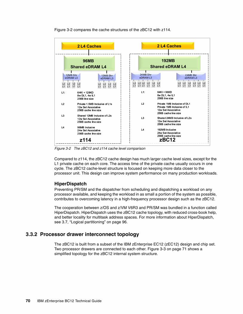
Figure 3-2 compares the cache structures of the zBC12 with z114.
Figure 3-2 The zBC12 and z114 cache level comparison
Compared to z114, the zBC12 cache design has much larger cache level sizes, except for the L1 private cache on each core. The access time of the private cache usually occurs in one cycle. The zBC12 cache-level structure is focused on keeping more data closer to the processor unit. This design can improve system performance on many production workloads.
HiperDispatchPreventing PR/SM and the dispatcher from scheduling and dispatching a workload on any processor available, and keeping the workload in as small a portion of the system as possible, contributes to overcoming latency in a high-frequency processor design such as the zBC12.
The cooperation between z/OS and z/VM V6R3 and PR/SM was bundled in a function called HiperDispatch. HiperDispatch uses the zBC12 cache topology, with reduced cross-book help, and better locality for multitask address spaces. For more information about HiperDispatch, see 3.7, “Logical partitioning” on page 96.
3.3.2 Processor drawer interconnect topology
The zBC12 is built from a subset of the IBM zEnterprise EC12 (zEC12) design and chip set. Two processor drawers are connected to each other. Figure 3-3 on page 71 shows a simplified topology for the zBC12 internal system structure.
L2L1
L2L1
L2L1
L2L1
L1: 64KI + 96KD6w DL1, 4w IL1256B line size
L2 Private 1MB Inclusive of DL1Private 1MB Inclusive of IL112w Set Associative256B cache line size
L3 Shared 24MB Inclusive of L2s12w Set Associative256B cache line size
L4 192MB Inclusive24w Set Associative256B cache line size
L1: 64KI + 96KD6w DL1, 4w IL1256B line size
L2 Private 1MB Inclusive of DL1Private 1MB Inclusive of IL112w Set Associative256B cache line size
L3 Shared 24MB Inclusive of L2s12w Set Associative256B cache line size
L4 192MB Inclusive24w Set Associative256B cache line size
zBC12
2 L4 Caches
192MB
Shared eDRAM L4
L2L1
24MB ShreDRAM L3
L2L1
L2L1
L2L1
L2L1
L2L1
L2L1
L2L1
L1: 64KI + 128KD8w DL1, 4w IL1256B line size
L2 Private 1.5MB Inclusive of L1s12w Set Associative256B cache line size
L3 Shared 12MB Inclusive of L2s12w Set Associative256B cache line size
L4 96MB Inclusive24w Set Associative256B cache line size
L1: 64KI + 128KD8w DL1, 4w IL1256B line size
L2 Private 1.5MB Inclusive of L1s12w Set Associative256B cache line size
L3 Shared 12MB Inclusive of L2s12w Set Associative256B cache line size
L4 96MB Inclusive24w Set Associative256B cache line size
z114
2 L4 Caches
96MB
Shared eDRAM L4
L2L1
12MB ShreDRAM L3
12MB ShreDRAM L3
L2L1
L2L1
L2L1
L2L1
L2L1
L2L1
24MB ShreDRAM L3
L2L1
70 IBM zEnterprise BC12 Technical Guide
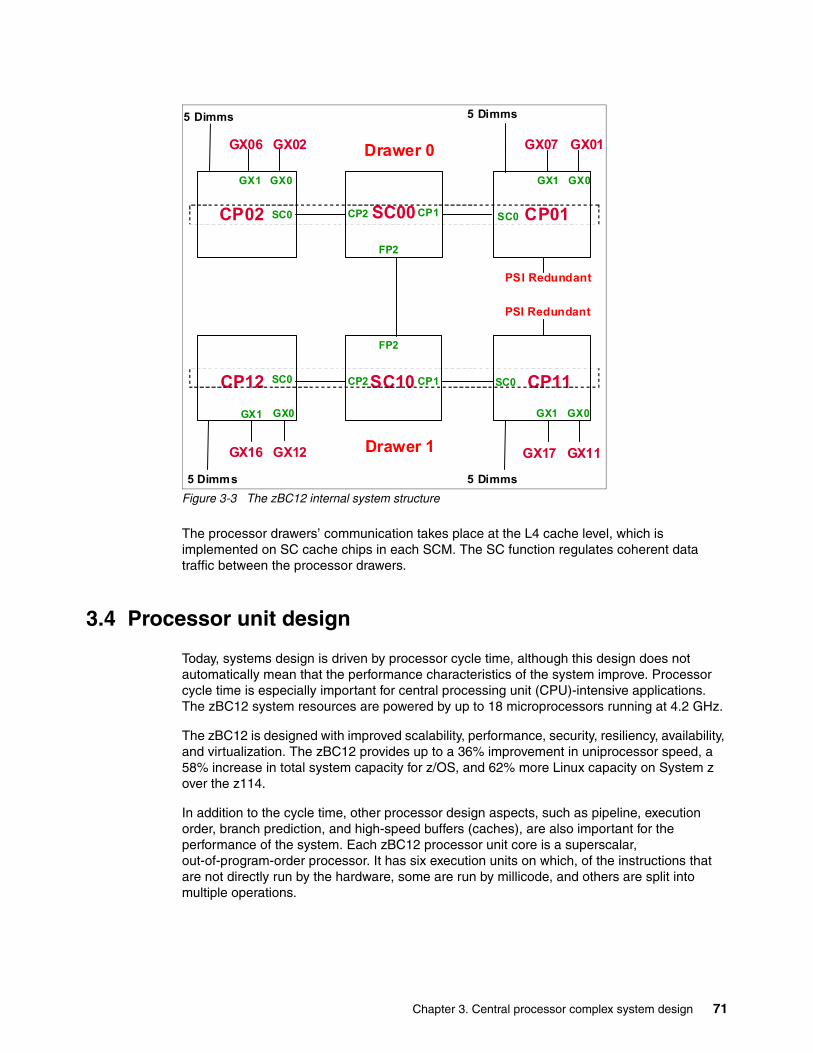
Figure 3-3 The zBC12 internal system structure
The processor drawers’ communication takes place at the L4 cache level, which is implemented on SC cache chips in each SCM. The SC function regulates coherent data traffic between the processor drawers.
3.4 Processor unit design
Today, systems design is driven by processor cycle time, although this design does not automatically mean that the performance characteristics of the system improve. Processor cycle time is especially important for central processing unit (CPU)-intensive applications. The zBC12 system resources are powered by up to 18 microprocessors running at 4.2 GHz.
The zBC12 is designed with improved scalability, performance, security, resiliency, availability, and virtualization. The zBC12 provides up to a 36% improvement in uniprocessor speed, a 58% increase in total system capacity for z/OS, and 62% more Linux capacity on System z over the z114.
In addition to the cycle time, other processor design aspects, such as pipeline, execution order, branch prediction, and high-speed buffers (caches), are also important for the performance of the system. Each zBC12 processor unit core is a superscalar, out-of-program-order processor. It has six execution units on which, of the instructions that are not directly run by the hardware, some are run by millicode, and others are split into multiple operations.
SC00
SC10
CP02
CP12
CP01
CP11
SC0 CP2 CP1
SC0
SC0
SC0CP1CP2
GX1 GX0 GX1 GX0
GX1
GX06 GX02
GX17 GX11
FP2
FP2
Drawer 0
GX0
GX07 GX01
PSI Redundant
5 Dimms 5 Dimms
5 Dimms
PSI Redundant
5 Dimms
GX1 GX0
GX16 GX12 Drawer 1
Chapter 3. Central processor complex system design 71
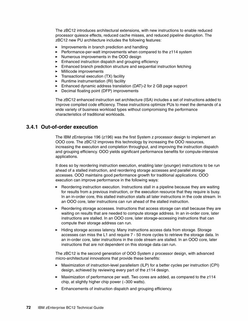
The zBC12 introduces architectural extensions, with new instructions to enable reduced processor quiesce effects, reduced cache misses, and reduced pipeline disruption. The zBC12 new PU architecture includes the following features:
� Improvements in branch prediction and handling� Performance-per-watt improvements when compared to the z114 system� Numerous improvements in the OOO design� Enhanced instruction dispatch and grouping efficiency� Enhanced branch prediction structure and sequential instruction fetching� Millicode improvements� Transactional execution (TX) facility� Runtime instrumentation (RI) facility� Enhanced dynamic address translation (DAT)-2 for 2 GB page support� Decimal floating point (DFP) improvements
The zBC12 enhanced instruction set architecture (ISA) includes a set of instructions added to improve compiled code efficiency. These instructions optimize PUs to meet the demands of a wide variety of business workload types without compromising the performance characteristics of traditional workloads.
3.4.1 Out-of-order execution
The IBM zEnterprise 196 (z196) was the first System z processor design to implement an OOO core. The zBC12 improves this technology by increasing the OOO resources, increasing the execution and completion throughput, and improving the instruction dispatch and grouping efficiency. OOO yields significant performance benefits for compute-intensive applications.
It does so by reordering instruction execution, enabling later (younger) instructions to be run ahead of a stalled instruction, and reordering storage accesses and parallel storage accesses. OOO maintains good performance growth for traditional applications. OOO execution can improve performance in the following ways:
� Reordering instruction execution. Instructions stall in a pipeline because they are waiting for results from a previous instruction, or the execution resource that they require is busy. In an in-order core, this stalled instruction stalls all later instructions in the code stream. In an OOO core, later instructions can run ahead of the stalled instruction.
� Reordering storage accesses. Instructions that access storage can stall because they are waiting on results that are needed to compute storage address. In an in-order core, later instructions are stalled. In an OOO core, later storage-accessing instructions that can compute their storage address can run.
� Hiding storage access latency. Many instructions access data from storage. Storage accesses can miss the L1 and require 7 - 50 more cycles to retrieve the storage data. In an in-order core, later instructions in the code stream are stalled. In an OOO core, later instructions that are not dependent on this storage data can run.
The zBC12 is the second generation of OOO System z processor design, with advanced micro-architectural innovations that provide these benefits:
� Maximization of instruction-level parallelism (ILP) for a better cycles per instruction (CPI) design, achieved by reviewing every part of the z114 design.
� Maximization of performance per watt. Two cores are added, as compared to the z114 chip, at slightly higher chip power (~300 watts).
� Enhancements of instruction dispatch and grouping efficiency.
72 IBM zEnterprise BC12 Technical Guide
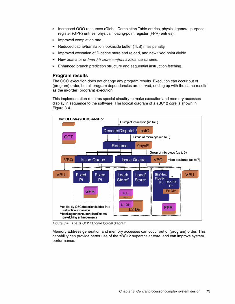
� Increased OOO resources (Global Completion Table entries, physical general purpose register (GPR) entries, physical floating-point register (FPR) entries).
� Improved completion rate.
� Reduced cache/translation lookaside buffer (TLB) miss penalty.
� Improved execution of D-cache store and reload, and new fixed-point divide.
� New oscillator or load-hit-store conflict avoidance scheme.
� Enhanced branch prediction structure and sequential instruction fetching.
Program resultsThe OOO execution does not change any program results. Execution can occur out of (program) order, but all program dependencies are served, ending up with the same results as the in-order (program) execution.
This implementation requires special circuitry to make execution and memory accesses display in sequence to the software. The logical diagram of a zBC12 core is shown in Figure 3-4.
Figure 3-4 The zBC12 PU core logical diagram
Memory address generation and memory accesses can occur out of (program) order. This capability can provide better use of the zBC12 superscalar core, and can improve system performance.
L2 Dir
VBQ
Decode/Dispatch1
Clump of instruction (up to 3)
Rename
Group of micro-ops (up to 3)
Issue Queue Issue Queue
Fixed Pt
Load/Store2
Fixed Pt
Bin/HexFloating
Pt
VBU VBU
GPR
FPR
VBQ
InstQ
0cycE
L1 Dir
Group of micro-ops (up to 3)
GCT
Fx Div
Dec FltPt
micro-ops issue (up to 7)
TLB0
TLB
Load/Store2
1) on-the-fly OSC detection bubble-free instruction expansion
2) banking for concurrent load/storesprefetching enhancements
Out Of Order (OOO) addition
Chapter 3. Central processor complex system design 73
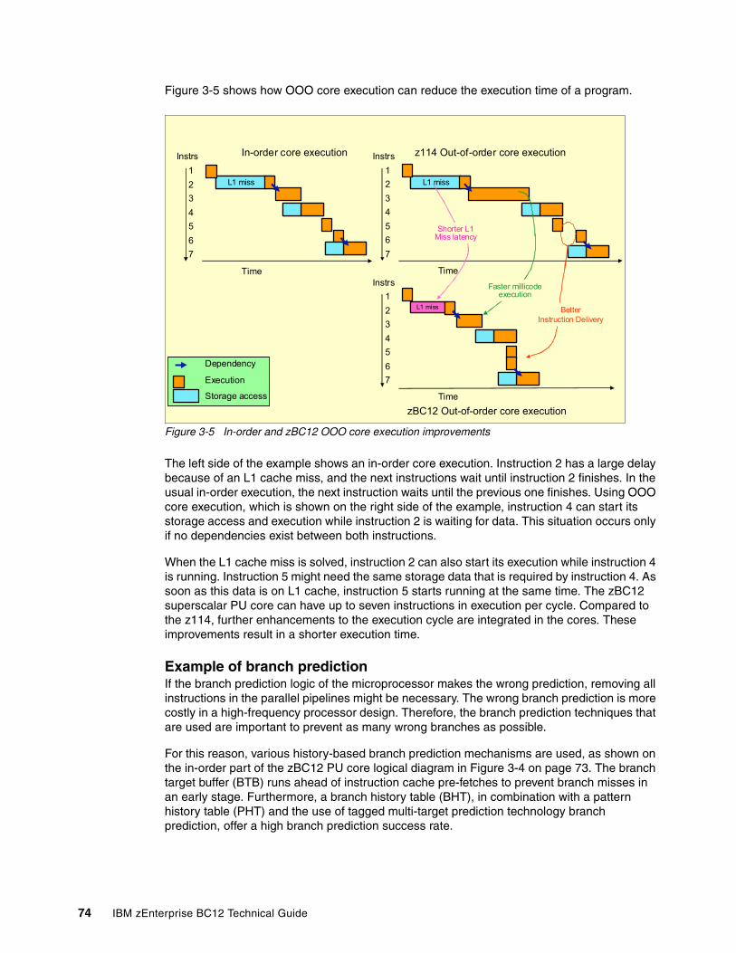
Figure 3-5 shows how OOO core execution can reduce the execution time of a program.
Figure 3-5 In-order and zBC12 OOO core execution improvements
The left side of the example shows an in-order core execution. Instruction 2 has a large delay because of an L1 cache miss, and the next instructions wait until instruction 2 finishes. In the usual in-order execution, the next instruction waits until the previous one finishes. Using OOO core execution, which is shown on the right side of the example, instruction 4 can start its storage access and execution while instruction 2 is waiting for data. This situation occurs only if no dependencies exist between both instructions.
When the L1 cache miss is solved, instruction 2 can also start its execution while instruction 4 is running. Instruction 5 might need the same storage data that is required by instruction 4. As soon as this data is on L1 cache, instruction 5 starts running at the same time. The zBC12 superscalar PU core can have up to seven instructions in execution per cycle. Compared to the z114, further enhancements to the execution cycle are integrated in the cores. These improvements result in a shorter execution time.
Example of branch predictionIf the branch prediction logic of the microprocessor makes the wrong prediction, removing all instructions in the parallel pipelines might be necessary. The wrong branch prediction is more costly in a high-frequency processor design. Therefore, the branch prediction techniques that are used are important to prevent as many wrong branches as possible.
For this reason, various history-based branch prediction mechanisms are used, as shown on the in-order part of the zBC12 PU core logical diagram in Figure 3-4 on page 73. The branch target buffer (BTB) runs ahead of instruction cache pre-fetches to prevent branch misses in an early stage. Furthermore, a branch history table (BHT), in combination with a pattern history table (PHT) and the use of tagged multi-target prediction technology branch prediction, offer a high branch prediction success rate.
L1 missL1 miss
Instrs
1
2
3
4
5
6
7
Time
In-order core execution
Execution
Storage access
Dependency
Execution
Storage access
Dependency
L1 missL1 miss
zBC12 Out-of-order core execution
Time
Instrs
1
2
3
4
5
6
7
Time
L1 missL1 miss
z114 Out-of-order core execution
Instrs
1
2
3
4
5
6
7
BetterInstruction Delivery
Shorter L1Miss latency
Faster millicodeexecution
74 IBM zEnterprise BC12 Technical Guide
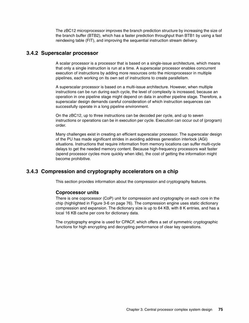
The zBC12 microprocessor improves the branch prediction structure by increasing the size of the branch buffer (BTB2), which has a faster prediction throughput than BTB1 by using a fast reindexing table (FIT), and improving the sequential instruction stream delivery.
3.4.2 Superscalar processor
A scalar processor is a processor that is based on a single-issue architecture, which means that only a single instruction is run at a time. A superscalar processor enables concurrent execution of instructions by adding more resources onto the microprocessor in multiple pipelines, each working on its own set of instructions to create parallelism.
A superscalar processor is based on a multi-issue architecture. However, when multiple instructions can be run during each cycle, the level of complexity is increased, because an operation in one pipeline stage might depend on data in another pipeline stage. Therefore, a superscalar design demands careful consideration of which instruction sequences can successfully operate in a long pipeline environment.
On the zBC12, up to three instructions can be decoded per cycle, and up to seven instructions or operations can be in execution per cycle. Execution can occur out of (program) order.
Many challenges exist in creating an efficient superscalar processor. The superscalar design of the PU has made significant strides in avoiding address generation interlock (AGI) situations. Instructions that require information from memory locations can suffer multi-cycle delays to get the needed memory content. Because high-frequency processors wait faster (spend processor cycles more quickly when idle), the cost of getting the information might become prohibitive.
3.4.3 Compression and cryptography accelerators on a chip
This section provides information about the compression and cryptography features.
Coprocessor unitsThere is one coprocessor (CoP) unit for compression and cryptography on each core in the chip (highlighted in Figure 3-6 on page 76). The compression engine uses static dictionary compression and expansion. The dictionary size is up to 64 KB, with 8 K entries, and has a local 16 KB cache per core for dictionary data.
The cryptography engine is used for CPACF, which offers a set of symmetric cryptographic functions for high encrypting and decrypting performance of clear key operations.
Chapter 3. Central processor complex system design 75
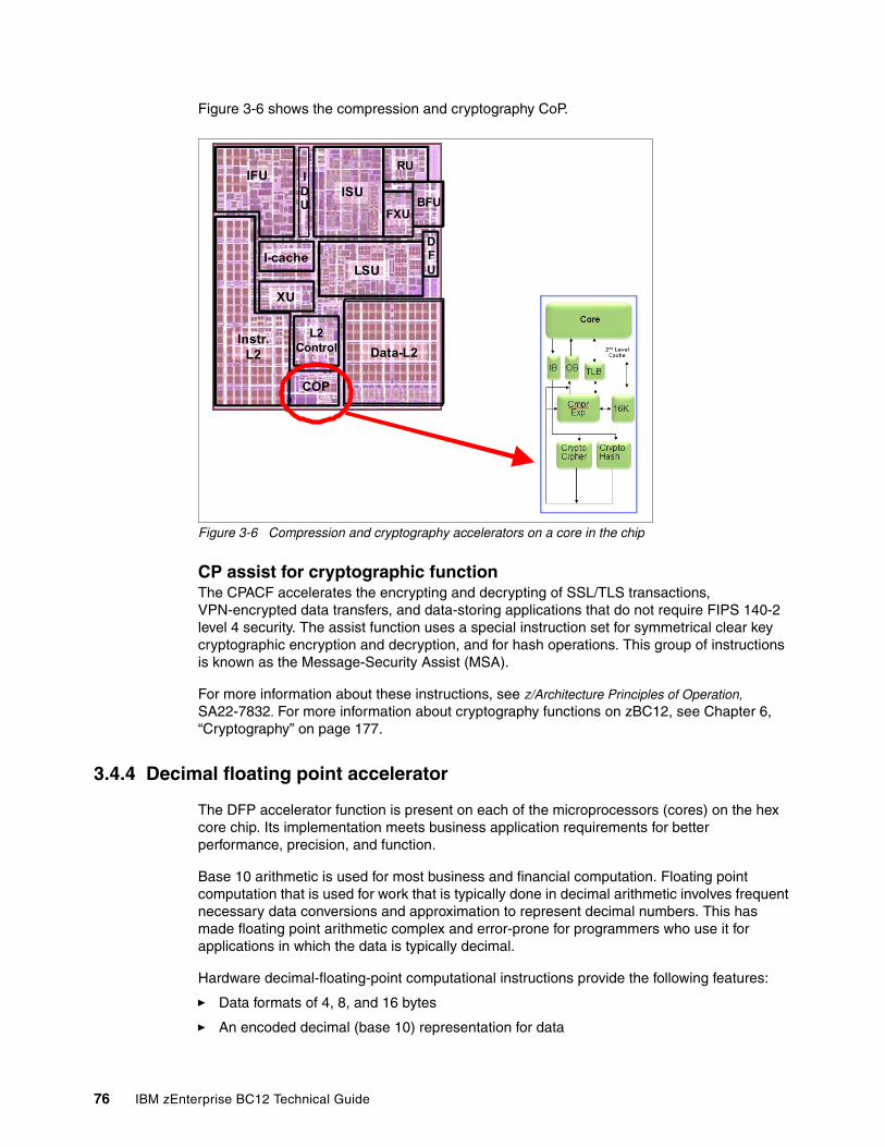
Figure 3-6 shows the compression and cryptography CoP.
Figure 3-6 Compression and cryptography accelerators on a core in the chip
CP assist for cryptographic functionThe CPACF accelerates the encrypting and decrypting of SSL/TLS transactions, VPN-encrypted data transfers, and data-storing applications that do not require FIPS 140-2 level 4 security. The assist function uses a special instruction set for symmetrical clear key cryptographic encryption and decryption, and for hash operations. This group of instructions is known as the Message-Security Assist (MSA).
For more information about these instructions, see z/Architecture Principles of Operation, SA22-7832. For more information about cryptography functions on zBC12, see Chapter 6, “Cryptography” on page 177.
3.4.4 Decimal floating point accelerator
The DFP accelerator function is present on each of the microprocessors (cores) on the hex core chip. Its implementation meets business application requirements for better performance, precision, and function.
Base 10 arithmetic is used for most business and financial computation. Floating point computation that is used for work that is typically done in decimal arithmetic involves frequent necessary data conversions and approximation to represent decimal numbers. This has made floating point arithmetic complex and error-prone for programmers who use it for applications in which the data is typically decimal.
Hardware decimal-floating-point computational instructions provide the following features:
� Data formats of 4, 8, and 16 bytes
� An encoded decimal (base 10) representation for data
Data-L2
LSU
ISU
RU
FXUBFU
DFU
COP
L2Control
XU
I-cache
IFU
Instr.L2
IDU
76 IBM zEnterprise BC12 Technical Guide
� Instructions for running decimal floating point computations
� An instruction that runs data conversions to and from the decimal floating point representation
The DFP architecture on zBC12 was improved to facilitate better performance on traditional zoned-decimal operations for Cobol programs. Additional instructions are provided to convert zoned-decimal data into DFP format in FPRs.
Benefits of the DFP acceleratorThe DFP accelerator offers the following benefits:
� Avoids rounding issues, such as those that happen with binary-to-decimal conversions.
� Has better control over existing binary-coded decimal (BCD) operations.
� Follows the standardization of the dominant decimal data and decimal operations in commercial computing, supporting industry standardization (EEE 745R) of DFP operations. Instructions are added in support of the Draft Standard for Floating-Point Arithmetic, which is intended to supersede the ANSI/IEEE standard 754-1985.
� Cobol programs that use zoned-decimal operations can take advantage of this zBC12-introduced architecture.
Software supportDFP is supported in various programming languages:
� Release 4 and later of High Level Assembler� C/C++ (requires z/OS V1.10 with program temporary fixes (PTFs) for full support or later)� Enterprise PL/I Release 3.7 and Debug Tool Release 8.1 or later� Java applications using the BigDecimal class library� SQL support (in DB2 V9 or later)
3.4.5 IEEE floating point
Binary and hexadecimal floating-point instructions are implemented in zBC12. They incorporate IEEE Standards into the system.
The key point is that Java and C/C++ applications tend to use IEEE binary floating point operations more frequently than earlier applications. Therefore, the better the hardware implementation of this set of instructions is, the better the applications perform.
3.4.6 Processor error detection and recovery
The PU uses a process called transient recovery as an error-recovery mechanism. When an error is detected, the instruction unit tries the instruction again and attempts to recover the error.
If the retry is not successful (that is, a permanent fault exists), a relocation process is started that restores the full capacity by moving work to another PU. Relocation under hardware control is possible because the R-unit has the full designed state in its buffer.
Chapter 3. Central processor complex system design 77
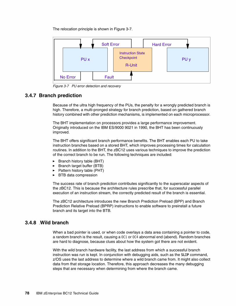
The relocation principle is shown in Figure 3-7.
Figure 3-7 PU error detection and recovery
3.4.7 Branch prediction
Because of the ultra high frequency of the PUs, the penalty for a wrongly predicted branch is high. Therefore, a multi-pronged strategy for branch prediction, based on gathered branch history combined with other prediction mechanisms, is implemented on each microprocessor.
The BHT implementation on processors provides a large performance improvement. Originally introduced on the IBM ES/9000 9021 in 1990, the BHT has been continuously improved.
The BHT offers significant branch performance benefits. The BHT enables each PU to take instruction branches based on a stored BHT, which improves processing times for calculation routines. In addition to the BHT, the zBC12 uses various techniques to improve the prediction of the correct branch to be run. The following techniques are included:
� Branch history table (BHT)� Branch target buffer (BTB)� Pattern history table (PHT)� BTB data compression
The success rate of branch prediction contributes significantly to the superscalar aspects of the zBC12. This is because the architecture rules prescribe that, for successful parallel execution of an instruction stream, the correctly predicted result of the branch is essential.
The zBC12 architecture introduces the new Branch Prediction Preload (BPP) and Branch Prediction Relative Preload (BPRP) instructions to enable software to preinstall a future branch and its target into the BTB.
3.4.8 .Wild branch
When a bad pointer is used, or when code overlays a data area containing a pointer to code, a random branch is the result, causing a 0C1 or 0C4 abnormal end (abend). Random branches are hard to diagnose, because clues about how the system got there are not evident.
With the wild branch hardware facility, the last address from which a successful branch instruction was run is kept. In conjunction with debugging aids, such as the SLIP command, z/OS uses the last address to determine where a wild branch came from. It might also collect data from that storage location. Therefore, this approach decreases the many debugging steps that are necessary when determining from where the branch came.
Soft Error Hard Error
No Error Fault
R-UnitPU yPU x
Instruction StateCheckpoint
78 IBM zEnterprise BC12 Technical Guide
3.4.9 Translation lookaside buffer
The TLB in the instruction and data L1 caches uses a secondary TLB to enhance performance. In addition, a translator unit is added to translate misses in the secondary TLB.
The size of the TLB is kept as small as possible because of its low access time requirements and hardware space limitations. Because memory sizes have recently increased significantly as a result of the introduction of 64-bit addressing, a smaller working set is represented by the TLB. To increase the working set representation in the TLB without enlarging the TLB, large page support is introduced and can be used when appropriate. See “Large page support” on page 94.
3.4.10 Instruction fetching, decoding, and grouping
The superscalar design of the microprocessor enables the decoding and execution of up to three instructions per cycle. Both execution and storage accesses for instruction and operand fetching can occur out of sequence.
Instruction fetchingInstruction fetching normally tries to get as far ahead of instruction decoding and execution as possible, because of the relatively large instruction buffers that are available. In the microprocessor, smaller instruction buffers are used. The operation code is fetched from the cache for instructions (I-cache), and put in instruction buffers that hold prefetched data awaiting decoding.
Instruction decodingThe processor can decode up to three instructions per cycle. The result of the decoding process is queued and subsequently used to form a group.
Instruction groupingFrom the instruction queue, up to five instructions can be completed on every cycle. A complete description of the rules is beyond the scope of this book.
The compilers and Java virtual machines (JVMs) are responsible for selecting instructions that best fit with the superscalar microprocessor, and abide by the rules to create code that best uses the superscalar implementation. All the System z compilers and the JVMs are under constant change to benefit from new instructions and advances in microprocessor designs.
3.4.11 Extended translation facility
Instructions have been added to the z/Architecture instruction set in support of the extended translation facility. They are used in data conversion operations for data encoded in Unicode, causing applications that are enabled for Unicode or globalization to be more efficient. These data-encoding formats are used in web services, grid, and on-demand environments where XML and SOAP technologies are used. High Level Assembler supports the Extended Translation Facility instructions.
Chapter 3. Central processor complex system design 79
3.4.12 Instruction set extensions
The processor supports a large number of instructions to support functions:
� Hexadecimal floating point instructions for various unnormalized multiply and multiply-add instructions
� Immediate instructions, including various add, compare, OR, exclusive-OR, subtract, load, and insert formats, the use of which improves performance
� Load instructions for handling unsigned halfwords (such as those halfwords used for Unicode)
� Cryptographic instructions (also known as Message Security Assist, or MSA), which offer the full complement of the Advanced Encryption Standard (AES), Secure Hash Algorithm (SHA), and Data Encryption Standard (DES) algorithms, along with functions for random number generation
� Extended Translate Facility-3 instructions, enhanced to conform with the current Unicode 4.0 standard
� Assist instructions, which help eliminate hypervisor resource usage
3.4.13 Transactional execution
This capability, know in the industry as hardware transactional memory, runs a group of instructions atomically. That is, either all of their results are committed or none of them is. The execution is optimistic. The instructions are run, but previous state values are saved in a transactional memory. If the transaction succeeds, the saved values are discarded. Otherwise, they are used to restore the original values.
The Transaction Execution (TX) facility provides instructions, including declaring the beginning and end of a transaction, and canceling the transaction. TX is expected to provide significant performance benefits and scalability by avoiding most locks. This benefit is especially important for heavily threaded applications, such as Java.
3.4.14 Runtime instrumentation
RI is a hardware facility that was introduced with the zEC12 for managed run times, such as the Java runtime environment (JRE). RI enables dynamic optimization of code generation as it is being run.
It requires fewer system resources than the current software-only profiling, and provides information about hardware and program characteristics. It enhances JRE, facilitating correct decisions by providing real-time feedback on the execution.
3.5 Processor unit functions
This section describes the PU functions.
3.5.1 Overview
All PUs on a zBC12 server are physically identical. When the system is initialized, one IFP is allocated from the pool of PUs available for the whole system. The other PUs can be characterized to specific functions: CP, IFL, ICF, zAAP, zIIP, or SAP.
80 IBM zEnterprise BC12 Technical Guide
The function that is assigned to a PU is set by the LIC, which is loaded when the system is initialized (at power-on reset) and the PUs are characterized. Only characterized PUs have a designated function. Non-characterized PUs are considered spares. At least one CP, IFL, or ICF must be ordered on a zBC12.
This design brings outstanding flexibility to the zBC12 server, because any PU can assume any available characterization. This design also plays an essential role in system availability, because PU characterization can be done dynamically, with no server outage, enabling the actions described in the following sections.
Also see Chapter 8, “Software support” on page 245 for information about software-level support on functions and features.
Concurrent upgrades Except on model conversion from H06 to H13, you can perform concurrent upgrades by the LIC, which assigns a PU function to a previously non-characterized PU. Within the processor drawer boundary, or the boundary of two processor drawers, no hardware changes are required, and the upgrade can be done concurrently through the following facilities:
� Customer Initiated Upgrade (CIU) facility for permanent upgrades� On/Off Capacity on Demand (On/Off CoD) for temporary upgrades� Capacity BackUp (CBU) for temporary upgrades� Capacity for Planned Event (CPE) for temporary upgrades
If the SCMs in the installed processor drawer have no available remaining PUs, an upgrade results in a model upgrade and the installation of an additional processor drawer (up to the limit of two processor drawers). Processor drawer installation is disruptive.
For more information about CoD, see Chapter 9, “System upgrades” on page 319.
PU sparingThe PU sparing on zBC12 H06 is based on prior Business Class (BC) offerings. Because of no dedicated spares, in the rare event of a PU failure, the failed PU’s characterization is dynamically and transparently reassigned to another PU. Because no designated spare PUs are in the zBC12 H06, an unassigned PU is used as a spare when available. The PUs can be used for sparing any characterization, such as CP, IFL, ICF, zAAP, zIIP, SAP, or IFP.
The PU sparing on zBC12 H13 is based on Enterprise Class (EC) offerings. There are two dedicated spare PUs on a zBC12 server. PUs that are not characterized on a server configuration are also used as additional spare PUs. More information about PU sparing is provided in 3.5.12, “Sparing rules” on page 92.
PU poolsPUs defined as CPs, IFLs, ICFs, zIIPs, and zAAPs are grouped together in their own pools, from where they can be managed separately. This approach significantly simplifies capacity planning and management for LPARs. The separation also has an effect on weight management, because CP, zAAP, and zIIP weights can be managed separately. For more information, see “PU weighting” on page 82.
All assigned PUs are grouped together in the PU pool. These PUs are dispatched to online logical PUs. As an example, consider a zBC12 with five CPs, one zAAP, one IFL, one zIIP, and one ICF. This system has a PU pool of nine PUs, which is called the pool width.
Chapter 3. Central processor complex system design 81
Subdivision of the PU pool defines the following pools:
� A CP pool of five CPs� An ICF pool of one ICF� An IFL pool of one IFL� A zAAP pool of one zAAP� A zIIP pool of one zIIP
PUs are placed in the pools according to the following occurrences:
� When the server is power-on reset� At the time of a concurrent upgrade� As a result of an addition of PUs during a CBU� Following a CoD upgrade, through On/Off CoD or CIU
PUs are removed from their pools when a concurrent downgrade takes place as the result of the removal of a CBU, and through On/Off CoD and conversion of a PU. Also, when a dedicated LPAR is activated, its PUs are taken from the correct pools, as is the case when an LPAR logically configures a PU on, if the width of the pool permits.
By having separate pools, a weight distinction can be made between CPs, zAAPs, and zIIPs, where previously specialty engines, such as zAAPs, automatically received the weight of the initial CP.
For an LPAR, logical PUs are dispatched from the supporting pool only. Therefore, logical CPs are dispatched from the CP pool, logical zAAPs are dispatched from the zAAP pool, logical zIIPs from the zIIP pool, logical IFLs from the IFL pool, and the logical ICFs from the ICF pool.
PU weightingBecause zAAPs, zIIPs, IFLs, and ICFs have their own pools from where they are dispatched, they can be given their own weights. For more information about PU pools and processing weights, see the Processor Resource/Systems Manager Planning Guide, SB10-7156.
3.5.2 Central processors
A CP is a PU that uses the full z/Architecture instruction set. It can run z/Architecture-based operating systems (z/OS, IBM z/Virtual Machine (z/VM), Transaction Processing Facility (TPF), IBM z/Transaction Processing Facility (z/TPF), IBM z/Virtual Storage Extended (z/VSE), and Linux), the coupling facility control code (CFCC), and IBM System z Advanced Workload Analysis Reporter (zAware). Up to six PUs can be characterized as CPs, depending on the configuration.
The zBC12 can only be initialized in LPAR mode. CPs are defined as either dedicated or shared. Reserved CPs can be defined to an LPAR to enable nondisruptive image upgrades. If the operating system in the LPAR supports the logical processor add function, reserved processors are no longer needed. Regardless of the installed model, an LPAR can have up to six logical CPs defined (the sum of active and reserved logical CPs).
All PUs characterized as CPs within a configuration are grouped into the CP pool. The CP pool can be seen on the Hardware Management Console (HMC) workplace. Any z/Architecture operating systems and CFCCs can run on CPs that are assigned from the CP pool.
82 IBM zEnterprise BC12 Technical Guide
Granular capacityThe zBC12 has 26 capacity levels, which are named from A to Z. Within each capacity level, a one, two, three, four, five, or six-way model is offered, each of which is identified by its capacity level indicator (A through Z) followed by an indication of the number of CPs available (01 to 06). Therefore, the zBC12 offers 156 capacity settings. All models have a related MSU value that is used to determine the software license charge for MLC software.
See 2.8, “Model configurations” on page 53, for more details about granular capacity.
3.5.3 Integrated Facility for Linux
An IFL is a PU that can be used to run Linux or Linux guests on z/VM operating systems. Up to six PUs can be characterized as IFLs on H06, and up to 13 PUs can be characterized as IFLs on H13. IFLs can be dedicated to a Linux LPAR or a z/VM LPAR, or can be shared by multiple Linux guests or z/VM LPARs running on the same zBC12 server.
Only z/VM, Linux on System z operating systems, IBM zAware, and designated software products can run on IFLs. IFLs are orderable by feature code (FC 5794).
IFL poolAll PUs characterized as IFLs within a configuration are grouped into the IFL pool. The IFL pool can be seen on the HMC workplace.
IFLs do not change the model capacity identifier of the zBC12. Software product license charges based on the model capacity identifier are not affected by the addition of IFLs.
Unassigned IFLsAn IFL that is purchased but not activated is registered as an unassigned IFL (FC 5799). When the system is subsequently upgraded with an additional IFL, the system recognizes that an IFL was already purchased and is present.
3.5.4 Internal coupling facilities
An ICF is a PU that is used to run the CFCC for Parallel Sysplex environments. Up to six ICFs can be characterized on H06, and up to 13 ICFs can be characterized on H13. ICFs are orderable by feature code (FC 5795).
Only CFCC can run on ICFs. ICFs do not change the model capacity identifier of the zBC12. Software product license charges that are based on the model capacity identifier are not affected by the addition of ICFs.
All ICFs within a configuration are grouped into the ICF pool. The ICF pool can be seen on the HMC workplace.
The ICFs can only be used by CF LPARs. ICFs are either dedicated or shared. ICFs can be dedicated to a CF LPAR, or shared by multiple CF LPARs running in the same server. However, having an LPAR with dedicated and shared ICFs at the same time is not possible.
A00: Model capacity identifier A00 is used only for IFL or ICF configurations.
Chapter 3. Central processor complex system design 83
Coupling thin interruptWith the introduction of Driver 15F (zEC12 and zBC12), System z/Architecture provides a new thin interrupt class called coupling thin interrupts. The capabilities provided by hardware, firmware, and software generate coupling related thin interrupts when the following signals are received:
� On the CF side, a CF command or a CF signal (arrival of a CF-to-CF duplexing signal) is received by a shared-engine CF image, or when the completion of a CF signal previously sent by the CF occurs (completion of a CF-to-CF duplexing signal).
� On the z/OS side, a CF signal is received by a shared-engine z/OS image (arrival of a List Notification signal) or an asynchronous CF operation completes.
The interrupt causes the receiving partition to be dispatched by LPAR, if it is not already dispatched, therefore enabling the request, signal, or request completion to be recognized and processed in a more timely manner.
After the image is dispatched, existing poll-for-work logic in both CFCC and z/OS can be used largely as-is to locate and process the work. The new interrupt simply expedites the re-dispatching of the partition.
LPAR presents these coupling thin interrupts to the guest partition, so CFCC and z/OS both require interrupt handler support capable of dealing with them. CFCC also changed to give up control of the processor as soon as all available pending work is exhausted (or when LPAR un-dispatches it off of the shared processor, whichever comes first).
Coupling facility combinationsTherefore, a CF image can have one of the following combinations defined in the image profile:
� Dedicated ICFs� Shared ICFs� Dedicated CPs� Shared CPs
Shared ICFs add flexibility. However, running only with shared CF PUs (either ICFs or CPs) is not a desirable production configuration. It is preferable for a production CF to operate by using dedicated ICFs. With CFCC Level 19 and coupling thin interrupts, you can experience CF response time improvements (or more consistent CF response time when using CFs with shared engines), whereas dedicated engines continue to be suggested to obtain the best CF performance.
84 IBM zEnterprise BC12 Technical Guide
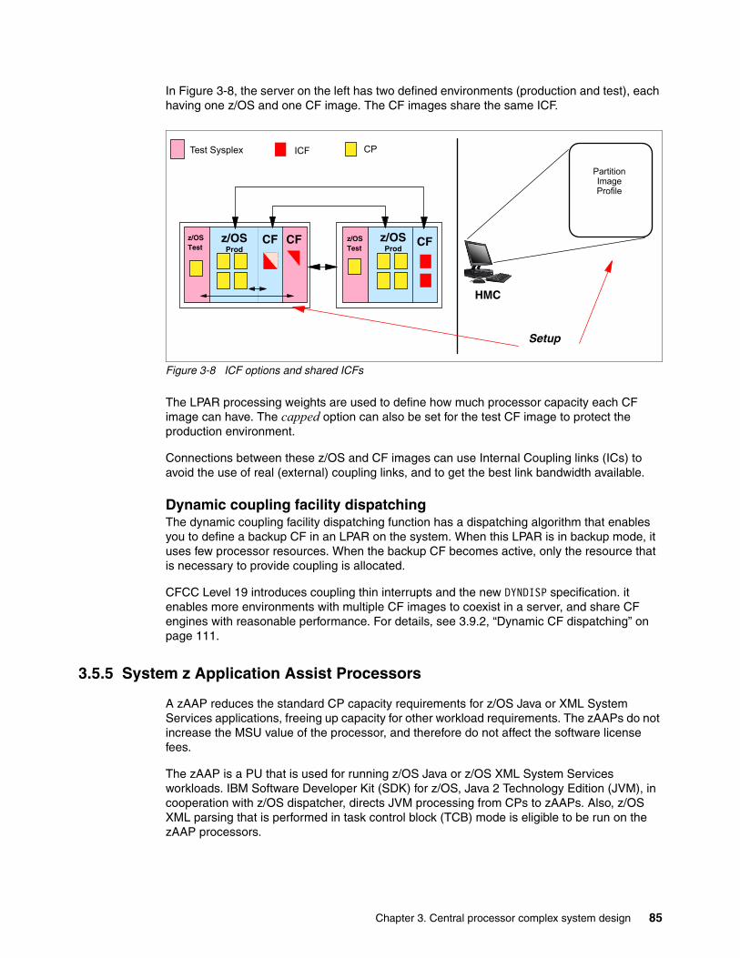
In Figure 3-8, the server on the left has two defined environments (production and test), each having one z/OS and one CF image. The CF images share the same ICF.
Figure 3-8 ICF options and shared ICFs
The LPAR processing weights are used to define how much processor capacity each CF image can have. The capped option can also be set for the test CF image to protect the production environment.
Connections between these z/OS and CF images can use Internal Coupling links (ICs) to avoid the use of real (external) coupling links, and to get the best link bandwidth available.
Dynamic coupling facility dispatchingThe dynamic coupling facility dispatching function has a dispatching algorithm that enables you to define a backup CF in an LPAR on the system. When this LPAR is in backup mode, it uses few processor resources. When the backup CF becomes active, only the resource that is necessary to provide coupling is allocated.
CFCC Level 19 introduces coupling thin interrupts and the new DYNDISP specification. it enables more environments with multiple CF images to coexist in a server, and share CF engines with reasonable performance. For details, see 3.9.2, “Dynamic CF dispatching” on page 111.
3.5.5 System z Application Assist Processors
A zAAP reduces the standard CP capacity requirements for z/OS Java or XML System Services applications, freeing up capacity for other workload requirements. The zAAPs do not increase the MSU value of the processor, and therefore do not affect the software license fees.
The zAAP is a PU that is used for running z/OS Java or z/OS XML System Services workloads. IBM Software Developer Kit (SDK) for z/OS, Java 2 Technology Edition (JVM), in cooperation with z/OS dispatcher, directs JVM processing from CPs to zAAPs. Also, z/OS XML parsing that is performed in task control block (TCB) mode is eligible to be run on the zAAP processors.
z/OSProd
z/OSProd
Setup
HMC
Partition ImageProfile
ICF CP
CF CF
Test Sysplex
z/OSTest
z/OSTest
CF
Chapter 3. Central processor complex system design 85
Using zAAPs include the following benefits:
� Potential cost savings.
� Simplification of infrastructure as a result of the integration of new applications with their associated database systems and transaction middleware (such as DB2, IMS, or CICS). Simplification can happen, for example, by introducing a uniform security environment, reducing the number of TCP/IP programming stacks and server interconnect links.
� Prevention of processing latencies that occur if Java application servers and their database servers were deployed on separate server platforms.
One CP must be installed with or before a zAAP installation. The number of zAAPs in a server cannot exceed double the number of purchased CPs. Up to four zAAPs can be characterized on H06, and up to eight zAAPs can be characterized on H13.
The quantity of permanent zAAPs plus temporary zAAPs cannot exceed double the quantity of purchased (permanent plus unassigned) CPs plus temporary CPs. Also, the quantity of temporary zAAPs cannot exceed the quantity of permanent zAAPs.
PUs that are characterized as zAAPs within a configuration are grouped into the zAAP pool. This grouping enables zAAPs to have their own processing weights, which are independent of the weight of parent CPs. The zAAP pool can be seen on the hardware console.
The zAAPs are orderable by feature code (FC 5797). Up to two zAAPs can be ordered for each CP or marked CP configured in the server.
The zAAPs and logical partition definitionsThe zAAPs are either dedicated or shared. In an LPAR, you must have at least one CP to be able to define zAAPs for that partition. You can define as many zAAPs for an LPAR as are available in the system.
How zAAPs workThe zAAPs are designed for z/OS Java code execution. When Java code must be run (for example, under control of WebSphere), the z/OS JVM calls the function of the zAAP. The z/OS dispatcher then suspends the JVM task on the CP on which it is running, and dispatches it on an available zAAP.
After the Java application code execution is finished, z/OS dispatches the JVM task again on an available CP, after which normal processing is resumed. This process reduces the CP time that is needed to run Java WebSphere applications, freeing capacity for other workloads.
Figure 3-9 on page 87 shows the logical flow of Java code running on a zBC12 that has a zAAP available. When JVM starts the execution of a Java program, it passes control to the z/OS dispatcher that will verify the availability of a zAAP.
Availability is treated in the following manner:
� If a zAAP is available (not busy), the dispatcher suspends the JVM task on the CP and assigns the Java task to the zAAP. When the task returns control to the JVM, it passes control back to the dispatcher that reassigns the JVM code execution to a CP.
� If no zAAP is available at that time (they are all busy), the z/OS dispatcher can enable a Java task to run on a standard CP, depending on the option that is used in the OPT statement in the IEAOPTxx member of SYS1.PARMLIB.
Logical partition: In an LPAR, as many zAAPs as are available can be defined together with at least one CP.
86 IBM zEnterprise BC12 Technical Guide
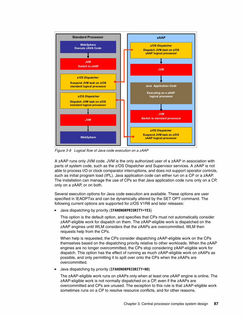
Figure 3-9 Logical flow of Java code execution on a zAAP
A zAAP runs only JVM code. JVM is the only authorized user of a zAAP in association with parts of system code, such as the z/OS Dispatcher and Supervisor services. A zAAP is not able to process I/O or clock comparator interruptions, and does not support operator controls, such as initial program load (IPL). Java application code can either run on a CP or a zAAP. The installation can manage the use of CPs so that Java application code runs only on a CP, only on a zAAP, or on both.
Several execution options for Java code execution are available. These options are user specified in IEAOPTxx and can be dynamically altered by the SET OPT command. The following current options are supported for z/OS V1R8 and later releases:
� Java dispatching by priority (IFAHONORPRIORITY=YES)
This option is the default option, and specifies that CPs must not automatically consider zAAP-eligible work for dispatch on them. The zAAP-eligible work is dispatched on the zAAP engines until WLM considers that the zAAPs are overcommitted. WLM then requests help from the CPs.
When help is requested, the CPs consider dispatching zAAP-eligible work on the CPs themselves based on the dispatching priority relative to other workloads. When the zAAP engines are no longer overcommitted, the CPs stop considering zAAP-eligible work for dispatch. This option has the effect of running as much zAAP-eligible work on zAAPs as possible, and only permitting it to spill over onto the CPs when the zAAPs are overcommitted.
� Java dispatching by priority (IFAHONORPRIORITY=NO)
The zAAP-eligible work runs on zAAPs only when at least one zAAP engine is online. The zAAP-eligible work is not normally dispatched on a CP, even if the zAAPs are overcommitted and CPs are unused. The exception to this rule is that zAAP-eligible work sometimes runs on a CP to resolve resource conflicts, and for other reasons.
Standard Processor zAAP
WebSphereExecute JAVA Code
z/OS Dispatcher
Suspend JVM task on z/OS standard logical processor
WebSphere
Java Application Code
Executing on a zAAPlogical processorz/OS Dispatcher
JVM
Switch to zAAP
JVMJVMSwitch to
z/OS Dispatcher
JVM
Dispatch JVM task on z/OS standard logical processor
JVM
z/OS Dispatcher
logical processor
z/OS Dispatcher
Dispatch JVM task on z/OS zAAP logical processor
JVM
Switch to standard processor
z/OS Dispatcher
Suspend JVM task on z/OS zAAP logical processor
Chapter 3. Central processor complex system design 87
Therefore, zAAP-eligible work does not affect the CP use that is used for reporting through subcapacity reporting tool (SCRT), no matter how busy the zAAPs are.
� Java discretionary crossover (IFACROSSOVER=YES or NO)
As of z/OS V1R8, the IFACROSSOVER parameter is no longer served.
If zAAPs are defined to the LPAR but are not online, the zAAP-eligible work units are processed by CPs in order of priority. The system ignores the IFAHONORPRIORITY parameter in this case, and handles the work as though it had no eligibility to zAAPs.
3.5.6 System z Integrated Information Processor
A zIIP enables eligible workloads to work with z/OS, and have a portion of the workload’s enclave service request block (SRB) work directed to the zIIP. The zIIPs do not increase the MSU value of the processor, and therefore do not affect the software license fee.
The z/OS communication server and IBM DB2 Universal Database™ (UDB) for z/OS V8 or later use the zIIP by indicating to z/OS which portions of the work are eligible to be routed to a zIIP.
There are several eligible DB2 UDB for z/OS V8 or later workloads executing in SRB mode:
� Query processing of network-connected applications that access the DB2 database over a TCP/IP connection using Distributed Relational Database Architecture (DRDA).DRDA enables relational data to be distributed among multiple platforms. It is inherent to DB2 for z/OS, therefore reducing the need for additional gateway products that can affect performance and availability.
The application uses the DRDA requester or server to access a remote database (IBM DB2 Connect™ is an example of a DRDA application requester).
� Star schema query processing, which is mostly used in business intelligence (BI) work.A star schema is a relational database schema for representing multidimensional data. It stores data in a central fact table, and is surrounded by additional dimension tables holding information about each perspective of the data. A star schema query, for example, joins various dimensions of a star schema data set.
� DB2 utilities that are used for index maintenance, such as LOAD, REORG, and REBUILD. Indexes enable quick access to table rows, but over time, as data in large databases is manipulated, they become less efficient and have to be maintained.
The zIIP runs portions of eligible database workloads, and in doing so helps to free up computer capacity and lower software costs. Not all DB2 workloads are eligible for zIIP processing. DB2 UDB for z/OS V8 and later gives z/OS the information to direct portions of the work to the zIIP. The result is that, in every user situation, separate variables determine how much work is actually redirected to the zIIP.
The z/OS Communications Server uses the zIIP for eligible Internet Protocol Security (IPSec) network encryption workloads. This configuration requires z/OS V1R10 or later releases. Portions of IPSec processing take advantage of the zIIPs, specifically end-to-end encryption with IPSec. The IPSec function moves a portion of the processing from the general-purpose processors to the zIIPs. In addition to performing the encryption processing, the zIIP also handles the cryptographic validation of message integrity and IPSec header processing.
The z/OS Global Mirror (zGM) software, formerly known as extended remote copy (XRC), uses the zIIP too. Most z/OS Data Facility Storage Management Subsystem (DFSMS) system data mover (SDM) processing associated with zGM is eligible to run on the zIIP. This function requires z/OS V1R8 with PTFs or later releases.
88 IBM zEnterprise BC12 Technical Guide
The first IBM relational database product to use z/OS XML system services is DB2 V9. With regard to DB2 V9 before the z/OS XML system services enhancement, z/OS XML system services non-validating parsing was partially directed to zIIPs when used as part of a distributed DB2 request through DRDA. This enhancement benefits DB2 V9 by making all z/OS XML system services non-validating parsing eligible to zIIPs when processing is used as part of any workload running in enclave SRB mode.
The z/OS Communications Server also enables the HiperSockets Multiple Write operation for outbound large messages (originating from z/OS) to be performed by a zIIP. Application workloads that are based on XML, HTTP, SOAP, Java, and other protocols, as well as traditional file transfers, can benefit from this capability.
For BI, IBM Scalable Architecture for Financial Reporting (SAFR) provides a high-volume, high-performance reporting solution by running many diverse queries in z/OS batch, and can also be eligible for zIIP.
For more information about zIIP and eligible workloads, see the IBM zIIP website:
http://www-03.ibm.com/systems/z/advantages/ziip/about.html
Installation information for zIIPOne CP must be installed with or before any zIIP installation. The number of zIIPs in a server cannot exceed twice the number of CPs and unassigned CPs in that server. Up to four zIIPs can be characterized on H06, and up to eight zIIPs can be characterized on H13.
The zIIPs are orderable by feature code (FC 5798). Up to two zIIPs can be ordered for each CP or marked CP configured in the server.
PUs that are characterized as zIIPs within a configuration are grouped into the zIIP pool. By doing this, zIIPs can have their own processing weights, independent of the weight of the parent CPs. The zIIP pool can be seen on the hardware console.
The quantity of permanent zIIPs plus temporary zIIPs cannot exceed twice the quantity of purchased CPs plus temporary CPs. Also, the quantity of temporary zIIPs cannot exceed the quantity of permanent zIIPs.
The zIIPs and logical partition definitionszIIPs are either dedicated or shared, depending on whether they are part of a dedicated or shared LPAR. In an LPAR, at least one CP must be defined before zIIPs for that partition can be defined. The number of zIIPs available in the system is the number of zIIPs that can be defined to an LPAR.
3.5.7 The zAAP on zIIP capability
The zAAPs and zIIPs support separate types of workloads. However, there are installations that do not have enough eligible workloads to justify buying a zAAP or a zAAP. IBM is now making available the capability of combining zAAP and zIIP workloads on zIIP processors, if no zAAPs are installed on the server. This combination can provide the following benefits:
� The combined eligible workloads can make the zIIP acquisition more cost-effective.
� When zIIPs are already present, the investment is maximized by running the Java and z/OS XML System Services-based workloads on existing zIIPs.
Logical partition: In an LPAR, as many zIIPs as are available can be defined together with at least one CP.
Chapter 3. Central processor complex system design 89
This capability does not eliminate the need to have one or more CPs for every two zIIP processors in the server. The support is provided by z/OS. For more information, see 8.3.2, “IBM zAAP support” on page 262.
When zAAPs are present2, this capability is not available, because it is not intended as a replacement for zAAPs, which continue to be available, and it is not intended as an overflow possibility for zAAPs. Do not convert zAAPs to zIIPs to take advantage of the zAAP to zIIP capability for the following reasons:
� Having both zAAPs and zIIPs maximizes the system potential for new workloads.
� The zAAPs have been available for over five years, and there might exist applications or middleware with zAAP-specific code dependencies. For example, the code can use the number of installed zAAP engines to optimize multithreading performance.
It is a good idea to plan and test before eliminating all zAAPs, because application code dependencies can exist that might affect performance.
3.5.8 System Assist Processors
A SAP is a PU that runs the channel subsystem LIC to control I/O operations. All SAPs perform I/O operations for all LPARs. Both models have two standard SAPs configured, and up to two additional SAPs.
SAP configurationA standard SAP configuration provides a well-balanced system for most environments. However, there are application environments with high I/O rates (typically various Transaction Processing Facility (TPF) environments). In this case, optional additional SAPs can be ordered. Assignment of additional SAPs can increase the capability of the channel subsystem to perform I/O operations. In zBC12 servers, the number of SAPs can be greater than the number of CPs.
2 The zAAP on zIIP capability is available to z/OS when running as a guest of z/VM on systems with zAAPs installed, if no zAAPs are defined to the z/VM LPAR. This design enables, for instance, testing this capability to estimate usage before committing to production.
Statement of Direction: zBC12 and zEC12 are planned to be the last high-end System z servers to offer support for zAAP specialty engine processors. IBM intends to continue support for running zAAP workloads on zIIP processors (zAAP on zIIP). This change is intended to help simplify capacity planning and performance management, while still supporting all the currently eligible workloads.
In addition, IBM provided a PTF for Authorized Program Analysis Report (APAR) OA38829 on z/OS V1.12 and V1.13 in September 2012. This PTF removes the restriction that prevents zAAP-eligible workloads from running on zIIP processors when a zAAP is installed on the server. This change is intended only to help facilitate migration and testing of zAAP workloads on zIIP processors.
IBM continues to support running zAAP workloads on zIIP processors (“zAAP on zIIP”). IBM z/OS V2.1 is designed to remove the restriction that prevents zAAP-eligible workloads from running on zIIP processors when a zAAP is installed on the server.
90 IBM zEnterprise BC12 Technical Guide
Optional additional orderable SAPsAn available option on all models is additional orderable SAPs (FC 5796). These additional SAPs increase the capacity of the channel subsystem (CSS) to perform I/O operations, usually suggested for TPF environments.
3.5.9 Reserved processors
Reserved processors are defined by the PR/SM to enable a nondisruptive capacity upgrade. Reserved processors are similar to spare logical processors, and can be shared or dedicated. Reserved CPs can be defined to an LPAR dynamically to enable nondisruptive image upgrades.
Reserved processors can be dynamically configured online by an operating system that supports this function, if enough unassigned PUs are available to satisfy this request. The PR/SM rules regarding logical processor activation remain unchanged.
Reserved processors provide the capability to define to an LPAR more logical processors than the number of available CPs, IFLs, ICFs, zAAPs, and zIIPs in the configuration. Therefore, you can configure online, nondisruptively, more logical processors after additional CPs, IFLs, ICFs, zAAPs, and zIIPs have been made available concurrently with one of the CoD options.
The maximum number of reserved processors that can be defined to an LPAR depends on the number of logical processors that are already defined. If the operating system in the LPAR supports the logical processor add function, reserved processors are no longer needed.
Do not define more active and reserved processors than the operating system for the LPAR can support. For more information about logical processors and reserved processors and their definition, see 3.7, “Logical partitioning” on page 96.
3.5.10 Integrated firmware processor
An IFP is allocated from the pool of PUs available for the whole system. Unlike other characterized PUs, the IFP is standard and is not defined by the customer. It is a single PU dedicated solely for the purpose of supporting the inherent PCIe features (10GbE Remote Direct Memory Access (RDMA) over Converged Ethernet (RoCE) and IBM zEnterprise Data Compression (zEDC) Express), and is initialized at power-on reset (POR).
The IFP supports Resource Group (RG) LIC to provide local PCIe I/O feature management and virtualization functions. For more information, see Appendix G, “Native PCI/e” on page 491.
3.5.11 Processor unit assignment
Characterized PUs are assigned at POR time, when the server is initialized. The intention of this initial assignment rule is to keep PUs of the same characterization type grouped together as much as possible regarding PU chips, to optimize shared cache usage.
Chapter 3. Central processor complex system design 91
The assignment rules follow this order:
1. Spares. No dedicated spare PU resides on H06. Two dedicated spare PUs reside on H13, where each processor drawer has one.
2. SAPs. Spread across processor drawers and high PU chips. Start with the high PU chip high core, then the next PU chip high core, which prevents all of the SAPs from being assigned on one PU chip.
3. IFP. Assign the IFP to the high chip on the low processor drawer.
4. CPs. Fill the PU chip and spill into the next chip on the low processor drawer first, before spilling over into the high processor drawer.
5. ICFs. Fill the high PU chip on the high processor drawer.
6. IFLs. Fill the high PU chip on the high processor drawer.
7. zAAPs. Attempts are made to align these zAAPs close to the CPs.
8. zIIPs. Attempts are made to align these zIIPs close to the CPs.
This implementation is to isolate, as much as possible, on separate processor drawers (and even on separate PU chips) processors that are used by separate operating systems, so that they do not use the same shared caches. CPs, zAAPs, and zIIPs are all used by z/OS, and can benefit by using the same shared caches. IFLs are used by z/VM and Linux, and ICFs are used by CFCC. Therefore, for performance reasons, the assignment rules prevent them from sharing L3 and L4 caches with z/OS processors.
This initial PU assignment that is done at POR can be dynamically rearranged by LPAR to improve system performance (see 3.7.2, “Storage operations” on page 101).
3.5.12 Sparing rules
On a zBC12 H06, because there is no dedicated spare PU, non-characterized PUs are used for sparing.
On a zBC12 H13, two dedicated spare PUs are available, one for each processor drawer. The two spare PUs can replace two characterized PUs, whether it is a CP, IFL, ICF, zAAP, zIIP, SAP, or IFP.
Systems with a failed PU for which no spare is available will call home for a replacement.
Follow these sparing rules:
� When a PU failure occurs on a chip that has four active cores, the two standard spare PUs are used to recover the failing PU and the parent PU (for example, the compression unit and CPACF) with the failing PU, even though only one of the PUs has failed.
� When a PU failure occurs on a chip that has four active cores, one standard spare PU is used to replace the PU.
� When no spares are left, non-characterized PUs are used for sparing, following the previous two rules.
Transparent CP, IFL, ICF, zAAP, zIIP, SAP and IFP sparingIf a spare PU is available, sparing of CP, IFL, ICF, zAAP, zIIP, SAP, and IFP is completely transparent and does not require an operating system or operator intervention.
With transparent sparing, the status of the application that was running on the failed processor is preserved, and it continues processing on a newly assigned CP, IFL, ICF, zAAP, zIIP, SAP, or IFP (allocated to one of the spare PUs) without customer intervention.
92 IBM zEnterprise BC12 Technical Guide
Application preservationIf no spare PU is available, application preservation (z/OS only) is invoked. The state of the failing processor is passed to another active processor that is used by the operating system and, through operating system recovery services, the task is resumed successfully (in most cases, without customer intervention).
Dynamic SAP and IFP sparing and reassignmentDynamic recovery is provided in case of failure of the SAP or IFP. If the SAP or IFP fails, and if a spare PU is available, the spare PU is dynamically assigned as a new SAP or IFP. If no spare PU is available, and more than one PU is characterized, a characterized PU is reassigned as an SAP or IFP (the preference order for choosing a spare PU is: IFL, ICF, and then CP). In either case, customer intervention is not required. This capability eliminates an unplanned outage, and permits a service action to be deferred to a more convenient time.
3.5.13 Increased flexibility with z/VM-mode partitions
The zBC12 provides a capability for the definition of a z/VM-mode LPAR that contains a mix of processor types, including CPs and specialty processors, such as IFLs, zIIPs, zAAPs, and ICFs.
The z/VM V5R4 and later software supports this capability, which increases flexibility and simplifies systems management. In a single LPAR, z/VM can perform these functions:
� Manage guests that use Linux on System z on IFLs, z/VSE, and z/OS on CPs.
� Execute designated z/OS workloads, such as parts of DB2 DRDA processing and XML, on zIIPs.
� Provide an economical Java execution environment under z/OS on zAAPs.
3.6 Memory design
This section describes various considerations regarding the zBC12 memory design.
3.6.1 Overview
The zBC12 memory design supports concurrent memory upgrades up to the limit provided by the physically installed capability.
The zBC12 can have more physically installed memory than the initial available capacity. Memory upgrades within the physically installed capacity can be performed concurrently by LIC, and no hardware changes are required. Note that memory upgrades cannot be done through CBU or On/Off CoD.
When the total capacity installed has more usable memory than required for a configuration, the LIC configuration control (LICCC) determines how much memory is used from each card. The sum of the LICCC-provided memory from each card is the amount available for use in the system.
Memory upgrade is disruptive if the physically installed capacity is reached.
Chapter 3. Central processor complex system design 93
Large page supportBy default, page frames are allocated with a 4 KB size. The zBC12 also supports large page sizes of 1 MB or 2 GB. The first z/OS release that supports 1 MB pages is z/OS V1R9. Linux on System z support for 1 MB pages is available in SUSE Linux Enterprise Server (SLES) 10 SP2 and Red Hat Enterprise Linux (RHEL) 5.2.
The TLB exists to reduce the amount of time that is required to translate a virtual address to a real address. This translation is done by dynamic address translation (DAT) when it must find the correct page for the correct address space. Each TLB entry represents one page. As with other buffers or caches, lines are discarded from the TLB on a least recently used (LRU) basis.
The worst-case translation time occurs when there is a TLB miss, and both the segment table (needed to find the page table) and the page table (needed to find the entry for the particular page in question) are not in cache. In this case, there are two complete real memory access delays, plus the address translation delay. The duration of a processor cycle is much smaller than the duration of a memory cycle, so a TLB miss is relatively costly.
It is desirable to have addresses in the TLB. With 4 KB pages, holding all the addresses for 1 MB of storage takes 256 TLB lines. When you are using 1 MB pages, it takes only 1 TLB line. Therefore, large page size exploiters have a much smaller TLB footprint.
Large pages enable the TLB to better represent a large working set and suffer fewer TLB misses by enabling a single TLB entry to cover more address translations.
Exploiters of large pages are better represented in the TLB, and are expected to see performance improvement in both elapsed time and processor usage. These improvements are because DAT and memory operations are part of processor busy time, even though the processor waits for memory operations to complete without processing anything else in the meantime.
To overcome the processor usage that is associated with creating a 1 MB page, a process must run for some time. It must maintain frequent memory access to keep the pertinent addresses in the TLB.
Very short-running work does not overcome the processor usage. Short processes with small working sets are expected to receive little or no improvement. Long-running work with high memory-access frequency is the best candidate to benefit from large pages.
Long-running work with low memory-access frequency is less likely to maintain its entries in the TLB. However, when it does run, a smaller number of address translations is required to resolve all the memory it needs. Therefore, a long-running process can benefit even without frequent memory access.
Weigh the benefits of whether something in this category should use large pages as a result of the system-level costs of tying up real storage. There is a balance between the performance of a process using large pages, and the performance of the remaining work on the system.
On zBC12 1 MB large pages become pageable if Flash Express is enabled. They are only available for 64-bit virtual private storage, such as virtual memory located above 2 GB.
One would be inclined to think that increasing the TLB size is a feasible option to deal with TLB-miss situations. However, this process is not as straightforward as it seems. As the size of the TLB increases, so does the processor usage that is involved in managing the TLB’s contents. Correct sizing of the TLB is subject to complex statistical modeling to find the optimal trade-off between size and performance.
94 IBM zEnterprise BC12 Technical Guide
3.6.2 Central storage
Central storage consists of main storage (addressable by programs), and storage not directly addressable by programs. Non-addressable storage includes the HSA. Central storage provides these functions:
� Data storage and retrieval for PUs and I/O� Communication with PUs and I/O� Communication with, and control of, optional expanded storage� Error checking and correction
Central storage can be accessed by all processors, but it cannot be shared between LPARs. Any system image (LPAR) must have a central storage size defined. This defined central storage is allocated exclusively to the LPAR during partition activation.
3.6.3 Expanded storage
Expanded storage can optionally be defined on zBC12. Expanded storage is physically a section of processor storage. It is controlled by the operating system, and transfers 4 KB pages to and from central storage.
Storage considerationsExcept for z/VM and Linux on System z (although not commonly used), z/Architecture operating systems do not use expanded storage. Because they operate in 64-bit addressing mode, they can have all the required storage capacity allocated as central storage.
However, z/VM is an exception because, even when operating in 64-bit mode, it can have guest virtual machines running in 31-bit addressing mode, which can use expanded storage. In addition, z/VM uses expanded storage for its own operations. However, using expanded storage is not recommended with z/VM V6R3.
Defining expanded storage to a CF image is not possible. However, any other image type can have expanded storage defined, even if that image runs a 64-bit operating system and does not use expanded storage.
The zBC12 only runs in LPAR mode. Storage is placed into a single storage pool, called the LPAR single storage pool, which can be dynamically converted to expanded storage and back to central storage as needed when partitions are activated or de-activated.
LPAR single storage poolIn LPAR mode, storage is not split into central storage and expanded storage at POR. Rather, the storage is placed into a single central storage pool that is dynamically assigned to expanded storage and back to central storage, as needed.
On the HMC, the storage assignment tab of a reset profile shows the customer storage, which is the total installed storage minus the 16 GB HSA. LPARs are still defined to have central storage and, optionally, expanded storage.
Activation of LPARs and dynamic storage reconfiguration cause the storage to be assigned to the type needed (central or expanded), and do not require a POR.
Chapter 3. Central processor complex system design 95
3.6.4 Hardware system area
The HSA is a non-addressable storage area that contains server LIC and configuration-dependent control blocks. The HSA has a fixed size of 16 GB, and is not part of the purchased memory that you order and install.
The fixed size of the HSA eliminates planning for future expansion of the HSA, because Hardware Configuration Definition and I/O configuration program (HCD/IOCP) always reserves the space for the following functions:
� Two CSSs� Fifteen LPARs in each CSS for a total of 30 LPARs� Subchannel set 0 (SS0) with 63.75 KB devices in each CSS� Subchannel set 1 (SS1) with 64 KB devices in each CSS
The HSA has sufficient reserved space to enable dynamic I/O reconfiguration changes to the maximum capability of the processor.
3.7 Logical partitioning
This section provides information about logical partitioning features.
3.7.1 Overview
Logical partitioning is a function implemented by the PR/SM on all zBC12 servers. The zBC12 runs only in LPAR mode. Therefore, all system aspects are controlled by PR/SM functions.
PR/SM is aware of the processor drawer structure on the zBC12. LPARs, however, do not have this awareness. LPARs have resources allocated to them from a variety of physical resources. From a systems standpoint, LPARs have no control over these physical resources, but the PR/SM functions do.
PR/SM manages and optimizes allocation and the dispatching of work on the physical topology. Most physical topology that was previously handled by the operating systems is the responsibility of PR/SM.
As seen in 3.5.11, “Processor unit assignment” on page 91, the initial PU assignment is done during POR, using rules to optimize cache usage. This step is the physical step, where CPs, zIIPs, zAAPs, IFLs, ICFs, SAPs, and IFP are allocated on the processor drawer.
When an LPAR is activated, PR/SM builds logical processors and allocates memory for the LPAR.
Memory allocation is spread across both processor drawers. This memory allocation design is driven by performance results, also minimizing variability for the majority of workloads.
Logical processors are dispatched by PR/SM on physical processors. The assignment topology used by PR/SM to dispatch logical or physical PUs is also based on cache usage optimization.
PR/SM optimizes chip assignments within the assigned processor drawer, to maximize L3 cache efficiency. So, logical processors from an LPAR are dispatched on physical processors on the same PU chip as much as possible.
96 IBM zEnterprise BC12 Technical Guide
Note that the number of processors per chip matches the number of z/OS processor affinity queues used by HiperDispatch, achieving optimal cache usage within an affinity node.
PR/SM also tries to re-dispatch a logical processor on the same physical processor to optimize private cache (L1 and L2) usage.
HiperDispatchPR/SM and z/OS work in tandem to more efficiently use processor resources. HiperDispatch is a function that combines the dispatcher actions and the knowledge that PR/SM has about the topology of the server.
Performance can be optimized by re-dispatching units of work to the same processor group, keeping processes running near their cached instructions and data, and minimizing transfers of data ownership among processors.
The nested topology is returned to z/OS by the Store System Information (STSI) 15.1.3 instruction. HiperDispatch uses the information to concentrate logical processors around shared caches, and dynamically optimizes the assignment of logical processors and units of work.
The z/OS dispatcher manages multiple queues, which are called affinity queues, with a target number of up to six processors per queue, which fits nicely into a single PU chip. These queues are used to assign work to as few logical processors as are needed for a given LPAR workload. So, even if the LPAR is defined with a large number of logical processors, HiperDispatch optimizes this number of processors nearest to the required capacity.
The z/VM V6R3 supportHiperDispatch is now supported with z/VM V6R3.
Logical partitionsPR/SM enables zBC12 servers to be initialized for a logically partitioned operation, supporting up to 30 LPARs. Each LPAR can run its own operating system image in any image mode, independent from the other LPARs.
An LPAR can be added, removed, activated, or deactivated at any time. Changing the number of LPARs is not disruptive, and does not require POR. Certain facilities might not be available to all operating systems, because the facilities might have software corequisites.
Each LPAR has the same resources as a real CPC. They are processors, memory, and channels:
� Processors
They are called logical processors, and they can be defined as CPs, IFLs, ICFs, zAAPs, or zIIPs. They can be dedicated to an LPAR, or shared among LPARs. When shared, a processor weight can be defined to provide the required level of processor resources to an LPAR. Also, the capping option can be turned on, which prevents an LPAR from acquiring more than its defined weight, limiting its processor consumption.
LPARs for z/OS can have CP, zAAP, and zIIP logical processors. All three logical processor types can be defined as either all dedicated or all shared. The zAAP and zIIP support is available in z/OS.
The weight and the number of online logical processors of an LPAR can be dynamically managed by the LPAR CPU Management function of the Intelligent Resource Director to achieve the defined goals of this specific partition, and of the overall system. The provisioning architecture of the zBC12, which is described in Chapter 9, “System upgrades” on page 319, adds another dimension to the dynamic management of LPARs.
Chapter 3. Central processor complex system design 97
PR/SM was enhanced to support an option to limit the amount of physical processor capacity used by an individual LPAR when a PU is defined as a general purpose processor (CP), or as an IFL shared across a set of LPARs.
This enhancement is designed to provide a physical capacity limit enforced as an absolute (versus relative) limit. It is not affected by changes to the logical or physical configuration of the system. This physical capacity limit can be specified in units of CPs or IFLs. The Change LPAR Controls and Customize Activation Profiles tasks on the HMC have been enhanced in support of this new function.
For the z/OS workload license charge (WLC), an LPAR defined capacity can be set, enabling the soft capping function. Workload charging introduces the capability to pay software license fees based on the size of the LPAR on which the product is running, rather than on the total capacity of the server:
– In support of WLC, the user can specify a defined capacity in MSUs per hour. The defined capacity sets the capacity of an individual LPAR when soft capping is selected.
The defined capacity value is specified on the Options tab on the Customize Image Profiles panel.
– WLM keeps a 4-hour rolling average of the CPU usage of the LPAR, and when the 4-hour average CPU consumption exceeds the defined capacity limit, WLM dynamically activates LPAR capping (soft capping). When the rolling 4-hour average returns under the defined capacity, the soft cap is removed.
For more information regarding WLM, see System Programmer's Guide to: Workload Manager, SG24-6472.
� Memory
Memory, either central storage or expanded storage, must be dedicated to an LPAR. The defined storage must be available during the LPAR activation. Otherwise, the activation fails.
Reserved storage can be defined to an LPAR, enabling nondisruptive memory addition to, and removal from, an LPAR, using the LPAR dynamic storage reconfiguration (z/OS and z/VM). For more information, see 3.7.5, “LPAR dynamic storage reconfiguration” on page 105.
� Channels
Channels can be shared between LPARs by including the partition name in the partition list of a channel path identifier (CHPID). I/O configurations are defined by the input/output configuration program (IOCP), or the HCD in conjunction with the CHPID mapping tool (CMT). The CMT is an optional, but strongly preferred, tool used to map CHPIDs onto physical channel identifiers (PCHIDs) that represent the physical location of a port on a card in a PCIe I/O drawer or I/O drawer.
IOCP is available on the z/OS, z/VM, and z/VSE operating systems, and as a stand-alone program on the hardware console. HCD is available on z/OS and z/VM operating systems.
Weight settings: When defined capacity is used to define an uncapped LPAR’s capacity, looking carefully at the weight settings of that LPAR is important.
If the weight is much smaller than the defined capacity, PR/SM will use a discontinuous cap pattern to achieve the defined capacity setting. Therefore, PR/SM will alternate between capping the LPAR at the MSU value corresponding to the relative weight settings, and no capping at all. It is best to avoid this case. Try to establish a defined capacity that is equal or close to the relative weight.
98 IBM zEnterprise BC12 Technical Guide
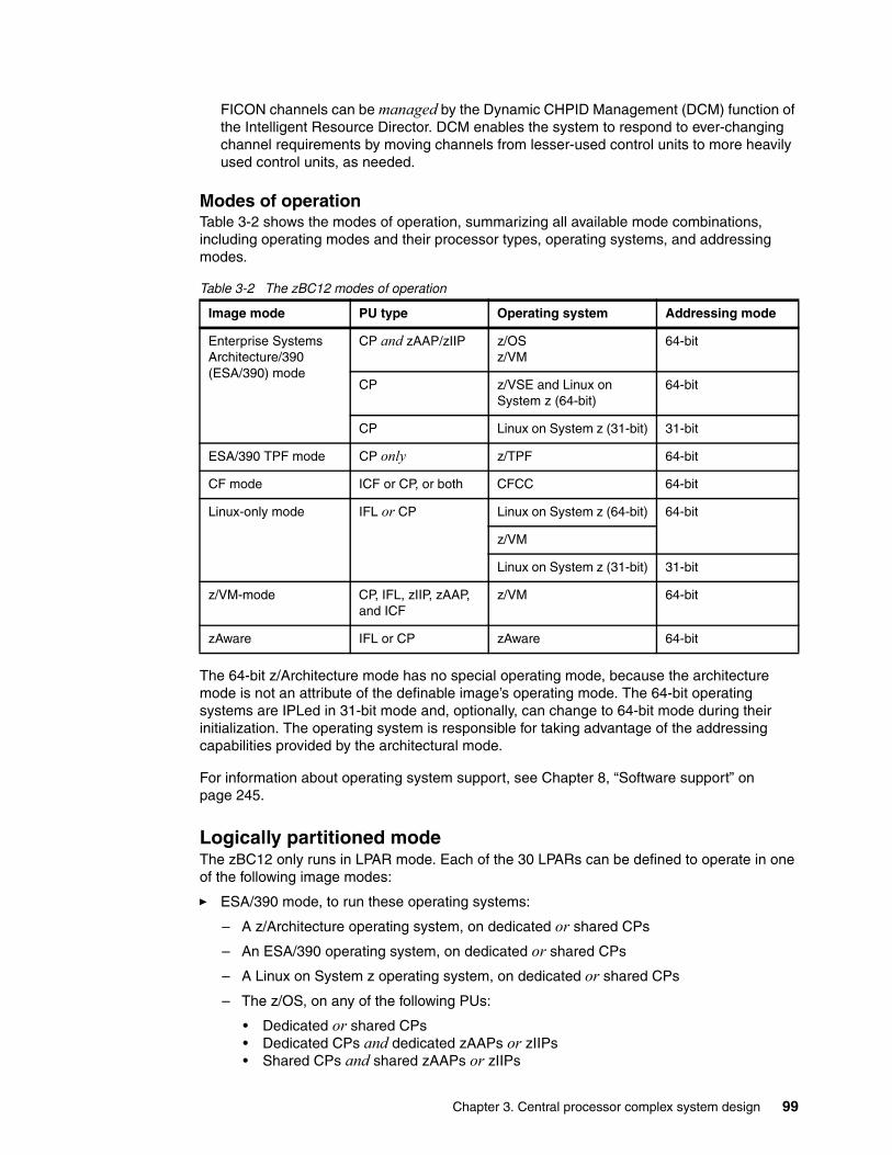
FICON channels can be managed by the Dynamic CHPID Management (DCM) function of the Intelligent Resource Director. DCM enables the system to respond to ever-changing channel requirements by moving channels from lesser-used control units to more heavily used control units, as needed.
Modes of operationTable 3-2 shows the modes of operation, summarizing all available mode combinations, including operating modes and their processor types, operating systems, and addressing modes.
Table 3-2 The zBC12 modes of operation
The 64-bit z/Architecture mode has no special operating mode, because the architecture mode is not an attribute of the definable image’s operating mode. The 64-bit operating systems are IPLed in 31-bit mode and, optionally, can change to 64-bit mode during their initialization. The operating system is responsible for taking advantage of the addressing capabilities provided by the architectural mode.
For information about operating system support, see Chapter 8, “Software support” on page 245.
Logically partitioned modeThe zBC12 only runs in LPAR mode. Each of the 30 LPARs can be defined to operate in one of the following image modes:
� ESA/390 mode, to run these operating systems:
– A z/Architecture operating system, on dedicated or shared CPs
– An ESA/390 operating system, on dedicated or shared CPs
– A Linux on System z operating system, on dedicated or shared CPs
– The z/OS, on any of the following PUs:
• Dedicated or shared CPs• Dedicated CPs and dedicated zAAPs or zIIPs• Shared CPs and shared zAAPs or zIIPs
Image mode PU type Operating system Addressing mode
Enterprise Systems Architecture/390 (ESA/390) mode
CP and zAAP/zIIP z/OSz/VM
64-bit
CP z/VSE and Linux on System z (64-bit)
64-bit
CP Linux on System z (31-bit) 31-bit
ESA/390 TPF mode CP only z/TPF 64-bit
CF mode ICF or CP, or both CFCC 64-bit
Linux-only mode IFL or CP Linux on System z (64-bit) 64-bit
z/VM
Linux on System z (31-bit) 31-bit
z/VM-mode CP, IFL, zIIP, zAAP, and ICF
z/VM 64-bit
zAware IFL or CP zAware 64-bit
Chapter 3. Central processor complex system design 99
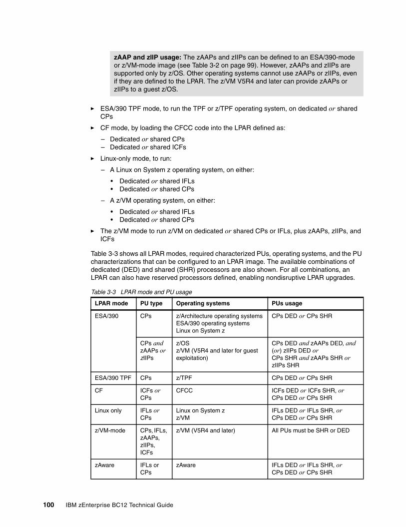
� ESA/390 TPF mode, to run the TPF or z/TPF operating system, on dedicated or shared CPs
� CF mode, by loading the CFCC code into the LPAR defined as:
– Dedicated or shared CPs – Dedicated or shared ICFs
� Linux-only mode, to run:
– A Linux on System z operating system, on either:
• Dedicated or shared IFLs • Dedicated or shared CPs
– A z/VM operating system, on either:
• Dedicated or shared IFLs • Dedicated or shared CPs
� The z/VM mode to run z/VM on dedicated or shared CPs or IFLs, plus zAAPs, zIIPs, and ICFs
Table 3-3 shows all LPAR modes, required characterized PUs, operating systems, and the PU characterizations that can be configured to an LPAR image. The available combinations of dedicated (DED) and shared (SHR) processors are also shown. For all combinations, an LPAR can also have reserved processors defined, enabling nondisruptive LPAR upgrades.
Table 3-3 LPAR mode and PU usage
zAAP and zIIP usage: The zAAPs and zIIPs can be defined to an ESA/390-mode or z/VM-mode image (see Table 3-2 on page 99). However, zAAPs and zIIPs are supported only by z/OS. Other operating systems cannot use zAAPs or zIIPs, even if they are defined to the LPAR. The z/VM V5R4 and later can provide zAAPs or zIIPs to a guest z/OS.
LPAR mode PU type Operating systems PUs usage
ESA/390 CPs z/Architecture operating systemsESA/390 operating systemsLinux on System z
CPs DED or CPs SHR
CPs and zAAPs or zIIPs
z/OS z/VM (V5R4 and later for guest exploitation)
CPs DED and zAAPs DED, and (or) zIIPs DED orCPs SHR and zAAPs SHR or zIIPs SHR
ESA/390 TPF CPs z/TPF CPs DED or CPs SHR
CF ICFs orCPs
CFCC ICFs DED or ICFs SHR, orCPs DED or CPs SHR
Linux only IFLs or CPs
Linux on System zz/VM
IFLs DED or IFLs SHR, orCPs DED or CPs SHR
z/VM-mode CPs, IFLs, zAAPs, zIIPs, ICFs
z/VM (V5R4 and later) All PUs must be SHR or DED
zAware IFLs or CPs
zAware IFLs DED or IFLs SHR, orCPs DED or CPs SHR
100 IBM zEnterprise BC12 Technical Guide
Dynamic add or delete of an LPAR nameDynamic add or delete of an LPAR name is the ability to add or delete LPARs and their associated I/O resources to or from the configuration without a POR.
The extra channel subsystem and Multiple Image Facility (MIF) ID pairs (Channel Subsystem ID(CSSID)/MIFID) can later be assigned to, or removed from, an LPAR for use through dynamic I/O commands using the HCD. At the same time, required channels have to be defined for the new LPAR.
Adding the Crypto feature to a logical partition You can preplan the addition of a Crypto Express3 or Crypto Express4S feature to an LPAR on the Crypto page in the image profile by defining the Cryptographic Candidate List, Cryptographic Online List, and Usage and Control Domain Indexes in the partition profile.
By using the Change LPAR Cryptographic Controls task, it is possible to add crypto adapters dynamically to an LPAR without an outage of the LPAR. Also, dynamic deletion or moving of these features no longer requires pre-planning. Support is provided in z/OS, z/VM, z/VSE, and Linux on System z.
LPAR group capacity limitThe group capacity limit feature enables the definition of a capacity limit for a group of LPARs on zBC12 servers. This feature enables a capacity limit to be defined for each LPAR running z/OS, and to define a group of LPARs on a server.
This feature enables the system to manage the group in such a way that the sum of the LPAR group capacity limits in MSUs per hour will not be exceeded. To take advantage of this feature, you must be running z/OS V1.8 or later, and all LPARs in the group have to be z/OS V1.8 and later.
PR/SM and WLM work together to enforce the capacity defined for the group, and enforce the capacity optionally defined for each individual LPAR.
3.7.2 Storage operations
In zBC12 servers, memory can be assigned as a combination of central storage and expanded storage, supporting up to 30 LPARs. Expanded storage is only used by the z/VM operating system.
Before activating an LPAR, central storage (and, optionally, expanded storage) must be defined to the LPAR. All installed storage can be configured as central storage.
Central storage can be dynamically assigned to expanded storage, and back to central storage as needed, without a POR. For details, see “LPAR single storage pool” on page 95.
Partition profile: Cryptographic coprocessors are not tied to partition numbers or MIF IDs. They are set up with Adjunct Processor (AP) numbers and domain indexes, which are assigned to a partition profile of a given name. The customer assigns these AP numbers and domains to the partitions, and continues to have the responsibility to clear them out when their profiles change.
Chapter 3. Central processor complex system design 101
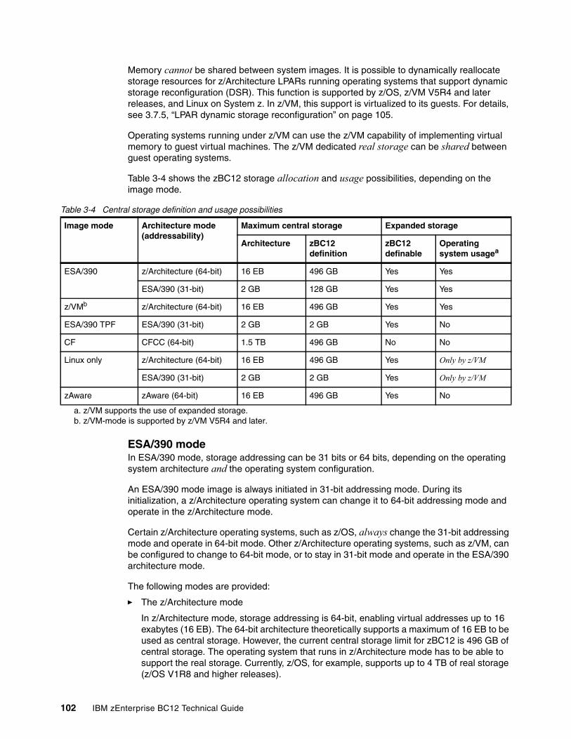
Memory cannot be shared between system images. It is possible to dynamically reallocate storage resources for z/Architecture LPARs running operating systems that support dynamic storage reconfiguration (DSR). This function is supported by z/OS, z/VM V5R4 and later releases, and Linux on System z. In z/VM, this support is virtualized to its guests. For details, see 3.7.5, “LPAR dynamic storage reconfiguration” on page 105.
Operating systems running under z/VM can use the z/VM capability of implementing virtual memory to guest virtual machines. The z/VM dedicated real storage can be shared between guest operating systems.
Table 3-4 shows the zBC12 storage allocation and usage possibilities, depending on the image mode.
Table 3-4 Central storage definition and usage possibilities
ESA/390 modeIn ESA/390 mode, storage addressing can be 31 bits or 64 bits, depending on the operating system architecture and the operating system configuration.
An ESA/390 mode image is always initiated in 31-bit addressing mode. During its initialization, a z/Architecture operating system can change it to 64-bit addressing mode and operate in the z/Architecture mode.
Certain z/Architecture operating systems, such as z/OS, always change the 31-bit addressing mode and operate in 64-bit mode. Other z/Architecture operating systems, such as z/VM, can be configured to change to 64-bit mode, or to stay in 31-bit mode and operate in the ESA/390 architecture mode.
The following modes are provided:
� The z/Architecture mode
In z/Architecture mode, storage addressing is 64-bit, enabling virtual addresses up to 16 exabytes (16 EB). The 64-bit architecture theoretically supports a maximum of 16 EB to be used as central storage. However, the current central storage limit for zBC12 is 496 GB of central storage. The operating system that runs in z/Architecture mode has to be able to support the real storage. Currently, z/OS, for example, supports up to 4 TB of real storage (z/OS V1R8 and higher releases).
Image mode Architecture mode(addressability)
Maximum central storage Expanded storage
Architecture zBC12definition
zBC12 definable
Operatingsystem usagea
a. z/VM supports the use of expanded storage.
ESA/390 z/Architecture (64-bit) 16 EB 496 GB Yes Yes
ESA/390 (31-bit) 2 GB 128 GB Yes Yes
z/VMb
b. z/VM-mode is supported by z/VM V5R4 and later.
z/Architecture (64-bit) 16 EB 496 GB Yes Yes
ESA/390 TPF ESA/390 (31-bit) 2 GB 2 GB Yes No
CF CFCC (64-bit) 1.5 TB 496 GB No No
Linux only z/Architecture (64-bit) 16 EB 496 GB Yes Only by z/VM
ESA/390 (31-bit) 2 GB 2 GB Yes Only by z/VM
zAware zAware (64-bit) 16 EB 496 GB Yes No
102 IBM zEnterprise BC12 Technical Guide
Expanded storage can also be configured to an image running an operating system in z/Architecture mode. However, only z/VM and Linux on System z3 are able to use expanded storage. Any other operating system running in z/Architecture mode (such as a z/OS) does not address the configured expanded storage. This expanded storage remains configured to this image, and is unused.
� The ESA/390 architecture mode
In ESA/390 architecture mode, storage addressing is 31-bit, supporting virtual addresses up to 2 GB. A maximum of 2 GB can be used for central storage. Because the processor storage can be configured as central and expanded storage, memory higher than 2 GB can be configured as expanded storage. In addition, this mode permits the use of either 24-bit or 31-bit addressing, under program control.
Because an ESA/390 mode image can be defined with up to 128 GB of central storage, the central storage above 2 GB is not used, but remains configured to this image.
The z/VM-modeIn z/VM-mode, certain types of PUs can be defined within one LPAR. This capability increases flexibility and simplifies systems management by enabling z/VM to perform the following tasks all in the same z/VM LPAR:
� Manage guests to operate Linux on System z on IFLs.� Operate z/VSE and z/OS on CPs.� Offload z/OS system software resource usage, such as DB2 workloads on zIIPs.� Provide an economical Java execution environment under z/OS on zAAPs.
ESA/390 TPF modeIn ESA/390 TPF mode, storage addressing follows the ESA/390 architecture mode. The TPF/ESA operating system runs in the 31-bit addressing mode.
Coupling facility modeIn CF mode, storage addressing is 64-bit for a CF image running CFCC Level 12 or later, enabling an addressing range of up to 16 EB. However, the current zBC12 definition limit for LPARs is 496 GB of storage.
CFCC Level 19, which is available for the zBC12, introduces several enhancements in the performance, reporting, serviceability, and resiliency areas.
For details, see 3.9.1, “Coupling facility control code” on page 109. Expanded storage cannot be defined for a CF image. Only IBM CFCC can run in CF mode.
Linux-only modeIn Linux-only mode, storage addressing can be 31-bit or 64-bit, depending on the operating system architecture and the operating system configuration, in exactly the same way as in ESA/390 mode.
3 Linux can use expanded storage, for example, for paging or for persistent block storage until LPAR deactivation.
Storage resources: Either a z/Architecture mode or an ESA/390 architecture mode operating system can run in an ESA/390 image on a zBC12. Any ESA/390 image can be defined with more than 2 GB of central storage and can have expanded storage. These options enable you to configure more storage resources than the operating system is capable of addressing.
Chapter 3. Central processor complex system design 103
Only Linux and z/VM operating systems can run in Linux-only mode. Linux on System z 64-bit distributions (Novell SLES 10 and later, and RHEL 5 and later) use 64-bit addressing and operate in the z/Architecture mode. In addition, z/VM uses 64-bit addressing and operates in the z/Architecture mode.
The zAware modeIn IBM zAware mode, storage addressing is 64-bit for a zAware image that runs zAware firmware. This configuration supports an addressing range of up to 16 EB. However, the current zBC12 definition limit for LPARs is 496 GB of storage.
The zAware feature, which is exclusive to zEC12 or zBC12, enables the following capabilities:
� Helps detect and diagnose unusual behavior of z/OS images in near real time.
� Reduces problem determination time and improves service availability beyond standard z/OS features.
� Provides an easy-to-use graphical user interface (GUI) with quick drill-down capabilities to view analytical data about z/OS behavior.
For more information, see Appendix A, “IBM zAware” on page 441. Only zAware firmware can run in zAware mode.
3.7.3 Reserved storageReserved storage can optionally be defined to an LPAR, enabling a nondisruptive image memory upgrade for this partition. Reserved storage can be defined to both central and expanded storage, and to any image mode, except the CF mode.
An LPAR must define an amount of central storage and, optionally (if not a CF image), an amount of expanded storage.
Both central storage and expanded storage can have two storage sizes defined:
� The initial value is the storage size that is allocated to the partition when it is activated.� The reserved value is an additional storage capacity beyond its initial storage size that an
LPAR can acquire dynamically. The reserved storage sizes defined to an LPAR do not have to be available when the partition is activated. They are simply predefined storage sizes to enable a storage increase, from an LPAR point of view.
Without the reserved storage definition, an LPAR storage upgrade is disruptive, requiring the following actions:
1. Partition deactivation2. An initial storage size definition change3. Partition activation
The additional storage capacity to an LPAR upgrade can come from these sources:
� Any unused available storage� Another partition that has released storage� A concurrent memory upgrade
A concurrent LPAR storage upgrade uses DSR. The z/OS operating system (OS) uses the reconfigurable storage unit (RSU) definition to add or remove storage units in a nondisruptive way.
104 IBM zEnterprise BC12 Technical Guide
In z/VM V5R4 and later releases, there is support the dynamic addition of memory to a running LPAR by using reserved storage, and also virtualizes this support to its guests. Removal of storage from the guests or z/VM is disruptive.
SLES 11 and RHEL 6 support both concurrent add and remove.
3.7.4 Logical partition storage granularityGranularity of central storage for an LPAR depends on the largest central storage amount that is defined, for either initial or reserved central storage, as shown in Table 3-5.
Table 3-5 LPAR main storage granularity
The granularity applies across all central storage defined, both initial and reserved. For example, for an LPAR with an initial storage amount of 30 GB and a reserved storage amount of 48 GB, the central storage granularity of both initial and reserved central storage is 256 MB.
Expanded storage granularity is fixed at 256 MB.
LPAR storage granularity information is required for LPAR image setup, and for the z/OS RSU definition. For z/VM V5R4 and later, the limitation is 256 GB.
3.7.5 LPAR dynamic storage reconfigurationDSR on zBC12 servers enables an OS running in an LPAR to add (nondisruptively) its reserved storage amount to its configuration, if any unused storage exists. This unused storage can be obtained when another LPAR releases storage, or when a concurrent memory upgrade takes place.
With DSR, the unused storage does not have to be continuous.
When an OS running in an LPAR assigns a storage increment to its configuration, PR/SM determines whether any free storage increments are available, and dynamically brings the storage online.
PR/SM dynamically takes offline a storage increment and makes it available to other partitions, when an OS running in an LPAR releases a storage increment.
LPAR: Largest main storage amount
LPAR: Central storage granularity
Central storage amount <= 128 GB 256 MB
128 GB < central storage amount <= 256 GB 512 MB
256 GB < central storage amount <= 512 GB 1000 MB
Chapter 3. Central processor complex system design 105
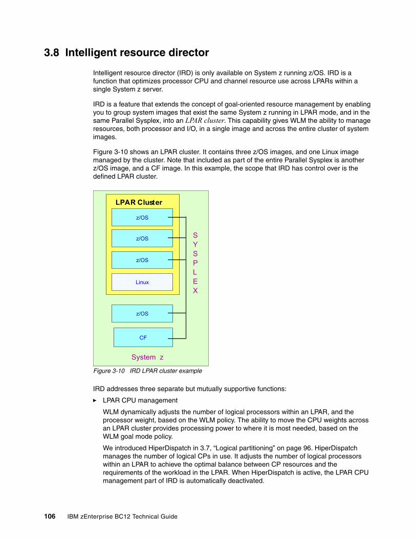
3.8 Intelligent resource director
Intelligent resource director (IRD) is only available on System z running z/OS. IRD is a function that optimizes processor CPU and channel resource use across LPARs within a single System z server.
IRD is a feature that extends the concept of goal-oriented resource management by enabling you to group system images that exist the same System z running in LPAR mode, and in the same Parallel Sysplex, into an LPAR cluster. This capability gives WLM the ability to manage resources, both processor and I/O, in a single image and across the entire cluster of system images.
Figure 3-10 shows an LPAR cluster. It contains three z/OS images, and one Linux image managed by the cluster. Note that included as part of the entire Parallel Sysplex is another z/OS image, and a CF image. In this example, the scope that IRD has control over is the defined LPAR cluster.
Figure 3-10 IRD LPAR cluster example
IRD addresses three separate but mutually supportive functions:
� LPAR CPU management
WLM dynamically adjusts the number of logical processors within an LPAR, and the processor weight, based on the WLM policy. The ability to move the CPU weights across an LPAR cluster provides processing power to where it is most needed, based on the WLM goal mode policy.
We introduced HiperDispatch in 3.7, “Logical partitioning” on page 96. HiperDispatch manages the number of logical CPs in use. It adjusts the number of logical processors within an LPAR to achieve the optimal balance between CP resources and the requirements of the workload in the LPAR. When HiperDispatch is active, the LPAR CPU management part of IRD is automatically deactivated.
z/OS
LPAR Cluster
z/OS
z/OS
z/OS
CF
System z
Linux
SYSPLEX
106 IBM zEnterprise BC12 Technical Guide
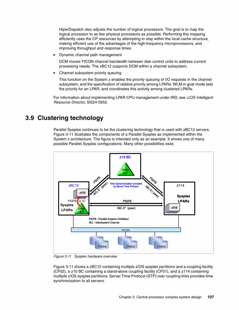
HiperDispatch also adjusts the number of logical processors. The goal is to map the logical processor to as few physical processors as possible. Performing this mapping efficiently uses the CP resources by attempting to stay within the local cache structure, making efficient use of the advantages of the high-frequency microprocessors, and improving throughput and response times.
� Dynamic channel path management
DCM moves FICON channel bandwidth between disk control units to address current processing needs. The zBC12 supports DCM within a channel subsystem.
� Channel subsystem priority queuing
This function on the System z enables the priority queuing of I/O requests in the channel subsystem, and the specification of relative priority among LPARs. WLM in goal mode sets the priority for an LPAR, and coordinates this activity among clustered LPARs.
For information about implementing LPAR CPU management under IRD, see z/OS Intelligent Resource Director, SG24-5952.
3.9 Clustering technology
Parallel Sysplex continues to be the clustering technology that is used with zBC12 servers. Figure 3-11 illustrates the components of a Parallel Sysplex as implemented within the System z architecture. The figure is intended only as an example. It shows one of many possible Parallel Sysplex configurations. Many other possibilities exist.
Figure 3-11 Sysplex hardware overview
Figure 3-11 shows a zBC12 containing multiple z/OS sysplex partitions and a coupling facility (CF02), a z10 BC containing a stand-alone coupling facility (CF01), and a z114 containing multiple z/OS sysplex partitions. Server Time Protocol (STP) over coupling links provides time synchronization to all servers.
Disks Disks Disks
CF02ICF
CF01ICF
FICON
z/OS
z/OS
PSIFB
PSIFB
PSIFB
PSIFB or IC
ISC-3
*(p
eer)
ISC-3* (peer)
ISC-3 ( peer)
zBC12
z10 BC
z114
SysplexLPARs
SysplexLPARs
Time Synchronization provided by Server Time Protocol
PSIFB - Parallel Sysplex InfiniBand
ISC - InterSystem Channel
Disks Disks Disks
CF02ICF
CF01ICF
FICON
z/OS
z/OS
PSIFB
PSIFB
PSIFB
PSIFB or IC
ISC-3
*(p
eer)
ISC-3* (peer)
ISC-3 ( peer)
zBC12
z10 BC
z114
SysplexLPARs
SysplexLPARs
Time Synchronization provided by Server Time Protocol
PSIFB - Parallel Sysplex InfiniBand
ISC - InterSystem Channel
Chapter 3. Central processor complex system design 107
CF link technology (1xIFB, 12xIFB, and 12xIFB3) selection depends on the system configuration, and the distance between their physical location. InterSystem Channel (ISC-3) links can be carried forward to zBC12 only when they are upgraded from either z114 or z10 BC. The Integrated Cluster Bus-4 (ICB-4) coupling link is not supported on both zBC12 and zEnterprise CPCs. For more information about link technologies, see 4.9.1, “Coupling links” on page 153.
Parallel Sysplex technology is an enabling technology, helping highly reliable, redundant, and robust System z technology to achieve near-continuous availability. A Parallel Sysplex consists of one or more (z/OS) OS images coupled through one or more CFs. The images can be combined together to form clusters. A properly configured Parallel Sysplex cluster maximizes availability in these ways:
� Continuous (application) availability
Changes can be introduced, such as software upgrades, one image at a time, while the remaining images continue to process work. For details, see Parallel Sysplex Application Considerations, SG24-6523.
� High capacity
Scales from 2 to 32 images.
� Dynamic workload balancing
Viewed as a single logical resource, work can be directed to any similar OS image in a Parallel Sysplex cluster having available capacity.
� Systems management
Architecture provides the infrastructure to satisfy customer requirements for continuous availability, and provides techniques for achieving simplified systems management consistent with this requirement.
� Resource sharing
A number of base (z/OS) components use CF shared storage. This exploitation enables sharing of physical resources with significant improvements in cost, performance, and simplified systems management.
� Single system image
The collection of system images in the Parallel Sysplex appears as a single entity to the operator, the user, and the database or application administrator. A single system image ensures reduced complexity from both operational and definition perspectives.
� N-2 support
Multiple hardware generations (normally three) are supported in the same Parallel Sysplex. This configuration provides for a gradual evolution of the systems in the Sysplex, without having to change all of them simultaneously. Similarly, software support for multiple releases or versions is supported.
Through state-of-the-art cluster technology, the power of multiple images can be harnessed to work in concert on common workloads. The System z Parallel Sysplex cluster takes the commercial strengths of the platform to improved levels of system management, competitive price for performance, scalable growth, and continuous availability.
Important: N-2 support is support for the current version of select products plus the two previous versions. Providing N-2 support is at IBM's sole discretion and should not be construed as an obligation to continue providing such support in the future.
108 IBM zEnterprise BC12 Technical Guide
3.9.1 Coupling facility control code
CFCC Level 19 is made available on the zBC12.
CFCC Level 19 is delivered with Driver Level 15, and introduced several improvements in the performance, reporting, serviceability, and resiliency areas as compared to CFCC Level 17.
Performance improvements� Dynamic structure size alter is enhanced to improve the performance of changing cache
structure size.
� DB2 global buffer pool (GBP) write-around (cache bypass) supports a new conditional write to GBP command. DB2 can use this enhancement during batch update/insert processing, to intelligently decide which entries should be written to the GBP cache, and which should be written around the cache to disk.
Before this enhancement, overrunning cache structures with useless directory entries and changed data during batch update/insert jobs (for example, reorganizations) caused several issues. These issues included CF processor usage, thrashing the cache through LRU processing, and cast out processing backlogs and delays.
� CF castout class contention avoidance reduces latch contention with more granular class assignments.
� CF storage class contention avoidance improves response time by changing the latching from a suspend lock to a spin lock.
� Coupling Thin Interrupts improves performance in environments which are sharing CF engines. Although dedicated engines continue to be suggested to obtain the best CF performance, Coupling Thin Interrupts can help to facilitate the use of a shared pool of engines, helping to lower hardware acquisition costs:
– The interrupt causes a shared logical processor CF partition to be dispatched by PR/SM, if it is not already dispatched, enabling the request or signal to be processed in a more timely manner. The CF will give up control when work is exhausted, or when PR/SM takes the physical processor away from the logical processor.
– Use controlled by a new DYNDISP specification.
You can now experience CF response time improvements or more consistent CF response time when using CFs with shared engines. This can also enable more environments with multiple CF images to coexist in a server, and share CF engines with reasonably performance. The response time for asynchronous CF requests can also be improved as a result of using Coupling Thin Interrupts on the z/OS host system, regardless of whether the CF is using shared or dedicated engines.
Coupling channel reportingCFCC Level 19 provides more Coupling channel characteristics reporting to z/OS by enabling it to know about the underlying InfiniBand hardware. This change enables the Resource Measurement Facility (RMF) to distinguish between coupling links using InfiniBand (CIB) CHPID types (12xIFB, 12xIFB3, and 1xIFB), and detect if there is any degradation in performance on CIB channels.
Chapter 3. Central processor complex system design 109
RMF uses the changed cross-system extended services (XES) interface and obtains new channel path characteristics. The channel path has these new characteristics:
� Stored in a new channel path data section of System Management Facility (SMF) record 74 subtype 4
� Added to the Subchannel Activity and CF To CF Activity sections of the RMF Postprocessor Coupling Facility Activity report
� Provided on the Subchannels Details panel of the RMF Monitor III Coupling Facility Systems report
Serviceability enhancementsServiceability enhancements provide help for debugging in these areas:
� Additional structure control information in CF memory dumps. Previously, only CF control structures were dumped, and no structure-related controls were included. With CFCC Level 19, new structure control information is included in CF memory dumps, although data elements (customer data) are still not dumped.
� Enhanced CFCC tracing support. CFCC Level 19 has enhanced trace points, especially in certain areas, such as latching, suspend queue management and dispatching, duplexing protocols, and sublist notification.
� Enhanced Triggers for CF nondisruptive dumping for soft-failure cases beyond break-duplexing.
Resiliency enhancementsCFCC Level 19 now supports Flash Express. It improves resilience while providing cost-effective standby capacity to help manage the potential overflow of WebSphere MQ-shared queues. Structures can now be allocated with a combination of real memory and Storage Class Memory provided by the Flash Express feature.
For more information about Flash Express and CF Flash exploitation, see Appendix C, “Flash Express” on page 461.
The CFCC is implemented by using the active wait technique. This technique means that the CFCC is always running (processing or searching for service), and never enters a wait state. This also means that the CFCC uses all of the processor capacity (cycles) available for the CF LPAR. If the LPAR running the CFCC has only dedicated processors (CPs or ICFs), using all processor capacity (cycles) is not a problem.
However, this configuration can be an issue if the LPAR that is running the CFCC also has shared processors. Therefore, enable dynamic dispatching on the CF LPAR. With CFCC Level 19 and Coupling Thin Interrupts, shared-processor CF can provide more consistent CF service time, and acceptable usage in a broader range of configurations. For more details, see 3.9.2, “Dynamic CF dispatching” on page 111.
CF structure sizing changes are expected when going from CFCC Level 17 (or earlier) to CFCC Level 19. Ensure the CF LPAR has at least 512 MB storage, and also review the CF structure size by using the CFSizer tool:
http://www.ibm.com/systems/z/cfsizer/
Performance consideration: Dedicated-processor CF still provides the best CF image performance for production.
110 IBM zEnterprise BC12 Technical Guide
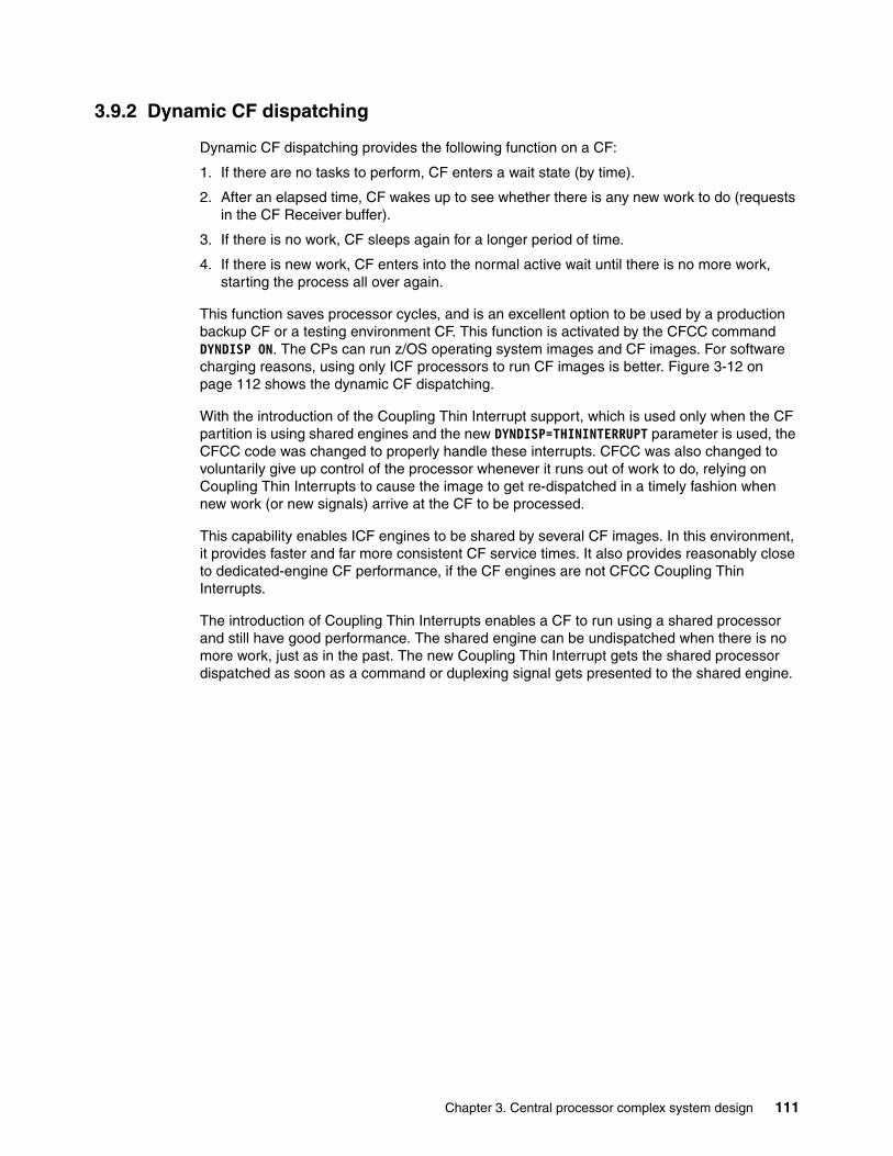
3.9.2 Dynamic CF dispatching
Dynamic CF dispatching provides the following function on a CF:
1. If there are no tasks to perform, CF enters a wait state (by time).
2. After an elapsed time, CF wakes up to see whether there is any new work to do (requests in the CF Receiver buffer).
3. If there is no work, CF sleeps again for a longer period of time.
4. If there is new work, CF enters into the normal active wait until there is no more work, starting the process all over again.
This function saves processor cycles, and is an excellent option to be used by a production backup CF or a testing environment CF. This function is activated by the CFCC command DYNDISP ON. The CPs can run z/OS operating system images and CF images. For software charging reasons, using only ICF processors to run CF images is better. Figure 3-12 on page 112 shows the dynamic CF dispatching.
With the introduction of the Coupling Thin Interrupt support, which is used only when the CF partition is using shared engines and the new DYNDISP=THININTERRUPT parameter is used, the CFCC code was changed to properly handle these interrupts. CFCC was also changed to voluntarily give up control of the processor whenever it runs out of work to do, relying on Coupling Thin Interrupts to cause the image to get re-dispatched in a timely fashion when new work (or new signals) arrive at the CF to be processed.
This capability enables ICF engines to be shared by several CF images. In this environment, it provides faster and far more consistent CF service times. It also provides reasonably close to dedicated-engine CF performance, if the CF engines are not CFCC Coupling Thin Interrupts.
The introduction of Coupling Thin Interrupts enables a CF to run using a shared processor and still have good performance. The shared engine can be undispatched when there is no more work, just as in the past. The new Coupling Thin Interrupt gets the shared processor dispatched as soon as a command or duplexing signal gets presented to the shared engine.
Chapter 3. Central processor complex system design 111
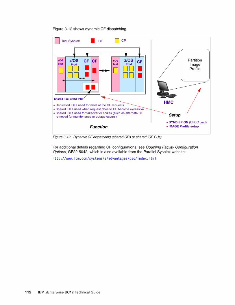
Figure 3-12 shows dynamic CF dispatching.
Figure 3-12 Dynamic CF dispatching (shared CPs or shared ICF PUs)
For additional details regarding CF configurations, see Coupling Facility Configuration Options, GF22-5042, which is also available from the Parallel Sysplex website:
http://www.ibm.com/systems/z/advantages/pso/index.html
z/OSProd
z/OSProd
Function
Setup
HMC
Partition ImageProfile
ICF CP
CF CF
Test Sysplex
z/OSTest
z/OSTest
CF
DYNDISP ON (CFCC cmd)IMAGE Profile setup
Shared Pool of ICF PUs
Dedicated ICFs used for most of the CF requestsShared ICFs used when request rates to CF become excessiveShared ICFs used for takeover or spikes (such as alternate CF removed for maintenance or outage occurs)
112 IBM zEnterprise BC12 Technical Guide
Chapter 4. Central processor complex I/O system structure
This chapter provides information about the I/O system structure and the connectivity options that are available on the IBM zEnterprise BC12 (zBC12).
We cover the following topics:
� Introduction to InfiniBand and PCIe� I/O system overview� I/O drawers� PCIe I/O drawers� I/O drawer and PCIe I/O drawer offerings� Fanouts� I/O feature cards� Connectivity� Parallel Sysplex connectivity� Cryptographic functions� Integrated firmware processor (IFP)� Flash Express� The 10 gigabit Ethernet (GbE) Remote Direct Memory Access (RDMA) over Converged
Ethernet (RoCE) Express� zEDC Express
4
© Copyright IBM Corp. 2014. All rights reserved. 113
4.1 Introduction to InfiniBand and PCIe
The zBC12 supports two internal I/O infrastructures:
� InfiniBand-based infrastructure for I/O drawers
� PCIe-based infrastructure for PCIe I/O drawers
InfiniBand I/O infrastructureThe InfiniBand I/O infrastructure was first made available on System z10, and consists of these components:
� InfiniBand fanouts supporting the current 6 gigabytes per second (GBps) InfiniBand I/O interconnect
� InfiniBand I/O card domain multiplexers with Redundant I/O Interconnect (RII) in the 5U, 8-slot, 2-domain I/O drawer
PCIe I/O infrastructureIBM extends the use of industry standards on the System z platform by offering a PCIe Generation 2 (PCIe Gen2) I/O infrastructure. The PCIe I/O infrastructure that is provided by the IBM zEnterprise EC12 (zEC12) and zBC12 improves I/O capability and flexibility, while enabling the future integration of PCIe adapters and accelerators.
The zBC12 PCIe I/O infrastructure consists of these components:
� PCIe fanouts supporting 8 GBps I/O bus interconnections for processor drawer connectivity to the PCIe I/O drawer
� The 7U, 32-slot, 4-domain PCIe I/O drawer for PCIe I/O features
The zBC12 PCIe I/O infrastructure offers these benefits:
� Provide increased bandwidth from the processor drawer to the I/O domain in the PCIe I/O drawer via an 8 GBps bus.
� Provide up to 14% more capacity:
– Two PCIe I/O drawers occupy the same space as one I/O cage. – Up to 128 channels (64 PCIe I/O features) are supported versus the 112 channels (28
I/O features) offered with the I/O cage.
� Provide better granularity for the SAN and the LAN:
– For the Fibre Channel connection (FICON), High Performance FICON for System z (zHPF), and Fibre Channel Protocol (FCP) SANs, the FICON Express8S has two channels per feature.
– The Open Systems Adapter (OSA)-Express5S GbE and the OSA-Express5S 1000 megabits per second (Mbps) baseband signaling twisted pair (1000BASE-T) features have two ports each, and the OSA-Express5S 10 GbE features have one port for LAN connectivity.
� New PCIe features can be plugged into the PCIe I/O drawer, such as zFlash Express, IBM zEnterprise Data Compression (zEDC) Express, and 10GbE RoCE Express.
4.1.1 InfiniBand specification
The InfiniBand specification defines the raw bandwidth of a one lane (referred to as 1x) connection at 2.5 gigabits per second (Gbps). Two additional lane widths are specified, which are referred to as 4x and 12x, as multipliers of the base link width.
114 IBM zEnterprise BC12 Technical Guide
Similar to Fibre Channel (FC), PCI Express, Serial Advanced Technology Attachment (SATA), and many other contemporary interconnects, InfiniBand is a point-to-point, bidirectional serial link that is intended for the connection of processors with high-speed peripherals, such as disks. InfiniBand supports various signaling rates and, as with PCIe, links can be bonded together for additional bandwidth.
The serial connection’s signaling rate is 2.5 Gbps on one lane in each direction, per physical connection. InfiniBand also supports 5 Gbps or 10 Gbps signaling rates.
4.1.2 Data, signaling, and link rates
Links use 8b/10b encoding (where every ten bits sent carry eight bits of data), so that the useful data transmission rate is four-fifths of the signaling rate (signaling rate equals raw bit rate). Therefore, links carry 2, 4, or 8 Gbps of useful data.
Links can be aggregated in units of 4 or 12, indicated as 4x1 or 12x. A 12x link therefore carries 120 Gbps raw or 96 Gbps of payload (useful) data. Larger systems with 12x links are typically used for cluster and supercomputer interconnects, as implemented on the IBM zEnterprise 114 (z114), and for inter-switch connections.
For details and the standards for InfiniBand, see the InfiniBand website:
http://www.infinibandta.org
4.1.3 PCIe
PCIe is a serial bus with an embedded clock, and uses 8b/10b encoding, where every 8 bits are encoded into a 10-bit symbol that is then decoded at the receiver. Therefore, the bus needs to transfer 10 bits to send 8 bits of actual usable data. A PCIe gen2bus single lane can transfer 5 Gbps of raw data (duplex connection), which is 10 Gbps of raw data in total. From these 10 Gbps, only 8 Gbps are actual data.
Therefore, an x16 (16 lanes) PCIe gen2 bus transfers 160 Gbps encoded, which is 128 Gbps of unencoded data. This example is 20 GBps raw data and 16 GBps of encoded data. The new measuring unit, gigatransfers per second (GT/s), refers to the raw data, even though only 80% of this transfer is actual data. The translation between GT/s to GBps is 5 GT/s equals 20 GBps or 1 GT/s equals 4 GBps.
The 16 lanes of the PCIe bus are virtual lanes, always consisting of one transmit and one receive lane. Each of these lanes consists of two physical copper wires, because the physical method used to transmit signals is a differential bus, which means that the signal is encoded into the various voltage levels between two wires (as opposed to one voltage level on one wire in comparison to the ground signal). Therefore, each of the 16 PCIe lanes actually uses four copper wires for the signal transmissions.
1 Note that zBC12 does not support this data rate.
The zBC12 and InfiniBand: Not all properties and functions offered by InfiniBand are implemented on the zBC12. Only a subset is used to fulfill the interconnect requirements that have been defined for zBC12.
Chapter 4. Central processor complex I/O system structure 115
4.2 I/O system overview
This section lists the zBC12 I/O subsystem characteristics, and provides a summary of the supported features.
4.2.1 Characteristics
The zBC12 I/O subsystem design provides great flexibility, high availability, and excellent performance characteristics:
� High bandwidth
The zBC12 uses PCIe as an internal interconnect protocol to drive PCIe I/O drawers. The I/O bus infrastructure data rate increases up to 8 GBps.
The zBC12 uses InfiniBand as the internal interconnect protocol to drive I/O drawers and central processor complex (CPC-to-CPC connection. InfiniBand supports I/O bus infrastructure data rates up to 6 GBps.
� Connectivity options:
– The zBC12 can be connected to an extensive range of interfaces, such as FICON/FCP for SAN connectivity, 10 GbE, GbE, and 1000BASE-T Ethernet for LAN connectivity.
– For CPC to CPC connection, zBC12 uses Parallel Sysplex InfiniBand (PSIFB) or InterSystem Channel (ISC)-32 Coupling Facility (CF) links. The 10GbE RoCE Express feature provides high-speed access to a remote CPC’s memory using Shared Memory Communications-RDMA (SMC-R) protocol.
� Concurrent I/O upgrades
You can concurrently add I/O features to the zBC12 if unused I/O slot positions are available.
� Concurrent PCIe I/O drawer upgrades
Additional PCIe I/O drawers can be installed concurrently if there is free space in one of the I/O drawer slots.
� Dynamic I/O configuration
Dynamic I/O configuration supports the dynamic addition, removal, or modification of channel path, control units, and I/O devices without a planned outage.
� Pluggable optics
The FICON Express8S, FICON Express8, FICON Express4, OSA-Express5S,and 10GbE RoCE Express features have Small Form-Factor Pluggable (SFP) optics to permit each channel to be individually serviced in the event of a fiber optic module failure. The traffic on the other channels on the same feature can continue to flow if a channel requires servicing.
� Concurrent I/O card maintenance
Every I/O card plugged in an I/O drawer or PCIe I/O drawer supports concurrent card replacement in the case of a repair action.
2 Available on carry-forward upgrades only
116 IBM zEnterprise BC12 Technical Guide
4.2.2 Summary of supported I/O features
The following I/O features are supported (a few of them are carried forward on upgrade only):
� Up to 128 FICON Express8S channels� Up to 32 FICON Express8 channels � Up to 32 FICON Express4 channels � Up to 16 FICON Express4-2C channels� Up to 96 OSA-Express5S ports� Up to 96 OSA-Express4S ports� Up to 32 OSA-Express3 ports � Up to 16 OSA-Express3-2P ports� Up to 48 ISC-3 coupling links� Up to 8 InfiniBand fanouts using one of these links:
– Up to 16 12xIFB coupling links– Up to 12 1xIFB coupling links with host channel adapter2-copper (HCA2-O) Long
Reach (LR) (1xIFB) fanout – Up to 32 1xIFB coupling links with host channel adapter2-optical (HCA3-O) LR (1xIFB)
fanout
In addition to I/O features, new PCIe features are supported exclusively in the PCIe I/O drawer:
� Up to 8 zFlash Express features
� Up to 8 zEDC Express features
� Up to 16 10GbE RoCE Express features
4.3 I/O drawers
The I/O drawer is five Electronic Industries Alliance (EIA) units high and supports up to eight I/O feature cards. Each I/O drawer supports two I/O domains (A and B) for a total of eight I/O card slots. Each I/O domain uses an InfiniBand Multiplexer (InfiniBand-MP) card in the I/O drawer, and a copper cable to connect to an HCA fanout in the processor drawer.
The link between the HCA in the processor drawer and the InfiniBand-MP in the I/O drawer supports a link rate of up to 6 GBps. All cards in the I/O drawer are installed horizontally. The two distributed converter assemblies (DCAs) distribute power to the I/O drawer.
Coupling links: The maximum number of external coupling links combined (ISC-3 and InfiniBand coupling links) cannot exceed 72 for the zBC12 H13 CPC, and 56 for the zBC12 H06 CPC.
Chapter 4. Central processor complex I/O system structure 117
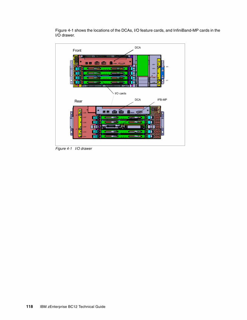
Figure 4-1 shows the locations of the DCAs, I/O feature cards, and InfiniBand-MP cards in the I/O drawer.
Figure 4-1 I/O drawer
LG0 1
LG0 2
L G03
L G04
L G05
Front
J00
J01
Rear
LG06
LG07
LG08
LG09
LG10
LG11
J00
J01
I/O cards
DCA
DCA IFB-MP
118 IBM zEnterprise BC12 Technical Guide
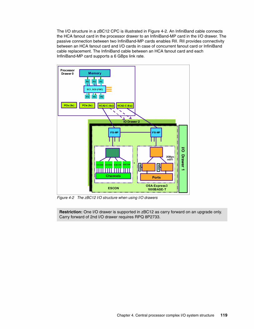
The I/O structure in a zBC12 CPC is illustrated in Figure 4-2. An InfiniBand cable connects the HCA fanout card in the processor drawer to an InfiniBand-MP card in the I/O drawer. The passive connection between two InfiniBand-MP cards enables RII. RII provides connectivity between an HCA fanout card and I/O cards in case of concurrent fanout card or InfiniBand cable replacement. The InfiniBand cable between an HCA fanout card and each InfiniBand-MP card supports a 6 GBps link rate.
Figure 4-2 The zBC12 I/O structure when using I/O drawers
Restriction: One I/O drawer is supported in zBC12 as carry forward on an upgrade only. Carry forward of 2nd I/O drawer requires RPQ 8P2733.
IFB-MP IFB-MP
I/O D
rawer 1
PCIe (8x)
Memory
SC1, SC0 (FBC)
PU PU
P U PU PU
P U
PCIe (8x)
ESCONOSA-Express3
1000BASE-T
.
Channels
ES CON ES CON E SCON ESCON
Ports
2GBpsmSTI
FP
GA
FP
GA
HCA2-C (6x))HCA2-C (6x))
ProcessorDrawer 0
IO Drawer 2
FP
GA
FP
GA
Chapter 4. Central processor complex I/O system structure 119
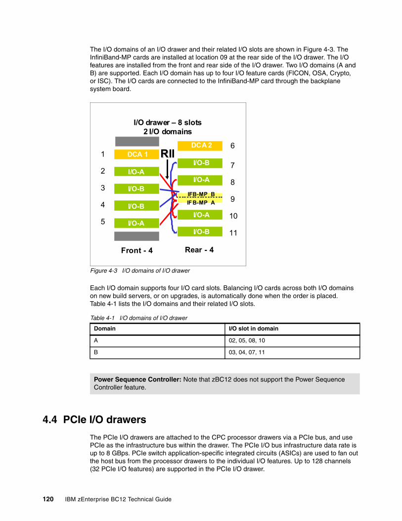
The I/O domains of an I/O drawer and their related I/O slots are shown in Figure 4-3. The InfiniBand-MP cards are installed at location 09 at the rear side of the I/O drawer. The I/O features are installed from the front and rear side of the I/O drawer. Two I/O domains (A and B) are supported. Each I/O domain has up to four I/O feature cards (FICON, OSA, Crypto, or ISC). The I/O cards are connected to the InfiniBand-MP card through the backplane system board.
Figure 4-3 I/O domains of I/O drawer
Each I/O domain supports four I/O card slots. Balancing I/O cards across both I/O domains on new build servers, or on upgrades, is automatically done when the order is placed. Table 4-1 lists the I/O domains and their related I/O slots.
Table 4-1 I/O domains of I/O drawer
4.4 PCIe I/O drawers
The PCIe I/O drawers are attached to the CPC processor drawers via a PCIe bus, and use PCIe as the infrastructure bus within the drawer. The PCIe I/O bus infrastructure data rate is up to 8 GBps. PCIe switch application-specific integrated circuits (ASICs) are used to fan out the host bus from the processor drawers to the individual I/O features. Up to 128 channels (32 PCIe I/O features) are supported in the PCIe I/O drawer.
Domain I/O slot in domain
A 02, 05, 08, 10
B 03, 04, 07, 11
Power Sequence Controller: Note that zBC12 does not support the Power Sequence Controller feature.
I/O drawer – 8 slots2 I/O domains
DCA 1
I/O-A
I/O-B
I/O-B
I/O-AI/O-A
I/O-B
DCA 2
I/O-B
I/O-A
IFB-MP B
IF B-MP A
Front - 4 Rear - 4
RIIRII1
2
3
4
5
6
7
8
9
10
11
120 IBM zEnterprise BC12 Technical Guide
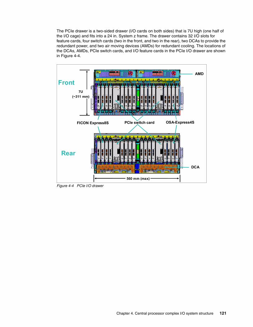
The PCIe drawer is a two-sided drawer (I/O cards on both sides) that is 7U high (one half of the I/O cage) and fits into a 24 in. System z frame. The drawer contains 32 I/O slots for feature cards, four switch cards (two in the front, and two in the rear), two DCAs to provide the redundant power, and two air moving devices (AMDs) for redundant cooling. The locations of the DCAs, AMDs, PCIe switch cards, and I/O feature cards in the PCIe I/O drawer are shown in Figure 4-4.
Figure 4-4 PCIe I/O drawer
Front
Rear
7U
(~311 mm)
PCIe switch cardFICON Express8S
DCA
560 mm (max)
AMD
OSA-Express4S
Chapter 4. Central processor complex I/O system structure 121
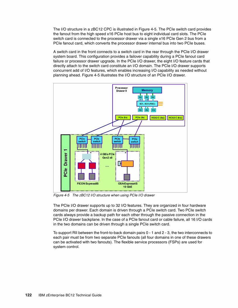
The I/O structure in a zBC12 CPC is illustrated in Figure 4-5. The PCIe switch card provides the fanout from the high speed x16 PCIe host bus to eight individual card slots. The PCIe switch card is connected to the processor drawer via a single x16 PCIe Gen 2 bus from a PCIe fanout card, which converts the processor drawer internal bus into two PCIe buses.
A switch card in the front connects to a switch card in the rear through the PCIe I/O drawer system board. This configuration provides a failover capability during a PCIe fanout card failure or processor drawer upgrade. In the PCIe I/O drawer, the eight I/O feature cards that directly attach to the switch card constitute an I/O domain. The PCIe I/O drawer supports concurrent add of I/O features, which enables increasing I/O capability as needed without planning ahead. Figure 4-5 illustrates the I/O structure of an PCIe I/O drawer.
Figure 4-5 The zBC12 I/O structure when using PCIe I/O drawer
The PCIe I/O drawer supports up to 32 I/O features. They are organized in four hardware domains per drawer. Each domain is driven through a PCIe switch card. Two PCIe switch cards always provide a backup path for each other through the passive connection in the PCIe I/O drawer backplane. In the case of a PCIe fanout card or cable failure, all 16 I/O cards in the two domains can be driven through a single PCIe switch card.
To support RII between the front-to-back domain pairs 0 - 1 and 2 - 3, the two interconnects to each pair must be from two separate PCIe fanouts (all four domains in one of these drawers can be activated with two fanouts). The flexible service processors (FSPs) are used for system control.
PCIeswitch
OSA-Express4S10 GbE
PCIeswitch
PCIeswitch
FICON Express8S
PCIeswitch
4 GB/s PCIeGen2 x8
…
PCIe (8x)
Memory
SC1, SC0 (FBC)
PU PU
PU PU P U
PU
PCIe (8x) HCA2-C (6x))HCA2-C (6x))
ProcessorDrawer 0
122 IBM zEnterprise BC12 Technical Guide
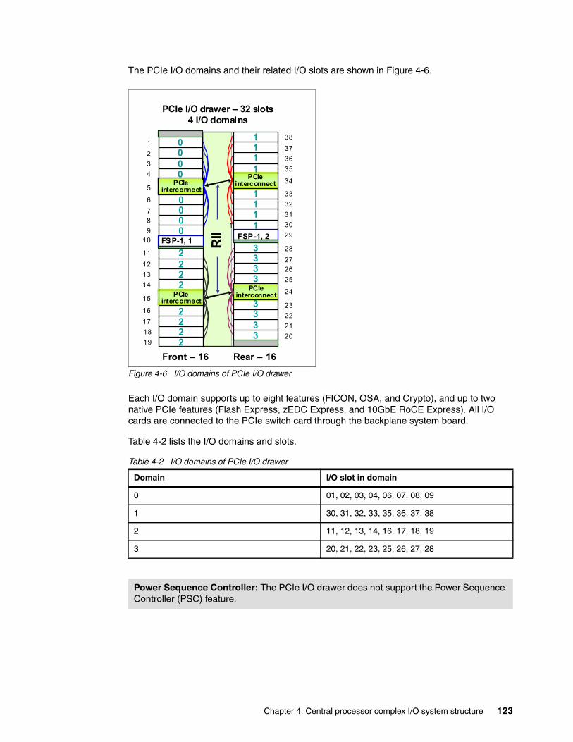
The PCIe I/O domains and their related I/O slots are shown in Figure 4-6.
Figure 4-6 I/O domains of PCIe I/O drawer
Each I/O domain supports up to eight features (FICON, OSA, and Crypto), and up to two native PCIe features (Flash Express, zEDC Express, and 10GbE RoCE Express). All I/O cards are connected to the PCIe switch card through the backplane system board.
Table 4-2 lists the I/O domains and slots.
Table 4-2 I/O domains of PCIe I/O drawer
Domain I/O slot in domain
0 01, 02, 03, 04, 06, 07, 08, 09
1 30, 31, 32, 33, 35, 36, 37, 38
2 11, 12, 13, 14, 16, 17, 18, 19
3 20, 21, 22, 23, 25, 26, 27, 28
Power Sequence Controller: The PCIe I/O drawer does not support the Power Sequence Controller (PSC) feature.
Front – 16 Rear – 16
FSP-1, 1
PCIeinterconnect
FSP-1, 2
RII
PCIeinterconnect
PCIeinterconnect
PCIeinterconnect
PCIe I/O drawer – 32 slots4 I/O domains
3333
0000
0000
2222
1111
1111
3333
2222
1
2
3
7
4
6
5
18
910
11
12
13
14
15
16
17
18
1920
21
22
23
24
25
2627
28
29
30
31
32
33
34
35
36
37
38
Chapter 4. Central processor complex I/O system structure 123
4.5 I/O drawer and PCIe I/O drawer offerings
The I/O drawers cannot be ordered on a new build zBC12. I/O feature types determine the appropriate mix of I/O drawers and PCIe I/O drawers, depending on features carried forward on an upgrade.
Some I/O and speciality features are supported only by I/O drawers:
� FICON Express8 � FICON Express4 � OSA-Express3 � ISC-3� Crypto Express3
The PCIe I/O drawers supports the following PCIe features:
� FICON Express8S� OSA-Express5S� OSA-Express4S� 10GbE RoCE Express� Crypto Express4S� Flash Express� The zEDC Express feature
Table 4-3 gives an overview of the number of I/O drawers and PCIe I/O drawers that can be present in a zBC12 with non-PCIe and PCIe features.
Table 4-3 I/O drawer and PCIe I/O drawer summary
4.6 Fanouts
The zBC12 CPC uses fanout cards to connect the I/O hardware subsystem to the processor drawers and to provide the InfiniBand coupling links for Parallel Sysplex. All fanout cards support concurrent add and replace.
The zBC12 supports two separate internal I/O infrastructures for the internal connection. InfiniBand-based infrastructure is used for the internal connection to I/O drawers, and PCIe-based infrastructure is used for PCIe I/O drawers in which the cards for the connection to peripheral devices and networks are located.
Restriction: On a new build zBC12, only PCIe I/O drawers are supported. A mixture of I/O drawers and PCIe I/O drawers are only available on upgrades to a zBC12.
Non-PCIe features, carry forward
I/O drawer Maximum PCIe I/O drawer
Maximum PCIe features
0 0 2 64
1-8 1a
a. Empty slots in an I/O drawer after upgrade can not be filled by a new MES.
2 64
9-16b
b. a maximum of 16 existing non-PCIe features are supported.
2ac
c. For the second I/O drawer carry forward, RPQ 8P2733 is required.
1 32
124 IBM zEnterprise BC12 Technical Guide
The InfiniBand and PCIe fanouts are in the front of the processor drawer. Each processor drawer has four fanout slots. Six types of fanout cards are supported by zBC12. Each fanout slot in the processor drawer holds one of the following six fanouts:
� HCA2-C
This copper fanout provides connectivity to the InfiniBand-MP card in the I/O drawer.
� PCIe fanout
This copper fanout provides connectivity to the PCIe switch card in the PCIe I/O drawer.
� HCA2-O (12xIFB)
This optical fanout provides 12xIFB coupling link connectivity up to 150 m (492.1 ft.) distance to a zEC12, zBC12, IBM zEnterprise 196 (z196), z114, or System z10.
� HCA2-O LR (1xIFB)
This optical long-range fanout provides 1xIFB coupling link connectivity up to 10 kilometers (km), or 6.2 miles, unrepeated distance to a zEC12, zBC12, z196, z114, or System z10 server.
� Host channel adapter for InfiniBand (HCA for InfiniBand, or HCA3-O (12xIFB))
This optical fanout provides 12xIFB coupling link connectivity up to 150 m (492.1 ft.) distance to a zEC12, zBC12, z196, z114, or System z10.
� HCA3-O LR (1xIFB)
This optical long-range fanout provides 1xIFB coupling link connectivity up to 10 km (6.2 miles) unrepeated distance to a zEC12, zBC12, z196, z114, or System z10 server.
The HCA3-O LR (1xIFB) fanout has four ports, and the other fanouts have two ports.
Chapter 4. Central processor complex I/O system structure 125
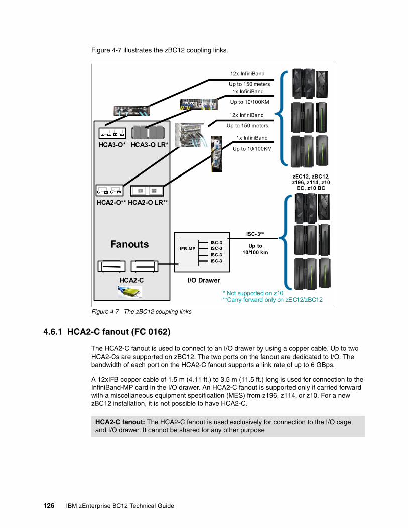
Figure 4-7 illustrates the zBC12 coupling links.
Figure 4-7 The zBC12 coupling links
4.6.1 HCA2-C fanout (FC 0162)
The HCA2-C fanout is used to connect to an I/O drawer by using a copper cable. Up to two HCA2-Cs are supported on zBC12. The two ports on the fanout are dedicated to I/O. The bandwidth of each port on the HCA2-C fanout supports a link rate of up to 6 GBps.
A 12xIFB copper cable of 1.5 m (4.11 ft.) to 3.5 m (11.5 ft.) long is used for connection to the InfiniBand-MP card in the I/O drawer. An HCA2-C fanout is supported only if carried forward with a miscellaneous equipment specification (MES) from z196, z114, or z10. For a new zBC12 installation, it is not possible to have HCA2-C.
12x InfiniBand
HCA2-O**
HCA2-C I/O Drawer
ISC-3
ISC-3
ISC-3
ISC-3
zEC12, zBC12, z196, z114, z10
EC, z10 BC
IFB-MP
ISC-3**
HCA2-O LR**
Up to 150 meters
Up to 10/100 km
.... .... .... ....
1x InfiniBand
Up to 10/100KM
Fanouts
HCA3-O* HCA3-O LR*
.... .... .... ....
12x InfiniBand
Up to 150 meters
1x InfiniBand
Up to 10/100KM
* Not supported on z10**Carry forward only on zEC12/zBC12
HCA2-C fanout: The HCA2-C fanout is used exclusively for connection to the I/O cage and I/O drawer. It cannot be shared for any other purpose
126 IBM zEnterprise BC12 Technical Guide
4.6.2 PCIe copper fanout (FC 0169)
The PCIe fanout card supports a PCIe Gen2, bus and is used to connect to the PCIe I/O drawer. PCIe fanout cards are always plugged in pairs. Up to four PCIe fanouts are supported on zBC12. The bandwidth of each port on the PCIe fanout supports a link rate of up to 8 GBps.
The PCIe fanout supports FICON Express8S, OSA Express5S, OSA Express4S, 10GbE RoCE Express, Crypto Express4S, Flash Express, and zEDC Express in PCIe I/O drawers.
4.6.3 HCA2-O (12xIFB) fanout (FC 0163)
The HCA2-O fanout for 12xIFB provides an optical interface that is used for coupling links. The two ports on the fanout are dedicated to coupling links to connect to zEC12, zBC12, z196, z114, and System z10 servers. Up to eight HCA2-O (12x InfiniBand) fanouts are supported by zBC12, and provide up to 16 ports for coupling links. An HCA2-O fanout is supported only if carried forward with an MES from z196, z114, or z10.
The HCA2-O fanout supports 12xIFB optical links that offer configuration flexibility, and high bandwidth for enhanced performance of coupling links. There are 12 lanes (two fibers per lane) in the cable, which means 24 fibers are used in parallel for data transfer. Each port provides one connector to transmit and one connector to receive data.
The fiber optic cables are industry-standard Optical Multimode 3 (OM3) 2000 megahertz per kilometer (MHz-km 50-µm multimode optical cables with Multi-Fiber Push-On (MPO) connectors. The maximum cable length is 150 meters. There are 12 pairs of fibers: 12 fibers for transmitting, and 12 fibers for receiving.
Each connection supports a link rate of 6 GBps when connected to a zEC12, zBC12, z196, z114, or System z10 server.
PCIe fanout: The PCIe fanout is used exclusively for I/O, and cannot be shared for any other purpose.
Important: The HCA2-O fanout has two ports (1 and 2). Each port has one connector for transmitting (TX) and one connector for receiving (RX). Be aware to use the correct cables. An example is shown in Figure 4-8 on page 128.
Chapter 4. Central processor complex I/O system structure 127
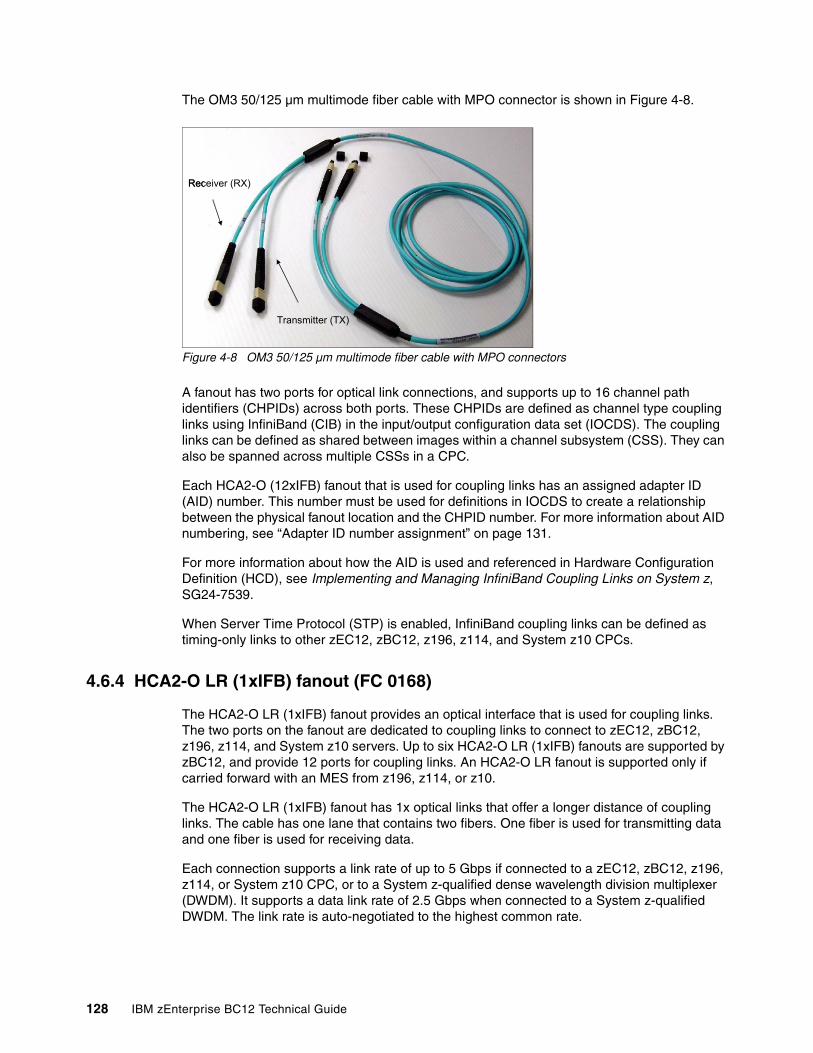
The OM3 50/125 µm multimode fiber cable with MPO connector is shown in Figure 4-8.
Figure 4-8 OM3 50/125 μm multimode fiber cable with MPO connectors
A fanout has two ports for optical link connections, and supports up to 16 channel path identifiers (CHPIDs) across both ports. These CHPIDs are defined as channel type coupling links using InfiniBand (CIB) in the input/output configuration data set (IOCDS). The coupling links can be defined as shared between images within a channel subsystem (CSS). They can also be spanned across multiple CSSs in a CPC.
Each HCA2-O (12xIFB) fanout that is used for coupling links has an assigned adapter ID (AID) number. This number must be used for definitions in IOCDS to create a relationship between the physical fanout location and the CHPID number. For more information about AID numbering, see “Adapter ID number assignment” on page 131.
For more information about how the AID is used and referenced in Hardware Configuration Definition (HCD), see Implementing and Managing InfiniBand Coupling Links on System z, SG24-7539.
When Server Time Protocol (STP) is enabled, InfiniBand coupling links can be defined as timing-only links to other zEC12, zBC12, z196, z114, and System z10 CPCs.
4.6.4 HCA2-O LR (1xIFB) fanout (FC 0168)
The HCA2-O LR (1xIFB) fanout provides an optical interface that is used for coupling links. The two ports on the fanout are dedicated to coupling links to connect to zEC12, zBC12, z196, z114, and System z10 servers. Up to six HCA2-O LR (1xIFB) fanouts are supported by zBC12, and provide 12 ports for coupling links. An HCA2-O LR fanout is supported only if carried forward with an MES from z196, z114, or z10.
The HCA2-O LR (1xIFB) fanout has 1x optical links that offer a longer distance of coupling links. The cable has one lane that contains two fibers. One fiber is used for transmitting data and one fiber is used for receiving data.
Each connection supports a link rate of up to 5 Gbps if connected to a zEC12, zBC12, z196, z114, or System z10 CPC, or to a System z-qualified dense wavelength division multiplexer (DWDM). It supports a data link rate of 2.5 Gbps when connected to a System z-qualified DWDM. The link rate is auto-negotiated to the highest common rate.
Transmitter (TX)
Receiver (RX)
Transmitter (TX)
Receiver (RX)
128 IBM zEnterprise BC12 Technical Guide
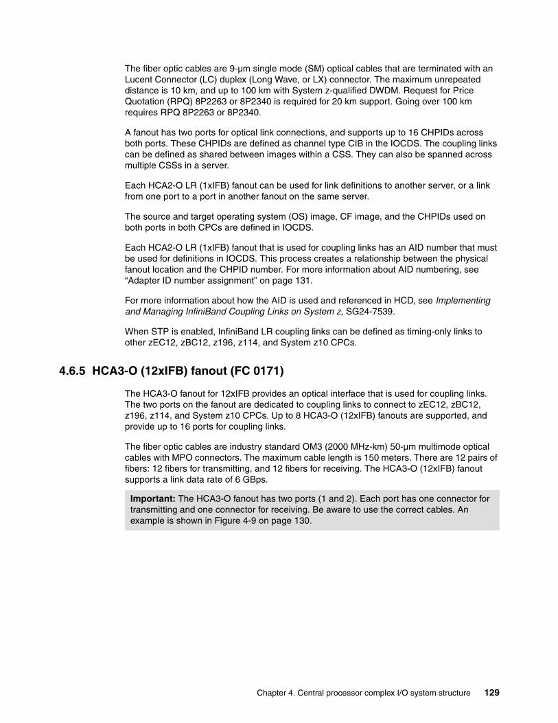
The fiber optic cables are 9-µm single mode (SM) optical cables that are terminated with an Lucent Connector (LC) duplex (Long Wave, or LX) connector. The maximum unrepeated distance is 10 km, and up to 100 km with System z-qualified DWDM. Request for Price Quotation (RPQ) 8P2263 or 8P2340 is required for 20 km support. Going over 100 km requires RPQ 8P2263 or 8P2340.
A fanout has two ports for optical link connections, and supports up to 16 CHPIDs across both ports. These CHPIDs are defined as channel type CIB in the IOCDS. The coupling links can be defined as shared between images within a CSS. They can also be spanned across multiple CSSs in a server.
Each HCA2-O LR (1xIFB) fanout can be used for link definitions to another server, or a link from one port to a port in another fanout on the same server.
The source and target operating system (OS) image, CF image, and the CHPIDs used on both ports in both CPCs are defined in IOCDS.
Each HCA2-O LR (1xIFB) fanout that is used for coupling links has an AID number that must be used for definitions in IOCDS. This process creates a relationship between the physical fanout location and the CHPID number. For more information about AID numbering, see “Adapter ID number assignment” on page 131.
For more information about how the AID is used and referenced in HCD, see Implementing and Managing InfiniBand Coupling Links on System z, SG24-7539.
When STP is enabled, InfiniBand LR coupling links can be defined as timing-only links to other zEC12, zBC12, z196, z114, and System z10 CPCs.
4.6.5 HCA3-O (12xIFB) fanout (FC 0171)
The HCA3-O fanout for 12xIFB provides an optical interface that is used for coupling links. The two ports on the fanout are dedicated to coupling links to connect to zEC12, zBC12, z196, z114, and System z10 CPCs. Up to 8 HCA3-O (12xIFB) fanouts are supported, and provide up to 16 ports for coupling links.
The fiber optic cables are industry standard OM3 (2000 MHz-km) 50-µm multimode optical cables with MPO connectors. The maximum cable length is 150 meters. There are 12 pairs of fibers: 12 fibers for transmitting, and 12 fibers for receiving. The HCA3-O (12xIFB) fanout supports a link data rate of 6 GBps.
Important: The HCA3-O fanout has two ports (1 and 2). Each port has one connector for transmitting and one connector for receiving. Be aware to use the correct cables. An example is shown in Figure 4-9 on page 130.
Chapter 4. Central processor complex I/O system structure 129
The OM3 50/125 µm multimode fiber cable with MPO connector is shown in Figure 4-9.
Figure 4-9 OM3 50/125 μm multimode fiber cable with MPO connectors
A fanout has two ports for optical link connections, and supports up to 16 CHPIDs across both ports. These CHPIDs are defined as channel type CIB in the IOCDS. The coupling links can be defined as shared between images within a channel subsystem. They can also be spanned across multiple CSSs in a CPC.
Each HCA3-O (12xIFB) fanout that is used for coupling links has an assigned AID number. This number must be used for definitions in IOCDS to create a relationship between the physical fanout location and the CHPID number. For more information about AID numbering, see “Adapter ID number assignment” on page 131.
For more information about how the AID is used and referenced in HCD, see Implementing and Managing InfiniBand Coupling Links on System z, SG24-7539.
When STP is enabled, InfiniBand LR coupling links can be defined as timing-only links to other zEC12, zBC12, z196, z114, and System z10 CPCs.
12xIFB and 12xIFB3 protocolsThere are two protocols that are supported by the HCA3-O for 12xIFB feature:
� 12xIFB3 protocol. When HCA3-O (12xIFB) fanouts are communicating with HCA3-O (12x InfiniBand) fanouts, and are defined with four or fewer CHPIDs per port, the 12xIFB3 protocol is used.
� 12x InfiniBand protocol. If more than four CHPIDs are defined per HCA3-O (12xIFB) port, or HCA3-O (12x InfiniBand) features are communicating with HCA2-O (12x InfiniBand) features on zEnterprise or System z10 CPCs, links run with the 12xIFB protocol.
The HCA3-O feature that supports 12xIFB coupling links is designed to deliver improved service times. When no more than four CHPIDs are defined per HCA3-O (12xIFB) port, the 12xIFB3 protocol is used. When you use the 12xIFB3 protocol, synchronous service times are up to 40% faster than when you use the 12xIFB protocol.
Transmitter (TX)
Receiver (RX)
Transmitter (TX)
Receiver (RX)
130 IBM zEnterprise BC12 Technical Guide
4.6.6 HCA3-O LR (1xIFB) fanout (FC 0170)
The HCA3-O LR fanout for 1xIFB provides an optical interface that is used for coupling links. The four ports on the fanout are dedicated to coupling links to connect to zEC12, zBC12, z196, z114, System z10 servers. Up to eight HCA3-O LR (1xIFB) fanouts are supported by zBC12, and provide up to 32 ports for coupling links.
The HCA-O LR fanout supports InfiniBand 1x optical links that offer long-distance coupling links. The cable has one lane that contains two fibers. One fiber is used for transmitting data, and the other fiber is used for receiving data.
Each connection supports a link rate of up to 5 Gbps if connected to zEC12, zBC12, z196, z114, o z10. It supports a link rate of 2.5 Gbps when connected to a System z-qualified DWDM. The link rate is auto-negotiated to the highest common rate.
The fiber optic cables are 9-µm single mode optical cables that are terminated with an LX connector. The maximum unrepeated distance is 10 km, and up to 100 km with System z-qualified DWDM. RPQ 8P2263 or 8P2340 is required for 20 km support. Going over 100 km requires RPQ 8P2263 or 8P2340.
A fanout has four ports for optical link connections, and supports up to 16 CHPIDs across all four ports. These CHPIDs are defined as channel type CIB in the IOCDS. The coupling links can be defined as shared between images within a CSS, and can also be spanned across multiple CSSs in a server. This configuration is compatible with the HCA2-O LR (1xIFB) fanout, which has two ports.
Each HCA3-O LR (1xIFB) fanout can be used for link definitions to another server, or a link from one port to a port in another fanout on the same server.
The source and target OS image, CF image, and the CHPIDs used on both ports in both servers are defined in IOCDS.
Each HCA3-O LR (1xIFB) fanout that is used for coupling links has an assigned AID number. This number must be used for definitions in IOCDS to create a relationship between the physical fanout location and the CHPID number. For more information about AID numbering, see “Adapter ID number assignment” on page 131.
For more information about how the AID is used and referenced in HCD, see Implementing and Managing InfiniBand Coupling Links on System z, SG24-7539.
When STP is enabled, InfiniBand LR coupling links can be defined as timing-only links to other zEC12, zBC12, z196, z114, and System z10 CPCs.
4.6.7 Fanout considerations
Because fanout slots in each processor drawer can be used to plug separate fanouts, where each fanout is designed for a special purpose, certain restrictions might apply to the number of available channels in the I/O drawer and PCIe I/O drawer.
Adapter ID number assignmentUnlike channels installed in an I/O drawer, which are identified by a physical channel identifier (PCHID) number related to their physical location, InfiniBand fanouts and ports are identified by an AID, initially dependent on their physical locations. This AID must be used to assign a CHPID to the fanout in the IOCDS definition. The CHPID assignment is done by associating the CHPID to an AID port.
Chapter 4. Central processor complex I/O system structure 131
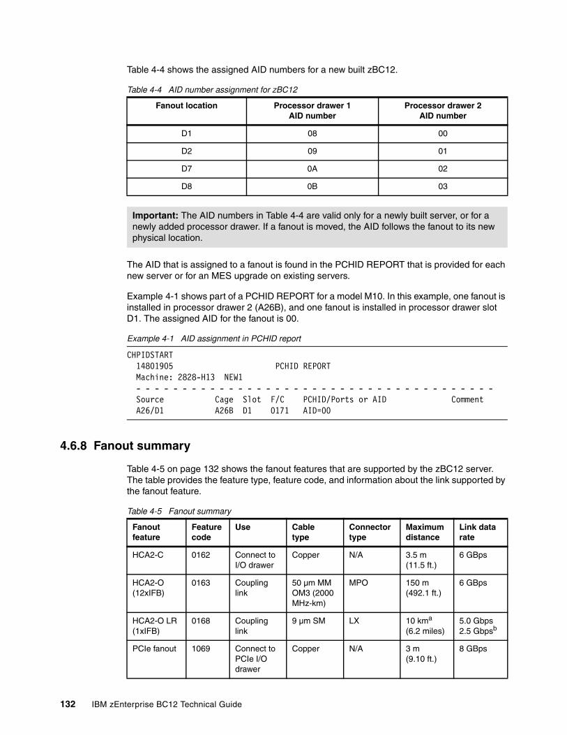
Table 4-4 shows the assigned AID numbers for a new built zBC12.
Table 4-4 AID number assignment for zBC12
The AID that is assigned to a fanout is found in the PCHID REPORT that is provided for each new server or for an MES upgrade on existing servers.
Example 4-1 shows part of a PCHID REPORT for a model M10. In this example, one fanout is installed in processor drawer 2 (A26B), and one fanout is installed in processor drawer slot D1. The assigned AID for the fanout is 00.
Example 4-1 AID assignment in PCHID report
CHPIDSTART 14801905 PCHID REPORT Machine: 2828-H13 NEW1 - - - - - - - - - - - - - - - - - - - - - - - - - - - - - - - - - - - - - - - Source Cage Slot F/C PCHID/Ports or AID Comment A26/D1 A26B D1 0171 AID=00
4.6.8 Fanout summary
Table 4-5 on page 132 shows the fanout features that are supported by the zBC12 server. The table provides the feature type, feature code, and information about the link supported by the fanout feature.
Table 4-5 Fanout summary
Fanout location Processor drawer 1AID number
Processor drawer 2 AID number
D1 08 00
D2 09 01
D7 0A 02
D8 0B 03
Important: The AID numbers in Table 4-4 are valid only for a newly built server, or for a newly added processor drawer. If a fanout is moved, the AID follows the fanout to its new physical location.
Fanout feature
Feature code
Use Cable type
Connector type
Maximum distance
Link data rate
HCA2-C 0162 Connect to I/O drawer
Copper N/A 3.5 m (11.5 ft.)
6 GBps
HCA2-O (12xIFB)
0163 Coupling link
50 µm MM OM3 (2000 MHz-km)
MPO 150 m(492.1 ft.)
6 GBps
HCA2-O LR (1xIFB)
0168 Coupling link
9 µm SM LX 10 kma
(6.2 miles)5.0 Gbps2.5 Gbpsb
PCIe fanout 1069 Connect to PCIe I/O drawer
Copper N/A 3 m(9.10 ft.)
8 GBps
132 IBM zEnterprise BC12 Technical Guide
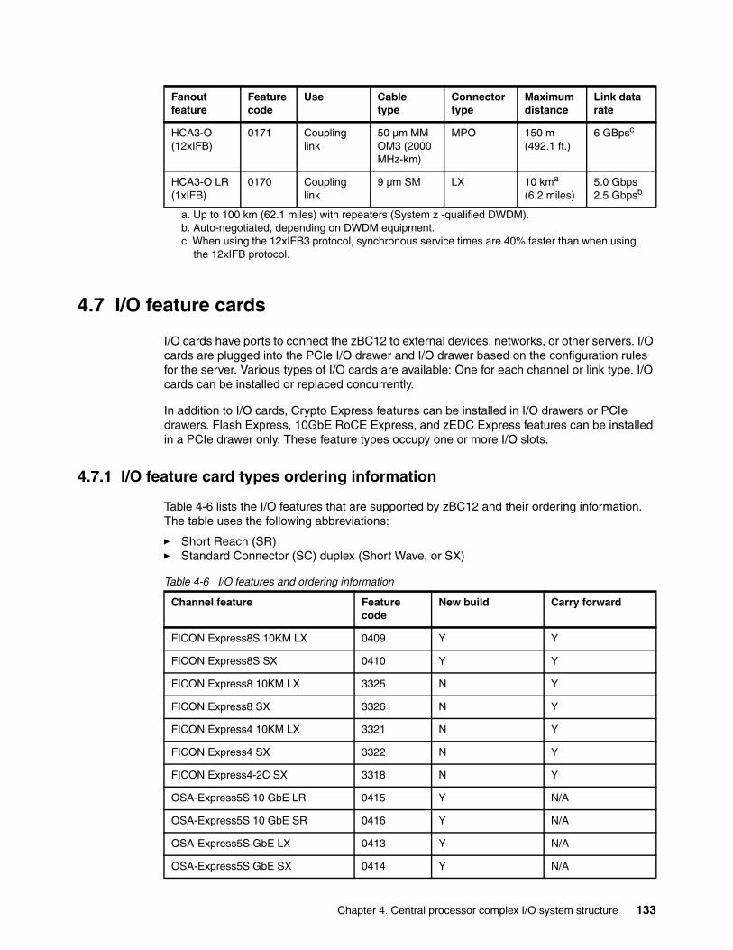
4.7 I/O feature cards
I/O cards have ports to connect the zBC12 to external devices, networks, or other servers. I/O cards are plugged into the PCIe I/O drawer and I/O drawer based on the configuration rules for the server. Various types of I/O cards are available: One for each channel or link type. I/O cards can be installed or replaced concurrently.
In addition to I/O cards, Crypto Express features can be installed in I/O drawers or PCIe drawers. Flash Express, 10GbE RoCE Express, and zEDC Express features can be installed in a PCIe drawer only. These feature types occupy one or more I/O slots.
4.7.1 I/O feature card types ordering information
Table 4-6 lists the I/O features that are supported by zBC12 and their ordering information. The table uses the following abbreviations:
� Short Reach (SR)� Standard Connector (SC) duplex (Short Wave, or SX)
Table 4-6 I/O features and ordering information
HCA3-O (12xIFB)
0171 Coupling link
50 µm MM OM3 (2000 MHz-km)
MPO 150 m(492.1 ft.)
6 GBpsc
HCA3-O LR (1xIFB)
0170 Coupling link
9 µm SM LX 10 kma
(6.2 miles)5.0 Gbps2.5 Gbpsb
a. Up to 100 km (62.1 miles) with repeaters (System z -qualified DWDM).b. Auto-negotiated, depending on DWDM equipment.c. When using the 12xIFB3 protocol, synchronous service times are 40% faster than when using
the 12xIFB protocol.
Fanout feature
Feature code
Use Cable type
Connector type
Maximum distance
Link data rate
Channel feature Feature code
New build Carry forward
FICON Express8S 10KM LX 0409 Y Y
FICON Express8S SX 0410 Y Y
FICON Express8 10KM LX 3325 N Y
FICON Express8 SX 3326 N Y
FICON Express4 10KM LX 3321 N Y
FICON Express4 SX 3322 N Y
FICON Express4-2C SX 3318 N Y
OSA-Express5S 10 GbE LR 0415 Y N/A
OSA-Express5S 10 GbE SR 0416 Y N/A
OSA-Express5S GbE LX 0413 Y N/A
OSA-Express5S GbE SX 0414 Y N/A
Chapter 4. Central processor complex I/O system structure 133
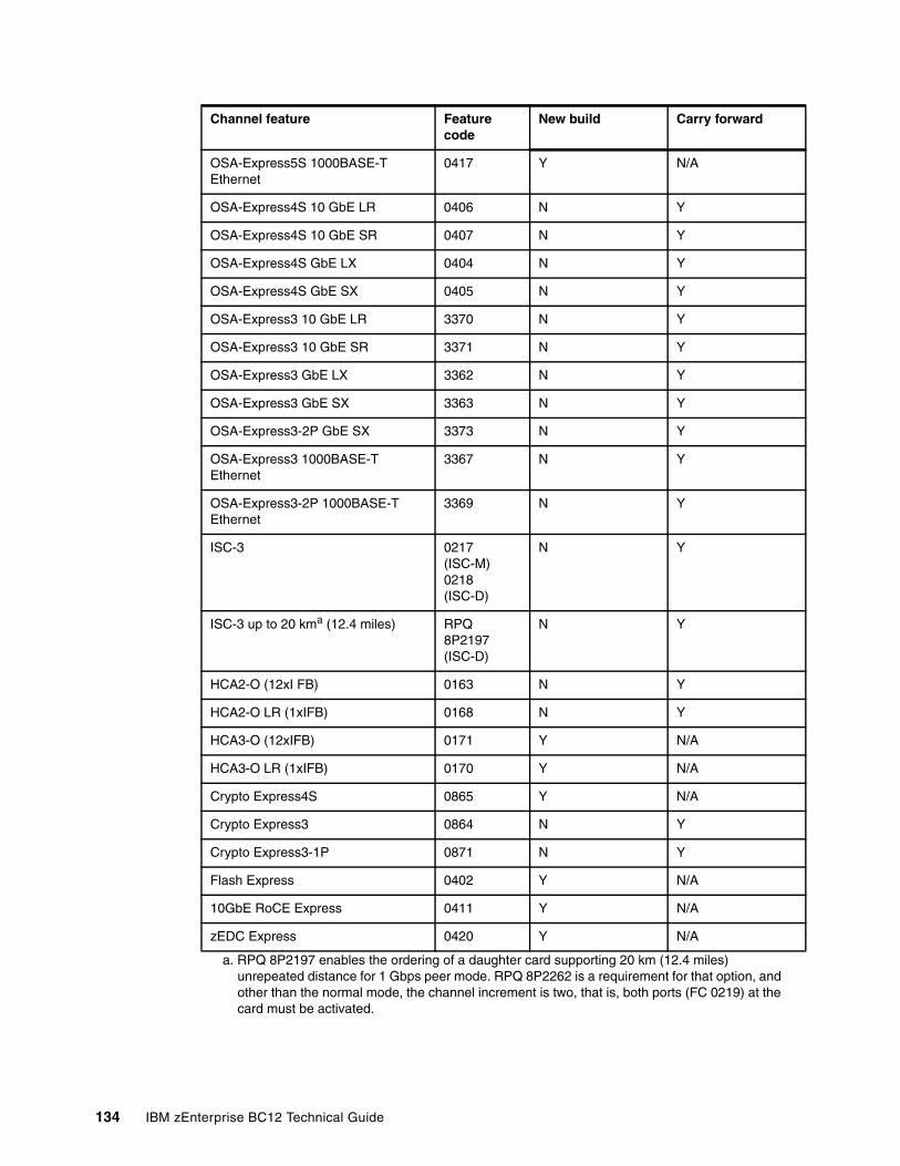
OSA-Express5S 1000BASE-T Ethernet
0417 Y N/A
OSA-Express4S 10 GbE LR 0406 N Y
OSA-Express4S 10 GbE SR 0407 N Y
OSA-Express4S GbE LX 0404 N Y
OSA-Express4S GbE SX 0405 N Y
OSA-Express3 10 GbE LR 3370 N Y
OSA-Express3 10 GbE SR 3371 N Y
OSA-Express3 GbE LX 3362 N Y
OSA-Express3 GbE SX 3363 N Y
OSA-Express3-2P GbE SX 3373 N Y
OSA-Express3 1000BASE-T Ethernet
3367 N Y
OSA-Express3-2P 1000BASE-T Ethernet
3369 N Y
ISC-3 0217 (ISC-M)0218 (ISC-D)
N Y
ISC-3 up to 20 kma (12.4 miles) RPQ 8P2197 (ISC-D)
N Y
HCA2-O (12xI FB) 0163 N Y
HCA2-O LR (1xIFB) 0168 N Y
HCA3-O (12xIFB) 0171 Y N/A
HCA3-O LR (1xIFB) 0170 Y N/A
Crypto Express4S 0865 Y N/A
Crypto Express3 0864 N Y
Crypto Express3-1P 0871 N Y
Flash Express 0402 Y N/A
10GbE RoCE Express 0411 Y N/A
zEDC Express 0420 Y N/A
a. RPQ 8P2197 enables the ordering of a daughter card supporting 20 km (12.4 miles) unrepeated distance for 1 Gbps peer mode. RPQ 8P2262 is a requirement for that option, and other than the normal mode, the channel increment is two, that is, both ports (FC 0219) at the card must be activated.
Channel feature Feature code
New build Carry forward
134 IBM zEnterprise BC12 Technical Guide
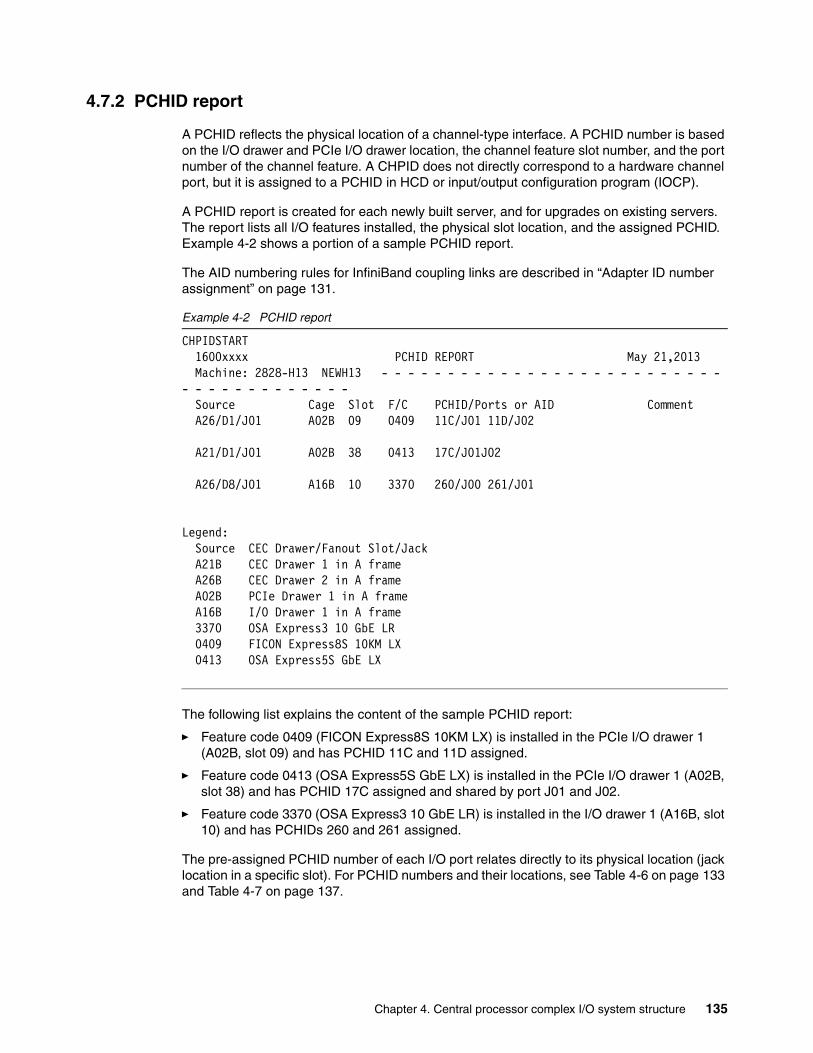
4.7.2 PCHID report
A PCHID reflects the physical location of a channel-type interface. A PCHID number is based on the I/O drawer and PCIe I/O drawer location, the channel feature slot number, and the port number of the channel feature. A CHPID does not directly correspond to a hardware channel port, but it is assigned to a PCHID in HCD or input/output configuration program (IOCP).
A PCHID report is created for each newly built server, and for upgrades on existing servers. The report lists all I/O features installed, the physical slot location, and the assigned PCHID. Example 4-2 shows a portion of a sample PCHID report.
The AID numbering rules for InfiniBand coupling links are described in “Adapter ID number assignment” on page 131.
Example 4-2 PCHID report
CHPIDSTART 1600xxxx PCHID REPORT May 21,2013 Machine: 2828-H13 NEWH13 - - - - - - - - - - - - - - - - - - - - - - - - - - - - - - - - - - - - - - - Source Cage Slot F/C PCHID/Ports or AID Comment A26/D1/J01 A02B 09 0409 11C/J01 11D/J02
A21/D1/J01 A02B 38 0413 17C/J01J02
A26/D8/J01 A16B 10 3370 260/J00 261/J01
Legend: Source CEC Drawer/Fanout Slot/Jack A21B CEC Drawer 1 in A frame A26B CEC Drawer 2 in A frame A02B PCIe Drawer 1 in A frame A16B I/O Drawer 1 in A frame 3370 OSA Express3 10 GbE LR 0409 FICON Express8S 10KM LX 0413 OSA Express5S GbE LX
The following list explains the content of the sample PCHID report:
� Feature code 0409 (FICON Express8S 10KM LX) is installed in the PCIe I/O drawer 1 (A02B, slot 09) and has PCHID 11C and 11D assigned.
� Feature code 0413 (OSA Express5S GbE LX) is installed in the PCIe I/O drawer 1 (A02B, slot 38) and has PCHID 17C assigned and shared by port J01 and J02.
� Feature code 3370 (OSA Express3 10 GbE LR) is installed in the I/O drawer 1 (A16B, slot 10) and has PCHIDs 260 and 261 assigned.
The pre-assigned PCHID number of each I/O port relates directly to its physical location (jack location in a specific slot). For PCHID numbers and their locations, see Table 4-6 on page 133 and Table 4-7 on page 137.
Chapter 4. Central processor complex I/O system structure 135
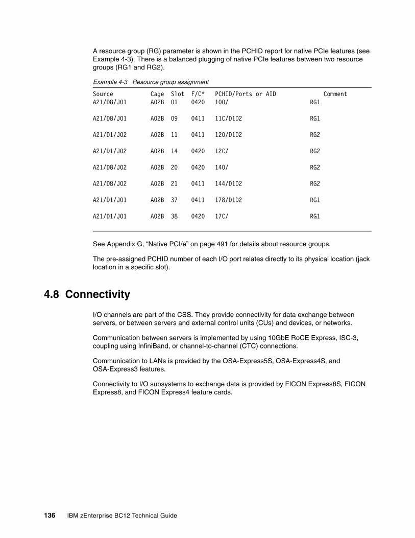
A resource group (RG) parameter is shown in the PCHID report for native PCIe features (see Example 4-3). There is a balanced plugging of native PCIe features between two resource groups (RG1 and RG2).
Example 4-3 Resource group assignment
Source Cage Slot F/C* PCHID/Ports or AID CommentA21/D8/J01 A02B 01 0420 100/ RG1
A21/D8/J01 A02B 09 0411 11C/D1D2 RG1
A21/D1/J02 A02B 11 0411 120/D1D2 RG2
A21/D1/J02 A02B 14 0420 12C/ RG2
A21/D8/J02 A02B 20 0420 140/ RG2
A21/D8/J02 A02B 21 0411 144/D1D2 RG2
A21/D1/J01 A02B 37 0411 178/D1D2 RG1
A21/D1/J01 A02B 38 0420 17C/ RG1
See Appendix G, “Native PCI/e” on page 491 for details about resource groups.
The pre-assigned PCHID number of each I/O port relates directly to its physical location (jack location in a specific slot).
4.8 Connectivity
I/O channels are part of the CSS. They provide connectivity for data exchange between servers, or between servers and external control units (CUs) and devices, or networks.
Communication between servers is implemented by using 10GbE RoCE Express, ISC-3, coupling using InfiniBand, or channel-to-channel (CTC) connections.
Communication to LANs is provided by the OSA-Express5S, OSA-Express4S, and OSA-Express3 features.
Connectivity to I/O subsystems to exchange data is provided by FICON Express8S, FICON Express8, and FICON Express4 feature cards.
136 IBM zEnterprise BC12 Technical Guide
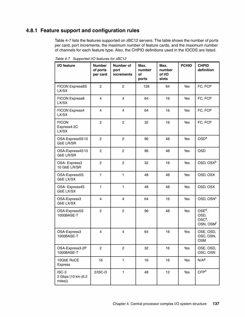
4.8.1 Feature support and configuration rules
Table 4-7 lists the features supported on zBC12 servers. The table shows the number of ports per card, port increments, the maximum number of feature cards, and the maximum number of channels for each feature type. Also, the CHPID definitions used in the IOCDS are listed.
Table 4-7 Supported I/O features for zBC12
I/O feature Number of ports per card
Number of port increments
Max. number ofports
Max. number of I/O slots
PCHID CHPID definition
FICON Express8S LX/SX
2 2 128 64 Yes FC, FCP
FICON Express8 LX/SX
4 4 64 16 Yes FC, FCP
FICON Express4 LX/SX
4 4 64 16 Yes FC, FCP
FICON Express4-2C LX/SX
2 2 32 16 Yes FC, FCP
OSA-Express5S 10 GbE LR/SR
2 2 96 48 Yes OSDa
OSA-Express4S 10 GbE LR/SR
2 2 96 48 Yes OSD
OSA- Express3 10 GbE LR/SR
2 2 32 16 Yes OSD, OSXb
OSA-Express5S GbE LX/SX
1 1 48 48 Yes OSD, OSX
OSA- Express4S GbE LX/SX
1 1 48 48 Yes OSD, OSX
OSA-Express3 GbE LX/SX
4 4 64 16 Yes OSD, OSNc
OSA-Express5S 1000BASE-T
2 2 96 48 Yes OSEd, OSD, OSCe, OSN, OSMf
OSA-Express3 1000BASE-T
4 4 64 16 Yes OSE, OSD, OSC, OSN, OSM
OSA-Express3-2P 1000BASE-T
2 2 32 16 Yes OSE, OSD, OSC, OSN
10GbE RoCE Express
16 1 16 16 Yes N/Ag
ISC-3 2 Gbps (10 km (6.2 miles))
2/ISC-D 1 48 12 Yes CFPh
Chapter 4. Central processor complex I/O system structure 137
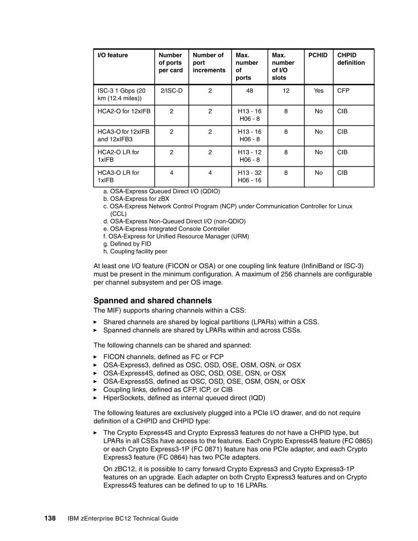
At least one I/O feature (FICON or OSA) or one coupling link feature (InfiniBand or ISC-3) must be present in the minimum configuration. A maximum of 256 channels are configurable per channel subsystem and per OS image.
Spanned and shared channelsThe MIF) supports sharing channels within a CSS:
� Shared channels are shared by logical partitions (LPARs) within a CSS.� Spanned channels are shared by LPARs within and across CSSs.
The following channels can be shared and spanned:
� FICON channels, defined as FC or FCP� OSA-Express3, defined as OSC, OSD, OSE, OSM, OSN, or OSX� OSA-Express4S, defined as OSC, OSD, OSE, OSN, or OSX� OSA-Express5S, defined as OSC, OSD, OSE, OSM, OSN, or OSX� Coupling links, defined as CFP, ICP, or CIB � HiperSockets, defined as internal queued direct (IQD)
The following features are exclusively plugged into a PCIe I/O drawer, and do not require definition of a CHPID and CHPID type:
� The Crypto Express4S and Crypto Express3 features do not have a CHPID type, but LPARs in all CSSs have access to the features. Each Crypto Express4S feature (FC 0865) or each Crypto Express3-1P (FC 0871) feature has one PCIe adapter, and each Crypto Express3 feature (FC 0864) has two PCIe adapters.
On zBC12, it is possible to carry forward Crypto Express3 and Crypto Express3-1P features on an upgrade. Each adapter on both Crypto Express3 features and on Crypto Express4S features can be defined to up to 16 LPARs.
ISC-3 1 Gbps (20 km (12.4 miles))
2/ISC-D 2 48 12 Yes CFP
HCA2-O for 12xIFB 2 2 H13 - 16H06 - 8
8 No CIB
HCA3-O for 12xIFB and 12xIFB3
2 2 H13 - 16H06 - 8
8 No CIB
HCA2-O LR for 1xIFB
2 2 H13 - 12H06 - 8
8 No CIB
HCA3-O LR for 1xIFB
4 4 H13 - 32H06 - 16
8 No CIB
a. OSA-Express Queued Direct I/O (QDIO)b. OSA-Express for zBXc. OSA-Express Network Control Program (NCP) under Communication Controller for Linux
(CCL)d. OSA-Express Non-Queued Direct I/O (non-QDIO)e. OSA-Express Integrated Console Controllerf. OSA-Express for Unified Resource Manager (URM)g. Defined by FIDh. Coupling facility peer
I/O feature Number of ports per card
Number of port increments
Max. number ofports
Max. number of I/O slots
PCHID CHPID definition
138 IBM zEnterprise BC12 Technical Guide

� Each Flash Express feature occupies two I/O slots, but does not have a CHPID type. However, LPARs in all CSSs have access to the features. The Flash Express feature can be defined to up to 603 LPARs.
� Each RoCE feature occupies one I/O slot, but does not have a CHPID type. However, LPARs in all CSSs have access to the feature. The RoCE feature can be defined to only one LPAR.
� Each zEDC feature occupies one I/O slot, but does not have a CHPID type. However, LPARs in all CSSs have access to the feature. The zEDC feature can be defined to up to 15 LPARs.
I/O feature cables and connectors
The IBM Facilities Cabling Services - fiber transport system offers a total cable solution service to help with cable ordering requirements. These services consider the requirements for all of the supported protocols and media types (for example, FICON, coupling links, and OSA), whether the focus is the data center, the SAN, LAN, or the end-to-end enterprise.
The Enterprise Fiber Cabling Services make use of a proven modular cabling system, the Fiber Transport System (FTS), which includes trunk cables, zone cabinets, and panels for servers, directors, and storage devices. FTS supports Fiber Quick Connect (FQC), a fiber harness integrated in the frame of a zBC12 for quick connection, which is offered as a feature on zBC12 servers for connection to FICON LX channels.
Whether you choose a packaged service or a custom service, high-quality components are used to facilitate moves, additions, and changes in the enterprise to prevent having to extend the maintenance window.
Table 4-8 lists the required connector and cable type for each I/O feature on the zBC12.
Table 4-8 I/O feature connector and cable types
3 Up to 30 LPARs for zBC12.
Cables: All fiber optic cables, cable planning, labeling, and installation are customer responsibilities for new zBC12 installations and upgrades. Fiber optic conversion kits and mode conditioning patch (MCP) cables are not orderable as features on zBC12 servers. All other cables have to be sourced separately.
Feature code Feature name Connector type Cable type
0409 FICON Express8S LX 10 km LC duplex 9 µm SM
0410 FICON Express8S SX LC duplex 50, 62.5 µm MMa
3325 FICON Express8 LX 10 km LC duplex 9 µm SM
3326 FICON Express8 SX LC duplex 50, 62.5 µm MM
3321 FICON Express4 LX 10 km LC duplex 9 µm SM
3322 FICON Express4 SX LC duplex 50, 62.5 µm MM
3318 FICON Express4-2C SX LC duplex 50, 62.5 µm MM
0415 OSA-Express5S 10 GbE LR LC duplex 9 µm SM
0416 OSA-Express5S 10 GbE SR LC duplex 50, 62.5 µm MM
0413 OSA-Express5S GbE LX LC duplex 9 µm SM
Chapter 4. Central processor complex I/O system structure 139
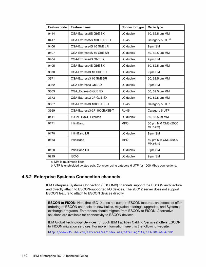
4.8.2 Enterprise Systems Connection channels
IBM Enterprise Systems Connection (ESCON®) channels support the ESCON architecture and directly attach to ESCON-supported I/O devices. The zBC12 server does not support ESCON feature to attach to ESCON devices directly.
0414 OSA-Express5S GbE SX LC duplex 50, 62.5 µm MM
0417 OSA-Express5S 1000BASE-T RJ-45 Category 5 UTPb
0406 OSA-Express4S 10 GbE LR LC duplex 9 µm SM
0407 OSA-Express4S 10 GbE SR LC duplex 50, 62.5 µm MM
0404 OSA-Express4S GbE LX LC duplex 9 µm SM
0405 OSA-Express4S GbE SX LC duplex 50, 62.5 µm MM
3370 OSA-Express3 10 GbE LR LC duplex 9 µm SM
3371 OSA-Express3 10 GbE SR LC duplex 50, 62.5 µm MM
3362 OSA-Express3 GbE LX LC duplex 9 µm SM
3363 OSA_Express3 GbE SX LC duplex 50, 62.5 µm MM
3373 OSA-Express3-2P GbE SX LC duplex 50, 62.5 µm MM
3367 OSA-Express3 1000BASE-T RJ-45 Category 5 UTP
3369 OSA-Express3-2P 1000BASE-T RJ-45 Category 5 UTP
0411 10GbE RoCE Express LC duplex 50, 66.5µm MM
0171 InfiniBand MPO 50 µm MM OM3 (2000 MHz-km)
0170 InfiniBand LR LC duplex 9 µm SM
0163 InfiniBand MPO 50 µm MM OM3 (2000 MHz-km)
0168 InfiniBand LR LC duplex 9 µm SM
0219 ISC-3 LC duplex 9 µm SM
a. MM is multimode fiberb. UTP is unshielded twisted pair. Consider using category 6 UTP for 1000 Mbps connections.
Feature code Feature name Connector type Cable type
ESCON to FICON: Note that zBC12 does not support ESCON features, and does not offer ordering of ESCON channels on new builds, migration offerings, upgrades, and System z exchange programs. Enterprises should migrate from ESCON to FICON. Alternative solutions are available for connectivity to ESCON devices.
IBM Global Technology Services (through IBM Facilities Cabling Services) offers ESCON to FICON migration services. For more information, see this the following website:
http://www-935.ibm.com/services/us/index.wss/offering/its/c337386u66547p02
140 IBM zEnterprise BC12 Technical Guide
The Prizm Protocol Converter Appliance from Optica Technologies Incorporated provides a FICON-to-ESCON conversion function that has been System z qualified. For more information, see the following website:
http://www.opticatech.com
4.8.3 FICON channels
The FICON Express8S, FICON Express8, and FICON Express4 features conform to the FICON architecture, the zHPF architecture, and the FCP architecture, providing connectivity between any combination of servers, directors, switches, and devices (control units, disks, tapes, and printers) in an SAN.
Each FICON Express8 or FICON Express4 feature occupies one I/O slot in the I/O drawer. Each feature has four ports, each supporting an LC duplex connector, with one PCHID and one CHPID associated with each port.
Each FICON Express8S feature occupies one I/O slot in the PCIe I/O drawer. Each feature has two ports, each supporting an LC duplex connector, with one PCHID and one CHPID associated with each port.
All FICON Express8S, FICON Express8, and FICON Express4 features use small form-factor pluggable (SFP) optics that enable concurrent repair or replacement for each SFP. The data flow on the unaffected channels on the same feature can continue. A problem with one FICON port no longer requires the replacement of a complete feature.
All FICON Express8S, FICON Express8, and FICON Express4 features also support cascading (the connection of two FICON Directors in succession) to minimize the number of cross-site connections, and to help reduce the implementation costs for disaster recovery applications, Geographically Dispersed Parallel Sysplex (GDPS), and remote copy.
All FICON Express8S, FICON Express8, and FICON Express4 features support 24,000 I/O devices (subchannels) for base and alias devices.
Each FICON Express8S, FICON Express8, and FICON Express4 channel can be defined independently, for connectivity to servers, switches, directors, disks, tapes, and printers:
� CHPID type FC
FICON, zHPF, and FICON CTC. FICON, FICON CTC, and zHPF protocols are supported simultaneously.
� CHPID type FCP
FCP, which supports attachment to SCSI devices directly or through FC switches or directors.
Vendor inquiries: IBM cannot confirm the accuracy of compatibility, performance, or any other claims by vendors for products that have not been System z qualified. Address any questions regarding these capabilities and device support to the suppliers of these products.
Important: FICON Express and FICON Express2 features installed in previous servers are not supported on a zBC12, and cannot be carried forward on an upgrade.
Chapter 4. Central processor complex I/O system structure 141
FICON channels (CHPID type FC or FCP) can be shared among LPARS, and can be defined as spanned. All ports on a FICON feature must be of the same type, either LX or SX. The features are connected to a FICON-capable control unit, either point-to-point or switched point-to-point, through a Fibre Channel switch.
FICON Express8SThe FICON Express8S feature resides exclusively in the PCIe I/O drawer. Each of the two independent ports is capable of 2 Gbps, 4 Gbps, or 8 Gbps, depending on the capability of the attached switch or device. The link speed is auto-negotiated, point-to-point, and transparent to users and applications.
The two types of supported FICON Express8S optical transceivers are the LX and the SX transceivers:
� FICON Express8S 10km LX feature FC 0409, with two ports per feature, supporting LC duplex connectors
� FICON Express8S SX feature FC 0410, with two ports per feature, supporting LC duplex connectors
Each port of the FICON Express8S 10 km LX feature uses a 1300 nanometer (nm) optical transceiver, and supports an unrepeated distance of 10 km (6.2 miles) using 9 µm SM fiber.
Each port of the FICON Express8S SX feature uses an 850 nm optical transceiver, and supports varying distances depending on the fiber used (50 or 62.5 µm MM fiber).
FICON Express8The FICON Express8 feature can be in an I/O cage or I/O drawer. Each of the four independent ports is capable of 2 Gbps, 4 Gbps, or 8 Gbps. The link speed depends on the capability of the attached switch or device. The link speed is auto-negotiated, point-to-point, and is transparent to users and applications.
The two types of supported FICON Express8 optical transceivers are the LX and the SX transceivers:
� FICON Express8 10km LX feature FC 3325, with four ports per feature, supporting LC duplex connectors
� FICON Express8 SX feature FC 3326, with four ports per feature, supporting LC duplex connectors
Each port of FICON Express8 10 km LX feature uses a 1300 nm fiber bandwidth transceiver, and supports an unrepeated distance of 10 km (6.2 miles) using 9 µm single-mode fiber.
Each port of FICON Express8 SX feature uses an 850 nm optical transceiver, and supports varying distances depending on the fiber used (50 or 62.5 µm multimode fiber).
Auto-negotiation: FICON Express8S features do not support auto-negotiation to a data link rate of 1 Gbps.
Auto-negotiation: FICON Express8 features do not support auto-negotiation to a data link rate of 1 Gbps.
142 IBM zEnterprise BC12 Technical Guide
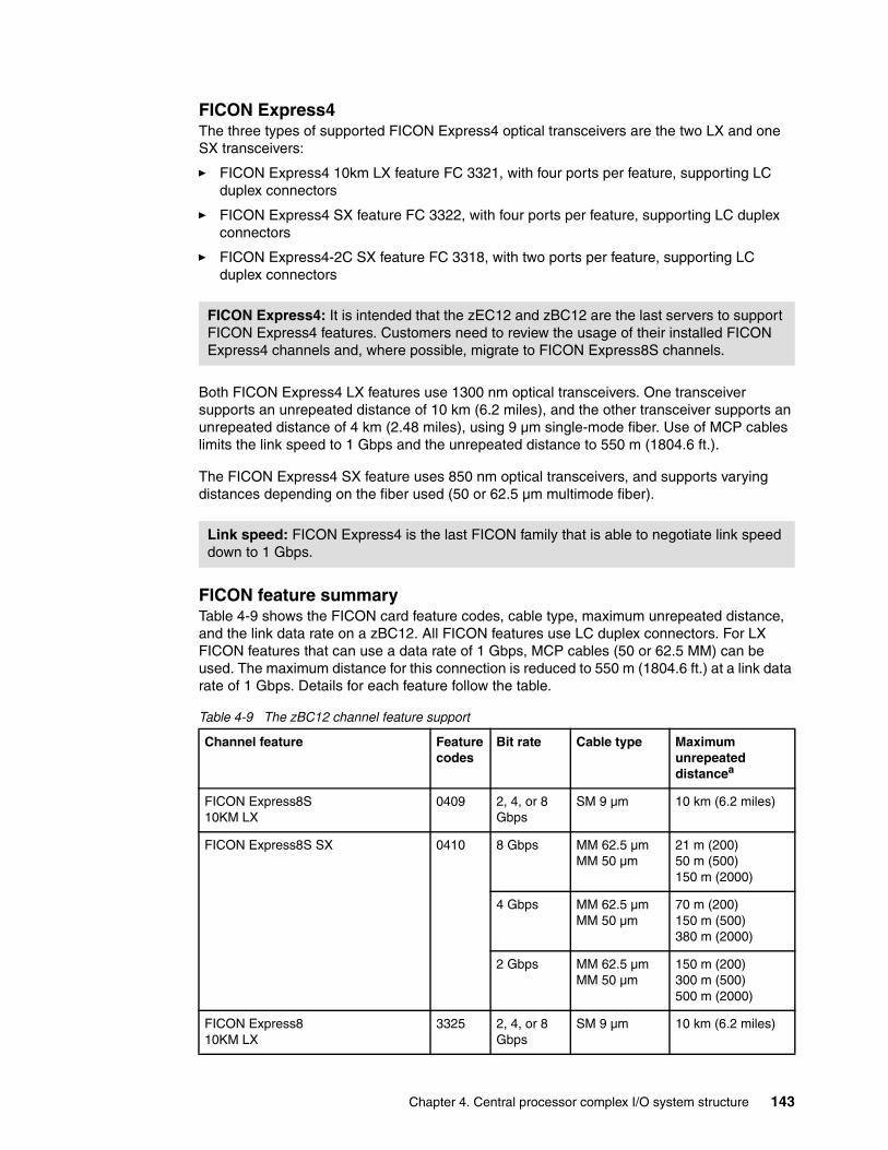
FICON Express4The three types of supported FICON Express4 optical transceivers are the two LX and one SX transceivers:
� FICON Express4 10km LX feature FC 3321, with four ports per feature, supporting LC duplex connectors
� FICON Express4 SX feature FC 3322, with four ports per feature, supporting LC duplex connectors
� FICON Express4-2C SX feature FC 3318, with two ports per feature, supporting LC duplex connectors
Both FICON Express4 LX features use 1300 nm optical transceivers. One transceiver supports an unrepeated distance of 10 km (6.2 miles), and the other transceiver supports an unrepeated distance of 4 km (2.48 miles), using 9 µm single-mode fiber. Use of MCP cables limits the link speed to 1 Gbps and the unrepeated distance to 550 m (1804.6 ft.).
The FICON Express4 SX feature uses 850 nm optical transceivers, and supports varying distances depending on the fiber used (50 or 62.5 µm multimode fiber).
FICON feature summaryTable 4-9 shows the FICON card feature codes, cable type, maximum unrepeated distance, and the link data rate on a zBC12. All FICON features use LC duplex connectors. For LX FICON features that can use a data rate of 1 Gbps, MCP cables (50 or 62.5 MM) can be used. The maximum distance for this connection is reduced to 550 m (1804.6 ft.) at a link data rate of 1 Gbps. Details for each feature follow the table.
Table 4-9 The zBC12 channel feature support
FICON Express4: It is intended that the zEC12 and zBC12 are the last servers to support FICON Express4 features. Customers need to review the usage of their installed FICON Express4 channels and, where possible, migrate to FICON Express8S channels.
Link speed: FICON Express4 is the last FICON family that is able to negotiate link speed down to 1 Gbps.
Channel feature Feature codes
Bit rate Cable type Maximumunrepeateddistancea
FICON Express8S 10KM LX
0409 2, 4, or 8 Gbps
SM 9 µm 10 km (6.2 miles)
FICON Express8S SX 0410 8 Gbps MM 62.5 µmMM 50 µm
21 m (200)50 m (500)150 m (2000)
4 Gbps MM 62.5 µmMM 50 µm
70 m (200)150 m (500)380 m (2000)
2 Gbps MM 62.5 µmMM 50 µm
150 m (200)300 m (500)500 m (2000)
FICON Express810KM LX
3325 2, 4, or 8 Gbps
SM 9 µm 10 km (6.2 miles)
Chapter 4. Central processor complex I/O system structure 143
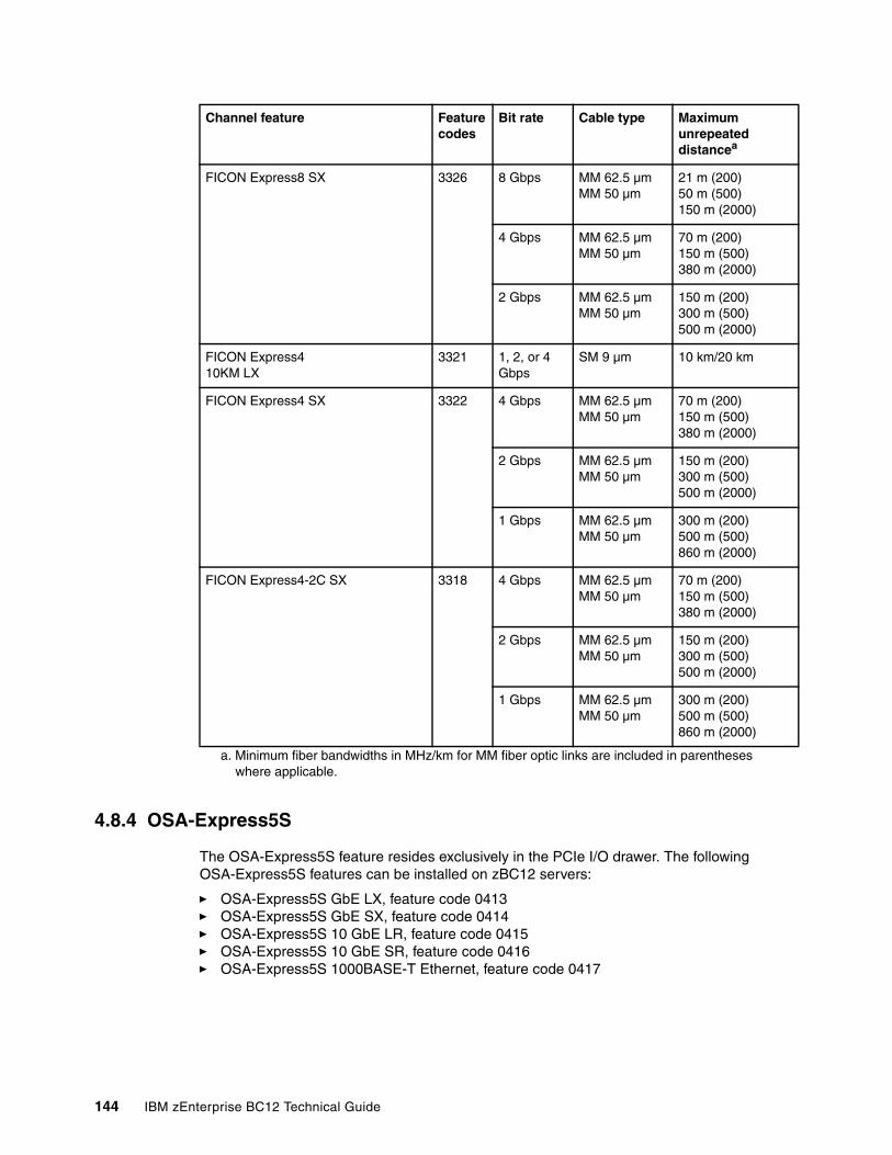
4.8.4 OSA-Express5S
The OSA-Express5S feature resides exclusively in the PCIe I/O drawer. The following OSA-Express5S features can be installed on zBC12 servers:
� OSA-Express5S GbE LX, feature code 0413� OSA-Express5S GbE SX, feature code 0414� OSA-Express5S 10 GbE LR, feature code 0415� OSA-Express5S 10 GbE SR, feature code 0416� OSA-Express5S 1000BASE-T Ethernet, feature code 0417
FICON Express8 SX 3326 8 Gbps MM 62.5 µmMM 50 µm
21 m (200)50 m (500)150 m (2000)
4 Gbps MM 62.5 µmMM 50 µm
70 m (200)150 m (500)380 m (2000)
2 Gbps MM 62.5 µmMM 50 µm
150 m (200)300 m (500)500 m (2000)
FICON Express410KM LX
3321 1, 2, or 4 Gbps
SM 9 µm 10 km/20 km
FICON Express4 SX 3322 4 Gbps MM 62.5 µmMM 50 µm
70 m (200)150 m (500)380 m (2000)
2 Gbps MM 62.5 µmMM 50 µm
150 m (200)300 m (500)500 m (2000)
1 Gbps MM 62.5 µmMM 50 µm
300 m (200)500 m (500)860 m (2000)
FICON Express4-2C SX 3318 4 Gbps MM 62.5 µmMM 50 µm
70 m (200)150 m (500)380 m (2000)
2 Gbps MM 62.5 µmMM 50 µm
150 m (200)300 m (500)500 m (2000)
1 Gbps MM 62.5 µmMM 50 µm
300 m (200)500 m (500)860 m (2000)
a. Minimum fiber bandwidths in MHz/km for MM fiber optic links are included in parentheses where applicable.
Channel feature Feature codes
Bit rate Cable type Maximumunrepeateddistancea
144 IBM zEnterprise BC12 Technical Guide
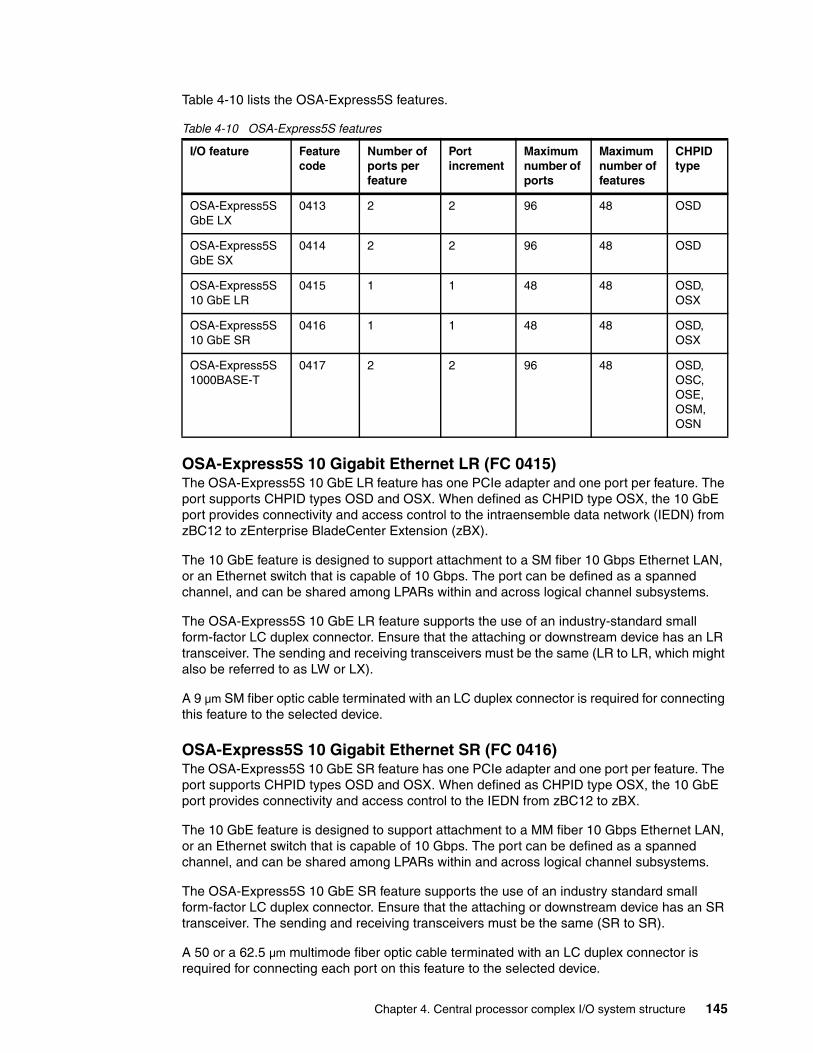
Table 4-10 lists the OSA-Express5S features.
Table 4-10 OSA-Express5S features
OSA-Express5S 10 Gigabit Ethernet LR (FC 0415)The OSA-Express5S 10 GbE LR feature has one PCIe adapter and one port per feature. The port supports CHPID types OSD and OSX. When defined as CHPID type OSX, the 10 GbE port provides connectivity and access control to the intraensemble data network (IEDN) from zBC12 to zEnterprise BladeCenter Extension (zBX).
The 10 GbE feature is designed to support attachment to a SM fiber 10 Gbps Ethernet LAN, or an Ethernet switch that is capable of 10 Gbps. The port can be defined as a spanned channel, and can be shared among LPARs within and across logical channel subsystems.
The OSA-Express5S 10 GbE LR feature supports the use of an industry-standard small form-factor LC duplex connector. Ensure that the attaching or downstream device has an LR transceiver. The sending and receiving transceivers must be the same (LR to LR, which might also be referred to as LW or LX).
A 9 µm SM fiber optic cable terminated with an LC duplex connector is required for connecting this feature to the selected device.
OSA-Express5S 10 Gigabit Ethernet SR (FC 0416)The OSA-Express5S 10 GbE SR feature has one PCIe adapter and one port per feature. The port supports CHPID types OSD and OSX. When defined as CHPID type OSX, the 10 GbE port provides connectivity and access control to the IEDN from zBC12 to zBX.
The 10 GbE feature is designed to support attachment to a MM fiber 10 Gbps Ethernet LAN, or an Ethernet switch that is capable of 10 Gbps. The port can be defined as a spanned channel, and can be shared among LPARs within and across logical channel subsystems.
The OSA-Express5S 10 GbE SR feature supports the use of an industry standard small form-factor LC duplex connector. Ensure that the attaching or downstream device has an SR transceiver. The sending and receiving transceivers must be the same (SR to SR).
A 50 or a 62.5 µm multimode fiber optic cable terminated with an LC duplex connector is required for connecting each port on this feature to the selected device.
I/O feature Feature code
Number of ports per feature
Port increment
Maximum number of ports
Maximum number of features
CHPID type
OSA-Express5S GbE LX
0413 2 2 96 48 OSD
OSA-Express5S GbE SX
0414 2 2 96 48 OSD
OSA-Express5S 10 GbE LR
0415 1 1 48 48 OSD,OSX
OSA-Express5S 10 GbE SR
0416 1 1 48 48 OSD,OSX
OSA-Express5S 1000BASE-T
0417 2 2 96 48 OSD, OSC, OSE, OSM, OSN
Chapter 4. Central processor complex I/O system structure 145
OSA-Express5S Gigabit Ethernet LX (FC 0413)The OSA-Express5S GbE long wavelength (LX) feature has one PCIe adapter and two ports. The two ports share a CHPID (type OSD exclusively). The ports support attachment to a 1 Gbps Ethernet LAN. Each port can be defined as a spanned channel, and can be shared among LPARs and across logical channel subsystems.
The OSA-Express5S GbE LX feature supports the use of an LC duplex connector. Ensure that the attaching or downstream device has an LX transceiver. The sending and receiving transceivers must be the same (LX to LX).
A 9 µm SM fiber optic cable terminated with an LC duplex connector is required for connecting each port on this feature to the selected device. If MM fiber optic cables are being reused, a pair of MCP cables is required, one cable for each end of the link.
OSA-Express5S Gigabit Ethernet SX (FC 0414)The OSA-Express5S GbE short-wavelength (SX) feature has one PCIe adapter and two ports. The two ports share a CHPID (type OSD exclusively). The ports support attachment to a 1 Gbps Ethernet LAN. Each port can be defined as a spanned channel, and can be shared among LPARs and across logical channel subsystems.
The OSA-Express5S GbE SX feature supports the use of an LC duplex connector. Ensure that the attaching or downstream device has an SX transceiver. The sending and receiving transceivers must be the same (SX to SX).
A 50 or 62.5 µm MM fiber optic cable terminated with an LC duplex connector is required for connecting each port on this feature to the selected device.
OSA-Express5S 1000BASE-T Ethernet feature (FC 0417)Feature code 0417 occupies one slot in the PCIe I/O drawer. It has two ports that connect to a 1000 megabits per second (Mbps), also 1 Gbps, or 100 Mbps Ethernet LAN. Each port has an SFP with an RJ-45 receptacle for cabling to an Ethernet switch. The RJ-45 receptacle is required to be attached using EIA/Telecommunications Industry Association (TIA) Category 5 or Category 6 UTP cable with a maximum length of 100 m (328 ft.). The SFP supports concurrent repair or replace action.
The OSA-Express5S 1000BASE-T Ethernet feature supports auto-negotiation when attached to an Ethernet router or switch. If the LAN speed and duplex mode are set to auto-negotiation, the OSA-Express port and the attached router or switch auto-negotiate the LAN speed and duplex mode settings between them, and connect at the highest common performance speed and duplex mode of interoperation.
If the attached Ethernet router or switch does not support auto-negotiation, the OSA-Express port examines the signal that it is receiving and connects at the speed and duplex mode of the device at the other end of the cable.
The OSA-Express5S 1000BASE-T Ethernet feature can be configured as CHPID type OSC, OSD, OSE, OSN, or OSM. Non-QDIO operation mode requires CHPID type OSE. The following settings are supported on the OSA-Express5S 1000BASE-T Ethernet feature port:
� Auto-negotiate� 100 Mbps half-duplex or full-duplex� 1000 Mbps full-duplex
If you are not using auto-negotiate, the OSA-Express port will attempt to join the LAN at the specified speed and duplex mode. If this specified speed and duplex mode does not match the speed and duplex mode of the signal on the cable, the OSA-Express port will not connect.
146 IBM zEnterprise BC12 Technical Guide
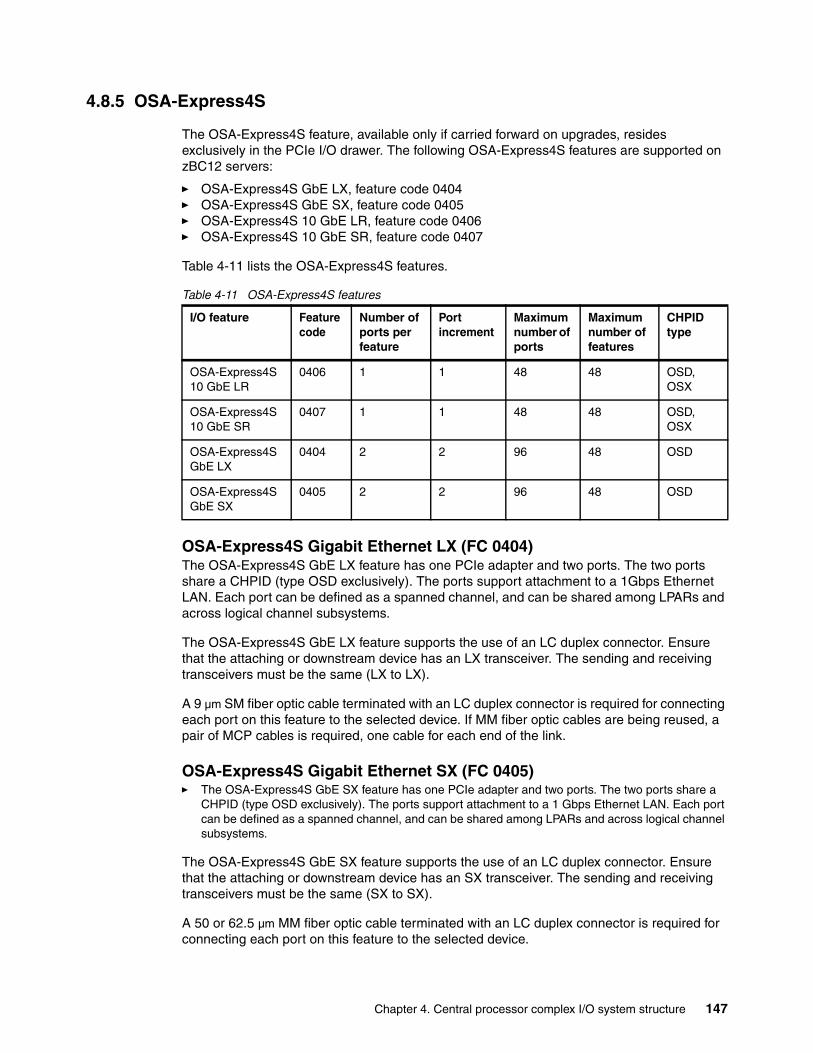
4.8.5 OSA-Express4S
The OSA-Express4S feature, available only if carried forward on upgrades, resides exclusively in the PCIe I/O drawer. The following OSA-Express4S features are supported on zBC12 servers:
� OSA-Express4S GbE LX, feature code 0404� OSA-Express4S GbE SX, feature code 0405� OSA-Express4S 10 GbE LR, feature code 0406� OSA-Express4S 10 GbE SR, feature code 0407
Table 4-11 lists the OSA-Express4S features.
Table 4-11 OSA-Express4S features
OSA-Express4S Gigabit Ethernet LX (FC 0404)The OSA-Express4S GbE LX feature has one PCIe adapter and two ports. The two ports share a CHPID (type OSD exclusively). The ports support attachment to a 1Gbps Ethernet LAN. Each port can be defined as a spanned channel, and can be shared among LPARs and across logical channel subsystems.
The OSA-Express4S GbE LX feature supports the use of an LC duplex connector. Ensure that the attaching or downstream device has an LX transceiver. The sending and receiving transceivers must be the same (LX to LX).
A 9 µm SM fiber optic cable terminated with an LC duplex connector is required for connecting each port on this feature to the selected device. If MM fiber optic cables are being reused, a pair of MCP cables is required, one cable for each end of the link.
OSA-Express4S Gigabit Ethernet SX (FC 0405)� The OSA-Express4S GbE SX feature has one PCIe adapter and two ports. The two ports share a
CHPID (type OSD exclusively). The ports support attachment to a 1 Gbps Ethernet LAN. Each port can be defined as a spanned channel, and can be shared among LPARs and across logical channel subsystems.
The OSA-Express4S GbE SX feature supports the use of an LC duplex connector. Ensure that the attaching or downstream device has an SX transceiver. The sending and receiving transceivers must be the same (SX to SX).
A 50 or 62.5 µm MM fiber optic cable terminated with an LC duplex connector is required for connecting each port on this feature to the selected device.
I/O feature Feature code
Number of ports per feature
Port increment
Maximum number of ports
Maximum number of features
CHPID type
OSA-Express4S 10 GbE LR
0406 1 1 48 48 OSD,OSX
OSA-Express4S 10 GbE SR
0407 1 1 48 48 OSD,OSX
OSA-Express4S GbE LX
0404 2 2 96 48 OSD
OSA-Express4S GbE SX
0405 2 2 96 48 OSD
Chapter 4. Central processor complex I/O system structure 147
OSA-Express4S 10 Gigabit Ethernet LR (FC 0406)The OSA-Express4S 10 GbE LR feature has one PCIe adapter and one port per feature. The port supports CHPID types OSD and OSX. When defined as CHPID type OSX, the 10 GbE port provides connectivity and access control to the IEDN from zBC12 to zBX.
The 10 GbE feature is designed to support attachment to a SM fiber 10 Gbps Ethernet LAN, or an Ethernet switch that is capable of 10 Gbps. The port can be defined as a spanned channel, and can be shared among LPARs within and across logical channel subsystems.
The OSA-Express4S 10 GbE LR feature supports the use of an industry standard small form-factor LC duplex connector. Ensure that the attaching or downstream device has an LR transceiver. The sending and receiving transceivers must be the same (LR to LR, which might also be referred to as LW or LX).
A 9 µm SM fiber optic cable terminated with an LC duplex connector is required for connecting this feature to the selected device.
OSA-Express4S 10 Gigabit Ethernet SR (FC 0407)The OSA-Express4S 10 GbE SR feature has one PCIe adapter and one port per feature. The port supports CHPID types OSD and OSX. When defined as CHPID type OSX, the 10 GbE port provides connectivity and access control to the IEDN from zBC12 to zBX.
The 10 GbE feature is designed to support attachment to a MM fiber 10 Gbps Ethernet LAN, or an Ethernet switch that is capable of 10 Gbps. The port can be defined as a spanned channel, and can be shared among LPARs within and across logical channel subsystems.
The OSA-Express4S 10 GbE SR feature supports the use of an industry standard small form factor LC duplex connector. Ensure that the attaching or downstream device has an SR transceiver. The sending and receiving transceivers must be the same (SR to SR).
A 50 or a 62.5 µm multimode fiber optic cable terminated with an LC duplex connector is required for connecting each port on this feature to the selected device.
4.8.6 OSA-Express3
This section provides information about the connectivity options that are offered by the OSA-Express3 features.
The OSA-Express3 features, available only if carried forward on upgrades, provide improved performance by reducing latency at the TCP/IP application. Direct access to the memory enables packets to flow directly from the memory to the LAN without firmware intervention in the adapter.
The following OSA-Express3 features are supported on zBC12servers:
� OSA-Express3 10 GbE LR, feature code 3370� OSA-Express3 10 GbE SR, feature code 3371� OSA-Express3 GbE LX, feature code 3362� OSA-Express3 GbE SX, feature code 3363� OSA-Express3 1000BASE-T Ethernet, feature code 3367� OSA-Express3-2P 1000BASE-T Ethernet, feature code 3369
148 IBM zEnterprise BC12 Technical Guide
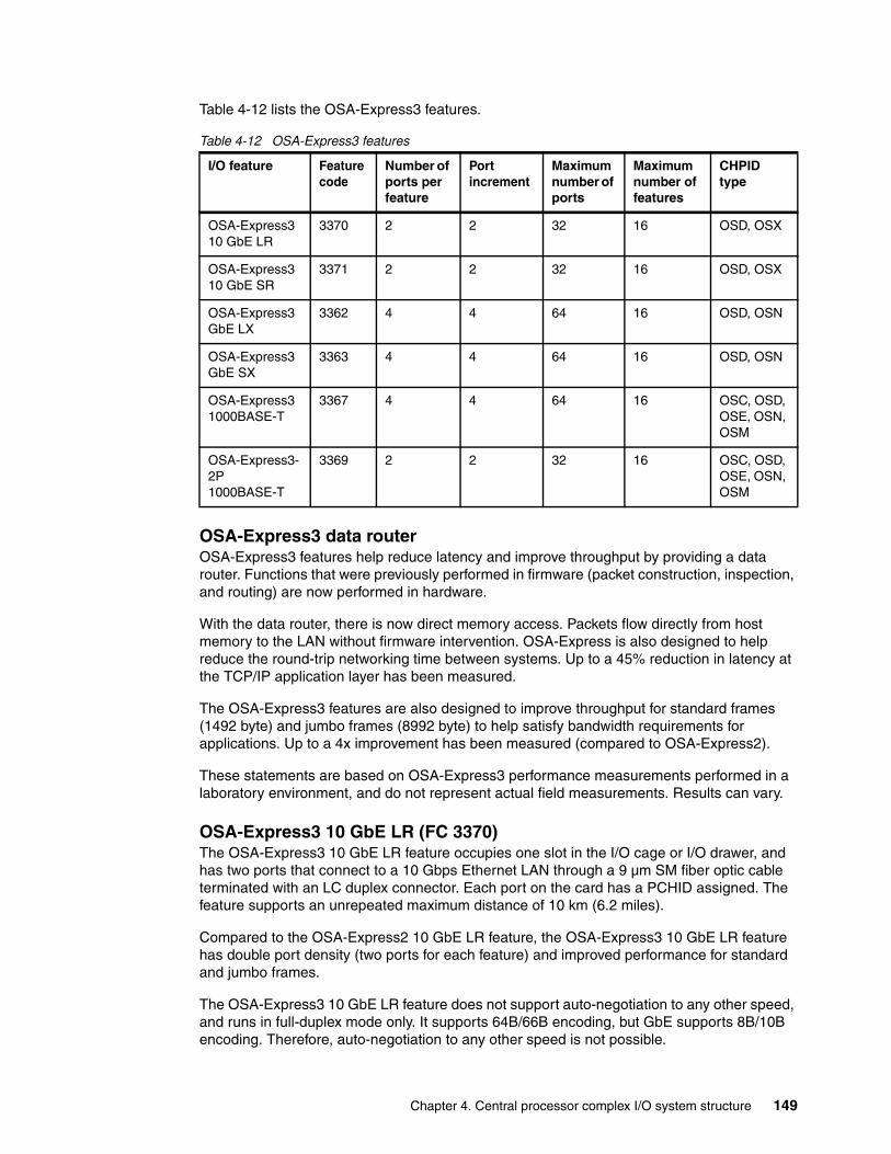
Table 4-12 lists the OSA-Express3 features.
Table 4-12 OSA-Express3 features
OSA-Express3 data routerOSA-Express3 features help reduce latency and improve throughput by providing a data router. Functions that were previously performed in firmware (packet construction, inspection, and routing) are now performed in hardware.
With the data router, there is now direct memory access. Packets flow directly from host memory to the LAN without firmware intervention. OSA-Express is also designed to help reduce the round-trip networking time between systems. Up to a 45% reduction in latency at the TCP/IP application layer has been measured.
The OSA-Express3 features are also designed to improve throughput for standard frames (1492 byte) and jumbo frames (8992 byte) to help satisfy bandwidth requirements for applications. Up to a 4x improvement has been measured (compared to OSA-Express2).
These statements are based on OSA-Express3 performance measurements performed in a laboratory environment, and do not represent actual field measurements. Results can vary.
OSA-Express3 10 GbE LR (FC 3370)The OSA-Express3 10 GbE LR feature occupies one slot in the I/O cage or I/O drawer, and has two ports that connect to a 10 Gbps Ethernet LAN through a 9 µm SM fiber optic cable terminated with an LC duplex connector. Each port on the card has a PCHID assigned. The feature supports an unrepeated maximum distance of 10 km (6.2 miles).
Compared to the OSA-Express2 10 GbE LR feature, the OSA-Express3 10 GbE LR feature has double port density (two ports for each feature) and improved performance for standard and jumbo frames.
The OSA-Express3 10 GbE LR feature does not support auto-negotiation to any other speed, and runs in full-duplex mode only. It supports 64B/66B encoding, but GbE supports 8B/10B encoding. Therefore, auto-negotiation to any other speed is not possible.
I/O feature Feature code
Number of ports per feature
Port increment
Maximum number of ports
Maximum number of features
CHPID type
OSA-Express3 10 GbE LR
3370 2 2 32 16 OSD, OSX
OSA-Express3 10 GbE SR
3371 2 2 32 16 OSD, OSX
OSA-Express3 GbE LX
3362 4 4 64 16 OSD, OSN
OSA-Express3 GbE SX
3363 4 4 64 16 OSD, OSN
OSA-Express3 1000BASE-T
3367 4 4 64 16 OSC, OSD, OSE, OSN, OSM
OSA-Express3-2P 1000BASE-T
3369 2 2 32 16 OSC, OSD, OSE, OSN, OSM
Chapter 4. Central processor complex I/O system structure 149
The OSA-Express3 10 GbE LR feature has two CHPIDs, with each CHPID having one port, and supports CHPID types OSD (QDIO mode) and OSX.
CHPID type OSD is supported by z/OS, z/VM, z/VSE, Transaction Processing Facility (TPF), and Linux on System z to provide customer-managed external network connections.
CHPID type OSX is dedicated for connecting the zEC12 and zBC12 to an IEDN, providing a private data exchange path across ensemble nodes.
OSA-Express3 10 GbE SR (FC 3371)The OSA-Express3 10 GbE SR feature (FC 3371) occupies one slot in the I/O cage or I/O drawer and has two CHPIDs, with each CHPID having one port.
External connection to a 10 Gbps Ethernet LAN is done through a 62.5 µm or 50 µm MM fiber optic cable terminated with an LC duplex connector. The maximum supported unrepeated distance is 33 m (108 ft.) on a 62.5 µm multimode (200 MHz) fiber optic cable, 82 m (269 ft.) on a 50 µm MM (500 MHz) fiber optic cable, and 300 m (984 ft.) on a 50 µm MM (2000 MHz) fiber optic cable.
The OSA-Express3 10 GbE SR feature does not support auto-negotiation to any other speed, and runs in full-duplex mode only. OSA-Express3 10 GbE SR supports 64B/66B encoding, but GbE supports 8B/10 encoding, making auto-negotiation to any other speed impossible.
The OSA-Express3 10 GbE SR feature supports CHPID types OSD (QDIO mode) and OSX.
CHPID type OSD is supported by z/OS, z/VM, z/VSE, TPF, and Linux on System z to provide customer-managed external network connections.
CHPID type OSX is dedicated for connecting the zEC12 and zBC12 to an IEDN, providing a private data exchange path across ensemble nodes.
OSA-Express3 GbE LX (FC 3362)Feature code 3362 occupies one slot in the I/O drawer. It has four ports that connect to a 1 Gbps Ethernet LAN through a 9 µm SM fiber optic cable terminated with an LC duplex connector, supporting an unrepeated maximum distance of 5 km (3.1 miles). MM (62.5 or 50 µm) fiber optic cable can be used with this feature.
The OSA-Express3 GbE LX feature does not support auto-negotiation to any other speed, and runs in full-duplex mode only.
The OSA-Express3 GbE LX feature has two CHPIDs, with each CHPID (OSD or OSN) having two ports, for a total of four ports per feature. Exploitation of all four ports requires OS support. See 8.2, “Support by operating system” on page 246.
OSA-Express3 GbE SX (FC 3363) Feature code 3363 occupies one slot in the I/O drawer. It has four ports that connect to a 1 Gbps Ethernet LAN through a 50 µm or 62.5 µm multimode fiber optic cable terminated with an LC duplex connector over an unrepeated distance of 550 meters (for 50 µm fiber) or 220 meters (for 62.5 µm fiber).
MCP: The use of these MM cable types requires an MCP cable at each end of the fiber optic link. The use of the SM-to-MM MCP cables reduces the supported distance of the link to a maximum of 550 m (1804.6 ft.).
150 IBM zEnterprise BC12 Technical Guide
The OSA-Express3 GbE SX feature does not support auto-negotiation to any other speed and runs in full-duplex mode only.
The OSA-Express3 GbE SX feature has two CHPIDs (OSD or OSN), with each CHPID having two ports, for a total of four ports per feature. Exploitation of all four ports requires OS support. See 8.2, “Support by operating system” on page 246.
OSA-Express3 1000BASE-T Ethernet feature (FC 3367)Feature code 3367 occupies one slot in the I/O drawer. It has four ports that connect to a 1000 Mbps (1 Gbps), 100 Mbps, or 10 Mbps Ethernet LAN. Each port has an RJ-45 receptacle for cabling to an Ethernet switch. The RJ-45 receptacle is required to be attached using EIA/TIA Category 5 or Category 6 UTP cable with a maximum length of 100 m (328 ft.).
The OSA-Express3 1000BASE-T Ethernet feature supports auto-negotiation when attached to an Ethernet router or switch. If the LAN speed and duplex mode are set to auto-negotiation, the OSA-Express port and the attached router or switch auto-negotiate the LAN speed and duplex mode settings between them, and connect at the highest common performance speed and duplex mode of interoperation.
If the attached Ethernet router or switch does not support auto-negotiation, the OSA-Express port examines the signal that it is receiving, and connects at the speed and duplex mode of the device at the other end of the cable.
The OSA-Express3 1000BASE-T Ethernet feature can be configured as CHPID type OSC, OSD, OSE, OSN, or OSM. Non-QDIO operation mode requires CHPID type OSE. The following settings are supported on the OSA-Express3 1000BASE-T Ethernet feature port:
� Auto-negotiate� 10 Mbps half-duplex or full-duplex� 100 Mbps half-duplex or full-duplex� 1000 Mbps full-duplex
If you are not using auto-negotiate, the OSA-Express port will attempt to join the LAN at the specified speed and duplex mode. If this specified speed and duplex mode does not match the speed and duplex mode of the signal on the cable, the OSA-Express port will not connect.
4.8.7 OSA-Express for ensemble connectivity
The following OSA-Express features are used to connect the zEnterprise CPC to its attached zBX Model 003 and other ensemble nodes:
� OSA-Express5S 10 GbE LR, feature code 0415� OSA-Express5S 10 GbE SR, feature code 0416� OSA-Express5S 1000BASE-T Ethernet, feature code 0417� OSA-Express4S 10 GbE LR, feature code 0406� OSA-Express4S 10 GbE SR, feature code 0407� OSA-Express3 10 GbE LR, feature code 3370� OSA-Express3 10 GbE SR, feature code 3371� OSA-Express3 1000BASE-T Ethernet, feature code 3367� OSA-Express3-2P 1000BASE-T Ethernet, feature code 3369
Intraensemble data networkThe IEDN is a private and secure 10 Gbps Ethernet network that connects all elements of an ensemble, and is access-controlled using integrated virtual LAN (VLAN) provisioning. No customer-managed switches or routers are required. The IEDN is managed by a primary Hardware Management Console (HMC)4.
Chapter 4. Central processor complex I/O system structure 151
The IEDN connection requires two ports on a 10 GbE feature (LX or SX). For redundancy, the two ports should be used on different adapter cards. The following features can be used, to be configured as CHPID type OSX:
� OSA-Express5S 10 GbE� OSA-Express4S 10 GbE� OSA-Express3 10 GbE (one port each from two OSA-Express3 10 GbE features)
The connection is from the zBC12 to the IEDN top-of-rack (TOR) switches on zBX Model 003. Conversely, with a stand-alone zBC12 node (no-zBX), the connection is interconnected pairs of OSX ports via LC duplex directly connected cables and not wrap cables as has previously been suggested.
For more information about OSA-Express5S, OSA-Express4S, and OSA-Express3 in an ensemble network, see 7.4, “IBM zBX connectivity” on page 228.
Intranode management networkThe intranode management network (INMN) is a private and physically isolated 1000BASE-T Ethernet internal management network, operating at 1 Gbps. It connects all resources (zBC12 and zBX Model 003 components) of an ensemble node for management purposes. It is prewired, internally switched, configured, and managed with full redundancy for high availability.
The INMN requires two ports (CHPID port 0) from two OSA-Express5S 1000BASE-T, or OSA-Express3 1000BASE-T features. CHPID port 1 is not used at all in this case configured as CHPID type OSM. The connection is through port J07 of the bulk power hubs (BPHs) in the zBC12. The INMN TOR switches on zBX Model 003 also connect to the BPHs.
For detailed information about OSA-Express in an ensemble network, see 7.4, “IBM zBX connectivity” on page 228.
4.8.8 HiperSockets
The HiperSockets function of zEnterprise CPCs is improved to provide up to 32 high-speed VLAN attachments.
HiperSockets can be customized to accommodate varying traffic sizes. Because HiperSockets does not use an external network, it can free up system and network resources, which can help eliminate attachment costs, and improve availability and performance.
HiperSockets eliminates being required to use I/O subsystem operations, and being required to traverse an external network connection to communicate between LPARs in the same zEnterprise CPC. HiperSockets offers significant value in server consolidation, connecting many virtual servers, and can be used instead of certain coupling link configurations in a Parallel Sysplex.
HiperSockets internal networks on zEnterprise CPCs support two transport modes:
� Layer 2 (link layer) � Layer 3 (network or IP layer)
Traffic can be IPv4, IPv6, or non-IP, such as AppleTalk, Digital Equipment Corporation network protocol (DECnet), Internetwork Packet Exchange (IPX), Network Basic Input/Output System (NetBIOS), or IBM Systems Network Architecture (SNA).
4 This HMC must be running with Version 2.11 or later, with feature codes 0090, 0025, 0019, and optionally 0020.
152 IBM zEnterprise BC12 Technical Guide
HiperSockets devices are protocol-independent and Layer 3-independent. Each HiperSockets device (Layer 2 and Layer 3 mode) has its own Media Access Control (MAC) address that is designed to enable the use of applications that depend on the existence of Layer 2 addresses, such as Dynamic Host Configuration Protocol (DHCP) servers and firewalls.
Layer 2 support helps facilitate server consolidation, reduce complexity, simplify network configuration, and enable LAN administrators to maintain the mainframe network environment in a similar manner to non-mainframe environments.
Packet forwarding decisions are based on Layer 2 information instead of Layer 3. The HiperSockets device can perform automatic MAC address generation to create uniqueness within and across LPARs and servers. The use of Group MAC addresses for multicast is supported, as well as broadcasts to all other Layer 2 devices on the same HiperSockets networks.
Datagrams are delivered only between HiperSockets devices that use the same transport mode. A Layer 2 device cannot communicate directly to a Layer 3 device in another LPAR network. A HiperSockets device can filter inbound datagrams by VLAN identification, the destination MAC address, or both.
Analogous to the Layer 3 functions, HiperSockets Layer 2 devices can be configured as primary or secondary connectors or multicast routers. This configuration enables the creation of high-performance and high-availability link layer switches between the internal HiperSockets network and an external Ethernet, or to connect to the HiperSockets Layer 2 networks of separate servers.
HiperSockets Layer 2 on zEnterprise CPCs is supported by Linux on System z, and by z/VM for Linux guest exploitation.
Exclusive to the zBC12 and other zEnterprise CPC’s is the Hipersockets Completion Queue function. This is designed to enable HiperSockets to transfer data synchronously if possible, and asynchronously if necessary. It therefore combines ultra-low latency with more tolerance for traffic peaks. This benefit can be especially helpful in burst situations.
To extend the HiperSockets network to the whole zEnterprise ensemble, integration with the physical IEDN network has been provided for the zEnterprise CPCs. This extended HiperSockets network will display as a single Layer 2 network.
4.9 Parallel Sysplex connectivity
Coupling links are required in a Parallel Sysplex configuration to provide connectivity from the z/OS images to the coupling facility. A properly configured Parallel Sysplex provides a highly reliable, redundant, and robust System z technology solution to achieve near-continuous availability. A Parallel Sysplex consists of one or more z/OS OS images coupled through one or more coupling facilities.
4.9.1 Coupling links
The type of coupling link that is used to connect a CF to an OS LPAR is important because of the effect of the link performance on response times and coupling overheads. For configurations covering large distances, the time spent on the link can be the largest part of the response time.
Chapter 4. Central processor complex I/O system structure 153
The following types of links are available to connect an OS LPAR to a CF:
� InfiniBand
PSIFB connects a zBC12 to a zEC12, zBC12, z196, z114, or System z10. 12xIFB coupling links are fiber optic connections that support a maximum distance of up to 150 m (492 ft.). InfiniBand coupling links are defined as CHPID type CIB. InfiniBand supports transmission of STP messages.
Note that zBC12 supports two types of 12xIFB coupling links, FC 0171 HCA3-O (12xIFB or 12xIFB3) fanout and FC 0163 HCA2-O (12xIFB) fanout).
� InfiniBand LR
InfiniBand LR connects a zBC12 to azEC12, zBC12, z196 or System z10 server. 1xIFB coupling links are fiber optic connections that support a maximum unrepeated distance of up to 10 km (6.2 miles) and up to 100 km (62.1 miles) with a System z qualified DWDM. InfiniBand LR coupling links are defined as CHPID type CIB. InfiniBand LR supports transmission of STP messages.
Note that zBC12 supports two types of 1xIFB coupling links, FC 0170 HCA3-O LR (1xIFB) fanout and FC 0168 HCA2-O LR (1xIFB) fanout. InfiniBand LR supports 7 or 32 subchannels per CHPID.
� Internal Coupling links (IC)
CHPIDs (type Internal Coupling Facility Peer, or ICP) that are defined for internal coupling can connect a CF to a z/OS LPAR in the same zBC12. IC connections require two CHPIDs to be defined, which can only be defined in peer mode. The bandwidth is greater than 2 GBps. A maximum of 32 IC CHPIDs (16 connections) can be defined.
� ISC-3
The ISC-3 type is available in peer mode only. ISC-3 links can be used to connect to zEC12, zBC12, z196, z114, or System z10. They are optic fiber links that support a maximum distance of 10 km (6.2 miles), 20 km (12.4 miles) with RPQ 8P2197, and 100 km (62.1 miles) with a System z qualified DWDM. ISC-3s support 9 um single-mode fiber optic cabling.
The link data rate is 2 Gbps at distances up to 10 km (6.2 miles), and 1 Gbps when RPQ 8P2197 is installed. Each port operates at 2 Gbps. Ports are ordered in increments of one. The maximum number of ISC-3 links per zBC12 is 48 (with RPQ 8P2733). ISC-3 supports transmission of STP messages.
ISC-3: It is intended that the zEC12 and zBC12 are the last systems for ordering ISC-3 coupling links. Customers need to review the use of their installed ISC-3 coupling links and, where possible, migrate to InfiniBand (FC 0171) or InfiniBand LR (FC 0170) coupling links.
154 IBM zEnterprise BC12 Technical Guide
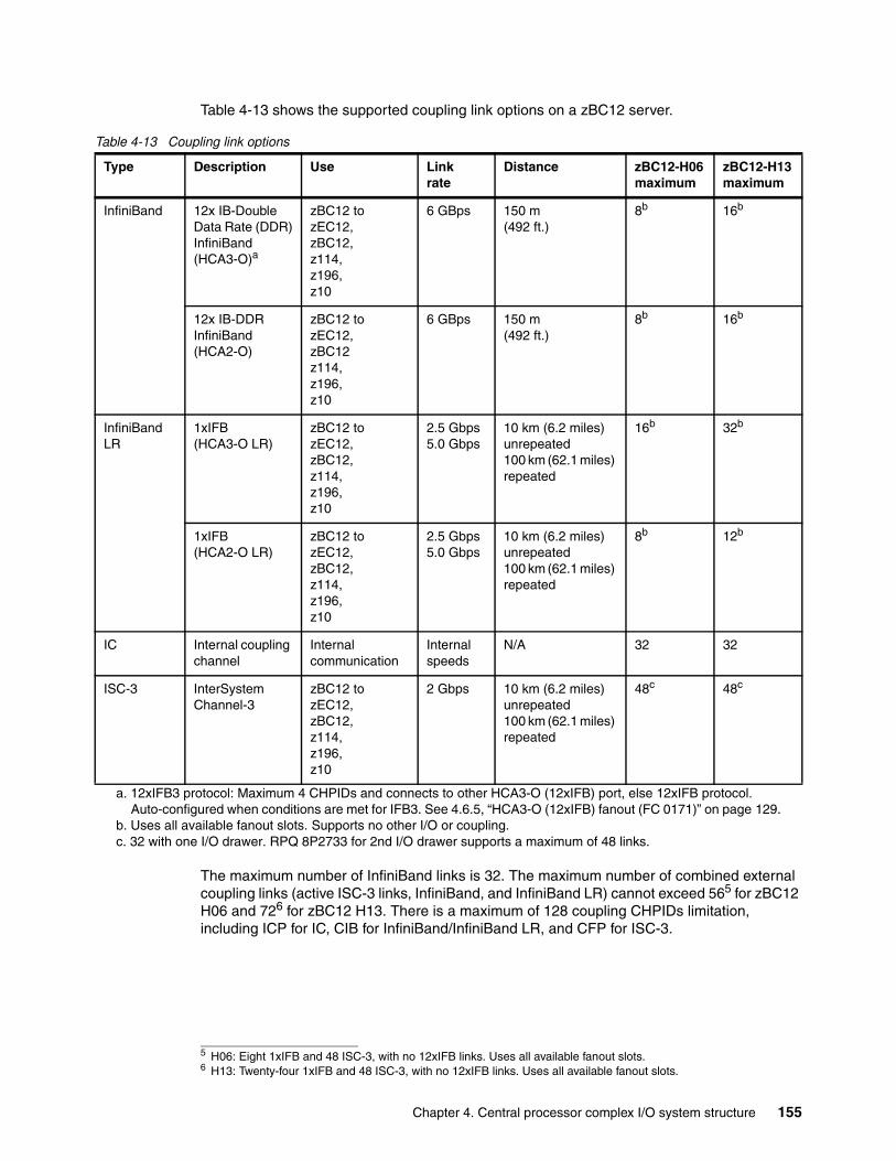
Table 4-13 shows the supported coupling link options on a zBC12 server.
Table 4-13 Coupling link options
The maximum number of InfiniBand links is 32. The maximum number of combined external coupling links (active ISC-3 links, InfiniBand, and InfiniBand LR) cannot exceed 565 for zBC12 H06 and 726 for zBC12 H13. There is a maximum of 128 coupling CHPIDs limitation, including ICP for IC, CIB for InfiniBand/InfiniBand LR, and CFP for ISC-3.
Type Description Use Link rate
Distance zBC12-H06 maximum
zBC12-H13 maximum
InfiniBand 12x IB-Double Data Rate (DDR)InfiniBand(HCA3-O)a
a. 12xIFB3 protocol: Maximum 4 CHPIDs and connects to other HCA3-O (12xIFB) port, else 12xIFB protocol. Auto-configured when conditions are met for IFB3. See 4.6.5, “HCA3-O (12xIFB) fanout (FC 0171)” on page 129.
zBC12 to zEC12,zBC12,z114,z196,z10
6 GBps 150 m (492 ft.)
8b
b. Uses all available fanout slots. Supports no other I/O or coupling.
16b
12x IB-DDRInfiniBand(HCA2-O)
zBC12 to zEC12,zBC12z114,z196,z10
6 GBps 150 m (492 ft.)
8b 16b
InfiniBand LR
1xIFB(HCA3-O LR)
zBC12 to zEC12,zBC12,z114,z196,z10
2.5 Gbps5.0 Gbps
10 km (6.2 miles)unrepeated100 km (62.1 miles) repeated
16b 32b
1xIFB(HCA2-O LR)
zBC12 to zEC12,zBC12,z114,z196,z10
2.5 Gbps5.0 Gbps
10 km (6.2 miles)unrepeated100 km (62.1 miles) repeated
8b 12b
IC Internal coupling channel
Internal communication
Internal speeds
N/A 32 32
ISC-3 InterSystem Channel-3
zBC12 to zEC12,zBC12,z114,z196,z10
2 Gbps 10 km (6.2 miles)unrepeated100 km (62.1 miles) repeated
48c
c. 32 with one I/O drawer. RPQ 8P2733 for 2nd I/O drawer supports a maximum of 48 links.
48c
5 H06: Eight 1xIFB and 48 ISC-3, with no 12xIFB links. Uses all available fanout slots.6 H13: Twenty-four 1xIFB and 48 ISC-3, with no 12xIFB links. Uses all available fanout slots.
Chapter 4. Central processor complex I/O system structure 155
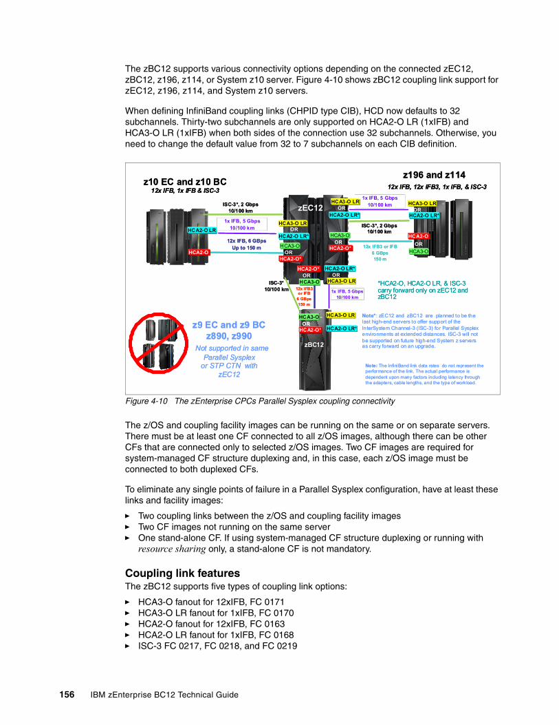
The zBC12 supports various connectivity options depending on the connected zEC12, zBC12, z196, z114, or System z10 server. Figure 4-10 shows zBC12 coupling link support for zEC12, z196, z114, and System z10 servers.
When defining InfiniBand coupling links (CHPID type CIB), HCD now defaults to 32 subchannels. Thirty-two subchannels are only supported on HCA2-O LR (1xIFB) and HCA3-O LR (1xIFB) when both sides of the connection use 32 subchannels. Otherwise, you need to change the default value from 32 to 7 subchannels on each CIB definition.
Figure 4-10 The zEnterprise CPCs Parallel Sysplex coupling connectivity
The z/OS and coupling facility images can be running on the same or on separate servers. There must be at least one CF connected to all z/OS images, although there can be other CFs that are connected only to selected z/OS images. Two CF images are required for system-managed CF structure duplexing and, in this case, each z/OS image must be connected to both duplexed CFs.
To eliminate any single points of failure in a Parallel Sysplex configuration, have at least these links and facility images:
� Two coupling links between the z/OS and coupling facility images� Two CF images not running on the same server� One stand-alone CF. If using system-managed CF structure duplexing or running with
resource sharing only, a stand-alone CF is not mandatory.
Coupling link features The zBC12 supports five types of coupling link options:
� HCA3-O fanout for 12xIFB, FC 0171� HCA3-O LR fanout for 1xIFB, FC 0170� HCA2-O fanout for 12xIFB, FC 0163� HCA2-O LR fanout for 1xIFB, FC 0168� ISC-3 FC 0217, FC 0218, and FC 0219
ISC-3*, 2 Gbps10/100 km
z196 and z11412x IFB, 12x IFB3, 1x IFB, & ISC-3
12x IFB, 6 GBpsUp to 150 m
z10 EC and z10 BC12x IFB, 1x IFB & ISC-3
1x IFB, 5 Gbps10/100 km
ISC-3*10/100 km 1x IFB, 5 Gbps
10/100 km
12x IFB3 or IFB
6 GBps150 m
HCA3-O
HCA3-O
ISC-3*, 2 Gbps10/100 km
HCA2-O*
HCA2-O*
HCA2-O OR
OR
*HCA2-O, HCA2-O LR, & ISC-3 carry forward only on zEC12 and zBC12
HCA3-O LROR
HCA3-O LROR
HCA2-O LR*
HCA2-O LR*
Note: The InfiniBand link data rates do not represent the performance of the link. The actual performance is dependent upon many factors including latency through the adapters, cable lengths, and the type of workload.
HCA2-O LR*
zEC12
zEC12
HCA2-O LR
1x IFB, 5 Gbps10/100 km
HCA3-O LROR
HCA2-O LR*
HCA2-O 12x IFB3 or IFB
6 GBps150 m
OR
HCA3-O
HCA3-O LROR
HCA3-O
HCA2-O* OR
z9 EC and z9 BCz890, z990
Not supported in same Parallel Sysplex
or STP CTN with zEC12
Note*: zEC12 and zBC12 are planned to be the last high-end servers to offer support of the InterSystem Channel-3 (ISC-3) for Parallel Sysplexenvironments at extended distances. ISC-3 will not be supported on future high-end System z servers as carry forward on an upgrade.
HCA3-O LROR
HCA2-O LR*
HCA3-O
HCA2-O*OR
zBC12
ISC-3*, 2 Gbps10/100 km
z196 and z11412x IFB, 12x IFB3, 1x IFB, & ISC-3
12x IFB, 6 GBpsUp to 150 m
z10 EC and z10 BC12x IFB, 1x IFB & ISC-3
1x IFB, 5 Gbps10/100 km
ISC-3*10/100 km 1x IFB, 5 Gbps
10/100 km
12x IFB3 or IFB
6 GBps150 m
HCA3-O
HCA3-O
ISC-3*, 2 Gbps10/100 km
HCA2-O*
HCA2-O*
HCA2-O OR
OR
*HCA2-O, HCA2-O LR, & ISC-3 carry forward only on zEC12 and zBC12
HCA3-O LROR
HCA3-O LROR
HCA2-O LR*
HCA2-O LR*
Note: The InfiniBand link data rates do not represent the performance of the link. The actual performance is dependent upon many factors including latency through the adapters, cable lengths, and the type of workload.
HCA2-O LR*
zEC12
zEC12
HCA2-O LR
1x IFB, 5 Gbps10/100 km
HCA3-O LROR
HCA2-O LR*
HCA2-O 12x IFB3 or IFB
6 GBps150 m
OR
HCA3-O
HCA3-O LROR
HCA3-O
HCA2-O* OR
z9 EC and z9 BCz890, z990
Not supported in same Parallel Sysplex
or STP CTN with zEC12
Note*: zEC12 and zBC12 are planned to be the last high-end servers to offer support of the InterSystem Channel-3 (ISC-3) for Parallel Sysplexenvironments at extended distances. ISC-3 will not be supported on future high-end System z servers as carry forward on an upgrade.
HCA3-O LROR
HCA2-O LR*
HCA3-O
HCA2-O*OR
HCA3-O
HCA2-O*OR
zBC12
156 IBM zEnterprise BC12 Technical Guide
The coupling link features that are available on the zBC12 connect zBC12 servers to the identified System z servers by various link options:
� 12xIFB using HCA3-O fanout card at 6 GBps to zEC12, zBC12, z196, z114, and System z10
� 1xIFB using both HCA3-O LR (1xIFB) and HCA2-O LR (1xIFB) at 5.0 or 2.5 Gbps to zEC12, zBC12, z196, z114, and System z10 servers
� 12xIFB using HCA2-O fanout card at 6 GBps to zEC12, zBC12, z196, z114, and System z10
� ISC-3 at 2 Gbps to zEC12, zBC12, z196, z114, and System z10
InfiniBand coupling links (FC 0163)For detailed information, see 4.6.3, “HCA2-O (12xIFB) fanout (FC 0163)” on page 127.
InfiniBand coupling links LR (FC 0168)For detailed information, see 4.6.4, “HCA2-O LR (1xIFB) fanout (FC 0168)” on page 128.
HCA3-O fanout for 12xIFB (FC 0171)For detailed information, see 4.6.5, “HCA3-O (12xIFB) fanout (FC 0171)” on page 129.
HCA3-O LR fanout for 1xIFB (FC 0170)For detailed information, see 4.6.6, “HCA3-O LR (1xIFB) fanout (FC 0170)” on page 131.
Internal coupling linksIC links are Licensed Internal Code (LIC)-defined links to connect a CF to a z/OS LPAR in the same server. These links are available on all System z servers. The IC link is a System z server coupling connectivity option that enables high-speed, efficient communication between a CF partition and one or more z/OS LPARs running on the same server. The IC is a linkless connection (implemented in LIC) and so does not require any hardware or cabling.
An IC link is a fast coupling link, using memory-to-memory data transfers. IC links do not have PCHID numbers, but they require CHPIDs.
IC links require an ICP channel path definition at the z/OS and the CF end of a channel connection to operate in peer mode. They are always defined and connected in pairs. The IC link operates in peer mode, and its existence is defined in HCD/IOCP.
IC links have the following attributes:
� On System z servers, operate in peer mode (channel type ICP).
� Provide the fastest connectivity, significantly faster than any external link alternatives.
� Result in better coupling efficiency than with external links, effectively reducing the server cost that is associated with Parallel Sysplex technology.
� Can be used in test or production configurations, and reduce the cost of moving into Parallel Sysplex technology while enhancing performance and reliability.
� Can be defined as spanned channels across multiple CSSs.
� Are no charge (no feature code). Employing ICFs with IC channels will result in considerable cost savings when configuring a cluster.
IC links are enabled by defining channel type ICP. A maximum of 32 IC channels can be defined on a System z server.
Chapter 4. Central processor complex I/O system structure 157
ISC-3 coupling linksThree feature codes are available to implement ISC-3 coupling links:
� FC 0217, ISC-3 mother card (ISC-M)� FC 0218, ISC-3 daughter card (ISC-D)� FC 0219, ISC-3 port (ISC-P)
The ISC-M (FC 0217) occupies one slot in the I/O cage or I/O drawer, and supports up to two daughter cards. The ISC-D (FC 0218) provides two independent ports with one CHPID that is associated with each enabled port. The ISC-3 ports are enabled and activated individually (one port at a time) by LIC.
When the quantity of ISC links (FC 0219) is selected, the quantity of ISC-P features selected determines the appropriate number of ISC-3 mother and daughter cards to be included in the configuration, up to a maximum of 12 ISC-M cards.
Each active ISC-P in peer mode supports a 2 Gbps (200 MBps) connection through 9 µm SM fiber optic cables terminated with an LC duplex connector. The maximum unrepeated distance for an ISC-3 link is 10 km (6.2 miles). With repeaters, the maximum distance extends to 100 km (62.1 miles). ISC-3 links can be defined as timing-only links when STP is enabled. Timing-only links are coupling links that enable two servers to be synchronized using STP messages when a CF does not exist at either end of the link.
RPQ 8P2197 extended distance optionThe RPQ 8P2197 daughter card provides two ports that are active and enabled when installed, and that do not require activation by LIC.
This RPQ enables the ISC-3 link to operate at 1 Gbps (100 MBps) instead of 2 Gbps (200 MBps). This lower speed enables an extended unrepeated distance of 20 km (12.4 miles). One RPQ daughter is required on both ends of the link to establish connectivity to other servers. This RPQ supports STP if defined as either a coupling link or timing-only.
Coupling link migration considerationsFor a more specific explanation of when to continue using the current ISC-3 technology versus migrating to InfiniBand coupling links, see the Coupling Facility Configuration Options white paper at the following website:
http://www.ibm.com/systems/z/advantages/pso/whitepaper.html
Coupling links and STPAll external coupling links can be used to pass time synchronization signals by using STP. STP is a message-based protocol in which timing messages are passed over data links between servers. The same coupling links can be used to exchange time and CF messages in a Parallel Sysplex.
Statement of Direction: The zEC12 and the zBC12 are planned to be the last System z servers to offer support of the ISC-3 for Parallel Sysplex environments at extended distances. ISC-3 will not be supported on future System z servers as carry forward on an upgrade. Enterprises should continue migrating from ISC-3 features (#0217, #0218, #0219) to 12xIFB (#0171 - HCA3-O fanout) or 1xIFB (#0170 - HCA3-O LR fanout) coupling links.
158 IBM zEnterprise BC12 Technical Guide
Using the coupling links to exchange STP messages has the following advantages:
� By using the same links to exchange STP messages and CF messages in a Parallel Sysplex, STP can scale with distance. Servers exchanging messages over short distances, such as InfiniBand links, can meet more stringent synchronization requirements than servers that exchange messages over long ISC-3 links (distances up to 100 km). This advantage is an enhancement over the IBM Sysplex Timer implementation, which does not scale with distance.
� Coupling links also provide the connectivity necessary in a Parallel Sysplex. Therefore, there is a potential benefit of minimizing the number of cross-site links required in a multi-site Parallel Sysplex.
Between any two servers that are intended to exchange STP messages, configure each server so that at least two coupling links exist for communication between the servers. This configuration prevents the loss of one link from causing the loss of STP communication between the servers. If a server does not have a CF LPAR, timing-only links can be used to provide STP connectivity.
The zBC12 does not support attachment to the IBM Sysplex Timer. A zBC12 can be added into a Mixed Coordinated Timing Network (CTN) only when there is a System z10 attached to the Sysplex Timer operating as a Stratum 1 server. Connections to two Stratum 1 servers are preferable to provide redundancy and avoid a single point of failure.
STP recovery enhancementThe new generation of host channel adapters (HCA3-O (12xIFB) and HCA3-O LR (1xIFB)), introduced for coupling, is designed to send a reliable, unambiguous Going Away Signal (GAS). This signal indicates that the server on which the HCA3 is running is about to enter a failed (check stopped) state.
The GAS sent by the Current Time Server (CTS) in an STP-only CTN is received by the Backup Time Server (BTS). The BTS can then safely take over as the CTS. The BTS does not have to rely on the previous Offline Signal (OLS) in a two-server CTN, or the Arbiter in a CTN with three or more servers.
This enhancement is exclusive to zEnterprise CPCs. It is available only if you have an HCA3-O (12xIFB) or HCA3-O LR (1xIFB) on the CTS communicating with an HCA3-O (12x InfiniBand) or HCA3-O LR (1x InfiniBand) on the BTS. However, the previous STP recovery design is still available for the cases when a GAS is not received, or for other failures besides a server failure.
For more information about STP configuration, see the following RedBooks publications:
� Server Time Protocol Planning Guide, SG24-7280� Server Time Protocol Implementation Guide, SG24-7281� Server Time Protocol Recovery Guide, SG24-7380
Important: A Parallel Sysplex environment in an external time reference (ETR) network must change to Mixed CTN or STP-only CTN before introducing a zBC12.
Important: For more information about configuring an STP CTN with three or more servers, see the white paper at the following website:
http://www-03.ibm.com/support/techdocs/atsmastr.nsf/WebIndex/WP101833
If the guidelines are not followed, this might result in all of the servers in the CTN becoming unsynchronized. This condition results in a sysplex-wide outage.
Chapter 4. Central processor complex I/O system structure 159
4.9.2 Oscillator card
Two oscillator cards are installed in the processor drawer to provide redundancy for continued operation and concurrent maintenance when a single oscillator card fails. The oscillator card in the CPC processor drawer provides a Pulse Per Second (PPS) input. This PPS signal can be received from a Network Time Protocol (NTP) server acts as an external time source (ETS).
Each oscillator card has a Bayonet Neill-Concelman (BNC) connector for PPS connection support, attaching to two different ETS. Two PPS connections from two different NTP servers are preferable for redundancy.
The time accuracy of an STP-only CTN is improved by adding an NTP server with the PPS output signal as the ETS device. STP tracks the highly stable, accurate PPS signal from the NTP server. It maintains accuracy of 10 µs as measured at the PPS input of the zEC12 server. If STP uses an NTP server without PPS, a time accuracy of 100 ms to the ETS is maintained. NTP servers with PPS output are available from various vendors that offer network timing solutions.
4.10 Cryptographic functions
Cryptographic functions are provided by the CP Assist for Cryptographic Function (CPACF) and the PCI Express cryptographic adapters. The zBC12 supports the Crypto Express4S feature, and, on a carry-forward only basis, the Crypto Express3 and Crypto Express3-1P cards when upgrading from earlier generations.
4.10.1 CPACF functions (FC 3863)
Feature code 3863 is required to enable CPACF functions.
4.10.2 Crypto Express4S feature (FC 0865)
Crypto Express4S is an optional and zBC12 feature not available in the previous generations. On the initial order, a minimum of two features are installed. Thereafter, the number of features increase by one at a time up to a maximum of 16 features. Each Crypto Express4S feature holds one PCI Express cryptographic adapter. Each adapter can be configured by the installation as a Secure IBM Common Cryptographic Architecture (CCA) coprocessor, as a Secure IBM Enterprise Public Key Cryptography Standards (PKCS) #11 (EP11) coprocessor, or as an accelerator.
Each Crypto Express4S feature occupies one I/O slot in the PCIe I/O drawer, and it has no CHPID assigned. However, it uses one PCHID.
4.10.3 Crypto Express3 feature (FC 0864)
Crypto Express3 is an optional feature, and it is available only in a carry-forward basis when you are upgrading from earlier generations to zBC12. The minimum number of carry-forward features is two, and the maximum number that is supported is eight features. Each Crypto Express3 feature holds two PCIe cryptographic adapters. Either of the adapters can be configured by the installation as a Secure IBM CCA coprocessor, or as an accelerator.
160 IBM zEnterprise BC12 Technical Guide
Each Crypto Express3 feature occupies one I/O slot in the I/O cage or in the I/O drawer. It has no CHPIDs assigned, but uses two PCHIDs.
4.10.4 Crypto Express3-1P feature (FC 0871)
Crypto Express3-1P is an optional feature, and it is available only in a carry-forward basis when you are upgrading from earlier generations to zBC12. The minimum number of carry-forward features is two, and the maximum number that is supported is eight features. Each Crypto Express3-1P feature holds one PCIe cryptographic adapters. The adapter can be configured by the installation as a Secure IBM CCA coprocessor, or as an accelerator.
Each Crypto Express3-1P feature occupies one I/O slot in the I/O cage or in the I/O drawer. It has no CHPIDs assigned, but uses one PCHID.
For more information about cryptographic functions, see Chapter 6, “Cryptography” on page 177.
4.11 Integrated firmware processor
The IFP is introduced by zEC12 and zBC12 servers. The IFP is reserved for managing the new generation of PCIe features. These new features are installed exclusively into the PCIe I/O drawer:
� The zEDC Express� 10GbE RoCE Express
All native PCIe features should be ordered in pairs for redundancy. According to their physical location in the PCIe I/O drawer, the features are assigned to one of the two RGs managed by the IFP. If two features of the same type are installed, one is managed by resource group 1 (RG 1) and the other feature is managed by resource group 2 (RG 2).This provides redundancy in case of maintenance or failure in one of the features or resource groups.
The IFP provides support for the following infrastructure management functions:
� Handle adapter layer functions� Firmware update� Maintenance functions
For more information about the IFP and RG, see Appendix G, “Native PCI/e” on page 491
4.12 Flash Express
The Flash Express cards are supported in the PCIe I/O drawer with other PCIe I/O cards. They are plugged into PCIe I/O drawers in pairs for availability. As with the Crypto Express4S cards, each card takes up a CHPID, and no HCD/IOCP definition is required. Flash Express subchannels are predefined, and are allocated from the .25K reserved in subchannel set 0.
Statement of Direction: The zEC12 and zBC12 systems are planned to be the last System z servers to offer support of the Crypto Express3 feature (#0864) and Crypto Express3-1P. You should upgrade from any type of Crypto Express3 features to the Crypto Express4S feature (#0865).
Chapter 4. Central processor complex I/O system structure 161
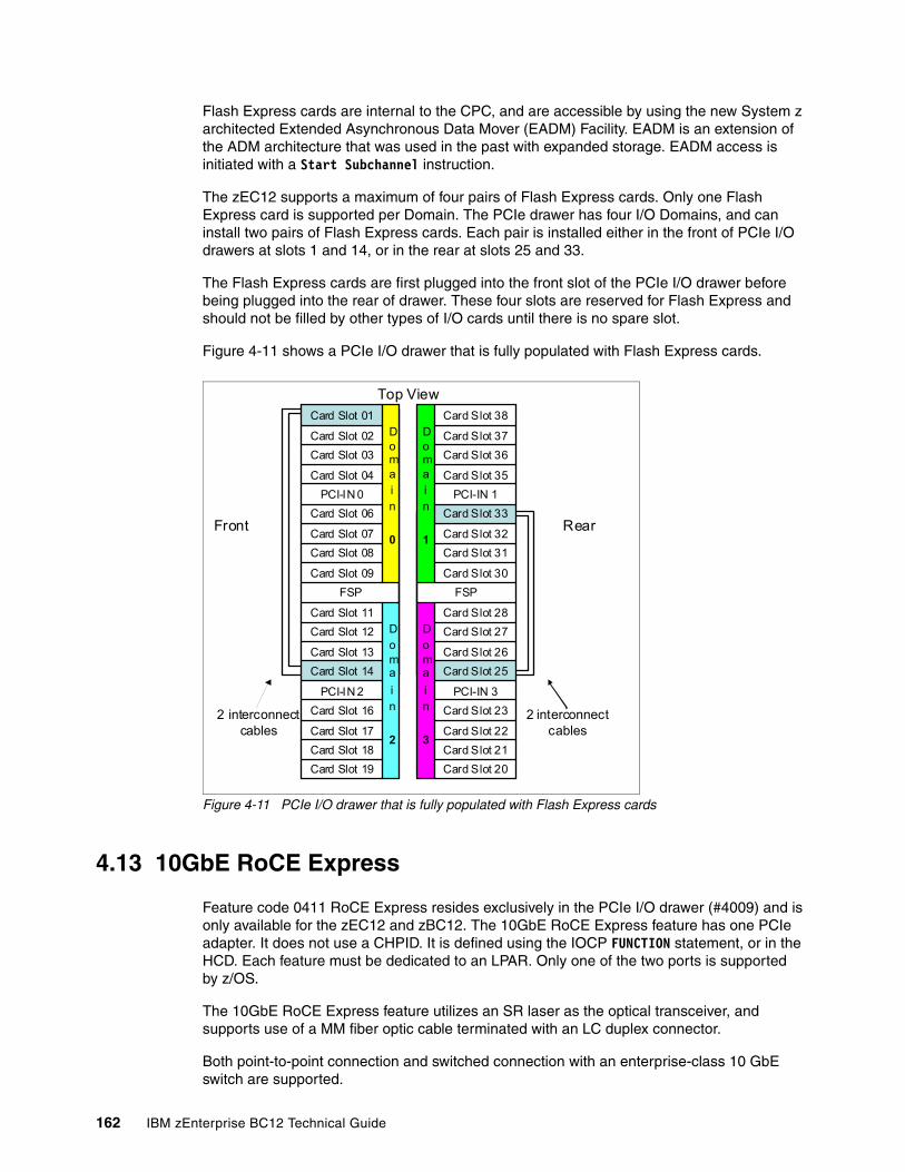
Flash Express cards are internal to the CPC, and are accessible by using the new System z architected Extended Asynchronous Data Mover (EADM) Facility. EADM is an extension of the ADM architecture that was used in the past with expanded storage. EADM access is initiated with a Start Subchannel instruction.
The zEC12 supports a maximum of four pairs of Flash Express cards. Only one Flash Express card is supported per Domain. The PCIe drawer has four I/O Domains, and can install two pairs of Flash Express cards. Each pair is installed either in the front of PCIe I/O drawers at slots 1 and 14, or in the rear at slots 25 and 33.
The Flash Express cards are first plugged into the front slot of the PCIe I/O drawer before being plugged into the rear of drawer. These four slots are reserved for Flash Express and should not be filled by other types of I/O cards until there is no spare slot.
Figure 4-11 shows a PCIe I/O drawer that is fully populated with Flash Express cards.
Figure 4-11 PCIe I/O drawer that is fully populated with Flash Express cards
4.13 10GbE RoCE Express
Feature code 0411 RoCE Express resides exclusively in the PCIe I/O drawer (#4009) and is only available for the zEC12 and zBC12. The 10GbE RoCE Express feature has one PCIe adapter. It does not use a CHPID. It is defined using the IOCP FUNCTION statement, or in the HCD. Each feature must be dedicated to an LPAR. Only one of the two ports is supported by z/OS.
The 10GbE RoCE Express feature utilizes an SR laser as the optical transceiver, and supports use of a MM fiber optic cable terminated with an LC duplex connector.
Both point-to-point connection and switched connection with an enterprise-class 10 GbE switch are supported.
Doma
in
2
Domain
0
Doma
in
3
Domain
1
Card Slot 19
Card Slot 18
Card Slot 17
Card Slot 16
PCI-IN 2
Card Slot 14
Card Slot 13
Card Slot 12
Card Slot 11
FSP
Card Slot 09
Card Slot 08
Card Slot 07
Card Slot 06
PCI-IN 0
Card Slot 04
Card Slot 03
Card Slot 02
Card Slot 01
Card Slot 33
Card Slot 32
Card Slot 31
Card Slot 30
Card Slot 20
Card Slot 21
Card Slot 22
Card Slot 23
PCI-IN 3
Card Slot 25
Card Slot 26
Card Slot 27
Card Slot 28
FSP
PCI-IN 1
Card Slot 35
Card Slot 36
Card Slot 37
Card Slot 38
Top View
RearFront
2 interconnect cables
2 interconnect cables
162 IBM zEnterprise BC12 Technical Guide
The maximum supported unrepeated distance, point-to-point is 300 meters.
A customer-supplied cable is required. Three types of cables can be used for connecting the port to the selected 10 GbE switch or to the 10GbE RoCE Express feature on the attached server:
� OM3 50 micron MM fiber optic cable, rated at 2000 MHz-km and terminated with an LC duplex connector (support 300 meters)
� OM2 50 micron MM fiber optic cable, rated at 500 MHz-km and terminated with an LC duplex connector (support 82 meters)
� OM1 62.5 micron MM fiber optic cable, rated at 200 MHz-km and terminated with an LC duplex connector (support 33 meters)
4.14 The zEDC Express
The zEDC Express is an optional feature (FC 0420), exclusive to the zEC12 and zBC12. It is designed to provide hardware-based acceleration for data compression and decompression.
The feature installs exclusively on the PCIe I/O drawer. Up to two zEDC Express features can be installed per PCIe I/O drawer domain. However, if the domain contains a Flash Express or 10GbE RoCE feature, only one zEDC feature can be installed on that domain.
Between one and eight features can be installed on the system. There is one PCIe adapter/compression coprocessor per feature, which implements compression as defined by RFC1951 (DEFLATE).
A zEDC Express feature can be shared by up to 15 LPARs.
Adapter support for zEDC is provided by RG code running on the system IFP. For resilience, there are always two independent RGs on the system, sharing the IFP. It is, therefore, suggested that a minimum of two zEDC features be installed, one per RG. For best data throughput and availability, two features per RG, for a total of four features, should be installed.
Support of zEDC Express functionality use is provided by z/OS V2R1 for both data compression and decompression. Support for data recovery (decompression), in the case that zEDC is not available on the system, is provided via software on z/OS V2R1, V1R13, and V1R12, with appropriate program temporary fixes (PTFs). Software decompression is slow and uses considerable processor resources, so it is not recommended for production environments.
Switch configuration for RoCE: If the IBM 10GbE RoCE Express features are connected to 10 GbE switches, the switches should support the following requirements:
� Global Pause function enabled� Priority Flow Control (PFC) disabled� No firewalls, no routing, and no IEDN
Chapter 4. Central processor complex I/O system structure 163
IBM System z Batch Network AnalyzerThe IBM System z Batch Network Analyzer (zBNA) is a free, “as is” tool. It is available to customers, IBM Business Partners, and IBM employees. The zBNA replaces the BWATOOL. It is Windows-based, provides graphical and text reports, including Gantt charts, and support for alternate processors.
The zBNA can be used to analyze customer-provided System Management Facility (SMF) records, to identify jobs and data sets that are candidates for zEDC compression, across a specified time window, typically a batch window. The zBNA is able to generate lists of data sets by job:
� Those that already perform hardware compression, and might be candidates for zEDC� Those that might be zEDC candidates, but are not in extended format
Therefore, zBNA can help estimate utilization of zEDC features, and help size the number of features needed.
IBM employees can obtain zBNA and other Capacity Planning Support
(CPS) tools via the IBM intranet at the following website:
http://w3-03.ibm.com/support/techdocs/atsmastr.nsf/WebIndex/PRS5126
IBM Business Partners can obtain zBNA and other CPS tools via the following website:
https://www.ibm.com/partnerworld/wps/servlet/mem/ContentHandler/tech_PRS5133
IBM clients can obtain zBNA and other CPS tools via the following website:
http://www-03.ibm.com/support/techdocs/atsmastr.nsf/WebIndex/PRS5132
164 IBM zEnterprise BC12 Technical Guide
Chapter 5. Central processor complex channel subsystem
In this chapter, we describe the concepts of the System z channel subsystem, including multiple channel subsystems. We also provide information about the technology, terminology, and implementation aspects of the channel subsystem.
We cover the following topics:
� Channel subsystem� Input/output configuration management� Channel subsystem summary� System-initiated channel path identifier reconfiguration� Multipath initial program load (IPL)
5
© Copyright IBM Corp. 2014. All rights reserved. 165
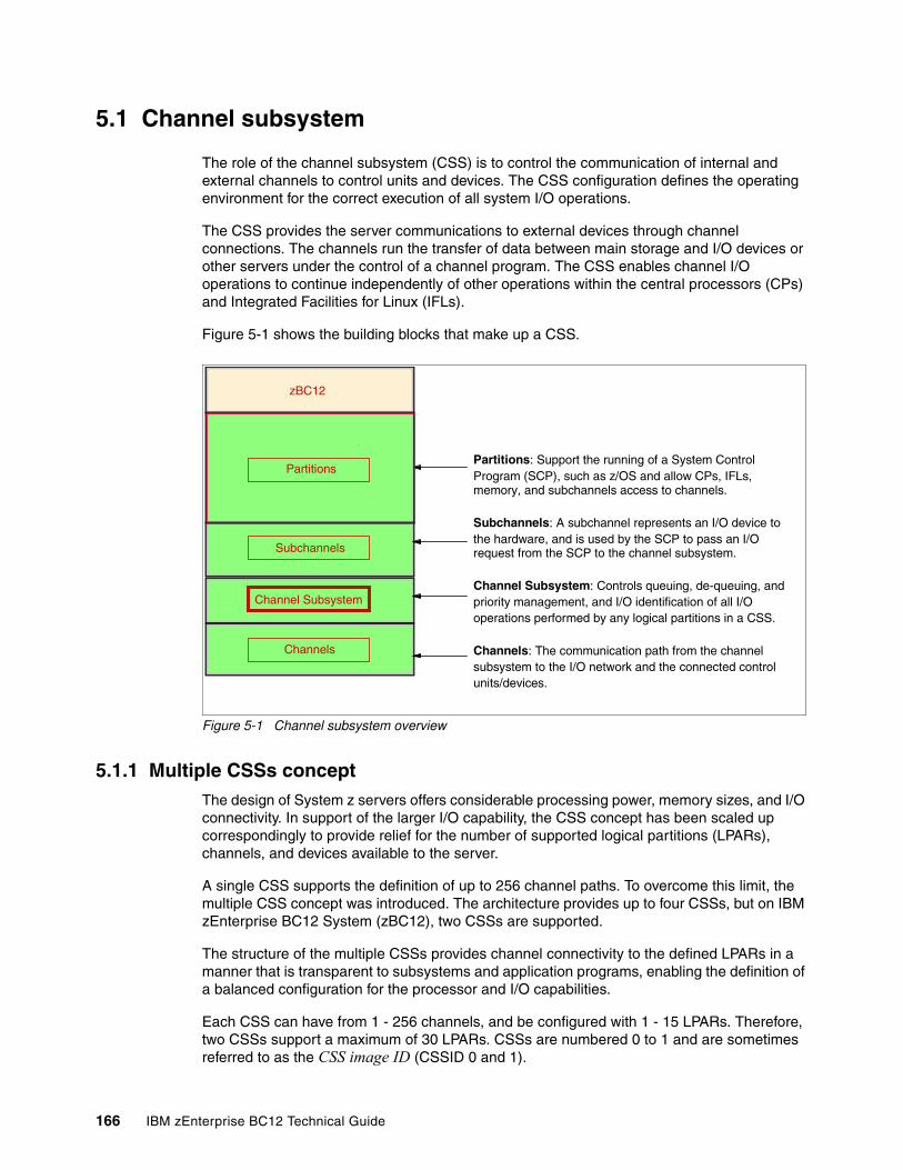
5.1 Channel subsystem
The role of the channel subsystem (CSS) is to control the communication of internal and external channels to control units and devices. The CSS configuration defines the operating environment for the correct execution of all system I/O operations.
The CSS provides the server communications to external devices through channel connections. The channels run the transfer of data between main storage and I/O devices or other servers under the control of a channel program. The CSS enables channel I/O operations to continue independently of other operations within the central processors (CPs) and Integrated Facilities for Linux (IFLs).
Figure 5-1 shows the building blocks that make up a CSS.
Figure 5-1 Channel subsystem overview
5.1.1 Multiple CSSs conceptThe design of System z servers offers considerable processing power, memory sizes, and I/O connectivity. In support of the larger I/O capability, the CSS concept has been scaled up correspondingly to provide relief for the number of supported logical partitions (LPARs), channels, and devices available to the server.
A single CSS supports the definition of up to 256 channel paths. To overcome this limit, the multiple CSS concept was introduced. The architecture provides up to four CSSs, but on IBM zEnterprise BC12 System (zBC12), two CSSs are supported.
The structure of the multiple CSSs provides channel connectivity to the defined LPARs in a manner that is transparent to subsystems and application programs, enabling the definition of a balanced configuration for the processor and I/O capabilities.
Each CSS can have from 1 - 256 channels, and be configured with 1 - 15 LPARs. Therefore, two CSSs support a maximum of 30 LPARs. CSSs are numbered 0 to 1 and are sometimes referred to as the CSS image ID (CSSID 0 and 1).
Channels
Subchannels
Partitions
Channel Subsystem
zBC12
Partitions: Support the running of a System Control Program (SCP), such as z/OS and allow CPs, IFLs, memory, and subchannels access to channels.
Subchannels: A subchannel represents an I/O device to the hardware, and is used by the SCP to pass an I/O request from the SCP to the channel subsystem.
Channel Subsystem: Controls queuing, de-queuing, andpriority management, and I/O identification of all I/O operations performed by any logical partitions in a CSS.
Channels: The communication path from the channel subsystem to the I/O network and the connected control units/devices.
166 IBM zEnterprise BC12 Technical Guide
5.1.2 CSS elementsWe describe the elements that encompass the CSS in this section.
SubchannelsA subchannel provides the logical representation of a device to a program, and contains the information required for sustaining a single I/O operation. A subchannel is assigned for each device defined to the LPAR.
Multiple subchannel sets, described in 5.1.3, “Multiple subchannel sets” on page 167, are available to increase addressability. Two subchannel sets per CSS are supported on zBC12. Subchannel set 0 can have up to 63.75 KB subchannels, and subchannel set 1 can have up to 64 KB minus one subchannels.
Channel pathsEach CSS can have up to 256 channel paths. A channel path is a single interface between a server and one or more control units. Commands and data are sent across a channel path to perform I/O requests.
Channel path identifierEach channel path in the system is assigned a unique identifier value known as a channel path identifier (CHPID). A total of 256 CHPIDs are supported by the CSS, and a maximum of 256 are supported per zBC12.
The channel subsystem communicates with I/O devices by means of channel paths between the channel subsystem and control units. On System z, a CHPID number is assigned to a physical location (slot/port) by the customer, through the Hardware Configuration Definition (HCD) tool or input/output configuration program (IOCP).
Control unitsA control unit (CU) provides the logical capabilities necessary to operate and control an I/O device, and adapts the characteristics of each device so that it can respond to the standard form of control provided by the CSS. A CU can be housed separately, or it can be physically and logically integrated with the I/O device, the CSS, or within the server itself.
I/O devicesAn I/O device provides external storage, a means of communication between data-processing systems, or a means of communication between a system and its environment. In the simplest case, an I/O device is attached to one CU, and is accessible through one channel path.
5.1.3 Multiple subchannel setsDo not confuse the multiple subchannel set (MSS) functionality with multiple channel subsystems. In most cases, a subchannel represents an addressable device. For example, a disk control unit with 30 drives uses 30 subchannels (for base addresses), and so forth. An addressable device is associated with a device number and the device number is commonly (but incorrectly) known as the device address.
Subchannel numbersSubchannel numbers (including their implied path information to a device) are limited to four hexadecimal digits by the architecture (0x0000 to 0xFFFF). Four hexadecimal digits provide 64 KB addresses, known as a set.
Chapter 5. Central processor complex channel subsystem 167
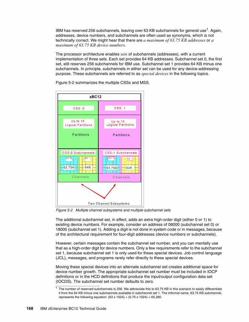
IBM has reserved 256 subchannels, leaving over 63 KB subchannels for general use1. Again, addresses, device numbers, and subchannels are often used as synonyms, which is not technically correct. We might hear that there are a maximum of 63.75 KB addresses or a maximum of 63.75 KB device numbers.
The processor architecture enables sets of subchannels (addresses), with a current implementation of three sets. Each set provides 64 KB addresses. Subchannel set 0, the first set, still reserves 256 subchannels for IBM use. Subchannel set 1 provides 64 KB minus one subchannels. In principle, subchannels in either set can be used for any device-addressing purpose. These subchannels are referred to as special devices in the following topics.
Figure 5-2 summarizes the multiple CSSs and MSS.
Figure 5-2 Multiple channel subsystems and multiple subchannel sets
The additional subchannel set, in effect, adds an extra high-order digit (either 0 or 1) to existing device numbers. For example, consider an address of 08000 (subchannel set 0) or 18000 (subchannel set 1). Adding a digit is not done in system code or in messages, because of the architectural requirement for four-digit addresses (device numbers or subchannels).
However, certain messages contain the subchannel set number, and you can mentally use that as a high-order digit for device numbers. Only a few requirements refer to the subchannel set 1, because subchannel set 1 is only used for these special devices. Job control language (JCL), messages, and programs rarely refer directly to these special devices.
Moving these special devices into an alternate subchannel set creates additional space for device number growth. The appropriate subchannel set number must be included in IOCP definitions or in the HCD definitions that produce the input/output configuration data set (IOCDS). The subchannel set number defaults to zero.
1 The number of reserved subchannels is 256. We abbreviate this to 63.75 KB in this scenario to easily differentiate it from the 64 KB minus one subchannels available in subchannel set 1. The informal name, 63.75 KB subchannel, represents the following equation: (63 x 1024) + (0.75 x 1024) = 65,280.
zBC12
168 IBM zEnterprise BC12 Technical Guide
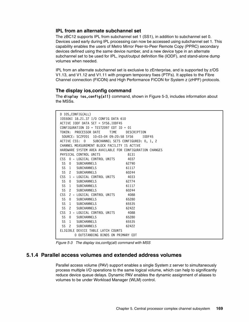
IPL from an alternate subchannel setThe zBC12 supports IPL from subchannel set 1 (SS1), in addition to subchannel set 0. Devices used early during IPL processing can now be accessed using subchannel set 1. This capability enables the users of Metro Mirror Peer-to-Peer Remote Copy (PPRC) secondary devices defined using the same device number, and a new device type in an alternate subchannel set to be used for IPL, input/output definition file (IODF), and stand-alone dump volumes when needed.
IPL from an alternate subchannel set is exclusive to zEnterprise, and is supported by z/OS V1.13, and V1.12 and V1.11 with program temporary fixes (PTFs). It applies to the Fibre Channel connection (FICON) and High Performance FICON for System z (zHPF) protocols.
The display ios,config commandThe display ios,config(all) command, shown in Figure 5-3, includes information about the MSSs.
Figure 5-3 The display ios,config(all) command with MSS
5.1.4 Parallel access volumes and extended address volumes
Parallel access volume (PAV) support enables a single System z server to simultaneously process multiple I/O operations to the same logical volume, which can help to significantly reduce device queue delays. Dynamic PAV enables the dynamic assignment of aliases to volumes to be under Workload Manager (WLM) control.
D IOS,CONFIG(ALL) IOS506I 18.21.37 I/O CONFIG DATA 610 ACTIVE IODF DATA SET = SYS6.IODF45 CONFIGURATION ID = TEST2097 EDT ID = 01 TOKEN: PROCESSOR DATE TIME DESCRIPTION SOURCE: SCZP201 10-03-04 09:20:58 SYS6 IODF45 ACTIVE CSS: 0 SUBCHANNEL SETS CONFIGURED: 0, 1, 2 CHANNEL MEASUREMENT BLOCK FACILITY IS ACTIVE HARDWARE SYSTEM AREA AVAILABLE FOR CONFIGURATION CHANGES PHYSICAL CONTROL UNITS 8131 CSS 0 - LOGICAL CONTROL UNITS 4037 SS 0 SUBCHANNELS 62790 SS 1 SUBCHANNELS 61117 SS 2 SUBCHANNELS 60244 CSS 1 - LOGICAL CONTROL UNITS 4033 SS 0 SUBCHANNELS 62774 SS 1 SUBCHANNELS 61117 SS 2 SUBCHANNELS 60244 CSS 2 - LOGICAL CONTROL UNITS 4088 SS 0 SUBCHANNELS 65280 SS 1 SUBCHANNELS 65535 SS 2 SUBCHANNELS 62422 CSS 3 - LOGICAL CONTROL UNITS 4088 SS 0 SUBCHANNELS 65280 SS 1 SUBCHANNELS 65535 SS 2 SUBCHANNELS 62422 ELIGIBLE DEVICE TABLE LATCH COUNTS 0 OUTSTANDING BINDS ON PRIMARY EDT
Chapter 5. Central processor complex channel subsystem 169
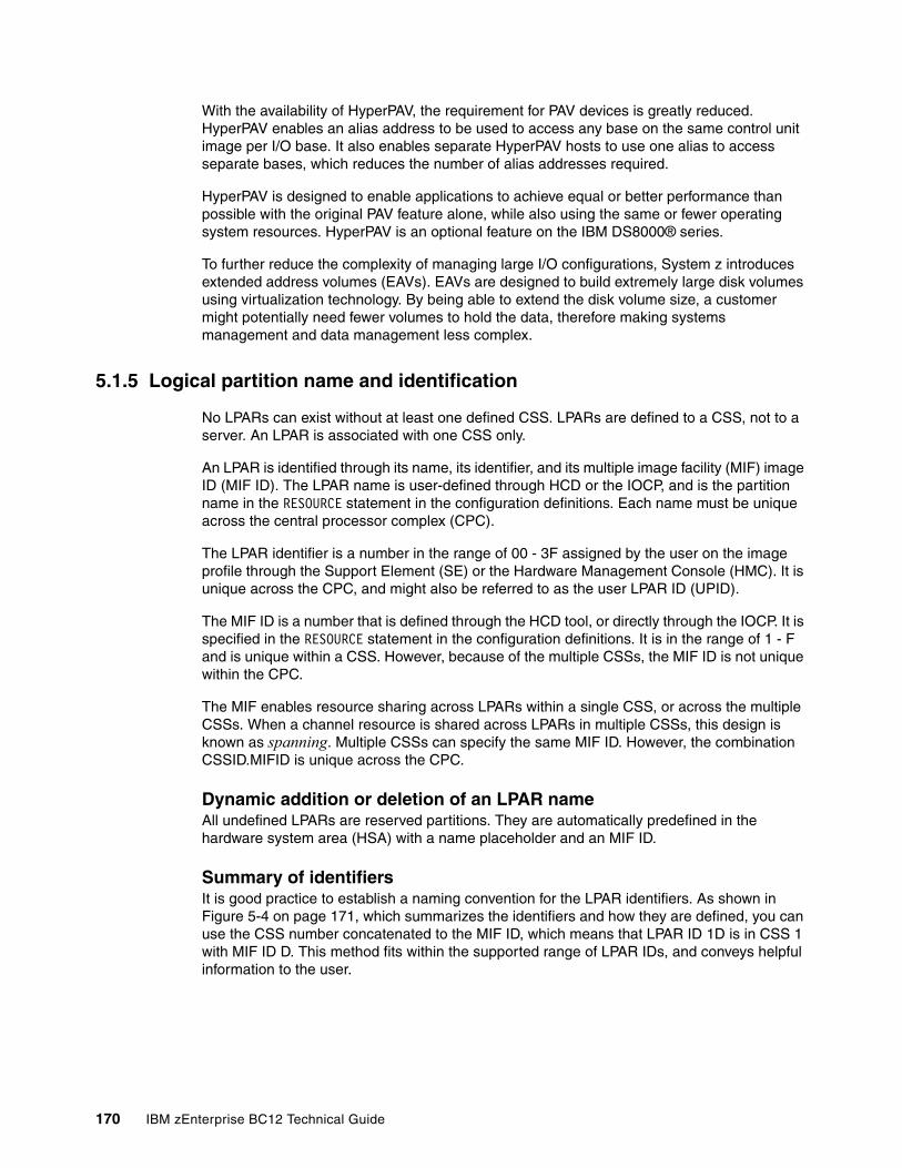
With the availability of HyperPAV, the requirement for PAV devices is greatly reduced. HyperPAV enables an alias address to be used to access any base on the same control unit image per I/O base. It also enables separate HyperPAV hosts to use one alias to access separate bases, which reduces the number of alias addresses required.
HyperPAV is designed to enable applications to achieve equal or better performance than possible with the original PAV feature alone, while also using the same or fewer operating system resources. HyperPAV is an optional feature on the IBM DS8000® series.
To further reduce the complexity of managing large I/O configurations, System z introduces extended address volumes (EAVs). EAVs are designed to build extremely large disk volumes using virtualization technology. By being able to extend the disk volume size, a customer might potentially need fewer volumes to hold the data, therefore making systems management and data management less complex.
5.1.5 Logical partition name and identification
No LPARs can exist without at least one defined CSS. LPARs are defined to a CSS, not to a server. An LPAR is associated with one CSS only.
An LPAR is identified through its name, its identifier, and its multiple image facility (MIF) image ID (MIF ID). The LPAR name is user-defined through HCD or the IOCP, and is the partition name in the RESOURCE statement in the configuration definitions. Each name must be unique across the central processor complex (CPC).
The LPAR identifier is a number in the range of 00 - 3F assigned by the user on the image profile through the Support Element (SE) or the Hardware Management Console (HMC). It is unique across the CPC, and might also be referred to as the user LPAR ID (UPID).
The MIF ID is a number that is defined through the HCD tool, or directly through the IOCP. It is specified in the RESOURCE statement in the configuration definitions. It is in the range of 1 - F and is unique within a CSS. However, because of the multiple CSSs, the MIF ID is not unique within the CPC.
The MIF enables resource sharing across LPARs within a single CSS, or across the multiple CSSs. When a channel resource is shared across LPARs in multiple CSSs, this design is known as spanning. Multiple CSSs can specify the same MIF ID. However, the combination CSSID.MIFID is unique across the CPC.
Dynamic addition or deletion of an LPAR nameAll undefined LPARs are reserved partitions. They are automatically predefined in the hardware system area (HSA) with a name placeholder and an MIF ID.
Summary of identifiersIt is good practice to establish a naming convention for the LPAR identifiers. As shown in Figure 5-4 on page 171, which summarizes the identifiers and how they are defined, you can use the CSS number concatenated to the MIF ID, which means that LPAR ID 1D is in CSS 1 with MIF ID D. This method fits within the supported range of LPAR IDs, and conveys helpful information to the user.
170 IBM zEnterprise BC12 Technical Guide
Figure 5-4 CSS, LPAR, and identifiers example
5.1.6 Physical channel ID
A physical channel ID (PCHID) reflects the physical identifier of a channel-type interface. A PCHID number is based on the I/O drawer or PCIe I/O drawer location, the channel feature slot number, and the port number of the channel feature. A hardware channel is identified by a PCHID. The physical channel, which uniquely identifies a connector jack on a channel feature, is known by its PCHID number. For further information, see 4.7.2, “PCHID report” on page 135.
Do not confuse PCHIDs with CHPIDs. A CHPID does not directly correspond to a hardware channel port, and it can be arbitrarily assigned. Within a single channel subsystem, 256 CHPIDs can be addressed, which gives a maximum of 512 CHPIDs when two CSSs are defined. Each CHPID number is associated with a single channel.
CHPIDs are not pre-assigned. The installation is responsible to assign the CHPID numbers through the use of the CHPID mapping tool (CMT) or HCD/IOCP. Assigning CHPIDs means that a CHPID number is associated with a physical channel/port location and a CSS. The CHPID number range is still from 00 - FF and must be unique within a CSS. Any non-internal CHPID that is not defined with a PCHID can fail validation when an attempt is made to build a production IODF or an IOCDS.
5.1.7 Channel spanningChannel spanning extends the MIF concept of sharing channels across LPARs to sharing channels across LPARs and channel subsystems.
Spanning is the ability for a PCHID to be mapped to CHPIDs defined in multiple channel subsystems. When defined that way, the channels can be transparently shared by any or all of the configured LPARs, regardless of the channel subsystem to which the LPAR is configured.
A channel is considered a spanned channel if the same CHPID number in separate CSSs is assigned to the same PCHID in IOCP, or is defined as spanned in HCD.
C S S 0 S p e c if ie d in H C D / IO C PC S S 1
S p e c if ie d in H M CIm a g e P ro file
S p e c if ie d in H C D / IO C PT S T 1 P R O D 1 P R O D 2
0 2 0 4 0 A
L o g ic a l P a r t it io n N a m e
L o g ic a l P a r t i t io n ID
S p e c if ie d in H C D / IO C P
T S T 2 P R O D 3 P R O D 4
1 4 1 6 1 D
L o g ic a l P a r t i t io n N a m e
L o g ic a l P a r t i t io n ID
M IF ID2
M IF ID4
M IF IDA
M IF ID4
M IF ID6
M IF IDD
Chapter 5. Central processor complex channel subsystem 171
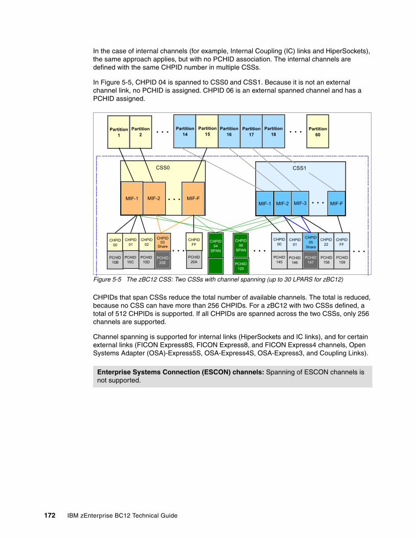
In the case of internal channels (for example, Internal Coupling (IC) links and HiperSockets), the same approach applies, but with no PCHID association. The internal channels are defined with the same CHPID number in multiple CSSs.
In Figure 5-5, CHPID 04 is spanned to CSS0 and CSS1. Because it is not an external channel link, no PCHID is assigned. CHPID 06 is an external spanned channel and has a PCHID assigned.
Figure 5-5 The zBC12 CSS: Two CSSs with channel spanning (up to 30 LPARS for zBC12)
CHPIDs that span CSSs reduce the total number of available channels. The total is reduced, because no CSS can have more than 256 CHPIDs. For a zBC12 with two CSSs defined, a total of 512 CHPIDs is supported. If all CHPIDs are spanned across the two CSSs, only 256 channels are supported.
Channel spanning is supported for internal links (HiperSockets and IC links), and for certain external links (FICON Express8S, FICON Express8, and FICON Express4 channels, Open Systems Adapter (OSA)-Express5S, OSA-Express4S, OSA-Express3, and Coupling Links).
Enterprise Systems Connection (ESCON) channels: Spanning of ESCON channels is not supported.
CSS0
Partition1
. . .Partition2
Partition14
Partition15
Partition16
Partition17
Partition18
Partition60
. . .
MIF-1 MIF-2 MIF-F. . .
CSS1
MIF-1 MIF-2 MIF-3 MIF-F
CHPID00
CHPID01
CHPID02
CHPID03
Share
PCHID10B
PCHID10C
PCHID10D
PCHID20E
. . .CHPID
FF
PCHID20A
CHPID04
SPAN
CHPID06
SPAN
PCHID120
CHPID00
CHPID01
CHPID05
Share
CHPID22
CHPIDFF
PCHID145
PCHID146
PCHID147
PCHID158
PCHID159
. . . . . .
. . .
172 IBM zEnterprise BC12 Technical Guide
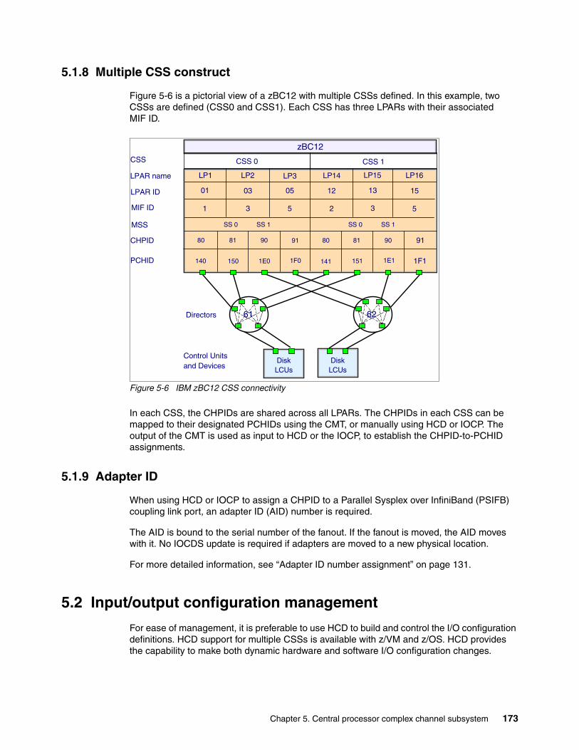
5.1.8 Multiple CSS construct
Figure 5-6 is a pictorial view of a zBC12 with multiple CSSs defined. In this example, two CSSs are defined (CSS0 and CSS1). Each CSS has three LPARs with their associated MIF ID.
Figure 5-6 IBM zBC12 CSS connectivity
In each CSS, the CHPIDs are shared across all LPARs. The CHPIDs in each CSS can be mapped to their designated PCHIDs using the CMT, or manually using HCD or IOCP. The output of the CMT is used as input to HCD or the IOCP, to establish the CHPID-to-PCHID assignments.
5.1.9 Adapter ID
When using HCD or IOCP to assign a CHPID to a Parallel Sysplex over InfiniBand (PSIFB) coupling link port, an adapter ID (AID) number is required.
The AID is bound to the serial number of the fanout. If the fanout is moved, the AID moves with it. No IOCDS update is required if adapters are moved to a new physical location.
For more detailed information, see “Adapter ID number assignment” on page 131.
5.2 Input/output configuration management
For ease of management, it is preferable to use HCD to build and control the I/O configuration definitions. HCD support for multiple CSSs is available with z/VM and z/OS. HCD provides the capability to make both dynamic hardware and software I/O configuration changes.
DiskLCUs
5
LP16LP2 LP3 LP14 LP15LP1
2 3531
SS 0
81 90 918081 90 9180
151 1E1 1F1141150 1E0 1F0140
CSS
LPAR name
PCHID
MIF ID
CHPID
DiskLCUs
Directors
Control Unitsand Devices
6261
LPAR ID 1503 05 12 1301
CSS 0 CSS 1
zBC12
MSS SS 1 SS 0 SS 1
Chapter 5. Central processor complex channel subsystem 173
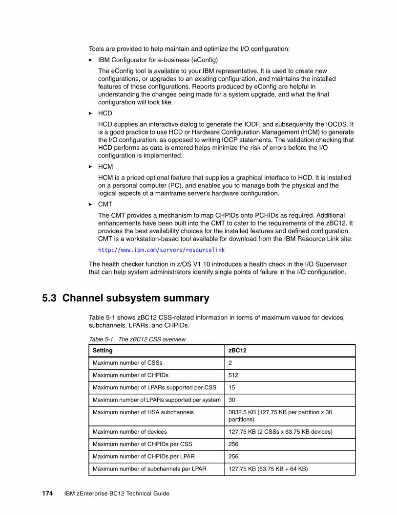
Tools are provided to help maintain and optimize the I/O configuration:
� IBM Configurator for e-business (eConfig)
The eConfig tool is available to your IBM representative. It is used to create new configurations, or upgrades to an existing configuration, and maintains the installed features of those configurations. Reports produced by eConfig are helpful in understanding the changes being made for a system upgrade, and what the final configuration will look like.
� HCD
HCD supplies an interactive dialog to generate the IODF, and subsequently the IOCDS. It is a good practice to use HCD or Hardware Configuration Management (HCM) to generate the I/O configuration, as opposed to writing IOCP statements. The validation checking that HCD performs as data is entered helps minimize the risk of errors before the I/O configuration is implemented.
� HCM
HCM is a priced optional feature that supplies a graphical interface to HCD. It is installed on a personal computer (PC), and enables you to manage both the physical and the logical aspects of a mainframe server’s hardware configuration.
� CMT
The CMT provides a mechanism to map CHPIDs onto PCHIDs as required. Additional enhancements have been built into the CMT to cater to the requirements of the zBC12. It provides the best availability choices for the installed features and defined configuration. CMT is a workstation-based tool available for download from the IBM Resource Link site:
http://www.ibm.com/servers/resourcelink
The health checker function in z/OS V1.10 introduces a health check in the I/O Supervisor that can help system administrators identify single points of failure in the I/O configuration.
5.3 Channel subsystem summary
Table 5-1 shows zBC12 CSS-related information in terms of maximum values for devices, subchannels, LPARs, and CHPIDs.
Table 5-1 The zBC12 CSS overview
Setting zBC12
Maximum number of CSSs 2
Maximum number of CHPIDs 512
Maximum number of LPARs supported per CSS 15
Maximum number of LPARs supported per system 30
Maximum number of HSA subchannels 3832.5 KB (127.75 KB per partition x 30 partitions)
Maximum number of devices 127.75 KB (2 CSSs x 63.75 KB devices)
Maximum number of CHPIDs per CSS 256
Maximum number of CHPIDs per LPAR 256
Maximum number of subchannels per LPAR 127.75 KB (63.75 KB + 64 KB)
174 IBM zEnterprise BC12 Technical Guide
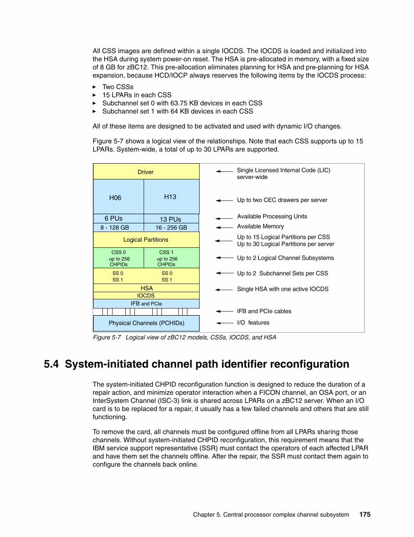
All CSS images are defined within a single IOCDS. The IOCDS is loaded and initialized into the HSA during system power-on reset. The HSA is pre-allocated in memory, with a fixed size of 8 GB for zBC12. This pre-allocation eliminates planning for HSA and pre-planning for HSA expansion, because HCD/IOCP always reserves the following items by the IOCDS process:
� Two CSSs� 15 LPARs in each CSS� Subchannel set 0 with 63.75 KB devices in each CSS� Subchannel set 1 with 64 KB devices in each CSS
All of these items are designed to be activated and used with dynamic I/O changes.
Figure 5-7 shows a logical view of the relationships. Note that each CSS supports up to 15 LPARs. System-wide, a total of up to 30 LPARs are supported.
Figure 5-7 Logical view of zBC12 models, CSSs, IOCDS, and HSA
5.4 System-initiated channel path identifier reconfiguration
The system-initiated CHPID reconfiguration function is designed to reduce the duration of a repair action, and minimize operator interaction when a FICON channel, an OSA port, or an InterSystem Channel (ISC-3) link is shared across LPARs on a zBC12 server. When an I/O card is to be replaced for a repair, it usually has a few failed channels and others that are still functioning.
To remove the card, all channels must be configured offline from all LPARs sharing those channels. Without system-initiated CHPID reconfiguration, this requirement means that the IBM service support representative (SSR) must contact the operators of each affected LPAR and have them set the channels offline. After the repair, the SSR must contact them again to configure the channels back online.
Single HSA with one active IOCDS
Available Processing Units
Up to 2 Logical Channel Subsystems
Up to 15 Logical Partitions per CSSUp to 30 Logical Partitions per server
Up to two CEC drawers per server
Available Memory
Physical Channels (PCHIDs)
HSAIOCDS
Driver
8 - 128 GB
H06
Logical Partitions
CSS 0 up to 256 CHPIDs
CSS 1 up to 256 CHPIDs
SS 0 SS 1
SS 0 SS 1
IFB and PCIe
Single Licensed Internal Code (LIC) server-wide
IFB and PCIe cables
I/O features
Up to 2 Subchannel Sets per CSS
6 PUs
H13
13 PUs16 - 256 GB
Chapter 5. Central processor complex channel subsystem 175
With system-initiated CHPID reconfiguration support, the SE sends a signal to the channel subsystem that a channel needs to be configured offline. The channel subsystem determines all the LPARs sharing that channel and sends an alert to the operating systems in those LPARs. The operating system then configures the channel offline without any operator intervention. This cycle is repeated for each channel on the card.
When the card is replaced, the SE sends another signal to the CSS for each channel. This time, the CSS alerts the operating system (OS) that the channel has to be configured back online. This process minimizes operator interaction to configure channels offline and online. System-initiated CHPID reconfiguration is supported by z/OS.
5.5 Multipath initial program load (IPL)
Multipath IPL helps increase availability, and helps eliminate manual problem determination during IPL execution. Multipath IPL enables the IPL to complete, if possible, using alternate paths when running an IPL from a device connected through ESCON and FICON channels. If an error occurs, an alternate path is selected. Multipath IPL is applicable to ESCON channels (CHPID type connection channel, or CNC) and to FICON channels (CHPID type fibre connection channel, or FC). Multipath IPL is supported by z/OS.
176 IBM zEnterprise BC12 Technical Guide
Chapter 6. Cryptography
In this chapter, we describe the hardware cryptographic functions available on the IBM zEnterprise BC12 System (zBC12). The central processor (CP) Assist for Cryptographic Function (CPACF), along with the PCIe, Cryptographic Coprocessors offer a balanced use of resources and unmatched scalability.
The zEnterprise central processor complexes (CPCs) include both standard cryptographic hardware and optional cryptographic features for flexibility and growth capability. IBM has a long history of providing hardware cryptographic solutions, from the development of Data Encryption Standard (DES) in the 1970s to having the Crypto Express tamper-sensing and tamper-responding programmable features designed to meet the US Government’s highest security rating FIPS 140-2 Level 41.
The cryptographic functions include the full range of cryptographic operations necessary for e-business, e-commerce, and financial institution applications. Custom cryptographic functions can also be added to the set of functions that the zBC12 offers.
Today, e-business applications increasingly rely on cryptographic techniques to provide the confidentiality and authentication required in this environment. Secure Sockets Layer/Transport Layer Security (SSL/TLS) is a key technology for conducting secure e-commerce using web servers, and it has being adopted by a rapidly increasing number of applications, demanding new levels of security, performance, and scalability.
We cover the following topics:
� “Cryptographic synchronous functions” on page 178� “Cryptographic asynchronous functions” on page 178� “CP Assist for Cryptographic Function” on page 189� “Crypto Express3” on page 191� “TKE workstation feature” on page 202� “Cryptographic functions comparison” on page 207� “Software support” on page 209
6
1 Federal Information Processing Standards (FIPS)140-2 Security Requirements for Cryptographic Modules
© Copyright IBM Corp. 2014. All rights reserved. 177
6.1 Cryptographic synchronous functions
Cryptographic synchronous functions are provided by the CPACF. For IBM and customer-written programs, CPACF functions can be started by instructions described in the z/Architecture Principles of Operation, SA22-7832. As a group, these instructions are known as the Message-Security Assist (MSA). The following services also invoke CPACF synchronous functions:
� The z/OS Integrated Cryptographic Service Facility (ICSF) callable services on z/OS� In-kernel cryptographic application programming interfaces (APIs) and the Library for IBM
Cryptographic Architecture (libica) functions running on Linux on System z
The zBC12 hardware includes the implementation of algorithms as hardware synchronous operations, which means holding the processor unit (PU) processing of the instruction flow until the operation has completed. The following list shows the synchronous functions:
� Data encryption and decryption algorithms for data privacy and confidentially:
– Single-length key DES– Double-length key DES– Triple-length key DES (also known as TDES)
Advanced Encryption Standard (AES) for 128-bit, 192-bit, and 256-bit keys
� Hashing algorithms for data integrity, such as Secure Hash Algorithm (SHA)-1, and SHA-2 support for SHA-224, SHA-256, SHA-384, and SHA-512
� Message authentication code:
– Single-length key message authentication code– Double-length key message authentication code
� Pseudo Random Number Generation (PRNG) for cryptographic key generation
SHA-1 and SHA-2 support for SHA-224, SHA-256, SHA-384, and SHA-512 come enabled on all servers, and do not require the CPACF enablement feature. The CPACF functions are supported by z/OS, IBM z/Virtual Machine (z/VM), IBM z/Virtual Storage Extended (z/VSE), IBM z/Transaction Processing Facility (z/TPF), and Linux on System z.
6.2 Cryptographic asynchronous functions
Cryptographic asynchronous functions are provided by the PCIe cryptographic adapters.
6.2.1 Secure key functions
The following secure key functions are provided as cryptographic asynchronous functions. System internal messages are passed to the cryptographic coprocessors to initiate the operation, then messages are passed back from the coprocessors to signal completion of the operation:
� Data encryption and decryption algorithms:
– Single-length key DES– Double-length key DES– TDES
Keys: The keys must be provided in clear form only.
178 IBM zEnterprise BC12 Technical Guide
� DES key generation and distribution
� Personal identification number (PIN) generation, verification, and translation functions
� Random number generator
� Public key algorithm (PKA) functions
Supported callable services intended for application programs that use PKA include these services:
– Importing Rivest-Shamir-Adleman (RSA) public-private key pairs in clear and encrypted forms
– RSA:
• Key generation, up to 4096 bit• Signature generation and verification, up to 4096 bit• Import and export of DES keys under an RSA key, up to 4096 bit
– Public key encryption (PKE)
The PKE service is provided for assisting the SSL/TLS handshake. PKE is used to offload compute-intensive portions of the protocol onto the cryptographic adapters.
– Public key decryption (PKD)
PKD supports a zero-pad option for clear RSA private keys. PKD is used as an accelerator for raw RSA private operations, such as those operations required by the SSL/TLS handshake and digital signature generation. The zero-pad option is used by Linux on System z to enable the use of cryptographic adapters for improved performance of digital signature generation.
– Europay MasterCard VISA (EMV) 2000 standard
Applications can be written to comply with the EMV 2000 standard for financial transactions between heterogeneous hardware and software. Support for EMV 2000 requires the PCIe feature at the zEnterprise CPC.
The Crypto Express3 and Crypto Express4s cards (PCIe cryptographic adapters) offer SHA-2 functions similar to those functions offered in the CPACF. The cards are in addition to the functions mentioned.
6.3 CPACF protected key
The zEnterprise CPCs support the protected key implementation. Since the deployment of PCI-X Cryptographic Coprocessors (PCIXCC), secure keys are processed on the PCI-X and PCIe cards, requiring an asynchronous operation to move the data and keys from the general-purpose CP to the crypto cards.
Clear keys process faster than secure keys, because the process is done synchronously on the CPACF. Protected keys blend the security of Crypto Express3and Crypto Express4s coprocessors and the performance characteristics of the CPACF, running closer to the speed of clear keys.
An enhancement to CPACF facilitates the continued privacy of cryptographic key material when used for data encryption. In Crypto Express3 and later coprocessors, a secure key is encrypted under a master key, while a protected key is encrypted under a wrapping key that is unique to each logical partition (LPAR).
Chapter 6. Cryptography 179
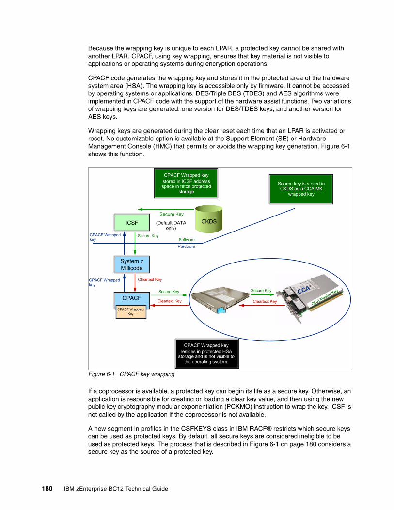
Because the wrapping key is unique to each LPAR, a protected key cannot be shared with another LPAR. CPACF, using key wrapping, ensures that key material is not visible to applications or operating systems during encryption operations.
CPACF code generates the wrapping key and stores it in the protected area of the hardware system area (HSA). The wrapping key is accessible only by firmware. It cannot be accessed by operating systems or applications. DES/Triple DES (TDES) and AES algorithms were implemented in CPACF code with the support of the hardware assist functions. Two variations of wrapping keys are generated: one version for DES/TDES keys, and another version for AES keys.
Wrapping keys are generated during the clear reset each time that an LPAR is activated or reset. No customizable option is available at the Support Element (SE) or Hardware Management Console (HMC) that permits or avoids the wrapping key generation. Figure 6-1 shows this function.
Figure 6-1 CPACF key wrapping
If a coprocessor is available, a protected key can begin its life as a secure key. Otherwise, an application is responsible for creating or loading a clear key value, and then using the new public key cryptography modular exponentiation (PCKMO) instruction to wrap the key. ICSF is not called by the application if the coprocessor is not available.
A new segment in profiles in the CSFKEYS class in IBM RACF® restricts which secure keys can be used as protected keys. By default, all secure keys are considered ineligible to be used as protected keys. The process that is described in Figure 6-1 on page 180 considers a secure key as the source of a protected key.
CPACF Wrapped keystored in ICSF address space in fetch protected
storage
Source key is stored in CKDS as a CCA MK
wrapped key
ICSF
System zMillicode
CPACF
CPACF WrappingKey
CPACF Wrapped keyresides in protected HSA
storage and is not visible to the operating system.
Secure Key
Cleartext KeyCleartext Key
Secure Key
Secure Key
(Default DATA only)
CKDS
Secure KeyCPACF Wrapped key Software
Hardware
CPACF Wrapped key
Cleartext Key
CCA
CCA Master Key
180 IBM zEnterprise BC12 Technical Guide
In Figure 6-1 on page 180, the source key is already stored in Cryptographic Key Data Set (CKDS) as a secure key (encrypted under the master key). This secure key is sent to the coprocessor to be deciphered and sent to CPACF in clear text. At CPACF, the key is wrapped under the LPAR wrapping key, and then it is returned to ICSF. After the key is wrapped, ICSF can keep the protected value in memory, passing it to the CPACF, where the key will be unwrapped for each encryption or decryption operation.
The protected key is designed to provide substantial throughput improvements for a large volume of data encryption, and low latency for encryption of small blocks of data. A high-performance secure key solution, which is also known as a protected key solution, requires ICSF HCR7770, and it is highly desirable to use a Crypto Express card.
6.3.1 Other key functions
Other key functions of the Crypto Express features serve to enhance the security of public and private key encryption processing:
� Remote loading of initial automated teller machine (ATM) keys
This function provides the ability to remotely load the initial keys for capable ATM and point-of-sale (POS) systems. Remote key loading refers to the process of loading DES keys to an ATM from a central administrative site without requiring someone to manually load the DES keys on each machine.
A new standard, American National Standards Institute (ANSI) X9.24-2, defines the acceptable methods of loading, using public key cryptographic (PKC) techniques. The process uses ICSF-callable services, along with the Crypto Express features, to perform the remote load.
ICSF has added two callable services:
– Trusted Block Create (CSNDTBC) is a callable service that is used to create a trusted block containing a public key and certain processing rules. The rules define the ways and formats in which keys are generated and exported.
– Remote Key Export (CSNDRKX) is a callable service that uses the trusted block to generate or export DES keys for local use, and for distribution to an ATM or other remote device. The PKA Key Import (CSNDPKI), PKA Key Token Change (CSNDKTC), and Digital Signature Verify (CSFNDFV) callable services support the remote key loading process.
� Key exchange with non-CCA cryptographic systems
This function enables the exchange of operational keys between the Crypto Express3 and non-Common Cryptographic Architecture (CCA) systems, such as the ATM. IBM CCA employs control vectors to control usage of cryptographic keys. Non-CCA systems use other mechanisms, or they can use keys that have no associated control information. Enhancements to key exchange functions added the capability to CCA to exchange keys between CCA systems and systems that do not use control vectors.
The capability enables the CCA system owner to define allowable types of key import and export, while preventing uncontrolled key exchange that can open the system to an increased threat of attack.
� Support for Elliptic Curve Cryptography digital signature algorithm (DSA), or ECDSA
Elliptic Curve Cryptography is an emerging PKA to eventually replace RSA cryptography in many applications. Elliptic Curve Cryptography is capable of providing digital signature functions and key agreement functions.
Chapter 6. Cryptography 181
The new CCA functions provide Elliptic Curve Cryptography key generation and key management, and provide digital signature generation and verification functions that are compliant with the ECDSA method that is described in ANSI X9.62 “Public Key Cryptography for the Financial Services Industry: The Elliptic Curve Digital Signature Algorithm (ECDSA)”.
Elliptic Curve Cryptography uses keys that are shorter than RSA keys for equivalent strength-per-key-bit. RSA is impractical at key lengths with strength-per-key-bit equivalent to AES-192 and AES-256. Therefore, the strength-per-key-bit is substantially greater in an algorithm that uses elliptical curves. This Crypto function is supported by z/OS, z/VM, and Linux on System z.
� Elliptic Curve Diffie-Hellman (ECDH) algorithm support
The CCA was extended to include the ECDH algorithm.
ECDH is a key agreement protocol that enables two parties, each having an elliptic curve public-private key pair, to establish a shared secret over an insecure channel. This shared secret can be used directly as a key, or to derive another key, which can then be used to encrypt subsequent communications using a symmetric key cipher, such as AES key-encrypting keys (KEKs). This list shows the enhancements:
– Key management function to support AES KEK– Generation of an Elliptic Curve Cryptography private key wrapped with an AES KEK– Import and export of an Elliptic Curve Cryptography private key wrapped with an
AES KEK– Support for ECDH with a new service
� PKA RSA optimal asymmetric encryption padding (OAEP) with SHA-256 algorithm
RSA Encryption Scheme - OAEP (RSAES-OAEP) is a public-key encryption scheme or method of encoding messages and data in combination with the RSA algorithm and a hash algorithm.
Currently, the CCA and z/OS ICSF provide key management services supporting the RSAES-OAEP method using the SHA-1 hash algorithm, as defined by the Public Key Cryptographic standards (PKCS) #1 V2.0 standard. These services can be used to exchange AES or DES/TDES key values securely between financial institutions and systems.
However, PKCS#1 V2.1 extends the OAEP method to include the use of the SHA-256 hashing algorithm to increase the strength of the key wrapping and unwrapping mechanism. The CCA key management services have been enhanced so that they can use RSAES-OAEP with SHA-256 in addition to RSAES-OAEP with SHA-1. This enhancement provides support for PKCS that is mandated by certain countries for interbank transactions and communication systems.
Licensing: Elliptic Curve Cryptography is delivered through the machine’s Machine Code (also called Licensed Internal Code, or LIC), and requires licensing terms in addition to the standard IBM Agreement for Licensed Machine Code (LMC).
These additional terms are delivered through the LMC’s Addendum for Elliptical Curve Cryptography. This Elliptic Curve Cryptography Addendum will be delivered with the machine along with the LMC when a cryptography feature is included in the zEnterprise CPC order, or when a cryptography feature is carried forward as part of a miscellaneous equipment specification (MES) order into zEnterprise CPC.
182 IBM zEnterprise BC12 Technical Guide
� User Defined Extensions (UDX) support
UDX enables the user to add customized operations to a cryptographic coprocessor. UDX to the CCA support customized operations that run within the Crypto Express features when defined as a coprocessor.
UDX is supported under a special contract through an IBM or approved third-party service offering. The CryptoCards website directs your request to an IBM Global Services location that is appropriate for your geographic location. A special contract is negotiated between you and IBM Global Services. The contract is for the development of the UDX by IBM Global Services according to your specifications, and an agreed-upon level of the UDX.
It is not possible to mix and match UDX definitions across Crypto Express features. Panels on the HMC and SE ensure that UDX files are applied to the appropriate crypto card type.
A UDX toolkit for System z is available for the Crypto Express3 (and later) features. In addition, there is an upgrade path for customers with UDX on a previous feature to migrate their code to the Crypto Express3 or later features. A UDX migration is no more disruptive than a normal machine change level (MCL) or ICSF release migration.
For more information, see the IBM CryptoCards website:
http://www.ibm.com/security/cryptocards
6.4 PKCS #11 Overview
The PKCS #11 is one of the industry-accepted standards (PKCS) provided by RSA Laboratories of RSA Security Inc. The PKCS #11 specifies an application programming interface (API) to devices, referred to as tokens, that hold cryptographic information and run cryptographic functions. PKCS #11 provides an alternative to IBM CCA.
The PKCS #11 describes the cryptographic token interface standard and its API, which is also known as the Cryptographic Token Interface Standard (Cryptoki). It is a de facto industry standard on many computing platforms today. It is a higher-level API when compared to CCA, and is easier to use by language C-based applications. The persistent storage and retrieval of objects is part of the standard. The objects are certificates, keys, and application-specific data objects.
6.4.1 The PKCS #11 model
On most single-user systems, a token is a smart card or other plug-installed cryptographic device that is accessed through a card reader or slot. Cryptoki provides a logical view of slots and tokens. This view makes each cryptographic device look logically similar to every other device, regardless of the technology that is used.
The PKCS #11 specification assigns numbers to slots, which are known as slot IDs. An application identifies the token that it wants to access by specifying the appropriate slot ID. On systems that have multiple slots, the application determines which slot to access.
The PKCS #11 logical view of a token is a device that stores objects and can run cryptographic functions. PKCS #11 defines three types of objects:
� A data object that is defined by an application.� A certificate object that stores a digital certificate.� A key object that stores a cryptographic key. The key can be a public key, a private key, or
a secret key.
Chapter 6. Cryptography 183
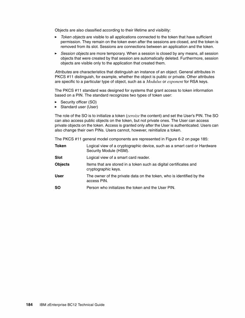
Objects are also classified according to their lifetime and visibility:
� Token objects are visible to all applications connected to the token that have sufficient permission. They remain on the token even after the sessions are closed, and the token is removed from its slot. Sessions are connections between an application and the token.
� Session objects are more temporary. When a session is closed by any means, all session objects that were created by that session are automatically deleted. Furthermore, session objects are visible only to the application that created them.
Attributes are characteristics that distinguish an instance of an object. General attributes in PKCS #11 distinguish, for example, whether the object is public or private. Other attributes are specific to a particular type of object, such as a Modulus or exponent for RSA keys.
The PKCS #11 standard was designed for systems that grant access to token information based on a PIN. The standard recognizes two types of token user:
� Security officer (SO)� Standard user (User)
The role of the SO is to initialize a token (zeroize the content) and set the User’s PIN. The SO can also access public objects on the token, but not private ones. The User can access private objects on the token. Access is granted only after the User is authenticated. Users can also change their own PINs. Users cannot, however, reinitialize a token.
The PKCS #11 general model components are represented in Figure 6-2 on page 185:
Token Logical view of a cryptographic device, such as a smart card or Hardware Security Module (HSM).
Slot Logical view of a smart card reader.
Objects Items that are stored in a token such as digital certificates and cryptographic keys.
User The owner of the private data on the token, who is identified by the access PIN.
SO Person who initializes the token and the User PIN.
184 IBM zEnterprise BC12 Technical Guide
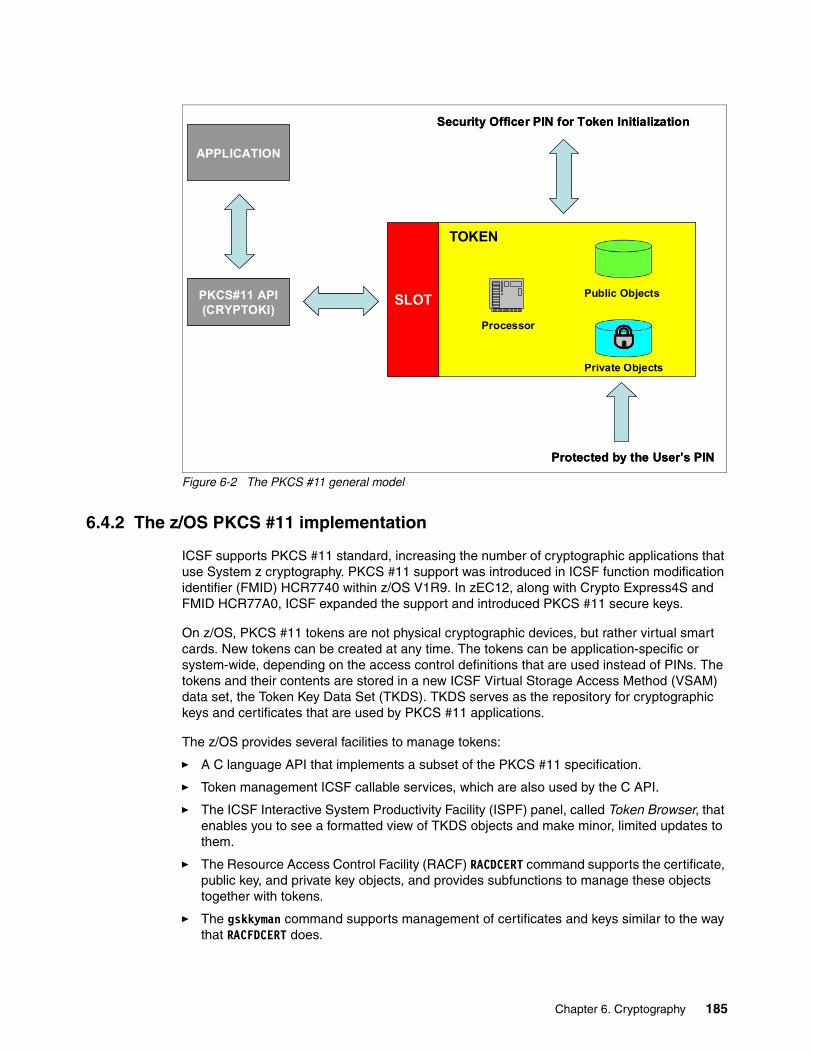
Figure 6-2 The PKCS #11 general model
6.4.2 The z/OS PKCS #11 implementation
ICSF supports PKCS #11 standard, increasing the number of cryptographic applications that use System z cryptography. PKCS #11 support was introduced in ICSF function modification identifier (FMID) HCR7740 within z/OS V1R9. In zEC12, along with Crypto Express4S and FMID HCR77A0, ICSF expanded the support and introduced PKCS #11 secure keys.
On z/OS, PKCS #11 tokens are not physical cryptographic devices, but rather virtual smart cards. New tokens can be created at any time. The tokens can be application-specific or system-wide, depending on the access control definitions that are used instead of PINs. The tokens and their contents are stored in a new ICSF Virtual Storage Access Method (VSAM) data set, the Token Key Data Set (TKDS). TKDS serves as the repository for cryptographic keys and certificates that are used by PKCS #11 applications.
The z/OS provides several facilities to manage tokens:
� A C language API that implements a subset of the PKCS #11 specification.
� Token management ICSF callable services, which are also used by the C API.
� The ICSF Interactive System Productivity Facility (ISPF) panel, called Token Browser, that enables you to see a formatted view of TKDS objects and make minor, limited updates to them.
� The Resource Access Control Facility (RACF) RACDCERT command supports the certificate, public key, and private key objects, and provides subfunctions to manage these objects together with tokens.
� The gskkyman command supports management of certificates and keys similar to the way that RACFDCERT does.
Private Objects
Processor
SLOT
TOKEN
PKCS#11 API(CRYPTOKI)
Protected by the User’s PIN
APPLICATION
Security Officer PIN for Token Initialization
Public Objects
Private Objects
Processor
SLOT
TOKEN
PKCS#11 API(CRYPTOKI)
PKCS#11 API(CRYPTOKI)
Protected by the User’s PIN
APPLICATION
Security Officer PIN for Token Initialization
Public Objects
Chapter 6. Cryptography 185
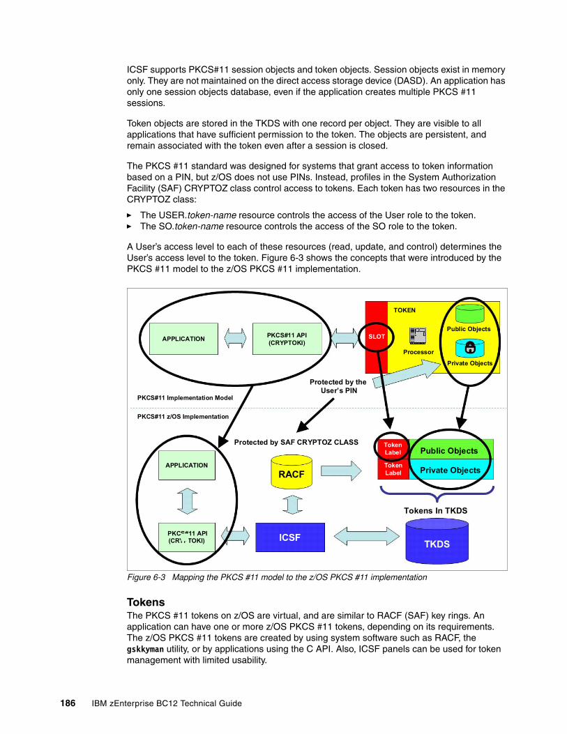
ICSF supports PKCS#11 session objects and token objects. Session objects exist in memory only. They are not maintained on the direct access storage device (DASD). An application has only one session objects database, even if the application creates multiple PKCS #11 sessions.
Token objects are stored in the TKDS with one record per object. They are visible to all applications that have sufficient permission to the token. The objects are persistent, and remain associated with the token even after a session is closed.
The PKCS #11 standard was designed for systems that grant access to token information based on a PIN, but z/OS does not use PINs. Instead, profiles in the System Authorization Facility (SAF) CRYPTOZ class control access to tokens. Each token has two resources in the CRYPTOZ class:
� The USER.token-name resource controls the access of the User role to the token.� The SO.token-name resource controls the access of the SO role to the token.
A User’s access level to each of these resources (read, update, and control) determines the User’s access level to the token. Figure 6-3 shows the concepts that were introduced by the PKCS #11 model to the z/OS PKCS #11 implementation.
Figure 6-3 Mapping the PKCS #11 model to the z/OS PKCS #11 implementation
TokensThe PKCS #11 tokens on z/OS are virtual, and are similar to RACF (SAF) key rings. An application can have one or more z/OS PKCS #11 tokens, depending on its requirements. The z/OS PKCS #11 tokens are created by using system software such as RACF, the gskkyman utility, or by applications using the C API. Also, ICSF panels can be used for token management with limited usability.
PKCS#11 API(CRYPTOKI)
APPLICATION
TOKEN
SLOT
Private Objects
Processor
Public Objects
PKCS#11 Implementation Model
PKCS#11 z/OS Implementation
APPLICATION
PKCS#11 API(CRYPTOKI)
RACF
TokenLabel
TokenLabel
Public Objects
Private Objects
Tokens In TKDS
ICSFTKDS
Protected by SAF CRYPTOZ CLASS
Protected by theUser’s PIN
PKCS#11 API(CRYPTOKI)
APPLICATION
TOKEN
SLOT
Private Objects
Processor
Public Objects
PKCS#11 Implementation Model
PKCS#11 z/OS Implementation
APPLICATION
PKCS#11 API(CRYPTOKI)
RACF
TokenLabel
TokenLabel
Public Objects
Private Objects
Tokens In TKDS
ICSFTKDS
Protected by SAF CRYPTOZ CLASS
Protected by theUser’s PIN
186 IBM zEnterprise BC12 Technical Guide
Each token has a unique token name or label that is specified by the user or application when the token is created. As with z/OS PKCS #11 token creation, the PKCS #11 tokens can be deleted by using the same system software tools used to create them.
Token Key Data SetThe TKDS is a VSAM data set that serves as the repository for cryptographic keys and certificates that are used by z/OS PKCS #11 applications. Before an installation can run PKCS #11 applications, the TKDS must be created. The ICSF installation options data set must then be updated to identify the name of the TKDS data set. To optimize performance, ICSF creates a data space that contains an in-storage copy of the TKDS.
6.4.3 Secure IBM Enterprise PKCS #11 (EP11) coprocessor
The IBM Enterprise PKCS #11 LIC implements an industry-standardized set of services. These services adhere to the PKCS #11 specification V2.20 and more recent amendments. It is designed to meet the Common Criteria (Evaluation Assurance Level, or EAL 4+) and FIPS 140-2 Level 4 certifications. It conforms to the Qualified Digital Signature (QDS) technical standards that are being mandated by the European Union.
The PKCS #11 secure key support is provided by the Crypto Express4S card that is configured in Secure EP11 coprocessor mode. Before EP11, ICSF PKCS #11 implementation only supported clear keys, and the key protection was provided only by RACF CRYPTOZ class protection. In EP11, keys can now be generated and securely wrapped under the EP11 Master Key. The secure keys never leave the secure coprocessor boundary unencrypted.
The Crypto Express4S firmware has a unique code for EP11 separated from the CCA code. Crypto Express4S with EP11 configuration is known as CEX4P. There is no change in the domain configuration in the LPAR activation profiles. The configuration selection is run in the Cryptographic Configuration panel on the SE. A coprocessor in EP11 mode is configured off after being zeroized.
Important: Until ICSF FMID HCR7790, keys in the TKDS were not encrypted. Therefore, the RACF profile must be created to protect the TKDS from unauthorized access.
Attention: The Trusted Key Entry (TKE) workstation is required for management of the Crypto Express4S when defined as an EP11 coprocessor.
Chapter 6. Cryptography 187
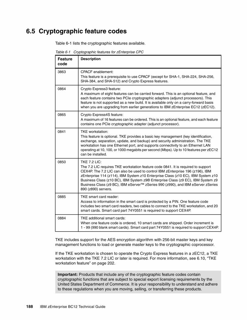
6.5 Cryptographic feature codes
Table 6-1 lists the cryptographic features available.
Table 6-1 Cryptographic features for zEnterprise CPC
TKE includes support for the AES encryption algorithm with 256-bit master keys and key management functions to load or generate master keys to the cryptographic coprocessor.
If the TKE workstation is chosen to operate the Crypto Express features in a zEC12, a TKE workstation with the TKE 7.2 LIC or later is required. For more information, see 6.10, “TKE workstation feature” on page 202.
Feature code
Description
3863 CPACF enablement:This feature is a prerequisite to use CPACF (except for SHA-1, SHA-224, SHA-256, SHA-384, and SHA-512) and Crypto Express features.
0864 Crypto Express3 feature:A maximum of eight features can be carried forward. This is an optional feature, and each feature contains two PCIe cryptographic adapters (adjunct processors). This feature is not supported as a new build. It is available only on a carry-forward basis when you are upgrading from earlier generations to IBM zEnterprise EC12 (zEC12).
0865 Crypto Express4S feature:A maximum of 16 features can be ordered. This is an optional feature, and each feature contains one PCIe cryptographic adapter (adjunct processor).
0841 TKE workstation:This feature is optional. TKE provides a basic key management (key identification, exchange, separation, update, and backup) and security administration. The TKE workstation has one Ethernet port, and supports connectivity to an Ethernet LAN operating at 10, 100, or 1000 megabits per second (Mbps). Up to 10 features per zEC12 can be installed.
0850 TKE 7.2 LIC:The 7.2 LIC requires TKE workstation feature code 0841. It is required to support CEX4P. The 7.2 LIC can also be used to control IBM zEnterprise 196 (z196), IBM zEnterprise 114 (z114), IBM System z10 Enterprise Class (z10 EC), IBM System z10 Business Class (z10 BC), IBM System z9® Enterprise Class (z9 EC), IBM System z9 Business Class (z9 BC), IBM eServer™ zSeries 990 (z990), and IBM eServer zSeries 890 (z890) servers.
0885 TKE smart card reader:Access to information in the smart card is protected by a PIN. One feature code includes two smart card readers, two cables to connect to the TKE workstation, and 20 smart cards. Smart card part 74Y0551 is required to support CEX4P.
0884 TKE additional smart cards:When one feature code is ordered, 10 smart cards are shipped. Order increment is 1 - 99 (990 blank smart cards). Smart card part 74Y0551 is required to support CEX4P.
Important: Products that include any of the cryptographic feature codes contain cryptographic functions that are subject to special export licensing requirements by the United States Department of Commerce. It is your responsibility to understand and adhere to these regulations when you are moving, selling, or transferring these products.
188 IBM zEnterprise BC12 Technical Guide
6.6 CP Assist for Cryptographic Function
The CPACF offers a set of symmetric cryptographic functions that enhance the encryption and decryption performance of clear key operations for SSL, VPN, and data-storing applications that do not require FIPS 140-2 Level 4 security.
CPACF is designed to facilitate the privacy of cryptographic key material when used for data encryption through key wrapping implementation. It ensures that key material is not visible to applications or operating systems during encryption operations.
The CPACF feature provides hardware acceleration for DES, TDES, message authentication code, AES-128, AES-192, AES-256, SHA-1, SHA-224, SHA-256, SHA-384, and SHA-512 cryptographic services. It provides high-performance hardware encryption, decryption, and hashing support.
The following instructions support the cryptographic assist function:
KMAC Compute Message Authentic CodeKM Cipher MessageKMC Cipher Message with ChainingKMF Cipher Message with Cipher Feedback (CFB)KMCTR Cipher Message with CounterKMO Cipher Message with Output Feedback (OFB)KIMD Compute Intermediate Message DigestKLMD Compute Last Message DigestPCKMO Provide Cryptographic Key Management Operation
New function codes for existing instructions were introduced with the zEnterprise CPC: KIMD adds KIMD-Galois Hash function (GHASH).
These functions are provided as problem-state z/Architecture instructions (MSA), which are directly available to application programs. When enabled, the CPACF runs at processor speed for every CP, Integrated Facility for Linux (IFL), System z Integrated Information Processor (zIIP), and System z Application Assist Processor (zAAP).
The cryptographic architecture includes DES, TDES, message authentication code, AES data encryption and decryption, SHA-1, and SHA-2 support for SHA-224, SHA-256, SHA-384, and SHA-512 hashing.
The functions of the CPACF must be explicitly enabled using FC 3863 by the manufacturing process, or at the customer’s site as an MES installation, except for SHA-1, and SHA-2 support for SHA-224, SHA-256, SHA-384, and SHA-512, which are always enabled.
6.7 Crypto Express4S
The Crypto Express4S feature (FC 0865) is an optional and zEC12-exclusive feature. Each feature has one PCIe cryptographic adapter. The Crypto Express4S feature occupies one I/O slot in a zEC12 PCIe I/O drawer. This feature provides a secure programming and hardware environment in which crypto processes are run.
Each cryptographic coprocessor includes a general-purpose processor, non-volatile storage, and specialized cryptographic electronics. The Crypto Express4S feature provides tamper-sensing and tamper-responding, high-performance cryptographic operations.
Chapter 6. Cryptography 189
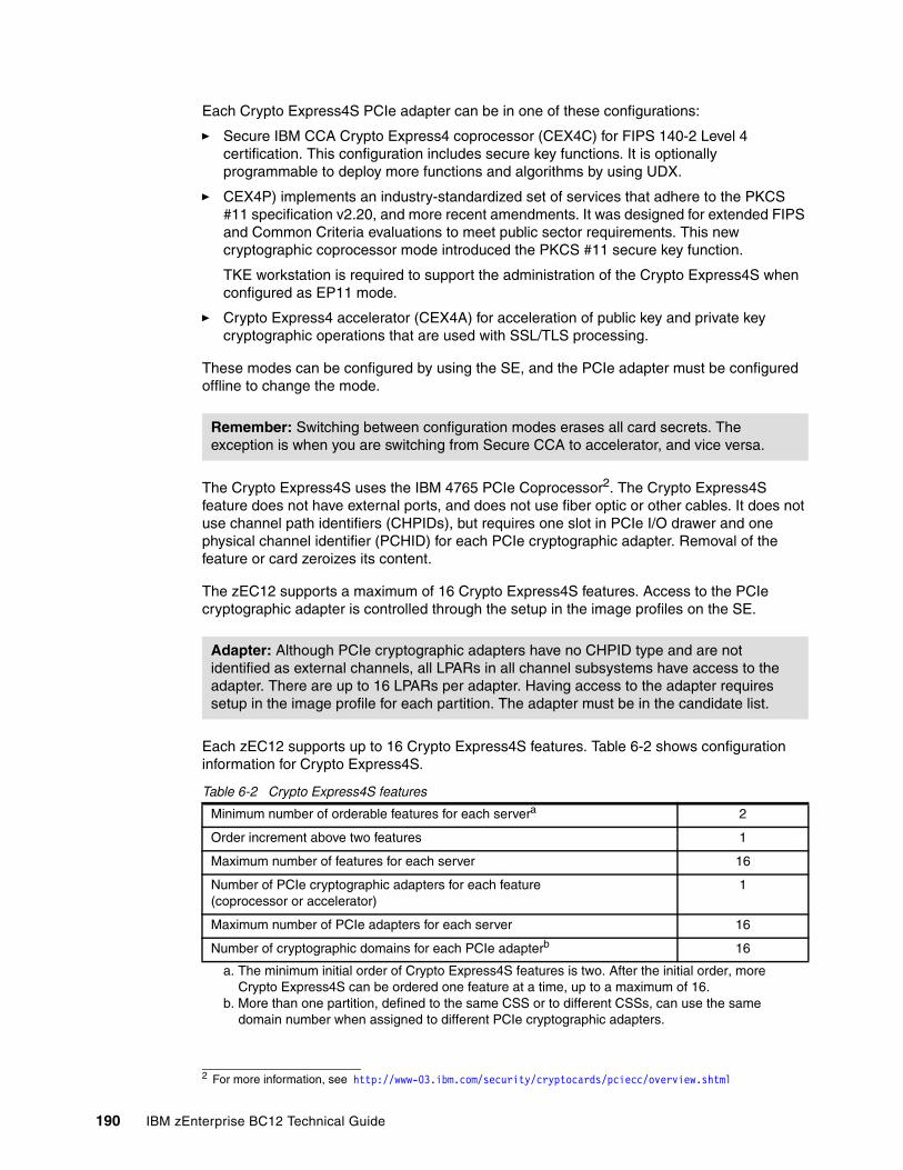
Each Crypto Express4S PCIe adapter can be in one of these configurations:
� Secure IBM CCA Crypto Express4 coprocessor (CEX4C) for FIPS 140-2 Level 4 certification. This configuration includes secure key functions. It is optionally programmable to deploy more functions and algorithms by using UDX.
� CEX4P) implements an industry-standardized set of services that adhere to the PKCS #11 specification v2.20, and more recent amendments. It was designed for extended FIPS and Common Criteria evaluations to meet public sector requirements. This new cryptographic coprocessor mode introduced the PKCS #11 secure key function.
TKE workstation is required to support the administration of the Crypto Express4S when configured as EP11 mode.
� Crypto Express4 accelerator (CEX4A) for acceleration of public key and private key cryptographic operations that are used with SSL/TLS processing.
These modes can be configured by using the SE, and the PCIe adapter must be configured offline to change the mode.
The Crypto Express4S uses the IBM 4765 PCIe Coprocessor2. The Crypto Express4S feature does not have external ports, and does not use fiber optic or other cables. It does not use channel path identifiers (CHPIDs), but requires one slot in PCIe I/O drawer and one physical channel identifier (PCHID) for each PCIe cryptographic adapter. Removal of the feature or card zeroizes its content.
The zEC12 supports a maximum of 16 Crypto Express4S features. Access to the PCIe cryptographic adapter is controlled through the setup in the image profiles on the SE.
Each zEC12 supports up to 16 Crypto Express4S features. Table 6-2 shows configuration information for Crypto Express4S.
Table 6-2 Crypto Express4S features
Remember: Switching between configuration modes erases all card secrets. The exception is when you are switching from Secure CCA to accelerator, and vice versa.
2 For more information, see http://www-03.ibm.com/security/cryptocards/pciecc/overview.shtml
Adapter: Although PCIe cryptographic adapters have no CHPID type and are not identified as external channels, all LPARs in all channel subsystems have access to the adapter. There are up to 16 LPARs per adapter. Having access to the adapter requires setup in the image profile for each partition. The adapter must be in the candidate list.
Minimum number of orderable features for each servera
a. The minimum initial order of Crypto Express4S features is two. After the initial order, more Crypto Express4S can be ordered one feature at a time, up to a maximum of 16.
2
Order increment above two features 1
Maximum number of features for each server 16
Number of PCIe cryptographic adapters for each feature(coprocessor or accelerator)
1
Maximum number of PCIe adapters for each server 16
Number of cryptographic domains for each PCIe adapterb
b. More than one partition, defined to the same CSS or to different CSSs, can use the same domain number when assigned to different PCIe cryptographic adapters.
16
190 IBM zEnterprise BC12 Technical Guide
The concept of dedicated processor does not apply to the PCIe cryptographic adapter. Whether configured as coprocessor or accelerator, the PCIe cryptographic adapter is made available to an LPAR. It is made available as directed by the domain assignment and the candidate list in the LPAR image profile. This availability is not changed by the shared or dedicated status that is given to the CPs in the partition.
When installed non-concurrently, Crypto Express4S features are assigned PCIe cryptographic adapter numbers sequentially during the power-on reset (POR) that follows the installation. When a Crypto Express4S feature is installed concurrently, the installation can select an out-of-sequence number from the unused range. When a Crypto Express4S feature is removed concurrently, the PCIe adapter numbers are automatically freed.
The definition of domain indexes and PCIe cryptographic adapter numbers in the candidate list for each LPAR must be planned ahead to enable nondisruptive changes:
� Operational changes can be made by using the Change LPAR Cryptographic Controls task from the SE, which reflects the cryptographic definitions in the image profile for the partition. With this function, adding and removing the cryptographic feature without stopping a running operating system (OS) can be done dynamically.
� The same usage domain index can be defined more than once across multiple LPARs. However, the PCIe cryptographic adapter number, coupled with the usage domain index specified, must be unique across all active LPARs.
The same PCIe cryptographic adapter number and usage domain index combination can be defined for more than one LPAR. For example, you might define a configuration for backup situations. However, only one of the LPARs can be active at a time.
The zBC12 enables up to 30 LPARs to be active concurrently. Each PCI Express supports 16 domains, whether it is configured as a CEX4A or a CEX4C. The server configuration must include at least four Crypto Express4S features (four PCIe adapters and 16 domains per PCIe adapter) when all 30 LPARs require concurrent access to cryptographic functions. More Crypto Express4S features might be needed to satisfy application performance and availability requirements.
6.8 Crypto Express3
The Crypto Express3 feature (FC 0864) has two PCIe cryptographic adapters. Each of the PCIe cryptographic adapters can be configured as a cryptographic coprocessor or a cryptographic accelerator.
The Crypto Express3 feature is the newest state-of-the-art generation cryptographic feature. As with its predecessors, it is designed to complement the functions of CPACF. This feature is tamper-sensing and tamper-responding. It provides dual processors operating in parallel supporting cryptographic operations with high reliability.
The CEX3 uses the 4765 PCIe coprocessor. It holds a secured subsystem module, batteries for backup power, and a full-speed USB 2.0 host port that is available through a mini-A connector. On System z, these USB ports are not used. The securely encapsulated subsystem contains two 32-bit IBM PowerPC 405D5 reduced instruction-set computer (RISC) processors running concurrently with cross-checking to detect malfunctions.
Chapter 6. Cryptography 191
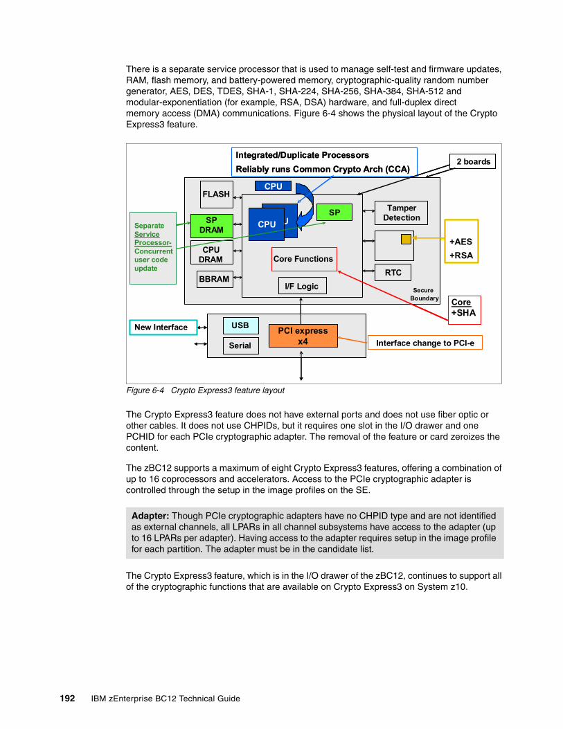
There is a separate service processor that is used to manage self-test and firmware updates, RAM, flash memory, and battery-powered memory, cryptographic-quality random number generator, AES, DES, TDES, SHA-1, SHA-224, SHA-256, SHA-384, SHA-512 and modular-exponentiation (for example, RSA, DSA) hardware, and full-duplex direct memory access (DMA) communications. Figure 6-4 shows the physical layout of the Crypto Express3 feature.
Figure 6-4 Crypto Express3 feature layout
The Crypto Express3 feature does not have external ports and does not use fiber optic or other cables. It does not use CHPIDs, but it requires one slot in the I/O drawer and one PCHID for each PCIe cryptographic adapter. The removal of the feature or card zeroizes the content.
The zBC12 supports a maximum of eight Crypto Express3 features, offering a combination of up to 16 coprocessors and accelerators. Access to the PCIe cryptographic adapter is controlled through the setup in the image profiles on the SE.
The Crypto Express3 feature, which is in the I/O drawer of the zBC12, continues to support all of the cryptographic functions that are available on Crypto Express3 on System z10.
Adapter: Though PCIe cryptographic adapters have no CHPID type and are not identified as external channels, all LPARs in all channel subsystems have access to the adapter (up to 16 LPARs per adapter). Having access to the adapter requires setup in the image profile for each partition. The adapter must be in the candidate list.
CPU
CPUSP
FLASH
CPU
DRAM
CPUCPUSP
DRAM
BBRAMRTC
I/F Logic
Core Functions
Tamper
Detection
Serial
USB
Secure
Boundary
PCI x I/F
CPU
Integrated/Duplicate Processors
Reliably runs Common Crypto Arch (CCA)
New Interface PCI express
x4
+AES
+RSA
Core+SHA
SP
FLASH
CPUDRAM
CPUCPUSPDRAM
BBRAMRTC
I/F Logic
Core Functions
TamperDetection
Serial
USB
SecureBoundary
PCI x I/F
CPU
Integrated/Duplicate Processors
Reliably runs Common Crypto Arch (CCA)
Interface change to PCI-e
PCI expressx4
2 boards
SeparateServiceProcessor-Concurrentuser codeupdate
192 IBM zEnterprise BC12 Technical Guide
When one or both of the two PCIe adapters are configured as a coprocessor, the following cryptographic enhancements, which were introduced with zBC12, are supported:
� Expanded key support for AES algorithm
CCA currently supports the AES algorithm to enable the use of AES keys to encrypt data. Expanded key support for AES adds a framework to support a much broader range of application areas, and it lays the groundwork for future use of AES in areas where standards and customer applications are expected to evolve.
As stronger algorithms and longer keys become increasingly common, security requirements dictate that these keys must be wrapped using KEKs of sufficient strength. This feature adds support for AES KEKs. These AES wrapping keys have adequate strength to protect other AES keys for transport or storage.
The new AES key types use the variable-length key token. The supported key types are EXPORTER, IMPORTER, and (for use in the encryption and decryption services) CIPHER.
New APIs have been added or modified to manage and use these new keys.
The following new or modified CCA API functions are also supported:
Key Token Build2 Builds skeleton variable length key tokens
Key Generate2 Generates keys using random key data
Key Part Import2 Creates keys from key part information
Key Test2 Verifies the value of a key or key part
Key Translate2 Translate a key: Changes the KEK that is used to wrap a key
Key Translate2 Reformat a key: Converts keys between the previous token format and the newer variable-length token format
Symmetric Key Export Modified to also export AES keys
Symmetric Key Import2 Imports a key that has been wrapped in the new token format
Secure Key Import2 (System z-only) Wraps key material under the master key or an AES KEK
Restrict Key Attribute Changes the attributes of a key token
Key Token Parse2 Parses key attributes in the new key token
Symmetric Algorithm Encipher Enciphers data
Symmetric Algorithm Decipher Deciphers data
� Enhanced ANSI TR-31 interoperable secure key exchange
ANSI TR-31 defines a method of cryptographically protecting TDES cryptographic keys and their associated usage attributes. The TR-31 method complies with the security requirements of the ANSI X9.24 Part 1 standard, although use of TR-31 is not required to comply with that standard.
CCA has added functions that can be used to import and export CCA TDES keys in TR-31 formats. These functions are designed primarily as a secure method of wrapping TDES keys for improved and more secure key interchange between CCA and non-CCA devices and systems.
Chapter 6. Cryptography 193
� PIN block decimalization table protection
To help avoid a decimalization table attack to learn a PIN, a solution is now available in the CCA to thwart this attack by protecting the decimalization table from manipulation. PINs are most often used for ATMs but are increasingly used at the point-of-sale, for debit and credit cards.
� ANSI X9.8 PIN security
This enhancement facilitates compliance with the processing requirements defined in the new version of the ANSI X9.8 and International Organization for Standardization (ISO) 9564 PIN Security Standards and provides added security for transactions that require PINs.
� Enhanced CCA key wrapping to comply with ANSI X9.24-1 key bundling requirements
A new CCA key token wrapping method uses cipher block chaining (CBC) mode in combination with other techniques to satisfy the key bundle compliance requirements in standards, including ANSI X9.24-1 and the recently published Payment Card Industry Hardware Security Module (PCI HSM) standard.
� Secure keyed-hash message authentication code (HMAC)
HMAC is a method for computing a message authentication code using a secret key and a secure hash function. It is defined in the standard FIPS (Federal Information Processing Standard) 198, “The Keyed-Hash Message Authentication Code (HMAC)”.
The new CCA functions support HMAC using SHA-1, SHA-224, SHA-256, SHA-384, and SHA-512 hash algorithms. The HMAC keys are variable-length keys and are securely encrypted so that their values are protected. This Crypto function is supported by z/OS, z/VM, and Linux on System z.
� Enhanced driver maintenance (EDM) and concurrent MCL apply
This enhancement is a process to eliminate or reduce cryptographic coprocessor card outages for new cryptographic function releases. With enhanced driver maintenance and concurrent MCL applied, new cryptographic functions can be applied without configuring the cryptographic coprocessor card off and on.
It is now possible to upgrade CCA, segment 3, LIC without any effect on performance during the upgrade. However, certain levels of CCA or hardware changes will still require cryptographic coprocessor card vary off and on. This Crypto function is exclusive to the zEnterprise CPC.
The enhancements include the following additional key features of Crypto Express3:
� Dynamic power management to maximize RSA performance while keeping the Crypto Express3 within temperature limits of the tamper-responding package
� All LPARs in all logical channel subsystems (LCSSs) having access to the Crypto Express3 feature, up to 32 LPARs per feature
� Secure code loading that enables the updating of functionality while installed in application systems
� Lock-step checking of dual central processing units (CPUs) for enhanced error detection and fault isolation of cryptographic operations performed by a coprocessor when a PCIe adapter is defined as a coprocessor
� Improved reliability, availability, and serviceability (RAS) over previous crypto features due to dual processors and the service processor
� Dynamic addition and configuration of the Crypto Express3 features to LPARs without an outage
194 IBM zEnterprise BC12 Technical Guide
The Crypto Express3 feature is designed to deliver throughput improvements for both symmetric and asymmetric operations.
A Crypto Express3 migration wizard is available to make the migration easier. The wizard enables the user to collect configuration data from a Crypto Express2 or Crypto Express3 feature configured as a coprocessor, and migrate that data to a separate Crypto Express coprocessor. The target for this migration must be a coprocessor with equivalent or greater capabilities.
6.8.1 Crypto Express3 coprocessor
The Crypto Express3 coprocessor is a PCIe cryptographic adapter that is configured as a coprocessor and provides a high-performance cryptographic environment with added functions.
The Crypto Express3 coprocessor provides asynchronous functions only.
The Crypto Express3 feature contains two PCIe cryptographic adapters. The two adapters provide equivalent (plus additional) functions as the PCIXCC and Crypto Express2 features, with improved throughput.
PCIe cryptographic adapters, when configured as coprocessors, are designed for the FIPS 140-2 Level 4 compliance rating for secure cryptographic hardware modules. Unauthorized removal of the adapter or feature zeros out its content.
The Crypto Express3 coprocessor enables the user to perform the following tasks:
� Encrypt and decrypt data by using secret-key algorithms. TDES, double-length key DES, and AES algorithms are supported.
� Generate, install, and distribute cryptographic keys securely by using both public and secret-key cryptographic methods.
� Generate, verify, and translate PINs.
� Use Crypto Express3, which supports 13-digit through 19-digit personal account numbers (PANs).
� Ensure the integrity of data by using MACs, hashing algorithms, and RSA PKA digital signatures, as well as Elliptic Curve Cryptography digital signatures.
The Crypto Express3 coprocessor also provides the functions listed for the Crypto Express3 accelerator, but with lower performance than the Crypto Express3 accelerator.
Three methods of master key entry are provided by Integrated Cryptographic Service Facility (ICSF) for the Crypto Express3 feature coprocessor:
� A passphrase initialization method, which generates and enters all master keys that are necessary to fully enable the cryptographic system in a minimal number of steps
� A simplified master key entry procedure provided through a series of Clear Master Key Entry panels from a Time Sharing Option (TSO) terminal
� A TKE workstation, which is available as an optional feature in enterprises that require enhanced key-entry security
Linux on System z also permits the master key entry through panels, or through the TKE workstation.
Chapter 6. Cryptography 195
The security-relevant portion of the cryptographic functions is performed inside the secure physical boundary of a tamper-resistant card. Master keys and other security-relevant information are also maintained inside this secure boundary.
A Crypto Express3 coprocessor operates with the Integrated Cryptographic Service Facility (ICSF) and IBM Resource Access Control Facility (RACF), or equivalent software products. It operates in a z/OS operating environment to provide data privacy, data integrity, cryptographic key installation and generation, electronic cryptographic key distribution, and PIN processing. These functions are also available on a Crypto Express3 coprocessor running in a Linux for System z environment.
The Processor Resource/Systems Manager (PR/SM) fully supports the Crypto Express3 coprocessor feature to establish a logically partitioned environment on which multiple LPARs can use the cryptographic functions. A 128-bit data-protection symmetric master key, a 256-bit AES master key, a 256-bit Elliptic Curve Cryptography master key, and one 192-bit PKA master key are provided for each of 16 cryptographic domains that a coprocessor can serve.
Use the dynamic addition or deletion of an LPAR name to rename an LPAR. Its name can be changed from NAME1 to a single asterisk (*) and then changed again from * to NAME2. The LPAR number and multiple image facility (MIF) ID are retained across the LPAR name change. The master keys in the Crypto Express3 feature coprocessor that were associated with the old LPAR NAME1 are retained. No explicit action is taken against a cryptographic component for this dynamic change.
6.8.2 Crypto Express3 accelerator
The Crypto Express3 accelerator is a coprocessor that is reconfigured by the installation process so that it uses only a subset of the coprocessor functions at a higher speed. Note the following information about the reconfiguration:
� It is done through the SE.
� It is done at the PCIe cryptographic adapter level. A Crypto Express3 feature can host a coprocessor and an accelerator, two coprocessors, or two accelerators.
� It works both ways, from coprocessor to accelerator and from accelerator to coprocessor. Master keys in the coprocessor domain can be optionally preserved when a coprocessor is reconfigured to be an accelerator.
� Reconfiguration is disruptive to coprocessor and accelerator operations. The coprocessor or accelerator must be deactivated before engaging the reconfiguration.
� FIPS 140-2 certification is not relevant to the accelerator, because it operates with clear keys only.
� The function extension capability through UDX is not available to the accelerator.
Coprocessors: Cryptographic coprocessors are not tied to LPAR numbers or MIF IDs. They are set up with PCIe adapter numbers and domain indexes that are defined in the partition image profile. The customer can dynamically configure them to a partition, and change or clear them when needed.
196 IBM zEnterprise BC12 Technical Guide
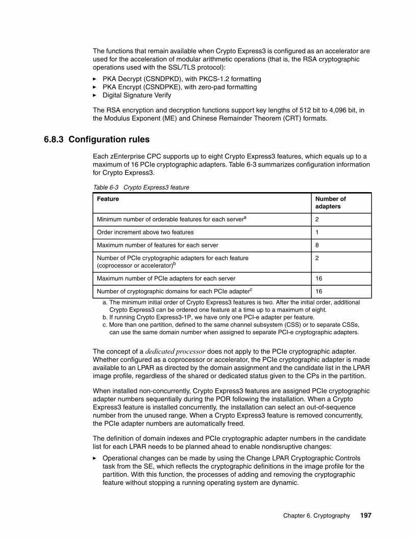
The functions that remain available when Crypto Express3 is configured as an accelerator are used for the acceleration of modular arithmetic operations (that is, the RSA cryptographic operations used with the SSL/TLS protocol):
� PKA Decrypt (CSNDPKD), with PKCS-1.2 formatting� PKA Encrypt (CSNDPKE), with zero-pad formatting� Digital Signature Verify
The RSA encryption and decryption functions support key lengths of 512 bit to 4,096 bit, in the Modulus Exponent (ME) and Chinese Remainder Theorem (CRT) formats.
6.8.3 Configuration rules
Each zEnterprise CPC supports up to eight Crypto Express3 features, which equals up to a maximum of 16 PCIe cryptographic adapters. Table 6-3 summarizes configuration information for Crypto Express3.
Table 6-3 Crypto Express3 feature
The concept of a dedicated processor does not apply to the PCIe cryptographic adapter. Whether configured as a coprocessor or accelerator, the PCIe cryptographic adapter is made available to an LPAR as directed by the domain assignment and the candidate list in the LPAR image profile, regardless of the shared or dedicated status given to the CPs in the partition.
When installed non-concurrently, Crypto Express3 features are assigned PCIe cryptographic adapter numbers sequentially during the POR following the installation. When a Crypto Express3 feature is installed concurrently, the installation can select an out-of-sequence number from the unused range. When a Crypto Express3 feature is removed concurrently, the PCIe adapter numbers are automatically freed.
The definition of domain indexes and PCIe cryptographic adapter numbers in the candidate list for each LPAR needs to be planned ahead to enable nondisruptive changes:
� Operational changes can be made by using the Change LPAR Cryptographic Controls task from the SE, which reflects the cryptographic definitions in the image profile for the partition. With this function, the processes of adding and removing the cryptographic feature without stopping a running operating system are dynamic.
Feature Number of adapters
Minimum number of orderable features for each servera
a. The minimum initial order of Crypto Express3 features is two. After the initial order, additional Crypto Express3 can be ordered one feature at a time up to a maximum of eight.
2
Order increment above two features 1
Maximum number of features for each server 8
Number of PCIe cryptographic adapters for each feature(coprocessor or accelerator)b
b. If running Crypto Express3-1P, we have only one PCI-e adapter per feature.
2
Maximum number of PCIe adapters for each server 16
Number of cryptographic domains for each PCIe adapterc
c. More than one partition, defined to the same channel subsystem (CSS) or to separate CSSs, can use the same domain number when assigned to separate PCI-e cryptographic adapters.
16
Chapter 6. Cryptography 197
� The same usage domain index can be defined more than once across multiple LPARs. However, the PCIe cryptographic adapter number coupled with the usage domain index specified must be unique across all active LPARs.
The same PCIe cryptographic adapter number and usage domain index combination can be defined for more than one LPAR (for example, to define a configuration for backup situations). Note that only one of the LPARs can be active at any one time.
The zBC12 enables up to 30 LPARs to be active concurrently. Each PCIe supports 16 domains, whether it is configured as a Crypto Express3 accelerator or as a Crypto Express3 coprocessor. The server configuration must include at least two Crypto Express3 features (four PCIe adapters and 16 domains per PCIe adapter) when all 30 LPARs require concurrent access to cryptographic functions. More Crypto Express3 features might be needed to satisfy application performance and availability requirements.
6.9 Tasks that are run by PCIe Crypto Express
The Crypto Express features running on zEC12 support all cryptographic functions that were introduced on zEnterprise CPC:
� Expanded key support for AES algorithm
CCA supports the AES algorithm to enable the use of AES keys to encrypt data. Expanded key support for AES adds a framework to support a much broader range of application areas. It also lays the groundwork for future use of AES in areas where standards and customer applications are expected to change.
As stronger algorithms and longer keys become increasingly common, security requirements dictate that these keys must be wrapped by using KEKs of sufficient strength. This feature adds support for AES KEKs. These AES wrapping keys have adequate strength to protect other AES keys for transport or storage.
This support introduced AES key types that use the variable-length key token. The supported key types are EXPORTER, IMPORTER (and, for use in the encryption and decryption services, CIPHER).
� Enhanced ANSI TR-31 interoperable secure key exchange
ANSI TR-31 defines a method of cryptographically protecting TDES cryptographic keys and their associated usage attributes. The TR-31 method complies with the security requirements of the ANSI X9.24 Part 1 standard.
However, use of TR-31 is not required to comply with that standard. CCA has added functions that can be used to import and export CCA TDES keys in TR-31 formats. These functions are designed primarily as a secure method of wrapping TDES keys for improved and more secure key interchange between CCA and non-CCA devices and systems.
� PIN block decimalization table protection
To help avoid a decimalization table attack to learn a PIN, a solution is now available in the CCA to thwart this attack by protecting the decimalization table from manipulation. PINs are most often used for ATMs, but are increasingly used at point-of sale, for debit and credit cards.
� ANSI X9.8 PIN security
This function facilitates compliance with the processing requirements defined in the new version of the ANSI X9.8 and ISO 9564 PIN Security Standards. It provides added security for transactions that require PINs.
198 IBM zEnterprise BC12 Technical Guide
� Enhanced CCA key wrapping to comply with ANSI X9.24-1 key bundling requirements
This support enables that CCA key token wrapping method to use cipher block chaining (CBC) mode in combination with other techniques to satisfy the key bundle compliance requirements. The standards include ANSI X9.24-1 and the recently published Payment Card Industry Hardware Security Module (PCI HSM) standard.
� Secure key HMAC
HMAC is a method for computing a message authentication code by using a secret key and a secure hash function. It is defined in the standard FIPS 198, “The Keyed-Hash Message Authentication Code (HMAC)”. The CCA function supports HMAC by using SHA-1, SHA-224, SHA-256, SHA-384, and SHA-512 hash algorithms. The HMAC keys are variable-length, and are securely encrypted so that their values are protected. This Crypto function is supported by z/OS, z/VM, and Linux on System z.
6.9.1 PCIe Crypto Express as a CCA coprocessor
The PCIe Crypto Express coprocessors enable the user to perform the following tasks:
� Encrypt and decrypt data by using secret-key algorithms. TDES, double-length key DES, and AES algorithms are supported.
� Generate, install, and distribute cryptographic keys securely by using both public and secret-key cryptographic methods that generate, verify, and translate PINs.
� Crypto Express coprocessors support 13 through 19-digit PANs.
� Ensure the integrity of data by using MACs, hashing algorithms, and RSA PKA digital signatures, as well as Elliptic Curve Cryptography digital signatures
The Crypto Express coprocessors also provide the functions that are listed for the Crypto Express accelerator. However, they provide a lower performance than the Crypto Express accelerator can provide.
Three methods of master key entry are provided by ICSF for the Crypto Express feature coprocessors:
� A pass-phrase initialization method, which generates and enters all master keys that are necessary to fully enable the cryptographic system in a minimal number of steps
� A simplified master key entry procedure that is provided through a series of Clear Master Key Entry panels from a TSO terminal
� A TKE workstation, which is available as an optional feature in enterprises that require enhanced key-entry security
Linux on System z also permits the master key entry through panels, or through the TKE workstation.
The security-relevant portion of the cryptographic functions is run inside the secure physical boundary of a tamper-resistant card. Master keys and other security-relevant information are also maintained inside this secure boundary.
The PR/SM fully supports the Crypto Express coprocessor features to establish a logically partitioned environment on which multiple LPARs can use the cryptographic functions.
Chapter 6. Cryptography 199
The following keys are provided for each of 16 cryptographic domains that a cryptographic adapter can serve:
� A 128-bit data-protection symmetric master key� A 256-bit AES master key� A 256-bit Elliptic Curve Cryptography master key� One 192-bit PKA master key
Use the dynamic addition or deletion of an LPAR name to rename an LPAR. Its name can be changed from NAME1 to a single asterisk (*) and then changed again from * to NAME2. The LPAR number and MIF ID are retained across the LPAR name change. The master keys in the Crypto Express feature coprocessor that were associated with the old LPAR NAME1 are retained. No explicit action is taken against a cryptographic component for this dynamic change.
6.9.2 PCIe Crypto Express as an EP11 coprocessor
The Crypto Express4S card configured in Secure IBM Enterprise PKCS #11 (EP11) coprocessor mode provides PKCS #11 secure key support. Before EP11, ICSF PKCS #11 implementation only supported clear keys. In EP11, keys can now be generated and securely wrapped under the EP11 Master Key. The secure keys never leave the secure coprocessor boundary unencrypted.
The secure EP11 coprocessor runs the following tasks:
� Encrypt and decrypt (AES, DES, TDES, RSA)� Sign and verify (DSA, RSA, ECDSA)� Generate keys and key pairs (DES, AES, DSA, Elliptic Curve Cryptography, RSA)� HMAC (SHA1, SHA224, SHA256, SHA384, SHA512)� Digest (SHA1, SHA224, SHA256, SHA384, SHA512)� Wrap and unwrap keys� Random number generation� Get mechanism list and information� Attribute values
The function extension capability through UDX is not available to the EP11.
When defined in EP11 mode, the TKE workstation is required to manage the Crypto Express4S feature.
6.9.3 PCIe Crypto Express as an accelerator
The Crypto Express accelerator is a coprocessor that is reconfigured by the installation process so that it uses only a subset of the coprocessor functions at a higher speed. This reconfiguration has the following characteristics:
� It is done through the SE.
� It is done at the PCIe cryptographic adapter level. A Crypto Express3 feature can host a coprocessor and an accelerator, two coprocessors, or two accelerators.
Coprocessors: Cryptographic coprocessors are not tied to LPAR numbers or MIF IDs. They are set up with PCIe adapter numbers and domain indexes that are defined in the partition image profile. You can dynamically configure them to a partition, and change or clear them when needed.
200 IBM zEnterprise BC12 Technical Guide
� It works both ways, from coprocessor to accelerator and from accelerator to coprocessor. Master keys in the coprocessor domain can be optionally preserved when it is reconfigured to be an accelerator.
� Reconfiguration is disruptive to coprocessor and accelerator operations. The coprocessor or accelerator must be deactivated before you begin the reconfiguration.
� FIPS 140-2 certification is not relevant to the accelerator, because it operates with clear keys only.
� The function extension capability through UDX is not available to the accelerator.
The functions that remain available when Crypto Express feature is configured as an accelerator are used for the acceleration of modular arithmetic operations. That is, the RSA cryptographic operations are used with the SSL/TLS protocol. The following operations are accelerated:
� CSNDPKD with PKCS-1.2 formatting� CSNDPKE with zero-pad formatting� Digital Signature Verify
The RSA encryption and decryption functions support key lengths of 512 bit to 4,096 bit, in the ME and CRT formats.
6.9.4 IBM CCA enhancements
A new set of cryptographic functions and callable services are provided by IBM CCA LIC to enhance the functions that secure financial transactions and keys. These functions require ICSF FMID HCR77A0 and Secure IBM CCA coprocessor mode:
� Improved wrapping key strength. To comply with cryptographic standards, including ANSI X9.24 Part 1 and PCI-HSM, a key must not be wrapped with a key weaker than itself. Many CCA verbs enable the customer to select the key wrapping key. With this release, CCA enables the customer to configure the coprocessor to ensure that their system meets these key wrapping requirements. It can be configured to respond in one of three ways when a key is wrapped with a weaker key:
– Ignore weak wrapping– Complete the requested operation but return a warning message– Prohibit weak wrapping altogether
� Derived Unique Key Per Transaction (DUKPT) for message authentication code and encryption keys. DUKPT is defined in the ANSI X9.24 Part 1 standard. It provides a method in which a separate key is used for each transaction or other message that is sent from a device. Therefore, an attacker who is able to discover the value of a key would be able to gain information only about a single transaction. The other transactions remain secure.
The keys are derived from a base key that is initially loaded into the device, but that is erased as soon as the first keys are derived from it. Those keys, in turn, are erased as subsequent keys are derived.
The original definition of DUKPT only permitted derivation of keys to be used in encryption of PIN blocks. The purpose was to protect PINs that were entered at a POS device and then sent to a host system for verification.
Recent versions of X9.24 Part 1 expanded this process so that DUKPT can also be used to derive keys for message authentication code generation and verification, and for data encryption and decryption. Three separate variations of the DUKPT key derivation process are used so that there is key separation between the keys that are derived for PIN, message authentication code, and encryption purposes.
Chapter 6. Cryptography 201
� Secure Cipher Text Translate2 (CTT2). CTT2 is a new data encryption service that takes input data that is encrypted with one key and returns the same data encrypted under a different key. This verb can securely change the encryption key for cipher text without exposing the intermediate plain text. The decryption of data and reencryption of data happens entirely inside the secure module on the Crypto Express feature.
� Compliance with new random number generation standards. The standards that define acceptable methods for generating random numbers have been enhanced to include improved security properties. The Crypto Express coprocessor function was updated to support methods compliant with these new standards.
In this release, the random number generation in the Crypto Express feature when defined as a coprocessor conforms to the Deterministic Random Bit Generator (DRBG) requirements by using the SHA-256 based DBRG mechanism. These requirements are defined in NIST Special Publication 800-90/90A.
The methods in these NIST standards supersede those previously defined in NIST FIPS 186-2, ANSI X9.31, and ANSI X9.62. These improvements help meet the timeline that is outlined in Chapter 4 of NIST SP800-131 for switching to the new methods and discontinuing the old methods.
� EMV enhancements for applications that support American Express cards. Two changes have been made to the CCA APIs to help improve support of EMV card applications that support American Express cards. The Transaction_Validation verb is used to generate and verify American Express card security codes (CSCs).
This release also adds support for the American Express CSC version 2.0 algorithm that is used by contact and contactless cards. The PIN_Change/Unblock verb is used for PIN maintenance. It prepares an encrypted message portion for communicating an original or replacement PIN for an EMV smart card.
The verb embeds the PINs in an encrypted PIN block from information that is supplied. With this CCA enhancement, PIN_Change/Unblock adds support for the message format that is used to change or unblock the PIN on American Express EMV cards.
6.10 TKE workstation feature
The TKE workstation is an optional feature that offers key management functions. The TKE workstation, feature code 0841, contains a combination of hardware and software. Included with the system unit are a mouse, keyboard, flat panel display, PCIe adapter, and a writable USB media to install TKE LIC. The TKE workstation feature code 0841 will be the first to have Crypto Express3 installed. TKE LIC V7.0 requires Crypto Express3, and it will not be supported on TKE workstation feature code 0840.
A TKE workstation is part of a customized solution for using the ICSF for z/OS licensed program or the Linux for System z. You use the TKE to manage the cryptographic keys of a zBC12 that has Crypto Express features installed, and that is configured for using DES, AES, Elliptic Curve Cryptography, and PKA cryptographic keys.
The TKE provides a secure, remote, and flexible method of providing Master Key Part Entry, and of remotely managing PCIe Cryptographic Coprocessors. The cryptographic functions on the TKE are performed by one PCIe Cryptographic Coprocessor. The TKE workstation communicates with the System z server using a TCP/IP connection. The TKE workstation is available with Ethernet LAN connectivity only.
Adapters: The TKE workstation supports Ethernet adapters only to connect to a LAN.
202 IBM zEnterprise BC12 Technical Guide
Up to ten TKE workstations can be ordered. You can use the TKE feature code 0841 to control the zEnterprise servers (zEC12, zBC12, z114 and z196), and also z10 EC, z10 BC, z9 EC, z9 BC, z990, and z890 servers.
6.10.1 TKE 7.0 Licensed Internal Code
The TKE workstation feature code 0841 along with LIC 7.0 offers a significant number of enhancements:
� Elliptic Curve Cryptography master key support
Elliptic Curve Cryptography keys will be protected using a new Elliptic Curve Cryptography master key (256-bit AES key). From the TKE, administrators can generate key material, load or clear the new Elliptic Curve Cryptography master key register, or clear the old Elliptic Curve Cryptography master key register. The Elliptic Curve Cryptography key material can be stored on the TKE or on a smart card.
� CBC default settings support
The TKE provides functionality that enables the TKE user to set the default key wrapping method that is used by the host crypto module.
� TKE Audit Record Upload Configuration Utility support
The TKE Audit Record Upload Configuration Utility enables TKE workstation audit records to be sent to a System z host and saved on the host as z/OS System Management Facilities (SMF) records. The SMF records have a record type of 82 (ICSF) and a subtype of 29. TKE workstation audit records are sent to the same TKE host transaction program that is used for TKE operations.
� USB flash memory drive support
The TKE workstation now supports a USB flash memory drive as a removable media device. When a TKE application displays media choices, the application enables you to choose a USB flash memory drive if the IBM-supported drive is plugged into a USB port on the TKE, and if it was formatted for the specified operation.
� Stronger pin strength support
TKE smart cards created on TKE 7.0 require a 6-digit pin rather than a 4-digit pin. TKE smart cards that were created before TKE 7.0 will continue to use 4-digit pins and will work on TKE 7.0 without changes. You can take advantage of the stronger pin strength by initializing new TKE smart cards and copying the data from the old TKE smart cards to the new TKE smart cards.
� Stronger password requirements for TKE passphrase user profile support
New rules are required for the passphrase that is used for the passphrase logon to the TKE workstation crypto adapter. The passphrase must meet the following requirements:
– Must be 8 to 64 characters in length– Contains at least two numeric and two non-numeric characters– Does not contain the user ID
These rules are enforced when you define a new user profile for passphrase logon, or when you change the passphrase for an existing profile. Your current passphrases will continue to work.
Chapter 6. Cryptography 203
� Simplified TKE usability with Crypto Express3 migration wizard
A wizard is now available to enable users to collect data, including key material, from a Crypto Express coprocessor, and to migrate the data to a separate Crypto Express coprocessor. The target Crypto Express coprocessor must have the same or greater capabilities. This wizard is an aid to help facilitate migration from Crypto Express2 to Crypto Express3. Crypto Express2 is not supported on zBC12. This wizard offers the following benefits:
– Reduces migration steps, thereby minimizing user errors– Minimizes the number of user clicks– Significantly reduces migration task duration
6.10.2 TKE 7.1 Licensed Internal Code
The TKE workstation feature code 0841 along with LIC 7.1 offers additional enhancements:
� New access control support for all TKE applications
Every TKE application, along with the ability to create and manage the crypto module and domain groups, now requires the TKE local cryptographic adapter profile to have explicit access to the TKE application or function that the user wants to run. This enhancement provides more control of the functions that TKE users can perform.
� New migration utility
During a migration from a lower release of TKE to TKE 7.1 LIC, it will be necessary to add access control points to the existing roles. The new access control points can be added through the new Migrate Roles Utility, or by manually updating each role through the Cryptographic Node Management Utility. The IBM-supplied roles created for TKE 7.1 LIC have all of the access control points that are needed to perform the functions they were permitted to use in TKE releases before TKE 7.1 LIC.
� Single process for loading an entire key
The TKE now has a wizard-like feature that takes users through the entire key loading procedure for a master or operational key. The feature preserves all of the existing separation of duties and authority requirements for clearing, loading key parts, and completing a key. The procedure saves time by walking users through the key loading procedure. However, this feature does not reduce the number of people that it takes to perform the key load procedure.
� Single process for generating multiple key parts of the same type
The TKE now has a wizard-like feature that enables a user to generate more than one key part at a time. The procedure saves time because the user has to start the process only one time, and the TKE efficiently generates the wanted number of key parts.
� AES operational key support
CCA V4.2 for the Crypto Express3 feature includes three new AES operational key types. From the TKE, users can load and manage the new AES EXPORTER, IMPORTER, and CIPHER operational keys from the TKE workstation crypto module notebook.
� Decimalization table support
CCA V4.2 for the Crypto Express3 feature includes support for 100 decimalization tables for each domain on a Crypto Express3 feature. From the TKE, users can manage the decimalization tables on the Crypto Express3 feature from the TKE workstation crypto module notebook. Users can manage the tables for a specific domain, or manage the tables of a set of domains if they use the TKE workstation Domain Grouping function.
204 IBM zEnterprise BC12 Technical Guide
� Host cryptographic module status support
From the TKE workstation crypto module notebook, users will be able to display the current status of the host cryptographic module that is being managed. If they view the Crypto Express3 feature module information from a crypto module group or a domain group, they will see only the status of the group’s master module.
� Display of active IDs on the TKE console
A user can be logged on to the TKE workstation in privileged access mode. In addition, the user can be signed onto the TKE workstation’s local cryptographic adapter. If a user is signed on in privileged access mode, that ID is shown on the TKE console. With this new support, both the privileged access mode ID and the TKE local cryptographic adapter ID will be displayed on the TKE console.
� Increased number of key parts on a smart card
If a TKE smart card is initialized on a TKE workstation with a 7.1 level of LIC, it will be able to hold up to 50 key parts. Previously, TKE smart cards held only 10 key parts.
� Use of ECDH to derive a shared secret
When the TKE workstation with a 7.1 level of LIC exchanges encrypted material with a Crypto Express3 at CCA Level V4.2, ECDH is used to derive the shared secret. This function increases the strength of the transport key that is used to encrypt the material.
6.10.3 TKE 7.2 Licensed Internal Code
The TKE workstation feature code 0841 along with LIC 7.2 offers even more enhancements:
� Support for the Crypto Express4S feature when configured as an EP11 coprocessor
The TKE workstation is required to manage a Crypto Express4S feature that is configured as an EP11 coprocessor. Enable domain grouping between Crypto Express4S features that are defined only as EP11. The TKE smart card reader (#0885) is mandatory. EP11 requires the use of the new smart card part 74Y0551 (#0884, #0885). The new smart card can be used for any of the six types of smart cards that are used on TKE. Two items must be placed on the new smart cards:
– Master Key Material. The Crypto Express4S feature has master keys for each domain. The key material must be placed on a smart card before the key material can be loaded.
– Administrator Signature Keys. When commands are sent to the Crypto Express4S feature, they must be signed by administrators. Administrator signature keys must be on smart cards.
� Support for the Crypto Express4S feature when configured as a CCA coprocessor
Crypto Express4S (defined as a CCA coprocessor) is managed the same way as any other CCA-configured coprocessor. A Crypto Express4S can be in the same crypto module group or domain group as a Crypto Express4S, Crypto Express3, and Crypto Express2 feature.
� Support for 24-byte DES master keys
CCA supports both 16-byte and 24-byte DES master keys. The DES master key length for a domain is determined by a new domain control bit that can be managed by using the TKE. Two access control points (ACPs) enable the user to choose between warning or prohibiting the loading of a weak Master Key. The latest CCA version is required.
Chapter 6. Cryptography 205
� Protect generated RSA keys with AES importer keys
TKE generated RSA keys are encrypted by AES keys before they are sent to System z. It enables the generation of 2046-bit and 4096-bit RSA keys for target crypto card use.
� New DES operational keys
Four new DES operational keys can be managed from the TKE workstation (#0841). The DES keys can be any of the following types:
– CIPHERXI– CIPHERXL– CIPHERXO– DUKPT-KEYGENKY
The new keys are managed the same way as any other DES operational key.
� New AES CIPHER key attribute
A new attribute, key can be used for data translate only, can now be specified when you create an AES CIPHER operational key part.
� Support creation of corresponding keys
There are some cases where operational keys must be loaded to different host systems to serve an opposite purpose. For example, one host system needs an exporter key encrypting key, and another system needs a corresponding importer key encrypting key with the same value. The TKE workstation now enables nine types of key material to be used for creating a corresponding key.
� Support for four smart card readers
The TKE workstation supports two, three, or four smart card readers when smart cards are being used. The additional readers were added to help reduce the number of smart card swaps needed while you manage EP11-configured coprocessors. EP11 can be managed with only two smart card readers. CCA-configured coprocessors can be managed with three or four smart card readers.
6.10.4 Logical partition, TKE host, and TKE target
If one or more LPARs are customized for using Crypto Express coprocessors, the TKE workstation can be used to manage DES, AES, Elliptic Curve Cryptography, and PKA master keys for all cryptographic domains of each Crypto Express coprocessor feature that is assigned to the LPARs that are defined to the TKE workstation.
Each LPAR in the same system that uses a domain that is managed through a TKE workstation connection is either a TKE host or a TKE target. An LPAR with a TCP/IP connection to the TKE is referred to as a TKE host. All other partitions are TKE targets.
The cryptographic control setting for an LPAR through the SE determines whether the workstation is a TKE host or TKE target.
6.10.5 Optional smart card reader
Adding an optional smart card reader (FC 0885) to the TKE workstation is possible. One feature code 0885 includes two smart card readers, two cables to connect to the TKE 7.0 workstation, and 20 smart cards. The reader supports the use of smart cards that contain an embedded microprocessor and associated memory for data storage that can contain the keys to be loaded into the Crypto Express features. The access to and the use of confidential data on the smart card is protected by a user-defined PIN.
206 IBM zEnterprise BC12 Technical Guide
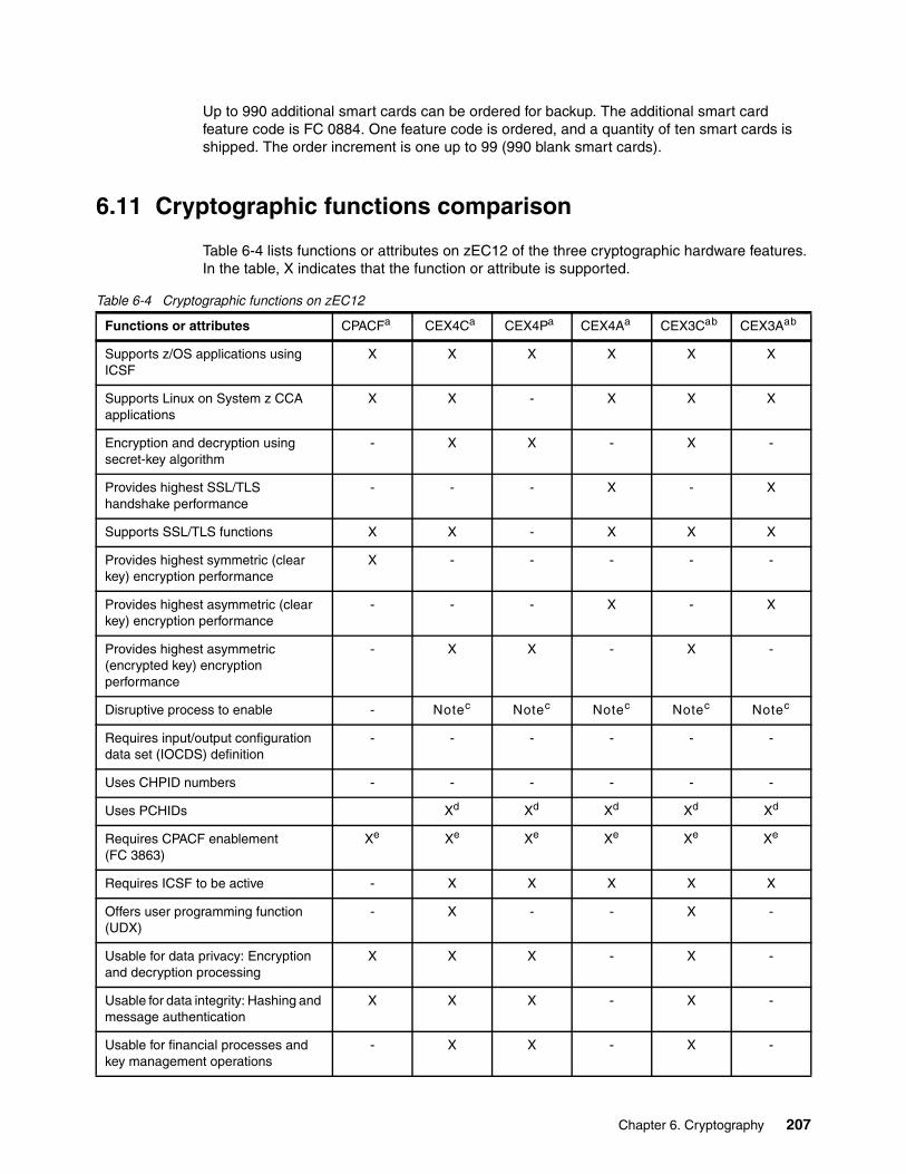
Up to 990 additional smart cards can be ordered for backup. The additional smart card feature code is FC 0884. One feature code is ordered, and a quantity of ten smart cards is shipped. The order increment is one up to 99 (990 blank smart cards).
6.11 Cryptographic functions comparison
Table 6-4 lists functions or attributes on zEC12 of the three cryptographic hardware features. In the table, X indicates that the function or attribute is supported.
Table 6-4 Cryptographic functions on zEC12
Functions or attributes CPACFa CEX4Ca CEX4Pa CEX4Aa CEX3Cab CEX3Aab
Supports z/OS applications using ICSF
X X X X X X
Supports Linux on System z CCA applications
X X - X X X
Encryption and decryption using secret-key algorithm
- X X - X -
Provides highest SSL/TLS handshake performance
- - - X - X
Supports SSL/TLS functions X X - X X X
Provides highest symmetric (clear key) encryption performance
X - - - - -
Provides highest asymmetric (clear key) encryption performance
- - - X - X
Provides highest asymmetric (encrypted key) encryption performance
- X X - X -
Disruptive process to enable - Notec Notec Notec Notec Notec
Requires input/output configuration data set (IOCDS) definition
- - - - - -
Uses CHPID numbers - - - - - -
Uses PCHIDs Xd Xd Xd Xd Xd
Requires CPACF enablement (FC 3863)
Xe Xe Xe Xe Xe Xe
Requires ICSF to be active - X X X X X
Offers user programming function (UDX)
- X - - X -
Usable for data privacy: Encryption and decryption processing
X X X - X -
Usable for data integrity: Hashing and message authentication
X X X - X -
Usable for financial processes and key management operations
- X X - X -
Chapter 6. Cryptography 207
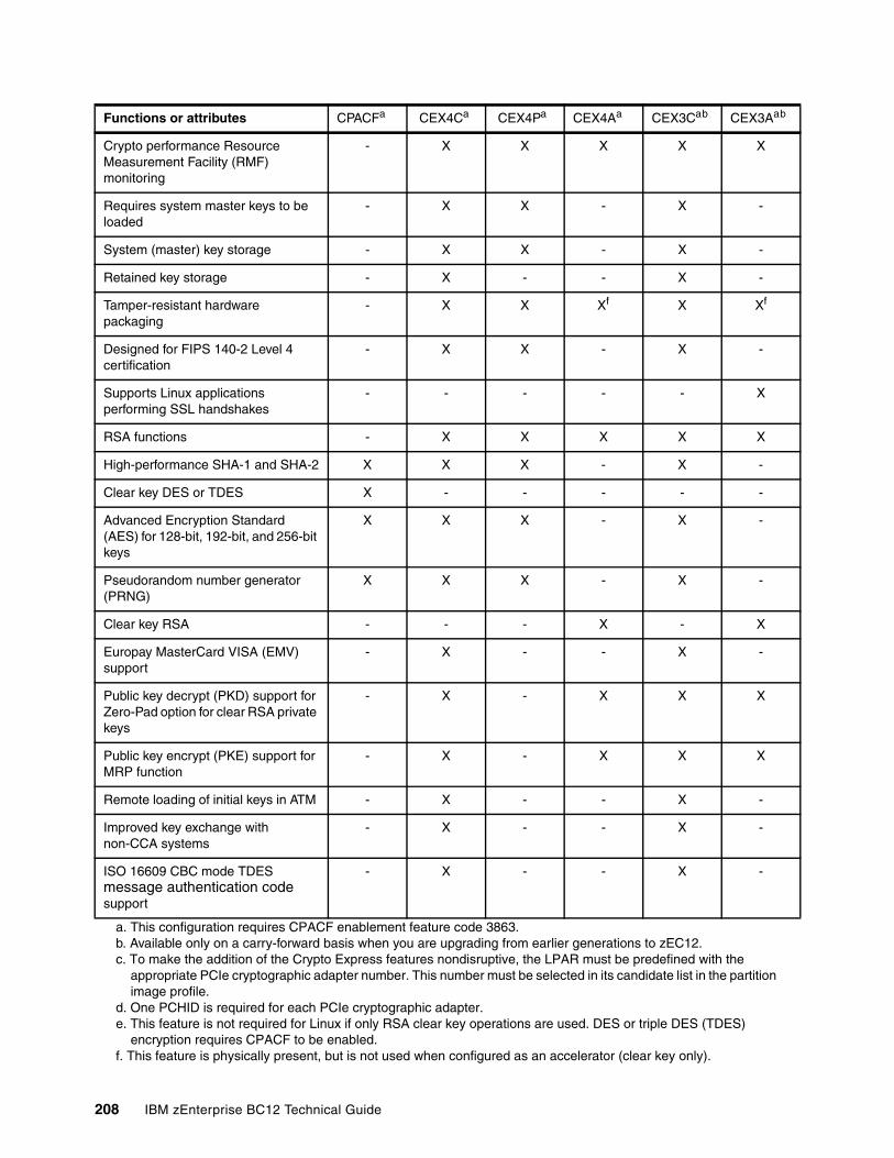
Crypto performance Resource Measurement Facility (RMF) monitoring
- X X X X X
Requires system master keys to be loaded
- X X - X -
System (master) key storage - X X - X -
Retained key storage - X - - X -
Tamper-resistant hardware packaging
- X X Xf X Xf
Designed for FIPS 140-2 Level 4 certification
- X X - X -
Supports Linux applications performing SSL handshakes
- - - - - X
RSA functions - X X X X X
High-performance SHA-1 and SHA-2 X X X - X -
Clear key DES or TDES X - - - - -
Advanced Encryption Standard (AES) for 128-bit, 192-bit, and 256-bit keys
X X X - X -
Pseudorandom number generator (PRNG)
X X X - X -
Clear key RSA - - - X - X
Europay MasterCard VISA (EMV) support
- X - - X -
Public key decrypt (PKD) support for Zero-Pad option for clear RSA private keys
- X - X X X
Public key encrypt (PKE) support for MRP function
- X - X X X
Remote loading of initial keys in ATM - X - - X -
Improved key exchange with non-CCA systems
- X - - X -
ISO 16609 CBC mode TDES message authentication code support
- X - - X -
a. This configuration requires CPACF enablement feature code 3863.b. Available only on a carry-forward basis when you are upgrading from earlier generations to zEC12. c. To make the addition of the Crypto Express features nondisruptive, the LPAR must be predefined with the
appropriate PCIe cryptographic adapter number. This number must be selected in its candidate list in the partition image profile.
d. One PCHID is required for each PCIe cryptographic adapter. e. This feature is not required for Linux if only RSA clear key operations are used. DES or triple DES (TDES)
encryption requires CPACF to be enabled.f. This feature is physically present, but is not used when configured as an accelerator (clear key only).
Functions or attributes CPACFa CEX4Ca CEX4Pa CEX4Aa CEX3Cab CEX3Aab
208 IBM zEnterprise BC12 Technical Guide

6.12 Software support
We list the software support levels in 8.4, “Cryptographic Support” on page 296.
Chapter 6. Cryptography 209

210 IBM zEnterprise BC12 Technical Guide
Chapter 7. IBM zEnterprise BladeCenter Extension Model 003
IBM has extended the mainframe system by bringing select IBM BladeCenter product lines under the same management umbrella. This is called the IBM zEnterprise BladeCenter Extension (zBX) Model 003, and the common management umbrella is the IBM Unified Resource Manager (URM).
The zBX brings the computing capacity of systems in blade form-factor to the IBM zEnterprise System. It is designed to provide a redundant hardware infrastructure that supports the multi-platform environment of the IBM zEnterprise BC12 System (zBC12) in a seamless, integrated way.
Also key to this hybrid environment is the URM. The URM helps deliver end-to-end infrastructure virtualization and management, and the ability to optimize multi-platform technology deployment according to complex workload requirements. For more information about the URM, see Chapter 12, “Hardware Management Console and Support Element” on page 393 and IBM zEnterprise Unified Resource Manager, SG24-7921.
This chapter introduces the ZBx Model 003, and describes its hardware components. It also explains the basic concepts and building blocks for zBX connectivity.
You can use this information for planning purposes, and to help define the configurations that best fit your requirements.
This chapter includes the following sections:
� IBM zBX concepts� IBM zBX hardware description� IBM zBX entitlements, firmware, and upgrades� IBM zBX connectivity� IBM zBX connectivity examples� References
7
© Copyright IBM Corp. 2014. All rights reserved. 211
7.1 IBM zBX concepts
The integration of System z in a hybrid computing infrastructure represents a new height for mainframe functionality and qualities of service. It is a cornerstone for the IT infrastructure, especially when flexibility for rapidly changing environments is needed.
The IBM zBC12 system characteristics make them especially valuable for mission-critical workloads. Today, most of these workloads employ multi-tiered architecture that spans various hardware and software platforms. However, there are differences in the quality of service offered by various the platforms.
There are also distinct configuration procedures for hardware and software, operational management, software servicing, and failure detection and correction. These procedures in turn require personnel with distinct skill sets, various sets of operational procedures, and an integration effort that is not trivial and, therefore, not often achieved. Failure to achieve integration translates to a lack of flexibility and agility, which can affect the bottom line.
IBM mainframe systems have been providing specialized hardware and fit-for-purpose (tuned to the task) computing capabilities for a long time. In addition to the machine instruction assists, another early example is the vector facility of the IBM 30901.
Other such specialty hardware includes the System Assist Processor for I/O handling (implemented in the 370-XA architecture), the coupling facility (CF), and the Cryptographic processors. Furthermore, all of the I/O cards are specialized dedicated hardware components with sophisticated firmware that offload processing from the System z processor units (PUs).
The common theme with all of these specialized hardware components is their seamless integration within the mainframe. The zBX components are also configured, managed, and serviced the same way as the other components of the System z central processor complex (CPC).
Although the zBX processors are not z/Architecture PUs, the zBX is handled by System z management firmware that is called the IBM zEnterprise Unified Resource Manager. The zBX hardware features are integrated into the mainframe system (are not add-ons).
System z has long been an integrated, heterogeneous system. With zBX, that integration reaches a new level. The zEnterprise with its zBX infrastructure enables you to run an application that spans z/OS, z/VM, Linux on System z, AIX, Linux on System x, and Microsoft Windows, yet have it under a single management umbrella. Also, zBX can host and integrate special-purpose workload optimizers, such as the IBM WebSphere DataPower Integration Appliance XI50 for zEnterprise (DataPower XI50z).
1 The following website has more information about the IBM 3090 vector facility:http://domino.watson.ibm.com/tchjr/journalindex.nsf/9fe6a820aae67ad785256547004d8af0/212e35ae6fecea7185256bfa00685bff!OpenDocument
212 IBM zEnterprise BC12 Technical Guide
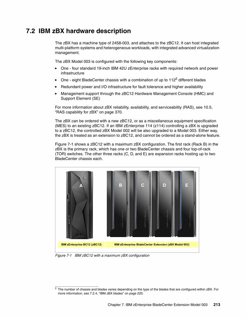
7.2 IBM zBX hardware description
The zBX has a machine type of 2458-003, and attaches to the zBC12. It can host integrated multi-platform systems and heterogeneous workloads, with integrated advanced virtualization management.
The zBX Model 003 is configured with the following key components:
� One - four standard 19-inch IBM 42U zEnterprise racks with required network and power infrastructure
� One - eight BladeCenter chassis with a combination of up to 1122 different blades
� Redundant power and I/O infrastructure for fault tolerance and higher availability
� Management support through the zBC12 Hardware Management Console (HMC) and Support Element (SE)
For more information about zBX reliability, availability, and serviceability (RAS), see 10.5, “RAS capability for zBX” on page 370.
The zBX can be ordered with a new zBC12, or as a miscellaneous equipment specification (MES) to an existing zBC12. If an IBM zEnterprise 114 (z114) controlling a zBX is upgraded to a zBC12, the controlled zBX Model 002 will be also upgraded to a Model 003. Either way, the zBX is treated as an extension to zBC12, and cannot be ordered as a stand-alone feature.
Figure 7-1 shows a zBC12 with a maximum zBX configuration. The first rack (Rack B) in the zBX is the primary rack, which has one or two BladeCenter chassis and four top-of-rack (TOR) switches. The other three racks (C, D, and E) are expansion racks hosting up to two BladeCenter chassis each.
Figure 7-1 IBM zBC12 with a maximum zBX configuration
2 The number of chassis and blades varies depending on the type of the blades that are configured within zBX. For more information, see 7.2.4, “IBM zBX blades” on page 220.
IBM zEnterprise BladeCenter Extension (zBX Model 003) IBM zEnterprise BC12 (zBC12)
EDCBA
Chapter 7. IBM zEnterprise BladeCenter Extension Model 003 213
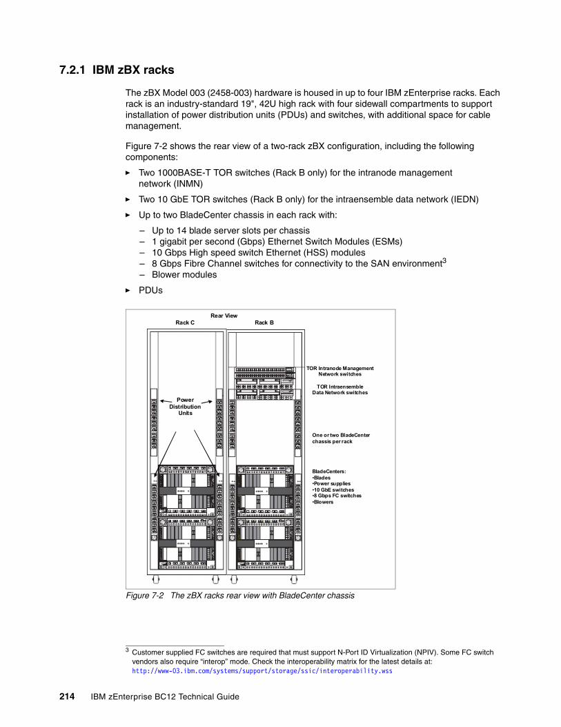
7.2.1 IBM zBX racks
The zBX Model 003 (2458-003) hardware is housed in up to four IBM zEnterprise racks. Each rack is an industry-standard 19", 42U high rack with four sidewall compartments to support installation of power distribution units (PDUs) and switches, with additional space for cable management.
Figure 7-2 shows the rear view of a two-rack zBX configuration, including the following components:
� Two 1000BASE-T TOR switches (Rack B only) for the intranode management network (INMN)
� Two 10 GbE TOR switches (Rack B only) for the intraensemble data network (IEDN)
� Up to two BladeCenter chassis in each rack with:
– Up to 14 blade server slots per chassis– 1 gigabit per second (Gbps) Ethernet Switch Modules (ESMs) – 10 Gbps High speed switch Ethernet (HSS) modules– 8 Gbps Fibre Channel switches for connectivity to the SAN environment3
– Blower modules
� PDUs
Figure 7-2 The zBX racks rear view with BladeCenter chassis
3 Customer supplied FC switches are required that must support N-Port ID Virtualization (NPIV). Some FC switch vendors also require “interop” mode. Check the interoperability matrix for the latest details at: http://www-03.ibm.com/systems/support/storage/ssic/interoperability.wss
TOR Intranode ManagementNetwork switches
TOR IntraensembleData Network switches
PowerDistribution
Units
One or two BladeCenterchassis per rack
BladeCenters:•Blades•Power supplies•10 GbE switches•8 Gbps FC switches•Blowers
Rack C Rack BRear View
214 IBM zEnterprise BC12 Technical Guide
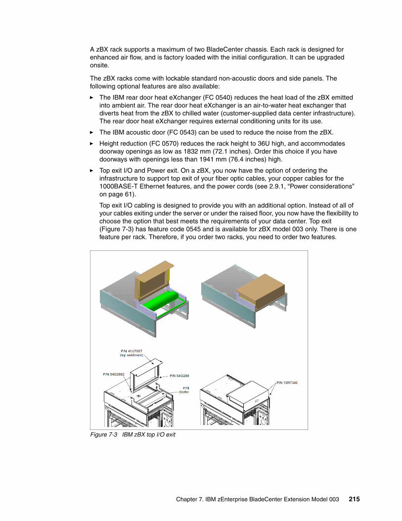
A zBX rack supports a maximum of two BladeCenter chassis. Each rack is designed for enhanced air flow, and is factory loaded with the initial configuration. It can be upgraded onsite.
The zBX racks come with lockable standard non-acoustic doors and side panels. The following optional features are also available:
� The IBM rear door heat eXchanger (FC 0540) reduces the heat load of the zBX emitted into ambient air. The rear door heat eXchanger is an air-to-water heat exchanger that diverts heat from the zBX to chilled water (customer-supplied data center infrastructure). The rear door heat eXchanger requires external conditioning units for its use.
� The IBM acoustic door (FC 0543) can be used to reduce the noise from the zBX.
� Height reduction (FC 0570) reduces the rack height to 36U high, and accommodates doorway openings as low as 1832 mm (72.1 inches). Order this choice if you have doorways with openings less than 1941 mm (76.4 inches) high.
� Top exit I/O and Power exit. On a zBX, you now have the option of ordering the infrastructure to support top exit of your fiber optic cables, your copper cables for the 1000BASE-T Ethernet features, and the power cords (see 2.9.1, “Power considerations” on page 61).
Top exit I/O cabling is designed to provide you with an additional option. Instead of all of your cables exiting under the server or under the raised floor, you now have the flexibility to choose the option that best meets the requirements of your data center. Top exit (Figure 7-3) has feature code 0545 and is available for zBX model 003 only. There is one feature per rack. Therefore, if you order two racks, you need to order two features.
Figure 7-3 IBM zBX top I/O exit
Chapter 7. IBM zEnterprise BladeCenter Extension Model 003 215
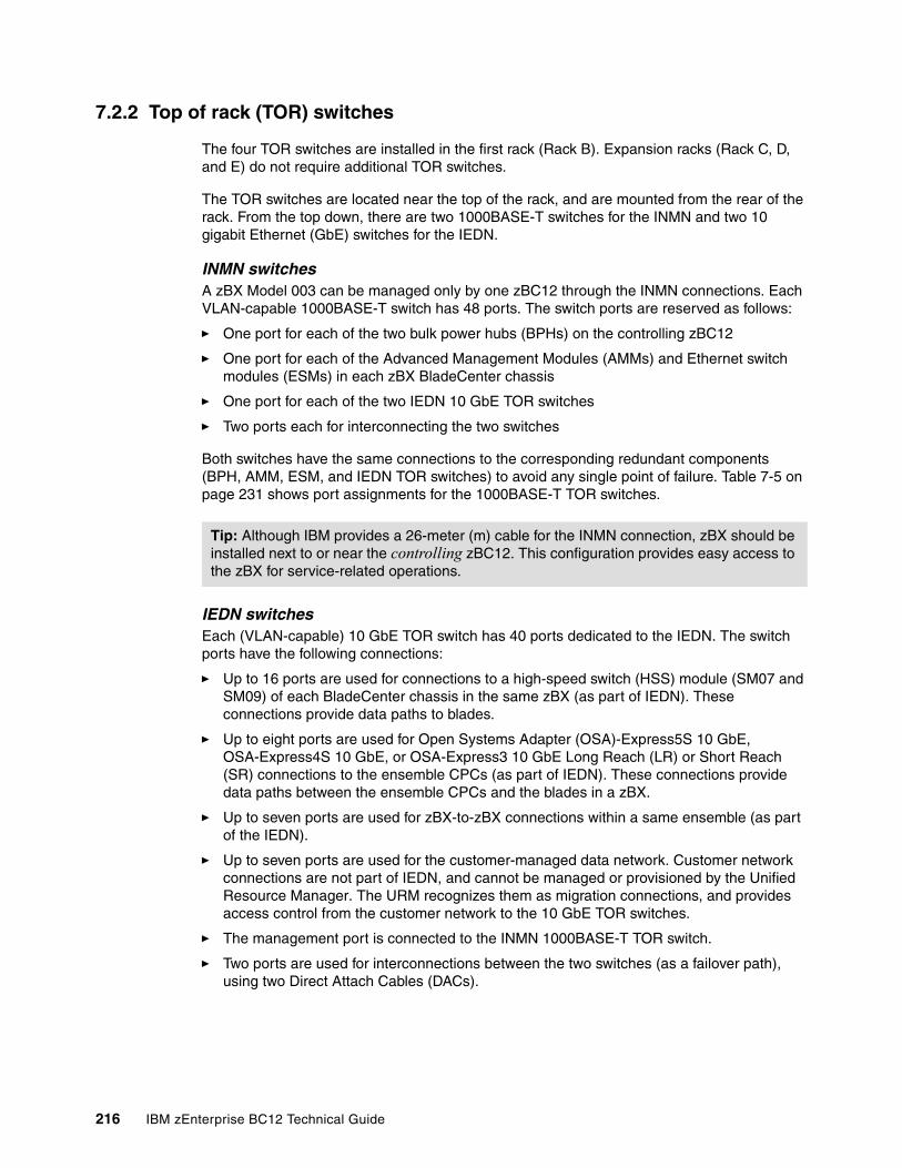
7.2.2 Top of rack (TOR) switches
The four TOR switches are installed in the first rack (Rack B). Expansion racks (Rack C, D, and E) do not require additional TOR switches.
The TOR switches are located near the top of the rack, and are mounted from the rear of the rack. From the top down, there are two 1000BASE-T switches for the INMN and two 10 gigabit Ethernet (GbE) switches for the IEDN.
INMN switchesA zBX Model 003 can be managed only by one zBC12 through the INMN connections. Each VLAN-capable 1000BASE-T switch has 48 ports. The switch ports are reserved as follows:
� One port for each of the two bulk power hubs (BPHs) on the controlling zBC12
� One port for each of the Advanced Management Modules (AMMs) and Ethernet switch modules (ESMs) in each zBX BladeCenter chassis
� One port for each of the two IEDN 10 GbE TOR switches
� Two ports each for interconnecting the two switches
Both switches have the same connections to the corresponding redundant components (BPH, AMM, ESM, and IEDN TOR switches) to avoid any single point of failure. Table 7-5 on page 231 shows port assignments for the 1000BASE-T TOR switches.
IEDN switchesEach (VLAN-capable) 10 GbE TOR switch has 40 ports dedicated to the IEDN. The switch ports have the following connections:
� Up to 16 ports are used for connections to a high-speed switch (HSS) module (SM07 and SM09) of each BladeCenter chassis in the same zBX (as part of IEDN). These connections provide data paths to blades.
� Up to eight ports are used for Open Systems Adapter (OSA)-Express5S 10 GbE, OSA-Express4S 10 GbE, or OSA-Express3 10 GbE Long Reach (LR) or Short Reach (SR) connections to the ensemble CPCs (as part of IEDN). These connections provide data paths between the ensemble CPCs and the blades in a zBX.
� Up to seven ports are used for zBX-to-zBX connections within a same ensemble (as part of the IEDN).
� Up to seven ports are used for the customer-managed data network. Customer network connections are not part of IEDN, and cannot be managed or provisioned by the Unified Resource Manager. The URM recognizes them as migration connections, and provides access control from the customer network to the 10 GbE TOR switches.
� The management port is connected to the INMN 1000BASE-T TOR switch.
� Two ports are used for interconnections between the two switches (as a failover path), using two Direct Attach Cables (DACs).
Tip: Although IBM provides a 26-meter (m) cable for the INMN connection, zBX should be installed next to or near the controlling zBC12. This configuration provides easy access to the zBX for service-related operations.
216 IBM zEnterprise BC12 Technical Guide
Figure 7-4 shows the connections of TOR switches and the first BladeCenter chassis in frame B. For more information about the connectivity options and rules for the INMN and the IEDN, see 7.4, “IBM zBX connectivity” on page 228.
Figure 7-4 Graphical illustration of zEnterprise network connections
7.2.3 IBM zBX BladeCenter chassis
Each zBX BladeCenter chassis is designed with additional components installed for high levels of resiliency.
The front of a zBX BladeCenter chassis has the following components:
� Blade server slots
There are 14 blade server slots (BS01 to BS14) available in a zBX BladeCenter chassis. Each slot can house any zBX supported blades, with the following restrictions:
– Slot 14 cannot hold a double-wide blade.– The DataPower XI50z blades are double-wide. Each feature takes two adjacent
BladeCenter slots, so the maximum number of DataPower blades per BladeCenter is seven. The maximum number of DataPower blades per zBX is 28.
� Power module
The power module includes a power supply and a three-pack of fans. Two of three fans are needed for power module operation. Power modules 1 and 2 (PM01 and PM02) are installed as a pair to provide a power supply for the seven blade server slots from BS01 to BS07. Power modules 3 and 4 (PM03 and PM04) support the BS08 to BS14.
The two different power connectors (marked with “1” and “2” in Figure 7-5) provide power connectivity for the power modules (PMs) and blade slots. PM01 and PM04 are connected to power connector 1, and PM02 and PM03 are connected to power connector 2. Therefore, each slot has fully redundant power from a different PM that is connected to a different power connector.
<- Port#B36P INMN
<- Port#B35P INMN
<- Port#B32P INMN
<- Port#B30P INMN
OSM
OSM
47P06
P04
P04
P03
P03BPH-B
BPH-A
P06
P07
P07
47
01
SM09
01
01
01
SM01
SM02
45
45 44
44 46
41
46
41
08 16
01 02
SM07
10
10 09
09
08 16
01 02
38
38 39
39
MM02
00
00
MM01
03
03
BladeCenter chassis B10B
Chapter 7. IBM zEnterprise BladeCenter Extension Model 003 217
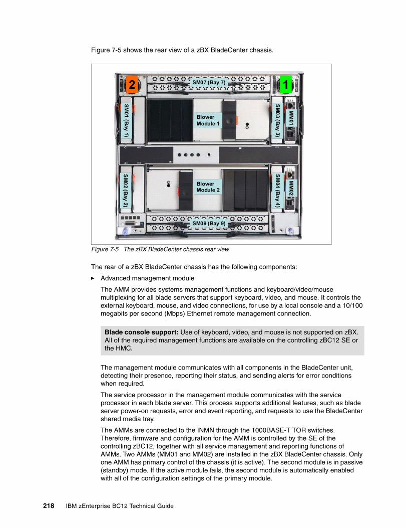
Figure 7-5 shows the rear view of a zBX BladeCenter chassis.
Figure 7-5 The zBX BladeCenter chassis rear view
The rear of a zBX BladeCenter chassis has the following components:
� Advanced management module
The AMM provides systems management functions and keyboard/video/mouse multiplexing for all blade servers that support keyboard, video, and mouse. It controls the external keyboard, mouse, and video connections, for use by a local console and a 10/100 megabits per second (Mbps) Ethernet remote management connection.
The management module communicates with all components in the BladeCenter unit, detecting their presence, reporting their status, and sending alerts for error conditions when required.
The service processor in the management module communicates with the service processor in each blade server. This process supports additional features, such as blade server power-on requests, error and event reporting, and requests to use the BladeCenter shared media tray.
The AMMs are connected to the INMN through the 1000BASE-T TOR switches. Therefore, firmware and configuration for the AMM is controlled by the SE of the controlling zBC12, together with all service management and reporting functions of AMMs. Two AMMs (MM01 and MM02) are installed in the zBX BladeCenter chassis. Only one AMM has primary control of the chassis (it is active). The second module is in passive (standby) mode. If the active module fails, the second module is automatically enabled with all of the configuration settings of the primary module.
Blade console support: Use of keyboard, video, and mouse is not supported on zBX. All of the required management functions are available on the controlling zBC12 SE or the HMC.
SM
01 (B
ay 1)S
M0
2 (Bay 2)
2 SM07 (Bay 7)
SM09 (Bay 9)
BlowerModule 2
BlowerModule 1
1
SM
03 (B
ay 3)S
M04 (B
ay 4
)
MM
01M
M02
218 IBM zEnterprise BC12 Technical Guide
� Ethernet switch module
Two 1000BASE-T (1 Gbps) ESMs (SM01 and SM02) are installed in switch bays 1 and 2 in the chassis. Each ESM has 14 internal full-duplex Gigabit ports. One is connected to each of the blade servers in the BladeCenter chassis, and two internal full-duplex 10/100 Mbps ports are connected to the AMM modules. Six 1000BASE-T copper RJ-45 connections are used for INMN connections to the TOR 1000BASE-T switches.
The ESM port 01 is connected to one of the 1000BASE-T TOR switches. As part of the INMN, configuration and firmware of ESM is controlled by the controlling zBC12 or zEC12 SE.
� High speed switch module
Two HSS modules (SM07 and SM09) are installed to switch bays 7 and 9.
The HSS modules provide 10 GbE uplinks to the 10 GbE TOR switches, and 10 GbE downlinks to the blades in the chassis.
Port 01 and 02 are connected to one of the 10 GbE TOR switches. Port 09 and 10 are used to interconnect HSS modules in bays 7 and 9 as a redundant failover path.
� 8-Gbps Fibre Channel switch module
Two 8 Gbps Fibre Channel (FC) switches (SM03 and SM04) are installed in switch bays 3 and 4. Each switch has 14 internal ports that are reserved for the blade servers in the chassis, and six external Fibre Channel ports to provide connectivity to the SAN environment.
� Blower module
There are two hot-swap blower modules installed. The blower speeds vary depending on the ambient air temperature at the front of the BladeCenter unit and the temperature of internal BladeCenter components. If a blower fails, the remaining blowers run full speed.
� BladeCenter mid-plane fabric connections
The BladeCenter mid-plane provides redundant power, control, and data connections to a blade server. It does so by internally routed chassis components (power modules, AMMs, switch modules, and the media tray) to connectors in a blade server slot.
There are six connectors in a blade server slot on the mid-plane (from top to bottom):
– Top 1X fabric connects blade to MM01, SM01, and SM03.
– Power connector from power module 1 (blade server slots 1 - 7) or power module 3 (blade server slots 8 - 14).
– Top 4X fabric connects blade to SM07.
– Bottom 4X fabric connects blade to SM09.
– Bottom 1X fabric connects blade to MM02, SM02, and SM04.
– Power connector from power module 2 (blade server slot 1 - 7) or power module 4 (blade server slot 8 - 14).
Each blade server therefore has redundant power, data, and control links from separate components.
Chapter 7. IBM zEnterprise BladeCenter Extension Model 003 219
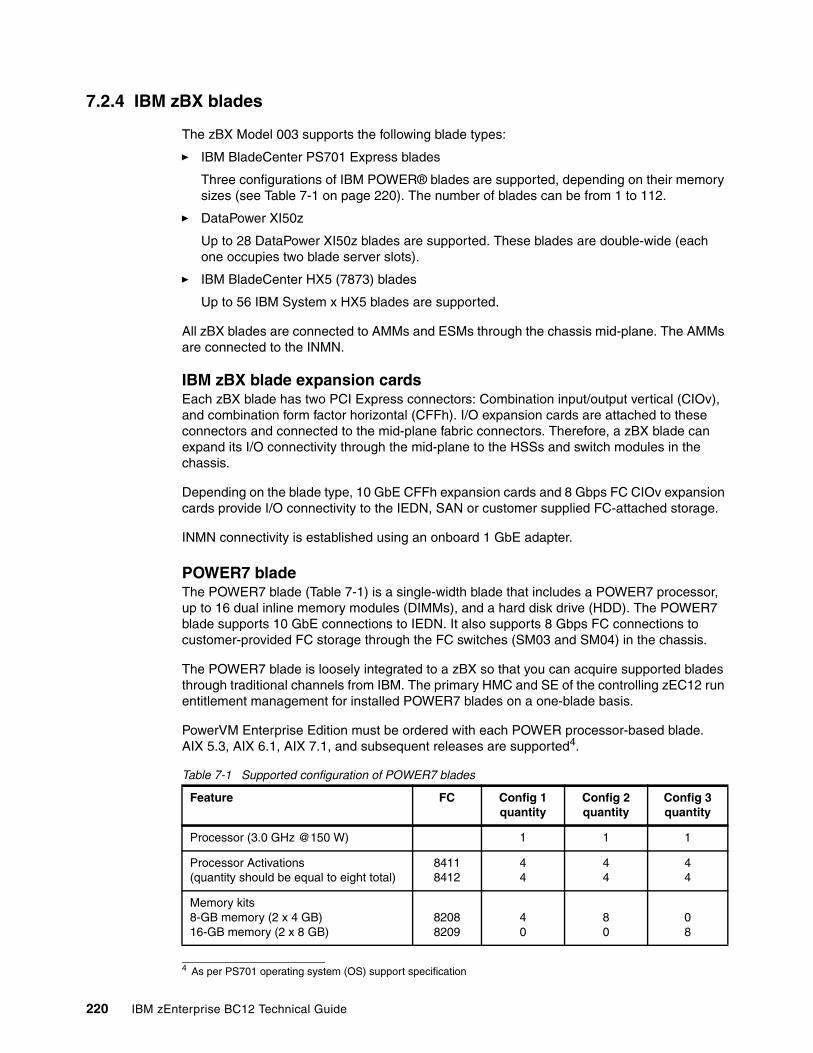
7.2.4 IBM zBX blades
The zBX Model 003 supports the following blade types:
� IBM BladeCenter PS701 Express blades
Three configurations of IBM POWER® blades are supported, depending on their memory sizes (see Table 7-1 on page 220). The number of blades can be from 1 to 112.
� DataPower XI50z
Up to 28 DataPower XI50z blades are supported. These blades are double-wide (each one occupies two blade server slots).
� IBM BladeCenter HX5 (7873) blades
Up to 56 IBM System x HX5 blades are supported.
All zBX blades are connected to AMMs and ESMs through the chassis mid-plane. The AMMs are connected to the INMN.
IBM zBX blade expansion cardsEach zBX blade has two PCI Express connectors: Combination input/output vertical (CIOv), and combination form factor horizontal (CFFh). I/O expansion cards are attached to these connectors and connected to the mid-plane fabric connectors. Therefore, a zBX blade can expand its I/O connectivity through the mid-plane to the HSSs and switch modules in the chassis.
Depending on the blade type, 10 GbE CFFh expansion cards and 8 Gbps FC CIOv expansion cards provide I/O connectivity to the IEDN, SAN or customer supplied FC-attached storage.
INMN connectivity is established using an onboard 1 GbE adapter.
POWER7 bladeThe POWER7 blade (Table 7-1) is a single-width blade that includes a POWER7 processor, up to 16 dual inline memory modules (DIMMs), and a hard disk drive (HDD). The POWER7 blade supports 10 GbE connections to IEDN. It also supports 8 Gbps FC connections to customer-provided FC storage through the FC switches (SM03 and SM04) in the chassis.
The POWER7 blade is loosely integrated to a zBX so that you can acquire supported blades through traditional channels from IBM. The primary HMC and SE of the controlling zEC12 run entitlement management for installed POWER7 blades on a one-blade basis.
PowerVM Enterprise Edition must be ordered with each POWER processor-based blade. AIX 5.3, AIX 6.1, AIX 7.1, and subsequent releases are supported4.
Table 7-1 Supported configuration of POWER7 blades
4 As per PS701 operating system (OS) support specification
Feature FC Config 1quantity
Config 2quantity
Config 3quantity
Processor (3.0 GHz @150 W) 1 1 1
Processor Activations(quantity should be equal to eight total)
84118412
44
44
44
Memory kits8-GB memory (2 x 4 GB)16-GB memory (2 x 8 GB)
82088209
40
80
08
220 IBM zEnterprise BC12 Technical Guide
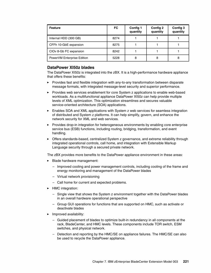
DataPower XI50z bladesThe DataPower XI50z is integrated into the zBX. It is a high-performance hardware appliance that offers these benefits:
� Provides fast and flexible integration with any-to-any transformation between disparate message formats, with integrated message-level security and superior performance.
� Provides web services enablement for core System z applications to enable web-based workloads. As a multifunctional appliance DataPower XI50z can help provide multiple levels of XML optimization. This optimization streamlines and secures valuable service-oriented architecture (SOA) applications.
� Enables SOA and XML applications with System z web services for seamless integration of distributed and System z platforms. It can help simplify, govern, and enhance the network security for XML and web services.
� Provides drop-in integration for heterogeneous environments by enabling core enterprise service bus (ESB) functions, including routing, bridging, transformation, and event handling.
� Offers standards-based, centralized System z governance, and extreme reliability through integrated operational controls, call home, and integration with Extensible Markup Language security through a secured private network.
The zBX provides more benefits to the DataPower appliance environment in these areas:
� Blade hardware management:
– Improved cooling and power management controls, including cooling of the frame and energy monitoring and management of the DataPower blades
– Virtual network provisioning
– Call home for current and expected problems.
� HMC integration:
– Single view that shows the System z environment together with the DataPower blades in an overall hardware operational perspective
– Group GUI operations for functions that are supported on HMC, such as activate or deactivate blades
� Improved availability:
– Guided placement of blades to optimize built-in redundancy in all components at the rack, BladeCenter, and HMC levels. These components include TOR switch, ESM switches, and physical network.
– Detection and reporting by the HMC/SE on appliance failures. The HMC/SE can also be used to recycle the DataPower appliance.
Internal HDD (300 GB) 8274 1 1 1
CFFh 10-GbE expansion 8275 1 1 1
CIOv 8-Gb FC expansion 8242 1 1 1
PowerVM Enterprise Edition 5228 8 8 8
Feature FC Config 1quantity
Config 2quantity
Config 3quantity
Chapter 7. IBM zEnterprise BladeCenter Extension Model 003 221
� Networking:
– Virtual network provisioning– Enforced isolation of network traffic by VLAN support– 10 Gbps end-to-end network infrastructure– Built-in network redundancy– Network protection via IEDN, possibly meeting your need for encryption of data flowing
between DataPower and the target System z server
� Monitoring and reporting:
– Monitoring and reporting of DataPower hardware health and degraded operation by HMC
– Monitoring of all hardware, call-home, and service actions
– Consolidation and integration of DataPower hardware problem reporting with other problems reported in zBX
� System z value:
– Simplified ordering process of the DataPower appliance by System z enables the correct blade infrastructure to be transparently ordered.
– Simplified upgrades keep MES history so that the upgrades flow based on what is installed.
– System z service on the zBX and DataPower blade using a common maintenance package and a single point of control. The DataPower appliance becomes part of the data center and comes under data center control.
In addition, although not specific to the zBX environment, dynamic load balancing for DataPower appliances is available by using the z/OS Communications Server Sysplex Distributor.
ConfigurationThe DataPower XI50z is a double-wide blade based on IBM HS22 blade. Each one takes two BladeCenter slots. Therefore, the maximum number of DataPower blades per BladeCenter is seven, and the maximum number of DataPower blades per zBX is 28. It can coexist with POWER7 blades and with IBM BladeCenter HX5 blades in the same zBX BladeCenter. Although DataPower XI50z blades are configured and ordered as zBX (machine type 2458-003) features, they have their own machine type (2462-4BX).
The DataPower XI50z with DataPower expansion unit has the following specifications:
� 2.13 GHz processor speed.
� Two quad core processors.
� 8 MB cache.
� 3 x 4 GB or 6 x 2 GB DIMMs (12 GB of RAM).
� 4 GB USB Flash Key that contains the DataPower XI50z firmware load.
� Two 300 GB HDDs used for logging, storing style sheets, and XML files. The hard disk array consists of two HDDs in a Redundant Array of Independent Disks (RAID)-1 (mirrored) configuration.
� Two Broadcom BCM5709S Ethernet adapters with TOE5 (integrated on system board)
� BPE46 Expansion Unit, which is a sealed field-replaceable unit (FRU) with one-way tamper-proof screws that contains the crypto for secure SOA applications.
5 TOE: TCP/IP Offload Engine6 BPE: BladeCenter PCI Express Gen 2 Expansion Blade
222 IBM zEnterprise BC12 Technical Guide

� XG5 accelerator PCIe card.
� CN1620 Cavium Crypto PCIe card.
� Dual 10 Gb Ethernet cards.
2462 Model 4BX (DataPower XI50z)The 2462 Model 4BX is designed to work together with the 2458 Model 003 (zBX). It is functionally equivalent to an IBM 4195-4BX with similar feature codes. The IBM 2462 Model 4BX is ordered through certain feature codes for the 2458-003.
When configuring the IBM 2458 Model 003 with feature code 0611 (DataPower XI50z), order a machine type IBM 2462 Model 4BX for each configured feature code. It requires Software product identifier (PID) 5765-G84.
A Software Maintenance Agreement (SWMA) must be active for the IBM software that runs on the DataPower XI50z before you can obtain service or other support. Failure to maintain SWMA results in you not being able to obtain service for the IBM software. This is true even if the DataPower XI50z is under warranty or post-warranty IBM hardware maintenance service contract.
The DataPower XI50z includes the following license entitlements:
� DataPower Basic Enablement (feature code 0650)� IBM Tivoli® Access Manager (feature code 0651)� TIBCO (feature code 0652).� Database Connectivity (DTB) (feature code 0653)� Application Optimization (AO) (feature code 0654)� Month Indicator (feature code 0660)� Day Indicator (feature code 0661)� Hour Indicator (feature code 0662)� Minute Indicator (feature code 0663)
5765-G84 IBM WebSphere DataPower Integration Blade XI50B feature code description:
� 0001 License with 1-year SWMA� 0002 Option for TIBCO� 0003 Option for Application Optimization� 0004 Option for Database Connectivity� 0005 Option for Tivoli Access Manager
Every IBM 2462 Model 4BX includes feature codes 0001, 0003, and 0005 (they are optional on DataPower XI50B). Optional Software feature codes 0002 and 0004 are required if FC 0652 TIBCO or FC 0653 Database Connectivity are ordered.
The TIBCO option (FC 0002) extends the DataPower XI50z so you can send and receive messages from TIBCO Enterprise Message Service (EMS).
The option for Database Connectivity (FC 0004) extends the DataPower XI50z to read and write data from relational databases, such as IBM DB2, Oracle, Sybase, and Microsoft SQL Server.
For software PID number 5765-G85 (registration and renewal), every IBM 2462 Model 4BX includes feature code 0001. Feature code 0003 is available at the end of the first year to renew software maintenance for one more year.
For software PID number 5765-G86 (maintenance reinstatement 12 months), feature code 0001 is available if software PID 5765-G85 feature code 0003 was not ordered before the year expired.
Chapter 7. IBM zEnterprise BladeCenter Extension Model 003 223
For software PID number 5765-G87 (3-year registration), feature code 0001 can be ordered instead of software PID 5765-G85 feature code 0003. This code makes the initial period three years rather than one year.
For software PID number 5765-G88 (3-year renewal), feature code 0001 can be used as alternative software PID 5765-G85 feature code 0003 if a three-year renewal is wanted. The maximum duration is five years.
For software PID number 5765-G89 (3-year after license), feature code 0001 is available if software PID 5765-G85 feature code 0003 was not ordered before the year expired. Use this option if a 3-year renewal is wanted.
IBM BladeCenter HX5 (7873) bladesThe IBM BladeCenter HX5 is a scalable blade server that provides new levels of utilization, performance, and reliability. It is suitable for compute-intensive and memory-intensive workloads, such as database, virtualization, business intelligence, modeling and simulation, and other enterprise applications.
Select System x blades running Linux on System x and Microsoft Windows on IBM System x servers are supported in the zBX. They use the zBX integrated hypervisor for IBM System x blades (kernel-based virtual machine), providing logical device integration between System z and System x blades for multi-tiered applications. System x blades are licensed separately, and are enabled and managed as part of the ensemble by URM.
The following operating systems are supported:
� Linux on System x (64bit only):
– Red Hat Enterprise Linux (RHEL) 5.5, 5.6, 5.7, 6.0, and 6.1– SUSE Linux Enterprise Server (SLES) 10 (SP4) and up, SLES 11 SP1 and later
� Microsoft Windows Server 2008 R2, Windows Server 2008 SP2, and Windows Server 2012 (Datacenter Edition is preferred), 64-bit only
Support of select IBM System x blades in the zBX enables the zEnterprise to access a whole new application portfolio. Front-end applications that need access to centralized data serving are a good fit for running on the blades, as are applications that are a front end to core CICS or IMS transaction processing, such as IBM WebSphere.
You can acquire BladeCenter HX5 (BC-H) blades through existing channels or through IBM. POWER7, DataPower XI50z, and System x blades can be mixed in the same BladeCenter chassis. Supported configuration options are listed in Table 7-2 on page 225.
IBM BladeCenter HX5 7873 is a dual-socket, 16-core blade with the following features:
� Intel 8-core processor� Two processor sockets� 2.13 GHz 105-W processor� Up to14 A16Ms features per BC-H� Up to 16 DIMM DDR-3 with 64, 128, 192, or 256 GB of memory � 200 GB solid-state drive (SSD) internal disk
224 IBM zEnterprise BC12 Technical Guide
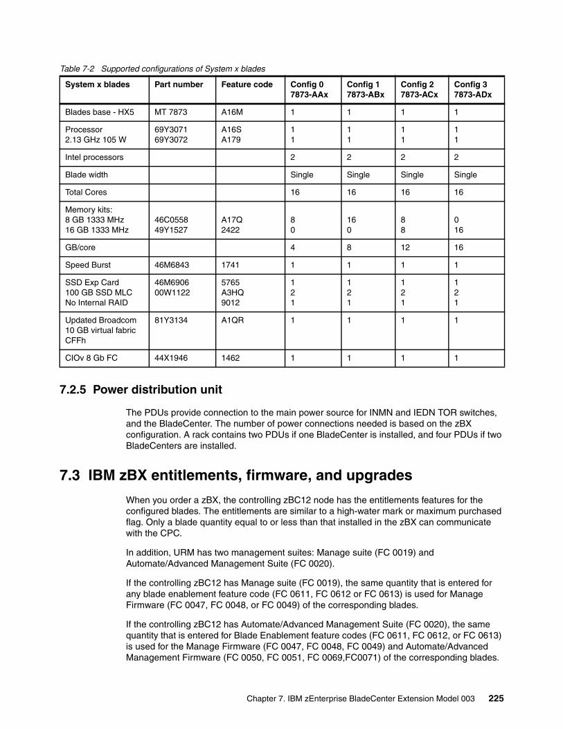
Table 7-2 Supported configurations of System x blades
7.2.5 Power distribution unit
The PDUs provide connection to the main power source for INMN and IEDN TOR switches, and the BladeCenter. The number of power connections needed is based on the zBX configuration. A rack contains two PDUs if one BladeCenter is installed, and four PDUs if two BladeCenters are installed.
7.3 IBM zBX entitlements, firmware, and upgrades
When you order a zBX, the controlling zBC12 node has the entitlements features for the configured blades. The entitlements are similar to a high-water mark or maximum purchased flag. Only a blade quantity equal to or less than that installed in the zBX can communicate with the CPC.
In addition, URM has two management suites: Manage suite (FC 0019) and Automate/Advanced Management Suite (FC 0020).
If the controlling zBC12 has Manage suite (FC 0019), the same quantity that is entered for any blade enablement feature code (FC 0611, FC 0612 or FC 0613) is used for Manage Firmware (FC 0047, FC 0048, or FC 0049) of the corresponding blades.
If the controlling zBC12 has Automate/Advanced Management Suite (FC 0020), the same quantity that is entered for Blade Enablement feature codes (FC 0611, FC 0612, or FC 0613) is used for the Manage Firmware (FC 0047, FC 0048, FC 0049) and Automate/Advanced Management Firmware (FC 0050, FC 0051, FC 0069,FC0071) of the corresponding blades.
System x blades Part number Feature code Config 0 7873-AAx
Config 1 7873-ABx
Config 2 7873-ACx
Config 3 7873-ADx
Blades base - HX5 MT 7873 A16M 1 1 1 1
Processor2.13 GHz 105 W
69Y307169Y3072
A16SA179
11
11
11
11
Intel processors 2 2 2 2
Blade width Single Single Single Single
Total Cores 16 16 16 16
Memory kits:8 GB 1333 MHz16 GB 1333 MHz
46C055849Y1527
A17Q2422
80
160
88
016
GB/core 4 8 12 16
Speed Burst 46M6843 1741 1 1 1 1
SSD Exp Card100 GB SSD MLCNo Internal RAID
46M690600W1122
5765A3HQ9012
121
121
121
121
Updated Broadcom 10 GB virtual fabric CFFh
81Y3134 A1QR 1 1 1 1
CIOv 8 Gb FC 44X1946 1462 1 1 1 1
Chapter 7. IBM zEnterprise BladeCenter Extension Model 003 225
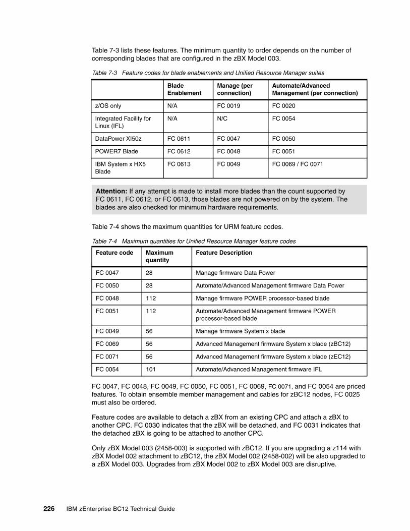
Table 7-3 lists these features. The minimum quantity to order depends on the number of corresponding blades that are configured in the zBX Model 003.
Table 7-3 Feature codes for blade enablements and Unified Resource Manager suites
Table 7-4 shows the maximum quantities for URM feature codes.
Table 7-4 Maximum quantities for Unified Resource Manager feature codes
FC 0047, FC 0048, FC 0049, FC 0050, FC 0051, FC 0069, FC 0071, and FC 0054 are priced features. To obtain ensemble member management and cables for zBC12 nodes, FC 0025 must also be ordered.
Feature codes are available to detach a zBX from an existing CPC and attach a zBX to another CPC. FC 0030 indicates that the zBX will be detached, and FC 0031 indicates that the detached zBX is going to be attached to another CPC.
Only zBX Model 003 (2458-003) is supported with zBC12. If you are upgrading a z114 with zBX Model 002 attachment to zBC12, the zBX Model 002 (2458-002) will be also upgraded to a zBX Model 003. Upgrades from zBX Model 002 to zBX Model 003 are disruptive.
Blade Enablement
Manage (per connection)
Automate/Advanced Management (per connection)
z/OS only N/A FC 0019 FC 0020
Integrated Facility for Linux (IFL)
N/A N/C FC 0054
DataPower XI50z FC 0611 FC 0047 FC 0050
POWER7 Blade FC 0612 FC 0048 FC 0051
IBM System x HX5 Blade
FC 0613 FC 0049 FC 0069 / FC 0071
Attention: If any attempt is made to install more blades than the count supported by FC 0611, FC 0612, or FC 0613, those blades are not powered on by the system. The blades are also checked for minimum hardware requirements.
Feature code Maximum quantity
Feature Description
FC 0047 28 Manage firmware Data Power
FC 0050 28 Automate/Advanced Management firmware Data Power
FC 0048 112 Manage firmware POWER processor-based blade
FC 0051 112 Automate/Advanced Management firmware POWER processor-based blade
FC 0049 56 Manage firmware System x blade
FC 0069 56 Advanced Management firmware System x blade (zBC12)
FC 0071 56 Advanced Management firmware System x blade (zEC12)
FC 0054 101 Automate/Advanced Management firmware IFL
226 IBM zEnterprise BC12 Technical Guide
A zBX Model 003 has the following improvements over Model 002:
� New AMM7 firmware in BladeCenter chassis with enhanced functions.
� Additional Ethernet connectivity to IEDN network for redundancy and increased bandwidth between TOR switches and BladeCenter switch modules.
� New Firmware levels with improved functionality.
� New URM support for ensembles with IBM zEnterprise EC12 (zEC12), zBC12, IBM zEnterprise 196 (z196), and z114 with zBX Models 002 and 003.
� IBM zBX FC link/path testing and diagnostics.
� Layer 2 (L2) integration support between customer data network and zBX.
� CPU Management for System x Blades. This enables URM to dynamically manage processors for x86 blades in the zBX. Enables customers to monitor availability of workload resources to satisfy defined service policy goals by using KVM8 Control Groups (cgroups9). The cgroup use by URM platform performance manager (PPM), is based on assigning virtual servers to cgroups, enabling dynamic CPU sharing management based on policy goals.
� Ensemble availability manager (EAM) provides basic availability services for the ensemble by the URM. It enables customers to monitor for zBX blade errors, including conditions affecting the availability of resources, and perform complete error analysis.
7.3.1 IBM zBX management
One key feature of the zBX is its integration under the System z management umbrella. Therefore, initial firmware installation, updates, and patches follow the already familiar pattern of System z. The same integration applies to the configuration and definitions.
Similar to channels and processors, the SE has a view for the zBX blades. This view shows icons for each of the zBX component’s objects, including an overall status (power, operational, and other conditions).
The following functions and actions are managed and controlled from the zBC12 HMC/SE:
� View firmware information for the BladeCenter and blades.� Retrieve firmware changes.� Change firmware level.� Backup/restore critical data: zBX configuration data is backed up as part of System zBC12
SE backup. It is restored on replacement of a blade.
For more information, see IBM zEnterprise Unified Resource Manager, SG24-7921.
7.3.2 IBM zBX firmware
The firmware for the zBX is managed, controlled, and delivered in the same way as for the zBC12. It is packaged and tested with System z microcode, and changes are supplied and applied with MCL bundle releases.
7 Advanced Management Module (BladeCenter feature)8 Kernel Virtual Machine9 With cgroups, you can restrict a set of tasks to a set of resources, prevent denial-of-service situations in KVM
environments, and monitor resource use.
Chapter 7. IBM zEnterprise BladeCenter Extension Model 003 227
The zBX firmware that is packaged with System z microcode has these benefits:
� Tested together with System z driver code and MCL bundle releases� Retrieve code uses the same integrated process as System z (IBM RETAIN® or media)� No need to use separate tools or connect to websites to obtain code� Use new upcoming System z firmware features, such as Digitally Signed Firmware� Infrastructure incorporates System z concurrency controls where possible� IBM zBX firmware update is fully concurrent, blades are similar to Config Off/On controls� Audit trail of all code changes in security log� Automatic back out of changes to previous working level on code apply failures� Optimizer firmware� IBM zBX requires the use of broadband Remote Support Facility (RSF) capability of HMC
7.4 IBM zBX connectivity
There are three types of LANs (each with redundant connections) that attach to the zBX:
� The INMN� The IEDN � The customer-managed data network
INMNThe INMN is fully isolated, and only established between the controlling zBC12 and the zBX. The zBX is managed by the HMC through the physically isolated INMN, which interconnects all resources of the zEC12 and zBX components.
IEDNThe IEDN connects the zBX to a maximum of eight zBC12 or zEC12. Any combination of up to eight zEnterprise systems (z196, z114, zEC12, and zBC12) can be connected to the IEDN. The IEDN provides private and secure 10 GbE high-speed data paths between all elements of a zEnterprise ensemble (up to eight zEC12,zBC12, z196, or z114 with optional zBXs).
Each zBC12 must have a minimum of two connections to the zBX. The IEDN is also used to connect a zBX to a maximum of seven other zBXs. The IEDN is a VLAN-capable network that supports enhanced security by isolating data traffic between virtual servers.
Figure 7-6 on page 229 shows the connectivity that is required for the zBX environment. The zBC12 connects through two OSA-Express5S 1000BASE-T, or OSA-Express3 1000BASE-T10 features (CHPID type OSA-Express for Unified Resource Manager (OSM)) to the BPHs and to the INMN TOR switches. The OSA-EXPRESS5S 10 GbE, OSA-Express4S3 10 GbE, or OSA-Express3 10 GbE10 features (CHPID type OSA-Express for zBX (OSX)) connect directly to the two IEDN TOR switches.
Depending on the requirements, any OSA-Express5S, OSA-Express4S, or OSA-Express3 features (CHPID type OSA-Express Queued Direct I/O (OSD)) can connect to the customer-managed data network.
Note: IEDN can expand to all members of an Ensemble.
10 Carry forward only for zBC12 when you are upgrading from earlier generations.
Terminology: If not specifically stated otherwise, the term “OSA1000BASE-T” applies throughout this chapter to the OSA-Express5S, OSA-Expess4S (not available on zBC12), and OSA-Express3 1000BASE-T features.
228 IBM zEnterprise BC12 Technical Guide
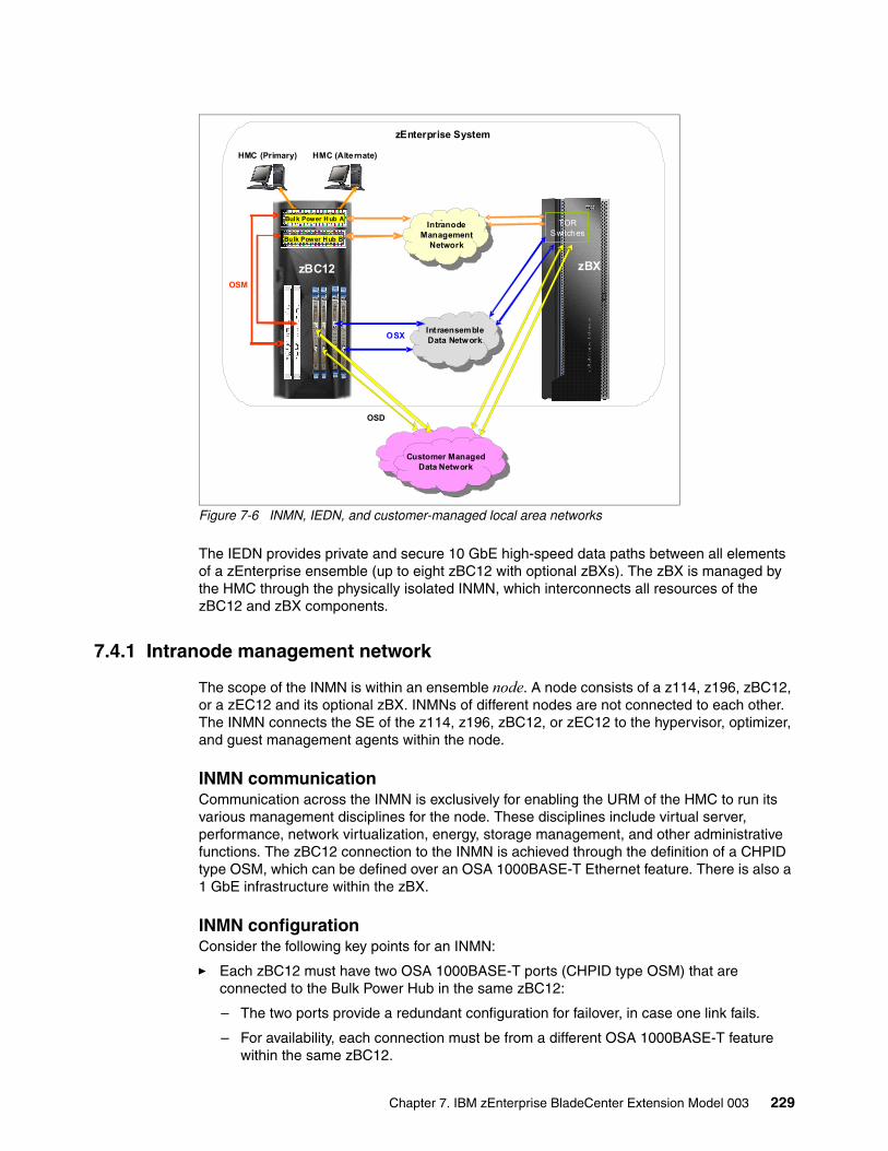
Figure 7-6 INMN, IEDN, and customer-managed local area networks
The IEDN provides private and secure 10 GbE high-speed data paths between all elements of a zEnterprise ensemble (up to eight zBC12 with optional zBXs). The zBX is managed by the HMC through the physically isolated INMN, which interconnects all resources of the zBC12 and zBX components.
7.4.1 Intranode management network
The scope of the INMN is within an ensemble node. A node consists of a z114, z196, zBC12, or a zEC12 and its optional zBX. INMNs of different nodes are not connected to each other. The INMN connects the SE of the z114, z196, zBC12, or zEC12 to the hypervisor, optimizer, and guest management agents within the node.
INMN communicationCommunication across the INMN is exclusively for enabling the URM of the HMC to run its various management disciplines for the node. These disciplines include virtual server, performance, network virtualization, energy, storage management, and other administrative functions. The zBC12 connection to the INMN is achieved through the definition of a CHPID type OSM, which can be defined over an OSA 1000BASE-T Ethernet feature. There is also a 1 GbE infrastructure within the zBX.
INMN configurationConsider the following key points for an INMN:
� Each zBC12 must have two OSA 1000BASE-T ports (CHPID type OSM) that are connected to the Bulk Power Hub in the same zBC12:
– The two ports provide a redundant configuration for failover, in case one link fails.
– For availability, each connection must be from a different OSA 1000BASE-T feature within the same zBC12.
zEnterprise System
Customer ManagedData Network
-
-Intranode
ManagementNetwork
OSX
OSD
IntraensembleData Network
OSM
zBC12
Bulk Power Hub B
HMC (Primary) HMC (Alternate)
Bul k Power H ub A
zBX
TOR Switches
Chapter 7. IBM zEnterprise BladeCenter Extension Model 003 229
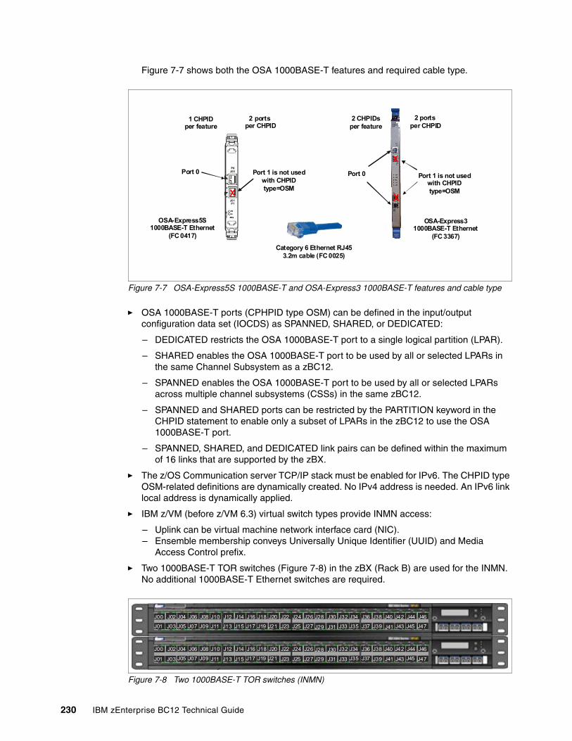
Figure 7-7 shows both the OSA 1000BASE-T features and required cable type.
Figure 7-7 OSA-Express5S 1000BASE-T and OSA-Express3 1000BASE-T features and cable type
� OSA 1000BASE-T ports (CPHPID type OSM) can be defined in the input/output configuration data set (IOCDS) as SPANNED, SHARED, or DEDICATED:
– DEDICATED restricts the OSA 1000BASE-T port to a single logical partition (LPAR).
– SHARED enables the OSA 1000BASE-T port to be used by all or selected LPARs in the same Channel Subsystem as a zBC12.
– SPANNED enables the OSA 1000BASE-T port to be used by all or selected LPARs across multiple channel subsystems (CSSs) in the same zBC12.
– SPANNED and SHARED ports can be restricted by the PARTITION keyword in the CHPID statement to enable only a subset of LPARs in the zBC12 to use the OSA 1000BASE-T port.
– SPANNED, SHARED, and DEDICATED link pairs can be defined within the maximum of 16 links that are supported by the zBX.
� The z/OS Communication server TCP/IP stack must be enabled for IPv6. The CHPID type OSM-related definitions are dynamically created. No IPv4 address is needed. An IPv6 link local address is dynamically applied.
� IBM z/VM (before z/VM 6.3) virtual switch types provide INMN access:
– Uplink can be virtual machine network interface card (NIC).– Ensemble membership conveys Universally Unique Identifier (UUID) and Media
Access Control prefix.
� Two 1000BASE-T TOR switches (Figure 7-8) in the zBX (Rack B) are used for the INMN. No additional 1000BASE-T Ethernet switches are required.
Figure 7-8 Two 1000BASE-T TOR switches (INMN)
X
X
OSA-Express31000BASE-T Ethernet
(FC 3367)
Port 0
2 ports per CHPID
Port 1 is not usedwith CHPID type=OSM
2 CHPIDsper feature
Category 6 Ethernet RJ453.2m cable (FC 0025)
2 ports per CHPID
1 CHPIDper feature
OSA-Express5S1000BASE-T Ethernet
(FC 0417)
Port 0 Port 1 is not usedwith CHPID type=OSM
X
J00 J02 J04 J06 J08 J10 J12 J14 J16 J18 J20 J22 J24 J26 J28 J30 J32 J34 J36 J38 J40 J42 J44 J46
J01 J03 J05 J07 J09 J11 J13 J15 J17 J19 J21 J23 J25 J27 J29 J31 J33 J35 J37 J39 J43 J45 J47J41
J00 J02 J04 J06 J08 J10 J12 J14 J16 J18 J20 J22 J24 J26 J28 J30 J32 J34 J36 J38 J40 J42 J44 J46
J01 J03 J05 J07 J09 J11 J13 J15 J17 J19 J21 J23 J25 J27 J29 J31 J33 J35 J37 J39 J43 J45 J47J41
230 IBM zEnterprise BC12 Technical Guide
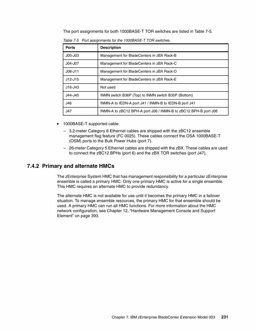
The port assignments for both 1000BASE-T TOR switches are listed in Table 7-5.
Table 7-5 Port assignments for the 1000BASE-T TOR switches
� 1000BASE-T supported cable:
– 3.2-meter Category 6 Ethernet cables are shipped with the zBC12 ensemble management flag feature (FC 0025). These cables connect the OSA 1000BASE-T (OSM) ports to the Bulk Power Hubs (port 7).
– 26-meter Category 5 Ethernet cables are shipped with the zBX. These cables are used to connect the zBC12 BPHs (port 6) and the zBX TOR switches (port J47).
7.4.2 Primary and alternate HMCs
The zEnterprise System HMC that has management responsibility for a particular zEnterprise ensemble is called a primary HMC. Only one primary HMC is active for a single ensemble. This HMC requires an alternate HMC to provide redundancy.
The alternate HMC is not available for use until it becomes the primary HMC in a failover situation. To manage ensemble resources, the primary HMC for that ensemble should be used. A primary HMC can run all HMC functions. For more information about the HMC network configuration, see Chapter 12, “Hardware Management Console and Support Element” on page 393.
Ports Description
J00-J03 Management for BladeCenters in zBX Rack-B
J04-J07 Management for BladeCenters in zBX Rack-C
J08-J11 Management for BladeCenters in zBX Rack-D
J12-J15 Management for BladeCenters in zBX Rack-E
J16-J43 Not used
J44-J45 INMN switch B36P (Top) to INMN switch B35P (Bottom)
J46 INMN-A to IEDN-A port J41 / INMN-B to IEDN-B port J41
J47 INMN-A to zBC12 BPH-A port J06 / INMN-B to zBC12 BPH-B port J06
Chapter 7. IBM zEnterprise BladeCenter Extension Model 003 231
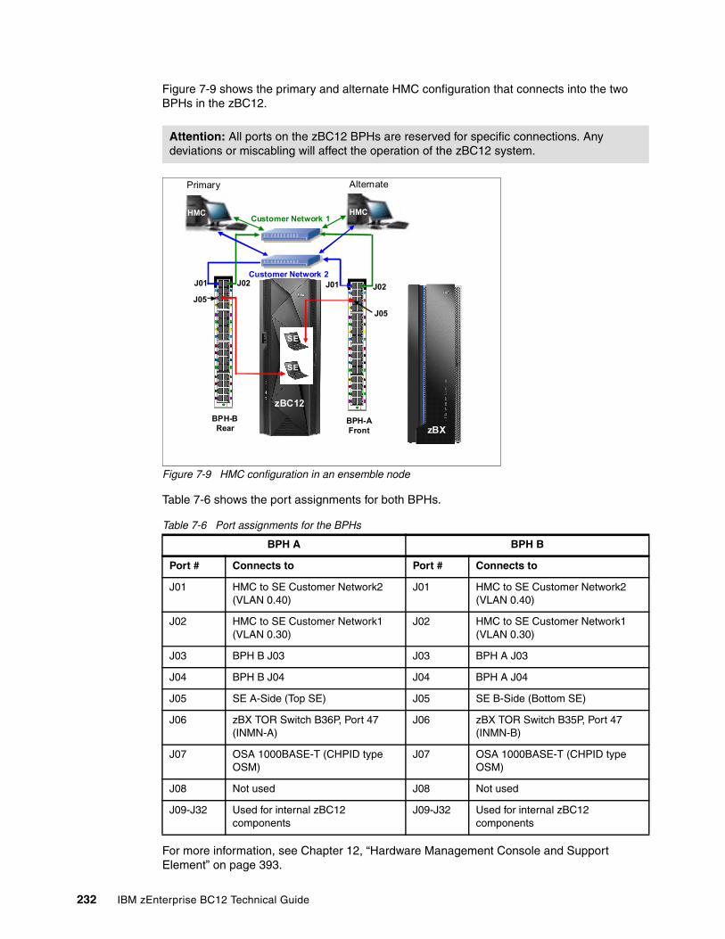
Figure 7-9 shows the primary and alternate HMC configuration that connects into the two BPHs in the zBC12.
Figure 7-9 HMC configuration in an ensemble node
Table 7-6 shows the port assignments for both BPHs.
Table 7-6 Port assignments for the BPHs
For more information, see Chapter 12, “Hardware Management Console and Support Element” on page 393.
Attention: All ports on the zBC12 BPHs are reserved for specific connections. Any deviations or miscabling will affect the operation of the zBC12 system.
BPH A BPH B
Port # Connects to Port # Connects to
J01 HMC to SE Customer Network2 (VLAN 0.40)
J01 HMC to SE Customer Network2 (VLAN 0.40)
J02 HMC to SE Customer Network1 (VLAN 0.30)
J02 HMC to SE Customer Network1 (VLAN 0.30)
J03 BPH B J03 J03 BPH A J03
J04 BPH B J04 J04 BPH A J04
J05 SE A-Side (Top SE) J05 SE B-Side (Bottom SE)
J06 zBX TOR Switch B36P, Port 47 (INMN-A)
J06 zBX TOR Switch B35P, Port 47 (INMN-B)
J07 OSA 1000BASE-T (CHPID type OSM)
J07 OSA 1000BASE-T (CHPID type OSM)
J08 Not used J08 Not used
J09-J32 Used for internal zBC12 components
J09-J32 Used for internal zBC12 components
BPH-AFront
BPH-BRear
J02J02
Customer Network 1
J01Customer Network 2
J01
HMC
SE
SE
J05
J05
HMC
Primary Alternate
zBC12
zBX
232 IBM zEnterprise BC12 Technical Guide
7.4.3 Intraensemble data network
The IEDN is the main application data path that is provisioned and managed by the URM of the controlling zBC12. Data communications for ensemble-defined workloads flow over the IEDN between nodes of an ensemble.
All of the physical and logical resources of the IEDN are configured and managed by the URM. The IEDN extends from the zBC12 through the OSA-Express5S 10-GbE, OSA-Express4S 10 GbE, or OSA-Express3 10 GbE ports when defined as CHPID type OSX. The minimum number of OSA 10 GbE features is two per zBC12. Similarly, a 10 GbE networking infrastructure within the zBX is used for IEDN access.
IEDN configurationThe IEDN connections can be configured in a number of ways. Consider the following key points for IEDN:
� Each zBC12 must have a minimum of two OSA 10 GbE ports that are connected to the zBX through the IEDN:
– The two ports provide a redundant configuration for failover purposes in case one link fails.
– For availability, each connection must be from a different OSA 10 GbE feature within the same zBC12.
– The zBX can have a maximum of 16 IEDN connections (eight pairs of OSA 10 GbE ports).
– Four connections between IEDN TOR switches and high speed switch modules in each BladeCenter chassis (two pairs of 10 GbE ports).
– For redundancy, two connections between both high-speed switch modules in each BladeCenter.
Terminology: If not specifically stated otherwise, the term “OSA10 GbE” applies throughout this chapter to the OSA-Express5S 10 GbE, OSA-Express4S 10 GbE, and OSA-Express3 10-GbE features.
Chapter 7. IBM zEnterprise BladeCenter Extension Model 003 233
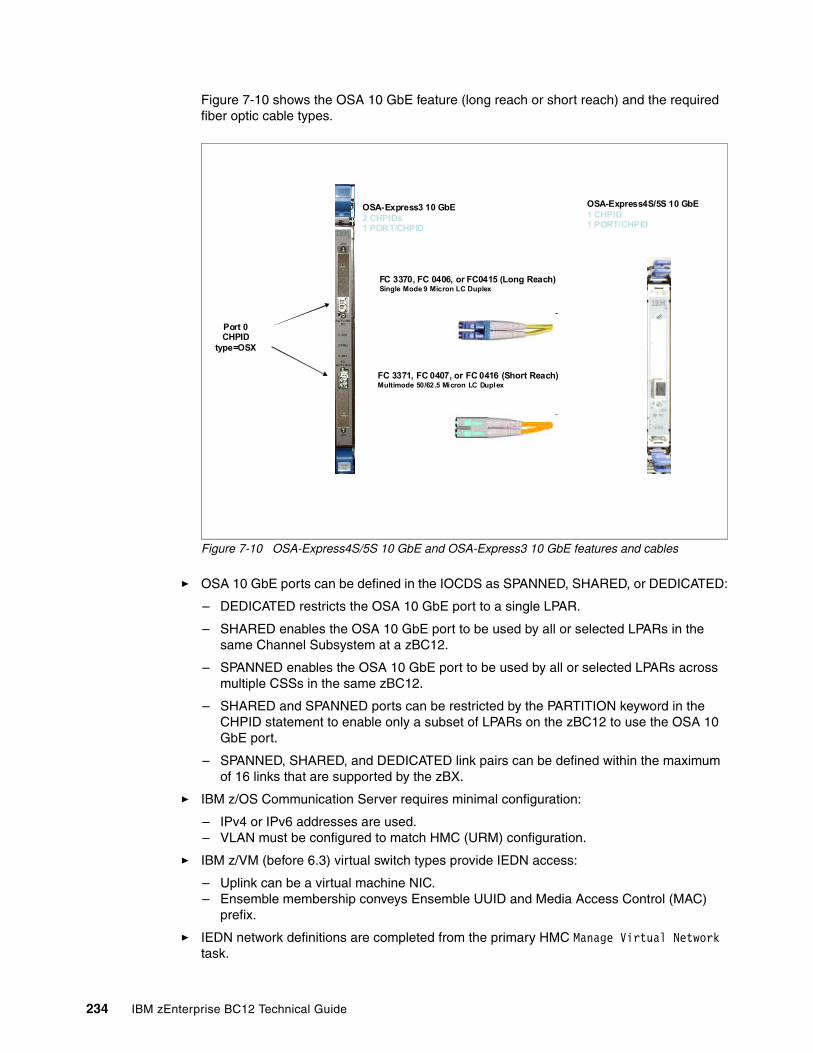
Figure 7-10 shows the OSA 10 GbE feature (long reach or short reach) and the required fiber optic cable types.
Figure 7-10 OSA-Express4S/5S 10 GbE and OSA-Express3 10 GbE features and cables
� OSA 10 GbE ports can be defined in the IOCDS as SPANNED, SHARED, or DEDICATED:
– DEDICATED restricts the OSA 10 GbE port to a single LPAR.
– SHARED enables the OSA 10 GbE port to be used by all or selected LPARs in the same Channel Subsystem at a zBC12.
– SPANNED enables the OSA 10 GbE port to be used by all or selected LPARs across multiple CSSs in the same zBC12.
– SHARED and SPANNED ports can be restricted by the PARTITION keyword in the CHPID statement to enable only a subset of LPARs on the zBC12 to use the OSA 10 GbE port.
– SPANNED, SHARED, and DEDICATED link pairs can be defined within the maximum of 16 links that are supported by the zBX.
� IBM z/OS Communication Server requires minimal configuration:
– IPv4 or IPv6 addresses are used.– VLAN must be configured to match HMC (URM) configuration.
� IBM z/VM (before 6.3) virtual switch types provide IEDN access:
– Uplink can be a virtual machine NIC.– Ensemble membership conveys Ensemble UUID and Media Access Control (MAC)
prefix.
� IEDN network definitions are completed from the primary HMC Manage Virtual Network task.
Port 0CHPID
type=OSX
FC 3370, FC 0406, or FC0415 (Long Reach)Single Mode 9 Micron LC Duplex
FC 3371, FC 0407, or FC 0416 (Short Reach)Multimode 50/62.5 Micron LC Duplex
OSA-Express4S/5S 10 GbE1 CHPID1 PORT/CHPID
OSA-Express3 10 GbE2 CHPIDs1 PORT/CHPID
234 IBM zEnterprise BC12 Technical Guide
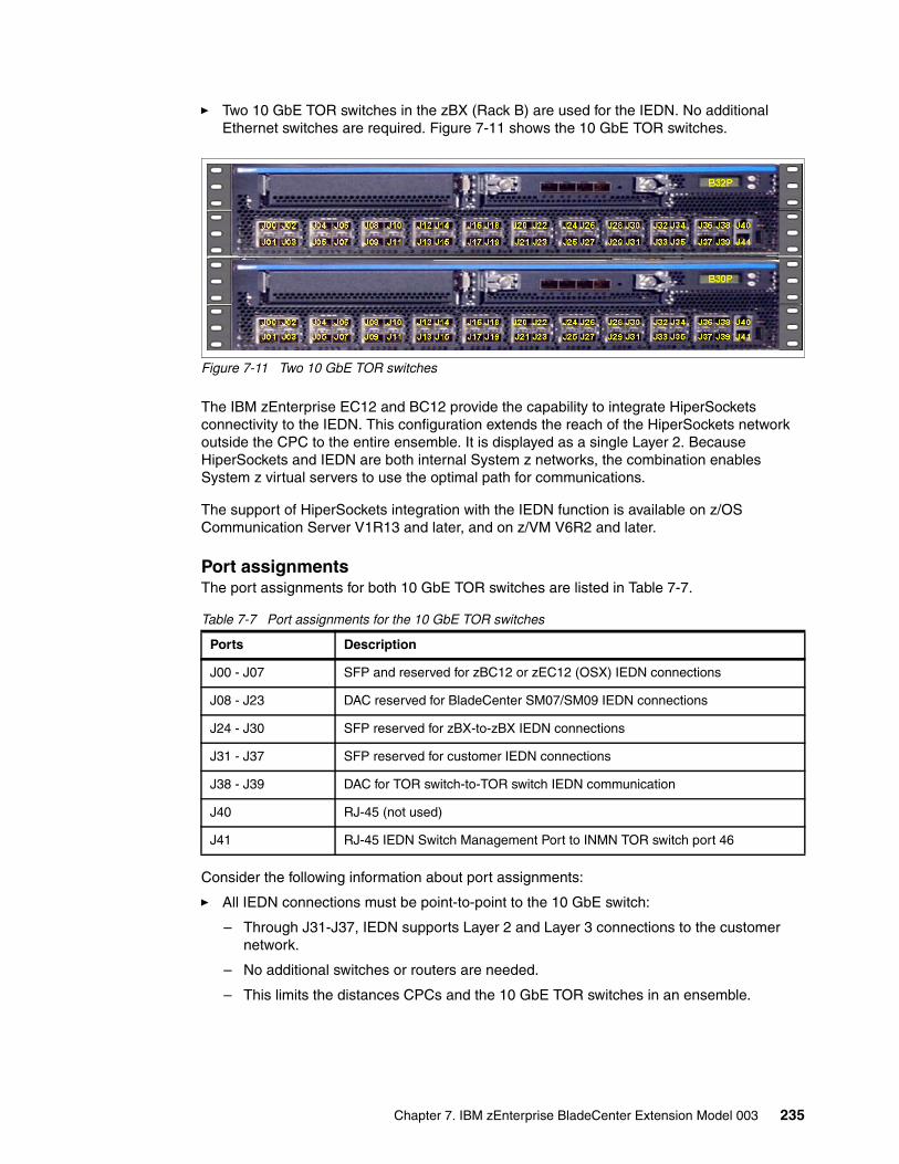
� Two 10 GbE TOR switches in the zBX (Rack B) are used for the IEDN. No additional Ethernet switches are required. Figure 7-11 shows the 10 GbE TOR switches.
Figure 7-11 Two 10 GbE TOR switches
The IBM zEnterprise EC12 and BC12 provide the capability to integrate HiperSockets connectivity to the IEDN. This configuration extends the reach of the HiperSockets network outside the CPC to the entire ensemble. It is displayed as a single Layer 2. Because HiperSockets and IEDN are both internal System z networks, the combination enables System z virtual servers to use the optimal path for communications.
The support of HiperSockets integration with the IEDN function is available on z/OS Communication Server V1R13 and later, and on z/VM V6R2 and later.
Port assignmentsThe port assignments for both 10 GbE TOR switches are listed in Table 7-7.
Table 7-7 Port assignments for the 10 GbE TOR switches
Consider the following information about port assignments:
� All IEDN connections must be point-to-point to the 10 GbE switch:
– Through J31-J37, IEDN supports Layer 2 and Layer 3 connections to the customer network.
– No additional switches or routers are needed.
– This limits the distances CPCs and the 10 GbE TOR switches in an ensemble.
Ports Description
J00 - J07 SFP and reserved for zBC12 or zEC12 (OSX) IEDN connections
J08 - J23 DAC reserved for BladeCenter SM07/SM09 IEDN connections
J24 - J30 SFP reserved for zBX-to-zBX IEDN connections
J31 - J37 SFP reserved for customer IEDN connections
J38 - J39 DAC for TOR switch-to-TOR switch IEDN communication
J40 RJ-45 (not used)
J41 RJ-45 IEDN Switch Management Port to INMN TOR switch port 46
Chapter 7. IBM zEnterprise BladeCenter Extension Model 003 235
� The 10 GbE TOR switches use small form-factor pluggable (SFP) optics for the external connections and DACs for connections:
– Ports J00-J07 are reserved for the zBC12 or zEC12 OSX IEDN connections. These ports use SFPs plugged according to the zBX order:
• FC 0632 LR SFP to FC 0415 OSA-Express5S 10 GbE LR• FC 0633 SR SFP to FC 0416 OSA-Express5S 10 GbE LR• FC 0632 LR SFP to FC 0406 OSA-Express4S 10 GbE LR• FC 0633 SR SFP to FC 0407 OSA-Express4S 10 GbE SR• FC 0632 LR SFP to FC 3370 OSA-Express3 10 GbE LR• FC 0633 SR SFP to FC 3371 OSA-Express3 10 GbE SR
– Ports J08-J23 are reserved for IEDN to BladeCenter attachment. The cables that are used are Direct Attach Cables (DACs), and are included with the zBX. These are hard wired 10 GbE SFP cables. The feature codes indicate the length of the cable:
• FC 0626: 1 meter for Rack B BladeCenters and IEDN to IEDN• FC 0627: 5 meters for Rack C BladeCenter • FC 0628: 7 meters for Racks D and E BladeCenters
� Ports J31-J37 are reserved for the zBC12 OSD IEDN connections. These ports use SFP modules plugged according to the zBX order. You must provide all IEDN cables except for zBX internal connections. The following 10 GbE fiber optic cable types are available, and list their maximum distance:
– Multimode fiber:
• 50-micron fiber at 2000 MHz-kilometer (km): 300 meters• 50-micron fiber at 500 MHz-km: 82 meters• 62.5-micron fiber at 200 MHz-km: 33 meters
– Single mode fiber:
• 10 km
7.4.4 Network connectivity rules with zBX
Interconnecting a zBX must follow these network connectivity rules:
� Only one zBX is supported per controlling zBC12.
� The zBX can be installed next to the controlling zBC12, within the limitation of the 26-meter cable.
� Customer-managed data networks are outside the ensemble. A customer-managed data network is connected with these components:
– CHPID type OSD from zBC12– IEDN TOR switch ports J31 to J37 from zBX
7.4.5 Network security considerations with zBX
The private networks that are involved in connecting the zBC12 to the zBX are constructed with extreme security in mind:
� The INMN is entirely private, and can be accessed only by the SE (standard HMC security applies). There are also additions to URM role-based security. Therefore, not just any user can reach the URM panels even if that user can perform other functions of the HMC. There are strict authorizations for users and programs to control who is permitted to take advantage of the INMN.
236 IBM zEnterprise BC12 Technical Guide

� The INMN network uses link-local IP addresses. Link-local addresses are not advertised, and are accessible only within a single LAN segment. There is no routing in this network because it is a flat network, with all Virtual Servers on the same IPv6 network. The URM communicates with the Virtual Servers through the SE over the INMN. The Virtual Servers cannot communicate with each other directly through INMN. They can communicate only with the SE.
� Only authorized programs or agents can take advantage of the INMN. Currently the Performance Agent can do so. However, there can be other platform management applications in the future that will need to be authorized to access the INMN.
� The IEDN is built on a flat network design (same IPv4 or IPv6 network). Each server that accesses the IEDN must be an authorized Virtual Server, and must belong to an authorized VLAN within the physical IEDN. VLAN enforcement is part of the hypervisor functions of the ensemble. The controls are in the OSA (CHPID type OSX), in the z/VM VSWITCH, and in the VSWITCH hypervisor function of the blades on the zBX.
The VLAN IDs and the Virtual MACs that are assigned to the connections from the Virtual Servers are tightly controlled through the URM. Therefore, there is no chance of either MAC or VLAN spoofing for any of the servers on the IEDN. If you decide to attach your network to the TOR switches of the zBX to communicate with the Virtual Servers on the zBX blades, access must be authorized in the TOR switches (MAC- or VLAN-based).
Although the TOR switches enforce the VMACs and VLAN IDs, you must take the usual network security measures to ensure that the devices in the Customer-Managed Data Network are not subject to MAC or VLAN spoofing. The URM functions cannot control the assignment of VLAN IDs and VMACs in those devices.
Whenever you decide to interconnect the external network to the secured IEDN, the security of that external network must involve all of the usual layers of the IBM Security Framework. These layers include physical security, platform security, application and process security, and data and information security.
� The INMN and the IEDN are both subject to Network Access Controls as implemented in z/OS and z/VM. Therefore, not just any virtual server on the zBC12 that can use these networks. INMN is not accessible at all from within the virtual servers.
� It is unnecessary to implement firewalls, IP filtering, or encryption for data flowing over the IEDN. However, if company policy or security require such measures to be taken, they are supported. You can implement any of the security technologies available, such as SSL/TLS or IP filtering.
� The centralized and internal network design of both the INMN and the IEDN limit the vulnerability to security breaches. Both networks reduce the amount of network equipment and administration tasks. They also reduce routing hops that are under the control of multiple individuals and subject to security threats. Both use IBM-only equipment (switches, blades) that have been tested, and in certain cases, preinstalled.
In summary, many more technologies than in the past are integrated in a more robust, secure fashion into the customer network. This configuration is achieved with the help of either the URM, or more System Authorization Facility (SAF) controls specific to zEnterprise System and the ensemble:
� MAC filtering
� VLAN enforcement
� ACCESS control
� Role-based security
Chapter 7. IBM zEnterprise BladeCenter Extension Model 003 237
� The following standard security implementations are still available for use in the IEDN:
– Authentication.
– Authorization and access control that includes multilevel security (MLS) and firewall IP filtering. Only stateless firewalls or IP filtering implementations can be installed in a Virtual Server in the ensemble.
– Confidentiality.
– Data integrity.
– Non-repudiation.
7.4.6 IBM zBX storage connectivity
The FC connections can be established between the zBX and a SAN environment. Customer-supplied FC switches are required, and must support NPIV11. Some FC switch vendors also require interop mode. Check the interoperability matrix for the latest details:
http://www-03.ibm.com/systems/support/storage/ssic/interoperability.wss
Each BladeCenter chassis in the zBX has two 20-port 8-Gbps FC switch modules. Each switch has 14 internal ports and six shortwave (SX) external ports. The internal ports are reserved for the blades in the chassis. The six external ports (J00, J15-J19) are used to connect to the SAN.
11 N-Port ID Virtualization
Remember: It is the customer’s responsibility to supply the cables for IEDN, the customer- managed network, and the connection between the zBX and the SAN environment.
238 IBM zEnterprise BC12 Technical Guide
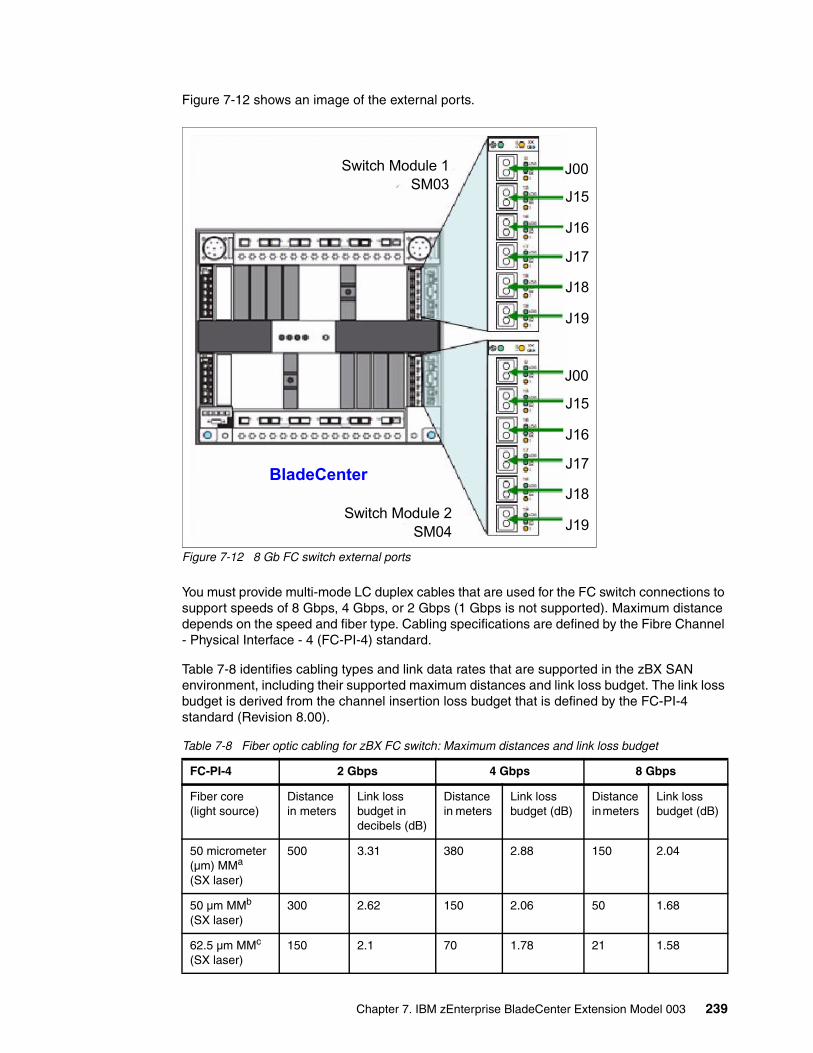
Figure 7-12 shows an image of the external ports.
Figure 7-12 8 Gb FC switch external ports
You must provide multi-mode LC duplex cables that are used for the FC switch connections to support speeds of 8 Gbps, 4 Gbps, or 2 Gbps (1 Gbps is not supported). Maximum distance depends on the speed and fiber type. Cabling specifications are defined by the Fibre Channel - Physical Interface - 4 (FC-PI-4) standard.
Table 7-8 identifies cabling types and link data rates that are supported in the zBX SAN environment, including their supported maximum distances and link loss budget. The link loss budget is derived from the channel insertion loss budget that is defined by the FC-PI-4 standard (Revision 8.00).
Table 7-8 Fiber optic cabling for zBX FC switch: Maximum distances and link loss budget
J00
J15
J16
J17
J18
J19
J00
J15
J16
J17
J18
J19
Switch Module 1SM03
BladeCenter
Switch Module 2SM04
FC-PI-4 2 Gbps 4 Gbps 8 Gbps
Fiber core (light source)
Distance in meters
Link loss budget in decibels (dB)
Distance in meters
Link loss budget (dB)
Distance in meters
Link loss budget (dB)
50 micrometer (µm) MMa
(SX laser)
500 3.31 380 2.88 150 2.04
50 µm MMb
(SX laser)300 2.62 150 2.06 50 1.68
62.5 µm MMc
(SX laser)150 2.1 70 1.78 21 1.58
Chapter 7. IBM zEnterprise BladeCenter Extension Model 003 239
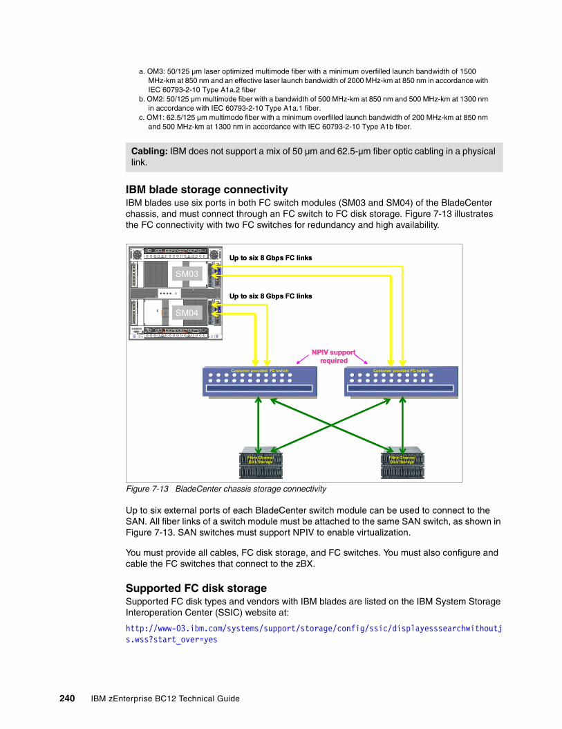
IBM blade storage connectivity IBM blades use six ports in both FC switch modules (SM03 and SM04) of the BladeCenter chassis, and must connect through an FC switch to FC disk storage. Figure 7-13 illustrates the FC connectivity with two FC switches for redundancy and high availability.
Figure 7-13 BladeCenter chassis storage connectivity
Up to six external ports of each BladeCenter switch module can be used to connect to the SAN. All fiber links of a switch module must be attached to the same SAN switch, as shown in Figure 7-13. SAN switches must support NPIV to enable virtualization.
You must provide all cables, FC disk storage, and FC switches. You must also configure and cable the FC switches that connect to the zBX.
Supported FC disk storageSupported FC disk types and vendors with IBM blades are listed on the IBM System Storage Interoperation Center (SSIC) website at:
http://www-03.ibm.com/systems/support/storage/config/ssic/displayesssearchwithoutjs.wss?start_over=yes
a. OM3: 50/125 µm laser optimized multimode fiber with a minimum overfilled launch bandwidth of 1500 MHz-km at 850 nm and an effective laser launch bandwidth of 2000 MHz-km at 850 nm in accordance with IEC 60793-2-10 Type A1a.2 fiber
b. OM2: 50/125 µm multimode fiber with a bandwidth of 500 MHz-km at 850 nm and 500 MHz-km at 1300 nm in accordance with IEC 60793-2-10 Type A1a.1 fiber.
c. OM1: 62.5/125 µm multimode fiber with a minimum overfilled launch bandwidth of 200 MHz-km at 850 nm and 500 MHz-km at 1300 nm in accordance with IEC 60793-2-10 Type A1b fiber.
Cabling: IBM does not support a mix of 50 µm and 62.5-µm fiber optic cabling in a physical link.
Customer provided FC switch
Fibre ChannelDisk Storage
Fibre ChannelDisk Storage
Customer provided FC switch
SM03
SM04
Up to six 8 Gbps FC links
NPIV support required
Up to six 8 Gbps FC links
Customer provided FC switch
Fibre ChannelDisk StorageFibre ChannelDisk Storage
Fibre ChannelDisk StorageFibre ChannelDisk Storage
Customer provided FC switch
SM03
SM04
Up to six 8 Gbps FC links
NPIV support required
Up to six 8 Gbps FC links
240 IBM zEnterprise BC12 Technical Guide
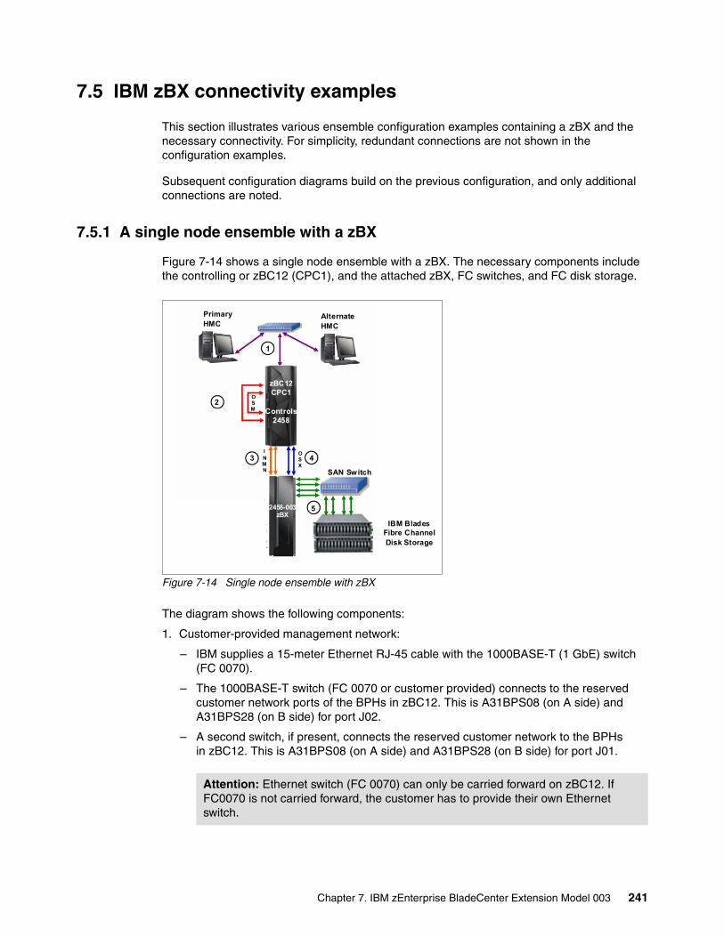
7.5 IBM zBX connectivity examples
This section illustrates various ensemble configuration examples containing a zBX and the necessary connectivity. For simplicity, redundant connections are not shown in the configuration examples.
Subsequent configuration diagrams build on the previous configuration, and only additional connections are noted.
7.5.1 A single node ensemble with a zBX
Figure 7-14 shows a single node ensemble with a zBX. The necessary components include the controlling or zBC12 (CPC1), and the attached zBX, FC switches, and FC disk storage.
Figure 7-14 Single node ensemble with zBX
The diagram shows the following components:
1. Customer-provided management network:
– IBM supplies a 15-meter Ethernet RJ-45 cable with the 1000BASE-T (1 GbE) switch (FC 0070).
– The 1000BASE-T switch (FC 0070 or customer provided) connects to the reserved customer network ports of the BPHs in zBC12. This is A31BPS08 (on A side) and A31BPS28 (on B side) for port J02.
– A second switch, if present, connects the reserved customer network to the BPHs in zBC12. This is A31BPS08 (on A side) and A31BPS28 (on B side) for port J01.
Attention: Ethernet switch (FC 0070) can only be carried forward on zBC12. If FC0070 is not carried forward, the customer has to provide their own Ethernet switch.
zBC12CPC1
Controls2458
IBM BladesFibre ChannelDisk Storage
2458-003zBX
Primary HMC
AlternateHMC
INMN
OSM
SAN Switch
OSX
1
2
3 4
55
Chapter 7. IBM zEnterprise BladeCenter Extension Model 003 241
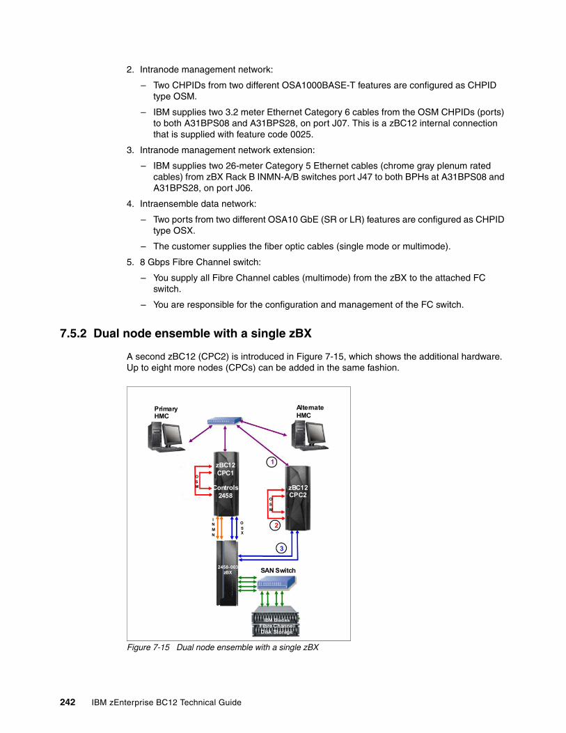
2. Intranode management network:
– Two CHPIDs from two different OSA1000BASE-T features are configured as CHPID type OSM.
– IBM supplies two 3.2 meter Ethernet Category 6 cables from the OSM CHPIDs (ports) to both A31BPS08 and A31BPS28, on port J07. This is a zBC12 internal connection that is supplied with feature code 0025.
3. Intranode management network extension:
– IBM supplies two 26-meter Category 5 Ethernet cables (chrome gray plenum rated cables) from zBX Rack B INMN-A/B switches port J47 to both BPHs at A31BPS08 and A31BPS28, on port J06.
4. Intraensemble data network:
– Two ports from two different OSA10 GbE (SR or LR) features are configured as CHPID type OSX.
– The customer supplies the fiber optic cables (single mode or multimode).
5. 8 Gbps Fibre Channel switch:
– You supply all Fibre Channel cables (multimode) from the zBX to the attached FC switch.
– You are responsible for the configuration and management of the FC switch.
7.5.2 Dual node ensemble with a single zBX
A second zBC12 (CPC2) is introduced in Figure 7-15, which shows the additional hardware. Up to eight more nodes (CPCs) can be added in the same fashion.
Figure 7-15 Dual node ensemble with a single zBX
Primary HMC
AlternateHMC
zBC12CPC1
Controls2458
2458-003zBX
IBM SmartAnalytics Optimizer
Fibre ChannelDisk Storage
IBM BladesFibre ChannelDisk Storage
SAN Switch
zBC12CPC2
OSM
OSX
INMN
OSM
1
2
3
242 IBM zEnterprise BC12 Technical Guide
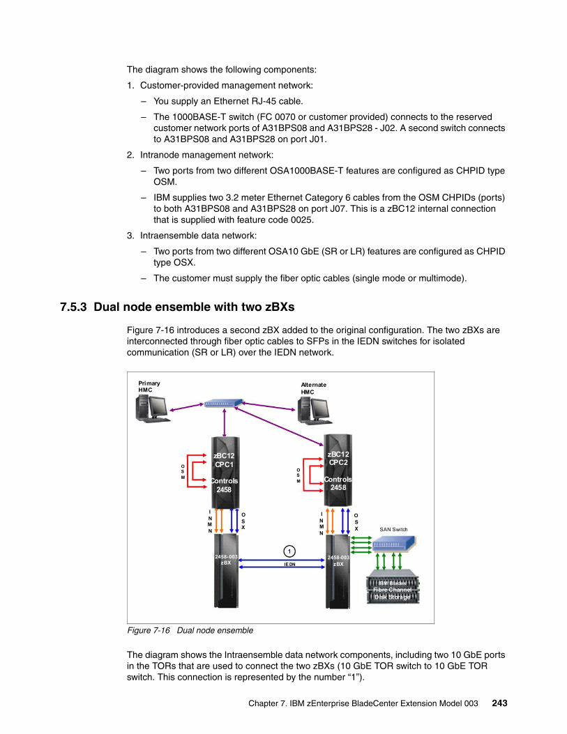
The diagram shows the following components:
1. Customer-provided management network:
– You supply an Ethernet RJ-45 cable.
– The 1000BASE-T switch (FC 0070 or customer provided) connects to the reserved customer network ports of A31BPS08 and A31BPS28 - J02. A second switch connects to A31BPS08 and A31BPS28 on port J01.
2. Intranode management network:
– Two ports from two different OSA1000BASE-T features are configured as CHPID type OSM.
– IBM supplies two 3.2 meter Ethernet Category 6 cables from the OSM CHPIDs (ports) to both A31BPS08 and A31BPS28 on port J07. This is a zBC12 internal connection that is supplied with feature code 0025.
3. Intraensemble data network:
– Two ports from two different OSA10 GbE (SR or LR) features are configured as CHPID type OSX.
– The customer must supply the fiber optic cables (single mode or multimode).
7.5.3 Dual node ensemble with two zBXs
Figure 7-16 introduces a second zBX added to the original configuration. The two zBXs are interconnected through fiber optic cables to SFPs in the IEDN switches for isolated communication (SR or LR) over the IEDN network.
Figure 7-16 Dual node ensemble
The diagram shows the Intraensemble data network components, including two 10 GbE ports in the TORs that are used to connect the two zBXs (10 GbE TOR switch to 10 GbE TOR switch. This connection is represented by the number “1”).
zBC12CPC2
Controls2458
2458-003zBX
IBM BladesFibre ChannelDisk Storage
SAN Switch
zBC12CPC1
Controls2458
2458-003zBX
IBM SmartAnalytics Optimizer
Fibre ChannelDisk Storage
Primary HMC
AlternateHMC
OSM
OSX
INMN
OSM
OSX
INMN
1
IE DN
Chapter 7. IBM zEnterprise BladeCenter Extension Model 003 243
Up to eight CPCs can be connected to a zBX by using the IEDN. More CPCs are added and connected to the zBX through the OSA 10 GbE (SR or LR) features configured as CHPID type OSX.
7.6 References
For more information about installation details, see zBX Installation Manual for Physical Planning 2458-002, GC27-2611 and zBX Installation Manual 2458-002, GC27-2610.
For more information about the BladeCenter components, see IBM BladeCenter Products and Technology, SG24-7523.
For more information about DataPower XI50z blades; see the following website:
http://www-01.ibm.com/software/integration/datapower/xi50z
Additional documentation is available on the IBM Resource Link:
http://www.ibm.com/servers/resourcelink
244 IBM zEnterprise BC12 Technical Guide
Chapter 8. Software support
This chapter lists the minimum operating system (OS) requirements and support considerations for the IBM zEnterprise BC12 System (zBC12) and its features. It addresses z/OS, z/VM, IBM z/Virtual Storage Extended (z/VSE), IBM z/Transaction Processing Facility (z/TPF), and Linux on System z. Because this information is subject to change, see the Preventive Service Planning (PSP) bucket for 2828DEVICE for the most current information. Also included is generic software support for IBM zEnterprise BladeCenter Extension (zBX) Model 003.
Support of zBC12 functions is dependent on the OS, and its version and release.
This chapter includes the following sections:
� Operating systems summary� Support by operating system� Support by function� Cryptographic Support� IBM z/OS migration considerations� Coupling facility and CFCC considerations� MIDAW facility� Worldwide port name tool� Device Support Facilities� IBM zBX Model 003 software support� Software licensing considerations� References
8
© Copyright IBM Corp. 2014. All rights reserved. 245
8.1 Operating systems summary
Table 8-1 lists the minimum OS levels that are required on the zBC12. For similar information about zBX, see 8.11, “IBM zBX Model 003 software support” on page 311.
Note that OS levels that are no longer in service are not covered in this publication. These older levels might provide support for some features.
Table 8-1 IBM zBC12 minimum operating systems requirements
8.2 Support by operating system
IBM zBC12 introduces several new functions. This section addresses support of those functions by the current OSs. Also included are some of the functions that were introduced in previous System z servers and carried forward or enhanced in zBC12. Features and functions available on previous servers but no longer supported by zBC12 have been removed.
For a list of supported functions and the z/OS and z/VM minimum required support levels, see Table 8-3 on page 249. For z/VSE, z/TPF, and Linux on System z, see Table 8-4 on page 255. The tabular format is intended to help determine, by a quick scan, which functions are supported and the minimum OS level required.
Operating systems ESA/390(31-bit mode)
z/Architecture(64-bit mode)
Notes
z/OS V1R11a
a. Regular service support for z/OS V1R11 ended in September 2012. However, by ordering the IBM Lifecycle Extension for z/OS V1R11 product, fee-based corrective service can be obtained for up to September 2014.
No Yes
Service is required. See the following box, which is titled “Features”
z/VM V5R4b
b. IBM z/VM V5R4, V6R2, and V6R3 provide compatibility support only. IBM z/VM V6R2 and V6R3 require an architecture level set (ALS) at z10 or higher. Support for z/VM V6R1 has ended on April 30, 2013.
No Yesc
c. IBM z/VM supports both 31-bit and 64-bit mode guests
z/VSE V4R3 No Yes
z/TPF V1R1 Yes Yes
Linux on System z Nod
d. 64-bit distributions included 31-bit emulation layer to run 31-bit software products.
See Table 8-2 on page 248
Features: Exploitation of certain features depends on the OS. In all cases, program temporary fixes (PTFs) might be required with the OS level indicated. Check the z/OS, z/VM, z/VSE, and z/TPF subsets of the 2828DEVICE PSP buckets. The PSP buckets are continuously updated, and contain the latest information about maintenance.
Hardware and software buckets contain installation information, hardware and software service levels, service guidelines, and cross-product dependencies.
For Linux on System z distributions, consult the distributor’s support information.
246 IBM zEnterprise BC12 Technical Guide
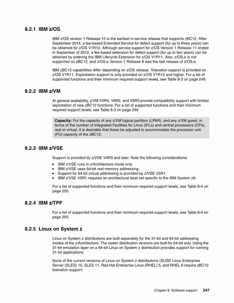
8.2.1 IBM z/OS
IBM z/OS version 1 Release 12 is the earliest in-service release that supports zBC12. After September 2014, a fee-based Extended Service for defect support (for up to three years) can be obtained for z/OS V1R12. Although service support for z/OS Version 1 Release 11 ended in September of 2012, a fee-based extension for defect support (for up to two years) can be obtained by ordering the IBM Lifecycle Extension for z/OS V1R11. Also, z/OS.e is not supported on zBC12, and z/OS.e Version 1 Release 8 was the last release of z/OS.e.
IBM zBC12 capabilities differ depending on z/OS release. Toleration support is provided on z/OS V1R11. Exploitation support is only provided on z/OS V1R12 and higher. For a list of supported functions and their minimum required support levels, see Table 8-3 on page 249.
8.2.2 IBM z/VM
At general availability, z/VM V5R4, V6R2, and V6R3 provide compatibility support with limited exploitation of new zBC12 functions. For a list of supported functions and their minimum required support levels, see Table 8-3 on page 249.
8.2.3 IBM z/VSE
Support is provided by z/VSE V4R3 and later. Note the following considerations:
� IBM z/VSE runs in z/Architecture mode only.� IBM z/VSE uses 64-bit real memory addressing.� Support for 64-bit virtual addressing is provided by z/VSE V5R1.� IBM z/VSE V5R1 requires an architectural level set specific to the IBM System z9.
For a list of supported functions and their minimum required support levels, see Table 8-4 on page 255.
8.2.4 IBM z/TPF
For a list of supported functions and their minimum required support levels, see Table 8-4 on page 255.
8.2.5 Linux on System z
Linux on System z distributions are built separately for the 31-bit and 64-bit addressing modes of the z/Architecture. The newer distribution versions are built for 64-bit only. Using the 31-bit emulation layer on a 64-bit Linux on System z distribution provides support for running 31-bit applications.
None of the current versions of Linux on System z distributions (SUSE Linux Enterprise Server (SLES) 10, SLES 11, Red Hat Enterprise Linux (RHEL) 5, and RHEL 6 require zBC12 toleration support.
Capacity: For the capacity of any z/VM logical partition (LPAR), and any z/VM guest, in terms of the number of Integrated Facilities for Linux (IFLs) and central processors (CPs), real or virtual, it is desirable that these be adjusted to accommodate the processor unit (PU) capacity of the zBC12.
Chapter 8. Software support 247
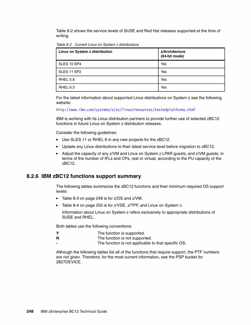
Table 8-2 shows the service levels of SUSE and Red Hat releases supported at the time of writing.
Table 8-2 Current Linux on System z distributions
For the latest information about supported Linux distributions on System z see the following website:
http://www.ibm.com/systems/z/os/linux/resources/testedplatforms.html
IBM is working with its Linux distribution partners to provide further use of selected zBC12 functions in future Linux on System z distribution releases.
Consider the following guidelines:
� Use SLES 11 or RHEL 6 in any new projects for the zBC12.
� Update any Linux distributions to their latest service level before migration to zBC12.
� Adjust the capacity of any z/VM and Linux on System z LPAR guests, and z/VM guests, in terms of the number of IFLs and CPs, real or virtual, according to the PU capacity of the zBC12.
8.2.6 IBM zBC12 functions support summary
The following tables summarize the zBC12 functions and their minimum required OS support levels:
� Table 8-3 on page 249 is for z/OS and z/VM.
� Table 8-4 on page 255 is for z/VSE, z/TPF, and Linux on System z.
Information about Linux on System z refers exclusively to appropriate distributions of SUSE and RHEL.
Both tables use the following conventions:
Y The function is supported.N The function is not supported.- The function is not applicable to that specific OS.
Although the following tables list all of the functions that require support, the PTF numbers are not given. Therefore, for the most current information, see the PSP bucket for 2827DEVICE.
Linux on System z distribution z/Architecture(64-bit mode)
SLES 10 SP4 Yes
SLES 11 SP2 Yes
RHEL 5.8 Yes
RHEL 6.3 Yes
248 IBM zEnterprise BC12 Technical Guide
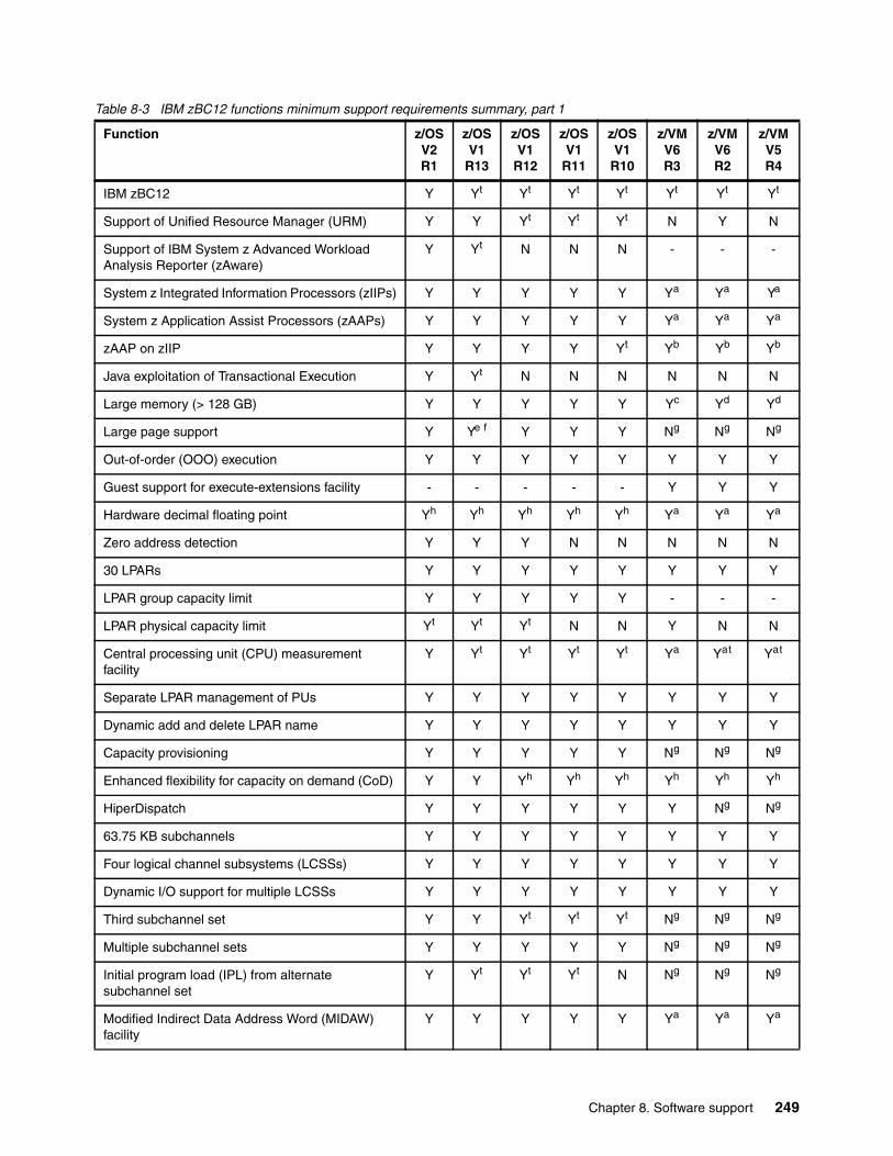
Table 8-3 IBM zBC12 functions minimum support requirements summary, part 1
Function z/OS V2 R1
z/OS V1
R13
z/OS V1
R12
z/OS V1
R11
z/OS V1
R10
z/VM V6 R3
z/VM V6 R2
z/VM V5 R4
IBM zBC12 Y Yt Yt Yt Yt Yt Yt Yt
Support of Unified Resource Manager (URM) Y Y Yt Yt Yt N Y N
Support of IBM System z Advanced Workload Analysis Reporter (zAware)
Y Yt N N N - - -
System z Integrated Information Processors (zIIPs) Y Y Y Y Y Ya Ya Ya
System z Application Assist Processors (zAAPs) Y Y Y Y Y Ya Ya Ya
zAAP on zIIP Y Y Y Y Yt Yb Yb Yb
Java exploitation of Transactional Execution Y Yt N N N N N N
Large memory (> 128 GB) Y Y Y Y Y Yc Yd Yd
Large page support Y Ye f Y Y Y Ng Ng Ng
Out-of-order (OOO) execution Y Y Y Y Y Y Y Y
Guest support for execute-extensions facility - - - - - Y Y Y
Hardware decimal floating point Yh Yh Yh Yh Yh Ya Ya Ya
Zero address detection Y Y Y N N N N N
30 LPARs Y Y Y Y Y Y Y Y
LPAR group capacity limit Y Y Y Y Y - - -
LPAR physical capacity limit Yt Yt Yt N N Y N N
Central processing unit (CPU) measurement facility
Y Yt Yt Yt Yt Ya Yat Yat
Separate LPAR management of PUs Y Y Y Y Y Y Y Y
Dynamic add and delete LPAR name Y Y Y Y Y Y Y Y
Capacity provisioning Y Y Y Y Y Ng Ng Ng
Enhanced flexibility for capacity on demand (CoD) Y Y Yh Yh Yh Yh Yh Yh
HiperDispatch Y Y Y Y Y Y Ng Ng
63.75 KB subchannels Y Y Y Y Y Y Y Y
Four logical channel subsystems (LCSSs) Y Y Y Y Y Y Y Y
Dynamic I/O support for multiple LCSSs Y Y Y Y Y Y Y Y
Third subchannel set Y Y Yt Yt Yt Ng Ng Ng
Multiple subchannel sets Y Y Y Y Y Ng Ng Ng
Initial program load (IPL) from alternate subchannel set
Y Yt Yt Yt N Ng Ng Ng
Modified Indirect Data Address Word (MIDAW) facility
Y Y Y Y Y Ya Ya Ya
Chapter 8. Software support 249
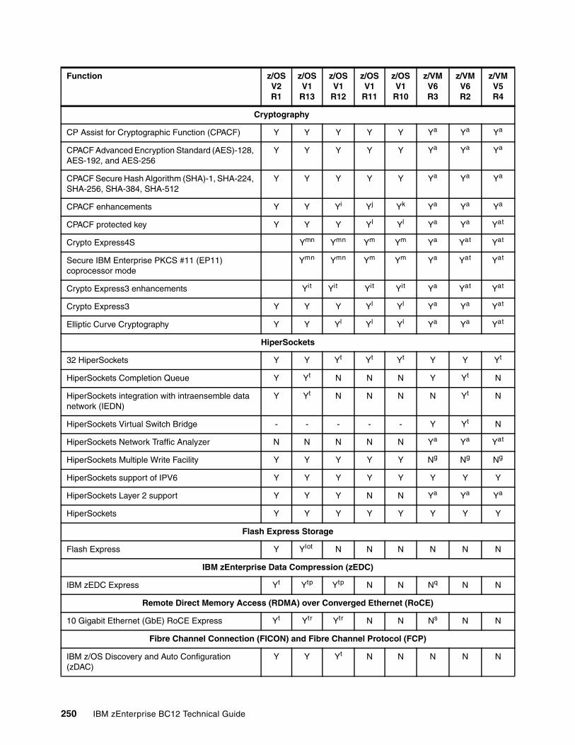
Cryptography
CP Assist for Cryptographic Function (CPACF) Y Y Y Y Y Ya Ya Ya
CPACF Advanced Encryption Standard (AES)-128, AES-192, and AES-256
Y Y Y Y Y Ya Ya Ya
CPACF Secure Hash Algorithm (SHA)-1, SHA-224, SHA-256, SHA-384, SHA-512
Y Y Y Y Y Ya Ya Ya
CPACF enhancements Y Y Yi Yj Yk Ya Ya Ya
CPACF protected key Y Y Y Yl Yl Ya Ya Yat
Crypto Express4S Ymn Ymn Ym Ym Ya Yat Yat
Secure IBM Enterprise PKCS #11 (EP11) coprocessor mode
Ymn Ymn Ym Ym Ya Yat Yat
Crypto Express3 enhancements Yit Yit Yit Yit Ya Yat Yat
Crypto Express3 Y Y Y Yl Yl Ya Ya Yat
Elliptic Curve Cryptography Y Y Yl Yl Yl Ya Ya Yat
HiperSockets
32 HiperSockets Y Y Yt Yt Yt Y Y Yt
HiperSockets Completion Queue Y Yt N N N Y Yt N
HiperSockets integration with intraensemble data network (IEDN)
Y Yt N N N N Yt N
HiperSockets Virtual Switch Bridge - - - - - Y Yt N
HiperSockets Network Traffic Analyzer N N N N N Ya Ya Yat
HiperSockets Multiple Write Facility Y Y Y Y Y Ng Ng Ng
HiperSockets support of IPV6 Y Y Y Y Y Y Y Y
HiperSockets Layer 2 support Y Y Y N N Ya Ya Ya
HiperSockets Y Y Y Y Y Y Y Y
Flash Express Storage
Flash Express Y Ylot N N N N N N
IBM zEnterprise Data Compression (zEDC)
IBM zEDC Express Yt Ytp Ytp N N Nq N N
Remote Direct Memory Access (RDMA) over Converged Ethernet (RoCE)
10 Gigabit Ethernet (GbE) RoCE Express Yt Ytr Ytr N N Ns N N
Fibre Channel Connection (FICON) and Fibre Channel Protocol (FCP)
IBM z/OS Discovery and Auto Configuration (zDAC)
Y Y Yt N N N N N
Function z/OS V2 R1
z/OS V1
R13
z/OS V1
R12
z/OS V1
R11
z/OS V1
R10
z/VM V6 R3
z/VM V6 R2
z/VM V5 R4
250 IBM zEnterprise BC12 Technical Guide
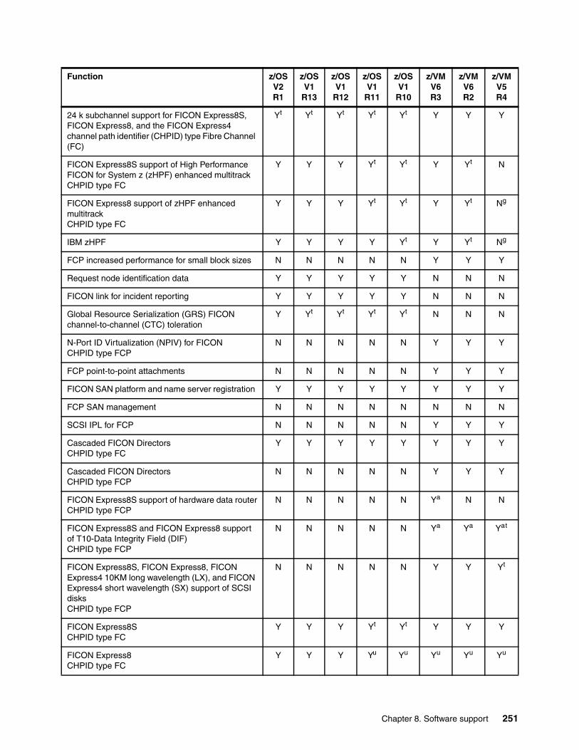
24 k subchannel support for FICON Express8S, FICON Express8, and the FICON Express4channel path identifier (CHPID) type Fibre Channel (FC)
Yt Yt Yt Yt Yt Y Y Y
FICON Express8S support of High Performance FICON for System z (zHPF) enhanced multitrackCHPID type FC
Y Y Y Yt Yt Y Yt N
FICON Express8 support of zHPF enhanced multitrackCHPID type FC
Y Y Y Yt Yt Y Yt Ng
IBM zHPF Y Y Y Y Yt Y Yt Ng
FCP increased performance for small block sizes N N N N N Y Y Y
Request node identification data Y Y Y Y Y N N N
FICON link for incident reporting Y Y Y Y Y N N N
Global Resource Serialization (GRS) FICON channel-to-channel (CTC) toleration
Y Yt Yt Yt Yt N N N
N-Port ID Virtualization (NPIV) for FICONCHPID type FCP
N N N N N Y Y Y
FCP point-to-point attachments N N N N N Y Y Y
FICON SAN platform and name server registration Y Y Y Y Y Y Y Y
FCP SAN management N N N N N N N N
SCSI IPL for FCP N N N N N Y Y Y
Cascaded FICON Directors CHPID type FC
Y Y Y Y Y Y Y Y
Cascaded FICON Directors CHPID type FCP
N N N N N Y Y Y
FICON Express8S support of hardware data routerCHPID type FCP
N N N N N Ya N N
FICON Express8S and FICON Express8 support of T10-Data Integrity Field (DIF)CHPID type FCP
N N N N N Ya Ya Yat
FICON Express8S, FICON Express8, FICON Express4 10KM long wavelength (LX), and FICON Express4 short wavelength (SX) support of SCSI disksCHPID type FCP
N N N N N Y Y Yt
FICON Express8SCHPID type FC
Y Y Y Yt Yt Y Y Y
FICON Express8CHPID type FC
Y Y Y Yu Yu Yu Yu Yu
Function z/OS V2 R1
z/OS V1
R13
z/OS V1
R12
z/OS V1
R11
z/OS V1
R10
z/VM V6 R3
z/VM V6 R2
z/VM V5 R4
Chapter 8. Software support 251
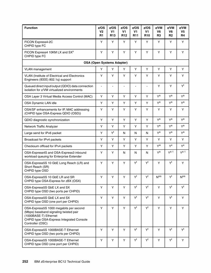
FICON Express4-2CCHPID type FC
Y Y Y Y Y Y Y Y
FICON Express4 10KM LX and SXv
CHPID type FCY Y Y Y Y Y Y Y
OSA (Open Systems Adapter)
VLAN management Y Y Y Y Y Y Y Y
VLAN (Institute of Electrical and Electronics Engineers (IEEE) 802.1q) support
Y Y Y Y Y Y Y Y
Queued direct input/output (QDIO) data connection isolation for z/VM virtualized environments
- - - - - Y Y Yt
OSA Layer 3 Virtual Media Access Control (MAC) Y Y Y Y Y Ya Ya Ya
OSA Dynamic LAN idle Y Y Y Y Y Ya Ya Ya
OSA/SF enhancements for IP, MAC addressing (CHPID type OSA-Express QDIO (OSD))
Y Y Y Y Y Y Y Y
QDIO diagnostic synchronization Y Y Y Y Y Ya Ya Ya
Network Traffic Analyzer Y Y Y Y Y Ya Ya Ya
Large send for IPv6 packet Y Yt N N N Ya Ya Ya
Broadcast for IPv4 packets Y Y Y Y Y Y Y Y
Checksum offload for IPv4 packets Y Y Y Y Y Yw Yx Yx
OSA-Express4S and OSA-Express3 inbound workload queuing for Enterprise Extender
Y Y N N N Ya Ya t Ya t
OSA-Express5S 10 GbE Long Reach (LR) and Short Reach (SR)CHPID type OSD
Y Y Y Yt Yt Y Yt Y
OSA-Express5S 10 GbE LR and SRCHPID type OSA-Express for zBX (OSX)
Y Y Y Yt Yt Naa Yt Naa
OSA-Express5S GbE LX and SXCHPID type OSD (two ports per CHPID)
Y Y Y Yt Yt Y Yt Yt
OSA-Express5S GbE LX and SXCHPID type OSD (one port per CHPID)
Y Y Y Yt Yt Y Yt Y
OSA-Express5S 1000 megabits per second (Mbps) baseband signaling twisted pair (1000BASE-T) EthernetCHPID type OSA-Express Integrated Console Controller (OSC)
Y Y Y Yt Yt Y Y Y
OSA-Express5S 1000BASE-T EthernetCHPID type OSD (two ports per CHPID)
Y Y Y Yt Yt Y Yt Yt
OSA-Express5S 1000BASE-T EthernetCHPID type OSD (one port per CHPID)
Y Y Y Yt Yt Y Yt Y
Function z/OS V2 R1
z/OS V1
R13
z/OS V1
R12
z/OS V1
R11
z/OS V1
R10
z/VM V6 R3
z/VM V6 R2
z/VM V5 R4
252 IBM zEnterprise BC12 Technical Guide
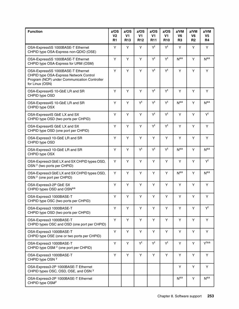
OSA-Express5S 1000BASE-T EthernetCHPID type OSA-Express non-QDIO (OSE)
Y Y Y Yt Yt Y Y Y
OSA-Express5S 1000BASE-T EthernetCHPID type OSA-Express for URM (OSM)
Y Y Y Yt Yt Naa Y Naa
OSA-Express5S 1000BASE-T EthernetCHPID type OSA-Express Network Control Program (NCP) under Communication Controller for Linux (OSN)
Y Y Y Yt Yt Y Y Y
OSA-Express4S 10-GbE LR and SRCHPID type OSD
Y Y Y Yt Yt Y Y Y
OSA-Express4S 10-GbE LR and SRCHPID type OSX
Y Y Yt Yt Yt Naa Y Naa
OSA-Express4S GbE LX and SX CHPID type OSD (two ports per CHPID)
Y Y Y Yt Yt Y Y Yt
OSA-Express4S GbE LX and SX CHPID type OSD (one port per CHPID)
Y Y Y Yt Yt Y Y Y
OSA-Express3 10-GbE LR and SRCHPID type OSD
Y Y Y Y Y Y Y Y
OSA-Express3 10-GbE LR and SR CHPID type OSX
Y Y Yt Yt Yt Naa Y Naa
OSA-Express3 GbE LX and SX CHPID types OSD, OSN y (two ports per CHPID)
Y Y Y Y Y Y Y Yt
OSA-Express3 GbE LX and SX CHPID types OSD, OSN y (one port per CHPID)
Y Y Y Y Y Naa Y Naa
OSA-Express3-2P GbE SXCHPID types OSD and OSNaa
Y Y Y Y Y Y Y Y
OSA-Express3 1000BASE-T CHPID type OSC (two ports per CHPID)
Y Y Y Y Y Y Y Y
OSA-Express3 1000BASE-T CHPID type OSD (two ports per CHPID)
Y Y Y Y Y Y Y Yt
OSA-Express3 1000BASE-T CHPID types OSC and OSD (one port per CHPID)
Y Y Y Y Y Y Y Y
OSA-Express3 1000BASE-TCHPID type OSE (one or two ports per CHPID)
Y Y Y Y Y Y Y Y
OSA-Express3 1000BASE-TCHPID type OSM z (one port per CHPID)
Y Y Yt Yt Yt Y Y Ytaa
OSA-Express3 1000BASE-TCHPID type OSN y
Y Y Y Y Y Y Y Y
OSA-Express3-2P 1000BASE-T EthernetCHPID types OSC, OSD, OSE, and OSN y
Y Y Y
OSA-Express3-2P 1000BASE-T EthernetCHPID type OSMz
Naa Y Naa
Function z/OS V2 R1
z/OS V1
R13
z/OS V1
R12
z/OS V1
R11
z/OS V1
R10
z/VM V6 R3
z/VM V6 R2
z/VM V5 R4
Chapter 8. Software support 253
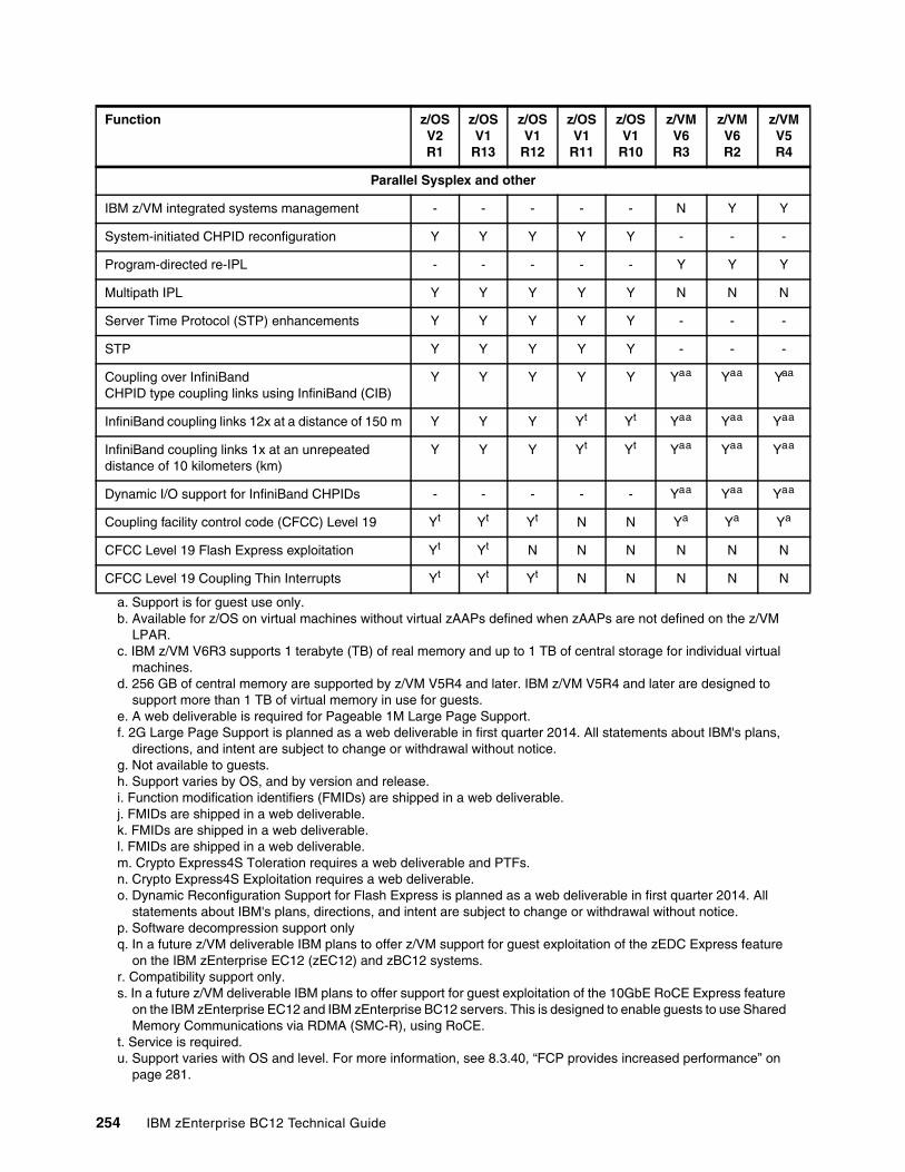
Parallel Sysplex and other
IBM z/VM integrated systems management - - - - - N Y Y
System-initiated CHPID reconfiguration Y Y Y Y Y - - -
Program-directed re-IPL - - - - - Y Y Y
Multipath IPL Y Y Y Y Y N N N
Server Time Protocol (STP) enhancements Y Y Y Y Y - - -
STP Y Y Y Y Y - - -
Coupling over InfiniBand CHPID type coupling links using InfiniBand (CIB)
Y Y Y Y Y Yaa Yaa Yaa
InfiniBand coupling links 12x at a distance of 150 m Y Y Y Yt Yt Yaa Yaa Yaa
InfiniBand coupling links 1x at an unrepeated distance of 10 kilometers (km)
Y Y Y Yt Yt Yaa Yaa Yaa
Dynamic I/O support for InfiniBand CHPIDs - - - - - Yaa Yaa Yaa
Coupling facility control code (CFCC) Level 19 Yt Yt Yt N N Ya Ya Ya
CFCC Level 19 Flash Express exploitation Yt Yt N N N N N N
CFCC Level 19 Coupling Thin Interrupts Yt Yt Yt N N N N N
a. Support is for guest use only.b. Available for z/OS on virtual machines without virtual zAAPs defined when zAAPs are not defined on the z/VM
LPAR.c. IBM z/VM V6R3 supports 1 terabyte (TB) of real memory and up to 1 TB of central storage for individual virtual
machines.d. 256 GB of central memory are supported by z/VM V5R4 and later. IBM z/VM V5R4 and later are designed to
support more than 1 TB of virtual memory in use for guests.e. A web deliverable is required for Pageable 1M Large Page Support.f. 2G Large Page Support is planned as a web deliverable in first quarter 2014. All statements about IBM's plans,
directions, and intent are subject to change or withdrawal without notice.g. Not available to guests.h. Support varies by OS, and by version and release.i. Function modification identifiers (FMIDs) are shipped in a web deliverable.j. FMIDs are shipped in a web deliverable.k. FMIDs are shipped in a web deliverable.l. FMIDs are shipped in a web deliverable.m. Crypto Express4S Toleration requires a web deliverable and PTFs.n. Crypto Express4S Exploitation requires a web deliverable.o. Dynamic Reconfiguration Support for Flash Express is planned as a web deliverable in first quarter 2014. All
statements about IBM's plans, directions, and intent are subject to change or withdrawal without notice.p. Software decompression support onlyq. In a future z/VM deliverable IBM plans to offer z/VM support for guest exploitation of the zEDC Express feature
on the IBM zEnterprise EC12 (zEC12) and zBC12 systems.r. Compatibility support only.s. In a future z/VM deliverable IBM plans to offer support for guest exploitation of the 10GbE RoCE Express feature
on the IBM zEnterprise EC12 and IBM zEnterprise BC12 servers. This is designed to enable guests to use Shared Memory Communications via RDMA (SMC-R), using RoCE.
t. Service is required.u. Support varies with OS and level. For more information, see 8.3.40, “FCP provides increased performance” on
page 281.
Function z/OS V2 R1
z/OS V1
R13
z/OS V1
R12
z/OS V1
R11
z/OS V1
R10
z/VM V6 R3
z/VM V6 R2
z/VM V5 R4
254 IBM zEnterprise BC12 Technical Guide
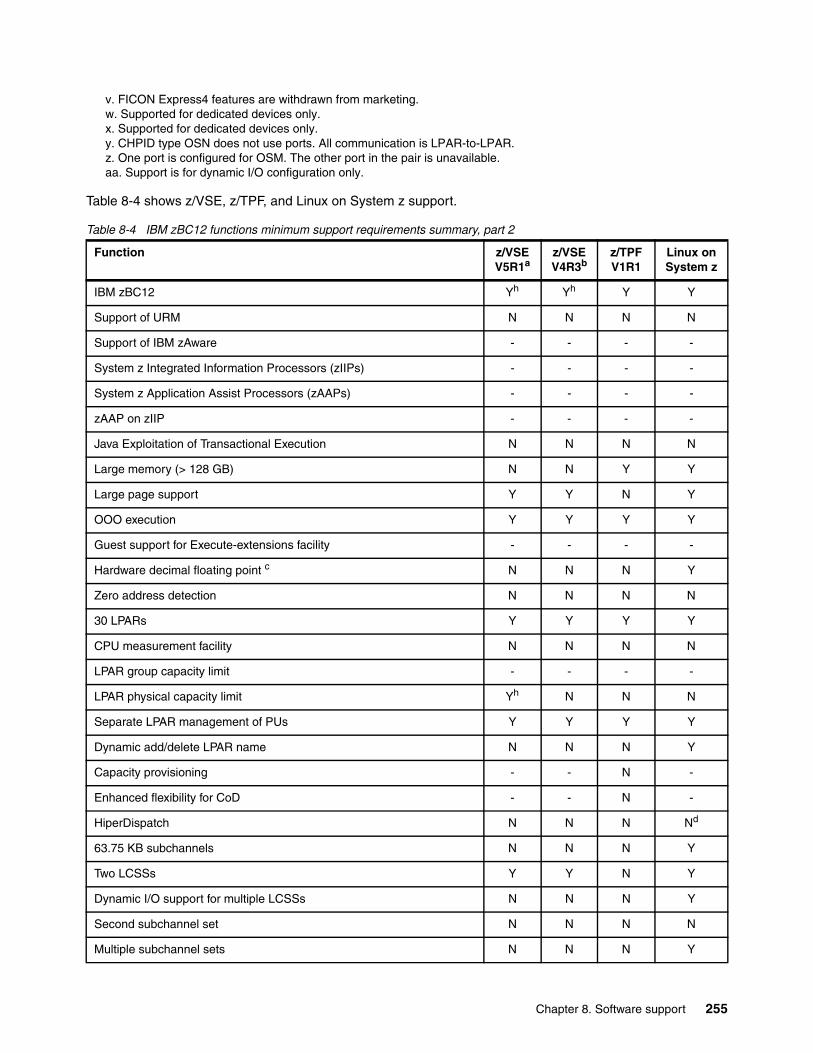
Table 8-4 IBM zBC12 functions minimum support requirements summary, part 2
v. FICON Express4 features are withdrawn from marketing.w. Supported for dedicated devices only.x. Supported for dedicated devices only.y. CHPID type OSN does not use ports. All communication is LPAR-to-LPAR.z. One port is configured for OSM. The other port in the pair is unavailable.aa. Support is for dynamic I/O configuration only.
Table 8-4 shows z/VSE, z/TPF, and Linux on System z support.
Function z/VSE V5R1a
z/VSE V4R3b
z/TPF V1R1
Linux on System z
IBM zBC12 Yh Yh Y Y
Support of URM N N N N
Support of IBM zAware - - - -
System z Integrated Information Processors (zIIPs) - - - -
System z Application Assist Processors (zAAPs) - - - -
zAAP on zIIP - - - -
Java Exploitation of Transactional Execution N N N N
Large memory (> 128 GB) N N Y Y
Large page support Y Y N Y
OOO execution Y Y Y Y
Guest support for Execute-extensions facility - - - -
Hardware decimal floating point c N N N Y
Zero address detection N N N N
30 LPARs Y Y Y Y
CPU measurement facility N N N N
LPAR group capacity limit - - - -
LPAR physical capacity limit Yh N N N
Separate LPAR management of PUs Y Y Y Y
Dynamic add/delete LPAR name N N N Y
Capacity provisioning - - N -
Enhanced flexibility for CoD - - N -
HiperDispatch N N N Nd
63.75 KB subchannels N N N Y
Two LCSSs Y Y N Y
Dynamic I/O support for multiple LCSSs N N N Y
Second subchannel set N N N N
Multiple subchannel sets N N N Y
Chapter 8. Software support 255
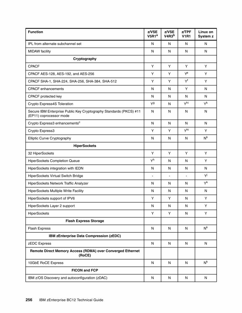
IPL from alternate subchannel set N N N N
MIDAW facility N N N N
Cryptography
CPACF Y Y Y Y
CPACF AES-128, AES-192, and AES-256 Y Y Ye Y
CPACF SHA-1, SHA-224, SHA-256, SHA-384, SHA-512 Y Y Yf Y
CPACF enhancements N N Y N
CPACF protected key N N N N
Crypto Express4S Toleration Yg N Yhi Yk
Secure IBM Enterprise Public Key Cryptography Standards (PKCS) #11 (EP11) coprocessor mode
N N N N
Crypto Express3 enhancementsc N N N N
Crypto Express3 Y Y Yhi Y
Elliptic Curve Cryptography N N N Nk
HiperSockets
32 HiperSockets Y Y Y Y
HiperSockets Completion Queue Yh N N Y
HiperSockets integration with IEDN N N N N
HiperSockets Virtual Switch Bridge - - - Yj
HiperSockets Network Traffic Analyzer N N N Yk
HiperSockets Multiple Write Facility N N N N
HiperSockets support of IPV6 Y Y N Y
HiperSockets Layer 2 support N N N Y
HiperSockets Y Y N Y
Flash Express Storage
Flash Express N N N Nk
IBM zEnterprise Data Compression (zEDC)
zEDC Express N N N N
Remote Direct Memory Access (RDMA) over Converged Ethernet (RoCE)
10GbE RoCE Express N N N Nk
FICON and FCP
IBM z/OS Discovery and autoconfiguration (zDAC) N N N N
Function z/VSE V5R1a
z/VSE V4R3b
z/TPF V1R1
Linux on System z
256 IBM zEnterprise BC12 Technical Guide
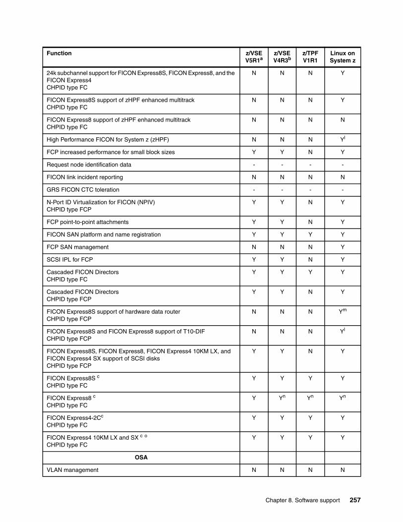
24k subchannel support for FICON Express8S, FICON Express8, and the FICON Express4CHPID type FC
N N N Y
FICON Express8S support of zHPF enhanced multitrackCHPID type FC
N N N Y
FICON Express8 support of zHPF enhanced multitrackCHPID type FC
N N N N
High Performance FICON for System z (zHPF) N N N Yl
FCP increased performance for small block sizes Y Y N Y
Request node identification data - - - -
FICON link incident reporting N N N N
GRS FICON CTC toleration - - - -
N-Port ID Virtualization for FICON (NPIV)CHPID type FCP
Y Y N Y
FCP point-to-point attachments Y Y N Y
FICON SAN platform and name registration Y Y Y Y
FCP SAN management N N N Y
SCSI IPL for FCP Y Y N Y
Cascaded FICON DirectorsCHPID type FC
Y Y Y Y
Cascaded FICON DirectorsCHPID type FCP
Y Y N Y
FICON Express8S support of hardware data routerCHPID type FCP
N N N Ym
FICON Express8S and FICON Express8 support of T10-DIFCHPID type FCP
N N N Yl
FICON Express8S, FICON Express8, FICON Express4 10KM LX, and FICON Express4 SX support of SCSI disksCHPID type FCP
Y Y N Y
FICON Express8S c
CHPID type FCY Y Y Y
FICON Express8 c
CHPID type FCY Yn Yn Yn
FICON Express4-2Cc
CHPID type FCY Y Y Y
FICON Express4 10KM LX and SX c o
CHPID type FCY Y Y Y
OSA
VLAN management N N N N
Function z/VSE V5R1a
z/VSE V4R3b
z/TPF V1R1
Linux on System z
Chapter 8. Software support 257
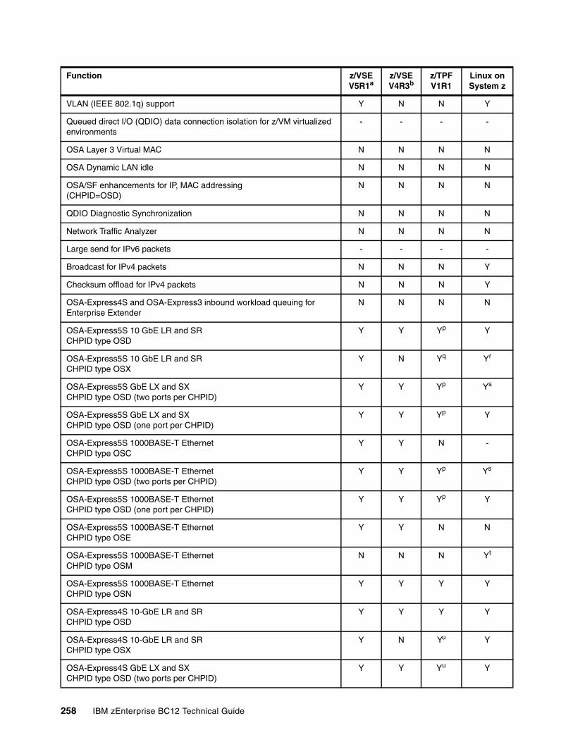
VLAN (IEEE 802.1q) support Y N N Y
Queued direct I/O (QDIO) data connection isolation for z/VM virtualized environments
- - - -
OSA Layer 3 Virtual MAC N N N N
OSA Dynamic LAN idle N N N N
OSA/SF enhancements for IP, MAC addressing(CHPID=OSD)
N N N N
QDIO Diagnostic Synchronization N N N N
Network Traffic Analyzer N N N N
Large send for IPv6 packets - - - -
Broadcast for IPv4 packets N N N Y
Checksum offload for IPv4 packets N N N Y
OSA-Express4S and OSA-Express3 inbound workload queuing for Enterprise Extender
N N N N
OSA-Express5S 10 GbE LR and SRCHPID type OSD
Y Y Yp Y
OSA-Express5S 10 GbE LR and SRCHPID type OSX
Y N Yq Yr
OSA-Express5S GbE LX and SXCHPID type OSD (two ports per CHPID)
Y Y Yp Ys
OSA-Express5S GbE LX and SXCHPID type OSD (one port per CHPID)
Y Y Yp Y
OSA-Express5S 1000BASE-T EthernetCHPID type OSC
Y Y N -
OSA-Express5S 1000BASE-T EthernetCHPID type OSD (two ports per CHPID)
Y Y Yp Ys
OSA-Express5S 1000BASE-T EthernetCHPID type OSD (one port per CHPID)
Y Y Yp Y
OSA-Express5S 1000BASE-T EthernetCHPID type OSE
Y Y N N
OSA-Express5S 1000BASE-T EthernetCHPID type OSM
N N N Yt
OSA-Express5S 1000BASE-T EthernetCHPID type OSN
Y Y Y Y
OSA-Express4S 10-GbE LR and SRCHPID type OSD
Y Y Y Y
OSA-Express4S 10-GbE LR and SRCHPID type OSX
Y N Yu Y
OSA-Express4S GbE LX and SX CHPID type OSD (two ports per CHPID)
Y Y Yu Y
Function z/VSE V5R1a
z/VSE V4R3b
z/TPF V1R1
Linux on System z
258 IBM zEnterprise BC12 Technical Guide
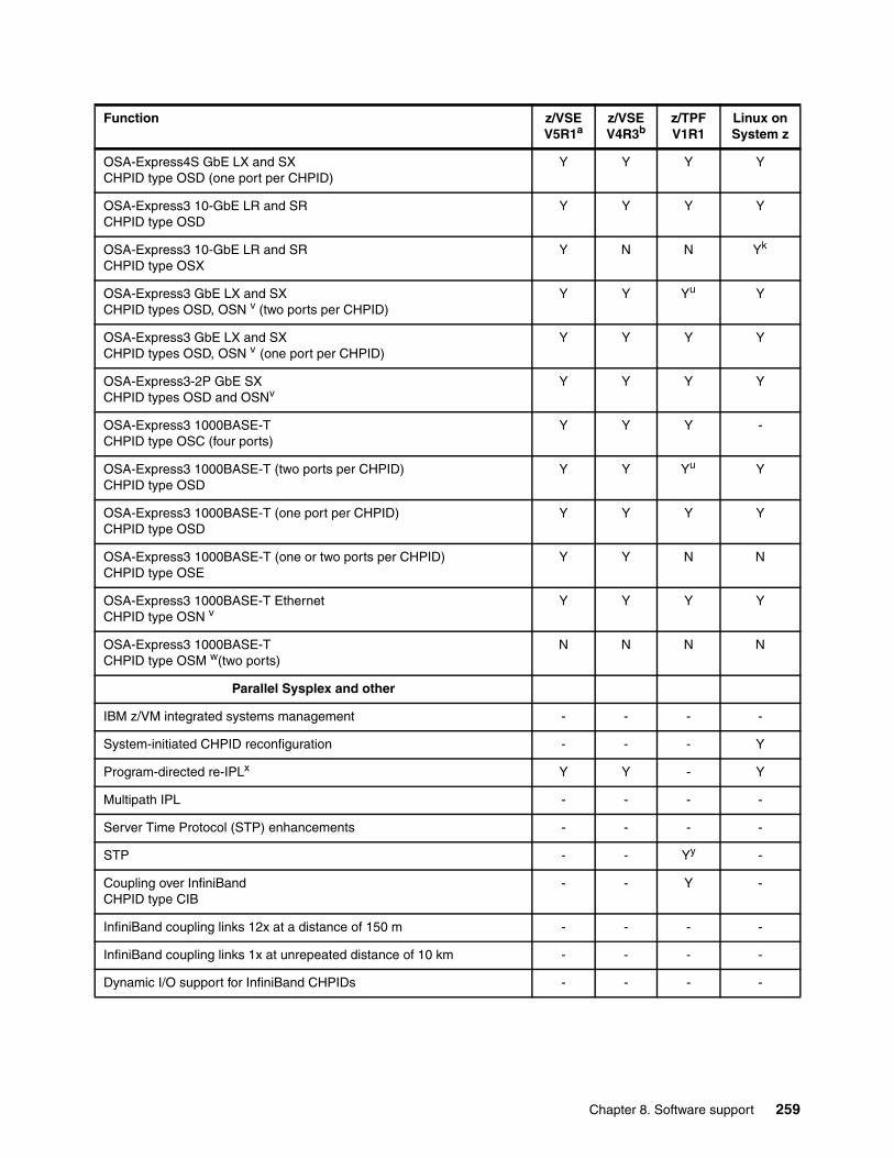
OSA-Express4S GbE LX and SXCHPID type OSD (one port per CHPID)
Y Y Y Y
OSA-Express3 10-GbE LR and SRCHPID type OSD
Y Y Y Y
OSA-Express3 10-GbE LR and SRCHPID type OSX
Y N N Yk
OSA-Express3 GbE LX and SX CHPID types OSD, OSN v (two ports per CHPID)
Y Y Yu Y
OSA-Express3 GbE LX and SX CHPID types OSD, OSN v (one port per CHPID)
Y Y Y Y
OSA-Express3-2P GbE SXCHPID types OSD and OSNv
Y Y Y Y
OSA-Express3 1000BASE-T CHPID type OSC (four ports)
Y Y Y -
OSA-Express3 1000BASE-T (two ports per CHPID) CHPID type OSD
Y Y Yu Y
OSA-Express3 1000BASE-T (one port per CHPID) CHPID type OSD
Y Y Y Y
OSA-Express3 1000BASE-T (one or two ports per CHPID) CHPID type OSE
Y Y N N
OSA-Express3 1000BASE-T EthernetCHPID type OSN v
Y Y Y Y
OSA-Express3 1000BASE-T CHPID type OSM w(two ports)
N N N N
Parallel Sysplex and other
IBM z/VM integrated systems management - - - -
System-initiated CHPID reconfiguration - - - Y
Program-directed re-IPLx Y Y - Y
Multipath IPL - - - -
Server Time Protocol (STP) enhancements - - - -
STP - - Yy -
Coupling over InfiniBand CHPID type CIB
- - Y -
InfiniBand coupling links 12x at a distance of 150 m - - - -
InfiniBand coupling links 1x at unrepeated distance of 10 km - - - -
Dynamic I/O support for InfiniBand CHPIDs - - - -
Function z/VSE V5R1a
z/VSE V4R3b
z/TPF V1R1
Linux on System z
Chapter 8. Software support 259
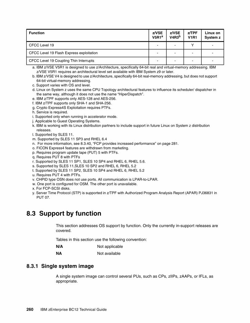
8.3 Support by function
This section addresses OS support by function. Only the currently in-support releases are covered.
Tables in this section use the following convention:
N/A Not applicable
NA Not available
8.3.1 Single system image
A single system image can control several PUs, such as CPs, zIIPs, zAAPs, or IFLs, as appropriate.
CFCC Level 19 - - Y -
CFCC Level 19 Flash Express exploitation - - - -
CFCC Level 19 Coupling Thin Interrupts - - - -
a. IBM z/VSE V5R1 is designed to use z/Architecture, specifically 64-bit real and virtual-memory addressing. IBM z/VSE V5R1 requires an architectural level set available with IBM System z9 or later.
b. IBM z/VSE V4 is designed to use z/Architecture, specifically 64-bit real-memory addressing, but does not support 64-bit virtual-memory addressing.
c. Support varies with OS and level.d. Linux on System z uses the same CPU Topology architectural features to influence its scheduler/ dispatcher in
the same way, although it does not use the name “HiperDispatch”.e. IBM z/TPF supports only AES-128 and AES-256.f. IBM z/TPF supports only SHA-1 and SHA-256.g. Crypto Express4S Exploitation requires PTFs.h. Service is required.i. Supported only when running in accelerator mode. j. Applicable to Guest Operating Systems.k. IBM is working with its Linux distribution partners to include support in future Linux on System z distribution
releases.l. Supported by SLES 11.m. Supported by SLES 11 SP3 and RHEL 6.4n. For more information, see 8.3.40, “FCP provides increased performance” on page 281.o. FICON Express4 features are withdrawn from marketing. p. Requires program update tape (PUT) 5 with PTFs.q. Requires PUT 8 with PTFsr. Supported by SLES 11 SP1, SLES 10 SP4 and RHEL 6, RHEL 5.6.s. Supported by SLES 11,SLES 10 SP2 and RHEL 6, RHEL 5.2t. Supported by SLES 11 SP2, SLES 10 SP4 and RHEL 6, RHEL 5.2u. Requires PUT 4 with PTFs.v. CHPID type OSN does not use ports. All communication is LPAR-to-LPAR.w. One port is configured for OSM. The other port is unavailable.x. For FCP-SCSI disks.y. Server Time Protocol (STP) is supported in z/TPF with Authorized Program Analysis Report (APAR) PJ36831 in
PUT 07.
Function z/VSE V5R1a
z/VSE V4R3b
z/TPF V1R1
Linux on System z
260 IBM zEnterprise BC12 Technical Guide
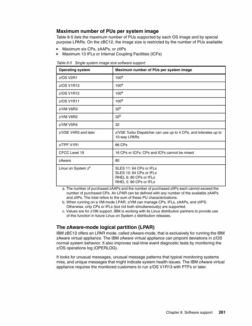
Maximum number of PUs per system imageTable 8-5 lists the maximum number of PUs supported by each OS image and by special purpose LPARs. On the zBC12, the image size is restricted by the number of PUs available:
� Maximum six CPs, zAAPs, or zIIPs� Maximum 13 IFLs or Internal Coupling Facilities (ICFs)
Table 8-5 Single system image size software support
The zAware-mode logical partition (LPAR)IBM zBC12 offers an LPAR mode, called zAware-mode, that is exclusively for running the IBM zAware virtual appliance. The IBM zAware virtual appliance can pinpoint deviations in z/OS normal system behavior. It also improves real-time event diagnostic tests by monitoring the z/OS operations log (OPERLOG).
It looks for unusual messages, unusual message patterns that typical monitoring systems miss, and unique messages that might indicate system health issues. The IBM zAware virtual appliance requires the monitored customers to run z/OS V1R13 with PTFs or later.
Operating system Maximum number of PUs per system image
z/OS V2R1 100a
a. The number of purchased zAAPs and the number of purchased zIIPs each cannot exceed the number of purchased CPs. An LPAR can be defined with any number of the available zAAPs and zIIPs. The total refers to the sum of these PU characterizations.
z/OS V1R13 100a
z/OS V1R12 100a
z/OS V1R11 100a
z/VM V6R3 32b
b. When running on a VM-mode LPAR, z/VM can manage CPs, IFLs, zAAPs, and zIIPS. Otherwise, only CPs or IFLs (but not both simultaneously) are supported.
z/VM V6R2 32b
z/VM V5R4 32
z/VSE V4R3 and later z/VSE Turbo Dispatcher can use up to 4 CPs, and tolerates up to 10-way LPARs
z/TPF V1R1 86 CPs
CFCC Level 19 16 CPs or ICFs: CPs and ICFs cannot be mixed
zAware 80
Linux on System zc
c. Values are for z196 support. IBM is working with its Linux distribution partners to provide use of this function in future Linux on System z distribution releases.
SLES 11: 64 CPs or IFLsSLES 10: 64 CPs or IFLsRHEL 6: 80 CPs or IFLs RHEL 5: 80 CPs or IFLs
Chapter 8. Software support 261
The z/VM-mode LPARIBM zBC12 supports an LPAR mode, called z/VM-mode, that is exclusively for running z/VM as the first-level OS. The z/VM-mode requires z/VM V5R4 or later, and enables z/VM to use a wider variety of specialty processors in a single LPAR. For instance, in a z/VM-mode LPAR, z/VM can manage Linux on System z guests running on IFL processors while also managing z/VSE and z/OS on CPs. It also enables z/OS to fully use zIIPs and zAAPs.
8.3.2 IBM zAAP support
IBM zAAPs do not change the model capacity identifier of the zBC12. IBM software product license charges based on the model capacity identifier are not affected by the addition of zAAPs. On a zBC12, z/OS V1R11 is the minimum level for supporting zAAPs, together with the current IBM Software Developer Kits (SDKs) for z/OS Java Technology Edition.
IBM zAAPs can be used by the following applications:
� Any Java application that is using the current IBM SDK.
� WebSphere Application Server V5R1 and later. Also, products that are based on it, such as WebSphere Portal, WebSphere Enterprise Service Bus (WebSphere ESB), and WebSphere Business Integration (WBI) for z/OS.
� CICS Transaction Server for z/OS (CICS TS) V2R3 and later.
� DB2 Universal Database (UDB) for z/OS Version 8 and later.
� IMS Version 8 and later.
� All z/OS XML System Services validation and parsing that run in Task Control Block (TCB) mode, which might be eligible for zAAP processing. This eligibility requires z/OS V1R9 and later. For z/OS 1R10 (with appropriate maintenance), middleware and applications that request z/OS XML System Services can have z/OS XML System Services processing running on the zAAP.
To use zAAPs, DB2 V9 has the following prerequisites:
� DB2 V9 for z/OS in new function mode
� The C application programming interface (API) for z/OS XML System Services, available with z/OS V1R9 with rollback APARs to z/OS V1R7 and z/OS V1R8
� One of the following items:
– z/OS V1R91 includes zAAP support.
– z/OS V1R81 requires an APAR for zAAP support.
The functioning of a zAAP is transparent to all Java programming on JVM V1.4.1 and later.
Use the PROJECTCPU option of the IEAOPTxx parmlib member to help determine whether zAAPs can be beneficial to the installation. Setting PROJECTCPU=YES directs z/OS to record the amount of eligible work for zAAPs and zIIPs in System Management Facility (SMF) record type 72 subtype 3.
The APPL% AAPCP field of the Workload Activity Report listing by the Workload Manager (WLM) service class indicates what percentage of a processor is zAAP-eligible. Because of zAAPs’ lower prices as compared to CPs, a utilization as low as 10% might provide benefits.
1 IBM z/OS V1R11 is the minimum z/OS level to support zAAP on zBC12.
262 IBM zEnterprise BC12 Technical Guide
8.3.3 IBM zIIP support
IBM zIIPs do not change the model capacity identifier of the zBC12. IBM software product license charges based on the model capacity identifier are not affected by the addition of zIIPs. On a zBC12, z/OS version 1 release 11 is the minimum level for supporting zIIPs.
No changes to applications are required to use zIIPs. IBM zIIPs can be used by these applications:
� DB2 V8 and later for z/OS Data serving, for applications that use data Distributed Relational Database Architecture (DRDA) over TCP/IP, such as data serving, data warehousing, and selected utilities
� z/OS XML services
� z/OS Common Information Model (CIM) Server
� z/OS Communications Server for network encryption (Internet Protocol Security, or IPsec) and for large messages that are sent by HiperSockets
� IBM Scalable Architecture for Financial Reporting (SAFR) from IBM Global Business Services® (GBS)
� IBM z/OS Global Mirror (zGM), formerly extended remote copy (XRC), and System Data Mover
� IBM OMEGAMON® XE on z/OS, OMEGAMON XE on DB2 Performance Expert, and DB2 Performance Monitor
The functioning of a zIIP is transparent to application programs.
Use the PROJECTCPU option of the IEAOPTxx parmlib member to help determine whether zIIPs can be beneficial to the installation. Setting PROJECTCPU=YES directs z/OS to record the amount of eligible work for zAAPs and zIIPs in SMF record type 72 subtype 3.
The APPL% IIPCP field of the Workload Activity Report listing by the WLM service class indicates what percentage of a processor is zIIP eligible. Because of zIIPs lower prices as compared to CPs, a utilization as low as 10% might provide benefits.
8.3.4 The zAAP on zIIP capability
This capability, first made available on System z9 servers under defined circumstances, enables workloads eligible to run on zAAPs to run on zIIP. It is intended as a means to optimize the investment on existing zIIPs, not as a replacement for zAAPs. The rule of at least one CP installed per zAAP and zIIP installed still applies.
IBM has released PTF for APAR OA38829 on z/OS V1R12 and V1R13. If the number of installed zAAPs plus the number of installed zIIPs does not exceed twice the number of installed standard CPs, this PTF enables zAAP-eligible workloads to be dispatched on zIIPS even when there are active zAAPs installed.
This PTF is intended only to help facilitate migration and testing of zAAP workloads on zIIP processors.
Statement of Direction: IBM zBC12 is planned to be the last high-end System z server to offer support for zAAP specialty engine processors. IBM intends to continue support for running zAAP workloads on zIIP processors (zAAP on zIIP). This configuration is intended to help simplify capacity planning and performance management, while still supporting all the currently eligible workloads.
Chapter 8. Software support 263
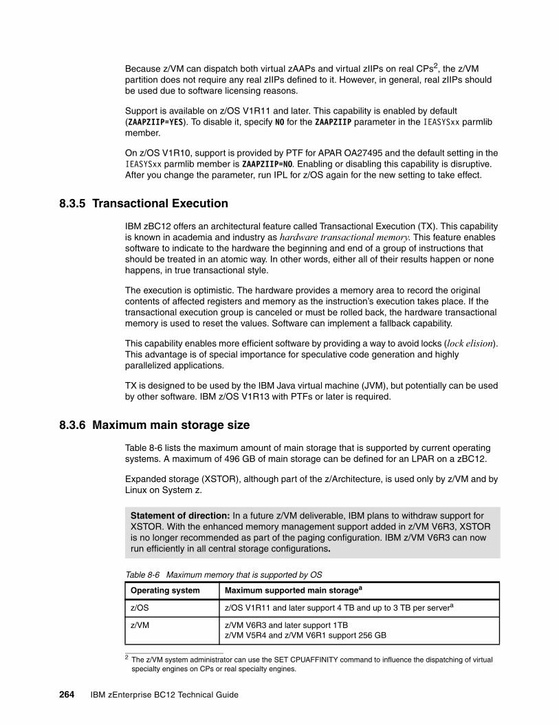
Because z/VM can dispatch both virtual zAAPs and virtual zIIPs on real CPs2, the z/VM partition does not require any real zIIPs defined to it. However, in general, real zIIPs should be used due to software licensing reasons.
Support is available on z/OS V1R11 and later. This capability is enabled by default (ZAAPZIIP=YES). To disable it, specify NO for the ZAAPZIIP parameter in the IEASYSxx parmlib member.
On z/OS V1R10, support is provided by PTF for APAR OA27495 and the default setting in the IEASYSxx parmlib member is ZAAPZIIP=NO. Enabling or disabling this capability is disruptive. After you change the parameter, run IPL for z/OS again for the new setting to take effect.
8.3.5 Transactional Execution
IBM zBC12 offers an architectural feature called Transactional Execution (TX). This capability is known in academia and industry as hardware transactional memory. This feature enables software to indicate to the hardware the beginning and end of a group of instructions that should be treated in an atomic way. In other words, either all of their results happen or none happens, in true transactional style.
The execution is optimistic. The hardware provides a memory area to record the original contents of affected registers and memory as the instruction’s execution takes place. If the transactional execution group is canceled or must be rolled back, the hardware transactional memory is used to reset the values. Software can implement a fallback capability.
This capability enables more efficient software by providing a way to avoid locks (lock elision). This advantage is of special importance for speculative code generation and highly parallelized applications.
TX is designed to be used by the IBM Java virtual machine (JVM), but potentially can be used by other software. IBM z/OS V1R13 with PTFs or later is required.
8.3.6 Maximum main storage size
Table 8-6 lists the maximum amount of main storage that is supported by current operating systems. A maximum of 496 GB of main storage can be defined for an LPAR on a zBC12.
Expanded storage (XSTOR), although part of the z/Architecture, is used only by z/VM and by Linux on System z.
Table 8-6 Maximum memory that is supported by OS
2 The z/VM system administrator can use the SET CPUAFFINITY command to influence the dispatching of virtual specialty engines on CPs or real specialty engines.
Statement of direction: In a future z/VM deliverable, IBM plans to withdraw support for XSTOR. With the enhanced memory management support added in z/VM V6R3, XSTOR is no longer recommended as part of the paging configuration. IBM z/VM V6R3 can now run efficiently in all central storage configurations.
Operating system Maximum supported main storagea
z/OS z/OS V1R11 and later support 4 TB and up to 3 TB per servera
z/VM z/VM V6R3 and later support 1TBz/VM V5R4 and z/VM V6R1 support 256 GB
264 IBM zEnterprise BC12 Technical Guide
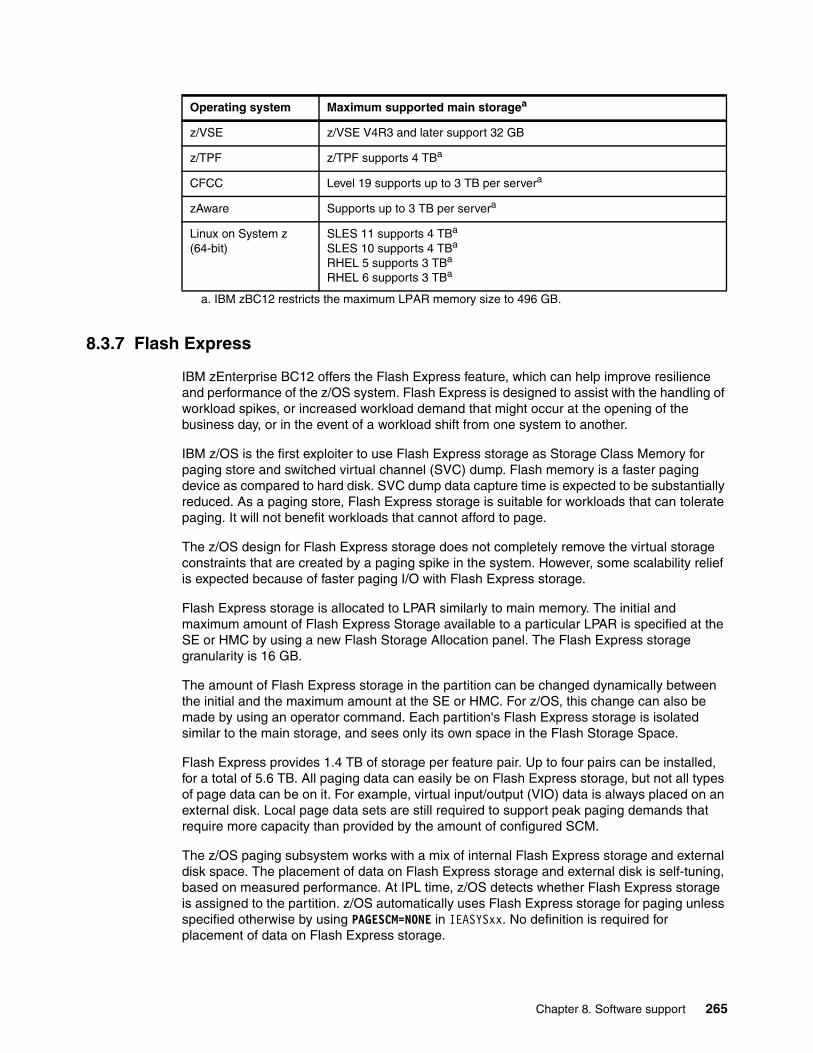
8.3.7 Flash Express
IBM zEnterprise BC12 offers the Flash Express feature, which can help improve resilience and performance of the z/OS system. Flash Express is designed to assist with the handling of workload spikes, or increased workload demand that might occur at the opening of the business day, or in the event of a workload shift from one system to another.
IBM z/OS is the first exploiter to use Flash Express storage as Storage Class Memory for paging store and switched virtual channel (SVC) dump. Flash memory is a faster paging device as compared to hard disk. SVC dump data capture time is expected to be substantially reduced. As a paging store, Flash Express storage is suitable for workloads that can tolerate paging. It will not benefit workloads that cannot afford to page.
The z/OS design for Flash Express storage does not completely remove the virtual storage constraints that are created by a paging spike in the system. However, some scalability relief is expected because of faster paging I/O with Flash Express storage.
Flash Express storage is allocated to LPAR similarly to main memory. The initial and maximum amount of Flash Express Storage available to a particular LPAR is specified at the SE or HMC by using a new Flash Storage Allocation panel. The Flash Express storage granularity is 16 GB.
The amount of Flash Express storage in the partition can be changed dynamically between the initial and the maximum amount at the SE or HMC. For z/OS, this change can also be made by using an operator command. Each partition's Flash Express storage is isolated similar to the main storage, and sees only its own space in the Flash Storage Space.
Flash Express provides 1.4 TB of storage per feature pair. Up to four pairs can be installed, for a total of 5.6 TB. All paging data can easily be on Flash Express storage, but not all types of page data can be on it. For example, virtual input/output (VIO) data is always placed on an external disk. Local page data sets are still required to support peak paging demands that require more capacity than provided by the amount of configured SCM.
The z/OS paging subsystem works with a mix of internal Flash Express storage and external disk space. The placement of data on Flash Express storage and external disk is self-tuning, based on measured performance. At IPL time, z/OS detects whether Flash Express storage is assigned to the partition. z/OS automatically uses Flash Express storage for paging unless specified otherwise by using PAGESCM=NONE in IEASYSxx. No definition is required for placement of data on Flash Express storage.
z/VSE z/VSE V4R3 and later support 32 GB
z/TPF z/TPF supports 4 TBa
CFCC Level 19 supports up to 3 TB per servera
zAware Supports up to 3 TB per servera
Linux on System z (64-bit)
SLES 11 supports 4 TBa
SLES 10 supports 4 TBa
RHEL 5 supports 3 TBa
RHEL 6 supports 3 TBa
a. IBM zBC12 restricts the maximum LPAR memory size to 496 GB.
Operating system Maximum supported main storagea
Chapter 8. Software support 265
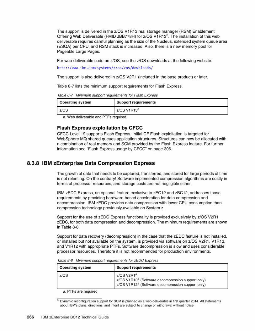
The support is delivered in the z/OS V1R13 real storage manager (RSM) Enablement Offering Web Deliverable (FMID JBB778H) for z/OS V1R133. The installation of this web deliverable requires careful planning as the size of the Nucleus, extended system queue area (ESQA) per CPU, and RSM stack is increased. Also, there is a new memory pool for Pageable Large Pages.
For web-deliverable code on z/OS, see the z/OS downloads at the following website:
http://www.ibm.com/systems/z/os/zos/downloads/
The support is also delivered in z/OS V2R1 (included in the base product) or later.
Table 8-7 lists the minimum support requirements for Flash Express.
Table 8-7 Minimum support requirements for Flash Express
8.3.8 IBM zEnterprise Data Compression Express
The growth of data that needs to be captured, transferred, and stored for large periods of time is not relenting. On the contrary! Software implemented compression algorithms are costly in terms of processor resources, and storage costs are not negligible either.
IBM zEDC Express, an optional feature exclusive to zEC12 and zBC12, addresses those requirements by providing hardware-based acceleration for data compression and decompression. IBM zEDC provides data compression with lower CPU consumption than compression technology previously available on System z.
Support for the use of zEDC Express functionality is provided exclusively by z/OS V2R1 zEDC, for both data compression and decompression. The minimum requirements are shown in Table 8-8.
Support for data recovery (decompression) in the case that the zEDC feature is not installed, or installed but not available on the system, is provided via software on z/OS V2R1, V1R13, and V1R12 with appropriate PTFs. Software decompression is slow and uses considerable processor resources. Therefore it is not recommended for production environments.
Table 8-8 Minimum support requirements for zEDC Express
3 Dynamic reconfiguration support for SCM is planned as a web deliverable in first quarter 2014. All statements about IBM's plans, directions, and intent are subject to change or withdrawal without notice.
Operating system Support requirements
z/OS z/OS V1R13a
a. Web deliverable and PTFs required.
Flash Express exploitation by CFCCCFCC Level 19 supports Flash Express. Initial CF Flash exploitation is targeted for WebSphere MQ shared queues application structures. Structures can now be allocated with a combination of real memory and SCM provided by the Flash Express feature. For further information see “Flash Express usage by CFCC” on page 306.
Operating system Support requirements
z/OS z/OS V2R1a z/OS V1R13a (Software decompression support only)z/OS V1R12a (Software decompression support only)
a. PTFs are required
266 IBM zEnterprise BC12 Technical Guide

8.3.9 10GbE RoCE Express
The zBC12 delivers a significant paradigm shift in network communications, using existing system z and industry-standard (mature and secure) communications technology along with emerging new network technology. It introduces the RoCE.
The 10GbE RoCE Express feature is designed to help reduce consumption of CPU resources for applications using the TCP/IP stack (such as WebSphere accessing a DB2 database). Use of the 10GbE RoCE Express feature can also help to reduce network latency with memory-to-memory transfers using SMC-R in z/OS V2R1.
It is transparent to applications, and can be used for LPAR-to-LPAR communication on a single z/OS system, or server-to-server communication in a multiple-central processor complex (CPC) environment.
IBM z/OS V2R1 with PTFs is the only supporting OS for SMC-R protocol. It does not roll back to previous z/OS releases. IBM z/OS V1R12 and z/OS V1R13 with PTFs only provide compatibility support.
IBM is also working with its Linux distribution partners to include support in future Linux on System z distribution releases.
Table 8-9 lists the minimum support requirements for 10GbE RoCE Express.
Table 8-9 Minimum support requirements for RoCE Express
8.3.10 Large page support
In addition to the existing 1 MB large pages and the 4 KB pages and page frames, zBC12 supports pageable 1 MB large pages, large pages 2 GB in size, and large page frames. For more information, see “Large page support” on page 94.
Table 8-10 lists the support requirements for 1 MB large pages.
Table 8-10 Minimum support requirements for 1 MB large page
Statement of direction: In a future z/VM deliverable, IBM plans to offer z/VM support for guest exploitation of the zEDC Express feature on the zEC12 and IBM zBC12 systems.
Statement of direction: IBM plans to offer future z/VM support for guests to use the 10GbE RoCE Express feature on the zEC12 and zBC12 systems.
Operating system Support requirements
z/OS z/OS V2R1 with PTFs.
Operating system Support requirements
z/OS z/OS V1R11z/OS V1R13a for pageable 1 MB large page
z/VM Not supported, and not available to guests
Chapter 8. Software support 267
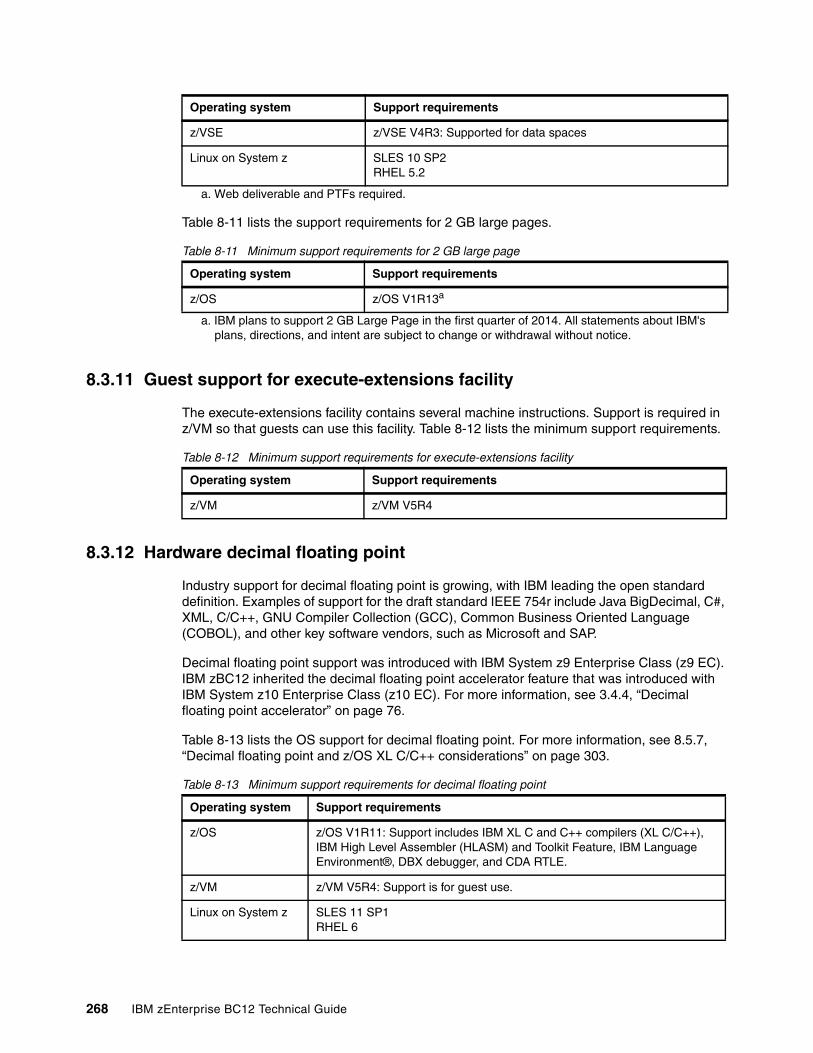
Table 8-11 lists the support requirements for 2 GB large pages.
Table 8-11 Minimum support requirements for 2 GB large page
8.3.11 Guest support for execute-extensions facility
The execute-extensions facility contains several machine instructions. Support is required in z/VM so that guests can use this facility. Table 8-12 lists the minimum support requirements.
Table 8-12 Minimum support requirements for execute-extensions facility
8.3.12 Hardware decimal floating point
Industry support for decimal floating point is growing, with IBM leading the open standard definition. Examples of support for the draft standard IEEE 754r include Java BigDecimal, C#, XML, C/C++, GNU Compiler Collection (GCC), Common Business Oriented Language (COBOL), and other key software vendors, such as Microsoft and SAP.
Decimal floating point support was introduced with IBM System z9 Enterprise Class (z9 EC). IBM zBC12 inherited the decimal floating point accelerator feature that was introduced with IBM System z10 Enterprise Class (z10 EC). For more information, see 3.4.4, “Decimal floating point accelerator” on page 76.
Table 8-13 lists the OS support for decimal floating point. For more information, see 8.5.7, “Decimal floating point and z/OS XL C/C++ considerations” on page 303.
Table 8-13 Minimum support requirements for decimal floating point
z/VSE z/VSE V4R3: Supported for data spaces
Linux on System z SLES 10 SP2RHEL 5.2
a. Web deliverable and PTFs required.
Operating system Support requirements
z/OS z/OS V1R13a
a. IBM plans to support 2 GB Large Page in the first quarter of 2014. All statements about IBM's plans, directions, and intent are subject to change or withdrawal without notice.
Operating system Support requirements
Operating system Support requirements
z/VM z/VM V5R4
Operating system Support requirements
z/OS z/OS V1R11: Support includes IBM XL C and C++ compilers (XL C/C++), IBM High Level Assembler (HLASM) and Toolkit Feature, IBM Language Environment®, DBX debugger, and CDA RTLE.
z/VM z/VM V5R4: Support is for guest use.
Linux on System z SLES 11 SP1RHEL 6
268 IBM zEnterprise BC12 Technical Guide
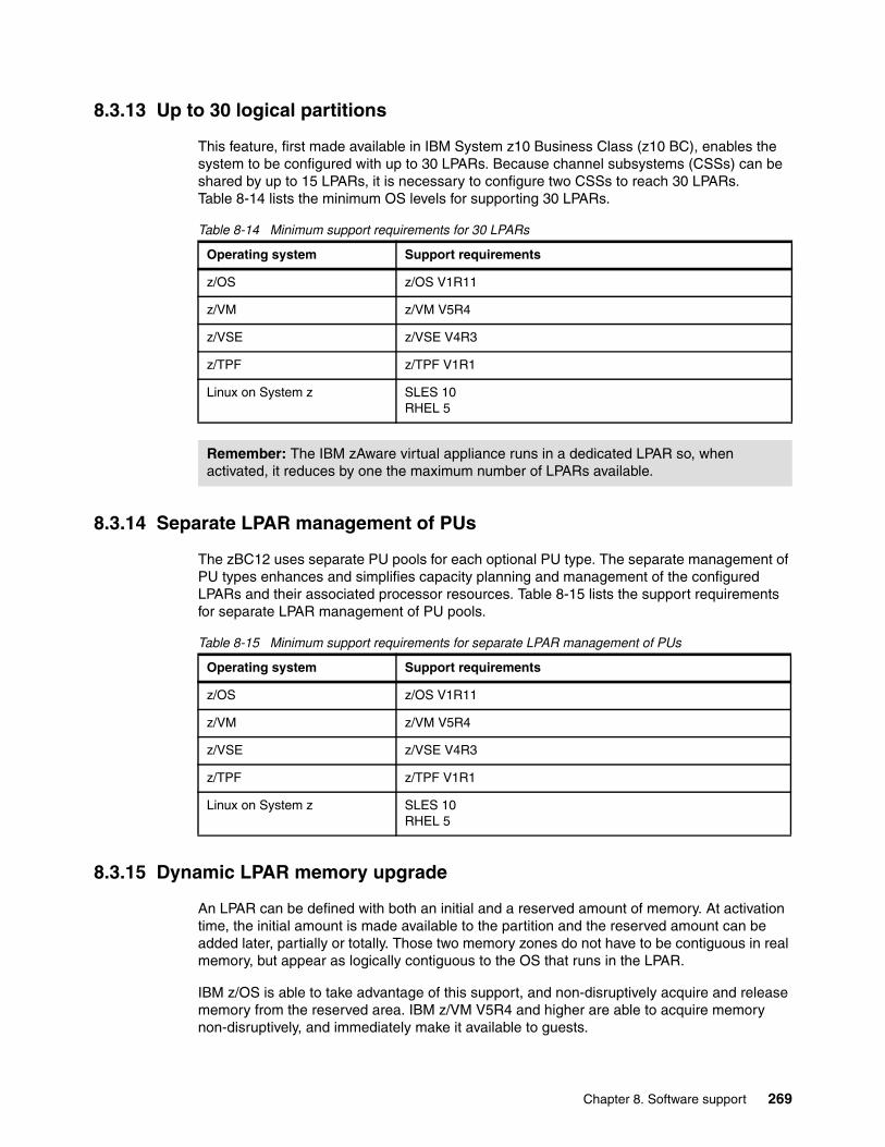
8.3.13 Up to 30 logical partitions
This feature, first made available in IBM System z10 Business Class (z10 BC), enables the system to be configured with up to 30 LPARs. Because channel subsystems (CSSs) can be shared by up to 15 LPARs, it is necessary to configure two CSSs to reach 30 LPARs. Table 8-14 lists the minimum OS levels for supporting 30 LPARs.
Table 8-14 Minimum support requirements for 30 LPARs
8.3.14 Separate LPAR management of PUs
The zBC12 uses separate PU pools for each optional PU type. The separate management of PU types enhances and simplifies capacity planning and management of the configured LPARs and their associated processor resources. Table 8-15 lists the support requirements for separate LPAR management of PU pools.
Table 8-15 Minimum support requirements for separate LPAR management of PUs
8.3.15 Dynamic LPAR memory upgrade
An LPAR can be defined with both an initial and a reserved amount of memory. At activation time, the initial amount is made available to the partition and the reserved amount can be added later, partially or totally. Those two memory zones do not have to be contiguous in real memory, but appear as logically contiguous to the OS that runs in the LPAR.
IBM z/OS is able to take advantage of this support, and non-disruptively acquire and release memory from the reserved area. IBM z/VM V5R4 and higher are able to acquire memory non-disruptively, and immediately make it available to guests.
Operating system Support requirements
z/OS z/OS V1R11
z/VM z/VM V5R4
z/VSE z/VSE V4R3
z/TPF z/TPF V1R1
Linux on System z SLES 10RHEL 5
Remember: The IBM zAware virtual appliance runs in a dedicated LPAR so, when activated, it reduces by one the maximum number of LPARs available.
Operating system Support requirements
z/OS z/OS V1R11
z/VM z/VM V5R4
z/VSE z/VSE V4R3
z/TPF z/TPF V1R1
Linux on System z SLES 10RHEL 5
Chapter 8. Software support 269
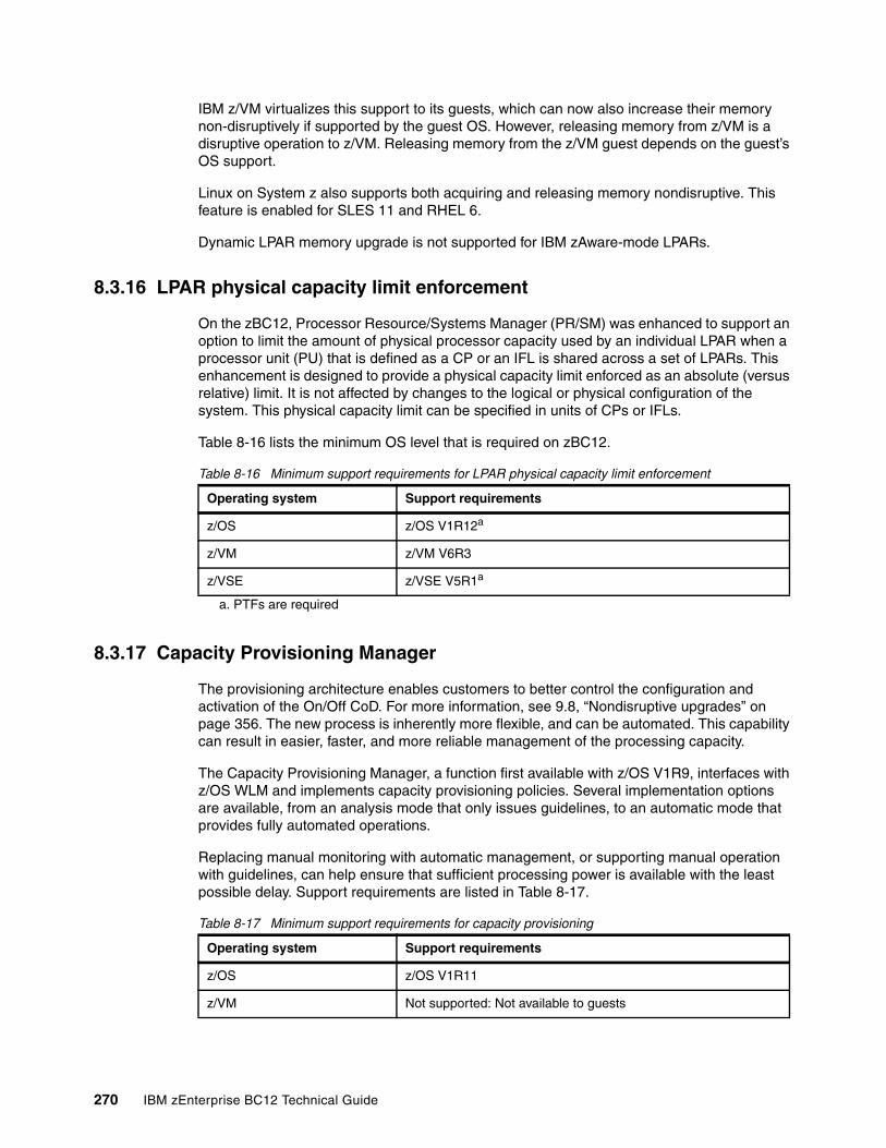
IBM z/VM virtualizes this support to its guests, which can now also increase their memory non-disruptively if supported by the guest OS. However, releasing memory from z/VM is a disruptive operation to z/VM. Releasing memory from the z/VM guest depends on the guest’s OS support.
Linux on System z also supports both acquiring and releasing memory nondisruptive. This feature is enabled for SLES 11 and RHEL 6.
Dynamic LPAR memory upgrade is not supported for IBM zAware-mode LPARs.
8.3.16 LPAR physical capacity limit enforcement
On the zBC12, Processor Resource/Systems Manager (PR/SM) was enhanced to support an option to limit the amount of physical processor capacity used by an individual LPAR when a processor unit (PU) that is defined as a CP or an IFL is shared across a set of LPARs. This enhancement is designed to provide a physical capacity limit enforced as an absolute (versus relative) limit. It is not affected by changes to the logical or physical configuration of the system. This physical capacity limit can be specified in units of CPs or IFLs.
Table 8-16 lists the minimum OS level that is required on zBC12.
Table 8-16 Minimum support requirements for LPAR physical capacity limit enforcement
8.3.17 Capacity Provisioning Manager
The provisioning architecture enables customers to better control the configuration and activation of the On/Off CoD. For more information, see 9.8, “Nondisruptive upgrades” on page 356. The new process is inherently more flexible, and can be automated. This capability can result in easier, faster, and more reliable management of the processing capacity.
The Capacity Provisioning Manager, a function first available with z/OS V1R9, interfaces with z/OS WLM and implements capacity provisioning policies. Several implementation options are available, from an analysis mode that only issues guidelines, to an automatic mode that provides fully automated operations.
Replacing manual monitoring with automatic management, or supporting manual operation with guidelines, can help ensure that sufficient processing power is available with the least possible delay. Support requirements are listed in Table 8-17.
Table 8-17 Minimum support requirements for capacity provisioning
Operating system Support requirements
z/OS z/OS V1R12a
a. PTFs are required
z/VM z/VM V6R3
z/VSE z/VSE V5R1a
Operating system Support requirements
z/OS z/OS V1R11
z/VM Not supported: Not available to guests
270 IBM zEnterprise BC12 Technical Guide
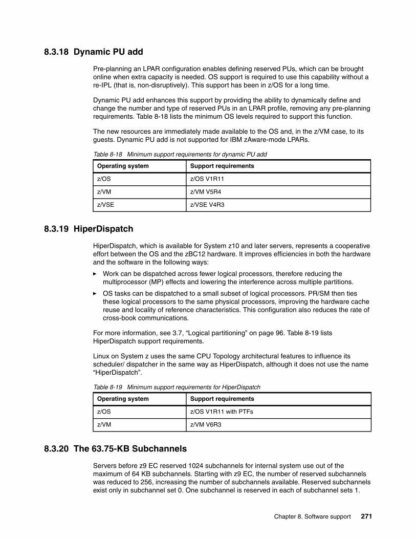
8.3.18 Dynamic PU add
Pre-planning an LPAR configuration enables defining reserved PUs, which can be brought online when extra capacity is needed. OS support is required to use this capability without a re-IPL (that is, non-disruptively). This support has been in z/OS for a long time.
Dynamic PU add enhances this support by providing the ability to dynamically define and change the number and type of reserved PUs in an LPAR profile, removing any pre-planning requirements. Table 8-18 lists the minimum OS levels required to support this function.
The new resources are immediately made available to the OS and, in the z/VM case, to its guests. Dynamic PU add is not supported for IBM zAware-mode LPARs.
Table 8-18 Minimum support requirements for dynamic PU add
8.3.19 HiperDispatch
HiperDispatch, which is available for System z10 and later servers, represents a cooperative effort between the OS and the zBC12 hardware. It improves efficiencies in both the hardware and the software in the following ways:
� Work can be dispatched across fewer logical processors, therefore reducing the multiprocessor (MP) effects and lowering the interference across multiple partitions.
� OS tasks can be dispatched to a small subset of logical processors. PR/SM then ties these logical processors to the same physical processors, improving the hardware cache reuse and locality of reference characteristics. This configuration also reduces the rate of cross-book communications.
For more information, see 3.7, “Logical partitioning” on page 96. Table 8-19 lists HiperDispatch support requirements.
Linux on System z uses the same CPU Topology architectural features to influence its scheduler/ dispatcher in the same way as HiperDispatch, although it does not use the name “HiperDispatch”.
Table 8-19 Minimum support requirements for HiperDispatch
8.3.20 The 63.75-KB Subchannels
Servers before z9 EC reserved 1024 subchannels for internal system use out of the maximum of 64 KB subchannels. Starting with z9 EC, the number of reserved subchannels was reduced to 256, increasing the number of subchannels available. Reserved subchannels exist only in subchannel set 0. One subchannel is reserved in each of subchannel sets 1.
Operating system Support requirements
z/OS z/OS V1R11
z/VM z/VM V5R4
z/VSE z/VSE V4R3
Operating system Support requirements
z/OS z/OS V1R11 with PTFs
z/VM z/VM V6R3
Chapter 8. Software support 271
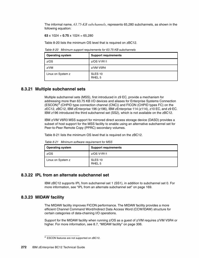
The informal name, 63.75-KB subchannels, represents 65,280 subchannels, as shown in the following equation:
63 x 1024 + 0.75 x 1024 = 65,280
Table 8-20 lists the minimum OS level that is required on zBC12.
Table 8-20 Minimum support requirements for 63.75-KB subchannels
8.3.21 Multiple subchannel sets
Multiple subchannel sets (MSS), first introduced in z9 EC, provide a mechanism for addressing more than 63.75 KB I/O devices and aliases for Enterprise Systems Connection (ESCON)4 (CHPID type connection channel (CNC)) and FICON (CHPID types FC) on the zEC12, zBC12, IBM zEnterprise 196 (z196), IBM zEnterprise 114 (z114), z10 EC, and z9 EC. IBM z196 introduced the third subchannel set (SS2), which is not available on the zBC12.
IBM z/VM V6R3 MSS support for mirrored direct access storage device (DASD) provides a subset of host support for the MSS facility to enable using an alternative subchannel set for Peer-to-Peer Remote Copy (PPRC) secondary volumes.
Table 8-21 lists the minimum OS level that is required on the zBC12.
Table 8-21 Minimum software requirement for MSS
8.3.22 IPL from an alternate subchannel set
IBM zBC12 supports IPL from subchannel set 1 (SS1), in addition to subchannel set 0. For more information, see “IPL from an alternate subchannel set” on page 169.
8.3.23 MIDAW facility
The MIDAW facility improves FICON performance. The MIDAW facility provides a more efficient Channel Command Word/Indirect Data Access Word (CCW/IDAW) structure for certain categories of data-chaining I/O operations.
Support for the MIDAW facility when running z/OS as a guest of z/VM requires z/VM V5R4 or higher. For more information, see 8.7, “MIDAW facility” on page 306.
Operating system Support requirements
z/OS z/OS V1R11
z/VM z/VM V5R4
Linux on System z SLES 10RHEL 5
4 ESCON features are not supported on zBC12.
Operating system Support requirements
z/OS z/OS V1R11
Linux on System z SLES 10RHEL 5
272 IBM zEnterprise BC12 Technical Guide
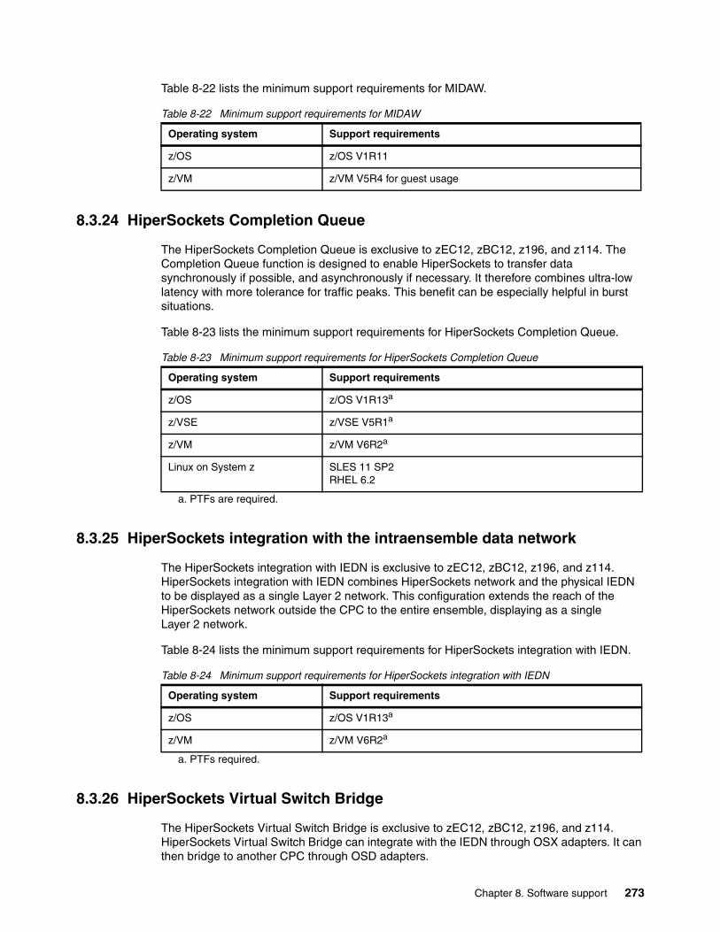
Table 8-22 lists the minimum support requirements for MIDAW.
Table 8-22 Minimum support requirements for MIDAW
8.3.24 HiperSockets Completion Queue
The HiperSockets Completion Queue is exclusive to zEC12, zBC12, z196, and z114. The Completion Queue function is designed to enable HiperSockets to transfer data synchronously if possible, and asynchronously if necessary. It therefore combines ultra-low latency with more tolerance for traffic peaks. This benefit can be especially helpful in burst situations.
Table 8-23 lists the minimum support requirements for HiperSockets Completion Queue.
Table 8-23 Minimum support requirements for HiperSockets Completion Queue
8.3.25 HiperSockets integration with the intraensemble data network
The HiperSockets integration with IEDN is exclusive to zEC12, zBC12, z196, and z114. HiperSockets integration with IEDN combines HiperSockets network and the physical IEDN to be displayed as a single Layer 2 network. This configuration extends the reach of the HiperSockets network outside the CPC to the entire ensemble, displaying as a single Layer 2 network.
Table 8-24 lists the minimum support requirements for HiperSockets integration with IEDN.
Table 8-24 Minimum support requirements for HiperSockets integration with IEDN
8.3.26 HiperSockets Virtual Switch Bridge
The HiperSockets Virtual Switch Bridge is exclusive to zEC12, zBC12, z196, and z114. HiperSockets Virtual Switch Bridge can integrate with the IEDN through OSX adapters. It can then bridge to another CPC through OSD adapters.
Operating system Support requirements
z/OS z/OS V1R11
z/VM z/VM V5R4 for guest usage
Operating system Support requirements
z/OS z/OS V1R13a
z/VSE z/VSE V5R1a
a. PTFs are required.
z/VM z/VM V6R2a
Linux on System z SLES 11 SP2RHEL 6.2
Operating system Support requirements
z/OS z/OS V1R13a
a. PTFs required.
z/VM z/VM V6R2a
Chapter 8. Software support 273
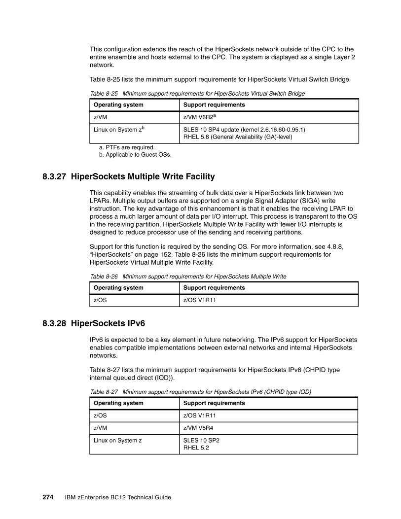
This configuration extends the reach of the HiperSockets network outside of the CPC to the entire ensemble and hosts external to the CPC. The system is displayed as a single Layer 2 network.
Table 8-25 lists the minimum support requirements for HiperSockets Virtual Switch Bridge.
Table 8-25 Minimum support requirements for HiperSockets Virtual Switch Bridge
8.3.27 HiperSockets Multiple Write Facility
This capability enables the streaming of bulk data over a HiperSockets link between two LPARs. Multiple output buffers are supported on a single Signal Adapter (SIGA) write instruction. The key advantage of this enhancement is that it enables the receiving LPAR to process a much larger amount of data per I/O interrupt. This process is transparent to the OS in the receiving partition. HiperSockets Multiple Write Facility with fewer I/O interrupts is designed to reduce processor use of the sending and receiving partitions.
Support for this function is required by the sending OS. For more information, see 4.8.8, “HiperSockets” on page 152. Table 8-26 lists the minimum support requirements for HiperSockets Virtual Multiple Write Facility.
Table 8-26 Minimum support requirements for HiperSockets Multiple Write
8.3.28 HiperSockets IPv6
IPv6 is expected to be a key element in future networking. The IPv6 support for HiperSockets enables compatible implementations between external networks and internal HiperSockets networks.
Table 8-27 lists the minimum support requirements for HiperSockets IPv6 (CHPID type internal queued direct (IQD)).
Table 8-27 Minimum support requirements for HiperSockets IPv6 (CHPID type IQD)
Operating system Support requirements
z/VM z/VM V6R2a
a. PTFs are required.
Linux on System zb
b. Applicable to Guest OSs.
SLES 10 SP4 update (kernel 2.6.16.60-0.95.1)RHEL 5.8 (General Availability (GA)-level)
Operating system Support requirements
z/OS z/OS V1R11
Operating system Support requirements
z/OS z/OS V1R11
z/VM z/VM V5R4
Linux on System z SLES 10 SP2RHEL 5.2
274 IBM zEnterprise BC12 Technical Guide
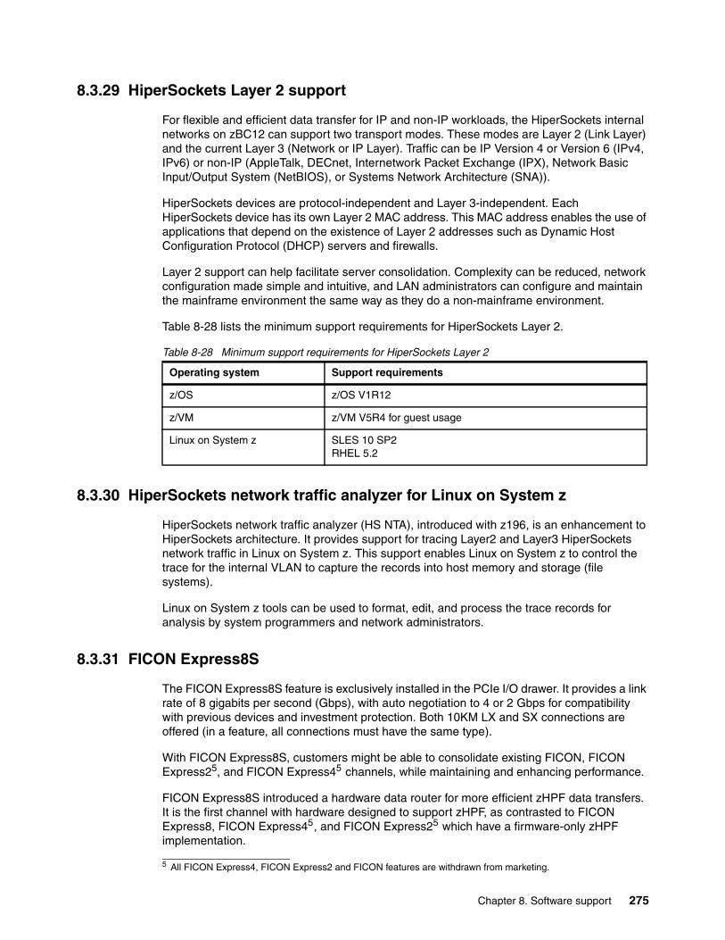
8.3.29 HiperSockets Layer 2 support
For flexible and efficient data transfer for IP and non-IP workloads, the HiperSockets internal networks on zBC12 can support two transport modes. These modes are Layer 2 (Link Layer) and the current Layer 3 (Network or IP Layer). Traffic can be IP Version 4 or Version 6 (IPv4, IPv6) or non-IP (AppleTalk, DECnet, Internetwork Packet Exchange (IPX), Network Basic Input/Output System (NetBIOS), or Systems Network Architecture (SNA)).
HiperSockets devices are protocol-independent and Layer 3-independent. Each HiperSockets device has its own Layer 2 MAC address. This MAC address enables the use of applications that depend on the existence of Layer 2 addresses such as Dynamic Host Configuration Protocol (DHCP) servers and firewalls.
Layer 2 support can help facilitate server consolidation. Complexity can be reduced, network configuration made simple and intuitive, and LAN administrators can configure and maintain the mainframe environment the same way as they do a non-mainframe environment.
Table 8-28 lists the minimum support requirements for HiperSockets Layer 2.
Table 8-28 Minimum support requirements for HiperSockets Layer 2
8.3.30 HiperSockets network traffic analyzer for Linux on System z
HiperSockets network traffic analyzer (HS NTA), introduced with z196, is an enhancement to HiperSockets architecture. It provides support for tracing Layer2 and Layer3 HiperSockets network traffic in Linux on System z. This support enables Linux on System z to control the trace for the internal VLAN to capture the records into host memory and storage (file systems).
Linux on System z tools can be used to format, edit, and process the trace records for analysis by system programmers and network administrators.
8.3.31 FICON Express8S
The FICON Express8S feature is exclusively installed in the PCIe I/O drawer. It provides a link rate of 8 gigabits per second (Gbps), with auto negotiation to 4 or 2 Gbps for compatibility with previous devices and investment protection. Both 10KM LX and SX connections are offered (in a feature, all connections must have the same type).
With FICON Express8S, customers might be able to consolidate existing FICON, FICON Express25, and FICON Express45 channels, while maintaining and enhancing performance.
FICON Express8S introduced a hardware data router for more efficient zHPF data transfers. It is the first channel with hardware designed to support zHPF, as contrasted to FICON Express8, FICON Express45, and FICON Express25 which have a firmware-only zHPF implementation.
Operating system Support requirements
z/OS z/OS V1R12
z/VM z/VM V5R4 for guest usage
Linux on System z SLES 10 SP2RHEL 5.2
5 All FICON Express4, FICON Express2 and FICON features are withdrawn from marketing.
Chapter 8. Software support 275
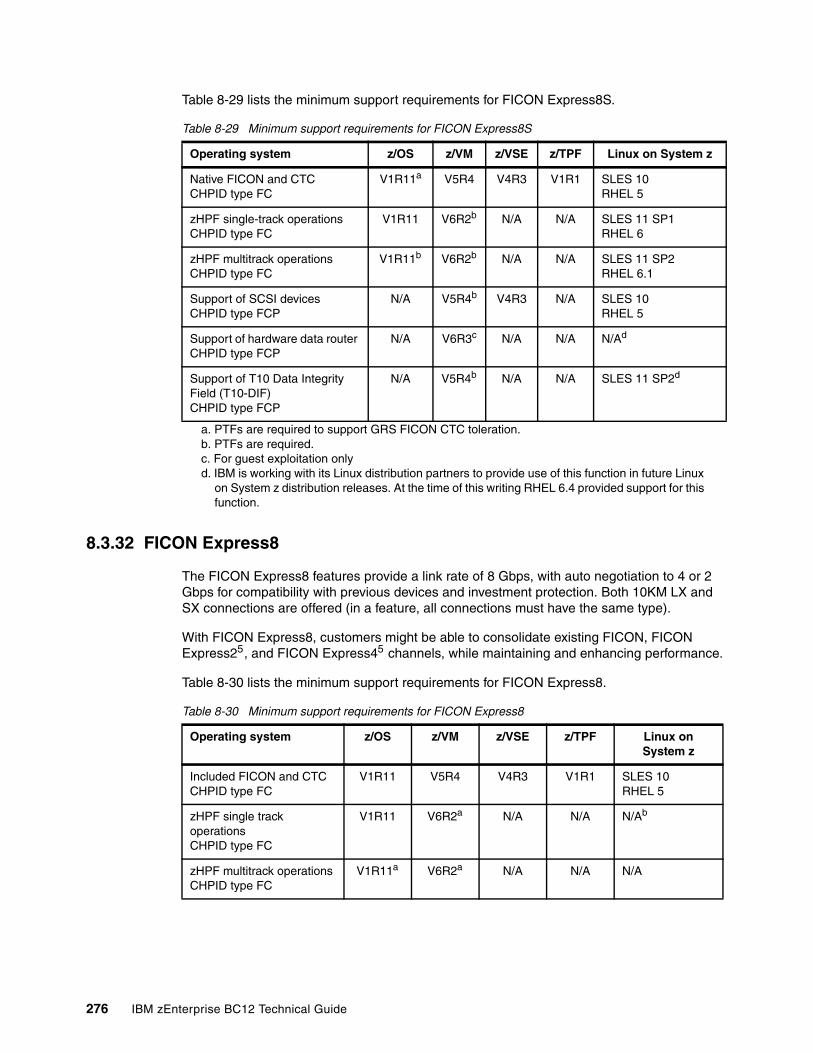
Table 8-29 lists the minimum support requirements for FICON Express8S.
Table 8-29 Minimum support requirements for FICON Express8S
8.3.32 FICON Express8
The FICON Express8 features provide a link rate of 8 Gbps, with auto negotiation to 4 or 2 Gbps for compatibility with previous devices and investment protection. Both 10KM LX and SX connections are offered (in a feature, all connections must have the same type).
With FICON Express8, customers might be able to consolidate existing FICON, FICON Express25, and FICON Express45 channels, while maintaining and enhancing performance.
Table 8-30 lists the minimum support requirements for FICON Express8.
Table 8-30 Minimum support requirements for FICON Express8
Operating system z/OS z/VM z/VSE z/TPF Linux on System z
Native FICON and CTCCHPID type FC
V1R11a V5R4 V4R3 V1R1 SLES 10RHEL 5
zHPF single-track operationsCHPID type FC
V1R11 V6R2b N/A N/A SLES 11 SP1RHEL 6
zHPF multitrack operationsCHPID type FC
V1R11b V6R2b N/A N/A SLES 11 SP2RHEL 6.1
Support of SCSI devicesCHPID type FCP
N/A V5R4b V4R3 N/A SLES 10RHEL 5
Support of hardware data router CHPID type FCP
N/A V6R3c N/A N/A N/Ad
Support of T10 Data Integrity Field (T10-DIF)CHPID type FCP
N/A V5R4b N/A N/A SLES 11 SP2d
a. PTFs are required to support GRS FICON CTC toleration.b. PTFs are required.c. For guest exploitation onlyd. IBM is working with its Linux distribution partners to provide use of this function in future Linux
on System z distribution releases. At the time of this writing RHEL 6.4 provided support for this function.
Operating system z/OS z/VM z/VSE z/TPF Linux on System z
Included FICON and CTCCHPID type FC
V1R11 V5R4 V4R3 V1R1 SLES 10 RHEL 5
zHPF single track operationsCHPID type FC
V1R11 V6R2a N/A N/A N/Ab
zHPF multitrack operationsCHPID type FC
V1R11a V6R2a N/A N/A N/A
276 IBM zEnterprise BC12 Technical Guide
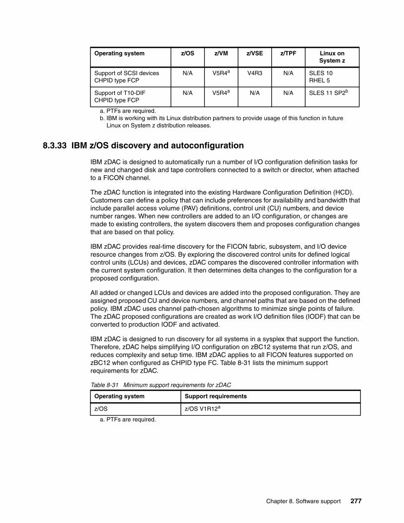
8.3.33 IBM z/OS discovery and autoconfiguration
IBM zDAC is designed to automatically run a number of I/O configuration definition tasks for new and changed disk and tape controllers connected to a switch or director, when attached to a FICON channel.
The zDAC function is integrated into the existing Hardware Configuration Definition (HCD). Customers can define a policy that can include preferences for availability and bandwidth that include parallel access volume (PAV) definitions, control unit (CU) numbers, and device number ranges. When new controllers are added to an I/O configuration, or changes are made to existing controllers, the system discovers them and proposes configuration changes that are based on that policy.
IBM zDAC provides real-time discovery for the FICON fabric, subsystem, and I/O device resource changes from z/OS. By exploring the discovered control units for defined logical control units (LCUs) and devices, zDAC compares the discovered controller information with the current system configuration. It then determines delta changes to the configuration for a proposed configuration.
All added or changed LCUs and devices are added into the proposed configuration. They are assigned proposed CU and device numbers, and channel paths that are based on the defined policy. IBM zDAC uses channel path-chosen algorithms to minimize single points of failure. The zDAC proposed configurations are created as work I/O definition files (IODF) that can be converted to production IODF and activated.
IBM zDAC is designed to run discovery for all systems in a sysplex that support the function. Therefore, zDAC helps simplifying I/O configuration on zBC12 systems that run z/OS, and reduces complexity and setup time. IBM zDAC applies to all FICON features supported on zBC12 when configured as CHPID type FC. Table 8-31 lists the minimum support requirements for zDAC.
Table 8-31 Minimum support requirements for zDAC
Support of SCSI devicesCHPID type FCP
N/A V5R4a V4R3 N/A SLES 10RHEL 5
Support of T10-DIFCHPID type FCP
N/A V5R4a N/A N/A SLES 11 SP2b
a. PTFs are required.b. IBM is working with its Linux distribution partners to provide usage of this function in future
Linux on System z distribution releases.
Operating system z/OS z/VM z/VSE z/TPF Linux on System z
Operating system Support requirements
z/OS z/OS V1R12a
a. PTFs are required.
Chapter 8. Software support 277
8.3.34 High performance FICON
IBM zHPF, first provided on System z10, is a FICON architecture for protocol simplification and efficiency. It reduces the number of information units (IUs) processed. Enhancements have been made to the z/Architecture and the FICON interface architecture to provide optimizations for online transaction processing (OLTP) workloads.
When used by the FICON channel, the z/OS OS, and the DS8000 control unit or other subsystems, the FICON channel processor usage can be reduced and performance improved. Appropriate levels of Licensed Internal Code (LIC) are required. Additionally, the changes to the architectures provide end-to-end system enhancements to improve reliability, availability, and serviceability (RAS).
IBM zHPF is compatible with these standards:
� Fibre Channel Framing and Signaling standard (FC-FS)� Fibre Channel Switch Fabric and Switch Control Requirements (FC-SW)� Fibre Channel Single-Byte-4 (FC-SB-4) standards
The zHPF channel programs can be used, for instance, by z/OS OLTP I/O workloads, DB2, Virtual Storage Access Method (VSAM), partitioned data set extended (PDSE), and IBM z/OS file system (zFS).
At announcement, zHPF supported the transfer of small blocks of fixed-size data (4 kilobytes (KB)) from a single track. This capability has been extended, first to 64 kilobytes (KB) and then to multitrack operations. The 64 KB data transfer limit on multitrack operations was removed by z196. This improvement enables the channel to fully use the bandwidth of FICON channels, resulting in higher throughputs and lower response times.
The multitrack operations extension applies exclusively to the FICON Express8S, FICON Express8, and FICON Express46, on the zEC12, zBC12, z196, and z114, when configured as CHPID type FC and connecting to z/OS. IBM zHPF requires matching support by the DS8000 series. Otherwise, the extended multitrack support is transparent to the CU.
From the z/OS point of view, the existing FICON architecture is called command mode and zHPF architecture is called transport mode. During link initialization, the channel node and the CU node indicate whether they support zHPF.
The mode that is used for an I/O operation depends on the CU that supports zHPF and settings in the z/OS OS. For z/OS usage, there is a parameter in the IECIOSxx member of SYS1.Parmlib (ZHPF=YES or NO) and in the SETIOS system command to control whether zHPF is enabled or disabled. The default is ZHPF=NO.
Support is also added for the D IOS,ZHPF system command to indicate whether zHPF is enabled, disabled, or not supported on the server.
Similar to the existing FICON channel architecture, the application or access method provides the channel program (CCWs). The way that zHPF (transport mode) manages channel program operations is significantly different from the CCW operation for the existing FICON architecture (command mode).
6 FICON Express4 LX 4KM is not supported on zBC12.
Requirement: All FICON CHPIDs defined to the same LCU must support zHPF. The inclusion of any non-compliant zHPF features in the path group causes the entire path group to support command mode only.
278 IBM zEnterprise BC12 Technical Guide
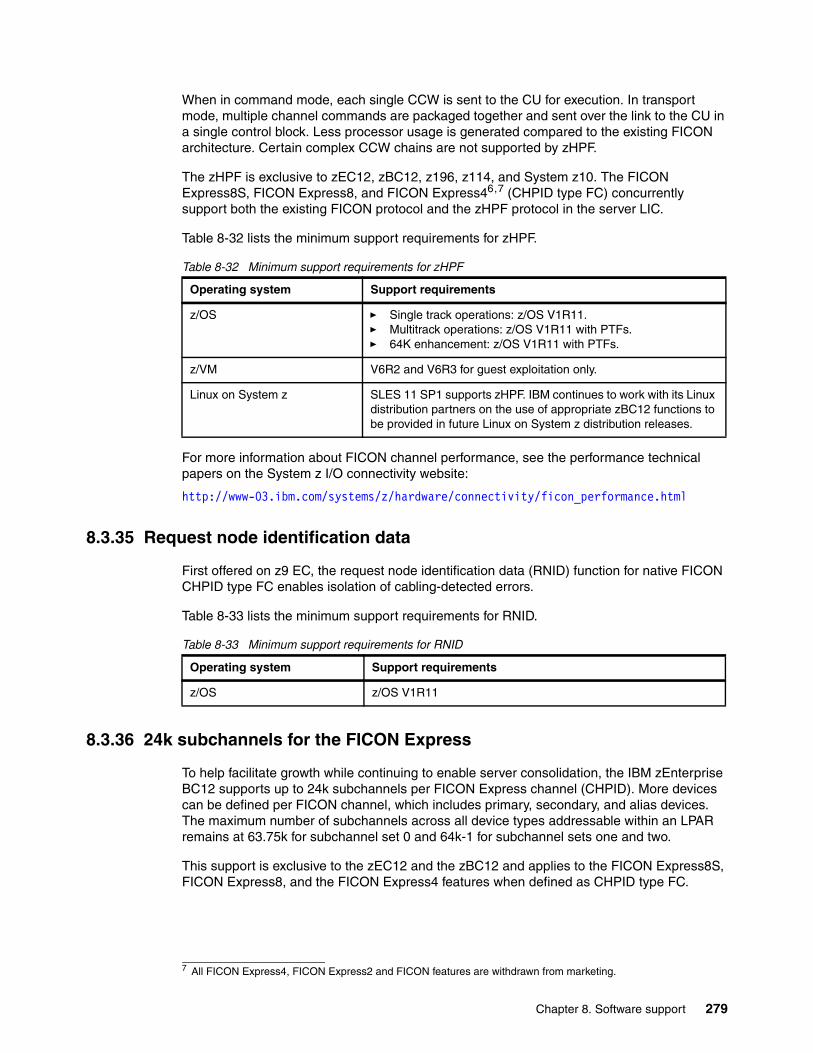
When in command mode, each single CCW is sent to the CU for execution. In transport mode, multiple channel commands are packaged together and sent over the link to the CU in a single control block. Less processor usage is generated compared to the existing FICON architecture. Certain complex CCW chains are not supported by zHPF.
The zHPF is exclusive to zEC12, zBC12, z196, z114, and System z10. The FICON Express8S, FICON Express8, and FICON Express46,7 (CHPID type FC) concurrently support both the existing FICON protocol and the zHPF protocol in the server LIC.
Table 8-32 lists the minimum support requirements for zHPF.
Table 8-32 Minimum support requirements for zHPF
For more information about FICON channel performance, see the performance technical papers on the System z I/O connectivity website:
http://www-03.ibm.com/systems/z/hardware/connectivity/ficon_performance.html
8.3.35 Request node identification data
First offered on z9 EC, the request node identification data (RNID) function for native FICON CHPID type FC enables isolation of cabling-detected errors.
Table 8-33 lists the minimum support requirements for RNID.
Table 8-33 Minimum support requirements for RNID
8.3.36 24k subchannels for the FICON Express
To help facilitate growth while continuing to enable server consolidation, the IBM zEnterprise BC12 supports up to 24k subchannels per FICON Express channel (CHPID). More devices can be defined per FICON channel, which includes primary, secondary, and alias devices. The maximum number of subchannels across all device types addressable within an LPAR remains at 63.75k for subchannel set 0 and 64k-1 for subchannel sets one and two.
This support is exclusive to the zEC12 and the zBC12 and applies to the FICON Express8S, FICON Express8, and the FICON Express4 features when defined as CHPID type FC.
7 All FICON Express4, FICON Express2 and FICON features are withdrawn from marketing.
Operating system Support requirements
z/OS � Single track operations: z/OS V1R11.� Multitrack operations: z/OS V1R11 with PTFs.� 64K enhancement: z/OS V1R11 with PTFs.
z/VM V6R2 and V6R3 for guest exploitation only.
Linux on System z SLES 11 SP1 supports zHPF. IBM continues to work with its Linux distribution partners on the use of appropriate zBC12 functions to be provided in future Linux on System z distribution releases.
Operating system Support requirements
z/OS z/OS V1R11
Chapter 8. Software support 279
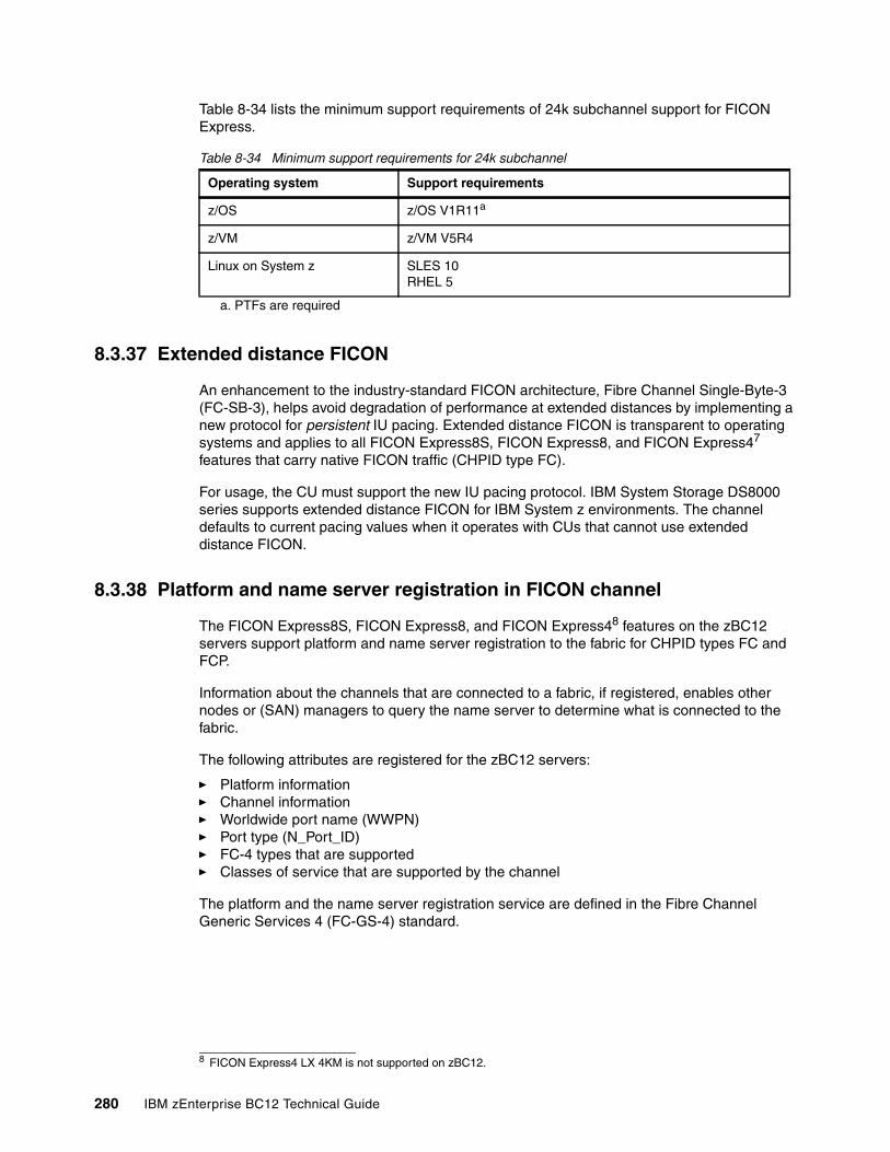
Table 8-34 lists the minimum support requirements of 24k subchannel support for FICON Express.
Table 8-34 Minimum support requirements for 24k subchannel
8.3.37 Extended distance FICON
An enhancement to the industry-standard FICON architecture, Fibre Channel Single-Byte-3 (FC-SB-3), helps avoid degradation of performance at extended distances by implementing a new protocol for persistent IU pacing. Extended distance FICON is transparent to operating systems and applies to all FICON Express8S, FICON Express8, and FICON Express47 features that carry native FICON traffic (CHPID type FC).
For usage, the CU must support the new IU pacing protocol. IBM System Storage DS8000 series supports extended distance FICON for IBM System z environments. The channel defaults to current pacing values when it operates with CUs that cannot use extended distance FICON.
8.3.38 Platform and name server registration in FICON channel
The FICON Express8S, FICON Express8, and FICON Express48 features on the zBC12 servers support platform and name server registration to the fabric for CHPID types FC and FCP.
Information about the channels that are connected to a fabric, if registered, enables other nodes or (SAN) managers to query the name server to determine what is connected to the fabric.
The following attributes are registered for the zBC12 servers:
� Platform information� Channel information� Worldwide port name (WWPN)� Port type (N_Port_ID)� FC-4 types that are supported� Classes of service that are supported by the channel
The platform and the name server registration service are defined in the Fibre Channel Generic Services 4 (FC-GS-4) standard.
Operating system Support requirements
z/OS z/OS V1R11a
a. PTFs are required
z/VM z/VM V5R4
Linux on System z SLES 10 RHEL 5
8 FICON Express4 LX 4KM is not supported on zBC12.
280 IBM zEnterprise BC12 Technical Guide
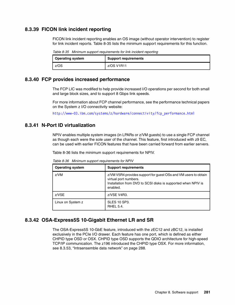
8.3.39 FICON link incident reporting
FICON link incident reporting enables an OS image (without operator intervention) to register for link incident reports. Table 8-35 lists the minimum support requirements for this function.
Table 8-35 Minimum support requirements for link incident reporting
8.3.40 FCP provides increased performance
The FCP LIC was modified to help provide increased I/O operations per second for both small and large block sizes, and to support 8 Gbps link speeds.
For more information about FCP channel performance, see the performance technical papers on the System z I/O connectivity website:
http://www-03.ibm.com/systems/z/hardware/connectivity/fcp_performance.html
8.3.41 N-Port ID virtualization
NPIV enables multiple system images (in LPARs or z/VM guests) to use a single FCP channel as though each were the sole user of the channel. This feature, first introduced with z9 EC, can be used with earlier FICON features that have been carried forward from earlier servers.
Table 8-36 lists the minimum support requirements for NPIV.
Table 8-36 Minimum support requirements for NPIV
8.3.42 OSA-Express5S 10-Gigabit Ethernet LR and SR
The OSA-Express5S 10-GbE feature, introduced with the zEC12 and zBC12, is installed exclusively in the PCIe I/O drawer. Each feature has one port, which is defined as either CHPID type OSD or OSX. CHPID type OSD supports the QDIO architecture for high-speed TCP/IP communication. The z196 introduced the CHPID type OSX. For more information, see 8.3.53, “Intraensemble data network” on page 288.
Operating system Support requirements
z/OS z/OS V1R11
Operating system Support requirements
z/VM z/VM V5R4 provides support for guest OSs and VM users to obtain virtual port numbers.Installation from DVD to SCSI disks is supported when NPIV is enabled.
z/VSE z/VSE V4R3.
Linux on System z SLES 10 SP3.RHEL 5.4.
Chapter 8. Software support 281
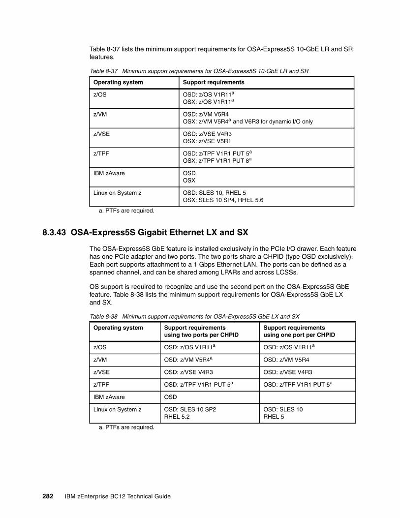
Table 8-37 lists the minimum support requirements for OSA-Express5S 10-GbE LR and SR features.
Table 8-37 Minimum support requirements for OSA-Express5S 10-GbE LR and SR
8.3.43 OSA-Express5S Gigabit Ethernet LX and SX
The OSA-Express5S GbE feature is installed exclusively in the PCIe I/O drawer. Each feature has one PCIe adapter and two ports. The two ports share a CHPID (type OSD exclusively). Each port supports attachment to a 1 Gbps Ethernet LAN. The ports can be defined as a spanned channel, and can be shared among LPARs and across LCSSs.
OS support is required to recognize and use the second port on the OSA-Express5S GbE feature. Table 8-38 lists the minimum support requirements for OSA-Express5S GbE LX and SX.
Table 8-38 Minimum support requirements for OSA-Express5S GbE LX and SX
Operating system Support requirements
z/OS OSD: z/OS V1R11a
OSX: z/OS V1R11a
a. PTFs are required.
z/VM OSD: z/VM V5R4OSX: z/VM V5R4a and V6R3 for dynamic I/O only
z/VSE OSD: z/VSE V4R3OSX: z/VSE V5R1
z/TPF OSD: z/TPF V1R1 PUT 5a
OSX: z/TPF V1R1 PUT 8a
IBM zAware OSDOSX
Linux on System z OSD: SLES 10, RHEL 5OSX: SLES 10 SP4, RHEL 5.6
Operating system Support requirementsusing two ports per CHPID
Support requirementsusing one port per CHPID
z/OS OSD: z/OS V1R11a OSD: z/OS V1R11a
z/VM OSD: z/VM V5R4a
a. PTFs are required.
OSD: z/VM V5R4
z/VSE OSD: z/VSE V4R3 OSD: z/VSE V4R3
z/TPF OSD: z/TPF V1R1 PUT 5a OSD: z/TPF V1R1 PUT 5a
IBM zAware OSD
Linux on System z OSD: SLES 10 SP2RHEL 5.2
OSD: SLES 10RHEL 5
282 IBM zEnterprise BC12 Technical Guide
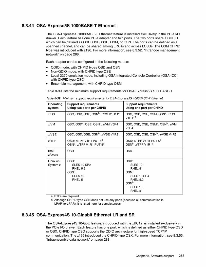
8.3.44 OSA-Express5S 1000BASE-T Ethernet
The OSA-Express5S 1000BASE-T Ethernet feature is installed exclusively in the PCIe I/O drawer. Each feature has one PCIe adapter and two ports. The two ports share a CHPID, which can be defined as OSC, OSD, OSE, OSM, or OSN. The ports can be defined as a spanned channel, and can be shared among LPARs and across LCSSs. The OSM CHPID type was introduced with z196. For more information, see 8.3.52, “Intranode management network” on page 288.
Each adapter can be configured in the following modes:
� QDIO mode, with CHPID types OSD and OSN � Non-QDIO mode, with CHPID type OSE � Local 3270 emulation mode, including OSA Integrated Console Controller (OSA-ICC),
with CHPID type OSC� Ensemble management, with CHPID type OSM
Table 8-39 lists the minimum support requirements for OSA-Express5S 1000BASE-T.
Table 8-39 Minimum support requirements for OSA-Express5S 1000BASE-T Ethernet
8.3.45 OSA-Express4S 10-Gigabit Ethernet LR and SR
The OSA-Express4S 10-GbE feature, introduced with the zBC12, is installed exclusively in the PCIe I/O drawer. Each feature has one port, which is defined as either CHPID type OSD or OSX. CHPID type OSD supports the QDIO architecture for high-speed TCP/IP communication. The z196 introduced the CHPID type OSX. For more information, see 8.3.53, “Intraensemble data network” on page 288.
Operating system
Support requirementsUsing two ports per CHPID
Support requirementsUsing one port per CHPID
z/OS OSC, OSD, OSE, OSNb: z/OS V1R11a OSC, OSD, OSE, OSM, OSNa: z/OS V1R11a
z/VM OSC, OSDa, OSE, OSNb: z/VM V5R4
a. PTFs are required.b. Although CHPID type OSN does not use any ports (because all communication is
LPAR-to-LPAR), it is listed here for completeness.
OSC, OSD, OSE, OSMa, OSNb: z/VM V5R4
z/VSE OSC, OSD, OSE, OSNb: z/VSE V4R3 OSC, OSD, OSE, OSNb: z/VSE V4R3
z/TPF OSD: z/TPF V1R1 PUT 5a
OSNb: z/TPF V1R1 PUT 5aOSD: z/TPF V1R1 PUT 5a
OSNb: z/TPF V1R1a
IBM zAware
OSD OSD
Linux on System z
OSD: SLES 10 SP2RHEL 5.2
OSNb: SLES 10 RHEL 5
OSD: SLES 10RHEL 5
OSM: SLES 10 SP4RHEL 5.2
OSNb: SLES 10 RHEL 5
Chapter 8. Software support 283
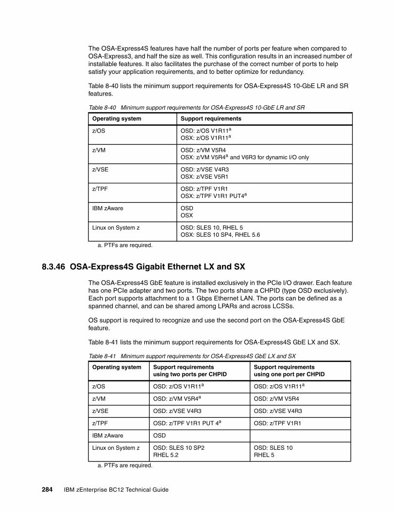
The OSA-Express4S features have half the number of ports per feature when compared to OSA-Express3, and half the size as well. This configuration results in an increased number of installable features. It also facilitates the purchase of the correct number of ports to help satisfy your application requirements, and to better optimize for redundancy.
Table 8-40 lists the minimum support requirements for OSA-Express4S 10-GbE LR and SR features.
Table 8-40 Minimum support requirements for OSA-Express4S 10-GbE LR and SR
8.3.46 OSA-Express4S Gigabit Ethernet LX and SX
The OSA-Express4S GbE feature is installed exclusively in the PCIe I/O drawer. Each feature has one PCIe adapter and two ports. The two ports share a CHPID (type OSD exclusively). Each port supports attachment to a 1 Gbps Ethernet LAN. The ports can be defined as a spanned channel, and can be shared among LPARs and across LCSSs.
OS support is required to recognize and use the second port on the OSA-Express4S GbE feature.
Table 8-41 lists the minimum support requirements for OSA-Express4S GbE LX and SX.
Table 8-41 Minimum support requirements for OSA-Express4S GbE LX and SX
Operating system Support requirements
z/OS OSD: z/OS V1R11a
OSX: z/OS V1R11a
a. PTFs are required.
z/VM OSD: z/VM V5R4OSX: z/VM V5R4a and V6R3 for dynamic I/O only
z/VSE OSD: z/VSE V4R3OSX: z/VSE V5R1
z/TPF OSD: z/TPF V1R1OSX: z/TPF V1R1 PUT4a
IBM zAware OSDOSX
Linux on System z OSD: SLES 10, RHEL 5OSX: SLES 10 SP4, RHEL 5.6
Operating system Support requirementsusing two ports per CHPID
Support requirementsusing one port per CHPID
z/OS OSD: z/OS V1R11a OSD: z/OS V1R11a
z/VM OSD: z/VM V5R4a
a. PTFs are required.
OSD: z/VM V5R4
z/VSE OSD: z/VSE V4R3 OSD: z/VSE V4R3
z/TPF OSD: z/TPF V1R1 PUT 4a OSD: z/TPF V1R1
IBM zAware OSD
Linux on System z OSD: SLES 10 SP2RHEL 5.2
OSD: SLES 10RHEL 5
284 IBM zEnterprise BC12 Technical Guide
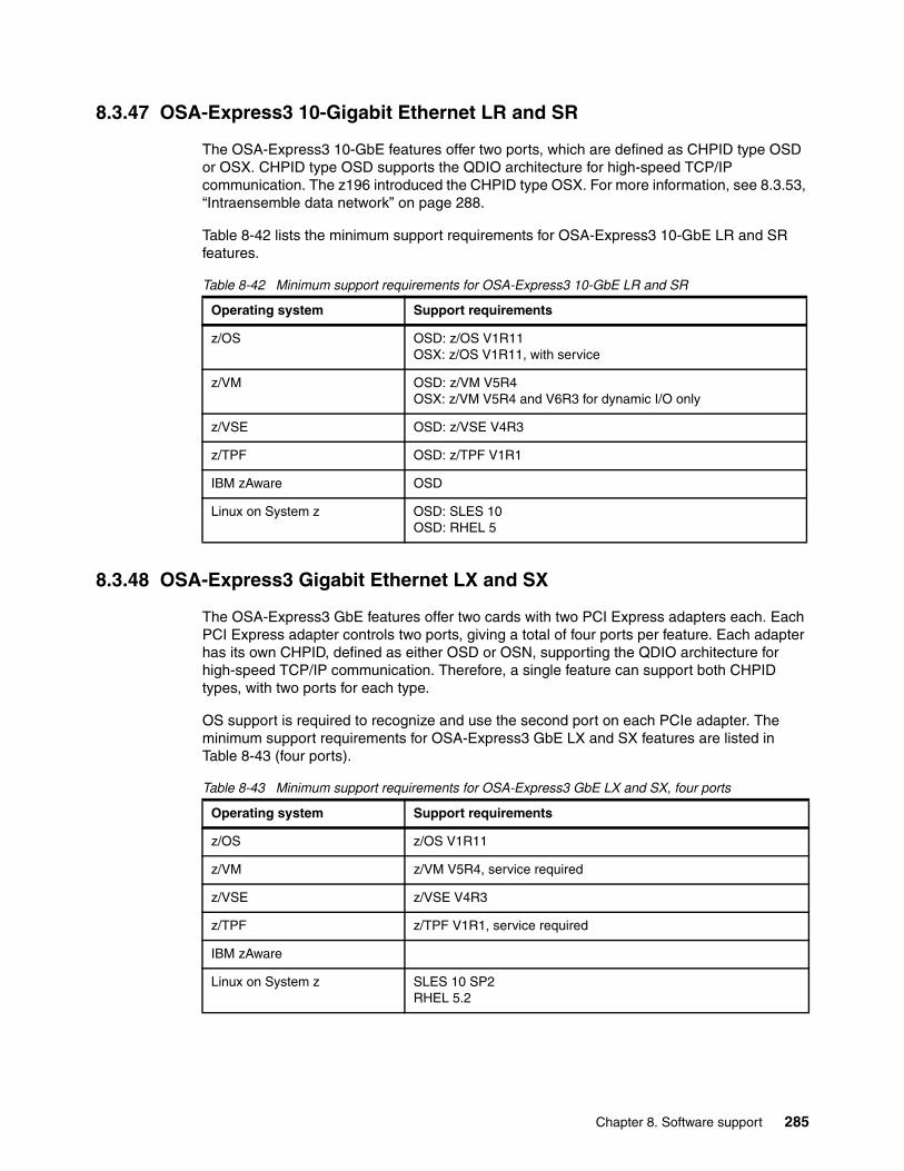
8.3.47 OSA-Express3 10-Gigabit Ethernet LR and SR
The OSA-Express3 10-GbE features offer two ports, which are defined as CHPID type OSD or OSX. CHPID type OSD supports the QDIO architecture for high-speed TCP/IP communication. The z196 introduced the CHPID type OSX. For more information, see 8.3.53, “Intraensemble data network” on page 288.
Table 8-42 lists the minimum support requirements for OSA-Express3 10-GbE LR and SR features.
Table 8-42 Minimum support requirements for OSA-Express3 10-GbE LR and SR
8.3.48 OSA-Express3 Gigabit Ethernet LX and SX
The OSA-Express3 GbE features offer two cards with two PCI Express adapters each. Each PCI Express adapter controls two ports, giving a total of four ports per feature. Each adapter has its own CHPID, defined as either OSD or OSN, supporting the QDIO architecture for high-speed TCP/IP communication. Therefore, a single feature can support both CHPID types, with two ports for each type.
OS support is required to recognize and use the second port on each PCIe adapter. The minimum support requirements for OSA-Express3 GbE LX and SX features are listed in Table 8-43 (four ports).
Table 8-43 Minimum support requirements for OSA-Express3 GbE LX and SX, four ports
Operating system Support requirements
z/OS OSD: z/OS V1R11OSX: z/OS V1R11, with service
z/VM OSD: z/VM V5R4OSX: z/VM V5R4 and V6R3 for dynamic I/O only
z/VSE OSD: z/VSE V4R3
z/TPF OSD: z/TPF V1R1
IBM zAware OSD
Linux on System z OSD: SLES 10OSD: RHEL 5
Operating system Support requirements
z/OS z/OS V1R11
z/VM z/VM V5R4, service required
z/VSE z/VSE V4R3
z/TPF z/TPF V1R1, service required
IBM zAware
Linux on System z SLES 10 SP2RHEL 5.2
Chapter 8. Software support 285
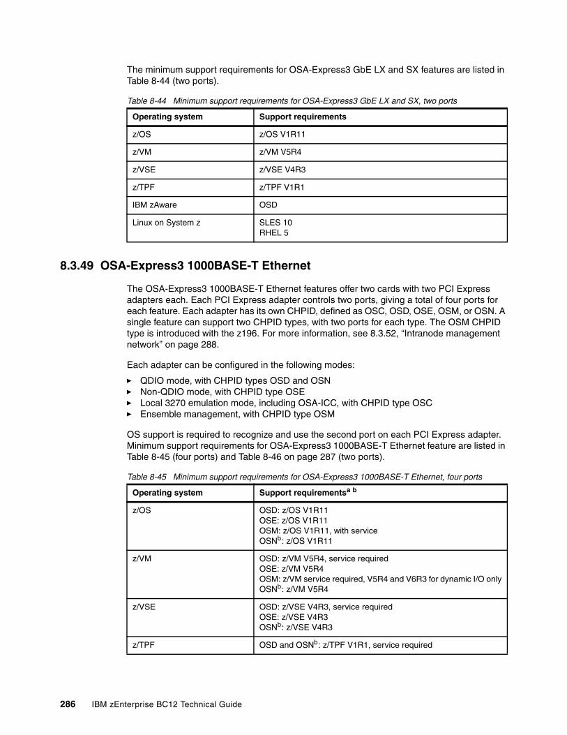
The minimum support requirements for OSA-Express3 GbE LX and SX features are listed in Table 8-44 (two ports).
Table 8-44 Minimum support requirements for OSA-Express3 GbE LX and SX, two ports
8.3.49 OSA-Express3 1000BASE-T Ethernet
The OSA-Express3 1000BASE-T Ethernet features offer two cards with two PCI Express adapters each. Each PCI Express adapter controls two ports, giving a total of four ports for each feature. Each adapter has its own CHPID, defined as OSC, OSD, OSE, OSM, or OSN. A single feature can support two CHPID types, with two ports for each type. The OSM CHPID type is introduced with the z196. For more information, see 8.3.52, “Intranode management network” on page 288.
Each adapter can be configured in the following modes:
� QDIO mode, with CHPID types OSD and OSN � Non-QDIO mode, with CHPID type OSE � Local 3270 emulation mode, including OSA-ICC, with CHPID type OSC� Ensemble management, with CHPID type OSM
OS support is required to recognize and use the second port on each PCI Express adapter. Minimum support requirements for OSA-Express3 1000BASE-T Ethernet feature are listed in Table 8-45 (four ports) and Table 8-46 on page 287 (two ports).
Table 8-45 Minimum support requirements for OSA-Express3 1000BASE-T Ethernet, four ports
Operating system Support requirements
z/OS z/OS V1R11
z/VM z/VM V5R4
z/VSE z/VSE V4R3
z/TPF z/TPF V1R1
IBM zAware OSD
Linux on System z SLES 10RHEL 5
Operating system Support requirementsa b
z/OS OSD: z/OS V1R11OSE: z/OS V1R11OSM: z/OS V1R11, with serviceOSNb: z/OS V1R11
z/VM OSD: z/VM V5R4, service requiredOSE: z/VM V5R4OSM: z/VM service required, V5R4 and V6R3 for dynamic I/O onlyOSNb: z/VM V5R4
z/VSE OSD: z/VSE V4R3, service requiredOSE: z/VSE V4R3OSNb: z/VSE V4R3
z/TPF OSD and OSNb: z/TPF V1R1, service required
286 IBM zEnterprise BC12 Technical Guide
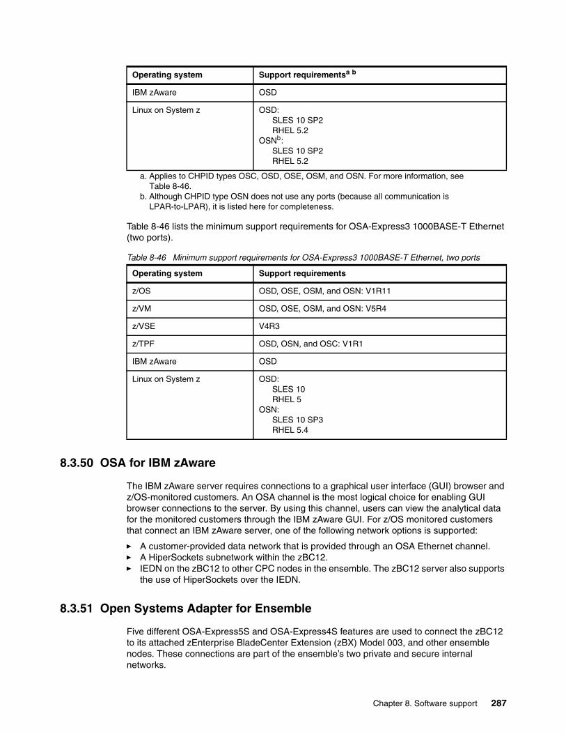
Table 8-46 lists the minimum support requirements for OSA-Express3 1000BASE-T Ethernet (two ports).
Table 8-46 Minimum support requirements for OSA-Express3 1000BASE-T Ethernet, two ports
8.3.50 OSA for IBM zAware
The IBM zAware server requires connections to a graphical user interface (GUI) browser and z/OS-monitored customers. An OSA channel is the most logical choice for enabling GUI browser connections to the server. By using this channel, users can view the analytical data for the monitored customers through the IBM zAware GUI. For z/OS monitored customers that connect an IBM zAware server, one of the following network options is supported:
� A customer-provided data network that is provided through an OSA Ethernet channel.� A HiperSockets subnetwork within the zBC12.� IEDN on the zBC12 to other CPC nodes in the ensemble. The zBC12 server also supports
the use of HiperSockets over the IEDN.
8.3.51 Open Systems Adapter for Ensemble
Five different OSA-Express5S and OSA-Express4S features are used to connect the zBC12 to its attached zEnterprise BladeCenter Extension (zBX) Model 003, and other ensemble nodes. These connections are part of the ensemble’s two private and secure internal networks.
IBM zAware OSD
Linux on System z OSD:SLES 10 SP2RHEL 5.2
OSNb:SLES 10 SP2RHEL 5.2
a. Applies to CHPID types OSC, OSD, OSE, OSM, and OSN. For more information, see Table 8-46.
b. Although CHPID type OSN does not use any ports (because all communication is LPAR-to-LPAR), it is listed here for completeness.
Operating system Support requirements
z/OS OSD, OSE, OSM, and OSN: V1R11
z/VM OSD, OSE, OSM, and OSN: V5R4
z/VSE V4R3
z/TPF OSD, OSN, and OSC: V1R1
IBM zAware OSD
Linux on System z OSD:SLES 10RHEL 5
OSN:SLES 10 SP3RHEL 5.4
Operating system Support requirementsa b
Chapter 8. Software support 287
For the intranode management network (INMN), use these features:
� OSA Express5S 1000BASE-T Ethernet, feature code 0417� OSA-Express3 1000BASE-T Ethernet, feature code 3367
For the IEDN, use these features:
� OSA-Express5S 10 Gigabit Ethernet (GbE) Long Reach (LR), feature code 0415� OSA-Express5S 10 Gigabit Ethernet (GbE) Short Reach (SR), feature code 0416� OSA-Express4S 10 Gigabit Ethernet (GbE) Long Reach (LR), feature code 0406� OSA-Express4S 10 Gigabit Ethernet (GbE) Short Reach (SR), feature code 0407� OSA-Express3 10 Gigabit Ethernet (GbE) Long Reach (LR), feature code 3370� OSA-Express3 10 Gigabit Ethernet (GbE) Short Reach (SR), feature code 3371
For more information about OSA-Express3, OSA-Express4S and OSA-Express5S in an ensemble network, see 7.4, “IBM zBX connectivity” on page 228.
8.3.52 Intranode management network
The intranode management network (INMN) is one of the ensemble’s two private and secure internal networks. The INMN is used by the URM functions.
The INMN is a private and physically isolated 1000Base-T Ethernet internal platform management network. It operates at 1 Gbps, and connects all resources (CPC and zBX components) of an ensemble node for management purposes. It is pre-wired, internally switched, configured, and managed with full redundancy for high availability.
The z196 introduced the OSM CHPID type. INMN requires two OSA-Express5S 1000BASE-T or OSA-Express3 1000BASE-T ports, from two different OSA-Express5S 1000BASE-T or OSA-Express3 1000BASE-T features, that are configured as CHPID type OSM. One port per CHPID is available with CHPID type OSM.
The OSA connection is through the bulk power hub (BPH) port J07 on the zBC12 to the top-of-rack (TOR) switches on zBX.
8.3.53 Intraensemble data network
The IEDN is one of the ensemble’s two private and secure internal networks. IEDN provides applications with a fast data exchange path between ensemble nodes. Specifically, it is used for communications across the virtualized images (LPARs, z/VM virtual machines, and blade LPARs).
The IEDN is a private and secure 10-Gbps Ethernet network that connects all elements of an ensemble. It is access-controlled by using integrated VLAN provisioning. No customer-managed switches or routers are required. IEDN is managed by the primary HMC that controls the ensemble. This configuration helps reduce the need for firewalls and encryption, and simplifies network configuration and management. It also provides full redundancy for high availability.
The z196 introduced the OSX CHPID type. The OSA connection is from the zBC12 to the TOR switches on zBX.
IEDN requires two OSA-Express5S, OSA-Express4S, or OSA-Express3 10 GbE ports that are configured as CHPID type OSX.
288 IBM zEnterprise BC12 Technical Guide
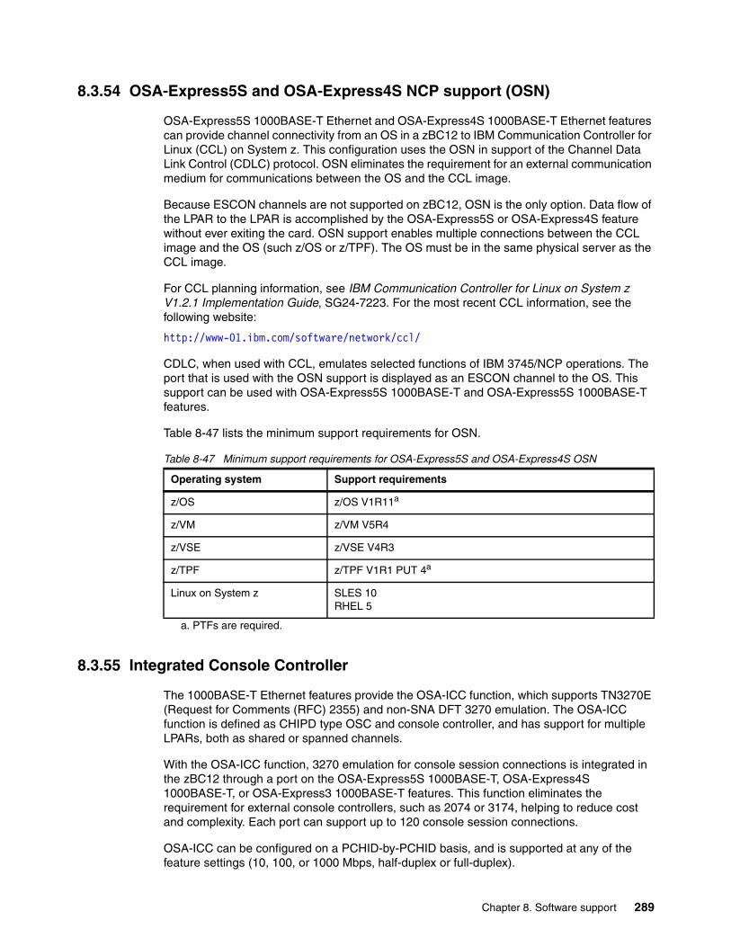
8.3.54 OSA-Express5S and OSA-Express4S NCP support (OSN)
OSA-Express5S 1000BASE-T Ethernet and OSA-Express4S 1000BASE-T Ethernet features can provide channel connectivity from an OS in a zBC12 to IBM Communication Controller for Linux (CCL) on System z. This configuration uses the OSN in support of the Channel Data Link Control (CDLC) protocol. OSN eliminates the requirement for an external communication medium for communications between the OS and the CCL image.
Because ESCON channels are not supported on zBC12, OSN is the only option. Data flow of the LPAR to the LPAR is accomplished by the OSA-Express5S or OSA-Express4S feature without ever exiting the card. OSN support enables multiple connections between the CCL image and the OS (such z/OS or z/TPF). The OS must be in the same physical server as the CCL image.
For CCL planning information, see IBM Communication Controller for Linux on System z V1.2.1 Implementation Guide, SG24-7223. For the most recent CCL information, see the following website:
http://www-01.ibm.com/software/network/ccl/
CDLC, when used with CCL, emulates selected functions of IBM 3745/NCP operations. The port that is used with the OSN support is displayed as an ESCON channel to the OS. This support can be used with OSA-Express5S 1000BASE-T and OSA-Express5S 1000BASE-T features.
Table 8-47 lists the minimum support requirements for OSN.
Table 8-47 Minimum support requirements for OSA-Express5S and OSA-Express4S OSN
8.3.55 Integrated Console Controller
The 1000BASE-T Ethernet features provide the OSA-ICC function, which supports TN3270E (Request for Comments (RFC) 2355) and non-SNA DFT 3270 emulation. The OSA-ICC function is defined as CHIPD type OSC and console controller, and has support for multiple LPARs, both as shared or spanned channels.
With the OSA-ICC function, 3270 emulation for console session connections is integrated in the zBC12 through a port on the OSA-Express5S 1000BASE-T, OSA-Express4S 1000BASE-T, or OSA-Express3 1000BASE-T features. This function eliminates the requirement for external console controllers, such as 2074 or 3174, helping to reduce cost and complexity. Each port can support up to 120 console session connections.
OSA-ICC can be configured on a PCHID-by-PCHID basis, and is supported at any of the feature settings (10, 100, or 1000 Mbps, half-duplex or full-duplex).
Operating system Support requirements
z/OS z/OS V1R11a
z/VM z/VM V5R4
z/VSE z/VSE V4R3
z/TPF z/TPF V1R1 PUT 4a
a. PTFs are required.
Linux on System z SLES 10 RHEL 5
Chapter 8. Software support 289
8.3.56 VLAN management enhancements
Table 8-48 lists minimum support requirements for VLAN management enhancements for the OSA-Express5S, OSA-Express4S, and OSA-Express3 features (CHPID type OSD).
Table 8-48 Minimum support requirements for VLAN management enhancements
8.3.57 GARP VLAN Registration Protocol
All OSA-Express5S, OSA-Express4S, and OSA-Express3 features support VLAN prioritization, a component of the IEEE 802.1 standard. Generic Attribute Registration Protocol (GARP) VLAN Registration Protocol (GVRP) support enables an OSA-Express port to register or unregister its VLAN IDs with a GVRP-capable switch, and dynamically update its table as the VLANs change. T
his process simplifies the network administration and management of VLANs because manually entering VLAN IDs at the switch is no longer necessary.
Minimum support requirements are listed in Table 8-49.
Table 8-49 Minimum support requirements for GVRP
8.3.58 Inbound workload queuing for OSA-Express5S, OSA-Express4S, and OSA-Express3
OSA-Express-3 introduced inbound workload queueing (IWQ), which creates multiple input queues and enables OSA to differentiate workloads “off the wire.” It then assigns work to a specific input queue (per device) to z/OS. The support is also available with OSA-Express5S and OSA-Express4S. CHPID types OSD and OSX are supported.
Each input queue is a unique type of workload, and has unique service and processing requirements. The IWQ function enables z/OS to preassign the appropriate processing resources for each input queue.
This approach enables multiple concurrent z/OS processing threads to process each unique input queue (workload), avoiding traditional resource contention. In a heavily mixed workload environment, this “off the wire” network traffic separation provided by OSA-Express5S, OSA-Express4S, and OSA-Express3 IWQ reduces the conventional z/OS processing required to identify and separate unique workloads. This advantage results in improved overall system performance and scalability.
Operating system Support requirements
z/OS z/OS V1R11.
z/VM z/VM V5R4. Support of guests is transparent to z/VM if the device is directly connected to the guest (pass through).
Operating system Support requirements
z/OS z/OS V1R11
z/VM z/VM V5R4
290 IBM zEnterprise BC12 Technical Guide
A primary objective of IWQ is to provide improved performance for business-critical interactive workloads by reducing contention that is created by other types of workloads. The following types of z/OS workloads are identified and assigned to unique input queues:
� IBM z/OS Sysplex Distributor traffic. Network traffic that is associated with a distributed virtual Internet Protocol address (VIPA) is assigned to a unique input queue. This configuration enables the Sysplex Distributor traffic to be immediately distributed to the target host.
� IBM z/OS bulk data traffic. Network traffic that is dynamically associated with a streaming (bulk data) TCP connection is assigned to a unique input queue. This configuration enables the bulk data processing to be assigned the appropriate resources, and isolated from critical interactive workloads.
IWQ is exclusive to OSA-Express5S, OSA-Express4S, and OSA-Express3 CHPID types OSD and OSX, and the z/OS OS. This limitation applies to zEC12, zBC12, z196, z114, and System z10.
Minimum support requirements for IWQ are listed in Table 8-50.
Table 8-50 Minimum support requirements for IWQ
8.3.59 Inbound workload queuing for Enterprise Extender
IWQ for the OSA-Express features was enhanced to differentiate and separate inbound Enterprise Extender traffic to a dedicated input queue.
IWQ for Enterprise Extender is exclusive to OSA-Express5S, OSA-Express4S, and OSA-Express3 CHPID types OSD and OSX, and the z/OS OS. This limitation applies to zEC12, zBC12, z196, and z114. Minimum support requirements are listed in Table 8-51.
Table 8-51 Minimum support requirements for IWQ
8.3.60 Query and display OSA configuration
OSA-Express3 introduced the capability for the OS to directly query and display the current OSA configuration information (similar to Open Systems Adapter/Support Facility (OSA/SF)). IBM z/OS uses this OSA capability by introducing a TCP/IP operator command called display OSAINFO.
Using the display OSAINFO command enables the operator to monitor and verify the current OSA configuration. Doing so helps improve the overall management, serviceability, and usability of OSA-Express5S, OSA-Express4S, and OSA-Express3.
The display OSAINFO command is exclusive to z/OS, and applies to OSA-Express5S, OSA-Express4S, and OSA-Express3 features, CHPID types OSD, OSM, and OSX.
Operating system Support requirements
z/OS z/OS V1R12
z/VM z/VM V5R4 for guest usage only, service required
Operating system Support requirements
z/OS z/OS V1R13
z/VM z/VM V5R4for guest usage only, service required
Chapter 8. Software support 291
8.3.61 Link aggregation support for z/VM
Link aggregation (IEEE 802.3ad) controlled by the z/VM Virtual Switch (VSWITCH) enables the dedication of an OSA-Express5S, OSA-Express4S, or OSA-Express3 port to the z/VM OS. The port must be participating in an aggregated group that is configured in Layer 2 mode.
Link aggregation (trunking) combines multiple physical OSA-Express5S, OSA-Express4S, or OSA-Express3 ports into a single logical link. This configuration increases throughput, and provides nondisruptive failover if a port becomes unavailable. The target links for aggregation must be of the same type. Link aggregation is applicable to the OSA-Express5S, OSA-Express4S, and OSA-Express3 features when configured as CHPID type OSD (QDIO). Link aggregation is supported by z/VM V5R4 and later.
8.3.62 QDIO data connection isolation for z/VM
The QDIO data connection isolation function provides a higher level of security when sharing an OSA connection in z/VM environments that use VSWITCH. The VSWITCH is a virtual network device that provides switching between OSA connections and the connected guest systems.
QDIO data connection isolation enables disabling internal routing for each QDIO connected. It also provides a means for creating security zones, and preventing network traffic between the zones.
VSWITCH isolation support is provided by APAR VM64281. IBM z/VM 5R4 and later support is provided by CP APAR VM64463 and TCP/IP APAR PK67610.
QDIO data connection isolation is supported by all OSA-Express5S, OSA-Express4S, and OSA-Express3 features on zBC12.
8.3.63 QDIO interface isolation for z/OS
Some environments require strict controls for routing data traffic between servers or nodes. In certain cases, the LPAR-to-LPAR capability of a shared OSA connection can prevent such controls from being enforced. With interface isolation, internal routing can be controlled on an LPAR basis. When interface isolation is enabled, the OSA discards any packets that are destined for a z/OS LPAR that is registered in the OSA address table (OAT) as isolated.
QDIO interface isolation is supported by Communications Server for z/OS V1R11 or later, and all OSA-Express5S, OSA-Express4S, and OSA-Express3 features on zBC12.
8.3.64 QDIO optimized latency mode
QDIO optimized latency mode (OLM) can help improve performance for applications that have a critical requirement to minimize response times for inbound and outbound data.
OLM optimizes the interrupt processing as follows:
� For inbound processing, the TCP/IP stack looks more frequently for available data to process. This process ensures that any new data is read from the OSA-Express5S, OSA-Express4S, or OSA-Express3 without needing more program controlled interrupts.
� For outbound processing, the OSA-Express5S, OSA-Express4S, or OSA-Express3 also look more frequently for available data to process from the TCP/IP stack. The process therefore does not require a SIGA instruction to determine whether more data is available.
292 IBM zEnterprise BC12 Technical Guide
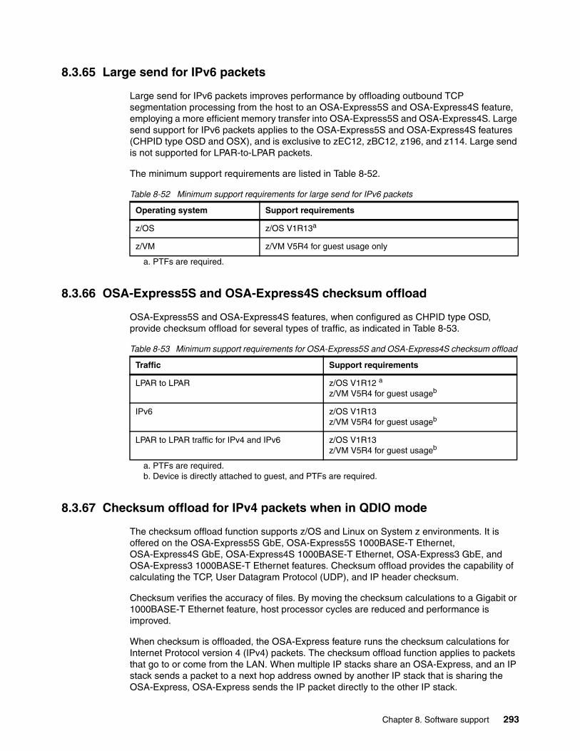
8.3.65 Large send for IPv6 packets
Large send for IPv6 packets improves performance by offloading outbound TCP segmentation processing from the host to an OSA-Express5S and OSA-Express4S feature, employing a more efficient memory transfer into OSA-Express5S and OSA-Express4S. Large send support for IPv6 packets applies to the OSA-Express5S and OSA-Express4S features (CHPID type OSD and OSX), and is exclusive to zEC12, zBC12, z196, and z114. Large send is not supported for LPAR-to-LPAR packets.
The minimum support requirements are listed in Table 8-52.
Table 8-52 Minimum support requirements for large send for IPv6 packets
8.3.66 OSA-Express5S and OSA-Express4S checksum offload
OSA-Express5S and OSA-Express4S features, when configured as CHPID type OSD, provide checksum offload for several types of traffic, as indicated in Table 8-53.
Table 8-53 Minimum support requirements for OSA-Express5S and OSA-Express4S checksum offload
8.3.67 Checksum offload for IPv4 packets when in QDIO mode
The checksum offload function supports z/OS and Linux on System z environments. It is offered on the OSA-Express5S GbE, OSA-Express5S 1000BASE-T Ethernet, OSA-Express4S GbE, OSA-Express4S 1000BASE-T Ethernet, OSA-Express3 GbE, and OSA-Express3 1000BASE-T Ethernet features. Checksum offload provides the capability of calculating the TCP, User Datagram Protocol (UDP), and IP header checksum.
Checksum verifies the accuracy of files. By moving the checksum calculations to a Gigabit or 1000BASE-T Ethernet feature, host processor cycles are reduced and performance is improved.
When checksum is offloaded, the OSA-Express feature runs the checksum calculations for Internet Protocol version 4 (IPv4) packets. The checksum offload function applies to packets that go to or come from the LAN. When multiple IP stacks share an OSA-Express, and an IP stack sends a packet to a next hop address owned by another IP stack that is sharing the OSA-Express, OSA-Express sends the IP packet directly to the other IP stack.
Operating system Support requirements
z/OS z/OS V1R13a
a. PTFs are required.
z/VM z/VM V5R4 for guest usage only
Traffic Support requirements
LPAR to LPAR z/OS V1R12 a
z/VM V5R4 for guest usageb
a. PTFs are required.b. Device is directly attached to guest, and PTFs are required.
IPv6 z/OS V1R13 z/VM V5R4 for guest usageb
LPAR to LPAR traffic for IPv4 and IPv6 z/OS V1R13 z/VM V5R4 for guest usageb
Chapter 8. Software support 293
The packet does not have to be placed out on the LAN. Checksum offload does not apply to such IP packets.
Checksum offload is supported by the GbE features, which include FC 0404, FC 0405, FC 3362, and FC 3363. It is also supported by the 1000BASE-T Ethernet features, including FC 0408 and FC 3367, when it is operating at 1000 Mbps (1 Gbps). Checksum offload is applicable to the QDIO mode only (channel type OSD).
IBM z/OS support for checksum offload is available in all in-service z/OS releases, and in all supported Linux on System z distributions.
8.3.68 Adapter interruptions for QDIO
Linux on System z and z/VM work together to provide performance improvements by using extensions to the QDIO architecture. Adapter interruptions, first added to z/Architecture with HiperSockets, provide an efficient, high-performance technique for I/O interruptions to reduce path lengths and processor usage. These reductions are in both the host OS and the adapter (OSA-Express5S, OSA-Expres4S, and OSA-Express3 when using CHPID type OSD).
In extending the use of adapter interruptions to OSD (QDIO) channels, the processor resources required to handle a traditional I/O interruption are reduced. This benefits OSA-Express TCP/IP support in z/VM, z/VSE, and Linux on System z.
Adapter interruptions apply to all of the OSA-Express5S, OSA-Express4S, and OSA-Express3 features on zBC12 when in QDIO mode (CHPID type OSD).
8.3.69 OSA Dynamic LAN idle
The OSA Dynamic LAN idle parameter change helps reduce latency and improve performance by dynamically adjusting the inbound blocking algorithm. System administrators can authorize the TCP/IP stack to enable a dynamic setting that previously was static.
For latency-sensitive applications, the blocking algorithm is modified to be latency sensitive. For streaming (throughput-sensitive) applications, the blocking algorithm is adjusted to maximize throughput. In all cases, the TCP/IP stack determines the best setting based on the current system and environmental conditions, such as inbound workload volume, processor use, and traffic patterns. It can then dynamically update the settings.
OSA-Express5S, OSA-Express4S, and OSA-Express3 features adapt to the changes, avoiding thrashing and frequent updates to the OAT. Based on the TCP/IP settings, OSA holds the packets before presenting them to the host. A dynamic setting is designed to avoid or minimize host interrupts.
OSA Dynamic LAN idle is supported by the OSA-Express5S, OSA-Express4S, and OSA-Express3 features on zBC12 when in QDIO mode (CHPID type OSD). It is used by z/OS V1R8 and higher, with PTFs.
8.3.70 OSA Layer 3 Virtual MAC for z/OS environments
To help simplify the infrastructure and facilitate load balancing when an LPAR is sharing an OSA MAC address with another LPAR, each OS instance can have its own unique logical or virtual MAC (VMAC) address. All IP addresses associated with a TCP/IP stack are accessible by using their own VMAC address, instead of sharing the MAC address of an OSA port. This also applies to Layer 3 mode, and to an OSA port spanned among CSSs.
294 IBM zEnterprise BC12 Technical Guide
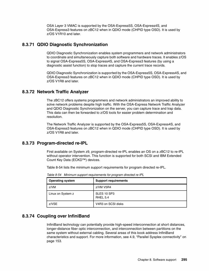
OSA Layer 3 VMAC is supported by the OSA-Express5S, OSA-Express4S, and OSA-Express3 features on zBC12 when in QDIO mode (CHPID type OSD). It is used by z/OS V1R10 and later.
8.3.71 QDIO Diagnostic Synchronization
QDIO Diagnostic Synchronization enables system programmers and network administrators to coordinate and simultaneously capture both software and hardware traces. It enables z/OS to signal OSA-Express5S, OSA-Express4S, and OSA-Express3 features (by using a diagnostic assist function) to stop traces and capture the current trace records.
QDIO Diagnostic Synchronization is supported by the OSA-Express5S, OSA-Express4S, and OSA-Express3 features on zBC12 when in QDIO mode (CHPID type OSD). It is used by z/OS V1R8 and later.
8.3.72 Network Traffic Analyzer
The zBC12 offers systems programmers and network administrators an improved ability to solve network problems despite high traffic. With the OSA-Express Network Traffic Analyzer and QDIO Diagnostic Synchronization on the server, you can capture trace and trap data. This data can then be forwarded to z/OS tools for easier problem determination and resolution.
The Network Traffic Analyzer is supported by the OSA-Express5S, OSA-Express4S, and OSA-Express3 features on zBC12 when in QDIO mode (CHPID type OSD). It is used by z/OS V1R8 and later.
8.3.73 Program-directed re-IPL
First available on System z9, program-directed re-IPL enables an OS on a zBC12 to re-IPL without operator intervention. This function is supported for both SCSI and IBM Extended Count Key Data (ECKD™) devices.
Table 8-54 lists the minimum support requirements for program directed re-IPL.
Table 8-54 Minimum support requirements for program directed re-IPL
8.3.74 Coupling over InfiniBand
InfiniBand technology can potentially provide high-speed interconnection at short distances, longer-distance fiber optic interconnection, and interconnection between partitions on the same system without external cabling. Several areas of this book address InfiniBand characteristics and support. For more information, see 4.9, “Parallel Sysplex connectivity” on page 153.
Operating system Support requirements
z/VM z/VM V5R4
Linux on System z SLES 10 SP3 RHEL 5.4
z/VSE V4R3 on SCSI disks
Chapter 8. Software support 295
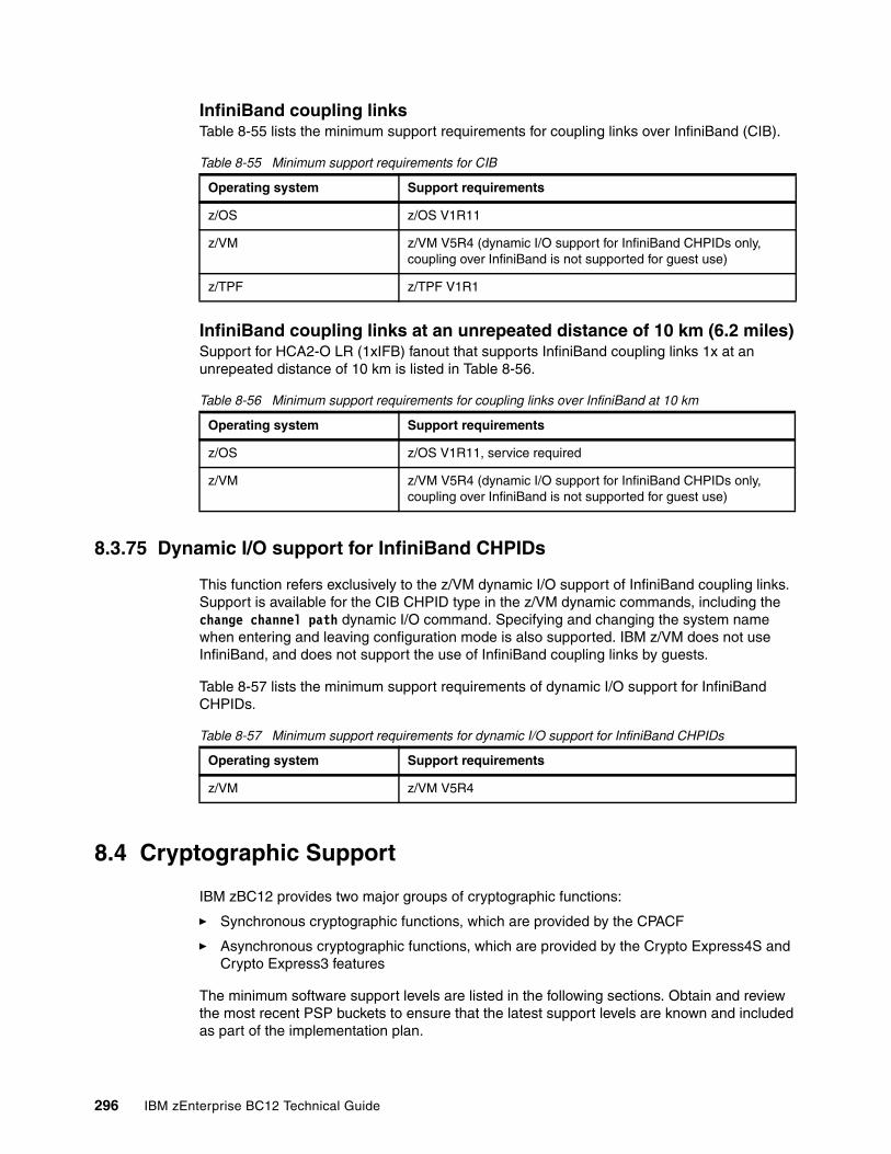
InfiniBand coupling linksTable 8-55 lists the minimum support requirements for coupling links over InfiniBand (CIB).
Table 8-55 Minimum support requirements for CIB
InfiniBand coupling links at an unrepeated distance of 10 km (6.2 miles)Support for HCA2-O LR (1xIFB) fanout that supports InfiniBand coupling links 1x at an unrepeated distance of 10 km is listed in Table 8-56.
Table 8-56 Minimum support requirements for coupling links over InfiniBand at 10 km
8.3.75 Dynamic I/O support for InfiniBand CHPIDs
This function refers exclusively to the z/VM dynamic I/O support of InfiniBand coupling links. Support is available for the CIB CHPID type in the z/VM dynamic commands, including the change channel path dynamic I/O command. Specifying and changing the system name when entering and leaving configuration mode is also supported. IBM z/VM does not use InfiniBand, and does not support the use of InfiniBand coupling links by guests.
Table 8-57 lists the minimum support requirements of dynamic I/O support for InfiniBand CHPIDs.
Table 8-57 Minimum support requirements for dynamic I/O support for InfiniBand CHPIDs
8.4 Cryptographic Support
IBM zBC12 provides two major groups of cryptographic functions:
� Synchronous cryptographic functions, which are provided by the CPACF
� Asynchronous cryptographic functions, which are provided by the Crypto Express4S and Crypto Express3 features
The minimum software support levels are listed in the following sections. Obtain and review the most recent PSP buckets to ensure that the latest support levels are known and included as part of the implementation plan.
Operating system Support requirements
z/OS z/OS V1R11
z/VM z/VM V5R4 (dynamic I/O support for InfiniBand CHPIDs only, coupling over InfiniBand is not supported for guest use)
z/TPF z/TPF V1R1
Operating system Support requirements
z/OS z/OS V1R11, service required
z/VM z/VM V5R4 (dynamic I/O support for InfiniBand CHPIDs only, coupling over InfiniBand is not supported for guest use)
Operating system Support requirements
z/VM z/VM V5R4
296 IBM zEnterprise BC12 Technical Guide
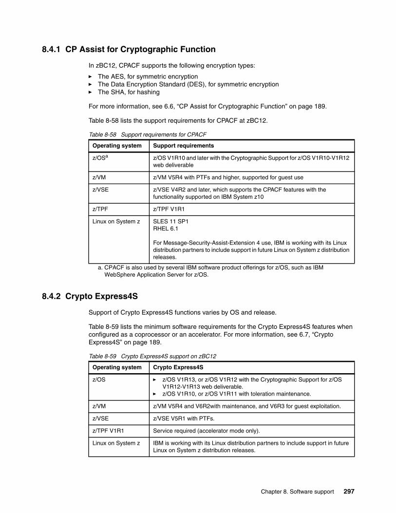
8.4.1 CP Assist for Cryptographic Function
In zBC12, CPACF supports the following encryption types:
� The AES, for symmetric encryption� The Data Encryption Standard (DES), for symmetric encryption� The SHA, for hashing
For more information, see 6.6, “CP Assist for Cryptographic Function” on page 189.
Table 8-58 lists the support requirements for CPACF at zBC12.
Table 8-58 Support requirements for CPACF
8.4.2 Crypto Express4S
Support of Crypto Express4S functions varies by OS and release.
Table 8-59 lists the minimum software requirements for the Crypto Express4S features when configured as a coprocessor or an accelerator. For more information, see 6.7, “Crypto Express4S” on page 189.
Table 8-59 Crypto Express4S support on zBC12
Operating system Support requirements
z/OSa
a. CPACF is also used by several IBM software product offerings for z/OS, such as IBM WebSphere Application Server for z/OS.
z/OS V1R10 and later with the Cryptographic Support for z/OS V1R10-V1R12 web deliverable
z/VM z/VM V5R4 with PTFs and higher, supported for guest use
z/VSE z/VSE V4R2 and later, which supports the CPACF features with the functionality supported on IBM System z10
z/TPF z/TPF V1R1
Linux on System z SLES 11 SP1RHEL 6.1
For Message-Security-Assist-Extension 4 use, IBM is working with its Linux distribution partners to include support in future Linux on System z distribution releases.
Operating system Crypto Express4S
z/OS � z/OS V1R13, or z/OS V1R12 with the Cryptographic Support for z/OS V1R12-V1R13 web deliverable.
� z/OS V1R10, or z/OS V1R11 with toleration maintenance.
z/VM z/VM V5R4 and V6R2with maintenance, and V6R3 for guest exploitation.
z/VSE z/VSE V5R1 with PTFs.
z/TPF V1R1 Service required (accelerator mode only).
Linux on System z IBM is working with its Linux distribution partners to include support in future Linux on System z distribution releases.
Chapter 8. Software support 297
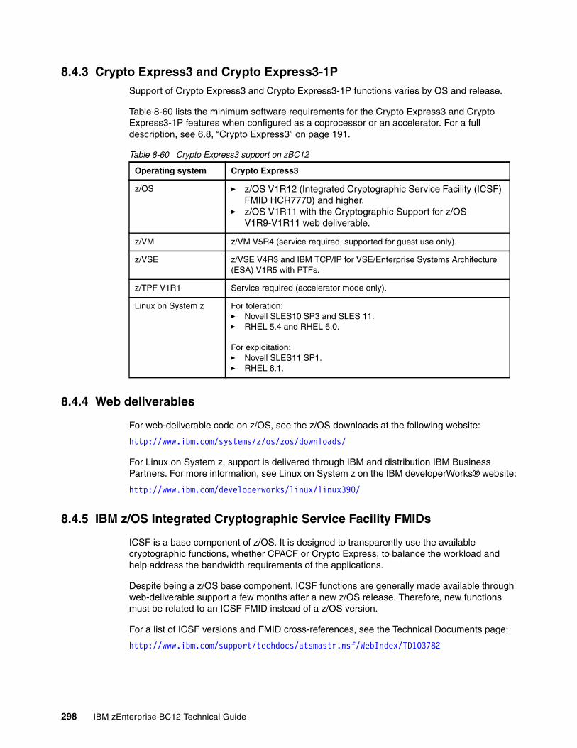
8.4.3 Crypto Express3 and Crypto Express3-1PSupport of Crypto Express3 and Crypto Express3-1P functions varies by OS and release.
Table 8-60 lists the minimum software requirements for the Crypto Express3 and Crypto Express3-1P features when configured as a coprocessor or an accelerator. For a full description, see 6.8, “Crypto Express3” on page 191.
Table 8-60 Crypto Express3 support on zBC12
8.4.4 Web deliverables
For web-deliverable code on z/OS, see the z/OS downloads at the following website:
http://www.ibm.com/systems/z/os/zos/downloads/
For Linux on System z, support is delivered through IBM and distribution IBM Business Partners. For more information, see Linux on System z on the IBM developerWorks® website:
http://www.ibm.com/developerworks/linux/linux390/
8.4.5 IBM z/OS Integrated Cryptographic Service Facility FMIDs
ICSF is a base component of z/OS. It is designed to transparently use the available cryptographic functions, whether CPACF or Crypto Express, to balance the workload and help address the bandwidth requirements of the applications.
Despite being a z/OS base component, ICSF functions are generally made available through web-deliverable support a few months after a new z/OS release. Therefore, new functions must be related to an ICSF FMID instead of a z/OS version.
For a list of ICSF versions and FMID cross-references, see the Technical Documents page:
http://www.ibm.com/support/techdocs/atsmastr.nsf/WebIndex/TD103782
Operating system Crypto Express3
z/OS � z/OS V1R12 (Integrated Cryptographic Service Facility (ICSF) FMID HCR7770) and higher.
� z/OS V1R11 with the Cryptographic Support for z/OS V1R9-V1R11 web deliverable.
z/VM z/VM V5R4 (service required, supported for guest use only).
z/VSE z/VSE V4R3 and IBM TCP/IP for VSE/Enterprise Systems Architecture (ESA) V1R5 with PTFs.
z/TPF V1R1 Service required (accelerator mode only).
Linux on System z For toleration: � Novell SLES10 SP3 and SLES 11. � RHEL 5.4 and RHEL 6.0.
For exploitation: � Novell SLES11 SP1. � RHEL 6.1.
298 IBM zEnterprise BC12 Technical Guide
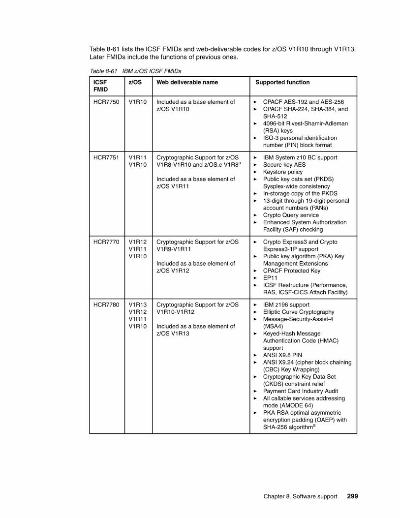
Table 8-61 lists the ICSF FMIDs and web-deliverable codes for z/OS V1R10 through V1R13. Later FMIDs include the functions of previous ones.
Table 8-61 IBM z/OS ICSF FMIDs
ICSF FMID
z/OS Web deliverable name Supported function
HCR7750 V1R10 Included as a base element of z/OS V1R10
� CPACF AES-192 and AES-256� CPACF SHA-224, SHA-384, and
SHA-512� 4096-bit Rivest-Shamir-Adleman
(RSA) keys� ISO-3 personal identification
number (PIN) block format
HCR7751 V1R11V1R10
Cryptographic Support for z/OS V1R8-V1R10 and z/OS.e V1R8a
Included as a base element of z/OS V1R11
� IBM System z10 BC support� Secure key AES� Keystore policy� Public key data set (PKDS)
Sysplex-wide consistency� In-storage copy of the PKDS� 13-digit through 19-digit personal
account numbers (PANs)� Crypto Query service� Enhanced System Authorization
Facility (SAF) checking
HCR7770 V1R12V1R11V1R10
Cryptographic Support for z/OS V1R9-V1R11
Included as a base element of z/OS V1R12
� Crypto Express3 and Crypto Express3-1P support
� Public key algorithm (PKA) Key Management Extensions
� CPACF Protected Key� EP11� ICSF Restructure (Performance,
RAS, ICSF-CICS Attach Facility)
HCR7780 V1R13V1R12V1R11V1R10
Cryptographic Support for z/OS V1R10-V1R12
Included as a base element of z/OS V1R13
� IBM z196 support� Elliptic Curve Cryptography� Message-Security-Assist-4
(MSA4)� Keyed-Hash Message
Authentication Code (HMAC) support
� ANSI X9.8 PIN� ANSI X9.24 (cipher block chaining
(CBC) Key Wrapping)� Cryptographic Key Data Set
(CKDS) constraint relief� Payment Card Industry Audit� All callable services addressing
mode (AMODE 64)� PKA RSA optimal asymmetric
encryption padding (OAEP) with SHA-256 algorithma
Chapter 8. Software support 299
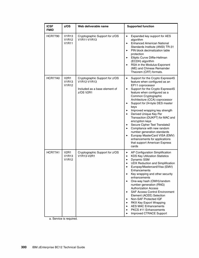
HCR7790 V1R13V1R12V1R11
Cryptographic Support for z/OS V1R11-V1R13
� Expanded key support for AES algorithm
� Enhanced American National Standards Institute (ANSI) TR-31
� PIN block decimalization table protection
� Elliptic Curve Diffie-Hellman (ECDH) algorithm
� RSA in the Modulus-Exponent (ME) and Chinese Remainder Theorem (CRT) formats.
HCR77A0 V2R1V1R13V1R12
Cryptographic Support for z/OS V1R12-V1R13
Included as a base element of z/OS V2R1
� Support for the Crypto Express4S feature when configured as an EP11 coprocessor
� Support for the Crypto Express4S feature when configured as a Common Cryptographic Architecture (CCA) coprocessor
� Support for 24-byte DES master keys
� Improved wrapping key strength� Derived Unique Key Per
Transaction (DUKPT) for MAC and encryption keys
� Secure Cipher Text Translate2� Compliance with new random
number generation standards� Europay MasterCard VISA (EMV)
enhancements for applications that support American Express cards
HCR77A1 V2R1V1R13V1R12
Cryptographic Support for z/OS V1R13-V2R1
� AP Configuration Simplification� KDS Key Utilization Statistics� Dynamic SSM� UDX Reduction and Simplification� Europay/Mastercard/Visa (EMV)
Enhancements� Key wrapping and other security
enhancements� One-way hash (OWH)/random
number generation (RNG) Authorization Access
� SAF Access Control Environment Element (ACEE) Selection
� Non-SAF Protected IQF� RKX Key Export Wrapping� AES MAC Enhancements� PKCS #11 Enhancements� Improved CTRACE Support
a. Service is required.
ICSF FMID
z/OS Web deliverable name Supported function
300 IBM zEnterprise BC12 Technical Guide
8.4.6 ICSF migration considerations
Consider the following points about the Cryptographic Support for z/OS V1R12-V1R13 web deliverable ICSF HCR77A0 code:
� It is not integrated in IBM ServerPac (even for new z/OS V1R13 orders).
� It is only required to use the functions available with zBC12.
� All systems in a sysplex that share a Public Key Data Set (PKDS)/Token Key Data Set (TKDS) must be at HCR77A0 to use the PKDS/TKDS Coordinated Administration support.
� The ICSF toleration PTFs are needed for the following reasons:
– Enable the use of a PKDS with RSA private key tokens encrypted under the Elliptic Curve Cryptography Master Key.
– Support for installation options data sets that use the keyword BEGIN(FMID).
� A new IBM System Modification Program Extended (SMP/E) for z/OS Fix Category is created for ICSF coexistence: IBM.Coexistence.ICSF.z/OS_V1R12-V1R13-HCR77A0.
8.5 IBM z/OS migration considerations
Except for base processor support, z/OS software changes do not require any of the functions introduced with the zBC12. Also, the functions do not require functional software. The approach, where applicable, is to enable z/OS to automatically make a function available based on the presence or absence of the required hardware and software.
8.5.1 General guidelines
IBM zBC12 introduces the latest System z technology. Although support is provided by z/OS starting with z/OS V1R11, use of zBC12 is dependent on the z/OS release. IBM z/OS.e is not supported on zBC12.
In general, consider the following guidelines:
� Do not change software releases and hardware at the same time.
� Keep members of a sysplex at the same software level, except during brief migration periods.
� Migrate to an STP-only or Mixed-Coordinated Timing Network (CTN) network before introducing a zBC12 into a sysplex.
� Review zBC12 restrictions and migration considerations before creating an upgrade plan.
8.5.2 Hardware Configuration Definition
On z/OS V1R11 and later, HCD or Hardware Configuration Management (HCM) help define a configuration for zBC12.
8.5.3 InfiniBand coupling links
Each system can use, or not use, InfiniBand coupling links, independently of how other systems are configured, and do so with other link types. InfiniBand coupling connectivity can be obtained only with other systems that also support InfiniBand coupling. IBM zBC12 does not support InfiniBand connectivity with System z9 and earlier systems.
Chapter 8. Software support 301
8.5.4 Large page support
The large page support function must not be enabled without the respective software support. If large page is not specified, page frames are allocated at the current size of 4 KB.
In z/OS V1R9 and later, the amount of memory to be reserved for large page support is defined by using the LFAREA parameter in the IEASYSxx member of SYS1.PARMLIB:
LFAREA=xx%|xxxxxxM|xxxxxxG
The parameter indicates the amount of storage, in percentage, MB, or GB. The value cannot be changed dynamically.
8.5.5 HiperDispatch
The HIPERDISPATCH=YES/NO parameter in the IEAOPTxx member of SYS1.PARMLIB, and on the SET OPT=xx command, controls whether HiperDispatch is enabled or disabled for a z/OS image. It can be changed dynamically, without an IPL or any outage.
The default is that HiperDispatch is disabled on all releases, from z/OS V1R10 (requires PTFs for zIIP support) through z/OS V1R12.
Beginning with z/OS V1R13, when running on a zEC12, zBC12, z196, or z114 server, the IEAOPTxx keyword HIPERDISPATCH defaults to YES. If HIPERDISPATCH=NO is specified, the specification is accepted as it was on previous z/OS releases.
Additionally, with z/OS V1R12 or later, any LPAR running with more than 64 logical processors is required to operate in HiperDispatch Management Mode.
The following rules control this environment:
� If an LPAR is defined at IPL with more than 64 logical processors, the LPAR automatically operates in HiperDispatch Management Mode, regardless of the HIPERDISPATCH= specification.
� If more logical processors are added to an LPAR that has 64 or fewer logical processors, and the additional logical processors would raise the number of logical processors to more than 64, the LPAR automatically operates in HiperDispatch Management Mode regardless of the HIPERDISPATCH=YES/NO specification. That is, even if the LPAR has the HIPERDISPATCH=NO specification, that LPAR is converted to operate in HiperDispatch Management.
� An LPAR with more than 64 logical processors running in HiperDispatch Management Mode cannot be reverted to run in non-HiperDispatch Management Mode.
To effectively use HiperDispatch, WLM goal adjustment might be required. Review the WLM policies and goals, and update them as necessary. It might be desirable to run with the new policies and HiperDispatch on for a period, turn it off, and use the older WLM policies. Then, compare the results of using HiperDispatch, readjust the new policies, and repeat the cycle, as needed. WLM policies can be changed without turning off HiperDispatch.
A health check is provided to verify whether HiperDispatch is enabled on a system image that is running on zBC12.
302 IBM zEnterprise BC12 Technical Guide
IBM z/VM supportTo address increasing workload demands for processor cycles, and for quicker access to memory, z/VM HiperDispatch can improve workload throughput by optimizing the use of processor cache. IBM z/VM HiperDispatch attempts to redispatch a virtual server repeatedly on the same physical CPU, or on topologically adjacent CPUs.
When a virtual server can be redispatched on the same CPU, or on an adjacent one, it increases the chances of obtaining data from the processor cache, and avoids time delays incurred by having to access main memory.
Strengthening the affinity between dispatched work and logical and physical processors increases the probability of cache hits, which improves performance. The importance and value of this capability to customers grow as processor configurations become large. IBM z/VM HiperDispatch is expected to deliver a CPU performance boost depending on a workload's characteristics. Memory-intensive workloads running on large numbers (16 to 32) of physical processors are most likely to achieve the highest performance gains.
8.5.6 Capacity Provisioning Manager
Installation of the capacity provisioning function on z/OS requires these prerequisites:
� Setting up and customizing z/OS Resource Measurement Facility (RMF), including the Distributed Data Server (DDS)
� Setting up the z/OS CIM Server (included in z/OS base)
� Performing capacity provisioning customization as described in z/OS z/OS MVS Capacity Provisioning User’s Guide, SA33-8299
Using the capacity provisioning function requires these prerequisites:
� TCP/IP connectivity to observed systems.� RMF DDS must be active.� CIM server must be active.� Security and CIM customization.� Capacity Provisioning Manager customization.
In addition, the Capacity Provisioning Control Center must be downloaded from the host and installed on a PC server. This application is only used to define policies. It is not required for regular operation.
Customization of the capacity provisioning function is required on the following systems:
� Observed z/OS systems. These are the systems in one or multiple Parallel Sysplexes that are to be monitored. For more information about the capacity provisioning domain, see 9.8, “Nondisruptive upgrades” on page 356.
� Runtime systems. These are the systems where the Capacity Provisioning Manager is running, or to which the server can fail over after server or system failures.
8.5.7 Decimal floating point and z/OS XL C/C++ considerations
IBM z/OS V1R13 or higher with PTFs is required to use the latest level (10) of the following two C/C++ compiler options:
ARCHITECTURE This option selects the minimum level of system architecture on which the program can run. Note that certain features provided by the compiler require a minimum architecture level. ARCH(10) uses instructions available on the zBC12.
Chapter 8. Software support 303
TUNE This option enables optimization of the application for a specific system architecture, within the constraints that are imposed by the ARCHITECTURE option. The TUNE level must not be lower than the setting in the ARCHITECTURE option.
For more information about the ARCHITECTURE and TUNE compiler options, see the z/OS V1R9.0 XL C/C++ User’s Guide, SC09-4767.
8.5.8 IBM System z Advanced Workload Analysis Reporter
IBM zAware is designed to offer a real-time, continuous learning, diagnostic, and monitoring capability. This capability is intended to help you pinpoint and resolve potential problems quickly enough to minimize any effect on your business. IBM zAware runs analytics in firmware, and intelligently examines the message logs for potential deviations, inconsistencies, or variations from the norm.
Many z/OS environments produce such a large volume of OPERLOG messages that it is difficult for operations personnel to analyze them easily. IBM zAware provides a simple GUI that you can use to easily drill down and identify message anomalies, which can facilitate faster problem resolution.
IBM zAware is ordered through specific features of zBC12, and requires z/OS V1R13 or later with IBM zAware exploitation support to collect specific log stream data. It requires a properly configured LPAR. For more information, see “The zAware-mode logical partition (LPAR)” on page 261.
To use the IBM zAware feature, complete the following tasks in z/OS:
� For each z/OS that is to be monitored through the IBM zAware customer, configure a network connection in the TCP/IP profile. If necessary, update firewall settings.
� Verify that each z/OS system meets the sysplex configuration and OPERLOG requirements for monitored customers of the IBM zAware virtual appliance.
� Configure the z/OS system logger to send data to the IBM zAware virtual appliance server.
� Prime the IBM zAware server with prior data from monitored customers.
8.6 Coupling facility and CFCC considerations
Coupling facility (CF) connectivity to a zBC12 is supported on the zEC12, zBC12, z196, z114, and z10. The LPAR running the CFCC can be on any of the previously listed supported
Attention: Use the previous System z ARCHITECTURE or TUNE options for C/C++ programs if the same applications run on both the zBC12 and on previous System z servers. However, if C/C++ applications will run only on zBC12 servers, use the latest ARCHITECTURE and TUNE options to ensure the best performance possible is delivered through the latest instruction set additions.
304 IBM zEnterprise BC12 Technical Guide
systems. See Table 8-62 on page 305 for more information about CFCC requirements for supported systems.
CFCC Level 18The initial support for CFCC on z114, the zBC12 predecessor, was Level 17. Therefore we include an overview of the enhancements offered by CFCC Level 18, which are included in CFCC Level 19:
� Coupling channel reporting enhancements:
– Enables RMF to differentiate various InfiniBand link types, and detect if the CIB link is running in a degraded state.
� Serviceability enhancements:
– Additional structure control information in CF dumps– Enhanced CFCC tracing support– Enhanced triggers for CF nondisruptive dumping
� Performance enhancements:
– Dynamic structure size alter improvement – DB2 global buffer pool (GBP) cache bypass– Cache structure management
CFCC Level 19CFCC level 19 is delivered on the zBC12 with driver level 15. CFCC Level 19 introduces the following enhancements:
� Performance improvements. Introduces Coupling Thin Interrupts:
– Improves the performance in share CF engines environments– Improves the response time of asynchronous CF requests
� Resiliency enhancements. Provides Flash Express support and cost-effective standby capacity to help manage the potential overflow of WebSphere MQ shared queues.
IBM zBC12 systems with CFCC level 19 require z/OS V1R12 or later, and z/VM V5R4 or later for guest virtual coupling.
To support upgrade from one CFCC level to the next, different levels of CFCC can be run concurrently while the CF LPARs are running on different servers. CF LPARs that run on the same server share the CFCC level. The latest CFCC level for zBC12 servers is CFCC level 19, as shown in Table 8-62.
Table 8-62 System z CFCC code level considerations
Consideration: Because coupling link connectivity to System z9 and previous systems is not supported, introduction of zBC12 into existing installations requires additional planning. Also, consider the level of CFCC. For more information, see “Coupling links and STP” on page 158.
Attention: Having more than 1024 structures requires a new version of the coupling facility resource management (CFRM) couple data set (CDS). In addition, all systems in the sysplex must be at z/OS V1R12 (or later), or have the coexistence and preconditioning PTFs installed. Falling back to a previous level without the coexistence PTF installed is not supported at sysplex IPL.
zEC12 CFCC Level 18 or CFCC Level 19
Chapter 8. Software support 305
For more information about CFCC code levels, see the Parallel Sysplex website:
http://www.ibm.com/systems/z/pso/cftable.html
CF structure sizing changes are expected when upgrading from CFCC Level 17 (or earlier) to CFCC Level 18 or CFCC Level 19, and when upgrading from CFCC Level 18 to CFCC Level 19. Review the CF LPAR size by using the CFSizer tool, available at the following website:
http://www.ibm.com/systems/z/cfsizer
Before migration, installation of compatibility and coexistence PTFs is highly desirable. A planned outage is required when you upgrade the CF or CF LPAR to CFCC Level 18 or to CFCC Level 19.
Flash Express usage by CFCC CFCC Level 19 supports Flash Express. Initial CF Flash exploitation is targeted for WebSphere MQ shared queues application structures.It is designed to help improve resilience while providing cost-effective standby capacity to help manage the potential overflow of WebSphere MQ shared queues. Structures can now be allocated with a combination of real memory and SCM provided by the Flash Express feature.
Flash memory in the CPC is assigned to a CF partition via hardware definition panels, the same way that it is assigned to the z/OS partitions. CFRM policy definition enables the desired maximum amount of flash memory to be used by a particular structure, on a structure-by-structure basis. Flash memory is not pre-assigned to structures at allocation time.
Structure size requirements for real memory get somewhat larger at initial allocation time to accommodate additional control objects needed to make use of flash memory.
CFSizer's structure recommendations will take these additional requirements into account, both for sizing the structure’s Flash usage itself, and for the related real memory considerations.
Current CFCC Flash Express usage requirements are as follows:
� CFCC Level 19 support� IBM z/OS Support for z/OS V1R13 with PTFs and z/OS V2R1 with PTFs� No new level of WebSphere MQ required
8.7 MIDAW facility
The MIDAW facility is a system architecture and software exploitation that is designed to improve FICON performance. This facility was first made available on System z9 servers, and is used by the media manager in z/OS.
zBC12 CFCC Level 19
z196 and z114 CFCC Level 17
z10 EC or z10 BC CFCC Level 15 or CFCC Level 16
z9 EC or IBM System z9 Business Class (z9 BC) CFCC Level 14 or later
IBM eServer zSeries 990 (z990) or IBM eServer zSeries 890 (z890)
CFCC Level 13 or later
306 IBM zEnterprise BC12 Technical Guide
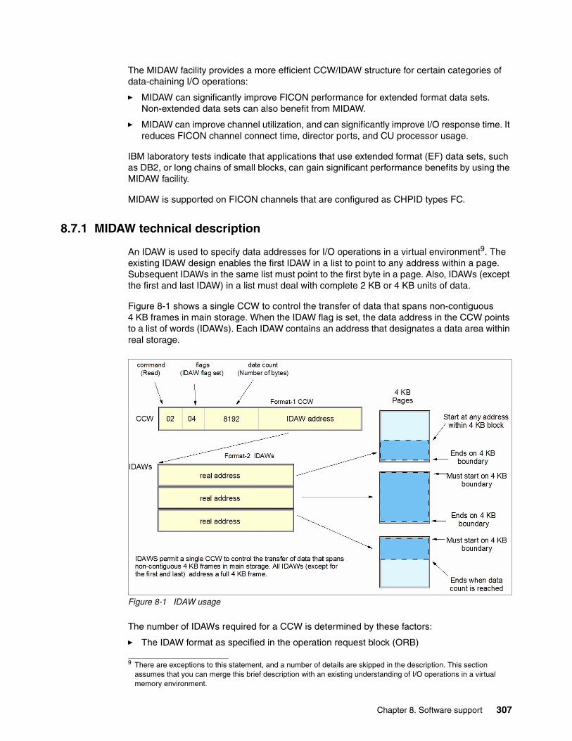
The MIDAW facility provides a more efficient CCW/IDAW structure for certain categories of data-chaining I/O operations:
� MIDAW can significantly improve FICON performance for extended format data sets. Non-extended data sets can also benefit from MIDAW.
� MIDAW can improve channel utilization, and can significantly improve I/O response time. It reduces FICON channel connect time, director ports, and CU processor usage.
IBM laboratory tests indicate that applications that use extended format (EF) data sets, such as DB2, or long chains of small blocks, can gain significant performance benefits by using the MIDAW facility.
MIDAW is supported on FICON channels that are configured as CHPID types FC.
8.7.1 MIDAW technical description
An IDAW is used to specify data addresses for I/O operations in a virtual environment9. The existing IDAW design enables the first IDAW in a list to point to any address within a page. Subsequent IDAWs in the same list must point to the first byte in a page. Also, IDAWs (except the first and last IDAW) in a list must deal with complete 2 KB or 4 KB units of data.
Figure 8-1 shows a single CCW to control the transfer of data that spans non-contiguous 4 KB frames in main storage. When the IDAW flag is set, the data address in the CCW points to a list of words (IDAWs). Each IDAW contains an address that designates a data area within real storage.
Figure 8-1 IDAW usage
The number of IDAWs required for a CCW is determined by these factors:
� The IDAW format as specified in the operation request block (ORB)
9 There are exceptions to this statement, and a number of details are skipped in the description. This section assumes that you can merge this brief description with an existing understanding of I/O operations in a virtual memory environment.
Chapter 8. Software support 307
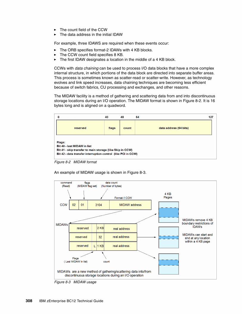
� The count field of the CCW� The data address in the initial IDAW
For example, three IDAWS are required when these events occur:
� The ORB specifies format-2 IDAWs with 4 KB blocks. � The CCW count field specifies 8 KB. � The first IDAW designates a location in the middle of a 4 KB block.
CCWs with data chaining can be used to process I/O data blocks that have a more complex internal structure, in which portions of the data block are directed into separate buffer areas. This process is sometimes known as scatter-read or scatter-write. However, as technology evolves and link speed increases, data chaining techniques are becoming less efficient because of switch fabrics, CU processing and exchanges, and other reasons.
The MIDAW facility is a method of gathering and scattering data from and into discontinuous storage locations during an I/O operation. The MIDAW format is shown in Figure 8-2. It is 16 bytes long and is aligned on a quadword.
Figure 8-2 MIDAW format
An example of MIDAW usage is shown in Figure 8-3.
Figure 8-3 MIDAW usage
308 IBM zEnterprise BC12 Technical Guide
The use of MIDAWs is indicated by the MIDAW bit in the CCW. If this bit is set, the skip flag cannot be set in the CCW. The skip flag in the MIDAW can be used instead. The data count in the CCW should equal the sum of the data counts in the MIDAWs. The CCW operation ends when the CCW count goes to zero or the last MIDAW (with the last flag) ends.
The combination of the address and count in a MIDAW cannot cross a page boundary. Therefore, the largest possible count is 4 KB. The maximum data count of all the MIDAWs in a list cannot exceed 64 KB, which is the maximum count of the associated CCW.
The scatter-read or scatter-write effect of the MIDAWs makes it possible to efficiently send small control blocks that are embedded in a disk record to separate buffers from those used for larger data areas within the record. MIDAW operations are on a single I/O block, in the manner of data chaining. Do not confuse this operation with CCW command chaining.
8.7.2 Extended format data sets
IBM z/OS EF data sets use internal structures (usually not visible to the application program) that require scatter-read (or scatter-write) operations. Therefore, CCW data chaining is required, which produces less than optimal I/O performance. Because the most significant performance benefit of MIDAWs is achieved with EF data sets, a brief review of the EF data sets is included here.
Both VSAM and non-VSAM (data set organization=physical sequential (DSORG=PS)) sets can be defined as EF data sets. For non-VSAM data sets, a 32-byte suffix is appended to the end of every physical record (that is, block) on disk. VSAM appends the suffix to the end of every control interval (CI), which normally corresponds to a physical record. A 32 KB CI is split into two records to be able to span tracks.
This suffix is used to improve data reliability, and facilitates other functions that are described in the following paragraphs. Therefore, for example, if the data control block block size (DCB BLKSIZE) or VSAM CI size is equal to 8192, the actual block on storage consists of 8224 bytes. The CU itself does not distinguish between suffixes and user data. The suffix is transparent to the access method and database.
In addition to reliability, EF data sets enable three other functions:
� Data Facility Storage Management Subsystem (DFSMS) striping� Access method compression� Extended addressability (EA)
EA is especially useful for creating large DB2 partitions (larger than 4 GB). Striping can be used to increase sequential throughput, or to spread random I/Os across multiple logical volumes. DFSMS striping is especially useful for using multiple channels in parallel for one data set. The DB2 logs are often striped to optimize the performance of DB2 sequential inserts.
Processing an I/O operation to an EF data set normally requires at least two CCWs with data chaining. One CCW would be used for the 32-byte suffix of the EF data set. With MIDAW, the additional CCW for the EF data set suffix is eliminated.
MIDAWs benefit both EF and non-EF data sets. For example, to read twelve 4 KB records from a non-EF data set on a 3390 track, Media Manager chains 12 CCWs together by using data chaining. To read twelve 4 KB records from an EF data set, 24 CCWs would be chained (two CCWs per 4 KB record). Using Media Manager track-level command operations and MIDAWs, an entire track can be transferred by using a single CCW.
Chapter 8. Software support 309
8.7.3 Performance benefits
IBM z/OS Media Manager has I/O channel programs support for implementing EF data sets, and automatically uses MIDAWs when appropriate. Most disk I/Os in the system are generated by using Media Manager.
Users of the Execute Channel Program in Real Storage (EXCPVR) instruction can construct channel programs that contain MIDAWs. However, doing so requires that they construct an input/output block common extension (IOBE) with the IOBE Modified Indirect Data Addressing (IOBEMIDA) bit set. Users of the Execute Channel Program (EXCP) instruction cannot construct channel programs that contain MIDAWs.
The MIDAW facility removes the 4 KB boundary restrictions of IDAWs and, in the case of EF data sets, reduces the number of CCWs. Decreasing the number of CCWs helps to reduce the FICON channel processor usage. Media Manager and MIDAWs do not cause the bits to move any faster across the FICON link. However, they do reduce the number of frames and sequences that flow across the link, therefore using the channel resources more efficiently.
The MIDAW facility with FICON Express8S, operating at 8 Gbps, showed an improvement in throughput for all reads on DB2 table scan tests with EF data sets, compared to use of IDAWs with FICON Express2, operating at 2 Gbps.
The performance of a specific workload can vary according to the conditions and hardware configuration of the environment. IBM laboratory tests found that DB2 gains significant performance benefits by using the MIDAW facility in the following areas:
� Table scans� Logging� Utilities� Using DFSMS striping for DB2 data sets
Media Manager with the MIDAW facility can provide significant performance benefits when used in combination applications that use EF data sets (such as DB2) or long chains of small blocks.
For more information about FICON and MIDAW, see the following resources:
� The I/O Connectivity website contains material about FICON channel performance:
http://www.ibm.com/systems/z/connectivity/
� DS8000 Performance Monitoring and Tuning, SG24-7146.
8.8 Input/output configuration program
All System z servers require a description of their I/O configuration. This description is stored in input/output configuration data set (IOCDS) files. The input/output configuration program (IOCP) enables creation of the IOCDS file from a source file that is known as the input/output configuration source (IOCS).
The IOCS file contains detailed information for each channel and path assignment, each CU, and each device in the configuration. The required level of IOCP for the zBC12 is V4 R1 L0 (IOCP 4.1.0) or later with PTFs. For more information, see the IOCP User’s Guide, SB10-7037.
310 IBM zEnterprise BC12 Technical Guide
8.9 Worldwide port name tool
Part of the installation of your zBC12 system is the pre-planning of the SAN environment. IBM has a stand-alone tool to assist with this planning before the installation. The capability of the worldwide port name (WWPN) tool was extended to calculate and show WWPNs for both virtual and physical ports ahead of system installation.
The tool assigns WWPNs to each virtual FCP channel/port using the same WWPN assignment algorithms that a system uses when assigning WWPNs for channels using NPIV. Therefore, the SAN can be set up in advance, enabling operations to proceed much faster after the server is installed. In addition, the SAN configuration can be retained instead of altered by assigning the WWPN to physical FCP ports when a FICON feature is replaced.
The WWPN tool takes a .csv file that contains the FCP-specific I/O device definitions, and creates the WWPN assignments that are required to set up the SAN. A binary configuration file that can be imported later by the system is also created. The .csv file can either be created manually, or exported from the HCD and HCM.
The WWPN tool on zBC12 (CHPID type FCP) requires the following levels:
� IBM z/OS V1R11 with PTFs, or V1R12 and later� IBM z/VM V5R4 with PTFs, or V6R2 and later
The WWPN tool is applicable to all FICON channels defined as CHPID type FCP (for communication with SCSI devices) on zBC12. It is available for download from the Resource Link website:
http://www.ibm.com/servers/resourcelink/
8.10 Device Support Facilities
Device Support Facilities (ICKDSF) Release 17 is required on all systems that share disk subsystems with a zBC12 processor.
ICKDSF supports a modified format of the CPU information field that contains a two-digit LPAR identifier. ICKDSF uses the CPU information field instead of CCW reserve/release for concurrent media maintenance. It prevents multiple systems from running ICKDSF on the same volume, and at the same time enables user applications to run while ICKDSF is processing.
To prevent data corruption, ICKDSF must be able to determine all sharing systems that can potentially run ICKDSF. Therefore, this support is required for zBC12.
8.11 IBM zBX Model 003 software support
IBM zBX Model 003 houses two types of blades: General-purpose and solution-specific.
Remember: The need for ICKDSF Release 17 applies even to systems that are not part of the same sysplex, or are running an OS other than z/OS, such as z/VM.
Chapter 8. Software support 311
8.11.1 IBM Blades
IBM offers a selected subset of IBM POWER7 blades that can be installed and operated on the zBX Model 003. These blades have been thoroughly tested to ensure compatibility and manageability in the IBM zEnterprise BC12environment.
The blades are virtualized by PowerVM Enterprise Edition. Their LPARs run either AIX Version 5 Release 3 TL12 (IBM POWER6® mode), AIX Version 6 Release 1 TL5 (POWER7 mode), or AIX Version 7 Release 1 and subsequent releases. Applications that are supported on AIX can be deployed to blades.
Also offered are selected IBM System x HX5 blades. Virtualization is provided by an integrated hypervisor by using Kernel-based virtual machines, and supporting Linux on System x and Microsoft Windows OSs.
Table 8-63 lists the OSs that are supported by HX5 blades.
Table 8-63 Operating support for zBX Model 003 HX5 Blades
8.11.2 IBM WebSphere DataPower Integration Appliance XI50 for zEnterprise
The IBM WebSphere DataPower Integration Appliance XI50 for zEnterprise (DataPower XI50z) is a special-purpose, double-wide blade.
The DataPower XI50z is a multifunctional appliance that can help provide these features:
� Provide multiple levels of XML optimization.
� Streamline and secure valuable service-oriented architecture (SOA) applications.
� Provide drop-in integration for heterogeneous environments by enabling core enterprise service bus (ESB) functions, including routing, bridging, transformation, and event handling.
� Simplify, govern, and enhance the network security for XML and web services.
Table 8-64 lists the minimum support requirements for DataPower Sysplex Distributor support.
Table 8-64 Minimum support requirements for DataPower Sysplex Distributor support
Operating system Support requirements
Linux on System x RHEL 5.5 and later, 6.0 and later SLES 10 (SP4) and later, SLES 11 (SP1)a and later
a. Latest patch level required
Microsoft Windows Microsoft Windows Server 2008 R2b
Microsoft Windows Server 2008 (SP2)b (Datacenter Edition preferred)Microsoft Windows Server 2012b(Datacenter Edition preferred)
b. 64 bit only
Operating system Support requirements
z/OS z/OS V1R11 for IPv4z/OS V1R12 for IPv4 and IPv6
312 IBM zEnterprise BC12 Technical Guide
8.12 Software licensing considerations
The IBM software portfolio for the zBC12 includes OS software10 (that is, z/OS, z/VM, z/VSE, and z/TPF) and middleware that runs on these OSs. It also includes middleware for Linux on System z environments.
IBM zBX software products are covered by International Program License Agreement (IPLA) and other agreements, such as the IBM International Passport Advantage® Agreement, similar to other AIX, Linux on System x, and Windows environments. PowerVM Enterprise Edition licenses must be ordered for POWER7 blades.
For the zBC12, two metric groups for software licensing are available from IBM, depending on the software product:
� Monthly license charge (MLC) � IPLA
MLC pricing metrics have a recurring charge that applies each month. In addition to the right to use the product, the charge includes access to IBM product support during the support period. MLC metrics, in turn, include various offerings.
IPLA metrics have a single, up-front charge for an entitlement to use the product. An optional and separate annual charge that is called subscription and support entitles you to access IBM product support during the support period. You also receive future releases and versions at no additional charge.
For more information, see the following references:
� The “Learn about Software licensing” web page, which has pointers to many documents:
http://www-01.ibm.com/software/lotus/passportadvantage/about_software_licensing.html
� The “Base license agreements” web page provides several documents:
http://www-03.ibm.com/software/sla/sladb.nsf/viewbla
� The IBM System z Software Pricing Reference Guide:
http://www.ibm.com/systems/z/resources/swprice/reference/index.html
� IBM System z Software Pricing webpages:
http://www.ibm.com/systems/z/resources/swprice/mlc/index.html
� The IBM International Passport Advantage Agreement can be downloaded from the “Learn about Software licensing” web page:
ftp://ftp.software.ibm.com/software/passportadvantage/PA_Agreements/PA_Agreement_International_English.pdf
The remainder of this section describes the software licensing options available on the zBC12.
8.12.1 MLC pricing metrics
MLC pricing applies to z/OS, z/VSE, and z/TPF OSs. Any mix of z/OS, z/VM, Linux, z/VSE, and z/TPF images is supported. Charges are based on processor capacity, which is measured in millions of service units (MSU) per hour.
10 Linux on System z distributions are not IBM products.
Chapter 8. Software support 313
Charge modelsThere are various workload license charges (WLC) pricing structures that support two charge models:
� Variable charges (several pricing metrics):
Variable charges apply to products such as z/OS, z/VSE, z/TPF, DB2, IMS, CICS, IBM MQSeries®, and IBM Domino®. There are several pricing metrics that employ the following charge types:
– Full-capacity. The CPC’s total number of MSUs is used for charging. Full-capacity is applicable when your CPC is not eligible for sub-capacity.
– Sub-capacity. Software charges are based on the usage of the LPARs where the product is running.
� Flat charges. Software products that are licensed under flat charges are not eligible for sub-capacity pricing. There is a single charge per CPC on the zBC12.
Sub-capacityFor eligible programs, sub-capacity supports software charges that are based on use of LPARs instead of the CPC’s total number of MSUs. Sub-capacity removes the dependency between software charges and CPC (hardware) installed capacity.
The sub-capacity licensed products are charged monthly, based on the highest observed four-hour rolling average usage of the LPARs in which the product runs. The exception is products that are licensed using the select application license charges (SALC) pricing metric. This pricing requires measuring the usage and reporting it to IBM.
The LPAR’s four-hour rolling average usage can be limited by a defined capacity value on the partition’s image profile. This value activates the soft capping function of PR/SM, limiting the four-hour rolling average partition usage to the defined capacity value. Soft capping controls the maximum four-hour rolling average usage (the last four-hour average value at every 5-minute interval). However, it does not control the maximum instantaneous partition use.
Also available is an LPAR group capacity limit, which sets soft capping by PR/SM for a group of LPARs running z/OS.
Even when using the soft capping option, the partition use can reach its maximum share based on the number of logical processors and weights in the image profile. Only the four-hour rolling average usage is tracked, enabling usage peaks above the defined capacity value.
Some pricing metrics apply to stand-alone System z servers. Others apply to the aggregation of multiple zBC12 and System z servers’ workloads within the same Parallel Sysplex.
For more information about WLC and how to combine LPAR usage, see z/OS Planning for Workload License Charges, SA22-7506:
http://www-03.ibm.com/systems/z/os/zos/bkserv/find_books.html
The following metrics apply to a stand-alone zBC12:
� Advanced entry workload license charges (AEWLC)� System z new application license charges (zNALC)� Parallel Sysplex license charges (PSLC)
314 IBM zEnterprise BC12 Technical Guide
The following metrics apply to an IBM zEnterprise BC12 on an actively coupled Parallel Sysplex:
� Advanced workload license charges (AWLC), when all CPCs are zEC12, zBC12, z196, or z114. Variable workload license charges (VWLC) are only supported under the AWLC Transition Charges for Sysplexes when not all CPCs are zEC12, zBC12, z196, or z114.
� IBM zNALC.
� PSLC.
8.12.2 Advanced workload license charges
AWLCs were introduced with the z196. They use the measuring and reporting mechanisms, and the existing MSU tiers, from VWLC.
Prices for tiers 4, 5, and 6 are different, with lower costs for charges above 875 MSUs. AWLC offers improved price performance as compared to VWLC for all customers above 3 MSUs.
Similar to WLC, AWLC can be implemented in full-capacity or sub-capacity mode. AWLC applies to z/OS and z/TPF, and their associated middleware products, such as DB2, IMS, CICS, WebSphere MQ, and IBM Domino, when running on a zBC12.
For more information, see the AWLC web page:
http://www-03.ibm.com/systems/z/resources/swprice/mlc/awlc.html
8.12.3 Advanced entry workload license charges
AEWLC were introduced with the z196. They use the measuring and reporting mechanisms, and the existing MSU tiers, from the entry workload license charges (EWLC) pricing metric and the midrange workload license charges (MWLC) pricing metric.
As compared to EWLC and MWLC, the software price performance has been extended. AEWLC also offers improved price performance as compared to PSLC.
Similarly to WLC, AEWLC can be implemented in full-capacity or sub-capacity mode. AEWLC applies to z/OS and z/TPF and their associated middleware products, such as DB2, IMS, CICS, WebSphere MQ, and IBM Lotus® Domino, when running on a z114.
For additional information, see the AEWLC web page:
http://www-03.ibm.com/systems/z/resources/swprice/mlc/aewlc.html
8.12.4 System z new application license charges
IBM zNALC offers a reduced price for the z/OS OS on LPARs that run a qualified new workload application, such as Java language business applications. These applications must run under WebSphere Application Server for z/OS, Domino, SAP, PeopleSoft, or Siebel.
IBM z/OS with zNALC provides a strategic pricing model available on the full range of System z servers for simplified application planning and deployment. IBM zNALC supports aggregation across a qualified Parallel Sysplex, which can provide a lower cost for incremental growth across new workloads that span a Parallel Sysplex.
For more information, see the zNALC web page:
http://www-03.ibm.com/systems/z/resources/swprice/mlc/znalc.html
Chapter 8. Software support 315
8.12.5 Select application license charges
SALC applies only to WebSphere MQ for System z. It allows a WLC customer to license WebSphere MQ under product use rather than the sub-capacity pricing provided under WLC.
WebSphere MQ is typically a low-usage product that runs pervasively throughout the environment. Customers who run WebSphere MQ at a low usage can benefit from SALC. Alternatively, you can still choose to license WebSphere MQ under the same metric as the z/OS software stack.
A reporting function, which IBM provides in the operating system IBM Software Usage Report program, is used to calculate the daily MSU number. The rules to determine the billable SALC MSUs for WebSphere MQ use the following algorithm:
1. Determines the highest daily usage of a program family, which is the highest of 24 hourly measurements recorded each day. Program refers to all active versions of WebSphere MQ
2. Determines the monthly usage of a program family, which is the fourth highest daily measurement that is recorded for a month
3. Uses the highest monthly usage that is determined for the next billing period
For more information about SALC, see the Other MLC Metrics web page:
http://www.ibm.com/systems/z/resources/swprice/mlc/other.html
8.12.6 Midrange workload license charges
MWLC applies to z/VSE V4 and later when running on zEC12, z196, and System z10 and z9 servers. The exceptions are:
� IBM z10 BC and z9 BC servers at capacity setting A01, to which zSeries entry license charges (zELC) applies
� IBM zBC12 where MWLC are not available
Similar to WLC, MWLC can be implemented in full-capacity or sub-capacity mode. MWLC applies to z/VSE V4 and later, and several IBM middleware products for z/VSE. All other z/VSE programs continue to be priced as before.
The z/VSE pricing metric is independent of the pricing metric for other systems (for instance, z/OS) that might be running on the same server. When z/VSE is running as a guest of z/VM, z/VM V5R4 or later is required.
To report usage, the sub-capacity reporting tool (SCRT) is used. One SCRT report per server is required.
For more information, see the MWLC web page:
http://www.ibm.com/systems/z/resources/swprice/mlc/mwlc.html
316 IBM zEnterprise BC12 Technical Guide
8.12.7 Parallel Sysplex license charges
PSLC applies to a large range of mainframe servers. The list can be obtained at the following website:
http://www-03.ibm.com/systems/z/resources/swprice/reference/exhibits/hardware.html
Although it can be applied to stand-alone CPCs, the metric only provides aggregation benefits when applied to group of CPCs in an actively coupled Parallel Sysplex cluster according to IBM terms and conditions.
Aggregation allows charging a product based on the total MSU value of the systems where the product runs. This is as opposed to all of the systems in the cluster. In an uncoupled environment, software charges are based on the MSU capacity of the system.
For more information, see the PSLC web page:
http://www.ibm.com/systems/z/resources/swprice/mlc/pslc.html
8.12.8 System z International Program License Agreement
For zBC12 and System z systems, the following types of products are generally in the IPLA category:
� Data management tools� DB2 for z/OS Value Unit Edition (VUE)� CICS TS VUE V5 and CICS Tools� IMS Database VUE V12 and IMS Tools� Application development tools� Certain WebSphere for z/OS products� Linux middleware products� IBM z/VM Versions V5 and V6
Generally, the following pricing metrics apply to IPLA products for zBC12 and System z:
� Value unit (VU). VU pricing, which applies to the IPLA products that run on z/OS. VU pricing is typically based on the number of MSUs, and provides a lower cost of incremental growth. Examples of eligible products are IMS Tools, CICS Tools, DB2 tools, application development tools, and WebSphere products for z/OS.
� Engine-based value unit (EBVU). EBVU pricing enables a lower cost of incremental growth with more engine-based licenses purchased. Examples of eligible products include z/VM V5 and V6, and certain z/VM middleware. They are priced based on the number of engines.
� Processor value units (PVU). In this metric, the number of engines is converted into PVU under the Passport Advantage terms and conditions. Most Linux middleware is also priced based on the number of engines.
For more information, see the System z IPLA web page:
http://www.ibm.com/systems/z/resources/swprice/zipla/index.html
Chapter 8. Software support 317
8.13 References
For the most current planning information, see the support website for each of the following OSs:
� z/OS:
http://www.ibm.com/systems/support/z/zos/
� z/VM:
http://www.ibm.com/systems/support/z/zvm/
� z/VSE:
http://www.ibm.com/servers/eserver/zseries/zvse/support/preventive.html
� z/TPF:
http://www.ibm.com/software/htp/tpf/pages/maint.htm
� Linux on System z:
http://www.ibm.com/systems/z/os/linux/
318 IBM zEnterprise BC12 Technical Guide
Chapter 9. System upgrades
This chapter provides an overview of IBM zEnterprise BC12 System (zBC12) upgrade capabilities and procedures, with an emphasis on capacity on demand (CoD) offerings.
The upgrade offerings to the zBC12 central processor complex (CPC) have been developed from previous IBM System z servers. In response to customer demands and changes in market requirements, a number of features have been added. The changes and additions are designed to provide increased customer control over the capacity upgrade offerings with decreased administrative work and with enhanced flexibility. The provisioning environment gives the customer an unprecedented flexibility, and a finer control over cost and value.
For detailed tutorials on all aspects of system upgrades, go to IBM Resource Link and select Customer Initiated Upgrade Information → Education. A list of available servers will help you select your particular product:
https://www-304.ibm.com/servers/resourcelink/hom03010.nsf/pages/CIUInformation?OpenDocument
Registration is required to access IBM Resource Link.
Given today’s business environment, the benefits of the growth capabilities that are provided by the zBC12 are plentiful, and include, but are not limited to, these benefits:
� Enabling exploitation of new business opportunities� Supporting the growth of dynamic, smart environments� Managing the risk of volatile, high-growth, and high-volume applications� Supporting 24x365 application availability� Enabling capacity growth during lockdown periods� Enabling planned downtime changes without availability effects
This chapter provides information about the following topics:
� Upgrade types� Concurrent upgrades� Miscellaneous equipment specification upgrades� Permanent upgrade through the CIU facility� On/Off Capacity on Demand� Capacity for Planned Event
9
© Copyright IBM Corp. 2014. All rights reserved. 319
� Capacity BackUp� Nondisruptive upgrades� Summary of capacity on demand offerings
For more information, see the following publications:
� IBM System z10 Capacity on Demand, SG24-7504� IBM zEnterprise 196 Capacity on Demand User’s Guide, SC28-2605
9.1 Upgrade types
We summarize the types of upgrades for the zBC12 in this section.
9.1.1 Overview of upgrade types
Upgrades can be categorized as described in the following scenario.
Permanent and temporary upgradesIn various situations, separate types of upgrades are needed. After a certain amount of time, depending on your growing workload, you might require more memory, additional I/O cards, or more processor capacity. However, in certain situations, only a short-term upgrade is necessary to handle a peak workload, or to temporarily replace lost capacity on a server that is down during a disaster or data center maintenance. The zBC12 offers the following solutions for such situations:
� Permanent:
– Miscellaneous equipment specification (MES)
The MES upgrade order is always performed by IBM personnel. The result can be either real hardware added to the server, or the installation of Licensed Internal Code configuration control (LICCC) to the server. In both cases, installation is performed by IBM personnel.
– Customer Initiated Upgrade (CIU)
Using the CIU facility for a given server requires that the online CoD buying feature (FC 9900) is installed on the server. The CIU facility supports LICCC upgrades only.
� Temporary
All temporary upgrades are LICCC-based. The billable capacity offering is On/Off CoD. The two replacement capacity offerings that are available are Capacity BackUp (CBU) and Capacity for Planned Event (CPE).
For descriptions, see 9.1.2, “Terminology related to CoD for zBC12 systems” on page 321.
MES: The MES provides a system upgrade that can result in more enabled processors and a separate central processor (CP) capacity level, but also in a second processor drawer, memory, I/O drawers, and I/O cards (physical upgrade). An MES can also upgrade the IBM zEnterprise BladeCenter Extension (zBX). Additional planning tasks are required for nondisruptive logical upgrades. You order an MES through your IBM representative, and the MES is delivered by IBM service personnel.
320 IBM zEnterprise BC12 Technical Guide
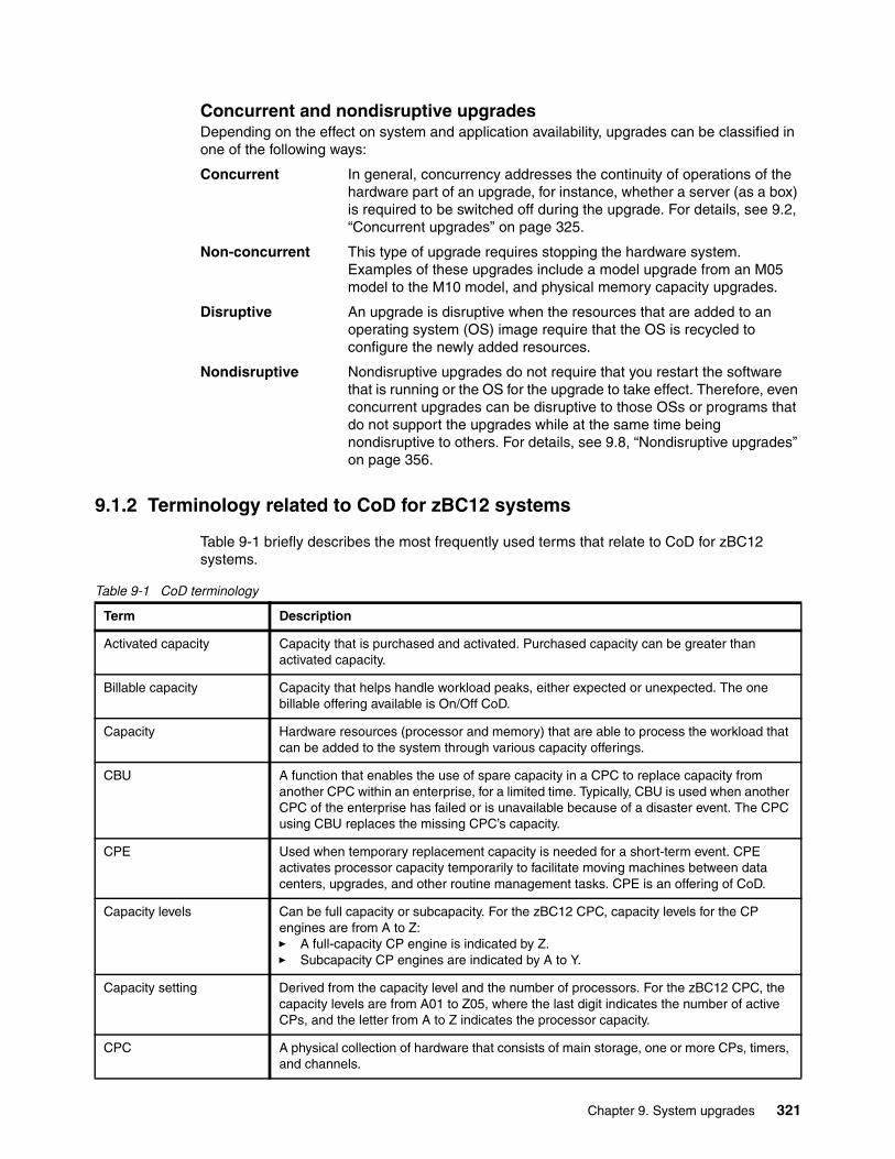
Concurrent and nondisruptive upgradesDepending on the effect on system and application availability, upgrades can be classified in one of the following ways:
Concurrent In general, concurrency addresses the continuity of operations of the hardware part of an upgrade, for instance, whether a server (as a box) is required to be switched off during the upgrade. For details, see 9.2, “Concurrent upgrades” on page 325.
Non-concurrent This type of upgrade requires stopping the hardware system. Examples of these upgrades include a model upgrade from an M05 model to the M10 model, and physical memory capacity upgrades.
Disruptive An upgrade is disruptive when the resources that are added to an operating system (OS) image require that the OS is recycled to configure the newly added resources.
Nondisruptive Nondisruptive upgrades do not require that you restart the software that is running or the OS for the upgrade to take effect. Therefore, even concurrent upgrades can be disruptive to those OSs or programs that do not support the upgrades while at the same time being nondisruptive to others. For details, see 9.8, “Nondisruptive upgrades” on page 356.
9.1.2 Terminology related to CoD for zBC12 systems
Table 9-1 briefly describes the most frequently used terms that relate to CoD for zBC12 systems.
Table 9-1 CoD terminology
Term Description
Activated capacity Capacity that is purchased and activated. Purchased capacity can be greater than activated capacity.
Billable capacity Capacity that helps handle workload peaks, either expected or unexpected. The one billable offering available is On/Off CoD.
Capacity Hardware resources (processor and memory) that are able to process the workload that can be added to the system through various capacity offerings.
CBU A function that enables the use of spare capacity in a CPC to replace capacity from another CPC within an enterprise, for a limited time. Typically, CBU is used when another CPC of the enterprise has failed or is unavailable because of a disaster event. The CPC using CBU replaces the missing CPC’s capacity.
CPE Used when temporary replacement capacity is needed for a short-term event. CPE activates processor capacity temporarily to facilitate moving machines between data centers, upgrades, and other routine management tasks. CPE is an offering of CoD.
Capacity levels Can be full capacity or subcapacity. For the zBC12 CPC, capacity levels for the CP engines are from A to Z:� A full-capacity CP engine is indicated by Z.� Subcapacity CP engines are indicated by A to Y.
Capacity setting Derived from the capacity level and the number of processors. For the zBC12 CPC, the capacity levels are from A01 to Z05, where the last digit indicates the number of active CPs, and the letter from A to Z indicates the processor capacity.
CPC A physical collection of hardware that consists of main storage, one or more CPs, timers, and channels.
Chapter 9. System upgrades 321
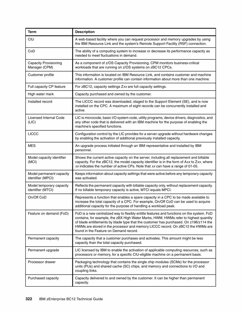
CIU A web-based facility where you can request processor and memory upgrades by using the IBM Resource Link and the system’s Remote Support Facility (RSF) connection.
CoD The ability of a computing system to increase or decrease its performance capacity as needed to meet fluctuations in demand.
Capacity Provisioning Manager (CPM)
As a component of z/OS Capacity Provisioning, CPM monitors business-critical workloads that are running on z/OS systems on zBC12 CPCs.
Customer profile This information is located on IBM Resource Link, and contains customer and machine information. A customer profile can contain information about more than one machine.
Full capacity CP feature For zBC12, capacity settings Zxx are full capacity settings.
High water mark Capacity purchased and owned by the customer.
Installed record The LICCC record was downloaded, staged to the Support Element (SE), and is now installed on the CPC. A maximum of eight records can be concurrently installed and active.
Licensed Internal Code(LIC)
LIC is microcode, basic I/O system code, utility programs, device drivers, diagnostics, and any other code that is delivered with an IBM machine for the purpose of enabling the machine’s specified functions.
LICCC Configuration control by the LIC provides for a server upgrade without hardware changes by enabling the activation of additional previously installed capacity.
MES An upgrade process initiated through an IBM representative and installed by IBM personnel.
Model capacity identifier (MCI)
Shows the current active capacity on the server, including all replacement and billable capacity. For the zBC12, the model capacity identifier is in the form of Axx to Zxx, where xx indicates the number of active CPs. Note that xx can have a range of 01-05.
Model permanent capacity identifier (MPCI)
Keeps information about capacity settings that were active before any temporary capacity was activated.
Model temporary capacity identifier (MTCI)
Reflects the permanent capacity with billable capacity only, without replacement capacity. If no billable temporary capacity is active, MTCI equals MPCI.
On/Off CoD Represents a function that enables a spare capacity in a CPC to be made available to increase the total capacity of a CPC. For example, On/Off CoD can be used to acquire additional capacity for the purpose of handling a workload peak.
Feature on demand (FoD) FoD is a new centralized way to flexibly entitle features and functions on the system. FoD contains, for example, the zBX High Water Marks, HWM. HWMs refer to highest quantity of blade entitlements by blade type that the customer has purchased. On z196/z114 the HWMs are stored in the processor and memory LICCC record. On zBC12 the HWMs are found in the Feature on Demand record.
Permanent capacity The capacity that a customer purchases and activates. This amount might be less capacity than the total capacity purchased.
Permanent upgrade LIC licensed by IBM to enable the activation of applicable computing resources, such as processors or memory, for a specific CIU-eligible machine on a permanent basis.
Processor drawer Packaging technology that contains the single chip modules (SCMs) for the processor units (PUs) and shared cache (SC) chips, and memory and connections to I/O and coupling links.
Purchased capacity Capacity delivered to and owned by the customer. It can be higher than permanent capacity.
Term Description
322 IBM zEnterprise BC12 Technical Guide
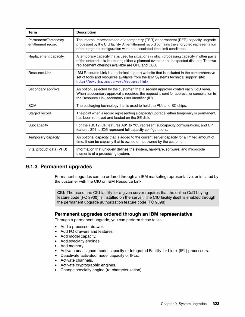
9.1.3 Permanent upgrades
Permanent upgrades can be ordered through an IBM marketing representative, or initiated by the customer with the CIU on IBM Resource Link.
Permanent upgrades ordered through an IBM representativeThrough a permanent upgrade, you can perform these tasks:
� Add a processor drawer.� Add I/O drawers and features.� Add model capacity.� Add specialty engines.� Add memory.� Activate unassigned model capacity or Integrated Facility for Linux (IFL) processors.� Deactivate activated model capacity or IFLs.� Activate channels.� Activate cryptographic engines.� Change specialty engine (re-characterization).
Permanent/Temporary entitlement record
The internal representation of a temporary (TER) or permanent (PER) capacity upgrade processed by the CIU facility. An entitlement record contains the encrypted representation of the upgrade configuration with the associated time limit conditions.
Replacement capacity A temporary capacity that is used for situations in which processing capacity in other parts of the enterprise is lost during either a planned event or an unexpected disaster. The two replacement offerings available are CPE and CBU.
Resource Link IBM Resource Link is a technical support website that is included in the comprehensive set of tools and resources available from the IBM Systems technical support site:http://www.ibm.com/servers/resourcelink/
Secondary approval An option, selected by the customer, that a second approver control each CoD order. When a secondary approval is required, the request is sent for approval or cancellation to the Resource Link secondary user identifier (ID).
SCM The packaging technology that is used to hold the PUs and SC chips.
Staged record The point when a record representing a capacity upgrade, either temporary or permanent, has been retrieved and loaded on the SE disk.
Subcapacity For the zBC12, CP features A01 to Y05 represent subcapacity configurations, and CP features Z01 to Z05 represent full capacity configurations.
Temporary capacity An optional capacity that is added to the current server capacity for a limited amount of time. It can be capacity that is owned or not owned by the customer.
Vital product data (VPD) Information that uniquely defines the system, hardware, software, and microcode elements of a processing system.
Term Description
CIU: The use of the CIU facility for a given server requires that the online CoD buying feature code (FC 9900) is installed on the server. The CIU facility itself is enabled through the permanent upgrade authorization feature code (FC 9898).
Chapter 9. System upgrades 323
� Add zBX and zBX features:– Chassis– Racks– Blades– Entitlements
Permanent upgrades initiated through CIU on IBM Resource LinkOrdering a permanent upgrade by using the CIU application through the IBM Resource Link enables you to add capacity to fit within your existing hardware:
� Add model capacity� Add specialty engines � Add memory � Activate unassigned model capacity or IFLs � Deactivate activated model capacity or IFLs
9.1.4 Temporary upgrades
System zBC12 offers the following types of temporary upgrades:
� On/Off CoD
This offering enables you to temporarily add additional capacity or specialty engines due to seasonal activities, period-end requirements, peaks in workload, or application testing.
This temporary upgrade can only be ordered using the CIU application through the Resource Link.
� CBU
This offering enables you to replace model capacity or specialty engines to a backup server in the event of an unforeseen loss of server capacity because of an emergency.
� CPE
This offering enables you to replace model capacity or specialty engines due to a relocation of workload during system migrations or a data center move.
CBU or CPE temporary upgrades can be ordered by using the CIU application through Resource Link, or by calling your IBM marketing representative. Temporary upgrades capacity changes can be billable or replacement capacity.
Billable capacityTo handle a peak workload, processors can be activated temporarily on a daily basis. You can activate up to twice the purchased millions of service units (MSU) capacity of any PU type. The one billable capacity offering is On/Off CoD.
Replacement capacityWhen processing capacity is lost in another part of an enterprise, replacement capacity can be activated. It enables you to activate any PU type up to the authorized limit.
Two replacement capacity offerings exist:
� CBU� CPE
Important: Most of the MESs can be concurrently applied without disrupting the existing workload (see 9.2, “Concurrent upgrades” on page 325 for details). However, certain MES changes are disruptive (for example, an upgrade of model H06 to H13, or adding memory).
324 IBM zEnterprise BC12 Technical Guide
9.2 Concurrent upgrades
Concurrent upgrades on the zBC12 can provide additional capacity with no server outage. In most cases, with prior planning and OS support, a concurrent upgrade can also be nondisruptive to the OS.
Given today’s business environment, the benefits of the concurrent capacity growth capabilities that are provided by the zBC12 are plentiful, and include, but are not limited to, the following benefits:
� Enabling the exploitation of new business opportunities� Supporting the growth of smart environments� Managing the risk of volatile, high-growth, and high-volume applications� Supporting 24x365 application availability� Enabling capacity growth during lockdown periods� Enabling planned-downtime changes without affecting availability
These capabilities are based on the flexibility of the design and structure, which enables concurrent hardware installation and LIC control over the configuration.
Subcapacity models provide for a CP capacity increase in two dimensions that can be used together to deliver configuration granularity. The first dimension is by adding CPs to the configuration, and the second dimension is by changing the capacity setting of the CPs currently installed to a higher MCI. In addition, a capacity increase can be delivered by increasing the CP capacity setting, and at the same time decreasing the number of active CPs.
The zBC12 supports the concurrent addition of processors to a running logical partition (LPAR). As a result, you can have a flexible infrastructure, in which you can add capacity without pre-planning. This function is supported by IBM z/Virtual Machine (z/VM). Planning ahead is required for z/OS LPARs. To be able to add processors to a running z/OS, reserved processors must be specified in the LPAR’s profile.
Another function concerns the system assist processor (SAP). When additional SAPs are concurrently added to the configuration, the SAP-to-channel affinity is dynamically remapped on all SAPs on the zBC12 to rebalance the I/O configuration.
All of the zBX and its features can be installed concurrently. For the IBM Smart Analytics Optimizer solution, the applications using the solution will continue to run during the upgrade. However, they will use the zBC12 resources to satisfy the application execution instead of using the zBX infrastructure.
9.2.1 Model upgrades
The zBC12 has the following machine type and model, and MCIs:
� Machine type and model is 2828-Hvv. The vv can be 06 or 13. The model number indicates how many PUs (vv) are available for customer characterization. Model M05 has one processor drawer installed, and model M10 contains two processor drawers.
� MCIs are A01 to Z05. The MCI describes how many CPs are characterized (01 to 05) and the capacity setting (A to Z) of the CPs.
A hardware configuration upgrade always requires additional physical hardware (processor or I/O drawers, or both). A zBC12 upgrade can change either, or both, the server model and the MCI.
Chapter 9. System upgrades 325
Note the following model upgrade information:
� LICCC upgrade:
– Does not change the server model 2828 H06, because an additional processor drawer is not added.
– Can change the MCI, the capacity setting, or both.
� Hardware installation upgrade:
– Can change the server model 2828 H06 to H13, if an additional processor drawer is included. This upgrade is non-concurrent.
– Can change the model capacity identifier, the capacity setting, or both.
The MCI can be concurrently changed. Concurrent upgrades can be accomplished for both permanent and temporary upgrades.
Licensed Internal Code upgrades (MES-ordered)The LICCC provides for server upgrade without hardware changes by activation of additional (previously installed) unused capacity. Concurrent upgrades through LICCC can be done for the following components and situations:
� Processors (logical CPs, IFL processors, Internal Coupling Facility (ICF) processors, System z Application Assist Processors (zAAPs), System z Integrated Information Processors (zIIPs), and SAPs.
� Unused PUs, if they are available on the installed processor drawers, or if the MCI for the CPs can be increased.
� Memory, when unused capacity is available on the installed memory cards. The plan-ahead memory option is available for customers to gain better control over future memory upgrades. See 2.5.4, “Memory upgrades” on page 49 for more details.
� I/O card ports, when there are available ports on the installed I/O cards.
Concurrent hardware installation upgrades (MES-ordered)Configuration upgrades can be concurrent when installing additional cards, drawers, and features:
� Host channel adapter2 (HCA2), host channel adapter for InfiniBand (HCA3), or PCIe fanout cards
� I/O cards, when slots are available in the installed I/O drawers and PCIe I/O drawers� I/O drawers and PCIe I/O drawers� All of zBX and zBX features
The concurrent I/O upgrade capability can be better used if a future target configuration is considered during the initial configuration.
Concurrent PU conversions (MES-ordered)The zBC12 supports concurrent conversion between all PU types, such as any-to-any PUs, including SAPs, to provide flexibility to meet changing business requirements.
Model upgrades: A model upgrade from the H06 to the H13 is disruptive.
326 IBM zEnterprise BC12 Technical Guide
LPARs might also have to free the PUs to be converted, and the OSs must have support to configure processors offline or online for the PU conversion to be done non-disruptively.
9.2.2 Customer Initiated Upgrade facility
The CIU facility is an IBM online system through which a customer can order, download, and install permanent and temporary upgrades for System z servers. Access to and use of the CIU facility requires a contract between the customer and IBM, through which the terms and conditions for use of the CIU facility are accepted.
The use of the CIU facility for a given server requires that the online CoD buying feature code (FC 9900) is installed on the server. The CIU facility itself is controlled through the permanent upgrade authorization feature code (FC 9898).
After a customer has placed an order through the CIU facility, the customer will receive a notice that the order is ready for download. The customer can then download and apply the upgrade by using functions that are available through the Hardware Management Console (HMC), along with the RSF. After all the prerequisites are met, the entire process, from ordering to activation of the upgrade, is performed by the customer.
After the download, the actual upgrade process is fully automated, and does not require any onsite presence of IBM service personnel.
CIU prerequisitesThe CIU facility supports LICCC upgrades only. It does not support I/O upgrades. All additional capacity that is required for an upgrade must be previously installed. An additional processor drawer or I/O cards cannot be installed as part of an order placed through the CIU facility. The sum of CPs, unassigned CPs, ICFs, zAAPs, zIIPs, IFLs, and unassigned IFLs cannot exceed the PU count of the installed drawers. The number of zAAPs or zIIPs (each) cannot exceed the number of purchased CPs.
CIU registration and agreed contract for CIUTo use the CIU facility, a customer must be registered and the system must be set up. After completing the CIU registration, access the CIU application through the IBM Resource Link website:
http://www.ibm.com/servers/resourcelink/
LICCC-based PU conversions: The LICCC-based PU conversions require that at least one PU, either CP, ICF, or IFL, remains unchanged. Otherwise, the conversion is disruptive. The PU conversion generates a new LICCC that can be installed concurrently in two steps:
1. The assigned PU is removed from the configuration. 2. The newly available PU is activated as the new PU type.
PU conversion: Customer planning and operator action are required to use concurrent PU conversion. Consider the following information about PU conversion:
� It is disruptive if all current PUs are converted to separate types.� It might require individual LPAR outage if dedicated PUs are converted.
Unassigned CP capacity is recorded by an MCI. CP feature conversions change (increase or decrease) the MCI.
Chapter 9. System upgrades 327
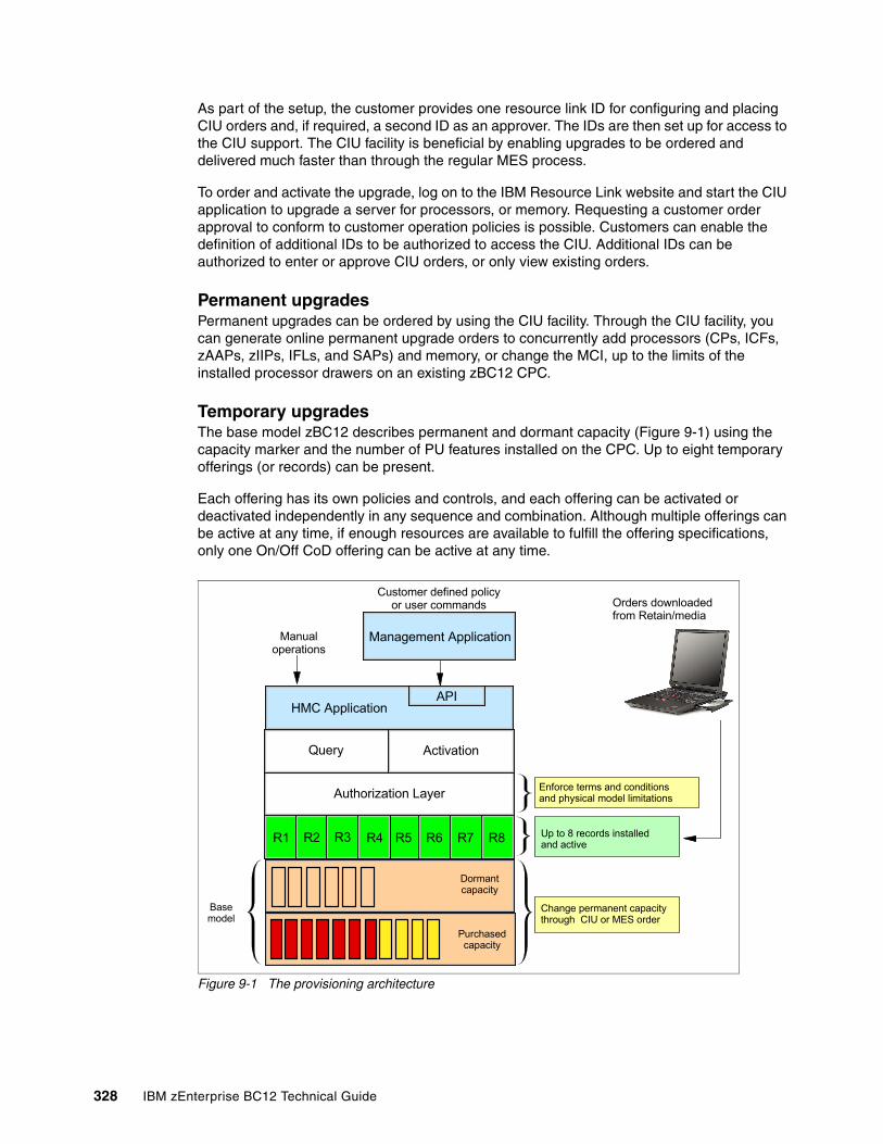
As part of the setup, the customer provides one resource link ID for configuring and placing CIU orders and, if required, a second ID as an approver. The IDs are then set up for access to the CIU support. The CIU facility is beneficial by enabling upgrades to be ordered and delivered much faster than through the regular MES process.
To order and activate the upgrade, log on to the IBM Resource Link website and start the CIU application to upgrade a server for processors, or memory. Requesting a customer order approval to conform to customer operation policies is possible. Customers can enable the definition of additional IDs to be authorized to access the CIU. Additional IDs can be authorized to enter or approve CIU orders, or only view existing orders.
Permanent upgradesPermanent upgrades can be ordered by using the CIU facility. Through the CIU facility, you can generate online permanent upgrade orders to concurrently add processors (CPs, ICFs, zAAPs, zIIPs, IFLs, and SAPs) and memory, or change the MCI, up to the limits of the installed processor drawers on an existing zBC12 CPC.
Temporary upgradesThe base model zBC12 describes permanent and dormant capacity (Figure 9-1) using the capacity marker and the number of PU features installed on the CPC. Up to eight temporary offerings (or records) can be present.
Each offering has its own policies and controls, and each offering can be activated or deactivated independently in any sequence and combination. Although multiple offerings can be active at any time, if enough resources are available to fulfill the offering specifications, only one On/Off CoD offering can be active at any time.
Figure 9-1 The provisioning architecture
Customer defined policy or user commands
Management Application
HMC Application
Query Activation
Authorization Layer
R1 R2 R3 R6
Dormantcapacity
Purchasedcapacity
Basemodel
Change permanent capacity through CIU or MES order
Enforce terms and conditionsand physical model limitations
Up to 8 records installed and active
Orders downloaded from Retain/media
API
Manual operations
R8R7R5R4
328 IBM zEnterprise BC12 Technical Guide
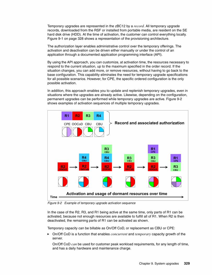
Temporary upgrades are represented in the zBC12 by a record. All temporary upgrade records, downloaded from the RSF or installed from portable media, are resident on the SE hard disk drive (HDD). At the time of activation, the customer can control everything locally. Figure 9-1 on page 328 shows a representation of the provisioning architecture.
The authorization layer enables administrative control over the temporary offerings. The activation and deactivation can be driven either manually or under the control of an application through a documented application programming interface (API).
By using the API approach, you can customize, at activation time, the resources necessary to respond to the current situation, up to the maximum specified in the order record. If the situation changes, you can add more, or remove resources, without having to go back to the base configuration. This capability eliminates the need for temporary upgrade specifications for all possible scenarios. However, for CPE, the specific ordered configuration is the only possible activation.
In addition, this approach enables you to update and replenish temporary upgrades, even in situations where the upgrades are already active. Likewise, depending on the configuration, permanent upgrades can be performed while temporary upgrades are active. Figure 9-2 shows examples of activation sequences of multiple temporary upgrades.
Figure 9-2 Example of temporary upgrade activation sequence
In the case of the R2, R3, and R1 being active at the same time, only parts of R1 can be activated, because not enough resources are available to fulfill all of R1. When R2 is then deactivated, the remaining parts of R1 can be activated as shown.
Temporary capacity can be billable as On/Off CoD, or replacement as CBU or CPE:
� On/Off CoD is a function that enables concurrent and temporary capacity growth of the server.
On/Off CoD can be used for customer peak workload requirements, for any length of time, and has a daily hardware and maintenance charge.
Time
R2R2 R2
R4
R2
R4
R2
R4
R3
R2
R4
R3
R2 R3R1 R4R2 R3R1 R4
R2
R3
R1
R2
R3
R1
R2
R3
R2
R3
R3
R1
R3
R1
Record and associated authorization
Activation and usage of dormant resources over time
CPE OOCoD CBU CBU
OOCoD OOCoD OOCoD OOCoD OOCoD
CPE
CPECBU
CBU
CBU CBU CBU
CBU
Chapter 9. System upgrades 329
The software charges can vary according to the license agreement for the individual products. See your IBM Software Group (SWG) representative for exact details.
On/Off CoD can concurrently add processors (CPs, ICFs, zAAPs, zIIPs, IFLs, and SAPs), increase the MCI, or both, up to the limit of the installed processor drawers of an existing server. It is restricted to twice the currently installed capacity. On/Off CoD requires a contractual agreement between the customer and IBM.
The customer decides whether to pre-pay or post-pay On/Off CoD. Capacity tokens inside the records are used to control activation time and resources.
� CBU is a concurrent and temporary activation of additional CPs, ICFs, zAAPs, zIIPs, IFLs, and SAPs, an increase of the MCI, or both.
CBU cannot be used for peak load management of customer workload, or for CPE. A CBU activation can last up to 90 days when a disaster or recovery situation occurs.
CBU features are optional, and require unused capacity to be available on the installed processor drawers of the backup server, either as unused PUs or as a possibility to increase the MCI, or both. A CBU contract must be in place before the special code that enables this capability can be loaded on the server. The standard CBU contract provides for five 10-day tests and one 90-day disaster activation over a five-year period. Contact your IBM representative for details.
� CPE is a concurrent and temporary activation of additional CPs, ICFs, zAAPs, zIIPs, IFLs, and SAPs, or an increase of the MCI, or both.
The CPE offering is used to replace temporary lost capacity within a customer’s enterprise for planned downtime events, for example, with data center changes. CPE cannot be used for peak load management of the customer workload, or for a disaster situation.
The CPE feature requires unused capacity to be available on installed processor drawers of the backup server, either as unused PUs or as a possibility to increase the MCI, or both. A CPE contract must be in place before the special code that enables this capability can be loaded on the server. The standard CPE contract provides for one three-day planned activation at a specific date. Contact your IBM representative for details.
9.2.3 Summary of concurrent upgrade functions
Table 9-2 summarizes the possible concurrent upgrade combinations.
Table 9-2 Concurrent upgrade summary
Type Name Upgrade Process
Permanent MES CPs, ICFs, zAAPs, zIIPs, IFLs, SAPs, processor drawer, memory, and I/O
Installed by IBM service personnel
Online permanent upgrade
CPs, ICFs, zAAPs, zIIPs, IFLs, SAPs, and memory
Performed through the CIU facility
Temporary On/Off CoD CPs, ICFs, zAAPs, zIIPs, IFLs, and SAPs Performed through the On/Off CoD facility
CBU CPs, ICFs, zAAPs, zIIPs, IFLs, and SAPs Performed through the CBU facility
CPE CPs, ICFs, zAAPs, zIIPs, IFLs, and SAPs Performed through the CPE facility
330 IBM zEnterprise BC12 Technical Guide
9.3 Miscellaneous equipment specification upgrades
MES upgrades enable concurrent and permanent capacity growth. MES upgrades enable the concurrent addition of processors (CPs, ICFs, zAAPs, zIIPs, IFLs, and SAPs), memory capacity, I/O ports, hardware, and entitlements to the zBX. MES upgrades enable the concurrent adjustment of both the number of processors and the capacity level. The MES upgrade can be done using LICCC only, by installing an additional processor drawer, adding I/O cards, or a combination:
� MES upgrades for processors are done by any of the following methods:
– LICCC assigning and activating unassigned PUs up to the limit of the installed processor drawers.
– LICCC to adjust the number and types of PUs, to change the capacity setting, or both.
– Installing an additional processor drawer, and LICCC assigning and activating unassigned PUs in the installed drawer.
� MES upgrades for memory are done by either of the following methods:
– Using LICCC to activate additional memory capacity up to the limit of the memory cards on the currently installed processor drawers. Plan-ahead memory features enable you to have better control over future memory upgrades. For details about the memory features, see 2.5.4, “Memory upgrades” on page 49.
– Installing an additional processor drawer, and using LICCC to activate additional memory capacity on installed processor drawers.
� MES upgrades for I/O are done by either of the following methods:
– Using LICCC to activate additional ports on already installed I/O cards.– Installing additional I/O cards and supporting infrastructure, if required, in I/O drawers
or PCIe I/O drawers that are already installed, or installing additional I/O drawers or PCIe I/O drawers to hold the new cards.
� MES upgrades for the zBX can only be performed through your IBM service support representative (SSR).
An MES upgrade requires IBM service personnel for the installation. In most cases, the time that is required for installing the LICCC and completing the upgrade is short. To better use the MES upgrade function, we strongly suggest that you carefully plan the initial configuration to enable a concurrent upgrade to a target configuration.
By planning ahead, it is possible to enable nondisruptive capacity and I/O growth with no system power down and no associated power-on resets (PORs) or initial program loads (IPLs). The availability of I/O drawers and PCIe I/O drawers has improved the flexibility to perform unplanned I/O configuration changes concurrently.
The store system information (STSI) instruction gives more useful and detailed information about the base configuration, and about temporary upgrades. STSI enables you to more easily resolve billing situations where independent software vendor (ISV) products are in use.
The model and MCI returned by the STSI instruction are updated to coincide with the upgrade. See “Store system information instruction” on page 357 for more details.
Upgrades: The MES provides the physical upgrade, resulting in more enabled processors, separate capacity settings for the CPs, additional memory, and I/O ports. Additional planning tasks are required for nondisruptive logical upgrades (see “Suggestions to avoid disruptive upgrades” on page 360).
Chapter 9. System upgrades 331
9.3.1 MES upgrade for processors
An MES upgrade for processors can concurrently add CPs, ICFs, zAAPs, zIIPs, IFLs, and SAPs to a zBC12 by assigning available PUs that are on the processor drawers, through LICCC. Depending on the quantity of the additional processors in the upgrade, an additional processor drawer might be required before the LICCC is enabled. Additional capacity can be provided by adding CPs, by changing the MCI on the current CPs, or by doing both.
9.3.2 MES upgrade for memory
An MES upgrade for memory can concurrently add more memory by enabling, through LICCC, additional capacity up to the limit of the currently installed memory cards. Installing an additional processor drawer, and LICCC-enabling the memory capacity on the new drawer, are disruptive upgrades.
The Preplanned Memory feature (FC 1993) is available to enable better control over future memory upgrades. See 2.5.5, “Preplanned memory” on page 49, for details about plan-ahead memory features.
The H06 model has, as a minimum, ten 4 GB dual inline memory modules (DIMMs), resulting in 40 GB of installed memory in total. The minimum customer addressable storage is 8 GB. If you require more than that, a non-concurrent upgrade can install up to 240 GB of memory for customer use, by changing the existing DIMMs.
The H13 model has, as a minimum, twenty 4 GB DIMMs, resulting in 80 GB of installed memory in total. The minimum customer addressable storage is 16 GB. If you require more than that, a non-concurrent upgrade can install up to 496 GB of memory for customer use, by changing the existing DIMMs.
An LPAR can dynamically take advantage of a memory upgrade if reserved storage was defined to that LPAR. The reserved storage is defined to the LPAR as part of the image profile. Reserved memory can be configured online to the LPAR by using the LPAR dynamic storage reconfiguration (DSR) function.
DSR enables a z/OS OS image, and z/VM partitions, to add reserved storage to their configuration if any unused storage exists. The nondisruptive addition of storage to a z/OS and z/VM partition necessitates that pertinent OS parameters have been prepared. If reserved storage has not been defined to the LPAR, the LPAR must be deactivated, the image profile changed, and the LPAR reactivated to enable the additional storage resources to be available to the OS image.
9.3.3 Preplanned Memory feature
The Preplanned Memory feature (FC 1993) enables you to install memory for future use:
� FC 1993 specifies memory to be installed but not used. Order one feature for each 8 GB that will be usable by the customer.
Maximums: The sum of CPs, inactive CPs, ICFs, zAAPs, zIIPs, IFLs, unassigned IFLs, and SAPs cannot exceed the maximum limit of PUs available for customer use. The number of zAAPs or zIIPs cannot exceed the number of purchased CPs.
332 IBM zEnterprise BC12 Technical Guide
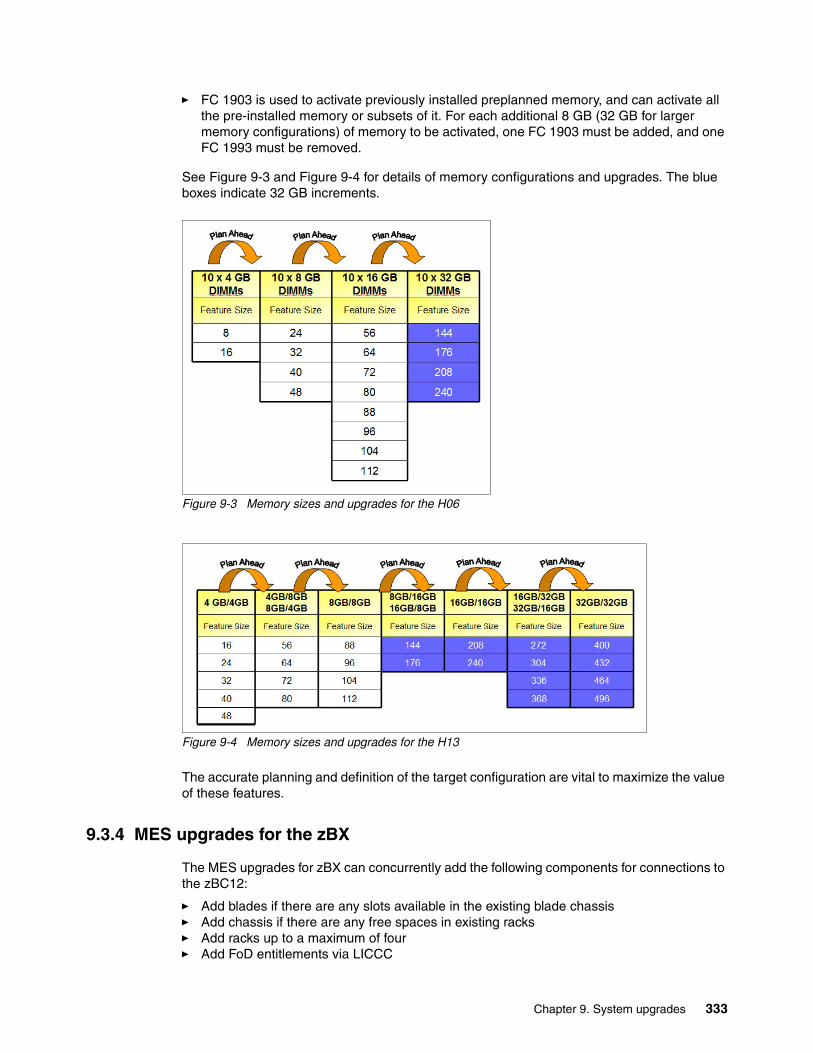
� FC 1903 is used to activate previously installed preplanned memory, and can activate all the pre-installed memory or subsets of it. For each additional 8 GB (32 GB for larger memory configurations) of memory to be activated, one FC 1903 must be added, and one FC 1993 must be removed.
See Figure 9-3 and Figure 9-4 for details of memory configurations and upgrades. The blue boxes indicate 32 GB increments.
Figure 9-3 Memory sizes and upgrades for the H06
Figure 9-4 Memory sizes and upgrades for the H13
The accurate planning and definition of the target configuration are vital to maximize the value of these features.
9.3.4 MES upgrades for the zBX
The MES upgrades for zBX can concurrently add the following components for connections to the zBC12:
� Add blades if there are any slots available in the existing blade chassis� Add chassis if there are any free spaces in existing racks� Add racks up to a maximum of four� Add FoD entitlements via LICCC
Chapter 9. System upgrades 333
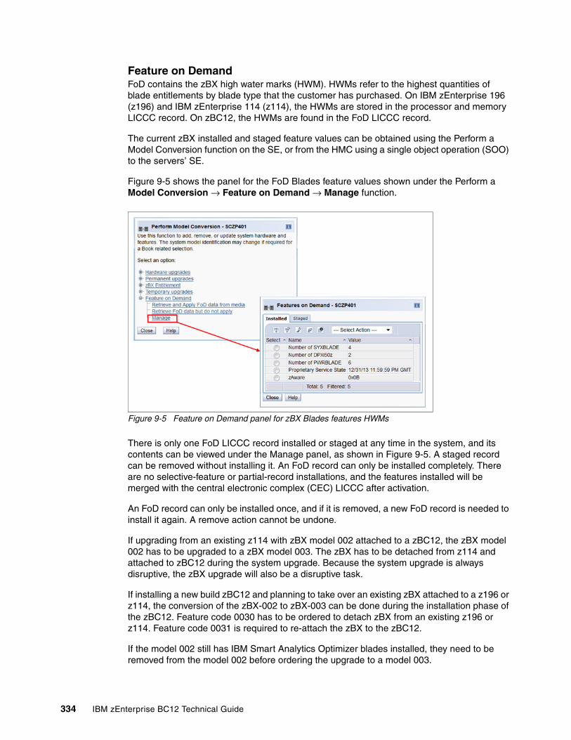
Feature on DemandFoD contains the zBX high water marks (HWM). HWMs refer to the highest quantities of blade entitlements by blade type that the customer has purchased. On IBM zEnterprise 196 (z196) and IBM zEnterprise 114 (z114), the HWMs are stored in the processor and memory LICCC record. On zBC12, the HWMs are found in the FoD LICCC record.
The current zBX installed and staged feature values can be obtained using the Perform a Model Conversion function on the SE, or from the HMC using a single object operation (SOO) to the servers’ SE.
Figure 9-5 shows the panel for the FoD Blades feature values shown under the Perform a Model Conversion → Feature on Demand → Manage function.
Figure 9-5 Feature on Demand panel for zBX Blades features HWMs
There is only one FoD LICCC record installed or staged at any time in the system, and its contents can be viewed under the Manage panel, as shown in Figure 9-5. A staged record can be removed without installing it. An FoD record can only be installed completely. There are no selective-feature or partial-record installations, and the features installed will be merged with the central electronic complex (CEC) LICCC after activation.
An FoD record can only be installed once, and if it is removed, a new FoD record is needed to install it again. A remove action cannot be undone.
If upgrading from an existing z114 with zBX model 002 attached to a zBC12, the zBX model 002 has to be upgraded to a zBX model 003. The zBX has to be detached from z114 and attached to zBC12 during the system upgrade. Because the system upgrade is always disruptive, the zBX upgrade will also be a disruptive task.
If installing a new build zBC12 and planning to take over an existing zBX attached to a z196 or z114, the conversion of the zBX-002 to zBX-003 can be done during the installation phase of the zBC12. Feature code 0030 has to be ordered to detach zBX from an existing z196 or z114. Feature code 0031 is required to re-attach the zBX to the zBC12.
If the model 002 still has IBM Smart Analytics Optimizer blades installed, they need to be removed from the model 002 before ordering the upgrade to a model 003.
334 IBM zEnterprise BC12 Technical Guide
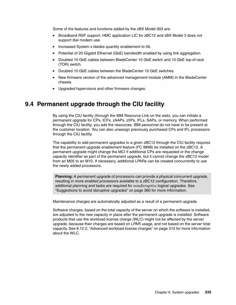
Some of the features and functions added by the zBX Model 003 are:
� Broadband RSF support. HMC application LIC for zBC12 and zBX Model 3 does not support dial modem use.
� Increased System x blades quantity enablement to 56.
� Potential of 20 Gigabit Ethernet (GbE) bandwidth enabled by using link aggregation.
� Doubled 10 GbE cables between BladeCenter 10 GbE switch and 10 GbE top-of-rack (TOR) switch.
� Doubled 10 GbE cables between the BladeCenter 10 GbE switches.
� New firmware version of the advanced management module (AMM) in the BladeCenter chassis.
� Upgraded hypervisors and other firmware changes.
9.4 Permanent upgrade through the CIU facility
By using the CIU facility (through the IBM Resource Link on the web), you can initiate a permanent upgrade for CPs, ICFs, zAAPs, zIIPs, IFLs, SAPs, or memory. When performed through the CIU facility, you add the resources. IBM personnel do not have to be present at the customer location. You can also unassign previously purchased CPs and IFL processors through the CIU facility.
The capability to add permanent upgrades to a given zBC12 through the CIU facility requires that the permanent upgrade enablement feature (FC 9898) be installed on the zBC12. A permanent upgrade might change the MCI if additional CPs are requested or the change capacity identifier as part of the permanent upgrade, but it cannot change the zBC12 model from an M05 to an M10. If necessary, additional LPARs can be created concurrently to use the newly added processors.
Maintenance charges are automatically adjusted as a result of a permanent upgrade.
Software charges, based on the total capacity of the server on which the software is installed, are adjusted to the new capacity in place after the permanent upgrade is installed. Software products that use the workload license charge (WLC) might not be affected by the server upgrade, because their charges are based on LPAR usage, and not based on the server total capacity. See 8.12.2, “Advanced workload license charges” on page 315 for more information about the WLC.
Planning: A permanent upgrade of processors can provide a physical concurrent upgrade, resulting in more enabled processors available to a zBC12 configuration. Therefore, additional planning and tasks are required for nondisruptive logical upgrades. See “Suggestions to avoid disruptive upgrades” on page 360 for more information.
Chapter 9. System upgrades 335
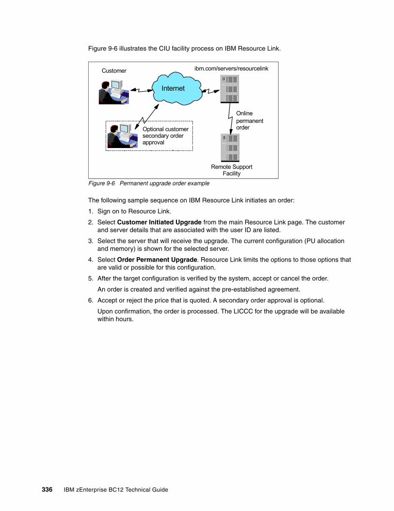
Figure 9-6 illustrates the CIU facility process on IBM Resource Link.
Figure 9-6 Permanent upgrade order example
The following sample sequence on IBM Resource Link initiates an order:
1. Sign on to Resource Link.
2. Select Customer Initiated Upgrade from the main Resource Link page. The customer and server details that are associated with the user ID are listed.
3. Select the server that will receive the upgrade. The current configuration (PU allocation and memory) is shown for the selected server.
4. Select Order Permanent Upgrade. Resource Link limits the options to those options that are valid or possible for this configuration.
5. After the target configuration is verified by the system, accept or cancel the order.
An order is created and verified against the pre-established agreement.
6. Accept or reject the price that is quoted. A secondary order approval is optional.
Upon confirmation, the order is processed. The LICCC for the upgrade will be available within hours.
ibm.com/servers/resourcelinkCustomer
Onlinepermanent order
Remote Support Facility
Internet
Optional customer secondary order approval
336 IBM zEnterprise BC12 Technical Guide
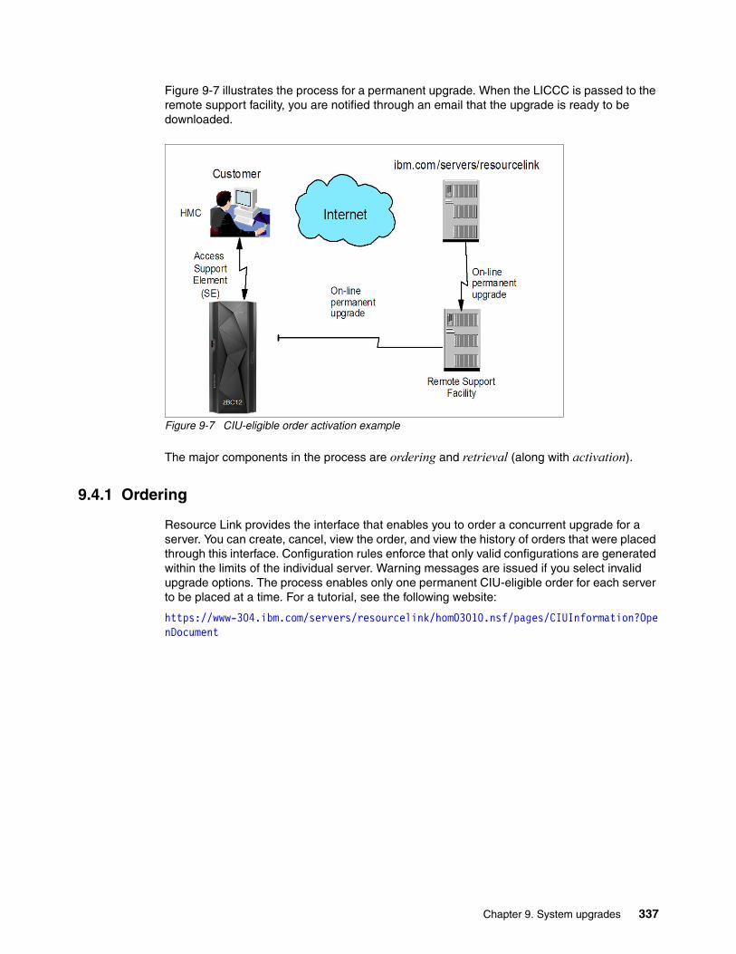
Figure 9-7 illustrates the process for a permanent upgrade. When the LICCC is passed to the remote support facility, you are notified through an email that the upgrade is ready to be downloaded.
Figure 9-7 CIU-eligible order activation example
The major components in the process are ordering and retrieval (along with activation).
9.4.1 Ordering
Resource Link provides the interface that enables you to order a concurrent upgrade for a server. You can create, cancel, view the order, and view the history of orders that were placed through this interface. Configuration rules enforce that only valid configurations are generated within the limits of the individual server. Warning messages are issued if you select invalid upgrade options. The process enables only one permanent CIU-eligible order for each server to be placed at a time. For a tutorial, see the following website:
https://www-304.ibm.com/servers/resourcelink/hom03010.nsf/pages/CIUInformation?OpenDocument
Chapter 9. System upgrades 337
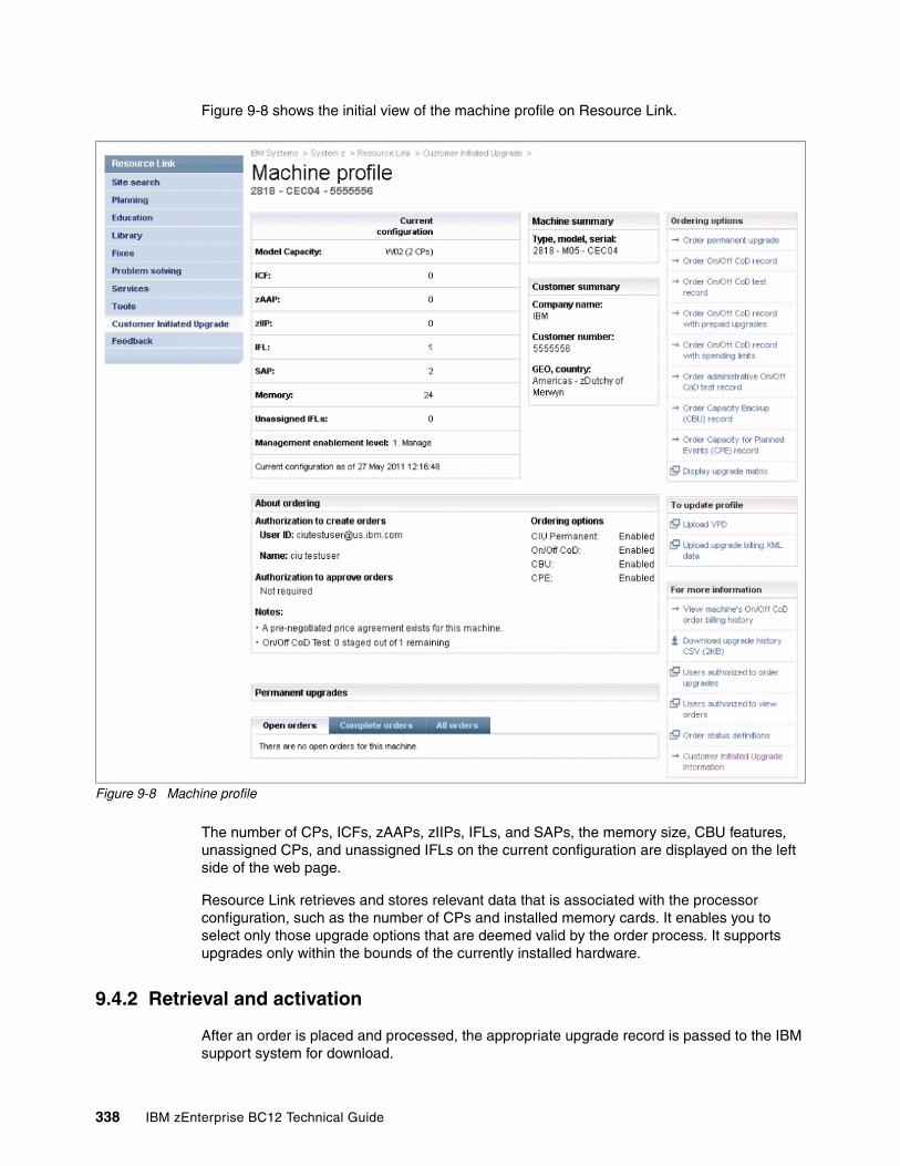
Figure 9-8 shows the initial view of the machine profile on Resource Link.
Figure 9-8 Machine profile
The number of CPs, ICFs, zAAPs, zIIPs, IFLs, and SAPs, the memory size, CBU features, unassigned CPs, and unassigned IFLs on the current configuration are displayed on the left side of the web page.
Resource Link retrieves and stores relevant data that is associated with the processor configuration, such as the number of CPs and installed memory cards. It enables you to select only those upgrade options that are deemed valid by the order process. It supports upgrades only within the bounds of the currently installed hardware.
9.4.2 Retrieval and activation
After an order is placed and processed, the appropriate upgrade record is passed to the IBM support system for download.
338 IBM zEnterprise BC12 Technical Guide
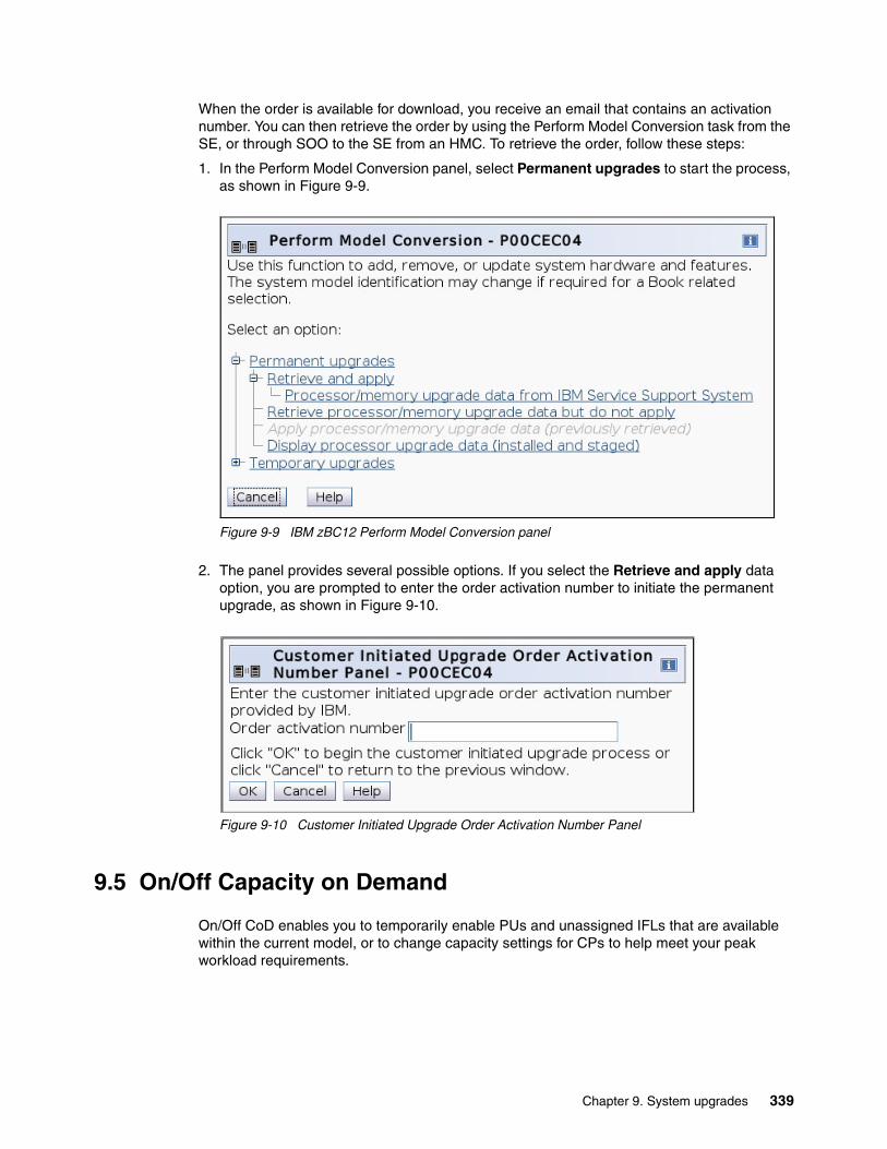
When the order is available for download, you receive an email that contains an activation number. You can then retrieve the order by using the Perform Model Conversion task from the SE, or through SOO to the SE from an HMC. To retrieve the order, follow these steps:
1. In the Perform Model Conversion panel, select Permanent upgrades to start the process, as shown in Figure 9-9.
Figure 9-9 IBM zBC12 Perform Model Conversion panel
2. The panel provides several possible options. If you select the Retrieve and apply data option, you are prompted to enter the order activation number to initiate the permanent upgrade, as shown in Figure 9-10.
Figure 9-10 Customer Initiated Upgrade Order Activation Number Panel
9.5 On/Off Capacity on Demand
On/Off CoD enables you to temporarily enable PUs and unassigned IFLs that are available within the current model, or to change capacity settings for CPs to help meet your peak workload requirements.
Chapter 9. System upgrades 339
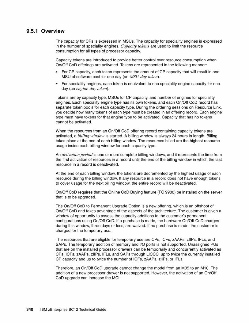
9.5.1 Overview
The capacity for CPs is expressed in MSUs. The capacity for speciality engines is expressed in the number of speciality engines. Capacity tokens are used to limit the resource consumption for all types of processor capacity.
Capacity tokens are introduced to provide better control over resource consumption when On/Off CoD offerings are activated. Tokens are represented in the following manner:
� For CP capacity, each token represents the amount of CP capacity that will result in one MSU of software cost for one day (an MSU-day token).
� For speciality engines, each token is equivalent to one speciality engine capacity for one day (an engine-day token).
Tokens are by capacity type, MSUs for CP capacity, and number of engines for speciality engines. Each speciality engine type has its own tokens, and each On/Off CoD record has separate token pools for each capacity type. During the ordering sessions on Resource Link, you decide how many tokens of each type must be created in an offering record. Each engine type must have tokens for that engine type to be activated. Capacity that has no tokens cannot be activated.
When the resources from an On/Off CoD offering record containing capacity tokens are activated, a billing window is started. A billing window is always 24 hours in length. Billing takes place at the end of each billing window. The resources billed are the highest resource usage inside each billing window for each capacity type.
An activation period is one or more complete billing windows, and it represents the time from the first activation of resources in a record until the end of the billing window in which the last resource in a record is deactivated.
At the end of each billing window, the tokens are decremented by the highest usage of each resource during the billing window. If any resource in a record does not have enough tokens to cover usage for the next billing window, the entire record will be deactivated.
On/Off CoD requires that the Online CoD Buying feature (FC 9900) be installed on the server that is to be upgraded.
The On/Off CoD to Permanent Upgrade Option is a new offering, which is an offshoot of On/Off CoD and takes advantage of the aspects of the architecture. The customer is given a window of opportunity to assess the capacity additions to the customer’s permanent configurations using On/Off CoD. If a purchase is made, the hardware On/Off CoD charges during this window, three days or less, are waived. If no purchase is made, the customer is charged for the temporary use.
The resources that are eligible for temporary use are CPs, ICFs, zAAPs, zIIPs, IFLs, and SAPs. The temporary addition of memory and I/O ports is not supported. Unassigned PUs that are on the installed processor drawers can be temporarily and concurrently activated as CPs, ICFs, zAAPs, zIIPs, IFLs, and SAPs through LICCC, up to twice the currently installed CP capacity and up to twice the number of ICFs, zAAPs, zIIPs, or IFLs.
Therefore, an On/Off CoD upgrade cannot change the model from an M05 to an M10. The addition of a new processor drawer is not supported. However, the activation of an On/Off CoD upgrade can increase the MCI.
340 IBM zEnterprise BC12 Technical Guide
9.5.2 Ordering
Concurrently installing temporary capacity by ordering On/Off CoD is possible in the following quantities:
� CP features equal to the MSU capacity of installed CPs� IFL features up to the number of installed IFLs� ICF features up to the number of installed ICFs� zAAP features up to the number of installed zAAPs� zIIP features up to the number of installed zIIPs� SAPs up to two for both models
On/Off CoD can provide CP temporary capacity by increasing the number of CPs, by changing the capacity setting of the CPs, or both. The capacity setting for all CPs must be the same. If the On/Off CoD is adding CP resources that have a capacity setting that differs from the installed CPs, the base capacity settings are changed to match.
On/Off CoD has the following limits associated with its use:
� The number of CPs cannot be reduced. � The target configuration capacity is limited:
– Twice the currently installed capacity, expressed in MSUs for CPs.– Twice the number of installed IFLs, ICFs, zAAPs, and zIIPs. The number of additional
SAPs that can be activated is two.
See Appendix D, “Valid zBC12 On/Off Capacity on Demand upgrades” on page 471 for the valid On/Off CoD configurations for CPs.
On/Off CoD can be ordered as prepaid or postpaid:
� A prepaid On/Off CoD offering record contains the resource descriptions, MSUs, number of speciality engines, and tokens that describe the total capacity that can be consumed. For CP capacity, the token contains MSU-days; for speciality engines, the token contains speciality engine-days.
� When resources on a prepaid offering are activated, they must have enough capacity tokens to support the activation for an entire billing window, which is 24 hours. The resources remain active until you deactivate them or until one resource has used all of its capacity tokens. When that happens, all activated resources from the record are deactivated.
� A postpaid On/Off CoD offering record contains resource descriptions, MSUs, and speciality engines, and it can contain capacity tokens describing MSU-days and speciality engine-days.
� When resources in a postpaid offering record without capacity tokens are activated, those resources remain active until they are deactivated, or until the offering record expires, which is usually 180 days after its installation.
� When resources in a postpaid offering record with capacity tokens are activated, those resources must have enough capacity tokens to support the activation for an entire billing window (24 hours). The resources remain active until they are deactivated or until one of the resource tokens is consumed, or until the record expires, usually 180 days after its installation. If one capacity token type is consumed, resources from the entire record are deactivated.
Chapter 9. System upgrades 341
As an example, for a zBC12 with capacity identifier D02, the following ways to deliver a capacity upgrade through On/Off CoD exist:
� One option is to add CPs of the same capacity setting. With this option, the MCI can be changed to a D03, which adds one additional CP (making a three-way) or to a D04, which adds two additional CPs (making a four-way).
� Another option is to change to a separate capacity level of the current CPs, and change the MCI to an E02 or to an F02. The capacity level of the CPs is increased, but no additional CPs are added. The D02 can also be temporarily upgraded to an E03 as indicated in the appendix pointer, therefore increasing the capacity level and adding another processor.
We suggest that you use the Large Systems Performance Reference (LSPR) information to evaluate the capacity requirements according to your workload type. LSPR data for current IBM processors is available at the following website:
https://www-304.ibm.com/servers/resourcelink/lib03060.nsf/pages/lsprindex
The On/Off CoD hardware capacity is charged on a 24-hour basis. There is a grace period at the end of the On/Off CoD day. This grace period provides up to an hour after the 24-hour billing period to either change the On/Off CoD configuration for the next 24-hour billing period, or deactivate the current On/Off CoD configuration. The times when the capacity is activated and deactivated are maintained in the zBC12 and sent back to the support systems.
If On/Off capacity is already active, additional On/Off capacity can be added without having to return the zBC12 to its original capacity. If the capacity is increased multiple times within a 24-hour period, the charges apply to the highest amount of capacity active in the period.
If additional capacity is added from an already active record containing capacity tokens, a check is made to control that the resource in question has enough capacity to be active for an entire billing window (24 hours). If that criteria is not met, no additional resources will be activated from the record.
If necessary, additional LPARs can be activated concurrently to use the newly added processor resources.
To participate in this offering, you must have accepted contractual terms for purchasing capacity through the Resource Link, established a profile, and installed an On/Off CoD enablement feature on the zBC12. Subsequently, you can concurrently install temporary capacity up to the limits in On/Off CoD, and use it for up to 180 days.
Monitoring occurs through the zBC12 call-home facility, and an invoice is generated if the capacity was enabled during the calendar month. The customer will continue to be billed for use of temporary capacity until the zBC12 is returned to the original configuration. If the On/Off CoD support is no longer needed, the enablement code must be removed.
On/Off CoD orders can be pre-staged in Resource Link to enable multiple optional configurations. The pricing of the orders is done at the time of the order, and the pricing can vary from quarter to quarter.
Planning: On/Off CoD provides a concurrent hardware upgrade, resulting in more enabled processors available to a zBC12 configuration. Additional planning tasks are required for nondisruptive upgrades. See “Suggestions to avoid disruptive upgrades” on page 360.
342 IBM zEnterprise BC12 Technical Guide
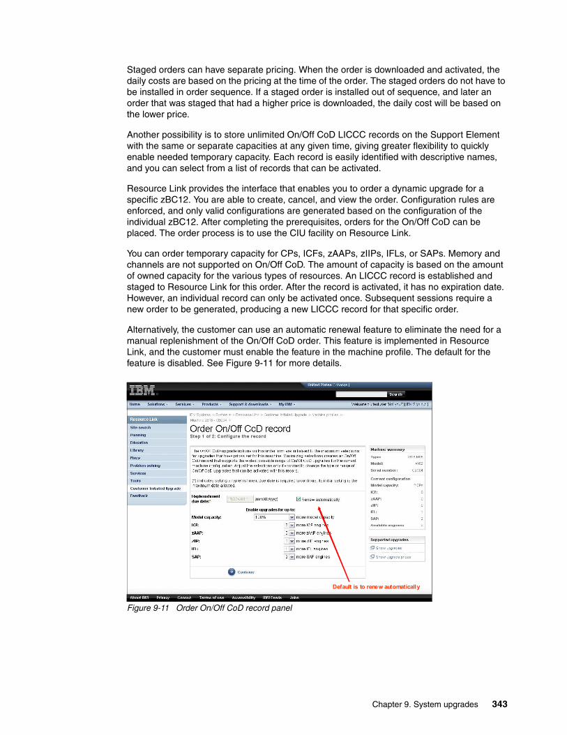
Staged orders can have separate pricing. When the order is downloaded and activated, the daily costs are based on the pricing at the time of the order. The staged orders do not have to be installed in order sequence. If a staged order is installed out of sequence, and later an order that was staged that had a higher price is downloaded, the daily cost will be based on the lower price.
Another possibility is to store unlimited On/Off CoD LICCC records on the Support Element with the same or separate capacities at any given time, giving greater flexibility to quickly enable needed temporary capacity. Each record is easily identified with descriptive names, and you can select from a list of records that can be activated.
Resource Link provides the interface that enables you to order a dynamic upgrade for a specific zBC12. You are able to create, cancel, and view the order. Configuration rules are enforced, and only valid configurations are generated based on the configuration of the individual zBC12. After completing the prerequisites, orders for the On/Off CoD can be placed. The order process is to use the CIU facility on Resource Link.
You can order temporary capacity for CPs, ICFs, zAAPs, zIIPs, IFLs, or SAPs. Memory and channels are not supported on On/Off CoD. The amount of capacity is based on the amount of owned capacity for the various types of resources. An LICCC record is established and staged to Resource Link for this order. After the record is activated, it has no expiration date. However, an individual record can only be activated once. Subsequent sessions require a new order to be generated, producing a new LICCC record for that specific order.
Alternatively, the customer can use an automatic renewal feature to eliminate the need for a manual replenishment of the On/Off CoD order. This feature is implemented in Resource Link, and the customer must enable the feature in the machine profile. The default for the feature is disabled. See Figure 9-11 for more details.
Figure 9-11 Order On/Off CoD record panel
Default is to renew automatically
Chapter 9. System upgrades 343
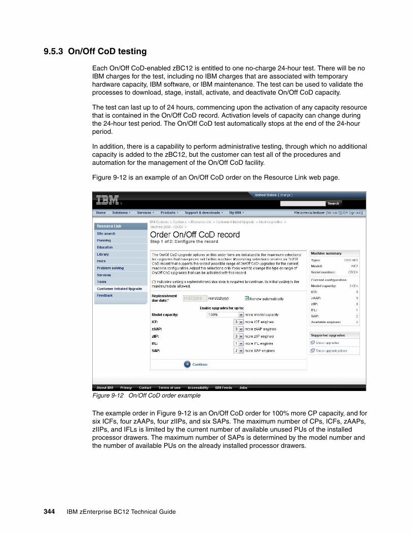
9.5.3 On/Off CoD testing
Each On/Off CoD-enabled zBC12 is entitled to one no-charge 24-hour test. There will be no IBM charges for the test, including no IBM charges that are associated with temporary hardware capacity, IBM software, or IBM maintenance. The test can be used to validate the processes to download, stage, install, activate, and deactivate On/Off CoD capacity.
The test can last up to of 24 hours, commencing upon the activation of any capacity resource that is contained in the On/Off CoD record. Activation levels of capacity can change during the 24-hour test period. The On/Off CoD test automatically stops at the end of the 24-hour period.
In addition, there is a capability to perform administrative testing, through which no additional capacity is added to the zBC12, but the customer can test all of the procedures and automation for the management of the On/Off CoD facility.
Figure 9-12 is an example of an On/Off CoD order on the Resource Link web page.
Figure 9-12 On/Off CoD order example
The example order in Figure 9-12 is an On/Off CoD order for 100% more CP capacity, and for six ICFs, four zAAPs, four zIIPs, and six SAPs. The maximum number of CPs, ICFs, zAAPs, zIIPs, and IFLs is limited by the current number of available unused PUs of the installed processor drawers. The maximum number of SAPs is determined by the model number and the number of available PUs on the already installed processor drawers.
344 IBM zEnterprise BC12 Technical Guide
9.5.4 Activation and deactivation
When a previously ordered On/Off CoD is retrieved from Resource Link, it is downloaded and stored on the SE hard disk. You can activate the order when the capacity is needed, either manually or through automation.
If the On/Off CoD offering record does not contain resource tokens, you must take action to deactivate the temporary capacity. Deactivation is accomplished from the SE, and is nondisruptive. Depending on how the additional capacity was added to the LPARs, you might be required to perform tasks at the LPAR level to remove the temporary capacity. For example, you might have to configure offline CPs that had been added to the partition, or deactivate additional LPARs created to use the temporary capacity, or both.
On/Off CoD orders can be staged in Resource Link so that multiple orders are available. An order can only be downloaded and activated one time. If a separate On/Off CoD order is required, or a permanent upgrade is needed, it can be downloaded and activated without having to restore the system to its original purchased capacity.
In support of automation, an API is provided that enables the activation of the On/Off CoD records. The activation is performed from the HMC, and requires specifying the order number. With this API, automation code can be used to send an activation command along with the order number to the HMC to enable the order.
9.5.5 Termination
A customer is contractually obliged to terminate the On/Off CoD right-to-use feature when a transfer in asset ownership occurs. A customer can also choose to terminate the On/Off CoD right-to-use feature without transferring ownership.
Application of FC 9898 terminates the right to use the On/Off CoD. This feature cannot be ordered if a temporary session is already active. Similarly, the CIU enablement feature cannot be removed if a temporary session is active. Any time that the CIU enablement feature is removed, the On/Off CoD right-to-use is simultaneously removed. Reactivating the right-to-use feature subjects the customer to the terms and fees that apply at that time.
Upgrade capability during On/Off CoDUpgrades involving physical hardware are supported while an On/Off CoD upgrade is active on a particular zBC12. LICCC-only upgrades can be ordered and retrieved from Resource Link and applied while an On/Off CoD upgrade is active. LICCC-only memory upgrades can also be retrieved and applied while an On/Off CoD upgrade is active.
Repair capability during On/Off CoDIf the zBC12 requires service while an On/Off CoD upgrade is active, the repair can take place without affecting the temporary capacity.
MonitoringWhen you activate an On/Off CoD upgrade, an indicator is set in the vital product data. This indicator is part of the call-home data transmission, which is sent on a scheduled basis. A time stamp is placed into call-home data when the facility is deactivated. At the end of each calendar month, the data is used to generate an invoice for the On/Off CoD that was used during that month.
Chapter 9. System upgrades 345
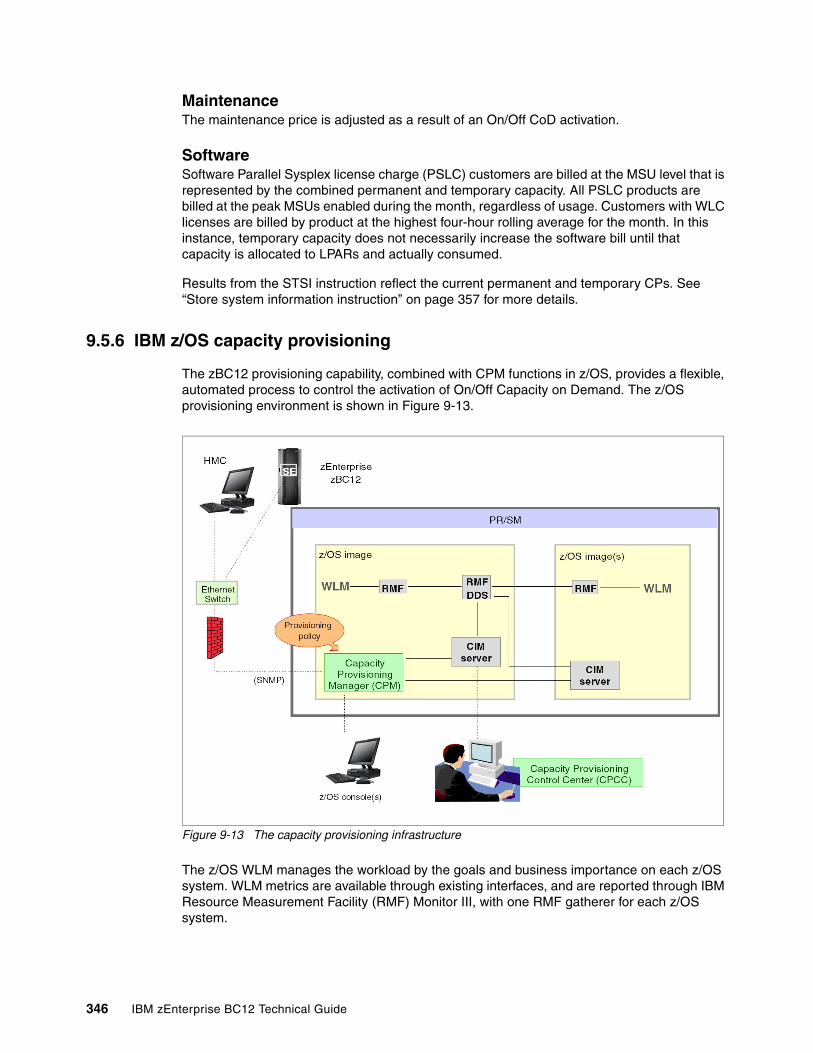
MaintenanceThe maintenance price is adjusted as a result of an On/Off CoD activation.
SoftwareSoftware Parallel Sysplex license charge (PSLC) customers are billed at the MSU level that is represented by the combined permanent and temporary capacity. All PSLC products are billed at the peak MSUs enabled during the month, regardless of usage. Customers with WLC licenses are billed by product at the highest four-hour rolling average for the month. In this instance, temporary capacity does not necessarily increase the software bill until that capacity is allocated to LPARs and actually consumed.
Results from the STSI instruction reflect the current permanent and temporary CPs. See “Store system information instruction” on page 357 for more details.
9.5.6 IBM z/OS capacity provisioning
The zBC12 provisioning capability, combined with CPM functions in z/OS, provides a flexible, automated process to control the activation of On/Off Capacity on Demand. The z/OS provisioning environment is shown in Figure 9-13.
Figure 9-13 The capacity provisioning infrastructure
The z/OS WLM manages the workload by the goals and business importance on each z/OS system. WLM metrics are available through existing interfaces, and are reported through IBM Resource Measurement Facility (RMF) Monitor III, with one RMF gatherer for each z/OS system.
346 IBM zEnterprise BC12 Technical Guide

Sysplex-wide data aggregation and propagation occur in the RMF distributed data server (DDS). The RMF Common Information Model (CIM) providers and associated CIM models publish the RMF Monitor III data.
The CPM, a function inside z/OS, retrieves critical metrics from one or more z/OS systems through the CIM structures and protocol. CPM communicates to (local or remote) SEs and HMCs through Simple Network Management Protocol (SNMP).
CPM has visibility of the resources in the individual offering records, and the capacity tokens. When CPM decides to activate resources, a check is performed to determine whether enough capacity tokens remain for the specified resource to be activated for at least 24 hours. If insufficient tokens remain, no resource from the On/Off CoD record is activated.
If a capacity token is completely consumed during an activation that is driven by the CPM, the corresponding On/Off CoD record is deactivated prematurely by the system, even if the CPM has activated this record, or parts of it. Warning messages will be issued if capacity tokens are getting close to being fully consumed. The messages will start being generated five days before a capacity token is fully consumed. The five days are based on the assumption that the consumption will be constant for the five days.
We suggest that you put operational procedures in place to handle these situations. You can either deactivate the record manually, let it happen automatically, or replenish the specified capacity token by using the Resource Link application.
The Capacity Provisioning Control Center (CPCC), which is on a workstation, provides an interface to administer capacity provisioning policies. The CPCC is not required for regular CPM operation. The CPCC will over time be moved into the z/OS Management Facility (z/OSMF). Parts of the CPCC have been included in z/OSMF V1R13.
Chapter 9. System upgrades 347
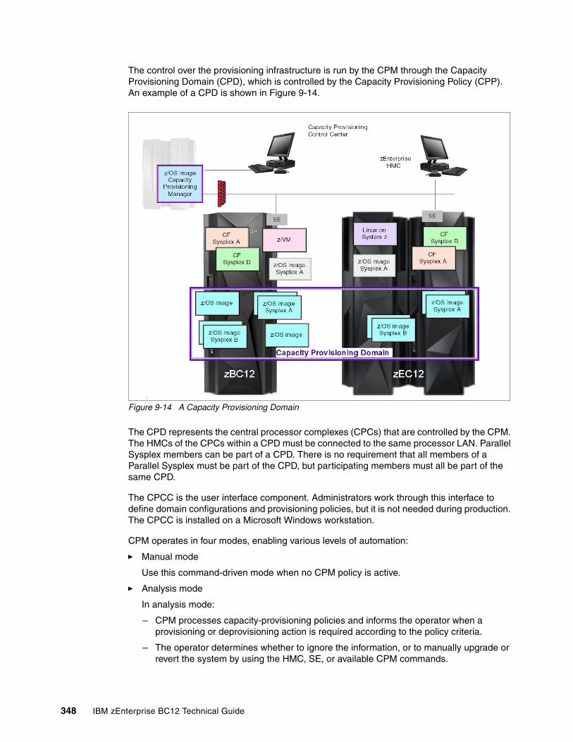
The control over the provisioning infrastructure is run by the CPM through the Capacity Provisioning Domain (CPD), which is controlled by the Capacity Provisioning Policy (CPP). An example of a CPD is shown in Figure 9-14.
Figure 9-14 A Capacity Provisioning Domain
The CPD represents the central processor complexes (CPCs) that are controlled by the CPM. The HMCs of the CPCs within a CPD must be connected to the same processor LAN. Parallel Sysplex members can be part of a CPD. There is no requirement that all members of a Parallel Sysplex must be part of the CPD, but participating members must all be part of the same CPD.
The CPCC is the user interface component. Administrators work through this interface to define domain configurations and provisioning policies, but it is not needed during production. The CPCC is installed on a Microsoft Windows workstation.
CPM operates in four modes, enabling various levels of automation:
� Manual mode
Use this command-driven mode when no CPM policy is active.
� Analysis mode
In analysis mode:
– CPM processes capacity-provisioning policies and informs the operator when a provisioning or deprovisioning action is required according to the policy criteria.
– The operator determines whether to ignore the information, or to manually upgrade or revert the system by using the HMC, SE, or available CPM commands.
348 IBM zEnterprise BC12 Technical Guide
� Confirmation mode
In this mode, CPM processes capacity-provisioning policies and interrogates the installed temporary offering records. Every action that is proposed by the CPM needs to be confirmed by the operator.
� Autonomic mode
This mode is similar to the confirmation mode, but no operator confirmation is required.
A number of reports are available in all modes, containing information about the workload, provisioning status, and the rationale for provisioning recommendations. User interfaces are through the z/OS console and the CPCC application.
The provisioning policy defines the circumstances under which additional capacity can be provisioned (when, which, and how). The criteria has three elements:
� A time condition is when provisioning is enabled:
– Start time indicates when provisioning can begin.– Deadline indicates that the provisioning of the additional capacity is no longer enabled.– End time indicates that the deactivation of the additional capacity must begin.
� A workload condition is a description of which workload qualifies for provisioning. The parameters include this information:
– The z/OS systems that might run the eligible work.
– The importance filter indicates eligible service class periods, which are identified by Workload Manager (WLM) importance.
– Performance index (PI) criteria:
• Activation threshold. The PI of the service class periods must exceed the activation threshold for a specified duration before the work is considered to be suffering.
• Deactivation threshold. The PI of the service class periods must fall below the deactivation threshold for a specified duration before the work is considered to no longer be suffering.
– Included service classes are eligible service class periods.
– Excluded service classes are service class periods that must not be considered.
� Provisioning scope is how much additional capacity can be activated, and it is expressed in MSUs.
Specified in MSUs, the number of zAAPs and the number of zIIPs must be one specification per CPC that is part of the CPD.
The maximum provisioning scope is the maximum additional capacity that can be activated for all of the rules in the CPD.
The provisioning ruleThe provisioning rule is in the specified time interval, if the specified workload is behind its objective, up to the defined additional capacity can be activated. The rules and conditions are named and stored in the CPP. For more information about z/OS Capacity Provisioning functions, see z/OS MVS Capacity Provisioning User’s Guide, SA33-8299.
If no workload condition is specified: The full capacity that is described in the policy will be activated and deactivated at the start and end times that are specified in the policy.
Chapter 9. System upgrades 349
Planning considerations for using automatic provisioningAlthough only one On/Off CoD offering can be active at any one time, several On/Off CoD offerings can be present on the zBC12. Changing from one to another requires that the active one be stopped before the inactive one can be activated. This operation decreases the current capacity during the change.
The provisioning management routines can interrogate the installed offerings, their content, and the status of the content of the offering. To avoid the decrease in capacity, we suggest that only one On/Off CoD offering be created on the zBC12 by specifying the maximum possible capacity.
The CPM can then, at the time that an activation is needed, activate a subset of the contents of the offering sufficient to satisfy the demand. If, at a later time, more capacity is needed, the CPM can activate more capacity up to the maximum supported in the offering.
Having an unlimited number of offering records pre-staged on the SE hard disk is possible. Changing the content of the offerings if necessary is also possible.
In a situation where a CBU offering is active on a zBC12, and that CBU offering is 100% or more of the base capacity, activating any On/Off CoD is not possible, because the On/Off CoD offering is limited to 100% of the base configuration.
The CPM operates based on WLM indications, and the construct used is the PI of a service class period. It is extremely important to select service class periods that are appropriate for the business application that needs more capacity.
For example, the application in question might be running through several service class periods, where the first period might be the important one. The application might be defined as importance level 2 or 3, but it might depend on other work running with importance level 1. Therefore, considering which workloads to control and which service class periods to specify is extremely important.
9.6 Capacity for Planned Event
CPE is offered with the zBC12 to provide replacement backup capacity for planned downtime events. For example, if a server room requires an extension or repair work, replacement capacity can be installed temporarily on another zBC12 in the customer’s environment.
Important: The CPM has control over capacity tokens for the On/Off CoD records. In a situation where a capacity token is completely consumed, the zBC12 deactivates the corresponding offering record.
Therefore, we strongly suggest that you prepare routines for detecting the warning messages about capacity tokens being used, and have administrative routines in place for these situations. The messages from the system begin five days before a capacity token is fully used. To avoid capacity records from being deactivated in this situation, replenish the necessary capacity tokens before they are completely used.
Important: CPE is for planned replacement capacity only, and it cannot be used for peak workload management.
350 IBM zEnterprise BC12 Technical Guide
CPE has these feature codes:
� FC 6833: Capacity for Planned Event enablement� FC 0116: 1 CPE Capacity Unit� FC 0117: 100 CPE Capacity Unit� FC 0118: 10000 CPE Capacity Unit� FC 0119: 1 CPE Capacity Unit-IFL� FC 0120: 100 CPE Capacity Unit-IFL� FC 0121: 1 CPE Capacity Unit-ICF� FC 0122: 100 CPE Capacity Unit-ICF� FC 0123: 1 CPE Capacity Unit-zAAP� FC 0124: 100 CPE Capacity Unit-zAAP� FC 0125: 1 CPE Capacity Unit-zIIP� FC 0126: 100 CPE Capacity Unit-zIIP� FC 0127: 1 CPE Capacity Unit-SAP� FC 0128: 100 CPE Capacity Unit-SAP
The feature codes are calculated automatically when the CPE offering is configured. Whether using the eConfig tool or the Resource Link, a target configuration must be ordered consisting of a model identifier or a number of speciality engines, or both. Based on the target configuration, a number of feature codes from the previous list is calculated automatically, and a CPE offering record is constructed.
CPE is intended to replace capacity lost within the enterprise because of a planned event, such as a facility upgrade or system relocation. CPE is intended for short duration events lasting up to a maximum of three days. Each CPE record, after it is activated, gives you access to dormant PUs on the server for which you have a contract (as described by the feature codes listed).
PUs can be configured in any combination of CP or specialty engine types (zIIP, zAAP, SAP, IFL, and ICF). At the time of CPE activation, the contracted configuration will be activated. The general rule of one zIIP and one zAAP for each configured CP will be controlled for the contracted configuration.
The processors that can be activated by CPE come from the available unassigned PUs on any installed processor drawer. CPE features can be added to an existing zBC12 non-disruptively. A one-time fee is applied for each individual CPE event, depending on the contracted configuration and its resulting feature codes. Only one CPE contract can be ordered at a time.
The base zBC12 configuration must have sufficient memory and channels to accommodate the potential requirements of the large CPE configuration. It is important to ensure that all required functions and resources are available on the zBC12 where CPE is activated, including coupling facility (CF) LEVELs for CF partitions, memory, cryptographic functions, and connectivity capabilities.
The CPE configuration is activated temporarily, and provides additional PUs in addition to the zBC12’s original, permanent configuration. The number of additional PUs is predetermined by the number and type of feature codes configured, as described by the list of the feature codes. The number of PUs that can be activated is limited by the unused capacity that is available on the server.
When the planned event is over, the server must be returned to its original configuration. You can deactivate the CPE features at any time before the expiration date.
A CPE contract must be in place before the special code that enables this capability can be installed. CPE features can be added to an existing zBC12 non-disruptively.
Chapter 9. System upgrades 351
9.7 Capacity BackUp
CBU provides reserved emergency backup processor capacity for unplanned situations in which capacity is lost in another part of your enterprise, and you want to recover by adding the reserved capacity on a designated zBC12.
CBU is the quick, temporary activation of PUs, and is available in the following durations:
� For up to 90 consecutive days, in case of a loss of processing capacity as a result of an emergency or disaster recovery situation
� For 10 days for testing your disaster recovery procedures
9.7.1 Ordering
The CBU process enables CBU to activate CPs, ICFs, zAAPs, zIIPs, IFLs, and SAPs. To be able to use the CBU process, a CBU enablement feature (FC 9910) must be ordered and installed. You must order the quantity and type of PUs that you require. CBU has these feature codes:
� FC 9910: CBU enablement� FC 6805: Additional test activations� FC 6817: Total CBU years ordered� FC 6818: CBU records ordered� FC 6820: Single CBU CP-year� FC 6821: 25 CBU CP-year� FC 6822: Single CBU IFL-year� FC 6823: 25 CBU IFL-year� FC 6824: Single CBU ICF-year� FC 6825: 25 CBU ICF-year� FC 6826: Single CBU zAAP-year� FC 6827: 25 CBU zAAP-year� FC 6828: Single CBU zIIP-year� FC 6829: 25 CBU zIIP-year� FC 6830: Single CBU SAP-year� FC 6831: 25 CBU SAP-year� FC 6832: CBU replenishment
The CBU entitlement record (FC 6818) contains an expiration date that is established at the time of order, and depends upon the quantity of CBU years (FC 6817). You have the capability to extend your CBU entitlements through the purchase of additional CBU years. The number of FC 6817 per instance of FC 6818 remains limited to five, and fractional years are rounded up to the nearest whole integer when calculating this limit.
For instance, if there are two years and eight months to the expiration date at the time of order, the expiration date can be extended by no more than two additional years. One test activation is provided for each additional CBU year added to the CBU entitlement record.
Feature code 6805 enables ordering additional tests in increments of one. The total number of tests supported is 15 for each feature code 6818.
Important: CBU is for disaster and recovery purposes only, and cannot be used for peak workload management or for a planned event.
352 IBM zEnterprise BC12 Technical Guide
The processors that can be activated by CBU come from the available unassigned PUs on any processor drawer. The maximum number of CBU features that can be ordered is 13. The number of features that can be activated is limited by the number of unused PUs on the server.
However, the ordering system permits over-configuration in the order itself. You can order up to 13 CBU features regardless of the current configuration. However, at activation, only the capacity already installed can be activated. Note that at activation, you can decide to activate only a subset of the CBU features that are ordered for the system.
Subcapacity makes a difference in the way that the CBU features are done. On the full-capacity models, the CBU features indicate the amount of additional capacity needed. If the amount of necessary CBU capacity is equal to four CPs, the CBU configuration is four CBU CPs.
The number of CBU CPs must be equal to or greater than the number of CPs in the base configuration, and all of the CPs in the CBU configuration must have the same capacity setting. For example, if the base configuration is a two-way D02, providing a CBU configuration of a four-way of the same capacity setting requires two CBU feature codes.
If the required CBU capacity changes the capacity setting of the CPs, going from model capacity identifier D02 to a CBU configuration of a four-way E04 requires four CBU feature codes with a capacity setting of Exx.
If the capacity setting of the CPs is changed, more CBU features are required, not more physical PUs. Therefore, your CBU contract requires more CBU features if the capacity setting of the CPs is changed.
Note that CBU can add CPs through LICCC only, and the zBC12 must have the correct number of processor drawers installed to support the required upgrade. CBU can change the MCI to a higher value than the base setting, but it does not change the zBC12 model. The CBU feature cannot decrease the capacity setting.
A CBU contract must be in place before the special code that enables this capability can be installed on the zBC12. CBU features can be added to an existing zBC12 non-disruptively. For each machine enabled for CBU, the authorization to use CBU is available for a definite number of years (one - five).
The installation of the CBU code provides an alternative configuration that can be activated in case of an actual emergency. Five CBU tests, lasting up to 10 days each, and one CBU activation, lasting up to 90 days for a real disaster and recovery, are typically available in a CBU contract.
The alternative configuration is activated temporarily, and provides additional capacity greater than the server’s original, permanent configuration. At activation time, you determine the capacity required for a given situation, and you can decide to activate only a subset of the capacity that is specified in the CBU contract.
The base server configuration must have sufficient memory and channels to accommodate the potential requirements of the large CBU target configuration. Ensure that all required functions and resources are available on the backup zBC12, including CF LEVELs for CF partitions, memory, cryptographic functions, and connectivity capabilities.
When the emergency is over (or the CBU test is complete), the zBC12 must be taken back to its original configuration. The CBU features can be deactivated by the customer at any time before the expiration date.
Chapter 9. System upgrades 353
Failure to deactivate the CBU feature before the expiration date can cause the system to degrade gracefully back to its original configuration. The system does not deactivate dedicated engines, or the last of in-use shared engines.
For detailed instructions, see the System z Capacity on Demand User’s Guide, SC28-6846.
9.7.2 CBU activation and deactivation
The activation and deactivation of the CBU function is a customer responsibility, and does not require the onsite presence of IBM service personnel. The CBU function is activated and deactivated concurrently from the HMC using the API. On the SE, CBU is activated either using the Perform Model Conversion task or through the API (the API enables task automation).
CBU activationCBU is activated from the SE by using the Perform Model Conversion task, or through automation by using the API on the SE or the HMC. In the case of a real disaster, use the Activate CBU option to activate the 90-day period.
Image upgradesAfter the CBU activation, the zBC12 can have more capacity, more active PUs, or both. The additional resources go into the resource pools, and are available to the LPARs. If the LPARs have to increase their share of the resources, the LPARs’ weight can be changed, or the number of logical processors can be concurrently increased by configuring reserved processors online.
The OS must have the capability to concurrently configure more processors online. If necessary, additional LPARs can be created to use the newly added capacity.
CBU deactivationTo deactivate the CBU, the additional resources have to be released from the LPARs by the OSs. In certain cases, releasing resources is a matter of varying the resources offline. In other cases, it can mean shutting down OSs or deactivating LPARs. After the resources have been released, the same facility on the SE is used to turn off CBU. To deactivate CBU, click Undo temporary upgrade from the Perform Model Conversion task on the SE.
CBU testingTest CBUs are provided as part of the CBU contract. CBU is activated from the SE by using the Perform Model Conversion task. Select the test option to initiate a 10-day test period. A standard contract can support five tests of this type. However, you can order additional tests in increments of one up to a maximum of 15 for each CBU order.
Planning: CBU for processors provides a concurrent upgrade, resulting in more enabled processors, or changed capacity settings available to a zBC12 configuration, or both. You decide, at activation time, to activate a subset of the CBU features ordered for the system. Therefore, additional planning and tasks are required for nondisruptive logical upgrades. See “Suggestions to avoid disruptive upgrades” on page 360.
Tip: The CBU tests activation is done the same way as the real activation, using the same SE Perform a Model Conversion panel and then selecting Temporary upgrades option. The HMC panels have been changed to avoid real CBU activations by setting the test activation as the default option.
354 IBM zEnterprise BC12 Technical Guide
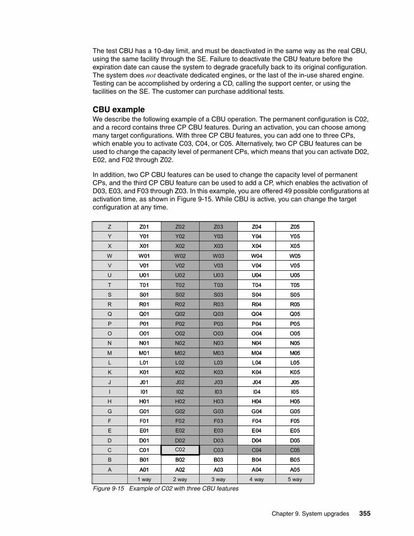
The test CBU has a 10-day limit, and must be deactivated in the same way as the real CBU, using the same facility through the SE. Failure to deactivate the CBU feature before the expiration date can cause the system to degrade gracefully back to its original configuration. The system does not deactivate dedicated engines, or the last of the in-use shared engine. Testing can be accomplished by ordering a CD, calling the support center, or using the facilities on the SE. The customer can purchase additional tests.
CBU exampleWe describe the following example of a CBU operation. The permanent configuration is C02, and a record contains three CP CBU features. During an activation, you can choose among many target configurations. With three CP CBU features, you can add one to three CPs, which enable you to activate C03, C04, or C05. Alternatively, two CP CBU features can be used to change the capacity level of permanent CPs, which means that you can activate D02, E02, and F02 through Z02.
In addition, two CP CBU features can be used to change the capacity level of permanent CPs, and the third CP CBU feature can be used to add a CP, which enables the activation of D03, E03, and F03 through Z03. In this example, you are offered 49 possible configurations at activation time, as shown in Figure 9-15. While CBU is active, you can change the target configuration at any time.
Figure 9-15 Example of C02 with three CBU features
A
B
C
D
E
F
G
H
I
J
K
L
M
N
O
P
Q
R
S
T
U
V
W
X
Y
Z
A05A04A03A02A01
5 way4 way3 way2 way1 way
B05B04B03B02B01
C05C04C03C02C01
D05D04D03D02D01
E05E04E03E02E01
F05F03F02F01
G05G04G03G02G01
H05H04H03H02H01
I05I04I03I02I01
J05J04J03J02J01
K05K04K03K02K01
L05L04L03L02L01
M05M04M03M02M01
N05N04N03N02N01
O05O04O03O02O01
P05P04P03P02P01
Q05Q04Q03Q02Q01
R05R04R03R02R01
S05S04S03S02S01
T05T04T03T02T01
U05U04U03U02U01
V05V04V03V02V01
W05 W04 W03 W02 W01
X05 X04 X03 X02 X01
Y05 Y04 Y03 Y02 Y01
Z05 Z04 Z03 Z02 Z01
F04
Chapter 9. System upgrades 355
9.7.3 Automatic CBU for Geographically Dispersed Parallel Sysplex
The intent of the IBM Geographically Dispersed Parallel Sysplex (GDPS) CBU is to enable automatic management of the PUs provided by the CBU feature in the event of a server or site failure. Upon detection of a site failure or planned disaster test, GDPS will concurrently add CPs to the servers in the takeover site to restore processing power for mission-critical production workloads. GDPS automation does the following tasks:
� Performs the analysis required to determine the scope of the failure. This function minimizes operator intervention and the potential for errors.
� Automates the authentication and activation of the reserved CPs.
� Automatically restarts the critical applications after reserved CP activation.
� Reduces the outage time to restart critical workloads from several hours to minutes.
The GDPS service is for z/OS only, or for z/OS in combination with Linux on System z.
9.8 Nondisruptive upgrades
Continuous availability is an increasingly important requirement for most customers, and even planned outages are no longer acceptable. Although Parallel Sysplex clustering technology is the best continuous availability solution for z/OS environments, nondisruptive upgrades within a single server can avoid system outages, and are suitable to additional OS environments.
The zBC12 supports concurrent upgrades, meaning that dynamically adding more capacity to the CPC is possible. If OS images running on the upgraded CPC do not require disruptive tasks to use the new capacity, the upgrade is also nondisruptive. Therefore, POR, LPAR deactivation, and IPL do not have to take place.
If the concurrent upgrade is intended to satisfy an image upgrade to an LPAR, the OS running in this partition must also have the capability to concurrently configure more capacity online. IBM z/OS OSs have this capability. IBM z/VM can concurrently configure new processors and I/O devices online, and memory can be dynamically added to z/VM partitions.
If the concurrent upgrade is intended to satisfy the need for more OS images, additional LPARs can be created concurrently on the zBC12 CPC, including all resources needed by such LPARs. These additional LPARs can be activated concurrently.
Linux OSs in general do not have the capability of adding more resources concurrently. However, Linux, and other types of virtual machines running under z/VM, can benefit from the z/VM capability to non-disruptively configure more resources online (processors and I/O).
With z/VM, Linux guests can manipulate their logical processors through the use of the Linux central processing unit (CPU) hotplug daemon. The daemon can start and stop logical processors based on the Linux average load value. The daemon is available in SUSE Linux Enterprise Server (SLES) 10 SP2. IBM is working with our Linux distribution IBM Business Partners to have the daemon available in other distributions for the System z servers.
ProcessorsCPs, ICFs, zAAPs, zIIPs, IFLs, and SAPs can be concurrently added to a zBC12 if unassigned PUs are available in any installed processor drawer. The number of zAAPs cannot exceed the number of CPs, plus unassigned CPs. The same is true for the zIIPs. If necessary, additional LPARs can be created concurrently to use the newly added processors.
356 IBM zEnterprise BC12 Technical Guide
The coupling facility control code (CFCC) can also configure more processors online to CF LPARs by using the CFCC image operations window.
MemoryMemory can be concurrently added up to the physically installed memory limit.
Using the previously defined reserved memory, z/OS OS images and z/VM partitions can dynamically configure more memory online, enabling nondisruptive memory upgrades. Linux on System z supports Dynamic Storage Reconfiguration.
I/OI/O adapters can be added concurrently if all of the required infrastructure (I/O slots and fanouts) is present on the configuration.
Dynamic I/O configurations are supported by certain OSs (z/OS and z/VM), enabling nondisruptive I/O upgrades. However, having dynamic I/O reconfiguration on a stand-alone CF server is not possible, because there is no OS with this capability running on this server.
Cryptographic adaptersCrypto Express3 and Crypto Express4 features can be added concurrently if all of the required infrastructure is in the configuration.
Special features Special features, such as Flash Express, IBM zEnterprise Data Compression (zEDC), and Remote Direct Memory Access (RDMA) over Converged Ethernet (RoCE), can also be added concurrently if all of the infrastructure is available in the configuration.
Concurrent upgrade considerationsBy using MES upgrade, On/Off CoD, CBU, or CPE, a zBC12 can be concurrently upgraded from one capacity identifier to another, either temporarily or permanently.
Enabling and using the additional processor capacity is transparent to most applications. However, certain programs depend on processor model-related information (for example, ISV products). You need to consider the effect on the software running on a zBC12 when you perform any of these configuration upgrades.
Processor identificationThe following instructions are used to obtain processor information:
� The STSI instruction
STSI reports the processor model and model capacity identifier for the base configuration and for any additional configuration changes through temporary upgrade actions. It fully supports the concurrent upgrade functions and is the preferred way to request processor information.
� The store CPU ID instruction (STIDP) instruction
STIDP is provided for purposes of compatibility with a previous version.
Store system information instructionThe STSI instruction returns the MCI for the permanent configuration, and the MCI for any temporary capacity. This is key to the functioning of CoD offerings.
Chapter 9. System upgrades 357
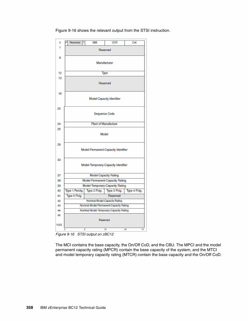
Figure 9-16 shows the relevant output from the STSI instruction.
Figure 9-16 STSI output on zBC12
The MCI contains the base capacity, the On/Off CoD, and the CBU. The MPCI and the model permanent capacity rating (MPCR) contain the base capacity of the system, and the MTCI and model temporary capacity rating (MTCR) contain the base capacity and the On/Off CoD.
358 IBM zEnterprise BC12 Technical Guide
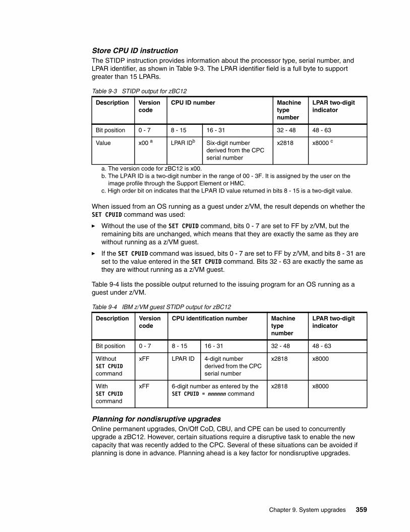
Store CPU ID instruction The STIDP instruction provides information about the processor type, serial number, and LPAR identifier, as shown in Table 9-3. The LPAR identifier field is a full byte to support greater than 15 LPARs.
Table 9-3 STIDP output for zBC12
When issued from an OS running as a guest under z/VM, the result depends on whether the SET CPUID command was used:
� Without the use of the SET CPUID command, bits 0 - 7 are set to FF by z/VM, but the remaining bits are unchanged, which means that they are exactly the same as they are without running as a z/VM guest.
� If the SET CPUID command was issued, bits 0 - 7 are set to FF by z/VM, and bits 8 - 31 are set to the value entered in the SET CPUID command. Bits 32 - 63 are exactly the same as they are without running as a z/VM guest.
Table 9-4 lists the possible output returned to the issuing program for an OS running as a guest under z/VM.
Table 9-4 IBM z/VM guest STIDP output for zBC12
Planning for nondisruptive upgradesOnline permanent upgrades, On/Off CoD, CBU, and CPE can be used to concurrently upgrade a zBC12. However, certain situations require a disruptive task to enable the new capacity that was recently added to the CPC. Several of these situations can be avoided if planning is done in advance. Planning ahead is a key factor for nondisruptive upgrades.
Description Versioncode
CPU ID number Machine type number
LPAR two-digit indicator
Bit position 0 - 7 8 - 15 16 - 31 32 - 48 48 - 63
Value x00 a
a. The version code for zBC12 is x00.
LPAR IDb
b. The LPAR ID is a two-digit number in the range of 00 - 3F. It is assigned by the user on the image profile through the Support Element or HMC.
Six-digit number derived from the CPC serial number
x2818 x8000 c
c. High order bit on indicates that the LPAR ID value returned in bits 8 - 15 is a two-digit value.
Description Version code
CPU identification number Machine type number
LPAR two-digit indicator
Bit position 0 - 7 8 - 15 16 - 31 32 - 48 48 - 63
WithoutSET CPUIDcommand
xFF LPAR ID 4-digit number derived from the CPC serial number
x2818 x8000
WithSET CPUIDcommand
xFF 6-digit number as entered by the SET CPUID = nnnnnn command
x2818 x8000
Chapter 9. System upgrades 359
The following list describes the major reasons for disruptive upgrades. However, by carefully planning, and by reviewing “Suggestions to avoid disruptive upgrades”, you can minimize the need for these outages:
� When reserved storage was not previously defined, LPAR memory upgrades are disruptive to image upgrades. IBM z/OS and z/VM support this function.
� Installation of an additional processor drawer to upgrade a model H06 to a model H13 is non-concurrent.
� When the OS cannot use the dynamic I/O configuration function, an I/O upgrade is disruptive to that LPAR. Linux, IBM z/Virtual Storage Extended (z/VSE), Transaction Processing Facility (TPF), IBM z/Transaction Processing Facility (z/TPF), and CFCC do not support the dynamic I/O configuration.
Suggestions to avoid disruptive upgradesBased on the previous list of reasons for disruptive upgrades (“Planning for nondisruptive upgrades” on page 359), here are several suggestions for avoiding or at least minimizing these situations, increasing the potential for nondisruptive upgrades:
� Using an SE function under Operational Customization tasks, called Logical Processor add, CPs, zIIPs, and zAAPs can be added concurrently to a running partition. CPs, zIIPs, and zAAPs initial or reserved number of processors can be dynamically changed.
� The OS that runs in the targeted LPAR must support the dynamic addition of resources, and be able to configure processors online. The total number of defined and reserved CPs cannot exceed the number of CPs supported by the OS. IBM z/OSV1R11, z/OS V1R12, and z/OS V1R13 with program temporary fixes (PTFs) supports up to 100 processors. IBM z/OS V2R1 also supports 100 processors. These processors include CPs, zAAPs, and zIIPs. IBM z/VM supports up to 32 processors.
� Configure reserved storage to LPARs. Configuring reserved storage for all LPARs before their activation enables them to be non-disruptively upgraded. The OS running in the LPAR must have the ability to configure memory online. The amount of reserved storage can be higher than the processor drawer threshold limit, even if the second processor drawer is not installed. The current partition storage limit is 1 terabyte (TB). IBM z/OS and z/VM support this function.
� Consider the plan-ahead memory options. Use a convenient entry point for memory capacity, and consider the memory options to enable future upgrades within the memory cards that are already installed on the processor drawers. For details about the offerings, see 2.5.3, “Memory configurations” on page 46.
Considerations when installing an additional CEC drawerDuring an upgrade, an additional CEC drawer can be installed non-concurrently. Depending on your I/O configuration, a fanout rebalancing might be desirable for availability reasons.
9.9 Summary of capacity on demand offerings
The CoD infrastructure and its offerings are major features for zBC12. The introduction of these features was based on numerous customer requirements for more flexibility, granularity, and better business control over the System z infrastructure, operationally and financially.
One major customer requirement is to eliminate the necessity for a customer authorization connection to the IBM Resource Link system at the time of activation of any offering. This requirement is being met by the zBC12.
360 IBM zEnterprise BC12 Technical Guide

After the offerings have been installed on the zBC12, they can be activated at any time, completely at the customer’s discretion. No intervention through IBM or IBM personnel is necessary. In addition, the activation of the CBU does not require a password.
The zBC12 can have up to eight offerings installed at the same time, with the limitation that only one of them can be an On/Off CoD offering. The others can be any combination. The installed offerings can be activated fully or partially, and in any sequence and any combination. The offerings can be controlled manually through command interfaces on the HMC, or programmatically through a number of APIs, so that IBM applications, ISV programs, or customer-written applications, can control the usage of the offerings.
Resource consumption (and therefore financial exposure) can be controlled by using capacity tokens in On/Off CoD offering records.
The CPM is an example of an application that uses the CoD APIs to provision On/Off CoD capacity based on the requirements of the running workload. The CPM cannot control other offerings.
Chapter 9. System upgrades 361

362 IBM zEnterprise BC12 Technical Guide
Chapter 10. Reliability, availability, and serviceability
In this chapter, we describe several of the reliability, availability, and serviceability (RAS) features of the zEnterprise System.
The IBM zEnterprise BC12 System (zBC12) design is focused on providing higher availability by reducing planned and unplanned outages. RAS can be accomplished with improved concurrent upgrade functions for processors, memory, and concurrent remove, repair, and add or upgrade for I/O. RAS also extends to the nondisruptive capability for downloading Licensed Internal Code (LIC) updates.
In most cases, a capacity upgrade can be concurrent without a system outage. As an extension to the RAS capabilities, this chapter provides information about the environmental controls that are implemented in the zBC12 to help reduce power consumption and cooling requirements.
The design of the memory on the zBC12 has taken a major step forward by implementing a fully redundant memory infrastructure, redundant array of independent memory (RAIM), a concept similar to the Redundant Array of Independent Disks (RAID) design that is used in external disk storage systems. The zEnterprise central processor complexes (CPCs) are the only servers in the industry offering this level of memory design.
To make the delivery and transmission of microcode (LIC) secure, fixes and restoration (backup) files are digitally signed. Any data that is transmitted to IBM Support is encrypted. The design goal for the zBC12 is to remove all sources of planned outages. We cover the following topics:
� IBM zBC12 availability characteristics� IBM zBC12 RAS functions� IBM zBC12 enhanced driver maintenance� RAS capability for the HMC and SE� RAS capability for zBX� Considerations for IBM PowerHA in a zBX environment� IBM System z Advanced Workload Analysis Reporter� RAS capability for Flash Express
10
© Copyright IBM Corp. 2014. All rights reserved. 363
10.1 IBM zBC12 availability characteristics
The following functions include the availability characteristics on the zBC12:
� Concurrent memory upgrade
Memory can be upgraded concurrently using an LIC configuration code (LICCC) update if physical memory is available in the processor drawers. If the physical memory cards have to be changed, the zBC12 needs to be powered down. To help ensure that the appropriate level of memory is available in a configuration, consider the plan-ahead memory feature.
The plan-ahead memory feature that is available with the zBC12 provides the ability to plan for nondisruptive memory upgrades by having the system pre-plugged with dual inline memory modules (DIMMs) based on a target configuration. Pre-plugged memory is enabled when you place an order through LICCC.
� Enhanced driver maintenance (EDM)
One of the greatest contributors to downtime during planned outages is LIC driver updates performed in support of new features and functions. The zBC12 is designed to support activating a selected new driver level concurrently.
� Concurrent fanout addition or replacement
A PCIe, host channel adapter (HCA), or Memory Bus Adapter (MBA) fanout card provides the path for data between memory and I/O using InfiniBand cables or PCIe cables. With the zBC12, a hot-pluggable and concurrently upgradeable fanout card is available.
Up to four fanout cards are available per processor drawer for a total of eight fanout cards when both processor drawers are installed. In the event of an outage, a fanout card, which is used for I/O, can be concurrently repaired while redundant I/O interconnect ensures that no I/O connectivity is lost.
� Redundant I/O interconnect
Redundant I/O interconnect helps maintain critical connections to devices. The zBC12 enables a multiplexer card in an I/O drawer or PCIe I/O drawer to be disconnected and replaced, continuing to provide connectivity to the zBC12’s I/O resources using a second connection inside the drawer for the connection while the repair action takes place.
� Dynamic oscillator switchover
The zBC12 has two oscillator cards: A primary and a backup. In the event of a primary card failure, the backup card is designed to transparently detect the failure, switch over, and provide the clock signal to the system.
� IBM zAware
IBM System z Advanced Workload Analysis Reporter (IBM zAware) is an availability feature designed to use near real-time continuous learning algorithms, providing a diagnostics capability intended to help you quickly pinpoint problems, which in turn can help you to more rapidly address service disruptions.
IBM zAware uses analytics to examine z/OS messages to find unusual patterns, inconsistencies, and variations. For more information about zAware, see 10.7, “IBM System z Advanced Workload Analysis Reporter” on page 374.
� Flash Express
Internal flash storage is spread over two PCIe adapters, which mirror to each other. If either card fails, the data is available on the other card. Data is stored over multiple flash devices in pairs, in a RAID configuration. If the flash device fails, the data is reconstructed dynamically. For more information about Flash Express, see 10.8, “RAS capability for Flash Express” on page 375.
364 IBM zEnterprise BC12 Technical Guide
� Redundant IBM zEnterprise BladeCenter Extension configurations
Redundant hardware configurations in the IBM zEnterprise BladeCenter Extension (zBX) provide the capacity to concurrently repair the BladeCenter components. Top-of-rack (TOR) switches, present on the first zBX rack (frame B) are also redundant, which enables firmware application and repair actions to be fully concurrent.
Power distribution units (PDUs) provide redundant (N+1) connections to the main power source, improving zBX availability. The internal and external network connections are redundant throughout all of the zBX racks, TORs, and BladeCenters.
� Balanced Power Plan Ahead (FC 3003)
The Balanced Power Plan Ahead feature enables you to order the maximum number of Bulk Power Regulators (BPRs) on any server configuration. This feature helps to ensure that your configuration will be in a balanced power environment if you intend to add books and I/O drawers to your server in the future. Regardless of your configuration, all six BPR pairs will be shipped, installed, and activated. Note that, when this feature is ordered, a co-requisite feature, the Line Cord Plan Ahead (FC 1901) is automatically selected.
� Processor unit (PU) sparing
The zBC12 model H13 has two dedicated spare PUs to maintain performance levels should an active central processor (CP), Internal Coupling Facility (ICF), Integrated Facility for Linux (IFL), System z Integrated Information Processor (zIIP), System z Application Assist Processor (zAAP), integrated firmware processor (IFP), or system assist processor (SAP) fail.
Transparent sparing for failed processors is supported. A zBC12 model H06 has no dedicated spares, but if not all processors are characterized, those unassigned PUs can be used as spares.
10.2 IBM zBC12 RAS functions
Unscheduled, scheduled, and planned outages have been addressed for the mainframe family of servers for many year:
Unscheduled This outage occurs because of an unrecoverable malfunction in a hardware component of the server.
Scheduled This outage is caused by changes or updates that have to be done to the server in a timely fashion. A scheduled outage can be caused by a disruptive patch that has to be installed, or other changes that have to be made to the system.
Planned This outage is caused by changes or updates that have to be done to the server. A planned outage can be caused by a capacity upgrade or a driver upgrade. A planned outage is usually requested by the customer, and often requires pre-planning. The zBC12 design phase focused on this pre-planning effort, and was able to simplify or eliminate it.
A fixed-size hardware system area (HSA) of 16 GB helps eliminate pre-planning requirements for HSA, and helps provide flexibility to dynamically update the configuration.
It is possible to perform the following tasks dynamically:
� Add a logical partition (LPAR). � Add a logical channel subsystem (LCSS).� Add a subchannel set.� Add a logical CP to an LPAR.
Chapter 10. Reliability, availability, and serviceability 365
� Add a cryptographic coprocessor.� Remove a cryptographic coprocessor.� Enable I/O connections.� Swap processor types.� Add memory.� Add a physical processor.
In addition, by addressing the elimination of planned outages, the following tasks are also possible:
� Concurrent driver upgrades � Concurrent and flexible Customer Initiated Upgrades (CIUs)
For a description of the flexible CIUs, see Chapter 9, “System upgrades” on page 319.
10.2.1 Scheduled outages
Concurrent hardware upgrades, concurrent parts replacement, concurrent driver upgrade, and concurrent firmware fixes, which are available with the zBC12, all address the elimination of scheduled outages. Furthermore, the following indicators and functions that address scheduled outages are included:
� Double memory data bus lane sparing
This feature reduces the number of repair actions for memory.
� Single memory clock sparing
� Double-dynamic random access memory (DRAM) IBM Chipkill tolerance
� Field repair of the cache fabric bus
� Power distribution N+2 design
� Redundant humidity sensors
� Redundant altimeter sensors
� Corrosion sensors1
� Unified support for the zBX
The zBX is supported the same as any other feature on the zBC12.
� Single processor core checkstop and sparing
This indicator implies that a processor core has malfunctioned and has been spared. IBM support personnel have to consider what actions to perform, and also take into account the history of the zBC12 by asking the question, “Has this type of incident happened previously on this server?”
� Hot swap InfiniBand hub cards
When properly configured for redundancy, hot swapping (replacing) the InfiniBand hub cards is possible:
– HCA2-optical, or HCA2-O (12xIFB)– HCA3-optical, or HCA3-O (12xIFB)
This avoids any kind of interruption when the need for replacing these types of cards occurs.
1 The current implementation is just for collecting field data for analysis. System operation will not be affected by the availability or functionality of this sensor.
366 IBM zEnterprise BC12 Technical Guide
� Redundant 1 gigabits per second (Gbps) Ethernet (GbE) service network with virtual local area network (VLAN)
The service network in the machine gives the machine code the capability to monitor each single internal function in the machine. This capability helps to identify problems, maintain the redundancy, and provide assistance in concurrently replacing a part. Through the implementation of the VLAN to the redundant internal Ethernet service network, these advantages are improving even more, because the VLAN makes the service network itself easier to handle and more flexible.
� PCIe I/O drawer
The PCIe I/O drawer is available for the zBC12. It can be installed concurrently, as can all PCIe I/O drawer-supported features.
10.2.2 Unscheduled outages
An unscheduled outage occurs because of an unrecoverable malfunction in a hardware component of the zBC12.
The following improvements are designed to minimize unscheduled outages:
� Continued focus on firmware quality
For LIC and hardware design, failures are eliminated through rigorous design rules, design walk-throughs, and peer reviews. Failures are also eliminated through element, subsystem, and system simulation, and extensive engineering and manufacturing testing.
� Memory subsystem improvements
The zBC12 uses the RAIM, which is a concept that is known in the disk industry as RAID. RAIM design detects and recovers from DRAM, socket, memory channel, or DIMM failures. The RAIM design includes the addition of one memory channel that is dedicated for RAS. The parity of the four data DIMMs is stored in the DIMMs that are attached to a fifth memory channel. Any failure in a memory component can be detected and corrected dynamically.
This design takes the RAS of the memory subsystem to another level, making it essentially a fully fault-tolerant N+1 design. The memory system on the zBC12 is implemented with an enhanced version of the Reed-Solomon error correction code (ECC) that is known as 90B/64B, and includes protection against memory channel and DIMM failures.
An extremely precise marking of faulty chips helps assure timely DRAM replacements. The key cache on the zBC12 memory is completely mirrored. For a full description of the memory system on the zBC12, see 2.5, “Memory” on page 44.
� Improved thermal and condensation management
� Soft-switch firmware
The capabilities of soft-switching firmware have been enhanced. Enhanced logic in this function ensures that every affected circuit is powered off during the soft switching of firmware components. For example, if you must upgrade the microcode of a Fibre Channel connection (FICON) feature, enhancements have been implemented to avoid any unwanted side effects that have been detected on previous servers.
� Server Time Protocol (STP) recovery enhancement
When HCA3-O (12xIFB) or HCA3-O Long Reach (LR) (1xIFB) coupling links are used, an unambiguous “going away signal” will be sent when the server on which the HCA3 is running is about to enter a failed (check stopped) state.
Chapter 10. Reliability, availability, and serviceability 367
When the “going away signal” that is sent by the Current Time Server (CTS) in an STP-only Coordinated Timing Network (CTN) is received by the Backup Time Server (BTS), the BTS can safely take over as the CTS without relying on the previous Offline Signal (OLS) in a two-server CTN, or as the Arbiter in a CTN with three or more servers.
10.3 IBM zBC12 enhanced driver maintenance
EDM is another step in reducing both the necessity and the eventual duration of a scheduled outage. One of the contributors to planned outages is LIC driver updates that are performed in support of new features and functions.
When properly configured, the zBC12 supports concurrently activating a selected new LIC driver level. Concurrent activation of the selected new LIC driver level is supported at specifically released sync points. However, there are certain LIC updates where a concurrent update/upgrade might not be possible.
Consider the following key points of EDM:
� The Hardware Management Console (HMC) can query whether a system is ready for a concurrent driver upgrade.
� Previous firmware updates, which require an initial machine load (IML) of zBC12 to be activated, can block the ability to perform a concurrent driver upgrade.
� An icon on the Support Element (SE) enables you or your IBM support personnel to define the concurrent driver upgrade sync point to be used for an EDM.
� The ability to concurrently install and activate a new driver can eliminate or reduce the duration of a planned outage.
� Concurrent crossover from driver level N to driver level N+1, to driver level N+2 must be done serially. No composite moves are supported.
� Disruptive upgrades are permitted at any time, and enable a composite upgrade (driver N to driver N+2).
� Concurrent back-out to the previous driver level is not possible. The driver level must move forward to driver level N+1 after EDM is initiated. Unrecoverable errors during an update can result in a scheduled outage to recover.
The EDM function does not completely eliminate the need for planned outages for driver-level upgrades. Upgrades might require a system-level or a functional element scheduled outage to activate the new LIC. The following circumstances require a scheduled outage:
� Specific complex code changes might dictate a disruptive driver upgrade. You are alerted in advance so that you can plan for the following changes:
– Design data or hardware initialization data fixes– Coupling facility control code (CFCC) release-level change
� Open Systems Adapter (OSA) channel path identifier (CHPID) code changes might require the CHPID to be varied OFF/ON to activate the new code.
� Changes to the code of standard PCIe features might require additional action from the customer if the specific feature needs to be offline to the connecting LPARs before the new code can be applied, and brought back online afterward.
� In case of a change to the resource group (RG) code, all standard PCIe features within that RG might have to be varied offline to all connection LPARs by the customer, and brought back online after the code is applied.
368 IBM zEnterprise BC12 Technical Guide
10.4 RAS capability for the HMC and SE
HMC and SE have the following RAS capabilities:
� Backup from HMC and SE
On a scheduled basis, the HMC and SE hard disks are backed up on the HMC backup USB media.
� Remote Support Facility (RSF)
The HMC RSF provides the important communication to a centralized IBM support network for hardware problem reporting and service. For more information, see 12.5, “Remote Support Facility” on page 402.
� Microcode Change Level (MCL)
Regular installation of MCLs is key for RAS, optimal performance, and new functions. Generally, plan to install MCLs quarterly at a minimum. Review high impact pervasive (Hiper) MCLs continuously. You must decide whether to wait for the next scheduled apply session, or schedule one earlier if your risk assessment of Hiper MCLs warrants.
For more information, see 12.6.4, “HMC and SE microcode” on page 407.
� Support Element
The zBC12 is provided with two notebook computers inside the Z frame. One is always the primary SE and the other is the alternate SE. The primary SE is the active one, and the alternate acts as the backup. Once per day, information is mirrored.
For more information, see 12.1, “Introduction to HMC and SE” on page 394.
� HMC in an ensemble
The serviceability function for the components of an ensemble is delivered through the same HMC/SE constructs as for earlier System z servers. From a serviceability point of view, all components of the ensemble, including the zBX, are treated as System z features, similar to the treatment of I/O cards and other traditional System z features.
The zBX receives all of its serviceability and problem management through the HMC/SE infrastructure. All service reporting, including call-home functions, will be delivered in a similar fashion.
The primary HMC for the zEnterprise is where portions of the Unified Resource Manager (URM) routines run. The URM is an active part of the zEnterprise System infrastructure. The HMC is therefore in a stateful environment that needs high-availability features to assure the survival of the system in case of failure.
Each zEnterprise ensemble must be equipped with two HMC workstations: A primary and an alternate. Although the primary HMC can perform all HMC activities (including URM activities), the alternate can only be the backup, and cannot be used for other tasks or activities.
For more information, see 12.7, “HMC in an ensemble” on page 423.
� Alternate HMC preload function
The Manage Alternate HMC task enables you to reload internal code onto the alternate HMC to minimize HMC downtime during an upgrade to a new driver level. After the new driver is installed on the alternate HMC, activate it by performing an HMC switchover.
Failover: The primary HMC and its alternate must be connected to the same VLAN and IP subnet to enable the alternate HMC to take over the IP address of the primary HMC during failover processing.
Chapter 10. Reliability, availability, and serviceability 369
10.5 RAS capability for zBX
The zBX was built with the traditional System z quality of service (QoS) in mind to include RAS capabilities. The zBX offering provides extended service capability with the zBC12 hardware management structure. The HMC/SE functions of the zBC12 CPC provide management and control functions for the zBX solution.
Apart from a zBX configuration with one chassis installed, the zBX is configured to provide N + 1 components. All of the components are designed to be replaced concurrently. In addition, zBX configuration upgrades can be performed concurrently.
The zBX has two TOR switches. These switches provide N + 1 connectivity for the private networks between the zBC12 CPC and the zBX for monitoring, controlling, and managing the zBX components.
BladeCenter componentsEach BladeCenter has the following components:
� Up to 14 blade server slots. Blades can be removed, repaired, and replaced concurrently.
� (N + 1) PDUs. Provided that the PDUs have power inputs from two separate sources, in case of a single source failure, the second PDU will take over the total load of its BladeCenter.
� (N + 1) hot-swap power module with fan. A pair of power modules provides power for seven blades. A fully configured BladeCenter with 14 blades has a total of four power modules.
� (N + 1) 1 GbE switch modules for the power system control network (PSCN).
� (N + 1) 10 GbE high-speed switches for the intraensemble data network (IEDN).
� (N + 1) 1000BaseT switches for the intranode management network (INMN).
� (N + 1) 8 Gb Fibre Channel (FC) switches for the external disk.
� Two hot-swap advanced management modules (AMMs).
� Two hot-swap fans/blowers.
IBM zBX firmwareThe testing, delivery, installation, and management of the zBX firmware is handled exactly the same way as for the zBC12 CPC. The same processes and controls are used. All fixes to the zBX are downloaded to the controlling zBC12’s SE and applied to the zBX.
The MCLs for the zBX are designed to be concurrent, and their status can be viewed at the zBC12’s HMC.
IBM zBX RAS and the Unified Resource ManagerThe Hypervisor Management function of URM provides tasks for managing the hypervisor lifecycle, managing storage resources, performing RAS and the using the first-failure data capture (FFDC) features, and monitoring the supported hypervisors.
Maximums: Certain BladeCenter configurations do not physically fill up the rack with their components, but they might have reached other maximums, such as power usage.
370 IBM zEnterprise BC12 Technical Guide
For blades that are deployed in a solution configuration, such as the Smart Analytics Optimizer or the DataPower solutions, the solution handles the complete end-to-end management for these blades and their operating systems (OSs), middleware, and applications.
For blades that are deployed by the customer, the URM handles the blades:
� The customer must have an entitlement for each blade in the configuration.
� When the blade is deployed in the BladeCenter chassis, the URM will power up the blade, verify that there is an entitlement for the blade, and verify that the blade can participate in an ensemble. If these two conditions are not met, the URM powers down the blade.
� The blade will be populated with the necessary microcode and firmware.
� The appropriate hypervisor will be loaded on the blade.
� The management scope will be deployed according to which management enablement level is present in the configuration.
� The administrator can define the blade profile, and the profiles for virtual servers to run on the blade, through the HMC.
Based on the profile for individual virtual servers inside the deployed hypervisor, the virtual servers can be activated and an OS can be loaded after the activation. For customer-deployed blades, all of the application, database, OS, and network management will be handled by the customer’s usual system management disciplines.
IBM zBX Model 003 - 2458-003
The zBC12 only supports a zBX model 003. When upgrading a IBM zEnterprise 114 (z114) to a zBC12, the zBX is also upgraded from a model 002 to a model 003.
The zBX Model 003 is based on the BladeCenter and blade hardware offerings that contain IBM certified components. zBX Model 003 BladeCenter and blade RAS features have been considerably extended for IBM System z®:
� Hardware redundancy at various levels:
– Redundant power infrastructure– Redundant power and switch units in the BladeCenter chassis– Redundant cabling for management of zBX and data connections
� Concurrent to system operations:
– Install more blades– Hardware repair– Firmware fixes and driver upgrades– Automated call home for hardware/firmware problems
The zBX offering provides extended service capabilities with the zBC12 hardware management structure. The HMC/SE functions of the zBC12 system provide management and control functions for the zBX solution.
As mentioned, the zBX has two pairs of TOR switches, the INMN N + 1 pair and the IEDN N + 1 switch pair. The management switch pair (INMN) provides N + 1 connectivity for the private networks between the zBC12 system and the zBX.
Important: Depending on the type of hardware repair being performed and firmware fixes being installed or activated, a deactivation of a target blade might be required.
Chapter 10. Reliability, availability, and serviceability 371
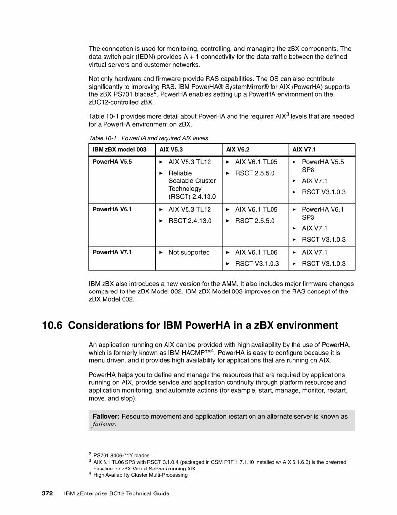
The connection is used for monitoring, controlling, and managing the zBX components. The data switch pair (IEDN) provides N + 1 connectivity for the data traffic between the defined virtual servers and customer networks.
Not only hardware and firmware provide RAS capabilities. The OS can also contribute significantly to improving RAS. IBM PowerHA® SystemMirror® for AIX (PowerHA) supports the zBX PS701 blades2. PowerHA enables setting up a PowerHA environment on the zBC12-controlled zBX.
Table 10-1 provides more detail about PowerHA and the required AIX3 levels that are needed for a PowerHA environment on zBX.
Table 10-1 PowerHA and required AIX levels
IBM zBX also introduces a new version for the AMM. It also includes major firmware changes compared to the zBX Model 002. IBM zBX Model 003 improves on the RAS concept of the zBX Model 002.
10.6 Considerations for IBM PowerHA in a zBX environment
An application running on AIX can be provided with high availability by the use of PowerHA, which is formerly known as IBM HACMP™4. PowerHA is easy to configure because it is menu driven, and it provides high availability for applications that are running on AIX.
PowerHA helps you to define and manage the resources that are required by applications running on AIX, provide service and application continuity through platform resources and application monitoring, and automate actions (for example, start, manage, monitor, restart, move, and stop).
2 PS701 8406-71Y blades3 AIX 6.1 TL06 SP3 with RSCT 3.1.0.4 (packaged in CSM PTF 1.7.1.10 installed w/ AIX 6.1.6.3) is the preferred
baseline for zBX Virtual Servers running AIX.
IBM zBX model 003 AIX V5.3 AIX V6.2 AIX V7.1
PowerHA V5.5 � AIX V5.3 TL12
� Reliable Scalable Cluster Technology (RSCT) 2.4.13.0
� AIX V6.1 TL05
� RSCT 2.5.5.0
� PowerHA V5.5 SP8
� AIX V7.1
� RSCT V3.1.0.3
PowerHA V6.1 � AIX V5.3 TL12
� RSCT 2.4.13.0
� AIX V6.1 TL05
� RSCT 2.5.5.0
� PowerHA V6.1 SP3
� AIX V7.1
� RSCT V3.1.0.3
PowerHA V7.1 � Not supported � AIX V6.1 TL06
� RSCT V3.1.0.3
� AIX V7.1
� RSCT V3.1.0.3
4 High Availability Cluster Multi-Processing
Failover: Resource movement and application restart on an alternate server is known as failover.
372 IBM zEnterprise BC12 Technical Guide
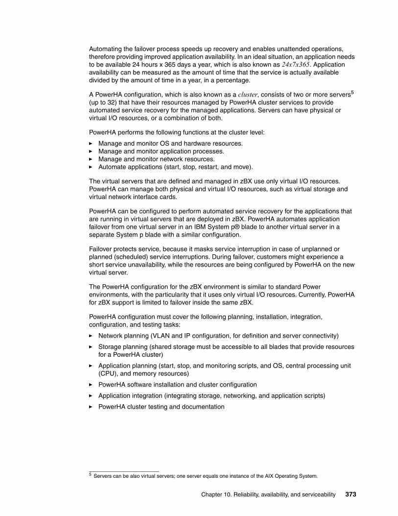
Automating the failover process speeds up recovery and enables unattended operations, therefore providing improved application availability. In an ideal situation, an application needs to be available 24 hours x 365 days a year, which is also known as 24x7x365. Application availability can be measured as the amount of time that the service is actually available divided by the amount of time in a year, in a percentage.
A PowerHA configuration, which is also known as a cluster, consists of two or more servers5 (up to 32) that have their resources managed by PowerHA cluster services to provide automated service recovery for the managed applications. Servers can have physical or virtual I/O resources, or a combination of both.
PowerHA performs the following functions at the cluster level:
� Manage and monitor OS and hardware resources.� Manage and monitor application processes.� Manage and monitor network resources.� Automate applications (start, stop, restart, and move).
The virtual servers that are defined and managed in zBX use only virtual I/O resources. PowerHA can manage both physical and virtual I/O resources, such as virtual storage and virtual network interface cards.
PowerHA can be configured to perform automated service recovery for the applications that are running in virtual servers that are deployed in zBX. PowerHA automates application failover from one virtual server in an IBM System p® blade to another virtual server in a separate System p blade with a similar configuration.
Failover protects service, because it masks service interruption in case of unplanned or planned (scheduled) service interruptions. During failover, customers might experience a short service unavailability, while the resources are being configured by PowerHA on the new virtual server.
The PowerHA configuration for the zBX environment is similar to standard Power environments, with the particularity that it uses only virtual I/O resources. Currently, PowerHA for zBX support is limited to failover inside the same zBX.
PowerHA configuration must cover the following planning, installation, integration, configuration, and testing tasks:
� Network planning (VLAN and IP configuration, for definition and server connectivity)
� Storage planning (shared storage must be accessible to all blades that provide resources for a PowerHA cluster)
� Application planning (start, stop, and monitoring scripts, and OS, central processing unit (CPU), and memory resources)
� PowerHA software installation and cluster configuration
� Application integration (integrating storage, networking, and application scripts)
� PowerHA cluster testing and documentation
5 Servers can be also virtual servers; one server equals one instance of the AIX Operating System.
Chapter 10. Reliability, availability, and serviceability 373
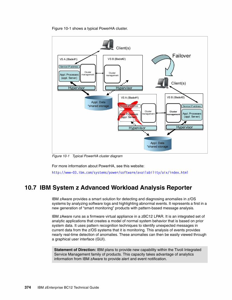
Figure 10-1 shows a typical PowerHA cluster.
Figure 10-1 Typical PowerHA cluster diagram
For more information about PowerHA, see this website:
http://www-03.ibm.com/systems/power/software/availability/aix/index.html
10.7 IBM System z Advanced Workload Analysis Reporter
IBM zAware provides a smart solution for detecting and diagnosing anomalies in z/OS systems by analyzing software logs and highlighting abnormal events. It represents a first in a new generation of “smart monitoring” products with pattern-based message analysis.
IBM zAware runs as a firmware virtual appliance in a zBC12 LPAR. It is an integrated set of analytic applications that creates a model of normal system behavior that is based on prior system data. It uses pattern recognition techniques to identify unexpected messages in current data from the z/OS systems that it is monitoring. This analysis of events provides nearly real-time detection of anomalies. These anomalies can then be easily viewed through a graphical user interface (GUI).
Service IP address
Appl. Processes(appl. Server)
VS A (Blade#1)
Clustermanagement
VS B (Blade#2)
Clustermanagement
Hypervisor Hypervisor
Appl. Processes(appl. Server)
Service IP address
VS A (Blade#1)
Clustermanagement
VS B (Blade#2)
Clustermanagement Appl. Processes
(appl. Server)
Service IP address
Hypervisor Hypervisor
Failover
Client(s)
Client(s)
Appl. Data*shared storage
Appl. Data*shared storage
Statement of Direction: IBM plans to provide new capability within the Tivoli Integrated Service Management family of products. This capacity takes advantage of analytics information from IBM zAware to provide alert and event notification.
374 IBM zEnterprise BC12 Technical Guide
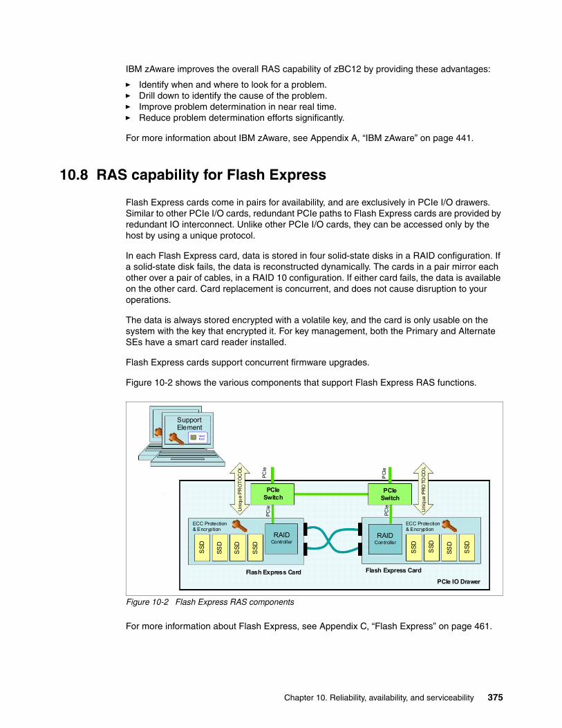
IBM zAware improves the overall RAS capability of zBC12 by providing these advantages:
� Identify when and where to look for a problem.� Drill down to identify the cause of the problem.� Improve problem determination in near real time.� Reduce problem determination efforts significantly.
For more information about IBM zAware, see Appendix A, “IBM zAware” on page 441.
10.8 RAS capability for Flash Express
Flash Express cards come in pairs for availability, and are exclusively in PCIe I/O drawers. Similar to other PCIe I/O cards, redundant PCIe paths to Flash Express cards are provided by redundant IO interconnect. Unlike other PCIe I/O cards, they can be accessed only by the host by using a unique protocol.
In each Flash Express card, data is stored in four solid-state disks in a RAID configuration. If a solid-state disk fails, the data is reconstructed dynamically. The cards in a pair mirror each other over a pair of cables, in a RAID 10 configuration. If either card fails, the data is available on the other card. Card replacement is concurrent, and does not cause disruption to your operations.
The data is always stored encrypted with a volatile key, and the card is only usable on the system with the key that encrypted it. For key management, both the Primary and Alternate SEs have a smart card reader installed.
Flash Express cards support concurrent firmware upgrades.
Figure 10-2 shows the various components that support Flash Express RAS functions.
Figure 10-2 Flash Express RAS components
For more information about Flash Express, see Appendix C, “Flash Express” on page 461.
ECC Protection & Encryption
ECC Protection & Encryption
Support Element
Uni
que
PR
OT
OC
OL
Uni
que
PR
OTO
CO
L
SS
D
SS
D
SS
D
SS
D
SS
D
SS
D
SS
D
SS
D
PCIeSwitch
PCIeSwitch
PCIe IO Drawer
Flash Express Card Flash Express Card
RAIDController
RAIDController
PC
Ie
PC
Ie
PC
Ie
PC
Ie
Chapter 10. Reliability, availability, and serviceability 375

376 IBM zEnterprise BC12 Technical Guide

Chapter 11. Environmental requirements
In this chapter, we briefly describe several of the environmental requirements for the IBM zEnterprise System. We list the dimensions, weights, power, and cooling requirements as an overview of what is needed to plan for the installation of an IBM zEnterprise BC12 System (zBC12) and IBM zEnterprise BladeCenter Extension (zBX).
There are a number of options for the physical installation of the zBC12, including raised floor and non-raised floor options, cabling from the bottom of the frame or off the top of the frame, and the option to have a high-voltage DC power supply directly into the zBC12, instead of the usual AC power supply.
For comprehensive physical planning information, see zEnterprise BC12 Installation Manual: Physical Planning, GC28-6923.
We cover the following topics:
� IBM zBC12 power and cooling� IBM zBC12 physical specifications� IBM zBX environmental components� Energy management
11
“You can’t make a product greener, whether it’s a car, a refrigerator, or a city, without making it smarter: Smarter materials, smarter software, or smarter design.”
_ “The Green Road Less Traveled” by Thomas L. Friedman, The New York Times, July 15, 2007
© Copyright IBM Corp. 2014. All rights reserved. 377
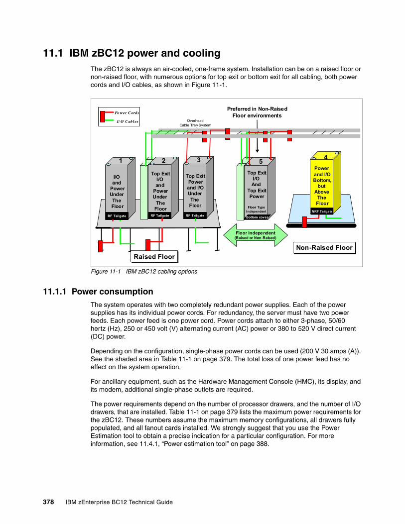
11.1 IBM zBC12 power and cooling The zBC12 is always an air-cooled, one-frame system. Installation can be on a raised floor or non-raised floor, with numerous options for top exit or bottom exit for all cabling, both power cords and I/O cables, as shown in Figure 11-1.
Figure 11-1 IBM zBC12 cabling options
11.1.1 Power consumptionThe system operates with two completely redundant power supplies. Each of the power supplies has its individual power cords. For redundancy, the server must have two power feeds. Each power feed is one power cord. Power cords attach to either 3-phase, 50/60 hertz (Hz), 250 or 450 volt (V) alternating current (AC) power or 380 to 520 V direct current (DC) power.
Depending on the configuration, single-phase power cords can be used (200 V 30 amps (A)). See the shaded area in Table 11-1 on page 379. The total loss of one power feed has no effect on the system operation.
For ancillary equipment, such as the Hardware Management Console (HMC), its display, and its modem, additional single-phase outlets are required.
The power requirements depend on the number of processor drawers, and the number of I/O drawers, that are installed. Table 11-1 on page 379 lists the maximum power requirements for the zBC12. These numbers assume the maximum memory configurations, all drawers fully populated, and all fanout cards installed. We strongly suggest that you use the Power Estimation tool to obtain a precise indication for a particular configuration. For more information, see 11.4.1, “Power estimation tool” on page 388.
Top ExitI/O And
Top ExitPower
Floor Type Independent
Bottom cover
Top ExitI/O and
PowerUnder
TheFloor
RF Tailgate
I/O and
PowerUnder The Floor
RF Tailgate
Power and I/OBottom,
but Above
The Floor
Raised FloorRaised FloorNon-Raised FloorNon-Raised Floor
OverheadCable Tray System
Pow er C ords
I/ O C abl es
1 2 54
Floor Independent(Raised or Non-Raised)
Top ExitPowerand I/OUnder The Floor
RF Tailgate
3
Preferred in Non-Raised Floor environments
NRF Tailgate
378 IBM zEnterprise BC12 Technical Guide
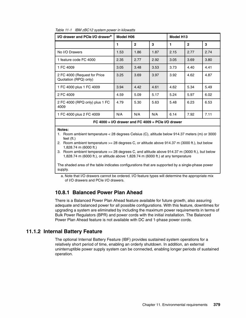
Table 11-1 IBM zBC12 system power in kilowatts
11.1.2 Internal Battery FeatureThe optional Internal Battery Feature (IBF) provides sustained system operations for a relatively short period of time, enabling an orderly shutdown. In addition, an external uninterruptible power supply system can be connected, enabling longer periods of sustained operation.
I/O drawer and PCIe I/O drawera
a. Note that I/O drawers cannot be ordered. I/O feature types will determine the appropriate mix of I/O drawers and PCIe I/O drawers.
10.8.1 Balanced Power Plan AheadThere is a Balanced Power Plan Ahead feature available for future growth, also assuring adequate and balanced power for all possible configurations. With this feature, downtimes for upgrading a system are eliminated by including the maximum power requirements in terms of Bulk Power Regulators (BPR) and power cords with the initial installation. The Balanced Power Plan Ahead feature is not available with DC and 1-phase power cords.
Model H06 Model H13
1 2 3 1 2 3
No I/O Drawers 1.53 1.86 1.87 2.15 2.77 2.74
1 feature code FC 4000 2.35 2.77 2.92 3.05 3.69 3.80
1 FC 4009 3.05 3.48 3.53 3.73 4.40 4.41
2 FC 4000 (Request for Price Quotation (RPQ) only)
3.25 3.69 3.97 3.92 4.62 4.87
1 FC 4000 plus 1 FC 4009 3.94 4.42 4.61 4.62 5.34 5.49
2 FC 4009 4.59 5.09 5.17 5.24 5.97 6.02
2 FC 4000 (RPQ only) plus 1 FC 4009
4.79 5.30 5.63 5.48 6.23 6.53
1 FC 4000 plus 2 FC 4009 N/A N/A N/A 6.14 7.92 7.11
FC 4000 = I/O drawer and FC 4009 = PCIe I/O drawer
Notes: 1. Room ambient temperature < 28 degrees Celsius (C), altitude below 914.37 meters (m) or 3000
feet (ft.)2. Room ambient temperature >= 28 degrees C, or altitude above 914.37 m (3000 ft.), but below
1,828.74 m (6000 ft.)3. Room ambient temperature >= 28 degrees C, and altitude above 914.37 m (3000 ft.), but below
1,828.74 m (6000 ft.), or altitude above 1,828.74 m (6000 ft.) at any temperature
The shaded area of the table indicates configurations that are supported by a single-phase power supply.
Chapter 11. Environmental requirements 379

If the batteries are not older than three years and have been discharged regularly, the IBF is capable of providing emergency power for the periods of time that are listed in Table 11-2.
Table 11-2 The zBC12 IBF sustained operations in minutes
11.1.3 Emergency power-offOn the front of the frame is an emergency power-off switch that, when activated, immediately disconnects utility and battery power from the server. This method causes all volatile data in the zBC12 to be lost.
If the zBC12 is connected to a machine room’s emergency power-off switch, and the IBF is installed, the batteries take over if the switch is engaged. To avoid this takeover, connect the machine room emergency power-off switch to the zBC12 power-off switch. Then, when the machine room emergency power-off switch is engaged, all power will be disconnected from the power cords and the IBF. However, all volatile data in the zBC12 will be lost.
11.1.4 Cooling requirementsThe zBC12 is air cooled. The zBC12 requires chilled air, ideally coming from under a raised floor, to fulfill the air-cooling requirements. However, a non-raised floor option is available. The requirements for cooling are indicated in zEnterprise BC12 Installation Manual: Physical Planning, GC28-6923.
The front and the rear of zBC12 dissipate separate amounts of heat. Most of the heat comes from the rear of the system. To calculate the heat output expressed in kilo British Thermal Units (kBTU) per hour for zBC12 configurations, multiply the table entries from Table 11-1 on page 379 by 3.4. The planning phase must consider correct placement of the zBC12 in relation to the cooling capabilities of the data center.
I/O drawers and PCIe I/O drawersa
a. Note that I/O drawers cannot be ordered. I/O feature types will determine the appropriate mix of I/O drawers and PCIe I/O drawers.
Model H06 Model H13
No I/O drawers 25 15
1 FC 4000 18 10.5
1 FC 4009 12 8.5
2 FC 4000 (RPQ only) 12 8.5
1 FC 4000 plus 1 FC 4009 9 6.5
2 FC 4009 7 5
2 FC 4000 (RPQ only) plus 1 FC 4009 7 5
1 FC 4000 plus 2 FC 4009 N/A 4
FC 4000 = I/O drawer and FC 4009 = PCIe I/O drawer
380 IBM zEnterprise BC12 Technical Guide
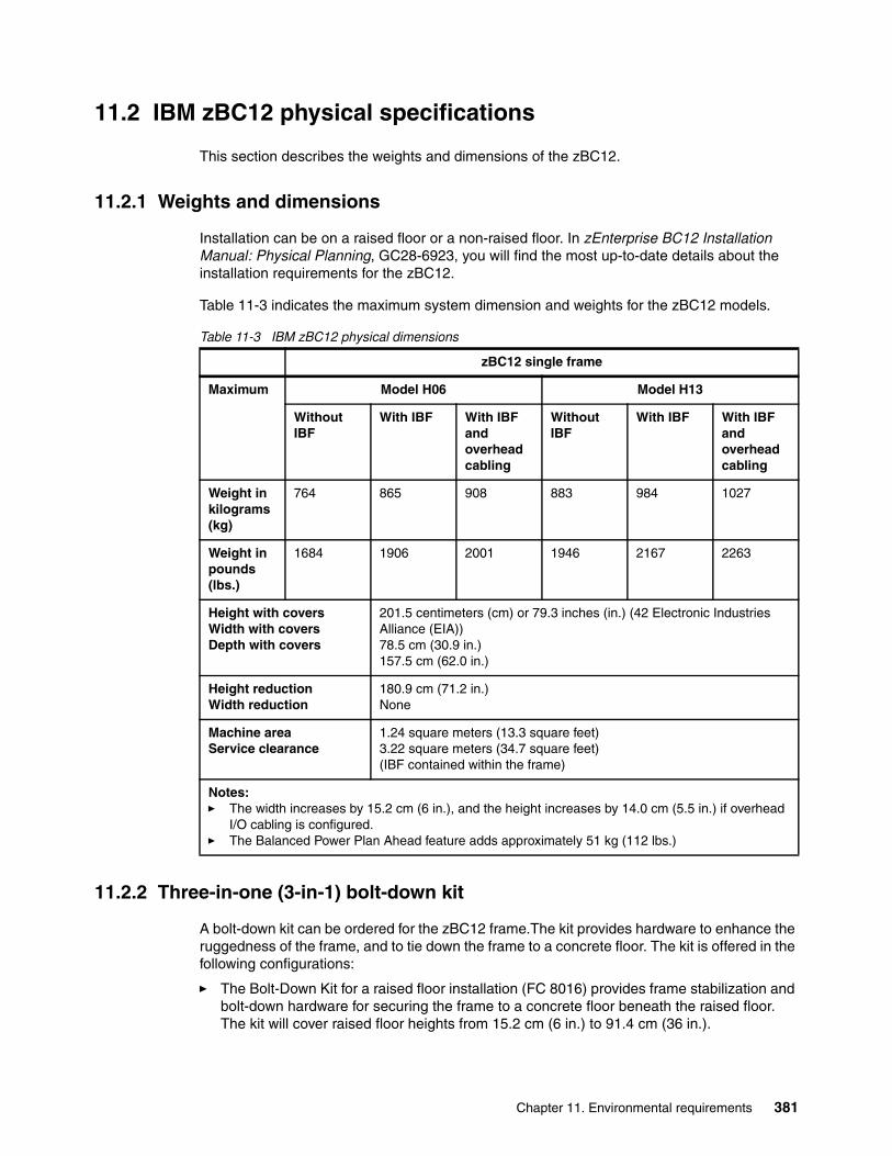
11.2 IBM zBC12 physical specifications
This section describes the weights and dimensions of the zBC12.
11.2.1 Weights and dimensions
Installation can be on a raised floor or a non-raised floor. In zEnterprise BC12 Installation Manual: Physical Planning, GC28-6923, you will find the most up-to-date details about the installation requirements for the zBC12.
Table 11-3 indicates the maximum system dimension and weights for the zBC12 models.
Table 11-3 IBM zBC12 physical dimensions
11.2.2 Three-in-one (3-in-1) bolt-down kit
A bolt-down kit can be ordered for the zBC12 frame.The kit provides hardware to enhance the ruggedness of the frame, and to tie down the frame to a concrete floor. The kit is offered in the following configurations:
� The Bolt-Down Kit for a raised floor installation (FC 8016) provides frame stabilization and bolt-down hardware for securing the frame to a concrete floor beneath the raised floor. The kit will cover raised floor heights from 15.2 cm (6 in.) to 91.4 cm (36 in.).
zBC12 single frame
Maximum Model H06 Model H13
Without IBF
With IBF With IBF and overhead cabling
Without IBF
With IBF With IBF and overhead cabling
Weight in kilograms (kg)
764 865 908 883 984 1027
Weight in pounds (lbs.)
1684 1906 2001 1946 2167 2263
Height with coversWidth with coversDepth with covers
201.5 centimeters (cm) or 79.3 inches (in.) (42 Electronic Industries Alliance (EIA))78.5 cm (30.9 in.)157.5 cm (62.0 in.)
Height reductionWidth reduction
180.9 cm (71.2 in.)None
Machine areaService clearance
1.24 square meters (13.3 square feet)3.22 square meters (34.7 square feet)(IBF contained within the frame)
Notes: � The width increases by 15.2 cm (6 in.), and the height increases by 14.0 cm (5.5 in.) if overhead
I/O cabling is configured.� The Balanced Power Plan Ahead feature adds approximately 51 kg (112 lbs.)
Chapter 11. Environmental requirements 381
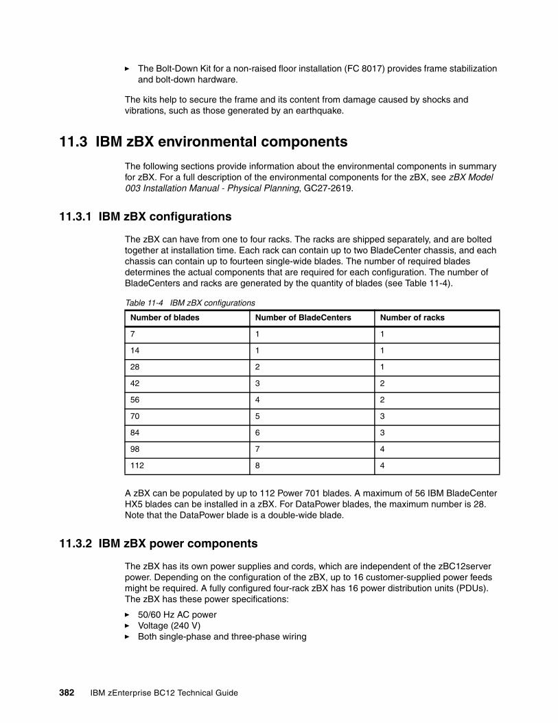
� The Bolt-Down Kit for a non-raised floor installation (FC 8017) provides frame stabilization and bolt-down hardware.
The kits help to secure the frame and its content from damage caused by shocks and vibrations, such as those generated by an earthquake.
11.3 IBM zBX environmental components
The following sections provide information about the environmental components in summary for zBX. For a full description of the environmental components for the zBX, see zBX Model 003 Installation Manual - Physical Planning, GC27-2619.
11.3.1 IBM zBX configurations
The zBX can have from one to four racks. The racks are shipped separately, and are bolted together at installation time. Each rack can contain up to two BladeCenter chassis, and each chassis can contain up to fourteen single-wide blades. The number of required blades determines the actual components that are required for each configuration. The number of BladeCenters and racks are generated by the quantity of blades (see Table 11-4).
Table 11-4 IBM zBX configurations
A zBX can be populated by up to 112 Power 701 blades. A maximum of 56 IBM BladeCenter HX5 blades can be installed in a zBX. For DataPower blades, the maximum number is 28. Note that the DataPower blade is a double-wide blade.
11.3.2 IBM zBX power components
The zBX has its own power supplies and cords, which are independent of the zBC12server power. Depending on the configuration of the zBX, up to 16 customer-supplied power feeds might be required. A fully configured four-rack zBX has 16 power distribution units (PDUs). The zBX has these power specifications:
� 50/60 Hz AC power� Voltage (240 V)� Both single-phase and three-phase wiring
Number of blades Number of BladeCenters Number of racks
7 1 1
14 1 1
28 2 1
42 3 2
56 4 2
70 5 3
84 6 3
98 7 4
112 8 4
382 IBM zEnterprise BC12 Technical Guide
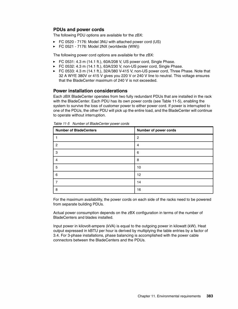
PDUs and power cordsThe following PDU options are available for the zBX:
� FC 0520 - 7176: Model 3NU with attached power cord (US)� FC 0521 - 7176: Model 2NX (worldwide (WW))
The following power cord options are available for the zBX:
� FC 0531: 4.3 m (14.1 ft.), 60A/208 V, US power cord, Single Phase.� FC 0532: 4.3 m (14.1 ft.), 63A/230 V, non-US power cord, Single Phase.� FC 0533: 4.3 m (14.1 ft.), 32A/380 V-415 V, non-US power cord, Three Phase. Note that
32 A WYE 380V or 415 V gives you 220 V or 240 V line to neutral. This voltage ensures that the BladeCenter maximum of 240 V is not exceeded.
Power installation considerationsEach zBX BladeCenter operates from two fully redundant PDUs that are installed in the rack with the BladeCenter. Each PDU has its own power cords (see Table 11-5), enabling the system to survive the loss of customer power to either power cord. If power is interrupted to one of the PDUs, the other PDU will pick up the entire load, and the BladeCenter will continue to operate without interruption.
Table 11-5 Number of BladeCenter power cords
For the maximum availability, the power cords on each side of the racks need to be powered from separate building PDUs.
Actual power consumption depends on the zBX configuration in terms of the number of BladeCenters and blades installed.
Input power in kilovolt-ampere (kVA) is equal to the outgoing power in kilowatt (kW). Heat output expressed in kBTU per hour is derived by multiplying the table entries by a factor of 3.4. For 3-phase installations, phase balancing is accomplished with the power cable connectors between the BladeCenters and the PDUs.
Number of BladeCenters Number of power cords
1 2
2 4
3 6
4 8
5 10
6 12
7 14
8 16
Chapter 11. Environmental requirements 383
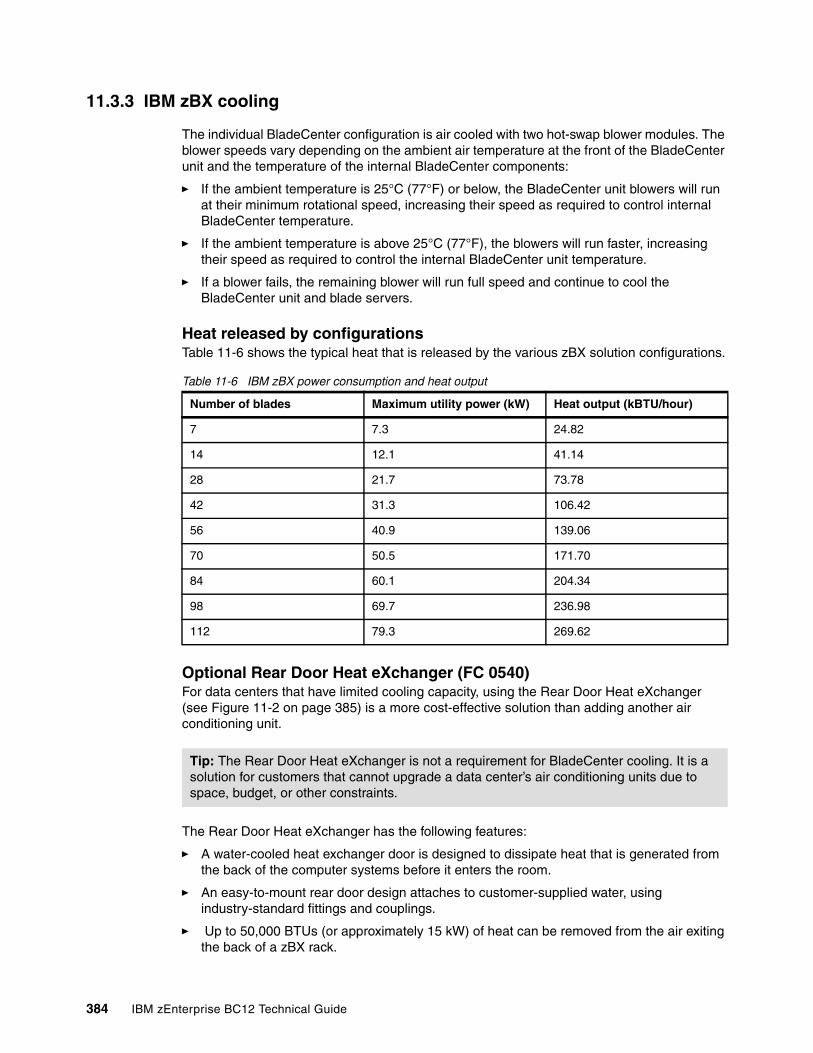
11.3.3 IBM zBX cooling
The individual BladeCenter configuration is air cooled with two hot-swap blower modules. The blower speeds vary depending on the ambient air temperature at the front of the BladeCenter unit and the temperature of the internal BladeCenter components:
� If the ambient temperature is 25°C (77°F) or below, the BladeCenter unit blowers will run at their minimum rotational speed, increasing their speed as required to control internal BladeCenter temperature.
� If the ambient temperature is above 25°C (77°F), the blowers will run faster, increasing their speed as required to control the internal BladeCenter unit temperature.
� If a blower fails, the remaining blower will run full speed and continue to cool the BladeCenter unit and blade servers.
Heat released by configurationsTable 11-6 shows the typical heat that is released by the various zBX solution configurations.
Table 11-6 IBM zBX power consumption and heat output
Optional Rear Door Heat eXchanger (FC 0540)For data centers that have limited cooling capacity, using the Rear Door Heat eXchanger (see Figure 11-2 on page 385) is a more cost-effective solution than adding another air conditioning unit.
The Rear Door Heat eXchanger has the following features:
� A water-cooled heat exchanger door is designed to dissipate heat that is generated from the back of the computer systems before it enters the room.
� An easy-to-mount rear door design attaches to customer-supplied water, using industry-standard fittings and couplings.
� Up to 50,000 BTUs (or approximately 15 kW) of heat can be removed from the air exiting the back of a zBX rack.
Number of blades Maximum utility power (kW) Heat output (kBTU/hour)
7 7.3 24.82
14 12.1 41.14
28 21.7 73.78
42 31.3 106.42
56 40.9 139.06
70 50.5 171.70
84 60.1 204.34
98 69.7 236.98
112 79.3 269.62
Tip: The Rear Door Heat eXchanger is not a requirement for BladeCenter cooling. It is a solution for customers that cannot upgrade a data center’s air conditioning units due to space, budget, or other constraints.
384 IBM zEnterprise BC12 Technical Guide
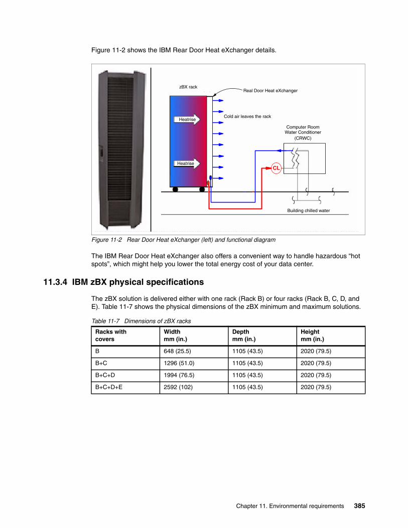
Figure 11-2 shows the IBM Rear Door Heat eXchanger details.
Figure 11-2 Rear Door Heat eXchanger (left) and functional diagram
The IBM Rear Door Heat eXchanger also offers a convenient way to handle hazardous “hot spots”, which might help you lower the total energy cost of your data center.
11.3.4 IBM zBX physical specifications
The zBX solution is delivered either with one rack (Rack B) or four racks (Rack B, C, D, and E). Table 11-7 shows the physical dimensions of the zBX minimum and maximum solutions.
Table 11-7 Dimensions of zBX racks
zBX rack
Building chilled water
Real Door Heat eXchanger
Cold air leaves the rack
Computer Room Water Conditioner
(CRWC)
CL
Heatrise
Heatrise
Racks withcovers
Widthmm (in.)
Depthmm (in.)
Heightmm (in.)
B 648 (25.5) 1105 (43.5) 2020 (79.5)
B+C 1296 (51.0) 1105 (43.5) 2020 (79.5)
B+C+D 1994 (76.5) 1105 (43.5) 2020 (79.5)
B+C+D+E 2592 (102) 1105 (43.5) 2020 (79.5)
Chapter 11. Environmental requirements 385
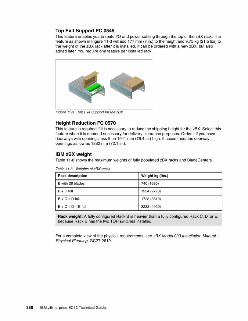
Top Exit Support FC 0545This feature enables you to route I/O and power cabling through the top of the zBX rack. The feature as shown in Figure 11-3 will add 177 mm (7 in.) to the height and 9.75 kg (21.5 lbs) to the weight of the zBX rack after it is installed. It can be ordered with a new zBX, but also added later. You require one feature per installed rack.
Figure 11-3 Top Exit Support for the zBX
Height Reduction FC 0570This feature is required if it is necessary to reduce the shipping height for the zBX. Select this feature when it is deemed necessary for delivery clearance purposes. Order it if you have doorways with openings less than 1941 mm (76.4 in.) high. It accommodates doorway openings as low as 1832 mm (72.1 in.).
IBM zBX weightTable 11-8 shows the maximum weights of fully populated zBX racks and BladeCenters.
Table 11-8 Weights of zBX racks
For a complete view of the physical requirements, see zBX Model 003 Installation Manual - Physical Planning, GC27-2619.
Rack description Weight kg (lbs.)
B with 28 blades 740 (1630)
B + C full 1234 (2720)
B + C + D full 1728 (3810)
B + C + D + E full 2222 (4900)
Rack weight: A fully configured Rack B is heavier than a fully configured Rack C, D, or E, because Rack B has the two TOR switches installed.
386 IBM zEnterprise BC12 Technical Guide
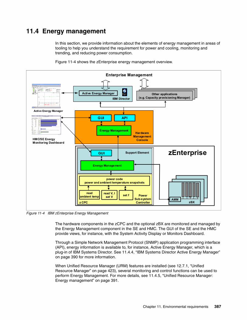
11.4 Energy management
In this section, we provide information about the elements of energy management in areas of tooling to help you understand the requirement for power and cooling, monitoring and trending, and reducing power consumption.
Figure 11-4 shows the zEnterprise energy management overview.
Figure 11-4 IBM zEnterprise Energy Management
The hardware components in the zCPC and the optional zBX are monitored and managed by the Energy Management component in the SE and HMC. The GUI of the SE and the HMC provide views, for instance, with the System Activity Display or Monitors Dashboard.
Through a Simple Network Management Protocol (SNMP) application programming interface (API), energy information is available to, for instance, Active Energy Manager, which is a plug-in of IBM Systems Director. See 11.4.4, “IBM Systems Director Active Energy Manager” on page 390 for more information.
When Unified Resource Manager (URM) features are installed (see 12.7.1, “Unified Resource Manager” on page 423), several monitoring and control functions can be used to perform Energy Management. For more details, see 11.4.5, “Unified Resource Manager: Energy management” on page 391.
Energy Management
power codepower and ambient temperature snapshots
read V, Iset V
readambient temp
HMC/SE Energy Monitoring Dashboard
z CPC zBXAMM
set f
Energy Management
APIGUI
Active Energy Manager
GUI zEnterprise
Active Energy Manager
Enterprise Management
Support Element
PowerSub-systemController
HardwareManagement
Console
Other applications(e.g. Capacity provisioning Manager)
Other applications(e.g. Capacity provisioning Manager)
Other applications(e.g. Capacity provisioning Manager)IBM Director
Chapter 11. Environmental requirements 387
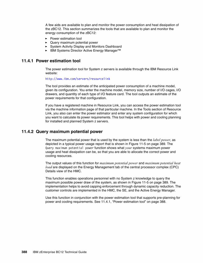
A few aids are available to plan and monitor the power consumption and heat dissipation of the zBC12. This section summarizes the tools that are available to plan and monitor the energy consumption of the zBC12:
� Power estimation tool� Query maximum potential power� System Activity Display and Monitors Dashboard� IBM Systems Director Active Energy Manager™
11.4.1 Power estimation tool
The power estimation tool for System z servers is available through the IBM Resource Link website:
http://www.ibm.com/servers/resourcelink
The tool provides an estimate of the anticipated power consumption of a machine model, given its configuration. You enter the machine model, memory size, number of I/O cages, I/O drawers, and quantity of each type of I/O feature card. The tool outputs an estimate of the power requirements for that configuration.
If you have a registered machine in Resource Link, you can access the power estimation tool via the machine information page of that particular machine. In the Tools section of Resource Link, you also can enter the power estimator and enter any system configuration for which you want to calculate its power requirements. This tool helps with power and cooling planning for installed and planned System z servers.
11.4.2 Query maximum potential power
The maximum potential power that is used by the system is less than the label power, as depicted in a typical power usage report that is shown in Figure 11-5 on page 389. The Query maximum potential power function shows what your systems maximum power usage and heat dissipation can be, so that you are able to allocate the correct power and cooling resources.
The output values of this function for maximum potential power and maximum potential heat load are displayed on the Energy Management tab of the central processor complex (CPC) Details view of the HMC.
This function enables operations personnel with no System z knowledge to query the maximum possible power draw of the system, as shown in Figure 11-5 on page 389. The implementation helps to avoid capping enforcement through dynamic capacity reduction. The customer controls are implemented in the HMC, the SE, and the Active Energy Manager.
Use this function in conjunction with the power estimation tool that supports pre-planning for power and cooling requirements. See 11.4.1, “Power estimation tool” on page 388.
388 IBM zEnterprise BC12 Technical Guide
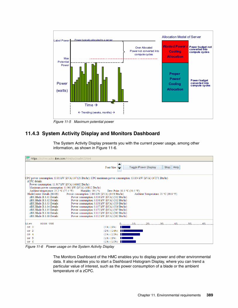
Figure 11-5 Maximum potential power
11.4.3 System Activity Display and Monitors Dashboard
The System Activity Display presents you with the current power usage, among other information, as shown in Figure 11-6.
Figure 11-6 Power usage on the System Activity Display
The Monitors Dashboard of the HMC enables you to display power and other environmental data. It also enables you to start a Dashboard Histogram Display, where you can trend a particular value of interest, such as the power consumption of a blade or the ambient temperature of a zCPC.
Label Power
Power
(watts)
Time
Trending (weeks, months)
Power typically allocated to a server
Over Allocated Power not converted into
compute cycles
Proper
Power/
Cooling
Allocation
Wasted Power /
Cooling
Allocation
Allocation Model of Server
Power budget not converted into compute cycles
Power budget converted into compute cycles
Max Potential
Power
Chapter 11. Environmental requirements 389
11.4.4 IBM Systems Director Active Energy Manager
IBM Systems Director Active Energy Manager is an energy management solution building block that returns true control of energy costs to the customer. Active Energy Manager is an industry-leading cornerstone of the IBM energy management framework.
Active Energy Manager Version 4.3.1 is a plug-in to IBM Systems Director Version 6.2.1 and is available for installation on Linux on System z. It can also run on Windows, Linux on IBM System x, and AIX and Linux on IBM Power Systems™. For more specific information, see Implementing IBM Systems Director Active Energy Manager 4.1.1, SG24-7780. Version 4.3.1 supports IBM zEnterprise System and its optional attached zBX.
Use Active Energy Manager to monitor the power and environmental values of resources, for System z and other IBM products, such as IBM Power Systems, IBM System x, or devices and hardware that are acquired from another vendor. You can view historical trend data for resources, calculate energy costs and savings, view properties and settings for resources, and view active energy-related events.
Active Energy Manager does not directly connect to the System z servers, but it attaches through a LAN connection to the HMC. See Figure 11-4 on page 387 and 12.4, “HMC and SE connectivity” on page 398. Active Energy Manager discovers the HMC managing the server by using a discovery profile that specifies the HMC’s IP address and the SNMP credentials for that System z HMC. As the system is discovered, the System z servers that are managed by the HMC are also discovered.
Active Energy Manager is a management software tool that can provide a single view of the actual power usage across multiple platforms, as opposed to the benchmarked or rated power consumption. It can effectively monitor and control power in the data center at the system, chassis, or rack level. By enabling these power management technologies, data center managers can more effectively manage the power of their systems while lowering the cost of computing.
The following data is available through Active Energy Manager:
� System name, machine type, model, serial number, and firmware level of the System z servers and optional zBX that is attached to IBM zEnterprise Systems.
� Ambient temperature.
� Exhaust temperature.
� Average power usage.
� Peak power usage.
� Limited status and configuration information. This information helps to explain the changes to the power consumption, which are called events:
– Changes in fan speed– Changes between power-off, power-on, and IML-complete states– CBU records expirations
IBM Systems Director Active Energy Manager provides customers with the intelligence necessary to effectively manage power consumption in the data center. Active Energy Manager, which is an extension to IBM Director Systems Management software, enables you to meter actual power usage and trend data for any single physical system or group of systems. Active Energy Manager uses monitoring circuitry, which was developed by IBM, to help identify how much actual power is being used, and the temperature of the system.
390 IBM zEnterprise BC12 Technical Guide
11.4.5 Unified Resource Manager: Energy management
The energy management capabilities for URM that can be used in an ensemble depend on which suite is installed in the ensemble:
� Manage Suite (feature code 0019)� Automate Suite (feature code 0020)
Manage SuiteFor energy management, the Manage Suite focuses on the monitoring capabilities. Energy monitoring can help you better understand the power and cooling demand of the zEnterprise System. It provides complete monitoring and trending capabilities for the zBC12 and the zBX using one or more of the following options:
� Monitors dashboard� Environmental Efficiency Statistics� Details view
Automate SuiteThe URM offers multiple energy management tasks as part of the automate suite. These tasks enable you to actually change system behaviors for optimized energy usage and energy saving:
� Power cap� Group power cap
Various options are presented, depending on the scope that is selected in the URM GUI.
Set Power CapThe power cap function can be used to limit the maximum amount of energy that is used by the ensemble. If enabled, it enforces power caps for the hardware by actually throttling the processors in the system.
The URM shows all of the components of an ensemble in the Set Power Cap window, as seen in Figure 11-7 on page 392. Because not all components that are used in a specific environment can support power capping, only those components that are marked as Enabled can actually perform power capping functions.
A zBC12 does not support power capping, as opposed to specific blades, which can be power-capped. When capping is enabled for a zBC12, this capping level is used as a threshold for a warning message that informs you that the zBC12 went above the set cap level. Being under the limit of the cap level is equal to the maximum potential power value (see 11.4.2, “Query maximum potential power” on page 388).
Chapter 11. Environmental requirements 391
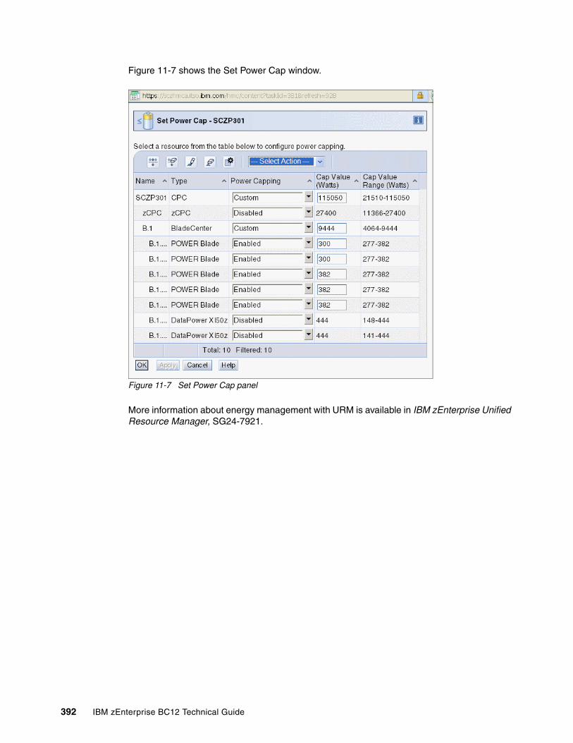
Figure 11-7 shows the Set Power Cap window.
Figure 11-7 Set Power Cap panel
More information about energy management with URM is available in IBM zEnterprise Unified Resource Manager, SG24-7921.
392 IBM zEnterprise BC12 Technical Guide
Chapter 12. Hardware Management Console and Support Element
The Hardware Management Console (HMC) supports many functions and tasks to extend the management capabilities of IBM zEnterprise BC12 System (zBC12). When tasks are performed on the HMC, the commands are sent to one or more Support Elements (SEs) which then issue commands to their central processor complexes (CPCs) or IBM zEnterprise BladeCenteExtension (zBX).
This chapter addresses the HMC and SE in general, and adds relevant information for HMCs that manage ensembles with the zEnterprise Unified Resource Manager (URM).
This chapter includes the following sections:
� Introduction to HMC and SE� HMC and SE enhancements and changes� Remote Support Facility� HMC and SE remote operations� HMC and SE key capabilities� HMC in an ensemble
12
© Copyright IBM Corp. 2014. All rights reserved. 393
12.1 Introduction to HMC and SE
The HMC is a stand-alone computer that runs a set of management applications. The HMC is a closed system, which means that no other applications can be installed on it.
The HMC is used to set up, manage, monitor, and operate one or more System z CPCs. It manages System z hardware, its logical partitions (LPARs), and provides support applications. At least one HMC is required to operate an IBM System z®. An HMC can manage multiple System z systems, and can be at a local or a remote site.
If the zBC12 is defined as a member of an ensemble, a pair of HMCs is required (a primary and an alternate). When a zBC12 is defined as a member of an ensemble, certain restrictions apply. For more information, see 12.7, “HMC in an ensemble” on page 423.
The SEs are two integrated notebook computers that are supplied with the zBC12. One is the primary SE and the other is the alternate SE. The primary SE is the active one, and the alternate acts as the backup. The SEs are closed systems, the same as the HMCs, and no other applications can be installed on them.
When tasks are performed at the HMC, the commands are routed to the active SE of the System z CPC. The SE then issues those commands to their CPC and controlled zBX (if any). One HMC can control up to 100 SEs and one SE can be controlled by up to 32 HMCs.
The microcode for the System z and zBX is managed at the HMC.
Some functions are only available on the SE. With single object operations (SOO) these functions can be used from the HMC. See “Single object operation” on page 404 for further details.
The HMC Remote Support Facility (RSF) provides the important communication to a centralized IBM support network for hardware problem reporting and service. For more information, see 12.5, “Remote Support Facility” on page 402.
12.2 SE driver support with new HMC
The driver of the HMC and SE is always equivalent to a specific HMC and SE version, as illustrated in the following examples:
� Driver 15 is equivalent to version 2.12.1� Driver 86 is equivalent to version 2.11.0� Driver 79 is equivalent to version 2.10.2
At the time of this writing, a zBC12 is shipped with HMC version 2.12.1, which can support different System z types. Some functions that are available on version 2.12.1 and later are only supported when connected to a zBC12 with driver 15.
394 IBM zEnterprise BC12 Technical Guide
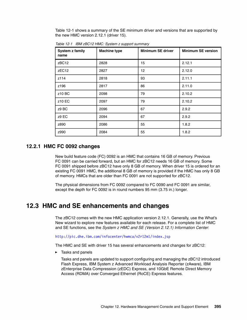
Table 12-1 shows a summary of the SE minimum driver and versions that are supported by the new HMC version 2.12.1 (driver 15).
Table 12-1 IBM zBC12 HMC: System z support summary
12.2.1 HMC FC 0092 changes
New build feature code (FC) 0092 is an HMC that contains 16 GB of memory. Previous FC 0091 can be carried forward, but an HMC for zBC12 needs 16 GB of memory. Some FC 0091 shipped before zBC12 have only 8 GB of memory. When driver 15 is ordered for an existing FC 0091 HMC, the additional 8 GB of memory is provided if the HMC has only 8 GB of memory. HMCs that are older than FC 0091 are not supported for zBC12.
The physical dimensions from FC 0092 compared to FC 0090 and FC 0091 are similar, except the depth for FC 0092 is in round numbers 95 mm (3.75 in.) longer.
12.3 HMC and SE enhancements and changes
The zBC12 comes with the new HMC application version 2.12.1. Generally, use the What’s New wizard to explore new features available for each release. For a complete list of HMC and SE functions, see the System z HMC and SE (Version 2.12.1) Information Center:
http://pic.dhe.ibm.com/infocenter/hwmca/v2r12m1/index.jsp
The HMC and SE with driver 15 has several enhancements and changes for zBC12:
� Tasks and panels
Tasks and panels are updated to support configuring and managing the zBC12 introduced Flash Express, IBM System z Advanced Workload Analysis Reporter (zAware), IBM zEnterprise Data Compression (zEDC) Express, and 10GbE Remote Direct Memory Access (RDMA) over Converged Ethernet (RoCE) Express features.
System z family name
Machine type Minimum SE driver Minimum SE version
zBC12 2828 15 2.12.1
zEC12 2827 12 2.12.0
z114 2818 93 2.11.1
z196 2817 86 2.11.0
z10 BC 2098 79 2.10.2
z10 EC 2097 79 2.10.2
z9 BC 2096 67 2.9.2
z9 EC 2094 67 2.9.2
z890 2086 55 1.8.2
z990 2084 55 1.8.2
Chapter 12. Hardware Management Console and Support Element 395
� Updates to x3270 Support (also known as Secure 3270)
The Configure 3270 Emulators task, on the HMC and Trusted Key Entry (TKE) consoles, has been enhanced to verify the authenticity of the certificate returned by the 3270 server when a secure and encrypted Secure Sockets Layer (SSL) connection is established to an IBM host.
For more information, see “Updates to x3270 Support (also known as Secure 3270)” on page 406.
� Enhanced IBM Service Support System
If the HMC and SE are at driver 15, they can use a new remote infrastructure to connect via RSF for some tasks. This might require the customer to change the network settings (proxy, firewall, and other system configurations) for the RSF infrastructure. For more information see 12.5.2, “RSF connections to IBM and Enhanced IBM Service Support System” on page 403.
� Audit logs changes
With driver 15 the RSF security events moved from security to audit logs. The SSL connection information is logged, including hostname, hostname on certificate, and cipher used.
� Default HMC user IDs
It is no longer possible to change the Managed Resource or Task Roles of the default user IDs (operator, advanced, sysprog, acsadmin, and service).
If you want the ability to change the roles for a default user ID, create your own version by copying an existing default user ID.
� Open Systems Adapter/Support Facility (OSA/SF)
The OSA/SF is a component of z/OS, IBM z/Virtual Machine (z/VM), and IBM z/Virtual Storage Extended (z/VSE), and is now available on the HMC.
With driver 15, the OSA Advanced Facilities task on the HMC is enhanced to provide configuration, validation, activation, and display support exclusively for the OSA-Express5S and OSA-Express4S features.
OSA/SF on the HMC is required for the OSA-Express5S feature. Either OSA/SF on the HMC or the OSA/SF in the operating system component can be used for the OSA-Express4S features.
For more and detailed information see OSA/SF on the HMC, SC14-7580.
� Help infrastructure updates
The content from the following publications is now incorporated into the HMC and SE (Version 2.12.1) help system:
– System z Hardware Management Console Operations Guide
– IBM zEnterprise System Hardware Management Console Operations Guide for Ensembles
– IBM zEnterprise System Support Element Operations Guide
This information can also be found on the System z HMC and SE (Version 2.12.1) Information Center:
http://pic.dhe.ibm.com/infocenter/hwmca/v2r12m1/index.jsp
� Defined capacity of LPARs (absolute physical HW LPAR capacity setting)
Driver 15 introduces the possibility to define, in the image profile for shared processors, the absolute processor capacity that the image can use (independent of the image weight or other cappings).
396 IBM zEnterprise BC12 Technical Guide
To indicate that the LPAR can use the not dedicated processors absolute capping, select Absolute capping on the image profile processor settings, to specify an absolute number of processors to cap the LPAR's activity. The absolute capping value can either be None, or a number of processors value from 0.01 to 255.0 can be specified.
� IBM zBX firmware management
The zBX Model 003 is managed from the HMC and owning processor SE, using the zEnterprise URM. The following support is provided:
– IBM zBX firmware upgrades are downloaded from IBM RETAIN using HMC broadband RSF connection. Firmware updates are saved locally to be installed during a scheduled Microcode Change Level (MCL) apply session.
– Firmware updates are installed from the HMC and SEs using the same process and controls currently in use for System z.
– IBM zBX hardware and firmware-related failures are reported to IBM and the IBM support structure is engaged, using the HMC RSF. This is the same process used for reporting System z problems.
� IBM zBX lifecycle management
– IBM zBX model 003 supports the same System X, POWER7 and IBM WebSphere DataPower Integration Appliance XI50 for zEnterprise (DataPower XI50z) blades types supported in zBX model 002.
– The new System X blades use a new 10 Gb internal Ethernet adapter.
– The BladeCenter H advanced management module (AMM) is no longer used on a zBX model 003. A new improved version of the AMM, called AMMe, replaced the hardware used in the zBX model 002.
– All zBX model 003 components firmware were upgraded.
� Server Time Protocol (STP)
Improved SE time accuracy before initial microcode load (IML).
With driver 15, if the CPC has not run IML, the SE will take the time from the external time source (ETS) every hour, if the Network Time Protocol (NTP) servers are configured in the ETS Configuration tab in the System (Sysplex) Time task. This helps to have the SE time accurate before the IML (also known as power-on reset).
� STP NTP broadband security
Authentication is added to the HMC NTP communication with NTP time servers. For more information, see “HMC NTP broadband authentication support for zBC12” on page 416.
� Environmental task usability improvements regarding the time frame
For more information, see “Environmental Efficiency Statistics task” on page 412.
� Crypto Function Integration in the Monitors Dashboard
For more information, see “The Monitors Dashboard task” on page 410.
� Removal of modem support from the HMC
This change affects customers who have set up the modem for RSF or for STP NTP access. For more information, see 12.5, “Remote Support Facility” on page 402 and 12.6.10, “NTP customer and server support on HMC” on page 416.
� Installation and activation by MCL bundle target
For more information, see “Microcode installation by MCL bundle target” on page 409.
Chapter 12. Hardware Management Console and Support Element 397
� A confirmation panel before processing a “Ctrl-Alt-Delete” request
� Capability to modify the time of the SE mirror scheduled operation
� Capability to mass delete messages from the Operating System Messages task
� An updated Network Settings task that clearly shows the ordering of the routing table entries
� Coprocessor Group Counter Sets support removed
In zBC12, each physical processor has its own crypto coprocessor. They no longer must share this coprocessor with another processor unit (PU). The Coprocessor Group Counter Sets of the counter facilities will not be available. All of the necessary crypto counter information is available in the crypto activity counter sets directly. The check-box selection for the Coprocessor Group Counter Sets is removed from the Image profile definition and the Change Logical Partition Security task.
12.3.1 HMC media support
The HMC provides a DVD-RAM drive and, with HMC version 2.11.0, a USB flash memory drive (UFD) was introduced as an alternative. The tasks that require access to a DVD-RAM drive now can access an UFD. There can be more than one UFD inserted into the HMC.
12.3.2 Tree Style user interface and Classic Style user interface
Two user interface styles are provided with an HMC. The Tree Style user interface (default) uses a hierarchical model popular in newer operating systems, and features context-based task launching. The Classic Style user interface uses the drag-and-drop interface style.
12.4 HMC and SE connectivity
The HMC has two Ethernet adapters that are supported by HMC version 2.12.1 for connectivity to up to two different Ethernet LANs.
The SEs on the zBC12 are connected to the Bulk Power Hub (BPH). The HMC to BPH communication is only possible through an Ethernet switch. Other System z and HMCs can also be connected to the switch. To provide redundancy for the HMCs, install two switches.
Only the switch (and not the HMC directly) can be connected to the BPH ports J02 and J01 for the customer network 1 and 2.
Note: If an HMC must be rebooted, always use the Shutdown and Restart task on the HMC to avoid any file corruption.
Tutorials: The IBM Resource Linka provides tutorials that demonstrate how to change from the Classic to the Tree Style interface, and introduce the function of the Tree Style interface on the HMC:
https://www-304.ibm.com/servers/resourcelink/hom03010.nsf/pages/education?OpenDocument
a. Registration is required to access the IBM Resource Link.
398 IBM zEnterprise BC12 Technical Guide
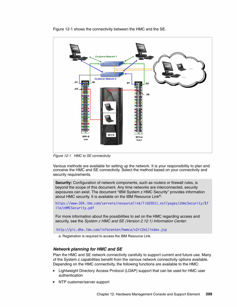
Figure 12-1 shows the connectivity between the HMC and the SE.
Figure 12-1 HMC to SE connectivity
Various methods are available for setting up the network. It is your responsibility to plan andconceive the HMC and SE connectivity. Select the method based on your connectivity and security requirements.
Network planning for HMC and SEPlan the HMC and SE network connectivity carefully to support current and future use. Many of the System z capabilities benefit from the various network connectivity options available. Depending on the HMC connectivity, the following functions are available to the HMC:
� Lightweight Directory Access Protocol (LDAP) support that can be used for HMC user authentication
� NTP customer/server support
Security: Configuration of network components, such as routers or firewall rules, is beyond the scope of this document. Any time networks are interconnected, security exposures can exist. The document “IBM System z HMC Security” provides information about HMC security. It is available on the IBM Resource Linka:
https://www-304.ibm.com/servers/resourcelink/lib03011.nsf/pages/zHmcSecurity/$file/zHMCSecurity.pdf
For more information about the possibilities to set on the HMC regarding access and security, see the System z HMC and SE (Version 2.12.1) Information Center:
http://pic.dhe.ibm.com/infocenter/hwmca/v2r12m1/index.jsp
a. Registration is required to access the IBM Resource Link.
zBC12BPH-Afront
BPH-Brear
J02J02
Customer Network 1
J01
Customer Network 2
J01
HMC
SE
SE
J05
J05
HMCHMC
…
…HMC
HMC
HMC SE
HMC
Chapter 12. Hardware Management Console and Support Element 399
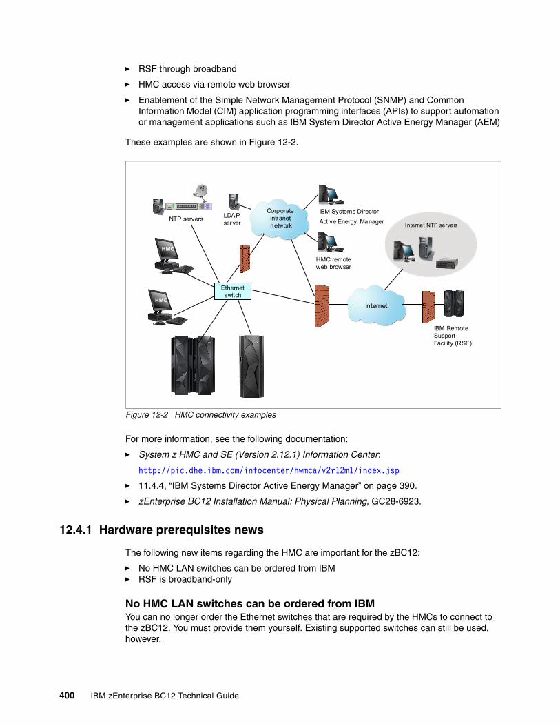
� RSF through broadband
� HMC access via remote web browser
� Enablement of the Simple Network Management Protocol (SNMP) and Common Information Model (CIM) application programming interfaces (APIs) to support automation or management applications such as IBM System Director Active Energy Manager (AEM)
These examples are shown in Figure 12-2.
Figure 12-2 HMC connectivity examples
For more information, see the following documentation:
� System z HMC and SE (Version 2.12.1) Information Center:
http://pic.dhe.ibm.com/infocenter/hwmca/v2r12m1/index.jsp
� 11.4.4, “IBM Systems Director Active Energy Manager” on page 390.
� zEnterprise BC12 Installation Manual: Physical Planning, GC28-6923.
12.4.1 Hardware prerequisites news
The following new items regarding the HMC are important for the zBC12:
� No HMC LAN switches can be ordered from IBM� RSF is broadband-only
No HMC LAN switches can be ordered from IBMYou can no longer order the Ethernet switches that are required by the HMCs to connect to the zBC12. You must provide them yourself. Existing supported switches can still be used, however.
HMC
Corporateintranetnetwork
Internet
HMC
Ju ly 14 14: 21: 00 2007 U TC
NTP servers
HMC remoteweb browser
Internet NTP servers
LDAPserver
IBM Systems Director
Active Energy Manager
Ethernet switch
IBM Remote Support Facility (RSF)
400 IBM zEnterprise BC12 Technical Guide
Ethernet switches/hubs typically have these characteristics:
� 16 auto-negotiation ports� 10/100/1000 Mbps data rate� Full or half duplex operation� Auto-medium dependent interface crossover (MDIX) on all ports� Port Status light-emitting diodes (LEDs)
RSF is broadband-onlyRSF through modem is not supported on the zBC12 HMC. Broadband is needed for hardware problem reporting and service. For more information, see 12.5, “Remote Support Facility” on page 402.
12.4.2 TCP/IP Version 6 on HMC and SE
The HMC and SE can communicate by using IPv4, IPv6, or both. Assigning a static IP address to an SE is unnecessary if the SE has to communicate only with HMCs on the same subnet. The HMC and SE can use IPv6 link-local addresses to communicate with each other.
IPv6 link-local addresses have the following characteristics:
� Every IPv6 network interface is assigned a link-local IP address.� A link-local address is used only on a single link (subnet) and is never routed.� Two IPv6-capable hosts on a subnet can communicate by using link-local addresses,
without having any other IP addresses assigned.
12.4.3 Assigning addresses to HMC and SE
An HMC can have the following IP configurations:
� Statically assigned IPv4 or statically assigned IPv6 addresses� DHCP assigned IPv4 or DHCP assigned IPv6 addressees� Auto configured IPv6:
– Link-local is assigned to every network interface.
– Router-advertised, which is broadcast from the router, can be combined with a Media Access Control (MAC) address to create a unique address.
– Privacy extensions can be enabled for these addresses as a way to avoid using the MAC address as part of address to ensure uniqueness.
An SE can have the following IP addresses:
� Statically assigned IPv4 or statically assigned IPv6� Auto configured IPv6 as link-local or router-advertised
IP addresses on the SE cannot be dynamically assigned through Dynamic Host Configuration Protocol (DHCP) to ensure repeatable address assignments. Privacy extensions are not used.
The HMC uses IPv4 and IPv6 multicasting1 to automatically discover SEs. The HMC Network Diagnostic Information task can be used to identify the IP addresses (IPv4 and IPv6) that are being used by the HMC to communicate to the CPC SEs.
1 For customer-supplied switch, multicast must be enabled at switch level.
Chapter 12. Hardware Management Console and Support Element 401
IPv6 addresses are easily identified. A fully qualified IPV6 address has 16 bytes. It is written as eight 16-bit hexadecimal blocks that are separated by colons, as shown in the following example:
2001:0db8:0000:0000:0202:b3ff:fe1e:8329
Because many IPv6 addresses are not fully qualified, shorthand notation can be used. In shorthand notation, the leading zeros can be omitted, and a series of consecutive zeros can be replaced with a double colon. The address in the previous example can also be written as follows:
2001:db8::202:b3ff:fe1e:8329
For remote operations that use a web browser, if an IPv6 address is assigned to the HMC, go to it by specifying that address. The address must be surrounded with square brackets in the browser’s address field:
https://[fdab:1b89:fc07:1:201:6cff:fe72:ba7c]
Using link-local addresses must be supported by browsers.
12.5 Remote Support Facility
The HMC RSF provides the important communication to a centralized IBM support network or hardware problem reporting and service. The following list shows the types of communication provided:
� Problem reporting and repair data� MCL delivery� Hardware inventory data also known as vital product data (VPD)� On-demand enablement
12.5.1 Security characteristics
The following security characteristics are in effect:
� RSF requests are always initiated from the HMC to IBM. An inbound connection is never initiated from the IBM Service Support System.
� All data that is transferred between the HMC and the IBM Service Support System is encrypted in a high-grade TLS/SSL encryption.
� When starting the TLS/SSL encrypted connection, the HMC validates the trusted host with its digital signature issued for the IBM Service Support System.
� Data sent to the IBM Service Support System consists of hardware problems and configuration data.
Restriction: RSF through modem is not supported on the zBC12 HMC. Broadband connectivity is needed for hardware problem reporting and service. Future HMC hardware will not include modem hardware. Modems on installed HMC FC 0091 hardware will not work with the HMC version 2.12.1, which is required to support zBC12.
402 IBM zEnterprise BC12 Technical Guide
12.5.2 RSF connections to IBM and Enhanced IBM Service Support System
If the HMC and SE are at driver 15, they can use a new remote infrastructure at IBM when the HMC connects via RSF for some tasks. To use the Enhanced IBM Service Support System and use the current available connections, it is required that the customer check his network infrastructure settings.
At the time of this writing, RSF is still using the “traditional” RETAIN connection, but we suggest adding to your current RSF infrastructure (proxy, firewall, and other settings) access to the new Enhanced IBM Service Support System.
To have the best availability and redundancy, and be prepared for the future, we suggest that the HMC has access to the internet to IBM via RSF as follows:
Via IP labels (also known as host names)*, which is the preferred way:
� www-945.ibm.com, port 443 � esupport.ibm.com, port 443
For IP addresses (redundancy if the domain name server (DNS) is not available), also see the Installation Manual - Physical Planning 2827, GC28-6914.
� IP addresses. IPv4, IPv6, or both can be used:
– IPv4:
• 129.42.26.224:443 • 129.42.34.224:443• 129.42.42.224:443• 129.42.50.224:443• 129.42.54.129:443• 129.42.56.129:443• 129.42.58.129:443• 129.42.60.129:443
– IPv6:
• 2620:0:6C0:1::1000:443 • 2630:0:6C1:1::1000:443• 2630:0:6C2:1::1000:443• 2620:0:6C4:1::1000:443• 2620:0:6C0:200:129:42:56:189:443• 2630:0:6C1:200:129:42:58:189:443• 2630:0:6C2:200:129:42:60:189:443• 2620:0:6C4:200:129:42:58:189:443
Additional resources: For more information about the benefits of Broadband RSF and SSL/TLS secured protocol, and a sample configuration for the Broadband RSF connection, see the IBM Resource Linka:
https://www-304.ibm.com/servers/resourcelink/lib03011.nsf/pages/zHmcBroadbandRsfOverview
a. Registration is required to access the IBM Resource Link.
Note: All other previous existing IP addresses are no longer supported.
Chapter 12. Hardware Management Console and Support Element 403
*Host name resolving and domain name serverIf the HMC initiates an RSF internet connection to IBM and the DNS name needs to be resolved, there are two possible ways:
� The HMC has a DNS configured, and the Resolve IBM IP addresses on console option is selected.
� The configured SSL proxy has access to a DNS server.
12.5.3 HMC and SE remote operations
There are two ways to perform remote manual operations on the HMC:
� Using a remote HMC
A remote HMC is a physical HMC that is on a different subnet from the SE. This configuration prevents the SE from being automatically discovered with IP multicast. A remote HMC requires TCP/IP connectivity to each SE to be managed. Therefore, any existing customer-installed firewalls between the remote HMC and its managed objects must permit communications between the HMC and SE.
For service and support, the remote HMC also requires connectivity to IBM, or to another HMC with connectivity to IBM through RSF. For more information, see 12.5, “Remote Support Facility” on page 402.
� Using a web browser to connect to an HMC
The zBC12 HMC application simultaneously supports one local user and any number of remote users. The user interface in the web browser is the same as the local HMC, and has the same functions. Some functions are not available. UFD access needs physical access, and you cannot shut down or restart the HMC from a remote location. Logon security for a web browser is provided by the local HMC user logon procedures.
Certificates for secure communications are provided, and can be changed by the user. A remote web browser session to the primary HMC that is managing an ensemble enables a user to perform ensemble-related actions. The remote browsers that were tested include Microsoft Internet Explorer, Mozilla Firefox, and Google Chrome. For detailed browser requirements, see the System z HMC and SE (Version 2.12.1) Information Center:
http://pic.dhe.ibm.com/infocenter/hwmca/v2r12m1/index.jsp
Single object operationIt is not necessary to be physically close to an SE to use it. The HMC can be used to access the SE remotely by using the SOO. The interface is the same as the one on the SE. For more information, see the System z HMC and SE (Version 2.12.1) Information Center:
http://pic.dhe.ibm.com/infocenter/hwmca/v2r12m1/index.jsp .
12.6 HMC and SE key capabilities
The HMC and SE have many capabilities. This section covers the key areas. For a complete list of capabilities, see the System z HMC and SE (Version 2.12.1) Information Center:
http://pic.dhe.ibm.com/infocenter/hwmca/v2r12m1/index.jsp
404 IBM zEnterprise BC12 Technical Guide
12.6.1 Central processor complex management
The HMC is the primary place for CPC control. For example, the input/output configuration data set (IOCDS) contains definitions of LPARs, channel subsystems (CSS), control units, (CUs), and devices, and their accessibility from LPARs. IOCDS can be created and put into production from the HMC.
The zBC12 is powered on and off from the HMC. The HMC is used to start power-on reset (POR) of the CPC. During the POR, PUs are characterized and placed into their respective pools, memory is put into a single storage pool, and the IOCDS is loaded and initialized into the hardware system area.
The Hardware messages task displays hardware-related messages at the CPC level, the LPAR level, or the SE level. It also displays hardware messages that are related to the HMC itself.
12.6.2 Logical partition management
Use the HMC to define LPAR properties, such as how many processors of each type, how many are reserved, or how much memory is assigned to it. These parameters are defined in LPAR profiles, and are stored on the SE.
Because Processor Resource/Systems Manager (PR/SM) must manage LPAR access to processors and the initial weights of each partition, weights are used to prioritize partition access to processors.
You can use a Load task on the HMC to IPL an operating system. It causes a program to be read from a designated device, and starts that program. The operating system can be IPLed from storage, the HMC DVD-RAM drive, the UFD, or an File Transfer Protocol (FTP) server.
When an LPAR is active and an operating system is running in it, you can use the HMC to dynamically change certain LPAR parameters. The HMC provides an interface to change partition weights, add logical processors to partitions, and add memory. LPAR weights can be also changed through a scheduled operation. Use the Customize Scheduled Operations task to define the weights that are set to LPARs at the scheduled time.
Channel paths can be dynamically configured on and off, as needed for each partition, from an HMC.
The Change LPAR Controls task for the zBC12 can export the Change LPAR Controls table data to a comma-separated values (.csv) formatted file. This support is available to a user when connected to the HMC remotely by a web browser.
Partition capping values can be scheduled, and are specified on the Change LPAR Controls scheduled operation support. Viewing of details about an existing Change LPAR Controls schedule operation is available on the SE.
Absolute physical HW LPAR capacity settingDriver 15 introduces the possibility to define, in the image profile for shared processors, the absolute processor capacity that the image can use (independent of the image weight or other cappings). To indicate that the LPAR can use the not-dedicated processors absolute capping, select Absolute capping on the image profile processor settings, to specify an absolute number of processors to cap the LPAR’s activity. The absolute capping value can either be None or a number of processors value from 0.01 to 255.0 can be specified.
Chapter 12. Hardware Management Console and Support Element 405
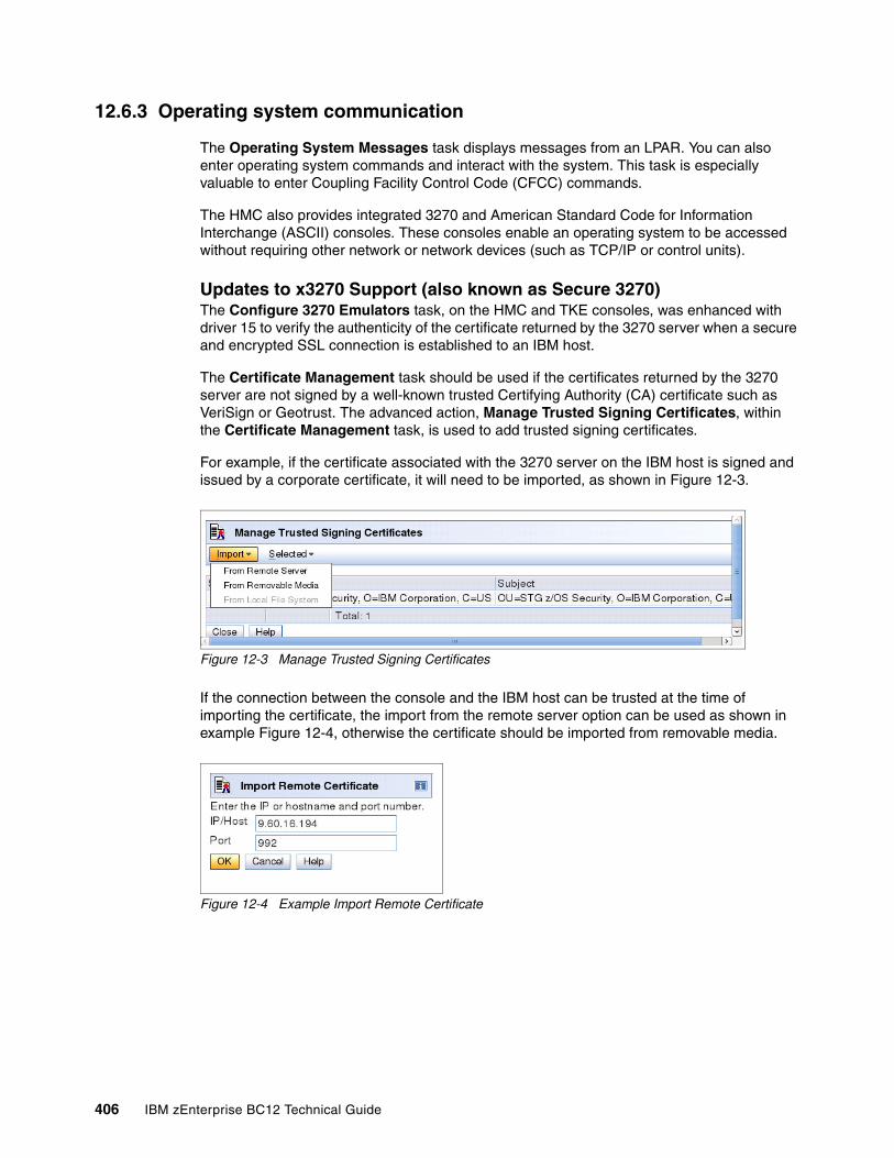
12.6.3 Operating system communication
The Operating System Messages task displays messages from an LPAR. You can also enter operating system commands and interact with the system. This task is especially valuable to enter Coupling Facility Control Code (CFCC) commands.
The HMC also provides integrated 3270 and American Standard Code for Information Interchange (ASCII) consoles. These consoles enable an operating system to be accessed without requiring other network or network devices (such as TCP/IP or control units).
Updates to x3270 Support (also known as Secure 3270)The Configure 3270 Emulators task, on the HMC and TKE consoles, was enhanced with driver 15 to verify the authenticity of the certificate returned by the 3270 server when a secure and encrypted SSL connection is established to an IBM host.
The Certificate Management task should be used if the certificates returned by the 3270 server are not signed by a well-known trusted Certifying Authority (CA) certificate such as VeriSign or Geotrust. The advanced action, Manage Trusted Signing Certificates, within the Certificate Management task, is used to add trusted signing certificates.
For example, if the certificate associated with the 3270 server on the IBM host is signed and issued by a corporate certificate, it will need to be imported, as shown in Figure 12-3.
Figure 12-3 Manage Trusted Signing Certificates
If the connection between the console and the IBM host can be trusted at the time of importing the certificate, the import from the remote server option can be used as shown in example Figure 12-4, otherwise the certificate should be imported from removable media.
Figure 12-4 Example Import Remote Certificate
406 IBM zEnterprise BC12 Technical Guide
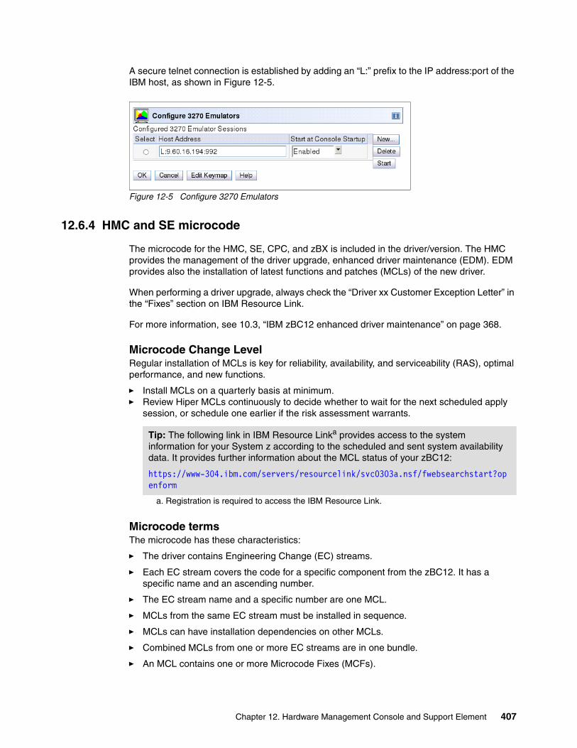
A secure telnet connection is established by adding an “L:” prefix to the IP address:port of the IBM host, as shown in Figure 12-5.
Figure 12-5 Configure 3270 Emulators
12.6.4 HMC and SE microcode
The microcode for the HMC, SE, CPC, and zBX is included in the driver/version. The HMC provides the management of the driver upgrade, enhanced driver maintenance (EDM). EDM provides also the installation of latest functions and patches (MCLs) of the new driver.
When performing a driver upgrade, always check the “Driver xx Customer Exception Letter” in the “Fixes” section on IBM Resource Link.
For more information, see 10.3, “IBM zBC12 enhanced driver maintenance” on page 368.
Microcode Change LevelRegular installation of MCLs is key for reliability, availability, and serviceability (RAS), optimal performance, and new functions.
� Install MCLs on a quarterly basis at minimum. � Review Hiper MCLs continuously to decide whether to wait for the next scheduled apply
session, or schedule one earlier if the risk assessment warrants.
Microcode termsThe microcode has these characteristics:
� The driver contains Engineering Change (EC) streams.
� Each EC stream covers the code for a specific component from the zBC12. It has a specific name and an ascending number.
� The EC stream name and a specific number are one MCL.
� MCLs from the same EC stream must be installed in sequence.
� MCLs can have installation dependencies on other MCLs.
� Combined MCLs from one or more EC streams are in one bundle.
� An MCL contains one or more Microcode Fixes (MCFs).
Tip: The following link in IBM Resource Linka provides access to the system information for your System z according to the scheduled and sent system availability data. It provides further information about the MCL status of your zBC12:
https://www-304.ibm.com/servers/resourcelink/svc0303a.nsf/fwebsearchstart?openform
a. Registration is required to access the IBM Resource Link.
Chapter 12. Hardware Management Console and Support Element 407
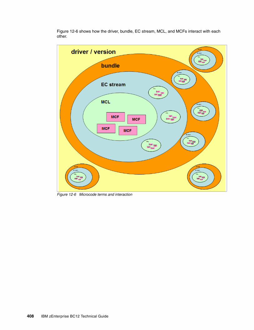
Figure 12-6 shows how the driver, bundle, EC stream, MCL, and MCFs interact with each other.
Figure 12-6 Microcode terms and interaction
408 IBM zEnterprise BC12 Technical Guide
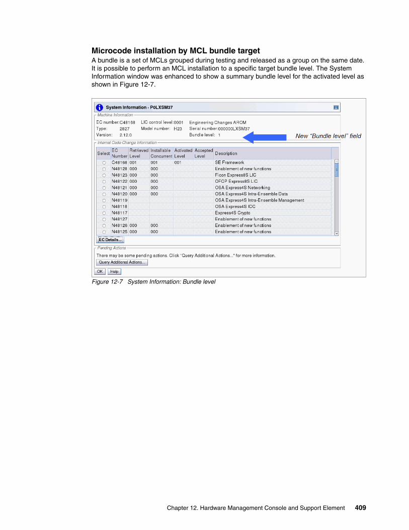
Microcode installation by MCL bundle targetA bundle is a set of MCLs grouped during testing and released as a group on the same date. It is possible to perform an MCL installation to a specific target bundle level. The System Information window was enhanced to show a summary bundle level for the activated level as shown in Figure 12-7.
Figure 12-7 System Information: Bundle level
Chapter 12. Hardware Management Console and Support Element 409
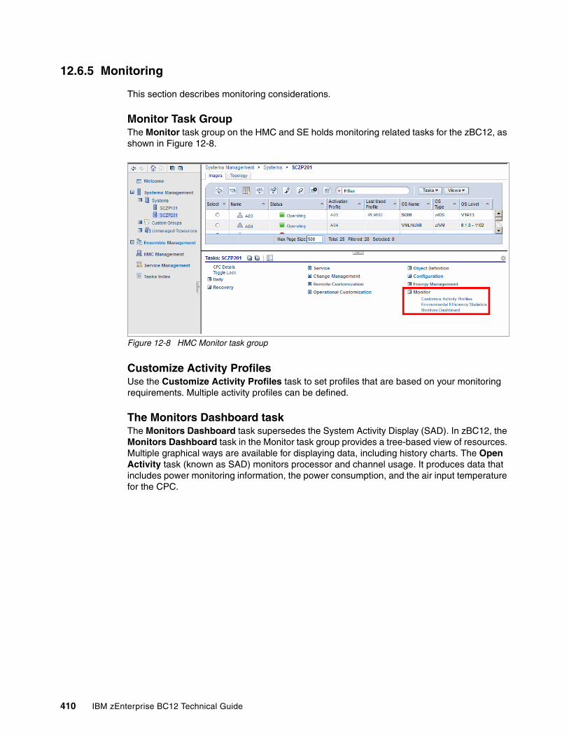
12.6.5 Monitoring
This section describes monitoring considerations.
Monitor Task GroupThe Monitor task group on the HMC and SE holds monitoring related tasks for the zBC12, as shown in Figure 12-8.
Figure 12-8 HMC Monitor task group
Customize Activity ProfilesUse the Customize Activity Profiles task to set profiles that are based on your monitoring requirements. Multiple activity profiles can be defined.
The Monitors Dashboard taskThe Monitors Dashboard task supersedes the System Activity Display (SAD). In zBC12, the Monitors Dashboard task in the Monitor task group provides a tree-based view of resources. Multiple graphical ways are available for displaying data, including history charts. The Open Activity task (known as SAD) monitors processor and channel usage. It produces data that includes power monitoring information, the power consumption, and the air input temperature for the CPC.
410 IBM zEnterprise BC12 Technical Guide
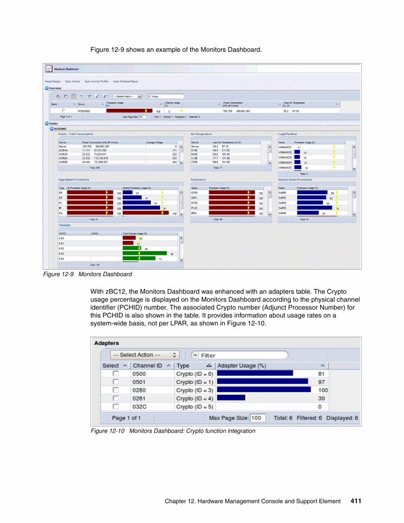
Figure 12-9 shows an example of the Monitors Dashboard.
Figure 12-9 Monitors Dashboard
With zBC12, the Monitors Dashboard was enhanced with an adapters table. The Crypto usage percentage is displayed on the Monitors Dashboard according to the physical channel identifier (PCHID) number. The associated Crypto number (Adjunct Processor Number) for this PCHID is also shown in the table. It provides information about usage rates on a system-wide basis, not per LPAR, as shown in Figure 12-10.
Figure 12-10 Monitors Dashboard: Crypto function integration
Chapter 12. Hardware Management Console and Support Element 411
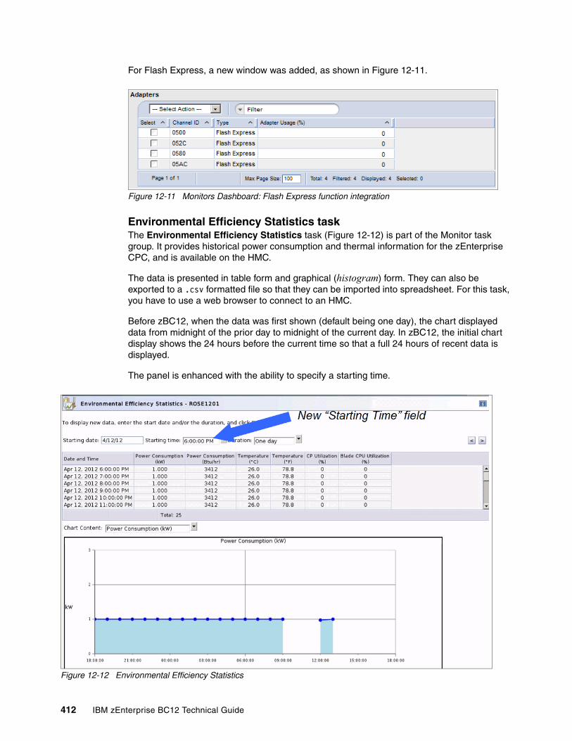
For Flash Express, a new window was added, as shown in Figure 12-11.
Figure 12-11 Monitors Dashboard: Flash Express function integration
Environmental Efficiency Statistics taskThe Environmental Efficiency Statistics task (Figure 12-12) is part of the Monitor task group. It provides historical power consumption and thermal information for the zEnterprise CPC, and is available on the HMC.
The data is presented in table form and graphical (histogram) form. They can also be exported to a .csv formatted file so that they can be imported into spreadsheet. For this task, you have to use a web browser to connect to an HMC.
Before zBC12, when the data was first shown (default being one day), the chart displayed data from midnight of the prior day to midnight of the current day. In zBC12, the initial chart display shows the 24 hours before the current time so that a full 24 hours of recent data is displayed.
The panel is enhanced with the ability to specify a starting time.
Figure 12-12 Environmental Efficiency Statistics
412 IBM zEnterprise BC12 Technical Guide
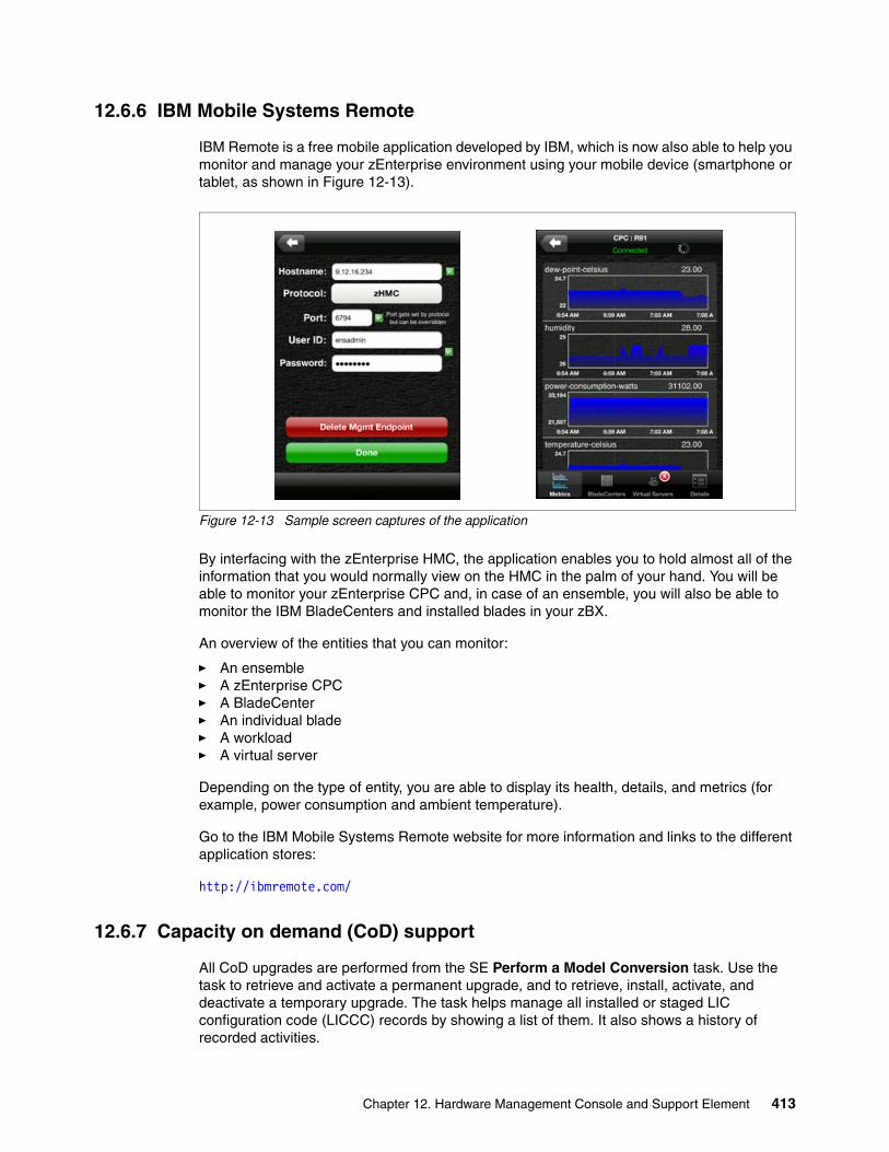
12.6.6 IBM Mobile Systems Remote
IBM Remote is a free mobile application developed by IBM, which is now also able to help you monitor and manage your zEnterprise environment using your mobile device (smartphone or tablet, as shown in Figure 12-13).
Figure 12-13 Sample screen captures of the application
By interfacing with the zEnterprise HMC, the application enables you to hold almost all of the information that you would normally view on the HMC in the palm of your hand. You will be able to monitor your zEnterprise CPC and, in case of an ensemble, you will also be able to monitor the IBM BladeCenters and installed blades in your zBX.
An overview of the entities that you can monitor:
� An ensemble� A zEnterprise CPC� A BladeCenter� An individual blade� A workload� A virtual server
Depending on the type of entity, you are able to display its health, details, and metrics (for example, power consumption and ambient temperature).
Go to the IBM Mobile Systems Remote website for more information and links to the different application stores:
http://ibmremote.com/
12.6.7 Capacity on demand (CoD) support
All CoD upgrades are performed from the SE Perform a Model Conversion task. Use the task to retrieve and activate a permanent upgrade, and to retrieve, install, activate, and deactivate a temporary upgrade. The task helps manage all installed or staged LIC configuration code (LICCC) records by showing a list of them. It also shows a history of recorded activities.
Chapter 12. Hardware Management Console and Support Element 413
HMC for IBM zEnterprise zBC12 has these CoD capabilities:
� SNMP API support:
– API interfaces for granular activation and deactivation– API interfaces for enhanced CoD query information– API Event notification for any CoD change activity on the system– CoD API interfaces (such as On/Off CoD and CBU)
� SE panel features (accessed through HMC Single Object Operations):
– Panel controls for granular activation and deactivation– History panel for all CoD actions
Descriptions editing of CoD records HMC/SE version 2.12.1 provides the following CoD information:
� Millions of service units (MSU) and processor tokens� Last activation time� Pending resources are shown by processor type instead of just a total count� Option to show details of installed and staged permanent records� More details for the Attention state by providing seven more flags
HMC and SE are a part of the z/OS Capacity Provisioning environment. The Capacity Provisioning Manager (CPM) communicates with the HMC through System z APIs, and enters CoD requests. For this reason, SNMP must be configured and enabled on the HMC.
For more information about using and setting up CPM, see these publications:
� z/OS MVS Capacity Provisioning User’s Guide, SC33-8299� IBM zEnterprise 196 Capacity on Demand User’s Guide, SC28-2605
12.6.8 Feature on demand (FoD) support
FoD is a new centralized way to flexibly entitle features and functions on the system. FoD contains, for example, the zBX high water marks (HWM). HWMs refer to the highest quantity of blade entitlements by blade type that the customer has purchased. On IBM zEnterprise 114 (z114) and IBM zEnterprise 196 (z196), the zBX HWMs are stored in the processor and memory LICCC record. On zBC12, they are found in the feature on demand record.
FoD supports separate LICCC controls for System z processors (central processors (CPs), Integrated Facilities for Linux (IFLs), System z Application Assist Processors (zAAPs), and System z Integrated Information Processors (zIIPs)) and HWMs, providing entitlement controls for each individual blade type. It is also used as LICCC support for the following features:
� zAware, for enablement and maximum connections� Base/Proprietary Service, for expiration date� New Features that are yet to be announced or developed
New since SE version 2.12.0: Some preselected defaults are removed. Specifying each selection in the window is required.
414 IBM zEnterprise BC12 Technical Guide
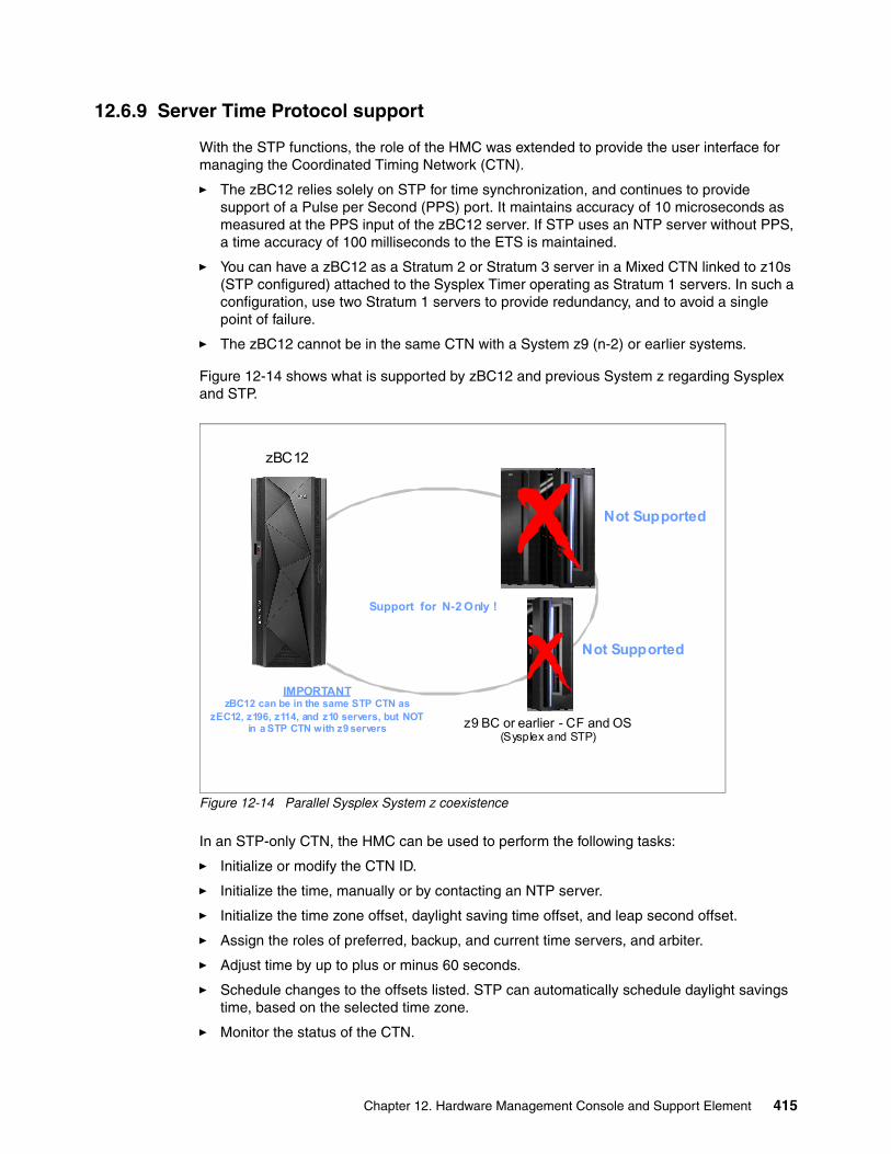
12.6.9 Server Time Protocol support
With the STP functions, the role of the HMC was extended to provide the user interface for managing the Coordinated Timing Network (CTN).
� The zBC12 relies solely on STP for time synchronization, and continues to provide support of a Pulse per Second (PPS) port. It maintains accuracy of 10 microseconds as measured at the PPS input of the zBC12 server. If STP uses an NTP server without PPS, a time accuracy of 100 milliseconds to the ETS is maintained.
� You can have a zBC12 as a Stratum 2 or Stratum 3 server in a Mixed CTN linked to z10s (STP configured) attached to the Sysplex Timer operating as Stratum 1 servers. In such a configuration, use two Stratum 1 servers to provide redundancy, and to avoid a single point of failure.
� The zBC12 cannot be in the same CTN with a System z9 (n-2) or earlier systems.
Figure 12-14 shows what is supported by zBC12 and previous System z regarding Sysplex and STP.
Figure 12-14 Parallel Sysplex System z coexistence
In an STP-only CTN, the HMC can be used to perform the following tasks:
� Initialize or modify the CTN ID.
� Initialize the time, manually or by contacting an NTP server.
� Initialize the time zone offset, daylight saving time offset, and leap second offset.
� Assign the roles of preferred, backup, and current time servers, and arbiter.
� Adjust time by up to plus or minus 60 seconds.
� Schedule changes to the offsets listed. STP can automatically schedule daylight savings time, based on the selected time zone.
� Monitor the status of the CTN.
zBC12
z9 BC or earlier - CF and OS(Sysplex and STP)
Support for N-2 Only !
Not Supported
Not Supported
IMPORTANTzBC12 can be in the same STP CTN as
zEC12, z196, z114, and z10 servers, but NOT in a STP CTN with z9 servers
Chapter 12. Hardware Management Console and Support Element 415
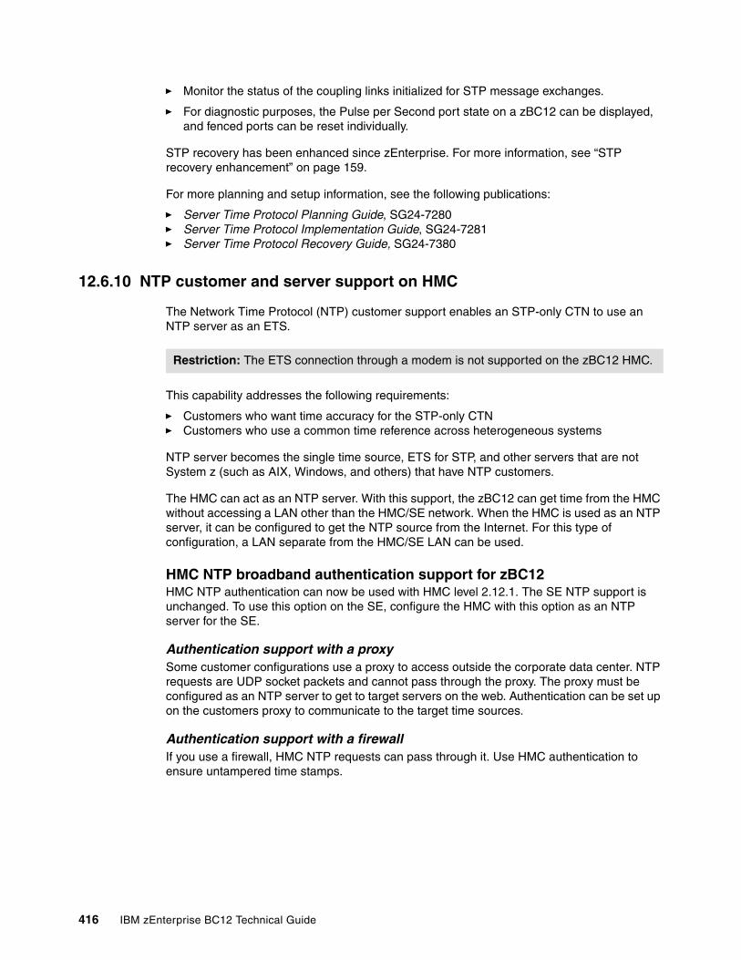
� Monitor the status of the coupling links initialized for STP message exchanges.
� For diagnostic purposes, the Pulse per Second port state on a zBC12 can be displayed, and fenced ports can be reset individually.
STP recovery has been enhanced since zEnterprise. For more information, see “STP recovery enhancement” on page 159.
For more planning and setup information, see the following publications:
� Server Time Protocol Planning Guide, SG24-7280� Server Time Protocol Implementation Guide, SG24-7281� Server Time Protocol Recovery Guide, SG24-7380
12.6.10 NTP customer and server support on HMC
The Network Time Protocol (NTP) customer support enables an STP-only CTN to use an NTP server as an ETS.
This capability addresses the following requirements:
� Customers who want time accuracy for the STP-only CTN� Customers who use a common time reference across heterogeneous systems
NTP server becomes the single time source, ETS for STP, and other servers that are not System z (such as AIX, Windows, and others) that have NTP customers.
The HMC can act as an NTP server. With this support, the zBC12 can get time from the HMC without accessing a LAN other than the HMC/SE network. When the HMC is used as an NTP server, it can be configured to get the NTP source from the Internet. For this type of configuration, a LAN separate from the HMC/SE LAN can be used.
HMC NTP broadband authentication support for zBC12HMC NTP authentication can now be used with HMC level 2.12.1. The SE NTP support is unchanged. To use this option on the SE, configure the HMC with this option as an NTP server for the SE.
Authentication support with a proxySome customer configurations use a proxy to access outside the corporate data center. NTP requests are UDP socket packets and cannot pass through the proxy. The proxy must be configured as an NTP server to get to target servers on the web. Authentication can be set up on the customers proxy to communicate to the target time sources.
Authentication support with a firewallIf you use a firewall, HMC NTP requests can pass through it. Use HMC authentication to ensure untampered time stamps.
Restriction: The ETS connection through a modem is not supported on the zBC12 HMC.
416 IBM zEnterprise BC12 Technical Guide
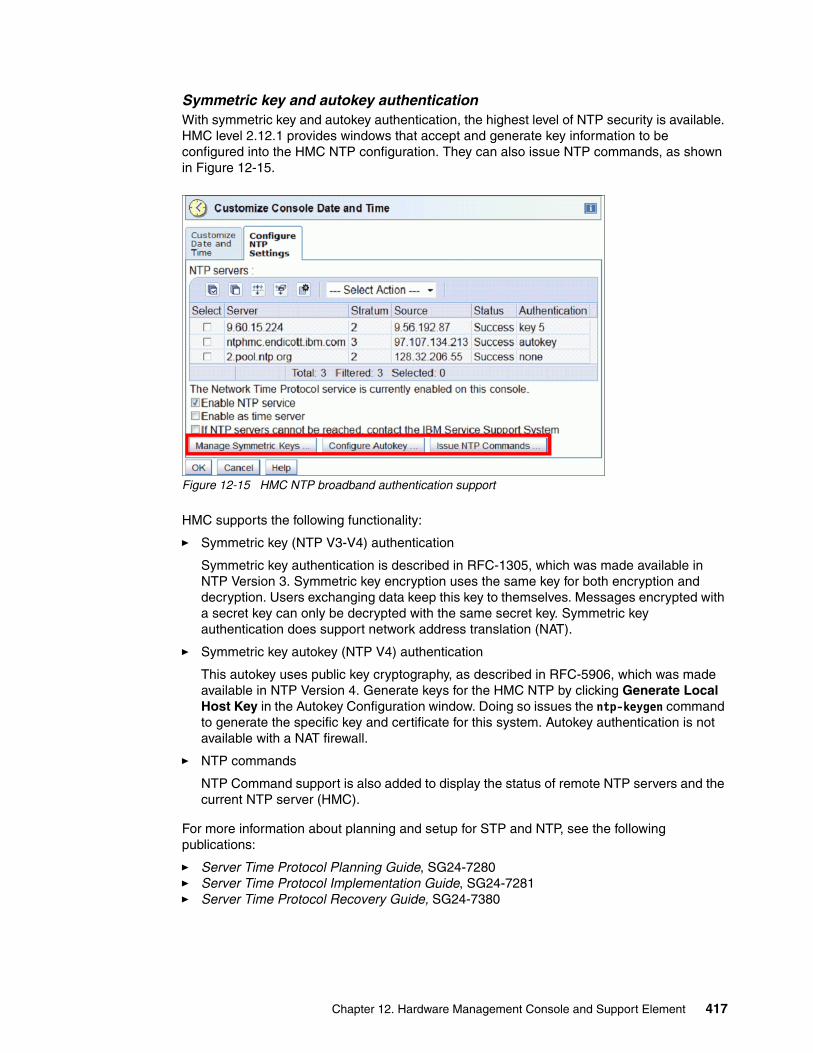
Symmetric key and autokey authenticationWith symmetric key and autokey authentication, the highest level of NTP security is available. HMC level 2.12.1 provides windows that accept and generate key information to be configured into the HMC NTP configuration. They can also issue NTP commands, as shown in Figure 12-15.
Figure 12-15 HMC NTP broadband authentication support
HMC supports the following functionality:
� Symmetric key (NTP V3-V4) authentication
Symmetric key authentication is described in RFC-1305, which was made available in NTP Version 3. Symmetric key encryption uses the same key for both encryption and decryption. Users exchanging data keep this key to themselves. Messages encrypted with a secret key can only be decrypted with the same secret key. Symmetric key authentication does support network address translation (NAT).
� Symmetric key autokey (NTP V4) authentication
This autokey uses public key cryptography, as described in RFC-5906, which was made available in NTP Version 4. Generate keys for the HMC NTP by clicking Generate Local Host Key in the Autokey Configuration window. Doing so issues the ntp-keygen command to generate the specific key and certificate for this system. Autokey authentication is not available with a NAT firewall.
� NTP commands
NTP Command support is also added to display the status of remote NTP servers and the current NTP server (HMC).
For more information about planning and setup for STP and NTP, see the following publications:
� Server Time Protocol Planning Guide, SG24-7280� Server Time Protocol Implementation Guide, SG24-7281� Server Time Protocol Recovery Guide, SG24-7380
Chapter 12. Hardware Management Console and Support Element 417
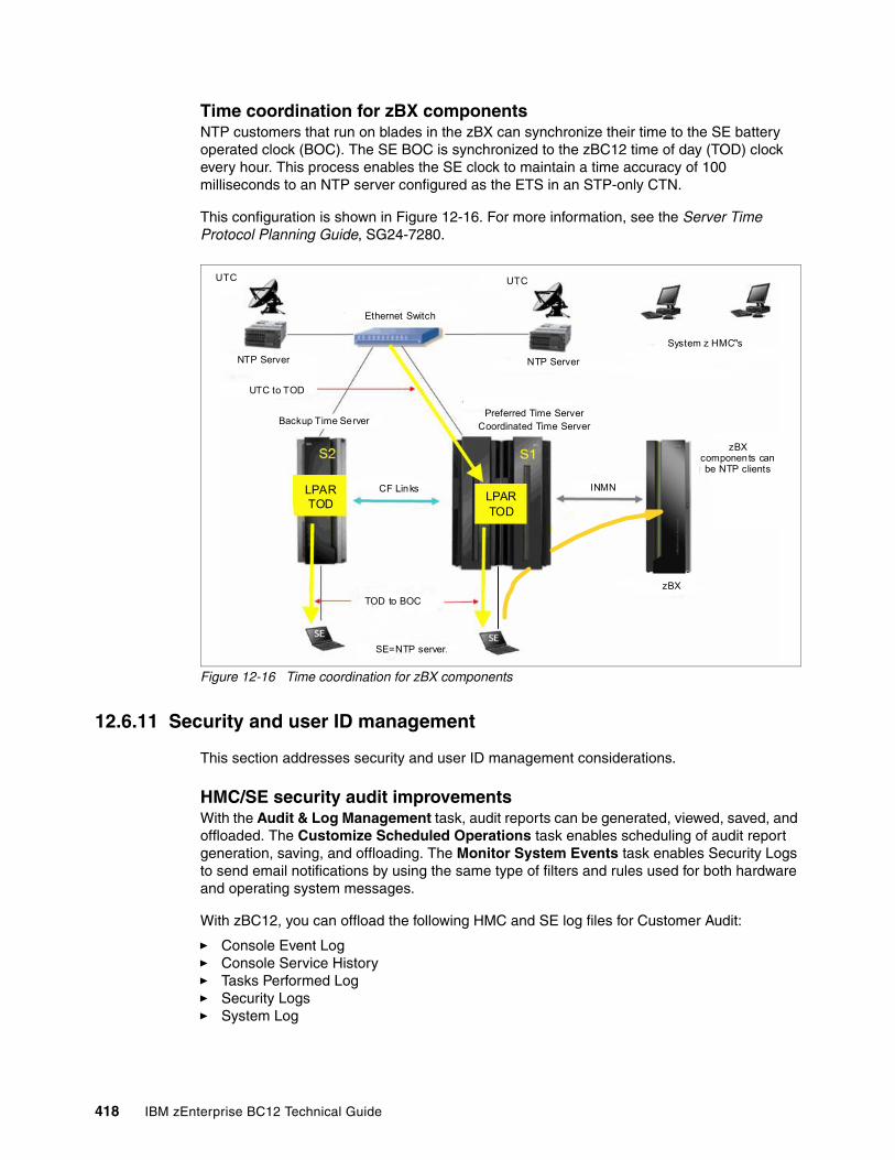
Time coordination for zBX componentsNTP customers that run on blades in the zBX can synchronize their time to the SE battery operated clock (BOC). The SE BOC is synchronized to the zBC12 time of day (TOD) clock every hour. This process enables the SE clock to maintain a time accuracy of 100 milliseconds to an NTP server configured as the ETS in an STP-only CTN.
This configuration is shown in Figure 12-16. For more information, see the Server Time Protocol Planning Guide, SG24-7280.
Figure 12-16 Time coordination for zBX components
12.6.11 Security and user ID management
This section addresses security and user ID management considerations.
HMC/SE security audit improvementsWith the Audit & Log Management task, audit reports can be generated, viewed, saved, and offloaded. The Customize Scheduled Operations task enables scheduling of audit report generation, saving, and offloading. The Monitor System Events task enables Security Logs to send email notifications by using the same type of filters and rules used for both hardware and operating system messages.
With zBC12, you can offload the following HMC and SE log files for Customer Audit:
� Console Event Log� Console Service History� Tasks Performed Log� Security Logs� System Log
UTC
NTP Server
Ethernet Switch
UTC to TOD
Backup Time Server
CF Links
TOD to BOC
SE=NTP server
LPARTOD
LPARTOD
Preferred Time ServerCoordinated Time Server
INMN
UTC
NTP Server
System z HMC"s
zBX
zBX components can be NTP clients
418 IBM zEnterprise BC12 Technical Guide
Full logoff load and delta logoff load (since last offload request) are provided. Offloading to removable media and to remote locations by FTP is available. The offloading can be manually started by the new Audit & Log Management task, or scheduled by the Scheduled Operations task. The data can be offloaded in the HTML and XML formats.
HMC User ID templates and LDAP user authenticationLDAP user authentication and HMC user ID templates enable adding and removing HMC users according to your own corporate security environment. This process uses an LDAP server as the central authority. Each HMC user ID template defines the specific levels of authorization levels for the tasks and objects for the user who is mapped to that template. The HMC User is mapped to a specific User ID template by user ID pattern matching. The system then obtains the name of the user ID template from content in the LDAP Server schema data.
Default HMC user IDsIt is no longer possible to change the Managed Resource or Task Roles of the default user IDs (operator, advanced, sysprog, acsadmin, and service).
If you want the ability to change the roles for a default user ID, create your own version by copying an existing default user ID.
View-only user IDs and access for HMC/SEWith HMC and SE user ID support, users can be created who have view-only access to selected tasks. Support for view-only user IDs is available for the following purposes:
� Hardware Messages� Operating System Messages� Customize and Delete Activation Profiles� Advanced Facilities� Configure On/Off
HMC and SE secure FTP supportYou can use a secure FTP connection from an HMC/SE FTP customer to a customer FTP server location. This configuration is implemented by using the SSH File Transfer Protocol, which is an extension of the Secure Shell (SSH) protocol. You can use the Manage SSH Keys console action (available to both HMC and SE) to import public keys that are associated with a host address.
Secure FTP infrastructure enables HMC/SE applications to query if a public key is associated with a host address, and to use the Secure FTP interface with the appropriate public key for a host. Tasks that use FTP now provide a selection for the Secure Host connection.
When selected, the task verifies that a public key is associated with the specified host name. If none is provided, a message box is displayed that points to the Manage SSH Keys task to input one. The following tasks provide this support:
� Import/Export IOCDS� Advanced Facilities FTP ICC Load� Audit and Log Management (Scheduled Operations Only)
12.6.12 System Input/Output Configuration Analyzer on the SE and HMC
The System Input/Output Configuration Analyzer task supports the system I/O configuration function. The information necessary to manage a system's I/O configuration must be obtained from many separate sources.
Chapter 12. Hardware Management Console and Support Element 419
The System Input/Output Configuration Analyzer task enables the system hardware administrator to access, from one location, the information from those sources. Managing I/O configurations then becomes easier, particularly across multiple CPCs.
The System Input/Output Configuration Analyzer task runs the following functions:
� Analyzes the current active IOCDS on the SE.� Extracts information about the defined channel, partitions, link addresses, and CUs.� Requests the channels node ID information. The FICON channels support remote node ID
information, which is also collected.
The System Input/Output Configuration Analyzer is a view-only tool. It does not offer any options other than viewing options. With the tool, data is formatted and displayed in five different views. The tool provides various sort options, and data can be exported to a UFD for later viewing.
The following five views are available:
� PCHID Control Unit View, which shows PCHIDs, CSS, channel path identifiers (CHPIDs), and their CUs.
� PCHID Partition View, which shows PCHIDS, CSS, CHPIDs, and the partitions they are in.� Control Unit View, which shows the CUs, their PCHIDs, and their link addresses in each
CSS.� Link Load View, which shows the Link address and the PCHIDs that use it.� Node ID View, which shows the Node ID data under the PCHIDs.
12.6.13 Automated operations
As an alternative to manual operations, an application can interact with the HMC and SE through an API. The interface enables a program to monitor and control the hardware components of the system in the same way that you can. The HMC APIs provide monitoring and control functions through SNMP and the CIM. These APIs can get and set a managed object’s attributes, issue commands, receive asynchronous notifications, and generate SNMP traps.
The HMC supports the CIM as an additional systems management API. The focus is on attribute query and operational management functions for System z, such as CPCs, images, and activation profiles. The zBC12 contains a number of enhancements to the CIM systems management API. The function is similar to that provided by the SNMP API.
For more information about APIs, see the System z Application Programming Interfaces, SB10-7030.
12.6.14 Cryptographic support
This section lists the cryptographic management and control functions available in HMC and SE.
Cryptographic hardwareThe zEC12 includes both standard cryptographic hardware and optional cryptographic features for flexibility and growth capability.
The HMC/SE interface provides the following capabilities:
� Defining the cryptographic controls� Dynamically adding a Crypto feature to a partition for the first time
420 IBM zEnterprise BC12 Technical Guide
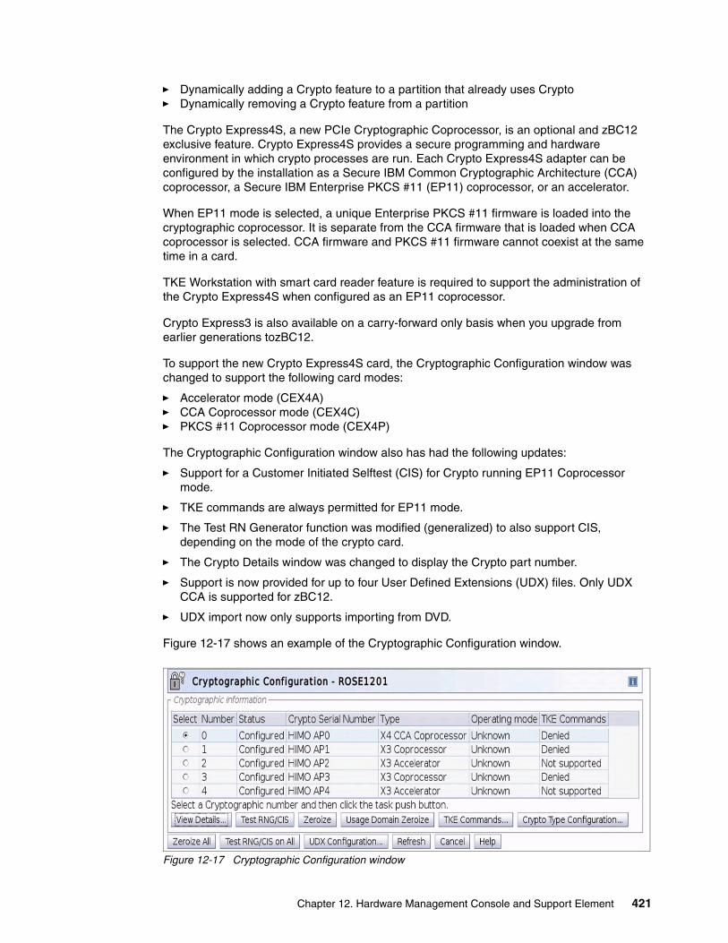
� Dynamically adding a Crypto feature to a partition that already uses Crypto� Dynamically removing a Crypto feature from a partition
The Crypto Express4S, a new PCIe Cryptographic Coprocessor, is an optional and zBC12 exclusive feature. Crypto Express4S provides a secure programming and hardware environment in which crypto processes are run. Each Crypto Express4S adapter can be configured by the installation as a Secure IBM Common Cryptographic Architecture (CCA) coprocessor, a Secure IBM Enterprise PKCS #11 (EP11) coprocessor, or an accelerator.
When EP11 mode is selected, a unique Enterprise PKCS #11 firmware is loaded into the cryptographic coprocessor. It is separate from the CCA firmware that is loaded when CCA coprocessor is selected. CCA firmware and PKCS #11 firmware cannot coexist at the same time in a card.
TKE Workstation with smart card reader feature is required to support the administration of the Crypto Express4S when configured as an EP11 coprocessor.
Crypto Express3 is also available on a carry-forward only basis when you upgrade from earlier generations tozBC12.
To support the new Crypto Express4S card, the Cryptographic Configuration window was changed to support the following card modes:
� Accelerator mode (CEX4A)� CCA Coprocessor mode (CEX4C)� PKCS #11 Coprocessor mode (CEX4P)
The Cryptographic Configuration window also has had the following updates:
� Support for a Customer Initiated Selftest (CIS) for Crypto running EP11 Coprocessor mode.
� TKE commands are always permitted for EP11 mode.
� The Test RN Generator function was modified (generalized) to also support CIS, depending on the mode of the crypto card.
� The Crypto Details window was changed to display the Crypto part number.
� Support is now provided for up to four User Defined Extensions (UDX) files. Only UDX CCA is supported for zBC12.
� UDX import now only supports importing from DVD.
Figure 12-17 shows an example of the Cryptographic Configuration window.
Figure 12-17 Cryptographic Configuration window
Chapter 12. Hardware Management Console and Support Element 421
The Usage Domain Zeroize task is provided to clear the appropriate partition crypto keys for a usage domain when you remove a crypto card from a partition.
Crypto Express4S in EP11 mode will be configured to the standby state after Zeroize.
For more information, see IBM zEnterprise EC12 Configuration Setup, SG24-8034.
Digitally signed firmwareOne critical issue with firmware upgrades is security and data integrity. Procedures are in place to use a process to digitally sign the firmware update files sent to the HMC, the SE, and the TKE. Using a hash-algorithm, a message digest is generated that is then encrypted with a private key to produce a digital signature.
This operation ensures that any changes made to the data are detected during the upgrade process by verifying the digital signature. It helps ensure that no malware can be installed on System z products during firmware updates. It enables zBC12 CP Assist for Cryptographic Function (CPACF) functions to comply with Federal Information Processing Standard (FIPS) 140-2 Level 1 for Cryptographic Licensed Internal Code (LIC) changes. The enhancement follows the System z focus of security for the HMC and the SE.
12.6.15 IBM z/VM virtual machine management
The HMC can be used for basic management of z/VM and its virtual machines. The HMC uses the z/VM Systems Management Application Programming Interface (SMAPI), which provides a graphical user interface (GUI) based alternative to the 3270 interface.
Monitoring the status information and changing the settings of z/VM and its virtual machines are possible. From the HMC interface, virtual machines can be activated, monitored, and deactivated.
Authorized HMC users can obtain various status information:
� Configuration of the particular z/VM virtual machine� IBM z/VM image-wide information about virtual switches and guest LANs� Virtual Machine Resource Manager (VMRM) configuration and measurement data
The activation and deactivation of z/VM virtual machines is integrated into the HMC interface. You can select the Activate and Deactivate tasks on CPC and CPC image objects, and for virtual machine management.
An event monitor is a trigger that monitors events from objects that are managed by HMC. When z/VM virtual machines change their status, they generate such events. You can create event monitors to handle these events. For example, selected users can be notified by an email message if the virtual machine changes status from Operating to Exception, or any other state.
In addition, in z/VM V5R4 (or later releases), the APIs can run the following functions:
� Create, delete, replace, query, lock, and unlock directory profiles.
� Manage and query LAN access lists (granting and revoking access to specific user IDs).
� Define, delete, and query virtual processors within an active virtual image and in a virtual image's directory entry.
� Set the maximum number of virtual processors that can be defined in a virtual image's directory entry.
422 IBM zEnterprise BC12 Technical Guide
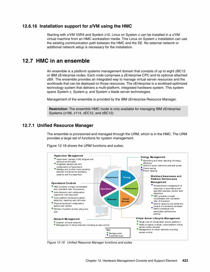
12.6.16 Installation support for z/VM using the HMC
Starting with z/VM V5R4 and System z10, Linux on System z can be installed in a z/VM virtual machine from an HMC workstation media. This Linux on System z installation can use the existing communication path between the HMC and the SE. No external network or additional network setup is necessary for the installation.
12.7 HMC in an ensemble
An ensemble is a platform systems management domain that consists of up to eight zBC12 or IBM zEnterprise nodes. Each node comprises a zEnterprise CPC and its optional attached zBX. The ensemble provides an integrated way to manage virtual server resources and the workloads that can be deployed on those resources. The zEnterprise is a workload-optimized technology system that delivers a multi-platform, integrated hardware system. This system spans System z, System p, and System x blade server technologies.
Management of the ensemble is provided by the IBM zEnterprise Resource Manager.
12.7.1 Unified Resource Manager
The ensemble is provisioned and managed through the URM, which is in the HMC. The URM provides a large set of functions for system management.
Figure 12-18 shows the URM functions and suites.
Figure 12-18 Unified Resource Manager functions and suites
Restriction: The ensemble HMC mode is only available for managing IBM zEnterprise Systems (z196, z114, zEC12, and zBC12).
Hypervisor Ma nagement
Hypervisors (except z/VM) shipped and serviced as firm ware. In tegrated deploym ent and
configuration of hypervisors Manage and control c omm unication
between vi rtual server operating systems and the hypervisor.
Operational Controls
HMC provides a single consolidated and c onsistent view of resources
Auto-d iscovery and configuration support for new resources.
Cross p latform hardware problem detection, reporting and c all home.
Physical hardware c onfiguration, backup and restore.
Del ivery of system ac tivity using new user.
Network Ma nagement
Creation of vi tual networks Managem ent of virtual networks including ac cess control
Energy Ma nagement
Monitoring and trend reporting of energy efficiency. Abili ty to query maximum potential power.• Power saving• Power capping
Workloa d Awareness and Platform Performance Mana gement
• Wizard-driven m anagement of resources in accordance with spec ified business service level objectives HMC provides a single
consolidated and consistent view of resources
• Moni tor resource use wi thin the context of a business workload• Define workloads and associated performance pol icies
Virtual Server Lifecycle Management
Single view of virtualization across pla tform s. Abi lity to deploy m ultiple, cross-platform vi rtual
servers within minutes Management of virtual networks including
access controlKey
Manage sui te• A utomate su ite
Hypervisors
Operations
Networks VirtualServers
Energy
Performance
Chapter 12. Hardware Management Console and Support Element 423
OverviewURM provides the following functions:
� Hypervisor management
Provides tasks for managing hypervisor lifecycle, managing storage resources, providing RAS and first-failure data capture (FFDC) features, and monitoring the supported hypervisors.
� Ensemble membership management
Provides tasks for creating an ensemble and controlling membership of the ensemble.
� Storage management
Provides a common user interface for allocation and deallocation of physical and virtual storage resources for an ensemble.
� Virtual server management
Provides lifecycle management to create, delete, activate, deactivate, and modify definitions of virtual servers.
� Virtual network management
Enables management of networking resources for an ensemble.
� Availability management
The resource workload Awareness availability function monitors and reports virtual servers availability status, based on the workloads that they are part of and their associated workload policies.
� Performance management
Provides a global performance view of all of the virtual servers that support workloads deployed in an ensemble. The virtual server workload performance goal is similar to a simplified z/OS Workload Manager (WLM) policy:
– You can define, monitor, report on, and manage the performance of virtual servers based on workload performance policies.
– Policies are associated to the workload:
• From the overall Workload performance health report, you can review the contributions of individual virtual servers.
• You can manage resources across virtual servers within a hypervisor instance.
� Ensemble availability management (EAM).
EAM implements basic availability services for the ensemble as part of the URM. It provides consistent high-availability management across Virtual Servers running on the zEnterprise and zBX in an ensemble, allowing error monitoring and identifying conditions affecting resource availability.
EAM Availability assessment is based on user defined policies for:
– PR/SM LPARs running on zEnterprise– Kernel-based virtual machine (KVM) virtual servers running on zBX– PowerVM virtual servers running on zBX
424 IBM zEnterprise BC12 Technical Guide
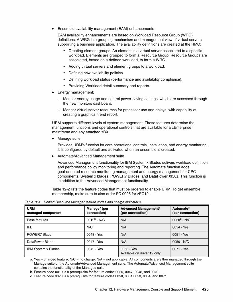
� Ensemble availability management (EAM) enhancements
EAM availability enhancements are based on Workload Resource Group (WRG) definitions. A WRG is a grouping mechanism and management view of virtual servers supporting a business application. The availability definitions are created at the HMC:
• Creating element groups. An element is a virtual server associated to a specific workload. Elements are grouped to form a Resource Group. Resource Groups are associated, based on a defined workload, to form a WRG.
• Adding virtual servers and element groups to a workload.
• Defining new availability policies.
• Defining workload status (performance and availability compliance).
• Providing Workload detail summary and reports.
� Energy management:
– Monitor energy usage and control power-saving settings, which are accessed through the new monitors dashboard.
– Monitor virtual server resources for processor use and delays, with capability of creating a graphical trend report.
URM supports different levels of system management. These features determine the management functions and operational controls that are available for a zEnterprise mainframe and any attached zBX:
� Manage suite
Provides URM’s function for core operational controls, installation, and energy monitoring. It is configured by default and activated when an ensemble is created.
� Automate/Advanced Management suite
Advanced Management functionality for IBM System x Blades delivers workload definition and performance policy monitoring and reporting. The Automate function adds goal-oriented resource monitoring management and energy management for CPC components. System x blades, POWER7 Blades, and DataPower XI50z. This function is in addition to the Advanced Management functionality.
Table 12-2 lists the feature codes that must be ordered to enable URM. To get ensemble membership, make sure to also order FC 0025 for zEC12.
Table 12-2 Unified Resource Manager feature codes and charge indicator.s
URMmanaged component
Managea (per connection)
a. Yes = charged feature, N/C = no charge, N/A = not applicable. All components are either managed through the Manage suite or the Automate/Advanced Management suite. The Automate/Advanced Management suite contains the functionality of the Managed suite.
Advanced Managementa (per connection)
Automatea (per connection)
Base features 0019b - N/C
b. Feature code 0019 is a prerequisite for feature codes 0020, 0047, 0048, and 0049.
N/A 0020c - N/C
c. Feature code 0020 is a prerequisite for feature codes 0050, 0051,0053, 0054, and 0071.
IFL N/C N/A 0054 - Yes
POWER7 Blade 0048 - Yes N/A 0051 - Yes
DataPower Blade 0047 - Yes N/A 0050 - N/C
IBM System x Blades 0049 - Yes 0053 - YesAvailable on driver 12 only
0071 - Yes
Chapter 12. Hardware Management Console and Support Element 425
APIs for the Unified Resource ManagerThe API is a web-oriented programming interface that makes the underlying URM capabilities available for use by higher-level management applications, system automation functions, and custom scripting. The functions that are available through the API support several important usage scenarios. These scenarios are in virtualization management, resource inventory, provisioning, monitoring, automation, and workload-based optimization, among others.
The Web Services API consists of two major components that are accessed by customer applications through TCP/IP network connections with the HMC.
For more information about the API and the URM, see System z Hardware Management Console Web Services API, SC27-2616 and IBM zEnterprise Unified Resource Manager, SG24-7921.
12.7.2 Ensemble definition and management
The ensemble starts with a pair of HMCs that are designated as the primary and alternate HMCs, and are assigned an ensemble identity. The zEnterprise CPCs and zBXs are then added to the ensemble through an explicit action at the primary HMC.
Feature codeFeature code 0025 (Ensemble Membership Flag) is associated with an HMC when a zBC12 is ordered. This feature code is required on the controlling zBC12 to be able to attach a zBX.
The new Create Ensemble task enables the Access Administrator to create an ensemble that contains CPCs, images, workloads, virtual networks, and storage pools. This ensemble can be created with or without an optional zBX.
If a zBC12 was entered into an ensemble, the CPC Details task on the SE and HMC reflects the ensemble name.
URM actions for the ensemble are conducted from a single primary HMC. All other HMCs connected to the ensemble are able to run system management tasks (but not ensemble management tasks) for any CPC within the ensemble. The primary HMC can also be used to run system management tasks on CPCs that are not part of the ensemble. These tasks include Load, Activate, and others.
The following list shows the ensemble-specific managed objects:
� Ensemble� Members� Blades� BladeCenters� Hypervisors� Storage Resources� Virtual Servers� Workloads
When another HMC accesses an ensemble node’s CPC, the HMC can do the same tasks as if the CPC were not a part of an ensemble. A few of those tasks have been extended to enable you to configure certain ensemble-specific properties. You can, for example, set the virtual network associated with OSAs for an LPAR. Showing ensemble-related data in certain tasks is supported. Generally, if the data affects the operation of the ensemble, the data is read-only on another HMC.
426 IBM zEnterprise BC12 Technical Guide
The following tasks show ensemble-related data on another HMC:
� Scheduled operations.
Displays ensemble-introduced scheduled operations, but you can view only these scheduled operations.
� User role
Shows ensemble tasks. You can modify and delete those roles.
� Event monitoring.
Displays ensemble-related events, but you cannot change or delete the event.
HMC considerations when used to manage an ensembleThe following considerations are valid when you use URM to manage an ensemble:
� All HMCs at the supported code level are eligible to create an ensemble. Only HMCs with FC 0092 or FC 0091 can be primary or alternate HMCs for zBC12.
� The primary and the alternate HMC must be the same machine type/feature code.
� There is a single HMC pair that manages the ensemble, consisting of a primary HMC and alternate HMC.
� Only one primary HMC manages an ensemble, which can consist of a maximum of eight CPCs.
� The HMC that ran the Create Ensemble wizard becomes the primary HMC. An alternate HMC is elected and paired with the primary.
� The Primary HMC (Version 2.12.1 or later) and Alternate HMC (Version 2.12.1 or later) are displayed on the HMC banner. When the ensemble is deleted, the titles change back to the default.
� A primary HMC is the only HMC that can run ensemble-related management tasks. These tasks include create virtual server, manage virtual networks, and create workload.
� A zEnterprise ensemble can have a maximum of eight nodes, and is managed by one primary HMC and its alternate. Each node consists of a zEnterprise CPC and its optional attached zBX.
� Any HMC can manage up to 100 CPCs. The primary HMC can run all non-ensemble HMC functions on CPCs that are not members of the ensemble.
� The primary and alternate HMCs must be on the same LAN segment.
� The alternate HMC’s role is to mirror ensemble configuration and policy information from the primary HMC.
� When failover happens, the alternate HMC becomes the primary HMC. This behavior is the same as primary and alternate SEs.
12.7.3 HMC availability
The HMC is attached to the same LAN as the CPCs SE. This LAN is referred to as the Customer Managed Management Network. The HMC communicates with each CPC, and optionally to one or more zBXs, through the SE.
If the zBC12 node is defined as a member of an ensemble, the primary HMC is the authoritative controlling (stateful) component for URM configuration. It is also the stateful component for policies that have a scope that spans all of the managed CPCs/SEs in the ensemble.
Chapter 12. Hardware Management Console and Support Element 427
The managing HMC has an active role in ongoing system monitoring and adjustment. This configuration requires the HMC to be configured in a primary/alternate configuration. It also cannot be disconnected from the managed ensemble members.
12.7.4 Considerations for multiple HMCs
Customers often deployed multiple HMC instances to manage an overlapping collection of systems. Until the emergence of ensembles, all of the HMCs were peer consoles to the managed systems. Using this configuration, all management actions are possible to any of the reachable systems while logged in to a session on any of the HMCs (subject to access control). With the URM, this paradigm has changed.
One ensemble is managed by one primary and alternate HMC pair. Multiple ensembles require an equal number of multiple primary and alternate HMC pairs to manage them. If a zBC12 or zEnterprise System node is added to an ensemble, management actions that target that system can be done only from the managing (primary) HMC for that ensemble.
12.7.5 HMC browser session to a primary HMC
A remote HMC browser session to the primary HMC managing an ensemble enables a user who is logged on to another HMC or a workstation to perform ensemble-related actions.
12.7.6 HMC ensemble topology
The system management functions that pertain to an ensemble use the virtual server resources and the intraensemble management network (IEDN). They are provided by the HMC/SE through the internode management network (INMN).
Failover: The primary HMC and its alternate must be connected to the same LAN segment. This configuration enables the alternate HMC to take over the IP address of the primary HMC during failover processing.
428 IBM zEnterprise BC12 Technical Guide
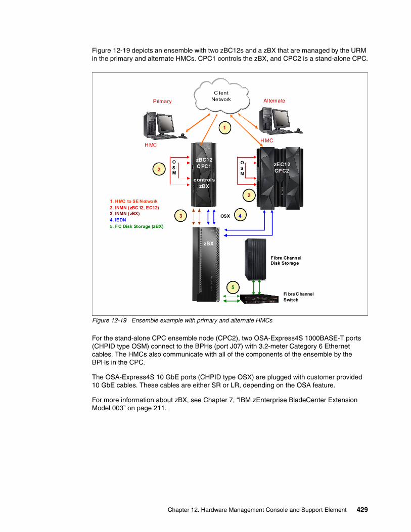
Figure 12-19 depicts an ensemble with two zBC12s and a zBX that are managed by the URM in the primary and alternate HMCs. CPC1 controls the zBX, and CPC2 is a stand-alone CPC.
Figure 12-19 Ensemble example with primary and alternate HMCs
For the stand-alone CPC ensemble node (CPC2), two OSA-Express4S 1000BASE-T ports (CHPID type OSM) connect to the BPHs (port J07) with 3.2-meter Category 6 Ethernet cables. The HMCs also communicate with all of the components of the ensemble by the BPHs in the CPC.
The OSA-Express4S 10 GbE ports (CHPID type OSX) are plugged with customer provided 10 GbE cables. These cables are either SR or LR, depending on the OSA feature.
For more information about zBX, see Chapter 7, “IBM zEnterprise BladeCenter Extension Model 003” on page 211.
H MCH MC
Primary
C lientNetwork
OSX
OSM
OSM
zB X
zBC12C PC1
controlszBX
zEC12CPC2
Fibre ChannelDisk Storage
1. HMC to SE Network
2. INMN (zBC12, EC12)3. INMN (zBX)
4. IEDN
5. FC Disk Storage (zBX)
Al ternate
2
2
1
3 4
5Fi bre ChannelSwitch
zBX
Chapter 12. Hardware Management Console and Support Element 429

430 IBM zEnterprise BC12 Technical Guide
Chapter 13. Performance
The IBM zEnterprise BC12 System (zBC12) central processor complex (CPC) has the same newly designed six-core chip as the IBM zEnterprise EC12 (zEC12), operating at a clock speed of 4.2 GHz. This provides up to 36% uniprocessor performance improvement, and up to 56% improvement in total system capacity for single-system image for z/OS, IBM z/Virtual Machine (z/VM), and IBM z/Virtual Storage Extended (z/VSE) workloads on System z, as compared to the IBM zEnterprise 114 (z114).
The zBC12 can be configured with up to 13 processors running concurrent production tasks, with up to 512 GB of memory, including 16 GB reserved for the hardware storage area (HSA). It offers hot-pluggable PCIe I/O drawers and I/O drawers, and continues the use of advanced technologies, such as PCIe and InfiniBand.
The zBC12 continues to offer a wide range of subcapacity settings, with 26 subcapacity levels for up to six central processors, giving a total of 156 distinct capacity settings in the system, and providing for a range of over 1:50 in processing power.
The zBC12 CPC provides a record level of capacity over the previous mid-size System z servers. This capacity is achieved both by increasing the performance of the individual processor units (PUs), and by increasing the number of PUs per server. The increased performance and the total system capacity available, along with possible energy savings, offer the opportunity to consolidate diverse applications on a single platform, with capacity on demand (CoD).
13
© Copyright IBM Corp. 2014. All rights reserved. 431
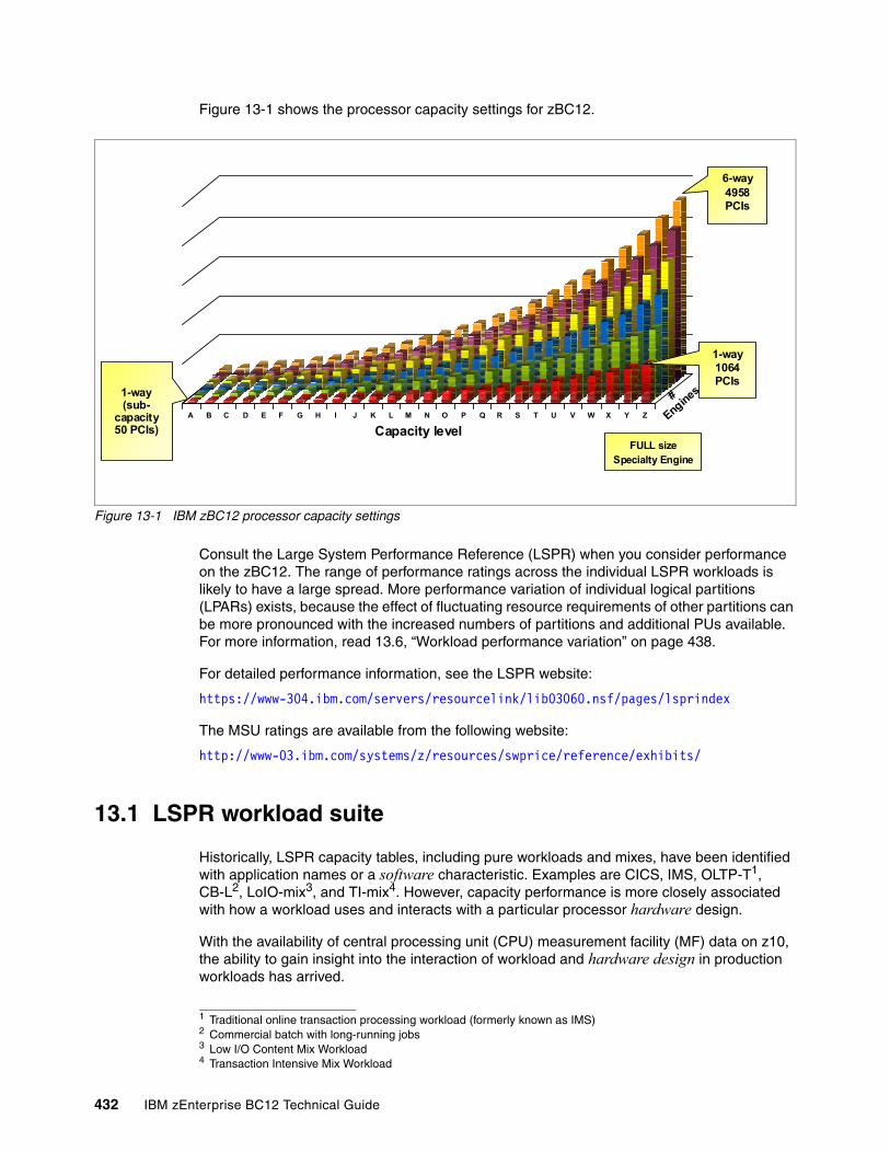
Figure 13-1 shows the processor capacity settings for zBC12.
Figure 13-1 IBM zBC12 processor capacity settings
Consult the Large System Performance Reference (LSPR) when you consider performance on the zBC12. The range of performance ratings across the individual LSPR workloads is likely to have a large spread. More performance variation of individual logical partitions (LPARs) exists, because the effect of fluctuating resource requirements of other partitions can be more pronounced with the increased numbers of partitions and additional PUs available. For more information, read 13.6, “Workload performance variation” on page 438.
For detailed performance information, see the LSPR website:
https://www-304.ibm.com/servers/resourcelink/lib03060.nsf/pages/lsprindex
The MSU ratings are available from the following website:
http://www-03.ibm.com/systems/z/resources/swprice/reference/exhibits/
13.1 LSPR workload suite
Historically, LSPR capacity tables, including pure workloads and mixes, have been identified with application names or a software characteristic. Examples are CICS, IMS, OLTP-T1, CB-L2, LoIO-mix3, and TI-mix4. However, capacity performance is more closely associated with how a workload uses and interacts with a particular processor hardware design.
With the availability of central processing unit (CPU) measurement facility (MF) data on z10, the ability to gain insight into the interaction of workload and hardware design in production workloads has arrived.
A B C D E F G H I J K L M N O P Q R S T U V W X Y Z
Capacity level
1-way(sub-
capacity50 PCIs)
1-way1064 PCIs
6-way 4958 PCIs
#
Engines
FULL sizeSpecialty Engine
1 Traditional online transaction processing workload (formerly known as IMS)2 Commercial batch with long-running jobs3 Low I/O Content Mix Workload4 Transaction Intensive Mix Workload
432 IBM zEnterprise BC12 Technical Guide
CPU MF data helps LSPR to adjust workload capacity curves based on the underlying hardware sensitivities, in particular, the processor access to caches and memory, which is known as nest activity intensity. With this nest activity intensity, the LSPR introduces three new workload capacity categories, which replace all prior primitives and mixes.
The LSPR contains the internal throughput rate ratios (ITRRs) for the zBC12 and the previous generation processor families, based upon measurements and projections that use standard IBM benchmarks in a controlled environment. The actual throughput that any user experiences can vary depending on considerations, such as the amount of multiprogramming in the user’s job stream, the I/O configuration, and the workload processed.
Therefore, no assurance can be given that an individual user can achieve throughput improvements equivalent to the performance ratios stated.
13.2 Fundamental components of workload capacity performance
Workload capacity performance is sensitive to three major factors:
� Instruction path length� Instruction complexity� Memory hierarchy
In this section, we examine each of these three factors.
Instruction path lengthA transaction or job will need to run a set of instructions to complete its task. These instructions are composed of various paths through the operating system, subsystems, and application. The total count of instructions run across these software components is referred to as the transaction or job path length.
Clearly, the path length will vary for each transaction or job, depending on the complexity of the tasks that must be performed. For a particular transaction or job, the application path length tends to stay the same, presuming that the transaction or job is asked to perform the same task each time.
However, the path length associated with the operating system or subsystem might vary based on a number of factors:
� Competition with other tasks in the system for shared resources. As the total number of tasks grows, more instructions are needed to manage the resources.
� The N-Way (number of logical processors) of the image or LPAR. As the number of logical processors grows, more instructions are needed to manage resources serialized by latches and locks.
Instruction complexityThe type of instructions and the sequence in which they are run will interact with the design of a micro-processor to affect a performance component we can define as “instruction complexity.” There are many design alternatives that affect this component:
� Cycle time (GHz) � Instruction architecture � Pipeline� Superscalar
Chapter 13. Performance 433
� Out-of-order (OOO) execution� Branch prediction
As workloads are moved between microprocessors with various designs, performance will likely vary. However, when on a processor, this component tends to be quite similar across all models of that processor.
Memory hierarchy and memory nestThe memory hierarchy of a processor generally refers to the caches, data buses, and memory arrays that stage the instructions and data needed to be run on the microprocessor to complete a transaction or job. There are many design alternatives that affect this component:
� Cache size � Latencies (sensitive to distance from the microprocessor) � Number of levels, MESI5 (management) protocol, controllers, switches, number, and
bandwidth of data buses and others
Certain caches are private to the microprocessor, which means that only that specific microprocessor can access them. Other caches are shared by multiple microprocessors. We define the term memory nest for a System z processor to refer to the shared caches and memory, along with the data buses that interconnect them.
Workload capacity performance will be quite sensitive to how deep into the memory hierarchy the processor must go to retrieve the workload’s instructions and data for execution. The best performance occurs when the instructions and data are found in the caches nearest the processor, so that little time is spent waiting before execution. As instructions and data must be retrieved from farther out in the hierarchy, the processor spends more time waiting for their arrival.
As workloads are moved between processors with various memory hierarchy designs, performance will vary as the average time to retrieve instructions and data from within the memory hierarchy will vary. Additionally, when on a processor, this component will continue to vary significantly, because the location of a workload’s instructions and data within the memory hierarchy is affected by many factors, including but not limited to these factors:
� Locality of reference� I/O rate� Competition from other applications and LPARs
13.3 Relative nest intensity
The most performance-sensitive area of the memory hierarchy is the activity to the memory nest, namely, the distribution of activity to the shared caches and memory. We introduce a term, Relative Nest Intensity (RNI) to indicate the level of activity to this part of the memory hierarchy. Using data from CPU MF, the RNI of the workload running in an LPAR can be calculated. The higher the RNI, the deeper into the memory hierarchy the processor must go to retrieve the instructions and data for that workload.
Many factors influence the performance of a workload. However, for the most part what these factors are influencing is the RNI of the workload. It is the interaction of all of these factors that results in a net RNI for the workload, which in turn directly relates to the performance of the workload.
5 M=Modified, E=Exclusive, S=Shared, I=Invalid
434 IBM zEnterprise BC12 Technical Guide
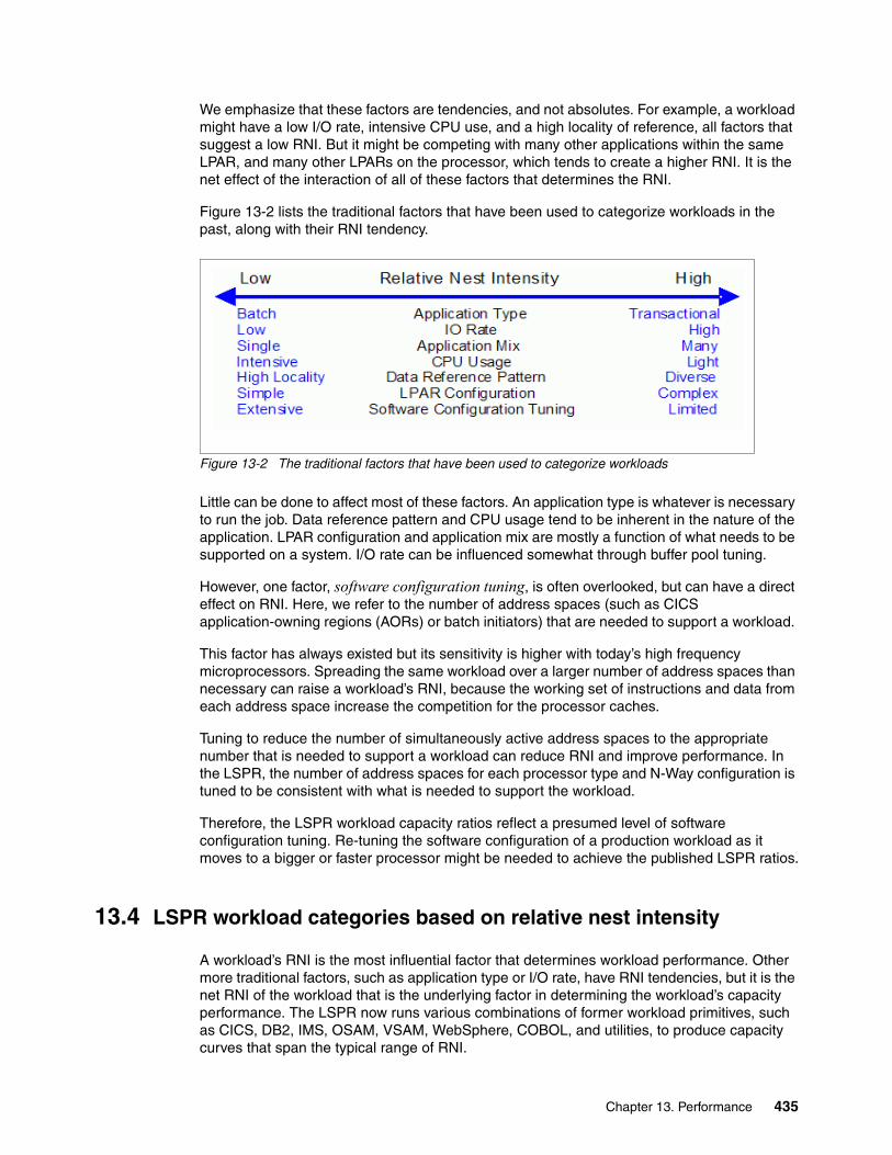
We emphasize that these factors are tendencies, and not absolutes. For example, a workload might have a low I/O rate, intensive CPU use, and a high locality of reference, all factors that suggest a low RNI. But it might be competing with many other applications within the same LPAR, and many other LPARs on the processor, which tends to create a higher RNI. It is the net effect of the interaction of all of these factors that determines the RNI.
Figure 13-2 lists the traditional factors that have been used to categorize workloads in the past, along with their RNI tendency.
Figure 13-2 The traditional factors that have been used to categorize workloads
Little can be done to affect most of these factors. An application type is whatever is necessary to run the job. Data reference pattern and CPU usage tend to be inherent in the nature of the application. LPAR configuration and application mix are mostly a function of what needs to be supported on a system. I/O rate can be influenced somewhat through buffer pool tuning.
However, one factor, software configuration tuning, is often overlooked, but can have a direct effect on RNI. Here, we refer to the number of address spaces (such as CICS application-owning regions (AORs) or batch initiators) that are needed to support a workload.
This factor has always existed but its sensitivity is higher with today’s high frequency microprocessors. Spreading the same workload over a larger number of address spaces than necessary can raise a workload’s RNI, because the working set of instructions and data from each address space increase the competition for the processor caches.
Tuning to reduce the number of simultaneously active address spaces to the appropriate number that is needed to support a workload can reduce RNI and improve performance. In the LSPR, the number of address spaces for each processor type and N-Way configuration is tuned to be consistent with what is needed to support the workload.
Therefore, the LSPR workload capacity ratios reflect a presumed level of software configuration tuning. Re-tuning the software configuration of a production workload as it moves to a bigger or faster processor might be needed to achieve the published LSPR ratios.
13.4 LSPR workload categories based on relative nest intensity
A workload’s RNI is the most influential factor that determines workload performance. Other more traditional factors, such as application type or I/O rate, have RNI tendencies, but it is the net RNI of the workload that is the underlying factor in determining the workload’s capacity performance. The LSPR now runs various combinations of former workload primitives, such as CICS, DB2, IMS, OSAM, VSAM, WebSphere, COBOL, and utilities, to produce capacity curves that span the typical range of RNI.
Chapter 13. Performance 435
Three new workload categories are represented in the LSPR tables:
� LOW (relative nest intensity)
A workload category representing light use of the memory hierarchy. This category is similar to past high-scaling primitives.
� AVERAGE (relative nest intensity)
A workload category representing an average use of the memory hierarchy. This category is similar to the past LoIO-mix workload, and is expected to represent the majority of production workloads.
� HIGH (relative nest intensity)
A workload category representing heavy use of the memory hierarchy. This category is similar to the past TI-mix workload.
These categories are based on the relative nest intensity. The RNI is influenced by many variables, such as application type, I/O rate, application mix, processor usage, data reference patterns, LPAR configuration, and software configuration running. CPU MF data can be collected by z/OS System Measurement Facility (SMF) on SMF 113 records. On zBC12, the number of extended counters is increased to 183. The structure of the SMF records does not change.
13.5 Relating production workloads to LSPR workloads
Historically, there have been a number of techniques that have been used to match production workloads to LSPR workloads:
� Application name
A customer running CICS can use the CICS LSPR workload.
� Application type
Create a mix of the LSPR online and batch workloads.
� I/O rate
Low I/O rates used a mix of the low I/O rate LSPR workloads.
The previous LSPR workload suite was made up of the following workloads:
� Traditional online transaction processing workload (OLTP-T), formerly known as IMS
� Web-enabled online transaction processing workload (OLTP-W), also known as Web/CICS/DB2
� A heavy Java-based online stock trading application WASDB (previously referred to as Trade2-EJB).
� Batch processing, represented by the commercial batch with long-running jobs (CB-L), or CBW2
� A new ODE-B Java batch workload, replacing the CB-J workload
The traditional Commercial Batch Short Job Steps (CB-S) workload (formerly CB84) was dropped.
436 IBM zEnterprise BC12 Technical Guide
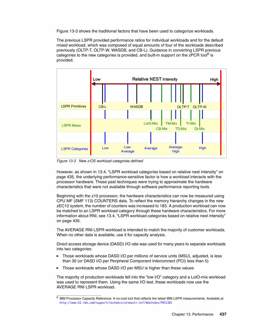
Figure 13-3 shows the traditional factors that have been used to categorize workloads.
The previous LSPR provided performance ratios for individual workloads and for the default mixed workload, which was composed of equal amounts of four of the workloads described previously (OLTP-T, OLTP-W, WASDB, and CB-L). Guidance in converting LSPR previous categories to the new categories is provided, and built-in support on the zPCR tool6 is provided.
Figure 13-3 New z/OS workload categories defined
However, as shown in 13.4, “LSPR workload categories based on relative nest intensity” on page 435, the underlying performance-sensitive factor is how a workload interacts with the processor hardware. These past techniques were trying to approximate the hardware characteristics that were not available through software performance reporting tools.
Beginning with the z10 processor, the hardware characteristics can now be measured using CPU MF (SMF 113) COUNTERS data. To reflect the memory hierarchy changes in the new zEC12 system, the number of counters was increased to 183. A production workload can now be matched to an LSPR workload category through these hardware characteristics. For more information about RNI, see 13.4, “LSPR workload categories based on relative nest intensity” on page 435.
The AVERAGE RNI LSPR workload is intended to match the majority of customer workloads. When no other data is available, use it for capacity analysis.
Direct access storage device (DASD) I/O rate was used for many years to separate workloads into two categories:
� Those workloads whose DASD I/O per millions of service units (MSU), adjusted, is less than 30 (or DASD I/O per Peripheral Component Interconnect (PCI) less than 5)
� Those workloads whose DASD I/O per MSU is higher than these values
The majority of production workloads fell into the “low I/O” category and a LoIO-mix workload was used to represent them. Using the same I/O test, these workloads now use the AVERAGE RNI LSPR workload.
6 IBM Processor Capacity Reference: A no-cost tool that reflects the latest IBM LSPR measurements. Available at http://www-03.ibm.com/support/techdocs/atsmastr.nsf/WebIndex/PRS1381
LSPR Categories Low Low-Average
Average-High
HighAverage
LSPR MixesLoIO-Mix TI-MixTM-Mix
DI-MixCB-Mix TD-Mix
Low High
LSPR Primitives CB-L WASDB OLTP-T OLTP-W
Relative NEST Intensity
LSPR Categories Low Low-Average
Average-High
HighAverage
LSPR MixesLoIO-Mix TI-MixTM-Mix
DI-MixCB-Mix TD-Mix
Low High
LSPR Primitives CB-L WASDB OLTP-T OLTP-W
Relative NEST Intensity
Chapter 13. Performance 437
Workloads with higher I/O rates can use the HIGH RNI workload or the AVG-HIGH RNI workload that is included with IBM Processor Capacity Reference (zPCR). Low-Average and Average-High categories provide better granularity for workload characterization.
For z10 and newer processors, the CPU MF data can be used to provide an additional “hint” as to workload selection. When available, this data enables the RNI for a production workload to be calculated. Using the RNI and another factor from CPU MF, the L1MP (percentage of data and instruction references that miss the L1 cache), a workload can be classified as LOW, AVERAGE, or HIGH RNI. This classification and the resulting “hint” are automated in the zPCR tool. It is best to use zPCR for capacity sizing.
The LSPR workloads, which have been updated for zBC12, are considered to reasonably reflect the current and growth workloads of the customer. The set contains three generic workload categories based on z/OS R1V13 supporting up to six processors in a single image.
13.6 Workload performance variation
Performance variability from application to application, similar to that seen on the IBM System z10 Business Class (z10 BC) and z114, is expected. This variability can be observed in certain ways. The range of performance ratings across the individual workloads is likely to have a spread, but not as large as with the z10 BC.
The memory and cache designs affect various workloads in a number of ways. All workloads are improved, with cache-intensive loads benefiting the most. When comparing moving from IBM System z9 Business Class (z9 BC) to z10 BC with moving from z10 BC to z114 or from z114 to zBC12, it is likely that the relative benefits per workload will vary.
Those workloads that benefited more than the average when moving from z9 BC to z10 BC will benefit less than the average when moving from z10 BC to z114, and vice versa. Also, enhancements, such as OOO instruction execution, yields significant performance benefit for especially compute-intensive applications while maintaining good performance growth for traditional workloads.
IBM zBC12 provides 156 available capacity settings. Each subcapacity indicator is defined with the notation A0x-Z0x, where x is the number of installed CPs, from one to six. There are a total of 26 subcapacity levels, designated by the letters A through Z.
This extreme granularity is helpful when choosing the right capacity setting for your needs. The customer effect of this variability is seen as increased deviations of workloads from single-number metric-based factors, such as millions of instructions per second (MIPS), MSUs, and CPU time charge-back algorithms.
Experience demonstrates that System z servers can be run at up to 100% usage levels, sustained, although most customers prefer to leave a bit of white space and run at 90% or slightly under. For any capacity comparison exercise, using only one number, such as the MIPS or MSU metric, is not a valid method.
Care should be exercised when deciding on the number of processors and the uniprocessor capacity to keep both the workload characteristics and LPAR configuration in mind. That’s why, when planning capacity, we suggest using zPCR and involving IBM technical support.
Main performance improvement drivers with zBC12The zBC12 is designed to deliver new levels of performance and capacity for large-scale consolidation and growth. The following attributes and design points of the zBC12 contribute to overall performance and throughput improvements as compared to the z114.
438 IBM zEnterprise BC12 Technical Guide
The z/Architecture implementation has the following enhancements:
� Transactional execution (TX) designed for z/OS, Java, DB2, and other exploiters
� Runtime instrumentation (RI) provides dynamic and self-tuning online recompilation capability for Java workloads
� Enhanced DAT-2 for supporting 2 GB pages for DB2 buffer pools, Java heap size, and other large structures
� Software directives implementation to improve hardware performance
� Decimal format conversions for Common Business Oriented Language (COBOL) programs
The zBC12 microprocessor design has the following enhancements:
� Six processor cores per chip
� Second generation OOO execution design
� Improved pipeline balance
� Enhanced branch prediction latency and instruction fetch throughput
� Improvements in execution bandwidth and throughput
� New design for Level 2 private cache with separation of cache structures for instructions and L2 operands
� Reduced access latency for most Level 1 cache misses
� Larger Level 2 cache with shorter latency
� Third level on-chip shared cache is doubled
� Fourth level book-shared cache is doubled
� Hardware and software prefetcher handling improvements
� Increased execution/completion throughput
� Improved fetch and store conflict scheme
� Enhance branch prediction structure and sequential instruction fetching
� Millicode performance improvements
� Optimized floating-point performance
� Faster engine for fixed-point division
� New second-level branch prediction array
� One cryptographic/compression co-processor per core
� Cryptography support of UTF8<>UTF16 conversions
� Higher clock frequency at 4.2 GHz
� IBM complementary metal-oxide semiconductor (CMOS) 13S 32 nm Silicon-On Insulator (SOI) technology with IBM embedded dynamic random access memory (eDRAM) technology
The zBC12 design has the following enhancements:
� Increased total number of PUs available on the system, from 14 to 18, and number of characterizable cores, from 10 to 13
� Hardware system area (HSA) increased from 8 GB to 16 GB
Chapter 13. Performance 439
� New coupling facility control code (CFCC) available for improved performance:
– Elapsed time improvements when dynamically altering the size of a cache structure
– DB2 conditional write to a group buffer pool (GBP)
– Performance improvements for coupling facility cache structures to avoid flooding the coupling facility cache with changed data, and avoid excessive delays and backlogs for cast-out processing
– Performance throughput enhancements for parallel cache castout processing by extending the number of record code check (RCC) cursors beyond 512
– Coupling facility (CF) Storage class and castout class contention avoidance by breaking up individual storage class and castout class queues to reduce storage class and castout class latch contention
The following new features are available on the zBC12:
� Open Systems Adapter (OSA)-Express5S family of features
� 10GbE Remote Direct Memory Access (RDMA) over Converged Ethernet (RoCE) Express feature
� Crypto Express4S performance enhancements
� Flash Express PCIe cards to handle paging workload spikes and improve performance
� IBM zEnterprise Data Compression (zEDC) Express feature
440 IBM zEnterprise BC12 Technical Guide
Appendix A. IBM zAware
This appendix introduces IBM System z Advanced Workload Analysis Reporter (IBM zAware), the next generation of system monitoring. It is a new feature that is designed to offer a near real-time, continuous learning, diagnostics, and monitoring capability. IBM zAware helps you pinpoint and resolve potential problems quickly enough to minimize the effect on your business.
This appendix includes the following sections:
� Troubleshooting in complex IT environments� Introducing the IBM zAware� IBM zAware Technology� IBM zAware prerequisites� Configuring and using the IBM zAware virtual appliance
For more information about IBM zAware, see Extending z/OS System Management Functions with IBM zAware, SG24-8070 and IBM System z Advanced Workload Analysis Reporter (IBM zAware) Guide, SC27-2623.
A
© Copyright IBM Corp. 2014. All rights reserved. 441
Troubleshooting in complex IT environments
In a 24 x 7 operating environment, a system problem or incident can drive up operations costs and disrupt service to the customers for hours or even days. Current information technology (IT) environments cannot afford recurring problems or outages that take too long to repair. These outages can result in damage to a company’s reputation, and limit the ability to remain competitive in the marketplace.
However, as systems become more complex, errors can occur anywhere. Some problems begin with symptoms that go undetected for long periods of time. Systems often experience soft failures (“sick but not dead”) that are much more difficult or unusual to detect. Moreover, problems can grow, cascade, and snowball.
Many everyday activities can introduce system anomalies and initiate either hard or soft failures in complex, integrated data centers:
� Increased volume of business activity� Application modifications to comply with changing regulatory requirements� IT efficiency efforts, such as consolidating images� Standard operational changes:
– Adding or upgrading hardware– Adding or upgrading software, such as operating systems, middleware, and
independent software vendor (ISV) products– Modifying network configurations– Moving workloads (provisioning, balancing, deploying, disaster recovery (DR) testing,
and other actions)
Using a combination of existing system management tools helps to diagnose problems. However, they cannot quickly identify messages that precede system problems, and cannot detect every possible combination of change and failure.
When using these tools, you might need to look through message logs to understand the underlying issue. But the number of messages makes this a challenging and skills-intensive task, and an error prone task.
To meet IT service challenges and to effectively sustain high levels of availability, a proven way is needed to identify, isolate, and resolve system problems quickly. Information and insight are vital to understanding baseline system behavior along with possible deviations. Having this knowledge reduces the time that is needed to diagnose problems, and address them quickly and accurately.
The current complex, integrated data centers require a team of experts to monitor systems and perform real-time diagnosis of events. However, it is not always possible to afford this level of skill for these reasons:
� A z/OS sysplex might produce more than 40 GB of message traffic per day for its images and components alone. Application messages can significantly increase that number.
� There are more than 40,000 unique message IDs defined in z/OS and the IBM software that runs on z/OS. ISV or customer messages can increase that number.
Introducing the IBM zAware
IBM zAware is an integrated expert solution that contains sophisticated analytics, IBM insight into the problem domain, and web-browser-based visualization.
442 IBM zEnterprise BC12 Technical Guide
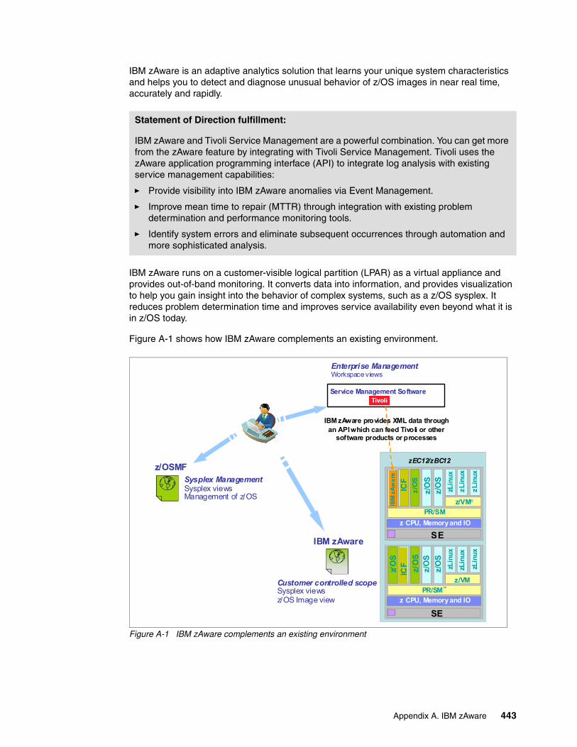
IBM zAware is an adaptive analytics solution that learns your unique system characteristics and helps you to detect and diagnose unusual behavior of z/OS images in near real time, accurately and rapidly.
IBM zAware runs on a customer-visible logical partition (LPAR) as a virtual appliance and provides out-of-band monitoring. It converts data into information, and provides visualization to help you gain insight into the behavior of complex systems, such as a z/OS sysplex. It reduces problem determination time and improves service availability even beyond what it is in z/OS today.
Figure A-1 shows how IBM zAware complements an existing environment.
Figure A-1 IBM zAware complements an existing environment
Statement of Direction fulfillment:
IBM zAware and Tivoli Service Management are a powerful combination. You can get more from the zAware feature by integrating with Tivoli Service Management. Tivoli uses the zAware application programming interface (API) to integrate log analysis with existing service management capabilities:
� Provide visibility into IBM zAware anomalies via Event Management.
� Improve mean time to repair (MTTR) through integration with existing problem determination and performance monitoring tools.
� Identify system errors and eliminate subsequent occurrences through automation and more sophisticated analysis.
Z C PU , M emor y and IOZ C PU , M emor y and IO
Vir
tua
l M
ac
hin
ezO
S
Z C PU , M emor y and IOz CPU, Memory and IO
PR/SM™
Vir
tua
l M
ac
hin
ezO
SV
irtu
al
Mac
hin
eIC
F
z/O
S
z/O
Sz/
OS
Z C PU , M emor y and IOZ C PU , M emor y and IO
Vir
tua
l M
ac
hin
ezO
S
Z C PU , M emor y and IOz CPU, Memory and IO
SE
PR/SM
Vir
tua
l M
ac
hin
ezO
SV
irtu
al
Ma
chin
eIB
MzA
wa
re
z/O
S
z/O
S
z/O
SSysplex ManagementSysplex viewsManagement of z/OS
Service Management Software
SE
zEC12/zBC12
z/VM®
zL
inu
x
zLin
ux
zL
inu
x
z/VM
zLin
ux
zLin
ux
zLin
ux
Enterprise ManagementWorkspace views
Customer controlled scopeSysplex viewsz/OS Image view
z/OSMF
IBM zAware
Vir
tu
al M
ac
hin
eIC
Fz/
OS
IBM zAware provides XML data throughan API which can feed Tivoli or other
software products or processes
Appendix A. IBM zAware 443
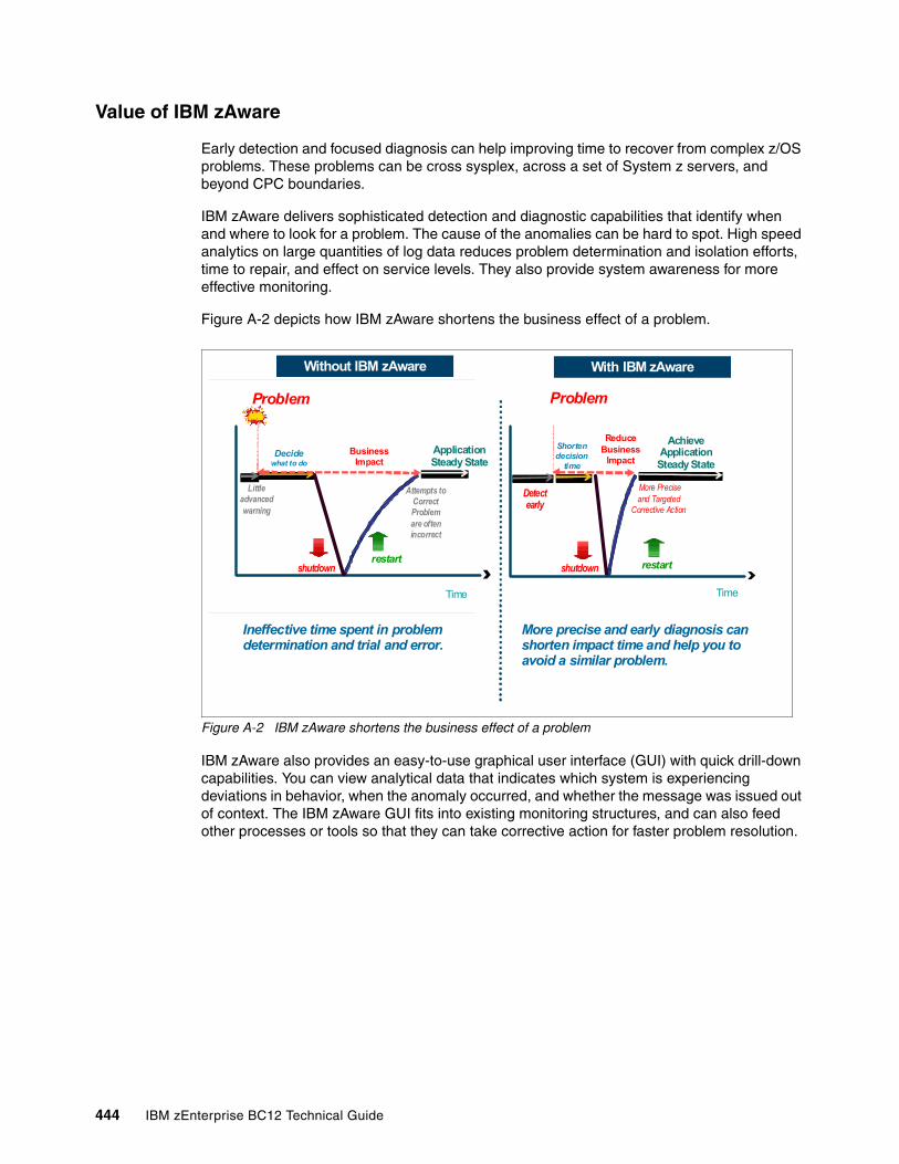
Value of IBM zAware
Early detection and focused diagnosis can help improving time to recover from complex z/OS problems. These problems can be cross sysplex, across a set of System z servers, and beyond CPC boundaries.
IBM zAware delivers sophisticated detection and diagnostic capabilities that identify when and where to look for a problem. The cause of the anomalies can be hard to spot. High speed analytics on large quantities of log data reduces problem determination and isolation efforts, time to repair, and effect on service levels. They also provide system awareness for more effective monitoring.
Figure A-2 depicts how IBM zAware shortens the business effect of a problem.
Figure A-2 IBM zAware shortens the business effect of a problem
IBM zAware also provides an easy-to-use graphical user interface (GUI) with quick drill-down capabilities. You can view analytical data that indicates which system is experiencing deviations in behavior, when the anomaly occurred, and whether the message was issued out of context. The IBM zAware GUI fits into existing monitoring structures, and can also feed other processes or tools so that they can take corrective action for faster problem resolution.
Ineffective time spent in problem determination and trial and error.
More precise and early diagnosis can shorten impact time and help you to avoid a similar problem.
Without IBM zAware With IBM zAware
Problem
Decidewhat to do
Business Impact
Application Steady State
shutdownrestart
Time Time
Problem
Shorten decision
time
Reduce Business
Impact
Achieve Application Steady State
shutdown restart
Little advanced warning
Detect early
More Precise and Targeted
Corrective Action
Attempts to Correct Problem are often incorrect
444 IBM zEnterprise BC12 Technical Guide
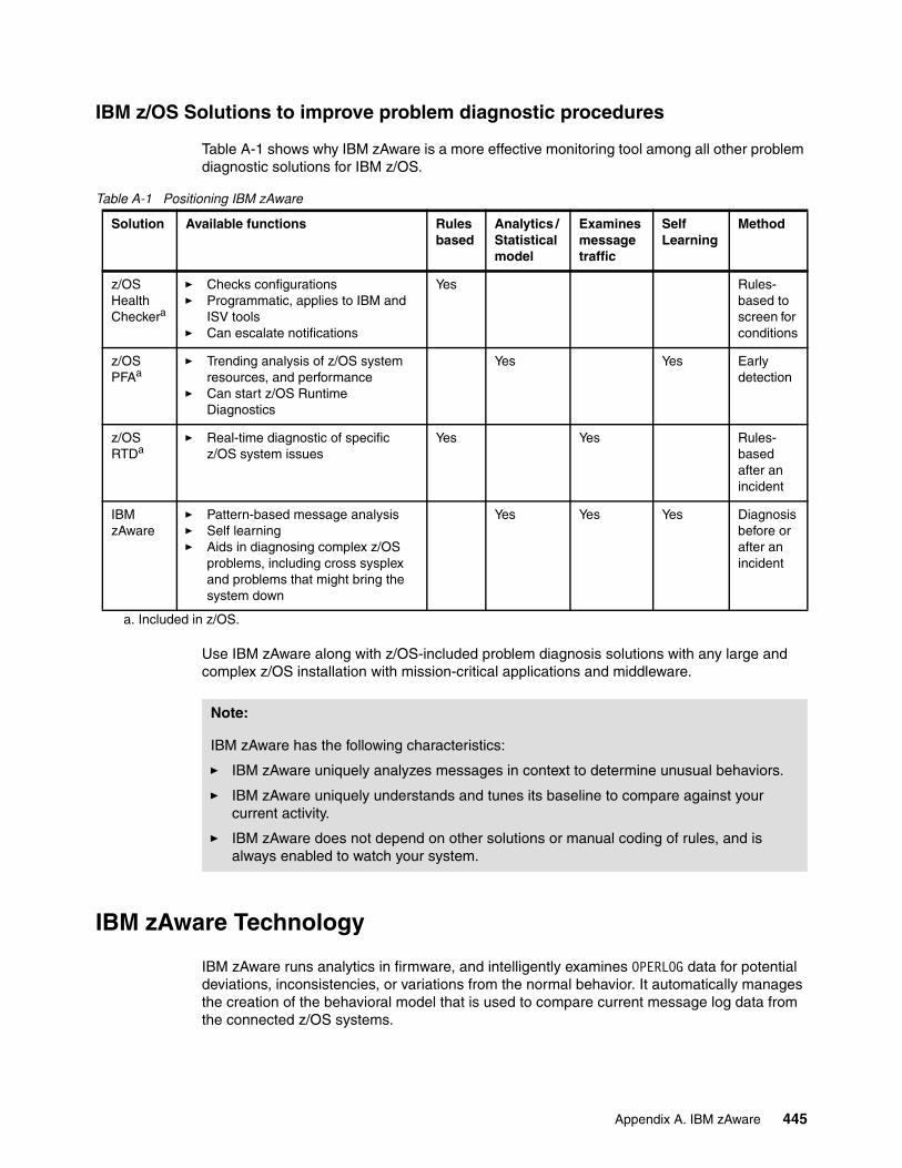
IBM z/OS Solutions to improve problem diagnostic procedures
Table A-1 shows why IBM zAware is a more effective monitoring tool among all other problem diagnostic solutions for IBM z/OS.
Table A-1 Positioning IBM zAware
Use IBM zAware along with z/OS-included problem diagnosis solutions with any large and complex z/OS installation with mission-critical applications and middleware.
IBM zAware Technology
IBM zAware runs analytics in firmware, and intelligently examines OPERLOG data for potential deviations, inconsistencies, or variations from the normal behavior. It automatically manages the creation of the behavioral model that is used to compare current message log data from the connected z/OS systems.
Solution Available functions Rules based
Analytics / Statistical model
Examines message traffic
Self Learning
Method
z/OS Health Checkera
a. Included in z/OS.
� Checks configurations� Programmatic, applies to IBM and
ISV tools� Can escalate notifications
Yes Rules-based to screen for conditions
z/OS PFAa
� Trending analysis of z/OS system resources, and performance
� Can start z/OS Runtime Diagnostics
Yes Yes Early detection
z/OS RTDa
� Real-time diagnostic of specific z/OS system issues
Yes Yes Rules- based after an incident
IBM zAware
� Pattern-based message analysis� Self learning� Aids in diagnosing complex z/OS
problems, including cross sysplex and problems that might bring the system down
Yes Yes Yes Diagnosis before or after an incident
Note:
IBM zAware has the following characteristics:
� IBM zAware uniquely analyzes messages in context to determine unusual behaviors.
� IBM zAware uniquely understands and tunes its baseline to compare against your current activity.
� IBM zAware does not depend on other solutions or manual coding of rules, and is always enabled to watch your system.
Appendix A. IBM zAware 445
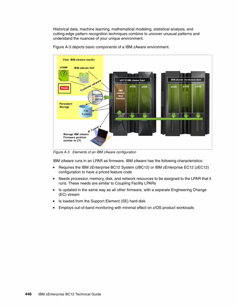
Historical data, machine learning, mathematical modeling, statistical analysis, and cutting-edge pattern recognition techniques combine to uncover unusual patterns and understand the nuances of your unique environment.
Figure A-3 depicts basic components of a IBM zAware environment.
Figure A-3 Elements of an IBM zAware configuration
IBM zAware runs in an LPAR as firmware. IBM zAware has the following characteristics:
� Requires the IBM zEnterprise BC12 System (zBC12) or IBM zEnterprise EC12 (zEC12) configuration to have a priced feature code
� Needs processor, memory, disk, and network resources to be assigned to the LPAR that it runs. These needs are similar to Coupling Facility LPARs
� Is updated in the same way as all other firmware, with a separate Engineering Change (EC) stream
� Is loaded from the Support Element (SE) hard disk
� Employs out-of-band monitoring with minimal effect on z/OS product workloads
View IBM zAware results
IBM zAware GUIz/OSMF
Customer netw
ork
PersistentStorage
File System
IP Tunnel
Manage IBM zAware Firmware partition (similar to CF)
zEC12 IBM zAware host IBM zAware monitored client
z/OSz/OS
IBMzAware
HostPartition
z/OSz/OSz/OS
446 IBM zEnterprise BC12 Technical Guide
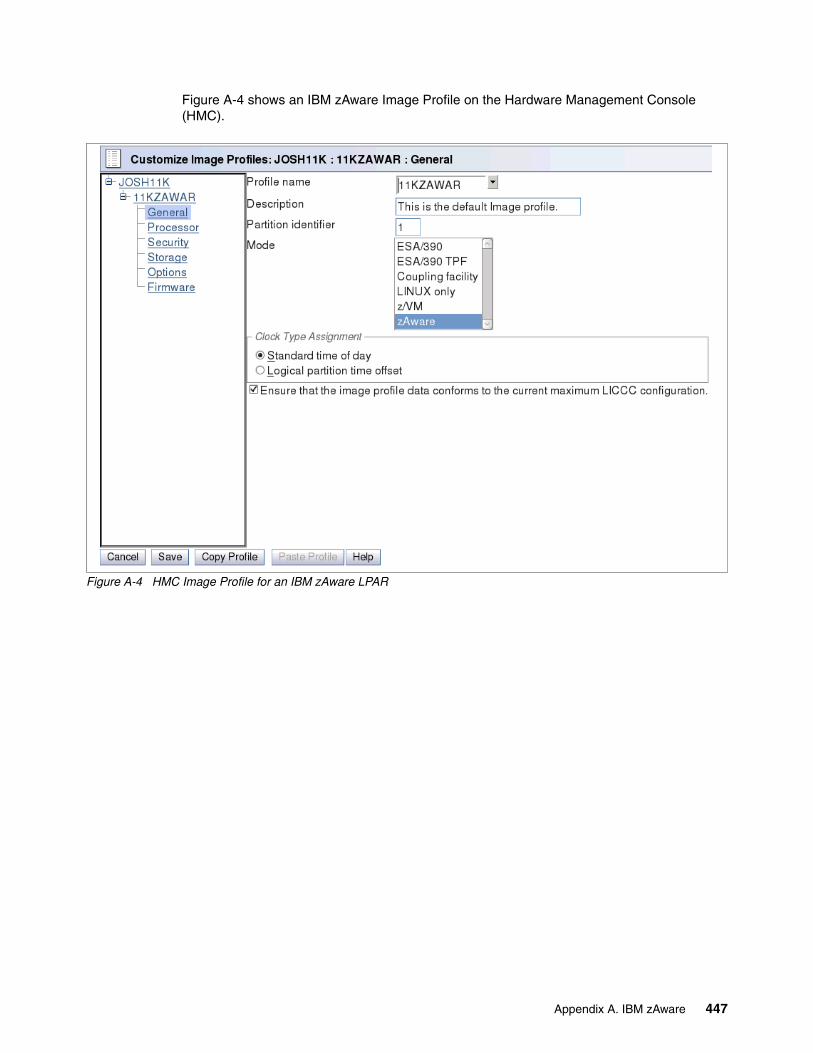
Figure A-4 shows an IBM zAware Image Profile on the Hardware Management Console (HMC).
Figure A-4 HMC Image Profile for an IBM zAware LPAR
Appendix A. IBM zAware 447
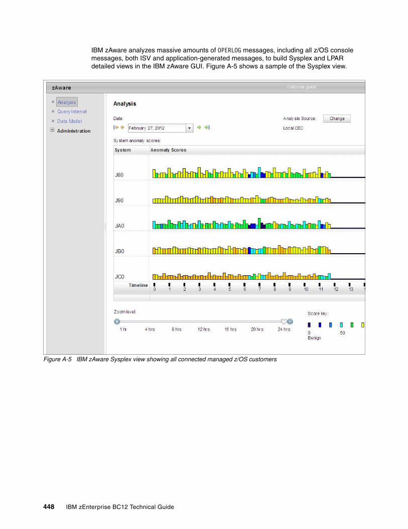
IBM zAware analyzes massive amounts of OPERLOG messages, including all z/OS console messages, both ISV and application-generated messages, to build Sysplex and LPAR detailed views in the IBM zAware GUI. Figure A-5 shows a sample of the Sysplex view.
Figure A-5 IBM zAware Sysplex view showing all connected managed z/OS customers
448 IBM zEnterprise BC12 Technical Guide
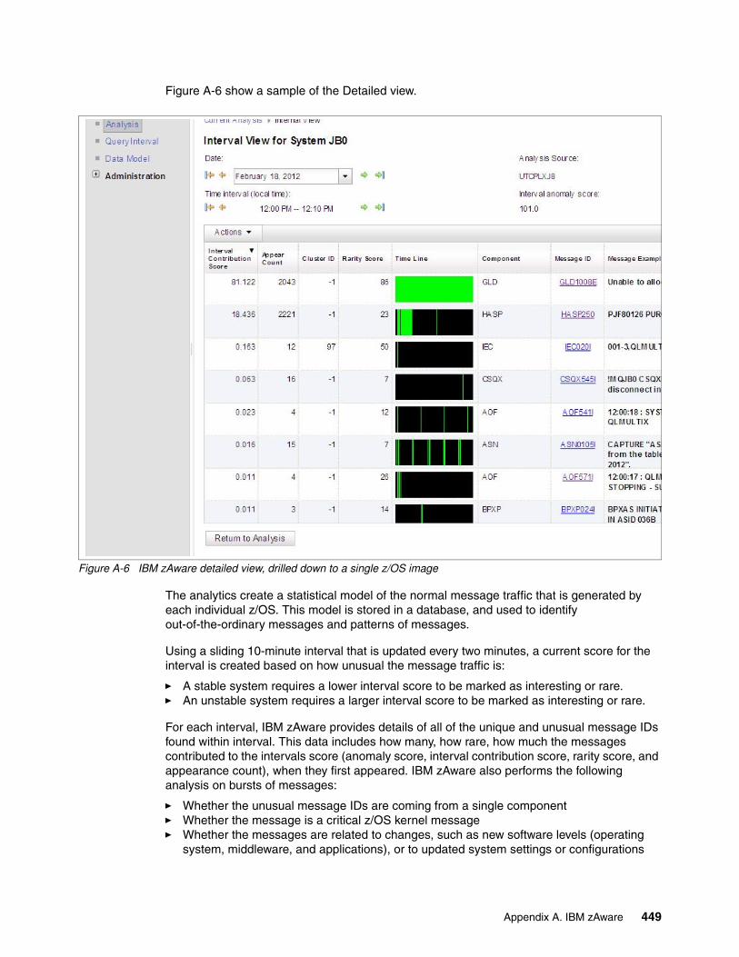
Figure A-6 show a sample of the Detailed view.
Figure A-6 IBM zAware detailed view, drilled down to a single z/OS image
The analytics create a statistical model of the normal message traffic that is generated by each individual z/OS. This model is stored in a database, and used to identify out-of-the-ordinary messages and patterns of messages.
Using a sliding 10-minute interval that is updated every two minutes, a current score for the interval is created based on how unusual the message traffic is:
� A stable system requires a lower interval score to be marked as interesting or rare.� An unstable system requires a larger interval score to be marked as interesting or rare.
For each interval, IBM zAware provides details of all of the unique and unusual message IDs found within interval. This data includes how many, how rare, how much the messages contributed to the intervals score (anomaly score, interval contribution score, rarity score, and appearance count), when they first appeared. IBM zAware also performs the following analysis on bursts of messages:
� Whether the unusual message IDs are coming from a single component� Whether the message is a critical z/OS kernel message� Whether the messages are related to changes, such as new software levels (operating
system, middleware, and applications), or to updated system settings or configurations
Appendix A. IBM zAware 449
The choice of unique message IDs is embedded in the domain knowledge of IBM zAware. IBM zAware detects things that typical monitoring systems miss because of these challenges:
� Message suppression (message too common)
Common messages are useful for long-term health issues.
� Uniqueness (message not common enough)
These are useful for real-time event diagnostic procedures.
IBM zAware assigns a color to an interval based on the distribution of interval score:
� Blue (Normal) represents an interval score in the range 1 - 99.5.
� Orange (Interesting) represents an interval score in the range 99.5 - 100.
� Red (Rare) represents an interval score of 101.
Training period
The IBM zAware server starts receiving current data from the z/OS system logger that runs on z/OS-monitored customers. However, the server cannot use this data for analysis until a model of normal system behavior exists.
The minimum amount of data for building the most accurate models is 90 days of data for each customer. By default, training automatically runs every 30 days. You can modify the number of days that are required for this training period, based on your knowledge of the workloads that run on z/OS-monitored customers. This training period applies for all monitored customers. Different training periods cannot be defined for each customer.
Priming IBM zAware
Instead of waiting for the IBM zAware server to collect data over the course of the training period, you can prime the server. You do so by transferring prior data for monitored customers, and requesting that the server build a model for each customer from the transferred data.
IBM zAware ignore message support
When a new workload is added to a system being monitored by zAware, or moved to a different system, it often generates messages that are not recognized by zAware. These messages are subsequently flagged as anomalous and cause orange bars to appear on the zAware analysis panel.
Sometimes the reporting of anomalous behavior is caused solely by the new workload, but sometimes a real problem is present as well. Therefore, it is not appropriate to automatically mark all of the messages as normal when new workloads are introduced. IBM zAware on zEC12 and zBC12 with driver level 15 introduces ignore message support to give the user input into the zAware rules. It enables you to mark the desired messages as ignore. An ignored message is not part of zAware analysis and scoring.
The first iteration of this work requires that the user mark each message to be ignored on a per-system basis. In other words, for each message that you want to ignore, you have to mark the particular message on each system for which zAware is to ignore it. You can choose from one of two types of ignore message, until the next train occurs (automatic or manual train) or forever.
450 IBM zEnterprise BC12 Technical Guide
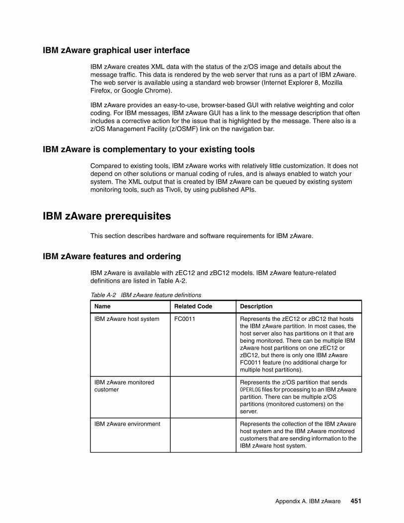
IBM zAware graphical user interface
IBM zAware creates XML data with the status of the z/OS image and details about the message traffic. This data is rendered by the web server that runs as a part of IBM zAware. The web server is available using a standard web browser (Internet Explorer 8, Mozilla Firefox, or Google Chrome).
IBM zAware provides an easy-to-use, browser-based GUI with relative weighting and color coding. For IBM messages, IBM zAware GUI has a link to the message description that often includes a corrective action for the issue that is highlighted by the message. There also is a z/OS Management Facility (z/OSMF) link on the navigation bar.
IBM zAware is complementary to your existing tools
Compared to existing tools, IBM zAware works with relatively little customization. It does not depend on other solutions or manual coding of rules, and is always enabled to watch your system. The XML output that is created by IBM zAware can be queued by existing system monitoring tools, such as Tivoli, by using published APIs.
IBM zAware prerequisites
This section describes hardware and software requirements for IBM zAware.
IBM zAware features and ordering
IBM zAware is available with zEC12 and zBC12 models. IBM zAware feature-related definitions are listed in Table A-2.
Table A-2 IBM zAware feature definitions
Name Related Code Description
IBM zAware host system FC0011 Represents the zEC12 or zBC12 that hosts the IBM zAware partition. In most cases, the host server also has partitions on it that are being monitored. There can be multiple IBM zAware host partitions on one zEC12 or zBC12, but there is only one IBM zAware FC0011 feature (no additional charge for multiple host partitions).
IBM zAware monitored customer
Represents the z/OS partition that sends OPERLOG files for processing to an IBM zAware partition. There can be multiple z/OS partitions (monitored customers) on the server.
IBM zAware environment Represents the collection of the IBM zAware host system and the IBM zAware monitored customers that are sending information to the IBM zAware host system.
Appendix A. IBM zAware 451
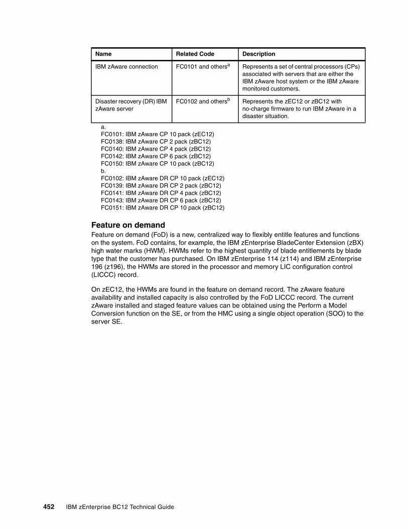
Feature on demandFeature on demand (FoD) is a new, centralized way to flexibly entitle features and functions on the system. FoD contains, for example, the IBM zEnterprise BladeCenter Extension (zBX) high water marks (HWM). HWMs refer to the highest quantity of blade entitlements by blade type that the customer has purchased. On IBM zEnterprise 114 (z114) and IBM zEnterprise 196 (z196), the HWMs are stored in the processor and memory LIC configuration control (LICCC) record.
On zEC12, the HWMs are found in the feature on demand record. The zAware feature availability and installed capacity is also controlled by the FoD LICCC record. The current zAware installed and staged feature values can be obtained using the Perform a Model Conversion function on the SE, or from the HMC using a single object operation (SOO) to the server SE.
IBM zAware connection FC0101 and othersa Represents a set of central processors (CPs) associated with servers that are either the IBM zAware host system or the IBM zAware monitored customers.
Disaster recovery (DR) IBM zAware server
FC0102 and othersb Represents the zEC12 or zBC12 with no-charge firmware to run IBM zAware in a disaster situation.
a. FC0101: IBM zAware CP 10 pack (zEC12)FC0138: IBM zAware CP 2 pack (zBC12)FC0140: IBM zAware CP 4 pack (zBC12)FC0142: IBM zAware CP 6 pack (zBC12)FC0150: IBM zAware CP 10 pack (zBC12)b. FC0102: IBM zAware DR CP 10 pack (zEC12)FC0139: IBM zAware DR CP 2 pack (zBC12)FC0141: IBM zAware DR CP 4 pack (zBC12)FC0143: IBM zAware DR CP 6 pack (zBC12)FC0151: IBM zAware DR CP 10 pack (zBC12)
Name Related Code Description
452 IBM zEnterprise BC12 Technical Guide
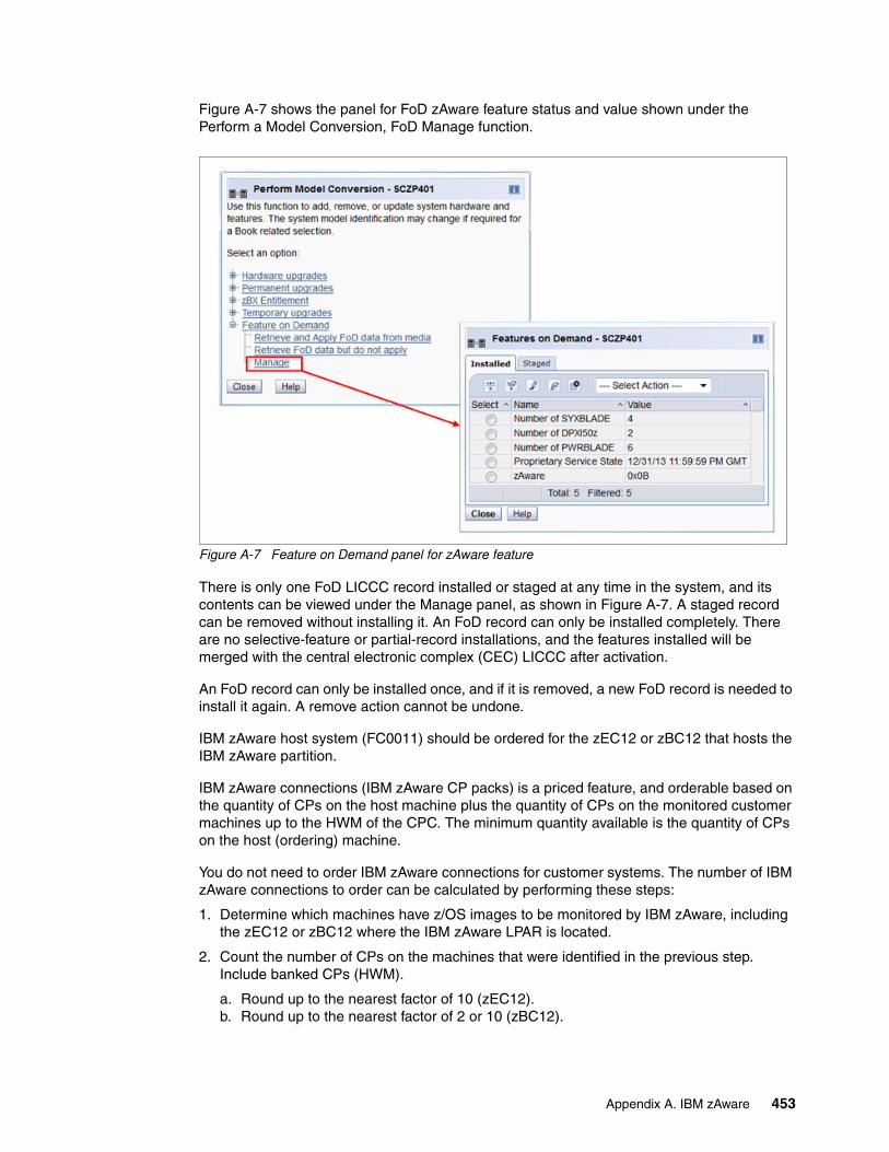
Figure A-7 shows the panel for FoD zAware feature status and value shown under the Perform a Model Conversion, FoD Manage function.
Figure A-7 Feature on Demand panel for zAware feature
There is only one FoD LICCC record installed or staged at any time in the system, and its contents can be viewed under the Manage panel, as shown in Figure A-7. A staged record can be removed without installing it. An FoD record can only be installed completely. There are no selective-feature or partial-record installations, and the features installed will be merged with the central electronic complex (CEC) LICCC after activation.
An FoD record can only be installed once, and if it is removed, a new FoD record is needed to install it again. A remove action cannot be undone.
IBM zAware host system (FC0011) should be ordered for the zEC12 or zBC12 that hosts the IBM zAware partition.
IBM zAware connections (IBM zAware CP packs) is a priced feature, and orderable based on the quantity of CPs on the host machine plus the quantity of CPs on the monitored customer machines up to the HWM of the CPC. The minimum quantity available is the quantity of CPs on the host (ordering) machine.
You do not need to order IBM zAware connections for customer systems. The number of IBM zAware connections to order can be calculated by performing these steps:
1. Determine which machines have z/OS images to be monitored by IBM zAware, including the zEC12 or zBC12 where the IBM zAware LPAR is located.
2. Count the number of CPs on the machines that were identified in the previous step. Include banked CPs (HWM).
a. Round up to the nearest factor of 10 (zEC12).b. Round up to the nearest factor of 2 or 10 (zBC12).
Appendix A. IBM zAware 453
A DR option (IBM zAware DR CP packs) is also available, and indicates that IBM zAware is installed on a DR zEC12 or zBC12 server. This feature is available at no additional fee, but is exclusive with an IBM zAware connection. For example, FC0151 represents the quantity of DR CPs. FC0150 represents the quantity of CPs associated with servers that are either the IBM zAware host system or the IBM zAware monitored customers.
FC0150 and FC0151 are mutually exclusive. If you have one then you cannot have the other. Also, in most cases, the number of FC0151 features on DR should match the number of FC0150 features on the IBM zAware host server.
If the machine is discontinued or you no longer need zAware, you can remove the zAware feature from the machine.
IBM zAware operating requirements
This section describes the requirements for the zAware host system and monitored customer.
IBM zAware host systemIBM zEC12 or zBC12 can host the IBM zAware server. An IBM zAware server requires its own LPAR, and runs its own self-contained firmware stack.
The following host system resources are part of the system:
� Processors:
– General-purpose CP or Integrated Facility for Linux (IFL) that can be shared with other LPARs in zEC12 or zBC12.
– Usage estimates between a partial engine to two engines, depending on the size of the configuration.
� Memory:
– Minimum 6 GB initial memory for the first 6 z/OS clients.– 256 MB is required for each additional z/OS clients above 6.– Flash Express is not supported.
� DASD:
– 500 GB persistent DASD storage.
– Only Extended Count Key Data (ECKD) format. Fibre Channel Protocol (FCP) devices are not supported.
– IBM zAware manages its own data store, and uses Logical Volume Manager (LVM) to aggregate multiple physical devices into a single logical device.
� Network (for both instrumentation data gathering and outbound alerting and communications):
– HiperSockets for the z/OS LPARs running on the same zEC12 or zBC12 as the IBM zAware LPAR.
– Open Systems Adapter (OSA) ports for the z/OS LPARs running on a different CPC than where IBM zAware LPAR runs.
– Dedicated IP address for IBM zAware LPAR.
Note: Host system resources (processors, memory, direct access storage device (DASD), and other resources) are dependent on the number of monitored customers, the amount of message traffic, and the length of time data is retained.
454 IBM zEnterprise BC12 Technical Guide
IBM zAware monitored clientIBM zAware monitored clients can be in the same central processing complex (CPC) as the IBM zAware host system, or in different CPCs.They can be in the same site or multiple sites:
� The distance between the IBM zAware host systems and monitored clients was increased to 3500 km.
� IBM zAware monitored clients can be on any System z servers (IBM zEC12, zBC12, z196, z114, IBM System z10, and other System z products) if they fulfill z/OS requirements. Monitoring can be done by sharing log files through an IP network with IBM zAware servers.
IBM z/OS requirementsIBM zAware monitored clients have the following z/OS requirements:
� z/OS V2.1 or higher� z/OS V1.13 with program temporary fixes (PTFs)� 90 days historical SYSLOG or formatted OPERLOG data to initially prime IBM zAware
Configuring and using the IBM zAware virtual appliance
The following checklist provides a task summary for configuring and using IBM zAware:
1. Phase 1. Planning:
a. Plan the configuration of the IBM zAware environment.
b. Plan the LPAR characteristics of the IBM zAware partition.
c. Plan the network connections that are required for the IBM zAware partition and each z/OS monitored customer.
d. Plan the security requirements for the IBM zAware server, its monitored customers, and users of the IBM zAware GUI.
e. Plan for using the IBM zAware GUI.
2. Phase 2. Configuring the IBM zAware partition:
a. Verify that your installation meets the prerequisites for using the IBM zAware virtual appliance.
b. Configure network connections for the IBM zAware partition through the Hardware Configuration Definition (HCD) or the input/output configuration program (IOCP).
c. Configure persistent storage for the IBM zAware partition through the HCD or IOCP.
d. Define the LPAR characteristics of the IBM zAware partition through the HMC.
e. Define network settings for the IBM zAware partition through the HMC.
f. Activate the IBM zAware partition through the HMC.
3. Phase 3. Configuring the IBM zAware server and its monitored clients:
a. Assign storage devices for the IBM zAware server through the IBM zAware GUI.
b. (Optional) Replace the self-signed certificate authority (CA) certificate that is configured in the IBM zAware server.
c. (Optional) Configure an LDAP directory or local file-based repository for authenticating users of the IBM zAware GUI.
d. (Optional) Authorize users or groups to access the IBM zAware GUI.
e. (Optional) Modify the configuration values that control IBM zAware analytics operation.
Appendix A. IBM zAware 455

f. Configure a network connection for each z/OS monitored customer through the TCP/IP profile. If necessary, update firewall settings.
g. Verify that each z/OS system meets the sysplex configuration and OPERLOG requirements for IBM zAware virtual appliance monitored customers.
h. Configure the z/OS system logger to send data to the IBM zAware virtual appliance server.
i. Prime the IBM zAware server with prior data from monitored customers.
j. Build a model of normal system behavior for each monitored customer. The IBM zAware server uses these models for analysis.
k. (Optional) Use IBM zAware ignore message support to give your input into the zAware rules. It enables you to mark desired messages as ignore. An ignored message is not part of zAware analysis and scoring.
456 IBM zEnterprise BC12 Technical Guide
Appendix B. Channel options
The following two tables describe all channel attributes, the required cable types, the maximum unrepeated distance, and the bit rate of the IBM zEnterprise BC12 System (zBC12).
For all optical links, the connector type is LC duplex, except the 12xIFB connection is established with a Multi-Fiber Push-On (MPO) connector. The electrical Ethernet cable for the Open Systems Adapter (OSA) connectivity is connected via an RJ45 jack.
B
Statement of direction:
� The zBC12 and IBM zEnterprise EC12 (zEC12) are planned to be the last IBM System z® server to support InterSystem Channel (ISC-3) Links. Enterprises should continue migrating from ISC-3 features to InfiniBand Coupling Links.
� The zBC12 and zEC12 are planned to be the last IBM System z® server to support Ethernet half-duplex operation and a 10 Mbps link data rate on 1000BASE-T Ethernet features. Any future 1000BASE-T Ethernet feature will support full-duplex operation and auto-negotiation to 100 or 1000 Mbps exclusively.
� The zBC12 and zEC12 are planned to be the last IBM System z® server to support the OSA-Express3 family of features. Enterprises should continue migrating from the OSA-Express3 features to the OSA-Express5S features.
� The zBC12 and zEC12 are planned to be the last IBM System z® server to support Fibre Channel connection (FICON) Express4 features. Enterprises should continue migrating from the FICON Express4 features to the FICON Express8S features.
All statements regarding IBM future direction and intent are subject to change or withdrawal without notice, and represent goals and objectives only.
© Copyright IBM Corp. 2014. All rights reserved. 457
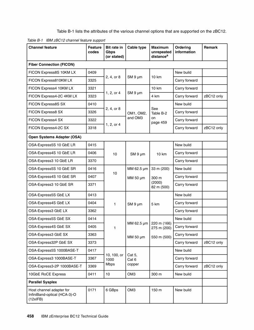
Table B-1 lists the attributes of the various channel options that are supported on the zBC12.
Table B-1 IBM zBC12 channel feature support
Channel feature Feature codes
Bit rate in Gbps(or stated)
Cable type Maximumunrepeateddistancea
Ordering information
Remark
Fiber Connection (FICON)
FICON Express8S 10KM LX 04092, 4, or 8 SM 9 µm 10 km
New build
FICON Express810KM LX 3325 Carry forward
FICON Express4 10KM LX 33211, 2, or 4 SM 9 µm
10 km Carry forward
FICON Express4-2C 4KM LX 3323 4 km Carry forward zBC12 only
FICON Express8S SX 04102, 4, or 8
OM1, OM2, and OM3
See Table B-2 on page 459
New build
FICON Express8 SX 3326 Carry forward
FICON Express4 SX 33221, 2, or 4
Carry forward
FICON Express4-2C SX 3318 Carry forward zBC12 only
Open Systems Adapter (OSA)
OSA-Express5S 10 GbE LR 0415
10 SM 9 µm 10 km
New build
OSA-Express4S 10 GbE LR 0406 Carry forward
OSA-Express3 10 GbE LR 3370 Carry forward
OSA-Express5S 10 GbE SR 041610
MM 62.5 µm
MM 50 µm
33 m (200)
300 m (2000)82 m (500)
New build
OSA-Express4S 10 GbE SR 0407 Carry forward
OSA-Express3 10 GbE SR 3371 Carry forward
OSA-Express5S GbE LX 0413
1 SM 9 µm 5 km
New build
OSA-Express4S GbE LX 0404 Carry forward
OSA-Express3 GbE LX 3362 Carry forward
OSA-Express5S GbE SX 0414
1 MM 62.5 µm
MM 50 µm
220 m (166)275 m (200)
550 m (500)
New build
OSA-Express4S GbE SX 0405 Carry forward
OSA-Express3 GbE SX 3363 Carry forward
OSA-Express32P GbE SX 3373 Carry forward zBC12 only
OSA-Express5S 1000BASE-T 041710, 100, or 1000Mbps
Cat 5,Cat 6copper
New build
OSA-Express3 1000BASE-T 3367 Carry forward
OSA-Express3-2P 1000BASE-T 3369 Carry forward zBC12 only
10GbE RoCE Express 0411 10 OM3 300 m New build
Parallel Sysplex
Host channel adapter for InfiniBand-optical (HCA-3)-O (12xIFB)
0171 6 GBps OM3 150 m New build
458 IBM zEnterprise BC12 Technical Guide
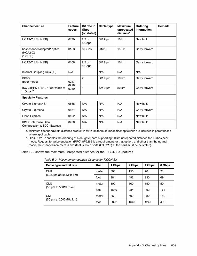
Table B-2 Maximum unrepeated distance for FICON SX
HCA3-O LR (1xIFB) 0170 2.5 or5 Gbps
SM 9 µm 10 km New build
host channel adapter2-optical (HCA2-O) (12xIFB)
0163 6 GBps OM3 150 m Carry forward
HCA2-O LR (1xIFB) 0168 2.5 or5 Gbps
SM 9 µm 10 km Carry forward
Internal Coupling links (IC) N/A N/A N/A N/A
ISC-3 (peer mode) 0217
02180219
2 SM 9 µm 10 km Carry forward
ISC-3 (RPQ 8P2197 Peer mode at 1 Gbps)b
1 SM 9 µm 20 km Carry forward
Specialty Features
Crypto Express4S 0865 N/A N/A N/A New build
Crypto Express3 0864 N/A N/A N/A Carry forward
Flash Express 0402 N/A N/A N/A New build
IBM zEnterprise Data Compression (zEDC) Express
0420 N/A N/A N/A New build
a. Minimum fiber bandwidth distance product in MHz·km for multi-mode fiber optic links are included in parentheses where applicable.
b. RPQ 8P2197 enables the ordering of a daughter card supporting 20 km unrepeated distance for 1 Gbps peer mode. Request for price quotation (RPQ) 8P2262 is a requirement for that option, and other than the normal mode, the channel increment is two (that is, both ports (FC 0219) at the card must be activated).
Table B-2 shows the maximum unrepeated distance for the FICON SX features.
Channel feature Feature codes
Bit rate in Gbps(or stated)
Cable type Maximumunrepeateddistancea
Ordering information
Remark
Cable type and bit rate Unit 1 Gbps 2 Gbps 4 Gbps 8 Gbps
OM1 (62,5 µm at 200MHz·km)
meter 300 150 70 21
foot 984 492 230 69
OM2 (50 µm at 500MHz·km)
meter 500 300 150 50
foot 1640 984 492 164
OM3 (50 µm at 2000MHz·km)
meter 860 500 380 150
foot 2822 1640 1247 492
Appendix B. Channel options 459

460 IBM zEnterprise BC12 Technical Guide
Appendix C. Flash Express
This appendix introduces the IBM Flash Express feature available on the IBM zEnterprise BC12 (zBC12) server.
Flash memory is a non-volatile computer storage technology. It was introduced on the market decades ago. Flash memory is commonly used today in memory cards, USB flash drives, solid-state drives (SSDs), and similar products for general storage and transfer of data.
Until recently, the high cost per gigabyte and limited capacity of SSDs restricted deployment of these drives to specific applications. Recent advances in SSD technology and economies of scale have driven down the cost of SSDs, making them a viable storage option for I/O-intensive enterprise applications.
An SSD, sometimes called a solid-state disk or electronic disk, is a data storage device that uses integrated circuit assemblies as memory to store data persistently. SSD technology uses electronic interfaces compatible with traditional block I/O hard disk drives (HDDs). SSDs do not employ any moving mechanical components.
This characteristic distinguishes them from traditional magnetic disks such as HDDs, which are electromechanical devices that contain spinning disks and movable read/write heads. With no seek time or rotational delays, SSDs can deliver substantially better I/O performance than HDDs. Flash SSDs demonstrate latencies that are 10 - 50 times lower than the fastest HDDs, often enabling dramatically improved I/O response times.
This appendix contains these sections:
� Flash Express overview� Using Flash Express� Security on Flash Express
C
© Copyright IBM Corp. 2014. All rights reserved. 461
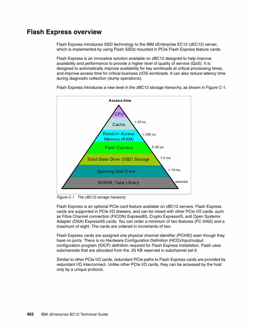
Flash Express overview
Flash Express introduces SSD technology to the IBM zEnterprise EC12 (zEC12) server, which is implemented by using Flash SSDs mounted in PCIe Flash Express feature cards.
Flash Express is an innovative solution available on zBC12 designed to help improve availability and performance to provide a higher level of quality of service (QoS). It is designed to automatically improve availability for key workloads at critical processing times, and improve access time for critical business z/OS workloads. It can also reduce latency time during diagnostic collection (dump operations).
Flash Express introduces a new level in the zBC12 storage hierarchy, as shown in Figure C-1.
Figure C-1 The zBC12 storage hierarchy
Flash Express is an optional PCIe card feature available on zBC12 servers. Flash Express cards are supported in PCIe I/O drawers, and can be mixed with other PCIe I/O cards, such as Fibre Channel connection (FICON) Express8S, Crypto Express4S, and Open Systems Adapter (OSA) Express4S cards. You can order a minimum of two features (FC 0402) and a maximum of eight. The cards are ordered in increments of two.
Flash Express cards are assigned one physical channel identifier (PCHID) even though they have no ports. There is no Hardware Configuration Definition (HCD)/input/output configuration program (IOCP) definition required for Flash Express installation. Flash uses subchannels that are allocated from the .25 KB reserved in subchannel set 0.
Similar to other PCIe I/O cards, redundant PCIe paths to Flash Express cards are provided by redundant I/O interconnect. Unlike other PCIe I/O cards, they can be accessed by the host only by a unique protocol.
< 20 ns
5-20 µs
< 10 ms
< 200 ns
Access time
1-3 ms
seconds
CPU
Cache
Random AccessMemory (RAM)
Flash Express
Solid State Drive (SSD) Storage
Spinning Disk Drive
WORM, Tape Library
462 IBM zEnterprise BC12 Technical Guide
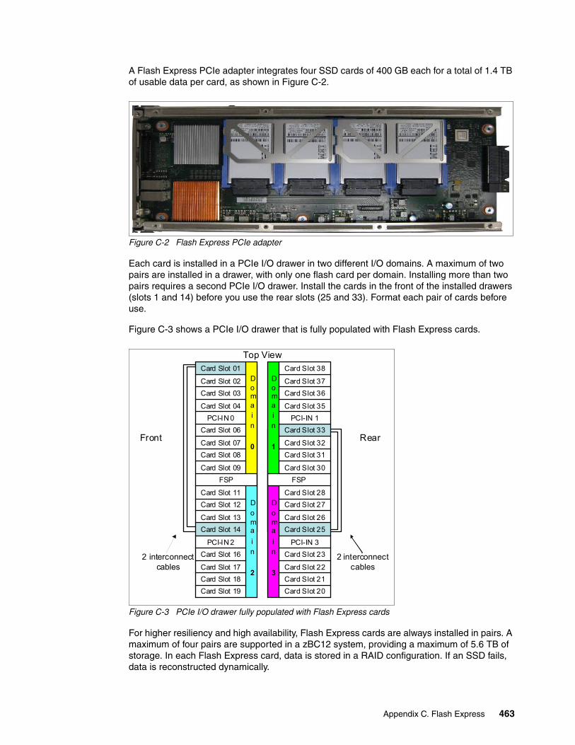
A Flash Express PCIe adapter integrates four SSD cards of 400 GB each for a total of 1.4 TB of usable data per card, as shown in Figure C-2.
Figure C-2 Flash Express PCIe adapter
Each card is installed in a PCIe I/O drawer in two different I/O domains. A maximum of two pairs are installed in a drawer, with only one flash card per domain. Installing more than two pairs requires a second PCIe I/O drawer. Install the cards in the front of the installed drawers (slots 1 and 14) before you use the rear slots (25 and 33). Format each pair of cards before use.
Figure C-3 shows a PCIe I/O drawer that is fully populated with Flash Express cards.
Figure C-3 PCIe I/O drawer fully populated with Flash Express cards
For higher resiliency and high availability, Flash Express cards are always installed in pairs. A maximum of four pairs are supported in a zBC12 system, providing a maximum of 5.6 TB of storage. In each Flash Express card, data is stored in a RAID configuration. If an SSD fails, data is reconstructed dynamically.
Doma
in
2
Domain
0
Doma
in
3
Domain
1
Card Slot 19
Card Slot 18
Card Slot 17
Card Slot 16
PCI-IN 2
Card Slot 14
Card Slot 13
Card Slot 12
Card Slot 11
FSP
Card Slot 09
Card Slot 08
Card Slot 07
Card Slot 06
PCI-IN 0
Card Slot 04
Card Slot 03
Card Slot 02
Card Slot 01
Card Slot 33
Card Slot 32
Card Slot 31
Card Slot 30
Card Slot 20
Card Slot 21
Card Slot 22
Card Slot 23
PCI-IN 3
Card Slot 25
Card Slot 26
Card Slot 27
Card Slot 28
FSP
PCI-IN 1
Card Slot 35
Card Slot 36
Card Slot 37
Card Slot 38
Top View
RearFront
2 interconnect cables
2 interconnect cables
Appendix C. Flash Express 463
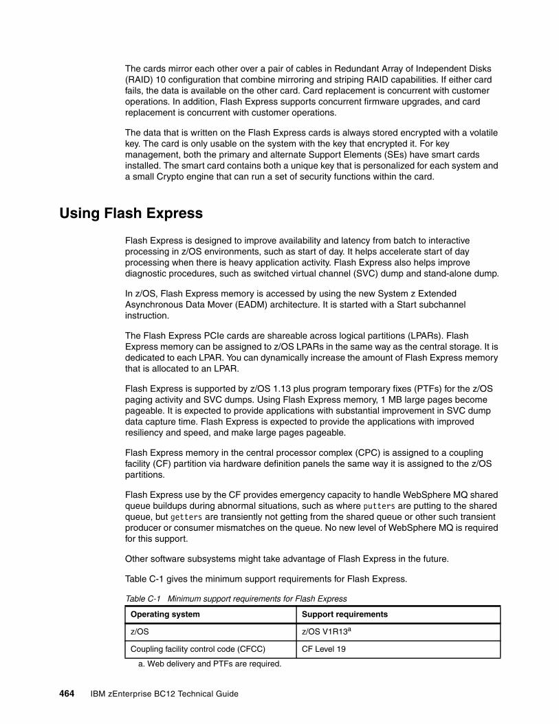
The cards mirror each other over a pair of cables in Redundant Array of Independent Disks (RAID) 10 configuration that combine mirroring and striping RAID capabilities. If either card fails, the data is available on the other card. Card replacement is concurrent with customer operations. In addition, Flash Express supports concurrent firmware upgrades, and card replacement is concurrent with customer operations.
The data that is written on the Flash Express cards is always stored encrypted with a volatile key. The card is only usable on the system with the key that encrypted it. For key management, both the primary and alternate Support Elements (SEs) have smart cards installed. The smart card contains both a unique key that is personalized for each system and a small Crypto engine that can run a set of security functions within the card.
Using Flash Express
Flash Express is designed to improve availability and latency from batch to interactive processing in z/OS environments, such as start of day. It helps accelerate start of day processing when there is heavy application activity. Flash Express also helps improve diagnostic procedures, such as switched virtual channel (SVC) dump and stand-alone dump.
In z/OS, Flash Express memory is accessed by using the new System z Extended Asynchronous Data Mover (EADM) architecture. It is started with a Start subchannel instruction.
The Flash Express PCIe cards are shareable across logical partitions (LPARs). Flash Express memory can be assigned to z/OS LPARs in the same way as the central storage. It is dedicated to each LPAR. You can dynamically increase the amount of Flash Express memory that is allocated to an LPAR.
Flash Express is supported by z/OS 1.13 plus program temporary fixes (PTFs) for the z/OS paging activity and SVC dumps. Using Flash Express memory, 1 MB large pages become pageable. It is expected to provide applications with substantial improvement in SVC dump data capture time. Flash Express is expected to provide the applications with improved resiliency and speed, and make large pages pageable.
Flash Express memory in the central processor complex (CPC) is assigned to a coupling facility (CF) partition via hardware definition panels the same way it is assigned to the z/OS partitions.
Flash Express use by the CF provides emergency capacity to handle WebSphere MQ shared queue buildups during abnormal situations, such as where putters are putting to the shared queue, but getters are transiently not getting from the shared queue or other such transient producer or consumer mismatches on the queue. No new level of WebSphere MQ is required for this support.
Other software subsystems might take advantage of Flash Express in the future.
Table C-1 gives the minimum support requirements for Flash Express.
Table C-1 Minimum support requirements for Flash Express
Operating system Support requirements
z/OS z/OS V1R13a
a. Web delivery and PTFs are required.
Coupling facility control code (CFCC) CF Level 19
464 IBM zEnterprise BC12 Technical Guide
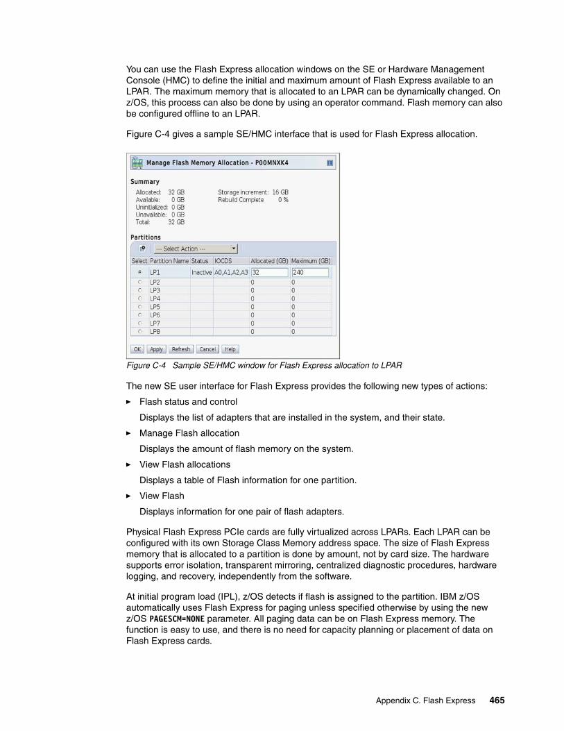
You can use the Flash Express allocation windows on the SE or Hardware Management Console (HMC) to define the initial and maximum amount of Flash Express available to an LPAR. The maximum memory that is allocated to an LPAR can be dynamically changed. On z/OS, this process can also be done by using an operator command. Flash memory can also be configured offline to an LPAR.
Figure C-4 gives a sample SE/HMC interface that is used for Flash Express allocation.
Figure C-4 Sample SE/HMC window for Flash Express allocation to LPAR
The new SE user interface for Flash Express provides the following new types of actions:
� Flash status and control
Displays the list of adapters that are installed in the system, and their state.
� Manage Flash allocation
Displays the amount of flash memory on the system.
� View Flash allocations
Displays a table of Flash information for one partition.
� View Flash
Displays information for one pair of flash adapters.
Physical Flash Express PCIe cards are fully virtualized across LPARs. Each LPAR can be configured with its own Storage Class Memory address space. The size of Flash Express memory that is allocated to a partition is done by amount, not by card size. The hardware supports error isolation, transparent mirroring, centralized diagnostic procedures, hardware logging, and recovery, independently from the software.
At initial program load (IPL), z/OS detects if flash is assigned to the partition. IBM z/OS automatically uses Flash Express for paging unless specified otherwise by using the new z/OS PAGESCM=NONE parameter. All paging data can be on Flash Express memory. The function is easy to use, and there is no need for capacity planning or placement of data on Flash Express cards.
Appendix C. Flash Express 465
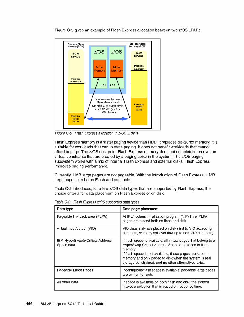
Figure C-5 gives an example of Flash Express allocation between two z/OS LPARs.
Figure C-5 Flash Express allocation in z/OS LPARs
Flash Express memory is a faster paging device than HDD. It replaces disks, not memory. It is suitable for workloads that can tolerate paging. It does not benefit workloads that cannot afford to page. The z/OS design for Flash Express memory does not completely remove the virtual constraints that are created by a paging spike in the system. The z/OS paging subsystem works with a mix of internal Flash Express and external disks. Flash Express improves paging performance.
Currently 1 MB large pages are not pageable. With the introduction of Flash Express, 1 MB large pages can be on Flash and pageable.
Table C-2 introduces, for a few z/OS data types that are supported by Flash Express, the choice criteria for data placement on Flash Express or on disk.
Table C-2 Flash Express z/OS supported data types
Data type Data page placement
Pageable link pack area (PLPA) At IPL/nucleus initialization program (NIP) time, PLPA pages are placed both on flash and disk.
virtual input/output (VIO) VIO data is always placed on disk (first to VIO accepting data sets, with any spillover flowing to non-VIO data sets).
IBM HyperSwap® Critical Address Space data
If flash space is available, all virtual pages that belong to a HyperSwap Critical Address Space are placed in flash memory.If flash space is not available, these pages are kept in memory and only paged to disk when the system is real storage constrained, and no other alternatives exist.
Pageable Large Pages If contiguous flash space is available, pageable large pages are written to flash.
All other data If space is available on both flash and disk, the system makes a selection that is based on response time.
z/OS z/OS
MainMemory
SCM SPACE
Data transfer be tween Main Memory and
Sto rage Class Memory is via EADMF (4KB or
1MB blocks)
MainMemory
Storage Class Memory (SCM )
Partition M aximum
Partition Initia l Value
Partition Initial Value
Partition Maximum
LP2LP1
Storage Class Memory (S CM)
SCM SPACE
466 IBM zEnterprise BC12 Technical Guide
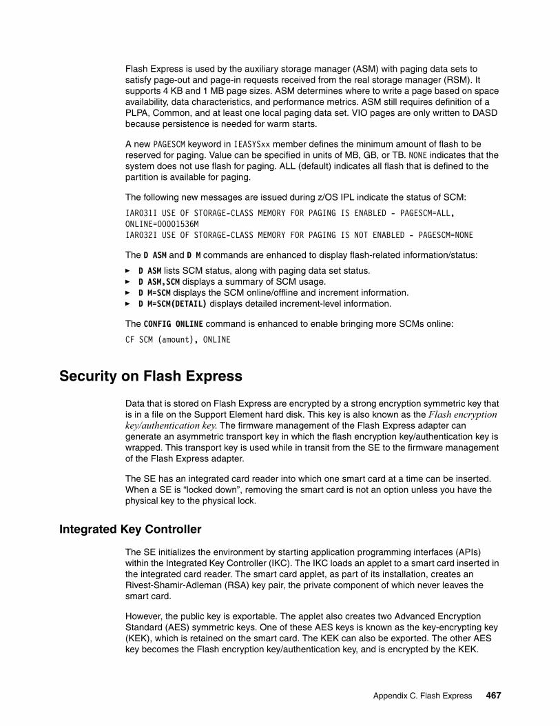
Flash Express is used by the auxiliary storage manager (ASM) with paging data sets to satisfy page-out and page-in requests received from the real storage manager (RSM). It supports 4 KB and 1 MB page sizes. ASM determines where to write a page based on space availability, data characteristics, and performance metrics. ASM still requires definition of a PLPA, Common, and at least one local paging data set. VIO pages are only written to DASD because persistence is needed for warm starts.
A new PAGESCM keyword in IEASYSxx member defines the minimum amount of flash to be reserved for paging. Value can be specified in units of MB, GB, or TB. NONE indicates that the system does not use flash for paging. ALL (default) indicates all flash that is defined to the partition is available for paging.
The following new messages are issued during z/OS IPL indicate the status of SCM:
IAR031I USE OF STORAGE-CLASS MEMORY FOR PAGING IS ENABLED - PAGESCM=ALL, ONLINE=00001536M IAR032I USE OF STORAGE-CLASS MEMORY FOR PAGING IS NOT ENABLED - PAGESCM=NONE
The D ASM and D M commands are enhanced to display flash-related information/status:
� D ASM lists SCM status, along with paging data set status.� D ASM,SCM displays a summary of SCM usage. � D M=SCM displays the SCM online/offline and increment information.� D M=SCM(DETAIL) displays detailed increment-level information.
The CONFIG ONLINE command is enhanced to enable bringing more SCMs online:
CF SCM (amount), ONLINE
Security on Flash Express
Data that is stored on Flash Express are encrypted by a strong encryption symmetric key that is in a file on the Support Element hard disk. This key is also known as the Flash encryption key/authentication key. The firmware management of the Flash Express adapter can generate an asymmetric transport key in which the flash encryption key/authentication key is wrapped. This transport key is used while in transit from the SE to the firmware management of the Flash Express adapter.
The SE has an integrated card reader into which one smart card at a time can be inserted. When a SE is “locked down”, removing the smart card is not an option unless you have the physical key to the physical lock.
Integrated Key Controller
The SE initializes the environment by starting application programming interfaces (APIs) within the Integrated Key Controller (IKC). The IKC loads an applet to a smart card inserted in the integrated card reader. The smart card applet, as part of its installation, creates an Rivest-Shamir-Adleman (RSA) key pair, the private component of which never leaves the smart card.
However, the public key is exportable. The applet also creates two Advanced Encryption Standard (AES) symmetric keys. One of these AES keys is known as the key-encrypting key (KEK), which is retained on the smart card. The KEK can also be exported. The other AES key becomes the Flash encryption key/authentication key, and is encrypted by the KEK.
Appendix C. Flash Express 467
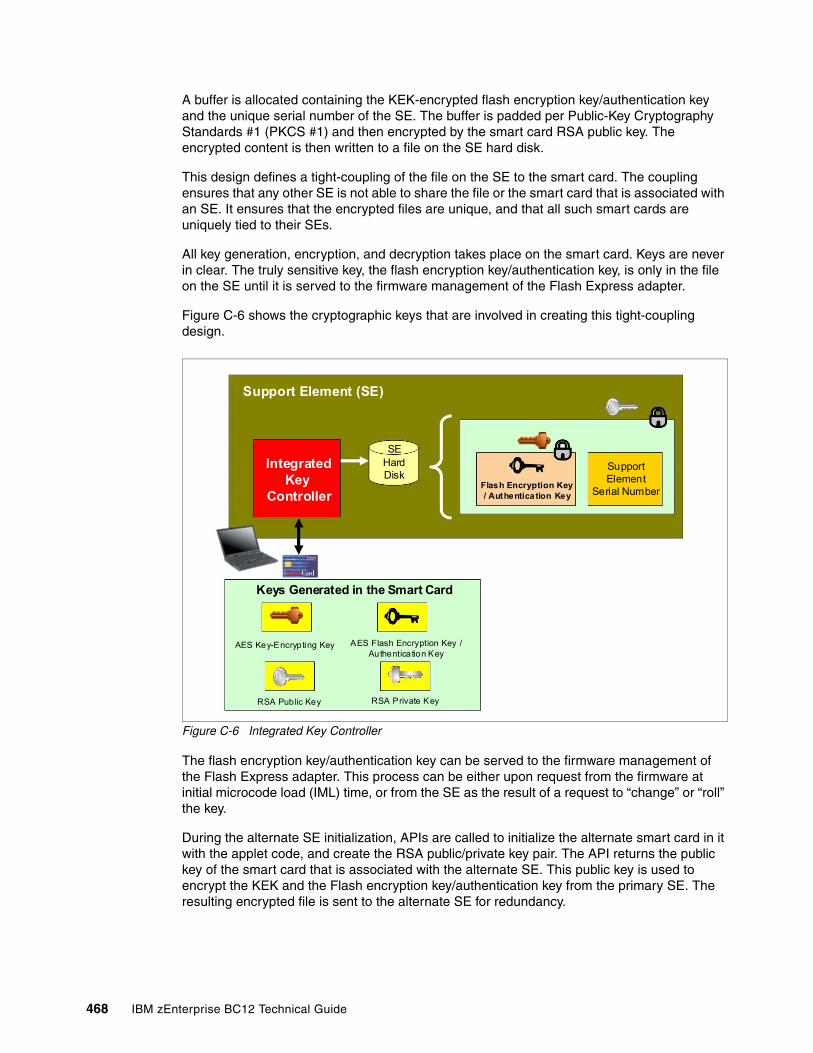
A buffer is allocated containing the KEK-encrypted flash encryption key/authentication key and the unique serial number of the SE. The buffer is padded per Public-Key Cryptography Standards #1 (PKCS #1) and then encrypted by the smart card RSA public key. The encrypted content is then written to a file on the SE hard disk.
This design defines a tight-coupling of the file on the SE to the smart card. The coupling ensures that any other SE is not able to share the file or the smart card that is associated with an SE. It ensures that the encrypted files are unique, and that all such smart cards are uniquely tied to their SEs.
All key generation, encryption, and decryption takes place on the smart card. Keys are never in clear. The truly sensitive key, the flash encryption key/authentication key, is only in the file on the SE until it is served to the firmware management of the Flash Express adapter.
Figure C-6 shows the cryptographic keys that are involved in creating this tight-coupling design.
Figure C-6 Integrated Key Controller
The flash encryption key/authentication key can be served to the firmware management of the Flash Express adapter. This process can be either upon request from the firmware at initial microcode load (IML) time, or from the SE as the result of a request to “change” or “roll” the key.
During the alternate SE initialization, APIs are called to initialize the alternate smart card in it with the applet code, and create the RSA public/private key pair. The API returns the public key of the smart card that is associated with the alternate SE. This public key is used to encrypt the KEK and the Flash encryption key/authentication key from the primary SE. The resulting encrypted file is sent to the alternate SE for redundancy.
Support Element (SE)
IntegratedKey
Controller
Keys Generated in the Smart Card
RSA Private Key
AES Flash Encryption Key / Authentica tion Key
AES Key-Encrypting Key
RSA Public Key
Flash Encryption Key / Authentication Key
SupportElement
Serial Number
SEHardDisk
468 IBM zEnterprise BC12 Technical Guide
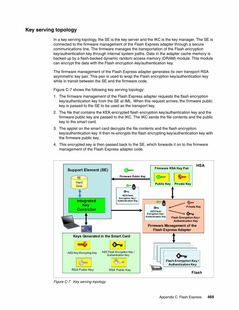
Key serving topology
In a key serving topology, the SE is the key server and the IKC is the key manager. The SE is connected to the firmware management of the Flash Express adapter through a secure communications line. The firmware manages the transportation of the Flash encryption key/authentication key through internal system paths. Data in the adapter cache memory is backed up by a flash-backed dynamic random access memory (DRAM) module. This module can encrypt the data with the Flash encryption key/authentication key.
The firmware management of the Flash Express adapter generates its own transport RSA asymmetric key pair. This pair is used to wrap the Flash encryption key/authentication key while in transit between the SE and the firmware code.
Figure C-7 shows the following key serving topology:
1. The firmware management of the Flash Express adapter requests the flash encryption key/authentication key from the SE at IML. When this request arrives, the firmware public key is passed to the SE to be used as the transport key.
2. The file that contains the KEK-encrypted flash encryption key/authentication key and the firmware public key are passed to the IKC. The IKC sends the file contents and the public key to the smart card.
3. The applet on the smart card decrypts the file contents and the flash encryption key/authentication key. It then re-encrypts the flash encrypting key/authentication key with the firmware public key.
4. This encrypted key is then passed back to the SE, which forwards it on to the firmware management of the Flash Express adapter code.
Figure C-7 Key serving topology
Flash Encryption Key / Authentication Key
Flash
Support Element (SE) Firmware RSA Key PairHSA
Firmware Public Key
AES Flash Encryption Key /
Authentication Key
Keys Generated in the Smart Card
RSA Public Key
AES Flash Encryption Key / Authentication Key
AES Key-Encrypting Key
RSA Public Key
SE
HardDisk
IntegratedKey
Controller
Public Key Private Key
Firmware Management of the Flash Express Adapter
Private Key
Flash Encryption Key / Authentication Key
AES Flash Encryption Key /
Authentication Key
Appendix C. Flash Express 469
Error recovery scenarios
Possible error scenarios are described in this section.
Primary Support Element failureWhen the primary SE fails, a switch is made to the alternate SE, which then becomes the new primary. When the former primary is brought back up, it becomes the alternate SE. The KEK and the Flash encryption key/authentication key from the primary SE were already sent to the alternate SE for redundancy at initialization time.
Removal of a smart cardIf a smart card is removed from the card reader, the card reader signals the event to the IKC listening code. The IKC listener then calls the SE to take the appropriate action. The appropriate action can involve deleting the flash encryption key or authentication key file.
In the case where the smart card is removed while the SE is powered off, there is no knowledge of the event. However, when the SE is powered on, notification is sent to the system administrator.
Primary Support Element failure during IML serving of the flash keyIf the primary SE fails during the serving of the key, the alternate SE takes over as the primary and restarts the key serving operation.
Alternate Support Element failure during switch over from the primaryIf the alternate SE fails during switch over when the primary SE fails, the key serving state is lost. When the primary comes back up, the key serving operation can be restarted.
Primary and Alternate Support Elements failureIf the primary and the alternate SE both fail, the key cannot be served. If the devices are still up, the key is still valid. If either or both SE are recovered, the files holding the flash encryption key/authentication key should still be valid. This is true even in a key roll case. There should be both new and current (old) keys available until the key serving operation is complete.
If both SEs are down, and the Flash Express goes down and comes back online before the SEs become available, all data on the Flash Express is lost. Reformatting is then necessary when the device is powered up.
If both Flash Express devices are still powered up, get the primary SE back online as fast as possible with the flash encryption key/authentication key file and associated smart card still intact. After that happens, the alternate SE can be brought online with a new smart card and taken through the initialization procedure.
470 IBM zEnterprise BC12 Technical Guide
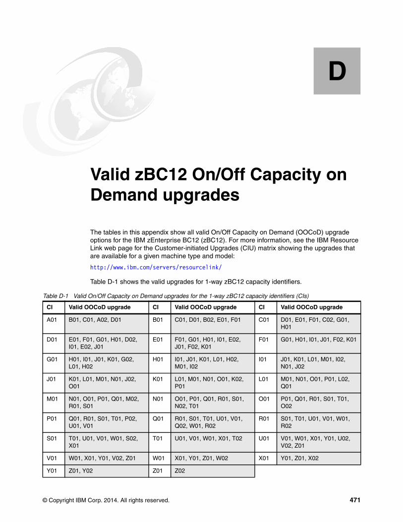
Appendix D. Valid zBC12 On/Off Capacity on Demand upgrades
The tables in this appendix show all valid On/Off Capacity on Demand (OOCoD) upgrade options for the IBM zEnterprise BC12 (zBC12). For more information, see the IBM Resource Link web page for the Customer-initiated Upgrades (CIU) matrix showing the upgrades that are available for a given machine type and model:
http://www.ibm.com/servers/resourcelink/
Table D-1 shows the valid upgrades for 1-way zBC12 capacity identifiers.
Table D-1 Valid On/Off Capacity on Demand upgrades for the 1-way zBC12 capacity identifiers (CIs)
D
CI Valid OOCoD upgrade CI Valid OOCoD upgrade CI Valid OOCoD upgrade
A01 B01, C01, A02, D01 B01 C01, D01, B02, E01, F01 C01 D01, E01, F01, C02, G01, H01
D01 E01, F01, G01, H01, D02, I01, E02, J01
E01 F01, G01, H01, I01, E02, J01, F02, K01
F01 G01, H01, I01, J01, F02, K01
G01 H01, I01, J01, K01, G02, L01, H02
H01 I01, J01, K01, L01, H02, M01, I02
I01 J01, K01, L01, M01, I02, N01, J02
J01 K01, L01, M01, N01, J02, O01
K01 L01, M01, N01, O01, K02, P01
L01 M01, N01, O01, P01, L02, Q01
M01 N01, O01, P01, Q01, M02, R01, S01
N01 O01, P01, Q01, R01, S01, N02, T01
O01 P01, Q01, R01, S01, T01, O02
P01 Q01, R01, S01, T01, P02, U01, V01
Q01 R01, S01, T01, U01, V01, Q02, W01, R02
R01 S01, T01, U01, V01, W01, R02
S01 T01, U01, V01, W01, S02, X01
T01 U01, V01, W01, X01, T02 U01 V01, W01, X01, Y01, U02, V02, Z01
V01 W01, X01, Y01, V02, Z01 W01 X01, Y01, Z01, W02 X01 Y01, Z01, X02
Y01 Z01, Y02 Z01 Z02
© Copyright IBM Corp. 2014. All rights reserved. 471
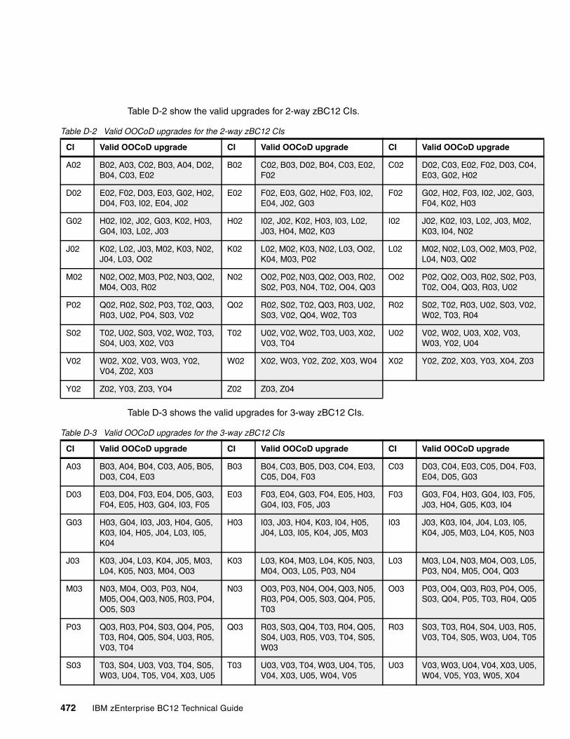
C04,
03,
02,
P02,
P03,
V02,
Z03
F03,
05,
5, N03
L05,
05, Q05
R05, T05
U05,
Table D-2 show the valid upgrades for 2-way zBC12 CIs.
Table D-2 Valid OOCoD upgrades for the 2-way zBC12 CIs
Table D-3 shows the valid upgrades for 3-way zBC12 CIs.
Table D-3 Valid OOCoD upgrades for the 3-way zBC12 CIs
CI Valid OOCoD upgrade CI Valid OOCoD upgrade CI Valid OOCoD upgrade
A02 B02, A03, C02, B03, A04, D02, B04, C03, E02
B02 C02, B03, D02, B04, C03, E02, F02
C02 D02, C03, E02, F02, D03, E03, G02, H02
D02 E02, F02, D03, E03, G02, H02, D04, F03, I02, E04, J02
E02 F02, E03, G02, H02, F03, I02, E04, J02, G03
F02 G02, H02, F03, I02, J02, GF04, K02, H03
G02 H02, I02, J02, G03, K02, H03, G04, I03, L02, J03
H02 I02, J02, K02, H03, I03, L02, J03, H04, M02, K03
I02 J02, K02, I03, L02, J03, MK03, I04, N02
J02 K02, L02, J03, M02, K03, N02, J04, L03, O02
K02 L02, M02, K03, N02, L03, O02, K04, M03, P02
L02 M02, N02, L03, O02, M03, L04, N03, Q02
M02 N02, O02, M03, P02, N03, Q02, M04, O03, R02
N02 O02, P02, N03, Q02, O03, R02, S02, P03, N04, T02, O04, Q03
O02 P02, Q02, O03, R02, S02, T02, O04, Q03, R03, U02
P02 Q02, R02, S02, P03, T02, Q03, R03, U02, P04, S03, V02
Q02 R02, S02, T02, Q03, R03, U02, S03, V02, Q04, W02, T03
R02 S02, T02, R03, U02, S03, W02, T03, R04
S02 T02, U02, S03, V02, W02, T03, S04, U03, X02, V03
T02 U02, V02, W02, T03, U03, X02, V03, T04
U02 V02, W02, U03, X02, V03,W03, Y02, U04
V02 W02, X02, V03, W03, Y02, V04, Z02, X03
W02 X02, W03, Y02, Z02, X03, W04 X02 Y02, Z02, X03, Y03, X04,
Y02 Z02, Y03, Z03, Y04 Z02 Z03, Z04
CI Valid OOCoD upgrade CI Valid OOCoD upgrade CI Valid OOCoD upgrade
A03 B03, A04, B04, C03, A05, B05, D03, C04, E03
B03 B04, C03, B05, D03, C04, E03, C05, D04, F03
C03 D03, C04, E03, C05, D04, E04, D05, G03
D03 E03, D04, F03, E04, D05, G03, F04, E05, H03, G04, I03, F05
E03 F03, E04, G03, F04, E05, H03, G04, I03, F05, J03
F03 G03, F04, H03, G04, I03, FJ03, H04, G05, K03, I04
G03 H03, G04, I03, J03, H04, G05, K03, I04, H05, J04, L03, I05, K04
H03 I03, J03, H04, K03, I04, H05, J04, L03, I05, K04, J05, M03
I03 J03, K03, I04, J04, L03, I0K04, J05, M03, L04, K05,
J03 K03, J04, L03, K04, J05, M03, L04, K05, N03, M04, O03
K03 L03, K04, M03, L04, K05, N03, M04, O03, L05, P03, N04
L03 M03, L04, N03, M04, O03, P03, N04, M05, O04, Q03
M03 N03, M04, O03, P03, N04, M05, O04, Q03, N05, R03, P04, O05, S03
N03 O03, P03, N04, O04, Q03, N05, R03, P04, O05, S03, Q04, P05, T03
O03 P03, O04, Q03, R03, P04, OS03, Q04, P05, T03, R04,
P03 Q03, R03, P04, S03, Q04, P05, T03, R04, Q05, S04, U03, R05, V03, T04
Q03 R03, S03, Q04, T03, R04, Q05, S04, U03, R05, V03, T04, S05, W03
R03 S03, T03, R04, S04, U03, V03, T04, S05, W03, U04,
S03 T03, S04, U03, V03, T04, S05, W03, U04, T05, V04, X03, U05
T03 U03, V03, T04, W03, U04, T05, V04, X03, U05, W04, V05
U03 V03, W03, U04, V04, X03, W04, V05, Y03, W05, X04
472 IBM zEnterprise BC12 Technical Guide
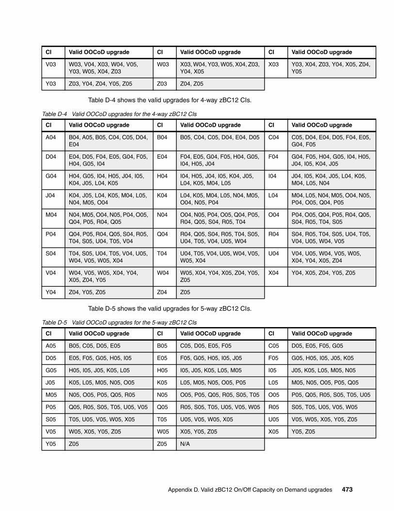
Z04,
E05,
05,
5,
N05,
Q05,
T05,
,
U05
Table D-4 shows the valid upgrades for 4-way zBC12 CIs.
Table D-4 Valid OOCoD upgrades for the 4-way zBC12 CIs
Table D-5 shows the valid upgrades for 5-way zBC12 CIs.
Table D-5 Valid OOCoD upgrades for the 5-way zBC12 CIs
V03 W03, V04, X03, W04, V05, Y03, W05, X04, Z03
W03 X03, W04, Y03, W05, X04, Z03, Y04, X05
X03 Y03, X04, Z03, Y04, X05, Y05
Y03 Z03, Y04, Z04, Y05, Z05 Z03 Z04, Z05
CI Valid OOCoD upgrade CI Valid OOCoD upgrade CI Valid OOCoD upgrade
CI Valid OOCoD upgrade CI Valid OOCoD upgrade CI Valid OOCoD upgrade
A04 B04, A05, B05, C04, C05, D04, E04
B04 B05, C04, C05, D04, E04, D05 C04 C05, D04, E04, D05, F04, G04, F05
D04 E04, D05, F04, E05, G04, F05, H04, G05, I04
E04 F04, E05, G04, F05, H04, G05, I04, H05, J04
F04 G04, F05, H04, G05, I04, HJ04, I05, K04, J05
G04 H04, G05, I04, H05, J04, I05, K04, J05, L04, K05
H04 I04, H05, J04, I05, K04, J05, L04, K05, M04, L05
I04 J04, I05, K04, J05, L04, K0M04, L05, N04
J04 K04, J05, L04, K05, M04, L05, N04, M05, O04
K04 L04, K05, M04, L05, N04, M05, O04, N05, P04
L04 M04, L05, N04, M05, O04, P04, O05, Q04, P05
M04 N04, M05, O04, N05, P04, O05, Q04, P05, R04, Q05
N04 O04, N05, P04, O05, Q04, P05, R04, Q05, S04, R05, T04
O04 P04, O05, Q04, P05, R04, S04, R05, T04, S05
P04 Q04, P05, R04, Q05, S04, R05, T04, S05, U04, T05, V04
Q04 R04, Q05, S04, R05, T04, S05, U04, T05, V04, U05, W04
R04 S04, R05, T04, S05, U04, V04, U05, W04, V05
S04 T04, S05, U04, T05, V04, U05, W04, V05, W05, X04
T04 U04, T05, V04, U05, W04, V05, W05, X04
U04 V04, U05, W04, V05, W05X04, Y04, X05, Z04
V04 W04, V05, W05, X04, Y04, X05, Z04, Y05
W04 W05, X04, Y04, X05, Z04, Y05, Z05
X04 Y04, X05, Z04, Y05, Z05
Y04 Z04, Y05, Z05 Z04 Z05
CI Valid OOCoD upgrade CI Valid OOCoD upgrade CI Valid OOCoD upgrade
A05 B05, C05, D05, E05 B05 C05, D05, E05, F05 C05 D05, E05, F05, G05
D05 E05, F05, G05, H05, I05 E05 F05, G05, H05, I05, J05 F05 G05, H05, I05, J05, K05
G05 H05, I05, J05, K05, L05 H05 I05, J05, K05, L05, M05 I05 J05, K05, L05, M05, N05
J05 K05, L05, M05, N05, O05 K05 L05, M05, N05, O05, P05 L05 M05, N05, O05, P05, Q05
M05 N05, O05, P05, Q05, R05 N05 O05, P05, Q05, R05, S05, T05 O05 P05, Q05, R05, S05, T05,
P05 Q05, R05, S05, T05, U05, V05 Q05 R05, S05, T05, U05, V05, W05 R05 S05, T05, U05, V05, W05
S05 T05, U05, V05, W05, X05 T05 U05, V05, W05, X05 U05 V05, W05, X05, Y05, Z05
V05 W05, X05, Y05, Z05 W05 X05, Y05, Z05 X05 Y05, Z05
Y05 Z05 Z05 N/A
Appendix D. Valid zBC12 On/Off Capacity on Demand upgrades 473
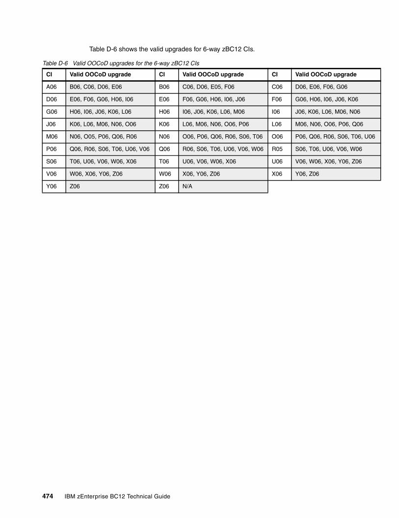
U06
Table D-6 shows the valid upgrades for 6-way zBC12 CIs.
Table D-6 Valid OOCoD upgrades for the 6-way zBC12 CIs
CI Valid OOCoD upgrade CI Valid OOCoD upgrade CI Valid OOCoD upgrade
A06 B06, C06, D06, E06 B06 C06, D06, E05, F06 C06 D06, E06, F06, G06
D06 E06, F06, G06, H06, I06 E06 F06, G06, H06, I06, J06 F06 G06, H06, I06, J06, K06
G06 H06, I06, J06, K06, L06 H06 I06, J06, K06, L06, M06 I06 J06, K06, L06, M06, N06
J06 K06, L06, M06, N06, O06 K06 L06, M06, N06, O06, P06 L06 M06, N06, O06, P06, Q06
M06 N06, O05, P06, Q06, R06 N06 O06, P06, Q06, R06, S06, T06 O06 P06, Q06, R06, S06, T06,
P06 Q06, R06, S06, T06, U06, V06 Q06 R06, S06, T06, U06, V06, W06 R05 S06, T06, U06, V06, W06
S06 T06, U06, V06, W06, X06 T06 U06, V06, W06, X06 U06 V06, W06, X06, Y06, Z06
V06 W06, X06, Y06, Z06 W06 X06, Y06, Z06 X06 Y06, Z06
Y06 Z06 Z06 N/A
474 IBM zEnterprise BC12 Technical Guide
Appendix E. RoCE
This appendix briefly describes the optional Remote Direct Memory Access (RDMA) over Converged Ethernet (RoCE) feature of IBM zEnterprise BC12 (zBC12) servers, and includes the following topics:
� Overview� Hardware� Software exploitation
E
© Copyright IBM Corp. 2014. All rights reserved. 475
Overview
Each generation of Open Systems Adapter (OSA)-Express continues to provide significant new functionality, resiliency and performance. HiperSockets also continues to provide significant industry unique qualities of service, virtualization, and performance (achieving natural improvements with each new z processor). IBM zBC12 delivers a significant paradigm shift in network communications by using existing System z and industry standard communications technology along with emerging new network technology.
� RDMA technology provides low latency, high bandwidth, high throughput, and low processor usage attachment between hosts.
� Shared Memory Communications-RDMA (SMC-R) is a new protocol that enables existing Transmission Control Protocol (TCP) applications to benefit transparently from RDMA for transferring data:
– SMC-R uses RoCE as the physical transport layer.– Initial deployment is limited to z/OS-to-z/OS communications, with a goal to expand
use to additional operating systems and possibly appliances and accelerators.
Remote Direct Memory Access technology overview
RoCE is part of the InfiniBand Architecture Specification that provides InfiniBand transport over Ethernet fabrics. It encapsulates InfiniBand transport headers into Ethernet frames using an Institute of Electrical and Electronics Engineers (IEEE)-assigned ethertype. One of the key InfiniBand transport mechanisms is RDMA, which is designed to enable transfer of data to or from memory on a remote system with low-latency, high-throughput, and low central processing unit (CPU) usage.
Traditional Ethernet transports such as TCP/IP typically use software-based mechanisms for error detection and recovery, and are based on the underlying Ethernet fabric using “best-effort” policy. With the traditional policy, the switches typically discard packets in the event of congestion and rely on the upper level transport for packet re-transmission. RoCE, however, uses hardware-based error detection and recovery mechanisms defined by the InfiniBand specification.
A RoCE transport performs best when the underlying Ethernet fabric provides a lossless capability, where packets are not routinely dropped. This can be accomplished by using DEthernet flow control whereby Global Pause frames are enabled for both transmission and reception on each of the Ethernet switches in the path between the 10GbE RoCE Express features. This capability is enabled by default in the 10GbE RoCE Express feature.
476 IBM zEnterprise BC12 Technical Guide
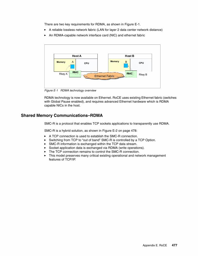
There are two key requirements for RDMA, as shown in Figure E-1.
� A reliable lossless network fabric (LAN for layer 2 data center network distance)
� An RDMA-capable network interface card (NIC) and ethernet fabric
Figure E-1 RDMA technology overview
RDMA technology is now available on Ethernet. RoCE uses existing Ethernet fabric (switches with Global Pause enabled), and requires advanced Ethernet hardware which is RDMA capable NICs in the host.
Shared Memory Communications–RDMA
SMC-R is a protocol that enables TCP sockets applications to transparently use RDMA.
SMC-R is a hybrid solution, as shown in Figure E-2 on page 478:
� A TCP connection is used to establish the SMC-R connection.� Switching from TCP to “out of band” SMC-R is controlled by a TCP Option.� SMC-R information is exchanged within the TCP data stream.� Socket application data is exchanged via RDMA (write operations).� The TCP connection remains to control the SMC-R connection.� This model preserves many critical existing operational and network management
features of TCP/IP.
Host A
Memory
Host B
MemoryCPU CPU
Rkey A Rkey B
A B
RNIC RNICEthernet Fabric
Appendix E. RoCE 477
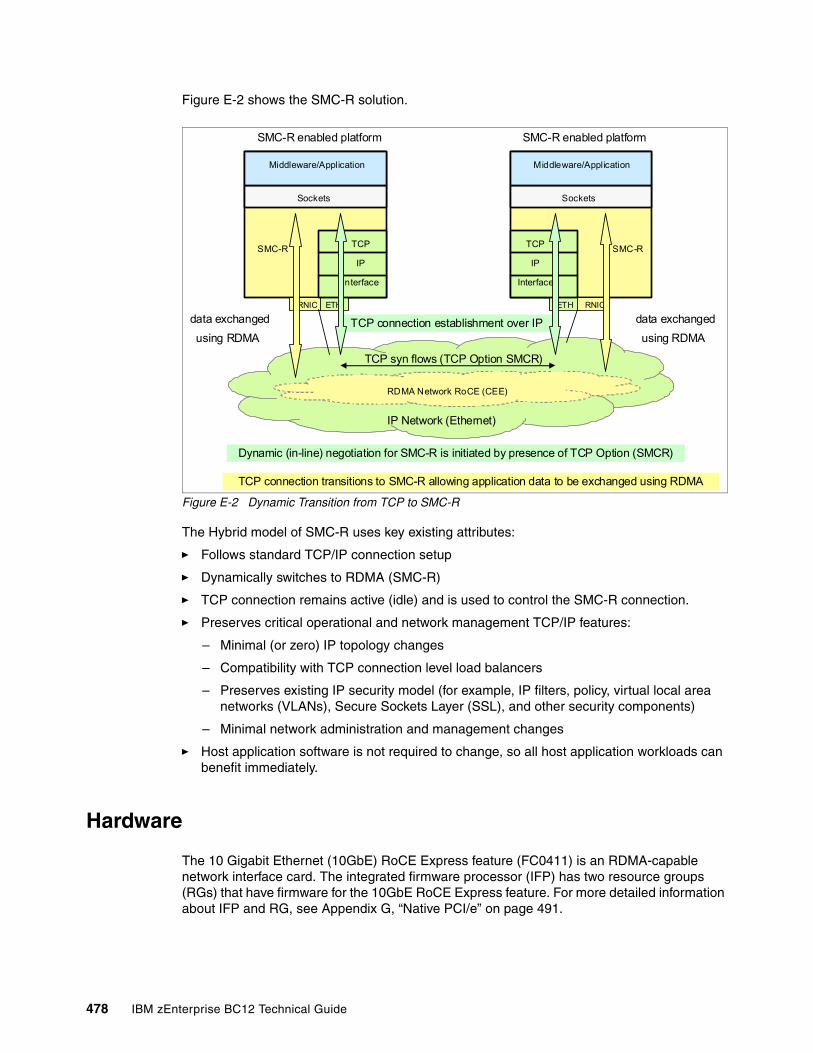
Figure E-2 shows the SMC-R solution.
Figure E-2 Dynamic Transition from TCP to SMC-R
The Hybrid model of SMC-R uses key existing attributes:
� Follows standard TCP/IP connection setup
� Dynamically switches to RDMA (SMC-R)
� TCP connection remains active (idle) and is used to control the SMC-R connection.
� Preserves critical operational and network management TCP/IP features:
– Minimal (or zero) IP topology changes
– Compatibility with TCP connection level load balancers
– Preserves existing IP security model (for example, IP filters, policy, virtual local area networks (VLANs), Secure Sockets Layer (SSL), and other security components)
– Minimal network administration and management changes
� Host application software is not required to change, so all host application workloads can benefit immediately.
Hardware
The 10 Gigabit Ethernet (10GbE) RoCE Express feature (FC0411) is an RDMA-capable network interface card. The integrated firmware processor (IFP) has two resource groups (RGs) that have firmware for the 10GbE RoCE Express feature. For more detailed information about IFP and RG, see Appendix G, “Native PCI/e” on page 491.
ETH RNIC
TCP
IP
Interface
Sockets
Middleware/Application
SMC-R enabled platform
SMC-R
ETHRNIC
TCP
IP
Interface
Sockets
Middleware/Application
SMC-R enabled platform
SMC-R
TCP connection establishment over IP
IP Network (Ethernet)
RDMA Network RoCE (CEE)
TCP connection transitions to SMC-R allowing application data to be exchanged using RDMA
Dynamic (in-line) negotiation for SMC-R is initiated by presence of TCP Option (SMCR)
TCP syn flows (TCP Option SMCR)
data exchanged
using RDMA
data exchanged
using RDMA
478 IBM zEnterprise BC12 Technical Guide
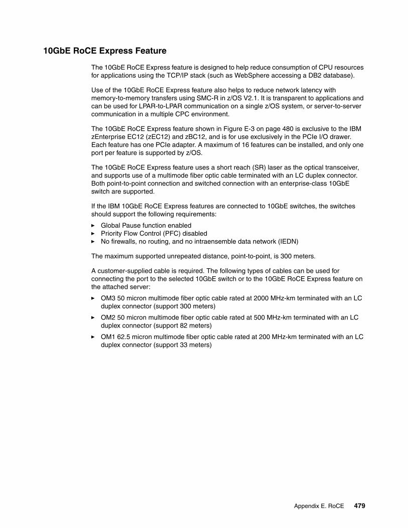
10GbE RoCE Express Feature
The 10GbE RoCE Express feature is designed to help reduce consumption of CPU resources for applications using the TCP/IP stack (such as WebSphere accessing a DB2 database).
Use of the 10GbE RoCE Express feature also helps to reduce network latency with memory-to-memory transfers using SMC-R in z/OS V2.1. It is transparent to applications and can be used for LPAR-to-LPAR communication on a single z/OS system, or server-to-server communication in a multiple CPC environment.
The 10GbE RoCE Express feature shown in Figure E-3 on page 480 is exclusive to the IBM zEnterprise EC12 (zEC12) and zBC12, and is for use exclusively in the PCIe I/O drawer. Each feature has one PCIe adapter. A maximum of 16 features can be installed, and only one port per feature is supported by z/OS.
The 10GbE RoCE Express feature uses a short reach (SR) laser as the optical transceiver, and supports use of a multimode fiber optic cable terminated with an LC duplex connector. Both point-to-point connection and switched connection with an enterprise-class 10GbE switch are supported.
If the IBM 10GbE RoCE Express features are connected to 10GbE switches, the switches should support the following requirements:
� Global Pause function enabled� Priority Flow Control (PFC) disabled� No firewalls, no routing, and no intraensemble data network (IEDN)
The maximum supported unrepeated distance, point-to-point, is 300 meters.
A customer-supplied cable is required. The following types of cables can be used for connecting the port to the selected 10GbE switch or to the 10GbE RoCE Express feature on the attached server:
� OM3 50 micron multimode fiber optic cable rated at 2000 MHz-km terminated with an LC duplex connector (support 300 meters)
� OM2 50 micron multimode fiber optic cable rated at 500 MHz-km terminated with an LC duplex connector (support 82 meters)
� OM1 62.5 micron multimode fiber optic cable rated at 200 MHz-km terminated with an LC duplex connector (support 33 meters)
Appendix E. RoCE 479
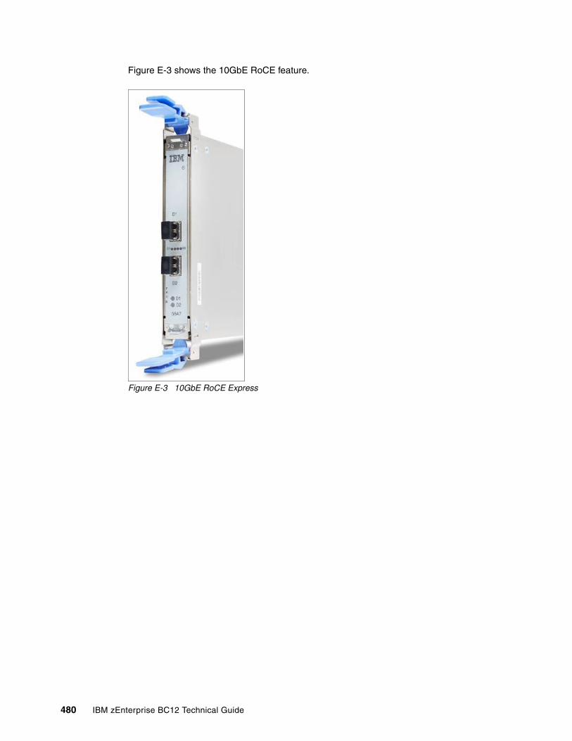
Figure E-3 shows the 10GbE RoCE feature.
Figure E-3 10GbE RoCE Express
480 IBM zEnterprise BC12 Technical Guide
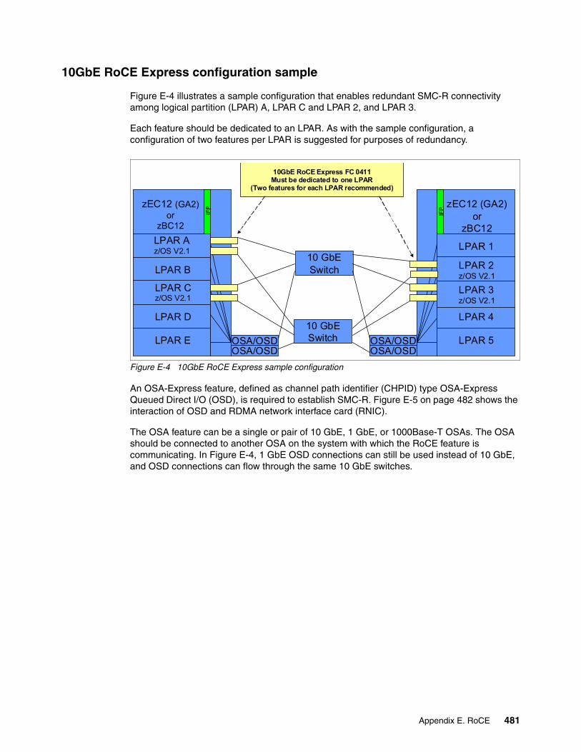
10GbE RoCE Express configuration sample
Figure E-4 illustrates a sample configuration that enables redundant SMC-R connectivity among logical partition (LPAR) A, LPAR C and LPAR 2, and LPAR 3.
Each feature should be dedicated to an LPAR. As with the sample configuration, a configuration of two features per LPAR is suggested for purposes of redundancy.
Figure E-4 10GbE RoCE Express sample configuration
An OSA-Express feature, defined as channel path identifier (CHPID) type OSA-Express Queued Direct I/O (OSD), is required to establish SMC-R. Figure E-5 on page 482 shows the interaction of OSD and RDMA network interface card (RNIC).
The OSA feature can be a single or pair of 10 GbE, 1 GbE, or 1000Base-T OSAs. The OSA should be connected to another OSA on the system with which the RoCE feature is communicating. In Figure E-4, 1 GbE OSD connections can still be used instead of 10 GbE, and OSD connections can flow through the same 10 GbE switches.
OSA/OSD OSA/OSD
zEC12 (GA2)or
zBC12
LPAR Az/OS V2.1
LPAR B
LPAR Cz/OS V2.1
LPAR D
LPAR E
zEC12 (GA2)or
zBC12
LPAR 1
LPAR 2z/OS V2.1
LPAR 3z/OS V2.1
LPAR 4
LPAR 5
10 GbESwitch
OSA/OSD OSA/OSD
10GbE RoCE Express FC 0411Must be dedicated to one LPAR
(Two features for each LPAR recommended)
IFP
10 GbESwitch
IFP
Appendix E. RoCE 481
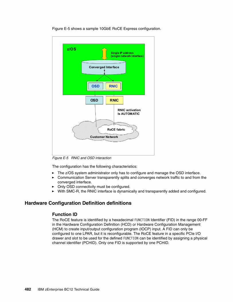
Figure E-5 shows a sample 10GbE RoCE Express configuration.
Figure E-5 RNIC and OSD interaction
The configuration has the following characteristics:
� The z/OS system administrator only has to configure and manage the OSD interface.� Communication Server transparently splits and converges network traffic to and from the
converged interface.� Only OSD connectivity must be configured.� With SMC-R, the RNIC interface is dynamically and transparently added and configured.
Hardware Configuration Definition definitions
Function IDThe RoCE feature is identified by a hexadecimal FUNCTION Identifier (FID) in the range 00-FF in the Hardware Configuration Definition (HCD) or Hardware Configuration Management (HCM) to create input/output configuration program (IOCP) input. A FID can only be configured to one LPAR, but it is reconfigurable. The RoCE feature in a specific PCIe I/O drawer and slot to be used for the defined FUNCTION can be identified by assigning a physical channel identifier (PCHID). Only one FID is supported by one PCHID.
RNIC activationIs AUTOMATIC
Single IP address(single network interface)
Converged Interface
z/OS
OSD RNIC
OSD RNIC
Customer Network
RoCE fabric
482 IBM zEnterprise BC12 Technical Guide
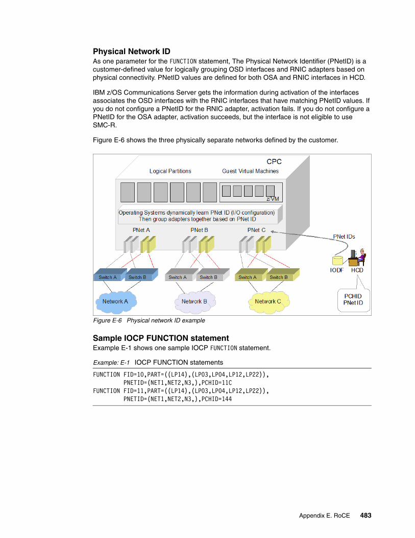
Physical Network IDAs one parameter for the FUNCTION statement, The Physical Network Identifier (PNetID) is a customer-defined value for logically grouping OSD interfaces and RNIC adapters based on physical connectivity. PNetID values are defined for both OSA and RNIC interfaces in HCD.
IBM z/OS Communications Server gets the information during activation of the interfaces associates the OSD interfaces with the RNIC interfaces that have matching PNetID values. If you do not configure a PNetID for the RNIC adapter, activation fails. If you do not configure a PNetID for the OSA adapter, activation succeeds, but the interface is not eligible to use SMC-R.
Figure E-6 shows the three physically separate networks defined by the customer.
Figure E-6 Physical network ID example
Sample IOCP FUNCTION statementExample E-1 shows one sample IOCP FUNCTION statement.
Example: E-1 IOCP FUNCTION statements
FUNCTION FID=10,PART=((LP14),(LP03,LP04,LP12,LP22)), PNETID=(NET1,NET2,N3,),PCHID=11CFUNCTION FID=11,PART=((LP14),(LP03,LP04,LP12,LP22)), PNETID=(NET1,NET2,N3,),PCHID=144
Appendix E. RoCE 483
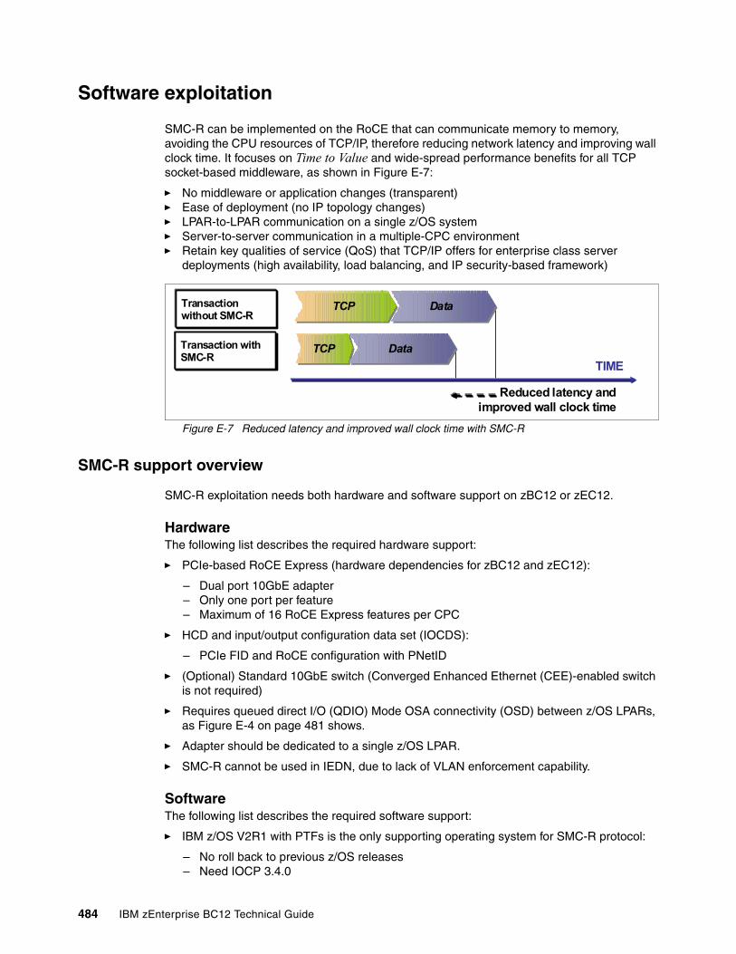
Software exploitation
SMC-R can be implemented on the RoCE that can communicate memory to memory, avoiding the CPU resources of TCP/IP, therefore reducing network latency and improving wall clock time. It focuses on Time to Value and wide-spread performance benefits for all TCP socket-based middleware, as shown in Figure E-7:
� No middleware or application changes (transparent)� Ease of deployment (no IP topology changes)� LPAR-to-LPAR communication on a single z/OS system� Server-to-server communication in a multiple-CPC environment� Retain key qualities of service (QoS) that TCP/IP offers for enterprise class server
deployments (high availability, load balancing, and IP security-based framework)
Figure E-7 Reduced latency and improved wall clock time with SMC-R
SMC-R support overview
SMC-R exploitation needs both hardware and software support on zBC12 or zEC12.
HardwareThe following list describes the required hardware support:
� PCIe-based RoCE Express (hardware dependencies for zBC12 and zEC12):
– Dual port 10GbE adapter– Only one port per feature– Maximum of 16 RoCE Express features per CPC
� HCD and input/output configuration data set (IOCDS):
– PCIe FID and RoCE configuration with PNetID
� (Optional) Standard 10GbE switch (Converged Enhanced Ethernet (CEE)-enabled switch is not required)
� Requires queued direct I/O (QDIO) Mode OSA connectivity (OSD) between z/OS LPARs, as Figure E-4 on page 481 shows.
� Adapter should be dedicated to a single z/OS LPAR.
� SMC-R cannot be used in IEDN, due to lack of VLAN enforcement capability.
SoftwareThe following list describes the required software support:
� IBM z/OS V2R1 with PTFs is the only supporting operating system for SMC-R protocol:
– No roll back to previous z/OS releases– Need IOCP 3.4.0
Reduced latency and improved wall clock time
Transaction without SMC-R
TIME
TCPTCP DataData
TCPTCP DataDataTransaction with SMC-R
484 IBM zEnterprise BC12 Technical Guide
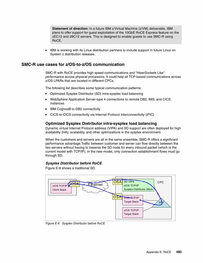
� IBM is working with its Linux distribution partners to include support in future Linux on System z distribution releases.
SMC-R use cases for z/OS-to-z/OS communication
SMC-R with RoCE provides high speed communications and “HiperSockets Like” performance across physical processors. It could help all TCP-based communications across z/OS LPARs that are located in different CPCs.
The following list describes some typical communication patterns:
� Optimized Sysplex Distributor (SD) intra-sysplex load balancing
� WebSphere Application Server-type 4 connections to remote DB2, IMS, and CICS instances
� IBM Cognos® to DB2 connectivity
� CICS-to-CICS connectivity via Internet Protocol interconnectivity (IPIC)
Optimized Sysplex Distributor intra-sysplex load balancingDynamic virtual Internet Protocol address (VIPA) and SD support are often deployed for high availability (HA), scalability, and other optimizations in the sysplex environment.
When the customers and servers are all in the same ensemble, SMC-R offers a significant performance advantage.Traffic between customer and server can flow directly between the two servers without having to traverse the SD node for every inbound packet (which is the current model with TCP/IP). In the new model, only connection establishment flows must go through SD.
Sysplex Distributor before RoCEFigure E-8 shows a traditional SD.
Figure E-8 Sysplex Distributor before RoCE
Statement of direction: In a future IBM z/Virtual Machine (z/VM) deliverable, IBM plans to offer support for guest exploitation of the 10GbE RoCE Express feature on the zEC12 and zBC12 servers. This is designed to enable guests to use SMC-R using RoCE.
CPC
z/OS TCP/IP
Target Stack
z/OS TCP/IP
Target Stack
XCF
z/OS TCP/IP
Sysplex Distributor Stack
SD VIPAEthernet
OSAOSA
OSAOSA
z/OS TCP/IP
Client Stack
z/OS TCP/IP
Client Stack
OSAOSA
Appendix E. RoCE 485
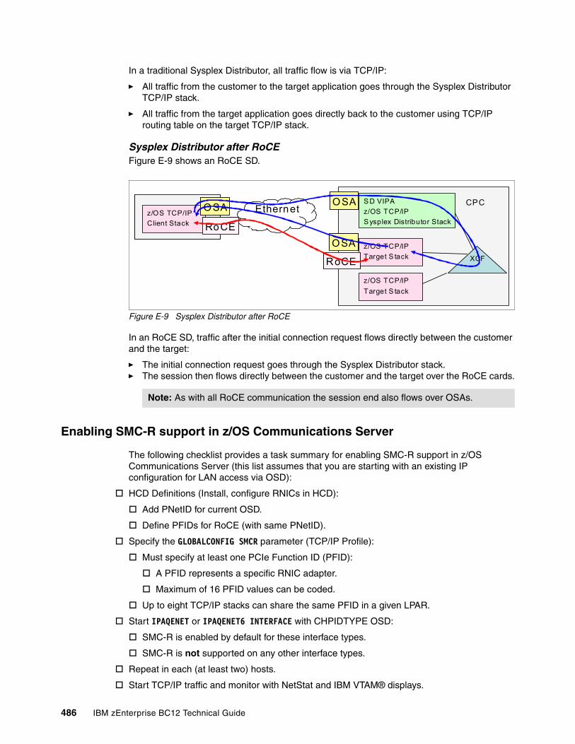
In a traditional Sysplex Distributor, all traffic flow is via TCP/IP:
� All traffic from the customer to the target application goes through the Sysplex Distributor TCP/IP stack.
� All traffic from the target application goes directly back to the customer using TCP/IP routing table on the target TCP/IP stack.
Sysplex Distributor after RoCEFigure E-9 shows an RoCE SD.
Figure E-9 Sysplex Distributor after RoCE
In an RoCE SD, traffic after the initial connection request flows directly between the customer and the target:
� The initial connection request goes through the Sysplex Distributor stack.� The session then flows directly between the customer and the target over the RoCE cards.
Enabling SMC-R support in z/OS Communications Server
The following checklist provides a task summary for enabling SMC-R support in z/OS Communications Server (this list assumes that you are starting with an existing IP configuration for LAN access via OSD):
HCD Definitions (Install, configure RNICs in HCD):
Add PNetID for current OSD.
Define PFIDs for RoCE (with same PNetID).
Specify the GLOBALCONFIG SMCR parameter (TCP/IP Profile):
Must specify at least one PCIe Function ID (PFID):
A PFID represents a specific RNIC adapter.
Maximum of 16 PFID values can be coded.
Up to eight TCP/IP stacks can share the same PFID in a given LPAR.
Start IPAQENET or IPAQENET6 INTERFACE with CHPIDTYPE OSD:
SMC-R is enabled by default for these interface types.
SMC-R is not supported on any other interface types.
Repeat in each (at least two) hosts.
Start TCP/IP traffic and monitor with NetStat and IBM VTAM® displays.
Note: As with all RoCE communication the session end also flows over OSAs.
CPC
z/OS TCP/IP
Target S tack
z/OS TCP/IP
Target S tack
XCF
z/OS TCP/IP
S ysplex Distributor Stack
S D VIPAEthernet
OSAOSA
OSAOSA
z/OS TCP/IP
Client Stack
z/OS TCP/IP
Client Stack
OSAOSA
RoCERoCE
RoCERoCE
486 IBM zEnterprise BC12 Technical Guide
Appendix F. IBM zEnterprise Data Compression Express
This appendix briefly describes the optional IBM zEnterprise Data Compression (zEDC) Express feature of IBM zEnterprise EC12 (zEC12) and IBM zEnterprise BC12 (zBC12) servers, and includes the following topics:
� Overview� IBM zEDC Express� Software support
F
© Copyright IBM Corp. 2014. All rights reserved. 487
Overview
The growth of data that needs to be captured, transferred, and stored for large periods of time is not relenting. On the contrary! Software implemented compression algorithms are costly in terms of processor resources, and storage costs are not negligible either.
IBM zEDC Express, an optional feature exclusive to zEC12 and zBC12, addresses those requirements by providing hardware-based acceleration for data compression and decompression. IBM zEDC provides data compression with lower central processing unit (CPU) consumption than compression technology previously available on System z.
Exploitation of the zEDC Express feature by z/OS V2R1 zEnterprise Data Compression acceleration capability is designed to deliver an integrated solution to help reduce CPU consumption, optimize performance of compression-related tasks, and enable more efficient use of storage resources, while providing a lower cost of computing and also helping to optimize the cross-platform exchange of data.
IBM zEDC Express
IBM zEDC Express is an optional feature (FC 0420), exclusive to the zEC12 and zBC12. It is designed to provide hardware-based acceleration for data compression and decompression.
The feature installs exclusively on the PCIe I/O drawer. Up to two zEDC Express features can be installed per PCIe I/O drawer domain. However, if the domain contains a Flash Express or 10GbE Remote Direct Memory Access (RDMA) over Converged Ethernet (RoCE) feature, only one zEDC feature can be installed on that domain.
Between one and eight features can be installed on the system. There is one PCIe adapter/compression coprocessor per feature, which implements compression as defined by RFC1951 (DEFLATE).
A zEDC Express feature can be shared by up to 15 logical partitions (LPARs).
Adapter support for zEDC is provided by resource group (RG) code running on the system integrated firmware processor (IFP). For resilience, there are always two independent RGs on the system, sharing the IFP. It is, therefore, suggested that a minimum of two zEDC features be installed, one per RG.
Consider also the total data throughput required and that, in the case of one feature becoming unavailable, the others should be able to absorb the load. Therefore, for best data throughput and availability, it is suggested that at least two features per RG are installed.
488 IBM zEnterprise BC12 Technical Guide
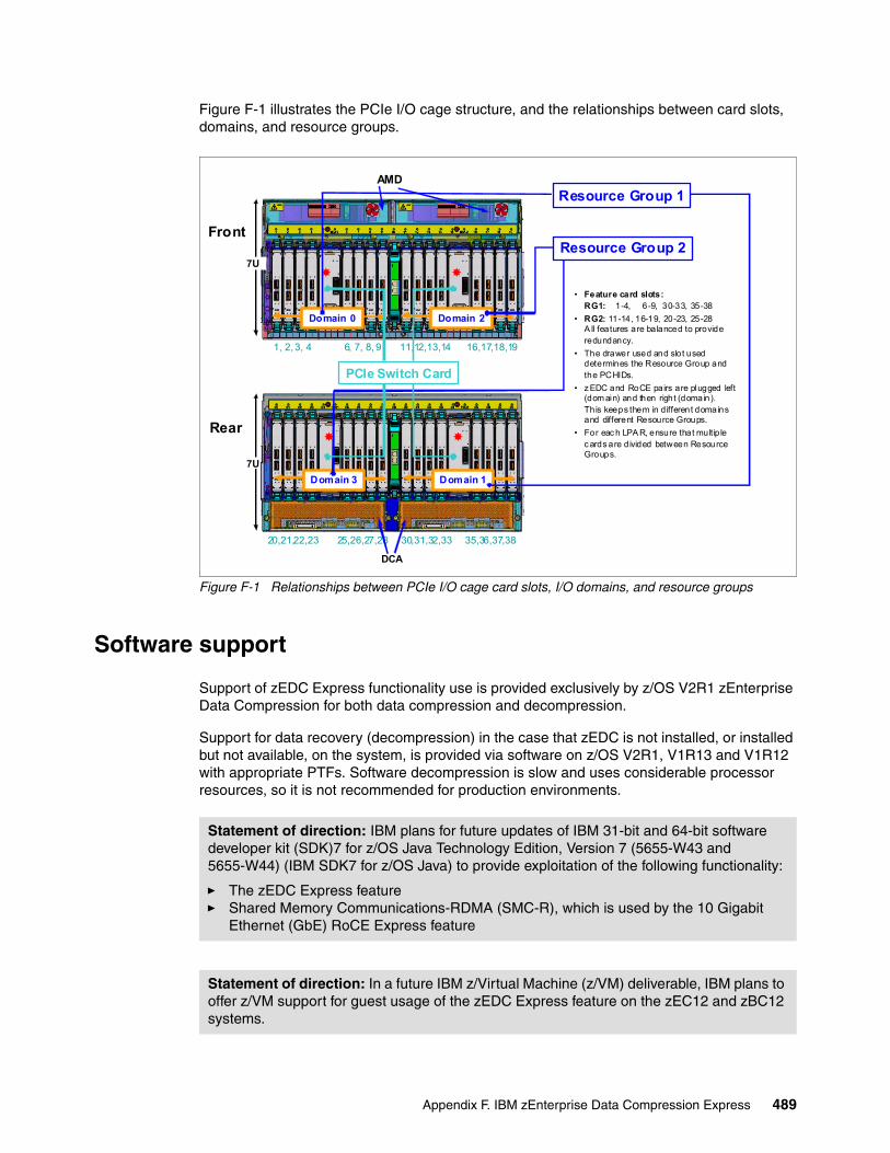
Figure F-1 illustrates the PCIe I/O cage structure, and the relationships between card slots, domains, and resource groups.
Figure F-1 Relationships between PCIe I/O cage card slots, I/O domains, and resource groups
Software support
Support of zEDC Express functionality use is provided exclusively by z/OS V2R1 zEnterprise Data Compression for both data compression and decompression.
Support for data recovery (decompression) in the case that zEDC is not installed, or installed but not available, on the system, is provided via software on z/OS V2R1, V1R13 and V1R12 with appropriate PTFs. Software decompression is slow and uses considerable processor resources, so it is not recommended for production environments.
Domain 0 Domain 2
1, 2, 3, 4 6, 7, 8, 9 11,12,13,14 16,17,18,19
Front
• Feature card slots:RG1: 1-4, 6-9, 30-33, 35-38
• RG2: 11-14, 16-19, 20-23, 25-28A ll features are balanced to provide redundancy.
• The drawer used and slot used determines the Resource Group and the PCHIDs.
• z EDC and RoCE pairs are plugged left (dom ain) and then right (domain).This keeps them in different domains and different Resource Groups.
• For eac h LPA R, ensure that multip le c ards are divided between Resource Groups.
7U
7U
Rear
Domain 3 Domain 1
20,21,22,23 25,26,27,28 30,31,32,33 35,36,37,38
AMD
DCA
Resource Group 1
Resource Group 2
PCIe Switch Card
Statement of direction: IBM plans for future updates of IBM 31-bit and 64-bit software developer kit (SDK)7 for z/OS Java Technology Edition, Version 7 (5655-W43 and 5655-W44) (IBM SDK7 for z/OS Java) to provide exploitation of the following functionality:
� The zEDC Express feature� Shared Memory Communications-RDMA (SMC-R), which is used by the 10 Gigabit
Ethernet (GbE) RoCE Express feature
Statement of direction: In a future IBM z/Virtual Machine (z/VM) deliverable, IBM plans to offer z/VM support for guest usage of the zEDC Express feature on the zEC12 and zBC12 systems.
Appendix F. IBM zEnterprise Data Compression Express 489
IBM System z Batch Network AnalyzerThe IBM System z Batch Network Analyzer (zBNA) is a free, as-is tool. It is available to customers, IBM Business Partners, and IBM employees.
IBM zBNA replaces the BWATOOL. It is Windows-based, provides graphical and text reports, including Gantt charts, and provides support for alternate processors.
IBM zBNA can be used to analyses customer-provided SMF records, to identify jobs and data sets which are candidates for zEDC compression, across a specified time window, typically a batch window. IBM zBNA is able to generate lists of data sets by job:
� Those that already perform hardware compression, and might be candidates for zEDC� Those that might be zEDC candidates, but are not in extended format
Therefore, zBNA can help estimate usage of zEDC features, and help size the number of features needed.
IBM Employees can obtain zBNA and other Capacity Planning Support (CPS) tools via the IBM intranet:
http://w3-03.ibm.com/support/techdocs/atsmastr.nsf/WebIndex/PRS5126
IBM Business Partners can obtain zBNA and other CPS tools via the Internet:
https://www.ibm.com/partnerworld/wps/servlet/mem/ContentHandler/tech_PRS5133
IBM Clients can obtain zBNA and other CPS tools via the Internet:
http://www-03.ibm.com/support/techdocs/atsmastr.nsf/WebIndex/PRS5132
490 IBM zEnterprise BC12 Technical Guide

Appendix G. Native PCI/e
In this appendix we introduce the concept of managing native PCIe features (10 Gigabit Ethernet (GbE) Remote Direct Memory Access (RDMA) over Converged Ethernet (RoCE) Express and IBM zEnterprise Data Compression (zEDC) Express).The new concept requires the use of an integrated firmware processor (IFP) and resource groups associated to the physical location of the feature cards.
We describe how these features are implemented into the PCIe I/O structure of the zBC12. The components and functions for managing the native PCIe features are:
� Design of native PCIe input/output adapter management� About native PCIe� Integrated firmware processor� Resource group� Management tasks� IBM zEDC Express� 10GbE RoCE Express� Defining native PCIe features
G
© Copyright IBM Corp. 2014. All rights reserved. 491
Design of native PCIe input/output adapter management
There are native PCIe feature card types introduced on IBM zEnterprise EC12 (zEC12) and IBM zEnterprise BC12 (zBC12) that require a new design to manage these cards. The following PCIe features are native:
� 10GbE RoCE Express� IBM zEDC Express
These adapters are plugged into a PCIe I/O drawer, together with existing PCIe I/O features, but they are managed in a different way from previous I/O adapters and features. The native PCIe feature cards are exclusively plugged into the PCIe I/O drawer, and have a physical channel identifier (PCHID) assigned according to the physical location in the PCIe I/O drawer.
On existing features that were plugged into an I/O drawer or I/O cage, all adapter layer functions have been integrated into the adapter hardware. For the new features introduced by zEC12 and zBC12 central processor complexes (Copts), the adapter layer function is now handled by an IFP.
In the next sections, we will describe the following concepts:
� Native PCIe adapter� Integrated firmware processor� Resource groups� Management functions
About native PCIe
For traditional PCIe I/O adapters, such as the Open Systems Adapter (OSA) and Fibre Channel connection (FICON) cards, the diagnostic program and device drivers are downloaded from the Service Element (SE) to the application-specific integrated circuit (ASIC) chips that are located on those cards.
With the introduction of the IFP and the native PCIe adapters, which do not have an ASIC chip, the device drivers for these native PCIe adapters were moved to the operating systems and the adapter layer function runs on the IFP, making use of two so-called resource groups.
All virtualization, recovery, diagnostics, failover, concurrent firmware updates, and similar functions on traditional I/O features are done on the adapter level. For the native PCIe features, these functions are done by the IFP.
Integrated firmware processor
The IFP is used to manage native PCIe adapters installed in a PCIe I/O drawer. On previous systems, this processor was not used, but was known as a reserved processor. The IFP is allocated from a pool of processor units (PUs) available for the whole system. Because IFP is exclusively used to manage native PCIe adapters, it is not taken from the pool of PUs that can be characterized for customer usage.
If a native PCIe feature is present in the system, the IFP is initialized and allocated during the system’s power-on reset (POR) phase. Although the IFP is allocated to one of the physical PUs, it is not visible for the customer. In case of error or failover scenarios, the IFP will act similarly to any other PU (sparing).
492 IBM zEnterprise BC12 Technical Guide
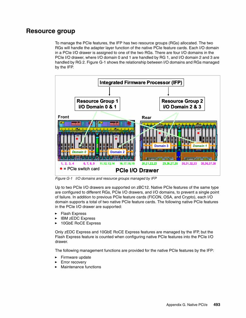
Resource group
To manage the PCIe features, the IFP has two resource groups (RGs) allocated. The two RGs will handle the adapter layer function of the native PCIe feature cards. Each I/O domain in a PCIe I/O drawer is assigned to one of the two RGs. There are four I/O domains in the PCIe I/O drawer, where I/O domain 0 and 1 are handled by RG 1, and I/O domain 2 and 3 are handled by RG 2. Figure G-1 shows the relationship between I/O domains and RGs managed by the IFP.
Figure G-1 I/O domains and resource groups managed by IFP
Up to two PCIe I/O drawers are supported on zBC12. Native PCIe features of the same type are configured to different RGs, PCIe I/O drawers, and I/O domains, to prevent a single point of failure. In addition to previous PCIe feature cards (FICON, OSA, and Crypto), each I/O domain supports a total of two native PCIe feature cards. The following native PCIe features in the PCIe I/O drawer are supported:
� Flash Express� IBM zEDC Express� 10GbE RoCE Express
Only zEDC Express and 10GbE RoCE Express features are managed by the IFP, but the Flash Express feature is counted when configuring native PCIe features into the PCIe I/O drawer.
The following management functions are provided for the native PCIe features by the IFP:
� Firmware update� Error recovery� Maintenance functions
Front
Domain 0 Domain 2
1, 2, 3, 4 6, 7, 8, 9 11,12,13,14 16,17,18,19
Rear
Domain 3 Domain 1
20,21,22,23 25,26,27,28 30,31,32,33 35,36,37,38
Resource Group 1I/O Domain 0 & 1
Resource Group 2I/O Domain 2 & 3
PCIe I/O Drawer
Integrated Firmware Processor (IFP)
= PCIe switch card
Front
Domain 0 Domain 2Domain 0Domain 0 Domain 2Domain 2
1, 2, 3, 4 6, 7, 8, 9 11,12,13,14 16,17,18,19
Rear
Domain 3 Domain 1
20,21,22,23 25,26,27,28 30,31,32,33 35,36,37,38
Rear
Domain 3 Domain 1Domain 3Domain 3 Domain 1Domain 1
20,21,22,23 25,26,27,28 30,31,32,33 35,36,37,38
Resource Group 1I/O Domain 0 & 1
Resource Group 2I/O Domain 2 & 3
PCIe I/O Drawer
Integrated Firmware Processor (IFP)
= PCIe switch card
Appendix G. Native PCI/e 493
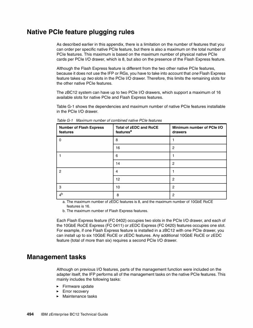
Native PCIe feature plugging rules
As described earlier in this appendix, there is a limitation on the number of features that you can order per specific native PCIe feature, but there is also a maximum on the total number of PCIe features. This maximum is based on the maximum number of physical native PCIe cards per PCIe I/O drawer, which is 8, but also on the presence of the Flash Express feature.
Although the Flash Express feature is different from the two other native PCIe features, because it does not use the IFP or RGs, you have to take into account that one Flash Express feature takes up two slots in the PCIe I/O drawer. Therefore, this limits the remaining slots for the other native PCIe features.
The zBC12 system can have up to two PCIe I/O drawers, which support a maximum of 16 available slots for native PCIe and Flash Express features.
Table G-1 shows the dependencies and maximum number of native PCIe features installable in the PCIe I/O drawer.
Table G-1 Maximum number of combined native PCIe features
Each Flash Express feature (FC 0402) occupies two slots in the PCIe I/O drawer, and each of the 10GbE RoCE Express (FC 0411) or zEDC Express (FC 0420) features occupies one slot. For example, if one Flash Express feature is installed in a zBC12 with one PCIe drawer, you can install up to six 10GbE RoCE or zEDC features. Any additional 10GbE RoCE or zEDC feature (total of more than six) requires a second PCIe I/O drawer.
Management tasks
Although on previous I/O features, parts of the management function were included on the adapter itself, the IFP performs all of the management tasks on the native PCIe features. This mainly includes the following tasks:
� Firmware update� Error recovery� Maintenance tasks
Number of Flash Express features
Total of zEDC and RoCE featuresa
a. The maximum number of zEDC features is 8, and the maximum number of 10GbE RoCE features is 16.
Minimum number of PCIe I/O drawers
0 8 1
16 2
1 6 1
14 2
2 4 1
12 2
3 10 2
4b
b. The maximum number of Flash Express features.
8 2
494 IBM zEnterprise BC12 Technical Guide
Firmware update
Microcode change level (MCL) upgrades on native PCIe adapters, or on the code of the resource groups (RG), require the specific adapter or all native PCIe adapters managed by the specific RG (depending on the piece of code to which it applies) to be offline during activation of the MCL.
However, to maintain availability, MCLs can only be applied to one RG at a time. While one RG is offline, the second RG and all adapters in it remains active at all times. An MCL that applies to a native PCIe adapter or RG will not even be possible if an error condition exists within the other RG.
Error recovery
In case of an error in one of the RGs, or in features assigned to an RG, the IFP will manage error recovery and collecting error data. The error data is sent by the IFP to the SE, which then provides a message on the SE and the Hardware Management Console (HMC). In case of an error that requires maintenance, a call to IBM support system is initiated by the HMC.
Maintenance tasks
Any maintenance action on a native PCIe feature is managed by the IFP. This includes testing or replacing a feature card. Before configuring a feature offline, the IFP ensures that the same type of feature is available in the same or the other RG (if applicable).
IBM zEDC Express
IBM zEDC Express is an optional feature (FC 0420), exclusive to the zEC12 and zBC12. It is designed to provide hardware-based acceleration for data compression and decompression.
The feature installs exclusively on the PCIe I/O drawer. Up to two zEDC Express features can be installed per PCIe I/O drawer domain. However, if the domain contains a Flash Express or 10GbE RoCE feature, only one zEDC feature can be installed on that domain.
Between one and eight features can be installed on the system. There is one PCIe adapter/compression coprocessor per feature, which implements compression as defined by RFC1951 (DEFLATE).
A zEDC Express feature can be shared by up to 15 logical partitions (LPARs).
For more information, also see Appendix F, “IBM zEnterprise Data Compression Express” on page 487.
10GbE RoCE Express
The 10 Gigabit Ethernet (10GbE) RoCE Express feature (FC 0411) is designed to help reduce consumption of CPU resources for applications using the TCP/IP stack (such as WebSphere accessing a DB2 database). Use of the 10GbE RoCE Express feature can also help to reduce network latency with memory-to-memory transfers using Shared Memory Communications-RDMA (SMC-R) in z/OS V2.1.
Appendix G. Native PCI/e 495
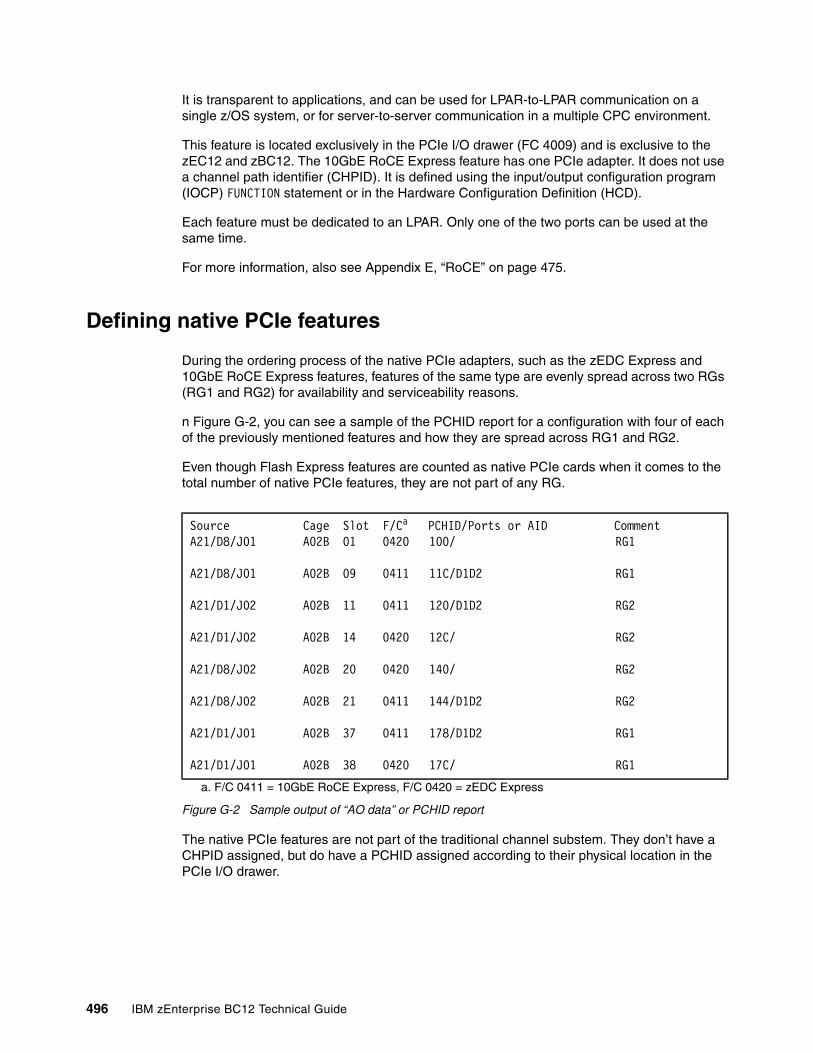
It is transparent to applications, and can be used for LPAR-to-LPAR communication on a single z/OS system, or for server-to-server communication in a multiple CPC environment.
This feature is located exclusively in the PCIe I/O drawer (FC 4009) and is exclusive to the zEC12 and zBC12. The 10GbE RoCE Express feature has one PCIe adapter. It does not use a channel path identifier (CHPID). It is defined using the input/output configuration program (IOCP) FUNCTION statement or in the Hardware Configuration Definition (HCD).
Each feature must be dedicated to an LPAR. Only one of the two ports can be used at the same time.
For more information, also see Appendix E, “RoCE” on page 475.
Defining native PCIe features
During the ordering process of the native PCIe adapters, such as the zEDC Express and 10GbE RoCE Express features, features of the same type are evenly spread across two RGs (RG1 and RG2) for availability and serviceability reasons.
n Figure G-2, you can see a sample of the PCHID report for a configuration with four of each of the previously mentioned features and how they are spread across RG1 and RG2.
Even though Flash Express features are counted as native PCIe cards when it comes to the total number of native PCIe features, they are not part of any RG.
Figure G-2 Sample output of “AO data” or PCHID report
The native PCIe features are not part of the traditional channel substem. They don’t have a CHPID assigned, but do have a PCHID assigned according to their physical location in the PCIe I/O drawer.
Source Cage Slot F/Ca PCHID/Ports or AID CommentA21/D8/J01 A02B 01 0420 100/ RG1
A21/D8/J01 A02B 09 0411 11C/D1D2 RG1
A21/D1/J02 A02B 11 0411 120/D1D2 RG2
A21/D1/J02 A02B 14 0420 12C/ RG2
A21/D8/J02 A02B 20 0420 140/ RG2
A21/D8/J02 A02B 21 0411 144/D1D2 RG2
A21/D1/J01 A02B 37 0411 178/D1D2 RG1
A21/D1/J01 A02B 38 0420 17C/ RG1
a. F/C 0411 = 10GbE RoCE Express, F/C 0420 = zEDC Express
496 IBM zEnterprise BC12 Technical Guide
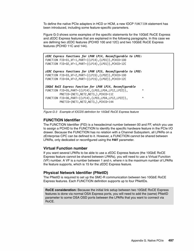
To define the native PCIe adapters in HCD or HCM, a new IOCP FUNCTION statement has been introduced, including some feature-specific parameters.
Figure G-3 shows some examples of the specific statements for the 10GbE RoCE Express and zEDC Express features that are explained in the following paragraphs. In this case we are defining two zEDC features (PCHID 100 and 12C) and two 10GbE RoCE Express features (PCHID 11C and 144).
Figure G-3 Example of IOCDS definition for 10GbE RoCE Express feature
FUNCTION IdentifierThe FUNCTION Identifier (FID) is a hexadecimal number between 00 and FF, which you use to assign a PCHID to the FUNCTION to identify the specific hardware feature in the PCIe I/O drawer. Because the FUNCTION has no relation with a Channel Subsystem, all LPARs on a zEnterprise CPC can be defined to it. However, a FUNCTION cannot be shared between LPARs, only dedicated or reconfigured using the PART parameter.
Virtual Function numberIf you want several LPARs to be able to use a zEDC Express feature (the 10GbE RoCE Express feature cannot be shared between LPARs), you will need to use a Virtual Function (VF) number. A VF is a number between 1 and n, where n is the maximum number of LPARs the feature supports, which is 15 for the zEDC Express feature.
Physical Network Identifier (PNetID)The PNetID is required to set up the SMC-R communication between two 10GbE RoCE Express features. Each FUNCTION definition supports up to four PNetIDs.
zEDC Express Functions for LPAR LP14, Reconfigurable to LP01:FUNCTION FID=01,VF=1,PART=((LP14),(LP01)),PCHID=100FUNCTION FID=02,VF=1,PART=((LP14),(LP01)),PCHID=12C
zEDC Express Functions for LPAR LP15, Reconfigurable to LP02:FUNCTION FID=03,VF=2,PART=((LP15),(LP02)),PCHID=100FUNCTION FID=04,VF=2,PART=((LP15),(LP02)),PCHID=12C
10GbE RoCE Express Function for LPAR LP14, ReconfigurableFUNCTION FID=05,PART=((LP14),(LP03,LP04,LP12,LP22)), * PNETID=(NET1,NET2,NET3,),PCHID=11CFUNCTION FID=06,PART=((LP14),(LP03,LP04,LP12,LP22)), * PNETID=(NET1,NET2,NET3,),PCHID=144
RoCE consideration: Because the initial link setup between two 10GbE RoCE Express features is done via normal OSA Express ports, you will need to add the (same) PNetID parameter to some OSA OSD ports between the LPARs that you want to connect via RoCE.
Appendix G. Native PCI/e 497

498 IBM zEnterprise BC12 Technical Guide
Appendix H. IBM System z10 Business Class to IBM zEnterprise BC12 upgrade checklist
The checklists in this section can help you to put together the information that you should use to consider upgrading from IBM System z10 Business Class (z10 BC) to IBM zEnterprise BC12 (zBC12).
All features available on z10 BC that upgraded to new features are listed and correlated to Table H-1 as a hardware (HW) checkpoint or a software (SW) checkpoint.
The new features, such as IBM System z Advanced Workload Analysis Reporter (zAware), Flash Express, IBM zEnterprise Data Compression (zEDC), or Remote Direct Memory Access (RDMA) over Converged Ethernet (RoCE) Express, will not be shown in this table. Operating system (OS) levels that are no longer in service are not covered in this publication. These older levels might provide support for some features. Work with your IBM support team to sort it out before the actual implementation.
Linux on System z is not an IBM product. Only the Linux vendor can provide the best guidance on suggested release levels.
A complete set of checklists is available in the Systems Assurance Product Review Guide for zBC12, SA13-002.
H
© Copyright IBM Corp. 2014. All rights reserved. 499
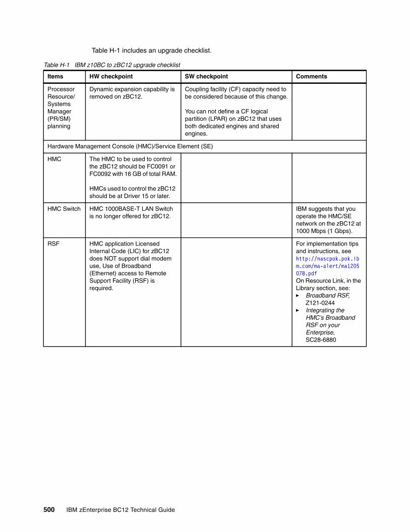
Table H-1 includes an upgrade checklist.
Table H-1 IBM z10BC to zBC12 upgrade checklist
Items HW checkpoint SW checkpoint Comments
Processor Resource/Systems Manager (PR/SM) planning
Dynamic expansion capability is removed on zBC12.
Coupling facility (CF) capacity need to be considered because of this change.
You can not define a CF logical partition (LPAR) on zBC12 that uses both dedicated engines and shared engines.
Hardware Management Console (HMC)/Service Element (SE)
HMC The HMC to be used to control the zBC12 should be FC0091 or FC0092 with 16 GB of total RAM.
HMCs used to control the zBC12 should be at Driver 15 or later.
HMC Switch HMC 1000BASE-T LAN Switch is no longer offered for zBC12.
IBM suggests that you operate the HMC/SE network on the zBC12 at 1000 Mbps (1 Gbps).
RSF HMC application Licensed Internal Code (LIC) for zBC12 does NOT support dial modem use, Use of Broadband (Ethernet) access to Remote Support Facility (RSF) is required.
For implementation tips and instructions, seehttp://nascpok.pok.ibm.com/ma-alert/ma120507B.pdfOn Resource Link, in the Library section, see:� Broadband RSF,
Z121-0244� Integrating the
HMC’s Broadband RSF on your Enterprise, SC28-6880
500 IBM zEnterprise BC12 Technical Guide
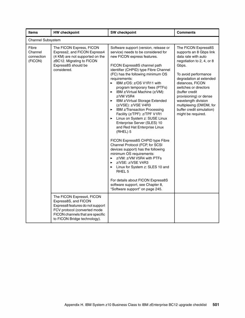
Channel Subsystem
Fibre Channel connection (FICON)
The FICON Express, FICON Express2, and FICON Express4 (4 KM) are not supported on the zBC12. Migrating to FICON Express8S should be considered.
Software support (version, release or service) needs to be considered for new FICON express features.
FICON Express8S channel path identifier (CHPID) type Fibre Channel (FC) has the following minimum OS requirements:� IBM z/OS: z/OS V1R11 with
program temporary fixes (PTFs)� IBM z/Virtual Machine (z/VM):
z/VM V5R4� IBM z/Virtual Storage Extended
(z/VSE): z/VSE V4R3� IBM z/Transaction Processing
Facility (z/TPF): z/TPF V1R1� Linux on System z: SUSE Linux
Enterprise Server (SLES) 10 and Red Hat Enterprise Linux (RHEL) 5
FICON Express8S CHPID type Fibre Channel Protocol (FCP, for SCSI devices support) has the following minimum OS requirements:� z/VM: z/VM V5R4 with PTFs� z/VSE: z/VSE V4R3� Linux for System z: SLES 10 and
RHEL 5
For details about FICON Express8S software support, see Chapter 8, “Software support” on page 245.
The FICON Express8S supports an 8 Gbps link data rate with auto negotiation to 2, 4, or 8 Gbps.
To avoid performance degradation at extended distances, FICON switches or directors (buffer credit provisioning) or dense wavelength division multiplexing (DWDM, for buffer credit simulation) might be required.
The FICON Express4, FICON Express8S, and FICON Express8 features do not support FCV protocol (converted mode FICON channels that are specific to FICON Bridge technology).
Items HW checkpoint SW checkpoint Comments
Appendix H. IBM System z10 Business Class to IBM zEnterprise BC12 upgrade checklist 501
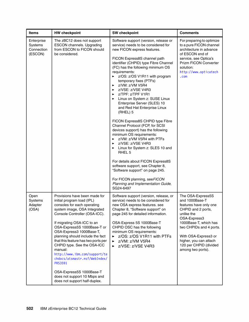
Enterprise Systems Connection (ESCON)
The zBC12 does not support ESCON channels. Upgrading from ESCON to FICON should be considered.
Software support (version, release or service) needs to be considered for new FICON express features.
FICON Express8S channel path identifier (CHPID) type Fibre Channel (FC) has the following minimum OS requirements:� z/OS: z/OS V1R11 with program
temporary fixes (PTFs)� z/VM: z/VM V5R4� z/VSE: z/VSE V4R3� z/TPF: z/TPF V1R1� Linux on System z: SUSE Linux
Enterprise Server (SLES) 10 and Red Hat Enterprise Linux (RHEL) 5
FICON Express8S CHPID type Fibre Channel Protocol (FCP, for SCSI devices support) has the following minimum OS requirements:� z/VM: z/VM V5R4 with PTFs� z/VSE: z/VSE V4R3� Linux for System z: SLES 10 and
RHEL 5
For details about FICON Express8S software support, see Chapter 8, “Software support” on page 245.
For FICON planning, seeFICON Planning and Implementation Guide, SG24-6497
For preparing to optimize to a pure FICON channel architecture in advance of ESCON end of service, see Optica’s Prizm FICON Converter solution: http://www.opticatech.com
Open Systems Adapter (OSA)
Provisions have been made for initial program load (IPL) consoles for each operating system image, OSA Integrated Console Controller (OSA-ICC).
If migrating OSA-ICC to an OSA-Express5S 1000Base-T or OSA-Express3 1000Base-T, planning should include the fact that this feature has two ports per CHPID type. See the OSA-ICC manual: http://www.ibm.com/support/techdocs/atsmastr.nsf/WebIndex/PRS3591
OSA-Express5S 1000Base-T does not support 10 Mbps and does not support half-duplex.
Software support (version, release, or service) needs to be considered for new OSA express features. see Chapter 8, “Software support” on page 245 for detailed information.
OSA-Express 5S 1000Base-T CHPID OSC has the following minimum OS requirements:� z/OS: z/OS V1R11 with PTFs� z/VM: z/VM V5R4� z/VSE: z/VSE V4R3
The OSA-Express5S and 1000Base-T features have only one CHPID and 2 ports, unlike the OSA-Express3 1000Base-T, which has two CHPIDs and 4 ports.
With OSA-Express3 or higher, you can attach 120 per CHPID (divided among two ports).
Items HW checkpoint SW checkpoint Comments
502 IBM zEnterprise BC12 Technical Guide
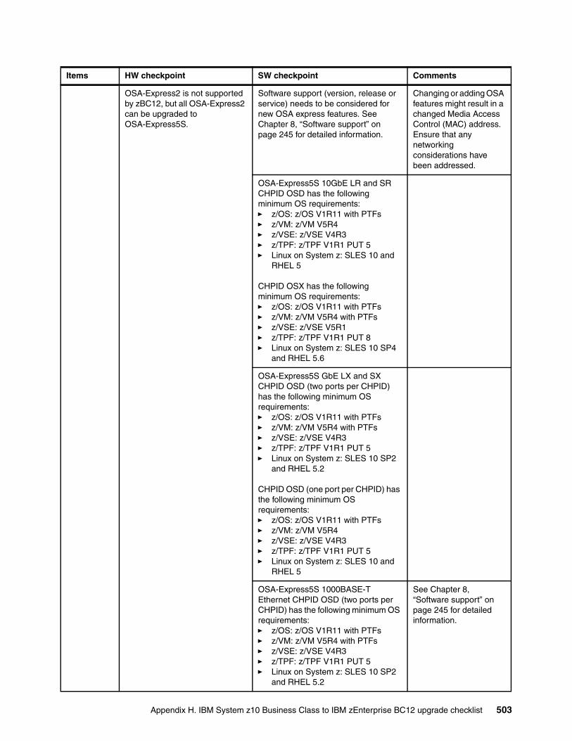
OSA-Express2 is not supported by zBC12, but all OSA-Express2 can be upgraded to OSA-Express5S.
Software support (version, release or service) needs to be considered for new OSA express features. See Chapter 8, “Software support” on page 245 for detailed information.
Changing or adding OSA features might result in a changed Media Access Control (MAC) address. Ensure that any networking considerations have been addressed.
OSA-Express5S 10GbE LR and SRCHPID OSD has the following minimum OS requirements:� z/OS: z/OS V1R11 with PTFs� z/VM: z/VM V5R4� z/VSE: z/VSE V4R3� z/TPF: z/TPF V1R1 PUT 5� Linux on System z: SLES 10 and
RHEL 5
CHPID OSX has the following minimum OS requirements:� z/OS: z/OS V1R11 with PTFs� z/VM: z/VM V5R4 with PTFs� z/VSE: z/VSE V5R1� z/TPF: z/TPF V1R1 PUT 8� Linux on System z: SLES 10 SP4
and RHEL 5.6
OSA-Express5S GbE LX and SXCHPID OSD (two ports per CHPID) has the following minimum OS requirements:� z/OS: z/OS V1R11 with PTFs� z/VM: z/VM V5R4 with PTFs� z/VSE: z/VSE V4R3� z/TPF: z/TPF V1R1 PUT 5� Linux on System z: SLES 10 SP2
and RHEL 5.2
CHPID OSD (one port per CHPID) has the following minimum OS requirements:� z/OS: z/OS V1R11 with PTFs� z/VM: z/VM V5R4� z/VSE: z/VSE V4R3� z/TPF: z/TPF V1R1 PUT 5� Linux on System z: SLES 10 and
RHEL 5
OSA-Express5S 1000BASE-T Ethernet CHPID OSD (two ports per CHPID) has the following minimum OS requirements:� z/OS: z/OS V1R11 with PTFs� z/VM: z/VM V5R4 with PTFs� z/VSE: z/VSE V4R3� z/TPF: z/TPF V1R1 PUT 5� Linux on System z: SLES 10 SP2
and RHEL 5.2
See Chapter 8, “Software support” on page 245 for detailed information.
Items HW checkpoint SW checkpoint Comments
Appendix H. IBM System z10 Business Class to IBM zEnterprise BC12 upgrade checklist 503
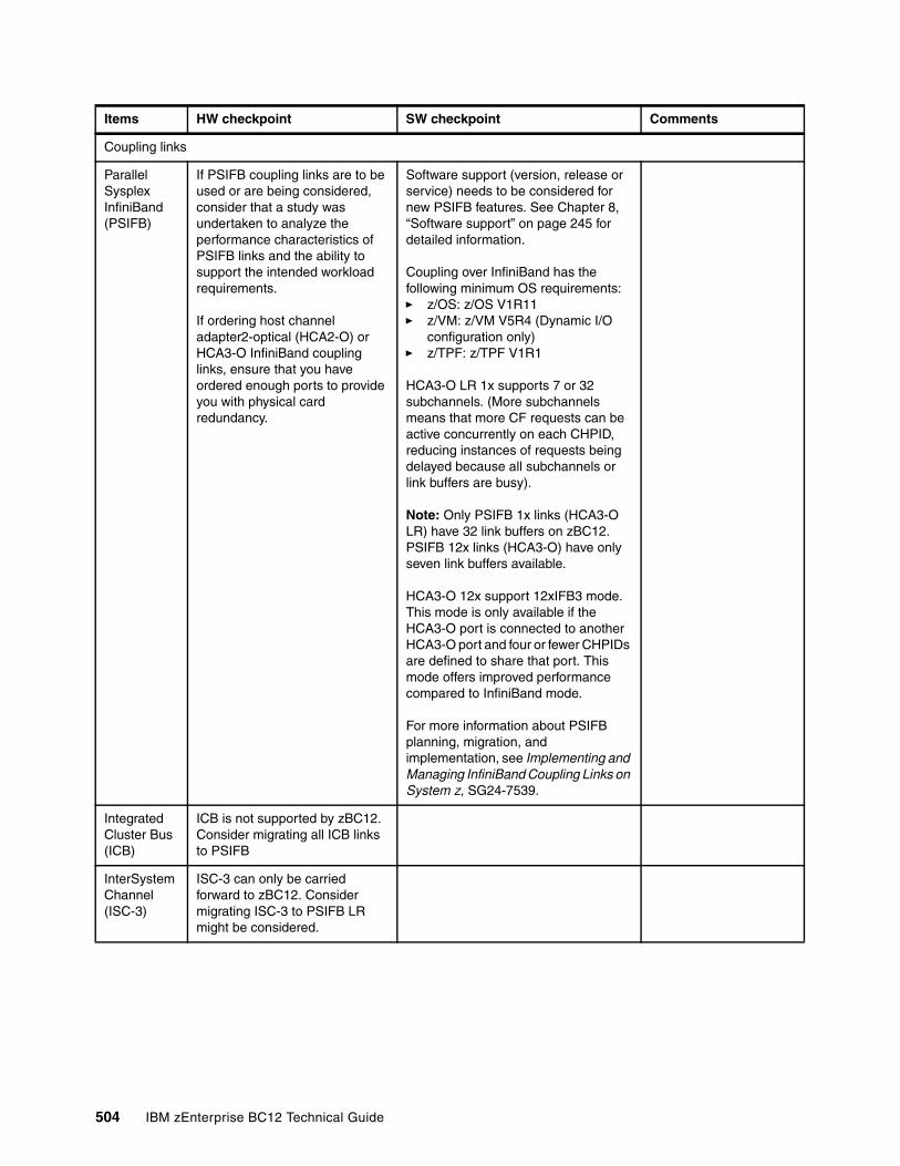
Coupling links
Parallel Sysplex InfiniBand (PSIFB)
If PSIFB coupling links are to be used or are being considered, consider that a study was undertaken to analyze the performance characteristics of PSIFB links and the ability to support the intended workload requirements.
If ordering host channel adapter2-optical (HCA2-O) or HCA3-O InfiniBand coupling links, ensure that you have ordered enough ports to provide you with physical card redundancy.
Software support (version, release or service) needs to be considered for new PSIFB features. See Chapter 8, “Software support” on page 245 for detailed information.
Coupling over InfiniBand has the following minimum OS requirements:� z/OS: z/OS V1R11� z/VM: z/VM V5R4 (Dynamic I/O
configuration only)� z/TPF: z/TPF V1R1
HCA3-O LR 1x supports 7 or 32 subchannels. (More subchannels means that more CF requests can be active concurrently on each CHPID, reducing instances of requests being delayed because all subchannels or link buffers are busy).
Note: Only PSIFB 1x links (HCA3-O LR) have 32 link buffers on zBC12. PSIFB 12x links (HCA3-O) have only seven link buffers available.
HCA3-O 12x support 12xIFB3 mode. This mode is only available if the HCA3-O port is connected to another HCA3-O port and four or fewer CHPIDs are defined to share that port. This mode offers improved performance compared to InfiniBand mode.
For more information about PSIFB planning, migration, and implementation, see Implementing and Managing InfiniBand Coupling Links on System z, SG24-7539.
Integrated Cluster Bus (ICB)
ICB is not supported by zBC12. Consider migrating all ICB links to PSIFB
InterSystem Channel (ISC-3)
ISC-3 can only be carried forward to zBC12. Consider migrating ISC-3 to PSIFB LR might be considered.
Items HW checkpoint SW checkpoint Comments
504 IBM zEnterprise BC12 Technical Guide
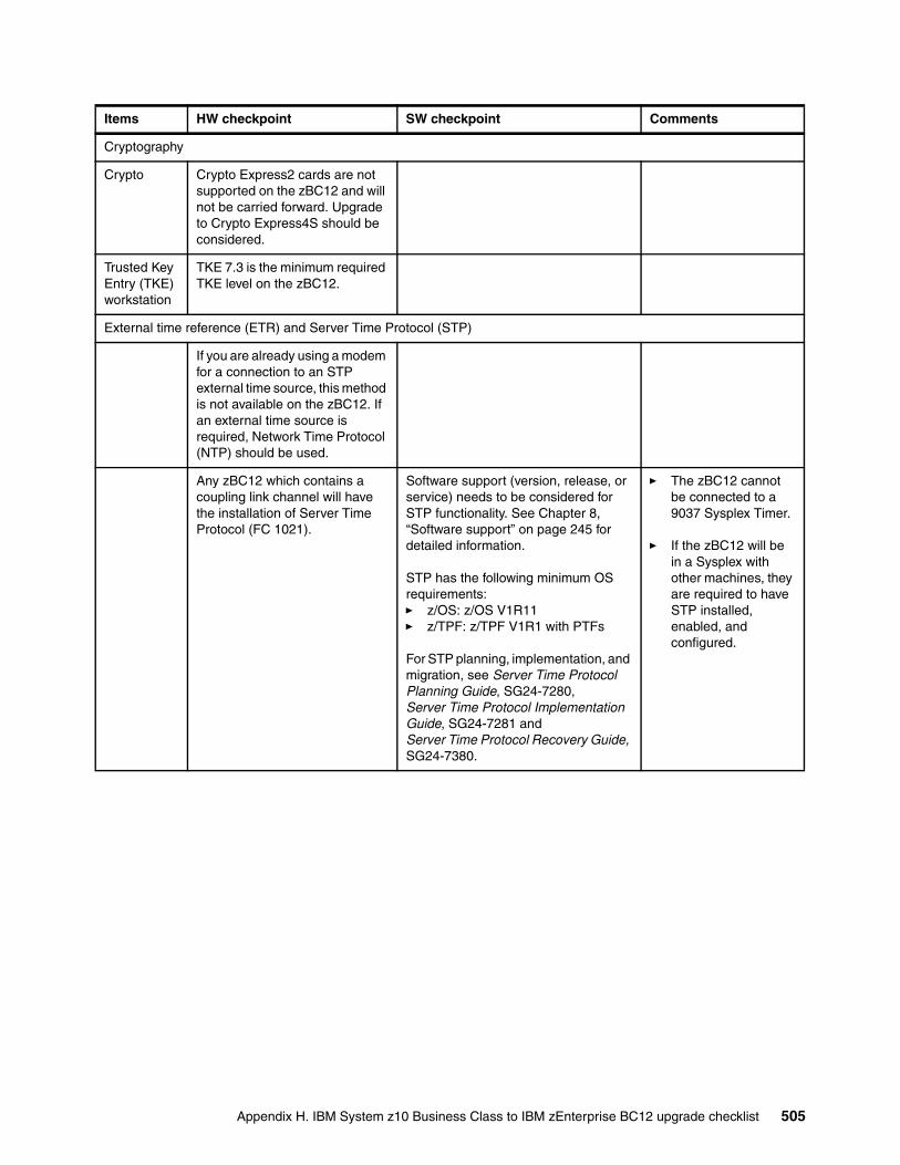
Cryptography
Crypto Crypto Express2 cards are not supported on the zBC12 and will not be carried forward. Upgrade to Crypto Express4S should be considered.
Trusted Key Entry (TKE) workstation
TKE 7.3 is the minimum required TKE level on the zBC12.
External time reference (ETR) and Server Time Protocol (STP)
If you are already using a modem for a connection to an STP external time source, this method is not available on the zBC12. If an external time source is required, Network Time Protocol (NTP) should be used.
Any zBC12 which contains a coupling link channel will have the installation of Server Time Protocol (FC 1021).
Software support (version, release, or service) needs to be considered for STP functionality. See Chapter 8, “Software support” on page 245 for detailed information.
STP has the following minimum OS requirements:� z/OS: z/OS V1R11� z/TPF: z/TPF V1R1 with PTFs
For STP planning, implementation, and migration, see Server Time Protocol Planning Guide, SG24-7280, Server Time Protocol Implementation Guide, SG24-7281 and Server Time Protocol Recovery Guide, SG24-7380.
� The zBC12 cannot be connected to a 9037 Sysplex Timer.
� If the zBC12 will be in a Sysplex with other machines, they are required to have STP installed, enabled, and configured.
Items HW checkpoint SW checkpoint Comments
Appendix H. IBM System z10 Business Class to IBM zEnterprise BC12 upgrade checklist 505
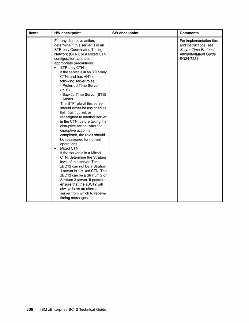
For any disruptive action, determine if this server is in an STP-only Coordinated Timing Network (CTN), or a Mixed CTN configuration, and use appropriate precautions:� STP-only CTN
If the server is in an STP-only CTN, and has ANY of the following server roles:- Preferred Time Server (PTS)- Backup Time Server (BTS)- ArbiterThe STP role of this server should either be assigned as Not Configured, or reassigned to another server in the CTN, before taking the disruptive action. After the disruptive action is completed, the roles should be reassigned for normal operations.
� Mixed CTNIf the server is in a Mixed CTN, determine the Stratum level of this server. The zBC12 can not be a Stratum 1 server in a Mixed CTN. The zBC12 can be a Stratum 2 or Stratum 3 server. If possible, ensure that the zBC12 will always have an alternate server from which to receive timing messages.
For implementation tips and instructions, see Server Time Protocol Implementation Guide, SG24-7281.
Items HW checkpoint SW checkpoint Comments
506 IBM zEnterprise BC12 Technical Guide
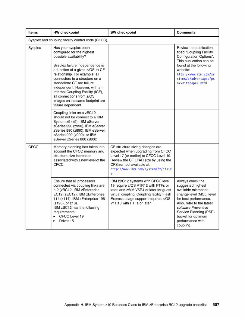
Sysplex and coupling facility control code (CFCC)
Sysplex Has your sysplex been configured for the highest possible availability?
Sysplex failure independence is a function of a given z/OS-to-CF relationship. For example, all connectors to a structure on a standalone CF are failure independent. However, with an Internal Coupling Facility (ICF), all connections from z/OS images on the same footprint are failure dependent.
Review the publication titled “Coupling Facility Configuration Options”. This publication can be found at the following website: http://www.ibm.com/systems/z/advantages/pso/whitepaper.html
Coupling links on a zEC12 should not be connect to a IBM System z9 (z9), IBM eServer zSeries 990 (z990), IBM eServer zSeries 890 (z890), IBM eServer zSeries 900 (z900), or IBM eServer zSeries 800 (z800).
CFCC Memory planning has taken into account the CFCC memory and structure size increases associated with a new level of the CFCC.
CF structure sizing changes are expected when upgrading from CFCC Level 17 (or earlier) to CFCC Level 19. Review the CF LPAR size by using the CFSizer tool available at:http://www.ibm.com/systems/z/cfsizer
Ensure that all processors connected via coupling links are n-2 (zBC12, IBM zEnterprise EC12 (zEC12), IBM zEnterprise 114 (z114), IBM zEnterprise 196 (z196), or z10).IBM zBC12 has the following requirements: � CFCC Level 19� Driver 15
IBM zBC12 systems with CFCC level 19 require z/OS V1R12 with PTFs or later, and z/VM V5R4 or later for guest virtual coupling. Coupling facility Flash Express usage support requires z/OS V1R13 with PTFs or later.
Always check the suggested highest available microcode change level (MCL) level for best performance. Also, refer to the latest software Preventive Service Planning (PSP) bucket for optimum performance with coupling.
Items HW checkpoint SW checkpoint Comments
Appendix H. IBM System z10 Business Class to IBM zEnterprise BC12 upgrade checklist 507
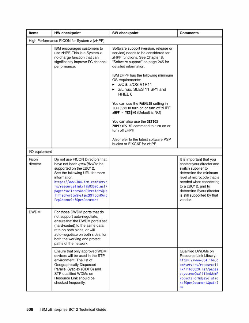
High Performance FICON for System z (zHPF)
IBM encourages customers to use zHPF. This is a System z no-charge function that can significantly improve FC channel performance.
Software support (version, release or service) needs to be considered for zHPF functions. See Chapter 8, “Software support” on page 245 for detailed information.
IBM zHPF has the following minimum OS requirements:� z/OS: z/OS V1R11� z/Linux: SLES 11 SP1 and
RHEL 6
You can use the PARMLIB setting in IECIOSxx to turn on or turn off zHPF:zHPF = YES|NO (Default is NO)
You can also use the SETIOS ZHPF=YES|NO command to turn on or turn off zHPF.
Also refer to the latest software PSP bucket or FIXCAT for zHPF.
I/O equipment
Ficon director
Do not use FICON Directors that have not been qualified to be supported on the zBC12.See the following URL for more information: https://www-304.ibm.com/servers/resourcelink/lib03020.nsf/pages/switchesAndDirectorsQualifiedForIbmSystemZRFiconRAndFcpChannels?OpenDocument
It is important that you contact your director and switch supplier to determine the minimum level of microcode that is needed when connecting to a zBC12, and to determine if your director is still supported by that vendor.
DWDM For those DWDM ports that do not support auto-negotiate, ensure that the DWDM port is set (hard-coded) to the same data rate on both sides, or will auto-negotiate on both sides, for both the working and protect paths of the network.
Ensure that only approved WDM devices will be used in the STP environment. The list of Geographically Dispersed Parallel Sysplex (GDPS) and STP qualified WDMs on Resource Link should be checked frequently.
Qualified DWDMs on Resource Link Library: https://www-304.ibm.com/servers/resourcelink/lib03020.nsf/pages/systemzQualifiedWdmProductsForGdpsSolutions?OpenDocument&pathID=
Items HW checkpoint SW checkpoint Comments
508 IBM zEnterprise BC12 Technical Guide
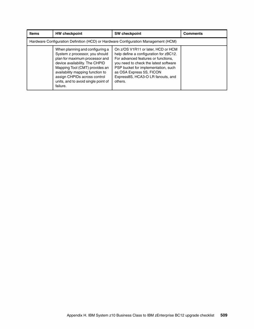
Hardware Configuration Definition (HCD) or Hardware Configuration Management (HCM)
When planning and configuring a System z processor, you should plan for maximum processor and device availability. The CHPID Mapping Tool (CMT) provides an availability mapping function to assign CHPIDs across control units, and to avoid single point of failure.
On z/OS V1R11 or later, HCD or HCM help define a configuration for zBC12. For advanced features or functions, you need to check the latest software PSP bucket for implementation, such as OSA Express 5S, FICON Express8S, HCA3-O LR fanouts, and others.
Items HW checkpoint SW checkpoint Comments
Appendix H. IBM System z10 Business Class to IBM zEnterprise BC12 upgrade checklist 509

510 IBM zEnterprise BC12 Technical Guide
Related publications
The publications listed in this section are considered particularly suitable to provide more detailed information about the topics covered in this book.
IBM Redbooks publications
For information about ordering these publications, see “How to get IBM Redbooks publications” on page 513. Note that some of the documents referenced here might be available in softcopy only:
� IBM zEnterprise 196 Technical Guide, SG24-7833
� IBM zEnterprise Unified Resource Manager, SG24-7921
� IBM zEnterprise 196 Configuration Setup, SG24-7834
� Server Time Protocol Planning Guide, SG24-7280
� Server Time Protocol Implementation Guide, SG24-7281
� System Programmer's Guide to: Workload Manager, SG24-6472
� z/OS Intelligent Resource Director, SG24-5952
� Parallel Sysplex Application Considerations, SG24-6523
� Implementing and Managing InfiniBand Coupling Links on System z, SG24-7539
� IBM System z Connectivity Handbook, SG24-5444
� IBM BladeCenter Products and Technology, SG24-7523
� IBM Communication Controller for Linux on System z V1.2.1 Implementation Guide, SG24-7223
� IBM System z10 Capacity on Demand, SG24-7504
� IBM System z10 Capacity on Demand, SG24-7504
� IBM zEnterprise 196 Capacity on Demand User’s Guide, SC28-2605
� Implementing IBM Systems Director Active Energy Manager 4.1.1, SG24-7780
� Using IBM System z As the Foundation for Your Information Management Architecture, REDP-4606
Other publications
These publications are also relevant as further information sources:
� zEnterprise Ensemble Planning and Configuring Guide, GC27-2608
� Installation Manual - Physical Planning (IMPP), GC28-6897
� zEnterprise 196 Processor Resource/Systems Manager Planning Guide, SB10-7155
� Coupling Facility Configuration Options, GF22-5042
� z/OS V1R9.0 XL C/C++ User’s Guide, SC09-4767
� z/OS Planning for Workload License Charges, SA22-7506
© Copyright IBM Corp. 2014. All rights reserved. 511
� z/OS MVS Capacity Provisioning User’s Guide, SA33-8299
� System z Capacity on Demand User’s Guide, SC28-6846
� Installation Manual - Physical Planning (IMPP), GC28-6897
� Hardware Management Console Operations Guide (V2.11.0), SC28-6895
� Implementing IBM Systems Director Active Energy Manager 4.1.1, SG24-7780
� zBX Installation Manual for Physical Planning 2458-002, GC27-2611
� System z Application Programming Interfaces, SB10-7030
Online resources
These websites are also relevant as further information sources:
� IBM Resource Link
http://www.ibm.com/servers/resourcelink/
� IBM Communication Controller for Linux on System z
http://www-01.ibm.com/software/network/ccl//
� FICON channel performance
http://www.ibm.com/systems/z/connectivity/
� Materialized Query Tables (MQTs)
http://www.ibm.com/servers/eserver/zseries/lspr/
� Large Systems Performance Reference measurements
http://www.ibm.com/developerworks/data/library/techarticle/dm-0509melnyk
� IBM zIIP
http://www-03.ibm.com/systems/z/advantages/ziip/about.html
� Parallel Sysplex coupling facility configuration
http://www.ibm.com/systems/z/advantages/pso/index.html
� Parallel Sysplex CFCC code levels
http://www.ibm.com/systems/z/pso/cftable.html
� IBM InfiniBand
http://www.infinibandta.org
� ESCON to FICON migration
http://www-935.ibm.com/services/us/index.wss/offering/its/c337386u66547p02
� Optica Technologies Inc.
http://www.opticatech.com/
� FICON channel performance
http://www-03.ibm.com/systems/z/hardware/connectivity/ficon_performance.html
� z/OS deliverables on the web
http://www.ibm.com/systems/z/os/zos/downloads/
� LInux on System z
http://www.ibm.com/developerworks/linux/linux390/
512 IBM zEnterprise BC12 Technical Guide
� ICSF versions and FMID cross-references
http://www.ibm.com/support/techdocs/atsmastr.nsf/WebIndex/TD103782
� z/OS
http://www.ibm.com/systems/support/z/zos/
� z/VM
http://www.ibm.com/systems/support/z/zvm/
� z/TPF
http://www.ibm.com/software/htp/tpf/pages/maint.htm
� z/VSE
http://www.ibm.com/servers/eserver/zseries/zvse/support/preventive.html
� Linux on System z
http://www.ibm.com/systems/z/os/linux/
� IBM license charges on System z
http://www.ibm.com/servers/eserver/zseries/swprice/znalc.htmlhttp://www.ibm.com/servers/eserver/zseries/swprice/mwlc.htmlhttp://www.ibm.com/servers/eserver/zseries/swprice/zipla/
How to get IBM Redbooks publications
You can search for, view, or download IBM Redbooks publications, Redpaper publications, Web Docs, draft publications, and additional materials, and order hardcopy IBM Redbooks publications, at the following website:
ibm.com/redbooks
Help from IBM
IBM Support and downloads
ibm.com/support
IBM Global Services
ibm.com/services
Related publications 513

514 IBM zEnterprise BC12 Technical Guide
(1.0” spine)0.875”<
->1.498”
460 <->
788 pages
IBM zEnterprise BC12 Technical Guide
IBM zEnterprise BC12 Technical Guide
IBM zEnterprise BC12 Technical
Guide
IBM zEnterprise BC12 Technical Guide

IBM zEnterprise BC12 Technical
Guide
IBM zEnterprise BC12 Technical
Guide

®
SG24-8138-00 ISBN 073843891X
INTERNATIONAL TECHNICALSUPPORTORGANIZATION
BUILDING TECHNICAL INFORMATION BASED ON PRACTICAL EXPERIENCE
IBM Redbooks are developed by the IBM International Technical Support Organization. Experts from IBM, clients, and IBM Business Partners from around the world create timely technical information based on realistic scenarios. Specific recommendations are provided to help you implement IT solutions more effectively in your environment.
For more information:ibm.com/redbooks
®
IBM zEnterprise BC12 Technical Guide
Explains virtualizing and managing the infrastructure for complex workloads
Describes the zEnterprise System, and related features and functions
Discusses zEnterprise hardware and software capabilities
The popularity of the Internet and the affordability of information technology (IT) hardware and software have resulted in an explosion dramatic increase in the number of applications, architectures, and platforms. Workloads have changed. Many applications, including mission-critical ones, are deployed on a variety of platforms, and the IBM System z design has adapted to this change. It takes into account a wide range of factors, including compatibility and investment protection, to match the IT requirements of an enterprise.
This IBM Redbooks publication provides information about the IBM zEnterprise BC12 (zBC12), an IBM scalable mainframe server. IBM is taking a revolutionary approach by integrating separate platforms under the well-proven System z hardware management capabilities, while extending System z qualities of service to those platforms.
The zEnterprise System consists of the zBC12 central processor complex, the IBM zEnterprise Unified Resource Manager, and the IBM zEnterprise BladeCenter Extension (zBX). The zBC12 is designed with improved scalability, performance, security, resiliency, availability, and virtualization. The zBC12 provides the following improvements over its predecessor, the IBM zEnterprise 114 (z114):
� Up to a 36% performance boost per core running at 4.2 GHz� Up to 58% more capacity for traditional workloads� Up to 62% more capacity for Linux workloads
The zBX infrastructure works with the zBC12 to enhance System z virtualization and management through an integrated hardware platform that spans mainframe, IBM POWER7, and IBM System x technologies. The federated capacity from multiple architectures of the zEnterprise System is managed as a single pool of resources, integrating system and workload management across the environment through the Unified Resource Manager.
This book provides an overview of the zBC12 and its functions, features, and associated software support. Greater detail is offered in areas relevant to technical planning. This book is intended for systems engineers, consultants, planners, and anyone who wants to understand zEnterprise System functions and plan for their usage. It is not intended as an introduction to mainframes. Readers are expected to be generally familiar with existing IBM System z technology and terminology.
Back cover


