Embed Size (px)
Citation preview
A. Gelbukh and A.F. Kuri Morales (Eds.): MICAI 2007, LNAI 4827, pp. 705–712, 2007. © Springer-Verlag Berlin Heidelberg 2007
Image Processing for 3D Reconstruction Using a Modified Fourier Transform Profilometry Method
Jesus Carlos Pedraza Ortega1, Jose Wilfrido Rodriguez Moreno2, Leonardo Barriga Rodriguez1, Efren Gorrostieta Hurtado3, Tomas Salgado Jimenez1,
Juan Manuel Ramos Arreguin4, and Angel Rivas5
1 Centro de Ingenieria y Desarrollo Industrial, Av. Pie de la Cuesta No. 702 Desarrollo San Pablo, Queretaro, Qro. C.P. 76130 Mexico
[email protected], [email protected], [email protected] 2 VALEO - Front End Module Division, Carr. Fed. Ags. a Lagos de Moreno Km. 75,
Aguascalientes, Ags. C.P. 20340 Mexico [email protected]
3 Universidad Autonoma de Queretaro, Centro Universitario, Cerro de las Campanas Queretaro, Qro. C.P. 76010 México [email protected]
4 Universidad Tecnologica de San Juan del Rio, Av. La Palma 125, Col. Vista Hermosa, San Juan del Rio, Queretaro, Qro. C.P. 76800 México
[email protected] 5 Universidad Autonoma de Nuevo Leon - FIME, Av. Universidad s/n, Cd. Universitaria,
San Nicolas de los Garza, Nuevo Leon, C.P. 66451 México [email protected]
Abstract. An image processing algorithm based on the Fourier Transform Profilometry (FTP) method for 3D reconstruction purposes is presented. This method uses a global and local analysis for the phase unwrapping stage and obtains better results than using a simple unwrapping algorithm in the normal FTP method. A sinusoidal fringe pattern of known spatial frequency is firstly projected on a reference frame and an image is acquired. Then, the object of the shape to know is placed in front of the reference frame, and the same fringe pattern is projected. Once again another image is acquired. The projected pattern is distorted according to the shape of the object. Later, the modified Fourier Transform Profilometry method is applied to the acquired images. The digitized images contains the (x,y) pixels of the object including the fringe pattern, and the phase difference between the acquired images contains the z (height or depth) information. The novelty in the proposed method comes in the part of the unwrapping algorithm at the moment of obtaining the depth information by using the above mentioned combined analysis.
Keywords: Unwrapping algorithms, local and global analysis, Fourier Transform Profilometry, 3D reconstruction.
1 Introduction
In the past 30 years, an important area of research in Computer Vision has been the inference of the 3D information about a scene from its 2D images. The idea is to
706 J.C. Pedraza Ortega et al.
extract the useful depth information from an image in an efficient and automatic way. The obtained information can be used to guide various processes such as robotic manipulation, automatic inspection, inverse engineering, 3D depth map for navigation and virtual reality applications [1]. Depending on the application, a simple 3D description is necessary to understand the scene and perform the desired task, while in other cases a dense map or detailed information of the object’s shape is necessary. Moreover, in some cases a complete 3D description of the object may be required.
Today, the three-dimensional shape of an object can be obtained in different ways. In 3D machine vision can be classified in two categories; Active and Passive Methods, which can be also classified as contact and non contact methods.
The active methods project energy in the scene and detect the reflected energy; some examples of these methods are sonar, laser ranging, fringe projection and structured method. The active methods work based on triangulation. On other hand, the passive methods use ambient illumination during data acquisition; some examples of these methods are motion parallax, shape from shading, stereo vision, depth from defocus and depth from focus.
In the present work we present a modification algorithm to the active method called the Fourier Transform Profilometry. The contribution is to add a pre-processing filter plus a data analysis in the unwrapping step. The method will be explained in the next section.
2 Fourier Transform Profilometry
The image of an object with projected fringes can be represented by the following equation:
)],(*2cos[*),(),(),( 0 yxxfyxbyxayxg ϕπ ++= (1)
where g(x,y) is the intensity of the image at (x,y) point, a(x,y) represents the background illumination, b(x,y) is the contrast between the light and dark fringes, f0 is the spatial-carrier frequency and ϕ(x,y) is the phase corresponding to the distorted fringe pattern, observed from the camera. The experimental setup will be explained in the next section.
Here is important to say that ϕ(x,y) contains the desired information, and a(x,y) and b(x,y) are unwanted irradiance variations. In most cases ϕ(x,y), a(x,y) and b(x,y) vary slowly compared with the spatial-carrier frequency f0. Then, the angle ϕ(x,y) is the phase shift caused by the object surface end the angle of projection, and its expressed as:
),(),(),( 0 yxyxyx zϕϕϕ += (2)
Where ϕ0(x,y) is the phase caused by the angle of projection corresponding to the reference plane, and ϕz(x,y) is the phase caused by the object’s height distribution.
Considering the figure 1, we have a fringe which is projected from the projector, the fringe reaches the object at point H and will cross the reference plane at the point C. The fringe then can be seen at the point F by the camera, and therefore the phase change caused by the object’s shape is given by:
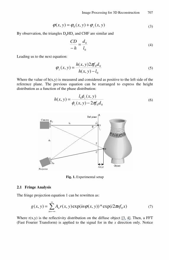
Image Processing for 3D Reconstruction 707
),(),(),( 0 yxyxyx zϕϕϕ += (3)
By observation, the triangles DpHDc and CHF are similar and
0
0
l
d
h
CD =−
(4)
Leading us to the next equation:
0
00
),(
2),(),(
lyxh
dfyxhyxz −
=πϕ (5)
Where the value of h(x,y) is measured and considered as positive to the left side of the reference plane. The previous equation can be rearranged to express the height distribution as a function of the phase distribution:
00
0
2),(
),(),(
dfyx
yxlyxh
z
z
πφφ
−= (6)
Fig. 1. Experimental setup
2.1 Fringe Analysis
The fringe projection equation 1 can be rewritten as:
∑∞
−∞=
=n
n xnfiyxinyxrAyxg )2exp(*)),(exp(),(),( 0πϕ (7)
Where r(x,y) is the reflectivity distribution on the diffuse object [3, 4]. Then, a FFT (Fast Fourier Transform) is applied to the signal for in the x direction only. Notice
708 J.C. Pedraza Ortega et al.
that even y is considered as fix, the same procedure will be applied for the number of y lines in both images. Therefore, we obtain the next equation:
∑∞
∞−
−= ),(),( 0 ynffQyfG n (8)
Now, we can observe that ϕ(x,y) and r(x,y) vary very slowly in comparison with the fringe spacing, then the Q peaks in the spectrum are separated each other. Also it is necessary to consider that if we choose a high spatial fringe pattern, the FFT will have a wider spacing among the frequencies. The next step is to remove all the signals with exception of the positive fundamental peak f0. The obtained filtered image is then shifted by f0 and centered. Later, the IFFT (Inverse Fast Fourier Transform) is applied in the x direction only, same as the FFT. The obtained equations for the reference and the object are given by:
))},(2(exp{),(),(ˆ 01 yxxfiyxrAyxg ϕπ += (9)
))},(2(exp{),(),(ˆ 00010 yxxfiyxrAyxg ϕπ += (10)
By multiplying the ĝ(x,y) with the conjugate of ĝ0(x,y), and separating the phase part of the result from the rest we obtain:
))},(ˆ),(ˆIm{log(
),(),(),(*0
0
yxgyxg
yxyxyxz
=
+= ϕϕϕ (11)
From the above equation, we can see that the phase map can be obtained by applying the same process for each horizontal line. The values of the phase map are wrapped at some specific values. Those phase values range between π and -π. Therefore, the next step is to apply some phase unwrapping algorithms. The whole methodology is described in figure 2.
The unwrapping consists of locating discontinuities of magnitude close to 2π, and then depending on the phase change we can add or take 2π according to the sign of the phase change. There are various methods for phase unwrapping, and the important thing to consider here is the abrupt phase changes in the neighbor pixels. There are a number of 2π phase jumps between 2 successive wrapped phase values, and this number must be determined. This number depends on the spatial frequency of the fringe pattern projected at the beginning of the process.
This step is the modified part in the Fourier Transform Profilometry originally proposed by Takeda [3], and represents the major contribution of this work. Another thing to consider is to carry out a smoothing before the doing the phase unwrapping, this procedure will help to reduce the error produced by the unwanted jump variations in the wrapped phase map. Some similar methods are described in [5].
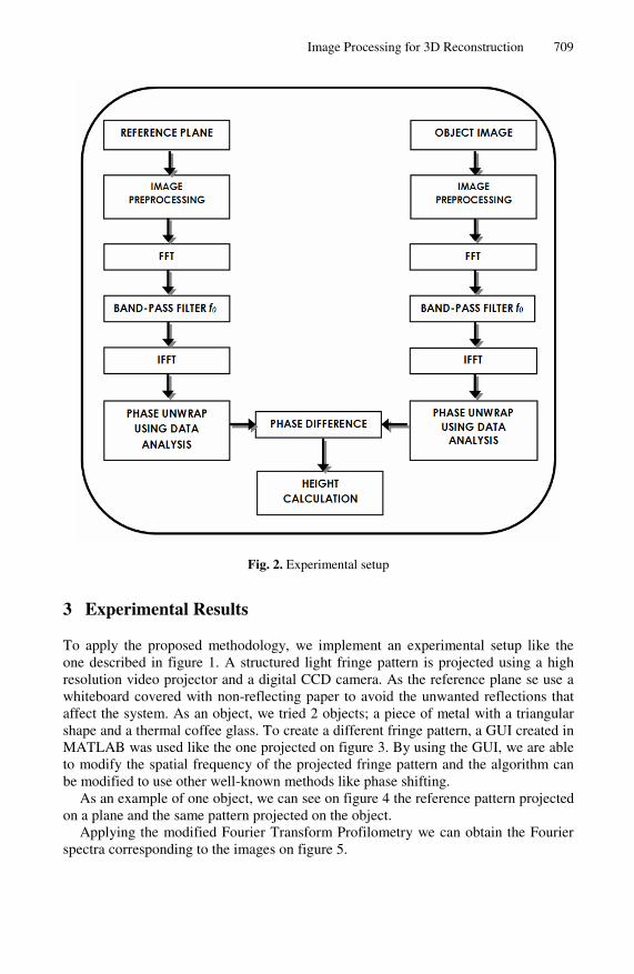
Image Processing for 3D Reconstruction 709
Fig. 2. Experimental setup
3 Experimental Results
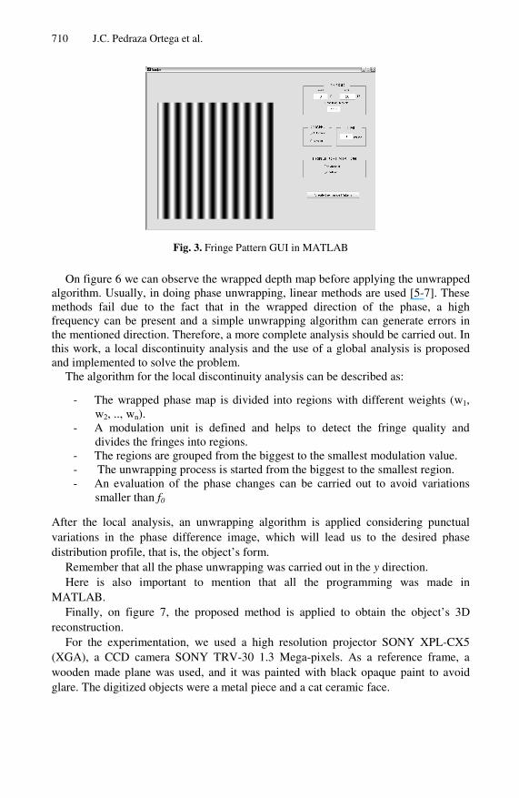
To apply the proposed methodology, we implement an experimental setup like the one described in figure 1. A structured light fringe pattern is projected using a high resolution video projector and a digital CCD camera. As the reference plane se use a whiteboard covered with non-reflecting paper to avoid the unwanted reflections that affect the system. As an object, we tried 2 objects; a piece of metal with a triangular shape and a thermal coffee glass. To create a different fringe pattern, a GUI created in MATLAB was used like the one projected on figure 3. By using the GUI, we are able to modify the spatial frequency of the projected fringe pattern and the algorithm can be modified to use other well-known methods like phase shifting.
As an example of one object, we can see on figure 4 the reference pattern projected on a plane and the same pattern projected on the object.
Applying the modified Fourier Transform Profilometry we can obtain the Fourier spectra corresponding to the images on figure 5.
710 J.C. Pedraza Ortega et al.
Fig. 3. Fringe Pattern GUI in MATLAB
On figure 6 we can observe the wrapped depth map before applying the unwrapped algorithm. Usually, in doing phase unwrapping, linear methods are used [5-7]. These methods fail due to the fact that in the wrapped direction of the phase, a high frequency can be present and a simple unwrapping algorithm can generate errors in the mentioned direction. Therefore, a more complete analysis should be carried out. In this work, a local discontinuity analysis and the use of a global analysis is proposed and implemented to solve the problem.
The algorithm for the local discontinuity analysis can be described as:
- The wrapped phase map is divided into regions with different weights (w1, w2, .., wn).
- A modulation unit is defined and helps to detect the fringe quality and divides the fringes into regions.
- The regions are grouped from the biggest to the smallest modulation value. - The unwrapping process is started from the biggest to the smallest region. - An evaluation of the phase changes can be carried out to avoid variations
smaller than f0
After the local analysis, an unwrapping algorithm is applied considering punctual variations in the phase difference image, which will lead us to the desired phase distribution profile, that is, the object’s form.
Remember that all the phase unwrapping was carried out in the y direction. Here is also important to mention that all the programming was made in
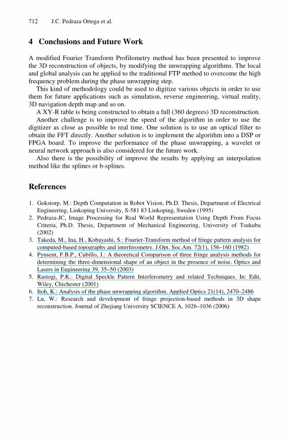
MATLAB. Finally, on figure 7, the proposed method is applied to obtain the object’s 3D
reconstruction. For the experimentation, we used a high resolution projector SONY XPL-CX5
(XGA), a CCD camera SONY TRV-30 1.3 Mega-pixels. As a reference frame, a wooden made plane was used, and it was painted with black opaque paint to avoid glare. The digitized objects were a metal piece and a cat ceramic face.
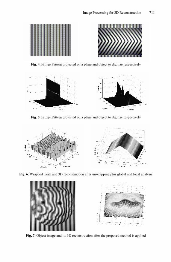
Image Processing for 3D Reconstruction 711
Fig. 4. Fringe Pattern projected on a plane and object to digitize respectively
Fig. 5. Fringe Pattern projected on a plane and object to digitize respectively
Fig. 6. Wrapped mesh and 3D reconstruction after unwrapping plus global and local analysis
Fig. 7. Object image and its 3D reconstruction after the proposed method is applied
712 J.C. Pedraza Ortega et al.
4 Conclusions and Future Work
A modified Fourier Transform Profilometry method has been presented to improve the 3D reconstruction of objects, by modifying the unwrapping algorithms. The local and global analysis can be applied to the traditional FTP method to overcome the high frequency problem during the phase unwrapping step.
This kind of methodology could be used to digitize various objects in order to use them for future applications such as simulation, reverse engineering, virtual reality, 3D navigation depth map and so on.
A XY-R table is being constructed to obtain a full (360 degrees) 3D reconstruction. Another challenge is to improve the speed of the algorithm in order to use the
digitizer as close as possible to real time. One solution is to use an optical filter to obtain the FFT directly. Another solution is to implement the algorithm into a DSP or FPGA board. To improve the performance of the phase unwrapping, a wavelet or neural network approach is also considered for the future work.
Also there is the possibility of improve the results by applying an interpolation method like the splines or b-splines.
References
1. Gokstorp, M.: Depth Computation in Robot Vision, Ph.D. Thesis, Department of Electrical Engineering, Linkoping University, S-581 83 Linkoping, Sweden (1995)
2. Pedraza-JC, Image Processing for Real World Representation Using Depth From Focus Criteria, Ph.D. Thesis, Department of Mechanical Engineering, University of Tsukuba (2002)
3. Takeda, M., Ina, H., Kobayashi, S.: Fourier-Transform method of fringe pattern analysis for computed-based topography and interferometry. J.Opt. Soc.Am. 72(1), 156–160 (1982)
4. Pynsent, F.B.P., Cubillo, J.: A theoretical Comparison of three fringe analysis methods for determining the three-dimensional shape of an object in the presence of noise. Optics and Lasers in Engineering 39, 35–50 (2003)
5. Rastogi, P.K.: Digital Speckle Pattern Interferometry and related Techniques. In: Edit, Wiley, Chichester (2001)
6. Itoh, K.: Analysis of the phase unwrapping algorithm. Applied Optics 21(14), 2470–2486 7. Lu, W.: Research and development of fringe projection-based methods in 3D shape
reconstruction. Journal of Zhejiang University SCIENCE A, 1026–1036 (2006)


