Embed Size (px)
Citation preview

Improvements on the thermal shock behaviour of MgO–spinel composite
refractories by incorporation of zircon–3 mol% Y2O3
Cemail Aksel *, Tuba Aksoy
Department of Materials Science and Engineering, Anadolu University, Iki Eylul Campus, Eskisehir 26470, Turkey
Received 20 August 2011; received in revised form 17 December 2011; accepted 4 January 2012
Available online 12 January 2012
Abstract
The effects of incorporations of zircon–3 mol% Y2O3 (Y) into MgO–spinel (M–S) compositions to improve mechanical properties and thermal
shock behaviour were investigated. Mechanical properties were measured, R � Rst parameters were calculated, and thermal shock tests were
performed. Microstructural features were examined using SEM and XRD. By adding zircon + Y to M–S: (i) up to �2 and �3-fold improvements
were achieved in mechanical properties and R � Rst parameters, (ii) there were improvements up to �2-fold in strength data measured after
performing thermal shock tests at 1000 8C. Parameters improving mechanical properties and thermal shock behaviour of M–S–(zircon + Y)
materials are given as follows: (i) interlinking and arresting or deviation of microcracks when reaching the ZrO2–Y2O3 grains or pores, increases in
(ii) KIc, (iii) critical defect size and (iv) bulk density, (v) formation of forsterite phase, (vi) coexistence of intergranular and transgranular fractures,
and (vii) reduction in MgO grain size, leading to longer service life.
# 2012 Elsevier Ltd and Techna Group S.r.l. All rights reserved.
Keywords: C. Thermal shock resistance; D. MgAl2O4; ZrSiO4; Y2O3
www.elsevier.com/locate/ceramint
Available online at www.sciencedirect.com
Ceramics International 38 (2012) 3673–3681
1. Introduction
Magnesium aluminate spinel (MgAl2O4) is an important
constituent of magnesium oxide (MgO) based refractory
materials. The most important factor in MgO–spinel (M–S)
refractories’ being used prevalently among the other MgO
and dolomite originated refractory materials is their much
higher resistance to thermal shocks and alkali attacks [1]. In
MgO–chrome refractories, concerns on allergy, ulcer and
carcinogen effects on skin of the toxic Cr6+ ions derived from
CrO3 have led to the need for use of no-chromium containing
alternative MgO–spinel refractories [2]. MgO–spinel refrac-
tories have service lives �1.5–2 times longer than MgO–
chrome refractories [3]. MgO–spinel bricks are preferred in the
cooling and transition zones where thermal stresses occur due
to high temperature difference and therefore severe thermal
shocks taking place during cooling and heating in cement rotary
kilns [4]. In addition, their use in the sintering zone that requires
adequate strength at high temperature affords economic
* Corresponding author. Tel.: +90 222 3350580x6362; fax: +90 222 3239501.
E-mail address: [email protected] (C. Aksel).
0272-8842/$36.00 # 2012 Elsevier Ltd and Techna Group S.r.l. All rights reserve
doi:10.1016/j.ceramint.2012.01.009
benefits [4]. Furthermore, the side walls and bottom of steel
teeming ladles and the checker work of glass tank furnace
regenerators are also other major application areas of spinel
refractories [4,5]. The stoichiometric type is similarly used
in cement kiln linings, as well as an alumina based castable in
ladles, which can also have high resistance to corrosion, erosion
and abrasion caused by calcium–aluminium–silicate containing
compounds [3]. MgO–spinel refractories are preferred as
they show high thermal shock resistance, high resistance
against basic slag and alkali attacks, including molten metal
abrasions [1].
It is reported [1,4–9] that the addition of spinel to MgO
markedly improves hot modulus of rupture, the retained
strength after thermal shock, refractoriness under load, and also
incorporation of additives such as Y2O3 into MgO–spinel
significantly develops densification and hot strength character-
istics of MgO–spinel composite refractory materials. While
service life of MgO–spinel refractories is prolonged especially
in connection with the rise in work of fracture energy when
spinel particles are added to MgO, a reduction occurs in other
mechanical properties [10–12]. This study has been conducted
for improving the mechanical and thermal shock performances
of materials further and prolonging service life further by
d.

C. Aksel, T. Aksoy / Ceramics International 38 (2012) 3673–36813674
obtaining high thermo-mechanical properties due to the
increase especially in resistance to fracture by additions of
zircon and Y2O3 in different proportions to various MgO–spinel
compositions. The relationships between the mechanisms
causing improvements in the mechanical–thermal shock
behaviours of composite refractories and microstructural
changes and parameters affecting these were examined and
explained citing reasons.
2. Materials and methods
Recipes were prepared by incorporating 5, 10, 20 and 30%
zircon (ZrSiO4) by weight and 3 mol% Y2O3 (Y) correlated
with ZrO2 content in zircon into MgO (M) based compositions
containing 5, 10, 20 and 30% MgAl2O4 spinel (S) by weight
(Table 1). The amounts of 3 mol% Y2O3 equivalent to ZrO2
proportion in zircon were calculated for each composition,
where those quantities of Y2O3 were subsequently converted to
weight percentages, and given in Table 1. Batches using MgO
(0–1 mm, 95.7% purity, Konya Selcuklu Krom Magnezit Tugla
Sanayi A.S., Turkey), spinel (0–1 mm, 64.1% Al2O3 and 34.1%
MgO, Konya Selcuklu Krom Magnezit Tugla Sanayi A.S.,
Turkey), zircon (�13 mm, 64.0% ZrO2 and 32.5% SiO2,
Colorobbia, Turkey) and Y2O3 (�4 mm, 99.9% purity, Color-
obbia, Turkey) were prepared. After incorporating 1.5%
MgSO4 and 1% totanin by weight as binder solutions into
each batch, they were mixed in a mixer (IKA, Labortechnik)
for �5 min with a speed of 7000 rpm. Those batches were
shaped into samples of �8 mm � 8 mm � 60 mm under a
Table 1
Compositions prepared for mechanical and thermal shock tests in which
weights of MgO (0–1 mm), spinel (0–1 mm), ZrSiO4 (�13 mm) and 3 mol%
Y2O3 (�4 mm) correlated with ZrO2 content in ZrSiO4 were used.
Compositions MgO
(M) (%)
Spinel
(S) (%)
ZrSiO4
(zircon) (%)
Y2O3a
(Y) (%)
M 100.00 – – –
M–5%S 95.00 5 – –
M–10%S 90.00 10 – –
M–20%S 80.00 20 – –
M–30%S 70.00 30 – –
M–5%S–5%(zircon + Y) 89.83 5 5 0.17
M–5%S–10%(zircon + Y) 84.66 5 10 0.34
M–5%S–20%(zircon + Y) 74.31 5 20 0.69
M–5%S–30%(zircon + Y) 63.97 5 30 1.03
M–10%S–5%(zircon + Y) 84.83 10 5 0.17
M–10%S–10%(zircon + Y) 79.66 10 10 0.34
M–10%S–20%(zircon + Y) 69.31 10 20 0.69
M–10%S–30%(zircon + Y) 58.97 10 30 1.03
M–20%S–5%(zircon + Y) 74.83 20 5 0.17
M–20%S–10%(zircon + Y) 69.66 20 10 0.34
M–20%S–20%(zircon + Y) 59.31 20 20 0.69
M–20%S–30%(zircon + Y) 48.97 20 30 1.03
M–30%S–5%(zircon + Y) 64.83 30 5 0.17
M–30%S–10%(zircon + Y) 59.66 30 10 0.34
M–30%S–20%(zircon + Y) 49.31 30 20 0.69
M–30%S–30%(zircon + Y) 38.97 30 30 1.03
a The amounts of 3 mol% Y2O3 equivalent to ZrO2 proportion in zircon were
calculated for each composition and afterwards those quantities of Y2O3 (Y)
were converted to weight percentages.
pressure of �100 MPa. The samples were sintered for 2 h in a
kiln (Nabertherm HT16/18) at 1600 8C using heating and
cooling rates of 5 8C/min. Bulk density (r) and apparent
porosity values of 3 specimens from each composition were
measured using the standard water immersion method and
average values were taken [13]. After samples were ground
using 800 and 1200 grade SiC papers until smooth surfaces
were obtained based on the standard sample preparation rules
[11,14], the samples were dried at �110 8C in an oven and
mechanical tests were carried out. The mechanical tests
performed using a load cell of 2 kN moving at a velocity of
0.5 mm/min with a support roller span (L) of 40 mm were
applied to minimum 5–6 samples and average values were
taken. Under standard tests; values of strength [14] (s),
modulus of elasticity [15] {E = L3m/(4WD3)}, fracture tough-
ness [16–19] {KIc = (3/2)(PLc1/2Y)/(WD2)}, fracture surface
energy, gS [20], {KIc = (2EgS)1/2} and work of fracture energy
[21] {gWOF = U/[2W(D � c)]} were determined by the 3-point
bending method in Instron 5581. The parameters used in the
equations given above are as follows [14–21]: m is slope of the
tangent of the initial straight-line portion of the load–deflection
curve, W is the specimen width, D is the specimen thickness,
P is the load at failure, c is the notch depth, and Y is a
dimensionless constant depending on the geometry of loading
and crack configuration, where {Y = A0 + A1(c/D) + A2(c/
D)2 + A3(c/D)3 + A4(c/D)4}, for L/D �8, A0 = 1.96, A1 =
�2.75, A2 = 13.66, A3 = �23.98, A4 = 25.22 [16,19]. Work of
fracture is usually interpreted as the work done in propagating a
crack to break a notched specimen, divided by twice the
fracture surface areas (since two new faces are created). gWOF is
the amount of energy required to propagate a crack completely
through a specimen, which is calculated by determining the
area remaining under the load–deflection curve (U) [21]. The
magnitude of critical defect size (C) value was calculated using
Griffith equation [20,22], where combining KIc data with those
of strength allowed an estimate to be made of the critical defect
size [10,11]. E values were calculated using the steepest slope
in the initial linear portion of the stress–strain curve, where the
correction for machine stiffness was also considered. KIc, gS
and gWOF measurements were performed using Single Edge
Notched Beam (SENB) method [16–21] at a depth of �25% of
thickness of the material using a 700 mm thick diamond disk on
specimens. Notch depth was measured using an Olympus
BX60M brand optical microscope. X-ray diffraction (XRD)
analysis was performed using Rigaku RINT2000 equipment.
The polishing of specimens for scanning electron microscope
(SEM) examination was carried out for �3.5 min using a 1 mm
diamond spray at the final stage and samples were thermally
etched at 1450 8C for 10 min to reveal grain boundaries in the
microstructure. SEM studies were carried out on Zeiss Evo 50
and JSM-5910LV devices analyzing microstructures and
fracture surfaces of materials. The mean MgO grain size
was calculated by a standard line mean intercept method [23],
using 3 SEM pictures taken on the polished and thermally
etched surface of the specimen. Hasselman parameters, which
determine the fracture resistance of materials due to thermal
stress/shock and used in estimation of maximum thermal

Table 2
Strength (s), modulus of elasticity (E), fracture surface energy (gS) and critical defect size (C) values of MgO, M–S and M–S–(zircon + Y) composite refractories
containing varied amounts of additives.
Compositions s (MPa) E (GPa) gS (J/m2) C (mm)
M 48.5 � 5.5 35.1 � 2.4 32.8 � 3.7 310.5
M–5%S 21.9 � 4.2 20.4 � 4.9 22.9 � 3.3 617.1
M–10%S 14.8 � 1.0 14.7 � 1.3 14.5 � 2.3 611.8
M–20%S 11.4 � 0.4 8.2 � 0.9 17.4 � 2.0 698.9
M–30%S 11.3 � 0.5 7.9 � 0.9 16.4 � 2.6 638.4
M–5%S–5%(zircon + Y) 15.6 � 3.1 15.9 � 2.2 27.0 � 6.5 1109.8
M–5%S–10%(zircon + Y) 23.2 � 3.1 19.8 � 2.0 21.2 � 3.8 491.5
M–5%S–20%(zircon + Y) 20.4 � 3.7 18.0 � 2.6 25.1 � 6.8 678.2
M–5%S–30%(zircon + Y) 23.5 � 3.8 18.4 � 2.6 28.6 � 8.5 593.3
M–10%S–5%(zircon + Y) 11.4 � 0.3 11.4 � 1.5 14.3 � 2.2 793.7
M–10%S–10%(zircon + Y) 15.0 � 2.1 12.1 � 0.7 21.4 � 3.5 729.3
M–10%S–20%(zircon + Y) 17.0 � 2.0 14.9 � 1.7 18.8 � 5.1 603.4
M–10%S–30%(zircon + Y) 21.6 � 1.8 18.3 � 1.4 26.3 � 4.2 653.3
M–20%S–5%(zircon + Y) 12.3 � 0.4 9.2 � 1.0 16.9 � 3.0 656.1
M–20%S–10%(zircon + Y) 14.9 � 1.0 10.6 � 0.9 15.4 � 3.6 463.8
M–20%S–20%(zircon + Y) 17.2 � 2.3 11.9 � 1.9 18.0 � 5.3 453.0
M–20%S–30%(zircon + Y) 19.9 � 2.9 15.4 � 0.7 22.9 � 4.1 569.0
M–30%S–5%(zircon + Y) 15.1 � 1.0 11.6 � 1.2 17.6 � 3.4 565.2
M–30%S–10%(zircon + Y) 16.9 � 1.1 12.9 � 1.0 20.9 � 4.8 593.1
M–30%S–20%(zircon + Y) 21.3 � 4.0 15.2 � 2.9 39.0 � 7.7 829.9
M–30%S–30%(zircon + Y) 32.5 � 1.9 21.4 � 0.2 33.2 � 3.1 428.8
Fig. 1. Fracture toughness (KIc) as a function of additives {additives: (i)
MgAl2O4 for M–S, and (ii) ZrSiO4 + Y2O3 for M–S–(zircon + Y)}.
C. Aksel, T. Aksoy / Ceramics International 38 (2012) 3673–3681 3675
resistance, were calculated by following formulas [24]:
{R = [s(1 � n)]/(Ea)} and {Rst = [gS/(a2E)]1/2}, where n is
the mean value of Poisson’s ratio and a is the mean thermal
expansion coefficient of the composite refractory. Thermal
shock tests were performed by sudden cooling in water from
500 and 1000 8C to 25 8C room temperature with strength
values determined in connection with thermal shock
temperatures.
3. Results and discussion
Mechanical tests data of composite refractories produced by
incorporating varied amounts of ZrSiO4 + 3 mol% Y2O3
(zircon + Y) into MgO–spinel (M–S) materials containing
varied ratios of spinel (MgAl2O4) are given below. The
additives used in figures and tables show: (i) MgAl2O4 for M–S,
and (ii) ZrSiO4 + Y2O3 for M–S–(zircon + Y) materials.
As seen in Table 2, it was observed that as the amount
of additives (i.e. both zircon and Y2O3) was increased, there
was generally a marked enhancement in the strength (s) and
modulus of elasticity (E) values of M–S–(zircon + Y) composite
refractories compared to M–S materials. This development was
significant especially with incorporation of �10% zircon + Y
additives into M–S for s and E values, where both of them
reached to maximum level on M–30%S–30%(zircon + Y)
composition. A 2.9-fold increase in s data and 2.7-fold rise in
E values were achieved with the addition of 30%(zircon + Y) to
M–30%S (Table 2).
The fracture toughness (KIc) data of composite refractories
obtained by adding varied ratios of �10%(zircon + Y) to M–S
compositions were in general higher than those of M–S
materials (Fig. 1). It was observed that KIc values of all
composites containing 30% zircon + Y additives were close to
each other. For instance; in KIc values obtained as a result of
incorporation of 20% and 30% zircon + Y into M–30%S,
improvements of 2.1-fold and 2.2-fold were attained respec-
tively in comparison with M–30%S (Fig. 1). As shown in Table
1, fracture surface energy (gS) values of M–S–(zircon + Y)
composite refractories were generally higher than the gS values
of M–S materials, especially when �10%(zircon + Y) is
incorporated into M–S compositions. In the gS values obtained
by incorporating 20% and 30% zircon + Y into M–30%S–
(zircon + Y) composition, 2.4-fold and 2.0-fold improvements
were observed respectively compared to M–30%S material,
where gS values were consistent with KIc data (Table 2 and
Fig. 1).
When the critical defect size (C) values were examined in
Table 2, a marked rise was observed in the C values of all M–S
and M–S–(zircon + Y) compositions into which additives were
incorporated, compared to the additive free MgO. In general,
the majority of M–S–(zircon + Y) compositions had lower

C. Aksel, T. Aksoy / Ceramics International 38 (2012) 3673–36813676
C values than those of M–S composites; however, some parts of
them were found to be equivalent to or predominantly much
higher than the critical defect size of M–S materials. This
increase in C data was associated with the improvement in KIc
values, showing a high resistance to fracture.
Work of fracture energy (gWOF) values were calculated
for different compositions selected as follows: (i) MgO =
27.4 � 3.1 J/m2, (ii) M–5%S = 63.9 � 15.2 J/m2, (iii) M–5%S–
5%(zircon + Y) = 65.2 � 13.6 J/m2, (iv) M–30%S = 67.6 �6.7 J/m2, (v) M–30%S–10%(zircon + Y) = 66.3 � 4.6 J/m2 and
(vi) M–30%S–30%(zircon + Y) = 60.6 � 8.9 J/m2. The gWOF
values of M–S and M–S–(zircon + Y) composite refractories
were quite close to each other. It was determined that the
incorporations of varied amounts of both (i) spinel into M–S and
(ii) zircon + YintoM–S–(zircon + Y)compositions improved the
gWOF data reaching up to �2.5-fold ratios in comparison with
additive free MgO.
Fig. 2 illustrates that bulk density (r) values increased
markedly with the increasing quantity of zircon + Y additives.
The mean bulk density values measured for M and
M–S composite refractories were �2.8 g/cm3, rising up to
�3.3 g/cm3 with increased amounts of added zircon + Y. In
M–S–(zircon + Y) compositions; the replacement of heavier
constituents such as zircon (rZircon: 4.56 g/cm3) and Y2O3
(rY2O3: 5.046 g/cm3), which had higher densities [25,26] in
comparison with M–S (rM–S: 3.58 g/cm3), caused an enhance-
ment in bulk density values leading to a decrease in apparent
porosity data. In addition, the apparent porosity data was
measured to be as �21% in M and M–S materials, showing a
downward trend reaching �12% with the rise in the amount of
zircon + Y incorporated into M–S compositions.
As microstructure and the distribution of elements were
examined for M–30%S–30%(zircon + Y) composite refractory,
which was chosen as an exemplar sample displaying marked
improvements on mechanical properties, it was observed that
MgO and SiO2 distributions were generally located in the
similar regions, indicating the formation of forsterite
(Mg2SiO4) phase (Fig. 3). X-ray diffraction (XRD) analysis
results for M–30%S–30%(zircon + Y) composition showed
that forsterite (2MgO.SiO2) and cubic zirconia phases were
Fig. 2. Bulk density (r) as a function of additives {additives: (i) MgAl2O4 for
M–S, and (ii) ZrSiO4 + Y2O3 for M–S–(zircon + Y)}.
identified besides MgO and spinel phases (Fig. 4). A stronger
bond is formed between the additives and the grains of main
constituent as a consequence of the formation of forsterite
phase due to the reaction between SiO2, which is released after
dissociation of zircon as ZrO2 and SiO2 during sintering, and
the main phase MgO. It was determined that sintering was more
effective with the formation of the new phase. This is also
consistent with the enhancement in bulk density values and the
drop in the amount of apparent porosity data occurring as a
result of the increase in the quantity of zircon + Yadded to M–S
compositions.
Microstructural observations in Figs. 3 and 5 demonstrate that
the white coloured ZrO2 grains, which were released after the
dissociation of zircon during sintering, were found in the same
regions with white coloured Y2O3 particles, where they were
located mainly at the surrounding of dark gray coloured MgO
grains. After sintering M–S–(zircon + Y) containing materials,
large tensile stresses occurred around the additives during cooling
as a result of the significant difference between the thermal
expansion coefficients (a) [25–27] of MgO, spinel, zircon and
Y2O3 (aMgO = 13.6 � 10�6 8C�1, aSpinel = 8.4 � 10�6 8C�1,
aZircon = 4.6 � 10�6 8C�1, aY2O3¼ 60:3 � 10�6 �C�1) and
such stresses resulted in formation of interlinked microcracks
[10–12,28]. It was observed that these microcracks were
interlinked to each other and arrested or deviated by propagating
for a short distance when reaching the ZrO2 grains located
together with Y2O3 or the pores (Figs. 3 and 5). In addition,
the mean MgO grain size was calculated for different
compositions selected as follows: (i) additive free MgO =
67.2 mm, (ii) M–30%S = 31.2 mm and (iii) M–30%S–30%
(zircon + Y) = 23.8 mm. There was a marked reduction in
MgO grain size with an enhancement in the quantity of all
additives (i.e. spinel and zircon + Y) in comparison with additive
free MgO, where the decreases in mean MgO grain size of MgO
material by adding additives were determined to be �2.2-fold
for M–30%S and �2.8-fold for M–30%S–30%(zircon + Y)
compositions.
The fracture surface images of the composite refractory
materials having compositions of M–30%S and M–30%S–
30%(zircon + Y) are given in Fig. 6. It is known from the
previous research that there are mainly transgranular cracks on
the fracture surface of MgO [10–12,28]. However, when the
spinel particles were added to MgO, fracture type turned
predominantly into intergranular cracks in M–S materials
(Fig. 6a) [10–12,28]. As zircon + Y were added to M–S on the
other hand, it was observed that the intergranular and
transgranular types of cracks occurred concurrently (Fig. 6b).
Fig. 7 illustrates schematic diagrams of load–deflection
curves of additive free MgO and M–30%S–30%(zircon + Y)
composite refractory materials. For additive free MgO, there
were predominantly transgranular cracks and thus catastrophic
failure occurred during fracture (Fig. 7a). However, the fracture
path of M–S–(zircon + Y) materials showed a stable behaviour
(Fig. 7b). This is due to the coexistence of both intergranular
and transgranular cracks on the fracture surface (Fig. 6b), where
these types of cracks were observed to propagate around the
smaller grains. Therefore, it appears that higher values of
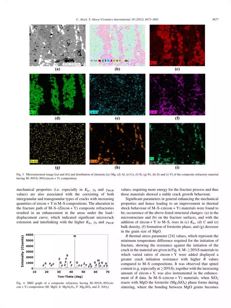
Fig. 3. Microstructural image [(a) and (b)] and distribution of elements [(c) Mg, (d) Al, (e) Ca, (f) Si, (g) Fe, (h) Zr and (i) Y] of the composite refractory material
having M–30%S–30%(zircon + Y) composition.
C. Aksel, T. Aksoy / Ceramics International 38 (2012) 3673–3681 3677
mechanical properties (i.e. especially in KIc, gS and gWOF
values) are also associated with the coexisting of both
intergranular and transgranular types of cracks with increasing
quantities of zircon + Y in M–S compositions. The alteration in
the fracture path of M–S–(Zircon + Y) composite refractories
resulted in an enhancement in the areas under the load–
displacement curve, which indicated significant microcrack
extension and interlinking with the higher KIc, gS and gWOF
Fig. 4. XRD graph of a composite refractory having M–30%S–30%(zir-
con + Y) composition (M: MgO, S: MgAl2O4, F: Mg2SiO4 and Z: ZrO2).
values, requiring more energy for the fracture process and thus
those materials showed a stable crack growth behaviour.
Significant parameters in general enhancing the mechanical
properties and hence leading to an improvement in thermal
shock behaviour of M–S–(zircon + Y) materials were found to
be; occurrence of the above-listed structural changes: (a) in the
microstructure and (b) on the fracture surfaces, and with the
addition of zircon + Y to M–S, rises in (c) KIc, (d) C and (e)
bulk density, (f) formation of forsterite phase, and (g) decrease
in the grain size of MgO.
R thermal stress parameter [24] values, which represent the
minimum temperature difference required for the initiation of
fracture, showing the resistance against the initiation of the
crack in the material are given in Fig. 8. M–�20%S materials to
which varied ratios of zircon + Y were added displayed a
greater crack initiation resistance with higher R values
compared to M–S compositions. It was observed that spinel
content (e.g. especially at �20%S), together with the increasing
amount of zircon + Y, was also instrumental in the enhance-
ment of R data. In M–S–(zircon + Y) materials; when SiO2
reacts with MgO the forsterite (Mg2SiO4) phase forms during
sintering, where the bonding between MgO grains becomes

Fig. 5. Microstructural image of a material with composition of M–30%S–30%(zircon + Y) {dark gray: MgO (M), light gray: MgAl2O4 (S) and Mg2SiO4 (F), and
white zones: ZrO2 (Z) and Y2O3 (Y)}.
C. Aksel, T. Aksoy / Ceramics International 38 (2012) 3673–36813678
stronger and in association with it, the crack initiation
resistance enhances. In general; R values of M–S–(zircon + Y)
compositions were higher than those of M–S materials, and
reached to a maximum level in M–30%S–30%(zircon + Y)
composition. When M–30%S–30%(zircon + Y) material
was compared to M–S compositions having minimum and
maximum R values, which are (i) M–10%S and (ii) M–30%S,
it was determined that higher resistance could be achieved
against initiation of the crack at ratios reaching (i) 1.9-fold
and (ii) 1.2-fold, respectively.
The Rst parameter represents the maximum temperature
difference allowed required for propagation of long cracks
under severe thermal stress conditions and is used in estimating
the further weakening of the composite refractory and crack
Fig. 6. Fracture surface images of materials with compositio
stability with the increase in the severity of thermal shock [24].
Fig. 9 shows that the highest Rst parameter values were firstly
attained in M–30%S–20%(zircon + Y) and afterwards in
M–30%S–30%(zircon + Y) compositions in comparison with
M and M–S materials. As M–30%S–20%(zircon + Y) material
was compared to (i) M–10%S and (ii) M–30%S, where these
M–S compositions had minimum and maximum Rst values, it
was determined that higher resistance to thermal shocks could
be achieved in ratios reaching (i) 2.0-fold and ii) 1.2-fold,
respectively. In addition, it was also found that the Rst value of
M–30%S–30%(zircon + Y) material was slightly higher than
that of M–30%S, which had maximum Rst data in M–S
compositions, and there was a marked improvement reaching
1.6-fold in the Rst data of M–30%S–30%(zircon + Y) compared
ns of (a) M–30%S and (b) M–30%S–30%(zircon + Y).

Fig. 7. Load–deflection curves for centred notched, 3-point bending specimens: (a) MgO (catastrophic), and (b) M–30%S–30%(zircon + Y) (stable).
C. Aksel, T. Aksoy / Ceramics International 38 (2012) 3673–3681 3679
to M–10%S having minimum Rst value among the M–S
composite refractories.
It was determined that R and Rst parameters were generally
in accord with each other, and the incorporations of zircon–
Y2O3 into M–S compositions improved both crack initiation
resistance and crack stability preventing the further weakening
of composite refractory materials under severe thermal
conditions. The R and Rst parameter values showed that
M–30%S–30%(zircon + Y) and M–30%S–20%(zircon + Y)
composite refractories displayed higher thermal stress resis-
tance and thermal shock damage resistance compared to M and
M–S materials that also illustrate consistency with the
determined mechanical properties.
Strength (s) values measured after thermal shock tests,
which were performed for M, M–S and M–S–(zircon + Y)
materials, were determined as a function of thermal shock
temperature (Fig. 10). The s values displayed a periodical
decrease with increasing thermal shock temperature. There was
also a sharp drop in the s values of MgO with increasing
thermal shock temperatures, which were measured to be as
48.5 � 5.5 MPa at 25 8C, 10.8 � 0.7 MPa at 500 8C and
6.1 � 0.4 MPa at 1000 8C. At 500 8C and 1000 8C thermal
shock temperatures, M–S–(zircon + Y) composite refractories,
when compared to M and M–S materials, have s data that are
close to each other in some compositions; however, have
significantly higher s values in certain other compositions. In
general, thermal shock test results indicate a similar trend with
the data of R and Rst parameters and verify the R and Rst values.
25
50
75
100
125
302520151050
Additives (%)
R (
K)
M-SM-5S-(Zircon+Y)M-10S-(Zircon+Y)M-20S-(Zircon+Y)M-30S-(Zircon+Y)
Fig. 8. R parameter as a function of additives {additives: (i) MgAl2O4 for M–S,
and (ii) ZrSiO4 + Y2O3 for M–S–(zircon + Y)}.
Therefore, the R and Rst thermal stress/shock parameters were
determined to be reliable indicators, which might be used in
determining the thermal behaviour of composite refractories. In
addition, the increases in KIc indicating a high resistance to
fracture and C, which led to development of crack propagation
resistance, were also found to be basic factors in the
improvement of thermal shock resistance, and the results
obtained were consistent with the thermal shock data.
The quantity and lengths of pre-formed microcracks occurred
due to the a differences of constituents and newly formed
microcracks after application of thermal shock were smaller
and limited in M–S–(zircon + Y) materials. The microstructural
variations and features stated above were associated with the
improvement occurring in the mechanical and thermal shock
behaviours of zircon + Y added M–S materials.
The material with the highest strength value, undergoing
thermal shock tests at 500 8C and 1000 8C, produced by adding
varied proportions of zircon + Y to M–S composite refractories
was found to be M–30%S–30%(zircon + Y). For example, in
the thermal shock tests performed at 1000 8C, M–30%S–
30%(zircon + Y) composition has respectively (i) 2.0-fold, (ii)
1.9-fold and (ii) 1.7-fold higher strength values when compared
to (i) MgO, (ii) M–10%S and (iii) M–30%S, in which M–10%S
has demonstrated the lowest thermal shock resistance among
M–S materials. This improvement is consistent with the low
loss of strength at high temperatures, high thermal shock
damage resistance and consequently longer service lives of
M–S–(zircon + Y) composite refractories for industrial uses.
1
2
3
4
5
302520151050
Additives (%)
Rst
(K
.m1/2
)
M-S
M-5S-(Zircon+Y)
M-10S-(Zircon+Y)
M-20S-(Zircon+Y)
M-30S-(Zircon+Y)
Fig. 9. Rst parameter as a function of additives {additives: (i) MgAl2O4 for
M–S, and (ii) ZrSiO4 + Y2O3 for M–S–(zircon + Y)}.

0
4
8
12
16
20
24
28
32
36
10005000
ΔT (°C)
σ (
MP
a)
M-5SM-10SM-20SM-30SM-5S-5(Zircon+Y)M-5S-10(Zircon+Y)M-5S-20(Zircon+Y)M-5S-30(Zircon+Y)M-10S-5(Zircon+Y)M-10S-10(Zircon+Y)M-10S-20(Zircon+Y)M-10S-30(Zircon+Y)M-20S-5(Zircon+Y)M-20S-10(Zircon+Y)M-20S-20(Zircon+Y)M-20S-30(Zircon+Y)M-30S-5(Zircon+Y)M-30S-10(Zircon+Y)M-30S-20(Zircon+Y)M-30S-30(Zircon+Y)
Fig. 10. Strength (s) values of M–S and M–S–(zircon + Y) composite refrac-
tories containing varied amounts of additives as a function of thermal shock
temperatures {additives: (i) MgAl2O4 for M–S, and (ii) ZrSiO4 + Y2O3 for
M–S–(zircon + Y)}.
C. Aksel, T. Aksoy / Ceramics International 38 (2012) 3673–36813680
4. Conclusions
With the addition of 30%(zircon + Y) to M–30%S,
improvements of up to �2 and �3-fold ratios were achieved
in mechanical properties. The R and Rst parameters showed that
M–30%S–30%(zircon + Y) materials had ratios reaching
respectively up to �1.9 and �1.6-fold higher thermal stress
and shock resistance in comparison with M–S composite
refractories. In M–S–(zircon + Y) materials; when SiO2, which
is released due to decomposition of zircon as ZrO2 and SiO2,
reacts with MgO, the bonding between MgO grains becomes
stronger as a result of the formation of the forsterite (Mg2SiO4)
phase, and consequently the crack initiation resistance is
enhanced. In addition; the rises in KIc and C, which led to
development of crack propagation resistance, were also found
to be effective factors to improve the thermal shock resistance
of the composite refractory materials. It was determined based
on the thermal shock tests performed at 1000 8C that M–30%S–
30%(zircon + Y) composition had (i) 2.0-fold, (ii) 1.9-fold and
(iii) 1.7-fold higher strength values in comparison respectively
with (i) MgO, (ii) M–10%S and (iii) M–30%S materials, where
M–10%S displayed the lowest thermal shock resistance among
M–S composite refractories. Thermal shock results confirmed
the R and Rst values, and thus R and Rst parameters were found
to be reliable indicators for determining the thermal behaviour
of composite refractory materials.
The basic parameters improving mechanical properties and
thermal shock behaviour of M–S–(zircon + Y) composite
refractories were determined as follows: (i) interlinking and
arresting or deviation of microcracks when reaching the ZrO2–
Y2O3 grains or pores, rises in (ii) fracture toughness and (iii)
critical defect size, (iv) increase in bulk density (e.g. decrease in
apparent porosity), (v) formation of forsterite phase, (vi)
coexistence of intergranular and transgranular cracks, and (vii)
decrease in MgO grain size, leading to low loss of strength, high
thermal shock damage resistance and longer service life for
industrial applications.
Acknowledgements
This study was partly supported by Anadolu University and
in part TUBITAK under project no: 106M394 with partial
support provided also by Konya Selcuklu Krom Magnezit
Tugla Sanayi A.S. We would like to express our gratitude to
A. Ozkaymak, R. Ozbasi, O. Bezirci, M. Ilhan and all agency
employees and personnel involved in this project for their
support. We also thank the agencies and plant authorities for the
supplied equipments and raw materials.
References
[1] G.R. Eusner, D.H. Hubble, Technology of spinel bonded periclase brick,
J. Am. Ceram. Soc. 43 (1960) 292–296.
[2] D.J. Bray, Toxicity of chromium compounds formed in refractories, Bull.
Am. Ceram. Soc. 64 (1985) 1012–1016.
[3] K. Tokunaga, H. Kozuka, T. Honda, F. Tanemura, Further improvements
in high temperature strength, coating adherence, and corrosion resistance
of magnesia–spinel bricks for rotary cement kiln, in: Proc UNITECR’91
Congress, Aachen, Germany, (1991), pp. 431–435.
[4] R.D. Maschio, B. Fabbri, C. Fiori, Industrial applications of refractories
containing magnesium aluminate spinel, Ind. Ceram. 8 (1988) 121–126.
[5] A. Ghosh, R. Sarkar, B. Mukherjee, S.K. Das, Effect of spinel content on
the properties of magnesia–spinel composite refractory, J. Eur. Ceram.
Soc. 24 (2004) 2079–2085.
[6] P. Bartha, Magnesia spinel bricks–properties, production and use, in: X.
Zhong, et al. (Eds.), Proc. Int. Symp. Refractories, Refractory Raw
Materials and High Performance Refractory Products, Pergamon, Hang-
zhou, 1989, pp. 661–674.
[7] C. Aksel, B. Rand, F.L. Riley, P.D. Warren, Thermal shock behaviour of
magnesia–spinel composites, J. Eur. Ceram. Soc. 24 (2004) 2839–2845.
[8] R. Sarkar, S.K. Das, G. Banerjee, Effect of additives on the densification
of reaction sintered and presynthesised spinels, Ceram. Int. 29 (2003)
55–59.
[9] R. Sarkar, H.S. Tripathi, A. Ghosh, Reaction sintering of different spinel
compositions in the presence of Y2O3, Mater. Lett. 58 (2004) 2186–2191.
[10] C. Aksel, F.L. Riley, Magnesia-spinel (MgAl2O4) refractory ceramic
composites, in: I.M. Low (Ed.), Ceramic Matrix Composites: Microstruc-
ture, Properties and Applications, Woodhead Publishing Limited and CRC
Press LLC, USA, 2006, pp. 359–399.
[11] C. Aksel, B. Rand, F.L. Riley, P.D. Warren, Mechanical properties of
magnesia–spinel composites, J. Eur. Ceram. Soc. 22 (2002) 745–754.
[12] C. Aksel, P.D. Warren, Work of fracture and fracture surface energy
of magnesia–spinel composites, Compos. Sci. Technol. 63 (2003)
1433–1440.
[13] BS 7134, Methods for determination of density and porosity, in: British
Standard Testing of Engineering Ceramics, Part 1, Section 1.2, 1989.
[14] ASTM C1161-90, Standard test method for flexural strength of advanced
ceramics at ambient temperature, Annual Book of ASTM Standards, vol.
15.01, ASTM, 1991, pp. 327–333.
[15] ASTM D790M-86, Standard test methods for flexural properties of
unreinforced and reinforced plastics and electrical insulating materials,
Annual book of ASTM Standards, vol. 08.01, ASTM, 1988, pp. 290–298.

C. Aksel, T. Aksoy / Ceramics International 38 (2012) 3673–3681 3681
[16] D.R. Larson, J.A. Coppola, D.P.H. Hasselman, Fracture toughness and
spalling behaviour of high-Al2O3 refractories, J. Am. Ceram. Soc. 57
(1974) 417–421.
[17] ASTM E399-90, Standard test method for plane-strain fracture toughness
of metallic materials, Annual Book of ASTM Standards, vol. 03.01,
ASTM, 1991, pp. 485–515.
[18] ASTM D5045-91, Standard test methods for plane-strain fracture tough-
ness and strain energy release rate of plastic materials, Annual Book of
ASTM Standards, vol. 08.03, ASTM, 1991, pp. 728–736.
[19] W.F. Brown, J.E. Srawley, Plane strain crack toughness testing of high
strength metallic materials, in: ASTM Special Technical Publication, No:
410, 1967.
[20] A.A. Griffith, The theory of rupture, in: Proceedings of the First Interna-
tional Congress for Applied Mechanics, 1924, pp. 55–63.
[21] R.W. Davidge, G. Tappin, The effective surface energy of brittle materials,
J. Mater. Sci. 3 (1967) 165–173.
[22] R.W. Davidge, Mechanical Behaviour of Ceramics, Cambridge Univer-
sity Press, Cambridge, 1979.
[23] M.I. Mendelson, Average grain size in polycrystalline ceramics, J. Am.
Ceram. Soc. 52 (1969) 443–446.
[24] D.P.H. Hasselman, Thermal stress resistance parameters for brittle refrac-
tory ceramics: a compendium, Am. Ceram. Soc. Bull. 49 (1970) 1033–1037.
[25] J.F. Shackelford, W. Alexander, J.S. Park (Eds.), CRC Materials Science
and Engineering Handbook, CRC Press, Boca Raton, Florida, 1994.
[26] S.J. Burnett, Properties of Refractory Materials, UKAEA Research Group
Report, Harwell, 1969.
[27] H. Hayaski, T. Saitou, N. Maruyama, H. Inaba, K. Kawamura, M. Mori,
Thermal expansion coefficient of yttria stabilized zirconia for various
yttria contents, Solid State Ionics 176 (2005) 613–619.
[28] C. Aksel, P.D. Warren, F.L. Riley, Fracture behaviour of magnesia and
magnesia–spinel composites before and after thermal shock, J. Eur.
Ceram. Soc. 24 (2004) 2407–2416.


