Embed Size (px)
Citation preview
1
In-situ synthesis and characterization of polyaniline -CaCu3Ti4O12 nano
crystal composites
P.Thomasa,b
, K.Dwarakanath,a and K.B.R.Varma.
b
a Dielectric Materials Division, Central Power Research Institute, Bangalore: 560 080, India.
b Materials Research Centre, Indian Institute of Science, Bangalore: 560012,India,
Abstract
High dielectric constant (ca.2.4x106 @1kHz) nano composite of Polyaniline (PANI) /
CaCu3Ti4O12 (CCTO) was synthesized using a simple procedure involving in-situ
polymerization of aniline in dil. HCl. The PANI and the composite were subjected to X-ray
diffraction, Fourier transform infrared, Thermo gravimetric, Scanning electron microscopy
and Transmission electron microscopy analyses. The presence of the nano crystallites of
CCTO embedded in the nanofibers of PANI matrix was established by TEM. Frequency
dependent characteristics of the dielectric constant, dielectric loss and AC conductivity were
studied for the PANI and the composites. The dielectric constant increased as the CCTO
content increased in PANI but decreased with increasing frequency (100Hz – 1MHz) of
measurement. The dielectric loss was two times less than the value obtained for pure PANI
around 100Hz. The AC conductivity increased slightly upto 2kHz as the CCTO content
increased in the PANI which was attributed to the polarization of the charge carriers.
Keywords: Polyaniline; CaCu3Ti4O12 oxide; Nanocomposite; Electrical properties;
Thermogravimetric; Electron microscopy.
1. Introduction
Corresponding author : Tel. +91-80-2293-2914; Fax: +91-80-2360-0683.
E-mail : [email protected] (K.B.R.Varma)
2
Polymeric materials associated with high dielectric constant, high breakdown strength
and low dielectric loss have been in increasing demand for the high energy density and
pulsed energy capacitors for both military and civilian applications. [1-3]. In order to
enhance the dielectric constant in polymers, ceramics such as Pb(Mg1/3Nb2/3)O3-
PbTiO3(PMNT), Pb(Zr,Ti)O3(PZT), BaTiO3 (BT) [4-9] were used as fillers due to their high
dielectric constant. The CaCu3Ti4O12 (CCTO) ceramic which has centrosymmetric bcc
structure (space group Im3, lattice parameter a ≈ 7.391o
A , and Z=2, has gained considerable
attention due to its unusual high dielectric constant (ε ~ 104-5
) which is nearly independent of
frequency (upto 10 MHz) and low thermal coefficient of permittivity (TCK) over a wider
range of temperature between 100-600K [10,11]. Several schools of thoughts exist to explain
the origin of high dielectric constant observed in CCTO ceramics [10-17]. Though several
explanations have been put forward, the actual mechanism of the origin of giant dielectric
constants in CCTO is still debatable as to whether it is intrinsic or extrinsic in nature.
Recently, CaCu3Ti4O12 (CCTO) ceramic has been used as a filler and studied to explore the
possibility of obtaining high dielectric constant composites for potential capacitor
applications [18-22]. It was reported that, the dielectric constant as high as 740 at 1kHz
was achieved for a composition of fixed concentration : 50 vol % CCTO and 50 vol %
PVDF-TrFE [18]. The dielectric constant increases as the CCTO content increases in the
polymer and decreases as the frequency increases [19-21]. The reason for increased low
frequency dielectric dispersion was attributed due to high dielectric loss associated with
CCTO [19,20]. A three phase percolative composite with Aluminum powder yielded a high
dielectric constant as high as 700 [19]. The PVDF/CCTO composite processed by melt
mixing and hot pressing process exhibited dielectric constant of 50 @ 100Hz with 60%
CCTO content [20].
3
By suitably incorporating the inorganic nano particles into the host polymer, one
could obtain new materials with a complimentary behavior between the two. Polymer /
inorganic nano particle composites have attracted considerable attention in recent years [23-
25]. Owing to their synergic properties, particularly, conducting polymer / inorganic nano
crystal composites were developed for various technological applications such as capacitors,
energy storage, and charge storage devices, optical and magnetic property based devices.
Polyaniline (PANI) is one of the most attractive conducting polymers extensively studied
due to its low cost, easy processability, environmental stability and good electrical
conductivity [26-32]. A review on conducting polymer nanocomposites provided an account
of the various approaches towards the synthesis and characterization of these materials [27].
Nanocomposites of polyaniline (PANI) have been widely studied by employing various
techniques and the morphology of the most composites reported comprising of encapsulation
of nano TiO2 particles inside the shell of conducting PANI [29-35]. A dielectric constant as
high as 3700 has been achieved for PANI-TiO2 nanocomposite [36]. The improved
conductivity of PANI-TiO2 nanocomposite was also observed [37,38]. However, the PANI-
TiO2 composite processed by the ultrasonic irradiation reported to exhibit a decrease in
conductivity with increase in TiO2 content in PANI [29]. It is reported that for the PANI-
Nb2O5 nanocomposite system, the conductivity, the dielectric constant and the dielectric loss
decrease with increasing wt % of Nb2O5 [39]. The conductivity behaviour of the PANI-metal
oxide composites have been well documented in the literature and has been found that the
variation in the conductivity phenomena of the composites studied, depends on the type and
content of the of fillers that are used [40-43]. The nanocomposites exhibiting both conducting
and magnetic properties were reported for the PANI/-Fe2O3 and PANI/Fe3O4 systems [44-
50]. PANI intercalated nanocomposite were reported to show improved electrical
conductivity [51,52]. The dielectric properties of PANI-BaTiO3 at microwave frequencies
4
showed that even at low concentration of PANI (5 wt %) , there is a drastic reduction in the
dielectric constant indicating the role played by the PANI [53]. Variation in the saturation
magnetization (Ms) and coercivity (Hc) as a function of LiNi0.5La0.08Fe1.92O4 content has been
studied for the core-shell structured LiNi0.5La0.08Fe1.92O4-PANI nanocomposites [54]. There
exists reports dealing with high dielectric constant composites of PANI and PANI/polymer
blends [55-61]. PANI/polyurethane based composite was reported to have exhibited a
dielectric constant of 1120 at 1kHz [55]. The dielectric constant ranging from 200-1000 at
1kHz was reported for the PANI/PVA composite, where the dispersed PANI particles of
submicron size were suspended in the insulating polyvinyl alcohol matrix [56]. PANI
incorporated in PVDF-TrFE based terpolymer [57] has shown improved dielectric constant
of 1000 at 1kHz. A PANI/Epoxy blend has also been studied and exhibited a high dielectric
constant close to 3000 [58].
Dielectric constant as high as 104 was reported for partially crystalline PANI [59]. A
high dielectric constant >104 has also been reported for the PANI system containing large
microcrystalline domains (hyperbranched) [60]. Recently, high dielectric constant of 2.0x10⁵
(at 1kHz) was reported for the PANI/Poly(acrylic acid) composite [61]. These findings
suggest that, PANI could be effectively employed to combine ceramic in order to achieve
improved electrical and dielectric properties. Incorporation of the nanofillers could enhance
the electrical and dielectric properties of the polyaniline. Synthesizing materials with such
large dielectric constants has been challenging and very important for the development of
new generation miniatured capacitors.
To the best of our knowledge, no work pertaining to PANI/CCTO nano particle
composite was reported in the literature. A simple method was used for the in-situ synthesis
of PANI-CCTO nano crystal composites and characterized for their structural and dielectric
properties.
5
2. Experimental
2.1. Materials and Characterization.
TiCl4 (titanium tetrachloride, 99.98%) (Merck, Germany), calcium carbonate (BDH;
A.R.grade), cupric chloride (Fluka, proanalyse grade), oxalic acid (S.D. Fine Chemicals,
analytical grade), ethanol or acetone (Nice, India; 99.5% pure), Aniline monomer as
received (E-merck, India), Ammonium persulphate (NH4)2S2O8 (APS), HCl (S.D.Fine
chemicals) and SCMC (Sodium Carboxymethyl Cellulose) were used for the preparation of
PANI-CCTO composites.
X-ray powder diffraction studies were carried out using an X’PERT-PRO
Diffractometer (Philips, Netherlands) using Cu Kα1 radiation ( = 0.154056 nm) in a wide
range of 2θ (5o
≤ 2θ ≤ 85o) with 0.0170 step size using the ‘Xcelerator’ check program.
Infrared spectra were recorded using a Perkin-Elmer FTIR spectrophotometer employing KBr
disc technique. Thermal analyses (TG) were done using the TA Instruments (UK), Model:
TGA Q500, with alumina as the reference material. The experiments were carried out at a
heating rate of 10oC min
-1 in flowing N2 atmosphere (flow rate:50cm
3 min
-1). Transmission
electron microscopy (TEM) were carried out using FEI-Technai TEM (G-F30, Hillsboro,
USA). Scanning electron microscope (SEM) (Cambridge Stereoscan S-360) was employed to
study the surface morphology of the composites. The powder was cold pressed into the
pellets of 12 mm diameter and 2 mm in thickness, at a pressure of 300 kg/cm2. The
capacitance measurements on gold sputtered pellets in two terminal parallel plate capacitor
mode were carried out as a function of frequency (100Hz–1MHz) using an impedance gain-
phase analyzer (HP4194A). The dielectric constants were evaluated using the standard
relation AdC or / , where C =capacitance, d is the thickness of the pellet, o =
8.854X10⁻¹²
F/m and A is the effective area of the sample.
6
2.2 Preparation of CaCu3Ti4O12 nanoparticles.
CaCu3Ti4O12 (CCTO) nanoparticles were synthesized using complex oxalate
precursor method [62]. In a typical preparation, titania gel was prepared from the aqueous
TiOCl2(0.05M) by adding NH4OH (aq) (at 25oC) till the pH reached ~ 8.0 and NH4Cl was
washed off on the filter funnel. This gel was added to 0.4 or 0.8 moles of oxalic acid (2 M
solution) (1:1 or 1:2 ratio of Ti: 2
42OC ) which was kept warm (~40oC). To the clear solution
obtained, calcium carbonate was added in aliquots and stirred. An aqueous solution
containing titanyl oxalic acid together with calcium titanyl oxalate remained clear without
any precipitate formation. This solution was cooled to 10oC to which cupric chloride
dissolved in acetone along with water (80/20) was added and stirred continuously. The thick
precipitate was separated out by further addition of acetone. Subsequently, the precipitate was
filtered, washed several times with acetone to make it chloride-free and dried in air. The
precursor was isothermally heated around 700oC to get nanoparticles (20-75nm) of phase-
pure calcium copper titanate, CaCu3Ti4O12 as confirmed by X-ray diffraction and TEM
studies.
2.3 Preparation of PANI-CaCu3Ti4O12 nanocomposites (In-situ polymerization)
The most preferred method for the synthesis of PANI is to use either HCl or H2SO4
with ammonium peroxydisulfate as an oxidant [63,64]. The PANI-CaCu3Ti4O12 nano crystal
composites were prepared by in-situ polymerization in dil.HCl. For the preparation of
PANI/CCTO nano crystal composites, as a first step, CCTO nanoparticles were added to
sodium carboxyl methyl cellulose (SCMC), which acts as dispersant, in the ratio 1.5
(SCMC):100(CCTO) in 100ml dil. HCl (pH 1-2) and ultrasonicated. The ultrasonication is to
avoid the agglomeration and to set the nanoparticles wet with the SCMC. To the above
suspension, 2 gm of aniline monomer was added and stirred for 1-2 h. 7.35gm of APS in 30
ml of 1M HCl solution was added drop wise to the above mixer and stirred for 12 h at room
7
temperature using silicone oil bath. The dark green solid mass thus prepared was washed
several times with dil. HCl. Then it was further washed with ethanol and filtered, dried in
vacuum oven at 80-100oC for 24 h. Composites with varying concentrations of CCTO (10,
30 and 50 %) by weight were fabricated.
The polyaniline (PANI) that is characterized in the present investigation has been
prepared by similar method that is described above.
3.0 Results and discussion
3.1. X-ray diffraction studies
The X-ray powder diffraction patterns obtained for pure PANI, pure CCTO and
series of PANI-CCTO composites with different weight fractions of CCTO are shown in
Fig.1. In Fig.1(a),the diffraction peak at 2 = 25o (200) is typical of PANI [65] apart from
the peaks corresponding to 2 = 43.8, 49 and 50.9o which are attributed to the nanocrystalline
nature of PANI [66]. Fig.1(b) shows the X-ray diffraction pattern obtained for the pure
CCTO nano crystalline powder which is compared well with the ICDD data (01-075-1149)
and with that reported in our previous publication [62]. The X-ray diffraction pattern
obtained for the various composites are depicted in the Fig.1(c-e). It is evident from these
figures that as the CCTO content increases in the PANI, the peaks corresponding to CCTO
dominate. The peak at 25o (200) corresponds to PANI (Fig. 1c) for the composite (90%
PANI+10%CCTO) is less intense as compared to that of the pure PANI (Fig.1a). The
intensity (Fig.1d) has further diminished for the composite corresponding to 70%
PANI+30%CCTO.
3.2. FTIR analysis
The FTIR spectra recorded for pure PANI, nano crystalline CCTO and their
composites are given in Fig.2. As shown in Fig.2(d), the characteristic peaks of PANI occur
around 1567,1484,130,1242 and 1118 cm-1
. The absorption peaks at 1567 and 1484 cm-1
are
8
attributed to the C = C stretching of the quinoid and benzenoid rings [67,68]. The peaks at
1301 and 1242 cm-1
are assigned to the C-N stretching modes of the benzenoid rings [68],
while the band at 1118 cm-1
is assigned to an in plane bending vibration of C-H (mode of
N=Q=N , Q=N+H-B and B-N
+H-B) which formed during the protonation [69,70]. The peak
at 801 cm-1
is attributed to the out of plane deformation of C-H in the p-disubstituted benzene
ring [71]. The IR spectrum was recorded for the CCTO nano particles and is depicted in
Fig.2(e). The absorption bands in the region 380–700 cm-1
arise from the mixed vibrations of
CuO4 and TiO6 groups prevailing in the CCTO structure. The IR spectra recorded for the
composites (Fig.2 (a-c)), exhibit the spectra similar to that of pure PANI unlike in the case of
X-ray diffraction wherein the characteristics of both PANI and CCTO are reflected.
3.3 Thermogravimetric analysis
Thermogravimetric analyses (TGA) of pure PANI and the PANI-CCTO nanocrystal
composites were done to assess their thermal stability and the results obtained are shown in
Fig.3. As reported [72], PANI has exhibited three typical steps of weight loss behaviour. In
the first step, a small fraction of weight loss occurred around 110oC which is attributed to the
loss of water molecule absorbed in the sample [72-74]. The second step around 285oC is for
the coevolution of water, acid or phase transition [72]. The third step could not be clearly
deciphered, however, degradation of PANI takes place after 285oC. The observed weight loss
for PANI at 590oC is around 39% and the weight loss decreases as the weight fraction of the
CCTO increases in the PANI-CCTO composite. This behaviour is similar to that reported in
the literature for PANI based composites [39]. The TGA in essence indicate that the
composites have better thermal stability than that of pure PANI.
3.4 SEM/TEM Studies
The SEM micrographs obtained for PANI are shown in Fig.4. The micrograph (left)
showing the agglomerated PANI, which is on careful examination at high magnification
9
(right) reveals the presence of the existence of nanofibers in the polymer. Fig. 5(a-c) shows
the bright field TEM images of nano powders of CCTO and SAED pattern of CCTO. Fig.
5(a,b) presents the bright field TEM images of the CCTO nano powders obtained from the
oxalate precursor and the size of the crystallites is in the range of 20-75 nm. Fig.5(c) shows
the SAED pattern with the zone axis as [012]. SAED pattern confirms the crystalline nature
of the particles. The ratio of the reciprocal vectors (t2/t1) is around 1.229, approaching the
calculated value of 1.225 for the bcc lattice. Fig. 6(a) shows the bright field TEM image of
PANI exhibiting nanofibrous morphology and observed that the dimensions of the PANI
nanofibre are ranging from 150-200 nm in width and the aspect ratio could not be specified
as there is some agglomeration and non-uniform thickness associated with the fibre. The
dimensions of the PANI and CCTO were determined and observed that (Fig. 6(b)), the
width of the PANI fibre is around 300 nm (marked in 6(b)) and the size of the CCTO
crystallites embedded in the PANI are in the range of 30-50 nm. The Fig.5(a-b) obtained for
CCTO particles is of high magnification wherein which one could see fusing of
nanocrystallites. Figs.6(a) and 6(b) are obtained for pure PANI and the PANI-CCTO
composite respectively. The magnification is relatively lower than that involved in Fig.5(a-b).
Fig.6(b) illustrates only the magnified version of PANI fibres embedded with CCTO
crystallites. Since Fig.6(b) is obtained at higher magnification, one could take a close look at
the fibre. As reported, PANI nanofibers are shown to form without any template or
surfactants. In this work we also found that some population of nanofibers occurs
spontaneously during the chemical oxidative polymerization of aniline without the addition
of any structural directing agents as reported by Huang and Kaner [75].
3.5. Dielectric properties and AC conductivity
10
The log-log plot of frequency dependent dielectric constant (r) at room temperature
is shown in Fig.7. The inset shows the dielectric constant as a function of weight percent
CCTO at different frequencies. As shown in Fig.7, high dielectric constant ( >106) has been
obtained for the PANI synthesized in this work. The dielectric constant obtained for PANI in
this work is much higher than that reported in the literature [59,60]. It maybe owing to the
presence of nano crystalline domains rather than micro domains present in the hyper
branched PANI. The observed high dielectric response (>106) for the nano crystalline PANI
at low frequencies (100Hz-1kHz) may be correlated to the hyper-electronic polarization [76]
and a strong polaron delocalization [59,77].
All the composites exhibited higher dielectric constants (r > 106) than that of pure
PANI and CCTO. The dielectric constant increases as the CCTO content increases in the
PANI. It is also reported that the introduction of nanoparticles into the PANI matrix,
increases the dielectric constant of the composite [36,44]. However, the dielectric constant
decreases with the increases in frequency, which is a known trend akin to that reported in
the other PANI/composites [55,56]. The r value obtained for all the three PANI/CCTO
composite samples lies in the range of 3.1-4.6x10⁶ at 100Hz. At 100kHz, the r value
obtained is > 105. It is to be noted that the r value obtained for 50% PANI+ 50% CCTO
composite is higher than that of 90% PANI+10% CCTO at all the frequencies under study.
The r value obtained for the PANI-CCTO composite in this work is much higher than that
reported for the other PANI based composite systems [55-58,61]. The CCTO nanocrystallites
surrounded by the network of PANI acting as nanodielectric domains yielded high dielectric
constants via the interfacial /Maxwell Wagner type of polarization mechanism.
The dielectric loss recorded as a function of frequency is shown in Fig.8. The inset
shows the dielectric loss as a function wt. % of CCTO at different frequencies. The
11
dielectric loss for PANI has very high value of 18.7 at 100Hz, which decreases drastically to
1.2 around 100kHz and subsequently, increases to 2.2 at 1MHz. The composites also exhibit
a similar trend to that of PANI. The observed loss value for 90% PANI+10% CCTO is 2
times less than the value obtained for pure PANI around 100Hz. Similar trend has been
observed for the other composites also. However, the dielectric loss decreases gradually as
the frequency increases upto 1kHz and sharply increases at higher frequencies (Fig.8).
The dielectric behaviour was rationalized using the universal dielectric law (UDR),
according to this model [78] , ' could be written as
o
s
o fs /)2/tan( 1' ---1
where o and frequency component s are temperature dependent, o is the permittivity of
free space. Equation (1) can be rewritten as
,)(' sfTAf ---2
with temperature-dependent constant A(T) = oos /)2/tan( .
The above equation in logarithmic form could be written as
fsTAf log))(log()log( ' ---3
Therefore, for a given temperature, a straight line with slope of s could be obtained if
)(log'
10 rf is plotted against )(log10 f ,which is evidenced in Fig.9. The value for the
parameter s deduced from the linear fit for the CCTO is 0.95, which is in agreement with
that reported in the literature [79] while that (s) for the PANI is 0.59 and for PANI-CCTO
nanocrystal composite is 0.63. The exponent s is connected with the ordering within the
cluster and small values of n correspond to the highly irregular clusters whereas large values
of n correspond to a highly ordered structure [80]. Our data reveal that n is low for pure
PANI and increases with the CCTO content in the composites, which shows that the addition
of CCTO to PANI increases the order. It is envisaged that polymer chains organize
12
themselves into more ordered structures with the addition of CCTO and hence the overall
increase in the order. The dielectric behaviour of CCTO , PANI and the composites follow
the universal dielectric law (UDR).
The frequency dependent AC conductivity behaviour of PANI/CCTO composites is
shown in Fig.10. The inset in Fig.10 indicates the frequency dependent AC conductivity of
PANI and CCTO. The AC conductivity of PANI is in the order of 5x10⁻⁵
s/cm which is
attributed to the low level of protonation as reported [39], and the composites exhibited
higher AC conductivity response than that of the pure PANI. The conductivity for PANI
(inset in fig.10) increases gradually upto 100kHz and increases sharply beyond 100kHz,
which is consistent with the observed high frequency dielectric loss response. All the
composites exhibited a similar trend, but the conductivity is almost constant upto 2kHz and
then increases as the frequency increases. In this work, it is observed that the conductivity
increases slightly upto 2kHz as the CCTO content increases in the PANI which is in contrast
with that observed for PANI-Nb2O5 composite [39]. This type of trend has been observed in
the other PANI based systems [37,38,40] and is attributed to the polarization of the charge
carriers and may also be due to the existence of interface nano-trapping levels effectively
interacting with the polaronic states. At higher frequencies, the conductivity decreased as the
CCTO content increased, which is the characteristic feature of the disordered materials and
due to the contribution of polarons, which move smaller distances in the amorphous region
and this supports the presence of isolated polarons in this region [42,43].
4. Conclusions
High dielectric constant Polyaniline (PANI) / CaCu3Ti4O12(CCTO) nanocrystal
composite was synthesized using in-situ polymerization of aniline in dil.HCl. The composite
13
corresponding to 50%CCTO-50%PANI exhibited higher dielectric constant (4.6x10⁶
@100Hz). As revealed by the TEM, CCTO nanocrystals are embedded in the nanofibers of
polyaniline matrix , which in turn act as nanodielectric domains in the composites which
could be the source for the high dielectric response of the composite. PANI has been
considered as one of the most potential conducting polymers due to its high conductivity.
On the other hand, CCTO has gained considerable attention due to its unusual high dielectric
constant (ε ~ 104-5
) which is nearly independent of frequency (upto 10 MHz) and low thermal
coefficient of permittivity (TCK) over a wider range of temperature (100-600K). In this work,
it is observed that, as the CCTO content increases in PANI, the dielectric constant increases
but the loss decreases implying that one could tune the dielectric properties by adding the
known quantities of CCTO to PANI. This would facilitate the design and fabrication of
PANI based materials for the potential applications in light emitting diodes, information
storage, frequency converters, modulators, dielectric amplifiers, sensors, anti corrosion
coatings, lightweight battery electrodes and electromangnetic shielding devices. These
composite with suitable binders, could also be used as electrode materials for the super
capacitor applications as demonstrated in the case of the other oxides [81,82]. Investigations
have been in progress for the development of electrode materials using the PANI/CCTO
composites using PVDF as binder.
Acknowledgements
The management of Central Power Research Institute is acknowledged for the
financial support (CPRI Project No.5.4.49).
14
References:
[1] F.W. MacDougall, J.B.Ennis, R.A.Cooper,J.Bates,K.Seal, Proceedings of the Fourteenth
IEEE International Pulsed Power Conference: Digest of Technical papers, Texas, USA, June
15-18, 2003.
[2] H.A.Calvin,J.J.Anderson,P.G.Slade, IEEE Trans.Comp.Hyb. Manuf. Technol. 16 (1993)
203.
[3] J.R.Lagari,W.J.Sarjeant, IEEE Trans.Power Electron.7 (1992) 251.
[4] Y.Bai, Z.Y.Cheng, V. Bharti, H. Xu, Q.M. Zhang, Appl.Phys.Lett. 76 (2000) 3804.
[5] S.U.Adikary, H.L.W.Chan, C.L.Choy, B.Sundaravel and I.H.Wilson, Compos.Sci.Tech.
62 (2002) 2161.
[6] Z.M.Dang, Y.F.Yu, H.P.Xu, J.Bai,, Compos.Sci.Tech, 68 (2008) 171.
[7] R.Sekar, A.K.Tripathi and P.K.C.Pillai , Mater.Sci.Engg- B. 5 (1989) 33.
[8] C.Muralidhar and P.K.C.Pillai, J.Mater.Sci. 23 (1987) 410.
[9] Z.M.Zhang,Y.Shen,C.W.Nan, Appl.Phys.Lett. 81 (2002) 4814.
[10] M.A.Subramanian, D.Li. N.Duran, B.A.Reisner, A.W.Sleight, J.Solid.State.Chem.
151(2000) 323.
[11] C.C.Homes,T.Vogt,S.M.Shapiro,S.Wakimoto,A.P.Ramirez, Science. 293(2001) 673.
[12] T.B. Adams, D.C. Sinclair, and A.R.West, Adv. Mater. 14 (2002) 1321.
[13] B.A. Bender, M.-J. Pan, Mater.Sci. Eng., B. 117 (2005) 339.
[14] L. Ni, X.M. Chen , X.Q. Liu, R.Z. Hou, Solid State Commun. 139 (2006) 45.
[15] D.C.Sinclair, T.B.Adams, F.D.Morrison, A.R.West. Appl. Phys. Lett. 80 (2002) 2153.
[16] B.Shriprakash, K.B.R.Varma, Physica B: Condensed Matter. 382 (2006) 312.
[17] P.Thomas, K.Dwarakanath, K.B.R.Varma, T.R.N.Kutty, J.Phys.Chem.Solids. 69 (2008)
2594.
[18] M.Arbatti,X.Shan and Z.Cheng, Adv.Mater. 19 (2007) 1369.
15
[19] B.Shriprakash, K.B.R.Varma, Compos. Sci. Tech. 67 (2007) 2363.
[20] P.Thomas,K.T.Varughese, K.Dwarakanath, K.B.R.Varma, Proceedings of the
International Conference on Polymeric Materials in Power Engineering (ICPMPE-2007),
CPRI, Bangalore, India, October 4-6, 2007.
[21] F. Amaral, C.P.L. Rubinger, F.Henry, L.C.Costa, M.A.Valente, A.B.Timmons, J.Non-
Cryst. Solids.354 (47-51) (2008) 5321.
[22]E.Tuncer,I.Sauers,D.R.James,A.R.Ellis,M.P.Paranthaman,T.Aytug,S.Sathyamurthy,K.L.
More, J.Li and A.Goyal, Nanotechnology. 18 (2007) 25703.
[23] H. S. Nalwa, Handbook of low and high dielectric constant materials and their
applications, Phenomena, Properties and Applications. Academic, San Diego, CA, 1999.
[24] B.Wei, Y. Daben, Ferroelectrics.157 (1994) 427.
[25] H.L.W. Chan, M.C. Cheung, C.L. Choy, Ferroelectrics. 224 (1999) 113. .
[26] H.S. Nalwa, Handbook of Organic Conductive Molecules and Polymers, Vol. 2, Wiley,
NY, 1997.
[27] Rupali Gangopadhyay, Amitabha De, Chem. Mater. 12 (2000) 608.
[28] J. Laska, K. Zak, A. Pron, Synth. Met. 84 (1997) 117.
[29] H.S. Xia, Q. Wang, Chem. Mater. 14 (2002) 2158.
[30] L.J. Zhang, M.X. Wan, J. Phys. Chem. B 107 (2003) 6748.
[31] L.J. Zhang, M.. Wan, Y. Wei, Synth. Met. 151 (2005) 1.
[32] D.C.Schnitzler,M.S.Meruvia,I.A.Hümmlgen,A.J.Z.G.Zarbin,Chem.Mater.15(2003) 4658.
[33] D.C. Schnitzler, A.J.Z.G. Zarbin, J. Br. Chem. Soc. 15 (2004) 378.
[34] X.W. Li,W. Chen, C.Q. Bian, J.B. He, N. Xu, G. Xue, Appl. Surf. Sci. 217 (2003) 16.
[35] F.Yi.Chuang , and S.M.Yang, Synth.Met, 152 (2005) 361.
[36] A. Dey, S. De, A. De, S.K. De, Nanotechnology. 15 (2004) 1277.
[37] T.C.Mo, H.W.Wang, S.Y.Chen, Y.C. Yeh, Ceram.Internl. 34 (2007) 1767.
16
[38] C.Bian, G.Xue, Mater.Lett 61 (2007) 1299.
[39] Y.T.Ravikiran, M.T.Lagare, M.Sairam, N.N. Mallikarjuna, B.Sreedhar, S.Manohar, A.G.
MacDiarmid, T.M. Aminabhavi, Synth. Met, 156 (2006) 1139.
[40] K.R.Anilkumar, A.Parveen, G.R.Badiger, M.V.N.AmbikaPrasad, Physica B 404 (2009) 1664–
1667
[41] S.Khasim, S.C.Raghavendra, M.Revanasiddappa, M.V.N.Ambika Prasad, Ferroelectrics,
325:1 (2009) 111-119
[42] S.D.Patil, S.C.Raghavendra, M.Revanasiddappa, P.Narsimha, M.V.N.Ambika Prasad,
Bull.Mater.Sci. 30(2) (2007) 89-92.
[43] M.V.Murugendrappa, A.Parveen, M.V.N. Ambika Prasad, Mater.Sci.Engg. A. 459
(2007) 371–374.
[44] N. N. Mallikarjuna,S. K. Manohar, P. V. Kulkarni,A.Venkataraman, T. M. Aminabhavi,
Jour.App.Poly.Sci.97 (2005) 1868.
[45] Q.L.Yang, J.Zhai, L.Feng, Y.L.Song, M.X.Wan, L.Jiang, W.G.Xu, Q.S.Li, Synth.Met,
135-136 (2003) 819.
[46] X. Lu, H. Mao, D. Chao, W. Zhang, Y.Wei, Jl. Solid State Chem, 179 (2006) 2609.
[47] M.X. Wan, W.C. Li, J. Polym. Sci. Part A: Polym. Chem. 34 (1997) 2129.
[48] J.G. Deng, C.L. He, Y.X. Peng, J.H. Wang, X.P. Long, P. Li, A.S.C. Chan, Synth. Met.
139 (2003) 295.
[49] Z.M. Zhang, M.X. Wan, Y. Wei, Nanotechnology 16 (2005) 2827.
[50] H. Xia, D. Chen, C. Xiao, H.S. Chan, J. Mater. Chem. 15 (2005) 2161.
[51] X.Zhang, L. Ji, S.Zhang, W. Yang, Jl. Power source 173 (2007) 1017.
[52] A. Dey, S. De, A. De, S.K. De, J.Phys Chem.Sol, 68 (2007) 66.
[53] H.C.Pant, M.K.Patra, A.Verma, S.R.Vadera, N.Kumar, Acta Materialia, 54 (2006) 3163.
[54] J. Jiang, L.Li,F.Xu, J. Phys. Chem. Solid, 68 (2007) 1656.
17
[55] C.P. Chwang,C.D.Liu, S.W.Huang, D.Y.Chao, S.N. Lee, Synth. Met, 142 (2004) 275.
[56] P.Dutta, S. Biswas, S.K. De, Mater. Res. Bull, 37 (2002) 193.
[57] C.Huang, Q.M. Zhang, J.Su, Appl Phys Lett, 82 (2003) 3502.
[58] J.Lu, K.S.Moon, B.K. Kim, C.P. Wong, Polymer, 48 (2007) 1510.
[59] J.Joo, S.M.Long, J.P.Pouget, E.J.Oh, A.G.MacDiarmid, A. Epstein, Phys.Rev.B. 57
(1998) 9567.
[60] X. Z. Yan and T. Goodson, III , J. Phys. Chem. B. 110 (2006) 14667.
[61] C.H.Ho, C.D.Liu,C.H.Hsieh,K.H.Hsieh,S.N.Lee, Synth.Met. 158 (2008) 630.
[62] P. Thomas, K. Dwarakanath, K.B.R. Varma, T.R.N. Kutty, J. Therm. Anal. Cal, 95(1)
(2009) 267.
[63] A.G. Mac Diarmid, R. Kaner, in: T. Skotheim (Ed.), Handbook of Conducting Polymers,
Marcel Dekker, New York, 1986, p. 689.
[64] MacDiarmid A G, Chiang J C, Halpern M, Huang W S, Mu S L, Somasiri N L, Wu W
and Yaniger S I, 1985. Mol. Cryst. Liq. Cryst. 121, 173
[65] Y.B.Moon, Y.Cao, P.Smith, A.J.Heeger, Polym.Commun.30 (1989) 196.
[66] S.C.K.Misra,M.Yadav,P.Mathur, Thin solid films. 514(2006) 272.
[67] Z.Wei,Z.Zhang,M.Wan, Langmuir. 12 (2004) 897.
[68] J.Du,Z.Liu, B.Han,Z.Li, J.Zhang,Y.Huang, Micopor. Mesopor. Mate. 84 (2005) 254.
[69] C.C.Li,Z.K.Zhang, Macromolecules. 37 (2004) 2683.
[70] E.T.Kang, K.G.Neho, K.L.Tan, Prog. Polym. Sci. 23(1998) 277.
[71] M.V.Kulkarni,A.K.Viswanath,R.Marimuth,T.Seth,Polym.Eng.Sci.44 (2004) 1676.
[72] S.Palaniappan, B.H.Narayana, Thermochimica Acta. 237 (1994) 91.
[73] V.G.Kulkarni,L.D.Campbell, W.R.Mathew, Synth.Met. 30 (1989) 321.
[74] T. Jeevananda, Siddaramaiah, S. Seetharamu, S. Saravanan, L.D. Souza , Synth.Met.140
(2004) 247.
18
[75] J. Huang and R.B. Kaner, Chem. Commun. (2006) 367–376.
[76] A.H.Pohl, IEEE. Trans. Elect. Insul. EI-21 (1986) 683.
[77] C.Huang, Q. M. Zhang, J. Su, Appl. Phys. Lett. 82 (2003) 3502.
[78] A.K.Jonscher, Dielectric relaxation in solids ( Chelsea Dielectrics Press), London 1983.
[79] C.C.Wang , L.W.Zhang, Phys.Rev.B. 74 (2006) 024106.
[80] T. Z. Rizvi, Abdul Shakoor, J. Phys. D: Appl. Phys. 42 (2009) 095415.
[81] M.Mastragostino, C.Arbizzani, F.Soavi, Solid State Ionics. 148 (2002) 493.
[82] H.Wang, Q.Hao, X.Yang, L. Lu, X.Wang, Electrochem. Commun. (2009), doi:10.1016/
j.elecom.2009.03.036.
19
Figure captions:
Figure. 1. The XRD diffraction pattern for : (a) PANI, (b) CCTO, (c) ) 90% PANI+10%
CCTO (d) 70% PANI+ 30% CCTO, and (e) 50% PANI + 50% CCTO.
Figure. 2. FTIR spectra for : (a) 50% PANI + 50% CCTO, (b) 70% PANI + 30% CCTO
(c) 90% PANI + 10% CCTO, (d) PANI, and (e) CCTO.
Figure. 3. TGA curves for: (a) PANI, (b) 90% PANI+10% CCTO (c) 70% PANI+ 30%
CCTO, and (d) 50% PANI/ 50% CCTO.
Figure.4. SEM micrographs showing the powders (left) are agglomeration of nanofibers
(right).
Figure.5. (a,b). Bright field TEM images of phase pure CCTO crystallites dimensions
ranging from 20-75 nm and (c) SAED pattern obtained with the zone axis of [012],
t2/t1=1.229.
Figure. 6. (a) Nanofibrils nature of PANI, dimensions ranging from 150-200 nm and (b)
50% PANI-50% CCTO nano composite showing CCTO nanocrystallites (30-50nm)
embedded in the PANI matrix (300nm).
Figure.7. Frequency dependent dielectric constant ( log-log scale) of PANI and
PANI/CCTO nano crystal composites.
20
Figure 8. Frequency dependent dielectric loss for PANI, CCTO and PANI-CCTO nano
composites.
Figure.9. Plot of )(log'
10 rf against )(log10 f for the CCTO, PANI and 50%
PANI+50%CCTO nano composite at room temperature.
Figure.10. Frequency dependent AC conductivity PANI-CCTO composites and the inset
for pristine PANI and pure CCTO.
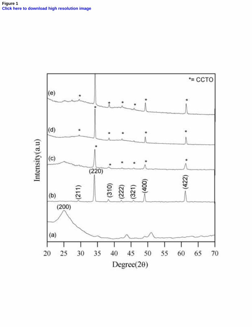
Figure 1Click here to download high resolution image
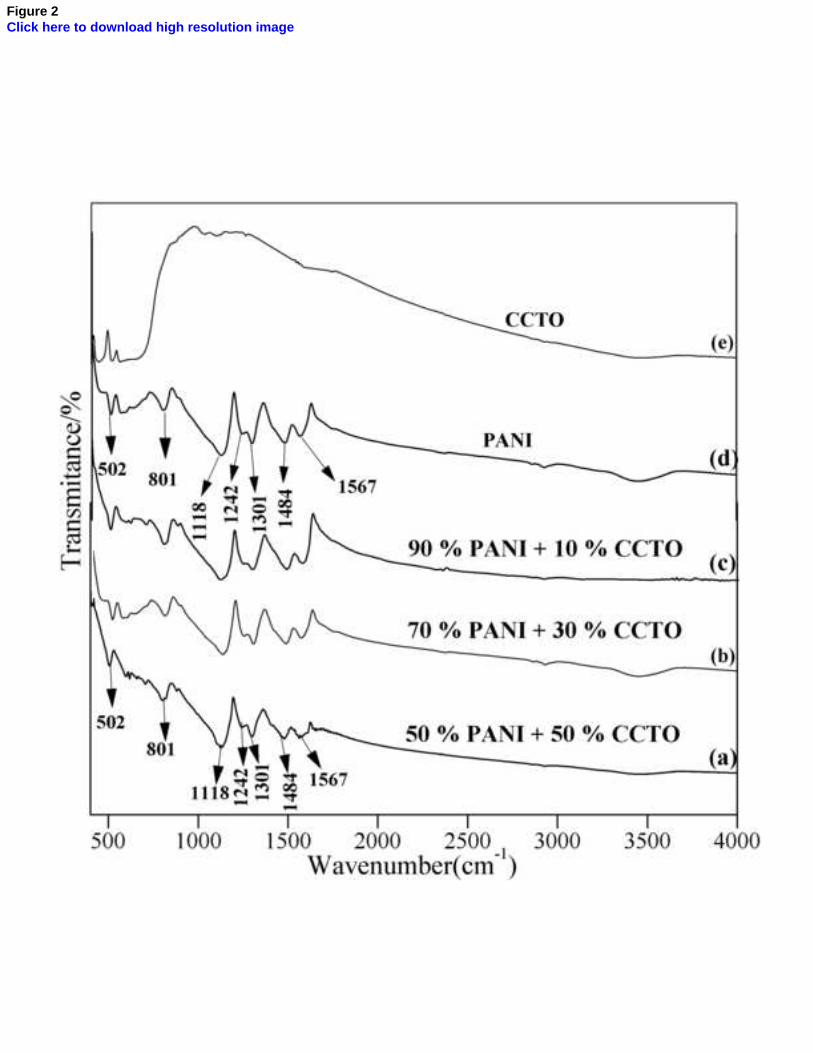
Figure 2Click here to download high resolution image
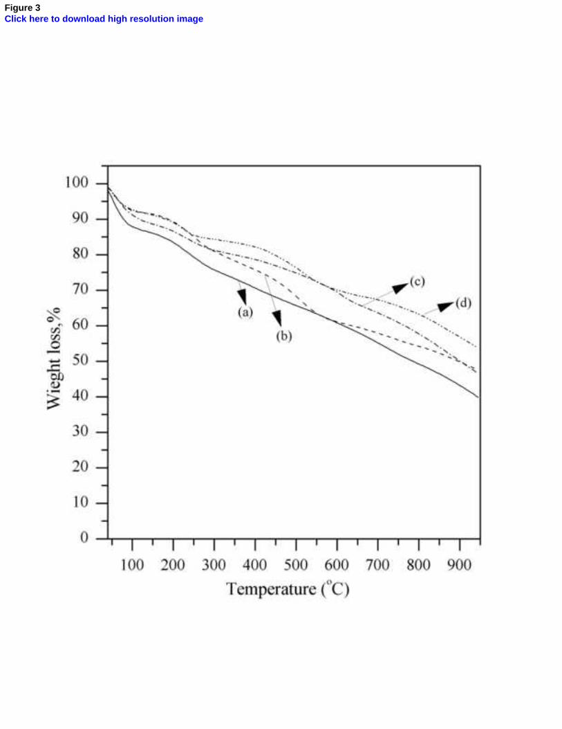
Figure 3Click here to download high resolution image
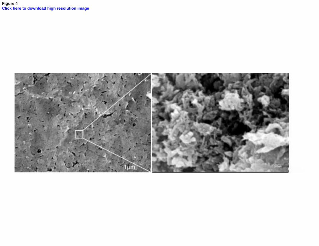
Figure 4Click here to download high resolution image
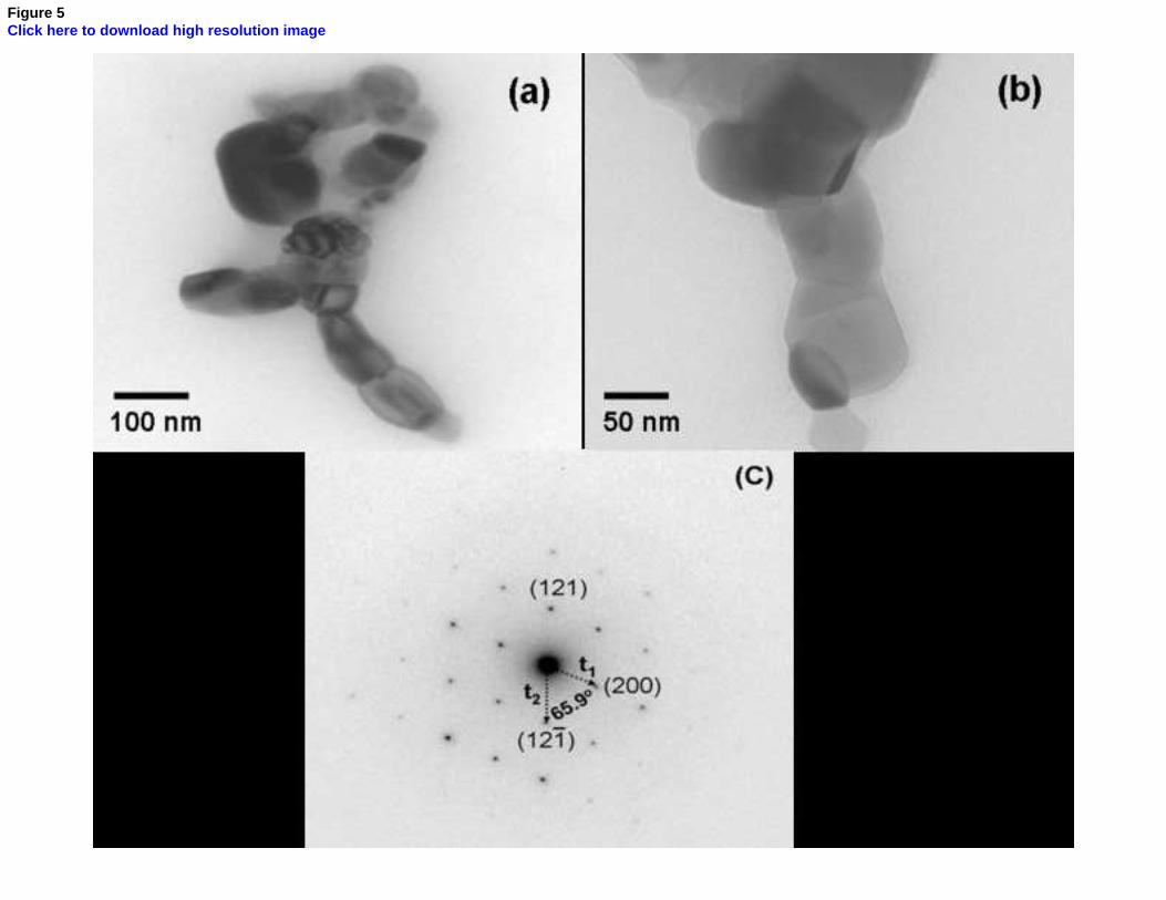
Figure 5Click here to download high resolution image
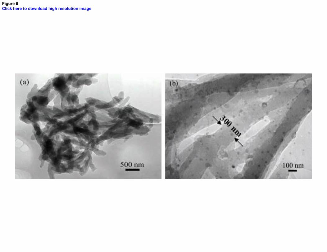
Figure 6Click here to download high resolution image
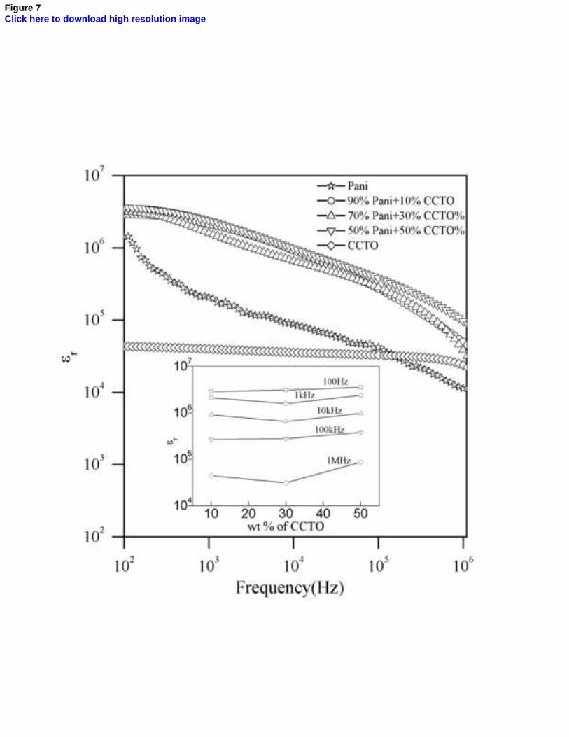
Figure 7Click here to download high resolution image
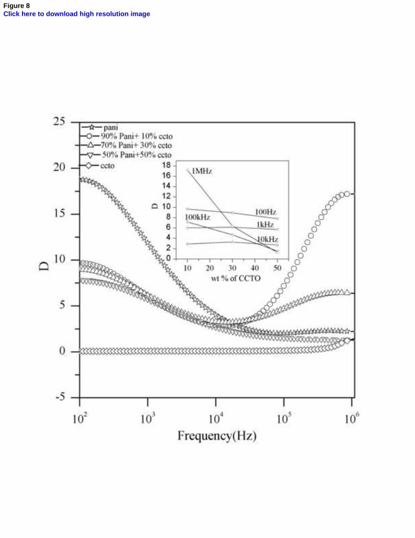
Figure 8Click here to download high resolution image
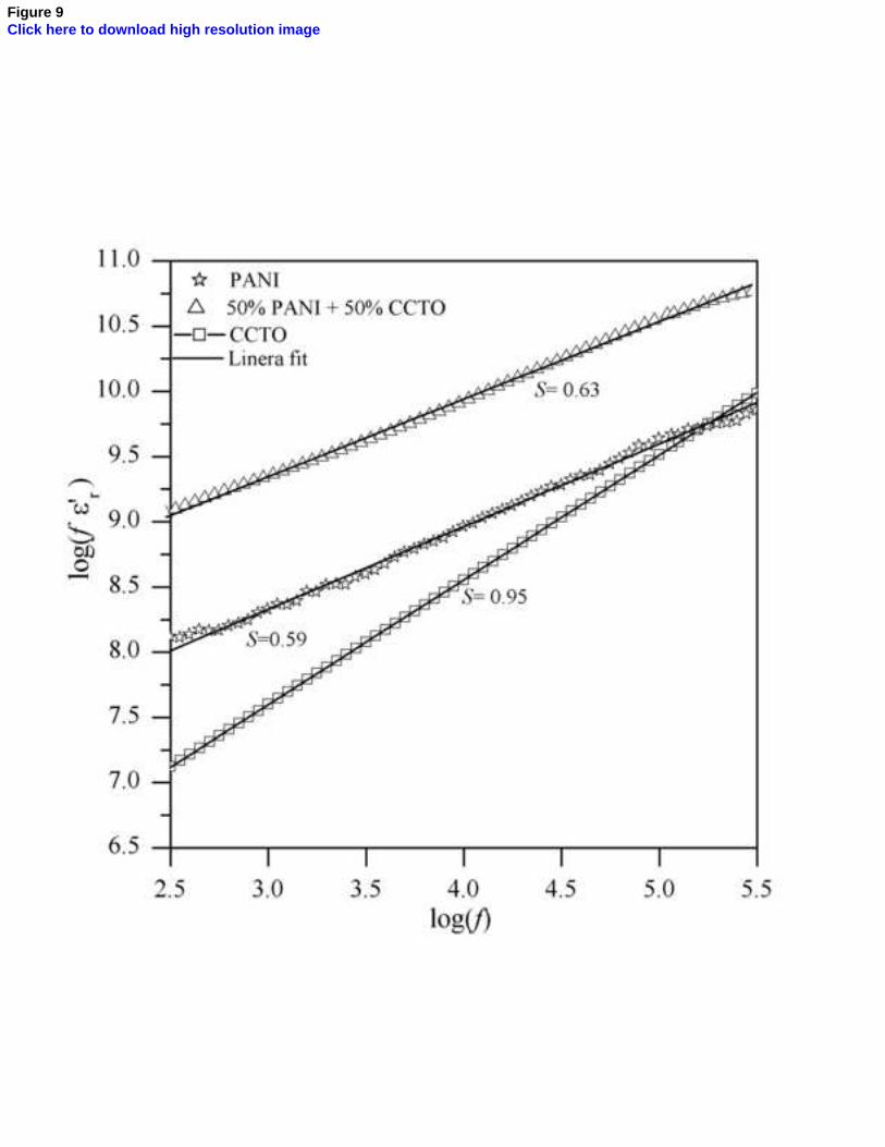
Figure 9Click here to download high resolution image
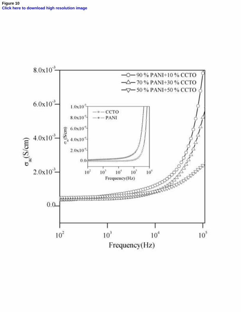
Figure 10Click here to download high resolution image


