Embed Size (px)
Citation preview
Application Notes
Issued
November 2013
Abstract
With the fast development of fiber optic communication technology and the trend of FTTX, indoor fiber optic cables are more and more required to be installed between and inside buildings. Compared with outdoor use fiber cable, indoor fiber optic cable experience less temperature and mechanical stress, but they have to be fire retardant, emit a low level of smoke in case of burning and also allow a small bend radius to make them be amendable to vertical installation and handle easily. This paper provides an introduction to the optical Fibre Indoor Cables.
KeywordsBreakout cable, Distribution Cable, Ribbon
Indoor Cable Application Note
Broadband optical access services are now commercially available. The number of fiber to the home (FTTH) service users is increasing rapidly. Optical fiber is suitable for broadband communication. As optical communications systems mature, fibers move closer to the end users. Indoor cables will become more and more important as users continue to demand more bandwidth at their desk. This applications note provides an introduction to optical indoor cables.
1 . General Indoor Cable Description
Indoor Optical Cable is intended primarily for use within an environmentally controlled structure (e.g., home, commercial, or controlled environment vault) to transport optical signals within that structure. Indoor cables may also be designed and rated for limited outdoor use, often between buildings for applications like campus applications. Indoor cables are frequently called premises cables. These cables shall meet appropriate National Electrical Code (NEC) requirements for particular indoor installations (as plenum cable, riser cable, or general purpose cable, as applicable), and other mechanical and environmental requirements outlined in the procurement specification.
2. Cable Classification
Indoor cables normally consists of one or more fibers of a specified fiber type, coated and/or buffered, to an appropriate specified diameter (commonly 250 m or 500 m coatings or 900 m buffer), organized in some manner (commonly loose fibers, tubes, ribbons, or unit jackets), and assembled into one of the following cable type configurations.
Most indoor cables are classified as backbone cables or interconnect cables, as determined by both their application space and, primarily, their mechanical design attributes and their application space.
3. Backbone Cables
Backbone cables consist of a large number of optical fibers, in a more robust design than interconnect cables. Backbone cables are used to provide an optical pathway between telecommunications rooms, equipment rooms, and/or entrance facilities. Backbone cables can be placed in riser shafts, cable racks, or cable trays. Backbone cables are classified according to their fire rating.
1 Fire code requirements in lieu of or in addition to the NEC may apply in specific applications. Some examples of nationally recognized codes are the Canadian and Mexican specifications. Because of the range of possible governing codes, this note limits its consideration to the NEC.
3.1 Backbone Cable for Vertical Applications
Backbone cables can be used in vertical applications. They usually have a higher tensile rating than backbone cables used for horizontal applications because they must carry their own weight. An example of a vertical backbone cable is a cable deployed between floors in a riser shaft.
3.2 Horizontal Backbone CableBackbone cables can be used in horizontal applications. These cables may have a tensile rating that is dependent on their fiber count. An example of a horizontal backbone cable is a cable deployed in an overhead racks or an under floor tray.
2 For higher fiber count cables, distribution and breakout cables may contain multiple sub-units within a protective outer jacket.
4. Interconnect Cables
Interconnect cables are designed for light-duty use. They are suitable for use as jumpers or patch cords between equipment bays. They are often used to provide optical pathways between active electronics and nearby terminal equipment. Interconnect cables usually have one to twelve loose or tight-buffered fibers or one or more fiber ribbons. The fibers are usually accompanied with a dielectric strength member and are jacketed for use in short length applications. Interconnect cables are classified according to their fire rating so they will be used in applications that match their fire retardant.
Interconnect cable, may be organized into classes primarily based on the fiber organization.NOTE: Interconnect cable of small fiber count is often referred to as cordage. Cordage is relatively light-duty, small fiber-count cable used for cross-connections to equipment or other cables.
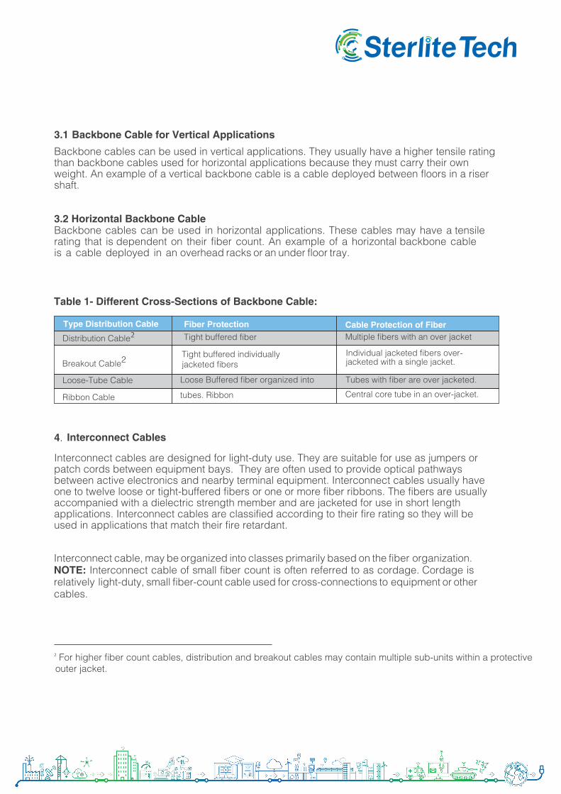
Central core tube in an over-jacket.
Type Distribution Cable
Distribution Cable2Fiber Protection Tight buffered fiber
Cable Protection of Fiber Multiple fibers with an over jacket
Breakout Cable2Tight buffered individually jacketed fibers
Individual jacketed fibers over-jacketed with a single jacket.
Tubes with fiber are over jacketed.Loose-Tube Cable
Ribbon Cable
Loose Buffered fiber organized into
tubes. Ribbon
Table 1- Different Cross-Sections of Backbone Cable:
Type Distribution Cable
Simplex Cable
Fiber Protection
Tight buffered fiber or protected loose buffered fiber.
Cable Protection of Fiber
Duplex Cable Contains two tight buffered individually jacketed fibers.
Two individually jacketed fibers with a single jacket. The two cables can be zipped apart.
Table 2- Different Cross-Sections of Interconnect Cable:
Quad CableA cable containing four(typically tight buffered) fibers. Tubes with fiber are over jacketed.
Cable with one or more ribbons in its core.Ribbon Cable Central core tube in an over-jacket.
A cable containing one or more 250 µm coated fibers.Loose Fiber Cables
A cable containing one or more 250 µm coated fibers.
Central tubes in an over-jacket.
5. Characteristics of Optical Cable
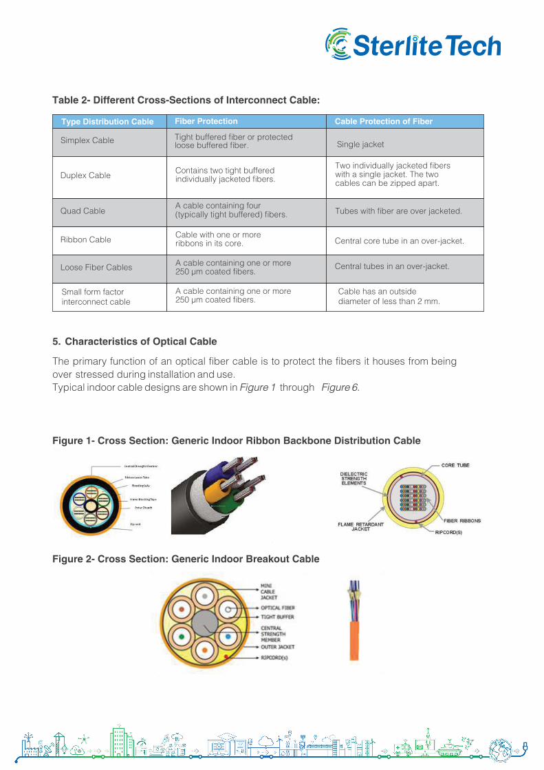
The primary function of an optical fiber cable is to protect the fibers it houses from being over stressed during installation and use.Typical indoor cable designs are shown in Figure 1 through Figure 6.
Figure 1- Cross Section: Generic Indoor Ribbon Backbone Distribution Cable
Figure 2- Cross Section: Generic Indoor Breakout Cable
Cable has an outside diameter of less than 2 mm.
Small form factor interconnect cable
Single jacket
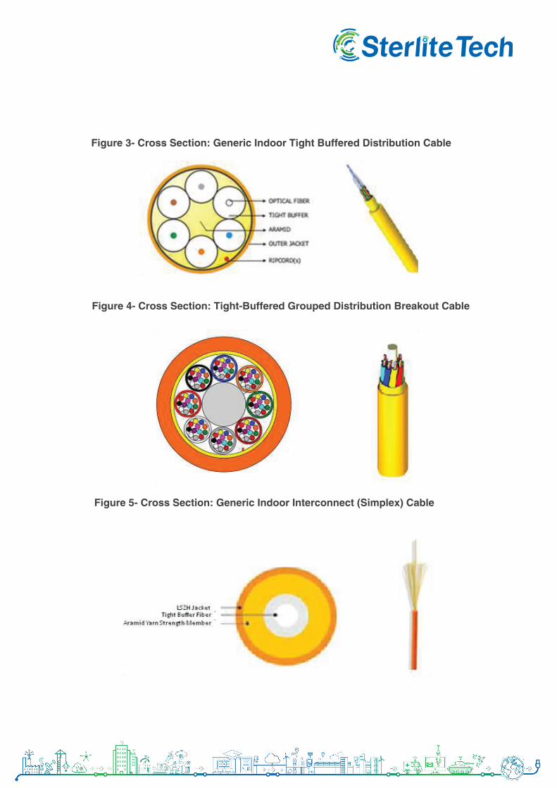
Figure 4- Cross Section: Tight-Buffered Grouped Distribution Breakout Cable
Figure 3- Cross Section: Generic Indoor Tight Buffered Distribution Cable
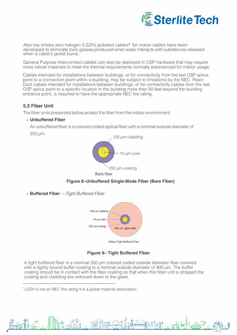
Figure 5- Cross Section: Generic Indoor Interconnect (Simplex) Cable
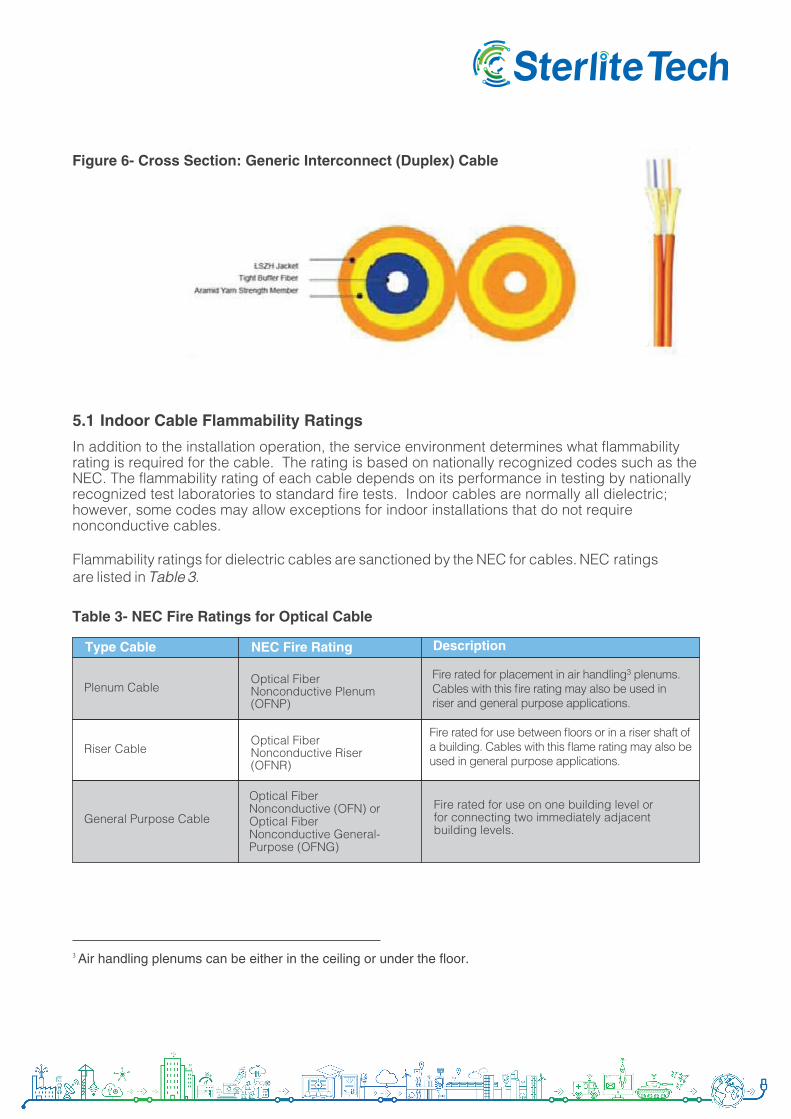
Figure 6- Cross Section: Generic Interconnect (Duplex) Cable
5.1 Indoor Cable Flammability Ratings
In addition to the installation operation, the service environment determines what flammability rating is required for the cable. The rating is based on nationally recognized codes such as the NEC. The flammability rating of each cable depends on its performance in testing by nationally recognized test laboratories to standard fire tests. Indoor cables are normally all dielectric; however, some codes may allow exceptions for indoor installations that do not require nonconductive cables.
Flammability ratings for dielectric cables are sanctioned by the NEC for cables. NEC ratings are listed in Table 3.
Fire rated for use on one building level or for connecting two immediately adjacent building levels.
Type Cable NEC Fire Rating Description
Plenum CableOptical Fiber Nonconductive Plenum (OFNP)
Riser CableOptical Fiber Nonconductive Riser (OFNR)
Table 3- NEC Fire Ratings for Optical Cable
Optical Fiber Nonconductive (OFN) or Optical Fiber Nonconductive General-Purpose (OFNG)
General Purpose Cable
3 Air handling plenums can be either in the ceiling or under the floor.
Fire rated for use between floors or in a riser shaft of a building. Cables with this flame rating may also be used in general purpose applications.
Fire rated for placement in air handling3 plenums. Cables with this fire rating may also be used in riser and general purpose applications.
Also low smoke zero halogen (LSZH) jacketed cables4 for indoor cables have been developed to eliminate toxic gasses produced when water interacts with substances released when a cable's jacket burns.
General Purpose Interconnect cables can also be deployed in OSP hardware that may require more robust materials to meet the thermal requirements normally experienced for indoor usage.
Cables intended for installations between buildings, or for connectivity from the last OSP splice point to a connection point within a building, may be subject to limitations by the NEC. Riser/Duct cables intended for installations between buildings, or for connectivity cables from the last OSP splice point to a specific location in the building more than 50 feet beyond the building entrance point, is required to have the appropriate NEC fire rating.
4 LSZH is not an NEC fire rating it is a jacket material description.
5.2 Fiber UnitThe fiber units presented below protect the fiber from the indoor environment:
Unbuffered Fiber
An unbuffered fiber is a colored coded optical fiber with a nominal outside diameter of
250 µm.
Bare fiber
Figure 8–Unbuffered Single-Mode Fiber (Bare Fiber)
250 µm coating
10 µm core
125 µm cladding
Buffered Fiber —Tight Buffered Fiber
Figure 9– Tight Buffered Fiber
A tight buffered fiber is a nominal 250 µm colored coded outside diameter fiber covered with a tightly bound buffer coating to a nominal outside diameter of 900 µm. The buffer coating should be in contact with the fiber coating so that when this fiber unit is stripped the coating and cladding are removed down to the glass.
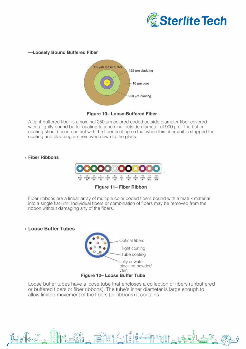
—Loosely Bound Buffered Fiber
Figure 10– Loose-Buffered Fiber
A tight buffered fiber is a nominal 250 µm colored coded outside diameter fiber covered with a tightly bound buffer coating to a nominal outside diameter of 900 µm. The buffer coating should be in contact with the fiber coating so that when this fiber unit is stripped the coating and cladding are removed down to the glass.
Fiber Ribbons
Fiber ribbons are a linear array of multiple color coded fibers bound with a matrix material into a single flat unit. Individual fibers or combination of fibers may be removed from the ribbon without damaging any of the fibers.
Figure 11– Fiber Ribbon
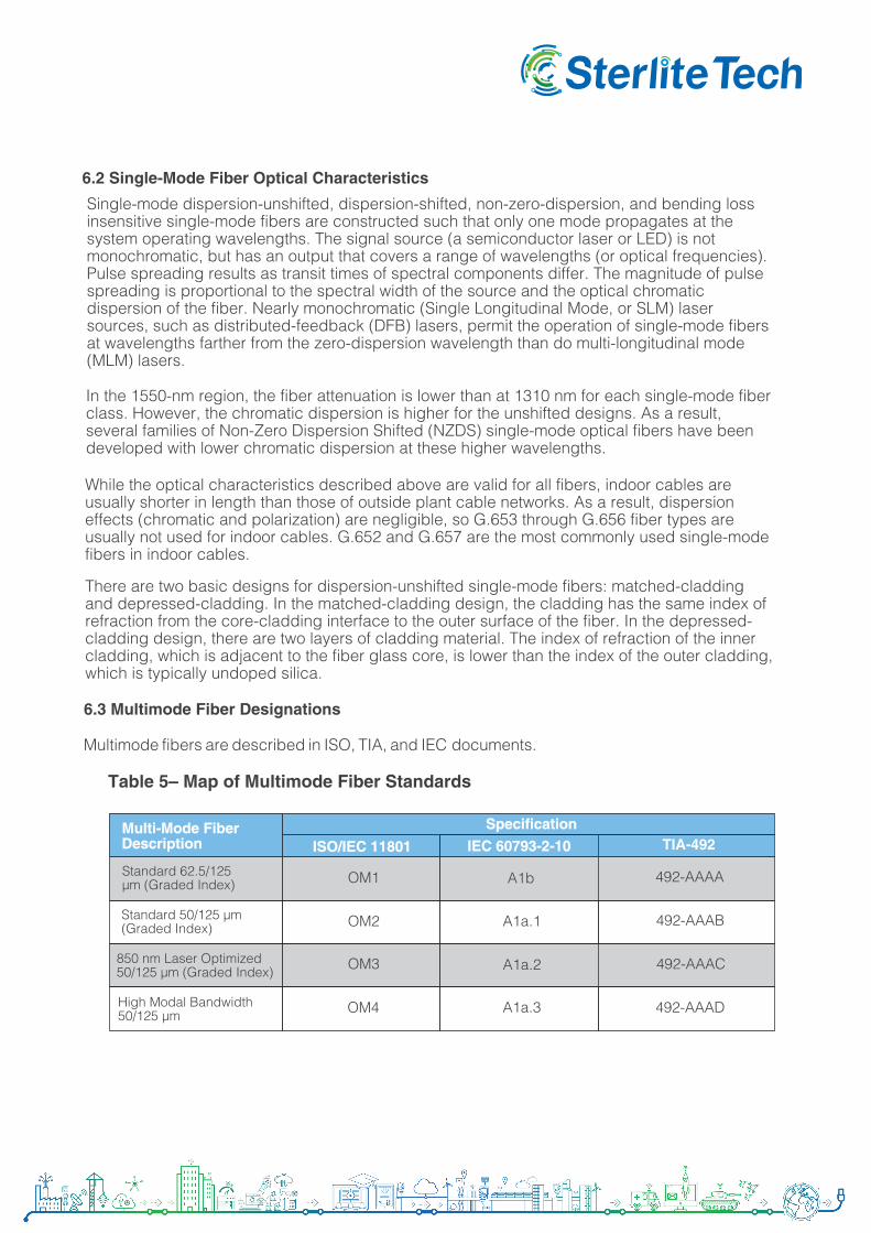
Loose Buffer Tubes
Loose buffer tubes have a loose tube that encloses a collection of fibers (unbuffered or buffered fibers or fiber ribbons). The tube's inner diameter is large enough to allow limited movement of the fibers (or ribbons) it contains.
Figure 12– Loose Buffer Tube
Optical fibers
Tight coating
Jelly or water blocking powder/ yarn
Tube coating
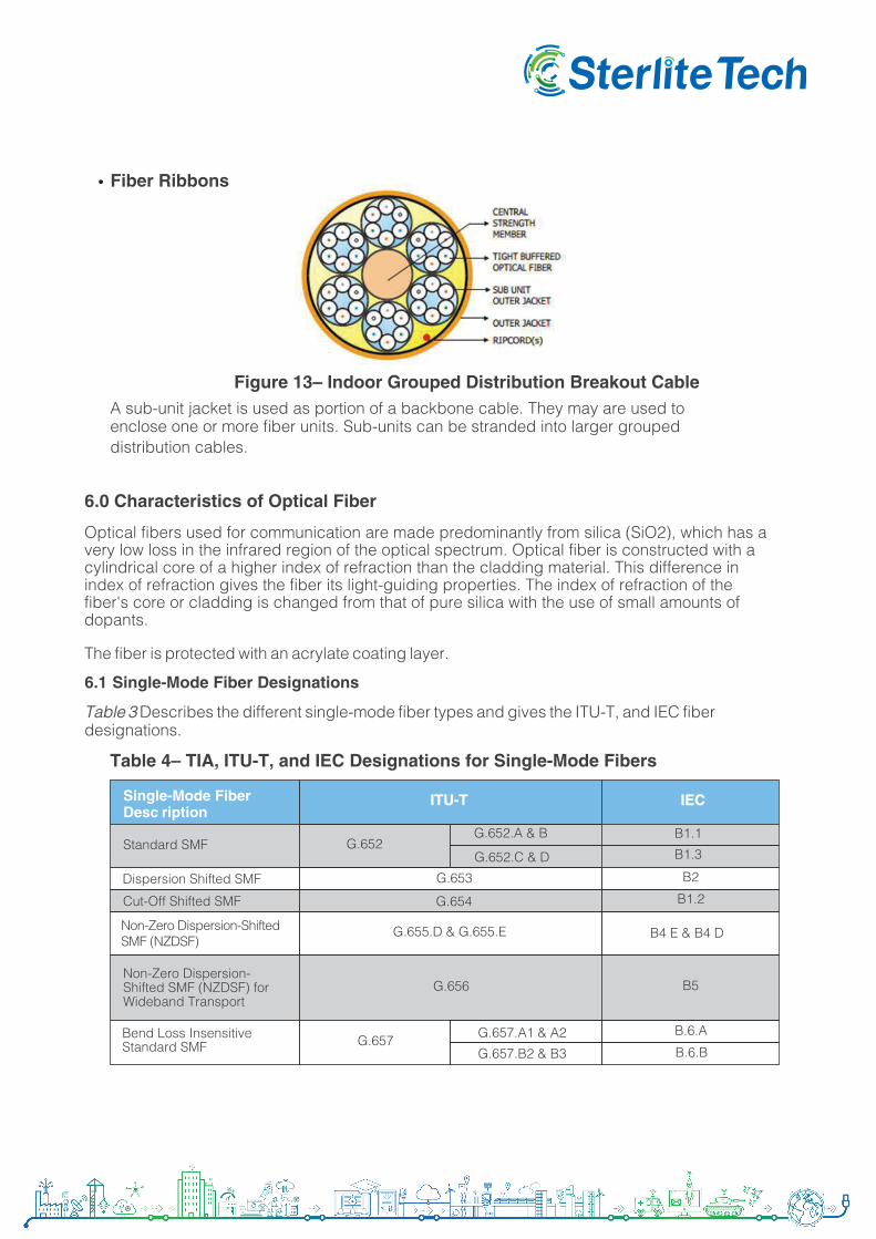
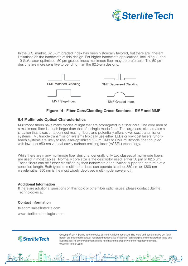
Figure 13– Indoor Grouped Distribution Breakout CableA sub-unit jacket is used as portion of a backbone cable. They may are used toenclose one or more fiber units. Sub-units can be stranded into larger groupeddistribution cables.
Fiber Ribbons
6.0 Characteristics of Optical Fiber
Optical fibers used for communication are made predominantly from silica (SiO2), which has a very low loss in the infrared region of the optical spectrum. Optical fiber is constructed with a cylindrical core of a higher index of refraction than the cladding material. This difference in index of refraction gives the fiber its light-guiding properties. The index of refraction of the fiber's core or cladding is changed from that of pure silica with the use of small amounts of dopants.
The fiber is protected with an acrylate coating layer.
6.1 Single-Mode Fiber Designations
Table 3 Describes the different single-mode fiber types and gives the ITU-T, and IEC fiber designations.
Non-Zero Dispersion-Shifted SMF (NZDSF) for Wideband Transport
B.6.A
Single-Mode Fiber Desc ription
ITU-T IEC
Standard SMF G.652G.652.A & B B1.1
B1.3
Dispersion Shifted SMF B2
B1.2Cut-Off Shifted SMF
G.652.C & D
G.653
G.654
G.655.D & G.655.E B4 E & B4 D
G.656 B5
Bend Loss Insensitive Standard SMF G.657 G.657.A1 & A2
G.657.B2 & B3 B.6.B
Table 4– TIA, ITU-T, and IEC Designations for Single-Mode Fibers
Non-Zero Dispersion-Shifted SMF (NZDSF)
6.2 Single-Mode Fiber Optical Characteristics
Single-mode dispersion-unshifted, dispersion-shifted, non-zero-dispersion, and bending loss insensitive single-mode fibers are constructed such that only one mode propagates at the system operating wavelengths. The signal source (a semiconductor laser or LED) is not monochromatic, but has an output that covers a range of wavelengths (or optical frequencies). Pulse spreading results as transit times of spectral components differ. The magnitude of pulse spreading is proportional to the spectral width of the source and the optical chromatic dispersion of the fiber. Nearly monochromatic (Single Longitudinal Mode, or SLM) laser sources, such as distributed-feedback (DFB) lasers, permit the operation of single-mode fibers at wavelengths farther from the zero-dispersion wavelength than do multi-longitudinal mode (MLM) lasers.
In the 1550-nm region, the fiber attenuation is lower than at 1310 nm for each single-mode fiber class. However, the chromatic dispersion is higher for the unshifted designs. As a result, several families of Non-Zero Dispersion Shifted (NZDS) single-mode optical fibers have been developed with lower chromatic dispersion at these higher wavelengths.
While the optical characteristics described above are valid for all fibers, indoor cables are usually shorter in length than those of outside plant cable networks. As a result, dispersion effects (chromatic and polarization) are negligible, so G.653 through G.656 fiber types are usually not used for indoor cables. G.652 and G.657 are the most commonly used single-mode fibers in indoor cables.
There are two basic designs for dispersion-unshifted single-mode fibers: matched-cladding and depressed-cladding. In the matched-cladding design, the cladding has the same index of refraction from the core-cladding interface to the outer surface of the fiber. In the depressed-cladding design, there are two layers of cladding material. The index of refraction of the inner cladding, which is adjacent to the fiber glass core, is lower than the index of the outer cladding, which is typically undoped silica.
6.3 Multimode Fiber Designations
Multimode fibers are described in ISO, TIA, and IEC documents.
Table 5– Map of Multimode Fiber Standards
High Modal Bandwidth 50/125 µm
Multi-Mode Fiber Description
Standard 62.5/125 µm (Graded Index) OM1 A1b
A1a.1
492-AAAA
Standard 50/125 µm (Graded Index)
850 nm Laser Optimized 50/125 µm (Graded Index) A1a.2
OM2
OM3
OM4
ISO/IEC 11801
Specification
IEC 60793-2-10 TIA-492
A1a.3
492-AAAB
492-AAAC
492-AAAD
Copyright© 2017 Sterlite Technologies Limited. All rights reserved. The word and design marks set forth herein are trademarks and/or registered trademarks of Sterlite Technologies and/or related affiliates and subsidiaries. All other trademarks listed herein are the property of their respective owners. www.sterlitetech.com
In the U.S. market, 62.5-µm graded index has been historically favored, but there are inherent limitations on the bandwidth of this design. For higher bandwidth applications, including 1- and 10-Gb/s laser-optimized, 50 µm graded index multimode fiber may be preferable. The 50-µm designs are more sensitive to bending than the 62.5-µm designs.
Figure 14– Fiber Core/Cladding Cross-Sections: SMF and MMF
6.4 Multimode Optical Characteristics Multimode fibers have many modes of light that are propagated in a fiber core. The core area of a multimode fiber is much larger than that of a single-mode fiber. The large core size creates a situation that is easier to connect mating fibers and potentially offers lower-cost transmission systems. Multimode transmission systems typically use either LEDs or low-cost lasers. Short-reach systems are likely to use laser-optimized 50-µm OM3 or OM4 multimode fiber coupled with low-cost 850-nm vertical-cavity surface-emitting laser (VCSEL) technology.
While there are many multimode fiber designs, generally only two classes of multimode fibers are used in most cables. Normally core size is the descriptor used: either 50 µm or 62.5 µm. These fibers can be further classified by their bandwidth or equivalent supported data rate at a specified length. Both types of multimode fibers can operate at either 850-nm or 1300-nm wavelengths; 850 nm is the most widely deployed multi-mode wavelength.
Additional InformationIf there are additional questions on this topic or other fiber optic issues, please contact Sterlite Technologies at:
Contact Information
www.sterlitetechnologies.com
SMF Matched Cladding
SMF Graded IndexMMF Step-Index
SMF Depressed Cladding


![cable heating 4PPOE_flatman_01_1113.ppt [Repaired]](https://img.pdfslide.net/doc/110x75/633385233108fad7760f171e/cable-heating-4ppoeflatman011113ppt-repaired.jpg)