Embed Size (px)
Citation preview

IndraDrive ML
DC/DC Converter with HMU05
Project Planning ManualR911398286
Edition 01

IndraDrive MLDC/DC Converter with HMU05
Project Planning Manual
DOK-INDRV*-HXX05_DCDC*-PR01-EN-P
RS-e489d08cf1a6cabc0a347e863d4bec23-1-en-US-5
Copyright © Bosch Rexroth AG 2019All rights reserved, also regarding any disposal, exploitation, reproduction,editing, distribution, as well as in the event of applications for industrialproperty rights.
Liability The specified data is intended for product description purposes only and shallnot be deemed to be a guaranteed characteristic unless expressly stipulatedin the contract. All rights are reserved with respect to the content of thisdocumentation and the availability of the product.
Editorial Department Engineering Drives [DiGr, HaKr, ReMa (UdSt; BaBo)]
Title
Type of Documentation
Document Typecode
Internal File Reference
IndraDrive ML DC/DC Converter with HMU05

Table of ContentsPage
1 Scope of applications..................................................................................................... 1
2 Important directions for use .......................................................................................... 32.1 Intended use .......................................................................................................................................... 32.1.1 Introduction.......................................................................................................................................... 32.1.2 Areas of use and application............................................................................................................... 32.2 Unintended use....................................................................................................................................... 4
3 Safety instructions for electric drives and controls......................................................... 53.1 Definitions of terms................................................................................................................................. 53.2 General information................................................................................................................................ 63.2.1 Using the Safety instructions and passing them on to others.............................................................. 63.2.2 Requirements for safe use.................................................................................................................. 63.2.3 Hazards by improper use.................................................................................................................... 73.3 Instructions with regard to specific dangers............................................................................................ 93.3.1 Protection against contact with electrical parts and housings............................................................. 93.3.2 Protective extra-low voltage as protection against electric shock .................................................... 103.3.3 Protection against dangerous movements........................................................................................ 113.3.4 Protection against electromagnetic and magnetic fields during operation and mounting.................. 123.3.5 Protection against contact with hot parts........................................................................................... 133.3.6 Protection during handling and mounting.......................................................................................... 133.3.7 Battery safety..................................................................................................................................... 133.3.8 Protection against pressurized systems............................................................................................ 143.4 Explanation of signal words and the Safety alert symbol..................................................................... 14
4 Components for operation as DC/DC converter.......................................................... 17
5 General requirements.................................................................................................. 19
6 Design.......................................................................................................................... 216.1 Parallel connection............................................................................................................................... 236.1.1 Parallel connection using HPC01.1-P001-NN optional card............................................................. 236.1.2 Parallel connection via analog I/Os of the control sections............................................................... 246.1.3 Parallel connection through command value input by the control unit.............................................. 256.2 Combining the individual components.................................................................................................. 266.2.1 Single application.............................................................................................................................. 266.2.2 Parallel connection (example with 2 HMU)........................................................................................ 276.3 Overall connection diagram, HMU as DC/DC converter....................................................................... 286.3.1 Single application.............................................................................................................................. 286.3.2 Parallel connection via analog I/Os of the control sections............................................................... 296.3.3 Parallel connection using HPC01.1-P001-NN optional card............................................................. 30
IndraDrive ML DC/DC Converter with HMU05 I
Table of Contents
R911398286_Edition 01 Bosch Rexroth AG

Page
7 Technical data.............................................................................................................. 317.1 Control voltage...................................................................................................................................... 317.2 Input and output voltage range............................................................................................................. 317.3 Control accuracy and voltage/current ripples....................................................................................... 327.4 DC output.............................................................................................................................................. 337.5 HLL05 smoothing choke ↔ HMU05...................................................................................................... 347.6 Output power........................................................................................................................................ 35
8 Parameterizing functional packages............................................................................ 378.1 Activating functional packages via parameters..................................................................................... 378.2 Activating functional packages via IndraWorks.................................................................................... 388.3 Setting the switching frequency and operation mode........................................................................... 398.4 Limiting the controller output................................................................................................................. 408.4.1 Limiting the output voltage................................................................................................................. 408.4.2 Limiting the output current................................................................................................................. 40
9 Parameterizing the analog input.................................................................................. 419.1 Analog input for output voltage control................................................................................................. 419.2 Parallel connection of DC/DC converters in voltage control................................................................. 42
10 Additional components................................................................................................. 4510.1 HLL smoothing choke........................................................................................................................... 45
11 Application examples................................................................................................... 4711.1 DC/DC converter at drive system in the TN-C mains........................................................................... 4711.2 DC/DC converter as a battery test stand in the IT mains..................................................................... 49
Index............................................................................................................................ 51
II/53
Table of Contents
IndraDrive ML DC/DC Converter with HMU05
Bosch Rexroth AG R911398286_Edition 01

1 Scope of applicationsUniversal inverters of the "HMU" series can also be used as DC/DCconverters.A DC/DC converter provides DC voltage with a variable output voltage. ThisDC voltage can be voltage-controlled or current-controlled.
IndraDrive ML DC/DC Converter with HMU05 1/53
Scope of applications
R911398286_Edition 01 Bosch Rexroth AG

2/53 IndraDrive ML DC/DC Converter with HMU05
Bosch Rexroth AG R911398286_Edition 01

2 Important directions for use2.1 Intended use2.1.1 Introduction
Rexroth products are developed and manufactured to the state-of-the-art.The products are tested prior to delivery to ensure operational safety andreliability.
Personal injury and property damage byusing products incorrectly!
WARNING
The products have been designed for use in an industrial environment andmay only be used as intended. Failure to use them in the intended way maycause situations resulting in property damage and personal injury.
Rexroth as the manufacturer shall not honor any warranty, liabilityor compensatory claims for damages resulting from unintendeduse of the products. The user alone shall bear the risks ofunintended use of the products.
Before using Rexroth products, make sure that all the prerequisites for anintended use of the products are satisfied:● Personnel that in any way, shape or form uses our products must first
read and understand the relevant safety instructions and be familiar withtheir intended use.
● Leave hardware products in their original state, i.e., do not make anystructural modifications. It is not permitted to decompile softwareproducts or alter their source codes.
● Do not install damaged or faulty products or put them into operation.● Make sure that the products have been installed as described in the
relevant documentation.
2.1.2 Areas of use and applicationDrive controllers by Rexroth are designed to control electric motors andmonitor their operation.Controlling and monitoring the drive controllers may require additionalsensors and actuators.
The drive controllers may only be used with the accessories andattachments specified in this documentation. Components thatare not expressly mentioned may neither be attached norconnected. The same applies to cables and lines.Operation is only allowed in the specified configurations andcombinations of the components using the software and firmwareas specified in the relevant functional descriptions.
Drive controllers have to be programmed before commissioning to ensurethat the motor executes the functions specific to the application.Drive controllers of the Rexroth IndraDrive ML series have been developedfor use in single- and multi-axis drive and control tasks.
IndraDrive ML DC/DC Converter with HMU05 3/53
Important directions for use
R911398286_Edition 01 Bosch Rexroth AG

Drive controllers may only be operated under the assembly and installationconditions specified in this documentation, in the specified mounting positionand under the specified ambient conditions (temperature, degree ofprotection, humidity, EMC, etc.).
2.2 Unintended use"Unintended use" refers to using the drive controllers outside of the operatingconditions, technical data and specifications described in this documentation.Drive controllers must not be used, if …● they are exposed to operating conditions that do not meet the specified
ambient conditions. This includes, for example, operation under water,under extreme temperature fluctuations or extreme maximumtemperatures.
● Furthermore, drive controllers may not be used in applications whichhave not been explicitly authorized by Rexroth. Therefore, pleasecarefully follow the specifications outlined in the general safetyinstructions!
Components of the Rexroth IndraDrive ML system are products ofCategory C3 (with restricted distribution) in accordance withIEC 61800‑3. The Category C3 comprises EMC limit values forline-based and radiated noise emission.Compliance with these Categories requires the appropriatemeasures of interference suppression (e.g., mains filters,shielding measures) to be used in the drive system.These components are not provided for use in a public low-voltage grid supplying residential areas. If these components areused in such a mains, high-frequency interference is to beexpected. This can require additional measures of interferencesuppression.
4/53
Important directions for use
IndraDrive ML DC/DC Converter with HMU05
Bosch Rexroth AG R911398286_Edition 01

3 Safety instructions for electric drives and controls3.1 Definitions of terms
Application documentation Application documentation comprises the entire documentation used toinform the user of the product about the use and safety-relevant features forconfiguring, integrating, installing, mounting, commissioning, operating,maintaining, repairing and decommissioning the product. The following termsare also used for this kind of documentation: Operating Instructions,Commissioning Manual, Instruction Manual, Project Planning Manual,Application Description, etc.
Component A component is a combination of elements with a specified function, whichare part of a piece of equipment, device or system. Components of theelectric drive and control system are, for example, supply units, drivecontrollers, mains choke, mains filter, motors, cables, etc.
Control system A control system comprises several interconnected control componentsplaced on the market as a single functional unit.
Device A device is a finished product with a defined function, intended for users andplaced on the market as an individual piece of merchandise.
Electrical equipment Electrical equipment encompasses all devices used to generate, convert,transmit, distribute or apply electrical energy, such as electric motors,transformers, switching devices, cables, lines, power-consuming devices,circuit board assemblies, plug-in units, control cabinets, etc.
Electric drive system An electric drive system comprises all components from mains supply tomotor shaft; this includes, for example, electric motor(s), motor encoder(s),supply units and drive controllers, as well as auxiliary and additionalcomponents, such as mains filter, mains choke and the corresponding linesand cables.
Installation An installation consists of several devices or systems interconnected for adefined purpose and on a defined site which, however, are not intended to beplaced on the market as a single functional unit.
Machine A machine is the entirety of interconnected parts or units at least one ofwhich is movable. Thus, a machine consists of the appropriate machine driveelements, as well as control and power circuits, which have been assembledfor a specific application. A machine is, for example, intended for processing,treatment, movement or packaging of a material. The term "machine" alsocovers a combination of machines which are arranged and controlled in sucha way that they function as a unified whole.
Manufacturer The manufacturer is an individual or legal entity bearing responsibility for thedesign and manufacture of a product which is placed on the market in theindividual's or legal entity's name. The manufacturer can use finishedproducts, finished parts or finished elements, or contract out work tosubcontractors. However, the manufacturer must always have overall controland possess the required authority to take responsibility for the product.
Product Examples of a product: Device, component, part, system, software, firmware,among other things.
Project Planning Manual A Project Planning Manual is part of the application documentation used tosupport the sizing and planning of systems, machines or installations.
Qualified persons In terms of this application documentation, qualified persons are thosepersons who are familiar with the installation, mounting, commissioning andoperation of the components of the electric drive and control system, as wellas with the hazards this implies, and who possess the qualifications their
IndraDrive ML DC/DC Converter with HMU05 5/53
Safety instructions for electric drives and controls
R911398286_Edition 01 Bosch Rexroth AG

work requires. To comply with these qualifications, it is necessary, amongother things,1) to be trained, instructed or authorized to switch electric circuits anddevices safely on and off, to ground them and to mark them2) to be trained or instructed to maintain and use adequate safety equipment3) to attend a course of instruction in first aid
User A user is a person installing, commissioning or using a product which hasbeen placed on the market.
3.2 General information3.2.1 Using the Safety instructions and passing them on to others
Do not attempt to install and operate the components of the electric drive andcontrol system without first reading all documentation provided with theproduct. Read and understand these safety instructions and all userdocumentation prior to working with these components. If you do not havethe user documentation for the components, contact your responsibleRexroth sales partner. Ask for these documents to be sent immediately to theperson or persons responsible for the safe operation of the components.If the component is resold, rented and/or passed on to others in any otherform, these safety instructions must be delivered with the component in theofficial language of the user's country.Improper use of these components, failure to follow the safety instructions inthis document or tampering with the product, including disabling of safetydevices, could result in property damage, injury, electric shock or even death.
3.2.2 Requirements for safe useRead the following instructions before initial commissioning of thecomponents of the electric drive and control system in order to eliminate therisk of injury and/or property damage. You must follow these safetyinstructions.● Rexroth is not liable for damages resulting from failure to observe the
safety instructions.● Read the operating, maintenance and safety instructions in your
language before commissioning. If you find that you cannot completelyunderstand the application documentation in the available language,please ask your supplier to clarify.
● Proper and correct transport, storage, mounting and installation, as wellas care in operation and maintenance, are prerequisites for optimal andsafe operation of the component.
● Only qualified persons may work with components of the electric driveand control system or within its proximity.
● Only use accessories and spare parts approved by Rexroth.● Follow the safety regulations and requirements of the country in which
the components of the electric drive and control system are operated.● Only use the components of the electric drive and control system in the
manner that is defined as appropriate. See chapter "Appropriate Use".● The ambient and operating conditions given in the available application
documentation must be observed.
6/53
Safety instructions for electric drives and controls
IndraDrive ML DC/DC Converter with HMU05
Bosch Rexroth AG R911398286_Edition 01

● Applications for functional safety are only allowed if clearly and explicitlyspecified in the application documentation "Integrated SafetyTechnology". If this is not the case, they are excluded. Functional safetyis a safety concept in which measures of risk reduction for personalsafety depend on electrical, electronic or programmable controlsystems.
● The information given in the application documentation with regard tothe use of the delivered components contains only examples ofapplications and suggestions.The machine and installation manufacturers must– make sure that the delivered components are suited for their
individual application and check the information given in thisapplication documentation with regard to the use of thecomponents,
– make sure that their individual application complies with theapplicable safety regulations and standards and carry out therequired measures, modifications and complements.
● Commissioning of the delivered components is only allowed once it issure that the machine or installation in which the components areinstalled complies with the national regulations, safety specifications andstandards of the application.
● Operation is only allowed if the national EMC regulations for theapplication are met.
● The instructions for installation in accordance with EMC requirementscan be found in the section on EMC in the respective applicationdocumentation.The machine or installation manufacturer is responsible for compliancewith the limit values as prescribed in the national regulations.
● The technical data, connection and installation conditions of thecomponents are specified in the respective application documentationsand must be followed at all times.
National regulations which the user has to comply with● European countries: In accordance with European EN standards● United States of America (USA):
– National Electrical Code (NEC)– National Electrical Manufacturers Association (NEMA), as well as
local engineering regulations– Regulations of the National Fire Protection Association (NFPA)
● Canada: Canadian Standards Association (CSA)● Other countries:
– International Organization for Standardization (ISO)– International Electrotechnical Commission (IEC)
3.2.3 Hazards by improper use● High electrical voltage and high working current! Danger to life or
serious injury by electric shock!● High electrical voltage by incorrect connection! Danger to life or injury by
electric shock!
IndraDrive ML DC/DC Converter with HMU05 7/53
Safety instructions for electric drives and controls
R911398286_Edition 01 Bosch Rexroth AG

● Dangerous movements! Danger to life, serious injury or propertydamage by unintended motor movements!
● Health hazard for persons with heart pacemakers, metal implants andhearing aids in proximity to electric drive systems!
● Risk of burns by hot housing surfaces!● Risk of injury by improper handling! Injury by crushing, shearing, cutting,
hitting!● Risk of injury by improper handling of batteries!● Risk of injury by improper handling of pressurized lines!
8/53
Safety instructions for electric drives and controls
IndraDrive ML DC/DC Converter with HMU05
Bosch Rexroth AG R911398286_Edition 01

3.3 Instructions with regard to specific dangers3.3.1 Protection against contact with electrical parts and housings
This section concerns components of the electric drive andcontrol system with voltages of more than 50 volts.
Contact with parts conducting voltages above 50 volts can cause personaldanger and electric shock. When operating components of the electric driveand control system, it is unavoidable that some parts of these componentsconduct dangerous voltage. High electrical voltage! Danger to life, risk of injury by electric shock orserious injury!● Only qualified persons are allowed to operate, maintain and/or repair the
components of the electric drive and control system.● Follow the general installation and safety regulations when working on
power installations.● Before switching on, the equipment grounding conductor must have
been permanently connected to all electrical components in accordancewith the connection diagram.
● Even for brief measurements or tests, operation is only allowed if theequipment grounding conductor has been permanently connected to thepoints of the components provided for this purpose.
● Before accessing electrical parts with voltage potentials higher than50 V, you must disconnect electrical components from the mains or fromthe power supply unit. Secure the electrical component fromreconnection.
● With electrical components, observe the following aspects:Always wait 30 minutes after switching off power to allow live capacitorsto discharge before accessing an electrical component. Measure theelectrical voltage of live parts before beginning to work to make surethat the equipment is safe to touch. Measure the electrical voltage bothconductor against conductor and conductor against ground (PE).Particularly if DC bus ground capacitor pairs without dischargingresistors (HAS04.1‑003‑NN1‑NN) are used, dangerous voltages againstground may be present for more than 24 hours after the power supplywas switched off. Only when voltage cannot be measured anymorebetween the positive and the negative DC bus connections is it allowedto discharge the DC bus ground capacitor pairs against ground. For thispurpose, use the appropriate high-resistance device (e.g., DUSPOL® by"Benning Elektrotechnik und Elektronik GmbH & Co. KG"; observe theOperating Manual!).
● Install the covers and guards provided for this purpose before switchingon.
● Never touch electrical connection points of the components while poweris turned on.
● Do not remove or plug in connectors when the component has beenpowered.
● Under specific conditions, electric drive systems can be operated atmains protected by residual-current-operated circuit-breakers sensitiveto universal current (RCDs/RCMs).
IndraDrive ML DC/DC Converter with HMU05 9/53
Safety instructions for electric drives and controls
R911398286_Edition 01 Bosch Rexroth AG

● Secure built-in devices from penetrating foreign objects and water, aswell as from direct contact, by providing an external housing, forexample a control cabinet.
High housing voltage and high leakage current! Danger to life, risk of injuryby electric shock!● Ground or connect the electrical drive and control system components
with the equipment grounding conductor to the grounding points beforepower-on and commissioning.
● Connect the equipment grounding conductor of the components of theelectric drive and control system permanently to the main power supplyat all times. The leakage current is greater than 3.5 mA.
● Establish an equipment grounding connection with a minimum crosssection according to the table below. With an outer conductor crosssection smaller than 10 mm2 (8 AWG), the alternative connection of twoequipment grounding conductors is allowed, each having the samecross section as the outer conductors.
Outer conductor crosssection
Minimum cross section of equipment groundingconductor
Leakage current ≥ 3.5 mA
1 equipment groundingconductor
2 equipment groundingconductors
1.5 mm2 (16 AWG)
10 mm2 (8 AWG)
2 × 1.5 mm2 (16 AWG)
2.5 mm2 (14 AWG) 2 × 2.5 mm2 (14 AWG)
4 mm2 (12 AWG) 2 × 4 mm2 (12 AWG)
6 mm2 (10 AWG) 2 × 6 mm2 (10 AWG)
10 mm2 (8 AWG) -
16 mm2 (6 AWG)
16 mm2 (6 AWG)
-
25 mm2 (4 AWG) -
35 mm2 (2 AWG) -
50 mm2 (1/0 AWG) 25 mm2 (4 AWG) -
70 mm2 (2/0 AWG) 35 mm2 (2 AWG) -
X mm2(X × 0.5) mm2
(applies to X ≥ 50)-
Tab. 3-1: Minimum cross section of equipment grounding connection
3.3.2 Protective extra-low voltage as protection against electric shock Protective extra-low voltage is used to allow connecting devices with basicinsulation to extra-low voltage circuits.On components of an electric drive and control system provided by Rexroth,all connections and terminals with voltages up to 50 volts are PELV("Protective Extra-Low Voltage") systems. It is allowed to connect devicesequipped with basic insulation (such as programming devices, PCs,notebooks, display units) to these connections.
10/53
Safety instructions for electric drives and controls
IndraDrive ML DC/DC Converter with HMU05
Bosch Rexroth AG R911398286_Edition 01

Danger to life, risk of injury by electric shock! High electrical voltage byincorrect connection!If extra-low voltage circuits of devices containing voltages and circuits ofmore than 50 volts (e.g., the mains connection) are connected to Rexrothproducts, the connected extra-low voltage circuits must comply with therequirements for PELV ("Protective Extra-Low Voltage").
3.3.3 Protection against dangerous movementsDangerous movements can be caused by faulty control of connected motors.Some common examples are:● Improper or wrong wiring or cable connection● Operator errors● Wrong input of parameters before commissioning● Malfunction of sensors and encoders● Defective components● Software or firmware errorsThese errors can occur immediately after equipment is switched on or evenafter an unspecified time of trouble-free operation.The monitoring functions in the components of the electric drive and controlsystem will normally be sufficient to avoid malfunction in the connecteddrives. Regarding personal safety, especially the danger of injury and/orproperty damage, this alone cannot be relied upon to ensure complete safety.Until the integrated monitoring functions become effective, it must beassumed in any case that faulty drive movements will occur. The extent offaulty drive movements depends upon the type of control and the state ofoperation. Dangerous movements! Danger to life, risk of injury, serious injury or propertydamage!A risk assessment must be prepared for the installation or machine, with itsspecific conditions, in which the components of the electric drive and controlsystem are installed.As a result of the risk assessment, the user must provide for monitoringfunctions and higher-level measures on the installation side for personalsafety. The safety regulations applicable to the installation or machine mustbe taken into consideration. Unintended machine movements or othermalfunctions are possible if safety devices are disabled, bypassed or notactivated.To avoid accidents, injury and/or property damage:● Keep free and clear of the machine’s range of motion and moving
machine parts. Prevent personnel from accidentally entering themachine’s range of motion by using, for example:– Safety fences– Safety guards– Protective coverings– Light barriers
● Make sure the safety fences and protective coverings are strong enoughto resist maximum possible kinetic energy.
IndraDrive ML DC/DC Converter with HMU05 11/53
Safety instructions for electric drives and controls
R911398286_Edition 01 Bosch Rexroth AG

● Mount emergency stopping switches in the immediate reach of theoperator. Before commissioning, verify that the emergency stoppingequipment works. Do not operate the machine if the emergencystopping switch is not working.
● Prevent unintended start-up. Isolate the drive power connection bymeans of OFF switches/OFF buttons or use a safe starting lockout.
● Make sure that the drives are brought to safe standstill before accessingor entering the danger zone.
● Additionally secure vertical axes against falling or dropping afterswitching off the motor power by, for example,– mechanically securing the vertical axes,– adding an external braking/arrester/clamping mechanism or– ensuring sufficient counterbalancing of the vertical axes.
● The standard equipment motor holding brake or an external holdingbrake controlled by the drive controller is not sufficient to guaranteepersonal safety!
● Disconnect electrical power to the components of the electric drive andcontrol system using the master switch and secure them fromreconnection ("lock out") for:– Maintenance and repair work– Cleaning of equipment– Long periods of discontinued equipment use
● Prevent the operation of high-frequency, remote control and radioequipment near components of the electric drive and control system andtheir supply leads. If the use of these devices cannot be avoided, checkthe machine or installation, at initial commissioning of the electric driveand control system, for possible malfunctions when operating such high-frequency, remote control and radio equipment in its possible positionsof normal use. It might possibly be necessary to perform a specialelectromagnetic compatibility (EMC) test.
3.3.4 Protection against electromagnetic and magnetic fields during opera‐tion and mounting
Electromagnetic and magnetic fields!Health hazard for persons with active implantable medical devices (AIMD)such as pacemakers or passive metallic implants.● Hazards for the above-mentioned groups of persons by electromagnetic
and magnetic fields in the immediate vicinity of drive controllers and theassociated current-carrying conductors.
● Entering these areas can pose an increased risk to the above-mentioned groups of persons. They should seek advice from theirphysician.
● If overcome by possible effects on above-mentioned persons duringoperation of drive controllers and accessories, remove the exposedpersons from the vicinity of conductors and devices.
12/53
Safety instructions for electric drives and controls
IndraDrive ML DC/DC Converter with HMU05
Bosch Rexroth AG R911398286_Edition 01

3.3.5 Protection against contact with hot partsHot surfaces of components of the electric drive and control system. Risk ofburns!● Do not touch hot surfaces of, for example, braking resistors, heat sinks,
supply units and drive controllers, motors, windings and laminatedcores!
● According to the operating conditions, temperatures of the surfaces canbe higher than 60 °C (140 °F) during or after operation.
● Before touching motors after having switched them off, let them cooldown for a sufficient period of time. Cooling down can require up to 140minutes! The time required for cooling down is approximately five timesthe thermal time constant specified in the technical data.
● Before touching chokes after having switched them off, let them cooldown for a sufficient period of time. Cooling down can require up to 140minutes!
● After switching off supply units and drive controllers, wait 15 minutes toallow them to cool down before touching them.
● Wear safety gloves or do not work at hot surfaces.● For certain applications, and in accordance with the respective safety
regulations, the manufacturer of the machine or installation must takemeasures to avoid injuries caused by burns in the final application.These measures can be, for example: Warnings at the machine orinstallation, guards (shieldings or barriers) or safety instructions in theapplication documentation.
3.3.6 Protection during handling and mountingRisk of injury by improper handling! Injury by crushing, shearing, cutting,hitting!● Observe the relevant statutory regulations of accident prevention.● Use suitable equipment for mounting and transport.● Avoid jamming and crushing by appropriate measures.● Always use suitable tools. Use special tools if specified.● Use lifting equipment and tools in the correct manner.● Use suitable protective equipment (hard hat, safety goggles, safety
shoes, safety gloves, for example).● Do not stand under hanging loads.● Immediately clean up any spilled liquids from the floor due to the risk of
falling!
3.3.7 Battery safetyBatteries consist of active chemicals in a solid housing. Therefore, improperhandling can cause injury or property damage.Risk of injury by improper handling!● Do not attempt to reactivate low batteries by heating or other methods
(risk of explosion and cauterization).● Do not attempt to recharge the batteries as this may cause leakage or
explosion.
IndraDrive ML DC/DC Converter with HMU05 13/53
Safety instructions for electric drives and controls
R911398286_Edition 01 Bosch Rexroth AG

● Do not throw batteries into open flames.● Do not dismantle batteries.● When replacing the battery/batteries, do not damage the electrical parts
installed in the devices.● Only use the battery types specified for the product.
Environmental protection and disposal! The batteries contained inthe product are considered dangerous goods during land, air, andsea transport (risk of explosion) in the sense of the legalregulations. Dispose of used batteries separately from otherwaste. Observe the national regulations of your country.
3.3.8 Protection against pressurized systemsAccording to the information given in the Project Planning Manuals, motorsand components cooled with liquids and compressed air can be partiallysupplied with externally fed, pressurized media, such as compressed air,hydraulics oil, cooling liquids and cooling lubricants. Improper handling of theconnected supply systems, supply lines or connections can cause injuries orproperty damage.Risk of injury by improper handling of pressurized lines!● Do not attempt to disconnect, open or cut pressurized lines (risk of
explosion).● Observe the respective manufacturer's operating instructions.● Before dismounting lines, relieve pressure and empty medium.● Use suitable protective equipment (safety goggles, safety shoes, safety
gloves, for example).● Immediately clean up any spilled liquids from the floor due to the risk of
falling!
Environmental protection and disposal! The agents (e.g., fluids)used to operate the product might not be environmentally friendly.Dispose of agents harmful to the environment separately fromother waste. Observe the national regulations of your country.
3.4 Explanation of signal words and the Safety alert symbolThe Safety Instructions in the available application documentation containspecific signal words (DANGER, WARNING, CAUTION or NOTICE) and,where required, a safety alert symbol (in accordance with ANSIZ535.6-2011).The signal word is meant to draw the reader's attention to the safetyinstruction and identifies the hazard severity.The safety alert symbol (a triangle with an exclamation point), whichprecedes the signal words DANGER, WARNING and CAUTION, is used toalert the reader to personal injury hazards.
14/53
Safety instructions for electric drives and controls
IndraDrive ML DC/DC Converter with HMU05
Bosch Rexroth AG R911398286_Edition 01

DANGER
In case of non-compliance with this safety instruction, death or serious injurywill occur.
WARNING
In case of non-compliance with this safety instruction, death or serious injurycould occur.
CAUTION
In case of non-compliance with this safety instruction, minor or moderateinjury could occur.
NOTICE
In case of non-compliance with this safety instruction, property damage couldoccur.
IndraDrive ML DC/DC Converter with HMU05 15/53
Safety instructions for electric drives and controls
R911398286_Edition 01 Bosch Rexroth AG

16/53 IndraDrive ML DC/DC Converter with HMU05
Bosch Rexroth AG R911398286_Edition 01

4 Components for operation as DC/DC converterComponent Type
Control section CSB02.5B-ET-EC-xx-NN-xx-NN-xx
Firmware ≥ FWA-INDRV*-PSB-21V04
Universal inverter HMU (500 V);liquid-cooled industrial type
HMU05.1N-F0140-0350-N-A4-D7-P__-NNNNHMU05.1N-F0170-0430-N-A4-D7-P__-NNNNHMU05.1N-F0220-0510-N-A4-D7-P__-NNNNHMU05.1N-F0270-0660-N-A4-D7-P__-NNNNHMU05.1N-F0340-0820-N-A4-D7-P__-NNNNHMU05.1N-F0430-1040-N-A4-D7-P__-NNNNHMU05.1N-F0540-1300-N-A4-D7-P__-NNNN
Universal inverter HMU (500 V);air-cooled industrial type
HMU05.1N-W0140-0350-N-A4-D7-P__-NNNNHMU05.1N-W0170-0430-N-A4-D7-P__-NNNNHMU05.1N-W0220-0510-N-A4-D7-P__-NNNNHMU05.1N-W0270-0660-N-A4-D7-P__-NNNNHMU05.1N-W0340-0820-N-A4-D7-P__-NNNN
Universal inverter HMU (690 V);liquid-cooled industrial type
HMU05.1N-F0140-0210-N-A5-11-P__-NNNNHMU05.1N-F0170-0250-N-A5-11-P__-NNNNHMU05.1N-F0220-0300-N-A5-11-P__-NNNNHMU05.1N-F0270-0370-N-A5-11-P__-NNNNHMU05.1N-F0400-0600-N-A5-11-P__-NNNN
DC bus choke HLL05.1x-xxxx-Sxxxx-x-xx-xxxx-xxxx
DC bus ground capacitor pairs HAS04.1-003-NNx-NN
Motor/balancing choke HML05.1W-xxxxx-Nyyyy-N-500 with yyyy from 0254 … 0771HML05.1W-xxxxx-Nyyyy-N-690 with yyyy from 0147 … 0374
Smoothing choke HLL05.1x-xxxx-Gxxxx-x-xx-xxxx-xxxx
Tab. 4-1: Components
IndraDrive ML DC/DC Converter with HMU05 17/53
Components for operation as DC/DC converter
R911398286_Edition 01 Bosch Rexroth AG

18/53 IndraDrive ML DC/DC Converter with HMU05
Bosch Rexroth AG R911398286_Edition 01

5 General requirements● Ambient conditions, such as temperature, cooling and distances:
See HMU05 Project Planning Manual (R911344279), except for thefollowing restriction:allowed coolant inlet temperature: < 50 °C
● Operation as a DC/DC converter requires a signal conditioner/measuring amplifier (galvanically isolated; DC 0 … 1000 V to 0 … 10 Vor DC 0 … 1400 V to 0 … 10 V), e.g. by "Knick".The signal conditioner/measuring amplifier provides the measuredvalues of the output voltage that are read in via the analog input at thecontrol section. Make sure that the high voltage input and the measuringsignal output are safely isolated.
● Operating HMU without a coolant flow is not allowed and may causeHMU to be destroyed.The coolant flow has to be monitored, e.g. with a flow monitor (forexample, SI5000 series by "IFM").Usually, one flow monitor suffices per cooling unit/drive system that isconnected in parallel as regards cooling technology.
● Operation as a DC/DC converter requires an HLL05.1…-G… typesmoothing choke.Assignment to HMU: chapter 7.5 "HLL05 smoothing choke ↔ HMU05"on page 34).
● Operation as a DC/DC converter requires output capacitances.To keep the current ripple low, the output capacitance should be≥ 10 mF. These are guide values. Any deviation causes the currentripple at the load to improve/decline.
● To keep the current ripple low in the case of parallel connection, anindividual capacitor package should be provided as output capacitancefor each HMU.
● The DC/DC converter is a two-quadrant converter that works as a buckconverter.The DC/DC converter can be both feeding and regenerative.
● The DC/DC converter is intended for operation at a DC bus that doesnot jump.
IndraDrive ML DC/DC Converter with HMU05 19/53
General requirements
R911398286_Edition 01 Bosch Rexroth AG

20/53 IndraDrive ML DC/DC Converter with HMU05
Bosch Rexroth AG R911398286_Edition 01

6 DesignSee also fig. 6-1 "System design and connection to output capacitance" onpage 22. To operate an HMU device as a DC/DC converter, the L1, L2 and L3connections are interconnected via an HML05 balancing choke and run to anHLL05.1x-xxxx-Gxxxx-N-… smoothing choke.The output of the smoothing choke is the positive terminal of the DC output.The L‑ DC bus connection is the negative terminal of the DC output.In addition, an output capacitance ≥ 10 mF is required at the DC output toreduce the current ripple. The current ripple value not only depends on theoutput capacitance value, but also on the type of connection.Make sure to choose the lowest possible inductance for the connection to theoutput capacitance. Keep the lines to the output capacitance as short aspossible and run them in parallel. See fig. 6-1 "System design andconnection to output capacitance" on page 22.
IndraDrive ML DC/DC Converter with HMU05 21/53
Design
R911398286_Edition 01 Bosch Rexroth AG

A Good connection to the DC output (DC out): The output capaci‐tance (Cout) has been connected as near as possible to the out‐put; the + and – lines to the output capacitance preferably havebeen run in parallel.
B Bad connection to the DC output (DC out): The output capaci‐tance (Cout) has not been connected directly at the output; the+ and – lines to the output capacitance have neither been runin parallel nor with a short distance.
Cout Output capacitanceCable 1 Twisted measuring line of electric strengthCable 2 Shielded or twisted line to the analog inputs at the control sec‐
tionCSB Control sectionDC in DC bus voltage (it usually is the power supply)DC out DC output (DC voltage output; load connection)HMU HMU05 universal inverterHML HML05 motor/balancing chokeHLL HLL05.1x-xxxx-Gxxxx-N-… smoothing chokeHVT High-voltage signal conditioner; measuring transducer that
converts the output DC voltage to a 0 … 10 V measuring signalFig. 6-1: System design and connection to output capacitance
22/53
Design
IndraDrive ML DC/DC Converter with HMU05
Bosch Rexroth AG R911398286_Edition 01

6.1 Parallel connection6.1.1 Parallel connection using HPC01.1-P001-NN optional card
The parallel connection of HMU using the HPC01.1-P001-NN optional card ispreferable for DC/DC converters in voltage control, since the rise time andthereby the overshoot and undershoot amplitudes are smaller in the case ofload variations. This parallel connection type can also be used for currentcontrol.Up to 4 HMU at a switching frequency of 4 kHz and up to 3 HMU at aswitching frequency of 6 kHz can be connected in parallel. The parallelconnection is not possible with 8 kHz.Advantages:● If the DC/DC converter is operated in voltage control, the rise time and
thereby the overshoot/undershoot amplitudes are smaller in the case ofload variations
● Suited for highly dynamic applications● Slight cost savings might be possible (price difference CSB02.5 control
section compared to 2 × (HPC01.1‑P001 + RKB0038 cable))● The control unit treats the parallel connection like one single DC/DC
converter. This reduces the complexity of control● Operating and switching is possible between voltage control and current
controlDisadvantages:● Derating of 5% in applications with low requirements on dynamics● Derating of 10% in highly dynamic applications● Symmetric design of power wiring is required● Switching frequencies of 8 kHz are not possible● Limited parallel connection:
– Parallel connection of 4 HMU only possible up to a switchingfrequency of 4 kHz
– Parallel connection of 3 HMU only possible up to a switchingfrequency of 6 kHz
IndraDrive ML DC/DC Converter with HMU05 23/53
Design
R911398286_Edition 01 Bosch Rexroth AG

6.1.2 Parallel connection via analog I/Os of the control sectionsThe master HMU transmits the current command values to the slave HMUvia the analog I/Os of the control sections.This option is preferable for applications with low dynamics in voltage andcurrent control with continuous current. Up to 4 HMU can be connected inparallel, independent of the switching frequency.Advantages:● 100% output current (no derating)● Operating and switching is possible between voltage control and current
control● The control unit treats the parallel connection like one single DC/DC
converter. This reduces the complexity of control● Symmetrical power wiring is not required● Switching frequencies of 4 kHz, 6 kHz and 8 kHz are possible● Parallel connection of up to 4 HMU is possible for 4 kHz, 6 kHz and
8 kHzDisadvantages:● Long rise time and thus not suited for highly dynamic applications● Each HMU needs its own control section
24/53
Design
IndraDrive ML DC/DC Converter with HMU05
Bosch Rexroth AG R911398286_Edition 01

6.1.3 Parallel connection through command value input by the control unitWith this parallel connection, each HMU gets its own command value fromthe control unit. 50% each with 2 HMU, 33% each with 3 HMU, etc.The rise time is short since the HMUs get the current command valuessimultaneously. This option is preferable for highly dynamic applications incurrent control. Up to 4 HMU can be connected in parallel, independent of theswitching frequency.Advantages:● 100% output current. Since each HMU is in current control itself, the
derating of the parallel connection does not apply● Suited for highly dynamic applications● Switching frequencies of 4 kHz, 6 kHz and 8 kHz are possible● Parallel connection of up to 4 HMU is possible for 4 kHz, 6 kHz and
8 kHzDisadvantages:● Each HMU needs its own control section● Only suited for current control● The control unit has to address all HMUs of the parallel connection and
split the current command value
IndraDrive ML DC/DC Converter with HMU05 25/53
Design
R911398286_Edition 01 Bosch Rexroth AG

6.2 Combining the individual components6.2.1 Single application
Cout Output capacitanceCable 1 Twisted measuring line of electric strengthCable 2 Shielded or twisted line to the analog inputs at the control sec‐
tionCSB Control sectionDC in DC bus voltage (it usually is the power supply)DC out DC voltage output (load connection)HMU Universal inverterHML Motor/balancing chokeHLL Smoothing chokeHVT High-voltage signal conditioner; measuring transducer that
converts the output DC voltage to a 0 … 10 V measuring signalFig. 6-2: Single application
26/53
Design
IndraDrive ML DC/DC Converter with HMU05
Bosch Rexroth AG R911398286_Edition 01

6.2.2 Parallel connection (example with 2 HMU)
Cout Output capacitanceCable 1 Twisted measuring line of electric strengthCable 2 Shielded or twisted line to the analog inputs at the control sec‐
tionCSB Control sectionDC in DC bus voltage (it usually is the power supply)DC out DC voltage output (load connection)HMU Universal inverterHML Motor/balancing chokeHLL Smoothing chokeHPC Parallel switching moduleHVT High-voltage signal conditioner; measuring transducer that
converts the output DC voltage to a 0 … 10 V measuring signalFig. 6-3: Parallel connection
IndraDrive ML DC/DC Converter with HMU05 27/53
Design
R911398286_Edition 01 Bosch Rexroth AG

6.3 Overall connection diagram, HMU as DC/DC converter6.3.1 Single application
Cout Output capacitanceCSB Control sectionDC in DC bus voltage (it usually is the power supply)DC out DC output (load connection)HMU Universal inverterHML Motor/balancing chokeHLL Smoothing chokeHVT High-voltage signal conditioner; measuring transducer that
converts the output DC voltage to a 0 … 10 V measuring signalUN3 Control voltageFig. 6-4: Single application
28/53
Design
IndraDrive ML DC/DC Converter with HMU05
Bosch Rexroth AG R911398286_Edition 01

6.3.2 Parallel connection via analog I/Os of the control sections
Cout Output capacitanceCSB Control sectionDC in DC bus voltage (it usually is the power supply)DC out DC output (load connection)HMU Universal inverterHML Motor/balancing chokeHLL Smoothing chokeHVT High-voltage signal conditioner; measuring transducer that
converts the output DC voltage to a 0 … 10 V measuring signalFig. 6-5: Parallel connection via analog I/Os of the control sections
IndraDrive ML DC/DC Converter with HMU05 29/53
Design
R911398286_Edition 01 Bosch Rexroth AG

6.3.3 Parallel connection using HPC01.1-P001-NN optional card
Cout Output capacitanceCSB Control sectionDC in DC bus voltage (it usually is the power supply)DC out DC output (load connection)HMU Universal inverterHML Motor/balancing chokeHLL Smoothing chokeHPC Parallel switching moduleHVT High-voltage signal conditioner; measuring transducer that
converts the output DC voltage to a 0 … 10 V measuring signalFig. 6-6: Parallel connection using HPC01.1-P001 parallel switching module
30/53
Design
IndraDrive ML DC/DC Converter with HMU05
Bosch Rexroth AG R911398286_Edition 01

7 Technical data7.1 Control voltage
Control voltage: See HMU05 Project Planning Manual (R911344279).
7.2 Input and output voltage rangeDC bus input HMU05.1… A4-D7
DC bus Symbol Unit Value
Voltage range UDC V DC 450 … 800
Nominal voltage UDC_nenn V DC 750
Tab. 7-1: DC bus voltage (HMU05.1… A4-D7) DC bus input HMU05.1… A5-11
DC bus Symbol Unit Value
Voltage range UDC V DC 450 … 1120
Nominal voltage UDC_nenn V DC 1100
Tab. 7-2: DC bus voltage (HMU05.1… A5-11) DC voltage at output for compliance with control performance
Voltage Symbol Unit Value
Minimum voltage 1) UDC_out_min V DC 20
Maximum voltage 2) UDC_out_max V Input voltage - 20 V
1) Output voltages of < 20 V are possible, but deteriorate the con‐trol accuracy and control time
2) A voltage difference of < 20 V between input voltage and out‐put voltage is possible, but deteriorates the control accuracyand control time
Tab. 7-3: DC voltage at the output
IndraDrive ML DC/DC Converter with HMU05 31/53
Technical data
R911398286_Edition 01 Bosch Rexroth AG

7.3 Control accuracy and voltage/current ripplesThe voltage and current ripples strongly depend on the design of thecomponents used (output capacitances) and on the controller setting.Depending on the design and controller setting, the actual values maydeviate from the values spedified below. Control accuracy, 500 V
Control accuracy, voltage 1) % < ±0.05
Control accuracy, current 1) % < ±0.44
Voltage ripple 2) % < ±0.03
Current ripple w/o additional output choke 3) Arms < ±0.32
1) By way of example, determined at HMU05.1N-F0220-0510-N-A4-D7-P__-NNNN + 475 µH DC choke with output capacitanceof 10 mF and "Knick P29000" signal conditioner at 400 V UDC(DC bus voltage 750 V) at output current of 0 A, 200 A and400 A. Switching frequency 8 kHz. The accuracy values referto the command values
2) Like 1), but the accuracy refers to the range of control3) Current ripple can be reduced with another choke between out‐
put capacitance and loadTab. 7-4: Control accuracy Control accuracy, 690 V
Control accuracy, voltage 1) % < ±0.13
Control accuracy, current 1) % < ±0.24
Voltage ripple 2) % < ±0.03
Current ripple w/o additional output choke 3) Arms < ±0.51
1) By way of example, determined at HMU05.1N-F0400-0600-N-A5-11-P__-NNNN + 2 mH DC choke with output capacitance of10 mF and "Knick P42001D3" signal conditioner at300 … 1050 V UDC (DC bus voltage 1100 V) at output currentof 0 A, 50 A, 100 A and 200 A. Switching frequency 6 kHz. Theaccuracy values refer to the command values
2) Like 1), but the accuracy refers to the range of control3) Current ripple can be reduced with another choke between out‐
put capacitance and loadTab. 7-5: Control accuracy
32/53
Technical data
IndraDrive ML DC/DC Converter with HMU05
Bosch Rexroth AG R911398286_Edition 01

7.4 DC output
DC/DC converter Symbol
Uni
t HMU05 HMU05 HMU05
500 V liquid-cooled 500 V air-cooled 690 V liquid-cooled
F014
0-03
50
F017
0-04
30
F022
0-05
10
F027
0-06
60
F034
0-08
20
F043
0-10
40
F054
0-13
00
W01
40-0
350
W01
70-0
430
W02
20-0
510
W02
70-0
660
W03
40-0
820
F014
0-02
10
F017
0-02
50
F022
0-03
00
F027
0-03
70
F040
0-60
0
DC
bus
Rated input current(UL data)
Iln_UL A 242 291 373 467 587 734 954 242 291 373 448 587 165 198 254 318 419
Rated input voltage(output voltage is20 V lower)
UDC_nenn V 750 750 1100
4 kH
z cu
rrent
Continuous current at4 kHz
IDC_out_cont_4 A 642 780 880 1050 1200 1350 1500 500 600 700 800 900 240 300 380 470 750
Corner voltage UDC_power_cont_4 V 283 280 318 334 367 408 477 363 364 400 420 489 756 726 735 744 615
Max. output currentat 730 V or 1080 V atDC output
IDC_out_max_4 A 249 299 383 480 603 754 980 249 299 383 460 603 168 202 259 324 427
Total IGBT powerdissipation at 4 kHzin watt
PDC_diss_cont_4 W 2500 2800 4250 4850 5550 6100 6700 2200 2400 3700 3950 4300 2400 2750 3250 3750 5400
6 kH
z cu
rrent
Continuous current at6 kHz (interpolated)(total current of all 3phases)
IDC_out_cont_6 A 576 700 760 855 970 1085 1200 350 425 500 575 650 183 225 288 355 570
Corner voltage UDC_power_cont_6 V 315 312 368 410 454 507 596 519 514 560 584 677 995 968 972 985 809
Max. output currentat 730 V or 1080 V atDC output
IDC_out_max_6 A 249 299 383 480 603 754 980 249 299 383 460 603 168 202 259 324 427
Total IGBT powerdissipation at 6 kHzin watt
PDC_diss_cont_6 W 2750 3100 4650 5000 5900 6450 7000 2150 2400 3550 3900 4300 2450 2750 3250 3750 5400
8 kH
z cu
rrent
Continuous current at8 kHz (total current ofall 3 phases)P-0-2610.0.166
IDC_out_cont_8 A 510 620 640 660 740 820 900 200 250 300 350 400 125 150 195 240 390
Corner voltage UDC_power_cont_8 V 356 352 437 531 595 671 730 730 730 730 730 730 1080 1080 1080 1080 1080
Max. output currentat 730 V or 1080 V atDC output
IDC_out_max_8 A 249 299 383 480 603 754 900 200 250 300 350 400 125 150 195 240 390
Total IGBT powerdissipation at 8 kHzin watt
PDC_diss_cont_8 W 3000 3450 5050 5150 6250 6800 7350 2100 2350 3450 3900 4300 2450 2750 3250 3800 5400
HM
L05
Balancing chokeHML05.1W-
D02
1U-N
0254
…50
0
D01
8U-N
0306
…50
0
D01
4U-N
0392
…50
0
D00
9U-N
0490
…50
0
D00
9U-N
0490
…50
0
D00
9U-N
0616
…50
0
D00
7U-N
0771
…50
0
D02
1U-N
0254
…50
0
D02
1U-N
0254
…50
0
D01
8U-N
0306
…50
0
D01
4U-N
0392
…50
0
D01
4U-N
0392
…50
0
D05
2U-N
0147
…69
0
D05
2U-N
0147
…69
0
D04
3U-N
0177
…69
0
D03
4U-N
0227
…69
0
D02
0U-N
0374
…69
0
Tab. 7-6: DC output
IndraDrive ML DC/DC Converter with HMU05 33/53
Technical data
R911398286_Edition 01 Bosch Rexroth AG

7.5 HLL05 smoothing choke ↔ HMU05Switchingfrequency
[kHz]
HMU05 (500 V; liquid-cooled)
F0140-0350 F0170-0430 F0220-0510 F0270-0660 F0340-0820 F0430-1040 F0540-1300
4 HLL05.1F-450U-G0660-N-D7
HLL05.1F-400U-G0855-N-D7 HLL05.1F-350U-G1100-N-D7 HLL05.1F-250U-G1500-N-D7
6 HLL05.1F-450U-G0660-N-D7 HLL05.1F-400U-G0855-N-D7 HLL05.1F-350U-G1100-N-D7 HLL05.1F-250U-
G1500-N-D7
8 HLL05.1F-450U-G0660-N-D7 HLL05.1F-400U-G0855-N-D7 HLL05.1F-350U-G1100-N-D7
Tab. 7-7: HLL05 ↔ HMU05 (500 V; liquid cooling)
Switchingfrequency
[kHz]
HMU05 (500 V; air-cooled)
W0140-0350 W0170-0430 W0220-0510 W0270-0660 W0340-0820
4 HLL05.1W-600U-G0650-N-D7 HLL05.1W-400U-G0900-N-D7
6 HLL05.1W-600U-G0350-N-D7 HLL05.1W-600U-G0650-N-D7
8 HLL05.1W-600U-G0350-N-D7 HLL05.1W-600U-G0650-N-D7
Tab. 7-8: HLL05 ↔ HMU05 (500 V; air cooling)
Switchingfrequency
[kHz]
HMU05 (690 V; liquid-cooled)
F0140-0210 F0170-0250 F0220-0300 F0270-0370 F0400-600
4 HLL05.1F-02M0-G0400-N-11 HLL05.1F-01M0-G0600-N-11 HLL05.1F-800U-G0750-N-11
6 HLL05.1F-02M0-G0200-N-11 HLL05.1F-02M0-G0400-N-11 HLL05.1F-01M0-G0600-N-11
8 HLL05.1F-02M0-G0200-N-11 HLL05.1F-02M0-G0400-N-11
Tab. 7-9: HLL05 ↔ HMU05 (690 V; liquid cooling)
34/53
Technical data
IndraDrive ML DC/DC Converter with HMU05
Bosch Rexroth AG R911398286_Edition 01

7.6 Output powerIn order not to overload the connection points at the DC bus input, the powerhas to be limited as the output voltage increases.For this purpose, the output current has to be reduced at and above anoutput voltage "corner voltage (UDC_power_cont)". The values can be calculated as follows:
Description Symbol Formula 1)
Continuous output power PDC_out_cont Iin_UL × UDC × 0.98
Maximum output voltage UDC_out_max UDC - 20 V
Maximum output current at maximum outputvoltage
IDC_out_max (Iin_UL × UDC) ÷ (UDC - 20 V)
Corner voltage UDC_power_cont (Iin_UL × UDC) ÷ (IDC_out_cont)
Maximum allowed output current dependingon output voltage
IDC_out (Iin_UL × UDC) ÷ (UDC_out)
IDC_out > IDC_out_cont ⇒ current limited to IDC_out_cont
1) See also tab. 7-6 "DC output" on page 33Tab. 7-10: Calculations
Output current vs. output voltage Output power vs. output voltage
IDC_out Output currentIDC_out_cont Continuous output currentIDC_out_max Maximum output currentUDC_out Output voltageUDC_out_max Maximum output voltageUDC_power_cont Corner voltagePDC_out Output powerPDC_out_cont Continuous output powerTab. 7-11: Output current/output power vs. output voltage
IndraDrive ML DC/DC Converter with HMU05 35/53
Technical data
R911398286_Edition 01 Bosch Rexroth AG

36/53 IndraDrive ML DC/DC Converter with HMU05
Bosch Rexroth AG R911398286_Edition 01

8 Parameterizing functional packagesDuring the initial commissioning of HMU as a DC/DC converter, the "DC/DCconverter" functional packages have to be activated.The functional packages are activated via parameters or via an IndraWorksdialog.The Application Manual "Power Supply Basic PSB-21 Functions"(R911385754) contains detailed descriptions of the parameters and DC/DCfunctions.
8.1 Activating functional packages via parameters1. Enter the value 0x00002002 in the parameter P‑0‑2003.0.0 "Selection of
functional packages".
Fig. 8-1: P‑0‑2003.0.02. Reset the 24 V control voltage or reboot the drive.3. Set the bits 0…3 to 2 in the parameter S‑0‑1715.0.150 "Basic
configuration of supply unit":Enter the value 0b0000.0000.0000.0010.
Fig. 8-2: S‑0‑1715.0.1504. Reset the 24 V control voltage or reboot the drive.
The "DC/DC converter" functional package has been activated and theDC/DC converter is ready for operation.
IndraDrive ML DC/DC Converter with HMU05 37/53
Parameterizing functional packages
R911398286_Edition 01 Bosch Rexroth AG

8.2 Activating functional packages via IndraWorks1. Call the dialog:
Commissioning ▶ Basic configuration / functional packages
Fig. 8-3: Basic configuration / functional packages2. "New configuration": Activate "DC/DC converter" operating mode.3. Reboot the drive.4. Select functional expansion package "DC expansion ("DCE")".5. Reboot the drive.
The "DC/DC converter" functional package has been activated and theDC/DC converter is ready for operation.
38/53
Parameterizing functional packages
IndraDrive ML DC/DC Converter with HMU05
Bosch Rexroth AG R911398286_Edition 01

8.3 Setting the switching frequency and operation modeThe switching frequencies 4 kHz, 6 kHz and 8 kHz are possible in the"DC/DC converter" mode.● Enter the switching frequency in the parameter S‑0‑1709.0.151 „Power
supply switching frequency“.● Enter operation mode in the parameters S‑0‑1709.0.1 … S‑0‑1709.0.4
or select it via IndraWorks (fig. 8-5 "Operation modes" on page 39).
Operation mode Coding Diagnostics
DC control 0x8201 A0540
Direct voltage control 0x8203 A0540
Fig. 8-4: S‑0‑1709 The operation mode can also be set via IndraWorks.Under "Operation modes" select the "Direct voltage control" or "DC control"operation mode for the primary and secondary operation modes.
Fig. 8-5: Operation modes
IndraDrive ML DC/DC Converter with HMU05 39/53
Parameterizing functional packages
R911398286_Edition 01 Bosch Rexroth AG

8.4 Limiting the controller output8.4.1 Limiting the output voltage
To limit the output voltage in the case of error (e.g., external voltagemeasurement fails), the range of control of the buck converter, and thus themaximum possible output voltage, can be limited.The parameter S‑0‑1741.0.186 determines the maximum output voltage.Depending on the direction of current, output current and switchingfrequency, a deviation of ±50 V is possible.If the output current is positive, the deviation is negative. If the current isnegative, the deviation is positive. The output voltage is limited by limiting thePWM sampling ratio. In the case of limitation, the PWM becomes steady.Thus, controlling the direct current is impossible when a higher voltage isapplied to the DC output. HMU is shut down due to overcurrent.
8.4.2 Limiting the output currentThe parameters of the DC current limit values S‑0‑1741.0.180 …S‑0‑1741.0.182 limit the amplitude of the output current (IDC Out).Limiting the amplitude makes sense if external components (e.g. choke)cannot carry the entire device current.The parameter S‑0‑1741.0.180 "Bipolar DC current limit value" limits both thepositive and the negative current.If different values are to be effective for both directions of current:● S‑0‑1741.0.181 "Positive DC current limit value" limits the positive
currents● S‑0‑1741.0.182 "Negative DC current limit value" limits the negative
currents
Fig. 8-6: S‑0‑1741The following scaling applies:
Fig. 8-7: S‑0‑1701.0.1The current value in parameter S‑0‑1701.0.1 "Nominal current of powersupply" corresponds to 100% ÷ √2 = 70.7%.S‑0‑1741.0.180 (…181;…182) = (IDC Out × 100%) ÷ (S‑0‑1701.0.1 × √2)Example:
The DC output current (IDC Out) is to be limited to ±200 A DC.The parameter value S‑0‑1701.0.1 "Nominal current of power supply" is391.999 A ⇒ ~392 A.Thus, the parameter value for S‑0‑1741.0.180 "Bipolar DC current limit value"is calculated as follows:S‑0‑1741.0.180 = (200 A × 100%) ÷ (392 A × √2) = 36.08%
40/53
Parameterizing functional packages
IndraDrive ML DC/DC Converter with HMU05
Bosch Rexroth AG R911398286_Edition 01
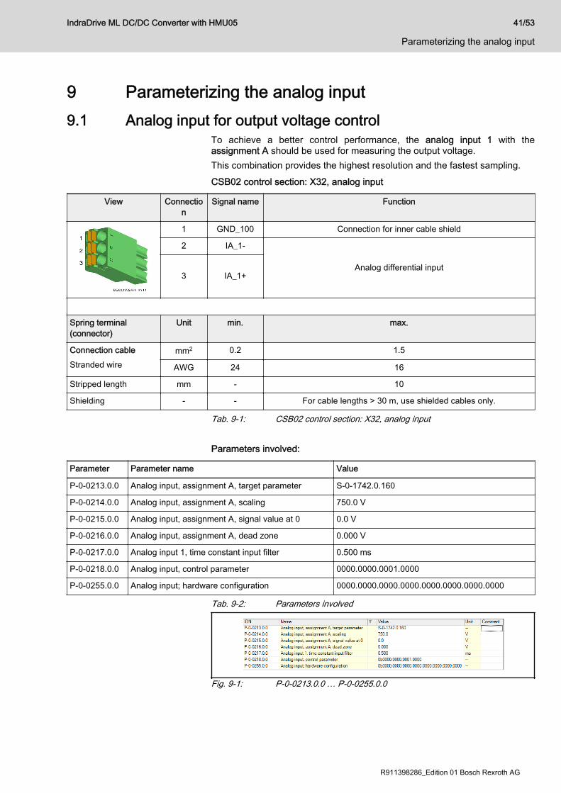
9 Parameterizing the analog input9.1 Analog input for output voltage control
To achieve a better control performance, the analog input 1 with theassignment A should be used for measuring the output voltage.This combination provides the highest resolution and the fastest sampling.CSB02 control section: X32, analog input
View Connection
Signal name Function
1 GND_100 Connection for inner cable shield
2 IA_1-
Analog differential input3 IA_1+
Spring terminal(connector)
Unit min. max.
Connection cableStranded wire
mm2 0.2 1.5
AWG 24 16
Stripped length mm - 10
Shielding - - For cable lengths > 30 m, use shielded cables only.
Tab. 9-1: CSB02 control section: X32, analog input Parameters involved:
Parameter Parameter name Value
P‑0‑0213.0.0 Analog input, assignment A, target parameter S‑0‑1742.0.160
P‑0‑0214.0.0 Analog input, assignment A, scaling 750.0 V
P‑0‑0215.0.0 Analog input, assignment A, signal value at 0 0.0 V
P‑0‑0216.0.0 Analog input, assignment A, dead zone 0.000 V
P‑0‑0217.0.0 Analog input 1, time constant input filter 0.500 ms
P‑0‑0218.0.0 Analog input, control parameter 0000.0000.0001.0000
P‑0‑0255.0.0 Analog input; hardware configuration 0000.0000.0000.0000.0000.0000.0000.0000
Tab. 9-2: Parameters involved
Fig. 9-1: P‑0‑0213.0.0 … P‑0‑0255.0.0
IndraDrive ML DC/DC Converter with HMU05 41/53
Parameterizing the analog input
R911398286_Edition 01 Bosch Rexroth AG

IndraWorks Ds:
Fig. 9-2: Status of local I/Os
9.2 Parallel connection of DC/DC converters in voltage controlIn the case of parallel connection, one HMU of the DC/DC converter isoperated in voltage control and the second HMU in current control.The parameter "S‑0‑1742.0.162, DC current, effective command value" of thevoltage-controlled HMU is the current input for the current-controlled HMUand there is transmitted to "S‑0‑1741.0.161, DC current command value".The value can be transmitted via a higher-level control or via an analogconnection between the HMU devices. Example of analog connection between HMU devices:"P‑0‑1742.0.162, DC current, effective command value" with a scaling of20 A per volt, for example, is assigned to the analog output X35 pin 1.4 at thevoltage-controlled DC/DC converter (depending on the size, a useful scalinghas to be entered).Pin 1.5 is the GND reference to the analog output.
Fig. 9-3: Analog output In the current-controlled DC/DC converter, the analog input X35 pins 1.1 and1.2 is assigned to the analog channel B. The analog value is now assigned to"S‑0‑1741.0.161, DC current command value".
42/53
Parameterizing the analog input
IndraDrive ML DC/DC Converter with HMU05
Bosch Rexroth AG R911398286_Edition 01

To ensure equal current distribution between the DC/DC converters, thescaling has to be the same as for the voltage-controlled DC/DC converter.The scaling in this example is 200 A per 10 V (20 A per1 V).At an input voltage of 0 V, the DC command value also is 0 A.Noise of the analog input at 0 V may cause the DC/DC converter to performunwanted control actions. To avoid these control actions, the dead zone ofthe analog input should be set to 0.05 V.
Fig. 9-4: Analog input
IndraDrive ML DC/DC Converter with HMU05 43/53
Parameterizing the analog input
R911398286_Edition 01 Bosch Rexroth AG

44/53 IndraDrive ML DC/DC Converter with HMU05
Bosch Rexroth AG R911398286_Edition 01

10 Additional components10.1 HLL smoothing choke
Depending on the switching frequency and size of the HMU used, anHLL05.1x‑xxxx‑Gxxxx‑x‑xx‑xxxx‑xxxx type smoothing choke has to be usedin addition to the HML balancing choke.When selecting this smoothing choke, make sure that the rated current of thesmoothing choke is not exceeded.On the assignment of HLL smoothing chokes to HMU, please see the chapterchapter 7.5 "HLL05 smoothing choke ↔ HMU05" on page 34.
750 V DC smoothing chokeCooling type Smoothing choke
Liquid-cooled HLL05.1F-500U-G0320-N-D7-NNNN-NNNNHLL05.1F-450U-G0660-N-D7-NNNN-NNNNHLL05.1F-400U-G0855-N-D7-NNNN-NNNNHLL05.1F-350U-G1100-N-D7-NNNN-NNNNHLL05.1F-250U-G1500-N-D7-NNNN-NNNN
Air-cooled HLL05.1W-600U-G0350-N-D7-NNNN-NNNNHLL05.1W-600U-G0650-N-D7-NNNN-NNNNHLL05.1W-400U-G0900-N-D7-NNNN-NNNN
Tab. 10-1: 750 V DC smoothing choke
1100 V DC smoothing chokeCooling type Smoothing choke
Liquid-cooled HLL05.1F-02M0-G0200-N-11-NNNN-NNNNHLL05.1F-02M0-G0400-N-11-NNNN-NNNNHLL05.1F-01M0-G0600-N-11-NNNN-NNNNHLL05.1F-800U-G0750-N-11-NNNN-NNNN
Tab. 10-2: 1100 V DC smoothing choke
IndraDrive ML DC/DC Converter with HMU05 45/53
Additional components
R911398286_Edition 01 Bosch Rexroth AG

46/53 IndraDrive ML DC/DC Converter with HMU05
Bosch Rexroth AG R911398286_Edition 01

11 Application examples11.1 DC/DC converter at drive system in the TN-C mains
Drive system with current-compensated DC bus choke HLL S:The current-compensated DC bus choke HLL S and the DC bus groundcapacitor pairs HAS04 prevent the DC output from jumping against ground.This is important since many third-party components, such as signalconditioners, battery buffers etc., are not suited for jumping against ground.It is also possible to operate the DC/DC converter alone with the supply unit.The main use are drive applications with battery buffer, test stands for driveunits, e.g. drive units of electric cars.
Fig. 11-1:
Transformer Mains transformer with grounded neutral point (TN-C mains)
F1…3F4…6
Fuses
HNF Mains filter
K1 Mains contactor
HNL Preconnected choke / chopper choke
IndraDrive ML DC/DC Converter with HMU05 47/53
Application examples
R911398286_Edition 01 Bosch Rexroth AG

HNC…NNNN Mains capacitor
HNA Mains connection module
HMU Universal inverter
HAS04 DC bus ground capacitor pairs
HVT High-voltage signal conditioner:Galvanically isolated measuring amplifier that converts aninput voltage of DC 0 … 1000 V or DC 0 … 1400 V to anoutput voltage of DC 0 … 10 V
HML Motor/balancing choke
HLL G Smoothing choke
HLL S Current-compensated DC bus choke
Cout Output capacitance
Tab. 11-1:
48/53
Application examples
IndraDrive ML DC/DC Converter with HMU05
Bosch Rexroth AG R911398286_Edition 01
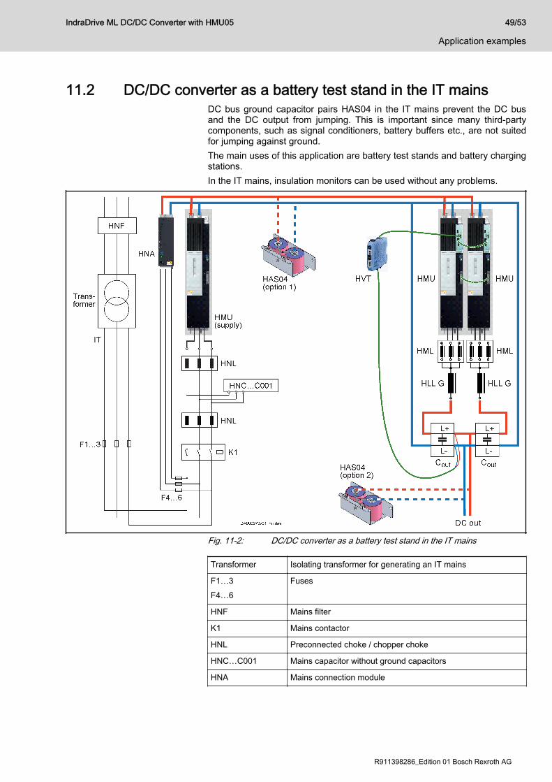
11.2 DC/DC converter as a battery test stand in the IT mainsDC bus ground capacitor pairs HAS04 in the IT mains prevent the DC busand the DC output from jumping. This is important since many third-partycomponents, such as signal conditioners, battery buffers etc., are not suitedfor jumping against ground.The main uses of this application are battery test stands and battery chargingstations.In the IT mains, insulation monitors can be used without any problems.
Fig. 11-2: DC/DC converter as a battery test stand in the IT mains
Transformer Isolating transformer for generating an IT mains
F1…3F4…6
Fuses
HNF Mains filter
K1 Mains contactor
HNL Preconnected choke / chopper choke
HNC…C001 Mains capacitor without ground capacitors
HNA Mains connection module
IndraDrive ML DC/DC Converter with HMU05 49/53
Application examples
R911398286_Edition 01 Bosch Rexroth AG
HMU Universal inverter
HAS04 DC bus ground capacitor pairsIf an insulation monitor is used, use DC bus ground capacitorpairs HAS04.1‑003‑NN1 without discharging resistors whereapplicable.Depending on the design, the DC bus ground capacitors canbe installed at the DC output (option 2; preferable) or at the DCbus (option 1).
HVT High-voltage signal conditioner:Galvanically isolated measuring amplifier that converts aninput voltage of DC 0 … 1000 V or DC 0 … 1400 V to anoutput voltage of DC 0 … 10 V
HML Motor/balancing choke
HLL G Smoothing choke
Cout Output capacitance
Tab. 11-2:
50/53
Application examples
IndraDrive ML DC/DC Converter with HMU05
Bosch Rexroth AG R911398286_Edition 01

IndexAAdditional components........................................ 45Analog input
Parameterizing............................................... 41Application examples.......................................... 47
CComponents
Combining...................................................... 26DC/DC converter............................................ 17Parallel connection (example with 2 HMU).... 27Single application........................................... 26
Connection diagramDC/DC converter............................................ 28Parallel connection using HPC01.1-P001-NN optional card................................... 30Parallel connection via analog I/Os ofcontrol sections.............................................. 29Single application........................................... 28
Control accuracy................................................. 32Controller output
Limiting........................................................... 40Cout
Output capacitance........................................ 19Current
Current ripples............................................... 32DC output....................................................... 33Limiting the output current............................. 40
DData
DC/DC converter............................................ 31DC output
Current........................................................... 33DC bus........................................................... 33Voltage........................................................... 33
DC/DC converterApplication examples..................................... 47Applications...................................................... 1Battery test stand in IT mains........................ 49Components................................................... 17Conditions...................................................... 19Connection diagram....................................... 28Data............................................................... 31Design............................................................ 21Drive system in TN-C mains.......................... 47Functional package........................................ 37Parallel connection......................................... 42Requirements................................................. 19Scope of applications....................................... 1Technical data................................................ 31Use................................................................... 1
DesignDC/DC converter............................................ 21
Drive system......................................................... 5
EElectric drive system............................................. 5
FFunctional package
DC/DC converter............................................ 37
HHLL
Smoothing choke, overview........................... 45HLL05
Smoothing choke, assignment to HMU05...... 34HMU05
Assignment to HLL05 smoothing choke........ 34
IIntended use......................................................... 3
Applications...................................................... 3IT mains
Battery test stand (application example)........ 49
OOperation mode
Setting............................................................ 39Output capacitance
Cout............................................................... 19Output power...................................................... 35
PParallel connection
Components (example with 2 HMU).............. 27Connection diagram, parallel connectionusing HPC01.1-P001-NN optional card......... 30Connection diagram, parallel connectionvia analog I/Os of control sections................. 29DC/DC converter............................................ 42Through command value input by controlunit................................................................. 25Using HPC01.1-P001-NN optional card......... 23Via analog I/Os of the control sections.......... 24
ParameterizingAnalog input................................................... 41Controller output............................................ 40Functional package........................................ 37
PELV................................................................... 10Power limitation................................................... 35Protective extra-low voltage................................ 10
SSafety instructions for electric drives andcontrols................................................................. 5Single application
Components................................................... 26Connection diagram....................................... 28
IndraDrive ML DC/DC Converter with HMU05 51/53
Index

Smoothing chokeHLL, Overview............................................... 45HLL05, assignment to HMU05....................... 34
State-of-the-art...................................................... 3Switching frequency
Setting............................................................ 39
TTechnical data
DC/DC converter............................................ 31TN-C mains
DC/DC converter at drive system (appli‐cation example).............................................. 47
UUnintended use..................................................... 4
Consequences, disclaimer............................... 3Use
Intended use.................................................... 3Unintended use................................................ 4
VVoltage
DC output....................................................... 33Input and output voltage range...................... 31Limiting the output voltage............................. 40Voltage ripples............................................... 32
52/53
Index
IndraDrive ML DC/DC Converter with HMU05

Notes
IndraDrive ML DC/DC Converter with HMU05 53/53

Bosch Rexroth AGElectric Drives and ControlsP.O. Box 13 5797803 Lohr, GermanyBgm.-Dr.-Nebel-Str. 297816 Lohr, GermanyPhone +49 9352 18 0Fax +49 9352 18 8400www.boschrexroth.com/electrics
*R911398286*R911398286
DOK-INDRV*-HXX05_DCDC*-PR01-EN-P


