Embed Size (px)
Citation preview

INDUCED DRAFT COOLING TOWER
PROJECT REPORT
ON
‘INDUCED DRAFT COOLING TOWER’
B.S.PATEL POLYTECHNIC,KHERVA
PROJECT GROUP: (1) Patel Kaushal 126440319030
(2) Patel Utkarsh 126440319031
(3) Patel Ravi 126440319032
(4) Patel Vishal 126440319038
(5) Patel Pasavin 126440319042
INTRNAL GUIDE- Mr.A.M.Patel H.O.D:-Mr.K.P.Patel
B.S.P.P. 2014-15 Page 1

INDUCED DRAFT COOLING TOWER
CERTIFICATE
This is to certify that Mr.Patel Kaushal A. having Enrolment No
: 126440319030 has completed Part-I UDP Project work having title Induced Draft Cooling
Tower.
He has undergone the process of shodh yatra, literature survey and problem
definition. He is supposed to carry out the residue UDP Part-II work on same problem
during Semester-V for the final fulfillment of the UDP work which is prerequisite to
complete Diploma Engineering.
Guide – Mr.Alpesh M.Patel H.O.D:-Mr.K.P.Patel
B.S.P.P. 2014-15 Page 2

INDUCED DRAFT COOLING TOWER
CERTIFICATE
This is to certify that Mr.Patel Utkarsh R. Having Enrolment No
: 126440319031 has completed Part-I UDP Project work having title Induced Draft Cooling
Tower.
He has undergone the process of shodh yatra, literature survey and problem
definition. He is supposed to carry out the residue UDP Part-II work on same problem
during Semester-V for the final fulfillment of the UDP work which is prerequisite to
complete Diploma Engineering.
Guide – Mr.A.M.Patel H.O.D:-Mr.K.P.Patel
B.S.P.P. 2014-15 Page 3

INDUCED DRAFT COOLING TOWER
CERTIFICATE
This is to certify that Mr.Patel Ravi S. having Enrolment No : 126440319032
has completed Part-I UDP Project work having title Induced Draft Cooling Tower .
He has undergone the process of shodh yatra, literature survey and problem
definition. He is supposed to carry out the residue UDP Part-II work on same problem
during Semester-V for the final fulfillment of the UDP work which is prerequisite to
complete Diploma Engineering.
Guide – Mr.A.M.Patel H.O.D:-Mr.K.P.Patel
B.S.P.P. 2014-15 Page 4

INDUCED DRAFT COOLING TOWER
CERTIFICATE
This is to certify that Mr.Patel Vishal P. having Enrolment No
: 126440319038 has completed Part-I UDP Project work having title Induced Draft Cooling
Tower .
He has undergone the process of shodh yatra, literature survey and problem
definition. He is supposed to carry out the residue UDP Part-II work on same problem
during Semester-V for the final fulfillment of the UDP work which is prerequisite to
complete Diploma Engineering.
Guide – Mr.A.M.Patel H.O.D:-Mr.K.P.Patel
B.S.P.P. 2014-15 Page 5

INDUCED DRAFT COOLING TOWER
CERTIFICATE
This is to certify that Mr.Patel Pasavin H. having Enrolment No
: 126440319042 has completed Part-I UDP Project work having title Induced Draft Cooling
Tower .
He has undergone the process of shodh yatra, literature survey and problem
definition. He is supposed to carry out the residue UDP Part-II work on same problem
during Semester-V for the final fulfillment of the UDP work which is prerequisite to
complete Diploma Engineering.
Guide – Mr.A.M.Patel H.O.D:-Mr.K.P.Patel
B.S.P.P. 2014-15 Page 6

INDUCED DRAFT COOLING TOWER
INDUSTRY DEFINED PROBLEM/PROJECT (IDP) STATEMENT FORM
STUDENT PARTICULARS-1
FIRST NAME KAUSHAL
LAST NAME PATEL
MOBILE NO. 1 8154887042 2 9924972429
EMAIL [email protected]
ENROLLMENT NO:-126440319030
COLLEGE NAME B.S.PATEL POLYTECNIC, GANPAT UNIVERSITY.
ADDRESS
AT:SHER
TA:MANDAL
DIST:AHEMEDABAD
BRANCH MECHANICAL ENGINEERING
SEMESTER 5th SEM. YEAR 2014-2015
TEAM NAME G-6
SIGNATURE OF STUDENT
B.S.P.P. 2014-15 Page 7

INDUCED DRAFT COOLING TOWER
INDUSTRY DEFINED PROBLEM/PROJECT (IDP) STATEMENT FORM
STUDENT PARTICULARS-2
FIRST NAME UTKARSH
LAST NAME PATEL
MOBILE NO. 1. 9998385986 2. 7600083413
EMAIL [email protected]
ENROLLMENT NO:-126440319031
COLLEGE NAME
B.S.PATEL POLYTECNIC, GANPAT UNIVERSITY.
ADDRESS
AT:KIMBUVA
TA:PATAN
DIST:PATAN
BRANCH
SEMESTER 5th SEM. YEAR 2014-2015
TEAM NAME G-6
SIGNATURE OF STUDENT
B.S.P.P. 2014-15 Page 8

INDUCED DRAFT COOLING TOWER
INDUSTRY DEFINED PROBLEM/PROJECT (IDP) STATEMENT FORM
STUDENT PARTICULARS-3
FIRST NAME RAVI
LAST NAME PATEL
MOBILE NO. 1. 7874697626 2.
EMAIL [email protected]
ENROLLMENT NO:-126440319032
COLLEGE NAME
B.S.PATEL POLYTECNIC, GANPAT UNIVERSITY.
ADDRESS
AT:MOTAP
TA:BECHARAJI
DIST:MEHSANA
BRANCH MECHANICAL ENGINEERING
SEMESTER 5th SEM. YEAR 2014-2015
TEAM NAME G-6
SIGNATURE OF STUDENT
B.S.P.P. 2014-15 Page 9

INDUCED DRAFT COOLING TOWER
INDUSTRY DEFINED PROBLEM/PROJECT (IDP) STATEMENT FORM
STUDENT PARTICULARS-4
FIRST NAME VISHAL
LAST NAME PATEL
MOBILE NO. 1. 9924392268 2. 9033335659
EMAIL [email protected]
ENROLLMENT NO:-126440319038
COLLEGE NAME B.S.PATEL POLYTECNIC, GANPAT UNIVERSITY.
ADDRESS
35-YOGESHWAR PARK SOCIETY,
WONDERPOINT,CTM,
AMRAIVADI,AHMEDABAD
BRANCH MECHANICAL ENGINEERING
SEMESTER 5th SEM. YEAR 2014-2015
TEAM NAME G-6
SIGNATURE OF STUDENT
B.S.P.P. 2014-15 Page 10
INDUCED DRAFT COOLING TOWER
INDUSTRY DEFINED PROBLEM/PROJECT (IDP) STATEMENT FORM
STUDENT PARTICULARS-5
FIRST NAME PASAVIN
LAST NAME PATEL
MOBILE NO. 1. 9537149323 2. 8734830193
EMAIL [email protected]
ENROLLMENT NO:-126440319042
COLLEGE NAME
B.S.PATEL POLYTECNIC, GANPAT UNIVERSITY.
ADDRESS
AT: MANDRISANA
TA:DETROJ
DIST: AHMEDABAD
BRANCH MECHANICAL ENGINEERING
SEMESTER 5th SEM. YEAR 2014-2015
TEAM NAME G-6
SIGNATURE OF STUDENT
B.S.P.P. 2014-15 Page 11

INDUCED DRAFT COOLING TOWER
ACKNOWLEDGEMENT
We are feeling pleasure introducing our project “INDUCED DRAFT COOLING TOWER”
result of our new radical ideas to significant windup our studies during in course “DIPLOMA
IN MECHANICAL ENGG.” B.S.Patel Polytechnic,Kherva,Mehsana. Suggestion to improve
quality of product are always well come many hands have given their active support &
contributed for design& development of “INDUCED DRAFT COOLING TOWER”
We would like to thank our Prof.A.M.Patel, we would also like to thank our respected
principal B.S.Patel &our head of the department Prof. K.P.Patel.
And special thank to Prof. A.M.Patel (Induced draft cooling Tower designer) for their kind
co-operation & excellent help in making of project.
Your Truly :-
Kaushal
Utkarsh
Ravi
Vishal
Pasavin
B.S.P.P. 2014-15 Page 12

INDUCED DRAFT COOLING TOWER
INDEX
Sr. No. Topics Name Page No.
01 SUMMERY 14
02 SELECTION OF PROJECT 15
03 MARKET SURVEY 16
04 INTRODUCTION 17
05 DEFINITION OF A PROJECT 18
06 AIM OF PROJECT 19
07 BASIC ELEMENTS OF PROJECT 20
08 WORKING PRINCIPLE 21
09 CLASSIFICATION OF COOLING TOWER 22
10 PARTS OF COOLING TOWER 23
11 MECHANICAL &THERMAL DESIGN PARAMETERS
OF COOLING TOWER
26
12 DESIGN CALCULATION 27
13 PROCEDURE FOR THE EXPERIMENT 28
14 PLANNING OF PROJECT WORK 29
15 REQUIRED MACHINE TOOLS & EQUIPMENTS 30
16 OPERATION PROCESS CHART & FLOW PROCESS
CHART
31
17 COSTING & CALCULATION 35
18 ADVANTAGES & DISADVATAGES 37
19 CONCLUSIONS 38
20 REFERENCES 39
B.S.P.P. 2014-15 Page 13

INDUCED DRAFT COOLING TOWER
SUMMARY
We can see many projects in our work shop like furnace, speed reduction gear box, Rolling
mill, Thermal Power Plant, Glass cutter machine etc. But finally we decided to select the
Induced draft cooling tower. As a project.
For that first we collected all the required material like MS sheet, PVC pipes, Fins, Wire
mesh, exhaust fan, Stand, Nut and bolts and some other material for cooling tower.
After this all and after some operations like cutting, bending, welding and fitting. Finally we
assembled the parts of our project with final testing.
In this project of Induced draft cooling tower, we are clever students is participate are as
follow.
B.S.P.P. 2014-15 Page 14

INDUCED DRAFT COOLING TOWER
SELECTION OF PROJECT
Before selecting a project, survey has to be done regarding demand & market value of the
product feasibility of the available resources & facilities.
RESOURCES OF PROJECT
Resources of project, which are very useful for doing project work are given below :
• Tool room
• Machine shop
• Fabrication Industries
• Discussion with project guide
• Market survey
• Industrial support
LITERATURE SURVEY
We have survey following literature or books for selection of project.
• Thermal engineering
• Powerplant engineering
• www.coolingtower.com
• www.induceddraftcoolingtower.com
• Autocad 2014& application.
Selection of Projection
• Resource utilized • Entrepreneurship
• Liberty • Discuss with student group
• Market survey. • Discuss with project in charge
• Magazine
B.S.P.P. 2014-15 Page 15

INDUCED DRAFT COOLING TOWER
MARKET SURVEY
Before you launch the product you need to check your self-market product for the product
selected by you
A comprehension market study in must be specific advantages of such study are as under.
• It makes it possible for you to estimate scale & utilization of installed capacity with
reference to proposed enterprise.
• You can judge weather the proposed capacity is one the higher or lower size.
• It enables you to evaluated the viability of an enterprise by arcing at a years
estimate of seals.
• It provides a preliminary input for the marketing strategy & process formulation or
the enterprise (A market program is set of decision required in respect of various
markets related to issues it influences the market.)
Market survey is usually focused on gross market demand present & future. It typically
highlights the gap between expected market demand & supply in respect offer given
product. Such a gap could be positive & therefore favorably. The gap could also negative.
B.S.P.P. 2014-15 Page 16

INDUCED DRAFT COOLING TOWER
INTRODUCTION
Over heating of machine elements is common problem in industry. It is caused due
to continuous operation of machine and atmospheric conditions of the surroundings.
Operation cannot be stopped or in other words the machine cannot be given time to be
cooled down and therefore there has to be provision for cooling. Water is the best cooling
medium as it is cheap and available in abundance. However it has to be noted that
continuous flow of fresh water to the machine is not advisable as it creates great waste.
Cooling tower is used to fulfil the purpose of cooling with minimum usage of fresh
water. It circulates fresh water for cooling to the machine and uses least make up water
that is lost due to evaporation. Apart from industry cooled water is needed for, for example,
air conditioners, or power generation. A cooling tower is the equipment used to reduce the
temperature of a water stream by extracting heat from water and emitting it to the
atmosphere. Cooling towers make use of evaporation whereby some of the water is
evaporated into a moving air stream and subsequently discharged into the atmosphere. As
a result, the remainder of the water is cooled down significantly as shown in the figure.
Cooling towers are able to lower the water temperatures more than devices that use only
air to reject heat, like the radiator in a car, and are therefore more cost-effective and energy
efficient.
B.S.P.P. 2014-15 Page 17

INDUCED DRAFT COOLING TOWER
DEFINITIONS
WHAT IS A COOLING TOWER?
A cooling tower is a heat rejection device, which extracts waste heat to the
atmosphere though the cooling of a water stream to a lower temperature. Common
applications for cooling towers are providing cooled water for air-conditioning,
manufacturing and electric power generation. The generic term "cooling tower" is used to
describe both direct (open circuit) and indirect (closed circuit) heat rejection equipment. A
direct, or open-circuit cooling tower is an enclosed structure with internal means to
distribute the warm water fed to it over a labyrinth-like packing or "fill." The fill may consist
of multiple, mainly vertical, wetted surfaces upon which a thin film of water spreads. An
indirect, or closed circuit cooling tower involves no direct contact of the air and the fluid,
usually water or a glycol mixture, being cooled. In a counter-flow cooling tower air travels
upward through the fill or tube bundles, opposite to the downward motion of the water. In a
cross-flow cooling tower air moves horizontally through the fill as the water moves
downward. Cooling towers are also characterized by the means by which air is moved.
Because evaporation consists of pure water, the concentration of dissolved minerals and
other solids in circulating water will tend to increase unless some means of dissolved-solids
control, such as blow-down, is provided. Some water is also lost by droplets being carried
out with the exhaust air (drift)
B.S.P.P. 2014-15 Page 18

INDUCED DRAFT COOLING TOWER
AIM OF PROJECT
• To developed attitude of inquiry
• To work as leader & as a member if a team
• To measure physical phenomenon.
• To developed problem solving ability.
• To developed ability of report writing.
• To developed planning & disciplinary studies
• To give students an opportunities to learn of to keep good record.
• To present students an excising and demanding challenges.
B.S.P.P. 2014-15 Page 19

INDUCED DRAFT COOLING TOWER
BASIC ELEMENTS OF PROJECT
1. Operation :
These are to carried out in particular sequence to order it would still better, if the
method of performing each operation may also be established. It may be kept in mind that
for carrying out each. Actually there is always an expenditure of resources may be in terms
of coast, time etc.
2. Resources :
For the purpose of carrying out the activities, the resources meet are in term of
manpower, material, machines, money & time. The competitions of any activity or for that
matter the future project can not be said to be over values required resources are made
available at the appropriate time. In other word man has to be prepared co-ordination these
resources.
3. Conditions :
The activities are carries out under specified conditions of restrictions which we
have a direct bearing on the competition of the involving the factor.
B.S.P.P. 2014-15 Page 20

INDUCED DRAFT COOLING TOWER
WORKING PRINCIPLE OF INDUCED DRAFT COOLING TOWER
Cooling tower is essentially a heat and mass transfer device. It removes
heat from the water and loses a fraction of water during heat transfer to the air. When air is
blown from downwards it came in contact with upcoming water the enthalpy of which is
higher and at the time of contact this air causes evaporation of water droplet. It is known
that in order to get evaporated water requires to gain certain amount of latent heat. It does
so from nearby droplet and evaporates into vapour form. Due to removal of sensible heat,
remaining water droplets loses temperature and cools down. Due to higher surface area in
packing heat transfer rate increases and water is further cooled to the require temperature.
Air moving upward takes away certain amount of water content in (vapour form) with it
which is not desirable. In order to recover lost water drift eliminators are provided.
Upcoming air loses their velocity and causes certain amount of vapour to be converted into
water. The water falls downward and collected in the basin.
B.S.P.P. 2014-15 Page 21

INDUCED DRAFT COOLING TOWER
CLASSIFICATION OF COOLING TOWER
Classification of cooling tower
Natural Draft Mechanical Draft Cooling Tower Cooling Tower Spray Packed Hyperbolic Forced Induced Type Type Draft Draft Draft
B.S.P.P. 2014-15 Page 22

INDUCED DRAFT COOLING TOWER
PARTS OF INDUCED DRAFT COOLING TOWER
FILLS :
Our honey combed PVC fills are high performance heavy duty, law weight, excellent
resistance to corrosion. These offer a striking balance between maximum heat transfer
surface area vis-à-vis minimum restriction to air flow.
B.S.P.P. 2014-15 Page 23

INDUCED DRAFT COOLING TOWER FAN :
The Axial flow fan consists of cast Aluminum or FRP variable pitch aerofoil blades fitted on a M.S. hot dip galvanized hub with S.S. 304 "U" bolts & nuts. The balanced fan assembly is mounted directly on the shaft of weather proof, flanged motor.
WATER DISTRIBUTION These spray water to wet the fill. Uniform water distribution at the top of the fill is
essential to achieve proper wetting of the entire fill surface. Nozzles can either be fixed and
spray in a round or square patterns, or they can be part of a rotating assembly as found in
some circular cross-section towers.
B.S.P.P. 2014-15 Page 24

INDUCED DRAFT COOLING TOWER
DRIFT ELIMINATORS:
These capture water droplets entrapped in the air stream that otherwise would be
lost to the atmosphere.
Air inlet:
This is the point of entry for the air entering a tower. The inlet may take up an entire
side of a tower (cross-flow design) or be located low on the side or the bottom of the tower
(counter-flow design).
B.S.P.P. 2014-15 Page 25

INDUCED DRAFT COOLING TOWER
MECHANICAL AND THERMAL DESIGN PARAMETERS FOR COOLING TOWER
power consumption by 7.5 tr cooling tower
In order to initiate cooling tower design the following parameters have been considered,
Technical Parameter Quantity Volume of circulating water (L) 3.8 m3/h Inlet temperature of water (T1) 38 0C Outlet temperature of water (T2) 32 0C Wet bulb temperature (WBT) 290C Height of the cooling tower (H) 1.2 m Inlet temperature of air (Ta1) 200C Outlet temperature of air (Ta2) 270C Design relative humidity (ɸ) 80% Allowable losses through Evaporation 1.44%
Thermal parameters Quantity Enthalpy of air at inlet temperature (Ha1) 50 KJ/Kg Enthalpy of air at outlet temperature (Ha2) 73 KJ/Kg Specific Humidity of air at inlet temperature (W1)
0.0118 Kg/Kg of air
Specific humidity of air at outlet temperature (W2)
0.018 Kg/Kg of air
Specific Volume of air at inlet temperature (Va1)
0.842 m3/Kg
Specific volume of air at outlet temperature (Va2)
0.875 m3/Kg
Enthalpy of water at inlet temperature (Hw1) 159.10 KJ/Kg Enthalpy of water at outlet temperature (Hw2)
134 KJ/Kg
B.S.P.P. 2014-15 Page 26
INDUCED DRAFT COOLING TOWER
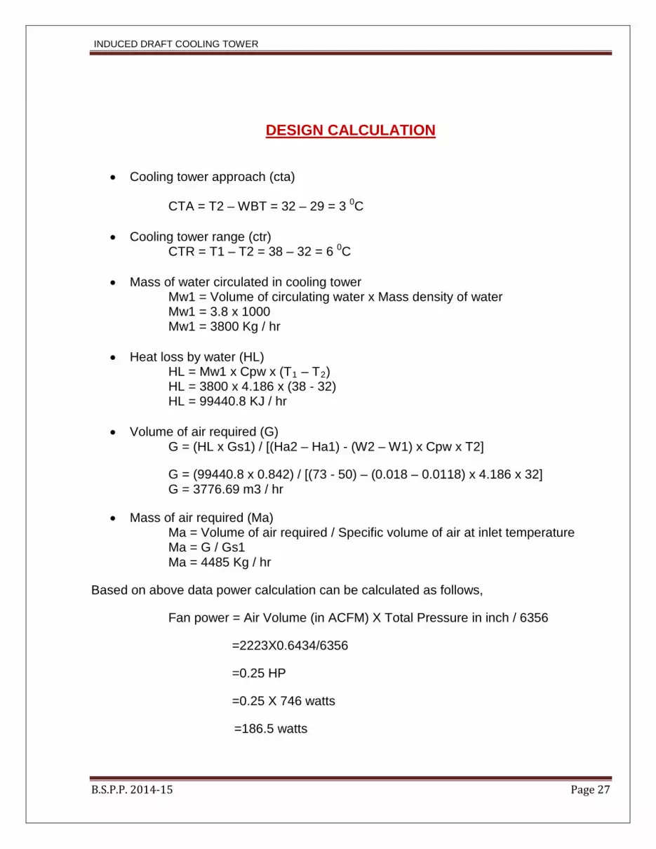
DESIGN CALCULATION
• Cooling tower approach (cta)
CTA = T2 – WBT = 32 – 29 = 3 0C
• Cooling tower range (ctr) CTR = T1 – T2 = 38 – 32 = 6 0C
• Mass of water circulated in cooling tower
Mw1 = Volume of circulating water x Mass density of water Mw1 = 3.8 x 1000 Mw1 = 3800 Kg / hr
• Heat loss by water (HL)
HL = Mw1 x Cpw x (T1 – T2) HL = 3800 x 4.186 x (38 - 32) HL = 99440.8 KJ / hr
• Volume of air required (G)
G = (HL x Gs1) / [(Ha2 – Ha1) - (W2 – W1) x Cpw x T2]
G = (99440.8 x 0.842) / [(73 - 50) – (0.018 – 0.0118) x 4.186 x 32] G = 3776.69 m3 / hr
• Mass of air required (Ma) Ma = Volume of air required / Specific volume of air at inlet temperature Ma = G / Gs1 Ma = 4485 Kg / hr
Based on above data power calculation can be calculated as follows,
Fan power = Air Volume (in ACFM) X Total Pressure in inch / 6356
=2223X0.6434/6356
=0.25 HP
=0.25 X 746 watts
=186.5 watts
B.S.P.P. 2014-15 Page 27

INDUCED DRAFT COOLING TOWER
PROCEDURE FOR THE EXPERIMENT
Initially tower performance will be determined by considering anonymous range and later
on it will be compared with the experimental one.
Range considered for the cooling tower is 38-32=6 c; where 38 is inlet temperature and 32
is outlet temperature.
Following equation is used to determine cooling tower efficiency which is known as the
merkel equation.
KaV/L = [(T1 – T2) / 4] x {(1 /Δ h1) + (1 / Δ h2) + (1 / Δ h3) + (1 / Δ h4)}
Where,
K = Mass transfer co-efficient (Kg / hr m2); V = Active cooling volume (m3); T1 = water temperature entering the cooling tower, 0C; T2 = water temperature leaving the cooling tower, 0C; hw = enthalpy of saturated air at water temperature, kJ/(kg of dry air); ha = enthalpy of air, kJ/(kg of dry air); a = total area of wetted surface includes the surface area of water drops as well as wetted slats or other fill material, m2; L = water mass flow rate, kg/s; Now, Δ h1 = Value of Hw - Ha at T2 + 0.1 (T1 – T2) Δ h2 = Value of Hw - Ha at T2 + 0.4 (T1 – T2) Δ h3 = Value of Hw - Ha at T1 - 0.4 (T1 – T2) Δ h4 = Value of Hw - Ha at T1 - 0.1 (T1 – T2) Calculation gives the following value for cooling tower performance KaV / L = 0.1540 EFFICIENCY OF COOLING TOWER N = (T1 – T2) / (T1 – WBT) N = (38 - 32) / (38 - 29) N = 66.67 % EFFECTIVENESS OF COOLING TOWER P = (T1 – T2) / (T1 – Ta1) P = (38 - 32) / (38 - 20) P=0.33
B.S.P.P. 2014-15 Page 28

INDUCED DRAFT COOLING TOWER
PLANNING OF PROJECT WORK
In the planning we have to select a project for our team has continue for give members for
this we added our past memory with a view of final a project that we must write to us.
We visited in many industries, visited library, read various books pertaining to
technical side made tentative collection of these all the project. Among these all the project
we compared the feasibility of project and reached at the decision to manufacture “Induce
draft cooling tower”. Because at the fact that it was available in our college workshop and
second during manufacture of this stall it should be easy for us to read and study the
thoughts to prevail difficulties.
In the planning stage we have also to analyze and study the different components
and part by dismantling the “Induce draft Cooling tower” and model list.
B.S.P.P. 2014-15 Page 29

INDUCED DRAFT COOLING TOWER
REQUIRED MACHINE TOOLS & EQUIPMENTS
The tools & equipment, which are needed for project Induced draft cooling tower.
We must required different machines for different operations like.
• Sheet cutting machine (Hand shearing machine)
• Sheet banding machine
• Welding machine
• Drilling machine
• Hand grinder
And also some equipments like
• Measuring tape (500 mm)
• Venier caliper (200 mm)
• Marker (Standard quality)
• Hand hacksaw (300 mm)
• Drill bit (3 mm to 15 mm)
• Right (single) point cutting tool.
B.S.P.P. 2014-15 Page 30

INDUCED DRAFT COOLING TOWER
B.S.P.P. 2014-15 Page 31

INDUCED DRAFT COOLING TOWER
FLOW PROCESS CHART
B.S.P.P. 2014-15 Page 32

INDUCED DRAFT COOLING TOWER
B.S.P.P. 2014-15 Page 33

INDUCED DRAFT COOLING TOWER
B.S.P.P. 2014-15 Page 34

INDUCED DRAFT COOLING TOWER
COSTING
• There are three elements of any products are :
• Material
• Labor
• Expenses
• Material : • Direct material :
Material which is processed for final product but it is a part of the product is direct
material cost is this material is called direct from market.
• In – direct material :
Material which does not forms part of the final product but it is a must be for
processing direct material is called in-direct material e.g. – Cotton waste, oil, etc.
• Labor : • Direct labor :
The worked who actually performed the work on the directly material rather
mechanically of by machine is called direct labor.
• In-direct labor :
It supervised the activity of the direct labor.
Expenses :
• Direct Expenses :
The expenses, which can be directly changed on the particular product, are called
expenses.
• In – Direct Expenses :
The expenses that can not be directly or confidently changed on particular
products are called in-direct expenses.
B.S.P.P. 2014-15 Page 35

INDUCED DRAFT COOLING TOWER
CALCULATION
Prime cost
• Direct material + Direct labour
= 6000 + 1,495
= 7,495 Rs.
• Overhead cost :
15% Prime Cost
= 1,124.25 Rs.
• Production cost :
= 7,495 + 1,124.25
= 8,619.25 Rs.
• Net Desired Profit
15% of production cost
= 1,292.88 Rs.
• Selling Price :
Production + Profit
= 8,619.25 + 1,292.88
= 9,912.13 Rs.
• Selling price of Cooling Tower is 9,912.13 Rs.
B.S.P.P. 2014-15 Page 36

INDUCED DRAFT COOLING TOWER
ADVANTAGES AND DISADVANTAGE
Advantages:-
The main advantage is that coldest water comes in contact with the direct air & warmest
water comes in contact with most humid air.
• The re-circulation is seldom a problem with this tower as outlet a discharge the
heated & humidity away from air enters below the tower.
• The size of 20 in diameter can be used.
• Claims are made that the ID fan tower has the advantage of tower first cool, requires
less space, and is capable of cooling through a wide range.
• The first cost is lower due to the reduction in pump capacity required & smallest
length of water pipes. The power consumption per kg. of water cooled is less
compared with FD fan system
Disadvantages:-
• The static pressure loss is higher as restricted are at base tends to above off the
flow of high velocity air. This requires higher HPmotor to drive the fan compared with
forced draft handling equipment.
• The air velocities through the packing are contently distributed & it has very little
movement near the walls & center of the tower.
B.S.P.P. 2014-15 Page 37
INDUCED DRAFT COOLING TOWER
CONCLUSIONS
The described study allows site-specific scenario calculations for the possible
development of water temperatures and the related impacts on the power plant cooling
system: these are e.g. cooling water temperature, heat discharge to the river or additional
operation costs due to high temperatures and low water levels. Therefore, the model will
provide a basis for site-specific adaptation measures.
Temperature inversions reduce a particular natural draft wetcooling tower heat
rejection by approximately 20% in winter and by approximately 8% in summer. The
reduction in tower performance due to the adversely affected pressure differential (draft
equation) on the outside of the tower, during temperature inversions, accounts for
approximately 20% of the total loss and the increased effective inlet temperature (transfer
process) for approximately 80% of the reduction in tower performance.
B.S.P.P. 2014-15 Page 38

INDUCED DRAFT COOLING TOWER
REFERENCES
Thermal Design Of Cooling Tower.pdf, Authors: Ronak Shah & Trupti Rathod, LDRP
institute of Technology and Research, Gandhinagar, India
Cooling Tower Design.pdf, Karachi
Workshop Exercise - Cooling Tower.pdf, www.energyefficiencyasia.org , UNEP
(Asia)
Cooling Tower Basics And Common Misconceptions.pdf, Jalal Engineering, [email protected] Karachi
Cooling Tower, Bureau of Energy Efficiency (India)
Cooling Tower Thermal Design Manual, page 6-21, Technical site of Daeil Aquaco.
LTD, USA
http://www.engineeringtoolbox.com/fans-efficiency-power-consumption-d_197.html
For experiment outlet temperature will be measured using thermometer and cooling tower performance will be found using above mentioned equation.
B.S.P.P. 2014-15 Page 39


