Embed Size (px)
Citation preview
�����������������
Citation: Samatas, G.G.; Pachidis, T.P.
Inertial Measurement Units (IMUs) in
Mobile Robots over the Last Five
Years: A Review. Designs 2022, 6, 17.
https://doi.org/10.3390/
designs6010017
Academic Editor: Oscar Reinoso
Garcia
Received: 19 January 2022
Accepted: 14 February 2022
Published: 16 February 2022
Publisher’s Note: MDPI stays neutral
with regard to jurisdictional claims in
published maps and institutional affil-
iations.
Copyright: © 2022 by the authors.
Licensee MDPI, Basel, Switzerland.
This article is an open access article
distributed under the terms and
conditions of the Creative Commons
Attribution (CC BY) license (https://
creativecommons.org/licenses/by/
4.0/).
Review
Inertial Measurement Units (IMUs) in Mobile Robots over theLast Five Years: A ReviewGerasimos G. Samatas 1 and Theodore P. Pachidis 2,*
1 MLV Research Group, Computer Science Department, International Hellenic University, 65404 Kavala, Greece;[email protected]
2 Human–Machines Interaction (Humain) Lab, Computer Science Department, International HellenicUniversity, 65404 Kavala, Greece
* Correspondence: [email protected]; Tel.: +30-2510-462281
Abstract: Robots and especially mobile robots have experienced rapid growth, making them part ofeveryday life. An inertial measurement unit (IMU), which is a set of sensors, plays an important rolein mobile robots’ navigation. Data collected by the IMU sensors on a robot are properly convertedand useful information is calculated concerning, i.e., position, orientation, and acceleration. With theadvancement of technology, IMUs have been transformed from large and complex devices into small,flexible, and efficient ones. The main sensors included in an IMU are the gyroscope, the accelerometer,and the magnetometer. Additionally, there are other sensors such as a barometer, a temperature sensor,a pressure sensor, or even an attitude sensor. The components that an IMU consists of are many and themain differences concern the technology they integrate, the designer purpose, and the specificationsset by the manufacturer. The purpose of this review is a comparative presentation of 42 IMU modelsfrom 7 different manufacturers over the last five years comparing main features such as structuredetails, connectivity, and communication protocols. Moreover, statistical results are quantitatively andqualitatively presented providing a future user the possibility to select the proper IMU.
Keywords: mobile robots; commercial Inertial Measurement Unit (IMU); sensors
1. Introduction
Nowadays, the word robot is very familiar to people. A major category of robotsis mobile robots. Mobile robots can navigate using various sensors, software, properlydeveloped and intelligent algorithms. Robots navigation is a complex process and toachieve it, many challenges must be overcome.
For the successful navigation of a robot, many open problems exist. These problemsconcern localization, mapping, simultaneous localization and mapping, path planning,obstacle avoidance. For localization, different sensors and methods have been developedfor more accurate positioning [1]. There are different techniques for calculating the robotlocation, in a relative or absolute way. Techniques that calculate robot location in an absoluteway are based on widespread systems. One well-known example is the Global PositionSystem (GPS), which determines the current position with the assistance of satellites [2].Techniques that relatively calculate robot location take into account previous states usingvarious sensors such as the Inertial Measurement Unit (IMU) [3].
An IMU is an electronic device based on a set of sensors that takes into account datagenerated by them. Basic sensors are accelerometers, gyroscopes, or even magnetometers.The data generated—depending on the type of IMU—concern acceleration, angular velocity,as well as orientation in three directions respectively. Each sensor takes into account areference axis making it mandatory to have one sensor for each lateral, longitudinal, andvertical axis for each accelerometer, gyroscope, and magnetometer, part of the device. Thus,there is a total output of nine different parameters (9 DOF) [4].
Designs 2022, 6, 17. https://doi.org/10.3390/designs6010017 https://www.mdpi.com/journal/designs
Designs 2022, 6, 17 2 of 16
Historically, inertial measurement units have made evolutionary leaps after manyyears of research. Based on the acquisition method of the data, their development is dividedinto three stages. At first, there are the mechanical gyroscopes from 1940 to 1960, then thestrap down gyroscopes (placed along with the object) with a time frame from 1960 to 1980.From 1980 until today there are the micro electro-mechanical gyroscopes. The transitionto micro electro-mechanical technologies was considered very important, as they movedfrom large and expensive gyroscopes to devices smaller in size, less weight, and reducedcost while increasing their reliability. Along with the gyroscopes, small accelerometersand magnetometers have been also created and today they are manufactured very small,reliable, and cost-effective IMUs known as Micro Electro Mechanical Systems (MEMS) [5].
This paper presents a comparative review on IMUs in the past five years and describesthe models, features, structure, connectivity, and their communication protocols. Moreover,deploys comparative presentation on commercial IMU products and presents usage statis-tics on commercial and research mobile robots. The novelty of this work is to provide easyaccess to the list of 42 IMU products, with the above characteristics, for future commercialor research projects with them.
The next section refers to the literature review and in particular presents the literatureselection protocol and the way the research was executed. The third one refers to thedescription of the selected models. More specific presents the 7 different manufacturersand two Tables (Tables 1 and 2) with features of 42 IMUs. The comparative presentation ofmodel’s features and the related analysis takes place at the fourth section. The fifth sectionprovides the mobile robots usage statistics. Finally, at last section, the conclusions of thiswork are presented.
2. Literature Report
Literature report is a scientific method, widely used to review various topics of interest.It is secondary research, as it takes into account other scientific researches related to thesame subject. After collecting the data, their evaluation follows and finally, we end up withthe analysis in a documented way [6].
2.1. Bibliography Selection Protocol
• Research QuestionQ1: What are the IMU models used in the last 5 years?Q2: What are the properties, main features, structure, response speed, connectivityand protocols of IMUs over the last 5 years?Q3: What are the comparative differences in their characteristics?Q4: What are the most used IMUs?
• Research Database
To extract data necessary, the research was done in many databases from the GoogleScholar website which has 90% of the scientific publications written in English [7]. Harzing’sPublish or Perish (HPP) (http://www.harzing.com (accessed on 13 November 2020))program was used to group the data and export it in processable form.
• Rejection Criteria
The following criteria were set, with criterion S1 occurring during the execution ofthe research.
K1: Publications must be written between the year 2016 and 2020 i.e., the last fiveyears.K2: Citations per year must be more than 4.K3: Citations must be over 20.
• Quality CriterionK4: The publication should refer to mobile robots.
• Acceptance CriterionK5: Publications should refer the company or IMU model used in their research.
Designs 2022, 6, 17 3 of 16
• Special CriterionS1: After the K1 through K5 application the number of publications per publishershould be at least 2.
2.2. Research Execution
Based on the above criteria and questions a query was designed in the HPPdatabase. A time period from 2016 to 2020 was chosen. The title should include theword “Robot”. With this title, robots are secured as the core element of the experiment.Then the keywords selected were: (IMU OR Inertial Measurement Unit) AND MobileRobot. With the OR we ensure that no matter how the word is abbreviated or para-phrased it will appear. With AND we make it mandatory for the publication to be inthe realm of mobile robots.
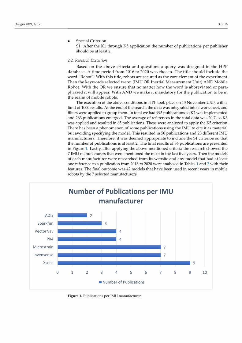
The execution of the above conditions in HPP took place on 13 November 2020, with alimit of 1000 results. At the end of the search, the data was integrated into a worksheet, andfilters were applied to group them. In total we had 995 publications so K2 was implementedand 263 publications emerged. The average of references in the total data was 20.7, so K3was applied and resulted in 65 publications. These were analyzed to apply the K5 criterion.There has been a phenomenon of some publications using the IMU to cite it as materialbut avoiding specifying the model. This resulted in 50 publications and 23 different IMUmanufacturers. Therefore, it was deemed appropriate to include the S1 criterion so thatthe number of publications is at least 2. The final results of 36 publications are presentedin Figure 1. Lastly, after applying the above-mentioned criteria the research showed the7 IMU manufacturers that were mentioned the most in the last five years. Then the modelsof each manufacturer were researched from its website and any model that had at leastone reference to a publication from 2016 to 2020 were analyzed in Tables 1 and 2 with theirfeatures. The final outcome was 42 models that have been used in recent years in mobilerobots by the 7 selected manufacturers.
Designs 2022, 6, x FOR PEER REVIEW 3 of 15
• Quality Criterion Κ4: The publication should refer to mobile robots.
• Acceptance Criterion Κ5: Publications should refer the company or IMU model used in their research.
• Special Criterion S1: After the K1 through K5 application the number of publications per publisher
should be at least 2.
2.2. Research Execution Based on the above criteria and questions a query was designed in the HPP database.
A time period from 2016 to 2020 was chosen. The title should include the word “Robot”. With this title, robots are secured as the core element of the experiment. Then the key-words selected were: (IMU OR Inertial Measurement Unit) AND Mobile Robot. With the OR we ensure that no matter how the word is abbreviated or paraphrased it will appear. With AND we make it mandatory for the publication to be in the realm of mobile robots.
The execution of the above conditions in HPP took place on 13 November 2020, with a limit of 1000 results. At the end of the search, the data was integrated into a worksheet, and filters were applied to group them. In total we had 995 publications so K2 was imple-mented and 263 publications emerged. The average of references in the total data was 20.7, so K3 was applied and resulted in 65 publications. These were analyzed to apply the K5 criterion. There has been a phenomenon of some publications using the IMU to cite it as material but avoiding specifying the model. This resulted in 50 publications and 23 different IMU manufacturers. Therefore, it was deemed appropriate to include the S1 cri-terion so that the number of publications is at least 2. The final results of 36 publications are presented in Figure 1. Lastly, after applying the above-mentioned criteria the research showed the 7 IMU manufacturers that were mentioned the most in the last five years. Then the models of each manufacturer were researched from its website and any model that had at least one reference to a publication from 2016 to 2020 were analyzed in Tables 1 and 2 with their features. The final outcome was 42 models that have been used in recent years in mobile robots by the 7 selected manufacturers.
Figure 1. Publications per IMU manufacturer.
9
7
7
4
4
3
2
0 1 2 3 4 5 6 7 8 9 10
Xsens
Invensense
Microstrain
PX4
VectorNav
Sparkfun
ADIS
Number of Publications per IMU manufacturer
Number of Publications
Figure 1. Publications per IMU manufacturer.
Designs 2022, 6, 17 4 of 16
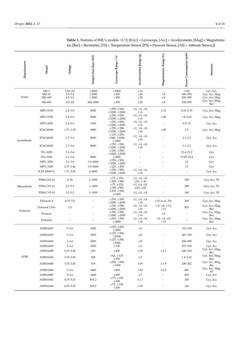
Table 1. Features of IMU’s models. (1/2) ([Gyr] = Gyroscope, [Acc] = Accelerometer, [Mag] = Magnetome-ter, [Bar] = Barometer, [TS] = Temperature Sensor, [PS] = Pressure Sensor, [AS] = Attitude Sensor.]).
Man
ufac
ture
r
Mod
el
Vol
tage
Out
putD
ata
Rat
e(H
Z)
Gyr
osco
peR
ange
(◦/s
)
Acc
eler
omet
erR
ange
(g)
Mag
neto
met
erR
ange
(G)
Pow
erC
onsu
mpt
ion
(mW
)
Stru
ctur
e
Xsens
Mti-1 2.19–3.6 ≤2000 ±2000 ±16 - <100 Gyr, Acc,Mti-10 4.5–3.4 ≤2000 ±450 ±20 ±8 400–550 Gyr, Acc, MagMti-100 4.5–3.4 ≤2000 ±450 ±20 ±8 450–950 Gyr, Acc, Mag
Mti-600 4.5–24 400–2000 ±450 ±20 ±8 450–950 Gyr, Acc, Mag,Bar
InvenSense
MPU-9150 2.4–3.5 8000 ±250, ±500,±1000, ±2000
±2, ±4, ±8,±16 ±12 0.24–0.35 Gyr, Acc, Mag
MPU-9250 2.4–3.5 8000 ±250, ±500,±1000, ±2000
±2, ±4, ±8,±16 ±48 1.8–2.62 Gyr, Acc, Mag
MPU-6050 2.4–3.5 1000 ±250, ±500,±1000, ±2000
±2, ±4, ±8,±16 - 9.5–13 Gyr, Acc
ICM-20948 1.71–1.95 9000 ±250, ±500,±1000, ±2000
±2, ±4, ±8,±16 ±49 2.5 Gyr, Acc, Mag
ICM-42605 1.7–3.6 8000±125, ±250,±500, ±1000,±2000
±2, ±4, ±8,±16 - 1.1–2.3 Gyr, Acc
ICM-20602 1.7–3.6 8000 ±250, ±500,±1000, ±2000
±2, ±4, ±8,±16 - 1.1–2.3 Gyr, Acc
ITG-3050 2.1–3.6 - ±250, ±500,±1000, ±2000 - - 12.4–21.2 Gyr
ITG-3200 2.1–3.6 8000 ±2000 - - 13.65–23.4 Gyr
MPU-3050 2.1–3.6 3.9–8000 ±250, ±500,±1000, ±2000 - - 13 Gyr
MPU-3300 2.37–3.46 3.9–8000 ±225, ±450 - - 13 Gyr
ICM-20608-G 1.71–3.45 4–8000 ±250, ±500,±1000, ±2000
±2, ±4, ±8,±16 - - Gyr, Acc
Microstrain
3DM-GX5-10 4–36 1–1000 ±75, ±150,±300, ±900
±2, ±4, ±8,±20, ± 40 - 300 Gyr, Acc, TS
3DM-CX5-10 3.2–5.2 1–1000 ±75, ±150,±300 ±900
±2, ±4, ±8,±20, ±40 - 300 Gyr, Acc, TS
3DM-CV5-10 3.2–5.2 1–1000 ±250, ±500,±1000 ±2, ±4, ±8 - 360 Gyr, Acc, TS
Pixhawk
Pixhawk 4 4.75–5.2 - ±250, ±500,±1000, ±2000
±2, ±4, ±8,±16 ±16 (x,y), 25y 360 Gyr, Acc, Mag
Pixhawk 3 Pro 3.3 - ±250, ±500,±1000, ±2000
±2, ±4, ±8,±16
±4, ±8, ±12,±16 825 Gyr, Acc, Mag,
Bar
Pixracer - - ±250, ±500,±1000, ±2000
±2, ±4, ±8,±16 ±8 - Gyr, Acc, Mag,
Bar
Pixhawk - - ±245, ±500,±2000
±2, ±4, ±8,±16
±2, ±4, ±8,±12 - Gyr, Acc, Mag,
Bar
ADIS
ADIS16475 3–3.6 2000 ±125, ±450,±2000 ±8 - 132–158 Gyr, Acc
ADIS16495 3–3.6 4500 ±125, ±500,±2000 ±8 - 267–320 Gyr, Acc
ADIS16465 3–3.6 2000 ±125, ±500,±2000 ±8 - 450–950 Gyr, Acc
ADIS16490 3–3.6 4250 ±100 ±8 - 267–320 Gyr, Acc
ADIS16488 3.15–3.45 819 ±450 ±18 ±2.5 240–262 Gyr, Acc, Mag,Bar
ADIS16445 3.15–3.45 820 ±62, ±125,±250 ±5 - 1.8–2.62 Gyr, Acc, Mag,
Bar
ADIS16448 3.15–3.45 819 ±250, ±500,±1000 ±18 ±1.9 239–262 Gyr, Acc, Mag,
Bar
ADIS16480 3–3.6 2460 ±450 ±10 ±2.5 841 Gyr, Acc, Mag,PS
ADIS16485 3–3.6 2460 ±450 ±5 - 650 Gyr, Acc
ADIS16362 4.75–5.25 819.2 ±75, ±150±300 ±1.7 - 245 Gyr, Acc
ADIS16365 4.75–5.25 819.2 ±75, ±150±300 ±18 - 120 Gyr, Acc
Designs 2022, 6, 17 5 of 16
Table 1. Cont.
Man
ufac
ture
r
Mod
el
Vol
tage
Out
putD
ata
Rat
e(H
Z)
Gyr
osco
peR
ange
(◦/s
)
Acc
eler
omet
erR
ange
(g)
Mag
neto
met
erR
ange
(G)
Pow
erC
onsu
mpt
ion
(mW
)
Stru
ctur
e
SparkFun
VR IMUBreakout—
BNO0801.65–3.6 - ±2000 ±8 - 45 Gyr, Acc, Mag
IMUBreakout—LSM9DS1
3.3 - ±245, ±500,±2000
±2, ±4, ±8,±16
±4, ±8, ±12,±16 14.85 Gyr, Acc, Mag
SparkFunMPU-6050 2.4–3.5 1000 ±250, ±500,
±1000, ±2000±2, ±4, ±8,±16 - 9.5–13 Gyr, Acc
ESP32 ThingMotion Shield 3.3 80 ±245, ±500,
±2000±2, ±4, ±8,±16
±4, ±8, ±12,±16 13.2 Gyr, Acc, Mag
SparkFunLSM6DS3 1.71–3.6 1600
±125, ±245,±500, ±1000,±2000
±2, ±4, ±8,±16
±2, ±4, ±8,±12, ±16 2.1–4.5 Gyr, Acc
VectorNav
VN-100 3.2–3.5 (WOC)12–34 (WC) 800 ±2000 ±16 ±2.5 185 (WOC),
200 (WC)Gyr, Acc, Mag,
PS
VN-110 3.2–3.5 (WOC)12–34 (WC) 800 ±490 ±15 ±2.5 <1000 (WOC),
<2000 (WC)Gyr, Acc, Mag,
PS, AS
VN-200 3.2–5.5 (WOC)3.3–17 (WC) 800 ±2000 ±16 - 445 (WOC),
500 (WC) Gyr, Acc, PS
VN-300 3.2–5.5 (WOC)3.3–14 (WC) 400 ±2000 ±16 ±2.5 <1250 (WOC),
1250 (WC) Gyr, Acc, PS
Table 2. Features of IMU’s models (2/2).
Man
ufac
ture
r
Mod
el
Gyr
osco
pe(N
onli
near
ity,
Sens
itiv
ity,
Noi
seD
ensi
ty)
Acc
eler
omet
er(N
onli
near
ity,
Sens
itiv
ity,
Noi
seD
ensi
ty)
Wei
ght(
g)
Dim
ensi
ons
(mm
)
Con
nect
ivit
yPr
otoc
ols
Soft
war
e
Cos
t(€)
Xsens
Mti-1±0.1% fs,
0.001◦/s/g,0.007◦/s/
√Hz
±0.5% fs,-,
0.12 mg/√
Hz<1 12.1 × 12.1 ×
2.55I2C, SPI,
UART, Xbus
MT SoftwareSuite
135
Mti-10±0.03% fs,0.006◦/s/g,
0.03◦/s/√
Hz
±0.1% fs,-,
0.06 mg/√
Hz
11 (WOC)52 (WC)
37 × 33 × 12(WOC)
57 × 42 × 23.5(WC)
RS232, RS485,RS422, UART,
USB, Xbus800
Mti-100±0.01% fs,0.003◦/s/g,
0.01◦/s/√
Hz
±0.1% fs,-,
0.06 mg/√
Hz
11 (WOC)52 (WC)
37 × 33 × 12(WOC)
57 × 42 × 23.5(WC)
RS232, RS485,RS422, UART,
USB, Xbus1470
Mti-600±0.1% fs,
0.001◦/s/g,0.007◦/s/
√Hz
±0.1% fs,-,
0.06 mg/√
Hz
11 (WOC)52 (WC)
37 × 33 × 12(WOC)
57 × 42 × 23.5(WC)
CAN, RS232,UART, Xbus 450
Designs 2022, 6, 17 6 of 16
Table 2. Cont.
Man
ufac
ture
r
Mod
el
Gyr
osco
pe(N
onli
near
ity,
Sens
itiv
ity,
Noi
seD
ensi
ty)
Acc
eler
omet
er(N
onli
near
ity,
Sens
itiv
ity,
Noi
seD
ensi
ty)
Wei
ght(
g)
Dim
ensi
ons
(mm
)
Con
nect
ivit
yPr
otoc
ols
Soft
war
e
Cos
t(€)
InvenSense
MPU-9150±0.2% fs,
0.0076◦/s/LSB,0.005◦/s/
√Hz
±0.5% fs,0.061 mg/LSB,0.4 mg/
√Hz
- 4 × 4 × 1 I2C
SmartRobotics
17
MPU-9250±0.1% fs,
0.0076◦/s/LSB,0.01◦/s/
√Hz
±0.5% fs,0.061 mg/LSB,0.3 mg/
√Hz
- 3 × 3 × 1 I2C, SPI 11.5
MPU-6050±0.2% fs,
0.0076◦/s/LSB,0.005◦/s/
√Hz
±0.5% fs,0.061 mg/LSB,0.4 mg/
√Hz
- 4 × 4 × 0.9 I2C 5
ICM-20948±0.1% fs,
0.0076◦/s/LSB,0.015◦/s/
√Hz
±0.5% fs,0.061 mg/LSB,0.23 mg/
√Hz
- 3 × 3 × 1 I2C, SPI 13.5
ICM-42605±0.1% fs,
0.061◦/s/LSB,0.0038◦/s/
√Hz
±0.1% fs,0.488 mg/LSB,0.07 mg/
√Hz
- 2.5 × 3 × 0.91 I2C, SPI 6
ICM-20602±0.1% fs,
0.0076◦/s/LSB,0.004◦/s/
√Hz
±0.3% fs,0.061 mg/LSB,0.1 mg/
√Hz
- 3 × 3 × 0.75 I2C, SPI 5
ITG-3050±0.2% fs, 0.0076
o/s/LSB,0.001 o/s /
√Hz
- - 4 × 4 × 0.9 I2C 2.5
ITG-3200±0.1% fs, 6.95 ×
10−5◦/s/LSB,0.003◦/s/
√Hz
- - 4 × 4 × 0.9 I2C 10.5
MPU-3050±0.2% fs,
0.0076◦/s/LSB,0.01◦/s/
√Hz
- - 4 × 4 × 0.9 I2C 7
MPU-3300±0.2% fs,
0.0068◦/s/LSB,0.005◦/s/
√Hz
- - 4 × 4 × 0.9 I2C, SPI 35
ICM-20608-G±0.1% fs,
0.0076◦/s/LSB,0.008◦/s/
√Hz
±0.5% fs,0.061 mg/LSB,0.25 mg/
√Hz
- 3 × 3 × 0.75 I2C, SPI 6.5
Microstrain
3DM-GX5-10±0.02% fs,
-,0.005◦/s /
√Hz
±0.02% fs,-,
0.02 mg/√
Hz16.5 36 × 36.6 × 11 RS232, LXRS
Protocol
SensorConnect
710
3DM-CX5-10±0.02% fs,
-,0.005◦/s/
√Hz
±0.02% fs,-,
0.02 mg/√
Hz8 38 × 24 × 9.7 RS232, LXRS
Protocol 710
3DM-CV5-10±0.06% fs,
-,0.0075◦/s/
√Hz
±0.04% fs,-,
0.1 mg/√
Hz11 38 × 24 × 9.7 TTL serial,
LXRS Protocol 710
Pixhawk
Pixhawk 4±0.1% fs,
0.0076◦/s/LSB,0.006◦/s/
√Hz
±0.5% fs,0.61 mg/LSB,0.15 mg/
√Hz
15.8 44 × 84 × 12 PWM, SBUS,I2C, SPI, CAN
Open SourceAutopilot
230
Pixhawk 3 Pro±0.1% fs,
0.0076◦/s/LSB,0.004◦/s /
√Hz
±0.3% fs,0.061 mg/LSB,0.1 mg/
√Hz
45 71 × 49 × 23PWM, SBUS,
I2C, SPI,SUMD, PPM
260
Pixracer±0.1% fs,
0.0076◦/s/LSB,0.008◦/s/
√Hz
±0.5% fs,0.061 mg/LSB,0.25 mg/
√Hz
10.5 36 × 36
UART, USB,PWM, SBUS,
I2C, SPI, JTAG,PPM, ST24
265
Pixhawk±0.2% fs,
0.0076◦/s/LSB,0.005◦/s/
√Hz
±0.5% fs,0.061 mg/LSB,0.4 mg/
√Hz
38 50 × 15.5 ×81.5
UART, PWM,SBUS, I2C, SPI,
PPM, USB,ST24, SUMD
230
Designs 2022, 6, 17 7 of 16
Table 2. Cont.
Man
ufac
ture
r
Mod
el
Gyr
osco
pe(N
onli
near
ity,
Sens
itiv
ity,
Noi
seD
ensi
ty)
Acc
eler
omet
er(N
onli
near
ity,
Sens
itiv
ity,
Noi
seD
ensi
ty)
Wei
ght(
g)
Dim
ensi
ons
(mm
)
Con
nect
ivit
yPr
otoc
ols
Soft
war
e
Cos
t(€)
AnalogDevises
ADIS16475
±0.2% fs,0.00625◦/s/LSB,0.003◦/s /
√Hz
rms
±0.25% fs,3.8 × 10−6
mg/LSB,0.023 mg/
√Hz rms
1.3 11 × 15 × 11 SPI
CoolVisionSDK
860
ADIS16495
±0.2% fs,9.53 ×
10−8◦/s/LSB,0.002◦/s/
√Hz rms
±0.25% fs,3.8 × 10−6
mg/LSB,0.017 mg/
√Hz rms
42 47 × 44 × 14 SPI 2500
ADIS16465±0.2% fs,
0.00625◦/s/LSB,0.002◦/s/
√Hz rms
±0.25% fs,3.8 × 10−6
mg/LSB,0.023 mg/
√Hz rms
- 22.4 × 22.4 × 9 SPI 630
ADIS16490
±0.3% fs,7.63 ×
10−8◦/s/LSB,0.002◦/s/
√Hz rms
±0.1% fs,7.63 × 10−6
mg/LSB,0.016 mg/
√Hz rms
42 47 × 44 × 14 SPI 3170
ADIS16488
±0.01% fs,3.052 ×
10−7◦/s/LSB,0.0059◦/s/
√Hz
rms
±0.1% fs,1.221 × 10−5
mg/LSB,0.063 mg/
√Hz rms
- 24.1 × 37.7 ×10.8 SPI 1800
ADIS16445±0.1% fs,
0.01◦/s/LSB,0.011◦/s/
√Hz rms
±0.2% fs,0.25 mg/LSB,
0.105 mg/√
Hz rms- 24.1 × 37.7 ×
10.8 SPI 550
ADIS16448
±0.1% fs,0.04◦/s/LSB,
0.0135◦/s/√
Hzrms
±0.2% fs,0.833 mg/LSB,
0.23 mg/√
Hz rms- 24.1 × 37.7 ×
10.8 SPI 650
ADIS16480
±0.01% fs,3.052 ×
10−7◦/s/LSB,0.0066◦/s/
√Hz
rms
±0.1% fs,1.221x10−6
mg/LSB,0.067 mg/
√Hz rms
48 47 × 44 × 14 SPI 2960
ADIS16485
±0.01% fs,3.052 ×
10−7◦/s/LSB,0.0066◦/s/
√Hz
rms
±0.1% fs,3.815x10−5
mg/LSB,0.055 mg/
√Hz rms
48 47 × 44 × 14 SPI 1600
ADIS16362±0.1% fs,
0.05◦/s/LSB,0.044◦/s/
√Hz rms
±0.1% fs,0.333 mg/LSB,
0.23 mg/√
Hz rms16 23 × 23 × 23 SPI 460
ADIS16365±0.1% fs,
0.05◦/s/LSB,0.044◦/s/
√Hz rms
±0.1% fs,0.333 mg/LSB,
0.5 mg/√
Hz rms16 23 × 23 × 23 SPI 605
SparkFun
VR IMUBreakout—
BNO080
±0.05% fs,0.0625◦/s/LSB,
-
±0.5% fs,1 mg/LSB,
0.19 mg/√
Hz- 26 × 31.2 UART, I2C,
SPI, SHTP
Arduino IDE
30
IMUBreakout—LSM9DS1
-,0.00875 o/s/LSB,
-
-,0.061 mg/LSB,
-- 23 × 23 UART, I2C,
SPI, SHTP 14
SparkFunMPU-6050
±0.2% fs,0.0076◦/s/LSB,0.005◦/s/
√Hz
±0.5% fs,0.061 mg/LSB,0.4 mg/
√Hz
- 25.5 × 15.2 ×2.48 I2C 25
ESP32 ThingMotion Shield
-,0.00875◦/s/LSB,
-
-,0.061 mg/LSB,
-- - SPI, I2C,
microSD 20
SparkFunLSM6DS3
-,-,
0.007◦/s/√
Hz
-,0.061 mg/LSB,0.09 mg/
√Hz
- 2.5 × 3 × 0.83 SPI, I2C 10
Designs 2022, 6, 17 8 of 16
Table 2. Cont.
Man
ufac
ture
r
Mod
el
Gyr
osco
pe(N
onli
near
ity,
Sens
itiv
ity,
Noi
seD
ensi
ty)
Acc
eler
omet
er(N
onli
near
ity,
Sens
itiv
ity,
Noi
seD
ensi
ty)
Wei
ght(
g)
Dim
ensi
ons
(mm
)
Con
nect
ivit
yPr
otoc
ols
Soft
war
e
Cos
t(€)
VectorNav
VN-100-,-,
0.0035◦/s/√
Hz
-,-,
0.14 mg/√
Hz rms
3.5 (WOC)15 (WC)
24 × 22 × 3(WOC)
36 × 33 ×9(WC)
TTL serial, SPI(WOC),
RS-232 (WC)
VectorNavControl Center
700
VN-110-,-,
0.0138◦/s/√
Hz
-,-,
0.04 mg/√
Hz rms
12 (WOC)125 (WC)
31 × 31 ×11(WOC)56 × 56 ×
23(WC)
Serial TTL(WOC),
RS-422 (WC)-
VN-200-,-,
0.0035◦/s/√
Hz
-,-,
0.14 mg/√
Hz rms
4 (WOC)16 (WC)
24 × 22 ×3(WOC)
36 × 33 ×9.5(WC)
TTL serial, SPI(WOC),
RS-232 (WC)2300
VN-300-,-,
0.0035◦/s/√
Hz
-,-,
<0.14 mg/√
Hz rms
4 (WOC)16 (WC)
24 × 22 ×3(WOC)
45 × 44 ×11(WC)
TTL serial, SPI(WOC),
RS-232 (WC)-
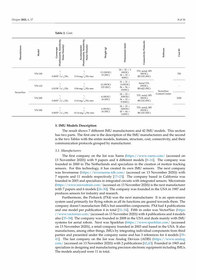
3. IMU Models Description
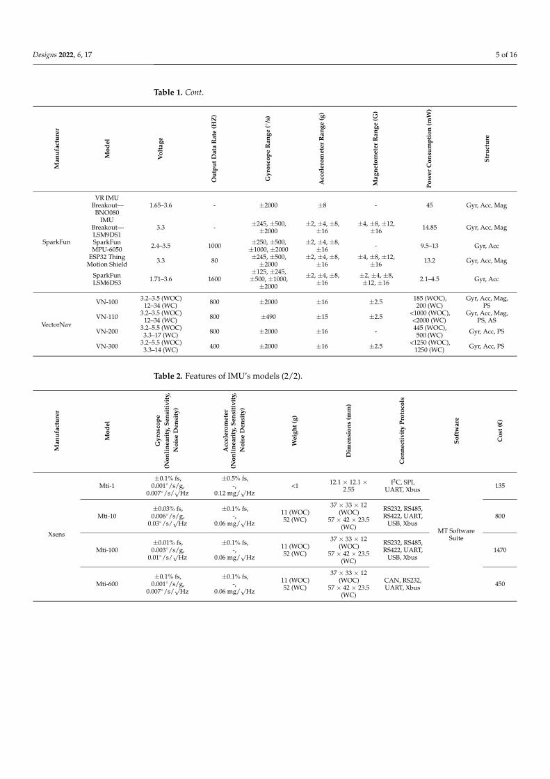
The result shows 7 different IMU manufacturers and 42 IMU models. This sectionhas two parts. The first one is the description of the IMU manufacturers and the secondis the two Tables with the entire models, features, structure, cost, connectivity, and theircommunication protocols grouped by manufacturer.
3.1. Manufacturers
The first company on the list was Xsens (https://www.xsens.com/ (accessed on13 November 2020)) with 9 papers and 4 different models [8–16]. The company wasfounded in 2000 in The Netherlands and specializes in the creation of motion trackingsensors. For this technology, it has created its own IMU sensors. The next companywas Invensense (https://invensense.tdk.com/ (accessed on 13 November 2020)) with7 reports and 11 models respectively [17–23]. The company based in California wasfounded in 2003 and specializes in integrated circuits with integrated sensors. Microstrain(https://www.microstrain.com/ (accessed on 13 November 2020)) is the next manufacturerwith 7 papers and 6 models [24–30]. The company was founded in the USA in 1987 andproduces sensors for industry and research.
Furthermore, the Pixhawk (PX4) was the next manufacturer. It is an open-sourcesystem used primarily for flying robots as all its functions are geared towards them. Thecompany doesn’t manufacture IMUs but assembles components. PX4 had 4 publicationsand one model per publication 4 in total [31–34]. Fifth in order was VectorNav (https://www.vectornav.com/ (accessed on 13 November 2020)) with 4 publications and 4 modelsalso [35–38]. The company was founded in 2008 in the USA and deals mainly with IMUsystems for aerial robots. Next was Sparkfun (https://www.sparkfun.com/ (accessedon 13 November 2020)), a retail company founded in 2003 and based in the USA. It alsomanufactures, among other things, IMUs by integrating individual components from thirdparties and presented under the company name and has 3 references for 4 models [39–41]. The last company on the list was Analog Devices (ADIS) (https://www.analog.com/ (accessed on 13 November 2020)) with 2 publications [42,43]. Founded in 1965 andspecializes in designing and manufacturing precision electronic equipment including IMUs.The models analyzed were 11 in total.
Designs 2022, 6, 17 9 of 16
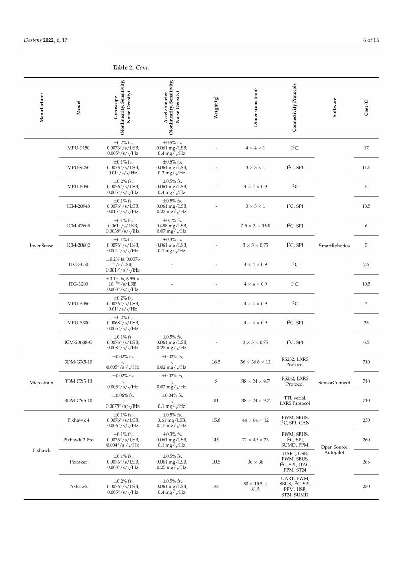
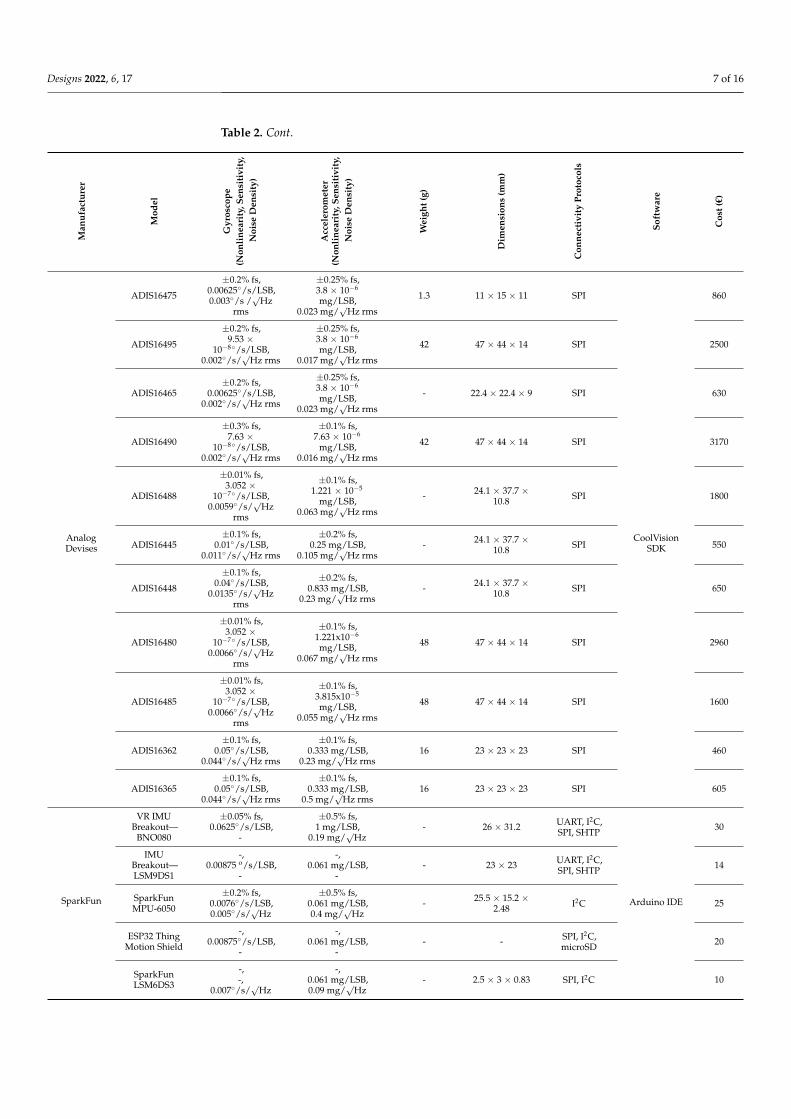
3.2. IMU Features Tables
This section contains IMUs with features (Tables 1 and 2) extracted from the officialwebsite of manufacturers described in Section 3.1. Table 1 includes the input voltage,output data rate, gyroscope—accelerometer—magnetometer range, power consumption,and structure. Table 2 includes three basic features (nonlinearity, sensitivity and noisedensity) of the two main sensors of each IMU (gyroscope and accelerometer). It includesalso the weight, dimensions, connectivity protocols, supporting software, and cost of IMUs.The cost feature in Table 2 was calculated in € with fixed exchange rates (1€ = 0.84 £ = 1.12$).Also, response speed and operational temperature range were extracted but the importanceof these features was low. At first, only 6 of the 42 models (14%) had response speeddata. The Mti-series had the faster response speed (2 ms) and the SparkFun LSM9DS1 andBNO080 had the slower one (6.6 ms). The operating temperature had only two values,30 models had operating temperature from −40 ◦C to +85 ◦C, which indicates that they arecategorized as an industrial range. The ADIS (Analog Devises) models (11 in total) hadfrom −40 ◦C to 105 ◦C. Furthermore, ADIS, because of the aforementioned difference atthe maximum range (20 ◦C), has categorized their products as AEC-Q100 Level 2, whichcorresponds to a higher grade than the industrial range.
4. Features Comparative Presentation and Analysis
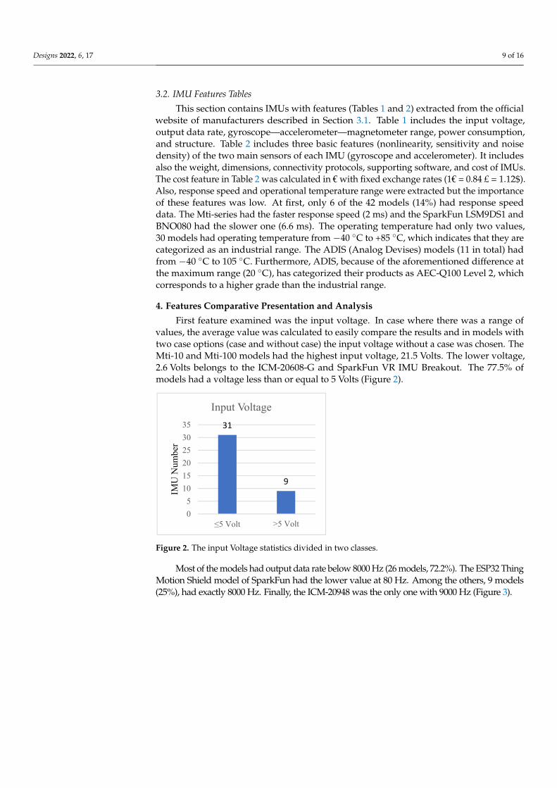
First feature examined was the input voltage. In case where there was a range ofvalues, the average value was calculated to easily compare the results and in models withtwo case options (case and without case) the input voltage without a case was chosen. TheMti-10 and Mti-100 models had the highest input voltage, 21.5 Volts. The lower voltage,2.6 Volts belongs to the ICM-20608-G and SparkFun VR IMU Breakout. The 77.5% ofmodels had a voltage less than or equal to 5 Volts (Figure 2).
Designs 2022, 6, x FOR PEER REVIEW 9 of 15
dimensions, connectivity protocols, supporting software, and cost of IMUs. The cost feature in Table 2 was calculated in € with fixed exchange rates (1€ = 0.84 £ = 1.12$). Also, response speed and operational temperature range were extracted but the importance of these features was low. At first, only 6 of the 42 models (14%) had response speed data. The Mti-series had the faster response speed (2 ms) and the SparkFun LSM9DS1 and BNO080 had the slower one (6.6 ms). The operating temperature had only two values, 30 models had operating tempera-ture from −40 °C to +85 °C, which indicates that they are categorized as an industrial range. The ADIS (Analog Devises) models (11 in total) had from −40 °C to 105 °C. Furthermore, ADIS, because of the aforementioned difference at the maximum range (20 °C), has categorized their products as AEC-Q100 Level 2, which corresponds to a higher grade than the industrial range.
4. Features Comparative Presentation and Analysis First feature examined was the input voltage. In case where there was a range of values,
the average value was calculated to easily compare the results and in models with two case options (case and without case) the input voltage without a case was chosen. The Mti-10 and Mti-100 models had the highest input voltage, 21.5 Volts. The lower voltage, 2.6 Volts belongs to the ICM-20608-G and SparkFun VR IMU Breakout. The 77.5% of models had a voltage less than or equal to 5 Volts (Figure 2).
Figure 2. The input Voltage statistics divided in two classes.
Most of the models had output data rate below 8000 Hz (26 models, 72.2%). The ESP32 Thing Motion Shield model of SparkFun had the lower value at 80 Hz. Among the others, 9 models (25%), had exactly 8000 Hz. Finally, the ICM-20948 was the only one with 9000 Hz (Figure 3).
Figure 3. Data Output rate.
To compare the power consumption in mW, in some cases, values have been con-verted properly. Also, in cases with a range of values, the maximum value was selected.
31
9
05
101520253035
≤5 Volt >5 Volt
IMU
Num
ber
Input Voltage
1
9
26
05
1015202530
9000
Hz
8000
Hz
<800
0 H
z
IMU
Num
ber
Data Output Rate
Figure 2. The input Voltage statistics divided in two classes.
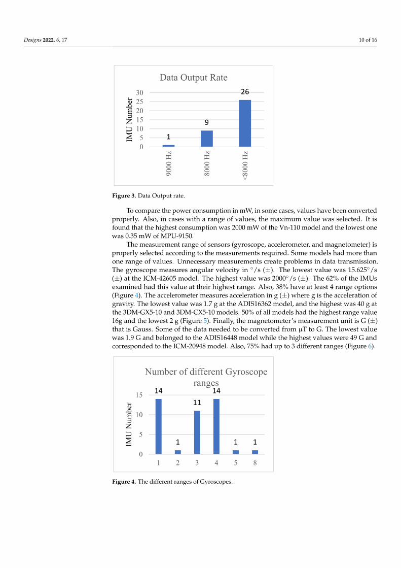
Most of the models had output data rate below 8000 Hz (26 models, 72.2%). The ESP32 ThingMotion Shield model of SparkFun had the lower value at 80 Hz. Among the others, 9 models(25%), had exactly 8000 Hz. Finally, the ICM-20948 was the only one with 9000 Hz (Figure 3).
Designs 2022, 6, 17 10 of 16
Designs 2022, 6, x FOR PEER REVIEW 9 of 15
dimensions, connectivity protocols, supporting software, and cost of IMUs. The cost feature in Table 2 was calculated in € with fixed exchange rates (1€ = 0.84 £ = 1.12$). Also, response speed and operational temperature range were extracted but the importance of these features was low. At first, only 6 of the 42 models (14%) had response speed data. The Mti-series had the faster response speed (2 ms) and the SparkFun LSM9DS1 and BNO080 had the slower one (6.6 ms). The operating temperature had only two values, 30 models had operating tempera-ture from −40 °C to +85 °C, which indicates that they are categorized as an industrial range. The ADIS (Analog Devises) models (11 in total) had from −40 °C to 105 °C. Furthermore, ADIS, because of the aforementioned difference at the maximum range (20 °C), has categorized their products as AEC-Q100 Level 2, which corresponds to a higher grade than the industrial range.
4. Features Comparative Presentation and Analysis First feature examined was the input voltage. In case where there was a range of values,
the average value was calculated to easily compare the results and in models with two case options (case and without case) the input voltage without a case was chosen. The Mti-10 and Mti-100 models had the highest input voltage, 21.5 Volts. The lower voltage, 2.6 Volts belongs to the ICM-20608-G and SparkFun VR IMU Breakout. The 77.5% of models had a voltage less than or equal to 5 Volts (Figure 2).
Figure 2. The input Voltage statistics divided in two classes.
Most of the models had output data rate below 8000 Hz (26 models, 72.2%). The ESP32 Thing Motion Shield model of SparkFun had the lower value at 80 Hz. Among the others, 9 models (25%), had exactly 8000 Hz. Finally, the ICM-20948 was the only one with 9000 Hz (Figure 3).
Figure 3. Data Output rate.
To compare the power consumption in mW, in some cases, values have been con-verted properly. Also, in cases with a range of values, the maximum value was selected.
31
9
05
101520253035
≤5 Volt >5 Volt
IMU
Num
ber
Input Voltage
1
9
26
05
1015202530
9000
Hz
8000
Hz
<800
0 H
z
IMU
Num
ber
Data Output Rate
Figure 3. Data Output rate.
To compare the power consumption in mW, in some cases, values have been convertedproperly. Also, in cases with a range of values, the maximum value was selected. It isfound that the highest consumption was 2000 mW of the Vn-110 model and the lowest onewas 0.35 mW of MPU-9150.
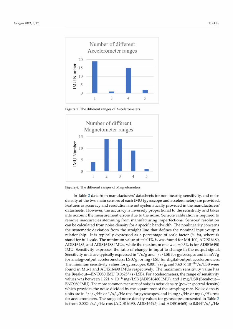
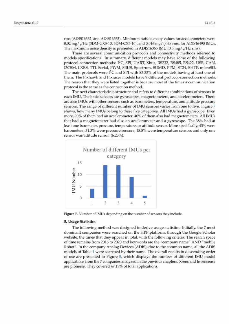
The measurement range of sensors (gyroscope, accelerometer, and magnetometer) isproperly selected according to the measurements required. Some models had more thanone range of values. Unnecessary measurements create problems in data transmission.The gyroscope measures angular velocity in ◦/s (±). The lowest value was 15.625◦/s(±) at the ICM-42605 model. The highest value was 2000◦/s (±). The 62% of the IMUsexamined had this value at their highest range. Also, 38% have at least 4 range options(Figure 4). The accelerometer measures acceleration in g (±) where g is the acceleration ofgravity. The lowest value was 1.7 g at the ADIS16362 model, and the highest was 40 g atthe 3DM-GX5-10 and 3DM-CX5-10 models. 50% of all models had the highest range value16g and the lowest 2 g (Figure 5). Finally, the magnetometer’s measurement unit is G (±)that is Gauss. Some of the data needed to be converted from µT to G. The lowest valuewas 1.9 G and belonged to the ADIS16448 model while the highest values were 49 G andcorresponded to the ICM-20948 model. Also, 75% had up to 3 different ranges (Figure 6).
Designs 2022, 6, x FOR PEER REVIEW 10 of 15
It is found that the highest consumption was 2000 mW of the Vn-110 model and the lowest one was 0.35 mW of MPU-9150.
The measurement range of sensors (gyroscope, accelerometer, and magnetometer) is properly selected according to the measurements required. Some models had more than one range of values. Unnecessary measurements create problems in data transmission. The gyroscope measures angular velocity in °/s (±). The lowest value was 15.625°/s (±) at the ICM-42605 model. The highest value was 2000°/s (±). The 62% of the IMUs examined had this value at their highest range. Also, 38% have at least 4 range options (Figure 4). The accelerometer measures acceleration in g (±) where g is the acceleration of gravity. The lowest value was 1.7 g at the ADIS16362 model, and the highest was 40 g at the 3DM-GX5-10 and 3DM-CX5-10 models. 50% of all models had the highest range value 16g and the lowest 2 g (Figure 5). Finally, the magnetometer’s measurement unit is G (±) that is Gauss. Some of the data needed to be converted from μT to G. The lowest value was 1.9 G and belonged to the ADIS16448 model while the highest values were 49 G and corre-sponded to the ICM-20948 model. Also, 75% had up to 3 different ranges (Figure 6).
Figure 4. The different ranges of Gyroscopes.
Figure 5. The different ranges of Accelerometers.
14
1
1114
1 10
5
10
15
1 2 3 4 5 8
IMU
Num
ber
Number of different Gyroscope ranges
0
5
10
15
20
1 3 4 5
IMU
Num
ber
Number of different Accelerometer ranges
0
5
10
15
1 2 3 4 5
IMU
Num
ber
Number of different Magnetometer ranges
Figure 4. The different ranges of Gyroscopes.
Designs 2022, 6, 17 11 of 16
Designs 2022, 6, x FOR PEER REVIEW 10 of 15
It is found that the highest consumption was 2000 mW of the Vn-110 model and the lowest one was 0.35 mW of MPU-9150.
The measurement range of sensors (gyroscope, accelerometer, and magnetometer) is properly selected according to the measurements required. Some models had more than one range of values. Unnecessary measurements create problems in data transmission. The gyroscope measures angular velocity in °/s (±). The lowest value was 15.625°/s (±) at the ICM-42605 model. The highest value was 2000°/s (±). The 62% of the IMUs examined had this value at their highest range. Also, 38% have at least 4 range options (Figure 4). The accelerometer measures acceleration in g (±) where g is the acceleration of gravity. The lowest value was 1.7 g at the ADIS16362 model, and the highest was 40 g at the 3DM-GX5-10 and 3DM-CX5-10 models. 50% of all models had the highest range value 16g and the lowest 2 g (Figure 5). Finally, the magnetometer’s measurement unit is G (±) that is Gauss. Some of the data needed to be converted from μT to G. The lowest value was 1.9 G and belonged to the ADIS16448 model while the highest values were 49 G and corre-sponded to the ICM-20948 model. Also, 75% had up to 3 different ranges (Figure 6).
Figure 4. The different ranges of Gyroscopes.
Figure 5. The different ranges of Accelerometers.
14
1
1114
1 10
5
10
15
1 2 3 4 5 8
IMU
Num
ber
Number of different Gyroscope ranges
0
5
10
15
20
1 3 4 5
IMU
Num
ber
Number of different Accelerometer ranges
0
5
10
15
1 2 3 4 5
IMU
Num
ber
Number of different Magnetometer ranges
Figure 5. The different ranges of Accelerometers.
Designs 2022, 6, x FOR PEER REVIEW 10 of 15
It is found that the highest consumption was 2000 mW of the Vn-110 model and the lowest one was 0.35 mW of MPU-9150.
The measurement range of sensors (gyroscope, accelerometer, and magnetometer) is properly selected according to the measurements required. Some models had more than one range of values. Unnecessary measurements create problems in data transmission. The gyroscope measures angular velocity in °/s (±). The lowest value was 15.625°/s (±) at the ICM-42605 model. The highest value was 2000°/s (±). The 62% of the IMUs examined had this value at their highest range. Also, 38% have at least 4 range options (Figure 4). The accelerometer measures acceleration in g (±) where g is the acceleration of gravity. The lowest value was 1.7 g at the ADIS16362 model, and the highest was 40 g at the 3DM-GX5-10 and 3DM-CX5-10 models. 50% of all models had the highest range value 16g and the lowest 2 g (Figure 5). Finally, the magnetometer’s measurement unit is G (±) that is Gauss. Some of the data needed to be converted from μT to G. The lowest value was 1.9 G and belonged to the ADIS16448 model while the highest values were 49 G and corre-sponded to the ICM-20948 model. Also, 75% had up to 3 different ranges (Figure 6).
Figure 4. The different ranges of Gyroscopes.
Figure 5. The different ranges of Accelerometers.
14
1
1114
1 10
5
10
15
1 2 3 4 5 8
IMU
Num
ber
Number of different Gyroscope ranges
0
5
10
15
20
1 3 4 5
IMU
Num
ber
Number of different Accelerometer ranges
0
5
10
15
1 2 3 4 5
IMU
Num
ber
Number of different Magnetometer ranges
Figure 6. The different ranges of Magnetometers.
In Table 2 data from manufacturers’ datasheets for nonlinearity, sensitivity, and noisedensity of the two main sensors of each IMU (gyroscope and accelerometer) are provided.Features as accuracy and resolution are not systematically provided in the manufacturers’datasheets. However, the accuracy is inversely proportional to the sensitivity and takesinto account the measurement errors due to the noise. Sensors calibration is required toremove inaccuracies stemming from manufacturing imperfections. Sensors’ resolutioncan be calculated from noise density for a specific bandwidth. The nonlinearity concernsthe systematic deviation from the straight line that defines the nominal input-outputrelationship. It is typically expressed as a percentage of scale factor (% fs), where fsstand for full scale. The minimum value of ±0.01% fs was found for Mti-100, ADIS16480,ADIS16485, and ADIS16488 IMUs, while the maximum one was ±0.3% fs for ADIS16490IMU. Sensitivity expresses the ratio of change in input to change in the output signal.Sensitivity units are typically expressed in ◦/s/g and ◦/s/LSB for gyroscopes and in mV/gfor analog-output accelerometers, LSB/g, or mg/LSB for digital-output accelerometers.The minimum sensitivity values for gyroscopes, 0.001◦/s/g, and 7.63 × 10⁻⁸◦/s/LSB werefound in Mti-1 and ADIS16490 IMUs respectively. The maximum sensitivity value hasthe Breakout—BNO080 IMU (0.0625◦/s/LSB). For accelerometers, the range of sensitivityvalues was between 1.221 × 10⁻⁶ mg/LSB (ADIS16480 IMU), and 1 mg/LSB (Breakout—BNO080 IMU). The more common measure of noise is noise density (power spectral density)which provides the noise divided by the square root of the sampling rate. Noise densityunits are in ◦/s/
√Hz or ◦/s/
√Hz rms for gyroscopes, and in mg/
√Hz or mg/
√Hz rms
for accelerometers. The range of noise density values for gyroscopes presented in Table 2is from 0.002◦/s/
√Hz rms (ADIS16490, ADIS16495, and ADIS16465) to 0.044◦/s/
√Hz
Designs 2022, 6, 17 12 of 16
rms (ADIS16362, and ADIS16365). Minimum noise density values for accelerometers were0.02 mg/
√Hz (3DM-GX5-10, 3DM-CX5-10), and 0.016 mg/
√Hz rms, for ADIS16490 IMUs.
The maximum noise density is presented in ADIS16365 IMU (0.5 mg/√
Hz rms).There are several communication protocols and connectivity methods referred to
models specifications. In summary, different models may have some of the followingprotocol-connection methods: I2C, SPI, UART, Xbus, RS232, RS485, RS422, USB, CAN,I3CSM, LXRS, TTL Serial, PWM, SBUS, Spectrum, SUMD, PPM, ST24, SHTP, microSD.The main protocols were I2C and SPI with 83.33% of the models having at least one ofthem. The Pixhawk and Pixracer models have 9 different protocol-connection methods.The reason that they were listed together is because most of the times a communicationprotocol is the same as the connection method.
The next characteristic is structure and refers to different combinations of sensors ineach IMU. The basic sensors are gyroscopes, magnetometers, and accelerometers. Thereare also IMUs with other sensors such as barometers, temperature, and altitude pressuresensors. The range of different number of IMU sensors varies from one to five. Figure 7shows, how many IMUs belong to these five categories. All IMUs had a gyroscope. Evenmore, 90% of them had an accelerometer. 40% of them also had magnetometers. All IMUsthat had a magnetometer had also an accelerometer and a gyroscope. The 38% had atleast one barometer, pressure, temperature, or attitude sensor. More specifically, 43% werebarometers, 31.3% were pressure sensors, 18.8% were temperature sensors and only onesensor was attitude sensor. (6.25%).
Designs 2022, 6, x FOR PEER REVIEW 12 of 15
Figure 7. Number of IMUs depending on the number of sensors they include.
5. Usage Statistics The following method was designed to derive usage statistics. Initially, the 7 most
dominant companies were searched on the HPP platform, through the Google Scholar website, the times that they appear in total, with the following criteria: The search space of time remains from 2016 to 2020 and keywords are the “company name” AND “mobile Robot”. In the company Analog Devices (ADIS), due to the common name, all the ADIS models of Table 1 were searched by their name. The overall results in descending order of use are presented in Figure 8, which displays the number of different IMU model ap-plications from the 7 companies analyzed in the previous chapters. Xsens and Invensense are pioneers. They covered 47.19% of total applications.
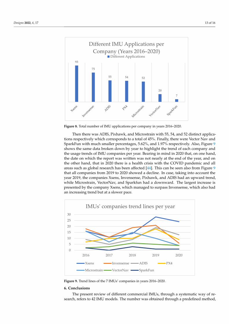
Figure 8. Total number of IMU applications per company in years 2016–2020.
Then there was ADIS, Pixhawk, and Microstrain with 55, 54, and 52 distinct applica-tions respectively which corresponds to a total of 45%. Finally, there were Vector Nav and SparkFun with much smaller percentages, 5.62%, and 1.97% respectively. Also, Figure 9 shows the same data broken down by year to highlight the trend of each company and the usage trends of IMU companies per year. Bearing in mind in 2020 that, on one hand, the date on which the report was written was not nearly at the end of the year, and on the other hand, that in 2020 there is a health crisis with the COVID pandemic and all areas such as global research has been affected [44]. This can be seen also from Figure 9 that all companies from 2019 to 2020 showed a decline. In case, taking into account the year 2019,
0
5
10
15
1 2 3 4 5
IMU
Num
ber
Number of different IMUs per category
93
75
55 54 52
207
Different IMU Applications per Company (Years 2016–2020)
Different Applications
Figure 7. Number of IMUs depending on the number of sensors they include.
5. Usage Statistics
The following method was designed to derive usage statistics. Initially, the 7 mostdominant companies were searched on the HPP platform, through the Google Scholarwebsite, the times that they appear in total, with the following criteria: The search spaceof time remains from 2016 to 2020 and keywords are the “company name” AND “mobileRobot”. In the company Analog Devices (ADIS), due to the common name, all the ADISmodels of Table 1 were searched by their name. The overall results in descending orderof use are presented in Figure 8, which displays the number of different IMU modelapplications from the 7 companies analyzed in the previous chapters. Xsens and Invensenseare pioneers. They covered 47.19% of total applications.
Designs 2022, 6, 17 13 of 16
Designs 2022, 6, x FOR PEER REVIEW 12 of 15
Figure 7. Number of IMUs depending on the number of sensors they include.
5. Usage Statistics The following method was designed to derive usage statistics. Initially, the 7 most
dominant companies were searched on the HPP platform, through the Google Scholar website, the times that they appear in total, with the following criteria: The search space of time remains from 2016 to 2020 and keywords are the “company name” AND “mobile Robot”. In the company Analog Devices (ADIS), due to the common name, all the ADIS models of Table 1 were searched by their name. The overall results in descending order of use are presented in Figure 8, which displays the number of different IMU model ap-plications from the 7 companies analyzed in the previous chapters. Xsens and Invensense are pioneers. They covered 47.19% of total applications.
Figure 8. Total number of IMU applications per company in years 2016–2020.
Then there was ADIS, Pixhawk, and Microstrain with 55, 54, and 52 distinct applica-tions respectively which corresponds to a total of 45%. Finally, there were Vector Nav and SparkFun with much smaller percentages, 5.62%, and 1.97% respectively. Also, Figure 9 shows the same data broken down by year to highlight the trend of each company and the usage trends of IMU companies per year. Bearing in mind in 2020 that, on one hand, the date on which the report was written was not nearly at the end of the year, and on the other hand, that in 2020 there is a health crisis with the COVID pandemic and all areas such as global research has been affected [44]. This can be seen also from Figure 9 that all companies from 2019 to 2020 showed a decline. In case, taking into account the year 2019,
0
5
10
15
1 2 3 4 5
IMU
Num
ber
Number of different IMUs per category
93
75
55 54 52
207
Different IMU Applications per Company (Years 2016–2020)
Different Applications
Figure 8. Total number of IMU applications per company in years 2016–2020.
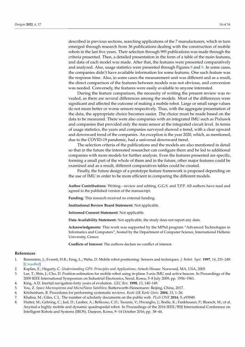
Then there was ADIS, Pixhawk, and Microstrain with 55, 54, and 52 distinct applica-tions respectively which corresponds to a total of 45%. Finally, there were Vector Nav andSparkFun with much smaller percentages, 5.62%, and 1.97% respectively. Also, Figure 9shows the same data broken down by year to highlight the trend of each company andthe usage trends of IMU companies per year. Bearing in mind in 2020 that, on one hand,the date on which the report was written was not nearly at the end of the year, and onthe other hand, that in 2020 there is a health crisis with the COVID pandemic and allareas such as global research has been affected [44]. This can be seen also from Figure 9that all companies from 2019 to 2020 showed a decline. In case, taking into account theyear 2019, the companies Xsens, Invensense, Pixhawk, and ADIS had an upward trend,while Microstrain, VectorNav, and Sparkfun had a downward. The largest increase ispresented by the company Xsens, which managed to surpass Invensense, which also hadan increasing trend but at a slower pace.
Designs 2022, 6, x FOR PEER REVIEW 13 of 15
the companies Xsens, Invensense, Pixhawk, and ADIS had an upward trend, while Mi-crostrain, VectorNav, and Sparkfun had a downward. The largest increase is presented by the company Xsens, which managed to surpass Invensense, which also had an increas-ing trend but at a slower pace.
Figure 9. Trend lines of the 7 IMUs’ companies in years 2016–2020.
6. Conclusions The present review of different commercial IMUs, through a systematic way of re-
search, refers to 42 IMU models. The number was obtained through a predefined method, described in previous sections, searching applications of the 7 manufacturers, which in turn emerged through research from 36 publications dealing with the construction of mo-bile robots in the last five years. Their selection through 995 publications was made through the criteria presented. Then, a detailed presentation in the form of a table of the main features, and data of each model was made. After that, the features were presented comparatively and analyzed. Also, usage statistics were presented through Figures 8 and 9. In some cases, the companies didn’t have available information for some features. One such feature was the response time. Also, in some cases the measurement unit was differ-ent and as a result, the direct comparison of the features between models was not obvious, and conversion was needed. Conversely, the features were easily available to anyone in-terested.
During the feature comparison, the necessity of writing the present review was re-vealed, as there are several differences among the models. Most of the differences were significant and affected the outcome of making a mobile robot. Large or small range val-ues do not mean better or worse sensors respectively. Thus, with the aggregate presenta-tion of the data, the appropriate choice becomes easier. The choice must be made based on the data to be measured. There were also companies with an integrated IMU such as Pixhawk and companies that provided only the main sensor at the integrated circuit level. In terms of usage statistics, the years and companies surveyed showed a trend, with a clear upward and downward trend of the companies. An exception is the year 2020, which, as mentioned, due to the COVID-19 pandemic, had a universal downward trend.
The selection criteria of the publications and the models are also mentioned in detail so that in the future the interested researcher can configure them and be led to additional companies with more models for further analysis. Even the features presented are specific, forming a small part of the whole of them and in the future, other major features could be examined and as a result, different comparatives tables could be created.
Finally, the future design of a prototype feature framework is proposed depending on the use of IMU in order to be more efficient in comparing the different models.
0
5
10
15
20
25
30
2016 2017 2018 2019 2020
IMUs' companies trend lines per year
Xsens Invensense ADIS PX4
Microstrain VectorNav SparkFun
Figure 9. Trend lines of the 7 IMUs’ companies in years 2016–2020.
6. Conclusions
The present review of different commercial IMUs, through a systematic way of re-search, refers to 42 IMU models. The number was obtained through a predefined method,
Designs 2022, 6, 17 14 of 16
described in previous sections, searching applications of the 7 manufacturers, which in turnemerged through research from 36 publications dealing with the construction of mobilerobots in the last five years. Their selection through 995 publications was made through thecriteria presented. Then, a detailed presentation in the form of a table of the main features,and data of each model was made. After that, the features were presented comparativelyand analyzed. Also, usage statistics were presented through Figures 8 and 9. In some cases,the companies didn’t have available information for some features. One such feature wasthe response time. Also, in some cases the measurement unit was different and as a result,the direct comparison of the features between models was not obvious, and conversionwas needed. Conversely, the features were easily available to anyone interested.
During the feature comparison, the necessity of writing the present review was re-vealed, as there are several differences among the models. Most of the differences weresignificant and affected the outcome of making a mobile robot. Large or small range valuesdo not mean better or worse sensors respectively. Thus, with the aggregate presentation ofthe data, the appropriate choice becomes easier. The choice must be made based on thedata to be measured. There were also companies with an integrated IMU such as Pixhawkand companies that provided only the main sensor at the integrated circuit level. In termsof usage statistics, the years and companies surveyed showed a trend, with a clear upwardand downward trend of the companies. An exception is the year 2020, which, as mentioned,due to the COVID-19 pandemic, had a universal downward trend.
The selection criteria of the publications and the models are also mentioned in detailso that in the future the interested researcher can configure them and be led to additionalcompanies with more models for further analysis. Even the features presented are specific,forming a small part of the whole of them and in the future, other major features could beexamined and as a result, different comparatives tables could be created.
Finally, the future design of a prototype feature framework is proposed depending onthe use of IMU in order to be more efficient in comparing the different models.
Author Contributions: Writing—review and editing, G.G.S. and T.P.P. All authors have read andagreed to the published version of the manuscript.
Funding: This research received no external funding.
Institutional Review Board Statement: Not applicable.
Informed Consent Statement: Not applicable.
Data Availability Statement: Not applicable, the study does not report any data.
Acknowledgments: This work was supported by the MPhil program “Advanced Technologies inInformatics and Computers”, hosted by the Department of Computer Science, International HellenicUniversity, Greece.
Conflicts of Interest: The authors declare no conflict of interest.
References1. Borenstein, J.; Everett, H.R.; Feng, L.; Wehe, D. Mobile robot positioning: Sensors and techniques. J. Robot. Syst. 1997, 14, 231–249.
[CrossRef]2. Kaplan, E.; Hegarty, C. Understanding GPS: Principles and Applications; Artech House: Norwood, MA, USA, 2005.3. Lee, T.; Shin, J.; Cho, D. Position estimation for mobile robot using in-plane 3-axis IMU and active beacon. In Proceedings of the
2009 IEEE International Symposium on Industrial Electronics, Seoul, Korea, 5–8 July 2009; pp. 1956–1961.4. King, A.D. Inertial navigation-forty years of evolution. GEC Rev. 1998, 13, 140–149.5. You, Z. Space Microsystems and Micro/Nano Satellites; Butterworth-Heinemann: Beijing, China, 2017.6. Kitchenham, B. Procedures for performing systematic reviews. Keele UK Keele Univ. 2004, 33, 1–26.7. Khabsa, M.; Giles, C.L. The number of scholarly documents on the public web. PLoS ONE 2014, 9, e93949.8. Hutter, M.; Gehring, C.; Jud, D.; Lauber, A.; Bellicoso, C.D.; Tsounis, V.; Hwangbo, J.; Bodie, K.; Fankhauser, P.; Bloesch, M.; et al.
Anymal-a highly mobile and dynamic quadrupedal robot. In Proceedings of the 2016 IEEE/RSJ International Conference onIntelligent Robots and Systems (IROS), Daejeon, Korea, 9–14 October 2016; pp. 38–44.
Designs 2022, 6, 17 15 of 16
9. Kim, W.; Lee, J.; Peternel, L.; Tsagarakis, N.; Ajoudani, A. Anticipatory robot assistance for the prevention of human static jointoverloading in human–robot collaboration. IEEE Robot. Autom. Lett. 2017, 3, 68–75. [CrossRef]
10. Dubé, R.; Gawel, A.; Sommer, H.; Nieto, J.; Siegwart, R.; Cadena, C. An online multi-robot SLAM system for 3D LiDARs. InProceedings of the 2017 IEEE/RSJ International Conference on Intelligent Robots and Systems (IROS), Vancouver, BC, Canada,24–28 September 2017; pp. 1004–1011.
11. Yoon, P.K.; Zihajehzadeh, S.; Kang, B.; Park, E.J. Robust biomechanical model-based 3-D indoor localization and tracking methodusing UWB and IMU. IEEE Sens. J. 2016, 17, 1084–1096. [CrossRef]
12. Bartlett, H.L.; Goldfarb, M. A phase variable approach for IMU-based locomotion activity recognition. IEEE Trans. Biomed. Eng.2017, 65, 1330–1338. [CrossRef]
13. Dang, Q.K.; Chee, Y.; Pham, D.D.; Suh, Y.S. A virtual blind cane using a line laser-based vision system and an inertial measurementunit. Sensors 2016, 16, 95. [CrossRef]
14. Meghdari, A.; Alemi, M.; Zakipour, M.; Kashanian, S.A. Design and realization of a sign language educational humanoid robot. J.Intell. Robot. Syst. 2019, 95, 3–17. [CrossRef]
15. Zhang, W.; Li, X.; Wei, D.; Ji, X.; Yuan, H. A foot-mounted pdr system based on imu/ekf+ hmm+ zupt+ zaru+ hdr+ compassalgorithm. In Proceedings of the 2017 International conference on indoor positioning and indoor navigation (IPIN), Sapporo,Japan, 18–21 September 2017; pp. 1–5.
16. Li, B.; Ushiroda, K.; Yang, L.; Song, Q.; Xiao, J. Wall-climbing robot for non-destructive evaluation using impact-echo and metriclearning SVM. Int. J. Intell. Robot. Appl. 2017, 1, 255–270. [CrossRef]
17. Wu, J.; Sun, L.; Jafari, R. A wearable system for recognizing American sign-language in real-time using IMU and surface EMGsensors. IEEE J. Biomed. Health Inform. 2016, 20, 1281–1290. [CrossRef] [PubMed]
18. Park, S.; Her, J.; Kim, J.; Lee, D. Design, modeling and control of omni-directional aerial robot. In Proceedings of the 2016IEEE/RSJ International Conference on Intelligent Robots and Systems (IROS), Daejeon, Korea, 9–14 October 2016; pp. 1570–1575.
19. Alakshendra, V.; Chiddarwar, S.S. Adaptive robust control of Mecanum-wheeled mobile robot with uncertainties. Nonlinear Dyn.2017, 87, 2147–2169. [CrossRef]
20. Liu, R.; Yuen, C.; Do, T.; Jiao, D.; Liu, X.; Tan, U. Cooperative relative positioning of mobile users by fusing IMU inertial and UWBranging information. In Proceedings of the 2017 IEEE International Conference on Robotics and Automation (ICRA), Singapore,29 May–3 June 2017; pp. 5623–5629.
21. Goldberg, B.; Zufferey, R.; Doshi, N.; Helbling, E.F.; Whittredge, G.; Kovac, M.; Wood, R.J. Power and control autonomy forhigh-speed locomotion with an insect-scale legged robot. IEEE Robot. Autom. Lett. 2018, 3, 987–993. [CrossRef]
22. Ando, H.; Ambe, Y.; Ishii, A.; Konyo, M.; Tadakuma, K.; Maruyama, S.; Tadokoro, S. Aerial hose type robot by water jet for firefighting. IEEE Robot. Autom. Lett. 2018, 3, 1128–1135. [CrossRef]
23. Alcaide, J.O.; Pearson, L.; Rentschler, M.E. Design, modeling and control of a SMA-actuated biomimetic robot with novelfunctional skin. In Proceedings of the 2017 IEEE International Conference on Robotics and Automation (ICRA), Singapore, 29May–3 June 2017; pp. 4338–4345.
24. Moore, T.; Stouch, D. A generalized extended kalman filter implementation for the robot operating system. In IntelligentAutonomous Systems 13; Springer: Berlin/Heidelberg, Germany, 2016; pp. 335–348.
25. Gregory, J.; Fink, J.; Stump, E.; Twigg, J.; Rogers, J.; Baran, D.; Fung, N.; Young, S. Application of multi-robot systems todisaster-relief scenarios with limited communication. In Field and Service Robotics; Springer: Berlin/Heidelberg, Germany, 2016;pp. 639–653.
26. Bjelonic, M.; Kottege, N.; Beckerle, P. Proprioceptive control of an over-actuated hexapod robot in unstructured terrain. InProceedings of the 2016 IEEE/RSJ International Conference on Intelligent Robots and Systems (IROS), Daejeon, Korea, 9–14October 2016; pp. 2042–2049.
27. Mangelson, J.G.; Dominic, D.; Eustice, R.M.; Vasudevan, R. Pairwise consistent measurement set maximization for robustmulti-robot map merging. In Proceedings of the 2018 IEEE International Conference on Robotics and Automation (ICRA),Brisbane, Australia, 21–25 May 2018; pp. 2916–2923.
28. Song, Y.; Nuske, S.; Scherer, S. A multi-sensor fusion MAV state estimation from long-range stereo, IMU, GPS and barometricsensors. Sensors 2017, 17, 11. [CrossRef]
29. Bjelonic, M.; Kottege, N.; Homberger, T.; Borges, P.; Beckerle, P.; Chli, M. Weaver: Hexapod robot for autonomous navigation onunstructured terrain. J. Field Robot. 2018, 35, 1063–1079. [CrossRef]
30. Wang, W.; Mateos, L.A.; Park, S.; Leoni, P.; Gheneti, B.; Duarte, F.; Ratti, C.; Rus, D. Design, modeling, and nonlinear modelpredictive tracking control of a novel autonomous surface vehicle. In Proceedings of the 2018 IEEE International Conference onRobotics and Automation (ICRA), Brisbane, Australia, 21–25 May 2018; pp. 6189–6196.
31. Schwarz, M.; Rodehutskors, T.; Droeschel, D.; Beul, M.; Schreiber, M.; Araslanov, N.; Ivanov, I.; Lenz, C.; Razlaw, J.; Schüller,S.; et al. NimbRo Rescue: Solving disaster-response tasks with the mobile manipulation robot Momaro. J. Field Robot. 2017, 34,400–425. [CrossRef]
32. Özaslan, T.; Loianno, G.; Keller, J.; Taylor, C.J.; Kumar, V.; Wozencraft, J.M.; Hood, T. Autonomous navigation and mapping forinspection of penstocks and tunnels with MAVs. IEEE Robot. Autom. Lett. 2017, 2, 1740–1747. [CrossRef]
Designs 2022, 6, 17 16 of 16
33. Sampedro, C.; Rodriguez-Ramos, A.; Bavle, H.; Carrio, A.; de la Puente, P.; Campoy, P. A fully-autonomous aerial robot forsearch and rescue applications in indoor environments using learning-based techniques. J. Intell. Robot. Syst. 2019, 95, 601–627.[CrossRef]
34. Schwarz, M.; Rodehutskors, T.; Schreiber, M.; Behnke, S. Hybrid driving-stepping locomotion with the wheeled-legged robotMomaro. In Proceedings of the 2016 IEEE International Conference on Robotics and Automation (ICRA), Stockholm, Sweden,16–21 May 2016; pp. 5589–5595.
35. Do, H.M.; Pham, M.; Sheng, W.; Yang, D.; Liu, M. RiSH: A robot-integrated smart home for elderly care. Robot. Auton. Syst. 2018,101, 74–92. [CrossRef]
36. Ding, Y.; Galiana, I.; Siviy, C.; Panizzolo, F.A.; Walsh, C. IMU-based iterative control for hip extension assistance with a softexosuit. In Proceedings of the 2016 IEEE International Conference on Robotics and Automation (ICRA), Stockholm, Sweden,16–21 May 2016; pp. 3501–3508.
37. Gong, Y.; Hartley, R.; Da, X.; Hereid, A.; Harib, O.; Huang, J.K.; Grizzle, J. Feedback control of a cassie bipedal robot: Walking,standing, and riding a segway. In Proceedings of the 2019 American Control Conference (ACC), Philadelphia, PA, USA, 10–12July 2019; pp. 4559–4566.
38. Klamt, T.; Rodriguez, D.; Schwarz, M.; Lenz, C.; Pavlichenko, D.; Droeschel, D.; Behnke, S. Supervised autonomous locomotionand manipulation for disaster response with a centaur-like robot. In Proceedings of the 2018 IEEE/RSJ International Conferenceon Intelligent Robots and Systems (IROS), Madrid, Spain, 1–5 October 2018; pp. 1–8.
39. Kundu, A.S.; Mazumder, O.; Lenka, P.K.; Bhaumik, S. Hand gesture recognition based omnidirectional wheelchair control usingIMU and EMG sensors. J. Intell. Robot. Syst. 2018, 91, 529–541. [CrossRef]
40. Santos, F.N.D.; Sobreira, H.; Campos, D.; Morais, R.; Moreira, A.P.; Contente, O. Towards a reliable robot for steep slope vineyardsmonitoring. J. Intell. Robot. Syst. 2016, 83, 429–444. [CrossRef]
41. Parrott, C.; Dodd, T.J.; Groß, R. HyMod: A 3-DOF hybrid mobile and self-reconfigurable modular robot and its extensions. InDistributed Autonomous Robotic Systems; Springer: Berlin/Heidelberg, Germany, 2018; pp. 401–414.
42. Li, Y.; Guo, S.; Wang, Y. Design and characteristics evaluation of a novel spherical underwater robot. Robot. Auton. Syst. 2017, 94,61–74. [CrossRef]
43. Koksal, N.; Jalalmaab, M.; Fidan, B. Adaptive linear quadratic attitude tracking control of a quadrotor UAV based on IMU sensordata fusion. Sensors 2019, 19, 46. [CrossRef] [PubMed]
44. Donthu, N.; Gustafsson, A. Effects of COVID-19 on business and research. J. Bus. Res. 2020, 117, 284–289. [CrossRef] [PubMed]


