Embed Size (px)
Citation preview
©P
HO
TO
DIS
C,
DIG
ITA
LS
TO
CK
,&
JOH
NF
OX
X
IEEE Robotics & Automation Magazine24 1070-9932/09/$25.00ª2009 IEEE MARCH 2009
Design ofService Robots
Experiences Using Software Engineering
According to the Interna-tional Federation of Ro-botics (IFR), ‘‘a servicerobot is a robot whichoperates semi or
fully autonomously to performservices useful to the well beingof human and equipment, ex-cluding manufacturing opera-tions’’ [1]. These devices aretypically complex systems requir-ing the input of knowledge fromnumerous disciplines. The authorshave been using different softwareengineering techniques for the last15 years, integrating new paradigmsin the service robot developmentprocess as they emerged. This hasmade it possible to achieve rapid devel-opment of applications and subsequentmaintenance. During the early years(1993–1998), our efforts were directed at thedevelopment of software for various kinds ofteleoperated robots to perform maintenance tasks innuclear power plants [2]; during a second phase (1999–
2006), we built applications for ship-hull cleaning robots [3]. All thistime, we have been applying all the possibilities of software engi-neering, from the use of paradigms for structured and object-basedprogramming in early developments to the adoption of the currentmodel-driven approach [model-driven engineering (MDE)] [4].
In the course of the researchconducted by the Division ofElectronics Engineering and Sys-tems (DSIE) Research Group, wecan see a parallelism betweeneach new need and the softwaredevelopment paradigm that hasbeen applied to meet that need.The first applications wereintended for teleoperated sys-tems, each specializing in ahighly specific maintenance taskwithin a fully structured opera-tional environment. The chal-lenge lays in how to reuse as
much as possible the code of oneapplication in another application.
To that end, we developed anarchitecture founded on the use
of object-based programming andthe development of generic control
modules. With the Ada95 language, itwas possible to put these ideas directly into
practice, and therefore, it was used as the imple-menting language. However, when at a later stage it
was decided to develop robots to clean ship hulls, the architec-ture was no longer useful because the new field entailed not fullystructured environments, only partly defined tasks, semiauto-mated systems, already developed industrial systems, and soforth. Moreover, when developing the new robotic applicationsfor these new systems, it proved impossible to define a singlecommon architecture for them all. As the software componentsDigital Object Identifier 10.1109/MRA.2008.931635
BY ANDR�ES IBORRA, DIEGO ALONSO C�ACERES, FRANCISCO J. ORTIZ,
JUAN PASTOR FRANCO, PEDRO S�ANCHEZ PALMA, AND B�ARBARA �ALVAREZ
(in this case, generic Ada packages) were designed to be used ina software architecture that imposed strong dependences amongthem in the absence of such an architecture, we lacked theframework that would allow the components to be reused.
The challenge was then to find an approach whereby the codecould be reused in applications with different architectures. Thesolution arrived at was to adopt the component-based develop-ment (CBD) paradigm [5]. CBD is conceived for the purpose ofspeeding up the software development process. It states that suchdevelopment would be achieved by linking independent parts,the components, in the same way as in mechanics and electronics.
Following in this line, the DSIE Research Group developedan abstract framework called ACRoSeT (reference architecturefor teleoperated service robots) [6], in which it is possible todefine software components for robotic applications independ-ent of the architecture and of the ultimate implementingtechnology. Despite the benefits it brought, the use of ACRo-SeT posed new challenges arising out of the conceptual leapfrom the predominant object-based technology to compo-nent-based design concepts. Each of the components definedin ACRoSeT had to be encoded manually in the chosenprogramming language. There was therefore a need for anapproach that came with a set of tools to facilitate automatic orsemiautomatic generation of applications. These needs can besatisfied by adopting a model-driven development approach.
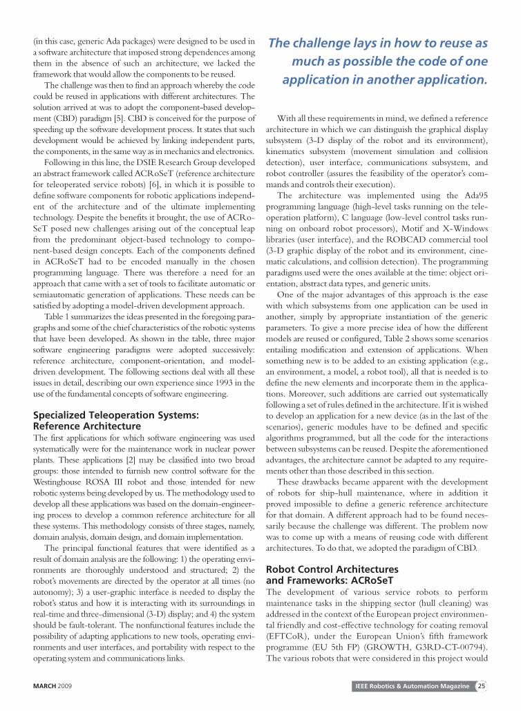
Table 1 summarizes the ideas presented in the foregoing para-graphs and some of the chief characteristics of the robotic systemsthat have been developed. As shown in the table, three majorsoftware engineering paradigms were adopted successively:reference architecture, component-orientation, and model-driven development. The following sections deal with all theseissues in detail, describing our own experience since 1993 in theuse of the fundamental concepts of software engineering.
Specialized Teleoperation Systems:Reference ArchitectureThe first applications for which software engineering was usedsystematically were for the maintenance work in nuclear powerplants. These applications [2] may be classified into two broadgroups: those intended to furnish new control software for theWestinghouse ROSA III robot and those intended for newrobotic systems being developed by us. The methodology used todevelop all these applications was based on the domain-engineer-ing process to develop a common reference architecture for allthese systems. This methodology consists of three stages, namely,domain analysis, domain design, and domain implementation.
The principal functional features that were identified as aresult of domain analysis are the following: 1) the operating envi-ronments are thoroughly understood and structured; 2) therobot’s movements are directed by the operator at all times (noautonomy); 3) a user-graphic interface is needed to display therobot’s status and how it is interacting with its surroundings inreal-time and three-dimensional (3-D) display; and 4) the systemshould be fault-tolerant. The nonfunctional features include thepossibility of adapting applications to new tools, operating envi-ronments and user interfaces, and portability with respect to theoperating system and communications links.
With all these requirements in mind, we defined a referencearchitecture in which we can distinguish the graphical displaysubsystem (3-D display of the robot and its environment),kinematics subsystem (movement simulation and collisiondetection), user interface, communications subsystem, androbot controller (assures the feasibility of the operator’s com-mands and controls their execution).
The architecture was implemented using the Ada95programming language (high-level tasks running on the tele-operation platform), C language (low-level control tasks run-ning on onboard robot processors), Motif and X-Windowslibraries (user interface), and the ROBCAD commercial tool(3-D graphic display of the robot and its environment, cine-matic calculations, and collision detection). The programmingparadigms used were the ones available at the time: object ori-entation, abstract data types, and generic units.
One of the major advantages of this approach is the easewith which subsystems from one application can be used inanother, simply by appropriate instantiation of the genericparameters. To give a more precise idea of how the differentmodels are reused or configured, Table 2 shows some scenariosentailing modification and extension of applications. Whensomething new is to be added to an existing application (e.g.,an environment, a model, a robot tool), all that is needed is todefine the new elements and incorporate them in the applica-tions. Moreover, such additions are carried out systematicallyfollowing a set of rules defined in the architecture. If it is wishedto develop an application for a new device (as in the last of thescenarios), generic modules have to be defined and specificalgorithms programmed, but all the code for the interactionsbetween subsystems can be reused. Despite the aforementionedadvantages, the architecture cannot be adapted to any require-ments other than those described in this section.
These drawbacks became apparent with the developmentof robots for ship-hull maintenance, where in addition itproved impossible to define a generic reference architecturefor that domain. A different approach had to be found neces-sarily because the challenge was different. The problem nowwas to come up with a means of reusing code with differentarchitectures. To do that, we adopted the paradigm of CBD.
Robot Control Architecturesand Frameworks: ACRoSeTThe development of various service robots to performmaintenance tasks in the shipping sector (hull cleaning) wasaddressed in the context of the European project environmen-tal friendly and cost-effective technology for coating removal(EFTCoR), under the European Union’s fifth frameworkprogramme (EU 5th FP) (GROWTH, G3RD-CT-00794).The various robots that were considered in this project would
The challenge lays in how to reuse as
much as possible the code of one
application in another application.
IEEE Robotics & Automation MagazineMARCH 2009 25
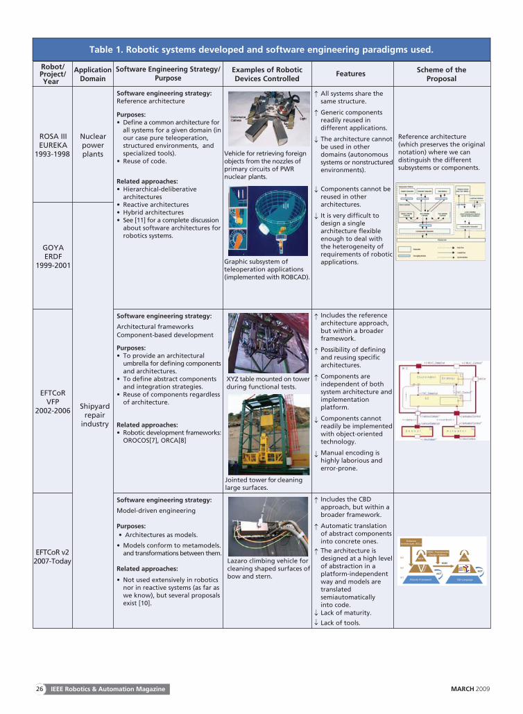
Table 1. Robotic systems developed and software engineering paradigms used.
Robot/Project/Year
ApplicationDomain
Software Engineering Strategy/Purpose
Examples of RoboticDevices Controlled
Features Scheme of theProposal
ROSA IIIEUREKA
1993-1998
Nuclearpowerplants Vehicle for retrieving foreign
objects from the nozzles ofprimary circuits of PWRnuclear plants.
GOYAERDF
1999-2001
Software engineering strategy:Reference architecture
Purposes:• Define a common architecture for all systems for a given domain (in our case pure teleoperation, structured environments, and specialized tools).• Reuse of code.
Related approaches:• Hierarchical-deliberative architectures• Reactive architectures• Hybrid architectures• See [11] for a complete discussion about software architectures for robotics systems.
Graphic subsystem ofteleoperation applications(implemented with ROBCAD).
↑ All systems share thesame structure.
↑ Generic componentsreadily reused indifferent applications.
↓ The architecture cannotbe used in otherdomains (autonomoussystems or nonstructuredenvironments).
↓ Components cannot bereused in otherarchitectures.
↓ It is very difficult todesign a singlearchitecture flexibleenough to deal withthe heterogeneity ofrequirements of roboticapplications.
Reference architecture(which preserves the originalnotation) where we candistinguish the differentsubsystems or components.
EFTCoRVFP
2002-2006
Software engineering strategy:
Architectural frameworks Component-based development
Purposes:• To provide an architectural umbrella for defining components and architectures.• To define abstract components and integration strategies.• Reuse of components regardless of architecture.
Related approaches:• Robotic development frameworks: OROCOS[7], ORCA[8]
↑ Includes the referencearchitecture approach,but within a broaderframework.
↑ Possibility of definingand reusing specificarchitectures.
↑ Components areindependent of bothsystem architecture andimplementationplatform.
↓ Components cannotreadily be implementedwith object-orientedtechnology.
↓ Manual encoding ishighly laborious anderror-prone.
EFTCoR v22007-Today
Shipyardrepair
industry
Software engineering strategy:
Model-driven engineering
Purposes: • Architectures as models.
• Models conform to metamodels. and transformations between them.
Related approaches:
• Not used extensively in robotics nor in reactive systems (as far as we know), but several proposals exist [10].
XYZ table mounted on towerduring functional tests.
Jointed tower for cleaninglarge surfaces.
Lazaro climbing vehicle forcleaning shaped surfaces ofbow and stern.
↑ Includes the CBDapproach, but within abroader framework.
↑ Automatic translationof abstract componentsinto concrete ones.
↑ The architecture isdesigned at a high levelof abstraction in aplatform-independentway and models aretranslatedsemiautomaticallyinto code.
↓ Lack of maturity.
↓ Lack of tools.
MOF
OO Language
MOF
Robotic Framework
M2M
M2TM2T
CBSE, Frameworks,Design Patterns
SoftwareArchitecture, ADLs
V3
M3
M2
M1
Stu
dio
IEEE Robotics & Automation Magazine26 MARCH 2009
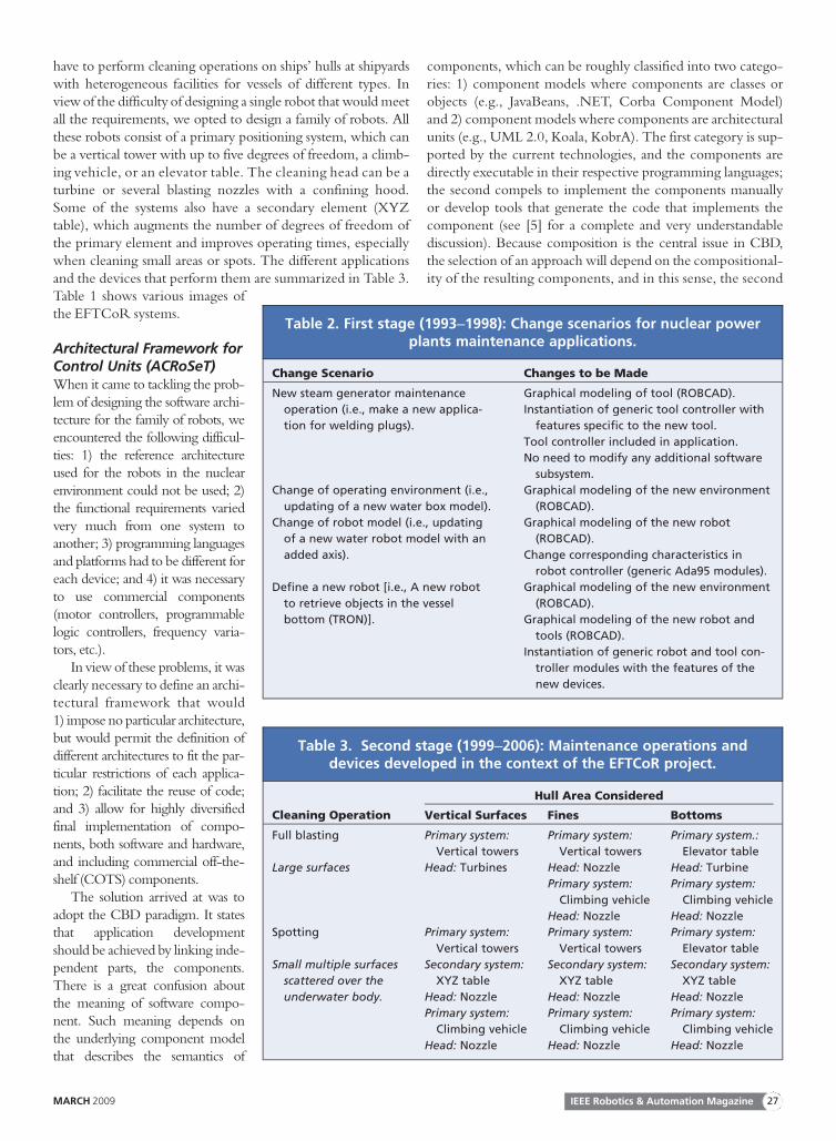
have to perform cleaning operations on ships’ hulls at shipyardswith heterogeneous facilities for vessels of different types. Inview of the difficulty of designing a single robot that would meetall the requirements, we opted to design a family of robots. Allthese robots consist of a primary positioning system, which canbe a vertical tower with up to five degrees of freedom, a climb-ing vehicle, or an elevator table. The cleaning head can be aturbine or several blasting nozzles with a confining hood.Some of the systems also have a secondary element (XYZtable), which augments the number of degrees of freedom ofthe primary element and improves operating times, especiallywhen cleaning small areas or spots. The different applicationsand the devices that perform them are summarized in Table 3.Table 1 shows various images ofthe EFTCoR systems.
Architectural Framework forControl Units (ACRoSeT)When it came to tackling the prob-lem of designing the software archi-tecture for the family of robots, weencountered the following difficul-ties: 1) the reference architectureused for the robots in the nuclearenvironment could not be used; 2)the functional requirements variedvery much from one system toanother; 3) programming languagesand platforms had to be different foreach device; and 4) it was necessaryto use commercial components(motor controllers, programmablelogic controllers, frequency varia-tors, etc.).
In view of these problems, it wasclearly necessary to define an archi-tectural framework that would1) impose no particular architecture,but would permit the definition ofdifferent architectures to fit the par-ticular restrictions of each applica-tion; 2) facilitate the reuse of code;and 3) allow for highly diversifiedfinal implementation of compo-nents, both software and hardware,and including commercial off-the-shelf (COTS) components.
The solution arrived at was toadopt the CBD paradigm. It statesthat application developmentshould be achieved by linking inde-pendent parts, the components.There is a great confusion aboutthe meaning of software compo-nent. Such meaning depends onthe underlying component modelthat describes the semantics of
components, which can be roughly classified into two catego-ries: 1) component models where components are classes orobjects (e.g., JavaBeans, .NET, Corba Component Model)and 2) component models where components are architecturalunits (e.g., UML 2.0, Koala, KobrA). The first category is sup-ported by the current technologies, and the components aredirectly executable in their respective programming languages;the second compels to implement the components manuallyor develop tools that generate the code that implements thecomponent (see [5] for a complete and very understandablediscussion). Because composition is the central issue in CBD,the selection of an approach will depend on the compositional-ity of the resulting components, and in this sense, the second
Table 2. First stage (1993–1998): Change scenarios for nuclear powerplants maintenance applications.
Change Scenario Changes to be Made
New steam generator maintenance
operation (i.e., make a new applica-
tion for welding plugs).
Graphical modeling of tool (ROBCAD).
Instantiation of generic tool controller with
features specific to the new tool.
Tool controller included in application.
No need to modify any additional software
subsystem.
Change of operating environment (i.e.,
updating of a new water box model).
Graphical modeling of the new environment
(ROBCAD).
Change of robot model (i.e., updating
of a new water robot model with an
added axis).
Graphical modeling of the new robot
(ROBCAD).
Change corresponding characteristics in
robot controller (generic Ada95 modules).
Define a new robot [i.e., A new robot
to retrieve objects in the vessel
bottom (TRON)].
Graphical modeling of the new environment
(ROBCAD).
Graphical modeling of the new robot and
tools (ROBCAD).
Instantiation of generic robot and tool con-
troller modules with the features of the
new devices.
Table 3. Second stage (1999–2006): Maintenance operations anddevices developed in the context of the EFTCoR project.
Cleaning Operation
Hull Area Considered
Vertical Surfaces Fines Bottoms
Full blasting Primary system:
Vertical towers
Primary system:
Vertical towers
Primary system.:
Elevator table
Large surfaces Head: Turbines Head: Nozzle Head: Turbine
Primary system:
Climbing vehicle
Primary system:
Climbing vehicle
Head: Nozzle Head: Nozzle
Spotting Primary system:
Vertical towers
Primary system:
Vertical towers
Primary system:
Elevator table
Small multiple surfaces
scattered over the
underwater body.
Secondary system:
XYZ table
Secondary system:
XYZ table
Secondary system:
XYZ table
Head: Nozzle Head: Nozzle Head: Nozzle
Primary system:
Climbing vehicle
Primary system:
Climbing vehicle
Primary system:
Climbing vehicle
Head: Nozzle Head: Nozzle Head: Nozzle
IEEE Robotics & Automation MagazineMARCH 2009 27
approach is clearly better. Components such as architecturalunits allow 1) specifying very precisely, using the concept ofport, both the services provided and the services required bya given component and 2) defining a composition theorybased on the notion of a connector. None of these featurescan be directly achieved using objects because classes onlypublish the provided services, and the unique way of interac-tion among objects is method invocation. Anyway, compo-nents can be implemented using objects and design patternsas long as the resulting code implements the semantics associatedto the components and their interactions.
The CBD paradigm has been adopted by several existingframeworks for robot development (e.g., Orocos [7], ORCA[8], etc.), of which some use objects and others use architec-tural units as components. Frameworks offer high rates ofreusability and ease of use, but little flexibility with regard tothe implementation platform: most of them are linked to C/C++ and Linux, although some achieve more independence,thanks to the use of some middleware. For industrial pur-poses, the EFTCoR project required the use of commercialdevices and programming languages for programmable logiccontrollers (PLCs) not catered for by the available frameworks.Moreover, the frameworks usually have an implicit architectureand offer the principal control loop for the application. Sinceone of the objectives pursued is the ability to define differentarchitectures, the use of a commercial framework posed addi-tional problems.
With these ideas in mind, ACRoSeT was designed as acomponent-based architectural framework to guide the designof control software for teleoperated service robots. ACRoSeTprovides a framework of abstract components, the architecturalunits mentioned earlier, which can be implemented in variousdifferent ways (by integrating different software or hardwaresolutions, or even COTS components).
We needed a way to define interfaces and behavior at ahigher level of abstraction so that they could be used in systemswith different platforms. This is what prompted the idea ofabstract components, which would be independent of theimplementation platform but could be translated into an exe-cutable software or hardware component. In opting for theseabstract components, we were trusting that the tools associatedwith the unified modeling language (UML) for generatingcode would evolve favorably, and this would make it possibleto generate the code automatically from ACRoSeT diagrams.
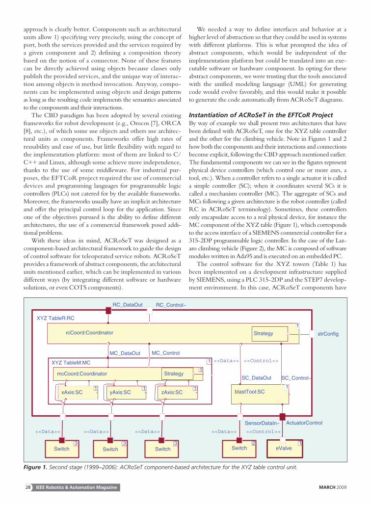
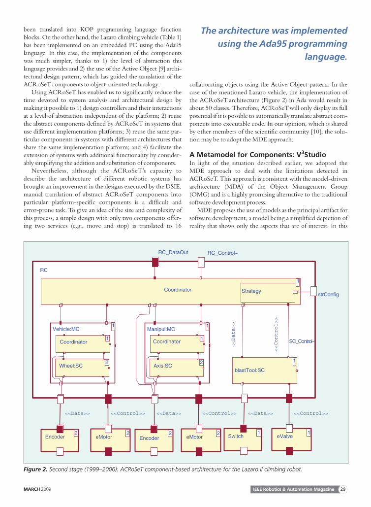
Instantiation of ACRoSeT in the EFTCoR ProjectBy way of example we shall present two architectures that havebeen defined with ACRoSeT, one for the XYZ table controllerand the other for the climbing vehicle. Note in Figures 1 and 2how both the components and their interactions and connectionsbecome explicit, following the CBD approach mentioned earlier.The fundamental components we can see in the figures representphysical device controllers (which control one or more axes, atool, etc.). When a controller refers to a single actuator it is calleda simple controller (SC); when it coordinates several SCs it iscalled a mechanism controller (MC). The aggregate of SCs andMCs following a given architecture is the robot controller (calledRC in ACRoSeT terminology). Sometimes, these controllersonly encapsulate access to a real physical device, for instance theMC component of the XYZ table (Figure 1), which correspondsto the access interface of a SIEMENS commercial controller for a315-2DP programmable logic controller. In the case of the Laz-aro climbing vehicle (Figure 2), the MC is composed of softwaremodules written in Ada95 and is executed on an embedded PC.
The control software for the XYZ towers (Table 1) hasbeen implemented on a development infrastructure suppliedby SIEMENS, using a PLC 315-2DP and the STEP7 develop-ment environment. In this case, ACRoSeT components have
RC_Control~
rcCoord:Coordinator
RC_DataOut
XYZ TableR:RC
XYZ TableM:MC
MC_ControlMC_DataOut
SC_Control~
strConfig Strategy
1
mcCoord:Coordinator
SensorDataIn~ ActuatorControl
<<Data>> <<Control>>
eValveSwitch2 1
SC_DataOut
blastTool:SC
<<Data>> <<Control>>
<<Data>>
Switch
xAxis:SC
<<Data>>
3Switch
yAxis:SC
<<Data>>
3Switch
zAxis:SC
Strategy
1 1 1 1
1
3
1
Figure 1. Second stage (1999–2006): ACRoSeT component-based architecture for the XYZ table control unit.
IEEE Robotics & Automation Magazine28 MARCH 2009
been translated into KOP programming language functionblocks. On the other hand, the Lazaro climbing vehicle (Table 1)has been implemented on an embedded PC using the Ada95language. In this case, the implementation of the componentswas much simpler, thanks to 1) the level of abstraction thislanguage provides and 2) the use of the Active Object [9] archi-tectural design pattern, which has guided the translation of theACRoSeT components to object-oriented technology.
Using ACRoSeT has enabled us to significantly reduce thetime devoted to system analysis and architectural design bymaking it possible to 1) design controllers and their interactionsat a level of abstraction independent of the platform; 2) reusethe abstract components defined by ACRoSeT in systems thatuse different implementation platforms; 3) reuse the same par-ticular components in systems with different architectures thatshare the same implementation platform; and 4) facilitate theextension of systems with additional functionality by consider-ably simplifying the addition and substitution of components.
Nevertheless, although the ACRoSeT’s capacity todescribe the architecture of different robotic systems hasbrought an improvement in the designs executed by the DSIE,manual translation of abstract ACRoSeT components intoparticular platform-specific components is a difficult anderror-prone task. To give an idea of the size and complexity ofthis process, a simple design with only two components offer-ing two services (e.g., move and stop) is translated to 16
collaborating objects using the Active Object pattern. In thecase of the mentioned Lazaro vehicle, the implementation ofthe ACRoSeT architecture (Figure 2) in Ada would result inabout 50 classes. Therefore, ACRoSeTwill only display its fullpotential if it is possible to automatically translate abstract com-ponents into executable code. In our opinion, which is sharedby other members of the scientific community [10], the solu-tion may be to adopt the MDE approach.
A Metamodel for Components: V3StudioIn light of the situation described earlier, we adopted theMDE approach to deal with the limitations detected inACRoSeT. This approach is consistent with the model-drivenarchitecture (MDA) of the Object Management Group(OMG) and is a highly promising alternative to the traditionalsoftware development process.
MDE proposes the use of models as the principal artifact forsoftware development, a model being a simplified depiction ofreality that shows only the aspects that are of interest. In this
<<Control>>
eValve
RC_Control~
Coordinator
RC_DataOut
SC_Control~
strConfig
<<Data>>
<<Control>>
Strategy
<<Data>>
Switch
Manipul:MC
1
1
blastTool:SC
1
<<Data>>
Encoder
Axis:SC
Coordinator
Vehicle:MC1
Wheel:SC
Coordinator
<<Data>> <<Control>>
eMotorEncoder
<<Control>>
eMotor
RC
2
1 1
2
2 2 2 2 1 1
Figure 2. Second stage (1999–2006): ACRoSeT component-based architecture for the Lazaro II climbing robot.
The architecture was implemented
using the Ada95 programming
language.
IEEE Robotics & Automation MagazineMARCH 2009 29
approach, a model is defined in accordance with a metamodel,which defines the abstract syntax of a modeling language andestablishes the concepts and relationships between them,including the rules that determine when a model is properlyformed. As a given system can be described by different mod-els at different levels of abstraction, model transformations areone of the key issues of this approach.
The use of the MDE approach and its supporting tools andtechnologies will allow us to
1) define a metamodel for ACRoSeT that will enable usto formally define the concepts that are important forthe designer and their relationships. Tools linked toMDE supply the necessary supporting infrastructure tocreate and manipulate models of robotic systems onthe basis of these elements
2) semiautomate the entire development process, fromspecification of the architecture to the final generationof code, thanks to the various model-to-model transfor-mation (M2M) and model-to-text (M2T) tools. Thehighly abstract models can later be specialized by exe-cuting various different model transformations, untilfinally there is a model close enough to the platform togenerate the associated code.
After weighing the advantages and disadvantages of abandon-ing UML as the principal notation vehicle, it was eventuallydecided to 1) define a metamodel for components, called V3Stu-dio, adapted to the modeling needs imposed by ACRoSeTratherthan using UML directly and 2) design a development processthat would make it possible to semiautomate the generation ofcode associated with the ACRoSeT model. With V3Studio, it ispossible to describe an application’s architecture on the basis of itscomponents and also the behavior and algorithms that are imple-mented by these components. V3Studio defines the minimum setof elements necessary to describe the architecture of applicationsand dispenses with all those which experience shows to beunnecessary. The V3Studio metamodel is divided into threeinterrelated views that describe each of the aspects of the applica-tion listed earlier: one view for the system’s architecture and twoviews for the behavior of its components (state machines fordescribing component behavior and activity diagrams for
describing the algorithms executed in statesand transitions). This fact also makes V3Stu-dio to be easier to use for designers who lacka thorough knowledge of UML, as it definesa total of 51 concepts when compared withmore than 200 in UML.
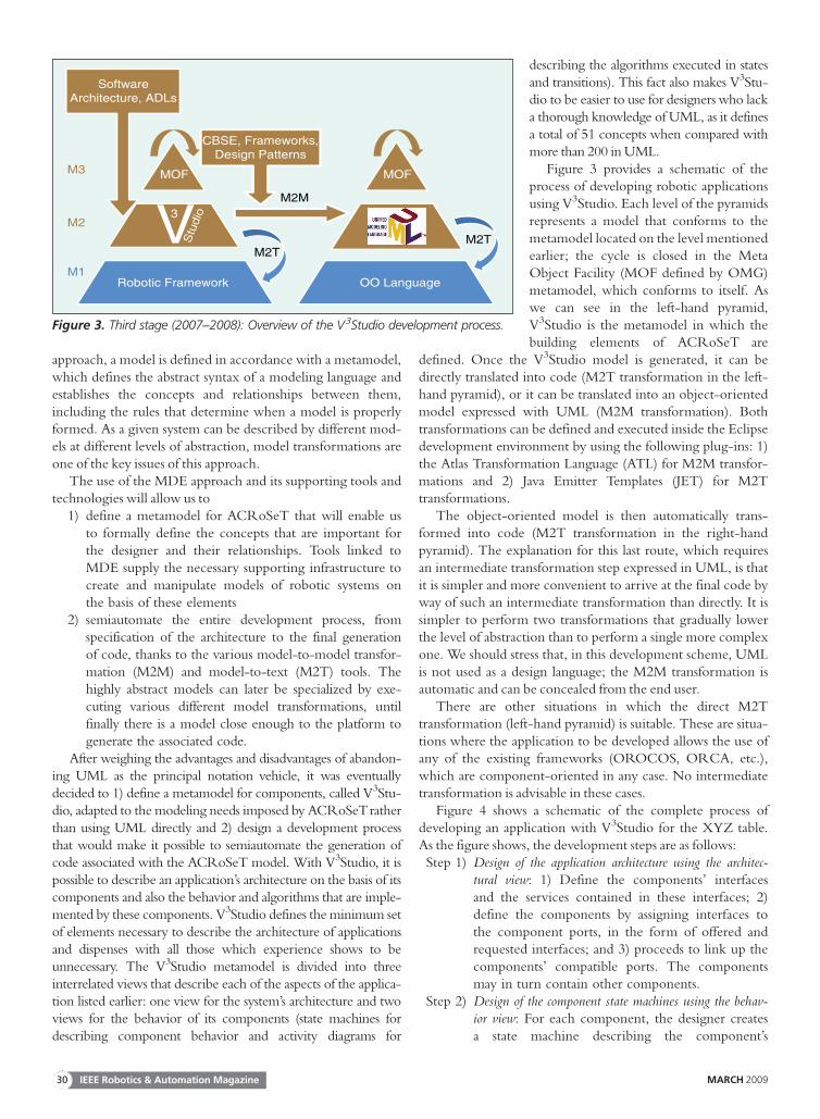
Figure 3 provides a schematic of theprocess of developing robotic applicationsusing V3Studio. Each level of the pyramidsrepresents a model that conforms to themetamodel located on the level mentionedearlier; the cycle is closed in the MetaObject Facility (MOF defined by OMG)metamodel, which conforms to itself. Aswe can see in the left-hand pyramid,V3Studio is the metamodel in which thebuilding elements of ACRoSeT are
defined. Once the V3Studio model is generated, it can bedirectly translated into code (M2T transformation in the left-hand pyramid), or it can be translated into an object-orientedmodel expressed with UML (M2M transformation). Bothtransformations can be defined and executed inside the Eclipsedevelopment environment by using the following plug-ins: 1)the Atlas Transformation Language (ATL) for M2M transfor-mations and 2) Java Emitter Templates (JET) for M2Ttransformations.
The object-oriented model is then automatically trans-formed into code (M2T transformation in the right-handpyramid). The explanation for this last route, which requiresan intermediate transformation step expressed in UML, is thatit is simpler and more convenient to arrive at the final code byway of such an intermediate transformation than directly. It issimpler to perform two transformations that gradually lowerthe level of abstraction than to perform a single more complexone. We should stress that, in this development scheme, UMLis not used as a design language; the M2M transformation isautomatic and can be concealed from the end user.
There are other situations in which the direct M2Ttransformation (left-hand pyramid) is suitable. These are situa-tions where the application to be developed allows the use ofany of the existing frameworks (OROCOS, ORCA, etc.),which are component-oriented in any case. No intermediatetransformation is advisable in these cases.
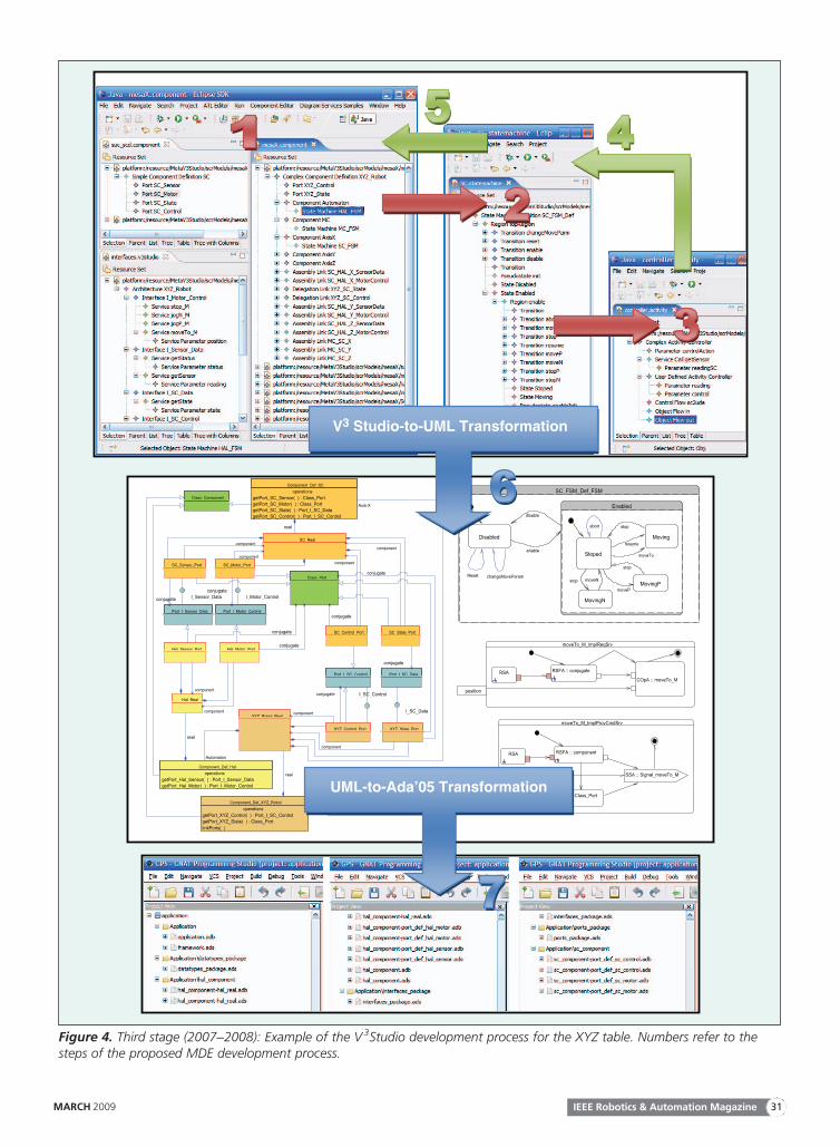
Figure 4 shows a schematic of the complete process ofdeveloping an application with V3Studio for the XYZ table.As the figure shows, the development steps are as follows:Step 1) Design of the application architecture using the architec-
tural view: 1) Define the components’ interfacesand the services contained in these interfaces; 2)define the components by assigning interfaces tothe component ports, in the form of offered andrequested interfaces; and 3) proceeds to link up thecomponents’ compatible ports. The componentsmay in turn contain other components.
Step 2) Design of the component state machines using the behav-ior view: For each component, the designer createsa state machine describing the component’s
MOF
OO Language
MOF
Robotic Framework
M2M
M2TM2T
CBSE, Frameworks,Design Patterns
SoftwareArchitecture, ADLs
V3
M3
M2
M1
Stu
dio
Figure 3. Third stage (2007–2008): Overview of the V3Studio development process.
IEEE Robotics & Automation Magazine30 MARCH 2009
V3 Studio-to-UML Transformation
UML-to-Ada’05 Transformation
Figure 4. Third stage (2007–2008): Example of the V3Studio development process for the XYZ table. Numbers refer to thesteps of the proposed MDE development process.
IEEE Robotics & Automation MagazineMARCH 2009 31
internal behavior and its reaction to the messages itreceives from other components.
Step 3) Design of algorithms using the algorithmic view: Thisview, based on the UML activity diagrams, de-scribes the algorithms that will be implemented bythe component depending on its current status.
Step 4) Association of activities and state machines: Once eachof the application’s three views has been separatelydefined, it only remains to run the process back-ward to complete the model. Each state and transi-tion of the state machines must be associated withthe corresponding activity that describes the algo-rithm that is implemented whenever the compo-nent is in that state or triggers that transition.
Step 5) Association of state machines and components: Eachcomponent must be associated with whichever ofthe state machines designed in Step 4 defining itsbehavior.
Step 6a) Transformation of the V3Studio model to a UML model:The translation is based into concepts handled byobject-oriented languages. A set of classes andadditional operations is generated, derived fromthe different design patterns that have been used toperform this translation (mainly Active Object, butalso Composite, Command, Proxy, and others).
Step 6b) Transformation of the V3Studio model to a robotic framework:Alternatively, it would be possible to design transfor-mations that generate code for any robotic frameworkon the basis of the V3Studio model, since both usesimilar concepts (for example, component and con-nector). This step has not yet been implemented.
Step 7) Transformation of a UML model to a programminglanguage: From the UML model generated in Step 6,we can directly generate code for any object-orientedprogramming language, since that model containsonly concepts used by languages of this type.
One of the requirements imposed on the V3Studio designwas that it facilitates and allows the reuse of models designed inas many scenarios as possible. Components can therefore bereused as models in different architectures; state machines canbe reused in different components; and finally, activities can bereused in different state machines. Moreover, the way in whicha component requests services from other components hasbeen parameterized. In this connection, the V3Studio catersfor two types of services (synchronous and asynchronous) andtwo communication patterns for every case (polling or sub-scription). In V3Studio, it is also possible to specify concur-rency policies for the components, indicating whether thecomponent will have its own implementation thread or, onthe contrary, will it be implemented on its container’s thread.
This process has been applied to generate code previouslyobtained manually. To give the reader an idea of the time sav-ings, the Ada code corresponding to the ACRoSeT design ofFigure 2 took about a week to one full-time programmer.With the V3Studio tools, it is simply a process of compilationthat only takes several seconds. Other issue is that the develop-ment of V3Studio has taken several months.
Finally, it should be stressed that designing the software of anysystem is a complex task that involves more steps rather than justthe design phase we have described. There are other very impor-tant phases such as verification and validation of both models andcode, which have not been described because they are outside thescope of this article. MDE is a relatively new approach that stillhas not reached a mature status, and, as such, there are still manyareas that are subject to intense research, such as 1) model verifica-tion and validation, i.e., how it can be assured that model transfor-mations produce the correct result and 2) model testing, i.e., howit can be assured that generated models still conform to applica-tion requirements, to mention a few. As far as we know, theMDE approach has not been applied to the field of robotics,except in small case studies like the one shown here. Nevertheless,there are important initiatives that are promoting its use [10].
ConclusionsThis article relates our experiences over the last 15 years in thedevelopment of robotic applications within the field of servicerobotics, using the techniques proposed by software engineer-ing. The process began with domain engineering and referencearchitectures, moved on to component-oriented development,and currently centered on model-driven design. Table 1 sum-marizes the ideas and characteristics of the developed roboticsystems as well as the software engineering paradigms that havebeen used and described here.
One of the key problems in software development for roboticsystems is that the possibilities of reusing software in new applica-tions are frequently limited. This means that we are forced over andover to solve the same problems starting practically from zero everytime. The possible causes of this include the following: 1) roboticsspecialists normally concentrate more on developing algorithmsand the way to solve concrete problems than on organizing thesoftware; 2) lack of good standards for the development of roboticsoftware and implementations of these standards; 3) the case studiesconducted to demonstrate the viability of software engineeringtechniques traditionally deal with information management sys-tems; and 4) the robotics community see software engineering notas a solution but as another problem that adds complexity toalready-complex problems.
This research has helped to demonstrate the viability of usingsoftware engineering techniques in real industrial applications,albeit using academic tools that cannot readily be accepted byindustry. There is a need for the development of commercial toolsincorporating these ideas, particularly CBD and MDE, designedfor the development of robotic applications. Our experience tellsus that software engineering has made a decisive contribution toimproving the quality of our applications and to reducing theeffort entailed in development. Our hopes for the future are basi-cally pinned on the MDE approach and the development of tools
CBD is conceived for the purpose
of speeding up the software
development process.
IEEE Robotics & Automation Magazine32 MARCH 2009
to provide automated support for code generation. One of thechallenges we are facing in the short term is to turn V3Studio intoa robust tool that can be offered to other research groups and is ofmore than strictly academic use. In the long term, we plan tointegrate V3Studio with a Software Product Line approach todefine a common architecture for a given family of products. Itwill be then possible to derive a concrete architecture for oneproduct by selecting components (in the form of V3Studio mod-els) from a component repository. After this step, the developercan use the process described in ‘‘A Metamodel for Components:V3Studio’’ section to generate the application code.
AcknowledgmentsThis work has been supported by EU and Spanish Governmentresearch programmes: 5th FP (GROWTH G3RD-CT-00794),CICYT-FEDER Program (MEDWSA, TIN2006-15175-C05-02). Additional funds have been supplied by the Government ofMurcia (Fundaci�on S�eneca) and the Spanish Ministry of Industry(PROFIT programs).
KeywordsService robots, software engineering, software architectures,frameworks, model-driven engineering.
References[1] J. Karlsson, ‘‘UN world robotics statistics 1999,’’ Ind. Robot., vol. 27,
no. 1, pp. 14–18, 2000.[2] A. Iborra, J. A. Pastor, B. �Alvarez, C. Fern�andez, and J. M. Fern�andez,
‘‘Robots in radioactive environments,’’ IEEE Robot. Automat. Mag.,vol. 10, no. 4, pp. 12–22, 2003.
[3] C. Fern�andez, A. Iborra, B. �Alvarez, J. Pastor, P. S�anchez, J. M. Fern�andez,and N. Ortega, ‘‘Ship shape in Europe: Co-operative robots in the shiprepair industry,’’ IEEE Robot. Automat. Mag., vol. 12, no. 3, pp. 65–77, 2005.
[4] T. Stahl and M. V€oelter, Model-Driven Software Development: Technology,Engineering, Management, 1st ed. New York: Wiley, 2006.
[5] K. Lau and Z. Wang, ‘‘Software component models,’’ IEEE Trans. Soft-ware Eng., vol. 33, no. 10, pp. 709–724, 2007.
[6] B. �Alvarez, P. S�anchez, J. A. Pastor, and F. Ortiz, ‘‘An architecturalframework for modelling teleoperated service robots,’’ ROBOTICA Int.J. Inf. Educ. Res. Robot. Artif. Intell., vol. 24, no. 4, pp. 411–418, 2006.
[7] H. Bruyninckx, ‘‘Open robot control software: The OROCOS project,’’in Proc. IEEE Int. Conf. Robotics Automation, 2001, vol. 3, pp. 2523–2528.
[8] A. Brooks, T. Kaupp, A. Makarenko, S. Williams, and A. Oreback,‘‘Towards component-based robotics,’’ in Proc. IEEE/RSJ Int. Conf.Intelligent Robots and Systems, 2005, vol. 1, pp. 163–168.
[9] D. Schmidt, M. Stal, H. Rohnert, and F. Buschmann, Pattern-OrientedSoftware Architecture, Patterns for Concurrent and Networked Objects, vol. 2.New York, Wiley, 2000.
[10] H. Bruyninckx, ‘‘Robotics software: The future should be open,’’IEEE Robot. Automat. Mag., vol. 15, no. 1, pp. 9–11, 2008.
[11] E. Coste-Mani�ere and R. Simmons, ‘‘Architecture, the backbone ofrobotic systems,’’ in Proc. 2000 IEEE Int. Conf. Robotics and Automation,pp. 67–72.
Andr�es Iborra received a Ph.D. degree in 1993 and anM.S. degree in 1989 in industrial engineering from theTechnical University of Madrid. He has worked as a researchengineer in robotics for nuclear power plants during 1993–
1998. In 1998, he joined the DSIE. He is full professor andthe head of the Electronics Technology Department at theTechnical University of Cartagena, where he has been since
1998. His current research interests include mechatronic sys-tems design and analysis, computer vision, robotics, andengineering education.
Diego Alonso C�aceres received an M.S. degree in electri-cal engineering from the Universidad Polit�ecnica de Valenciain 2001 and a Ph.D. degree from the Universidad Polit�ecn-ica de Cartagena in 2008, where he is currently a lecturer.He joined the DSIE in 2004. His research interests focus onthe application of the model-driven engineering approachand to the development of component-based reactive sys-tems with real-time constraints.
Francisco J. Ortiz received his Ph.D. degree in industrialengineering from the Technical University of Cartagena,Spain, in 2005. Since 1999, he has participated in differentprojects focused in computer-assisted surgery, service robotics,and software engineering in the DSIE. He is currently anassociate professor at the Electronics Technology Departmentof the Technical University of Cartagena. His research inter-ests include mechatronic systems design, software architecturesfor robotics, and model-driven engineering.
Juan Pastor Franco received his Ph.D. degree in telecom-munication engineering from the Technical University ofCartagena, Spain, in 2002. He is currently an associateprofessor at the Technical University of Cartagena in thefield of computer science. He has worked as a research engi-neer in robotics for nuclear power plants from 1995–2000.In 2000, he joined the DSIE. His research interests includemechatronic systems design and analysis, robotics, designpatterns, and model-driven development.
Pedro S�anchez Palma received his Ph.D. degree incomputer science from the Technical University of Valencia,Spain, in 2000. Since 1996, he has participated in differentprojects focused on software engineering and conceptualmodeling. In 2000, he joined the DSIE. He is currently anassociate professor at the Technical University of Cartagenain the field of computer science. His current research inter-ests include model-driven engineering, real-time systems,and conceptual modeling.
B�arbara �Alvarez received his Ph.D. degree in telecommu-nication engineering from the Technical University ofMadrid, Spain, in 1997. Since 1995, she has participated indifferent projects focused in robotics applications for theindustry. In 1998, she joined the DSIE. She is currently anassociate professor at the Technical University of Cartagenain the field of computer science. Her research interestsinclude real-time systems and software architectures for tele-operation and computer vision systems.
Address for Correspondence: Andr�es Iborra, UniversidadPolit�ecnica de Cartagena, Divisi�on de Sistemas e Ingenier�ıaElectr�onica (DSIE), Campus Muralla del Mar, s/n. CartagenaE-30202, Spain. E-mail: [email protected].
IEEE Robotics & Automation MagazineMARCH 2009 33


