Embed Size (px)
Citation preview

Influence of deposition parameters on chemical propertiesof calcium phosphate coatings prepared by usingelectrostatic spray deposition
S. Leeuwenburgh,1 J. Wolke,1 J. Schoonman,2 J. A. Jansen1
1Department of Periodontology and Biomaterials, Radboud University Nijmegen Medical Center, P.O. Box 9101, 6500HB, Nijmegen, The Netherlands2Laboratory for Inorganic Chemistry, Delft University of Technology, Delft, The Netherlands
Received 20 January 2005; revised 24 March 2005; accepted 24 March 2005Published online 16 June 2005 in Wiley InterScience (www.interscience.wiley.com). DOI: 10.1002/jbm.a.30420
Abstract: The electrostatic spray deposition (ESD) tech-nique offers the possibility of depositing calcium phosphate(CaP) coatings onto various substrate materials with definedchemical and morphological properties. The relationshipbetween physical, apparatus-related deposition parameters,and the chemical characteristics of ESD coatings was inves-tigated by means of X-ray diffraction, Fourier transforminfrared spectroscopy, and energy dispersive spectroscopyto be able to deposit CaP coatings with tailored chemicalproperties. The results showed that the chemical character-istics of CaP coatings, deposited with use of the ESD tech-nique, were strongly dependent on the deposition tempera-ture, the nozzle-to-substrate distance, the liquid flow rate,and the geometry of the spraying nozzle. By investigatingthe influence of the deposition temperature, informationcould be obtained on the formation mechanism of CaP coat-ings—and specifically the biologically interesting carbonate
apatite phase—using the ESD technique. CaP coatings werenot formed merely because of solvent evaporation; a chem-ical reaction was needed to synthesize the coatings. Thisreaction involved thermal decomposition of the organic sol-vent butyl carbitol into carbonate ions via formation ofintermediate oxalate ions. The amount of carbonate incor-poration, and consequently, the Ca/P ratios of the depositedcoatings, was shown 1) to decrease with increasing nozzle-to-substrate distance, 2) to decrease with increasing liquidflow rate, and 3) to decrease by making use of a noveltwo-component nozzle geometry. © 2005 Wiley Periodicals,Inc. J Biomed Mater Res 74A: 275–284, 2005
Key words: electrostatic spray deposition; calcium phos-phate; carbonate apatite; deposition parameters; chemicalcharacteristics
INTRODUCTION
In the biomedical field, coatings are frequently ap-plied onto the surface of metallic dental and orthope-dic implants to improve their biological performance.Because of its similarity to the inorganic component ofbone and teeth, calcium phosphate (CaP) ceramicswere early considered as a suitable class of materialsfor use as a surface coating on top of metals such astitanium and its alloys.1 CaP materials are generallycategorized as bioactive ceramics, which implies thatthe implant material bonds to surrounding osseoustissue, resulting in a strong interface between boneand the implant surface.2 Generally, the phenomenon
of bioactivity is characterized by the formation of anintermediate CaP layer at this interface. The capacityof biomaterial surfaces to initiate the formation of thisintermediate CaP layer is indicative of their bioactiv-ity. This capacity is strongly related to the chemicalstability, and accordingly, to the physicochemicalproperties of the implant material surface on exposureto body fluids.3–5 Specifically, the osteogenic capacityof CaP ceramics was shown to be dependent on chem-ical properties, such as the composition, molecularstructure, crystal structure, and crystallinity of thecoating.
To be able to investigate this fundamental relation-ship between the physicochemical nature of CaP coat-ings and their biological performance in vitro and invivo, a flexible deposition technique is required, whichoffers the possibility of varying a wide range of coat-ing properties. Although the conventional plasma-spraying technique has given good results in the past,this technique does not offer the earlier mentioned
Correspondence to: John A. Jansen; e-mail: [email protected]
Contract grant sponsor: Dutch Technology FoundationSTW; contract grant number: NKG 5546
© 2005 Wiley Periodicals, Inc.
flexibility regarding the variation in chemical andmorphological coating properties.6 Therefore, the fea-sibility of a coating technique, referred to as electro-static spray deposition (ESD), was investigated re-cently for these purposes.7 This technique has enabledthe deposition of inorganic coatings with defined mor-phological and chemical characteristics.8,9
Briefly, the basic principle of ESD is the generationof a spray of charged, micron-sized droplets. This isaccomplished by means of electrostatic atomization10
of precursor solutions that contain inorganic precursorsalts. These spray droplets are directed toward agrounded and heated substrate as a result of the ap-plied potential difference. After complete solventevaporation, a thin inorganic layer is left on the sub-strate surface.
To deposit ESD coatings with defined chemicalproperties (crystallinity, crystal phase, and molecularstructure of the coating), the relationship between var-ious processing parameters of the technique and thechemical properties of the deposited coatings has to beunderstood. In a previous study, the influence of thecomposition of the precursor solutions on the chemi-cal properties of ESD coatings was investigated.11 Themain objective of the current study was to study theinfluence of physical, apparatus-related deposition pa-rameters on these chemical properties. Therefore, fourrelevant apparatus-related deposition parameters(deposition temperature, nozzle-to-substrate distance,liquid flow rate, and the geometry of the sprayingnozzle) were selected and investigated in this study.The deposition temperature and nozzle-to-substratedistance were chosen for their influence on solventevaporation. The liquid flow rate and the geometry ofthe spraying nozzle were expected to influence themixing characteristics of the precursor solutions.
MATERIALS AND METHODS
ESD process
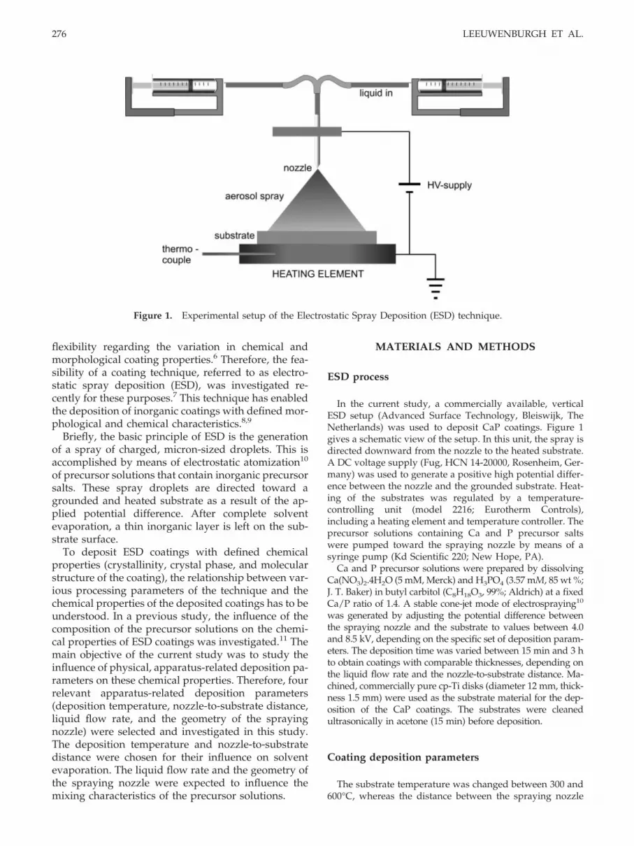
In the current study, a commercially available, verticalESD setup (Advanced Surface Technology, Bleiswijk, TheNetherlands) was used to deposit CaP coatings. Figure 1gives a schematic view of the setup. In this unit, the spray isdirected downward from the nozzle to the heated substrate.A DC voltage supply (Fug, HCN 14-20000, Rosenheim, Ger-many) was used to generate a positive high potential differ-ence between the nozzle and the grounded substrate. Heat-ing of the substrates was regulated by a temperature-controlling unit (model 2216; Eurotherm Controls),including a heating element and temperature controller. Theprecursor solutions containing Ca and P precursor saltswere pumped toward the spraying nozzle by means of asyringe pump (Kd Scientific 220; New Hope, PA).
Ca and P precursor solutions were prepared by dissolvingCa(NO3)2.4H2O (5 mM, Merck) and H3PO4 (3.57 mM, 85 wt %;J. T. Baker) in butyl carbitol (C8H18O3, 99%; Aldrich) at a fixedCa/P ratio of 1.4. A stable cone-jet mode of electrospraying10
was generated by adjusting the potential difference betweenthe spraying nozzle and the substrate to values between 4.0and 8.5 kV, depending on the specific set of deposition param-eters. The deposition time was varied between 15 min and 3 hto obtain coatings with comparable thicknesses, depending onthe liquid flow rate and the nozzle-to-substrate distance. Ma-chined, commercially pure cp-Ti disks (diameter 12 mm, thick-ness 1.5 mm) were used as the substrate material for the dep-osition of the CaP coatings. The substrates were cleanedultrasonically in acetone (15 min) before deposition.
Coating deposition parameters
The substrate temperature was changed between 300 and600°C, whereas the distance between the spraying nozzle
Figure 1. Experimental setup of the Electrostatic Spray Deposition (ESD) technique.
276 LEEUWENBURGH ET AL.

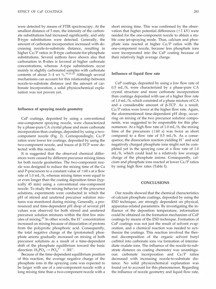
and the substrate was varied between 5 and 40 mm. Regard-ing the geometry of the spraying nozzle, a two-componentnozzle with separate inlet for Ca and P precursor solutionswas used as standard nozzle (stainless steel, flat outlet, innerand outer diameter of 0.9 and 1.4 mm, respectively) to avoidpremature precipitation of the precursor solutions beforespray generation. This novel nozzle geometry was com-pared with a conventional one-component nozzle geometryusing premixed precursor solutions. Both nozzle geometriesare depicted in Figure 2.
By using the standard two-component nozzle, the precur-sor flow rate was varied between 0.5 and 2.0 mL/h (equalflow rate for both Ca and P precursor solutions), whereas theflow rate was fixed at 2.0 mL/h for the one-componentnozzle. The thickness of the deposited coatings varied be-tween �0.5 and 10 �m, depending on the nozzle-to-sub-strate distance and the liquid flow rate. After deposition,some of the coatings were subjected to additional heat treat-ments in air at a temperature of 650°C in an infrared furnace(E4-10-P; Research Inc., Minneapolis, MN) to study the crys-tallization behavior of CaP ceramic coatings.12
Characterization of the ESD coating
The as-deposited and heat-treated ESD coatings werecharacterized by using the following techniques:
1. X-ray diffraction (XRD): CaP coatings were subjectedto X-ray diffraction analysis on a thin-film Philips X-Ray Diffractometer using CuK�-radiation (PW 3710, 40kV, 40 mA) to characterize the crystal structure of thedeposited coatings. Coatings were analyzed by fixingthe sample to a position of 2.5° and scanning the de-tector between 20°2� and 50°2� with a step size of0.02°2�, a scanning speed of 0.01°2�/s, and a sampletime of 2 s/step.
2. Fourier transform infrared spectrometry (FTIR): Tocharacterize the molecular structure of the depositedcoatings, infrared spectra of the films on the substrateswere obtained from 4000 to 400 cm�1 by reflectionFourier transform infrared spectrometry (SpectrumOne; Perkin-Elmer) because infrared radiation cannotpass through the titanium substrate.
3. Energy dispersive spectroscopy (EDS): The scanningelectron microscope was equipped with an energy-dispersive X-ray microanalyzer (Voyager). EDS wasconducted at a magnification of 500� at an acceleratingvoltage of 10 kV to determine the chemical composi-tion of the deposited coatings. Stoichiometric hydroxy-apatite disks of known Ca/P ratio and of equal thick-ness to the coated Ti-substrates (1.5 mm) were used asa reference for the determination of Ca/P ratios of thedeposited ESD coatings.
RESULTS
Influence of deposition temperature
The minimum deposition temperature for the for-mation of CaP coatings by means of ESD appeared tobe 300°C; at lower temperatures, it was impossible toobtain solid, ceramic coatings. Figure 3 shows theFTIR spectra of as-deposited coatings, synthesized atdifferent deposition temperatures. At 300°C, twobroad and unsplit phosphate absorption bands wereobserved between 1250 and 900 cm�1 (�3) and 650 and500 cm�1 (�4). However, remnants of the organic sol-vent were still present at 300°C. Several absorptionpeaks were assigned to organic groups,13 such as in-
Figure 3. FTIR spectra of as-deposited calcium phosphatecoatings, prepared by using ESD at different depositiontemperatures. [I] 300°C, [II] 350°C [III] 450°C, and [IV]600°C.
Figure 2. Conventional one-component and novel two-component spraying nozzle geometries.
EFFECT OF CaP COATINGS 277

tense CH stretch absorptions (between 2850 and 2940cm�1), a CH bending band at 1460 cm�1, a symmetricCH bending band of the CH3 group at 1376 cm�1, anda CH2 rocking absorption at 722 cm�1. Moreover,absorption peaks at 1713 and 1598 cm�1 were assignedto CAO13 and nitrate groups.14 However, some au-thors have reported a bending mode of water (�2)15 at1595 cm�1. At a deposition temperature of 350°C, theorganic remnants and CAO groups were absent, andtwo broad �3 carbonate absorptions were observed at1487 cm�1 and 1425 cm�1. In addition, a small �2carbonate peak at 870 cm�1 was found. These vibra-tions correspond to carbonate groups engaged in anamorphous CaP environment.16 Absorption peaks at782, 1323, and 1646 cm�1 corresponded to the pres-ence of hydrated calcium oxalate.17 At a depositiontemperature of 450°C, the nitrate and/or water ab-sorption band around 1600 cm�1 had completely dis-appeared, whereas the oxalate absorption peaks werealso hardly visible anymore. On the contrary, the car-bonate bands at 1487, 1425, and 870 cm�1 were stillpresent. Phosphate absorptions between 1250 and 900cm�1 (�3) and 650 and 500 cm�1 (�4) remained broadand unsplit up to deposition temperatures of 550°C,but at 600°C, these two absorption bands split up intosharper bands at 1087, 1032 (�3), 962 (�1), 602, and 567cm�1 (�4). Furthermore, sharp carbonate bands (�3) at1455 and 1416 cm�1 revealed that carbonate wasmainly substituting for phosphate anions (type B sub-stitutions) in a crystalline CaP environment. By meansof XRD analysis, the crystalline apatitic structure ofthese coatings was confirmed (data not shown); mainreflection lines were located at 25.8°, 31.9°, and32.9°2�, which correspond to (002), (211), and (300)reflections of the apatite structure.18 This finding indi-cated that the as-deposited coatings remained amor-phous up to deposition temperatures of 600°C, whichwas the temperature for crystallization of these B-typecarbonate apatite (CA) coatings.
After an additional heat treatment of the variousas-deposited coatings at 650°C, all coatings trans-
formed into crystalline CA coatings. No chemical dif-ferences were observed after heat treatment betweenthe various deposition temperatures. As shown in Ta-ble I, EDS analysis revealed that the Ca/P ratios of thedeposited coatings were higher than the initial Ca/Psolution ratio of 1.4.
Influence of nozzle-to-substrate distance
Figure 4(A) shows the FTIR-spectra of heat-treatedcoatings, synthesized at different nozzle-to-substratedistances. At a high distance of 40 mm, the FTIRspectrum revealed characteristics of the �-tricalci-umphosphate (�-TCP) phase,15,18 such as phosphateabsorptions (shoulders) at 1115, 972, and 945 cm�1 (�3)and relatively broad �4 phosphate absorptions at 602and 551 cm�1. Hardly any carbonate was detected bymeans of FTIR. On the contrary, at a smaller distanceof 10 mm, CO3 absorption peaks at 879 (�2), 1414, 1456,and 1546 (�3) cm�1 indicated a considerable increase ofcarbonate incorporation. Absorption peaks at 1086,1035 (�3), 962 (�1), 602, and 567 cm�1 (�4) were assignedto phosphate groups in a crystalline apatite lattice.Carbonate anions were substituted for both phosphate(B-type) and hydroxyl groups (A-type) in a crystallineapatite lattice.15,18,19 At a small distance of 5 mm, theintensity of the carbonate absorptions had increasedsignificantly. Moreover, the absorption peak at 1546cm�1 had disappeared, which corresponds to A-typecarbonate-for-hydroxyl substitutions. This indicatedthat carbonate ions were substituting for phosphategroups only (B-type substitutions).
The corresponding XRD-diffractograms are de-picted in Figure 4(B). At a high distance of 40 mm, aphase mixture of �-TCP and CA was observed. Mainreflection lines were located at 25.8°, 27.8°, 31.0° and34.3°2� (matching with JCPDS File No. 9-169 of the�-TCP phase), and 25.8°, 31.6°, 32.1° and 32.8°2�,which correspond to (002), (211), (112), and (300) re-
TABLE ICa/P Ratios of Deposited Coatings (After Heat Treatment) as Measured by EDS
Temperature(°C)
Nozzle-to-SubstrateDistance (mm)
Flow Rate(mL/h) Nozzle Geometry Ca/P Ratio of Coating
300 20 1.0 Two-component 1.9–2.0350 20 1.0 Two-component 1.9–2.0450 20 1.0 Two-component 1.9–2.0600 20 1.0 Two-component 2.0–2.1340 5 1.0 Two-component 2.2–2.3340 10 1.0 Two-component 1.7–1.8340 40 1.0 Two-component 1.6–1.7340 20 0.5 Two-component 2.0–2.1340 20 1.0 Two-component 1.7–1.8340 20 1.0 One-component 2.1–2.2340 20 1.0 Two-component 1.8–1.9
278 LEEUWENBURGH ET AL.

flections of the apatite structure.15,18,19 At a smallerdistance of 10 mm, the heat-treated coatings consistedmainly of CA (main reflections located at 25.8°, 31.7°,
32.1°, and 32.8°2�). However, a small shoulder at31.0°2� indicated that there was still a minor contam-ination of �-TCP. The reflections at 27.4 and 36.0°2�
Figure 4. (A) FTIR spectra of heat-treated calcium phosphate coatings, prepared by using ESD at different nozzle-to-substrate distances. [I] 40 mm, [II] 10 mm, and [III] 5 mm. All coatings were heat-treated at 650°C. (B) XRD patterns ofheat-treated calcium phosphate coatings, prepared by using ESD at different nozzle-to-substrate distances. [I] 40 mm, [II] 10mm, and [III] 5 mm. All coatings were heat-treated at 650°C. Carbonate apatite; ∧ �-TCP; 0 Ti; # rutile.
EFFECT OF CaP COATINGS 279

corresponded to rutile (TiO2) due to oxidation of theunderlying substrate. At small distances of 5 and 10mm, the Ti substrates were not completely coveredwith CaP material, thus allowing for oxidation of Tidue to heat treatment. At a distance of 40 mm, no bareTi was left because of complete coating coverage, andconsequently, less TiO2 was detected. At 5 mm, theXRD pattern corresponded to CA (main reflections at31.8°, 32.1°, and 32.9°2�) without any impurity phases,except TiO2. The intensity of the diffraction peaks ofthe CaP coating was relatively low as a result of thesmall dimensions of the deposited CaP spot. EDS mea-surements showed that the Ca/P ratio of the depos-ited coatings increased with decreasing nozzle-to-sub-strate distance (Table I).
Influence of spraying nozzle geometry
FTIR spectra of heat-treated coatings, deposited byusing one- or two-component nozzle geometries, areshown in Figure 5(A). By using a two-componentnozzle, a small �2 absorption at 879 cm�1 and three �3absorptions at 1411, 1456, and 1547 cm�1 were as-signed to carbonate groups substituting for hydroxyl(A-type) and phosphate groups (B-type). Phosphatepeaks were located at 1089, 1020 (�3), 961 (�1), 600, and565 cm�1 (�4). On the contrary, carbonate peaks weresignificantly more intense with use of a conventionalone-component spraying nozzle. Furthermore, onlyB-type substitutions were left (peaks at 1456 and 1416cm�1), absorption peaks corresponding to A-type sub-stitutions were not detected. Phosphate absorptionswere comparable with the two-component nozzle. Thecorresponding XRD diffractograms are shown in Fig-ure 5(B). Both patterns revealed main reflection linesat 25.8°, 31.9°, 32.8° and 34.0°2� of (carbonate) apatite.However, by using the two-component nozzle, extrareflection peaks at 31.0° and 34.3°2� were assigned tothe presence of a minor second phase: �-TCP. Ca/Pratios of the deposited coatings were higher by usingone-component nozzles compared with two-compo-nent nozzle geometries (Table I).
Influence of liquid flow rate
Regarding the influence of the liquid flow rate onthe molecular structure of deposited coatings, relevantFTIR spectra of heat-treated coatings are shown inFigure 6(A). At a flow rate of 1.0 mL/h, a small �2absorption at 879 cm�1 and three �3 absorptions at1414, 1456, and 1546 cm�1 were related to carbonateions substituting for hydroxyl (A-type) and phosphategroups (B-type). Phosphate peaks were located at 1055
(�3), 961 (�1), 600, and 567 cm�1 (�4). At a lower flowrate of 0.5 mL/h, carbonate peaks were considerablymore intense. Only B-type substitutions were left(peaks at 1456 and 1416 cm�1), and absorption peakscorresponding to A-type substitutions were not de-tected. At 0.5 mL/h, phosphate absorptions weresharper than the higher flow rate of 1.0 mL/h.
XRD revealed that a phase mixture consisting of CAand a considerable amount of �-TCP was deposited byusing a flow rate of 1.0 mL/h, whereas phase pure CAwithout any trace of �-TCP was deposited at a flowrate of 0.5 mL/h [Fig. 6(B)]. Correspondingly, Ca/Pratios of deposited coatings were higher with use oflow flow rates.
DISCUSSION
The main objective of the current study was to studythe influence of several apparatus-related depositionparameters on the chemical characteristics of CaPcoatings deposited by means of the ESD technique.The results clearly show that the crystal and molecularstructure of ESD-deposited coatings are dependent onall selected apparatus-related deposition parameters.
Influence of deposition temperature
By means of characterizing ESD coatings, whichwere deposited at various deposition temperatures,information could be obtained on the formation mech-anism of CaP coatings by means of the ESD technique.Formation of CaP coatings was not just the result ofsolvent evaporation. At the minimum temperature of300°C, organic remnants of the solvent were stillpresent. These remnants were absent at a depositiontemperature of 350°C, whereas both oxalate (C2O4
2�)and carbonate (CO3
2�) anions were formed simulta-neously. At a higher deposition temperature of 450°C,only carbonate ions were present, and hardly anyoxalate was left anymore. In a previous study, it wasshown that carbonate anions play an essential role incontrolling the chemical properties of ESD-derivedCaP coatings.11 Here, it was concluded that carbonateions were formed via intermediate oxalate groups asthe result of thermal decomposition of the organicsolvent butyl carbitol. From literature, it is known thatoxalate decomposes to carbonate around 425°C ac-cording to the following reaction20:
C2O42�3CO3
2�CO
At a deposition temperature of 450°C, carbonate wasstill engaged in an amorphous environment. From XRDand FTIR analysis, it was concluded that these CaP coat-
280 LEEUWENBURGH ET AL.

ings became crystalline on deposition (B-type CA) at atemperature of 600°C. Generally, all coatings trans-formed into crystalline CA after heat treatment, irrespec-tive of their initial deposition temperature, indicating
that the deposition temperature did not influence thefinal chemical structure of the heat-treated coatings. Thiscalcium phosphate phase is particularly interesting be-cause of its chemical resemblance to bone mineral.
Figure 5. (A) FTIR spectra of heat-treated calcium phosphate coatings, prepared by using ESD with different nozzlegeometries: [I] two-component nozzle geometry and [II] one-component nozzle geometry. All coatings were heat-treated at650°C. (B) XRD patterns of heat-treated calcium phosphate coatings, prepared by using ESD with different nozzle geometries:[I] two-component nozzle geometry and [II] one-component nozzle geometry. All coatings were heat-treated at 650°C. Carbonate apatite; ∧ �-TCP; 0 Ti.
EFFECT OF CaP COATINGS 281

Influence of nozzle-to-substrate distance
From XRD and FTIR spectroscopy, it can be con-cluded that the chemical properties of ESD-derivedCaP coatings are dependent on the nozzle-to-substrate
distance at which the coatings were deposited. At ahigh distance of 40 mm, a phase mixture of CA and�-TCP was formed with hardly any carbonate incor-poration. At a smaller distance, the carbonate contenthad increased, and both A- and B-type substitutions
Figure 6. (A) FTIR spectra of heat-treated calcium phosphate coatings, prepared by using ESD at different liquid flow rates:[I] 1.0 mL/h, and [II] 0.5 mL/h. All coatings were heat-treated at 650°C. (B) XRD patterns of heat-treated calcium phosphatecoatings, prepared by using ESD at different liquid flow rates: [I] 1.0 mL/h and [II] 0.5 mL/h. All coatings were heat-treatedat 650°C. Carbonate apatite; ∧ �-TCP; 0 Ti.
282 LEEUWENBURGH ET AL.
were detected by means of FTIR spectroscopy. At thesmallest distance of 5 mm, the intensity of the carbon-ate substitutions had increased significantly, and onlyB-type substitutions were detected. Generally, theamount of carbonate incorporation increased with de-creasing nozzle-to-substrate distance, resulting inhigher Ca/P ratios in B-type carbonate-for-phosphatesubstitutions. Several authors have shown also thatcarbonation in B-sites is favored at higher carbonateconcentrations, whereas A-type substitutions occurmainly in slightly carbonated samples with carbonatecontents of about 3–4 wt %.19,21,22 Although severalmechanisms can account for this relationship betweennozzle-to-substrate distance and the amount of car-bonate incorporation, a solid physicochemical expla-nation was not proven yet.
Influence of spraying nozzle geometry
CaP coatings, deposited by using a conventionalone-component spraying nozzle, were characterizedby a phase-pure CA crystal phase and more carbonateincorporation than coatings, deposited by using a two-component nozzle (Fig. 2). Correspondingly, Ca/Pratios were lower for coatings, deposited by using thetwo-component nozzle, and traces of �-TCP were de-tected with this nozzle.
It is suggested that the observed chemical differ-ences were caused by different precursor mixing timesfor both nozzle geometries. The two-component noz-zle was designed to reduce the mixing time of the Caand P-precursors to a constant value of �60 s at a flowrate of 1.0 mL/h, whereas mixing times were equal toor even longer than the coating deposition times (typ-ically 45 min) using a conventional one-componentnozzle. To study the mixing behavior of the precursorsolutions, experiments were conducted in which thepH of stirred and unstirred precursor solution mix-tures was monitored during mixing. Generally, a pro-nounced and time-dependent pH drop of several pHvalues was observed for both stirred and unstirredprecursor solution mixtures within the first few min-utes of mixing.23 In other words, the H concentrationincreased on mixing because of dissociation of protonsfrom the polyprotic phosphoric acid. Consequently,the total negative charge of the (protonated) phos-phate anions gradually increased on mixing of bothprecursor solutions as a result of a time-dependentshift of the phosphate equilibrium toward the basicdirection: H3PO4 3 PO4
3� 3H.Because of the time-dependent equilibrium position
of this reaction, the average negative charge of thephosphate ions in the spraying cone was expected tobe larger with use of a one-component nozzle with along mixing time than a two-component nozzle with a
short mixing time. This was confirmed by the obser-vation that higher potential differences (�1 kV) wereneeded for the one-component nozzle to obtain a sta-ble cone jet-spraying mode. Thus, calcium and phos-phate ions reacted at higher Ca/P ratios with theone-component nozzle, because less phosphate ionswere incorporated into the CaP coating because oftheir relatively high average charge.
Influence of liquid flow rate
CaP coatings, deposited by using a low flow rate of0.5 mL/h, were characterized by a phase-pure CAcrystal structure and more carbonate incorporationthan coatings deposited with use of a higher flow rateof 1.0 mL/h, which consisted of a phase mixture of CAand a considerable amount of �-TCP. As a result,Ca/P ratios were lower at the higher flow rate. Again,the aforementioned time-dependent pH drop, occur-ring on mixing of the two precursor solution compo-nents, was suggested to be responsible for this phe-nomenon. At a high flow rate of 1.0 mL/h, the mixingtime of the precursors (�60 s) was twice as shortcompared to a flow rate of 0.5 mL/h. As a conse-quence, the dissociation reaction yielding H and acidnegatively charged phosphate ions might not be com-pleted yet in the spraying cone at a flow rate of 1.0mL/h, which could lead to a relatively low averagecharge of the phosphate anions. Consequently, cal-cium and phosphate ions reacted at lower Ca/P ratiosby using high flow rates (Table I).
CONCLUSIONS
Our results showed that the chemical characteristicsof calcium phosphate coatings, deposited by using theESD technique, are strongly dependent on physical,apparatus-related parameters. By investigating the in-fluence of the deposition temperature, informationcould be obtained on the formation mechanism of CaPcoatings by means of the ESD technique. Formation ofCaP coatings was not just the result of solvent evap-oration, and a chemical reaction was needed to syn-thesize the coatings. This reaction involved the ther-mal decomposition of the organic solvent butylcarbitol into carbonate ions via formation of interme-diate oxalate ions. The influence of the nozzle-to-sub-strate distance on coating chemistry was unambigu-ous: carbonate incorporation and Ca/P ratiosdecreased with increasing nozzle-to-substrate dis-tance. No solid physicochemical explanation wasfound yet to account for this phenomenon. Regardingthe influence of nozzle geometry and liquid flow rate,
EFFECT OF CaP COATINGS 283

it was concluded that the mixing characteristics of thecalcium and phosphate precursor solutions are an im-portant factor in controlling coating properties. Longmixing times at low flow rates and/or a one-compo-nent nozzle geometry using premixed precursor solu-tions resulted in more carbonate incorporation andhigher Ca/P ratios than short mixing times. This effectcould be explained by the time-dependent equilibriumposition of the dissociation reaction, by which protonsare removed from the polyprotic phosphoric acidyielding negatively charged, protonated phosphategroups. As a consequence, long mixing times wereexpected to correspond to a higher average negativecharge of the phosphate ions in the spraying cone,resulting in less phosphate incorporation and higherCa/P ratios than shorter mixing times.
In general, it was concluded that ESD is especiallysuitable in research focused on the fundamental rela-tionship between CaP coating characteristics and bio-logical coating performance due to the versatility ofthe technique regarding deposition of coatings withtailored chemical characteristics.
References
1. Lacefield WR. Hydroxylapatite coatings. In: Hench LL, WilsonJ, editors. An introduction to bioceramics. Singapore: WorldScientific Publishing Co.; 1993. p 223–238.
2. Hench LL, Ethridge EC. Biomaterials. New York: AcademicPress; 1982.
3. Ducheyne P, Qiu Q. Bioactive ceramics: the effect of surfacereactivity on bone formation and bone cell function. Biomate-rials 1999;20:2287–2303.
4. LeGeros RZ. Biodegradation and bioresorption of calciumphosphate ceramics. Clin Mater 1993;14:65–88.
5. de Bruijn JD. Calcium phosphate biomaterials: bone-bondingand biodegradation properties (PhD thesis). The Netherlands:University of Leiden; 1993.
6. Lacefield WR. Current status of ceramic coatings for dentalimplants. Implant Dent 1998;7:315–322.
7. Leeuwenburgh S, Wolke J, Schoonman J, Jansen J. Electrostaticspray deposition (ESD) of calcium phosphate coatings.J Biomed Mater Res 2003;66A:330–334.
8. Chen CH. Thin film components for lithium-ion batteries (PhDthesis). The Netherlands: Delft University of Technology; 1998.
9. Taniguchi I, van Landschoot RC, Schoonman J. Fabrication ofLa1-xSrxCo1-yFeyO3 thin films by electrostatic spray deposition.Solid State Ionics 2003;56:1–3.
10. Hartman R. Electrohydrodynamic atomization in the cone-jetmode (PhD thesis). The Netherlands: Delft University of Tech-nology; 1998.
11. Leeuwenburgh SCG, Wolke JGC, Schoonman J, Jansen JA.Influence of precursor solution parameters on chemicalproperties of calcium phosphate coatings prepared usingelectrostatic spray deposition (ESD). Biomaterials 2004;25:641– 649.
12. Yoshinari M, Hayakawa T, Wolke JGC, Nemote K, Jansen JA.Influence of rapid heating with infrared radiation on RF mag-netron-sputtered calcium phosphate coatings. J Biomed MaterRes 1997;37:60–67.
13. Pouchert CJ. The Aldrich library of infrared spectra. 3rd ed.Milwaukee: Aldrich Chemical Company; 1981.
14. Hadjiivanov KI. Identification of neutral and charged NxOy
surface species by IR spectroscopy. Catal Rev Sci Eng 2000;42:71–44.
15. Koutsopoulos S. Synthesis and characterization of hydroxyap-atite crystals: a review study on the analytical methods.J Biomed Mater Res 2002;62:600–612.
16. Layrolle P, Ito A, Tateishi T. Sol–gel synthesis of amorphouscalcium phosphate and sintering into microporous hydroxy-apatite bioceramics. J Am Ceram Soc 1998;81:1421–1428.
17. Kingsley RJ, van Gilder R, LeGeros RZ, Watabe N. Multimin-eral calcareous deposits in the marine alga acetabularia acetab-ulum (chlorophyta;dasycladaceae). J Phycol 2003;39:937–947.
18. LeGeros RZ. Calcium phosphates in oral biology and medi-cine. Basel: Karger; 1991.
19. Elliott JC. Structure and chemistry of the apatites and othercalcium orthophosphates. Amsterdam: Elsevier; 1994.
20. Kloprogge JT, Bostrom TE, Weier ML. In situ observation ofthe thermal decomposition of weddelite by heating stage andenvironmental scanning electron microscopy. Am Mineralo-gist 2004;89:245–248.
21. Nelson DGA, Featherstone JDB. Preparation, analysis andcharacterization of carbonated apatites. Calcif Tissue Int 1982;34:S69–S81.
22. El Feki H, Rey C, Vignoles M. Carbonate ions in apatites:infrared investigations in the �4 CO3 domain. Calcif Tissue Int1991;49:269–274.
23. Leeuwenburgh SCG, Wolke JGC, Schoonman J, Jansen JA.Unpublished results 2002.
284 LEEUWENBURGH ET AL.


