Embed Size (px)
Citation preview

Citation: Pragana, J.P.M.; Sampaio,
R.F.V.; Bragança, I.M.F.; Silva, C.M.A.;
Martins, P.A.F. Injection Lap Riveting
of Aluminum Busbars—A
Thermo-Electro-Mechanical
Investigation. J. Manuf. Mater. Process.
2022, 6, 74. https://doi.org/
10.3390/jmmp6040074
Academic Editor: Steven Y. Liang
Received: 15 June 2022
Accepted: 4 July 2022
Published: 6 July 2022
Publisher’s Note: MDPI stays neutral
with regard to jurisdictional claims in
published maps and institutional affil-
iations.
Copyright: © 2022 by the authors.
Licensee MDPI, Basel, Switzerland.
This article is an open access article
distributed under the terms and
conditions of the Creative Commons
Attribution (CC BY) license (https://
creativecommons.org/licenses/by/
4.0/).
Manufacturing andMaterials Processing
Journal of
Article
Injection Lap Riveting of Aluminum Busbars—A Thermo-Electro-Mechanical InvestigationJoão P. M. Pragana 1 , Rui F. V. Sampaio 1, Ivo M. F. Bragança 2, Carlos M. A. Silva 1 and Paulo A. F. Martins 1,*
1 IDMEC, Instituto Superior Tecnico, Universidade de Lisboa, Av. Rovisco Pais, 1049-001 Lisboa, Portugal;[email protected] (J.P.M.P.); [email protected] (R.F.V.S.);[email protected] (C.M.A.S.)
2 CIMOSM, Instituto Superior de Engenharia de Lisboa, Instituto Politécnico de Lisboa, Estr. de Benfica 529,1549-020 Lisboa, Portugal; [email protected]
* Correspondence: [email protected]
Abstract: This paper presents a new mechanical joining process to assemble aluminum busbars in energydistribution systems. The process is based on the extension of injection lap riveting to the connection ofbusbars made from the same material as the rivets and requires redesigning the joints to ensure completefilling with good mechanical interlocking and appropriate contact pressures on the overlapping area.The experimental work was carried out in unit cells and involved the fabrication of the riveted jointsand the evaluation of their electrical resistance at different service temperatures. Comparisons with thebolted joints that were fabricated and tested for reference purposes show that injection riveted jointsprovide lower values of electrical resistance and require much less space for assembly due to the absenceof material protrusions above and below their surfaces. Numerical simulation with finite elementsallows the relating of the reduction in electrical resistance with the changes in the electric current flowwhen the bolts are replaced by the new type of rivets. The experimental and numerical predictionsrevealed that the new type of rivets experience an increase in electrical resistance of up to 6 µΩ (30%)when the service temperature approaches 105 C. Still, the resistance at this temperature (26.2 µΩ) ismore than 3 times smaller than that of the bolted joints (80.5 µΩ).
Keywords: busbars; mechanical joining; injection lap riveting; electrical resistance; experimentation;finite element method
1. Introduction
The importance of electric vehicles in the reduction in greenhouse gas emissions is cre-ating new challenges and opportunities in the design of busbar power distribution systems.On one hand, there is a growing tendency to replace copper busbars with aluminum orcopper-aluminum (hybrid) busbars, and on the other hand, there is an increasing demandto improve the overall efficiency of the power distribution systems.
The first trend has been boosted by the appreciation of copper, which rose more than90% in the last two years [1], but it comes with the price of aluminum having a lower electricconductivity than copper. In practical terms, this means that aluminum busbars requiregreater cross-sections than copper busbars to ensure the same electric current-carryingcapacity. However, this is not a problem for automakers because, as was recently shown bySampaio et al. [2], aluminum busbars provide 32% mass reduction and 84% cost savings,when compared to copper busbars with similar electric conductance.
The second trend related with the efficiency of the busbar power distribution systems canbe approached in several different ways, but the reduction in the electrical resistance of thejoints between the busbars is a key aspect of the problem that will be dealt with in this paper.
The joining of busbars can be conducted by means of mechanical- and thermal-basedprocesses (Figure 1) [3]. The mechanical joining processes comprise those in which (i) the forces
J. Manuf. Mater. Process. 2022, 6, 74. https://doi.org/10.3390/jmmp6040074 https://www.mdpi.com/journal/jmmp

J. Manuf. Mater. Process. 2022, 6, 74 2 of 16
are directly applied to the surface of the joints by means of bolts or rivets and those in which(ii) the forces are indirectly applied to the surface of the joints by means of external clamps.
J. Manuf. Mater. Process. 2022, 6, x FOR PEER REVIEW 2 of 17
The joining of busbars can be conducted by means of mechanical- and thermal-based
processes (Figure 1) [3]. The mechanical joining processes comprise those in which (i) the
forces are directly applied to the surface of the joints by means of bolts or rivets and those
in which (ii) the forces are indirectly applied to the surface of the joints by means of exter-
nal clamps.
Figure 1. Types of joints used in busbar power distribution systems: (a) bolted joints, (b) riveted
joints, (c) clamped joints, and (d) welded joints.
Mechanical joining by means of bolts (Figure 1a) requires the busbars to be partially
placed over one another and bolted through the overlapping area. The bolted joints are
versatile and easy to assemble and disassemble but have the disadvantage of requiring
holes to be drilled or punched through the busbars. The presence of holes in conjunction
with the use of bolts gives rise to non-uniform contact pressures through the overlapping
areas and causes a distortion of the electric current and an increase in the electrical re-
sistance [4]. A poor surface condition of the busbar overlapping areas and the self-loosen-
ing of the bolts are also known to increase the electrical resistance of these joints [5,6].
Mechanical joining by means of conventional rivets [7] (Figure 1b) also requires bus-
bars with pre-drilled or punched holes to be partially placed over one another. Riveting
is performed through the overlapping area, and the electric performance of the joints is
generally good. However, riveted joints are more difficult to assemble and disassemble
than bolted joints, and the head and tail of the rivets, as with the head of the bolts and
nuts, give rise to material protrusions above and below their surfaces.
Mechanical joining by application of external clamps may require, or not, partial
overlapping of the busbars (Figure 1c). This type of joint is commonly used in busway
trunking systems [8], and polymer plates can be used to insulate the clamps from the bus-
bars and minimize the disturbance of the electric current. Clamped joints are easy to as-
semble and disassemble but are generally more expensive to fabricate and require more
space than bolted or riveted joints.
Thermal joining processes generally involve the butt welding of the busbars (Figure
1d) by laser beam welding [9], electron beam welding [10], and plasma arc welding [11].
Despite the current-carrying capacity being practically unaffected by these joints, their use
is constrained by the low absorptivity of the busbar materials, the surface preparation
requirements, the large busbar thicknesses, and the difficult applicability in situ. Reliabil-
ity problems also arise in welded joints made from different materials (e.g., aluminum
and copper) due to the formation of hard and brittle intermetallic compounds in the weld
seam [12].
The search for joining processes capable of increasing the efficiency of the busbar
power distribution systems is stimulating the development of new processes that can ef-
fectively diminish the electrical resistance of the joints without compromising their relia-
bility and ease of installation. This paper is focused on this goal and presents an innova-
tive, low-cost, and easy-to-use riveting process that minimizes the disturbance of the
Figure 1. Types of joints used in busbar power distribution systems: (a) bolted joints, (b) rivetedjoints, (c) clamped joints, and (d) welded joints.
Mechanical joining by means of bolts (Figure 1a) requires the busbars to be partiallyplaced over one another and bolted through the overlapping area. The bolted joints areversatile and easy to assemble and disassemble but have the disadvantage of requiring holesto be drilled or punched through the busbars. The presence of holes in conjunction withthe use of bolts gives rise to non-uniform contact pressures through the overlapping areasand causes a distortion of the electric current and an increase in the electrical resistance [4].A poor surface condition of the busbar overlapping areas and the self-loosening of the boltsare also known to increase the electrical resistance of these joints [5,6].
Mechanical joining by means of conventional rivets [7] (Figure 1b) also requiresbusbars with pre-drilled or punched holes to be partially placed over one another. Rivetingis performed through the overlapping area, and the electric performance of the joints isgenerally good. However, riveted joints are more difficult to assemble and disassemblethan bolted joints, and the head and tail of the rivets, as with the head of the bolts and nuts,give rise to material protrusions above and below their surfaces.
Mechanical joining by application of external clamps may require, or not, partialoverlapping of the busbars (Figure 1c). This type of joint is commonly used in buswaytrunking systems [8], and polymer plates can be used to insulate the clamps from thebusbars and minimize the disturbance of the electric current. Clamped joints are easy toassemble and disassemble but are generally more expensive to fabricate and require morespace than bolted or riveted joints.
Thermal joining processes generally involve the butt welding of the busbars (Figure 1d)by laser beam welding [9], electron beam welding [10], and plasma arc welding [11].Despite the current-carrying capacity being practically unaffected by these joints, theiruse is constrained by the low absorptivity of the busbar materials, the surface preparationrequirements, the large busbar thicknesses, and the difficult applicability in situ. Reliabilityproblems also arise in welded joints made from different materials (e.g., aluminum andcopper) due to the formation of hard and brittle intermetallic compounds in the weldseam [12].
The search for joining processes capable of increasing the efficiency of the busbar powerdistribution systems is stimulating the development of new processes that can effectivelydiminish the electrical resistance of the joints without compromising their reliability andease of installation. This paper is focused on this goal and presents an innovative, low-cost,and easy-to-use riveting process that minimizes the disturbance of the electric current,while requiring less assembly space than bolted and clamped joints (Figure 2).

J. Manuf. Mater. Process. 2022, 6, 74 3 of 16
J. Manuf. Mater. Process. 2022, 6, x FOR PEER REVIEW 3 of 17
electric current, while requiring less assembly space than bolted and clamped joints (Fig-
ure 2).
The methodology stems from the extension of the applicability domain of injection
lap riveting [13], previously developed by the authors for the connection of hybrid bus-
bars made from dissimilar materials (e.g., aluminum and copper), with rivets made from
the softer material. The working principle of injection lap riveting is based on plasticity
and friction and differs from that of conventional self-pierce riveting, which is based on
plasticity, friction, and fracture [13]. Moreover, because the rivets commonly used in self-
pierce riveting are made from steel to allow piercing through the busbar strips, the result-
ing joints will experience larger disturbances of electric current than those which are in-
jection lap riveted.
The challenge to be dealt with in this paper is to redesign the joints to ensure that the
injected rivets made from the same material (aluminum) of the busbar strips can provide
sound mechanical interlocks and generate adequate contact pressures on the overlapping
area.
Figure 2. Busbar power distribution system with parallel connections to allow different equipment
to operate independently: (a) examples of bolted, clamped, and injection lap riveted joints and (b)
detail of the injection lap riveted joint showing the geometry of the rivet and dovetail hole.
Finite element modelling, using a thermo-electro-mechanical computer program de-
veloped by the authors, gave support to the presentation and allowed the development of
a digital twin of the injection lap riveted joint that can replicate the fabrication process and
provide estimates of the electrical resistance at different service temperatures.
2. Materials and Methods
The extension of the injection lap riveting process to the connection of aluminum
busbars made from the same material as the rivets was built upon an experimental and
numerical twofold methodological approach covering (i) the fabrication and (ii) the
thermo-electrical characterization of the joints. The work was carried out in unit cells that
were representative of the injection lap riveted joints in order to focus attention on the
regions of interest (joints) and exclude the remaining geometry of the busbars from the
analysis. Comparisons with conventional bolted joints are included for reference pur-
poses.
2.1. Fabrication of the Joints
The unit cells of the injection lap riveted joints were made from aluminum AA1050-
H111 strips with 100 mm length, 50 mm width, and 5 mm thickness. The overlap 𝐿 was
made equal to the width 𝑤, as is common practice in busbars [14], and the ratio 𝐿 𝑤⁄
Figure 2. Busbar power distribution system with parallel connections to allow different equipment tooperate independently: (a) examples of bolted, clamped, and injection lap riveted joints and (b) detailof the injection lap riveted joint showing the geometry of the rivet and dovetail hole.
The methodology stems from the extension of the applicability domain of injection lapriveting [13], previously developed by the authors for the connection of hybrid busbarsmade from dissimilar materials (e.g., aluminum and copper), with rivets made from thesofter material. The working principle of injection lap riveting is based on plasticityand friction and differs from that of conventional self-pierce riveting, which is based onplasticity, friction, and fracture [13]. Moreover, because the rivets commonly used in self-pierce riveting are made from steel to allow piercing through the busbar strips, the resultingjoints will experience larger disturbances of electric current than those which are injectionlap riveted.
The challenge to be dealt with in this paper is to redesign the joints to ensure that theinjected rivets made from the same material (aluminum) of the busbar strips can provide soundmechanical interlocks and generate adequate contact pressures on the overlapping area.
Finite element modelling, using a thermo-electro-mechanical computer program de-veloped by the authors, gave support to the presentation and allowed the development ofa digital twin of the injection lap riveted joint that can replicate the fabrication process andprovide estimates of the electrical resistance at different service temperatures.
2. Materials and Methods
The extension of the injection lap riveting process to the connection of aluminumbusbars made from the same material as the rivets was built upon an experimental andnumerical twofold methodological approach covering (i) the fabrication and (ii) the thermo-electrical characterization of the joints. The work was carried out in unit cells that wererepresentative of the injection lap riveted joints in order to focus attention on the regionsof interest (joints) and exclude the remaining geometry of the busbars from the analysis.Comparisons with conventional bolted joints are included for reference purposes.
2.1. Fabrication of the Joints
The unit cells of the injection lap riveted joints were made from aluminum AA1050-H111 strips with 100 mm length, 50 mm width, and 5 mm thickness. The overlap L wasmade equal to the width w, as is common practice in busbars [14], and the ratio L/wbetween the overlap and the strip thickness was equal to 10 to minimize streamline effectsin the electric current [15]. The semi-tubular rivets with an 11.5 mm outer diameter werefabricated from aluminum AA1050-O rods with a 20 mm diameter.
The unit cells of the bolted joints were made from the same aluminum AA1050-H111strips and M8 medium carbon steel (class 8.8) hexagonal socket head bolts and nuts.
J. Manuf. Mater. Process. 2022, 6, 74 4 of 16
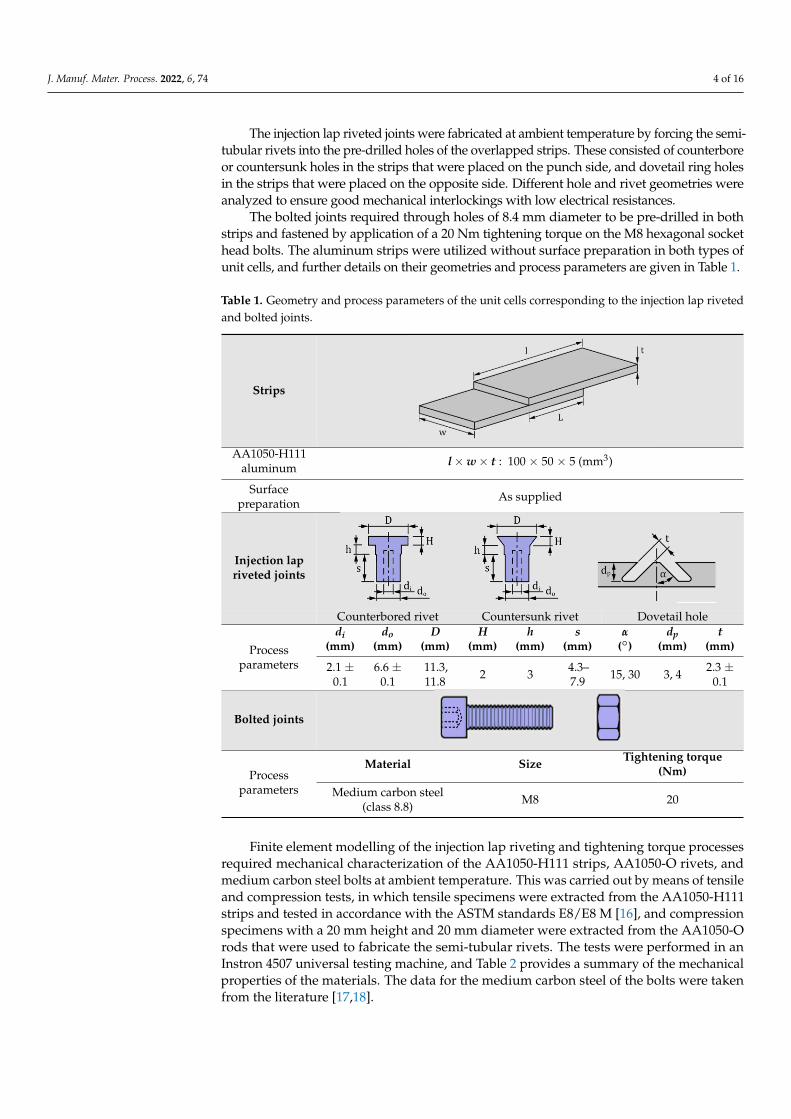
The injection lap riveted joints were fabricated at ambient temperature by forcing the semi-tubular rivets into the pre-drilled holes of the overlapped strips. These consisted of counterboreor countersunk holes in the strips that were placed on the punch side, and dovetail ring holesin the strips that were placed on the opposite side. Different hole and rivet geometries wereanalyzed to ensure good mechanical interlockings with low electrical resistances.
The bolted joints required through holes of 8.4 mm diameter to be pre-drilled in bothstrips and fastened by application of a 20 Nm tightening torque on the M8 hexagonal sockethead bolts. The aluminum strips were utilized without surface preparation in both types ofunit cells, and further details on their geometries and process parameters are given in Table 1.
Table 1. Geometry and process parameters of the unit cells corresponding to the injection lap rivetedand bolted joints.
Strips
J. Manuf. Mater. Process. 2022, 6, x FOR PEER REVIEW 4 of 17
between the overlap and the strip thickness was equal to 10 to minimize streamline effects
in the electric current [15]. The semi-tubular rivets with an 11.5 mm outer diameter were
fabricated from aluminum AA1050-O rods with a 20 mm diameter.
The unit cells of the bolted joints were made from the same aluminum AA1050-H111
strips and M8 medium carbon steel (class 8.8) hexagonal socket head bolts and nuts.
The injection lap riveted joints were fabricated at ambient temperature by forcing the
semi-tubular rivets into the pre-drilled holes of the overlapped strips. These consisted of
counterbore or countersunk holes in the strips that were placed on the punch side, and
dovetail ring holes in the strips that were placed on the opposite side. Different hole and
rivet geometries were analyzed to ensure good mechanical interlockings with low electri-
cal resistances.
The bolted joints required through holes of 8.4 mm diameter to be pre-drilled in both
strips and fastened by application of a 20 Nm tightening torque on the M8 hexagonal
socket head bolts. The aluminum strips were utilized without surface preparation in both
types of unit cells, and further details on their geometries and process parameters are
given in Table 1.
Table 1. Geometry and process parameters of the unit cells corresponding to the injection lap riveted
and bolted joints.
Strips
AA1050-H111
aluminum 𝒍 × 𝒘 × 𝒕: 100 × 50 × 5 (mm3)
Surface
preparation As supplied
Injection lap
riveted joints
Counterbored rivet Countersunk rivet Dovetail hole
Process
parameters
𝒅𝒊
(mm) 𝒅𝒐
(mm) 𝑫
(mm) 𝑯
(mm) 𝒉
(mm) 𝒔
(mm) 𝜶 (°)
𝒅𝒑
(mm)
𝒕 (mm)
2.1 ± 0.1 6.6 ± 0.1 11.3, 11.8 2 3 4.3–7.9 15, 30 3, 4 2.3 ±
0.1
Bolted joints
Process
parameters
Material Size Tightening torque
(Nm)
Medium carbon steel
(class 8.8) M8 20
Finite element modelling of the injection lap riveting and tightening torque processes
required mechanical characterization of the AA1050-H111 strips, AA1050-O rivets, and
medium carbon steel bolts at ambient temperature. This was carried out by means of ten-
sile and compression tests, in which tensile specimens were extracted from the AA1050-
AA1050-H111aluminum l×w× t : 100 × 50 × 5 (mm3)
Surfacepreparation As supplied
Injection lapriveted joints
J. Manuf. Mater. Process. 2022, 6, x FOR PEER REVIEW 4 of 17
between the overlap and the strip thickness was equal to 10 to minimize streamline effects
in the electric current [15]. The semi-tubular rivets with an 11.5 mm outer diameter were
fabricated from aluminum AA1050-O rods with a 20 mm diameter.
The unit cells of the bolted joints were made from the same aluminum AA1050-H111
strips and M8 medium carbon steel (class 8.8) hexagonal socket head bolts and nuts.
The injection lap riveted joints were fabricated at ambient temperature by forcing the
semi-tubular rivets into the pre-drilled holes of the overlapped strips. These consisted of
counterbore or countersunk holes in the strips that were placed on the punch side, and
dovetail ring holes in the strips that were placed on the opposite side. Different hole and
rivet geometries were analyzed to ensure good mechanical interlockings with low electri-
cal resistances.
The bolted joints required through holes of 8.4 mm diameter to be pre-drilled in both
strips and fastened by application of a 20 Nm tightening torque on the M8 hexagonal
socket head bolts. The aluminum strips were utilized without surface preparation in both
types of unit cells, and further details on their geometries and process parameters are
given in Table 1.
Table 1. Geometry and process parameters of the unit cells corresponding to the injection lap riveted
and bolted joints.
Strips
AA1050-H111
aluminum 𝒍 × 𝒘 × 𝒕: 100 × 50 × 5 (mm3)
Surface
preparation As supplied
Injection lap
riveted joints
Counterbored rivet Countersunk rivet Dovetail hole
Process
parameters
𝒅𝒊
(mm) 𝒅𝒐
(mm) 𝑫
(mm) 𝑯
(mm) 𝒉
(mm) 𝒔
(mm) 𝜶 (°)
𝒅𝒑
(mm)
𝒕 (mm)
2.1 ± 0.1 6.6 ± 0.1 11.3, 11.8 2 3 4.3–7.9 15, 30 3, 4 2.3 ±
0.1
Bolted joints
Process
parameters
Material Size Tightening torque
(Nm)
Medium carbon steel
(class 8.8) M8 20
Finite element modelling of the injection lap riveting and tightening torque processes
required mechanical characterization of the AA1050-H111 strips, AA1050-O rivets, and
medium carbon steel bolts at ambient temperature. This was carried out by means of ten-
sile and compression tests, in which tensile specimens were extracted from the AA1050-
Counterbored rivet Countersunk rivet Dovetail hole
Processparameters
di(mm)
do(mm)
D(mm)
H(mm)
h(mm)
s(mm)
α()
dp(mm)
t(mm)
2.1 ±0.1
6.6 ±0.1
11.3,11.8 2 3 4.3–
7.9 15, 30 3, 4 2.3 ±0.1
Bolted joints
J. Manuf. Mater. Process. 2022, 6, x FOR PEER REVIEW 4 of 17
between the overlap and the strip thickness was equal to 10 to minimize streamline effects
in the electric current [15]. The semi-tubular rivets with an 11.5 mm outer diameter were
fabricated from aluminum AA1050-O rods with a 20 mm diameter.
The unit cells of the bolted joints were made from the same aluminum AA1050-H111
strips and M8 medium carbon steel (class 8.8) hexagonal socket head bolts and nuts.
The injection lap riveted joints were fabricated at ambient temperature by forcing the
semi-tubular rivets into the pre-drilled holes of the overlapped strips. These consisted of
counterbore or countersunk holes in the strips that were placed on the punch side, and
dovetail ring holes in the strips that were placed on the opposite side. Different hole and
rivet geometries were analyzed to ensure good mechanical interlockings with low electri-
cal resistances.
The bolted joints required through holes of 8.4 mm diameter to be pre-drilled in both
strips and fastened by application of a 20 Nm tightening torque on the M8 hexagonal
socket head bolts. The aluminum strips were utilized without surface preparation in both
types of unit cells, and further details on their geometries and process parameters are
given in Table 1.
Table 1. Geometry and process parameters of the unit cells corresponding to the injection lap riveted
and bolted joints.
Strips
AA1050-H111
aluminum 𝒍 × 𝒘 × 𝒕: 100 × 50 × 5 (mm3)
Surface
preparation As supplied
Injection lap
riveted joints
Counterbored rivet Countersunk rivet Dovetail hole
Process
parameters
𝒅𝒊
(mm) 𝒅𝒐
(mm) 𝑫
(mm) 𝑯
(mm) 𝒉
(mm) 𝒔
(mm) 𝜶 (°)
𝒅𝒑
(mm)
𝒕 (mm)
2.1 ± 0.1 6.6 ± 0.1 11.3, 11.8 2 3 4.3–7.9 15, 30 3, 4 2.3 ±
0.1
Bolted joints
Process
parameters
Material Size Tightening torque
(Nm)
Medium carbon steel
(class 8.8) M8 20
Finite element modelling of the injection lap riveting and tightening torque processes
required mechanical characterization of the AA1050-H111 strips, AA1050-O rivets, and
medium carbon steel bolts at ambient temperature. This was carried out by means of ten-
sile and compression tests, in which tensile specimens were extracted from the AA1050-
Processparameters
Material Size Tightening torque(Nm)
Medium carbon steel(class 8.8) M8 20
Finite element modelling of the injection lap riveting and tightening torque processesrequired mechanical characterization of the AA1050-H111 strips, AA1050-O rivets, andmedium carbon steel bolts at ambient temperature. This was carried out by means of tensileand compression tests, in which tensile specimens were extracted from the AA1050-H111strips and tested in accordance with the ASTM standards E8/E8 M [16], and compressionspecimens with a 20 mm height and 20 mm diameter were extracted from the AA1050-Orods that were used to fabricate the semi-tubular rivets. The tests were performed in anInstron 4507 universal testing machine, and Table 2 provides a summary of the mechanicalproperties of the materials. The data for the medium carbon steel of the bolts were takenfrom the literature [17,18].

J. Manuf. Mater. Process. 2022, 6, 74 5 of 16
Table 2. Mechanical properties of the materials.
AA1050-H111 AA1050-O Steel (Class 8.8)
Elastic modulus (GPa) 69 69 205
Poisson ratio 0.33 0.33 0.29
Yield strength (MPa) 34 28 640
Ultimate tensile strength (MPa) 83 76 800
Stress-strain curve (MPa) σ = 109 ε0.17 σ = 140 ε0.24 -
2.2. Thermo-Electrical Characterization of the Materials and Joints
The experimental apparatus shown in Figure 3 was utilized to perform the thermo-electrical characterization of the aluminum AA1050 and of the unit cells corresponding tothe injection lap riveted and bolted joints. The specimens were fixed along their edges intwo copper blocks and connected to an AC transformer (OFICEL 1.5 kVA).
J. Manuf. Mater. Process. 2022, 6, x FOR PEER REVIEW 5 of 17
H111 strips and tested in accordance with the ASTM standards E8/E8 M [16], and com-
pression specimens with a 20 mm height and 20 mm diameter were extracted from the
AA1050-O rods that were used to fabricate the semi-tubular rivets. The tests were per-
formed in an Instron 4507 universal testing machine, and Table 2 provides a summary of
the mechanical properties of the materials. The data for the medium carbon steel of the
bolts were taken from the literature [17,18].
Table 2. Mechanical properties of the materials.
AA1050-H111 AA1050-O Steel (Class 8.8)
Elastic modulus (GPa) 69 69 205
Poisson ratio 0.33 0.33 0.29
Yield strength (MPa) 34 28 640
Ultimate tensile strength (MPa) 83 76 800
Stress-strain curve (MPa) 𝜎 = 109 휀0.17 𝜎 = 140 휀0.24 -
2.2. Thermo-Electrical Characterization of the Materials and Joints
The experimental apparatus shown in Figure 3 was utilized to perform the thermo-
electrical characterization of the aluminum AA1050 and of the unit cells corresponding to
the injection lap riveted and bolted joints. The specimens were fixed along their edges in
two copper blocks and connected to an AC transformer (OFICEL 1.5 kVA).
Figure 3. (a) Layout and (b) photograph of the experimental apparatus that was utilized to perform
the thermo-electrical characterization of the materials and joints. Figure 3. (a) Layout and (b) photograph of the experimental apparatus that was utilized to performthe thermo-electrical characterization of the materials and joints.
The experimental procedure consisted in supplying an electric current of 1500 A forapproximately 10 to 20 min to raise the temperature of the specimens by Joule effect up to amaximum value Tmax = 115 C (at the center). The temperature was measured by thermalimaging and required painting the strips, rivets, and bolts in black to ensure equal valuesof emissivity. The thermal imaging equipment utilized in the experiments consisted of an
J. Manuf. Mater. Process. 2022, 6, 74 6 of 16
infrared camera (FLIR E86) equipped with a focal plane array microbolometer detector,464 × 348 resolution, and a spectral range of 7.5 to 14 µm.
Once the maximum temperature Tmax = 115 C was reached, the transformer wasswitched off, and the specimens began to cool down by convection and radiation to theenvironment. The electric resistance of the unit cells was determined in the cooling stage,starting at T0 = 105 C, to cope with the limiting temperature defined by the IEEE standardfor metal-clad switchgears [19], and finishing at the ambient temperature of 20 C.
The electric resistance was determined by means of a four-point probe technique [20],and the two measuring probes were spaced 100 mm apart and connected to a micro-ohmmeter KoCoS PROMET R600 supplying an electric current of 600 A for approximately2 s. The voltage drop V measured by the probes allowed the determining of the electricresistance by means of the Ohm’s law. The procedure was repeated each time the drop intemperature between two successive measurements was equal to ∆T = Tn+1 − Tn = 5 C.
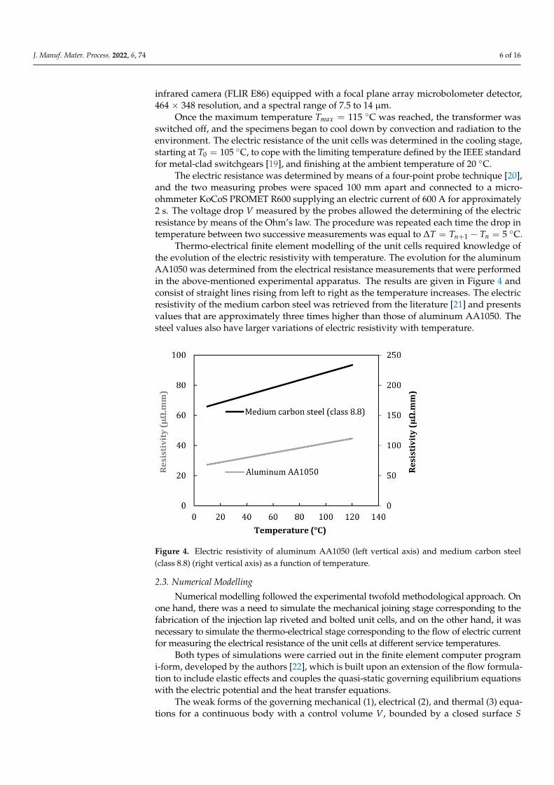
Thermo-electrical finite element modelling of the unit cells required knowledge ofthe evolution of the electric resistivity with temperature. The evolution for the aluminumAA1050 was determined from the electrical resistance measurements that were performedin the above-mentioned experimental apparatus. The results are given in Figure 4 andconsist of straight lines rising from left to right as the temperature increases. The electricresistivity of the medium carbon steel was retrieved from the literature [21] and presentsvalues that are approximately three times higher than those of aluminum AA1050. Thesteel values also have larger variations of electric resistivity with temperature.
J. Manuf. Mater. Process. 2022, 6, x FOR PEER REVIEW 6 of 17
The experimental procedure consisted in supplying an electric current of 1500 A for
approximately 10 to 20 min to raise the temperature of the specimens by Joule effect up to
a maximum value 𝑇𝑚𝑎𝑥 = 115 °C (at the center). The temperature was measured by ther-
mal imaging and required painting the strips, rivets, and bolts in black to ensure equal
values of emissivity. The thermal imaging equipment utilized in the experiments con-
sisted of an infrared camera (FLIR E86) equipped with a focal plane array microbolometer
detector, 464 × 348 resolution, and a spectral range of 7.5 to 14 μm.
Once the maximum temperature 𝑇𝑚𝑎𝑥 = 115 °C was reached, the transformer was
switched off, and the specimens began to cool down by convection and radiation to the
environment. The electric resistance of the unit cells was determined in the cooling stage,
starting at 𝑇0 = 105 °C, to cope with the limiting temperature defined by the IEEE stand-
ard for metal-clad switchgears [19], and finishing at the ambient temperature of 20 °C.
The electric resistance was determined by means of a four-point probe technique [20],
and the two measuring probes were spaced 100 mm apart and connected to a micro-ohm-
meter KoCoS PROMET R600 supplying an electric current of 600 A for approximately 2 s.
The voltage drop 𝑉 measured by the probes allowed the determining of the electric re-
sistance by means of the Ohm’s law. The procedure was repeated each time the drop in
temperature between two successive measurements was equal to ∆𝑇 = 𝑇𝑛+1 − 𝑇𝑛 = 5 °C.
Thermo-electrical finite element modelling of the unit cells required knowledge of
the evolution of the electric resistivity with temperature. The evolution for the aluminum
AA1050 was determined from the electrical resistance measurements that were performed
in the above-mentioned experimental apparatus. The results are given in Figure 4 and
consist of straight lines rising from left to right as the temperature increases. The electric
resistivity of the medium carbon steel was retrieved from the literature [21] and presents
values that are approximately three times higher than those of aluminum AA1050. The
steel values also have larger variations of electric resistivity with temperature.
Figure 4. Electric resistivity of aluminum AA1050 (left vertical axis) and medium carbon steel (class
8.8) (right vertical axis) as a function of temperature.
2.3. Numerical Modelling
Numerical modelling followed the experimental twofold methodological approach.
On one hand, there was a need to simulate the mechanical joining stage corresponding to
the fabrication of the injection lap riveted and bolted unit cells, and on the other hand, it
was necessary to simulate the thermo-electrical stage corresponding to the flow of electric
current for measuring the electrical resistance of the unit cells at different service temper-
atures.
Figure 4. Electric resistivity of aluminum AA1050 (left vertical axis) and medium carbon steel(class 8.8) (right vertical axis) as a function of temperature.
2.3. Numerical Modelling
Numerical modelling followed the experimental twofold methodological approach. Onone hand, there was a need to simulate the mechanical joining stage corresponding to thefabrication of the injection lap riveted and bolted unit cells, and on the other hand, it wasnecessary to simulate the thermo-electrical stage corresponding to the flow of electric currentfor measuring the electrical resistance of the unit cells at different service temperatures.
Both types of simulations were carried out in the finite element computer programi-form, developed by the authors [22], which is built upon an extension of the flow formula-tion to include elastic effects and couples the quasi-static governing equilibrium equationswith the electric potential and the heat transfer equations.
The weak forms of the governing mechanical (1), electrical (2), and thermal (3) equa-tions for a continuous body with a control volume V, bounded by a closed surface S
J. Manuf. Mater. Process. 2022, 6, 74 7 of 16
consisting of a region St where tractions ti are applied and a region Sq where the heat fluxqn containing the heat dissipated by convection and radiation is defined, are given by,∫
Vσ′ijδDijdV +
∫V
KDvδDvdV −∫
SttiδuidS = 0 (1)
∫V∇2ΦδΦdV = 0 (2)
∫V
k∇T∇(δT)dV −∫
SqqnδTdSq +
∫V
ρcdTdt
δTdV −∫
VβσijDijδTdV = 0 (3)
In the above equations, the velocity ui, the electric potential Φ, and the temperature Tare the primary unknowns. The remaining symbols are the deviatoric Cauchy stress σ′ij, therate of deformation Dij, the volumetric rate of deformation Dv with the associated penaltyfunction K, the thermal conductivity k, the specific heat capacity ρc, and the fraction β ofplastic work converted into heat.
Mechanical joining by injection lap riveting was simulated under rotational symmetricconditions because forcing the semi-tubular rivets into the dovetail ring holes of the stripsplaced on the opposite punch side gives rise to axisymmetric plastic deformation in therivets and neighborhood strip materials. Figure 5a shows the finite element mesh at thebeginning and the end of the injection lap riveting process, in which the cross-section of therivets and strips was discretized by means of approximately 5000 quadrilateral elements.The flat compression punch and die were considered as rigid objects and discretized bymeans of linear friction elements. The CPU time for modelling the mechanical joiningby injection lap riveting was roughly 90 min in a computer equipped with an Intel Corei7-6950X processor.
The thermo-electric simulations for determining the evolution of the electric currentdensity and the electrical resistance with temperature required the utilization of three-dimensional models with a half-width size of the unit cells utilized in the experiments.A thin interface layer with 0.05 mm thickness was included to simulate the influenceof the surface roughness and the oxide films along the overlapping area between thealuminum strips. The discretization of the strips and interface layer was performed withapproximately 50,000 hexahedral elements. The copper blocks were modelled as rigidobjects and their contours underwent discretization by means of spatial triangular elements.
The modelling strategy followed the experimental procedure that was previouslydescribed to perform the thermo-electrical characterization of the joints. The first partconsisted of a thermal simulation of the unit cells subjected to Joule heating due to anelectric current of 1500 A supplied by the transformer for approximately 10 min.
The second part started after achieving the target temperature Tmax = 115 C atthe center of the unit cells and consisted of modelling the cooling by convection andradiation to the environment after switching off the transformer. The electrical resistancemeasurement instants, during which the micro-ohmmeter supplied an electric current of600 A for approximately 2 s, were modelled by coupling the thermal and electric modulesof the finite element computer program in a staggered manner.
The simulation of the bolted unit cells made exclusive use of three-dimensional models,in which the mechanical simulations were used to replicate the tightening torque of 20 Nm,and the thermal and electrical simulations were used to replicate the heating, cooling, andelectrical resistance measurement stages. The results of these simulations will be presentedin the following sections of the paper.

J. Manuf. Mater. Process. 2022, 6, 74 8 of 16
J. Manuf. Mater. Process. 2022, 6, x FOR PEER REVIEW 8 of 17
cooling, and electrical resistance measurement stages. The results of these simulations will
be presented in the following sections of the paper.
Figure 5. Finite element modelling of the injection lap riveted unit cells showing (a) a rotational
symmetric model utilized in the simulation of mechanical joining at the beginning and at the end of
the process and (b) a three-dimensional model utilized in the thermo-electric simulation.
3. Results and Discussion
3.1. Injection Lap Riveting
The finite element simulation of injection lap riveting focused on the combined influ-
ence of the different process parameters included in Table 1, namely (i) the inclination
angle 𝛼 and (ii) the depth 𝑑𝑝 of the dovetail ring holes and (iii) the geometry (counter-
sunk or counterbored) of the rivet heads. Concerning the inclination angle 𝛼 of the dove-
tail ring holes, it may be concluded from Figure 6 that the countersunk rivet head geom-
etries with small inclination angles (say, 𝛼 = 15°) give rise to small interlockings, incom-
plete filling of the dovetail ring holes, and low contact pressures (below 100 MPa) between
the strips and between the strips and rivets (refer to the radial stress in Figure 6a), through
which most of the electric current flows.
Raising the inclination angle 𝛼 to 30° helps to improve the quality of the injection
lap riveted joints because the interlocking becomes larger, and the contact pressures can
reach values of up to 200 MPa (Figure 6b). However, filling of the dovetail ring hole re-
mains incomplete, which will negatively affect the overall electric performance of the
joints.
Figure 5. Finite element modelling of the injection lap riveted unit cells showing (a) a rotationalsymmetric model utilized in the simulation of mechanical joining at the beginning and at the end ofthe process and (b) a three-dimensional model utilized in the thermo-electric simulation.
3. Results and Discussion3.1. Injection Lap Riveting
The finite element simulation of injection lap riveting focused on the combined in-fluence of the different process parameters included in Table 1, namely (i) the inclinationangle α and (ii) the depth dp of the dovetail ring holes and (iii) the geometry (countersunkor counterbored) of the rivet heads. Concerning the inclination angle α of the dovetail ringholes, it may be concluded from Figure 6 that the countersunk rivet head geometries withsmall inclination angles (say, α = 15) give rise to small interlockings, incomplete filling ofthe dovetail ring holes, and low contact pressures (below 100 MPa) between the strips andbetween the strips and rivets (refer to the radial stress in Figure 6a), through which most ofthe electric current flows.
Raising the inclination angle α to 30 helps to improve the quality of the injection lapriveted joints because the interlocking becomes larger, and the contact pressures can reachvalues of up to 200 MPa (Figure 6b). However, filling of the dovetail ring hole remainsincomplete, which will negatively affect the overall electric performance of the joints.
Similar results are obtained from the analysis of the vertical contact pressure betweenthe strips in both cases (α = 15 and α = 30). This conclusion is very important becausethe electric contact resistance R of the joints is dependent on the square root of the contact

J. Manuf. Mater. Process. 2022, 6, 74 9 of 16
pressure [23], due to its role in breaking the oxide films and flattening the asperities byplastic deformation.
J. Manuf. Mater. Process. 2022, 6, x FOR PEER REVIEW 9 of 17
Similar results are obtained from the analysis of the vertical contact pressure between
the strips in both cases (𝛼 = 15° and 𝛼 = 30°). This conclusion is very important because
the electric contact resistance 𝑅 of the joints is dependent on the square root of the contact
pressure [23], due to its role in breaking the oxide films and flattening the asperities by
plastic deformation.
Figure 6. Finite element simulation of injection lap riveting with countersunk head rivets showing
the mesh at the beginning (left) and the distribution of radial contact pressure (MPa) at the end of
the stroke (right) for two-unit cells corresponding to (a) 𝛼 = 15°, 𝑑𝑝 = 4 mm and (b) 𝛼 = 30°, 𝑑𝑝 =
4 mm.
The attempt to use shallower dovetail holes (𝑑𝑝 = 3 mm) to ensure complete filling
of the cavities exacerbates the problem, as shown in Figure 7. In fact, not only do the un-
filled pockets represent a greater percentage of the total cavity volume, but also the inter-
locking and contact pressures become substantially smaller than in the case of the deeper
dovetail holes with 𝑑𝑝 = 4 mm (Figure 6b).
The difficulties that were encountered in filling the dovetail holes with the counter-
sunk head rivets are mainly caused by the plastic deformation of the holes as the rivet is
injected by compression. This problem results from the fact that the rivets and strips are
made from aluminum AA1050 with similar mechanical strength and had never been ob-
served with this importance by the authors [13]. The reason is because previous work was
carried out with dissimilar materials, in which the dovetail holes were pre-drilled in the
stronger strips and the rivets were made from the material of the softer strips.
Figure 6. Finite element simulation of injection lap riveting with countersunk head rivets showingthe mesh at the beginning (left) and the distribution of radial contact pressure (MPa) at the end of thestroke (right) for two-unit cells corresponding to (a) α = 15, dp = 4 mm and (b) α = 30, dp = 4 mm.
The attempt to use shallower dovetail holes (dp = 3 mm) to ensure complete filling ofthe cavities exacerbates the problem, as shown in Figure 7. In fact, not only do the unfilledpockets represent a greater percentage of the total cavity volume, but also the interlockingand contact pressures become substantially smaller than in the case of the deeper dovetailholes with dp = 4 mm (Figure 6b).
J. Manuf. Mater. Process. 2022, 6, x FOR PEER REVIEW 10 of 17
Figure 7. Finite element simulation of injection lap riveting countersunk head rivets, showing the
mesh at the beginning (left) and the distribution of radial contact pressure (MPa) at the end of the
stroke (right) for unit cells with 𝛼 = 30°, 𝑑𝑝 = 3 mm
The solution by which to minimize the unfilled pockets inside the dovetail ring holes
and, at the same time, to ensure a good mechanical interlocking and contact pressure be-
tween the strips and the rivet involved modifying the rivet head by introducing a coun-
terbored geometry (Figure 8).
As seen, the counterbored head rivets can provide contact pressures above 200 MPa,
without causing bending of the strips and large plastic deformation of the dovetail ring
holes during injection by compression. The filling of the dovetail ring hole is also good, as
can be inferred from the photograph of the cross-section taken from an experimental unit
cell (Figure 8b-right) and from the mesh details that are included in the riveting force vs.
the punch stroke evolution of Figure 9.
The comparison with the cross-section geometry of a unit cell fabricated with a coun-
tersunk rivet (Figure 8b-left) head also confirms the advantage of the counterbored geom-
etry (Figure 8b-right) in providing a better filling of the dovetail ring hole.
Figure 8. Finite element simulation of injection lap riveting counterbored head rivets showing (a)
the mesh at the beginning (left) and the distribution of radial contact pressure (MPa) at the end of
stroke (right) for unit cells with 𝛼 = 30°, 𝑑𝑝 = 4 mm and (b) a photograph of a cross-section where
the counterbored head rivet (right) is compared with that obtained using a countersunk geometry
(left).
Figure 7. Finite element simulation of injection lap riveting countersunk head rivets, showing themesh at the beginning (left) and the distribution of radial contact pressure (MPa) at the end of thestroke (right) for unit cells with α = 30, dp = 3 mm.

J. Manuf. Mater. Process. 2022, 6, 74 10 of 16
The difficulties that were encountered in filling the dovetail holes with the countersunkhead rivets are mainly caused by the plastic deformation of the holes as the rivet is injectedby compression. This problem results from the fact that the rivets and strips are made fromaluminum AA1050 with similar mechanical strength and had never been observed withthis importance by the authors [13]. The reason is because previous work was carried outwith dissimilar materials, in which the dovetail holes were pre-drilled in the stronger stripsand the rivets were made from the material of the softer strips.
The solution by which to minimize the unfilled pockets inside the dovetail ring holesand, at the same time, to ensure a good mechanical interlocking and contact pressurebetween the strips and the rivet involved modifying the rivet head by introducing acounterbored geometry (Figure 8).
J. Manuf. Mater. Process. 2022, 6, x FOR PEER REVIEW 10 of 17
Figure 7. Finite element simulation of injection lap riveting countersunk head rivets, showing the
mesh at the beginning (left) and the distribution of radial contact pressure (MPa) at the end of the
stroke (right) for unit cells with 𝛼 = 30°, 𝑑𝑝 = 3 mm
The solution by which to minimize the unfilled pockets inside the dovetail ring holes
and, at the same time, to ensure a good mechanical interlocking and contact pressure be-
tween the strips and the rivet involved modifying the rivet head by introducing a coun-
terbored geometry (Figure 8).
As seen, the counterbored head rivets can provide contact pressures above 200 MPa,
without causing bending of the strips and large plastic deformation of the dovetail ring
holes during injection by compression. The filling of the dovetail ring hole is also good, as
can be inferred from the photograph of the cross-section taken from an experimental unit
cell (Figure 8b-right) and from the mesh details that are included in the riveting force vs.
the punch stroke evolution of Figure 9.
The comparison with the cross-section geometry of a unit cell fabricated with a coun-
tersunk rivet (Figure 8b-left) head also confirms the advantage of the counterbored geom-
etry (Figure 8b-right) in providing a better filling of the dovetail ring hole.
Figure 8. Finite element simulation of injection lap riveting counterbored head rivets showing (a)
the mesh at the beginning (left) and the distribution of radial contact pressure (MPa) at the end of
stroke (right) for unit cells with 𝛼 = 30°, 𝑑𝑝 = 4 mm and (b) a photograph of a cross-section where
the counterbored head rivet (right) is compared with that obtained using a countersunk geometry
(left).
Figure 8. Finite element simulation of injection lap riveting counterbored head rivets showing (a) themesh at the beginning (left) and the distribution of radial contact pressure (MPa) at the end of stroke(right) for unit cells with α = 30, dp = 4 mm and (b) a photograph of a cross-section where thecounterbored head rivet (right) is compared with that obtained using a countersunk geometry (left).
As seen, the counterbored head rivets can provide contact pressures above 200 MPa,without causing bending of the strips and large plastic deformation of the dovetail ringholes during injection by compression. The filling of the dovetail ring hole is also good, ascan be inferred from the photograph of the cross-section taken from an experimental unitcell (Figure 8b-right) and from the mesh details that are included in the riveting force vs.the punch stroke evolution of Figure 9.
The comparison with the cross-section geometry of a unit cell fabricated with a counter-sunk rivet (Figure 8b-left) head also confirms the advantage of the counterbored geometry(Figure 8b-right) in providing a better filling of the dovetail ring hole.
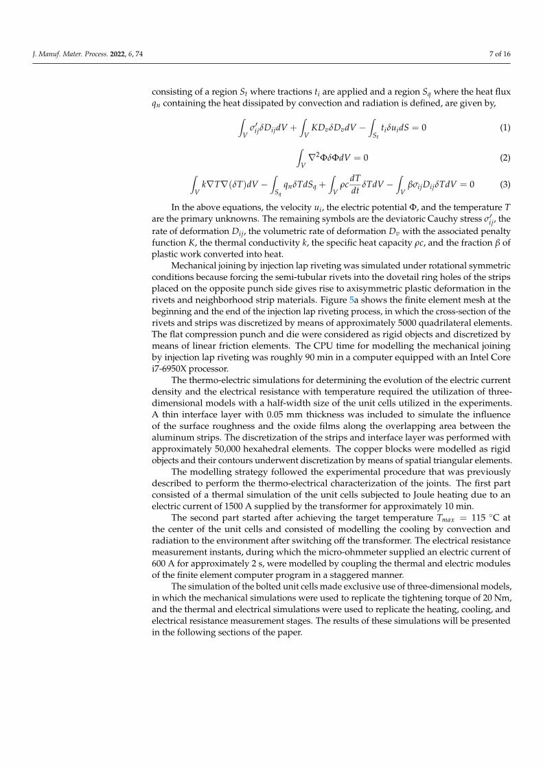
Regarding the finite element and experimental evolutions of the riveting force with thecompression punch stroke, three main stages may be distinguished. The initial stage (labelledas ‘A’ in Figure 9) is associated with the sliding with friction of the rivet inner wall along theinward dovetail hole surface. The second stage, labelled as ‘B’, corresponds to a region of thegraphic in which the force grows moderately with the punch stroke up to an instant of timecorresponding to the contact between the rivet end and the dovetail hole end.
J. Manuf. Mater. Process. 2022, 6, 74 11 of 16
J. Manuf. Mater. Process. 2022, 6, x FOR PEER REVIEW 11 of 17
Regarding the finite element and experimental evolutions of the riveting force with
the compression punch stroke, three main stages may be distinguished. The initial stage
(labelled as ‘A’ in Figure 9) is associated with the sliding with friction of the rivet inner
wall along the inward dovetail hole surface. The second stage, labelled as ‘B’, corresponds
to a region of the graphic in which the force grows moderately with the punch stroke up
to an instant of time corresponding to the contact between the rivet end and the dovetail
hole end.
The final stage labelled as ‘C’ is characterized by a sharp increase in the force due to
the compression of the counterbored rivet head against the strip.
Figure 9. Experimental and finite element predicted evolution of the riveting force with punch
stroke for a counterbored head rivet with 𝛼 = 30°, 𝑑𝑝 = 4 mm. The mesh details are taken from each
of the three deformation stages.
3.2. Thermo-Electro Characterization of the Joints
Figure 10 provides a comparison between the experimental and the finite element
predicted distributions of temperature for an instant of time corresponding to a tempera-
ture of 85 °C at the center of the injection lap riveted and bolted joints. As seen in Figure
10a, the agreement between the experimental and numerical results obtained for the in-
jection lap riveted joint is good, showing a relatively uniform distribution of temperature,
with small differences between the highest values of the center (85 °C) and the lowest
values (75 °C) next to the copper blocks where the unit cell was fixed and connected to the
micro-ohmmeter supplying an electric current of 600 A for approximately 2 s.
The results obtained for the bolted joint (Figure 10b) are different because they show
a larger concentration of temperature in the bolt, with values approximately 30 °C higher
than those found next to the copper blocks. Because the disturbance in temperature dis-
tribution due to Joule heating is a direct consequence of the disturbance in the electric
current, one may conclude that injection lap riveted joints provide smaller electrical re-
sistance values than bolted joints. This is confirmed in Figure 11, which shows the average
electrical resistance values of the injection lap riveted (IJL) joints to be 3.2 times smaller
than those of the bolted (B) joints.
The experimental procedure for determining the electrical resistance of the injection
lap riveted joints at different temperatures was previously described in Section 2.3, and
the results shown in Figure 11 allow the conclusion that the experimental and numerical
electrical resistances vary linearly over the entire temperature range. The variations cor-
respond to an increase of approximately 6 μΩ in the case of the injected lap riveted joints
and 18 μΩ in the case of the bolted joints.
Figure 9. Experimental and finite element predicted evolution of the riveting force with punch strokefor a counterbored head rivet with α = 30, dp = 4 mm. The mesh details are taken from each of thethree deformation stages.
The final stage labelled as ‘C’ is characterized by a sharp increase in the force due tothe compression of the counterbored rivet head against the strip.
3.2. Thermo-Electro Characterization of the Joints
Figure 10 provides a comparison between the experimental and the finite elementpredicted distributions of temperature for an instant of time corresponding to a temperatureof 85 C at the center of the injection lap riveted and bolted joints. As seen in Figure 10a,the agreement between the experimental and numerical results obtained for the injectionlap riveted joint is good, showing a relatively uniform distribution of temperature, withsmall differences between the highest values of the center (85 C) and the lowest values(75 C) next to the copper blocks where the unit cell was fixed and connected to themicro-ohmmeter supplying an electric current of 600 A for approximately 2 s.
The results obtained for the bolted joint (Figure 10b) are different because they show alarger concentration of temperature in the bolt, with values approximately 30 C higher thanthose found next to the copper blocks. Because the disturbance in temperature distributiondue to Joule heating is a direct consequence of the disturbance in the electric current, onemay conclude that injection lap riveted joints provide smaller electrical resistance valuesthan bolted joints. This is confirmed in Figure 11, which shows the average electricalresistance values of the injection lap riveted (IJL) joints to be 3.2 times smaller than those ofthe bolted (B) joints.
The experimental procedure for determining the electrical resistance of the injectionlap riveted joints at different temperatures was previously described in Section 2.3, andthe results shown in Figure 11 allow the conclusion that the experimental and numericalelectrical resistances vary linearly over the entire temperature range. The variations corre-spond to an increase of approximately 6 µΩ in the case of the injected lap riveted jointsand 18 µΩ in the case of the bolted joints.
The black dashed line in Figure 11 corresponds to the finite element predictions for anideal joint made from two aluminum strips in perfect contact, without auxiliary joiningelements and no contaminant and oxide films along their overlapping area. Comparisonagainst the results obtained for the injection lap riveted and bolted unit cells allows theconclusion that bolted joints provide electrical resistance values 7 times higher than anideal joint, whereas injection lap riveted joints provide electrical resistance values only2.2 times higher.

J. Manuf. Mater. Process. 2022, 6, 74 12 of 16J. Manuf. Mater. Process. 2022, 6, x FOR PEER REVIEW 12 of 17
Figure 10. Experimental and finite element predicted distribution of temperature for an instant cor-
responding to a temperature of 85 °C at the center of the (a) injection lap riveted and (b) bolted
joints.
Figure 11. Experimental and finite element predicted evolutions of the electrical resistance with
temperature.
The black dashed line in Figure 11 corresponds to the finite element predictions for
an ideal joint made from two aluminum strips in perfect contact, without auxiliary joining
elements and no contaminant and oxide films along their overlapping area. Comparison
against the results obtained for the injection lap riveted and bolted unit cells allows the
conclusion that bolted joints provide electrical resistance values 7 times higher than an
Figure 10. Experimental and finite element predicted distribution of temperature for an instant corre-sponding to a temperature of 85 C at the center of the (a) injection lap riveted and (b) bolted joints.
The reason for the discrepancies in the results obtained with the two different types ofunit cells results from the fact that electric current mainly flows through the bolts and rivetsdue to the inability of the AA1050 aluminum strips to generate enough contact pressuresalong the overlapping area to break the hard Al2O3 oxides. This is confirmed by the finiteelement predictions of current density j shown in Figure 12a,b.
J. Manuf. Mater. Process. 2022, 6, x FOR PEER REVIEW 12 of 17
Figure 10. Experimental and finite element predicted distribution of temperature for an instant cor-
responding to a temperature of 85 °C at the center of the (a) injection lap riveted and (b) bolted
joints.
Figure 11. Experimental and finite element predicted evolutions of the electrical resistance with
temperature.
The black dashed line in Figure 11 corresponds to the finite element predictions for
an ideal joint made from two aluminum strips in perfect contact, without auxiliary joining
elements and no contaminant and oxide films along their overlapping area. Comparison
against the results obtained for the injection lap riveted and bolted unit cells allows the
conclusion that bolted joints provide electrical resistance values 7 times higher than an
Figure 11. Experimental and finite element predicted evolutions of the electrical resistance withtemperature.

J. Manuf. Mater. Process. 2022, 6, 74 13 of 16
J. Manuf. Mater. Process. 2022, 6, x FOR PEER REVIEW 13 of 17
ideal joint, whereas injection lap riveted joints provide electrical resistance values only 2.2
times higher.
The reason for the discrepancies in the results obtained with the two different types
of unit cells results from the fact that electric current mainly flows through the bolts and
rivets due to the inability of the AA1050 aluminum strips to generate enough contact pres-
sures along the overlapping area to break the hard Al2O3 oxides. This is confirmed by the
finite element predictions of current density 𝑗 shown in Figure 12a,b.
Figure 12. Finite element predicted distributions of electric current density (A/mm2) and tempera-
ture (°C) for the (a) injection lap riveted (counterbored) and (b) bolted unit cells when the tempera-
ture at the center is equal to 85 °C (during the cooling stage).
In fact, the highest current density 𝑗 values of approximately 12 A/mm2 that are
found in the bolt (Figure 12b) are in close agreement with the electric current of 600 A,
Figure 12. Finite element predicted distributions of electric current density (A/mm2) and temperature(C) for the (a) injection lap riveted (counterbored) and (b) bolted unit cells when the temperature atthe center is equal to 85 C (during the cooling stage).
In fact, the highest current density j values of approximately 12 A/mm2 that are foundin the bolt (Figure 12b) are in close agreement with the electric current of 600 A, suppliedby micro-ohmmeter during the measuring stage, flowing almost exclusively through thecross section of the M8 hexagonal socket head bolt,
j =600π·42 = 11.9 A/mm2 (4)

J. Manuf. Mater. Process. 2022, 6, 74 14 of 16
The finite element predictions of electric current density near the copper fixing blocks(Figure 12a,b) also cope with the expected analytical values resulting from the 600 Asupplied by the micro-ohmmeter flowing through the 50 mm × 5 mm cross-section of thealuminum strips,
j =60050·5 = 2.4 A/mm2 (5)
The finite element predicted distribution of temperature included in Figures 12a and 13bhelps in further corroborating the previously mentioned results because the electric current,in the case of the bolted joints, is mainly flowing from one strip to the other through thesmall cross-section of the steel bolts with an electric resistivity 6 times higher than that ofaluminum (refer to Figure 4).
J. Manuf. Mater. Process. 2022, 6, x FOR PEER REVIEW 15 of 17
Figure 13. Sheet-bulk compression (SBC) of aluminum busbar joints: (a) schematic view of the fab-
rication process, (b) experimental and finite element predicted evolutions of the electrical resistance
with temperature, and (c) finite element predicted distributions of electric current density (A/mm2)
when the temperature at the center is equal to 85 °C.
4. Conclusions
The extension of the injection lap riveting process to the in-situ connection of busbars
made from the same material as the rivets is feasible and capable of ensuring good electric
performances. The main conclusions drawn from the experimental and numerical work
performed in aluminum AA1050 unit cells are the following:
• Injection lap riveted joints require much less space for assembly than alternative so-
lutions based on conventional bolting or riveting due to the absence of material pro-
trusions above and below the joint surfaces.
• Semi-tubular rivet heads must have counterbored geometries and appropriate shank
lengths to ensure complete filling with good mechanical interlocking and appropriate
contact pressures on the overlapping areas between the two busbar strip conductors.
• Injection lap riveted joints built upon semi-tubular counterbored head rivets provide
electrical resistances more than 3 times smaller than those of bolted joints due to the
replacement of the steel bolts by aluminum rivets, causing smaller electric current
disturbances.
• The sensitivity of the electrical resistance to temperature variations is also smaller for
the injection lap riveted joints, which experience an increase of just 6 μΩ when the
temperature is raised from 20 °C to 105 °C.
• Future developments must account for the differences between the in situ and the
factory assembly of busbar systems because in the case of the latter, the new solution
based on joining by sheet-bulk compression can provide electrical resistances 35%
smaller than those obtained by the newly proposed injection lap riveting process.
Author Contributions: Conceptualization, I.M.F.B., C.M.A.S. and P.A.F.M.; methodology, I.M.F.B.,
C.M.A.S. and P.A.F.M.; software, R.F.V.S., J.P.M.P. and P.A.F.M.; validation, R.F.V.S. and J.P.M.P.;
formal analysis, R.F.V.S., J.P.M.P., I.M.F.B., C.M.A.S. and P.A.F.M.; investigation, R.F.V.S., J.P.M.P.,
I.M.F.B., C.M.A.S. and P.A.F.M.; resources, I.M.F.B., C.M.A.S. and P.A.F.M.; writing—original draft
preparation, P.A.F.M.; writing—review and editing, R.F.V.S., J.P.M.P., I.M.F.B., C.M.A.S. and
P.A.F.M.; visualization, R.F.V.S. and J.P.M.P.; supervision, I.M.F.B., C.M.A.S. and P.A.F.M.; project
Figure 13. Sheet-bulk compression (SBC) of aluminum busbar joints: (a) schematic view of thefabrication process, (b) experimental and finite element predicted evolutions of the electrical resistancewith temperature, and (c) finite element predicted distributions of electric current density (A/mm2)when the temperature at the center is equal to 85 C.
3.3. Future Research Directions
Injection lap riveting with counterbored semi-tubular rivets offers significant gains inthe electrical resistance of aluminum busbar joints when compared to countersunk headriveted and bolted joints. However, the overall electrical resistance values are still 2 timeshigher than those of an ideal joint without auxiliary elements and oxide films along theoverlapping area.
Future research directions should therefore privilege the development of joiningprocesses without auxiliary elements that can generate high contact pressures along theoverlapping area. In the case of aluminum busbars produced in large batches, a possiblefuture direction is to make use of joining by sheet-bulk compression, which was previouslydeveloped by the authors to assemble the strip or sheet conductors in progressive toolsystems comprising a sequence of lancing, bending, and compression operations [24](Figure 13a).
Experimental and finite element simulation work performed in joining by sheet-bulkcompression (SBC) of aluminum AA1050 unit cells unveils electrical resistances varyingfrom 12.7 µΩ to 17.2 µΩ, when the temperature increases from 20 C to 105 C (Figure 13b).

J. Manuf. Mater. Process. 2022, 6, 74 15 of 16
This means shortening by nearly half the distance to the values provided by the idealbusbar joint due to smaller variations in the electric current density (Figure 13c) than thoseobtained in the injection lap riveted joints (Figure 12a).
The conclusion is that for applications in situ, in which sheet-bulk compression cannotbe employed, there is still room to further develop the injection lap riveting (ILR) processto obtain better electric performances. The drawback resulting from the necessity of pre-drilling the dovetail ring holes cannot be seen as an exclusive limitation of injection lapriveting because conventional bolted joints also require pre-drilling (or punching) throughholes in the busbar strips. In fact, the main limitation of the process, which required theredesigning of the joints, has to do with plastic deformation and friction along the contactinterfaces between the rivets and the dovetail ring holes in strips made from the samematerial as the rivets.
4. Conclusions
The extension of the injection lap riveting process to the in-situ connection of busbarsmade from the same material as the rivets is feasible and capable of ensuring good electricperformances. The main conclusions drawn from the experimental and numerical workperformed in aluminum AA1050 unit cells are the following:
• Injection lap riveted joints require much less space for assembly than alternativesolutions based on conventional bolting or riveting due to the absence of materialprotrusions above and below the joint surfaces.
• Semi-tubular rivet heads must have counterbored geometries and appropriate shanklengths to ensure complete filling with good mechanical interlocking and appropriatecontact pressures on the overlapping areas between the two busbar strip conductors.
• Injection lap riveted joints built upon semi-tubular counterbored head rivets provideelectrical resistances more than 3 times smaller than those of bolted joints due to thereplacement of the steel bolts by aluminum rivets, causing smaller electric currentdisturbances.
• The sensitivity of the electrical resistance to temperature variations is also smaller forthe injection lap riveted joints, which experience an increase of just 6 µΩ when thetemperature is raised from 20 C to 105 C.
• Future developments must account for the differences between the in situ and thefactory assembly of busbar systems because in the case of the latter, the new solutionbased on joining by sheet-bulk compression can provide electrical resistances 35%smaller than those obtained by the newly proposed injection lap riveting process.
Author Contributions: Conceptualization, I.M.F.B., C.M.A.S. and P.A.F.M.; methodology, I.M.F.B.,C.M.A.S. and P.A.F.M.; software, R.F.V.S., J.P.M.P. and P.A.F.M.; validation, R.F.V.S. and J.P.M.P.; for-mal analysis, R.F.V.S., J.P.M.P., I.M.F.B., C.M.A.S. and P.A.F.M.; investigation, R.F.V.S., J.P.M.P., I.M.F.B.,C.M.A.S. and P.A.F.M.; resources, I.M.F.B., C.M.A.S. and P.A.F.M.; writing—original draft preparation,P.A.F.M.; writing—review and editing, R.F.V.S., J.P.M.P., I.M.F.B., C.M.A.S. and P.A.F.M.; visualization,R.F.V.S. and J.P.M.P.; supervision, I.M.F.B., C.M.A.S. and P.A.F.M.; project administration, P.A.F.M.; fund-ing acquisition, P.A.F.M. All authors have read and agreed to the published version of the manuscript.
Funding: This research was funded by Fundação para a Ciência e a Tecnologia of Portugal andIDMEC under LAETA-UIDB/50022/2020 and PTDC/EME-EME/0949/2020.
Institutional Review Board Statement: Not applicable.
Informed Consent Statement: Not applicable.
Data Availability Statement: All data supporting the reported results are available in the paper.
Acknowledgments: The authors would like to thank the support provided by Fundação para aCiência e a Tecnologia of Portugal and IDMEC under LAETA-UIDB/50022/2020 and PTDC/EME-EME/0949/2020.
Conflicts of Interest: The authors declare no conflict of interest.

J. Manuf. Mater. Process. 2022, 6, 74 16 of 16
References1. YCharts. Available online: http://ycharts.com/indicators/copper_price (accessed on 26 May 2022).2. Sampaio, R.F.; Zwicker, M.F.; Pragana, J.P.; Bragança, I.M.; Silva, C.; Nielsen, C.V.; Martins, P.A. Busbars for e-mobility: State-of-
the-art review and a new joining by forming technology. In Mechanical and Industrial Engineering: Historical Aspects and FutureDirections; Davim, J.P., Ed.; Springer: Berlin, Germany, 2022; pp. 111–141.
3. Bao, Y.J.; Cheng, K.W.E.; Ding, K.; Wang, D.H. The study on the busbar system and its fault analysis. In Proceedings of the 5thInternational Conference on Power Electronics Systems and Applications (PESA), Hong Kong, China, 11–13 December 2013; pp. 1–7.
4. Tzeneva, R.; Slavtchev, Y.; Mladenov, V. New connection design of high-power bolted busbar connections. In Proceedings of the11th WSEAS International Conference on Circuits, Agios Nikolaos, Greece, 23–25 July 2007; pp. 228–233.
5. Sampaio, R.F.V.; Pragana, J.P.M.; Bragança, I.M.F.; Silva, C.M.A.; Nielsen, C.V.; Martins, P.A.F. Electric performance of fastenedhybrid busbars: An experimental and numerical study. J. Mater. Des. Appl. 2021, 236, 1152–1163. [CrossRef]
6. Moustafa, G.; Grossmann, S.; Abdel-Salam, M.; Dessouky, S.S.; El-Makkawy, S.M. Joint resistance of bolted copper bus-barconnections as influenced by mechanical contact devices material and configuration. In Proceedings of the 13th Middle EastPower Systems Conference (MEPCON), Assiut, Egypt, 20–23 December 2009; pp. 300–305.
7. Chapman, D.; Norris, T. Copper for Busbars: Guidance for Design and Installation; Copper Development Association: New York, NY,USA, 2014; pp. 90–102.
8. Rana, B.; Mallick, P.; Rana, T.K.; Basu, D.; Biswas, A.N.; Pramanik, S. Efficient and superior elbow joint for high power buswaytrunking system. In Proceedings of the 8th Annual Industrial Automation and Electromechanical Engineering Conference(IEMECON), Bangkok, Thailand, 16–18 August 2017; pp. 16–21.
9. Katayama, S. Introduction: Fundamentals of laser welding. In Handbook of Laser Welding Technologies; Katayama, S., Ed.; WoodheadPublishing: Cambridge, UK, 2013; pp. 3–16.
10. Moschinger, M.; Mittermayr, F.; Enzinger, N. Influence of beam figure on porosity of electron beam welded thin-walled aluminumplates. Materials 2022, 15, 3519. [CrossRef] [PubMed]
11. Xu, B.; Tashiro, S.; Jiang, F.; Chen, S.; Manabu, T. Effect of arc pressure on the digging process in variable polarity plasma arcwelding of A5052P aluminum alloy. Materials 2019, 12, 1071. [CrossRef] [PubMed]
12. Schmidt, P.A.; Schweier, M.; Zaeh, M.F. Joining of lithium-ion batteries using laser beam welding: Electrical losses of weldedaluminum and copper joints. In Proceedings of the ICALEO—International Congress on Applications of Lasers & Electro-Optics,Temecula, CA, USA, 23–27 September 2012; pp. 915–923.
13. Ferreira, F.R.; Pragana, J.P.M.; Bragança, I.M.F.; Silva, C.M.A.; Nielsen, C.V.; Martins, P.A.F. Injection lap riveting. CIRP Ann.Manuf. Technol. 2021, 70, 261–264. [CrossRef]
14. Braunovic, M. Effect of connection design on the contact resistance of high power overlapping bolted joints. IEEE Trans. Compon.Packag. Technol. 2002, 25, 642–650. [CrossRef]
15. Melsom, S.W.; Booth, H.C. The efficiency of overlapping joints in copper and aluminium busbar conductors. J. Inst. Electr. Eng.1922, 60, 889–899. [CrossRef]
16. ASTM E8/E8 M; Standard Test Methods for Tension Testing of Metallic Materials. ASTM International: West Conshohocken, PA,USA, 2016.
17. ISO 898-1:2013; Mechanical Properties of Fasteners Made of Carbon Steel and Alloy Steel-Part 1: Bolts, Screws and Studs withSpecified Property Classes-Coarse Thread and Fine Pitch Thread. ISO—International Organization for Standardization: Geneva,Switzerland, 2013.
18. ISO 898-2:2012; Mechanical Properties of Fasteners Made of Carbon Steel and Alloy Steel-Part 2: Nuts with Specified PropertyClasses-Coarse Thread and Fine Pitch Thread. ISO—International Organization for Standardization: Geneva, Switzerland, 2012.
19. IEEE Std C37.20.2; IEEE Standard for Metal-Clad Switchgear. IEEE Power and Energy Society: New York, NY, USA, 2015.20. Kumar, N.; Masters, I.; Das, A. In-depth evaluation of laser-welded similar and dissimilar material tab-to-busbar electrical
interconnects for electric vehicle battery pack. J. Manuf. Processes 2021, 70, 78–96. [CrossRef]21. MatWeb. Available online: https://www.matweb.com (accessed on 1 May 2022).22. Nielsen, C.V.; Martins, P.A.F. Finite element flow formulation. In Metal Forming: Formability, Simulation and Tool Design; Academic
Press: London, UK, 2021; pp. 181–249.23. Studer, F.J. Contact resistance in spot welding. Weld. J. 1939, 18, 374–380.24. Reichel, A.; Sampaio, R.; Pragana, J.; Bragança, I.; Silva, C.; Martins, P. Form-fit joining of hybrid busbars using a flexible tool
demonstrator. Proc. Inst. Mech. Eng. Part L J. Mater. Des. Appl. 2021, 236, 1164–1175. [CrossRef]


