Embed Size (px)
Citation preview
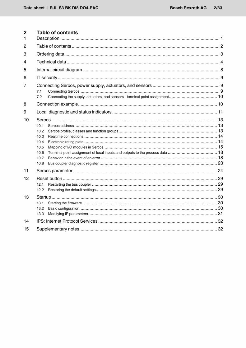
Inline bus coupler for Sercos with digital inputs and outputs
R-IL S3 BK DI8 DO4-PAC
The bus coupler with integrated I/Os is intended for use within a Sercos® network and represents the link to the Inline I/O system.Up to 63 Inline devices can be connected to the bus coupler.The bus coupler supports a maximum of 16 PCP de-vices.A corresponding SDDML file is available for integrat-ing the Inline station into the programming system.This file can be downloaded at www.boschrex-roth.com/electrics.
Features• Sercos specification V1.3.1• Sercos diagnostic LED S and communication
phase LED CP• Minimum Sercos cycle time of 250 µs• FSP-IO (Function Specific Profile-IO) for modular
I/O devices• Maximum of 6 realtime connections• Hot plugging of participants in Sercos network• Diagnostics trace
• Internet Protocol Services (IPS)• 2 Ethernet ports• 8 digital inputs, 4 digital outputs (on-board)
Valid from index GK1.
This data sheet is only valid in association with the “Automation terminals of the Inline product range” application description(DOK-CONTRL-ILSYSINS***-AW..-EN-P, MNR R911317021).
Make sure you always use the latest docu-mentation.It can be downloaded underwww.boschrexroth.com/electrics.
Sercos controller board8 digital inputs4 digital outputs
01 / 2022
R911170560Edition 05
Data sheet
1 Description
Data sheet | R-IL S3 BK DI8 DO4-PAC Bosch Rexroth AG 2/33
2 Table of contents1 Description .............................................................................................................................. 12 Table of contents ..................................................................................................................... 23 Ordering data .......................................................................................................................... 34 Technical data ......................................................................................................................... 45 Internal circuit diagram ............................................................................................................ 86 IT security ................................................................................................................................ 97 Connecting Sercos, power supply, actuators, and sensors ..................................................... 9
7.1 Connecting Sercos .............................................................................................................. 97.2 Connecting the supply, actuators, and sensors - terminal point assignment...................................... 10
8 Connection example.............................................................................................................. 109 Local diagnostic and status indicators ................................................................................... 1110 Sercos ................................................................................................................................... 13
10.1 Sercos address................................................................................................................. 1310.2 Sercos profile, classes and function groups.............................................................................. 1310.3 Realtime connections ......................................................................................................... 1410.4 Electronic rating plate ......................................................................................................... 1410.5 Mapping of I/O modules in Sercos ......................................................................................... 1510.6 Terminal point assignment of local inputs and outputs to the process data ....................................... 1810.7 Behavior in the event of an error ............................................................................................ 1810.8 Bus coupler diagnostic register ............................................................................................. 23
11 Sercos parameter .................................................................................................................. 2412 Reset button .......................................................................................................................... 29
12.1 Restarting the bus coupler ................................................................................................... 2912.2 Restoring the default settings................................................................................................ 29
13 Startup................................................................................................................................... 3013.1 Starting the firmware .......................................................................................................... 3013.2 Basic configuration............................................................................................................. 3013.3 Modifying IP parameters...................................................................................................... 31
14 IPS: Internet Protocol Services .............................................................................................. 3215 Supplementary notes............................................................................................................. 32
Data sheet | R-IL S3 BK DI8 DO4-PAC Bosch Rexroth AG 3/33
Description Type MNR Pcs./Pkt.Inline bus coupler for Sercos III with eight digital inputs and four digital outputs, complete with accessories (Inline con-nectors, marking fields, and end plate)
R-IL S3 BK DI8 DO4-PAC R911170875 1
3 Ordering data
Accessories Type MNR Pcs./Pck.Sercos III cabel, 100-Base-T, CAT5E, S/STPRJ-45 <-> RJ-45 connector, 8-wire, twisted pairLength: 0.25 m RKB0013/00,25
(*******-*******-*******)R911317797 1
Length: 0.35 m RKB0013/00,35(*******-*******-*******)
R911317800 1
Length: 0.55 m RKB0013/00,55(*******-*******-*******)
R911317801 1
Sercos III cabel, 100-Base-T, CAT5E, shieldedRJ-45 <-> RJ-45 connector, 4-wireLength: 2 m RKB0011/002,0 (RBS0016-
REB0400-RBS0016)R911342087 1
Length: 5 m RKB0011/005,0 (RBS0016-REB0400-RBS0016)
R911321548 1
Length: 10 m RKB0011/010,0 (RBS0016-REB0400-RBS0016)
R911338772 1
Length: 20 m RKB0011/020,0 (RBS0016-REB0400-RBS0016)
R911342096 1
Additional lengths available on request
Documentation Type MNR Pcs./Pkt.Application descriptionAutomation terminals of the Inline product range
DOK-CONTRL-ILSYSINS***-AW..-EN-P
R911317021 1
Project planning manualSecurity manual
DOK-IWORKS-SECURITY***-PR..-EN-P
R911342562 1
Additional ordering dataFor additional ordering data (accessories), please refer to the product catalog at www.boschrexroth.com/electrics.
Data sheet | R-IL S3 BK DI8 DO4-PAC Bosch Rexroth AG 4/33
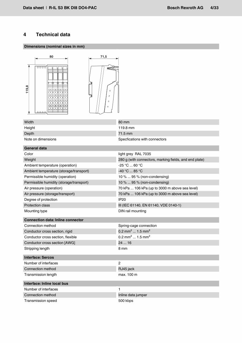
Dimensions (nominal sizes in mm)
Width 80 mmHeight 119.8 mmDepth 71.5 mmNote on dimensions Specfications with connectors
4 Technical data11
9,8
80 71,5
General dataColor light grey RAL 7035Weight 280 g (with connectors, marking fields, and end plate)Ambient temperature (operation) -25 °C ... 60 °CAmbient temperature (storage/transport) -40 °C ... 85 °CPermissible humidity (operation) 10 % ... 95 % (non-condensing)Permissible humidity (storage/transport) 10 % ... 95 % (non-condensing)Air pressure (operation) 70 kPa ... 106 kPa (up to 3000 m above sea level)Air pressure (storage/transport) 70 kPa ... 106 kPa (up to 3000 m above sea level)Degree of protection IP20Protection class III (IEC 61140, EN 61140, VDE 0140-1)Mounting type DIN rail mounting
Connection data: Inline connectorConnection method Spring-cage connectionConductor cross section, rigid 0.2 mm² ... 1.5 mm²Conductor cross section, flexible 0.2 mm² ... 1.5 mm²Conductor cross section [AWG] 24 ... 16Stripping length 8 mm
Interface: SercosNumber of interfaces 2Connection method RJ45 jackTransmission length max. 100 m
Interface: Inline local busNumber of interfaces 1Connection method Inline data jumperTransmission speed 500 kbps
Data sheet | R-IL S3 BK DI8 DO4-PAC Bosch Rexroth AG 5/33
System limits of the bus couplerAmount of process data max. 512 Byte (per station)Number of local bus devices that can be connected max. 63Number of devices with parameter channel max. 16
Observe the logic current consumption of each device when configuring an Inline station! It is specified in every terminal-specific data sheet. The current consumption can differ depending on the individual terminal. The per-missible number of devices that can be connected therefore depends on the specific station structure.
SercosEquipment type Sercos slaveDevice profile FSP_IOCycle Time ≥ 250 µs
Bus coupler supply UBK; Communications power UL (7.5 V) and the analog supply UANA (24 V) are generated from the bus coupler supply.Supply voltage 24 V DC (via Inline connector)Supply voltage range 19.2 V DC ... 30 V DC (including all tolerances, including ripple)Current consumption typ. 60 mA (without connected I/O terminal blocks)
max. 1 A (with max. number of connected I/O terminal blocks)Power consumption typ. 1.44 W (without connected I/O terminals, without sensors
or actuators at the onboard I/Os)
Communications power (UL)Supply voltage 7.5 V DCPower supply unit max. 0.8 A DC
Supply of analog modules (UANA)Supply voltage 24 V DCSupply voltage range 19.2 V DC ... 30 V DC (including all tolerances, including ripple)Power supply unit max. 0.5 A DC
Main circuit supply (UM)Supply voltage 24 V DC (via Inline connector)Supply voltage range 19.2 V DC ... 30 V DC (including all tolerances, including ripple)Power supply unit max. 8 A DC (sum of UM + US)Current consumption min. 3 mA (without connected peripherals)
max. 8 A DC
Segment circuit supply (US)Supply voltage 24 V DC (via Inline connector)Supply voltage range 19.2 V DC ... 30 V DC (including all tolerances, including ripple)Power supply unit max. 8 A DC (sum of UM + US)Current consumption min. 3 mA (without connected peripherals)
max. 8 A DC
Data sheet | R-IL S3 BK DI8 DO4-PAC Bosch Rexroth AG 6/33
ProtectionNOTICE Electronics may be damaged when overloadedProvide external protection for the 24 V areas UBK, UM, and US. If you are using an external fuse, the power supply unit must be able to supply four times the nominal current of the fuse. This ensures that it trips in the event of an error.
Digital inputsNumber of inputs 8Connection method Inline connectorConnection technology 3-conductorDescription of the input EN 61131-2 type 1Nominal input voltage 24 V DCNominal input current typ. 3 mACurrent flow Limited to 3 mA, maximumInput voltage range "0" signal -30 V DC ... 5 V DCInput voltage range "1" signal 15 V DC ... 30 V DCSignal delay < 11 µs (ton, 24 V)
< 140 µs (toff, 24 V)Permissible conductor length to the sensor 100 mReverse polarity protection Suppressor diode
Digital outputsNumber of outputs 4Connection method Inline connectorConnection technology 3-conductorNominal output voltage 24 V DCVoltage difference with nominal current < 1 VOutput current per channel max. 500 mAOutput current of the device max. 2 ANominal load, ohmic 12 WNominal load, inductive 12 VA (1.2 H, 48 Ω)Nominal load, lamp 12 WSignal delay < 40 µs (ton, no load)
< 50 µs (ton, load = 0.5 A)< 350 µs (toff, no load)< 235 µs (toff, load = 0.5 A)
Signal delay when switching on an ohmic nominal load max. 50 µs (in the case of 0.5 A load)Signal delay when switching off an ohmic nominal load max. 250 µs (in the case of 0.5 A load)Maximum operating frequency with inductive nominal load
0.5 Hz (1.2 H, 48 Ω)
Behavior at voltage switch-off The output follows the power supply without delayLimitation of the voltage induced on circuit interruption approx. -30 VOutput voltage when switched off max. 500 mVOutput current when switched off max. 500 µA (When not loaded, a voltage can be measured
even at an output that is not set.)Behavior with overload Auto restartBehavior with inductive overload Output can be destroyedReverse voltage resistance to short pulses Reverse voltage proofResistance to permanent reverse voltage max. 2 AOvercurrent shut-down min. 0.7 A
Data sheet | R-IL S3 BK DI8 DO4-PAC Bosch Rexroth AG 7/33
Output current with ground connection interrupt when switched off
max. 25 mA
Switching capacity with ground connection interrupt typ. 100 mW (at 1 kΩ load resistance)Short-circuit and overload protection Freewheeling circuit in the output driver
Digital outputs
Error messages to the higher level control or computer systemShort-circuit or overload of the digital outputs YesSensor supply failure YesFailure of the actuator supply Yes
Protective circuitSurge protection, protection against polarity reversal of the supply voltage
35 V suppressor diode
Mechanical testsVibration resistance in acc. with EN 60068-2-6/IEC 60068-2-6
5g
Shock in acc. with EN 60068-2-27/IEC 60068-2-27 Operation: 25g, 11 ms duration, semi-sinusoidal shock impulse
Conformance with EMC Directive 2014/30/EUImmunity test in accordance with EN 61000-6-2/IEC 61000-6-2Electrostatic discharge (ESD) EN 61000-4-2/IEC 61000-4-2
Criterion B, 6 kV contact discharge, 8 kV air discharge
Electromagnetic fields EN 61000-4-3/IEC 61000-4-3 Criterion A, Field intensity: 10 V/mFast transients (burst) EN 61000-4-4/IEC 61000-4-4 Criterion A, all interfaces 1 kV
Criterion B, all interfaces 2 kVTransient overvoltage (surge) EN 61000-4-5/IEC 61000-4-5
Criterion B, supply lines DC: 0.5 kV/0.5 kV (symmetrical/asym-metrical), fieldbus cable shield 1 kV
Conducted interference EN 61000-4-6/IEC 61000-4-6 Criterion A, Test voltage 10 VNoise emission test in accordance with EN 61000-6-4/IEC 61000-6-4
Class A
ApprovalsFor the latest approvals, please visit www.boschrexroth.com/electrics.
Data sheet | R-IL S3 BK DI8 DO4-PAC Bosch Rexroth AG 8/33
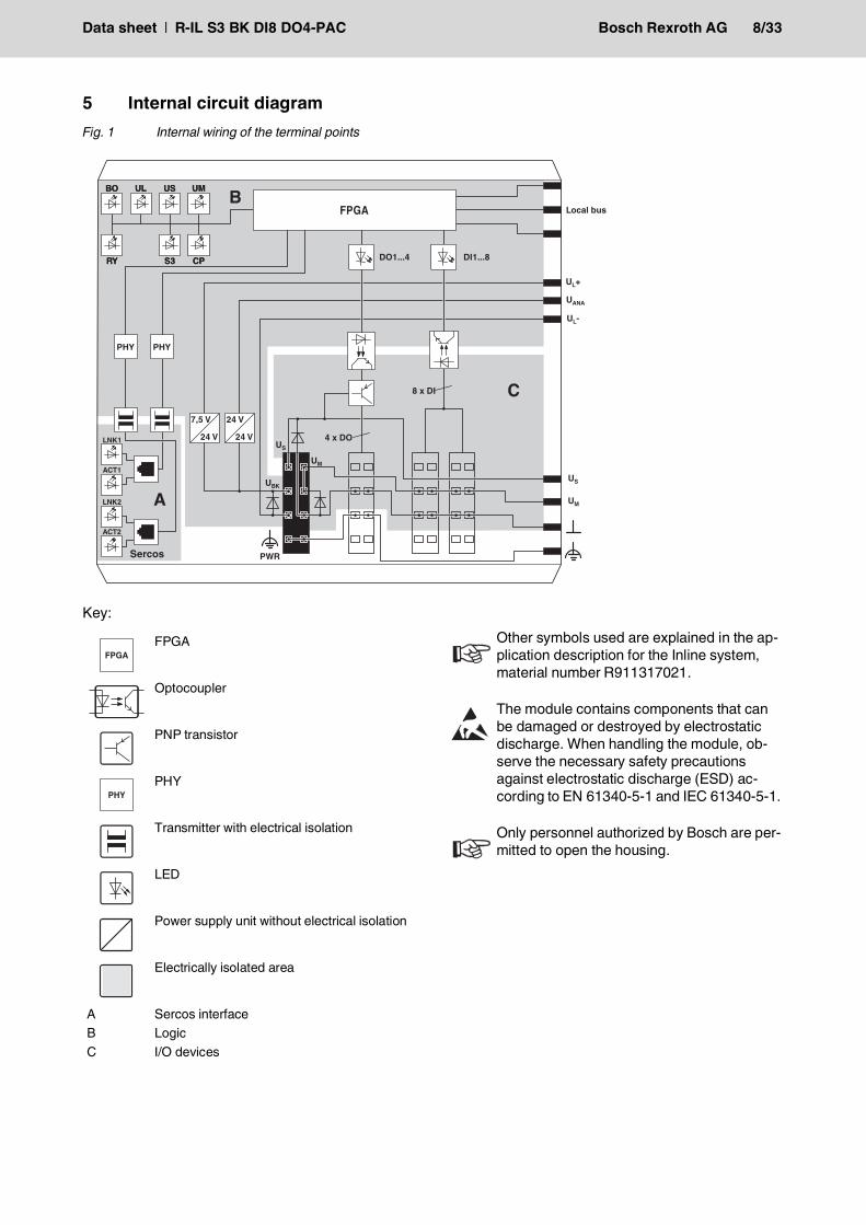
5 Internal circuit diagramFig. 1 Internal wiring of the terminal points
Key:
FPGA
Optocoupler
PNP transistor
PHY
Transmitter with electrical isolation
LED
Power supply unit without electrical isolation
Electrically isolated area
A Sercos interfaceB LogicC I/O devices
FPGA
Other symbols used are explained in the ap-plication description for the Inline system, material number R911317021.
The module contains components that can be damaged or destroyed by electrostatic discharge. When handling the module, ob-serve the necessary safety precautions against electrostatic discharge (ESD) ac-cording to EN 61340-5-1 and IEC 61340-5-1.
Only personnel authorized by Bosch are per-mitted to open the housing.
Data sheet | R-IL S3 BK DI8 DO4-PAC Bosch Rexroth AG 9/33
6 IT security
If possible, deactivate unused communication chan-nels.Assign passwords such that third-parties cannot ac-cess the bus coupler and make changes without au-thorization.Due to its communication interfaces, the bus coupler should not be used in safety-critical applications with-out additional security appliances.Therefore, please take additional protective measures in accordance with the IT security requirements and the standards applicable to your application (e.g. vir-tual networks (VPN) for remote maintenance access, firewalls, etc.) for protection against unauthorized net-work access.The operation of installations, systems and machines requires the implementation of an integral concept for state-of-the-art IT security. Bosch Rexroth products are part of this integral concept. Bosch Rexroth prod-uct characteristicshave to be taken into consideration in an integral IT se-curity concept. The relevant characteristics are docu-mented in the IT security guideline DOK-IWORKS-SECURITY***-PR..-EN-P (R911342562) dokumen-tiert.
7 Connecting Sercos, power supply, actuators, and sensors
7.1 Connecting SercosConnect Sercos to the bus coupler via an RJ45 con-nector.
NOTE: Risk of unauthorized network ac-cessConnecting devices to a network via Ethernet entails the danger of unauthorized access to the network.To prevent unauthorized network access, please read the following notes.
Install Sercos in accordance with the specifi-cations in the current “Planning and Installa-tion Guide” (see www.sercos.com).
ShieldingThe shield of the connected twisted pair ca-bles is electrically connected to the socket. When connecting network segments, avoid ground loops, potential transfers, and equi-potential bonding currents via the braided shield.
Observe bending radiiThe housing dimensions specified under "Di-mensions" refer to the bus coupler with I/O connectors without Ethernet connection. When installing the bus coupler in a control box, observe the bending radii of the cables and the connectors used.If required, use angled RJ45 connectors to maintain these bending radii.
Data sheet | R-IL S3 BK DI8 DO4-PAC Bosch Rexroth AG 10/33
7.2 Connecting the supply, actuators, and sensors - terminal point assignment
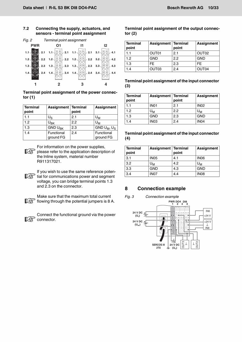
Fig. 2 Terminal point assignment
Terminal point assignment of the power connec-tor (1)
Terminal point assignment of the output connec-tor (2)
Terminal point assignment of the input connector (3)
Terminal point assignment of the input connector (4)
8 Connection exampleFig. 3 Connection example
Terminal point
Assignment Terminal point
Assignment
1.1 US 2.1 UM1.2 UBK 2.2 UM1.3 GND UBK 2.3 GND UM, US1.4 Functional
ground FG2.4 Functional
ground FG
For information on the power supplies, please refer to the application description of the Inline system, material number R911317021.
If you wish to use the same reference poten-tial for communications power and segment voltage, you can bridge terminal points 1.3 and 2.3 on the connector.
Make sure that the maximum total current flowing through the potential jumpers is 8 A.
Connect the functional ground via the power connector.
1.1
1.2
1.3
1.4
2.1
2.2
2.3
2.4
1
2
3
4
1
2
3
4
PWR
1.1
1.2
1.3
1.4
2.1
2.3
2.4
2.2
1.1
1.2
1.3
1.4
2.1
2.2
2.3
2.4
1
2
3
4
1
2
3
4
O1
1.1
1.2
1.3
1.4
2.1
2.3
2.4
2.2
1.1
1.2
1.3
1.4
2.1
2.2
2.3
2.4
1
2
3
4
1
2
3
4
I1
1.1
1.2
1.3
1.4
2.1
2.3
2.4
2.2
3.1
3.2
3.3
3.4
4.1
4.2
4.3
4.4
1
2
3
4
1
2
3
4
I2
3.1
3.2
3.3
3.4
4.1
4.3
4.4
4.2
1 2 3 4
Terminal point
Assignment Terminal point
Assignment
1.1 OUT01 2.1 OUT021.2 GND 2.2 GND1.3 FE 2.3 FE1.4 OUT03 2.4 OUT04
Terminal point
Assignment Terminal point
Assignment
1.1 IN01 2.1 IN021.2 UM 2.2 UM1.3 GND 2.3 GND1.4 IN03 2.4 IN04
Terminal point
Assignment Terminal point
Assignment
3.1 IN05 4.1 IN063.2 UM 4.2 UM3.3 GND 4.3 GND3.4 IN07 4.4 IN08
1.1
1.2
1.3
1.4
2.1
2.2
2.3
2.4
1.1
1.2
1.3
1.4
2.1
2.2
2.3
2.4
3.1
3.2
3.3
3.4
4.1
4.2
4.3
4.4
1.1
1.2
1.3
1.4
2.1
2.2
2.3
2.4
SERCOS III2TX
DO4PWR1 2 3 4
DI8
24 V DC(UBK)
+-
24 V DC(US)
+-
- +24 V DC(U )M
+24 VIN6
IN8
+24 V
OUT3
OUT2
Data sheet | R-IL S3 BK DI8 DO4-PAC Bosch Rexroth AG 11/33
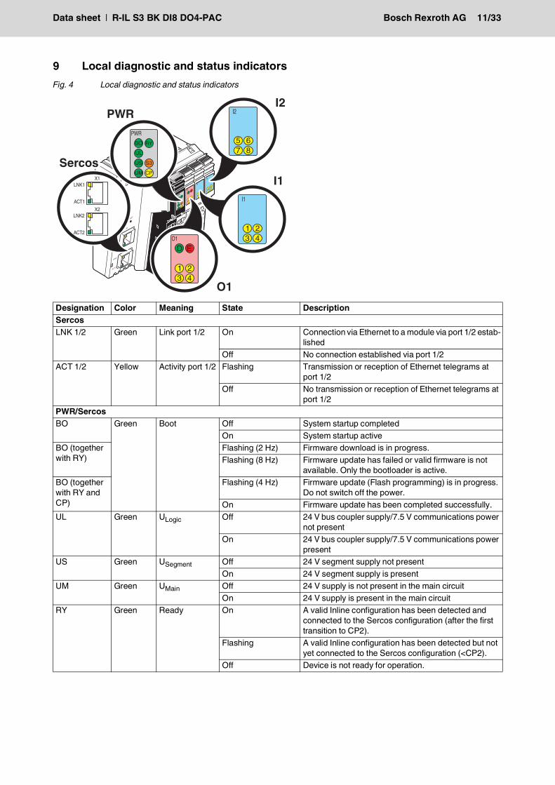
9 Local diagnostic and status indicatorsFig. 4 Local diagnostic and status indicators
Designation Color Meaning State DescriptionSercosLNK 1/2 Green Link port 1/2 On Connection via Ethernet to a module via port 1/2 estab-
lishedOff No connection established via port 1/2
ACT 1/2 Yellow Activity port 1/2 Flashing Transmission or reception of Ethernet telegrams at port 1/2
Off No transmission or reception of Ethernet telegrams at port 1/2
PWR/SercosBO Green Boot Off System startup completed
On System startup activeBO (together with RY)
Flashing (2 Hz) Firmware download is in progress.Flashing (8 Hz) Firmware update has failed or valid firmware is not
available. Only the bootloader is active.BO (together with RY and CP)
Flashing (4 Hz) Firmware update (Flash programming) is in progress. Do not switch off the power.
On Firmware update has been completed successfully.UL Green ULogic Off 24 V bus coupler supply/7.5 V communications power
not presentOn 24 V bus coupler supply/7.5 V communications power
presentUS Green USegment Off 24 V segment supply not present
On 24 V segment supply is presentUM Green UMain Off 24 V supply is not present in the main circuit
On 24 V supply is present in the main circuitRY Green Ready On A valid Inline configuration has been detected and
connected to the Sercos configuration (after the first transition to CP2).
Flashing A valid Inline configuration has been detected but not yet connected to the Sercos configuration (<CP2).
Off Device is not ready for operation.
Data sheet | R-IL S3 BK DI8 DO4-PAC Bosch Rexroth AG 12/33
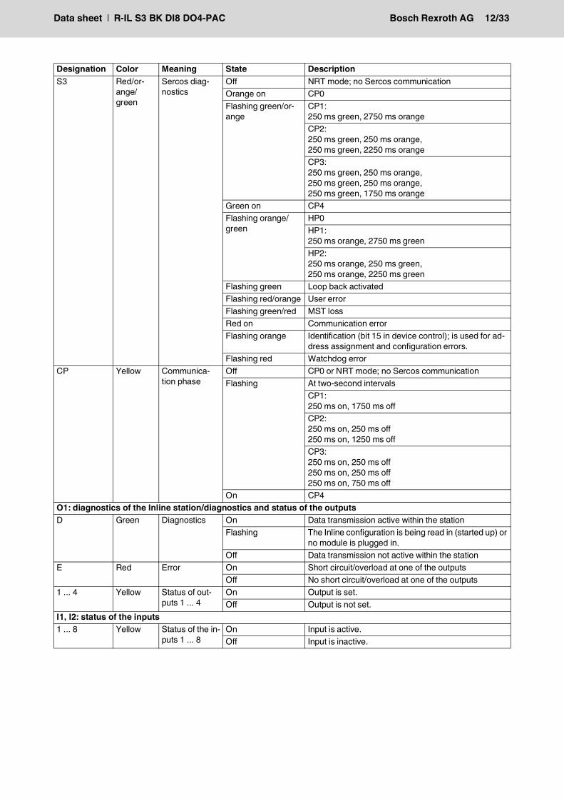
S3 Red/or-ange/green
Sercos diag-nostics
Off NRT mode; no Sercos communicationOrange on CP0Flashing green/or-ange
CP1:250 ms green, 2750 ms orangeCP2:250 ms green, 250 ms orange,250 ms green, 2250 ms orangeCP3:250 ms green, 250 ms orange,250 ms green, 250 ms orange,250 ms green, 1750 ms orange
Green on CP4Flashing orange/green
HP0HP1:250 ms orange, 2750 ms greenHP2:250 ms orange, 250 ms green,250 ms orange, 2250 ms green
Flashing green Loop back activatedFlashing red/orange User errorFlashing green/red MST lossRed on Communication errorFlashing orange Identification (bit 15 in device control); is used for ad-
dress assignment and configuration errors.Flashing red Watchdog error
CP Yellow Communica-tion phase
Off CP0 or NRT mode; no Sercos communicationFlashing At two-second intervals
CP1:250 ms on, 1750 ms offCP2:250 ms on, 250 ms off250 ms on, 1250 ms offCP3:250 ms on, 250 ms off250 ms on, 250 ms off250 ms on, 750 ms off
On CP4O1: diagnostics of the Inline station/diagnostics and status of the outputsD Green Diagnostics On Data transmission active within the station
Flashing The Inline configuration is being read in (started up) or no module is plugged in.
Off Data transmission not active within the stationE Red Error On Short circuit/overload at one of the outputs
Off No short circuit/overload at one of the outputs1 ... 4 Yellow Status of out-
puts 1 ... 4 On Output is set.Off Output is not set.
I1, I2: status of the inputs1 ... 8 Yellow Status of the in-
puts 1 ... 8On Input is active.Off Input is inactive.
Designation Color Meaning State Description
Data sheet | R-IL S3 BK DI8 DO4-PAC Bosch Rexroth AG 13/33
10 Sercos
10.1 Sercos addressThe bus coupler supports remote address assignment of the Sercos address according to the Sercos speci-fication.There is no switch for setting the Sercos address.The Sercos address is saved retentively.
10.2 Sercos profile, classes and function groups
The following Sercos profile, classes and function groups are implemented in the module:
10.2.1 Sercos communication model(SCP: Sercos Communication Profiles)
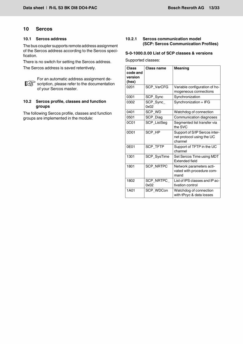
S-0-1000.0.00 List of SCP classes & versionsSupported classes:
For an automatic address assignment de-scription, please refer to the documentation of your Sercos master.
Class code and version (hex)
Class name Meaning
0201 SCP_VarCFG Variable configuration of ho-mogeneous connections
0301 SCP_Sync Synchronization0302 SCP_Sync_
0x02Synchronization + IFG
0401 SCP_WD Watchdog of connection0501 SCP_Diag Communication diagnoses0C01 SCP_ListSeg Segmented list transfer via
the SVC0D01 SCP_HP Support of S/IP Sercos inter-
net protocol using the UC channel
0E01 SCP_TFTP Support of TFTP in the UC channel
1301 SCP_SysTime Set Sercos Time using MDT Extended field
1801 SCP_NRTPC Network parameters acti-vated with procedure com-mand
1802 SCP_NRTPC_0x02
List of IPS classes and IP ac-tivation control
1A01 SCP_WDCon Watchdog of connection with tPcyc & data losses
Data sheet | R-IL S3 BK DI8 DO4-PAC Bosch Rexroth AG 14/33
10.2.2 Sercos Internet protocol services(IPS: Internet Protocol Services)
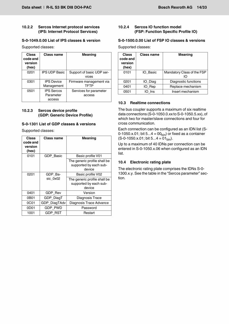
S-0-1049.0.00 List of IPS classes & versionSupported classes:
10.2.3 Sercos device profile(GDP: Generic Device Profile)
S-0-1301 List of GDP classes & versionsSupported classes:
10.2.4 Sercos IO function model(FSP: Function Specific Profile IO)
S-0-1500.0.00 List of FSP IO classes & versionsSupported classes:
10.3 Realtime connectionsThe bus coupler supports a maximum of six realtime data connections (S-0-1050.0.xx to S-0-1050.5.xx), of which two for master/slave connections and four for cross communication.Each connection can be configured as an IDN list (S-0-1050.x.01; bit 5...4 = 00bin) or fixed as a container (S-0-1050.x.01; bit 5...4 = 01bin).Up to a maximum of 40 IDNs per connection can be entered in S-0-1050.x.06 when configured as an IDN list.
10.4 Electronic rating plateThe electronic rating plate comprises the IDNs S-0-1300.x.y. See the table in the “Sercos parameter” sec-tion.
Class code and version
(hex)
Class name Meaning
0201 IPS UDP Basic Support of basic UDP ser-vices
0301 IPS Device Management
Firmware management via TFTP
0501 IPS Sercos Parameter
access
Services for parameter access
Class code and version
(hex)
Class name Meaning
0101 GDP_Basic Basic profile V01The generic profile shall be
supported by each sub-device
0201 GDP_Ba-sic_0x02
Basic profile V02The generic profile shall be
supported by each sub-device
0401 GDP_Rev Version0B01 GDP_DiagT Diagnosis Trace0C01 GDP_DiagTAdv Diagnosis Trace Advance0D01 GDP_PWD Password1001 GDP_RST Restart
Class code and version
(hex)
Class name Meaning
0101 IO_Basic Mandatory Class of the FSP IO
0201 IO_Diag Diagnostic functions0401 IO_Rep Replace mechanism0501 IO_Ins Insert mechanism
Data sheet | R-IL S3 BK DI8 DO4-PAC Bosch Rexroth AG 15/33
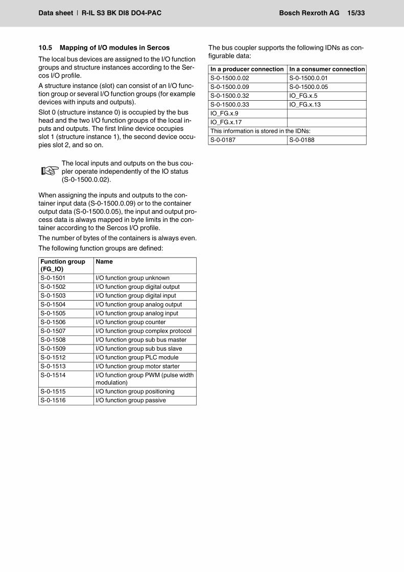
10.5 Mapping of I/O modules in SercosThe local bus devices are assigned to the I/O function groups and structure instances according to the Ser-cos I/O profile.A structure instance (slot) can consist of an I/O func-tion group or several I/O function groups (for example devices with inputs and outputs).Slot 0 (structure instance 0) is occupied by the bus head and the two I/O function groups of the local in-puts and outputs. The first Inline device occupies slot 1 (structure instance 1), the second device occu-pies slot 2, and so on.
When assigning the inputs and outputs to the con-tainer input data (S-0-1500.0.09) or to the container output data (S-0-1500.0.05), the input and output pro-cess data is always mapped in byte limits in the con-tainer according to the Sercos I/O profile.The number of bytes of the containers is always even.The following function groups are defined:
The bus coupler supports the following IDNs as con-figurable data:
The local inputs and outputs on the bus cou-pler operate independently of the IO status (S-0-1500.0.02).
Function group (FG_IO)
Name
S-0-1501 I/O function group unknownS-0-1502 I/O function group digital outputS-0-1503 I/O function group digital inputS-0-1504 I/O function group analog outputS-0-1505 I/O function group analog inputS-0-1506 I/O function group counterS-0-1507 I/O function group complex protocolS-0-1508 I/O function group sub bus masterS-0-1509 I/O function group sub bus slaveS-0-1512 I/O function group PLC moduleS-0-1513 I/O function group motor starterS-0-1514 I/O function group PWM (pulse width
modulation)S-0-1515 I/O function group positioningS-0-1516 I/O function group passive
In a producer connection In a consumer connectionS-0-1500.0.02 S-0-1500.0.01S-0-1500.0.09 S-0-1500.0.05S-0-1500.0.32 IO_FG.x.5S-0-1500.0.33 IO_FG.x.13IO_FG.x.9IO_FG.x.17This information is stored in the IDNs:S-0-0187 S-0-0188
Data sheet | R-IL S3 BK DI8 DO4-PAC Bosch Rexroth AG 16/33
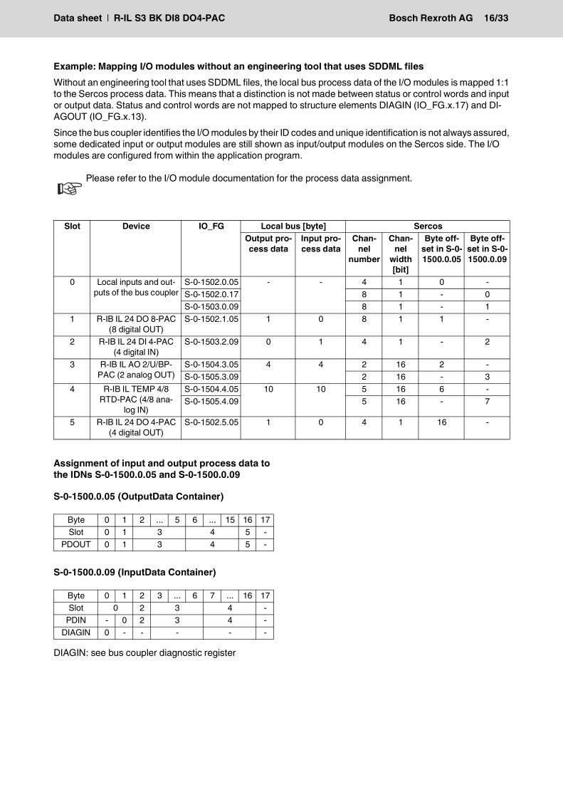
Example: Mapping I/O modules without an engineering tool that uses SDDML filesWithout an engineering tool that uses SDDML files, the local bus process data of the I/O modules is mapped 1:1 to the Sercos process data. This means that a distinction is not made between status or control words and input or output data. Status and control words are not mapped to structure elements DIAGIN (IO_FG.x.17) and DI-AGOUT (IO_FG.x.13).Since the bus coupler identifies the I/O modules by their ID codes and unique identification is not always assured, some dedicated input or output modules are still shown as input/output modules on the Sercos side. The I/O modules are configured from within the application program.
Assignment of input and output process data to the IDNs S-0-1500.0.05 and S-0-1500.0.09
S-0-1500.0.05 (OutputData Container)
S-0-1500.0.09 (InputData Container)
DIAGIN: see bus coupler diagnostic register
Please refer to the I/O module documentation for the process data assignment.
Slot Device IO_FG Local bus [byte] SercosOutput pro-cess data
Input pro-cess data
Chan-nel
number
Chan-nel
width [bit]
Byte off-set in S-0-1500.0.05
Byte off-set in S-0-1500.0.09
0 Local inputs and out-puts of the bus coupler
S-0-1502.0.05 - - 4 1 0 -S-0-1502.0.17 8 1 - 0S-0-1503.0.09 8 1 - 1
1 R-IB IL 24 DO 8-PAC (8 digital OUT)
S-0-1502.1.05 1 0 8 1 1 -
2 R-IB IL 24 DI 4-PAC (4 digital IN)
S-0-1503.2.09 0 1 4 1 - 2
3 R-IB IL AO 2/U/BP-PAC (2 analog OUT)
S-0-1504.3.05 4 4 2 16 2 -S-0-1505.3.09 2 16 - 3
4 R-IB IL TEMP 4/8 RTD-PAC (4/8 ana-
log IN)
S-0-1504.4.05 10 10 5 16 6 -S-0-1505.4.09 5 16 - 7
5 R-IB IL 24 DO 4-PAC (4 digital OUT)
S-0-1502.5.05 1 0 4 1 16 -
Byte 0 1 2 ... 5 6 ... 15 16 17Slot 0 1 3 4 5 -
PDOUT 0 1 3 4 5 -
Byte 0 1 2 3 ... 6 7 ... 16 17Slot 0 2 3 4 -
PDIN - 0 2 3 4 -DIAGIN 0 - - - - -
Data sheet | R-IL S3 BK DI8 DO4-PAC Bosch Rexroth AG 17/33
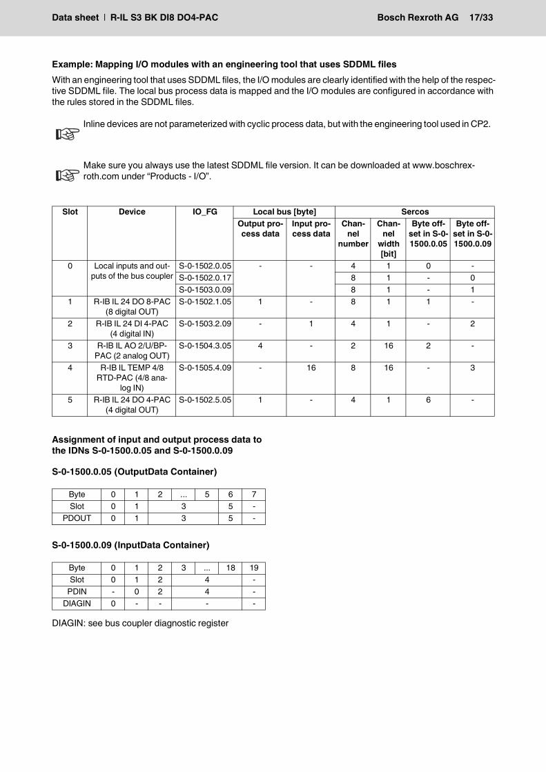
Example: Mapping I/O modules with an engineering tool that uses SDDML filesWith an engineering tool that uses SDDML files, the I/O modules are clearly identified with the help of the respec-tive SDDML file. The local bus process data is mapped and the I/O modules are configured in accordance with the rules stored in the SDDML files.
Assignment of input and output process data to the IDNs S-0-1500.0.05 and S-0-1500.0.09
S-0-1500.0.05 (OutputData Container)
S-0-1500.0.09 (InputData Container)
DIAGIN: see bus coupler diagnostic register
Inline devices are not parameterized with cyclic process data, but with the engineering tool used in CP2.
Make sure you always use the latest SDDML file version. It can be downloaded at www.boschrex-roth.com under “Products - I/O”.
Slot Device IO_FG Local bus [byte] SercosOutput pro-cess data
Input pro-cess data
Chan-nel
number
Chan-nel
width [bit]
Byte off-set in S-0-1500.0.05
Byte off-set in S-0-1500.0.09
0 Local inputs and out-puts of the bus coupler
S-0-1502.0.05 - - 4 1 0 -S-0-1502.0.17 8 1 - 0S-0-1503.0.09 8 1 - 1
1 R-IB IL 24 DO 8-PAC (8 digital OUT)
S-0-1502.1.05 1 - 8 1 1 -
2 R-IB IL 24 DI 4-PAC (4 digital IN)
S-0-1503.2.09 - 1 4 1 - 2
3 R-IB IL AO 2/U/BP-PAC (2 analog OUT)
S-0-1504.3.05 4 - 2 16 2 -
4 R-IB IL TEMP 4/8 RTD-PAC (4/8 ana-
log IN)
S-0-1505.4.09 - 16 8 16 - 3
5 R-IB IL 24 DO 4-PAC (4 digital OUT)
S-0-1502.5.05 1 - 4 1 6 -
Byte 0 1 2 ... 5 6 7Slot 0 1 3 5 -
PDOUT 0 1 3 5 -
Byte 0 1 2 3 ... 18 19Slot 0 1 2 4 -
PDIN - 0 2 4 -DIAGIN 0 - - - -
Data sheet | R-IL S3 BK DI8 DO4-PAC Bosch Rexroth AG 18/33
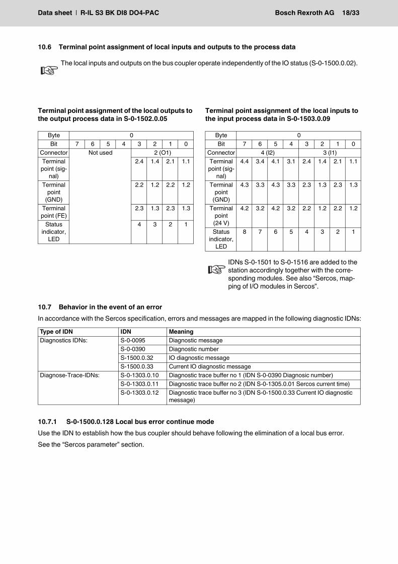
10.6 Terminal point assignment of local inputs and outputs to the process data
Terminal point assignment of the local outputs to the output process data in S-0-1502.0.05
Terminal point assignment of the local inputs to the input process data in S-0-1503.0.09
10.7 Behavior in the event of an errorIn accordance with the Sercos specification, errors and messages are mapped in the following diagnostic IDNs:
10.7.1 S-0-1500.0.128 Local bus error continue modeUse the IDN to establish how the bus coupler should behave following the elimination of a local bus error.See the “Sercos parameter” section.
The local inputs and outputs on the bus coupler operate independently of the IO status (S-0-1500.0.02).
Byte 0Bit 7 6 5 4 3 2 1 0
Connector Not used 2 (O1)Terminal
point (sig-nal)
2.4 1.4 2.1 1.1
Terminal point
(GND)
2.2 1.2 2.2 1.2
Terminal point (FE)
2.3 1.3 2.3 1.3
Status indicator,
LED
4 3 2 1
Byte 0Bit 7 6 5 4 3 2 1 0
Connector 4 (I2) 3 (I1)Terminal
point (sig-nal)
4.4 3.4 4.1 3.1 2.4 1.4 2.1 1.1
Terminal point
(GND)
4.3 3.3 4.3 3.3 2.3 1.3 2.3 1.3
Terminal point
(24 V)
4.2 3.2 4.2 3.2 2.2 1.2 2.2 1.2
Status indicator,
LED
8 7 6 5 4 3 2 1
IDNs S-0-1501 to S-0-1516 are added to the station accordingly together with the corre-sponding modules. See also “Sercos, map-ping of I/O modules in Sercos”.
Type of IDN IDN MeaningDiagnostics IDNs: S-0-0095 Diagnostic message
S-0-0390 Diagnostic numberS-1500.0.32 IO diagnostic messageS-1500.0.33 Current IO diagnostic message
Diagnose-Trace-IDNs: S-0-1303.0.10 Diagnostic trace buffer no 1 (IDN S-0-0390 Diagnosic number)S-0-1303.0.11 Diagnostic trace buffer no 2 (IDN S-0-1305.0.01 Sercos current time)S-0-1303.0.12 Diagnostic trace buffer no 3 (IDN S-0-1500.0.33 Current IO diagnostic
message)
Data sheet | R-IL S3 BK DI8 DO4-PAC Bosch Rexroth AG 19/33
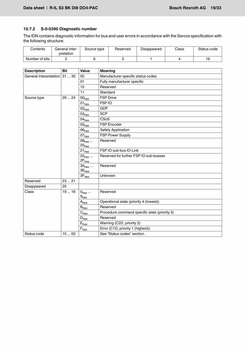
10.7.2 S-0-0390 Diagnostic numberThe IDN contains diagnostic information for bus and user errors in accordance with the Sercos specification with the following structure:
Contents General inter-pretation
Source type Reserved Disappeared Class Status code
Number of bits 2 6 3 1 4 16
Description Bit Value MeaningGeneral interpretation 31 ... 30 00 Manufacturer specific status codes
01 Fully manufacturer specific10 Reserved11 Standard
Source type 29 ... 24 00hex FSP Drive01hex FSP IO02hex GDP03hex SCP04hex CSoS05hex FSP Encoder06hex Safety Application07hex FSP Power Supply08hex ... 20hex
Reserved
21hex FSP IO sub-bus IO-Link22hex ... 2Fhex
Reserved for further FSP IO sub-busses
30hex ... 3Ehex
Reserved
3Fhex UnknownReserved 23 ... 21Disappeared 20Class 19 ... 16 0hex ...
9hex
Reserved
Ahex Operational state (priority 4 (lowest))Bhex ReservedChex Procedure command specific state (priority 3)Dhex ReservedEhex Warning (C2D, priority 2)Fhex Error (C1D, priority 1 (highest))
Status code 15 ... 00 See “Status codes” section.
Data sheet | R-IL S3 BK DI8 DO4-PAC Bosch Rexroth AG 20/33
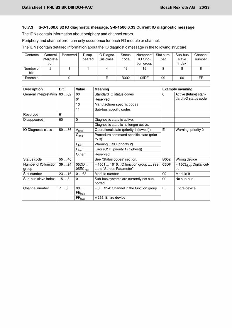
10.7.3 S-0-1500.0.32 IO diagnostic message, S-0-1500.0.33 Current IO diagnostic messageThe IDNs contain information about periphery and channel errors.Periphery and channel error can only occur once for each I/O module or channel.The IDNs contain detailed information about the IO diagnostic message in the following structure:
Contents General interpreta-
tion
Reserved Disap-peared
IO Diagno-sis class
Status code
Number of IO func-
tion group
Slot num-ber
Sub-bus slave index
Channel number
Number of bits
2 1 1 4 16 16 8 8 8
Example 0 E B002 05DF 09 00 FF
Description Bit Value Meaning Example meaningGeneral interpretation 63 ... 62 00 Standard IO status codes 0 Active (future) stan-
dard I/O status code01 Reserved10 Manufacturer specific codes11 Sub-bus specific codes
Reserved 61 Disappeared 60 0 Diagnostic state is active.
1 Diagnostic state is no longer active. IO Diagnosis class 59 ... 56 Ahex Operational state (priority 4 (lowest)) E Warning, priority 2
Chex Procedure command specific state (prior-ity 3)
Ehex Warning (C2D, priority 2)Fhex Error (C1D, priority 1 (highest))Other Reserved
Status code 55 ... 40 See “Status codes” section. B002 Wrong deviceNumber of IO function group
39 ... 24 05DD ... 05EChex
= 1501 ... 1616, I/O function group ..., see table “Sercos Parameter”
05DF = 1503dec: Digital out-put
Slot number 23 ... 16 0 ... 63 Module number 09 Module 9Sub-bus slave index 15 ... 8 0 Sub-bus systems are currently not sup-
ported.00 No sub-bus
Channel number 7 ... 0 00 ... FEhex
= 0 ... 254: Channel in the function group FF Entire device
FFhex = 255: Entire device
Data sheet | R-IL S3 BK DI8 DO4-PAC Bosch Rexroth AG 21/33
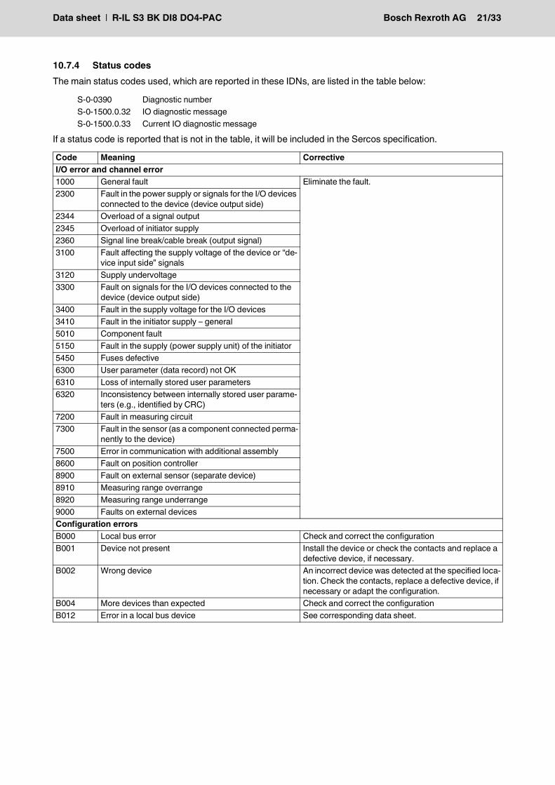
10.7.4 Status codesThe main status codes used, which are reported in these IDNs, are listed in the table below:
If a status code is reported that is not in the table, it will be included in the Sercos specification.
S-0-0390 Diagnostic numberS-0-1500.0.32 IO diagnostic messageS-0-1500.0.33 Current IO diagnostic message
Code Meaning CorrectiveI/O error and channel error1000 General fault Eliminate the fault.2300 Fault in the power supply or signals for the I/O devices
connected to the device (device output side)2344 Overload of a signal output2345 Overload of initiator supply2360 Signal line break/cable break (output signal)3100 Fault affecting the supply voltage of the device or “de-
vice input side” signals3120 Supply undervoltage3300 Fault on signals for the I/O devices connected to the
device (device output side)3400 Fault in the supply voltage for the I/O devices3410 Fault in the initiator supply – general5010 Component fault5150 Fault in the supply (power supply unit) of the initiator5450 Fuses defective6300 User parameter (data record) not OK6310 Loss of internally stored user parameters6320 Inconsistency between internally stored user parame-
ters (e.g., identified by CRC)7200 Fault in measuring circuit7300 Fault in the sensor (as a component connected perma-
nently to the device)7500 Error in communication with additional assembly8600 Fault on position controller8900 Fault on external sensor (separate device)8910 Measuring range overrange8920 Measuring range underrange9000 Faults on external devicesConfiguration errorsB000 Local bus error Check and correct the configurationB001 Device not present Install the device or check the contacts and replace a
defective device, if necessary.B002 Wrong device An incorrect device was detected at the specified loca-
tion. Check the contacts, replace a defective device, if necessary or adapt the configuration.
B004 More devices than expected Check and correct the configurationB012 Error in a local bus device See corresponding data sheet.
Data sheet | R-IL S3 BK DI8 DO4-PAC Bosch Rexroth AG 22/33
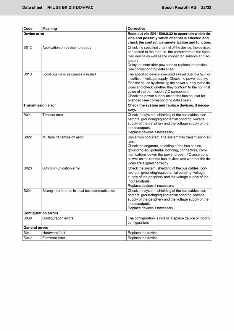
Device error Read out via IDN 1500.0.32 to ascertain which de-vice and possibly which channel is affected and check the contact, parameterization and function.
B012 Application on device not ready Check the specified channel of the device, the devices connected to the module, the parameters of the spec-ified device as well as the connected sensors and ac-tuators.Delay the start after power on or replace the device.See corresponding data sheet.
B013 Local bus devices causes a restart The specified device executed a reset due to a fault or insufficient voltage supply. Check the power supply.Find the cause by checking the power supply to the de-vices and check whether they conform to the nominal value of the permissible AC component.Check the power supply unit of the bus coupler for overload (see corresponding data sheet).
Transmission error Check the system and replace devices, if neces-sary.
B021 Timeout error Check the system, shielding of the bus cables, con-nectors, grounding/equipotential bonding, voltage supply of the periphery and the voltage supply of the inputs/outputs.Replace devices if necessary.
B022 Multiple transmission error Bus errors occurred. The system has transmission er-rors.Check the segment, shielding of the bus cables, grounding/equipotential bonding, connectors, com-munications power (for power drops), FO assembly, as well as the remote bus devices and whether the de-vices are aligned correctly.
B023 I/O communication error Check the system, shielding of the bus cables, con-nectors, grounding/equipotential bonding, voltage supply of the periphery and the voltage supply of the inputs/outputs.Replace devices if necessary.
B024 Strong interference in local bus communication Check the system, shielding of the bus cables, con-nectors, grounding/equipotential bonding, voltage supply of the periphery and the voltage supply of the inputs/outputs.Replace devices if necessary.
Configuration errorsB030 Configuration errors The configuration is invalid. Replace device or modify
configuration.General errorsB041 Hardware fault Replace the device.B042 Firmware error Replace the device.
Code Meaning Corrective
Data sheet | R-IL S3 BK DI8 DO4-PAC Bosch Rexroth AG 23/33
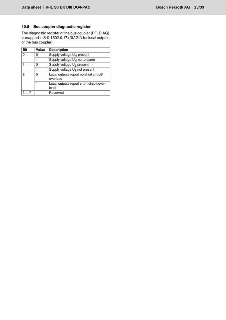
10.8 Bus coupler diagnostic registerThe diagnostic register of the bus coupler (PF_DIAG) is mapped in S-0-1502.0.17 (DIAGIN for local outputs of the bus coupler).
Bit Value Description0 0 Supply voltage UM present
1 Supply voltage UM not present1 0 Supply voltage US present
1 Supply voltage US not present2 0 Local outputs report no short circuit/
overload1 Local outputs report short circuit/over-
load3 ... 7 Reserved
Data sheet | R-IL S3 BK DI8 DO4-PAC Bosch Rexroth AG 24/33
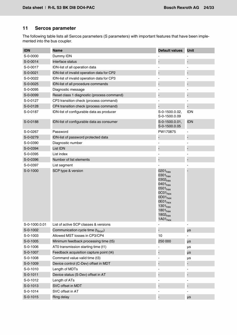
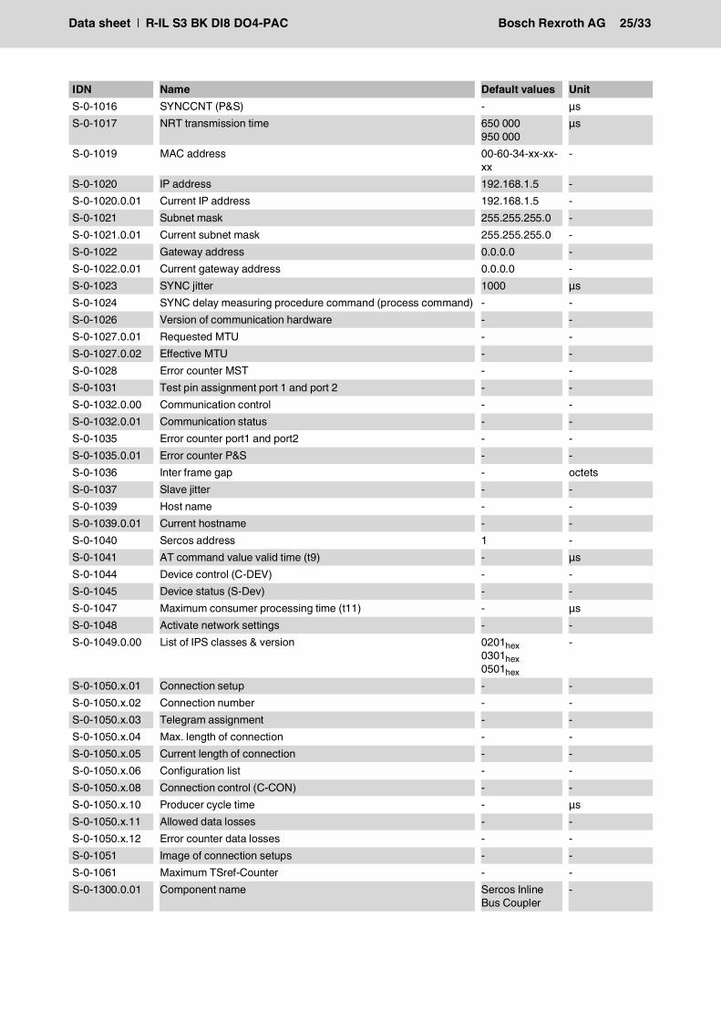
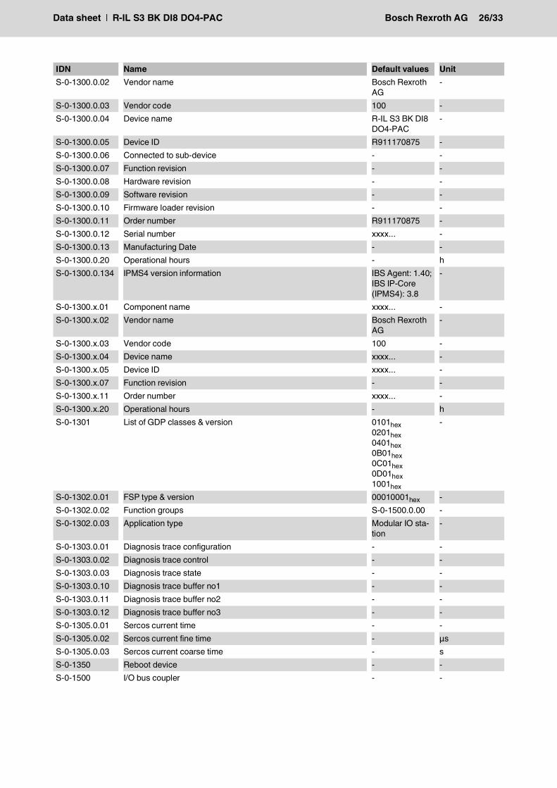
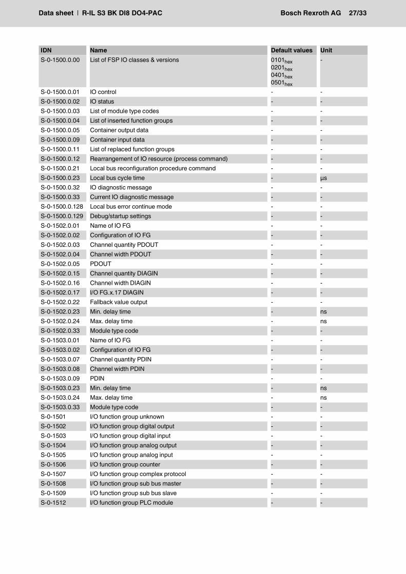
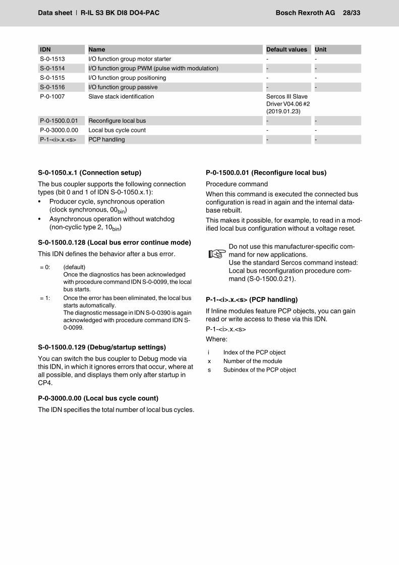
11 Sercos parameterThe following table lists all Sercos parameters (S parameters) with important features that have been imple-mented into the bus coupler.
IDN Name Default values UnitS-0-0000 Dummy IDN - -S-0-0014 Interface status - -S-0-0017 IDN-list of all operation data - -S-0-0021 IDN-list of invalid operation data for CP2 - -S-0-0022 IDN-list of invalid operation data for CP3 - -S-0-0025 IDN-list of all procedure commands - -S-0-0095 Diagnostic message - -S-0-0099 Reset class 1 diagnostic (process command) - -S-0-0127 CP3 transition check (process command) - -S-0-0128 CP4 transition check (process command) - -S-0-0187 IDN-list of configurable data as producer S-0-1500.0.02,
S-0-1500.0.09IDN
S-0-0188 IDN-list of configurable data as consumer S-0-1500.0.01,S-0-1500.0.05
IDN
S-0-0267 Password PW170875 -S-0-0279 IDN-list of password protected data - -S-0-0390 Diagnostic number - -S-0-0394 List IDN - -S-0-0395 List index - -S-0-0396 Number of list elements - -S-0-0397 List segment - -S-0-1000 SCP type & version 0201hex
0301hex0302hex0401hex0501hex0C01hex0D01hex0E01hex1301hex1801hex1802hex1A01hex
-
S-0-1000.0.01 List of active SCP classes & versions - -S-0-1002 Communication cycle time (tScyc) - μsS-0-1003 Allowed MST losses in CP3/CP4 10 -S-0-1005 Minimum feedback processing time (t5) 250 000 μsS-0-1006 AT0 transmission starting time (t1) - μsS-0-1007 Feedback acquisition capture point (t4) - μsS-0-1008 Command value valid time (t3) - μsS-0-1009 Device control (C-Dev) offset in MDT - -S-0-1010 Length of MDTs - -S-0-1011 Device status (S-Dev) offset in AT - -S-0-1012 Length of ATs - -S-0-1013 SVC offset in MDT - -S-0-1014 SVC offset in AT - -S-0-1015 Ring delay - μs
Data sheet | R-IL S3 BK DI8 DO4-PAC Bosch Rexroth AG 25/33
S-0-1016 SYNCCNT (P&S) - μsS-0-1017 NRT transmission time 650 000
950 000μs
S-0-1019 MAC address 00-60-34-xx-xx-xx
-
S-0-1020 IP address 192.168.1.5 -S-0-1020.0.01 Current IP address 192.168.1.5 -S-0-1021 Subnet mask 255.255.255.0 -S-0-1021.0.01 Current subnet mask 255.255.255.0 -S-0-1022 Gateway address 0.0.0.0 -S-0-1022.0.01 Current gateway address 0.0.0.0 -S-0-1023 SYNC jitter 1000 μsS-0-1024 SYNC delay measuring procedure command (process command) - -S-0-1026 Version of communication hardware - -S-0-1027.0.01 Requested MTU - -S-0-1027.0.02 Effective MTU - -S-0-1028 Error counter MST - -S-0-1031 Test pin assignment port 1 and port 2 - -S-0-1032.0.00 Communication control - -S-0-1032.0.01 Communication status - -S-0-1035 Error counter port1 and port2 - -S-0-1035.0.01 Error counter P&S - -S-0-1036 Inter frame gap - octetsS-0-1037 Slave jitter - -S-0-1039 Host name - -S-0-1039.0.01 Current hostname - -S-0-1040 Sercos address 1 -S-0-1041 AT command value valid time (t9) - μsS-0-1044 Device control (C-DEV) - -S-0-1045 Device status (S-Dev) - -S-0-1047 Maximum consumer processing time (t11) - μsS-0-1048 Activate network settings - -S-0-1049.0.00 List of IPS classes & version 0201hex
0301hex0501hex
-
S-0-1050.x.01 Connection setup - -S-0-1050.x.02 Connection number - -S-0-1050.x.03 Telegram assignment - -S-0-1050.x.04 Max. length of connection - -S-0-1050.x.05 Current length of connection - -S-0-1050.x.06 Configuration list - -S-0-1050.x.08 Connection control (C-CON) - -S-0-1050.x.10 Producer cycle time - μsS-0-1050.x.11 Allowed data losses - -S-0-1050.x.12 Error counter data losses - -S-0-1051 Image of connection setups - -S-0-1061 Maximum TSref-Counter - -S-0-1300.0.01 Component name Sercos Inline
Bus Coupler-
IDN Name Default values Unit
Data sheet | R-IL S3 BK DI8 DO4-PAC Bosch Rexroth AG 26/33
S-0-1300.0.02 Vendor name Bosch Rexroth AG
-
S-0-1300.0.03 Vendor code 100 -S-0-1300.0.04 Device name R-IL S3 BK DI8
DO4-PAC-
S-0-1300.0.05 Device ID R911170875 -S-0-1300.0.06 Connected to sub-device - -S-0-1300.0.07 Function revision - -S-0-1300.0.08 Hardware revision - -S-0-1300.0.09 Software revision - -S-0-1300.0.10 Firmware loader revision - -S-0-1300.0.11 Order number R911170875 -S-0-1300.0.12 Serial number xxxx... -S-0-1300.0.13 Manufacturing Date - -S-0-1300.0.20 Operational hours - hS-0-1300.0.134 IPMS4 version information IBS Agent: 1.40;
IBS IP-Core (IPMS4): 3.8
-
S-0-1300.x.01 Component name xxxx... -S-0-1300.x.02 Vendor name Bosch Rexroth
AG-
S-0-1300.x.03 Vendor code 100 -S-0-1300.x.04 Device name xxxx... -S-0-1300.x.05 Device ID xxxx... -S-0-1300.x.07 Function revision - -S-0-1300.x.11 Order number xxxx... -S-0-1300.x.20 Operational hours - hS-0-1301 List of GDP classes & version 0101hex
0201hex0401hex0B01hex0C01hex0D01hex1001hex
-
S-0-1302.0.01 FSP type & version 00010001hex -S-0-1302.0.02 Function groups S-0-1500.0.00 -S-0-1302.0.03 Application type Modular IO sta-
tion-
S-0-1303.0.01 Diagnosis trace configuration - -S-0-1303.0.02 Diagnosis trace control - -S-0-1303.0.03 Diagnosis trace state - -S-0-1303.0.10 Diagnosis trace buffer no1 - -S-0-1303.0.11 Diagnosis trace buffer no2 - -S-0-1303.0.12 Diagnosis trace buffer no3 - -S-0-1305.0.01 Sercos current time - -S-0-1305.0.02 Sercos current fine time - μsS-0-1305.0.03 Sercos current coarse time - sS-0-1350 Reboot device - -S-0-1500 I/O bus coupler - -
IDN Name Default values Unit
Data sheet | R-IL S3 BK DI8 DO4-PAC Bosch Rexroth AG 27/33
S-0-1500.0.00 List of FSP IO classes & versions 0101hex0201hex0401hex0501hex
-
S-0-1500.0.01 IO control - -S-0-1500.0.02 IO status - -S-0-1500.0.03 List of module type codes - -S-0-1500.0.04 List of inserted function groups - -S-0-1500.0.05 Container output data - -S-0-1500.0.09 Container input data - -S-0-1500.0.11 List of replaced function groups - -S-0-1500.0.12 Rearrangement of IO resource (process command) - -S-0-1500.0.21 Local bus reconfiguration procedure command - -S-0-1500.0.23 Local bus cycle time - μsS-0-1500.0.32 IO diagnostic message - -S-0-1500.0.33 Current IO diagnostic message - -S-0-1500.0.128 Local bus error continue mode - -S-0-1500.0.129 Debug/startup settings - -S-0-1502.0.01 Name of IO FG - -S-0-1502.0.02 Configuration of IO FG - -S-0-1502.0.03 Channel quantity PDOUT - -S-0-1502.0.04 Channel width PDOUT - -S-0-1502.0.05 PDOUT - -S-0-1502.0.15 Channel quantity DIAGIN - -S-0-1502.0.16 Channel width DIAGIN - -S-0-1502.0.17 I/O FG.x.17 DIAGIN - -S-0-1502.0.22 Fallback value output - -S-0-1502.0.23 Min. delay time - nsS-0-1502.0.24 Max. delay time - nsS-0-1502.0.33 Module type code - -S-0-1503.0.01 Name of IO FG - -S-0-1503.0.02 Configuration of IO FG - -S-0-1503.0.07 Channel quantity PDIN - -S-0-1503.0.08 Channel width PDIN - -S-0-1503.0.09 PDIN - -S-0-1503.0.23 Min. delay time - nsS-0-1503.0.24 Max. delay time - nsS-0-1503.0.33 Module type code - -S-0-1501 I/O function group unknown - -S-0-1502 I/O function group digital output - -S-0-1503 I/O function group digital input - -S-0-1504 I/O function group analog output - -S-0-1505 I/O function group analog input - -S-0-1506 I/O function group counter - -S-0-1507 I/O function group complex protocol - -S-0-1508 I/O function group sub bus master - -S-0-1509 I/O function group sub bus slave - -S-0-1512 I/O function group PLC module - -
IDN Name Default values Unit
Data sheet | R-IL S3 BK DI8 DO4-PAC Bosch Rexroth AG 28/33
S-0-1050.x.1 (Connection setup)The bus coupler supports the following connection types (bit 0 and 1 of IDN S-0-1050.x.1):• Producer cycle, synchronous operation
(clock synchronous, 00bin)• Asynchronous operation without watchdog
(non-cyclic type 2, 10bin)
S-0-1500.0.128 (Local bus error continue mode)This IDN defines the behavior after a bus error.
S-0-1500.0.129 (Debug/startup settings)You can switch the bus coupler to Debug mode via this IDN, in which it ignores errors that occur, where at all possible, and displays them only after startup in CP4.
P-0-3000.0.00 (Local bus cycle count)The IDN specifies the total number of local bus cycles.
P-0-1500.0.01 (Reconfigure local bus)Procedure commandWhen this command is executed the connected bus configuration is read in again and the internal data-base rebuilt.This makes it possible, for example, to read in a mod-ified local bus configuration without a voltage reset.
P-1-<i>.x.<s> (PCP handling)If Inline modules feature PCP objects, you can gain read or write access to these via this IDN.P-1-<i>.x.<s>Where:
S-0-1513 I/O function group motor starter - -S-0-1514 I/O function group PWM (pulse width modulation) - -S-0-1515 I/O function group positioning - -S-0-1516 I/O function group passive - -P-0-1007 Slave stack identification Sercos III Slave
Driver V04.06 #2 (2019.01.23)
P-0-1500.0.01 Reconfigure local bus - -P-0-3000.0.00 Local bus cycle count - -P-1-<i>.x.<s> PCP handling - -
IDN Name Default values Unit
= 0: (default)Once the diagnostics has been acknowledged with procedure command IDN S-0-0099, the local bus starts.
= 1: Once the error has been eliminated, the local bus starts automatically.The diagnostic message in IDN S-0-0390 is again acknowledged with procedure command IDN S-0-0099.
Do not use this manufacturer-specific com-mand for new applications.Use the standard Sercos command instead: Local bus reconfiguration procedure com-mand (S-0-1500.0.21).
i Index of the PCP objectx Number of the modules Subindex of the PCP object
Data sheet | R-IL S3 BK DI8 DO4-PAC Bosch Rexroth AG 29/33
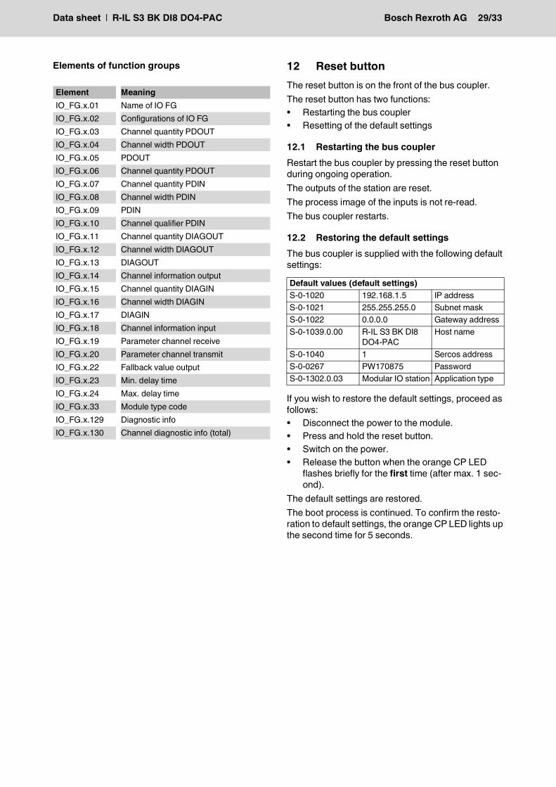
Elements of function groups 12 Reset buttonThe reset button is on the front of the bus coupler.The reset button has two functions:• Restarting the bus coupler• Resetting of the default settings
12.1 Restarting the bus couplerRestart the bus coupler by pressing the reset button during ongoing operation.The outputs of the station are reset.The process image of the inputs is not re-read.The bus coupler restarts.
12.2 Restoring the default settingsThe bus coupler is supplied with the following default settings:
If you wish to restore the default settings, proceed as follows:• Disconnect the power to the module.• Press and hold the reset button.• Switch on the power.• Release the button when the orange CP LED
flashes briefly for the first time (after max. 1 sec-ond).
The default settings are restored.The boot process is continued. To confirm the resto-ration to default settings, the orange CP LED lights up the second time for 5 seconds.
Element MeaningIO_FG.x.01 Name of IO FGIO_FG.x.02 Configurations of IO FGIO_FG.x.03 Channel quantity PDOUTIO_FG.x.04 Channel width PDOUTIO_FG.x.05 PDOUTIO_FG.x.06 Channel quantity PDOUTIO_FG.x.07 Channel quantity PDINIO_FG.x.08 Channel width PDINIO_FG.x.09 PDINIO_FG.x.10 Channel qualifier PDINIO_FG.x.11 Channel quantity DIAGOUTIO_FG.x.12 Channel width DIAGOUTIO_FG.x.13 DIAGOUTIO_FG.x.14 Channel information outputIO_FG.x.15 Channel quantity DIAGINIO_FG.x.16 Channel width DIAGINIO_FG.x.17 DIAGINIO_FG.x.18 Channel information inputIO_FG.x.19 Parameter channel receiveIO_FG.x.20 Parameter channel transmitIO_FG.x.22 Fallback value outputIO_FG.x.23 Min. delay timeIO_FG.x.24 Max. delay timeIO_FG.x.33 Module type codeIO_FG.x.129 Diagnostic infoIO_FG.x.130 Channel diagnostic info (total)
Default values (default settings)S-0-1020 192.168.1.5 IP addressS-0-1021 255.255.255.0 Subnet maskS-0-1022 0.0.0.0 Gateway addressS-0-1039.0.00 R-IL S3 BK DI8
DO4-PACHost name
S-0-1040 1 Sercos addressS-0-0267 PW170875 PasswordS-0-1302.0.03 Modular IO station Application type
Data sheet | R-IL S3 BK DI8 DO4-PAC Bosch Rexroth AG 30/33
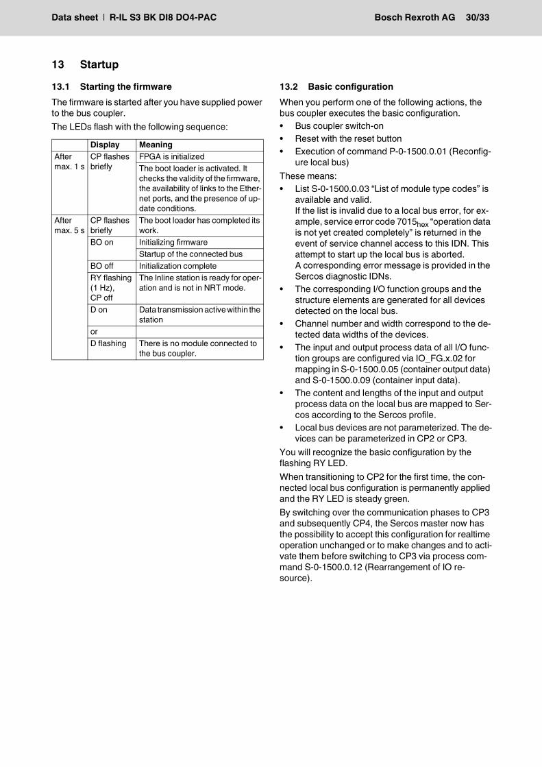
13 Startup
13.1 Starting the firmwareThe firmware is started after you have supplied power to the bus coupler.The LEDs flash with the following sequence:
13.2 Basic configurationWhen you perform one of the following actions, the bus coupler executes the basic configuration.• Bus coupler switch-on• Reset with the reset button• Execution of command P-0-1500.0.01 (Reconfig-
ure local bus)These means:• List S-0-1500.0.03 “List of module type codes” is
available and valid.If the list is invalid due to a local bus error, for ex-ample, service error code 7015hex “operation data is not yet created completely” is returned in the event of service channel access to this IDN. This attempt to start up the local bus is aborted.A corresponding error message is provided in the Sercos diagnostic IDNs.
• The corresponding I/O function groups and the structure elements are generated for all devices detected on the local bus.
• Channel number and width correspond to the de-tected data widths of the devices.
• The input and output process data of all I/O func-tion groups are configured via IO_FG.x.02 for mapping in S-0-1500.0.05 (container output data) and S-0-1500.0.09 (container input data).
• The content and lengths of the input and output process data on the local bus are mapped to Ser-cos according to the Sercos profile.
• Local bus devices are not parameterized. The de-vices can be parameterized in CP2 or CP3.
You will recognize the basic configuration by the flashing RY LED.When transitioning to CP2 for the first time, the con-nected local bus configuration is permanently applied and the RY LED is steady green.By switching over the communication phases to CP3 and subsequently CP4, the Sercos master now has the possibility to accept this configuration for realtime operation unchanged or to make changes and to acti-vate them before switching to CP3 via process com-mand S-0-1500.0.12 (Rearrangement of IO re-source).
Display MeaningAfter max. 1 s
CP flashes briefly
FPGA is initializedThe boot loader is activated. It checks the validity of the firmware, the availability of links to the Ether-net ports, and the presence of up-date conditions.
After max. 5 s
CP flashes briefly
The boot loader has completed its work.
BO on Initializing firmwareStartup of the connected bus
BO off Initialization completeRY flashing (1 Hz), CP off
The Inline station is ready for oper-ation and is not in NRT mode.
D on Data transmission active within the station
orD flashing There is no module connected to
the bus coupler.
Data sheet | R-IL S3 BK DI8 DO4-PAC Bosch Rexroth AG 31/33
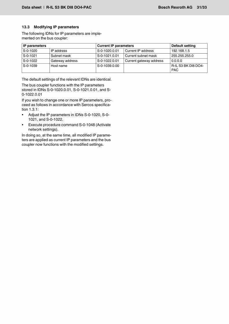
13.3 Modifying IP parametersThe following IDNs for IP parameters are imple-mented on the bus coupler:
The default settings of the relevant IDNs are identical.The bus coupler functions with the IP parameters stored in IDNs S-0-1020.0.01, S-0-1021.0.01, and S-0-1022.0.01If you wish to change one or more IP parameters, pro-ceed as follows in accordance with Sercos specifica-tion 1.3.1:• Adjust the IP parameters in IDNs S-0-1020, S-0-
1021, and S-0-1022.• Execute procedure command S-0-1048 (Activate
network settings).In doing so, at the same time, all modified IP parame-ters are applied as current IP parameters and the bus coupler now functions with the modified settings.
IP parameters Current IP parameters Default settingS-0-1020 IP address S-0-1020.0.01 Current IP address 192.168.1.5S-0-1021 Subnet mask S-0-1021.0.01 Current subnet mask 255.255.255.0S-0-1022 Gateway address S-0-1022.0.01 Current gateway address 0.0.0.0S-0-1039 Host name S-0-1039.0.00 R-IL S3 BK DI8 DO4-
PAC
Data sheet | R-IL S3 BK DI8 DO4-PAC Bosch Rexroth AG 32/33
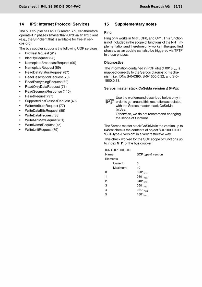
14 IPS: Internet Protocol ServicesThe bus coupler has an IPS server. You can therefore operate it in phases smaller than CP3 via an IPS client (e.g., the SIP client that is available for free at ser-cos.org).The bus coupler supports the following UDP services:• BrowseRequest (91)• IdentifyRequest (93)• NameplateBroadcastRequest (99)• NameplateRequest (89)• ReadDataStatusRequest (87)• ReadDescriptionRequest (73)• ReadEverythingRequest (69)• ReadOnlyDataRequest (71)• ReadSegmentResponse (110)• ResetRequest (97)• SupportedIpsClassesRequest (49)• WriteAttributeRequest (77)• WriteDataBitsRequest (85)• WriteDataRequest (83)• WriteMinMaxRequest (81)• WriteNameRequest (75)• WriteUnitRequest (79)
15 Supplementary notes
PingPing only works in NRT, CP0, and CP1. This function is not included in the scope of functions of the NRT im-plementation and therefore only works in the specified phases, as an update can also be triggered via TFTP in these phases.
DiagnosticsThe information contained in PCP object 0018hex is mapped correctly to the Sercos diagnostic mecha-nism, i.e. IDNs S-0-0390, S-0-1500.0.32, and S-0-1500.0.33.
Sercos master stack CoSeMa version ≤ 04Vxx
The Sercos master stack CoSeMa in the version up to 04Vxx checks the contents of object S-0-1000-0-00 “SCP type & version” in a very restrictive way.This check worked for the SCP scope of functions up to index GH1 of the bus coupler.
Use the workaround described below only in order to get around this restriction associated with the Sercos master stack CoSeMa 04Vxx.Otherwise, we do not recommend changing the scope of functions.
IDN S-0-1000.0.00Name SCP type & versionElements Current: 6 Maximum: 100 0201hex1 0301hex2 0401hex3 0501hex4 0E01hex5 1801hex
Data sheet | R-IL S3 BK DI8 DO4-PAC Bosch Rexroth AG 33/33
Bosch Rexroth AGP.O. Box 13 5797803 Lohr a.Main, GermanyBgm.-Dr.-Nebel-Str. 297816 Lohr a.Main, GermanyPhone +49 9352 18 0Fax +49 9352 18 8400www.boschrexroth.com/electrics
All rights reserved. No part of this document may be reproduced or stored, processed, duplicated, or circulated using electronic systems, in any form or by any means, without the prior written authorization of Bosch Rexroth AG, Electric Drives and Controls. Violations shall give rise to claims for damages.The data specified above only serve to describe the product. They do not in-dicate any specific condition or suitability for a certain application. It must be remembered that our products are subject to natural wear and ageing.
DOK-CONTRL-ILS3BK-DI8DO-KB05-EN-P
7730
_en_
04
Reprint forbidden - subject to modifications
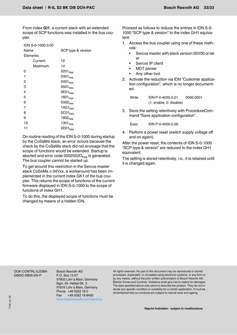
From index GI1, a current stack with an extended scope of SCP functions was installed in the bus cou-pler.
On routine reading of the IDN S-0-1000 during startup by the CoSeMa stack, an error occurs because the check by the CoSeMa stack did not envisage that the scope of functions would be extended. Startup is aborted and error code 0002002Dhex is generated. The bus coupler cannot be started up.To get around this restriction in the Sercos master stack CoSeMa ≤ 04Vxx, a workaround has been im-plemented in the current index GK1 of the bus cou-pler. This returns the scope of functions of the current firmware displayed in IDN S-0-1000 to the scope of functions of index GH1.To do this, the displayed scope of functions must be changed by means of a hidden IDN.
Proceed as follows to reduce the entries in IDN S-0-1000 “SCP type & version” to the index GH1 equiva-lent:1. Access the bus coupler using one of these meth-
ods:• Sercos master with stack version 05V00 or lat-
er• Sercos IP client• MDT parser• Any other tool
2. Activate the reduction via IDN “Customer applica-tion configuration”, which is no longer document-ed.
3. Store the setting retentively with ProcedureCom-mand “Save application configuration”.
4. Perform a power reset (switch supply voltage off and on again).
After the power reset, the contents of IDN S-0-1000 “SCP type & version” are reduced to the index GH1 equivalent.The setting is stored retentively, i.e., it is retained until it is changed again.
IDN S-0-1000.0.00Name SCP type & versionElements Current: 12 Maximum: 140 0201hex1 0301hex2 0401hex3 0501hex4 0E01hex5 1801hex6 0302hex7 1A01hex8 0C01hex9 1802hex10 1301hex11 0D01hex
Write IDN P-0-4000.0.01 0000.0001 (1: enable, 0: disable)
Exec IDN P-0-4000.0.00


