Embed Size (px)
Citation preview
Installation and
Operating Instructions
-Heat Recovery System-
Issue: 01-2012
11_0000_Montageanleitung_Waermerueckgewinnung_GB.indd 111_0000_Montageanleitung_Waermerueckgewinnung_GB.indd 1 13.12.11 14:4613.12.11 14:46
Preface
With this Heat Recovery System, you have purchased a DK quality product.
Heat Recovery Systems by DK are manufactured according to the relevant standards and recommendations.
Each unit is carefully inspected and all components undergo compression trial which al-lows us to supply you with a reliable system.
A long and trouble-free service life requires an expert installation and commissioning of the unit. For your own benefit, the following assembly notes should be closely observed.
The documentation in your hand complies with state-of-the-art technology available at the date of issue. The manufacturer reserves the right to perform technical alterations according to the further development of the product. All water and brine tanks which were delivered by DK are pressure equipments. Those tanks with a max operating pressure of 10 bar are according to pressure equipments directive below the limit values (please see equipments directive 97/23/EG, article 3 (1), to paragraphs 1.1 to 1.3 and paragraph 2). Therefore a CE marking is not necessary.
We wish you a successful application of yourDK – Heat Recovery System
DK-Kälteanlagen GmbH • D-48282 Emsdetten
11_0000_Montageanleitung_Waermerueckgewinnung_GB.indd 211_0000_Montageanleitung_Waermerueckgewinnung_GB.indd 2 13.12.11 14:4613.12.11 14:46
1. Safety notes ................................................................................... 22. Service ........................................................................................... 33. Vessels with double-wall internal heat exchangers3.1 Fitting and installation .................................................................... 43.1.1 Mains water vessels ........................................................................ 53.1.2 Heating water vessels ...................................................................... 53.2 Water connection tank .................................................................... 63.2.1 Mains water vessels ........................................................................ 63.2.2 Heating water vessels ...................................................................... 93.3 Corrosion protection ....................................................................... 113.4 Refrigerant connection .................................................................... 123.4.1 Double-walled tubular heat exchangers .......................................... 144. Vessels with double-wall external heat exchangers4.1 Fitting and installation .................................................................... 154.2 Water connection tank .................................................................... 154.2.2 Water connection heat exchanger ................................................... 154.3 Corrosion protection ....................................................................... 174.4 Refrigerant connection .................................................................... 174.4.1 Refrigerant connection for double-walled tubular heat exchangers 175. Electric connection ...................................................................... 186. Commissioning of unit ................................................................ 196.1 Installation of the temperature control for the 3 way valve .......... 216.2 Setting the temperature control ..................................................... 217. Closing down of unit ................................................................... 228. Re-starting ................................................................................... 229. Maintenance ................................................................................ 229.1 Maintenance of water relief valve ................................................... 239.2 Maintenance of heat exchanger....................................................... 239.3 Installation of physical water conditioner ....................................... 2410. Trouble-shooting Correx®-external current anode ............... 2510.1 Trouble-shooting pumps ................................................................. 2511. Spare parts list .............................................................................. 2612. Wiring diagram ............................................................................ 2813. Wiring diagram of legionella-kill-unit ....................................... 29
Table of Contents
11_0000_Montageanleitung_Waermerueckgewinnung_GB.indd 311_0000_Montageanleitung_Waermerueckgewinnung_GB.indd 3 13.12.11 14:4613.12.11 14:46
The electrical installation as well as the assembly and starting of the refrigeration system may only be performed by trained licensed experts. Such installation staff must observe the generally applicable regulations for the prevention of accidents by VBGA (German professional association) for “Electrical Plants and Equipment” as well as all applicable VDE regulations. Repair work which exceeds the maintenance work stipulated in this technical documentation must only be carried out by qualified experts. For this, please refer to “your” refrigeration expert.
The electrical installation must be carried out according to the connection diagram. Maintenance work on the electrical unit is only permissible if disconnection of plants is
secured. DK-Kälteanlagen GmbH can not be held liable for any damage caused by inappropriate
handling or unauthorized intervention, inflicted in particular on the electronic and electrical as well as refrigerating functional assemblies. The commissioning of the heat recovery system may exclusively be carried out by such
persons entitled to do so and who are familiar with these installation and operating instructions with regard to the proper use of the same. Knowledge of the relevant regulations for the prevention of accidents as well as other generally acknowledged instructions for technical safety is prerequisite. When cleaning the plant please observe that water does not come into contact with any
electrical functional assemblies which do not at least comply with a protective system of IP 55.
When using cleaning agents and disinfectants, please observe the manufacturers’ safety
instructions carefully.
1. Safety notesPlease observe the following for your personal safety as well as for the maintenance of your warranty:
2
11_0000_Montageanleitung_Waermerueckgewinnung_GB.indd 411_0000_Montageanleitung_Waermerueckgewinnung_GB.indd 4 13.12.11 14:4613.12.11 14:46
The texts used in this documentation graphically emphasise instructions and notes subject to particular caution.
In your own interest, please observe that any required repair work within the warranty period may exclusively be performed by a servicing facility authorized by DK-Kältenanlagen GmbH. This ensures your warranty rights. Repair and maintenance work on electrical and refrigeration equipment must only be carried out by licensed refrigeration companies. For this, please refer to "your"refrigeration specialist.
... provides useful information concerning regulatoryapplication or maintenance of the product’s service value.
... points out that non-observance may lead to personal injury or damage of the technical equipment.
2. Service
3
11_0000_Montageanleitung_Waermerueckgewinnung_GB.indd 511_0000_Montageanleitung_Waermerueckgewinnung_GB.indd 5 13.12.11 14:4613.12.11 14:46
3.1 Fitting and installation
The installation site should be protected against frost and be equipped with a floor drain.
The DK-Heat Recovery System is a special boiler enamel vessel fitted with a cathodicprotection against corrosion. The vessel’s strong design ensures that during normal handling the internal thermo glazing is not damaged.
It must be observed that the equipment is not exposed to hard concussions(e.g. by placing it hard on one foot during unloading)!
Before starting with the connection of the water-carrying or refrigerant-carrying connections, dismantle insulation.
The insulation comprises 2 PU shells with glass fibre reinforced plastic coating.
The two shells are fixed with quick acting closures, 2 for tanks with a capacity up to 750 l, 3 for tanks with a capacity up to 1000 l.
The quick acting closures can be opened with an 8 mm Allan key.
Before removing the front insulation, withdraw the thermometer from the immersion shell.
As an alternative, the DK Heat Recovery System is available with flexible foam insulation which is closed at the back of the tank with a strap. If the tanks are bigger the insulation can be delivered in several pieces.
3. Vessels with internalheat exchangers
4
11_0000_Montageanleitung_Waermerueckgewinnung_GB.indd 611_0000_Montageanleitung_Waermerueckgewinnung_GB.indd 6 13.12.11 14:4613.12.11 14:46

The DK-Heat Recovery System is a special boiler enamel vessel fitted with a cathodic protection against corrosion. The vessel’s strong design ensures that during normal handling the internal thermo glazing is not damaged.
The DK-Heat recovery System is raw black tank for heating purposes in a closed system. This tank DOES NOT HAVE a cathodic protection against corrosion.If the heating system is fitted with pipes and components which are not diffused oxygen-tight the tank has to have an anti-corrosion coating or the water has to be added with suitable corrosion protection inhibitors.
3.1.1 Mains water tank
3.1.2 Hot water tank (heating)
No welding work may be performed to enamelled tanks!
5
11_0000_Montageanleitung_Waermerueckgewinnung_GB.indd 711_0000_Montageanleitung_Waermerueckgewinnung_GB.indd 7 13.12.11 14:4613.12.11 14:46
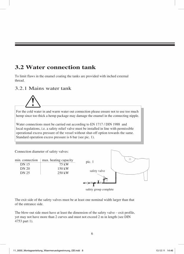
Connection diameter of safety valves:
min. connection max. heating capacity DN 15 75 kW DN 20 150 kW DN 25 250 kW
To limit flaws in the enamel coating the tanks are provided with inched external thread.
3.2 Water connection tank
safety valve
safety group complete
The exit side of the safety valves must be at least one nominal width larger than that of the entrance side.
The blow-out side must have at least the dimension of the safety valve – exit profile, yet may not have more than 2 curves and must not exceed 2 m in length (see DIN 4753 part 1).
pic. 1
6
For the cold water in and warm water out connection please ensure not to use too much hemp since too thick a hemp package may damage the enamel in the connecting nipple.
Water connections must be carried out according to EN 1717 / DIN 1988 and local regulations, i.e. a safety relief valve must be installed in line with permissible operational excess pressure of the vessel without shut-off option towards the same. Standard operation excess pressure is 6 bar (see pic. 1).
3.2.1 Mains water tank
11_0000_Montageanleitung_Waermerueckgewinnung_GB.indd 811_0000_Montageanleitung_Waermerueckgewinnung_GB.indd 8 13.12.11 14:4613.12.11 14:46
If the admission pressure is higher than the tank’s permissible operational excess pressure thecold water pipe must be fitted with a pressure reducing valve (DK offers the water safetyarmature in compliance with such demands. This armature is fitted to the cold water inlet.)
The heat exchangers of the DK Heat Recovery System are fitted with a brass compression ringconnection in the lower part of the tank and have been tested as to closeness at factory.
7
• The circulation connection to the cold water inlet interrupts the water layer principle.• For certain vessel types, the cold water and warm water connection are located to the bottom of the tank.• The cold water connection is marked in blue, the warm water connection in red.
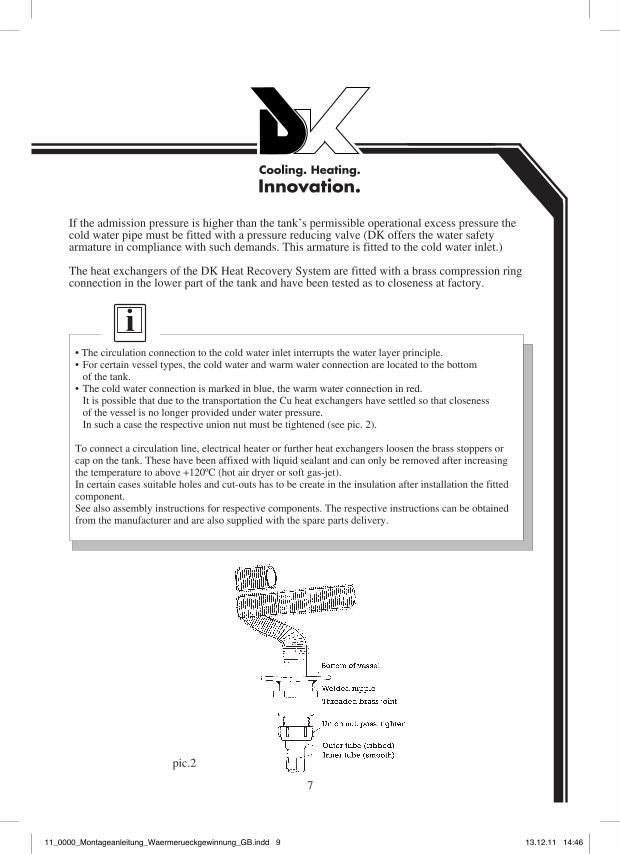
It is possible that due to the transportation the Cu heat exchangers have settled so that closenessof the vessel is no longer provided under water pressure.In such a case the respective union nut must be tightened (see pic. 2).
To connect a circulation line, electrical heater or further heat exchangers loosen the brass stoppers or cap on the tank. These have been affixed with liquid sealant and can only be removed after increasing the temperature to above +120ºC (hot air dryer or soft gas-jet).In certain cases suitable holes and cut-outs has to be create in the insulation after installation the fitted component.See also assembly instructions for respective components. The respective instructions can be obtained from the manufacturer and are also supplied with the spare parts delivery.
pic.2
11_0000_Montageanleitung_Waermerueckgewinnung_GB.indd 911_0000_Montageanleitung_Waermerueckgewinnung_GB.indd 9 13.12.11 14:4613.12.11 14:46
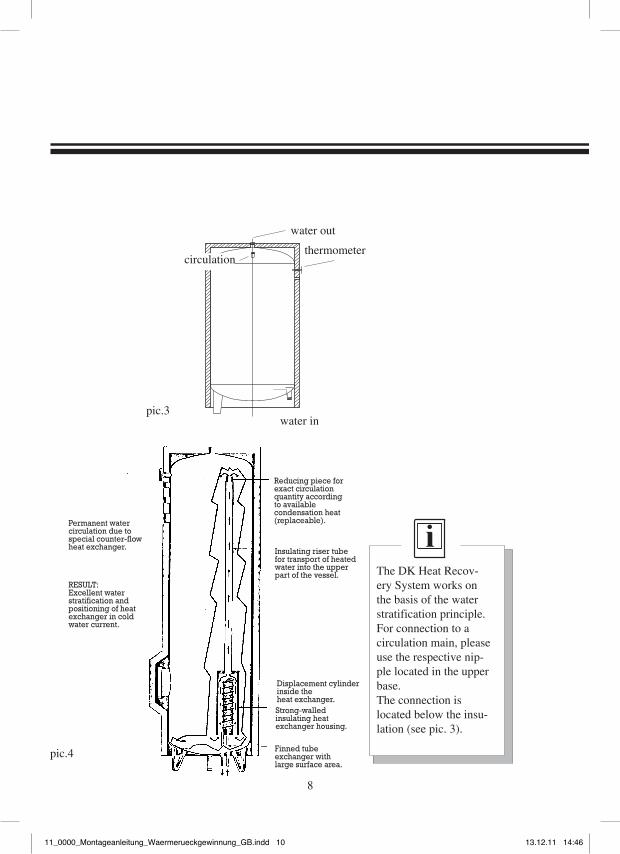
water out
circulationthermometer
water in
8
pic.4
The DK Heat Recov-ery System works on the basis of the water stratification principle. For connection to a circulation main, please use the respective nip-ple located in the upper base. The connection is located below the insu-lation (see pic. 3).
pic.3
Reducing piece for exact circulation quantity according to availablecondensation heat (replaceable).Permanent water
circulation due to special counter-flow heat exchanger. Insulating riser tube
for transport of heated water into the upper part of the vessel.
RESULT:Excellent water stratification and positioning of heat exchanger in cold water current.
Displacement cylinder inside the heat exchanger.Strong-walled insulating heat exchanger housing.
Finned tube exchanger with large surface area.
11_0000_Montageanleitung_Waermerueckgewinnung_GB.indd 1011_0000_Montageanleitung_Waermerueckgewinnung_GB.indd 10 13.12.11 14:4613.12.11 14:46
3.2.2 Heating water vessels
For the cold and hot water connections please observe not to use too much hemp since too thick a hemp package may damage the enamel in the connecting nipple.Water connections must be carried out according to valid rules and local regulations i.e. a safety relief valve must be installed in line with permissible operational excess pressure of the vessel without shut-off option towards the same. Standard operation excess pressure is 3.0 bar.
The exit side of the safety valves must be at least one nominal width larger than that of the entrance side.
The blow-out side must have at least the dimension of the safety valve – exit profile, however may not have more than 2 curves and may not be longer than 2 m (see DIN 4753 part 1).
The heat exchangers of the DK Heat Recovery System are fitted with a brass compression ring connection in the lower part of the tank and have been tested as to closeness at factory.
9
11_0000_Montageanleitung_Waermerueckgewinnung_GB.indd 1111_0000_Montageanleitung_Waermerueckgewinnung_GB.indd 11 13.12.11 14:4613.12.11 14:46
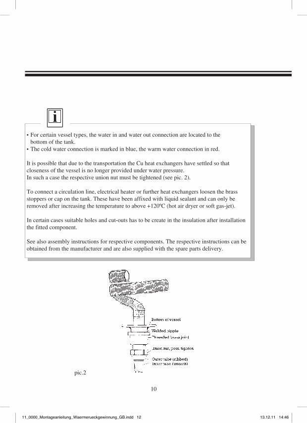
pic.2
• For certain vessel types, the water in and water out connection are located to thebottom of the tank.
• The cold water connection is marked in blue, the warm water connection in red.
It is possible that due to the transportation the Cu heat exchangers have settled so that closeness of the vessel is no longer provided under water pressure.In such a case the respective union nut must be tightened (see pic. 2).
To connect a circulation line, electrical heater or further heat exchangers loosen the brass stoppers or cap on the tank. These have been affixed with liquid sealant and can only be removed after increasing the temperature to above +120ºC (hot air dryer or soft gas-jet).
In certain cases suitable holes and cut-outs has to be create in the insulation after installation the fitted component.
See also assembly instructions for respective components. The respective instructions can be obtained from the manufacturer and are also supplied with the spare parts delivery.
10
11_0000_Montageanleitung_Waermerueckgewinnung_GB.indd 1211_0000_Montageanleitung_Waermerueckgewinnung_GB.indd 12 13.12.11 14:4613.12.11 14:46
The DK Heat Recovery System is equipped with anodes for cathodic protection against corro-sion (Mg anode or Correx current anode).
CORREX® UP - long-term solution for corrosion problems
Electronic + long duration anode, the maintenance-free corrosion protection for enamel storage heat recovery exchanger as per DIN 4753 part 3 and part 6. CORREX® UP – the cur-rent anode for multi-purpose application in enamel storage tanks of all sizes.
The supplied double-wire line between the screwed CORREX® anode and the separately supplied connector potentiostat must by no means be extended.
The possible reversal of polarity may lead to an accelerated corrosion.
In any case, a 230 V power outlet should be in the immediate proximity of the tank.
Magnesium reactive anodes must be serviced every other year (see label on tank).
CORREX® current anodes are maintenance-free and must be hooked to a 230 V outlet.
3.3 Corrosion Protection
11
11_0000_Montageanleitung_Waermerueckgewinnung_GB.indd 1311_0000_Montageanleitung_Waermerueckgewinnung_GB.indd 13 13.12.11 14:4613.12.11 14:46
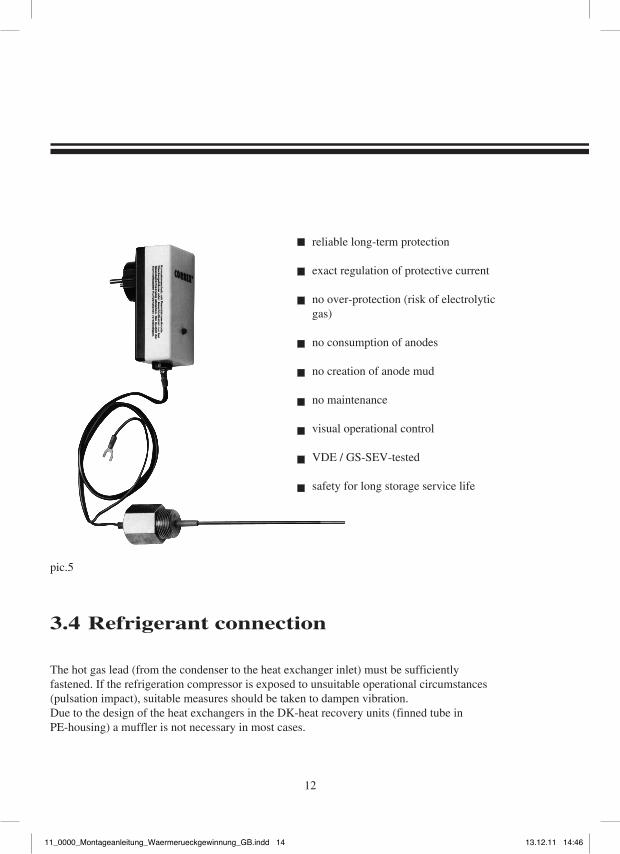
reliable long-term protection
exact regulation of protective current
no over-protection (risk of electrolytic gas)
no consumption of anodes
no creation of anode mud
no maintenance
visual operational control
VDE / GS-SEV-tested
safety for long storage service life
3.4 Refrigerant connection
The hot gas lead (from the condenser to the heat exchanger inlet) must be sufficiently fastened. If the refrigeration compressor is exposed to unsuitable operational circumstances (pulsation impact), suitable measures should be taken to dampen vibration.Due to the design of the heat exchangers in the DK-heat recovery units (finned tube in PE-housing) a muffler is not necessary in most cases.
12
pic.5
11_0000_Montageanleitung_Waermerueckgewinnung_GB.indd 1411_0000_Montageanleitung_Waermerueckgewinnung_GB.indd 14 13.12.11 14:4613.12.11 14:46
13
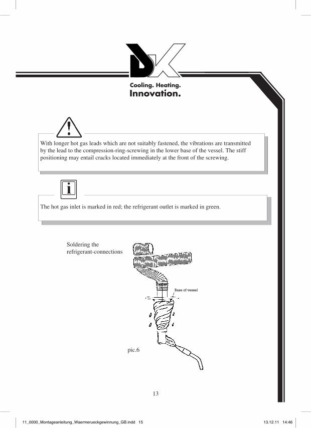
With longer hot gas leads which are not suitably fastened, the vibrations are transmittedby the lead to the compression-ring-screwing in the lower base of the vessel. The stiff positioning may entail cracks located immediately at the front of the screwing.
The hot gas inlet is marked in red; the refrigerant outlet is marked in green.
pic.6
Base of vessel
Soldering therefrigerant-connections
11_0000_Montageanleitung_Waermerueckgewinnung_GB.indd 1511_0000_Montageanleitung_Waermerueckgewinnung_GB.indd 15 13.12.11 14:4613.12.11 14:46
14
When soldering the refrigeration lead to the heat exchanger inlet or outlet, it must be observed that the brass compression-ring-screwing connection which fits the heat exchanger to the vessel is not overheated. This may damage the sealing (pic. 6).
The conventional dimension used in the refrigeration industry does not apply to the refrigerant connection, but serves only as leakage indication of the double walls.If any liquid run out the outlet, the heat exchanger is defective. In such a case an expert must be instantly called to the site and must carry out a pressure test according to DIN 1988 part 8. The safety valve must under no circumstances be closed.
To connect a circulation line, electrical heating, or further heat exchangers loosen the brass stoppers or covers on the tank. These have been affixed with liquid sealant and can only be removed after increasing the temperature to above +120°C (hot air dryer or soft gas-flame). See also assembly instructions for respective components. The respective instructions can be obtained from the manufacturer and are also supplied with the spare parts delivery.
3.4.1 double-walled Heat Exchanger
For heating drinking water, the DK Heat Recovery System as a rule uses double-walled tubular heat exchangers. As a leak indicator, capillary tubes with safety valve (Schrader valve in twin-nipple 7/16") are soldered at the inlet and outlet of the heat exchangers into the spacing and outlet of the heat exchangers.
11_0000_Montageanleitung_Waermerueckgewinnung_GB.indd 1611_0000_Montageanleitung_Waermerueckgewinnung_GB.indd 16 13.12.11 14:4613.12.11 14:46
4. Vessels with externaldouble-wall heat exchangers
4.1 Fitting and installation - see notes item 3.1 -
4.2 Water connection tank - see notes under item 3.2 -
15
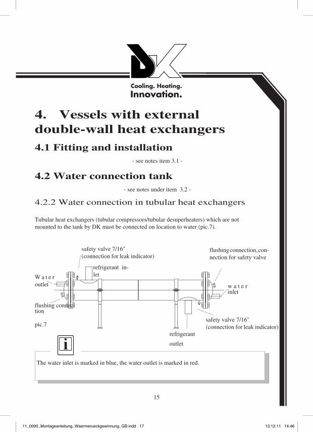
4.2.2 Water connection in tubular heat exchangers
Tubular heat exchangers (tubular compressors/tubular desuperheaters) which are notmounted to the tank by DK must be connected on location to water (pic.7).
The water inlet is marked in blue, the water outlet is marked in red.
W a t e r outlet w a t e r
inlet
flushing connec-tion
refrigerant in-let
refrigerant
outlet
flushing connection, con-nection for safety valve
safety valve 7/16" (connection for leak indicator)
pic.7safety valve 7/16" (connection for leak indicator)
11_0000_Montageanleitung_Waermerueckgewinnung_GB.indd 1711_0000_Montageanleitung_Waermerueckgewinnung_GB.indd 17 13.12.11 14:4613.12.11 14:46
16
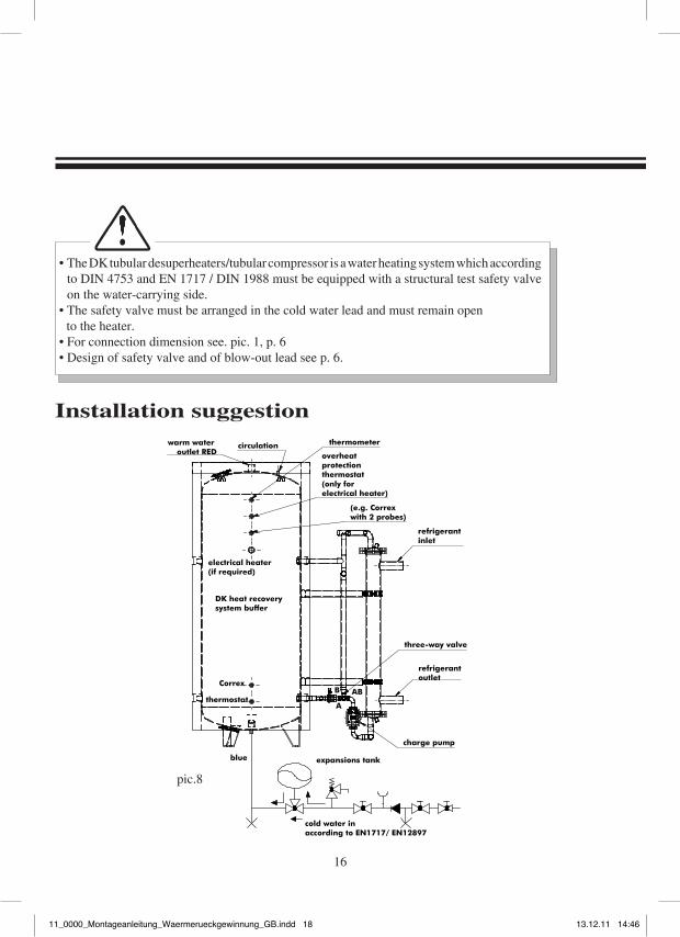
• The DK tubular desuperheaters/tubular compressor is a water heating system which according to DIN 4753 and EN 1717 / DIN 1988 must be equipped with a structural test safety valve on the water-carrying side.
• The safety valve must be arranged in the cold water lead and must remain open to the heater. • For connection dimension see. pic. 1, p. 6• Design of safety valve and of blow-out lead see p. 6.
Installation suggestion
pic.8
11_0000_Montageanleitung_Waermerueckgewinnung_GB.indd 1811_0000_Montageanleitung_Waermerueckgewinnung_GB.indd 18 13.12.11 14:4613.12.11 14:46
4.3 Corrosion protection - see notes under item 3.3. page 11 -
4.4 Refrigerant connection
The hot gas lead (from the condenser to the heat exchanger inlet) must be sufficiently fastened. If the refrigeration compressor is exposed to unsuitable operational circumstances (pulsation impact), suitable measures should be taken to dampen vibration.
The water-carrying tubes between vessel and heat exchanger are fitted with a temperature dependent controlled water valve in certain units. This valve is not pre-set by the factory. Any alterations must be carried out in line with the respective notes of the manufacturers of the valves.
The hot gas inlet is marked in red; the refrigerant outlet is marked in green.(see pic. 7, page 15)
17
4.4.1 double-walled shell and tube Heat Exchanger
For heating drinking water, the DK Heat Recovery System as a rule uses double-walled tubular heat exchangers. As a leak indicator, capillary tubes with safety valve (Schrader valve in twin-nipple 7/16") are soldered at the inlet and outlet of the heat exchangers into the spacing and outlet of the heat exchangers.
11_0000_Montageanleitung_Waermerueckgewinnung_GB.indd 1911_0000_Montageanleitung_Waermerueckgewinnung_GB.indd 19 13.12.11 14:4613.12.11 14:46
The conventional dimension used in the refrigeration industry does not apply to the refrigerant connection, but serves only as leakage indication of the double walls.If any liquid run out the outlet, the heat exchanger is defective. In such a case an expert must be instantly called to the site and must carry out a pressure test according to DIN 1988 part 8. The safety valve must under no circumstances be closed.To improve the transition of the heat, the inner and the outer tubes are expanded on one another. The safety chamber is not filled with a carrying medium so that it is possible to start refrigeration before connection with water.
Risk of electrocution!Before working on the pump, be sure to disconnect all phases of the supply voltage. Due to residual hazardous high touch voltage (condensers), please wait five minutes after disconnection before starting work on the module (perform only with AC Voltage1~-configuration). Check if all connections (even zero-potential contacts) are neutral.
The charge pump integrated into the water circulation must be carried out according to local EVU regulations and VDE 0100. The charge pump should be controlled via the condenser and via the thermostats located in the lower part of the tank. The instructions in the installation manual of the pump manufacturer must always be observed. See therefore the installation manual of the pump manufacturer.
5. Electric connection
18
11_0000_Montageanleitung_Waermerueckgewinnung_GB.indd 2011_0000_Montageanleitung_Waermerueckgewinnung_GB.indd 20 13.12.11 14:4613.12.11 14:46
6. Commissionning of unit
• Fill tank with water while switched off, while emptying at the highest bleeding point.• Check for leaks, possibly tighten screwed connections• Close the bleeding point once the air has been completely removed from the tank.• Before starting and at regular intervals, check the functions of the CORREX® external current anode – for this see also paragraph 3.3 page 11.• For rotary current plants, please observe the correct rotating sense. For this, observe indicating arrows on the devices.
The DK Heat Recovery System may only be started after having been completely filled with water and after thorough ventilation.
19
6.1 Initial Operation of Pump
When operating 3x400V three-phase current pumps, please observe the pump's sense of rotation.How to check the sense of rotation:The sense of rotation, depending on the terminal box, is indicated by a lamp either on or inside the terminal box. The lamp lights up in green if the sense of rotation is correct. If the sense of rotation is incorrect, the lamp is dimly lit only. To check the sense of rotation, briefly switch on the pump. If the sense of rotation is incorrect, proceed as follows:
• Disconnect all live parts.• Switch 2 phases in the terminal box.• Start the pump again.
The pump's rotor compartment is automatically vented shortly after starting up. A brief dry running of the pump causes not damage.TOP-S/-SD/-Z pumps and TOP-D venting screws can be vented as follows if need be:
11_0000_Montageanleitung_Waermerueckgewinnung_GB.indd 2111_0000_Montageanleitung_Waermerueckgewinnung_GB.indd 21 13.12.11 14:4613.12.11 14:46
Risk of scalding!Depending on the temperature of the pumping medium as well as the system pressure, it is possible that, when the venting screw is fully opened, hot pumping medium of a liquid or vaporous form exits or shoots out under high pressure.
Danger of damaging the pump!The pump, when the venting screw is opened and depending on the degree of operating pressure, may lock. The required intake pressure must be available on the pump's suction side!
Danger of burns from contact the pump!Depending on the operation condition of the pump or of the unit (temperature of the con-veyed medium) the whole pump could be very hot.
20
• Switch off the pump.• Close the shut-off device on the pressure-carrying side.• Protect electrical parts against leaking water.• Carefully open venting screw using appropriate tools.• Carefully reverse the motor shaft repeatedly with screwdriver.• Tighten venting screw again after 15 to 30 seconds.• Switch on the pump.• Open shut-off device again.
If other pumps are in use, proceed in the same manner.
11_0000_Montageanleitung_Waermerueckgewinnung_GB.indd 2211_0000_Montageanleitung_Waermerueckgewinnung_GB.indd 22 13.12.11 14:4613.12.11 14:46
6.2 Assembly of Temperature Controlfor 3-way Valve
6.3 How to Set the Temperature Control
If the temperature control is included in the delivery as a loose part, the followingsteps must be carried out:• Set the hand wheel to digit "7".• Screw the temperature control onto the valve.• Insert the sensor into the thermowell and secure with the screw.• Be sure not to bend or press flat the capillary tube.
The temperature control's setting range lies between 40°C and 70°C. Set the control to the desired temperature. Higher numbers correspond to higher temperatures, but also to a reduced amount of water. The control limits the water temperature downwards, meaning that the control always tries to reach the set temperature. Should the hot gas temperatures fall, for example in winter, it is possible that, if the temperature control is set too high, the water is pumped into the bypass and that no water is pushed into the vessel. Temperature increments equal 5°C fromdigit to digit.
Ziffer Temperatur1 – 40°C2 – 45°C3 – 50°C4 – 55°C5 – 60°C6 – 65°C7 – 70°C
21
The sound level of the pump is below the limits prescribed by theEG directive 2006/42/EG for machines.
11_0000_Montageanleitung_Waermerueckgewinnung_GB.indd 2311_0000_Montageanleitung_Waermerueckgewinnung_GB.indd 23 13.12.11 14:4613.12.11 14:46
DK Heat Recovery System (drinking water storage) with built-in CORREX® current anode may only be disconnected after the water has been emptied from the tank.
7. Closing down
22
9. MaintenanceDK’s enamelled Heat Recovery Systems which are equipped with a CORREX® external current anode do not require maintenance.Please observe the green control lamp which should be lit. If the red light flashes, please consult paragraph 10, troubleshooting.For fitted magnesium reactive anodes, maintenance should be performed on the Heat Recovery System every other year. If the anode is worn by more than 50%,exchange.
8. Re-startingWhen re-starting after having interrupted operation, it is usually sufficient to completely open the individual points of outlets for a short time (approx. 5 minutes) in order to drain residual water in the pipes.Re-start plant according to instructions in paragraph 6
Within the framework of this maintenance work we also recommend removing deposits and anode mud from the tank. To do so, empty the tank.
11_0000_Montageanleitung_Waermerueckgewinnung_GB.indd 2411_0000_Montageanleitung_Waermerueckgewinnung_GB.indd 24 13.12.11 14:4613.12.11 14:46
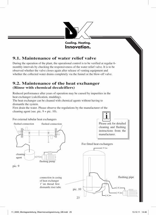
9.1. Maintenance of water relief valveDuring the operation of the plant, the operational control is to be verified at regular 6-monthly intervals by checking the responsiveness of the water relief valve. It is to be observed whether the valve closes again after release of venting equipment and whether the collected water drains completely via the funnel or the blow-off valve.
9.2. Maintenance of the heat exchanger(Rinse with chemical decalcifiers)
Reduced performance after years of operation may be caused by impurities in the heat exchanger (calcification, mudding). The heat exchanger can be cleaned with chemical agents without having to dismantle the system. First drain the water. Please observe the regulations by the manufacturer of the cleaning agent (see. pic. 9 + pic. 10).
flushed connectionflushed connection
flushing pump
For external tubular heat exchangers
flushing pipeconnection in casing of heat exchanger 1" int. thread first dismantle riser tube
For fitted heat exchangers
Please ask for detailed cleaning and flushing instructions from the manufacturer.
pic. 10
pic. 9
cleaning agent
23
11_0000_Montageanleitung_Waermerueckgewinnung_GB.indd 2511_0000_Montageanleitung_Waermerueckgewinnung_GB.indd 25 13.12.11 14:4613.12.11 14:46
24
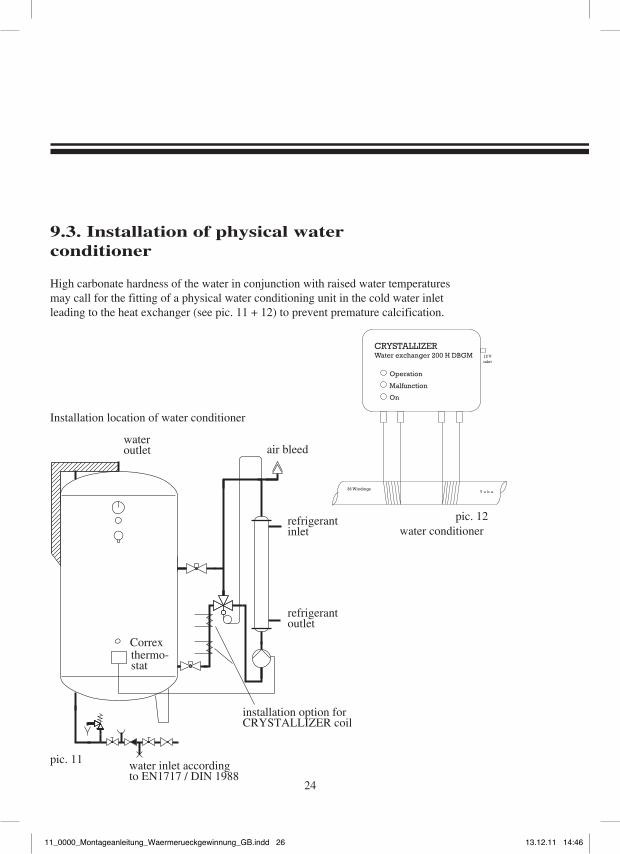
9.3. Installation of physical water conditioner
High carbonate hardness of the water in conjunction with raised water temperatures may call for the fitting of a physical water conditioning unit in the cold water inlet leading to the heat exchanger (see pic. 11 + 12) to prevent premature calcification.
water outlet air bleed
refrigerant outlet
installation option for CRYSTALLIZER coil
water inlet according to EN1717 / DIN 1988
Correx
refrigerant inlet
pic. 12
pic. 11
water conditioner
Installation location of water conditioner
thermo-stat
Water exchanger 200 H DBGMCRYSTALLIZER
Operation
Malfunction
On
12 Vinlet
36 WindingsT u b e
11_0000_Montageanleitung_Waermerueckgewinnung_GB.indd 2611_0000_Montageanleitung_Waermerueckgewinnung_GB.indd 26 13.12.11 14:4613.12.11 14:46
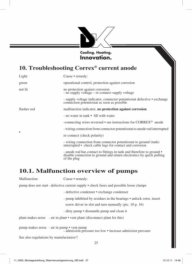
Light: Cause • remedy:
green operational control, protection against corrosion
not lit no protection against corrosion - no supply voltage – re-connect supply voltage
- supply voltage indicator, connector potentiostat defective • exchange connection potentiostat as soon as possible
flashes red malfunction indicator, no protection against corrosion
- no water in tank • fill with water
-connecting wires reversed • see instructions for CORREX® anode
- wiring connection from connector potentiostat to anode rod interrupted • re-connect (check polarity)
- wiring connection from connector potentiostat to ground (tank) interrupted • check cable lugs for contact and corrosion
- anode rod has contact to fittings in tank and therefore to ground • disable connection to ground and return electronics by quick pulling of the plug
Malfunction: Cause • remedy:
pump does not start - defective current supply • check fuses and possible loose clamps - defective condenser • exchange condenser - pump inhibited by residues in the bearings • unlock rotor, insert
screw driver in slot and turn manually (pic. 10 p. 16) - dirty pump • dismantle pump and clean it
plant makes noise - air in plant • vent plant (disconnect plant for this)
pump makes noise - air in pump • vent pump - admission pressure too low • increase admission pressure
See also regulations by manufacturers!!
10.1. Malfunction overview of pumps
10. Troubleshooting Correx® current anode
25
11_0000_Montageanleitung_Waermerueckgewinnung_GB.indd 2711_0000_Montageanleitung_Waermerueckgewinnung_GB.indd 27 13.12.11 14:4613.12.11 14:46
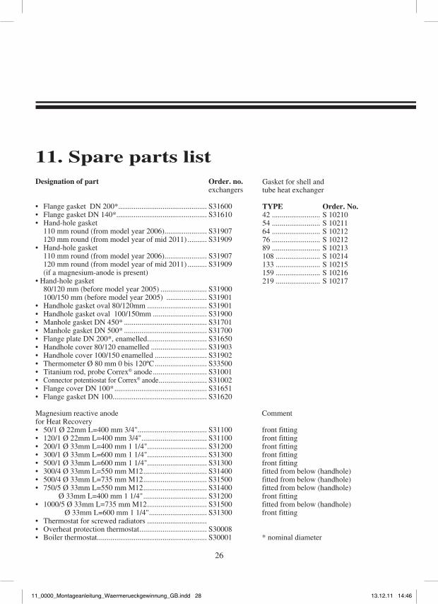
11. Spare parts listDesignation of part Order. no. exchangers
• Flange gasket DN 200*.............................................. S31600• Flange gasket DN 140*............................................... S31610• Hand-hole gasket 110 mm round (from model year 2006) ...................... S31907 120 mm round (from model year of mid 2011) .......... S31909• Hand-hole gasket 110 mm round (from model year 2006) ...................... S31907 120 mm round (from model year of mid 2011) .......... S31909 (if a magnesium-anode is present)• Hand-hole gasket 80/120 mm (before model year 2005) ........................ S31900 100/150 mm (before model year 2005) ..................... S31901• Handhole gasket oval 80/120mm ............................... S31901• Handhole gasket oval 100/150mm ............................ S31900• Manhole gasket DN 450* ........................................... S31701• Manhole gasket DN 500* ........................................... S31700• Flange plate DN 200*, enamelled ............................... S31650• Handhole cover 80/120 enamelled ............................. S31903• Handhole cover 100/150 enamelled ........................... S31902• Thermometer Ø 80 mm 0 bis 120ºC ........................... S33500• Titanium rod, probe Correx® anode ............................ S31001• Connector potentiostat for Correx® anode ......................... S31002• Flange cover DN 100* ................................................ S31651• Flange gasket DN 100................................................. S31620
Magnesium reactive anode Comment for Heat Recovery• 50/1 Ø 22mm L=400 mm 3/4".................................... S31100 front fitting• 120/1 Ø 22mm L=400 mm 3/4".................................. S31100 front fitting• 200/1 Ø 33mm L=400 mm 1 1/4"............................... S31200 front fitting• 300/1 Ø 33mm L=600 mm 1 1/4"............................... S31300 front fitting • 500/1 Ø 33mm L=600 mm 1 1/4"............................... S31300 front fitting • 300/4 Ø 33mm L=550 mm M12 ................................. S31400 fitted from below (handhole)• 500/4 Ø 33mm L=735 mm M12 ................................. S31500 fitted from below (handhole)• 750/5 Ø 33mm L=550 mm M12 ................................. S31400 fitted from below (handhole) Ø 33mm L=400 mm 1 1/4" ................................. S31200 front fitting• 1000/5 Ø 33mm L=735 mm M12 ............................... S31500 fitted from below (handhole) Ø 33mm L=600 mm 1 1/4" .............................. S31300 front fitting• Thermostat for screwed radiators ...............................• Overheat protection thermostat ................................... S30008• Boiler thermostat ......................................................... S30001 * nominal diameter
26
Gasket for shell and tube heat exchanger
TYPE Order. No.42 ......................... S 1021054 ......................... S 1021164 ......................... S 1021276 ......................... S 1021289 ......................... S 10213108 ....................... S 10214133 ....................... S 10215159 ....................... S 10216219 ....................... S 10217
11_0000_Montageanleitung_Waermerueckgewinnung_GB.indd 2811_0000_Montageanleitung_Waermerueckgewinnung_GB.indd 28 13.12.11 14:4613.12.11 14:46
27
11_0000_Montageanleitung_Waermerueckgewinnung_GB.indd 2911_0000_Montageanleitung_Waermerueckgewinnung_GB.indd 29 13.12.11 14:4613.12.11 14:46
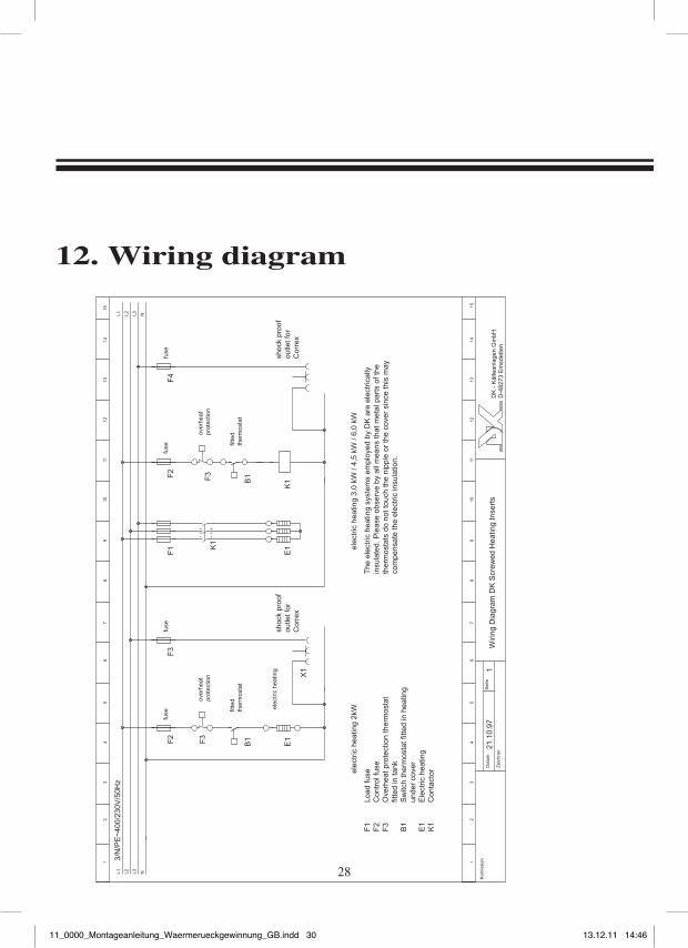
12. Wiring diagram
fuse
over
heat
prot
ectio
n
fitte
dth
erm
osta
t
fuse
over
heat
prot
ectio
n
fitte
dth
erm
osta
t
elec
tric
hea
ting
shoc
k pr
oof
outle
t for
Cor
rex
fuse
shoc
k pr
oof
outle
t for
Cor
rex
fuse
Load
fuse
Con
trol
fuse
Ove
rhea
t pro
tect
ion
ther
mos
tat
fitte
d in
tank
Sw
itch
ther
mos
tat f
itted
in h
eatin
g un
der
cove
rE
lect
ric h
eatin
gC
onta
ctorel
ectr
ic h
eatin
g
Wiri
ng D
iagr
am D
K S
crew
ed H
eatin
g In
sert
s
elec
tric
hea
ting
The
ele
ctric
hea
ting
syst
ems
empl
oyed
by
DK
are
ele
ctric
ally
in
sula
ted.
Ple
ase
obse
rve
by a
ll m
eans
that
met
al p
arts
of t
he
ther
mos
tats
do
not t
ouch
the
nipp
le o
r th
e co
ver
sinc
e th
is m
ay
com
pens
ate
the
elec
tric
insu
latio
n.
28
11_0000_Montageanleitung_Waermerueckgewinnung_GB.indd 3011_0000_Montageanleitung_Waermerueckgewinnung_GB.indd 30 13.12.11 14:4613.12.11 14:46
29
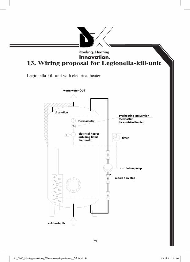
13. Wiring proposal for Legionella-kill-unit
Legionella-kill-unit with electrical heater
11_0000_Montageanleitung_Waermerueckgewinnung_GB.indd 3111_0000_Montageanleitung_Waermerueckgewinnung_GB.indd 31 13.12.11 14:4613.12.11 14:46

11_0000_Montageanleitung_Waermerueckgewinnung_GB.indd 3211_0000_Montageanleitung_Waermerueckgewinnung_GB.indd 32 13.12.11 14:4613.12.11 14:46


