Embed Size (px)
Citation preview
Installation Instructions
Questions? Call 1-800-561-3344 or Visit our Website at: GEAppliances.ca
READ CAREFULLY. KEEP THESE INSTRUCTIONS.
Read these instructions completely and carefully.
• IMPORTANT – Save these instructions for local inspector’s use.
• IMPORTANT – Observe all governing codes and ordinances.
• Note to Installer – Be sure to leave these instructions with the consumer.
BEFORE YOU BEGIN• Note to Consumer – Keep these instructions
for future reference.• Skilllevel – Installation of this appliance requires basic
mechanical and electrical skills.• Proper installation is the responsibility of the installer. • Product failure due to improper installation is not
covered under the warranty.
OvertheRangeMicrowaveOven PVM2188
29-6070(04-16 MCC)
Popcorn
Convenience Cooking
Express Cook
Potato
StartPauseCancel
Off
Beverage
Reheat
SetClock
Turntable
SurfaceLight
Vent
Add30 Sec.
PowerLevel
0
8
5
2
7
4
1
9
6
3
CookTimeDefrost
Weight/Time
TimerOn/Off
Throughout this manual, features and appearance may vary from your model.
2
Outside Back Exhaust .................................. 21-24
Installation Overview ................................ 21
Preparing Rear Wall for Outside Back Exhaust ................................21
Attach Mounting Plate to Wall .......... 21, 22
Preparation of Top Cabinet .......................22
Adapting Blower for Outside Back Exhaust .......................................... 22, 23
Mount the Microwave Oven...............23, 24
BeforeYouUseYourMicrowaveOven...................... 25
CONTENTSGeneral information
Important Safety Instructions ....................................... 3
Electrical Requirements .................................................. 3
Tools You Will Need .......................................................... 4
Hood Exhaust ................................................................. 5,6
Damage–Shipment/Installation .................................. 7
Parts Included ................................................................... 7
MountingSpace ................................................................ 8
Step-by-stepinstallationguide
PlacementofMountingPlate ................................... 9-11
Removing the Mounting Plate ............................. 9
Finding the Wall Studs .......................................... 9
Determining Mounting Plate Location ..............10
Aligning the Mounting Plate .............................. 11
Installation Types ..................................................... 12-23
Recirculating .................................................. 13-16
Attach Mounting Plate to Wall ................ 13
Preparation of Top Cabinet ...................... 13
Adjust the Blower ...................................... 14
Installing the Charcoal Filter .................... 15
Mount the Microwave Oven............... 15, 16
Installing the Charcoal Filter
without Top Access ............................ 16
Outside Top Exhaust ..................................... 17-20
Attach Mounting Plate to Wall .................17
Preparation of Top Cabinet .......................18
Adjust Blower Motor ..................................18
Assemble and Install Adaptor ..................19
Mount the Microwave Oven............... 19, 20
Connecting Ductwork ................................20
A
B
C
Installation Instructions
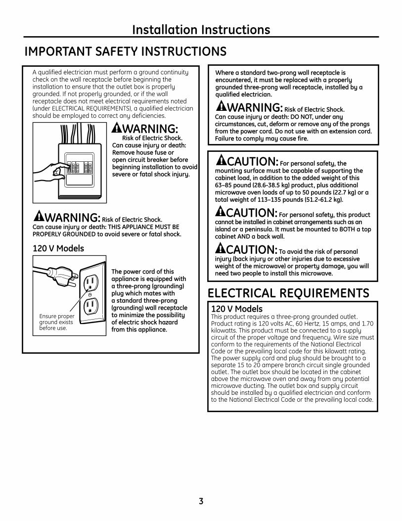
A qualified electrician must perform a ground continuity check on the wall receptacle before beginning the installation to ensure that the outlet box is properly grounded. If not properly grounded, or if the wall receptacle does not meet electrical requirements noted (under ELECTRICAL REQUIREMENTS), a qualified electrician should be employed to correct any deficiencies.
WARNING: RiskofElectricShock.
Can cause injury or death: Removehousefuseor opencircuitbreakerbeforebeginninginstallationtoavoidsevereorfatalshockinjury.
WARNING:RiskofElectricShock. Can cause injury or death: THIS APPLIANCE MUST BE PROPERLY GROUNDED toavoidsevereorfatalshock.
120 V Models
The power cord of this appliance is equipped with athree-prong(grounding) plugwhichmateswith astandardthree-prong (grounding)wallreceptacle to minimize the possibility ofelectricshockhazard from this appliance.
IMPORTANT SAFETY INSTRUCTIONS
3
ELECTRICAL REQUIREMENTS
Installation Instructions
Ensure proper ground exists before use.
CAUTION: For personal safety, the mountingsurfacemustbecapableofsupportingthecabinetload,inadditiontotheaddedweightofthis63–85pound(28.6-38.5kg)product,plusadditionalmicrowaveovenloadsofupto50pounds(22.7kg)oratotalweightof113–135pounds(51.2-61.2kg).
CAUTION: For personal safety, this product cannotbeinstalledincabinetarrangementssuchasanisland or a peninsula. It must be mounted to BOTH a top cabinetANDabackwall.
CAUTION:Toavoidtheriskofpersonalinjury(backinjuryorotherinjuriesduetoexcessiveweightofthemicrowave)orpropertydamage,youwillneedtwopeopletoinstallthismicrowave.
Whereastandardtwo-prongwallreceptacleisencountered, it must be replaced with a properly groundedthree-prongwallreceptacle,installedbyaqualified electrician.
WARNING:RiskofElectricShock. Can cause injury or death: DO NOT, under any circumstances,cut,deformorremoveanyoftheprongsfrom the power cord. Do not use with an extension cord. Failure to comply may cause fire.
120 V ModelsThis product requires a three-prong grounded outlet. Product rating is 120 volts AC, 60 Hertz, 15 amps, and 1.70 kilowatts. This product must be connected to a supply circuit of the proper voltage and frequency. Wire size must conform to the requirements of the National Electrical Code or the prevailing local code for this kilowatt rating. The power supply cord and plug should be brought to a separate 15 to 20 ampere branch circuit single grounded outlet. The outlet box should be located in the cabinet above the microwave oven and away from any potential microwave ducting. The outlet box and supply circuit should be installed by a qualified electrician and conform to the National Electrical Code or the prevailing local code.
4
Installation Instructions
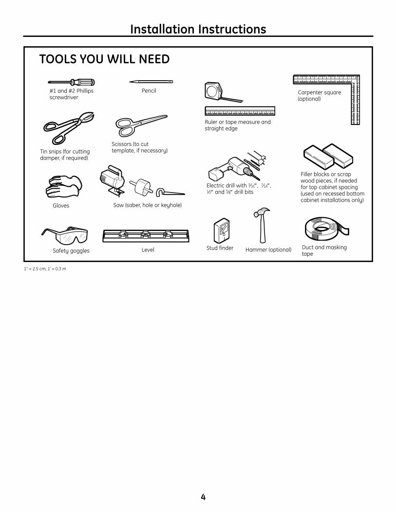
TOOLS YOU WILL NEED
#1 and #2 Phillips screwdriver
Pencil
Ruler or tape measure and straight edge
Carpenter square (optional)
Tin snips (for cutting damper, if required)
Electric drill with 3⁄16″, 7⁄16″, 1⁄2″ and 5⁄8″ drill bits
Hammer (optional)Stud finder
Filler blocks or scrap wood pieces, if needed for top cabinet spacing (used on recessed bottom cabinet installations only)
Gloves Saw (saber, hole or keyhole)
Level Duct and masking tape
Scissors (to cut template, if necessary)
Safety goggles
1” = 2.5 cm; 1’ = 0.3 m
5
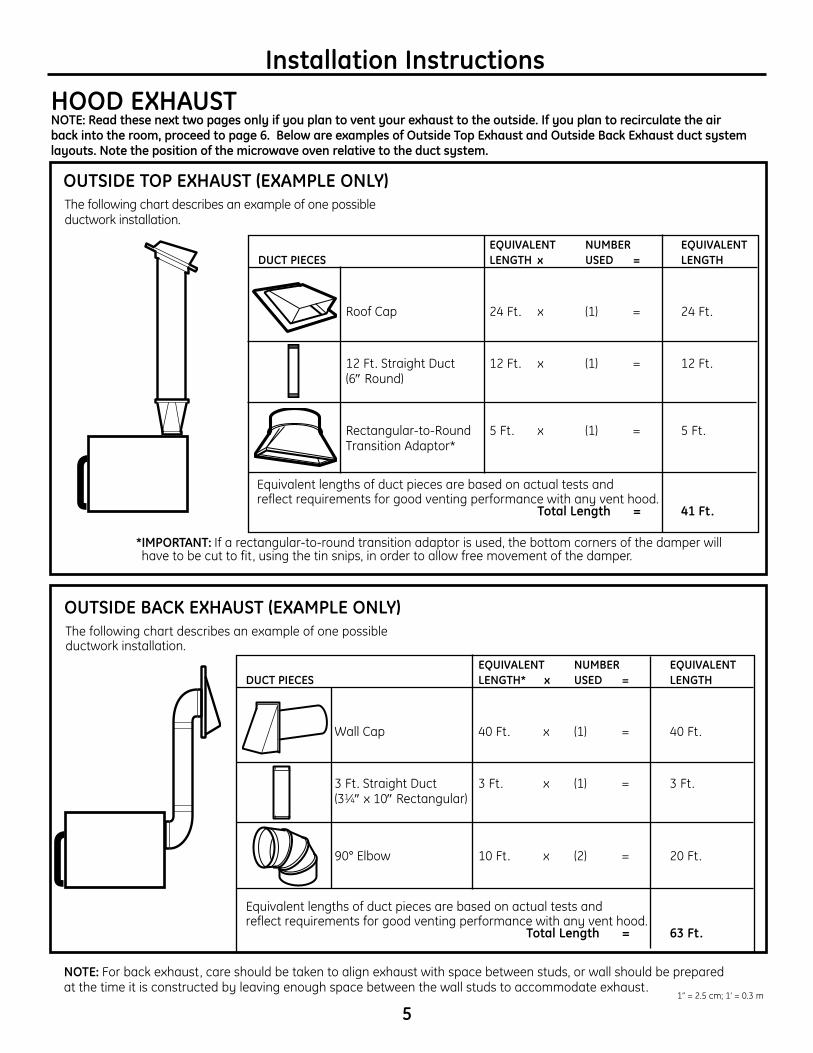
Installation InstructionsHOOD EXHAUSTNOTE: Readthesenexttwopagesonlyifyouplantoventyourexhausttotheoutside.Ifyouplantorecirculatetheairbackintotheroom,proceedtopage6.BelowareexamplesofOutsideTopExhaustandOutsideBackExhaustductsystemlayouts.Notethepositionofthemicrowaveovenrelativetotheductsystem.
OUTSIDETOPEXHAUST(EXAMPLEONLY)
EQUIVALENT NUMBER EQUIVALENTDUCT PIECES LENGTH x USED = LENGTH
Roof Cap 24 Ft. x (1) = 24 Ft.
12 Ft. Straight Duct 12 Ft. x (1) = 12 Ft. (6″ Round)
Rectangular-to-Round 5 Ft. x (1) = 5 Ft. Transition Adaptor*
Equivalent lengths of duct pieces are based on actual tests and reflect requirements for good venting performance with any vent hood. TotalLength = 41Ft.
* IMPORTANT: If a rectangular-to-round transition adaptor is used, the bottom corners of the damper will have to be cut to fit , using the tin snips, in order to allow free movement of the damper.
The following chart describes an example of one possible ductwork installation.
The following chart describes an example of one possible ductwork installation.
NOTE: For back exhaust, care should be taken to align exhaust with space between studs, or wall should be prepared at the time it is constructed by leaving enough space between the wall studs to accommodate exhaust.
OUTSIDEBACKEXHAUST(EXAMPLEONLY)
EQUIVALENT NUMBER EQUIVALENTDUCT PIECES LENGTH* x USED = LENGTH
Wall Cap 40 Ft. x (1) = 40 Ft.
3 Ft. Straight Duct 3 Ft. x (1) = 3 Ft. (31⁄4″ x 10″ Rectangular)
90° Elbow 10 Ft. x (2) = 20 Ft.
Equivalent lengths of duct pieces are based on actual tests and reflect requirements for good venting performance with any vent hood.
TotalLength = 63Ft.
1” = 2.5 cm; 1’ = 0.3 m
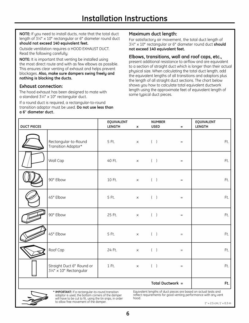
EQUIVALENT NUMBER EQUIVALENTDUCT PIECES LENGTH x USED = LENGTH
Rectangular-to-Round 5 Ft. x ( ) = Ft. Transition Adaptor*
Wall Cap 40 Ft. x ( ) = Ft.
90° Elbow 10 Ft. x ( ) = Ft.
45° Elbow 5 Ft. x ( ) = Ft.
90° Elbow 25 Ft. x ( ) = Ft.
45° Elbow 5 Ft. x ( ) = Ft.
Roof Cap 24 Ft. x ( ) = Ft.
Straight Duct 6″ Round or 1 Ft. x ( ) = Ft. 31⁄4″ x 10″ Rectangular
TotalDuctwork = Ft.
Equivalent lengths of duct pieces are based on actual tests and reflect requirements for good venting performance with any vent hood.
6
* IMPORTANT: If a rectangular-to-round transition adaptor is used, the bottom corners of the damper will have to be cut to fit , using the tin snips, in order to allow free movement of the damper.
NOTE: If you need to install ducts, note that the total duct length of 31⁄4″ x 10″ rectangular or 6″ diameter round duct shouldnotexceed140equivalentfeet.Outside ventilation requires a HOOD EXHAUST DUCT. Read the following carefully:NOTE: It is important that venting be installed using the most direct route and with as few elbows as possible. This ensures clear venting of exhaust and helps prevent blockages. Also,makesuredampersswingfreelyandnothingisblockingtheducts.
Exhaust connection: The hood exhaust has been designed to mate with a standard 31⁄4″ x 10″ rectangular duct.If a round duct is required, a rectangular-to-round transition adaptor must be used. Do not use less than a 6″ diameter duct.
Maximumductlength:For satisfactory air movement, the total duct length of 31⁄4″ x 10″ rectangular or 6″ diameter round duct should notexceed140equivalentfeet.
Elbows, transitions, wall and roof caps, etc., present additional resistance to airflow and are equivalent to a section of straight duct which is longer than their actual physical size. When calculating the total duct length, add the equivalent lengths of all transitions and adaptors plus the length of all straight duct sections. The chart below shows you how to calculate total equivalent ductwork length using the approximate feet of equivalent length of some typical duct pieces.
Installation Instructions
1” = 2.5 cm; 1’ = 0.3 m
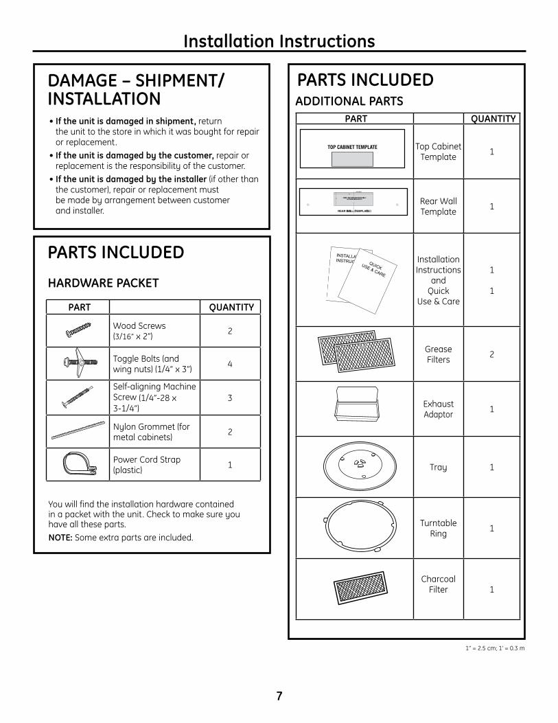
PART QUANTITY
Top Cabinet Template 1
Rear Wall Template 1
Installation Instructions
and Quick
Use & Care
1 1
Grease Filters 2
Exhaust Adaptor 1
Tray 1
Turntable Ring 1
Charcoal Filter 1
PART QUANTITY
Wood Screws (3/16” x 2”) 2
Toggle Bolts (and wing nuts) (1/4” x 3”) 4
Self-aligning Machine Screw (1/4”-28 x 3-1/4”)
3
Nylon Grommet (for metal cabinets) 2
Power Cord Strap (plastic) 1
7
Installation Instructions
• Iftheunitisdamagedinshipment, return the unit to the store in which it was bought for repair or replacement.
• Iftheunitisdamagedbythecustomer, repair or replacement is the responsibility of the customer.
•Iftheunitisdamagedbytheinstaller (if other than the customer), repair or replacement must be made by arrangement between customer and installer.
DAMAGE–SHIPMENT/ INSTALLATION
PARTS INCLUDED
INSTALLATIONINSTRUCTIONS QUICKUSE & CARE
ADDITIONAL PARTS
PARTS INCLUDED
You will find the installation hardware contained in a packet with the unit. Check to make sure you have all these parts. NOTE: Some extra parts are included.
HARDWARE PACKET
≤
≤
≤
1” = 2.5 cm; 1’ = 0.3 m
8
Installation Instructions
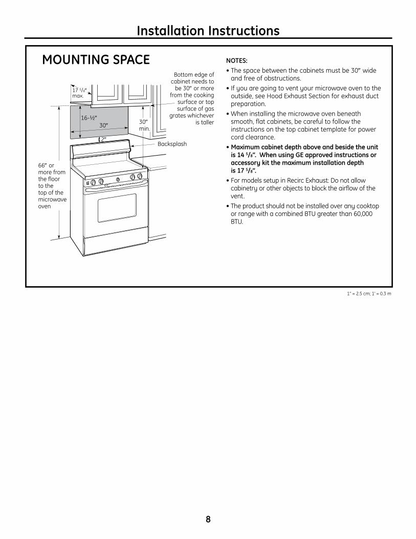
MOUNTING SPACE NOTES:• The space between the cabinets must be 30″ wide
and free of obstructions. • If you are going to vent your microwave oven to the
outside, see Hood Exhaust Section for exhaust duct preparation.
• When installing the microwave oven beneath smooth, flat cabinets, be careful to follow the instructions on the top cabinet template for power cord clearance.
•Maximumcabinetdepthaboveandbesidetheunitis 14 5/8”.WhenusingGEapprovedinstructionsoraccessorykitthemaximuminstallationdepth is 17 5/8”.
• For models setup in Recirc Exhaust: Do not allow cabinetry or other objects to block the airflow of the vent.
• The product should not be installed over any cooktop or range with a combined BTU greater than 60,000 BTU.
Backsplash
66″ or more from the floor to the top of the microwave oven
30″
2″
30″ min.
16-½″
Bottom edge of cabinet needs to
be 30″ or more from the cooking
surface or top surface of gas
grates whichever is taller
17 5/8″ max.
1” = 2.5 cm; 1’ = 0.3 m
9
Installation Instructions
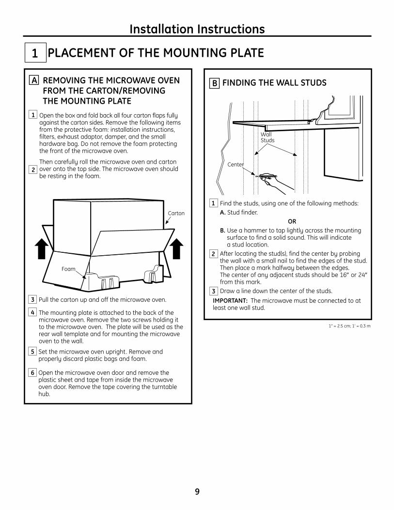
Find the studs, using one of the following methods: A. Stud finder.
OR B. Use a hammer to tap lightly across the mounting
surface to find a solid sound. This will indicate a stud location.
After locating the stud(s), find the center by probing the wall with a small nail to find the edges of the stud. Then place a mark halfway between the edges. The center of any adjacent studs should be 16″ or 24″ from this mark.
Draw a line down the center of the studs.IMPORTANT: The microwave must be connected to at least one wall stud.
1
Open the box and fold back all four carton flaps fully against the carton sides. Remove the following items from the protective foam: installation instructions, filters, exhaust adaptor, damper, and the small hardware bag. Do not remove the foam protecting the front of the microwave oven.
Then carefully roll the microwave oven and carton over onto the top side. The microwave oven should be resting in the foam.
REMOVING THE MICROWAVE OVEN FROMTHECARTON/REMOVINGTHE MOUNTING PLATE
FINDING THE WALL STUDSBA
2
PLACEMENT OF THE MOUNTING PLATE1
Wall Studs
Center
3
Carton
Pull the carton up and off the microwave oven.
Open the microwave oven door and remove the plastic sheet and tape from inside the microwave oven door. Remove the tape covering the turntable hub.
Foam
2
3
6
Set the microwave oven upright. Remove and properly discard plastic bags and foam.
1
The mounting plate is attached to the back of the microwave oven. Remove the two screws holding it to the microwave oven. The plate will be used as the rear wall template and for mounting the microwave oven to the wall.
4
5
1” = 2.5 cm; 1’ = 0.3 m
10
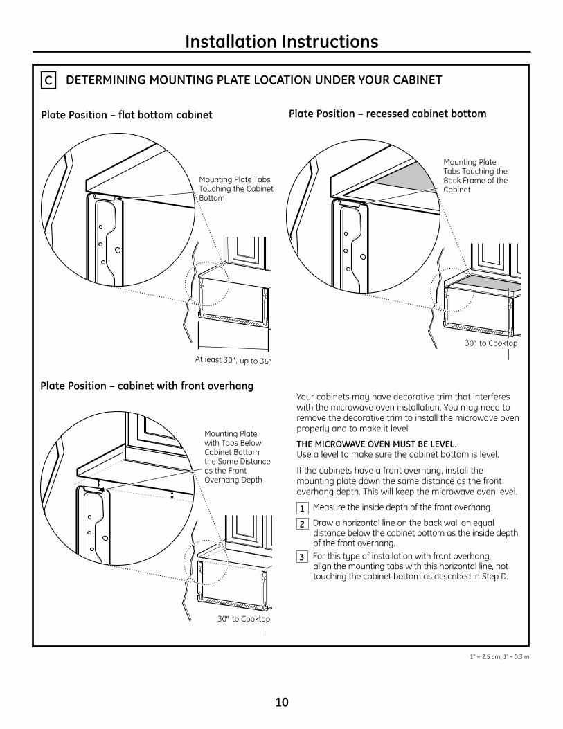
DETERMINING MOUNTING PLATE LOCATION UNDER YOUR CABINETC
Your cabinets may have decorative trim that interferes with the microwave oven installation. You may need to remove the decorative trim to install the microwave oven properly and to make it level.
THE MICROWAVE OVEN MUST BE LEVEL. Use a level to make sure the cabinet bottom is level.
If the cabinets have a front overhang, install the mounting plate down the same distance as the front overhang depth. This will keep the microwave oven level.
Measure the inside depth of the front overhang.
Draw a horizontal line on the back wall an equal distance below the cabinet bottom as the inside depth of the front overhang.
For this type of installation with front overhang, align the mounting tabs with this horizontal line, not touching the cabinet bottom as described in Step D.
Plate Position – flat bottom cabinet
PlatePosition–cabinetwithfrontoverhang
Mounting Plate Tabs Touching the Cabinet Bottom
Mounting Plate with Tabs Below Cabinet Bottom the Same Distance as the Front Overhang Depth
At least 30″, up to 36″
Plate Position – recessed cabinet bottom
Mounting Plate Tabs Touching the Back Frame of the Cabinet
30″ to Cooktop
30″ to Cooktop
1
2
3
Installation Instructions
1” = 2.5 cm; 1’ = 0.3 m
11
Installation Instructions
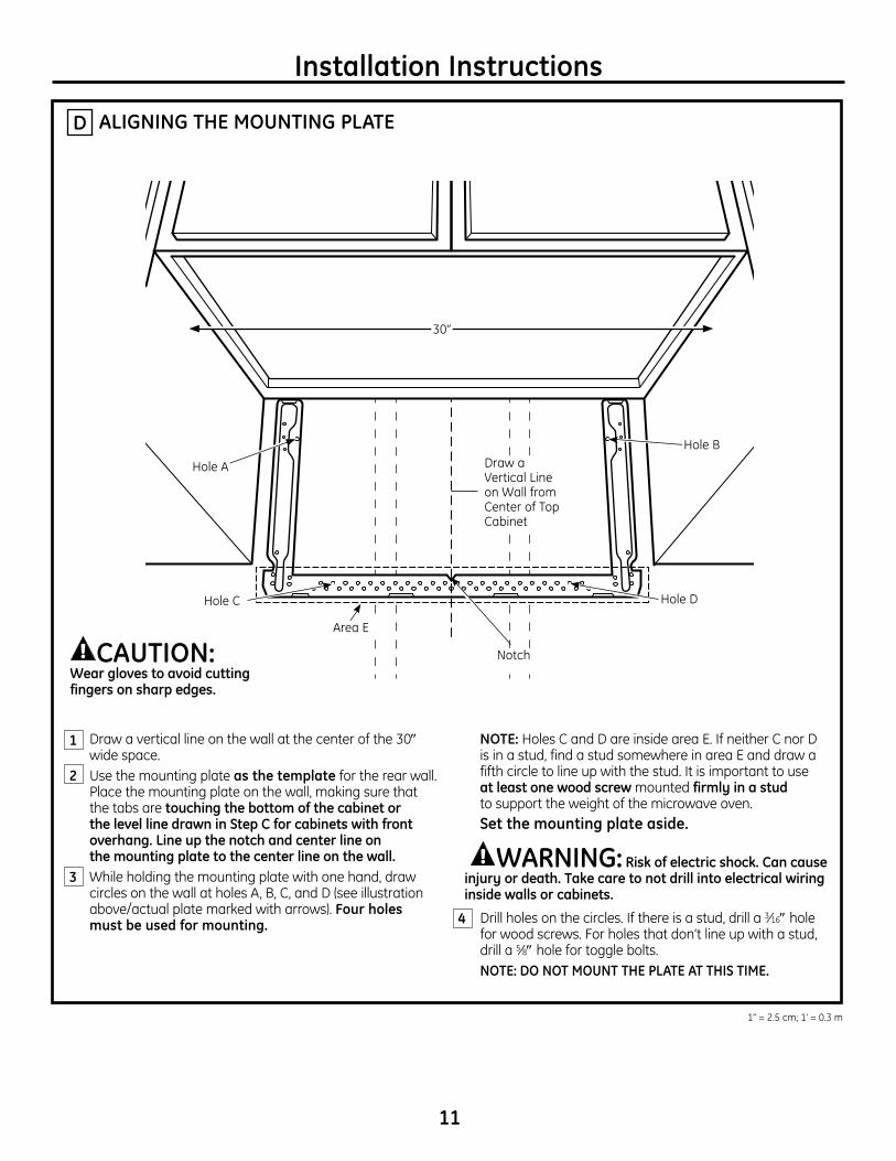
ALIGNING THE MOUNTING PLATE
Draw a vertical line on the wall at the center of the 30″ wide space.
Use the mounting plate as the template for the rear wall. Place the mounting plate on the wall, making sure that the tabs are touchingthebottomofthecabinetor thelevellinedrawninStepCforcabinetswithfrontoverhang.Lineupthenotchandcenterlineon themountingplatetothecenterlineonthewall.
While holding the mounting plate with one hand, draw circles on the wall at holes A, B, C, and D (see illustration above/actual plate marked with arrows) . Four holes mustbeusedformounting.
NOTE: Holes C and D are inside area E. If neither C nor D is in a stud, find a stud somewhere in area E and draw a fifth circle to line up with the stud. It is important to use at least one wood screw mounted firmly in a stud to support the weight of the microwave oven.
Setthemountingplateaside.
WARNING:Riskofelectricshock.Cancauseinjuryordeath.Takecaretonotdrillintoelectricalwiringinside walls or cabinets.
Drill holes on the circles. If there is a stud, drill a 3⁄16″ hole for wood screws. For holes that don’t line up with a stud, drill a 5⁄8″ hole for toggle bolts.
NOTE: DO NOT MOUNT THE PLATE AT THIS TIME.
2
3
4
Draw a Vertical Line on Wall from Center of Top Cabinet
Area E
Hole A
Hole B
Hole D
Notch
Hole C
D
CAUTION: Wearglovestoavoidcuttingfingersonsharpedges.
1
30”
1” = 2.5 cm; 1’ = 0.3 m
12
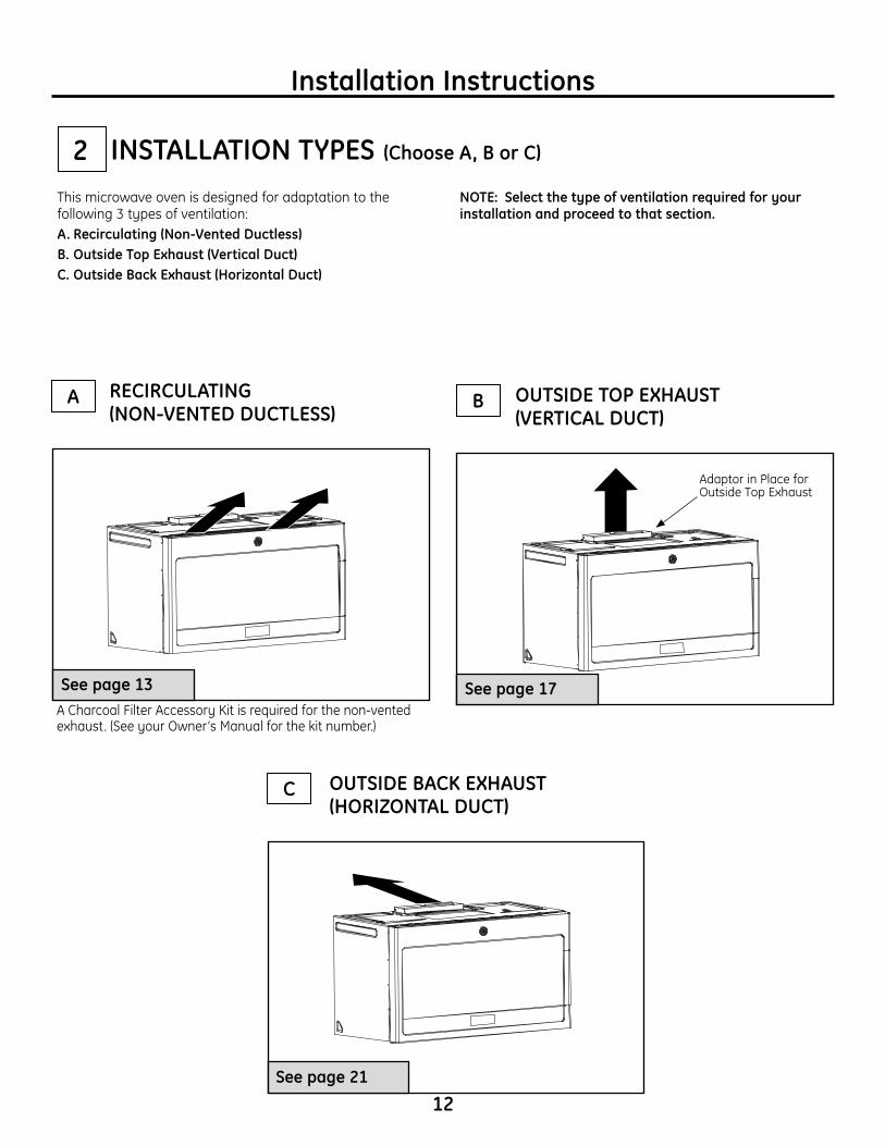
This microwave oven is designed for adaptation to the following 3 types of ventilation: A.Recirculating(Non-VentedDuctless)B.OutsideTopExhaust(VerticalDuct)C.OutsideBackExhaust(HorizontalDuct)
NOTE:Selectthetypeofventilationrequiredforyourinstallation and proceed to that section.
B OUTSIDE TOP EXHAUST (VERTICALDUCT)
Seepage17
Adaptor in Place for Outside Top Exhaust
2
OUTSIDE BACK EXHAUST (HORIZONTALDUCT)
Seepage21
C
RECIRCULATING (NON-VENTEDDUCTLESS)
Seepage13A Charcoal Filter Accessory Kit is required for the non-vented exhaust. (See your Owner’s Manual for the kit number.)
A
Installation Instructions
INSTALLATION TYPES (ChooseA,BorC)
Installation Instructions
13
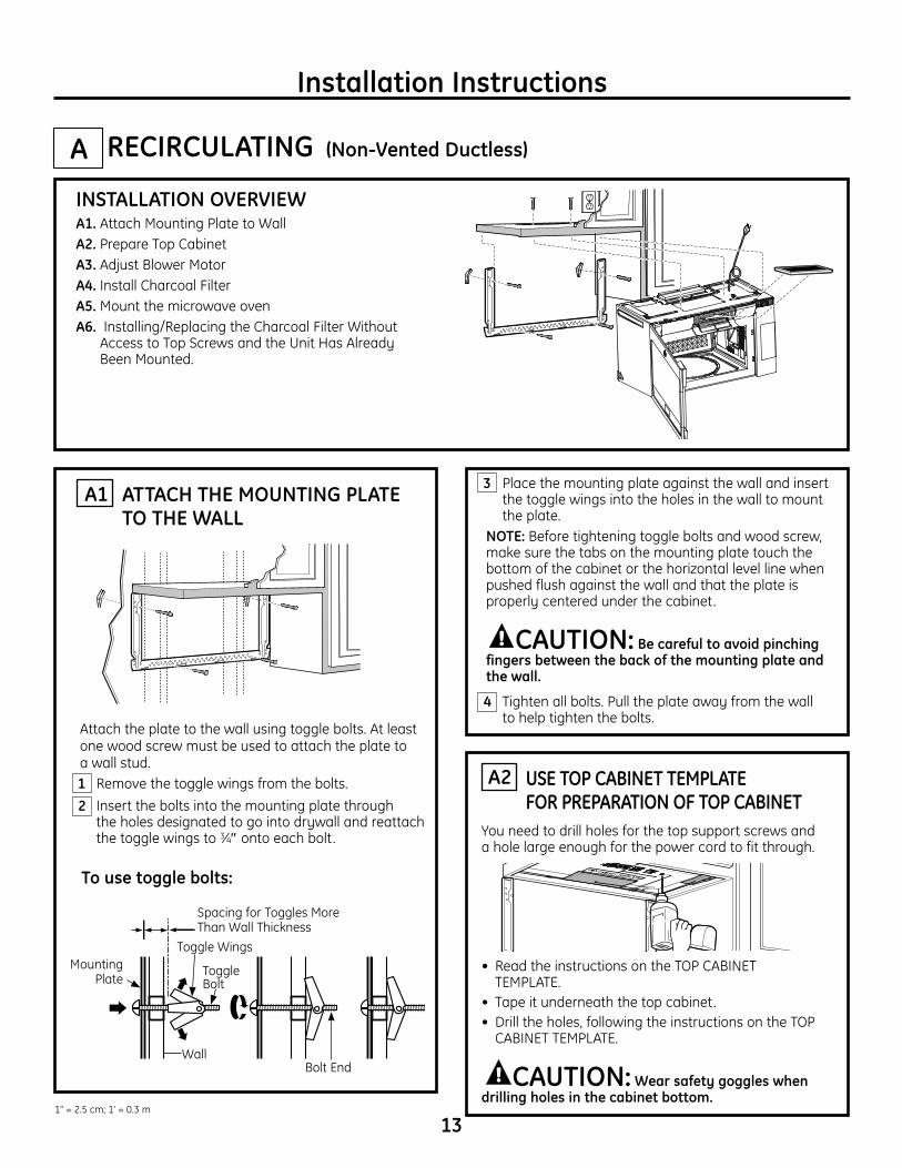
USE TOP CABINET TEMPLATE FOR PREPARATION OF TOP CABINET
A2
RECIRCULATING (Non-VentedDuctless)INSTALLATION OVERVIEWA1. Attach Mounting Plate to WallA2. Prepare Top CabinetA3. Adjust Blower MotorA4. Install Charcoal FilterA5. Mount the microwave ovenA6. Installing/Replacing the Charcoal Filter Without
Access to Top Screws and the Unit Has Already Been Mounted.
• Read the instructions on the TOP CABINET TEMPLATE.
• Tape it underneath the top cabinet.• Drill the holes, following the instructions on the TOP
CABINET TEMPLATE.
CAUTION:Wearsafetygoggleswhendrillingholesinthecabinetbottom.
You need to drill holes for the top support screws and a hole large enough for the power cord to fit through.
A
Place the mounting plate against the wall and insert the toggle wings into the holes in the wall to mount the plate.
NOTE: Before tightening toggle bolts and wood screw, make sure the tabs on the mounting plate touch the bottom of the cabinet or the horizontal level line when pushed flush against the wall and that the plate is properly centered under the cabinet.
CAUTION:Becarefultoavoidpinchingfingersbetweenthebackofthemountingplateandthe wall.
Tighten all bolts. Pull the plate away from the wall to help tighten the bolts.
3 ATTACH THE MOUNTING PLATE TO THE WALL
A1
Attach the plate to the wall using toggle bolts. At least one wood screw must be used to attach the plate to a wall stud. Remove the toggle wings from the bolts. Insert the bolts into the mounting plate through
the holes designated to go into drywall and reattach the toggle wings to 3⁄4″ onto each bolt.
1
4
Wall
Mounting Plate
Spacing for Toggles More Than Wall Thickness
Bolt End
Toggle Bolt
Toggle Wings
Tousetogglebolts:
2
1” = 2.5 cm; 1’ = 0.3 m
Installation Instructions
14
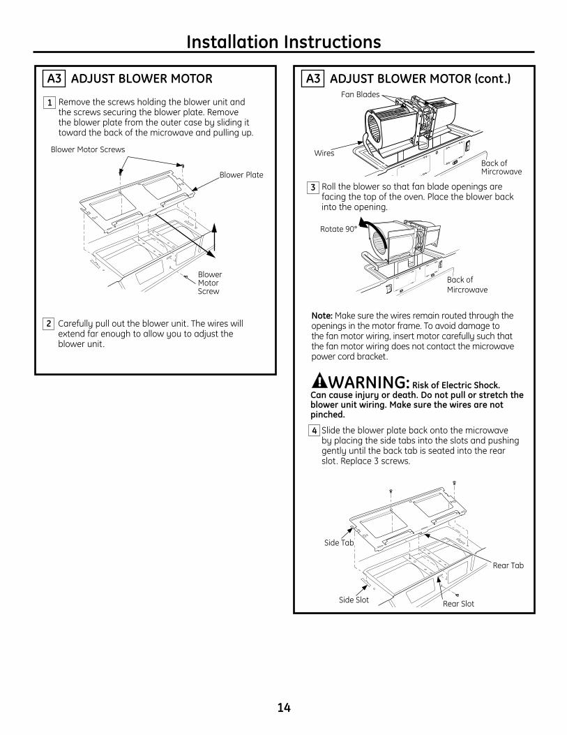
ADJUST BLOWER MOTORA3
Remove the screws holding the blower unit and the screws securing the blower plate. Remove the blower plate from the outer case by sliding it toward the back of the microwave and pulling up.
1
Blower Plate
Blower Motor Screws
Blower Motor Screw
2 Carefully pull out the blower unit. The wires will extend far enough to allow you to adjust the blower unit.
ADJUSTBLOWERMOTOR(cont.)A3
Roll the blower so that fan blade openings are facing the top of the oven. Place the blower back into the opening.
Slide the blower plate back onto the microwave by placing the side tabs into the slots and pushing gently until the back tab is seated into the rear slot. Replace 3 screws.
Note: Make sure the wires remain routed through the openings in the motor frame. To avoid damage to the fan motor wiring, insert motor carefully such that the fan motor wiring does not contact the microwave power cord bracket.
3
4
Back of Mircrowave
Rotate 90°
WARNING: RiskofElectricShock. Can cause injury or death. Do not pull or stretch the blowerunitwiring.Makesurethewiresarenotpinched.
Side Tab
Side Slot Rear Slot
Rear Tab
Back of Mircrowave
Fan Blades
Wires
Installation Instructions
A5
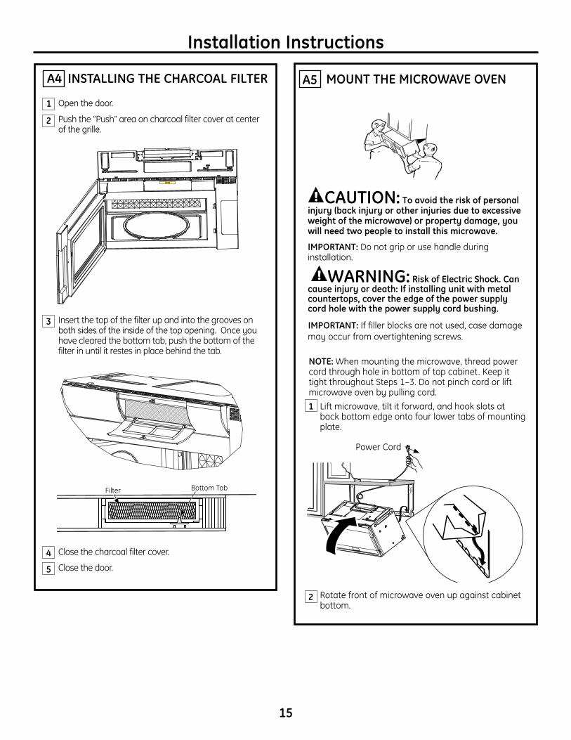
CAUTION: Toavoidtheriskofpersonalinjury(backinjuryorotherinjuriesduetoexcessiveweightofthemicrowave)orpropertydamage,youwillneedtwopeopletoinstallthismicrowave.
IMPORTANT: Do not grip or use handle during installation.
WARNING: RiskofElectricShock.Cancauseinjuryordeath:Ifinstallingunitwithmetalcountertops,covertheedgeofthepowersupplycordholewiththepowersupplycordbushing.
IMPORTANT: If filler blocks are not used, case damage may occur from overtightening screws.
MOUNT THE MICROWAVE OVEN
NOTE: When mounting the microwave, thread power cord through hole in bottom of top cabinet. Keep it tight throughout Steps 1–3. Do not pinch cord or lift microwave oven by pulling cord.
Lift microwave, tilt it forward, and hook slots at back bottom edge onto four lower tabs of mounting plate.
Rotate front of microwave oven up against cabinet bottom.
1
2
Power Cord
INSTALLING THE CHARCOAL FILTERA4
Open the door.
Push the “Push” area on charcoal filter cover at center of the grille.
Insert the top of the filter up and into the grooves on both sides of the inside of the top opening. Once you have cleared the bottom tab, push the bottom of the filter in until it restes in place behind the tab.
Close the charcoal filter cover.
Close the door.
2
1
3
4
5
15
Filter Bottom Tab
16
Installation Instructions
A5 MOUNT THE MICROWAVE OVEN (cont.)
5
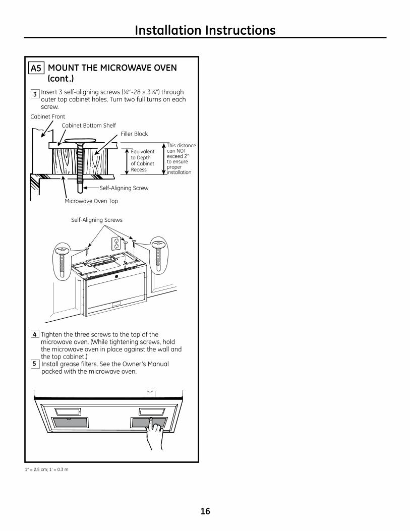
4 Tighten the three screws to the top of the microwave oven. (While tightening screws, hold the microwave oven in place against the wall and the top cabinet.)
Install grease filters. See the Owner’s Manual packed with the microwave oven.
Insert 3 self-aligning screws (1⁄4″-28 x 31⁄4”) through outer top cabinet holes. Turn two full turns on each screw.
3
Cabinet FrontCabinet Bottom Shelf
Filler Block
Microwave Oven Top
Equivalent to Depth of Cabinet Recess
Self-Aligning Screw
Self-Aligning Screws
This distance can NOT exceed 2” to ensure proper installation
Popcorn
Convenience Cooking
Express Cook
Potato
StartPause
CancelOff
Beverage
Reheat
Clock
Turntable
SurfaceLight
VentFan
Add30 Sec.
PowerLevel 0
8
5
2
7
4
1
9
6
3
TimeCook
DefrostTime/Weight
TimerOn/Off
1” = 2.5 cm; 1’ = 0.3 m
OUTSIDE TOP EXHAUST (VerticalDuct)
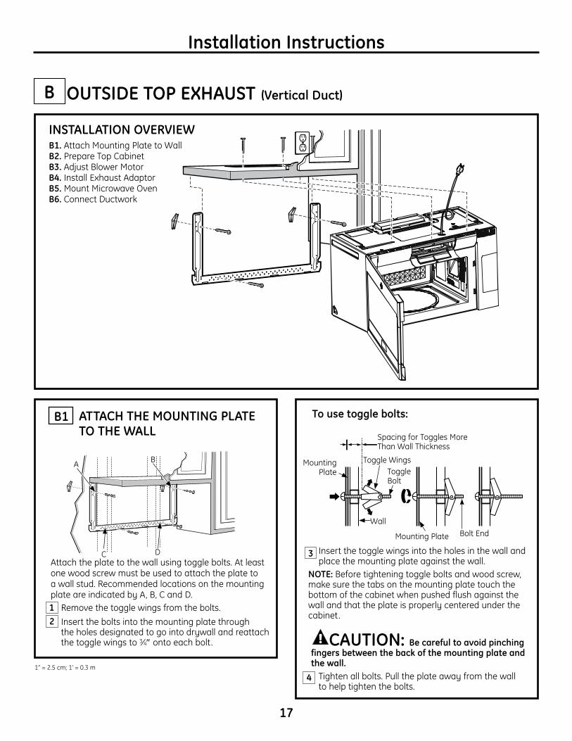
Insert the toggle wings into the holes in the wall and place the mounting plate against the wall.
NOTE: Before tightening toggle bolts and wood screw, make sure the tabs on the mounting plate touch the bottom of the cabinet when pushed flush against the wall and that the plate is properly centered under the cabinet.
CAUTION: Becarefultoavoidpinchingfingersbetweenthebackofthemountingplateandthe wall.
Tighten all bolts. Pull the plate away from the wall to help tighten the bolts.
3
B
4
ATTACH THE MOUNTING PLATE TO THE WALL
B1
17
Attach the plate to the wall using toggle bolts. At least one wood screw must be used to attach the plate to a wall stud. Recommended locations on the mounting plate are indicated by A, B, C and D. Remove the toggle wings from the bolts. Insert the bolts into the mounting plate through
the holes designated to go into drywall and reattach the toggle wings to 3⁄4″ onto each bolt.
1
INSTALLATION OVERVIEWB1. Attach Mounting Plate to WallB2. Prepare Top CabinetB3. Adjust Blower MotorB4. Install Exhaust AdaptorB5. Mount Microwave OvenB6. Connect Ductwork
Wall
Mounting Plate
Mounting Plate
Spacing for Toggles More Than Wall Thickness
Bolt End
Toggle Bolt
Toggle Wings
Tousetogglebolts:
Installation Instructions
2
A B
C D
1” = 2.5 cm; 1’ = 0.3 m
18
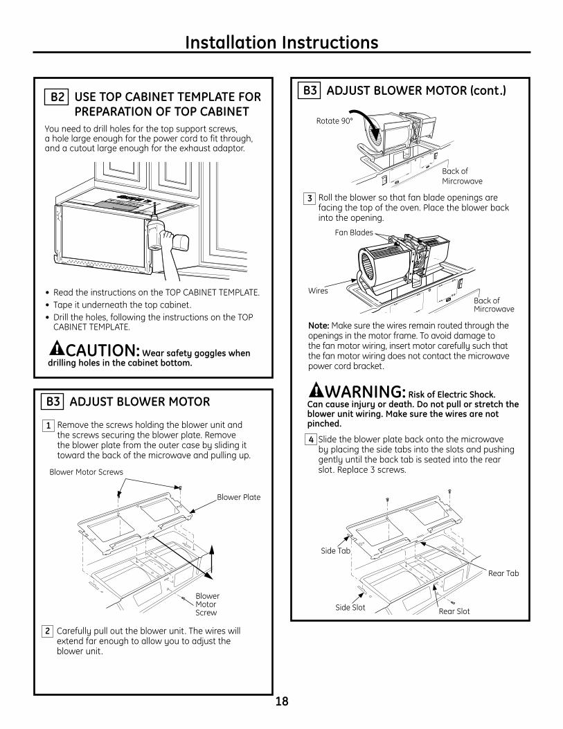
USE TOP CABINET TEMPLATE FOR PREPARATION OF TOP CABINET
You need to drill holes for the top support screws, a hole large enough for the power cord to fit through, and a cutout large enough for the exhaust adaptor.
B2
• Read the instructions on the TOP CABINET TEMPLATE.• Tape it underneath the top cabinet.• Drill the holes, following the instructions on the TOP
CABINET TEMPLATE.
CAUTION:Wearsafetygoggleswhendrillingholesinthecabinetbottom.
Installation Instructions
ADJUST BLOWER MOTOR
ADJUSTBLOWERMOTOR(cont.)
B3
B3
Remove the screws holding the blower unit and the screws securing the blower plate. Remove the blower plate from the outer case by sliding it toward the back of the microwave and pulling up.
1
Blower Plate
Blower Motor Screws
Blower Motor Screw
2 Carefully pull out the blower unit. The wires will extend far enough to allow you to adjust the blower unit.
Roll the blower so that fan blade openings are facing the top of the oven. Place the blower back into the opening.
Slide the blower plate back onto the microwave by placing the side tabs into the slots and pushing gently until the back tab is seated into the rear slot. Replace 3 screws.
Note: Make sure the wires remain routed through the openings in the motor frame. To avoid damage to the fan motor wiring, insert motor carefully such that the fan motor wiring does not contact the microwave power cord bracket.
3
4
Back of Mircrowave
Rotate 90°
Back of Mircrowave
Fan Blades
Wires
WARNING: RiskofElectricShock. Can cause injury or death. Do not pull or stretch the blowerunitwiring.Makesurethewiresarenotpinched.
Side Tab
Side Slot Rear Slot
Rear Tab

19
Installation Instructions
MOUNT THE MICROWAVE OVENB5
CAUTION: Toavoidtheriskofpersonalinjury(backinjuryorotherinjuriesduetoexcessiveweightofthemicrowave)orpropertydamage,youwillneedtwopeopletoinstallthismicrowave.
IMPORTANT: Do not grip or use handle during installation.
WARNING: RiskofElectricShock.Cancauseinjuryordeath:Ifinstallingunitwithmetalcountertops,covertheedgeofthepowersupplycordholewiththepowersupplycordbushing.
IMPORTANT: If filler blocks are not used, case damage may occur from overtightening screws.
NOTE: When mounting the microwave, thread power cord through hole in bottom of top cabinet. Keep it tight throughout Steps 1–3. Do not pinch cord or lift microwave oven by pulling cord.
Lift microwave, tilt it forward, and hook slots at back bottom edge onto four lower tabs of mounting plate.
Rotate front of microwave oven up against cabinet bottom.
1
2
Power Cord
ASSEMBLE AND INSTALL ADAPTORB4
Place the microwave oven in its upright position, with the top of the unit facing up and the front of the unit facing toward you.
Remove the screw on the back side of the blower plate and raise the blower plate off of the microwave.
Slide the damper from left to right into the tabs on the blower plate. The yellow tape on the damper should be facing away from you.
Remove the yellow tape from the damper. Makesurethatthedamperpivotseasilybeforemountingmicrowaveoven.
You will need to make adjustments to assure proper alignment with your house exhaust duct after the microwave oven is installed.
Position the blower plate with damper back on the microwave and secure it with the screws that were removed.
1
2
3
4
5
DamperBlower Plate
CONNECTING DUCTWORK
20
3
Cabinet Front
Cabinet Bottom ShelfFiller Block
Microwave Oven Top
Equivalent to Depth of Cabinet Recess
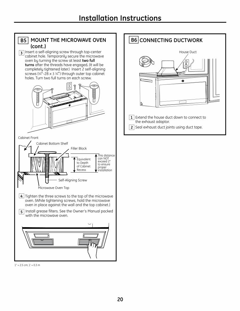
Insert a self-aligning screw through top-center cabinet hole. Temporarily secure the microwave oven by turning the screw at least two full turns after the threads have engaged. (It will be completely tightened later.) Insert 2 self-aligning screws (1⁄4″-28 x 3 1⁄4″) through outer top cabinet holes. Turn two full turns on each screw.
Tighten the three screws to the top of the microwave oven. (While tightening screws, hold the microwave oven in place against the wall and the top cabinet.)
Install grease filters. See the Owner’s Manual packed with the microwave oven.
Popcorn
Convenience Cooking
Express Cook
Potato
StartPause
CancelOff
Beverage
Reheat
Clock
Turntable
SurfaceLight
VentFan
Add30 Sec.
PowerLevel 0
8
5
2
7
4
1
9
6
3
TimeCook
DefrostTime/Weight
TimerOn/Off
5
4
Installation Instructions
1
2
Extend the house duct down to connect to the exhaust adaptor.
Seal exhaust duct joints using duct tape.
House Duct
Self-Aligning Screw
MOUNT THE MICROWAVE OVEN (cont.)
B5 B6
This distance can NOT exceed 2” to ensure proper installation
1” = 2.5 cm; 1’ = 0.3 m
OUTSIDE BACK EXHAUST (HorizontalDuct)
PREPARING THE REAR WALL FOR OUTSIDE BACK EXHAUST
C1
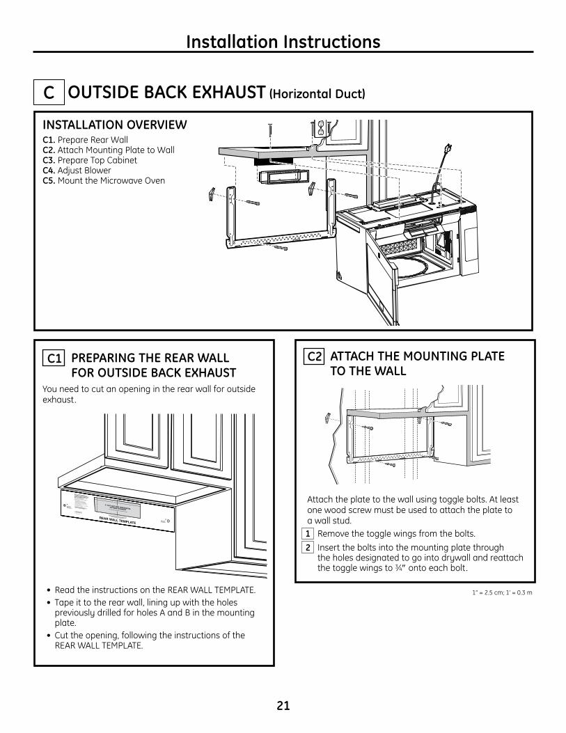
INSTALLATION OVERVIEWC1. Prepare Rear WallC2. Attach Mounting Plate to WallC3. Prepare Top CabinetC4. Adjust BlowerC5. Mount the Microwave Oven
Installation Instructions
C
21
ATTACH THE MOUNTING PLATE TO THE WALL
C2
Attach the plate to the wall using toggle bolts. At least one wood screw must be used to attach the plate to a wall stud. Remove the toggle wings from the bolts. Insert the bolts into the mounting plate through
the holes designated to go into drywall and reattach the toggle wings to 3⁄4″ onto each bolt.
12
You need to cut an opening in the rear wall for outside exhaust.
• Read the instructions on the REAR WALL TEMPLATE.• Tape it to the rear wall, lining up with the holes
previously drilled for holes A and B in the mounting plate.
• Cut the opening, following the instructions of the REAR WALL TEMPLATE.
1” = 2.5 cm; 1’ = 0.3 m
2
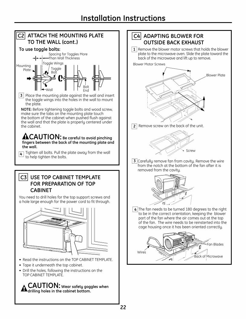
1 Remove the blower motor screws that holds the blower plate to the microwave oven. Slide the plate toward the back of the microwave and lift up to remove.
ADAPTING BLOWER FOR OUTSIDE BACK EXHAUST
C4
Remove screw on the back of the unit.
22
USE TOP CABINET TEMPLATE FOR PREPARATION OF TOP CABINET
C3
• Read the instructions on the TOP CABINET TEMPLATE.• Tape it underneath the top cabinet.• Drill the holes, following the instructions on the
TOP CABINET TEMPLATE.
CAUTION:Wearsafetygoggleswhendrillingholesinthecabinetbottom.
Wall
Mounting Plate
Spacing for Toggles More Than Wall Thickness
Toggle Bolt
Toggle Wings
Tousetogglebolts:
Bolt End
Installation Instructions
You need to drill holes for the top support screws and a hole large enough for the power cord to fit through.
Place the mounting plate against the wall and insert the toggle wings into the holes in the wall to mount the plate.
NOTE: Before tightening toggle bolts and wood screw, make sure the tabs on the mounting plate touch the bottom of the cabinet when pushed flush against the wall and that the plate is properly centered under the cabinet.
CAUTION:Becarefultoavoidpinchingfingersbetweenthebackofthemountingplateandthe wall.
Tighten all bolts. Pull the plate away from the wall to help tighten the bolts.
3
4
Blower Plate
Blower Motor Screws
The fan needs to be turned 180 degrees to the right to be in the correct orientation, keeping the blower part of the fan where the air comes out at the top of the fan. The wire needs to be reinsterted into the cage housing once it has been oriented correctly.
4
Back of Microwave
Fan Blades
Wires
3
ATTACH THE MOUNTING PLATE TO THE WALL (cont .)
C2
Screw
Carefully remove fan from cavity. Remove the wire from the notch at the bottom of the fan after it is removed from the cavity.
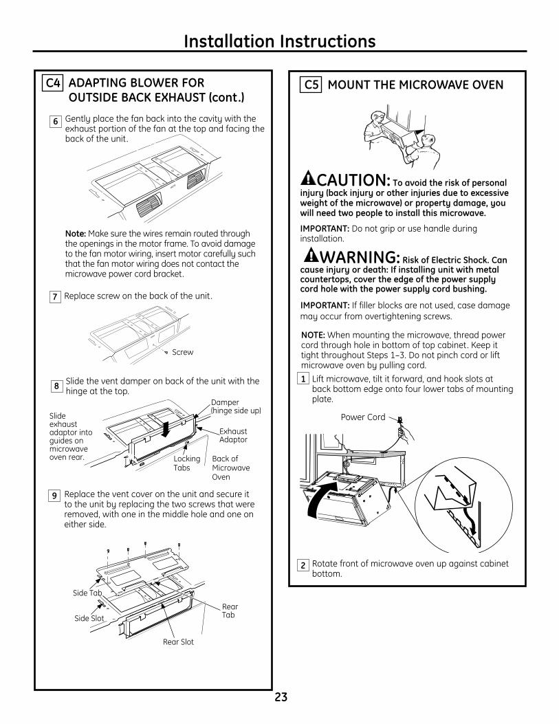
Replace the vent cover on the unit and secure it to the unit by replacing the two screws that were removed, with one in the middle hole and one on either side.
9
6
Installation Instructions
MOUNT THE MICROWAVE OVENC5
CAUTION: Toavoidtheriskofpersonalinjury(backinjuryorotherinjuriesduetoexcessiveweightofthemicrowave)orpropertydamage,youwillneedtwopeopletoinstallthismicrowave.
IMPORTANT: Do not grip or use handle during installation.
WARNING: RiskofElectricShock.Cancauseinjuryordeath:Ifinstallingunitwithmetalcountertops,covertheedgeofthepowersupplycordholewiththepowersupplycordbushing.
IMPORTANT: If filler blocks are not used, case damage may occur from overtightening screws.
NOTE: When mounting the microwave, thread power cord through hole in bottom of top cabinet. Keep it tight throughout Steps 1–3. Do not pinch cord or lift microwave oven by pulling cord.
Lift microwave, tilt it forward, and hook slots at back bottom edge onto four lower tabs of mounting plate.
Rotate front of microwave oven up against cabinet bottom.
1
2
Power Cord
ADAPTING BLOWER FOR OUTSIDE BACK EXHAUST(cont.)
C4
Side Tab
Side Slot
Rear Slot
Rear Tab
7 Replace screw on the back of the unit.
Screw
8 Slide the vent damper on back of the unit with the hinge at the top.
Slide exhaust adaptor into guides on microwave oven rear.
Exhaust Adaptor
Damper (hinge side up)
Locking Tabs
Back of Microwave Oven
23
Gently place the fan back into the cavity with the exhaust portion of the fan at the top and facing the back of the unit.
Note: Make sure the wires remain routed through the openings in the motor frame. To avoid damage to the fan motor wiring, insert motor carefully such that the fan motor wiring does not contact the microwave power cord bracket.
24
Installation Instructions
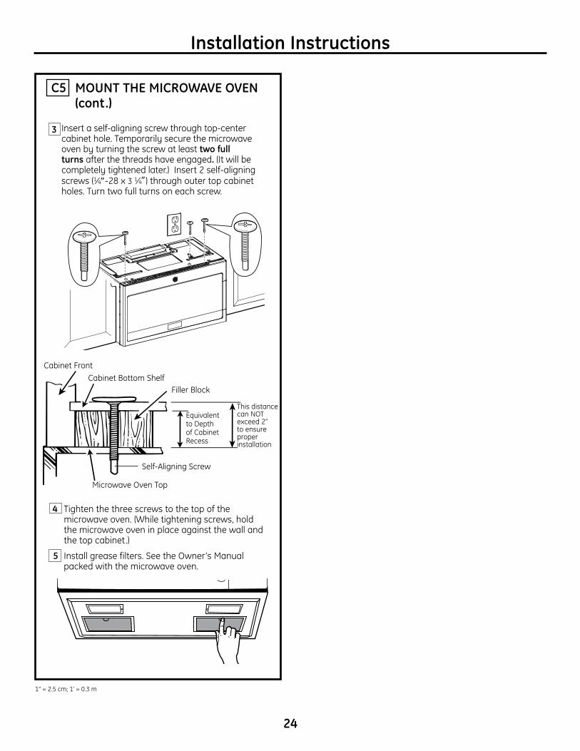
MOUNT THE MICROWAVE OVEN (cont.)
C5
5
Cabinet Front
4 Tighten the three screws to the top of the microwave oven. (While tightening screws, hold the microwave oven in place against the wall and the top cabinet.)
Insert a self-aligning screw through top-center cabinet hole. Temporarily secure the microwave oven by turning the screw at least two full turns after the threads have engaged. (It will be completely tightened later.) Insert 2 self-aligning screws (1⁄4″-28 x 3 1⁄4″) through outer top cabinet holes. Turn two full turns on each screw.
Install grease filters. See the Owner’s Manual packed with the microwave oven.
Cabinet Bottom ShelfFiller Block
Microwave Oven Top
Equivalent to Depth of Cabinet Recess
Self-Aligning Screw
This distance can NOT exceed 2” to ensure proper installation
Popcorn
Convenience Cooking
Express Cook
Potato
StartPause
CancelOff
Beverage
Reheat
Clock
Turntable
SurfaceLight
VentFan
Add30 Sec.
PowerLevel 0
8
5
2
7
4
1
9
6
3
TimeCook
DefrostTime/Weight
TimerOn/Off
3
1” = 2.5 cm; 1’ = 0.3 m
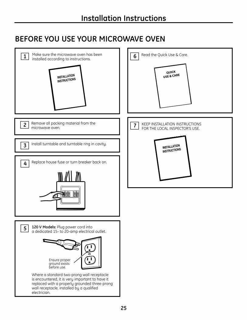
KEEP INSTALLATION INSTRUCTIONS FOR THE LOCAL INSPECTOR’S USE.
120 V Models: Plug power cord into a dedicated 15- to 20-amp electrical outlet.
7
Read the Quick Use & Care.6
Replace house fuse or turn breaker back on. 4
Remove all packing material from the microwave oven.2
Make sure the microwave oven has been installed according to instructions.1
25
BEFORE YOU USE YOUR MICROWAVE OVEN
Ensure proper ground exists before use.
QUICK
USE & CARE
Installation Instructions
Install turntable and turntable ring in cavity.3
5
Where a standard two-prong wall receptacle is encountered, it is very important to have it replaced with a properly grounded three-prong wall receptacle, installed by a qualified electrician.
Installation Instructions
26Printed in China