Embed Size (px)
Citation preview
1
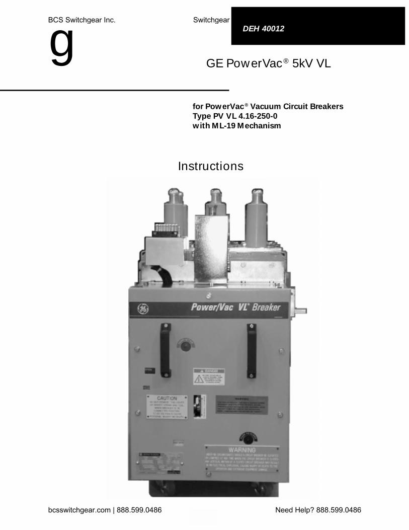
GE PowerVac ® 5kV VL
for PowerVac ® Vacuum Circuit BreakersType PV VL 4.16-250-0with ML-19 Mechanism
Instructions
DEH 40012
gBCS Switchgear Inc. Switchgear | Circuit Breakers | Parts | Tech Support
bcsswitchgear.com | 888.599.0486 Need Help? 888.599.0486
2
DEH-40012
WARNINGS, CAUTIONS AND NOTESAS USED IN THIS PUBLICATION
This document is based on information available at the time of this publication. While efforts havebeen made to ensure accuracy, the information contained herein does not cover all details or varia-tions in hardware and software, nor does it provide for every possible contingency in connectionwith installation, operation, and maintenance. Features may be described herein that are notpresent in all hardware and software systems. GE Industrial Systems assumes no obligation ofnotice to holders of this document with respect to changes subsequently made.
WARNINGSWarning notices are used in this publication to emphasize that hazardous voltages,currents, or other conditions that could cause personal injury or death are presentin this equipment or may be associated with its use.
Warning notices are also used for situations in which inattention or lack of equip-ment knowledge could cause either personal injury or damage to equipment.
CAUTIONSCaution notices are used for situations in which equipment might be damaged ifcare is not taken.
NOTESNotes call attention to information that is especially significant to understandingand operating the equipment.
GE Industrial Systems makes no representation or warranty, expressed, implied, or statutory, withrespect to, and assumes no responsibility for the accuracy completeness, sufficiency, or useful-ness of the information contained herein. No warranties of merchantability or fitness for purposeshall apply.
The following is a trademark of GE Company: PowerVac®
© 2000 GE CompanyAll Rights Reserved
BCS Switchgear Inc. Switchgear | Circuit Breakers | Parts | Tech Support
bcsswitchgear.com | 888.599.0486 Need Help? 888.599.0486
PowerVac ® 5kV Vertical LiftTable of Contents
3
Chapter 1. Introduction1-1 Safety ...................................................................................................................... 61-2 Maintenance ........................................................................................................... 6
Chapter 2. Description .................................................................................................................... 7
Chapter 3. Receiving, Handling & Storage3-1 Receiving ................................................................................................................ 83-2 Handling .................................................................................................................. 83-3 Storage .................................................................................................................... 83-4 Safety Precautions .................................................................................................. 83-5 Unpacking the Breaker ............................................................................................ 83-6 Safety Interlocks ...................................................................................................... 9
Positive Interlock System ....................................................................................... 9Interference Bolts .................................................................................................. 10
Chapter 4. Installation4-1 Breaker Preparation ............................................................................................... 114-2 Equipment Test Position ....................................................................................... 114-3 Positive Interlock System .................................................................................... 114-4 Checking for Proper Interlock ............................................................................... 124-5 Primary Contact Penetration ................................................................................. 144-6 Stationary Auxiliary Switch (MOC) ....................................................................... 164-7 Stops ...................................................................................................................... 164-8 Ground ................................................................................................................... 164-9 Secondary Coupler ................................................................................................ 174-10 Position Switch ..................................................................................................... 17
Chapter 5. Operation5-1 Description ............................................................................................................ 185-2 Close Spring Charging ....................................................................................... 195-3 Trip-Free Operation .............................................................................................. 205-4 Closing Operation ................................................................................................. 205-5 Opening Operation................................................................................................ 21
Chapter 6. Control Circuit6-1 Typical Wiring Controls ........................................................................................ 22
Chapter 7. Mechanical Check and Slow Close7-1 Visual Inspection .................................................................................................. 257-2 Closing Spring Charging ...................................................................................... 257-3 Closing Spring Gag .............................................................................................. 257-4 Slow Closing ......................................................................................................... 257-5 Gag Tool Removal ................................................................................................. 25
Chapter 8. Dimensional Checks8-1 Primary Contact Erosion ....................................................................................... 268-2 Spring Wipe Indicator .......................................................................................... 268-3 Contact Gap ........................................................................................................... 27
BCS Switchgear Inc. Switchgear | Circuit Breakers | Parts | Tech Support
bcsswitchgear.com | 888.599.0486 Need Help? 888.599.0486
PowerVac® 5kV Vertical LiftTable of Contents
4
Chapter 9. Electrical Checks9-1 Electrical Operation............................................................................................... 289-2 High Potential Test ................................................................................................ 28
Primary Circuit ....................................................................................................... 28Secondary Circuit .................................................................................................. 28
9-3 Primary Circuit Resistance.................................................................................... 289-4 Vacuum Integrity Test ............................................................................................ 289-5 Insulation Tests ..................................................................................................... 29
Chapter 10. Maintenance10-1 General .................................................................................................................. 3010-2 Service Conditions ................................................................................................ 3110-3 Fault Interruptions ................................................................................................. 3110-4 Contact Erosion ..................................................................................................... 3110-5 Transfer Finger Wear ............................................................................................. 3110-6 Mechanism ............................................................................................................ 3110-7 Primary Insulation Parts ........................................................................................ 3110-8 Lubrication ............................................................................................................ 3210-9 Recommended Maintenance ................................................................................ 3210-10 Breaker Timing and Speed Check ........................................................................ 32
Chapter 11. Mechanical Adjustments11-1 General .................................................................................................................. 3511-2 Wipe Adjustment ................................................................................................... 3511-3 Contact Gap Adjustment ....................................................................................... 3611-4 Trip Coil Plunger ................................................................................................... 3711-5 Close Coil Plunger ................................................................................................ 3811-6 Control Switch Adjustment .................................................................................. 3911-7 Adjustment of MOC Switch .................................................................................. 3911-8 Positive Interlock ................................................................................................... 40
Chapter 12. Repair and Replacement12-1 General .................................................................................................................. 4412-2 Replacing Interrupters ........................................................................................... 4412-3 Primary Bushing .................................................................................................... 4512-4 Mechanism ............................................................................................................ 4512-5 Control Switches ................................................................................................... 4512-6 Trip Coil Replacement .......................................................................................... 4512-7 Closing Coil Replacement .................................................................................... 4712-8 Auxiliary Switch Replacement .............................................................................. 4712-9 Motor Replacement ............................................................................................... 4912-10 “Y” Relay Replacement ........................................................................................ 49
Chapter 13. Renewal Parts13-1 Ordering Instructions ............................................................................................ 51
Chapter 14. Stationary Cubicle Subassembly14-1 Introduction ........................................................................................................... 5314-2 Major Components ............................................................................................... 5314-3 Testing and Inspection .......................................................................................... 5414-4 Compartment Maintenance ................................................................................... 58
PowerVac ® 5kV Vertical LiftTable of Contents
5
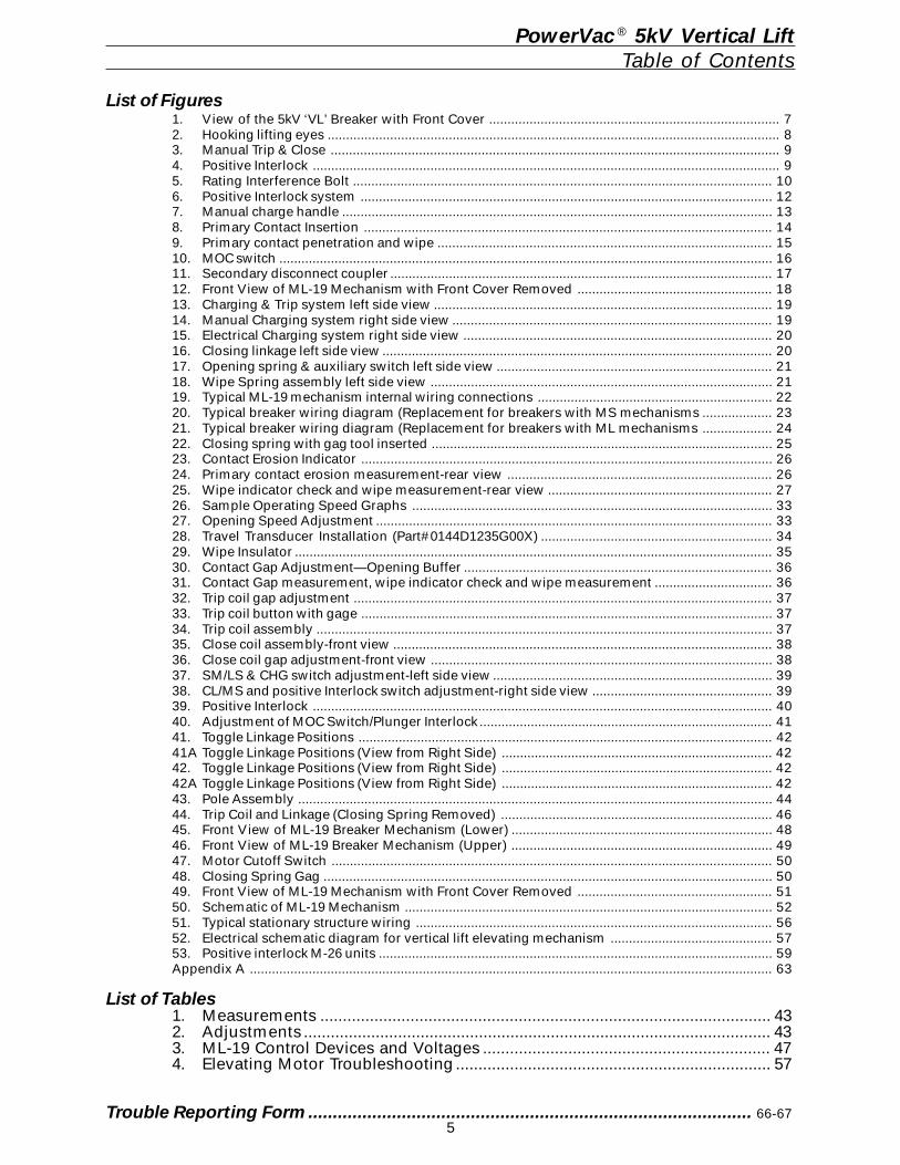
List of Figures1. View of the 5kV ‘VL’ Breaker with Front Cover ............................................................................... 72. Hooking lifting eyes ........................................................................................................................... 83. Manual Trip & Close .......................................................................................................................... 94. Positive Interlock ............................................................................................................................... 95. Rating Interference Bolt .................................................................................................................. 106. Positive Interlock system ................................................................................................................ 127. Manual charge handle ..................................................................................................................... 138. Primary Contact Insertion ............................................................................................................... 149. Primary contact penetration and wipe ........................................................................................... 1510. MOC switch ...................................................................................................................................... 1611. Secondary disconnect coupler ........................................................................................................ 1712. Front View of ML-19 Mechanism with Front Cover Removed ..................................................... 1813. Charging & Trip system left side view ............................................................................................ 1914. Manual Charging system right side view ....................................................................................... 1915. Electrical Charging system right side view .................................................................................... 2016. Closing linkage left side view .......................................................................................................... 2017. Opening spring & auxiliary switch left side view ........................................................................... 2118. Wipe Spring assembly left side view ............................................................................................. 2119. Typical ML-19 mechanism internal wiring connections ................................................................ 2220. Typical breaker wiring diagram (Replacement for breakers with MS mechanisms ................... 2321. Typical breaker wiring diagram (Replacement for breakers with ML mechanisms ................... 2422. Closing spring with gag tool inserted ............................................................................................. 2523. Contact Erosion Indicator ................................................................................................................ 2624. Primary contact erosion measurement-rear view ........................................................................ 2625. Wipe indicator check and wipe measurement-rear view ............................................................. 2726. Sample Operating Speed Graphs .................................................................................................. 3327. Opening Speed Adjustment ............................................................................................................ 3328. Travel Transducer Installation (Part#0144D1235G00X) ............................................................... 3429. Wipe Insulator .................................................................................................................................. 3530. Contact Gap Adjustment—Opening Buffer .................................................................................... 3631. Contact Gap measurement, wipe indicator check and wipe measurement ................................ 3632. Trip coil gap adjustment .................................................................................................................. 3733. Trip coil button with gage ................................................................................................................ 3734. Trip coil assembly ............................................................................................................................ 3735. Close coil assembly-front view ....................................................................................................... 3836. Close coil gap adjustment-front view ............................................................................................. 3837. SM/LS & CHG switch adjustment-left side view ............................................................................ 3938. CL/MS and positive Interlock switch adjustment-right side view ................................................. 3939. Positive Interlock ............................................................................................................................. 4040. Adjustment of MOC Switch/Plunger Interlock ................................................................................ 4141. Toggle Linkage Positions ................................................................................................................. 4241A Toggle Linkage Positions (View from Right Side) .......................................................................... 4242. Toggle Linkage Positions (View from Right Side) .......................................................................... 4242A Toggle Linkage Positions (View from Right Side) .......................................................................... 4243. Pole Assembly ................................................................................................................................. 4444. Trip Coil and Linkage (Closing Spring Removed) .......................................................................... 4645. Front View of ML-19 Breaker Mechanism (Lower) ....................................................................... 4846. Front View of ML-19 Breaker Mechanism (Upper) ....................................................................... 4947. Motor Cutoff Switch ........................................................................................................................ 5048. Closing Spring Gag .......................................................................................................................... 5049. Front View of ML-19 Mechanism with Front Cover Removed ..................................................... 5150. Schematic of ML-19 Mechanism .................................................................................................... 5251. Typical stationary structure wiring ................................................................................................. 5652. Electrical schematic diagram for vertical lift elevating mechanism ............................................ 5753. Positive interlock M-26 units ........................................................................................................... 59Appendix A .............................................................................................................................................. 63
List of Tables1. Measurements .................................................................................................... 432. Adjustments ........................................................................................................ 433. ML-19 Control Devices and Voltages ................................................................ 474. Elevating Motor Troubleshooting ...................................................................... 57
Trouble Reporting Form.......................................................................................... 66-67
6
PowerVac® 5kV Vertical LiftChapter 1. Introduction
1-1 Safety
IT IS IMPERATIVE THAT ALL PERSONNELASSOCIATED WITH THIS EQUIPMENT READAND COMPLETELY UNDERSTAND THEWARNINGS LOCATED THROUGHOUT THISINSTRUCTION BOOK. FAILURE TO DO SOCAN RESULT IN DAMAGE TO PROPERTY ORPERSONAL INJURY.
Each user must maintain a safety program forthe protection of personnel, as well as otherequipment, from the potential hazards associ-ated with electrical equipment.
The following requirements are intended to aug-ment the user’s safety program but NOT sup-plant the user’s responsibility for devising acomplete safety program. The following basicindustry practiced safety requirements are ap-plicable to all major electrical equipment suchas switchgear or switchboards. GE neither con-dones nor assumes any responsibility for prac-tices which deviate from the following:
1. ALL CONDUCTORS MUST BE ASSUMEDTO BE ENERGIZED UNLESS THEIR POTEN-TIAL HAS BEEN MEASURED AS TOGROUND.
Many accidents have been caused bypower system back feeds from a wide vari-ety of sources.
2. It is strongly recommended that all equip-ment be completely de-energized, verifiedto be “dead”, then grounded with adequatecapacity grounding assemblies prior to anymaintenance. The grounding cable assem-blies must be able to withstand energizingfault levels so that protective equipmentmay clear the circuit safely. Additional dis-cussion on this concept is covered in Chap-ter 20 of ANSI/NFPA 70B, Electrical Equip-ment Maintenance.
3. Although interlocks to reduce some of therisks are provided, the individual’s actionswhile performing service or maintenanceare essential to prevent accidents. Eachperson’s knowledge; his mental awareness;and his planned and executed actions of-ten determine if an accident will occur.The most important method of avoidingaccidents is for all associated personnelto carefully apply a thorough understand-ing of the specific equipment from the view-points of its purpose, its construction, itsoperation and the situations which couldbe hazardous.
1-2 MaintenanceAll personnel associated with installation, op-eration and maintenance of electrical equip-ment, such as power circuit breakers and otherpower handling equipment, must be thoroughlyinstructed, with periodic retraining, regardingpower equipment in general as well as the par-ticular model of equipment on which they areworking. Instruction books, actual devices andappropriate safety and maintenance practicessuch as OSHA publications, National ElectricSafety Code (ANSI C2), and National Fire Pro-tection Association (NFPA) 70B Electrical Equip-ment Maintenance must be closely studied andfollowed. During actual work, supervisionshould audit practices to assure conformance.
7
2-1 Description
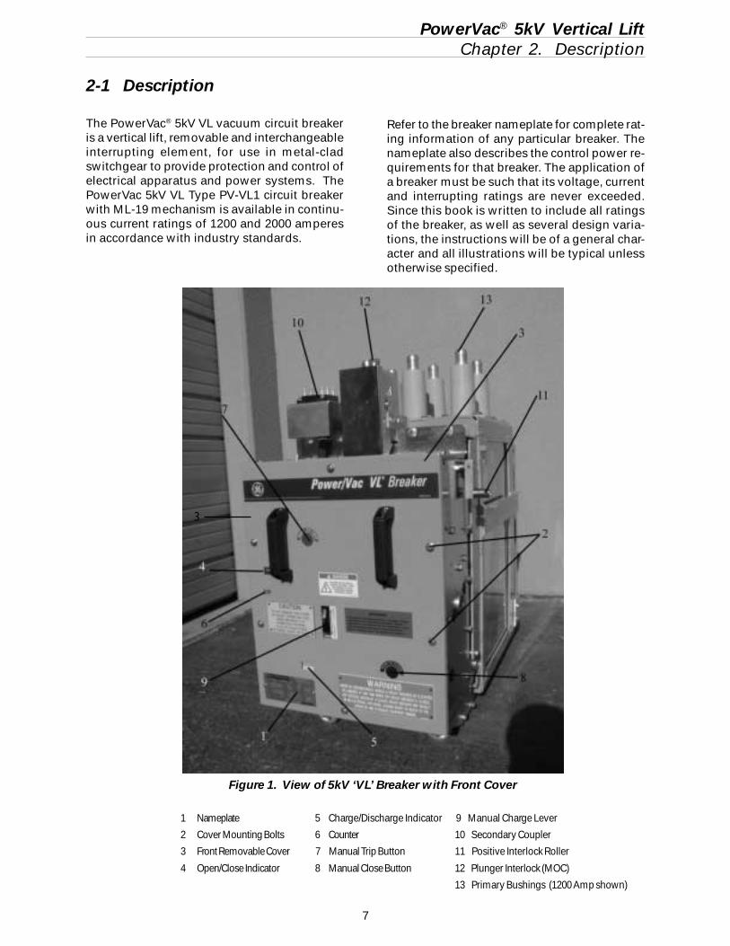
The PowerVac® 5kV VL vacuum circuit breakeris a vertical lift, removable and interchangeableinterrupting element, for use in metal-cladswitchgear to provide protection and control ofelectrical apparatus and power systems. ThePowerVac 5kV VL Type PV-VL1 circuit breakerwith ML-19 mechanism is available in continu-ous current ratings of 1200 and 2000 amperesin accordance with industry standards.
PowerVac® 5kV Vertical LiftChapter 2. Description
Refer to the breaker nameplate for complete rat-ing information of any particular breaker. Thenameplate also describes the control power re-quirements for that breaker. The application ofa breaker must be such that its voltage, currentand interrupting ratings are never exceeded.Since this book is written to include all ratingsof the breaker, as well as several design varia-tions, the instructions will be of a general char-acter and all illustrations will be typical unlessotherwise specified.
1 Nameplate 5 Charge/Discharge Indicator 9 Manual Charge Lever
2 Cover Mounting Bolts 6 Counter 10 Secondary Coupler
3 Front Removable Cover 7 Manual Trip Button 11 Positive Interlock Roller
4 Open/Close Indicator 8 Manual Close Button 12 Plunger Interlock (MOC)
13 Primary Bushings (1200 Amp shown)
3
Figure 1. View of 5kV ‘VL’ Breaker with Front Cover
8
PowerVac® 5kV Vertical LiftChapter 3. Receiving, Handling & Storage
3-1. ReceivingEach breaker is carefully inspected before ship-ment. Immediately upon receipt of the circuitbreaker, an examination should be made for anydamage sustained in transit. If injury or roughhandling is evident, a claim should be filed im-mediately with the transportation company, andthe nearest GE Sales Office should be notified.
CAUTION: THE BREAKER HAS BEENSHIPPED IN THE CLOSED POSITION.
3-2. HandlingIt is expected that care will be exercised duringthe unpacking and installation of breakers sothat no damage will occur from careless orrough handling, or from exposure to moistureor dirt. Loose parts associated with the breakerare sometimes included in the same crate. Checkall parts against the packing list to be sure thatno parts have been overlooked.
3-3. StorageIt is recommended that the breaker be put intoservice immediately in its permanent location.If this is not possible, the following precautionsmust be taken to assure the proper storage ofthe breaker.
The breaker should be stored in a clean loca-tion, free from corrosive gases or fumes. Par-ticular care should be taken to protect the equip-ment from moisture and cement dust, as thiscombination has a very corrosive effect on manyparts.
Breakers should be carefully protected againstcondensation, preferably by storing in a warm,dry room of moderate temperature such as 40 to100° F. High humidity may have an adverse ef-fect on the insulating parts and should beavoided. Circuit breakers for outdoor metal-clad switchgear should be stored in the equip-ment only when power is available and the heat-ers are in operation to prevent condensation.
Rollers, latches, etc. of the operating mechanismshould be coated with GE part No.0282A2048P009 (Mobil 28 red) grease to preventrusting.
If the breaker is stored for any length of time, itshould be inspected periodically to see thatcorrosion has not started. Should the breakerbe stored under unfavorable atmospheric con-ditions, it should be serviced before being placedon line.
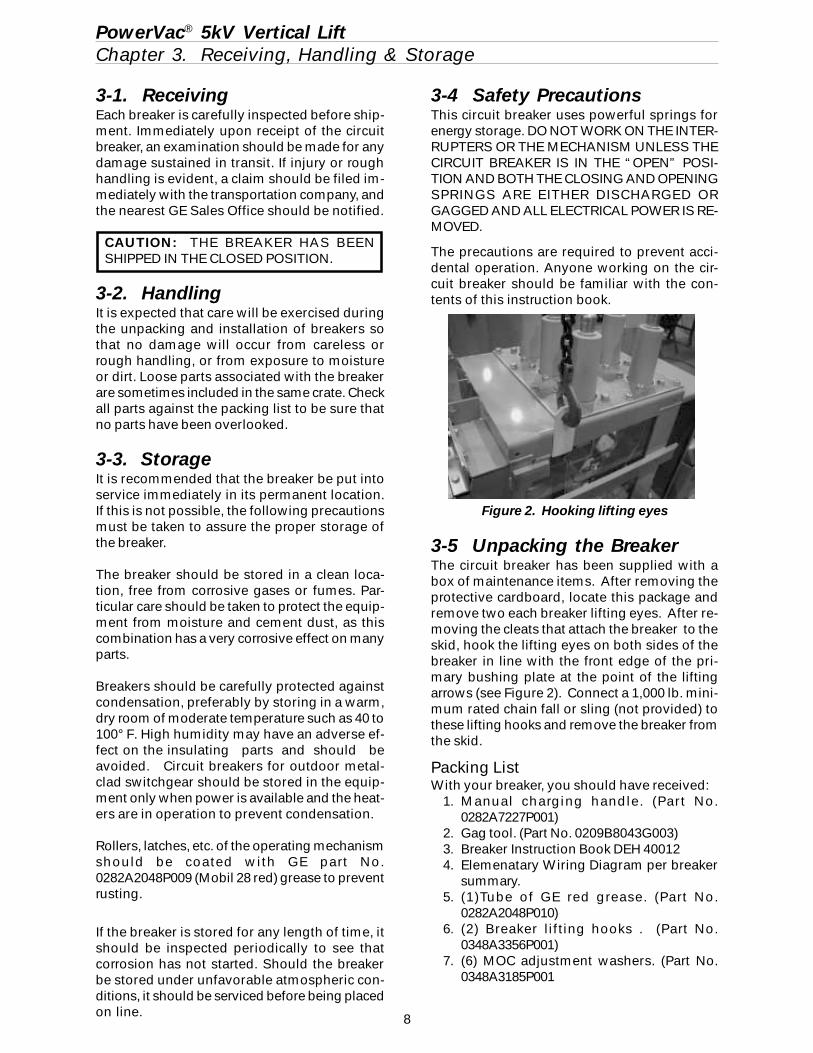
Figure 2. Hooking lifting eyes
3-4 Safety PrecautionsThis circuit breaker uses powerful springs forenergy storage. DO NOT WORK ON THE INTER-RUPTERS OR THE MECHANISM UNLESS THECIRCUIT BREAKER IS IN THE “OPEN” POSI-TION AND BOTH THE CLOSING AND OPENINGSPRINGS ARE EITHER DISCHARGED ORGAGGED AND ALL ELECTRICAL POWER IS RE-MOVED.
The precautions are required to prevent acci-dental operation. Anyone working on the cir-cuit breaker should be familiar with the con-tents of this instruction book.
3-5 Unpacking the BreakerThe circuit breaker has been supplied with abox of maintenance items. After removing theprotective cardboard, locate this package andremove two each breaker lifting eyes. After re-moving the cleats that attach the breaker to theskid, hook the lifting eyes on both sides of thebreaker in line with the front edge of the pri-mary bushing plate at the point of the liftingarrows (see Figure 2). Connect a 1,000 lb. mini-mum rated chain fall or sling (not provided) tothese lifting hooks and remove the breaker fromthe skid.
Packing ListWith your breaker, you should have received:
1. Manual charging handle. (Part No.0282A7227P001)
2. Gag tool. (Part No. 0209B8043G003)3. Breaker Instruction Book DEH 400124. Elemenatary Wiring Diagram per breaker
summary.5. (1)Tube of GE red grease. (Part No.
0282A2048P010)6. (2) Breaker lifting hooks . (Part No.
0348A3356P001)7. (6) MOC adjustment washers. (Part No.
0348A3185P001
9
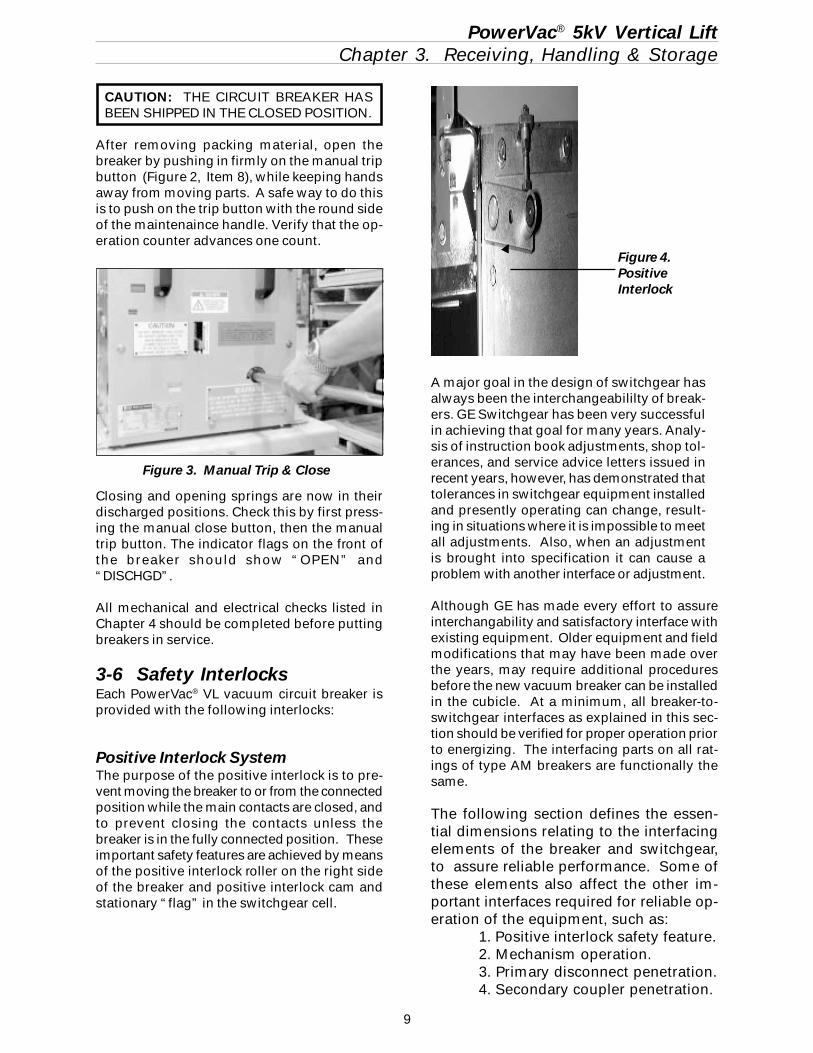
CAUTION: THE CIRCUIT BREAKER HASBEEN SHIPPED IN THE CLOSED POSITION.
After removing packing material, open thebreaker by pushing in firmly on the manual tripbutton (Figure 2, Item 8), while keeping handsaway from moving parts. A safe way to do thisis to push on the trip button with the round sideof the maintenaince handle. Verify that the op-eration counter advances one count.
Closing and opening springs are now in theirdischarged positions. Check this by first press-ing the manual close button, then the manualtrip button. The indicator flags on the front ofthe breaker should show “OPEN” and“DISCHGD”.
All mechanical and electrical checks listed inChapter 4 should be completed before puttingbreakers in service.
3-6 Safety InterlocksEach PowerVac® VL vacuum circuit breaker isprovided with the following interlocks:
Positive Interlock SystemThe purpose of the positive interlock is to pre-vent moving the breaker to or from the connectedposition while the main contacts are closed, andto prevent closing the contacts unless thebreaker is in the fully connected position. Theseimportant safety features are achieved by meansof the positive interlock roller on the right sideof the breaker and positive interlock cam andstationary “flag” in the switchgear cell.
PowerVac® 5kV Vertical LiftChapter 3. Receiving, Handling & Storage
A major goal in the design of switchgear hasalways been the interchangeabililty of break-ers. GE Switchgear has been very successfulin achieving that goal for many years. Analy-sis of instruction book adjustments, shop tol-erances, and service advice letters issued inrecent years, however, has demonstrated thattolerances in switchgear equipment installedand presently operating can change, result-ing in situations where it is impossible to meetall adjustments. Also, when an adjustmentis brought into specification it can cause aproblem with another interface or adjustment.
Although GE has made every effort to assureinterchangability and satisfactory interface withexisting equipment. Older equipment and fieldmodifications that may have been made overthe years, may require additional proceduresbefore the new vacuum breaker can be installedin the cubicle. At a minimum, all breaker-to-switchgear interfaces as explained in this sec-tion should be verified for proper operation priorto energizing. The interfacing parts on all rat-ings of type AM breakers are functionally thesame.
The following section defines the essen-tial dimensions relating to the interfacingelements of the breaker and switchgear,to assure reliable performance. Some ofthese elements also affect the other im-portant interfaces required for reliable op-eration of the equipment, such as:
1. Positive interlock safety feature.2. Mechanism operation.3. Primary disconnect penetration.4. Secondary coupler penetration.
Figure 4.PositiveInterlock
Figure 3. Manual Trip & Close
10
PowerVac® 5kV Vertical LiftChapter 3. Receiving, Handling & Storage
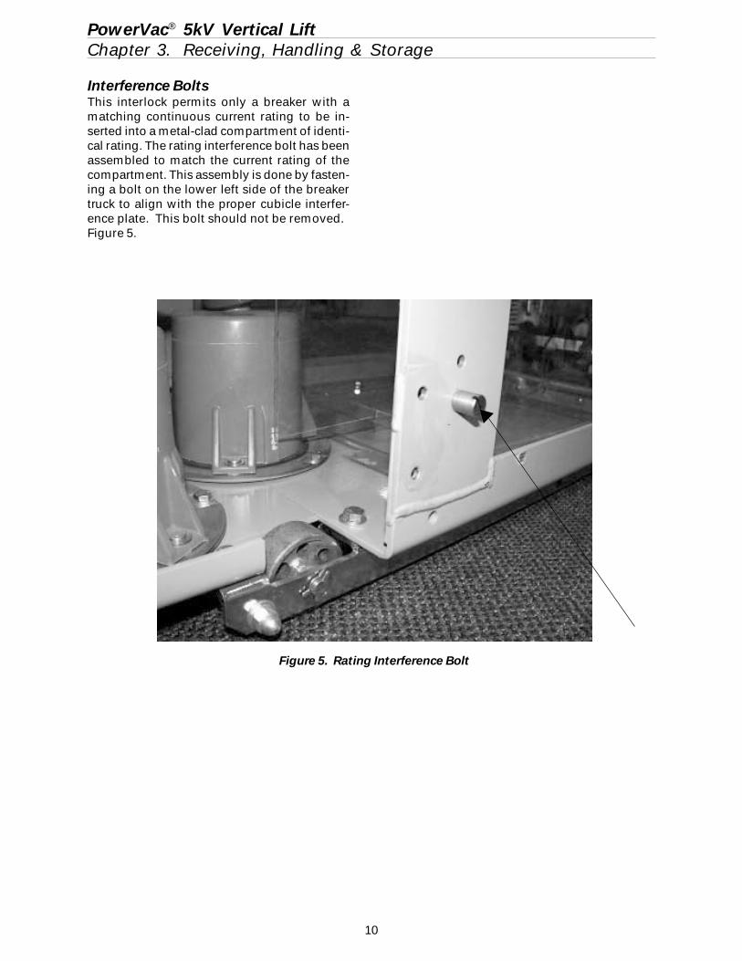
Interference BoltsThis interlock permits only a breaker with amatching continuous current rating to be in-serted into a metal-clad compartment of identi-cal rating. The rating interference bolt has beenassembled to match the current rating of thecompartment. This assembly is done by fasten-ing a bolt on the lower left side of the breakertruck to align with the proper cubicle interfer-ence plate. This bolt should not be removed.Figure 5.
Figure 5. Rating Interference Bolt
11
PowerVac® 5kV Vertical LiftChapter 4. Installation
4-1 Breaker PreparationPrior to interfacing the breaker into theswitchgear cell, rub a small amount of0282A2048P009 red grease, provided with thebreaker, on the silvered portion of the breakerstuds, ground shoe, and 16 secondary couplerpins, to form a thin coating for contact pur-poses.
4-2 Equipment Test PositionIn most AM breaker Metal-Clad Switchgearunits, there is a breaker “Test Position” whichallows you to functionally test the breaker with-out connecting to the bus. This position is low-ered fully down from the breaker being fully con-nected into the cubicle. When in the “test posi-tion”, a secondary coupler cable must be usedto connect the secondary control circuits forelectrical breaker operation.
While in the test position, the breaker interlockis not activated. The interlock roller will notrest in the lower “Vee” notch in the equipmentinterlock cam plate allowing the operator toclose and open the breaker electrically or manu-ally (see Figure 6).
The breaker positive interlock system shouldbe checked while in the test position prior toelevating the breaker.
WARNING: FAILURE TO PROPERLY VERIFYALL BREAKER SWITCHGEAR INTERFACESAND PROPER POSITIVE INTERLOCK OPERA-TION COULD RESULT IN A BREAKER OP-ERATIONAL FAILURE.
4-3 Positive InterlockThe positive interlock system prevents connect-ing or disconnecting the breaker in the cubicle,when the breaker is in the closed position andthe vacuum contacts are closed.
This interlock feature is accomplished by a rollerand lever located on the interlock shaft, on theright side of the breaker. (Figures 1, 4 and 6)The positive interlock lever (roller) provides atrip-free and discharged condition when rack-ing the breaker in the connected or disconnectposition. When the breaker is raised or lowered,
the positive interlock roller and lever are forcedforward by the postitive interlock cam on theright side of the switchgear cell. The interlockroller and lever are held in this forward positionduring raising and lowering operations, prevent-ing the breaker from being closed in any inter-mediate position between the connect and thefully lowered position. Any attempt to chargethe breaker will cause the stored energy springsto automatically discharge without the breakercontacts closing or moving. The breaker mustbe fully connected (raised) and the clutch handlemust be released before the breaker can beclosed. Releasing the clutch handle allows theinterlock cam plate in the cell to move down-ward allowing the interlock roller and lever toreturn to their normal vertical positions. Thebreaker may then be closed.
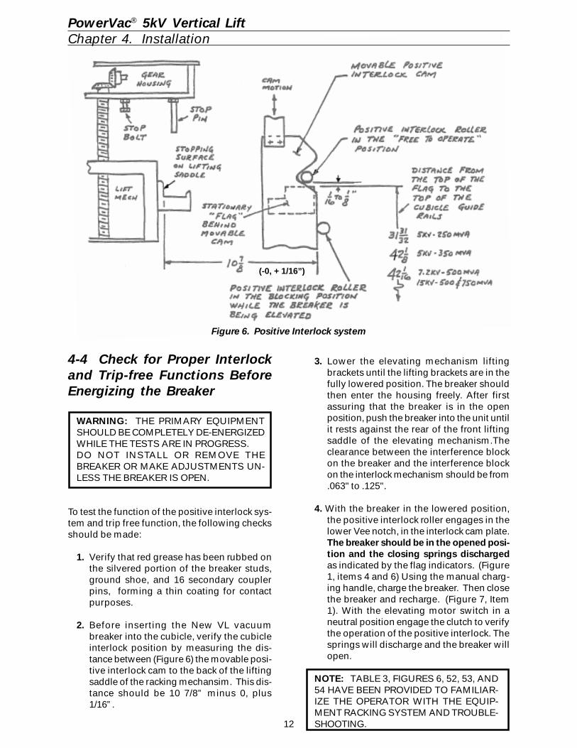
The following positive interlock adjustments aremade at the factory and verified for proper op-eration per Figure 6. The distance from the topof the stationary flag to the top of the switchgearguide rails is set. This maintains the surfaceupon which the breaker wheels rest when thebreaker is lowered. The upper elevating motorlimit switch is then adjusted to achieve a rollerto flag clearance of 1/16" to 1/8" as shown inFigure 6. The limit switch de-energizes the el-evating motor circuit and should be activatedwhen the primary disconnects and secondarycoupler reach their nominal contact penetrationposition. If the timing of this sequence is off,the cell must be adjusted back to factory speci-fications.
Typical instructions for making adjustments tothe cell positive interlock cam as provided withthe original equipment are outlined in Figure 6and Figure 53.
12
4-4 Check for Proper Interlockand Trip-free Functions BeforeEnergizing the Breaker
WARNING: THE PRIMARY EQUIPMENTSHOULD BE COMPLETELY DE-ENERGIZEDWHILE THE TESTS ARE IN PROGRESS.DO NOT INSTALL OR REMOVE THEBREAKER OR MAKE ADJUSTMENTS UN-LESS THE BREAKER IS OPEN.
To test the function of the positive interlock sys-tem and trip free function, the following checksshould be made:
1. Verify that red grease has been rubbed onthe silvered portion of the breaker studs,ground shoe, and 16 secondary couplerpins, forming a thin coating for contactpurposes.
2. Before inserting the New VL vacuumbreaker into the cubicle, verify the cubicleinterlock position by measuring the dis-tance between (Figure 6) the movable posi-tive interlock cam to the back of the liftingsaddle of the racking mechansim. This dis-tance should be 10 7/8” minus 0, plus1/16”.
Figure 6. Positive Interlock system
PowerVac® 5kV Vertical LiftChapter 4. Installation
3. Lower the elevating mechanism liftingbrackets until the lifting brackets are in thefully lowered position. The breaker shouldthen enter the housing freely. After firstassuring that the breaker is in the openposition, push the breaker into the unit untilit rests against the rear of the front liftingsaddle of the elevating mechanism.Theclearance between the interference blockon the breaker and the interference blockon the interlock mechanism should be from.063" to .125".
4. With the breaker in the lowered position,the positive interlock roller engages in thelower Vee notch, in the interlock cam plate.The breaker should be in the opened posi-tion and the closing springs dischargedas indicated by the flag indicators. (Figure1, items 4 and 6) Using the manual charg-ing handle, charge the breaker. Then closethe breaker and recharge. (Figure 7, Item1). With the elevating motor switch in aneutral position engage the clutch to verifythe operation of the positive interlock. Thesprings will discharge and the breaker willopen.
NOTE: TABLE 3, FIGURES 6, 52, 53, AND54 HAVE BEEN PROVIDED TO FAMILIAR-IZE THE OPERATOR WITH THE EQUIP-MENT RACKING SYSTEM AND TROUBLE-SHOOTING.
(-0, + 1/16”)
13
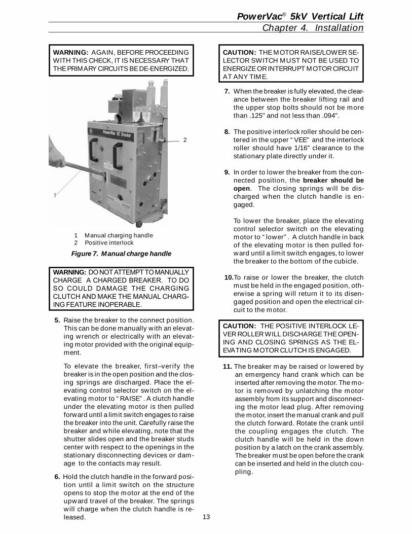
WARNING: AGAIN, BEFORE PROCEEDINGWITH THIS CHECK, IT IS NECESSARY THATTHE PRIMARY CIRCUITS BE DE-ENERGIZED.
5. Raise the breaker to the connect position.This can be done manually with an elevat-ing wrench or electrically with an elevat-ing motor provided with the original equip-ment.
To elevate the breaker, first–verify thebreaker is in the open position and the clos-ing springs are discharged. Place the el-evating control selector switch on the el-evating motor to “RAISE”. A clutch handleunder the elevating motor is then pulledforward until a limit switch engages to raisethe breaker into the unit. Carefully raise thebreaker and while elevating, note that theshutter slides open and the breaker studscenter with respect to the openings in thestationary disconnecting devices or dam-age to the contacts may result.
6. Hold the clutch handle in the forward posi-tion until a limit switch on the structureopens to stop the motor at the end of theupward travel of the breaker. The springswill charge when the clutch handle is re-leased.
CAUTION: THE MOTOR RAISE/LOWER SE-LECTOR SWITCH MUST NOT BE USED TOENERGIZE OR INTERRUPT MOTOR CIRCUITAT ANY TIME.
1 Manual charging handle2 Positive interlock
Figure 7. Manual charge handle
WARNING: DO NOT ATTEMPT TO MANUALLYCHARGE A CHARGED BREAKER. TO DOSO COULD DAMAGE THE CHARGINGCLUTCH AND MAKE THE MANUAL CHARG-ING FEATURE INOPERABLE.
2
PowerVac® 5kV Vertical LiftChapter 4. Installation
7. When the breaker is fully elevated, the clear-ance between the breaker lifting rail andthe upper stop bolts should not be morethan .125" and not less than .094".
8. The positive interlock roller should be cen-tered in the upper “VEE” and the interlockroller should have 1/16" clearance to thestationary plate directly under it.
9. In order to lower the breaker from the con-nected position, the breaker should beopen. The closing springs will be dis-charged when the clutch handle is en-gaged.
To lower the breaker, place the elevatingcontrol selector switch on the elevatingmotor to “lower”. A clutch handle in backof the elevating motor is then pulled for-ward until a limit switch engages, to lowerthe breaker to the bottom of the cubicle.
10.To raise or lower the breaker, the clutchmust be held in the engaged position, oth-erwise a spring will return it to its disen-gaged position and open the electrical cir-cuit to the motor.
CAUTION: THE POSITIVE INTERLOCK LE-VER ROLLER WILL DISCHARGE THE OPEN-ING AND CLOSING SPRINGS AS THE EL-EVATING MOTOR CLUTCH IS ENGAGED.
11. The breaker may be raised or lowered byan emergency hand crank which can beinserted after removing the motor. The mo-tor is removed by unlatching the motorassembly from its support and disconnect-ing the motor lead plug. After removingthe motor, insert the manual crank and pullthe clutch forward. Rotate the crank untilthe coupling engages the clutch. Theclutch handle will be held in the downposition by a latch on the crank assembly.The breaker must be open before the crankcan be inserted and held in the clutch cou-pling.
14
When the breaker is in the fully elevated and inthe connected position, releasing the motoroperating handle will return the positive inter-lock roller into the upper Vee notch in the inter-lock cam plate. The breaker positive interlockswitch will close and energize the motor charg-ing circuit allowing the closing spring tocharge. The breaker may now be closed.
In order to lower the breaker from the connectedposition, the breaker should be opened. If thebreaker has not been opened, operating themotor elevating clutch will open the contactsand discharge the springs.
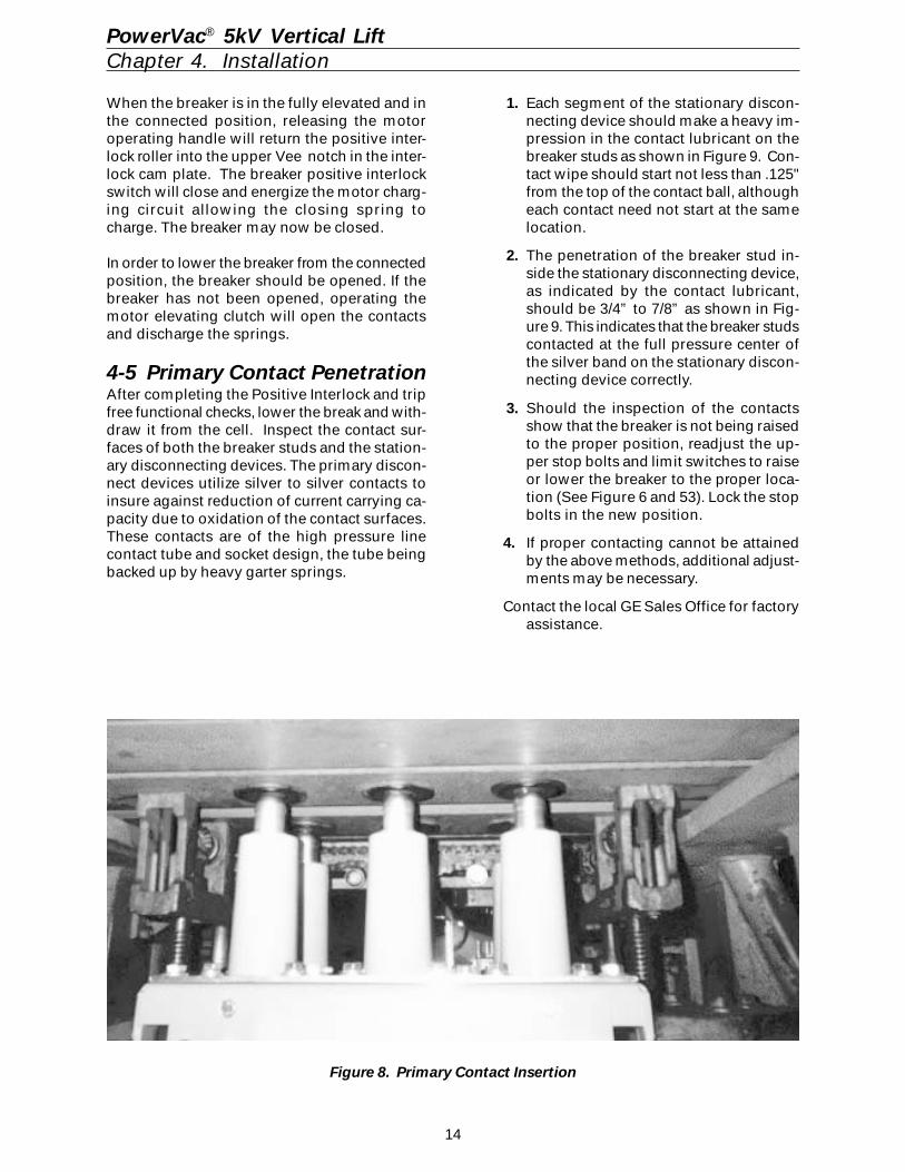
4-5 Primary Contact PenetrationAfter completing the Positive Interlock and tripfree functional checks, lower the break and with-draw it from the cell. Inspect the contact sur-faces of both the breaker studs and the station-ary disconnecting devices. The primary discon-nect devices utilize silver to silver contacts toinsure against reduction of current carrying ca-pacity due to oxidation of the contact surfaces.These contacts are of the high pressure linecontact tube and socket design, the tube beingbacked up by heavy garter springs.
1. Each segment of the stationary discon-necting device should make a heavy im-pression in the contact lubricant on thebreaker studs as shown in Figure 9. Con-tact wipe should start not less than .125"from the top of the contact ball, althougheach contact need not start at the samelocation.
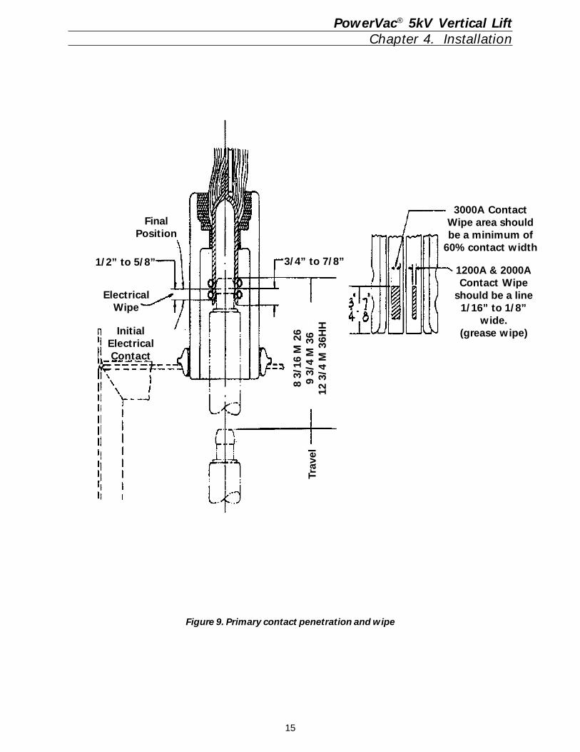
2. The penetration of the breaker stud in-side the stationary disconnecting device,as indicated by the contact lubricant,should be 3/4” to 7/8” as shown in Fig-ure 9. This indicates that the breaker studscontacted at the full pressure center ofthe silver band on the stationary discon-necting device correctly.
3. Should the inspection of the contactsshow that the breaker is not being raisedto the proper position, readjust the up-per stop bolts and limit switches to raiseor lower the breaker to the proper loca-tion (See Figure 6 and 53). Lock the stopbolts in the new position.
4. If proper contacting cannot be attainedby the above methods, additional adjust-ments may be necessary.
Contact the local GE Sales Office for factoryassistance.
Figure 8. Primary Contact Insertion
PowerVac® 5kV Vertical LiftChapter 4. Installation
15
Figure 9. Primary contact penetration and wipe
PowerVac® 5kV Vertical LiftChapter 4. Installation
FinalPosition
1/2” to 5/8”
ElectricalWipe
InitialElectricalContact
3/4” to 7/8”
Trav
el
3000A ContactWipe area shouldbe a minimum of
60% contact width
1200A & 2000AContact Wipe
should be a line1/16” to 1/8”
wide.(grease wipe)
8 3/
16 M
26
9 3/
4 M
36
12 3
/4 M
36H
H
16
4-6 Stationary Auxiliary Switch(MOC)
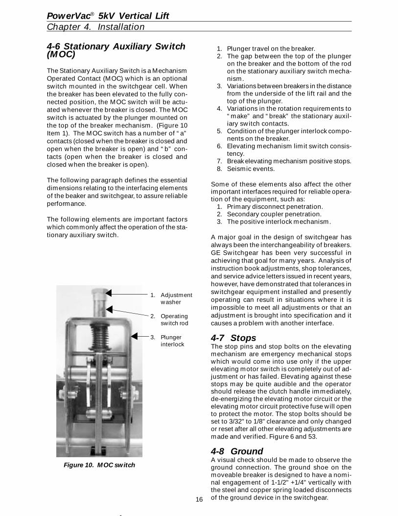
The Stationary Auxiliary Switch is a MechanismOperated Contact (MOC) which is an optionalswitch mounted in the switchgear cell. Whenthe breaker has been elevated to the fully con-nected position, the MOC switch will be actu-ated whenever the breaker is closed. The MOCswitch is actuated by the plunger mounted onthe top of the breaker mechanism. (Figure 10Item 1). The MOC switch has a number of “a”contacts (closed when the breaker is closed andopen when the breaker is open) and “b” con-tacts (open when the breaker is closed andclosed when the breaker is open).
The following paragraph defines the essentialdimensions relating to the interfacing elementsof the beaker and switchgear, to assure reliableperformance.
The following elements are important factorswhich commonly affect the operation of the sta-tionary auxiliary switch.
PowerVac® 5kV Vertical LiftChapter 4. Installation
1. Plunger travel on the breaker.2. The gap between the top of the plunger
on the breaker and the bottom of the rodon the stationary auxiliary switch mecha-nism.
3. Variations between breakers in the distancefrom the underside of the lift rail and thetop of the plunger.
4. Variations in the rotation requirements to“make” and “break” the stationary auxil-iary switch contacts.
5. Condition of the plunger interlock compo-nents on the breaker.
6. Elevating mechanism limit switch consis-tency.
7. Break elevating mechanism positive stops.8. Seismic events.
Some of these elements also affect the otherimportant interfaces required for reliable opera-tion of the equipment, such as:
1. Primary disconnect penetration.2. Secondary coupler penetration.3. The positive interlock mechanism.
A major goal in the design of switchgear hasalways been the interchangeability of breakers.GE Switchgear has been very successful inachieving that goal for many years. Analysis ofinstruction book adjustments, shop tolerances,and service advice letters issued in recent years,however, have demonstrated that tolerances inswitchgear equipment installed and presentlyoperating can result in situations where it isimpossible to meet all adjustments or that anadjustment is brought into specification and itcauses a problem with another interface.
4-7 StopsThe stop pins and stop bolts on the elevatingmechanism are emergency mechanical stopswhich would come into use only if the upperelevating motor switch is completely out of ad-justment or has failed. Elevating against thesestops may be quite audible and the operatorshould release the clutch handle immediately,de-energizing the elevating motor circuit or theelevating motor circuit protective fuse will opento protect the motor. The stop bolts should beset to 3/32" to 1/8" clearance and only changedor reset after all other elevating adjustments aremade and verified. Figure 6 and 53.
4-8 GroundA visual check should be made to observe theground connection. The ground shoe on themoveable breaker is designed to have a nomi-nal engagement of 1-1/2" +1/4" vertically withthe steel and copper spring loaded disconnectsof the ground device in the switchgear.
Figure 10. MOC switch
1. Adjustmentwasher
2. Operatingswitch rod
3. Plungerinterlock
17
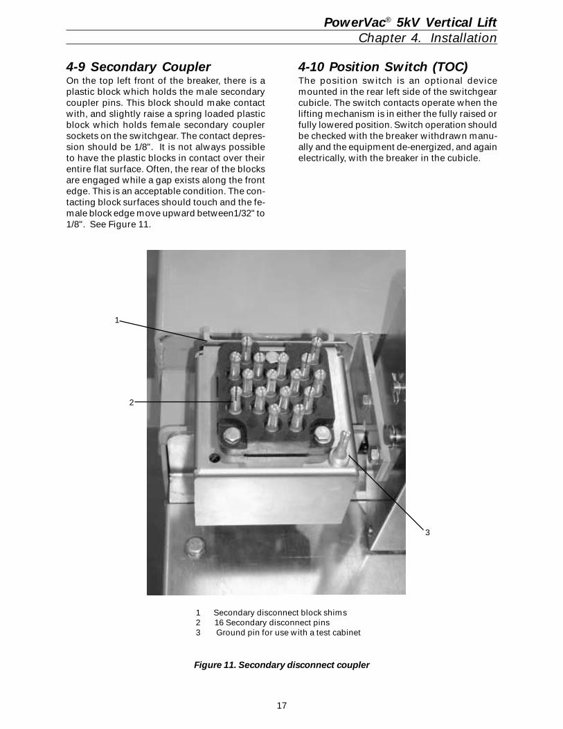
4-9 Secondary CouplerOn the top left front of the breaker, there is aplastic block which holds the male secondarycoupler pins. This block should make contactwith, and slightly raise a spring loaded plasticblock which holds female secondary couplersockets on the switchgear. The contact depres-sion should be 1/8". It is not always possibleto have the plastic blocks in contact over theirentire flat surface. Often, the rear of the blocksare engaged while a gap exists along the frontedge. This is an acceptable condition. The con-tacting block surfaces should touch and the fe-male block edge move upward between1/32" to1/8". See Figure 11.
Figure 11. Secondary disconnect coupler
1
2
3
1 Secondary disconnect block shims2 16 Secondary disconnect pins3 Ground pin for use with a test cabinet
PowerVac® 5kV Vertical LiftChapter 4. Installation
4-10 Position Switch (TOC)The position switch is an optional devicemounted in the rear left side of the switchgearcubicle. The switch contacts operate when thelifting mechanism is in either the fully raised orfully lowered position. Switch operation shouldbe checked with the breaker withdrawn manu-ally and the equipment de-energized, and againelectrically, with the breaker in the cubicle.
18
5-1 Description
The PowerVac® 5kV VL vacuum circuit breakeruses a sealed vacuum power interrupter to es-tablish and interrupt a primary circuit. Primaryconnections to the associated metal-cladswitchgear are made by pole assemblies, elec-trically and mechanically connected to thevacuum interrupters. The operating mechanismprovides vertical motion at each pole locationin order to move the lower contact of thevacuum interrupters from an open position to aspring-loaded closed position and then back tothe open position on command.
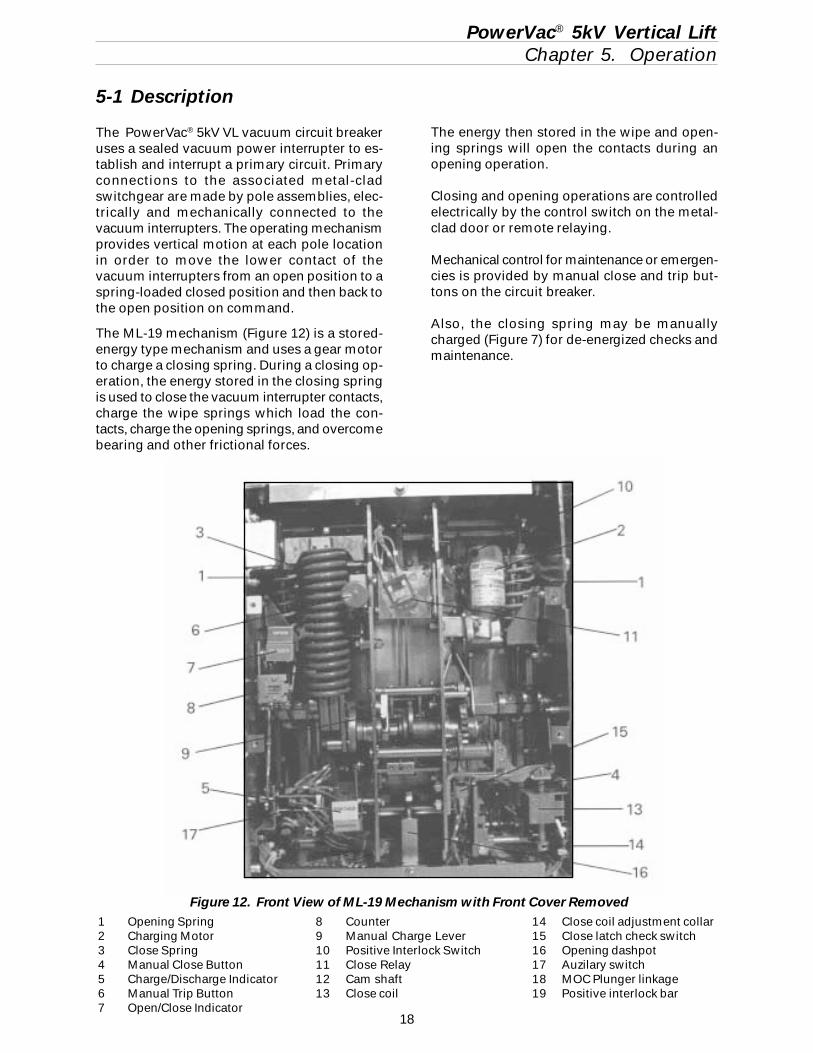
The ML-19 mechanism (Figure 12) is a stored-energy type mechanism and uses a gear motorto charge a closing spring. During a closing op-eration, the energy stored in the closing springis used to close the vacuum interrupter contacts,charge the wipe springs which load the con-tacts, charge the opening springs, and overcomebearing and other frictional forces.
PowerVac® 5kV Vertical LiftChapter 5. Operation
The energy then stored in the wipe and open-ing springs will open the contacts during anopening operation.
Closing and opening operations are controlledelectrically by the control switch on the metal-clad door or remote relaying.
Mechanical control for maintenance or emergen-cies is provided by manual close and trip but-tons on the circuit breaker.
Also, the closing spring may be manuallycharged (Figure 7) for de-energized checks andmaintenance.
Figure 12. Front View of ML-19 Mechanism with Front Cover Removed1 Opening Spring2 Charging Motor3 Close Spring4 Manual Close Button5 Charge/Discharge Indicator6 Manual Trip Button7 Open/Close Indicator
8 Counter9 Manual Charge Lever10 Positive Interlock Switch11 Close Relay12 Cam shaft13 Close coil
14 Close coil adjustment collar15 Close latch check switch16 Opening dashpot17 Auzilary switch18 MOC Plunger linkage19 Positive interlock bar
19
PowerVac® 5kV Vertical LiftChapter 5. Operation
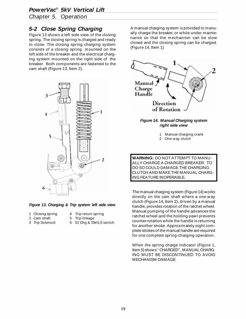
5-2 Close Spring ChargingFigure 13 shows a left side view of the closingspring. The closing spring is charged and readyto close. The closing spring charging systemconsists of a closing spring mounted on theleft side of the breaker and the electrical charg-ing system mounted on the right side of thebreaker. Both components are fastened to thecam shaft (Figure 13, Item 2).
Figure 14. Manual Charging systemright side view
1 Manual charging crank2 One way clutch
A manual charging system is provided to manu-ally charge the breaker, or while under mainte-nance so that the mechanism can be slowclosed and the closing spring can be charged.(Figure 14, Item 1)
WARNING: DO NOT ATTEMPT TO MANU-ALLY CHARGE A CHARGED BREAKER. TODO SO COULD DAMAGE THE CHARGINGCLUTCH AND MAKE THE MANUAL CHARG-ING FEATURE INOPERABLE.
The manual charging system (Figure 14) worksdirectly on the cam shaft where a one-wayclutch (Figure 14, Item 2), driven by a manualhandle, provides rotation of the ratchet wheel.Manual pumping of the handle advances theratchet wheel and the holding pawl preventscounter-rotation while the handle is returningfor another stroke. Approximately eight com-plete strokes of the manual handle are requiredfor one complete spring-charging operation.
When the spring charge indicator (Figure 1,Item 5) shows “CHARGED”, MANUAL CHARG-ING MUST BE DISCONTINUED TO AVOIDMECHANISM DAMAGE.
Figure 13. Charging & Trip system left side view
1 Closing spring 4 Trip return spring2 Cam shaft 5 Trip linkage3 Trip Solenoid 6 52 Chg & SM/LS switch
20
The closing coil cannot be electrically energizedunless the closing spring is completely charged.This action is prevented by the 52/CHG switchin the closing circuit. (Figure 13, Item 6)
5-3 Trip Free OperationThe linkage is mechanically trip-free in any lo-cation on the closing stroke. Electrically ener-gizing the trip coil while closing will, after theauxiliary switch contacts change position, ro-tate the trip latch and permit the circuit breakerto open fully. The linkage will reset as in a nor-mal open operation and the closing spring willrecharge as described under “CLOSE SPRING
CHARGING”.
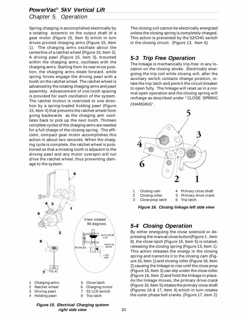
5-4 Closing OperationBy either energizing the close solenoid or de-pressing the manual close button(Figure 1 , Item8) the close latch (Figure 15, Item 5) is rotated,releasing the closing spring (Figure 13, Item 1).This action releases the energy in the closingspring and transmits it to the closing cam (Fig-ure 16, Item 1) and closing roller (Figure 16, Item2) causing the linkage to rise until the close prop(Figure 16, Item 3) can slip under the close roller(Figure 16, Item 2) and hold the linkage in place.As the linkage moves, the primary drive crank(Figure 16, Item 5) rotates the primary cross shaft(Figures 16 & 17, Item 4) which in turn rotatesthe outer phase bell cranks. (Figure 17, item 2)
Figure 15. Electrical Charging systemright side view
1 Charging arms 5 Close latch2 Ratchet wheel 6 Charging motor3 Driving pawl 7 52 LCS switch4 Holding pawl 8 Trip latch
Spring charging is accomplished electrically bya rotating eccentric on the output shaft of agear motor (Figure 15, Item 6) which in turndrives pivoted charging arms (Figure 15, Item1). The charging arms oscillate about thecenterline of a ratchet wheel (Figure 15, Item 2).A driving pawl (Figure 15, item 3), mountedwithin the charging arms, oscillates with thecharging arms. Starting from its rear-most posi-tion, the charging arms rotate forward, whilespring forces engage the driving pawl with atooth on the ratchet wheel. The ratchet wheel isadvanced by the rotating charging arms and pawlassembly. Advancement of one tooth spacingis provided for each oscillation of the system.The ratchet motion is restricted to one direc-tion by a spring-loaded holding pawl (Figure15, Item 4) that prevents the ratchet wheel fromgoing backwards as the charging arm oscil-lates back to pick up the next tooth. Thirteencomplete cycles of the charging arms are neededfor a full charge of the closing spring. The effi-cient, compact gear motor accomplishes thisaction in about two seconds. When the charg-ing cycle is complete, the ratchet wheel is posi-tioned so that a missing tooth is adjacent to thedriving pawl and any motor overspin will notdrive the ratchet wheel, thus preventing dam-age to the system.
PowerVac® 5kV Vertical LiftChapter 5. Operation
1 Closing cam 4 Primary cross shaft2 Closing roller 5 Primary drive crank3 Close prop latch 6 Trip latch
Figure 16. Closing linkage left side view
View rotated 90 degrees
21
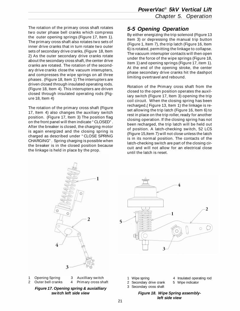
1 Wipe spring 4 Insulated operating rod2 Secondary drive crank 5 Wipe indicator3 Secondary cross shaft
Figure 18. Wipe Spring assembly-left side view
PowerVac® 5kV Vertical LiftChapter 5. Operation
The rotation of the primary cross shaft rotatestwo outer phase bell cranks which compressthe outer opening springs (Figure 17, Item 1).The primary cross shaft also rotates two sets ofinner drive cranks that in turn rotate two outersets of secondary drive cranks, (Figure 18, Item2) As the outer secondary drive cranks rotateabout the secondary cross shaft, the center drivecranks are rotated. The rotation of the second-ary drive cranks close the vacuum interrupters,and compresses the wipe springs on all threephases . (Figure 18, Item 1) The interrupters aredriven closed through insulated operating rods.(Figure 18, Item 4). This interrupters are drivenclosed through insulated operating rods (Fig-ure 18, Item 4)
The rotation of the primary cross shaft (Figure17, Item 4) also changes the auxiliary switchposition. (Figure 17, Item 3) The position flagon the front panel will then indicate “CLOSED”.After the breaker is closed, the charging motoris again energized and the closing spring ischarged as described under “CLOSE SPRINGCHARGING”. Spring charging is possible whenthe breaker is in the closed position becausethe linkage is held in place by the prop.
5-5 Opening OperationBy either energizing the trip solenoid (Figure 13Item 3) or depressing the manual trip button(Figure 1, Item 7), the trip latch (Figure 16, Item6) is rotated, permitting the linkage to collapse.The vacuum interrupter contacts will then openunder the force of the wipe springs (Figure 18,item 1) and opening springs (Figure 17, item 1).At the end of the opening stroke, the centerphase secondary drive cranks hit the dashpotlimiting overtravel and rebound.
Rotation of the Primary cross shaft from theclosed to the open position operates the auxil-iary switch (Figure 17, Item 3) opening the tripcoil circuit. When the closing spring has beenrecharged,( Figure 13, Item 1) the linkage is re-set allowing the trip latch (Figure 16, Item 6) torest in place on the trip roller, ready for anotherclosing operation. If the closing spring has notbeen recharged, the trip latch will be held outof position. A latch-checking switch, 52 LCS(Figure 15,Item 7) will not close unless the latchis in its normal position. The contacts of thelatch-checking switch are part of the closing cir-cuit and will not allow for an electrical closeuntil the latch is reset.
1 Opening Spring 3 Auxilliary switch2 Outer bell cranks 4 Primary cross shaft
Figure 17. Opening spring & auxialliaryswitch left side view
22
PowerVac® 5kV Vertical LiftChapter 6. Control Circuit
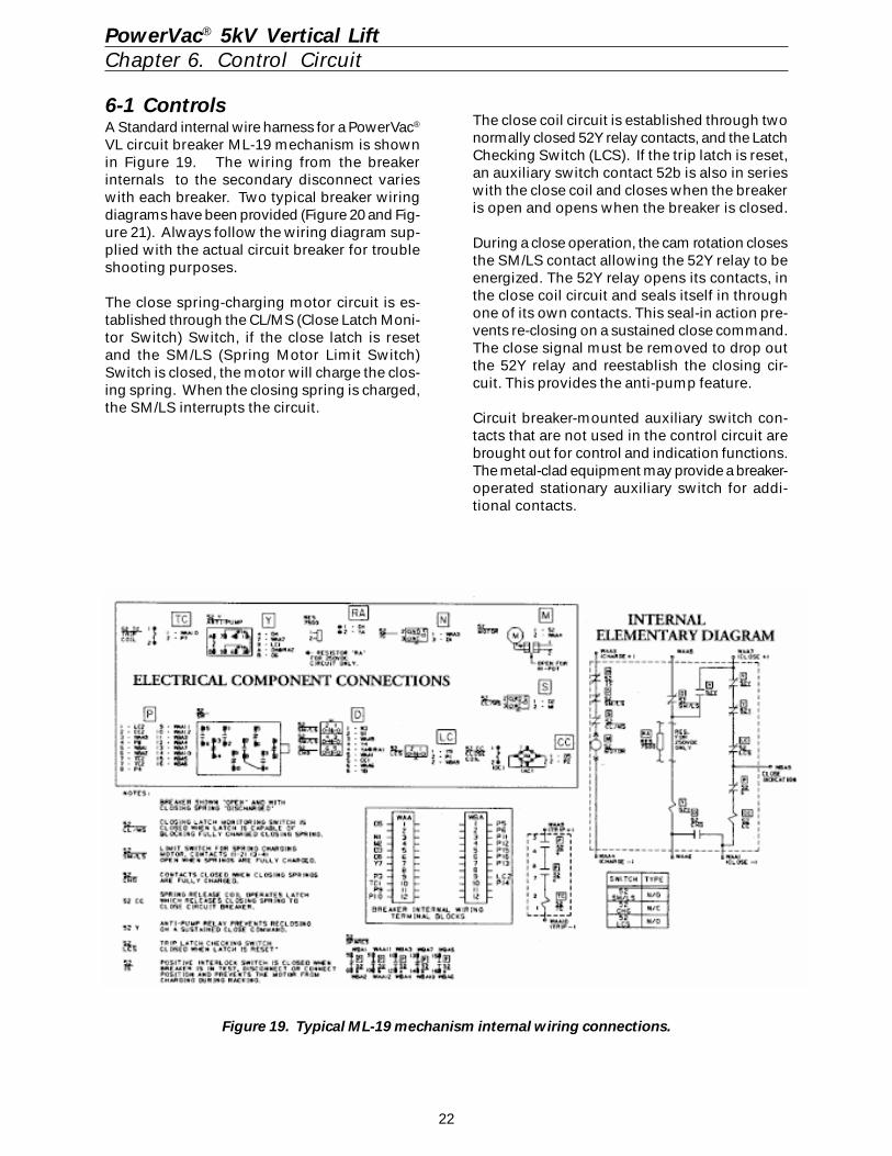
6-1 ControlsA Standard internal wire harness for a PowerVac®
VL circuit breaker ML-19 mechanism is shownin Figure 19. The wiring from the breakerinternals to the secondary disconnect varieswith each breaker. Two typical breaker wiringdiagrams have been provided (Figure 20 and Fig-ure 21). Always follow the wiring diagram sup-plied with the actual circuit breaker for troubleshooting purposes.
The close spring-charging motor circuit is es-tablished through the CL/MS (Close Latch Moni-tor Switch) Switch, if the close latch is resetand the SM/LS (Spring Motor Limit Switch)Switch is closed, the motor will charge the clos-ing spring. When the closing spring is charged,the SM/LS interrupts the circuit.
The close coil circuit is established through twonormally closed 52Y relay contacts, and the LatchChecking Switch (LCS). If the trip latch is reset,an auxiliary switch contact 52b is also in serieswith the close coil and closes when the breakeris open and opens when the breaker is closed.
During a close operation, the cam rotation closesthe SM/LS contact allowing the 52Y relay to beenergized. The 52Y relay opens its contacts, inthe close coil circuit and seals itself in throughone of its own contacts. This seal-in action pre-vents re-closing on a sustained close command.The close signal must be removed to drop outthe 52Y relay and reestablish the closing cir-cuit. This provides the anti-pump feature.
Circuit breaker-mounted auxiliary switch con-tacts that are not used in the control circuit arebrought out for control and indication functions.The metal-clad equipment may provide a breaker-operated stationary auxiliary switch for addi-tional contacts.
Figure 19. Typical ML-19 mechanism internal wiring connections.
23
PowerVac® 5kV Vertical LiftChapter 6. Control Circuit
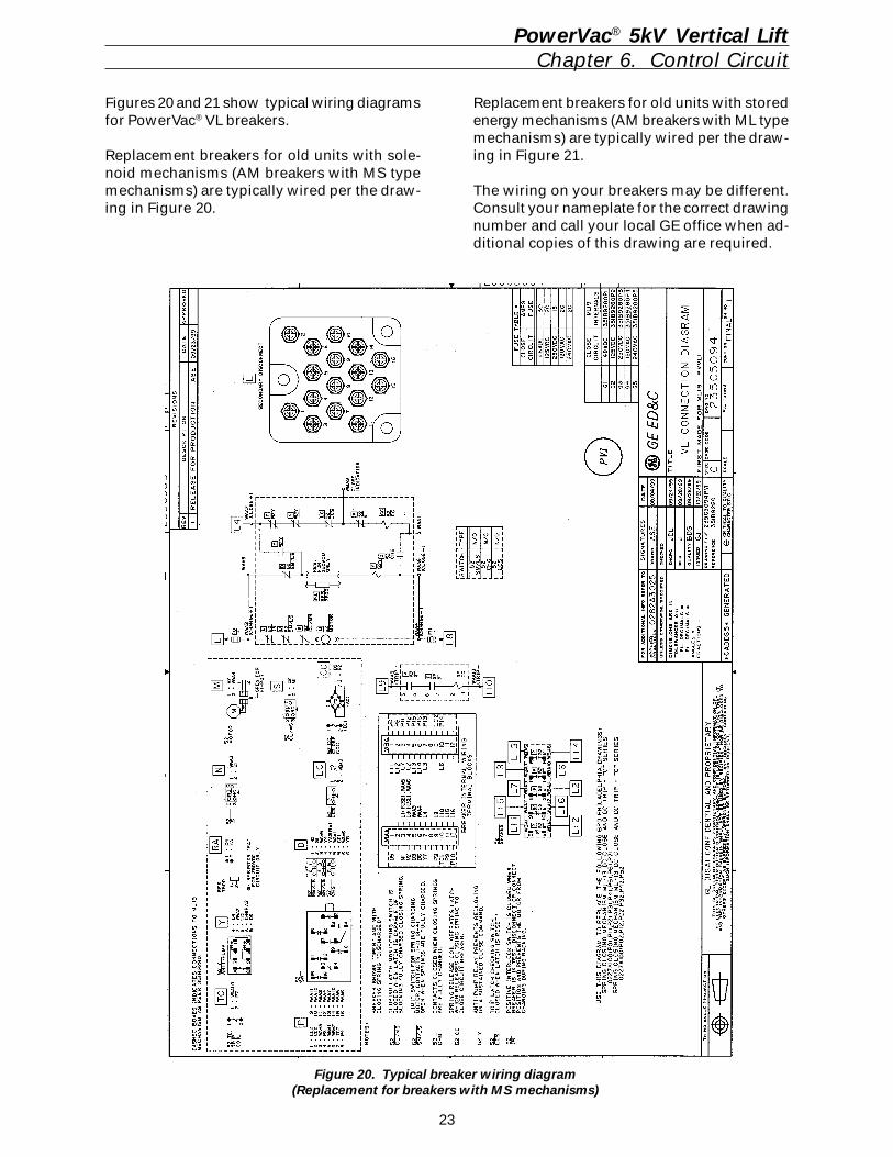
Figures 20 and 21 show typical wiring diagramsfor PowerVac® VL breakers.
Replacement breakers for old units with sole-noid mechanisms (AM breakers with MS typemechanisms) are typically wired per the draw-ing in Figure 20.
Figure 20. Typical breaker wiring diagram(Replacement for breakers with MS mechanisms)
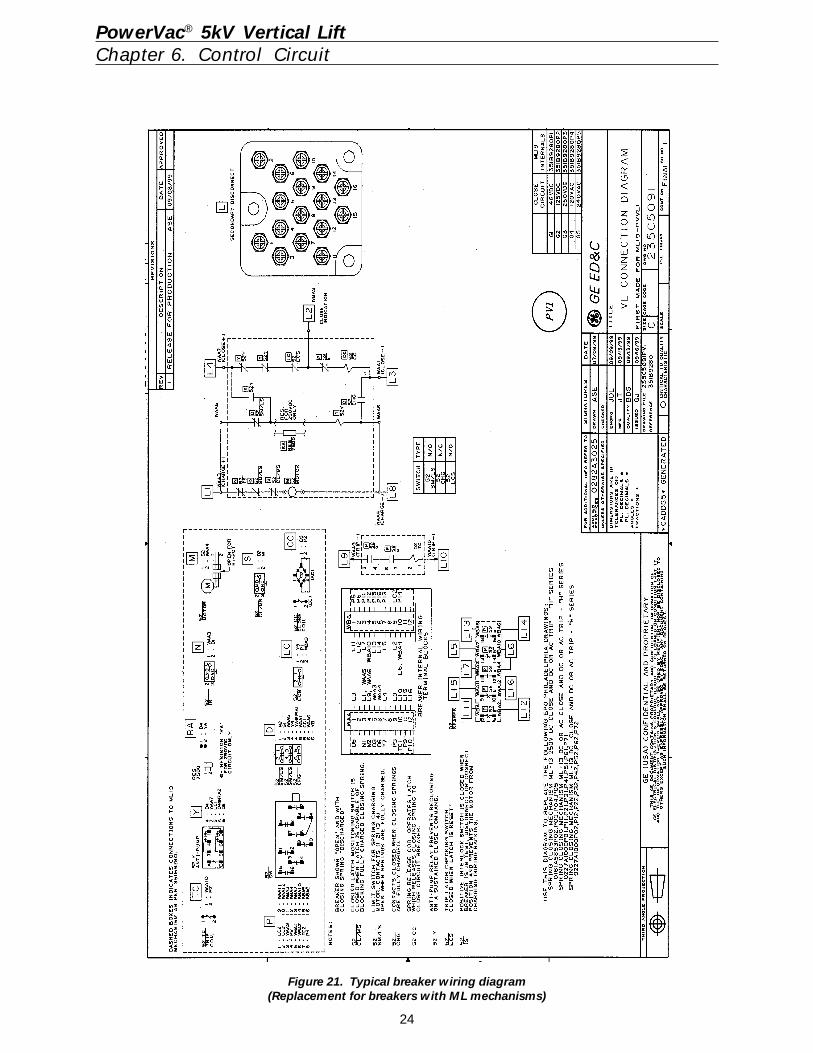
Replacement breakers for old units with storedenergy mechanisms (AM breakers with ML typemechanisms) are typically wired per the draw-ing in Figure 21.
The wiring on your breakers may be different.Consult your nameplate for the correct drawingnumber and call your local GE office when ad-ditional copies of this drawing are required.
24
Figure 21. Typical breaker wiring diagram(Replacement for breakers with ML mechanisms)
PowerVac® 5kV Vertical LiftChapter 6. Control Circuit
25
7-4 Slow ClosingTo manually slow close the breaker contacts,remove the top plate of mechanism. Install theclosing spring gag, as described above. Put themanual charge handle on the manual chargelever and move the handle up and down. Thebreaker will be fully closed when the springcharge indicator shows “CHARGED”
CAUTION: WITH THE GAG TOOL INSTALLED,THE BREAKER CLOSED, AND OPENINGSPRINGS CHARGED, THE BREAKER CAN BETRIPPED AT FULL SPEED.
7-5 Gag Tool RemovalTo remove the gag tool, the closing spring mustbe fully charged. If the spring charge indicatordoes not show “CHARGED” in the window,manually charge the spring until it does. Lift upand push down and away on the gag tool toclear the détentes on the gag tool from the slotsin the closing spring guide. For safety, first closethe breaker by depressing the manual “CLOSE”button and then depress the manual “TRIP”button. All stored energy is now removed fromthe breaker.
PowerVac® 5kV Vertical LiftChapter 7. Mechanical Checking and Slow Closing
7-1 Visual InspectionVisually inspect the circuit breaker for any signsof damage or loose hardware.
7-2 Closing Spring ChargingManually charge the breaker closing spring us-ing the charging handle provided. (Figure 7, Item1) The closing spring is charged by aratcheting mechanism that advances oneratchet tooth at a time. Approximately eightcomplete strokes are required. When the springis fully charged, the spring load is held by theclosing latch. The spring indicator (Figure 1,Item 5) changes from “DISCHGD” to“CHARGED”, and a positive snap is heard asthe spring travels over center.
CAUTION: AFTER THE SPRING IS COM-PLETELY CHARGED, AS INDICATED ABOVE,FURTHER FORCING THE CHARGINGHANDLE MAY CAUSE DAMAGE TO THECLOSING LATCH AND ITS ASSOCIATEDPARTS.
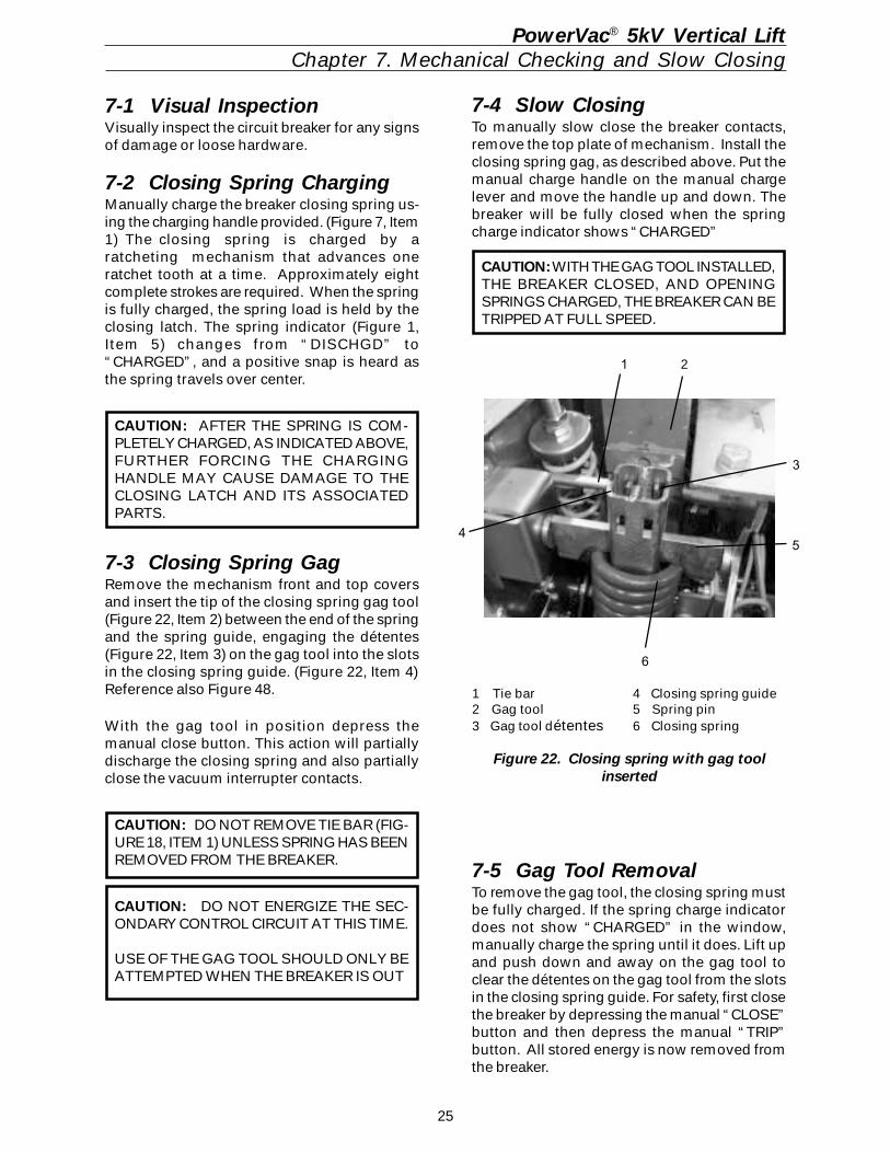
7-3 Closing Spring GagRemove the mechanism front and top coversand insert the tip of the closing spring gag tool(Figure 22, Item 2) between the end of the springand the spring guide, engaging the détentes(Figure 22, Item 3) on the gag tool into the slotsin the closing spring guide. (Figure 22, Item 4)Reference also Figure 48.
With the gag tool in position depress themanual close button. This action will partiallydischarge the closing spring and also partiallyclose the vacuum interrupter contacts.
CAUTION: DO NOT REMOVE TIE BAR (FIG-URE 18, ITEM 1) UNLESS SPRING HAS BEENREMOVED FROM THE BREAKER.
CAUTION: DO NOT ENERGIZE THE SEC-ONDARY CONTROL CIRCUIT AT THIS TIME.
USE OF THE GAG TOOL SHOULD ONLY BEATTEMPTED WHEN THE BREAKER IS OUT
1 Tie bar 4 Closing spring guide2 Gag tool 5 Spring pin3 Gag tool détentes 6 Closing spring
Figure 22. Closing spring with gag toolinserted
1 2
3
4 5
6
26
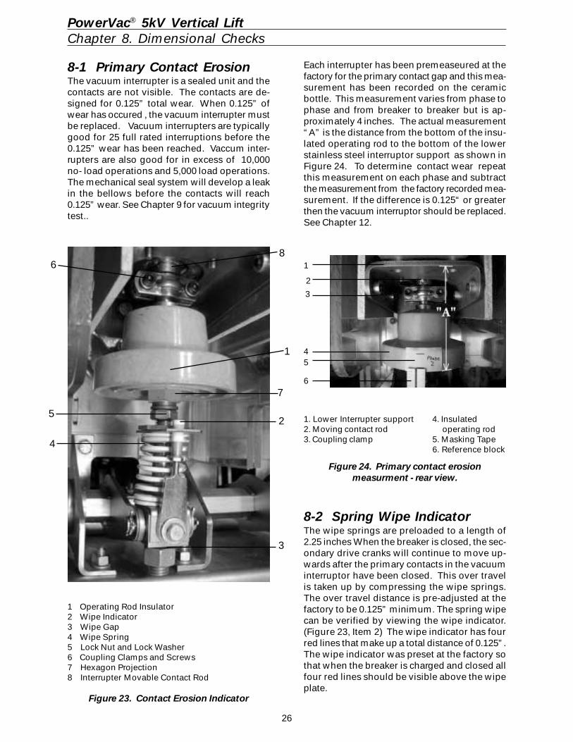
Each interrupter has been premeaseured at thefactory for the primary contact gap and this mea-surement has been recorded on the ceramicbottle. This measurement varies from phase tophase and from breaker to breaker but is ap-proximately 4 inches. The actual measurement“A” is the distance from the bottom of the insu-lated operating rod to the bottom of the lowerstainless steel interruptor support as shown inFigure 24. To determine contact wear repeatthis measurement on each phase and subtractthe measurement from the factory recorded mea-surement. If the difference is 0.125“ or greaterthen the vacuum interruptor should be replaced.See Chapter 12.
8-2 Spring Wipe IndicatorThe wipe springs are preloaded to a length of2.25 inches When the breaker is closed, the sec-ondary drive cranks will continue to move up-wards after the primary contacts in the vacuuminterruptor have been closed. This over travelis taken up by compressing the wipe springs.The over travel distance is pre-adjusted at thefactory to be 0.125” minimum. The spring wipecan be verified by viewing the wipe indicator.(Figure 23, Item 2) The wipe indicator has fourred lines that make up a total distance of 0.125”.The wipe indicator was preset at the factory sothat when the breaker is charged and closed allfour red lines should be visible above the wipeplate.
8-1 Primary Contact ErosionThe vacuum interrupter is a sealed unit and thecontacts are not visible. The contacts are de-signed for 0.125” total wear. When 0.125” ofwear has occured , the vacuum interrupter mustbe replaced. Vacuum interrupters are typicallygood for 25 full rated interruptions before the0.125” wear has been reached. Vaccum inter-rupters are also good for in excess of 10,000no- load operations and 5,000 load operations.The mechanical seal system will develop a leakin the bellows before the contacts will reach0.125” wear. See Chapter 9 for vacuum integritytest..
PowerVac® 5kV Vertical LiftChapter 8. Dimensional Checks
1
4
3
6
5
2
1. Lower Interrupter support 4. Insulated2. Moving contact rod operating rod3. Coupling clamp 5. Masking Tape
6. Reference block
Figure 24. Primary contact erosionmeasurment - rear view.
1 Operating Rod Insulator2 Wipe Indicator3 Wipe Gap4 Wipe Spring5 Lock Nut and Lock Washer6 Coupling Clamps and Screws7 Hexagon Projection8 Interrupter Movable Contact Rod
Figure 23. Contact Erosion Indicator
1
2
3
4
5
6 8
7
27
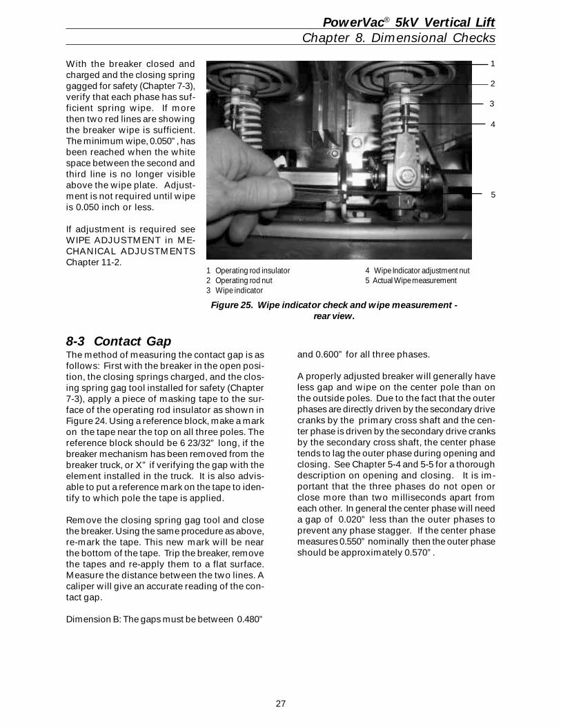
With the breaker closed andcharged and the closing springgagged for safety (Chapter 7-3),verify that each phase has suf-ficient spring wipe. If morethen two red lines are showingthe breaker wipe is sufficient.The minimum wipe, 0.050”, hasbeen reached when the whitespace between the second andthird line is no longer visibleabove the wipe plate. Adjust-ment is not required until wipeis 0.050 inch or less.
If adjustment is required seeWIPE ADJUSTMENT in ME-CHANICAL ADJUSTMENTSChapter 11-2.
8-3 Contact GapThe method of measuring the contact gap is asfollows: First with the breaker in the open posi-tion, the closing springs charged, and the clos-ing spring gag tool installed for safety (Chapter7-3), apply a piece of masking tape to the sur-face of the operating rod insulator as shown inFigure 24. Using a reference block, make a markon the tape near the top on all three poles. Thereference block should be 6 23/32” long, if thebreaker mechanism has been removed from thebreaker truck, or X” if verifying the gap with theelement installed in the truck. It is also advis-able to put a reference mark on the tape to iden-tify to which pole the tape is applied.
Remove the closing spring gag tool and closethe breaker. Using the same procedure as above,re-mark the tape. This new mark will be nearthe bottom of the tape. Trip the breaker, removethe tapes and re-apply them to a flat surface.Measure the distance between the two lines. Acaliper will give an accurate reading of the con-tact gap.
Dimension B: The gaps must be between 0.480”
PowerVac® 5kV Vertical LiftChapter 8. Dimensional Checks
1 Operating rod insulator2 Operating rod nut3 Wipe indicator
and 0.600” for all three phases.
A properly adjusted breaker will generally haveless gap and wipe on the center pole than onthe outside poles. Due to the fact that the outerphases are directly driven by the secondary drivecranks by the primary cross shaft and the cen-ter phase is driven by the secondary drive cranksby the secondary cross shaft, the center phasetends to lag the outer phase during opening andclosing. See Chapter 5-4 and 5-5 for a thoroughdescription on opening and closing. It is im-portant that the three phases do not open orclose more than two milliseconds apart fromeach other. In general the center phase will needa gap of 0.020” less than the outer phases toprevent any phase stagger. If the center phasemeasures 0.550” nominally then the outer phaseshould be approximately 0.570”.
3
4
5
1
2
Figure 25. Wipe indicator check and wipe measurement -rear view.
4 Wipe Indicator adjustment nut5 Actual Wipe measurement
28
9-1 Electrical OperationElectrical checking consists of electrical breakeroperation primary and seconary wiring high-po-tential testing (if required), primary circuitreistance (if required), PowerVac interrupter high-potential testing, and insulation resistance toground.
To check the electrical operation with the breakerremoved from the cubicle, attach a secondarytest coupler to the circuit breaker connector andthe other end to the secondary coupler mountedin the cubicle. Check the control voltage on thenameplate and close and open the breaker sev-eral times.
CAUTION: REPEATED OPERATIONS AT A RATEEXCEEDING TWO PER MINUTE MAY CAUSECHARGING MOTOR OVERHEATING AND FAILURE.
Leave the circuit breaker in an open and springdischarged condition after checks are completeand before inserting the circuit breaker into ametal-clad unit. Reinstall the front cover if ithas been removed.
9-2 High-Potential TestIf hi-potential tests to check the integrity of theinsulation are required, the AC hi-potential testdescribed below is strongly recommended. DChigh-potential testing is not recommended. Thefollowing procedure must be adhered to.
CAUTION: IF DC HIGH-POTENTIAL TESTING ISREQUIRED, THE DC HIGH POTENTIAL MACHINEMUST NOT PRODUCE PEAK VOLTAGES EXCEED-ING 50 KV.
NOTE: ALWAYS RECHECK WITH AN AC TESTSET, IF INITIAL RESULTS ARE QUESTIONABLE.
Primary CircuitThe breaker should be AC hi-potted in the closedbreaker mode to verify the insulation system.An AC hi-pot machine capable of producing thetest voltages shown below may be used to hi-pot the breaker phase to phase and phase toground.
BREAKER VOLTAGE TEST VOLTAGE4.16 kV 14 kV
CAUTION: DISCONNECT THE SURGE SUPPRES-SORS BEFORE HI-POTTING THE CIRCUIT BREAKER.
The machine should be connected with its out-put potential at zero and the voltage increasedat 500 vps to the test voltage and that voltagemaintained for 60 seconds. The voltage shouldthen be returned to zero and the hi-pot machineremoved from the circuit. Do not exceed thetest voltage indicated for the applicable breakervoltage rating.
If the test should experience a failure, STOP,turn off the test set and discharge the breakercircuit.
1. Check the test setup and leads for con-nection errors.
2. Wipe down the breaker to remove anymoisture, dust and contamination.
3. Retest the breaker at the proper test volt-age.
Secondary CircuitPrior to hi-potting the breaker secondary circuit,disconnect the motor leads and thread a wireconnecting all secondary coupler pins. Con-nect the hi-pot machine from this wire to ground.Increase the voltage to 1125 volts (rms) 60 Hzand maintain for 60 seconds. Reduce the volt-age to zero and remove the hi-pot machine con-nections from the circuit. Remove the wire con-necting the secondary coupler pins and recon-nect the motor leads.
9-3 Primary Circuit ResistanceA resistance check of the primary circuit maybe made with the breaker closed. Use a lowresistance measuring instrument which mea-sures micro-ohms. The 100 ampere readingshould be less than 40 micro-ohms when con-nected.
9-4 Vacuum Interrupter Integrity TestNOTE: USE OF A DC HI-POT IS NOT RECOMMENDED,BUT CAN BE USED FOR QUICK FIELD CHECKS ONLY.ALWAYS RECHECK WITH AN AC TESTER IF INITIAL RE-SULTS ARE QUESTIONABLE. PRIOR TO PERFORMINGANY VACUUM INTERRUPTER INTEGRITY TEST, THEOUTSIDE (EXTERNAL SURFACE) OF THE VACUUM IN-TERRUPTERS SHOULD BE WIPED CLEAN OF ANYCONTANMINATES WITH A NON-LINTING CLOTH ORINDUSTRIAL TYPE WIPER. THIS IS CRITICAL: THE EN-TIRE EXTERNAL SURFACE IS TO BE COMPLETELY FREEOF ALL DIRT, DEBRIS, DUST, OIL, ETC.
CAUTION: X-RADIATION WILL BE PRODUCED IF ANABNORMALLY HIGH VOLTAGE IS APPLIED ACROSS APAIR OF ELECTRODES IN A VACUUM. X-RADIATIONWILL INCREASE AS VOLTAGE INCREASES AND/ORAS CONTACT SEPARATION DECREASES. ONLY TESTA CORRECTLY-ADJUSTED CIRCUIT BREAKER.
DURING A HIGH-POTENTIAL OR A VACUUM INTEG-RITY TEST, ANY X-RADIATION WHICH MAY BE PRO-DUCED WILL NOT BE HAZARDOUS AT A DISTANCESAFE FOR HIGH-POTENTIAL TESTING, IF THE TEST ISCONDUCTED AT THE REC-OMMENDED VOLTAGEAND WITH THE NORMAL OPEN CIRCUIT BREAKER GAP.
DO NOT APPLY VOLTAGE THAT IS HIGHER THANTHE RECOMMENDED VALUE OR USE CONTACTSEPARATION THAT IS LESS THAN THE RECOM-MENDED OPEN-POSITION BREAKER CONTACTGAP.
PowerVac® 5kV Vertical LiftChapter 9. Electrical Checks
29
2. After the high-potential voltage is removed,discharge any electrical charge that may beretained.
CAUTION: MANY DC HIGH-POTENTIAL MA-CHINES ARE HALFWAVE RECTIFIERS. THIS TYPEOF HI-POT TESTER MUST NOT BE USED TO TESTVACUUM INTERRUPTERS. THE CAPACITANCEOF THE POWERVAC BOTTLES IS VERY LOW ANDTHE LEAKAGE IN THE RECTIFIER AND ITS DCVOLTAGE MEASURING EQUIPMENT IS SUCHTHAT THE PULSE FROM THE HALFWAVE RECTI-FIER MAY BE IN THE NEIGHBORHOOD OF 120KV WHEN THE METER IS ACTUALLY READING40 KV. IN THIS CASE, SOME PERFECTLY GOODBOTTLES CAN SHOW A RELATIVELY HIGH LEAK-AGE CURRENT SINCE IT IS THE PEAK VOLTAGEOF 120 KV THAT IS PRODUCING ERRONEOUSBOTTLE LEAKAGE CURRENT. IN ADDITION, AB-NORMAL X-RADIATION WILL BE PRODUCED.
The following is a list of acceptable hi-potentialmachines.
AC machines: Hipotronics Model 7BT 60AHipotronics Model 60HVTBiddle Cat. 222060Phoenix Model 7BT 60A
DC machines: Hipotronics Model 860PLHipotronics Model 880PL
9-5 Insulation TestsThe primary circuit insulation on the breaker maybe checked phase to phase and phase to groundusing a 2500 Volt or other suitable megohmeter.
CAUTION: DISCONNECT THE SURGE SUPPRES-SORS BEFORE HI-POTTING THE CIRCUITBREAKER.
Since definite limits cannot be given for satis-factory insulation values, a record should bekept of the megohmeter readings as well as tem-perature and humidity readings. This recordshould be used to detect any weakening of theinsulation from one check period to the next.Generally, readings should equal or exceed10,000 megohms.
To measure the breaker secondary circuit insu-lation resistance, with a megohmeter discon-nect the motor leads and thread a wire connect-ing together all secondary coupler pins. Themeasurement is made by connecting a 500 Voltmegohmeter from the wire to ground.
PowerVac® 5kV Vertical LiftChapter 9. Electrical Checks
This test of the vacuum interrupter will deter-mine its internal dielectric condition and vacuumintegrity.
CAUTION: DISCONNECT THE SURGE SUPPRES-SORS BEFORE HI-POTTING THE CIRCUITBREAKER AND VACUUM INTERRUPTERS.
The vacuum integrity test is performed usingan AC hi-potential tester. A vacuum integritytest of the interrupter is required to insure thatno loss of vacuum has occurred.
With the breaker open, individually check eachinterrupter by connecting the hi-pot machine“Hot” lead to the primary bushing and theground lead to the load side bushing. If themachine has a center point ground, the con-nections can be made either way.
For the Vacuum Integrity Test, Apply 27 kV (rms)60 Hz at 500 vps and hold for 10 seconds. If nobreakdown occurs, the interrupter is in accept-able condition. After the hi-potential voltage isremoved, discharge any electrical charge thatmay be present through the internal ground ofthe test machine or by a grounded cable to oneof the phase bushings.
If a failure of a vacuum bottle should occur dur-ing the integrity test, the test procedure shouldbe reviewed and the pole piece cleaned.
GE failure rate for vacuum bottles is 0.0007 perfield unit.
1. Note the voltage level at failure on the firsttest, and retest the phase pole piece. If thepole piece passes re-test, the vacuum bottleis acceptable. STOP.
2. If the test fails again, but at a higher-voltagelevel than was observed in the first test,clean the pole piece and retest.
3. If a failure of the integrity test occurs a thirdtime, consider the vacuum bottle to havelost vacuum and replace the complete polepiece as described under Repair of Inter-rupter Assembly, Chapter 12.
Although a AC high-potential test is recom-mended for checking the vacuum integrity, a DChigh potential test can also be conducted onthe vacuum interrupters at 40 kV and held for 10seconds with the restrictions noted as follows.
1. No attempt should be made to compare theone vacuum interrupter with another, nor tocorrelate the condition of any interrupter tolow values of DC leakage current. There isno significant correlation.
30
PowerVac® 5kV Vertical LiftChapter 10. Maintenance
10-1 GeneralPowerVac® 5kV VL circuit breakers have beendesigned to be as maintenance-free as practi-cable. They include features such as sealedvacuum interrupters and long-life syntheticgreases which contribute to many years oftrouble-free performance with a minimumamount of maintenance.
If maintenance on the PowerVac® VL breaker isbeing performed to an extended schedule suchas a 5-year or 10-year program, the vacuuminterrupter integrity test should be performed ifthe breaker is removed for reasons other thanscheduled breaker maintenance, and it has beenmore than one year since the last vacuum in-tegrity test.
Both long and short term maintenance of all elec-trical equipment is essential for reliability andsafety. Maintenance programs MUST be custom-ized to the specific application, well planned,and carried out consistent with both industryexperience and manufacturer’s recommenda-tions. The local environment must always beconsidered in such programs, including suchvariables as ambient temperatures, extrememoisture, number of operations, corrosive at-mosphere or major insect problems and anyother unusual or abusive condition of the ap-plication.
One of the critical service activities, sometimesneglected, involves the servicing and calibra-tion of various relay, protection, and control de-vices. These devices monitor conditions in theprimary and secondary circuits, sometimes ini-tiating emergency corrective action such asopening or closing circuit breakers. In view ofthe vital role of these devices, it is importantthat a periodic test program be followed. As wasoutlined above, it is recognized that the intervalbetween periodic checks will vary dependingupon environment, the type of device and theuser’s experience. It is the General Electricrecommendation that, until the user has accu-mulated enough experience to select a test in-terval better suited to his individual require-ments, all significant relay calibrations shouldbe checked at an interval of one to two years.
To accomplish this, protective relays can be ad-equately tested using field test sets. Specificcalibration instructions on particular devicestypically are provided by supplied instructionbooks.
Instruction books supplied by manufacturersaddress components that would normally re-quire service or maintenance during the usefullife of the equipment. However, they can not in-clude every possible part that could require at-tention, particularly over a very long serviceperiod or under adverse environments. Mainte-nance personnel must be alert to deteriorationof any part of the supplied switchgear, takingactions, as necessary, to restore it to service-able status.
Industry publications of recommended mainte-nance practices such as ANSI/NFPA 70B, Elec-trical Equipment Maintenance, should be care-fully studied and applied in each user’s forma-tion of a planned maintenance program.
Some users may require additional assistancefrom GE in the planning and performance ofmaintenance. The local GE office can be con-tacted to either undertake maintenance or to pro-vide technical assistance, including the latestequipment publications.
The performance and safety of this equipmentmay be compromised by the modification ofsupplied parts or their replacement by non-iden-tical substitutes. All such design changesshould be qualified by GE factory engineering.
The user should methodically keep written main-tenance records as an aid in future service plan-ning and equipment reliability improvement. Un-usual experiences should be promptly com-municated to GE.
PowerVac® InterrupterThe PowerVac® Interrupter used in this breakeris a reliable, clean interrupting element. Sincethe contacts are contained in a vacuum cham-ber, they remain clean and require no mainte-nance at any time. The metallic vapors erodedfrom the contact surfaces during high currentinterruption remain in the chamber and are de-posited on metal shields thus insuring a highdielectric value of the vacuum and the walls ofthe interrupter.
Trouble ReportingAlthough all reputable manufacturers designtheir products to perform satisfactorily with aminimum of problems, the IEEE SwitchgearCommittee, an organization of both users andmanufacturers, recognized the need for a com-mon trouble reporting format. A reproduciblecopy of this form is included on pages 66 and67 of this book and is recommended for usewith any manufacturer’s circuit breakers.
31
Any major observed problems should be docu-mented. Forward the completed user reportforms to GE Resolution at West Burlington,Iowa.
The intent is for each maintenance organizationto keep specific problem files with this informa-tion documented. If the problem is serious orrepetitive, a summary should be sent to the ap-propriate manufacturer for action. The level ofdetail included on the form is considered verydesirable so that the manufacturer’s investiga-tor may more thoroughly understand and solvethe reported problem.
10-2 Service ConditionsThe frequency of required maintenance dependson the severity of the service conditions of theswitchgear application. If the service conditionsare mild, the interval between maintenance op-erations may be extended to 10 years or 10,000no load operations or 5000 normal load switch-ing operations.
Mild service conditions are defined as an envi-ronment in which the switchgear is protectedfrom the deleterious effects of conditions suchas:
Salt spray.Changes in temperature that produce dust conductive/or abrasive and condensation.Damaging chemicals and fumes.Vibration or mechanical shock.High relative humidity (90%).Temperature extremes (below -30º C or above+40º C).
WARNING: BEFORE ANY MAINTENANCEWORK IS PERFORMED, MAKE CERTAINTHAT ALL CONTROL CIRCUITS ARE DE-EN-ERGIZED AND THAT THE BREAKER IS RE-MOVED FROM THE METALCLAD UNIT. DONOT WORK ON THE BREAKER OR MECHA-NISM WHILE IT IS IN THE CLOSED POSI-TION WITHOUT TAKING PRECAUTIONS TOPREVENT ACCIDENTAL TRIPPING. DO NOTWORK ON THE BREAKER WHILE THE CLOS-ING SPRING IS CHARGED UNLESS IT IS SE-CURED IN THAT POSITION BY THE CLOS-ING-SPRING GAG.
PowerVac® 5kV Vertical LiftChapter 10. Maintenance
10-3 Fault InterruptionsThe erosion rate of the primary contacts in thevacuum interrupters is very low for no-load andnormal load switching operations. However,fault current interruptions at or near the breakerrating may result in appreciable contact erosion.With frequent fault interruptions, it is neces-sary to perform maintenance based on the num-ber of interruptions. After each 20 full fault inter-ruptions the following should be performed:
1. Contact erosion check.2. Wipe and gap check.3. Vacuum interrupter integrity test.
10-4 Contact ErosionRefer to Chapter 8-1 for contact erosion and con-tact gap measurements. When erosion reaches1/8 inch, the interrupter should be replaced.
10-5 Transfer Finger WearWith the breaker open, examine the movingcontact rod projecting below the transfer fingers(Figure 23, Item 8). Wipe off the lubricant inorder to see the metal surface condition. Thefinger locations should present a burnished sil-ver contact surface without copper appearance.If copper is visible at more than one locationper pole or the silver plating is torn, the inter-rupter assembly should be replaced. After in-spection, re-lubricate with grease, part #0282A2048P009 (Mobil 28 red grease).
10-6 MechanismCheck all items covered in INSTALLATION Chap-ter 4 and readjust or tighten hardware as re-quired. Lubricate as recommended under LU-BRICATION.
10-7 Primary Insulation PartsUsing dry, non-linting cloth or industrial-typewipers, clean accessible insulation surfaces onthe interrupter supports and operating rod insu-lators. In service locations, where contamina-tion is heavy or external flashovers have oc-curred, or occurance is noted during interrupterhigh-potential testing, remove the interrupterassemblies and clean the inside surfaces of theinterrupter supports and the outer insulationsurfaces of the PowerVac interrupters. Followthe procedure in REPAIR AND REPLACEMENT,Chapter 12.
32
Be sure to discharge the interrupter before re-moving the interrupter assemblies. Removal andre-assembly of complete interrupter assembliesis recommended and adjustment is not nor-mally required due to the design of the inter-rupter operating rod insulator connection. Theinterrupter assemblies should be returned to thesame location from which they were removed.
Replacement of individual vacuum bottles is notrecommended. Therefore, vacuum bottles arenot supplied as a replacement part.
10-8 LubricationProper lubrication is important for maintainingreliable circuit breaker performance. The ML-19mechanism uses bearings which have a syn-thetic lining in some locations. These bearingsdo not require lubrication to maintain low fric-tion, but lubrication does not harm them andoiling lightly is recommended. Sleeve bearingsare used in some linkage locations and needleor roller bearings are used for low friction onthe trip shaft and close shaft.
Bearings are lubricated during factory assem-bly with grease and oil, but all lubricants havea tendency to deteriorate with age. Providing afresh lubricant supply at periodic intervals isessential to proper breaker operation, especiallywhere frequent operation may have forced lu-bricant out of the bearing surfaces. Apply afew drops of light synthetic machine oil suchas Mobil 1 at each bearing. Apply a coat of0282A2048P009 grease on the four corners ofthe closing spring guide where it enters insidethe spring. Metal-to-metal contact surfacesshould be cleaned and lubricated with0282A2048P009 grease to provide cleanlinessand prevent oxidation.
Electrical primary contact surfaces also requireperiodic lubrication to inhibit oxidation andminimize friction. At each inspection and main-tenance interval, do the following:
1. Wipe clean and coat lightly with0282A2048P009 grease all silvered primarycontact surfaces such as the movable con-tact rod of the interrupter and the primarydisconnect fingers.
2. Clean and coat lightly with 0282A2048P009grease the pins of the secondary coupler.
PowerVac® 5kV Vertical LiftChapter 10. Maintenance
10-9 RecommendedMaintenanceThe following operations should be performedat each maintenance check:
1. Perform a visual inspection of the breaker.Check for loose or damaged parts.
2. Perform a slow closing operation de-scribed under MECHANICAL CHECKINGAND SLOW CLOSING.
3. Check the erosion indicator and the wipeand gap as described under DIMENSIONALCHECKS.
4. Perform the vacuum interrupter integrity testas described under ELECTRICAL CHECKS.
5. Lubricate the breaker operating mechanismas described under LUBRICATION.
6. Check the electrical operation of the breakerusing the portable test cabinet.
CAUTION: REPEATED OPERATIONS AT ARATE EXCEEDING TWO PER MINUTE MAYCAUSE CHARGING MOTOR OVERHEAT-ING AND SUBSEQUENT MOTOR FAILURE.
7. Examine the movable contact rod as de-scribed in Chapter 10-5.
8. If desired, perform the additional tests(Megger, Primary and Secondary High Po-tential, and Primary Circuit Resistance).See ELECTRICAL CHECKS.
10-10 Breaker Timing & SpeedCheckTiming and speed checks are optional and alsodepend on the level of maintenance performed.Generally these tests are not required for nor-mal maintenance. If a new mechanism has beeninstalled or extensive repair, replacement ormajor disassembly has been performed, it isrecommended that these tests be performed.
To determine contact velocity, a travel transducerand oscillograph are required. Optional traveltransducer and linkage system can be obtainedby contacting your local GE Sales Office by or-dering part number 0144D1238G001. The traveltransducer apparatus can typically be installedas shown in Figure 28. A typical travel traceand interpretation are shown in Figure 26.
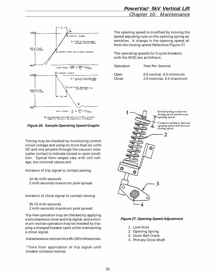
33
Timing may be checked by monitoring controlcircuit voltage and using no more than six voltsDC and one ampere through the vacuum inter-rupter contact to indicate closed or open condi-tion. Typical time ranges vary with coil volt-age, but nominal values are:
Initiation of trip signal to contact parting
32-45 milli-seconds 2 milli-seconds maximum pole spread
Initiation of close signal to contact closing
35-75 milli-seconds 2 milli-seconds maximum pole spread.
Trip-free operation may be checked by applyinga simultaneous close and trip signal, and a mini-mum reclose operation may be checked by trip-ping a charged breaker open while maintaininga close signal.
Instantaneous reclose time 85-150 milliseconds.
*Time from application of trip signal untilbreaker contacts reclose.
Figure 27. Opening Speed Adjustment
1. Lock Nuts2. Opening Spring3. Outer Bell Crank4. Primary Cross Shaft
PowerVac® 5kV Vertical LiftChapter 10. Maintenance
Figure 26. Sample Operating Speed Graphs
The opening speed is modified by moving thespeed adjusting nuts on the opening spring as-semblies. A change in the opening speed af-fects the closing speed Reference Figure 27.
The operating speeds for 5 cycle breakerswith the MOC are as follows:
Operation Feet Per Second
Open 6.5 normal, 4.5 minimumClose 2.6 nominal, 4.2 maximum
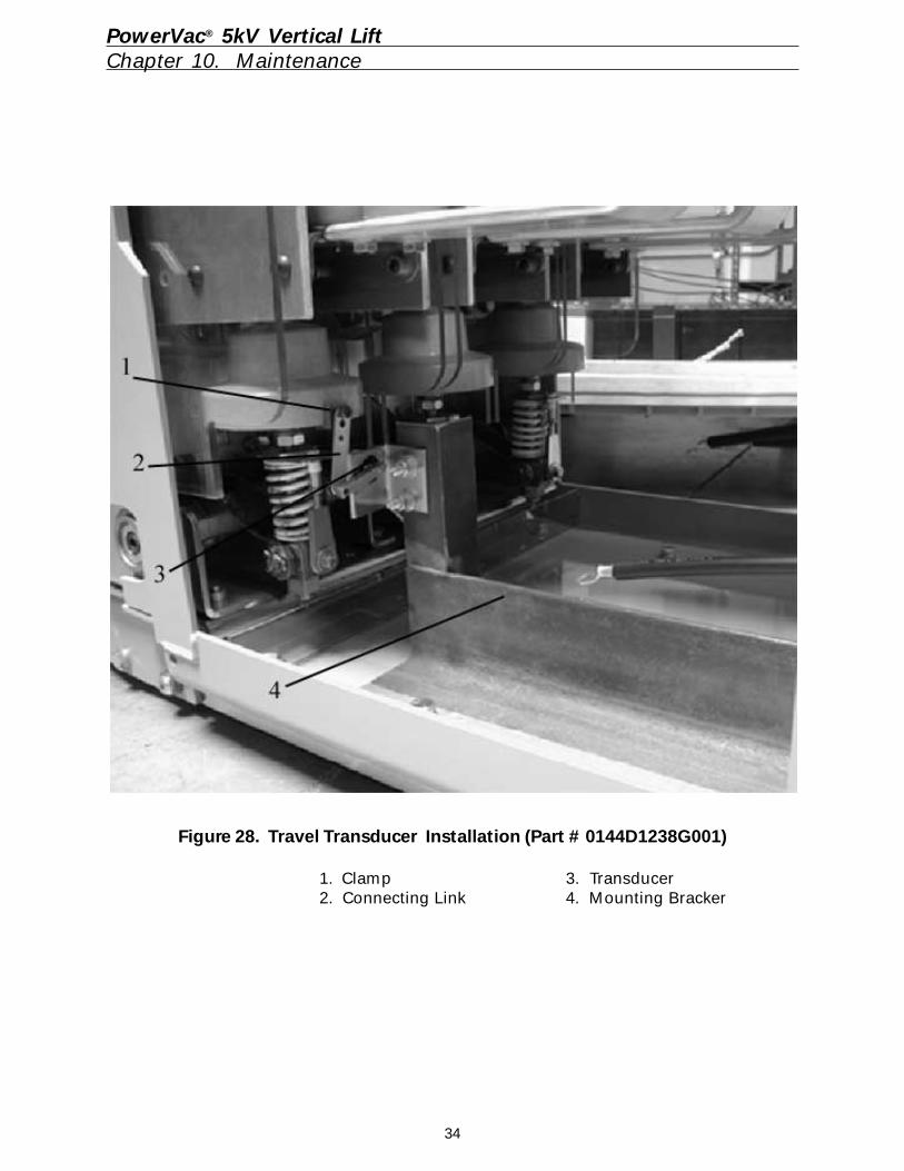
34
Figure 28. Travel Transducer Installation (Part # 0144D1238G001)
1. Clamp 3. Transducer2. Connecting Link 4. Mounting Bracker
PowerVac® 5kV Vertical LiftChapter 10. Maintenance
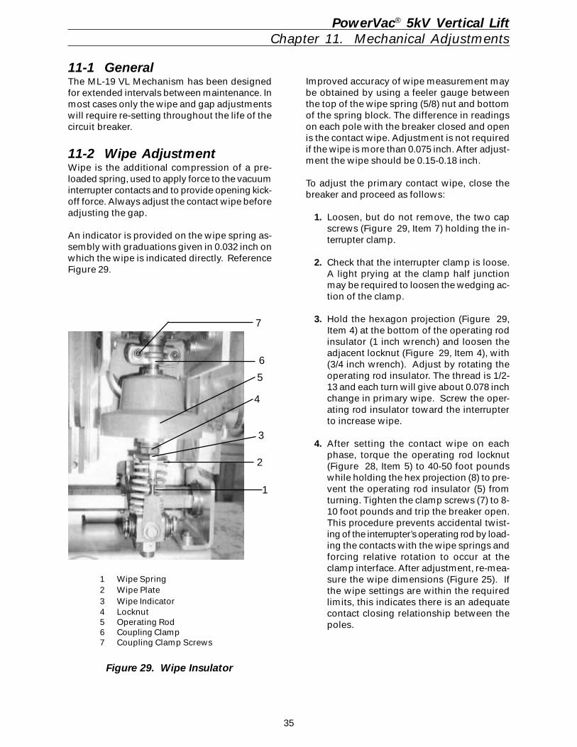
35
PowerVac® 5kV Vertical LiftChapter 11. Mechanical Adjustments
11-1 GeneralThe ML-19 VL Mechanism has been designedfor extended intervals between maintenance. Inmost cases only the wipe and gap adjustmentswill require re-setting throughout the life of thecircuit breaker.
11-2 Wipe AdjustmentWipe is the additional compression of a pre-loaded spring, used to apply force to the vacuuminterrupter contacts and to provide opening kick-off force. Always adjust the contact wipe beforeadjusting the gap.
An indicator is provided on the wipe spring as-sembly with graduations given in 0.032 inch onwhich the wipe is indicated directly. ReferenceFigure 29.
Figure 29. Wipe Insulator
1 Wipe Spring2 Wipe Plate3 Wipe Indicator4 Locknut5 Operating Rod6 Coupling Clamp7 Coupling Clamp Screws
Improved accuracy of wipe measurement maybe obtained by using a feeler gauge betweenthe top of the wipe spring (5/8) nut and bottomof the spring block. The difference in readingson each pole with the breaker closed and openis the contact wipe. Adjustment is not requiredif the wipe is more than 0.075 inch. After adjust-ment the wipe should be 0.15-0.18 inch.
To adjust the primary contact wipe, close thebreaker and proceed as follows:
1. Loosen, but do not remove, the two capscrews (Figure 29, Item 7) holding the in-terrupter clamp.
2. Check that the interrupter clamp is loose.A light prying at the clamp half junctionmay be required to loosen the wedging ac-tion of the clamp.
3. Hold the hexagon projection (Figure 29,Item 4) at the bottom of the operating rodinsulator (1 inch wrench) and loosen theadjacent locknut (Figure 29, Item 4), with(3/4 inch wrench). Adjust by rotating theoperating rod insulator. The thread is 1/2-13 and each turn will give about 0.078 inchchange in primary wipe. Screw the oper-ating rod insulator toward the interrupterto increase wipe.
4. After setting the contact wipe on eachphase, torque the operating rod locknut(Figure 28, Item 5) to 40-50 foot poundswhile holding the hex projection (8) to pre-vent the operating rod insulator (5) fromturning. Tighten the clamp screws (7) to 8-10 foot pounds and trip the breaker open.This procedure prevents accidental twist-ing of the interrupter’s operating rod by load-ing the contacts with the wipe springs andforcing relative rotation to occur at theclamp interface. After adjustment, re-mea-sure the wipe dimensions (Figure 25). Ifthe wipe settings are within the requiredlimits, this indicates there is an adequatecontact closing relationship between thepoles.
1
2
3
4
5
6
7
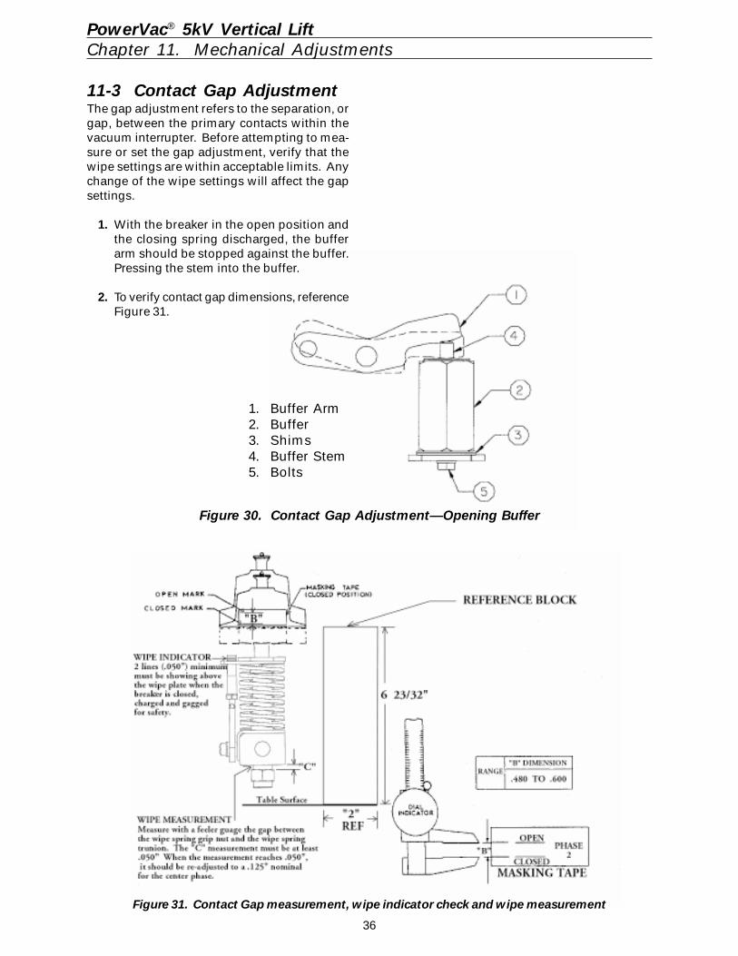
36
PowerVac® 5kV Vertical LiftChapter 11. Mechanical Adjustments
Figure 31. Contact Gap measurement, wipe indicator check and wipe measurement
Figure 30. Contact Gap Adjustment—Opening Buffer
1. Buffer Arm2. Buffer3. Shims4. Buffer Stem5. Bolts
11-3 Contact Gap AdjustmentThe gap adjustment refers to the separation, orgap, between the primary contacts within thevacuum interrupter. Before attempting to mea-sure or set the gap adjustment, verify that thewipe settings are within acceptable limits. Anychange of the wipe settings will affect the gapsettings.
1. With the breaker in the open position andthe closing spring discharged, the bufferarm should be stopped against the buffer.Pressing the stem into the buffer.
2. To verify contact gap dimensions, referenceFigure 31.
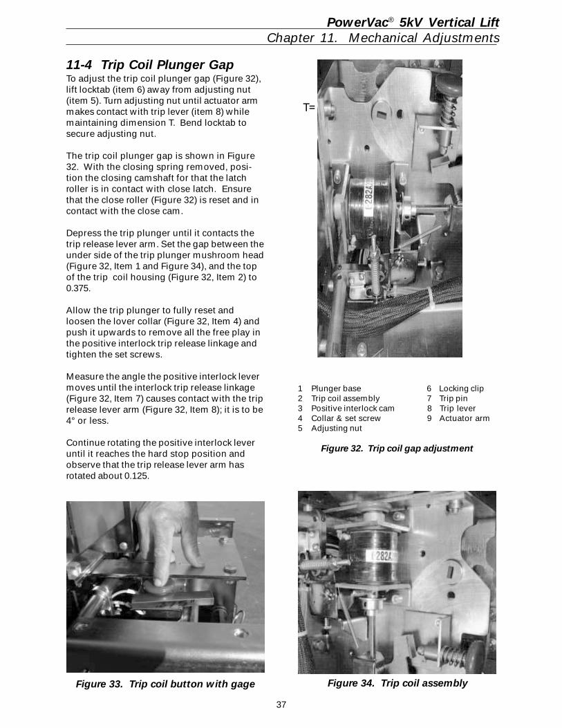
37
1 Plunger base 6 Locking clip2 Trip coil assembly 7 Trip pin3 Positive interlock cam 8 Trip lever4 Collar & set screw 9 Actuator arm5 Adjusting nut
Figure 32. Trip coil gap adjustment
PowerVac® 5kV Vertical LiftChapter 11. Mechanical Adjustments
Figure 33. Trip coil button with gage
11-4 Trip Coil Plunger GapTo adjust the trip coil plunger gap (Figure 32),lift locktab (item 6) away from adjusting nut(item 5). Turn adjusting nut until actuator armmakes contact with trip lever (item 8) whilemaintaining dimension T. Bend locktab tosecure adjusting nut.
The trip coil plunger gap is shown in Figure32. With the closing spring removed, posi-tion the closing camshaft for that the latchroller is in contact with close latch. Ensurethat the close roller (Figure 32) is reset and incontact with the close cam.
Depress the trip plunger until it contacts thetrip release lever arm. Set the gap between theunder side of the trip plunger mushroom head(Figure 32, Item 1 and Figure 34), and the topof the trip coil housing (Figure 32, Item 2) to0.375.
Allow the trip plunger to fully reset andloosen the lover collar (Figure 32, Item 4) andpush it upwards to remove all the free play inthe positive interlock trip release linkage andtighten the set screws.
Measure the angle the positive interlock levermoves until the interlock trip release linkage(Figure 32, Item 7) causes contact with the triprelease lever arm (Figure 32, Item 8); it is to be4° or less.
Continue rotating the positive interlock leveruntil it reaches the hard stop position andobserve that the trip release lever arm hasrotated about 0.125.
Figure 34. Trip coil assembly
T=
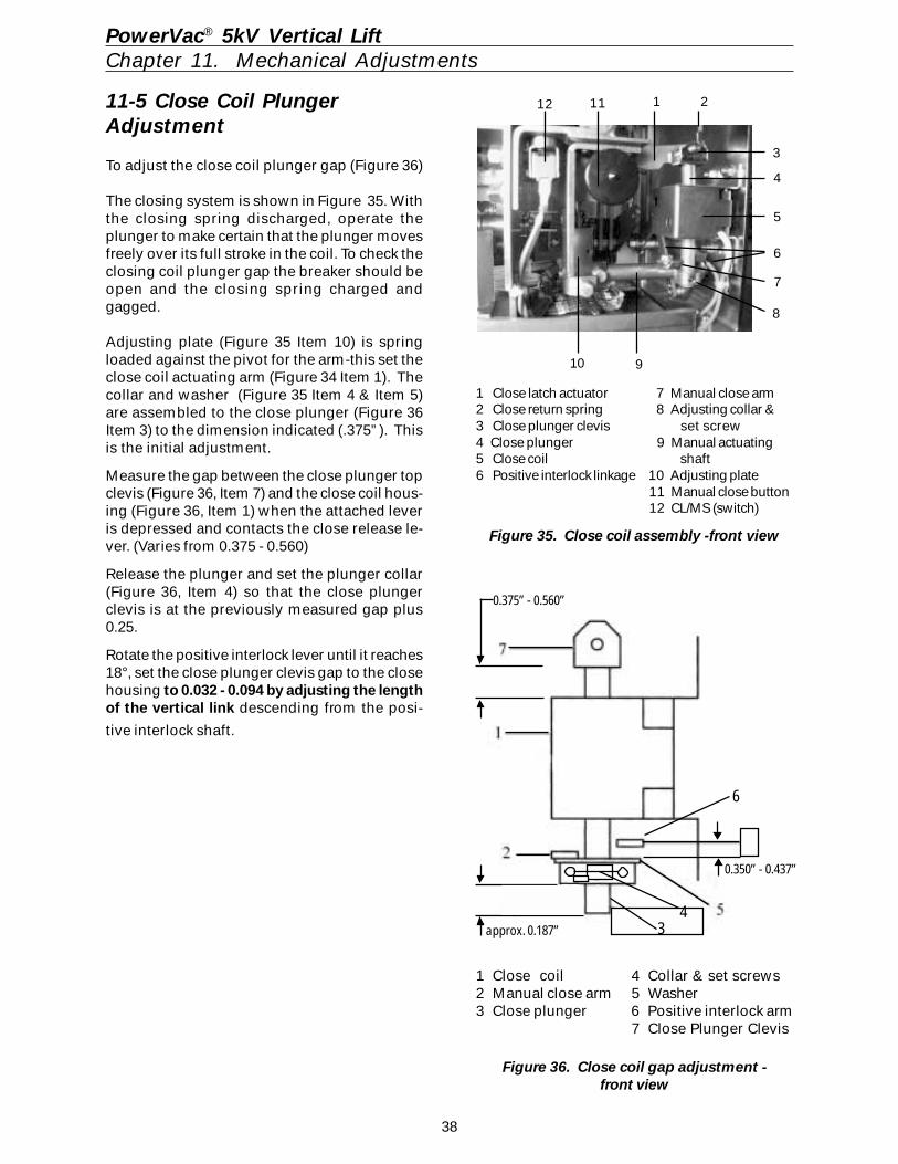
38
11 1 212
1 Close latch actuator 7 Manual close arm2 Close return spring 8 Adjusting collar &3 Close plunger clevis set screw4 Close plunger 9 Manual actuating5 Close coil shaft6 Positive interlock linkage 10 Adjusting plate
11 Manual close button12 CL/MS (switch)
Figure 35. Close coil assembly -front view
9 10
3
4
5
8
6
7
1 Close coil 4 Collar & set screws2 Manual close arm 5 Washer3 Close plunger 6 Positive interlock arm
7 Close Plunger Clevis
Figure 36. Close coil gap adjustment -front view
0.375” - 0.560”
6
approx. 0.187”
0.350” - 0.437”
PowerVac® 5kV Vertical LiftChapter 11. Mechanical Adjustments
11-5 Close Coil PlungerAdjustment
To adjust the close coil plunger gap (Figure 36)
The closing system is shown in Figure 35. Withthe closing spring discharged, operate theplunger to make certain that the plunger movesfreely over its full stroke in the coil. To check theclosing coil plunger gap the breaker should beopen and the closing spring charged andgagged.
Adjusting plate (Figure 35 Item 10) is springloaded against the pivot for the arm-this set theclose coil actuating arm (Figure 34 Item 1). Thecollar and washer (Figure 35 Item 4 & Item 5)are assembled to the close plunger (Figure 36Item 3) to the dimension indicated (.375”). Thisis the initial adjustment.
Measure the gap between the close plunger topclevis (Figure 36, Item 7) and the close coil hous-ing (Figure 36, Item 1) when the attached leveris depressed and contacts the close release le-ver. (Varies from 0.375 - 0.560)
Release the plunger and set the plunger collar(Figure 36, Item 4) so that the close plungerclevis is at the previously measured gap plus0.25.
Rotate the positive interlock lever until it reaches18°, set the close plunger clevis gap to the closehousing to 0.032 - 0.094 by adjusting the lengthof the vertical link descending from the posi-
tive interlock shaft.
43
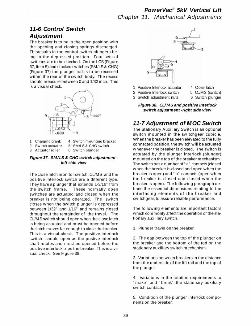
39
PowerVac® 5kV Vertical LiftChapter 11. Mechanical Adjustments
1 Charging crank 4 Switch mounting bracket2 Switch actuator 5 SM/LS & CHG switch3 Actuator roller 6 Switch plunger
Figure 37. SM/LS & CHG switch adjustment -left side view
11-6 Control SwitchAdjustmentThe breaker is to be in the open position withthe opening and closing springs discharged.Thisresults in the control switch plungers be-ing in the depressed position. Four sets ofswitches are to be checked. On the LCS (Figure37, Item 5) and stacked switches (SM/LS & CHG)(Figure 37) the plunger rod is to be recessedwithin the rear of the switch body. The recessshould measure between 0 and 1/32 inch. Thisis a visual check.
The close latch monitor switch, CL/MS and thepositive Interlock switch are a different type.They have a plunger that extends 1-3/16” fromthe switch frame. These normally openswitches are actuated and closed when thebreaker is not being operated. The switchcloses when the switch plunger is depressedbetween 1/32” and 1/16” and remains closedthroughout the remainder of the travel. TheCL/MS switch should open when the close latchis being actuated and must be opened beforethe latch moves far enough to close the breaker.This is a visual check. The positive interlockswitch should open as the postive interlockshaft rotates and must be opened before thepositive interlock trips the breaker. This is a vi-sual check. See Figure 38.
1 Positive Interlock actuator 4 Close latch2 Positive Interlock switch 5 CL/MS (switch)3 Switch adjustment nuts 6 Switch plunger
Figure 38. CL/MS and positive Interlockswitch adjustment -right side view
11-7 Adjustment of MOC SwitchThe Stationary Auxiliary Switch is an optionalswitch mounted in the switchgear cubicle.When the breaker has been elevated to the fullyconnected position, the switch will be actuatedwhenever the breaker is closed. The switch isactuated by the plunger interlock (plunger)mounted on the top of the breaker mechanism.The switch has a number of “a” contacts (closedwhen the breaker is closed and open when thebreaker is open) and “b” contacts (open whenthe breaker is closed and closed when thebreaker is open). The following paragraph de-fines the essential dimensions relating to theinterfacing elements of the breaker andswitchgear, to assure reliable performance.
The following elements are important factorswhich commonly affect the operation of the sta-tionary auxiliary switch.
1. Plunger travel on the breaker.
2. The gap between the top of the plunger onthe breaker and the bottom of the rod on thestationary auxiliary switch mechanism.
3. Variations between breakers in the distancefrom the underside of the lift rail and the top ofthe plunger.
4. Variations in the rotation requirements to“make” and “break” the stationary auxiliaryswitch contacts.
5. Condition of the plunger interlock compo-nents on the breaker.
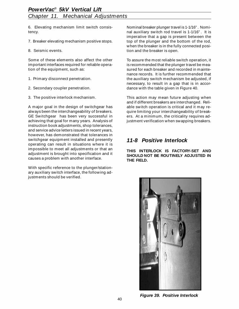
40
6. Elevating mechanism limit switch consis-tency.
7. Breaker elevating mechanism positive stops.
8. Seismic events.
Some of these elements also affect the otherimportant interfaces required for reliable opera-tion of the equipment, such as:
1. Primary disconnect penetration.
2. Secondary coupler penetration.
3. The positive interlock mechanism.
A major goal in the design of switchgear hasalways been the interchangeability of breakers.GE Switchgear has been very successful inachieving that goal for many years. Analysis ofinstruction book adjustments, shop tolerances,and service advice letters issued in recent years,however, has demonstrated that tolerances inswitchgear equipment installed and presentlyoperating can result in situations where it isimpossible to meet all adjustments or that anadjustment is brought into specification and itcauses a problem with another interface.
With specific reference to the plunger/station-ary auxiliary switch interface, the following ad-justments should be verified.
PowerVac® 5kV Vertical LiftChapter 11. Mechanical Adjustments
Nominal breaker plunger travel is 1-1/16”. Nomi-nal auxiliary switch rod travel is 1-1/16”. It isimperative that a gap is present between thetop of the plunger and the bottom of the rod,when the breaker is in the fully connected posi-tion and the breaker is open.
To assure the most reliable switch operation, itis recommended that the plunger travel be mea-sured for each breaker and recorded in mainte-nance records. It is further recommended thatthe auxiliary switch mechanism be adjusted, ifnecessary, to result in a gap that is in accor-dance with the table given in Figure 40.
This action may mean future adjusting whenand if different breakers are interchanged. Reli-able switch operation is critical and it may re-quire limiting your interchangeability of break-ers. At a minimum, the criticality requires ad-justment verification when swapping breakers.
11-8 Positive Interlock
THIS INTERLOCK IS FACTORY-SET ANDSHOULD NOT BE ROUTINELY ADJUSTED INTHE FIELD.
Figure 39. Positive Interlock
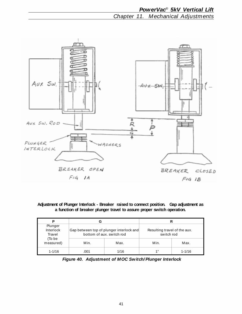
41
PowerVac® 5kV Vertical LiftChapter 11. Mechanical Adjustments
Figure 40. Adjustment of MOC Switch/Plunger Interlock
P G R Plunger Interlock Gap between top of plunger interlock and Resulting travel of the aux. Travel bottom of aux. switch rod switch rod (To be measured) Min. Max. Min. Max.
1-1/16 .001 1/16 1” 1-1/16
Adjustment of Plunger Interlock - Breaker raised to connect position. Gap adjustment asa function of breaker plunger travel to assure proper switch operation.
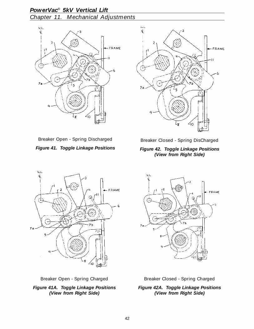
42
PowerVac® 5kV Vertical LiftChapter 11. Mechanical Adjustments
Breaker Open - Spring Discharged
Figure 41. Toggle Linkage Positions
Breaker Open - Spring Charged
Figure 41A. Toggle Linkage Positions(View from Right Side)
Breaker Closed - Spring Charged
Figure 42A. Toggle Linkage Positions(View from Right Side)
Breaker Closed - Spring DisCharged
Figure 42. Toggle Linkage Positions(View from Right Side)
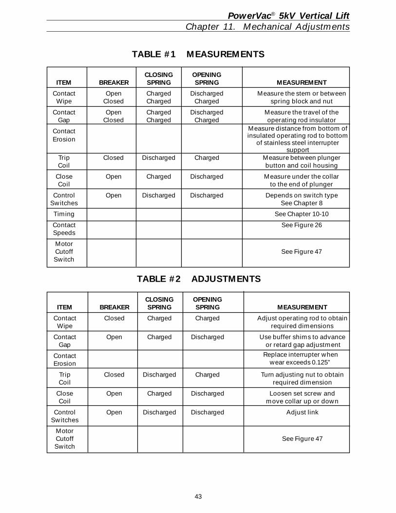
43
TABLE #1 MEASUREMENTS
CLOSING OPENINGITEM BREAKER SPRING SPRING MEASUREMENT
Contact Open Charged Discharged Measure the stem or betweenWipe Closed Charged Charged spring block and nut
Contact Open Charged Discharged Measure the travel of theGap Closed Charged Charged operating rod insulator
Contact
Trip Closed Discharged Charged Measure between plungerCoil button and coil housing
Close Open Charged Discharged Measure under the collarCoil to the end of plunger
Control Open Discharged Discharged Depends on switch typeSwitches See Chapter 8
Timing See Chapter 10-10
Contact See Figure 26Speeds
MotorCutoff See Figure 47Switch
PowerVac® 5kV Vertical LiftChapter 11. Mechanical Adjustments
TABLE #2 ADJUSTMENTS
CLOSING OPENINGITEM BREAKER SPRING SPRING MEASUREMENT
Contact Closed Charged Charged Adjust operating rod to obtainWipe required dimensions
Contact Open Charged Discharged Use buffer shims to advanceGap or retard gap adjustment
ContactErosion
Trip Closed Discharged Charged Turn adjusting nut to obtainCoil required dimension
Close Open Charged Discharged Loosen set screw andCoil move collar up or down
Control Open Discharged Discharged Adjust linkSwitches
MotorCutoff See Figure 47Switch
Measure distance from bottom ofinsulated operating rod to bottom
of stainless steel interruptersupport
Erosion
Replace interrupter whenwear exceeds 0.125”
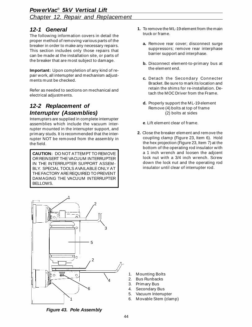
44
PowerVac® 5kV Vertical LiftChapter 12. Repair and Replacement
12-1 GeneralThe following information covers in detail theproper method of removing various parts of thebreaker in order to make any necessary repairs.This section includes only those repairs thatcan be made at the installation site, or parts ofthe breaker that are most subject to damage.
Important: Upon completion of any kind of re-pair work, all interrupter and mechanism adjust-ments must be checked.
Refer as needed to sections on mechanical andelectrical adjustments.
12-2 Replacement ofInterrupter (Assemblies)Interrupters are supplied in complete interrupterassemblies which include the vacuum inter-rupter mounted in the interrupter support, andprimary studs. It is recommended that the inter-rupter NOT be removed from the assembly inthe field.
CAUTION: DO NOT ATTEMPT TO REMOVEOR REINSERT THE VACUUM INTERRUPTERIN THE INTERRUPTER SUPPORT ASSEM-BLY. SPECIAL TOOLS AVAILABLE ONLY ATTHE FACTORY ARE REQUIRED TO PREVENTDAMAGING THE VACUUM INTERRUPTERBELLOWS.
1. To remove the ML-19 element from the maintruck or frame.
a. Remove rear cover; disconnect surgesuppressors; remove rear interphasebarrier support and interphase.
b. Disconnect element-to-primary bus atthe element end.
c. Detach the Secondary ConnecterBracket. Be sure to mark its location andretain the shims for re-installation. De-tach the MOC Driver from the Frame.
d. Properly support the ML-19 elementRemove (4) bolts at top of frame
(2) bolts at sides
e. Lift element clear of frame.
2. Close the breaker element and remove thecoupling clamp (Figure 23, Item 6). Holdthe hex projection (Figure 23, Item 7) at thebottom of the operating rod insulator witha 1 inch wrench and loosen the adjcentlock nut with a 3/4 inch wrench. Screwdown the lock nut and the operating rodinsulator until clear of interrupter rod.
Figure 43. Pole Assembly
1. Mounting Bolts2. Bus Runbacks3. Primary Bus4. Secondary Bus5. Vacuum Interrupter6. Movable Stem (clamp)1
2
2
3
4
5
6
1
45
PowerVac® 5kV Vertical LiftChapter 12. Repair and Replacement
12-3 Primary DisconnectBushingsThe primary disconnect bushing assembliesshould not be removed. Alignment of theseitems is critical to the function of the vertical liftequipment. If removal of these bushings isrequired, contact your local GE office for thelocation of a GE Authorized Service Center thatcan replace them.
12-4 MechanismPin Retaining Rings – These rings are widelyused in the ML-19 mechanism to retain pins.They can be installed and removed with a pairof standard pliers. Reuse is not recommended.To remove, slowly squeeze the removal ears toopen the ring. To install, position ring in thepin groove and squeeze the installation earsclosed, leaving no more than 1/16 inch gap be-tween the ears. Retaining rings can be obtainedfrom your local GE Sales office by ordering partnumber 0282A2015G001.
12-5 Control SwitchesControl switches may be removed from theirmounting brackets by disconnecting the wiresand removing the mounting hardware. Whenreplacing the switches, check that the correcttype, normally open or normally closed, is used.Reinstall, wire, and adjust per DIMENSIONALCHECKS - CONTROL SWITCH ADJUSTMENT.
12-6 Trip Coil ReplacementTOOLS REQUIRED
1/8" Allen wrench Needle nose pliers 7/16" Socket wrench 7/16" Box/combination wrench 1/4" Square drive ratchet 1/4" Square 3" extension Loctite #271 or equivalent
Perform the operation in the following sequence:Reference Figure 44
1. Charge closing spring and install gag tool.2. Depress the close and then the trip but-
tons.3. Pump the manual close handle 3 - 4 times.4. With the 5/16" Allen wrench, remove the
pivot bolt (Figure 49) on the closing spring(Figure 49, Item 3).
5. Remove the closing spring.6. Disconnect the trip linkage tension spring
(Figure 44, Item 4).
3. Remove interrupter assembly fasteners (8);four on the upper standoff and four on thelower. Remove the old assembly and in-stall the new assembly.
4. Install the new assembly. Screw the oper-ating rod insulator up to mate with the baseof the interrupter rod. Install couplingclamp. Tighten coupling clamp cap screws,then loosen them 1-2 turns.
a. With continuity indicator across the con-tacts, back off the operating rod until thecontacts separate, (continuity indicatoroff).
b. Advance operating rod until contactstouch, (continuity indicator on).
c. Advance operating rod two and one-half(2-1/2) additional turns.
d. Tighten lock nut to 40-50 foot poundsand the coupling clamp cap screws to8-10 foot pounds.
e. Check wipe - must be 0.12 - 0.18 inch(set all three phases before measuring).It is not necessary that all three poleshave the same wipe measurement aslong as all three poles fall within thespecified limits.
f. Check gap - must be 0.48 - 0.60 inch.Adjust if needed per CONTACT GAPADJUSTMENT in MECHANICAL AD-JUSTMENT (Chapter 11-3).
5. After the interrupter assembly is installed,check the erosion indicator. If the erosionindicator does not line up to the mark, ad-just indicator (Figure 23).
6. Perform the VACUUM INTERRUPTER IN-TEGRITY TEST as described in ELECTRI-CAL CHECKS (Chapter 9-4).
CAUTION: PRIMARY DISCONNECT WIPECAN ONLY BE CHECKED WHEN THESWITCHEAR IS DE-ENERGIZED.
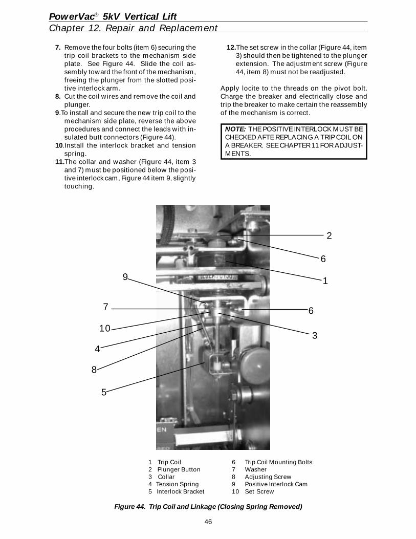
46
PowerVac® 5kV Vertical LiftChapter 12. Repair and Replacement
7. Remove the four bolts (item 6) securing thetrip coil brackets to the mechanism sideplate. See Figure 44. Slide the coil as-sembly toward the front of the mechanism,freeing the plunger from the slotted posi-tive interlock arm.
8. Cut the coil wires and remove the coil andplunger.
9.To install and secure the new trip coil to themechanism side plate, reverse the aboveprocedures and connect the leads with in-sulated butt connectors (Figure 44).
10.Install the interlock bracket and tensionspring.
11.The collar and washer (Figure 44, item 3and 7) must be positioned below the posi-tive interlock cam, Figure 44 item 9, slightlytouching.
12.The set screw in the collar (Figure 44, item3) should then be tightened to the plungerextension. The adjustment screw (Figure44, item 8) must not be readjusted.
Apply locite to the threads on the pivot bolt.Charge the breaker and electrically close andtrip the breaker to make certain the reassemblyof the mechanism is correct.
NOTE: THE POSITIVE INTERLOCK MUST BECHECKED AFTE REPLACING A TRIP COIL ONA BREAKER. SEE CHAPTER 11 FOR ADJUST-MENTS.
2
1
34
5
6
6
9
7
10
8
1 Trip Coil 6 Trip Coil Mounting Bolts2 Plunger Button 7 Washer3 Collar 8 Adjusting Screw4 Tension Spring 9 Positive Interlock Cam5 Interlock Bracket 10 Set Screw
Figure 44. Trip Coil and Linkage (Closing Spring Removed)
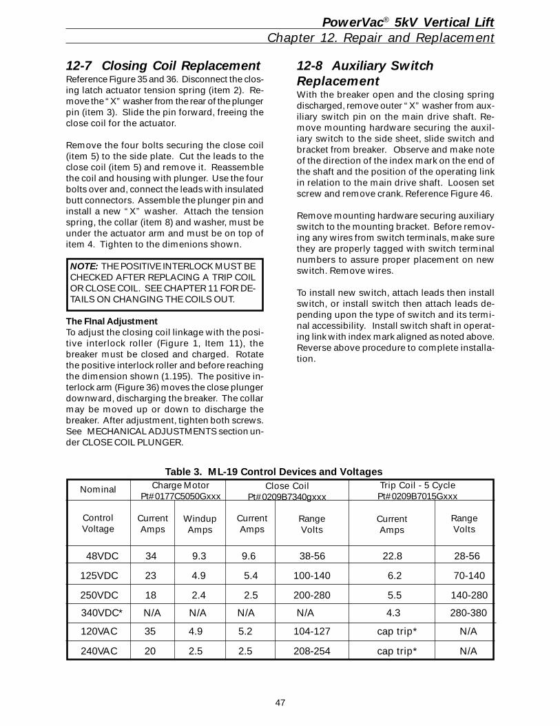
47
PowerVac® 5kV Vertical LiftChapter 12. Repair and Replacement
12-7 Closing Coil ReplacementReference Figure 35 and 36. Disconnect the clos-ing latch actuator tension spring (item 2). Re-move the “X” washer from the rear of the plungerpin (item 3). Slide the pin forward, freeing theclose coil for the actuator.
Remove the four bolts securing the close coil(item 5) to the side plate. Cut the leads to theclose coil (item 5) and remove it. Reassemblethe coil and housing with plunger. Use the fourbolts over and, connect the leads with insulatedbutt connectors. Assemble the plunger pin andinstall a new “X” washer. Attach the tensionspring, the collar (item 8) and washer, must beunder the actuator arm and must be on top ofitem 4. Tighten to the dimenions shown.
NOTE: THE POSITIVE INTERLOCK MUST BECHECKED AFTER REPLACING A TRIP COILOR CLOSE COIL. SEE CHAPTER 11 FOR DE-TAILS ON CHANGING THE COILS OUT.
The FInal AdjustmentTo adjust the closing coil linkage with the posi-tive interlock roller (Figure 1, Item 11), thebreaker must be closed and charged. Rotatethe positive interlock roller and before reachingthe dimension shown (1.195). The positive in-terlock arm (Figure 36) moves the close plungerdownward, discharging the breaker. The collarmay be moved up or down to discharge thebreaker. After adjustment, tighten both screws.See MECHANICAL ADJUSTMENTS section un-der CLOSE COIL PLUNGER.
12-8 Auxiliary SwitchReplacementWith the breaker open and the closing springdischarged, remove outer “X” washer from aux-iliary switch pin on the main drive shaft. Re-move mounting hardware securing the auxil-iary switch to the side sheet, slide switch andbracket from breaker. Observe and make noteof the direction of the index mark on the end ofthe shaft and the position of the operating linkin relation to the main drive shaft. Loosen setscrew and remove crank. Reference Figure 46.
Remove mounting hardware securing auxiliaryswitch to the mounting bracket. Before remov-ing any wires from switch terminals, make surethey are properly tagged with switch terminalnumbers to assure proper placement on newswitch. Remove wires.
To install new switch, attach leads then installswitch, or install switch then attach leads de-pending upon the type of switch and its termi-nal accessibility. Install switch shaft in operat-ing link with index mark aligned as noted above.Reverse above procedure to complete installa-tion.
240VAC 20 2.5 2.5 208-254 cap trip* N/A
120VAC 35 4.9 5.2 104-127 cap trip* N/A
340VDC* N/A N/A N/A N/A 4.3 280-380
250VDC 18 2.4 2.5 200-280 5.5 140-280
125VDC 23 4.9 5.4 100-140 6.2 70-140
48VDC 34 9.3 9.6 38-56 22.8 28-56
ControlVoltage
CurrentAmps
WindupAmps
Charge MotorPt#0177C5050Gxxx
Nominal
CurrentAmps
RangeVolts
Close CoilPt#0209B7340gxxx
CurrentAmps
RangeVolts
Trip Coil - 5 CyclePt#0209B7015Gxxx
Table 3. ML-19 Control Devices and Voltages
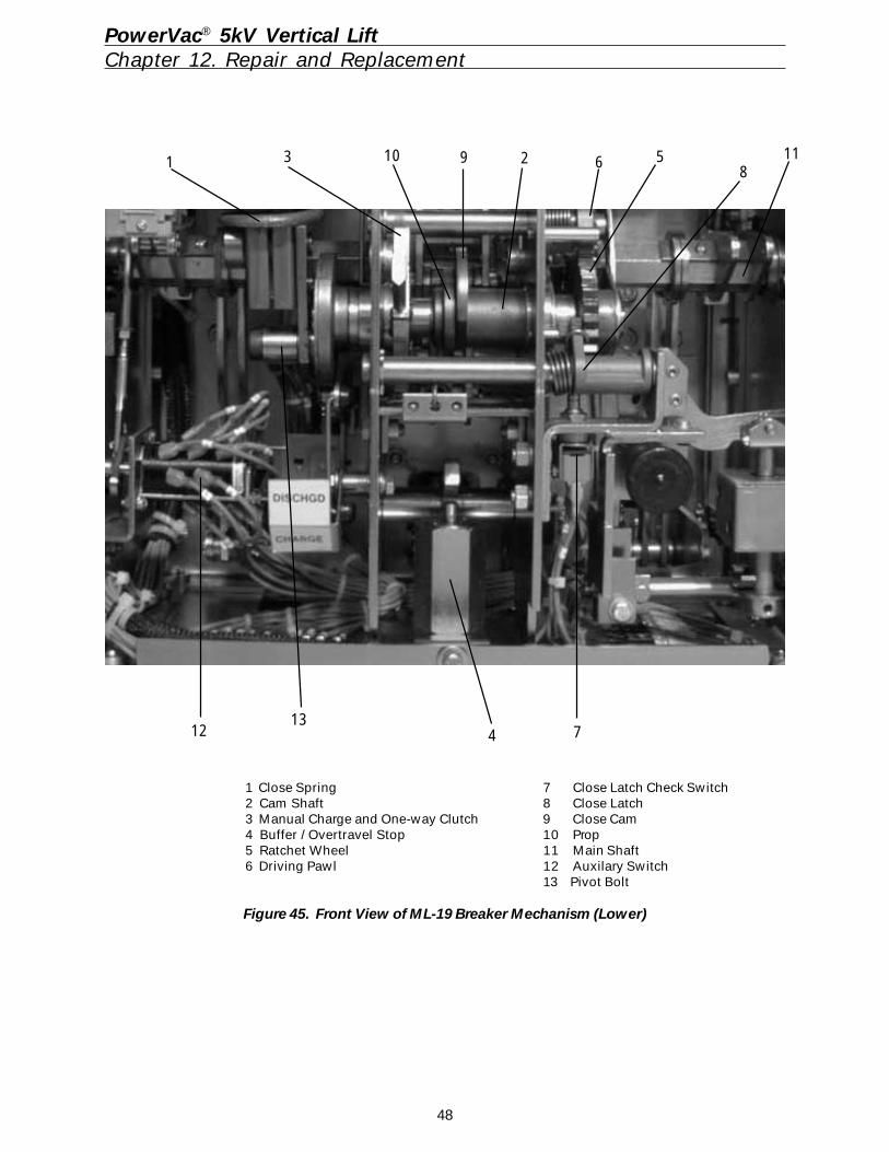
48
PowerVac® 5kV Vertical LiftChapter 12. Repair and Replacement
1 Close Spring 7 Close Latch Check Switch2 Cam Shaft 8 Close Latch3 Manual Charge and One-way Clutch 9 Close Cam4 Buffer / Overtravel Stop 10 Prop5 Ratchet Wheel 11 Main Shaft6 Driving Pawl 12 Auxilary Switch
13 Pivot Bolt
Figure 45. Front View of ML-19 Breaker Mechanism (Lower)
4
3 9 2 568
1110
12 713
1
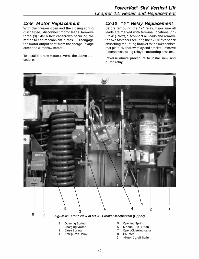
49
Figure 46. Front View of ML-19 Breaker Mechanism (Upper)
1 Opening Spring 5 Opening Spring2 Charging Motor 6 Manual Trip Button3 Close Spring 7 Open/Close Indicator4 Anti-pump Relay 8 Counter
9 Motor Cutoff Switch
65 43
2 1
PowerVac® 5kV Vertical LiftChapter 12. Repair and Replacement
12-9 Motor ReplacementWith the breaker open and the closing springdischarged, disconnect motor leads. Removethree (3) 3/8-16 hex capscrews securing themotor to the mechanism plates. Disengagethe motor output shaft from the charge linkagearms and withdraw motor.
To install the new motor, reverse the above pro-cedure.
12-10 “Y” Relay ReplacementBefore removing the “Y” relay, make sure allleads are marked with terminal locations (fig-ure 41). Next, disconnect all leads and removethe two fasteners securing the “Y” relay’s shockabsorbing mounting bracket to the mechanismrear plate. Withdraw relay and bracket. Removefasteners securing relay to mounting bracket.
Reverse above procedure to install new antipump relay.
8 7
9
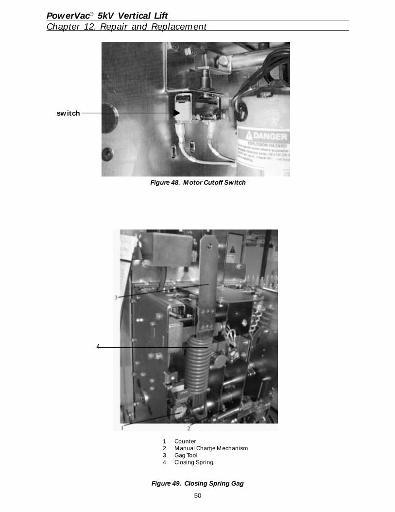
50
4
1 Counter2 Manual Charge Mechanism3 Gag Tool4 Closing Spring
Figure 49. Closing Spring Gag
PowerVac® 5kV Vertical LiftChapter 12. Repair and Replacement
Figure 48. Motor Cutoff Switch
switch
51
PowerVac® 5kV Vertical LiftChapter 13. Renewal Parts
It is recommended that sufficient renewal partsbe carried in stock to enable the prompt replace-ment of any worn, broken or damaged parts. Astock of such parts minimizes service interrup-tions caused by breakdowns, and saves timeand expense. When continuous operation is aprimary consideration, more renewal partsshould be carried, the amount depending uponthe severity of the service and the time requiredto secure replacements.
Renewal parts which are GE furnished may notbe identical to the original parts, but they willbe interchangeable. Verify that the parts areoriginal GE parts of operational problems mayoccur.
A separate Renewal Parts Bulletin DEF-008 maybe available from your local GE Sales office.
13-1 Ordering Instructions1. Always specify the complete nameplate in-
formation. Include the manufacturing dateof both the breaker and the mechanism.See Figure 50.
2. Specify the quantity, catalog number (iflisted), reference number (if listed), anddescription of each part ordered, and theparts bulletin number.
3. Standard hardware, such as screws, bolts,nuts, washers, etc. are not listed in thisbulletin. Such items should be purchasedlocally.
4. For prices or information on parts not listedin the Renewal Parts Bulletin DEF-008, re-fer to the nearest GE office.
Figure 49. Front View of ML-19 Mechanism with Front Cover Removed
1 Opening Spring2 Charging Motor3 Close Spring4 Manual Close Button5 Charge/Discharge Indicator6 Manual Trip Button7 Open/Close Indicator
8 Counter9 Manual Charge Lever10 Positive Interlock Switch11 Close Relay12 Cam shaft13 Close coil
14 Close coil adjustment collar15 Close latch check switch16 Opening dashpot17 Auzilary switch18 MOC Plunger linkage19 Positive interlock bar
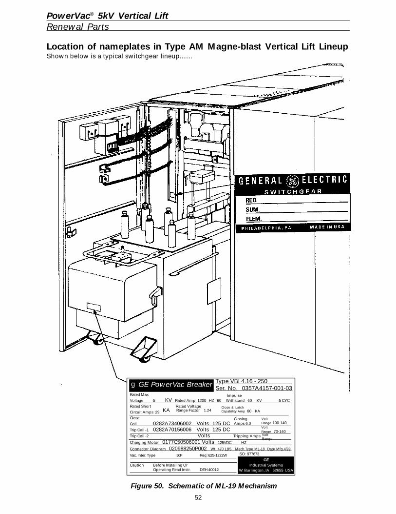
52
PowerVac® 5kV Vertical LiftRenewal Parts
Location of nameplates in Type AM Magne-blast Vertical Lift LineupShown below is a typical switchgear lineup.......
Figure 50. Schematic of ML-19 Mechanism
gGE PowerVac Breaker Type VBI 4.16 - 250Ser. No. 0357A4157-001-03
Rated Max
Voltage 5 KV Rated Amp. 1200 HZ 60 Withstand 60 KV 5 CYCRated Short Rated Voltage
Circuit Amps 29Close
Coil 0282A73406002 Volts 125 DCTrip Coil -1 0282A70156006 Volts 125 DCTrip Coil -2 Volts Tripping Amps
Charging Motor 0177C50506001 VoltsConnector Diagram 020988250P002 Wt. 470 LBS. Mech.Type ML-18 Date Mfg.4/99
Vac. Inter. Type 50F Req: 625-1222W
Caution Before Installing OrOperating Read Instr. DEH 40012
GEIndustrial Systems
W. Burlington, IA 52655 USA
SO: 977673
Impulse
Range Factor 1.24KA
125VDC` HZ
ClosingAmps 6.0
VoltRange 100-140
VoltRange
VoltRange 70-140
Close & LatchCapability Amp 60 KA
53
PowerVac® 5kV Vertical LiftChapter 14. Stationary Cubicle Subassembly
14-1 IntroductionThe breaker cubicle sub-assembly is normallythe existing Magne-blast stationary housing forthe removable breaker unit. It contains the pri-mary disconnects, elevating mechanism, buses,current transformers, and secondary controlwiring.
14-2 Description of MajorComponents
1. Breaker EnclosureThe existing Magne-blast enclosure consists ofa compartment with a hinged door or panel. Ter-minal blocks, fuse blocks, and some controldevices are mounted inside the enclosure onthe side sheets.
2. Breaker Elevating MechanismThe elevating mechanism is designed to raisethe breaker unit into the operating position andto lower the breaker to the disconnected posi-tion. It consists of a motor, heavy duty jackscrews, jack nuts, and a carriage frame. Railsare built into the breaker frame to guide it intoposition. By means of interlocks, the breakercannot be lowered or raised until it has beentripped. The breaker contacts can only be closedwhen the breaker is in the connected position.For more detail, refer to Chapter 4.
3. Primary DisconnectsThe primary disconnect devices utilize silver tosilver contacts to insure against reduction ofcurrent carrying capacity due to oxidation of thecontact surfaces. These contacts are of the highpressure line contact tube and socket design,the tube being backed up by heavy garter springsto insure contact pressure.
4. BusesThe main buses are enclosed in a metal com-partment with removable covers to provide ac-cessibility. The buses are supported by flameretardant, track resistant, glass laminate insu-lating material and porcelain, which is practi-cally impervious to moisture, and an excellentdielectric. No additional coating is necessary.
The bus insulation is an extruded thermoplas-tic insulation sleeve, suitable for 105 degree Coperating temperatures. The bus bars are in-serted into the sleeves leaving only the boltedjoints exposed. The bus terminates before andafter the breaker unit. Current transformers maybe located along the bus, on either side of thebreaker, for control applications.
5. Breaker Testing ProvisionsOptional provisions for testing the breaker unitafter removing it from the cubicle can be fur-nished. The test equipment can be located ona panel adjacent to the breaker compartment. Itconsists of a test coupler to provide controlpower to operate the breaker, and push buttonsto trip and close the breaker electrically.
6. ConnectionsThe main bus bars and other connection barsare made of copper, and the contact surfacesare silver plated. All field assembled joints inthe primary conductors should be made as fol-lows:
1. Wipe silver clean with a clean cloth anddenatured alcohol. If badly tarnished, usea non-abrasive silver polish. Do not usesteel wool, sandpaper, or any abrasive onthe silvered surface. Avoid handling ofcleaned surfaces as much as possible.
2. After cleaning, apply a light of coating ofgrease, 0282A2048P009, to the silvered sur-faces so that the contact area will be thor-oughly sealed. Using a standard washer,lock washer, and nut, together, tightenjoints to the torque values shown below.
BOLT CONNECTION TIGHTENING
Bolt Size Torque1/2 x 13 50 - 60 foot pounds5/8 x 11 60 - 70 foot pounds
7. Ground ConnectionA ground connection is made between thebreaker ground shoe and the compartmentground bus.
8. Door AlignmentThe exisitng Magne-blast compartment shouldhave been properly adjusted and leveled dur-ing the orginal installation. Proper door align-ment can be verified as follows.
The top of each door should be level with theadjacent doors; the sides of each door plumb;the surface of each door flush with the adjacentdoor; and, the space between adjacent doorsequalized to permit their free swing and presenta neat appearance. The door stops should beadjusted to permit a door swing of approximately105 degrees.
54
PowerVac® 5kV Vertical LiftChapter 14. Stationary Cubicle Subassembly
If it is necessary to align the doors of the breakercompartment, the following procedure shouldbe followed.
1. Doors may be raised or lowered verti-cally, or moved forward or backward hori-zontally, by loosening the hinge mount-ing nuts on the left side sheet and shiftingthe hinge and door assembly as allowedby the slotted holes in the hinge.
2. Doors may be shifted to the right or leftby adding or removing washers or shimsfrom between the hinge and side sheet.
3. Doors may be plumbed by slightly bend-ing the appropriate hinges. To do this, openthe door and insert a drift pin in either ofthe two holes in the hinge. Pulling forwardon the drift pin will move the door to theright, and pushing back will move the doorto the left. Adjust each hinge individuallyas required to plumb the door.
14-3 Testing and Inspection
1. GeneralAlthough the breaker has been completelytested at the factory, a final field inspection andtest should be made to be sure that the equip-ment has been properly installed and that allconnections are correct and have not becomeloose in transportation. Reference Chapter 4.
WARNING: THE PRIMARY EQUIPMENTSHOULD BE COMPLETELY DE-ENERGIZEDWHILE THE TESTS ARE IN PROGRESS.
2. Breaker TestingThe operation of the breaker with its associ-ated devices may be tested outside the unit byuse of the test coupler. Reference Chapter 9.
3. Hi-potential TestingHi-potential tests to check the integrity of theswitchgear insulation is not necessary, if theinsulation has been previously checked duringmaintenance. Should the purchaser desire tomake hi-potential tests, the test voltage shouldnot exceed 14kV AC at 60 Hz. This voltage is75% of factory test voltage and is in accordancewith ANSI standards.
4. Breaker PositioningBefore proceeding to place the breaker in theoperating position,the steps as outlined inChapter 4 must be taken.
WARNING: DO NOT INSTALL OR REMOVETHE BREAKER OR MAKE ADJUSTMENTSUNLESS THE BREAKER IS OPEN.
4.1. Rub a small amount of 0282A2048P009lubricant on the silvered portion of thebreaker studs, ground shoe, and 16 sec-ondary coupler pins, to form a thin coat-ing for contact purposes.
4.2. Lower the elevating mechanism liftingbrackets until the lifting brackets are inthe fully lowered position. The breakershould then enter the housing freely.After first assuring that the breaker is inthe open position, push the breaker intothe unit until it rests against the rear ofthe front lifting saddle of the elevatingmechanism.
4.3. The clearance between the interferenceblock on the breaker and the interferenceblock on the interlock mechanismshould be from .063" to .125". Figure 6.
WARNING: AGAIN, BEFORE PROCEEDINGWITH THIS CHECK, IT IS NECESSARY THATTHE PRIMARY CIRCUITS BE DE-ENERGIZED.
4.4. To elevate the breaker, place the elevat-ing control selector switch on the elevat-ing motor to “RAISE”. A clutch handleunder the elevating motor is then pulledforward until a limit switch engages toraise the breaker into the unit. Carefullyraise the breaker and while elevating,note that the shutter slides open and thebreaker studs center with respect to theopenings in the stationary disconnect-ing devices or damage to the contactsmay result.
4.5. Hold the clutch handle in the forwardposition until a limit switch on the struc-ture opens to stop the motor at the endof the upward travel of the breaker. Thesprings will charge when the clutchhandle is released. Figure 53.
CAUTION: THE MOTOR RAISE/LOWER SE-LECTOR SWITCH MUST NOT BE USED TOENERGIZE OR INTERRUPT MOTOR CIRCUITAT ANY TIME.
4.6. When the breaker is fully elevated, theclearance between the breaker lifting railand the upper stop bolts should not bemore than .125" and not less than .094".
55
PowerVac® 5kV Vertical LiftChapter 14. Stationary Cubicle Subassembly
4.7. The positive interlock roller should becentered in the upper “VEE” and theinterlock roller should have 1/16" clear-ance to the stationary plate directly un-der it. Figure 6 and 53.
4.8. To lower the breaker, proceed the sameas for raising, except, place the selec-tor switch to “LOWER”.
4.9. To raise or lower the breaker, the clutchmust be held in the engaged position,otherwise a spring will return it to itsdisengaged position and open the elec-trical circuit to the motor.
4.10. The breaker may be raised or loweredby an emergency hand crank which canbe inserted after removing the motor.The motor is removed by unlatching themotor assembly from its support and dis-connecting the motor lead plug.
After removing the motor, insert themanual crank and pull the clutch for-ward. Rotate the crank until the couplingengages the clutch. The clutch handlewill be held in the down position by alatch on the crank assembly. The breakermust be open before the crank can beinserted and held in the clutch coupling.
4.11. After the breaker is lowered and with-drawn from the unit, inspect the con-tact surfaces of both the breaker studsand the stationary disconnecting de-vices.
a. Each segment of the stationary discon-necting device should make a heavy im-pression in the contact lubricant on thebreaker studs. Contact wipe should startnot less than .125" from the top of thecontact ball, although each contact neednot start at the same location. Figure 9.
b. The penetration of the breaker stud in-side the stationary disconnecting device,as indicated by the contact lubricant,should be .75" to .875". This indicatesthat the breaker studs contacted at thefull pressure center of the silver band onthe stationary disconnecting device. Fig-ure 9.
c. Should the inspection of the contactsshow that the breaker is not being raised
to the proper position, readjust the up-per stop bolts and limit switches to raiseor lower the breaker to the proper loca-tion. Lock the stop bolts in the new posi-tion. Figure 6.
d. If proper contacting cannot be attainedby the above methods, additional adjust-ments may be necessary.
CAUTION: DO NOT MAKE THESE ADJUST-MENTS. CONTACT YOUR LOCAL GE REPRE-SENTATIVE FOR ADDITIONAL INFORMATION.
5. Positive InterlockThe cell-side positive interlock cam causes aclosed and charged breaker to open and allsprings to discharge. While engaged the posi-tive interlock cam prevents closing the primarycontacts when the breaker is being raised orlowered by holding the breaker mechanism ina trip condition. The breaker mechanism holdsthe positive interlock switch open during rack-ing and prevents the charging motor from oper-ating. Figure 6 and 53.
1. Lower the elevating mechanism liftingbrackets until the lifting brackets are in thefully lowered position. The breaker shouldthen enter the housing freely. After firstassuring that the breaker is in the open po-sition, insert the breaker into the unit untilit rests against the rear of the front liftingsaddle of the elevating mechanism. Refer-ence Figure 6 and 53.
2. When inserting a breaker into a unit for el-evating, engaging the elevator clutch willtrip a closed breaker and discharge theopening and closing springs if they are en-ergized.
WARNING: AGAIN, IT IS EMPHASIZED THATBEFORE PROCEEDING WITH THIS CHECK,IT IS NECESSARY THAT THE PRIMARY CIR-CUITS BE DE-ENERGIZED.
3. Open the breaker. Elevate the breaker tothe raised position. The positive interlockroller should engage into the upper Vee.Breaker can be electrically closed.
4. Snap the selector switch to the “LOWER”position. Pull the clutch handle forward.The breaker should be open and the clos-ing spring will discharge, when engagingthe clutch and lowering the breaker.
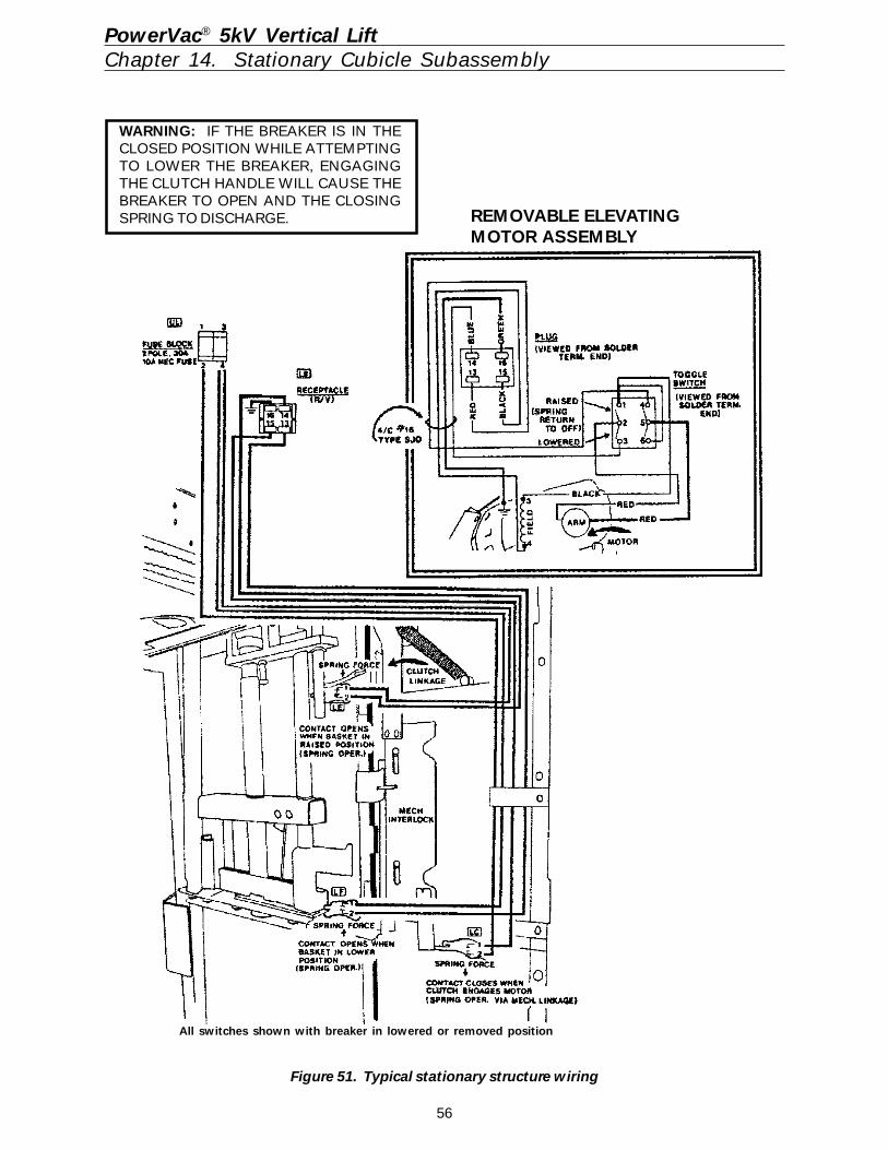
56
PowerVac® 5kV Vertical LiftChapter 14. Stationary Cubicle Subassembly
Figure 51. Typical stationary structure wiring
WARNING: IF THE BREAKER IS IN THECLOSED POSITION WHILE ATTEMPTINGTO LOWER THE BREAKER, ENGAGINGTHE CLUTCH HANDLE WILL CAUSE THEBREAKER TO OPEN AND THE CLOSINGSPRING TO DISCHARGE.
All switches shown with breaker in lowered or removed position
REMOVABLE ELEVATINGMOTOR ASSEMBLY
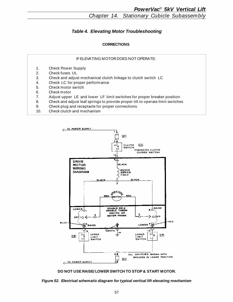
57
PowerVac® 5kV Vertical LiftChapter 14. Stationary Cubicle Subassembly
CORRECTIONS
IF ELEVATING MOTOR DOES NOT OPERATE:
1. Check Power Supply2. Check fuses UL3. Check and adjust mechanical clutch linkage to clutch switch LC4. Check LC for proper performance5. Check motor switch6. Check motor7. Adjust upper LE and lower LF limit switches for proper breaker position8. Check and adjust leaf springs to provide proper tilt to operate limit switches9. Check plug and receptacle for proper connections10. Check clutch and mechanism
Table 4. Elevating Motor Troubleshooting
DO NOT USE RAISE/LOWER SWITCH TO STOP & START MOTOR.
Figure 52. Electrical schematic diagram for typical vertical lift elevating mechanism
58
14-4 Breaker CompartmentMaintenance
GeneralA regular maintenance schedule should be es-tablished to obtain the best service and reliabil-ity from the breaker compartment. Plant operat-ing and local conditions will dictate the fre-quency of inspection required. For specific in-formation regarding the maintenance of devices,relays, meters, etc., refer to the separate instruc-tion book furnished for each device. The breakertesting device, which may be furnished as anoption, provides a convenient means for main-taining the circuit breaker. Under normal oper-ating conditions the protective relays do notoperate, therefore, it is important to check theoperation of these devices regularly.
A permanent record of all maintenance workshould be kept, the degree of detail dependingon the operating conditions. In any event, it willbe a valuable reference for subsequent mainte-nance work and for station operation. It is rec-ommended that the record include reports oftests made, the condition of equipment and re-pairs and adjustments that were made.
WARNING: BEFORE ANY COVERS AREREMOVED OR AND DOORS ARE OPENEDWHICH PERMIT ACCESS TO THE PRIMARYCIRCUITS, IT IS ESSENTIAL THAT THE CIR-CUIT OR CIRCUITS BE DE-ENERGIZED ANDBREAKERS BE WITHDRAWN TO A DISCON-NECTED POSITION, AND TAGGED.
IF WORK IS TO BE DONE ON REMOTEEQUIPMENT CONNECTED TO A UNIT, THEBREAKER FOR THAT UNIT SHOULD BEPLACED IN THE DISCONNECTED POSITIONAND TAGGED. ALSO, REMOTE EQUIPMENTSHOULD BE ISOLATED FROM ANY OTHERPOWER SOURCES CONNECTED TO IT.
The primary circuits of the equipment are insu-lated in order to reduce the size of the equip-ment. However, this insulation, except in one oftwo instances, requires a certain amount of airgap between phases and to ground to completethe insulation integrity. Inserting any object inthis air space, when equipment is energized,whether it be a tool or a part of the body, mayunder certain conditions, in effect, short circuitthis gap and may cause a breakdown in the pri-mary circuit to ground and cause serious dam-age or injury or both.
6. Stationary Auxiliary Switch (MOC)On units equipped with stationary auxiliaryswitches, the clearance between the end of theswitch mechanism operating rod and the oper-ating plunger on the circuit breaker should be 0to 0.062" with the circuit breaker in the raisedand open position. Figures 10 and 40.
Any adjustment in this dimension must bemade on the auxiliary switch setting. Careshould be taken to prevent destroyinginterchangability of the circuit breaker by ex-cessive adjustment. Consult GE nearest salesoffice.
7. Spring DischargeWhen elevating or lowering the breaker, thepositive interlock lever roller on the breaker in-teracts with the positive interlock cam in thecell. Subsequently...The closing spring is dis-charged and the breaker is trip-free. Figures 6and 53.
CAUTION: IF THE INTERLOCK DOES NOTFUNCTION AS INDICATED ABOVE, DO NOTMAKE ADJUSTMENTS. CONTACT YOURLOCAL GE REPRESENTATIVE FOR ADDI-TIONAL INFORMATION.
8. Space HeatersSpace heaters are provided in all equipment inorder to keep the inside temperature severaldegrees higher than that outside. By maintain-ing a slight temperature differential, the heatershelp facilitate drying and prevent condensationand the resulting corrosion and insulation dete-rioration which might occur.
Before energizing the heaters, be sure the powersource is of the proper voltage, frequency, andphase arrangement, and is connected in accor-dance with the wiring diagrams furnished withthe equipment.
Heaters should be visually inspected severaltimes a year to assure they are operating prop-erly. It is also recommended that the heaters beenergized at all times and that thermostatic con-trol NOT be used.
PowerVac® 5kV Vertical LiftChapter 14. Stationary Cubicle Subassembly
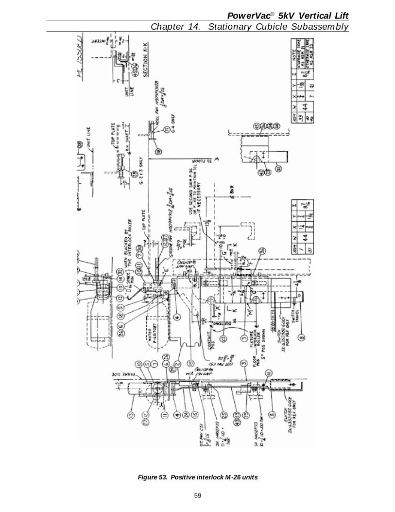
59
Figure 53. Positive interlock M-26 units
PowerVac® 5kV Vertical LiftChapter 14. Stationary Cubicle Subassembly
60
Care should be exercised in the maintenanceand checking procedures that accidental trip-ping or operation of the protective devices isnot initiated.
The equipment and connections should be giventhe following overall maintenance at least an-nually.
1. Thoroughly clean the equipment, remov-ing all dust and other accumulations. Wipeclean the buses and supports with a cleancloth and denatured alcohol. Do not usesolvents. Inspect the buses and connec-tions carefully for evidence of overheatingor weakening of the insulation.
2. Measure the resistance to ground and be-tween phases of the insulation of busesand connections. Since definite limits can-not be given for satisfactory insulation re-sistance values, a record must be kept ofthe reading. Weakening of the insulationfrom one maintenance period to the nextcan be recognized from the comparison ofthe recorded readings. The readingsshould be taken under similar conditionseach time, and the recordings should beadjusted to include the temperature and hu-midity.
PowerVac® 5kV Vertical LiftChapter 14. Stationary Cubicle Subassembly
Hi-potential tests are not required, but if itseems advisable, based on the insulationresistance tests or after repairs, the testvoltage should not exceed 14kV AC, 60 Hz.These voltages are 75% of the factory testvoltages and are in accordance with ANSIstandards.
Potential transformers and control powertransformers must be disconnected duringhigh voltage testing.
3. Clean elevating mechanism and lubricate.
4. Check primary disconnecting device con-tacts for signs of abnormal wear or over-heating. Clean contacts with de-naturedalcohol.
Discoloration of the silvered surfaces is notordinarily harmful unless atmospheric con-ditions cause deposits, such as sulfides,on the contacts. If necessary, the depositscan be removed with a good grade of sil-ver polish.
Before inserting the breaker, apply a thincoat of 0282A2048P009 lubricant, to thebreaker studs for lubrication.
5. Check tightness and continuity of all con-trol connections and wiring.
6. If the equipment is equipped with heaters,check to see that all heaters are energizedand operating.
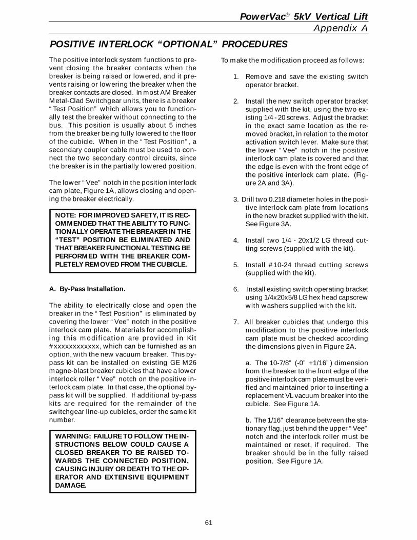
61
PowerVac® 5kV Vertical LiftAppendix A
The positive interlock system functions to pre-vent closing the breaker contacts when thebreaker is being raised or lowered, and it pre-vents raising or lowering the breaker when thebreaker contacts are closed. In most AM BreakerMetal-Clad Switchgear units, there is a breaker“Test Position” which allows you to function-ally test the breaker without connecting to thebus. This position is usually about 5 inchesfrom the breaker being fully lowered to the floorof the cubicle. When in the “Test Position”, asecondary coupler cable must be used to con-nect the two secondary control circuits, sincethe breaker is in the partially lowered position.
The lower “Vee” notch in the position interlockcam plate, Figure 1A, allows closing and open-ing the breaker electrically.
NOTE: FOR IMPROVED SAFETY, IT IS REC-OMMENDED THAT THE ABILITY TO FUNC-TIONALLY OPERATE THE BREAKER IN THE“TEST” POSITION BE ELIMINATED ANDTHAT BREAKER FUNCTIONAL TESTING BEPERFORMED WITH THE BREAKER COM-PLETELY REMOVED FROM THE CUBICLE.
A. By-Pass Installation.
The ability to electrically close and open thebreaker in the “Test Position” is eliminated bycovering the lower “Vee” notch in the positiveinterlock cam plate. Materials for accomplish-ing this modification are provided in Kit#xxxxxxxxxxxx, which can be furnished as anoption, with the new vacuum breaker. This by-pass kit can be installed on existing GE M26magne-blast breaker cubicles that have a lowerinterlock roller “Vee” notch on the positive in-terlock cam plate. In that case, the optional by-pass kit will be supplied. If additional by-passkits are required for the remainder of theswitchgear line-up cubicles, order the same kitnumber.
WARNING: FAILURE TO FOLLOW THE IN-STRUCTIONS BELOW COULD CAUSE ACLOSED BREAKER TO BE RAISED TO-WARDS THE CONNECTED POSITION,CAUSING INJURY OR DEATH TO THE OP-ERATOR AND EXTENSIVE EQUIPMENTDAMAGE.
To make the modification proceed as follows:
1. Remove and save the existing switchoperator bracket.
2. Install the new switch operator bracketsupplied with the kit, using the two ex-isting 1/4 - 20 screws. Adjust the bracketin the exact same location as the re-moved bracket, in relation to the motoractivation switch lever. Make sure thatthe lower “Vee” notch in the positiveinterlock cam plate is covered and thatthe edge is even with the front edge ofthe positive interlock cam plate. (Fig-ure 2A and 3A).
3. Drill two 0.218 diameter holes in the posi-tive interlock cam plate from locationsin the new bracket supplied with the kit.See Figure 3A.
4. Install two 1/4 - 20x1/2 LG thread cut-ting screws (supplied with the kit).
5. Install #10-24 thread cutting screws(supplied with the kit).
6. Install existing switch operating bracketusing 1/4x20x5/8 LG hex head capscrewwith washers supplied with the kit.
7. All breaker cubicles that undergo thismodification to the positive interlockcam plate must be checked accordingthe dimensions given in Figure 2A.
a. The 10-7/8” (-0” +1/16”) dimensionfrom the breaker to the front edge of thepositive interlock cam plate must be veri-fied and maintained prior to inserting areplacement VL vacuum breaker into thecubicle. See Figure 1A.
b. The 1/16” clearance between the sta-tionary flag, just behind the upper “Vee”notch and the interlock roller must bemaintained or reset, if required. Thebreaker should be in the fully raisedposition. See Figure 1A.
POSITIVE INTERLOCK “OPTIONAL” PROCEDURES
62
PowerVac® 5kV Vertical LiftAppendix A
B. CHECKING FOR PROPER INTERLOCK ANDTRIP-FREE FUNCTIONS BEFORE LOWERINGTHE BREAKER FROM THE ELEVATED POSITION.
1. STANDARD OPERATION: When the breakeris in the fully elevated and connected position,releasing the motor operating handle will re-turn the positive interlock roller into the upper“Vee” notch in the interlock switches and ener-gizing the circuit that will charge the springs.The breaker may now be closed.
In order to lower the breaker from the connectedposition, the breaker must be opened. If thebreaker is not open, the operator can not, andshould not be able to engage the clutch or acti-vate the motor circuit. The positive interlockroller will remain locked and will not allow theinterlock cam plate to move vertically far enoughto activate the elevating motor.
2. MODIFICATION KIT CHECK: To test thefunction of the positive interlock system and trip-free function, the following checks should bemade:
a. With the breaker closed and in the el-evated position, the positive interlockroller on the breaker must remain lockedand not allow the motor handle to bemoved far enough to engage the clutchand close the clutch switch contacts thatenergize the motor circuit. There shouldbe 1/16” clearance between the clutchand motor coupler, when the motorhandle is pulled forward.
b. Disconnect the elevating motor plugfrom its socket.
c. Trip the breaker to the open position.
d. Using the manual charging, charge theclosing springs in the breaker until thesemaphore shows charged.
e. Pull back the elevating handle on themotor so that the interlock roll is at thedimension shown in Figure 1A. Hold itin this position while pressing themanual close push button on thebreaker. The main power springs mustdischarge and the breaker must remainopen, as indicated by the semaphoreson the front of the breaker. This indi-cates that the breaker contacts will notclose during raising or lowering thebreaker.
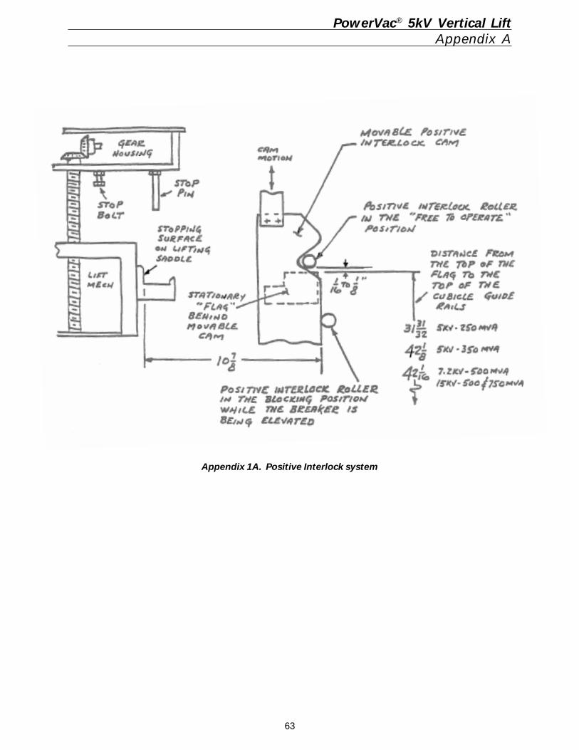
63
PowerVac® 5kV Vertical LiftAppendix A
Appendix 1A. Positive Interlock system
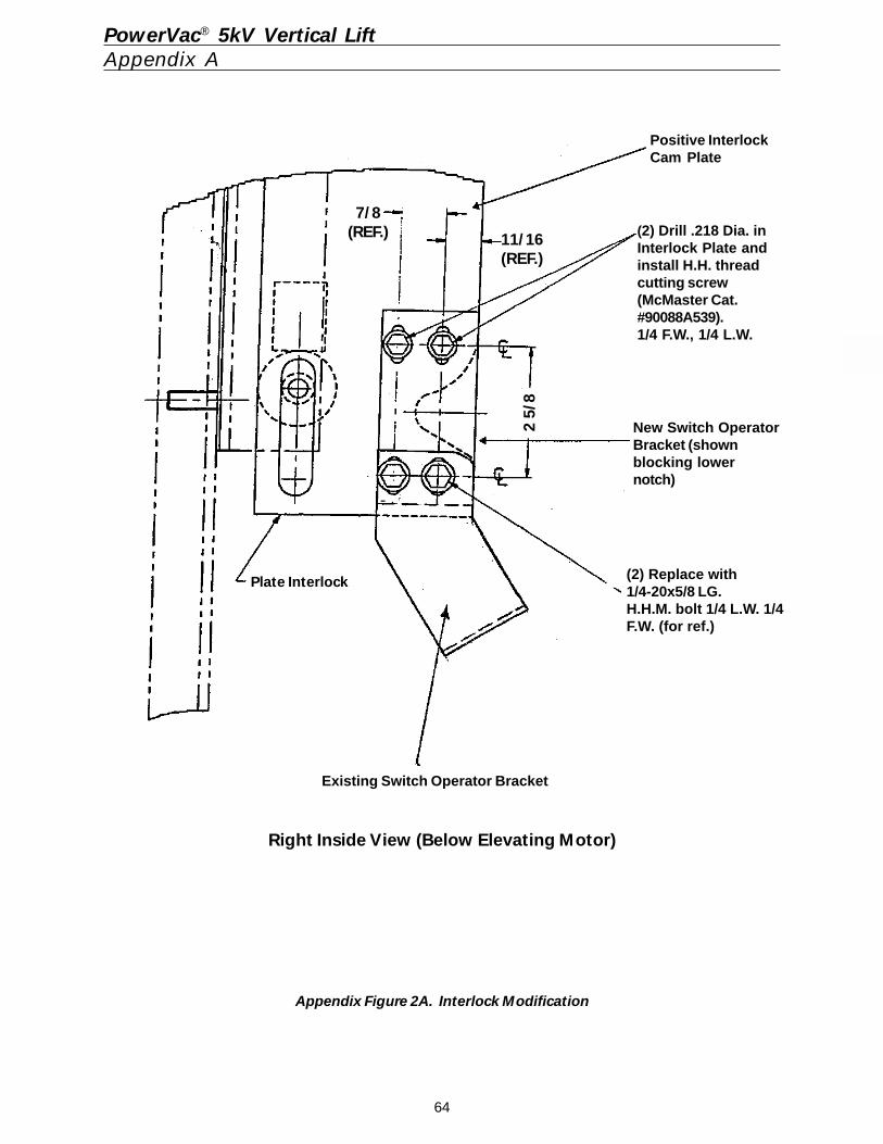
64
PowerVac® 5kV Vertical LiftAppendix A
Appendix Figure 2A. Interlock Modification
Right Inside View (Below Elevating Motor)
(2) Drill .218 Dia. inInterlock Plate andinstall H.H. threadcutting screw(McMaster Cat.#90088A539).1/4 F.W., 1/4 L.W.
Positive InterlockCam Plate
New Switch OperatorBracket (shownblocking lowernotch)
(2) Replace with1/4-20x5/8 LG.H.H.M. bolt 1/4 L.W. 1/4F.W. (for ref.)
Existing Switch Operator Bracket
7/8(REF.) 11/16
(REF.)
2 5/
8
Plate Interlock
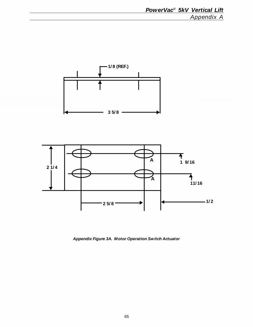
65
PowerVac® 5kV Vertical LiftAppendix A
Appendix Figure 3A. Motor Operation Switch Actuator
1/8 (REF.)
3 5/8
2 1/4 1 9/16
11/16
1/22 5/8
A
A
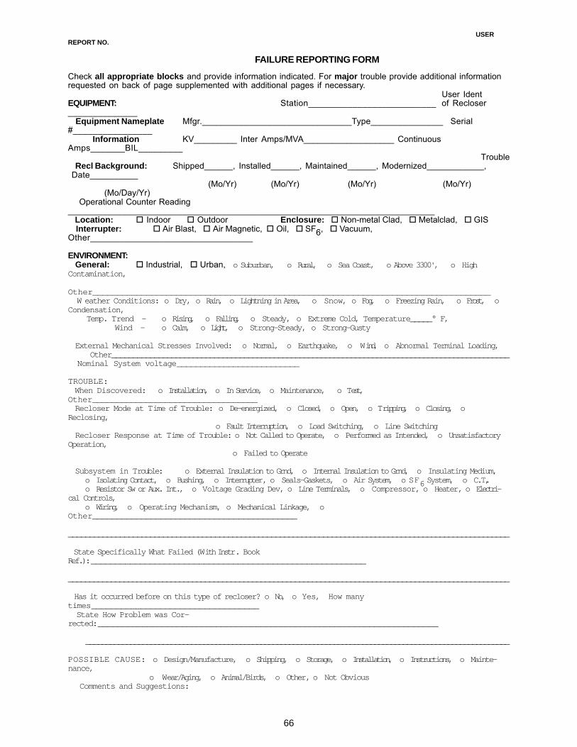
66
USERREPORT NO.
FAILURE REPORTING FORMCheck all appropriate blocks and provide information indicated. For major trouble provide additional informationrequested on back of page supplemented with additional pages if necessary.
User IdentEQUIPMENT: Station__________________________ of Recloser______________ Equipment Nameplate Mfgr._______________________________Type_______________ Serial#________________ Information KV_________ Inter Amps/MVA___________________ ContinuousAmps_______BIL_________
Trouble Recl Background: Shipped______, Installed______, Maintained______, Modernized____________, Date__________
(Mo/Yr) (Mo/Yr) (Mo/Yr) (Mo/Yr) (Mo/Day/Yr) Operational Counter Reading__________________________________________________________________________ Location: ! Indoor ! Outdoor Enclosure: ! Non-metal Clad, ! Metalclad, ! GIS Interrupter: ! Air Blast, ! Air Magnetic, ! Oil, ! SF6, ! Vacuum,Other_________________________________
ENVIRONMENT: General: ! Industrial, ! Urban, o Suburban, o Rural, o Sea Coast, o Above 3300', o HighContamination,
Other_________________________________________________________________________________ W eather Conditions: o Dry, o Rain, o Lightning in Area, o Snow, o Fog, o Freezing Rain, o Frost, oCondensation, Temp. Trend — o Rising, o Falling, o Steady, o Extreme Cold, Temperature_____° F,
Wind — o Calm, o Light, o Strong-Steady, o Strong-Gusty
External Mechanical Stresses Involved: o Normal, o Earthquake, o Wind, o Abnormal Terminal Loading, Other_____________________________________________________________________________________________ Nominal System voltage__________________________
TROUBLE: When Discovered: o Installation, o In Service, o Maintenance, o Test,Other__________________________________ Recloser Mode at Time of Trouble: o De-energized, o Closed, o Open, o Tripping, o Closing, oReclosing,
o Fault Interruption, o Load Switching, o Line Switching Recloser Response at Time of Trouble: o Not Called to Operate, o Performed as Intended, o UnsatisfactoryOperation,
o Failed to Operate
Subsystem in Trouble: o External Insulation to Grnd, o Internal Insulation to Grnd, o Insulating Medium,o Isolating Contact, o Bushing, o Interrupter, o Seals-Gaskets, o Air System, o SF6 System, o C.T.,o Resistor Sw or Aux. Int., o Voltage Grading Dev, o Line Terminals, o Compressor, o Heater, o Electri-
cal Controls,o Wiring, o Operating Mechanism, o Mechanical Linkage, o
Other__________________________________________
______________________________________________________________________________________________________
State Specifically What Failed (With Instr. BookRef.):________________________________________________________
_______________________________________________________________________________________________________
Has it occurred before on this type of recloser? o No, o Yes, How manytimes__________________________________ State How Problem was Cor-rected:_____________________________________________________________________
________________________________________________________________________________________________________
POSSIBLE CAUSE: o Design/Manufacture, o Shipping, o Storage, o Installation, o Instructions, o Mainte-nance,
o Wear/Aging, o Animal/Birds, o Other, o Not Obvious Comments and Suggestions:
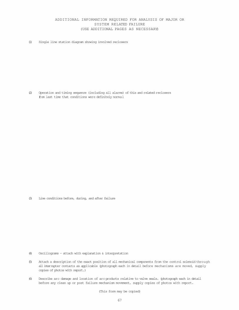
67
ADDITIONAL INFORMATION REQUIRED FOR ANALYSIS OF MAJOR ORSYSTEM RELATED FAILURE
(USE ADDITIONAL PAGES AS NECESSARY)
(1) Single line station diagram showing involved reclosers
(2) Operation and timing sequence (including all alarms) of this and related reclosersfrom last time that conditions were definitely normal
(3) Line conditions before, during, and after failure
(4) Oscillograms - attach with explanation & interpretation
(5) Attach a description of the exact position of all mechanical components from the control solenoid throughall interrupter contacts as applicable (photograph each in detail before mechanisms are moved, supplycopies of photos with report.)
(6) Describe arc damage and location of arc products relative to valve seals. (photograph each in detailbefore any clean up or post failure mechanism movement, supply copies of photos with report.
(This form may be copied)
68
g________________________________________
General Electric Company510 East Agency RoadWest Burlington, Iowa 52655
DEH 40012 1000 RFD © 2000 General Electric Company
These instructions do not purport to cover all details or variations in equipment nor to provide forevery possible contingency to be met in connection with installation, operation or maintenance.Should further information be desired or should particular problems arise which are not coveredsufficiently for the purchaser’s purposes, the matter should be referred to the General ElectricCompany.
GE Industrial Systems


