Embed Size (px)
Citation preview

Instruction Handbook for:
use
adjustmentmaintenance
instal lat ion
TIME
35 F
30 F
25 F
Green Heating Technology
2
Table of Content
Safety warningsSafety warnings symbols legend . . . . . . . . . . . . 4References to Laws and Norms . . . . . . . . . . . . . 4
Personnel in charge of installation . . . . . . . . . . . . . 4Installation, use and maintenance . . . . . . . . . . . . . 4
User warnings . . . . . . . . . . . . . . . . . . . . . . . . . . 5Important . . . . . . . . . . . . . . . . . . . . . . . . . . . . . . . . . 5First starting up and Use . . . . . . . . . . . . . . . . . . . . . 5Installation, first starting up, maintenance
and servicing . . . . . . . . . . . . . . . . . . . . . . . . . . . 6Appliance booklet or central plant booklet . . . . . . 6Combustion checking . . . . . . . . . . . . . . . . . . . . . . . 6Boiler operation and servicing . . . . . . . . . . . . . . . . 6
User guideKeyboard buttons . . . . . . . . . . . . . . . . . . . . . . . . 7Multi-function display . . . . . . . . . . . . . . . . . . . . 8Commands on the lower side . . . . . . . . . . . . . . 9Commands outside the boiler . . . . . . . . . . . . . 9Typical use . . . . . . . . . . . . . . . . . . . . . . . . . . . . 10
Preliminary operations . . . . . . . . . . . . . . . . . . . . . 10Boiler activation . . . . . . . . . . . . . . . . . . . . . . . . . . . 10Temperature adjustment . . . . . . . . . . . . . . . . . . . . 10
Hour and day setting . . . . . . . . . . . . . . . . . . . . 11Set the display with 4 digits . . . . . . . . . . . . . . 11DHW pre-heating mode (Acqua Step) . . . . . . 11
To set the desired “step” . . . . . . . . . . . . . . . . . . . . 12Manual set of Acqua Step . . . . . . . . . . . . . . . . . . . 12Loading a preset Acqua Step program . . . . . . . . . 12Setting the Acqua Step program no. 3 - User . . . 12
INFO menu . . . . . . . . . . . . . . . . . . . . . . . . . . . . 13Holiday menu . . . . . . . . . . . . . . . . . . . . . . . . . . 14SPA function . . . . . . . . . . . . . . . . . . . . . . . . . . . 15Incidental malfunctioning . . . . . . . . . . . . . . . . 15
The burner doesn’t turn on . . . . . . . . . . . . . . . . . . 15Shortage of domestic hot water production . . . . 15
Boiler inactivity . . . . . . . . . . . . . . . . . . . . . . . . 15Safety shut off . . . . . . . . . . . . . . . . . . . . . . . . . . . . 16Stand-by mode with anti-frost & anti-locking
function . . . . . . . . . . . . . . . . . . . . . . . . . . . . . . . 16“Ambient Anti-Frost” Function . . . . . . . . . . . . . . . 17
InstallationLaw and regulation prescriptions for the
installer . . . . . . . . . . . . . . . . . . . . . . . . . . . . 17Dimensions and connections . . . . . . . . . . . . . 18Pump capacity diagram . . . . . . . . . . . . . . . . . . 18Specifications for inlet air . . . . . . . . . . . . . . . . 19
Domestic water supply characteristics . . . . . . 19Protection against freezing . . . . . . . . . . . . . . . 19Outdoor installation in a partially protected
place . . . . . . . . . . . . . . . . . . . . . . . . . . . . . . 20Positioning and fastening . . . . . . . . . . . . . . . . 20Hydraulic system (DHW and heating) . . . . . . . 21
Advices and suggestions to avoid vibrations and noises in the system . . . . . . . . . . . . . . . . . 21
Cleaning and preservation of the systems . . . . . . 21Heating system . . . . . . . . . . . . . . . . . . . . . . . . . . . . 22
Heating system filling and pressuring . . . . . . 22Gas connection . . . . . . . . . . . . . . . . . . . . . . . . 23Electrical connections . . . . . . . . . . . . . . . . . . . 23Closing the boiler casing . . . . . . . . . . . . . . . . . 24Flue systems . . . . . . . . . . . . . . . . . . . . . . . . . . . 24
General indications . . . . . . . . . . . . . . . . . . . . . . . . 24Reducer for short systems . . . . . . . . . . . . . . . . . . . 25Flue terminals positioning . . . . . . . . . . . . . . . . . . . 26Flue system types . . . . . . . . . . . . . . . . . . . . . . . . . . 27
Adjustment and MaintenanceFirst starting up . . . . . . . . . . . . . . . . . . . . . . . . 28Access to the inside of the boiler . . . . . . . . . . 28Inlet gas check . . . . . . . . . . . . . . . . . . . . . . . . . 29PCB parameters settings (technician menu) . 29
Main boiler parameters (PC) . . . . . . . . . . . . . . . . . 30Max and Min pressure adjustment . . . . . . . . 30Max heating power adjustment . . . . . . . . . . . 31Burner pressure tables . . . . . . . . . . . . . . . . . . 32Electronic settings . . . . . . . . . . . . . . . . . . . . . . 33
Accessing the main board . . . . . . . . . . . . . . . . . . . 33Main board settings . . . . . . . . . . . . . . . . . . . . . . . . 34
Gas conversion . . . . . . . . . . . . . . . . . . . . . . . . . 34Combustion check . . . . . . . . . . . . . . . . . . . . . . 35Hydraulic settings (pump speed) . . . . . . . . . . 36Draining the heating system . . . . . . . . . . . . . . 36Alarms - boiler block . . . . . . . . . . . . . . . . . . . . 36Warnings for servicing . . . . . . . . . . . . . . . . . . . 41Technical data . . . . . . . . . . . . . . . . . . . . . . . . . . 42Boiler internal components . . . . . . . . . . . . . . 45Electrical diagram . . . . . . . . . . . . . . . . . . . . . . 46Hydraulic diagram . . . . . . . . . . . . . . . . . . . . . . 47
AddendumOutdoor Sensor Kit . . . . . . . . . . . . . . . . . . . . . 48
Installation and setting . . . . . . . . . . . . . . . . . . . . . 48Outdoor Sensor kit and Remote Control . . . . . . . 48
Remote Control Kit . . . . . . . . . . . . . . . . . . . . . 49
Green Heating Technology
3
Safety warningsThis instructions manual is an essential and complementary part of the product and it is supplied to-gether with the boiler .
Carefully read the manual, achieving all important information for a safe installation, use and servicing .
f Carefully keep the manual, together with the documentation of all the accessories of the boiler and of the system, for any further consultation you may need.
f The installation must be carried out by a qualified technician, in accordance with manufacturer in-structions and with the relevant requirements of the current issue.
f Carbon monoxide (CO) danger: the CO is a no-smelling and no-colour gas. When a forced draught boiler with air inlet from the room (appliance type B2) is installed, permanent ventilation of the installation room is mandatory and extremely important. Ventilation must be made and sized in compliance with Laws and Rules in force. Whatever manumission, closing or neutralization of the permanent ventilation could lead to very serious consequences to people in the rooms, as intoxica-tion by CO, permanent damage and death. Besides, the CO and O2 mix can be explosive .
f A qualified technician is a person with a specific technical competence in the field of the heating appliances for domestic use and domestic hot water production, in compliance with Laws and Rules in force .
f The operations that the user can do are only and exclusively the ones contained in the "USER GUIDE" section.
f The manufacturer has no contractual and extra-contractual responsibility for any damage arising from wrong installation, wrong use and non-observance of current laws and instructions given by the manufacturer himself.
f Important: this gas boiler is used to heat the water at a temperature lower than the boiling one, at atmospheric pressure; it must be connected to an heating system and/or to a domestic hot water system, in accordance with its features and power.
f Packing items (cartons, nails, plastic bags and so on) must not be left within children easy reach, as they are potentially dangerous.
f Before any cleaning or servicing operation, disconnect the boiler from the mains electrical supply by means of the main electrical switch and stop the gas supply by means of the suitable cock.
f In case of fault and/or bad operation of the appliance, disconnect it immediately and do not try to repair it by yourselves.
f Boiler servicing and repair must be carried out exclusively by qualified technicians, which will use original spare parts. Strictly observe the above requirement, avoiding any risk of compromising the appliance safety .
f If the appliance should be definitively dismissed, remove or cut off any potential dangerous item.
f When transferring the appliance (e.g. leaving it installed after a removal or a sale of the building), make always sure that the instructions manual is close to the boiler for the future use of new owners and/or installers.
f This appliance must be used for its clearly recommended utilization only. Any other utilization must be considered dangerous and incorrect.
f It is strictly forbidden to use the appliance for different purposes than the specified ones.
f This appliance must be installed exclusively to wall .

Green Heating Technology
4
Safety warnings symbols legend Generic safety
warning Electrical danger
(fulguration) Physical danger
(personal damage)
Thermal danger (burns)
General warning or advice to avoid material damage or to achieve improvements
References to Laws and Norms All the references to norms and national laws mentioned in this handbook are indicative as
laws and norms are subject to issues and integrations by the authorities in charge. Also comply to eventual local norms and laws (not mentioned in this handbook) in force in the territory where the installation takes place.
Personnel in charge of installationPlace here all necessary advices according to national rules about WORK SAFETY of Personnel in charge of installation. An example follows:
Law number 192 of 19-August-2005 and further revisions “Title of the law or brief description”.
Always proceed with caution when handling the boiler and carrying out installation/mainte-nance work as metal parts may cause injuries such as cuts and abrasions. Wear personal protec-tion devices (especially gloves) while doing the above mentioned operations
Installation, use and maintenancePlace here all necessary advices according to national rules about BOILER INSTALLATION, An example follows .
Law number 412 of 26-July-1993 n°412 and further revisions “Title of the law or brief description”.
Green Heating Technology
5
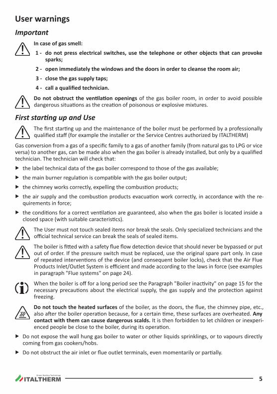
User warningsImportant
In case of gas smell:
1 - do not press electrical switches, use the telephone or other objects that can provoke sparks;
2 - open immediately the windows and the doors in order to cleanse the room air;
3 - close the gas supply taps;
4 - call a qualified technician.
Do not obstruct the ventilation openings of the gas boiler room, in order to avoid possible dangerous situations as the creation of poisonous or explosive mixtures.
First starting up and Use The first starting up and the maintenance of the boiler must be performed by a professionally
qualified staff (for example the installer or the Service Centres authorized by ITALTHERM)
Gas conversion from a gas of a specific family to a gas of another family (from natural gas to LPG or vice versa) to another gas, can be made also when the gas boiler is already installed, but only by a qualified technician. The technician will check that:
f the label technical data of the gas boiler correspond to those of the gas available;
f the main burner regulation is compatible with the gas boiler output;
f the chimney works correctly, expelling the combustion products;
f the air supply and the combustion products evacuation work correctly, in accordance with the re-quirements in force;
f the conditions for a correct ventilation are guaranteed, also when the gas boiler is located inside a closed space (with suitable caracteristics).
The User must not touch sealed items nor break the seals. Only specialized technicians and the official technical service can break the seals of sealed items.
The boiler is fitted with a safety flue flow detection device that should never be bypassed or put out of order. If the pressure switch must be replaced, use the original spare part only. In case of repeated interventions of the device (and consequent boiler locks), check that the Air Flue Products Inlet/Outlet System is efficient and made according to the laws in force (see examples in paragraph "Flue systems" on page 24).
When the boiler is off for a long period see the Paragraph "Boiler inactivity" on page 15 for the necessary precautions about the electrical supply, the gas supply and the protection against freezing.
Do not touch the heated surfaces of the boiler, as the doors, the flue, the chimney pipe, etc., also after the boiler operation because, for a certain time, these surfaces are overheated. Any contact with them can cause dangerous scalds. It is then forbidden to let children or inexperi-enced people be close to the boiler, during its operation.
f Do not expose the wall hung gas boiler to water or other liquids sprinklings, or to vapours directly coming from gas cookers/hobs.
f Do not obstruct the air inlet or flue outlet terminals, even momentarily or partially.
Green Heating Technology
6
f Do not put any object on the gas boiler and don't leave any flammable liquid or solid materials, (e.g. paper, clothes, plastic, polystirene) in its proximity.
f This appliance is not intended for use by persons (including children) with reduced physical, sensory or mental capabilities, or lack of experience and knowledge, unless they have been given supervi-sion or instruction concerning use of the appliance by a person responsible for their safety. Children should be supervised to ensure that they do not play with the appliance. (CEI EN 60335-1:2008-07 § 7.12)
f If the gas boiler is going to be definitively unused, call a qualified technician to carry out all required operations, checking in particular disconnection of gas, water and electrical supplies.
f Only for those models that draw directly from the installation room (type B appliances installed in-door): the installation of aspirators, fireplaces or similar appliances in the room where the type B ap-pliance is installed (and in adjacent rooms in case of indirect ventilation) is prohibited except in cases foreseen by rules in force and anyway the installation must be made in compliance with all specific safety measures mentioned in the rules and laws in force, even in case of modifications or additions.
Installation, first starting up, maintenance and servicingAll operations for installation, first starting up, maintenance, servicing and gas conversion must be car-ried out by qualified technicians, in accordance with the Norms and Laws in force.
Maintenance operations must be carried out in compliance with the manufacturer prescriptions, and in compliance with the laws and rules presently in force for what is not mentioned in this handbook; we advice to perform them at least once a year to maintain the boiler’s performance.
Appliance booklet or central plant bookletAll appliances must have an appliance booklet (for outputs less or equal 35 kW) or a central plant book-let (for outputs more than 35 kW). All maintenance and servicing operations and combustion checks must be written on the booklet, together with the name of the person responsible for servicing.
Combustion checkingCombustion checking consists of a control of the boiler efficiency. Boilers that, after the checking, will have efficiency rates lower than the ones required and not changeable with suitable adjustments (that must be performed by qualified technicians), must be replaced.
Boiler operation and servicingThe user (owner or tenant of the flat where the boiler is installed) or the administrator of the block of flats (in case of a central heating system) are responsible for the appliance operation and servicing; they can both transfer the responsibility of the servicing and eventually of the operation to another person, which must be a qualified technician as indicated by the Laws. Even if the user or the administrator de-cide to assume personally this responsibility, ordinary servicing of the warm air heater and combustion checks must be anyway carried out by a qualified technician
Green Heating Technology
7
User guide
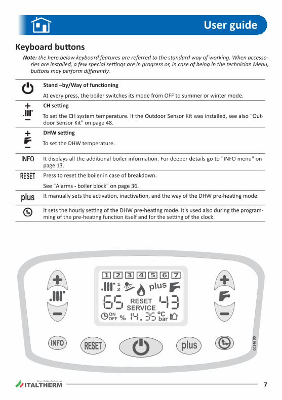
Keyboard buttonsNote: the here below keyboard features are referred to the standard way of working. When accesso-
ries are installed, a few special settings are in progress or, in case of being in the technician Menu, buttons may perform differently.
Stand –by/Way of functioning
At every press, the boiler switches its mode from OFF to summer or winter mode.
CH setting
To set the CH system temperature. If the Outdoor Sensor Kit was installed, see also "Out-door Sensor Kit" on page 48.
DHW setting
To set the DHW temperature.
It displays all the additional boiler information. For deeper details go to "INFO menu" on page 13.
Press to reset the boiler in case of breakdown .
See "Alarms - boiler block" on page 36.
It manually sets the activation, inactivation, and the way of the DHW pre-heating mode.
It sets the hourly setting of the DHW pre-heating mode. It's used also during the program-ming of the pre-heating function itself and for the setting of the clock.
0014
6 00
Green Heating Technology
8
Multi-function display
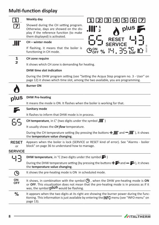
… Weekly day
Showed during the CH setting program. Otherwise, days are showed on the dis-play if the reference function (to make them displayed) is activated.
0014
7 00
CH – winter mode
If flashing, it means that the boiler is functioning in CH mode.
CH zone require
It shows which CH zone is demanding for heating.
DHW time slot indication
During the DHW program setting (see "Setting the Acqua Step program no. 3 - User" on page 12) it shows which time slot, among the two available, you are programming.
Burner ON
DHW Pre-heating
It means the mode is ON. It flashes when the boiler is working for that.
Sanitary mode
It flashes to inform that DHW mode is in process.
CH temperature, in C° (two digits under the symbol )
It usually shows the CH flow temperature.
During the CH temperature setting (by pressing the buttons and ), it shows the temperature value changing .
or
Appears when the boiler is lock (SERVICE or RESET kind of error). See "Alarms - boiler block" on page 36 to understand how to manage.
DHW temperature, in °C (two digits under the symbol )
During the DHW temperature setting (by pressing the buttons and ), it shows the temperature value changing .
It shows the pre-heating mode is ON in scheduled mode.
It shows, in combination with the symbol , when the DHW pre-heating mode is ON or OFF. This visualization does not mean that the pre-heating mode is in process as if it was, the symbol would be flashing.
It appears when the two digits at its right are showing the burner power during the func-tioning. This information is just available by entering the menu (see "INFO menu" on page 13).
Green Heating Technology
9
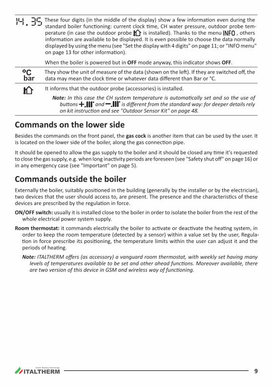
These four digits (in the middle of the display) show a few information even during the standard boiler functioning: current clock time, CH water pressure, outdoor probe tem-perature (in case the outdoor probe is installed). Thanks to the menu , others information are available to be displayed. It is even possible to choose the data normally displayed by using the menu (see "Set the display with 4 digits" on page 11; or "INFO menu" on page 13 for other information).
When the boiler is powered but in OFF mode anyway, this indicator shows OFF .
They show the unit of measure of the data (shown on the left). If they are switched off, the data may mean the clock time or whatever data different than Bar or °C.
It informs that the outdoor probe (accessories) is installed.
Note: In this case the CH system temperature is automatically set and so the use of buttons and is different from the standard way: for deeper details rely on kit instruction and see "Outdoor Sensor Kit" on page 48.
Commands on the lower sideBesides the commands on the front panel, the gas cock is another item that can be used by the user. It is located on the lower side of the boiler, along the gas connection pipe.
It should be opened to allow the gas supply to the boiler and it should be closed any time it's requested to close the gas supply, e.g. when long inactivity periods are foreseen (see "Safety shut off" on page 16) or in any emergency case (see "Important" on page 5).
Commands outside the boilerExternally the boiler, suitably positioned in the building (generally by the installer or by the electrician), two devices that the user should access to, are present. The presence and the characteristics of these devices are prescribed by the regulation in force.
ON/OFF switch: usually it is installed close to the boiler in order to isolate the boiler from the rest of the whole electrical power system supply.
Room thermostat: it commands electrically the boiler to activate or deactivate the heating system, in order to keep the room temperature (detected by a sensor) within a value set by the user, Regula-tion in force prescribe its positioning, the temperature limits within the user can adjust it and the periods of heating.
Note: ITALTHERM offers (as accessory) a vanguard room thermostat, with weekly set having many levels of temperatures available to be set and other ahead functions. Moreover available, there are two version of this device in GSM and wireless way of functioning.
Green Heating Technology
10
Typical usePreliminary operations
f Be sure the gas cock is opened.
f Be sure the boiler is electrically powered and set in OFF: only OFF has to be displayed on the screen .
Boiler activation f Press the button :
• once to set the boiler in summer mode only (DHW only). Summer mode is recognizable by the only symbol presence on the display and not by the symbol presence ;
• pressing twice to set the boiler in winter mode for making the boiler working both for CH and DHW. Winter mode is recognizable by the both symbols presence and on the display;
• at each press of the button , the boiler cyclically switches from OFF to summer and to winter + mode .
f Opening a DHW tap, the burner fires up, and later then DHW is available. In case pre-heating mode is desired (see "DHW pre-heating mode (Acqua Step)" on page 11).
f On winter mode + , when room thermostat demands for heating, the burner fires up and thanks to the water flow the heating get transferred . In case of contemporary demand of both DHW and CH, the DHW demand has the priority till the demand finish. Usually, as DHW does not last for long, this priority does not affect the CH efficiency in the system.
Temperature adjustmentNote: correct adjustment leads to creating the conditions for energy saving.
Note: if a Low Temperature Kit or an Outdoor Probe Kit are installed, refer to the relevant documen-tation for what concerns the heating system temperature adjustment.
Note: don't make confusion between the heating system temperature here described, with the temperature of the room set on the Room Thermostat.
f Heating system adjustment: by using the buttons and , the setting of the heating system temperature is made (the value, during the adjustment, is shown on the display under the symbol ). Generally, in the deep cold season and/or with poor building thermal insulation (or if you notice that the burner stays on for a long time, but the room temperature rises too slowly) prefer higher settings. On the contrary, if you notice that the room temperature exceeds too much, for thermal inertia, the value set on the room temperature, it's appropriate to decrease the system temperature. When the optional Outdoor Temperature Probe Kit is installed, the system tempera-ture is automatically managed and the use of the buttons and is different: for details, see also "Outdoor Sensor Kit" on page 48.
f Domestic hot water adjustment: the buttons and set the temperature of the hot water produced by the boiler (the value, during the adjustment, is shown on the display under the sym-bol ). On this type of boiler, we suggest to set it in such a way to have a comfortable hot water temperature by drawing only hot water or eventually by mixing it with a little cold water. Avoid maxi-mum values if not strictly needed, that will force to mix the hot water with bigger quantities of cold water. Consider that, because of the dispersions along the pipings, a certain time is needed to have a stable water temperature on the cock outlet, therefore the best temperature evaluation is achieved during a bath or a shower, and/or activating the DHW pre-heating function (see "DHW pre-heating mode (Acqua Step)" on page 11).
Green Heating Technology
11
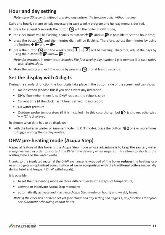
Hour and day settingNote: after 20 seconds without pressing any button, the function quits without saving.
Daily and hourly set are strictly necessary in case weekly program and holiday menu is desired.
f press for at least 5 seconds the button with the boiler in OFF mode;
f the clock hours will be flashing, thanks to buttons and is possible to set the hour time;
f press the button and the minutes digit will be flashing. Therefore, adjust the minutes by using the buttons and ;
f press the button and the weekly day … will be flashing. Therefore, adjust the days by using the buttons and ;
Note: for instance, in order to set Monday like first weekly day number 1 (set number 3 in case today was Wednesday).
f Store the setting and exit the mode by pressing ; for at least 5 seconds.
Set the display with 4 digits During the standard function the four digits take place in the bottom side of the screen and can show:
• No indication (choose this if you don't want any indication)
• DHW flow (when there is no DHW request, the value is zero)
• Current time (if the clock hasn't been set yet: no indication)
• CH water pressure
• Outdoor probe temperature (if it is installed - in this case the symbol is shown, otherwise "– – °C" is displayed)
To choose what data has to be displayed:
f with the boiler in winter or summer mode (no OFF mode), press the button one or more times to toggle among the display modes .
DHW pre-heating mode (Acqua Step)A special feature of this boiler is the Acqua Step mode whose advantage is to keep the sanitary water always warmed in order to shortcut the DHW time delivery when required. This allows to shortcut the waiting time and the water waste.
Thanks to the insulated material the DHW exchanger is wrapped of, the boiler reduces the heating loss-es and so gets an optimized consumption of gas in comparison with the traditional boilers (especially during brief and frequent DHW withdrawals).
It is possible:
• to set the pre-heating mode on three different levels (the steps) of temperature;
• activate or inactivate Acqua Step manually;
• automatically activate and inactivate Acqua Step mode on hourly and weekly bases.
Note: if the clock has not been set yet (see "Hour and day setting" on page 11) any functions that fore-see automatic scheduling cannot be set.
Green Heating Technology
12
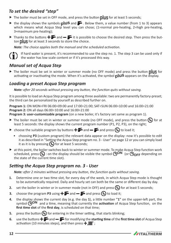
To set the desired “step” f The boiler must be set in OFF mode, and press the button for at least 5 seconds;
f the display shows the symbols and . Below them, a value number (from 1 to 3) appears which means what Acqua Step level you can chose; (1=normal pre-heating, 2=high pre-heating, 3=maximum pre-heating);
f Thanks to the buttons and it is possible to choose the desired step. Then press the but-ton for at least 3 seconds to store the choice.
Note: The choice applies both the manual and the scheduled activation.
If hard water is present, it's recommended to use the step no. 1. The step 3 can be used only if the water has low scale content or if it's processed this way.
Manual set of Acqua Step f The boiler must be set in winter or summer mode (no OFF mode) and press the button for
activating or inactivating the mode. When it's activated, the symbol appears on the display .
Loading a preset Acqua Step programNote: after 20 seconds without pressing any button, the function quits without saving.
It is possible to load an Acqua Step program among three available: two are permanently factory-preset; the third can be personalized by yourself as described further on.
Program 1: ON MON÷FRI 06:00÷09:00 and 17:00÷21:00; SAT÷SUN 06:00÷10:00 and 16:00÷21:00Program 2: ON all days 06:00÷10:00 and 16:00÷21:00Program 3: user-customizable program (on a new boiler, it's factory set same as program 1).
f The boiler must be set in winter or summer mode (no OFF mode), and press the button for at least 5 seconds: the display shows the current program number (P1, P2, P3), on the right;
f choose the suitable program by buttons and and press to load it;
• choosing P3 (custom program) the relevant data appear on the display: now it's possible to edit it as described in "Setting the Acqua Step program no. 3 - User" on page 12 or you can simply load it as it is by pressing for at least 5 seconds;
f at this point, the boiler switches back to winter or summer mode. To make Acqua Step function work scheduled, press : on the display should be visible the symbol (or depending on the state of the current time slot).
Setting the Acqua Step program no. 3 ‑ UserNote: after 2 minutes without pressing any button, the function quits without saving.
1. Determine one or two time slot, for every day of the week, in which Acqua Step mode is thought to be automatically required. Daily and hourly set can both be the same or different day by day.
2. set the boiler in winter or in summer mode (not in OFF) and press for at least 5 seconds;
3. choose the program P3 using and and press to load it;
4. the display shows the current day (e.g. the day 1), a little number "1" on the upper-left part, the symbol and a time, meaning that currently the activation of Acqua Step function, on the first time slot of the first day, is scheduled on that time;
5. press the button for entering in the timer setting, that starts blinking;
6. use the buttons and for modifying the starting time of the first time slot of Acqua Step activation (10 minutes steps), and then press ;
Green Heating Technology
13
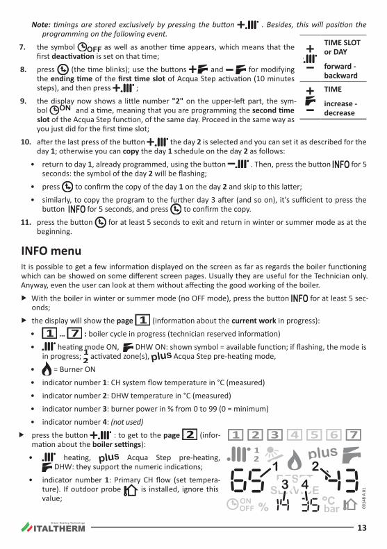
Note: timings are stored exclusively by pressing the button . Besides, this will position the programming on the following event.
7. the symbol as well as another time appears, which means that the first deactivation is set on that time;
8. press (the time blinks); use the buttons and for modifying the ending time of the first time slot of Acqua Step activation (10 minutes steps), and then press ;
9. the display now shows a little number "2" on the upper-left part, the sym-bol and a time, meaning that you are programming the second time slot of the Acqua Step function, of the same day. Proceed in the same way as you just did for the first time slot;
10. after the last press of the button the day 2 is selected and you can set it as described for the day 1; otherwise you can copy the day 1 schedule on the day 2 as follows:
• return to day 1, already programmed, using the button . Then, press the button for 5 seconds: the symbol of the day 2 will be flashing;
• press to confirm the copy of the day 1 on the day 2 and skip to this latter;
• similarly, to copy the program to the further day 3 after (and so on), it's sufficient to press the button for 5 seconds, and press to confirm the copy.
11. press the button for at least 5 seconds to exit and return in winter or summer mode as at the beginning .
INFO menuIt is possible to get a few information displayed on the screen as far as regards the boiler functioning which can be showed on some different screen pages. Usually they are useful for the Technician only. Anyway, even the user can look at them without affecting the good working of the boiler.
f With the boiler in winter or summer mode (no OFF mode), press the button for at least 5 sec-onds;
f the display will show the page (information about the current work in progress):
• … : boiler cycle in progress (technician reserved information)
• heating mode ON, DHW ON: shown symbol = available function; if flashing, the mode is in progress; activated zone(s), Acqua Step pre-heating mode,
• = Burner ON
• indicator number 1: CH system flow temperature in °C (measured)
• indicator number 2: DHW temperature in °C (measured)
• indicator number 3: burner power in % from 0 to 99 (0 = minimum)
• indicator number 4: (not used)
f press the button : to get to the page (infor-mation about the boiler settings):
• heating, Acqua Step pre-heating, DHW: they support the numeric indications;
• indicator number 1: Primary CH flow (set tempera-ture). If outdoor probe is installed, ignore this value;
TIME SLOT or DAY
forward - backward
TIME
increase - decrease
0014
8 A
01
1 23 4
Green Heating Technology
14
• indicator number 2: DHW temperature (set temperature)
• indicator number 3: Secondary CH flow (set temperature)
• indicator number 4: chosen Acqua Step level
f Press the button : the display shows the page : information which are referred to the thermoregulation (if the outdoor probe is installed only).
• CH system, zone/s, outdoor probe: they support the numeric indications.
• indicator number 1: CH flow temperature to the primary zone (shown when the request is on). The temperature is calculated on the base on the outdoor probe temperature according to its kd curve setting
• indicator number 2: outdoor probe kd curve number
• indicator number 3: CH flow temperature to the secondary zone (shown when the request is on). The temperature is calculated on the base on the outdoor probe temperature according to its kd curve setting
• indicator number 4: Outdoor temperature felt by the outdoor probe. If the value is –9°C it means that the outdoor temperature is 9° C below 0° or even lower.
f Pressing the buttons and it is possible to turn the pages onward or backward;
f Press the button to exit the INFO menu. Anyway, after 15 minutes the boiler automatically exits the menu.
Holiday menuNote: if the clock has not been set yet (see "Hour and day setting" on page 11) this function cannot be
used.
The user can decide to keep the boiler on OFF mode as many days as he wants. After that, the boiler automatically returns in winter mode (or, if the optional Remote Control is installed, this latter returns in the mode it was in the moment of the activation, while the boiler returns in Summer mode to allow the correct work of the Remote Control).
f The boiler must be set on OFF mode (not in winter or summer mode), and press the button for at least 5 seconds;
f on the left side of the display the symbol and “Ho” will appear as well as on the right side a value number;
f press the buttons and to set the number of inactivity days (don't include the current day);
f press the button for at least 3 second to save the setting. From now the Holiday function is ON and will expire at 23:59:59 of the last day.
Note: afterwards, it is possible to set the boiler in modes different from OFF, but the Holiday function will operate only if the boiler is set to OFF.
Green Heating Technology
15
SPA functionNote: if the optional Remote Control is installed, this function can only be managed by it.
This function is useful, in example, when a bath tub has to be filled. It forces the DHW temperature to the maximum for 30 minutes, then the function deactivates automatically.
f With the boiler in winter or summer mode (no OFF mode), press the button for at least 5 seconds;
f on the central, lower side of the display, the indication "SPA" appears, and the digits below the symbol blink;
f to deactivate the function before, press one of the buttons or .
Incidental malfunctioning Avoid performing personally any intervention that are job of the technician, for example the
ones on the electrical circuits, on hydraulic system or on the gas system, and whatever other operation that's not mentioned in this "User Guide" section and expressly allowed to the User. Always address yourselves to qualified personnel.
Boilers must be always equipped with original accessories only.
ITALTHERM Srl is not responsible for damages caused by the incorrect, wrong or unreasonable use of not original materials.
The burner doesn’t turn on f if the room thermostat (or programmable room thermostat, or similar) is installed, check that it is
really requiring the room heating;
f Be sure the boiler is set on winter + or summer mode (not in OFF). The reference symbols must be shown on the display (see "Multi-function display" on page 8);
f In case the display shows or , or in case the boiler seems to be working in an inappropriate way, see "Alarms - boiler block" on page 36;
f check the CH pressure is correct (1÷1.5 Bar in a cold state) or anyway not lower than 0.5 Bar;
Shortage of domestic hot water production f check the DHW temperature is not set on a too low value: if so, adjust it (see "Temperature adjust-
ment" on page 10);
f call a qualified technician to check gas valve regulation;
f call a qualified technician to check, and eventually clean, the DHW exchanger.
Remark: where the water hardness value is too high, it is suggested the installation of a soften-ing device, in order to prevent the limestone precipitation; this operation avoids a frequent cleaning of the coil .
Boiler inactivityThe effects of the periods of inactivity can be relevant in particular situations such as in flats used only for some months per year, most of all in cold places.
The user will have to decide to put the boiler in the SAFETY SHUT OFF state disconnecting all the sup-plies, or to leave it on OFF mode (but electrically supplied) in order to let the Anti Frost Function work . When there is the possibility of freezing it is convenient to chose between the advantages and the dis-advantages of the SAFETY SHUT OFF and of the Stand By/Anti Freezing Way.
Green Heating Technology
16
Safety shut off f Turn off the general switch on the Electrical Supply Line of the Boiler;
f Close the Gas Tap;
When it is expected that the temperature is going to decrease under 0°C, call a technician to do the following:
• Fill the system with an anti-freezing solution (unless the system was already filled with said solu-tion) otherwise it must be completely emptied. Notice that if it had been necessary to restore the pressure (because of possible loss) in an heating system already filled with an Anti freezing solution, the concentration of the solution could have decreased and it could not guarantee the Anti freezing Protection.
• completely empty the hot and cold sanitary water system, including the sanitary circuit and the boiler’s sanitary exchanger.
Remark: the boiler is equipped with a system which protects the main components from the excep-tional cases of mechanical lock, due to the inactivity in presence of water and scale. The anti-locking function can’t work in Safety shut off mode, because of the lack of electrical supply.
Before re-igniting the boiler, have a technician check that the pump is not blocked due to inac-tivity (for the technician: unscrew the plug in the centre of the cap to access the rotor shaft and turn it with a screwdriver or other suitable tool).
Stand‑by mode with anti‑frost & anti‑locking functionWhen the boiler is left in OFF mode during a period of inactivity, it will be protected against freezing by several functions provided in the electronic controller, which heat the parts involved when the tempera-ture falls below factory set values.
The anti-frost heating is accomplished by turning on the burner and pump.
In addition, when the boiler is in stand-by, it periodically activates the main internal components to avoid rare cases of blockage due to inactivity in the presence of water and lime. This can also occur when the boiler is locked (red lamp on) provided that the system pressure is correct.
In order for these systems to be active:
• the boiler must be receiving gas and electricity;
• boiler must be left on OFF mode (OFF shown on the display);
• system pressure must be correct (1÷1.5 bar in a cold state, minimum 0.5 bar)
In case of lack of gas, the burner won’t turn on and the boiler will go in LOCK OUT state (red lamp on or flashing). Nevertheless the pump will work, making the water circulate in the system and reducing in this way the possibility of freezing. It is available, on demand, an Anti Frost Electrical resistance kit which must be installed on the secondary exchanger to protect the boiler also in case of lack of gas.
ATTENTION: the anti-frost protections cannot intervene in the absence of electricity. If you an-ticipate this possibility, we recommend you add a good brand of anti-freeze to the heating sys-tem, following the producer’s instructions.
We recommend to ask directly the installer/technician about the type of antifreeze product put in the heating system during installation.
When the power comes back on, the boiler will check the temperature measured by the two probes and, if it suspects freezing verified by a particular automatic control cycle, alarm 39 will be triggered. For more details, see the relative description in the paragraph "Alarms - boiler block" on page 36.
Green Heating Technology
17
We recommend that you completely empty the hot and cold sanitary water system, including the sanitary circuit and the boiler’s sanitary exchanger. The anti-frost function does not protect the sanitary circuit outside the boiler.
“Ambient Anti‑Frost” FunctionNote: if you want to use the “Ambient Anti-Frost” function that is often available in common room
thermostats or chronothermostats, it is necessary to leave the boiler on Winter + mode and NOT on OFF mode.
The “Ambient Anti-Frost” function does not protect the sanitary circuit outside the boiler and, especially, in areas where the heating system doesn’t reach. For this reason, we recommend that you empty the cold and hot sanitary water from the parts of the system that are at risk of freezing.
Installation
Law and regulation prescriptions for the installerNote for the translator/writer: Place in this paragraph all the recommendations relevant to the compli-ance with laws in the destination nation/country (if any). As an example (from Italian regulation):
Characteristics of the room: as this boiler has an heat output lower than 35 kW (about 30000 Kcal/h), it is not required to install the appliance in a dedicated room, provided that the room complies with the regulation in force and that all installation rules assuring a safe and regular gas boiler operation, are strictly respected .
Permanent ventilation of the installation room is mandatory and extremely important when a boiler with air draught from the installation room (B… appliance type) is installed. Ventilation must be made and sized in compliance with Laws and Rules in force.
Instructing the user: at the end of the installation, the installer must:
• explain the operation of the boiler and its safety devices to the user;
• give this user this booklet and the documentation within his/her competence, duly filled in where required.
Green Heating Technology
18
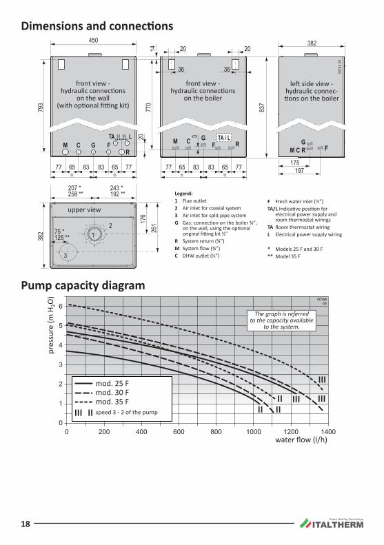
Dimensions and connections
0014
2 00
12
3
2077
014
450
77= =65 83 83 65 77 77
= =65 83 83 65 77
3533
GLTA
FCMG G
FM C RFCM
RR
TA / L
197175
20
36
20
36
3
837
382
207 *258 **
75 *125 **
243 *192 **
26117
6
793
382
Legend:1 Flue outlet2 Air inlet for coaxial system3 Air inlet for split-pipe systemG Gas: connection on the boiler ¾”;
on the wall, using the optional original fitting kit ½”
R System return (¾”)M System flow (¾”)C DHW outlet (½”)
F Fresh water inlet (½”)TA/L Indicative position for
electrical power supply and room thermostat wirings
TA Room thermostat wiringL Electrical power supply wiring
* Models 25 F and 30 F** Model 35 F
front view - hydraulic connections
on the wall (with optional fitting kit)
upper view
front view - hydraulic connections
on the boiler
left side view - hydraulic connec-tions on the boiler
Pump capacity diagram
0
1
2
3
4
5
6
0 200 400 1000 1200 600 800 1400
0015900
pres
sure
(m H
2O)
water flow (l/h)
mod. 35 F
mod . 25 Fmod. 30 F
speed 3 - 2 of the pump
The graph is referred to the capacity available
to the system.
Green Heating Technology
19
Specifications for inlet airAir must be withdrawn from places free of pollutant (like fluorine, chlorine, sulfur, ammonia, alkaline or similar agents). In the event of installation of the boiler in atmospheres with not negligible presence of aggressive chemical substances (e.g. hairdressing salons, laundries) we recommend to foresee the air inlet from outdoor, choosing the type C installation.
Domestic water supply characteristicsThe cold water inlet pressure must be lower than 6 Bar. Besides, for an optimal boiler functioning, wa-ter pressure should be more than 1 Bar. A lower pressure could make difficult to restore correctly the pressure the heating system, and reduce the flow of hot water available from the boiler.
In case of higher pressure it is indispensable to install a PRESSURE REDUCER upstream the boiler .
The cleaning frequency of the DHW heat exchanger depends on the water supply hardness. If the wa-ter hardness is more than 25° fr it’s required to install a softener to bring the hardness below that value.
Besides, the presence of solid residuals or impurities in the water (for example in case of new systems) could compromise the correct functioning of the boiler. For DHW production systems, the regulation in force prescribes a safety filter to protect the systems.
Protection against freezingThanks to its antifreeze system, inner components could never reach a temperature lower than 5°C. This system is activated when the boiler is supplied by the electrical and gas lines, provided that the pressure in the heating system is correct. On request, it is possible to install an antifreeze electrical resistance device on the domestic exchanger, so as to protect boiler even in case of gas lack.
In case of boiler installation in rooms where temperature can drop down to 0°, it is advisable to fill the heating circuit with an antifreeze liquid specific for heating systems, propylenic glycol based, following the instructions of its manufacturer. Pay attention to the correct product con-centration: adding those substances to the heating water in incorrect dose could lead to the deformation of the seals and cause unusual noises during operation.
ITALTHERM S.r.l. will not be held responsible for consequent damages.
Instruct the User about the antifreeze function of the boiler and about the antifreeze product added in the heating system.
Green Heating Technology
20
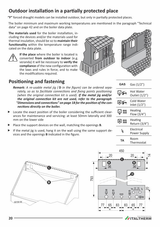
Outdoor installation in a partially protected place“F” forced draught models can be installed outdoor, but only in partially protected places.
The boiler minimum and maximum working temperatures are mentioned in the paragraph "Technical data" on page 42 and on the boiler data plate.
The materials used for the boiler installation, in-cluding the devices and/or the materials used for thermal insulation, should be so to maintain their functionality within the temperature range indi-cated on the data plate .
If the place where the boiler is located is converted from outdoor to indoor (e.g. veranda) it will be necessary to verify the compliance of the new configuration with the laws and rules in force, and to make the modifications required.
Positioning and fasteningRemark: A re-usable metal jig ( D in the figure) can be ordered sepa-
rately, so as to facilitate connections and fixing points positioning (when the original connection kit is used). If the metal jig and/or the original connection kit are not used, refer to the paragraph
"Dimensions and connections" on page 18 for the position of the con-nections directly on the boiler.
f Locate the exact position of the boiler considering the sufficient clear-ances for maintenance and servicing: at least 50mm laterally and 300 mm on the lower side
f Place the support devices on the wall, matching the openings B .
f If the metal jig is used, hang it on the wall using the same support de-vices and the openings B indicated in the figure.
Gas (1/2”)
Hot Water Outlet (1/2”)
Cold Water Inlet (1/2”)
Heating Flow (3/4”)
Heating Return (3/4”)
Electrical Power Supply
Room Thermostat
0000
4 00
B B
D
C
B
C
00150 00
2014
450
793
77= =65 83 83 65 77
3533
20
36
20
36
Green Heating Technology
21
f Fix up the connections and all ducts for heating flow and return, cold water, hot water, gas and electrical cables, predisposing them in the holes of the metal jig or respecting the measures in the paragraph "Dimensions and connections" on page 18. The upper edge of boiler’s body, used as a refer-ence in the paragraph "Flue system types" on page 27, is represented by the dotted line C in the figure.
f Remove the jig (if used) and hang the boiler to the support devices, by the openings B indicated in the figure.
Remove, from the boiler, all the styrofoam reinforcements, and the plastic caps placed to close the hydraulic connections.
f Proceed with the hydraulic, gas, electrical and flue connections following the instructions and warn-ings reported in the following paragraphs .
The connections of the boiler are engineered to fit plain couplings with screw ring, interposing a plain gasket of suitable size and material, that ensure a reliable seal even without excessive tightening force. They are NOT suitable for hemp, teflon tape or similar materials
Remark: the lower grid is spare inside packing, not assembled. We suggest to fix the grid only at the end of the boiler installation operations.
Hydraulic system (DHW and heating) Make sure that the hydraulic and heating systems ducts are not used as earth connections of
the electrical system. They are absolutely NOT SUITABLE for such a use. Besides: they don't guarantee the earth dispersion; in case of electrical fault they could generate a fulguration risk; there could take place galvanic currents in the pipings and consequent corrosion and hydraulic leaks .
Advices and suggestions to avoid vibrations and noises in the system f Do not use pipes with reduced diameters;
f Do not use bends with small radius and reductions of important sections.
Cleaning and preservation of the systemsThe efficiency, the reliability and the safety of the boilers, as all generic thermal systems and compo-nents, depend strictly on the features of the water that supply them and on their treatment.
A proper treatment of the water improves the protection of the systems against corrosions (and there-fore perforations, noise, leaks, etc.) and limestone incrustations that drastically reduce the efficiency of the thermal exchange (consider that 1 mm of limestone incrustations reduces of 18% the thermal exchange of the heating element on which it has been formed).
ITALTHERM guarantees its products only if the characteristics of the water comply with UNI 8065, re-ported also in laws on energy saving .
Thoroughly wash the heating system with water, before connecting the boiler. This will elimi-nate residual like welding drops, slag, hemp, mastic, mud, rust and other dirt from pipes and radiators. Otherwise, these substances could enter the boiler and damage the internal compo-nents (pump etc.).
f In case of old or very dirty systems, to wash them use specific, proven efficiency products, in the suitable quantity and following the instructions of its manufacturer.
f If the water on boiler inlet is harder than 25° fr, it’s required to install a softener to bring the hardness below that value, as required by the reference regulation.
f For floor system and generally all low temperature systems, the water treatment product must have filming action (protection against corrosion and incrustation) and action against bacteria and algae.
Green Heating Technology
22
Heating system f Connect the safety evacuation ducts of the boiler to an evacuation funnel. If safety valves are not
connected to an evacuation device, their intervention could flood the room. The manufacturer can-not be held responsible for any damage arising from that situation.
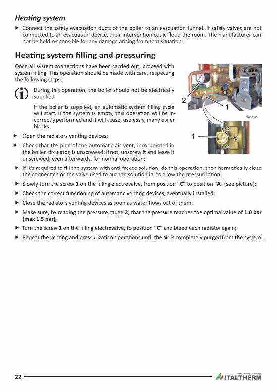
Heating system filling and pressuringOnce all system connections have been carried out, proceed with system filling. This operation should be made with care, respecting the following steps:
During this operation, the boiler should not be electrically supplied.
If the boiler is supplied, an automatic system filling cycle will start. If the system is empty, this operation will be in-correctly performed and it will cause, uselessly, many boiler blocks .
f Open the radiators venting devices;
f Check that the plug of the automatic air vent, incorporated in the boiler circulator, is unscrewed: if not, unscrew it and leave it unscrewed, even afterwards, for normal operation;
f If it's required to fill the system with anti-freeze solution, do this operation, then hermetically close the connection or the valve used to put the solution in, to allow the pressurization.
f Slowly turn the screw 1 on the filling electrovalve, from position "C" to position "A" (see picture);
f Check the correct functioning of automatic venting devices, eventually installed;
f Close the radiators venting devices as soon as water flows out of them;
f Make sure, by reading the pressure gauge 2, that the pressure reaches the optimal value of 1.0 bar (max 1.5 bar);
f Turn the screw 1 on the filling electrovalve, to position "C" and bleed each radiator again;
f Repeat the venting and pressurization operations until the air is completely purged from the system.
Green Heating Technology
23
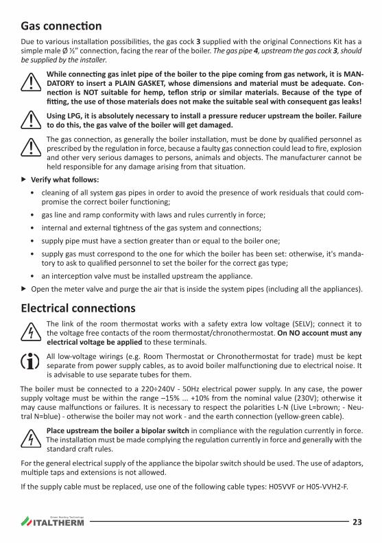
Gas connectionDue to various installation possibilities, the gas cock 3 supplied with the original Connections Kit has a simple male Ø ½” connection, facing the rear of the boiler. The gas pipe 4, upstream the gas cock 3, should be supplied by the installer.
While connecting gas inlet pipe of the boiler to the pipe coming from gas network, it is MAN-DATORY to insert a PLAIN GASKET, whose dimensions and material must be adequate. Con-nection is NOT suitable for hemp, teflon strip or similar materials. Because of the type of fitting, the use of those materials does not make the suitable seal with consequent gas leaks!
Using LPG, it is absolutely necessary to install a pressure reducer upstream the boiler. Failure to do this, the gas valve of the boiler will get damaged.
The gas connection, as generally the boiler installation, must be done by qualified personnel as prescribed by the regulation in force, because a faulty gas connection could lead to fire, explosion and other very serious damages to persons, animals and objects. The manufacturer cannot be held responsible for any damage arising from that situation.
f Verify what follows:
• cleaning of all system gas pipes in order to avoid the presence of work residuals that could com-promise the correct boiler functioning;
• gas line and ramp conformity with laws and rules currently in force;
• internal and external tightness of the gas system and connections;
• supply pipe must have a section greater than or equal to the boiler one;
• supply gas must correspond to the one for which the boiler has been set: otherwise, it's manda-tory to ask to qualified personnel to set the boiler for the correct gas type;
• an interception valve must be installed upstream the appliance.
f Open the meter valve and purge the air that is inside the system pipes (including all the appliances).
Electrical connections The link of the room thermostat works with a safety extra low voltage (SELV); connect it to
the voltage free contacts of the room thermostat/chronothermostat. On NO account must any electrical voltage be applied to these terminals .
All low-voltage wirings (e.g. Room Thermostat or Chronothermostat for trade) must be kept separate from power supply cables, as to avoid boiler malfunctioning due to electrical noise. It is advisable to use separate tubes for them.
The boiler must be connected to a 220÷240V - 50Hz electrical power supply. In any case, the power supply voltage must be within the range –15% ... +10% from the nominal value (230V); otherwise it may cause malfunctions or failures. It is necessary to respect the polarities L-N (Live L=brown; - Neu-tral N=blue) - otherwise the boiler may not work - and the earth connection (yellow-green cable).
Place upstream the boiler a bipolar switch in compliance with the regulation currently in force. The installation must be made complying the regulation currently in force and generally with the standard craft rules.
For the general electrical supply of the appliance the bipolar switch should be used. The use of adaptors, multiple taps and extensions is not allowed.
If the supply cable must be replaced, use one of the following cable types: H05VVF or H05-VVH2-F.
Green Heating Technology
24
The supply cable replacement must be done by qualified personnel.
It is mandatory the earth connection in accordance with the rules actually in force. To replace the cable, open the control panel cover, unlock its fastening device and disconnect it from the terminals. Install the new cable proceeding in the reverse way. When connecting the cable to the boiler, it’s man-datory:
• to leave the Earth wire about 2 cm longer than the other (Live and Neutral) wires;
• to lock the cable upstream the terminals by means of the suitable fastening device.
Electrical safety of the appliance is only achieved when it is well connected to an efficient earth-ing system, executed as indicated by the safety rules actually in force.
A qualified technician must check that the electrical system is in line with the maximum power allowed by the boiler, indicated on the data plate, with particular attention to the cables section.
ITALTHERM S.r.l. declines any responsibility for damages to persons, animals or things caused by the faulty or missing connection of the boiler earthing and by failure to comply with the rules.
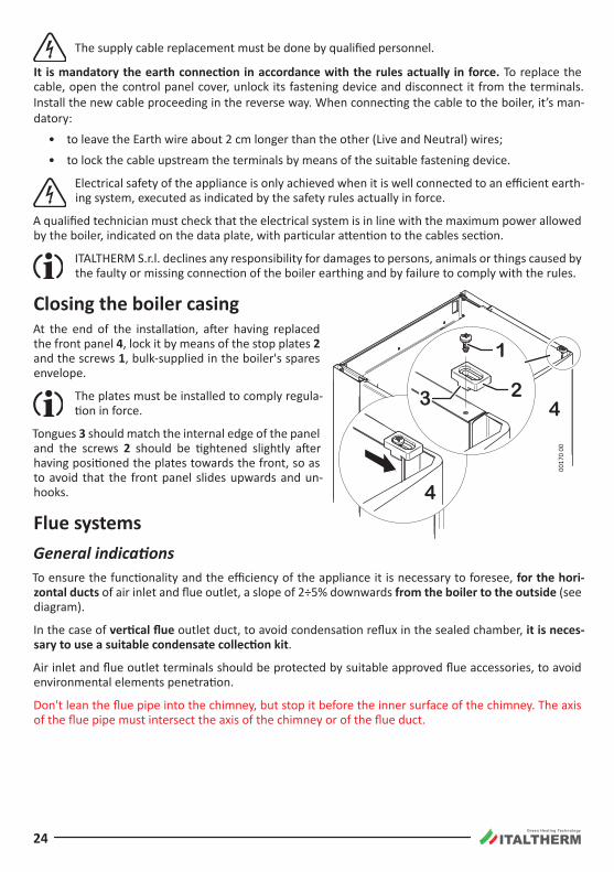
Closing the boiler casingAt the end of the installation, after having replaced the front panel 4, lock it by means of the stop plates 2 and the screws 1, bulk-supplied in the boiler's spares envelope .
The plates must be installed to comply regula-tion in force.
Tongues 3 should match the internal edge of the panel and the screws 2 should be tightened slightly after having positioned the plates towards the front, so as to avoid that the front panel slides upwards and un-hooks .
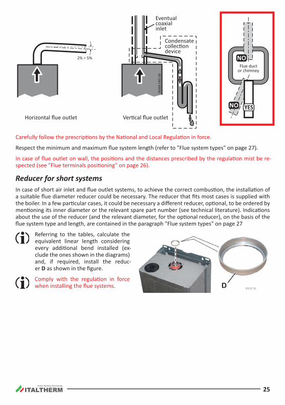
Flue systemsGeneral indicationsTo ensure the functionality and the efficiency of the appliance it is necessary to foresee, for the hori-zontal ducts of air inlet and flue outlet, a slope of 2÷5% downwards from the boiler to the outside (see diagram).
In the case of vertical flue outlet duct, to avoid condensation reflux in the sealed chamber, it is neces-sary to use a suitable condensate collection kit .
Air inlet and flue outlet terminals should be protected by suitable approved flue accessories, to avoid environmental elements penetration.
Don't lean the flue pipe into the chimney, but stop it before the inner surface of the chimney. The axis of the flue pipe must intersect the axis of the chimney or of the flue duct.
1
3
4
42
0017
0 00
Green Heating Technology
25
0000
8 EN
G 00
Eventualcoaxialinlet
Horizontal flue outlet Ver�cal flue outlet
2% ÷ 5%
Condensatecollec�ondevice
Flue ductor chimney
NO
NO YES
Carefully follow the prescriptions by the National and Local Regulation in force.
Respect the minimum and maximum flue system length (refer to "Flue system types" on page 27).
In case of flue outlet on wall, the positions and the distances prescribed by the regulation mist be re-spected (see "Flue terminals positioning" on page 26).
Reducer for short systemsIn case of short air inlet and flue outlet systems, to achieve the correct combustion, the installation of a suitable flue diameter reducer could be necessary. The reducer that fits most cases is supplied with the boiler. In a few particular cases, it could be necessary a different reducer, optional, to be ordered by mentioning its inner diameter or the relevant spare part number (see technical literature). Indications about the use of the reducer (and the relevant diameter, for the optional reducer), on the basis of the flue system type and length, are contained in the paragraph "Flue system types" on page 27
Referring to the tables, calculate the equivalent linear length considering every additional bend installed (ex-clude the ones shown in the diagrams) and, if required, install the reduc-er D as shown in the figure.
Comply with the regulation in force when installing the flue systems.
Green Heating Technology
26
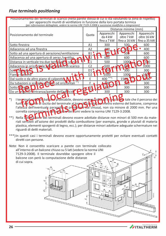
Flue terminals positioningPosizionamento dei terminali di scarico (nella parete stessa di cui si sta valutando la zona di rispetto)
per apparecchi muniti di ventilatore in funzione della loro portata termica (per informazioni dettagliate, vedere la norma UNI 7129-3:2008 e successive modifiche o integrazioni)
Posizionamento del terminale Quota
Distanze minime (mm)Apparecchi
da 4 kW fino a 7 kW
Apparecchi oltre 7 kW
fino a 16 kW
Apparecchi oltre 16 kW fino a 35 kW
Sotto finestra A1 300 500 600Adiacenza ad una finestra A2 400 400 400Sotto ad una apertura di aerazione/ventilazione B1 300 500 600Adiacenza ad una apertura di aeraz./ventilaz. B2 600 600 600Distanza in verticale tra due terminali di scarico C1 500 1000 1500Adiacenza in orizzontale ad un termin. di scarico C2 500 800 1000Sotto balcone *) D1 300 300 300Fianco balcone D2 1000 1000 1000Dal suolo o da altro piano di calpestio E 400 ***) 1500 ***) 2200Da tubazioni o scarichi verticali od orizzontali **) F 300 300 300Sotto gronda G 300 300 300Da un angolo/rientranza/parete dell’edificio H 300 300 300
*) I terminali sotto un balcone praticabile, devono essere collocati in posizione tale che il percorso dei fumi, dal punto di uscita del terminale al loro sbocco dal perimetro esterno del balcone, compresa l'altezza dell’eventuale parapetto di protezione (se chiusa), non sia minore di 2000 mm. Per una corretta computazione del percorso dei fumi vedere la norma UNI 7129-3:2008 .
**) Nella collocazione dei terminali devono essere adottate distanze non minori di 500 mm da mate-riali sensibili all'azione dei prodotti della combustione (per esempio, gronde e pluviali di materia plastica, elementi sporgenti di legno, ecc.); per distanze minori adottare adeguate schermature nei riguardi di detti materiali.
***) In questi casi i terminali devono essere opportunamente protetti per evitare eventuali contatti diretti con persone.
Nota: Non è consentito scaricare a parete con terminale collocato all’interno di un balcone chiuso su 5 lati (vedere la norma UNI 7129-3:2008). Il terminale dovrebbe sporgere oltre il balcone con però la computazione delle distanze di cui sopra.
This is valid only in Europe.
Replace with information
from local regulation about
terminals positioning
Green Heating Technology
27
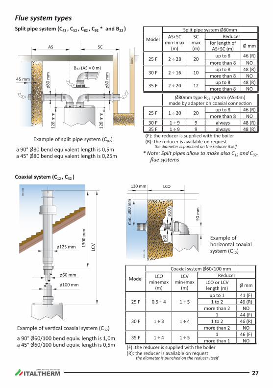
Flue system typesSplit pipe system (C42 , C52 , C82 , C92 * and B22 )
Model
Split pipe system Ø80mmAS+SC
min÷max (m)
SC max (m)
Reducerfor length of AS+SC (m) Ø mm
25 F 2 ÷ 28 20 up to 8 46 (R)more than 8 NO
30 F 2 ÷ 16 10 up to 8 48 (R)more than 8 NO
35 F 2 ÷ 20 12 up to 8 48 (R)more than 8 NO
Ø80mm type B22 system (AS=0m) made by adapter on coaxial connection
25 F 1 ÷ 20 20 up to 8 46 (R)more than 8 NO
30 F 1 ÷ 9 9 always 48 (R)35 F 1 ÷ 9 9 always 48 (R)
(F): the reducer is supplied with the boiler(R): the reducer is available on request the diameter is punched on the reducer itself
AS SC
45 mm
ø80
mm
ø80
mm
128
mm
128
mm
0000
7 01
B22 (AS = 0 m)
Example of split pipe system (C82)
a 90° Ø80 bend equivalent length is 0,5m a 45° Ø80 bend equivalent length is 0,25m * Note: Split pipes allow to make also C12 and C32.
flue systems
Coaxial system (C12 , C32 )
1300
mm
ø100 mm
ø60 mm
LCVø125 mm
0001
0 00
LCO
min
. 30
0 m
m
130 mm
ø100
90 m
m
ø60
0001
1 00
Model
Coaxial system Ø60/100 mmLCO
min÷max (m)
LCV min÷max
(m)
ReducerLCO or LCV length (m) Ø mm
25 F 0 .5 ÷ 4 1 ÷ 5up to 1 41 (F)1 to 2 46 (R)
more than 2 NO
30 F 1 ÷ 3 1 ÷ 41 44 (F)
1 to 2 46 (R)more than 2 NO
35 F 1 ÷ 4 1 ÷ 5 1 46 (F)more than 1 NO
(F): the reducer is supplied with the boiler(R): the reducer is available on request the diameter is punched on the reducer itself
Example of vertical coaxial system (C32)
a 90° Ø60/100 bend equiv. length is 1,0m a 45° Ø60/100 bend equiv. length is 0,5m
Example of horizontal coaxial system (C12)
Green Heating Technology
28
Adjustment and Maintenance ATTENTION: the operations described below must be carried out only by qualified personnel
[authorized by ITALTHERM] .
When regulation/measuring is over, remember to tighten pressure tapping point screws and ALWAYS check for gas leaks!
Before boiler ignition, verify that pump is not blocked due to its inactivity: unscrew the plug located in the middle of the cap to gain access to the rotor shaft, and turn it manually using a screwdriver or another suitable tool.
During the first ignition of the brand new boiler, it is necessary that burner works for at least 30 minutes, before performing combustion checks. During this time, the fumes of the eventual residual manufacturing materials are produced, and they could alter the measured values.
Remark: during the first 10 minutes of electrical power supply, the re-ignition delay is nil.
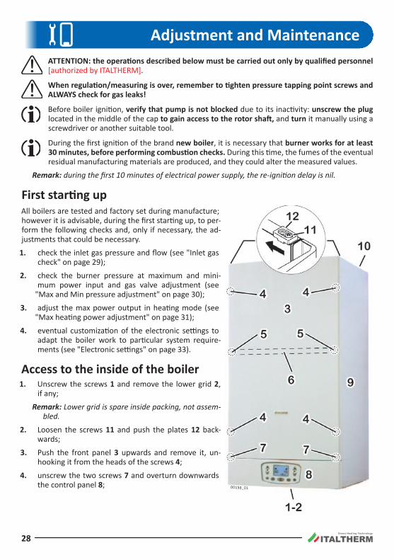
First starting upAll boilers are tested and factory set during manufacture; however it is advisable, during the first starting up, to per-form the following checks and, only if necessary, the ad-justments that could be necessary.
1. check the inlet gas pressure and flow (see "Inlet gas check" on page 29);
2. check the burner pressure at maximum and mini-mum power input and gas valve adjustment (see
"Max and Min pressure adjustment" on page 30);
3. adjust the max power output in heating mode (see "Max heating power adjustment" on page 31);
4. eventual customization of the electronic settings to adapt the boiler work to particular system require-ments (see "Electronic settings" on page 33).
Access to the inside of the boiler1. Unscrew the screws 1 and remove the lower grid 2,
if any;
Remark: Lower grid is spare inside packing, not assem-bled.
2. Loosen the screws 11 and push the plates 12 back-wards;
3. Push the front panel 3 upwards and remove it, un-hooking it from the heads of the screws 4;
4. unscrew the two screws 7 and overturn downwards the control panel 8;
Green Heating Technology
29
5. Should the removal of the side panel(s) 9 be necessary:
• unscrew the screws 5 and remove the bracket 6;
• remove the panel 9 upwards, slightly displacing it outwards to free it from the chassis, unhooking it from the tongues 10;
6. after the regulations (described in the following paragraphs), close the boiler repeating everything in the other sense, carefully hooking (if removed) the panel(s) 9 to the tongues 10 and the front panel 3 to the screws 4, locking it by the screws 11 and the plates 12 .
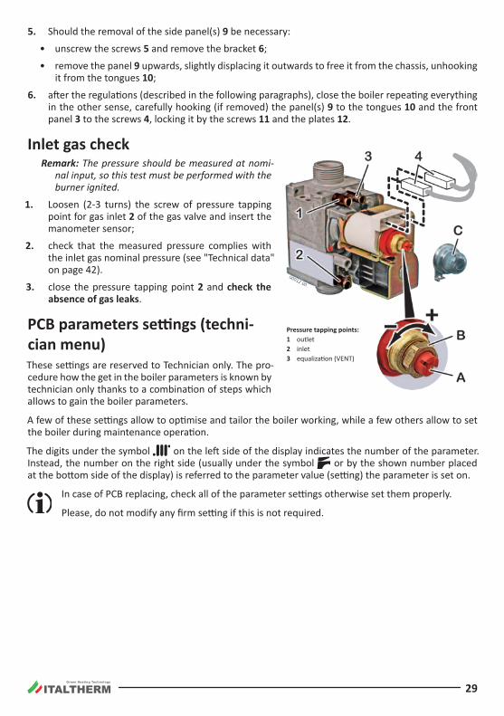
Inlet gas checkRemark: The pressure should be measured at nomi-
nal input, so this test must be performed with the burner ignited.
1. Loosen (2-3 turns) the screw of pressure tapping point for gas inlet 2 of the gas valve and insert the manometer sensor;
2. check that the measured pressure complies with the inlet gas nominal pressure (see "Technical data" on page 42).
3. close the pressure tapping point 2 and check the absence of gas leaks .
PCB parameters settings (techni-cian menu)These settings are reserved to Technician only. The pro-cedure how the get in the boiler parameters is known by technician only thanks to a combination of steps which allows to gain the boiler parameters .
A few of these settings allow to optimise and tailor the boiler working, while a few others allow to set the boiler during maintenance operation.
The digits under the symbol on the left side of the display indicates the number of the parameter. Instead, the number on the right side (usually under the symbol or by the shown number placed at the bottom side of the display) is referred to the parameter value (setting) the parameter is set on.
In case of PCB replacing, check all of the parameter settings otherwise set them properly.
Please, do not modify any firm setting if this is not required.
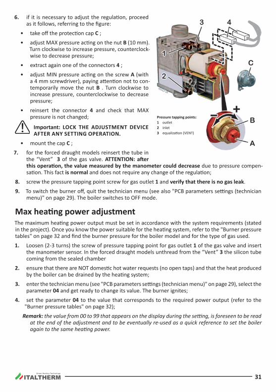
Pressure tapping points:1 outlet2 inlet3 equalization (VENT)
Green Heating Technology
30
Main boiler parameters (PC)The parameters listed in the following table are limited to those described in this handbook . The com-plete parameter list is available in the documentation for the technician.
Param-eter
Adjustment range (factory setting)
Description
01 0-1 (*) Type of GAS supply:
Value 0 = for Natural Gas (G20) supply
Value 1 = for LPG (G30/G31) supplyNote (*): The factory setting depends on the gas type arranged in factory for the boiler.
To change the type of gas supply, it is necessary to follow the complete instructions described in the paragraph "Gas conversion" on page 34.
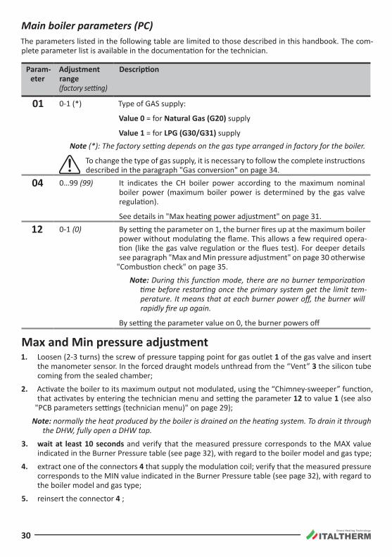
04 0…99 (99) It indicates the CH boiler power according to the maximum nominal boiler power (maximum boiler power is determined by the gas valve regulation).
See details in "Max heating power adjustment" on page 31.
12 0-1 (0) By setting the parameter on 1, the burner fires up at the maximum boiler power without modulating the flame. This allows a few required opera-tion (like the gas valve regulation or the flues test). For deeper details see paragraph "Max and Min pressure adjustment" on page 30 otherwise
"Combustion check" on page 35.
Note: During this function mode, there are no burner temporization time before restarting once the primary system get the limit tem-perature. It means that at each burner power off, the burner will rapidly fire up again.
By setting the parameter value on 0, the burner powers off
Max and Min pressure adjustment1. Loosen (2-3 turns) the screw of pressure tapping point for gas outlet 1 of the gas valve and insert
the manometer sensor. In the forced draught models unthread from the “Vent” 3 the silicon tube coming from the sealed chamber;
2. Activate the boiler to its maximum output not modulated, using the “Chimney-sweeper” function, that activates by entering the technician menu and setting the parameter 12 to value 1 (see also
"PCB parameters settings (technician menu)" on page 29);
Note: normally the heat produced by the boiler is drained on the heating system. To drain it through the DHW, fully open a DHW tap.
3. wait at least 10 seconds and verify that the measured pressure corresponds to the MAX value indicated in the Burner Pressure table (see page 32), with regard to the boiler model and gas type;
4. extract one of the connectors 4 that supply the modulation coil; verify that the measured pressure corresponds to the MIN value indicated in the Burner Pressure table (see page 32), with regard to the boiler model and gas type;
5. reinsert the connector 4 ;
Green Heating Technology
31
6. if it is necessary to adjust the regulation, proceed as it follows, referring to the figure:
• take off the protection cap C ;
• adjust MAX pressure acting on the nut B (10 mm). Turn clockwise to increase pressure, counterclock-wise to decrease pressure;
• extract again one of the connectors 4 ;
• adjust MIN pressure acting on the screw A (with a 4 mm screwdriver), paying attention not to con-temporarily move the nut B . Turn clockwise to increase pressure, counterclockwise to decrease pressure;
• reinsert the connector 4 and check that MAX pressure is not changed;
Important: LOCk THE ADJUSTMENT DEVICE AFTER ANY SETTING OPERATION.
• mount the cap C ;
7. for the forced draught models reinsert the tube in the “Vent” 3 of the gas valve . ATTENTION: after this operation, the value measured by the manometer could decrease due to pressure compen-sation. This fact is normal and does not require any change of the regulation;
8. screw the pressure tapping point screw for gas outlet 1 and verify that there is no gas leak .
9. To switch the burner off, quit the technician menu (see also "PCB parameters settings (technician menu)" on page 29). The boiler switches to OFF mode.
Max heating power adjustmentThe maximum heating power output must be set in accordance with the system requirements (stated in the project). Once you know the power suitable for the heating system, refer to the "Burner pressure tables" on page 32 and find the burner pressure for the boiler model and for the type of gas used.
1. Loosen (2-3 turns) the screw of pressure tapping point for gas outlet 1 of the gas valve and insert the manometer sensor. In the forced draught models unthread from the “Vent” 3 the silicon tube coming from the sealed chamber
2. ensure that there are NOT domestic hot water requests (no open taps) and that the heat produced by the boiler can be drained by the heating system;
3. enter the technician menu (see "PCB parameters settings (technician menu)" on page 29), select the parameter 04 and get ready to change its value. The burner ignites;
4. set the parameter 04 to the value that corresponds to the required power output (refer to the "Burner pressure tables" on page 32);
Remark: the value from 00 to 99 that appears on the display during the setting, is foreseen to be read at the end of the adjustment and to be eventually re-used as a quick reference to set the boiler again to the same heating power.
Pressure tapping points:1 outlet2 inlet3 equalization (VENT)
Green Heating Technology
32
5. for the forced draught models reinsert the tube in the “Vent” 3 of the gas valve . ATTENTION: after this operation, the value measured by the manometer could decrease due to pressure compensa-tion. This fact is normal and does not require any change of the regulation;
6. screw the pressure tapping point screw for gas outlet 1 and verify that there is no gas leak .
7. To switch the burner off, quit the technician menu (see also "PCB parameters settings (technician menu)" on page 29). The boiler switches to OFF mode.
The MAX power for the heating system is adjusted now.
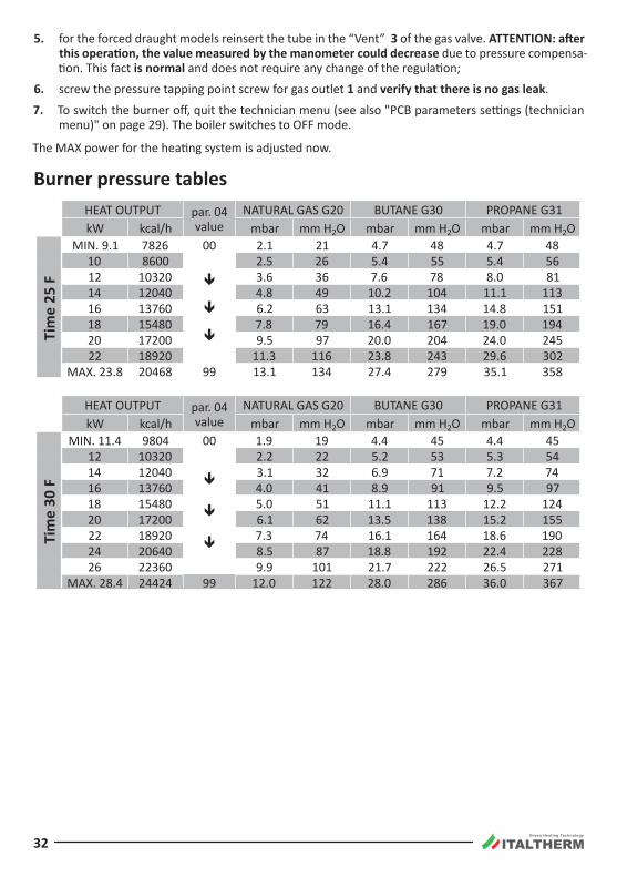
Burner pressure tablesHEAT OUTPUT par . 04
valueNATURAL GAS G20 BUTANE G30 PROPANE G31
kW kcal/h mbar mm H2O mbar mm H2O mbar mm H2O
Tim
e 25
F
MIN . 9 .1 7826 00 2 .1 21 4 .7 48 4 .7 4810 8600
ê
ê
ê
2 .5 26 5 .4 55 5 .4 5612 10320 3.6 36 7 .6 78 8 .0 8114 12040 4 .8 49 10 .2 104 11 .1 11316 13760 6 .2 63 13.1 134 14 .8 15118 15480 7 .8 79 16 .4 167 19 .0 19420 17200 9 .5 97 20 .0 204 24 .0 24522 18920 11.3 116 23.8 243 29 .6 302
MAX. 23.8 20468 99 13.1 134 27 .4 279 35.1 358
HEAT OUTPUT par . 04 value
NATURAL GAS G20 BUTANE G30 PROPANE G31kW kcal/h mbar mm H2O mbar mm H2O mbar mm H2O
Tim
e 30
F
MIN . 11 .4 9804 00 1 .9 19 4 .4 45 4 .4 4512 10320
ê
ê
ê
2 .2 22 5 .2 53 5.3 5414 12040 3.1 32 6 .9 71 7 .2 7416 13760 4 .0 41 8 .9 91 9 .5 9718 15480 5 .0 51 11 .1 113 12 .2 12420 17200 6 .1 62 13.5 138 15 .2 15522 18920 7.3 74 16 .1 164 18 .6 19024 20640 8 .5 87 18 .8 192 22 .4 22826 22360 9 .9 101 21 .7 222 26 .5 271
MAX. 28.4 24424 99 12 .0 122 28 .0 286 36.0 367
Green Heating Technology
33
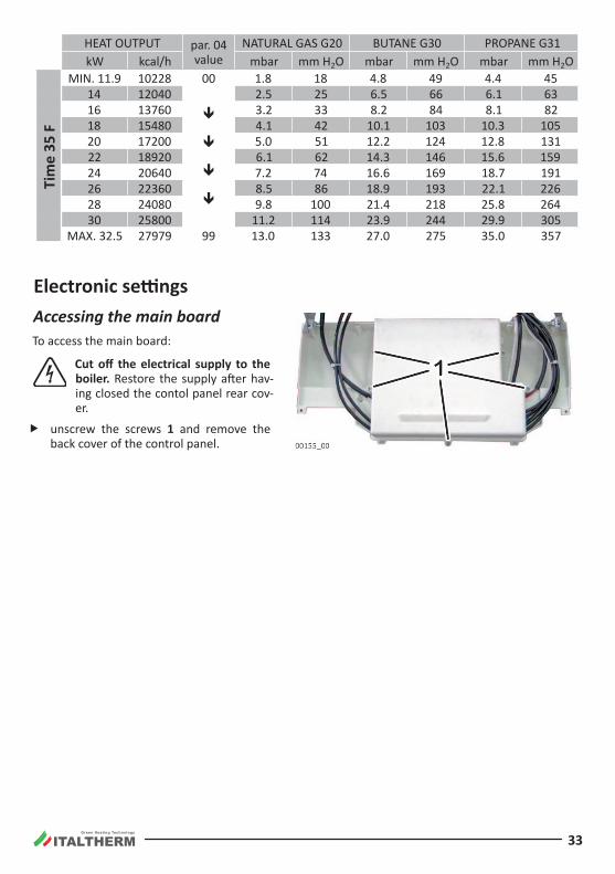
HEAT OUTPUT par . 04 value
NATURAL GAS G20 BUTANE G30 PROPANE G31kW kcal/h mbar mm H2O mbar mm H2O mbar mm H2O
Tim
e 35
F
MIN . 11 .9 10228 00 1 .8 18 4 .8 49 4 .4 4514 12040
ê
ê
ê
ê
2 .5 25 6 .5 66 6 .1 6316 13760 3.2 33 8 .2 84 8 .1 8218 15480 4 .1 42 10 .1 103 10.3 10520 17200 5 .0 51 12 .2 124 12 .8 13122 18920 6 .1 62 14.3 146 15 .6 15924 20640 7 .2 74 16 .6 169 18 .7 19126 22360 8 .5 86 18 .9 193 22 .1 22628 24080 9 .8 100 21 .4 218 25 .8 26430 25800 11 .2 114 23.9 244 29 .9 305
MAX. 32.5 27979 99 13.0 133 27 .0 275 35.0 357
Electronic settingsAccessing the main boardTo access the main board:
Cut off the electrical supply to the boiler. Restore the supply after hav-ing closed the contol panel rear cov-er .
f unscrew the screws 1 and remove the back cover of the control panel .
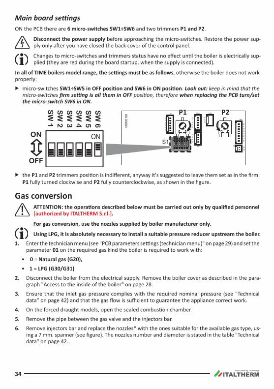
Green Heating Technology
34
Main board settingsON the PCB there are 6 micro-switches SW1÷SW6 and two trimmers P1 and P2 .
Disconnect the power supply before approaching the micro-switches. Restore the power sup-ply only after you have closed the back cover of the control panel.
Changes to micro-switches and trimmers status have no effect until the boiler is electrically sup-plied (they are red during the board startup, when the supply is connected).
In all of TIME boilers model range, the settings must be as follows, otherwise the boiler does not work properly:
f micro-switches SW1÷SW5 in OFF position and SW6 in ON position . Look out: keep in mind that the micro-switches firm setting is all them in OFF position, therefore when replacing the PCB turn/set the micro‑switch SW6 in ON.
S1
M15
M4
M2
M16
M6
M1
S1
2827262524232221
3938
789
10
123456
6869707172
737475
SW
1
SW
6
ONON
SW
1
ON
OFF
SW
2S
W 3
SW
4S
W 5
SW
6
0009
3 00
P1 P2
f the P1 and P2 trimmers position is indifferent, anyway it's suggested to leave them set as in the firm: P1 fully turned clockwise and P2 fully counterclockwise, as shown in the figure.
Gas conversion ATTENTION: the operations described below must be carried out only by qualified personnel
[authorized by ITALTHERM S.r.l.].
For gas conversion, use the nozzles supplied by boiler manufacturer only.
Using LPG, it is absolutely necessary to install a suitable pressure reducer upstream the boiler.
1. Enter the technician menu (see "PCB parameters settings (technician menu)" on page 29) and set the parameter 01 on the required gas kind the boiler is required to work with:
• 0 = Natural gas (G20),
• 1 = LPG (G30/G31)
2. Disconnect the boiler from the electrical supply. Remove the boiler cover as described in the para-graph "Access to the inside of the boiler" on page 28.
3. Ensure that the inlet gas pressure complies with the required nominal pressure (see "Technical data" on page 42) and that the gas flow is sufficient to guarantee the appliance correct work.
4. On the forced draught models, open the sealed combustion chamber.
5. Remove the pipe between the gas valve and the injectors bar.
6. Remove injectors bar and replace the nozzles* with the ones suitable for the available gas type, us-ing a 7 mm. spanner (see figure). The nozzles number and diameter is stated in the table "Technical data" on page 42.
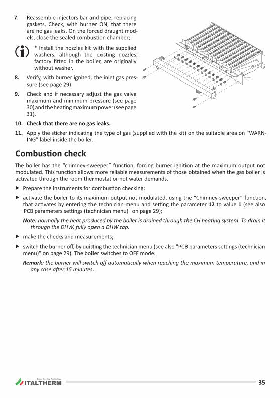
Green Heating Technology
35
7. Reassemble injectors bar and pipe, replacing gaskets. Check, with burner ON, that there are no gas leaks. On the forced draught mod-els, close the sealed combustion chamber;
* Install the nozzles kit with the supplied washers, although the existing nozzles, factory fitted in the boiler, are originally without washer.
8. Verify, with burner ignited, the inlet gas pres-sure (see page 29).
9. Check and if necessary adjust the gas valve maximum and minimum pressure (see page 30) and the heating maximum power (see page 31).
10. Check that there are no gas leaks.
11. Apply the sticker indicating the type of gas (supplied with the kit) on the suitable area on “WARN-ING” label inside the boiler .
Combustion checkThe boiler has the “chimney-sweeper” function, forcing burner ignition at the maximum output not modulated. This function allows more reliable measurements of those obtained when the gas boiler is activated through the room thermostat or hot water demands.
f Prepare the instruments for combustion checking;
f activate the boiler to its maximum output not modulated, using the “Chimney-sweeper” function, that activates by entering the technician menu and setting the parameter 12 to value 1 (see also
"PCB parameters settings (technician menu)" on page 29);
Note: normally the heat produced by the boiler is drained through the CH heating system. To drain it through the DHW, fully open a DHW tap.
f make the checks and measurements;
f switch the burner off, by quitting the technician menu (see also "PCB parameters settings (technician menu)" on page 29). The boiler switches to OFF mode.
Remark: the burner will switch off automatically when reaching the maximum temperature, and in any case after 15 minutes.
00015 00
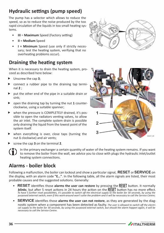
Green Heating Technology
36
Hydraulic settings (pump speed)The pump has a selector which allows to reduce the speed, so as to reduce the noise produced by the too rapid circulation of the liquids in too small heating sys-tems .
• III = Maximum Speed (Factory setting)
• II = Medium Speed
• I = Minimum Speed (use only if strictly neces-sary; test the heating system, verifying that no overheating problems occur).
Draining the heating systemWhen it is necessary to drain the heating system, pro-ceed as described here below:
f Unscrew the cap 3;
f connect a rubber pipe to the draining tap termi-nal 2 ;
f put the other end of the pipe in a suitable drain or sink;
f open the draining tap by turning the nut 1 counter-clockwise, using a suitable spanner;
f when the pressure is COMPLETELY drained, it's pos-sible to open the radiators venting valves, to allow the air inlet . The complete system drain is possible only draining the liquid from the lowest point of the system itself .
f when everything is over, close taps (turning the nut 1 clockwise) and air vents;
f screw the cap 3 on the terminal 2 .
In the primary exchanger a certain quantity of water of the heating system remains. If you want to remove the boiler from the wall, we advice you to close with plugs the hydraulic inlet/outlet heating system connections.
Alarms - boiler blockFollowing a malfunction, the boiler can lockout and show a particular signal, or on the display, with an alarm code "E…". In the following table, all the alarm signals are listed, their most probable causes and the suggested solutions. Generally:
• identifies those alarms the user can restore by pressing the button. It normally blinks, but after 5 reset actions in 24 hours the action on the button has no more effect. To have 5 further reset possibilities, it's possible to switch off the electrical supply to the boiler for 30 seconds, by using the purposed external switch, even if this work-around won't solve the problem and it will be necessary to call the Service Centre;
• identifies those alarms the user can not restore, as they are generated by the diag-nostic system when a component has been detected as faulty. The user is allowed to switch off the electri-cal supply to the boiler for 30 seconds, by using the purposed external switch, but should the alarm happen again, it will be necessary to call the Service Centre.
00016 00
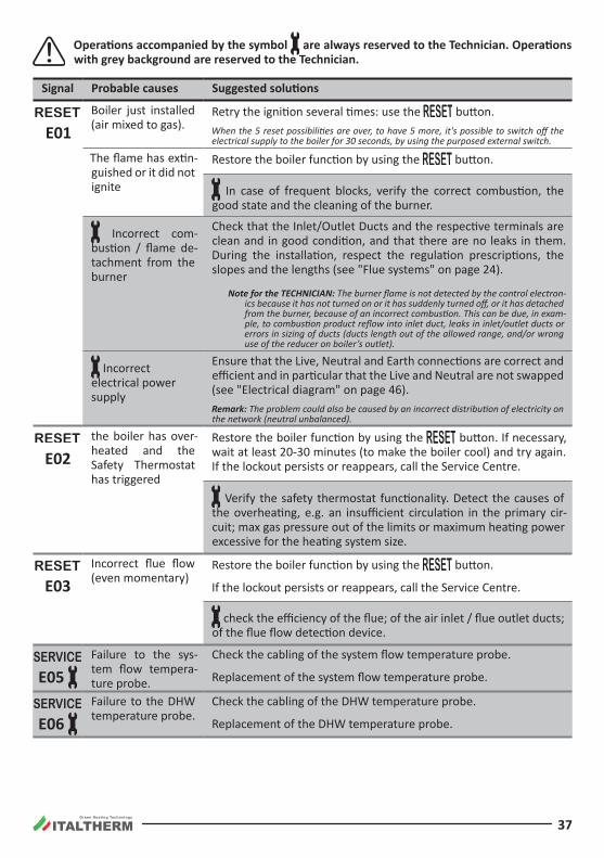
Green Heating Technology
37
Operations accompanied by the symbol are always reserved to the Technician. Operations with grey background are reserved to the Technician.
Signal Probable causes Suggested solutions
E01
Boiler just installed (air mixed to gas).
Retry the ignition several times: use the button.When the 5 reset possibilities are over, to have 5 more, it's possible to switch off the electrical supply to the boiler for 30 seconds, by using the purposed external switch.
The flame has extin-guished or it did not ignite
Restore the boiler function by using the button.
In case of frequent blocks, verify the correct combustion, the good state and the cleaning of the burner.
Incorrect com-bustion / flame de-tachment from the burner
Check that the Inlet/Outlet Ducts and the respective terminals are clean and in good condition, and that there are no leaks in them. During the installation, respect the regulation prescriptions, the slopes and the lengths (see "Flue systems" on page 24).
Note for the TECHNICIAN: The burner flame is not detected by the control electron-ics because it has not turned on or it has suddenly turned off, or it has detached from the burner, because of an incorrect combustion. This can be due, in exam-ple, to combustion product reflow into inlet duct, leaks in inlet/outlet ducts or errors in sizing of ducts (ducts length out of the allowed range, and/or wrong use of the reducer on boiler’s outlet).
Incorrect electrical power supply
Ensure that the Live, Neutral and Earth connections are correct and efficient and in particular that the Live and Neutral are not swapped (see "Electrical diagram" on page 46).Remark: The problem could also be caused by an incorrect distribution of electricity on the network (neutral unbalanced).
E02
the boiler has over-heated and the Safety Thermostat has triggered
Restore the boiler function by using the button. If necessary, wait at least 20-30 minutes (to make the boiler cool) and try again. If the lockout persists or reappears, call the Service Centre.
Verify the safety thermostat functionality. Detect the causes of the overheating, e.g. an insufficient circulation in the primary cir-cuit; max gas pressure out of the limits or maximum heating power excessive for the heating system size.
E03
Incorrect flue flow (even momentary)
Restore the boiler function by using the button.
If the lockout persists or reappears, call the Service Centre.
check the efficiency of the flue; of the air inlet / flue outlet ducts; of the flue flow detection device.
E05
Failure to the sys-tem flow tempera-ture probe.
Check the cabling of the system flow temperature probe.
Replacement of the system flow temperature probe.
E06
Failure to the DHW temperature probe.
Check the cabling of the DHW temperature probe.
Replacement of the DHW temperature probe.
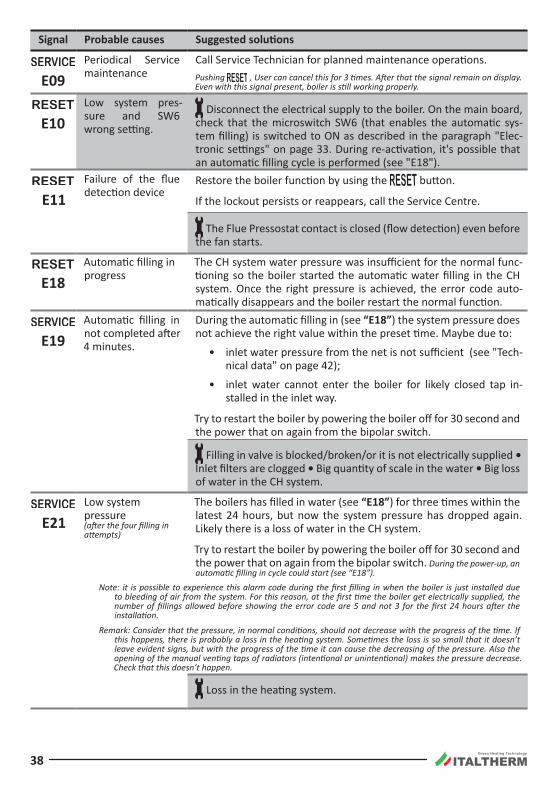
Green Heating Technology
38
Signal Probable causes Suggested solutions
E09
Periodical Service maintenance
Call Service Technician for planned maintenance operations.Pushing , User can cancel this for 3 times. After that the signal remain on display. Even with this signal present, boiler is still working properly.
E10
Low system pres-sure and SW6 wrong setting.
Disconnect the electrical supply to the boiler. On the main board, check that the microswitch SW6 (that enables the automatic sys-tem filling) is switched to ON as described in the paragraph "Elec-tronic settings" on page 33. During re-activation, it's possible that an automatic filling cycle is performed (see "E18").
E11
Failure of the flue detection device
Restore the boiler function by using the button.
If the lockout persists or reappears, call the Service Centre.
The Flue Pressostat contact is closed (flow detection) even before the fan starts .
E18
Automatic filling in progress
The CH system water pressure was insufficient for the normal func-tioning so the boiler started the automatic water filling in the CH system. Once the right pressure is achieved, the error code auto-matically disappears and the boiler restart the normal function.
E19
Automatic filling in not completed after 4 minutes.
During the automatic filling in (see “E18”) the system pressure does not achieve the right value within the preset time. Maybe due to:
• inlet water pressure from the net is not sufficient (see "Tech-nical data" on page 42);
• inlet water cannot enter the boiler for likely closed tap in-stalled in the inlet way .
Try to restart the boiler by powering the boiler off for 30 second and the power that on again from the bipolar switch .
Filling in valve is blocked/broken/or it is not electrically supplied • Inlet filters are clogged • Big quantity of scale in the water • Big loss of water in the CH system .
E21
Low system pressure (after the four filling in attempts)
The boilers has filled in water (see “E18”) for three times within the latest 24 hours, but now the system pressure has dropped again. Likely there is a loss of water in the CH system .
Try to restart the boiler by powering the boiler off for 30 second and the power that on again from the bipolar switch . During the power-up, an automatic filling in cycle could start (see “E18”).
Note: it is possible to experience this alarm code during the first filling in when the boiler is just installed due to bleeding of air from the system. For this reason, at the first time the boiler get electrically supplied, the number of fillings allowed before showing the error code are 5 and not 3 for the first 24 hours after the installation.
Remark: Consider that the pressure, in normal conditions, should not decrease with the progress of the time. If this happens, there is probably a loss in the heating system. Sometimes the loss is so small that it doesn’t leave evident signs, but with the progress of the time it can cause the decreasing of the pressure. Also the opening of the manual venting taps of radiators (intentional or unintentional) makes the pressure decrease. Check that this doesn’t happen.
Loss in the heating system.
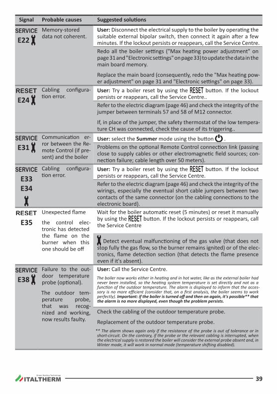
Green Heating Technology
39
Signal Probable causes Suggested solutions
E22
Memory-stored data not coherent .
User: Disconnect the electrical supply to the boiler by operating the suitable external bipolar switch, then connect it again after a few minutes. If the lockout persists or reappears, call the Service Centre.Redo all the boiler settings ("Max heating power adjustment" on page 31 and "Electronic settings" on page 33) to update the data in the main board memory .
Replace the main board (consequently, redo the "Max heating pow-er adjustment" on page 31 and "Electronic settings" on page 33).
E24
Cabling configura-tion error.
User: Try a boiler reset by using the button. If the lockout persists or reappears, call the Service Centre..Refer to the electric diagram (page 46) and check the integrity of the jumper between terminals 57 and 58 of M12 connector.
If, in place of the jumper, the safety thermostat of the low tempera-ture CH was connected, check the cause of its triggering..
E31
Communication er-ror between the Re-mote Control (if pre-sent) and the boiler
User: select the Summer mode using the button .Problems on the optional Remote Control connection link (passing close to supply cables or other electromagnetic field sources; con-nection failure; cable length over 50 meters).
E33 E34
Cabling configura-tion error.
User: Try a boiler reset by using the button. If the lockout persists or reappears, call the Service Centre.Refer to the electric diagram (page 46) and check the integrity of the wirings, especially the eventual short cable jumpers between two contacts of the same connector (on the cabling connections to the electronic board).
E35
Unexpected flame
the control elec-tronic has detected the flame on the burner when this one should be off
Wait for the boiler automatic reset (5 minutes) or reset it manually by using the button. If the lockout persists or reappears, call the Service Centre
Detect eventual malfunctioning of the gas valve (that does not stop fully the gas flow, so the burner remains ignited) or of the elec-tronics, flame detection section (that detects the flame presence even if it's absent).
E38
Failure to the out-door temperature probe (optional).
The outdoor tem-perature probe, that was recog-nized and working, now results faulty.
User: Call the Service Centre .The boiler now works either in heating and in hot water, like as the external boiler had never been installed, so the heating system temperature is set directly and not as a function of the outdoor temperature. The alarm is displayed to inform that the acces-sory is no more efficient (consider that, on a first analysis, the boiler seems to work perfectly). Important: if the boiler is turned off and then on again, it's possible** that the alarm is no more displayed, even though the problem persists.
Check the cabling of the outdoor temperature probe.
Replacement of the outdoor temperature probe.** The alarm shows again only if the resistance of the probe is out of tolerance or in short-circuit. On the contrary, if the probe or the relevant cabling is interrupted, when the electrical supply is restored the boiler will consider the external probe absent and, in Winter mode, it will work in normal mode (temperature shifting disabled).
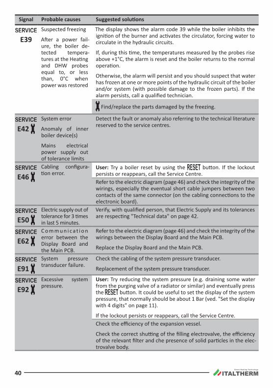
Green Heating Technology
40
Signal Probable causes Suggested solutions
E39
Suspected freezing
After a power fail-ure, the boiler de-tected tempera-tures at the Heating and DHW probes equal to, or less than, 0°C when power was restored
The display shows the alarm code 39 while the boiler inhibits the ignition of the burner and activates the circulator, forcing water to circulate in the hydraulic circuits.
If, during this time, the temperatures measured by the probes rise above +1°C, the alarm is reset and the boiler returns to the normal operation.
Otherwise, the alarm will persist and you should suspect that water has frozen at one or more points of the hydraulic circuit of the boiler and/or system (with possible damage to the frozen parts). If the alarm persists, call a qualified technician.
Find/replace the parts damaged by the freezing.
E42
System error
Anomaly of inner boiler device(s)
Mains electrical power supply out of tolerance limits
Detect the fault or anomaly also referring to the technical literature reserved to the service centres .
E46
Cabling configura-tion error.
User: Try a boiler reset by using the button. If the lockout persists or reappears, call the Service Centre.Refer to the electric diagram (page 46) and check the integrity of the wirings, especially the eventual short cable jumpers between two contacts of the same connector (on the cabling connections to the electronic board).
E50
Electric supply out of tolerance for 3 times in last 5 minutes.
Verify, with qualified person, that Electric Supply and its tolerances are respecting "Technical data" on page 42.
E62
C o m m u n i c a t i o n error between the Display Board and the Main PCB .
Refer to the electric diagram (page 46) and check the integrity of the wirings between the Display Board and the Main PCB .
Replace the Display Board and the Main PCB .
E91
System pressure transducer failure.
Check the cabling of the system pressure transducer.
Replacement of the system pressure transducer.
E92
Excessive system pressure.
User: Try reducing the system pressure (e.g. draining some water from the purging valve of a radiator or similar) and eventually press the button. It could be useful to set the display of the system pressure, that normally should be about 1 Bar (ved. "Set the display with 4 digits" on page 11).
If the lockout persists or reappears, call the Service Centre.Check the efficiency of the expansion vessel.
Check the correct shutting of the filling electrovalve, the efficiency of the relevant filter and che presence of solid particles in the elec-trovalve body .
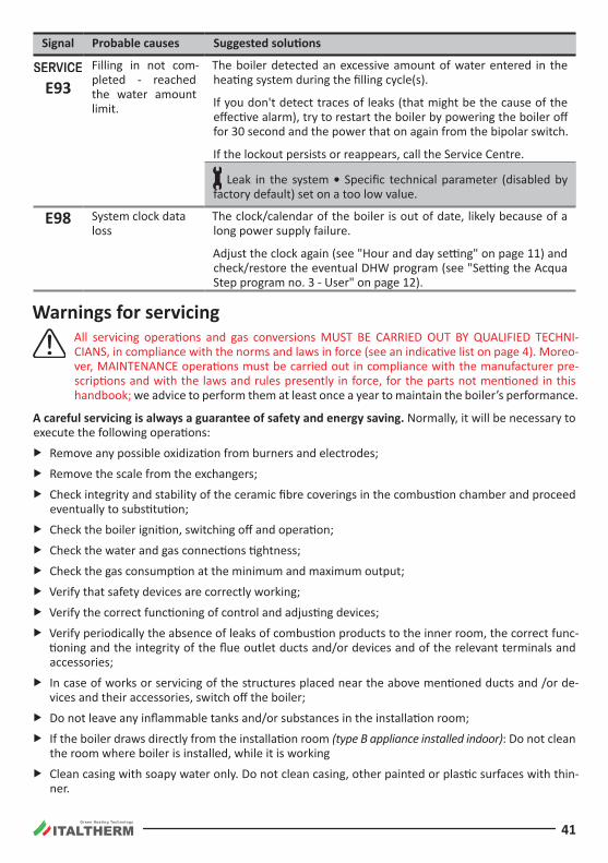
Green Heating Technology
41
Signal Probable causes Suggested solutions
E93
Filling in not com-pleted - reached the water amount limit .
The boiler detected an excessive amount of water entered in the heating system during the filling cycle(s).
If you don't detect traces of leaks (that might be the cause of the effective alarm), try to restart the boiler by powering the boiler off for 30 second and the power that on again from the bipolar switch.
If the lockout persists or reappears, call the Service Centre.
Leak in the system • Specific technical parameter (disabled by factory default) set on a too low value.
E98 System clock data loss
The clock/calendar of the boiler is out of date, likely because of a long power supply failure.
Adjust the clock again (see "Hour and day setting" on page 11) and check/restore the eventual DHW program (see "Setting the Acqua Step program no. 3 - User" on page 12).
Warnings for servicing All servicing operations and gas conversions MUST BE CARRIED OUT BY QUALIFIED TECHNI-
CIANS, in compliance with the norms and laws in force (see an indicative list on page 4). Moreo-ver, MAINTENANCE operations must be carried out in compliance with the manufacturer pre-scriptions and with the laws and rules presently in force, for the parts not mentioned in this handbook; we advice to perform them at least once a year to maintain the boiler’s performance.
A careful servicing is always a guarantee of safety and energy saving. Normally, it will be necessary to execute the following operations:
f Remove any possible oxidization from burners and electrodes;
f Remove the scale from the exchangers;
f Check integrity and stability of the ceramic fibre coverings in the combustion chamber and proceed eventually to substitution;
f Check the boiler ignition, switching off and operation;
f Check the water and gas connections tightness;
f Check the gas consumption at the minimum and maximum output;
f Verify that safety devices are correctly working;
f Verify the correct functioning of control and adjusting devices;
f Verify periodically the absence of leaks of combustion products to the inner room, the correct func-tioning and the integrity of the flue outlet ducts and/or devices and of the relevant terminals and accessories;
f In case of works or servicing of the structures placed near the above mentioned ducts and /or de-vices and their accessories, switch off the boiler;
f Do not leave any inflammable tanks and/or substances in the installation room;
f If the boiler draws directly from the installation room (type B appliance installed indoor): Do not clean the room where boiler is installed, while it is working
f Clean casing with soapy water only. Do not clean casing, other painted or plastic surfaces with thin-ner .
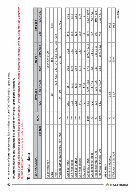
Green Heating Technology
42
f
In a
ny c
ase
of p
arts
repl
acem
ent,
it is
man
dato
ry to
use
ITAL
THER
M o
rigin
al sp
are
part
s.
ITAL
THER
M d
eclin
es a
ny re
spon
sibi
lity
in c
ase
of n
on-o
rigin
al sp
are
part
s util
izatio
n.
"Onc
e al
l che
ck a
nd se
rvic
ing
oper
ation
s hav
e be
en ca
rrie
d ou
t, th
e te
chni
cian
mus
t writ
e a
repo
rt fo
r the
use
r, w
ho m
ust c
ount
ersi
gn a
copy
for
rece
ipt a
nd v
isio
n" as
pre
scrib
ed b
y th
e re
gula
tion
in fo
rce.
Tech
nica
l dat
aTE
CHN
ICAL
DAT
AU
.M.
Tim
e 25
FTi
me
30 F
Tim
e 35
FG
as ty
peG
20G
30 /
G31
G20
G30
/ G
31G
20G
30 /
G31
CE c
ertifi
catio
n06
94 C
M 3
400
Clas
sII2
H3+
II2H3
+II2
H3+
Type
B22
- C12
- C3
2 - C
42 -
C52
- C62
- C8
2 - C
92W
orki
ng te
mpe
ratu
re ra
nge
(min
÷max
)°C
0 ÷
+60
0 ÷
+60
0 ÷
+60
Max
hea
t inp
utkW
25 .7
25 .7
30.5
30.5
34.5
34.5
Min
hea
t inp
utkW
10.3
10.3
13.0
13.0
13.5
13.5
Max
hea
t out
put
kW23
.823
.828
.428
.432
.532
.5M
in h
eat o
utpu
tkW
9 .1
9 .1
11 .4
11 .4
11 .9
11 .9
NO
X Cla
ss
22
/ 23
23
2CO
at 0
% O
2 (Q
n)pp
m56
.972
.9 /
38.6
57 .6
107.
7 / 6
2.3
66 .4
51.8
/ 30
.9CO
2 at n
omin
al in
put
%7 .
27.
3 / 7
.16 .
57.
8 / 7
.76 .
77.
3 / 7
.1Fl
ue te
mpe
ratu
re (Q
n)°C
129
126
/ 126
113
113
/ 113
107
103
/ 103
Flue
mas
s flow
rate
(Qn)
kg/h
51 .9
58.1
/ 59
.468
.865
.6 /
66.1
74 .6
79.3
/ 81
.1
EFFI
CIEN
CYN
omin
al e
ffici
ency
%92
.893
.194
.3Effi
cien
cy a
t 30%
load
%91
.790
.691
.3(fo
llow
s)
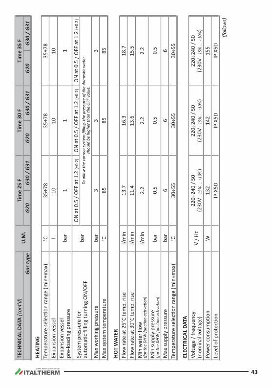
Green Heating Technology
43
TECH
NIC
AL D
ATA
(con
t'd)
U.M
.Ti
me
25 F
Tim
e 30
FTi
me
35 F
Gas
type
G20
G30
/ G
31G
20G
30 /
G31
G20
G30
/ G
31
HEAT
ING
Tem
pera
ture
sele
ction
rang
e (m
in÷m
ax)
°C35
÷78
35÷7
835
÷78
Expa
nsio
n ve
ssel
l10
1010
Expa
nsio
n ve
ssel
pr
e-lo
adin
g pr
essu
reba
r1
11
Syst
em p
ress
ure
for
auto
mati
c fil
ling
turn
ing
ON
/OFF
bar
ON
at 0
.5 /
OFF
at 1
.2 (±
0.2)
ON
at 0
.5 /
OFF
at 1
.2 (±
0.2)
ON
at 0
.5 /
OFF
at 1
.2 (±
0.2)
To a
llow
the
corr
ect s
yste
m fi
lling
, the
pre
ssur
e of
the
dom
estic
wat
er
shou
ld b
e hi
gher
than
the
OFF
val
ue.
Max
wor
king
pre
ssur
eba
r3
33
Max
syst
em te
mpe
ratu
re°C
8585
85
HOT
WAT
ERFl
ow ra
te a
t 25°
C te
mp.
rise
l/min
13.7
16.3
18 .7
Flow
rate
at 3
0°C
tem
p. ri
sel/m
in11
.413
.615
.5M
in w
ater
flow
(fo
r the
DHW
func
tion
activ
ation
)l/m
in2 .
22 .
22 .
2
Min
supp
ly p
ress
ure
(for t
he D
HW fu
nctio
n ac
tivati
on)
bar
0 .5
0 .5
0 .5
Max
supp
ly p
ress
ure
bar
66
6Te
mpe
ratu
re se
lecti
on ra
nge
(min
÷max
)°C
30÷5
530
÷55
30÷5
5
ELEC
TRIC
AL D
ATA
Volta
ge /
freq
uenc
y (n
omin
al v
olta
ge)
V / H
z22
0÷24
0 / 5
0 (2
30V
–15%
... +
10%
)22
0÷24
0 / 5
0 (2
30V
–15%
... +
10%
)22
0÷24
0 / 5
0 (2
30V
–15%
... +
10%
)Po
wer
con
sum
ption
W13
214
215
5Le
vel o
f pro
tecti
onIP
X5D
IP X
5DIP
X5D
(follo
ws)
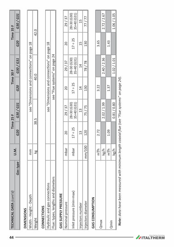
Green Heating Technology
44
TECH
NIC
AL D
ATA
(con
t'd)
U.M
.Ti
me
25 F
Tim
e 30
FTi
me
35 F
Gas
type
G20
G30
/ G
31G
20G
30 /
G31
G20
G30
/ G
31
DIM
ENSI
ON
SW
idth
- He
ight
- De
pth
mm
see
"Dim
ensio
ns a
nd c
onne
ction
s" o
n pa
ge 1
8W
eigh
tkg
38.5
40 .0
42 .0
CON
NEC
TIO
NS
Hydr
aulic
and
gas
con
necti
ons
see
"Dim
ensio
ns a
nd c
onne
ction
s" o
n pa
ge 1
8Fl
ue: t
ypes
, len
gths
and
dia
met
ers
see
"Flu
e sy
stem
s" o
n pa
ge 2
4
GAS
SU
PPLY
PRE
SSU
REN
omin
al p
ress
ure
mba
r20
29 /
3720
29 /
3720
29 /
37
Inle
t pre
ssur
e (m
in÷m
ax)
mba
r17
÷ 2
528
÷30
(G30
) 35
÷40
(G31
)17
÷ 2
528
÷30
(G30
) 35
÷40
(G31
)17
÷ 2
528
÷30
(G30
) 35
÷40
(G31
)In
ject
ors n
umbe
r13
1314
1415
15In
ject
ors d
iam
eter
mm
/100
120
75 /
7513
078
/ 78
130
77 /
77
GAS
CO
NSU
MPT
ION
Qm
axm
³/h2 .
723.
223.
65kg
/h2.
02 /
1.99
2.40
/ 2.
362.
72 /
2.67
Qm
inm
³/h1 .
091.
371.
43kg
/h0.
81 /
0.80
1.02
/ 1.
011.
06 /
1.05
Not
e: d
ata
have
bee
n m
easu
red
with
min
imum
leng
th c
oaxi
al fl
ue (s
ee "F
lue
syst
ems"
on
page
24)
.
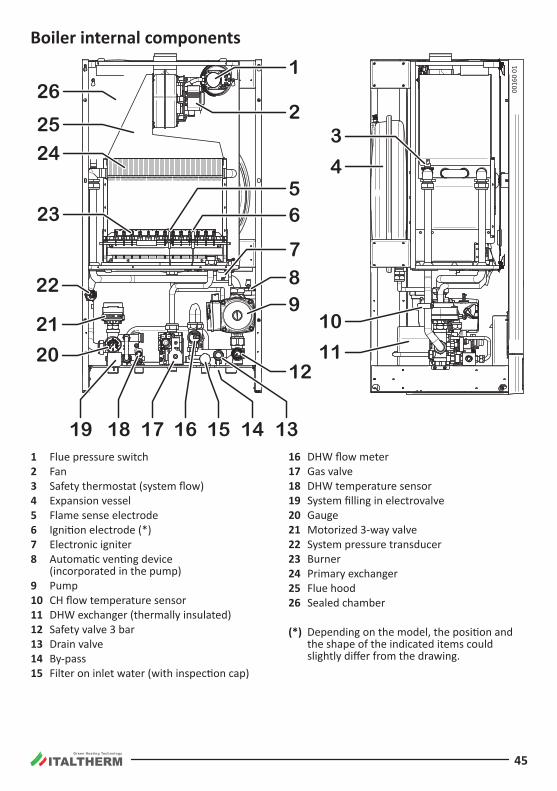
Green Heating Technology
45
Boiler internal components
1315 1416171819
3
11
10
20
21
22
23
24
25
26
4
2
56
87
1
9
12
0016
0 01
1 Flue pressure switch2 Fan3 Safety thermostat (system flow)4 Expansion vessel5 Flame sense electrode6 Ignition electrode (*)7 Electronic igniter8 Automatic venting device
(incorporated in the pump)9 Pump10 CH flow temperature sensor11 DHW exchanger (thermally insulated)12 Safety valve 3 bar13 Drain valve14 By-pass15 Filter on inlet water (with inspection cap)
16 DHW flow meter17 Gas valve18 DHW temperature sensor19 System filling in electrovalve20 Gauge21 Motorized 3-way valve22 System pressure transducer23 Burner24 Primary exchanger25 Flue hood26 Sealed chamber
(*) Depending on the model, the position and the shape of the indicated items could slightly differ from the drawing.
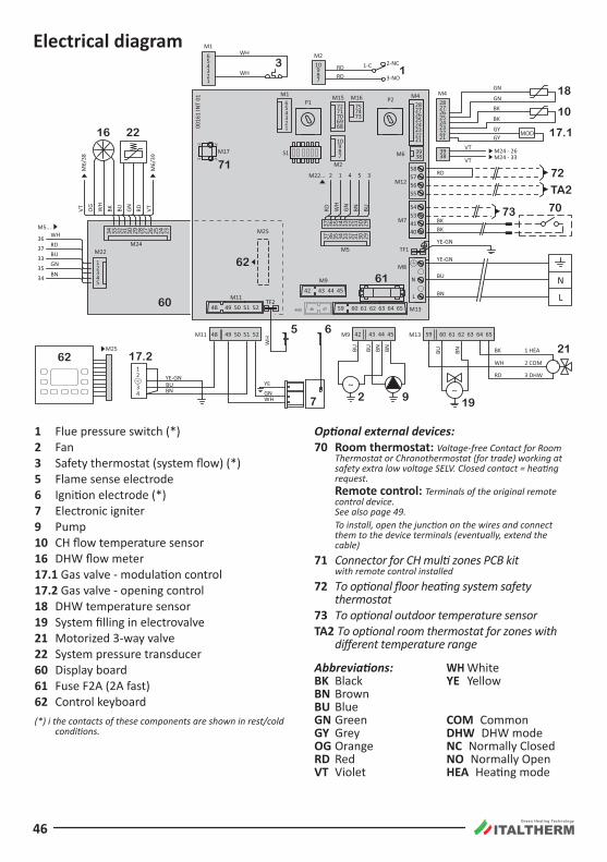
Green Heating Technology
46
Electrical diagram
46 47M10
M4
M9M11
M25
M25
M1M2
34
21
L
N
M13
~
VT M24 - 26M24 - 33VT
WH
WH
GN
BK
BKGN
YE-GN
GNWH
YE
BN
BU
YE-GN
BK
RD
RD WH
GN BN BUVT OG
WH
BK BU GN RD VT
RDWH
BUGN
BN
BK
YE-GNBUBN
WH
RD
WH
BK
3 DHW
2 COM
1 HEABNBNBUBU BNBU
GYGY
RDRD
2-NC
3-NO
1-C
N
L42 43 44 45
5048 49 51 52
5048 49 51 52
40415354
55565758
59 60 61 62 63 64 65
7677
7879
42 43 44 45
2122
252423
282726
2122
252423
2827263
21
654
987
2
36
34353337
1 4 5 3
10
706968
7172
737475
3839
321
654 9
87
10
M8
M7
M12
S1
TF1
M11
M4
30 293134 33 3237 36 35
30 293134 33 3237 36 35
3938M6
M1
M2
M15
345
21
M22
M16P1
M17
P2
TF2M13
M5
27 2628 24 232534 33 29303132
M24
M22...
M5...
M6/
38
M6/
39
M9
6059 61 62 63 64 65
7
5 6
17.2
18
10
17.1
62
60
62
70
3
0016
1 IN
T 01
61
73
72
TA2
71
16 22
21
2 9 19
1
1 Flue pressure switch (*)2 Fan3 Safety thermostat (system flow) (*)5 Flame sense electrode6 Ignition electrode (*)7 Electronic igniter9 Pump10 CH flow temperature sensor16 DHW flow meter17.1 Gas valve - modulation control17.2 Gas valve - opening control18 DHW temperature sensor19 System filling in electrovalve21 Motorized 3-way valve22 System pressure transducer60 Display board61 Fuse F2A (2A fast)62 Control keyboard(*) i the contacts of these components are shown in rest/cold
conditions.
Optional external devices:70 Room thermostat: Voltage-free Contact for Room
Thermostat or Chronothermostat (for trade) working at safety extra low voltage SELV. Closed contact = heating request. Remote control: Terminals of the original remote control device. See also page 49. To install, open the junction on the wires and connect them to the device terminals (eventually, extend the cable)
71 Connector for CH multi zones PCB kit with remote control installed
72 To optional floor heating system safety thermostat
73 To optional outdoor temperature sensorTA2 To optional room thermostat for zones with
different temperature range
Abbreviations:Bk BlackBN BrownBU BlueGN GreenGY GreyOG OrangeRD RedVT Violet
WH WhiteYE Yellow
COM CommonDHW DHW modeNC Normally ClosedNO Normally OpenHEA Heating mode
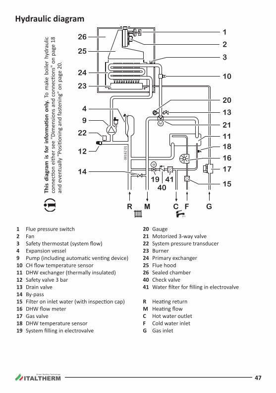
Green Heating Technology
47
Hydraulic diagram
Th
is d
iagr
am is
for
info
rmati
on o
nly.
To
mak
e bo
iler
hydr
aulic
co
nnec
tion
eith
er s
ee "
Dim
ensio
ns a
nd c
onne
ction
s" o
n pa
ge 1
8 an
d ev
entu
ally
"Pos
ition
ing
and
fast
enin
g" o
n pa
ge 2
0.
0016
2 01
M
25
26
14
24
23
22
9
4
12
1
2
21
10
3
17
1118
1519
4041
R M C F G
16
20
13
1 Flue pressure switch2 Fan3 Safety thermostat (system flow)4 Expansion vessel9 Pump (including automatic venting device)10 CH flow temperature sensor11 DHW exchanger (thermally insulated)12 Safety valve 3 bar13 Drain valve14 By-pass15 Filter on inlet water (with inspection cap)16 DHW flow meter17 Gas valve18 DHW temperature sensor19 System filling in electrovalve
20 Gauge21 Motorized 3-way valve22 System pressure transducer23 Burner24 Primary exchanger25 Flue hood26 Sealed chamber40 Check valve41 Water filter for filling in electrovalve
R Heating returnM Heating flowC Hot water outletF Cold water inletG Gas inlet
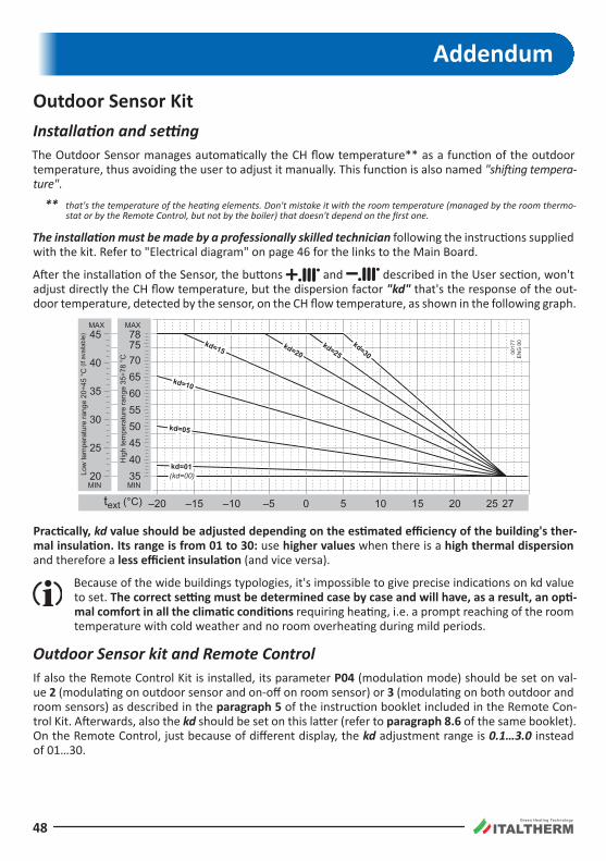
Green Heating Technology
48
Addendum
Outdoor Sensor kitInstallation and settingThe Outdoor Sensor manages automatically the CH flow temperature** as a function of the outdoor temperature, thus avoiding the user to adjust it manually. This function is also named "shifting tempera-ture" .
** that's the temperature of the heating elements. Don't mistake it with the room temperature (managed by the room thermo-stat or by the Remote Control, but not by the boiler) that doesn't depend on the first one.
The installation must be made by a professionally skilled technician following the instructions supplied with the kit. Refer to "Electrical diagram" on page 46 for the links to the Main Board.
After the installation of the Sensor, the buttons and described in the User section, won't adjust directly the CH flow temperature, but the dispersion factor "kd" that's the response of the out-door temperature, detected by the sensor, on the CH flow temperature, as shown in the following graph.
35404550556065707578
MAX
MIN
Hig
h te
mpe
ratu
re ra
nge
35÷7
8 °C
–20text (°C) –15 –10 –5 0 5 10 15 20 25 27
20
25
30
35
40
45MAX
MIN
Low
tem
pera
ture
rang
e 20
÷45
°C (i
f ava
ilabl
e)
(kd=00)
kd=05
kd=01
kd=10
kd=15 kd=20kd=25
kd=30 0017
7E
NG
00
Practically, kd value should be adjusted depending on the estimated efficiency of the building's ther-mal insulation. Its range is from 01 to 30: use higher values when there is a high thermal dispersion and therefore a less efficient insulation (and vice versa).
Because of the wide buildings typologies, it's impossible to give precise indications on kd value to set . The correct setting must be determined case by case and will have, as a result, an opti-mal comfort in all the climatic conditions requiring heating, i.e. a prompt reaching of the room temperature with cold weather and no room overheating during mild periods.
Outdoor Sensor kit and Remote ControlIf also the Remote Control Kit is installed, its parameter P04 (modulation mode) should be set on val-ue 2 (modulating on outdoor sensor and on-off on room sensor) or 3 (modulating on both outdoor and room sensors) as described in the paragraph 5 of the instruction booklet included in the Remote Con-trol Kit. Afterwards, also the kd should be set on this latter (refer to paragraph 8.6 of the same booklet). On the Remote Control, just because of different display, the kd adjustment range is 0.1…3.0 instead of 01…30.

Green Heating Technology
49
Remote Control kit
This remote control is more than a simple room thermostat . Thanks to this, it is possible to manage the boiler in all its set-tings like DHW and CH temperature adjustment, boiler reset in case of boiler block, and of course it works as a room thermo-stat both in manual and weekly program mode. It’s powered by the boiler (in safety low voltage), so it doesn’t need batteries .
Extract the Remote Control from its package . keep the rel-evant user instruction booklet and annex it to this Manual.
Nor the Remote Control neither the relevant cable coming from the boiler must not, for any reason, be connected to the 230Vac supply mains.
To avoid malfunctions due to electrical noise, the Remote Control connections, as well as all low-voltage connections,, should be kept separated from power supply cables, e.g. by enclosing it into separate raceways .
The maximum overall cable length shouldn't exceed 50 m.
Install the Remote Control at approx. 1.5 m over floor in a place suitable for correct sensing of the room tem-perature. Do not install behind doors, curtains, near heat sources nor expose to direct sunlight or water sprinkles.
1. Cut off electricity from boiler;
2. install the device as described in the paragraph 4 of the supplied instruction booklet;
3. link the Remote Control wirings to the "Room Thermostat - Remote Control" cable coming out of the boiler, by means of a suitable bipolar terminal. See also "Electrical diagram" on page 46;
Note: The Remote Control link is not polarized.
Check the correct work of the device. The electronics recognizes it automatically (otherwise the alarm E31 appears (see "Alarms - boiler block" on page 36) provided that:
• on the boiler's control panel, by means of the button , the Summer mode is forever set . Hereafter the boiler working modes (even OFF) should be selected on the Remote Control only;
• the main boiler board is set as described in "Main board settings" on page 34.
0008
8a_0
0
NONONO SI
1.5
mt
CONTROLLO REMOTO
EASYREMOTE
MANUALE DI
ISTRUZIONI

Green Heating Technology
50
Notes

Green Heating Technology
51
Notes
ITALTHERM SrlVia S. D’Acquisto, snc • 29010 Pontenure (PC) - IT Tel. +39.0523.575611 • Fax +39.0523.575600
www.italtherm.it • e-mail: [email protected]
9600
0003
0_02
_EN
G -
10/
03/2
015
ITA
LTH
ER
M S
rl de
clin
es a
ny r
espo
nsib
ility
for
even
tual
prin
ting
and/
or t
rans
crip
tion
erro
rs in
the
pre
sent
man
ual.
In o
rder
to
cons
tant
ly im
prov
e its
pro
duct
s, th
e co
mpa
ny h
as th
e rig
ht to
cha
nge
feat
ures
and
dat
a w
ritte
n in
the
pres
ent m
anua
l, at
any
tim
e an
d w
ithou
t not
ice.
www.italtherm.it
UNI EN ISO 9001:2008